simulating the behavior of restrained steel beams to flame
TRANSCRIPT

Simulating the Behavior of Restrained Steel Beams to
Flame Impingement from Localized-Fires
Chao Zhanga,b,∗, Guo-Qiang Lic,∗∗, Asif Usmanid
aCollege of Civil Engineering, Tongji University, 1239 Siping Road, Shanghai 200092,China
bNational Institute of Standards and Technology, National Fire Research Laboratory,Fire Research Division, Gaithersburg, MD 20899-1070, USA
cState Key Laboratory for Disaster Reduction in Civil Engineering, Tongji University,1239 Siping Road, Shanghai 200092, China
dSchool of Engineering, Edinburgh University, Edinburgh EH9 3JN, UK
Abstract
Steel structures may be exposed to localized heating by a fire source nearby.Flame impingement from localized fire may lead to high temperatures in theexposed steel members, which may lead to structural failure. This papernumerically investigates the thermal and mechanical behaviors of restrainedsteel beams exposed to flame impingement from localized fires. Four steelbeams with different dimensions and restraints were considered. Both devel-oping and steady burning fires were investigated. The standard ISO834 firewas also used for comparison. The study finds that the temperature distri-butions within the steel beams subjected to flame impingement are highlynon-uniform both across and along the beams. Along the beam length, thetemperatures near the fire source may be hundreds of degrees higher thanthose far from the fire source. Due to different temperature distribution, thedeformation mode for restrained steel beam subjected to flame impingementmay be significantly different from that of a beam subjected to the standardISO834 fire. The failure temperatures for restrained steel beams subjectedto localized fires may be higher or lower than those for restrained beamssubjected to the standard ISO834 fire. Reliance on the standard fire maylead to an unconservative design if the potential real fires are localized fires.
∗Currently Guest Scientist at NIST. E-mail address: [email protected] or08 chao [email protected](C. Zhang).
∗∗E-mail address: [email protected](G.Q. Li)
Preprint submitted to Journal of Constructional Steel Research March 4, 2013

Keywords: Restrained steel beam; Flame impingement from localized fire;Thermal and mechanical behavior; Numerical investigation
1. Introduction
In the past two decades, many researchers have investigated the behaviorof steel beams exposed to fire [1, 2, 3, 4, 5, 6, 7, 8, 9, 10]. Liu et al. [1]experimentally investigated the role of the connections and axial restraint inaffecting the fire resistance of a steel beam. In their experiments, the furnacewas programmed to follow the ISO834 standard temperature-time curves.Li and Guo [2] tested the behavior of restrained steel beams subjected to anatural fire. In the test, an arbitrary temperature-time curve which includedboth heating and cooling phases was used to represent the natural fire. VilaReal et al. [3] conducted a validation test on the lateral-torsional bucklingresistance of unrestrained steel I beams subjected to fire. In the test, thethermal action on a simply supported beam was changed from room tem-perature up to 600 oC. In [1, 2, 3], all the specimens in the furnace wereheated uniformly such that the longitudinal temperature gradients were neg-ligible. In [1, 2], the upper flanges of the tested beams were protected withfireproofing materials to consider the heat-sink effect resulting from concreteslabs on the steel beams in real building construction. As a result, the trans-verse temperature gradients in the specimens were very large (in both tests[1, 2], the maximum temperature differences between the upper and lowerflange were on the order of several hundreds of degrees). In [3], the beamwas unprotected so that the transverse temperature gradient was negligible.Recently, the effect of transverse thermal gradient on the behavior of steelbeam-columns exposed to fire was experimentally investigated by Dwaikatet al. [4]. In their experiment, both ASTM E119 standard fire and a designfire were considered. The design fire included a growth phase simulating theASTM E119 standard fire for about 90 min and then underwent a rapid cool-ing phase. The specimens with uniform insulation were exposed to fire fromfour sides, and the insulation on some specimens was removed in specificlocations to cause thermal gradient.
Yin and Wang [5, 6], Li et al. [7], Tan and Huang [8], Bailey et al. [9],Usmani et al. [10], EI-Rimawi et al.[11] and Kodur and Dwaikat [12], onthe other hand, have numerically investigated the behavior of steel beamsin fire conditions. Among those studies, [5, 6, 7, 8] considered the effects
2
of non-uniform temperature distributions in their investigations. However,the profiles of those non-uniform temperature distributions (transversely orlongitudinally) were arbitrarily assumed and considered to be linear.
The fire conditions used in the studies mentioned above are all designedto represent fully-developed compartment fires or post-flashover fires. In afully-developed compartment fire, the gas properties within the compartmentare approximately uniform because of flashover. Correspondingly, the steelmembers exposed to compartment fires are uniformly heated on all exposedsides such that the temperature gradients along the length of the members arealways negligible and the temperature distributions within the steel sectionsare approximately uniform (as in steel columns) or varying linearly withdepth (as in ceiling steel beams). However, in some spaces such as open carpark buildings and large enclosures where fuels are located in specific areasso that horizontal fire spread is not possible, the flashover phenomena (thatall exposed fuel surfaces within the compartment burn simultaneously [13])are unlikely to happen. Localized fires are more appropriate when evaluatingthe fire safety of structures in such spaces.
The gas properties in a localized fire are highly non-uniform and thetemperature distributions in the exposed steel members are longitudinallyand transversely nonlinear [14, 15]. Until now, few reports on the behaviorof steel beams exposed to localized fires have been issued. Hasemi et al.[16] experimentally studied the heating mechanism of ceiling/beams exposedto localized fires. Based on the test data, a correlation was proposed byHasemi to calculate the heat flux to the ceiling from flame impingementfrom localized fires. The correlation has been adopted by the Eurocode EC1[17]. In SFPE handbook [18], the correlations proposed by Wakamatsu areadopted to calculate the heat fluxes to different parts of steel I beams fromlocalized fires. Recently, Jeffers and Sotelino [19] simulated the thermo-mechanical behavior of a simply supported steel beam exposed to a localizedfire by a computationally efficient fiber element approach.
The purpose of this study is to investigate the thermal and structuralbehaviors of restrained steel beams exposed to localized fires. Correlationsrecommended by SFPE handbook were used to calculate the heat fluxes toexposed steel I beams. The finite element program ANSYS 1 was used as the
1Certain commercial entities, equipment, or materials may be identified in this docu-ment in order to describe an experimental procedure or concept adequately. Such identifi-
3
numerical tool.
2. Modeling localized fire
2.1. Heat release rate
Heat release rate (HRR) is the most import variable in measuring fireseverity, which can be calculated by
HRR = mf · △Hc (1)
where, mf is the mass burning rate of the fuel; and △Hc is the net heatof combustion of the fuel. In ventilation controlled fires (fully-developedcompartment fires), the HRRs are alternatively calculated by
HRR = ma · △Hair (2)
where, mair is the mass rate of air inflow; and △Hair is the heat releasedper unit mass air consumed. For most common fuels, △Hc,air = 3.03 ±0.02MJ/kg [13].
TheHRR of a real fire can be measured by cone calorimetry (see Babrauskaset al. [20]). In design work, the natural fire safety concept (NFSC) is widelyused to represent the fire conditions [17, 21]. As shown in Fig.1, the NFSCfire is assumed to be t-square in the growth stage and decay stage begins atthe time when 70 percent of design fire load is consumed. The steady firewith a single constant HRR in the whole fire duration time, which is usuallyconsidered in fire resistance design [22], is also illustrated in Fig.1.
For an NFSC fire, in the growth stage, the HRR is given by
HRR = αt2 (3)
the fire growth time tg is given by
tg =
√HRRmax
α(4)
cation is not intended to imply recommendation or endorsement by the National Instituteof Standards and Technology, nor is it intended to imply that the entities, materials, orequipment are necessarily the best available for the purpose.
4

and the fuel energy consumed during the fire growth stage, Qg, is
Qg =
∫ tg
0
αt2dt =αtg
3
3(5)
where, α is the fire intensity coefficient, taken as 0.00293, 0.0117 and 0.0466for slow, medium and fast growth fire, respectively.
The duration time of steady burning in an NSFC fire is given by
ts =0.7qfAf −Qg
HRRmax
(6)
and the duration of the decaying stage is given by
td =0.6qfAf
HRRmax
(7)
where, qf and Af are design fire load density and floor area, respectively;and HRRmax is the maximum heat release rate.
The total duration time of an NFSC fire is given by
tf = tg + ts + td (8)
2.2. Flame length
Heskestad’s correlation is used by EC1 [17] to calculate the unconfinedflame length of a localized fire, which is given by
Lf = −1.02D + 0.235Q2/5 (9)
where, D is the diameter of the fire; and Q is the HRR of the fire.The unconfined flame length can also be calculated by[16]
Lf
D= 3.5Q∗
Dn (10)
where n = 2/5 for Q∗D ≥ 1.0 and n = 2/3 for Q∗
D < 1.0. Q∗D is a non-
dimensional HRR given by
Q∗D =
Q
ρ∞cpT∞√gD5/2
(11)
where, ρ∞, cp and T∞ are density, specific heat and temperature of gas atambient temperature; and g is the gravitational acceleration.
5

For localized fires beneath an unconfined ceiling, the horizontal flamelength, defined as the distance between the flame tip and the fire centerline,is given by [18]
LC +HC
HC
= 2.90Q∗HC
1/3 (12)
The horizontal flame lengths along the lower and upper flanges of I-beamsmounted to a ceiling are given by [18]
LB +HB
HB
= 2.3Q∗HB
0.3 (13)
andLC +HC
HC
= 2.9Q∗HC
0.4 (14)
where Q∗HC
and Q∗HB
are defined as in Eq.11 with D is replaced by HC andHB, respectively. HC and HB are the distances between the fire and theceiling, and the fire and the lower flange of the beam, respectively.
2.3. Heat flux from localized fire
Hasemi et al. [16, 23, 24] conducted a series of fire tests to investigate theheating mechanisms of building components exposed to localized fires. A flatceiling with and without a steel I beam beneath it was located at differentdistances above burners using propane gas fuel. Steady fires were consideredin the tests. The HRRs from the fire source ranged from 90 kW to 900 kW inthe ceiling/beam tests, and 80 kW to 750 kW in the ceiling tests. Heat fluxgauges were used to measure the incident heat flux along the ceiling/beamat different distances away from the fire centerline. A detailed description ofthe tests is given in [23, 24].
In EC1 [17], the heat flux received by the ceiling exposed to flame im-pingement from localized fires is given by
qin = 100 (yC ≤ 0.30) (15a)
qin = 136.3− 121yC (0.30 < yC ≤ 1.00) (15b)
qin = 15y−3.7C (yC ≥ 1.00) (15c)
where qin is the incident heat flux in kW; and yC is a non-dimensional pa-rameter, defined by
yC =r +HC + z0LC +HC + z0
(16)
6

in which, z0 is the vertical position of the virtual heat source, obtained from
z0D
= 2.4(1−Q∗D2/5) (Q∗
D ≥ 1.0) (17a)
z0D
= 2.4(Q∗D2/5 −Q∗
D2/3) (Q∗
D < 1.0) (17b)
In the SFPE handbook [18], an alternative correlation proposed by Waka-matsu is presented for calculating the heat flux received by the ceiling, qin,and is given by
qin = 518.8e−3.7yC (18)
The heat fluxes incident onto different parts of an I-beam mounted be-neath a ceiling can be calculated by the following correlations [18]: the heatflux to the downward face of the lower flange is
qin = 518.8e−3.7yB (19)
the heat flux to the upward face of the lower flange and the web is
qin = 148.1e−2.75yC (20)
and the heat flux to the downward face of the upper flange is
qin = 100.5e−2.85yC (21)
where yB is defined the same as in Eq.16 with the subscript ‘C’ is replacedby ‘B’.
Myllymaki and Kokkala [18, 25] measured heat fluxes onto I-beams ex-posed to fires as large as 3.9 MW. They found that for fires over 2.0 MW,the correlations suggested by Wakamatsu for the upward face of the lowerflange, web, and downward face of the upper flange underestimate the heatflux to these areas on the I-beam. For these large fires, the I-beam becomescompletely engulfed in the fire. As a result, heat fluxes on all parts of theI-beam follow the correlation suggested for the downward face of the lowerflange provided in Eq.19.
3. Numerical study
3.1. Numerical toolThe finite element program ANSYS was used as the numerical tool. AN-
SYS can predict the transient, nonlinear thermal/structural behaviors of var-ious structures under fire conditions if the material properties are provided,as validated by previous studies [21, 26, 27].
7

3.2. Basic elements
3.2.1. SHELL131-3D layered thermal shell
In the following studies, SHELL131 is used to model the thermal behaviorof steel beams in fire conditions. SHELL131 is a 3D layered shell elementhaving in-plane and through-thickness thermal conduction capability. It has4 nodes with up to 32 temperature degrees of freedom at each node. Theelement is applicable to a 3D, steady-state or transient thermal analysis.SHELL131 generates temperatures that can be passed to structural shellelements (such as SHELL181) for structural analysis.
The ability of SHELL131 to solve the transient, nonlinear heat transferproblem was verified using an example in Holman’s heat transfer book [28].The problem involves the heating of a 30 mm ceramic wall exposed to aradiation source on one side at 1000 oC, and to room air at 20 oC with aradiation surrounding temperature of 20 oC on the other side. Properties ofthe ceramic are k = 3.0 W/mK, ρ = 1600 kg/m3, and c = 800 J/kgK. Theemissivity is taken as 0.8. The convection heat transfer coefficient from theheated side of the plate is calculated by h = 1.92△T 1/4. In [28], the problemwas solved by finite difference method (FDM). In a previous work [27], theproblem was solved using ANSYS with 2D thermal solid element PLANE55and thermal surface element SURF151. Fig.2 shows excellent agreementamong the results of wall temperatures predicted by the various methods.
3.2.2. SHELL181-finite strain shell
SHELL181 was adopted to model the structural behavior of steel beamsin fire. SHELL181 is suitable for analyzing thin to moderately-thick shellstructures. It is a 4-node element with six degrees of freedom at each node:translations in the x, y, and z direction, and rotations about the x, y, and zaxes. SHELL181 is well-suited for linear, large rotation, and/or large strainnonlinear applications. Change in shell thickness is accounted for in nonlinearanalysis.
Ding et al. [29] used SHELL181 to model tests of the fire resistance offire-resistant steel members. In this paper, the use of SHELL181 to predictthe structural behaviors of steel beams in fire was validated using test datafrom Li and Guo [2] and Liu et al. [1].
Test on specimen 1 in [2] was considered. The tested beam had a crosssection H250×250×8×12 and a clear span length of 4500 mm. Two concen-trated loads were applied symmetrically to the restrained beam by two jacks.The distance between these two point loads was 1500 mm. The load ratio
8

(LR) of the restrained beam at room temperature was 0.7. LR was definedas the ratio of the applying moment to the moment capacity of the beam sec-tion calculated by design codes. Fig.3 shows the FE structural model of therestrained steel I beam. The steel beam was modeled using SHELL181, andthe restraints at the beam ends were modeled using spring-damper elementCOMBIN14. As shown in Fig.3(b), an axial spring and a rotational springlocated at mid-height of the beam end section are used to provide axial androtational restraints, respectively. The axial stiffness provided is ka = 39.54kN/mm and the rotational stiffness is kr = 1.09 × 10⁸ Nm/rad. The hightemperature material model for structural steel reported in [30] was used inthe numerical model. Figs. 4, 5 and 6 show good agreement between thenumerical results and test data. The discrepancy between the numerical andmeasured results could be due to the fact that the stress-strain model in [30]cannot model high temperature creep successfully [12].
Test numbered “FUR15” in [1] was considered. The tested beam had across section 178×102×19UB and a clear span length of 2000 mm. Two sym-metrical concentrated loads were applied. The distance between these twopoint loads was 800 mm. The LR of the restrained beam at room temperaturewas 0.5. End-plate beam-to-column connections were used. The axial stiff-ness provided is ka = 8 kN/mm and the rotational stiffness is kr = 1.4× 10⁵
Nm/rad. Figs. 7 and 8 show good agreement between the numerical resultsand test data.
3.3. FE model and investigated cases
In our investigation, restrained ceiling beams under uniform load subjectto flame impingement from localized fires were considered. Table 1 givescharacteristics of the investigated cases. In the table, ‘R’ and ‘A’ correspondto rotational and axial restraints, respectively. Four beams with differentdimensions and restraints were considered. Beam B1 was the above testedbeam in [1], and beam B3 was the above tested beam in [2] without ribs.Beam B2 was similar to beam B1 with axial restraint only and B4 was similarto beam B3 with axial restraint only. The LRs for B1 and B2 were 0.5, andfor B3 and B4 were 0.7. The ceiling height was 2 m. The fire source waslocated at the floor and just below the center of the beams. Medium NFSCand steady fires were considered. The maximum heat release rates for thosetwo fires were equal and taken as 1.6 MW. The ISO834 standard fire was alsoconsidered for comparison. The fire duration was taken as 1 h. In all cases,
9

the beams were unprotected and three-sides exposed. The upward surfacesof the beam upper flanges were assumed to be adiabatic.
4. Results and discussions
4.1. Steel temperature distribution
Fig. 9 shows results for the temperature of a steel beam subjected tothe NFSC fire. The temperature distributions within steel beam are highlynon-uniform both transversely and longitudinally, and the location of themaximum temperature changes with time. At the very beginning of thedeveloping phase, the maximum temperature is located at the lower flange,as shown in Fig. 9a; then, the maximum temperature moves to the web andstays within the web during the later developing and steady burning phases,as shown in Fig. 9b and Fig. 9c; during the decay phase, the maximumtemperature first moves from the web to the lower flange, then from thelower flange to the upper flange, as shown in Fig. 9d and Fig. 9e.
Fig. 10 shows results at t = 300s and t = 3000s for the temperature ofa steel beam subjected to the steady fire. The temperature distributionswithin the steel beam are also highly non-uniform both transversely andlongitudinally. During the entire heating phase, the maximum temperatureremains within the web.
Fig. 11 shows results for the temperature of a steel beam subjected tothe the ISO834 fire. The temperature distribution within the steel beamsection is nonlinear. During the entire heating phase, the maximum temper-ature remains within the web. In simulations using the ISO834 fire, uniformheating conditions along the beam length were assumed; therefore, the steeltemperatures are longitudinally uniform, as shown in Fig. 11.
4.2. Structural response
Fig. 12a and 12b show the results of deflection and reaction force, re-spectively, for the restrained steel beam B1 subjected to different fires. Instandard fire test [31], a load-bearing element is definitely failed when eitherits deflection reaches L/20 (for horizontal members) or when it collapses (forvertical members). Here, L is the clear span of the specimen. In our inves-tigation, the failure temperature of restrained beams is defined as the max-imum steel temperature when the restrained beams either reach the abovedeflection limit or buckle. In Fig. 12a, values for the failure temperature are
10

also presented. Fig. 12b shows that the restrained beam B1 buckles in allinvestigated fires.
Fig. 13a and 13b show the results of deflection and reaction force, respec-tively, for the restrained steel beam B2 subjected to different fires. BeamB2 buckles in the NFSC fire. In the steady and ISO834 fires, beam B2 failswhen its mid-span deflection reaches 2000/20 = 100 mm.
Fig. 14a and 14b show the results of deflection and reaction force, respec-tively, for the restrained steel beam B3 subjected to different fires. Beam B3buckles in both the NFSC and steady fires. In the ISO834 fire, beam B2 failswhen its mid-span deflection reaches 4500/20 = 225 mm.
Fig. 15a and 15b show the results of deflection and reaction force, respec-tively, for the restrained steel beam B4 subjected to different fires. Beam B4buckles in both the NFSC and steady fires. In the ISO834 fire, beam B2 failswhen its mid-span deflection reaches 4500/20 = 225 mm.
The failure modes and failure temperatures (marked as Tfail) are sum-marized in Table 1. Beams in the NFSC fire buckle in all cases; and beamsin the steady and ISO834 fires buckle in some cases. For beams B1, B2 andB3, the failure temperatures in the ISO834 fire are lower than those in eitherthe NFSC or steady fire; but for beam B4, the failure temperature in ISO834fire is higher than that in both the NFSC and steady fires (Tfail in ISO834fire is 514 oC and 13 % higher than that in the NFSC fire). Generally, thefailure temperatures in the NFSC are lower than those in the steady fire.
4.3. Discussions
For steel beams subjected to flame impingement from localized fires, thesteel temperatures just above the fire source may be hundreds of degreeshigher than those far from the fire source, as shown in Figs. 9 and 10. Dueto the nonlinear longitudinal temperature gradient, the restrained beam inlocalized fires are more likely to undergo lateral displacements. Fig. 16 showsthe results of deformations at the definite failure condition for Beam B4 in theNFSC localized fire. The beam undergoes large deflection with global lateraldisplacement and significant local deformation in the middle section. Bycomparison, the same beam undergoes only large deflection when subjectedto the standard ISO834 fire, as shown in Fig. 17.
The heating history affects the temperature distribution within the ex-posed member. Therefore, although the maximum heat release rate for theNFSC and steady localized fires are equal, the same beam exposed to those
11

two fires might behave differently due to the different temperature distribu-tions as illustrated in cases 2a and 2b.
The temperature distribution within the restrained steel beam affects thebeam behavior and its failure temperature.
5. Conclusions
The thermal and mechanical behaviors of restrained steel beams subjectedto flame impingement from localized fires have been investigated numericallyusing ANSYS. Based on the results of this investigation, the following con-clusions can be drawn:
• The temperature distributions within a steel beam subjected to flameimpingement from localized fire are highly non-uniform both along thebeam axis and trhough its depth. Along the beam length, the tem-peratures near the fire source may be hundreds of degrees higher thanthose far from the fire source.
• The failure temperature for a restrained steel beam subjected to flameimpingement from localized fire may be higher or lower than the samebeam subjected to the standard ISO834 fire. In the cases investigated,the failure temperature in a localized fire can be 60 oC or 13 % lower(In the case the failure temperature in the standard ISO834 fire is 514oC).
• The deformation mode for a restrained steel beam subjected to flameimpingement from localized fire may be different from that subjectedto the standard ISO834 fire.
• The structural fire design based on the standard fire may be unconser-vative if the potential real fires are localized fires.
• Finally, although not specifically investigated here, it has been notedin previous studies (e.g. [10]) that transverse variation of temperatures(causing through-depth temperature gradients) will produce thermalbowing resulting in increase deflection and reduced axial forces in thebeam (under weak rotational restraint). Longitudinal variations of tem-peratures (in the absence of significant transverse gradients) producethe opposite effect, reduced deflections and increased axial forces (under
12
strong translational restraint). This general observation is consistentwith the findings here.
6. Acknowledgement
The work presented in this paper was originated at Tongji University andcompleted at NIST. The research work at Tongji was partially supportedby the National Natural Science Foundation of China through the contract51120185001. The support is acknowledged.
Valuable suggestions and review comments from Drs. John L. Gross,Jiann C. Yang and Fahim H. Sadek of NIST in the development of themanuscript are gratefully acknowledged.
[1] T.C.H. Liu, M.K. Fahad, J.M. Davies. Experimental investigation of be-havior of axially restrained steel beams in fire. Journal of ConstructionalSteel Research, 2002;58:1211-30.
[2] G.Q. Li, S.X., Guo. Experiment on restrained steel beams subjectedto heating and cooling. Journal of Constructional Steel Research,2008;64:268-74.
[3] P.M.M. Vila-Real, P.A.G. Piloto, J.-M. Franssen. A new proposal of asimple model for the lateral-torsional buckling of unrestrained steel Ibeams in case of fire: experimental and numerical validation. Journal ofConstructional Steel Research, 2003;59:179-99.
[4] M.M.S. Dwaikat, V.K.R. Kodur, S.E. Quiel, M.E.M. Garlock. Experi-mental behaviour of steel beam-columns subjected to fire-induced ther-mal gradient. Journal of Constructional Steel Research, 2011;67:30-38.
[5] Y.Z. Yin, Y.C. Wang. A numerical study of large deflection behavior ofrestrained steel beams at elevated temperatures. Journal of Construc-tional Steel Research, 2004;60:1029-47.
[6] Y.Z. Yin, Y.C. Wang. Numerical simulations of the effects of non-uniform temperature distributions on lateral torsional buckling re-sistance of steel I-beams. Journal of Constructional Steel Research,2003;59:1009-33.
13

[7] G.Q. Li, P. J. Wang, S.C. Jiang. Non-linear finite element analysis ofaxially restrained steel beams at elevated temperatures in fire. Journalof Constructional Steel Research, 2007;63:1175-83.
[8] K.H. Tan, Z.F. Huang. Structural responses of axially restrained steelbeams with semirigid moment connection in fire. Journal of StructuralEngineering, 2005;131:541-51.
[9] C.G. Bailey, I.W. Burgess, R.J. Plank. The lateral-torsional bucklingof unrestrained steel beams in fire. Journal of Constructional Steel Re-search, 1996;36:101-19.
[10] A.S. Usmani, J.M. Rotter, S. Lamont, A.M. Sanad, M. Gillie. Fun-damental principles of structural behavior under thermal effects. FireSafety Journal, 2001;36:721-44.
[11] J.A. EI-Rimawi, I.W. Burgess, R.J. Plank. The influence of connectionstiffness on the behavior of steel beams in fire. Journal of ConstructionalSteel Research, 1997;43:1-15.
[12] V.K.R. Kodur, M.M.S. Dwaikat. Effect of high temperature creep onthe fire response of restrained steel beams. Materials and Structures,2010;43:1327-41.
[13] D. Drysdale. An introduction to fire dynamics, 2rd edition. John Wileyand Sons. 1999.
[14] C. Zhang, G.Q. Li. Thermal response of steel columns exposed to lo-calized fires - numerical simulation and comparison with experimentalresults. Journal of Structural Fire Engineering, 2011;2:311-7.
[15] C. Zhang, G.Q. Li. Thermal behavior of a steel beam exposed to a lo-calized fire - numerical simulation and comparison with experimentalresults. In: Proceedings of the 4th International Conference on Protec-tion of Structures against Hazards, Beijing, China, 2009, p. 409-15.
[16] Y. Hasemi, Y. Yokobayashi, T. Wakamatsu, A.V. Ptchelintsev. Mod-eling of heating mechanism and thermal response of structural com-ponents exposed to localized fires: A new application of diffusion flamemodeling to fire safety engineering. NIST Internal Report 6030, NationalInstitute of Standards and Technology, Gaithersburg, Maryland, 1997.
14

[17] Eurocode 1: Actions on structures - Part 1-2: General actions - Actionson structures exposed to fire. BSI, 2002.
[18] B.Y. Lattimer. Heat fluxes from fires to surfaces. In: SFPE Handbookof Fire Protection Engineering, 3rd edition, Section 2-4, Society of FireProtection Engineers, Maryland, 2002.
[19] A.E. Jeffers, E.D. Sotelino. An efficient fiber element approach forthe thermo-structural simulation of non-uniformly heated frames. FireSafety Journal, 2012;51:18-26.
[20] V. Babrauskas. SFPE Handbbok of Fire Protection Engineering, 3rdedition, Section 3-1:Heat Release Rates, Society of Fire Protection En-gineers, 2002.
[21] G.Q. Li, C. Zhang. Creep effect on buckling of axially restrainedsteel columns in real fires. Journal of Constructional Steel Research,2012;71:182-8.
[22] A.H. Buchanan. Structural design for fire safety. John Wiley and SonsLtd.; 2002
[23] Y. Yokobayashi, Y. Hasemi, Takashi. Wakamatsu, Takao. Wakamatsu.Heating mechanism of flat ceiling exposed to localized fire - An introduc-tion to the fire safety design of building structures exposed to localizedfire. J. Struct. Constr. Eng., AIJ, 1996;484:149-56. (in Japanese).
[24] Y. Yokobayashi, Y. Hasemi, Takashi. Wakamatsu, Takao. Wakamatsu.Experimental study on the heating mechanism and thermal response ofa steel beam under ceiling exposed to localized fires. J. Struct. Constr.Eng., AIJ, 1997;498:169-75. (in Japanese).
[25] J. Myllymaki, M. Kokkala. Thermal exposure to a high welded I-beamabove a pool fire. Proceedings of the 1st International Workshop onStructures in fire, Copenhagen, Denmark, 2000, p. 211-24.
[26] C. Zhang, G.Q. Li, Y.C. Wang. Sensitivity study on using differentformulae for calculating the temperature of insulated steel members innatural fires. Fire Technology, 2012;48:343-66.
15

[27] G.Q. Li, C. Zhang. Thermal response to fire of uniformly insulated steelmembers: background and verification of the formulation reccomendedby chinese code CECS200. Advanced Steel Construction, 2010;6:788-802.
[28] J.P. Holman. Heat transfer, 9th edition. McGraw-Hill Inc., 2002.
[29] J. Ding, G.Q. Li, Y. Sakumoto. Parametric Studies on Fire Resistance ofFire-resistant Steel Members, Journal of Constructional Steel Research,2004;60:1007-27.
[30] T. T. Lie, B.A. Macaulay. Evaluation of the fire resistance of pro-tected steel columns. Internal Report No. 583, National Research ConcilCanada; 1989.
[31] BS 476-20. British Standard BS 476, Part 20: Method for determinationof the fire resistance of load bearing elements of construction (GeneralPrinciples), British Standard Institution. London, 1987.
16

Table 1: Investigated cases
Case Beam L Restraints LR Fire type Failure mode Tfail
1a B1 2000 mm R&A 0.5 NFSC buckling 720 oC1b B1 2000 mm R&A 0.5 steady buckling 777 oC1c B1 2000 mm R&A 0.5 ISO834 buckling 676 oC2a B2 2000 mm A 0.5 NFSC buckling 687 oC2b B2 2000 mm A 0.5 steady deflection 744 oC2c B2 2000 mm A 0.5 ISO834 deflection 649 oC3a B3 4500 mm R&A 0.7 NFSC buckling 798 oC3b B3 4500 mm R&A 0.7 steady buckling 798 oC3c B3 4500 mm R&A 0.7 ISO834 deflection 703 oC4a B4 4500 mm A 0.7 NFSC buckling 454 oC4b B4 4500 mm A 0.7 steady buckling 474 oC4c B4 4500 mm A 0.7 ISO834 deflection 514 oC
Figure 1: Illustration of the HRR history of a NFSC and steady fire
17

Figure 2: Comparison among the results of temperatures of a ceramic wall predicted bydifferent methods
Figure 3: FE model of a restrained steel I beam in validation study for Li and Guo test [2]
18

Figure 4: Numerical vs test results for Li and Guo test [2]
Figure 5: Predicted and measured deflection of the steel beam in [2]
19

Figure 6: Predicted and measured restraint axial force of the steel beam in [2]
Figure 7: Predicted and measured deflection of the steel beam in [1]
20
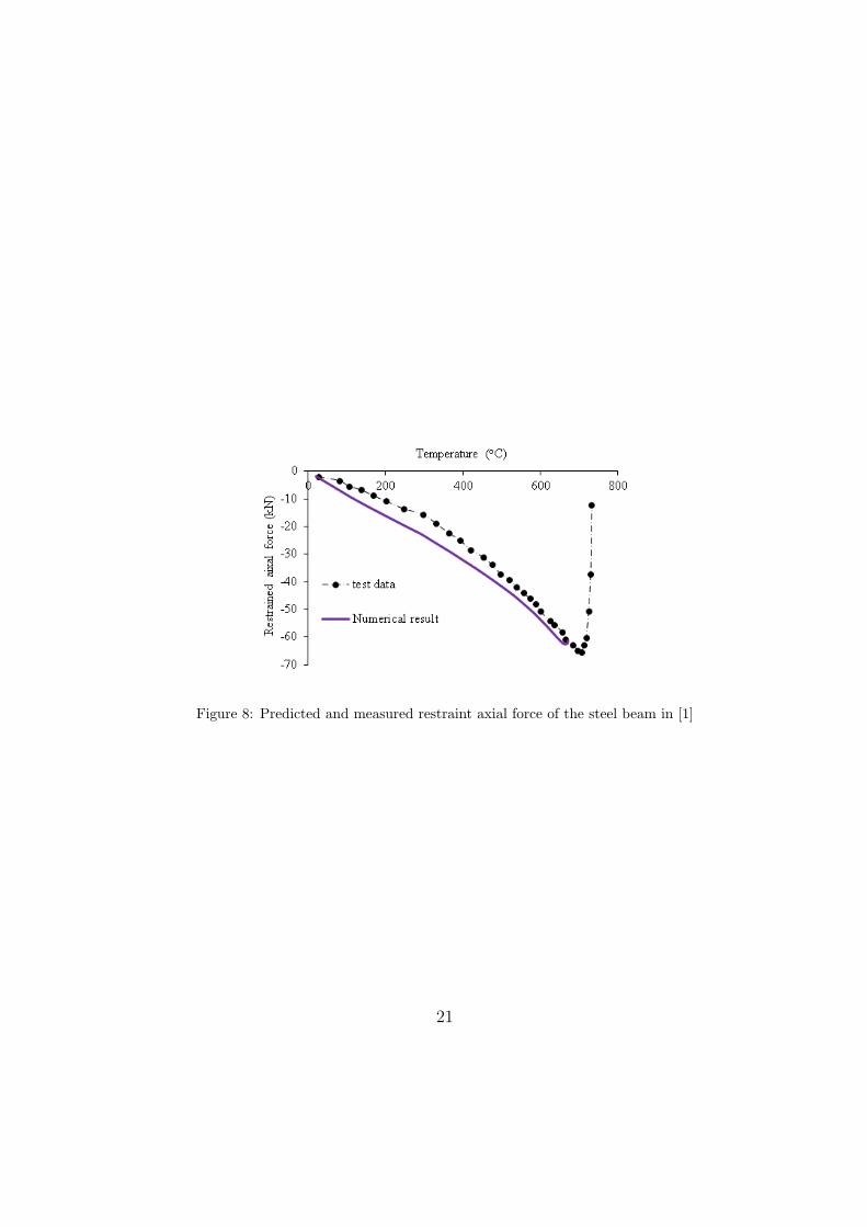
Figure 8: Predicted and measured restraint axial force of the steel beam in [1]
21

(a) Case 1, t=90 s (b) Case 1, t=300 s
(c) Case 1, t=1800 s (d) Case 1, t=2400 s
(e) Case 1, t=3000 s
Figure 9: Temperature results for steel beam subjected to NFSC fire
22
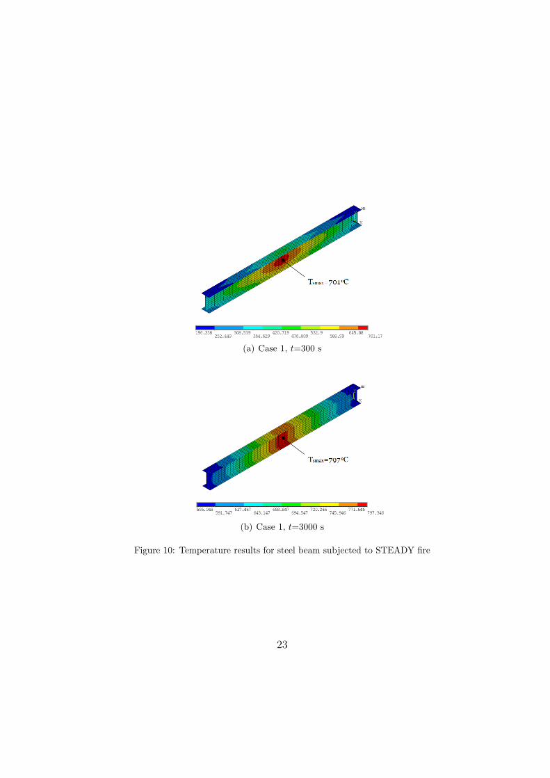
(a) Case 1, t=300 s
(b) Case 1, t=3000 s
Figure 10: Temperature results for steel beam subjected to STEADY fire
23
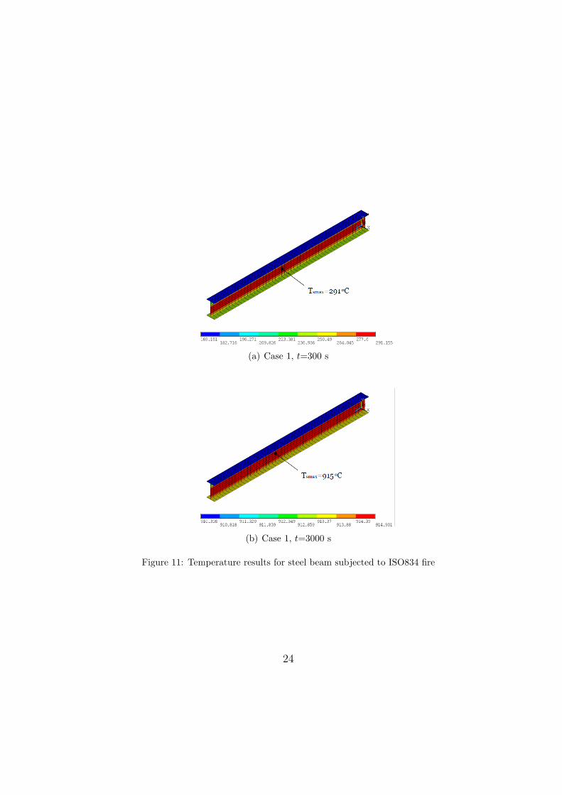
(a) Case 1, t=300 s
(b) Case 1, t=3000 s
Figure 11: Temperature results for steel beam subjected to ISO834 fire
24

(a) Deflection
(b) Force
Figure 12: Results for mid-span deflection and reaction force for restrained steel beam B1in different fires
25

(a) Deflection
(b) Force
Figure 13: Results for mid-span deflection and reaction force for restrained steel beam B2in different fires
26

(a) Deflection
(b) Force
Figure 14: Results for mid-span deflection and reaction force for restrained steel beam B3in different fires
27

(a) Deflection
(b) Force
Figure 15: Results for mid-span deflection and reaction force for restrained steel beam B4in different fires
28

Figure 16: Results for deformation for beam B4 in NFSC fire
Figure 17: Results for deformation for beam B4 in ISO834 fire
29