simplified structural analysis of steel portal frames ...simplified structural analysis of steel...
TRANSCRIPT
Simplified structural analysis of steel portal frames developed from structural optimization
H. K. Issa
Faculty of Engineering Soran University, Kurdistan Region of Iraq
Abstract
A parametric study, based on design optimization using distributed genetic algorithm, is conducted to develop a reliable design procedure for steel portal frames. The efforts are made to modify distributed genetic algorithm in order to enhance the quality of performance and accelerate the convergence to possible optimum solutions. The modification includes defining a state-of-art mutation scheme and a reproduction procedure. Software called DO-DGA has been developed to handle the design optimization. The study can help structural designers to work out the member forces required to design the elements of steel portal frames without referring to the complicated structural analysis. Implementing the results of structural optimization by DO-DGA, graphs and tables are developed from which the designers can determine the member forces. The main variables in the parametric study of steel portal frame are the slope of pitched rafter, the applied load to the rafter, the length and height of the haunch and the span of the frame. The procedure is promising since it can bring the design optimization into a daily-use tool in design offices. Keywords: distributed genetic algorithm, steel portal frame, structural optimisation.
1 Introduction
It has been witnessed that considerable developments have occurred in the Kurdistan region of Iraq during the past few years. Along with the developments many single storey buildings in the form of factories, workshops and showrooms have been constructed. Because of its economy and versatility for large spans in construction of pitched-roofs such as shopping centres, warehouses, retail shops,
Computer Aided Optimum Design in Engineering XII 47
www.witpress.com, ISSN 1743-3509 (on-line) WIT Transactions on The Built Environment, Vol 125, © 201 WIT Press2
doi:10.2495/OP120051

pools, factories, etc, the steel portal frame (SPF) has become the most often used structure within this sector. Any structural designer attempts to conduct an economical design. This can be achieved by formulating a design problem and solving it by an optimization technique while meeting the requirements of a code of practice to control the safety of the structure [1]. However, large number of iterations in implementing the optimization technique, it cannot be achieved by using the designer’s experiences and intuition. As it is believed that the major cost of structural steelwork is its own weight, approaches to minimizing the weight have become increasingly interesting for the researchers. Any structural system needs to be analyzed before stepping into the design process. Structural optimization techniques offer a sophisticated procedure including several iterations of structural analysis and design until an optimum design solution is achieved. The whole process is time consuming and complicated so that it makes the designers hesitant to apply the techniques to the design of real life structures. Hence, developing a simplified yet comprehensive technique will encourage designers to apply optimization techniques as a daily-use tool in design offices. In this paper, a modified distributed genetic algorithm (DGA) is implemented to conduct the weight minimization of SPF. Through the design optimization applied to different sizes of SPFs, the author develops a number of graphs and tables from which the structural designers can figure out the member forces and assign sections to the structural components of SPFs. The main privilege of the method is that the designers do not need to carry out the complicated analysis procedure.
2 Distributed genetic algorithm
The basic mechanism of the genetic algorithm (GA) is based on randomised procedures of selecting and reproduction of the population of individuals and copying the fittest individuals into the next generation. A GA moves from one generation to another until either a certain individual dominates over population or a predetermined maximum number of generations is reached. A basic GA consists of three main operators; reproduction, crossover and mutation. In the reproduction stage, a set of population is selected for mating depending on their fitness values which represent the objective function. If any constraint is violated, a penalty is applied to the objective function. The value of the penalty is related to the degree in which the constraints are violated. Then each individual undergoes crossover and mutation based on the predetermined probability values. Many researchers have examined GA and have yielded satisfied results. They have applied different genetic operators to enhance the performance quality of GA. Toropov and Mahfouz [1] modified GA to improve its rate of convergence. The modified GA was linked to a system of structural design rules, interacting with a finite element package in order to obtain minimum weight designs of plane structural steel frames. Camp et al. [2] used three crossover schemes;
48 Computer Aided Optimum Design in Engineering XII
www.witpress.com, ISSN 1743-3509 (on-line) WIT Transactions on The Built Environment, Vol 125, © 201 WIT Press2

fixed, flexible, and uniform to minimize the weight of the structure. Kameshki and Saka [3] applied a GA for optimum design of unbraced multi-storey frames with semi-rigid beam-to-column connection. Saka [4] studied optimum design of pitched roof SPFs using GA. Degertekin et al. [5] implemented GA to investigate the optimal load and resistance factor design. These researchers have applied simple GA to minimize the weight of steel structures. Another form of modification in GA is DGA. In DGA, the performance of the conventional GA is improved by some minor modifications in its main algorithm that leads to quicker convergence and higher searching capability compared to conventional GA [6]. Adopting the migration idea of the population, DGA uses a number of population groups and implements genetic operations in parallel for all populations existing in different groups. Then the best populations of each group migrate to another group, making them possible to contribute in quicker converge than GA into an optimum solution. In this study, a DGA has been modified for the purpose of improving the algorithm performance and saving the computation time in convergence into an optimum solution. For this purpose software coded by Visual Basic 6.0, called design optimization with distributed genetic algorithm (DO-DGA) has been developed to conduct the optimization process. The main aspects of modification are introducing twin analogy and a state-of-art mutation scheme [7] as follows:
Although twin is not meaningful in genetic algorithm, DO-DGA had adopted this idea to produce more offspring. As the best parents in the population can give better offspring, a probability has been assigned to the parents that allow them to undergo crossover operation twice resulting in producing more offspring. This will make it possible to increase the number of better individuals among the population of the group.
In contrast to the literatures which have addressed a constant value for mutation probability, DO-DGA uses a variable mutation probability. This assists the algorithms to make more diversity among population and consequently more feasible design spaces can be employed to reach the fittest individuals. Reaching to global optimum requires best diversity among population. The mutation probability can be formulated as follows:
)( minmax20/20/1
20/20/1max
mmN
G
mG
m PPee
eePP
G
C
C
(1)
where PmGc= mutation probability of the current generation; Pm
max and Pm
min= maximum and minimum mutation probabilities; GC = number of current generation; and NG = number of predetermined generations.
The algorithm uses a DO-DGA penalty function when the aim is to minimize the weight as below:
i
i
g
gC
2
0 (2)
If gi ≤ 0
If 0 < gi ≤ 1
If gi > 1
Computer Aided Optimum Design in Engineering XII 49
www.witpress.com, ISSN 1743-3509 (on-line) WIT Transactions on The Built Environment, Vol 125, © 201 WIT Press2

whereby the fitness function is defined as follows:
)1( CWF (3)
where gi = value of constraint i; F = fitness value; W = total weight of frame; and C = penalty value.
In addition to those modifications, DO-DGA uses a general stiffness matrix for both prismatic and non-prismatic developed by Issa and Mohammad [8].
3 Optimum design to Eurocode 3
Eurocode 3 states that when an elastic analysis is used for the design of steel frames such as the one shown in fig. 1, the section capacity and buckling resistance should be calculated. The interaction effect of axial compressive and bending moment stresses should be verified to make sure the capacity of section required to withstand the compressive stress which may end up with lateral torsional buckling and overall buckling failures in beam-column members. It is required to use the effective length equal to that between two intermediate restraints to check the buckling resistance.
Figure 1: Typical pitched roof steel portal frame.
In the design of pitched roof SPF, it is common to have the same universal beam section for rafters and a different universal beam sections for the columns. For the reason of economy, the same section of rafter is used to produce the haunch. Therefore, the optimum design of the pitched roof steel portal frame necessitates using two design variables; one for rafter and its haunch and another for the columns. However, if it is necessary to use different section for the haunched part, the number of design variables increases to three. The design of pitched roof SPF with haunched eaves, when the objective is obtaining minimum weight and the constraints are implemented according to Eurocode 3 has the following form of formula:
Minimize
nm
jj
ng
iim VW
11
(4)
50 Computer Aided Optimum Design in Engineering XII
www.witpress.com, ISSN 1743-3509 (on-line) WIT Transactions on The Built Environment, Vol 125, © 201 WIT Press2

Subjected to: - Displacement and deflection
iui i=1, 2, 3 …., nj (5)
juj j=1,2, nm (6)
- Strength
cxjxj MM j=1,2, … nm (7)
bjxj MM j=1,2, … nm (8)
1cxj
xjxx
bxj
j
M
Mk
P
P j=1, . . nm (9)
1bj
xjxx
bxj
j
M
Mk
P
P j=1, . . . nm (10)
1
bj
xjyx
byj
j
M
Mk
P
P j=1, . . . nm (11)
- Dimension
Bfbk ≤ Bfck k=1, 2, 3 …. nj (12)
Where, W = total weight of frame; ng = number of member groups; γm = unit weigh of the member group; nm = number of members in a group; Vj = volume of member j; nj = total number of joints; δi = horizontal and vertical displacements of joint i, δiu = upper limit of displacements; Δj = maximum deflection of member j; Δj = maximum allowable deflection; Mxj = maximum bending moment about major axis; Mcxj = bending moment capacity of member j; Mbj = lateral torsional buckling resistance moment; Pj = axial member force of member j; Pbxj and Pbyj = buckling capacity of member j about major and minor axes respectively; kxx and kyx = interaction factors depend on equivalent moment factor; Bfbk and Bfck = width of the beam and column at the intersection joint respectively. Eqn. (5) verifies the displacement of the joints. Eqn. (6) verifies the deflection of members. Eqn. (7) checks the moment capacity of the member section-section and Eqn. (8) makes sure that the lateral torsional buckling does not take place. Eqns. (9 - 11) verify the interaction of axial compressive and bending moment stresses. Eqn. (12) should be applied to the joint of beam-column connection to keep the width of beam not greater than the width of column. As the nature of the structural optimization variables is discrete, the solution of the optimum design problem given in Eqn. (4) necessitates selecting universal beam section from the table of standard section for rafters, columns and haunched section.
Computer Aided Optimum Design in Engineering XII 51
www.witpress.com, ISSN 1743-3509 (on-line) WIT Transactions on The Built Environment, Vol 125, © 201 WIT Press2

4 Parametric studies
In this section, the relationships between structural parameters of SPF, such as span length, haunch length, loads and member forces are illustrated. A SPF with varied span, angle of pitched-roof, and applied loads is employed to conduct the other parametric studies such as the pitch angle-weight relationships and coefficients of bending moments, shear forces, and axial forces. As shown in fig. 2, the frame is assumed to experience a uniform factored load, w. The reason for the parametric study is to have an insight for the structural engineers to calculate bending moments, shear forces and axial forces induced in SPFs’ members.
Figure 2: The SPF for the parametric studies.
4.1 Role of haunch
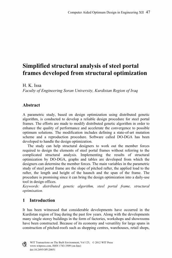
A number of optimum solutions with similar column and rafter cross-sections were selected to investigate the effect of haunch on the lateral displacement and the average strength ratio of SPFs. Lateral displacement ratio is joint’s displacement/allowable displacement and strength ratio is member’s strength/induced stress. The surface area of haunch that is taken into account involves a product of the depth and the length of haunch. Fig. 3 shows that there is a proportional relationship between the surface area of haunch and the average displacement ratio, i.e. the optimum solution with smaller average displacement ratio has smaller haunch length and depth and vice versa. In contrast, there is an inverse relationship between the surface area of haunch and the average strength ratio as shown in fig. 4, i.e. the optimum solution that possesses higher strength ratio has smaller haunch length and depth. This demonstrates the influential role of the haunch in controlling the displacement rather than strength. This implies that the construction of the haunch depends much more on displacement rather than the large bending moment.
52 Computer Aided Optimum Design in Engineering XII
www.witpress.com, ISSN 1743-3509 (on-line) WIT Transactions on The Built Environment, Vol 125, © 201 WIT Press2
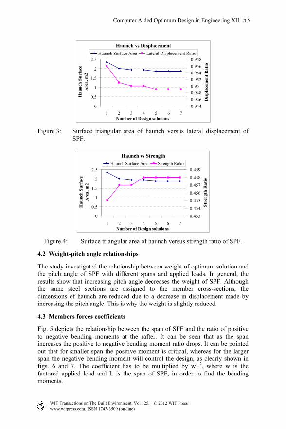
Figure 3: Surface triangular area of haunch versus lateral displacement of SPF.
Figure 4: Surface triangular area of haunch versus strength ratio of SPF.
4.2 Weight-pitch angle relationships
The study investigated the relationship between weight of optimum solution and the pitch angle of SPF with different spans and applied loads. In general, the results show that increasing pitch angle decreases the weight of SPF. Although the same steel sections are assigned to the member cross-sections, the dimensions of haunch are reduced due to a decrease in displacement made by increasing the pitch angle. This is why the weight is slightly reduced.
4.3 Members forces coefficients
Fig. 5 depicts the relationship between the span of SPF and the ratio of positive to negative bending moments at the rafter. It can be seen that as the span increases the positive to negative bending moment ratio drops. It can be pointed out that for smaller span the positive moment is critical, whereas for the larger span the negative bending moment will control the design, as clearly shown in figs. 6 and 7. The coefficient has to be multiplied by wL2, where w is the factored applied load and L is the span of SPF, in order to find the bending moments.
Haunch vs Displacement
0
0.5
1
1.5
2
2.5
1 2 3 4 5 6 7Number of Design solutions
Hau
nch
Su
rfac
e A
rea,
m2
0.944
0.946
0.948
0.95
0.952
0.954
0.956
0.958
Dis
pla
cem
ent
Rat
io
Haunch Surface Area Lateral Displacement Ratio
Haunch vs Strength
0
0.5
1
1.5
2
2.5
1 2 3 4 5 6 7Number of Design solutions
Hau
nch
Su
rfac
e A
rea,
m2
0.453
0.454
0.455
0.456
0.457
0.458
0.459
Str
engt
h R
atio
Haunch Surface Area Strength Ratio
Computer Aided Optimum Design in Engineering XII 53
www.witpress.com, ISSN 1743-3509 (on-line) WIT Transactions on The Built Environment, Vol 125, © 201 WIT Press2

Figure 5: Relationships between the rafter positive/negative moments ratio and span.
Figure 6: Relationships between the coefficient of negative moment and span.
Figure 7: Relationships between the coefficient of positive moment and span.
Positive/Negative Moments Ratios of Rafter
0.000.200.400.600.801.001.201.401.60
5 10 15 20 25 30Span, m
Coe
ffic
ien
t
Pitch Angle=6 Pitch Angle=8 Pitch Angle=10 Pitch Angle=12
Negative Moment Coefficient
0.04
0.05
0.06
0.07
0.08
0.09
5 10 15 20 25 30Span, m
Coe
ffic
ien
t
Pitch Angle=6 Pitch Angle=8 Pitch Angle=10 Pitch Angle=12
Positive Moment Coefficient
0.000.010.020.030.040.050.060.070.08
5 10 15 20 25 30Span, m
Coe
ffic
ien
t
Pitch Angle=6 Pitch Angle=8 Pitch Angle=10 Pitch Angle=12
54 Computer Aided Optimum Design in Engineering XII
www.witpress.com, ISSN 1743-3509 (on-line) WIT Transactions on The Built Environment, Vol 125, © 201 WIT Press2

Including the frame’s self weight, the relationship between the span and coefficients of maximum axial and shear forces at column and rafter are illustrated in fig. 8 through fig. 10 with different pitch angle. There are sharp increases in axial force at column and rafter as length of span increases, whereas this change is smoother for the maximum shear coefficient at the rafter. The pitch angle does not have significant effects on the maximum axial force at column and rafter, but it does affect the value of shear force at the rafter. The coefficient must be multiplied by wL, in order to find the shear and axial forces in structural members.
Figure 8: Relationships between the coefficient of column axial force and span.
Figure 9: Relationships between the coefficient of rafter axial force and span.
4.4 Haunch length
Fig. 11 shows that the role of haunch is substantial when the span of SPF is between 10m and 20m. The role of haunch is less effective for the SPF with the span of less than 10m or greater than 20m. This is because the frame is controlled by strength when the span of SFP is less than 10m or greater than 20m.
Maximum Axial Force Coefficient at Column
0.50
0.52
0.54
0.56
0.58
0.60
0.62
5 10 15 20 25 30Span, m
Coe
ffic
ien
t
Pitch Angle=6 Pitch Angle=8 Pitch Angle=10 Pitch Angle=12
Maximum Axial Force Coefficient at Rafter
0.00
0.10
0.20
0.30
0.40
0.50
0.60
0.70
5 10 15 20 25 30Span, m
Coe
ffic
ien
t
Pitch Angle=6 Pitch Angle=8 Pitch Angle=10 Pitch Angle=12
Computer Aided Optimum Design in Engineering XII 55
www.witpress.com, ISSN 1743-3509 (on-line) WIT Transactions on The Built Environment, Vol 125, © 201 WIT Press2

Figure 10: Relationships between the coefficients of rafter shear force and span.
Figure 11: Relationships between the span and the haunch length/span ratio.
5 Numerical example
A numerical example is conducted to demonstrate the effectiveness of the simplified method of analysis. The frame shown in fig. 12 is used for the analysis with a uniform factored gravity load of 15kN/m. The SPF of the example has a 20m span. The length of haunch is 1.4m as calculated from fig. 11. The slope of the pitched roof is assumed to be 10˚. The results of the simplified method of analysis and the actual analysis using matrix analysis method are tabulated in table 1.
Maximum Shear Force Coefficient at Rafter
0.44
0.46
0.48
0.50
0.52
0.54
5 10 15 20 25 30Span, m
Coe
ffic
ien
t
Pitch Angle=6 Pitch Angle=8 Pitch Angle=10 Pitch Angle=12
Haunch Length/ Span Ratio
0.000
0.025
0.050
0.075
0.100
5 10 15 20 25 30Span, m
Rat
io
Pitch Angle=6 Pitch Angle=8 Pitch Angle=10 Pitch Angle=12
56 Computer Aided Optimum Design in Engineering XII
www.witpress.com, ISSN 1743-3509 (on-line) WIT Transactions on The Built Environment, Vol 125, © 201 WIT Press2

Figure 12: The SPF used in the numerical example.
As can be seen in table 1, there is a small difference between the results obtained by the simplified method of analysis and the analysis that has been conducted by matrix method of analysis. The maximum difference yielded does not exceed from 3%.
Table 1: The results yielded from the analysis of SPF in the numerical example.
Method of Analysis
Axial Force,
Column
Axial Force, Rafter
Shear Force, Rafter
Negative Moment,
Rafter
Positive Moment,
Rafter
Simplified Method
171 kN 120 kN 145 kN 468 kN.m 174 kN.m
Matrix Method 167 kN 120 kN 142 kN 466 kN.m 178 kN.m
6 Conclusion
A parametric study was conducted to develop a simplified method of structural analysis for SPF through generated graphs used to determine the member forces. The graphs were constructed based on the solutions offered by a structural optimization technique. The developed graphs are easy to use and seem totally practical. A modified DGA was used to perform the structural optimization process on SPFs. The modification includes using a variable mutation probability and twin analogy to bring the elite individuals into the genetic operations twice while they are already secured to be dropped into the next generation. DO-DGA software handles the structural optimization using modified DGA. It can obtain the optimum solutions of SPFs within a few minutes.
Computer Aided Optimum Design in Engineering XII 57
www.witpress.com, ISSN 1743-3509 (on-line) WIT Transactions on The Built Environment, Vol 125, © 201 WIT Press2

Applying DO-DGA to develop graphs will make it possible for an engineer to determine all member forces of SPFs required for design of cross-sections without carrying out the structural analysis procedures provided that the applied loads, pitch angle and span length are given. Consequently, it can save the time of calculations. Applying a numerical example, it is demonstrated that there is no considerable difference between the simplified method of analysis using graphs and the conventional matrix method of analysis. This proves that the graphs are valid and promising since they can expedite bringing the usage of optimization technique into daily office-use by structural engineers.
References
[1] Toropov, V.V., and Mahfouz, S.Y., Design optimization of structural steelwork using a genetic algorithm, FEM and a system of design rules. Engineering Computations, 18 (3/4), pp. 437–459, 2001.
[2] Camp, C., Pezeshk, S., and Cao G., Optimum design of two-dimensional structures using a genetic algorithm. ASCE Journal of Structural Engineering, 124 (5), pp. 551–559, 1998.
[3] Kameshki, E.S., and Saka, M.P., Optimum design of non-linear steel frames with semi-rigid connection using a genetic algorithm. Computer and Structures, 79, pp. 1593–1604, 2001.
[4] Saka, M.P., Optimum design of pitched roof steel frames with haunched rafter by genetic algorithms. Computers and Structures, 81, pp. 1967–1978, 2003.
[5] Degertekin, S.O., Saka, M.P., and Hayalioglu, M.S., Optimal load and resistance factor design of geometrically nonlinear steel space frames via tabu search and genetic algorithm. Engineering Structures, 30, pp. 197–205, 2008.
[6] Mühlenbein, H., Schomisch, M., and Born, J., The parallel genetic algorithms as a function optimizer. Parallel Computing, 17, pp. 619–632, 1991.
[7] Issa, H.K, and Mohammad, F.A. Effect of mutation schemes on convergence to optimum design of steel frames. Journal of Constructional Steel Research. 66, pp. 954–961, 2010.
[8] Issa, H.K, and Mohammad, F.A Practical non-prismatic stiffness matrix for haunched-rafter pitched-roof steel portal frames. (Book Chapter) Challenges, Opportunities and Solutions in Structural Engineering and Construction. ed. N. Ghafoori, CRC Press: Las Vegas, pp. 167–171, 2010.
58 Computer Aided Optimum Design in Engineering XII
www.witpress.com, ISSN 1743-3509 (on-line) WIT Transactions on The Built Environment, Vol 125, © 201 WIT Press2