simple programming function navi lathe instruction · pdf fileintroduction this instruction...
TRANSCRIPT


Introduction
This instruction manual describes how to use NAVI LATHE. Incorrect handling may lead to unforeseen accidents, so make sure to read this instruction manual thoroughly before operation to ensure correct usage. NAVI LATHE supports the following NC series.
Written as in this manual Appropriate NC
M7 series M70/M70V/M700/M700V series
E70 series E70 series
Notes on Reading This Manual
(1) This manual describes as many special operations as possible, but it should be kept in mind that operations not mentioned in this manual cannot be performed.
(2) For the specifications of individual machine tools, refer to the manuals issued by the respective machine tool builders. The "restrictions" and "available functions" described by the machine tool builders have precedence over this manual.
(3) This manual is written on the assumption that all option functions are added. Confirm with the specifications issued by the machine tool builder before starting to use.
(4) Refer to the Instruction Manual issued by each machine tool builder for details on each machine tool.
(5) Some screens and functions may differ depending on the NC system (or its version), and some functions may not be possible. Please confirm the specifications before use.
Refer to the following documents. MITSUBISHI CNC 700/70 Series Instruction Manual ................................................IB-1500042 MITSUBISHI CNC 700/70 Series Setup Manual .......................................................IB-1500124 MITSUBISHI CNC 700/70 Series Programming Manual (Lathe System) .................IB-1500057 MITSUBISHI CNC M700V/M70V Series Instruction Manual......................................IB-1500922 MITSUBISHI CNC M700VW Series Setup Manual.................................................. IB-1500933 MITSUBISHI CNC M700VS Series Setup Manual................................................... IB-1500906 MITSUBISHI CNC M70V Series Setup Manual........................................................ IB-1500958 MITSUBISHI CNC M700V/M70V Series Programming Manual (Lathe System) .......IB-1500924 MITSUBISHI CNC E70 Series Instruction Manual .....................................................IB-1501186 MITSUBISHI CNC E70 Series Setup Manual ............................................................IB-1501158 MITSUBISHI CNC E70 Series Programming Manual (Lathe System) .......................IB-1501193


Precautions for Safety
Always read the specifications issued by the machine tool builder, this manual, related manuals and attached documents before operation or programming to ensure correct use. Understand the NAVI LATHE, safety items and cautions before using the system. This manual ranks the safety precautions into "DANGER", "WARNING" and "CAUTION".
DANGER
When the user may be subject to imminent fatalities or major injuries if handling is mistaken.
WARNING
When the user may be subject to fatalities or major injuries if handling is mistaken.
CAUTION
When the user may be subject to bodily injury or when property damage may occur if handling is mistaken.
Note that even items ranked as "
CAUTION", may lead to serious consequences depending on the situation. In any case, important information that must always be observed is described.
DANGER
Not applicable in this manual.
WARNING
1. Items related to operation If the operation start position is set in a block which is in the middle of the program and
the program is started, the program before the set block is not executed. Please confirm that G and F modal and coordinate values are appropriate. If there are coordinate system shift commands or M, S, T and B commands before the block set as the start position, carry out the required commands using the MDI, etc. If the program is run from the set block without carrying out these operations, there is a danger of interference with the machine or of machine operation at an unexpected speed, which may result in breakage of tools or machine tool or may cause damage to the operators.
Under the constant surface speed control (during G96 modal), if the axis targeted for the constant surface speed control moves toward the spindle center, the spindle rotation speed will increase and may exceed the allowable speed of the workpiece or chuck, etc. In this case, the workpiece, etc. may jump out during machining, which may result in breakage of tools or machine tool or may cause damage to the operators.

CAUTION
1. Items related to product and manual For items described as "Restrictions" or "Usable State" in this manual, the instruction
manual issued by the machine tool builder takes precedence over this manual. Items not described in this manual must be interpreted as "not possible". This manual is written on the assumption that all option functions are added. Confirm
with the specifications issued by the machine tool builder before starting use. Refer to the Instruction Manual issued by each machine tool builder for details on
each machine tool. Some screens and functions may differ depending on the NC system (or its version),
and some functions may not be possible. Please confirm the specifications before use.
2. Items related to installation and assembly
Ground the signal cables to ensure stable system operation. Also ground the NC unit main frame, power distribution panel and machine to one point, so they all have the same potential.
3. Items related to preparation before use
Always set the stored stroke limit. Failure to set this could result in collision with the machine end.
Always turn the power OFF before connecting/disconnecting the I/O device cable. Failure to do so could damage the I/O device and NC unit.
4. Items related to screen operation
NAVI LATHE uses the following variables in order to operate the NC program. NC program mode Variables used by NAVI LATHE
User macro mode #100 to #199 MTB macro mode #450 to #499
When NC program mode is user macro mode, do not use common variables (#100 to #199). If those variables are written over, malfunction will be resulted. If mistakenly written them over, turn the NC power OFF after securing your safety. When starting NAVI LATHE by turning the NC power ON again, the system recovers the data. NC program mode is specified on the Preferences screen.
When either "TOOL REG No." or "CYCLE" is input in each machining process screen, the cutting speed and feedrate are automatically determined using the data in the tool file screen and the cutting condition file screen. Note that the cutting speed and feedrate of each process determined once will not be changed by changing the data in the tool file screen and the cutting condition file screen.
When starting NAVI LATHE by mistake while NAVI LATHE is not used, perform the operation after setting the variable value again and confirming the safety.
(Continued on next page)

CAUTION (Continued from previous page)
5. Items related to operation Stay out of the moveable range of the machine during automatic operation. During
rotation, keep hands, feet and face away from the spindle. Carry out dry operation before actually machining, and confirm the machining program,
tool offset and workpiece coordinate system offset. If the operation start position is set from a block in the program and the program is
started, the program before the set block is not executed. If there are coordinate system shift commands or M, S, T, and B commands before the block set as the starting position, carry out the required commands using the MDI, etc. There is a danger of interference with the machine if the operation is started from the set starting position block without carrying out these operations.
Program so the mirror image function is turned ON/OFF at the mirror image center. The mirror image center will deviate if the function is turned ON/OFF at a position other than the mirror image center.
6. Items related to faults and abnormalities
If the battery low warning is issued, save the machining programs, tool data and parameters in an input/output device, and then replace the battery. When the battery alarm is issued, the machining programs, tool data and parameters may be destroyed. Reload the data after replacing the battery.
If the axis overruns or emits an abnormal noise, immediately press the emergency stop button and stop the axis movement.
(Continued on next page)
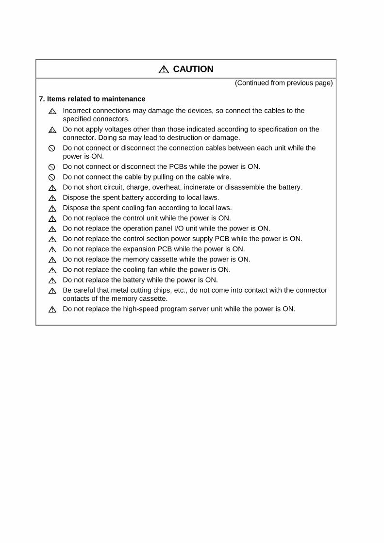
CAUTION (Continued from previous page)
7. Items related to maintenance Incorrect connections may damage the devices, so connect the cables to the
specified connectors. Do not apply voltages other than those indicated according to specification on the
connector. Doing so may lead to destruction or damage. Do not connect or disconnect the connection cables between each unit while the
power is ON. Do not connect or disconnect the PCBs while the power is ON.
Do not connect the cable by pulling on the cable wire. Do not short circuit, charge, overheat, incinerate or disassemble the battery. Dispose the spent battery according to local laws. Dispose the spent cooling fan according to local laws. Do not replace the control unit while the power is ON. Do not replace the operation panel I/O unit while the power is ON. Do not replace the control section power supply PCB while the power is ON. Do not replace the expansion PCB while the power is ON. Do not replace the memory cassette while the power is ON. Do not replace the cooling fan while the power is ON. Do not replace the battery while the power is ON. Be careful that metal cutting chips, etc., do not come into contact with the connector
contacts of the memory cassette. Do not replace the high-speed program server unit while the power is ON.

Trademarks MELDAS, MELSEC, EZSocket, EZMotion, iQ Platform, MELSOFT, GOT, CC-Link, CC-Link/LT and CC-Link
IE are either trademarks or registered trademarks of Mitsubishi Electric Corporation in Japan and/or other
countries.
Ethernet is a registered trademark of Xerox Corporation in the United States and/or other countries.
Microsoft® and Windows® are either trademarks or registered trademarks of Microsoft Corporation in the
United States and/or other countries.
CompactFlash and CF are either trademarks or registered trademarks of SanDisk Corporation in the United
States and/or other countries.
UNIX is a registered trademark of The Open Group in the United States and/or other countries.
Intel® and Pentium® are either trademarks or registered trademarks of Intel Corporation in the United States
and/or other countries.
Other company and product names that appear in this manual are trademarks or registered trademarks of the
respective companies.


Contents
1. OUTLINE ............................................................................................................................... 1 1.1 System Outline ......................................................................................................... 1 1.2 Input Procedures ...................................................................................................... 3 1.3 Screen Configuration ................................................................................................ 4 1.4 Starting NAVI LATHE ............................................................................................... 6 1.5 Setting up NAVI LATHE ............................................................................................ 6
2. FUNCTIONS OF DISPLAY AREA .......................................................................................... 8 2.1 LIST VIEW Area ....................................................................................................... 9 2.2 OPERATION VIEW Area ........................................................................................ 12 2.3 Setting Area ............................................................................................................ 13 2.4 Message Area ........................................................................................................ 13 2.5 Menu Display Area ................................................................................................. 13
3. BASIC OPERATIONS .......................................................................................................... 14 3.1 Changing Active View ............................................................................................. 14 3.2 Changing Screen .................................................................................................... 14 3.3 Setting Data ............................................................................................................ 16 3.4 Switching Windows ................................................................................................. 19 3.5 Switching Selection Tags ........................................................................................ 19 3.6 Inputting Operations ............................................................................................... 20
4. SCREEN SPECIFICATIONS ................................................................................................ 21 4.1 Starting NAVI LATHE ............................................................................................. 21 4.2 Screen Related to the Program .............................................................................. 22
4.2.1 Program Edit Screen ................................................................................ 22 4.2.1.1 Program Edit and Part System ..................................................... 29
4.3 Screens Related to the Process Edit Functions ...................................................... 30 4.3.1 Process List Screen ................................................................................. 30 4.3.2 Operating Process ................................................................................... 32 4.3.3 System Synchro Screen ........................................................................... 43 4.3.4 Process Mode Selection Screen .............................................................. 45 4.3.5 Initial Condition Setting Screen ................................................................ 51 4.3.6 Turning Screen ........................................................................................ 56 4.3.7 Copy Cutting Screen ................................................................................ 62 4.3.8 Threading Screen..................................................................................... 65 4.3.9 Grooving Screen ...................................................................................... 69 4.3.10 Trapezoidal Grooving Screen ................................................................. 72 4.3.11 Hole Drilling Screen................................................................................ 75 4.3.12 EIA Screen ............................................................................................. 78 4.3.13 Milling Hole Drilling Screen ..................................................................... 79 4.3.14 Keyway Cutting Screen .......................................................................... 93 4.3.15 Contour Cutting Screen .......................................................................... 99 4.3.16 Transfer Screen ....................................................................................109 4.3.17 Cut Off Screen ......................................................................................112 4.3.18 Balance Cut (Turn) Screen ....................................................................114 4.3.19 Balance Cut (Copy) Screen ...................................................................117 4.3.20 Two-part System Simultaneous Thread Cutting
(identical screw) Screen ......................................................................120
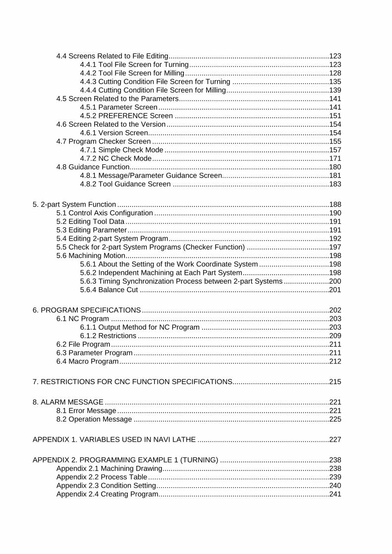
4.4 Screens Related to File Editing ..............................................................................123 4.4.1 Tool File Screen for Turning ....................................................................123 4.4.2 Tool File Screen for Milling ......................................................................128 4.4.3 Cutting Condition File Screen for Turning ...............................................135 4.4.4 Cutting Condition File Screen for Milling ..................................................139
4.5 Screen Related to the Parameters .........................................................................141 4.5.1 Parameter Screen ...................................................................................141 4.5.2 PREFERENCE Screen ...........................................................................151
4.6 Screen Related to the Version ...............................................................................154 4.6.1 Version Screen........................................................................................154
4.7 Program Checker Screen ......................................................................................155 4.7.1 Simple Check Mode ................................................................................157 4.7.2 NC Check Mode ......................................................................................171
4.8 Guidance Function.................................................................................................180 4.8.1 Message/Parameter Guidance Screen....................................................181 4.8.2 Tool Guidance Screen ............................................................................183
5. 2-part System Function .......................................................................................................188 5.1 Control Axis Configuration .....................................................................................190 5.2 Editing Tool Data ...................................................................................................191 5.3 Editing Parameter ..................................................................................................191 5.4 Editing 2-part System Program ..............................................................................192 5.5 Check for 2-part System Programs (Checker Function) ........................................197 5.6 Machining Motion ...................................................................................................198
5.6.1 About the Setting of the Work Coordinate System ..................................198 5.6.2 Independent Machining at Each Part System ..........................................198 5.6.3 Timing Synchronization Process between 2-part Systems ......................200 5.6.4 Balance Cut ............................................................................................201
6. PROGRAM SPECIFICATIONS ...........................................................................................202 6.1 NC Program ..........................................................................................................203
6.1.1 Output Method for NC Program ..............................................................203 6.1.2 Restrictions .............................................................................................209
6.2 File Program ..........................................................................................................211 6.3 Parameter Program ...............................................................................................211 6.4 Macro Program ......................................................................................................212
7. RESTRICTIONS FOR CNC FUNCTION SPECIFICATIONS...............................................215
8. ALARM MESSAGE .............................................................................................................221 8.1 Error Message .......................................................................................................221 8.2 Operation Message ...............................................................................................225
APPENDIX 1. VARIABLES USED IN NAVI LATHE ................................................................227
APPENDIX 2. PROGRAMMING EXAMPLE 1 (TURNING) .....................................................238 Appendix 2.1 Machining Drawing .................................................................................238 Appendix 2.2 Process Table ........................................................................................239 Appendix 2.3 Condition Setting ....................................................................................240 Appendix 2.4 Creating Program...................................................................................241

APPENDIX 3. PROGRAMMING EXAMPLE 2 (MILLING) .......................................................248 Appendix 3.1 Machining Drawing .................................................................................248 Appendix 3.2 Process Table ........................................................................................249 Appendix 3.3 Condition Setting ....................................................................................250 Appendix 3.4 Creating Program...................................................................................251


1. OUTLINE 1.1 System Outline
- 1 -
1. OUTLINE
1.1 System Outline
This manual is an instruction manual for NAVI LATHE. The part program for the turning center is created with the NAVI LATHE.
(1) The following machining processes can be edited.
Turning Processes - Turning (Outer dia., inner dia., front face) - Copy cutting (Outer dia., inner dia., front face) - Threading (Outer dia., inner dia., front face) - Grooving (Outer dia., inner dia., front face) - Trapezoidal grooving (Outer dia., inner dia., front face) - Hole drilling (Drilling, deep-hole drilling, step, tapping) - EIA - Cutting off
Milling Processes
- Milling hole drilling (Drilling, deep-hole drilling, boring, tapping) [Hole pattern]
- Random (front face/outer surface/side surface) - Line (front face/outer surface/side surface) - Arc (front face/side surface) - Circle (front face/side surface) - Square (front face/side surface) - Grid (front face/side surface)
- Keyway cutting (Front face, outer surface, side surface) - Contour cutting (Front face, outer surface, side surface)
Assist process - Transfer
Balance cut - Turning balance cut - Copying balance cut - Two-part system simultaneous thread cutting
(Note) Milling interporation specifications are required to edit the milling processes.
(2) The tool file (for the turning/milling machining) and the cutting condition file (for the turning/milling machining) are provided and the cutting conditions for each process are determined automatically.

1. OUTLINE 1.1 System Outline
- 2 -
(3) The operation screen consists of the LIST VIEW area and the OPERATION VIEW area. In the LIST
VIEW area, the whole part program can be always viewed. In the OPERATION VIEW area, there are the guide drawings related to the input items, and the data can be easily input by using these guide drawings.
(4) Program Checker enables the machining shape of a part program to be graphically traced. With this function, errors in input data can be detected at an earlier stage.
(5) Guidance function provides an operator with error recovery information. (6) Part program is a macro-program-based NC program. Commands can be added between processes
from the edit screen of the standard MITSUBISHI CNC 700/70 Series. (7) The macro program mentioned above can be customized by the machine tool builder.
[LIST VIEW area] The object of the NAVI LATHE is selected.
[OPERATION VIEW area] The screen is displayed corresponding to the object selected in the LIST VIEW.
[Cutting conditions automatically determined]
Upon tool registration No. entry, the cutting conditions for each process are automatically determined based on the tool file and cutting condition file.
[Help]
[Guide drawing]
[Menu keys]
A tool guidance window will be displayed by touching this icon on the touchscreen.
A message/parameter guidance window will be displayed by touching this icon on the touchscreen. When loading the machining
program and touching this icon on the touchscreen, a program checker screen will appear.
1. OUTLINE 1.2 Input Procedures
- 3 -
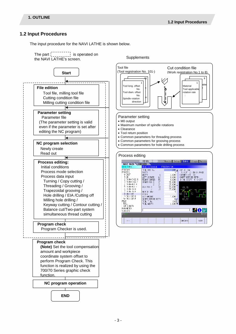
1.2 Input Procedures
The input procedure for the NAVI LATHE is shown below.
8 Material Tool applicable rotation rate
:
99 Tool leng. offset
No. Tool diam. offset
No. Spindle rotation
direction
Program check Program Checker is used.
NC program operation
NC program selection Newly create Read out
Process editing: Initial conditions Process mode selection Process data input
Turning / Copy cutting / Threading / Grooving / Trapezoidal grooving / Hole drilling / EIA /Cutting off Milling hole drilling / Keyway cutting / Contour cutting / Balance cut/Two-part system simultaneous thread cutting
File edition Tool file, milling tool file Cutting condition file Milling cutting condition file
Parameter setting Parameter file
(The parameter setting is valid even if the parameter is set after editing the NC program)
The part is operated on the NAVI LATHE's screen.
Tool file (Tool registration No. 101-)
Supplements
Parameter setting • M0 output • Maximum number of spindle rotations • Clearance • Tool return position • Common parameters for threading process • Common parameters for grooving process • Common parameters for hole drilling process
Tool leng. offset
No.
:
1 Tool leng. offset
No. Tool diam. offset
No. Spindle rotation
direction
END
Start
Process editing
Program check (Note) Set the tool compensation amount and workpiece coordinate system offset to perform Program Check. This function is realized by using the 700/70 Series graphic check function.
Cut condition file (Work registration No.1 to 8)
1 Material Tool applicable rotation rate
:

1. OUTLINE 1.3 Screen Configuration
- 4 -
1.3 Screen Configuration
The screen configuration for the NAVI LATHE is shown below.
Program
Process
Process for selecting functions
Program edit screen
Process list screen
System synchro screen
Initial condition setting screen
(For a new process,select a process from the process mode.)
Process modeselectionscreen
Turning screen
Copy cutting screen
Threading screen
Grooving screen
Trapezoidal grooving screen
Hole drilling screen
EIA screen
Cutting off screen
Milling hole drill ing screen
Keyway cutting screen
Contour cutting screen
Transfer process screen
Balance cut (turn) screen
Balance cut (copy) screen
Two-part system simultaneous thread cutting
screen
Process pattern screen
Process pattern screen
Program checker
Tool file screen
Milling tool file screen
Cutting condition file
screen
Milling cutting condition file
screen
File
Parameter Paraneterscreen
Preference screen
Version Versionscreen

1. OUTLINE 1.3 Screen Configuration
- 5 -
Screen name Details
Program edit screen NC program is newly created and read out, etc. Process list screen Tool information and cutting conditions for each process of a NC
program are listed. Process mode selection screen
The process mode (turning process, etc.) is selected.
System synchro screen The order of the processes of the NC programs created for each part system is edited.
Initial conditions setting screen
The initial conditions for a NC program are set.
Turning screen Various parameters for turning process are input. Turning pattern screen The machining patterns for turning process are input. Copy cutting screen Various parameters for copy cutting process are input. Copy cutting pattern screen Machining patterns for copy cutting process are input. Threading screen Various parameters for threading process are input. Grooving screen Various parameters for grooving process are input. Trapezoidal grooving screen Various parameters for trapezoidal grooving process are input. Hole drilling screen Various parameters for hole drilling process are input. EIA screen The EIA process is input. Cutting off screen Various parameters for cutting-off process are input. Milling hole drilling screen Various parameters for milling hole drilling process are input. Milling hole drilling pattern screen
The machining patterns for milling hole drilling process are input.
Keyway cutting screen Various parameters for keyway cutting process are input. Contour cutting screen Various parameters for contour cutting process are input. Contour cutting pattern screen The machining patterns for contour cutting process are input. Transfer screen Various parameters for transfer process are input. Balance cut (turn) screen Various parameters for balance cut (turn) process are input. Balance cut (turn) machining pattern screen
Various parameters for balance cut (turn) pattern are input.
Balance cut (copy) screen Various parameters for balance cut (copy) process are input. Balance cut (copy) pattern screen
Various parameters for balance cut (copy) pattern are input.
Two-part systems simultaneous thread cutting (identical screw) screen
Various parameters for two-part system simultaneous thread cutting (identical screw) process are input.
Tool file screen The tool data by each tool is registered. Milling tool file screen The tool data for milling machining is registered. Cutting condition file screen The cutting conditions (cutting speed, feedrate) by each process
are input, corresponding to tip material. Also, the cutting conditions (speed rate) by each process are input, corresponding to workpiece material.
Milling cutting condition file screen
The cutting conditions (the cutting speed and the feedrate) by each process for the tip materials of the milling machining and the cutting condition (speed ratio) for the workpiece materials are registered.
Parameter screen The parameters for a NC program are set. Preference screen The system is set up. Version screen The version data of the NAVI LATHE is displayed. Program checker The machining shape of a NC program is graphically displayed.

1. OUTLINE 1.4 Starting NAVI LATHE
- 6 -
1.4 Starting NAVI LATHE
Select EDIT function, then the lathe menu to display NAVI LATHE screen.
Program edit screen is displayed once when the power is turned ON. Then, whatever the screen previously selected with NAVI LATHE is displayed thereafter.
1.5 Setting up NAVI LATHE
Part program output from NAVI LATHE is a macro-program-based NC program. Thus, macro programs have to be registered in the NC system in advance. Also, the destinations where NC programs or NAVI LATHE's reference files are saved, as well as the unit for data input, have to be specified prior to NAVI LATHE operations.
NAVI LATHE setup items
Item Details Standard value PATH PROGRAM
Path to the folder in which NC program is saved. MEM:/
PATH PARAMETER
Path to the folder in which tool file, cutting condition file and parameter file are saved.
In M700/M700VM: D:/NCFILE/NAVI
Other than those above: MEM:/
MACRO Macro program mode 1: User macro mode 2: MTB macro mode
1 (User Macro)
UNIT Unit for data input 1: inch 2: mm
2 (mm)
Parameter Name of parameter file 9114 Tool file Name of tool file 9111 Cutting condition file tip material
Name of cutting condition file (tip material) 9112
Cutting condition file workpiece material
Name of cutting condition file (workpiece material) 9113
2-part system specification
Whether 2-part system specification is provided or not. (0: NONE, 1: EXIST)
0 ( NONE)

1. OUTLINE 1.5 Setting up NAVI LATHE
- 7 -
NAVI LATHE setup procedures
(1) Open PARAMETER screen. (2) Set "999 MAINTE" to 1. [PREFERENCE] menu is displayed.
(3) Press [PREFERENCE] menu.
PREFERENCE screen is displayed.
(4) Select the macro type. (1:User macro 2:MTB macro)
(5) Press [MACRO ENTRY] menu.
"OK?(Y/N)" message is displayed.
(6) Press [Y] key. Macro program is registered in NC system. (7) Enter the program path. (8) Enter the parameter path. (9) Select the unit.
(1:inch, 2:mm) When the unit is changed, turn the power OFF and ON again.
(10) Enter the name of parameter file (11) Enter the name of tool file (12) Enter the name of cutting condition file
(tip material and workpiece material)
(13) Enter 0 or 1 according to whether the
2-part system specification is provided or not.
When the setting value for 2-part system specification is changed, turn the power OFF and ON again.
(Addendum) • Always carry out a macro program registration when setting up NAVI LATHE or switching "MACRO" types.
• Change "PROGRAM PATH" and "PARAMETER PATH" when necessary. • When "UNIT" is changed, turn the power OFF and ON again. • If the tool file, cutting condition file and parameter file do not exist in "PARAMETER PATH" folder when
the power is turned ON, the system creates them. • When the value for 2-part system specification is changed, turn the power OFF and ON again.
2. FUNCTIONS OF DISPLAY AREA
- 8 -
2. FUNCTIONS OF DISPLAY AREA
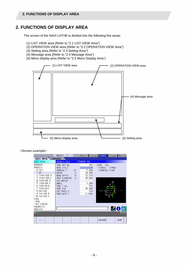
The screen of the NAVI LATHE is divided into the following five areas.
(1) LIST VIEW area (Refer to "2.1 LIST VIEW Area") (2) OPERATION VIEW area (Refer to "2.2 OPERATION VIEW Area") (3) Setting area (Refer to "2.3 Setting Area") (4) Message area (Refer to "2.4 Message Area") (5) Menu display area (Refer to "2.5 Menu Display Area")
(3) Setting area
(1) LIST VIEW area (2) OPERATION VIEW area
(4) Message area
(5) Menu display area
<Screen example>

2. FUNCTIONS OF DISPLAY AREA 2.1 LIST VIEW Area
- 9 -
2.1 LIST VIEW Area
The object of the NAVI LATHE is selected in this area.
(1) Area bar
When the LIST VIEW area is active, the area bar is highlighted.
(2) Objects The list of objects that can be selected are displayed. The object is composed of the main object and the sub object, which is a specification of the main object. The details of each object are as follows.
Main object Sub object Details PROGRAM - Newly creates, reads out, and deletes, etc. the NC program. PROCESS 0 INIT
1 DR :
Displays the currently edited process list. The settings of the selected process can be displayed and changed. When the 2-part system specification is set to "1: EXIST", the process list of the currently edited part system is displayed. If you select a waiting part system during a process that is carried out just by the other part system, this view shows the process being carried out by the other part system (shows the process number, but no process name). (*1)
FILE TOOL Displays and changes the tool file. M TOOL Displays and changes the tool file for the milling machining.
(Note) This is valid when the milling interporation specifications are provided.
CUT CONDTN Displays and changes the cutting conditions for each process per tip material or workpiece material.
M CUT CONDTN
Displays and changes the cutting conditions for each process per tip material or workpiece material for the milling machining. (Note) This file is valid when the milling interporation
specifications are provided. PARAMETER - Displays the tool option and the miscellaneous parameter to
be used in each process. Those can be changed. VERSION - Displays the version data of the NAVI LATHE.
(Note) If too many processes are registered and all the objects cannot be displayed, a scroll bar will be
displayed. In this case, change display of the list by pressing cursor key or page key down, or by clicking on the scroll bar.
(4) Selected part system number
(1) Area bar
(2) Object
(3) Cursor

2. FUNCTIONS OF DISPLAY AREA 2.1 LIST VIEW Area
- 10 -
*1 For the following machining case, the process list of the LIST VIEW is displayed as below.
<Addendum>
If a selected process shows no process name in the LIST VIEW (a process being run by the other part system), "$nMACHINING" (n: part system number) is displayed In the OPERATION VIEW area.
Process List
Editing 1st part system Editing 2nd part system
Process 0 INIT 1 DR-FACE 2 TURN-FACE R 3 TURN-FACE F 4 !TURN-OUT R 5 !TURN-OUT F 6 7 THD-OUT R 8 THD-OUT F
Process 0 INIT 1 2 3 4 !TURN-OUT R 5 !TURN-OUT F 6 GRV-OUT 7 8
<Flow for machining>
1st part system 2nd part system
Drilling
Face roughing turning
Face finishing turning
Waiting for outer diameter grooving
to be over
Outer diameter roughing thread
cutting
Outer diameter finishing thread
cutting
Waiting for face roughing turning
to be over
Outer diameter groving
Start Start
End End
Roughing balance cut (turn)
Finishing balance cut (turn)
The processes that are being run by the other system

2. FUNCTIONS OF DISPLAY AREA 2.1 LIST VIEW Area
- 11 -
(3) Cursors
When the LIST VIEW area is active and the object is selected with the cursor, the display in the OPERATION VIEW area and the menu display area will be changed.
<Cursor movement> The cursor is moved using the cursor keys or a pointing device.
Key type Operation of cursor [↑] Cursor key Moves the cursor one field up regardless of the main object or sub object.
Note that if the ↑ cursor is pressed when the cursor is at the top, the cursor does not move.
[↓] Cursor key Moves the cursor one field down regardless of the main object or sub object. Note that if the ↓ cursor is pressed when the cursor is at the bottom, the cursor does not move.
[←] Cursor key When the cursor is at the sub object, moves the cursor to the previous main object.
[→] Cursor key
When the cursor is at the sub object, moves the cursor to the next main object.
[Page Up] key
Moves the displayed data toward the top.
[Page Down] key
Moves the displayed data toward the bottom.
Pointing device Cursor jumps to the spot where clicked with a pointing device. If an object not selectable is clicked, cursor does not jump.
(4) The part system number being selected
When the 2-part system specification is "1: EXIST" and the multi-part system program management is ON, the part system number being selected at the NAVI LATHE is displayed. If the program is not opened, the selected part number cannot be displayed. - When selecting the 1st part system: - When selecting the 2nd part system: This display is changed by the menu [$<->$]. * The menu [$<->$] is displayed in the condition that the LIST VIEW is active and the cursor is on the
machining process or the process name.

2. FUNCTIONS OF DISPLAY AREA 2.2 OPERATION VIEW Area
- 12 -
2.2 OPERATION VIEW Area
The various data are displayed in this area. Selecting the object in the LIST VIEW area changes the contents displayed in the OPERATION VIEW area.
(1) Area bar
When the OPERATION VIEW area is active, the area bar is highlighted. The name of the currently edited program is displayed.
(2) Help
Quick reference on the setting items is displayed. (3) Guide drawing
When the process is edited, a guide drawing according to the currently edited machining mode is displayed.
(4) Sub cursor
Key type Operation of cursor [↑] Cursor key Moves the cursor one field up.
Note that if the ↑ cursor is pressed when the cursor is at the top, the cursor does not move.
[↓] Cursor key Moves the cursor one field down. Note that if the ↓ cursor is pressed when the cursor is at the bottom, the cursor does not move.
[Page Up] key Moves the displayed data toward the top. [Page Down] key
Moves the displayed data toward the bottom.
(3) Guide drawing
(1) Area bar
(2) Help
(4) Sub cursor

2. FUNCTIONS OF DISPLAY AREA 2.3 Setting Area
- 13 -
2.3 Setting Area
The value to be set to data is input.
2.4 Message Area
An error message or operation message, etc. during operation is displayed.
2.5 Menu Display Area
The screen operation is selected, and the screen is changed. The different menus are displayed in each screen. (Refer to the chapter 4.)

3. BASIC OPERATIONS 3.1 Changing Active View
- 14 -
3. BASIC OPERATIONS
3.1 Changing Active View
To operate NAVI LATHE, activate either LIST VIEW area or OPERATION VIEW area. When the VIEW is active, the area bar is highlighted and data can be input. Use menu keys [←] and [→] or a pointing device to switch either one of the VIEWs to be activated.
3.2 Changing Screen
When the object is selected in the LIST VIEW area, the screen (contents in the OPERATION VIEW area) changes. (Refer to the section 2.1 LIST VIEW Area.) Note that the screen cannot be changed while the OPERATION VIEW area is active. In such a case, press the [←] menu key or click "LIST VIEW" with a pointing device to turn the LIST VIEW area active.
Operation example
(1) Open the program edit screen. The OPERATION VIEW area is active.
(2) Press the [←] menu key. The LIST VIEW area will turn active.

3. BASIC OPERATIONS 3.2 Changing Screen
- 15 -
(3) Select the object with the cursor key. The OPERATION VIEW area will change
into the screen corresponding to the selected object.
(4) Press the [MODIFY] menu key. The OPERATION VIEW area will turn active.

3. BASIC OPERATIONS 3.3 Setting Data
- 16 -
3.3 Setting Data
After moving the sub cursor, input the data into the setting area and then press the [INPUT] key, and the data will be set. (The sub cursor is displayed only when the OPERATION VIEW area is active.)
Sub cursor
Setting area

3. BASIC OPERATIONS 3.3 Setting Data
- 17 -
Operation method
An example for setting the data on the hole drilling screen is shown below. (1) Screen selection Select the object to be changed from the
LIST VIEW and press [MODIFY] menu key.
The OPERATION VIEW area will turn active. (Refer to the section 3.2 "Changing screen".)
(2) Setting item selection Move the sub cursor with cursor keys. This is an example of the sub cursor
movement on the hole drilling screen.
(3) Data key input Set data with the numeral keys or
alphabet keys, etc. [1] [8] [.] [0] [0] [0]
The data is set in the data setting area. 18.000
(4) [INPUT] key input Press the [INPUT] key. Data for the selected setting item is set.
The sub cursor moves to the next position.
(Note 1) The contents in the data setting area are only displayed when [INPUT] key is not pressed and will be invalidated if the screen is changed at this time. Data for the currently selected setting item will be set when [INPUT] key is pressed.
(Note 2) If illegal data is set, an error occurs when [INPUT] is pressed. Set the correct data again.

3. BASIC OPERATIONS 3.3 Setting Data
- 18 -
Operations in the data setting area
The key is input at the position where the cursor is displayed. If a cursor is not displayed, the key input is invalid. When a key is input, the data appears at the cursor position, and the cursor moves one character space to the right.
[→] / [←] keys: Moves the cursor one character to the left or right.
(1) The cursor is at the position shown on the right.
1 2 3 7 7 7 | 4 5 6
(2) Press the [→] key. The cursor moves one character space to
the right. 1 2 3 7 7 7 4 | 5 6
[DETETE] key: Deletes the character in front of the cursor.
(1) Move the cursor to the position where
the data is to be deleted. The cursor in the data setting area moves. 1 2 3 4 | 5 6
(2) Press the [DETETE] key. The character in front of the cursor is
deleted. 1 2 3 | 5 6
3. BASIC OPERATIONS 3.4 Switching Windows
- 19 -
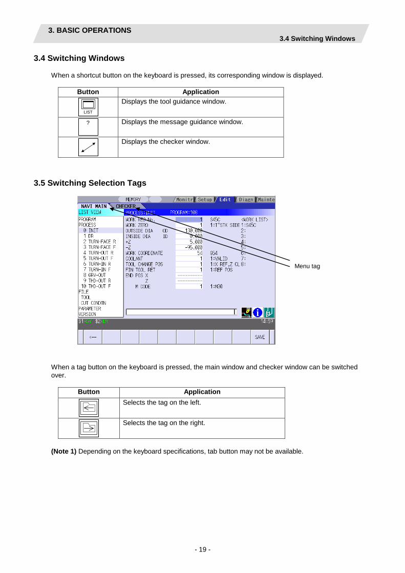
3.4 Switching Windows
When a shortcut button on the keyboard is pressed, its corresponding window is displayed.
Button Application
LIST
Displays the tool guidance window.
?
Displays the message guidance window.
Displays the checker window.
3.5 Switching Selection Tags
When a tag button on the keyboard is pressed, the main window and checker window can be switched over.
Button Application
Selects the tag on the left.
Selects the tag on the right.
(Note 1) Depending on the keyboard specifications, tab button may not be available.
Menu tag

3. BASIC OPERATIONS 3.6 Inputting Operations
- 20 -
3.6 Inputting Operations
In addition to the method of directly inputting numeric data for specific data settings, a method to input the operation results using four rules operators and function symbols can be used.
Input method
Numeric values, function symbols, operators and parentheses ( ) are combined and set in the data setting area. The operation results appear when the [INPUT] key is pressed. Data for the currently selected setting item will be set when [INPUT] key is pressed again. The contents in the data setting area are erased.
Examples of operator settings, and results Function symbols, setting examples
and results
Operation Setting example
Operation results Function Function
symbol Setting
example Operation
results
Addition =100+50 150.000 Absolute value ABS =ABS (50−60) 10.000
Subtraction =100−50 50.000 Square root SQRT =SQRT (3) 1.732 Multiplication =12.3∗4 49.200 Sine SIN =SIN (30) 0.5 Division =100/3 33.333 Cosine COS =COS (15) 0.966
Function =1.2∗ (2.5+SQRT(4)) 5.400
Tangent TAN =TAN (45) 1 Arc tangent ATAN =ATAN (1.3) 52.431
Circle ratio PAI =PAI*10 31.415 Inch INCH =INCH/10 2.54
Operation examples
(1) Set as shown below, and press the [INPUT] key. =12∗20 [INPUT]
The operation results appear in the data setting area. 240 |
(2) Press the [INPUT] key again.
Data for the selected setting item is set. The cursor moves to the next position.
Notes for using operators and functions
Division: Zero division causes an error. Square root: If the value in the parentheses is negative, an error occurs. Triangle function: The unit of angle θ is degree (°). Arc tangent: −90 < operation results < 90.
Restrictions
• Always use "=" for the first character. • Do not use the following characters as the second character or last character.
Invalid as second character: ∗, /, ) Invalid as last character: ∗, /, (, +, -
• Make sure that the left parentheses and right parentheses are balanced. • The 360° limit does not apply on the angle. SIN (500) is interpreted as SIN (140).

4. SCREEN SPECIFICATIONS 4.1 Starting NAVI LATHE
- 21 -
4. SCREEN SPECIFICATIONS
4.1 Starting NAVI LATHE
When NAVI LATHE is started, the program edit screen will be displayed.
Screen layout
At the initial start up of NAVI LATHE, the cursor is displayed at the position of [PROGRAM] in the LIST VIEW area, and the program edit screen is displayed in the OPERATION VIEW area. The LIST VIEW area is active. The process program is not selected.

4. SCREEN SPECIFICATIONS 4.2 Screen Related to the Program
- 22 -
4.2 Screen Related to the Program
4.2.1 Program Edit Screen
The NC program is newly created and read out, etc. on this screen. When [PROGRAM] is selected in the LIST VIEW area, this screen is displayed.
Screen layout
The process list of the currently selected program is displayed in the LIST VIEW area.

4. SCREEN SPECIFICATIONS 4.2 Screen Related to the Program
- 23 -
<Turning process displays>
Process name Display character Remarks
Turning OD OPEN TURN-OUT ? A symbol that indicates the machining type (rough/finishing) is put at ?. • Rough machining: R • Finishing machining: F
OD CLOSE TURN-OUT ?
ID OPEN TURN-IN ?
ID CLOSE TURN-IN ?
FACE OPEN TURN-FACE ?
FACE CLOSE TURN-FACE ?
BACK OPEN TURN-BACK ?
BACK CLOSE TURN-BACK ?
Copy cutting Outer diameter COPY OUT ? A symbol that indicates the machining type (rough/finishing) is put at ?. • Rough machining: R • Finishing machining: F
Inner diameter COPY-IN ?
Thread Outer diameter THD-OUT ? A symbol that indicates the machining type (rough/finishing) is put at ?. • Rough machining: R • Finishing machining: F • Rough + finishing: No symbol
Inner diameter THD-IN ?
Face THD-FACE ?
Back THD-BACK ?
Groove Outer diameter GRV-OUT ?
Inner diameter GRV-IN ?
Face GRV-FACE ?
Back GRV-BACK ?
Trapezoidal grooving
Outer diameter TGRV-OUT ? A symbol that indicates the machining type (rough/finishing) is put at ?. • Rough machining: R • Finishing machining: F
Inner diameter TGRV-IN ?
Face TGRV-FACE ?
Back TGRV-BACK ?
Hole drilling Drill DR-**** Symbols that indicate the machining area (front face/back surface) are put at ****. (When the process is created with the parameter "#1001 SUB SPINDLE SPED" set to "1: EXIST".) - FACE - BACK
Deep hole PECK-****
Bore BORE-****
Tapping TAP-****
EIA EIA
Cutting off CUTOFF

4. SCREEN SPECIFICATIONS 4.2 Screen Related to the Program
- 24 -
<Milling process displays>
Process name Display character Remarks
Milling hole drilling
Drilling M DR-**** Symbols that indicate the machining area (front face/outer surface/side surface) are put at ****. ・FACE ・OUT ・SIDE ・BACK
Deep hole drilling
M PECK-****
Step M BORE-****
Tapping M TAP-****
Keyway cutting
Front face K WAY-FACE ? A symbol that indicates machining type (rough/finishing) is put at ?. ・Rough machining: R ・Finishing machining: F
Outer surface K WAY-OUT ?
Side surface K WAY-SIDE ?
Back surface K WAY-BACK ?
Contour cutting
Front face CONT-FACE ?
Outer surface CONT-OUT ?
Side surface CONT-SIDE ?
Back surface CONT-BACK?
<Assist process displays>
Process name Display character Remarks
Transfer MAIN -> SUB TRS-SUB
SUB -> MAIN TRS-MAIN
SYNC TRS-SYNC
<Balance cut process displays>
Process name Display character Remarks
Balance cut (turn)
Outer diameter ! TURN-OUT ? A symbol that indicates the machining type (rough/finishing) is put at ?. - Rough machining: R - Finishing machining: F
Inner diameter ! TURN-IN ?
Face ! TURN-FACE ?
Back ! TURN-BACK ?
Balance cut (copy)
Outer diameter ! COPY-OUT ?
Inner diameter ! COPY-IN ?
Two-part system simultaneous thread cutting (identical screw)
Outer diameter ! THD1-OUT
Inner diameter ! THD1-IN

4. SCREEN SPECIFICATIONS 4.2 Screen Related to the Program
- 25 -
Screen display item
No. Display item Details Setting range 1 PROGRAM LIST Displays the names and comments of the NC
program that can be currently read out. The program name can be displayed up to 32 characters. When the 2-part system specification is "1: EXIST", the program names and comments to be displayed are switched by the parameter and program path. For the details of the PROGRAM LIST, refer to " 4.2.1.1 Program Editing and Part Systems".
-
(Note 1) The program list displays the files stored under the directory which you designated in the
preference screen. The directory is not displayed. (Note 2) The maximum length of program name for display is 32 characters. Any exceeded part is not
displayed in the list. If you move the cursor left or right in the program setting area, you can browse the exceeded part.
(Note 3) For the multi-part system, a file name can be set up to 29 characters. (Note 4) The program list shows up to 120 files in the numerical order (ascending). Any file after the 120th
file is not displayed in that order. (Note 5) If the first character of the program name is 0, it is treated as a character string, and is sorted. (Note 6) If the number of the program name is larger than "2147483647", it is treated as a character string,
and is sorted.
Menus
No. Menu Details 1 ← Turns the LIST VIEW area active. 2 NEW Newly creates the NC program. (Note 1)
< Display in the setting area when pressing the menu > O( ) COMMENT( )
3 OPEN Reads out the existing NC program. (Note 1) (Note 2) < Display in the setting area when pressing the menu > O( ) When this menu is pressed, the cursor appears at the program list's name section. When the setting area is empty, select a program with the cursor and press the [INPUT] key to read the program.
4 COPY Copies the existing NC program to another program. (Note 1)
< Display in the setting area when pressing the menu > O( ) → O( )
5 COMMENT Edits the comment in the NC program. (Note 1) < Display in the setting area when pressing the menu > O( ) COMMENT( )
6 RENAME Renames the existing NC program. (Note 1) < Display in the setting area when pressing the menu > O( ) → O( )
4. SCREEN SPECIFICATIONS 4.2 Screen Related to the Program
- 26 -
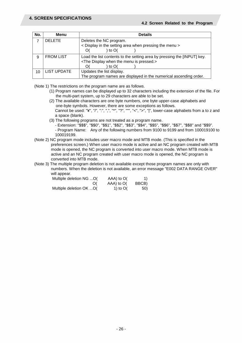
No. Menu Details 7 DELETE Deletes the NC program.
< Display in the setting area when pressing the menu > O( ) to O( )
9 FROM LIST Load the list contents to the setting area by pressing the [INPUT] key. <The Display when the menu is pressed.> O( ) to O( )
10 LIST UPDATE Updates the list display. The program names are displayed in the numerical ascending order.
(Note 1) The restrictions on the program name are as follows.
(1) Program names can be displayed up to 32 characters including the extension of the file. For the multi-part system, up to 29 characters are able to be set.
(2) The available characters are one byte numbers, one byte upper-case alphabets and one-byte symbols. However, there are some exceptions as follows. Cannot be used: "¥", "/", ":", ",", "*", "?", """, "<", ">", "|", lower-case alphabets from a to z and a space (blank).
(3) The following programs are not treated as a program name. - Extension: "$$$", "$$0", "$$1", "$$2", "$$3", "$$4", "$$5", "$$6", "$$7", "$$8" and "$$9". - Program Name: Any of the following numbers from 9100 to 9199 and from 100019100 to 100019199.
(Note 2) NC program mode includes user macro mode and MTB mode. (This is specified in the preferences screen.) When user macro mode is active and an NC program created with MTB mode is opened, the NC program is converted into user macro mode. When MTB mode is active and an NC program created with user macro mode is opened, the NC program is converted into MTB mode.
(Note 3) The multiple program deletion is not available except those program names are only with numbers. When the deletion is not available, an error message "E002 DATA RANGE OVER" will appear. Multiple deletion NG ...O( AAA) to O( 1)
O( AAA) to O( BBCB) Multiple deletion OK ...O( 1) to O( 50)
4. SCREEN SPECIFICATIONS 4.2 Screen Related to the Program
- 27 -
(Supplement) 1. The following is the operation to enable the import from the program list.
INPUT key …[NEW] and [OPEN] FROM LIST menu …[NEW], [OPEN], [COMMENT], [COPY], [RENAME] and [DELETE]
2. When [FROM LIST] menu is pressed, contents are not echoed back to the setting section. 3. When [FROM LIST] menu is pressed, the cursor is displayed only in the name field of the list.
The cursor is not displayed in the comment field.
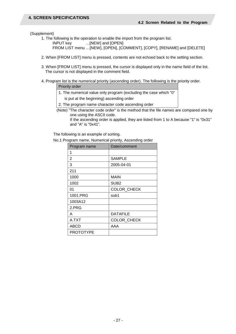
4. Program list is the numerical priority (ascending order). The following is the priority order. Priority order 1. The numerical value only program (excluding the case which "0"
is put at the beginning) ascending order 2. The program name character code ascending order
(Note) "The character code order" is the method that the file names are compared one by one using the ASCII code. If the ascending order is applied, they are listed from 1 to A because "1" is "0x31" and "A" is "0x41".
The following is an example of sorting. No.1 Program name, Numerical priority, Ascending order
Program name Date/comment 1 2 SAMPLE 3 2005-04-01 211 1000 MAIN 1002 SUB2 01 COLOR_CHECK 1001.PRG sub1 1003A12 2.PRG A DATAFILE A.TXT COLOR_CHECK ABCD AAA PROTOTYPE

4. SCREEN SPECIFICATIONS 4.2 Screen Related to the Program
- 28 -
Operation example (Opening the existing NC program)
(1) Select the [PROGRAM] in the LIST VIEW area.
The program edit screen will be displayed. The list of the NC program that can be read out will be displayed.
(2) Press the [OPEN] menu key, and input the NC program No. to be read out. The [OPEN] menu will be highlighted, and
the setting area will be displayed. The cursor appears on the program name field of the list.
(3) Press the [INPUT] key. The highlight of the [OPEN] menu will turn
OFF, and the setting area will disappear. The process of the NC program read out will be displayed in the LIST VIEW area. The NC program No. read out will be displayed on the area bar of the OPERATION VIEW area.

4. SCREEN SPECIFICATIONS 4.2 Screen Related to the Program
- 29 -
4.2.1.1 Program Edit and Part System
Prog
ram
pat
h
#1285 ext21 bit0:
Multi-part system
program management
#1285 ext21 bit2:
Multi-system program
generation and
operation
Program list
display pattern
[NEW] [OPEN] [COPY] [COMMENT][RENAME] [DELETE]
Remarks
NC
mem
ory
OFF -
Part system none specified.
$1 Type 1 [Program existed] Open the 1st part system program. [No program] Error "E01 Designated file does not exist."
Per file
ON OFF
All part systems (for the number of the part system)
All part systems (for the number of the part system) 1st and 2nd part system generate the INIT process.
Type 2 [Program existed] Open the 1st part system program. [No program] Error "E01 Designated file does not exist."
All part systems at a time (For the comments, only $1 and $2 are applicable.)
ON ON
$1 $1 Type 1 [Program existed] Open the 1st part system program. [No program] Error "E01 Designated file does not exist."
Per file The 2-part system spec. cannot be set to "1: EXIST".
Excl
udin
g N
C m
emor
y
- -
All files $1 Type 1 [Program existed] Open the 1st part system program. [No program] Error "E01 Designated file does not exist."
Per file

4. SCREEN SPECIFICATIONS 4.3 Screen Related to the Process Edit Functions
- 30 -
4.3 Screens Related to the Process Edit Functions
4.3.1 Process List Screen
The tool information and cutting conditions for each process are displayed on this screen. When [PROCESS] is selected in the LIST VIEW area, this screen is displayed. When the NC program is not selected, this screen is not displayed.
Screen layout
Screen display items
No. Display item Details Setting range 1 PCS The process name is displayed.
(Note) This name is same as the name displayed in the LIST VIEW area.
-
2 T NAME The name of tool to be used is displayed. - 3 T The tool No. and compensation No. are displayed.
The tool No. can be changed. T-command will not be output if the tool No. is set to "0". Set the tool No. to "0" unless T-command needs to be output, such as when the same tool is used for the multiple consecutive processes.
0 to 99999999
4 V The cutting speed is displayed. The cutting speed can be changed.
1 to 9999 m/min 1 to 9999 feet/min
5 F The feedrate is displayed. The feedrate can be changed. When TAP or THREAD process is applied, the pitch (mm/rev) is displayed.
0.0001 to 999.9999 mm/rev 0.00001 to 99.99999 inch/rev

4. SCREEN SPECIFICATIONS 4.3 Screen Related to the Process Edit Functions
- 31 -
Menus
No. Menu Details 1 ← Turns the LIST VIEW area active. 2 $1+$2 LIST System synchro screen is displayed.
When setting the timing synchronization in each process of the programs created for each part system, press this menu. This menu is displayed only when the 2-part system specification is "1: EXIST" and the multi-part system program management is ON.
4. SCREEN SPECIFICATIONS 4.3 Screen Related to the Process Edit Functions
- 32 -
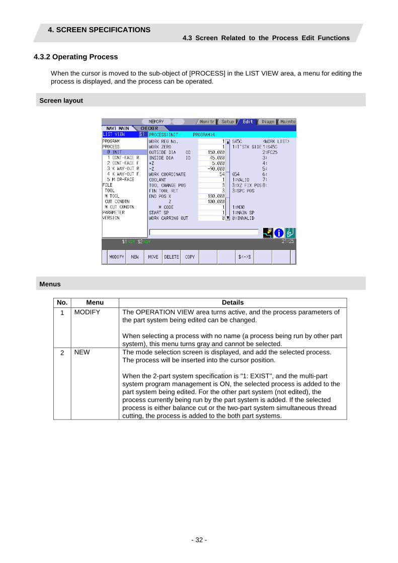
4.3.2 Operating Process
When the cursor is moved to the sub-object of [PROCESS] in the LIST VIEW area, a menu for editing the process is displayed, and the process can be operated.
Screen layout
Menus
No. Menu Details 1 MODIFY The OPERATION VIEW area turns active, and the process parameters of
the part system being edited can be changed. When selecting a process with no name (a process being run by other part system), this menu turns gray and cannot be selected.
2 NEW The mode selection screen is displayed, and add the selected process. The process will be inserted into the cursor position. When the 2-part system specification is "1: EXIST", and the multi-part system program management is ON, the selected process is added to the part system being edited. For the other part system (not edited), the process currently being run by the part system is added. If the selected process is either balance cut or the two-part system simultaneous thread cutting, the process is added to the both part systems.

4. SCREEN SPECIFICATIONS 4.3 Screen Related to the Process Edit Functions
- 33 -
No. Menu Details 3 MOVE Changes the process position.
The process can be moved between the part systems when the 2-part system specification is "1: EXIST" and the multi-part system program management is ON. (The movement between the part systems cannot be performed in balance cut machining process and the two-part system simultaneous thread cutting process.) Change the tool No. when the process is moved between the part systems. The other part system corresponding to the process is interchanged with the part system of the process in operation when the process is moved between the part systems. Example) Move "2 TURN-FACE R" of $1 to $2
<Before moving> <After moving>
Process list Process list
$1 $2 $1 $2 PROCESS 0 INIT 1 DR-FACE 2 TURN-FACE R 3 TURN-FACE F :
PROCESS 0 INIT 1 2 3 :
PROCESS 0 INIT 1 DR-FACE
2 3 TURN-FACE F :
PROCESS 0 INIT 1 2 TURN-FACE R 3 :
4 DELETE Deletes the process at the cursor position. When performing the deletion, the process under the deleted process will be moved up. The processes corresponding to each part system are deleted together when the 2-part system specification is "1: EXIST" and the multi-part system program management is ON. Example) Delete "1 DR-FACE" of $1
< Before deleting> < After deleting>
Process list Process list
$1 $2 $1 $2 PROCESS 0 INIT 1 DR-FACE 2 TURN-FACE R 3 TURN-FACE F :
PROCESS 0 INIT 1 2 3 :
PROCESS 0 INIT 1 TURN-FACE R 2 TURN-FACE F :
PROCESS 0 INIT 1 2 :

4. SCREEN SPECIFICATIONS 4.3 Screen Related to the Process Edit Functions
- 34 -
No. Menu Details 5 COPY Copies the process at the cursor position.
The copied process will be inserted under the cursor position. The processes corresponding to each part system are copied together when the 2-part system specification is "1: EXIST" and the multi-part system program management is ON. Example) Copy "1 DR-FACE" in $1
< Before copying> < After copying>
Process list Process list
$1 $2 $1 $2 PROCESS 0 INIT 1 DR-FACE 2 TURN-FACE R 3 TURN-FACE F :
PROCESS 0 INIT 1 2 3 :
PROCESS 0 INIT 1 DR-FACE 2 DR-FACE 3 TURN-FACE R 4 TURN-FACE F :
PROCESS 0 INIT 1 2 3 4 :
8 $<->$ Switches a part system to be edited. Pressing this menu, the process data of the next part system is displayed in the LIST VIEW. The part system is switched in the order of $1, $2 and $1. After switching the part system, the cursor is displayed in the same process position as before the switch. * When the 2-part system specification is "0: NONE", or when the 2-part system specification is "1: EXIST" and the multi-part system program management is OFF, this menu is not displayed.

4. SCREEN SPECIFICATIONS 4.3 Screen Related to the Process Edit Functions
- 35 -
Operation example (Selecting the process)
(1) Validate the LIST VIEW area, select the process with the cursor key.
The contents of the OPERATION VIEW area will change to those of the selected process.
(2) Press the [MODIFY] menu key. The OPERATION VIEW area will turn active.

4. SCREEN SPECIFICATIONS 4.3 Screen Related to the Process Edit Functions
- 36 -
Operation example (Deleting the process)
(1) Validate the LIST VIEW area, select the process to be deleted with the cursor key.
The contents of the OPERATION VIEW area will change to those of the selected process.
(2) Press the [DELETE] menu key. The [DELETE] menu will be highlighted, and a massage confirming the deletion will appear.
(3) Press the [Y] key. The highlight of the [DELETE] menu will turn OFF, and the process at the cursor position will be deleted. The process under the deleted process will be moved up one. The contents in the OPERATION VIEW area will change to those of the process at the cursor position.
When not deleting the process, press the [N] key
4. SCREEN SPECIFICATIONS 4.3 Screen Related to the Process Edit Functions
- 37 -
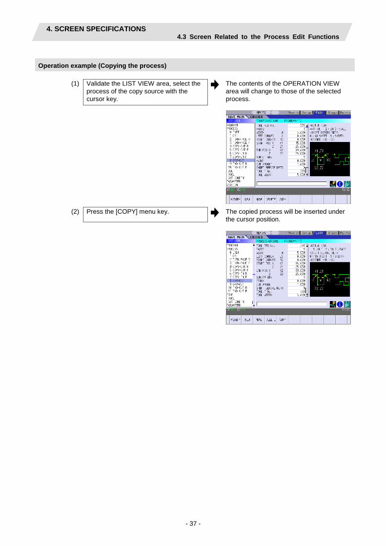
Operation example (Copying the process)
(1) Validate the LIST VIEW area, select the process of the copy source with the cursor key.
The contents of the OPERATION VIEW area will change to those of the selected process.
(2) Press the [COPY] menu key. The copied process will be inserted under the cursor position.

4. SCREEN SPECIFICATIONS 4.3 Screen Related to the Process Edit Functions
- 38 -
Operation example (Moving the process)
(1) Validate the LIST VIEW area, select the process to be moved with the cursor key. The contents of the OPERATION VIEW
area will change to those of the selected process.
(2) Press the [MOVE] menu key. The [MOVE] menu will be highlighted. The mark "M" will be displayed beside the process to be moved.
(3) Select the position of the movement destination with the cursor key.

4. SCREEN SPECIFICATIONS 4.3 Screen Related to the Process Edit Functions
- 39 -
(4) Press the [INPUT] key. The message to confirm a movement is
displayed.
If the [MOVE] menu key is pressed again during the movement operation, the movement operation will be canceled.
(5) Press the [Y] key. The process of the movement source will be moved to the cursor position. The highlight of the [MOVE] menu will turn OFF.
When not moving the process, press the [N] key
(Note) For the [NEW] menu, refer to the next section.

4. SCREEN SPECIFICATIONS 4.3 Screen Related to the Process Edit Functions
- 40 -
Operation example (Part system changeover)
(1) Validate the LIST VIEW area, and select the process to be changed with the cursor key.
The contents of the OPERATION VIEW area will change to those of the selected process.
(2) Press the [$<->$] menu key. The process data of the part system after the changeover is displayed in the LIST VIEW area. The cursor position is not moved. The contents in the OPERATION VIEW area will change to those of the process at the cursor position. The currently selected part system number will change.
4. SCREEN SPECIFICATIONS 4.3 Screen Related to the Process Edit Functions
- 41 -
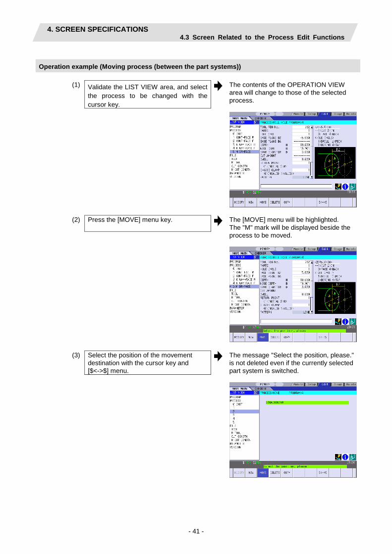
Operation example (Moving process (between the part systems))
(1) Validate the LIST VIEW area, and select the process to be changed with the cursor key.
The contents of the OPERATION VIEW area will change to those of the selected process.
(2) Press the [MOVE] menu key. The [MOVE] menu will be highlighted. The "M" mark will be displayed beside the process to be moved.
(3) Select the position of the movement destination with the cursor key and [$<->$] menu.
The message "Select the position, please." is not deleted even if the currently selected part system is switched.

4. SCREEN SPECIFICATIONS 4.3 Screen Related to the Process Edit Functions
- 42 -
(4) Press the [INPUT] key. The message to confirm a movement
appears.
If the [MOVE] menu key is pressed again during the movement operation, the operation will be canceled.
(5) Press the [Y] key. The process of the movement source will be moved to the cursor position. The highlight of the [MOVE] menu will turn OFF.
Press the [N] key in order not to move.

4. SCREEN SPECIFICATIONS 4.3 Screen Related to the Process Edit Functions
- 43 -
4.3.3 System Synchro Screen
The machining processes order of NC program created by each part system are edited on this screen. The screen is displayed by pressing [$1+$2 LIST] menu key on the Process list screen.
Screen layout
Screen display item
No. Display item Details Setting range 1 $1 The process list generated for the 1st part system is
displayed.
2 $2 The process list generated for the 2nd part system is displayed.
(1)
(2)
(2)

4. SCREEN SPECIFICATIONS 4.3 Screen Related to the Process Edit Functions
- 44 -
Menus
No. Display item Details Remarks 3 MOVE Changes the process position.
The process can be moved between the part systems when the 2-part system specification is "1: EXIST" and the multi-part system program management is ON. (The movement between the part systems cannot be performed in balance cut machining process and the two-part system simultaneous thread cutting process.) Change the tool No. when the process is moved between the part systems. The other part system corresponding to the process is interchanged with the part system of the process in operation when the process is moved between the part systems.
4 DELETE Deletes the process at the cursor position. When deleting a process, the process under the deleted process will be moved up. The processes corresponding to each part system are deleted together when the 2-part system specification is "1: EXIST" and the multi-part system program management is ON.
5 COPY Copies the process at the cursor position. The copied process will be inserted under the cursor position. The processes corresponding to each part system are copied together when the 2-part system specification is "1: EXIST" and the multi-part system program management is ON.
10 RETURN Return to the Process List Screen.

4. SCREEN SPECIFICATIONS 4.3 Screen Related to the Process Edit Functions
- 45 -
4.3.4 Process Mode Selection Screen
When a new process is added, the process mode is selected on this screen. This screen is displayed by pressing the [NEW] menu key with the cursor positioned on [PROCESS] in the LIST VIEW.
Screen layout
• Turning
• Milling
(Note) Milling process is available only when the milling interporation specifications are provided.

4. SCREEN SPECIFICATIONS 4.3 Screen Related to the Process Edit Functions
- 46 -
• Assist
•Balance cut

4. SCREEN SPECIFICATIONS 4.3 Screen Related to the Process Edit Functions
- 47 -
Screen display item
• Turning process No. Display item Details Setting range 1 Process mode Displays the process mode that can be selected for
the turning machining. Select the process mode by moving the sub cursor or inputting numerical values.
1: TURN 2: COPY 3: GROOVE 4: T GROOVE 5: THREAD 6: HOLE 7: EIA 8: CUTOFF
• Milling Process No. Display item Details Setting range 1 Process mode Displays the process mode that can be selected for
milling. Select the process mode by moving the sub cursor or inputting numerical values.
1: MILL HOLE 2: KEYWAY 3: CONTOUR
• Assist process No. Display item Details Setting range 1 Process mode Displays the process mode that can be selected for
assist process. Select the process mode by moving the sub cursor or inputting numerical values. (Note) The transfer process is available only when the parameter "#1001 SUB SPINDLE SPEC" is "1: EXIST".
1: TRANSFER
• Balance cut process No. Display item Details Setting range 1 Process mode Displays the process mode that can be selected for
balance cut machining. Select the process mode by moving the sub cursor or inputting numerical values. (Note) The balance cut process is available only when the 2-part system specification is "1: EXIST" and the multi-part system program management is ON.
1: TURN 2: COPY 3: THREAD
4. SCREEN SPECIFICATIONS 4.3 Screen Related to the Process Edit Functions
- 48 -
Menu
No. Menu Details 1 ← Cancels adding a new process.
The LIST VIEW area will turn active after cancel. 2 LATHE Displays the process mode for the turning machining. 3 MILLING Displays the process mode for milling.
(Note) This is valid when the milling interporation specifications are provided.
4 ASSIST Displays the process mode for assist process. (Note) This menu is available only when the parameter "#1001 SUB
SPINDLE SPEC" is "1: EXIST". 5 BALANCE CUT Displays the process mode for balance cut machining.
(Note) This menu is available only when the 2-part system specification is "1: EXIST" and the multi-part system program management is ON.
(Note) The process insertion position for the second part system is the same as the process number position of the first part system.

4. SCREEN SPECIFICATIONS 4.3 Screen Related to the Process Edit Functions
- 49 -
Operation example (Adding a new process)
(1) Validate the LIST VIEW area, and select the position where the process is added with the cursor key.
(2) Press the [NEW] menu key. A blank process will be inserted into the cursor position. The process mode selection screen will be displayed in the OPERATION VIEW area, and the OPERATION VIEW area will turn active.
(3) Select the process mode with the cursor or the numerical value input.
4. SCREEN SPECIFICATIONS 4.3 Screen Related to the Process Edit Functions
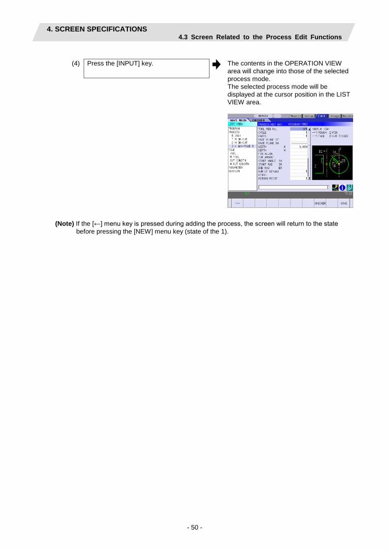
- 50 -
(4) Press the [INPUT] key. The contents in the OPERATION VIEW
area will change into those of the selected process mode. The selected process mode will be displayed at the cursor position in the LIST VIEW area.
(Note) If the [←] menu key is pressed during adding the process, the screen will return to the state
before pressing the [NEW] menu key (state of the 1).
4. SCREEN SPECIFICATIONS 4.3 Screen Related to the Process Edit Functions
- 51 -
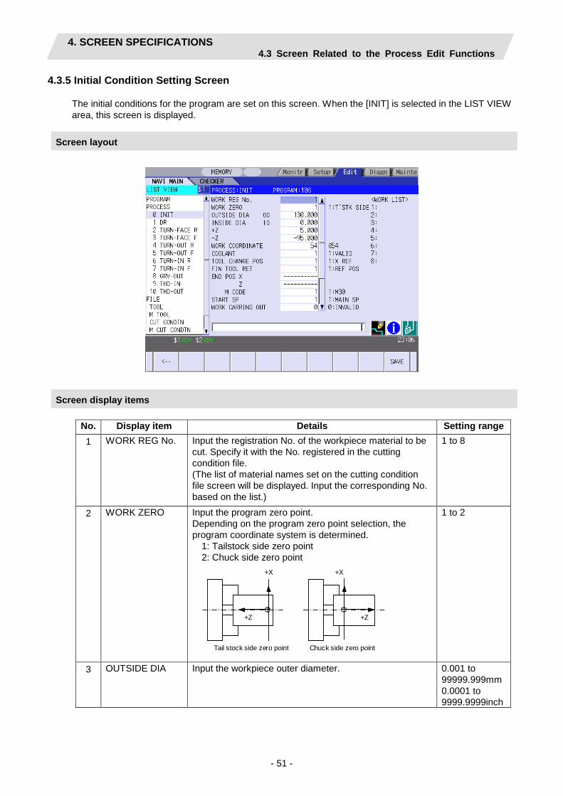
4.3.5 Initial Condition Setting Screen
The initial conditions for the program are set on this screen. When the [INIT] is selected in the LIST VIEW area, this screen is displayed.
Screen layout
Screen display items
No. Display item Details Setting range 1 WORK REG No. Input the registration No. of the workpiece material to be
cut. Specify it with the No. registered in the cutting condition file. (The list of material names set on the cutting condition file screen will be displayed. Input the corresponding No. based on the list.)
1 to 8
2 WORK ZERO Input the program zero point. Depending on the program zero point selection, the program coordinate system is determined.
1: Tailstock side zero point 2: Chuck side zero point
+X
+Z
Tail stock side zero point
+X
+Z
Chuck side zero point
1 to 2
3 OUTSIDE DIA Input the workpiece outer diameter. 0.001 to 99999.999mm 0.0001 to 9999.9999inch
4. SCREEN SPECIFICATIONS 4.3 Screen Related to the Process Edit Functions
- 52 -
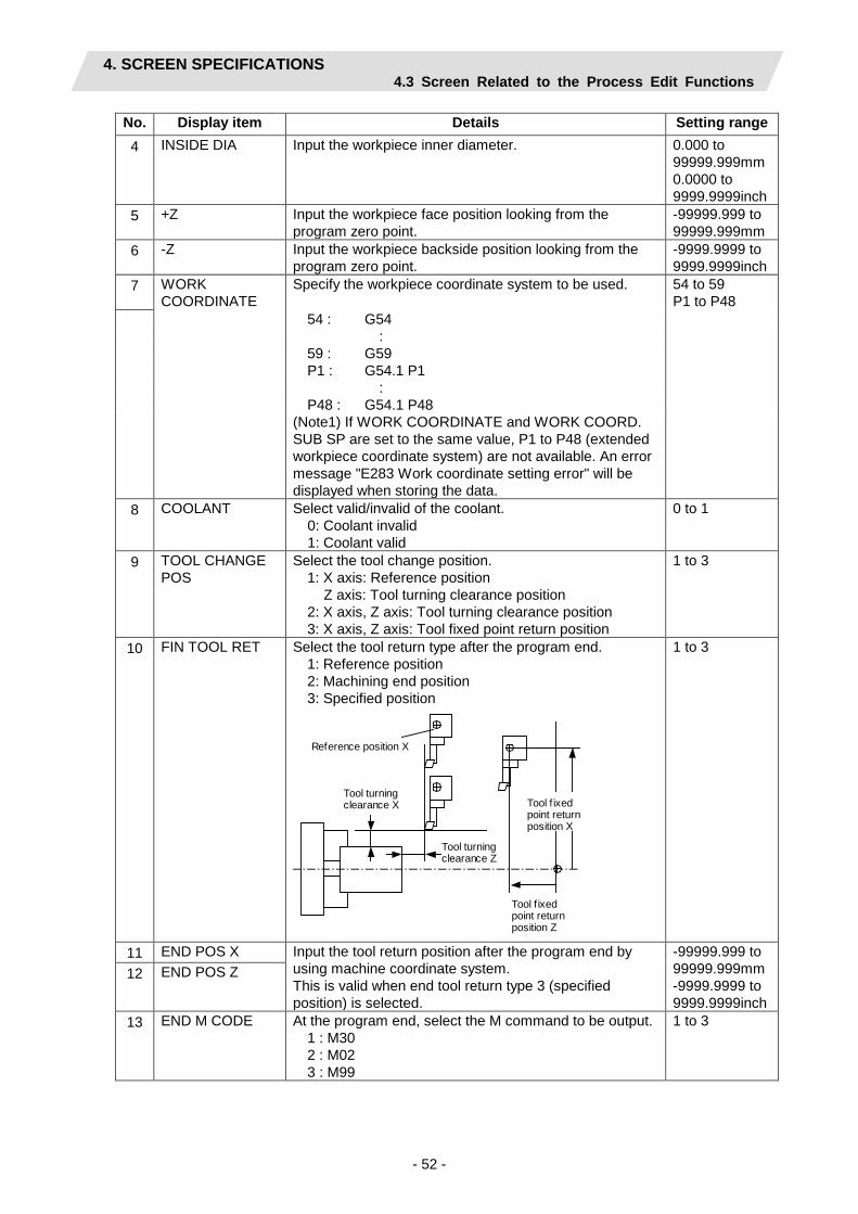
No. Display item Details Setting range 4 INSIDE DIA Input the workpiece inner diameter. 0.000 to
99999.999mm 0.0000 to 9999.9999inch
5 +Z Input the workpiece face position looking from the program zero point.
-99999.999 to 99999.999mm
6 -Z Input the workpiece backside position looking from the program zero point.
-9999.9999 to 9999.9999inch
7 WORK COORDINATE
Specify the workpiece coordinate system to be used. 54 to 59 P1 to P48
54 : G54 :
59 : G59 P1 : G54.1 P1
: P48 : G54.1 P48
(Note1) If WORK COORDINATE and WORK COORD. SUB SP are set to the same value, P1 to P48 (extended workpiece coordinate system) are not available. An error message "E283 Work coordinate setting error" will be displayed when storing the data.
8 COOLANT Select valid/invalid of the coolant. 0: Coolant invalid 1: Coolant valid
0 to 1
9 TOOL CHANGE POS
Select the tool change position. 1: X axis: Reference position
Z axis: Tool turning clearance position 2: X axis, Z axis: Tool turning clearance position 3: X axis, Z axis: Tool fixed point return position
1 to 3
10 FIN TOOL RET Select the tool return type after the program end. 1: Reference position 2: Machining end position 3: Specified position
Tool turning clearance X
Tool turning clearance Z
Tool f ixed point return position Z
Tool f ixed point return position X
Reference position X
1 to 3
11 END POS X Input the tool return position after the program end by using machine coordinate system. This is valid when end tool return type 3 (specified position) is selected.
-99999.999 to 99999.999mm -9999.9999 to 9999.9999inch
12 END POS Z
13 END M CODE At the program end, select the M command to be output. 1 : M30 2 : M02 3 : M99
1 to 3

4. SCREEN SPECIFICATIONS 4.3 Screen Related to the Process Edit Functions
- 53 -
No. Display item Details Setting range 14 START SP Select the spindle that performs machining at the start of
the program. 1: MAIN SP 2: SUB SP (Note) This can be set only when the parameter "1001
SUB SPINDLE SPEC" is "1: EXIST".
1,2 (Default: 1)
15 WORK CARRING OUT
Select valid/invalid of the workpiece delivery to the parts catcher when the machining is completed. 0: INVALID 1: VALID (Note 1) This can be set only when the parameter "1001
SUB SPINDLE SPEC" is "1: EXIST". (Note 2) A workpiece delivery device is necessary for the
machine specifications.
0,1 (Default: 0)
16 CARRING OUT POS Z
Set the workpiece carrying out position with the Z coordinate 0: INVALID 1: VALID (Note) This can be set only when the WORK CARRING
OUT is set to "1: VALID".
-99999.999 to 99999.999 mm -9999.9999 to 9999.9999 inch
17 WORK COORD. SUB SP
Specify the workpiece coordinate system to be used with the sub spindle. (Note 1) This can be set only when the parameter "1001
SUB SPINDLE SPEC" is "1: EXIST". (Note 2) If WORK COORDINATE and WORK COORD.
SUB SP are set to the same value, P1 to P48 (extended workpiece coordinate system) are not available. An error message "E283 Work coordinate setting error" will be displayed when storing the data.
54 to 59 P1 to P48
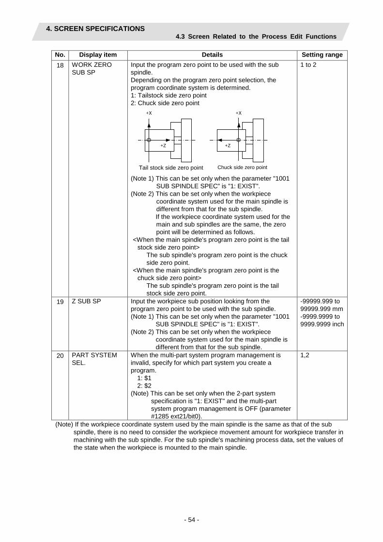
4. SCREEN SPECIFICATIONS 4.3 Screen Related to the Process Edit Functions
- 54 -
No. Display item Details Setting range 18 WORK ZERO
SUB SP Input the program zero point to be used with the sub spindle. Depending on the program zero point selection, the program coordinate system is determined. 1: Tailstock side zero point 2: Chuck side zero point
+X
+Z
心押台側原点
+X
+Z
チャック側原点
(Note 1) This can be set only when the parameter "1001 SUB SPINDLE SPEC" is "1: EXIST".
(Note 2) This can be set only when the workpiece coordinate system used for the main spindle is different from that for the sub spindle. If the workpiece coordinate system used for the main and sub spindles are the same, the zero point will be determined as follows.
<When the main spindle's program zero point is the tail stock side zero point>
The sub spindle's program zero point is the chuck side zero point.
<When the main spindle's program zero point is the chuck side zero point>
The sub spindle's program zero point is the tail stock side zero point.
1 to 2
19 Z SUB SP Input the workpiece sub position looking from the program zero point to be used with the sub spindle. (Note 1) This can be set only when the parameter "1001
SUB SPINDLE SPEC" is "1: EXIST". (Note 2) This can be set only when the workpiece
coordinate system used for the main spindle is different from that for the sub spindle.
-99999.999 to 99999.999 mm -9999.9999 to 9999.9999 inch
20 PART SYSTEM SEL.
When the multi-part system program management is invalid, specify for which part system you create a program. 1: $1 2: $2 (Note) This can be set only when the 2-part system
specification is "1: EXIST" and the multi-part system program management is OFF (parameter #1285 ext21/bit0).
1,2
(Note) If the workpiece coordinate system used by the main spindle is the same as that of the sub spindle, there is no need to consider the workpiece movement amount for workpiece transfer in machining with the sub spindle. For the sub spindle's machining process data, set the values of the state when the workpiece is mounted to the main spindle.
Tail stock side zero point Chuck side zero point

4. SCREEN SPECIFICATIONS 4.3 Screen Related to the Process Edit Functions
- 55 -
Menus
No. Menu Details 1 ← Turns the LIST VIEW area active. 10 SAVE Saves the changes in the initial conditions.
If illegal parameters are found in saving, an error will be displayed. When a parameter is incorrectly input, the cursor moves to that parameter position.

4. SCREEN SPECIFICATIONS 4.3 Screen Related to the Process Edit Functions
- 56 -
4.3.6 Turning Screen
(1) Turning screen The parameters for the turning process are input on this screen.
Screen layout
Screen display items
No. Display item Details Setting range 1 TOOL REG No. Input the registration No. of the tool to be used.
Use the No. registered in the tool file. $1:101 to 150 601 to 650 (Default: 101) $2: 1101 to 1150 1601 to 1650 (Default: 1101)
2 CYCLE Input the machining method. <1: Rough machining>
Cuts into the cutting area gradually. Leaves the finishing allowance for the cutting shape.
<2: Finishing machining> Machines the cutting shape in one cycle.
1,2 (Default: 1)

4. SCREEN SPECIFICATIONS 4.3 Screen Related to the Process Edit Functions
- 57 -
No. Display item Details Setting range 3 PARTS Input the machining area.
<1: OUT-OPEN> Machines the outer diameter area from the front face of workpiece.
<2: OUT-CL> Machines the outer diameter area from the halfway of workpiece.
<3: IN-OPEN> Machines the inner diameter area from the front face of workpiece.
<4: IN-CL> Machines inner area from the halfway of workpiece.
<5: FACE-OPEN> Machines the front face of workpiece.
<6: FACE-CL> Machines the front face from the halfway of workpiece.
<7: BACK-OPEN> Machines the back side of workpiece.
<8: BACK-CL> Machines the back side of workpiece from the halfway of workpiece.
(Note 1) BACK-OPEN and BACK-CL are available only when the parameter "1001 SUB SPINDLE SPEC" is "1: EXIST".
1 to 8 (Default: 1)
[OPEN type]
Pe (Cutting shape end point)
Approach point
Cutting start point
[CLOSE type]
P1 (Cutting shape start point) Cutting start point
Pe (Cutting shape end point)
Approach point
When the cutting shape is not incremented or decremented monotonously, CLOSE type is selected.
4 APPRCH POS X Input the approach point. After machining, the tool returns to the approach point.
-99999.999 to 99999.999mm -9999.9999 to 9999.9999inch 5 APPRCH POS Z

4. SCREEN SPECIFICATIONS 4.3 Screen Related to the Process Edit Functions
- 58 -
No. Display item Details Setting range 6 FINISH ALLOW X
(FX) Input the finishing allowance for the rough machining. Input both FX and FZ with radius value.
0.000 to 99999.999mm 0.0000 to 9999.9999inch
7 FINISH ALLOW Z (FZ)
8 CUT AMOUNT Input the cut amount for the rough machining. 0.001 to 99.999mm
9 RETRACT AMOUNT
Input the retract amount for the rough machining. 0.0001 to 9.9999inch
10 TOOL T No. Specify the tool No. and the compensation No. to be used. (T function code data being output as the NC data) When tool registration No. is specified, tool No. registered in the tool file is automatically set. If this is set to "0", T function code is not output.
0 to 99999999
11 CUT SPEED V Input the cutting speed. When tool registration No. is specified, cutting speed is automatically set based on the contents in the tool file and cutting condition file.
1 to 9999 m/min 1 to 9999 feet/min
12 FEEDRATE F Input the feedrate. When tool registration No. is specified, feedrate is automatically set based on the contents in the tool file and cutting condition file.
0.0001 to 999.9999 mm/rev 0.00001 to 99.99999 inch/rev
13 COOLANT M CODE
Input the tool coolant M code. When there is no coolant, input 999. When tool registration No. is specified, the coolant M code registered in the tool file is automatically set.
1 to 999
(Addendum) The tool is retracted as shown below during rough machining.
[OPEN type] [CLOSE type] The tool is retracted in 45˚ direction in respect to the cutting shape.
Cutting start point
Approach point
The tool is retracted tracing the cutting shape.
Cutting start point
Approach point
(Note) Tool path is not provided based on the tool shape (tool nose angle, front edge angle, etc.) Therefore, when the cutting shape is not incremented or decremented monotonously, take the tool shape into consideration to input the cutting shape.

4. SCREEN SPECIFICATIONS 4.3 Screen Related to the Process Edit Functions
- 59 -
Menus
No. Menu Details 1 ← Turns the LIST VIEW area active. 5 PATTERN Machining pattern selection screen is displayed. 8 CHECKER Displays the checker screen. Select this to check the set data. 10 SAVE Saves the changes in the process.
If illegal parameters are found in saving, an error will be displayed. When a parameter is incorrectly input, the cursor moves to that parameter position. If illegal parameters are found in the pattern input screen, the screen name and error will be displayed.
(2) Turning pattern screen The cutting shapes for the turning process are input on this screen.
Screen layout
Screen display items
No. Display item Details Setting range 1 No. Shape No. 1 to 50 2 M Input the shape.
<1> Linear (G01) machining <2> CW circular (G02) machining <3> CCW circular (G03) machining (Note) Not omittable.
1 to 3

4. SCREEN SPECIFICATIONS 4.3 Screen Related to the Process Edit Functions
- 60 -
No. Display item Details Setting range 3 D Input right turn or left turn in respect to the vector
at the end of the previous shape. 1: Left turn 2: Right turn (Note 1) When nothing is input, it is regarded as
"contacting". (Note 2) Omittable. However, when the end point
of the previous line, X and Z, is uncertain, always input.
Turn to left Tangent Turn to right
1,2
4 X Z
Input the start point of a shape in the line No.1 and the end point of each shape in the line No.2 and after. Specify with diameter value of the program coordinate system for X and with radius value for Z.
Z
X
(Note 1) Always input the coordinate in the final
line. Omittable except for the line No.1 and the last one.
(Note 2) Always input when the corner shape dimension is input in the previous line.
-99999.999 to 99999.999mm -9999.9999 to 9999.9999inch
5 R/A • When the shape is arc, input the radius of arc. Positive value: Arc command smaller than 180° Negative value: Arc command larger than 180° • When the shape is linear, input the angle.
135°
(Note 1) Always input when the shape is arc. (Note 2) When the shape is linear and the
coordinate X, Z or vector I, K is input, this data is invalid.
Radius: 0.001 to 999999.999mm, -999999.999 to -0.001mm Angle: -359.999 to 360.000°

4. SCREEN SPECIFICATIONS 4.3 Screen Related to the Process Edit Functions
- 61 -
No. Display item Details Setting range
6 I K
• When the shape is arc, input the arc center coordinate. • When the shape is linear, input the gradient (vector).
Z
80 40
40
60
I = 40. K = 60.
Z
80 40
20
60
I = 40. K = 40.
X
X
(Note 1) When the shape is arc and only one of
either I or K is input, the other one is regarded as "0".
(Note 2) When the shape is linear and the coordinate X, Z or angle is input, this data is invalid.
-99999.999 to 99999.999mm -9999.9999 to 9999.9999inch
7 C Input the corner dimension. Positive value: Corner R Negative value: Corner C
R C
(Note 1) When corner dimension is specified,
input the end point X, Y in the next line in principle.
-99999.999 to 99999.999mm -9999.9999 to 9999.9999inch
Menus
No. Menu Details 1 LINE INSERT Inserts the shape data in front of the cursor position.
(Note) This menu is not available when the cursor is at No.1 (machining start point).
2 LINE DELETE Deletes the shape data at the cursor position. (Note) This menu is not available when the cursor is at No.1
(machining start point). 6 COPY Copies the previous line data at the cursor position. 7 +INPUT Inputs data at the cursor position with the data in the previous line
added. (Note) This is valid only when inputting the coordinate X and Z.
8 CLEAR Clears the data at the cursor position. 10 RETURN Returns to the turning screen.
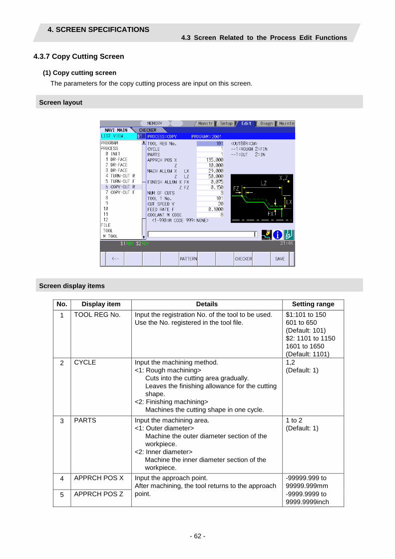
4. SCREEN SPECIFICATIONS 4.3 Screen Related to the Process Edit Functions
- 62 -
4.3.7 Copy Cutting Screen
(1) Copy cutting screen The parameters for the copy cutting process are input on this screen.
Screen layout
Screen display items
No. Display item Details Setting range 1 TOOL REG No. Input the registration No. of the tool to be used.
Use the No. registered in the tool file. $1:101 to 150 601 to 650 (Default: 101) $2: 1101 to 1150 1601 to 1650 (Default: 1101)
2 CYCLE Input the machining method. <1: Rough machining>
Cuts into the cutting area gradually. Leaves the finishing allowance for the cutting shape.
<2: Finishing machining> Machines the cutting shape in one cycle.
1,2 (Default: 1)
3 PARTS Input the machining area. <1: Outer diameter>
Machine the outer diameter section of the workpiece.
<2: Inner diameter> Machine the inner diameter section of the workpiece.
1 to 2 (Default: 1)
4 APPRCH POS X Input the approach point. After machining, the tool returns to the approach point.
-99999.999 to 99999.999mm
5 APPRCH POS Z -9999.9999 to 9999.9999inch
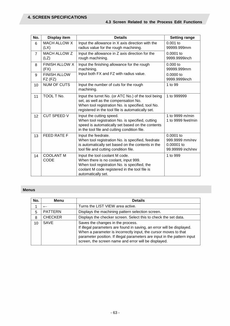
4. SCREEN SPECIFICATIONS 4.3 Screen Related to the Process Edit Functions
- 63 -
No. Display item Details Setting range 6 MACH ALLOW X
(LX) Input the allowance in X axis direction with the radius value for the rough machining.
0.001 to 99999.999mm
7 MACH ALLOW Z (LZ)
Input the allowance in Z axis direction for the rough machining.
0.0001 to 9999.9999inch
8 FINISH ALLOW X (FX)
Input the finishing allowance for the rough machining. Input both FX and FZ with radius value.
0.000 to 99999.999mm
9 FINISH ALLOW FZ (FZ)
0.0000 to 9999.9999inch
10 NUM OF CUTS Input the number of cuts for the rough machining.
1 to 99
11 TOOL T No. Input the turret No. (or ATC No.) of the tool being set, as well as the compensation No. When tool registration No. is specified, tool No. registered in the tool file is automatically set.
1 to 999999
12 CUT SPEED V Input the cutting speed. When tool registration No. is specified, cutting speed is automatically set based on the contents in the tool file and cutting condition file.
1 to 9999 m/min 1 to 9999 feet/min
13 FEED RATE F Input the feedrate. When tool registration No. is specified, feedrate is automatically set based on the contents in the tool file and cutting condition file.
0.0001 to 999.9999 mm/rev 0.00001 to 99.99999 inch/rev
14 COOLANT M CODE
Input the tool coolant M code. When there is no coolant, input 999. When tool registration No. is specified, the coolant M code registered in the tool file is automatically set.
1 to 999
Menus
No. Menu Details 1 ← Turns the LIST VIEW area active. 5 PATTERN Displays the machining pattern selection screen. 8 CHECKER Displays the checker screen. Select this to check the set data. 10 SAVE Saves the changes in the process.
If illegal parameters are found in saving, an error will be displayed. When a parameter is incorrectly input, the cursor moves to that parameter position. If illegal parameters are input in the pattern input screen, the screen name and error will be displayed.

4. SCREEN SPECIFICATIONS 4.3 Screen Related to the Process Edit Functions
- 64 -
(2) Copy cutting pattern screen
The cutting shapes for the turning process are input on this screen.
Screen layout
Screen display items Refer to the section "4.3.5 Turning Screen (2) Turning pattern screen".
Menus
No. Menu Details 1 LINE INSERT Inserts the shape data in front of the cursor position.
(Note) This menu is not available when the cursor is at No.1 (machining start point).
2 LINE DELETE Deletes the shape data at the cursor position. (Note) This menu is not available when the cursor is at No.1
(machining start point). 6 COPY Copies the previous line data at the cursor position.
7 +INPUT Input data at the cursor position with the data in the previous line added. (Note) This is valid only when inputting the coordinate X and Z.
8 CLEAR Clears the data at the cursor position.
10 RETURN Returns to the copy cutting screen.

4. SCREEN SPECIFICATIONS 4.3 Screen Related to the Process Edit Functions
- 65 -
4.3.8 Threading Screen
The parameters for the thread process are input on this screen.
Screen layout
Screen display items
No. Display item Details Setting range
1 TOOL REG No. Input the registration No. of the tool to be used. Use the No. registered in the tool file.
$1:301 to 350 (Default: 301) $2: 1301 to 1350 (Default: 1301)
2 CYCLE Input the machining method. <1: ROUGH (Rough machining)>
Cuts into the thread shape gradually. Leaves the finishing allowance for the thread shape.
<2: FIN (Finishing machining)> Machines the thread shape in one cycle.
<3: R+F (Rough machining and Finishing machining)> Do the rough machining first before the finishing machining.
1 to 3 (Default: 1)
3 PARTS Input the machining area. <1: OUT (Outer diameter)>
Thread the outer diameter area of the workpiece. <2: IN (inner diameter)>
Thread the inner diameter area of the workpiece. <3: Face>
Thread the front area of the workpiece. <4: BACK>
Thread the back side of the workpiece. (Note) BACK is available only when the parameter
"1001 SUB SPINDLE SPEC" is "1: EXIST".
1 to 4 (Default: 1)

4. SCREEN SPECIFICATIONS 4.3 Screen Related to the Process Edit Functions
- 66 -
No. Display item Details Setting range 4 CUT METHOD Select the threading cutting pattern for the rough
machining. 1: Constant area-normal 2: Constant area-zigzag 3: Constant depth-normal 4: Constant depth-zigzag
[Constant depth-normal] [Constant area-normal]
[Constant area-zigzag] [Constant depth-zigzag]
Single cutting amount Single cutting amount Single cutting amount
Single cutting amount Single cutting amount Single cutting amount
S3 S2 S1
S3 S1 S2
1 to 4 (Default: 1)
5 ANG OF CUT (A)
Input the cutting edge angle for the rough machining. When the cutting edge angle is set to 0, the zigzag cutting pattern will be invalid. Cutting edge angle
Cutting edge angle
Cutting edge angle = 0 Cutting edge angle 0 Cutting edge angle 0
0.000 to 60.000°
6 PITCH (P) Input the screw pitch. 0.0001 to 999.9999mm 0.00001 to 99.99999inch
7 HEIGHT (H) Input the thread height. When selecting a thread type from the menu, thread height can be input automatically based on the pitch.
M METER
UN UNIFY
W WIT
PF PT PS
PIPING
NPT PIPING
TM TRAP.30°
TW TRAP.29°
0.001 to 999.999mm 0.0001 to 9999.9999mm
8 START POS X (X1)
Input the X coordinate of the threading start point in the diameter value.
-99999.999 to 99999.999mm
9 START POS Z (Z1)
Input the Z coordinate of the threading start point. -9999.9999 to 9999.9999inch
10 END POS X (X2)
Input the X coordinate of the threading end point in the diameter value.
-99999.999 to 99999.999mm

4. SCREEN SPECIFICATIONS 4.3 Screen Related to the Process Edit Functions
- 67 -
No. Display item Details Setting range 11 END POS Z (Z2) Input the Z coordinate of the threading end point. -9999.9999 to
9999.9999inch 12 FIN ALLOW Input the threading finishing allowance for the
rough machining. Chamfered section is machined as continuous thread.
0.000 to 99999.999mm 0.0000 to 9999.9999inch
13 CUT AMOUNT Input the cutting amount corresponding the respective methods below for the rough machining. <Constant cutting amount method>
Maximum cutting amount per cut is input. Cutting amount is calculated according to the following formula, and the average is taken. Number of cutting cycles =
((Thread height - Threading finishing allowance)/Cutting amount) ↑
↑: Rounded up Actual cutting amount =
(Thread height – Threading finishing allowance)/Number of cutting cycles
<Constant area method>
Initial cutting amount is input. "n" th cutting amount (dn) is calculated according to the following formula. dn = d1( √n - √(n-1) )
d1: Initial cutting amount
0.001 to 99999.999mm 0.0001 to 9999.9999inch
14 CHM. ANGLE Input the chamfering angle. 0: No chamfering 1: 45° 2: 60°
Chamfering is not carried out when: Thread angle + chamfering angle > 90°
0 to 2
15 CHM. AMOUNT Input the chamfering amount. Chamfered section is machined as continuous thread.
0.1 to 9.9 (Number of threads)
16 TOOL T No. Input the turret No. (or ATC No.) of the tool being set, as well as the compensation No. When tool registration No. is specified, tool No. registered in the tool file is automatically set.
1 to 999999
17 CUT SPEED V Input the cutting speed. When tool registration No. is specified, cutting speed is automatically set based on the contents in the tool file and cutting condition file.
1 to 9999 m/min 1 to 9999 feet/min
18 COOLANT M CODE
Input the tool coolant M code. When there is no coolant, input 999. When tool registration No. is specified, the coolant M code registered in the tool file is automatically set.
1 to 999

4. SCREEN SPECIFICATIONS 4.3 Screen Related to the Process Edit Functions
- 68 -
Menus
No. Menu Details 1 ← Turns the LIST VIEW area active. 8 CHECKER Displays the checker screen. Select this to check the set data.
10 SAVE Saves the changes in the process. If illegal parameters are found in saving, an error will be displayed. When a parameter is incorrectly input, the cursor moves to that parameter position.

4. SCREEN SPECIFICATIONS 4.3 Screen Related to the Process Edit Functions
- 69 -
4.3.9 Grooving Screen
The parameters for the groove process are input on this screen.
Screen layout
Screen display items
No. Display item Details Setting range 1 TOOL REG No. Input the registration No. of the tool to be used. Use
the No. registered in the tool file. $1:201 to 250 (Default: 201) $2: 1201 to 1250 (Default: 1201)
2 PARTS Input the machining area. <1: Outer diameter>
Groove the outer diameter area of the workpiece. <2: Inner diameter>
Groove the inner diameter area of the workpiece. <3: Face>
Groove the front area of the workpiece. <4: BACK>
Groove the back area of the workpiece. (Note) BACK is available only when the parameter
"1001 SUB SPINDLE SPEC" is "1: EXIST".
1 to 4 (Default: 1)
3 WIDTH (W) Input the groove width. 0.001 to 99999.999mm 0.0001 to 9999.9999inch
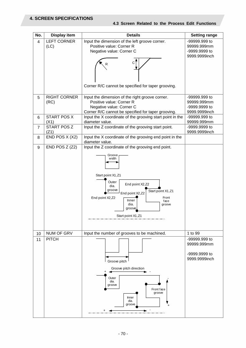
4. SCREEN SPECIFICATIONS 4.3 Screen Related to the Process Edit Functions
- 70 -
No. Display item Details Setting range 4 LEFT CORNER
(LC) Input the dimension of the left groove corner. Positive value: Corner R Negative value: Corner C
R C
Corner R/C cannot be specified for taper grooving.
-99999.999 to 99999.999mm -9999.9999 to 9999.9999inch
5 RIGHT CORNER (RC)
Input the dimension of the right groove corner. Positive value: Corner R Negative value: Corner C Corner R/C cannot be specified for taper grooving.
-99999.999 to 99999.999mm -9999.9999 to 9999.9999inch
6 START POS X (X1)
Input the X coordinate of the grooving start point in the diameter value.
-99999.999 to 99999.999mm
7 START POS Z (Z1)
Input the Z coordinate of the grooving start point. -9999.9999 to 9999.9999inch
8 END POS X (X2) Input the X coordinate of the grooving end point in the diameter value.
9 END POS Z (Z2) Input the Z coordinate of the grooving end point.
Groove width
Start point X1,Z1
End point X2,Z2
Start point X1,Z1
End point X2,Z2 Start point X1,Z1
End point X2,Z2 Outer dia.
groove
Inner dia.
groove
Front face
groove
10 NUM OF GRV Input the number of grooves to be machined. 1 to 99 11 PITCH
Groove pitch
Outer dia.
groove
Inner dia.
groove
Front face groove
Groove pitch direction
+ -
+ - +
-
-99999.999 to 99999.999mm -9999.9999 to 9999.9999inch
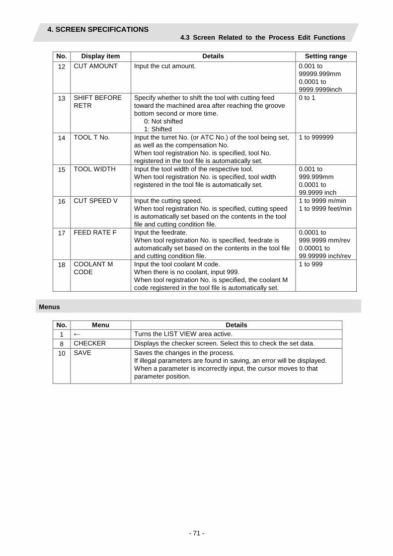
4. SCREEN SPECIFICATIONS 4.3 Screen Related to the Process Edit Functions
- 71 -
No. Display item Details Setting range 12 CUT AMOUNT Input the cut amount. 0.001 to
99999.999mm 0.0001 to 9999.9999inch
13 SHIFT BEFORE RETR
Specify whether to shift the tool with cutting feed toward the machined area after reaching the groove bottom second or more time. 0: Not shifted 1: Shifted
0 to 1
14 TOOL T No. Input the turret No. (or ATC No.) of the tool being set, as well as the compensation No. When tool registration No. is specified, tool No. registered in the tool file is automatically set.
1 to 999999
15 TOOL WIDTH Input the tool width of the respective tool. When tool registration No. is specified, tool width registered in the tool file is automatically set.
0.001 to 999.999mm 0.0001 to 99.9999 inch
16 CUT SPEED V Input the cutting speed. When tool registration No. is specified, cutting speed is automatically set based on the contents in the tool file and cutting condition file.
1 to 9999 m/min 1 to 9999 feet/min
17 FEED RATE F Input the feedrate. When tool registration No. is specified, feedrate is automatically set based on the contents in the tool file and cutting condition file.
0.0001 to 999.9999 mm/rev 0.00001 to 99.99999 inch/rev
18 COOLANT M CODE
Input the tool coolant M code. When there is no coolant, input 999. When tool registration No. is specified, the coolant M code registered in the tool file is automatically set.
1 to 999
Menus
No. Menu Details 1 ← Turns the LIST VIEW area active. 8 CHECKER Displays the checker screen. Select this to check the set data. 10 SAVE Saves the changes in the process.
If illegal parameters are found in saving, an error will be displayed. When a parameter is incorrectly input, the cursor moves to that parameter position.
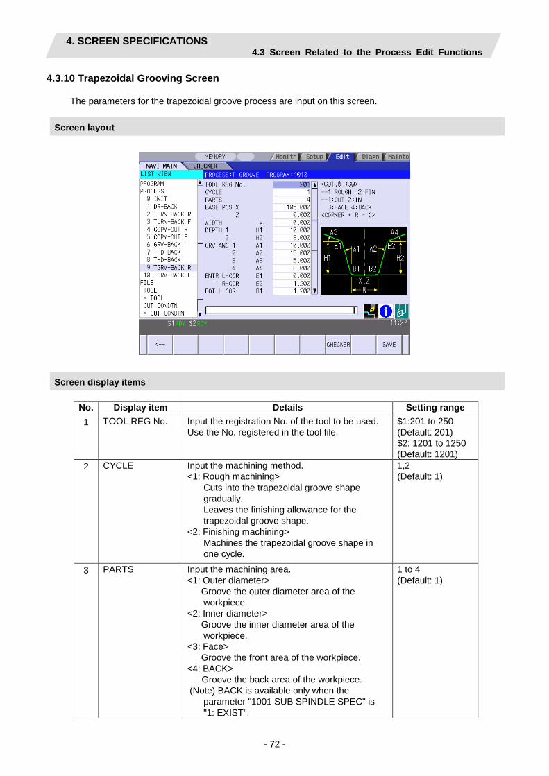
4. SCREEN SPECIFICATIONS 4.3 Screen Related to the Process Edit Functions
- 72 -
4.3.10 Trapezoidal Grooving Screen
The parameters for the trapezoidal groove process are input on this screen.
Screen layout
Screen display items
No. Display item Details Setting range 1 TOOL REG No. Input the registration No. of the tool to be used.
Use the No. registered in the tool file. $1:201 to 250 (Default: 201) $2: 1201 to 1250 (Default: 1201)
2 CYCLE Input the machining method. <1: Rough machining>
Cuts into the trapezoidal groove shape gradually. Leaves the finishing allowance for the trapezoidal groove shape.
<2: Finishing machining> Machines the trapezoidal groove shape in one cycle.
1,2 (Default: 1)
3 PARTS Input the machining area. <1: Outer diameter>
Groove the outer diameter area of the workpiece.
<2: Inner diameter> Groove the inner diameter area of the workpiece.
<3: Face> Groove the front area of the workpiece.
<4: BACK> Groove the back area of the workpiece.
(Note) BACK is available only when the parameter "1001 SUB SPINDLE SPEC" is "1: EXIST".
1 to 4 (Default: 1)

4. SCREEN SPECIFICATIONS 4.3 Screen Related to the Process Edit Functions
- 73 -
No. Display item Details Setting range 4 BASE POS X Input the X coordinate, basic point of the
trapezoidal groove (the bottom center of the trapezoidal groove), in the diameter value.
-99999.999 to 99999.999mm
5 BASE POS Z Input the Z coordinate, basic point of the trapezoidal groove (the bottom center of the trapezoidal groove), in the diameter value.
-9999.9999 to 9999.9999inch 0.001 to 99999.999mm
6 WIDTH (W) Input the groove width.
7 DEPTH 1 (H1) Input the left-side depth of the groove. 0.0001 to 9999.9999inch
8 DEPTH 2 (H2) Input the right-side depth of the groove.
9 GRV ANG 1 (A1) Input the angle between the bottom and left-side surface of the groove.
0.000 to 89.999°
10 GRV ANG 2 (A2) Input the angle between the bottom and right-side surface of the groove.
0.000 to 89.999°
11 GRV ANG 3 (A3) Input the angle between the left-side of the groove and the workpiece surface.
-89.999 to 89.999°
12 GRV ANG 4 (A4) Input the angle between the right-side of the groove and the workpiece surface.
E1 E2
B1 B2
H1 H2
W
X,Z
A1 A2
A3 A4
-89.999 to 89.999°
13 ENTR L-COR (E1)
Input the left corner amount of trapezoidal groove entrance. Positive value: Corner R Negative value: Corner C
-99999.999 to 99999.999mm
14 ENTR R-COR (E2)
Input the right corner amount of trapezoidal groove entrance. Positive value: Corner R Negative value: Corner C
-9999.9999 to 9999.9999inch
15 BOT L-COR (B1) Input the left corner amount of trapezoidal groove bottom. Positive value: Corner R Negative value: Corner C
16 BOT R-COR (B2) Input the right corner amount of trapezoidal groove bottom. Positive value: Corner R Negative value: Corner C

4. SCREEN SPECIFICATIONS 4.3 Screen Related to the Process Edit Functions
- 74 -
No. Display item Details Setting range 17 FIN ALLOW Input the finishing allowance of the groove for the
rough machining. 0.000 to 99999.999mm 0.0000 to 9999.9999inch
18 CUT AMOUNT Input the cut amount. 0.001 to 99999.999mm 0.0001 to 9999.9999inch
19 TOOL T No. Input the turret No. (or ATC No.) of the tool being set, as well as the compensation No. When tool registration No. is specified, tool No. registered in the tool file is automatically set.
1 to 999999
20 TOOL WIDTH Input the tool width of the respective tool. When tool registration No. is specified, tool width registered in the tool file is automatically set.
0.001 to 999.999mm 0.0001 to 99.9999inch
21
CUT SPEED V Input the cutting speed. When tool registration No. is specified, cutting speed is automatically set based on the contents in the tool file and cutting condition file.
1 to 9999 m/min 1 to 9999 feet/min
22
FEED RATE F Input the feedrate. When tool registration No. is specified, feedrate is automatically set based on the contents in the tool file and cutting condition file.
0.0001 to 999.9999 mm/rev 0.00001 to 99.99999 inch/rev
23 COOLANT M CODE
Input the tool coolant M code. When there is no coolant, input 999. When tool registration No. is specified, the coolant M code registered in the tool file is automatically set.
1 to 999
Menus
No. Menu Details 1 ← Turns the LIST VIEW area active. 8 CHECKER Displays the checker screen. Select this to check the set data. 10 SAVE Saves the changes in the process.
If illegal parameters are found in saving, an error will be displayed. When a parameter is incorrectly input, the cursor moves to that parameter position.

4. SCREEN SPECIFICATIONS 4.3 Screen Related to the Process Edit Functions
- 75 -
4.3.11 Hole Drilling Screen
Miscellaneous parameters related to the hole drilling process patterns are input on this screen. This is displayed when PATTERN menu is pressed on the hole drilling screen.
Screen layout
Screen display items
No. Display item Details Setting range 1 TOOL REG No. Input the registration No. of the tool to be used.
Use the No. registered in the tool file. $1:401 to 450 501 to 550 (Default: 401) $2: 1401 to 1450 1501 to 1550 (Default: 1401)
2 PARTS Input the machining area. <1: FACE>
Hole drilling the face area of the workpiece. <2: BACK>
Hole drilling the back area of the workpiece. (Note) This item is available only when the
parameter "1001 SUB SPINDLE SPEC" is "1: EXIST".
1,2 (Default: 1)

4. SCREEN SPECIFICATIONS 4.3 Screen Related to the Process Edit Functions
- 76 -
No. Display item Details Setting range 3 HOLE CYCLE Input the type of hole machining cycle.
<1: DRILL> (G83) The machining is performed as far as the hole bottom at a stretch, and the tool is lifted up after the hole bottom dwell has been executed.
<2: PECK> (G83) The machining is performed halfway of the hole, and the tool is returned to the higher than the hole top position each time. The machining is performed as far as the hole bottom by repeating such operations.
<3: BORING> (G85) The machining is performed as far as the hole bottom at a stretch, and the tool is lifted up with the cutting feedrate after the hole bottom dwell has been executed.
<4: TAP> (G84,G84.1) The tap machining is performed as far as the hole bottom, and the tool is lifted up with the reversed rotation after the hole bottom dwell has been executed.
1 to 4 (Default: 1)
4 SURFACE Z (ZF) Input the top surface position of the hole. -99999.999 to 99999.999mm
5 DEPTH (H) Input the hole depth from the workpiece top surface with the addition input method. When the hole depth is changed, tool nose depth will be automatically updated. If the calculated nose depth is 0 or below, the data range will be over.
-99999.999 to 99999.999mm -9999.9999 to 9999.9999inch
6 NOSE DEPTH (B) Input the nose depth from the workpiece top surface with the addition input method. When the nose depth is changed, hole depth will be automatically updated.
0.001 to 99999.999mm
7 SPOT DIAMETER (D)
Input the spot diameter. When inputting the spot diameter, hole depth and nose depth are automatically changed.
0.001 to Tool diameter
8 CUT AMOUNT When selecting the hole cycle type C=2(deep hole), input the cut amount per cut.
0.001 to 99999.999mm
9 DWELL Input the dwell time at the bottom of the hole. 0.0 to 99.999sec 10 TOOL T No. Input the turret No. (or ATC No.) of the tool being
set, as well as the compensation No. When tool registration No. is specified, tool No. registered in the tool file is automatically set.
1 to 999999
11 TOOL DIA Input the tool radius of the respective tool. When tool registration No. is specified, tool radius registered in the tool file is automatically set.
0.001 to 999.999mm 0.0001 to 99.9999inch
12 CUT SPEED V Input the cutting speed. When tool registration No. is specified, cutting speed is automatically set based on the contents in the tool file and cutting condition file.
1 to 9999 m/min 1 to 9999 feet/min
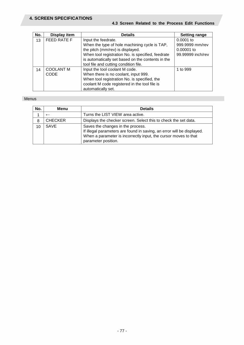
4. SCREEN SPECIFICATIONS 4.3 Screen Related to the Process Edit Functions
- 77 -
No. Display item Details Setting range 13 FEED RATE F Input the feedrate.
When the type of hole machining cycle is TAP, the pitch (mm/rev) is displayed. When tool registration No. is specified, feedrate is automatically set based on the contents in the tool file and cutting condition file.
0.0001 to 999.9999 mm/rev 0.00001 to 99.99999 inch/rev
14 COOLANT M CODE
Input the tool coolant M code. When there is no coolant, input 999. When tool registration No. is specified, the coolant M code registered in the tool file is automatically set.
1 to 999
Menus
No. Menu Details 1 ← Turns the LIST VIEW area active. 8 CHECKER Displays the checker screen. Select this to check the set data. 10 SAVE Saves the changes in the process.
If illegal parameters are found in saving, an error will be displayed. When a parameter is incorrectly input, the cursor moves to that parameter position.
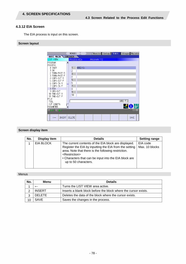
4. SCREEN SPECIFICATIONS 4.3 Screen Related to the Process Edit Functions
- 78 -
4.3.12 EIA Screen
The EIA process is input on this screen.
Screen layout
Screen display item
No. Display item Details Setting range 1 EIA BLOCK The current contents of the EIA block are displayed.
Register the EIA by inputting the EIA from the setting area. Note that there is the following restriction. <Restriction> • Characters that can be input into the EIA block are
up to 50 characters.
EIA code Max. 10 blocks
Menus
No. Menu Details 1 ← Turns the LIST VIEW area active. 2 INSERT Inserts a blank block before the block where the cursor exists. 3 DELETE Deletes the data of the block where the cursor exists. 10 SAVE Saves the changes in the process.

4. SCREEN SPECIFICATIONS 4.3 Screen Related to the Process Edit Functions
- 79 -
4.3.13 Milling Hole Drilling Screen
(1) Milling hole drilling screen The parameters for the milling hole drilling are input on this screen.
Screen layout
Screen display items
No. Display item Details Setting range 1 TOOL REG
No. Input the registration No. of the tool to be used. Use the No. registered in the tool file.
$1:701 to 799 (Default: 701) $2: 1701 to 1799 (Default: 1701)
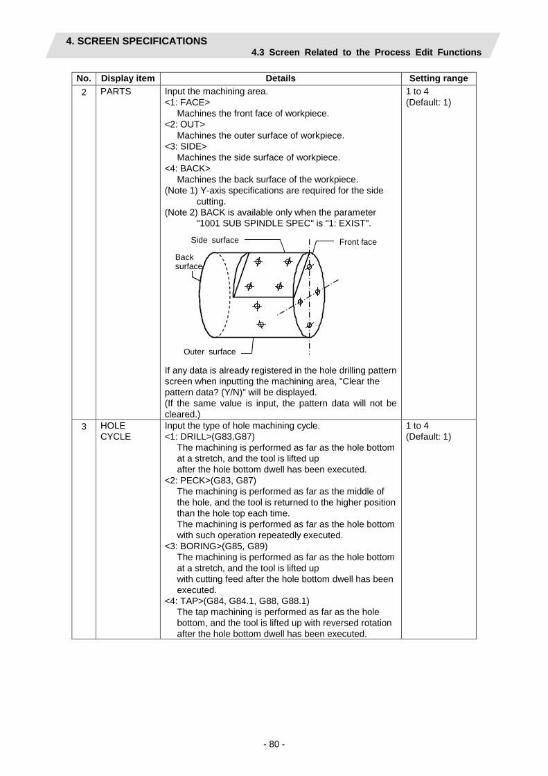
4. SCREEN SPECIFICATIONS 4.3 Screen Related to the Process Edit Functions
- 80 -
No. Display item Details Setting range 2 PARTS Input the machining area.
<1: FACE> Machines the front face of workpiece.
<2: OUT> Machines the outer surface of workpiece.
<3: SIDE> Machines the side surface of workpiece.
<4: BACK> Machines the back surface of the workpiece.
(Note 1) Y-axis specifications are required for the side cutting.
(Note 2) BACK is available only when the parameter "1001 SUB SPINDLE SPEC" is "1: EXIST".
Outer surface
Side surface Front face
Back surface
If any data is already registered in the hole drilling pattern screen when inputting the machining area, "Clear the pattern data? (Y/N)" will be displayed. (If the same value is input, the pattern data will not be cleared.)
1 to 4 (Default: 1)
3 HOLE CYCLE
Input the type of hole machining cycle. <1: DRILL>(G83,G87)
The machining is performed as far as the hole bottom at a stretch, and the tool is lifted up after the hole bottom dwell has been executed.
<2: PECK>(G83, G87) The machining is performed as far as the middle of the hole, and the tool is returned to the higher position than the hole top each time. The machining is performed as far as the hole bottom with such operation repeatedly executed.
<3: BORING>(G85, G89) The machining is performed as far as the hole bottom at a stretch, and the tool is lifted up with cutting feed after the hole bottom dwell has been executed.
<4: TAP>(G84, G84.1, G88, G88.1) The tap machining is performed as far as the hole bottom, and the tool is lifted up with reversed rotation after the hole bottom dwell has been executed.
1 to 4 (Default: 1)

4. SCREEN SPECIFICATIONS 4.3 Screen Related to the Process Edit Functions
- 81 -
No. Display item Details Setting range 4 BASE
PLANE BZ BASE PLANE BR BASE PLANE BA
Set the hole top position in respect to the machining area. [Front face] [Outer surface]
[Side surface] [Back]
X
Z
BZ X
Z BR
BR
BA X
Z
X
Z
BZ
BASE PLANE BZ/BR are switched according to the machining area. BASE PLANE BA is set only for the side cutting.
Base plane BZ -99999.999 to 99999.999mm -9999.9999 to 9999.9999inch Base plane BR 0.001 to 99999.999mm 0.0001 to 9999.9999inch Base plane BA -359.999 to 360.000°
5 DEPTH H Input the hole depth from the workpiece top surface with an addition input method. When the hole depth is changed, nose depth is automatically updated. If the calculated nose depth is 0 or below, the data is out of the range.
-99999.999 to 99999.999mm -9999.9999 to 9999.9999inch
6 NOSE DEPTH B
Input the tool nose depth from the workpiece top surface with an addition input method. When the nose depth is changed, hole depth is automatically updated.
0.001 to 99999.999mm 0.0001 to 9999.9999inch
7 SPOT DIAMETER D
Input the spot diameter. When inputting the spot diameter, hole depth and nose depth are automatically changed.
0.001 to Tool diameter (mm) 0.0001 to Tool diameter (inch)
8 CUT AMOUNT
Input the cutting amount per cut when the hole cycle type C=2 (PECK) is selected.
0.001 to 99999.999mm 0.0001 to 9999.9999inch
9 DWELL Input the dwell time at the bottom of the hole. 0.0 to 99.999sec

4. SCREEN SPECIFICATIONS 4.3 Screen Related to the Process Edit Functions
- 82 -
No. Display item Details Setting range 10 RETURN
POINT When machining multiple holes, select the height of the tool movement to the next hole position. 1:Initial point level return 2:R point level return
Initial point level return -OUT-
Initial point level return -FACE-
Safe profile clearance
R point level return -OUT-
Safe profile clearance
Hole clearance
R point level return -FACE-
Hole clearance
Initial point level return -BACK-
Safe profile clearance
R point level return -BACK-
Hole clearance
1,2 (Default: 1)
11 C-AXIS CLAMP
Select whether to clamp C axis or not in the machining. Select “Clamp C axis” for heavy load machining. 0:Invalid 1:Valid
0,1 (Default: 0)
12 PATTERN The machining pattern is displayed. RANDOM LINE ARC CIRCLE SQUARE GRID Change the machining pattern on the machining pattern screen.
- (Default: LINE)
13 TOOL T No. Input the turret No. (or ATC No.) of the tool being set, as well as the compensation No. When tool registration No. is specified, the tool No. registered in the tool file is automatically set.
0 to 99999999
14 DIA Input the tool diameter. When tool registration No. is specified, the tool diameter registered in the tool file is automatically set.
0.001 to 999.999mm 0.0001 to 99.9999inch
15 CUT SPEED V
Input the cutting speed. When tool registration No. is specified, cutting speed is automatically set based on the contents in the tool file and cutting condition file.
1 to 9999 m/min 1 to 9999 feet/min

4. SCREEN SPECIFICATIONS 4.3 Screen Related to the Process Edit Functions
- 83 -
No. Display item Details Setting range 16 FEED RATE
F Input the feedrate. When the type of the hole machining cycle is TAP, the pitch (mm/rev) is displayed. When tool registration No. is specified, feedrate is automatically set based on the contents in the tool file and cutting condition file.
0.0001 to 999.9999 mm/rev 0.00001 to 99.99999 inch/rev
17 COOLANT M CODE
Input the tool coolant M code. When there is no coolant, input 999. When tool registration No. is specified, the coolant M code registered in the tool file is automatically set.
1 to 999
Menus
No. Menu Details 1 ← Turns the LIST VIEW area active. 5 PATTERN The machining pattern selection screen is displayed. 8 CHECKER Displays the checker screen. Select this to check the set data. 10 SAVE Saves the changes in the process.
If illegal parameters are found in saving, an error will be displayed. When a parameter is incorrectly input, the cursor moves to that parameter position.

4. SCREEN SPECIFICATIONS 4.3 Screen Related to the Process Edit Functions
- 84 -
(2) Hole Drilling Pattern Screen
Various parameters for hole drilling patterns are input on this screen. When the [PATTERN] menu is pressed on the hole drilling screen, this screen is displayed.
Screen layout
Machining area and hole machining pattern
The hole machining patterns selectable for each machining area are as follows.
Pattern Machining area
Random Line Arc Circle Square Grid
Front face
Outer surface × × × ×
Side surface
Back surface
: Selectable, ×: Not selectable
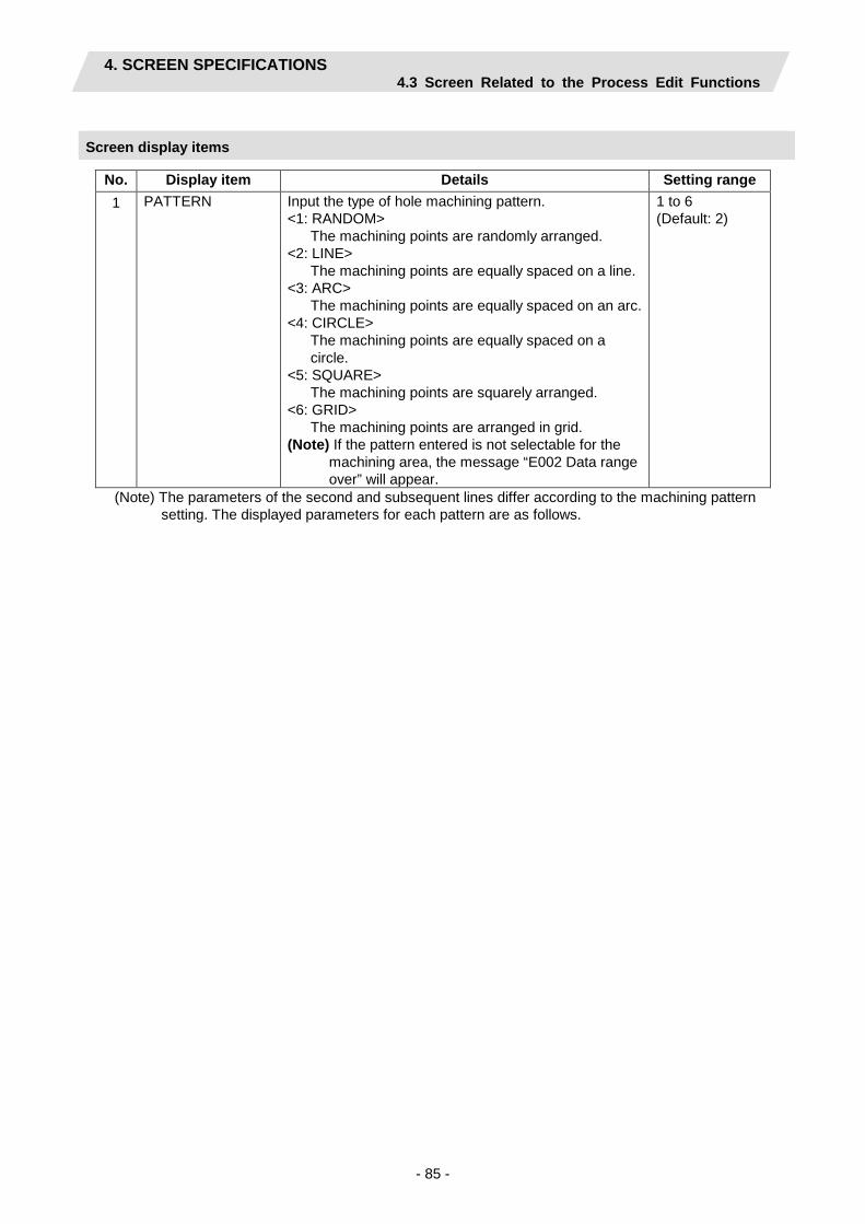
4. SCREEN SPECIFICATIONS 4.3 Screen Related to the Process Edit Functions
- 85 -
Screen display items
No. Display item Details Setting range 1 PATTERN Input the type of hole machining pattern.
<1: RANDOM> The machining points are randomly arranged.
<2: LINE> The machining points are equally spaced on a line.
<3: ARC> The machining points are equally spaced on an arc.
<4: CIRCLE> The machining points are equally spaced on a circle.
<5: SQUARE> The machining points are squarely arranged.
<6: GRID> The machining points are arranged in grid.
(Note) If the pattern entered is not selectable for the machining area, the message “E002 Data range over” will appear.
1 to 6 (Default: 2)
(Note) The parameters of the second and subsequent lines differ according to the machining pattern setting. The displayed parameters for each pattern are as follows.

4. SCREEN SPECIFICATIONS 4.3 Screen Related to the Process Edit Functions
- 86 -
・Parameters for RANDOM
No. Display item Details Setting range
2 HOLE No. Input the hole No. 1 to 35 3 FACE:
POS X POS Y
OUT: POS C POS Z
SIDE: POS Y POS Z
Input the hole position. [Front face] [Outer circumference]
[Side face]
[Back face]
X
Y x
C
Z
c
y
90
Y
Z
y
z
180
270
360
z
X
Y x
y
X,Y,Z: -99999.999 to 99999.999mm -9999.9999 to 9999.9999inch C: -359.999 to 360.000
Input the hole position in tabular form for the random pattern. The Image of the operation area
Pattern --1: RANDOM 2: LINE 3: ARC Hole position 4: CIRCLE 5: SQUARE 6: GRID No. X Y ▲
X
Y x
y
1
2
3
4
5
6
7
8
9
10
11
12 ▼
Guide drawing corresponds to the machining area.

4. SCREEN SPECIFICATIONS 4.3 Screen Related to the Process Edit Functions
- 87 -
・Parameters for LINE
[Front face] [Outer surface] [Side surface]
X
Y BX,B
C
Z BC,BZ
Y
Z
A
K A
K
BY,BZ
A
K
[Back surface]
X
Y BX,B
A
K
No. Display item Details Setting range 2 FACE:
BASE POS X BASE POS Y
OUT: BASE POS C BASE POS Z
SIDE: BASE POS Y BASE POS Z
Set the first hole position for the machining area. X,Y,Z: -99999.999 to 99999.999mm -9999.9999 to 9999.9999inch C: -359.999° to 360.000°
3 ANGLE (A) PITCH (A)
Front face: Input the angle formed with the machining direction and the positive direction of the X axis.
Outer surface: Input the pitch angle in respect to the machining direction.
Side surface: Input the angle formed with the machining direction and the positive direction of the Y axis.
-359.999° to 360.000°
4 PITCH (K) Input the space from the machining point to the next machining point.
-99999.999 to 99999.999mm -9999.9999 to 9999.9999inch
5 NUM OF HOLES
Input the number of holes. 2 to 999
6 OMIT 1 to 4 Specify the hole No. to be omitted (deleted). Maximum hole No. that can be specified is 127.
0 to number of holes (Default: 0)

4. SCREEN SPECIFICATIONS 4.3 Screen Related to the Process Edit Functions
- 88 -
・Parameters for ARC
[Front face] [Side surface] [Back surface]
Y
Z BY,BZ
X
Y BX,B
A
R
K
A K
R
X
Y BX,B
A
R
K
No. Display item Details Setting range 2 FACE:
BASE POS X BASE POS Y
SIDE: BASE POS Y BASE POS Z
Input the arc center position. X,Y,Z: -99999.999 to 99999.999mm -9999.9999 to 9999.9999inch
3 RADIUS R Input the arc radius. 0.001 to 99999.999mm 0.0001 to 9999.9999inch
4 START ANGLE A
Front face: Input the angle formed with the first machining point and the positive direction of the X axis.
Side surface: Input the angle formed with the first machining point and the positive direction of the Y axis.
-359.999° to 360.000°
5 PITCH K Input the angle from the previous machining point to the next machining point.
-359.999° to 360.000°
6 NUM OF HOLES
Input the number of holes. 2 to 999
7 OMIT 1 to 4 Specify the hole No. to be omitted (deleted). Maximum hole No. that can be specified is 127.
0 to number of holes (Default: 0)
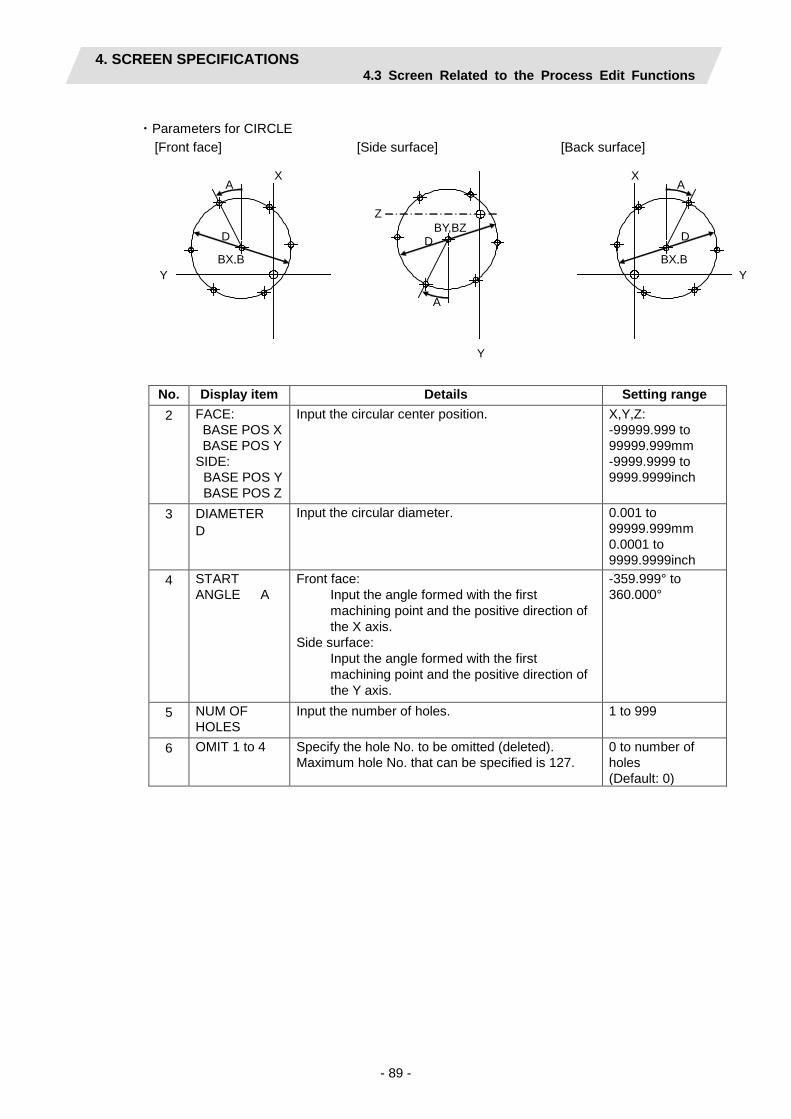
4. SCREEN SPECIFICATIONS 4.3 Screen Related to the Process Edit Functions
- 89 -
・Parameters for CIRCLE
[Front face] [Side surface] [Back surface]
Y
Z BY,BZ
A
D
X
Y BX,B
A
D
X
Y BX,B
A
D
No. Display item Details Setting range 2 FACE:
BASE POS X BASE POS Y
SIDE: BASE POS Y BASE POS Z
Input the circular center position. X,Y,Z: -99999.999 to 99999.999mm -9999.9999 to 9999.9999inch
3 DIAMETER D
Input the circular diameter. 0.001 to 99999.999mm 0.0001 to 9999.9999inch
4 START ANGLE A
Front face: Input the angle formed with the first machining point and the positive direction of the X axis.
Side surface: Input the angle formed with the first machining point and the positive direction of the Y axis.
-359.999° to 360.000°
5 NUM OF HOLES
Input the number of holes. 1 to 999
6 OMIT 1 to 4 Specify the hole No. to be omitted (deleted). Maximum hole No. that can be specified is 127.
0 to number of holes (Default: 0)

4. SCREEN SPECIFICATIONS 4.3 Screen Related to the Process Edit Functions
- 90 -
・Parameters for SQUARE
[Front face] [Side surface] [Back surface]
Y
Z
BY,BZ
A
B
J
I
X
Y BX,B
A
B I
J
1
2
3
4 5
1
2
3 4
5
X
Y BX,B
A
B I
J
1
2
3
4 5
No. Display item Details Setting range 2 FACE:
BASE POS X BASE POS Y
SIDE: BASE POS Y BASE POS Z
Input the position of the machining start point. X,Y,Z: -99999.999mm to 99999.999mm -9999.9999 to 9999.9999inch
3 X WIDTH I Input the width of the machining point in the X axis direction.
-99999.999mm to 99999.999mm -9999.9999 to 9999.9999inch
4 X NUM OF HOLES
Input the number of machining points in the X axis direction.
2 to 999
5 Y WIDTH J Input the width of the machining point in the Y axis direction.
-99999.999mm to 99999.999mm -9999.9999 to 9999.9999inch
6 Y NUM OF HOLES
Input the number of machining points in the Y axis direction.
2 to999
7 ANGLE A Front face: Input the angle formed with the machining start direction and the X axis.
Side surface: Input the angle formed with the machining start direction and the Y axis.
-359.999° to 360.000°
8 ANGLE B Input the interior angle. Default value is 90°.
0.001° to 179.999° (Default: 90°)
9 OMIT 1 to 4 Specify the hole No. to be omitted (deleted). Maximum hole No. that can be specified is 127.
0 to number of holes (Default: 0)

4. SCREEN SPECIFICATIONS 4.3 Screen Related to the Process Edit Functions
- 91 -
・Parameters for GRID
[Front face] [Side surface] [Back surface]
Y
Z
BY,BZ
A
B
J
I
X
Y BX,B
A
B I
J
1
2
3
4
5
1
2
3
4
5
X
Y BX,B
A
B I
J
1
2
3
4
5
No. Display item Details Setting range 2 FACE:
BASE POS X BASE POS Y
SIDE: BASE POS Y BASE POS Z
Input the position of the machining start point. X,Y,Z: -99999.999mm to 99999.999mm -9999.9999 to 9999.9999inch
3 X WIDTH I Input the width of the machining point in the X axis direction.
-99999.999mm to 99999.999mm -9999.9999 to 9999.9999inch
4 X NUM OF HOLES
Input the number of machining points in the X axis direction.
2 to 999
5 Y WIDTH J Input the width of the machining point in the Y axis direction.
-99999.999mm to 99999.999mm -9999.9999 to 9999.9999inch
6 Y NUM OF HOLES
Input the number of machining points in the Y axis direction.
2 to 999
7 ANGLE A Front face: Input the angle formed with the machining start direction and the X axis.
Side surface: Input the angle formed with the machining start direction and the Y axis.
-359.999° to 360.000°
8 ANGLE B Input the interior angle. Default value is 90°.
0.001° to 179.999° (Default: 90°)
9 OMIT 1 to 4 Specify the hole No. to be omitted (deleted). Maximum hole No. that can be specified is 127.
0 to number of holes (Default: 0)
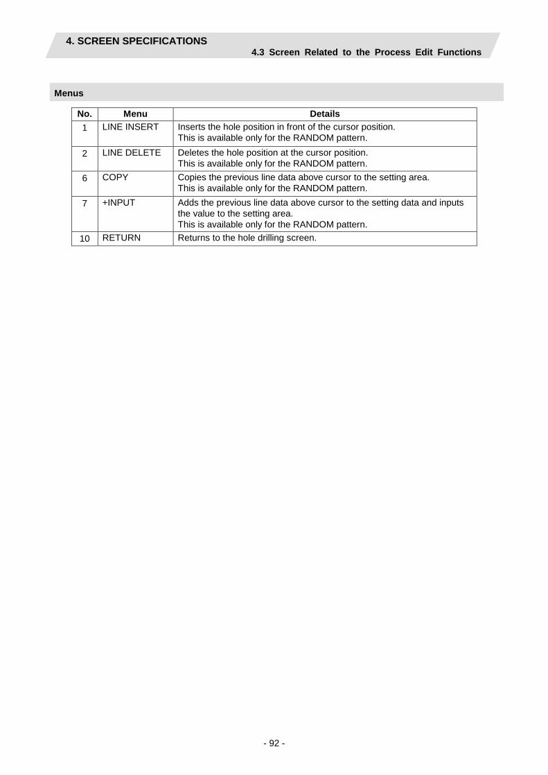
4. SCREEN SPECIFICATIONS 4.3 Screen Related to the Process Edit Functions
- 92 -
Menus
No. Menu Details 1 LINE INSERT Inserts the hole position in front of the cursor position.
This is available only for the RANDOM pattern.
2 LINE DELETE Deletes the hole position at the cursor position. This is available only for the RANDOM pattern.
6 COPY Copies the previous line data above cursor to the setting area. This is available only for the RANDOM pattern.
7 +INPUT Adds the previous line data above cursor to the setting data and inputs the value to the setting area. This is available only for the RANDOM pattern.
10 RETURN Returns to the hole drilling screen.

4. SCREEN SPECIFICATIONS 4.3 Screen Related to the Process Edit Functions
- 93 -
4.3.14 Keyway Cutting Screen
(1) Keyway Cutting Screen The parameters for the keyway cutting are input on this screen.
Screen layout

4. SCREEN SPECIFICATIONS 4.3 Screen Related to the Process Edit Functions
- 94 -
Screen display items
No. Display item Details Setting range 1 TOOL REG
No. Input the registration No. of the tool to be used. Use the No. registered in the tool file.
$1:701 to 799 (Default: 701) $2: 1701 to 1799 (Default: 1701)
2 CYCLE Input the machining method. <1: ROUGH (rough machining)>
Cuts into the keyway shape gradually. Leaves the finishing allowance in respect to the keyway shape.
<2: FIN (finishing machining)> Machines the keyway shape in one cycle.
Keyway clearance
Safe profile clearance positon [Rough machining]
Keyway clearance + Finishing allowance
Safe profile clearance position
[Finishing machining]
Finishing allowance
1,2 (Default: 1)
3 PARTS Input the machining area. <1: FACE>
Machines the front face of workpiece. <2: OUT>
Machines the outer surface of workpiece. <3: SIDE>
Machines the side surface of workpiece. <4: BACK>
Machines the back surface of the workpiece. (Note 1) Y-axis specifications are required for the side
cutting. (Note 2) BACK is available only when the parameter
"1001 SUB SPINDLE SPEC" is "1: EXIST".
Outer surface
Side surface Front face
Back surface
1 to 4 (Default: 1)

4. SCREEN SPECIFICATIONS 4.3 Screen Related to the Process Edit Functions
- 95 -
No. Display item Details Setting range 4 BASE
PLANE BZ BASE PLANE BR BASE PLANE BA
Set the machining base plane in respect to the machining area. [Front face]
[Outer surface]
[Side surface]
[Back surface]
Y
X X
Z
BZ S
ER
S
Y
X X
Z SZ
SA BR
EZ
Y
X X
Z SZ
BA BR
EZ
SY
Y
X X
Z
B
S
E
S
BASE PLANE BZ/BR are changed each other according to the machining area. BASE PLANE BA is set only for the side cutting.
Base plane BZ -99999.999 to 99999.999mm -9999.9999 to 9999.9999inch Base plane BR 0.001 to 99999.999mm 0.0001 to 9999.9999inch Base plane BA -359.999 to 360.000°
5 WIDTH W Input the width and depth of the keyway. An error will occur when the keyway width is smaller than the tool width. Machining path is determined as follows depending on whether Y-axis specifications are provided or not.
Y-axis specifications provided: When the keyway width exceeds the tool width, cutting is performed with shifting the tool on Y axis.
No Y-axis specifications provided: Cutting is only executed on the center line of the keyway.
Width Depth
0.001 to 999.999mm 0.0001 to 99.9999inch
6 DEPTH H

4. SCREEN SPECIFICATIONS 4.3 Screen Related to the Process Edit Functions
- 96 -
No. Display item Details Setting range 7 FIN ALLOW Set the finishing allowance in the depth of the keyway.
Rough machining leaves the finishing allowance in respect to the bottom of the keyway.
0.000 to 999.999mm 0.0000 to 99.9999inch
8 CUT AMOUNT
Input the cutting depth amount of the keyway for the rough machining.
0.001 to 99999.999mm 0.0001 to 9999.9999inch
9 START ANGLE SA SHIFT POS SY
Refer to the figure of base plane. START ANGLE SA and SHIFT POS SY are switched each other according to the machining area. START RAD SR and START POS SZ are switched each other according to the machining area. END RADIUS ER and END POS EZ are switched each other according to the machining area.
Start position BZ, end position EZ -99999.999 to 99999.999mm -9999.9999 to 9999.9999inch Start radius SR, end radius ER, shift position SY 0.001 to 99999.999mm 0.0001 to 9999.9999inch Start angle SA -359.999 to 360.000°
10 START RAD SR START POS SZ
11 END RAD ER END POS EZ
12 NUM OF KEYWAY
Input the number of keyways. 1 to 9 (Default: 1)
13 PITCH Input the pitch if the number of keyways is 2 or more. Front face, outer surface -359.999 to 360.000° Side surface 0.001 to 99999.999mm 0.0001 to 9999.9999inch

4. SCREEN SPECIFICATIONS 4.3 Screen Related to the Process Edit Functions
- 97 -
No. Display item Details Setting range 14 RETURN
POINT When the number of keyways is 2 or more, select the height of the tool movement to the next hole position. 1: Initial point level return 2: R point level return
Initial point level return
R point level return
Safe profile clearance
Keyway clearance
1,2 (Default: 1)
15 C-AXIS CLAMP
Select whether to clamp C axis or not in the machining. Select “Clamp C axis” for heavy load machining. 0: Not clamp C axis 1: Clamp C axis
0,1 (Default: 0)
16 APPROACH IN AXIS DIR
When the positioning is performed, the tool moves to the position set in the K-WAY CLEARANCE with rapid traverse. Set “rapid traverse” or “cutting feed” to be performed in the cutting from that set position to the axis direction. 1: RAPID (G00) 2: CUT (G01)
Keyway clearance
[Rough machining]
Keyway clearance + finishing allowance
[Finishing machining]
Approach in the axis direction G0/G1
Approach in the axis direction G0/G1
1,2 (Default: 1)
17 TOOL T No. Input the turret No. (or ATC No.) of the tool being set, as well as the compensation No. When tool registration No. is specified, the tool No. registered in the tool file is automatically set.
0 to 99999999
18 DIA Input the tool diameter. When tool registration No. is specified, the tool diameter registered in the tool file is automatically set.
0.001 to 999.999mm 0.0001 to 99.9999inch
19 CUT SPEED V
Input the cutting speed. When tool registration No. is specified, cutting speed is automatically set based on the contents in the tool file and cutting condition file.
1 to9999 m/min 1 to 9999 feet/min
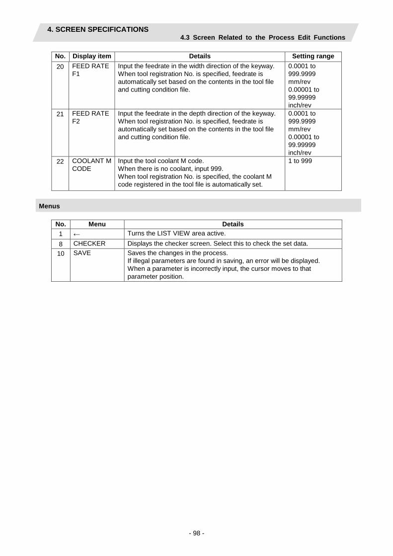
4. SCREEN SPECIFICATIONS 4.3 Screen Related to the Process Edit Functions
- 98 -
No. Display item Details Setting range 20 FEED RATE
F1 Input the feedrate in the width direction of the keyway. When tool registration No. is specified, feedrate is automatically set based on the contents in the tool file and cutting condition file.
0.0001 to 999.9999 mm/rev 0.00001 to 99.99999 inch/rev
21 FEED RATE F2
Input the feedrate in the depth direction of the keyway. When tool registration No. is specified, feedrate is automatically set based on the contents in the tool file and cutting condition file.
0.0001 to 999.9999 mm/rev 0.00001 to 99.99999 inch/rev
22 COOLANT M CODE
Input the tool coolant M code. When there is no coolant, input 999. When tool registration No. is specified, the coolant M code registered in the tool file is automatically set.
1 to 999
Menus
No. Menu Details 1 ← Turns the LIST VIEW area active. 8 CHECKER Displays the checker screen. Select this to check the set data. 10 SAVE Saves the changes in the process.
If illegal parameters are found in saving, an error will be displayed. When a parameter is incorrectly input, the cursor moves to that parameter position.

4. SCREEN SPECIFICATIONS 4.3 Screen Related to the Process Edit Functions
- 99 -
4.3.15 Contour Cutting Screen
(1) Contour Cutting Screen The parameters for the contour cutting are input on this screen.
Screen layout
Screen display items
No. Display item
Details Setting range
1 TOOL REG No.
Input the registration No. of the tool to be used. Use the No. registered in the tool file.
$1:701 to 799 (Default: 701) $2: 1701 to 1799 (Default: 1701)
(Continued to the next page)

4. SCREEN SPECIFICATIONS 4.3 Screen Related to the Process Edit Functions
- 100 -
(Continued from the last page)
No. Display item
Details Setting range
2 CYCLE Input the machining method. <1: ROUGH (rough machining)>
In the axis direction: Machines with the tool cutting into the shape. FIN ALLOW FV is left.
In the diameter direction: Machines with shifting the tool. FIN ALLOW FH is left.
<2: FIN (finishing machining)> Finishes the bottom first and then the side surface.
[Finishing the bottom] In the axis direction: Machines the FIN ALLOW FV in one cycle. In the diameter direction: Machines with shifting the tool. FIN ALLOW FH is left. Finishing of bottom is not executed when FIN ALLOW FV is set to 0.
[Finishing the side surface] In the axis direction: Machines with the tool cutting into the FIN ALLOW FH. In the diameter direction: Machines the FIN ALLOW FH in one cycle. Finishing of side surface cannot be executed when FIN ALLOW FH is set to 0
1,2 (Default: 1)
3 PARTS Input the machining area. <1: FACE> Machines the front face of workpiece. <2: OUT> Machines the outer surface of workpiece. <3: SIDE> Machines the side surface of workpiece. <4: BACK> Machines the back surface of the workpiece. (Note 1) Y-axis specifications are required for the side cutting. (Note 2) BACK is available only when the parameter "1001
SUB SPINDLE SPEC" is "1: EXIST".
Outer surface
Side surface Front face
Back surface
1 to 4 (Default: 1)

4. SCREEN SPECIFICATIONS 4.3 Screen Related to the Process Edit Functions
- 101 -
No. Display item
Details Setting range
4 BASE PLANE BZ BASE PLANE BR BASE PLANE BA
Set the machining base plane in respect to the machining area. [Front face] [Outer surface]
[Back surface]
[Side surface]
X
Z
BZ X
Z BR
BR
BA X
Z
X
Z
B
BASE PLANE BZ/BR are switched according to the machining area. BASE PLANE BA is set only for the side cutting.
Base plane BZ -99999.999 to 99999.999mm -9999.9999 to 9999.9999inch Base plane BR 0.001 to 99999.999mm 0.0001 to 9999.9999inch Base plane BA -359.999 to 360.000°
5 TOOL PATH
Input the tool path of the contour shape. <1: CENTER>
Machines the center of the contour shape. <2: RIGHT>
Machines the right side of the contour shape. <3: LEFT>
Machines the left side of the contour shape.
1 to 3 (Default: 1)
6 WIDTH W Input the machining width and depth of the contour shape. An error occurs when the machining width is smaller than the tool width. Machining width cannot be input when CENTER is set as tool path.
0.001 to 999.999mm 0.0001 to 99.9999inch
7 DEPTH D
8 FIN ALLOW FH FIN ALLOW FV
Set the finishing allowance in the tool diameter direction and in the tool axis direction. FIN ALLOW FH cannot be input when CENTER is set as tool path.
0.000 to 999.999mm 0.0000 to 99.9999inch
9 CUT AMOUNT
Input the cutting amount to the tool axis direction. This is not available when CENTER is set as tool path for finishing machining.
0.001 to 99999.999mm 0.0001 to 9999.9999inch

4. SCREEN SPECIFICATIONS 4.3 Screen Related to the Process Edit Functions
- 102 -
No. Display item
Details Setting range
10 APPROACH IN AXIS DIR
When the positioning is performed, the tool moves to the position set in the E-ML CLEARANCE with rapid traverse. Set “rapid traverse” or “cutting feed” to be performed in the cutting from that set position to the axis direction.
1: RAPID (G00) 2: CUT (G01)
Milling clearance
[Rough machining]
Milling clearance +finishing allowance
[Finishing machining]
Approach in axis direction G0/G1
Approach in axis direction G0/G1
1,2 (Default: 1)
11 TOOL T No. Input the turret No. (or ATC No.) of the tool being set, as well as the compensation No. When tool registration No. is specified, the tool No. registered in the tool file is automatically set.
0 to 99999999
12 DIA Input the tool diameter. When tool registration No. is specified, the tool diameter registered in the tool file is automatically set.
0.001 to 999.999mm 0.0001 to 99.9999inch
13 CUT SPEED V
Input the cutting speed. When tool registration No. is specified, cutting speed is automatically set based on the contents in the tool file and cutting condition file.
1 to 9999 m/min 1 to 9999 feet/min
14 FEED RATE F1
Input the feedrate in the width direction of the groove. When tool registration No. is specified, feedrate is automatically set based on the contents in the tool file and cutting condition file.
0.0001 to 999.9999 mm/rev 0.00001 to 99.99999 inch/rev
15 FEED RATE F2
Input the feedrate in the depth direction of the groove. When tool registration No. is specified, feedrate is automatically set based on the contents in the tool file and cutting condition file.
0.0001 to 999.9999 mm/rev 0.00001 to 99.99999 inch/rev
16 COOLANT M CODE
Input the tool coolant M code. When there is no coolant, input 999. When tool registration No. is specified, the coolant M code registered in the tool file is automatically set.
1 to 999

4. SCREEN SPECIFICATIONS 4.3 Screen Related to the Process Edit Functions
- 103 -
Menus
No. Menu Details 1 ← Turns the LIST VIEW area active. 5 PATTERN Displays the machining pattern selection screen. 8 CHECKER Displays the checker screen. Select this to check the set data. 10 SAVE Saves the changes in the process.
If illegal parameters are found in saving, an error will be displayed. When a parameter is incorrectly input, the cursor moves to that parameter position.
(2) Contour cutting pattern screen The parameters for the contour cutting pattern are input on this screen. When the [PATTERN] menu is pressed on the contour cutting screen, this screen is displayed.
Screen layout

4. SCREEN SPECIFICATIONS 4.3 Screen Related to the Process Edit Functions
- 104 -
Input coordinate system of contour machining shape
Machining area Input coordinate system Remarks Front face X-Y Outer surface C-Z, Y-Z The input coordinate system can be changed with
menu keys. Side surface Y-Z Back surface X-Y The sign of the Y coordinate is reversed from that of
the front face.
[Front face] [Outer surface]
[Side surface] [Back surface]
X X
Z
y
Z
BR
BA X
Z
x
z c
y z
X
Z
y
x

4. SCREEN SPECIFICATIONS 4.3 Screen Related to the Process Edit Functions
- 105 -
Screen display items
No. Display item Details Setting range Shape 1 to 35 1 1 M Input the shape.
<1>The linear (G01) machining is performed. <2>The CW arc (G02) machining is performed. <3>The CCW arc (G03) machining is performed.
(Note) This cannot be omitted.
1 to 3
2 D Input right turn or left turn in respect to the vector at the end of the previous shape. 1: Left turn 2: Right turn (Note 1) When nothing is input, it is regarded as
“contacting”. (Note 2) This data, although omittable, must be input
when the end points X,Y of the previous line are uncertain.
Left turn Tangent Right turn
1,2
3 FACE: PX,PY OUT: PC,PZ PY,PZ SIDE: PY,PZ BACK: PX,PY
Input the position of the machining end point. [Front face] [Outer surface]
[Side surface]
[Back surface]
X
Y x
C
Z
c
y
90
Y
Z
y
z
180
270
360
z
X
Y x
y
(Note 1) Input the end point PX, PY and PZ with radius value.
(Note 2) The input coordinate system C-Z and Y-Z can be changed each other when the machining area is set to outer surface.
(Note 3) This must be input if the line is the last one. This can be omitted unless it is the last one.
(Note 4) This must be input if the corner shape dimensions are set in the previous line.
X,Y,Z: -99999.999 to 99999.999mm -9999.9999 to 9999.9999inch C: -99999.999° to 99999.000°

4. SCREEN SPECIFICATIONS 4.3 Screen Related to the Process Edit Functions
- 106 -
No. Display item Details Setting range 4 R/A • Input the radius when the shape is arc.
Positive value: Arc command (less than 180°)
Negative value: Arc command (more than 180°)
• Input the angle when the shape is line. (Note 1) This must be input if the shape is arc. (Note 2) This data turns invalid when setting
the position X,Y (C,Z/Y,Z) or vector I,J for the line shape.
(Note 3) The radius R is specified by length even when machining outer surface.
Radius: -999999.999 to -0.001mm, 0.001 to 999999.999mm -99999.9999 to -0.0001inch, 0.0001 to 99999.9999 inch Angle: -359.999 to 360.000
5 I J
• Input the gradient (vector) when the shape is line. X
Y
End point of line “n” End point of
line “n”-1
30 10
60
20
• Input the position of arc center when the shape is arc. X
Y
Line “n”
Center
18
25
(Note 1) When either I or J is input in the arc shape, the other is regarded as 0.
(Note 2) This data is invalid when setting the position X,Y (C,Z/Y,Z) or angle in the line shape.
-99999.999 to 99999.999mm -9999.9999 to 9999.9999inch
6 C Input the corner size. Positive value: Corner R Negative value: Corner C
R C
(Note 1) When corner dimensions are
specified, the end points X,Y (C,Z/Y,Z) are entered for the following line in principle
-99999.999 to 99999.999mm -9999.9999 to 9999.9999inch
(Note) The first point is a machining start point, so only the positions X,Y (C,Z/Y,Z) can be input.
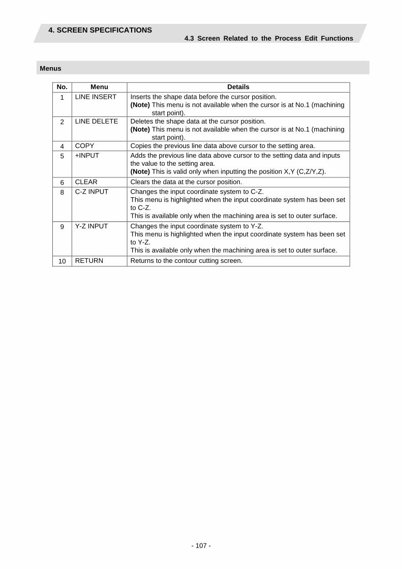
4. SCREEN SPECIFICATIONS 4.3 Screen Related to the Process Edit Functions
- 107 -
Menus
No. Menu Details 1 LINE INSERT Inserts the shape data before the cursor position.
(Note) This menu is not available when the cursor is at No.1 (machining start point).
2 LINE DELETE Deletes the shape data at the cursor position. (Note) This menu is not available when the cursor is at No.1 (machining
start point). 4 COPY Copies the previous line data above cursor to the setting area. 5 +INPUT Adds the previous line data above cursor to the setting data and inputs
the value to the setting area. (Note) This is valid only when inputting the position X,Y (C,Z/Y,Z).
6 CLEAR Clears the data at the cursor position. 8 C-Z INPUT
Changes the input coordinate system to C-Z. This menu is highlighted when the input coordinate system has been set to C-Z. This is available only when the machining area is set to outer surface.
9 Y-Z INPUT
Changes the input coordinate system to Y-Z. This menu is highlighted when the input coordinate system has been set to Y-Z. This is available only when the machining area is set to outer surface.
10 RETURN Returns to the contour cutting screen.
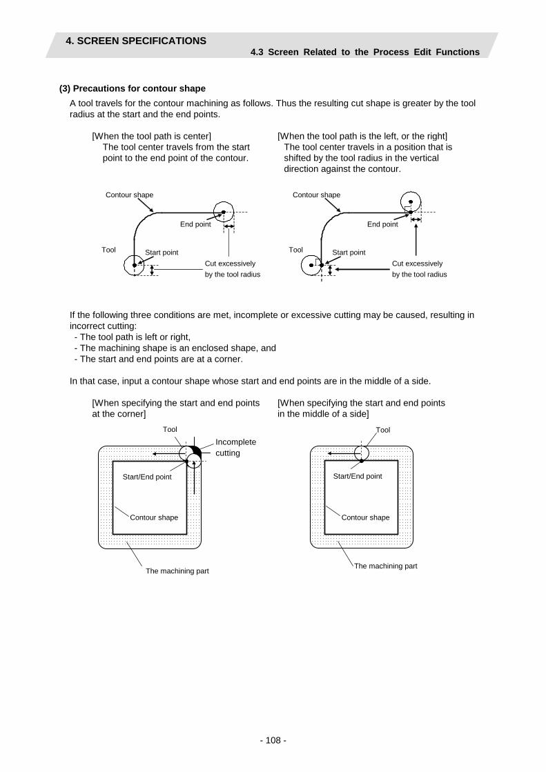
4. SCREEN SPECIFICATIONS 4.3 Screen Related to the Process Edit Functions
- 108 -
(3) Precautions for contour shape
A tool travels for the contour machining as follows. Thus the resulting cut shape is greater by the tool radius at the start and the end points.
[When the tool path is center] [When the tool path is the left, or the right] The tool center travels from the start point to the end point of the contour.
The tool center travels in a position that is shifted by the tool radius in the vertical direction against the contour.
End point
Start point
Contour shape
Cut excessively by the tool radius
Tool
End point
Start point
Contour shape
Cut excessively by the tool radius
Tool
If the following three conditions are met, incomplete or excessive cutting may be caused, resulting in incorrect cutting: - The tool path is left or right, - The machining shape is an enclosed shape, and - The start and end points are at a corner. In that case, input a contour shape whose start and end points are in the middle of a side.
[When specifying the start and end points at the corner]
[When specifying the start and end points in the middle of a side]
Incomplete cutting
The machining part
Contour shape
Start/End point
Tool
The machining part
Tool
Start/End point
Contour shape

4. SCREEN SPECIFICATIONS 4.3 Screen Related to the Process Edit Functions
- 109 -
4.3.16 Transfer Screen
The parameters for the transfer process between the main and sub spindles and those for the workpiece transfer from the sub spindle to the parts catcher are input on this screen. When there is a transfer process, the other processes are regarded as the transferred spindle side processes until another transfer process comes up.
Screen layout

4. SCREEN SPECIFICATIONS 4.3 Screen Related to the Process Edit Functions
- 110 -
Screen display items
No. Display item Details Setting range 1 TRANSFER
TYPE Select the transfer direction. 1: MAIN -> SUB (From main spindle to sub spindle) 2: SUB -> MAIN (From sub spindle to main spindle) 3: SYNC (Spindle synchronization)
(Note) When switching from the spindle synchronization to the main spindle, select "SUB -> MAIN", and when switching from the spindle synchronization to the sub spindle, select "MAIN -> SUB".
1 to 3 (Default: 1)
2 APPRCH POS Z AZ
Set the Z coordinate of the position in which the sub spindle approaches the main spindle at a rapid traverse rate for the transfer process. Set the position relative to the machine coordinate system.
-99999.999 to 99999.999 mm -9999.9999 to 9999.9999 inch
メイン主軸 サブ主軸
[1.メイン主軸→サブ主軸]
メイン主軸 サブ主軸 [2.サブ主軸→メイン主軸]
メイン主軸 サブ主軸
[3.主軸同期]
①
②
③
①
②
③
①
②
メイン主軸 サブ主軸
①
②
③
④
・ワーク引き抜き無しの場合(メイン主軸から同期した例)
・ワーク引き抜き有りの場合
[Main spindle -> sub spindle]
[Sub spindle -> main spindle]
Main spindle
Main spindle
Sub spindle
Sub spindle
Sub spindle Without workpiece pulling (example: synchronized from the main spindle)
With workpiece pulling Main spindle Sub spindle
[Spindle synchronization]
Main spindle Sub spindle
Main spindle

4. SCREEN SPECIFICATIONS 4.3 Screen Related to the Process Edit Functions
- 111 -
No. Display item Details Setting range 3 TRANSFER
POS Z TZ Set the Z coordinate of the transfer position relative to the machine coordinate system.
-99999.999 to 99999.999 mm -9999.9999 to 9999.9999 inch
4 TRANSFER FEED RATE
Set the movement feedrate from the approach position to the transfer position.
0.001 to 9999.999 mm/min 0.0001 to 999.9999 inch/min
5 TOOL WAITING POS
Select the waiting position of the tool for the transfer. 1: X REF, Z CL (X axis - reference position, Z axis -
tool turning clearance position) 2: XZ CL (X and Z axes - tool turning clearance
position) 3: XZ FIX POS (X and Z axes - tool fixed point return
position)
1 to 3
6 C-AXIS POSITIONING
When transferring, select whether to perform the C-axis positioning for the both spindles. 0: NONE 1: EXIST
0, 1 (Default: 0)
7 C-AXIS POS (MAIN SP)
Set the C-axis position of the main spindle when transferring. (Note) This is available only when selecting "1: EXIST" at
the C-AXIS POSITIONING.
-359.999 to 360.000°
8 C-AXIS POS (SUB SP)
Set the C-axis position of the sub spindle when transferring. (Note) This is available only when selecting "1: EXIST" at
the C-AXIS POSITIONING.
-359.999 to 360.000°
9 WORK PULLING
Select whether to perform the workpiece pulling. 0: NONE 1: EXIST (Note 1) This is available only when selecting "3: SYNC"
at the TRANSFER TYPE. (Note 2) This works only when the current machining
spindle is the main or the spindle synchronization.
0, 1 (Default: 0)
10 PULLING AMOUNT
Set the pulling amount of the workpiece. (Note) This is available only when selecting "1: EXIST" at
the WORK PULLING.
0.001 to 99999.999 mm 0.0001 to 9999.9999 inch
Menus
No. Menu Details 1 ← Turns the LIST VIEW area active. 10 SAVE Saves the changes in the process.
If illegal parameters are found in saving, an error will be displayed. When a parameter is incorrectly input, the cursor moves to that parameter position.

4. SCREEN SPECIFICATIONS 4.3 Screen Related to the Process Edit Functions
- 112 -
4.3.17 Cut Off Screen
The parameters for the cut off are input on this screen.
Screen layout
Screen display items
No. Display item Details Setting range 1
TOOL REG No.
Input the registration No. of the tool to be used for the cut off. Use the No. registered in the tool file. (Note) The tool for cutting off is used the grooving tools in
the tool file.
$1: 201 to 250 $2: 1201 to 1250
2 CORNER TYPE
Specify the corner type 0: NONE (no corners) 1: RIGHT (right corner) 2: LEFT (left corner)
0 to 2 (Default: 0)
3 CORNER Input the corner size. A positive value: corner R, a negative value: corner C
R
C
(Note) This is available only when selecting "1: RIGHT"
or "2: LEFT" at the CORNER TYPE.
-99999.999 to 99999.999 mm -9999.9999 to 9999.9999 inch
4 START POS X1
Set the start position X for the cut off machining (cut off start diameter).
0.001 to 99999.999 mm 0.0001 to 9999.9999 inch
5 END POS X2
Set the end position X for the cut off machining (cut off end diameter). (Note) Set the position including the excessive amount of
the machining.
-99999.999 to 99999.999 mm -9999.9999 to 9999.9999 inch

4. SCREEN SPECIFICATIONS 4.3 Screen Related to the Process Edit Functions
- 113 -
No. Display item Details Setting range 6 CUT OFF
POS Z Set the start position Z for the cut off machining. (Note) Set the position including the tool width.
-99999.999 to 99999.999 mm -9999.9999 to 9999.9999 inch
7 CUT AMOUNT
Input the cut amount. 0.001 to 99999.999 mm 0.0001 to 9999.9999 inch
8 SUB SP RETURN
Select whether to return the sub spindle to the original position after the cut off. (Note 1) This is available only when the parameter "1001
SUB SPINDLE SPEC" is "1: EXIST". (Note 2) When you select "1: EXIST" for this item, the
sub spindle is selected as the machining spindle after the cut off.
(Note 3) The machining spindle works only in "spindle synchronization", but does not work in the other cases.
0, 1 (Default: 0)
9 TOOL T No. Input the turret No. (or ATC No.) of the tool being set, as well as the compensation No. When tool registration No. is specified, tool No. registered in the tool file is automatically set.
0 to 99999999
10 TOOL WIDTH
Input the tool width of the respective tool. When tool registration No. is specified, tool width registered in the tool file is automatically set.
0.001 to 999.999 mm 0.0001 to 99.9999 inch
11 CUT SPEED V
Input the cutting speed. When tool registration No. is specified, cutting speed is automatically set based on the contents in the tool file and cutting condition file.
1 to 9999 m/min 1 to 9999 feet/min
12 FEED RATE F
Input the feedrate. When tool registration No. is specified, feedrate is automatically set based on the contents in the tool file and cutting condition file.
0.0001 to 999.9999 mm/rev 0.00001 to 99.99999 inch/rev
13 COOLANT M CODE
Input the tool coolant M code. When there is no coolant, input 999. When tool registration No. is specified, the coolant M code registered in the tool file is automatically set.
1 to 999
Menus
No. Menu Details 1 ← Turns the LIST VIEW area active. 8 CHECKER Displays the checker screen. Select this to check the set data. 10 SAVE Saves the changes in the process.
If illegal parameters are found in saving, an error will be displayed. When a parameter is incorrectly input, the cursor moves to that parameter position.
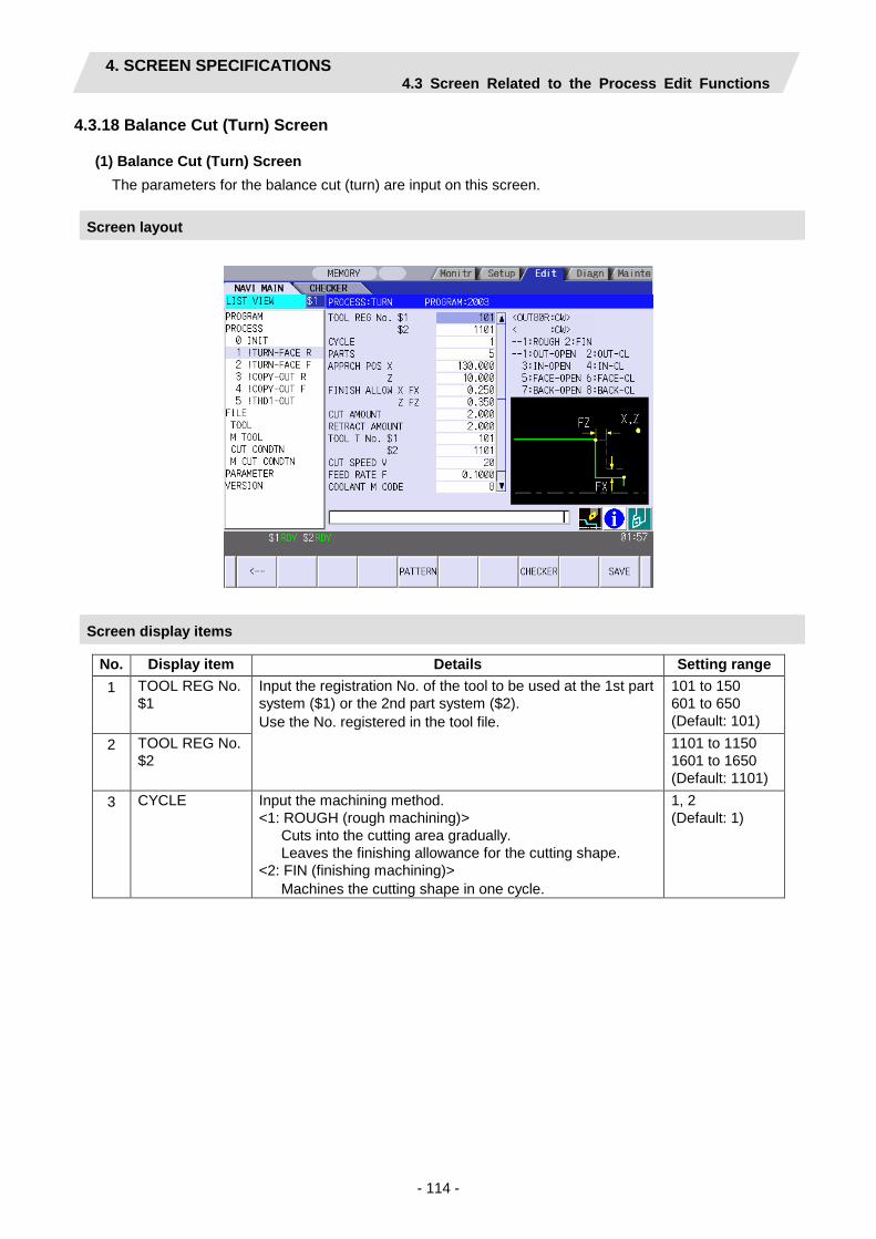
4. SCREEN SPECIFICATIONS 4.3 Screen Related to the Process Edit Functions
- 114 -
4.3.18 Balance Cut (Turn) Screen
(1) Balance Cut (Turn) Screen The parameters for the balance cut (turn) are input on this screen.
Screen layout
Screen display items
No. Display item Details Setting range 1 TOOL REG No.
$1 Input the registration No. of the tool to be used at the 1st part system ($1) or the 2nd part system ($2). Use the No. registered in the tool file.
101 to 150 601 to 650 (Default: 101)
2 TOOL REG No. $2
1101 to 1150 1601 to 1650 (Default: 1101)
3 CYCLE Input the machining method. <1: ROUGH (rough machining)> Cuts into the cutting area gradually. Leaves the finishing allowance for the cutting shape. <2: FIN (finishing machining)> Machines the cutting shape in one cycle.
1, 2 (Default: 1)

4. SCREEN SPECIFICATIONS 4.3 Screen Related to the Process Edit Functions
- 115 -
No. Display item Details Setting range 4 PARTS Input the machining area.
<1: OUT-OPEN> Machines the outer diameter area from the front face of workpiece.
<2: OUT-CL> Machines the outer diameter area from the halfway of workpiece.
<3: IN-OPEN> Machines the inner diameter area from the front face of workpiece.
<4: IN-CL> Machines inner area from the halfway of workpiece.
<5: FACE-OPEN> Machines the front face of workpiece.
<6: FACE-CL> Machines the front face from the halfway of workpiece.
<7: BACK-OPEN> Machines the back side of workpiece.
<8: BACK-CL> Machines the back side of workpiece from the halfway of workpiece.
(Note 1) BACK-OPEN and BACK-CL are available only when the parameter "1001 SUB SPINDLE SPEC" is "1: EXIST".
1 to 8 (Default: 1)
5 APPRCH POS X
Input the approach point. After machining, the tool returns to the approach point.
-99999.999 to 99999.999 mm
6 APPRCH POS Z
-9999.9999 to 9999.9999 inch
7 FINISH ALLOW X FX
Input the finishing allowance for the rough machining. Input both FX and FZ with radius value.
0.000 to 99999.999 mm
8 FINISH ALLOW Z FZ
0.0000 to 9999.9999 inch
9 CUT AMOUNT Input the cut amount for the rough machining. 0.001 to 99.999 mm
10 RETRACT AMOUNT
Input the retract amount for the rough machining. 0.0001 to 9.9999 inch
11 TOOL T No. $1
Input the turret No. (or ATC No.) of the tool being set in the 1st part system or the 2nd part system, as well as the compensation No. When the tool registration No. $1 or $2 is specified, a tool No. registered in the tool file is automatically set.
0 to 99999999
12 TOOL T No. $2
0 to 99999999
13 CUT SPEED V
Input the cutting speed common to both part systems. When tool registration No. $1 is specified, cutting speed is automatically set based on the contents in the tool file and cutting condition file. The cut speed of the 1st part system is set.
1 to 9999 m/min 1 to 9999 feet/min
14 FEED RATE F Input the feedrate common to both part systems. When tool registration No. $1 is specified, feedrate is automatically set based on the contents in the tool file and cutting condition file. The feed rate of the 1st part system is set.
0.0001 to 999.9999 mm/rev 0.00001 to 99.99999 inch/rev
15 COOLANT M CODE
Input the tool coolant M code. When there is no coolant, input 999. When tool registration No. is specified, the coolant M code registered in the tool file is automatically set. The coolant M code of the1st part system is set.
1 to 999

4. SCREEN SPECIFICATIONS 4.3 Screen Related to the Process Edit Functions
- 116 -
Menus
No. Menu Details 1 ← Turns the LIST VIEW area active. 5 PATTERN Machining pattern selection screen is displayed. 8 CHECKER Displays the checker screen. Select this to check the set data. 10 SAVE Saves the changes in the process.
If illegal parameters are found in saving, an error will be displayed. When a parameter is incorrectly input, the cursor moves to that parameter position. If illegal parameters are input in the pattern input screen, the screen name and error will be displayed.
(2) Balance Cut (Turn) pattern Screen
This screen is for entering the cutting shapes of balance cut (turn) process. The items to set through this screen are the same as of the turning pattern screen.
Screen layout
Screen display items
Refer to the section "4.3.6 Turning Screen (2) Turning pattern screen".
Menus
Refer to the section "4.3.6 Turning Screen (2) Turning pattern screen".

4. SCREEN SPECIFICATIONS 4.3 Screen Related to the Process Edit Functions
- 117 -
4.3.19 Balance Cut (Copy) Screen
(1) Balance Cut (Copy) Screen The parameters for the balance cut (copy) are input on this screen.
Screen layout
Screen display items
No. Display item Details Setting range 1 TOOL REG No.
$1 Input the registration No. of the tool to be used at the 1st part system ($1) or the 2nd part system ($2). Use the No. registered in the tool file.
101 to 150 601 to 650 (Default: 101)
2 TOOL REG No. $2
1101 to 1150 1601 to 1650 (Default: 1101)
3 CYCLE Input the machining method. <1: ROUGH (rough machining)> Cuts into the cutting area gradually. Leaves the finishing allowance for the cutting shape. <2: FIN (finishing machining)> Machines the cutting shape in one cycle.
1, 2 (Default: 1)
4 PARTS Input the machining area. <1:OUT (outer diameter)> Machine the outer diameter section of the workpiece. <2: IN (inner diameter)> Machine the inner diameter section of the workpiece.
1 to 2 (Default: 1)
5 APPRCH POS X
Input the approach point. After machining, the tool returns to the approach point.
-99999.999 to 99999.999 mm
6 APPRCH POS Z
-9999.9999 to 9999.9999 inch
7 MACH ALLOW X LX
Input the allowance in X axis direction with the radius value for the rough machining.
0.001 to 99999.999 mm
8 MACH ALLOW Z LZ
Input the allowance in Z axis direction for the rough machining.
0.0001 to 9999.9999 inch

4. SCREEN SPECIFICATIONS 4.3 Screen Related to the Process Edit Functions
- 118 -
No. Display item Details Setting range 9 FINISH ALLOW
X FX Input the finishing allowance for the rough machining. Input both FX and FZ with radius value.
0.000 to 99999.999 mm
10 FINISH ALLOW Z FZ
0.0000 to 9999.9999 inch
11 NUM OF CUTS Input the number of cuts for the rough machining. 1 to 99 12 TOOL T No.
$1 Input the turret No. (or ATC No.) of the tool being set in the 1st part system or the 2nd part system, as well as the compensation No. When the tool registration No. $1 or $2 is specified, a tool No. registered in the tool file is automatically set.
0 to 99999999
13 TOOL T No. $2
0 to 99999999
14 CUT SPEED V
Input the cutting speed common to both part systems. When tool registration No. $1 is specified, cutting speed is automatically set based on the contents in the tool file and cutting condition file. The cut speed of the 1st part system is set.
1 to 9999 m/min 1 to 9999 feet/min
15 FEED RATE F Input the feedrate common to both part systems. When tool registration No. $1 is specified, feedrate is automatically set based on the contents in the tool file and cutting condition file. The feed rate of the 1st part system is set.
0.0001 to 999.9999 mm/rev 0.00001 to 99.99999 inch/rev
16 COOLANT M CODE
Input the tool coolant M code. When there is no coolant, input 999. When tool registration No. is specified, the coolant M code registered in the tool file is automatically set. The coolant M code of the1st part system is set.
1 to 999
Menus
No. Menu Details 1 ← Turns the LIST VIEW area active. 5 PATTERN Machining pattern selection screen is displayed. 8 CHECKER Displays the checker screen. Select this to check the set data. 10 SAVE Saves the changes in the process.
If illegal parameters are found in saving, an error will be displayed. When a parameter is incorrectly input, the cursor moves to that parameter position. If illegal parameters are input in the pattern input screen, the screen name and error will be displayed.

4. SCREEN SPECIFICATIONS 4.3 Screen Related to the Process Edit Functions
- 119 -
(2) Balance Cut (Copy) Pattern Screen This screen is for entering the cutting shapes of balance cut (copy) process. The items to set through this screen are the same as of the copy cutting pattern screen.
Screen layout
Screen display items
Refer to the section "4.3.7 Copy cutting screen (2) Copy cutting pattern screen".
Menus
Refer to the section "4.3.7 Copy cutting screen (2) Copy cutting pattern screen".
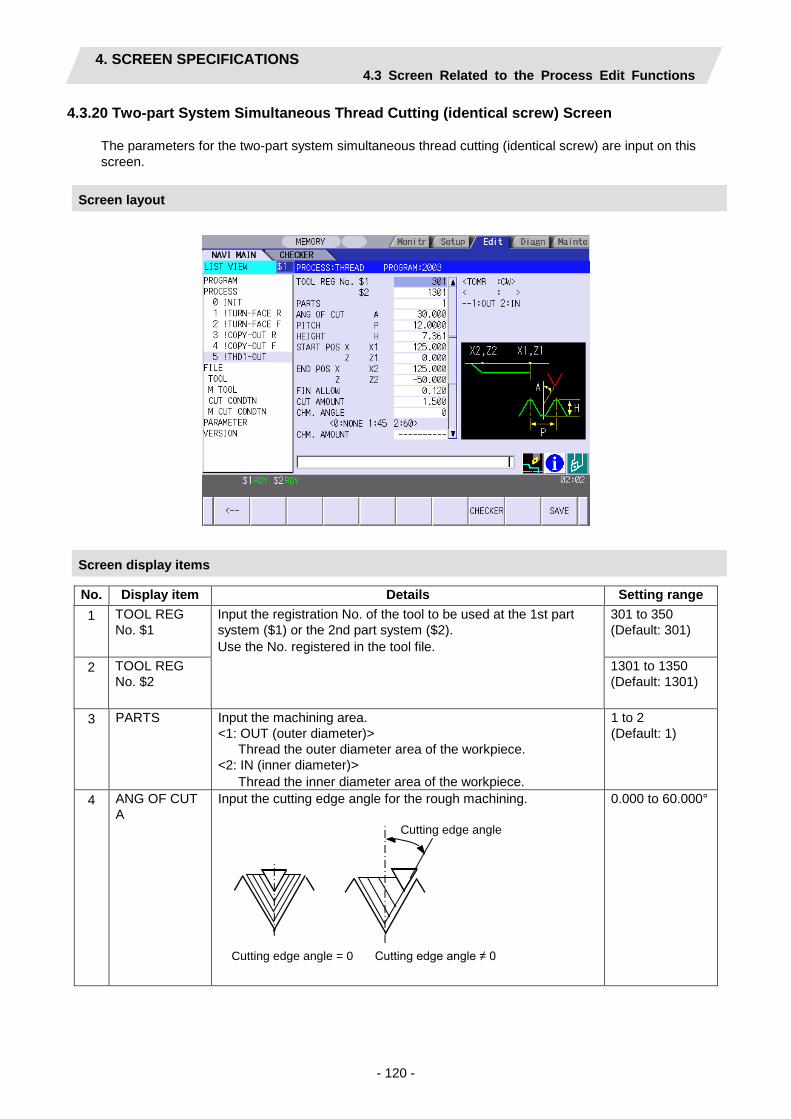
4. SCREEN SPECIFICATIONS 4.3 Screen Related to the Process Edit Functions
- 120 -
4.3.20 Two-part System Simultaneous Thread Cutting (identical screw) Screen
The parameters for the two-part system simultaneous thread cutting (identical screw) are input on this screen.
Screen layout
Screen display items
No. Display item Details Setting range 1 TOOL REG
No. $1 Input the registration No. of the tool to be used at the 1st part system ($1) or the 2nd part system ($2). Use the No. registered in the tool file.
301 to 350 (Default: 301)
2 TOOL REG No. $2
1301 to 1350 (Default: 1301)
3 PARTS Input the machining area. <1: OUT (outer diameter)> Thread the outer diameter area of the workpiece. <2: IN (inner diameter)> Thread the inner diameter area of the workpiece.
1 to 2 (Default: 1)
4 ANG OF CUT A
Input the cutting edge angle for the rough machining.
0.000 to 60.000°
切り込み角度
切り込み角度 = 0 切り込み角度 ≠ 0
Cutting edge angle
Cutting edge angle = 0 Cutting edge angle ≠ 0
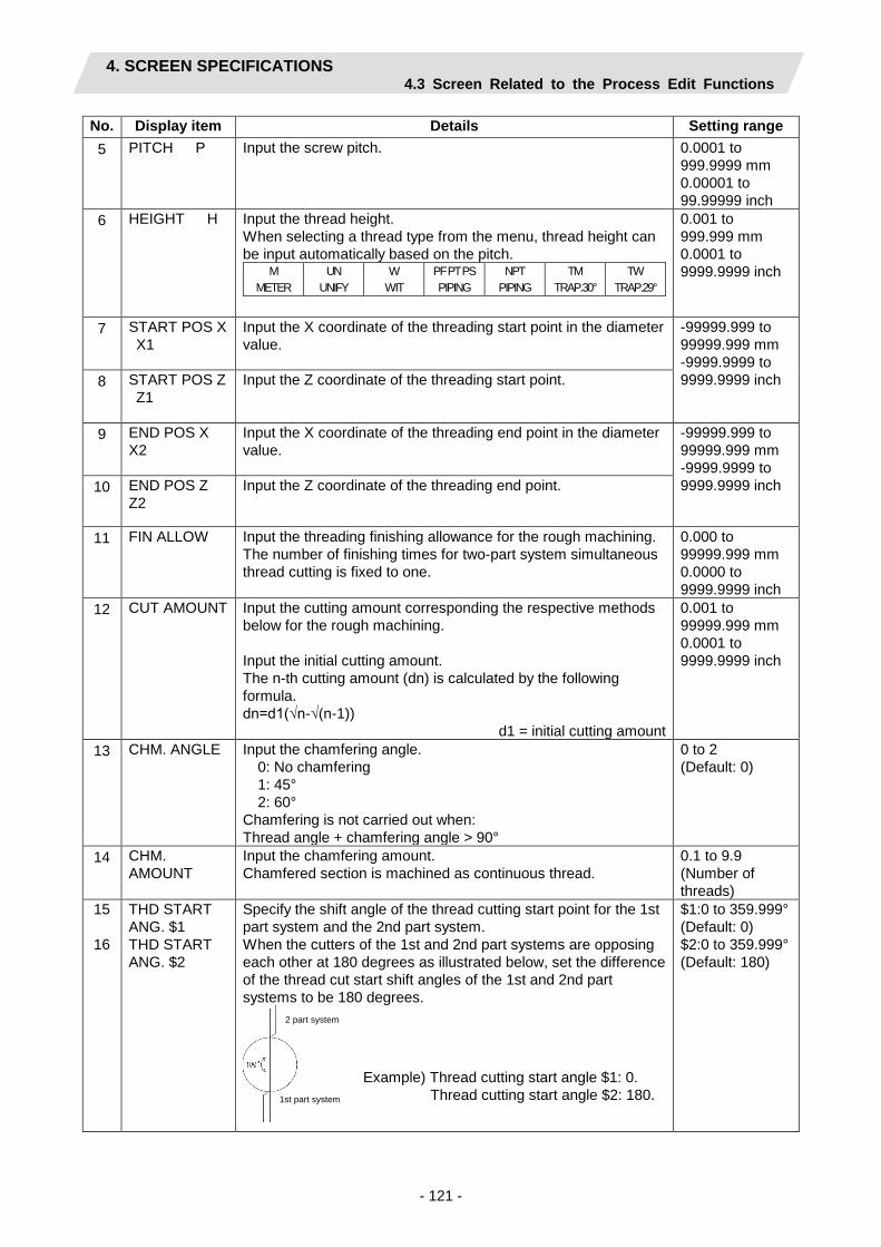
4. SCREEN SPECIFICATIONS 4.3 Screen Related to the Process Edit Functions
- 121 -
No. Display item Details Setting range 5 PITCH P Input the screw pitch. 0.0001 to
999.9999 mm 0.00001 to 99.99999 inch
6 HEIGHT H Input the thread height. When selecting a thread type from the menu, thread height can be input automatically based on the pitch.
M METER
UN UNIFY
W WIT
PF PT PS PIPING
NPT PIPING
TM TRAP.30°
TW TRAP.29°
0.001 to 999.999 mm 0.0001 to 9999.9999 inch
7 START POS X X1
Input the X coordinate of the threading start point in the diameter value.
-99999.999 to 99999.999 mm -9999.9999 to 9999.9999 inch 8 START POS Z
Z1 Input the Z coordinate of the threading start point.
9 END POS X X2
Input the X coordinate of the threading end point in the diameter value.
-99999.999 to 99999.999 mm -9999.9999 to 9999.9999 inch 10 END POS Z
Z2 Input the Z coordinate of the threading end point.
11 FIN ALLOW Input the threading finishing allowance for the rough machining. The number of finishing times for two-part system simultaneous thread cutting is fixed to one.
0.000 to 99999.999 mm 0.0000 to 9999.9999 inch
12 CUT AMOUNT Input the cutting amount corresponding the respective methods below for the rough machining. Input the initial cutting amount. The n-th cutting amount (dn) is calculated by the following formula. dn=d1(√n-√(n-1))
d1 = initial cutting amount
0.001 to 99999.999 mm 0.0001 to 9999.9999 inch
13 CHM. ANGLE Input the chamfering angle. 0: No chamfering 1: 45° 2: 60° Chamfering is not carried out when: Thread angle + chamfering angle > 90°
0 to 2 (Default: 0)
14 CHM. AMOUNT
Input the chamfering amount. Chamfered section is machined as continuous thread.
0.1 to 9.9 (Number of threads)
15
16
THD START ANG. $1 THD START ANG. $2
Specify the shift angle of the thread cutting start point for the 1st part system and the 2nd part system. When the cutters of the 1st and 2nd part systems are opposing each other at 180 degrees as illustrated below, set the difference of the thread cut start shift angles of the 1st and 2nd part systems to be 180 degrees.
$1:0 to 359.999° (Default: 0) $2:0 to 359.999° (Default: 180)
1st part system
2 part system
Example) Thread cutting start angle $1: 0. Thread cutting start angle $2: 180.

4. SCREEN SPECIFICATIONS 4.3 Screen Related to the Process Edit Functions
- 122 -
No. Display item Details Setting range 17
18
TOOL T No. $1 TOOL T No. $2
Input the turret No. (or ATC No.) of the tool being set in the 1st part system or the 2nd part system, as well as the compensation No. When the tool registration No. $1 or $2 is specified, a tool No. registered in the tool file is automatically set.
0 to 99999999
19 CUT SPEED V
Input the cutting speed common to both part systems. When tool registration No. $1 is specified, cutting speed is automatically set based on the contents in the tool file and cutting condition file. The cut speed of the 1st part system is set.
1 to 9999 m/min 1 to 9999 feet/min
20 COOLANT M CODE
Input the tool coolant M code. When there is no coolant, input 999. When tool registration No. is specified, the coolant M code registered in the tool file is automatically set. The coolant M code of the1st part system is set.
1 to 999
Menus
No. Menu Details 1 ← Turns the LIST VIEW area active. 8 CHECKER Displays the checker screen. Select this to check the set data. 10 SAVE Saves the changes in the process.
If illegal parameters are found in saving, an error will be displayed. When a parameter is incorrectly input, the cursor moves to that parameter position.

4. SCREEN SPECIFICATIONS 4.4 Screens Related to File Editing
- 123 -
4.4 Screens Related to File Editing
4.4.1 Tool File Screen for Turning
The tool data for turning is registered on this screen. When [TOOL] is selected in the LIST VIEW area, this screen is displayed. The tool data for turning includes the followings. Use the menu key to select one.
• TURNING TOOLS • GROOVING TOOLS • THREADING TOOLS • DRILLS • TAPS • BUTTON TOOLS
Screen layout
(Note) Menu for the currently selected tool is highlighted.
(2)
(1)
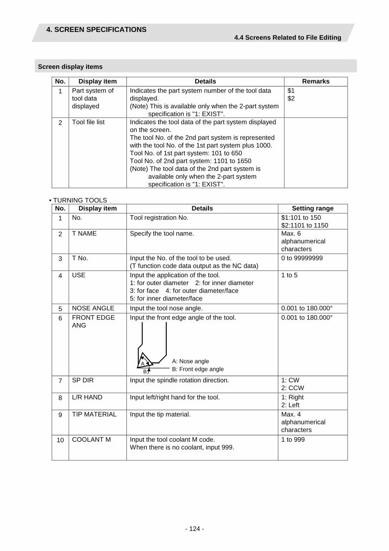
4. SCREEN SPECIFICATIONS 4.4 Screens Related to File Editing
- 124 -
Screen display items
No. Display item Details Remarks 1 Part system of
tool data displayed
Indicates the part system number of the tool data displayed. (Note) This is available only when the 2-part system
specification is "1: EXIST".
$1 $2
2 Tool file list Indicates the tool data of the part system displayed on the screen. The tool No. of the 2nd part system is represented with the tool No. of the 1st part system plus 1000. Tool No. of 1st part system: 101 to 650 Tool No. of 2nd part system: 1101 to 1650 (Note) The tool data of the 2nd part system is
available only when the 2-part system specification is "1: EXIST".
• TURNING TOOLS
No. Display item Details Setting range 1 No. Tool registration No. $1:101 to 150
$2:1101 to 1150 2 T NAME Specify the tool name. Max. 6
alphanumerical characters
3 T No. Input the No. of the tool to be used. (T function code data output as the NC data)
0 to 99999999
4 USE Input the application of the tool. 1: for outer diameter 2: for inner diameter 3: for face 4: for outer diameter/face 5: for inner diameter/face
1 to 5
5 NOSE ANGLE Input the tool nose angle. 0.001 to 180.000° 6 FRONT EDGE
ANG Input the front edge angle of the tool.
A B
A: Nose angle B: Front edge angle
0.001 to 180.000°
7 SP DIR Input the spindle rotation direction. 1: CW 2: CCW
8 L/R HAND Input left/right hand for the tool. 1: Right 2: Left
9 TIP MATERIAL Input the tip material. Max. 4 alphanumerical characters
10 COOLANT M Input the tool coolant M code. When there is no coolant, input 999.
1 to 999

4. SCREEN SPECIFICATIONS 4.4 Screens Related to File Editing
- 125 -
• GROOVING TOOLS No. Display item Details Setting range 1 No. Tool registration No. $1:201 to 250
$2:1201 to 1250 2 T NAME Input the tool name. Max. 6 alphanumerical
characters 3 T No. Input the No. of the tool to be used.
(T function code data output as the NC data) 0 to 99999999
4 USE Input the application of the tool. 1: for outer diameter 2: for inner diameter 3: for face
1 to 3
5 TOOL WIDTH Input the tip width.
Tool width
0.001 to 999.999mm 0.0001 to 99.9999inch
6 SP DIR Input the spindle rotation direction. 1: CW 2: CCW
7 L/R HAND Input left/right hand for the tool. 1: Right 2: Left
8 TIP MATERIAL Input the tip material. Max. 4 alphanumerical characters
9 COOLANT M Input the tool coolant M code. When there is no coolant, input 999.
1 to 999
• THREADING TOOLS
No. Display item Details Setting range 1 No. Tool registration No. $1:301 to 350
$2:1301 to 1350 2 T NAME Input the tool name. Max. 6 alphanumerical
characters 3 T No. Input the No. of the tool to be used.
(T function code data output as the NC data) 0 to 99999999
4 USE Input the application of the tool. 1: for outer diameter 2: for inner diameter 3: for face
1 to 3
5 NOSE ANGLE Input the tool nose angle.
A: Nose angle A
0.001 to 180.000°
6 SP DIR Input the spindle rotation direction. 1: CW 2: CCW
7 L/R HAND Input left/right hand for the tool. 1: Right 2: Left
8 TIP MATERIAL Input the tip material. Max. 4 alphanumerical characters
9 COOLANT M Input the tool coolant M code. When there is no coolant, input 999.
1 to 999

4. SCREEN SPECIFICATIONS 4.4 Screens Related to File Editing
- 126 -
• DRILLS
No. Display item Details Setting range 1 No. Tool registration No. $1:401 to 450
$2:1401 to 1450 2 T NAME Input the tool name. Max. 6 alphanumerical
characters 3 T No. Input the No. of the tool to be used.
(T function code data output as the NC data) 0 to 99999999
4 DIA Input the tool radius. 0.001 to 999.999mm 0.0001 to 99.9999inch
5 NOSE ANGLE Input the tool nose angle. 0.001 to 180.000° 6 SP DIR Input the spindle rotation direction. 1: CW
2: CCW 7 TIP MATERIAL Input the tip material. Max. 4 alphanumerical
characters 8 COOLANT M Input the tool coolant M code.
When there is no coolant, input 999. 1 to 999
• TAPS
No. Display item Details Setting range 1 No. Tool registration No. $1:501 to 550
$2:1501 to 1550 2 T NAME Input the tool name. Max. 6 alphanumerical
characters 3 T No. Input the No. of the tool to be used.
(T function code data output as the NC data) 0 to 99999999
4 DIA Input the tool radius. 0.001 to 999.999mm 0.0001 to 99.9999inch
5 NOSE ANGLE Input the tool nose angle. 0.001 to 180.000° 6 PITCH Input the pitch. 0.0001 to
999.9999mm/rev 0.00001 to 99.99999inch/rev
7 SP DIR Input the spindle rotation direction. 1:CW 2:CCW
8 TIP MATERIAL Input the tip material. Max. 4 alphanumerical characters
9 COOLANT M Input the tool coolant M code. When there is no coolant, input 999.
1 to 999

4. SCREEN SPECIFICATIONS 4.4 Screens Related to File Editing
- 127 -
• BUTTON TOOLS
No. Display item Details Setting range 1 No. Tool registration No. $1:601 to 650
$2:1601 to 1650 2 T NAME Input the tool name. Max. 6 alphanumerical
characters 3 T No. Input the No. of the tool to be used.
(T function code data output as the NC data) 1 to 999999
4 USE Input the application of the tool. 1: for outer diameter 3. for face
1, 3
5 TIP DIA Input the tip diameter. 0.001 to 999.999mm 0.001 to 99.9999inch
6 SP DIR Input the spindle rotation direction. 1: CW 2: CCW
7 L/R HAND Input left/right hand for the tool. 1: Right 2: Left
8 TIP MATERIAL Input the tip material. Max. 4 alphanumerical characters
9 COOLANT M Input the tool coolant M code. When there is no coolant, input 999.
1 to 999
Menus
No. Menu Details 1 ← Turns the LIST VIEW area active. 2 TURN Displays the turning tool input screen. 3 GROOV Displays the grooving tool input screen. 4 THREAD Displays the threading tool input screen. 5 DRILL Displays the drilling input screen. 6 TAP Displays the tapping input screen. 7 BUTTON Displays the button tool input screen. 10 SAVE Saves the changes in the tool file. 12 COLUMN INSERT Inserts the tool data (one column) in the column before the cursor. 13 COLUMN DELETE Deletes the tool data (one column) in the column of the cursor position. 15 $<->$ Switches the part system of the tool data displayed. Pressing this menu
key, the tool data of the next part system is displayed on the tool file list. The part system switches in this order of $1, $2 and $1. After the switch, the cursor moves to the retained position. The cursor position is retained while the tool data of the same process is displayed. (Note) This menu is available only when the 2-part system specification
is "1: EXIST". 17 COPY Copies the tool data contents of the cursor position (one column). 18 PASTE Pastes the copied tool data contents (one column) in the column of the
cursor position. 19 CLEAR Clears the tool data (one column) in the column of the cursor position.
(Note) The cursor position is retained until the following actions are taken. - Until activating the LIST VIEW (until pressing the menu [<-] or clicking the LIST VIEW.)

4. SCREEN SPECIFICATIONS 4.4 Screens Related to File Editing
- 128 -
4.4.2 Tool File Screen for Milling
The tool data for milling is registered on this screen. When [M TOOL] is selected in the LIST VIEW area, this screen is displayed.
Screen layout
Screen display items
No. Display item Details Setting range 1 Part system of tool
data displayed Indicates the part system number of the tool data displayed. (Note) This is available only when the 2-part system specification is "1: EXIST".
$1 $2
2 Tool file list Indicates the tool data of the part system displayed on the screen. The tool No. of the 2nd part system is represented with the tool No. of the 1st part system plus 1000. Tool No. of 1st part system: 101 to 650 Tool No. of 2nd part system: 1101 to 1650 (Note) The tool data of the 2nd part system is available only when the 2-part system specification is "1: EXIST".
3 No. Tool registration No. $1:701 to 799 $2:1701 to 1799
4 T NAME Input the tool name. Max. 6 alphanumeric characters
5 T NO. Input the No. of the tool to be used. (T function code data output as the NC data)
0 to 99999999
6 DIA Input the tool diameter. 0.001 to 999.999mm 0.0001 to 99.9999 inch
7 NOSE ANGLE Input the tool nose angle. 0.001 to 180.000°
(1)
(2)

4. SCREEN SPECIFICATIONS 4.4 Screens Related to File Editing
- 129 -
No. Display item Details Setting range 8 F/PITCH Input the feedrate of the tool.
Input the pitch when performing tapping. 0.0001 to 999.9999 mm/rev 0.00001 to 99.99999 inch/rev
9 SP DIR Input the spindle rotation direction. 1:CW 2:CCW
10 TIP MATERIAL Input the tip material.
Max. 4 alphanumeric characters
11 COOLANT M Input the tool coolant M code. When there is no coolant, input 999.
1 to 999
Menus
No. Menu Details 1 ← Turns the LIST VIEW area active. 2 COLUMN INSERT Inserts the tool data (one column) in the column before the cursor. 3 COLUMN DELETE Deletes the tool data (one column) in the column of the cursor position. 5 $<->$ Switches the part system of the tool data displayed. Pressing this menu
key, the tool data of the next part system is displayed on the tool file list. The part system switches in this order of $1, $2 and $1. After the switch, the cursor moves to the retained position. The cursor position is retained while the tool data of the same process is displayed. (Note) This menu is available only when the 2-part system specification is "1: EXIST".
7 COPY Copies the tool data contents of the cursor position (one column). 8 PASTE Pastes the copied tool data contents (one column) in the column of the
cursor position. 9 CLEAR Clears the tool data (one column) in the column of the cursor position. 10 SAVE Saves the changes in the tool file.
(Note) The cursor position is retained until the following actions are taken. - Until activating the LIST VIEW (until pressing the menu [<-] or clicking the LIST VIEW

4. SCREEN SPECIFICATIONS 4.4 Screens Related to File Editing
- 130 -
Operation method ([COLUMN INSERT])
(1) Display the tool file screen and move the cursor to the position where the column is to be inserted.
(2) Press the [COLUMN INSERT] menu key.
The blank column is inserted in the cursor position.

4. SCREEN SPECIFICATIONS 4.4 Screens Related to File Editing
- 131 -
Operation method ([COLUMN DELETE])
(1) Display the tool file screen and move the cursor to the position where the column is to be deleted.
(2) Press the [COLUMN DELETE] menu key.
The column to be deleted is highlighted and the confirmation message appears.
(3) Press the [Y] key.
The data in the cursor position is deleted.
(Note) After the deletion, the data will be aligned.
Press the [N] key in order not to erase the column.
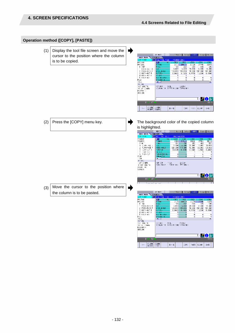
4. SCREEN SPECIFICATIONS 4.4 Screens Related to File Editing
- 132 -
Operation method ([COPY], [PASTE])
(1) Display the tool file screen and move the cursor to the position where the column is to be copied.
(2) Press the [COPY] menu key.
The background color of the copied column is highlighted.
(3) Move the cursor to the position where the column is to be pasted.

4. SCREEN SPECIFICATIONS 4.4 Screens Related to File Editing
- 133 -
(4) Press the [PASTE] menu key.
The confirmation message appears.
(5) Press the [Y] key.
The data of the copied column is written to the cursor position.
Press the [N] key in order not to paste the column.
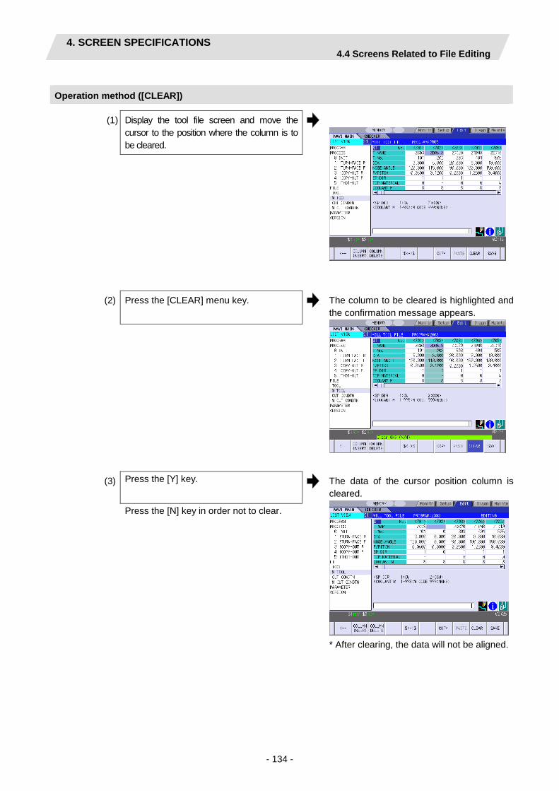
4. SCREEN SPECIFICATIONS 4.4 Screens Related to File Editing
- 134 -
Operation method ([CLEAR])
(1) Display the tool file screen and move the cursor to the position where the column is to be cleared.
(2) Press the [CLEAR] menu key. The column to be cleared is highlighted and the confirmation message appears.
(3) Press the [Y] key. The data of the cursor position column is cleared.
* After clearing, the data will not be aligned.
Press the [N] key in order not to clear.

4. SCREEN SPECIFICATIONS 4.4 Screens Related to File Editing
- 135 -
4.4.3 Cutting Condition File Screen for Turning
The cutting conditions (cutting speed, feedrate) of each process are registered, corresponding to each tip material type. Also, the cutting conditions (speed rate) of each process are registered, corresponding to each workpiece material type. When [CUT CONDTN] is selected in the LIST VIEW area, this screen is displayed.
Screen layout
(Note) Menu for the currently selected cutting condition is highlighted.

4. SCREEN SPECIFICATIONS 4.4 Screens Related to File Editing
- 136 -
Screen display items
• Cutting condition file (Tip material) No. Display item Details Setting range 1 No. Tip registration No. 1 to 8 2 TIP MATL Input the name that represents the tip material. Max. 4
alphanumeric characters
3 TURN R
V Input the cutting speed for the rough turning machining.
Cutting speed: 1.00 to 9999.00m/min 1.00 to 9999.00feet/min Feedrate: 0.0001 to 999.9999 mm/rev 0.00001 to 99.99999 inch/rev
4 F Input the feedrate for the rough turning machining. 5 TURN F
V Input the cutting speed for the finishing turning
machining. 6 F Input the feedrate for the finishing turning
machining. 7 GRV R
V Input the cutting speed for the rough grooving
machining. 8 F Input the feedrate for the rough grooving machining. 9 GRV F
V Input the cutting speed for the finishing grooving
machining. 10 F Input the feedrate for the finishing grooving
machining. 11 THR V Input the cutting speed for the threading machining. 12 DRILL V Input the cutting speed for the drilling machining. 13 F Input the feedrate for the drilling machining. 14 TAP V Input the cutting speed for the tapping machining.

4. SCREEN SPECIFICATIONS 4.4 Screens Related to File Editing
- 137 -
• Cutting condition file (Workpiece material)
No. Display item Details Setting range 1 No. Workpiece registration No. 1 to 8 2 WORK MATL Input the name that represents the workpiece
material. Max. 5 alphanumeric characters
3 TURN R
V Input the rate (%) of the workpiece material in respect to the cutting speed during rough turning machining.
1 to 200%
4 F Input the rate (%) of the workpiece material in respect to the feedrate during rough turning machining.
5 TURN F
V Input the rate (%) of the workpiece material in respect to the cutting speed during finishing turning machining.
6 F Input the rate (%) of the workpiece material in respect to the feedrate during finishing turning machining.
7 GRV R
V Input the rate (%) of the workpiece material in respect to the cutting speed during rough grooving machining.
8 F Input the rate (%) of the workpiece material in respect to the feedrate during rough grooving machining.
9 GRV F
V Input the rate (%) of the workpiece material in respect to the cutting speed during finishing grooving machining.
10 F Input the rate (%) of the workpiece material in respect to the feedrate during finishing grooving machining.
11 THR V Input the rate (%) of the workpiece material in respect to the cutting speed during threading machining.
12 DRILL V Input the rate (%) of the workpiece material in respect to the cutting speed during drilling machining.
13 F Input the rate (%) of the workpiece material in respect to the feedrate during drilling machining.
14 TAP V Input the rate (%) of the workpiece material in respect to the cutting speed during tapping machining.

4. SCREEN SPECIFICATIONS 4.4 Screens Related to File Editing
- 138 -
Menus
No. Menu Details 1 ← Turns the LIST VIEW area active. 2 TIP MATL Displays the cutting condition file (Tip material) screen. 3 WORK MATL Displays the cutting condition file (Workpiece material) screen. 10 SAVE Saves the changes in the cutting condition file.
CAUTION
When either "TOOL REG No." or "CYCLE" is input in each machining process screen, the cutting speed and feedrate are automatically determined using the data in the tool file screen and the cutting condition file screen. Note that the cutting speed and feedrate of each process determined once will not be changed by changing the data in the tool file screen and the cutting condition file screen.

4. SCREEN SPECIFICATIONS 4.4 Screens Related to File Editing
- 139 -
4.4.4 Cutting Condition File Screen for Milling
The cutting conditions (cutting speed, feedrate) of each process are registered, corresponding to each tip material type for milling. Also, the cutting conditions (speed rate) of each process are registered, corresponding to each workpiece material type. When [M CUT CONDTN] is selected in the LIST VIEW area, this screen is displayed.
Screen layout
Screen display items
• Cutting condition file (Tip material) No. Display item Details Setting range 1 No. Tip registration No. (1 to 8) - 2 TIP MATL Input the name that represents the tip material. Max. 4 alphanumeric
characters 3 DRILL V Input the cutting speed for the drilling machining. Cutting speed:
1.00 to 9999.00 m/min 1.00 to 9999.00 feet/min
4 TAP V Input the cutting speed for the tapping machining. 5 BORE V Input the cutting speed for the boring machining. 6 END ML R V Input the cutting speed for the rough keyway/contour
machining. 7 END ML F V Input the cutting speed for the finishing
keyway/contour machining.
(Note) Menu for the currently selected cutting condition is highlighted.

4. SCREEN SPECIFICATIONS 4.4 Screens Related to File Editing
- 140 -
• Cutting condition file (Workpiece material)
No. Display item Details Setting range 1 No. Workpiece registration No. (1~8) - 2 WORK MATL Input the name that represents the workpiece material.
The workpiece material name input on the cutting condition file screen (for turning) is displayed.
-
3 DRILL V Input the rate (%) of the workpiece material in respect to the cutting speed during drilling machining.
1 to 200%
4 F Input the rate (%) of the workpiece material in respect to the feedrate during drilling machining.
5 TAP V Input the rate (%) of the workpiece material in respect to the cutting speed during tapping machining.
6 BORE V Input the rate (%) of the workpiece material in respect to the cutting speed during boring machining.
7 F Input the rate (%) of the workpiece material in respect to the feedrate during boring machining.
8 END ML R V Input the rate (%) of the workpiece material in respect to the cutting speed during rough keyway/contour machining.
9 F Input the rate (%) of the workpiece material in respect to the feedrate during rough keyway/contour machining.
10 END ML F V Input the rate (%) of the workpiece material in respect to the cutting speed during finishing keyway/contour machining.
11 F Input the rate (%) of the workpiece material in respect to the feedrate during finishing keyway/contour machining.
Menus
No. Menu Details 1 ← Turns the LIST VIEW area active. 2 TIP MATL Displays the cutting condition file (Tip material) screen for milling. 3 WORK MATL Displays the cutting condition file (Workpiece material) screen for
milling. 10 SAVE Saves the changes in the cutting condition file.
CAUTION
When either "TOOL REG No." or "CYCLE" is input in each machining process screen, the cutting speed and feedrate are automatically determined using the data in the tool file screen and the cutting condition file screen. Note that the cutting speed and feedrate of each process determined once will not be changed by changing the data in the tool file screen and the cutting condition file screen.

4. SCREEN SPECIFICATIONS 4.5 Screen Related to the Parameters
- 141 -
4.5 Screen Related to the Parameters
4.5.1 Parameter Screen
The parameter screen, on which the parameters for the machining program are entered, is provided for the turning and the milling machining. When [PARAMETER] is selected in the LIST VIEW area, this screen is displayed.
Screen layout
- Parameter for turning
- Parameter for milling

4. SCREEN SPECIFICATIONS 4.5 Screen Related to the Parameters
- 142 -
- Parameter for ASSIST
- Parameter for 2SYSTEM

4. SCREEN SPECIFICATIONS 4.5 Screen Related to the Parameters
- 143 -
Screen display items
• Parameters for turning No. Display item Details Setting range 101 M1 OUTPUT Specify whether to output the M1 code before tool
indexing command. 0: Not output 1: Output
0,1
102 SPDL CLAMP SPEED
Input the maximum spindle clamp speed of a machining program.
1 to 99999 rev/min
103 TOOL TURNING CL X
This is a constant to specify the turret positioning point when the tool is determined.
0.001 to 99999.999mm
104 TOOL TURNING CL Z
0.0001 to 9999.9999inch
105 TOOL FIX RET POS X
Input the tool change position in the machine coordinate system. This is valid when fixed point is selected for the tool change position.
Tool turning clearance X
Tool turning clearance Z
Tool fixed point return position Z
Tool fixed point return position X
Reference position X
Safe profile clearance Z
Safe profile clearance X
-99999.999 to 99999.999mm
106 TOOL FIX RET POS Z
-9999.9999 to 9999.9999inch
107 SAFE PROFILE CL OD
Input the clearance for the outer diameter area in radius value when the approaching/escaping path is used between processes. (Note) When approaching, two axes move
together. But when escaping, the axes move one by one in the order of Z and X axes. Thus, set the safe profile clearance to avoid any interference with the tailstock, etc.
0.001 to 99999.999mm
108 SAFE PROFILE CL FACE
Input the clearance for the front area in radius value when the approaching/escaping path is used between processes. (Note) When approaching, two axes move
together. But when escaping, the axes move one by one in the order of Z and X axes. Thus, set the safe profile clearance to avoid any interference with the tailstock, etc.
0.0001 to 9999.9999inch
109 SEQUENCE No. OUTPUT
Specify whether to output sequence No. in each process of the machining program. 0: Do not output 1: Output
0,1

4. SCREEN SPECIFICATIONS 4.5 Screen Related to the Parameters
- 144 -
No. Display item Details Setting range 201 THD
CLEARANCE EXIT
Input the clearance between the highest part of the thread shape and the tool retract position in the radius value.
Clearance exit
Clearance exit
Clearance entrance
Clearance entrance
0.001 to 99999.999mm 0.0001 to 9999.9999inch
202 THD CLEARANCE ENTR
Input the distance between the threading start point and machining start point.
0.000 to 99999.999mm 0.0000 to 9999.9999inch
301 GRV DWELL Input the dwell value at the bottom of the groove. 0.000 to 99.999sec
302 GRV 2nd SHIFT AMOUNT
Input the amount of which the tool is shifted with cutting feed toward the machined area after reaching the groove bottom second or more time.
2nd time grooving parallel shift amount
0.001 to 99999.999mm 0.0001 to 9999.9999inch
303 GRV CLEARANCE
Input the distance from the point where cutting feedrate for grooving is started and the top surface position of the groove in radius value.
0.001 to 99999.999mm 0.0001 to 9999.9999inch
304 GRV RETRACT LENGTH
Input the retract length of the tool used for the grooving machining in the radius value.
0.001 to 99999.999mm 0.0001 to 9999.9999inch
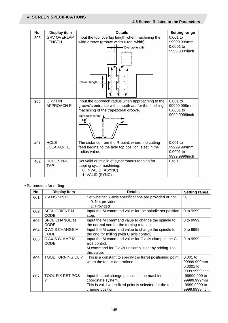
4. SCREEN SPECIFICATIONS 4.5 Screen Related to the Parameters
- 145 -
No. Display item Details Setting range 305 GRV OVERLAP
LENGTH Input the tool overlap length when machining the wide groove (groove width > tool width).
Overlap length
Retract length
0.001 to 99999.999mm 0.0001 to 9999.9999inch
306 GRV FIN APPROACH R
Input the approach radius when approaching to the groove's entrance with smooth arc for the finishing machining of the trapezoidal groove.
Approach radius
0.001 to 99999.999mm 0.0001 to 9999.9999inch
401 HOLE CLEARANCE
The distance from the R-point, where the cutting feed begins, to the hole top position is set in the radius value.
0.001 to 99999.999mm 0.0001 to 9999.9999inch
402 HOLE SYNC TAP
Set valid or invalid of synchronous tapping for tapping cycle machining. 0: INVALID (ASYNC) 1: VALID (SYNC)
0 to 1
• Parameters for milling
No. Display item Details Setting range 601 Y AXIS SPEC
Set whether Y-axis specifications are provided or not. 0: Not provided 1: Provided
0,1
602 SPDL ORIENT M CODE
Input the M command value for the spindle set position stop.
0 to 9999
603 SPDL CHANGE M CODE
Input the M command value to change the spindle to the normal one for the turning rotation.
0 to 9999
604 C AXIS CHANGE M CODE
Input the M command value to change the spindle to the one for milling (with C axis control).
0 to 9999
605 C AXIS CLAMP M CODE
Input the M command value for C axis clamp in the C axis control. M command for C axis unclamp is set by adding 1 to this value.
0 to 9999
606 TOOL TURNING CL Y
This is a constant to specify the turret positioning point when the tool is determined.
0.001 to 99999.999mm 0.0001 to 9999.9999inch
607 TOOL FIX RET POS Y
Input the tool change position in the machine coordinate system. This is valid when fixed point is selected for the tool change position.
-99999.999 to 99999.999mm -9999.9999 to 9999.9999inch

4. SCREEN SPECIFICATIONS 4.5 Screen Related to the Parameters
- 146 -
No. Display item Details Setting range 608 AXIS DIR COEF OF
SPEED The keyway/contour cutting feedrate in the diameter direction is automatically set. The cutting feedrates in the axis direction are determined by multiplying the value in the diameter direction by this coefficient. F1 = F ∗ α F: Feedrate in the diameter direction F1: Feedrate in the axis direction α: Coefficient
1 to 200%
609 TOOL SPINDLE NO. Input the tool spindle No. This No. is used to specify the spindle in the tapping cycle. (Note) Do not set a value larger than the value of
"#1039 spinno".
1 to 4 (Default: 2)
701 HOLE CLEARANCE
The distance from the R-point, where the cutting feed begins, to the hole top position is set.
0.001 to 99999.999mm 0.0001 to 9999.9999inch
702 HOLE SYNC TAP
Set “asynchronous tapping: 0” or “synchronous tapping: 1” for the tapping cycle (C=4) machining. 0: INVALID (ASYNC) 1: VALID (SYNC)
0,1
703 TAP ON M CODE Input the M command value to turn ON the TAP mode for the tool spindle.
0 to 9999
704 TAP OFF M CODE Input the M command value to turn OFF the TAP mode for the tool spindle.
0 to 9999
801 K-WAY CUT WIDTH PCT (%)
Set the overlap of the tool shift (“overlap percentage”) with “%” when the keyway width is larger than the diameter of the end mill. For example, if the overlap percentage is 70% when the machining is performed with the tool of φ 100, the machining is performed to the second line in the width of maximum 70mm. When this data is not input, 50% is applied.
1 to 100%
802 K-WAY CLEARANCE Set the distance from the cutting start position of the keyway to the base plane position. In the second rough machining or later, the cutting start position approaches to the position at the distance of this clearance amount from the previous position.
Keyway clearance
[Rough machining]
Keyway clearance + finishing allowance
[Finishing machining]
0.001 to 99999.999mm 0.0001 to 9999.9999 inch
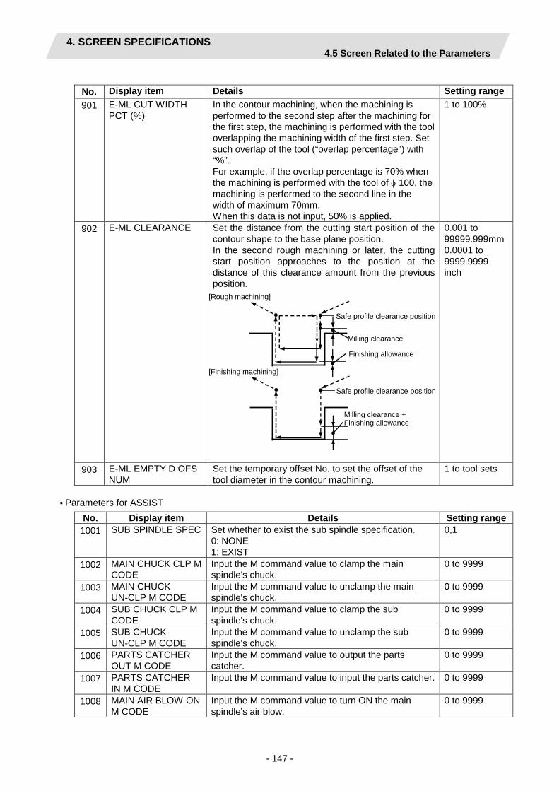
4. SCREEN SPECIFICATIONS 4.5 Screen Related to the Parameters
- 147 -
No. Display item Details Setting range 901 E-ML CUT WIDTH
PCT (%) In the contour machining, when the machining is performed to the second step after the machining for the first step, the machining is performed with the tool overlapping the machining width of the first step. Set such overlap of the tool (“overlap percentage”) with “%”. For example, if the overlap percentage is 70% when the machining is performed with the tool of φ 100, the machining is performed to the second line in the width of maximum 70mm. When this data is not input, 50% is applied.
1 to 100%
902 E-ML CLEARANCE Set the distance from the cutting start position of the contour shape to the base plane position. In the second rough machining or later, the cutting start position approaches to the position at the distance of this clearance amount from the previous position.
Milling clearance
Safe profile clearance position
[Rough machining]
Milling clearance + Finishing allowance
Safe profile clearance position
[Finishing machining]
Finishing allowance
0.001 to 99999.999mm 0.0001 to 9999.9999 inch
903 E-ML EMPTY D OFS NUM
Set the temporary offset No. to set the offset of the tool diameter in the contour machining.
1 to tool sets
• Parameters for ASSIST
No. Display item Details Setting range 1001 SUB SPINDLE SPEC Set whether to exist the sub spindle specification.
0: NONE 1: EXIST
0,1
1002 MAIN CHUCK CLP M CODE
Input the M command value to clamp the main spindle's chuck.
0 to 9999
1003 MAIN CHUCK UN-CLP M CODE
Input the M command value to unclamp the main spindle's chuck.
0 to 9999
1004 SUB CHUCK CLP M CODE
Input the M command value to clamp the sub spindle's chuck.
0 to 9999
1005 SUB CHUCK UN-CLP M CODE
Input the M command value to unclamp the sub spindle's chuck.
0 to 9999
1006 PARTS CATCHER OUT M CODE
Input the M command value to output the parts catcher.
0 to 9999
1007 PARTS CATCHER IN M CODE
Input the M command value to input the parts catcher. 0 to 9999
1008 MAIN AIR BLOW ON M CODE
Input the M command value to turn ON the main spindle's air blow.
0 to 9999

4. SCREEN SPECIFICATIONS 4.5 Screen Related to the Parameters
- 148 -
No. Display item Details Setting range 1009 MAIN AIR BLOW
OFF M CODE Input the M command value to turn OFF the main spindle's air blow.
0 to 9999
1010 SUB AIR BLOW ON M CODE
Input the M command value to turn ON the sub spindle's air blow.
0 to 9999
1011 SUB AIR BLOW OFF M CODE
Input the M command value to turn OFF the sub spindle's air blow.
0 to 9999
1012 AIR BLOW TIME Set the air blow time for the main and sub spindles. 0 to 99 sec 1013 SUB SP ORIENT M
CODE Input the M command value for the sub spindle set position stop.
0 to 9999
1014 SUB SP CHNG M CODE
Input the M command value to change the sub spindle to the normal one for the turning rotation.
0 to 9999
1015 SUB C-AX CHNG M CODE
Input the M command value to change the sub spindle to the one for milling (with C axis control).
0 to 9999
1016 SUB C-AX CLP M CODE
Input the M command value for C-axis clamp during C-axis control of the sub spindle. The M command value for the C-axis unclamp is the value for this parameter plus 1.
0 to 9999
1017 SUB SPINDLE No. Input the spindle number for the sub spindle. 1 to 4 (Default: 2)
1018 SUB SP CW ROT M CODE
Input the M command value to turn ON a forward rotation of the sub spindle. When 0 is set, M3 will be output.
0 to 9999
1019 SUB SP CCW ROT M CODE
Input the M command value to turn ON a reverse rotation of the sub spindle. When 0 is set, M4 will be output.
0 to 9999
1020 SUB SP STOP M CODE
Input the M command value to stop the sub spindle. When 0 is set, M5 will be output.
0 to 9999
1021 SUB SP C AXIS NAME
Select the C-axis name while the sub spindle is under the C-axis control. 1: A 2: B (Note) Even if the parameter is changed, the already
created machining programs or machining processes are not reflected. Create a machining program again after changing the parameter.
1, 2 (Default: 1)
1022 TRANSFER AXIS NAME
Set the name of the transfer axis. 1: A 2: B
1, 2 (Default: 2)
1023 OVER TRAVEL OF PUSH
Input the value of over travel of sub spindle when checking if the sub spindle is set properly during the transfer process.
0.000 to 99999.999 mm 0.0000 to 9999.9999 inch
1024 SUB SP ORIGIN Set the zero point of sub spindle with machine coordinate system.
-99999.999 to 99999.999 mm -9999.9999 to 9999.9999 inch
1025 MAIN SP SELECT M CODE
Input the M command value to set the main spindle. 0 to 9999
1026 SUB SP SELECT M CODE
Input the M command value to set the sub spindle. 0 to 9999

4. SCREEN SPECIFICATIONS 4.5 Screen Related to the Parameters
- 149 -
• Parameters for 2SYSTEM
No. Display item Details Setting range 1101 $1 SYS CHG SAFE
POS X Set the retract position of the X axis direction of the turret when switching the machining part system.
-99999.999 to 99999.999 mm -9999.9999 to 9999.9999 inch
1102 $2 SYS CHG SAFE POS X
1103 $1 Z AXIS MOVE TYPE
Designate either a turret or a spindle to be moved by the Z axis command. 1: TURRET 2: SPINDLE
1, 2 (Default: 1)
1104 $2 Z AXIS MOVE TYPE
1105 $2 Z AXIS DIR Designate the Z axis direction for $2. 1: SAME (same as $1's Z axis direction) 2: OPPOSITE (opposite to $1's Z axis direction)
1, 2 (Default: 1)
1106 MIXED SYNC CTRL ON M
Input the M command value to turn ON the mixed synchronous control. (Note) This is available for mixed synchronous
control (cross axis control) II. For the mixed synchronous control (cross axis control) I, set "0".
0 to 9999 (Default: 112)
1107 MIXED SYNC CTRL OFF M
Input the M command value to turn OFF the mixed synchronous control. (Note) This is valid for mixed synchronous control
(cross axis control) II. For the mixed synchronous control (cross axis control) I, set "0".
0 to 9999 (Default: 113)
1108 TOOL FIX RET POS X
Set the tool change position for $2 relative to the machine coordinate system. This is valid when the fixed point is selected for the tool change position. (Note) These are the parameters for $2 of the lathe
turning process "105 TOOL FIX RTE POS X" and "106 TOOL FIX RTE POS Z".
-99999.999 to 99999.999 mm -9999.9999 to 9999.9999 inch (Default: 0.000)
1109 TOOL FIX RET POS Z
1110 Y AXIS SPEC Set whether to exist the Y axis specification for $2. 0: NONE 1: EXIST (Note) This is the parameter for $2 of the milling
process "601 Y AXIS SPEC", and is available only when the milling specification is valid.
0, 1 (Default: 0)
1111 TOOL FIX RET POS Y
Set the tool change position for $2 relative to the machine coordinate system. This is valid when the fixed point is selected for the tool change position. (Note) This is the parameter for $2 of the milling
process "607 TOOL FIX RTE POS Y", and is available only when the milling specification is valid.
-99999.999 to 99999.999 mm -9999.9999 to 9999.9999 inch (Default: 0.000)
1112 TOOL SPINDLE NO. Input the tool spindle No. for $2 This is used for designating the spindle for tap cycle, etc. (Note) This is the parameter for $2 of the milling
process "609 TOOL SPINDLE NO.", and is available only when the milling specification is valid.
1 to 4 (Default: 4)
(Note 1) The parameters 1110 to 1112 are able to set the cursor movement even if the milling specification is invalid. However, the parameter values are not used.
(Note 2) When changing the parameter, the change is not reflected in an existing machining program. Create the machining program again.

4. SCREEN SPECIFICATIONS 4.5 Screen Related to the Parameters
- 150 -
Menus
No. Menu Details 1 ← Turns the LIST VIEW area active. 2 LATHE Displays the parameter input screen for turning. 3 MILLING Displays the parameter input screen for milling. 4 ASSIST Displays the parameter input screen for assist process. 5 2SYSTEM Displays the parameter input screen for 2-part system process.
This menu is available only when the 2-part system specification is "1: EXIST".
10 SAVE Saves the changes in the parameters.

4. SCREEN SPECIFICATIONS 4.5 Screen Related to the Parameters
- 151 -
4.5.2 PREFERENCE Screen
Prior to the NAVI LATHE operation, system setups are done on this screen. The followings are the items to be setup.
- Path to the folder in which NC program is saved - Path to the folder in which tool file, cutting condition file and parameter file are saved - Macro program mode (1: User Macro, 2: MTB Macro) - Unit for data input (1: inch, 2: mm) - Parameter file name - Toll file name - Cutting condition file (for tip material, workpiece material) name - 2-part system specification (0: NONE, 1: EXIST)
This screen is displayed when [PREFERENCE] menu, which appears when 1 is input in the parameter "999 MAINTE", is pressed.
Screen layout
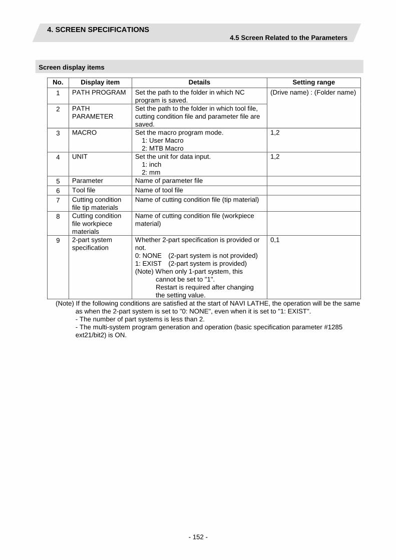
4. SCREEN SPECIFICATIONS 4.5 Screen Related to the Parameters
- 152 -
Screen display items
No. Display item Details Setting range 1 PATH PROGRAM Set the path to the folder in which NC
program is saved. (Drive name) : (Folder name)
2 PATH PARAMETER
Set the path to the folder in which tool file, cutting condition file and parameter file are saved.
3 MACRO Set the macro program mode. 1: User Macro 2: MTB Macro
1,2
4 UNIT Set the unit for data input. 1: inch 2: mm
1,2
5 Parameter Name of parameter file 6 Tool file Name of tool file 7 Cutting condition
file tip materials Name of cutting condition file (tip material)
8 Cutting condition file workpiece materials
Name of cutting condition file (workpiece material)
9 2-part system specification
Whether 2-part specification is provided or not. 0: NONE (2-part system is not provided) 1: EXIST (2-part system is provided) (Note) When only 1-part system, this
cannot be set to "1". Restart is required after changing the setting value.
0,1
(Note) If the following conditions are satisfied at the start of NAVI LATHE, the operation will be the same as when the 2-part system is set to "0: NONE", even when it is set to "1: EXIST". - The number of part systems is less than 2. - The multi-system program generation and operation (basic specification parameter #1285 ext21/bit2) is ON.

4. SCREEN SPECIFICATIONS 4.5 Screen Related to the Parameters
- 153 -
Menus
No. Menu Details 6 MACRO ENTRY User macro program or MTB macro program is registered in the NC
system. (Note 1) (Note 2) 9 RETURN Returns to the parameter screen. 10 SAVE Saves the changes in the preference setting data. (Note 3) (Note 1) When changing the following parameters, make sure to do the macro entry.
Basic specification parameters - #1037 Command type - #1309 GType (Switch command format)
(Note 2) If "2" (MTB macro) is set at the PREFERENCE - MACRO even though there is no specification of the machine tool builder macro, an error message "E292 Program entry over" appears and the entry cannot be registered. When there is no specification of the machine maker macro, set "1" (user macro) at the PREFERENCE - MACRO.
(Note 3) The PREFERENCE data is saved as the preference setting file (navi.ini) in the following folders. Model MTB macro specification Save folder
M700/M700VW series EXIST
C:¥ncsys¥navilathe¥ NONE
M700VS series EXIST /PRG/MMACRO/ NONE /PRG/USER/
M70/M70V series EXIST /PRG/MMACRO/ E70 NONE /PRG/USER/

4. SCREEN SPECIFICATIONS 4.6 Screen Related to the Version
- 154 -
4.6 Screen Related to the Version
4.6.1 Version Screen
The version data for the NAVI LATHE is displayed on this screen. When [VERSION] is selected in the LIST VIEW area, this screen is displayed.
Screen layout
Version

4. SCREEN SPECIFICATIONS 4.7 Program Checker Screen
- 155 -
4.7 Program Checker Screen
Machining shapes of a NC program are graphically displayed on this screen. Program Checker screen appears when or the tab is pressed while MAIN screen is displayed. Program Checker screen also appear when the checker icon is clicked. On the checker screen, you can choose the following two check modes. (1) Simple check: This is the mode where the NAVI LATHE analyzes and draws the machining shape of
the machining program which was created by the NAVI LATHE. (2) NC check: This is the mode that the graphic check function of NC analyzes and draws the tool path and
the machining shape of the machining program which was created by the NAVI LATHE. The checker screen starts with the simple check mode at the initial startup. After that, it starts according to the mode last used. Switch the check mode using the mode change menu.
Main menus (Mode change)
While the simple check menu or the NC check menu is displayed, the following menus are displayed by pressing the menu change key.
No. Menu Details 1 EXIT Terminates the Program Checker and then closes the screen. 2 SIMPLE CHECK This menu is to change the check mode to the simple check.
While the current check mode is the simple check, this menu is highlighted. 3 NC CHECK This menu is to change the check mode to the NC check.
While the current check mode is the NC check, this menu is highlighted. The transition between each menu is as follows. Menu change key [SIMPLE CHECK] menu [NC CHECK] menu Mode change menu Move to the menu of the
currently selected mode Select the simple check mode Move to the simple check menu
Select the NC check mode Move to the NC check menu
Simple check menu Move to the mode change menu
- -
NC check menu Move to the mode change menu
- -

4. SCREEN SPECIFICATIONS 4.7 Program Checker Screen
- 156 -
Screen layout
The screen layout may change according to the presence or absence of the following specifications. No. Name Outline 1 Milling specification When this specification exists, this enables two-plane graphics, and
displays "VIEW". Also the "VIEW" menu is displayed. 2 Sub spindle
specification When this specification and the milling specification exist together, "FACE/BACK selection" of "DRAW STATUS" is displayed.
3 Two-part system specification
When this specification exists, "FACE/BACK selection" and "part system selection" of "DRAW STATUS" are displayed. Also the menu [$<->$] is displayed.
Display/non-display of the display items is determined by the combination of the specifications as follows.
○: Display × : Non-display
No. Specification none/exist Display item Display
example Milling spec. Sub spindle spec.
Two-part system spec.
“VIEW” “DRAW STATUS” FACE/BACK selection
“DRAW STATUS” part system selection
1 None None None × × × 1 2 None None Exist × × ○ 2 3 None Exist None × × × 1 4 None Exist Exist × × ○ 2 5 Exist None None ○ × × 3 6 Exist None Exist ○ × ○ 5 7 Exist Exist None ○ ○ × 4 8 Exist Exist Exist ○ ○ ○ 6
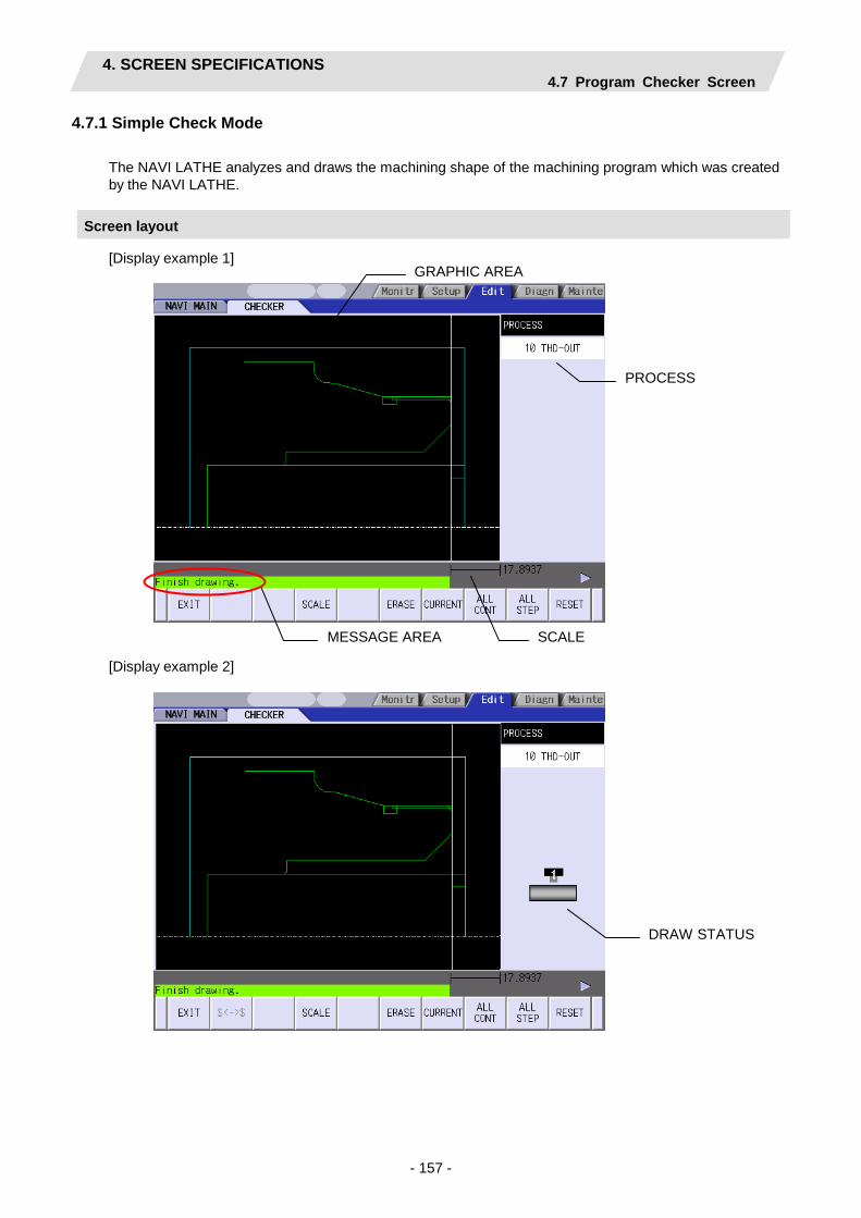
4. SCREEN SPECIFICATIONS 4.7 Program Checker Screen
- 157 -
4.7.1 Simple Check Mode
The NAVI LATHE analyzes and draws the machining shape of the machining program which was created by the NAVI LATHE.
Screen layout
[Display example 1]
[Display example 2]
GRAPHIC AREA
PROCESS
MESSAGE AREA SCALE
DRAW STATUS
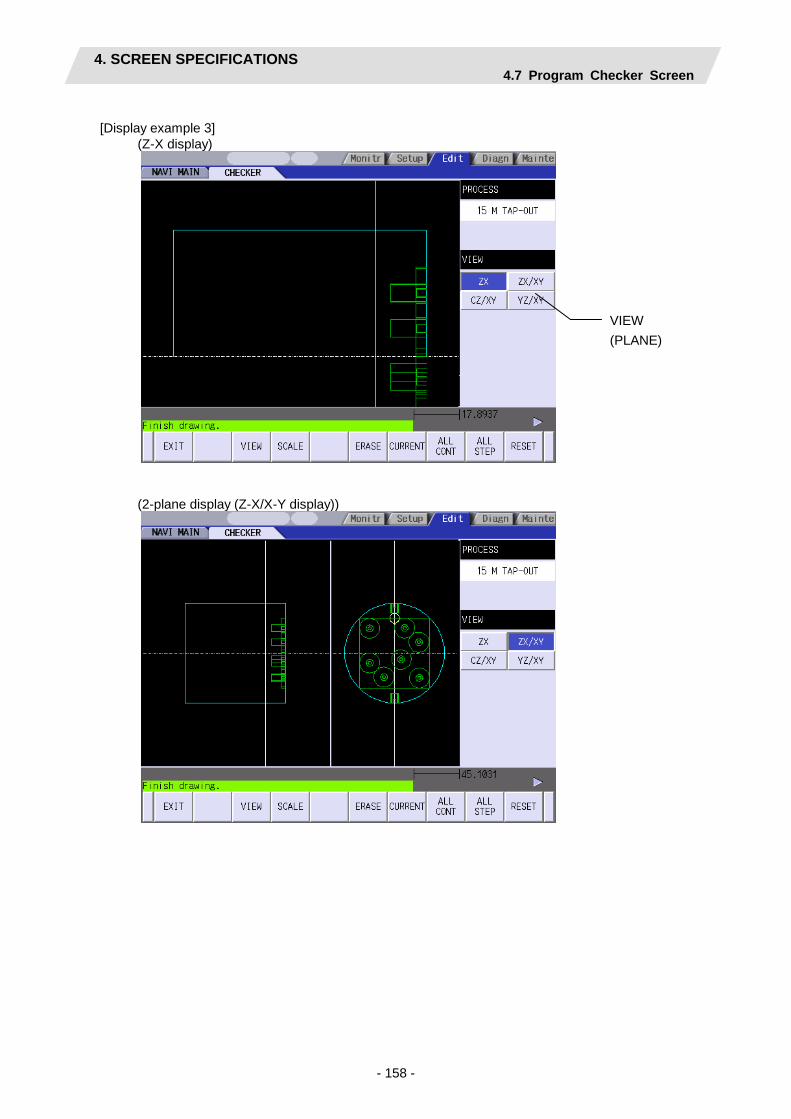
4. SCREEN SPECIFICATIONS 4.7 Program Checker Screen
- 158 -
[Display example 3] (Z-X display)
(2-plane display (Z-X/X-Y display))
VIEW (PLANE)

4. SCREEN SPECIFICATIONS 4.7 Program Checker Screen
- 159 -
[Display example 4]
(Z-X display)
(2-plane display (Y-Z/X-Y display))
BASE RADIUS /BASE ANGLE

4. SCREEN SPECIFICATIONS 4.7 Program Checker Screen
- 160 -
[Display example 5]
(Z-X display)
(2-plane display (Y-Z/X-Y display))

4. SCREEN SPECIFICATIONS 4.7 Program Checker Screen
- 161 -
[Display example 6]
(Z-X display)
(2-plane display (Y-Z/X-Y display))
DRAW STATUS

4. SCREEN SPECIFICATIONS 4.7 Program Checker Screen
- 162 -
Screen display items
No. Menu Details 1 GRAPHIC AREA Graphically displays the workpiece shape and the machining shape.
Items and their display colors on the screen are as follows: 1) Machining shape (main spindle) --- Green 2) Machining shape (sub spindle) --- Orange 3) Workpiece --- Light blue 4) Cutting plane on Y-Z view --- White 5) Radius display --- Yellow (Note) When the 2-part system specification is "1: EXIST", the
machining shape of the part system not selected is drawn in gray.
2 PROCESS Indicates the name of the process of which machining shape is currently displayed. (Note) When the 2-part system specification is "1: EXIST", the
process names of the 2nd part system are also displayed. 3 VIEW Displays the currently selected view.
(Note) This is available when the milling interpolation specifications are provided. Not available unless the milling interpolation specifications are provided.
4 SCALE Indicates the scale value of the graphic display area. 5 MESSAGE AREA Messages on graphic display of the machining shape appear here.
6 RADIUS/ANGLE Base radius and base angle of the graphic display area are input and indicated. Base radius is indicated when C-Z view is selected, while base angle is shown when Y-Z view is selected. This is not displayed unless C-Z view or Y-Z view is selected. When the [R/A] menu is selected in the VIEW change menu while ALL CONT or ALL STEP is performed, the cursor appears to set base radius and base angle.

4. SCREEN SPECIFICATIONS 4.7 Program Checker Screen
- 163 -
No. Menu Details 7 DRAW STATUS Displays the following drawing modes.
1) FACE/BACK selection There are the FACE selection and the BACK selection in this selection. While the FACE is selected, a green arrow is displayed at the right side of the workpiece. In this mode, only the machining on the front face of workpiece is drawn. The drawing of the back surface machining is not performed. While the BACK is selected, an orange arrow is displayed at the left side of the workpiece. In this mode, only the machining on the back surface of workpiece is drawn. The drawing of the front face machining is not performed. FACE/BACK selection is switched by the [CHAGE FACE] menu.
2) Part system selection There are $1 part system selection and the $2 part system selection in this selection. While $1 is selected, the tool mark is displayed above the workpiece. While $2 is selected, the tool mark is displayed below the workpiece. Part system selection is switched with the [$<->$] menu key.
(Note) The DRAW STATUS differs according to the presence or absence of the sub spindle specification and the 2-part system specification. Refer to the chapter of screen layout for details.
Display combinations of the DRAW STATUS are as follows.
No. FACE/BACK selection
Part system selection
Graphic icon
1 Invalid Invalid No icon 2 Invalid $1
3 Invalid $2
4 FACE Invalid
5 FACE $1
6 FACE $2
7 BACK Invalid
8 BACK $1
9 BACK $2

4. SCREEN SPECIFICATIONS 4.7 Program Checker Screen
- 164 -
Main menus
No. Menu Details 1 EXIT Terminates the Program Checker and then closes the screen.
2 $<->$ Use this menu to change the part system in the DRAW STATUS. The part system will be changed from $1 to 2 or $2 to $1 by pressing this menu. (Note 1) During the drawing of the current process, this menu is not
displayed because the tool part system of the currently edited process is selected and is unable to be changed.
(Note 2) During the drawing of all the processes, $1 is set as the default and the part system can be changed by pressing this menu.
(Note 3) When the 2-part system specification of NAVI LATHE is set to "0: NONE", this menu is not displayed.
(Note 4) When the NC has no specification of the multi-part system program management, this menu is not displayed even if the 2-part system specification of NAVI LATHE is set to "1: EXIST".
3 VIEW Use this menu to change view, base radius and base angle. Select a view from ZX, ZX/XY, CZ/XY or YZ/XY. The menu will be changed to the VIEW change menu by pressing this menu. (Note) Not available unless the milling interpolation specifications are
provided. 4 SCALE Use this menu when changing scale.
Standard scale setting, scaling up/down, and graphic area shifting can be performed. The menu will be changed to SCALE change menu by pressing this menu. In the 2-plane display mode, scale frames are made on both of the planes.
6 ERASE Deletes the drawing data. 7 CURRENT Draws the machining shapes of the currently selected process.
The shapes are drawn based on the view and scale set for CURRENT display.
8 ALL CONT Draws the machining shapes of all the processes successively. The shapes are drawn based on the view and scale set for ALL CONT display.
9 ALL STEP Draws the machining shapes of one process at a time. The shapes are drawn based on the view and scale set for ALL CONT display.
10 RESET Resets the graphic display of the machining shapes. (Note 1) Views and scales are arranged for CURRENT display and for ALL CONT display. (Note 2) The views and scales selected in the CURRENT display are retained for the CURRENT display.
When the CURRENT display is performed for any other process, the views and scales for the CURRENT display turn to the standard ones.
(Note 3) The scales, the views selected and the part system selected in the ALL CONT or ALL STEP display are retained for the ALL CONT display. These views, scales and part system are retained for the ALL CONT display until the NAVI LATHE is closed.
(Note 4) The selection of CURRENT or ALL CONT is retained even when the check mode is switched between Simple and NC check.

4. SCREEN SPECIFICATIONS 4.7 Program Checker Screen
- 165 -
View change menu This is the sub menu displayed by pressing the [VIEW] menu.
No. Menu Details 1 CANCEL Returns to the main menu. 3 ZX Converts the view into the Z-X view and returns to the main menu. 4 ZX/XY Converts the view into the 2-plane display of Z-X and X-Y, and then
returns to the main menu. 5 CZ/XY Converts the view into the 2-plane display of C-Z and X-Y, and then
returns to the main menu. In ALL CONT and ALL STEP display, C-Z view only displays the shapes made upon the fixed base radius for the machining process.
6 YZ/XY While drawing the VIEW of the Y-Z and X-Y in the ALL CONT and ALL STEP, Y-Z VIEW displays only the shapes made upon the fixed base radius for the machining process.
8 R/A Set the base radius and the base angle. These are selectable only when Y-Z or C-Z view is selected. When this menu is pressed, the cursor appears in the RADIUS/ANGLE display area. The [R/A] menu does not appear when Z-X or ZX/XY view is selected, or when the CURRENT display is performed.
9 CHANGE FACE Switches the end surface for drawing in the XY plane. When the end surface is the FACE , the drawing is switched to the BACK, when the end surface is the BACK, the drawing is switched to the FACE. This menu does not appear while ZX VIEW is selected. When the parameter "1001 SUB SPINDLE SPEC" is "0: NONE", the [CHANGE FACE] menu is not displayed.
(Note 1) [VIEW] menu is not available while graphic display is performed. Press [RESET] menu and cancel
the graphic display in advance. (Note 2) The displayed shapes are deleted upon any change of the VIEW. (Note 3) The views in the CURRENT display are set as follows, according to the machining process and
the machining area.
Machining Process View Turning ZX Milling hole drilling Front face ZX/XY Outer diameter CZ/XY Side surface YZ/XY Back surface ZX/XY Keyway cutting Front face ZX/XY Outer diameter CZ/XY Side surface YZ/XY Back surface ZX/XY Contour cutting Front face ZX/XY Outer diameter CZ/XY Side surface YZ/XY Back surface ZX/XY Balance cut (turn) ZX Balance cut (copy) ZX Two-part system simultaneous thread cutting (identical screw)
ZX

4. SCREEN SPECIFICATIONS 4.7 Program Checker Screen
- 166 -
(Note 4) Some views selected may not display the machining shapes. Refer to the examples of the graphic display for the machining shapes of the process displayed on each view.
(Note 5) When the checker runs while any object except PROCESS is selected in the LIST VIEW area, views for ALL CONT display are applied.
SCALE change menus
This is the sub menu of the [SCALE] menu. No. Display item Details 1 CANCEL Cancels the SCALE change and returns to the main menu. 2 STANDARD Changes the scale to the standard setting and returns to the main
menu. Scale value is automatically calculated based on the workpiece sizes. The center of workpiece displayed coincides with that of the screen.
3 ENLARGE Enlarges the scale. The same function can be achieved by pressing – key.
4 REDUCE Reduces the scale. The same function can be achieved by pressing + key. (Note) The solid scale frame will be drawn in dotted lines when its size
exceeds 100%. 5 ↑ Moves up the scale frame. The same function can also be achieved
by pressing ↑ key. When ZX/XY view is selected, the two planes are simultaneously moved. When CZ/XY or YZ/XY view is selected, the scale frame in the selected area is moved.
6 ↓ Moves down the scale frame. The same function can also be achieved by pressing ↓ key. When ZX/XY view is selected, the two planes are simultaneously moved. When CZ/XY or YZ/XY view is selected, the scale frame in the selected area is moved.
7 ← Moves the scale frame toward the left. The same function can also be achieved by pressing ← key. In the 2-plane display, the scale frame in the selected area is moved.
8 → Moves the scale frame toward the right. The same function can also be achieved by pressing → key. In the 2-plane display, the scale frame in the selected area is moved.
9 SELECT Select the area to adjust the scale. This is available in the 2-plane display.
10 SET Determines the scale and returns to the main menu. The same result can also be achieved by pressing [INPUT] key.
(Note 1) Display area is shown with a white frame. (Note 2) The displayed machining shape will be deleted upon change of display scale or position. (Note 3) The [SCALE] menu cannot be pressed during the drawing.
Press the [RESET] menu to stop the drawing, then press the [SCALE] menu.

4. SCREEN SPECIFICATIONS 4.7 Program Checker Screen
- 167 -
Drawings of XY VIEW
The XY VIEW draws either the FACE or BACK end surface. The end surface to be drawn differs according to the drawing mode or the machining spindle.
Drawing mode Machining spindle Drawing end surface CURRENT (Drawing mode for the current process)
FACE Draws only the machining shape of front side end surface in the XY VIEW.
BACK Draws only the machining shape of back side end surface in the XY VIEW.
ALL CONT and ALL STEP (Drawing mode for all processes and all steps)
FACE/BACK Draws the machining shape of the selected side of end surface in the XY VIEW. FACE/BACK of the drawing end surface is switched with the [DRAW BACK] menu. When the [DRAW BACK] menu is OFF, the shape of front side end surface is drawn. When the [DRAW BACK] menu is ON, the shape of back side end surface is drawn.
Drawing images of FACE/BACK (when drilling both end surfaces) ZX VIEW XY VIEW
selecting the front side of end surface
XY VIEW selecting the back side of end surface
Drawing of ZX/CZ/YZ VIEW
Whether the front or back side is selected, the center of the drawing area coincides with that of the workpiece. The horizontal axis (Z axis) is drawn in the program zero position of the main and sub spindles respectively as listed below.
Spindle Drawing of Z axis Main spindle The drawing is calculated by using the +Z and -Z values set in the initial
setting screen. (Note) When +Z=100 and -Z=0 are set in the initial setting screen, the Z axis
is drawn on the back surface of the workpiece. Sub spindle The drawing is calculated by the setting value "Z SUB SP" in the initial setting
screen. (Note) When Z SUB SP=0 is set in the initial setting screen, the Z axis is
drawn on the back surface of the workpiece.

4. SCREEN SPECIFICATIONS 4.7 Program Checker Screen
- 168 -
Restrictions on the graphic display function - Graphic display is not available for the EIA process. - When there is an error in the specified shape data for the turning/copy cutting, the shape data is
displayed up to the error point.
Examples of graphic drawings [Turning] Only ZX view is displayed for turning.
[Turning / Copy cutting]
[Threading]
[Grooving]
[Trapezoidal grooving]
[Hole drilling --- Drilling ---]
[Hole drilling --- Tapping ---]
[Cut off]
(Note) When the 2-part system specification is "1: EXIST", the machining shape of the balance cut
process will be the same as the machining shape of each turning.
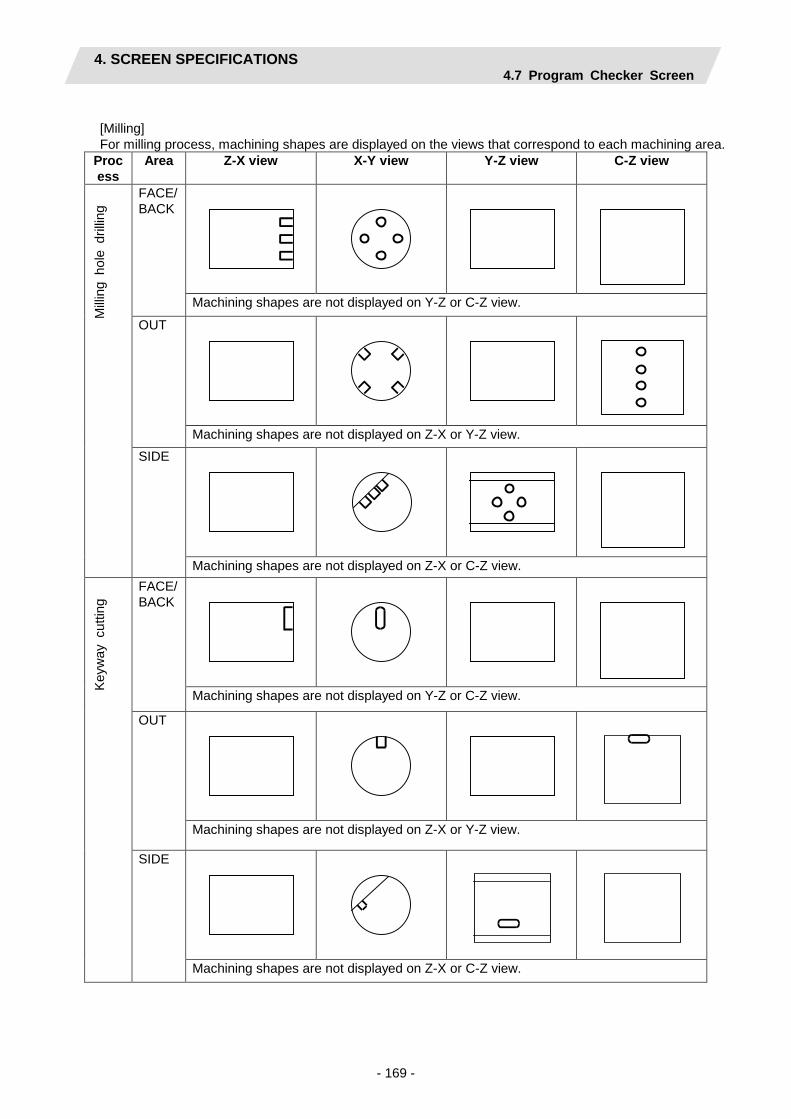
4. SCREEN SPECIFICATIONS 4.7 Program Checker Screen
- 169 -
[Milling] For milling process, machining shapes are displayed on the views that correspond to each machining area.
Process
Area Z-X view X-Y view Y-Z view C-Z view
Milli
ng h
ole
drilli
ng
FACE/BACK
Machining shapes are not displayed on Y-Z or C-Z view.
OUT
Machining shapes are not displayed on Z-X or Y-Z view. SIDE
Machining shapes are not displayed on Z-X or C-Z view.
Keyw
ay c
uttin
g FACE/
BACK
Machining shapes are not displayed on Y-Z or C-Z view.
OUT
Machining shapes are not displayed on Z-X or Y-Z view.
SIDE
Machining shapes are not displayed on Z-X or C-Z view.

4. SCREEN SPECIFICATIONS 4.7 Program Checker Screen
- 170 -
Proce
ss Area Z-X view X-Y view Y-Z view C-Z view
Con
tour
cut
ting
FACE
Machining shapes are not displayed on Y-Z or C-Z view.
OUT
Machining shapes are not displayed on Z-X or Y-Z view.
SIDE
Machining shapes are not displayed on Z-X or C-Z view.

4. SCREEN SPECIFICATIONS 4.7 Program Checker Screen
- 171 -
4.7.2 NC Check Mode
This mode draws the tool path by using the graphic check function of the NC and the machining shape of the program which was created with the NAVI LATHE.
Screen layout (NC check)
[ Z-X display]
[2-plane display (example of Z-X/X-Y display))]
(Note 1) The 2-plane display is available only when the specification of milling interpolation exists. (Note 2) Maximum 4 axes are displayed in the counter according to the presence or absence of the C and
Y axes specification.
(8)
(6)
(10) (1)
(3)
(2)
(4) (5) (9)
(1) (10)
(7)

4. SCREEN SPECIFICATIONS 4.7 Program Checker Screen
- 172 -
Screen display items
No. Display item Details 1 GRAPHIC AREA Graphically displays the workpiece shape and the machining shape.
Items and their display colors on the screen are as follows: 1) Machining shape (front face spindle) --- Green 2) Machining shape (back surface spindle) --- Orange 3) Workpiece --- Light blue 4) Cutting plane on Y-Z view --- White 5) Radius display --- Yellow 6) Tool path --- rapid traverse Blue, cutting feed Green (Note) When the 2-part system specification is "1: EXIST", the machining
shape of the part system not selected is drawn in gray. 2 PROCESS Indicates the name of the process of which machining shape is currently
displayed. (Note) When the 2-part system specification is "1: EXIST", the process
name of the 2nd part system is also displayed. 3 VIEW Displays the currently selected view.
(Note) This is available when the milling interpolation specifications are provided. Not available unless the milling interpolation specifications are provided.
4 SCALE Indicates the scale value of the graphic display area. 5 MESSAGE AREA Messages on graphic display of the machining shape appear here.
6 RADIUS/ANGLE Base radius and base angle of the graphic display area are input and indicated. Base radius is indicated when C-Z view is selected, while base angle is shown when Y-Z view is selected. This is not displayed unless C-Z view or Y-Z view is selected. When the [R/A] menu is selected in the VIEW change menu while ALL CONT or ALL STEP is performed, the cursor appears to set base radius and base angle.
7 WORK COORDINATE POSITION
Displays the counter of workpiece coordinate position. The counter displays up to four axes, two of which are X and Z axes, according to the presence or absence of C axis and Y axis specifications. The axis name set in the axis parameter #1022 axname2 is displayed. For the 2-part system specification, the workpiece coordinate position counter of the part system being selected is displayed.

4. SCREEN SPECIFICATIONS 4.7 Program Checker Screen
- 173 -
No. Display item Details 8 DRAW STATUS Displays the following drawing modes.
1) FACE/BACK selection There are the FACE selection and the BACK selection in this selection. While the FACE is selected, a green arrow is displayed at the right side of the workpiece. In this mode, only the machining on the front face of workpiece is drawn. The drawing of the back surface machining is not performed. While the BACK is selected, an orange arrow is displayed at the left side of the workpiece. In this mode, only the machining on the back surface of workpiece is drawn. The drawing of the front face machining is not performed. FACE/BACK selection is switched by the [CHANGE FACE] menu.
2) Part system selection There are $1 part system selection and the $2 part system selection in this selection. While $1 is selected, the tool mark is displayed above the workpiece. While $2 is selected, the tool mark is displayed below the workpiece. Part system selection is switched with the [$<¥>$] menu key.
(Note) The DRAW STATUS differs according to the presence or absence of the sub spindle specification and the 2-part system specification. Refer to the chapter of screen layout for details.
Display combinations of the DRAW STATUS are as follows.
No. FACE/BACK selection
Part system selection
Graphic icon
1 Invalid Invalid No icon 2 Invalid $1
3 Invalid $2
4 FACE Invalid
5 FACE $1
6 FACE $2
7 BACK Invalid
8 BACK $1
9 BACK $2
9 NC MESSAGE AREA
Displays the alarm messages output from the NC.
10 CHECK MODE DISPLAY AREA
When the current check mode is the NC check, the letters "NC" appear to indicate the NC check is being selected.

4. SCREEN SPECIFICATIONS 4.7 Program Checker Screen
- 174 -
Main menus
No. Menu Details 1 EXIT Terminates the Program Checker and then closes the screen.
2 $<->$ Use this menu to change the part system in the DRAW STATUS. The part system will be changed from $1 to 2 or $2 to $1 by pressing this menu. (Note 1) During the drawing of the current process, this menu is not
displayed because the tool part system of the currently edited process is selected and is unable to be changed.
(Note 2) During the drawing of the all processes, $1 is selected as the default and the part system can be changed by pressing this menu.
(Note 3) When the 2-part system specification of NAVI LATHE is set to "0: NONE", this menu is not displayed.
(Note 4) When the NC has no specification of the multi-part system program management, this menu is not displayed even if the 2-part system specification of NAVI LATHE is set to "1: EXIST".
2 VIEW Use this menu to change view, base radius and base angle. Select a view from ZX, ZX/XY, CZ/XY or YZ/XY. The menu will be changed to the VIEW change menu by pressing this menu. (Note) Not available unless the milling interpolation specifications are
provided. 3 SCALE Use this menu when changing scale.
Standard scale setting, scaling up/down, and graphic area shifting can be performed. The menu will be changed to SCALE change menu by pressing this menu. In the 2-plane display mode, scale frames are made on both of the planes.
4 ERASE Deletes the drawing data. 5 CURRENT
PROCESS Use this menu when drawing the tool path of the currently selected process. While this menu is selected, it is highlighted.
6 ALL PROCESS Use this menu when drawing the tool path of the entire processes continuously. While this menu is selected, it is highlighted.
7 CHECK CONT
Draws the tool path continuously according to the mode in the current process or the entire processes.
8 CHECK STEP Draws the tool path for every movement command block according to the mode of the current process or the entire processes.
9 RESET Resets the graphic display of the machining shapes. (Note 1) Views and scales are arranged for CURRENT display and for ALL CONT display. (Note 2) The views and scales selected in the CURRENT display are retained for the CURRENT display.
When the CURRENT display is performed for any other process, the views and scales for the CURRENT display turn to the standard ones.
(Note 3) The scales, the views selected and the part system selected in the ALL CONT or ALL STEP display are retained for the ALL CONT display. These views, scales and part system are retained for the ALL CONT display until the NAVI LATHE is closed.
(Note 4) After the CURENT PROCESS drawing or the ALL PROCESS drawing is completed, if the [CHECK CONT] or the [CHECK STEP] menu is pressed again, it starts drawing without deleting the displayed tool path.
(Note 5) The selection of CURRENT or ALL CONT is retained even when the check mode is switched between Simple and NC check.
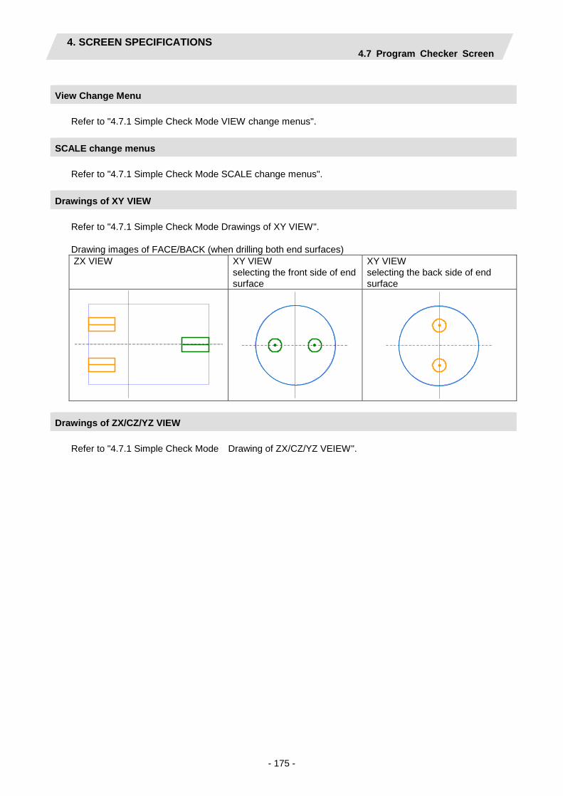
4. SCREEN SPECIFICATIONS 4.7 Program Checker Screen
- 175 -
View Change Menu Refer to "4.7.1 Simple Check Mode VIEW change menus".
SCALE change menus Refer to "4.7.1 Simple Check Mode SCALE change menus".
Drawings of XY VIEW Refer to "4.7.1 Simple Check Mode Drawings of XY VIEW". Drawing images of FACE/BACK (when drilling both end surfaces) ZX VIEW XY VIEW
selecting the front side of end surface
XY VIEW selecting the back side of end surface
Drawings of ZX/CZ/YZ VIEW Refer to "4.7.1 Simple Check Mode Drawing of ZX/CZ/YZ VEIEW".

4. SCREEN SPECIFICATIONS 4.7 Program Checker Screen
- 176 -
Restrictions on the graphic display function - Graphic display is also available for the EIA process. - When there is an error in the specified shape data for the turning/copy cutting/contour cutting, the shape
data is displayed up to the error point. In this case, the [CHECK CONT] or the [CHECK STEP] menu cannot be pressed.
- Whether the graphic mode is in the foreground (70V) or the background (M700VM/M700VS), the NC check is available even during the graphic check on the 700 HMI screen.
- When the NC check of the NAVI LATHE is executed during cycle start with the foreground (70V) graphic check mode, an error message "E294 Program running" appears. In this case, the program shape is drawn, but the [CHECK CONT] or [CHECK STEP] menu cannot be pressed.
M70V/E70 700VS/700VW Remarks Graphic check mode Foreground Background In automatic operation NC check NG NC check OK In emergency stop NC check NG NC check OK In the HMI graphic check NC check OK NC check OK Emergency stop during the NAVI2D check NC check stop No impact NC reset during the NAVI2D check NC check stop No impact Automatic operation during the NAVI2D check
Operation alarm No impact
- When the cycle start button is pressed during the NC check of the NAVI LATHE with the foreground (70V) graphic check mode, an operation alarm "M01 Program check mode" appears and the cycle start is disabled.
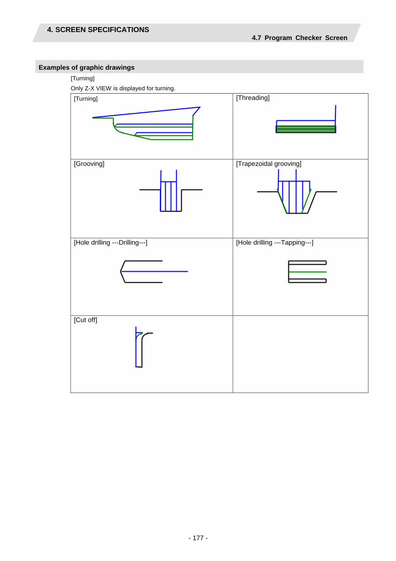
4. SCREEN SPECIFICATIONS 4.7 Program Checker Screen
- 177 -
Examples of graphic drawings [Turning]
Only Z-X VIEW is displayed for turning.
[Turning]
[Threading]
[Grooving]
[Trapezoidal grooving]
[Hole drilling ---Drilling---]
[Hole drilling ---Tapping---]
[Cut off]

4. SCREEN SPECIFICATIONS 4.7 Program Checker Screen
- 178 -
[Milling] For milling process, machining shapes are displayed on the views that correspond to each machining area.
Z-X VIEW X-Y VIEW Y-Z VIEW C-Z VIEW
Milli
ng h
ole
drilli
ng
FACE/BACK
Machining shapes are not displayed on Y-Z or C-Z VIEW.
OUT
Machining shapes are not displayed on Z-X or Y-Z VIEW. SIDE
Machining shapes are not displayed on Z-X or C-Z VIEW.
Keyw
ay c
uttin
g FACE/
BACK
Machining shapes are not displayed on Y-Z or C-Z VIEW.
OUT
Machining shapes are not displayed on Z-X or Y-Z VIEW.
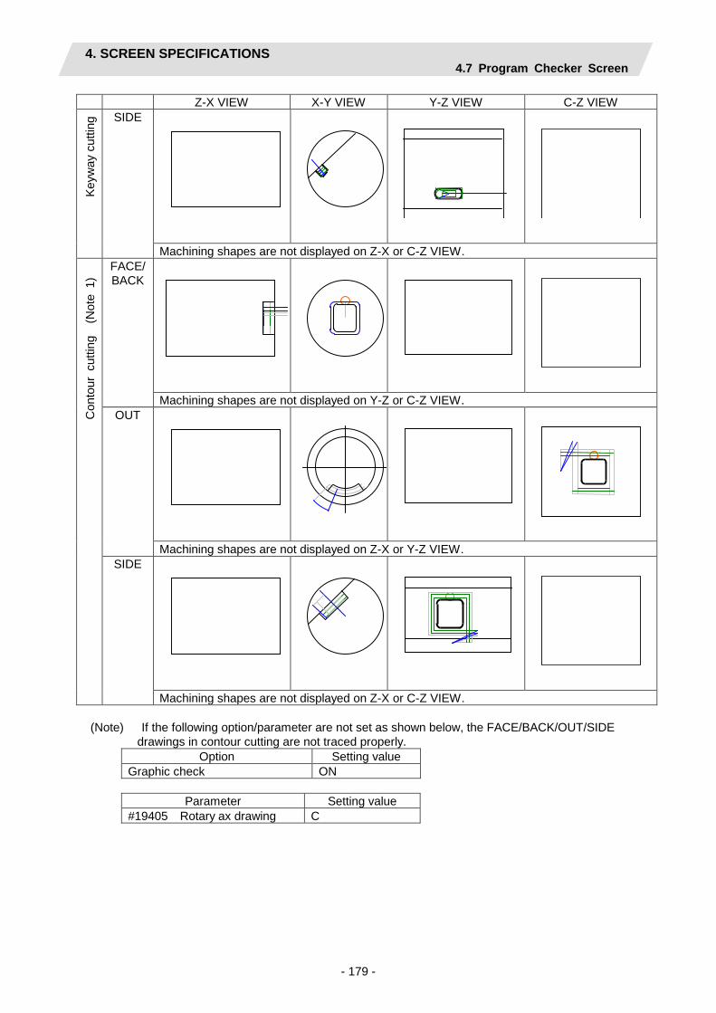
4. SCREEN SPECIFICATIONS 4.7 Program Checker Screen
- 179 -
Z-X VIEW X-Y VIEW Y-Z VIEW C-Z VIEW Ke
yway
cut
ting
SIDE
Machining shapes are not displayed on Z-X or C-Z VIEW.
Con
tour
cut
ting
(N
ote
1)
FACE/BACK
Machining shapes are not displayed on Y-Z or C-Z VIEW. OUT
Machining shapes are not displayed on Z-X or Y-Z VIEW. SIDE
Machining shapes are not displayed on Z-X or C-Z VIEW.
(Note) If the following option/parameter are not set as shown below, the FACE/BACK/OUT/SIDE drawings in contour cutting are not traced properly.
Option Setting value Graphic check ON
Parameter Setting value
#19405 Rotary ax drawing C

4. SCREEN SPECIFICATIONS 4.8 Guidance Function
- 180 -
4.8 Guidance Function
Guidance Function helps an operator perform data inputting. Guidance Function includes Message Guidance and Tool Guidance. Message Guidance screen will be appeared by pressing
key or by clicking the icon , and Tool Guidance screen will be appeared
by pressing LIST key or by clicking the icon . The message/parameter guidance screen will be closed
by clicking [OK] , and the tool guidance screen will be closed by clicking [Close] button.
Guidance Type
Starting method Details Key-
board Icon
Message Guidance
?
When selecting the parameter screen, the parameter guidance is displayed. When not selecting the parameter screen, the message guidance is displayed. <Message guidance> Details or countermeasures related to the current error and message are displayed.
<Parameter guidance> For the parameter selected with the cursor, the detail and the setting range are displayed.
Tool
Guidance
LIST
A segment of tool data registered in the tool file is displayed. Note that no editing is possible.

4. SCREEN SPECIFICATIONS 4.8 Guidance Function
- 181 -
4.8.1 Message/Parameter Guidance Screen
The message guidance or the parameter guidance is displayed in this function. When the parameter screen is selected, the parameter guidance is displayed, and when the other screen other than the parameter is selected, the message guidance is displayed. The message guidance or the parameter guidance is switched by the tab.
Screen layout
<Alarm guidance>
<Parameter guidance>
Screen display items
No. Display item Details 1 Message Displays the message of the alarm occurring currently.
2 Trouble shooting Displays the indication for the alarm currently occurring.
3 Parameter name Displays the parameter name. At the time of the parameter guidance start, the selected parameter is displayed.
4 Details Indicates the explanation of the displaying parameter. When the message exceeds five lines, the scroll bar will appear.
5 Setting range Indicates the setting range of the displaying parameter.
Parameter name

4. SCREEN SPECIFICATIONS 4.8 Guidance Function
- 182 -
Buttons
No. Button Details 1 OK(O) Closes the guidance window. 2 PREV.(P) Goes back to a previous parameter.
When the first parameter is displayed, the letters are grayed and the button is disabled.
3 NEXT(N) Goes to a next parameter. When the last parameter is displayed, the letters are grayed and the button is disabled. (Note) The last parameter differs according to the presence or the absence of
the 2-part system specification. When 2-part system specification is “1: EXIST”: “1112 TOOL SPINDLE NO” When 2-part system specification is “0: NONE: “1026 SUB SP SELECT M CODE”

4. SCREEN SPECIFICATIONS 4.8 Guidance Function
- 183 -
4.8.2 Tool Guidance Screen
The primary data of tool data registered with the tool file of the part system selecting are displayed.
Screen layout When the 2-part system specification is “0: NONE” - Displaying the tools for turning
- Displaying the tools for milling

4. SCREEN SPECIFICATIONS 4.8 Guidance Function
- 184 -
When the 2-part system specification is “1: EXIST” - Displaying the tools for turning
- Displaying the tools for milling
(1)
(2)
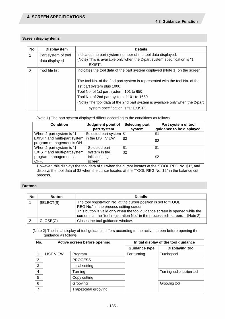
4. SCREEN SPECIFICATIONS 4.8 Guidance Function
- 185 -
Screen display items
No. Display item Details 1 Part system of tool
data displayed Indicates the part system number of the tool data displayed. (Note) This is available only when the 2-part system specification is "1:
EXIST". 2 Tool file list Indicates the tool data of the part system displayed (Note 1) on the screen.
The tool No. of the 2nd part system is represented with the tool No. of the 1st part system plus 1000. Tool No. of 1st part system: 101 to 650 Tool No. of 2nd part system: 1101 to 1650 (Note) The tool data of the 2nd part system is available only when the 2-part
system specification is "1: EXIST".
(Note 1) The part system displayed differs according to the conditions as follows.
Condition Judgment point of part system
Selecting part system
Part system of tool guidance to be displayed.
When 2-part system is "1: EXIST" and multi-part system program management is ON.
Selected part system in the LIST VIEW
$1 $1 $2 $2
When 2-part system is "1: EXIST" and multi-part system program management is OFF.
Selected part system in the initial setting screen.
$1 $1 $2
$2
However, this displays the tool data of $1 when the cursor locates at the “TOOL REG No. $1”, and displays the tool data of $2 when the cursor locates at the “TOOL REG No. $2” in the balance cut process.
Buttons
No. Button Details 1 SELECT(S) The tool registration No. at the cursor position is set to "TOOL
REG No." in the process editing screen. This button is valid only when the tool guidance screen is opened while the cursor is at the "tool registration No." in the process edit screen. (Note 2)
2 CLOSE(C) Closes the tool guidance window.
(Note 2) The initial display of tool guidance differs according to the active screen before opening the guidance as follows.
No. Active screen before opening Initial display of the tool guidance Guidance type Displaying tool
1 LIST VIEW Program For turning Turning tool 2 PROCESS 3 Initial setting 4 Turning Turning tool or button tool 5 Copy cutting 6 Grooving Grooving tool 7 Trapezoidal grooving
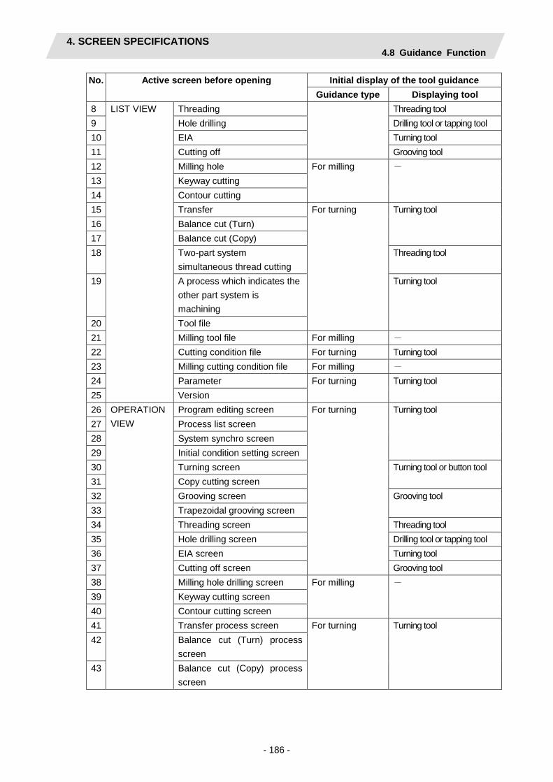
4. SCREEN SPECIFICATIONS 4.8 Guidance Function
- 186 -
No. Active screen before opening Initial display of the tool guidance Guidance type Displaying tool
8 LIST VIEW Threading Threading tool 9 Hole drilling Drilling tool or tapping tool 10 EIA Turning tool 11 Cutting off Grooving tool 12 Milling hole For milling - 13 Keyway cutting 14 Contour cutting 15 Transfer For turning Turning tool 16 Balance cut (Turn) 17 Balance cut (Copy) 18 Two-part system
simultaneous thread cutting Threading tool
19 A process which indicates the other part system is machining
Turning tool
20 Tool file 21 Milling tool file For milling - 22 Cutting condition file For turning Turning tool 23 Milling cutting condition file For milling - 24 Parameter For turning Turning tool 25 Version 26 OPERATION
VIEW Program editing screen For turning Turning tool
27 Process list screen 28 System synchro screen 29 Initial condition setting screen 30 Turning screen Turning tool or button tool 31 Copy cutting screen 32 Grooving screen Grooving tool 33 Trapezoidal grooving screen 34 Threading screen Threading tool 35 Hole drilling screen Drilling tool or tapping tool 36 EIA screen Turning tool 37 Cutting off screen Grooving tool 38 Milling hole drilling screen For milling - 39 Keyway cutting screen 40 Contour cutting screen 41 Transfer process screen For turning Turning tool 42 Balance cut (Turn) process
screen 43 Balance cut (Copy) process
screen

4. SCREEN SPECIFICATIONS 4.8 Guidance Function
- 187 -
No. Active screen before opening Initial display of the tool guidance Guidance type Displaying tool
44 OPERATION VIEW
Two-part system simultaneous thread cutting screen
Threading tool
45 Brank process screen Turning tool 46 Tool file screen 47 Milling tool file screen For milling - 48 Cutting condition file screen For turning Turning tool 49 Milling cutting condition file
screen For milling -
50 Parameter screen For turning Turning tool
(Note 3) The cursor position does not move after changing the tool type.
The cursor and scroll bar stay the same position
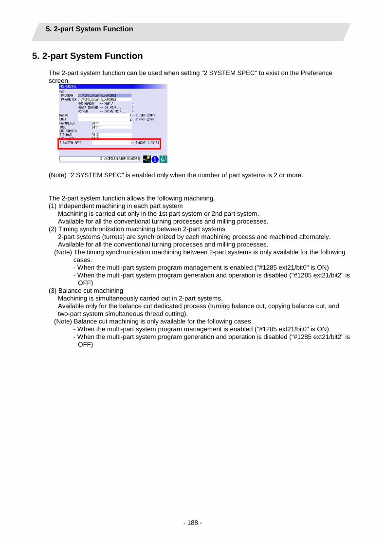
5. 2-part System Function
- 188 -
5. 2-part System Function
The 2-part system function can be used when setting "2 SYSTEM SPEC" to exist on the Preference screen.
(Note) "2 SYSTEM SPEC" is enabled only when the number of part systems is 2 or more.
The 2-part system function allows the following machining. (1) Independent machining in each part system
Machining is carried out only in the 1st part system or 2nd part system. Available for all the conventional turning processes and milling processes.
(2) Timing synchronization machining between 2-part systems 2-part systems (turrets) are synchronized by each machining process and machined alternately. Available for all the conventional turning processes and milling processes.
(Note) The timing synchronization machining between 2-part systems is only available for the following cases. - When the multi-part system program management is enabled ("#1285 ext21/bit0" is ON) - When the multi-part system program generation and operation is disabled ("#1285 ext21/bit2" is
OFF) (3) Balance cut machining
Machining is simultaneously carried out in 2-part systems. Available only for the balance cut dedicated process (turning balance cut, copying balance cut, and two-part system simultaneous thread cutting).
(Note) Balance cut machining is only available for the following cases. - When the multi-part system program management is enabled ("#1285 ext21/bit0" is ON) - When the multi-part system program generation and operation is disabled ("#1285 ext21/bit2" is
OFF)

5. 2-part System Function
- 189 -
The machining process corresponding to each machining is as follows. No. Machining
process Independent machining
Synchronization machining
Balance cut
Remarks
1 Turning Processes
-1 Turning ○ ○ ○ -2 Copy cutting ○ ○ ○
-3 Grooving ○ ○ -4 Trapezoidal
grooving ○ ○
-5 Threading ○ ○ ○ There are following restrictions for balance cut. - Machining area: Only the
outer dia. and inner dia. - Cut method: Only "Constant
area-normal" -6 Hole drilling ○ ○ -7 Cutting off ○ ○ 2 Milling -1 Milling hole ○ ○ -2 Keyway
cutting ○ ○
-3 Contour cutting
○ ○
3 Others -1 Workpiece
transfer ○ ○
(Caution)
- The machining program created with NAVI LATHE is for a part system when the multi-part system program management is disabled.
- NAVI macro program is registered only for the 1st part system because of the NC memory capacity. Accordingly, when the multi-part system program generation and operation are enabled ("#1285 ext21/bit2" is ON), a program error occurs because the 2nd part system and the following cannot call an NAVI LATHE macro program. Therefore, it is required to disable the multi-part system program generation and operation to operate the program for the 2nd part system.

5. 2-part System Function 5.1 Control Axis Configuration
- 190 -
5.1 Control Axis Configuration
The configuration of the control axis supported by this function is shown as follows.
The following axis configuration is the standard for this function.
- Workpiece spindle: 1 axis (main spindle) - Tool spindle: Up to 2 axes (1 axis for each system) - 1st part system control axis: Up to 4 axes (X, Z, Y, and C) *Y and C are used when milling function is enabled. The turret is moved by the Z axis command.
- 2nd part system control axis: Up to 4 axes (X, Z, Y, and C) *Y and C are used when milling function is enabled. The turret is moved by the Z axis command. Z axis direction is the same as the 1st part system.
- Phase difference between 1st part system and 2nd part system: 180°
The following changes to the above are available. (1) Change to spindle movement type
When the spindle moves according to the Z axis command, change the following NAVI dedicated parameter.
- #1103 $1 Z axis movement type, #1104 $2 Z axis movement type (Setting value: 1 = Turret movement type, 2 = Spindle movement type) * Default setting is 1.
Some spindle movement types using the mixed synchronization control or control axis superimposition of NC are required to set the NC parameter separately. Refer to "7. RESTRICTIONS FOR CNC FUNCTION SPECIFICATIONS" for the setting of NC parameter.
(2) Change to Z axis direction reverse type
When the Z axis direction of the 2nd part system is reverse to the 1st part system, change the following parameter.
- #1105 $2 Z axis direction (Setting value: 1 = Same direction with the 1st part system, 2 = Reverse direction to the 1st part system) * Default setting is 1. (Note) Z axis direction of the 1st part system is fixed.
(3) Change to the type with sub spindle
For the type with sub spindle, change the following parameter. - #1001 Sub spindle specification (Setting value: 0 = NONE 1 = EXIST) * Default setting is 0 (Note) Separately setting the parameter #1002 or later is also required.
The machining on the sub spindle side is available for the type with sub spindle. Note that the simultaneous machining of the both spindles, which the workpieces are set on both of the main spindle and sub spindle, is not available.
X1
$1 Main SP
$2
X2
Z2
Y2
Z1 Y1
Sub SP
$2
X2
Z2
Y2
C1
A,B
Z1
X1
$1
Y1
$2 Z axis type is also available
A,B Spindle movement type is
also available
Standard configuration
Z2
X2 Y2
$2
Z axis direction reverse type is also available
Type with sub spindle is also available
(1)
(2)
(3)
(1)

5. 2-part System Function 5.2 Editing Tool Data
- 191 -
5.2 Editing Tool Data
When the 2-part system specification is enabled, the part system changeover of the tool data is available on the tool file screen and mill tool file screen. Select the part system to input the tool data with the [$<->$] menu, and input the tool data. The selected part system is displayed on the upper left of the data input table.
Refer to "4.4.1 Tool File Screen for Turning" and "4.4.2 Tool File Screen for Milling" for details.
5.3 Editing Parameter
When the 2-part system specification is enabled, the [2 SYSTEM] menu on the parameter screen is enabled and parameters for 2-part systems can be set.
Refer to "4.5.1 Parameter Screen" for details.
Example of tool file screen
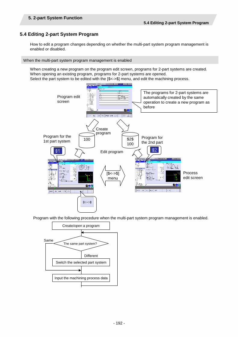
5. 2-part System Function 5.4 Editing 2-part System Program
- 192 -
5.4 Editing 2-part System Program
How to edit a program changes depending on whether the multi-part system program management is enabled or disabled.
When the multi-part system program management is enabled
When creating a new program on the program edit screen, programs for 2-part systems are created. When opening an existing program, programs for 2-part systems are opened. Select the part system to be edited with the [$<->$] menu, and edit the machining process.
Program with the following procedure when the multi-part system program management is enabled.
Switch the selected part system
Input the machining process data
Same
Different
Create/open a program
The same part system?
[$<->$] menu
100 $2$ 100
The programs for 2-part systems are automatically created by the same operation to create a new program as before
Program for the 1st part system
Program for the 2nd part
Program edit screen
Process edit screen
Create program
Edit program

5. 2-part System Function 5.4 Editing 2-part System Program
- 193 -
(1) Creating or opening a program The operation method for the program edit screen is the same as when the 2-part system specification is disabled. When creating a program with the [NEW] menu, a program for the 1st part system (the program with the specified name) and a program for the 2nd part system (the program with the name added "$2$" to the beginning of the specified one) are created. If opening a program which only either part system exists on the [OPEN] menu, the program for not existing part system is automatically created. The selected part system is switched to the 1st part system when creating or opening a program.
(2) Selecting the part system to edit
The selected part system is displayed at the top of the screen. The selected part system is switched by pressing the part system changeover menu ([$<->$]) which is displayed when activating LIST VIEW. (The selected part system switches from $1->$2->$1 … each time this menu key is pressed.)
(3) Adding a machining process
A process is added to the program of selectd part system by pressing the [NEW] menu with activating LIST VIEW. When the balance cut process is added, it is also added to the program of non-selected part system. When a process other than the balance cut process is added, the process indicating that the other part system is in machining for timing synchronization is automatically inserted to keep the synchronization between the systems.
(4) Editing data of the machining process
- Turning process and milling process Select the tool corresponding to the selected part system, and other editing method is the same as when the 2-part system specification is disabled.
- Assist process (Transfer process) The operation method is the same as when the 2-part system specification is disabled.
- Balance cut process
Data other than tool registration No. and tool No. are common to both systems for the balance cut process. Therefore, the edited contents are saved to programs of both part systems regardless of the selected part system.
Part system changeover menu
Selected part system display
Set for each system
The same as 1-part system specification

5. 2-part System Function 5.4 Editing 2-part System Program
- 194 -
(5) Displaying LIST VIEW
The contents of the selected part system are displayed on LIST VIEW. The process indicating that the other part system is in machining is displayed as a blank based on the synchronization between the systems.
$1 LIST VIEW $2 LIST VIEW Remarks 0 INIT 0 INIT 1 DR 1 (Blank) $1 operation only; $2 waiting 2 TURN-FACE R 2 (Blank) 3 TURN-FACE F 3 (Blank) 4 ! TURN-OUT R 4 ! TURN-OUT R Balance cut ($1,$2
simultaneously) 5 ! TURN-OUT F 5 ! TURN-OUT F 6 (Blank) 6 GRV-OUT $2 operation only; $1 waiting 7 THD-OUT R 7 (Blank) $1 operation only; $2 waiting 8 THD-OUT F 8 (Blank)
(6) Editing machining order
The machining order and the part system to machine can be changed after creating a program. This operation is carried out on LIST VIEW menu or System synchro screen.
Refer to "Operating Process" and "System Synchro Screen" for details.
LIST VIEW menu System synchro screen
The processes for 2-part systems are displayed simultaneously.
This allows operating in the same way as when the 2-part system specification is disabled.

5. 2-part System Function 5.4 Editing 2-part System Program
- 195 -
When the multi-part system program management is disabled
When creating a new program on the program edit screen, a program for one part systems is created. The machining processes are edited by the selected machining part system on the initial setting screen.
Program with the following procedure when the multi-part system program management is disabled.
Select a part system
Input the machining process data
Create/open a program
100
Program edit screen
The programs for 1 part system is automatically created by the same operation to create a new program as before
Create program
Edit program
Initial setting screen
Part system selection
Process edit screen

5. 2-part System Function 5.4 Editing 2-part System Program
- 196 -
(1) Creating or opening a program The operation method for the program edit screen is the same as when the 2-part system specification is disabled. When creating a program with the [NEW] menu, a program for one part system is created. When creating a program with the [NEW] menu, the program is created in the condition of the first part system selected.
(2) Selecting the part system to edit
Select the part system to edit at the setting item "PART SYSTEM SEL." on the initial setting screen. (1: $1 (1st part system), 2: $2 (2nd part system)) (Note) The selected part system is not displayed in the upper screen.
(3) Adding a machining process
The operation method is the same as when the 2-part system specification is disabled. (4) Editing a machining process
・Turning process and milling process Select the tool corresponding to the selected part system, and other editing method is the same as when the 2-part system specification is disabled.
・Assist process (Transfer process) The operation method is the same as when the 2-part system specification is disabled.
(Note) The balance cut process cannot create when the multi-part system program management is
disabled. (5) Displaying LIST VIEW
The displaying method is the same as when the 2-part system specification is disabled.
Machining part system selection data
Set for each system
The same as 1-part system specification

5. 2-part System Function 5.5 Check for 2-part System Programs (Checker Function)
- 197 -
5.5 Check for 2-part System Programs (Checker Function)
When 2-part system specification is enabled, the drawing on the checker screen is performed for the 2-part systems. When the 2-part system specification is enabled, the machining shapes are drawn for 2-part systems on the checker screen. The drawing of each part system is identifiable with a color. ・Selected part system: drawn in green ・Non-selected part system: drawn in gray The selected part system is indicated on the right side of the screen with the icon, and it switches at the [$<->$] menu.
Refer to "4.7 Program Checker Screen" for details.
Drawing for $1
Drawing for $2
Simultaneous drawing for 2-part systems.
Display the selected part system
Graphic area

5. 2-part System Function 5.6 Machining Motion
- 198 -
5.6 Machining Motion
5.6.1 About the Setting of the Work Coordinate System
The workpiece coordinate zero point is set for every part system. It is possible to set a different zero point position for each part system. But when machining the balance cut process, the workpiece coordinate zero point of both part systems need to be the same.
<Main spindle side> $1 workpiece
coordinate system
$1 outer diameter
$1 inner diameter
$1 +Z $1 -Z
$2 –Z $2 workpiece coordinate system
$1 inner diameter
$1 outer diameter
Sum of $1 +Z and $1-Z
$2 –Z sub spindle
$1 –Z sub spindle
$2 workpiece coordinate system sub spindle
$1 workpiece coordinate system sub spindle
<Sub spindle side>
$2 +Z
5.6.2 Independent Machining at Each Part System
(1) Machining motion for the 1st part system The machining motion for the 1st part system is the same as when the 2-part system specification is disabled.
(2) Machining motion for the 2nd part system (a) Approach and escape motions
The clearances such as tool turning clearance, safe profile clearance, etc. use the same value as the 1st part system, and the tool fixed point return position uses another value. The movement order of the axis for the approach and escape is the same specification as the 1st part system.
Tool turning clearance X
Tool turning clearance Z
$2 tool fixed point return position Z
$2 tool fixed poin return position X
Reference position
Safe profile clearance Z
Safe profile clearance X

5. 2-part System Function 5.6 Machining Motion
- 199 -
(b) Cutting motion Cutting motion (motion after the approach to before the escape) is the same specification as the 1st part system. However, because of the phase difference with the 1st part system, the setting position of C axis on the screen is shifted by 180 degree in the milling machining.
The following case uses the mixed synchronous control. In that case, parameter setting of the NC is necessary. ・When the machining part system commands to Z axis of other part system
・When the machining part system commands to C axis of other part system (Milling machining) The cases below also run automatic start to the non-machining part system in the program operation. In the result, each axis of non-machining part system returns the zero point, and moves to the part system change safe position. ・The multi-part system program management is enabled. (“#1285 ext21/bit0” is ON) ・The multi-part system program generation and operation is disabled. (“#1285 ext21/bit2” is
OFF)
Setting position on the screen
45
45
225
Z1
X1 $1
SP
$2 X2
Z1
X1 $1
SP
$2 X2
Example of 2nd part system command to Z axis of 1st par system
Machining position for
1st part system
Machining position for
2nd part system

5. 2-part System Function 5.6 Machining Motion
- 200 -
5.6.3 Timing Synchronization Process between 2-part Systems
2-part systems (turrets) are synchronized by each machining process and machined alternately. (1) Changing operation for machining part system
When changing the machining part system, the waiting part system moves to the part system change safe position. The machining part system moves to the machine start position after the waiting part system moved to the part system change safe position.
(Note) The part system change safe position is designated in the parameter (#1101 $1 SYS CHG
SAFE POS X, #1102 $2 SYS CHG SAFE POS X).
For the spindle movement type, when changing the machining part system, Z axis moves to the zero point of workpiece coordinate system.
(2) Approach and escape motions Same as the independent machining.
(3) Cutting motion The cutting motion (after the approach to before the escape) is the same specification as the independent machining.
SP
SP
Z1
X1
$1 is at machine end position
$2 is at part system change safe
$1 SP
$1 moves to part system change safe position
$2 is at part system change safe position
$2 moves to machine start position
$1 is at part system change safe position
$2 X2
Z1 X1 $1
$2
$2
Z1 X1 $1
X2
X2
Z2 Z2
Z2
SP
SP
Z1 X1
$1 is at machine end position
$2 is at part system change safe
position
$1 SP
$1 moves to part system change safe position
Z axis of $1 moves to zero point of work coordinate system
$2 is at part system change safe position
$2 moves to machine start position
$1 is at part system change safe position
$2 X2
Z1
X1 $1
$2
$2
Z1
X1 $1
X2
X2
Z2 Z2
Z2

5. 2-part System Function 5.6 Machining Motion
- 201 -
5.6.4 Balance Cut
Machining is simultaneously carried out in 2-part systems. Available only for the balance cut dedicated process (turning balance cut, copying balance cut, and two-part system simultaneous thread cutting). In Comparison with the each part system independent machining, this is able to set the cutting speed faster.
(1) Balance cut (turn)
The turning process is simultaneously carried out in 2-part systems. The machining motions of each part system are the same specification as the independent machining.
(2) Balance cut (copy) The copy cutting process is simultaneously carried out in 2-part systems. The machining motions of each part system are the same specification as the independent machining.
(3) Two-part system simultaneous thread cutting The threading process is simultaneously carried out in 2-part systems. Two-part system simultaneous thread cutting cycle II (G76.2) of NC is used. Refer to “MITSUBISHI CNC M700V/M70V Series Programing Manual (Lathe System) IB-1500924” for the machine operations.

6. PROGRAM SPECIFICATIONS
- 202 -
6. PROGRAM SPECIFICATIONS
The configuration of the program related to the NAVI LATHE is as shown below.
(1) NC program (2) File program (3) Miscellaneous parameter program (4) Macro program
(Note) Macro program is registered in the NC memory of 700/70 series in which NAVI LATHE is installed.
O100 ( ) : :G65 P○○○G65 P×××G65 P△△△ : :
NAVI LATHE
O100 ( ) : :G65 P○○○G65 P×××G65 P△△△ : :
NC program Macro program
O○○○ ( )G0 X#1 Y#2; : :
O××× ( )G0 X#1 Y#2; : :
O△△△ ( )G0 X#1 Y#2; : :
For grooving
For threading
For hole drilling
:Tool file
Cuttingcondition file
File program
Programinput/output
NC program
#○○=1;:
Parameter program
Macrocall
O****( )T#1; : :
For tool change
Macrocall

6. PROGRAM SPECIFICATIONS 6.1 NC Program
- 203 -
6.1 NC Program
NAVI LATHE outputs the NC programs. The NC program No. ranges from 1 to 7999 or from 10000 to 99999999.
6.1.1 Output Method for NC Program
In the NAVI LATHE, the NC program is output in the process unit. The output method for the NC program is as follows.
Process Machining program
Hole drilling (Drill Line) Turning (Outer diameter) Turning (Face) Grooving (Outer diameter) Threading (Outer diameter) Milling hole drilling (Drill Front face) Keyway cutting (Outer surface) Contour cutting (Side surface)
(NAVI-HOLE-PECK); • • • (/NAVI); (NAVI-TURN-OUT); • • • (/NAVI); (NAVI-TURN-FACE); • • • (/NAVI); (NAVI-GRV-OUT); • • • (/NAVI); (NAVI-THD-OUT); • • • (/NAVI); • • • (NAVI-M HOLE-FACE-DRILL); • • • (/NAVI); (NAVI-M KWAY-OUT); • • • (/NAVI); (NAVI-M CONT-SIDE); • • • (/NAVI); • • •
Machining start comment Process data Process end comment

6. PROGRAM SPECIFICATIONS 6.1 NC Program
- 204 -
Process start comment
Process Comment Remarks Initial setting (NAVI-INIT); The symbol which indicates the
machining area is set in the **** part. OUT: Outer diameter IN: Inner diameter FACE: Front face BACK: Back surface
Turning (NAVI-TURN-****) Copy cutting (NAVI-COPY-****) Threading (NAVI-THD-****) Trapezoidal grooving (NAVI-TGRV-****) Hole drilling Drilling (NAVI-HOLE-DRILL);
Pecking (NAVI-HOLE-PECK); Boring (NAVI-HOLE-BORE); Tapping (NAVI-HOLE-TAP);
EIA (NAVI-EIA); Milling hole drilling
Drilling (NAVI-M HOLE-****-DRILL); The symbol which indicates the machining area is set in the **** part. OUT: Outer surface SIDE: Side surface FACE: Front face BACK: Back surface
Deep hole drilling
(NAVI-M HOLE-****-PECK);
Boring (NAVI-M HOLE-****-BORE); Tapping (NAVI-M HOLE-****-TAP);
Keyway cutting (NAVI-M KWAY-****); Contour cutting (NAVI-M CONT-****); Transfer (NAVI-TRANS-TO-****); The symbol which indicates the
transfer direction is set in the **** part. MAIN: Transfer to the main spindle SUB: Transfer to the sub spindle SYNC: Spindle synchronization
Balance cut (turn) (NAVI-!TURN-****); The symbol which indicates the machining area is set in the **** part. OUT: Outer diameter IN: Inner diameter FACE: Front face BACK: Back surface
Balance cut (copy) (NAVI-!COPY-****); Two-part system simultaneous thread cutting (identical screw)
(NAVI-!THD1-****);
Waiting process (NAVI-WAIT); End process (NAVI-FIN);

6. PROGRAM SPECIFICATIONS 6.1 NC Program
- 205 -
Process data
Process Program block Remarks
Initial setting G65 P9110 A B C D E F・・・
Z; Zero point return, spindle clamp
Turning ROUGH G65 P9120 C F I ・・・Z; G96 S_ M3(4) ; G0 X_ Z_ F_; G41(42); G71(72) U(W)_ R_ H_; G71(72) P_ Q_ U_ W_; N_ G0 X_ Z_; ・・・ N_ G1 X_ Z_; N_ G65 P9105 C; G40; M5;
Movement to the tool change position, T command Workpiece coordinate system setting Movement to the approach point Nose R compensation mode ON Start point of the cutting shape End point of the cutting shape Move. to the safe profile clearance position Nose R compen. mode cancel.
FIN G65 P9120 C F I ・・・Z; G96 S_ M3(4) ; G0 X_ Z_ F_; G41(42); G70 P_ Q_; GOTO N_ N_ G0 X_ Z_; ・・・ N_ G1 X_ Z_; N_ G65 P9105 C; G40; M5;
Movement to the tool change position, T command Workpiece coordinate system setting Movement to the approach point Nose R compensation mode ON Start point of the cutting shape End point of the cutting shape Move. to the safe profile clearance position Nose R compen. mode cancel.

6. PROGRAM SPECIFICATIONS 6.1 NC Program
- 206 -
Process Program block Remarks
Copy cutting ROUGH G65 P9130 C F I ・・・Z; G96 S_ M3(4) ; G0 X_ Z_ F_; G41(42); G73 U_ W_ R_; G73 P_ Q_ U_ W_; N_ G0 X_ Z_; ・・・ N_ G1 X_ Z_; N_ G65 P9105 C; G40; M5;
Movement to the tool change position, T command Workpiece coordinate system setting Movement to the approach point Nose R compensation mode ON Start point of the cutting shape End point of the cutting shape Move. to the safe profile clearance position Nose R compen. mode cancel
FIN G65 P9130 C F I ・・・Z; G96 S_ M3(4) ; G0 X_ Z_ F_; G41(42); G70 P_ Q_; GOTO N_ N_ G0 X_ Z_; ・・・ N_ G1 X_ Z_; N_ G65 P9105 C; G40; M5;
Movement to the tool change position, T command Workpiece coordinate system setting Movement to the approach point Nose R compensation mode ON Start point of the cutting shape End point of the cutting shape Move. to the safe profile clearance position Nose R compen. mode cancel
Threading G65 P9140 A B C・・・Z; Grooving G65 P9150 B C D・・・Z; Trapezoidal grooving G65 P9160 A B C・・・Z; Hole drilling
DRILL G65 P9170 C D E・・・Z; Common in drilling, pecking, boring and tapping. PECK
BORING TAP
EIA process ・・・; Cut off G65 P9107 C D F・・・Z; Milling hole drilling
DRILL G65 P9171 C D F・・・Z; Common in drilling, deep hole drilling, boring and tapping. PECK
BORING TAP
Keyway cutting G65 P9155 A C D・・・Z;
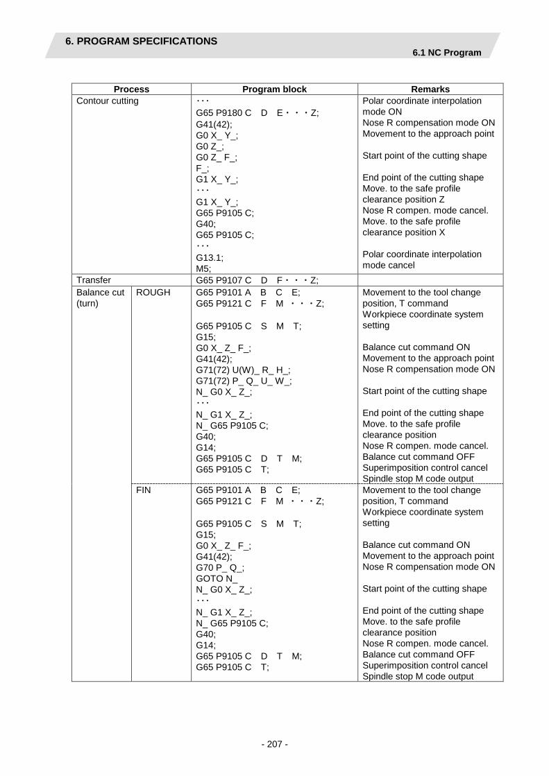
6. PROGRAM SPECIFICATIONS 6.1 NC Program
- 207 -
Process Program block Remarks
Contour cutting ・・・ G65 P9180 C D E・・・Z; G41(42); G0 X_ Y_; G0 Z_; G0 Z_ F_; F_; G1 X_ Y_; ・・・ G1 X_ Y_; G65 P9105 C; G40; G65 P9105 C; ・・・ G13.1; M5;
Polar coordinate interpolation mode ON Nose R compensation mode ON Movement to the approach point Start point of the cutting shape End point of the cutting shape Move. to the safe profile clearance position Z Nose R compen. mode cancel. Move. to the safe profile clearance position X Polar coordinate interpolation mode cancel
Transfer G65 P9107 C D F・・・Z; Balance cut (turn)
ROUGH G65 P9101 A B C E; G65 P9121 C F M ・・・Z; G65 P9105 C S M T; G15; G0 X_ Z_ F_; G41(42); G71(72) U(W)_ R_ H_; G71(72) P_ Q_ U_ W_; N_ G0 X_ Z_; ・・・ N_ G1 X_ Z_; N_ G65 P9105 C; G40; G14; G65 P9105 C D T M; G65 P9105 C T;
Movement to the tool change position, T command Workpiece coordinate system setting Balance cut command ON Movement to the approach point Nose R compensation mode ON Start point of the cutting shape End point of the cutting shape Move. to the safe profile clearance position Nose R compen. mode cancel. Balance cut command OFF Superimposition control cancel Spindle stop M code output
FIN G65 P9101 A B C E; G65 P9121 C F M ・・・Z; G65 P9105 C S M T; G15; G0 X_ Z_ F_; G41(42); G70 P_ Q_; GOTO N_ N_ G0 X_ Z_; ・・・ N_ G1 X_ Z_; N_ G65 P9105 C; G40; G14; G65 P9105 C D T M; G65 P9105 C T;
Movement to the tool change position, T command Workpiece coordinate system setting Balance cut command ON Movement to the approach point Nose R compensation mode ON Start point of the cutting shape End point of the cutting shape Move. to the safe profile clearance position Nose R compen. mode cancel. Balance cut command OFF Superimposition control cancel Spindle stop M code output

6. PROGRAM SPECIFICATIONS 6.1 NC Program
- 208 -
Process Program block Remarks
Balance cut (copy)
ROUGH G65 P9101 A B C E; G65 P9131 C F I ・・・Z; G65 P9105 C S M T; G15; G0 X_ Z_ F_; G41(42); G73 U_ W_ R_; G73 P_ Q_ U_ W_; N_ G0 X_ Z_; ・・・ N_ G1 X_ Z_; N_ G65 P9105 C; G40; G14; G65 P9105 C D T M; G65 P9105 C T;
Movement to the tool change position, T command Workpiece coordinate system setting Balance cut command ON Movement to the approach point Nose R compensation mode ON Start point of the cutting shape End point of the cutting shape Move. to the safe profile clearance position Nose R compen. mode cancel. Balance cut command OFF Superimposition control cancel Spindle stop M code output
FIN G65 P9101 A B C E; G65 P9131 C F I ・・・Z; G65 P9105 C S M T; G15; G0 X_ Z_ F_; G41(42); G70 P_ Q_; GOTO N_ N_ G0 X_ Z_; ・・・ N_ G1 X_ Z_; N_ G65 P9105 C; G40; G14; G65 P9105 C D T M; G65 P9105 C T;
Movement to the tool change position, T command Workpiece coordinate system setting Balance cut command ON Movement to the approach point Nose R compensation mode ON Start point of the cutting shape End point of the cutting shape Move. to the safe profile clearance position Nose R compen. mode cancel. Balance cut command OFF Superimposition control cancel Spindle stop M code output
Two-part system simultaneous thread cutting (identical screw)
G65 P9101 A B C E; G65 P9146 A B C ・・・Z;
End process G65 P9190; M#156;
(Note 1) Macro program No. (P***) in the table is used when user macro is selected. For the macro program No. used when MTB macro is selected, refer to the section "6.4 Macro Program".
(Note 2) The data that follows each address in the table is output at μm level. (Note 3) The programs in the above table are some examples. The output program may change by the
presence or absence of the milling interpolation, the NAVI parameter "1001 SUB SPINDLE SPEC" and the 2-part system specifications.
Process end comment
Process Program block Remarks
All processes are common. (/NAVI);

6. PROGRAM SPECIFICATIONS 6.1 NC Program
- 209 -
6.1.2 Restrictions
The NC program output from the NAVI LATHE can be edited with various commercially available editor tools. Note that there are the following restrictions.
(1) Deleting block
Deleting a block in the NC program process unit (process start comment to end comment) is no problem. However, if either block of process start comment, process data or process end comment is deleted, NAVI LATHE may not be able to edit the program. Do not delete any block of process start comment, process data or process end comment.
(2) Inserting block Inserting a block between the processes of the NC program (between the process end comment and next process start comment) is no problem. If a block is inserted into the process of the NC program (between the process start comment and process end comment), the inserted block will not be recognized in most cases while NAVI LATHE is editing the process. Note that if NAVI MILL edits the process which a block is inserted into, the block may be lost. In response to the operating process (moving process, deleting process, copying process) with NAVI LATHE, an inserted block is operated as follows.
Process operation Inserted block in the process Inserted block between the processes
Moving process Moved with the process. The inserted block is not moved. Deleting process Deleted with the process. The inserted block is not deleted. Copying process Copied with the process. The inserted block is not copied.

6. PROGRAM SPECIFICATIONS 6.1 NC Program
- 210 -
(Example1) Moving process (An inserted block exists in the process.)
Before movement After movement
(NAVI-GRV-OUT); G65 P9130 ・・・・; Process A M50; Inserted block (/NAVI); (NAVI-THD-OUT); G65 P9130 ・・・・; Process B (/NAVI);
(NAVI-THD-OUT); G65 P9130 ・・・・; Process B (/NAVI); (NAVI-GRV-OUT); G65 P9140 ・・・・; Process A M50; Inserted block (/NAVI);
Move process A right after process B.
(Example2) Moving process (An inserted block exists between the processes.)
Before movement After movement (NAVI-GRV-OUT);
G65 P9140 ・・・・; Process A (/NAVI); M50; Inserted block (NAVI-THD-OUT); G65 P9130 ・・・・; Process B (/NAVI);
M50; Inserted block (NAVI-THD-OUT); G65 P9130 ・・・・; Process B (/NAVI); (NAVI-GRV-OUT); G65 P9140 ・・・・; Process A (/NAVI);
Move process A right after process B.
(3) Changing process data
If the contents of the macro program call block in the process data is changed, editing the program with the NAVI LATHE may be disabled. Therefore, do not change the contents of the macro program call block in the process data.

6. PROGRAM SPECIFICATIONS 6.2 File Program
- 211 -
6.2 File Program
This program is used to store the contents of each NAVI LATHE file.
<Program No., Comment> No. Name User
macro No. MTB
macro No. Program comment
1 Tool file 9111 100019111 TOOL FILE 2 Cutting condition file
(Tip material) 9112 100019112 CUT CONDITION FILE TIP
3 Cutting condition file (Workpiece material)
9113 100019113 CUT CONDITION FILE TIP WORK
(Note 1) Tool files and cutting condition files are saved via "parameter path" specified in the PREFERENCE screen.
(Note 2) Tool files and cutting condition files are saved under the file name specified in the PREFERENCE screen.
6.3 Parameter Program
This program is used to store the contents of the NAVI LATHE's parameters.
<Program No., Comment> No. Name User
macro No. MTB
macro No. Program comment
1 Parameter 9114 100019114 PARAMETER
(Note 1) Parameters are saved via "parameter path" specified in the PREFERENCE screen. (Note 2) Parameters are saved under the file name specified in the PREFERENCE screen.

6. PROGRAM SPECIFICATIONS 6.4 Macro Program
- 212 -
6.4 Macro Program
This program is called from the NC program. (Macro program will be registered in the NC memory of 700/70 Series in which NAVI LATHE is installed.)
<Program No., Comment> No. Name User
macro No. MTB
macro No. Program comment
1 Macro program for waiting process
9101 100019101 WAIT-MACRO
2 Macro program for tool change 9102 100019102 TOOL-CHANGE-MACRO 3 Macro program for parameter
setting - 9108
100019104 PARAM-SET-MACRO
4 Macro program for variable control
9105 100019108 VARIABLE-CTRL-MACRO
5 Macro program for transfer process
9106 100019105 WORK-TRANS-MACRO
6 Macro program for cutting off process
9107 100019106 CUTOFF-MACRO
7 Macro program for workpiece coordinate system setting
9109 100019107 WORK-COORD-SET-MACRO
8 Macro program for INIT process
9110 100019109 INIT-MACRO
9 Macro program for turning process
9120 100019110 TURN-MACRO
10 Macro program for balance cut (turn) process
9121 100019120 TURN-BALANCE-MACRO
11 Macro program for copy-cutting process
9130 100019121 COPY-MACRO
12 Macro program for balance cut (copy) process
9131 100019130 COPY-BALANCE-MACRO
13 Macro program for threading process
9140 to 9145
100019131 THREAD-MACRO
14 Macro program for two-part system simultaneous thread cutting (identical screw) process
9146,9148 100019140 to 100019145
2SYS_THREAD
15 Macro program for grooving process
9150 to 9154
100019146,9148 GROOVE-MACRO
16 Macro program for keyway cutting process
9155 to 9158
100019150 to 100019154
KEYWAY-MACRO
17 Macro program for trapezoidal grooving process
9160 to 9166
100019155 to 10019158
TGROOVE-MACRO
18 Macro program for hole drilling process
9170 100019160 to 100019166
HOLE-MACRO
19 Macro program for milling hole drilling process
9171 to 9177
100019170 M-HOLE-MACRO
20 Macro program for contour cutting process
9180 100019171 to 10019177
CONT-MACRO
21 Macro program for cross control
9189 100019180 CROSS-MODE_ON_OFF
22 Macro program for end process
9190 100019189 END-MACRO

6. PROGRAM SPECIFICATIONS 6.4 Macro Program
- 213 -
(Note 1) Modal initialization: The following commands are output at the head of each macro program.
(a) Hole drilling fixed cycle cancel (G80) (b) Tool nose R compensation cancel (G40) (c) Plane selection Z-X(G18) (d) Absolute value command (G90) (d) is commanded only when G code system 3 or 5 is selected.
(Note 2) T command:
If "0" is specified for the tool No. when using NAVI LATHE, tool change (T command) will not be carried out. The number of digits for the tool length compensation No. is determined according to the settings of "#1098 Tlno.".
(Note 3) Reading a program again when the date of the program is updated
When the date of the following programs is updated while NAVI LATHE is running, the updated program can be read. (1) NC program (2) File program (tool file program and cutting condition file program) (3) Parameter program
When the date of the program is updated, the message to confirm the reading of the updated program is displayed. Press the [Y] key to read the program, and press the [N] key not to read the program. The screen display is updated as follows by reading the program.
- Reading the NC program The display is in the state immediately after opening the program with the [OPEN] menu.
- Reading the file program The head of the data is displayed when the file screen corresponding to the program read is displayed.
- Reading the parameter program The head of the data is displayed when the parameter screen is displayed.

6. PROGRAM SPECIFICATIONS 6.4 Macro Program
- 214 -
< Example of when the NC program is updated > (1) Update the opening NC program with NAVI
LATHE from other than NAVI LATHE. The message to confirm the reading of the
updated program appears.
(2) Press the [Y] key. The program is read and the screen display
is updated. (Note) The display is the same as the state
after opening the NC program with the [OPEN] menu.
Press the [N] key in order not to read the program.
If the program is updated when NAVI LATHE is not activated, the confirmation of reading the updated program will be performed in the next NAVI LATHE activation.

7. RESTRICTIONS FOR CNC FUNCTION SPECIFICATIONS
- 215 -
7. RESTRICTIONS FOR CNC FUNCTION SPECIFICATIONS
NAVI LATHE operations and the creations of machining programs with NAVI LATHE require the following specifications for 700/70 Series CNC functions.
Required specifications
Division Specifications Remarks Additional specifications Synchronous tapping cycle Constant surface speed control Tool offset 80 sets This is necessary when 21 or
higher value is set for the offset No.
Expansion workpiece coordinate system selection (48 sets)
This is necessary when specifying G54.1Pn (n=1 to 48) in the workpiece coordinate system.
User macro MTB macro This is necessary when the
macro program mode is MTB macro. 128KB of free space is required. (Note) MTB macro is not
available for E70. Compound type fixed cycle for the
turning
Compound type fixed cycle for turning (Type II)
Variable command 200 sets or more Conner chamfering / Corner R Milling interpolation / Polar
coordinate interpolation These are necessary for milling. The cylindrical interpolation is necessary for the G code system 6 or 7.
Cylindrical interpolation Multiple-spindle control II Spindle position control
(spindle/C axis control) Balance cut To enable the balance cut
function in the G code system 6 or 7, disable the option of mirror image for facing tool posts. Enable this function only when using the 2-part system specification. (Note) This function is invalid
for the M70 type B. Two-part system simultaneous
thread cutting Enable this function only when using the 2-part system specification. (Note) This function is invalid
for the M70 type B.
Control axis superimposition Mixed synchronous control

7. RESTRICTIONS FOR CNC FUNCTION SPECIFICATIONS
- 216 -
Division Parameter
name Setting details Remarks
Parameter specifications #1013 axname 1:X 2:Z
Address of each axis name is specified.
#1014 incax 1:U 2:W
Specify the incremental command axis name address for each axis.
#1017 rot 3:1 Specify the 3rd axis as the rotary axis for the milling machining.
#1019 dia 1(X axis):1 The diameter specification axis is selected by the X axis. The radius specification axis is selected by the other axes.
#1026 base-I X Address of the axes configuring a plane is specified. #1027 base-J Y
#1028 base-K Z #1029 aux-I X If there is an axis parallel to #1026
base_l, specify that axis address. #1030 aux-J Y,C If there is an axis parallel to #1027
base_l, specify that axis address. Set Y when G code system is any of 2 to 5. Set C when G code system is 6 or 7.
#1037 cmdtyp 3 to 6 Specify the G code system of a program. When the G code system has been changed, the macro has to be registered again.
#1076 AbsInc 1 Absolute command and incremental command are switched by the address code.
#1098 Tlno. 0 The high-order 2 digits or 3 digits are designated as tool NO. The low-order 2 digits or 1 digit are designated as tool length and wear offset number.
#1128 RstVCl 0 Specify how to handle the common variables when resetting. Common variables are not cleared after resetting. Set "0" when user macro mode is applied to the macro program. MTB macro mode does not require the setting "0".
#1129 PwrVCl 0 Specify how to handle the common variables when the power is turned ON. Common variables are not cleared after the power is turned ON. Set "0" when user macro mode is applied for the macro program. MTB macro mode does not require the setting "0".

7. RESTRICTIONS FOR CNC FUNCTION SPECIFICATIONS
- 217 -
Division Parameter
name Setting details Remarks
Parameter specifications #1181 G96_ax
1 Specify the 1st axis for the axis to be targeted for constant surface speed control.
#1183 clmp_M – Set the M code for C axis clamp. Input the same value as set in “605 C AXIS CLAMP M CODE” which is the parameter for milling.
#1146 Sclamp 1 Specify how to handle the spindle speed clamp function with G92S command. If S command and G92 command are in the same block, S command is always handled as a clamp command.
#1227 aux11 (bit5)
0 Clamp the rotation regardless of the constant surface speed mode when the spindle rotation speed clamp command is issued.
#1228 aux12 (bit5)
0 Select the workpiece coordinate for the coordinates during constant surface speed.
#1229 set01 (bit2)
0 When the start-up and cancel commands are operated during nose R and radius compensation, their blocks are not handled by intersection operation processing; they are handled as offset vectors in the direction vertical to that of the commands.
#1265 ext01 bit0: 0 bit2: 0
Select the conventional format for the following command format. • Compound type fixed cycle for
turning. • Hole drilling fixed cycle
MITSUBISHI CNC special format cannot be used.
#1273 ext09 bit2: 1 When the shape specified at the turning (ROUGH) G71/G72, or copy cutting (ROUGH) G73 is not a monotone increasing or decreasing shape, set "1".
#1280 ext16 (bit4)
0/1 Select how to command mixed control. 0: Use PLC interface signal for
mixed control 1: Use G command for mixed
control
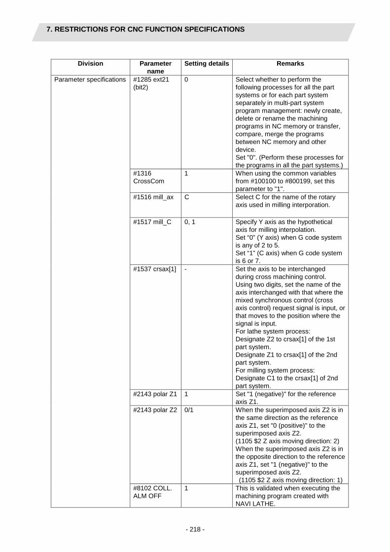
7. RESTRICTIONS FOR CNC FUNCTION SPECIFICATIONS
- 218 -
Division Parameter
name Setting details Remarks
Parameter specifications #1285 ext21 (bit2)
0 Select whether to perform the following processes for all the part systems or for each part system separately in multi-part system program management: newly create, delete or rename the machining programs in NC memory or transfer, compare, merge the programs between NC memory and other device. Set "0". (Perform these processes for the programs in all the part systems.)
#1316 CrossCom
1 When using the common variables from #100100 to #800199, set this parameter to "1".
#1516 mill_ax C Select C for the name of the rotary axis used in milling interporation.
#1517 mill_C 0, 1 Specify Y axis as the hypothetical axis for milling interpolation. Set “0” (Y axis) when G code system is any of 2 to 5. Set “1” (C axis) when G code system is 6 or 7.
#1537 crsax[1] - Set the axis to be interchanged during cross machining control. Using two digits, set the name of the axis interchanged with that where the mixed synchronous control (cross axis control) request signal is input, or that moves to the position where the signal is input. For lathe system process: Designate Z2 to crsax[1] of the 1st part system. Designate Z1 to crsax[1] of the 2nd part system. For milling system process: Designate C1 to the crsax[1] of 2nd part system.
#2143 polar Z1 1 Set "1 (negative)" for the reference axis Z1.
#2143 polar Z2 0/1 When the superimposed axis Z2 is in the same direction as the reference axis Z1, set "0 (positive)" to the superimposed axis Z2. (1105 $2 Z axis moving direction: 2) When the superimposed axis Z2 is in the opposite direction to the reference axis Z1, set "1 (negative)" to the superimposed axis Z2. (1105 $2 Z axis moving direction: 1)
#8102 COLL. ALM OFF
1 This is validated when executing the machining program created with NAVI LATHE.
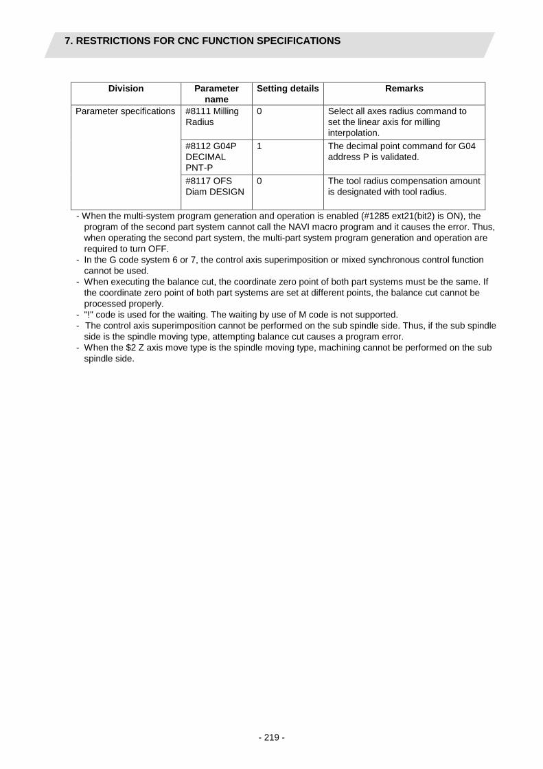
7. RESTRICTIONS FOR CNC FUNCTION SPECIFICATIONS
- 219 -
Division Parameter
name Setting details Remarks
Parameter specifications #8111 Milling Radius
0 Select all axes radius command to set the linear axis for milling interpolation.
#8112 G04P DECIMAL PNT-P
1 The decimal point command for G04 address P is validated.
#8117 OFS Diam DESIGN
0 The tool radius compensation amount is designated with tool radius.
- When the multi-system program generation and operation is enabled (#1285 ext21(bit2) is ON), the program of the second part system cannot call the NAVI macro program and it causes the error. Thus, when operating the second part system, the multi-part system program generation and operation are required to turn OFF.
- In the G code system 6 or 7, the control axis superimposition or mixed synchronous control function cannot be used.
- When executing the balance cut, the coordinate zero point of both part systems must be the same. If the coordinate zero point of both part systems are set at different points, the balance cut cannot be processed properly.
- "!" code is used for the waiting. The waiting by use of M code is not supported. - The control axis superimposition cannot be performed on the sub spindle side. Thus, if the sub spindle
side is the spindle moving type, attempting balance cut causes a program error. - When the $2 Z axis move type is the spindle moving type, machining cannot be performed on the sub
spindle side.

7. RESTRICTIONS FOR CNC FUNCTION SPECIFICATIONS
- 220 -
Listed below are the other cases which disable the machining . When selecting the main spindle:
○:machinable ×:non-machinable
No. Machine configuration Machining content 1003 $1 Z AXIS MOVE
TYPE 1004 $2 Z AXIS MOVE
TYPE $1 independent
machining $2 independent
machining Balance cut machining
1 Turret moving type Turret moving type ○ ○ ○ 2 Spindle moving type Turret moving type ○ ○ ○ 3 Turret moving type Spindle moving type ○ × × 4 Spindle moving type Spindle moving type ○ ○ ×
When selecting the sub spindle:
○:machinable ×:non-machinable
No. Machine configuration Machining content 1003 $1 Z AXIS MOVE
TYPE 1004 $2 Z AXIS MOVE
TYPE $1 independent
machining $2 independent
machining Balance cut machining
1 Turret moving type Turret moving type ○ ○ ○ 2 Spindle moving type Turret moving type × ○ × 3 Turret moving type Spindle moving type ○ × × 4 Spindle moving type Spindle moving type × × ×
(Note 1) When either the mixed control (cross axis control) II or $2 Z axis move type is the spindle moving type, the 2nd part system is unable to perform milling. Milling is enabled when $1 Z axis move type is the turret moving type, and $2 Z axis move type is the turret moving type. When performing milling, select the mixed control (cross axis control) I.
(Note 2) When the mixed control (cross axis control) II is selected, the transfer process cannot
perform at the 2nd part system. When processing the transfer, select the mixed control (cross axis control) I.
Recommended specifications
Division Specifications Remarks Additional specifications Graphic check Graphic trace
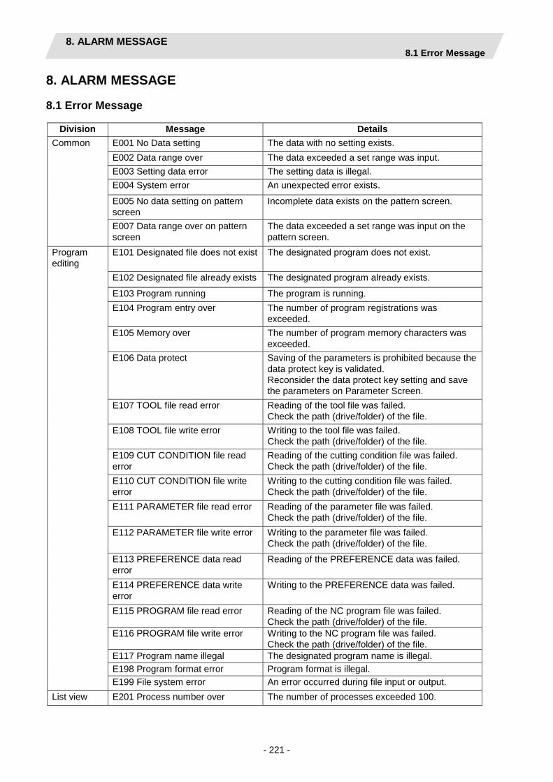
8. ALARM MESSAGE 8.1 Error Message
- 221 -
8. ALARM MESSAGE
8.1 Error Message
Division Message Details Common E001 No Data setting The data with no setting exists.
E002 Data range over The data exceeded a set range was input. E003 Setting data error The setting data is illegal. E004 System error An unexpected error exists.
E005 No data setting on pattern screen
Incomplete data exists on the pattern screen.
E007 Data range over on pattern screen
The data exceeded a set range was input on the pattern screen.
Program editing
E101 Designated file does not exist The designated program does not exist.
E102 Designated file already exists The designated program already exists.
E103 Program running The program is running. E104 Program entry over The number of program registrations was
exceeded. E105 Memory over The number of program memory characters was
exceeded. E106 Data protect Saving of the parameters is prohibited because the
data protect key is validated. Reconsider the data protect key setting and save the parameters on Parameter Screen.
E107 TOOL file read error Reading of the tool file was failed. Check the path (drive/folder) of the file.
E108 TOOL file write error Writing to the tool file was failed. Check the path (drive/folder) of the file.
E109 CUT CONDITION file read error
Reading of the cutting condition file was failed. Check the path (drive/folder) of the file.
E110 CUT CONDITION file write error
Writing to the cutting condition file was failed. Check the path (drive/folder) of the file.
E111 PARAMETER file read error Reading of the parameter file was failed. Check the path (drive/folder) of the file.
E112 PARAMETER file write error Writing to the parameter file was failed. Check the path (drive/folder) of the file.
E113 PREFERENCE data read error
Reading of the PREFERENCE data was failed.
E114 PREFERENCE data write error
Writing to the PREFERENCE data was failed.
E115 PROGRAM file read error Reading of the NC program file was failed. Check the path (drive/folder) of the file.
E116 PROGRAM file write error Writing to the NC program file was failed. Check the path (drive/folder) of the file.
E117 Program name illegal The designated program name is illegal. E198 Program format error Program format is illegal. E199 File system error An error occurred during file input or output.
List view E201 Process number over The number of processes exceeded 100.

8. ALARM MESSAGE 8.1 Error Message
- 222 -
Division Message Details
Turning, copy cutting
E211 Geometry record number entry over
Exceeded the number of records currently registered.
E212 Geometry maximum record number over
The maximum number of records (35) is exceeded.
E213 Geometry record number entry over
The record No. is illegal.
E214 I,K disagreement with A (angle)
Linear I,K and angle are contradictory.
E214 I,J disagreement with A (angle)
Linear I,J and angle are contradictory.
E214 J,K disagreement with A (angle)
Linear J,K and angle are contradictory.
E215 No end point on surface (line number)
The end point does not exist on the surface.
E216 No continuity with previous line (line number)
There is no continuity with the previous line.
E217 No circle (line number) Circle cannot be determined from set data. E218 Corner C error (line number) Corner C cannot be determined. E219 Corner R error (line number) Corner R cannot be determined. E220 shape input error (line number)
Shape input error
E221 Last line has corner R/C (line number)
Corner R/C was set in the last line.
E222 Start point error (line number) Start point error E223 Corner no move The block following corner R or corner C is not a
movement command. E224 Corner short When issuing corner C or corner R command, the
movement distance in the next block is smaller than corner C or corner R.
E225 Cutting shape reversed The cutting shape is not incremented or decremented monotonously.
E226 Depth of cutting shape <= CUT AMOUNT
“Depth of cutting shape <= cutting amount” is applied.
E227 Starting shape not linear Starting shape is circular. When OPEN type is selected in PARTS, circular cannot be specified for the starting shape.
E228 APPRCH POS illegal Approach point is illegal for the cutting shape. E229 Halfway position of cutting shape illegal
Halfway position of the cutting shape is beyond the end position.
Threading E231 H < FIN ALLOW "Thread height < finishing allowance" is applied. E232 H < CUT AMOUNT "Thread height < cutting amount" is applied. E233 THREAD angle > 45 deg. "Thread angle > 45°" is applied for taper thread. E234 THREAD length = 0 "Thread length = 0" is applied. E235 PITCH isn't set Thread height cannot be calculated because the
pitch is not set. Set the pitch. Grooving E241 W < TOOL WIDTH "Groove width < tool width" is applied.
E242 GRV Height < CUT AMOUNT "Groove height < cutting amount" is applied.
E243 GRV Height < |Corner Size| "Groove height < corner size" is applied. E244 Corner R/C input error Corner R/C is specified for the taper grooving. E245 GRV angle > 45 deg. "Groove angle > 45°" is applied for taper groove.
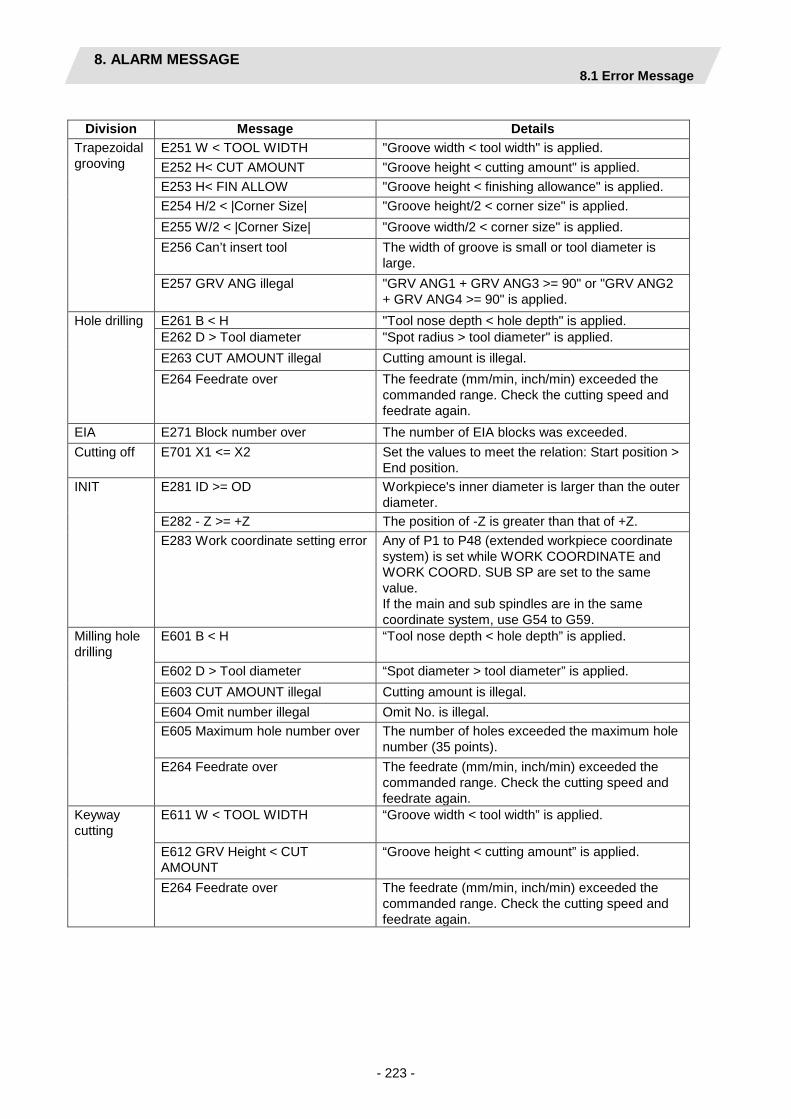
8. ALARM MESSAGE 8.1 Error Message
- 223 -
Division Message Details
Trapezoidal grooving
E251 W < TOOL WIDTH "Groove width < tool width" is applied. E252 H< CUT AMOUNT "Groove height < cutting amount" is applied. E253 H< FIN ALLOW "Groove height < finishing allowance" is applied. E254 H/2 < |Corner Size| "Groove height/2 < corner size" is applied. E255 W/2 < |Corner Size| "Groove width/2 < corner size" is applied. E256 Can’t insert tool The width of groove is small or tool diameter is
large. E257 GRV ANG illegal "GRV ANG1 + GRV ANG3 >= 90" or "GRV ANG2
+ GRV ANG4 >= 90" is applied. Hole drilling E261 B < H "Tool nose depth < hole depth" is applied.
E262 D > Tool diameter "Spot radius > tool diameter" is applied. E263 CUT AMOUNT illegal Cutting amount is illegal. E264 Feedrate over The feedrate (mm/min, inch/min) exceeded the
commanded range. Check the cutting speed and feedrate again.
EIA E271 Block number over The number of EIA blocks was exceeded. Cutting off E701 X1 <= X2 Set the values to meet the relation: Start position >
End position. INIT E281 ID >= OD Workpiece's inner diameter is larger than the outer
diameter. E282 - Z >= +Z The position of -Z is greater than that of +Z. E283 Work coordinate setting error Any of P1 to P48 (extended workpiece coordinate
system) is set while WORK COORDINATE and WORK COORD. SUB SP are set to the same value. If the main and sub spindles are in the same coordinate system, use G54 to G59.
Milling hole drilling
E601 B < H “Tool nose depth < hole depth” is applied.
E602 D > Tool diameter “Spot diameter > tool diameter” is applied. E603 CUT AMOUNT illegal Cutting amount is illegal. E604 Omit number illegal Omit No. is illegal. E605 Maximum hole number over The number of holes exceeded the maximum hole
number (35 points). E264 Feedrate over The feedrate (mm/min, inch/min) exceeded the
commanded range. Check the cutting speed and feedrate again.
Keyway cutting
E611 W < TOOL WIDTH “Groove width < tool width” is applied.
E612 GRV Height < CUT AMOUNT
“Groove height < cutting amount” is applied.
E264 Feedrate over The feedrate (mm/min, inch/min) exceeded the commanded range. Check the cutting speed and feedrate again.

8. ALARM MESSAGE 8.1 Error Message
- 224 -
Division Message Details Contour cutting
E621 FH > WIDTH “Finishing allowance FH > cutting width” is applied.
E622 FV > DEPTH “Finishing allowance FV > cutting depth” is applied.
E623 WIDTH < TOOL WIDTH “Cutting width < tool width” is applied. E624 DEPTH < CUT AMOUNT “Cutting depth < cutting amount” is applied. E211 Geometry record number entry over
Exceeded the number of records currently registered.
E212 Geometry maximum record number over
The maximum number of records (35) is exceeded.
E213 Geometry record number entry over
The record No. is illegal.
E214 I,K disagreement with A (angle)
Linear I,K and angle are contradictory.
E214 I,J disagreement with A (angle)
Linear I,J and angle are contradictory.
E214 J,K disagreement with A (angle)
Linear J,K and angle are contradictory.
E215 No end point on surface (line number)
The end point does not exist on the surface.
E216 No continuity with previous line (line number)
There is no continuity with the previous line.
E217 No circle (line number) Circle cannot be determined from set data. E218 Corner C error (line number) Corner C cannot be determined. E219 Corner R error (line number) Corner R cannot be determined. E220 shape input error (line number)
Shape input error
E221 Last line has corner R/C (line number)
Corner R/C was set in the last line.
E222 Start point error (line number) Start point error E223 Corner no move The block following corner R or corner C is not a
movement command. E224 Corner short When issuing corner C or corner R command, the
movement distance in the next block is smaller than corner C or corner R.
E264 Feedrate over The feedrate (mm/min, inch/min) exceeded the commanded range. Check the cutting speed and feedrate again.
OTHERS E291 Memory over The number of program memory characters was exceeded during macro transfer.
E292 Program entry over The number of program registrations was exceeded during macro transfer.
E293 Macro transporting error An error occurred during macro transfer. E294 Program running The program is running. E295 Tool register number over The number of tools registered has exceeded 100.

8. ALARM MESSAGE 8.2 Operation Message
- 225 -
8.2 Operation Message
Division Message Details Common OK? (Y/N) Message to confirm the operation.
Y: Execute the operation. N: Do not execute the operation.
Save data?(Y/N) Message to confirm saving data Y: Save data. N: Do not save data.
Clear the pattern data? (Y/N) Message to confirm clearing the pattern data Y: Clear the pattern data N: Cancel the pattern change.
Delete OK? (Y/N) Message to confirm deleting the program or process data
Y: Delete the program or process data. N: Do not delete the program or process data.
Select the position, please During process movement mode. Loading program The program is being loaded. No init process. Create OK?(Y/N) INIT process creation confirmation
Edited the program that was not created with NAVI LATHE.
Y: Create the INIT process. N: Cancel opening the program.
The data was changed. Save the changes?(Y/N)
Save confirmation for unsaved data Y: Save data. N: Not save data.
The page cannot be changed during edit.
Editing the process data. Switch the screen after the saving operation.
Macro transporting complete Macro transporting complete Data protect Saving of the program, file, parameters is
prohibited because the data protect key is validated. Reconsider the data protect key setting.
File reload NC program has been changed. Reloaded? (Y/N)
A message to confirm whether to update the program opened in NAVI LATHE. The opened program in the NAVI LATHE was updated by an external device.
Y: Open the updated program. N: Not open the updated program.
TOOL file was changed. Reloaded? (Y/N)
A message to confirm whether to update the data of TOOL file. The TOOL file was updated by an external device.
Y: Open the updated TOOL file. N: Not open the updated TOOL file.
CUT CONDITION file was changed. Reloaded? (Y/N)
A message to confirm whether to update the contents of CUT CONDITION file (tip materials or workpiece materials). The CUT CONDITION file was updated by an external device.
Y: Open the updated CUT CONDITION file. N: Not open the updated CUT CONDITION file.

8. ALARM MESSAGE 8.2 Operation Message
- 226 -
Division Message Details File reload PARAMETER file was changed.
Reloaded? (Y/N) A message to confirm whether to update the PARAMETER contents. The PARAMETER file was updated by an external device.
Y: Open the updated PARAMETER file. N: Not open the updated PARAMETER file.
NC program has been deleted. Initialize? (Y/N)
A message to confirm whether to cancel the program editing. The opened program in the NAVI LATHE has been deleted by an external device.
Y: Cancel the program editing. N: Not cancel the program editing.
TOOL file was deleted. Initialize? (Y/N)
A message to confirm whether to restore the contents of TOOL file to the default. The TOOL file was deleted by an external device.
Y: Restore the contents of TOOL file to the default value.
N: Not restore the contents of TOOL file to the default value.
CUT CONDITION file was deleted. Initialize? (Y/N)
A message to confirm whether to restore the contents of CUT CONDITION file (tip materials or workpiece materials) to the default. The CUT CONDTION file was deleted by an external device.
Y: Restore the contents of CUT CONDITION file to the default value.
N: Not restore the contents of CUT CONDITION file to the default value.
PARAMETER file was deleted. Initialize? (Y/N)
A message to confirm whether to restore the contents of PARAMETER file to the default. The PARAMETER file was deleted by an external device.
Y: Restore the contents of PARAMETER file to the default value.
N: Not restore the contents of PARAMETER file to the default value.
Reload completed Reload completed Initialize completed Initialize completed
Tool file Delete OK? (Y/N) Message to confirm deleting the tool data column. Y: Delete. N: Do not delete.
Clear OK? (Y/N) Message to confirm clearing the tool data. Y: Clear. N: Do not clear.
Paste OK? (Y/N) Message to confirm pasting the tool data. Y: Paste. N: Do not paste.
Checker Stop drawing The shape drawing has been stopped. On drawing The shape drawing is being carried out. Finish drawing The shape drawing has been completed.

APPENDIX 1. VARIABLES USED IN NAVI LATHE
- 227 -
APPENDIX 1. VARIABLES USED IN NAVI LATHE
NAVI LATHE uses the following variables to run an NC program. The data meanings of the variables change according to the process in operation and the setting of the parameter "1001 SUB SPINDLE SPEC".
(1) Operation variables during program operation
- Parameter “1001 SUB SPINDLE SPEC” NONE
Common variable No. Data name Setting range Standard
value Remarks User macro mode
MTB macro mode
#150 #450 WORK COORDINATE 54 to 59, 101 to 148 54 Variable for operation
#151 #451 COOLANT 0 to 1 1 Variable for operation
#152 #452 TOOL CHANGE POS 1 to 3 1 Variable for operation
#153 #453 FIN TOOL RET 1 to 3 1 Variable for operation
#154 #454 END POS X -99999.999 to 99999.999mm -9999.9999 to 9999.9999inch
0 Variable for operation
#155 #455 END POS Z 0 Variable for operation
#156 #456 END M CODE 1 to 3 1 Variable for operation
#157 #457 OUTSIDE DIA 0.001 to 99999.999mm 0.0001 to 9999.9999inch
100 Variable for operation
#158 #458 +Z -99999.999 to 99999.999mm -9999.9999 to 9999.9999inch
100 Variable for operation
#159 #459 Milling interpolation specification
0: NONE, 1: EXIST 0 Variable for operation
- Parameter “1001 SUB SPINDLE SPEC” EXIST
Common variable No. Data name Setting range Standard
value Remarks User macro mode
MTB macro mode
#150 #450 WORK COORDINATE 54 to 59, 101 to 148 54 Variable for operation
#151 #451 COOLANT 0 to 1 1 Variable for operation
#152 #452 TOOL CHANGE POS 1 to 3 1 Variable for operation
#153 (Integer part)
#453 (Integer part)
FIN TOOL RET 1 to 3 1 End process
START SP 1: MAIN SP, 2: SUB SP 1 Excluding end process
#153 (decimal part)
#453 (decimal part)
WORK CARRING OUT
0: NONE, 1: EXIST 0

APPENDIX 1. VARIABLES USED IN NAVI LATHE
- 228 -
Common variable No. Data name Setting range Standard
value Remarks User macro mode
MTB macro mode
#154 #454 END POS X -99999.999 to 99999.999mm -9999.9999 to 9999.9999inch
0 End process
WORK COORDINATE SUB SPIN
54 to 59, 101 to 148 54 Excluding end process
#155 #455 END POS Z -99999.999 to 99999.999mm -9999.9999 to 9999.9999inch
0 Variable for operation
#156 #456 END M CODE 1 to 3 1 Variable for operation
#157 #457 OUTSIDE DIA 0.001 to 99999.999mm 0.0001 to 9999.9999inch
100 Variable for operation
#158 #458 +Z -99999.999 to 99999.999mm -9999.9999 to 9999.9999inch
100 Variable for operation
#159 #459 Milling interpolation specification
0: NONE, 1: EXIST 0 Variable for operation
(2) Parameter variables during program operation
- Parameter “1001 SUB SPINDLE SPEC” NONE Common
variable No. Para No.
Parameter name Setting range Standard
value Remarks User
macro mode
MTB macro mode
#160 #460 101 M1 OUTPUT 0: INVALID, 1: VALID 0 Common #161 #461 102 SPDL CLAMP SPEED 1 to 99999 rev/min 2000
rev/min
#162 #462 103 TOOL TURNING CL X 0.001 to 99999.999mm 50.000mm Common
#163 #463 104 TOOL TURNING CL Z 0.0001 to 9999.9999inch 1.9685inch Common
#164 #464 105 TOOL FIX RET POS X -99999.999 to 99999.999mm 0 Common
#165 #465 106 TOOL FIX RET POS Z
-9999.9999 to 9999.9999inch 0 Common
#166 #466 107 SAFE PROFILE CL OD
0.001 to 99999.999mm 0.0001 to 9999.9999inch
2.000mm 0.0787inch
Common
#167 #467 108 SAFE PROFILE CL FACE
Common
#168 #468 PART SYSTEM SEL. 1: $1, 2: $2 1 Common #169 #469 $2 TOOL CHANGE
POS 1: X REF,Z CL, 2: XZ CL, 3: XZ FIX POS
1 Common
#170 #470 1101 $1 SYS CHG SAFE POS X
-99999.999 to 99999.999mm -9999.9999 to 9999.9999inch
0 INIT
301 GRV DWELL 0.001 to 99.999sec 1.000sec GRV, TGRV, CUTOFF
105 $1 TOOL FIX RET POS X
-99999.999 to 99999.999mm -9999.9999 to 9999.9999inch
0 Balance cut process

APPENDIX 1. VARIABLES USED IN NAVI LATHE
- 229 -
Common variable No. Para
No. Parameter name Setting range
Standard value
Remarks User macro mode
MTB macro mode
#171 #471 1102 $2 SYS CHG SAFE POS X
-99999.999 to 99999.999mm -9999.9999 to 9999.9999inch
0 INIT
302 GRV 2nd SHIFT AMOUNT
0.001 to 99999.999mm 0.0001 to 9999.9999inch
0.1mm 0.0039inch
GRV
106 $1 TOOL FIX RET POS Z
-99999.999 to 99999.999mm -9999.9999 to 9999.9999inch
0 Balance cut process
#172 #472 303 GRV CLEARANCE 0.001 to 99999.999mm 0.0001 to 9999.9999inch
1.000mm 0.0394inch
GRV, TGRV, CUTOFF
1108 $2 TOOL FIX RET POS X
-99999.999 to 99999.999mm -9999.9999 to 9999.9999inch
0 Balance cut process
#173 #473 304 GRV RETRACT LENGTH
0.001 to 99999.999mm 0.0001 to 9999.9999inch
0.2mm 0.0079inch
GRV, TGRV, CUTOFF
1109 $2 TOOL FIX RET POS Z
-99999.999 to 99999.999mm -9999.9999 to 9999.9999inch
0 Balance cut process
#174 #474 201 THD CLEARANCE EXIT
0.001 to 99999.999mm 0.0001 to 9999.9999inch
0.001mm 0.0001inch
THD
305 GRV OVERLAP LENGTH
0.001 to 99999.999mm 0.0001 to 9999.9999inch
0.1mm 0.0039inch
GRV, TGRV
#175 #475 202 THD CLEARANCE ENTR
0.000 to 99999.999mm 0.0000 to 9999.9999inch
0 THD
306 GRV FIN APPROACH R
0.001 to 99999.999mm 0.0001 to 9999.9999inch
0.5mm 0.0197inch
GRV
#176 #476 401 HOLE CLEARANCE 0.001 to 99999.999mm 0.0001 to 9999.9999inch
2.000mm 0.0787inch
HOLE
#177 #477 402 HOLE SYNC TAP 0: INVALID, 1: VALID 0 HOLE #180 #480 601 Y AXIS SPEC 0: NONE, 1: EXIST 0 Common
#181 #481 602 SPDL ORIENT M CODE
0 to 9999 19 Common
#182 #482 603 SPDL CHANGE M CODE
0 to 9999 102 Common
#183 #483 1110 $2 Y AXIS SPEC 0: NONE, 1: EXIST 0 INIT
604 C AXIS CHANGE M CODE
0 to 9999 103 K WAY, M HOLE, CONT
#184 #484 605 C AXIS CLAMP M CODE
0 to 9999 110 Common
#185 #485 609 TOOL SPINDLE NO. 1 to 4 2 Common #186 #486 606 TOOL TURNING CL Y
0.000 to 99999.999mm 0.0000 to 9999.9999inch
50.000mm 1.9685inch
Common

APPENDIX 1. VARIABLES USED IN NAVI LATHE
- 230 -
Common variable No. Para
No. Parameter name Setting range
Standard value
Remarks User macro mode
MTB macro mode
#187 #487 607 TOOL FIX RET POS Y -99999.999 to 99999.999mm -9999.9999 to 9999.9999inch
0 Common
#188 #488 608 AXIS DIR COEF OF SPEED
1 to 200% 50 Common
#189 #489 701 HOLE CLEARANCE 0.001 to 99999.999mm 0.0001 to 9999.9999inch
2.000mm 0.0787inch
M HOLE
#190 #490 702 HOLE SYNC TAP 0: INVALID, 1: VALID 0 M HOLE #191 #491 801 K-WAY CUT WIDTH
PCT(%) 1 to 100% 50 K WAY
#192 #492 802 K-WAY CLEARANCE 0.001 to 99999.999mm 0.0001 to 9999.9999inch
2.000mm 0.0787inch
K WAY
903 E-ML EMPTY D OFS NUM
1 to tool sets 0 CONT
#193 #493 703 HOLE TAP ON M CODE
0 to 9999 0 M HOLE
901 E-ML CUT WIDTH PCT(%)
1 to 100% 50 CONT
#194 #494 704 HOLE TAP OFF M CODE
0 to 9999 0 M HOLE
902 E-ML CLEARANCE 0.001 to 99999.999mm 0.0001 to 9999.9999inch
2.000mm 0.0787inch
CONT
#195 #495 1105 $2 Z AXIS DIR 1: SAME, 2: OPPOSITE 1 Common
#196 (integer part)
#496 (integer part)
1103 $1 Z AXIS MOVE TYPE
1: TURRET, 2: SPINDLE 1 Common
#196 (decimal part)
#496 (decimal part)
1104 $2 Z AXIS MOVE TYPE
1: TURRET, 2: SPINDLE 1 Common
#197 (integer part)
#497 (integer part)
1106 MIXED SYNC CTRL ON M
0 to 9999 112 Common
#197 (decimal part)
#497 (decimal part)
1107 MIXED SYNC CTRL OFF M
0 to 9999 113 Common
#198 (integer part)
#498 (integer part)
610 TOOL SP CW ROT M CODE
0 to 9999 3 Common
#198 (decimal part)
#498 (decimal part)
611 TOOL SP CCW ROT M CODE
0 to 9999 4 Common
#199 (integer part)
#499 (integer part)
612 TOOL SP STOP M CODE
0 to 9999 5 Common
#199 (decimal part)
#499 (decimal part)
613 TOOL SP SELECT M CODE
0 to 9999 0 Common

APPENDIX 1. VARIABLES USED IN NAVI LATHE
- 231 -
- Parameter “1001 SUB SPINDLE SPEC” EXIST
Common variable No. Para
No. Parameter name Setting range
Standard value
Remarks User macro mode
MTB macro mode
#160 #460 101 M1 OUTPUT 0: INVALID, 1: VALID 0 Common #161 #461 102 SPDL CLAMP SPEED 1 to 99999 rev/min 2000
rev/min INIT
START SP 1: MAIN SP, 2: SUB SP 1 Each process
#162 #462 103 TOOL TURNING CL X 0.001 to 99999.999mm 0.0001 to 9999.9999 inch
50.000mm 1.9685inch
Each process
1006 PARTS CATCHER OUT M
0 to 9999 68 End process
#163 #463 104 TOOL TURNING CL Z 0.001 to 99999.999 mm 0.0001 to 9999.9999 inch
50.000mm 1.9685inch
Common
1007 PARTS CATCHER IN M
0 to 9999 69 End process
#164 #464 105 TOOL FIX RET POS X -99999.999 to 99999.999mm 0 Common
#165 #465 106 TOOL FIX RET POS Z
-9999.9999 to 9999.9999inch 0 Common
#166 #466 107 SAFE PROFILE CL OD
0.001 to 99999.999mm 0.0001 to 9999.9999inch
2.000mm 0.0787inch
Common
#167 #467 108 SAFE PROFILE CL FACE
Common
#168 #468 PART SYSTEM SEL. 1: $1, 2: $2 1 Each process
1025 MAIN SP SELECT M CODE
0 to 9999 297 TRS
#169 #469 $2 TOOL CHANGE POS
1: X REF,Z CL, 2: XZ CL, 3: XZ FIX POS
1 Common
#170 #470 1101 $1 SYS CHG SAFE POS X
-99999.999 to 99999.999mm -9999.9999 to 9999.9999inch
0 INIT
301 GRV DWELL 0.001 to 99.999sec 1.000sec GRV, TGRV, CUTOFF
1019 SUB SP CCW ROT M CODE
0 to 9999 4 TRS
105 $1 TOOL FIX RET POS X
-99999.999 to 99999.999mm -9999.9999 to 9999.9999inch
0 Balance cut process
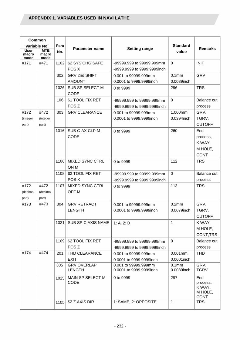
APPENDIX 1. VARIABLES USED IN NAVI LATHE
- 232 -
Common
variable No. Para No.
Parameter name Setting range Standard
value Remarks User
macro mode
MTB macro mode
#171 #471 1102 $2 SYS CHG SAFE POS X
-99999.999 to 99999.999mm -9999.9999 to 9999.9999inch
0 INIT
302 GRV 2nd SHIFT AMOUNT
0.001 to 99999.999mm 0.0001 to 9999.9999inch
0.1mm 0.0039inch
GRV
1026 SUB SP SELECT M CODE
0 to 9999 296 TRS
106 $1 TOOL FIX RET POS Z
-99999.999 to 99999.999mm -9999.9999 to 9999.9999inch
0 Balance cut process
#172 (integer
part)
#472 (integer
part)
303 GRV CLEARANCE 0.001 to 99999.999mm 0.0001 to 9999.9999inch
1.000mm 0.0394inch
GRV, TGRV, CUTOFF
1016 SUB C-AX CLP M CODE
0 to 9999 260 End process, K WAY, M HOLE, CONT
1106 MIXED SYNC CTRL ON M
0 to 9999 112 TRS
1108 $2 TOOL FIX RET POS X
-99999.999 to 99999.999mm -9999.9999 to 9999.9999inch
0 Balance cut process
#172 (decimal
part)
#472 (decimal
part)
1107 MIXED SYNC CTRL OFF M
0 to 9999 113 TRS
#173 #473 304 GRV RETRACT LENGTH
0.001 to 99999.999mm 0.0001 to 9999.9999inch
0.2mm 0.0079inch
GRV, TGRV, CUTOFF
1021 SUB SP C AXIS NAME 1: A, 2: B 1 K WAY, M HOLE, CONT,TRS
1109 $2 TOOL FIX RET POS Z
-99999.999 to 99999.999mm -9999.9999 to 9999.9999inch
0 Balance cut process
#174 #474 201 THD CLEARANCE EXIT
0.001 to 99999.999mm 0.0001 to 9999.9999inch
0.001mm 0.0001inch
THD
305 GRV OVERLAP LENGTH
0.001 to 99999.999mm 0.0001 to 9999.9999inch
0.1mm 0.0039inch
GRV, TGRV
1025 MAIN SP SELECT M CODE
0 to 9999 297 End process, K WAY, M HOLE, CONT
1105 $2 Z AXIS DIR 1: SAME, 2: OPPOSITE 1 TRS
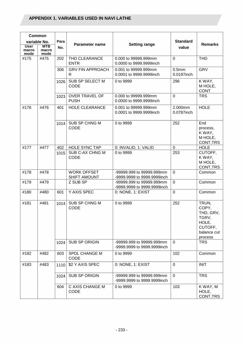
APPENDIX 1. VARIABLES USED IN NAVI LATHE
- 233 -
Common variable No. Para
No. Parameter name Setting range
Standard value
Remarks User macro mode
MTB macro mode
#175 #475 202 THD CLEARANCE ENTR
0.000 to 99999.999mm 0.0000 to 9999.9999inch
0 THD
306 GRV FIN APPROACH R
0.001 to 99999.999mm 0.0001 to 9999.9999inch
0.5mm 0.0197inch
GRV
1026 SUB SP SELECT M CODE
0 to 9999 296 K WAY, M HOLE, CONT
1023 OVER TRAVEL OF PUSH
0.000 to 99999.999mm 0.0000 to 9999.9999inch
0 TRS
#176 #476 401 HOLE CLEARANCE 0.001 to 99999.999mm 0.0001 to 9999.9999inch
2.000mm 0.0787inch
HOLE
1014 SUB SP CHNG M CODE
0 to 9999 252 End process, K WAY, M HOLE, CONT,TRS
#177 #477 402 HOLE SYNC TAP 0: INVALID, 1: VALID 0 HOLE 1015 SUB C-AX CHNG M
CODE 0 to 9999 253 CUTOFF,
K WAY, M HOLE, CONT,TRS
#178 #478 WORK OFFSET SHIFT AMOUNT
-99999.999 to 99999.999mm -9999.9999 to 9999.9999inch
0 Common
#179 #479 Z SUB SP -99999.999 to 99999.999mm -9999.9999 to 9999.9999inch
0 Common
#180 #480 601 Y AXIS SPEC 0: NONE, 1: EXIST 0 Common
#181 #481 1014 SUB SP CHNG M CODE
0 to 9999 252 TRUN, COPY, THD, GRV, TGRV, HOLE, CUTOFF, balance cut process
1024 SUB SP ORIGIN -99999.999 to 99999.999mm -9999.9999 to 9999.9999inch
0 TRS
#182 #482 603 SPDL CHANGE M CODE
0 to 9999 102 Common
#183 #483 1110 $2 Y AXIS SPEC 0: NONE, 1: EXIST 0 INIT
1024 SUB SP ORIGIN -99999.999 to 99999.999mm -9999.9999 to 9999.9999inch
0 TRS
604 C AXIS CHANGE M CODE
0 to 9999 103 K WAY, M HOLE, CONT,TRS

APPENDIX 1. VARIABLES USED IN NAVI LATHE
- 234 -
Common variable No. Para
No. Parameter name Setting range
Standard value
Remarks User macro mode
MTB macro mode
#184 #484 1001 SUB SPINDLE SPEC 0: NONE, 1: EXIST 0 TURN, COPY, THD, GRV, TGRV, HOLE, CUTOFF, balance cut process
605 C AXIS CLAMP M CODE
0 to 9999 110 End process
1017 SUB SPINDLE NO. 1 to 4 2 TRS #185 #485 609 TOOL SPINDLE NO. 1 to 4 2 Common #186 #486 606 TOOL TURNING CL Y
0.000 to 99999.999mm 0.0000 to 9999.9999inch
50.000mm 1.9685inch
Common
#187 #487 607 TOOL FIX RET POS Y -99999.999 to 99999.999mm -9999.9999 to 9999.9999inch
0 Common
#188 #488 608 AXIS DIR COEF OF SPEED
1 to 200% 50 Common
#189 #489 1022 TRANSFER AXIS NAME
1: A, 2: B 2 INIT, TRS
1018 SUB SP CW ROT M CODE
0 to 9999 3 TURN, COPY, THD, GRV, TGRV, HOLE, CUTOFF, balance cut process
701 HOLE CLEARANCE 0.001 to 99999.999mm 0.0001 to 9999.9999inch
2.000mm 0.0787inch
M HOLE
#190 #490 1019 SUB SP CCW ROT M CODE
0 to 9999 4 TURN, COPY, THD, GRV, TGRV, HOLE, CUTOFF, balance cut process
702 HOLE SYNC TAP 0: INVALID, 1: VALID 0 M HOLE 1002 MAIN CHUCK CLP M
CODE 0 to 9999 11 TRS

APPENDIX 1. VARIABLES USED IN NAVI LATHE
- 235 -
Common
variable No. Para No.
Parameter name Setting range Standard
value Remarks User
macro mode
MTB macro mode
#191 #491 1020 SUB SP STOP M CODE
0 to 9999 5 TURN, COPY, THD, GRV, TGRV, HOLE, CUTOFF, balance cut process
801 K-WAY CUT WIDTH PCT(%)
1 to 100% 50 K WAY
1003 MAIN CHUCK UN-CLP M
0 to 9999 10 TRS
#192 #492 1025 MAIN SP SELECT M CODE
0 to 9999 297 TURN, COPY, THD, GRV, TGRV, HOLE, CUTOFF, balance cut process
802 K-WAY CLEARANCE 0.001 to 99999.999mm 0.0001 to 9999.9999inch
2.000mm 0.0787inch
K WAY
903 E-ML EMPTY D OFS NUM
1 to tool sets 0 CONT
1004 SUB CHUCK CLP M CODE
0 to 9999 211 TRS
#193 #493 1026 SUB SP SELECT M CODE
0 to 9999 296 TURN, COPY, THD, GRV, TGRV, HOLE, CUTOFF, balance cut process
703 HOLE TAP ON M CODE
0 to 9999 0 M HOLE
901 E-ML CUT WIDTH PCT(%)
1 to 100% 50 CONT
1005 SUB CHUCK UN-CLP M
0 to 9999 210 TRS

APPENDIX 1. VARIABLES USED IN NAVI LATHE
- 236 -
Common variable No. Para
No. Parameter name Setting range
Standard value
Remarks User macro mode
MTB macro mode
#194 #494 1017 SUB SPINDLE NO. 1 to 4 2 TURN, COPY, THD, GRV, TGRV, HOLE, CUTOFF, balance cut process
704 HOLE TAP OFF M CODE
0 to 9999 0 M HOLE
902 E-ML CLEARANCE 0.001 to 99999.999mm 0.0001 to 9999.9999inch
2.000mm 0.0787inch
CONT
1008 MAIN AIR BLOW ON M
0 to 9999 20 TRS
#195 #495 1105 $2 Z AXIS DIR 1: SAME, 2: OPPOSITE 1 Common
1009 MAIN AIR BLOW OFF M
0 to 9999 21 TRS
#196 (integer part)
#496 (integer part)
1103 $1 Z AXIS MOVE TYPE
1: TURRET, 2: SPINDLE 1 Common
1010 SUB AIR BLOW ON M 0 to 9999 TRS #196 (decimal part)
#496 (decimal part)
1104 $2 Z AXIS MOVE TYPE
1: TURRET, 2: SPINDLE 1 Common
#197 (integer part)
#497 (integer part)
1106 MIXED SYNC CTRL ON M
0 to 9999 112 Common
1011 SUB AIR BLOW OFF M
0 to 9999 221 TRS
#197 (decimal part)
#497 (decimal part)
1107 MIXED SYNC CTRL OFF M
0 to 9999 113 Common
#198 (integer part)
#498 (integer part)
610 TOOL SP CW ROT M CODE
0 to 9999 3 K WAY, M HOLE, CONT
1012 AIR BLOW TIME 0 to 99 sec 3 TRS #198 (decimal part)
#498 (decimal part)
611 TOOL SP CCW ROT M CODE
0 to 9999 4 K WAY, M HOLE, CONT
#199 (integer part)
#499 (integer part)
612 TOOL SP STOP M CODE
0 to 9999 5 K WAY, M HOLE, CONT
1103 $1 Z AXIS MOVE TYPE
1: TURRET, 2: SPINDLE 1 TRS
#199 (decimal part)
#499 (decimal part)
613 TOOL SP SELECT M CODE
0 to 9999 0 CUTOFF, K WAY, M HOLE, CONT
1104 $2 Z AXIS MOVE TYPE
1: TURRET, 2: SPINDLE 1 TRS

APPENDIX 1. VARIABLES USED IN NAVI LATHE
- 237 -
CAUTION NAVI LATHE uses the following variables in order to operate the NC program.
NC program mode Variables used by NAVI LATHE User macro mode #100 to #199 MTB macro mode #450 to #499
When NC program mode is user macro mode, do not use common variables (#100 to #199). If those variables are written over, malfunction will be resulted. If mistakenly written them over, turn the NC power OFF after securing your safety. When starting NAVI LATHE by turning the NC power ON again,the system recovers the data. NC program mode is specified on the Preferences screen.
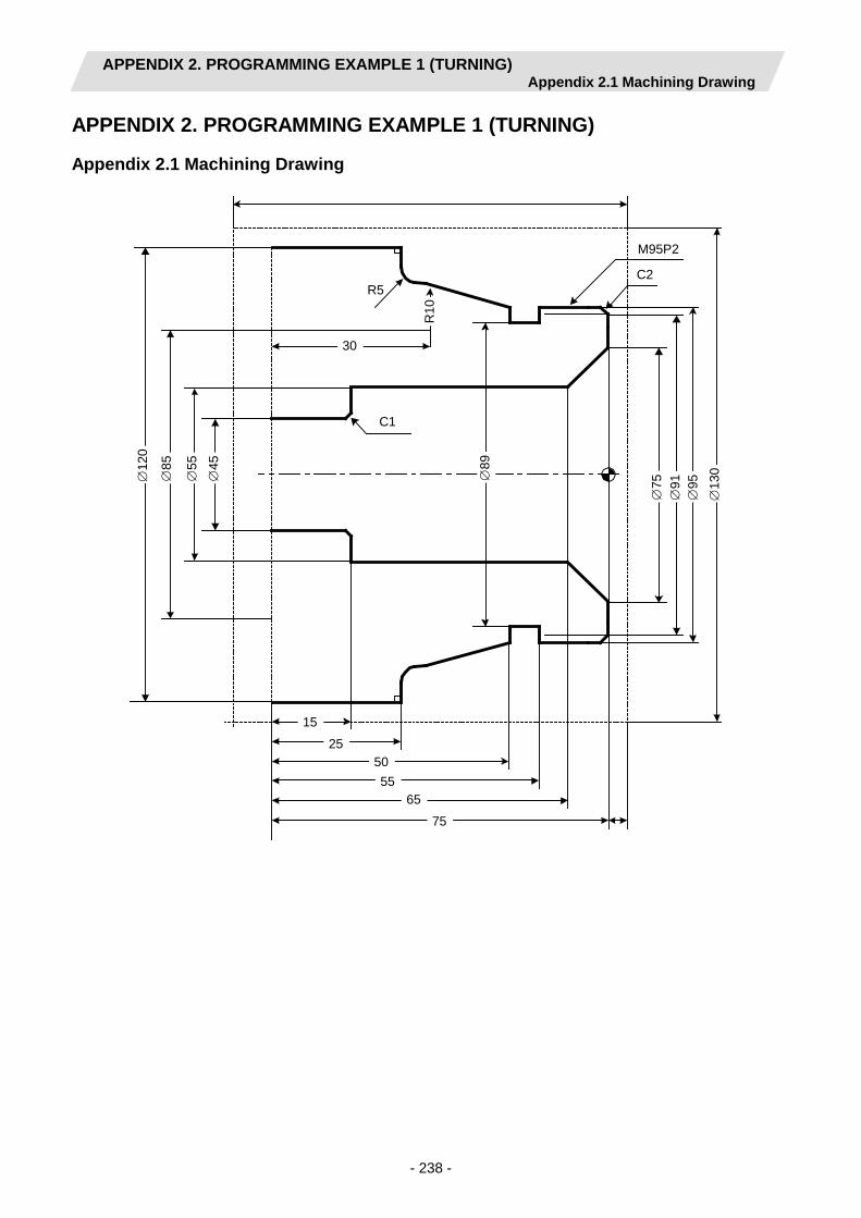
APPENDIX 2. PROGRAMMING EXAMPLE 1 (TURNING) Appendix 2.1 Machining Drawing
- 238 -
APPENDIX 2. PROGRAMMING EXAMPLE 1 (TURNING)
Appendix 2.1 Machining Drawing
75
65 55
50 25
15
∅45
∅55
∅85
∅12
0
∅13
0
∅95
∅91
∅75
∅89
C1
30
R5
R10
C2
M95P2

APPENDIX 2. PROGRAMMING EXAMPLE 1 (TURNING) Appendix 2.2 Process Table
- 239 -
Appendix 2.2 Process Table
Processes are shown below. Process Machining Tool
1 Drilling machining DR 2 Turning rough machining for front face OUTR
Turning finishing machining for front face OUTR 3 Turning rough machining for outer diameter OUTR
Turning finishing machining for outer diameter OUTR 4 Turning rough machining for inner diameter INR
Turning finishing machining for inner diameter INR 5 Grooving for outer diameter GO 6 Threading rough machining for outer diameter TOMR
Threading finishing machining for outer diameter TOMR
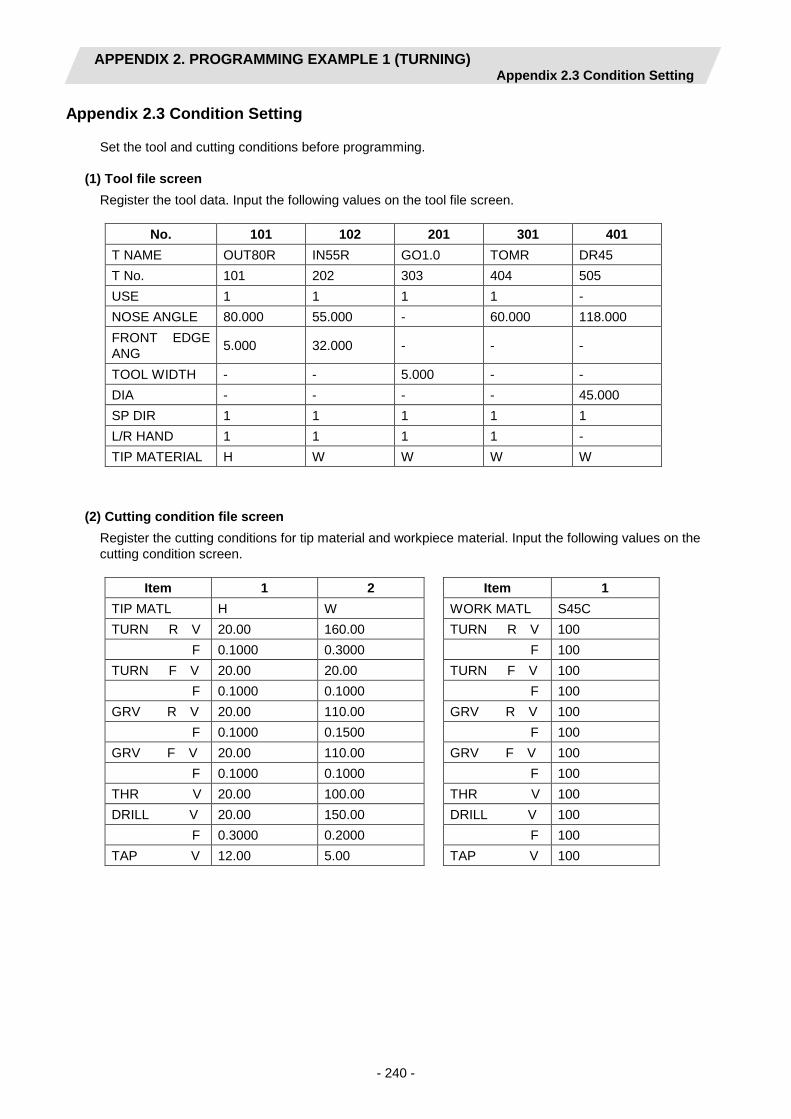
APPENDIX 2. PROGRAMMING EXAMPLE 1 (TURNING) Appendix 2.3 Condition Setting
- 240 -
Appendix 2.3 Condition Setting
Set the tool and cutting conditions before programming. (1) Tool file screen
Register the tool data. Input the following values on the tool file screen.
(2) Cutting condition file screen Register the cutting conditions for tip material and workpiece material. Input the following values on the cutting condition screen.
No. 101 102 201 301 401 T NAME OUT80R IN55R GO1.0 TOMR DR45 T No. 101 202 303 404 505 USE 1 1 1 1 - NOSE ANGLE 80.000 55.000 - 60.000 118.000 FRONT EDGE ANG 5.000 32.000 - - -
TOOL WIDTH - - 5.000 - - DIA - - - - 45.000 SP DIR 1 1 1 1 1 L/R HAND 1 1 1 1 - TIP MATERIAL H W W W W
Item 1 2 TIP MATL H W TURN R V 20.00 160.00 F 0.1000 0.3000 TURN F V 20.00 20.00 F 0.1000 0.1000 GRV R V 20.00 110.00 F 0.1000 0.1500 GRV F V 20.00 110.00 F 0.1000 0.1000 THR V 20.00 100.00 DRILL V 20.00 150.00 F 0.3000 0.2000 TAP V 12.00 5.00
Item 1 WORK MATL S45C TURN R V 100 F 100 TURN F V 100 F 100 GRV R V 100 F 100 GRV F V 100 F 100 THR V 100 DRILL V 100 F 100 TAP V 100

APPENDIX 2. PROGRAMMING EXAMPLE 1 (TURNING) Appendix 2.4 Creating Program
- 241 -
Appendix 2.4 Creating Program
1. Open the program edit screen. 2. Press the [NEW] menu and create a new NC program. 3. Move the cursor to "0 INIT" and press the [MODIFY] menu. 4. Input the following values.
Item Setting value Details WORK REG No. 1 S45C WORK ZERO 1 T'STK SIDE OUTSIDE DIA OD 130.000 INSIDE DIA ID 0.000 +Z 5.000 -Z -95.000 WORK COORDINATE 54 G54 COOLANT 1 VALID TOOL CHANGE POS 1 X REF FIN TOOL RET 1 REF END POS X - Z - M CODE 1 M30
LIST VIEW
PROGRAM PROCESS 0 INIT FILE
4.1 Save the initial conditions by pressing the [SAVE] menu. 4.2 Turn the LIST VIEW area active by pressing the [←] key.
LIST VIEW PROGRAM PROCESS 0 INIT FILE

APPENDIX 2. PROGRAMMING EXAMPLE 1 (TURNING) Appendix 2.4 Creating Program
- 242 -
5. Process 1 Drilling machining (DR)
5.1 Open the process mode selection screen by pressing the [NEW] menu. 5.2 Open the hole drilling screen and set the following items.
Item Setting value Details TOOL REG No. 401 DR45 HOLE CYCLE 1 DRILL SURFACE Z ZF -5.000 DEPTH H 80.000 NOSE DEPTH B 93.519 SPOT DIAMETER D 45.000 CUT AMOUNT - DWELL 1.000 TOOL T No. 505 TOOL DIA 45.000 CUT SPEED V 150 FEED RATE F 0.2000
5.3 Save the data of the drilling machining by pressing the [SAVE] menu. 5.4 Turn the LIST VIEW area active by pressing the [←] key.
LIST VIEW
PROGRAM PROCESS 0 INIT 1 DR FILE

APPENDIX 2. PROGRAMMING EXAMPLE 1 (TURNING) Appendix 2.4 Creating Program
- 243 -
6. Process 2 Turning rough machining for front face (OUTR)
6.1 Open the process mode selection screen by pressing the [NEW] menu. 6.2 Open the turning screen and set the following items.
<Turning screen>
Item Setting value Details TOOL REG No. 101 OUT80R CYCLE 1 ROUGH PARTS 5 FACE-OPEN APPRCH POS X 134.000 Z -7.000 FINISH ALLOW X FX 0.150 Z FZ 0.150 CUT AMOUNT 2.000 RETRACT AMOUNT 2.000 TOOL T No. 101 CUT SPEED V 20 FEED RATE F 0.1000
6.3 Press the [PATTERN] menu and set the following items. <Turning pattern screen>
(Note) The value in the parentheses is calculated automatically. 6.4 After returning the screen to the turning screen by pressing the
[RETURN] menu, save the data of the turning face rough machining by pressing the [SAVE] menu.
6.5 Turn the LIST VIEW area active by pressing the [←] key.
No. M X Z R/A 1 130.000 0.000
2 1 36.000 0.000 (270.000)
3 1 36.000 -5.000 (180.000)
LIST VIEW
PROGRAM PROCESS 0 INIT 1 DR
2 TURN-FACE R FILE
7. Process 2 Turning finishing machining for front face (OUTR) 7.1 Press the [COPY] menu and move down the cursor in the LIST VIEW
area. 7.2 Press the [MODIFY] menu and set the following item.
Item Setting value Details CYCLE 2 FIN
7.3 Save the data of the turning face finishing machining by pressing the
[SAVE] menu. 7.4 Turn the LIST VIEW area active by pressing the [←] key.
LIST VIEW
PROGRAM PROCESS 0 INIT 1 DR 2 TURN-FACE R 3 TURN-FACE F FILE

APPENDIX 2. PROGRAMMING EXAMPLE 1 (TURNING) Appendix 2.4 Creating Program
- 244 -
8. Process 3 Turning rough machining for outer diameter (OUTR)
8.1 Open the process mode selection screen by pressing the [NEW] menu. 8.2 Open the turning screen and set the following items.
<Turning screen>
Item Setting value Details TOOL REG No. 101 OUT80R CYCLE 1 ROUGH PARTS 1 OUT-OPEN APPRCH POS X 134.000 Z -7.000 FINISH ALLOW X FX 0.150 Z FZ 0.150 CUT AMOUNT 4.875 RETRACT AMOUNT 2.000 TOOL T No. 101 CUT SPEED V 20 FEED RATE F 0.1000
8.3 Press the [PATTERN] menu and set the following items.
<Turning pattern screen> No. M X Z R/A I K 1 91.000 0.000
2 1 95.000 2.000 (45.000)
3 1 95.000 25.000 (0.000)
4 1 (104.320) (42.415) (14.981)
5 3 (105.000) (45.000) 10.000 85.000 45.000
6 2 (115.000) (50.000) 5.000 (115.000) (45.000)
7 1 120.000 50.000 90.000
8 1 120.000 75.000 (0.000)
(Note) The value in the parentheses is calculated automatically. 8.4 After returning the screen to the turning screen by pressing the
[RETURN] menu, save the data of the turning outer diameter rough machining by pressing the [SAVE] menu.
8.5 Turn the LIST VIEW area active by pressing the [←] key.
LIST VIEW
PROGRAM PROCESS 0 INIT 1 DR 2 TURN-FACE R 3 TURN-FACE F
4 TURN-OUT R FILE

APPENDIX 2. PROGRAMMING EXAMPLE 1 (TURNING) Appendix 2.4 Creating Program
- 245 -
9. Process 3 Turning finishing machining for outer diameter (OUTR)
9.1 Press the [COPY] menu and move down the cursor in the LIST VIEW area.
9.2 Press the [MODIFY] menu and set the following item. Item Setting value Details
CYCLE 2 FIN 9.3 Save the data of the turning outer diameter finishing machining by
pressing the [SAVE] menu. 9.4 Turn the LIST VIEW area active by pressing the [←] key.
LIST VIEW
PROGRAM PROCESS 0 INIT 1 DR 2 TURN-FACE R 3 TURN-FACE F 4 TURN-OUT R 5 TURN-OUT F FILE
10. Process 4 Turning rough machining for inner diameter (INR)
10.1 Open the process mode selection screen by pressing the [NEW] menu. 10.2 Open the turning screen and set the following items.
<Turning screen> Item Setting value Details
TOOL REG No. 102 IN55R CYCLE 1 ROUGH PARTS 3 IN-OPEN APPRCH POS X 45.000 Z -10.000 FINISH ALLOW X FX 0.150 Z FZ 0.150 CUT AMOUNT 3.500 RETRACT AMOUNT 2.000 TOOL T No. 202 CUT SPEED V 160 FEED RATE F 0.3000
10.3 Press the [PATTERN] menu and set the following items.
<Turning pattern screen>
(Note) The value in the parentheses is calculated automatically. 10.4 After returning the screen to the turning screen by pressing the
[RETURN] menu, save the data of the turning inner diameter rough machining by pressing the [SAVE] menu.
10.5 Turn the LIST VIEW area active by pressing the [←] key.
No. M X Z R/A 1 75.000 0.000 2 1 55.000 10.000 (315.000) 3 1 55.000 60.000 (0.000) 4 1 47.000 60.000 (270.000) 5 1 45.000 61.000 (315.000)
LIST VIEW
PROGRAM PROCESS 0 INIT 1 DR 2 TURN-FACE R 3 TURN-FACE F 4 TURN-OUT R 5 TURN-OUT F
6 TURN-IN R FILE

APPENDIX 2. PROGRAMMING EXAMPLE 1 (TURNING) Appendix 2.4 Creating Program
- 246 -
11. Process 4 Turning finishing machining for inner diameter (INR)
11.1 Press the [COPY] menu and move down the cursor in the LIST VIEW area.
11.2 Press the [MODIFY] menu and set the following item. Item Setting value Details
CYCLE 2 FIN 11.3 Save the data of the turning inner diameter finishing machining by
pressing the [SAVE] menu. 11.4 Turn the LIST VIEW area active by pressing the [←] key.
LIST VIEW
PROGRAM PROCESS 0 INIT 1 DR 2 TURN-FACE R 3 TURN-FACE F 4 TURN-OUT R 5 TURN-OUT F 6 TURN-IN R 7 TURN-IN F FILE
12. Process 5 Grooving for outer diameter (GO)
12.1 Open the process mode selection screen by pressing the [NEW] menu. 12.2 Open the grooving screen and set the following items.
Item Setting value Details TOOL REG No. 201 GO1.0 PARTS 1 OUT WIDTH W 5.000 LEFT CORNER LC 0.000
RIGHT CORNER RC 0.000
START POS X X1 95.000 Z Z1 25.000 END POS X X2 89.000 Z Z2 25.000 NUM OF GRV 1 PITCH 0 CUT AMOUNT 1.000 SHIFT BEFORE RETR 0 TOOL T No. 303 TOOL WIDTH 5.000 CUT SPEED V 110 FEED RATE F 0.1500
12.3 Save the data of the grooving outer diameter machining by pressing the
[SAVE] menu. 12.4 Turn the LIST VIEW area active by pressing the [←] key.
LIST VIEW
PROGRAM PROCESS
0 INIT 1 DR 2 TURN-FACE R
3 TURN-FACE F 4 TURN-OUT R 5 TURN-OUT F 6 TURN-IN R 7 TURN-IN F
8 GRV-OUT FILE
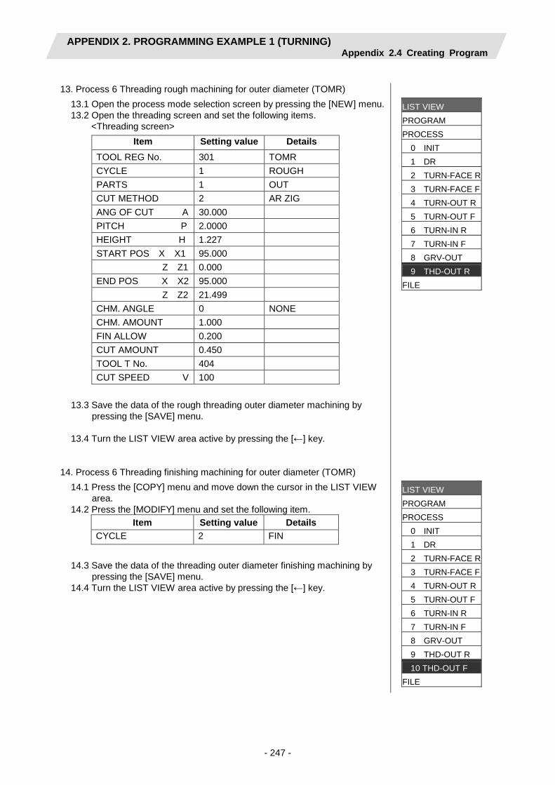
APPENDIX 2. PROGRAMMING EXAMPLE 1 (TURNING) Appendix 2.4 Creating Program
- 247 -
13. Process 6 Threading rough machining for outer diameter (TOMR)
13.1 Open the process mode selection screen by pressing the [NEW] menu. 13.2 Open the threading screen and set the following items.
<Threading screen> Item Setting value Details
TOOL REG No. 301 TOMR CYCLE 1 ROUGH PARTS 1 OUT CUT METHOD 2 AR ZIG ANG OF CUT A 30.000 PITCH P 2.0000 HEIGHT H 1.227 START POS X X1 95.000 Z Z1 0.000 END POS X X2 95.000 Z Z2 21.499 CHM. ANGLE 0 NONE CHM. AMOUNT 1.000 FIN ALLOW 0.200 CUT AMOUNT 0.450 TOOL T No. 404 CUT SPEED V 100
13.3 Save the data of the rough threading outer diameter machining by
pressing the [SAVE] menu. 13.4 Turn the LIST VIEW area active by pressing the [←] key.
LIST VIEW
PROGRAM PROCESS 0 INIT 1 DR 2 TURN-FACE R 3 TURN-FACE F 4 TURN-OUT R 5 TURN-OUT F 6 TURN-IN R 7 TURN-IN F 8 GRV-OUT 9 THD-OUT R FILE
14. Process 6 Threading finishing machining for outer diameter (TOMR) 14.1 Press the [COPY] menu and move down the cursor in the LIST VIEW
area. 14.2 Press the [MODIFY] menu and set the following item.
Item Setting value Details CYCLE 2 FIN
14.3 Save the data of the threading outer diameter finishing machining by
pressing the [SAVE] menu. 14.4 Turn the LIST VIEW area active by pressing the [←] key.
LIST VIEW
PROGRAM PROCESS 0 INIT 1 DR 2 TURN-FACE R 3 TURN-FACE F 4 TURN-OUT R 5 TURN-OUT F 6 TURN-IN R 7 TURN-IN F 8 GRV-OUT 9 THD-OUT R 10 THD-OUT F FILE

APPENDIX 3. PROGRAMMING EXAMPLE 2 (MILLING) Appendix 3.1 Machining Drawing
- 248 -
APPENDIX 3. PROGRAMMING EXAMPLE 2 (MILLING)
Appendix 3.1 Machining Drawing
120.150.
Φ15
0
Φ12
0
Φ50 Φ80
8-M8 P=1.25 Depth8Prepared Φ6.8 Depth12
90.
50.
2- Φ6.8 Hole Depth10
C=0
C=270.
C=180.
X
Y
X
Z
8.10.25.
60.

APPENDIX 3. PROGRAMMING EXAMPLE 2 (MILLING) Appendix 3.2 Process Table
- 249 -
Appendix 3.2 Process Table
Processes are shown below. Process Machining Tool
1 8-M8
Milling hole drilling for front face ZCD3 (φ3 Center Drill) Milling hole drilling for front face ZDR6.8 (φ6.8 Drill) Milling hole drilling for front face ZDC20 (φ20
Countersink) Milling tap machining for front face ZTPM8 (M8 P=1.25
Tap) 2 Contour rough cutting for front face ZED10 (φ10 End Mill)
Contour finishing cutting for front face ZED10 (φ10 End Mill) 3
2-φ6.8 Milling hole drilling for outer surface XCD3 (φ3 Center Drill) Milling hole drilling for outer surface XDR6.8 (φ6.8 Drill) Milling hole drilling for outer surface XDC20 (φ20
Countersink) 4 Keyway rough cutting for outer surface XED10 (φ10 End Mill)
Keyway finishing cutting for outer surface XED10 (φ10 End Mill)

APPENDIX 3. PROGRAMMING EXAMPLE 2 (MILLING) Appendix 3.3 Condition Setting
- 250 -
Appendix 3.3 Condition Setting
Set the tool and cutting conditions before programming. (1) Tool file screen for milling
Register the tool data. Input the following values on the tool file screen for milling.
No. 701 702 703 704 705 T NAME ZCD3 ZDR6.8 ZDC20 ZTPM8 ZED10 T No. 101 202 303 404 505 DIA 3. 6.8 20. 8. 10. NOSE ANGLE 120. 118 90 180 180 F/PITCH 0.06 0.12 0.28 1.25 0.4 SP DIR 1 1 1 1 1 TIP MATERIAL H H H W W
No. 711 712 713 714 715
T NAME XCD3 XDR6.8 XDC20 XTPM8 XED10 T No. 1111 1212 1313 1414 1515 DIA 3 6.8 20. 8. 10. NOSE ANGLE 120 118 90 180 180 F/PITCH 0.06 0.12 0.28 1.25 0.4 SP DIR 1 1 1 1 1 TIP MATERIAL H H H W W
(2) Cutting condition file screen for milling Set the cutting speed for the tip material, as well as coefficients of cutting speed rate and feedrate for the workpiece material. Input as follows on the cutting condition file screen for milling machining. [Cutting condition file (tip material)] [Cutting condition file (workpiece material)]
Item 1 2 TIP MATL H W DRILL V 23. 65. TAP V 12. 12. BORE V 23. 95. END ML R V 22. 40. END ML F V 25. 55.
Item 1 WORK MATL S45C DRILL V 100 F 100 TAP V 100 BORE V 100 F 100 END ML R V 100 F 100 END ML F V 100 F 100

APPENDIX 3. PROGRAMMING EXAMPLE 2 (MILLING) Appendix 3.4 Creating Program
- 251 -
Appendix 3.4 Creating Program
1. Open the program edit screen. 2. Press the [NEW] menu and create a new NC program. 3. Move the cursor to "0 INIT" and press the [MODIFY] menu. 4. Input the following values.
Item Setting value Details WORK REG No. 1 S45C WORK ZERO 1 T'STK SIDE OUTSIDE DIA OD 150.000 INSIDE DIA ID 0.000 +Z 0.000 -Z -150.000 WORK COORDINATE 54 G54 COOLANT 1 VALID TOOL CHANGE POS 1 X REF FIN TOOL RET 1 REF END POS X - Z - M CODE 1 M30
LIST VIEW
PROGRAM PROCESS 0 INIT FILE
4.1 Save the initial conditions by pressing the [SAVE] menu. 4.2 Turn the LIST VIEW area active by pressing the [←] key.
LIST VIEW PROGRAM PROCESS 0 INIT FILE

APPENDIX 3. PROGRAMMING EXAMPLE 2 (MILLING) Appendix 3.4 Creating Program
- 252 -
5. Process 1 Milling hole drilling for front face (φ3 Center Drill)
5.1 Open the process mode selection screen by pressing the [NEW] menu. 5.2 Open the milling hole drilling screen and set the following items.
Item Setting value Details TOOL REG No. 701 ZCD3 PARTS 1 FACE HOLE CYCLE 1 DRILL BASE PLANE BZ 50.000 DEPTH H 3.000 NOSE DEPTH B 3.866 SPOT DIAMETER D 3.000 CUT AMOUNT - DWELL 0.000 RETURN POINT 2 R point C-AXIS CLAMP 1 VALID TOOL T No. 101 TOOL DIAMETER 3.000 CUT SPEED V 23 FEED RATE F 0.06
5.3 Press the [PATTERN] menu and set the following items.
<Hole drilling machining pattern screen (circle)>
Item Setting value Details PATTERN 4 CIRCLE BASE POS X 0. BASE POS Y 0. DIAMETER D 80 START ANGLE A 0 NUM OF HOLES 8 OMIT 1 0 2 0 3 0 4 0
5.4 Press the [RETURN] menu to change to the milling hole drilling screen
before pressing the [SAVE] menu. 5.5 Turn the LIST VIEW area active by pressing the [←] key.
LIST VIEW
PROGRAM PROCESS 0 INIT 1 M DR -FACE FILE
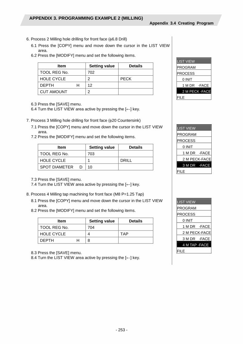
APPENDIX 3. PROGRAMMING EXAMPLE 2 (MILLING) Appendix 3.4 Creating Program
- 253 -
6. Process 2 Milling hole drilling for front face (φ6.8 Drill)
6.1 Press the [COPY] menu and move down the cursor in the LIST VIEW area.
6.2 Press the [MODIFY] menu and set the following items.
Item Setting value Details TOOL REG No. 702 HOLE CYCLE 2 PECK DEPTH H 12 CUT AMOUNT 2
6.3 Press the [SAVE] menu. 6.4 Turn the LIST VIEW area active by pressing the [←] key.
LIST VIEW
PROGRAM PROCESS 0 INIT 1 M DR -FACE 2 M PECK -FACE FILE
7. Process 3 Milling hole drilling for front face (φ20 Countersink) 7.1 Press the [COPY] menu and move down the cursor in the LIST VIEW
area. 7.2 Press the [MODIFY] menu and set the following items.
Item Setting value Details TOOL REG No. 703 HOLE CYCLE 1 DRILL SPOT DIAMETER D 10
7.3 Press the [SAVE] menu. 7.4 Turn the LIST VIEW area active by pressing the [←] key.
LIST VIEW
PROGRAM PROCESS 0 INIT 1 M DR -FACE 2 M PECK-FACE 3 M DR -FACE FILE
8. Process 4 Milling tap machining for front face (M8 P=1.25 Tap) 8.1 Press the [COPY] menu and move down the cursor in the LIST VIEW
area. 8.2 Press the [MODIFY] menu and set the following items.
Item Setting value Details TOOL REG No. 704 HOLE CYCLE 4 TAP DEPTH H 8
8.3 Press the [SAVE] menu. 8.4 Turn the LIST VIEW area active by pressing the [←] key.
LIST VIEW
PROGRAM PROCESS 0 INIT 1 M DR -FACE 2 M PECK-FACE 3 M DR -FACE 4 M TAP -FACE FILE

APPENDIX 3. PROGRAMMING EXAMPLE 2 (MILLING) Appendix 3.4 Creating Program
- 254 -
9. Process 5 Contour rough cutting for front face (φ10 End Mill)
9.1 Open the process mode selection screen by pressing the [NEW] menu. 9.2 Open the contour cutting screen and set the following items.
Item Setting value Details TOOL REG No. 705 ZED10 CYCLE 1 Rough PARTS 1 FACE BASE PLANE BZ 50. TOOL PATH 2 RIGHT WIDTH W 18. DEPTH D 10. FIN ALLOW FH 2. FV 1. CUT AMOUNT 5. APPROACH IN AXIS DIR 1 RAPID (G00) TOOL T No. 505 DIA 10. CUT SPEED V 40 FEED RATE F1 0.4 F2 0.2
9.3 Press the [PATTERN] menu and set the following items. <Contour cutting pattern screen>
(Note) The value in the parentheses is calculated automatically. 9.4 Press the [RETURN] menu to change to the contour cutting screen
before pressing the [SAVE] menu. 9.5 Turn the LIST VIEW area active by pressing the [←] key.
No. M X Y R/A I J
1 70. 19.586
2 1 0 60. (150.)
3 1 -51.962 30. (210.)
4 1 -51.962 -30. (270.)
5 0 -60. (330.)
6 51.962 -30. (30.)
7 51.962 47. (90.)
LIST VIEW
PROGRAM PROCESS 0 INIT 1 M DR -FACE 2 M PECK-FACE 3 M DR -FACE 4 M TAP -FACE 5 CONT -FACE R FILE

APPENDIX 3. PROGRAMMING EXAMPLE 2 (MILLING) Appendix 3.4 Creating Program
- 255 -
10. Process 6 Contour finishing cutting for front face (φ10 End Mill)
10.1 Press the [COPY] menu and move down the cursor in the LIST VIEW area.
10.2 Press the [MODIFY] menu and set the following item.
Item Setting value Details CYCLE 2 Finishing
10.3 Press the [SAVE] menu. 10.4 Turn the LIST VIEW area active by pressing the [←] key.
LIST VIEW PROGRAM PROCESS 0 INIT 1 M DR -FACE 2 M PECK-FACE 3 M DR -FACE 4 M TAP -FACE 5 CONT -FACE R 6 CONT -FACE F FILE
11. Process 7 Milling hole drilling for outer surface (φ3 Center Drill) 11.1 Open the process mode selection screen by pressing the [NEW] menu. 11.2 Open the milling hole drilling screen and set the following items.
Item Setting value Details TOOL REG No. 711 ZCD3
PARTS 2 OUT
HOLE CYCLE 1 DRILL
BASE PLANE BR 60.000
DEPTH H 3.000
NOSE DEPTH B 3.866
SPOT DIAMETER D 3.000
CUT AMOUNT -
DWELL 0.000
RETURN POINT 2 R point
C-AXIS CLAMP 1 VALID
TOOL T No. 1111
TOOL DIAMETER 3.000
CUT SPEED V 23
FEED RATE F 0.06 11.3 Press the [PATTERN] menu and set the following items.
<Hole drilling machining pattern screen (RANDOM)> No. C Z 1 0. 90. 2 180. 90.
11.4 Press the [RETURN] menu to change to the milling hole drilling screen
before pressing the [SAVE] menu. 11.5 Turn the LIST VIEW area active by pressing the [←] key.
LIST VIEW PROGRAM PROCESS 0 INIT 1 M DR -FACE 2 M PECK-FACE 3 M DR -FACE 4 M TAP -FACE 5 CONT -FACE R 6 CONT -FACE F 7 M DR -OUT FILE

APPENDIX 3. PROGRAMMING EXAMPLE 2 (MILLING) Appendix 3.4 Creating Program
- 256 -
12. Process 8 Milling hole drilling for outer surface (φ6.8 Drill)
12.1 Press the [COPY] menu and move down the cursor in the LIST VIEW area.
12.2 Press the [MODIFY] menu and set the following items.
Item Setting value Details TOOL REG No. 712 HOLE CYCLE 2 PECK DEPTH H 12 CUT AMOUNT 2
12.3 Press the [SAVE] menu. 12.4 Turn the LIST VIEW area active by pressing the [←] key.
LIST VIEW PROGRAM PROCESS 0 INIT 1 M DR -FACE 2 M PECK-FACE 3 M DR -FACE 4 M TAP -FACE 5 CONT -FACE R 6 CONT -FACE F 7 M DR -OUT 8 M PECK-OUT T FILE
13. Process 9 Milling hole drilling for outer surface (φ20 Countersink)
13.1 Press the [COPY] menu and move down the cursor in the LIST VIEW area.
13.2 Press the [MODIFY] menu and set the following items.
Item Setting value Details TOOL REG No. 713 HOLE CYCLE 1 DRILL SPOT DIAMETER D 10
13.3 Press the [SAVE] menu. 13.4 Turn the LIST VIEW area active by pressing the [←] key.
LIST VIEW PROGRAM PROCESS 0 INIT 1 M DR -FACE 2 M PECK-FACE 3 M DR -FACE 4 M TAP -FACE 5 CONT -FACE R 6 CONT -FACE F 7 M DR -OUT 8 M PECK-OUT 9 M DR -OUT FILE

APPENDIX 3. PROGRAMMING EXAMPLE 2 (MILLING) Appendix 3.4 Creating Program
- 257 -
14. Process 10 Keyway rough cutting for outer surface (φ10 End Mill)
14.1 Open the process mode selection screen by pressing the [NEW] menu. 14.2 Open the keyway cutting screen and set the following items.
Item Setting value Details TOOL REG No. 715 XED10 CYCLE 1 Rough PARTS 2 OUT BASE PLANE BR 25. WIDTH W 10. DEPTH H 8. FIN ALLOW 1. CUT AMOUNT 4. START ANGLE SA 0. START POS SZ -7. END POS EZ 20. NUM OF KEYWAY 1 RETURN POINT 1 Initial point C-AXIS CLAMP 1 VALID APPROACH IN AXIS DIR 1 RAPID (G00) TOOL T No. 1515 DIA 10. CUT SPEED V 40 FEED RATE F1 0.4 F2 0.2
14.3 Press the [SAVE] menu. 14.4 Turn the LIST VIEW area active by pressing the [←] key.
LIST VIEW PROGRAM PROCESS 0 INIT 1 M DR -FACE 2 M PECK-FACE 3 M DR -FACE 4 M TAP -FACE 5 CONT -FACE R 6 CONT -FACE F 7 M DR -OUT 8 M PECK-OUT 9 M DR -OUT 10 K WAY-OUT R FILE
15. Process 11 Keyway finishing cutting for outer surface (φ10 End Mill) 15.1 Press the [COPY] menu and move down the cursor in the LIST VIEW
area. 15.2 Press the [MODIFY] menu and set the following item.
Item Setting value Details CYCLE 2 Finishing
15.3 Press the [SAVE] menu. 15.4 Turn the LIST VIEW area active by pressing the [←] key.
LIST VIEW PROGRAM PROCESS 0 INIT 1 M DR -FACE 2 M PECK-FACE 3 M DR -FACE 4 M TAP -FACE 5 CONT -FACE R 6 CONT -FACE F 7 M DR -OUT 8 M PECK-OUT 9 M DR -OUT 10 K WAY-OUT R 11 K WAY-OUT F FILE


Revision History
Date of revision Manual No. Revision details
Nov. 2005 IB(NA)1500146-A First edition created.
Mar.2007 IB(NA)1500146-B • Milling function was added. • Explanations for 70 Series were added. • Mistakes were corrected.
Apr. 2010 IB(NA)1500146-C • Reviewed "Precautions for Safety". • Corrected the mistakes.
Oct. 2015 IB(NA)1500146-D The descriptions were revised corresponding to S/W version FH of MITSUBISHI CNC M700/M70 Series. The descriptions were revised corresponding to S/W version L0 of MITSUBISHI CNC M700V/M70V/E70 Series. The assist and balance cut processes were added to the machining process edit. The description of 2-part system function was added. The description of NC check function was added. Restrictions for E70 series were added. Other contents were reviewed/corrected.
Apr. 2016 IB(NA)1500146-E Precautions were added to "Precautions for Safety", "7. RESTRICTIONS FOR CNC FUNCTION SPECIFICATIONS" and "APPENDIX 1. VARIABLES USED IN NAVI LATHE".

Global Service Network
AMERICA EUROPE
MITSUBISHI ELECTRIC AUTOMATION INC. (AMERICA FA CENTER) MITSUBISHI ELECTRIC EUROPE B.V. Central Region Service Center Mitsubishi-Electric-Platz 1, 40882 RATINGEN, GERMANY 500 CORPORATE WOODS PARKWAY, VERNON HILLS, ILLINOIS 60061, U.S.A. TEL: +49-2102-486-1850 / FAX: +49-2102-486-5910 TEL: +1-847-478-2500 / FAX: +1-847-478-2650
Germany Service CenterMichigan Service Satellite KURZE STRASSE. 40, 70794 FILDERSTADT-BONLANDEN, GERMANY ALLEGAN, MICHIGAN 49010, U.S.A. TEL: + 49-711-770598-123 / FAX: +49-711-770598-141 TEL: +1-847-478-2500 / FAX: +1-847-478-2650
France Service Center DEPARTEMENT CONTROLE NUMERIQUEOhio Service Satellite 25, BOULEVARD DES BOUVETS, 92741 NANTERRE CEDEX FRANCE LIMA, OHIO 45801, U.S.A. TEL: +33-1-41-02-83-13 / FAX: +33-1-49-01-07-25 TEL: +1-847-478-2500 / FAX: +1-847-478-2650 CINCINATTI, OHIO 45201, U.S.A. France (Lyon) Service Satellite DEPARTEMENT CONTROLE NUMERIQUE TEL: +1-847-478-2500 / FAX: +1-847-478-2650 120, ALLEE JACQUES MONOD 69800 SAINT PRIEST FRANCE
TEL: +33-1-41-02-83-13 / FAX: +33-1-49-01-07-25Minnesota Service Satellite ROGERS, MINNESOTA 55374, U.S.A. Italy Service Center TEL: +1-847-478-2500 / FAX: +1-847-478-2650 VIALE COLLEONI, 7 - CENTRO DIREZIONALE COLLEONI PALAZZO SIRIO INGRESSO 1
20864 AGRATE BRIANZA (MB), ITALYWest Region Service Center TEL: +39-039-6053-342 / FAX: +39-039-6053-206 16900 VALLEY VIEW AVE., LAMIRADA, CALIFORNIA 90638, U.S.A. TEL: +1-714-699-2625 / FAX: +1-847-478-2650 Italy (Padova) Service Satellite
VIA G. SAVELLI, 24 - 35129 PADOVA, ITALYNorthern CA Satellite TEL: +39-039-6053-342 / FAX: +39-039-6053-206 SARATOGA, CALIFORNIA 95070, U.S.A. TEL: +1-714-699-2625 / FAX: +1-847-478-2650 U.K. Branch
TRAVELLERS LANE, HATFIELD, HERTFORDSHIRE, AL10 8XB, U.K.Pennsylvania Service Satellite TEL: +49-2102-486-0 / FAX: +49-2102-486-5910 PITTSBURG, PENNSYLVANIA 15644, U.S.A. TEL: +1-732-560-4500 / FAX: +1-732-560-4531 Spain Service Center
CTRA. DE RUBI, 76-80-APDO. 420Connecticut Service Satellite 08173 SAINT CUGAT DEL VALLES, BARCELONA SPAIN TORRINGTON, CONNECTICUT 06790, U.S.A. TEL: +34-935-65-2236 / FAX: +34-935-89-1579 TEL: +1-732-560-4500 / FAX: +1-732-560-4531
Poland Service CenterSouth Region Service Center UL.KRAKOWSKA 50, 32-083 BALICE, POLAND 1845 SATTELITE BOULEVARD STE. 450, DULUTH, GEORGIA 30097, U.S.A. TEL: +48-12-630-4700 / FAX: +48-12-630-4701 TEL +1-678-258-4529 / FAX +1-678-258-4519
Mitsubishi Electric Turkey A.Ş Ümraniye ŞubesiTexas Service Satellites Turkey Service Center GRAPEVINE, TEXAS 76051, U.S.A. ŞERIFALI MAH. NUTUK SOK. NO.5 34775 TEL: +1-678-258-4529 / FAX: +1-678-258-4519 ÜMRANIYE, ISTANBUL, TURKEY HOUSTON, TEXAS 77001, U.S.A. TEL: +90-216-526-3990 / FAX: +90-216-526-3995 TEL: +1-678-258-4529 / FAX: +1-678-258-4519
Czech Republic Service CenterTennessee Service Satellite KAFKOVA 1853/3, 702 00 OSTRAVA 2, CZECH REPUBLIC Nashville, Tennessee, 37201, U.S.A. TEL: +420-59-5691-185 / FAX: +420-59-5691-199 TEL: +1-678-258-4529 / FAX: +1-678-258-4519
Russia Service CenterFlorida Service Satellite 213, B.NOVODMITROVSKAYA STR., 14/2, 127015 MOSCOW, RUSSIA WEST MELBOURNE, FLORIDA 32904, U.S.A. TEL: +7-495-748-0191 / FAX: +7-495-748-0192 TEL: +1-678-258-4529 / FAX: +1-678-258-4519
MITSUBISHI ELECTRIC EUROPE B.V. (SCANDINAVIA)Canada Region Service Center Sweden Service Center 4299 14TH AVENUE MARKHAM, ONTARIO L3R OJ2, CANADA HAMMARBACKEN 14 191 49 SOLLENTUNA, SWEDEN TEL: +1-905-475-7728 / FAX: +1-905-475-7935 TEL: +46-8-6251000 / FAX: +46-8-966877
Canada Service Satellite Bulgaria Service Center EDMONTON, ALBERTA T5A 0A1, CANADA 4 A.LYAPCHEV BOUL., POB 21, BG-1756 SOFIA, BULGARIA TEL: +1-905-475-7728 FAX: +1-905-475-7935 TEL: +359-2-8176009 / FAX: +359-2-9744061
Mexico Region Service Center Ukraine (Kharkov) Service Center MARIANO ESCOBEDO 69 TLALNEPANTLA, 54030 EDO. DE MEXICO APTEKARSKIY LANE 9-A, OFFICE 3, 61001 KHARKOV, UKRAINE TEL: +52-55-3067-7500 / FAX: +52-55-9171-7649 TEL: +380-57-732-7774 / FAX: +380-57-731-8721
Monterrey Service Satellite Ukraine (Kiev) Service Center MONTERREY, N.L., 64720, MEXICO 4-B, M. RASKOVOYI STR., 02660 KIEV, UKRAINE TEL: +52-81-8365-4171 TEL: +380-44-494-3355 / FAX: +380-44-494-3366
Belarus Service Center BRAZIL OFFICE 9, NEZAVISIMOSTI PR.177, 220125 MINSK, BELARUS
TEL: +375-17-393-1177 / FAX: +375-17-393-0081MELCO CNC do Brasil Comércio e Serviços S.ABrazil Region Service Center South Africa Service Center AV. GISELE CONSTANTINO,1578, PARQUE BELA VISTA, VOTORANTIM-SP, BRAZIL CEP:18.110-650 5 ALBATROSS STREET, RHODESFIELD, KEMPTON PARK 1619, GAUTENG, SOUTH AFRICA TEL: +55-15-3363-9900 TEL: +27-11-394-8512 / FAX: +27-11-394-8513 JOVIMAQ – Joinville, SC Satellite office MAQSERVICE – Canoas, RS Satellite office

ASEAN CHINA
MITSUBISHI ELECTRIC ASIA PTE. LTD. (ASEAN FA CENTER) MITSUBISHI ELECTRIC AUTOMATION (CHINA) LTD. (CHINA FA CENTER)Singapore Service Center China (Shanghai) Service Center 307 ALEXANDRA ROAD #05-01/02 MITSUBISHI ELECTRIC BUILDING SINGAPORE 159943 1-3,5-10,18-23/F, NO.1386 HONG QIAO ROAD, CHANG NING QU, TEL: +65-6473-2308 / FAX: +65-6476-7439 SHANGHAI 200336, CHINA
TEL: +86-21-2322-3030 / FAX: +86-21-2308-3000Malaysia (KL) Service Center China (Ningbo) Service Dealer 60, JALAN USJ 10 /1B 47620 UEP SUBANG JAYA SELANGOR DARUL EHSAN, MALAYSIA China (Wuxi) Service Dealer TEL: +60-3-5631-7605 / FAX: +60-3-5631-7636 China (Jinan) Service Dealer
China (Hangzhou) Service DealerMalaysia (Johor Baru) Service Center China (Wuhan) Service Satellite 17 & 17A, JALAN IMPIAN EMAS 5/5, TAMAN IMPIAN EMAS, 81300 SKUDAI, JOHOR MALAYSIA. TEL: +60-7-557-8218 / FAX: +60-7-557-3404 China (Beijing) Service Center
9/F, OFFICE TOWER 1, HENDERSON CENTER, 18 JIANGUOMENNEI DAJIE,Philippines Service Center DONGCHENG DISTRICT, BEIJING 100005, CHINA UNIT NO.411, ALABAMG CORPORATE CENTER KM 25. WEST SERVICE ROAD TEL: +86-10-6518-8830 / FAX: +86-10-6518-8030 SOUTH SUPERHIGHWAY, ALABAMG MUNTINLUPA METRO MANILA, PHILIPPINES 1771 China (Beijing) Service Dealer TEL: +63-2-807-2416 / FAX: +63-2-807-2417
China (Tianjin) Service Center UNIT 2003, TIANJIN CITY TOWER, NO 35 YOUYI ROAD, HEXI DISTRICT,
VIETNAM TIANJIN 300061, CHINA TEL: +86-22-2813-1015 / FAX: +86-22-2813-1017
MITSUBISHI ELECTRIC VIETNAM CO.,LTD China (Shenyang) Service SatelliteVietnam (Ho Chi Minh) Service Center China (Changchun) Service Satellite UNIT 01-04, 10TH FLOOR, VINCOM CENTER 72 LE THANH TON STREET, DISTRICT 1, HO CHI MINH CITY, VIETNAM China (Chengdu) Service Center TEL: +84-8-3910 5945 / FAX: +84-8-3910 5946 ROOM 407-408, OFFICE TOWER AT SHANGRI-LA CENTER, NO. 9 BINJIANG DONG ROAD,
JINJIANG DISTRICT, CHENGDU, SICHUAN 610021, CHINAVietnam (Hanoi) Service Satellite TEL: +86-28-8446-8030 / FAX: +86-28-8446-8630 6th Floor, Detech Tower, 8 Ton That Thuyet Street, My Dinh 2 Ward, Nam Tu Liem District, Hanoi,Vietnam TEL: +84-4-3937-8075 / FAX: +84-4-3937-8076 China (Shenzhen) Service Center
ROOM 2512-2516, 25/F., GREAT CHINA INTERNATIONAL EXCHANGE SQUARE, JINTIAN RD.S., FUTIAN DISTRICT, SHENZHEN 518034, CHINA TEL: +86-755-2399-8272 / FAX: +86-755-8218-4776
INDONESIA China (Xiamen) Service Dealer China (Dongguan) Service Dealer
PT. MITSUBISHI ELECTRIC INDONESIA Indonesia Service Center ( Cikarang Office ) JL.Kenari Raya Blok G2-07A Delta Silicon 5, Lippo Cikarang-Bekasi 17550, INDONESIA KOREA TEL: +62-21-2961-7797 / FAX: +62-21-2961-7794
MITSUBISHI ELECTRIC AUTOMATION KOREA CO., LTD. (KOREA FA CENTER)Korea Service Center
THAILAND 1480-6, GAYANG-DONG, GANGSEO-GU SEOUL 157-200 KOREA TEL: +82-2-3660-9602 / FAX: +82-2-3664-8668
MITSUBISHI ELECTRIC FACTORY AUTOMATION (THAILAND) CO.,LTDThailand Service Center Korea Daegu Service Satellite 12TH FLOOR, SV.CITY BUILDING, OFFICE TOWER 1, NO. 896/19 AND 20 RAMA 3 ROAD, 4F KT BUILDING, 1630 SANGYEOK-DONG, BUK-KU, DAEGU 702-835, KOREA KWAENG BANGPONGPANG, KHET YANNAWA, BANGKOK 10120,THAILAND TEL: +82-53-382-7400 / FAX: +82-53-382-7411 TEL: +66-2-682-6522-31 / FAX: +66-2-682-6020
TAIWAN INDIA
MITSUBISHI ELECTRIC TAIWAN CO., LTD. (TAIWAN FA CENTER)MITSUBISHI ELECTRIC INDIA PVT. LTD. Taiwan (Taichung) Service Center (Central Area)India Service Center NO.8-1, INDUSTRIAL 16TH RD., TAICHUNG INDUSTRIAL PARK, SITUN DIST., 2nd FLOOR, TOWER A & B, DLF CYBER GREENS, DLF CYBER CITY, TAICHUNG CITY 40768, TAIWAN R.O.C. DLF PHASE-III, GURGAON 122 002, HARYANA, INDIA TEL: +886-4-2359-0688 / FAX: +886-4-2359-0689 TEL: +91-124-4630 300 / FAX: +91-124-4630 399 Ludhiana satellite office Taiwan (Taipei) Service Center (North Area) Jamshedpur satellite office 10F, NO.88, SEC.6, CHUNG-SHAN N. RD., SHI LIN DIST., TAIPEI CITY 11155, TAIWAN R.O.C.
TEL: +886-2-2833-5430 / FAX: +886-2-2833-5433India (Pune) Service Center EMERALD HOUSE, EL-3, J-BLOCK, MIDC BHOSARI. PUNE – 411 026, MAHARASHTRA, INDIA Taiwan (Tainan) Service Center (South Area) TEL: +91-20-2710 2000 / FAX: +91-20-2710 2100 11F-1., NO.30, ZHONGZHENG S. ROAD, YONGKANG DISTRICT, TAINAN CITY 71067, TAIWAN, R.O.C. Baroda satellite office TEL: +886-6-252-5030 / FAX: +886-6-252-5031 Mumbai satellite office
India (Bangalore) Service Center PRESTIGE EMERALD, 6TH FLOOR, MUNICIPAL NO. 2, LAVELLE ROAD, BANGALORE - 560 043, KAMATAKA, INDIA TEL: +91-80-4020-1600 / FAX: +91-80-4020-1699 Chennai satellite office Coimbatore satellite office
OCEANIA
MITSUBISHI ELECTRIC AUSTRALIA LTD.Australia Service Center 348 VICTORIA ROAD, RYDALMERE, N.S.W. 2116 AUSTRALIA TEL: +61-2-9684-7269 / FAX: +61-2-9684-7245

Notice
Every effort has been made to keep up with software and hardware revisions in the contents described in this manual. However, please understand that in some unavoidable cases simultaneous revision is not possible. Please contact your Mitsubishi Electric dealer with any questions or comments regarding the use of this product.
Duplication Prohibited This manual may not be reproduced in any form, in part or in whole, without written permission from Mitsubishi Electric Corporation.
2005-2016 MITSUBISHI ELECTRIC CORPORATION ALL RIGHTS RESERVED.
