simple practice programs - kavediasirkavediasir.yolasite.com/resources/mic program.pdfsimple...
TRANSCRIPT

Introduction to 8051 Microcontroller 37 38 Microprocessor and Microcontroller (BSc IT)
Simple Practice Programs
Program 1: - Exchange the content of FFh and FF00hSolution: - Here one is internal memory location and other is memory external location. so first the content of ext memory location FF00h is loaded in acc. then the content of int memory location FFh is saved first and then content of acc is transferred to FFh. now saved content of FFh is loaded in acc and then it is transferred to FF00h.
Mov dptr, #0FF00h; take the address in dptrMovx a, @dptr ; get the content of 0050h in aMov r0, 0FFh ; save the content of 50h in r0Mov 0FFh, a ; move a to 50hMov a, r0 ; get content of 50h in aMovx @dptr, a ; move it to 0050h
Program 2: - Store the higher nibble of r7 in to both nibbles of r6Solution: –first we shall get the upper nibble of r7 in r6. Then we swap nibbles of r7 and make OR operation with r6 so the upper and lower nibbles are duplicated
Mov a, r7 ; get the content in accAnl a, #0F0h ; mask lower bitMov r6, a ; send it to r6Swap a ; xchange upper and lower nibbles of accOrl a, r6 ; OR operation Mov r6, a ; finally load content in r6
Program 3: - Treat r6-r7 and r4-r5 as two 16 bit registers. Perform subtraction between them. Store the result in 20h (lower byte) and 21h (higher byte).Solution: - first we shall clear the carry. Then subtract the lower bytes afterward then subtract higher bytes.
Clr c ; clear carryMov a, r4 ; get first lower byteSubb a, r6 ; subtract it with otherMov 20h, a ; store the resultMov a, r5 ; get the first higher byte
Subb a, r7 ; subtract from otherMov 21h, a ; store the higher byte
Program 4: - Divide the content of r0 by r1. Store the result in r2 (answer) and r3 (reminder). Then restore the original content of r0. Solution:-after getting answer to restore original content we have to multiply answer with divider and then add reminder in that.
Mov a, r0 ; get the content of r0 and r1Mov b, r1 ; in register A and BDiv ab ; divide A by B Mov r2, a ; store result in r2Mov r3, b ; and reminder in r3Mov b, r1 ; again get content of r1 in BMul ab ; multiply it by answerAdd a, r3 ; add reminder in new answerMov r0, a ; finally restore the content of r0
Program 5: - Transfer the block of data from 20h to 30h to external location 1020h to 1030h. Solution: - here we have to transfer 10 data bytes from internal to external RAM. So first, we need one counter. Then we need two pointers one for source second for destination.
Mov r7, #0Ah ; initialize counter by 10dMov r0, #20h ; get initial source locationMov dptr, #1020h ; get initial destination location
Nxt: Mov a, @r0 ; get first content in accMovx @dptr, a ; move it to external locationInc r0 ; increment source locationInc dptr ; increase destination location
Djnz r7, nxt ; decrease r7. if zero then over otherwise move next
Program 6: - Find out how many equal bytes between two memory blocks 10h to 20h and 20h to 30h.
Chapter-5 1st Proof May 31, 2013
Introduction to 8051 Microcontroller 37 38 Microprocessor and Microcontroller (BSc IT)
Solution: - here we shall compare each byte one by one from both blocks. Increase the count every time when equal bytes are found
Mov r7, #0Ah ; initialize counter by 10dMov r0, #10h ; get initial location of block1Mov r1, #20h ; get initial location of block2Mov r6, #00h ; equal byte counter. Starts from zero
Nxt: Mov a, @r0 ; get content of block 1 in accMov b, a ; move it to BMov a, @r1 ; get content of block 2 in accCjne a, b, nomatch ; compare both if equalInc r6 ; increment the counter
Nomatch: inc r0 ; otherwise go for second numberInc r1djnz r7, nxt ; decrease r7. if zero then over otherwise
;move next
Program 7: - Given block of 100h to 200h. Find out how many bytes from this block are greater then the number in r2 and less then number in r3. Store the count in r4.Solution: - in this program, we shall take each byte one by one from given block. Now here two limits are given higher limit in r3 and lower limit in r2. So we check first higher limit and then lower limit if the byte is in between these limits then count will be incremented.
Mov dptr, #0100h ; get initial locationMov r7, #0FFh; counterMov r4, #00h ; number counterMov 20h, r2 ; get the upper and lower limits inMov 21h, r3 ; 20h and 21h
Nxt: Movx a, @dptr ; get the content in accCjne a, 21h, lower ; check the upper limit firstSjmp out ; if number is larger
Lower: jnc out ; jump outCjne a, 20h, limit ; check lower limitSjmp out ; if number is lower
Limit: jc out ; jump outInc r4 ; if number within limit increment count
Out: inc dptr ; get next locationDjnz r7, nxt ; repeat until block completes
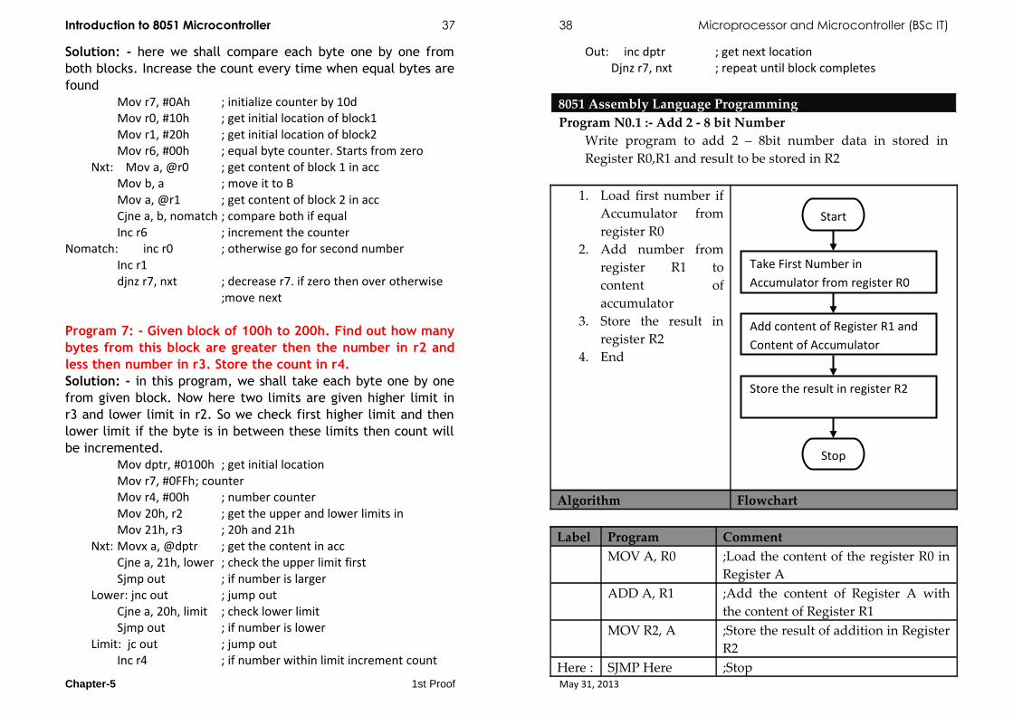
8051 Assembly Language ProgrammingProgram N0.1 :- Add 2 - 8 bit Number
Write program to add 2 – 8bit number data in stored in Register R0,R1 and result to be stored in R2
1. Load first number if Accumulator from register R0
2. Add number from register R1 to content of accumulator
3. Store the result in register R2
4. End
Algorithm Flowchart
Label Program CommentMOV A, R0 ;Load the content of the register R0 in
Register AADD A, R1 ;Add the content of Register A with
the content of Register R1MOV R2, A ;Store the result of addition in Register
R2Here : SJMP Here ;Stop
Chapter-5 1st Proof May 31, 2013
Start
Take First Number in Accumulator from register R0
Add content of Register R1 and Content of Accumulator
Store the result in register R2
Stop

Introduction to 8051 Microcontroller 37 38 Microprocessor and Microcontroller (BSc IT)
Program N0.2 : Add 2 - 8 bit NumberWrite program to add 2 – 8bit number Data is stored in internal memory and store the result in register R2
Label Program CommentMOV A, #44H ;Load the content 44H in Register AADD A, #66H ;Add the content of Register A with
the content 66HMOV R2, A ;Store the result of addition in Register
R2Here :
SJMP Here ;Stop
Program N0.3 : Add 2 - 8 bit NumberWrite program to add 2 – 8bit number Data is stored in data memory location 51H , 52H and store the result in data memory location 53H
Label Program CommentMOV A, 51H ;Load Register A with the content of
memory location 55HADD A, 52H ;Add the content of Register A with
the content of data memory 52HMOV 53H, A ;Store the result of addition in data
memory 53HHere : SJMP Here ;stop
Program N0.4 : Add 2 - 8 bit NumberWrite program to add 2 – 8bit number Data is stored in data memory location whose address is stored in R1 and R2 register and store the result in data memory location 53H
Label Program CommentMOV A, @R1 ;Load Register A with the content of
memory location pointer by register R1
ADD A, @R2 ;Add the content of Register A with the content of location pointer by register R2s
MOV 53H, A ;Store the result of addition in data memory 53H
Here : SJMP Here
Program N0.5 : Subtract 2 - 8 bit NumberWrite program to Subtract 2 – 8bit number data in stored in Register R0,R1 and result to be stored in R2
Label Program CommentMOV A , R0 ;Load the content of the register R0 in
Register ASUBB A, R1 ; Subtract the content of Register A
with the content of Register R1MOV R2,A ;Store the result of addition in Register
R2Here : SJMP Here ;stop
Program N0.6 : Subtract 2 - 8 bit NumberWrite program to Subtract 2 – 8bit number Data is stored in internal memory and store the result in register R2
Label Program CommentMOV A , #44H ;Load the content 44H in Register ASUBB A, #66H ; Subtract the content of Register A
with the content 66HMOV R2,A ;Store the result of addition in Register
R2Here : SJMP Here ;stop
Program N0.7 : Subtract 2 - 8 bit NumberWrite program to Subtract 2 – 8bit number Data is stored in data memory location 51H , 52H and store the result in data memory location 53H
Chapter-5 1st Proof May 31, 2013
Introduction to 8051 Microcontroller 37 38 Microprocessor and Microcontroller (BSc IT)
Label Program CommentMOV A, 51H ;Load Register A with the content of
memory location 55HSUBB A, 52H ; Subtract the content of Register A
with the content of data memory 52HMOV 53H, A ;Store the result of addition in data
memory 53HHere : SJMP Here ;stop
Program N0.8 : Subtract 2 - 8 bit NumberWrite program to Subtract 2 – 8bit number Data is stored in data memory location whose address is stored in R1 and R2 register and store the result in data memory location 53H
Label Program CommentMOV A, @R1 ;Load Register A with the content of
memory location pointer by register R1
SUBB A, @R2 ; Subtract the content of Register A with the content of location pointer by register R2s
MOV 53H ,A ;Store the result of addition in data memory 53H
Here : SJMP Here ;stop
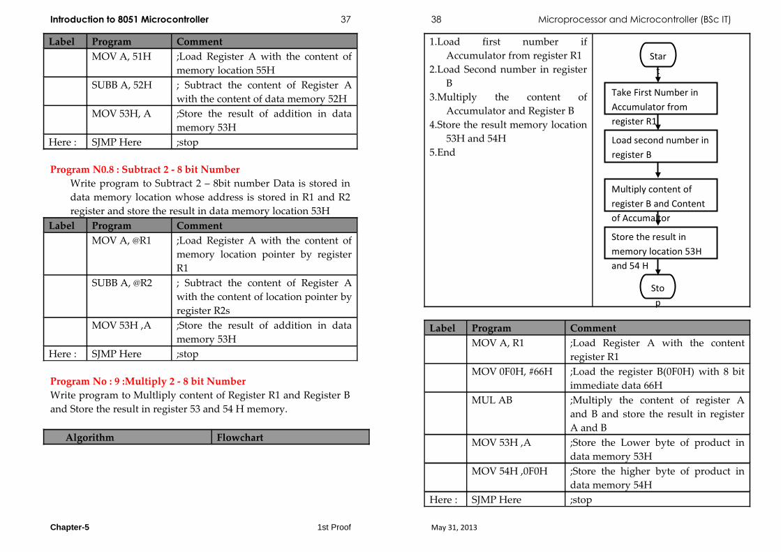
Program No : 9 :Multiply 2 - 8 bit NumberWrite program to Multliply content of Register R1 and Register B and Store the result in register 53 and 54 H memory.
Algorithm Flowchart
1.Load first number if Accumulator from register R1
2.Load Second number in register B
3.Multiply the content of Accumulator and Register B
4.Store the result memory location 53H and 54H
5.End
Label Program CommentMOV A, R1 ;Load Register A with the content
register R1MOV 0F0H, #66H ;Load the register B(0F0H) with 8 bit
immediate data 66HMUL AB ;Multiply the content of register A
and B and store the result in register A and B
MOV 53H ,A ;Store the Lower byte of product in data memory 53H
MOV 54H ,0F0H ;Store the higher byte of product in data memory 54H
Here : SJMP Here ;stop
Chapter-5 1st Proof May 31, 2013
Start
Take First Number in Accumulator from register R1
Load second number in register B
Store the result in memory location 53H and 54 H
Stop
Multiply content of register B and Content of Accumaltor

Introduction to 8051 Microcontroller 37 38 Microprocessor and Microcontroller (BSc IT)
Program No : 10 Divide 2 - 8 bit NumberWrite program to Divide content of Register R1 and Register B and Store the result in register 53 and 54 H memory.
Label Program CommentMOV A, R1 ;Load Register A with the content
register R1MOV 0F0H, #66H ;Load the register B(0F0H) with 8 bit
immediate data 66HDIV AB ;Divide the content of register A and
B and store the result in register A and B
MOV 53H ,A ;Store the Quotient in data memory 53H
MOV 54H ,0F0H ;Store the remainder in data memory 54H
Here : SJMP Here ;stop
Program N0.11 :BCD AdditionWrite program to perform BCD addition of 2- 8bit number Data is stored in data memory location 51H , 52H and store the result in data memory location 53H
Label Program CommentMOV A, 51H ;Load Register A with the content of
memory location 55HADD A, 52H ;Add the content of Register A with
the content of data memory 52HDA A ;Convert the Binary result to BCD
FormatMOV 53H, A ;Store the result of addition in data
memory 53HHere : SJMP Here ;stop
Program N0.12 : BCD Addition
Write program to perform BCD addition of 2- 8bit number Data is stored in data memory location 51H , 52H and store the result in data memory location 53H and carry in 54H
Algorithm Flowchart1. Load first number if
Accumulator from 51H data memory location
2. Add content of accumulator with data of memory location 52H
3. Decimal adjust Accumulator
4. Store the result memory location 53H
5. Store Carry in 54H ,memory location
6. End
Label Program CommentMOV A, 51H ;Load Register A with the content of
memory location 55HADD A, 52H ;Add the content of Register A with the
content of data memory 52HDA A ;Convert the Binary result to BCD
FormatMOV 53H, A ;Store the result of addition in data
Chapter-5 1st Proof May 31, 2013

Introduction to 8051 Microcontroller 37 38 Microprocessor and Microcontroller (BSc IT)
memory 53HMOV A, #00H ;Clear the content of accumulatorRLC A ;bring carry in D0 Bit of AccumulatorMOV 54H , |A ;Store in memory location 54H
Here : SJMP Here ;stop
Program No 13 : Add two 8 bit numberSuppose the two data bytes are in Register R2 and R3 of the Bank 1. Perform addition on the data bytes stored in R2 and R3 register. If result is greater than 8 bit, then store LSB of result in R4 and MSB of result in R5.
Label Mnemonic Operands Comment CLR PSW.4 ; Select Register Bank 1 of
internal RAMSETB PSW.3MOV R5, #00H ; Load MSB register R5 with
00HMOV A, R2 ; Load first number in
AccumulatorADD A, R3 ; Add first number with
second number JNC Down , If Result < 8 bit then go to
Down INC R5 ; Increment MSB counter by 1
Down MOV R4, A Store result in internal memory
Here: SJMP Here ;Stop
Program No 14 :Sum Of seriesLet the array of ten data bytes is stored in external RAM from memory location 5000H. let sum be 16 bit. Store LSB of result in memory location 500AH and MSB of result in memory location 500BH.write Assembly Language Program.
Algorithm1. Select Register Bank 02. Initialize register to store Carry 3. Initialize register as counter4. Initialize memory pointer for array5. Clear Accumulator which is uses as sum register6. Add number from array7. If Result < 8 bit, then go to Step 98. Increment Carry counter by 19. Increment memory pointer by 110. Decrement byte counter by 111. If byte counter <> 0, then go to Step 612. Store LSB and MSB (Value of Carry
Counter) of result in memory.13. Stop.
Label Mnemonic Operands Comment CLR PSW.3 ; Select Register Bank 0CLR PSW.4CLR PSW.7 ; Clear Carry FlagMOV R1, #00H ; Initialize Carry
Counter with 00MOV R0, #0AH ; Initialize byte CounterMOV DPTR, #
5000H; Initialize memory pointer
MOV R2, #00H ; Clear R2UP: MOVX A, @DPTR ;Copy content of
external memory to register A
ADDC A, R2 ; Add R2 register with number from array in A with Cy
MOV R2, A ; Store Result to R2JNC DN ; IF CY = 0, then go to
Down
Chapter-5 1st Proof May 31, 2013

Introduction to 8051 Microcontroller 37 38 Microprocessor and Microcontroller (BSc IT)
INC R1 ;Increment register R1Down INC DPTR ; Increment memory
pointerDJNZ R0, UP ; Decrement byte
counter, if byte counter ≠ 0 Then go to up
MOV @DPTR, A ; Store LSB of result in internal memory
INC DPTR, A ; Increment memory pointer by1
MOV A, R1 ;Copy content of register R4 to register A
MOV @DPTR, A ; Store MSB of the result in internal memory
Here: AJMP Here ; Stop
Program No 15: Multiply 2-8 numberLet multiplicand is stored in external memory location 8000H and multiplier is stored in memory location 8001H. Store LSB and MSB of the result in external memory locations 8002H and 8003H respectively. Write assembly language program
Label Mnemonic Operands Comment MOV DPTR,
#8000H; Initialize memory pointer to point external memory location 8000H
MOVX A, @ DPTR ; Load Multiplicand in AMOV 0F0H, A ; Copy in to B registerINC DPTR ; Increment memory pointer ie
DPTRMOVX A, @DPTR ; Load Multiplier in AMUL AB ; Multiply multiplicand with
multiplierINC DPTR ; Increment memory pointer
MOVX @ DPTR, A ; Store LSB of result in memory
MOV A, 0F0H ; Copy MSB of result in AINC DPTR ; Increment memory pointer
by 1MOVX @ DPTR, A ; Store MSB of result in
memoryHere: SJMP Here ; Stop
Program No 16 :Smallest from an ArrayLet array of the ten bytes is stored in internal memory of 8051 from memory, location 60H and Store smallest number in memory location 70H.Write assembly language program.
Label Mnemonic Operands Comment MOV R1, #0AH ; Initialize register R1 as
counterMOV R0, #5OH ; Initialize memory pointerDEC R1 ; Decrement counter by 1 ie R1
registerMOV 70H, @R0 ; Store number in memory
location 70 HUP: INC R0 ; Increment memory pointer
by 1MOV A, @R0 ; Read Next number CJNE A, 70H,
DN; if number ≠ next number, then go to Down
AJMP NEXT ; else go to NEXTDown:
JNC NEXT ; If next number < number then go to NEXT
MOV 70H, A ; Else replace next number with number
NEXT: DJNZ R1, UP ; Decrement byte counter by 1, if byte counter ≠ o then go to UP
Chapter-5 1st Proof May 31, 2013

Introduction to 8051 Microcontroller 37 38 Microprocessor and Microcontroller (BSc IT)
Here: SJMP Here ; Stop
Program No 17 :Arranging number in Ascending orderThe block or array is stored in external memory from address 9000H.Write program to arrange number in ascending order
Algorithm 1. Initialize comparison / pass counter to count number of
passes2. Initialize memory pointer to3. read data byte from array4. Initialize counter equal to number of data bytes5. Read numbers from the array6. Compare two numbers7. If number <= next number then go to step 88. Exchange or swap numbers9. Increment memory pointer to10. read next number from array 11. Decrement byte counter by one12. If byte counter <> 0 then go13. step 414. Decrement comparison counter15. By one16. If comparison counter <> 0 then go to step 2 17. Stop
Label Mnemonic Operands Comment MOV R0, #0AH ; Initialize pass counter
UP1: MOV DPTR, #9000H
; Initialize memory pointer DPTR to 9000H
MOV R1, #0AH ; Initialize byte CounterUP: MOV R2, DPL ; Save the lower byte address
MOVX A, @DPTR ; Read number from arrayMOV 0F0H, A ; Copy number to B registerINC DPTR ; Increment memory Pointer
MOVX A, @DPTR ; Read next number from array
CJNE A, 0F0, Down
; Compare number with next number
SJMP SKIP ;Jump to skipDown:
JNC SKIP ; If number > next number then skip
MOV DPL, R2 ; Else exchange the number with next number
MOVX @ DPTR, A ; store data in memoryINC DPTR ;Increment memory pointerMOV A, 0F0H MOVX @ DPTR, A
SKIP: DJNZ R1 UP ; Decrement byte counter if not 0 go to UP
DJNZ RO UP1 ; Decrement pass counter if not 0 go to UP1
Here: SJMP Here ; StopNote : To arrange numbers in array in descending order, the above both i.e. for byte and word program for ascending order can be executed by replacing JNC instruction with JC instruction. Program No 18 :Block Transfer
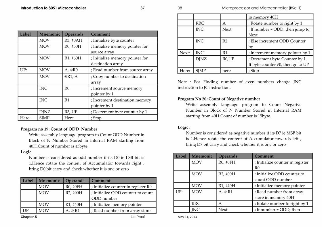
Let 15 bytes are stored in the internal memory from address 50H and the starting address of the destination block where we want to transfer these 15 bytes is 60H.Write assembly language program.
Chapter-5 1st Proof May 31, 2013
Introduction to 8051 Microcontroller 37 38 Microprocessor and Microcontroller (BSc IT)
Label Mnemonic Operands Comment MOV R3, #0AH ; Initialize byte counter MOV R0, #50H ; Initialize memory pointer for
source array MOV R1, #60H ; Initialize memory pointer for
destination array UP: MOV A, @R0 ; Read number from source array
MOV @R1, A ; Copy number to destination array
INC R0 ; Increment source memory pointer by 1
INC R1 ; Increment destination memory pointer by 1
DJNZ R3, UP ; Decrement byte counter by 1 Here: SJMP Here ; Stop
Program no 19 :Count of ODD NumberWrite assembly language program to Count ODD Number in Block of N Number Stored in internal RAM starting from 40H.Count of number is 15byte.
Logic Number is considered as odd number if its D0 ie LSB bit is 1.Hence rotate the content of Accumulator towards right , bring D0 bit carry and check whether it is one or zero
Label Mnemonic Operands Comment MOV R0, #0FH ; Initialize counter in register R0MOV R2, #00H ; Initialize ODD counter to count
ODD numberMOV R1, #40H ; Initialize memory pointer
UP: MOV A, @ R1 ; Read number from array store
in memory 40HRRC A ; Rotate number to right by 1JNC Next ; If number ≠ ODD, then jump to
NextINC R2 ; Else increment ODD Counter
byNext: INC R1 ; Increment memory pointer by 1
DJNZ R0,UP ; Decrement byte Counter by 1 , If byte counter ≠0, then go to UP
Here: SJMP here ; Stop
Note : For Finding number of even numbers change JNC instruction to JC instruction.
Program No 20.:Count of Negative numberWrite assembly language program to Count Negative Number in Block of N Number Stored in Internal RAM starting from 40H.Count of number is 15byte.
Logic :Number is considered as negative number if its D7 ie MSB bit is 1.Hence rotate the content of Accumulator towards left , bring D7 bit carry and check whether it is one or zero
Label Mnemonic Operands Comment MOV R0, #0FH ; Initialize counter in register
R0MOV R2, #00H ; Initialize ODD counter to
count ODD numberMOV R1, #40H ; Initialize memory pointer
UP: MOV A, @ R1 ; Read number from array store in memory 40H
RRC A ; Rotate number to right by 1JNC Next ; If number ≠ ODD, then
Chapter-5 1st Proof May 31, 2013

Introduction to 8051 Microcontroller 37 38 Microprocessor and Microcontroller (BSc IT)
jump to NextINC R2 ; Else increment ODD
Counter byNext: INC R1 ; Increment memory pointer
by 1 DJNZ R0,UP ; Decrement byte Counter by
1 , If byte counter ≠0, then go to UP
Here: SJMP here ; StopLabel Mnemonic Operands Comment
Note : For Finding number of positive numbers change JNC instruction to JC instruction.
Program No 21 : 2’s Complement of numberLet the number is stored in R0 register of Bank 0, then find out the 2’ s complement of the number and store result in R1 register of the same bank.
Label Mnemonic Operands Comment CLR PSW.4 ; C lear RS1 CLR PSW.3 ;Clear RS0 , Select Bank 0MOV A, R0 ; Copy number to accumulatorCPL A ; Complement the accumulatorADD A, #01H ; Find 2nd Complement MOV R1, A ; Store result in R1
LOOP: AJMP LOOP ; Stop
Program No :22 :PackingPacking two unpacked BCD bytes are stored in r0, r1. The program below packs these two unpacked bytes into a single byte and store in r2.
Unpacked BCD : In unpacked BCD, the lower 4 bits of the number represent the BCD number, and rest of the bits are 0.
Example : “0000 1001” and “0000 0101” are unpacked BCD for 9 and 5, respectively. Unpacked BCD requires 1 byte of memory or an 8 bit register to store it.
Packed BCD: In packed BCD, a single byte has two BCD numbers in it; one in the lower 4 bits and one in upper 4 bits.
Example: “0101 1001” is packed BCD for 59H. It takes one byte of memory to store the packed BCD operands. Packed BCD is used since it is twice as efficient in storing data.
Label Mnemonic CommentsMOV R1, #05H ;Move 05 into the register r1MOV R0, #09H ;Move 09 into the register r0MOV A, R1 ;Move 1st number in accumulatorANL A,#0FH ;Masking upper nibble
SWAP A;Contents of lower and higher nibble of accumulator are exchanged
MOV R2, A;Contents of accumulator transferred to r2
MOV A, R0 ;Move 2nd number in accumulatorANL A,#OFH ;Masking upper nibbleADD A, R2 ;The 2 bytes are packedMOV R2, A ;Packed result is stored in register R2
HERE: SJMP HERE ;Stay in this loop
Program No :23 :UnpackingWrite program to unpack packed BCD number stored in 40H. Store the unpacked number in 41H and 42H respectively Using direct addressing mode
Label Mnemonic Comments
MOV A, 40H;Move data from 40H memory to accumulator
Chapter-5 1st Proof May 31, 2013

Introduction to 8051 Microcontroller 37 38 Microprocessor and Microcontroller (BSc IT)
MOV R1 ,A;copy content of Accumulator to register R1
ANL A,#0FH ;Masking upper nibble
MOV 41H ,A;Copy content of register A to memory location 41H
MOV A,R1;Copy content of register R1 to register A
SWAP A;Contents of lower and higher nibble of accumulator are exchanged
ANL A,#OFH ;Masking upper nibble
MOV 42H , A;Store the content of Register A memory location 42H
HERE: SJMP HERE ;Stop
Program No :24 :UnpackingWrite program to unpack packed BCD number stored in 50H. Store the unpacked number in 51H and 52H respectively. using indirect addressing mode.
Label Mnemonic Comments
MOV R0,#50H;Initialise memory pointer Ro to 50H data memory location
MOV A, @R0;Move data from data memory to accumulator
MOV R1 ,A;copy content of Accumulator to register R1
ANL A,#0FH ;Masking upper nibble
INC R0;Increment memory pointer to point Next location
MOV @R0 ,A;Store content of register A to memory location pointer by R0 register
MOV A,R1;Copy content of register R1 to register A
SWAP A;Contents of lower and higher nibble of accumulator are exchanged
ANL A,#OFH ;Masking upper nibble
INC R0;Increment memory pointer to point Next location
MOV @R0, A;Store content of register A to memory location pointer by R0 register
HERE: SJMP HERE ;Stop
Program No :26 : MaskingWrite program to mask the upper nibble of BCD number stored in 50H. Store the masked number in 51H and to mask lower nibble of number stored at 52H ,store the result at 53H. using indirect addressing mode.
Label Mnemonic Comments
MOV R0,#50H;Initialise memory pointer Ro to 50H data memory location
MOV A, @R0;Move data from data memory to accumulator
MOV R1 ,A;copy content of Accumulator to register R1
ANL A,#0FH ;Masking upper nibble
INC R0;Increment memory pointer to point Next location
MOV @R0 ,A;Store content of register A to memory location pointer by R0 register
MOV A,R1;Copy content of register R1 to register A
ANL A,#0F0H ;Masking Lower nibble
INC R0;Increment memory pointer to point Next location
MOV @R0, A;Store content of register A to memory location pointer by R0 register
HERE: SJMP HERE ;Stop
Program No.25 : maskingChapter-5 1st Proof May 31, 2013

Introduction to 8051 Microcontroller 37 38 Microprocessor and Microcontroller (BSc IT)
Write program to mask the upper nibble of BCD number stored in 50H. Store the masked number in 51H and to mask lower nibble of number stored at 52H ,store the result at 53H. using direct addressing mode.
Label Mnemonic Comments
MOV A, 50H;Move data from 40H memory to accumulator
MOV R1 ,A;copy content of Accumulator to register R1
ANL A,#0FH ;Masking upper nibble
MOV 51H ,A;Copy content of register A to memory location 51H
MOV A,R1 ;Copy content of register R1 to register AANL A,#0F0H ;Masking Lower nibble
MOV 52H , A;Store the content of Register A memory location 52H
HERE: SJMP HERE ;Stop
Program No.27:Largest from Block of dataWrite program to find largest from a block of 10 bytes stored from memory location 50H,Store the result at 60H
Algorithm1. Initialize byte counter for number of bytes to be arranges 2. Initialize memory pointer to read numbers from data
memory array3. Read number from the memory4. Increment memory pointer to read next number5. Decrement counter 6. Compare Max Number with next number7. If max > next number, then go to step 88. Make max next number which is largest9. Increment memory pointer to read next number in the
array10. Decrement byte counter by 1
11. If byte counter <> 0 then go to step 512. Store result13. Stop
Label Mnemonic Operands Comment CLR PSW.3 ; Clear RS1CLR PSW.4 ;Clear RS0 so as to select
register bank 0MOV R1, 0AH ; Initialize byte pointerMOV RO, #5OH ; Initialize memory pointer to
point data memoryDEC R1 ; Decrement byte counter by 1MOV 60H, @R0 ; Store number in memory
location 60 HUP: INC R0 ; Increment memory pointer
by 1MOV A, @R0 ; Read Next number CJNE A, 60H,
Down; if number ≠ next number, then go to Down
SJMP NEXT ; else go to NEXTDown: JC NEXT ; If next number > number then
go to NEXTMOV 60H, A ; Else replace next number
with numberNEXT: DJNZ R1, UP ; Decrement byte counter by 1,
if byte counter ≠ o then go to UP
LOOP:
SJMP LOOP ; Stop
Program 28 :Write an assembly language program to convert 8 bit two digit BCD number system into Hexadecimal number system.Algorithm
Chapter-5 1st Proof May 31, 2013

Introduction to 8051 Microcontroller 37 38 Microprocessor and Microcontroller (BSc IT)
a. Start the Programb. Get the data from the 8300
memory location to R5 register. (R5 = 99).c. Separate the MSB and LSB
of R5 register using ANL 0Fh and ANL F0h commands.d. Move the MSB to
Accumulator and LSB to R2 register.( A = 09, R2 = 09)e. Multiply the MSB with 0Ah
Data.(09*0A) = 5A)f. Add the Accumulator with
LSB of the Data. (5A+9 = 63)g. Move the Accumulator to
8301 memory location.(8301 = 63)h. Stop the program.
Chapter-5 1st Proof May 31, 2013

Introduction to 8051 Microcontroller 37 38 Microprocessor and Microcontroller (BSc IT)
FlowChart : BCD to Hexa Decimal ConversionProgram 29: Write an Assembly language program to convert the given hexadecimal value to its equivalent BCD conversion.
a. Start the program.b. Move the data from memory
location 8300 to Accumulator.(A = FFh)c. Divide the accumulator with
64h( FF/64 ( A= 2 and B = 37h )d. Move the accumulator to
8301h ( 8301 = 02)e. Move the B reg to
accumulator (A = 37h)f. Divide the accumulator with
0Ah (37/0A ( A=05 and B = 05 )g. Swap the Accumulator.(A =
50)h. Add the accumulator with B
register.(A = 50+5)i. Move the accumulator to
8302h(8302 = 55)j. Stop the program.
Chapter-5 1st Proof May 31, 2013

Introduction to 8051 Microcontroller 37 38 Microprocessor and Microcontroller (BSc IT)
Flow Chart : Hex to BCD
Program 29 :Write Alp to convert the given hexadecimal value to its equivalent ASCII code.Algorithm
1. Start the program.2. Move the data from memory location 8300 to
Accumulator.(A = FFh)3. Divide the accumulator with 64h( FF/64 ( A= 2 and B =
37h )4. Add the accumulator with 30h5. Move the accumulator to 8301h ( 8301 = 32)6. Move the B reg to accumulator (A = 37h)
Chapter-5 1st Proof May 31, 2013

Introduction to 8051 Microcontroller 37 38 Microprocessor and Microcontroller (BSc IT)
7. Divide the accumulator with 0Ah (37/0A ( A=05 and B = 05 )
8. Add the accumulator with 30h9. Move the accumulator to 8302h(8302 = 35)10. Move B reg to Accumulator.11. Add the accumulator with 30h12. Move the accumulator to 8303h(8303 = 35)13. Stop the program.
Flow Chart : Hex to ASCII Conversion
Chapter-5 1st Proof May 31, 2013
Introduction to 8051 Microcontroller 37 38 Microprocessor and Microcontroller (BSc IT)
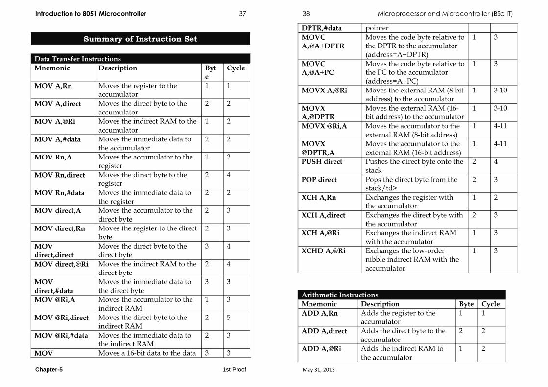
Summary of Instruction Set
Data Transfer InstructionsMnemonic Description Byt
eCycle
MOV A,Rn Moves the register to the accumulator
1 1
MOV A,direct Moves the direct byte to the accumulator
2 2
MOV A,@Ri Moves the indirect RAM to the accumulator
1 2
MOV A,#data Moves the immediate data to the accumulator
2 2
MOV Rn,A Moves the accumulator to the register
1 2
MOV Rn,direct Moves the direct byte to the register
2 4
MOV Rn,#data Moves the immediate data to the register
2 2
MOV direct,A Moves the accumulator to the direct byte
2 3
MOV direct,Rn Moves the register to the direct byte
2 3
MOV direct,direct
Moves the direct byte to the direct byte
3 4
MOV direct,@Ri Moves the indirect RAM to the direct byte
2 4
MOV direct,#data
Moves the immediate data to the direct byte
3 3
MOV @Ri,A Moves the accumulator to the indirect RAM
1 3
MOV @Ri,direct Moves the direct byte to the indirect RAM
2 5
MOV @Ri,#data Moves the immediate data to the indirect RAM
2 3
MOV Moves a 16-bit data to the data 3 3
DPTR,#data pointerMOVC A,@A+DPTR
Moves the code byte relative to the DPTR to the accumulator (address=A+DPTR)
1 3
MOVC A,@A+PC
Moves the code byte relative to the PC to the accumulator (address=A+PC)
1 3
MOVX A,@Ri Moves the external RAM (8-bit address) to the accumulator
1 3-10
MOVX A,@DPTR
Moves the external RAM (16-bit address) to the accumulator
1 3-10
MOVX @Ri,A Moves the accumulator to the external RAM (8-bit address)
1 4-11
MOVX @DPTR,A
Moves the accumulator to the external RAM (16-bit address)
1 4-11
PUSH direct Pushes the direct byte onto the stack
2 4
POP direct Pops the direct byte from the stack/td>
2 3
XCH A,Rn Exchanges the register with the accumulator
1 2
XCH A,direct Exchanges the direct byte with the accumulator
2 3
XCH A,@Ri Exchanges the indirect RAM with the accumulator
1 3
XCHD A,@Ri Exchanges the low-order nibble indirect RAM with the accumulator
1 3
Arithmetic InstructionsMnemonic Description Byte CycleADD A,Rn Adds the register to the
accumulator1 1
ADD A,direct Adds the direct byte to the accumulator
2 2
ADD A,@Ri Adds the indirect RAM to the accumulator
1 2
Chapter-5 1st Proof May 31, 2013

Introduction to 8051 Microcontroller 37 38 Microprocessor and Microcontroller (BSc IT)
ADD A,#data Adds the immediate data to the accumulator
2 2
ADDC A,Rn Adds the register to the accumulator with a carry flag
1 1
ADDC A,direct Adds the direct byte to the accumulator with a carry flag
2 2
ADDC A,@Ri Adds the indirect RAM to the accumulator with a carry flag
1 2
ADDC A,#data Adds the immediate data to the accumulator with a carry flag
2 2
SUBB A,Rn Subtracts the register from the accumulator with a borrow
1 1
SUBB A,direct Subtracts the direct byte from the accumulator with a borrow
2 2
SUBB A,@Ri Subtracts the indirect RAM from the accumulator with a borrow
1 2
SUBB A,#data Subtracts the immediate data from the accumulator with a borrow
2 2
INC A Increments the accumulator by 1
1 1
INC Rn Increments the register by 1 1 2INC Rx Increments the direct byte
by 12 3
INC @Ri Increments the indirect RAM by 1
1 3
DEC A Decrements the accumulator by 1
1 1
DEC Rn Decrements the register by 1 1 1DEC Rx Decrements the direct byte
by 11 2
DEC @Ri Decrements the indirect RAM by 1
2 3
INC DPTR Increments the Data Pointer by 1
1 3
MUL AB Multiplies A and B 1 5DIV AB Divides A by B 1 5DA A Decimal adjustment of the
accumulator according to BCD code
1 1
Logic InstructionsMnemonic Description Byte CycleANL A,Rn AND register to
accumulator1 1
ANL A,direct AND direct byte to accumulator
2 2
ANL A,@Ri AND indirect RAM to accumulator
1 2
ANL A,#data AND immediate data to accumulator
2 2
ANL direct,A AND accumulator to direct byte
2 3
ANL direct,#data
AND immediate data to direct register
3 4
ORL A,Rn OR register to accumulator
1 1
ORL A,direct OR direct byte to accumulator
2 2
ORL A,@Ri OR indirect RAM to accumulator
1 2
ORL direct,A OR accumulator to direct byte
2 3
ORL direct,#data OR immediate data to direct byte
3 4
XRL A,Rn Exclusive OR register to accumulator
1 1
XRL A,direct Exclusive OR direct byte to accumulator
2 2
Chapter-5 1st Proof May 31, 2013

Introduction to 8051 Microcontroller 37 38 Microprocessor and Microcontroller (BSc IT)
XRL A,@Ri Exclusive OR indirect RAM to accumulator
1 2
XRL A,#data Exclusive OR immediate data to accumulator
2 2
XRL direct,A Exclusive OR accumulator to direct byte
2 3
XORL direct,#data
Exclusive OR immediate data to direct byte
3 4
CLR A Clears the accumulator 1 1CPL A Complements the
accumulator (1=0, 0=1)1 1
SWAP A Swaps nibbles within the accumulator
1 1
RL A Rotates bits in the accumulator left
1 1
RLC A Rotates bits in the accumulator left through carry
1 1
RR A Rotates bits in the accumulator right
1 1
RRC A Rotates bits in the accumulator right through carry
1 1
Bit-oriented InstructionsMnemonic Description Byte CycleCLR C Clears the carry flag 1 1CLR bit Clears the direct bit 2 3SETB C Sets the carry flag 1 1SETB bit Sets the direct bit 2 3CPL C Complements the carry flag 1 1CPL bit Complements the direct bit 2 3ANL C,bit AND direct bit to the carry flag 2 2ANL C,/bit AND complements of direct bit to
the carry flag2 2
ORL C,bit OR direct bit to the carry flag 2 2ORL C,/bit OR complements of direct bit to 2 2
the carry flagMOV C,bit Moves the direct bit to the carry
flag2 2
MOV bit,C Moves the carry flag to the direct bit
2 3
Chapter-5 1st Proof May 31, 2013