simple method of composition shifting with a distillation
TRANSCRIPT

NISTIR 5689
A Simple Method of CompositionShifting with a Distillation Columnfor a Heat Pump Employing a ZeotropicRefrigerant Mixture
Peter I. Rothfleisch
Building and Fire Research LaboratoryGaithersburg, Maryland 20899
United States Department of CommerceTechnology AdministrationNational Institute of Standards and Technology

NISTIR 5689
A Simple Method of CompositionShifting with a Distillation Columnfor a Heat Pump Employing a ZeotropicRefrigerant Mixture
Peter I. Rothfleisch
July 1995
U.S. Department of CommerceRonald H. Brown, SecretaryTechnology of AdministrationMary L. Good, Under Secretary for TechnologyNational Institute of Standards and TechnologyArati Prabhakar, Director
Prepared for: Prepared for:U.S. Department of Energy U.S. Environmental Protection AgencyWilliam Noel, Project Manager Robert V. Hendriks, Project OfficerOffice of Building Technology Office of Research and DevelopmentBuilding Equipment Division Air and Energy Engineering Resear ch LaboratoryEnergy Efficiency and Renewable Energy Research Triangle Park, NC 277111000 Independence Ave., SWWashington, DC 20585
iii
ABSTRACT
This work presents a simplified method of controlling heat pump capacity by shifting thecomposition of a zeotropic refrigerant mix ture with a distillation column. Simplicity is achievedby incorporating the distillation column into the typical suction accumulator used by residentialheat pumps. A U.S. patent has been applied for under the title "Accumulator Distillation Insertfor Zeotropic Mixtures". An experimental system employing this distillation concept has beenevaluated in the laboratory for zeotropic mixtures of R32/134a (30/70) and R32/125/134 a(23/25/52). For the binary mixture the circulating refrigerant composition was shifted t oR32/134a (54/46). For the ternary mixture the circulating refrigerant composition was shifte dto R32/125/134a (36/36/28). Seasonal calculations have shown these composition shifts t oreduce the seasonal resistance heat requirement by up to five percent compared to R22 .Additionally, the instantaneous peak energy requirement of the dwelling has been reduce drelative to R22 by six to nine percent depending on the climate region. The distillation inser tshould be capable of producing greater c omposition shifts after further optimization of the insertand improved integration with the heat pump s ystem. For the ternary mixture, it is expected thatthe insert will be capable of producing a circulating refrigerant composition composed entirelyof R32/125.

iv
ACKNOWLEDGEMENTS
This study was conducted under the sponsorship of the U.S. Department of Energy, Officeof Building Technology, Building Equipment Division with Mr. William Noel as progra mmanager. Funds were also contributed by the U.S. Environmental Protection Agency, Office ofResearch and Development, Air and Energy Engineering Research Laboratory under th emanagement of Mr. Robert Hendriks.
v
TABLE OF CONTENTS
TABLE OF CONTENTS . . . . . . . . . . . . . . . . . . . . . . . . . . . . . . . . . . . . . . . . . . . . . . . . . . . . v
LIST OF FIGURES . . . . . . . . . . . . . . . . . . . . . . . . . . . . . . . . . . . . . . . . . . . . . . . . . . . . . . . vi
LIST OF TABLES . . . . . . . . . . . . . . . . . . . . . . . . . . . . . . . . . . . . . . . . . . . . . . . . . . . . . . . . vii
INTRODUCTION . . . . . . . . . . . . . . . . . . . . . . . . . . . . . . . . . . . . . . . . . . . . . . . . . . . . . . . . . 1
OPERATING PRINCIPLES OF A PASSIVE SYSTEM . . . . . . . . . . . . . . . . . . . . . . . . . . . 3
OPERATING PRINCIPLES OF THE PROPOSED SYSTEM . . . . . . . . . . . . . . . . . . . . . . . 5
GENERAL COMPOSITION SHIFT RELATIONS . . . . . . . . . . . . . . . . . . . . . . . . . . . . . . . 9
TEST METHODOLOGY AND RESULTS . . . . . . . . . . . . . . . . . . . . . . . . . . . . . . . . . . . . . 12
SEASONAL CALCULATIONS . . . . . . . . . . . . . . . . . . . . . . . . . . . . . . . . . . . . . . . . . . . . . 16
CONCLUSIONS AND RECOMMENDATIONS FOR FUTURE WORK . . . . . . . . . . . . . 19
REFERENCES . . . . . . . . . . . . . . . . . . . . . . . . . . . . . . . . . . . . . . . . . . . . . . . . . . . . . . . . . . . 21

vi
LIST OF FIGURES
1. Outdoor Temperature Dependence of Building Load and Heat Pump Output . . . . . . . . . . . . . . . . . . . . . . . . . . . . . . . . . . . . . . . . . . . . . . . . . . . . . 2
2. Typical System Components . . . . . . . . . . . . . . . . . . . . . . . . . . . . . . . . . . . . . . . . . . . . . . . . 3
3. Passive (Equilibrium Stage) Composition Shift Mechanism . . . . . . . . . . . . . . . . . . . . . . . . 4
4. Patent Pending Version . . . . . . . . . . . . . . . . . . . . . . . . . . . . . . . . . . . . . . . . . . . . . . . . . . . . 7
5. Experimental Version . . . . . . . . . . . . . . . . . . . . . . . . . . . . . . . . . . . . . . . . . . . . . . . . . . . . . . 7
6. Distillation Column Composition Shift Mechanism . . . . . . . . . . . . . . . . . . . . . . . . . . . . . . 8
7. Binary Mixture Storage Requirements . . . . . . . . . . . . . . . . . . . . . . . . . . . . . . . . . . . . . . . . 11
8. Ternary Mixture Storage Requirements . . . . . . . . . . . . . . . . . . . . . . . . . . . . . . . . . . . . . . . 11

vii
LIST OF TABLES
1. TEST RESULTS FOR BINARY MIXTURE OF R32/134a (30/70) . . . . . . . . . . . . . . . . . 14
2. TEST RESULTS FOR TERNARY MIXTURE OF R32/125/134a (23/25/52) . . . . . . . . . . . . . . . . . . . . . . . . . . . . . . . . . . . . . . . . . . . . . . . . . . . . . . . . . . . . . . 15
3. HEATING SEASONAL PERFORMANCE FACTOR (HSPF) . . . . . . . . . . . . . . . . . . . . . 17
4. PERCENTAGE OF SEASONAL BUILDING LOAD OBTAINED FROM RESISTANCE HEAT . . . . . . . . . . . . . . . . . . . . . . . . . . . . . . . . . . . . . . . . . . . . . . . . . . . . . 17
5. NORMALIZED HEATING SYSTEM COP FOR PEAK BINS - REGION 3 . . . . . . . . . . 18
6. NORMALIZED HEATING SYSTEM COP FOR PEAK BINS - REGION 4 . . . . . . . . . . 18
7. NORMALIZED HEATING SYSTEM COP FOR PEAK BINS - REGION 5 . . . . . . . . . . 18

1
INTRODUCTION
The heating capacity of a single speed air-to-air heat pump is directly proportional to theoutside (evaporator) temperature. As the outside temperature falls, the suction pressure and thesuction temperature also fall. This causes both the suction vapor specific volume and th ecompression ratio to increase. Consequently, the system heating capacity is reduced and th especific compressor work input is increased. The building heat load, on the other hand, is directlyproportional to the temperature difference between the indoor and outdoor air. Therefore, th ebuilding heat load increases as the outside temperature fa lls. For outdoor temperatures below thebalance point, the output of the heat pump must be augmented with an auxiliary energy source.
The auxiliary energy required for an entire heating season is the difference between theseasonal building load and the seasonal heat pump output be low the balance point. The auxiliaryenergy is usually supplied by electric resistance heating, which has a coefficient of performance(COP) of one. Since the COP of a heat pump is usually greater than one, the heating seasonalperformance factor (HSPF) can be increased by modulating the heat pump capacity to meet thebuilding load thereby reducing the auxiliary heat required. Although the increase in HSPF i smodest (depending on the climatic region), the reduction in peak load to the electric utility canbe significant. The benefit of reducing the peak energy demand is magnified if the electric powerplant uses a less efficient electric generation system to meet the peak demand.
To reduce the amount of auxiliary heat required, the heat pump capacity mus t be increasedto match the building load as the outside temperature falls. Th e only commercially available heatpumps capable of matching system capacity to the building load have been those which vary thevolumetric capacity of the compressor. This can be accomplished several ways; the mos tcommon methods are two-speed compressor motors and frequency inverters for variable- speedcompressor motors. The system capacity can also be controlled by varying the composition ofa zeotropic refrigerant mixture. Specifically, by controlling the mixture composition th ethermodynamic properties of the refrigerant mixture can be altered to increase system capacityas the outside temperature drops. Basically, composition shifting of a zeotropic mixture can bethought of as a chemical analogue to a variable displacement compressor.

OUTDOOR TEMPERATURE C ( F)
SavedAux. Heat
RemainingAux. Heat
Initial MixtureCapacity
FinalMixtureCapacity
2
Figure 3 Outdoor Temperature Dependence of Building Load and Heat PumpOutput
The effects of increasing the heat pump capacity to ma tch the building load are shown fora single-speed system capable of shifting the composition of a zeotropic refrigerant mixture inFigure 1. In this figure, it is assumed that the heat pump would op erate on the original refrigerant
mixture until the outdoor temperature falls to the balance point. Figure 1 shows that the resultof increasing the heat pump capacity below the balance point will be a reduced auxiliary energyrequirement.
The literature (patents and articles) describes many different methods and systems fo rvarying the capacity of a heat pump by controlling the composition of a zeotropic mixture. Anextensive bibliographical list of proposed composition shifting systems is contained in reference3. All of these may be classified into one of the two generic categories of active and passiv esystems. An active system is one that uses a distillation column, whereas a passive system usesan accumulator. Generally, the methods with accumulators are simple to implement but requirea large refrigerant charge. Additionally, the magnitude of the refrigerant composition change istheoretically limited to the vapor composition that is in thermal equilibrium with the origina lmixtures bubble point. However, in practice, the magnitude of the refrigerant compositio nchange is further limited by the maximum percentage of the total refrigerant charge that may bestored in the accumulator. Conversely, the column methods can achieve much large rcomposition changes at the cost of increased system complexity in terms of both hardware andcontrol. Many of the proposed active systems have been so complex that they would never becost effective enough to be applied in the competitive residential heat pump market.
The problems of hardware and control complexity encountered in the previously proposeddistillation column systems are largely due to the failure of designers to integrate the distillation
COND
COMP
EVAP
EXPANSIONDEVICE
3 2
1
5
4
ACCUMULATOR
3
Figure 4 Typical System Components
column with the natural tendencies of heat pump operation. This work presents an activ edistillation column method for shifting the composition that retains the simplicity of a passiv esystem. Simplicity is achieved by integrating the distillation column with the heat pump in amanner that does not change the basic cycle and method of operation.
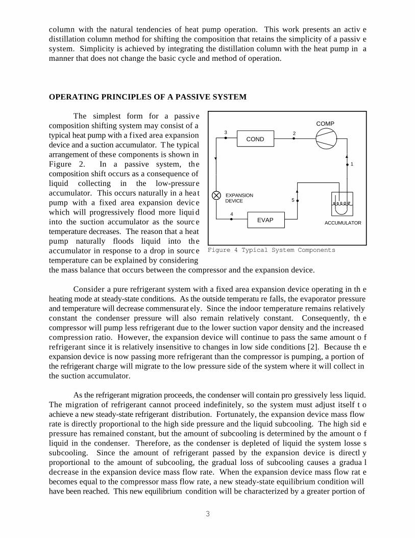
OPERATING PRINCIPLES OF A PASSIVE SYSTEM
The simplest form for a passivecomposition shifting system may consist of atypical heat pump with a fixed area expansiondevice and a suction accumulator. The typicalarrangement of these components is shown inFigure 2. In a passive system, thecomposition shift occurs as a consequence ofliquid collecting in the low-pressureaccumulator. This occurs naturally in a hea tpump with a fixed area expansion devic ewhich will progressively flood more liqui dinto the suction accumulator as the sourc etemperature decreases. The reason that a heatpump naturally floods liquid into theaccumulator in response to a drop in sourcetemperature can be explained by consideringthe mass balance that occurs between the compressor and the expansion device.
Consider a pure refrigerant system with a fixed area expansion device operating in th eheating mode at steady-state conditions. As the outside temperatu re falls, the evaporator pressureand temperature will decrease commensurat ely. Since the indoor temperature remains relativelyconstant the condenser pressure will also remain relatively constant. Consequently, th ecompressor will pump less refrigerant due to the lower suction vapor density and the increasedcompression ratio. However, the expansion device will continue to pass the same amount o frefrigerant since it is relatively insensitive to changes in low side conditions [2]. Because th eexpansion device is now passing more refrigerant than the compressor is pumping, a portion ofthe refrigerant charge will migrate to the low pressure side of the system where it will collect inthe suction accumulator.
As the refrigerant migration proceeds, the condenser will contain pro gressively less liquid.The migration of refrigerant cannot proceed indefinitely, so the system must adjust itself t oachieve a new steady-state refrigerant distribution. Fortunately, the expansion device mass flowrate is directly proportional to the high side pressure and the liquid subcooling. The high sid epressure has remained constant, but the amount of subcooling is determined by the amount o fliquid in the condenser. Therefore, as the condenser is depleted of liquid the system losse ssubcooling. Since the amount of refrigerant passed by the expansion device is directl yproportional to the amount of subcooling, the gradual loss of subcooling causes a gradua ldecrease in the expansion device mass flow rate. When the expansion device mass flow rat ebecomes equal to the compressor mass flow rate, a new steady-state equilibrium condition willhave been reached. This new equilibrium condition will be characterized by a greater portion of

CHARGED COMPOSITION
DEW POINT
BUBBLE POINT
TIE LINESLIMITING
4
Figure 5 Passive (Equilibrium Stage) Composition Shift Mechanism
the total refrigerant mass in the low side, less subcoolin g (it may even have two-phase refrigerantentering the expansion device) and a lower capacity.
Having examined how a decrease in the outside temperature causes the migration o frefrigerant from the condenser to the suction accumulator, the consequences of this for azeotropic mixture will now be addressed. Since accumulators normally have a minimal amountof heat transfer at the outside surface, the liquid and vapor inside the vessel will be in a n
approximate state of thermal equilibrium. A Temperature-Composition diagram for a zeotropicmixture of R32/134a is shown in Figure 3. In this figure, thermal equilibrium means that th evapor leaving the accumulator and the liquid remain ing must lie on a horizontal tie line. In otherwords, this type of passive system can p roduce a shift no greater than a single equilibrium stage.Additionally, if the accumulator is in thermal equilibrium then species conservation dictates thatone point on the tie line must be concurrent with the vertical line defined by the original chargedcomposition. These constraints define the two limiting tie lines which are shown in Figure 3 .It is theoretically possible for the system to operate so that the state in the accumulator i srepresented by any tie line that lies between these two. The max imum system capacity will occurwhen the circulating fluid, represented by the vapor leaving the accumulator, has the greates tcomposition of the more volatile component. This vapor composition is defined by the tie linethat extends from the original composition bubble point.
Although it is theoretically possible for an ac cumulator storage system to operate so thatthe circulating composition is that of the vapor in equilibrium with the bubble point, it is no tfeasible in practice. Since the liquid remaining in the accumulator and the vapor leaving mustlie on the same tie line, as the composition of the more volatile component increases in the vaporit also increases in the stored liquid. Consequently, as the maximum capacity composition i sapproached increasingly larger percentages of the refrigerant charge will have to be stored in the

5
accumulator. It is impractical to store large percentages of the total refrigerant charge becausethe excess refrigerant will have to be accommodated in the cooling mode when the accumulatoris empty.
OPERATING PRINCIPLES OF THE PROPOSED SYSTEM
The proposed distillation system retains the simplicity of an accumulator storage system,but eliminates the need to store large percentages of the refrigerant charge. Additionally, th emaximum composition shift is not limited to the vapor composition in equilibrium with th ebubble point of the initial composition. This result is made possible by removing the therma lequilibrium constraint. Since the stored liquid and the leaving vapor are not in therma lequilibrium they no longer must lie on the same tie line. Consequently, the stored liquid ma yconsist of the less volatile component in a nearly pure composition.
The thermal equilibrium constraint is removed by adding a distillation insert and a lowwattage heat source inside the accumulator. The hardware component layout for the proposedsystem is shown in Figure 4. A patent application for the concept of placing a distillation insertinside a typical suction accumulator is currently pending. The patent application is entitle d"Accumulator Distillation Insert for Zeotropic Mixtures".
The distillation insert is composed of a liquid-barrier and a small diameter packe ddistillation column. The insert divides the accumulator into three separate regions of differentfunctions. The volume above the liquid barrier serves as the liquid-vapor separation zone. Itsfunction is identical to the top portion of a standard accumulator. The center region is definedby the liquid-barrier and the volume contained within the distillation column. The liquid-barrierdirects all the liquid that leaves the separation zone through the column. The column is fille dwith a random distillation packing which provi des the surface area for the heat and mass transfernecessary for column operation. The region below the insert is the liquid storage and vapo rgeneration volume which also functions exactly as in a standard accumulator except for th eaddition of the heat source for vapor generation. The heat source, which is represented in th efigure by the symbol Q , is obtained from an electric immersion heater. It is important t oin
mention that the addition of the dist illation insert and heat source adds no new moving parts anddoes not affect the normal accumulator function of providing protection against liquid sluggingwith positive oil return.
Although the distillation insert was developed to be placed inside a standard suctio naccumulator, for visualization purposes a glass version of the device was used in the experimentalprogram. Additionally, to improve the level of the experimental instrumentation the thre efunctional regions of separation, distillation and storage/generation w ere separated into physicallyseparate components. The hardware component layout for the experim ental version of the deviceis shown in Figure 5.
The random packing utilized in the experimental column consists of 3 mm Teflon RaschigRings. To develop the theory of a randomly packed continuous contact tower requires adifferential analysis. However, a simple qualitative description of the distillation colum noperating principles can be made by considering the random packing to be composed of distincttrays. This type of distillation column, known as a multistage tray tower, is common in th e
6
chemical industry. The analysis of tray towers is conducted in a manner similar to the passivesystem by considering each tray to constitut e one equilibrium stage or tie line. Each equilibriumstage or tray is then referred to as a theoretical plate (TP). The complete multistage tray tower(the analogy for the random packed tower) consists of a series of single stage equilibriu mdistillations such as occur in a passive system accumulator.

COND
COMP
EVAP
EXPANSIONDEVICE
3 2
1
5
4Qin
DISTILLATIONCOLUMN
STORAGE/GENERATION
SEPARATIONLIQUID - VAPOR
COND
COMP
EVAP
EXPANSION
QinSTORAGE/GENERATION
DEVICE
DISTILLATIONCOLUMN
3 2
1
5
4
LIQUID - VAPORSEPARATION
7
Figure 6 Patent Pending Version
Figure 7 Experimental Version
CHARGED COMPOSITION CIRCULATING COMPOSITION
S
TP4
TP3
TP2
TP1
SEPARATION
TO TP4
TO TP3
TO TP2
TO TP1
TO SEPARATION
TO COMP
OILRETURN
TO S
TO TP4
TO TP3
TO TP2
TO TP1
SEPARATIONFROMEVAP
TO COMP
TP1
TP2
TP3
TP4
LIQUID VAPORTO S FROM S
S = STORAGE
8
Figure 8 Distillation Column Composition Shift Mechanism
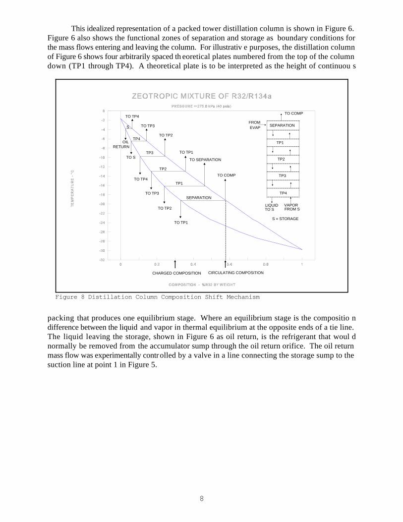
This idealized representation of a packed tower distillation column is shown in Figure 6.Figure 6 also shows the functional zones of separation and storage as boundary conditions forthe mass flows entering and leaving the column. For illustrativ e purposes, the distillation columnof Figure 6 shows four arbitrarily spaced th eoretical plates numbered from the top of the columndown (TP1 through TP4). A theoretical plate is to be interpreted as the height of continuou s
packing that produces one equilibrium stage. Where an equilibrium stage is the compositio ndifference between the liquid and vapor in thermal equilibrium at the opposite ends of a tie line.The liquid leaving the storage, shown in Figure 6 as oil return, is the refrigerant that woul dnormally be removed from the accumulator sump through the oil return orifice. The oil returnmass flow was experimentally controlled by a valve in a line connecting the storage sump to thesuction line at point 1 in Figure 5.

MslMT
Xc XicXc Xsl
9
(1)
GENERAL COMPOSITION SHIFT RELATIONS
Comparing Figure 6 with Figure 3 shows that the ability of t he distillation column to storenearly pure liquid of the less volatile component has the potential to produce a much greate rcomposition shift than a passive system. The difference in composition shifting potential can bequantified using conservation of mass and species f or a given percentage of the initial refrigerantcharge that is stored in the accumulator. Eq uation 1 shows the resulting binary mixture equationwhich relates the fraction of the total refrigerant charge stored in the accumulator to the initialcomposition, the circulating composition and the stored liquid composition.
Where M is the mass of refrigerant liquid stored in the accumulator, M is the total refrigerantsl T
charge mass, X is the circulating composition, X is the initial charge composition, and X is thec ic sl
composition of the stored liquid. All compositions in Equation 1 are mass fractions referred tothe more volatile component. For both passive and distillation accumulators M and X areT ic
known quantities and the mass of liquid stored, M , can be assumed. For a passive accumulator,sl
X and X are equilibrium phase compositions on the opposite ends of a tie line. For th ec sl
distillation accumulator, X and X are independent quantities. c sl
In Figure 7, Equation 1 is used to compare the storage requirements necessary to producea change in the circulating composition of the distillation column system relative to a passiv esystem for a zeotropic mixture of 30% R32 and 70% R134a by weight. Clearly, the necessarystorage requirements to produce a given composition shift have been considerably reduced. Inother words, for a given limitation on the maximum amount of possible refrigerant storage themaximum possible composition of R32 in the circulating refrigerant is increased.
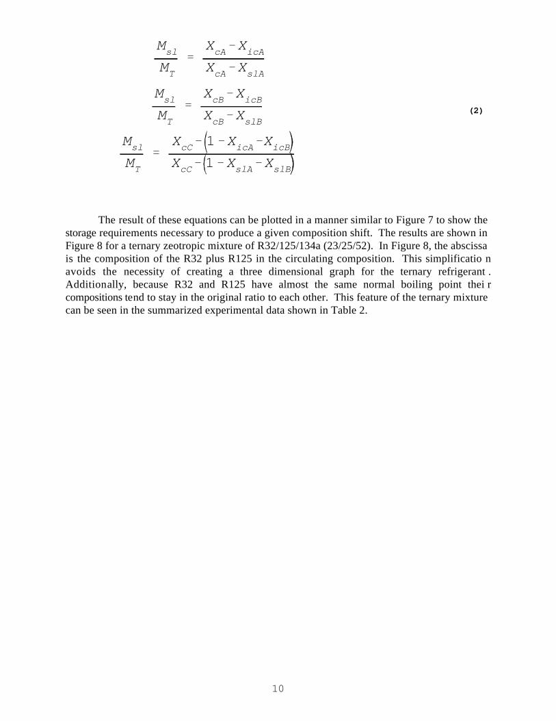
For a ternary refrigerant, applying mass and species conservation results in a set of threeequations for the composition shift. This set is labelled as Equation 2. The subscripts T,c,ic andsl have the same meaning as in Equation 1 and the additional subscripts A,B and C refer to eachcomponent in the mixture. Similar to Equation 1, this set of equations represents the relationshipbetween the fraction of refrigerant stored in the accumulator and the relevant syste mcompositions for each component.
MslMT
XcA XicAXcA XslA
MslMT
XcB XicBXcB XslB
MslMT
XcC 1 XicA XicBXcC 1 XslA XslB
10
(2)
The result of these equations can be plotted in a manner similar to Figure 7 to show thestorage requirements necessary to produce a given composition shift. The results are shown inFigure 8 for a ternary zeotropic mixture of R32/125/134a (23/25/52). In Figure 8, the abscissais the composition of the R32 plus R125 in the circulating composition. This simplificatio navoids the necessity of creating a three dimensional graph for the ternary refrigerant .Additionally, because R32 and R125 have almost the same normal boiling point thei rcompositions tend to stay in the original ratio to each other. This feature of the ternary mixturecan be seen in the summarized experimental data shown in Table 2.

Xc
11
Figure 9 Binary Mixture Storage Requirements
Figure 10 Ternary Mixture Storage Requirements
Xc
XicMslMT
Xsl
1MslMT
12
(3)
TEST METHODOLOGY AND RESULTS
The following test procedure was developed to assess the difference in compositio nshifting potential between a standard accumulator and an accumulator e quipped with a distillationinsert. Equations 1 and 2 show that the circulating composition, X , is dependent upon the initialc
composition X , the composition of the stored liquid X , the total refrigerant charge mass M ,ic sl T
and the mass of liquid refrigerant that is stored in the accumulator M . For convenience,sl
rearrange Equation 1 by solving for X so that it appears as the dependent variable.c
Of the independent variables on the right hand side of Equation 3, X defines the mixture to beic
tested and M is a parameter that can be varied through a range for each mixture tested. Th eT
remaining two variables M and X are functions of the operating conditions and syste msl sl
hardware (i.e., heat exchangers , expansion valve setting, accumulator design, etc.) .Consequently, a test method was required that considers these factors so that the difference incomposition shift between the standard and distillation accumulators could be attributed only tothe specific accumulator used and not some other systemic factor.
To facilitate the comparison of the two accumulators a test rig was constructed with thestandard accumulator of Figure 2 and the experimental distillation accumulator of Figure 5connected in parallel with isolat ion valves. This allows the refrigerant flow to be switched fromthe standard accumulator to the experimental version without changing the total refrigeran tcharge mass M or the initial composition X . T ic
The refrigerant charge was determined at the 8.3 C (47 F) high temperature heating testby adding enough refrigerant to produce a specified amount of subcooling with the han dexpansion valve adjusted to produce approximately 2.8 C (5 F) of superheat. At this tes tcondition the circulating composition X and the initial composition X are the same since therec ic
is no liquid in the accumulator (M =0). To simulate the behavior of a system with a fixed areasl
expansion device the frost accumulation test 1.7 C (35 F) and the low temperature test -8.3 C(17 F) were conducted with the same refrigerant charge and expansion valve setting.
After conducting the three required tests (high temperature, frost accumulation, and lowtemperature) with the standard accumulator, the isolation valves were switched to direct th erefrigerant flow through the experimental distillation accumulator. The same three tests wer ethen repeated with the experimental distillation version. To ensure that the total refrigeran tcharge mass M was still the same, refrigerant was added as necessary to produce the sam eT
composition, subcooling, superheat, system pressures and capacity as the standard accumulatorhigh temperature heating test. The expansion valve setting was not changed.
13
The test results for a zeotropic mixture of R32/134a (30/70) are shown in Table 1. Thetest results for a ternary zeotropic mixture of R32/125/134a (23/25/52) are shown in Table 2. Thepower inputs shown in these tables is the shaft power consumed by the compressor as measuredby in-line torque and RPM transducers. The COP values are not adjusted for fan power. Thesetest results show that the distillation accumulator is capable of producing a much large rcomposition shift than the standard accumulator. The ternary mixture has the added advantagethat as the composition shift progresses the R32 and the R125 tend to stay in their origina lproportions to each other in the circulating composition. This feature of the ternary mixture canprevent the circulating refrigerant from reaching a flammable composition as in the binar ymixture.
A set of tests with the standard accumulator was also conducted with R22. This test willonly be used as a comparison baseline for seasonal calculations, so the actual test data will notbe reported. A complete uncertainty analysis for the experimental apparatus used in this studyhas been previously reported in reference 4. This analysis showed that the uncertainty in th emeasured heating capacity expressed by nondimensionalizing with the heating capacity itsel f( Q /Q ) was 2.4%. H H

14
TABLE 1 TEST RESULTS FOR BINARY MIXTURE OF R32/134a (30/70)
SYSTEM OUTDOO CAPACIT POWE COMP REFRIG. PRESS. DISCHTYPE R Y R COP PERCEN kPa (psia) TEMP
TEMP. INPUT T
C ( F) (W) WEIGHTW (Btu/h) BY DISCH. SUCT. C ( F)
STANDARDACCUMULATOR
8.3 1923 417.1 4.610 30.17% 1628 470 70.9(47) (6562) R32 (236.1) (68.1) (159.7)
1.7 1632 386.0 4.226 34.29% 1414 406 61.7(35) (5568) R32 (205.2) (58.9) (143.1)
-8.3 1098 334.5 3.281 40.14% 1291 308 68.4(17) (3746) R32 (187.3) (44.7) (155.2)
EXPERIMENTALDISTILLATION
ACCUMULATOR
8.3 1949 418.2 4.658 30.08% 1628 472 70.1(47) (6649) R32 (236.1) (68.5) (158.2)
1.7 1664 393.0 4.235 35.89% 1433 416 61.7(35) (5679) R32 (207.8) (60.4) (143.0)
-8.3 1242 374.9 3.313 53.85% 1479 357 74.1(17) (4239) R32 (214.5) (51.8) (165.4)
NOTE: The uncertainty in the measured heating capacity expressed by nondimen sionalizing with the heating capacity itself ( Q /Q )H H
was 2.4%.

15
TABLE 2 TEST RESULTS FOR TERNARY MIXTURE OF R32/125/134a (23/25/52)
SYSTEM OUTDOO CAPACITY POWE COMP REFRIG. PRESS. DISCHTYPE R R COP PERCENT kPa (psia) TEMP
TEMP. W (Btu/h) INPUT BY
C ( F) (W)WEIGHT DISCH. SUCT. C ( F)
STANDARDACCUMULATO
R
8.3 2009 441.7 4.547 23.06 R32 1727 501 68.1(47) (6855) 25.04 R125 (250.5) (72.7) (154.5)
51.9 R134a
1.7 1718 412.0 4.169 25.04 R32 1546 442 59.3(35) (5863) 26.68 R125 (224.2) (64.1) (138.8)
48.28 R134a
-8.3 1189 357.4 3.325 28.45 R32 1391 336 63.2(17) (4056) 29.38 R125 (201.8) (48.7) (145.7)
42.17 R134a
EXPERIMENTALDISTILLATIONACCUMULATO
R
8.3 2045 442.4 4.621 22.96 R32 1721 507 67.1(47) (6977) 25.10 R125 (249.6) (73.5) (152.8)
51.94 R134a
1.7 1722 420.5 4.094 25.29 R32 1538 443 56.8(35) (5875) 26.76 R125 (223.0) (64.3) (134.3)
47.95 R134a
-8.3 1337 399.4 3.348 35.66 R32 1608 385 66.1(17) (4563) 36.20 R125 (233.2) (55.8) (150.9)
28.14 R134a
NOTE: The uncertainty in the measured heating capacity expressed by nondimen sionalizing with the heating capacity itself ( Q /Q )H H
was 2.4%.
16
SEASONAL CALCULATIONS
There are several different measures available to quantify the benefits of employing anaccumulator distillation insert. The most familiar of these would be to calculate the Heatin gSeasonal Performance Factor (HSPF). The HSPF is the ratio of the seasonal building loa dexpressed in Btu/h to the seasonal energy input to the heating system expressed in Watts. TheSI version of HSPF is a dimensionless seasonal COP. The energy input includes the electricalenergy input to both the heat pump and the resi stance heat. The results of the HSPF calculationsare summarized in Table 3. The effect of the distillation accumulator on HSPF is small exceptfor region 5 where the ternary fluid with the distillation accumulator increases the HSPF b yapproximately four percent.
Although the effect on HSPF is small, the distillation accum ulator is capable of producinga reduction in the peak energy demand of the dwelling. This effect is quantified by examiningthe seasonal resistance heat requirement and t he instantaneous system COP at peak heating load.In Table 4, the percentage of the seasonal building load that is obtained from the resistance heatis shown for the binary and ternary mixtures with a standard a ccumulator and with the distillationaccumulator. The tests with R22 in the standard accumulator are shown for comparison. Thebest performing alternative is the ternary fluid with the distillation accumulator, which reducesthe seasonal resistance heat requirement by approximately five percent.
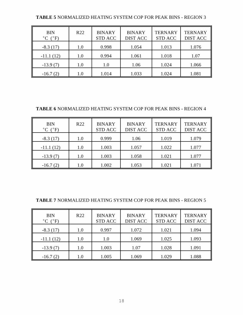
The instantaneous peak energy efficiency for the dwelling is quantified by calculating theoverall heating system COP for the -8.3 (17), -11.1 (12), -13.9 (7), and -16.7 C (2 F)temperature bins. Where the overall heating system COP is the instantaneous building loa ddivided by the total electric energy into the heat pump and the resistance heat. The results of thiscalculation, normalized by the R22 values for each bin, are shown for climate regions 3, 4 and5 in Tables 5, 6 and 7, respectively. By this measure, the effect of the distillation accumulatoris more pronounced. The best performing alternative is again the ternary fluid with th edistillation accumulator, which has a COP higher by 6 to 9% depending o n the climate region andtemperature bin.

17
TABLE 3 HEATING SEASONAL PERFORMANCE FACTOR (HSPF)
CLIMATE R22 BINARY TERNARYREGION
(Btu/W*h) (Btu/W*h) (Btu/W*h)
STANDARDACCUMULATOR
3 3.339 3.214 3.217(11.394) (10.966) (10.976)
4 2.485 2.444 2.471(8.478) (8.340) (8.430)
5 1.986 1.961 1.988(6.778) (6.690) (6.782)
EXPERIMENTALDISTILLATION
ACCUMULATOR
3 --- 3.320 3.261(11.328) (11.126)
4 --- 2.554 2.538(8.715) (8.659)
5 --- 2.056 2.066(7.016) (7.050)
TABLE 4 PERCENTAGE OF SEASONAL BUILDING LOAD OBTAINEDFROM RESISTANCE HEAT
CLIMATE R22 BINARY TERNARYREGION
STANDARDACCUMULATOR
3 8.87 8.07 7.62
4 21.57 20.37 19.53
5 33.58 32.55 31.50
EXPERIMENTALDISTILLATION
ACCUMULATOR
3 --- 6.97 7.01
4 --- 18.11 17.92
5 --- 29.36 28.72
18
TABLE 5 NORMALIZED HEATING SYSTEM COP FOR PEAK BINS - REGION 3
BIN R22 BINARY BINARY TERNARY TERNARYC ( F) STD ACC DIST ACC STD ACC DIST ACC
-8.3 (17) 1.0 0.998 1.054 1.013 1.076
-11.1 (12) 1.0 0.994 1.061 1.018 1.07
-13.9 (7) 1.0 1.0 1.06 1.024 1.066
-16.7 (2) 1.0 1.014 1.033 1.024 1.081
TABLE 6 NORMALIZED HEATING SYSTEM COP FOR PEAK BINS - REGION 4
BIN R22 BINARY BINARY TERNARY TERNARYC ( F) STD ACC DIST ACC STD ACC DIST ACC
-8.3 (17) 1.0 0.999 1.06 1.019 1.079
-11.1 (12) 1.0 1.003 1.057 1.022 1.077
-13.9 (7) 1.0 1.003 1.058 1.021 1.077
-16.7 (2) 1.0 1.002 1.053 1.021 1.071
TABLE 7 NORMALIZED HEATING SYSTEM COP FOR PEAK BINS - REGION 5
BIN R22 BINARY BINARY TERNARY TERNARYC ( F) STD ACC DIST ACC STD ACC DIST ACC
-8.3 (17) 1.0 0.997 1.072 1.021 1.094
-11.1 (12) 1.0 1.0 1.069 1.025 1.093
-13.9 (7) 1.0 1.003 1.07 1.028 1.091
-16.7 (2) 1.0 1.005 1.069 1.029 1.088

19
CONCLUSIONS AND RECOMMENDATIONS FOR FUTURE WORK
This study has shown the accumulator distillation insert to be a simple, effective an dinexpensive means to reduce the peak heating energy demand on the electric utility. However,the best performing alternative, the ternary mixture used with the distillation insert, has not yetbeen utilized to its full potential. I f this mixture were to be shifted so that 52% of the refrigerantcharge were to be stored in the accumulator as pure R134a, then the system would be runningentirely on the more volatile pair of refrigerants. This high pressure circulating composition of48% R32/52% R125 would further reduce the amount of auxiliary energy required and producea commensurate reduction in the peak electrical demand.
To reach this maximum composition shift with the distillatio n accumulator, system designmust account for the steady state and transient refri gerant mass distribution between the high andlow sides of the system. Assuming that the column and storage heater are capable of purifyingthe stored liquid R134a, then the design problem reduces to the allocation of system volume (i.e.,heat exchanger sizing) for a given charge mass and selection of the expansion device.
Additionally, the type of expansion device should also be considered. Although this studyutilized a hand valve to simulate a fixed area expansion device such as a short tube restrictor orcapillary tube, the application of the distil lation insert is not limited to such an expansion device.Specifically, some sort of stepping motor valve that can be controlled to help regulate the liquidlevel in the storage sump may be beneficial. Ideally, to accomplish the maximum compositionshift requires that all of the less volatile component (R134a in the case of this ternary) be storedin the accumulator. However, the amount of liquid stored should not be so much that a severeloss of subcooling occurs at the condenser outlet because of the detrimental effect o nperformance this would impose.
A further refinement to enhance the performance of the distillation accumulator would beto eliminate the parasitic power required for vapor generation. This can be accomplished b yrouting the liquid line through the accumulator sump. In this manner, the vapor necessary fo rcolumn operation can be generated wh ile simultaneously obtaining beneficial liquid subcooling.However, the drawback of this refinement is that it will be more difficult to control the amountof heat applied to vapor generation.
In summary, the distillation accumulator requires a system design that is capable o foperating with a dry accumulator in the cooling mode and an increasing amount of stored liquidin the heating mode as the outside temperature falls. The amount of stored liquid shoul dapproach a maximum value as the outdoor temperature approaches the heat pumps minimu moutdoor operating temperature. This maximum should be determined by the amount of storedliquid necessary to produce the desired c omposition shift without overly depriving the system ofsubcooling.

20
REFERENCES
1. Treybal, R.E., "Mass-Transfer Operations," 3rd. ed. New York: McGraw-Hill, 1980.
2. Aaron, D., and Domanski, P., "An Experimental In vestigation and Modelling of the FlowRate of Refrigerant 22 Through the Short Tube Restrictor," NISTIR 4120, Nationa lInstitute of Standards and Technology, Gaithersburg, Maryland, 1989.
3. Rothfleisch, P.I., and Didion, D., "A Performanc e Evaluation of a Variable Speed, MixedRefrigerant Heat Pump," NISTIR 4597, National Institute of Standards and Technology,Gaithersburg, Maryland, 1991.
4. Rothfleisch, P.I., and Didion, D., "A Study of Heat Pump Performance Using Mixturesof R32/R134a and R32/R125/R134a as "Drop-In" Working Fluids for R22 With an dWithout a Liquid-Suction Heat Exchanger," NISTIR 5321, Natio nal Institute of Standardsand Technology, Gaithersburg, Maryland, 1993.