simon w. pallam, visa m. ibrahim , matthew luka · pdf filethe 3g on systems and the...
TRANSCRIPT
International Journal of Scientific & Engineering Research, Volume 4, Issue 11, November-2013 1531 ISSN 2229-5518
IJSER © 2013 http://www.ijser.org
Simulator-based Design of WCDMA Wireless Cellular Communication System Using Efficient Method
Simon W. Pallam, Visa M. Ibrahim, Matthew Luka
Abstract—The design of a third generation (3G) Wideband Code Division Multiple Access (WCDMA) wireless cellular communication system needs a higher design and simulation scheme that will guarantee the system scalability and quality of service due to rapid growth in the number of wireless communication users around the globe. Some previous wireless communication systems, especially the second generation (2G) wireless cellular sys-tems, were designed based on Traditional scheme of simulation. The 2G wireless communication systems had limited performance and quality of ser-vice as compared to the 3G wireless communication systems. In this work, a newer simulation scheme called the Efficient Scheme of modeling will be used to develop a 3G multi-user WCDMA wireless cellular communication system that is scalable. The Efficient scheme of design and simulation will be investigated and compared with the Traditional method in order to ascertain which one is better for the design of the 3G WCDMA wireless communica-tion system. MATLAB simulation software will be used due to its availability, cost effectiveness and interactive features. The Physical layer of the 3G multi-user WCDMA wireless communication link will be developed using SIMULINK functions while the simulation scripts will be written using MATLAB-based S-functions. Keywords – WCDMA Wireless Cellular Communication System, Efficient method
—————————— ——————————
1. INTRODUCTION
he world’s demand for wireless cellular telecommunica-tion systems is growing at a faster rate than for wired-line
telephone network as more people around the world are sub-scribing to wireless communication systems (WCS) [1]. The 3G wireless systems are required to have voice services of wire line quality, and provide high bit rate data services of up to 2Mbits/s depending on the radio environment. At the same time, they are to operate reliably in different types of environments: macro, micro, and pico; urban, subur-ban, and rural; indoor and outdoor. The strict requirements of the 3G on systems and the complexity of the new standards warrant improved methodologies that result in optimized im-plementations for their given applications. The WCDMA End-to-End Physical Layer models part of the frequency divi-sion duplex (FDD) downlink physical layer of the 3G wireless communication system known as wideband code division multiple access (WCDMA).
————————————————
The air interface spreads encoded user data at a relatively low rate over a wide bandwidth (5 MHz), using a sequence of
pseudorandom units called chips at a very high rate (3.84 MHz). By assigning a unique code to each user, the receiver, which has knowledge of the code of the intended user, can successfully separate the desired signal from the received waveform. Code Division Multiple Access, which is one of the standard radio access schemes, is called spread spectrum technique be-cause it assigns unique codes to each communication in order to differentiate it from others in the same spectrum. In a world of finite spectrum resources, CDMA enables many more peo-ple to share the airwaves at the same time than do Time divi-sion multiple access (TDMA) and frequency division multiple access (FDMA) technologies. 3G wireless data services and applications such as wireless email, web, digital picture, Glob-al Positioning System (GPS) applications, video and audio streaming, TV broadcasting and wireless networks have much to offer in terms of capacity enhancement and performance. This is why CDMA technology forms the platform on which 2G and 3G systems advanced services are built and are very much popular in cellular communications [2]. The simulation of Wireless communication system allows the evaluation of different variables in the system, such as the properties of the channel, which are affected by environmental factors in the design [3], [4], [5]. One of the most challenging parts of the design of wireless Cellular communication sys-tems is the design of the baseband physical layer. The base-band physical layer algorithms are designed to establish and maintain a reliable radio link between base stations and user terminals. These baseband algorithms are designed to over-come propagation effects, interference effects, and degradation effects resulting from nonlinearities and noise in the hardware implementation. All these effects must therefore be modeled and simulated in the software. Since simulations were widely
T
• Simon Wasinya Pallam, M.Eng. ElectricalEngineering, Lecturer at Electrical & Electronics Engineering department, Modibbo Adama University of Technology, Yola, Nigeria. E-mail: [email protected]
• Ibrahim Musa Visa, M.Eng. Electrical Engineering, Lecturer at Electrical & Electronics Engineering department, Modibbo Adama University of Technology, Yola, Nigeria E-mail: [email protected]
• Matthew Luka, M.Eng. Electrical Engineering, Lecturer at Electrical & Electronics Engineering department, Modibbo Adama University of Technology, Yola, Nigeria. E-mail: [email protected]
IJSER
International Journal of Scientific & Engineering Research, Volume 4, Issue 11, November-2013 1532 ISSN 2229-5518
IJSER © 2013 http://www.ijser.org
used in the design of first and second generation systems, simulation requirements have increased with every generation of wireless systems. 2G systems were primarily designed to support low data rate digital voice and short messaging with relatively low quality of service. Therefore, the baseband algo-rithms had lower complexity, lower sampling rates, and lower performance requirements. However, 3G systems must sup-port real-time voice applications at toll quality and support real-time multimedia and high data rate of internet and mo-bile data applications with qualities comparable to high-speed wire-line systems such as digital subscriber loop (DSL). Hence, the simulation of 3G systems is significantly more challenging than that of 2G. However, despite the significant increase in complexity, 3G systems are expected to be more power effi-cient and smaller in size.
2. MODELING OF DATA, CHANNEL AND CHIP-MATCHED FILTERING
Data generation, channel and chip-matched filtering can be modeled in a WCDMA system with K users and a spreading code with N chips per bit. Bi-phase Shift Keying (BPSK) mod-ulation can be used with each transmitted signal limited to [0:T]. The kth user's transmitted signal Sk(t) is given by:
where, Pk = transmitted power of kth user; bk,i Є {+1, -1} is the ith transmitted bit in a stream of L bits [6].
It should be noted that the transmitted signal Sk(t) corre-sponds to ytx in the Matlab simulation programs. Equation (2) is a spreading waveform with Ck,n Є {+1, -1} and π(t) being a rectangular pulse of duration Tc; T=nTc as there are N chips per bit. The received signal due to the superposition of the attenuated and delayed signals of the K users is given by:
where Wk is the complex amplitude with which the kth signal is received and includes the effect of channel attenuation and the phase offset; ζk is the relative delay with respect to a refer-ence at the receiver. This received signal at the channel output r(t) corresponds to ynoisy in the Matlab simulation programs. The noise component v(t) is assumed to be Gaussian with ze-ro-mean and double-sided spectral density of N0/2. This re-ceived signal is fed into a chip matched filter whose output is as follows:
A discrete observation vector ř i is formed at bit i by sampling the integrator output and collecting N successive chip- matched filter outputs given by:
Each observation vector ř i can be viewed as a linear combina-tion of 2K signal vectors, corresponding to 2 from each of the K users due to the past and the current bits. So ř i can be writ-ten as:
with vi ≈ N(0, k), where A is the N x 2K matrix signal vectors, which depends on spreading codes of each user; W is the 2K x 2K diagonal matrix of complex amplitudes; bi is the 2K x 1 vector of K users’ previous and current data bits; and the N x 1 vector K, is the noise covariance. The matrices A, W and bi are expanded below.
The N x 2K matrix A(ζ) has a column corresponding to two adjacent bits of each user given that qk Є {0, 1, ……, N – 1} and yk Є {0, 1}, where ckR [qk] and ckX [qk] are the spreading codes shifted by integer in multiples of chips delays and ζk is the relative delay with respect to a reference at the receiver.
Expanding A(ζ) in equation (7) by substituting equations (8) and (9) yields:
where yi =STř i is the code-matched filter detector output vec-tor. Equation (12) is an expression of N x 2K matrix of relative time delays encountered by multiple signals in a channel with re-spect to the receiver during transmission and reception. When signals are transmitted, they undergo varied delays ζk in the channel due to multipath fading effects. They arrive at the receiver input at different instants. Similarly,
A(ζ)={(1-y1)c1R[q1]+y1ckR[q1+1]} {(1-y1)c1X[q1]+y1ckX[q1+1]}, . . {(1–yk)ckR[qk]+ykckR[qk+1]} {(1–yk)c1X[qk]+ykckX[qk+1]} (12)
ckR [qk] = [ck,N-qk . .ck, N-1 0 …0]T (10)
ckX [qk] = [0 . . 0 ck,0 . . ck, qk-1 ]T (11)
A(ζ) ≡ [a1R(ζ1) a1X(ζ1), .., akR(ζk) akX(ζk)] (7)
Let akR(ζk) = (1 - yk)ckR [qk] + ykckR [qk+ 1] (8)
and akX(ζk) = (1 - yk)ckX [qk] + ykckX[qk+ 1] (9)
ři = AWbi + vi (6)
ři = [ř[i], ř[i + 1], . . . , ř [i + N-1]]T (5)
(n+1)Tc
r(n) = ∫ r(t) dt (4) nTc
k
r(t) = ∑wk x Sk(t - ζk ) + v(t) (3) k=1
N-1
Ck(t) = ∑Ck,n π(t - nTc) (2) n=0
L-1
Sk(t) = √(2Pk) ∑bk,i x ck(t - iT) (1) i=0
IJSER

International Journal of Scientific & Engineering Research, Volume 4, Issue 11, November-2013 1533 ISSN 2229-5518
IJSER © 2013 http://www.ijser.org
where bk, i is the ith bit of the kth user. The chip matched filter block generates an output for every chip waveform, which is then vectored and fed into the chan-nel estimation block. Maximum likelihood (ML) channel esti-mation uses a fixed preamble which is known at the receiver [7], [8], [9]. The preamble bits are sent across the channel in the initial part of a transmission. The ML channel estimation block uses the resulting output from the channel in the form of the chip matched filter vector and the knowledge of the preamble bits is used to estimate the channel parameters (amplitude, and delay information). The multi-user detector uses the chip matched filter outputs and the matrix which conveys the delay and amplitude information to detect the bits of all the users.
3. THE EFFICIENT METHOD OF SIMULATION A new method of modeling which combines the spreading, channel modeling and chip-matched filtering can be incorpo-rated into one block as shown in Fig. 1. This method is called “the Efficient method of simulation” [6].
The new method gives more accurate results than the Tradi-tional method, while keeping the system sampling time to once a chip. Separate bit streams are fed into a single block which models the spreading, channel modeling and the chip-matched filtering. Each user has a unique spreading code as shown in Fig. 2 (a), (b) and (c), which modulates the bits, and all these chip streams are superimposed in the channel. The
superimposed chip stream over any bit period is essentially a linear combination of all the users' spreading codes which are delayed and suitably aligned with each other. This baseband waveform over a bit duration (N chips) depends on the two consecutive bits of all the users as shown in Fig. 3. This block uses the present and the previous bits of all users, the individ-ual delays, the amplitudes and the channel parameters to cal-culate the chip-matched filter output. In this simulation sys-tem, there is no explicit representation of the intermediate sig-nals such as chip sequences, noise and baseband channel waveform. A Matlab S-function (Simulink-function) is used to directly calculate the chip-matched filter outputs from the cur-rent and previous bits of all the users and the channel proper-ties.
Fig. 1: The efficient method of modeling, spreading, channel and chip-matched filtering
Vector to serial
Bits 2
Bits 1 1/z
unit delay
Sprd_cmf
CDMA
Mux
Spreading, channel
modeling & chip-
matched filtering
Therefore,
bi = [ b1,i-1, b1,i, . . , bk, i] T (14)
W=diag[w1, ...,wk]=
w1 0 … … 0 0 0 w1 … … 0 0 0 0 … … 0 0 : : : : : : (13) : : : : : : 0 0 … … wk 0 0 0 … … 0 wk
Chip
(b)
(1) (1)
time
User2 unique spreading code
(a)
ith bit (-1) ith bit (1)
time
Chip-matched filter observation window
chip
User1 unique spreading code
Chip
(c)
User3 unique spreading code
time
(1) (-1)
Fig. 2 : Superimposition of chip streams of 3 users (a), (b) and (c) with 7 chips per bit
Chip
+3 +1 -1 -3
time
Superimpo- sed baseband waveform (d)
IJSER

International Journal of Scientific & Engineering Research, Volume 4, Issue 11, November-2013 1534 ISSN 2229-5518
IJSER © 2013 http://www.ijser.org
4. UPLINK AND DOWNLINK IN A PHYSICAL LAYER SYSTEM This work can be used to study typical scenarios such as Up-link, Downlink and a phone to phone call, all of which occur in a WCDMA system. Fig. 4 shows an uplink system with N users, random data stream of 30000 bits signal-to-noise ratio of 0dB, equal signal power of 10dB for all users and a single path.
The first 50 bits comprising the preamble are used in the esti-mation of channel parameters and the other 29,950 bits are used for conveying useful information. The real-time plots can be used to compare the bit error rates (BERs) of different users (users 1 and 2 in this case). The system can be modified to simulate a complete system like the one shown in Fig. 6, which shows a one-way call from one mobile phone to another. It has both the uplink and the downlink systems in place. The real-time behavior of such a block diagram is expected to be close to that of a real life system. Furthermore, such a simulation scheme is scalable to include more mobile phones and base-stations in the simulations.
5. SIMULATION OF RANDOM SIGNAL GENERATED IN WIRELESS COMMUNICATION SYSTEM
This part of the work deals with the processing of a randomly generated binary data stream in a communication system con-sisting of a Bernouili binary signal generator, 16-QAM (Quad-rature Amplitude Modulator) baseband modulator, AWGN (Additive White Gaussian Noise) channel, 16-QAM demodu-lator and Bit Error Counters. During the simulation, the Ber-noulli signal generator generated a random bit stream x=[30000 x 1] as a column vector which was passed through the system for processing. The first 50 bit stream in ‘x’ was stem plotted to form a graph of ‘Binary values’ versus ‘Bit in-dex’ shown in Fig. 5.1. The bits in the stream ‘x’ were convert-ed into bits per symbol ‘k’ which were used to plot a graph of ‘Integer values’ versus ‘Symbol index’ as shown in Fig. 5.2. The 16-QAM modulator then modulated and transmitted the pro-cessed signal ‘ytx’ to the AWGN channel with a ratio of bit power-to-noise spectral density EbNo=10dB input. A noisy signal ‘ynoisy’ was received at the channel output. A scatter-
Fig. 4: A phone call in a WCDMA Wireless network
Fig. 3: Received signal with details of chip level.
γk 1-γk qk=4
Received Vector chip
i-1th bit
ith bit (-1)
Time
ζk =Tc ( qk + γk )
IJSER

International Journal of Scientific & Engineering Research, Volume 4, Issue 11, November-2013 1535 ISSN 2229-5518
IJSER © 2013 http://www.ijser.org
plot of the transmitted and received signals are shown in Fig. 5.3.
The noisy signal, ‘ynoisy’ from the channel output was there-fore transmitted to the input of the User Equipment (UE) re-ceiver antenna and demodulated using 16-QAM demodulator. The demodulated signal was converted from integer to bits ‘z’ and from matrix to vector form. Finally, the transmitted and received signals ‘x’ and ‘z’ respectively were compared in or-der to compute the number of errors and the bit error rate as presented in Table 1. The script for this simulation is presented in appendix A. Table 1: Table of Simulation results of random signal
6. DEVELOPMENT OF WCDMA PHYSICAL LAYER SYSTEM
There are two schemes for developing WCDMA wireless physical layer link using simulink blocks. The first link can be developed by Traditional method as shown in Fig. 6 while the second link can be developed using Efficient method as shown in Fig. 7. The physical layer links form the backbone of the Simulink Testbed in this work. The simulations of the physical layer links were run several times to ascertain the simulation times, number of errors and the bit error rates. MATLAB environment has a profiling support which times the calls to various functional blocks. The underlying S-functions are also individually timed in the sequence of block execution. The profiling process generates a report at the end of the run and gives a complete break-up of the execution time spent in different parts of the simulation system. Table 3 shows a summary of the profiling report after the simulation runs. Table 3: Profiling report for simulation in WCDMA system
The time taken for the pulse generator function was reduced by a substantial amount in the Efficient method. The difference between the two methods is that the Traditional
0 5 10 15 20 25 30 35 40 45 500
5
10
15Random symbol
Symbol index
Intege
r valu
es
-5 0 5-5
-4
-3
-2
-1
0
1
2
3
4
5
Quadr
ature
In-Phase
Received signal
Received signalsignal constellation
Fig. 5.3 Scatterplot of received signal and signal constellation
Fig. 5.2 Plot of random symbols
0 5 10 15 20 25 30 35 40 45 500
0.1
0.2
0.3
0.4
0.5
0.6
0.7
0.8
0.9
1
Bit Index
Binary
Value
s
Fig. 5.1 Plot of Random Binary bits
IJSER

International Journal of Scientific & Engineering Research, Volume 4, Issue 11, November-2013 1536 ISSN 2229-5518
IJSER © 2013 http://www.ijser.org
method simulates the WCDMA channel coding, channel mapping and transmit Antenna subsystems separately while the Efficient method combines and simulates all the subsystems in a single subsystem. The simulation time taken by Traditional method was four times longer than the time taken by Efficient method. From the separate simulation runs of the Traditional method and the Efficient method, the bit error rates computed by the system are 0.0028 and 0.00164 respectively. The simulink testbed has five different display blocks for viewing simulation results as follows; BLER (Block Error Rate) shows the block error rate of the
combined transport channels; BER (Bit Error Rate) shows the results of the BER compu-
tation block associated with each transport channel. The block output consists of three-element vector comprising error rate, number of error detected and the total number of symbols compared;
Time scopes shows the bit stream before spreading, after spreading, and after combining the different weighted physical channels. It displays both the real and the imag-inary part of the output of the channel estimator for the first rake finger;
Power spectrum shows the power spectrum of the signal before spreading, after spreading, after pulse shaping, and at the input of the receiver antenna; and
Scatter plots shows the constellation of signal at the out-put of the data correlator, after phase decorrelation, and after amplitude correction.
7.1 CONCLUSION The development of the WCDMA wireless communication system physical layer link, which was carried out successfully, can be used as a simulation testbed for the design and devel-opment of WCDMA wireless cellular communication system. Comparing the performances of Traditional and Efficient methods of simulations, it was shown that the later was four times faster than the former. The Traditonal Method had high-er bit error rate than the Efficient method. This shows that the Efficient method is much better for the design and implemen-tation of 3G WCDMA wireless communication systems than the Traditional method. The Efficient scheme of simulation could, therefore, help reduce the design and verification time and complexity of 3G wireless communication systems with less error rates. A simulation of randomly generated data stream was also carried out and the number of errors and bit error rates were computed for the various simulation parame-ters of binary input, transmit antenna subsystem, channel model, and receiver subsystems. This simulation portrays what happens in a real life wireless cellular communication system when users make phone to phone calls.
7.2 APPENDIX
SIMULATION SCRIPT FOR RANDOM SIGNAL GENERATED IN WCDMA WIRELESS COMMUNICATION SYSTEM %% Define simulation parameters. M=16; % Size of signal constellation. k=log2(M); % number of bits per symbol. n=3e4; % total number of bits passed into he process.
Fig. 7. Efficient method of simulating WCDMA Wireless Com-munication System physical layer link
Fig. 6. Traditional method of Simulating WCDMA Wireless Communication System physical layer link
IJSER
International Journal of Scientific & Engineering Research, Volume 4, Issue 11, November-2013 1537 ISSN 2229-5518
IJSER © 2013 http://www.ijser.org
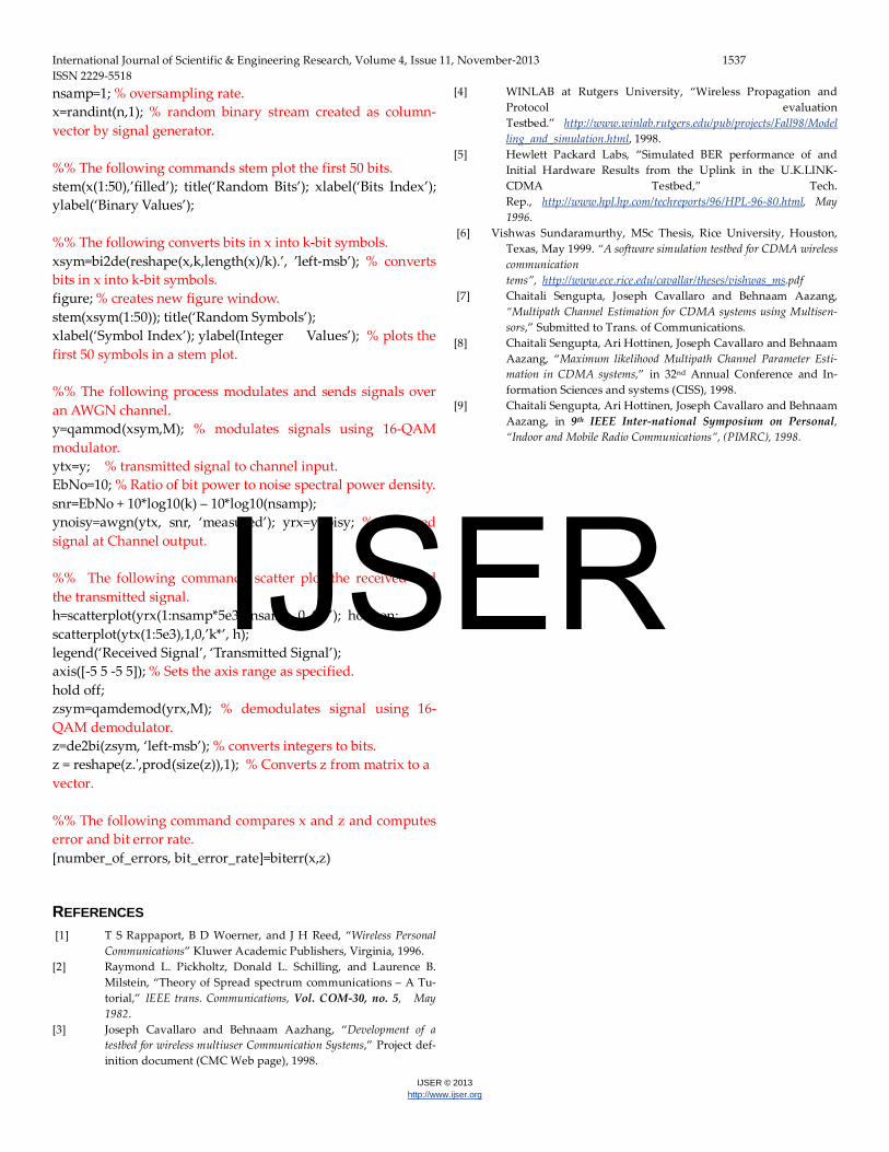
nsamp=1; % oversampling rate. x=randint(n,1); % random binary stream created as column-vector by signal generator. %% The following commands stem plot the first 50 bits. stem(x(1:50),’filled’); title(‘Random Bits’); xlabel(‘Bits Index’); ylabel(‘Binary Values’); %% The following converts bits in x into k-bit symbols. xsym=bi2de(reshape(x,k,length(x)/k).’, ’left-msb’); % converts bits in x into k-bit symbols. figure; % creates new figure window. stem(xsym(1:50)); title(‘Random Symbols’); xlabel(‘Symbol Index’); ylabel(Integer Values’); % plots the first 50 symbols in a stem plot. %% The following process modulates and sends signals over an AWGN channel. y=qammod(xsym,M); % modulates signals using 16-QAM modulator. ytx=y; % transmitted signal to channel input. EbNo=10; % Ratio of bit power to noise spectral power density. snr=EbNo + 10*log10(k) – 10*log10(nsamp); ynoisy=awgn(ytx, snr, ‘measured’); yrx=ynoisy; % Received signal at Channel output. %% The following commands scatter plot the received and the transmitted signal. h=scatterplot(yrx(1:nsamp*5e3), nsamp, 0, ‘g*’); hold on; scatterplot(ytx(1:5e3),1,0,’k*’, h); legend(‘Received Signal’, ‘Transmitted Signal’); axis([-5 5 -5 5]); % Sets the axis range as specified. hold off; zsym=qamdemod(yrx,M); % demodulates signal using 16-QAM demodulator. z=de2bi(zsym, ‘left-msb’); % converts integers to bits. z = reshape(z.',prod(size(z)),1); % Converts z from matrix to a vector. %% The following command compares x and z and computes error and bit error rate. [number_of_errors, bit_error_rate]=biterr(x,z)
REFERENCES [1] T S Rappaport, B D Woerner, and J H Reed, “Wireless Personal
Communications” Kluwer Academic Publishers, Virginia, 1996. [2] Raymond L. Pickholtz, Donald L. Schilling, and Laurence B.
Milstein, “Theory of Spread spectrum communications – A Tu-torial,” IEEE trans. Communications, Vol. COM-30, no. 5, May 1982.
[3] Joseph Cavallaro and Behnaam Aazhang, “Development of a testbed for wireless multiuser Communication Systems,” Project def-inition document (CMC Web page), 1998.
[4] WINLAB at Rutgers University, “Wireless Propagation and Protocol evaluation Testbed.” http://www.winlab.rutgers.edu/pub/projects/Fall98/Modelling_and_simulation.html, 1998.
[5] Hewlett Packard Labs, “Simulated BER performance of and Initial Hardware Results from the Uplink in the U.K.LINK-CDMA Testbed,” Tech. Rep., http://www.hpl.hp.com/techreports/96/HPL-96-80.html, May 1996.
[6] Vishwas Sundaramurthy, MSc Thesis, Rice University, Houston, Texas, May 1999. “A software simulation testbed for CDMA wireless communication tems”, http://www.ece.rice.edu/cavallar/theses/vishwas_ms.pdf
[7] Chaitali Sengupta, Joseph Cavallaro and Behnaam Aazang, “Multipath Channel Estimation for CDMA systems using Multisen-sors,” Submitted to Trans. of Communications.
[8] Chaitali Sengupta, Ari Hottinen, Joseph Cavallaro and Behnaam Aazang, “Maximum likelihood Multipath Channel Parameter Esti-mation in CDMA systems,” in 32nd Annual Conference and In-formation Sciences and systems (CISS), 1998.
[9] Chaitali Sengupta, Ari Hottinen, Joseph Cavallaro and Behnaam Aazang, in 9th IEEE Inter-national Symposium on Personal, “Indoor and Mobile Radio Communications”, (PIMRC), 1998.
IJSER