simblee™ rfd77402 iot 3d tof sensor module - digi-key sheets/rf digital pdfs/rfd77402.… ·...
TRANSCRIPT
RFD77402 DATASHEET v1.8
© 2017 RF Digital Corporation 7.24.2017 www.simblee.com
1
Simblee™ RFD77402
Simblee™ RFD77402
IoT 3D ToF Sensor Module
Features
Fully Integrated microelectronic device with an embedded sensor and VCSEL(Vertical Cavity Surface Emitting Laser)
• 850 nm VCSEL and electronic driver • Optical receiver sensor and optics • Microelectronic controller
Time-of-Flight (ToF) is a highly accurate distance mapping and 3D imaging technology
Eye safe invisible infrared (IR) illumination using a class 1 laser emitter
High accuracy and high repeatability I2C interface for device control and data transfer Ultra-small SMD package Standard solder reflow compatible Lead-free, RoHS compliant Small size 4.8mm x 2.8mm x 1mm
Applications
Absolute and highly accurate distance measurement at distances ranging from 100 mm to 2000 mm
User detection for IoT devices Robotics applications such as obstacle detection and obstacle
avoidance White goods type of applications such as hand detection in
automatic faucets and soap dispensers 1D gesture recognition Directional movement detection along Z-axis Volume or height control
Simblee™ IoT 3D ToF Sensor Module RFD77402 DATASHEET

RFD77402 DATASHEET v1.8
© 2017 RF Digital Corporation 7.24.2017 www.simblee.com
2
Simblee™ RFD77402
Contents
Features ........................................................................................................................................................................................1
Applications ...................................................................................................................................................................................1 1 General Characteristics .................................................................................................................................................................5
1.1 Technical Specifications ...................................................................................................................................................5
Table 1: Technical Specifications .............................................................................................................................................5 1.2 Electrical Specifications ...................................................................................................................................................5
Table 2: Electrical Characteristics ............................................................................................................................................5 1.3 System Block Diagram and Device Pinout .......................................................................................................................6
Figure 1: RFD77402 Block Diagram and Device Pinout (top view) ..........................................................................................6
Table 3: Device Pinout ..............................................................................................................................................................6 1.4 Electrical Connectivity ......................................................................................................................................................7
Figure 2: Electrical Connectivity Schematic ..............................................................................................................................7 2 Module Interface ............................................................................................................................................................................8
2.1 Electrical Interface ............................................................................................................................................................8
2.1.1 I2C Single Byte Access.....................................................................................................................................................8 Figure 3: I2C Basic 8-bit Read and Write Cycles ......................................................................................................................8
2.1.2 I2C Write Access with Auto Increment and Word Mode Features ....................................................................................9 Figure 4: I2C Write Direct Access: Auto Increment and Word Mode Options ...........................................................................9
2.1.3 I2C Read Access with Address Auto Increment and Word Mode Features .....................................................................9
Figure 5: I2C Burst Read: Address Auto Increment and Word Mode ........................................................................................9 2.1.4 I2C Write Indirect Addressing with Address Auto Increment and Word Mode ................................................................10
Figure 6: I2C Indirect Address Burst Write with Address Auto Increment and Word Mode ....................................................10 Figure 7: I2C Indirect Address Write with Address Auto Increment and Word Mode (1-Byte Access) ...................................10
Figure 8: I2C Indirect Address Write with Address Auto Increment and Word Mode (2-Byte Access) ...................................11
2.1.5 I2C Read Indirect Addressing with Address Auto Increment and Word Mode ...............................................................11 Figure 9: I2C Burst Read Indirect Addressing .........................................................................................................................11
Figure 10: I2C Indirect Address Read with Address Auto Increment and Word Mode (1-Byte Access ..................................12 Figure 11: I2C Indirect Address Read with Address Auto Increment and Word Mode (2-Byte Access) .................................13
2.1.6 I2C Timing Information....................................................................................................................................................14
Figure 12: I2C Timing Characteristics Definitions ...................................................................................................................14 Table 2: I2C Timing Characteristics Information .....................................................................................................................14
2.2 Host Interface Power Management ................................................................................................................................15 Figure 13: Module State Diagram ...........................................................................................................................................15
2.2.1 Standby / Leakage in Different Electrical Conditions .....................................................................................................16
Table 5: I2C SCL/SCA Power-up/down Sequence .................................................................................................................16

RFD77402 DATASHEET v1.8
© 2017 RF Digital Corporation 7.24.2017 www.simblee.com
3
Simblee™ RFD77402
2.2.2 Power-up and power-down Sequence ...........................................................................................................................16
Figure 14: I2C SCL/SDA Power-up/down Sequence ..............................................................................................................16 2.3 Module Programming Interface ..........................................................................................................................................16
Table 6: Host Interface Registers ...........................................................................................................................................17 2.3.1 Configuration Parameters ..............................................................................................................................................18
Table 7: Configuration Parameters Used to Configure the Module ........................................................................................18
2.3.2 Module Interface Registers ............................................................................................................................................19 Table 8: Interrupt Control Status Register ..............................................................................................................................19
Table 9: Interrupt Enable Register ..........................................................................................................................................20 Table 10: Command Register .................................................................................................................................................20
Table 11: Device Status Register ...........................................................................................................................................21
Table 12: Result Register .......................................................................................................................................................21 Table 13: Result Confidence Register ....................................................................................................................................22
Table 14: Command Configuration Register A .......................................................................................................................22 Table 15: Command Configuration Register B .......................................................................................................................22
Table 16: Host to MCPU Mailbox Register .............................................................................................................................23
Table 17: MCPU to Hot Mailbox Register ...............................................................................................................................23 Table 18: PMU Configuration Register ...................................................................................................................................24
Table 19: I2C Address Pointer Register ..................................................................................................................................24 Table 20: I2C Data Port Register ............................................................................................................................................25
Table 21: I2C Init Configuration Register ................................................................................................................................25
Table 22: MCPU Power Management Control Register .........................................................................................................26 2.3.3 Hardware Configuration Registers .................................................................................................................................26
Table 23: HW/FW Configuration Register 0............................................................................................................................26 Table 24: HW/FW Configuration Register 1............................................................................................................................26
Table 25: HW/FW Configuration Register 2............................................................................................................................27
Table 26: HW/FW Configuration Register 3............................................................................................................................27 2.3.4 Other I2C Host Registers ................................................................................................................................................28
Table 27: Module Chip ID Register .........................................................................................................................................28 Table 28: Patch Memory Configuration Control Register .......................................................................................................28
3 Programming Guide .....................................................................................................................................................................29
3.1 Programming Flow Charts .............................................................................................................................................29 Figure 15: Power-up Initialization ...........................................................................................................................................29
3.1.1 Single Measure ..............................................................................................................................................................30 Figure 16: Single Measure Flow Chart ...................................................................................................................................30
4 Performance ................................................................................................................................................................................31
4.1 Measurement Conditions and Accuracy ........................................................................................................................31

RFD77402 DATASHEET v1.8
© 2017 RF Digital Corporation 7.24.2017 www.simblee.com
4
Simblee™ RFD77402
Figure 17: Scatter Chart Showing Measured Distances Versus Actual Distance ...................................................................31
4.2 Maximum Ranging Distance and Ranging Accuracy .....................................................................................................32 Table 29: Range Accuracy Information in the Range of 50mm to 2000mm ...........................................................................32
5 Mechanical Dimensions ...............................................................................................................................................................33 Figure 18: Overall Dimensions ...............................................................................................................................................33
Figure 19: Landing Pad and Solder Pad Recommendation ...................................................................................................33
Figure 20: Field of View (FoV) and Field of Illumination (FoI) ................................................................................................34 6 Cover Glass Selection Guide .......................................................................................................................................................34
7 Recommend Reflow Temperature Profile ....................................................................................................................................34 Figure 21: Solder Profile .........................................................................................................................................................34
Table 30: Recommended Reflow Profile ................................................................................................................................35
8 Packaging (Tape and Reel Dimensions) .....................................................................................................................................36 Figure 22: Product Packaging Arrangement ...........................................................................................................................36
9 Storage Conditions ......................................................................................................................................................................37 Table 31: Recommended Storage Conditions ........................................................................................................................37
10 RoHS and REACH Compliance .................................................................................................................................................37
11 Eye Safety Considerations .........................................................................................................................................................37 Figure 23: Class 1 Laser Product Label .................................................................................................................................37

RFD77402 DATASHEET v1.8
© 2017 RF Digital Corporation 7.24.2017 www.simblee.com
5
Simblee™ RFD77402
1 General Characteristics 1.1 Technical Specifications Performance and power consumption can be tuned to the application needs by changing configuration and/or through a customized firmware.
Table 1: Technical Specifications
(*) target with 90% reflectivity in dark environment and no cover glass
1.2 Electrical Specifications Table 2: Electrical Characteristics
(*) Note that a pull-up to 1.8V implies that INT pin is configured as open drain (failure in doing so will cause high leakage).
RFD77402 DATASHEET v1.8
© 2017 RF Digital Corporation 7.24.2017 www.simblee.com
6
Simblee™ RFD77402
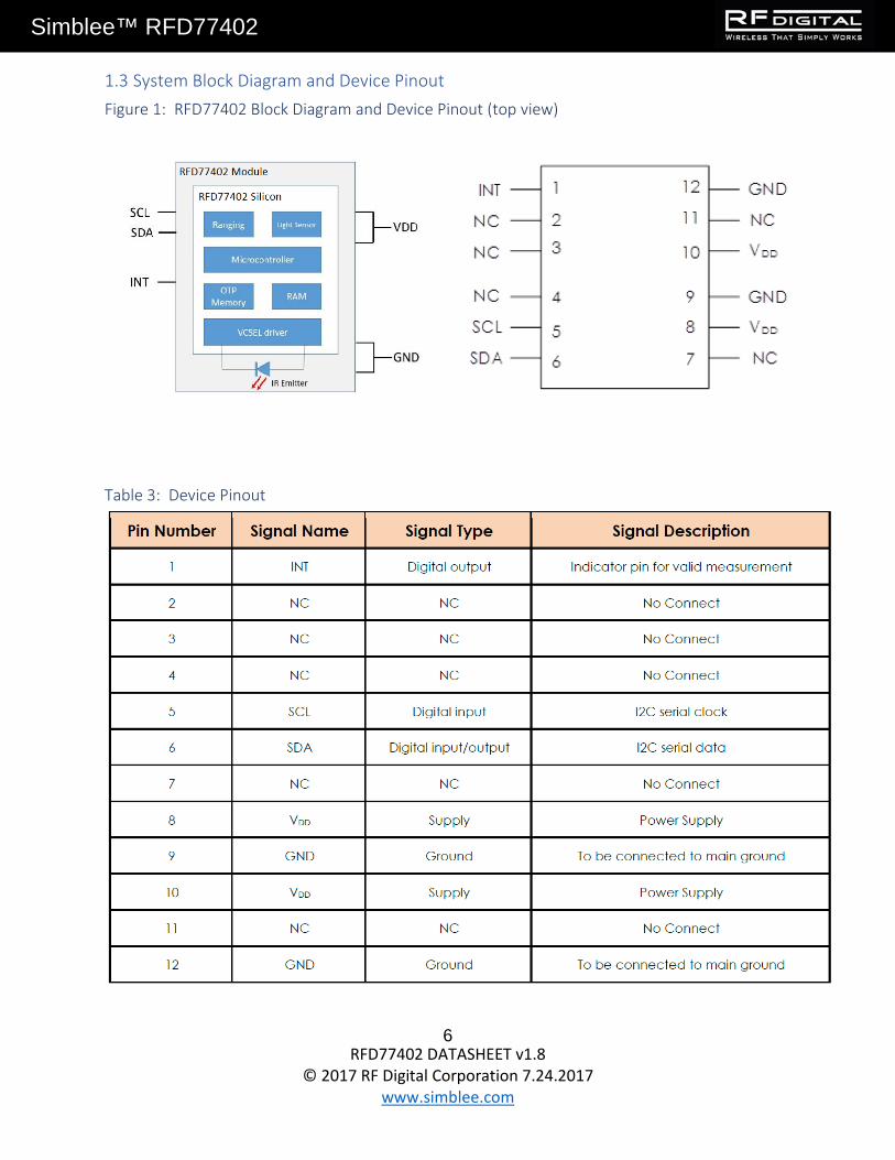
1.3 System Block Diagram and Device Pinout Figure 1: RFD77402 Block Diagram and Device Pinout (top view)
Table 3: Device Pinout

RFD77402 DATASHEET v1.8
© 2017 RF Digital Corporation 7.24.2017 www.simblee.com
7
Simblee™ RFD77402
1.4 Electrical Connectivity Figure 2: Electrical Connectivity Schematic
RFD77402 DATASHEET v1.8
© 2017 RF Digital Corporation 7.24.2017 www.simblee.com
8
Simblee™ RFD77402
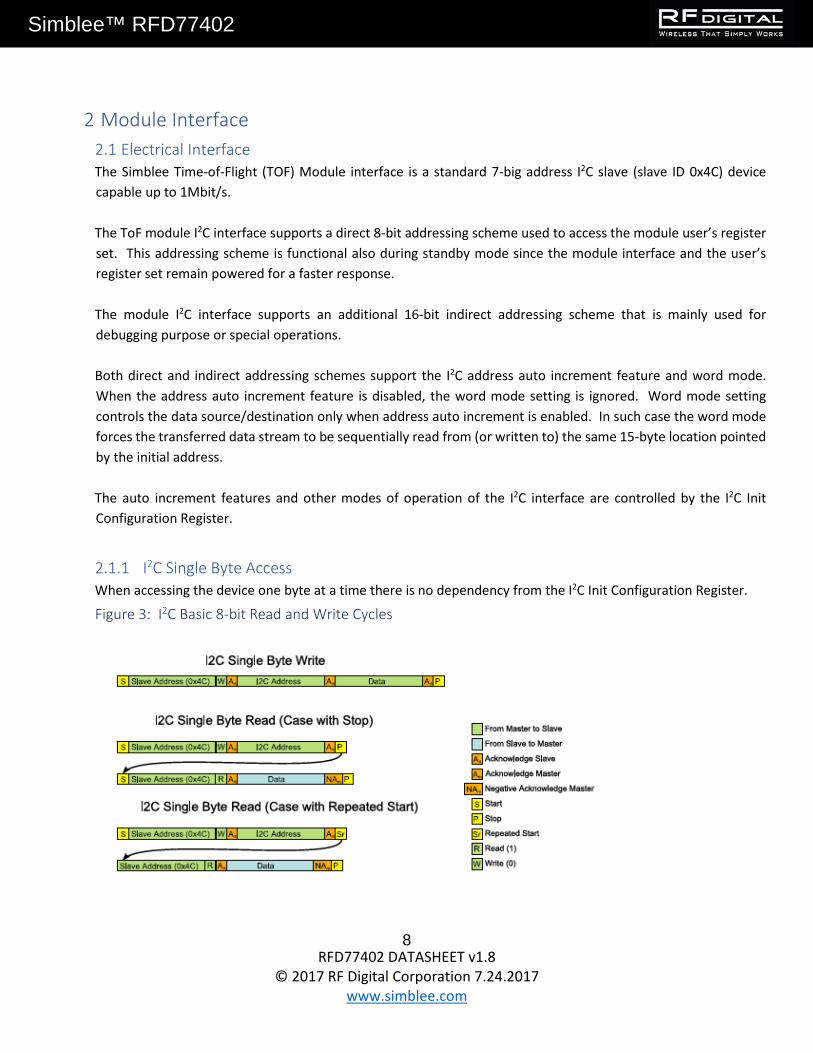
2 Module Interface 2.1 Electrical Interface The Simblee Time-of-Flight (TOF) Module interface is a standard 7-big address I2C slave (slave ID 0x4C) device capable up to 1Mbit/s. The ToF module I2C interface supports a direct 8-bit addressing scheme used to access the module user’s register set. This addressing scheme is functional also during standby mode since the module interface and the user’s register set remain powered for a faster response. The module I2C interface supports an additional 16-bit indirect addressing scheme that is mainly used for debugging purpose or special operations. Both direct and indirect addressing schemes support the I2C address auto increment feature and word mode. When the address auto increment feature is disabled, the word mode setting is ignored. Word mode setting controls the data source/destination only when address auto increment is enabled. In such case the word mode forces the transferred data stream to be sequentially read from (or written to) the same 15-byte location pointed by the initial address. The auto increment features and other modes of operation of the I2C interface are controlled by the I2C Init Configuration Register.
2.1.1 I2C Single Byte Access When accessing the device one byte at a time there is no dependency from the I2C Init Configuration Register.
Figure 3: I2C Basic 8-bit Read and Write Cycles

RFD77402 DATASHEET v1.8
© 2017 RF Digital Corporation 7.24.2017 www.simblee.com
9
Simblee™ RFD77402
2.1.2 I2C Write Access with Auto Increment and Word Mode Features When performing a burst write to the I2C interface, the module response depends on the setting of bits 1:0 of the I2C Init Configuration Register controlling the address auto increment features and word mode. If none of these modes are enabled, the data burst write is going to be directed to the same I2C address. In case of address auto increment, the data is written sequentially to the location starting with initial the I2C address. In case both modes are enabled, each 2-byte from the data burst stream is going to overwrite the 2-byte location pointed by the I2C address.
Figure 4: I2C Write Direct Access: Auto Increment and Word Mode Options
2.1.3 I2C Read Access with Address Auto Increment and Word Mode Features The behavior of the address auto increment and word mode features are similar to the one previously described for the I2C burst write.
Figure 5: I2C Burst Read: Address Auto Increment and Word Mode

RFD77402 DATASHEET v1.8
© 2017 RF Digital Corporation 7.24.2017 www.simblee.com
10
Simblee™ RFD77402
2.1.4 I2C Write Indirect Addressing with Address Auto Increment and Word Mode As previously mentioned, the ToF module supports an I2C indirect address scheme. In this case, the 16-bit address is written to the register. Each subsequent byte will be written to the 16-bit address location pointed by the register in a manner that depends on bits 2:3 of the I2C Init of the Configuration Register (address auto increment and word mode control bits).
Figure 6: I2C Indirect Address Burst Write with Address Auto Increment and Word Mode
Figure 7: I2C Indirect Address Write with Address Auto Increment and Word Mode (1-Byte Access)

RFD77402 DATASHEET v1.8
© 2017 RF Digital Corporation 7.24.2017 www.simblee.com
11
Simblee™ RFD77402
Figure 8: I2C Indirect Address Write with Address Auto Increment and Word Mode (2-Byte Access)
2.1.5 I2C Read Indirect Addressing with Address Auto Increment and Word Mode The indirect addressing I2C read follows the same rules as described above in terms of address auto increment and word mode.
Figure 9: I2C Burst Read Indirect Addressing

RFD77402 DATASHEET v1.8
© 2017 RF Digital Corporation 7.24.2017 www.simblee.com
12
Simblee™ RFD77402
Figure 10: I2C Indirect Address Read with Address Auto Increment and Word Mode (1-Byte Access

RFD77402 DATASHEET v1.8
© 2017 RF Digital Corporation 7.24.2017 www.simblee.com
13
Simblee™ RFD77402
Figure 11: I2C Indirect Address Read with Address Auto Increment and Word Mode (2-Byte Access)

RFD77402 DATASHEET v1.8
© 2017 RF Digital Corporation 7.24.2017 www.simblee.com
14
Simblee™ RFD77402
2.1.6 I2C Timing Information Figure 12: I2C Timing Characteristics Definitions
Table 2: I2C Timing Characteristics Information

RFD77402 DATASHEET v1.8
© 2017 RF Digital Corporation 7.24.2017 www.simblee.com
15
Simblee™ RFD77402
2.2 Host Interface Power Management The module enters standby mode once power is applied. To wake up the module to a fully on state (MCPU responding) the user must set to ‘1’ bit 9 (“MCPU_Init_State”) of the register PMU Configuration Register at address 0x14 and then issue a command that will then cause the MCPU to wake up. A command issued to the module with “MCPU_Init_State” not set to ‘1’ will cause the module to exit the Standby state and go in MCPU OFF state. In this state power is applied to the rest of the module but the MCPU is off.
Figure 13: Module State Diagram

RFD77402 DATASHEET v1.8
© 2017 RF Digital Corporation 7.24.2017 www.simblee.com
16
Simblee™ RFD77402
2.2.1 Standby / Leakage in Different Electrical Conditions Table 5: I2C SCL/SCA Power-up/down Sequence
2.2.2 Power-up and power-down Sequence Figure 14 below shows the RFD77402 power up and power down sequence. Please note that the module itself has no restrictions in terms of VDD and VI2C_pull-up sequencing, but in the case of VDD ON while VI2C_pull-up supply unit offers a path to GND. The value of such leakage current depends on the power supply impedance to GND. Therefore, unless the power supply unit offers a significantly high impedance to GND limiting such leakage, the application designer should avoid keeping VDD ON while VI2C_pull-up Is OFF for a long time (steady state).
Figure 14: I2C SCL/SDA Power-up/down Sequence
2.3 Module Programming Interface The I2C Interface registers defined in this section remain powered when in standby mode. For this reason, these registers are accessible at any time through the I2C direct address scheme. Note that the addresses of these registers are provided as 16-bit addresses according to the internal MCPU memory map. The external user must use the least significant byte of the address to access these registers through the I2C direct addressing scheme.

RFD77402 DATASHEET v1.8
© 2017 RF Digital Corporation 7.24.2017 www.simblee.com
17
Simblee™ RFD77402
Table 6: Host Interface Registers

RFD77402 DATASHEET v1.8
© 2017 RF Digital Corporation 7.24.2017 www.simblee.com
18
Simblee™ RFD77402
2.3.1 Configuration Parameters Table 7: Configuration Parameters Used to Configure the Module

RFD77402 DATASHEET v1.8
© 2017 RF Digital Corporation 7.24.2017 www.simblee.com
19
Simblee™ RFD77402
2.3.2 Module Interface Registers The following registers are used by the system host for module configuration and for operational communication. The user should not attempt to modify reserved fields as this could cause unpredictable behavior.
Table 8: Interrupt Control Status Register

RFD77402 DATASHEET v1.8
© 2017 RF Digital Corporation 7.24.2017 www.simblee.com
20
Simblee™ RFD77402
Table 9: Interrupt Enable Register
Table 10: Command Register

RFD77402 DATASHEET v1.8
© 2017 RF Digital Corporation 7.24.2017 www.simblee.com
21
Simblee™ RFD77402
Table 11: Device Status Register
Table 12: Result Register

RFD77402 DATASHEET v1.8
© 2017 RF Digital Corporation 7.24.2017 www.simblee.com
22
Simblee™ RFD77402
Table 13: Result Confidence Register
Table 14: Command Configuration Register A
Table 15: Command Configuration Register B

RFD77402 DATASHEET v1.8
© 2017 RF Digital Corporation 7.24.2017 www.simblee.com
23
Simblee™ RFD77402
Table 16: Host to MCPU Mailbox Register
Table 17: MCPU to Host Mailbox Register

RFD77402 DATASHEET v1.8
© 2017 RF Digital Corporation 7.24.2017 www.simblee.com
24
Simblee™ RFD77402
Table 18: PMU Configuration Register
Table 19: I2C Address Pointer Register

RFD77402 DATASHEET v1.8
© 2017 RF Digital Corporation 7.24.2017 www.simblee.com
25
Simblee™ RFD77402
Table 20: I2C Data Port Register
Table 21: I2C Init Configuration Register

RFD77402 DATASHEET v1.8
© 2017 RF Digital Corporation 7.24.2017 www.simblee.com
26
Simblee™ RFD77402
Table 22: MCPU Power Management Control Register
2.3.3 Hardware Configuration Registers These registers are used for hardware or firmware configuration and typically set up once at power up.
Table 23: HW/FW Configuration Register 0
Table 24: HW/FW Configuration Register 1

RFD77402 DATASHEET v1.8
© 2017 RF Digital Corporation 7.24.2017 www.simblee.com
27
Simblee™ RFD77402
Table 25: HW/FW Configuration Register 2
Table 26: HW/FW Configuration Register 3

RFD77402 DATASHEET v1.8
© 2017 RF Digital Corporation 7.24.2017 www.simblee.com
28
Simblee™ RFD77402
2.3.4 Other I2C Host Registers
Table 27: Module Chip ID Register
Table 28: Patch Memory Configuration Control Register

RFD77402 DATASHEET v1.8
© 2017 RF Digital Corporation 7.24.2017 www.simblee.com
29
Simblee™ RFD77402
3 Programming Guide 3.1 Programming Flow Charts Figure 15: Power-up Initialization

RFD77402 DATASHEET v1.8
© 2017 RF Digital Corporation 7.24.2017 www.simblee.com
30
Simblee™ RFD77402
3.1.1 Single Measure Figure 16: Single Measure Flow Chart

RFD77402 DATASHEET v1.8
© 2017 RF Digital Corporation 7.24.2017 www.simblee.com
31
Simblee™ RFD77402
4 Performance 4.1 Measurement Conditions and Accuracy In all measurement tables in this document, it is considered that the full Field of View (FoV) is covered. Figure 17 below shows a scatter chart for the measured distance in mm versus the actual distance in mm. The target used here was a gray chart with 17% reflectivity. The red dotted lines indicate the specified ± 10% for maximum deviation allowed within the operational range of the device which is from 100mm to 2000mm. Below this specified range of operation, the deviation is higher and it is specified at ±15%. Unless mentioned otherwise, the device is controlled through the API using the default settings. It’s effective FoV is governed by its Fol which is 23º. The FoV of the receiver is set to 55º so as to collect more reflected light from targets with uneven surfaces and multidirectional reflections.
Figure 17: Scatter Chart Showing Measured Distances Versus Actual Distance

RFD77402 DATASHEET v1.8
© 2017 RF Digital Corporation 7.24.2017 www.simblee.com
32
Simblee™ RFD77402
4.2 Maximum Ranging Distance and Ranging Accuracy Table 29 below shows the ranging accuracy specifications of the device. The data for these measurements were obtained with the device operating at room temperature and there was no cover glass on the device when the measurements were performed.
Table 29: Range Accuracy Information in the Range of 50mm to 2000mm
(*) note that RFD77402’s official technical specification states ±10% accuracy in the range of 100mm to 2000mm

RFD77402 DATASHEET v1.8
© 2017 RF Digital Corporation 7.24.2017 www.simblee.com
33
Simblee™ RFD77402
5 Mechanical Dimensions Figure 18: Overall Dimensions
Figure 19: Landing Pad and Solder Pad Recommendation

RFD77402 DATASHEET v1.8
© 2017 RF Digital Corporation 7.24.2017 www.simblee.com
34
Simblee™ RFD77402
Figure 20: Field of View (FoV) and Field of Illumination (FoI)
6 Cover Glass Selection Guide To obtain the best performance, the following rules should be taken in account for the Cover Glass:
• Material: PMMA, Acrylic • Spectral transmittance: T< 5% for λ< 770nm, T> 90% for λ > 820nm • Air gap: 100 µm • Thickness: < 1mm (the thinner, the better) • Dimensions bigger than 6x8mm • All the surfaces of the CG not relevant for the VCSEL emission and signal detection (e.g. lateral faces)
should be absorbing (e.g. by applying black non-reflective color).
7 Recommend Reflow Temperature Profile Figure 21: Solder Profile

RFD77402 DATASHEET v1.8
© 2017 RF Digital Corporation 7.24.2017 www.simblee.com
35
Simblee™ RFD77402
Table 30: Recommended Reflow Profile

RFD77402 DATASHEET v1.8
© 2017 RF Digital Corporation 7.24.2017 www.simblee.com
36
Simblee™ RFD77402
8 Packaging (Tape and Reel Dimensions) Figure 22: Product Packaging Arrangement

RFD77402 DATASHEET v1.8
© 2017 RF Digital Corporation 7.24.2017 www.simblee.com
37
Simblee™ RFD77402
9 Storage Conditions The RFD77402 module is an MSL 3 package.
Table 31: Recommended Storage Conditions
After this limit, dry bake to be done; 6 hours at 85ºC
10 RoHS and REACH Compliance The RFD77402 module is compliant with the European RoHS Directive 2002/95/EC (Restriction of the Use of Certain Hazardous Substances in Electrical and Electronic Equipment) and REACH (Registration, Authorization and Restriction of Chemicals, European Union Regulation (EC 1907/2006).
11 Eye Safety Considerations The RFD77402 module contains a laser emitter and corresponding drive circuitry. The laser output is Class 1 laser safety under all reasonably foreseeable conditions including single faults in compliance with IEC 60825-1:2014. The laser output will remain within Class 1 limits as long as the RF Digital recommended device setting are used and the operating conditions specific in this datasheet are respected. The laser output power must not be increased by any means and no optics should be used with the intention of focusing the laser beam.
Figure 23: Class 1 Laser Product Label

RFD77402 DATASHEET v1.8
© 2017 RF Digital Corporation 7.24.2017 www.simblee.com
38
Simblee™ RFD77402
Disclaimer RF Digital, a subsidiary of Heptagon, a member of the ams group its affiliates, agents, and employees, and all persons acting on its or their behalf (collectively, “RF Digital”), disclaims any and all liability for any errors, inaccuracies or incompleteness contained in any datasheet or in any other disclosure relating to any product. RF Digital makes no warranty, representation or guarantee regarding the suitability of the products for any purpose or the continuing production of any product. To the maximum extent permitted by applicable law, RF Digital disclaims (i) any and all liability arising out of the application or use of any product and (ii) any and all implied warranties, including warranties of fitness for particular purpose, non-infringement and merchantability. IN NO EVENT SHALL RF DIGITAL BE LIABLE FOR ANY DIRECT, INDIRECT, CONSEQUENTIAL, PUNITIVE, SPECIAL OR INCIDENTAL DAMAGES (INCLUDING, WITHOUT LIMITATION, DAMAGES FOR LOSS AND PROFITS, BUSINESS INTERRUPTION, OR LOSS OF INFORMATION) ARISING OUT OF THE USE OR INABILITY TO USE THIS DOCUMENT, EVEN IF RF DIGITAL HAS BEEN ADVISED OF THE POSSIBILITY OF SUCH DAMAGES. It is the customer’s responsibility to validate that a particular product with the properties described in the product specification is suitable for use in a particular application. Parameters provided in datasheets and/or specifications may vary in different applications and performance may vary over time. All operating parameters, including typical parameters, must be validated for each customer application by the customer’s technical experts. Customers are solely responsible for compliance with all legal, regulatory and safety-related requirements concerning their products, notwithstanding any applications-related information or support that may be provided by RF Digital. Customers represent that they have all the necessary expertise to create and implement their own safeguards that anticipate dangerous failures, monitor failures and their consequences, lessen the likelihood of dangerous failures and take appropriate remedial actions. Except as expressly indicated in writing, RF Digital’s products are not designed for use in medical, life-saving, or life-sustaining applications or for any other application in which the failure of the said products could result in personal injury or death. Customers using RF Digital’s products not expressly indicated for use in such applications do so at their own risk. Customers should obtain the latest relevant information before placing orders and should verify that such information is current and complete. Please contact authorized RF Digital personnel to obtain written terms and conditions regarding products designed for such applications. No license, express or implied, by estoppel or otherwise, to any intellectual property rights is granted by this document or by any conduct of RF Digital. RF Digital reserves the right to make changes, without further notice, to any its products and accompanying supporting documentation.
RF Digital’s product specifications and datasheets do not expand or otherwise modify RF Digital’s terms and conditions of sale, including but not limited to any warranties expressed therein.
RF Digital Corporation 1601 Pacific Coast Hwy Suite 290 Hermosa Beach, CA 90254 USA Tel: (949) 610-0008 Fax: (949) 610-0009 www.rfdigital.com
Watch our videos at: www.youtube.com/simblee
For support, please send email with detailed project information to: [email protected]
© 2017 RF Digital Corporation. All rights reserved.