simaticprocess control system pcs 7 - libraryftp.ruigongye.com/200806/s7jlibrb.pdf · contents...
TRANSCRIPT

Contents
Technological blocks 1
Driver blocks 2
Communication blocks 3Glossary, Index
SIMATIC
Process Control System PCS 7Library
Manual
Edition 03/2003A5E00180684-01
21.02.2003

Copyright © Siemens AG 2003 All rights reserved
The reproduction, transmission or use of this document or itscontents is not permitted without express written authority.Offenders will be liable for damages. All rights, including rightscreated by patent grant or registration of a utility model or design,are reserved.
Siemens AGBereich Automation and DrivesGeschaeftsgebiet Industrial Automation SystemsPostfach 4848, D- 90327 Nuernberg
Disclaimer of Liability
We have checked the contents of this manual for agreement withthe hardware and software described. Since deviations cannot beprecluded entirely, we cannot guarantee full agreement. However,the data in this manual are reviewed regularly and any necessarycorrections included in subsequent editions. Suggestions forimprovement are welcomed.
©Siemens AG 2003Technical data subject to change.
Siemens Aktiengesellschaft A5E00180684-01
Safety Guidelines
This manual contains notices intended to ensure personal safety, as well as to protect the products and
connected equipment against damage. These notices are highlighted by the symbols shown below and
graded according to severity by the following texts:
! Dangerindicates that death, severe personal injury or substantial property damage will result if properprecautions are not taken.
! Warningindicates that death, severe personal injury or substantial property damage can result if properprecautions are not taken.
! Cautionindicates that minor personal injury can result if proper precautions are not taken.
Cautionindicates that property damage can result if proper precautions are not taken.
Noticedraws your attention to particularly important information on the product, handling the product, or to aparticular part of the documentation.
Qualified Personnel
Only qualified personnel should be allowed to install and work on this equipment. Qualified persons are
defined as persons who are authorized to commission, to ground and to tag circuits, equipment, and
systems in accordance with established safety practices and standards.
Correct Usage
Note the following:
! WarningThis device and its components may only be used for the applications described in the catalog or the
technical description, and only in connection with devices or components from other manufacturers
which have been approved or recommended by Siemens.
This product can only function correctly and safely if it is transported, stored, set up, and installedcorrectly, and operated and maintained as recommended.
Trademarks
SIMATIC®, SIMATIC HMI® and SIMATIC NET® are registered trademarks of SIEMENS AG.
Third parties using for their own purposes any other names in this document which refer to trademarks might
infringe upon the rights of the trademark owners.
21.02.2003

Process Control System PCS 7 - LibraryA5E00180684-01 iii
Contents
1 Technological blocks .....................................................................................................1-1
1.1 General notes on the block description.............................................................1-11.2 General information on faceplates ....................................................................1-61.3 Measurement and Control.................................................................................1-71.3.1 CTRL_PID: PID controller block .......................................................................1-71.3.1.1 CTRL_PID: Description.....................................................................................1-71.3.1.2 CTRL_PID: Signal processing in the setpoint
and process variable branches .........................................................................1-91.3.1.3 CTRL_PID: Generation of the manipulated variable.......................................1-111.3.1.4 CTRL_PID: Manual, automatic and tracking mode ........................................1-121.3.1.5 CTRL_PID: Changing operating modes .........................................................1-141.3.1.6 CTRL_PID: Error handling ..............................................................................1-161.3.1.7 CTRL_PID: Startup, time and message characteristics .................................1-171.3.1.8 CTRL_PID: VSTATUS ....................................................................................1-191.3.1.9 CTRL_PID: Block diagram..............................................................................1-201.3.1.10 CTRL_PID: I/Os ..............................................................................................1-211.3.1.11 CTRL_PID: Operator control and monitoring..................................................1-251.3.2 CTRL_S: PID step controller block .................................................................1-291.3.2.1 CTRL_S: Description ......................................................................................1-291.3.2.2 CTRL_S: Signal processing in the setpoint and process variable branches ..1-321.3.2.3 CTRL_S: Control signal generation ................................................................1-341.3.2.4 CTRL_S: Manual, automatic and tracking mode ............................................1-371.3.2.5 CTRL_S: Changing operating modes .............................................................1-401.3.2.6 CTRL_S: Error handling..................................................................................1-421.3.2.7 CTRL_S: Operator control and monitoring .....................................................1-431.3.2.8 CTRL_S: Startup, time and message characteristics .....................................1-431.3.2.9 CTRL_S: VSTATUS........................................................................................1-451.3.2.10 CTRL_S: Block diagram..................................................................................1-461.3.2.11 CTRL_S: I/Os..................................................................................................1-481.3.3 DEADT_P: Dead time element .......................................................................1-531.3.3.1 DEADT_P: Description....................................................................................1-531.3.3.2 DEADT_P: I/Os ...............................................................................................1-541.3.4 DIF_P: Differentiation......................................................................................1-551.3.4.1 DIF_P: Description ..........................................................................................1-551.3.4.2 DIF_P: I/Os......................................................................................................1-561.3.5 DIG_MON: Digital value monitoring................................................................1-571.3.5.1 DIG_MON: Description ...................................................................................1-571.3.5.2 DIG_MON: I/Os...............................................................................................1-601.3.5.3 DIG_MON: Operator control and monitoring ..................................................1-611.3.5.4 DIG_MON: VSTATUS.....................................................................................1-611.3.6 FMCS_PID: Controller block ...........................................................................1-621.3.6.1 FMCS_PID: Description ..................................................................................1-621.3.6.2 Addressing ......................................................................................................1-631.3.6.3 Function...........................................................................................................1-641.3.6.4 Setpoint, limit, error signal and manipulated variable generation ...................1-651.3.6.5 Manual, automatic and tracking mode ............................................................1-66
21.02.2003
Contents
Process Control System PCS 7 - Libraryiv A5E00180684-01
1.3.6.6 Operating mode selection ...............................................................................1-681.3.6.7 Safety operation ..............................................................................................1-691.3.6.8 Transferring parameters to the module...........................................................1-701.3.6.9 Reading data from the module........................................................................1-701.3.6.10 Error handling..................................................................................................1-701.3.6.11 FMCS_PID: Startup, time and message characteristics.................................1-711.3.6.12 Backup mode of the FM355 ............................................................................1-741.3.6.13 FMCS_PID: I/Os..............................................................................................1-741.3.6.14 FMCS_PID: Operator control and monitoring .................................................1-791.3.6.15 FMCS_PID: VSTATUS ...................................................................................1-831.3.7 FMT_PID: Temperature controller block.........................................................1-841.3.7.1 FMT_PID: Description.....................................................................................1-841.3.7.2 Addressing ......................................................................................................1-851.3.7.3 FMT_PID: Function .........................................................................................1-861.3.7.4 FMT_PID: Generation of setpoints, limits, error signals
and manipulated variables ..............................................................................1-871.3.7.5 Manual, auto and tracking mode.....................................................................1-881.3.7.6 Mode switching................................................................................................1-891.3.7.7 Safety mode ....................................................................................................1-911.3.7.8 Download of parameters to the module ..........................................................1-911.3.7.9 Reading module data / Working with the configuration tool............................1-911.3.7.10 Optimization (Overview)..................................................................................1-911.3.7.11 Switching between different PID parameter sets ............................................1-921.3.7.12 Error handling..................................................................................................1-931.3.7.13 FMT_PID: Startup, time and message characteristics....................................1-931.3.7.14 FM355-2: Backup mode..................................................................................1-951.3.7.15 FMT_PID: I/OS................................................................................................1-951.3.7.16 FMT_PID: Operator control and monitoring..................................................1-1011.3.7.17 FMT_PID: VSTATUS ....................................................................................1-1051.3.8 INT_P: Integration .........................................................................................1-1061.3.8.1 INT_P: Description ........................................................................................1-1061.3.8.2 INT_P: I/Os....................................................................................................1-1101.3.9 MEANTM_P: Mean time value generation....................................................1-1111.3.9.1 MEANTM_P: Description ..............................................................................1-1111.3.9.2 MEANTM_P: I/Os..........................................................................................1-1121.3.10 MEAS_MON: Measurement value monitoring ..............................................1-1131.3.10.1 MEAS_MON: Description..............................................................................1-1131.3.10.2 MEAS_MON: I/Os .........................................................................................1-1151.3.10.3 MEAS_MON: Operator control and monitoring.............................................1-1171.3.10.4 MEAS_MON: VSTATUS ...............................................................................1-1191.3.11 POLYG_P: Polygon with a max. of 8 points .................................................1-1201.3.11.1 POLYG_P: Description .................................................................................1-1201.3.11.2 POLYG_P: I/Os.............................................................................................1-1211.3.12 PT1_P: Delay element of the 1st order.........................................................1-1221.3.12.1 PT1_P: Description .......................................................................................1-1221.3.12.2 PT1_P: I/Os...................................................................................................1-1231.3.13 RAMP_P: Ramp generation..........................................................................1-1231.3.13.1 RAMP_P: Description ...................................................................................1-1231.3.13.2 RAMP_P: I/Os ...............................................................................................1-1251.3.14 RATIO_P: ration control ................................................................................1-1251.3.14.1 RATIO_P: Description...................................................................................1-1251.3.14.2 RATIO_P: I/Os ..............................................................................................1-1271.3.14.3 RATIO_P: Operator control and monitoring..................................................1-1281.3.14.4 RATIO_P: VSTATUS ....................................................................................1-129
21.02.2003

Contents
Process Control System PCS 7 - LibraryA5E00180684-01 v
1.3.15 SPLITR_P: Split range ..................................................................................1-1301.3.15.1 SPLITR_P: Description .................................................................................1-1301.3.15.2 SPLITR_P: I/Os.............................................................................................1-1321.4 Motor and valve.............................................................................................1-1331.4.1 MOT_REV: Motor with two rotary directions.................................................1-1331.4.1.1 MOT_REV: Description.................................................................................1-1331.4.1.2 MOT_REV: I/Os ............................................................................................1-1381.4.1.3 MOT_REV: Operator control and monitoring................................................1-1411.4.1.4 MOT_REV: VSTATUS ..................................................................................1-1421.4.2 MOT_SPED: Motor with two speeds ............................................................1-1431.4.2.1 MOT_SPED: Description ..............................................................................1-1431.4.2.2 MOT_SPED: I/Os..........................................................................................1-1471.4.2.3 MOT_SPED: Operator control and monitoring .............................................1-1501.4.2.4 MOT_SPED: VSTATUS................................................................................1-1511.4.3 MOTOR: Motor with control signal ................................................................1-1521.4.3.1 MOTOR: Description.....................................................................................1-1521.4.3.2 MOTOR: I/Os ................................................................................................1-1561.4.3.3 MOTOR: Operator control and monitoring....................................................1-1581.4.3.4 MOTOR: VSTATUS ......................................................................................1-1591.4.4 VAL_MOT: Motor valve control .....................................................................1-1601.4.4.1 VAL_MOT: Description .................................................................................1-1601.4.4.2 VAL_MOT: I/Os.............................................................................................1-1651.4.4.3 VAL_MOT: Operator control and monitoring ................................................1-1681.4.4.4 VAL_MOT: VSTATUS...................................................................................1-1691.4.5 VALVE: Valve control....................................................................................1-1701.4.5.1 VALVE: Description.......................................................................................1-1701.4.5.2 VALVE: I/Os ..................................................................................................1-1741.4.5.3 VALVE: Operator control and monitoring......................................................1-1771.4.5.4 VALVE: VSTATUS ........................................................................................1-1781.5 Other Technological blocks...........................................................................1-1791.5.1 ADD4_P: Adder for max. 4 values ................................................................1-1791.5.1.1 ADD4_P: Description ....................................................................................1-1791.5.1.2 ADD4_P: I/Os................................................................................................1-1791.5.2 ADD8_P: Adder for max. 8 values ................................................................1-1801.5.2.1 ADD8_P: Description ....................................................................................1-1801.5.2.2 ADD8_P: I/Os................................................................................................1-1801.5.3 AVER_P: Mean time value............................................................................1-1811.5.3.1 AVER_P: Description ....................................................................................1-1811.5.3.2 AVER_P: I/Os ...............................................................................................1-1821.5.4 COUNT_P: Counter ......................................................................................1-1831.5.4.1 COUNT_P: Description .................................................................................1-1831.5.4.2 COUNT_P: I/Os ............................................................................................1-1841.5.5 DOSE: Dosing...............................................................................................1-1851.5.5.1 DOSE: Description ........................................................................................1-1851.5.5.2 DOSE: I/Os....................................................................................................1-1901.5.5.3 DOSE: Operator control and monitoring .......................................................1-1941.5.5.4 DOSE: VSTATUS .........................................................................................1-1971.5.6 ELAP_CNT: Hour meter................................................................................1-1981.5.6.1 ELAP_CNT: Description................................................................................1-1981.5.6.2 ELAP_CNT: I/Os ...........................................................................................1-2011.5.6.3 ELAP_CNT: Operator control and monitoring...............................................1-2021.5.6.4 ELAP_CNT: VSTATUS.................................................................................1-203
21.02.2003

Contents
Process Control System PCS 7 - Libraryvi A5E00180684-01
1.5.7 INTERLOK: Interlock display.........................................................................1-2041.5.7.1 INTERLOK: Description ................................................................................1-2041.5.7.2 INTERLOK: I/Os............................................................................................1-2061.5.7.3 INTERLOK: Operator control and monitoring ...............................................1-2071.5.7.4 INTERLOK: VSTATUS..................................................................................1-2081.5.8 LIMITS_P: Limits...........................................................................................1-2091.5.8.1 LIMITS_P: Description ..................................................................................1-2091.5.8.2 LIMITS_P: I/Os..............................................................................................1-2111.5.9 MUL4_P: Multiplicator for max. 4 values ......................................................1-2121.5.9.1 MUL4_P: Description ....................................................................................1-2121.5.9.2 MUL4_P: I/Os................................................................................................1-2121.5.10 MUL8_P: Multiplikation für maximal 8 Werte ................................................1-2131.5.10.1 MUL8_P: Description ....................................................................................1-2131.5.10.2 MUL8_P: I/Os................................................................................................1-2131.5.11 OB1_TIME: Calculating CPU load ................................................................1-2141.5.11.1 OB1_TIME: Description ................................................................................1-2141.5.11.2 OB1_TIME: I/Os............................................................................................1-2151.5.12 SWIT_CNT: Switching cycle counter ............................................................1-2161.5.12.1 SWIT_CNT: Description................................................................................1-2161.5.12.2 SWIT_CNT: I/Os ...........................................................................................1-2191.5.12.3 SWIT_CNT: Operator control and monitoring...............................................1-2201.5.12.4 SWIT_CNT: VSTATUS .................................................................................1-2211.6 Conversion blocks.........................................................................................1-2221.6.1 Conversion blocks, general information........................................................1-2221.6.2 R_TO_DW: Conversion REAL to DWORD...................................................1-2231.6.2.1 R_TO_DW: Description.................................................................................1-2231.6.2.2 R_TO_DW: I/Os ............................................................................................1-2231.7 Operator control blocks .................................................................................1-2241.7.1 Overview of the operator control blocks........................................................1-2241.7.2 OP_A: Local control of analog values...........................................................1-2281.7.2.1 OP_A: Description.........................................................................................1-2281.7.2.2 OP_A: I/Os ....................................................................................................1-2301.7.2.3 OP_A: Operator control and monitoring........................................................1-2301.7.3 OP_A_LIM: Local control of analog values (limiting) ....................................1-2301.7.3.1 OP_A_LIM: Description.................................................................................1-2301.7.3.2 OP_A_LIM: I/Os ............................................................................................1-2331.7.3.3 OP_A_LIM: Operator control and monitoring................................................1-2331.7.4 OP_A_RJC: Local control of analog values (rejecting).................................1-2341.7.4.1 OP_A_RJC: Description................................................................................1-2341.7.4.2 OP_A_RJC: I/Os ...........................................................................................1-2371.7.4.3 OP_A_RJC: Operator control and monitoring...............................................1-2371.7.5 OP_D: Local control of digital values (2 buttons)..........................................1-2381.7.5.1 OP_D: Description.........................................................................................1-2381.7.5.2 OP_D: I/Os ....................................................................................................1-2401.7.5.3 OP_D: Operator control and monitoring .......................................................1-2411.7.6 OP_D3: Local control of digital values (3 buttons)........................................1-2421.7.6.1 OP_D3: Description.......................................................................................1-2421.7.6.2 OP_D3: I/Os ..................................................................................................1-2451.7.6.3 OP_D3: Operator control and monitoring .....................................................1-2461.7.7 P_TRIG: Local control of digital values (1 button) ........................................1-2471.7.7.1 P_TRIG: Description .....................................................................................1-2471.7.7.2 P_TRIG: I/Os.................................................................................................1-2491.7.7.3 OP_TRIG: Operator control and monitoring .................................................1-250
21.02.2003

Contents
Process Control System PCS 7 - LibraryA5E00180684-01 vii
1.8 Message blocks ............................................................................................1-2511.8.1 Overview of the message blocks ..................................................................1-2511.8.2 MSG_NACK: User-specific messages (no mandatory acknowledgement)..1-2521.8.2.1 MSG_NACK: Description ..............................................................................1-2521.8.2.2 MSG_NACK: I/Os .........................................................................................1-2531.8.3 MESSAGE: Message blocks (configurable messages)................................1-2541.8.3.1 MESSAGE: Description ................................................................................1-2541.8.3.2 MESSAGE: I/Os............................................................................................1-2571.9 Appendix .......................................................................................................1-2581.9.1 Technical data "Technological blocks"..........................................................1-258
2 Driver blocks...................................................................................................................2-1
2.1 Notes on using driver blocks.............................................................................2-12.2 Signal blocks and diagnostic drivers.................................................................2-22.2.1 CH_AI: Analog value input ................................................................................2-22.2.1.1 CH_AI: Description............................................................................................2-22.2.1.2 CH_AI: I/Os .......................................................................................................2-72.2.2 CH_AO: Analog value output ............................................................................2-82.2.2.1 CH_AO: Description..........................................................................................2-82.2.2.2 CH_AO: I/Os ...................................................................................................2-112.2.3 CH_DI: Digital value input ...............................................................................2-122.2.3.1 CH_DI: Description .........................................................................................2-122.2.3.2 CH_DI: I/Os.....................................................................................................2-152.2.4 CH_DO: Digital value output ...........................................................................2-162.2.4.1 CH_DO: Description........................................................................................2-162.2.4.2 CH_DO: I/Os ...................................................................................................2-182.2.5 CH_U_AI: Analog value input (universal) .......................................................2-192.2.5.1 CH_U_AI (universal): Description ...................................................................2-192.2.5.2 CH_U_AI: I/Os ................................................................................................2-242.2.6 CH_U_AO: Analogvalue output (universal) ....................................................2-262.2.6.1 CH_U_AO (universal): Description .................................................................2-262.2.6.2 CH_U_AO: I/Os...............................................................................................2-302.2.7 CH_U_DI: Digital value input (universal) ........................................................2-312.2.7.1 CH_U_DI (universal): Description...................................................................2-312.2.7.2 CH_U_DI: I/Os ................................................................................................2-342.2.8 CH_U_DO: Digital value output (universal) ....................................................2-352.2.8.1 CH_U_DO (universal): Description .................................................................2-352.2.8.2 CH_U_DO: I/Os ..............................................................................................2-382.2.9 DREP: Diagnose repeater at the DP master system......................................2-392.2.9.1 DREP: Description ..........................................................................................2-392.2.9.2 DREP: I/Os......................................................................................................2-432.2.9.3 DREP: Message texts and auxiliary process values ......................................2-442.2.10 DREP_L: Diagnose repeater downstream of a Y Link....................................2-462.2.10.1 DREP_L: Description ......................................................................................2-462.2.10.2 DREP_L: I/Os..................................................................................................2-502.2.10.3 DREP_L: Message texts and auxiliary process values ..................................2-512.2.11 IM_DRV: Transferring process signal changes with Time Stamp ..................2-532.2.11.1 IM_DRV: Description.......................................................................................2-532.2.11.2 IM_DRV: I/Os ..................................................................................................2-582.2.11.3 IM_DRV: Message texts and auxiliary process values...................................2-582.2.11.4 IM interface......................................................................................................2-602.2.12 MOD_1: Monitoring 16-channel S7-300/400 SM modules
without diagnostic functions ............................................................................2-632.2.12.1 MOD_1: Description........................................................................................2-63
21.02.2003

Contents
Process Control System PCS 7 - Libraryviii A5E00180684-01
2.2.12.2 MOD_1 / MOD_2: I/Os....................................................................................2-672.2.12.3 MOD_1 / MOD_2 / MOD_3: Message texts and auxiliary process values .....2-682.2.13 MOD_2: Monitoring 32-channel S7-300/400 SM modules
without diagnostic functions ............................................................................2-692.2.13.1 MOD_2: Description........................................................................................2-692.2.14 MOD_3: Monitoring 16-channel S7-200/300/400 SM modules
without diagnostic functions ............................................................................2-732.2.14.1 MOD_3: Description........................................................................................2-732.2.14.2 MOD_3: I/O .....................................................................................................2-772.2.15 MOD_CP: Diagnose CP 341/441....................................................................2-782.2.15.1 MOD_CP: Description.....................................................................................2-782.2.15.2 MOD_CP: I/Os ................................................................................................2-812.2.15.3 MOD_CP: Message texts and auxiliary process values .................................2-822.2.16 MOD_D1: Monitoring 16-channel S7-300/400 SM modules
with diagnostic functions .................................................................................2-832.2.16.1 MOD_D1: Description .....................................................................................2-832.2.16.2 MOD_D1 / MOD_D2: I/Os...............................................................................2-892.2.16.3 MOD_D1: Message texts and auxiliary process values..................................2-902.2.17 MOD_D2: Monitoring 32-channel S7-300/400 SM modules
with diagnostic functions .................................................................................2-922.2.17.1 MOD_D2: Description .....................................................................................2-922.2.17.2 MOD_D2: Message texts and auxiliary process values..................................2-972.2.18 MOD_MS: Monitoring 16-channel ET200S/X Motor starter modules
with diagnostic functions .................................................................................2-992.2.18.1 MOD_MS: Description ....................................................................................2-992.2.18.2 MOD_MS: I/Os ..............................................................................................2-1032.2.18.3 MOD_MS: Message texts and auxiliary process values...............................2-1042.2.19 MOD_HA: Monitoring device-specific diagnostics of HART field devices ....2-1062.2.19.1 MOD_HA: Description...................................................................................2-1062.2.19.2 MOD_HA: I/Os ..............................................................................................2-1112.2.19.3 MOD_HA: Message texts and auxiliary process values ...............................2-1122.2.20 OB_BEGIN: CPU diagnostics and AS communication diagnostics..............2-1132.2.20.1 OB_BEGIN: Description................................................................................2-1132.2.20.2 OB_BEGIN: I/Os ...........................................................................................2-1182.2.20.3 OB_BEGIN: Message texts and auxiliary process values ............................2-1192.2.21 OB_DIAG: OB diagnostics for avoiding CPU Stop .......................................2-1242.2.21.1 OB_DIAG: Description ..................................................................................2-1242.2.21.2 OB_DIAG: I/Os..............................................................................................2-1272.2.22 OB_DIAG1: OB diagnostics for avoiding CPU Stop in
DPV1 master systems...................................................................................2-1282.2.22.1 OB_DIAG1: Description ................................................................................2-1282.2.22.2 OB_DIAG1: I/Os............................................................................................2-1322.2.22.3 OB_DIAG1: Message texts and auxiliary process values ............................2-1332.2.23 OB_END: Reset stack pointer of OB_BEGIN ...............................................2-1342.2.23.1 OB_END: Description ...................................................................................2-1342.2.23.2 OB_END: I/Os ...............................................................................................2-1352.2.24 OR_M_16: OR value status of 2 redundant signal modules
with max. 16 channels...................................................................................2-1362.2.24.1 OR_M_16: Description..................................................................................2-1362.2.24.2 OR_M_16 / OR_M_32: I/Os..........................................................................2-1382.2.24.3 OR_M_16 / OR_M_32: Message texts and auxiliary process values...........2-1392.2.25 OR_M_32: OR-Value Status of 2 redundanten Signal Modules
with 32 channels............................................................................................2-1402.2.25.1 OR_M_32: Description..................................................................................2-140
21.02.2003

Contents
Process Control System PCS 7 - LibraryA5E00180684-01 ix
2.2.26 PO_UPDAT: Output process image .............................................................2-1402.2.26.1 PO_UPDAT: Description...............................................................................2-1402.2.27 RACK: Rack monitoring ................................................................................2-1412.2.27.1 RACK: Description ........................................................................................2-1412.2.27.2 RACK: I/Os....................................................................................................2-1442.2.27.3 RACK: Message texts and auxiliary process values ....................................2-1452.2.28 RCV_341: Receiving serial data with CP 341...............................................2-1462.2.28.1 RCV_341: Description...................................................................................2-1462.2.28.2 RCV_341: I/Os ..............................................................................................2-1502.2.28.3 RCV_341: Message texts and auxiliary process values...............................2-1512.2.29 SND_341: Sending serial data with CP 341 .................................................2-1522.2.29.1 SND_341: Description...................................................................................2-1522.2.29.2 SND_341: I/Os ..............................................................................................2-1562.2.29.3 SND_341: Message texts and auxiliary process values...............................2-1572.2.30 SUBNET: DP master system monitoring ......................................................2-1582.2.30.1 SUBNET: Description....................................................................................2-1582.2.30.2 SUBNET: I/Os ...............................................................................................2-1612.2.30.3 SUBNET: Message texts and auxiliary process values................................2-1622.3 PROFIBUS PA - Blocks ................................................................................2-1632.3.1 DPAY_V0: Monitoring DP/PA and Y Links operating as V0 slave................2-1632.3.1.1 DPAY_V0: Description ..................................................................................2-1632.3.1.2 DPAY_V0: I/Os .............................................................................................2-1672.3.1.3 DPAY_V0: Message texts and auxiliary process values ..............................2-1682.3.2 DPAY_V1: Enabling blocks downstream of a DP/PA
and Y Link operating as V1 slave..................................................................2-1692.3.2.1 DPAY_V1: Description ..................................................................................2-1692.3.2.2 DPAY_V1: I/Os .............................................................................................2-1712.3.3 MOD_PAL0: Diagnostics of a DPV0 PA slave
(via DP/PA coupler downstream of a DPV1 DP/PA Link).............................2-1722.3.3.1 MOD_PAL0: Description ...............................................................................2-1722.3.3.2 MOD_PAL0: I/Os ..........................................................................................2-1742.3.3.3 MOD_PAL0: Message texts and auxiliary process values ...........................2-1752.3.4 MOD_PAX0: Diagnostics of a DPV0 PA slave
(via DP/PA coupler on DP master system) ...................................................2-1772.3.4.1 MOD_PAX0: Description...............................................................................2-1772.3.4.2 MOD_PAX0: I/Os ..........................................................................................2-1802.3.4.3 MOD_PAX0: Message texts and auxiliary process values...........................2-1812.3.5 PA_AI: Analog value input PROFIBUS PA...................................................2-1832.3.5.1 PA_AI: Description ........................................................................................2-1832.3.5.2 PA_AI: I/Os....................................................................................................2-1852.3.5.3 PA_AI: Message texts...................................................................................2-1872.3.6 PA_AO: Analog value output PROFIBUS PA...............................................2-1882.3.6.1 PA_AO: Description ......................................................................................2-1882.3.6.2 PA_AO: I/Os..................................................................................................2-1912.3.6.3 PA_AO: Message texts .................................................................................2-1942.3.7 PA_DI: Digital value input PROFIBUS PA....................................................2-1952.3.7.1 PA_DI: Description........................................................................................2-1952.3.7.2 PA_DI: I/Os ...................................................................................................2-1972.3.7.3 PA_DI: Message texts...................................................................................2-1992.3.8 PA_DO: Digital value output PROFIBUS PA................................................2-2002.3.8.1 PA_DO: Description ......................................................................................2-2002.3.8.2 PA_DO: I/Os..................................................................................................2-2032.3.8.3 PA_DO: Message texts.................................................................................2-2052.3.9 PA_TOT: Totalizer PROFIBUS PA ...............................................................2-206
21.02.2003

Contents
Process Control System PCS 7 - Libraryx A5E00180684-01
2.3.9.1 PA_TOT: Description ....................................................................................2-2062.3.9.2 PA_TOT: I/Os................................................................................................2-2082.3.9.3 PA_TOT: Message texts ...............................................................................2-2102.3.10 PADP_L0x: monitoring DP/PA slaves...........................................................2-2112.3.10.1 PADP_L00: Description ................................................................................2-2112.3.10.2 PADP_L0x: I/Os ............................................................................................2-2142.3.10.3 PADP_L00: Message texts and auxiliary process values.............................2-2152.3.10.4 PADP_L01: Description ................................................................................2-2162.3.10.5 PADP_L01: Message texts and auxiliary process values.............................2-2192.3.10.6 PADP_L02: Description ................................................................................2-2212.3.10.7 PADP_L02: Message texts and auxiliary process values.............................2-2242.3.11 PADP_L10 :Monitoring DPV0 PA with max. 16 slots....................................2-2262.3.11.1 PADP_L10: Description ................................................................................2-2262.3.11.2 PADP_L10: I/Os............................................................................................2-2312.4 Appendix .......................................................................................................2-2322.4.1 Addressing ....................................................................................................2-2322.4.2 MSG_STAT: Error information of the output parameter ...............................2-2332.4.3 MODE settings for signal modules................................................................2-2332.4.4 MODE settings for PA devices......................................................................2-2382.4.5 Text library for signal modules ......................................................................2-2392.4.6 Text library for DP/PA slaves downstream of a DPV0 PA or Y LINK ...........2-2412.4.7 Technical data "Driver blocks" ......................................................................2-241
3 Communication blocks ..................................................................................................3-1
3.1 REC_BO: Receive 128 BOOL values with BRCV ............................................3-13.1.1 REC_BO: Description .......................................................................................3-13.1.2 I/O of REC_BO..................................................................................................3-33.2 REC_R: Receive 32 BOOL and 32 REAL values with BRCV ..........................3-43.2.1 REC_R: Description ..........................................................................................3-43.2.2 I/Os of REC_R...................................................................................................3-63.3 SEND_BO: Send 128 BOOL values with BSEND ............................................3-73.3.1 SEND_BO: Description .....................................................................................3-73.3.2 I/Os of SEND_BO..............................................................................................3-93.4 SEND_R: Send 32 BOOL and 32 REAL values driven by changes
with BSEND.....................................................................................................3-103.4.1 SEND_R: Description......................................................................................3-103.1.2 I/Os of SEND_R ..............................................................................................3-133.5 Appendix .........................................................................................................3-143.5.1 Technical data "Communication blocks".........................................................3-14
Glossary
Index
21.02.2003
Process Control System PCS 7 - LibraryA5E00180684-01 1-1
1 Technological blocks
1.1 General notes on the block description
The setup of the block description is always uniform and contains the followingsections:
Header of the block description
Example: CTRL_PID: PID controller block
The header begins with the type name of the block (CTRL_PID). This symbolname is entered in the symbol name and must be unambiguous within the project.The type name also includes the keyword relevant to the task/function of the block(PID controller block).
Object name (type + number)
FB x
Syntactical components of the object name of a block type:Function block = FB, Function = FC and the Block number = x.
Command button for the displaying block I/Os
Example:
You can directly open the list of block I/Os of the selected block by clicking on the"Block Connections" command button. The icon preceding the block allows quicklocation of the command button.
Function
Here you can find a brief description of the block function.Further information on complex blocks is found in the section describing theoperating principle.
21.02.2003

Technological blocks
Process Control System PCS 7 - Library1-2 A5E00180684-01
Operating principle
This section provides further information relevant to the function of specific inputs,operating modes, time sequences etc. You should be familiar with these contextsin order to use the block effectively.
Calling OBs
Here you will find information on the organization blocks (OBs), in which thedescribed block must be installed. The CFC when used automatically installs thisblock in the cyclic OB (watchdog interrupt) and in the OBs listed in the task list ofthe block (e.g. in restart OB100).
CFC generates the required OBs during compilation. If you use the blocks withoutCFC, you have to program these OBs and call their instance within the blocks.
Error handling
The Boolean block output ENO indicates the error in the CFC chart.The value is equivalent to the BIE (binary result in STEP 7 STL, after ending theblock) or OK bit (in SCL notation) and indicates:
ENO=BIE=OK=1 (TRUE) ->The result of the block is OK.
ENO=BIE=OK=0 (FALSE) ->Invalid result or calculating conditions (e.g. inputvalues, operating modes etc.).
At the FBs, you will find in addition the inverted BIE at the QERR output of theinstance DB:
QERR=NOT ENO
The error message is created by two separate operations:
The operating system recognizes a processing error (e.g. value overflow, thecalled system functions return an error code with binary input bit=0).This is a system service and is thus not mentioned specifically in the individualblock description.
The block algorithm verifies the functional validity of values and operating modes.These error events are documented in the description of the block.
You can evaluate the error indication, for example to generate messages (refer tothe section on interrupt blocks) or to utilize substitute values for invalid results.
21.02.2003

Technological blocks
Process Control System PCS 7 - LibraryA5E00180684-01 1-3
Startup characteristics
A difference is made between:
• Initial startupThe first call of the block in its OB. This is usually the OB that performs thestandard process-specific operations (e.g. the watchdog interrupt OB).The block enters a status that conforms with its input parameters, i.e. the initialvalues (also refer to "I/Os") or values you have already configured, for examplein CFC. The initial startup response is not described separately unless theblock does not conform with this rule.
• StartupThe block is executed once during the CPU startup. The block is thus called inthe startup OB (where it is additionally installed either automatically via the ESor manually by the operator via STEP 7. In this case, the startup characteristicsare described.
Time response
Block assigned this function must be installed into a watchdog interrupt OB. Itcalculates its time constants/parameters on the basis of its sampling time (the timeinterval between two consecutive cyclic processes).In a CFC configuration on ES, the sampling time is also determined by thesegmentation of the runtime group, which ensures that the block is not executed inevery OB cycle.This sampling time is entered at the I/Os, in the SAMPLE_T parameter.
In a CFC configuration this is performed automatically when the block is installed inthe OB and runtime group (hence, this input is hidden to the user).
In a STEP 7 configuration this must be done manually.
Time response is mentioned only if the block has been assigned this feature.
Message characteristics
A block assigned these characteristics reports various events to the master OSsystem. Existing parameters required for the generation of messages aredocumented.Blocks not having message characteristics can be expanded with additionalinterrupt blocks. A reference to the message characteristics is found in thedescription of the individual message blocks.
21.02.2003

Technological blocks
Process Control System PCS 7 - Library1-4 A5E00180684-01
I/O of...
The I/Os of the block represent its data interface. These can be used either toenter parameter data in the block or to fetch results of the block operations.
I/O (parameter) Meaning Data type Default I/O Attrib. OCM Valid valuesU1 Addend 1 REAL 0 I Q + >0.....
The "I/O" table lists all I/O parameters of the block type in alphabetical order. Theuser can access these lists using the engineering tools. Elements accessible onlyvia the block algorithm (internal values) are not listed.The columns have the following meaning:
I/O = Name of the parameter, derived from the designation in English languagefor example PV_IN = Process Variable INput (process variable, control variable).Wherever laid down by SIMATIC conventions, the same name rules have beenused.
The state of delivery of the block display in CFC is identified as follows: I/O namein bold characters = I/o is visible, standard characters = I/O is hidden.
Meaning = Function (short description)
Data type = S7 data type of the parameter (BOOL, REAL, etc.).
Default = Default initialization value of the block parameter (unless configuredotherwise).
Type = Type of access of the block algorithm to the parameter. Differentiatesbetween inputs, non-interacting inputs and outputs (see table)
Abbre-viation
Type
I Input. Initialize block with parameters (representation in CFC: left-hand block side)O Output. Output value. (representation in CFC: right-hand block side)I/O Input/Output. Retroactive input, set by the OS, the block can write it back (representation in
CFC: left-hand block side)
Attr. (Attribute) = Additional features of the parameter when used under CFC.Input and in/out parameters which cannot be interconnected can be configured (atonline FCs, only the input/output parameters).Output parameters cannot be configured. Their values can be transferred in CFCby interconnecting them to an input of the same data type.
21.02.2003

Technological blocks
Process Control System PCS 7 - LibraryA5E00180684-01 1-5
Additional properties of the parameter are specified as follows:
Abbre-viation
Attrib.
B Operator controllable (only via OS block).The operator has write access to this element via the OS. Hidden in the CFC.
M MESSAGE ID of the message block (e.g. ALARM_8P); not configurable. This ID is assigned bythe message server.
Q Interconnectable. The element can be interconnected with another output of the same type.
OCM = Parameters marked with "+" can be enabled for operator control andmonitoring via the corresponding OS block.
Valid values = Additional limitation within the data type range of values.
Operator control and monitoring
When a corresponding OS block exists for the AS block, the views of thefaceplates are described in a table.
21.02.2003
Technological blocks
Process Control System PCS 7 - Library1-6 A5E00180684-01
1.2 General information on faceplates
What is a faceplate?
The graphical display of all the elements of a technological block in the automationsystem, which is intended for operator control and monitoring. The faceplate blockis displayed in a separate window on the OS and can be called up by means ofdisplay selection buttons, reference tag list, block icon, etc.
Prerequisites
To use the faceplate functions: Install WinCC and the "Basis Process Control" and"Advanced Process Control" control system packages.
The faceplates are designed for graphics boards with a resolution of 1280 x 1024pixels. One screen can display up to 12 faceplates with a size of 320 x 256 pixelsin a matrix format consisting of 3 rows and 4 columns and without scroll bars.When using graphics boards with a lower resolution, the scroll bars must bedisplayed or the user must reduce the number of blocks.
Advantages of the faceplates
The faceplates have the following advantages:
• Easy to learn
• Easy to configure, by means of a defined interface between the faceplate andthe AS block
• Easy to handle, due to only few handling instructions
• Clear representation of the process
• WinCC and Windows conformity
Display
The faceplates have two different display formats:
• Group display: Display of the AS values in various views with selectionelement for the loop monitor display
• Loop monitor display: Display of the elements of all the views of the groupdisplay.
Further information
Detailed information on the design, configuration and testing of a faceplate can befound in the "PCS 7 Programming Instructions for Blocks" Manual.
21.02.2003

Technological blocks
Process Control System PCS 7 - LibraryA5E00180684-01 1-7
1.3 Measurement and Control
1.3.1 CTRL_PID: PID controller block
1.3.1.1 CTRL_PID: Description
Object name (type + number)
FB 61
Function
CTRL_PID is a continuous PID control block used for setting up the followingstandard controller circuits: fixed setpoint controls, cascade controls (single /multiple cascades), ratio controls, synchro controls and proportional controls.
In addition to its actual controller functions, block provides the following processingoptions:
• Modes: Manual mode, automatic or tracking
• Limit monitoring of the process variable and error signal as well as messagegeneration via the ALARM8_P block.
• Disturbance variable input
• Setpoint tracking (SP=PV_IN)
• Setpoint value and process variable range setting (physical normalization)
• Setting the range of values for manipulated variables (physical normalizing)
• Dead band (on threshold) in the error signal branch
• Proportional, integral and derivative action, which can be enabled and disabledindividually
• Proportional and derivative action in the feedback path.
• Operating point setting for P or PD controller mode
21.02.2003

Technological blocks
Process Control System PCS 7 - Library1-8 A5E00180684-01
Calling OBs
The watchdog interrupt OB in which you install the block (for example OB32). It isalso installed in OB100 (see startup characteristics).
Operating principle
The block operates as (delayed derivative action) PID controller. Its step responseis shown below, with integrator functions according to the trapezoid rule.
t
GAIN * TV
TM_LAG + SAMPLE_T/2
LMN_HLM
LMN_LLM
LMN
1 if t>00 if t<0Input jump ER(t) =
GAIN
GAIN
TN
ER(t)*GAIN
Note
The input parameter LMNR_IN is displayed in the faceplate (loop display) as themanipulated variable. If there is no position feedback available from the process,you can interconnect the manipulated variable output LMN with LMNR_IN in CFCin order to display the manipulated variable in the loop display.
21.02.2003

Technological blocks
Process Control System PCS 7 - LibraryA5E00180684-01 1-9
1.3.1.2 CTRL_PID: Signal processing in the setpoint and processvariable branches
Setpoint generation
The setpoint SP can be obtained from three different sources, which are selectedvia the inputs SP_TRK_ON and SPEXTSEL_OP in accordance with the followingtable:
SP_TRK_ON SPEXTSEL_OP SP= State
0 0 SP_OP Internal setpoint
irrelevant 1 SP_EXT External setpoint
1 0 PV_IN ** Tracked setpoint
** in manual mode only when SPBUMPON =1
Internal setpoint
The internal setpoint SP_OP is controlled via OP_A_LIM or OP_A_RJC (rangeSP_LLM - SP_HLM).
External Setpoint
The external setpoint SP_EXT can be interconnected and is limited to the range(SPEXTLLM,SPEXTHLM).
Changes in the internal or external setpoint are limited to a maximum gradient(SPDRLM, SPURLM), provided the setpoint ramp has been set (SPRAMPOF = 0).
Tracked setpoint
If SP_TRK_ON=1, the process variable PV_IN is used as the setpoint. tracking ofthe setpoint to the process variable is enabled only in manual mode (for internalsetpoint and when SPBUMPON = 1), and is primarily used to provide an adequatesetpoint when switching from manual to auto mode.
21.02.2003

Technological blocks
Process Control System PCS 7 - Library1-10 A5E00180684-01
Error signal generation
Is based on the effective setpoint value SP and the process variable PV_IN and isavailable at the output ER after the dead band DEADB_W has expired.
Error signal monitoring
The error signal ER is monitored for alarm limits (ERL_ALM, ERH_ALM) with acommon hysteresis (ER_HYS). Results are displayed at the corresponding outputs(QERL_ALM, QERH_ALM).
Process variable monitoring
The process variable PV_IN is monitored for warning and alarm limits (PVL_ALM,PVL_WRN PVH_WRN, PVH_ALM) with a common hysteresis (HYS). Results aredisplayed at the corresponding outputs (QPVL_ALM, QPVL_WRN, QPVH_WRN,QPVH_ALM).
Physical normalization
The error signal ER is normalized from the physical measuring range of theprocess variable (NM_PVHR, NM_PVLR) to a percentage.
100*__ PVLRNMPVHRNM
ERERnormiert −
=
After the PID algorithm has been executed, the manipulated variable isdenormalized from a percentage value to the physical measuring range of themanipulated value (NM_LMNHR,NM_LMNLR).
)__(*100
LMN + NM_LMNLR normiert LMNLRNMLMNHRNMLMN −=
Internal or external setpoints, process variables as well as the correspondingparameters are all entered in the physical measuring range of the process variable.
The manual value, tracking value of the manipulated variable, feed forward controlas well as the corresponding parameters are all entered in the physical measuringrange of the manipulated variable.
The controller GAIN is specified in normalized (dimensionless) format.
21.02.2003

Technological blocks
Process Control System PCS 7 - LibraryA5E00180684-01 1-11
1.3.1.3 CTRL_PID: Generation of the manipulated variable
The manipulated variable LMN can be derived from three different sources, whichare selected via the inputs LMN_SEL, LIOP_MAN_SEL, AUT_L and AUT_ON_OPas shown in the table below:
LMN_SEL LIOP_MAN_SEL AUT_L AUT_ON_OP LMN= State
0 0 X 0 MAN_OP (is limited) Manual mode, set viathe OS
0 0 X 0 MAN_OP (is limited) Manual mode, set viathe OS
0 0 X 1 Calculated by PIDalgorithm
Auto mode, via the OS
0 1 0 X MAN_OP (is limited) Manual mode, setwhen AUT_L=0
0 1 0 X MAN_OP (is limited) Manual mode, setwhen AUT_L=0
0 1 1 X Calculated by PIDalgorithm
Auto mode, set whenAUT_L=1
1 X X X LMN_TRK Manipulated variabletracked
x = Any state
• The changeover from manual to auto mode is carried out at the OS by settingthe parameter AUT_ON_OP, if LIOP_MAN_SEL=0.
• The change from manual to auto is carried out by means of interconnection inthe CFC by setting the parameter AUT_L, if LIOP_MAN_SEL=1.
• Tracking mode can be enabled only by means of an interconnection via theparameter LMN_SEL. Tracking takes priority over manual and auto mode.
In auto mode, the normalized manipulated variable is generated according to thefollowing algorithm:
normiertnormiert ERsLAGTM
sTV
sTNGAINLMN *
*_1
*
*
11*
+++=
and is subsequently denormalized. Also refer to: Complex number
Disturbance variable and limitation
In automatic mode, the disturbance variable DISV is added to the output of the PIDalgorithm. The result is limited to the range LMN_LLM to LMN_HLM.
21.02.2003

Technological blocks
Process Control System PCS 7 - Library1-12 A5E00180684-01
1.3.1.4 CTRL_PID: Manual, automatic and tracking mode
Manual mode
The manipulated variable is set by the operator at OS via the input MAN_OP. It isoperated and limited by means of OP_A_LIM or OP_A_RJC (range MAN_HLM –MAN_LLM). The output values of QVHL and QVLL of OP_A_LIM or OP_A_RJCare passed to the outputs QLMN_HLM and QLMN_LLM.
Automatic mode
The PID algorithm calculates the manipulated variable. The control parametersGAIN, TN, TV and TM_LAG can not be interconnected by default. If they must beinterconnected for exceptional applications such as gain scheduling, thecorresponding system attribute s7_link must be modified. Note that parameterchanges during automatic operation may cause to a surge of the manipulatedvariable.
• The controller direction of control can be reversed (rising error signal causes afalling manipulated variable) by setting a negative proportional GAIN. Theproportional action can be disabled by setting P_SEL = 0, and the integralaction by setting TN=0. If the manipulated variable LMN is limited for automode, the integrator is set to hold (anti-wind-up). The direction of action of theintegrator is reversed by inverting the sign at parameter TN.
• Operating point (input LMN_OFF): Sets the operating point at the inputLMN_OFF. In auto mode, this value replaces the disabled integral action of thePID algorithm. The operating point is entered in the measuring range of themanipulated variable.
• The derivative action is designed as a delaying derivative function. It can bedisabled by setting TV=0. The direction of action of the differentiator isreversed by inverting the sign of the value at parameter TV.
• The delay constant TM_LAG should have a meaningful ratio to the derivativeaction time TV. This ratio is also referred to as the "derivative gain" (maximumof the unit step response of the derivative component). Its value usually lieswithin the range 5 < TV/TM_LAG < 10.
• Setting proportional action in feedback path: When PFDB_SEL = TRUE, theproportional action is set in the feedback. Hence, a control step does not affectthe proportional action, so that overshoot can be reduced or avoided when thesetpoint value changes, without changing the tracking characteristics. In automode, a reset at PFDB_SEL will cause an extremely high surge of themanipulated variables, i.e. the mode should be changed only in manual mode.
• Setting derivative action in feedback path: The derivative action is set in thefeedback by setting DFDB_SEL = TRUE. A control step therefore does notaffect the derivative action. The changeover of DFDB_SEL is not bumpless.
21.02.2003

Technological blocks
Process Control System PCS 7 - LibraryA5E00180684-01 1-13
Tracking mode
In this state (LMN_SEL=1) the manipulated variable is fetched from theinterconnected tracked value LMN_TRK and set at the output. The outputsQLMN_HLM and QLMN_LLM are set to FALSE. "Tracking" mode takes priorityover all other modes, which means that this input can be used to configure anemergency-off circuit for the system.
Proportional and derivative action in the feedback path
Overshoot of the process variable after a setpoint step can be reduced or avoidedby setting a P and D action in the feedback branch. In this mode, a setpoint stepneither affects the P and D action nor does it trigger a step of the manipulatedvariable. Use PFDB_SEL=1 to set the P action and DFDB_SEL=1 to set the Daction in the feedback circuit.
Cascading several PID controllers
The manipulated variable LMN of the master controller is connected to inputSP_EXT of the slave controller. Also make sure the master controller is set totracking mode when the cascade is cut. In such cases, the slave controllergenerates the signal QCAS_CUT, which is interconnected to the input LMN_SELof the master controller. A cut can be caused by manual or tracking mode, bysetpoint changes or manipulated variable tracking of the slave controller.
QCAS_CUT= NOT( QMAN_AUT) OR LMN_SEL OR SP_TRK_ON OR NOT(QSPEXT_ON)
The tracking input LMN_TRK of the master controller is interconnected to theoutput SP of the slave controller, in order to avoid jumps when the cascade isclosed again.
A directional lock of the integrator should be immediately triggered in the mastercontroller when the slave controller reaches the limit of a manipulated variable.This is ensured by interconnecting (with controller operation in positive direction)input INT_HPOS or INT_HNEG of the master controller to the output QLMN_HLMor QLMN_LLM of the slave controller.
21.02.2003

Technological blocks
Process Control System PCS 7 - Library1-14 A5E00180684-01
1.3.1.5 CTRL_PID: Changing operating modes
Change of the operating mode
Can be set either by means of operator control or via interconnected inputs.
External/Internal setpoint
The changeover is carried out by OS operation of the input SPEXTSEL_OP or byinterconnection of SPEXON_L. You must set the corresponding enable inputsSPINT_EN, SPEXT_EN or the selection input LIOP_INT_SEL to enable thechangeover.
If SPBUMPON = 1, the effective setpoint is taken over to the internal setpoint inorder to allow a bumpless changeover from external or tracking mode to internalmode.
Enabling the changeover of internal <-> external setpoint
QSPEXTEN = TRUE: SPEXTSEL_OP can be set from FALSE(internal setpoint) to TRUE (external setpoint).
QSPINTEN = TRUE: SPEXTSEL_OP can be reset from TRUE(external setpoint) to FALSE (internal setpoint).
SPEXTSEL_OP is tracked or reset as required.
Enabling setpoint control via the operator input
Q_SP_OP = TRUE: SP_OP can be set.
SP_OP is tracked or reset as required.
Manual/auto mode
The operator performs a changeover at the OS by setting input AUT_ON_OP or byinterconnecting AUT_L. You must set the corresponding enable inputsMANOP_EN, AUTOP_EN or the selection input LIOP_MAN_SEL in order toenable this changeover.
21.02.2003

Technological blocks
Process Control System PCS 7 - LibraryA5E00180684-01 1-15
Enabling the changeover manual <-> auto mode
QAUTOP = TRUE: AUT_ON_OP can be set from FALSE (manual mode)to TRUE (automatic mode).
QMANOP = TRUE: AUT_ON_OP can be reset from TRUE (automatic mode)to FALSE (manual mode).
If appropriate, AUT_ON_OP is tracked or reset.
Enabling setpoint control via the operator input
QLMNOP = TRUE: MAN_OP can be set.
MAN_OP is tracked or reset as required.
Special measures are taken for the modes listed below in order to ensure abumpless changeover:
• External setpoint / Setpoint tracking: when SPBUMPON = TRUE, the internalsetpoint SP_OP is set equal to the effective (external or tracked) setpoint.
• Auto mode: The manual value MAN_OP is tracked to the effective manipulatedvariable.
• Tracking mode: The manual value MAN_OP is tracked to the effectivemanipulated variable.
• Manual or tracking mode: The integrator is tracked to allow a bumplesschangeover to auto mode.
Integral component = manipulated variable (percentage) minus the proportionalcomponent minus the disturbance variable (percentage)
Caution: When this formula is applied, the integrator may be loaded with extremelyhigh numeric values if at the time of changeover the field value overshoots, i.e. anextremely high proportional component has developed. Additional measures havebeen implemented as of V6.0 to allow flexible limiting of the integral component.
The derivative component is disabled and compensated.
21.02.2003

Technological blocks
Process Control System PCS 7 - Library1-16 A5E00180684-01
1.3.1.6 CTRL_PID: Error handling
Error handling
The block algorithm handles the following events:
Operator control error
QOP_ERR = 1 is set if at least one operator error occurs during the operation ofone of the parameters SPEXTSEL_OP, AUT_ON_OP, SP_OP or MAN_OP.Otherwise, QOP_ERR=0. An operator error is held only for the duration of onecycle.
• Parameter assignment error NM_PVHR <=NM_PVHR:
• The error signal ER is set to zero and ENO=0 or QERR=1.
• NM_LMNHR <=NM_LMNHR:
• In auto mode, the disturbance variable will be output and ENO=0 or QERR=1.
• Absolute value (TN) <SAMPLE_T/2:
• When TN > 0, the result of TN = SAMPLE_T/2 forms the calculation condition,and when TN < 0, TN = -SAMPLE_T/2 is used. When TN= 0, the integrator isdisabled and the operating point LMN_OFF is set.
• Absolute value (TV) <SAMPLE_T:
• When TV > 0, the result of TV = SAMPLE_T forms the calculation condition,and when TV < 0, TN = -SAMPLE_T is used. When TV = 0, the differentiator isdisabled.
• TM_LAG <SAMPLE_T/2:
• When TM_LAG < SAMPLE_T/2, TM_LAG < SAMPLE_T/2 is used forcalculation. In these cases the derivative component behaves as an idealdifferentiator.
21.02.2003

Technological blocks
Process Control System PCS 7 - LibraryA5E00180684-01 1-17
1.3.1.7 CTRL_PID: Startup, time and message characteristics
Startup characteristics
During CPU startup, the internal setpoint of the CTRL_PID is set in manual mode.The block must be called from the startup OB accordingly. In CFC engineering thisis handled by the CFC. Using the basic STEP 7 tools, you must enter the call in thestartup OB.After startup, the messages will be suppressed for the duration of the cycles set inRUNUPCYC.
Time response
The block must be called in a watchdog interrupt OB. The sampling time of theblock is entered in the parameter SAMPLE_T.
Assignment of the 32 bit status word VSTATUS
see CTRL_PID: VSTATUS
Message characteristics
The CTRL_PID block uses the ALARM8_P block for generating messages.
Messages are triggered by
• The functions monitoring the limits of process variables and the error signals,
• The CSF signal which is referenced as a control system error byinterconnection.
Messages triggered as a result of the violation of limits can be suppressedindividually via the corresponding M_SUP_xx inputs. Process messages (not thesystem control messages!) can be completely locked by setting MSG_LOCK.
QMSG_SUP is set if the RUNUPCYC cycles have not expired since the restartwhen MSG_LOCK = TRUE or MSG_STAT = 21.
The table below lists message texts of the CTRL_PID block and their assignmentto the block parameters.
21.02.2003

Technological blocks
Process Control System PCS 7 - Library1-18 A5E00180684-01
Assignment of message texts and message class to the block parameters
MessageNo.
Blockparameter
Default message text Messageclass
Can be suppressed by
1 QPVH_ALM PV:$$BlockComment$$ too high AH M_SUP_AH, MSG_LOCK2 QPVH_WRN PV:$$BlockComment$$ high WH M_SUP_WH, MSG_LOCK3 QPVL_WRN PV:$$BlockComment$$ low WL M_SUP_WL, MSG_LOCK4 QPVL_ALM PV:$$BlockComment$$ too low AL M_SUP_AL, MSG_LOCK5 CSF External error S -6 QERH_ALM ER:$$BlockComment$$ too high AH M_SUP_ER, MSG_LOCK7 QERL_ALM ER:$$BlockComment$$ too low AL M_SUP_ER, MSG_LOCK
The first three of the auxiliary process values of the message block are assignedSIMATIC BATCH data, the fourth is reserved for PV_IN, while the remaining value(AUX_PRx) can be set user-specific.
Assignment of auxiliary process values to the block parameters
Value Block parameter
1 BA_NA2 STEP_NO3 BA_ID4 PV_IN5 AUX_PR056 AUX_PR067 AUX_PR078 AUX_PR089 AUX_PR0910 AUX_PR010
Monitoring of process variables
n.a.
21.02.2003

Technological blocks
Process Control System PCS 7 - LibraryA5E00180684-01 1-19
1.3.1.8 CTRL_PID: VSTATUS
The 32-bit status word extends the status display in the block icons and faceplates.The 16 low bits (bit 0 - 15) are used by the block as follows:
Bit no.: 7 6 5 4 3 2 1 0
Parameter - - - QSPEXTON QMAN_AUT MSG_LOCK BA_EN OCCUPIED
Bit no.: 15 14 13 12 11 10 9 8
Parameter OOS QMSG_SUP LMN_SEL - - - - -
The 16-bit input USTATUS (data type WORD) uses the high bits (bit 16 - 31). Theuser can use these freely.
21.02.2003
Technological blocks
Process Control System PCS 7 - Library1-20 A5E00180684-01
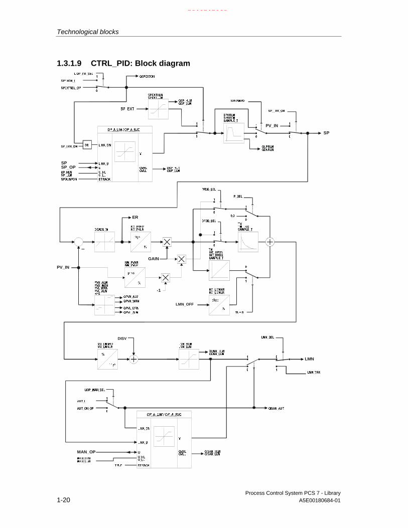
1.3.1.9 CTRL_PID: Block diagram
LMN_OFF
GAIN
SP_OP
MAN_OP
SP
PV_IN
PV_IN
LMN
ER
DISV
-1
SP
21.02.2003

Technological blocks
Process Control System PCS 7 - LibraryA5E00180684-01 1-21
1.3.1.10 CTRL_PID: I/Os
I/O(parameter)
Meaning Datatype
Default Type Attrib. OCM Validvalues
AUT_L Interconnectable input forMAN/AUTO:0: Manual, 1: Auto
BOOL 0 I Q
AUT_ON_OP
Operator input:0: Manual, 1: Auto
BOOL 0 IO B +
AUTOP_EN 1: auto mode enabled BOOL 1 I Q
AUX_PRx Auxiliary process value x ANY 0 IO Q
BA_EN BATCH enabled BOOL 0 I Q +
BA_ID Current batch number DWORD 0 IO Q +
BA_NA BATCH name STRING[32]
'' I Q +
CSF Control system fault BOOL 0 I Q
DEADB_W Dead band width REAL 0 I + >=0
DFDB_SEL Set D action in feedback (1 =enabled)
BOOL 0 I Q
DISV Disturbance value REAL 0 I Q
ER Error signal REAL 0 O +
ER_HYS Hysteresis for monitoring the errorsignal
REAL 0.1 I + >= 0
ERH_ALM Error signal:High limit alarm
REAL 100 I + >DEADBW
ERL_ALM Error signal:Low limit alarm
REAL -100 I + < -DEADBW
GAIN Proportional gain REAL 1 I +
HYS Hysteresis REAL 5 I + >=0
INT_HNEG 1 = freeze integral component(negative direction)
BOOL 0 I Q
INT_HPOS 1 = freeze integral component(positive direction)
BOOL 0 I Q
LIOP_INT_SEL
1: interconnection enabled0: operator control enabled
BOOL 0 I Q
LIOP_MAN_SEL
1: interconnection active0: operator input enabled
BOOL 0 I Q
LMN Manipulated variable output REAL 0 O
LMN_HLM High limit manipulated variable REAL 100 I Q + LMN_HLM> LMN_LLM
LMN_LLM Low limit manipulated variable REAL 0 I Q + LMN_LLM <LMN_HLM
LMN_OFF Operating point REAL 0 I Q +
LMN_SEL 1 = external manipulated variableenabled
BOOL 0 I Q
LMN_TRK External manipulated variable REAL 0 I Q
LMNOP_ON 1 = enable operation ofmanipulated variable LMN_OP
BOOL 1 I Q
LMNR_IN Position feedback for display onOS
REAL 0 I Q
21.02.2003

Technological blocks
Process Control System PCS 7 - Library1-22 A5E00180684-01
I/O(parameter)
Meaning Datatype
Default Type Attrib. OCM Validvalues
M_SUP_AH 1 = message suppressionHigh limit alarm, process variable
BOOL 0 I +
M_SUP_AL 1 = message suppressionLow limit alarm, process variable
BOOL 0 I +
M_SUP_ER Message suppression:error signal alarm
BOOL 1 I +
M_SUP_WH 1 = Message suppression:High warning, process variable
BOOL 0 I +
M_SUP_WL 1 = Message suppression:Low warning, process variable
BOOL 0 I +
MAN_HLM High limit for manual manipulatedvariable
REAL 100 I +
MAN_LLM Low limit for manual manipulatedvariable
REAL 0 I +
MAN_OP Operator input:Manipulated variable
REAL 0 IO B +
MANOP_EN 1 = enable manual mode BOOL 1 I Q
MO_PVHR High limit of display (measurementrange)
REAL 110 I +
MO_PVLR Low limit of display (measurementrange)
REAL -10 I +
MSG_ACK Acknowledge messages WORD 0 O
MSG_EVID Message number DWORD 0 I M
MSG_LOCK 1 = suppress message accordingto process status
BOOL 0 I Q +
MSG_STAT Error message status WORD 0 O
NM_LMNHR High limit:normalization of manipulatedvariable (measurement range)
REAL 100 I
NM_LMNLR Low limit:normalization of manipulatedvariable (measurement range)
REAL 0 I
NM_PVHR High limit:normalization of process variable(measurement range)
REAL 100 I
NM_PVLR Low limit normalization of processvariable (measurement range)
REAL 0 I
OCCUPIED Occupied by BATCH BOOL 0 I Q +
OOS Reserve BOOL 0 I +
OPTI_EN 1 = controller tuning ON, 0 = OFF BOOL 0 I +
P_SEL 1 = set P component BOOL 1 I Q
PFDB_SEL 1 = set P component in feedback BOOL 0 I Q
PV_IN Process value REAL 0 IO Q +
PVH_ALM Process value:High limit alarm
REAL 100 I + PVH_ALM> PVL_ALM
PVH_WRN Process value:High warning
REAL 95 I + PVH_WRN>PVL_WRN
21.02.2003

Technological blocks
Process Control System PCS 7 - LibraryA5E00180684-01 1-23
I/O(parameter)
Meaning Datatype
Default Type Attrib. OCM Validvalues
PVL_ALM Process value:Low limit alarm
REAL 0 I + PVL_ALM <PVH_ALM
PVL_WRN Process value:Low warning
REAL 5 I + PVL_WRN<PVH_WRN
Q_SP_OP 1 = enable operator input ofsetpoint
BOOL 0 O +
QC_LMN Quality Code for LMN BYTE 16#80 O
QC_LMN_I Quality Code for output LMN BYTE 16#80 I
QC_LMNR_IN Quality Code for LMNR_IN BYTE 16#80 I
QC_PV_IN Quality Code for PV_IN BYTE 16#80 I
QAUT_OP 1 = enable auto mode BOOL 0 O +
QCAS_CUT 1 = cascade is cut BOOL 1 O
QDNRLM 1 = negative setpoint ramp limited BOOL 0 O
QERH_ALM Error signal:1 = high limit alarm
BOOL 0 O +
QERL_ALM Error signal1 = low limit alarm
BOOL 0 O +
QERR 1 = error output (inverted ENO) BOOL 1 O +
QLMN_HLM 1 = limit high range of manipulatedvariable output
BOOL 0 O
QLMN_LLM 1 = limit low range of manipulatedvariable output
BOOL 0 O
QLMNOP 1 = enable operator input ofmanipulated variable
BOOL 0 O +
QMAN_AUT 0 = Manual1 = Auto
BOOL 0 O +
QMANOP 1 = enable manual mode BOOL 0 O +
QMSG_ERR 1 = message error BOOL 0 O
QMSG_SUP 1 = message suppression BOOL 0 O +
QOP_ERR 1 = group error message BOOL 0 O
QPVH_ALM 1 = high limit alarm BOOL 0 O
QPVH_WRN 1 = high warning BOOL 0 O
QPVL_ALM 1 = low limit alarm BOOL 0 O
QPVL_WRN 1 = low warning BOOL 0 O
QSP_HLM 1 = set high limit of setpoint output BOOL 0 O
QSP_LLM 1 = set low limit of setpoint output BOOL 0 O
QSPEXTEN 1 = enable external setpoint BOOL 0 O +
QSPEXTON 0 = Internal1 = External
BOOL 0 O +
QSPINTEN 1 = set internal setpoint BOOL 0 O +
QUPRLM 1 = set positive setpoint ramp limit BOOL 0 O
RUNUPCYC Number of run-up cycles INT 3 I
SAMPLE_T Sampling time in [s] REAL 1 I >=0.001
SP Active setpoint REAL 0 O +
SP_EXT External setpoint REAL 0 I Q
21.02.2003

Technological blocks
Process Control System PCS 7 - Library1-24 A5E00180684-01
I/O(parameter)
Meaning Datatype
Default Type Attrib. OCM Validvalues
SP_HLM Setpoint high limit REAL 100 I + SP_HLM >SP_LLM
SP_LLM Setpoint low limit REAL 0 I + SP_LLM <SP_HLM
SP_OP Operator input for setpoint REAL 0 IO B +
SP_OP_ON Enable operator input of SP_OP BOOL 1 I Q
SP_TRK_ON 1 = track setpoint SP_OP BOOL 0 I +
SPBUMPON 1 = bumpless setpoint BOOL 1 I +
SPDRLM max. negative setpoint ramp [1/s] REAL 100 I +
SPEXON_L Interconnectable inputinternal/external(0 = internal/1 = external)
BOOL 0 I Q
SPEXT_EN 1 = enable external setpoint BOOL 1 I Q
SPEXTHLM High limit of external setpoint REAL 100 I Q SPEXTHLM>SPEXTLLM
SPEXTLLM Low limit of external setpoint REAL 0 I Q SPEXTLLM<SPEXTHLM
SPEXTSEL_OP
Mode:0 = internal1 = external
BOOL 0 IO B +
SPINT_EN 1 = enable internal operation BOOL 1 I Q
SPRAMPOF 1 = setpoint ramp limiting OFF BOOL 1 I +
SPURLM max. positive setpoint of ramp rate[1/s]
REAL 100 I +
STEP_NO BATCH step number DWORD 0 IO Q +
TM_LAG Time lag of D action in [s] REAL 1 I + ≥±SAMPLE_T/2
TN Tracking time in [s] REAL 10 I + TN=0,
≥±SAMPLE_T/2
TV Derivative time in [s] REAL 0 I + TV=0,
≥±SAMPLE_T
USTATUS Status word in VSTATUS, can beset user-specific
WORD 0 I
VSTATUS Extended status display in blockicons
DWORD 0 O
For information on abbreviations used refer to: General information on the blockdescription
21.02.2003

Technological blocks
Process Control System PCS 7 - LibraryA5E00180684-01 1-25
1.3.1.11 CTRL_PID: Operator control and monitoring
The tables show the assignment of the parameters of the AS block to the I/O fieldsof the faceplate.
Display I/O field Operatorauthorization
Parameters of theAS block
Operator textin the log
Default Setpoint value (as a bar) SP
(in the corresponding input dialogbox:HL=SetpointLL=)
5 SP_HLMSP_OPSP_LLM
Setpoint
(upper value) MO_PVHR(lower value) MO_PVLRProcess variable (as a bar) PV_IN(bar at extreme right)(red= upper alarm value) PVH_ALM(red= lower alarm value) PVL_ALM(yellow= upper warning value) PVH_WRN(yellow= lower warning value) PVL_WRNMode(selection list: Manual/Automatic) 5
QMAN_AUTAUT_ON_OP =0/1
Mode=Manual/Auto
Setpoint(in the corresponding input dialogbox:HL=SetpointLL=)
5
SP
SP_HLMSP_OPSP_LLM Setpoint
Process variable PV_IN(unit setpoint/process variable) (S7_unit of PV_IN)Manual
(in the corresponding input dialogbox:HL=ManualLL=)
5
MAN_OP
MAN_HLMMAN_OPMAN_LLM
Manual
Manipulated variable LMNR_IN(unit manual/manipulatedvariable)
(S7_shortcut ofMAN_OP)
Tracking LMN_SEL =1(symbol bell)(symbol bell disabled)
QMSG_SUPMSG_LOCK
(symbol batch) OCCUPIEDManual (as pointer)Manipulated variable (as ahorizontal bar)
21.02.2003

Technological blocks
Process Control System PCS 7 - Library1-26 A5E00180684-01
Display I/O field Operatorauthorization
Parameters ofthe AS block
Operator text inthe log
Setpoint
(selection list:internal/external) 6
QSPEXTON
SPEXTSEL_OP =0/1 Internal/ExternalSetpoint processing
Bump ext->in 6 SPBUMPON =0/1 Bump SP off/onTracked manipulatedvariable=Process variable
6 SP_TRK_ON =0/1 Track off/on
Without ramp 6 SPRAMPOF =0/1 Ascent limit on/offError signal monitoringSuppress message 6 M_SUP_ER =0/1 Suppress ER =
No/YesUpper limit 6 ERH_ALM ER:HH alarmLower limit 6 ERL_ALM ER:LL alarmHysteresis 6 ER_HYS ER_HysteresisUpper limit exceeded QERH_ALMLower limit exceeded QERL_ALM
Maintenance
Error signal EXT
Display I/O field Operatorauthorization
Parameters of theAS block
Operator textin the log
Control parametersKP 6 GAIN GainTN s (=in sec) 6 TN TNTV s 6 TV TV
ParameterDead band 6 DEADB_W Dead bandHysteresis(in the corresponding inputdialog box:
HL=HysLL=) 6
HYS
(no check)
HYS
0,0
Hysteresis
(unit deadband/hysteresis)
(S7_unit of PV_IN)
Lag time s 6 TM_LAG Lag timeSetpoint ramp
Rise s (=per sec) 6 SPURLM Pos. ramp rateDrop /s 6 SPDRLM Neg. ramp rate(unit rise/drop) (S7_shortcut of
PV_IN)Setpoint/Process variable bar
Parameter
HL(in the corresponding inputdialog box:
HL=bar HLLL=)
6
MO_PVHR
(no check)
MO_PVHR
MO_PVLR
21.02.2003

Technological blocks
Process Control System PCS 7 - LibraryA5E00180684-01 1-27
Display I/O field Operatorauthorization
Parameters of theAS block
Operator textin the log
LL(in the corresponding inputdialog box:
HL=bar LLLL=)
6
MO_PVLR
MO_PVHR
MO_PVLR
(no check)
(unit HL/LL) (S7_unit of PV_IN)
Display I/O field Operatorauthoriza-tion
Parameters of theAS block
Operator textin the log
(blue= Display of the setpoint limit)
(upper value) SP_HLM
(lower value) SP_LLM
(yellow bars = warning)
(upper value) PVH_WRN
(lower value) PVL_WRN
(red bars = alarm)
(upper value) PVH_ALM
(lower value) PVL_ALM
Alarm
AOact (=active)
6
6
PVH_ALM
M_SUP_AH =0/1
PV:HH alarm
Suppress HH=No/Yes
WHact
6
6
PVH_WRN
M_SUP_WH =0/1
PV:H alarm
Suppress H=No/Yes
WLact
6
6
PVL_WRN
M_SUP_AL =0/1
PV:L alarm
Suppress LL=No/Yes
ALact
6
6
PVL_ALM
M_SUP_WL =0/1
PV:LL alarm
Suppress L=No/Yes
Setpoint
Limits
HL(in the corresponding inputdialog box:
HL=Setpoint HLLL=)
6
6
6
SP_HLM
(no check)
SP_HLM
SP_LLM
SP high limit
SP high limit
SP low limit
21.02.2003

Technological blocks
Process Control System PCS 7 - Library1-28 A5E00180684-01
Display I/O field Operatorauthoriza-tion
Parameters of theAS block
Operator textin the log
LL(in the corresponding inputdialog box:
HL=Setpoint LLLL=)
6
6
6
SP_LLM
SP_HLM
SP_LLM
(no check)
SP low limit
SP high limit
SP low limit
(unit HL/LL) (S7_unit of PV_IN)Manual Value
HL(in the corresponding inputdialog box:
HL=Manual HLLL=)
6
6
6
MAN_HLM
(no check)
MAN_HLM
MAN_LLM
Man. high limit
Man. high limit
Man. low limitLL(in the corresponding inputdialog box:
HL=Manual LLLL=)
6
6
6
MAN_LLM
MAN-HLM
MAN-LLM
(no check)
Man. low limit
Man. high limit
Man. low limit
(unit HL/LL) (S7_unit of PV_IN)
Display I/O field Operatorauthoriza-tion
Parameters of theAS block
Operator textin the log
Batch control
Enable BA_ENOccupied OCCUPIED
Batch
Name BA_NA
Batch
Step STEP_NO
21.02.2003

Technological blocks
Process Control System PCS 7 - LibraryA5E00180684-01 1-29
1.3.2 CTRL_S: PID step controller block
1.3.2.1 CTRL_S: Description
Object name (type + number)
FB 76
FunctionThe CTRL_S controller block is a step controller for process control systems inwhich integral-action actuating elements (for example, motor-driven valves) areused. The valves are controlled by means of two binary control signals.
The operating principle of the step controller is based on a combination of the PIDalgorithm of a sampling controller and a downstream position controller. In theprocess, the continuous control signal is converted into a sequence of controlpulses.
The parameter configuration can be used to activate or de-activate partial functionsof the PID algorithm and thus adapt these to the process:
• Modes: Manual mode, automatic or tracking
• Monitoring limits of the process variable and error signal as well as messagegeneration via the ALARM8_P block.
• Disturbance variable
• Setpoint tracking (SP=PV_IN)
• Value range setting for setpoint values and process variables (physicalnormalization)
• Proportional, integral and derivative action, which can be enabled and disabledindividually
• A proportional and derivative action can be set in the feedback path (P actiononly in step controllers with position feedback).
• Operating point setting for P or PD controller mode
• The downstream positioning controller takes the following applications intoaccount:
• Controlling with position feedback signal:
• Controlling without position feedback signal:
• Direct signal adjustment by means of manual operation or interconnectedsignals
• Suppression of the control signals based on corresponding status signals fromthe motor (motor protection) or valve (end stop signals).
• Reduction of the number of control pulses by means of adaptive responsethreshold
21.02.2003

Technological blocks
Process Control System PCS 7 - Library1-30 A5E00180684-01
Operating principle
PI step controllers are commonly used applications. In this mode, the stepresponse of the controller is as follows:
t
Event
ER
t0
Motor positionMTR_TM
100 %
2*GAIN*ER
GAIN*ER
te TNt
PP
titpte
P
Positioningpulses
1P0
t
Designations:
P0 Starting pulseP Sequential pulset0 Starting instantte Duration of the starting pulseti Pulse width (= PULSE_TM)tp Pause width
(depending on the parameter assignment, does therefore not correspond toBREAK_TM)
21.02.2003

Technological blocks
Process Control System PCS 7 - LibraryA5E00180684-01 1-31
Note
The faceplate (loop display) is displayed as the effective manipulated variable ofinput parameter LMNR_IN. The position feedback is interconnected to thisparameter.
Control input LMNR_ON can be used to set this variable in the control algorithm. IfLMNR_ON=0, the controller operates without position feedback.
If oscillation develops at the control valve action due to a lag in position feedback,use a step controller without position feedback and switch the feedback to inputPV_IN. You can compensate the dead time response of the control valve at the PIparameters GAIN and TN. Use CTRL_PID as master controller (cf. cascadecontrols) for controlling the actual process.
Calling OBs
The watchdog interrupt OB in which you install the block (for example OB32). It isalso installed in OB100 (see startup characteristics).
21.02.2003
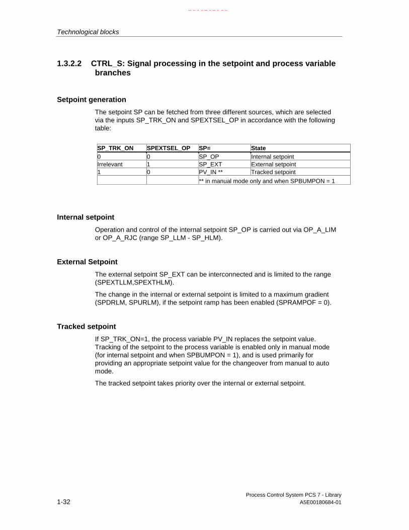
Technological blocks
Process Control System PCS 7 - Library1-32 A5E00180684-01
1.3.2.2 CTRL_S: Signal processing in the setpoint and process variablebranches
Setpoint generation
The setpoint SP can be fetched from three different sources, which are selectedvia the inputs SP_TRK_ON and SPEXTSEL_OP in accordance with the followingtable:
SP_TRK_ON SPEXTSEL_OP SP= State0 0 SP_OP Internal setpointIrrelevant 1 SP_EXT External setpoint1 0 PV_IN ** Tracked setpoint
** in manual mode only and when SPBUMPON = 1
Internal setpoint
Operation and control of the internal setpoint SP_OP is carried out via OP_A_LIMor OP_A_RJC (range SP_LLM - SP_HLM).
External Setpoint
The external setpoint SP_EXT can be interconnected and is limited to the range(SPEXTLLM,SPEXTHLM).
The change in the internal or external setpoint is limited to a maximum gradient(SPDRLM, SPURLM), if the setpoint ramp has been enabled (SPRAMPOF = 0).
Tracked setpoint
If SP_TRK_ON=1, the process variable PV_IN replaces the setpoint value.Tracking of the setpoint to the process variable is enabled only in manual mode(for internal setpoint and when SPBUMPON = 1), and is used primarily forproviding an appropriate setpoint value for the changeover from manual to automode.
The tracked setpoint takes priority over the internal or external setpoint.
21.02.2003

Technological blocks
Process Control System PCS 7 - LibraryA5E00180684-01 1-33
Error signal
It is generated based on the effective setpoint value SP and the process variablePV_IN and is available at the output ER after the dead band DEADB_W hasexpired.
Error signal alarm
The error signal ER is monitored to alarm limits (ERL_ALM, ERH_ALM) with acommon hysteresis (ER_HYS). The message is displayed at the correspondingoutputs (QERL_ALM, QERH_ALM).
Process variable alarm
The process variable PV_IN is monitored for warning and alarm limits (PVL_ALM,PVL_WRN, PVH_WRN, PVH_ALM) using a common hysteresis (HYS). The errormessage is displayed at the corresponding outputs (QPVL_ALM, QPVL_WRN,QPVH_WRN,QPVH_ALM).
Physical normalization
The error signal ER is normalized from the physical measuring range of theprocess variable (NM_PVHR, NM_PVLR) to a percentage.
100*__ PVLRNMPVHRNM
ERERnormiert −
=
Internal or external setpoints, process variables as well as the correspondingparameters are entered in the physical measuring range of the process variable.
The operating range of the valve is normalized to 0 to 100. Manual values, trackingvalues of the manipulated variable and disturbance variables are entered aspercentage.
The controller GAIN is specified in normalized (dimensionless) format.
21.02.2003

Technological blocks
Process Control System PCS 7 - Library1-34 A5E00180684-01
1.3.2.3 CTRL_S: Control signal generation
The control signals are generated based on various sources, which are selectedvia the control inputs in accordance with the following table:
No. Operatingmode
Internal/external
Positionfeedback
Source Remark
Effective
Generally:Depending on thesetting LMN_OFFand DISV can alsostill be effective inautomatic mode
Tracked
Generally:SP_OP is trackedif SPBUMPON=0
2 Startup /restart
- - Startup values Startup values
4 Manual /Tracking
- yes MAN_OP SP_OP=SP_EXT/PV_IN
Manipulated variableoperation
8 yes LMN_TRK SP_OP=SP_EXT/PV_INMAN_OP=LMNR_IN
Tracking toexternal manipulatedvariable
5 - LMNUP_OP/
LMNDN_OP
SP_OP=SP_EXT/PV_IN
MAN_OP=LMNR_IN
Manipulated variableoperation at the OS
6 - LMNUP/LMNDN SP_OP=SP_EXT/PV_IN
MAN_OP=LMNR_IN
Direct controlsignal adjustment
via interconnection
9 Automatic Internal - SP_OP,
manipulatedvariable from PIDalgorithm
MAN_OP=LMNR_IN
Setpoint from OS
12 SP_EXT,
control signal fromPID algorithm
SP_OP=SP_EXT
MAN_OP=LMNR_IN
Interconnectedsetpoint
21.02.2003
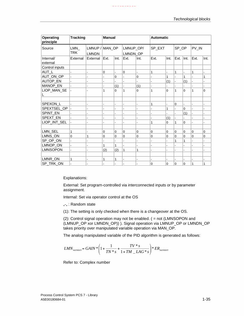
Technological blocks
Process Control System PCS 7 - LibraryA5E00180684-01 1-35
Operatingprinciple
Tracking Manual Automatic
Source LMN_TRK
LMNUP /
LMNDN
MAN_OP LMNUP_OP/
LMNDN_OP
SP_EXT SP_OP PV_IN
Internal/external
External External Ext. Int. Ext. Int. Ext. Int. Ext. Int. Ext. Int.
Control inputsAUT_L - - 0 - 0 - 1 - 1 - 1 -AUT_ON_OP - - - 0 - 0 - 1 - 1 - 1AUTOP_EN - - - - - - - (1) - (1) - -MANOP_EN - - - (1) - (1) - - - - - -LIOP_MAN_SEL
- - 1 0 1 0 1 0 1 0 1 0
SPEXON_L - - - - - - 1 - 0 - - -SPEXTSEL_OP - - - - - - - 1 - 0 - -SPINT_EN - - - - - - - - - (1) - -SPEXT_EN - - - - - - - (1) - - - -LIOP_INT_SEL - - - - - - 1 0 1 0 - -
LMN_SEL 1 - 0 0 0 0 0 0 0 0 0 0LMNS_ON 0 1 0 0 0 0 0 0 0 0 0 0SP_OP_ON - - - - - - - - 1 1 - -LMNOP_ON - - 1 1 - - - - - - - -LMNSOPON - - (2) (2) 1 1 - - - - - -
LMNR_ON 1 - 1 1 - - - - - - - -SP_TRK_ON - - - - - - 0 0 0 0 1 1
Explanations:
External: Set program-controlled via interconnected inputs or by parameterassignment.
Internal: Set via operator control at the OS
„-„ : Random state
(1): The setting is only checked when there is a changeover at the OS.
(2): Control signal operation may not be enabled. ( = not (LMNSOPON and(LMNUP_OP xor LMNDN_OP)) ). Signal operation via LMNUP_OP or LMNDN_OPtakes priority over manipulated variable operation via MAN_OP.
The analog manipulated variable of the PID algorithm is generated as follows:
normiertnormiert ERsLAGTM
sTV
sTNGAINLMN *
*_1
*
*
11*
+++=
Refer to: Complex number
21.02.2003

Technological blocks
Process Control System PCS 7 - Library1-36 A5E00180684-01
Superimposing the disturbance variable and its limitation
In automatic mode the disturbance variable DISV is added at the output of the PIDalgorithm. The result is limited to the range LMN_LLM to LMN_HLM.
The three-step element with threshold adaptation
The three-point element has an on and off threshold, which can be adapted by theblock to a value between.
Minimum response thresold
Maximum response threshold
adapted response threshold
Off threshold
Input value
Manipulated variable high
Manipulated variable high
1
1
Off threshold: 55.0 / MTR_TM * SAMPLE_T
Minimum response threshold: 100.0 / MTR_TM * Maximum(PULSE_TM,SAMPLE_T)
Maximum response threshold: 10.0
Adaptation of the response threshold can be switched off by setting THRADA_ON= FALSE. This sets the response threshold to the minimum value.
The currently effective response threshold can be viewed at output THRESON.
Note:
The response threshold is set to minimum in the following cases(also if THRADA = TRUE):
• Manual or tracking mode of step controllers without position feedback
• Controllers without integral component (TN = 0 s)
21.02.2003

Technological blocks
Process Control System PCS 7 - LibraryA5E00180684-01 1-37
1.3.2.4 CTRL_S: Manual, automatic and tracking mode
Manual mode
In manual mode offers you three options of operating control signals:
• Manipulated variable preset via MAN_OP
• Stepping mode of MAN_OP
• Direct operation of control signals via actuating commands
Operation of MAN_OP via manipulated variable preset or stepping mode is onlypossible in control systems with position feedback (LMNR_ON=1). Operation andlimiting is carried out by means of OP_A_LIM or OP_A_RJC (range MAN_HLM –MAN_LLM). The output values of QVHL and QVLL of OP_A_LIM or OP_A_RJCare transferred to the outputs QLMN_HLM and QLMN_LLM. The value ofMAN_OP is then passed to output LMN and the motor is traveled via the controlsignals until the value of the position feedback LMNR_IN reaches the value ofMAN_OP.
Direct operation of control signals via actuating commands is, however alsopossible in control systems operating with and without position feedback. Signaloperation is enabled via LMNSOPON and the control signals are set viaLMNUP_OP or LMNDN_OP. The valve is then traveled until the operation iscanceled or the limit is reached.
Control signal operation takes priority over manipulated variable operation. IfMAN_OP is not the effective input signal, the value is tracked to LMNR_IN.
Automatic mode
The PID algorithm calculates the manipulated variable LMN. The controlparameters GAIN, TN, TV and TM_LAG can not be interconnected by default.
If they must be interconnected for exceptional applications such as gainscheduling, the corresponding system attribute s7_link must be modified. Pleasenote that parameter changes in auto mode may lead to surges of the manipulatedvariable.
The controller direction of control action can be reversed (rising error signal causesa falling manipulated variable) by setting a negative proportional GAIN value. Theproportional action can be disabled by setting P_SEL = 0.
• The integral action can be disabled by setting TN=0. In the case of controlsystems with position feedback, the integral action can be locked for aparticular direction by interconnecting input INTH_POS or INTH_NEG.
• The integrator is stopped automatically when anti-wind-up measures takeeffect after the limit switch LMNR_HS or LMNR_LS has been triggered orwhen the position feedback LMNR_IN is effective and leaves the range ofLMN_HLM,LMN_LLM.
• Operating point (input LMN_OFF): In automatic mode, this value replaces theintegral action of the PID algorithm when the integral action is disabled. Theoperating point is entered in the measuring range of the manipulated variable.
21.02.2003

Technological blocks
Process Control System PCS 7 - Library1-38 A5E00180684-01
• The derivative action is a delaying component. It can be disabled by settingTV=0. You should set a meaningful ratio between the time lag constantTM_LAG and the derivative time. This ratio is also referred to as derivativegain (maximum of the unit response of the derivative component) and normallylies in the range 5 < TV/TM_LAG < 10.
• Setting a proportional action in the feedback branch of the controller. WhenPFDB_SEL = TRUE, the proportional action is set in the feedback of thecontroller. A control step thus does not affect the proportional action, andovershoot as a response to setpoint steps can be reduced or avoided withoutchanging the tracking characteristics. In auto mode, a changeover ofPFDB_SEL will cause an extremely high offset of manipulated variables, i.e.this action should be performed in manual mode.
• Setting a derivative action in the feedback branch of the controller. WhenDFDB_SEL = TRUE, the derivative action is set in the feedback of thecontroller. A control step thus does not affect the derivative action. Thechangeover of DFDB_SEL is not bumpless.
The calculated manipulated variable is then converted into a sequence of actuatingpulses: The algorithm for generating the actuating pulse is influenced by thefollowing parameters:
• MTR_TM: Motor actuating time = Time required to cover the maximum traveldistance of the valve.
• PULSE_TM: Minimum pulse width. The smallest step a valve travels. Amountsto 100%*PULSE_TM/MTR_TM.
• BREAK_TM: Minimum break time: After an actuating pulse has terminated, thisperiod must expire before a new pulse can be output.
• LMNR_HS,LMNR_LS: Limit switch. If one of the limit switches is set, thecorresponding output signal QLMNUP or QLMNDN is locked.
At the negative edge of the motor protection signal MSS, the motor protectionerror is held and passed to output QMSS_ST. The parameter MSS_SIG isused to specify whether only to display an error message (MSS_SIG=0), orwhether the motor is to be limited irrespective of all other inputs and systemstates (MSS_SIG = 1). The motor protection error (QMSS_ST = 1) is reportedto the OS. The operator can reset QMSS_ST via the ERROR input, or it isreset automatically by setting an interconnection with L_RESET=1.
• LMNR_ON: If LMNR_ON is used controlling is performed with positionfeedback. The control input may not be changed over while an operation isbusy.
• DEADB_W: The dead band in the error signal is necessary in order to reduceswitching frequency of the controller as a result of minor error signalfluctuations around zero. At the operating point of the loop, the error signalchanges around the value "(100% *PULSE_TM/MTR_TM) * Process gain" dueto a minimum pulse. Hence, the dead band should be greater than 50% of thisvalue. If DEADB_W is negative, the dead band is ignored.
21.02.2003

Technological blocks
Process Control System PCS 7 - LibraryA5E00180684-01 1-39
Tracking mode
There are two options of handling control signals in tracking mode:
Tracking via the external manipulated variable LMN_TRK
Direct control of the control signals via the interconnected inputs LMNS_ON,LMNUP and LMNDN
Tracking via an external manipulated variable LMN_TRK is only possible in controlsystems with position feedback. The setting LMN_SEL=1 is used the pass themanipulated variable from the interconnected tracked value LMN_TRK to outputLMN. The valve is traveled via the control signals until the value of the positionfeedback LMNR_IN has reached the value of LMN_TRK.
Tracking mode by means of LMN_ON and with direct operation of the controlsignals via interconnected inputs LMNUP and LMNDN has the highest priority of allmodes. When LMNS_ON is set, the control signals can be set only via inputLMNUP or LMNDN. As long as LMNS_ON is set, all other influences on controlsignals will be suppressed.
Switching the P and D component to the feedback
The P and D action can be set in the feedback to reduce or avoid overshoot of theprocess variable as a result of a setpoint step. In this operating mode, the setpointstep does not affect the P or D action, and the control value does not respond witha step. When PFDB_SEL=1 is set, the P component is set in the feedback.PFDB_SEL does not affect step controllers with feedback. In this operating mode,the P action cannot be set in the feedback. When DFDB_SEL=1 is set, thederivative component is set in the feedback.
Cascading PID controllers
The manipulated variable LMN of the master controller (note that the mastercontroller is only the slave controller, and not a step controller !) is connected toinput SP_EXT of the slave controller. Also make sure the master controller is set totracking mode when the cascade is cut. In such cases, the slave controllergenerates the signal QCAS_CUT, which is interconnected to the input LMN_SELof the master controller. The cause of this cut can be found manual or trackingmode, setpoint changes or manipulated variable tracking of the slave controller.
QCAS_CUT=LMNS_ON or LMN_SEL or (not QMAN_AUT) or (QMAN_AUT andSP_TRK_ON)
The tracking input LMN_TRK of the master controller is interconnected to outputSP of the slave controller in order to prevent a jump when the cascade is closedagain.
You should furthermore set a directional lock of the integrator at the mastercontroller, which takes effect when the slave controller reaches a manipulatedvariable limit, by interconnecting (with positive controller operating direction) theinput INT_HPOS or INT_HNEG of the master controller to output QLMN_HLM orQLMN_LLM of the slave controller.
21.02.2003

Technological blocks
Process Control System PCS 7 - Library1-40 A5E00180684-01
1.3.2.5 CTRL_S: Changing operating modes
Operating mode changeover
This can be triggered either by the operator or via interconnected inputs.
External/Internal setpoint
Depending on the setting of at the selection input LIOP_INT_SEL, the changeoveris carried out by setting the input SPEXTSEL_OP on the operator station, or bymeans of an interconnection of SPEXON_L. This changeover operation at the OSmust be enabled by setting the corresponding enable inputs SPINT_EN,SPEXT_EN.
If SPBUMPON = 1, the internal setpoint is replaced with the effective setpoint, inorder to allow a bumpless changeover from external or tracking mode to internalmode.
Enabling the changeover internal <-> external setpoint
QSPEXTEN = TRUE: SPEXTSEL_OP can be set from FALSE(internal setpoint) to TRUE (external setpoint).
QSPINTEN = TRUE: SPEXTSEL_OP can be reset from TRUE(external setpoint) to FALSE (internal setpoint).
SPEXTSEL_OP is tracked or reset as required.
Enabling setpoint control via the operator input
Q_SP_OP = TRUE: SP_OP operation is enabled.
SP_OP is tracked or reset as required.
Manual/Automatic
Depending on the setting of the selection input LIOP_MAN_SEL, the changeover isperformed at the OS by setting input AUT_ON_OP or by interconnection of AUT_L.The changeover must be enabled at the OS by setting the corresponding enableinputs MANOP_EN, AUTOP_EN.
21.02.2003

Technological blocks
Process Control System PCS 7 - LibraryA5E00180684-01 1-41
Enabling the changeover manual <-> automatic mode
QAUTOP = TRUE: AUT_ON_OP can be set from FALSE (manual mode)to TRUE (automatic mode).
QMANOP = TRUE: AUT_ON_OP can be reset from TRUE (automatic mode)to FALSE (manual mode).
AUT_ON_OP is tracked or reset as required.
Enabling manual mode
Manipulated variable operation is enabled at the faceplate via MAN_OP by settingQLMNVOP, the control signal is controlled via QLMNSOP instructions:
QLMNVOP QLMNSOPLMNOP_ON 1 -LMNSOPON - 1LMNR_ON 1 -LMNSOPON and (LMNUP_OP xor LMNDN_OP) 0 -LMN_SEL 0 0LMNS_ON 0 0QMAN_AUT 0 0
Special measures are applied for the modes listed below in order to ensure abumpless changeover:
• External setpoint / Setpoint tracking: When SPBUMPON = TRUE, the value ofthe internal setpoint SP_OP is set equal to the value of the effective (externalor tracked) setpoint.
• Auto mode: The manual value MAN_OP is tracked to the value of the effectivemanipulated variable LMNR_IN.
• Tracking mode: When LMN_SEL is set, the manually input value MAN_OP istracked to the value of LMN_TRK. You can thus see up to which value thevalve is traveled. When LMN_SEL is canceled, MAN_OP will be reset to thevalue of LMNR_IN, in order to ensure a bumpless changeover when MAN_OPis set.
• Manual mode: In control systems with position feedback the integrator istracked to allow a bumpless changeover to auto mode.Integrated component = manipulated variable ( in [%] ) minus the proportionalcomponent minus the disturbance variable ( in [%] )
21.02.2003

Technological blocks
Process Control System PCS 7 - Library1-42 A5E00180684-01
1.3.2.6 CTRL_S: Error handling
Error handling
The block algorithm handles the following events:
Operator control error
QOP_ERR = 1 will be set if at least one operator error occurs during the operationof one of the parameters SPEXTSEL_OP, AUT_ON_OP, SP_OP or MAN_OP.Otherwise, QOP_ERR = 0. Operator errors are held for the duration of one cycle.
Configuration error:NM_PVHR <= NM_PVLR: The error signal ER is set to zero. ENO=0 or QERR=1 isset.
Configuration error:SAMPLE_T<0.001: The sampling time SAMPLE_T is set to 0.001. ENO=0 orQERR=1 is set.
Configuration error:GAIN=0: The error signal ER is set to zero. ENO=0 or QERR=1 is set.
TN < SAMPLE_T/2:If TN > 0, TN = SAMPLE_T/2 is used for calculation. If TN= 0, the integrator isdisabled and the operating point LMN_OFF is active.
TV < SAMPLE_T:If TV > 0, TV = SAMPLE_T is used for calculation. If TV = 0, the differentiator isdisabled.
TM_LAG < SAMPLE_T/2:If TM_LAG < SAMPLE_T/2, TM_LAG < SAMPLE_T/2 is used for calculation. Inthese cases the differential component responds as an ideal differentiator.
The low limits of MTR_TM, PULSE_TM and BREAK_TM are set to the value ofSAMPLE_T.
If the enable inputs *_EN are reset during active operation, this is indicated via theoutputs QMAN_ERR or QAUT_ERR.
QMAN_ERR will also be set if the control input for the position feedbackLMNR_ON is canceled while the controller is being tracked to LMN_TRK. In thiscase the valve is stopped.
21.02.2003
Technological blocks
Process Control System PCS 7 - LibraryA5E00180684-01 1-43
1.3.2.7 CTRL_S: Operator control and monitoring
Operator control and monitoring
The faceplate can be used to display interrupts and, if necessary, trends.
The assignment of the parameters of the AS block to the I/O fields of the faceplatecorresponds in essence with CTRL_PID (see CTRL_PID: Operator control andmonitoring).
1.3.2.8 CTRL_S: Startup, time and message characteristics
Startup characteristics
During CPU startup, the internal setpoint of CTRL_S is set in manual mode. Theblock must be called in the startup OB accordingly. In CFC engineering, this ishandled by the CFC. You must enter the call manually in the startup OB, using thebasic STEP 7 tools.After startup, the messages will be suppressed for duration of the cycles set inRUNUPCYC.
MAN_OP and LMN with LMNR_IN are initialized during the startup. The integralaction is set to zero.
Time response
The block must be called via a watchdog interrupt OB. The sampling time of theblock is entered in the parameter SAMPLE_T.
Assignment of the 32-bit status word VSTATUS
see CTRL_S: VSTATUS
Message characteristics
The CTRL_S block uses the ALARM8_P block for generating messages.
Messages are triggered by
• The limit monitoring functions of the process variable and the system deviation,
• The CSF signal QMSS_ST, which is referenced as a control system error byinterconnection.
Messages triggered as a result of the violation of limits can be suppressedindividually by setting the corresponding M_SUP_xx inputs. Process messages(not the control system messages!) can be locked centrally by setting MSG_LOCK.
QMSG_SUP is set if the RUNUPCYC cycles have not expired yet since a restartand when MSG_LOCK = TRUE or MSG_STAT = 21.
The message texts of the CTRL_S block and their assignment to the blockparameters are listed in the table below.
21.02.2003

Technological blocks
Process Control System PCS 7 - Library1-44 A5E00180684-01
Assignment of message texts and message class to the block parameters
MessageNo.
Block parameter Default message text Messageclass
Can be suppressed by
1 QPVH_ALM(at PV_IN 1PVH_ALM)
PV:$$BlockComment$$too high
AH M_SUP_AH, MSG_LOCK
2 QPVH_WRN(at PV_IN 1PVH_WRN)
PV:$$BlockComment$$high
WH M_SUP_WH, MSG_LOCK
3 QPVL_WRN(at PV_IN 1PVL_WRN)
PV:$$BlockComment$$low
WL M_SUP_WL, MSG_LOCK
4 QPVL_ALM(at PV_IN 1PVL_ALM)
PV:$$BlockComment$$too low
AL M_SUP_AL, MSG_LOCK
5 CSF External error S -6 QERH_ALM
(at ER 1ERH_ALM)
ER:$$BlockComment$$too high
AH M_SUP_ER, MSG_LOCK
7 QERL_ALM(at ER 1 ERL_ALM)
ER:$$BlockComment$$too low
AL M_SUP_ER, MSG_LOCK
8 QMSS_ST Motor protection S -
The first three of the auxiliary process values of the message block are assignedSIMATIC BATCH data, the fourth is reserved for PV_IN and the remaining ones(AUX_PRx) can be assigned user-specific.
Assignment of auxiliary process value to the block parameters
Value Block parameter1 BA_NA2 STEP_NO3 BA_ID4 PV_IN5 AUX_PR056 AUX_PR067 AUX_PR078 AUX_PR089 AUX_PR0910 AUX_PR10
Monitoring of process variables
n.a.
21.02.2003

Technological blocks
Process Control System PCS 7 - LibraryA5E00180684-01 1-45
1.3.2.9 CTRL_S: VSTATUS
The 32-bit status word extends the status display in the block icons and faceplates.The 16 low bits (bits 0 - 15) are used by the block as follows:
Bit no.: 7 6 5 4 3 2 1 0
Parameter QLMNR_ON - QMSS_ST QSPEXTON QMAN_AUT MSG_LOCK BA_EN OCCUPIED
Bit no.: 15 14 13 12 11 10 9 8
Parameter OOS QMSG_SUP LMN_SEL - QLMNR_LS QLMNR_HS QLMNDN QLMNUP
The 16-bit input USTATUS (data type WORD) uses the high bits (bits 16 - 31).These bits can be used freely.
21.02.2003

Technological blocks
Process Control System PCS 7 - Library1-46 A5E00180684-01
1.3.2.10 CTRL_S: Block diagram
+
- 1
QSP_HLMQSP_LLM ER
%
phys
NM_PVHRNM_PVLR
1
0
SPRAMPOF
1
0
SPURLMSPDRLMSAMPLE_T
QUPRLMQDNRLM
DEADB_W > 0
0
1DEADB_W
QERH_ALMQERL_ALM
ERH_ALMERL_ALMER_HYS
SP
SP_TRK_ON
1
0
PV_IN
QMAN_AUT
LMN_SEL
LMNS_ON
SP_TRK_ON
QCAS_CUT
AND
OR
SPEXON_L
SPEXTSEL_OP
LIOP_INT_SEL
1
0
QSPEXTON
SPEXTHLMSPEXTLLM
QSP_HLMQSP_LLM
SP_EXT
SPBUMPON
ORSP_TRK_ON
LINK_U
V
U
U_HLU_LL
QVHLQVLL
LINK_ON
BTRACK
OP_A_LIM / OP_A_RJC
SP_HLMSP_LLM
SP
SP_OP
OP_ENSP_OP_ON
PV_IN
0
GAIN
- 1DFDB_SEL
TV > 0
+
PFDB_SEL
TN > 0
1
0
1
0
1
0
1
0
TVSAMPLE_
TNSAMPLE_TINT_HPOSINT_HNEG
DISV
LMN_OFF
P S
0
1
0
PV_IN
%phys
NM_PVHRNM_PVLR
PVH_ALM, PVH_WRN,PVL_WRN, PVL_ALM, HYS QPVH_ALM
QPVH_WRNQPVL_WRNQPVL ALM
MAN_OP
MAN_HLMMAN_LLM
1
LMNR_IN
LMNOP_ON
QLMN_HLMQLMN_LLM
LINK_U
V
U
U_HLU_LL
QVHLQVLL
LINK_ON
BTRACK
OP_A_LIM / OP_A_RJC
1
0
ANDLMN_SEL
LMNS_ON
LMNR_ON
LMN_TRK
OP_EN
QMAN_AUT
LMNSOPON AND(LMNUP_OP XORLMNDN_OP)
ORLMN_SEL
LMNS_ON
LMNR_ON
1
0
AUT_L
AUT_OP_ON
LIOP_MAN_SEL
1
0
LMNS_ON
LMNUPLMNDN
LMNR_IN
1
0
LMNS_ON
QMAN_AUT
LMN_SEL OR
LMN_HLMLMN LLM
LMN
+
QLMN_HLMQLMN_LLM
- 1LMNUP_OP
LMNDN_OP
1
0
LMNS_ON
QMAN_AUT
LMN_SEL
LMNSOPON
AND
THRADA_ONMTR_TMPULSE_TMSAMPLE T
CTRL_S with position feedback
QLMNDN
QLMNUP
PULSE_TMBREAK_TMSAMPLE_T
AND
LMNR_HS
LMNR_LS
AND
AND
AND
QMSS_ST
OR
MSS_SIG
MSSAND
ANDRESETOR
L_RESET
THRESON
21.02.2003

Technological blocks
Process Control System PCS 7 - LibraryA5E00180684-01 1-47
+
- 1
1
0
SPRAMPOF
1
0
SPURLMSPDRLMSAMPLE_T
QUPRLMQDNRLM
PVH_ALM, PVH_WRN,PVL_WRN, PVL_ALM, HYS QPVH_ALM
QPVH_WRNQPVL_WRNQPVL ALM
PV_IN
ER
%
phys
NM_PVHRNM_PVLR
DEADB_W > 0
0
1DEADB_W
QERH_ALMQERL_ALM
ERH_ALMERL_ALMER_HYS
SP
SP_TRK_ON
1
0
PV_IN
LMNR_SIM
SPEXON_L
SPEXTSEL_OP
LIOP_INT_SEL
1
0
QSPEXTON
QSP_HLMQSP_LLM
SPEXTHLMSPEXTLLM
QSP_HLMQSP_LLM
SP_EXT
SPBUMPON
ORSP_TRK_ON
LINK_U
V
U
U_HLU_LL
QVHLQVLL
LINK_ON
BTRACK
OP_A_LIM / OP_A_RJC
SP_HLMSP_LLM
SP
SP_OP
OP_ENSP_OP_ON
PV_IN
%phys
NM_PVHRNM_PVLR
QLMNDN
QLMNUP
PULSE_TMBREAK_TMSAMPLE_T
AND
LMNR_HS
LMNR_LS
AND
AND
AND1
0
LMNS_ON
LMNUPLMNDN
LMNUP_OPLMNDN_OP
1
0
LMNS_ON
LMN_SEL
LMNSOPON
AND
THRADA_ONMTR_TMPULSE_TMSAMPLE_T
CTRL_S without position feedback
1001
0
0
0
- 1001
0
+
0
OR
0
1
+
- 1
0
GAIN
- 1 DFDB_SEL TV > 0
+
PFDB_SEL
1
0
1
0
1
0
TVSAMPLE_
DISV
P S
0
1
0
SAMPLE_T / TN
+
SAMPLE_T/MTR_TM
0
1
LMNRSONLMN_HLM-LMN_HLM
0
QMAN_AUT
1
0
AUT_L
AUT_OP_ON
LIOP_MAN_SEL
LMN_SEL
LMNS_ON
SP_TRK_ON
QCAS_CUT
AND
OR
QMSS_ST
OR
MSS_SIG
MSSAND
ANDRESETOR
L_RESET
THRESON
21.02.2003

Technological blocks
Process Control System PCS 7 - Library1-48 A5E00180684-01
1.3.2.11 CTRL_S: I/Os
I/O(parameter)
Meaning Datatype
Default Type Attr. OCM Valid values
AUT_L Interconnectable input forMANUAL/AUTO:0 = Manual1 = Auto
BOOL 0 I Q
AUT_ON_OP Operator input0 = Manual, 1 = Auto,
BOOL 0 IO B +
AUTOP_EN 1 = enable auto mode BOOL 1 I QAUX_PRx Auxiliary process value x ANY 0 IO QBA_EN BATCH enable BOOL 0 I Q +BA_ID Current BATCH number DWORD 0 IO Q +BA_NA BATCH name STRING
[16]'' I Q +
BREAK_TM Minimum break time [s] REAL 1 I +CSF Control system fault BOOL 0 I QDEADB_W Dead band width REAL 0 I + ≥ 0
DFDB_SEL Derivative action in feedbackpath(1 0 enabled)
BOOL 0 I Q
DISV Disturbance variable REAL 0 I QER_HYS Hysteresis for monitoring the
error signalREAL 0.1 I + ≥ 0
ERH_ALM Error signal:High limit alarm
REAL 100 I + > 0
ERL_ALM Error signal:Low limit alarm
REAL -100 I + < 0
GAIN Proportional gain REAL 1 I +HYS Hysteresis REAL 5 I + ≥0
INT_HNEG Lock negative integral action BOOL 0 IINT_HPOS Lock positive integral action BOOL 0 IL_RESET Interconnectable input RESET:
Motor protection error(QMSS_ST=0)
BOOL 0 I Q
LIOP_INT_SEL
1 = Interconnection active0 = operator input enabled
BOOL 0 I Q
LIOP_MAN_SEL
1 = Interconnection active0 = operation enabled
BOOL 0 I Q
LMN Manipulated value output REAL 0 OLMN_HLM High limit:
manipulated variableREAL 100 I Q + LMN_HLM >
LMN_LLMLMN_LLM Low limit:
manipulated variableREAL 0 I Q + LMN_LLM <
LMN_HLMLMN_OFF Linearization point REAL 0 I Q +LMN_SEL 1 = external control value
activeBOOL 0 I Q
LMN_TRK External manipulated variable REAL 0 I QLMNDN Control signal low BOOL 0 I
21.02.2003

Technological blocks
Process Control System PCS 7 - LibraryA5E00180684-01 1-49
I/O(parameter)
Meaning Datatype
Default Type Attr. OCM Valid values
LMNDN_OP Operator controlled controlsignal low
BOOL 0 I +
LMNOP_ON 1 = enable MAN_OP BOOL 1 I QLMNR_HS High limit signal of position
feedbackBOOL 0 I
LMNR_IN Position feedback for OSdisplay
REAL 0 I Q
LMNR_LS Low limit signal of positionfeedback
BOOL 0 I
LMNR_ON Control with position feedback BOOL 0 ILMNR_SIM Simulated position feedback REAL 0 O +LMNRSON Simulated position feedback =
ONBOOL 0 I +
LMNS_ON Enable external manipulatedvariable(LMNDN, LMNUP)
BOOL 0 I
LMNSOPON Enable control signal operation BOOL 1 ILMNUP Interconnected control signal
upBOOL 0 I
LMNUP_OP Operator input:Control signal up
BOOL 0 IO +
M_SUP_AH 1 = message suppression:high limit alarm processvariable
BOOL 0 I +
M_SUP_AL 1 = message suppression:low limit alarm process variable
BOOL 0 I +
M_SUP_ER Suppression of messages:Error signal
BOOL 1 I +
M_SUP_WH 1 = message suppression:high warning, process variable
BOOL 0 I +
M_SUP_WL 1 = message suppression:low warning, process variable
BOOL 0 I +
MAN_HLM High limit of manualmanipulated variable
REAL 100 I +
MAN_LLM Low limit of manualmanipulated variable
REAL 0 I +
MAN_OP Operator input:manipulated variable
REAL 0 IO B +
MANOP_EN 1 = manual mode enabled BOOL 1 I QMO_PVHR High limit of display (measuring
range)REAL 110 I +
MO_PVLR Low limit of display (measuringrange)
REAL -10 I +
MSG_ACK Acknowledge message WORD 0 OMSG_EVID Message number DWORD 0 I MMSG_LOCK 1 = Message suppressed
according to specific processstatus
BOOL 0 I Q +
MSG_STAT Error message status WORD 0 OMSS Motor protective circuit-
breaker:active low, i.e. 0 = error
BOOL 1 I
21.02.2003

Technological blocks
Process Control System PCS 7 - Library1-50 A5E00180684-01
I/O(parameter)
Meaning Datatype
Default Type Attr. OCM Valid values
MSS_SIG Reset control signals in case ofMSS fault
BOOL 0 I
MTR_TM Motor actuation time [s] REAL 60 I +NM_PVHR High limit:
normalized process variableREAL 100 I
NM_PVLR Low limit:normalized process variable
REAL 0 I
OCCUPIED Occupied by BATCH BOOL 0 I Q +OSS Reserve BOOL 0 I Q +OPTI_EN 1 = enable controller tuning BOOL 0 I +P_SEL 1 = set proportional action BOOL 1 I QPFDB_SEL 1 = set proportional action in
feedbackBOOL 0 I Q
PULSE_TM Minimum pulse width [s] REAL 1 I +PV_IN Process variable REAL 0 IO QE +PVH_ALM Process variable:
High limit alarmREAL 100 I + PVH_ALM 1
PVL_ALMPVH_WRN Process variable:
High warningREAL 95 I + PVH_WRN 1
PVL_WRNPVL_ALM Process variable:
Low limit alarmREAL 0 I + PVL_ALM 1
PVH_ALMPVL_WRN Process variable:
Low warningREAL 5 I + PVL_WRN1P
VH_WRNQ_SP_OP 1 = enable setpoint operation BOOL 0 O +QAUT_ERR Missing enable signals for auto
modeBOOL 0 O
QAUTOP 1 = set auto mode BOOL 0 O +
QC_LMN Quality Code for LMN BYTE 16#80 O
QC_LMN_I Quality Code for output LMN BYTE 16#80 I
QC_LMNR_IN Quality Code for LMNR_IN BYTE 16#80 I
QC_PV_IN Quality Code for PV_IN BYTE 16#80 IQCAS_CUT 1 = cascade is cut BOOL 1 O QQDNRLM 1 = set negative setpoint ramp
limitBOOL 0 O
QERH_ALM Error signal:1 = high limit alarm
BOOL 0 O +
QERL_ALM Error signal:1 = low limit alarm
BOOL 0 O +
QERR 1 = error output (inverted ENO) BOOL 1 O +QLMN_HLM 1 = set high limit of
manipulated valueBOOL 0 O
QLMN_LLM 1 = set low limit of manipulatedvalue
BOOL 0 O
QLMN_SEL 1 = tracking to LMN_TRKenabled
BOOL 0 O +
QLMNDN Control signal down BOOL 0 O +QLMNOP Manipulated variable:
1 = enable operator inputBOOL 0 O +
QLMNR_HS High limit signal of positionfeedback value set
BOOL 0 O +
QLMNR_LS Low limit signal of positionfeedback value set
BOOL 0 O +
21.02.2003

Technological blocks
Process Control System PCS 7 - LibraryA5E00180684-01 1-51
I/O(parameter)
Meaning Datatype
Default Type Attr. OCM Valid values
QLMNR_ON Position feedback is set BOOL 0 O +QLMNRSON Simulation of position feedback
is setBOOL 0 O +
QLMNS_ON 1: control signal adjustment =ON
BOOL 0 O +
QLMNSOP Operator control:Signal output enabled
BOOL 1 O +
QLMNUP Manipulated variable signal UP BOOL 0 O +QLMNVOP Output:
operation of manipulated valueenabled
BOOL 1 O +
QMAN_AUT 0 = MANUAL1 = AUTO
BOOL 0 O +
QMAN_ERR Missing enable signals formanualmode
BOOL 0 O
QMANOP 1 = enable manual mode BOOL 0 O +QMAN_ERR Error output of ALARM_8P BOOL 0 OQMSG_SUP 1 = message suppression
enabledBOOL 0 O +
QMSS_ST Motor protection triggered(0 = reset with RESET)
BOOL 0 O +
QOP_ERR 1 = group error message(operator error)
BOOL 0 O
QPVH_ALM 1 = high limit alarm BOOL 0 OQPVH_WRN 1 = High warning BOOL 0 OQPVL_ALM 1 = low limit alarm BOOL 0 OQPVL_WRN 1 = low warning BOOL 0 OQSP_HLM 1 = set high limit of setpoint
outputBOOL 0 O
QSP_LLM 1 = set low limit of setpointoutput
BOOL 0 O
QSPEXTEN 1 = enable external setpoint BOOL 0 O +QSPEXTON 0 = internal
1 = externalBOOL 0 O +
QSPINTEN 1 = enable internal setpoint BOOL 0 O +QUPRLM 1 = limit positive setpoint ramp BOOL 0 ORESET Operator input for reset of
motor protection errors(QMSS_ST=0)
BOOL 0 IO B +
RUNUPCYC Number of run-up cycles INT 3 ISAMPLE_T Sampling time [s] REAL 1 I 10.001SP Active setpoint REAL 0 O E +SP_EXT External setpoint REAL 0 I QSP_HLM Setpoint high limit REAL 100 I + SP_HLM >
SP_LLMSP_LLM Setpoint low limit REAL 0 I + SP_LLM <
SP_HLMSP_OP Operator input:
SetpointREAL 0 IO B +
SP_OP_ON 1 = enable setpoint operation BOOL 1 I QSP_TRK_ON 1 = track setpoint SP_OP BOOL 0 I +SPBUMPON 1 = bumpless setpoint ON BOOL 1 I +
21.02.2003
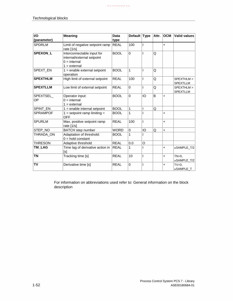
Technological blocks
Process Control System PCS 7 - Library1-52 A5E00180684-01
I/O(parameter)
Meaning Datatype
Default Type Attr. OCM Valid values
SPDRLM Limit of negative setpoint ramprate [1/s]
REAL 100 I +
SPEXON_L Interconnectable input forinternal/external setpoint0 = internal1 = external
BOOL 0 I Q
SPEXT_EN 1 = enable external setpointoperation
BOOL 1 I Q
SPEXTHLM High limit of external setpoint REAL 100 I Q SPEXTHLM >SPEXTLLM
SPEXTLLM Low limit of external setpoint REAL 0 I Q SPEXTHLM >SPEXTLLM
SPEXTSEL_OP
Operator input:0 = internal1 = external
BOOL 0 IO B +
SPINT_EN 1 = enable internal setpoint BOOL 1 I QSPRAMPOF 1 = setpoint ramp limiting =
OFFBOOL 1 I +
SPURLM Max. positive setpoint ramprate [1/s]
REAL 100 I +
STEP_NO BATCH step number WORD 0 IO Q +THRADA_ON Adaptation of threshold:
0 = hold constantBOOL 1 I
THRESON Adaptive threshold REAL 0.0 OTM_LAG Time lag of derivative action in
[s]REAL 1 I + ≥SAMPLE_T/2
TN Tracking time [s] REAL 10 I + TN=0,≥SAMPLE_T/2
TV Derivative time [s] REAL 0 I + TV=0,≥SAMPLE_T
For information on abbreviations used refer to: General information on the blockdescription
21.02.2003

Technological blocks
Process Control System PCS 7 - LibraryA5E00180684-01 1-53
1.3.3 DEADT_P: Dead time element
1.3.3.1 DEADT_P: Description
Object name (type + number)
FB 37
Function
An analog value of the input U is not passed to output V until a definable number ofcycles DEADT have expired. The following equation applies:
V(t) = U(t-Tdead), with Tdead = DEADT ∗ Tsampling
Refer to the startup characteristics for the time 0 < t < Tdead.
Operating principle
t
U(t)
V(t)
Ttot = DEAD x Tabtast
Ttot
Operating principle of the DEADT_P
• The block fetches the analog input value U during its current cycle, buffers itand outputs it to output V after the set number of DEADT cycles have expired.The maximum number of buffered values is limited to 16 (see also "Errorhandling").
• If the parameter DEADT is modified while the block is being executed, theblock responds in the same ways as it would during a CPU startup.
Error handling
If the parameter DEADT < 0 or DEADT > 16, the value DEADT=16 is usedinternally for calculation, ENO=0 or QERR=1 is displayed.
21.02.2003

Technological blocks
Process Control System PCS 7 - Library1-54 A5E00180684-01
Calling OBs
The watchdog interrupt OB in which you install the block (for example OB32). It isalso installed in OB100 (see startup characteristics).
Startup characteristics
During a CPU startup or when the dead time parameter DEADT is modified, theactive input value U is written to the internal dead time buffer.
Time response
The block is called in a watchdog interrupt OB in order to satisfy all block functions.The user can calculate the dead time Tdead on the basis of the following equation:
• Tdead = DEADT ∗ Tsampling
Tsample is equal to the sampling time of the block.
• When planning with CFC the higher-order runtime group of the block with itssampling parameter has to be taken into consideration.
1.3.3.2 DEADT_P: I/Os
I/O(parameter)
Meaning Data type Default Type Attrib. Validvalues
DEADT Dead time in cycles INT 0 I Q < 16QERR 1 = Error BOOL 1 OU Input REAL 0 I QV Output REAL 0 O
For information on abbreviations used refer to: General information on the blockdescription
21.02.2003

Technological blocks
Process Control System PCS 7 - LibraryA5E00180684-01 1-55
1.3.4 DIF_P: Differentiation
1.3.4.1 DIF_P: Description
Object name (type + number)
FB 38
Calling OBs
The watchdog interrupt OB in which you install the block (for example OB32). It isalso installed in OB100 (see startup characteristics).
Function
The block approximates a DT1 action and operates according to the trapezoid rule:
V = TD/(TM_LAG+SAMPLE_T/2) ∗ (U-U_LAST)U_LAST = U_LAST + SAMPLE_T/TD ∗ V
Operating principle
The algorithm operates according to the trapezoid rule. The following steps arecarried out in addition:
• The high limit of output V is set to V_HL, the low limit to V_LL. Internalcalculation is not affected by the limiting function.
• The assigned output Q_HL or Q_LL is set when limiting is active.
t
TD
TM_LAG + SAMPLE_T/2
V_HL
V_LL
V
U=1 wenn t >0U=0 wenn t< 0
Eingangsprung
TM_LAG
Jump response of the DIF_P
21.02.2003

Technological blocks
Process Control System PCS 7 - Library1-56 A5E00180684-01
Error handling
In case of an overflow/underflow, the REAL value of the high/low limit is set in theresult V and ENO is set high.
The following configuration errors will also lead to ENO=0 and V=0:
• V_LL > 0
• V_HL < 0
Startup characteristics
After a CPU startup, the internal flag for the old value of input U is tracked to thisinput. This ensures that the output value V is "0" during the first cyclic operation.
Time response
The block is called in a watchdog interrupt OB.
1.3.4.2 DIF_P: I/Os
I/O(parameter)
Meaning Datatype
Default Type Attrib. OCM Validvalues
QERR 1 = Error BOOL 1 OQVHL Initial value high limit BOOL 0 OQVLL Initial value low limit BOOL 0 OSAMPLE_T Sampling time [s] REAL 1 I > 0TD Differentiation time [s] REAL 1 I Q > 0TM_LAG Lag time [s] REAL 10 I Q > 0U Input REAL 0 I QV Output value REAL 0 OV_HL High limit value of V REAL 100 I Q V_HL > V_LLV_LL Low limit value of V REAL -100 I Q V_LL > V_HL
For information on abbreviations used refer to: General information on the blockdescription
21.02.2003

Technological blocks
Process Control System PCS 7 - LibraryA5E00180684-01 1-57
1.3.5 DIG_MON: Digital value monitoring
1.3.5.1 DIG_MON: Description
Object name (type + number)
FB 62
Function
The block is used to monitor a digital measuring point with chatter suppression.Both the signal status and the state of the control system (external control systemfaults, channel faults) belong to the measuring point. The parameter MSG_CLAScan be used to determine the message class of the measuring point.
Operating principle
The block monitors changes of the digital value at input Ix. The timer is retriggeredat each edge of the input signal. After the waiting time set in SUPPTIME hasexpired, the value of input Ix is passed to output Q.This ensures that only the signals held at least until the period set in SUPPTIMEhas expired will be passed to the output. Signals changing at a faster rate will notbe passed on.When SUPPTIME < SAMPLE_T, the input value Ix will be passed to output Q.
Calling OBs
The watchdog interrupt OB in which you install the block (for example OB32). It isalso installed in OB100 (see startup characteristics).
Error handling
QERR=1 if the configuration of the message class is invalid (see "Messagecharacteristics"). An error message is not output in this case.
Startup characteristics
During CPU startup the old initial value Q is retained. Monitoring of changes is re-enabled after the restart. The block must be called in the startup OB accordingly. InCFC engineering this is handled by the CFC. You must enter the call manually inthe startup OB, using the basic STEP 7 tools.Messages will be suppressed after startup until the cycles set in RUNUPCYC haveexpired.
21.02.2003

Technological blocks
Process Control System PCS 7 - Library1-58 A5E00180684-01
Assignment of the 32-bit status word VSTATUS
DIG_MON: VSTATUS
Time response
The block must be called in a watchdog interrupt OB. The sampling time of theblock is entered in the parameter SAMPLE_T.
Message characteristics
The DIG_MON block uses the ALARM8_P block (MSG_EVID) for generatingmessages (1 to 6 and 8). Message 7 does not require acknowledgement and isgenerated via NOTIFY (MSG_EVID1).
Messages are triggered by
• A change of the output signal Q
• The CSF signal received as a control system error via interconnection.
Process messages (not the control system messages!) can be locked by settingMSG_LOCK.
QMSG_SUP is set if the RUNUPCYC cycles have not expired since the restart andwhen MSG_LOCK = TRUE or MSG_STAT = 21.
Message classes
Change at output Q can be signaled with a selectable message class to the OS byconfiguring the input MSG_CLAS (refer to table). You can assign the followingmessage classes to a message:
21.02.2003

Technological blocks
Process Control System PCS 7 - LibraryA5E00180684-01 1-59
Assignment of message texts and classes to the block parameters
Message no. MSG_EVID
Block parameter Default message text Messageclass
Can besuppressed by
1 Q AND MSG_CLAS = 1 $$BlockComment$$alarm high
AH MSG_LOCK
2 Q AND MSG_CLAS = 2 $$BlockComment$$warning high
WH MSG_LOCK
3 Q AND MSG_CLAS = 3 $$BlockComment$$tolerance high
TH MSG_LOCK
4 Q AND MSG_CLAS = 4 $$BlockComment$$tolerance low
TL MSG_LOCK
5 Q AND MSG_CLAS = 5 $$BlockComment$$warning low
WL MSG_LOCK
6 Q AND MSG_CLAS = 6 $$BlockComment$$alarm low
AL MSG_LOCK
7 no message8 CSF external error S7 Q AND MSG_CLAS = 7 Operator request OR MSG_LOCK
The first three of the auxiliary process values of the message block are assignedSIMATIC BATCH data and the remaining ones (AUX_PRx) can be assigned user-specific.
Assignment of auxiliary process values to block parameters
Value Block parameter1 BA_NA2 STEP_NO3 BA_ID4 AUX_PR045 AUX_PR056 AUX_PR067 AUX_PR078 AUX_PR089 AUX_PR0910 AUX_PR10
Monitoring of process variables
n.a.
21.02.2003

Technological blocks
Process Control System PCS 7 - Library1-60 A5E00180684-01
1.3.5.2 DIG_MON: I/Os
I/O(parameter)
Meaning Data type Default Type Attr. OCM Validvalues
AUX_PRx Auxiliary value x block ANY 0 IO Q
BA_EN BATCH enable BOOL 0 I Q +
BA_ID Current batch number DWORD 0 I Q +
BA_NA Batch name STRING[32]
0 I Q +
CSF 1 = external error BOOL 0 I Q
I Error signal BOOL 0 I Q +
MSG_ACK Message acknowledged WORD 0 O
MSG_CLAS Message class of the signal INT 0 I 1 - 7
MSG_EVID Message number DWORD 0 I M
MSG_LOCK 1= message suppression accordingto the process-specific status
BOOL 0 I Q +
MSG_STAT Error message status WORD 0 O
OCCUPIED Occupied by batch BOOL 0 I Q +
OSS Reserve BOOL 0 I
Q Output signal BOOL 0 O +
QC_I QC_I for I BYTE 16#80 I
QERR 1 = error output (inverted ENO) BOOL 1 O +
QMSG_ERR 1 = message error BOOL 0 O +
QMSG_SUP 1 = message suppression BOOL 0 O +
RUNUPCYC Number of run up cycles INT 3 I
SAMPLE_T Sampling time [s] REAL 1.0 I >0
STEP_NO BATCH step number DWORD 0 IQ Q +
SUPPTIME Time in [s] to expire before an edgetransition at the input is passed to theoutput.
REAL 0 I +
USTATUS Status word in VSTATUS, can be setuser-specific
WORD 0 I
VSTATUS Extended status display in blockicons
DWORD 0 O
For information on abbreviations used refer to: General information on the blockdescription
21.02.2003

Technological blocks
Process Control System PCS 7 - LibraryA5E00180684-01 1-61
1.3.5.3 DIG_MON: Operator control and monitoring
The tables show the assignment of the parameters of the AS block to the I/O fieldsof the faceplate.
Display I/O field Operatorauthoriza-tion
Parameters ofthe AS block
Operator text inthe log
Input IOutput QTime lag s (=in sec)
(in the corresponding input dialog box:HL=DelayLL=) 6
SUPPTIME
(no check)
SUPPTIME
0,0
Suppress time
(symbol bell)
(symbol bell disabled)
QMSG_SUP
MSG_LOCK
Default
(symbol batch) OCCUPIED
Display I/O field Operatorauthoriza-tion
Parameters ofthe AS block
Operator text inthe log
Batch control
Enable BA_ENOccupied OCCUPIED
Batch
Name BA_NA
Batch
Step STEP_NO
1.3.5.4 DIG_MON: VSTATUS
The 32-bit status word extends the status display in the block icons and faceplates.The 16 low bits (bits 0 - 15) are used by the block as follows:
Bit no.: 7 6 5 4 3 2 1 0
Parameter I - - - - MSG_LOCK BA_EN OCCUPIED
Bit no.: 15 14 13 12 11 10 9 8
Parameter OOS QMSG_SUP - - - - - Q
The 16-bit input USTATUS (data type WORD) uses the high bits (bits 16 - 31).These bits can be used freely.
21.02.2003

Technological blocks
Process Control System PCS 7 - Library1-62 A5E00180684-01
1.3.6 FMCS_PID: Controller block
1.3.6.1 FMCS_PID: Description
Object name (type + number)
FB 114
Area of Application
The block "FMCS_PID" is used to interface the FM355 controller block.
It can be used for the C (continuous-action controllers) and S (step-action andpulse controllers) module types. It does not in itself contain any control algorithms,since the control functions are carried out exclusively on the module. It can beused to monitor all the relevant process variables and to change all the relevantcontroller parameters. Application examples of the FM355 and detaileddescriptions of the input and output parameters can be found in the manual of thecontroller module FM355.
Use of the controller module FM 355 as a continuous controller
The block provides the following display and setting options:
• Display of the result of the limit monitoring carried out on the module for twolimit pairs for the process variable PV or the error signal ER (QH_ALM,QH_WRN, QL_WRN, QL_ALM outputs). MONERSEL is used to specifywhether PV or ER is monitored.
• Disabling of the generation of individual messages when limits are exceeded
• Split-range function
• Dead band (DEADB_W, on threshold) in the error-signal branch
• Specification of the control algorithm: PID algorithm (QFUZZY = 0) or FUZZYalgorithm (QFUZZY = 1)
• Manipulated variable tracking
• Disabling of the integral action
• Setpoint tracking (SP = PV)
21.02.2003

Technological blocks
Process Control System PCS 7 - LibraryA5E00180684-01 1-63
Use of the controller module FM 355 as a pulse controller
Similar to continuous-action controllers, except that split-range control is notpossible.
You can use the pulse controller to generate pulse width modulated control signals.This variable is converted into a binary output signal, so that the ratio between thepulse width and configured period corresponds with the manipulated value LNM.
Use of the controller module FM 355 as a step-action controller
Similar to continuous-action controllers, with the following differences:
• Output QLMNR_ON indicates whether a feedback signal is available (1 =exists, 0 = does not exist).
• Split-range operation is not possible.
When used as a step-action controller without a position feedback (QLMNR_ON =0), manual adjustment of the manipulated variable is only possible at the finalpositions. In this case the safety position or the manual value is interpreted by thecontroller module as follows:
LMN_SAFE < 40 %: Close actuating element completely
LMN_SAFE < 60 %: Open actuating element completely
40 % ≤ LMN_SAFE ≤ 60 %:Hold current setting
Calling OBs
The block can be installed alternatively in the following OBs:
Cyclic task: OB1
Watchdog interrupt OB: for example OB32
• The block must be installed with the same instance in the startup block OB100
1.3.6.2 Addressing
The controller channel of an FM355 belonging to the instance is addressed via itslogical base address (set in HW Config) (LADDR input) and the controller channelnumber (CHANNEL input, valid values = 1 to 4). ACC_MODE must be set to TRUEafter a change is made to CHANNEL.
The FM355-2 module is monitored by the PCS7 blocks of the PCS 7 Library. InputMODE is interconnected with output OMODE of the MOD_D1 block. The blockcommunicates only via the FM355 control channel. Hence, the measurementrange coding in the low word of the output OMODE is irrelevant and assigned zero.
21.02.2003

Technological blocks
Process Control System PCS 7 - Library1-64 A5E00180684-01
1.3.6.3 Function
The "FMCS_PID" block forms the interface between the controller block (FM355)and the blocks of the SIMATIC PCS 7 libraries and can also be interconnected withother SIMATIC S7 blocks.
The block and the controller module operate asynchronously to each other.
All the relevant process and disturbance variables are provided by the module andcan only be read by the block. The block can furthermore transfer variousoperating modes and settings to the controller module.
As a rule, the FM355 obtains its parameters via the block. Whenever a parameterchanges at the block, the change is transferred to the module. If, however youwant to change a parameter directly at the FM355 via the operator panel (OP), youfirst have to enable this function at OP_SEL (OP_SEL = 1). OP_SEL must be resetif you want to restrict operator control and parameter configuration to the blockagain after the OP has been used.
When configuration via the OP is enabled, the controller module does not acceptany parameters from the block. However, the blocks continues to update theprocess variables SP_OP_ON, LMNOP_ON, SP_OP and LMN, thus allowing abumpless changeover to the mode in which configuration is carried out by theblock. The remaining parameters (for example, GAIN) are overwritten with the dataof the block instance when you set OP_SEL = 0. The entries made with the OP arelost, if you have not entered the data in the block instance before reversingOP_SEL.
A part of the parameters cannot only be specified by means of the configurationtool, but also via the function block. These two parameter records can deviate fromeach other. The input SDB_SEL at the function block is used in order to avoid thisconflict. SDB_SEL = 1 is used to specify that the module only reads theseparameters from the function block and not from the parameter configuration tool.SDB_SEL = 0 is used to specify that the module only reads these parameters fromthe function block and not from the parameter configuration tool. Note that theparameters are transferred from the parameter configuration tool to the module atevery STOP-RUN transition of the CPU. On the other hand, the parameters of theFB are transferred to the module at every change in the block input.
When configuration via the OP is permitted, the operator inputs are disabled withthe following exception: The operation OP_SEL=0 (re-activate P bus operation) ispossible.
21.02.2003

Technological blocks
Process Control System PCS 7 - LibraryA5E00180684-01 1-65
1.3.6.4 Setpoint, limit, error signal and manipulated variable generation
Setpoint generation with FMCS_PID
The setpoint SP can be fetched from four different sources:
• From one of the controller modules (you have configured it via OP, or themodule is in back-up mode). In this case setpoint operation is disabled and theapplied value is written to the operating input SP_OP of the block.
• The other three sources depend on the status of the inputs SP_TRK_ON,SPEXTSEL_OP and SP_OP_ON (see also: External/Internal setpoint in thesection Operating mode selection.
SP_TRK_ON SPEXTSEL_OP SP_OP_ON SP= State
Irrelevant 0 0 SP_INT Internal setpoint
0 0 1 SP_OP Internal (operator controlled) setpoint
Irrelevant 1 Irrelevant SP_EXT External setpoint
1 0 0 PV ** Tracked setpoint
** (for manual mode only and when SPBUMPON = 1)
The effective setpoint is limited to the range (SP_LLM, SP_HLM).
If SP_TRK_ON is set, in the manual mode (when SP_OP_ON=1,SPEXTSEL_OP=0 and SPBUMPON = 1) the setpoint SP_OP is tracked. Thisresults in a bumpless changeover from manual to automatic mode.
Bumpless changeover to manual operation is ensured by writing back the activesetpoint and manipulated variables.
Limit generation
Depending on the input MONERSEL, the controller module monitors either theprocess variable PV (MONERSEL = 0) or the error signal ER (MONERSEL = 1) forwarning and alarm limits (L_WRN, H_WRN, L_ALM, H_ALM). Monitoring is carriedout with the common hysteresis HYS.
The block makes the monitoring result available at the QL_WRN, QH_WRN,QL_ALM and QH_ALM outputs. While monitoring the process variable PV theblock signals any violation of the high and low limits, unless message suppressionhas been enabled.
Error signal
The error signal is generated by the controller module, based on the active setpointSP and the process variable PV and is made available at output ER of the block.
After the dead band DEADB_W has expired, the error signal is processed further inthe PID algorithm. A disturbance variable is not added.
21.02.2003

Technological blocks
Process Control System PCS 7 - Library1-66 A5E00180684-01
Manipulated variable generation by the FMCS_PID block
The manipulated value LMN is derived from various sources. The following priorityapplies if several control input are set TRUE concurrently:
Priority Control input LMN Status
1. SAFE_ON = 1 = LMN_SAFE Safety mode
2. Manual = LMN_OP Manual mode (QMAN_AUT=0)
3. LMNTRKON = 1 = analog input on BG or 0.0 Tracking mode
4. LMN_REON = 1 = LMN_RE External setpoint
5. Automatic = PID algorithm Auto mode (QMAN_AUT=1)
• The changeover between "Manual mode" and "Auto mode " is carried out onthe OS, via the parameter AUT_ON_OP, if LIOP_MAN_SEL=0.
• The changeover between "Manual mode" and "Auto mode " is carried out byinterconnection in the CFC via parameter AUT_L, if LIOP_MAN_SEL=1.
In step controllers the manipulated variable is converted into control pulses(QLMNUP; QLMNDN) under consideration of the motor-specific parameters "Motoractuating time" (MOTOR_TM), Minimum pulse duration (PULSE_TM), Minimumbreak duration (BREAK_TM).
1.3.6.5 Manual, automatic and tracking mode
Manual mode
The manipulated variable is determined by operator control at input LMN_OP(stepping mode is also possible here). When changing over to automatic mode, themodule takes over the manipulated variable set "manually“ as the operating point.
"Manual mode“ takes priority over "Tracking mode".
Manual mode for step controller:
Actuating commands can be used for direct control of the control signal for stepcontrollers. Signal operation is enabled with LMNSOPON and the control signalsare set with LMNUP_OP or LMNDN_OP. The valve is then driven until theoperation is disabled or the end position is acheived.
The control signal operation has priority over the manipulated value operation viaLMN_OP.
The LMN_OP input cannot be controlled when step controllers without positionfeedback are used.
21.02.2003

Technological blocks
Process Control System PCS 7 - LibraryA5E00180684-01 1-67
Automatic mode
The manipulated variable is calculated by the PID or fuzzy algorithm of the module.The control parameters GAIN, TI, TD and TM_LAG can be interconnected.
The controller's direction of control can be reversed (rising error signal causes afalling manipulated variable) by setting a negative proportional GAIN.
The integral action can be disabled by setting TI=0.
The operator-controllable manipulated-variable input LMN_OP is tracked to theLMN output so that bumpless changeover from automatic to manual mode isensured.
External manipulated variable (LMN_RE)
The block transfers the value LMN_RE to the FM355. The FM355 accepts theexternal manipulated variable LMN_RE manipulated variable as LMN, ifLNM_REON = 1.
"External manipulated variable“ mode takes priority over "Auto mode".
Tracking the manipulated variable
In manipulated variable tracking mode (LMNTRKON = 1), the manipulated variableis tracked to an analog input of the module or to the value 0.0.
"Tracking“ mode takes priority over the "External manipulated variable “ mode.
Safety mode (LMN_SAFE)
The block transfers the value LMN_SAFE to the FM355. The FM355 accepts thesafety manipulated variable LMN_SAFE as manipulated variable LMN, ifSAFE_ON = 1.
"Safety mode“ takes priority over all other operating modes.
21.02.2003

Technological blocks
Process Control System PCS 7 - Library1-68 A5E00180684-01
1.3.6.6 Operating mode selection
This can be triggered either by operator control or via interconnected inputs. Thechangeover is carried out by means of the operator control blocks assigned to themodes.
External/Internal setpoint
The changeover is carried out by OS operation of the input SPEXTSEL_OP or byinterconnection of SPEXON_L. These changeovers must be enabled by setting thecorresponding enable inputs SPINT_EN, SPEXT_EN or the selection inputLIOP_INT_SEL.
SP_OP_ON must be set TRUE to enable setpoint operation.
Enabling the changeover between internal and external setpoints
QSPEXTEN = TRUE: SPEXTSEL_OP can be set from FALSE(internal setpoint) to TRUE (external setpoint).
QSPINTEN = TRUE: SPEXTSEL_OP can be set from TRUE(external setpoint) to FALSE (internal setpoint).
SPEXTSEL_OP is either reset or tracked.
Manual/Automatic
The changeover is carried out by OS operation of the input AUT_ON_OP or byinterconnection of AUT_L. This changeover must be enabled by setting thecorresponding enable inputs MANOP_EN, AUTOP_EN or the selection inputLIOP_MAN_SEL.
LMNOP_ON must be set TRUE to enable manual control of the variable.
21.02.2003

Technological blocks
Process Control System PCS 7 - LibraryA5E00180684-01 1-69
Enabling the changeover between manual and auto mode
QAUTOP = TRUE: AUT_ON_OP can be set from FALSE (manual mode)to TRUE (auto mode).
QMANOP = TRUE: AUT_ON_OP an be set from TRUE (auto mode)to FALSE (manual mode).
AUT_ON_OP is tracked or reset as required.
Measures for bumpless changeover
• Setpoint external/ setpoint tracking: If SPBUMPON = TRUE, the internalsetpoint SP_OP is set to the effective (external or tracked) setpoint.
• Automatic mode , safety mode, tracking mode or external manipulated variableLMN_RE: The manipulated value LMN_OP is tracked to the effectivemanipulated variable.
• Manual mode, safety mode, tracking mode or external manipulated variableLMN_RE: The integrator is tracked so that a bumpless changeover to automode is possible**. Using the configuration tool, you can disable the defaultbumpless changeover function, in order to allow a faster correction of the errorsignal.
** not with stop controllers.
1.3.6.7 Safety operation
The interconnectable input SAFE_ON is used to set safety mode. This is executedby the controller module with highest priority. In safety mode, the value present atthe LMN_SAFE input of the block is output at the control output.
21.02.2003

Technological blocks
Process Control System PCS 7 - Library1-70 A5E00180684-01
1.3.6.8 Transferring parameters to the module
The channel-specific controller and operating parameters are transferred to thecontroller module whenever a corresponding block parameter changes. As long asoperator control via OP is disabled, the module rejects the parameters written bythe block.
The process of transferring the controller and operating parameters to thecontroller module can require several block calls.
1.3.6.9 Reading data from the module
The channel-specific process variables are read by the controller module whenevera block is called up. The reading process can require several block calls, inparticular in the case of decentralized operation.
If you have changed channel-specific controller and operating parameters on themodule by means of an operator control via OP, the block also reads the currentparameters from the controller modules. It then updates the SP_OP_ON (setpoint-value operation on), LMNOP_ON (manipulated-variable operation on), SP_OP(operating setpoint) and LMN_OP (operating manipulated variable) inputs.
1.3.6.10 Error handling
The block supplies the following error displays:
Error display MeaningQOP_ERR = 1 Operator control error: If there is no new operator control error, QOP_ERR is reset in
the next block cycle.QPARF_FM = 1 Error when assigning parameters directly to the controller module using the parameter
assignment tool, or an invalid control channel number (CHANNEL) was set at the block.QCH_F = 1 Channel error. Due to a hardware fault the controller channel belonging to the instance
cannot return valid results.QMODF = 1 Controller module has been removed or is faulty.QPERAF = 1 I/O access error. The block could not access the controller module.
21.02.2003

Technological blocks
Process Control System PCS 7 - LibraryA5E00180684-01 1-71
1.3.6.11 FMCS_PID: Startup, time and message characteristics
During CPU startup or restart of the block, the operating modes MANUAL andINTERNAL are set.
Startup Characteristics
At CPU startup or initial start of the block, the block determines if an FM355 typeactuator module is installed in the configured slot (specified by the inputsSUBN_ID, RACK_NO and SLOT_NO). If not, a QPARF = 1 error display is output(see Error handling). The operating modes MANUAL and INTERNAL are set.
Note
The configuration tool can be configured in HW Config with Save/Compile andDownload to the SDB (system data). These SDB parameters can deviate from theparameters of the FB's. When SDB_SEL = 0, the SDB parameters are sent to themodule at every STOP-RUN transition of the CPU. The FB parameters are writtento the module, however, a few cycles later. With SDB_SEL = 1, the module doesnot load the SDB parameters at a STOP-RUN transition of the CPU. This avoids ajump in the manipulated variable when the SDB parameters deviate from the FBparameters.
The following cases are differentiated:
• The FM335 had failed and it was not being operated via OP before its failure.The block transfers the current controller and operating parameters to theFM355.
• The FM335 had failed and it was being operated via OP before its failure.The block reads the current values from the FM355 and updates its outputsSP, LMN, Q_SP_OP and QLMNOP.
• The FM335 had not failed and it was being operated via OP.The block reads the current values from the FM355 and updates its outputsSP, LMN, Q_SP_OP and QLMNOP.
• The FM335 had not failed and was not being operated via OP.The controller and operating parameters of the FM and the block are identical.The block does nothing.
The block transfers the controller and operating parameters to the FM355 duringthe startup (however not during the initial run).
Time response
n.a.
Assignment of the 32-bit status word VSTATUS
FMCS_PID: VSTATUS
21.02.2003

Technological blocks
Process Control System PCS 7 - Library1-72 A5E00180684-01
Message characteristics
The FMCS_PID block uses the ALARM8_P block to generate messages.
Messages are triggered by:
• The limit monitoring functions of the process variable and the system deviation
• The hardware monitoring function of the module (executed primarily by theMOD_D1 block)
Messages regarding limit violation can be suppressed individually by setting thecorresponding M_SUP_xx inputs. Process messages (not the control systemmessages!) can be completely locked by setting MSG_LOCK.
QMSG_SUP is set if the RUNUPCYC cycles have not expired yet since a restart,MSG_LOCK = TRUE or MSG_STAT = 21.
Assignment of message texts and message classes to the block parameters
Message no. Block parameter Default message text Messageclass
Can besuppressed by
1 QPERAF/QMODF @6%d@/@7%d@/@8%d@Controller channel fault @5%d@
S
2 QPARF_FM @6%d@/@7%d@/@8%d@ channelconfiguration error @5%d@
messages -
3 No message -4 No message -5 QH_ALM $$BlockComment$$ too high AH M_SUP_AL,
MSG_LOCK6 QH_WRN $$BlockComment$$ high WH M_SUP_ER,
MSG_LOCK7 QL_WRN $$BlockComment$$ low WL M_SUP_ER,
MSG_LOCK8 QL_ALM $$BlockComment$$ too low AL M_SUP_AL,
MSG_LOCK
The first three of the auxiliary process values of the message block are assignedSIMATIC BATCH data, the next three contain information on the location of theblock and the seventh is reserved for the process variable.
21.02.2003

Technological blocks
Process Control System PCS 7 - LibraryA5E00180684-01 1-73
Assignment of auxiliary process values to the block parameters
Value Block parameter1 BA_NA2 STEP_NO3 BA_ID4 PV5 CHANNEL6 SUBNET_ID7 RACK_NO8 SLOT_NO9 AUX_PR0910 AUX_PR10
Important note:
The FM355 can be configured via HW Config by means of a configuration tool.Other than the standard counting method 0 to n in PCS7, this configuration toolcounts the control and signal channels of this modules from 1 to n. The displayedFM355 channel error number FM355 is therefore one count lower than the numberin the configuration tool in the case of hardware errors.
Example:
12.10.2002 10.20 Origin FM355 Wire break AE Channel 02 Incoming.
Monitoring of process variables
n.a.
21.02.2003

Technological blocks
Process Control System PCS 7 - Library1-74 A5E00180684-01
1.3.6.12 Backup mode of the FM355
If the CPU changes over to STOP or fails, the FM355 changes over to backupmode. In this case it automatically enables operator control via the OP (acts as ifOP_SEL=1).
1.3.6.13 FMCS_PID: I/Os
I/O(parameter)
Meaning Datatype
Default Type Attrib. OCM Valid values
ACC_MODE SUBN1_ID, SUBN2_ID,RACK_NO, SLOT_NO andCHANNEL included ininternal processing
BOOL 0 I/O
AUT_L Interconnectable input forMANUAL/AUTO:0 = MANUAL1 = AUTO
BOOL 0 I Q
AUT_ON_OP
Operator input:
0 = MANUAL1 = AUTO
BOOL 0 IO B +
AUTOP_EN 1 = enable auto mode BOOL 0 I QBA_EN Occupied by batch BOOL 0 I Q +BA_ID Current batch number DWORD 0 IO Q +BA_NA Batch name STRING
[16]0 I Q +
BREAK_TM Minimum break time (s) REAL 2 I QCHANNEL Controller channel number INT 1 ID_EL_SEL D action input of the
controllerINT 0 I Q
DEADB_W Dead band width REAL 0 I +DISV Disturbance variable REAL 0 OEXT Error signal REAL 0 OFUZID_ON Fuzzy identification on BOOL 0 I QGAIN Proportional gain REAL 1 I +H_ALM High limit alarm REAL 100 I + H_ALM > H_WRN
>L_WRN > L_ALM
H_WRN High warning REAL 90 I + H_ALM > H_WRN>L_WRN > L_ALM
HYS Hysteresis REAL 1 I + >= 0L_ALM Low limit alarm REAL 0 I + H_ALM > H_WRN
>L_WRN > L_ALM
21.02.2003

Technological blocks
Process Control System PCS 7 - LibraryA5E00180684-01 1-75
I/O(parameter)
Meaning Datatype
Default Type Attrib. OCM Valid values
L_WRN Low warning REAL 10 I + H_ALM > H_WRN>L_WRN > L_ALM
LADDR Logical address of FM355 INT 0 ILIOP_INT_SEL
1 = Interconnection active0 = operator control enabled
BOOL 0 I Q
LIOP_MAN_SEL
1 = Interconnection active0 = operation enabled
BOOL 0 I Q
LMN Manipulated variable REAL 0 O +LMN_A Manipulated value A of the
split-range function/positionfeedback
REAL 0 O
LMN_B Manipulated value B of thesplit-range function/positionfeedback
REAL 0 O
LMN_HLM Manipulated value high limit REAL 100 I +LMN_LLM Manipulated value low limit REAL 0 I +LMN_OP Operator input for
manipulated variablesREAL 0 IO B +
LMN_RE External manipulatedvalue
REAL 0 I Q
LMN_REON Set external manipulatedvalue
BOOL 0 I Q
LMN_SAFE Safety manipulated value REAL 0 I +LMNDN_OP Operator input:
Control signal downBOOL 0 IO Q
LMNOP_ON 1 = operator input ofLMN_OPenabled
BOOL 0 IO
LMNRHSRE High limit signal of positionfeedback
BOOL 0 I Q
LMNRLSRE Low limit signal of positionfeedback
BOOL 0 I Q
LMNRS_ON Simulation of positionfeedback ON
BOOL 0 I Q
LMNRSVAL Start value of simulatedposition feedback
REAL 0 I Q
LMNSOPON Operator input of controlsignal is On
BOOL 0 I Q
LMNTRKON Tracking (manipulated valuevia analog input)
BOOL 0 I Q
LMNUP_OP Operator input for controlsignal UP
BOOL 0 IO Q
M_SUP_AH 1 = suppress high limitalarm
BOOL 0 I Q +
M_SUP_AL 1 = suppress low limit alarm BOOL 0 I Q +M_SUP_WH 1 = suppress high warning BOOL 0 I Q +M_SUP_WL 1 = suppress low warning BOOL 0 I Q +MANOP_EN 1 = enable manual mode BOOL 0 I QMO_PVHR Monitored PV high limit
(measuring range)REAL 110 I +
21.02.2003

Technological blocks
Process Control System PCS 7 - Library1-76 A5E00180684-01
I/O(parameter)
Meaning Datatype
Default Type Attrib. OCM Valid values
MO_PVLR Monitored PV low limit(measuring range)
REAL -10 I +
MODE_CS Operating mode:0 = C-controller,1 = S-controller
BOOL 0 I QB +
MONERSEL Monitoring:0 = process variable1 = error signal
BOOL 0 I Q
MSG_ACK Acknowledge message WORD 0 OMSG_EVID Message event number DWORD 0 I MMSG_LOCK 1 = message suppression at
specific process stateBOOL 0 I Q +
MSG_STAT Error message status WORD 0 OMTR_TM Motor actuation time (s) REAL 60 I QOCCUPIED Batch occupied identifier BOOL 0 I Q +OP_SEL Mode selection switch
0 = P-bus 1 = C-busBOOL 0 I Q +
OPTI_EN 1 = controller tuning ON0 = OFF
BOOL 0 I +
OSS Reserve
P_SEL Enable P action BOOL 1 I QPFDB_SEL P action in feedback path BOOL 0 I QPULSE_TM Minimum pulse width (s) REAL 2 I QPV Process variable REAL 0 O E +Q_SP_OP 1 = operator input of
setpoint enabledBOOL 0 O +
QAUTOP 1 = AUTO mode enabled BOOL 0 O +QC_LMN Quality Code for LMN BYTE 16#80 OQC_PV Quality Code for PV BYTE 16#80 IQCH_F Channel error BOOL 0 OQDNRLM Limit of negative setpoint
ramp reachedBOOL 0 O
QERR Inverted value of ENO BOOL 1 OQFUZZY 0 = PID algorithm; 1 =
FuzzyBOOL 0 O
QH_ALM High limit alarm BOOL 0 OQH_WRN High warning BOOL 0 OQL_ALM Low limit alarm BOOL 0 OQL_WRN Low warning BOOL 0 OQLMN_HLM 1 = High limit of manipulated
value reachedBOOL 0 O
QLMN_LLM 1 = Low limit of manipulatedvalue reached
BOOL 0 O
QLMN_RE 0 = manual1 = auto
BOOL 0 O
QLMNDN Control signal down BOOL 0 OQLMNOP 1 = manipulated value
operation enabledBOOL 0 O +
21.02.2003

Technological blocks
Process Control System PCS 7 - LibraryA5E00180684-01 1-77
I/O(parameter)
Meaning Datatype
Default Type Attrib. OCM Valid values
QLMNOPON Manipulated value operationon
BOOL 0 O
QLMNR_HS High limit signal of positionfeedback
BOOL 0 O
QLMNR_LS Low limit signal of positionfeedback
BOOL 0 O
QLMNR_ON Position feedback ON BOOL 0 OQLMNSAFE Safety mode BOOL 0 OQLMNTRK Tracking mode BOOL 0 OQLMNUP Control signal up BOOL 0 OQMAN_AUT 0 = Manual
1 = AutoBOOL 0 O +
QMANOP 1 = manual mode enabled BOOL 0 O +QMODF 1 = module fault BOOL 0 OQMSG_ERR 1 = message error BOOL 0 O +QMSG_SUP 1 = set message
suppressionBOOL 0 O +
QOP_ERR 1 = Operator Error BOOL 0 OQOP_SEL Operation via P-Bus (0) or
C-Bus (1)BOOL 0 O
QPARF 1 = direct parameterassignment error
BOOL 0 O
QPARF_FM 1 = FM parameterassignment error orCHANNEL is false
BOOL 0 O
QPERAF 1 = I/O access error BOOL 0 OQSP_HLM 1 = setpoint high limit active BOOL 0 OQSP_LLM 1 = setpoint low limit active BOOL 0 OQSPEXTEN 1 = enable external setpoint BOOL 0 O +QSPINTEN 1 = enable internal setpoint BOOL 0 O +QSPINTON Internal setpoint ON BOOL 0 O +QSPLEPV Fuzzy controller display:
Setpoint < process variableBOOL 0 O
QSPOPON Setpoint operation on BOOL 0 OQSPR Split-range mode BOOL 0 OQUPRLM Limit of positive setpoint
rampBOOL 0 O
RACK_NO Rack number BYTE 255 IRUNUPCYC Number of run up cycles INT 3 ISAFE_ON Safety position ON BOOL 0 I QSDB_SEL 1 = The SDB parameters
are not taken over by themodule after a STOP toRUN transition of the CPU
BOOL 1 I Q +
SLOT_NO Slot number BYTE 255 ISP Setpoint REAL 0 O E +SP_EXT External setpoint REAL 0 I Q
21.02.2003

Technological blocks
Process Control System PCS 7 - Library1-78 A5E00180684-01
I/O(parameter)
Meaning Datatype
Default Type Attrib. OCM Valid values
SP_HLM Setpoint high limit REAL 100 I +SP_INT Internal setpoint REAL 0 I QSP_LLM Setpoint low limit REAL 0 I +SP_OP Operator input of setpoint REAL 0 IO B +SP_OP_ON Enable manual input of
setpointSP_ON
BOOL 1 IO Q
SP_TRK_ON 1 = SP_OP is tracked to PV BOOL 0 I +SPBUMPON 1 = bumpless setpoint BOOL 1 I +SPEXON_L Interconnectable input for
SP_EXT( 1 = SP_EXT is active)
BOOL 0 I Q
SPEXT_EN Enable external setpoint BOOL 0 I QSPEXTSEL_OP Operation input:
0: Internal setpoint1: External setpoint
BOOL 0 IO B +
SPINT_EN Enable internal setpoint BOOL 0 I QSTEP_NO BATCH step number WORD 0 IO Q +SUBN1_ID ID of the primary DP master
systemBYTE 255 I
SUBN2_ID ID of the redundant DPmaster system
BYTE 255 I
TD Derivative time (s) REAL 0 I + 0 or >= 1.0TI Reset time (s) REAL 3000 I + 0 or >= 0.5TM_LAG Time lag of the derivative
action (s)REAL 5 I + w0.5
For information on abbreviations used refer to: General information on the blockdescription
Parameters with the same name such as the FB "PID_CS also have the samemeaning (refer to the manuals Controller module FM355 Structuring andConfiguration)
21.02.2003

Technological blocks
Process Control System PCS 7 - LibraryA5E00180684-01 1-79
1.3.6.14 FMCS_PID: Operator control and monitoring
The tables show the assignment of the parameters of the AS block to the I/O fieldsof the faceplate.
Display I/O field Operatorauthoriza-tion
Parameters of the ASblock
Operator textin the log
Default Setpoint value (as bar graph) SP(high value) MO_PVHR
(low value) MO_PVLR
Process variable (as a bar) PV_IN
(bar at extreme right)
(red= high limit alarm)(red= low limit alarm)
PVH_ALM
PVL_ALM(yellow= high limit warning)(yellow= low limit warning)
PVH_WRN
PVL_WRNMode
(selection list:Manual/Automatic) 5
QMAN_AUT
AUT_ON_OP =0/1 Mode=Manual/Auto
Setpoint
(in the corresponding input dialogbox:
HL=SetpointLL=) 5
SP
SP_HLM
SP_OP
SP_LLM
Setpoint
Process variable PV
(unit setpoint/process variable) (S7_shortcut of PV)
Manual
(in the corresponding input dialogbox:
HL=ManualLL=)
6
6
LMN_OP
LMN_HLM
LMN_OP
LMN_LLM
LMN high limit
LMN low limitManipulated variable LMN
(unit manual/manipulated variable) (S7_shortcut of LMN)
(symbol bell)
(symbol bell disabled)
QMSG_SUP
MSG_LOCK(symbol batch) OCCUPIED
(symbol bell)
(symbol bell disabled)
QMSG_SUP
MSG_LOCKManual (as pointer)
Manipulated variable (as a horizontalbar graph)
21.02.2003

Technological blocks
Process Control System PCS 7 - Library1-80 A5E00180684-01
Display I/O field Operatorauthoriza-tion
Parameters of the ASblock
Operator textin the log
Maintenance Setpoint
(selection list:
internal/external)
QSPEXTON
SPEXTSEL_OP =0/1 SP =internal/external
Bump SPBUMPON =0/1 Bump SP off/on
Track SP_TRK_ON =0/1 SP track off/on
Operator OP OP_SEL=0/1 Switch to P-Bus/
Switch to C-Bus
SDB data SDB_SEL SDB parameter
=Yes/No
Error Signal Alarm
Alarm high QH_ALM
Alarm low QL_ALM
Warning high QH_WRN
Warning low QL_WRN
Error signal ER
Display I/O field Operatorauthoriza-tion
Parameters of the ASblock
Operator textin the log
Parameter Control parameters
KP 6 GAIN Gain
TI s (=in sec) 6 TI TI
TD s 6 TD TD
Parameter
Dead band DEADB_W Dead band
Hysteresis(in the corresponding inputdialog box:
HL=HysLL=)
6
6
HYS
(no check)
HYS
0.0
Hysteresis
Hysteresis
Time lag S TM_LAG Time lag
Manipulated variable
Safety 6 LMN_SAFE LMN safety
Bar
21.02.2003

Technological blocks
Process Control System PCS 7 - LibraryA5E00180684-01 1-81
Display I/O field Operatorauthoriza-tion
Parameters of the ASblock
Operator textin the log
High limit(in the corresponding inputdialog box:
HL=Bar HLLL=)
6
6
6
MO_PVHR
(no check)
MO_PVHR
MO_PVLRLow limit(in the corresponding inputdialog box:
HL=Bar LLLL=)
6
6
6
MO_PVLR
MO_PVHR
MO_PVLR
(no check)
Display I/O field Operatorauthoriza-tion
Parameters of the ASblock
Operator textin the log
Limits (blue = display setpoint limit)(high limit) SP_HLM
(low limit) SP_LLM
(red bar graph = Alarm)
(high value) PVH_WRN
(low value) PVL_WRN
(yellow bar graph = Warning)
(high limit) PVH_ALM
(low limit) PVL_ALM
Alarm
AOact (=active)
6
6
H_ALM
M_SUP_AH =0/1
HH alarm
SuppressHH=No/Yes
WOact
6
6
H_WRN
M_SUP_WH =0/1
H alarm
SuppressH=No/Yes
WUact
6
6
L_WRN
M_SUP_AL =0/1
LL alarm
SuppressLL=No/Yes
AUact
6
6
L_ALM
M_SUP_WL =0/1
LL alarm
SuppressLL=No/Yes
Setpoint
21.02.2003

Technological blocks
Process Control System PCS 7 - Library1-82 A5E00180684-01
Display I/O field Operatorauthoriza-tion
Parameters of the ASblock
Operator textin the log
HL(in the corresponding inputdialog:
HL=SPLL=)
6
6
6
SP_HLM
(no check)
SP_HLM
SP_LLM
SP high limit
SP high limit
SP low limitLL(in the corresponding inputdialog:
HL=SPLL=)
6
6
6
SP_LLM
SP_HLM
SP_LLM
(no check)
SP low limit
SP high limit
SP low limit
Manual value
HL(in the corresponding inputdialog:
HL=ManualLL=)
6
6
6
LMN_HLM
(no check)
LMN_HLM
LMN_LLM
LMN high limit
LMN high limit
LMN low limitLL(in the corresponding inputdialog:
HL=ManualLL=)
6
6
6
LMN_LLM
LMN_HLM
LMN_LLM
(no check)
LMN low limit
LMN high limit
LMN low limit
Display I/O field Operatorauthoriza-tion
Parameters of the ASblock
Operator textin the log
Batch controlEnable BA_ENOccupied OCCUPIED
ChargeName BA_NA
Batch
Step STEP_NO
21.02.2003

Technological blocks
Process Control System PCS 7 - LibraryA5E00180684-01 1-83
Display I/O field Operatorauthoriza-tion
Parameters of the ASblock
Operator textin the log
MotorMinimum pulse PULSE_TMMinimum pause BREAK_TMRuntime MTR_TMOpen limit reached QLMNR_HSClose limit reached QLMNR_LSControl signal up QLMNUP
Standard S
Control signal down QLMNDNWith feedback LMNR_ON
1.3.6.15 FMCS_PID: VSTATUS
The 32-bit status word extends the status display in the block icons and faceplates.The 16 low bits (bits 0 - 15) are used by the block as follows:
Bit no.: 7 6 5 4 3 2 1 0
Parameter - - - QSPINTON QMAN_AUT MSG_LOCK BA_EN OCCUPIED
Bit no.: 15 14 13 12 11 10 9 8
Parameter OOS QMSG_SUP - - - - - -
The 16-bit input USTATUS (data type WORD) uses the high bits (bits 16 - 31).These bits can be used freely.
21.02.2003

Technological blocks
Process Control System PCS 7 - Library1-84 A5E00180684-01
1.3.7 FMT_PID: Temperature controller block
1.3.7.1 FMT_PID: Description
Object name (type + number)
FB 77
Area of application
The "FMT_PID" interfaces the temperature controller module FM355-2.
It can be used for the module types FM 355-2 C (C controller) and FM 355-2 S (Sand P controller). It does not itself contain a control algorithm, since the PID controlfunction is performed only on the module. You can use it to monitor all relevantprocess variables and to change all relevant controller parameters. A sampleapplication of FM355-2 and a detailed description on I/O parameters is found in themanual of the temperature controller module FM355-2.
The controller parameters can be set via the "Auto-tuning" function on the module(TUN_ON = TRUE).
Use of the FM 355-2 C as continuous-action-controller (C controller)
The block provides the following displays and setting options:
• Display of the result of the limit monitoring carried out on the module for twolimit pairs for the process variable PV or the error signal ER (QH_ALM,QH_WRN, QL_WRN, QL_ALM outputs). MONERSEL is used to specifywhether PV or ER is monitored.
• Disabling of the generation of individual messages when limits are exceeded
• Split-range function
• Dead band (DEADB_W, on threshold) in the error-signal branch
• PID algorithm
• Attenuation of the P-action to setpoint changes via PFAC_SP < 1.0 (avoidsovershoot; optimized control and error response)
• Manipulated variable tracking
• Disabling of the integral action
• Setpoint tracking in manual mode (SP = PV)
21.02.2003

Technological blocks
Process Control System PCS 7 - LibraryA5E00180684-01 1-85
Use of the controller module FM 355-2-C as a pulse controller
Similar to continuous-action controllers, except that split-range control is notpossible.
You can use the pulse controller to generate pulse width modulated control signals.This variable is converted into a binary output signal, so that the ratio between thepulse width and configured period corresponds with the manipulated value LNM.
Use of the controller module FM 355-2-C as a step-action controller
Similar to continuous-action controllers, with the following differences:
• Output QLMNR_ON indicates whether a feedback signal is available (1 =exists, 0 = does not exist).
• Split-range operation is not possible.
When used as a step-action controller without a position feedback (QLMNR_ON =0), manual adjustment of the manipulated variable is only possible at the finalpositions. In this case the safety position or the manual value is interpreted by thecontroller module as follows:
LMN_SAFE < 40 %: Close actuating element completely
LMN_SAFE < 60 %: Open actuating element completely
40 % ≤ LMN_SAFE ≤ 60 %:Hold current setting
Calling OBs
Watchdog OB: e.g. OB32
For startup recognition the block must be installed with the same instance inOB100.
1.3.7.2 Addressing
The controller channel of an FM355-2 belonging to the instance is addressed viaits logical base address (set in HW Config) (LADDR input) and the controllerchannel number (CHANNEL input, valid values = 0 to 3). ACC_MODE must be setto TRUE after a change is made to CHANNEL.
• The FM355-2 module is monitored by the PCS7 blocks of the PCS 7 Library.Input MODE is interconnected with output OMODE of the MOD_D1 block. Theblock communicates only via the FM355-2 control channel. Hence, themeasurement range coding in the low word of the output OMODE is irrelevantand assigned zero.
21.02.2003

Technological blocks
Process Control System PCS 7 - Library1-86 A5E00180684-01
1.3.7.3 FMT_PID: Function
The "FMT_PID" block forms the interface between the temperature controllermodule (FM355-2) and the blocks of the SIMATIC PCS 7 libraries and can also beinterconnected with other SIMATIC S7 blocks.
The block and the FM355-2 operate asynchronously to each other.
All the relevant process and disturbance variables are provided by the module andcan only be read by the block. The block can furthermore transfer variousoperating modes and settings to the controller module.
As a rule, the FM355-2 obtains its parameters via the block. However, you can alsobypass the block (using the configuration tool, for example). The parameters of theFMT_PID are then updated automatically. This ensures that the parameters in theFM355-2 and in the block are always synchronized.
Some of the parameters can be specified by the function block in addition to theconfiguration tool. These two parameter sets may deviate. The SDB_SEL input atthe function block is available to avoid such a conflict. With SDB_SEL = 1 you canspecify that the module should only accept these parameters from the functionblock and not from the configuration tool. With SDB_SEL = 0 you can specify thatthe module should only accept these parameters from the configuration tool andnot from the function block. Note that the parameters from the configuration toolare sent to the module after every STOP-RUN transition of the CPU. Theparameters of the FB, on the other hand, are sent to the module each time there isa change at the block input.
21.02.2003

Technological blocks
Process Control System PCS 7 - LibraryA5E00180684-01 1-87
1.3.7.4 FMT_PID: Generation of setpoints, limits, error signals andmanipulated variables
Generation of setpoints with FMT_PID
The other three sources depend on the status of the inputs SP_TRK_ON,SPEXTSEL_OP and SP_OP_ON (see also: External/Internal setpoint in thesection "Safty mode".
SP_TRK_ON SPEXTSEL_OP SP= State
0 0 SP_OP Internal (operator controlled) setpointIrrelevant 1 SP_EXT External setpoint1 0 PV ** Tracked setpoint
** in manual mode only and when SPBUMPON = 1
The effective setpoint is limited to the range (SP_LLM, SP_HLM).
When SP_TRK_ON is set the SP_OP setpoint will be tracked (for internal setpointand when SPBUMPON = 1). This enables bumpless changeover from manual toauto mode.
Limit generation
Depending on the input MONERSEL, the controller module monitors either theprocess variable PV (MONERSEL = 0) or the error signal ER (MONERSEL = 1) forwarning and alarm limits (L_WRN, H_WRN, L_ALM, H_ALM). Monitoring is carriedout with the common hysteresis HYS.
The block makes the monitoring result available at the QL_WRN, QH_WRN,QL_ALM and QH_ALM outputs. While monitoring the process variable PV theblock signals any violation of the high and low limits, unless message suppressionhas been enabled.
Error signal
The error signal is generated by the controller module, based on the active setpointSP and the process variable PV and is made available at output ER of the block.
After the dead band DEADB_W has expired, the error signal is processed further inthe PID algorithm. A disturbance variable is not added.
21.02.2003

Technological blocks
Process Control System PCS 7 - Library1-88 A5E00180684-01
Manipulated variable generation by the FMT_PID block
The manipulated value LMN is derived from various sources. The following priorityapplies if several control input are set TRUE concurrently:
Priority Control input LMN Status
1. SAFE_ON = 1 = LMN_SAFE Safety mode
2. TUN_ON = 1 ** = LMNalt + TUN_DLMN Optimization mode(PHASE = 2)
3. LMNTRKON = 1 = analog input on BG or 0.0 Tracking mode
4. Manual = LMN_OP Manual mode (QMAN_AUT=0)
5. LMN_REON = 1 = LMN_RE External setpoint
6. Automatic = PID algorithm Auto mode (QMAN_AUT=1)
** The optimization also has to be set by a setpoint step or TUN_ST/TUN_CST =1 in Phase 2.
• The changeover between "Manual mode" and "Auto mode " is carried out onthe OS, via the parameter AUT_ON_OP, if LIOP_MAN_SEL=0.
• The changeover between "Manual mode" and "Auto mode " is carried out byinterconnection in the CFC via parameter AUT_L, if LIOP_MAN_SEL=1.
In step controllers the manipulated variable is converted into control pulses(QLMNUP; QLMNDN) under consideration of the motor-specific parameters "Motoractuating time" (MOTOR_TM), Minimum pulse duration (PULSE_TM), Minimumbreak duration (BREAK_TM).
1.3.7.5 Manual, auto and tracking mode
Manual mode
The manipulated variable is determined by operator control at input LMN_OP(stepping mode is also possible here). When changing over to automatic mode, themodule takes over the manipulated variable set "manually“ as the operating point.
"Manual mode“ takes priority over "External Setpoint".
Manual mode for step controller:
Actuating commands can be used for direct control of the control signal for stepcontrollers. Signal operation is enabled with LMNSOPON and the control signalsare set with LMNUP_OP or LMNDN_OP. The valve is then driven until theoperation is disabled or the end position is acheived.
The control signal operation has priority over the manipulated value operation viaLMN_OP.
The LMN_OP input cannot be controlled when step controllers without positionfeedback are used.
21.02.2003

Technological blocks
Process Control System PCS 7 - LibraryA5E00180684-01 1-89
Auto mode
The manipulated variable is calculated by the PID or fuzzy algorithm of the module.The control parameters GAIN, TI, TD and TM_LAG can be interconnected.
The controller's direction of control can be reversed (rising error signal causes afalling manipulated variable) by setting a negative proportional GAIN.
The integral action can be disabled by setting TI=0.
The operator-controllable manipulated-variable input LMN_OP is tracked to theLMN output so that bumpless changeover from automatic to manual mode isensured.
External setpoint (LMN_RE)
The block transfers the value LMN_RE to the FM355. The FM355 uses theexternal manipulated variable LMN_RE as the manipulated variable LMN, ifLNM_REON = 1 is set.
Tracking the manipulated variable
In manipulated variable tracking mode (LMNTRKON = 1), the manipulated variableis tracked to an analog input of the module or to the value 0.0.
"Tracking“ mode takes priority over the "External manipulated variable“ mode.
Safety mode (LMN_SAFE)
The block transfers the value LMN_SAFE to the FM355-2. The FM355-2 acceptsthe safety manipulated variable LMN_SAFE as manipulated variable LMN, ifSAFE_ON = 1.
"Safety mode“ takes priority over all other operating modes.
1.3.7.6 Mode switching
This can be triggered either by operator control or via interconnected inputs. Thechangeover is carried out by means of the operator control blocks assigned to themodes.
External/Internal setpoint
The changeover is carried out by OS operation of the input SPEXTSEL_OP or byinterconnection of SPEXON_L. These changeovers must be enabled by setting thecorresponding enable inputs SPINT_EN, SPEXT_EN or the selection inputLIOP_INT_SEL.
SP_OP_ON must be set TRUE to enable operator control of the setpoint.
21.02.2003

Technological blocks
Process Control System PCS 7 - Library1-90 A5E00180684-01
Enabling changeover between internal and external setpoint
QSPEXTEN = TRUE: SPEXTSEL_OP can be set from FALSE(internal setpoint) to TRUE (external setpoint).
QSPINTEN = TRUE: SPEXTSEL_OP can be set from TRUE(external setpoint) to FALSE (internal setpoint).
SPEXTSEL_OP is tracked or reset as required.
Manual/Automatic
The changeover is carried out by OS operation of the input AUT_ON_OP or byinterconnection of AUT_L. This changeover must be enabled by setting thecorresponding enable inputs MANOP_EN, AUTOP_EN or the selection inputLIOP_MAN_SEL.
LMNOP_ON must be set TRUE to enable manual control of the variable.
Enabling the changeover between manual and auto mode
QAUTOP = TRUE: AUT_ON_OP can be set from FALSE (manual mode)to TRUE (auto mode).
QMANOP = TRUE: AUT_ON_OP an be set from TRUE (auto mode)to FALSE (manual mode).
AUT_ON_OP is tracked or reset as required.
21.02.2003

Technological blocks
Process Control System PCS 7 - LibraryA5E00180684-01 1-91
Measures for bumpless changeover
• Setpoint external/ setpoint tracking: If SPBUMPON = TRUE, the internalsetpoint SP_OP is set to the effective (external or tracked) setpoint.
• Automatic mode , safety mode, tracking mode or external manipulated variableLMN_RE: The manipulated value LMN_OP is tracked to the effectivemanipulated variable.
• Manual mode, safety mode, tracking mode or external manipulated variableLMN_RE: The integrator is tracked so that a bumpless changeover to automode is possible**. Using the configuration tool, you can disable the defaultbumpless changeover function, in order to allow a faster correction of the errorsignal.
** not with stop controllers.
1.3.7.7 Safety mode
The interconnectable input SAFE_ON is used to set safety mode. This is executedby the controller module with highest priority. In safety mode, the value present atthe LMN_SAFE input of the block is output at the control output.
1.3.7.8 Download of parameters to the module
The channel-specific controller and operating parameters are transferred to thecontroller module whenever a corresponding block parameter changes.
The download of controller and operating parameters to the controller module canrequire several block calls.
1.3.7.9 Reading module data / Working with the configuration tool
The channel-specific process variables are read by the controller module whenevera block is called up. The reading process can require several block calls, inparticular in the case of decentralized operation.
However, you can also bypass the block (using the configuration tool, for example).The parameters of the FMT_PID are then read and updated automatically by themodule. This ensures that the parameters in the FM355-2 and in the block arealways synchronized.
Note
Before clicking on the "Download to module" button to read in the parameters fromthe configuration tool, you should always use the “Upload to PG“ button first toensure the effective parameters from the configuration tool are identical to those inthe module.
1.3.7.10 Optimization (Overview)
1. Create a stationary state.
21.02.2003

Technological blocks
Process Control System PCS 7 - Library1-92 A5E00180684-01
2. PID_ON to TRUE (if you want PID parameters).
3. Configure TUN_DLMN/TUN_CLMN.
4. TUN_ON = TRUE (Phase 1, Ready for Optimization).
5. Start the optimization using a setpoint step or by setting TUN_ST.
6. If you have set the parameters correctly, the controller optimization is now inPhase 2 and STATUS_H is 0. When the point of inflection has been reached(PHASE >= 3), you can evaluate the diagnostics display at the STATUS_Hparameter . Phase 0 is reached in a few cycles for process type I and theoptimization is completely ended. For process types II and III, the optimizationgoes to Phase 7 (checking the process types). If STATUS_H>20000, avaluation error has occurred or the point of inflection was not achieved. In thiscase, repeat the procedure.
7. Once the optimization is completed, the parameters PFAC_SP, GAIN, TI, TD,D_F, CON_ZONE and CONZ_ON are updated (for both the module and atFMT_PID). The PI or PID parameter sets are saved on the FM355-2.
More detailed information about the optimization procedure is available in themanual for the FM355-2 temperature controller module.
1.3.7.11 Switching between different PID parameter sets
Another parameter set is stored on the FM 355-2 in addition to the effective PIDparameter set. SAVE_PAR or UNDO_PAR are used to save and retrieve theparameter sets. This affects the following parameters:
PFAC_SP, GAIN, TI, TD, D_F, CON_ZONE, RATIOFAC, CONZ_ON, P_SEL.
Following optimization both the PI and the PID parameters sets are saved on theFM355-2. These parameter are loaded with LOAD_PID. If PID_ON = TRUE, thePID parameter set is loaded as the effective controller parameters, otherwise thePI parameter set is loaded. This affects the following parameters:
GAIN, TI, TD, CON_ZONE.
21.02.2003

Technological blocks
Process Control System PCS 7 - LibraryA5E00180684-01 1-93
1.3.7.12 Error handling
• The "FMT_PID" block does not communicate with the corresponding controllermodule if a higher-priority error has occurred (see Online Help MOD_D1,MODE= 16#40xxxxxx). In this case QMODF = TRUE. Communication ispossible after a channel error has occurred (MODE= 16#00xxxxxx).
The block supplies the following error displays:
Error display MeaningQOP_ERR = 1 Operator control error: If there is no new operator control error, QOP_ERR is reset in
the next block cycle.QPARF = 1 Error in the block parameter configuration.QPARF_FM = 1 Error when assigning parameters directly to the controller module using the parameter
assignment tool, or an invalid control channel number (CHANNEL) was set at the block.QCH_F = 1 Channel error. Due to a hardware fault the controller channel belonging to the instance
cannot return valid results.QMODF = 1 Controller module has been removed or is faulty.QPERAF = 1 I/O access error. The block could not access the controller module.
1.3.7.13 FMT_PID: Startup, time and message characteristics
Startup characteristics
During CPU startup or restart of the block, the operating modes MANUAL andINTERNAL are set and the controller parameters are written from the FB to themodule.
Note
The configuration tool can be configured in HW Config with Save/Compile andDownload to the SDB (system data). These SDB parameters can deviate from theparameters of the FB's. When SDB_SEL = 0, the SDB parameters are sent to themodule at every STOP-RUN transition of the CPU. The FB parameters are writtento the module, however, a few cycles later. With SDB_SEL = 1, the module doesnot load the SDB parameters at a STOP-RUN transition of the CPU. This avoids ajump in the manipulated variable when the SDB parameters deviate from the FBparameters.
Time response
n.a.
21.02.2003

Technological blocks
Process Control System PCS 7 - Library1-94 A5E00180684-01
Assignment of the 32-bit status word VSTATUS
See FMT_PID: VSTATUS
Message characteristics
The FMT_PID block uses the ALARM8_P block to generate messages.
Messages are triggered by:
• The limit monitoring functions of the process variable and the system deviation
• The hardware monitoring function of the module (executed primarily by theMOD_D1 block)
Messages regarding limit violation can be suppressed individually by setting thecorresponding M_SUP_xx inputs. Process messages (not the control systemmessages!) can be completely locked by setting MSG_LOCK.
QMSG_SUP is set if the RUNUPCYC cycles have not expired yet since a restart,MSG_LOCK = TRUE or MSG_STAT = 21.
Assignment of message texts and message classes to the block parameters
Message no. Block parameter Default message text Message class Can besuppressed by
1 QPERAF/QMODF @6%d@/@7%d@/@8%d@controller channel error @5%d@
S -
2 QPARF_FM @6%d@/@7%d@/@8%d@controller channel configurationerror @5%d@
S -
3 No message -
4 No message -
5 QH_ALM $$BlockComment$$ too high AH M_SUP_AL,MSG_LOCK,
6 QH_WRN $$BlockComment$$ high WH M_SUP_ER,MSG_LOCK,
7 QL_WRN $$BlockComment$$ low WL M_SUP_ER,MSG_LOCK,
8 QL_ALM $$BlockComment$$ too low AL M_SUP_AL,MSG_LOCK
The first three of the auxiliary process variables of the message block are assignedSIMATIC BATCH data, the fourth is reserved for the process variable and the fifthfor the controller channel ID. The remaining auxiliary process variables can beconfigured user-specific .
21.02.2003
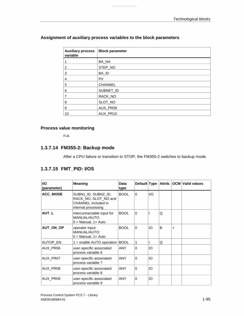
Technological blocks
Process Control System PCS 7 - LibraryA5E00180684-01 1-95
Assignment of auxiliary process variables to the block parameters
Auxiliary processvariable
Block parameter
1 BA_NA
2 STEP_NO
3 BA_ID
4 PV
5 CHANNEL
6 SUBNET_ID
7 RACK_NO
8 SLOT_NO
9 AUX_PR09
10 AUX_PR10
Process value monitoring
n.a.
1.3.7.14 FM355-2: Backup mode
After a CPU failure or transition to STOP, the FM355-2 switches to backup mode.
1.3.7.15 FMT_PID: I/OS
I/O(parameter)
Meaning Datatype
Default Type Attrib. OCM Valid values
ACC_MODE SUBN1_ID, SUBN2_ID,RACK_NO, SLOT_NO andCHANNEL included ininternal processing
BOOL 0 I/O
AUT_L interconnectable input forMANUAL/AUTO:0 = Manual, 1= Auto
BOOL 0 I Q
AUT_ON_OP operator input:MANUAL/AUTO:0 = Manual, 1= Auto
BOOL 0 IO B +
AUTOP_EN 1 = enable AUTO operation BOOL 1 I Q
AUX_PR06 user-specific associatedprocess variable 6
ANY 0 IO
AUX_PR07 user-specific associatedprocess variable 7
ANY 0 IO
AUX_PR08 user-specific associatedprocess variable 8
ANY 0 IO
AUX_PR09 user-specific associatedprocess variable 9
ANY 0 IO
21.02.2003

Technological blocks
Process Control System PCS 7 - Library1-96 A5E00180684-01
I/O(parameter)
Meaning Datatype
Default Type Attrib. OCM Valid values
AUX_PR10 user-specific associatedprocess variable 10
ANY 0 IO
BA_EN Batch enable BOOL 0 I Q +
BA_ID Batch: current batchnumber
DWORD 0 I Q +
BA_NA Batch ID STRING[32]
'' I Q +
BREAK_TM Minimum break time (s) REAL 0 IO Q
CHANNEL Controller channel number INT 0 I
CON_ZONE Control zone REAL 100 IO
CONZ_ON Control zone ON BOOL 0 IO
D_EL_SEL D-action input INT 0 IO Q
D_F Derivative factor REAL 5 IO
DEADB_W Dead band width REAL 0 IO +
DISV Error variable REAL 0 O
ER Error signal REAL 0 O
GAIN Proportional gain REAL 1 IO +
H_ALM High limit alarm REAL 100 IO + H_ALM > H_WRN>L_WRN > L_ALM
H_WRN High warning REAL 95 IO + H_ALM > H_WRN>L_WRN > L_ALM
HYS Hysteresis REAL 1 IO + >= 0
LADDR Logical address of FM355-2
INT 0 I
L_ALM Low limit alarm REAL -5 IO + H_ALM > H_WRN>L_WRN > L_ALM
L_WRN Low warning REAL -3 IO + H_ALM > H_WRN>L_WRN > L_ALM
LIOP_INT_SEL 1 = interconnection active0 = operator controlenabled
BOOL 0 I Q
LIOP_MAN_SEL 1 = interconnection active0 = operator controlenabled
BOOL 0 I Q
LMN Manipulated value REAL 0 O +
LMN_A Manipulated value A: Split-range function/positionfeedback
REAL 0 O
LMN_B Manipulated value B: Split-range function
REAL 0 O
LMN_HLM Manipulated value high limit REAL 100 IO +
21.02.2003

Technological blocks
Process Control System PCS 7 - LibraryA5E00180684-01 1-97
I/O(parameter)
Meaning Datatype
Default Type Attrib. OCM Valid values
LMN_LLM Manipulated value low limit REAL 0 IO +
LMN_OP Operator input formanipulated value
REAL 0 IO B +
LMN_RE External setpoint REAL 0 I Q
LMN_REON Enable external setpoint BOOL 0 I Q
LMN_SAFE Safety manipulated value REAL 0 IO +
LMNDN_OP Manipulated value lowoperation
BOOL 0 I Q
LMNOP_ON 1 = operator may inputLMN_OP
BOOL 1 IO
LMNRHSRE Upper end stop signal:Position feedback
BOOL 0 I Q
LMNRLSRE Lower end stop signal:Position feedback
BOOL 0 I Q
LMNSOPON Enable manipulated valueoperation
BOOL 0 IO Q
LMNTRKON Tracking (manipulatedvariable via analog input)
BOOL 0 I Q
LMNUP_OP Manipulated value highoperation
BOOL 0 IO Q
LOAD_PID Load optimized PI/PIDparameters
BOOL 0 IO
M_SUP_AH 1 = message suppression:High limit alarm
BOOL 0 I Q +
M_SUP_AL 1 = message suppression:Low limit alarm
BOOL 0 I Q +
M_SUP_WH 1 = message suppression:High warning
BOOL 0 I Q +
M_SUP_WL 1 = message suppression:Low warning
BOOL 0 I Q +
MANOP_EN 1 = enable MANUALoperation
BOOL 1 I Q
MO_PVHR Upper display limit(measurement range)
REAL 110 I +
MO_PVLR Lower display limit(measurement range)
REAL -10 I +
MODE Mode DWORD 0 I
MONERSEL monitoring:
0 = process variable1 = error signal
BOOL 0 IO Q
MSG_ACK Message acknowledged WORD 0 O
MSG_EVID Message number DWORD 0 I M
MSG_LOCK 1 = message suppression,depending on specificprocess state
BOOL 0 I Q +
MSG_STAT Error message status WORD 0 O
21.02.2003

Technological blocks
Process Control System PCS 7 - Library1-98 A5E00180684-01
I/O(parameter)
Meaning Datatype
Default Type Attrib. OCM Valid values
MTR_TM Motor actuation time (s) REAL 60 IO Q
OCCUPIED Occupied by BATCH BOOL 0 I Q +
OOS Reserve BOOL 0 I +
P_SEL Enable P-action BOOL 1 IO Q
PFAC_SP Proportional gain REAL 1 IO
PHASE Phase of auto-tuning (0..7) INT 0 O
PID_ON 1 = enable PID mode BOOL 0 IO
PULSE_TM Minimum break time [s] REAL 0 IO
PV Process variable REAL 0 O +
Q_SP_OP 1 = enable setpointoperation
BOOL 0 O +
QAUTOP 1 = enable AUTO operation BOOL 0 O +
QC_LMN Quality Code for LMN BYTE 16#80 O
QC_PV Quality Code for PV BYTE 16#80 O
QCH_F Channel error BOOL 0 O
QDNRLM Negative setpoint ramp limittriggered
BOOL 0 O
QERR inverted ENO BOOL 1 O
QH_ALM High limit alarm triggered BOOL 0 O
QH_WRN High warning triggered BOOL 0 O
QL_ALM Low limit alarm triggered BOOL 0 O
QL_WRN Low warning triggered BOOL 0 O
QLMN_HLM Manipulated value: Highlimit triggered
BOOL 0 O
QLMN_LLM Manipulated value: Lowlimit triggered
BOOL 0 O
QLMN_RE 1 = external manipulatedvalue enabled
BOOL 0 O
QLMNDN Manipulated value low BOOL 0 O
QLMNOP 1 = manipulated valueoperation enabled
BOOL 0 O +
QLMNR_HS Upper end stop of positionfeedback
BOOL 0 O
QLMNR_LS Lower end stop of positionfeedback
BOOL 0 O
QLMNR_ON Position feedback enabled BOOL 0 O
QLMNSAFE Safety mode BOOL 0 O
QLMNTRK Tracking mode BOOL 0 O
QLMNUP Manipulated value high BOOL 0 O
QMAN_AUT 0 = Manual, 1 = Auto BOOL 0 O +
QMAN_FC 1 = tracking modeor Anti-Reset-Windup atslave controller
BOOL 0 O
QMANOP 1 = manual mode enabled BOOL 0 O +
21.02.2003

Technological blocks
Process Control System PCS 7 - LibraryA5E00180684-01 1-99
I/O(parameter)
Meaning Datatype
Default Type Attrib. OCM Valid values
QMODF 1 = module fault BOOL 0 O
QMSG_ERR 1 = message error BOOL 0 O +
QMSG_SUP 1 = message suppressionenabled
BOOL 0 O +
QOP_ERR 1 = group error message BOOL 0 O
QPAR_ACT 1 = update controllerparameters
BOOL 0 O
QPARF_FM 1 = direct moduleconfiguration error orCHANNEL false
BOOL 0 O
QPERAF 1 = I/O access error BOOL 0 O
QSP_HLM 1 = high limit setpointtriggered
BOOL 0 O
QSP_LLM 1 = low limit setpointtriggered
BOOL 0 O
QSPEXTEN 1 = external operationenabled
BOOL 0 O +
QSPINTEN 1 = internal operationenabled
BOOL 0 O +
QSPEXTON External setpoint enabled BOOL 0 O
QSPR Split-range mode BOOL 0 O
QSTEPCON 1 = Step controlled BOOL 0 O
QTUN_ON 1 = tuning is busy BOOL 0 O
QUPRLM 1 = Setpoint ramp rate limittriggered
BOOL 0 O
RACK_NO Rack number BYTE 255 I
RATIOFAC Ratio factor REAL 0 IO
RET_VALU Return value of SFC 58/59(WR_REC/RD_REC)
WORD 0 O
RUNUPCYC number of run up cycles INT 3 I
SAFE_ON Safety position ON BOOL 0 I Q
SAVE_PAR Save control parameters BOOL 0 I
SDB_SEL 1 = the SDB parametersare not loaded by themodule at STOP-RUNtransition of the CPU
BOOL 1 I Q +
SLOT_NO Slot number BYTE 255 I
SP Setpoint REAL 0 O +
SP_EXT External setpoint REAL 0 I Q
SP_HLM Setpoint high limit REAL 100 IO +
SP_LLM Setpoint low limit REAL 0 IO +
SP_OP Operator input setpoint REAL 0 IO B +
SP_OP_ON Enable operator input ofSP_ON
BOOL 1 I Q
SP_TRK_ON 1 = SP_OP tracked to PV BOOL 0 I +
21.02.2003

Technological blocks
Process Control System PCS 7 - Library1-100 A5E00180684-01
I/O(parameter)
Meaning Datatype
Default Type Attrib. OCM Valid values
SPBUMPON 1 = bumpless setpoint BOOL 1 I +
SPEXON_L Interconnectable input forSP_EXT(1 = SP_EXT is set)
BOOL 0 I Q
SPEXT_EN 1 = enable external setpointoperation
BOOL 1 I Q
SPEXTSEL_OP Operator input:0: Internalsetpoint,1: External setpoint
BOOL 0 IO B +
SPINT_EN 1 = enable internal setpointoperation
BOOL 1 I Q
STATUS_C Status of cooling tuning INT 0 O
STATUS_D Status of controller design INT 0 O
STATUS_H Status of heating tuning INT 0 O
STEP_NO BATCH step number DWORD 0 I Q + 0 or >= 1,0
SUBN1_ID ID of the primary DPmaster system
BYTE 255 I
SUBN2_ID ID of the redundant DPmaster system
BYTE 255 I
TD Derivative time (s) REAL 0 IO 0 or >= 0,5
TI Integration time (s) REAL 3000 IO
TUN_CLMN Delta manipulated value forcooling tuning
REAL -20 IO
TUN_CST Start cooling tuning BOOL 0 IO
TUN_DLMN Delta manipulated value forprocess excitation
REAL 20 IO
TUN_ON Enable controller tuning BOOL 0 IO
TUN_ST Start controller tuning BOOL 0 IO
UNDO_PAR Undo controller parameterchanges
BOOL 0 IO
USTATUS Status word in VSTATUS,user-specific
WORD 0 I
VSTATUS Extended status display inblock icons
DWORD 0 O
ZONE_TUN Error channels joined inone zone for parallel tuning
WORD 0 O
For information on abbreviations used refer to: General information on the blockdescription
For detailed information on FM 355-2 parameters, refer to the FM 355-2Temperature Controller manual
21.02.2003

Technological blocks
Process Control System PCS 7 - LibraryA5E00180684-01 1-101
1.3.7.16 FMT_PID: Operator control and monitoring
The tables show the assignment of the parameters of the AS block to the I/O fieldsof the faceplate.
Display I/O field Operatorauthoriza-tion
Parameter of theAS block
Operator text inthe protocol
Setpoint (as bar) SP(high value) MO_PVHR(low value) MO_PVLR
PV (as bar) PV_IN
(bar at extreme right)(red = high limit alarm)(red = low limit alarm)
PVH_ALM
PVL_ALM(yellow = high warning)(yellow = low warning)
PVH_WRN
PVL_WRN
Opmode
(Selection list:Manual/Auto) 5
QMAN_AUT
AUT_ON_OP =0/1 Mode=Manual/Auto
Setpoint
(in the corresponding inputdialog:
HL=SPLL=) 5
SP
SP_HLM
SP_OP
SP_LLM
Setpoint
PV PV
(Unit SP/PV) (S7_shortcut von PV)
Manual
(in the corresponding inputdialog:
HL=ManualLL=)
6
6
LMN_OP
LMN_HLM
LMN_OP
LMN_LLM
LMN high limit
LMN low limit
MV LMN
(Unit manual/manipulated value) (S7_shortcut von LMN)
(symbol bell)
(symbol bell disabled)
QMSG_SUP
MSG_LOCK
(symbol batch) OCCUPIED
Manual (pointer)
Standard
Process value (as horizontal bar)
21.02.2003

Technological blocks
Process Control System PCS 7 - Library1-102 A5E00180684-01
Display I/O field Operatorauthorization
Parameter of theAS block
Operator text in theprotocol
SP
(Selection list:internal/external)
QSPEXTON
SPEXTSEL_OP =0/1 SP =internal/external
Bumpless SPBUMPON =0/1 SP bumpless off/ontrack SP_TRK_ON =0/1 SP track off/onselect OP OP_SEL=0/1 Switch to P-Bus/
Switch to K-BusSDB data SDB_SEL SDBparameter
=Yes/No
Error signal monitoringAlarm high QH_ALMAlarm low QL_ALMWarning high QH_WRNWarning low QL_WRN
Maintenance
Error signal ER
21.02.2003

Technological blocks
Process Control System PCS 7 - LibraryA5E00180684-01 1-103
Display I/O field Operatorauthoriza-tion
Parameter of theAS block
Operator text inthe protocol
Control parameter
CP 6 GAIN Gain
TI s ( = in [s] ) 6 TI TI
TD s 6 TD TD
Parameter
Dead band DEADB_W Dead band
Hysteresis
(in the corresponding input dialog:
OG=
Hys
UG=)
6
6
HYS
(no check)
HYS
0,0
Hysteresis
Hysteresis
Delay S D_F Derivative actionfactor
Manipulated value
safe 6 LMN_SAFE LMN safety
Bar
HL
(in the corresponding input dialog:
HL=
bar HL
LL=)
6
6
6
MO_PVHR
(no check)
MO_PVHR
MO_PVLR
Parameter
LL
(in the corresponding input dialog:
HL=
bar LL
LL=)
6
6
6
MO_PVLR
MO_PVHR
MO_PVLR
(no check)
21.02.2003

Technological blocks
Process Control System PCS 7 - Library1-104 A5E00180684-01
Display I/O field Operatorauthoriza-tion
Parameter of theAS block
Operator text inthe protocol
(blue = display SP limit)(high value) SP_HLM(low value) SP_LLM(red bar = alarm)(high value) PVH_WRN(low value) PVL_WRN(yellow bar = warning)(high value) PVH_ALM(low value) PVL_ALMAlarmAHact ( = active )
66
H_ALMM_SUP_AH =0/1
HH alarmSuppressHH=No/Yes
WHact
66
H_WRNM_SUP_WH =0/1
H alarmSuppressH=No/Yes
WLact
66
L_WRNM_SUP_AL =0/1
LL alarmSuppressLL=No/Yes
ALact
66
L_ALMM_SUP_WL =0/1
LL alarmSuppressLL=No/Yes
SPHL(in the corresponding input dialog:
HL=SPLL=)
6
66
SP_HLM
(no check)SP_HLMSP_LLM
SP high limit
SP high limitSP low limit
LL(in the corresponding input dialog:
HL=SPLL=)
6
66
SP_LLM
SP_HLMSP_LLM(no check)
SP low limit
SP high limitSP low limit
Manual valueHL(in the corresponding input dialog:
LL=MVLL=)
6
66
LMN_HLM
(no check)LMN_HLMLMN_LLM
LMN high limit
LMN high limitLMN low limit
Limits
LL(in the corresponding input dialog:
HL=MVLL=)
6
66
LMN_LLM
LMN_HLMLMN_LLM(no check)
LMN low limit
LMN high limitLMN low limit
21.02.2003

Technological blocks
Process Control System PCS 7 - LibraryA5E00180684-01 1-105
Display I/O field Operatorauthoriza-tion
Parameter of theAS block
Operator textin the protocol
Batch control
enable BA_EN
occupied OCCUPIED
Batch
Name BA_NA
Batch
Step STEP_NO
Display I/O field Operatorauthoriza-tion
Parameter of theAS block
Operator textin the protocol
MotorMin. pulse width PULSE_TMMin. break time BREAK_TMRuntime MTR_TMEnd position "open" reached QLMNR_HSEnd position "closed" reached QLMNR_LSControl signal "open" QLMNUPControl signal "close QLMNDN
Standard S
With feedback LMNR_ON
1.3.7.17 FMT_PID: VSTATUS
The 32-bit status word extends the status display in the block icons and faceplates.The 16 low bits (bits 0 - 15) are used by the block as follows:
Bit no.: 7 6 5 4 3 2 1 0
Parameter - - - QSPEXTON QMAN_AUT MSG_LOCK BA_EN OCCUPIED
Bit no.: 15 14 13 12 11 10 9 8
Parameter OOS QMSG_SUP - - - - - -
The 16-bit input USTATUS (data type WORD) uses the high bits (bits 16 - 31).These bits can be used freely.
21.02.2003

Technological blocks
Process Control System PCS 7 - Library1-106 A5E00180684-01
1.3.8 INT_P: Integration
1.3.8.1 INT_P: Description
Object name (type + number)
FB 40
Calling OBs
The watchdog interrupt OB in which you install the block (for example OB32). It isalso installed in OB100 (see startup characteristics).
Function
Forms the time integral of the input value:
VTI
Udt= ∗∫1
21.02.2003

Technological blocks
Process Control System PCS 7 - LibraryA5E00180684-01 1-107
Operating principle
The structure of INT_P is shown in the figure.
The block functions by means of sum generation in accordance with the trapezoidrule per sampling interval (SAMPLE_T). The result, Vinternal, lies within the rangeV_HL - hyst to V_LL + hyst (refer to the figure). Subsequently the value is written tothe output V after an additional limitation to between V_LL and V_HL.
In addition the internal result Vinternal is monitored for violation of the limits V_LLand V_HL and displayed via the Boolean outputs QVLL and QVHL (refer to thefigure).
t
V_HL
V_LL
V
U=1 if t>0U=0 if t<0
Input step
V_HL + hyst
V_LL - hyst
TI
U
hyst = HYS/100x(V_HL-V_LL)
V intern
V
Jump response of the INT_P
21.02.2003

Technological blocks
Process Control System PCS 7 - Library1-108 A5E00180684-01
Error handling
Apart from the errors recognized by the operating system, the followingconfiguration errors are also indicated by the block algorithm via ENO=0 andQERR=1:
• V_LL ≥ V_HL (V := 0)
• SAMPLE_T ≤ 0 (calculation is continued internally with the substitutevalue = 1)
• TI ≤ 0 (calculation is continued internally with the substitute value = 1)
• Hysteresis HYS ≤ 0 (calculation is continued internally with the substitutevalue = 1)
t
t
QVHL 1
t
QVLL1
V_HL
V_LL
V intern
0
V_HL+hys
V_LL-h
Limit monitoring of the INT_P
Startup characteristics
During startup the internal historical process data as well as the output V are reset.The block must therefore additionally be called from the startup OB (OB100).
21.02.2003

Technological blocks
Process Control System PCS 7 - LibraryA5E00180684-01 1-109
Time response
The block must be installed in a watchdog interrupt OB.
EN
TI
HOLD
0
U
ENO
V
#
&TRACK
VTRACK
QVHL
QVLL
FehlerbehandlungQERR
I
#
V_HL
V_LL
HYS hyst=HYSx(VHL-VLL)
100
VHL+hyst
VLL-hystVintern
INT_P
INT_P structure
21.02.2003

Technological blocks
Process Control System PCS 7 - Library1-110 A5E00180684-01
1.3.8.2 INT_P: I/Os
I/O(parameter)
Meaning Datatype
Default Type Attrib. OCM Valid values
HOLD 1 = Hold integration(takes priority over TRACK)
BOOL 0 I Q
HYS Hysteresis of V_INTERN in [%] REAL 1 I Q ≥ 0QERR 1 = error BOOL 1 OQVHL 1 = high limit output value BOOL 0 OQVLL 1 = low limit output value BOOL 0 ORESET 1 = RESET (restart) BOOL 1 ISAMPLE_T Sampling time [s] REAL 1 I > 0TI Tracking time [s] REAL 1 I Q ≥ 0TRACK 1 = tracking BOOL 0 I QU Input value REAL 0 I QV Output value REAL 0 OV_HL High limit for V REAL 100 I Q V_HL > V_LLV_LL Low limit for V REAL 0 I Q V_LL < V_HLVTRACK Tracking value REAL 0 I Q
For information on abbreviations used refer to: General information on the blockdescription
21.02.2003

Technological blocks
Process Control System PCS 7 - LibraryA5E00180684-01 1-111
1.3.9 MEANTM_P: Mean time value generation
1.3.9.1 MEANTM_P: Description
Object name (type + number)
FB 42
Calling OBs
The watchdog interrupt OB in which you install the block (for example OB32). It isalso installed in OB100 (see startup characteristics).
Function
The blocks is used to form a mean time value of an analog input signals across aconfigurable past time period in accordance with the equation:
Vn = ( U1 + U2 +...+Un) / n
where U1...Un are the detected values used for averaging.
Operating principle
During every execution of the block the arithmetic mean value is calculated fromthe current input value U and the values saved during the time T_WINDOW. This isthen updated at the output V. The current input value then overwrites the oldesthistorical process data.
• The time window across which averaging is to be carried out is entered in theparameter T_WINDOW.
• The block determines the number n of values to be saved from the integer partof the quotient T_WINDOW / SAMPLE_T.
• The block can save a maximum of 20 historical process variables internally. Adata reduction is carried out in case of a longer time window.
• The STOP_RES input can be used:
- To stop the calculation process with "1". The output value remainsunchanged for the period.
- To reset the mean time value by a falling edge 1→0.
• If SAMPLE_T or T_WINDOW is changed, the mean time value is reset.
21.02.2003

Technological blocks
Process Control System PCS 7 - Library1-112 A5E00180684-01
Error handling
Only by means of the operating system.
Startup characteristics
Does not exist.
• If the block was active before the CPU stop, and continues to calculateafterwards, the CPU out-time relative to T_WINDOW has to be taken intoconsideration. This allows you to decide whether the result can still be used orwhether the calculation process has to be reset via the input STOP_RES.
Time response
The block must be called from a watchdog interrupt OB.
1.3.9.2 MEANTM_P: I/Os
I/O(parameter)
Meaning Datatype
Default Type Attrib. OCM Validvalues
QERR 1 = Error BOOL 1 O
SAMPLE_T Sampling time [s] REAL 1.0 I >0
STOP_RES Stop /reset mean value calculation BOOL 0 I Q
T_WINDOW Size of the time window [s] REAL 20 I
U Input value REAL 0 I Q
V Output value REAL 0 O
For explanations and meaning of the abbreviations please refer to: Generalinformation on the block description
21.02.2003

Technological blocks
Process Control System PCS 7 - LibraryA5E00180684-01 1-113
1.3.10 MEAS_MON: Measurement value monitoring
1.3.10.1 MEAS_MON: Description
Object name (type + number)
FB 65
Function
The block is used to monitor a measured value (analog signal) with regard to thelimit pairs
• Warning limit (high/low) and
• Alarm limit (high/low)
Operating principle
The block monitors the measured value at input U. The high or low transgressionof a limit is indicated at a corresponding output and signaled if applicable(see message characteristics Message characteristics).
Calling OBs
In the same OB with and after the block whose measured value is to be monitored.Additionally in OB100 (see startup characteristics).
Error handling
In the event of arithmetical errors the outputs ENO=0 and QERR=1 will be set.
Startup characteristics
After startup, messages will be suppressed for the number of cycles configured inthe value RUNUPCYC.
Time response
No time response. The block is to run in the same runtime group (see CFC) withthe measured value producer.
21.02.2003

Technological blocks
Process Control System PCS 7 - Library1-114 A5E00180684-01
Message characteristics
The MEAS_MON block uses the ALARM8_P block to generate messages.
Messages are triggered by
• The limit monitoring functions of the measured value
• The CSF signal which is referenced as a control system error byinterconnection.
Messages regarding limit infringements can be suppressed individually via thecorresponding M_SUP_xx inputs. The process messages (not process controlmessages!) can be completely blocked with MSG_LOCK.
QMSG_SUP is set if the RUNUPCYC cycles have not expired yet since a restart,MSG_LOCK = TRUE or MSG_STAT = 21.
Assignment of message texts and message class to the block parameters
Message No. Block parameter Default message text Messageclass
Can besuppressed by
1 QH_ALM $$BlockComment$$ too high AH M_SUP_AH,MSG_LOCK
2 QH_WRN $$BlockComment$$ high WH M_SUP_WH,MSG_LOCK
3 QL_WRN $$BlockComment$$ low WL M_SUP_WL,MSG_LOCK
4 QL_ALM $$BlockComment$$ too low AL M_SUP_AL,MSG_LOCK
5 CSF External error S -
The first three of the auxiliary process values of the message block are assignedSIMATIC BATCH data, the fourth is reserved for U and the remaining ones(AUX_PRx) can be assigned user-specific.
21.02.2003

Technological blocks
Process Control System PCS 7 - LibraryA5E00180684-01 1-115
Assignment of the auxiliary process value for the block parameters
Value Block parameter1 BA_NA2 STEP_NO3 BA_ID4 U5 AUX_PR056 AUX_PR067 AUX_PR078 AUX_PR089 AUX_PR0910 AUX_PR10
Monitoring of process variables
n.a.
1.3.10.2 MEAS_MON: I/Os
I/O(parameter)
Meaning Data type Default Type Attrib. OCM Validvalues
AUX_PRx Auxiliary value x ANY 0 IO Q
BA_EN Batch enable BOOL 0 I Q +
BA_ID Current batch ID DWORD 0 IO Q +
BA_NA Batch name STRING[16]
0 I Q +
CSF Control System Fault1 = external error
BOOL 0 I Q
HYS Hysteresis REAL 5 I + ≥ 0
M_SUP_AH 1 = suppress HL alarm BOOL 0 I +
M_SUP_AL 1 = suppress LL alarm BOOL 0 I +
M_SUP_WH 1 = suppress HL warning BOOL 0 I +
M_SUP_WL 1 = suppress LL warning BOOL 0 I +
MO_PVHR High limit display range(measuring range) - only forOS
REAL 110 I +
MO_PVLR Low limit display range(measuring range) - only forOS
REAL -10 I +
MSG_ACK Message acknowledged WORD 0 O
MSG_EVID Message event number DWORD 0 I M
MSG_LOCK 1 = Process messagesdisabled
BOOL 0 I Q +
MSG_STAT Error message status WORD 0 O
OCCUPIED Occupied by batch BOOL 0 I Q +
OOS Reserve
21.02.2003

Technological blocks
Process Control System PCS 7 - Library1-116 A5E00180684-01
I/O(parameter)
Meaning Data type Default Type Attrib. OCM Validvalues
QC_U Quality Code for U BYTE 16#80 I
QERR 1 = error output (invertedENO)
BOOL 1 O +
QH_ALM 1 = HL alarm triggered BOOL 0 O
QH_WRN 1 = HL warning triggered BOOL 0 O
QL_ALM 1 = LL alarm triggered BOOL 0 O
QL_WRN 1 = LL warning triggered BOOL 0 O
QMSG_ERR 1 = message error BOOL 0 O +
QMSG_SUP 1 = message suppressionenabled
BOOL 0 O +
RUNUPCYC Number of run-up cycles INT 3 I
STEP_NO Batch step number WORD 0 IO Q +
U Analog input (measuredvalue)
REAL 0 I QE +
U_AH HL alarm REAL 100 I + U_AH>U_WH
U_AL LL alarm REAL 0 I + U_AL<U_WL
U_WH HL warning REAL 95 I + U_AH>U_WH> U_WL
U_WL LL warning REAL 5 I + U_WH>U_WL> U_AL
For information on abbreviations used refer to: General information on the blockdescription
21.02.2003

Technological blocks
Process Control System PCS 7 - LibraryA5E00180684-01 1-117
1.3.10.3 MEAS_MON: Operator control and monitoring
The tables show the assignment of the parameters of the AS block to the I/O fieldsof the faceplate.
Display I/O field Operatorauthoriza-tion
Parameters of the ASblock
Operator text inthe log
Process variable (as a bar) U
(high value) MO_PVHR
(low value) MO_PVLR
(bar graph at right)
(red= high alarm limit) U_AH
(red= low alarm limit) U_AL
(yellow= high warning limit) U_WH
(yellow= low warning limit) U_WL
Message suppression MSG_LOCK
Process variable = U
E1 (S7_shortcut of U)
Hysteresis
(in the corresponding input dialogbox:
HL=
Hys
LL=)
6
6
HYS
(no check)
HYS
0,0
Hysteresis
Hysteresis
(symbol bell) QMSG_SUP
Default
(symbol batch) OCCUPIED
21.02.2003

Technological blocks
Process Control System PCS 7 - Library1-118 A5E00180684-01
Display I/O field Operatorauthoriza-tion
Parameters of theAS block
Operator text in thelog
(Scale HL) MO_PVHR
(Scale LL) MO_PVLR
(red bar = alarm)
(upper value) U_AH
(lower value) U_AL
(yellow bar = warning)
(upper value) U_WH
(lower value) U_WL
Signaling
AHact (=active) 6
U_AHM_SUP_AH =0/1
HL alarmSuppress HL = No/Yes
WHact 6
U_WHM_SUP_WH =0/1
HL alarmSuppress HL = No/Yes
WLact 6 M_SUP_WL =0/1
LL alarmSuppress LL = No/Yes
ALact 6
U_ALM_SUP_AL =0/1
LL alarmSuppress LL = No/Yes
Bar
HL(in the corresponding inputdialog box:
HL=
HLLL=)
6
6
6
MO_PVHR
(no check)MO_PVHR
MO_PVLR
Limits
LL(in the corresponding inputdialog box:
HL=
LLLL=)
6
66
MO_PVLR
MO_PVHRMO_PVLR
(no check)
Display
I/O field Operator
authoriza-tion
Parameters of theAS block
Operator text in thelog
Batch control
Enable BA_EN
Occupied OCCUPIED
Batch
Name BA_NA
Batch
Step STEP_NO
21.02.2003

Technological blocks
Process Control System PCS 7 - LibraryA5E00180684-01 1-119
1.3.10.4 MEAS_MON: VSTATUS
The 32-bit status word extends the status display in the block icons and faceplates.The 16 low bits (bits 0 - 15) are used by the block as follows:
Bit no.: 7 6 5 4 3 2 1 0
Parameter - - - MSG_LOCK BA_EN OCCUPIED
Bit no.: 15 14 13 12 11 10 9 8
Parameter OOS QMSG_SUP - - - - - -
The 16-bit input USTATUS (data type WORD) uses the high bits (bits 16 - 31).These bits can be used freely.
21.02.2003

Technological blocks
Process Control System PCS 7 - Library1-120 A5E00180684-01
1.3.11 POLYG_P: Polygon with a max. of 8 points
1.3.11.1 POLYG_P: Description
Object name (type + number)
FC 271
Calling OBsThe OB in which the block is installed.
Function
An input U is converted to output V in accordance with a non-linear characteristiccurve and with a maximum of 8 time slices.
Operating principleAfter the N time slices have been specified (pairs of coordinates Ui,Vi with i = 1...Nin continuous sequence) and the configuration of the number N has been carriedout, the block operates as follows:
• Linear interpolation between the time slices.
• Extrapolation outside the last two time slices on the basis of the first two or thelast two time slices.
VN
V3
V2
V1
VN-1
U1 U2 U3 UN-1 UN U
V
U1 < U2 < ... < UN
Characteristic curve representation
Error handling
ENO=0 as well as V=U are output when:
• the number of time slices N < 2 or N > 8
• Ui > Ui+1 for i=1,2...N-1
21.02.2003

Technological blocks
Process Control System PCS 7 - LibraryA5E00180684-01 1-121
1.3.11.2 POLYG_P: I/Os
I/O(parameter)
Meaning Data type Default Type Attrib. OCM Validvalues
N Number of time slices INT 0 I 2 ≤ N ≤ 8
U Input REAL 0.0 I Q
U1 U value of time slice 1 REAL 0.0 I Q
U2 U value of time slice 2 REAL 0.0 I Q
... ... ... ... ... ...
U8 U value of time slice 8 REAL 0.0 I Q
V1 V value of time slice V 1 REAL 0.0 I Q
V2 V value of time slice V 2 REAL 0.0 I Q
... ... ... ... ... ...
V8 V value of time slice V 8 REAL 0.0 I Q
V Output value REAL 0.0 O
For information on abbreviations used refer to: General information on the blockdescription
21.02.2003

Technological blocks
Process Control System PCS 7 - Library1-122 A5E00180684-01
1.3.12 PT1_P: Delay element of the 1st order
1.3.12.1 PT1_P: Description
Object name (type + number)
FB 51
Calling OBs
The OB into which the block is installed (for example OB32).
Function
The block operates in accordance with the equation:
V = U ∗ (1 - exp(-t/TM_LAG))
Operating principle
The input signal U is passed to the output V in accordance with the time constantTM_LAG.
The STOP_RES input can be used:
1. To stop the calculation process with "1". The output value remains unchangedfor the period.
2. To reset the output (V=U) at a negative edge 1 → 0.
V
tTM_LAGU=1 if t>0U=0 if t<0
Input step
0
1
0.63
Jump response of the PTI_P
Error handling
Only by means of the operating system.
21.02.2003

Technological blocks
Process Control System PCS 7 - LibraryA5E00180684-01 1-123
1.3.12.2 PT1_P: I/Os
I/O(parameter)
Meaning Data type Default Type Attrib. Validvalues
QERR 1 = error BOOL 1 O
SAMPLE_T Sampling time [s] REAL 1.0 I >0
STOP_RES Stop / Reset PT1 function BOOL 0 I Q
TM_LAG Length of time constant REAL 0.0 I
U Input value REAL 0.0 I Q
V Output value REAL 0.0 O
For information on abbreviations used refer to: General information on the blockdescription
1.3.13 RAMP_P: Ramp generation
1.3.13.1 RAMP_P: Description
Object name (type + number)
FB 52
Calling OBs
The watchdog interrupt OB in which you install the block (for example OB32). It isalso installed in OB100 (see startup characteristics).
Function
Limitation of the ramp of an analog signal
21.02.2003

Technological blocks
Process Control System PCS 7 - Library1-124 A5E00180684-01
Operating principle
The block calculates the ramp of the input signal dU/dt and compares it with thetwo limits URLM for positive changes or DRLM for negative changes (also refer tothe table).
• If the ramp (as a quantity) exceeds the respective maximum ramp (URLM orDRLM), the output V is only changed by the permitted rate and thecorresponding limitation display QLIM_U or QLIM_D is set.
• If the ramp lies within the valid range, the input value is passed through (U=V)and the values QLIM_U and QLIM_D are reset.
• If the input RATE_OFF=1, the ramp generation is disabled, so that V=U, andQLIM_U = QLIM_D = 0.
RATE_OFF dU/dt Meaning Output V QLIM_D QLIM_U
0 < - DRLM Input value drops too rapidly V-(DRLM /SAMPLE_T)
1 0
0 - DRLM to URLM Rate of change is permissible U 0 0
0 > URLM Input value U rises too rapidly V+(URLM /SAMPLE_T)
0 1
1 not significant Ramp disabled U 0 0
Error handling
If SAMPLE_T<0, ENO=0 or QERR=1 is output.
Startup characteristics
Output V is reset during the startup. The block must therefore additionally be calledfrom the startup OB (OB100).
Time response
The block must be called from a watchdog interrupt OB.
21.02.2003

Technological blocks
Process Control System PCS 7 - LibraryA5E00180684-01 1-125
1.3.13.2 RAMP_P: I/Os
I/O(parameter)
Meaning Datatype
Default Type Attrib. Validvalues
DRLM maximum negative change of the output valuein [units/s]
REAL 3.0 I Q DRLM<URLM
QERR 1 = error BOOL 1 O
QLIM_D Negative gradient too large BOOL 0 O
QLIM_U Positive gradient too large BOOL 0 O
RATE_OFF 1 = ramp rate monitoring off BOOL 0 I Q
SAMPLE_T Sampling time [s] REAL 1.0 I >0
U Analog input (measured value) REAL 0.0 I Q
URLM maximum positive change of the output valuein [units/s]
REAL 3.0 I Q URLM>DRLM
V Ramp output REAL 0.0 O
For information on abbreviations used refer to: General information on the blockdescription
1.3.14 RATIO_P: ration control
1.3.14.1 RATIO_P: Description
Object name (type + number)
FB 70
Function
The block is used to create a ratio, e.g. in a ratio control. It is also used as apercentage adjuster (for example, speed ratio control), or to influence the referenceinput variable of a cascade.
Operating principle
The RATIO_P block operates in accordance with the equation: V = U1 * U2 +BIASU1 is derived by interconnection while U2 is selected dependent on theinternal/external operating mode.
21.02.2003
Technological blocks
Process Control System PCS 7 - Library1-126 A5E00180684-01
Internal/external changeover
The operating mode is selected by the following measures and indicated at theoutput QIN_EX:
• Operation of the input IN_EX, when L_IE_ON=0 and the enable signalsIN_OP_EN and EX_OP_EN are valid.
• Interconnection of L_IN_EX, if L_IE_ON=1.
Internal: The parameter U2 in the formula is specified by operator control and,after limiting to (U2_LL, U2_HL), incorporated in the formula. Operator control musthave been enabled at U2_OP_EN.
External: The parameter U2 is specified by interconnecting the input U2_EXT and,after limiting to (U2_LL, U2_HL), incorporated in the formula. The controllable inputU2 is tracked to U2_EXT in order to enable smooth changeover to "internal".
Calling OBs
Installation is carried out in the OB containing the block which uses the result. TheRATIO_P must be positioned before first (first calculate, then use).
Error handling
Arithmetic error are indicated by ENO=0 or QERR=1.Operator errors are displayed as a group at output QOP_ERR.
Startup characteristics
No special measures.
Time response
If the result for the blocks with time characteristics is relevant (for example, ratiocontrol, synchro control), the block should be installed in the same OB and beforeit.
Message characteristics
Does not exist.
Monitoring of the process variable
Does not exist
21.02.2003

Technological blocks
Process Control System PCS 7 - LibraryA5E00180684-01 1-127
1.3.14.2 RATIO_P: I/Os
I/O(parameter)
Meaning Datatype
Default Type Attr. OCM Validvalues
BIAS Share by which V is moved REAL 0 I Q +
EX_OP_EN 1 = enable external operator controlmode
BOOL 0 I Q +
IN_EX Operation:0= internal, 1= external
BOOL 0 IO B +
IN_OP_EN 1 = enable internal operation BOOL 0 I Q +
L_IE_ON 1 = Interconnection active,0 = Operation enabled
BOOL 0 I Q +
L_IN_EX Interconnectable input for IN_EX BOOL 0 I Q
MO_U1HR High limit display range REAL 110 I +
MO_U1LR Low limit display range REAL -10 I +
QC_U1 Quality Code for U1 BYTE 16#80 I
QERR 1 = error (inverted ENO) BOOL 1 O +
QIE_OP 1 = enable internal/external operatormode
BOOL 0 O +
QIN_EX 0 = internal, 1= external BOOL 0 O +
QOP_ERR 1 = operator error output BOOL 0 O +
QU2_OP 1 = enable U2 operation BOOL 0 O +
QVHL 1 = high limit of output value Vtriggered
BOOL 0 O +
QVLL 1 = low limit of output value Vtriggered
BOOL 0 O +
U1 Input REAL 0 I Q +
U2 internal factor REAL 1 IO B +
U2_EXT external factor REAL 1 I Q +
U2_HL Low limit U2 REAL 1 I +
U2_LL High limit U2 REAL 0 I +
U2_OP_EN 1 = enable operator input of U2 BOOL 1 I Q
V Output value REAL 0 O +
V_HL High limit of V REAL 100 I + V_HL>V_LL
V_LL Low limit of V REAL 0 I + V_LL<V_HL
For information on abbreviations used refer to: General information on the blockdescription
21.02.2003

Technological blocks
Process Control System PCS 7 - Library1-128 A5E00180684-01
1.3.14.3 RATIO_P: Operator control and monitoring
The tables show the assignment of the parameters of the AS block to the I/O fieldsof the faceplate.
Display I/O field Operatorauthoriza-tion
Parameters ofthe AS block
Operator text inthe log
U1 (as a bar)
Operating mode
(selection list:
internal/external) 5
QIN_EX
IN_EX =0/1 Internal/External
U1
U2
(in the corresponding input dialog box:
HL
U2
LL)
6
6
U2
U2_HL
U2
U2_LL
U2
High limit U2
U2
Low limit U2
BIAS BIAS
V V
> Upper limit QVHL
< Lower limit QVLL
(Scale horizontal)
Default
V (as a horizontal bar)
Display I/O field Operatorauthoriza-tion
Parameters ofthe AS block
Operator text inthe log
U1
HL
(in the corresponding input dialog box:
HL=
U1_OG
LL=)
6
6
6
MO_U1HR
(no check)
MO_U1HR
MO_U1LR
LL
(in the corresponding input dialog box:
HL=
U1_UG
LL=)
6
6
6
MO_U1LR
MO_U1HR
MO_U1LR
(no check)
Limits
V
21.02.2003

Technological blocks
Process Control System PCS 7 - LibraryA5E00180684-01 1-129
Display I/O field Operatorauthoriza-tion
Parameters ofthe AS block
Operator text inthe log
HL
(in the corresponding input dialog box:
HL=
V_OG
LL=)
6
6
6
V_HL
(no check)
V_HL
V_LL
High limit V
High limit V
Low limit V
LL
(in the corresponding input dialog box:
HL=
V_UG
LL=)
6
6
6
V_LL
V_HL
V_LL
(no check)
Low limit V
High limit V
Low limit V
U2
HL
(in the corresponding input dialog box:
HL=
U2_OG
LL=)
6
6
6
U2-HL
(no check)
U2-HL
U2_LL
High limit U2
High limit U2
Low limit U2
LL
(in the corresponding input dialog box:
HL=
U2_UG
LL=)
6
6
6
U2_LL
U2-HL
U2_LL
(no check)
Low limit U2
High limit U2
Low limit U2
1.3.14.4 RATIO_P: VSTATUS
The 32-bit status word extends the status display in the block icons and faceplates.The 16 low bits (bits 0 - 15) are used by the block as follows:
Bit no.: 7 6 5 4 3 2 1 0
Parameter QIN_EX - - - - -
Bit no.: 15 14 13 12 11 10 9 8
Parameter - - - - - - QVLL QVHL
The 16-bit input USTATUS (data type WORD) uses the high bits (bits 16 - 31).These bits can be used freely.
21.02.2003

Technological blocks
Process Control System PCS 7 - Library1-130 A5E00180684-01
1.3.15 SPLITR_P: Split range
1.3.15.1 SPLITR_P: Description
Object name (type + number)
FC 272
Calling OBs
The OB in which the controller block runs whose manipulated variable isprocessed.
Function
Together with a controller block the block is used to implement a split-rangecontrol.
21.02.2003

Technological blocks
Process Control System PCS 7 - LibraryA5E00180684-01 1-131
Operating principle
The block is installed in the run sequence after the controller block. The controlleroutput of the controller block is interconnected to the input U of the SPLITR_Pblock. The neutral position and the dead band zone is set by means of thecorresponding parameters. V1 and V2 are adapted to the physical dimension bymeans of the configuration of the upper / lower limits of V1 and V2. The transfercharacteristics have the following appearance:
V2HRANGE
V1HRANGE
V2LRANGE
V1LRANGE
UHRANGEULRANGE
NEUT_POS
DEADB_W
V2
V1U
U
QV2U
U
QV1
1
1
0
0
DEADB_W
Transfer characteristics of the SPLITR_P
Error handling
ENO=0 is output at the following errors:
• Incorrect calculation of V1 (whereby V1=V1LRANGE also applies)
• Incorrect calculation of V2 (whereby V2=V2LRANGE also applies)
21.02.2003

Technological blocks
Process Control System PCS 7 - Library1-132 A5E00180684-01
1.3.15.2 SPLITR_P: I/Os
I/O(parameter)
Meaning Datatype
Default Type Attrib. Valid values
DEADB_W Dead band width REAL 10.0 I
NEUT_POS Neutral position REAL 50.0 I > ULRANGE< UHRANGE
QV1 ACTIVE / 1 = output 1 is active BOOL 0 O
QV2 1 = output 2 is active BOOL 0 O
U Input value REAL 0.0 I Q
UHRANGE Measurement range high limit of U REAL 100.0 I Q > ULRANGE
ULRANGE Measurement range low limit of U REAL 0.0 I Q < UHRANGE
V1 Output 1 REAL 0.0 O
V1HRANGE Final value of V1 measurement range REAL 100.0 I Q > V1LRANGE
V1LRANGE Initial value of V1 measurement range REAL 0.0 I Q < V1HRANGE
V2 Output 2 REAL 0.0 O
V2HRANGE Final value of V2 measurement range REAL 100.0 I Q > V2LRANGE
V2LRANGE Initial value of V2 measurement range REAL 0.0 I Q < V2HRANGE
For information on abbreviations used refer to: General information on the blockdescription
21.02.2003

Technological blocks
Process Control System PCS 7 - LibraryA5E00180684-01 1-133
1.4 Motor and valve
1.4.1 MOT_REV: Motor with two rotary directions
1.4.1.1 MOT_REV: Description
Object name (type + number)
FB 67
Calling OBs
The watchdog interrupt OB in which you install the block (for example OB32). It isalso installed in OB100 (see startup characteristics).
Function
The block is used to drive motors with 2 directions of rotation(clockwise/counterclockwise). A maximum of 2 feedback signals, which aregenerated by auxiliary contactors, are monitored.
Operating principle
Various inputs are available for controlling the motor. They are implemented in adefined hierarchical dependency to each other and to the motor states. In particularthe interlock, feedback or rotary direction monitoring and the motor protectivecircuit-breaker functions influence the control signals QSTART (1: on, 0: off) andQDIR (1: counterclockwise, 0: clockwise).
The allocation of priorities to the individual input variables and events with regardto their influence on the control signals is shown in the following table. Thesubsequent sections provide further details.
Priority: Event:High Motor protection error, if MSS_OFF = 12 Delay at change of rotary direction
LOCK = 1LOCK_ON = 1 (with LOCK_DIR)
2 Monitoring error, if FAULT_OFF = 1Low Auto/manual modeNo effect Motor protection error, if MSS_OFF = 0
Monitoring error, if FAULT_OFF = 0Control system error, operator error
21.02.2003

Technological blocks
Process Control System PCS 7 - Library1-134 A5E00180684-01
Manual/Auto mode
This reversal is carried out either by means of operator control of AUT_ON_OP atthe OS, or via the interconnection at input AUT_L, provided the functions requiredare enabled. The set Mode is indicated at output QMAN_AUT (1: Auto, 0: Manual).
Manual mode: This mode allows control via the OS or interconnectable inputs.
OS operation: (LINK_MAN = 0): Either the OS: FORW_ON inputs are set forclockwise, or REV_ON for counterclockwise direction, or MOT_OFF is used toswitch off. The corresponding enable parameters FW_OP_EN, RV_OP_EN orOFFOP_EN must be set.
Operation via interconnectable inputs: (LINK_MAN = 1): The commands are setvia the inputs L_FORW, L_REV and L_OFF. You can connect these to allowtracking or a local control, for example. You must, however set these functions viathe switches LINK_MAN, LIOP_SEL and AUT_L by means of a suitable logic.
Automatic mode: An automatic function block interconnection is used to set theinputs AUTO_ON (1: ON, 0: OFF) or AUTO_DIR (1:counterclockwise,0=clockwise).
Interlock
The interlock function takes priority over all other control signals and errors - withthe exception of the motor protective circuit-breaker when a corresponding enablesignal is set (MSS_OFF = 1) and the time monitoring function during a reversal ofthe rotary direction. If LOCK is set, the motor is switched off directly, while themotor is switched on directly when LOCK_ON is set, provided that LOCK is notalso set. LOCK_DIR is used to set the desired rotary direction at LOCK_ON = 1.
Monitoring
The monitoring logic monitors the agreement between the control commandsQSTART or QDIR and the process variable feedbacks FB_ON or FB_DIR andoutputs the actual status via QRUN and QSTOP. It sets a monitoring error(QMON_ERR = 1) if after the period TIME_MON no feedback corresponding toQSTART or QDIR has been set, or if it changes unexpectedly without a request byQSTART or QDIR.
If there is no feedback, either QSTART can be interconnected to FB_ON and QDIRto FB_DIR or monitoring can be disabled by setting MONITOR = 0.
The FAULT_OFF parameter specifies the relevance of the monitoring error. WhenFAULT_OFF = 1, the motor is switched off in case of an error, whereas the errordoes not have any effect on the control outputs if FAULT_OFF = 0.
Motor protection
At the negative edge of the motor protection signal MSS, the motor protection errorheld and passed to the output QMSS_ST. The parameter MSS_OFF is used tospecify whether only to indicate the error status (MSS_OFF=0), or whether the
21.02.2003

Technological blocks
Process Control System PCS 7 - LibraryA5E00180684-01 1-135
motor is to be limited irrespective of all other inputs and system states(MSS_OFF = 1).
Bumpless changeover
In order to ensure bumpless changeover to manual mode in all operating modes,the manual values FORW_ON, REV_ON and MOT_OFF are always corrected tothe current values of QSTART and QDIR (exception: reversal of rotary direction).
Reversal of the rotary direction
When this function is selected, the procedure is as follows:
• The motor is stopped (QSTART=0).
• The internal OFF monitor waits for the time period TIME_OFF to expire andthen starts the motor in reversed direction, provided the OFF monitor does notreport an error. It should be noted here that the TIME_OFF parameter specifiesthe expected time to pass before the motor actually comes to a halt, thusallowing a reversal of the rotary direction without causing damage to the motor.The motor standstill message does not reduce this time, since this message isoutput by the contactor relay and does not provide any information on thephysical state of the motor.
Error handling
The status of the motor protective circuit-breaker (QMSS_ST = 1) and themonitoring error status (QMON_ERR=1) are reported to the OS and influence theblock algorithm as described above. The operator can reset the error status via theRESET input, or it is automatically reset at a rising edge of MSS by interconnectingL_RESET with "1". The control system fault CSF is merely reported to the OS andapplied to the group error message QGR_ERR alongside with the motor protectionand monitoring errors. It does not have any further influence on the blockalgorithm.
Operator errors are indicated at the output QOP_ERR without a message.
Startup after error status
The system makes a differentiation based on the operating mode active at themoment of reset:
• In automatic mode, the motor can restart after the reset, provided acorresponding start signal is supplied in this mode.
• In manual mode, the motor must be switched on explicitly, since manualoperation is corrected to "OFF".
21.02.2003

Technological blocks
Process Control System PCS 7 - Library1-136 A5E00180684-01
Startup characteristics
When the CPU starts, the MOTOR block is switched to manual mode and the OFFcommand is output. The block must be called in the startup OB accordingly. InCFC engineering this is handled by the CFC. Using the basic STEP 7 tools, youneed to enter the call in the startup OB. After startup, the messages will besuppressed during the number of cycles specified in the RUNUPCYC parameter.
The START_OFF input is used to specify whether the motor is switched off whenthe CPU is started (START_OFF=1) or whether the last operating state is held.
Time response
The block must be called via a watchdog interrupt OB. The sampling time of theblock is entered in the parameter SAMPLE_T.
Assignment of the 32-bit status word VSTATUS
The 32-bit status word is used for extended status indication in the block icons andin the faceplates. The block uses the 16 LSB bits (bit 0 – 15) as follows:
Bit no.: 7 6 5 4 3 2 1 0
Parameter QMON_ERR - QMSS_ST - QMAN_AUT - BA_EN OCCUPIED
Bit no.: 15 14 13 12 11 10 9 8
Parameter OOS QMSG_SUP - - QDIR QSTOP QRUN LOCK
The 16-bit input USTATUS (data type WORD) uses the MSB bits (Bit 16 - 31).These bits can be set user-specific.
Message characteristics
The MOT_REV block uses the ALARM8_P block to generate messages.Messages are triggered by:
• Control system faults
• The motor protective circuit-breaker signal and the monitoring error (runtimeerror)
• The CSF signal, which is referenced by interconnection.
QMSG_SUP is set if the RUNUPCYC cycles have not expired since the restart, orif MSG_STAT = 21.
21.02.2003
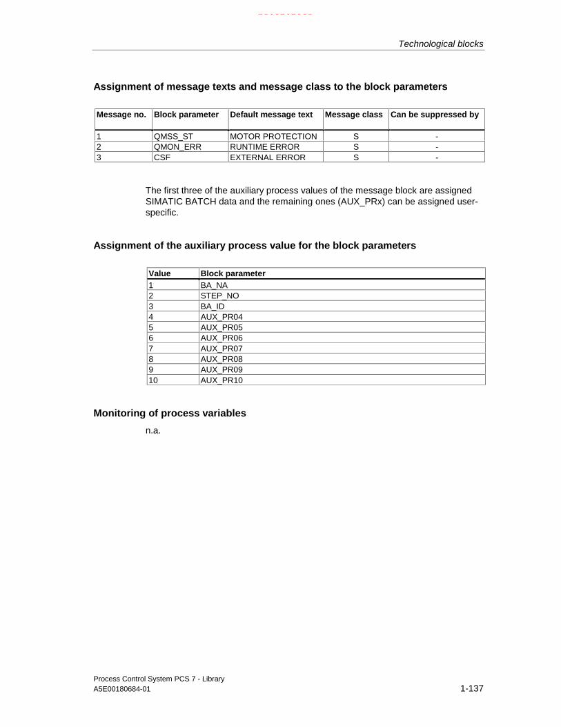
Technological blocks
Process Control System PCS 7 - LibraryA5E00180684-01 1-137
Assignment of message texts and message class to the block parameters
Message no. Block parameter Default message text Message class Can be suppressed by
1 QMSS_ST MOTOR PROTECTION S -2 QMON_ERR RUNTIME ERROR S -3 CSF EXTERNAL ERROR S -
The first three of the auxiliary process values of the message block are assignedSIMATIC BATCH data and the remaining ones (AUX_PRx) can be assigned user-specific.
Assignment of the auxiliary process value for the block parameters
Value Block parameter1 BA_NA2 STEP_NO3 BA_ID4 AUX_PR045 AUX_PR056 AUX_PR067 AUX_PR078 AUX_PR089 AUX_PR0910 AUX_PR10
Monitoring of process variables
n.a.
21.02.2003

Technological blocks
Process Control System PCS 7 - Library1-138 A5E00180684-01
1.4.1.2 MOT_REV: I/Os
I/O(parameter)
Meaning Datatype
Default Type Attrib. OCM Validvalues
AUT_L Interconnectable input forMANUAL/AUTO (0=Manual/1=Auto)
BOOL 0 I Q
AUT_ON_OP Operator input:1 = AUTO, 0 = MANUAL
BOOL 0 IO B +
AUTO_DIR AUTO mode (rotary direction):1 = anticlockwise,0 = clockwise
BOOL 0 I Q
AUTO_ON AUTO mode:1 = ON,0 = Off
BOOL 0 I Q
AUTOP_EN 1 = enable AUTO operation BOOL 1 I Q
AUX_PRx Auxiliary process value x ANY 0 IO Q
BA_EN Batch enable BOOL 0 I Q +
BA_ID Current batch ID DWORD 0 IO Q +
BA_NA Batch name STRING[16]
0 I Q +
CSF Control System Fault BOOL 0 I Q
FAULT_OFF 1 = In case of Fault: Motor OFF BOOL 1 I Q
FB_DIR Feedback of rotary direction:1 = anticlockwise0 = clockwise
BOOL 0 I Q
FB_ON Feedback:1=ON
BOOL 0 I Q
FORW_ON 1 = set clockwise direction BOOL 0 IO B +
FW_OP_EN 1 = enable operator input of clockwisedirection
BOOL 1 I Q
L_FORW AUTO mode:1 = set clockwise direction
BOOL 0 I Q
L_OFF AUTO mode:1 = Motor OFF
BOOL 0 I Q
L_RESET Interconnectable RESET input BOOL 0 I Q
L_REV AUTO mode:1 = set anticlockwise direction
BOOL 0 I Q
LINK_MAN 0 = enable operator input BOOL 0 I Q
LIOP_SEL Interconnectable input forMANUAL/AUTO changeover (AUT_L)1 = interconnection is active0 = operation enabled
BOOL 0 I Q
LOCK 1 = reset lock (OFF) BOOL 0 I Q +
LOCK_DIR 1=REV, 0=FORW
Rotary direction when LOCK_ON = 11 = clockwise,0 = anticlockwise
BOOL 0 I Q +
21.02.2003

Technological blocks
Process Control System PCS 7 - LibraryA5E00180684-01 1-139
I/O(parameter)
Meaning Datatype
Default Type Attrib. OCM Validvalues
LOCK_ON 1 = set lock (ON) BOOL 0 I Q +
MANOP_EN 1 = enable manual mode BOOL 1 I
MONITOR 1 = Monitoring ON BOOL 1 I Q +
MOT_OFF 1 = Motor OFF BOOL 0 IO B +
MSG_ACK Message acknowledged WORD 0 O
MSG_EVID Message number DWORD 0 I M
MSG_STAT Error message status WORD 0 O
MSS Motor protective circuit-breaker:(active low; i.e. 0 = error
BOOL 1 I Q
MSS_OFF 1 = In case of MSS fault: Motor stop BOOL 1 I Q
OCCUPIED Occupied by batch BOOL 0 I Q +
OFFOP_EN 1 = enable operator input of motor"OFF"
BOOL 1 I Q
OOS Reserve BOOL 0 I +
QAUTOP 1 = enable AUTO mode BOOL 0 O +
QC_FB_DIR Quality Code for FB_DIR BYTE 16#80 I
QC_FB_ON Quality Code for FB_ON BYTE 16#80 I
QC_QDIR Quality Code for QDIR BYTE 16#80 O
QC_QDIR_I Quality Code for output QDIR BYTE 16#80 I
QC_QSTART Quality Code for QSTART BYTE 16#80 O
QC_QSTART_I
Quality Code for output QSTART BYTE 16#80 I
QDIR Direction control output:1 = anticlockwise
BOOL 0 O +
QERR 1 = error output (inverted ENO) BOOL 1 O +
QFORW_OP 1 = enable operator input of:set clockwise direction
BOOL 0 O +
QGR_ERR 1 = group error message BOOL 0 O
QMAN_AUT 0 = MANUAL1 = AUTO
BOOL 0 O +
QMANOP 1 = enable manual mode BOOL 0 O +
QMON_ERR 1 = monitoring error BOOL 0 O +
QMSG_ERR 1 = ALARM8_P error BOOL 0 O +
QMSG_SUP 1 = message suppression BOOL 0 O +
QMSS_ST Unacknowledged motor protectivecircuit-breaker
BOOL 0 O +
QOFF_OP Operator input: 1 = motor OFF BOOL 0 O +
QOP_ERR 1 = group operator error message BOOL 0 O
QREV_OP 1 = reverse operation output BOOL 0 O +
QRUN 1 = motor is running BOOL 0 O +
QSTART Control output Start: 1 = ON BOOL 0 O +
QSTOP 1 = motor STOP BOOL 0 O +
21.02.2003

Technological blocks
Process Control System PCS 7 - Library1-140 A5E00180684-01
I/O(parameter)
Meaning Datatype
Default Type Attrib. OCM Validvalues
RESET Error RESET input, controllable byoperator
BOOL 0 IO B +
REV_ON Operator input:1 = anticlockwise rotation ON
BOOL 0 IO B +
RUNUPCYC Number of run-up cycles INT 3 I
RV_OP_EN 1 = operator input of anticlockwisedirection
BOOL 1 I Q
SAMPLE_T Sampling time [s] REAL 1.0 I >0
START_OFF 1 = startup with Motor OFF BOOL 1 I Q
STEP_NO Batch step number WORD 0 IO Q +
TIME_OFF Monitoring time for OFF [s] REAL 3.0 I + ≥ 0
TIME_ON Monitoring time for ON [s] REAL 3.0 I + ≥ 0
USTATUS Status word in VSTATUS, can be setuser-specific
WORD 0 I
VSTATUS Extended status display in the blockicons
DWORD 0 O
21.02.2003

Technological blocks
Process Control System PCS 7 - LibraryA5E00180684-01 1-141
1.4.1.3 MOT_REV: Operator control and monitoring
The tables show the assignment of the parameters of the AS block to the I/O fieldsof the faceplate.
Display I/O field Operatorauthoriza-tion
AS block parameters Operator text inthe log
(Symbol motor)
Status
(upper display field, empty)
Forward
Reverse
Stop
QRUN&QDIR
QRUN&QDIR
QSTOP
(middle display field, empty)
Monitoring QMON_ERR
(lower display field, empty)
Protection QMSS_ST
Mode
(selection list:
Manual/Automatic) 5
QMAN_AUT
AUT_ON_OP=0/1 Manual mode/
Automatic mode
Command
(selection list:
Forward
Stop
Reverse)
5
5
5
FORW_ON=1
MOT_OFF=0
REV_ON=0
Motor forwards
5
5
5
FORW_ON=0
MOT_OFF=0
REV_ON=1
Motor reverse
5
5
5
FORW_ON=0
MOT_OFF=1
REV_ON=0
Motor off
Monitoring/protection
Reset 5 RESET =1 Error reset
(symbol bell) QMSG_SUP
(symbol batch) OCCUPIED
Default
(symbol lock) LOCK
21.02.2003

Technological blocks
Process Control System PCS 7 - Library1-142 A5E00180684-01
Display I/O field Operatorauthoriza-tion
AS block parameters Operator text inthe log
Monitoring time
on [s]
(in the corresponding input dialogbox
HL=
Time
LL=)
6
6
TIME_ON
(no check)
TIME_ON
0,0
Mon. time on
Mon. time on
off [s]
(in the corresponding input dialogbox
HL=
Time
LL=)
6
6
TIME_OFF
(no check)
TIME_OFF
0,0
Mon. time off
Mon. time off
Maintenance
Active (=active) 6 MONITOR = 0/1 Monitoring off/on
Display I/O field Operatorauthoriza-tion
Parametersof the AS block
Operator textin the log
Batch control
Enable BA_EN
Occupied OCCUPIED
Batch
Name BA_NA
Batch
Step STEP_NO
1.4.1.4 MOT_REV: VSTATUS
The 32-bit status word is used for extended status indication in the block icons andin the faceplates. The block uses the 16 LSB bits (bit 0 – 15) as follows:
Bit no.: 7 6 5 4 3 2 1 0
Parameter QMON_ERR
- QMSS_ST - QMAN_AUT - BA_EN OCCUPIED
Bit no.: 15 14 13 12 11 10 9 8
Parameter OOS QMSG_SUP - - QDIR QSTOP QRUN LOCK
The 16-bit input USTATUS (data type WORD) uses the MSB bits (Bit 16 - 31).These bits can be set user-specific.
21.02.2003

Technological blocks
Process Control System PCS 7 - LibraryA5E00180684-01 1-143
1.4.2 MOT_SPED: Motor with two speeds
1.4.2.1 MOT_SPED: Description
Object name (type + number)
FB 68
Calling OBs
The watchdog interrupt OB in which you install the block (for example OB32). It isalso installed in OB100 (see startup characteristics).
Function
The block is used to control two-speed motors (slow/rapid). The two feedbacksignals output by the contactor relays can be monitored.
Operating principle
Various inputs are available for controlling the motor. These are implemented in adefined hierarchical dependency to each other and to the motor states. In particularthe interlock, the feedback monitoring and the motor protective circuit-breakerfunctions influence the control signals QSTART (1: on, 0: off) and QSPEED (1:fast, 0: slow).
The allocation of priorities to individual input variables and events with regard totheir influence on the control signals is shown in the following table. The sectionsbelow provide further details.
Priority: Event:High Motor protection error, if MSS_OFF = 1
LOCK = 1 LOCK_ON = 1 (with LOCK_SPD)
Monitoring error, if FAULT_OFF = 1Low Automatic/Manual modeNo effect Motor protection error, if MSS_OFF = 0
Monitoring error, if FAULT_OFF = 0Control system error, operator error
Note
Deceleration times during changeover from rapid speed to slow speed must be setby means of an external timer (on delay).
21.02.2003

Technological blocks
Process Control System PCS 7 - Library1-144 A5E00180684-01
Manual/Automatic
The mode is set either via operator control of AUT_ON_OP via the OS, or bymeans of an interconnection at the AUT_L input, provided the functions requiredare enabled. The set operating mode is indicated at output QMAN_AUT (1: Auto,0: Manual).
• Manual mode: This operating mode permits operator control via the OS orcontrol by means of interconnectable inputs.
- Operator control via OS: (LINK_MAN = 0): The following inputs can beoperated at the OS: SP1_ON for slow speed, SP2_ON for rapid speed orMOT_OFF for switching off the motor. The appropriate parameters(S1_OP_EN, S2_OP_EN or OFFOP_EN) must be set accordingly.
- Operation via interconnectable inputs: (LINK_MAN = 1): In this casethe commands are input at L_SP1, L_SP2 and L_OFF. You caninterconnect these inputs to allow tracking or local control, for example.Note that you must set the switches LINK_MAN, LIOP_SEL and AUT_L bymeans of a suitable logic.
• Auto mode. An automatic function block interconnection outputs the automode instructions to the inputs AUTO_ON (1: ON, 0: OFF) or AUTO_SPD (1:fast, 0: slow).
Interlock
The interlock function takes priority over all other control signals and errors - withthe exception of the motor protective circuit-breaker when a corresponding enablesignal is set (MSS_OFF = 1). The motor is switched off directly when LOCK is set.It is switched on when LOCK_ON is set, provided that LOCK is not also set.LOCK_SPD is used to specify the desired speed for LOCK_ON = 1 (1: rapid, 0:slow).
Monitoring
The monitoring logic monitors consistency between the control commandsQSTART or QSPEED and the process variable feedback signals FB_ON orFB_SPEED and outputs the actual state via QRUN and QSTOP. It sets amonitoring error (QMON_ERR = 1) if after the period TIME_MON has expired nofeedback corresponding to QSTART or QSPEED is set or if it changesunexpectedly without a request by QSTART or QSPEED.
If there is no feedback, either QSTART can be interconnected to FB_ON andQSPEED to FB_SPEED, or monitoring can be disabled by setting MONITOR = 0.
The FAULT_OFF parameter determines the significance of the monitoring error.When FAULT_OFF = 1, the motor is switched off when a fault occurs; this errorstatus does not affect the control outputs if FAULT_OFF = 0.
21.02.2003

Technological blocks
Process Control System PCS 7 - LibraryA5E00180684-01 1-145
Motor protection
At the negative edge of the motor protection signal MSS, the motor protection erroris held and passed to the output QMSS_ST. The MSS_OFF parameter determineswhether the error state is only indicated (MSS_OFF=0), or whether the motor is tobe limited irrespective of all other inputs and system states (MSS_OFF = 1).
Bumpless changeover
In order to ensure bumpless changeover to manual mode in all operating modes,the manual values SP1_ON, SP2_ON and MOT_OFF are always corrected to thecurrent values of QSTART and QSPEED.
Error handling
Faults at the motor protective circuit-breaker (QMSS_ST = 1) and monitoring errors(QMON_ERR=1) are reported to the OS and influence the block as describedabove. You can either reset these error states via the RESET input or let thesystem automatically reset these states at the next positive edge at MSS byinterconnecting L_RESET to a "1" signal. The control system fault CSF is merelyreported to the OS and applied to the group error QGR_ERR alongside with themotor protection and monitoring error. It does not have any further influence on theblock algorithm.
Operator errors are indicated at output QOP_ERR, without a message.
Startup after error status
The system makes a differentiation based on the operating mode active at themoment of reset:
• In automatic mode, the motor can restart after the reset, provided acorresponding start signal is supplied by the automatic mode.
• In manual mode, the motor must be switched on explicitly, since manualoperation had been tracked to "OFF".
Startup characteristics
When the CPU starts, the MOTOR block is switched to manual mode and the OFFcommand is output. The block must be called in the startup OB accordingly. InCFC engineering this action is handled by the CFC. Using the basic STEP 7 tools,you must enter the call in the startup OB. After the startup, messages will besuppressed during the number of cycles defined in RUNUPCYC.
The START_OFF input is used to specify whether the motor controls are switchedoff when the CPU is started (START_OFF=1) or whether the last operating state isheld.
21.02.2003

Technological blocks
Process Control System PCS 7 - Library1-146 A5E00180684-01
Time response
The block must be called via a watchdog interrupt OB. The SAMPLE_T parametercontains the sampling time of the block.
Assignment of the 32-bit status word VSTATUS
The 32-bit status word is used for extended status indication in the block icons andin the faceplates. The block uses the 16 LSB bits (bit 0 – 15) as follows:
Bit no.: 7 6 5 4 3 2 1 0
Parameter QMON_ERR - QMSS_ST - QMAN_AUT - BA_EN OCCUPIED
Bit no.: 15 14 13 12 11 10 9 8
Parameter OOS QMSG_SUP QSTOPING QSTRTING QSPEED QSTOP QRUN LOCK
The 16-bit input USTATUS (data type WORD) uses the MSB bits (Bit 16 - 31).These bits can be set user-specific.
Message characteristics
The MOT_SPED block uses the ALARM8_P block to generate messages.Messages are triggered by:
• A control system fault
• The motor protective circuit-breaker signal and the monitoring error (runtimeerror)
• The CSF signal, which is referenced by interconnection.
QMSG_SUP is set if the RUNUPCYC cycles have not expired since the restart, orif MSG_STAT = 21.
Assignment of message texts and message class to the block parameters
Message No. Block parameter Default message text Message class Can be suppressed by
1 QMSS_ST MOTOR PROTECTION S -2 QMON_ERR RUNTIME ERROR S -3 CSF EXTERNAL ERROR S -
The first three of the auxiliary process values of the message block are assignedSIMATIC BATCH data and the remaining ones (AUX_PRx) can be set user-specific.
21.02.2003

Technological blocks
Process Control System PCS 7 - LibraryA5E00180684-01 1-147
Assignment of auxiliary process values to the block parameters
Value Block parameter1 BA_NA2 STEP_NO3 BA_ID4 AUX_PR045 AUX_PR056 AUX_PR067 AUX_PR078 AUX_PR089 AUX_PR0910 AUX_PR10
Monitoring of process values
n.a.
1.4.2.2 MOT_SPED: I/Os
I/O(parameter)
Meaning Datatype
Default Type Attrib. OCM Validvalues
AUT_L Interconnectable input forMANUAL/AUTO(0=Manual/1=Auto)
BOOL 0 I Q
AUT_ON_OP Mode input1=AUTO,0= MANUAL
BOOL 0 IO B +
AUTO_ON AUTO mode:
1 = ON0 = OFF
BOOL 0 I Q
AUTO_SPD Automatic speed value:1 = rapid
BOOL 0 I Q
AUTOP_EN 1 = enable AUTO mode BOOL 1 I Q
AUX_PRx Auxiliary process value X ANY 0 IO Q
BA_EN BATCH enable BOOL 0 I Q +
BA_ID Current batch ID DWORD 0 IO Q +
BA_NA Batch name STRING[16]
0 I Q +
CSF Control System Fault1 = external error
BOOL 0 I Q
FAULT_OFF 1 = stop motor on fault BOOL 1 I Q
FB_ON Feedback: 1 = on BOOL 0 I Q
FB_SPEED Speed feedback: 1 = rapid BOOL 0 I Q
L_OFF AUTO mode: 1 = Motor off BOOL 0 I Q
L_RESET Interconnectable input RESET BOOL 0 I Q
21.02.2003

Technological blocks
Process Control System PCS 7 - Library1-148 A5E00180684-01
I/O(parameter)
Meaning Datatype
Default Type Attrib. OCM Validvalues
L_SP1 AUTO mode:1 = Clockwise rotation ON
BOOL 0 I Q
L_SP2 AUTO mode:1 = Anticlockwise rotation ON
BOOL 0 I Q
LINK_MAN 0 = Operator input enabled,1 = Manual control via L_SP1,L_SP2, L_MOTOFF
BOOL 0 I Q
LIOP_SEL Interconnectable input forManual/Auto- changeover (AUT_L)1 = interconnection active0 = Operator control enabled
BOOL 0 I Q
LOCK 1 = lock (OFF) BOOL 0 I Q +
LOCK_ON 1 = lock (ON) BOOL 0 I Q +
LOCK_SPD Speed at LOCK_ON = 11 = rapid, 0 = slow
BOOL 0 I Q +
MANOP_EN 1 = enable manual operation BOOL 1 I Q
MONITOR Monitoring: 1 = on BOOL 1 I +
MOT_OFF Operator input: 1 = motor off BOOL 0 IO B +
MSG_ACK Message acknowledged WORD 0 O
MSG_EVID Message number DWORD 0 I M
MSG_STAT Error message status WORD 0 O
MSS Motor protective circuit-breaker(active low, i.e. 0 = error)
BOOL 1 I Q
MSS_OFF 1 = motor off on protection fault BOOL 1 I Q
OCCUPIED Occupied by BATCH BOOL 0 I Q +
OFFOP_EN 1 = disable operator control ofmotor
BOOL 1 I Q
OOS Reserve BOOL 0 I +
QAUTOP 1 = enable AUTO operation BOOL 0 O +
QC_FB_ON Quality Code for FB_ON BYTE 16#80 I
QC_FB_SPEED Quality Code for FB_SPEED BYTE 16#80 I
QC_QSPEED Quality Code for QSPEED BYTE 16#80 O
QC_QSPEED_I Quality Code for Output QSPEED BYTE 16#80 I
QC_QSTART Quality Code for QSTART BYTE 16#80 O
QC_QSTART_I Quality Code for Output QSTART BYTE 16#80 I
QERR 1 = error output (Inverted ENO) BOOL 1 O +
QGR_ERR 1 = group error BOOL 0 O
QMAN_AUT 0 = MANUAL, 1 = AUTO BOOL 0 O +
QMANOP 1 = enable manual mode BOOL 0 O +
QMON_ERR 1 = monitoring error BOOL 0 O +
QMSG_ERR 1 = message error BOOL 0 O +
QMSG_SUP 1 = set message suppression BOOL 0 O +
QMSS_ST hold motor protection error(1 = error)
BOOL 0 O +
21.02.2003

Technological blocks
Process Control System PCS 7 - LibraryA5E00180684-01 1-149
I/O(parameter)
Meaning Datatype
Default Type Attrib. OCM Validvalues
QOFF_OP 1 = disable operator control ofmotor
BOOL 0 O +
QOP_ERR 1 = runtime error BOOL 0 O
QRUN 1 = motor running BOOL 0 O +
QS1_OP 1 = enable start speed 1 BOOL 0 O +
QS2_OP 1 = enable start speed 2 BOOL 0 O +
QSPEED Speed control output:1 = rapid
BOOL 0 O +
QSTART Control output: 1 = on BOOL 0 O
QSTOP 1 = Motor stop BOOL 0 O +
QSTOPING Reserve message BOOL 0 O +
QSTRTING Reserve message BOOL 0 O +
RESET Operator controllable error resetinput
BOOL 0 IO B +
RUNUPCYC Number of initial run cycles INT 3 I
S1_OP_EN 1 = enable start speed 1 BOOL 1 I Q
S2_OP_EN 1 = enable start speed 2 BOOL 1 I Q
SAMPLE_T Sampling time [s] REAL 1,0 I > 0
SP1_ON 1 = Start speed 1 on BOOL 0 IO B +
SP2_ON 1 = Start speed 2 on BOOL 0 IO B +
START_OFF 1 = Motor OFF at startup: BOOL 1 I Q
STEP_NO BATCH step number DWORD 0 IO Q +
TIME_MON Monitoring time [s] REAL 3.0 I + ≥ 0
USTATUS Status word in VSTATUS, free foruser
WORD 0 I
VSTATUS Extended status display in the blockicons
DWORD 0 O
For information on abbreviations used refer to: General information on the blockdescription
21.02.2003

Technological blocks
Process Control System PCS 7 - Library1-150 A5E00180684-01
1.4.2.3 MOT_SPED: Operator control and monitoring
The tables show the assignment of the parameters of the AS block to the I/O fieldsof the faceplate.
Display I/O field Operatorauthoriza-tion
AS block parameters Operator text inthe log
(Symbol motor)Status
(upper display field, empty)stopslowfast
QSTOPING; QSTOP
QSTRTING; QRUN
QSPEED(middle display field, empty)Monitoring QMON_ERR(lower display field, empty)Protection QMSS_ST
Mode:
(selection list: Manual/Automatic) 5
QMAN_AUT
AUT_ON_OP =0/1 Manual mode/
Automatic modeCommand
(selection list:fastslowStop)
5
5
5
SP1_ON=1
SP2_ON=0
MOT_OFF =0
Motor speed 1
5
5
5
SP1_ON=0
SP2_ON=1
MOT_OFF =0
Motor speed 2
5
5
5
SP1_ON=0
SP2_ON=0
MOT_OFF =1
Motor off
Monitoring/protectionReset 5 RESET =1 Error reset
(symbol bell) QMSG_SUP(symbol batch) OCCUPIED
Default
(symbol lock) LOCK
21.02.2003

Technological blocks
Process Control System PCS 7 - LibraryA5E00180684-01 1-151
Display I/O field Operatorauthoriza-tion
AS block parameters Operator text inthe log
Monitoring time
on/off s (=in sec)
(in the corresponding inputdialog box:
HL=
Time
LL=)
6
6
TIME_MON
(no check)
TIME_MON
0,0
Mon. time on/off
Mon. time on/off
Active 6 MONITOR =0/1 Monitoring off/on
Maintenance
Batch control
Enable BA_EN
Occupied OCCUPIED
Batch
Name BA_NA
Batch
Step STEP_NO
1.4.2.4 MOT_SPED: VSTATUS
The 32-bit status word extends the status display in the block icons and faceplates.The 16 low bits (bits 0 - 15) are used by the block as follows:
Bit no.: 7 6 5 4 3 2 1 0
Parameter QMON_ERR - QMSS_ST - QMAN_AUT - BA_EN OCCUPIED
Bit no.: 15 14 13 12 11 10 9 8
Parameter OOS QMSG_SUP QSTOPING QSTRTING QSPEED QSTOP QRUN LOCK
The 16-bit input USTATUS (data type WORD) uses the high bits (bits 16 - 31).These bits can be used freely.
21.02.2003

Technological blocks
Process Control System PCS 7 - Library1-152 A5E00180684-01
1.4.3 MOTOR: Motor with control signal
1.4.3.1 MOTOR: Description
Object name (type + number)
FB 66
Calling OBs
The watchdog interrupt OB in which you install the block (for example OB32). It isalso installed in OB100 (see startup characteristics).
Function
The block is used to control motors by means of a control signal (on/off). The motorspeed feedback (on/off) can be monitored optionally. This motor speed feedbacksignal is provided by a contactor relay.
Operating principle
Various inputs are available for controlling the motor. They are implemented in aconcrete hierarchical dependency to each other and to the motor states. Inparticular the locking, the feedback monitoring and the motor circuit breakerinfluence the control signals QSTART.
The allocation of priorities to individual input variables and events with regard totheir influence on the control signal is listed in the following table. The sectionsbelow provide further details.
Priority: Event:High Motor protection error, if MSS_OFF = 1
LOCK = 1 LOCK_ON = 1
Monitoring error, if FAULT_OFF = 1Low Automatic/Manual modeNo effect Motor protection error, if MSS_OFF = 0
Monitoring error, if FAULT_OFF = 0Control system error, operator error
21.02.2003

Technological blocks
Process Control System PCS 7 - LibraryA5E00180684-01 1-153
Manual/Automatic
The operator can set the mode either at OS operator control by means ofAUT_ON_OP (LIOP_SEL = 0) or by interconnecting the input AUT_L(LIOP_SEL = 1). If the OS system is used, the corresponding enable signalsAUTOP_EN and MANOP_EN must be set. The set operating mode is indicated atthe output QMAN_AUT (1: Auto, 0: Manual).
• Manual mode: Operations are performed by the OS system via the inputMAN_ON, if the corresponding enable signals ON_OP_EN and OFFOP_ENare set.
• Automatic mode: An automatic unit outputs the control commands via theinterconnected input AUTO_ON.
Interlock
The interlock function takes priority over all other control signals and errors - withthe exception of the motor protection when the corresponding enable signal is set(MSS_OFF = 1). When LOCK is set, the motor is switched off directly. The motor isswitched on directly when LOCK_ON is set, provided that LOCK is not also set.
Monitoring
The monitoring logic monitors consistency between the control command QSTARTand the process variable feedback FB_ON and outputs the actual state via QRUNand QSTOP. It sets a monitoring error (QMON_ERR = 1) if after the periodTIME_MON no feedback corresponding to QSTART has been set or if it changesunexpectedly without a request by QSTART.
If there is no feedback, either QSTART can be interconnected to FB_ON ormonitoring can be disabled by setting MONITOR = 0.
The parameter FAULT_OFF specifies the relevance of the monitoring error. IfFAULT_OFF = 1, the motor is switched off when a fault occurs. This error statusdoes not affect the control outputs when FAULT_OFF = 0.
Motor protection
At the negative edge of the motor protection signal MSS, the motor protection erroris held and passed to the output QMSS_ST. The parameter MSS_OFF is used tospecify whether only to indicate the error status (MSS_OFF=0), or whether themotor is to be limited irrespective of all other inputs and system states(MSS_OFF = 1).
Bumpless changeover
In order to ensure a bumpless changeover to manual mode, the manual valueMAN_ON is always corrected to the current value of QSTART.
21.02.2003

Technological blocks
Process Control System PCS 7 - Library1-154 A5E00180684-01
Error handling
The motor protection error (QMSS_ST = 1) and the monitoring error(QMON_ERR=1) are reported to the OS and influence the block functions asdescribed above. The errors can be reset either by the operator via the RESETinput, or automatically at the next positive edge of MSS by interconnectingL_RESET with a "1" signal. The control system fault CSF is merely reported to theOS and applied to the group error QGR_ERR parameter alongside with the motorprotection and monitoring errors. It does not have any further influence on theblock algorithm.
Operator errors are indicated at output QOP_ERR, without a message.
Startup after error state
The system makes a differentiation based on the operating mode active at themoment of reset:
• In automatic mode, the motor can restart after the reset, provided acorresponding start signal is supplied by the automatic mode.
• In manual mode, the motor must be switched on explicitly since manualoperation had been tracked to "OFF".
Startup characteristics
When the CPU starts, the MOTOR block is switched to manual mode and the OFFcommand is output. The block must be called in the startup OB accordingly. InCFC engineering this is handled by CFC. Using the basic STEP 7 tools, you mustenter this call in the startup OB. After startup, the messages will be suppressedduring number of cycles defined at RUNUPCYC.
The START_OFF input is used to specify whether the motor controls are to beswitched off when the CPU is started (START_OFF=1) or whether the lastoperating state is held.
Time response
The block must be called via a watchdog interrupt OB. The sampling time of theblock is entered in the parameter SAMPLE_T.
Assignment of the 32-bit status word VSTATUS
see MOTOR: VSTATUS
21.02.2003

Technological blocks
Process Control System PCS 7 - LibraryA5E00180684-01 1-155
Message characteristics
The MOTOR block uses the ALARM8_P block for generating messages.
The messages are triggered by
• Control system faults
• The signals of the motor protective circuit-breaker and the monitoring error(runtime error)
• The CSF signal, which is referenced as a control system error byinterconnection
QMSG_SUP is set if the RUNUPCYC cycles have not expired since the restart or ifMSG_STAT = 21.
Assignment of message texts and message class to the block parameters
Message no. Block parameter Default message text Message class Can be suppressed by1 QMSS_ST MOTOR PROTECTION S -2 QMON_ERR RUNTIME ERROR S -3 CSF EXTERNAL ERROR S -
The first three of the auxiliary process values of the message block are assignedSIMATIC BATCH data and the remaining ones (AUX_PRx) can be assigned user-specific.
Assignment of auxiliary process values to the block parameters
Value Block parameter1 BA_NA2 STEP_NO3 BA_ID4 AUX_PR045 AUX_PR056 AUX_PR067 AUX_PR078 AUX_PR089 AUX_PR0910 AUX_PR10
Monitoring of the process variable
n.a.
21.02.2003

Technological blocks
Process Control System PCS 7 - Library1-156 A5E00180684-01
1.4.3.2 MOTOR: I/Os
I/O(parameter)
Meaning Datatype
Default Type Attrib. OCM Validvalues
AUT_L Interconnectable input forMANUAL/AUTO (0=Manual/1=Auto)
BOOL 0 I Q
AUT_ON_OP Mode:1 = AUTO, 0 = MANUAL
BOOL 0 IO B +
AUTO_ON AUTO Mode:1 = ON; 0 = Off
BOOL 0 I Q
AUTOP_EN 1 = enable AUTO mode BOOL 1 I Q
AUX_PRx Auxiliary value x ANY 0 IO Q
BA_EN Batch enable BOOL 0 I Q +
BA_ID Current batch ID DWORD 0 IO Q +
BA_NA Batch name STRING[16]
0 I Q +
CSF Control System Fault1 = external error
BOOL 0 I Q
FAULT_OFF 1 = motor OFF In case of fault BOOL 1 I Q
FB_ON Feedback:1 = ON
BOOL 0 I Q
L_RESET Interconnectable RESET input BOOL 0 I Q
LIOP_SEL Interconnectable input forMANUAL/AUTO changeover (AUT_L)1 = Interconnection is active0 = enable operator control
BOOL 0 I Q
LOCK 1 = Lock (OFF) BOOL 0 I Q +
LOCK_ON 1 = Lock (ON) BOOL 0 I Q +
MAN_ON Manual mode:
1 = ON; 0 = OFF
BOOL 0 IO B +
MANOP_EN 1 = MANUAL mode enabled BOOL 1 I Q
MONITOR 1 = Monitoring ON BOOL 1 I +
MSG_ACK Message acknowledged WORD 0 O
MSG_EVID Message number DWORD 0 I M
MSG_STAT Error message status WORD 0 O
MSS Motor protecting switch:(active low, i.e. 0 = error
BOOL 1 I Q
MSS_OFF 1 = motor OFF in case of MSS fault BOOL 1 I Q
OCCUPIED Batch: occupied identifier BOOL 0 I Q +
OFFOP_EN 1 = enable motor "OFF" operation BOOL 1 I Q
ON_OP_EN 1 = enable motor ON operation BOOL 1 I Q
OOS Reserve BOOL 0 I +
QAUTOP 1 = enable AUTO mode BOOL 0 O +
QC_FB_ON Quality Code for FB_ON BYTE 16#80 I
QC_QSTART Quality Code for QSTART BYTE 16#80 O
QC_QSTART_I Quality Code for output QSTART BYTE 16#80 I
21.02.2003

Technological blocks
Process Control System PCS 7 - LibraryA5E00180684-01 1-157
QERR 1 = error (inverted ENO) BOOL 1 O +
QGR_ERR 1 = Group error BOOL 0 O
QMAN_AUT 1 = AUTO0 = MANUAL
BOOL 0 O +
QMANOP 1 = enable MANUAL mode BOOL 0 O +
QMON_ERR 1 = monitoring error BOOL 0 O +
QMSG_ERR 1 = message error BOOL 0 O +
QMSG_SUP 1 = message suppression enabled BOOL 0 O +
QMSS_ST Hold motor protection status(1 = error)
BOOL 0 O +
QOFF_OP 1 = motor enable OFF BOOL 0 O +
QON_OP 1 = enable ON BOOL 0 O +
QOP_ERR 1 = group operator error message BOOL 0 O
QRUN 1 = motor is running BOOL 0 O +
QSTART Control output start1 = on
BOOL 0 O +
QSTOP 1 = Motor STOP BOOL 0 O +
RESET Operator input:Error RESET
BOOL 0 IO B +
RUNUPCYC Number of run-up cycles INT 3 I
SAMPLE_T Sampling time [s] REAL 1.0 I > 0
START_OFF 1 = startup up with Motor OFF BOOL 1 I Q
STEP_NO Batch step number WORD 0 IO Q +
TIME_MON Monitoring time [s] REAL 3.0 I + > 0
USTATUS Status word in VSTATUS; can beconfigured user-specific
WORD 0 I
VSTATUS Extended status display in block icons DWORD 0 O
For information on abbreviations used refer to: General information on the blockdescription
21.02.2003
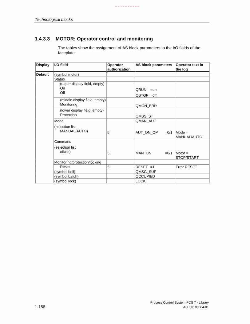
Technological blocks
Process Control System PCS 7 - Library1-158 A5E00180684-01
1.4.3.3 MOTOR: Operator control and monitoring
The tables show the assignment of AS block parameters to the I/O fields of thefaceplate.
Display I/O field Operatorauthorization
AS block parameters Operator text inthe log
(symbol motor)Status
(upper display field, empty)OnOff
QRUN =on
QSTOP =off(middle display field, empty)Monitoring QMON_ERR(lower display field, empty)Protection QMSS_ST
Mode
(selection list:MANUAL/AUTO) 5
QMAN_AUT
AUT_ON_OP =0/1 Mode =MANUAL/AUTO
Command
(selection list:off/on) 5 MAN_ON =0/1 Motor =
STOP/STARTMonitoring/protection/locking
Reset 5 RESET =1 Error RESET(symbol bell) QMSG_SUP(symbol batch) OCCUPIED
Default
(symbol lock) LOCK
21.02.2003

Technological blocks
Process Control System PCS 7 - LibraryA5E00180684-01 1-159
Display I/O field Operatorauthoriza-tion
Parameters of the ASblock
Operator text inthe log
Monitoring time
on/off s (=in sec)
(in the corresponding inputdialog box:
HL=
Time
LL=)
6
6
TIME_MON
(no check)
TIME_MON
0,0
Mon. time on/off
Mon. time on/off
Maintenance
Active 6 MONITOR =0/1 Monitoring off/on
Display I/O field Operatorauthoriz-ation
Parameters of the ASblock
Operator text inthe log
Batch controlEnable BA_ENOccupied OCCUPIED
BatchName BA_NA
Batch
Step STEP_NO
1.4.3.4 MOTOR: VSTATUS
The 32-bit status word extends the status display in the block icons and faceplates.The 16 low bits (bits 0 - 15) are used by the block as follows:
Bit no.: 7 6 5 4 3 2 1 0
Parameter QMON_ERR - QMSS_ST - QMAN_AUT - BA_EN OCCUPIED
Bit no.: 15 14 13 12 11 10 9 8
Parameter OOS QMSG_SUP
- - - QSTOP QRUN LOCK
21.02.2003

Technological blocks
Process Control System PCS 7 - Library1-160 A5E00180684-01
1.4.4 VAL_MOT: Motor valve control
1.4.4.1 VAL_MOT: Description
Object name (type + number)
FB 74
Calling OBs
The watchdog interrupt OB in which you install the block (for example OB32). It isalso installed in OB100 (see startup characteristics).
Function
The block is used to control motor-driven valves by means of two control signals.The valve can be stopped at any position. The two position feedback signals aregenerated by limit switches (open/closed).
Operating principle
Various inputs are available for controlling the motor-driven valve. These areimplemented in a defined hierarchical dependency to each other and to systemstates. In particular the interlock, the feedback or rotary direction monitoring andthe motor protective circuit-breaker influence the control signals QSTART (0: motoron, 1: motor off) and QOC (1: open, 0: close).
The allocation of priorities to the individual input variables and events with regardto their influence on the control signal is shown in the following table. The sectionsbelow provide further details.
Priority: Event:
High Motor protection fault, if MSS_OFF = 1
2 Monitoring error, if FAULT_OFF = 1
Waiting time at change of rotary direction
V_LOCK = 1
VL_CLOSE = 1
VL_OPEN = 1
2 VL_HOLD = 1
Low AUTO/MANUAL mode
No effect Motor protection fault, if MSS_OFF = 0
Monitoring error, if FAULT_OFF = 0
Control system error, operator error
21.02.2003

Technological blocks
Process Control System PCS 7 - LibraryA5E00180684-01 1-161
Manual/Automatic
The mode is changed over either at the OS by means of operator control ofAUT_ON_OP or via an interconnection at the AUT_L input, provided the functionsrequired are enabled. The set operating mode is indicated at output QMAN_AUT(1: Auto; 0: Manual).
• Manual mode: This operating mode permits control either at the OS or viainterconnectable inputs.
- Operator control at the OS (LINK_MAN = 0): The input OPEN_VAL isused for opening, CLOS_VAL for closing or STOP_VAL for stopping. Thefunctions required (OP_OP_EN, CL_OP_EN or ST_OP_EN) must beenabled.
- Operation via interconnectable inputs (LINK_MAN = 1): In this case thecommands are set at the inputs L_OPEN, L_CLOSE and L_STOP, whichyou can interconnect to allow tracking or local control, for example. Notethat you must select these functions at the switches LINK_MAN,LIOP_SEL and AUT_L by means of a suitable logic.
• Auto mode: An interconnected automatic function block outputs itsinstructions to the inputs AUTO_ON (1: on, 0: off) or AUTO_OC (1: open, 0:close).
Interlock
The interlock function takes priority over all other control inputs and is onlyoverridden by a motor protection fault or monitoring error if the relevant enablesignals have been set (MSS_OFF = 1, FAULT_OFF = 1). If V_LOCK is set, themotor-driven valve is brought to its idle position, which is defined by SS_POS. It isopened or closed respectively by VL_OPEN or VL_CLOSE.
VL_HOLD blocks the automatic and manual inputs and holds the last statusrequest. The priorities of the individual interlock inputs are described in theOperating principle section.
Monitoring
The monitoring logic (enabled with MONITOR = 1) verifies consistency betweenthe setpoint status (determined in QSTART and QOC) and the process variablefeedback of the valve (provided by FB_OPEN and FB_CLOSE). If the setpointstatus has not been reached after the monitoring time TIME_ON has expired,output QMON_ERR will be set. QMON_ERR is set immediately if the feedbackchanges without a reason (command).If no feedback signals are connected, a MONITOR = 0 signal must be output to themonitoring function. The monitor assumes in this case that the setpoint state of thevalve has been reached within the time TIME_ON.In error-free monitoring operation, the QOPENING and QCLOSING outputsindicate whether the valve is currently opening or closing, and the QOPENED andQCLOSED outputs indicate whether the valve has reached a final position.If the valve is stopped at an intermediate position, the direction of movement isindicated with QOPENING=1 or QCLOSING=1, while 0 will indicate the finalpositions.
21.02.2003

Technological blocks
Process Control System PCS 7 - Library1-162 A5E00180684-01
The FAULT_OFF parameter determines the significance of a monitoring error. IfFAULT_OFF = 1, the motor is switched off when a fault has been detected, and thevalve holds its current position. This fault status has no effect on the controloutputs when FAULT_OFF = 0, and the block thus behaves as if the monitoringfunction were switched off and indicates the monitoring error only at theQMON_ERR output.
The TIME_OFF parameter determines the waiting time until the motor can beswitched on again. QSTART = FALSE if the valve has reached the final position. Amotor restart in reverse direction when QSTART=TRUE is not performed unlessthe set period TIME_OFF has expired. (Also refer to reversing the direction oftravel).
Motor protection
At the negative edge of the motor protection signal MSS, the motor protection erroris held and passed to output QMSS_ST. The MSS_OFF parameter determinesonly to indicate the error status (MSS_OFF=0), or that the motor is switched offirrespective of all other inputs and system states (MSS_OFF = 1) and that thevalve idles in its current position.
Bumpless changeover
In order to ensure bumpless changeover to manual mode in all operating modes,the manual values OPEN_VAL, CLOS_VAL and STOP_VAL are always tracked tothe current values of QSTART and QDIR (exception: change in the direction ofrotation).
Reversing the direction of travel
If the direction of travel of the valve is reversed before reaches a final position, thefollowing steps are taken:
• The motor is stopped (QSTART=0).
• The internal OFF monitor waits for the time period TIME_OFF to expire andthen starts the motor in reverse direction, provided the OFF monitor does notreport an error.
Error handling
The motor protection fault (QMSS_ST = 1) and the monitoring error(QMON_ERR=1) are reported to the OS and influence the block algorithm asdescribed above. The operator can either reset these states via the RESET input,or automatically at the next positive edge at MSS by interconnecting L_RESETwith a "1" signal. The control system fault CSF is merely reported to the OS andapplied to the group error QGR_ERR alongside with the motor protection andmonitoring errors. It does not have any further influence on the block algorithm.
Operator errors are indicated at output QOP_ERR without message.
21.02.2003
Technological blocks
Process Control System PCS 7 - LibraryA5E00180684-01 1-163
Startup after error status
The system makes a differentiation based on the operating mode active at themoment of reset:
• In automatic mode, the motor valve cannot start up again unless the monitoringor motor protection error is reset and a corresponding start signal is providedby the automation system.
• In manual mode, the motor must be switched on explicitly, since manualoperation had been tracked to "HOLD".
Startup characteristics
When the CPU starts, the VAL_MOT block is switched to manual operation and theHOLD command is output. This block must be called in the startup OB accordingly.In CFC engineering this is handled by the CFC. Using the basic STEP 7 tools, youmust enter this call manually in the startup OB. After startup, the messages will besuppressed during the number of cycles set at RUNUPCYC.
Time response
The block must be called via a watchdog interrupt OB. The sampling time of theblock is entered in the parameter SAMPLE_T.
Assignment of the 32-bit status word VSTATUS
see VAL_MOT: VSTATUS
Message characteristics
The VAL_MOT block uses the ALARM8_P block to generate messages.
The messages are triggered by the control system faults:
• Motor protective circuit-breaker signals and monitoring errors (runtime error)
• The CSF signal, which is referenced as a control system error byinterconnection.
QMSG_SUP is set if the RUNUPCYC cycles have not expired since the restart or ifMSG_STAT = 21.
21.02.2003

Technological blocks
Process Control System PCS 7 - Library1-164 A5E00180684-01
Assignment of message texts and message class to the block parameters
Message No. Block parameter Default message text Message class Can be suppressed by1 QMSS_ST MOTOR PROTECTION S -2 QMON_ERR RUNTIME ERROR S -3 CSF EXTERNAL ERROR S -
The first three of the auxiliary process values of the message block are assignedSIMATIC BATCH data and the remaining ones (AUX_PRx) can be set user-specific.
Assignment of auxiliary process values to the block parameters
Value Block parameter1 BA_NA2 STEP_NO3 BA_ID4 AUX_PR045 AUX_PR056 AUX_PR067 AUX_PR078 AUX_PR089 AUX_PR0910 AUX_PR10
Monitoring of process variables
n.a.
21.02.2003

Technological blocks
Process Control System PCS 7 - LibraryA5E00180684-01 1-165
1.4.4.2 VAL_MOT: I/Os
I/O(parameter)
Meaning Data type Default Type Attrib. OCM Validvalues
AUT_L Interconnectable input forMAN/AUTO(0: Manual/1:Auto)
BOOL 0 I Q
AUT_ON_OP Operator input:1 = AUTO, 0 = MANUAL
BOOL 0 IO B +
AUTO_OC AUTO mode rotary direction:1 = Open 0 = Close
BOOL 0 I Q
AUTO_ON AUTO mode:1 = ON
BOOL 0 I Q
AUTOP_EN 1 = enable operator control ofAUTO
BOOL 1 I Q
AUX_PRx Auxiliary process value x ANY 0 IO Q
BA_EN Batch enable BOOL 0 I Q +
BA_ID Current batch ID DWORD 0 IO Q +
BA_NA Batch name STRING[16] 0 I Q +
CL_OP_EN 1 = enable CLOSE valve BOOL 1 I Q
CLOS_VAL Operator input:1 = CLOSE valve
BOOL 0 IO B +
CSF 1 = external error BOOL 0 I Q
FAULT_OFF 1 = Motor OFF in case of fault: BOOL 1 I Q
FB_CLOSE Feedback: 1 = closed BOOL 0 I Q
FB_OPEN Feedback: 1 = open BOOL 0 I Q
L_CLOSE AUTO mode: 1 = CLOSE valve BOOL 0 I Q
L_OPEN AUTO mode: 1 = OPEN valve BOOL 0 I Q
L_RESET Interconnectable RESET input BOOL 0 I Q
L_STOP AUTO Mode: 1 = STOP valve BOOL 0 I Q
LINK_MAN 0 = Operator input enabled1 = manual control via L_OPEN,L_CLOSE, L_STOP
BOOL 0 I Q
LIOP_SEL Interconnectable input formanual/automatic changeover(AUT_L)1 = Interconnection is active0 = operator control is enabled
BOOL 0 I Q
MANOP_EN 1 = enable manual mode BOOL 1 I Q
MONITOR 1 = monitoring ON BOOL 1 I +
MSG_ACK Message acknowledged WORD 0 O
MSG_EVID Message number DWORD 0 I M
MSG_STAT Error message status WORD 0 O
MSS Motor protective circuit-breaker:(active low, i.e. 0 = Error
BOOL 0 I Q
MSS_OFF 1 = Motor OFF in case of MSSfault
BOOL 1 I Q
21.02.2003

Technological blocks
Process Control System PCS 7 - Library1-166 A5E00180684-01
I/O(parameter)
Meaning Data type Default Type Attrib. OCM Validvalues
OCCUPIED Occupied by batch BOOL 0 I Q +
OOS Reserve BOOL 0 I +
OP_OP_EN 1 = enable OPEN valve BOOL 1 I Q
OPEN_VAL Operator input: 1 = OPEN valve BOOL 0 IO B +
QAUTOP 1 = enable AUTO mode BOOL 0 O +
QC_FB_CLOSE Quality Code for FB_CLOSE BYTE 16#80 I
QC_FB_OPEN Quality Code for FB_OPEN BYTE 16#80 I
QC_QSTART Quality Code for QSTART BYTE 16#80 O
QC_QSTART_I Quality Code for Output QSTART BYTE 16#80 I
QC_QOC Quality Code for QOC BYTE 16#80 O
QC_QOC_I Quality Code for Output QOC BYTE 16#80 I
QCL_OP 1 = CLOSE valve enabled BOOL 0 0 +
QCLOSED 1 = valve is closed BOOL 0 O +
QCLOSING 1 = valve is closing BOOL 0 O +
QERR 1 = error output (inverted ENO) BOOL 1 O +
QGR_ERR 1 = group error message BOOL 0 O
QMAN_AUT 0 = MANUAL1 = AUTO
BOOL 0 O +
QMANOP 1 = enable manual mode BOOL 0 O +
QMON_ERR 1 = monitoring error BOOL 0 O +
QMSG_ERR 1 = message error BOOL 0 O +
QMSG_SUP 1 = set message suppression BOOL 0 O +
QMSS_ST Unacknowledged motor protectionsignal
BOOL 0 O +
QOC Direction control output:1 = OPEN
BOOL 0 O
QOP_ERR 1 = operator error BOOL 0 O
QOP_OP 1 = OPEN valve enabled BOOL 0 O +
QOPENED 1 = valve is opened BOOL 0 O +
QOPENING 1 = valve is opening BOOL 0 O +
QST_OP 1 = STOP valve enabled BOOL 0 O +
QSTART Control output1 = motor ON
BOOL 0 O +
RESET Operator input:RESET error
BOOL 0 IO B +
RUNUPCYC Number of run-up cycles INT 3 I
SAMPLE_T Sampling time [s] REAL 1,0 I >0
SS_POS 0 = idle position closed BOOL 0 I Q
ST_OP_EN 1 = enable operator input:
STOP valve
BOOL 1 I Q
STEP_NO Batch step number WORD 0 IO Q +
STOP_VAL Operator input:1 = STOP valve
BOOL 0 IO B +
21.02.2003

Technological blocks
Process Control System PCS 7 - LibraryA5E00180684-01 1-167
I/O(parameter)
Meaning Data type Default Type Attrib. OCM Validvalues
TIME_OFF Motor OFF monitoring time [s] REAL 3,0 I + ≥ 0
TIME_ON Valve actuation time:Monitoring time [s]
REAL 3,0 I + ≥ 0
V_LOCK 1 = Lock (SS_POS) BOOL 0 I Q +
VL_CLOSE 1 = Lock (closed) BOOL 0 I Q +
VL_HOLD 1 = Lock (hold/disabled) BOOL 0 I Q +
VL_OPEN 1 = Lock (open) BOOL 0 I Q +
USTATUS Status word in VSTATUS; can beconfigured user-specific
WORD 0 I
VSTATUS Extended status display in blockicons
DWORD 0 O
For information on abbreviations used refer to: General information on the blockdescription
21.02.2003

Technological blocks
Process Control System PCS 7 - Library1-168 A5E00180684-01
1.4.4.3 VAL_MOT: Operator control and monitoring
The tables show the assignment of the parameters of the AS block to the I/O fieldsof the faceplate.
Display I/O field Operatorauthoriza-tion
AS block parameters Operator text in thelog
(Symbol motor valve)
Status
(upper display field, empty)
opening
Opened
closing
Closed
QOPENING
QOPENED
QCLOSING
QCLOSED
(middle display field, empty)
Monitoring QMON_ERR
(lower display field, empty)
Protection QMSS_ST
Mode
(selection list:
Manual/Automatic)
5
QMAN_AUT
AUT_ON_OP =0/1 Mode=Manual/Auto
Command
(selection list:
Open
Close
Stop)
5
5
5
OPEN_VAL =1
STOP_VAL =0
CLOS_VAL =0
Open valve
5
5
5
OPEN_VAL =0
STOP_VAL =0
CLOS_VAL =1
Close valve
5
5
5
OPEN_VAL =0
STOP_VAL =1
CLOS_VAL =0
Stop valve
Monitoring/protection
Reset 5 RESET =1 Error reset
(symbol bell) QMSG_SUP
(symbol batch) OCCUPIED
Default
(symbol lock) V_LOCK
21.02.2003

Technological blocks
Process Control System PCS 7 - LibraryA5E00180684-01 1-169
Display I/O field Operatorauthoriza-tion
Parameters of the ASblock
Operator text inthe log
Monitoring time
Open s (=in sec)
(in the corresponding inputdialog box:
HL=
Time
LL=)
6
6
TIME_ON
(no check)
TIME ON
0,0
Mon. time on
Mon. time on
Close s
(in the corresponding inputdialog box:
HL=
Time
LL=)
6
6
TIME_OFF
(no check)
TIME OFF
0,0
Mon. time off
Mon. time off
Maintenance
active 6 MONITOR =0/1 Monitoring off/on
Display I/O field Operatorauthoriza-tion
Parameters of the ASblock
Operator text inthe log
Batch control
Enable BA_EN
Occupied OCCUPIED
Batch
Name BA_NA
Batch
Step STEP_NO
1.4.4.4 VAL_MOT: VSTATUS
The 32-bit status word extends the status display in the block icons and faceplates.The 16 low bits (bits 0 - 15) are used by the block as follows:
Bit no.: 7 6 5 4 3 2 1 0
Parameter QMON_ERR - QMSS_ST - QMAN_AUT - BA_EN OCCUPIED
Bit no.: 15 14 13 12 11 10 9 8
Parameter OOS QMSG_SUP - QCLOSING QOPENING QCLOSED QOPENED V_LOCK
The 16-bit input USTATUS (data type WORD) uses the high bits (bits 16 - 31).These bits can be used freely.
21.02.2003

Technological blocks
Process Control System PCS 7 - Library1-170 A5E00180684-01
1.4.5 VALVE: Valve control
1.4.5.1 VALVE: Description
Object name (type + number)
FB 73
Calling OBs
The watchdog interrupt OB in which you install the block (for example OB32). It isalso installed in OB100 (see startup characteristics).
Function
The block is used to operate control valves (open/close fittings) by means ofcontrol signals (open/close). The position of rest of the valve can be the closed oropened state. The two position feedback signals (open/closed) are generated bythe limit switches and can be monitored.
Operating principle
Various inputs are available for controlling the valve. They are implemented in adefined hierarchical relationship to each other and to the valve states. In particularthe locking and feedback monitoring influence the control signal QCONTROL.
The allocation of priorities to the individual input variables and events with regardto their influence on the control signal is shown in the following table. Thesubsequent sections provide further details.
Priority: Event:High V_LOCK = 1
VL_CLOSE = 1 VL_OPEN = 1
Monitoring error, if FAULT_OFF = 1Low Automatic/Manual modeNo effect Monitoring error, if FAULT_OFF = 0
Control system error, operator error
21.02.2003

Technological blocks
Process Control System PCS 7 - LibraryA5E00180684-01 1-171
Position of rest
The position of rest of the controlled valve is signaled at input SS_POS (1: open, 0:closed). This only affects the definition of the control output QCONTROL (0:position of rest, valve terminated). The commands on input side remain unaffected(a "1" signal at the input always means "open").
Example: When SS_POS=1 (valve in "open” position), control outputQCONTROL=1 signal actuates the "Close valve" command.
Manual/Automatic
The mode is selected either via operator control of AUT_ON_OP at the OS, or bymeans of an interconnection at input AUT_L, provided the functions required areenabled. The set operating mode is indicated at output QMAN_AUT (1: Auto, 0:Manual).
• Manual mode: Input MAN_OC is operated via the OS. The correspondingenable parameters (OP_OP_EN or CL_OP_EN) must be set.
• Auto mode: The interconnection of the automation system outputs the controlcommands to input AUTO_OC (1: open, 0: close).
Interlock
The interlock function takes priority over all other control signals and errors. IfV_LOCK is set, the valve is set to its rest position (QCONTROL = 0). If V_LOCK isnot set, a locking state (open/closed) can also be selected directly via the inputsVL_OPEN and VL_CLOSE. The signal VL_CLOSE locks VL_OPEN.
Monitoring
The monitoring logic verifies consistency between the output control commandQCONTROL and the process variable feedback of the valve (FB_OPEN,FB_CLOSE). Output QMON_ERR will be set if the final position has not beenreached after the monitoring time TIME_MON has expired, or if the feedback signalchanges its status for no apparent reason (command), and the valve will be de-energized.If no limit feedback is connected, the status of MONITOR must be set to "0" and bereported to the monitoring function, which then assumes that the limit of the valvehas been reached within the time TIME_MON. Until then, QOPENING orQCLOSING is displayed.When the monitor operates error-free, the outputs QOPENING and QCLOSINGindicate whether the valve is opening or closing, while the outputs QOPENED andQCLOSED show whether the valve has reached the limit position.
The inputs NO_FB_xx and NOMON_xx are used to configure whether there is nofeedback of the "open" and "closed" (NO_FB_xx=1) states, or whether the existingfeedback should not be evaluated (NOMON_xx=1), for example due to the failureof the limit switch.
21.02.2003

Technological blocks
Process Control System PCS 7 - Library1-172 A5E00180684-01
The parameter FAULT_SS defines the significance of the monitoring error. IfFAULT_SS = 1, the motor is brought to a rest position defined in SS_POS in caseof a fault. The fault has no effect on the control outputs if FAULT_SS = 0.
Bumpless changeover
In order to ensure a bumpless changeover to manual mode, the manual valueMAN_OC is always tracked to the current value of QCONTROL.
Error handling
The monitoring error (QMON_ERR = 1) is reported to the OS and influences theblock functions as described above. The operator can either call the RESETfunction to reset the error or the block resets it automatically by an interconnectionat the rising edge of L_RESET. The control system fault CSF is merely reported tothe OS and is applied to the group error QGR_ERR alongside with the monitoringerror. It does not have any further influence on the block algorithm.
Operator errors are indicated at output QOP_ERR without message.
Startup after error status
The system makes a differentiation based on the operating mode active at themoment of reset:
• In automatic mode, the motor valve cannot start up again unless the monitoringor motor protection error is reset and a corresponding start signal is output bythe automation system.
• In manual mode the motor must be switched on explicitly, since manualoperation had been tracked to "HOLD".
Startup characteristics
During a CPU startup, the VALVE block is switched to manual mode and theQCONTROL=0 (rest position) signal is output. The block must be called in thestartup OB accordingly. In CFC engineering, this is handled by the CFC. Using thebasic STEP 7 tools, you must manually enter this call in the startup OB. Afterstartup, the messages will be suppressed during the number of cycles set atRUNUPCYC.
At the START_SS input parameter you can decide either to set the valve to safetystate when the CPU is started (START_SS=1) or to retain its last operating state.
Time response
The block must be called via a watchdog interrupt OB. The sampling time of theblock is set in the SAMPLE_T parameter.
21.02.2003

Technological blocks
Process Control System PCS 7 - LibraryA5E00180684-01 1-173
Assignment of the 32-bit status word VSTATUS
The 32-bit status word is used for extended status indication in the block icons andin the faceplates. The block uses the 16 LSB bits (bit 0 – 15) as follows:
Bit no.: 7 6 5 4 3 2 1 0
Parameter QMON_ERR - QMAN_AUT - BA_EN OCCUPIED
Bit no.: 15 14 13 12 11 10 9 8
Parameter OOS QMSG_SUP - QCLOSING QOPENING QCLOSED QOPENED V_LOCK
The 16-bit input USTATUS (data type WORD) uses the MSB bits (Bit 16 - 31).These bits can be set user-specific.
Message characteristics
The VALVE block uses the ALARM8_P block for generating messages.
Messages are triggered by the control system faults.
• The monitoring error (runtime error)
• The CSF signal which is referenced as a control system error byinterconnection.
QMSG_SUP is set if the RUNUPCYC cycles have not expired since the restart or ifMSG_STAT = 21.
Assignment of message texts and message class to the block parameters
Message No. Block parameter Default message text Message class Can be suppressed by1 QMON_ERR RUNTIME ERROR S -2 CSF EXTERNAL ERROR S -
The first three of the auxiliary process values of the message block are assignedSIMATIC BATCH data and the remaining ones (AUX_PRx) can be assigned user-specific.
21.02.2003

Technological blocks
Process Control System PCS 7 - Library1-174 A5E00180684-01
Assignment of auxiliary process values to the block parameters
Value Block parameter1 BA_NA2 STEP_NO3 BA_ID4 AUX_PR045 AUX_PR056 AUX_PR067 AUX_PR078 AUX_PR089 AUX_PR0910 AUX_PR10
Monitoring of process variables
n.a.
1.4.5.2 VALVE: I/Os
I/O(parameter)
Meaning Data type Default Type Attrib. OCM Validvalues
AUT_L Interconnectable input forMAN/AUTO(0: Manual/1:Auto)
BOOL 0 I Q
AUT_ON_OP Mode input:1=AUTO, 0= MANUAL
BOOL 0 IO B +
AUTO_OC AUTO mode rotary direction:1 = OPEN0 = CLOSE
BOOL 0 I Q
AUTOP_EN 1 = enable AUTO mode BOOL 1 I Q
AUX_PRx Auxiliary process value x ANY 0 IO Q
BA_EN Batch enable BOOL 0 I Q +
BA_ID Current batch ID DWORD 0 IO Q +
BA_NA Batch name STRING[16] 0 I Q +
CL_OP_EN 1 = enable CLOSE BOOL 1 I Q
CSF 1 = external fault BOOL 0 I Q
FAULT_SS 1 = Safe state position in case offault
BOOL 1 I Q
FB_CLOSE Feedback:1 = CLOSED
BOOL 0 I Q
FB_OPEN Feedback:1 = OPENED
BOOL 0 I Q
L_RESET Interconnectable RESET input BOOL 0 I Q
21.02.2003

Technological blocks
Process Control System PCS 7 - LibraryA5E00180684-01 1-175
I/O(parameter)
Meaning Data type Default Type Attrib. OCM Validvalues
LIOP_SEL Interconnectable input forMANUAL/AUTO changeover(AUT_L)1 = interconnection is active0 = operation enabled
BOOL 0 I Q
MAN_OC Operator input:1 = OPEN0 = CLOSE
BOOL 0 IO B +
MANOP_EN 1 = enable manual operation BOOL 1 I Q
MONITOR 1 = Monitoring ON,0 = Monitoring OFF
BOOL 1 I +
MSG_ACK Message acknowledged WORD 0 O
MSG_EVID Message number DWORD 0 I M
MSG_STAT Error message status WORD 0 O
NO_FB_CL Motor protective circuit-breaker:(active low, i.e. 0 = error
BOOL 0 I Q
NO_FB_OP 1 = no OPEN feedback BOOL 0 I Q
NOMON_CL 1 = no CLOSED feedback BOOL 0 I Q
NOMON_OP 1 = no OPENED feedback BOOL 0 I Q
OCCUPIED Occupied by batch BOOL 0 I Q +
OOS Reserve BOOL 0 I +
OP_OP_EN 1 = enable OPEN operation BOOL 1 I Q
QAUTOP 1 = enabled AUTO mode BOOL 0 O +
QC_FB_CLOSE
Quality Code for FB_CLOSE BYTE 16#80 I
QC_FB_OPEN
Quality Code for FB_OPEN BYTE 16#80 I
QC_QCONTROL
Quality Code for QCONTROL BYTE 16#80 O
QC_QCONTROL_I
Quality Code for outputQCONTROL
BYTE 16#80 I
QCL_OP 1 = enable CLOSE operation BOOL 0 O +
QCLOSED 1 = valve is CLOSED BOOL 0 O +
QCLOSING 1 = valve is CLOSING BOOL 0 O +
QCONTROL Control Output:0 = rest position
BOOL 0 O
QERR 1 = error output (inverted ENO) BOOL 1 O +
QGR_ERR 1 = group error BOOL 0 O
QMAN_AUT 1 = AUTO0 = MANUAL
BOOL 0 O +
QMANOP 1 = enable manual mode BOOL 0 O +
QMON_ERR 1 = monitoring error BOOL 0 O +
QMSG_ERR 1 = message error BOOL 0 O +
QMSG_SUP 1 = set message suppression BOOL 0 O +
QOP_ERR 1 = group error BOOL 0 O
21.02.2003

Technological blocks
Process Control System PCS 7 - Library1-176 A5E00180684-01
I/O(parameter)
Meaning Data type Default Type Attrib. OCM Validvalues
QOP_OP 1 = enable OPEN operation BOOL 0 O +
QOPENED 1 = valve is OPENED BOOL 0 O +
QOPENING 1 = valve is OPENING BOOL 0 O +
RESET Operator input of error reset BOOL 0 IO B +
RUNUPCYC Number of run-up cycles INT 3 I
SAMPLE_T Sampling time [s] REAL 1,0 I > 0
SS_POS Rest position1 = OPENED (type O),0 = CLOSED (type C)
BOOL 0 I Q
START_SS 1 = startup in safe state andmanual mode
BOOL 1 I Q
STEP_NO Batch step number WORD 0 IO Q +
TIME_MON Monitoring time [s] REAL 3,0 I + ≥ 0
V_LOCK 1 = Lock (SS_POS) BOOL 0 I Q +
VL_CLOSE 1 = Lock (closed) BOOL 0 I Q +
VL_OPEN 1 = Lock (open) BOOL 0 I Q +
USTATUS Status word in VSTATUS;definable by user
WORD 0 I
VSTATUS Extended status display in blockicons
DWORD 0 O
For information on abbreviations used refer to: General information on the blockdescription
21.02.2003

Technological blocks
Process Control System PCS 7 - LibraryA5E00180684-01 1-177
1.4.5.3 VALVE: Operator control and monitoring
The tables show the assignment of the parameters of the AS block to the I/O fieldsof the faceplate.
Display I/O field Operatorauthoriza-tion
Parameters of the ASblock
Operator text in the log
(Symbol motor valve)
Status
(upper display field, empty)
opening
Opened
closing
Closed
QOPENING
QOPENED
QCLOSING
QCLOSED
(lower display field, empty)
Monitoring
QMON_ERR
Mode:
(selection list:
Manual/Automatic) 5
QMAN_AUT
AUT_ON_OP =0/1 Mode=Manual/Auto
Command
(selection list:
open/close)
5 MAN_OC =0/1 Valve close/
valve open
Monitoring/locking
reset 5 RESET 0 / Error Reset
(symbol bell) Q_MSGSUP
(symbol batch) OCCUPIED
Default
(symbol lock) V_LOCK
21.02.2003

Technological blocks
Process Control System PCS 7 - Library1-178 A5E00180684-01
Display I/O field Operatorauthoriza-tion
Parameters of the ASblock
Operator text inthe log
Monitoring time
open/close s(=sin sec)
(in the corresponding inputdialog box:
HL=
Time
LL=)
6
6
TIME_ON
TIME_ON
Mon. time on/off
Mon. time on/off
Maintenance
active 6 MONITOR =0/1 Monitoring=
Off/On
Display I/O field Operatorauthoriza-tion
Parameters of the ASblock
Operator text inthe log
Batch controlEnable BA_ENOccupied OCCUPIED
BatchName BA_NA
Batch
Step STEP_NO
1.4.5.4 VALVE: VSTATUS
The 32-bit status word extends the status display in the block icons and faceplates.The 16 low bits (bits 0 - 15) are used by the block as follows:
Bit no.: 7 6 5 4 3 2 1 0
Parameter QMON_ERR - QMAN_AUT - BA_EN OCCUPIED
Bit no.: 15 14 13 12 11 10 9 8
Parameter OOS QMSG_SUP - QCLOSING QOPENING QCLOSED QOPENED V_LOCK
The 16-bit input USTATUS (data type WORD) uses the high bits (bits 16 - 31). Thesebits can be used freely.
21.02.2003

Technological blocks
Process Control System PCS 7 - LibraryA5E00180684-01 1-179
1.5 Other Technological blocks
1.5.1 ADD4_P: Adder for max. 4 values
1.5.1.1 ADD4_P: Description
Object name (type + number)
FC 256
Function
The block calculates the sum of up to 4 valuesV = U1+...+Un (n≤4)
Calling OBs
Only the OB in which the block is installed.
Error handling
In case of an overflow/underflow, the REAL value of the high/low limit is set in theresult V and ENO is set high.
1.5.1.2 ADD4_P: I/Os
I/O (parameter) Meaning Data type Default Type Attrib.
U1 Addend 1 REAL I Q
U2 Addend 2 REAL I Q
U3 Addend 3 REAL I Q
U4 Addend 4 REAL I Q
V Result REAL O
For information on abbreviations used refer to: General information on the blockdescription
21.02.2003

Technological blocks
Process Control System PCS 7 - Library1-180 A5E00180684-01
1.5.2 ADD8_P: Adder for max. 8 values
1.5.2.1 ADD8_P: Description
Object name (type + number)
FC 257
Function
The block calculates the sum of up to 8 valuesV = U1+U2+U3+...+Un (n≤8)
Error handling
In case of an overflow/underflow, the REAL value of the high/low limit is set in theresult V and ENO is set high.
Calling OBs
Only the OB in which the block is installed.
1.5.2.2 ADD8_P: I/Os
I/O (parameter) Meaning Data type Default Type Attrib.U1 Addend 1 REAL I QU2 Addend 2 REAL I QU3 Addend 3 REAL I Q.... .... .... .... .... ....U8 Addend 8 REAL I QV Result REAL O
For information on abbreviations used refer to: General information on the blockdescription
21.02.2003

Technological blocks
Process Control System PCS 7 - LibraryA5E00180684-01 1-181
1.5.3 AVER_P: Mean time value
1.5.3.1 AVER_P: Description
Object name (type + number)
FB 34
Calling OBs
The watchdog interrupt OB in which you install the block (for example OB32). It isalso installed in OB100 (see startup characteristics).
Function
The block calculates the mean time value of an active parameter based on the timewhich has passed since its start. The equation:
V = (N ∗ Valt + U) / (N+1), with:
• U = Applied parameter
• V = Current average
• Vold = Average of the cycles executed since the start
• N = Number of cycles used for averaging
Operating principle
Function principle of the block:
• Calculation is started with a positive edge at the RUN input. An existing eventV is overwritten by the input value U (see also: startup characteristics).
• In the subsequent cycles, the result is recalculated in output V and the cyclecounter N is incremented.
• The calculation is terminated by resetting the RUN input and the actual valuesof the results V and N are saved.
Error handling
In case of an overflow/underflow, the REAL value of the high/low limit is set in theresult V. ENO is set to low and QERR is set to high.
21.02.2003

Technological blocks
Process Control System PCS 7 - Library1-182 A5E00180684-01
Startup characteristics
During the initial run and during a CPU startup:
• The input value U is written to output V,
• The cycle counter N is reset.
The block is called in the startup OB accordingly.
Time response
The block is called from a watchdog interrupt OB in order to satisfy its designatedfunctions. The user can calculate the time Taverage based on the followingequation:
Taverage = N ∗ Tsampling
Tsampling represents the sampling time of the block.
In a CFC configuration the higher-level runtime group of the block with its samplingparameters must be taken into account if necessary.
1.5.3.2 AVER_P: I/Os
I/O (parameter) Meaning Data type Default Type Attrib.
N Average number of cycles REAL 0 O
QERR 1 = error output (inverted ENO) BOOL 1 O
RUN Calculate average0 = OFF
1 = ON
BOOL 0 I Q
U Input value REAL 0 I Q
V Mean value REAL 0 O
For information on abbreviations used refer to: General information on the blockdescription
21.02.2003

Technological blocks
Process Control System PCS 7 - LibraryA5E00180684-01 1-183
1.5.4 COUNT_P: Counter
1.5.4.1 COUNT_P: Description
Object name (type + number)
FB 36
Calling OBs
Only the OB in which the block is installed (for example OB32).
Function
A positive edge of the binary input signal I0 increments or decrements the countervalue V, according to the set mode.
Operating principle
Operating principle of the block:
• The mode can be set at the MODE parameter:
- MODE = 0 = Up counter
- MODE = 1 = Down counter
• Block operation as incremental counter:
- Every positive edge at the I0 input increments the counter.
- When the high limit V=V_HL is reached, the counter is not incrementedfurther and output QVHL is set high.
- When the mode is reversed to "Down count", output V is decremented atthe next positive edge of I0 and QVHL is reset.
- RESET=1 sets V=V_LL, QVLL=1, QVHL=0, and the internal edge flag iscorrected to the input value.
• Block operation as decremented counter:
- Every positive edge at the I0 input decrements the counter.
- When the lower limit V=V_LL has been reached, the counter is notdecremented further and output QVLL is set high.
- When the mode is reversed to "Up count", the output V is incremented atthe next positive edge of I0 and QVLL is reset.
- RESET=1 sets V=V_HL, QVHL=1, QVLL=0, and the internal edge flag iscorrected to the input value.
21.02.2003

Technological blocks
Process Control System PCS 7 - Library1-184 A5E00180684-01
Error handling
In case of an overflow/underflow, the REAL value of the high/low limit is set in theresult V. ENO is set low and QERR is set high.
Startup characteristics
During the initial run and during a CPU startup the block performs one RESET,according to the mode set (refer to operating principle, RESET).
Time response
Does not exist. However, it is advisable to install the block in the OB that alsocontains the edge triggering block.
1.5.4.2 COUNT_P: I/Os
I/O (parameter) Meaning Datatype
Default Type Attrib. Valid values
I0 Input BOOL 0 I Q
MODE Counter mode:1 = up,0 = down
BOOL 0 I Q
QERR 1 = error BOOL 1 O
QVHL 1 = V > V_HL BOOL 0 O
QVLL 1 = V < V_LL BOOL 0 O
RESET 1 = Reset BOOL 0 I Q
V Counter value DINT 0 O
V_HL High limit of V DINT 100 I V_HL ≥ V_LL
V_LL Low limit of V DINT 0 I V_LL ≤ V_HL
For information on abbreviations used refer to: General information on the blockdescription
21.02.2003

Technological blocks
Process Control System PCS 7 - LibraryA5E00180684-01 1-185
1.5.5 DOSE: Dosing
1.5.5.1 DOSE: Description
Object name (type + number)
FB 63
Calling OBs
The watchdog interrupt OB in which you install the block (for example OB32). It isalso installed in OB100 (see startup characteristics).
Function
The DOSE block is used for upsizing or downsizing batches in single-componentdosing with weighing devices and also for dosing using volumetric measuringdevices. When flow meters are used, the integral flow value should be madeavailable at input PV_IN. At the end of dosing an automatic correction for dribblingcan be made which will become active at the next dosing. The initial dribbling isspecified at the input DRIBB.The dosing value is monitored against the setpoint value for exceeding or fallingbelow tolerance and the results supplied to two corresponding outputs at the end ofdosing.
Operating modes
The internal/external operating modes can be set, either via the inputSPEXTSEL_OP or the interconnected input SPEXON_L. The result togglesbetween "internal setpoint" and "external setpoint":
• Internal. The setpoint is input by the operation of SP_OP and limited toSP_LLM / SP_HLM.
• External. The setpoint (SP) is obtained from SP_EXT and limited as describedabove.
21.02.2003

Technological blocks
Process Control System PCS 7 - Library1-186 A5E00180684-01
Dosing start
The following operations are carried out in this step:
• Dosing is started by operating the input START_OP or by the rising edge of theinterconnected signal L_START in the same block.
• You have to wait until the scales stands still, i.e. STNDSTLL=1. If there is nostandstill signal available, this input must be configured with 1. This is followedby tarring: in other words, the current process variable PV_IN is brought intothe tare memory.
• Depending on whether batching is upward or downward (selected viaREVERSE), the current dosing value PV_OUT is calculated as follows:
- REVERSE=0: PV_OUT=PV_IN - TARA (PV_IN rises)
- REVERSE=1: PV_OUT=TARA - PV_IN (PV_IN falls)
• QSTRTDOS is set and QEND_DOS, QTOL_P and QTOL_N are reset (seecomponent change).
End of dosing
The final phase of dosing takes place in the following steps:
• As soon as PV_OUT 1 SP - DRIBB_F, QSTRTDOS is reset.
• As soon as standstill is signaled (STNDSTLL=1), a counter with the time [s]specified under RELAXTME is loaded and then decremented cyclically by thesampling time SAMPLE_T. The settling time (QRELXING=1) runs as long asthe counter is > 0.
• Once the settling time has elapsed, an underdosing or overdosing will beevaluated in accordance with the configured tolerance limits TOL_N andTOL_P, and a dribbling correction (see below) will be carried out, providedDRIB_COR=1.
• If the dosed quantity falls within the range of tolerance, the end of dosing(QEND_DOS=1) is set.
Component change
If there is a component change, set COMP_CHG = 1 before you start dosing.When dosing is started (QSTRTDOS = 1), the dribbling value set at this point inDRIBB is passed to the output DRIBB_F.
21.02.2003

Technological blocks
Process Control System PCS 7 - LibraryA5E00180684-01 1-187
Dribbling correction
If correction is required (DRIB_COR=1), the dribbling value is calculated as follows(also refer to component change):
DRIBB_F = DRIBB_F - ( SP - PV_OUT ) * DCF / 100
The following condition must be satisfied:
0 ≤ DRIBB_F ≤ DRIBBMAX
The correction factor is limited internally to 0 -100.
Overdosing /underdosing
• In the event of overdosing (PV_OUT > SP + TOL_P), QTOL_P andQEND_DOS are set.
• In the event of underdosing (PV_OUT < SP - TOL_N) only QTOL_N is set. It ispossible to make up by hand (see "Post-dosing"). As soon as this isterminated, the dosing end is indicated (QEND_DOS=1). The block outputs arenot updated until the next dosing process is started.
Post-dosing
Only when there has been underdosing it is possible to make up by hand, via theoperation of POSTDOSE or the interconnectable input L_PDOSE.
• Set DRIB_COR = 1
• With the rising edge of the signal, the signal QSTRT_DOS for the start ofdosing is set for the time PDOS_TME. This procedure can be repeated untileither the setpoint value has been exceeded or the end of the procedure hasbeen acknowledged by means of operation of the ACK_TOL_OP input or ofthe interconnectable ACK_TOL.
• After acknowledgment, the end of dosing (QEND_DOS=1) is displayed and nofurther updating of the outputs undertaken.
Cancel
If necessary, the dosing procedure can be terminated prematurely by means of theCANCEL_OP instruction or via the interconnectable input CANCEL. After this anew dosing run can be started.
Error handling
Operator errors of the various operator control blocks which are detected will beOR-ed and routed to the group output QOP_ERR. In the event of arithmeticalerrors the status at the output ENO is set low and QERR is set high.
21.02.2003

Technological blocks
Process Control System PCS 7 - Library1-188 A5E00180684-01
Startup characteristics
At CPU startup, "Abort dosing" will be simulated but without generating a message.For this the block must be called from the startup OB. In CFC engineering this ishandled by the CFC. Using the basic STEP 7 tools, you will have to enter the callmanually in the startup OB. After startup, messages will be suppressed for thenumber of cycles configured in the value RUNUPCYC.
Time response
The block must be called via a watchdog interrupt OB. The sampling time of theblock is set in parameter SAMPLE_T.
Assignment of the 32-bit status word VSTATUS
see DOSE: VSTATUS
Message characteristics
The DOSE block uses the ALARM8_P (MSG_EVID) block to generate messages.The "Request acknowledgement" message does not need to be acknowledged andis generated via NOTIFY (MSG_EVID1).
Messages are triggered by
• The limit monitoring functions for the dosing value
• Reaching of the dosing end or aborting of the dosing process
• The CSF signal which is referenced as a control system error byinterconnection.
Messages regarding limit infringements can be suppressed individually via thecorresponding M_SUP1 to 3 inputs. The process messages (not process controlmessages!) can be completely blocked with MSG_LOCK.
QMSG_SUP is set if the RUNUPCYC cycles have not expired yet since a restart,MSG_LOCK = TRUE or MSG_STAT = 21.
21.02.2003

Technological blocks
Process Control System PCS 7 - LibraryA5E00180684-01 1-189
Assignment of message texts and message class to the block parameters
Message No.
MSG_EVID
Block parameter Default messagetext
Messageclass
Can besuppressed by
1 (SP-TOL_N 1 PV_OUT 1SP+TOL_P)
Dosing OK PM M_SUP_1,MSG_LOCK
2 QTOL_P Overdosing AH M_SUP_2,MSG_LOCK
3 QTOL_N Underdosing AL M_SUP_3,MSG_LOCK
4 CSF External error S -
5 CANCEL Cancel dosing PM MSG_LOCK
6, 7, 8 nomessage
Message No.
MSG_EVID
Block parameter Default messagetext
Messageclass
Can besuppressed by
6,7,8 (PV_OUT < SP-TOL_N) Request foracknowledgment
OR -
The first three of the auxiliary process values of the message block are assignedSIMATIC BATCH data, the fourth is reserved for PV_OUT and the remaining ones(AUX_PRx) can be assigned freely.
Assignment of auxiliary process values to the block parameters
Value Block parameter1 BA_NA2 STEP_NO3 BA_ID4 PV_OUT5 AUX_PR056 AUX_PR067 AUX_PR078 AUX_PR089 AUX_PR0910 AUX_PR10
Monitoring of process variables
n.a.
21.02.2003
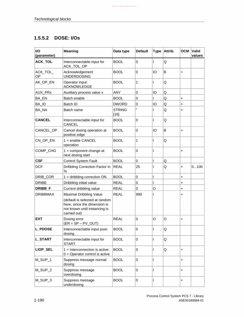
Technological blocks
Process Control System PCS 7 - Library1-190 A5E00180684-01
1.5.5.2 DOSE: I/Os
I/O(parameter)
Meaning Data type Default Type Attrib. OCM Validvalues
ACK_TOL Interconnectable input forACK_TOL_OP
BOOL 0 I Q
ACK_TOL_OP
AcknowledgementUNDERDOSING
BOOL 0 IO B +
AK_OP_EN Operator input:ACKNOWLEDGE
BOOL 1 I Q
AUX_PRx Auxiliary process value x ANY 0 IO Q
BA_EN Batch enable BOOL 0 I Q +
BA_ID Batch ID DWORD 0 IO Q +
BA_NA Batch name STRING[16]
" I Q +
CANCEL Interconnectable input forCANCEL
BOOL 0 I Q
CANCEL_OP Cancel dosing operation atpositive edge
BOOL 0 IO B +
CN_OP_EN 1 = enable CANCELoperation
BOOL 1 I Q
COMP_CHG 1 = component change atnext dosing start
BOOL 0 I +
CSF Control System Fault BOOL 0 I Q
DCF Dribbling Correction Factor in%
REAL 25 I Q + 0...100
DRIB_COR 1 = dribbling correction ON BOOL 0 I +
DRIBB Dribbling initial value REAL 0 I +
DRIBB_F Current dribbling value REAL 0 O +
DRIBBMAX Maximal Dribbling Value
(default is selected at randomhere, since the dimension isnot known until instancing iscarried out)
REAL 999 I +
EXT Dosing error(ER = SP – PV_OUT)
REAL 0 O O +
L_PDOSE Interconnectable input post-dosing
BOOL 0 I Q
L_START Interconnectable input forSTART
BOOL 0 I Q
LIOP_SEL 1 = Interconnection is active;0 = Operator control is active
BOOL 0 I Q +
M_SUP_1 Suppress message normaldosing
BOOL 0 I +
M_SUP_2 Suppress messageoverdosing
BOOL 0 I +
M_SUP_3 Suppress messageunderdosing
BOOL 0 I +
21.02.2003

Technological blocks
Process Control System PCS 7 - LibraryA5E00180684-01 1-191
I/O(parameter)
Meaning Data type Default Type Attrib. OCM Validvalues
MO_PVHR Upper display limit(measuring range)
REAL 110 I +
MO_PVLR Lower display limit(measuring range)
REAL -10 I +
MSG_ACK Message acknowledged WORD 0 O
MSG_EVID ALARM8_P event ID DWORD 0 I M
MSG_LOCK 1 = message suppressionaccording to specific processstate
BOOL 0 I Q +
MSG_STAT Error message status WORD 0 O
OCCUPIED Occupied by batch BOOL 0 I Q +
OOS Reserve BOOL 0 I +
P_OFF_EN Operator input enabled: 1 =CONTINUE
BOOL 1 I Q
P_ON_EN Operator input enables: 1 =PAUSE
BOOL 1 I Q
PAUSE Interconnectable input forPAUSE_OP
BOOL 0 I Q
PAUSE_OP 1 = STOP current dosingoperation0 = CONTINUE
BOOL 0 IO B +
PD_OP_EN Operator input enabled:
1 = POSTDOSE
BOOL 1 I Q
PDOS_TME POSTDOSE time [s] REAL 0 I +
POSTDOSE POSTDOSE at positive edge BOOL 0 IO B +
PV_IN Process value weight(weighing input)
REAL 0 I Q +
PV_OUT DOSE: press value REAL 0 O E +
Q 1 = dosing device ON BOOL 0 O
Q_SP_OP Operator control enabled:
1 = enter setpoint
BOOL 0 O +
QAK_OP Operator control enabled:1 = ACKNOWLEDGE
BOOL 0 O +
QC_PV_IN Quality Code for PV_IN BYTE 16#80 I
QC_Q Quality Code for Q BYTE 16#80 O
QC_Q_I Quality Code for output Q BYTE 16#80 I
QCN_OP Operator control enabled:1 = CANCEL
BOOL 0 O +
QEND_DOS 1 = end of dosing BOOL 1 O +
QERR 1 = error output (invertedENO)
BOOL 1 O +
QMSG_ERR 1 = message error BOOL 0 O +
QMSG_SUP 1 = message suppression BOOL 0 O +
QOP_ERR 1 = operator error BOOL 0 O
21.02.2003

Technological blocks
Process Control System PCS 7 - Library1-192 A5E00180684-01
I/O(parameter)
Meaning Data type Default Type Attrib. OCM Validvalues
QP_OFF_EN Operator control enabled:1 = CONTINUE
BOOL 0 O +
QP_ON_EN Operator control enabled:1 = PAUSE
BOOL 0 O +
QPD_OP Operator control enabled:1 = POSTDOSE"
BOOL 0 O +
QRELXING 1 = setting time active BOOL 0 O +
QSP_HLM 1 = setpoint high limit active BOOL 0 O
QSP_LLM 1 = setpoint low limit active BOOL 0 O
QSPEXTEN Operator control enabled:1 = EXTERNAL
BOOL 0 O +
QSPEXTON Setpoint:1 = external0 = internal
BOOL 0 O +
QSPINTEN Operator control enabled:1 = INTERNAL
BOOL 0 O +
QSTRT_OP Operator control enabled:1 = DOSE START
BOOL 0 O +
QSTRTDOS 1 = Dosing started BOOL 0 O +
QTOL_N 1 = underdosed after doseend
BOOL 0 O +
QTOL_P 1 = overdosed after dose end BOOL 0 O +
RELAXTME Settling time after dose stop[s]
REAL 3 I +
REVERSE 0 = gain in weight
1 = loss in weight
BOOL 0 I +
RUNUPCYC Number of run-up cycles BYTE 3 I
SAMPLE_T Sampling time [s] REAL 1 I >0
SP_EXT External setpoint REAL 0 I Q
SP_HLM Setpoint high limit REAL 100 I +
SP_LLM Setpoint low limit REAL 0 I +
SP_OP Operator input:Setpoint
REAL 0 IO B +
SP_OP_ON Operator control enabled:1 = setpoint ON
BOOL 1 I Q
SPBUMPON 1 = Bumpless setpoint ON BOOL 0 I +
SPEXON_L Interconnectable input forselecting SP_EXT (0 =internal, 1 = external)
BOOL 0 I Q
SPEXT_EN Operator control enabled:external setpoint
BOOL 1 I Q
SPEXT_ON 1= Interconnection, i.e.SP_EXT is active;0= operator control enabled:
BOOL 0 I Q +
SPEXTSEL_OP
Operator control enabled:select SP_EXT
BOOL 0 IO B +
21.02.2003

Technological blocks
Process Control System PCS 7 - LibraryA5E00180684-01 1-193
I/O(parameter)
Meaning Data type Default Type Attrib. OCM Validvalues
SPINT_EN Operator control enabled:select internal setpoint
BOOL 1 I Q
ST_OP_EN Operator input enabled:1 = DOSE start
BOOL 0 I Q
START_OP 1 = DOSE start at positiveedge
BOOL 0 IO B +
STEP_NO Batch step Number WORD 0 IO Q +
STNDSTLL Feedback from dosing device:1 = standstill
BOOL 1 I Q +
TOL_N Lower tolerance band REAL 0 I +
TOL_P Upper tolerance band REAL 0 I +
USTATUS Status word in VSTATUS;definable by user
WORD 0 I
VSTATUS Extended status display inblock icons
DWORD 0 O
For information on abbreviations used refer to: General information on the blockdescription
21.02.2003

Technological blocks
Process Control System PCS 7 - Library1-194 A5E00180684-01
1.5.5.3 DOSE: Operator control and monitoring
The tables show the assignment of the parameters of the AS block to the I/O fieldsof the faceplate.
Display I/O field Operatorauthoriza-tion
Parameters of the ASblock
Operator textin the log
Setpoint value (as a bar)
(in the corresponding input dialogbox:
HL=
Setpoint
LL=)
5
6
5
6
SP_OP
SP_HLM
SP_OP
SP_LLM
Setpoint
SP high limit
Setpoint
SP low limit
Process variable (as a bar) PV_IN
Status
dosing
Waiting time (relaxing)
end
(QSTRTDOS)
(QRELXING)
(QEND_DOS)
Command
(selection list:
continue/pause) 5 PAUSE_OP =0/1 Continue/ Pause
Setpoint
(in the corresponding input dialogbox:
HL=
Setpoint
LL=)
5
6
5
6
SP_OP
SP_HLM
SP_OP
SP_LLM
Setpoint
SP high limit
Setpoint
SP low limit
Process variable PV_IN
(unit setpoint/process variable) (S7_shortcut of SP_OP)
deviation EXT
dribbling DRIBB_F
unit (S7_shortcut of SP_OP)
Start 5 START_OP =1 Dose start
cancel 5 CANCEL_OP =1 Cancel
postdose 5 POSTDOSE =1 Postdose
(symbol bell)
(symbol bell disabled)
QMSG_SUP
MSG_LOCK
(symbol batch) OCCUPIED
Default
21.02.2003

Technological blocks
Process Control System PCS 7 - LibraryA5E00180684-01 1-195
Display I/O field Operatorauthoriza-tion
Parameters of the ASblock
Operator textin the log
Setpoint
(selection list:
internal/external) 6
QSPEXTON
SPEXTSEL_OP =0/1 Internal/External
Limit violation
upper QTOL_P
lower QTOL_N
acknowledge 5 ACK_TOL_OP =1 Acknowledge
Customize
Setpoint bumpless 6 SPBUMPON =0/1 SP bumplessoff/on
Correction 6 DRIB_COR =0/1 Dribblingcorrection off/on
New component 6 COMP_CHG =0/1 Componentchange off/on
Maintenance
downward 6 REVERSE =0/1 Reverse=No/Yes
Tolerance band
Upper limit
(in the corresponding inputdialog box:
HL=
T.HL
LL=)
6
6
6
TOL_P
(no check)
TOL_P
TOL_N
Upper tol. band
Upper tol. band
Lower tol. band
Lower limit
(in the corresponding inputdialog box:
HL=
T.LL
LL=)
6
6
6
TOL_N
TOL_P
TOL_N
(no check)
Lower tol. band
Upper tol. band
Lower tol. band
Coasting
Default
(in the corresponding inputdialog box:
HL=
Init
LL=)
6
6
6
DRIBB
DRIBBMAX
DRIBB
(no check)
Dribbling init.
Max. dribbling
Dribbling init.
Parameter
Maximum
(in the corresponding inputdialog box:
HL=
Max
LL=)
6
6
DRIBBMAX
(no check)
DRIBBMAX
0,0
Max. dribbling
Max. dribbling
21.02.2003
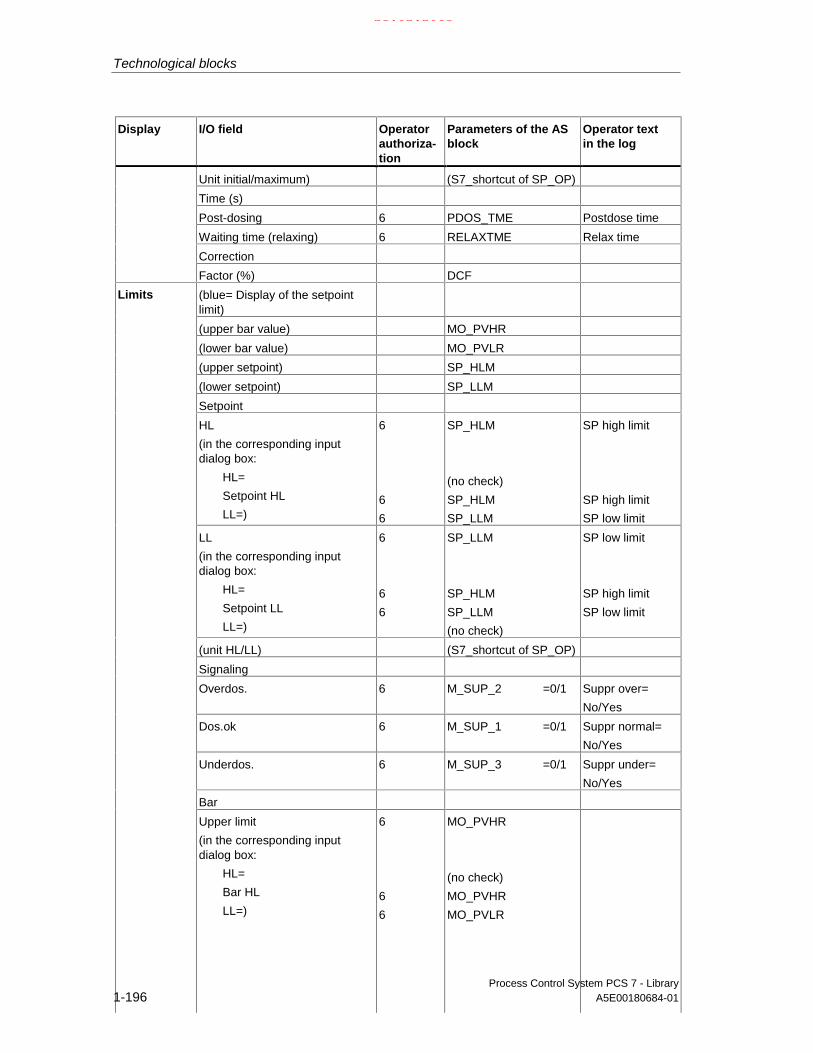
Technological blocks
Process Control System PCS 7 - Library1-196 A5E00180684-01
Display I/O field Operatorauthoriza-tion
Parameters of the ASblock
Operator textin the log
Unit initial/maximum) (S7_shortcut of SP_OP)
Time (s)
Post-dosing 6 PDOS_TME Postdose time
Waiting time (relaxing) 6 RELAXTME Relax time
Correction
Factor (%) DCF
(blue= Display of the setpointlimit)
(upper bar value) MO_PVHR
(lower bar value) MO_PVLR
(upper setpoint) SP_HLM
(lower setpoint) SP_LLM
Setpoint
HL
(in the corresponding inputdialog box:
HL=
Setpoint HL
LL=)
6
6
6
SP_HLM
(no check)
SP_HLM
SP_LLM
SP high limit
SP high limit
SP low limit
LL
(in the corresponding inputdialog box:
HL=
Setpoint LL
LL=)
6
6
6
SP_LLM
SP_HLM
SP_LLM
(no check)
SP low limit
SP high limit
SP low limit
(unit HL/LL) (S7_shortcut of SP_OP)
Signaling
Overdos. 6 M_SUP_2 =0/1 Suppr over=
No/Yes
Dos.ok 6 M_SUP_1 =0/1 Suppr normal=
No/Yes
Underdos. 6 M_SUP_3 =0/1 Suppr under=
No/Yes
Bar
Limits
Upper limit
(in the corresponding inputdialog box:
HL=
Bar HL
LL=)
6
6
6
MO_PVHR
(no check)
MO_PVHR
MO_PVLR
21.02.2003

Technological blocks
Process Control System PCS 7 - LibraryA5E00180684-01 1-197
Display I/O field Operatorauthoriza-tion
Parameters of the ASblock
Operator textin the log
Lower limit
(in the corresponding inputdialog box:
HL=
Bar LL
LL=)
6
6
6
MO_PVLR
MO_PVHR
MO_PVLR
(no check)
Batch control
Enable BA_EN
Occupied OCCUPIED
Batch
Name BA_NA
Batch
Step STEP_NO
1.5.5.4 DOSE: VSTATUS
The 32-bit status word extends the status display in the block icons and faceplates.The 16 low bits (bits 0 - 15) are used by the block as follows:
Bit no.: 7 6 5 4 3 2 1 0
Parameter QSTRTDOS - QSPEXTON - MSG_LOCK BA_EN OCCUPIED
Bit no.: 15 14 13 12 11 10 9 8
Parameter OOS QMSG_SUP - - QTOL_N QTOL_P QEND_DOS QRELXING
The 16-bit input USTATUS (data type WORD) uses the high bits (bits 16 - 31).These bits can be used freely.
21.02.2003

Technological blocks
Process Control System PCS 7 - Library1-198 A5E00180684-01
1.5.6 ELAP_CNT: Hour meter
1.5.6.1 ELAP_CNT: Description
Object name (type + number)
FB 64
Calling OBs
The watchdog interrupt OB in which you install the block (for example OB32). It isalso installed in OB100 (see startup characteristics).
Function
The block is used to measure the operating hours of units.
Operating principle
The block detects the time as long as the input ON_OFF=1, meaning that theconnected device is operating. The value SAMPLE_T[s]/3600 is added to the valueHOURS at every execution. The output HOURS thus specifies the number ofoperating hours.
Setting the counter
Under certain circumstances (for example, after maintenance or replacement of theunit), the initial value of the operating hour counter has to be specified (as a rule 0).At the OS, the operator sets the tracking value at the HOURS_OP input. This valueis then passed to the HOURS output by via the TRACK_OP input or byinterconnecting the TRACK input to the HOURS output.
Error handling
Arithmetic error are indicated by ENO=0 or QERR=1.
Startup characteristics
No special measures. After startup, the messages will be suppressed by thenumber of cycles set in RUNUPCYC.
21.02.2003

Technological blocks
Process Control System PCS 7 - LibraryA5E00180684-01 1-199
Time response
The block function only makes sense in a watchdog interrupt OB. In order toensure correct time acquisition, it should be installed (in CFC) in the runtime blockof the control block of the monitored unit also.
Assignment of the 32-bit status word VSTATUS
The 32-bit status word is used for extended status indication in the block icons andin the faceplates. The block uses the 16 LSB bits (bit 0 – 15) as follows:
Bit no.: 7 6 5 4 3 2 1 0
Parameter ON_OFF - - - - MSG_LOCK - -
Bit no.: 15 14 13 12 11 10 9 8
Parameter OOS QMSG_SUP - - - - - -
The 16-bit input USTATUS (data type WORD) uses the MSB bits (Bit 16 - 31).These bits can be set user-specific.
Message characteristics
The EPLAP_CNT block uses the ALARM8_P block to generate messages.
Messages are triggered by:
• The limit monitoring functions for the operating hours
• Limit violation messages can be suppressed individually via the correspondingM_SUP_xx inputs. The process messages (not process control messages!)can be locked centrally with MSG_LOCK.
QMSG_SUP is set if the RUNUPCYC cycles have not expired since the restart andMSG_LOCK = TRUE or MSG_STAT = 21.
Assignment of message texts and message class to the block parameters
Message no. Blockparameter
Default message text Messageclass
Can be suppressed by
1 QH_ALM $$BlockComment$$ Alarm high M M_SUP_AH, MSG_LOCK2 QH_WRN $$BlockComment$$ Warning high M M_SUP_WH, MSG_LOCK
All auxiliary process values (AUX_PRx) of the message block can be assigneduser-specific.
21.02.2003

Technological blocks
Process Control System PCS 7 - Library1-200 A5E00180684-01
Assignment of auxiliary process values to the block parameters
Value Block parameter
1 AUX_PR012 AUX_PR023 AUX_PR034 AUX_PR045 AUX_PR056 AUX_PR067 AUX_PR078 AUX_PR089 AUX_PR0910 AUX_PR10
Monitoring of process variables
n.a.
21.02.2003

Technological blocks
Process Control System PCS 7 - LibraryA5E00180684-01 1-201
1.5.6.2 ELAP_CNT: I/Os
I/O(parameter)
Meaning Data type Default Type Attrib. OCM
AUX_PRx Auxiliary process value x ANY 0 IO QHOURS Duty period (hours) REAL 0 O +HOURS_AH Alarm high limit (hours) REAL 100 I +HOURS_OP Tracking value (hours) REAL 0 IO B +HOURS_WH Warning high limit (hours) REAL 95 I +M_SUP_AH 1 = suppress HL alarm BOOL 0 I +M_SUP_WH 1 = suppress HL warning BOOL 0 I +MO_HOUHR Upper display limit (bar graph) REAL 120 I +MO_HOULR Lower display limit (bar graph) REAL 0 I +MSG_ACK Message acknowledged WORD 0 OMSG_EVID Message number DWORD 0 I MMSG_LOCK 1 = suppress messages at specific
process stateBOOL 0 I Q +
MSG_STAT Error message status WORD 0 OON_OFF Unit status
1 = ON0 = OFF
BOOL 0 I Q +
OOS Reserve BOOL 0 I +QC_ON_OFF Quality Code for ON_OFF BYTE 16#80 IQERR 1 = error output (inverted ENO) BOOL 1 O +QH_ALM 1 = HL alarm active BOOL 0 OQH_WRN 1 = HL warning active BOOL 0 OQMSG_ERR 1 = message error BOOL 0 O +QMSG_SUP 1 = message suppression BOOL 0 O +RUNUPCYC Number of run-up cycles BYTE 3 ISAMPLE_T Sampling time [s] REAL 1 ITRACK Interconnectable input for TRACK BOOL 0 I QTRACK_OP 1 = Set HOURS to H_TRACK BOOL 0 IO B +USTATUS Status word in VSTATUS; definable by
userWORD 0 I
VSTATUS Extended status display in block icons DWORD 0 O
For information on abbreviations used refer to: General information on the blockdescription
21.02.2003

Technological blocks
Process Control System PCS 7 - Library1-202 A5E00180684-01
1.5.6.3 ELAP_CNT: Operator control and monitoring
The tables show the assignment of the parameters of the AS block to the I/O fieldsof the faceplate.
Display I/O field Operatorauthoriza-tion
Parameters of the ASblock
Operator text inthe log
h (bar graph) HOURS
(bar graph at right)
(red= upper alarm value) HOURS_AH
(yellow= upper warningvalue)
HOURS_WH
Process variables
hours HOURS
State
on/off ON_OFF
Default
(symbol bell)
(symbol bell disabled)
QMSG_SUP
MSG_LOCK
Display I/O field Operatorauthoriza-tion
Parameters of the ASblock
Operator text inthe log
Default
Preset value = 5 HOURS_OP Preset value
Maintenance
reset 5 TRACK_OP =1 0 / Preset
Display I/O field Operatorauthoriza-tion
Parameters of the ASblock
Operator text inthe log
(red bar = alarm)
(upper value) HOURS_AH
(yellow bar = warning)
(upper value) HOURS_WH
Alarm
Alarm
active
6
6
HOURS_AH
M_SUP_AH =0/1
HH alarm
Suppress HH=
No/Yes
Warning
active
6
6
HOURS_WH
M_SUP_WH =0/1
H alarm
Suppress H=No/Yes
Limits
Bar graph
21.02.2003

Technological blocks
Process Control System PCS 7 - LibraryA5E00180684-01 1-203
Display I/O field Operatorauthoriza-tion
Parameters of the ASblock
Operator text inthe log
High limit
(in the corresponding inputdialog box:
HL=
Bar HL
LL=)
6
6
6
MO_HOUHR
(no check)
MO_HOUHR
MO_HOULR
Low limit
(in the corresponding inputdialog box:
HL=
Bar LL
LL=)
6
6
6
MO_HOULR
MO_HOUHR
MO_HOULR
(no check)
1.5.6.4 ELAP_CNT: VSTATUS
The 32-bit status word extends the status display in the block icons and faceplates.The 16 low bits (bits 0 - 15) are used by the block as follows:
Bit no.: 7 6 5 4 3 2 1 0
Parameter ON_OFF - - - - MSG_LOCK - -
Bit no.: 15 14 13 12 11 10 9 8
Parameter OOS QMSG_SUP - - - - - -
The 16-bit input USTATUS (data type WORD) uses the high bits (bits 16 - 31).These bits can be used freely.
21.02.2003

Technological blocks
Process Control System PCS 7 - Library1-204 A5E00180684-01
1.5.7 INTERLOK: Interlock display
1.5.7.1 INTERLOK: Description
Object name (type + number)
FB 75
Calling OBs
In the same OB with and after the last block whose signals are to be displayed onthe INTERLOK.
Function
The INTERLOK block is used to implement a standardized interlock display whichcan be called on the OS. The block can be assigned a maximum of 10 inputsignals, which can each be inverted as required.
Operating principle
The first five inputs I1_1 to I1_5 form a group. Each signal can be linked logicallyeither directly or inverted by setting the corresponding inputs NEG1_1 to NEG1_5.The type of logic operation of the first group is set at the AND_OR1 parameter.NEGRES_1 = 1 inverts the result of Q1 used to form Q via AND_OR3. Output Q1,however is not inverted.The same applies to the second group of five inputs.The two group results can be operated linked logically by an AND/OR operation.
With input OVERWRITE=1 the output Q can be set to low when an interlock isactive (Q=1) and is only possible if OVERW_EN=1. Input OVERWRITE=0 ifOVERW_EN=0 or if the interlock condition is not satisfied. Q_OVERWR=1 at theoutput indicates that output Q has been overwritten.
Applies only if input CHECK_EN = TRUE:
The output parameter FIRST_I contains the number (1 to 10) of the input Ix whichwas first TRUE or inverted FALSE. If several conditions are set simultaneously, thelowest number is entered in FIRST_I. A positive edge at input RESET setsFIRST_I equal to zero, if none of the above conditions are satisfied. Output Q isusually interconnected to RESET.
Error handling
Only by means of the operating system.
21.02.2003

Technological blocks
Process Control System PCS 7 - LibraryA5E00180684-01 1-205
Startup characteristics
No special measures taken.
Time response
The block does not have a time response.
Message characteristics
Does not exist.
Assignment of the 32-bit status word VSTATUS
The 32-bit status word is used for extended status indication in the block icons andin the faceplates. The block uses the 16 LSB bits (bit 0 – 15) as follows:
Bit no.: 7 6 5 4 3 2 1 0
Parameter ON_OFF - - - - MSG_LOCK - -
Bit no.: 15 14 13 12 11 10 9 8
Parameter OOS QMSG_SUP - - - - - -
The 16-bit input USTATUS (data type WORD) uses the MSB bits (Bit 16 - 31).These bits can be set user-specific.
Monitoring of process variables
n.a.
21.02.2003

Technological blocks
Process Control System PCS 7 - Library1-206 A5E00180684-01
1.5.7.2 INTERLOK: I/Os
I/O(parameter)
Meaning Datatype
Default Type Attrib. OCM
AND_OR1 1 = AND, 0 = OR, first group BOOL 0 I Q +
AND_OR2 1 = AND, 0 = OR, second group BOOL 0 I Q +
AND_OR3 1 = AND, 0 = OR, both groups BOOL 0 I Q +
CHECK_EN 1 = FIRST_I Check Enable BOOL 0 I Q +
FIRST_I First input set TRUE (inverted FALSE) BOOL 0 O +
I1_1 Input 1, first group BOOL 0 I Q +
I1_2 Input 2, first group BOOL 0 I Q +
I1_3 Input 3, first group BOOL 0 I Q +
I1_4 Input 4, first group BOOL 0 I Q +
I1_5 Input 5, first group BOOL 0 I Q +
I2_1 Input 1, first group BOOL 0 I Q +
I2_2 Input 2, second group BOOL 0 I Q +
I2_3 Input 3, second group BOOL 0 I Q +
I2_4 Input 4, second group BOOL 0 I Q +
I2_5 Input 5, second group BOOL 0 I Q +
NEG1_1 1 = I1_1 will be inverted BOOL 0 I Q +
NEG1_2 1 = I1_2 will be inverted BOOL 0 I Q +
NEG1_3 1 = I1_3 will be inverted BOOL 0 I Q +
NEG1_4 1 = I1_4 will be inverted BOOL 0 I Q +
NEG1_5 1 = I1_5 will be inverted BOOL 0 I Q +
NEG2_1 1 = I2_1 will be inverted BOOL 0 I Q +
NEG2_2 1 = I2_2 will be inverted BOOL 0 I Q +
NEG2_3 1 = I2_3 will be inverted BOOL 0 I Q +
NEG2_4 1 = I2_4 will be inverted BOOL 0 I Q +
NEG2_5 1 = I2_5 will be inverted BOOL 0 I Q +
NEGRES_1 1 = result of first group will be inverted BOOL 0 I Q +
NEGRES_2 1 = result of second group will be inverted BOOL 0 I Q +
OVERW_EN 1 = OVERWRITE enabled BOOL 0 I Q +
OVERWRITE 1 = OVERWRITE BOOL 0 IO Q +
Q Output signal BOOL 0 O +
Q_OVERWR 1 = Q is overwritten BOOL 0 O +
Q1 Interim result, first group BOOL 0 O +
Q2 Interim result, second group BOOL 0 O +
QC_I1_1 Quality Code for I1_1 BYTE 16#80 I
QC_I1_2 Quality Code for I1_2 BYTE 16#80 I
QC_I1_3 Quality Code for I1_3 BYTE 16#80 I
QC_I1_4 Quality Code for I1_4 BYTE 16#80 I
QC_I1_5 Quality Code for I1_5 BYTE 16#80 I
QC_I2_1 Quality Code for I2_1 BYTE 16#80 I
21.02.2003

Technological blocks
Process Control System PCS 7 - LibraryA5E00180684-01 1-207
I/O(parameter)
Meaning Datatype
Default Type Attrib. OCM
QC_I2_2 Quality Code for I2_2 BYTE 16#80 I
QC_I2_3 Quality Code for I2_3 BYTE 16#80 I
QC_I2_4 Quality Code for I2_4 BYTE 16#80 I
QC_I2_5 Quality Code for I2_5 BYTE 16#80 I
QC_Q Quality Code for Q BYTE 16#80 O
QC_Q_I Quality Code for output Q BYTE 16#80 I
RESET Positive edge = reset FIRST_I BOOL 0 I Q +
USTATUS Status word in VSTATUS; definable by user WORD 0 I
VSTATUS Extended status display in block icons DWORD 0 O
For explanations and meaning of the abbreviations please refer to: Generalinformation on block definiptions
1.5.7.3 INTERLOK: Operator control and monitoring
The table shows the assignment of the parameters of the AS block to the I/O fieldsof the faceplate.
Display I/O field Operatorauthoriza-tion
Parameters ofthe AS block
Operator text inthe log
(Logic plan)
(output field) in_1 I1_1 0 / in_1
in_2 I1_2 0 / in_2
in_3 I1_3 0 / in_3
in_4 I1_4 0 / in_4
in_5 I1_5 0 / in_5
in_6 I2_1 0 / in_6
in_7 I2_2 0 / in_7
in_8 I2_3 0 / in_8
in_9 I2_4 0 / in_9
Default
in_10 I2_5 0 / in_10
Overwrite
Enable OVERW_EN
Maintenance
active 5 OVERWRITE=0/1 Overwrite=Off/On
*) Shows only the text of Text_1 in the faceplate.
21.02.2003
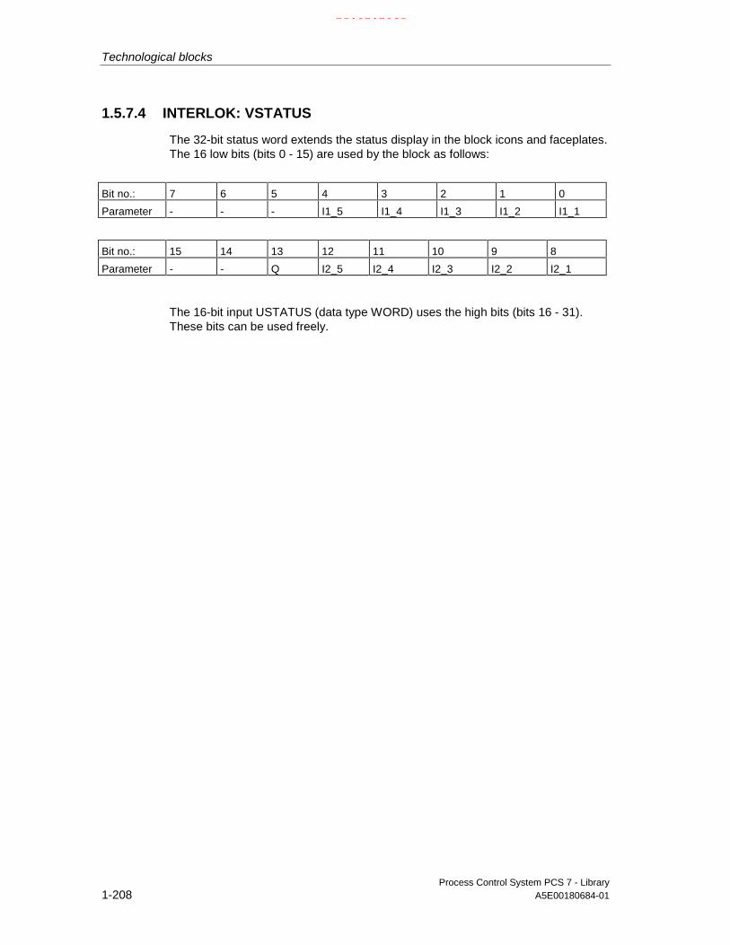
Technological blocks
Process Control System PCS 7 - Library1-208 A5E00180684-01
1.5.7.4 INTERLOK: VSTATUS
The 32-bit status word extends the status display in the block icons and faceplates.The 16 low bits (bits 0 - 15) are used by the block as follows:
Bit no.: 7 6 5 4 3 2 1 0
Parameter - - - I1_5 I1_4 I1_3 I1_2 I1_1
Bit no.: 15 14 13 12 11 10 9 8
Parameter - - Q I2_5 I2_4 I2_3 I2_2 I2_1
The 16-bit input USTATUS (data type WORD) uses the high bits (bits 16 - 31).These bits can be used freely.
21.02.2003

Technological blocks
Process Control System PCS 7 - LibraryA5E00180684-01 1-209
1.5.8 LIMITS_P: Limits
1.5.8.1 LIMITS_P: Description
Object name (type + number)
FB 41
Calling OBs
The OB in which the block is installed.
Function
Limitation of an analog value to an adjustable range.
21.02.2003

Technological blocks
Process Control System PCS 7 - Library1-210 A5E00180684-01
Operating principle
The block passes the analog input value U to the output V as long as it lies withinthe set limits.
• If the value is outside the low limit, the low limit value is output. If the value isoutside the high limit, the high limit value is output.
• The active limitation is indicated at the set binary outputs. A hysteresis can beset in order to avoid dithering of the display when the input value fluctuatesaround the limit.
U
U
U
V
QVLL
QVHL
VLL VHL
VHL
VLL
1
1
0
0HYST
HYST
Operating principle of the LIMITS_P
Error handling
If V_HL - V_LL ≤ HYS, QVHL and QVLL can be 1 simultaneously.
21.02.2003

Technological blocks
Process Control System PCS 7 - LibraryA5E00180684-01 1-211
1.5.8.2 LIMITS_P: I/Os
I/O (parameter) Meaning Data type Default I/O Attr.
HYS Hysteresis REAL 0.0 I Q
QERR 1 = error BOOL 1 O
QVHL 1 = V > V_HL
High limit alarm triggered
BOOL 0 O
QVLL 1 = V < V_LL
Low limit alarm triggered
BOOL 0 O
U Input value REAL 0.0 I Q
V Output value REAL 0.0 O
V_HL High limit of V REAL 100.0 I Q
V_LL Low limit of V REAL 0.0 I Q
For information on abbreviations used refer to: General information on the blockdescription
21.02.2003

Technological blocks
Process Control System PCS 7 - Library1-212 A5E00180684-01
1.5.9 MUL4_P: Multiplicator for max. 4 values
1.5.9.1 MUL4_P: Description
Object name (type + number)
FC 262
Calling OBs
The OB in which the block is installed.
Function
The block multiplies up to 4 values
V := U1∗...∗Un (n≤4)
depending on the parameter value (refer to the following table).Use the lowest number of inputs possible for parameter values in order to reducethe calculation time.
Parameter value I/O no. MeaningMUL4_P FC 262 Multiplier with 4 inputs
Error handling
In case of an overflow/underflow, the REAL value of the high/low limit is set in theresult V. ENO will be set low and QERR high.
1.5.9.2 MUL4_P: I/Os
I/O(parameter)
Meaning Datatype
Default Type Attrib. OCM Validvalues
U1 Input 1 REAL I Q
.... .... .... .... .... ....
U4 Input 4 REAL I Q
V Result REAL O
For information on abbreviations used refer to: General information on the blockdescription
21.02.2003

Technological blocks
Process Control System PCS 7 - LibraryA5E00180684-01 1-213
1.5.10 MUL8_P: Multiplikation für maximal 8 Werte
1.5.10.1 MUL8_P: Description
Object name (type + number)
FC 263
Calling OBs
The OB in which the block is installed.
Function
The block multiplies up to 8 values
V := U1∗U2∗U3∗...∗Un (n≤8)
depending on the parameter value (refer to the following table).Use the lowest number of inputs possible for parameter values in order to reducethe calculation time.
Parameter value Meaning I/O No.MUL8_P Multiplier with 8 inputs FC 263
Error handling
In case of an overflow/underflow, the REAL value of the high/low limit is set in theresult V. ENO will be set low and QERR high.
1.5.10.2 MUL8_P: I/Os
I/O (parameter) Meaning Data type Default Type Attrib.
U1 Input 1 REAL I Q.... .... .... .... ....U8 Input 8 REAL I QV Result REAL O
For information on abbreviations used refer to: General information on the blockdescription
21.02.2003

Technological blocks
Process Control System PCS 7 - Library1-214 A5E00180684-01
1.5.11 OB1_TIME: Calculating CPU load
1.5.11.1 OB1_TIME: Description
Object name (type + number)
FB 69
Calling OBs
OB1
Function
The OB1_TIME block provides information relating to the degree of CPU utilization.
Operating principle
The block is installed in OB1.
• The block is reset (i.e. CNT, MAX, MIN, MEAN and the internal ACT_TME arereset ) and started by a negative edge (1->0) at input STOP_RES. The currentsystem time is determined and saved internally under L_TME.
• In each execution cycle, the block determines the system time of day in ms,saves it internally in ACT_TIME and calculates the maximum value since thereset time (MAX), the root mean square value (MEAN) and the minimum value(MIN) of the time that has passed since its last execution(OB_1_TIME=ACT_TIME-L_TIME). Counter CNT is then incremented by 1and L_TIME=ACT_TIME is reset. The root mean square value is calculated asfollows:
MEANCNT
CNT MEAN OB TIME=+
+1
112 2( * _ )
• The calculated values must be interpreted by the commissioning personnel inorder to derive the degree of CPU utilization.
• A 1 at the input STOP_RES causes the block algorithm not to be processedfurther (processing is "halted). ENO is reset during this time to 0 .
21.02.2003

Technological blocks
Process Control System PCS 7 - LibraryA5E00180684-01 1-215
Message characteristics
n.a.
Error handling
Only by means of the operating system.
Operator control and monitoring
• n.a.
1.5.11.2 OB1_TIME: I/Os
I/O(parameter)
Meaning Data type Default I/O Attr.
CNT Counter DINT 0 O
MAX maximum time value DINT 0 O
MAX_CNT High limit of CNT DINT 10000 I
MEAN Root mean square value DINT 0 O
MIN minimum time value DINT 0 O
OB1_TIME Cycle execution time
ACT_TIME - L_TIME
DINT 0 O
QERR Inverted value of ENO BOOL 1 O
STOP_MAX 1 = Stop at CNT = MAX_CNT BOOL 0 I Q
STOP_RES 1 = STOP0 = RESET
BOOL 1 I Q
For information on abbreviations used refer to: General information on the blockdescription
21.02.2003

Technological blocks
Process Control System PCS 7 - Library1-216 A5E00180684-01
1.5.12 SWIT_CNT: Switching cycle counter
1.5.12.1 SWIT_CNT: Description
Object name (type + number)
FB 71
Calling OBs
In the same OB with and after the block which supplies the switching signals.Additionally in OB100 (see startup characteristics).
Function
The block is used to count unit switching cycles.
Operating principle
The block counts the switching cycles at a positive edge (0->1) at input ON_OFFand outputs the result at the output V. The maximum count value is limited to 231
switching operations, since it is of the data type DINT.
Tracking
The counter output V can be tracked to the value VTRACK_OP by settingTRACK_OP via the OS or by interconnecting TRACK. VTRACK_OP can, in turn becontrolled by the operator.
Monitoring limits
A warning or alarm limit can be set at each of the inputs VWH and VAH. Whenthese are exceeded, the counter value V generates a signal (at QH_WRN orQH_ALM) and, if necessary, a message (refer to message characteristics).
Error handling
Upon a counter overflow of V, the error output QERR is set for one cycle and acontrol system message is transmitted. The counter is then resumed at "0".Operator errors are displayed at output QOP_ERR.
21.02.2003

Technological blocks
Process Control System PCS 7 - LibraryA5E00180684-01 1-217
Startup characteristics
No special measures. After startup messages will be suppressed for the number ofcycles set in RUNUPCYC.
Time responseThe block must be executed in the same runtime group (for CFC planning) as thecontrol block of the unit to be monitored and recognize the edges reliably.
Assignment of the 32-bit status word VSTATUSThe 16-bit input USTATUS (data type WORD) uses the MSB bits (Bit 16 - 31).These bits can be set user-specific.
Bit no.: 7 6 5 4 3 2 1 0
Parameter ON_OFF - - - - MSG_LOCK - -
Bit no.: 15 14 13 12 11 10 9 8
Parameter OOS QMSG_SUP - - - - - -
The 16-bit input USTATUS (data type WORD) uses the MSB bits (Bit 16 - 31).These bits can be set user-specific.
Message characteristicsThe SWIT_CNT block uses the ALARM8_P block to generate messages.
Messages are triggered by the functions monitoring limits during switchingoperations.
Messages generated as a result of the violation of limits can be suppressedindividually by setting the corresponding inputs M_SUP_xx. Process messages(not process control messages!) can be locked globally by setting MSG_LOCK.
QMSG_SUP is set if the RUNUPCYC cycles have not expired since the restartwhen MSG_LOCK = TRUE or MSG_STAT = 21.
21.02.2003

Technological blocks
Process Control System PCS 7 - Library1-218 A5E00180684-01
Assignment of message texts and message classes to the block parameters
Message no. Block parameter Default message text Message class Can besuppressed by
1 QAH $$BlockComment$$Alarm high
M M_SUP_AH,MSG_LOCK
2 QWH $$BlockComment$$Warning high
M M_SUP_WH,MSG_LOCK
All the auxiliary process values (AUX_PRx) of the message block can be assigneduser-specific.
Assignment of auxiliary process values to the block parameters
Value Block parameter1 AUX_PR012 AUX_PR023 AUX_PR034 AUX_PR045 AUX_PR056 AUX_PR067 AUX_PR078 AUX_PR089 AUX_PR0910 AUX_PR10
Monitoring of process values
n.a.
21.02.2003

Technological blocks
Process Control System PCS 7 - LibraryA5E00180684-01 1-219
1.5.12.2 SWIT_CNT: I/Os
I/O(parameter)
Meaning Datatype
Default Type Attrib. OCM Validvalues
AUX_PRx Auxiliary process value x ANY 0 IO Q
M_SUP_AH 1 = suppress HL alarm BOOL 0 I +
M_SUP_WH 1 = suppress HL warning BOOL 0 I +
MO_VHR High display limit (bar graph) REAL 120 I +
MO_VLR Low display limit (bar graph) REAL 0 I +
MSG_ACK Message acknowledged WORD 0 O
MSG_EVID Message number DWORD 0 I M
MSG_LOCK 1 = lock messages BOOL 0 I Q +
MSG_STAT Error message status WORD 0 O
ON_OFF Unit status to be counted:1 = ON, 0 = OFF
BOOL 0 I Q +
OOS Reserve BOOL 0 I +
QC_ON_OFF Quality Code for ON_OFF BYTE 16#80 I
QERR 1 = error output (inverted ENO) BOOL 1 O +
QH_ALM 1 = HL alarm triggered BOOL 0 O
QH_WRN 1 = HL warning triggered BOOL 0 O
QMSG_ERR 1 = ALARM8_P error BOOL 0 O +
QMSG_SUP 1 = message suppression BOOL 0 O +
RUNUPCYC Number of run-up cycles INT 3 I
TRACK Interconnectable input for TRACK BOOL 0 I Q
TRACK_OP 1= track V to V_TRACK BOOL 0 IO B +
V Number of switching cycles DINT 0 O +
VAH High limit alarm, counter value DINT 100 I +
VTRACK_OP Tracking value DINT 0 IO B + ≥ 0
VWH High warning alarm, counter value DINT 95 I +
USTATUS Status word in VSTATUS; definable byuser
WORD 0 I
VSTATUS Extended status display in block icons DWORD 0 O
For information on abbreviations used refer to: General information on the blockdescription
21.02.2003

Technological blocks
Process Control System PCS 7 - Library1-220 A5E00180684-01
1.5.12.3 SWIT_CNT: Operator control and monitoring
The tables show the assignment of the parameters of the AS block to the I/O fieldsof the faceplate.
Display I/O field Operatorauthoriza-tion
Parameters of the ASblock
Operator textin the log
S (bar graph) V(bar graph at right)(red= upper warning value) VAH(yellow= upper warning value) VWHSwitching operationsNumber VState
on/off ON_OFF
Default
(symbol bell) QMSG_SUPDefaultDefault value =
Maintenance
reset
Display I/O field Operatorauthoriza-tion
Parameters of the ASblock
Operator text inthe log
(yellow bar graph = warning)(upper value) VAH(red bar graph = alarm)(upper value) VWH
AlarmAlarmactive
66
VAHM_SUP_AH =0/1
HH alarmSuppress HH=No/Yes
Warningactive
66
VWHM_SUP_WH =0/1
H alarmSuppress H=No/Yes
BarHigh limit(in the corresponding inputdialog box:
HL=Bar HLLL=)
6
66
MO_VHR
(no check)MO_VHRMO_VLR
Limits
Low limit(in the corresponding inputdialog box:
HL=Bar LLLL=)
6
66
MO_VLR
MO_VHRMO_VLR(no check)
21.02.2003

Technological blocks
Process Control System PCS 7 - LibraryA5E00180684-01 1-221
1.5.12.4 SWIT_CNT: VSTATUS
The 32-bit status word extends the status display in the block icons and faceplates.The 16 low bits (bits 0 - 15) are used by the block as follows:
Bit no.: 7 6 5 4 3 2 1 0
Parameter ON_OFF - - - - MSG_LOCK - -
Bit no.: 15 14 13 12 11 10 9 8
Parameter OOS QMSG_SUP - - - - - -
The 16-bit input USTATUS (data type WORD) uses the high bits (bits 16 - 31).These bits can be used freely.
21.02.2003
Technological blocks
Process Control System PCS 7 - Library1-222 A5E00180684-01
1.6 Conversion blocks
1.6.1 Conversion blocks, general information
What are conversion blocks used for?
In CFC you can only connect block outputs (source type) to inputs (target type) ofthe same data type (for example, REAL output with REAL input). Conversionblocks must be used to allow the interconnection of different data types. The inputand output data of the block are of a different type, and it thus converts the inputdata type according to the data type set at the output.
The CFC block library ELEMENTA contains the conversion blocks required forthese interconnection and an additional R_TO_DW block with expanded propertiesfor process engineering applications.
Calling OBs
The conversion block must be installed in the OB upstream of the block thatevaluates the conversion result.
21.02.2003

Technological blocks
Process Control System PCS 7 - LibraryA5E00180684-01 1-223
1.6.2 R_TO_DW: Conversion REAL to DWORD
1.6.2.1 R_TO_DW: Description
Object name (type + number)
FC 282
Function
The block converts a REAL value to a DWORD value. REAL numbers between 0and 4294967000 are accepted.
Error handling
If the values are outside the limits specified above, ENO = 0 and the high limit( = 0) or low limit ( = 4294967000) will be set.
1.6.2.2 R_TO_DW: I/Os
I/O (parameter) Meaning Data type Default TypeU Value to convert REAL 0.0 IV Converted value DWORD 0 O
21.02.2003

Technological blocks
Process Control System PCS 7 - Library1-224 A5E00180684-01
1.7 Operator control blocks
1.7.1 Overview of the operator control blocks
In this chapter we shall introduce the operator control blocks and show how theycan be used to operate block parameters.
What are operator control blocks used for?
An operator control block represents the operator control interface between blocksof the AS and OS and offers the following standard solutions:
How can the input parameter "W" of the function block "FB_yyy" be operated bythe plant operator and also be modified by the AS program?
The solution principle is shown in the figure, using a operator control block with itstwo OP_AS and OP_OS elements.
OS-Block AS-BlockCS
LINK_ON
LINK_x
X
Xok
#
X
OP_AS
FB_yyy
Y
OP_OS
X
External value / AS-Block
Switch Internal / External
OS Data storage
FB_yyy.W=Xok
OP_EN_x QOP_ERR
Concept of operator control
21.02.2003

Technological blocks
Process Control System PCS 7 - LibraryA5E00180684-01 1-225
Concept of operator control
The operator control block must be implemented at two locations (refer to thefigure):
• In the AS (AS block, abbreviated as OP_AS)
• In the OS (OS block, abbreviated as OP_OS)
The valid value output at OP_AS can be based on two different sources:
• An external source, i.e. it is provided by another AS block (via the LINK_xinput),
• An internal source, i.e. it is provided by the OP_OS block that is controlled bythe operator at the OS.
General operating procedure:
• The OP_OS selected at the OS queries the values at OP_AS, or theenable/disable status of operator control. In order to keep the operator up todate on the status of OP_AS, the result is displayed asynchronously to theOP_AS in an OS-specific runtime cycle.
• The plant operator controls/modifies an operator controlled element at OP_OS,whose algorithm checks the validity of input data:
- Invalid entries (block-specific) are corrected or rejected, depending on thesituation. A corresponding message is output to the operator.
- The corrected or valid value is transferred to OP_AS and logged at the OS.
• The OP_AS receives the value and performs a validity check, since it couldwell be that the current AS status has changed since the last execution ofOP_OS.
If the block detects illegal input data (block-specific), these will be corrected orrejected according to the situation. The OP_AS reports the result at theBoolean output QOP_ERR, i.e. it outputs a pulse of a width equal to thesampling time of OP_AS.
- The corrected or valid value, or otherwise the old valid value, is output forfurther use at the corresponding Xok output of the OP_AS.
Overview
The table shows an overview of the operator control blocks, implemented as FBsthat require an instance DB each for each application.
Block name Meaning Operating method FB no.
OP_A Analog value operation 45OP_A_LIM Analog value operation Limiting 46OP_A_RJC Analog value operation Rejecting 47OP_D Digital value operation, 2 pushbuttons 48OP_D3 Digital value operation, 3 pushbuttons 49OP_TRIG Digital value operation, pushbutton function 50
21.02.2003
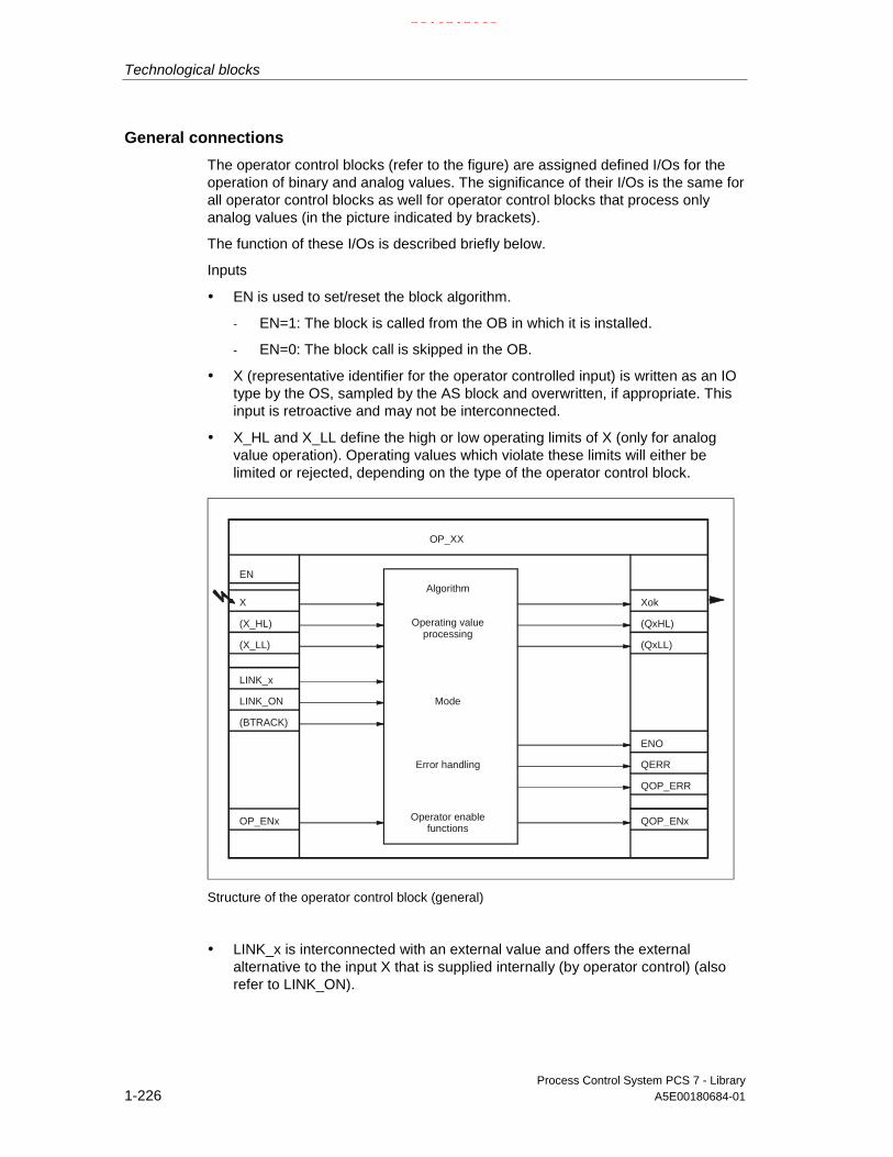
Technological blocks
Process Control System PCS 7 - Library1-226 A5E00180684-01
General connections
The operator control blocks (refer to the figure) are assigned defined I/Os for theoperation of binary and analog values. The significance of their I/Os is the same forall operator control blocks as well for operator control blocks that process onlyanalog values (in the picture indicated by brackets).
The function of these I/Os is described briefly below.
Inputs
• EN is used to set/reset the block algorithm.
- EN=1: The block is called from the OB in which it is installed.
- EN=0: The block call is skipped in the OB.
• X (representative identifier for the operator controlled input) is written as an IOtype by the OS, sampled by the AS block and overwritten, if appropriate. Thisinput is retroactive and may not be interconnected.
• X_HL and X_LL define the high or low operating limits of X (only for analogvalue operation). Operating values which violate these limits will either belimited or rejected, depending on the type of the operator control block.
EN
X
(X_HL)
LINK_x
LINK_ON
OP_ENx
(BTRACK)
QERR
Xok
QOP_ERR
(QxHL)
(QxLL)
QOP_ENx
(X_LL)
Algorithm
Operating valueprocessing
Mode
Operator enablefunctions
Error handling
OP_XX
ENO
Structure of the operator control block (general)
• LINK_x is interconnected with an external value and offers the externalalternative to the input X that is supplied internally (by operator control) (alsorefer to LINK_ON).
21.02.2003

Technological blocks
Process Control System PCS 7 - LibraryA5E00180684-01 1-227
• LINK_ON changes mode, which selects the value to be processed:
- LINK_ON=1: The value at input LINK_x, which is usually received fromanother interconnected block, is handled as external default value.
- LINK_ON=0: The value at input X, which is usually entered at the OS, ishandled as an internal default value (output by its own OP_XX).
• BTRACK (if it exists) is used for bumpless changeover operations during thetransitions of LINK_ON=1 to LINK_ON=0.
- BTRACK=1: When LINK_ON=1, the algorithm tracks the operatorcontrolled inputs X to the LINK_x inputs accordingly. The object of thisoperation is to ensure that the block does not process any old operatingvalues of the X inputs and thus change active values during thechangeover to manual mode (LINK_ON=0).
- BTRACK=0: When LINK_ON=1, the operator controlled inputs X will not beoverwritten. Hence, their value will usually remain different to the value atLINK_x. During the changeover LINK_ON=0 these old values becomevalid again and lead to corresponding changes of the active Xok outputvalues (referred to as bump).
• The OP_EN_x parameter is used to enable/disable operator control of theassigned input X:
- OP_EN_x=1: Input X is enabled for operator controls.
- OP_EN_x=0: Operator control is locked or rejected.
Outputs
• ENO indicates the validity of the result Xok (1 = OK, 0 = invalid).
• QERR = Inverted ENO (stored in the block instance).
• A logic "1" at the QOP_ERR parameter indicates an operator control error. Theoutput will be reset again at the next cycle (sampling time).
• Xok (representative identifier for the effective active output) contains the validoutput value, depending on the operator control block type and operatingmode. It is made interconnected to the AS block whose input is to be operated.Depending on the operator control block, the identifier is then named V, Q_1etc.
• QxHL and QxLL indicate violation of the high/low operating limits for X (analogvalue operations only). Operating values violating these limits will either belimited or rejected, depending on the type of the operator control block.
• QOP_ENx contains the output value, which is passed on according toOP_ENx. It can be queried by other AS blocks, and provides information onthe current enable/disable status of operator control of OP_AS.
21.02.2003

Technological blocks
Process Control System PCS 7 - Library1-228 A5E00180684-01
1.7.2 OP_A: Local control of analog values
1.7.2.1 OP_A: Description
Object name (type + number)
FB 45
Calling OBs
The operator control block must be installed in the same OB with and before theblock that utilizes operator control.
Function
Basic operator control block for processing analog values of an AS block, withoutlimit monitoring and operator enable functions.
Operating principle
Operating principle of the block:
EN
U
LINK_ U
LINK_ON
BTRACK
V
#
&ENO
QOP_ERRerror handling
OP_A
OP_A structure
21.02.2003

Technological blocks
Process Control System PCS 7 - LibraryA5E00180684-01 1-229
• U is entered by the OS operator control.
• LINK_U is assigned an external value (configured or interconnected).
• LINK_ON toggles the external/internal value:
- LINK_ON=1: LINK_U is passed to V.
- LINK_ON=0: U is passed to V.
• BTRACK allows tracking of an operator controlled input U (only if LINK_ON=1).
- BTRACK=1: U is tracked to the value of LINK_U. This ensures that a surgedoes not occur at output V during the transition to LINK_ON=0.
- BTRACK=0: U retains its last (operated) value, which is enabled againafter the transition to LINK_ON=0.
Error handling
The following error messages are output:
• ENO=0, only by system controls (no particular handling in the block)
• QOP_ERR=1 is set for the duration of one cycle, if an operation is performedat input U while an active external value (LINK_ON=1) is set. Input U retains itsprevious value (status prior to operator intervention).
Error displays of the OP_A
ENO QOP_ERR Cause, if applicable reaction0 X Errors detected by the system (no particular handling in the block)1 1 ( Π ) Operator control not permitted while LINK_ON=1. Input U remains unchanged.
Π: Pulse width = sampling time X. Random value
Time response
Not available. Install the OP_A in the same OB and upstream of the block whoseinput is to be controlled by the operator.
Message characteristics
Not available. Operator errors can be reported by interconnecting outputQOP_ERR to a message block (refer to the section message blocks).
21.02.2003

Technological blocks
Process Control System PCS 7 - Library1-230 A5E00180684-01
1.7.2.2 OP_A: I/Os
I/O (parameter) Meaning Datatype
Default Type Attrib. OCM
BTRACK Bumpless changeover BOOL 1 I Q +LINK_ON 0 = operator control enabled
1 = interconnection enabledBOOL 0 I Q +
LINK_U Interconnectable input for U REAL 0.0 I QQOP_ERR 1 = operator error BOOL 1 OU Operator controlled analog input REAL 0.0 IO B +V Analog value REAL 0.0 O +
For information on abbreviations used refer to: General information on the blockdescription
1.7.2.3 OP_A: Operator control and monitoring
The table shows the assignment of the parameters of the AS block to the I/O fieldsof the faceplate.
Display I/O field Operatorauthorization
Parameters of the ASblock
Operator text in the log
Output V
Setpoint
(unit setpoint/output)
5 U
(S7_unit of U)
U
Tracking
Default
bumpless 6 BTRACK =0/1 Bumpless off/on
1.7.3 OP_A_LIM: Local control of analog values (limiting)
1.7.3.1 OP_A_LIM: Description
Object name (type + number)
FB 46
Calling OBs
The operator control block must be installed in the same OB with and before theblock that utilizes operator control.
21.02.2003

Technological blocks
Process Control System PCS 7 - LibraryA5E00180684-01 1-231
Function
The operator control block OP_A_LIM (operation analog limited) processes theanalog value of a block.Operator control outside the operating limits is limited to respective violated limitvalue. Instead of the operating value (U), an interconnected or configured value(LINK_U) can be checked (LINK_ON=1).
Operating principle
Operating principle of the block:
EN
U
LINK_ U
LINK_ON
BTRACKENO
V
QOP_ERR
#
&
U_HL
U_LL QVHL
QVLL
OP_EN
error handling QOP_LIM
X
X
QOP_EN
OP_A_LIM
QERR
OP_A_LIM structure
• The value of U is written via the OS controls. Operator control is:
- Enabled if OP_EN=1,
- Disabled if OP_EN=0.
• LINK_U is assigned an external value (configured or interconnected).
• LINK_ON passes the limited external/internal value to U_LL or U_HL:
- LINK_ON=1: The limited value LINK_U is passed to V.
- LINK_ON=0: The limited value U is passed to V and written back to inputU, i.e. input U may change due to a change of operating limits and withoutoperator control.
21.02.2003

Technological blocks
Process Control System PCS 7 - Library1-232 A5E00180684-01
• BTRACK allows tracking of the operator controlled input U (only if LINK_ON=1)
- BTRACK=1: The operator input U is tracked to the limited value LINK_U.Hence, it is ensured that a surge will not occur at output V during atransition to LINK_ON=0
- BTRACK=0: U retains its previous (operated) value, which is returned tooutput V after the transition to LINK_ON=0.
Error handling
The following errors are displayed:
ENO QOP_ERR QOP_LIM Cause, if applicable reaction0 X X Errors recognized by the system1 1 ( Π ) 0 Operator control not permitted if LINK_ON=1. Input U retains its value.1 1 ( Π ) 0 Operator controlled input is enabled at the OS (OP_EN=1), but has been
disabled in the AS (OP_EN=0).1 1 ( Π ) 1 ( Π ) Enabled operator control outside of limits. Input U is limited.
Π: Pulse width = sampling time X: Random value
Errors indicated by OP_A_LIM (limitations)
QVLL QVHL Cause1 0 Input value < U_LL. (input value = U or LINK_U)0 1 Input value > U_HL. (input value = U or LINK_U)
Time response
Not available.Install the OP_A_LIM in the same OB and upstream of the block whose input is tobe operator controlled.
Message characteristics
Not available. The outputs QOP_ERR or QOP_LIM can be interconnected to amessage block in order to report operator errors (refer to the section on messageblocks).
21.02.2003

Technological blocks
Process Control System PCS 7 - LibraryA5E00180684-01 1-233
1.7.3.2 OP_A_LIM: I/Os
I/O (parameter) Meaning Data type Default Type Attrib. OCM
BTRACK Bumpless changeover 1=On,0=Off
BOOL 1 I Q +
LINK_ON 0 = operator control enabled1 = interconnection active
BOOL 0 I Q +
LINK_U Interconnectable input for U REAL 0.0 I Q
OP_EN 1 = manual mode enabled BOOL 1 I Q
QERR 1 = execution error BOOL 1 O +
QOP_EN 1 = operator control enabled BOOL 0 O +
QOP_ERR 1 = operator error BOOL 0 O
QOP_LIM 1 = operator error, limiting BOOL 0 O
QVHL 1 = high limit of V active BOOL 0 O
QVLL 1 = low limit of V Active BOOL 0 O
U Operator analog input REAL 0.0 IO B +
U_HL High limit U REAL 100.0 I Q +
U_LL Low limit U REAL 0.0 I Q +
V Analog value REAL 0.0 O +
For information on abbreviations used refer to: General information on the blockdescription
1.7.3.3 OP_A_LIM: Operator control and monitoring
The table shows the assignment of the parameters of the AS block to the I/O fieldsof the faceplate.
Display I/O field Operatorauthorization
Parameters of the ASblock
Operator text inthe log
Output V
Setpoint
(unit setpoint/output)
(in the corresponding input dialogbox:
HL
Setpoint
LL=)
5
5
U
(S7_unit of U)
U_HL
U
U_LL
U
U
Tracking
Default
bumpless 6 BTRACK =0/1 Bumpless off/on
21.02.2003

Technological blocks
Process Control System PCS 7 - Library1-234 A5E00180684-01
1.7.4 OP_A_RJC: Local control of analog values (rejecting)
1.7.4.1 OP_A_RJC: Description
Object name (type + number)
FB 47
Calling OBs
The operator control block must be installed in the same OB with and upstream ofthe block that utilizes operator control.
Function
The operator control block OP_A_RJC (operation analog rejected) processes theanalog value of a block.Any operation outside the operating limits will be discarded. Instead of theoperating value (U), an interconnected or configured value (LINK_U) can bechecked (LINK_ON=1). In this case the block limits the value according toOP_A_LIM.
21.02.2003

Technological blocks
Process Control System PCS 7 - LibraryA5E00180684-01 1-235
Operating principle
Operating principle of the block (see the figure):
EN
U
LINK_ U
LINK_ON
BTRACKENO
V
QOP_ERR
#
&
U_HL
U_LL QVHL
QVLL
OP_EN
error handling QOP_RJC
X
X
QOP_EN
OP_A_RJC
QERR
OP_A_RJC structure
• The value of U is written via the OS controls. Operator control is:
- Enabled if OP_EN=1,
- Disabled OP_EN=0.
• LINK_U is assigned an external value (configured or interconnected).
• LINK_ON passes the limited external/internal value to U_LL or U_HL:
- LINK_ON=1: Limited LINK_U value is passed to V.
- LINK_ON=0: The old (limited) U value is passed to V and written back toinput U, i.e. input U may change due to a change of operating limits andwithout operator intervention.
• BTRACK allows tracking of the operator controlled input U (only if LINK_ON=1)
- BTRACK=1: The operator input U is tracked to the limited value LINK_U.Hence, it is ensured that a surge will not occur at output V during atransition to LINK_ON=0
- BTRACK=0: U retains its previous (operated) value, which is returned tooutput V after the transition to LINK_ON=0.
21.02.2003

Technological blocks
Process Control System PCS 7 - Library1-236 A5E00180684-01
Error handling
The following errors are displayed:
ENO QOP_ERR QOP_RJC Cause, if applicable reaction0 X X Errors recognized by the system1 1 ( Π ) 0 Operator control not permitted if LINK_ON=1. Input U retains its value.1 1 ( Π ) 0 Operator input is enabled at the OS (OP_EN=1), but has been disabled
at the AS (OP_EN=0).1 1 ( Π ) 1 ( Π ) Enabled operator control outside of limits. Operated input is discarded.
Π: Pulse width = sampling time X: Random value
Error indication of OP_A_RJC (limitation only if LINK_ON=1)
QVLL QVHL Cause1 0 Input value < U_LL. (input value = LINK_U)0 1 Input value > U_HL. (input value = LINK_U)
Time response
Not available.Install the OP_A_RJC in the same OB and before the block whose input is to beoperator controlled.
Message characteristics
Not available. The outputs QOP_ERR or QOP_RJC can be interconnected to amessage block in order to report operator errors (refer to the section on messageblocks).
21.02.2003
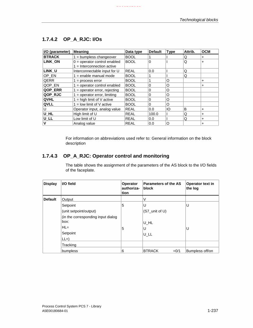
Technological blocks
Process Control System PCS 7 - LibraryA5E00180684-01 1-237
1.7.4.2 OP_A_RJC: I/Os
I/O (parameter) Meaning Data type Default Type Attrib. OCMBTRACK 1 = bumpless changeover BOOL 1 I Q +LINK_ON 0 = operator control enabled
1 = Interconnection activeBOOL 0 I Q +
LINK_U Interconnectable input for U REAL 0.0 I QOP_EN 1 = enable manual mode BOOL 1 I QQERR 1 = process error BOOL 1 O +QOP_EN 1 = operator control enabled BOOL 0 O +QOP_ERR 1 = operator error, rejecting BOOL 0 OQOP_RJC 1 = operator error, limiting BOOL 0 OQVHL 1 = high limit of V active BOOL 0 OQVLL 1 = low limit of V active BOOL 0 OU Operator input, analog value REAL 0.0 IO B +U_HL High limit of U REAL 100.0 I Q +U_LL Low limit of U REAL 0.0 I Q +V Analog value REAL 0.0 O +
For information on abbreviations used refer to: General information on the blockdescription
1.7.4.3 OP_A_RJC: Operator control and monitoring
The table shows the assignment of the parameters of the AS block to the I/O fieldsof the faceplate.
Display I/O field Operatorauthoriza-tion
Parameters of the ASblock
Operator text inthe log
Output V
Setpoint
(unit setpoint/output)
(in the corresponding input dialogbox:
HL=
Setpoint
LL=)
5
5
U
(S7_unit of U)
U_HL
U
U_LL
U
U
Tracking
Default
bumpless 6 BTRACK =0/1 Bumpless off/on
21.02.2003

Technological blocks
Process Control System PCS 7 - Library1-238 A5E00180684-01
1.7.5 OP_D: Local control of digital values (2 buttons)
1.7.5.1 OP_D: Description
Object name (type + number)
FB 48
Calling OBs
The operator control block must be installed in the same OB with and upstream ofthe block that utilizes operator control.
Function
The operator control block OP_D is used to control the digital value of a block bymeans of two pushbuttons. A valid entered value is output to output Q.
21.02.2003

Technological blocks
Process Control System PCS 7 - LibraryA5E00180684-01 1-239
Operating principle
Operating principle of the block (see the figure):
EN
I0
LINK_ I
LINK_ON
BTRACK
Q0
#
&
#
ENO
QOP_ERR
OP_EN0
error handling
QOP_EN0
OP_EN1 QOP_EN1
OP_D
OP_D structure
• I0 is written via the OS controls. Operator control is set at two separate inputs:
- OP_EN0=1 for "0" operation
- OP_EN1=1 for "1" operation
• LINK_I is assigned a configured or interconnected external value.
• LINK_ON enables the external/internal value:
- LINK_ON=1: LINK_U is passed to Q0,
- LINK_ON=0: The assigned I0 value is passed to Q0.
• BTRACK allows tracking of the operator controlled input I0 (only ifLINK_ON=1).
- BTRACK=1: The operator input I0 is tracked to LINK_I. in order to ensurethat a surge does not occur at output Q0 during the transition ofLINK_ON=0.
- BTRACK=0: I0 retains its last (operated) value, which is returned to outputQ0 after the transition to LINK_ON=0.
21.02.2003

Technological blocks
Process Control System PCS 7 - Library1-240 A5E00180684-01
Error handling
The following errors are displayed:
ENO QOP_ERR Cause, if applicable reaction0 X Errors detected by the system (no special handling routine in the block)1 1 ( Π ) Operator input was not enabled or performed while LINK_ON=1.
Input I0 remains unchanged.
Π: Pulse width = sampling time X: Random value
Time response
Not available.Install the OP_D in the same OB and before the block whose input is to beoperator controlled.
Message characteristics
Not available. The output QOP_ERR can be interconnected to a message block inorder to report operator errors (refer to the section on message blocks).
1.7.5.2 OP_D: I/Os
I/O (parameter) Meaning Data type Default Type Attrib. OCM
BTRACK 1 = bumpless changeover BOOL 1 I Q +I0 Operator input 0 BOOL 0 IO B +LINK_I Interconnectable input for I BOOL 0 I QLINK_ON 0 = operator control enabled
1 = interconnection activeBOOL 0 I Q +
OP_EN0 Operator controlled input = disabled BOOL 1 I QOP_EN1 Operator controlled input = enabled BOOL 1 I QQ0 Binary output BOOL 0 O +QOP_EN0 Operator controlled input = disabled BOOL 0 O +QOP_EN1 Operator controlled output = enabled BOOL 0 O +QOP_ERR 1 = operator error BOOL 0 O
For information on abbreviations used refer to:General information on the block description
21.02.2003

Technological blocks
Process Control System PCS 7 - LibraryA5E00180684-01 1-241
1.7.5.3 OP_D: Operator control and monitoring
The table shows the assignment of the parameters of the AS block to the I/O fieldsof the faceplate.
Display I/O field Operatorauthorization
Parameters of the ASblock
Operator text inthe log
Output QO
Command
(selection list:
Off/On 5 IO =0/1 Off/On
Tracking
Default
bumpless 6 BTRACK =0/1 Bumpless off/on
21.02.2003

Technological blocks
Process Control System PCS 7 - Library1-242 A5E00180684-01
1.7.6 OP_D3: Local control of digital values (3 buttons)
1.7.6.1 OP_D3: Description
Object name (type + number)
FB 49
Calling OBs
The operator control block must be installed in the same OB with and upstream ofthe block that utilizes operator control.
Function
The operator control block OP_D3 is used to perform a logical one-of-three digitalvalue operation. If one of the three operator inputs I1, I2 or I3 is set, thecorresponding output is set to 1 and the other outputs are reset, in as far as theoperation is permissible.
Operating principle
The block operates according to the principle described below (see the figure). Theexpression x=1..3 is used here as index for the respective three inputs/outputs:
• The OS control system sets the inputs I1, I2 and I3 simultaneously ("1" to theinput to be enabled and "0" to the other two). Three separate inputs are usedfor enabling/disabling operator control:
- OP_EN_Ix=1 : Enables operator control of input Ix
- OP_EN_Ix=0 : Disables operator control of input Ix
• Each LINK_Ix is assigned an external configured or interconnected value.
• LINK_ON enables the external/internal values:
- LINK_ON=1: LINK_Ix are processed and passed to Qx.
- LINK_ON=0: Operator controlled Ix inputs are processed and passed toQx.
• BTRACK allows tracking of the operator controlled inputs Ix (only ifLINK_ON=1).
- BTRACK=1: The operator controlled inputs Ix are tracked to LINK_Ix,which ensures that a surge does not occur at output Qx during thetransition of LINK_ON=0.
21.02.2003

Technological blocks
Process Control System PCS 7 - LibraryA5E00180684-01 1-243
- BTRACK=0: Ix retains its last (operated) value, which is returned to outputQx after the transition to LINK_ON=0.
• The selection logic applies the three input values (Ix or LINK_Ix) in the orderx=1,2,3 and memorizes the highest index "x" of the input with logical "1" status.The output Qx specified by the index will be set ("1"), while and the remainingtwo outputs Qx will be reset ("0"). If all three inputs I1=I2=I3=0 , the outputs arenot changed.
EN
I1
LINK_ I1
LINK_ON
BTRACK
Q1
#
&
#
ENO
QOP_ERR
OP_EN_I1
error handling
QOP_EN1x=1..3
Input 1
I2
LINK_ I2
I3
LINK_ I3
Input 2
Input 3
selection
logic
1 of 3
Q2
Q3
X
X
XY
Y
Y
OP_EN_I2 QOP_EN2
OP_EN_I3 QOP_EN3
OP_D3
QERR
OP_D3 structure
21.02.2003

Technological blocks
Process Control System PCS 7 - Library1-244 A5E00180684-01
Error handling
The following errors are displayed:
ENO QOP_ERR Cause and, if applicable, reaction0 X Errors detected by the system0 0 All inputs are "0" or more than one input is "1". The output is set according to highest
set input (refer to the operating principles, selection logic).0 1 More than one input is "1". The output is set according to highest set input (refer to
the operating principles, selection logic). The error handling routine changes theinputs Ix in accordance with the rule: The input Ix with the highest index "x" remainsset, the others will be reset".
Time response
Not available.Install the OP_D3 in the same OB and upstream of the block whose input is to becontrolled by the operator.
Message characteristics
Not available. The output QOP_ERR can be interconnected to a message block iferrors are to be reported (refer to the section on message blocks).
21.02.2003

Technological blocks
Process Control System PCS 7 - LibraryA5E00180684-01 1-245
1.7.6.2 OP_D3: I/Os
I/O (parameter) Meaning Datatype
Default I/O Attrib. OCM
BTRACK 1 = bumpless changeover BOOL 1 I Q +
I1 Operator input 1 BOOL 0 IO B +
I2 Operator input 2 BOOL 0 IO B +
I3 Operator input 3 BOOL 1 IO B +
LINK_I1 Interconnectable input for I1 BOOL 0 I Q
LINK_I2 Interconnectable input for I2 BOOL 0 I Q
LINK_I3 Interconnectable input for I3 BOOL 0 I Q
LINK_ON 0 = operator control enabled1 = Interconnection active
BOOL 0 I Q +
OP_EN_I1 Enable switch 1 BOOL 1 I Q
OP_EN_I2 Enable switch 2 BOOL 1 I Q
OP_EN_I3 Enable switch 3 BOOL 1 I Q
Q1 Binary output, switch 1 BOOL 0 O +
Q2 Binary output, switch 2 BOOL 0 O +
Q3 Binary output, switch 3 BOOL 1 O +
QERR 1 = process error BOOL 1 O +
QOP_EN1 Enable output 1 BOOL 0 O +
QOP_EN2 Enable output 2 BOOL 0 O +
QOP_EN3 Enable output 3 BOOL 0 O +
QOP_ERR 1 = operator error BOOL 0 O
For information on abbreviations used refer to:General information on the block description
21.02.2003

Technological blocks
Process Control System PCS 7 - Library1-246 A5E00180684-01
1.7.6.3 OP_D3: Operator control and monitoring
The table shows the assignment of the parameters of the AS block to the I/O fieldsof the faceplate.
Display I/O field Operatorauthorization
Parameters of the ASblock
Operator text in thelog
Output Q1; Q2; Q3
Command
(selection list:
switch 1
switch 2
switch 3)
5
5
5
I1 =1
I2 =0
I3 =0
Switch1
5
5
5
I1 =0
I2 =1
I3 =0
Switch2
5
5
5
I1 =0
I2 =0
I3 =1
Switch3
Tracking
Default
bumpless 6 BTRACK =0/1 Bumpless off/on
21.02.2003

Technological blocks
Process Control System PCS 7 - LibraryA5E00180684-01 1-247
1.7.7 OP_TRIG: Local control of digital values (1 button)
1.7.7.1 OP_TRIG: Description
Object name (type + number)
FB 50
Calling OBs
The operator control block must be installed in the same OB with and upstream ofthe block that utilizes operator control.
Function
This operator control block is used to implement a single pushbutton control(compare with RESET pushbutton).
21.02.2003

Technological blocks
Process Control System PCS 7 - Library1-248 A5E00180684-01
Operating principle
Operating principle of the block (see the figure):
EN
I0
LINK_ IQ0
ENO
QOP_ERRerror handling
OP_EN QOP_EN1
SIGNAL
>1
OP_TRIG
(has no function)
OP_TRIG structure
• The operator sets a logical 1 at input I0, in as far as this is permitted byOP_EN=1.Output Q0 is set to 1 for the duration of one cycle (sampling time) and is thenreset. The operator input I0 is reset by the operator control block afterprocessing.
• The interconnectable input (LINK_I) is redundant to the operator input. At itspositive edge a logical "1" is set at output Q0 for the duration of one cycle(sampling time) and is then reset. LINK_I does not have any influence on theoperation enable function QOP_EN.
• The block's interconnectable input (SIGNAL) is displayed on the OS. It doesnot have any function and is only used for the OS display. It is advisable tointerconnect the signal to be reset, since it does not make any sense to use ofthe single-cycle output signal Q0 of the block.
21.02.2003

Technological blocks
Process Control System PCS 7 - LibraryA5E00180684-01 1-249
Error handling
The following errors are displayed:
Errors indicated by OP_TRIG
ENO QOP_ERR Cause, if applicable reaction0 X Errors detected by the system (no special handling routine in the block)1 1 ( Π ) Operator control is not enabled. Input I0 is set to "0".
Π: Pulse width = sampling time X: Random value
Time response
Not available.Install the OP_TRIG in the same OB and upstream of the block whose input is tobe controlled by the operator.
Message characteristics
Not available. The output QOP_ERR can be interconnected to a message block inorder to report operator errors (refer to the section message blocks).
1.7.7.2 OP_TRIG: I/Os
I/O (parameter) Meaning Datatype
Default Type Attrib. OCM
I0 Operator input BOOL 0 IO B +
LINK_I Input interconnectable to I0 BOOL 0 I Q
OP_EN 1 = operator control enabled BOOL 1 I Q
Q0 Binary output BOOL 0 O
QOP_EN 1 = operator input enabled BOOL 0 O +
QOP_ERR 1 = operator error BOOL 0 O
SIGNAL Feedback signal for display on OS BOOL 0 I Q +
For information on abbreviations used refer to:General information on the block description
21.02.2003

Technological blocks
Process Control System PCS 7 - Library1-250 A5E00180684-01
1.7.7.3 OP_TRIG: Operator control and monitoring
The table shows the assignment of the parameters of the AS block to the I/O fieldsof the faceplate.
Display I/O field Operatorauthorization
Parameters of theAS block
Operator text inthe log
Feedback
exists SIGNAL
Command
Default
reset 5 IO = 1 Reset
21.02.2003

Technological blocks
Process Control System PCS 7 - LibraryA5E00180684-01 1-251
1.8 Message blocks
1.8.1 Overview of the message blocks
What is the purpose of message blocks?
The plant operator may require information on events involving changes of a digitalvalue or status in the AS. Due to the message blocks implemented in the AS, thereis not need for the OS system to poll the AS in order to obtain this information.These blocks monitor the digital values and report changes to the OS (includingadditional and configurable information). The OS system can visualize, log andarchive this information.The table shows an overview of the message blocks, which are implemented asFBs.
Overview of the message blocks
FB no. Type name Meaning Operation method
43 MESSAGE Generation of configurable messages SIMATIC Process Control -Standard
59 MSG_NACK Generation of user-specific messages whichdo not require acknowledgement
SIMATIC Process Control -Standard
The operating principle of the MESSAGE is shown in the block diagram, using theS7 block ALARM_8P.The adaptation of messages for individual blocks is described under "Messagecharacteristics".
21.02.2003

Technological blocks
Process Control System PCS 7 - Library1-252 A5E00180684-01
1.8.2 MSG_NACK: User-specific messages (no mandatoryacknowledgement)
1.8.2.1 MSG_NACK: Description
Object name (type + number)
FB 78
Calling OBs:
The message block must be installed in the message OB.
Area of application
The message block MSG_NACK is used to generate user-specific messages,which do not require an acknowledgement (process messages).
Function
The block can generate up to eight user-specific messages of this type.
Operating principle
Messages not requiring acknowledgement are output via NOTIFY_8P. The outputof individual or all messages can be locked (at MSG_LOCK). Locked messagesare indicated at the output. If MSG_LOCK is set to lock all messages, the blocksets QSUP = TRUE if an incoming message is to be output.
21.02.2003
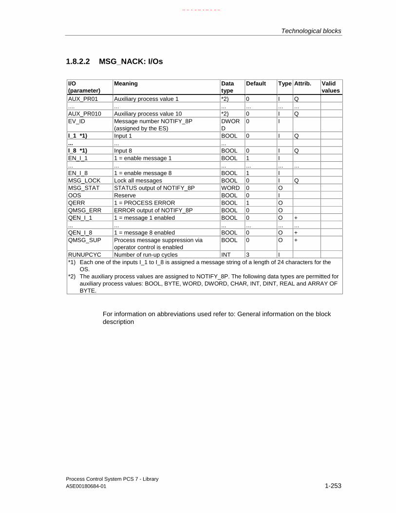
Technological blocks
Process Control System PCS 7 - LibraryA5E00180684-01 1-253
1.8.2.2 MSG_NACK: I/Os
I/O(parameter)
Meaning Datatype
Default Type Attrib. Validvalues
AUX_PR01 Auxiliary process value 1 *2) 0 I Q.... ... ... ... ... ...AUX_PR010 Auxiliary process value 10 *2) 0 I QEV_ID Message number NOTIFY_8P
(assigned by the ES)DWORD
0 I
I_1 *1) Input 1 BOOL 0 I Q... ... ...I_8 *1) Input 8 BOOL 0 I QEN_I_1 1 = enable message 1 BOOL 1 I... ... ... ... ... ...EN_I_8 1 = enable message 8 BOOL 1 IMSG_LOCK Lock all messages BOOL 0 I QMSG_STAT STATUS output of NOTIFY_8P WORD 0 OOOS Reserve BOOL 0 IQERR 1 = PROCESS ERROR BOOL 1 OQMSG_ERR ERROR output of NOTIFY_8P BOOL 0 OQEN_I_1 1 = message 1 enabled BOOL 0 O +... ... ... ... ... ...QEN_I_8 1 = message 8 enabled BOOL 0 O +QMSG_SUP Process message suppression via
operator control is enabledBOOL 0 O +
RUNUPCYC Number of run-up cycles INT 3 I*1) Each one of the inputs I_1 to I_8 is assigned a message string of a length of 24 characters for the
OS.*2) The auxiliary process values are assigned to NOTIFY_8P. The following data types are permitted for
auxiliary process values: BOOL, BYTE, WORD, DWORD, CHAR, INT, DINT, REAL and ARRAY OFBYTE.
For information on abbreviations used refer to: General information on the blockdescription
21.02.2003
Technological blocks
Process Control System PCS 7 - Library1-254 A5E00180684-01
1.8.3 MESSAGE: Message blocks (configurable messages)
1.8.3.1 MESSAGE: Description
Object name (type + number)
FB 43
Calling OBs
The message block and its instance must be installed in the monitoring and eventrecognition OB (for example OB32) as well as in OB100 (refer to the startupcharacteristics).
Function
The MESSAGE block is used to generate configurable messages and forms theinterface between the block outputs whose changes are to be reported and the S7block ALARM_8P.
Operating principle
The inputs of the block are used to assign individual messages to the monitoredsignals, and also to enable/lock messages depending on the process states.
• EN: EN=1 enables block processing.
• I_1 to I_8: Changes at these monitored signals are reported. A configurablemessage text (24 characters) is assigned to each of these signals. The textcan be adapted for further in the OS configuration.Each change in these inputs triggers the output of a message to the OS,provided the message function is not locked.
• I_1ISCSF to I_8ISCSF: A logical "1" identifies the corresponding message ascontrol system message (CSF).
• MSG_LOCK: Allows process-specific locking of messages output at this block.At the positive edge of the lock signal, all active process messages (not controlsystem messages) are reset, and thus reported outgoing to the OS.
• AUX_PR01 to AUX_PR10: These inputs can be interconnected to randomvalues of any data type. These values are referred to as auxiliary processvalues, are limited to 16 characters and included in the message to the OS,and thus provide more detailed information on the event triggering themessage.
21.02.2003

Technological blocks
Process Control System PCS 7 - LibraryA5E00180684-01 1-255
• The operator can lock the messages of a reference tag at the OS. The OSreports this status to the corresponding message block that returns aconfirmation (via its ALARM_8P) to the OS. The OS enters the messageacknowledgement and reports it as gone in the message event log.
• QMSG_SUP indicates that message suppression is enabled.
• The OS system evaluates MSG_STAT, QMSG_ERR and MSG_ACK.
Error handling
Error handling of the message block is limited to the error information ofALARM_8P (refer to the "System Software for S7-300/400 - System and StandardFunctions" Manual).
The online help for ALARM_8P, STAT parameter, provides information on errormessages of the MSG_STAT parameter.
Startup characteristics
During startup, the message block suppresses all messages, including controlsystem messages. The duration (number of cycles) of message suppression is setin the RUNUPCYC parameter. During restart, this parameter value is loaded intoan internal counter and decremented each time the block is executed. Messageswill not be generated unless this counter value is equal to zero.
Messages
Messages are generated via ALARM_8P (SFB35). All the blocks use the PMCcommunication channel. The ALARM_8P is assigned 8 digital inputs and 10auxiliary process values. Every recognized edge transition at one or more digitalinputs triggers a message, irrespective of an acknowledgment. The auxiliaryprocess values are assigned consistent to the message at the time of edgeevaluation. All eight signals are assigned a common message number (MSG_ID),which is subdivided at the OS into 8 messages. The ES assigns the messagenumber automatically by calling the message server.
Message text
Each block message is assigned a default text with a maximum length of 24characters. The message is assigned to an (internal or external) parameter of theblock and a specific message class (refer to the table). The message texts andclass can be modified when you create your configuration. The block algorithm isnot affected by a change in the message class.
21.02.2003

Technological blocks
Process Control System PCS 7 - Library1-256 A5E00180684-01
Assignment of message texts and message classes to the block parameters
Message no. Block parameter Default messagetext
Message class
1 I1 TEXT 1 F: : : :8 I8 TEXT8 F
Message classes
The available message classes and their meaning are listed in the table.
Message class MeaningAH ALARM HIGHWH WARNING HIGHWL WARNING LOWAL ALARM LOWTH TOLERANCE HIGHTL TOLERANCE LOWF AS control system message (error)S AS control system message (fault)S* OS control system message (fault)M Preventive maintenancePM Process message- Operation messageOR Operator requestOM *1) Operation message
*1) If the block is used for operation messages, the inputs I_1, ... have to besupplied with pulses; a static value 1 would trigger multiple messages.
Auxiliary process values
The auxiliary process values can be assigned in differing numbers and sequenceto every message. Auxiliary process values not used in the block algorithm can beinterconnected freely as input parameters AUX_PRx at the block.
Permitted data types of auxiliary process values: BOOL, BYTE, WORD, DWORD,CHAR, INT, DINT, REAL and ARRAY OF BYTE
21.02.2003

Technological blocks
Process Control System PCS 7 - LibraryA5E00180684-01 1-257
1.8.3.2 MESSAGE: I/Os
I/O (parameter) Meaning Data type Default Type Attrib.AUX_PR01 Auxiliary process value 1 *2) 0 I Q.... ... ... ... ... ...AUX_PR010 Auxiliary process value 10 *2) 0 I QEV_ID Message number ALARM_8P
(assigned by ES)DWORD 0 I
I_1 *1) Input 1 BOOL 0 I Q... ... ...I_8 *1) Input 8 BOOL 0 I QI_1ISCSF 1 = control system message BOOL 0 I... ... ... ... ... ...I_8ISCSF 1 = control system message BOOL 0 IMSG_ACK ACK_STATE output of ALARM_8P WORD 0 OMSG_LOCK Lock messages at specific process status BOOL 0 I QMSG_STAT STATUS output of ALARM_8P: WORD 0 OOOS Reserve BOOL 0 I +QERR 1 = Error BOOL 1 OQMSG_ERR Error output of ALARM_8P BOOL 0 OQMSG_SUP 1 = message suppression enabled BOOL 0 ORUNUPCYC Number of run-up cycles INT 3 I
*1) Each one of the inputs I_1 to I_8 is assigned a message text with a length of 24characters and a message class for the OS.
*2) The following data types of auxiliary process values are permitted: BOOL, BYTE,WORD, DWORD, CHAR, INT, DINT, REAL and ARRAY OF BYTE
For information on abbreviations used refer to: General information on the blockdescription
21.02.2003

Technological blocks
Process Control System PCS 7 - Library1-258 A5E00180684-01
1.9 Appendix
1.9.1 Technical data "Technological blocks"
These technical data apply to the "Technological blocks".
Meaning:
Block type name
Symbolic name in the symbol table of the library for the corresponding FB or FC.These names must be unique in the project.
FB/FC no.
Block number.
Typical runtime
Time normally required by the CPU for processing the corresponding blockprogram (for example, for a driver this represents the execution time in thewatchdog interrupt OB (OB3x) without generation of a channel error message).
The table below shows the runtime of blocks in a CPU S7 417-4. The block runtimeon other CPUs depends on the CPU performance
Block length
Memory requirements of the program code, once for each block type.
Length of instance data
Memory requirement of an instance DB
Temporary memory
Local data requirements for one block execution cycle. This limit is CPU-specific; aCPU STOP will be triggered if it is exceeded. You must verify this in your CPUconfiguration and redistribute memory to the blocks if necessary.
21.02.2003
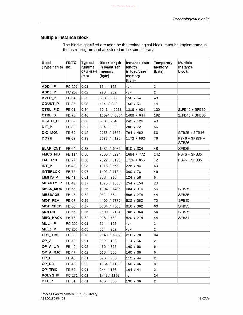
Technological blocks
Process Control System PCS 7 - LibraryA5E00180684-01 1-259
Multiple instance block
The blocks specified are used by the technological block, must be implemented inthe user program and are stored in the same library.
Block(Type name)
FB/FCno.
TypicalruntimeCPU 417-4(ms)
Block lengthin load/usermemory(byte)
Instance datalengthin load/usermemory(byte)
Temporarymemory(byte)
Multipleinstanceblock
ADD4_P FC 256 0,01 194 / 122 - / - 2
ADD8_P FC 257 0,02 298 / 202 - / - 2
AVER_P FB 34 0,05 508 / 368 156 / 54 48
COUNT_P FB 36 0,05 484 / 340 166 / 54 44
CTRL_PID FB 61 0,44 8042 / 6622 1316 / 604 136 2xFB46 + SFB35
CTRL_S FB 76 0,46 10594 / 8864 1488 / 644 192 2xFB46 + SFB35
DEADT_P FB 37 0,06 898 / 704 242 / 126 48
DIF_P FB 38 0,07 694 / 502 208 / 72 56
DIG_MON FB 62 0,18 2056 / 1678 794 / 482 56 SFB35 + SFB36
DOSE FB 63 0,28 5036 / 4130 1172 / 592 76 FB46 + SFB35 +SFB36
ELAP_CNT FB 64 0,23 1434 / 1086 610 / 334 48 SFB35
FMCS_PID FB 114 0,56 7660 / 6294 1694 / 772 142 FB46 + SFB35
FMT_PID FB 77 0,56 7322 / 6128 1726 / 856 72 FB46 + SFB35
INT_P FB 40 0,08 1118 / 868 228 / 84 60
INTERLOK FB 75 0,07 1492 / 1154 300 / 78 46
LIMITS_P FB 41 0,01 308 / 216 124 / 58 6
MEANTM_P FB 42 0,17 1576 / 1306 254 / 154 20
MEAS_MON FB 65 0,25 1904 / 1486 684 / 376 56 SFB35
MESSAGE FB 43 0,22 932 / 684 506 / 278 44 SFB35
MOT_REV FB 67 0,28 4466 / 3776 822 / 382 70 SFB35
MOT_SPED FB 68 0,27 5334 / 4556 816 / 382 66 SFB35
MOTOR FB 66 0,26 2590 / 2134 706 / 364 54 SFB35
MSG_NACK FB 78 0,22 998 / 732 520 / 274 44 SFB31
MUL4_P FC 262 0,01 214 / 122 - / - 2
MUL8_P FC 263 0,03 334 / 202 - / - 2
OB1_TIME FB 69 0,16 2140 / 1822 216 / 70 84
OP_A FB 45 0,01 232 / 156 114 / 56 2
OP_A_LIM FB 46 0,02 486 / 358 160 / 68 6
OP_A_RJC FB 47 0,02 518 / 388 160 / 68 6
OP_D FB 48 0,01 376 / 286 112 / 44 2
OP_D3 FB 49 0,02 1354 / 1136 150 / 46 8
OP_TRIG FB 50 0,01 244 / 166 104 / 44 2
POLYG_P FC 271 0,01 1446 / 1176 - / - 24
PT1_P FB 51 0,01 456 / 338 136 / 66 2
21.02.2003

Technological blocks
Process Control System PCS 7 - Library1-260 A5E00180684-01
Block(Type name)
FB/FCno.
TypicalruntimeCPU 417-4(ms)
Block lengthin load/usermemory(byte)
Instance datalengthin load/usermemory(byte)
Temporarymemory(byte)
Multipleinstanceblock
R_TO_DW FC 282 0,01 344 / 262 - / - 10
RAMP_P FB 52 0,01 708 / 524 188 / 64 54
REC_BO FB 208 0,17 3246 / 2356 992 / 128 2
REC_R FB 210 0,17 1838 / 1332 956 / 476 2
SEND_BO FB 207 0,21 2298 / 1668 718 / 110 2
SEND_R FB 209 0,19 4486 / 3886 908 / 478 2
RATIO_P FB 70 0,04 742 / 526 316 / 134 12 FB46 + SFB35
SPLITR_P FC 272 0,04 832 / 644 - / - 10
SWIT_CNT FB 71 0,23 1332 / 988 606 / 316 92 SFB35
VAL_MOT FB 74 0,29 4490 / 3782 820 / 382 70 SFB35
VALVE FB 73 0,26 3256 / 2728 726 / 366 54 SFB35
21.02.2003

Process Control System PCS 7 - LibraryA5E00180684-01 2-1
2 Driver blocks
2.1 Notes on using driver blocks
General
• The OBs in which the blocks are installed are defined in the driver blocks.Please note that not all OBs listed will be generated for all CPUs. Relevantinformation can be found in the Online Help of the respective OBs.
• Firmware version V3.1 or faster must be installed in the CPU in order to enablethe driver generator to use driver blocks of the PCS 7 Library V60.
• The CFC function "Generate module drivers" automatically interconnects andconfigures the selected I/Os. Always set these interconnections andconfigurations manually if you are going to integrate the block into the chartyourself, otherwise errors my develop when you compile the chart.
Signal processing blocks
The driver blocks of the PCS 7 Library offer three types of channel blocks for signalprocessing:
1. Standard channel blocks:CH_AI, CH_AO, CH_DI, CH_DO.Used only for processing the signals of S7-300/400 SM modules. Please usethese standard blocks if you want to optimize memory utilization and runtimeand do not need to process any PA devices.
2. Universal channel blocks:CH_U_AI, CH_U_AO, CH_U_DI, CH_U_DO.Used for processing the signals of S7-300/400 SM modules or PA fielddevices. Of advantage when using these blocks is that you can create CFCcharts irrespective of the hardware I/O to be used later. A disadvantage ofuniversal blocks is an increase of the load on memory and of cycle times. Theydo not have message characteristics.
3. PA channel blocks:PA_AI, PA_AO, PA_DI, PA_DO, PA_TOTDesigned especially for use with PA field devices, and used primarily wherethe special features of these devices are required. In contrast to CH blocks, thePA channel blocks process not only the signal itself, but also all variablesaccording to the hardware configuration required for the device. Furthermore,the PA channel blocks can output control system messages.
21.02.2003
Driver blocks
Process Control System PCS 7 - Library2-2 A5E00180684-01
2.2 Signal blocks and diagnostic drivers
2.2.1 CH_AI: Analog value input
2.2.1.1 CH_AI: Description
Object name (type + number)
FC 275
Area of application
The block processes analog signals at the inputs of S7-300/400 SM analog inputmodules.
The calling OB
The watchdog interrupt OB3x is the calling OB in which the block is installed (forexample OB 32).
Use in the CFC
When the CFC function "Generate module drivers" is used, the systemautomatically:
• Interconnects the MODE input to the corresponding output OMODE_xx of theMOD block.
Function and operating principle
The block processes all channel-specific signal functions of an analog inputmodule in cyclic intervals.
The block reads non-linearized analog values from the process image (partition)and converts them into their physical value or uses them to calculate percentagevalues. The MODE input is used to determine in which form non-linearized data isavailable and how it is to be processed. If the high byte of the MODE inputparameter = 16#40 (value status = higher-priority error), the non-linearized value ishandled as invalid.
21.02.2003
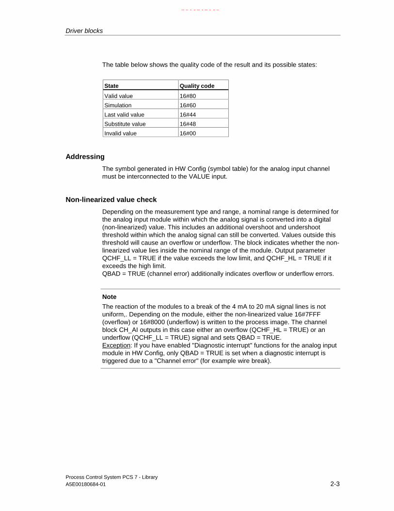
Driver blocks
Process Control System PCS 7 - LibraryA5E00180684-01 2-3
The table below shows the quality code of the result and its possible states:
State Quality code
Valid value 16#80
Simulation 16#60
Last valid value 16#44
Substitute value 16#48
Invalid value 16#00
Addressing
The symbol generated in HW Config (symbol table) for the analog input channelmust be interconnected to the VALUE input.
Non-linearized value check
Depending on the measurement type and range, a nominal range is determined forthe analog input module within which the analog signal is converted into a digital(non-linearized) value. This includes an additional overshoot and undershootthreshold within which the analog signal can still be converted. Values outside thisthreshold will cause an overflow or underflow. The block indicates whether the non-linearized value lies inside the nominal range of the module. Output parameterQCHF_LL = TRUE if the value exceeds the low limit, and QCHF_HL = TRUE if itexceeds the high limit.QBAD = TRUE (channel error) additionally indicates overflow or underflow errors.
Note
The reaction of the modules to a break of the 4 mA to 20 mA signal lines is notuniform,. Depending on the module, either the non-linearized value 16#7FFF(overflow) or 16#8000 (underflow) is written to the process image. The channelblock CH_AI outputs in this case either an overflow (QCHF_HL = TRUE) or anunderflow (QCHF_LL = TRUE) signal and sets QBAD = TRUE.Exception: If you have enabled "Diagnostic interrupt" functions for the analog inputmodule in HW Config, only QBAD = TRUE is set when a diagnostic interrupt istriggered due to a "Channel error" (for example wire break).
21.02.2003

Driver blocks
Process Control System PCS 7 - Library2-4 A5E00180684-01
NAMUR limit check
The NAMUR guideline for analog signal processing defines the limits for Life Zero(4 mA to 20 mA) analog signals at faulty channels:
3.6 mA = Analog signal = 21 mA
The above NAMUR limits are fixed defaults for limit value monitoring. If you want toset other limit values, you must set input CH_F_ON = TRUE and assign relevantnew limits in mA at the inputs CH_F_HL and CH_F_LL. QBAD = TRUE when theset low or high limit is exceeded at a life zero analog signal.
Note
The selectable limits must lie within the overshoot and undershoot hysteresis of themodule. Values outside the NAMUR range are also possible, in as far as themodule does not limit the measured values automatically to this range.
Normal value
The non-linearized value is converted into its physical value, based on the inputparameters VLRANGE, VHRANGE and MODE (see also OMODE_xx). To allowthe interconnection of the VLRANGE and VHRANGE settings to other blockparameters, these are written to the outputs OVLRANGE and OVHRANGE. Theconversion algorithm presumes a linearized input signal. When VLRANGE = 0 andVHRANGE = 100, you obtain a percentage value. If VHRANGE = VLRANGE isset, you obtain the input signal of the analog input module (e.g. mA), according tothe MODE setting. If the non-linearized value is already a physical value, setVLRANGE = 0 and VHRANGE = 1. The Quality Code is set to QUALITY = 16#80.
When operating in PTC measurement mode, the analog value contains anencoded binary signal and the REAL output provides the following information:
Measured resistance < trigger value Output = 0.0
Measured resistance > trigger value Output ≠ 0.0.
Note
In the measuring mode "Thermocouple with external or internal comparison ", thephysical variable is converted into +/- 80 mV in S7 300 modules. You have todetermine the temperature with reference to the corresponding conversion tables.
The physical equivalence in mV is provided by the module as non-linearized value.Set VHRANGE and VLRANGE +/- 80 mV.
21.02.2003

Driver blocks
Process Control System PCS 7 - LibraryA5E00180684-01 2-5
Simulation
If input parameter SIM_ON = TRUE, then the value at input SIM_V is output withthe Quality Code QUALITY = 16#60. QBAD = TRUE: reset due to a higher-priorityerror. A valid mode must be set in low word of the input MODE in simulation modealso. Otherwise QBAD = 1 is output. Simulation has the highest priority. Thesimulation value will be converted into non-linearized data, based on the operatingmode and the input parameters VHRANGE and VLRANGE. This value will bechecked in the same way as a non-linearized value from the process image. Youcan therefore also simulate the states QBAD, QCHF_LL and QCHF_HL.With the setting VLRANGE > VHRANGE, the QBAD = TRUE state cannot besimulated. The outputs QCHF_LL und QCHF_HL are set accordingly to the valueSIM_V. QSIM = TRUE when the block is in simulation mode,.
Substitute value
If input parameter SUBS_ON = TRUE, then the value of input SUBS_V is output assubstitute value, as long as the non-linearized value is invalid. The quality code isset to QUALITY = 16#48 and QBAD = 1.
Hold last value
The last valid output value (V_LAST) will be output if input parameter SUBS_ON =FALSE, i.e. if the non-linearized value is invalid. When V_DELTA > 0, the followingapplies:
ABS (V - V_LAST) > V_DELTA: V = V_LAST1 (second to last valid outputvalue)
ABS (V - V_LAST) ≤ V_DELTA: V = V_LAST (last valid output value)
The quality code will be set to QUALITY = 16#44 and QBAD = 1.
If valid non-linearized values are available and V_DELTA > 0 and ABS (V -V_LAST) > V_DELTA, the last valid output value (V_LAST) with QUALITY = 16#44(QBAD = 0) is held for the duration of one cycle.
Delayed value acceptance
After restart or if the quality code changes from "BAD" to "GOOD", the QualityCode and value are not updated until the CNT_LIM cycles have passed. Thisfunction is disabled when CNT_LIM = 0 ( = default),. During the accept value delay,the quality code = 16#00 and QBAD = 1. The last value will be held during theaccept value delay.
Error handling
The function does not check the plausibility of input parameters. If an invalidoperating mode is set in the low word of the MODE input parameter, it is assumedthat the non-linearized value is invalid.
21.02.2003

Driver blocks
Process Control System PCS 7 - Library2-6 A5E00180684-01
Startup characteristics
n.a.
Time response
n.a.
Message characteristics
n.a.
Operator control and monitoring
The block does not have a faceplate.
21.02.2003
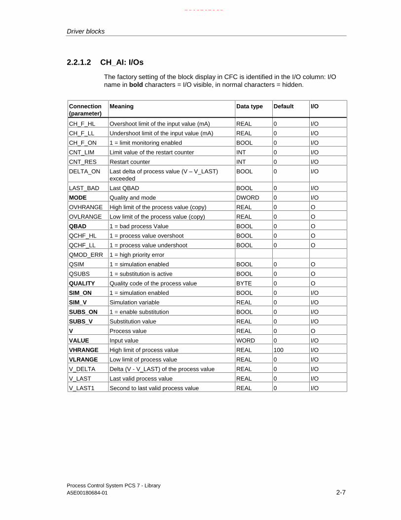
Driver blocks
Process Control System PCS 7 - LibraryA5E00180684-01 2-7
2.2.1.2 CH_AI: I/Os
The factory setting of the block display in CFC is identified in the I/O column: I/Oname in bold characters = I/O visible, in normal characters = hidden.
Connection(parameter)
Meaning Data type Default I/O
CH_F_HL Overshoot limit of the input value (mA) REAL 0 I/O
CH_F_LL Undershoot limit of the input value (mA) REAL 0 I/O
CH_F_ON 1 = limit monitoring enabled BOOL 0 I/O
CNT_LIM Limit value of the restart counter INT 0 I/O
CNT_RES Restart counter INT 0 I/O
DELTA_ON Last delta of process value (V – V_LAST)exceeded
BOOL 0 I/O
LAST_BAD Last QBAD BOOL 0 I/O
MODE Quality and mode DWORD 0 I/O
OVHRANGE High limit of the process value (copy) REAL 0 O
OVLRANGE Low limit of the process value (copy) REAL 0 O
QBAD 1 = bad process Value BOOL 0 O
QCHF_HL 1 = process value overshoot BOOL 0 O
QCHF_LL 1 = process value undershoot BOOL 0 O
QMOD_ERR 1 = high priority error
QSIM 1 = simulation enabled BOOL 0 O
QSUBS 1 = substitution is active BOOL 0 O
QUALITY Quality code of the process value BYTE 0 O
SIM_ON 1 = simulation enabled BOOL 0 I/O
SIM_V Simulation variable REAL 0 I/O
SUBS_ON 1 = enable substitution BOOL 0 I/O
SUBS_V Substitution value REAL 0 I/O
V Process value REAL 0 O
VALUE Input value WORD 0 I/O
VHRANGE High limit of process value REAL 100 I/O
VLRANGE Low limit of process value REAL 0 I/O
V_DELTA Delta (V - V_LAST) of the process value REAL 0 I/O
V_LAST Last valid process value REAL 0 I/O
V_LAST1 Second to last valid process value REAL 0 I/O
21.02.2003

Driver blocks
Process Control System PCS 7 - Library2-8 A5E00180684-01
2.2.2 CH_AO: Analog value output
2.2.2.1 CH_AO: Description
Object name (type + number)
FC 276
Area of application
The block processes signals of S7-300/400 SM analog output modules.
Calling OBs
The watchdog interrupt OB3x into which the block is installed (for example OB 32)and the restart OB100 are the calling OBs.
Use in the CFC
The CFC function "Generate module drivers" automatically:
• Interconnects the MODE input to the corresponding output OMODE_xx of theMOD block.
• Installs the CH_AO block downstream of the MOD block assigned to it inOB100.
Note
If you do not use the CFC function "Generate module drivers", you have to ensurethat the CH_AO block is installed downstream of the MOD block assigned to it inthe OB100.
Function and operating principle
The block processes all channel-specific signal functions in cyclical intervals.
The block writes a process value as an analog non-linearized value to the processimage (partition). The MODE input parameter is used to determine in which formthe non-linearized value is to be generated.If the high byte of the input parameter MODE = 0 (value status), the non-linearizedvalue will still be written to the process image (partition), but the quality code"invalid value" will be set.
21.02.2003

Driver blocks
Process Control System PCS 7 - LibraryA5E00180684-01 2-9
The quality code states:
Status Quality code
Valid value 16#80
High value limited 16#56
Low value limited 16#55
Simulation 16#60
Invalid value 16#00
Addressing
You must interconnect the VALUE output with the symbol for the analog outputchannel which was generated with HW Config (symbol table).
Normal value
• The parameters ULRANGE and UHRANGE map the process value U to thenon-linearized VALUE (quantization steps) of the analog output module,depending on the MODE. For example in the mode 4..20mA (16#0203), thenon-linearized value for 4mA will be output if U = ULRANGE, and the non-linearized value for 20mA is output if U = UHRANGE.
• PHYS_LIM is used to set the limits of the non-linearized VALUE. With defaultsetting PHYS_LIM = 0, the output VALUE will be limited to the normalizinglimits of the module. In accordance with the above example, the blockcalculates the non-linearized value for 20 mA for U > UHRANGE and the non-linearized value for 4mA for U < ULRANGE The quality codes 16#56 (highvalue limited) and 16#55 (low value limited) are applied accordingly at theQUALITY output instead of the 16#80 (valid value).
• In order to output analog values outside the normalization values and up to thephysical limits of the module, you have to set PHYS_LIM = 1. The outputvalues are not limited until, in the above example, the module limits areexceeded by specifying U = 200 (36mA) or U = -50 (-4mA) at ULRANGE = 0and UHRANGE = 100. The output values are then limited to the physical limitsspecified in the data sheets of the modules and the corresponding qualitycodes are output.
• The outputs QCHF_HL and QCHF_LL also provide information on whether theoutput values have been limited.
Simulation
The value of SIM_U is output with quality code (QUALITY) = 16#60 if inputparameter SIM_ON = TRUE. A valid mode must be set in the low word of inputMODE in simulation mode also. Otherwise QBAD = 1 is output. If a higher-priorityerror has occurred, QBAD = FALSE is set. Simulation takes highest priority. QSIM= TRUE when the block is in simulation mode.
21.02.2003

Driver blocks
Process Control System PCS 7 - Library2-10 A5E00180684-01
I/O fault
The quality code QUALITY = 16#00 is set when the high byte of input MODE = 0(value status). The current non-linearized value will always be written to theprocess image (partition).
Value limiting
You can limit the low or high threshold of process variables, in order to avoidtriggering of errors (QBAD = TRUE) before all data have been written to theprocess image (partition).
LIMIT_ON = TRUE limits process variables (V)
- to V_HL, if V > V_HL and
- to LL_V, if V < V_LL.
Error handling
The plausibility of input parameters will not be checked. If an invalid operatingmode was set in the low word of the MODE input, the digitized output value is setto 0 and QUALITY = 16#00 is output.
Startup characteristics
The MOD blocks set the LSB of byte 2 of their outputs OMODE_xx in OB100. If theblock detects this code, it acknowledges it and then reacts as follows:
The process variable U is computed and transferred to the process image ifSTART_ON = false. Otherwise the non-linearized value corresponding to theSTART_U process value is written to the process image.
Time response
n.a.
Message characteristics
n.a.
Operator control and monitoring
The block does not have a faceplate.
21.02.2003

Driver blocks
Process Control System PCS 7 - LibraryA5E00180684-01 2-11
2.2.2.2 CH_AO: I/Os
The factory setting of the block display in CFC is identified in the I/O column: I/Oname in bold characters = I/O visible, in normal characters = hidden.
Connection(parameter)
Meaning Data type Default I/O
LL_V process value if U < V LL REAL 0 I/O
LIMIT_ON 1 = limit of control process value BOOL 0 I/O
MODE Value status and mode DWORD 0 I/O
PHYS_LIM 1 = enable physical module limits BOOL 0 I/O
QBAD 1 = invalid output value BOOL 0 O
QCHF_HL 1 = process value overshoot BOOL 0 O
QCHF_LL 1 = process value undershoot BOOL 0 O
QMOD_ERR 1 = higher-priority error
QSIM 1 = simulation is busy BOOL 0 O
QUALITY Quality code of output value BYTE 0 O
SIM_ON 1 = enable simulation BOOL 0 I/O
SIM_U Simulation value REAL 0 I/O
START_ON 1 = enable startup substitution value BOOL 0 I/O
START_U Startup substitution value REAL 0 I/O
U Process value REAL 0 I/O
UHRANGE High limit of process value REAL 0 I/O
ULRANGE Low limit of process value REAL 0 I/O
V_HL High limit value REAL 0 I/O
V_LL Low limit value REAL 0 I/O
VALUE Process image output value WORD 0 O
21.02.2003

Driver blocks
Process Control System PCS 7 - Library2-12 A5E00180684-01
2.2.3 CH_DI: Digital value input
2.2.3.1 CH_DI: Description
Object name (type + number)
FC 277
Area of application
The block processes the input signals of S7-300/400 SM digital input modules.
Calling OBs
The watchdog interrupt OB3x into which the block is installed (for example OB 32).
Use in the CFC
The CFC function "Generate module drivers" when used automatically:
• Interconnects the MODE input to the corresponding output OMODE_xx of theMOD or PADP block.
Function and operating principle
The block cyclically processes all channel-specific signal functions.
It reads a digital value of the data type BOOL from the process image (partition). Ifthe high byte of input parameter MODE = 16#40 (value status = higher-priorityerror), the digital value is considered invalid. If input parameter PQC = TRUE, thevalue status of the digital value is read from the process image (partition).
A quality code is added to the result and assigned the following values:
State Quality code
valid value 16#80
simulation 16#60
last valid value 16#44
substitution value 16#48
invalid value 16#00
21.02.2003

Driver blocks
Process Control System PCS 7 - LibraryA5E00180684-01 2-13
Addressing
The symbol generated in HW Config (symbol table) for the digital input channel hasto be interconnected to the VALUE input. If the process image (partition) alsocontains the value status of the digital input channel, you have to interconnect thecorresponding symbol with input VALUE_QC and set input PQC = TRUE.
Normal value
The digital value of the process image (partition) is set at output parameter Q withQuality Code QUALITY = 16#80.
Simulation
If input parameter SIM_ON = TRUE, the value of input SIM_I (PA_ON = FALSE) orSIM_OUT (PA_ON = TRUE) is output to the output parameter Q with quality codeQUALITY = 16#60. Simulation takes highest priority. QBAD = TRUE if a higher-priority error has occurred. QSIM = TRUE when the block is in simulation mode.
Substitute value
If input parameter SUBS_ON = TRUE, the value of input parameter SUBS_I isoutput at output parameter Q with Quality Code QUALITY = 16#48 and QBAD = 1,in as far as the digital value of the process image (partition) is invalid.
Hold last value
The last valid value is output if input parameter SUBS_ON = FALSE and the non-linearized value is invalid. The Quality Code is set to QUALITY = 16#44 and QBAD= 1.
• The last valid output value corresponds to Q_LAST.
21.02.2003

Driver blocks
Process Control System PCS 7 - Library2-14 A5E00180684-01
Error handling
The system does not check the plausibility of input parameters.
Startup characteristics
n.a.
Time response
n.a.
Message characteristics
The block does not have message characteristics.
Operator control and monitoring
The block does not have a faceplate.
21.02.2003

Driver blocks
Process Control System PCS 7 - LibraryA5E00180684-01 2-15
2.2.3.2 CH_DI: I/Os
The factory setting of the block display in CFC is identified in the I/O column: I/Oname in bold characters = I/O visible, in normal characters = hidden.
Connection(parameter)
Meaning Data type Default I/O
MODE Value status and operating mode DWORD 0 I/O
PQC 1 = use process image value status BOOL 0 I/O
Q Process value BOOL 0 O
Q_LAST Last valid process value BOOL 0 I/O
QBAD 1 = invalid process value BOOL 0 I/O
QMOD_ERR 1 = higher-priority error BOOL 0 O
QSIM 1 = simulation active BOOL 0 O
QSUBS 1 = substitution active BOOL 0 O
QUALITY Quality code of process value BYTE 0 O
SIM_I Simulation value BOOL 0 I/O
SIM_ON 1 = enable simulation BOOL 0 I/O
SUBS_I Substitute value BOOL 0 I/O
SUBS_ON 1 = enable failure substitution BOOL 0 I/O
VALUE Input value BOOL 0 I/O
VALUE_QC Process image value status BOOL 0 I/O
21.02.2003
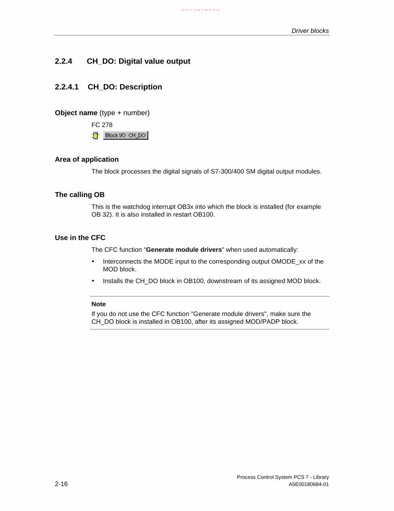
Driver blocks
Process Control System PCS 7 - Library2-16 A5E00180684-01
2.2.4 CH_DO: Digital value output
2.2.4.1 CH_DO: Description
Object name (type + number)
FC 278
Area of application
The block processes the digital signals of S7-300/400 SM digital output modules.
The calling OB
This is the watchdog interrupt OB3x into which the block is installed (for exampleOB 32). It is also installed in restart OB100.
Use in the CFC
The CFC function "Generate module drivers" when used automatically:
• Interconnects the MODE input to the corresponding output OMODE_xx of theMOD block.
• Installs the CH_DO block in OB100, downstream of its assigned MOD block.
Note
If you do not use the CFC function "Generate module drivers", make sure theCH_DO block is installed in OB100, after its assigned MOD/PADP block.
21.02.2003

Driver blocks
Process Control System PCS 7 - LibraryA5E00180684-01 2-17
Function and operating principle
The block cyclically processes all channel-specific signal functions.
The block writes a digital value to a process image (partition). If the high byte at theMODE input parameter = 0 (value status), this value will still be written to theprocess image (partition) and a quality code "invalid value" is set.
The quality code states:
State Quality code
Valid value 16#80
Simulation 16#60
Invalid value 16#00
Addressing
The symbol generated in HW Config for the symbol table of the digital outputchannel has to be interconnected to the VALUE output.
Normal value
The digital value I0 is written to the process image (partition) and Quality Code(QUALITY) = 16#80 is set.
Simulation
When input parameter SIM_ON = TRUE, the value of input parameter SIM_I(PA_ON = FALSE) or SIM_SP (PA_ON = TRUE) will be written to the processimage (partition) and quality code QUALITY = 16#60 is set. Simulation has thehighest priority. QBAD = FALSE when a higher-priority error has occurred. QSIM =TRUE when the block is in simulation mode.
I/O fault
If the high byte of input parameter MODE = 0 (value status), the quality codeQUALITY = 16#00. The current digital value is always written to the process image(partition).
Error handling
The system does not check the plausibility of input parameters.
21.02.2003

Driver blocks
Process Control System PCS 7 - Library2-18 A5E00180684-01
Startup characteristics
The MOD blocks set the LSB in byte 2 of its OMODE_xx outputs in OB100. If theblock recognizes this code, it acknowledges it and reacts as follows:
If START_ON is not set, the process variable I will be written to the process image.Otherwise START_I is used instead of process variable I.
Time response
n.a.
Message characteristics
n.a.
Operator control and monitoring
The block does not have a faceplate.
2.2.4.2 CH_DO: I/Os
The factory setting of the block display in CFC is identified in the I/O column: I/Oname in bold characters = I/O visible, in normal characters = hidden.
I/O(parameter)
Meaning Data type Default Type
I Process value BOOL 0 I/O
MODE Quality and Mode DWORD 0 I/O
QBAD 1 = invalid output value BOOL 0 O
QMOD_ERR 1 = higher-priority error
QSIM 1 = simulation active BOOL 0 O
QUALITY Quality code of output value BYTE 0 O
SIM_I Simulation value BOOL 0 I/O
SIM_ON 1 = enable simulation BOOL 0 I/O
START_I Startup substitution value BOOL 0 I/O
START_ON 1 = enable startup substitution value BOOL 0 I/O
VALUE PI output value BOOL 0 O
21.02.2003

Driver blocks
Process Control System PCS 7 - LibraryA5E00180684-01 2-19
2.2.5 CH_U_AI: Analog value input (universal)
2.2.5.1 CH_U_AI (universal): Description
Object name (type + number)
FC 283
Area of application
The block processes analog input signals of S7-300/400 SM analog input modulesor PA field devices (PA Profile 3.0 Analog Input).
The calling OB
This is the watchdog interrupt OB3x into which the block is installed (for exampleOB 32)
Use in the CFC
When the CFC function "Generate module driver" is used, it automatically:
• Configures input PA_ON in accordance with the I/O devices used [S7 signalmodules (=0) or PA field devices (=1)].
• Interconnects the quality code symbol of the analog input channel to the inputQC (when operating with PA devices).
• Interconnects input MODE to the corresponding output OMODE_xx of theMOD or PADP block).
Function and operating principle
The block cyclically processes all channel-specific signal functions and/or signalsof the data type REAL of a PA field device, with or without Quality Code.
The block uses a tag at input parameter PA_ON to distinguish between an analognon-linearized value and a REAL value of a field device with quality code (seeAddressing).
• PA_ON = TRUE
The condition PQC = TRUE must be satisfied, since the REAL value of a PA fielddevice is always defined with a quality code.
21.02.2003
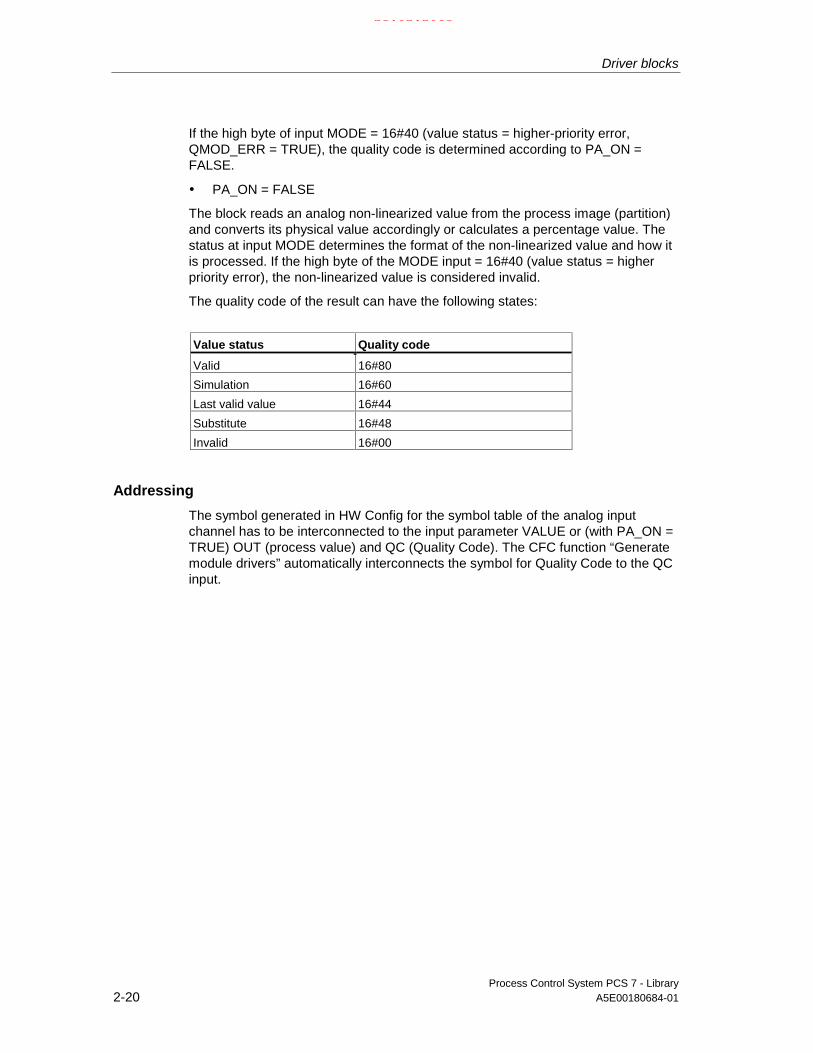
Driver blocks
Process Control System PCS 7 - Library2-20 A5E00180684-01
If the high byte of input MODE = 16#40 (value status = higher-priority error,QMOD_ERR = TRUE), the quality code is determined according to PA_ON =FALSE.
• PA_ON = FALSE
The block reads an analog non-linearized value from the process image (partition)and converts its physical value accordingly or calculates a percentage value. Thestatus at input MODE determines the format of the non-linearized value and how itis processed. If the high byte of the MODE input = 16#40 (value status = higherpriority error), the non-linearized value is considered invalid.
The quality code of the result can have the following states:
Value status Quality code
Valid 16#80
Simulation 16#60
Last valid value 16#44
Substitute 16#48
Invalid 16#00
Addressing
The symbol generated in HW Config for the symbol table of the analog inputchannel has to be interconnected to the input parameter VALUE or (with PA_ON =TRUE) OUT (process value) and QC (Quality Code). The CFC function “Generatemodule drivers” automatically interconnects the symbol for Quality Code to the QCinput.
21.02.2003

Driver blocks
Process Control System PCS 7 - LibraryA5E00180684-01 2-21
Non-linearized value check
Only if PA_ON = FALSE: Depending on the measurement type and range of theanalog input module, the nominal range sets the range for converting analogsignals into a digital values (non-linearized values) and includes anovershoot/undershoot range within which an analog signal can still be converted.An overflow or underflow error signal is generated if the signal is out of range. Theblock indicates whether the non-linearized value lies inside the nominal range ofthe module.Output parameter QCHF_LL = TRUE if the value is outside the nominal low range,output parameter QCHF_HL = TRUE if the value is outside the nominal high range.QBAD = TRUE (channel error) is also set when a signal overflow or underflow erroroccurs.
Note
The reaction of the modules to a cable break in the 4…20 mA signal line is notuniform. Depending on the module, either 16#7FFF (overflow) or 16#8000(underflow) is written as non-linearized value to the process image. Channel blockCH_U_AI then correspondingly outputs either an overflow (QCHF_HL = TRUE) oran underflow (QCHF_LL = TRUE) signal, each together with QBAD = TRUE.Exception: If you have set the "Diagnostic interrupt" attribute to the analog inputmodule in HW Config, only QBAD = TRUE will be set if a diagnostic interrupt istriggered after a "Channel error" has occurred (e.g. due to a wire break).
NAMUR limit check
Only if PA_ON = FALSE: The NAMUR guideline for analog signal processingdefines limits for life zero (4 to 20 mA) analog signals which have a channel error:
3.6 mA = Analog signal = 21 mA
The above NAMUR limits are set as fixed defaults for limit value monitoring. If youwant to set other limit values, you have to set the input parameter CH_F_ON =TRUE and set corresponding new limits in mA at the input parameters CH_F_HLand CH_F_LL. QBAD = TRUE if a life zero analog signal is outside the current highor low limit range.
Note
The set hysteresis must lie within the overshoot and undershoot range of themodule. Values outside the NAMUR range are also possible, if the module doesnot automatically limit the measurement values.
21.02.2003

Driver blocks
Process Control System PCS 7 - Library2-22 A5E00180684-01
Normal value
Only if PA_ON = FALSE: The non-linearized value is adjusted to its physical valuebased on the input parameters VLRANGE, VHRANGE and MODE (see alsoOMODE_xx). These values will be written to the outputs OVLRANGE andOVHRANGE to allow the interconnection of the settings of VLRANGE andVHRANGE to other block I/Os. The conversion algorithm depends on a linearizedinput signal. If VLRANGE = 0 and VHRANGE = 100, you obtain a percentagevalue. If VHRANGE = VLRANGE is set, you obtain the input signal of the analoginput module (e.g. mA) according to the MODE setting. Set VLRANGE = 0 andVHRANGE = 1 if the non-linearized value is already a physical value. The qualitycode will be set to QUALITY = 16#80.
In measurement mode PTC, an encoded binary signal is included in the analogvalue. In this case, output REAL provides the following information:
• Measured resistance < response value output = 0.0
• Measured resistance > response value output ≠ 0.0. 1.0
Note
In the measuring mode "External or internal comparison of thermocouple values",the physical unit is adapted to the +/- 80 mV range in S7 300 modules. You have todetermine the temperature by means of the corresponding conversion tables.
The physical equivalence in mV is delivered by the module as non-linearizedvalue. Set VHRANGE and VLRANGE +/- 80 mV in this case.
Simulation
If input parameter SIM_ON = TRUE, the value at input SIM_V is output with QualityCode QUALITY = 16#60. QBAD = TRUE: reset due to a higher-priority error. Avalid operating mode has to be set in low word of input parameter MODE insimulation mode also. Otherwise QBAD = 1 is output. Simulation takes highestpriority. The simulation value is converted into a non-linearized value, based on theoperating mode and the input parameters VHRANGE and VLRANGE. This value isverified in the same as a non-linearized value from the process image, which alsoallows simulation of the QBAD, QCHF_LL and QCHF_HL states.If VLRANGE > VHRANGE, the status QBAD = TRUE can not be simulated. Theoutputs QCHF_LL and QCHF_HL are set according to the value of SIM_V.
If PA_ON = TRUE, no conversion to a non-linerarized value is performed. If thereis no upstream error and the PA field device indicates a "BAD" Quality Code, eitherthe substitute value SUBS_V (SUBS_ON=TRUE) or the most recent value isoutput.
QSIM = TRUE when the block is in simulation mode.
21.02.2003

Driver blocks
Process Control System PCS 7 - LibraryA5E00180684-01 2-23
Substitute value
When input parameter SUBS_ON = TRUE and the non-linearized value is invalid,the value at input SUBS_V will be output as substitute. The quality code will be setto QUALITY = 16#48 and QBAD = 1.
Hold last value
When input parameter SUBS_ON = FALSE, the last valid output value (V_LAST) isreturned if the non-linearized value is invalid. If V_DELTA > 0, the followingapplies:
ABS (V - V_LAST) > V_DELTA: V = V_LAST1 (second to last valid outputvalue)
ABS (V - V_LAST) ≤ V_DELTA: V = V_LAST (last valid output value)
The quality code will be set to QUALITY = 16#44 and QBAD = 1.
If valid non-linearized values are available and V_DELTA > 0 and ABS (V -V_LAST) > V_DELTA, the last valid output value (V_LAST) with QUALITY = 16#44(QBAD = 0) is held for the duration of one cycle.
Delayed value acceptance
Only if PA_ON = FALSE: After a restart or if the Quality Code is changed from"BAD" to "GOOD", the quality code and value are not updated unless the numberof cycles specified in CNT_LIM have expired. When CNT_LIM = 0 ( = default), thisfunction is disabled. During this delay time, the Quality Code = 16#00 and QBAD =1 and the last value will be retained.
Value limiting
When PA_ON = TRUE, you can set a limiting filter for process values of theprocess image (partition).
If the switch LIMIT_ON = TRUE, the process values (V) are limited:
- To V_HL, if V > V_HL.
- To LL_V, if V < V_LL.
21.02.2003

Driver blocks
Process Control System PCS 7 - Library2-24 A5E00180684-01
Error handling
The plausibility of input parameters will not be checked. In case of invalid operatingmode settings in the low word of input parameter MODE, it is assumed that thenon-linearized value is invalid.
Start-up characteristics
n.a.
Time response
n.a.
Message characteristics
The block does not have message characteristics.
Operator control and monitoring
The block does not have a faceplate.
2.2.5.2 CH_U_AI: I/Os
The factory setting of the block display in CFC is identified in the I/O column: I/Oname in bold characters = I/O visible, in normal characters = hidden.
I/O(parameter)
Meaning Data type Default Type
CH_F_HL Overshoot high limit of the input value (mA) REAL 0 I/O
CH_F_LL Undershoot low limit of the input value (mA) REAL 0 I/O
CH_F_ON 1 = enable limit monitoring BOOL 0 I/O
CNT_LIM Limits of the startup counter INT 0 I/O
CNT_RES Startup counter INT 0 I/O
DELTA_ON Exceeded last delta process value BOOL 0 I/O
PA_ON 1 = use PA field device in process image BOOL 0 I/O
LAST_BAD Last invalid process value BOOL 0 I/O
LIMIT_ON 1 = enable process value limiting at PA field device BOOL 0 I/O
LL_V Process value, if V < V_LL REAL 0 I/O
MODE Value status and operating mode DWORD 0 I/O
OUT Process image of input REAL 0 I/O
OVHRANGE High limit of the process value (copy) REAL 0 O
OVLRANGE Low limit of the process value (copy) REAL 0 O
PA_ON 1 = use PA field device in process image BOOL 0 I/O
PQC 1 = use value status in process image BOOL 0 I/O
QBAD 1 = process value invalid BOOL 0 O
21.02.2003
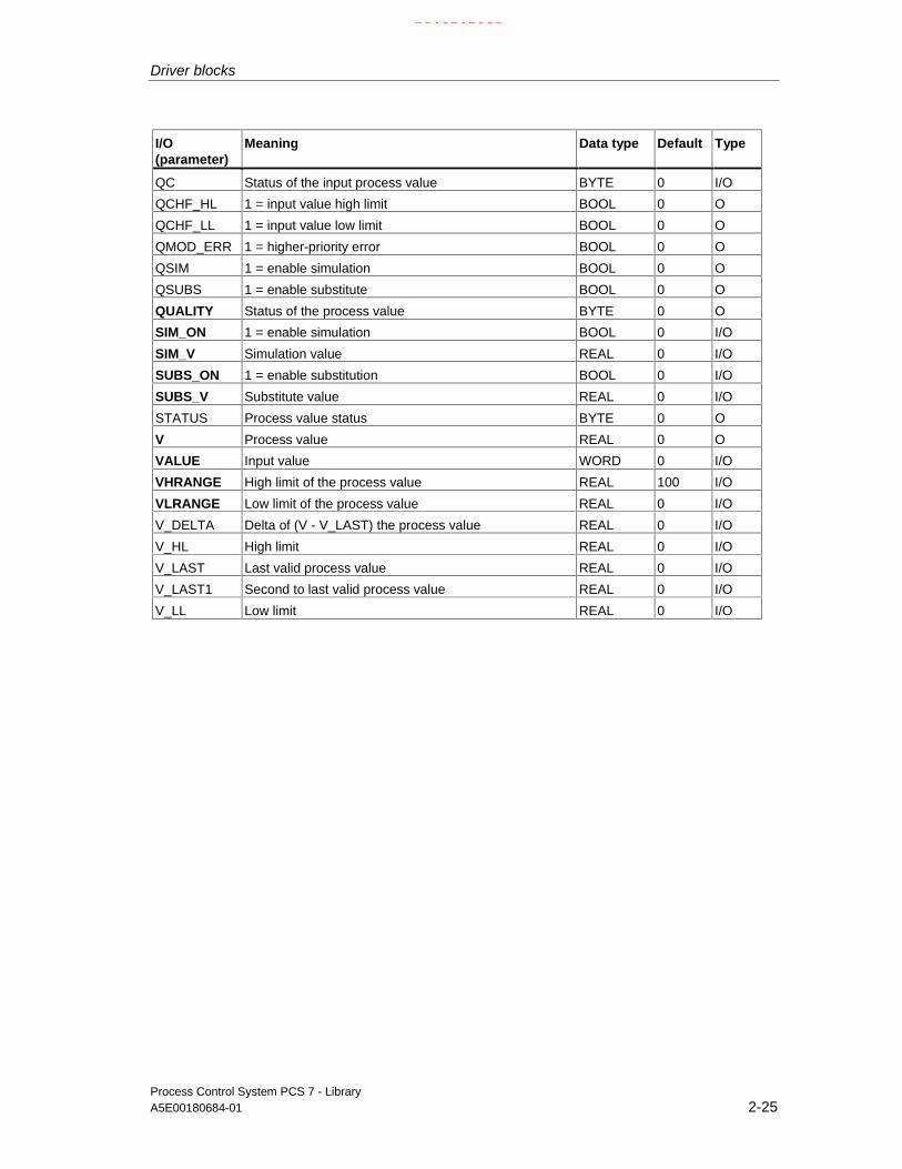
Driver blocks
Process Control System PCS 7 - LibraryA5E00180684-01 2-25
I/O(parameter)
Meaning Data type Default Type
QC Status of the input process value BYTE 0 I/O
QCHF_HL 1 = input value high limit BOOL 0 O
QCHF_LL 1 = input value low limit BOOL 0 O
QMOD_ERR 1 = higher-priority error BOOL 0 O
QSIM 1 = enable simulation BOOL 0 O
QSUBS 1 = enable substitute BOOL 0 O
QUALITY Status of the process value BYTE 0 O
SIM_ON 1 = enable simulation BOOL 0 I/O
SIM_V Simulation value REAL 0 I/O
SUBS_ON 1 = enable substitution BOOL 0 I/O
SUBS_V Substitute value REAL 0 I/O
STATUS Process value status BYTE 0 O
V Process value REAL 0 O
VALUE Input value WORD 0 I/O
VHRANGE High limit of the process value REAL 100 I/O
VLRANGE Low limit of the process value REAL 0 I/O
V_DELTA Delta of (V - V_LAST) the process value REAL 0 I/O
V_HL High limit REAL 0 I/O
V_LAST Last valid process value REAL 0 I/O
V_LAST1 Second to last valid process value REAL 0 I/O
V_LL Low limit REAL 0 I/O
21.02.2003

Driver blocks
Process Control System PCS 7 - Library2-26 A5E00180684-01
2.2.6 CH_U_AO: Analogvalue output (universal)
2.2.6.1 CH_U_AO (universal): Description
Object name (type + number)
FC 284
Area of application
The block processes analog output signals of S7-300/400 SM analog outputmodules or of PA field devices [the PA profile 3.0 Analog Output, only REAL values(e.g. SP) with quality code].
The calling OB
The restart OB100 and the watchdog interrupt OB3x into which the block isinstalled (for example OB 32).
Use in CFC
The CFC function "Generate module drivers" automatically:
• Configures input PA_ON in accordance with the I/O devices used [S7 signalmodules (=0) or PA field devices (=1)].
• Interconnects the symbol for the quality code of the analog output channel tothe input QC_SP of PA devices.
• Interconnects the MODE input with the corresponding output OMODE_xx ofthe MOD or PADP block.
• Installs the CH_U_AO block after the MOD/PADP block that is assigned to it inthe OB100.
Note
If you do not use the CFC function "Generate module drivers", you have to ensurethat the CH_U_AO block is installed in OB100 after its assigned MOD-/PADPblock.
21.02.2003
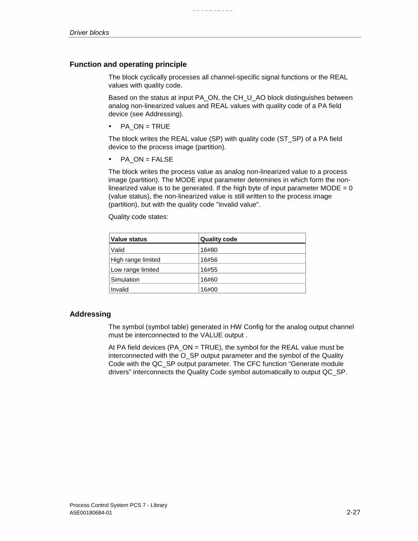
Driver blocks
Process Control System PCS 7 - LibraryA5E00180684-01 2-27
Function and operating principle
The block cyclically processes all channel-specific signal functions or the REALvalues with quality code.
Based on the status at input PA_ON, the CH_U_AO block distinguishes betweenanalog non-linearized values and REAL values with quality code of a PA fielddevice (see Addressing).
• PA_ON = TRUE
The block writes the REAL value (SP) with quality code (ST_SP) of a PA fielddevice to the process image (partition).
• PA_ON = FALSE
The block writes the process value as analog non-linearized value to a processimage (partition). The MODE input parameter determines in which form the non-linearized value is to be generated. If the high byte of input parameter MODE = 0(value status), the non-linearized value is still written to the process image(partition), but with the quality code "invalid value".
Quality code states:
Value status Quality code
Valid 16#80
High range limited 16#56
Low range limited 16#55
Simulation 16#60
Invalid 16#00
Addressing
The symbol (symbol table) generated in HW Config for the analog output channelmust be interconnected to the VALUE output .
At PA field devices (PA_ON = TRUE), the symbol for the REAL value must beinterconnected with the O_SP output parameter and the symbol of the QualityCode with the QC_SP output parameter. The CFC function “Generate moduledrivers” interconnects the Quality Code symbol automatically to output QC_SP.
21.02.2003

Driver blocks
Process Control System PCS 7 - Library2-28 A5E00180684-01
Normal value
• Only if PA_ON = FALSE: The parameters ULRANGE and UHRANGE map theprocess value U to the non-linearized VALUE (quantization steps) of theanalog output module according to the set MODE. For example in 4...20mA(16#0203) mode, the non-linearized value for 4 mA is output if U = ULRANGE,and the non-linearized value for 20mA is output if U = UHRANGE.
• PHYS_LIM can be used to set the limits for the non-linearized VALUE. Thedefault setting of PHYS_LIM = 0 limits the value at output VALUE to the defaultlimits of the module. In accordance with the above example, the blockcalculates non-linearized values for the 20 mA range if U > UHRANGE, and forthe 4mA range if U < ULRANGE. The quality codes 16#56 (high range limited)and 16#55 (low range limited) are applied accordingly at the QUALITY output,instead of 16#80 (valid value).
• You must set PHYS_LIM = 1 to allow the output of analog values outside thenormalized limits and up to the physical limits of the module. The output valuesare not limited until the module limits are exceeded, for example when you setU = 200 (36mA) or U = -50 (-4mA) if ULRANGE = 0 and UHRANGE = 100 inthe sample above. In this case the output values will be limited to the physicallimits specified in the data sheets of the modules and the corresponding qualitycodes will be output.
• The outputs QCHF_HL and QCHF_LL also provide information on whetheroutput value limits have been set.
Simulation
If input parameter SIM_ON = TRUE, the value at SIM_U is output with quality code(QUALITY) = 16#60. A valid mode must be set in the low word of input MODE insimulation mode also. Otherwise QBAD = 1. Simulation mode has highest priority.QBAD = FALSE when a higher-priority error has occurred. QSIM = TRUE when theblock is in simulation mode.
I/O error
If the high byte of the input parameter MODE = 0 (value status), the quality codeQUALITY = 16#00 is set. The current non-linearized value is always written to theprocess image (partition).
Value limiting
If PA_ON = TRUE, you can define a high/low hysteresis for process variables inorder to avoid the occurrence of errors (QBAD = TRUE) before the values arewritten to the process image (partition).
If parameter LIMIT_ON = TRUE, the process variables (V) are limited
- to V_HL, if V > V_HL and
- to LL_V, if V < V_LL.
21.02.2003

Driver blocks
Process Control System PCS 7 - LibraryA5E00180684-01 2-29
Error handling
The plausibility of input parameters will not be checked. If an invalid operatingmode was set in the low word of the MODE input parameter, the digitized outputvalue will be set to 0 and QUALITY = 16#00 is output.
Startup characteristics
The MOD blocks set the LSB in byte 2 of their OMODE_xx output parameters inOB100. If the block detects this code, it responds with an acknowledgement and:
If START_ON is not set, computes the process value U and writes the result to theprocess image. Otherwise the non-linearized value corresponding to the START_Uprocess value is written to the process image.
When PA field devices are enabled (PA_ON = TRUE), the actual REAL value withquality code is written to the process image.
Time response
n.a.
Message characteristics
No message function.
Operator control and monitoring
The block does not have a faceplate.
21.02.2003

Driver blocks
Process Control System PCS 7 - Library2-30 A5E00180684-01
2.2.6.2 CH_U_AO: I/Os
The factory setting of the block display in CFC is identified in the I/O column: I/Oname in bold characters = I/O visible, in normal characters = hidden.
I/O(parameter)
Meaning Data type Default Type
LIMIT_ON 1 = enable limiting of the process value BOOL 0 I/O
LL_V Process value, if U < V_LL REAL 0 I/O
MODE Value status and operating mode DWORD 0 I/O
PA_ON 1 = PA field device, 0 = signal module BOOL 0 I/O
O_SP Process image setpoint REAL 0 O
PHYS_LIM 1 = enable physical limit of the module BOOL 0 I/O
QBAD 1 = invalid output value BOOL 0 O
QCHF_HL 1 = overshoot of process value BOOL 0 O
QCHF_LL 1 = undershoot of process value BOOL 0 O
QC_SP Process image Quality Code setpoint BYTE 0 O
QMOD_ERR 1 = higher-priority error BOOL 0 O
QSIM 1 = simulation enabled BOOL 0 O
QUALITY Output value status BYTE 0 O
SIM_ON 1 = enable simulation BOOL 0 I/O
SIM_U Simulation value REAL 0 I/O
START_ON 1 = enable substitution at startup BOOL 0 I/O
START_U Startup substitute value REAL 0 I/O
ST_SP Status setpoint BYTE 0 I/O
U Process value REAL 0 I/O
UHRANGE High limit of the process value REAL 100 I/O
ULRANGE Low limit of the process value REAL 0 I/O
VALUE Output value WORD 0 O
V_HL High limit REAL 0 I/O
V_LL Low limit REAL 0 I/O
21.02.2003

Driver blocks
Process Control System PCS 7 - LibraryA5E00180684-01 2-31
2.2.7 CH_U_DI: Digital value input (universal)
2.2.7.1 CH_U_DI (universal): Description
Object name (type + number)
FC 285
Area of application
The block processes digital input signals of S7-300/400 SM digital input modules orof PA field devices (PA-Profile 3.0 Discrete Input).
The calling OBs
The watchdog interrupt OB3x into which the block is installed (for example OB 32).
Use in CFC
The CFC function "Generate module drivers" automatically:
• Configures input PA_ON in accordance with the I/O devices used [S7 signalmodules (=0) or PA field devices (=1)].
• Interconnects the symbol for the quality code of the analog input channel withinput QC (at PA devices).
• Interconnects the MODE input to the corresponding output OMODE_xx of theMOD or PADP block.
Function and operating principle
The block cyclically processes all channel-specific signal functions or the processvalues with Quality Code of a PA field device.
Based on the status at input parameter PA_ON, the block distinguishes between adigital value with or without Quality Code of the data type BOOL and a digital valuewith quality code of the data type BYTE of a PA field device (see Addressing).
• PA_ON = TRUE
21.02.2003

Driver blocks
Process Control System PCS 7 - Library2-32 A5E00180684-01
The block cyclically reads the process value OUT_D and the status byte (STATUS,see Addressing) of the PROFIBUS PA field device (structure an accordance withthe discrete input of the PA profiles) from the process image (partition). The statusbyte contains information on the measured value and on the status of thePROFIBUS PA field device. The block transfers the process value to output Q asshown below:
Q = FALSE, if the process value = 0
Q = TRUE, if the process value <> 0.
If the high byte of the MODE input parameter = 16#40 (value status = higher-priority error), the process value and quality code are treated as if PA_ON =FALSE.
• PA_ON = FALSE
The block reads a digital value of the data type BOOL from the process image(partition). If the high byte of the input parameter MODE = 16#40 (value status =higher-priority error), the function treats this value as invalid. If input parameter PQC= TRUE, it fetches the status of the digital value from the process image (partition).
A quality code is added to the result. This code can have the following states:
Value status Quality code
Valid 16#80
Simulation 16#60
Last valid value 16#44
Substitute value 16#48
Invalid value 16#00
Addressing
The symbol generated in HW Config (symbol table) for the digital input channelmust be interconnected to the VALUE input. If the process image (partition) alsocontains the value status of the digital input channel, you must interconnect thecorresponding symbol to input VALUE_QC and set input PQC = TRUE.
When using PA field devices (PA_ON = TRUE), interconnect the symbol generatedin HW Config (symbol table) for the digital input channel with input I_OUT_D. TheCFC function "Generate module drivers" automatically interconnects the symbol forthe Quality Code of the digital input channel with input QC.
Normal value
The function outputs the digital value of the process image (partition) and thequality code QUALITY = 16#80 to output Q.
21.02.2003

Driver blocks
Process Control System PCS 7 - LibraryA5E00180684-01 2-33
Simulation
If input parameter SIM_ON = TRUE, the value of input parameter SIM_I (PA_ON =FALSE) or SIM_OUT (PA_ON = TRUE) is output with quality code QUALITY =16#60 to the output Q. QBAD = TRUE: reset due to a higher-priority error(QMOD_ERR = TRUE). Simulation has highest priority.
If PA_ON = TRUE, the simulation takes place as follows: If there is no upstreamerror (QMOD_ERR = FALSE) and the PA field device indicates a "BAD" QualityCode, either the substitute value SUBS_V (SUBS_ON=TRUE) or the most recentvalue is output.
QSIM = TRUE when the block is in simulation mode.
Substitute value
When input parameter SUBS_ON = TRUE and the digital value of the processimage (partition) is invalid, the function outputs the signal QBAD = 1 and the valueat input SUBS_I with quality code QUALITY = 16#48 to output Q.
Hold last value
If the input parameter SUBS_ON = FALSE, the function outputs the last validoutput value, if the non-linearized value is invalid and sets QBAD = 1 and thequality code to QUALITY = 16#44.
• Last valid output value = Q_LAST.
Error handling
The function does not check the plausibility of input parameters.
Start-up characteristics
n.a.
Time response
n.a.
Message characteristics
n.a..
Operator control and monitoring
The block does not have a faceplate.
21.02.2003

Driver blocks
Process Control System PCS 7 - Library2-34 A5E00180684-01
2.2.7.2 CH_U_DI: I/Os
The factory setting of the block display in CFC is identified in the I/O column: I/Oname in bold characters = I/O visible, in normal characters = hidden.
I/O(parameter)
Meaning Data type Default Type
I_OUT_D Input value of the process image BYTE 0 I/O
MODE Value status and operating mode DWORD 0 I/O
OUT_D Process value BYTE 0 O
PA_ON 1 = PA field device BOOL 0 I/O
PQC 1 = use value status in the process image BOOL 0 I/O
Q Process value BOOL 0 O
Q_LAST Last valid process value BOOL 0 I/O
QBAD 1 = invalid process value BOOL 0 I/O
QC Value status in the process image (symbol) BYTE 0 I/O
QMOD_ERR 1 = higher-priority error BOOL 0 O
QSIM 1 = simulation enabled BOOL 0 O
QSUBS 1 = substitution enabled BOOL 0 O
QUALITY Process value status BYTE 0 O
SIM_I Simulation value BOOL 0 I/O
SIM_ON 1 = set simulation mode BOOL 0 I/O
SIM_OUT Output simulation value BYTE 0 I/O
SUBS_I Substitute value BOOL 0 I/O
SUBS_ON 1 = enable substitution BOOL 0 I/O
SUBS_OUT Output substitute value BYTE 0 I/O
STATUS Process value status BYTE 0 O
V_LAST Last valid process value BYTE 0 I/O
VALUE Input value BOOL 0 I/O
VALUE_QC Value status in the process image BOOL 0 I/O
21.02.2003

Driver blocks
Process Control System PCS 7 - LibraryA5E00180684-01 2-35
2.2.8 CH_U_DO: Digital value output (universal)
2.2.8.1 CH_U_DO (universal): Description
Object name (type + number)
FC 286
Area of application
The block is used for processing digital output values of S7-300/400 SM digitaloutput modules or PA field devices (PA profile 3.0 Discrete Input = only SP orRCAS_IN).
The calling OBs
The restart OB100 and the watchdog interrupt OB3x into which the block isinstalled (for example OB 32).
Use in CFC
The CFC function "Generate module drivers" when used automatically:
• Configures input PA_ON in accordance with the I/O devices used [S7 signalmodules (=0) or PA field devices (=1)].
• Interconnects the quality code symbol of the analog output channel to the inputQC_SP of PA field devices.
• Interconnects the MODE input to the corresponding output OMODE_xx of theMOD block (or of the PADP block).
• Installs the CH_U_DO block after the MOD/PADP block assigned to it in theOB100.
Note
If you do not use the CFC function "Generate module drivers", you have to ensurethat the CH_U_DO block is installed in OB100, after its assigned MOD-/PADPblock.
21.02.2003

Driver blocks
Process Control System PCS 7 - Library2-36 A5E00180684-01
Function and operating principle
The block cyclically processes all channel-specific signal functions or processvalues with quality code of a PA field device.
Based on the status at input PA_ON, the block distinguishes between a digitaloutput value without quality code of the data type BOOL and a digital output valuewith quality code of the data type BYTE of a PA field device (see Addressing).
• PA_ON = TRUE
The block writes the process value with QC to a process image (partition) [structureof the process value corresponds with the digital output of the PA Profile, 1 byte(SP) with 1 byte (ST_SP) QC]. The QC contains information on the process valuestatus. The QC code is described in the PROFIBUS PA 3.0 "GeneralRequirements".
If the high byte at input parameter MODE = 16#40 (value status = higher-priorityerror), the function continues to write the process value with QC to the processimage (partition), but sets the quality code status "invalid" at the QUALITY output ofthe block.
• PA_ON = FALSE
The block writes a digital value to a process image (partition). If the high byte ofinput parameter MODE = 0 (value status), it continues to write the digital value tothe process image (partition), but also set the quality code to "invalid".
The quality code can have the following states:
Value status QC
Valid values 16#80
Simulation value 16#60
Invalid value 16#00
Addressing
The symbol generated with HW Config (symbol table) for the digital output channelmust be interconnected to the VALUE input.
When PA field devices (PA_ON = TRUE) are used, the symbol generated in thesymbol table for the process value with QC must be interconnected to outputvariable O_SP. The CFC function "Generate module drivers" automaticallyinterconnects the symbol for the QC of the analog output channel with outputQC_SP.
Normal value
The digital value is written to the process image (partition) andQC (QUALITY) = 16#80.
21.02.2003

Driver blocks
Process Control System PCS 7 - LibraryA5E00180684-01 2-37
Simulation
If input parameter SIM_ON = TRUE, the block writes the value of input parameterSIM_I (PA_ON = FALSE) or SIM_OUT (PA_ON = TRUE) to the process image(partition) and sets QC QUALITY = 16#60. QBAD = TRUE: reset due to a higher-priority error (QMOD_ERR = TRUE). Simulation takes highest priority. QSIM =TRUE when the block is operating in simulation mode,.
I/O error
If the high byte of input parameter MODE = 0 (value status), the block sets thequality code QUALITY = 16#00. The function always writes the actual non-linearized value to the process image (partition).
Error handling
The plausibility of input parameters will not be checked.
Startup characteristics
In OB100, the MOD blocks set the LSB in byte 2 of their outputs OMODE_xx.When the block detects this code, it outputs an acknowledgement and:
If START_ON is not set, it writes the process value I to the process image;otherwise it substitutes this process value with START_I.
When PA field devices (PA_ON = TRUE) are used, the actual BYTE value and theQC are written to the process image.
Time response
n.a.
Message characteristics
n.a.
Operator control and monitoring
The block does not have a faceplate.
21.02.2003

Driver blocks
Process Control System PCS 7 - Library2-38 A5E00180684-01
2.2.8.2 CH_U_DO: I/Os
The factory setting of the block display in CFC is identified in the I/O column: I/Oname in bold characters = I/O visible, in normal characters = hidden.
I/O(parameter)
Meaning Data type Default Type
I Process value BOOL 0 I/O
MODE Value status and operating mode DWORD 0 I/O
O_SP Process image setpoint BYTE 0 O
PA_ON 1 = PA field device BOOL 0 I/O
QBAD 1 = invalid output value BOOL 0 O
QC_SP Process image quality code setpoint BYTE 0 O
QMOD_ERR 1 = higher priority error BOOL 0 O
QSIM 1 = simulation enabled BOOL 0 O
QUALITY Output value status BYTE 0 O
SIM_I Simulation value BOOL 0 I/O
SIM_ON 1 = enable simulation BOOL 0 I/O
SIM_SP Simulation setpoint BYTE 0 I/O
SP Setpoint BYTE 0 I/O
ST_SP Setpoint status BYTE 0 I/O
START_I Substitution at startup BOOL 0 I/O
START_ON 1 = enable startup substitution BOOL 0 I/O
VALUE Output value BOOL 0 O
21.02.2003

Driver blocks
Process Control System PCS 7 - LibraryA5E00180684-01 2-39
2.2.9 DREP: Diagnose repeater at the DP master system
2.2.9.1 DREP: Description
Object name (type + number)
FB 113
Area of application
This block evaluates diagnostics data output by a SIMATIC diagnostics repeaterfor PROFIBUS DP. This repeater must be connected to a DP master.
The calling OBs
OB1 Cyclic processing
OB82 Diagnostic interrupt
OB86 Rack failure
OB100 Restart (warm start) (startup, message initialization)
Use in CFC
The CFC function "Generate module drivers" automatically:
• Inserts OB_DIAG1 upstream of DREP
• Configures
- the diagnostic address DADDR of the diagnostic repeater
- the geographical address (SUBN_ID and PADP_ADR)
• Interconnects
- the OUT structures CPU_DIAG of the OB_BEGIN block and RAC_DIAG ofthe OB_DIAG1 block to the INOUT structures of the same name of theDREP block.
- the EN input to the output of an AND block.The function will connect the inputs of those blocks to the outputsEN_SUBx (x = number of the DP master system) of the OB_BEGIN blocks,to EN_Rxxx (xxx = module rack/station ID) of the SUBNET block and toEN_F of the OB_DIAG1 block.
- EN_DIAG to output EN_DIAG of the OB_DIAG1 block
21.02.2003

Driver blocks
Process Control System PCS 7 - Library2-40 A5E00180684-01
Function and operating principle
The diagnostics repeater performs the following tasks:
• Diagnostics function for two PROFIBUS segments (DP2 and DP3):
The diagnostics function returns the location and cause of line errors, e.g.cable break or missing terminating resistors.
The error location is output with reference to existing nodes, e.g. "Short-circuitto shielding at signal line A, node 12 <-> 13”.
• Repeater function for three PROFIBUS segments (DP1, DP2, DP3):
The diagnostic repeater amplifies data signals on the bus and interconnectsspecific RS485 segments.
• PG interfacing, galvanically or electrically isolated from other bus segments:
Even if the system is operating at higher transmission rates, interference duethe removal or connection of PG cables at other PROFIBUS DP segments isnot to be expected.
The "Diagnostic Repeaters for PROFIBUS DP" manual contains information on thestructure of line error states at the DP1, DP2, DP3 segments and at the PGinterface.
The block reports only the diagnostic events at segments DP2 and DP3 of thediagnostic repeater.
Error events at the PG interface and segment DP1 are reported in a general "lineerror“ group message.
The upstream block OB_DIAG1 reports failure and return of the diagnosticsrepeater.
An incoming "line error“ group message is going to be generated for each segment(DP2 or DP3) when a diagnostics repeater detects an error event (bits in thediagnostic message frame indicating the cause of error):
Bit Description
A.0 1 = indefinite error location and cause (possibly electromagnetic interference).A.1 CPU redundancy lossA.2 1 = - -A.3 1 = further measurement circuits connected to the segment, the other diagnostics repeater is
connected with segment DP2.A.4 1 = further measurement circuits connected to the segment, the other diagnostics repeater is
connected with segment DP3.A.5 1 = - -A.6 1 = indefinite error causeA.7 1 = critical message frame error rateB.0 1 = - -B.1 1 = - -B.2 1 = - -B.3 1 = - -B.4 1 = - -B.5 1 = - -
21.02.2003

Driver blocks
Process Control System PCS 7 - LibraryA5E00180684-01 2-41
Bit Description
B.6 1 = - -B.7 1 = - -C.0 1 = segment automatically switched off due to continuous zero level on the line.C.1 1 = segment automatically switched off due to continuous fluctuation of the line level.C.2 1 = - -C.3 1 = - -C.4 1 = more than 32 nodes connected to the measurement segment.C.5 1 = the distance node <-> diagnostics repeater exceeds the permitted cable length.C.6 1 = the maximum permitted number of diagnostics repeater connected in series has been
exceeded.C.7 1 = - -
The outgoing message will be generated when all segment bits are equal to zero.
Call HW Config in order to analyze events output by the diagnostic repeaters.
An appropriate incoming/outgoing message is going to be generated for thesegments (DP2 or DP3) as a result of the following events recognized by adiagnostics repeater:
Bit Description
A.0 1 = -A.1 1 = -A.2 1 = -A.3 1 = -A.4 1 = -A.5 1 = -A.6 1 = -A.7 1 = -B.0 1 = break of signal line AB.1 1 = short-circuit to shielding at signal line B.B.2 1 = -B.3 1 = short-circuit to shielding at signal line A.B.4 1 = break of signal line B.B.5 1 = -B.6 1 = break of signal line A and/or B, or the terminating resistor is missing.B.7 1 = short-circuit at signal line A <-> B, or an additional terminating resistor was installed.C.0 1 = -C.1 1 = -C.2 1 = -C.3 1 = -C.4 1 = -C.5 1 = -C.6 1 = -C.7 1 = -
21.02.2003

Driver blocks
Process Control System PCS 7 - Library2-42 A5E00180684-01
Events recognized by the diagnostics repeater are determined synchronously inOB82. Diagnostic event data are fetched via SFB54 in the OB_BEGIN block andwritten to the structure DINFO. The function always sets only one bit to indicate thecause of an incoming error. Bit C7 may be set in addition, e.g. if the diagnosticsrepeater has detected further errors. In this case, all reported events will bequeued. DREP generates a corresponding group error message via ALARM_8P.Dithering messages which may develop especially due to error events A.0.1 andA.6.1 are suppressed as follows :
After an outgoing message, a new outgoing message will be suppressed for theduration of the time (in [s]) set in the DELAY parameter. If a further error is queued,the outgoing message will not be generated until this error is outgoing.
Error handling
The block evaluates error data of ALARM_8P and writes these to thecorresponding output parameter. See error information of output parameterMSG_STAT. The block reports a diagnostics event if an error occurs while itattempts to read access diagnostics data, or if any other disruption corruptsdiagnostic data.
Startup characteristics
ALARM_8P messages are initialized by the DREP block that uses SFC13(DPNRM_DG) to fetch actual diagnostics data from the diagnostics repeater.
Reaction to overload
The interconnected OB_DIAG1 locks the call of DREP for diagnostics if anoverload has occurred.
Time response
n.a.
21.02.2003

Driver blocks
Process Control System PCS 7 - LibraryA5E00180684-01 2-43
Message characteristics
The multiple instances ALARM_8P will be called only if a message of one of thoseinstances is to be output. Previous message acknowledgements will always beupdated by the corresponding ALARM block at this point of time. If the connectionto WinCC is down, each ALARM_8P instance can store a maximum of twomessage states of its event ID (i.e. usually two messages). Dithering messagescan be suppressed via the DELAY input.
The block generates the following messages:
OB no. Start event Message
1 Cyclic processing Call of ALARM_8P, due to incomplete data transfer or if a message wasnot acknowledged
100 Restart Initialization of ALARM_8P
82 Diagnostic interrupt Group error message
Operator control and monitoring:
The block is not assigned a faceplate.
Note: In the OCM column of the "DREP…" table, the "+" character identifies thevariables to be transferred to the OS, if you have set the "enable operator controland monitoring" attribute in the block object properties. Default: This option is notset.
2.2.9.2 DREP: I/Os
The factory setting of the block display in CFC is identified in the I/O column: I/Oname in bold characters = I/O visible, in normal characters = hidden.
I/O Meaning Type Default Type OCM
ACC_MODE 1 = accept MODE settings BOOL 0 I/O
CPU_DIAG CPU diagnostics STRUCT I/O
DADDR Diagnostic address of the diagnostics repeater INT 0 I
DELAY Interrupt delay (s) INT 2 I
DINFO Diagnostic data of the diagnostics repeater STRUCT O
EN_DIAG 1 = queued diagnostic event BOOL 0 I
EN_MSG 1 = enable message BOOL 1 I
EV_Idx Message number DWORD 0 I
MSG_ACKx Message acknowledged WORD 0 O
MSG_STATx Message error status WORD 0 O
PADP_ADR DP/PA address of the diagnostics repeater BYTE 255 I
QDREPF 1 = removed/faulty diagnostics repeater BOOL 0 O +
QERR 1 = program error BOOL 1 O
RAC_DIAG OB_DIAG1 diagnostics STRUCT I/O
SUBN_ID DP master system ID BYTE 255 I
21.02.2003

Driver blocks
Process Control System PCS 7 - Library2-44 A5E00180684-01
2.2.9.3 DREP: Message texts and auxiliary process values
Assignment of message texts and classes
Message blockALARM_8P
MessageID
Blockparameter
Default message text Messageclass
1 Diagnostic repeater @1%d@/@2%d@/ segmentDP2: Line interference
S
2 Diagnostic repeater @1%d@/@2%d@/DP2:→@5%d@.@6%d@m/break A/@3%d@↔@4%d@
S
3 Diagnostic repeater @1%d@/@2%d@/DP2:→@5%d@.@6%d@m/short-circuit A/@3%d@↔@4%d@
S
4 Diagnostic repeater @1%d@/@2%d@/DP2:→@5%d@.@6%d@m/ short-circuitB/@3%d@↔@4%d@
S
5 Diagnostic repeater @1%d@/@2%d@/DP2:→@5%d@.@6%d@m/ short-circuit B/@3%d@↔@4%d@
S
6 Diagnostic repeater @1%d@/@2%d@/DP2:→@5%d@.@6%d@m/break AB or terminatingresistor missing/@3%d@↔@4%d@
S
7 Diagnostic repeater @1%d@/@2%d@/DP2:→@5%d@.@6%d@m/ short-circuit AB or toomany terminating resistors / @3%d@↔@4%d@
S
EV_ID1
8 Diagnostic repeater @1%d@/@2%d@/ segmentDP1: line interference
S
1 Diagnostic repeater @1%d@/@2%d@/ segmentDP3: line interference
S
2 Diagnostic repeater @1%d@/@2%d@/DP3:→@5%d@.@6%d@m/ break A/@3%d@↔@4%d@
S
3 Diagnostic repeater @1%d@/@2%d@/DP3:→@5%d@.@6%d@m/ short-circuit A/@3%d@↔@4%d@
S
4 Diagnostic repeater @1%d@/@2%d@/DP3:→@5%d@.@6%d@m/ breakB/@3%d@↔@4%d@
S
5 Diagnostic repeater @1%d@/@2%d@/DP3:→@5%d@.@6%d@m/ short-circuit B/@3%d@↔@4%d@
S
6 Diagnostic repeater @1%d@/@2%d@/DP3:→@5%d@.@6%d@m/ break AB or terminatingresistor missing /@3%d@↔@4%d@
S
7 Diagnostic repeater @1%d@/@2%d@/DP3:→@5%d@.@6%d@m/ short-circuit AB or toomany Terminating resistors / @3%d@↔@4%d@
S
EV_ID2
8 Diagnostic repeater @1%d@/@2%d@:@7W%t#DREP_TXT@
S
The message texts and their number are found in the text library DREP_TXT(see DREP_TXT).
21.02.2003

Driver blocks
Process Control System PCS 7 - LibraryA5E00180684-01 2-45
Assignment of auxiliary process values
Message blockALARM_8P
Auxiliaryprocessvalue
Block parameters Meaning
EV_ID1 1 SUBN_ID DP master system ID (byte)
2 PADP_ADR Address of the diagnostic repeater (byte)
3 Station x (segment DP2)
4 Station y (segment DP2)
5 Distance to diagnostics repeater (segment DP2)
6 Distance to diagnostics repeater (segment DP2)
EV_ID2 1 SUBN_ID1 DP master system ID (byte)
EV_ID2 1 SUBN_ID DP master system ID (byte)
2 PADP_ADR Address of diagnostics repeater (byte)
3 Station x (segment DP3)
4 Station y (segment DP3)
5 Distance to diagnostics repeater (segment DP3)
6 Distance to diagnostics repeater (segment DP3)
7 Text number (Message 1 - 2) of DREP_TXT
21.02.2003

Driver blocks
Process Control System PCS 7 - Library2-46 A5E00180684-01
2.2.10 DREP_L: Diagnose repeater downstream of a Y Link
2.2.10.1 DREP_L: Description
Object name (type + number)
FB 125
Area of application
This block evaluates diagnostic data output by a SIMATIC diagnostics repeater forPROFIBUS DP. The diagnostics repeater must be interconnected downstream of aDPV1 Y Link.
The calling OBs
OB1 Cyclic processing
OB82 Diagnostic interrupt
OB86 Module rack failure
OB100 Restart (warm start) (startup, message initialization)
Use in CFC
The CFC function "Generate module drivers" automatically:
• Inserts the OB_DIAG1 block upstream of DREP_L
• Configures
- the diagnostics address DADDR of the diagnostics repeater
- the geographical address (SUBN1_ID, SUBN2_ID, RACK_NO undPADP_ADR)
• Interconnects
- the OUT structures CPU_DIAG of the OB_BEGIN blocks and RAC_DIAGof the OB_DIAG1 block with the DREP_L INOUT structures of the samename.
- the EN input to the output of an AND block.whose inputs will be interconnected with the outputs EN_SUBx (x = DPmaster system ID) of the OB_BEGIN block, EN_Rxxx (xxx = rack/stationID) of the SUBNET block and with EN_F of the OB_DIAG1 block.
- EN_DIAG with output EN_DIAG of the OB_DIAG1 block
21.02.2003

Driver blocks
Process Control System PCS 7 - LibraryA5E00180684-01 2-47
Function and operating principle
The diagnostics repeater is assigned the following tasks:
• Diagnostics function for two PROFIBUS segments (DP2 and DP3):
The diagnostics function returns the location and cause of line errors, e.g.cable break or missing terminating resistors.
The error location is output, including a reference to the relevant nodes, e.g."Short-circuit to shielding at signal line A, node 12 <-> 13”.
• Repeater function for three PROFIBUS segments (DP1, DP2, DP3):
The diagnostics repeater amplifies data signals on the bus and interconnectsthe relevant RS485 segments.
• PG interfacing, galvanically or electrically isolated from other bus segments:
Even if the system is operating at higher transmission rates, interference dueto the removal or connection of PG cables is not to be expected at the otherPROFIBUS DP segments.
The "Diagnostic Repeaters for PROFIBUS DP" manual contains information on thePG interface and on the structure of line error states at the DP1, DP2, DP3segments.
The block reports only the diagnostic events at segments DP2 and DP3 of thediagnose repeater.
Error events at the PG interface and at segment DP1 are reported in a general"line error“ group message.
The interconnected block OB_DIAG1 reports failure and return of the diagnosticsrepeater.
An incoming "line error“ group message is going to be generated for each segment(DP2 or DP3) when a diagnostics repeater detects an error event (bits in thediagnostic message frame indicating the cause of error):
Bit Description
A.0 1 = indefinite error location and cause (possibly electromagnetic interference).
A.1 CPU redundancy loss
A.2 1 = - -
A.3 1 = further measurement circuits at the segment, the other diagnostics repeater is connected withits segment DP2.
A.4 1 = further measurement circuits at the segment, the other diagnostics repeater has is connectedwith its segment DP3.
A.5 1 = - -
A.6 1 = indefinite error cause
A.7 1 = critical message frame error rate
B.0 1 =
B.1 1 =
B.2 1 = - -
B.3 1 =
21.02.2003
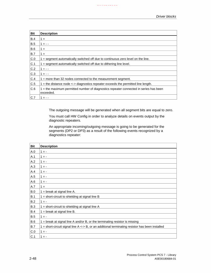
Driver blocks
Process Control System PCS 7 - Library2-48 A5E00180684-01
Bit Description
B.4 1 =
B.5 1 = - -
B.6 1 =
B.7 1 =
C.0 1 = segment automatically switched off due to continuous zero level on the line.
C.1 1 = segment automatically switched off due to dithering line level.
C.2 1 = - -
C.3 1 = - -
C.4 1 = more than 32 nodes connected to the measurement segment.
C.5 1 = the distance node <-> diagnostics repeater exceeds the permitted line length.
C.6 1 = the maximum permitted number of diagnostics repeater connected in series has beenexceeded.
C.7 1 = - -
The outgoing message will be generated when all segment bits are equal to zero.
You must call HW Config in order to analyze details on events output by thediagnostic repeaters.
An appropriate incoming/outgoing message is going to be generated for thesegments (DP2 or DP3) as a result of the following events recognized by adiagnostics repeater:
Bit Description
A.0 1 = -
A.1 1 = -
A.2 1 = -
A.3 1 = -
A.4 1 = -
A.5 1 = -
A.6 1 = -
A.7 1 =
B.0 1 = break at signal line A.
B.1 1 = short-circuit to shielding at signal line B
B.2 1 = -
B.3 1 = short-circuit to shielding at signal line A
B.4 1 = break at signal line B.
B.5 1 = -
B.6 1 = break at signal line A and/or B, or the terminating resistor is missing
B.7 1 = short-circuit signal line A <-> B, or an additional terminating resistor has been installed
C.0 1 = -
C.1 1 = -
21.02.2003

Driver blocks
Process Control System PCS 7 - LibraryA5E00180684-01 2-49
Events recognized by the diagnostics repeater are determined synchronously inOB82. Diagnostic event data are fetched via SFB54 in the OB_BEGIN block andwritten to the structure DINFO. The function always sets only one bit to indicate thecause of an incoming error. Bit C7 may also be set, e.g. if the diagnostics repeaterhas detected further errors. In this case, all previously reported events will bequeued. DREP generates a corresponding group error message via ALARM_8P.Dithering messages which may develop especially due to error events A.0.1 andA.6.1 are suppressed as follows :
After an outgoing message, a new outgoing message will be delayed by the time in[s] set at the DELAY parameter. If a further error is queued, the outgoing messagewill not be generated until this error has been reported outgoing.
Error handling
The block evaluates error data of ALARM_8P and writes the result to thecorresponding output parameter. See MSG_STATx: Error information of the outputparameter.
The block reports a diagnostics error if an error occurs when it attempts to readaccess diagnostics data, or if any other disruption corrupts diagnostic data.
A new outgoing message is suppressed until the delay time in [s] has expired afterthe last outgoing message. If an error is queued, an outgoing message will not begenerated until the previous error message has been cleared.
Startup characteristics
The DREP_L block initializes the messages of ALARM_8P. It uses SFC13(DPNRM_DG) to read actual diagnostic data output by the diagnostics repeaters.
Reaction to overload
The upstream OB_DIAG1 block locks the call of DREP for diagnostics if anoverload has occurred.
Time response
n.a.
21.02.2003

Driver blocks
Process Control System PCS 7 - Library2-50 A5E00180684-01
Message characteristics:
The multiple instances ALARM_8P will be called only if a message of one of thoseinstances is to be output. Previous message acknowledgements will always beupdated by the corresponding ALARM block at this point of time. If the connectionto WinCC is down, each ALARM_8P instance can store a maximum of twomessage states of its event ID (i.e. usually two messages). Dithering messagescan be suppressed via the DELAY input.
The block generates the following messages:
OB no. Startup event Message
1 Cyclic processing Call of ALARM_8P, if incomplete data transfer or if message was notacknowledged
100 Restart Initialization of ALARM_8P82 Diagnostic interrupt Group error message
Operator control and monitoring
The block is not assigned a faceplate (picture block).
Note: In the OCM column of the "DREP_L" table, the "+" character identifies thevariables to be transferred to the OS, if you have set the "enable operator controland monitoring" attribute in the block object properties. Default: This option is notset.
2.2.10.2 DREP_L: I/Os
The factory setting of the block display in CFC is identified in the I/O column: I/Oname in bold characters = I/O visible, in normal characters = hidden.
I/O Meaning Type Default Type OCM
ACC_MODE 1 = accept MODE settings BOOL 0 I/OCPU_DIAG CPU diagnostics STRUCT I/ODADDR Diagnostic address of the diagnostics repeater INT 0 IDELAY Interrupt delay (s) INT 2 IDINFO Diagnostic data of the diagnostics repeater STRUCT OEN_DIAG 1 = queued diagnostic event BOOL 0 IEN_MSG 1 = enable message BOOL 1 IEV_Idx Message ID DWORD 0 IMSG_ACKx Acknowledge message WORD 0 OMSG_STATx Message error status WORD 0 OPADP_ADR DP/PA address of the diagnostic repeater BYTE 255 IQDREPF 1 = removed/faulty diagnostic repeater BOOL 0 O +QERR 1 = program error BOOL 1 ORAC_DIAG OB_DIAG1 diagnostics STRUCT I/ORACK_NO Rack number BYTE 255 ISUBN1_ID ID of the primary DP master system BYTE 255 ISUBN2_ID ID of the redundant DP master system BYTE 255 I
21.02.2003

Driver blocks
Process Control System PCS 7 - LibraryA5E00180684-01 2-51
2.2.10.3 DREP_L: Message texts and auxiliary process values
Assignment of message text / class
Message blockALARM_8P
Message ID Block-parameter
Default message text Messageclass
1 Diagnostic repeater@1%d@/@2%d@/@3%d@/ segment DP2:line error
S
2 Diagnostic repeater@1%d@/@2%d@/@3%d@/DP2:→@6%d@.@7%d@m/break A/ @4%d@↔@5%d@
S
3 Diagnostic repeater@1%d@/@2%d@/@3%d@/DP2:→@6%d@.@7%d@m/ short-circuit A/@4%d@ ↔@5%d@
S
4 Diagnostic repeater@1%d@/@2%d@/@3%d@/DP2:→@5%d@.@7%d@m/mreakB/@3%d@↔@4%d@
S
5 Diagnostic repeater@1%d@/@2%d@/@3%d@/DP2:→@6%d@.@7%d@m/ short-circuit B/@4%d@ ↔@5%d@
S
6 Diagnostic repeater@1%d@/@2%d@/@3%d@/DP2:→@6%d@.@7%d@m/ break AB or missingterminating resistor/@3%d@↔@4%d@
S
7 Diagnostic repeater@1%d@/@2%d@/@3%d@/DP2:→@6%d@.@7%d@m/ short-circuit AB or toomany terminating resistors/@4%d@↔@5%d@
S
EV_ID1
8 Diagnostic repeater@1%d@/@2%d@/@3%d@/ Segment DP1:line interference
S
1 Diagnostic repeater@1%d@/@2%d@/@3%d@/ Segment DP3:line interference
S
2 Diagnostic repeater@1%d@/@2%d@/@3%d@/DP3:→@6%d@.@7%d@m/ break A/ @4%d@↔@5%d@
S
3 Diagnostic repeater@1%d@/@2%d@/@3%d@/DP3:→@6%d@.@7%d@m/ short-circuit A/@4%d@ ↔@5%d@
S
EV_ID2
4 Diagnostic repeater@1%d@/@2%d@/@3%d@/DP3:→@5%d@.@7%d@m/breakB/@3%d@↔@4%d@
S
21.02.2003

Driver blocks
Process Control System PCS 7 - Library2-52 A5E00180684-01
Message blockALARM_8P
Message ID Block-parameter
Default message text Messageclass
5 Diagnostic repeater@1%d@/@2%d@/@3%d@/DP3:→@6%d@.@7%d@m/ short-circuit B/@4%d@ ↔@5%d@
S
6 Diagnostic repeater@1%d@/@2%d@/@3%d@/DP3:→@6%d@.@7%d@m/ break AB or missingterminating resistor/@3%d@↔@4%d@
S
7 Diagnostic repeater@1%d@/@2%d@/@3%d@/DP3:→@6%d@.@7%d@m/short-circuit AB or toomany terminating resistor/ @4%d@↔@5%d@
S
8 Diagnostic repeater@1%d@/@2%d@/@3%d@:@8W%t#DREP_L_TXT@
S
The message texts and their number are found in the text library DREP_TXT (seeDREP_TXT).
Assignment of auxiliary process values
Message blockALARM_8P
Auxiliaryprocess value
Blockparameter
Meaning
1 SUBN_ID1 DP master system ID (byte)
2 RACK_NO Rack/station number (byte)
3 PADP_ADR Address diagnostics repeater (byte)
4 Station x (segment DP2)
5 Station y (segment DP2)
6 Distance to diagnostics repeater (segment DP2)
EV_ID1
7 Distance to diagnostics repeater (segment DP2)
1 SUBN_ID1 DP master system ID (byte)
2 RACK_NO Rack/station number (byte)
3 PADP_ADR Address diagnostics repeater (Byte)
4 Station x (segment DP3)
5 Station y (segment DP3)
6 Distance to diagnostics repeater (segment DP3)
EV_ID2
7 Distance to diagnostics repeater (segment DP3)
If SUBN_ID1 = 16#FF, the auxiliary process variable 1 is substituted withSUBN_ID2.
21.02.2003

Driver blocks
Process Control System PCS 7 - LibraryA5E00180684-01 2-53
2.2.11 IM_DRV: Transferring process signal changes with Time Stamp
2.2.11.1 IM_DRV: Description
Object name (type + number)
FB 90
The calling OBs
In CFC, the block is automatically integrated into the run sequence.
OB1 Cyclic program
OB40 Process interrupt 0
OB100 Restart (warm start)
Alternatively to OB40, the block can be integrated into another process interruptOB (OB41 to OB47).
Area of application
The block is used to transfer changes in process signals with time stamp andevents not specific to signals (special messages) to the OS.
Description of functions
In an AS the block forms the link between an IM151-2 / IM153-2 and the OS(WinCC). It fetches message data from IM message buffers (max. of 20 messageseach) and transfer these to the corresponding OS by means of the pseudomessage function ALARM_T.
• Process interrupt: The IM generates a process interrupt for incomingmessages. The timestamp status, including the IM data record number and thenumber of messages in this date record, are fetched from the startupinformation of the process interrupt OB (refer to the process interrupt data) andstored for cyclic processing. The interrupt stack can hold up to 17 processinterrupts; if this maximum is exceeded, all new information will be lost.
21.02.2003

Driver blocks
Process Control System PCS 7 - Library2-54 A5E00180684-01
• Cyclic processing: If any messages are queued in the stack,SFC 59/RD_REC reads the respective data record (message buffer). If thestack contains several data records, it will fetch the record that contains theoldest messages (oldest process interrupt). The block instance temporarilystores a maximum of 20 messages of a data record (current number ofmessages is listed in the process interrupt data).The IM can enter new messages in a data record after it read the record. If alldata records are currently used, the IM enters the special message "incomingbuffer overflow error" in the message buffer. It enters the special message"outgoing buffer overflow error" at the start of the next free record. Messagedata received within the interval between a buffer overflow and the enabling ofa record will be lost.The function compares the slot/channel number of the stored messages withthe input parameters of the slot/channel number block S_CH_xxx. If identical, itassigns the message a corresponding event ID (EV_ID_xxx) and signalnumber (1 to 8) of the pseudo ALARM_T (ALARM_8P) block, and enters themessage timestamp (8 bytes) in the ARRAY of byte (index corresponding tothe signal number of the pseudo ALARM_T).After all the messages have been assigned, the block calls the pseudoALARM_T blocks in order to transfer the new messages to the relevantoperator stations. The signals returned by the pseudo ALARM_T and thecontrol system message block ALARM_8P (STAT_xx, M_ACK_xx) areavailable at the block output. If STAT_xx = 11 (the previous job is still busy), itcalls the pseudo ALARM_T or ALARM_8P again in the next cycle.Messages may be lost in all other situations. If no agreement can be found withthe input parameters in a message, then output QBPARF = TRUE for theduration of one cycle (see error handling) and the event will be reported (seeMessage characteristics).
Addressing/parameter assignment
Also refer to addressing
The function writes the logical address of the IM (corresponds to the diagnosticaddress) determined in HW Config to the driver block input (LADDR). Any changeto the LADDR block input will initiate a scan cycle, according to the startupcharacteristics of the block. Saved process interrupt data will be deleted.
When operating the DP master system in DPV1 mode, you must enter the Iaddress of the IM at the block input (LADDR).
The RACK holding the IM is monitored via the RACK block. Connect inputRAC_DIAG to output RAC_DIAG of the corresponding RACK block. The racknumber is set in the RACK block.
Process signals which require a timestamp and are detected via an IM must beconfigured accordingly in HW Config.
21.02.2003

Driver blocks
Process Control System PCS 7 - LibraryA5E00180684-01 2-55
Any signal assigned a timestamp by the IM is defined uniquely by its slot andchannel numbers. The system provides 128 inputs of the data type WORD forprocessing up to 128 signals. The function writes the slot number of thecorresponding digital input module to the most significant byte, and the channelnumber (signal of the digital input module) to the least significant byte. The slot andsignal number of the process signals must be entered at the block inputs(S_CH_xxx) (hex format).
Example:
Via HW Config, you have set a timestamp resolution of 10 ms for the digital signal10 of a digital input module at slot 5 of an ET200M:Enter the number 16#050A at the first free input S_CH_xxx of the IM_DRV block.
Error handling
I/O access error:
QPERAF The block could not access the IM. A data record could not be read.If this record is not stored in the IM, these messages are lost.
Block processing error:
QERR A block execution error has occurred.
Module configuration error:
QPARF Faulty module configuration (wrong logical basic address entered).
Configuration error:
QBPARF Faulty block configuration. The slot/channel number of an IM message does not agree withany slot/channel number of the block input parameters (message is lost).
Rack error:
QRACKF Failure of the IM rack, or IM failure
IM startup characteristics
During startup/restart of the IM, the system will generate process interrupts onceagain for those records which were occupied prior to restart but had not beenfetched.
The special message "Begin startup data" is entered at the start the first free datarecord. After restart, the system checks all monitored digital signals for changes,outputs a message if appropriate and finally generates the special message "Endof startup data".
21.02.2003

Driver blocks
Process Control System PCS 7 - Library2-56 A5E00180684-01
Startup characteristics of the driver block IM_DRV
Initializes the ALARM_8P and the pseudo ALARM_T blocks, using the data storedprior to the CPU transition to STOP. During an initial startup, the initializationrouting sets the signal status to "Zero".
During startup/initial startup, the driver block verifies the existence of an IM at itslogical address set in LADDR. If the result is negative, the driver block sets outputQPARF = TRUE and does not access any I/O in its subsequent cycles. It enablesQPARF = FALSE and I/O access only after the correct module has been insertedor new parameters have been assigned. Stored process interrupt data which werenot computed before the restart will be deleted.
Redundancy
Timestamping in H systems equipped with two IM units is redundant, if
• Both IM units communicate via the communication (K) bus,
• No error has occurred during the update of the active and passive IM.
The SUBNET and RACK blocks report loss of redundancy (failure of an IM),separately from the IM_DRV block.
Time stamping is interrupted for the duration of the changeover between the active<-> passive IM. This period of interrupt is indicated by the special message"Changeover at redundancy start/end".
The active IM usually reports the current I/O status to the passive IM. The specialmessage " Incoming error: Redundancy_Info_Loss " will be output if thiscommunication is disrupted. After the I/O states of the active and passive IM havebeen aligned, the special message "Outgoing error: Redundancy_Info_Loss" isoutput.
Time response
n.a.
Message characteristics
The block uses one ALARM_8P and 17 pseudo ALARM_T multiple instanceblocks. The eight timestamp values assigned to each of the pseudo ALARM_Tblock calls are transferred by means of an ARRAY [0..65] of BYTE. The structureof the ARRAY is as follows:
BYTE 0 - 1: Format identifier of the following date/time stamp
BYTE 2 - 9: Date/time stamp Signal_1
BYTE 10 - 17: Date/time stamp Signal_2
BYTE 58 - 65: Date/time stamp Signal_8
21.02.2003

Driver blocks
Process Control System PCS 7 - LibraryA5E00180684-01 2-57
The format identifier of bytes 0 - 1 specifies the bit coding of the timestampstructure (8 bytes are assigned to one time stamp value):
Format identifier: 0 Date/time in SIMATIC S7 BCD format ( DATE_AND_TIME)
1 Date/time in ISP format
Year Month
Day Hours
Minutes Seconds
1/10 s 1/100 s 1/1000 s Weekday
Time stamp in ISP format
Complete time information to ISP conventions (time since 1.1.1900; 00:00 h). Dueto the four bytes for the seconds units, the time expired since 1.1.1900; 0:00 h canbe expressed in seconds.
BYTE 0 seconds (4 bytes)
3
4 second fragments (4 bytes)
7
The driver block outputs the time stamps provided by the IM in ISP format andwithout any changes.
In cyclic operation of the driver block and to reduce runtime, the pseudo ALARM_Tblocks and the control system message block ALARM_8P are called only if thesignal states have changed.
Operator control and monitoring
The block does not have a faceplate.
21.02.2003

Driver blocks
Process Control System PCS 7 - Library2-58 A5E00180684-01
2.2.11.2 IM_DRV: I/Os
The factory setting of the block display in CFC is identified in the I/O column: I/Oname in bold characters = I/O visible, in normal characters = hidden.
Connection(parameter)
Meaning Data type Default I/O
EV_ID Message number for ALARM_8P DWORD 0 I
EV_ID_xx Message number for ALARM_T_xx (xx = 00 - 16) DWORD 0 I
LADDR Logical address of the IM WORD 0 I
M_ACK_xx Message acknowledged (xx = 00 - 16) x WORD 0 I
Q_ERR_xx Message error (xx = 00 – 16) BOOL 0 O
QBPARF 1 = block parameter assignment error BOOL 0 O
QERR 1 = block processing error (inverted value of ENO) BOOL 1 O
QPARF 1 = module parameter assignment error BOOL 0 O
QPERAF 1 = I/O access error BOOL 0 O
QRACKF 1 = rack failure BOOL 0 O
RAC_DIAG Rack status information STRUCT I/O
S_CH_xxx Slot/channel number (xxx = 000 - 127) WORD 0 I
STAT_xx STATUS output (xx = 00 - 16) WORD 0 O
2.2.11.3 IM_DRV: Message texts and auxiliary process values
Assignment of message texts/classes to signal/special messages
An ALARM_8P block is used for the control system messages shown in thefollowing table. If an I/O access error has occurred, the block enters the geographicaddress of the IM in the auxiliary process values:1 = slot number of the message,2 = channel number of the message3 = RET_VAL of the SFC 59 (RD_REC).
ALARM_8P_16message no.
Outputparameter
Default message text Messageclass
1 QBPARF Error S_CHxx: Slot=@1%d@ Channel=@2%d@ S
2 QPERAF I/O access error: Ret_Val@3%d@ S
3 QPARF Parameter assignment error S
The message buffer may contain the following special messages that aregenerated with ALARM_8P_00 (multiple-instanced call of the pseudo ALARM_T).The block writes the format identifier and the eight timestamp values to the firstauxiliary process value
21.02.2003
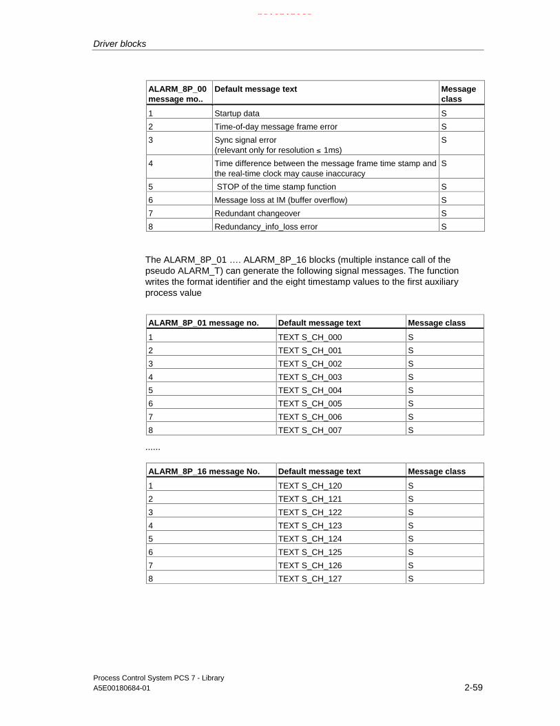
Driver blocks
Process Control System PCS 7 - LibraryA5E00180684-01 2-59
ALARM_8P_00message mo..
Default message text Messageclass
1 Startup data S
2 Time-of-day message frame error S
3 Sync signal error(relevant only for resolution ≤ 1ms)
S
4 Time difference between the message frame time stamp andthe real-time clock may cause inaccuracy
S
5 STOP of the time stamp function S
6 Message loss at IM (buffer overflow) S
7 Redundant changeover S
8 Redundancy_info_loss error S
The ALARM_8P_01 …. ALARM_8P_16 blocks (multiple instance call of thepseudo ALARM_T) can generate the following signal messages. The functionwrites the format identifier and the eight timestamp values to the first auxiliaryprocess value
ALARM_8P_01 message no. Default message text Message class
1 TEXT S_CH_000 S
2 TEXT S_CH_001 S
3 TEXT S_CH_002 S
4 TEXT S_CH_003 S
5 TEXT S_CH_004 S
6 TEXT S_CH_005 S
7 TEXT S_CH_006 S
8 TEXT S_CH_007 S
......
ALARM_8P_16 message No. Default message text Message class
1 TEXT S_CH_120 S
2 TEXT S_CH_121 S
3 TEXT S_CH_122 S
4 TEXT S_CH_123 S
5 TEXT S_CH_124 S
6 TEXT S_CH_125 S
7 TEXT S_CH_126 S
8 TEXT S_CH_127 S
21.02.2003
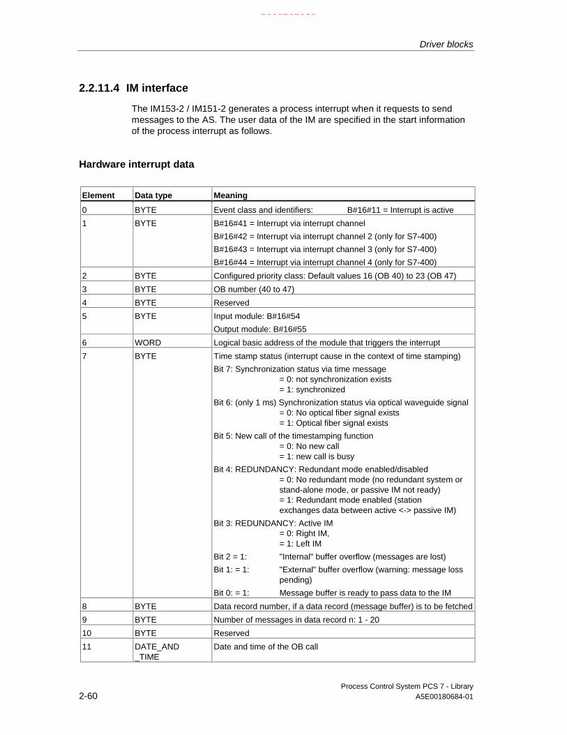
Driver blocks
Process Control System PCS 7 - Library2-60 A5E00180684-01
2.2.11.4 IM interface
The IM153-2 / IM151-2 generates a process interrupt when it requests to sendmessages to the AS. The user data of the IM are specified in the start informationof the process interrupt as follows.
Hardware interrupt data
Element Data type Meaning
0 BYTE Event class and identifiers: B#16#11 = Interrupt is active
1 BYTE B#16#41 = Interrupt via interrupt channel
B#16#42 = Interrupt via interrupt channel 2 (only for S7-400)
B#16#43 = Interrupt via interrupt channel 3 (only for S7-400)
B#16#44 = Interrupt via interrupt channel 4 (only for S7-400)
2 BYTE Configured priority class: Default values 16 (OB 40) to 23 (OB 47)
3 BYTE OB number (40 to 47)
4 BYTE Reserved
5 BYTE Input module: B#16#54
Output module: B#16#55
6 WORD Logical basic address of the module that triggers the interrupt
7 BYTE Time stamp status (interrupt cause in the context of time stamping)
Bit 7: Synchronization status via time message= 0: not synchronization exists= 1: synchronized
Bit 6: (only 1 ms) Synchronization status via optical waveguide signal= 0: No optical fiber signal exists= 1: Optical fiber signal exists
Bit 5: New call of the timestamping function= 0: No new call= 1: new call is busy
Bit 4: REDUNDANCY: Redundant mode enabled/disabled= 0: No redundant mode (no redundant system orstand-alone mode, or passive IM not ready)= 1: Redundant mode enabled (stationexchanges data between active <-> passive IM)
Bit 3: REDUNDANCY: Active IM= 0: Right IM,= 1: Left IM
Bit 2 = 1: "Internal" buffer overflow (messages are lost)
Bit 1: = 1: "External" buffer overflow (warning: message losspending)
Bit 0: = 1: Message buffer is ready to pass data to the IM
8 BYTE Data record number, if a data record (message buffer) is to be fetched
9 BYTE Number of messages in data record n: 1 - 20
10 BYTE Reserved
11 DATE_AND_TIME
Date and time of the OB call
21.02.2003

Driver blocks
Process Control System PCS 7 - LibraryA5E00180684-01 2-61
The IM_DRV evaluates only bit 5 of byte 7 (time stamp status). If this bit = 1, allpreviously received and not yet computed process interrupts will be rejected.
The IM sets this bit is only in the first process alarm after a new call of the timestamp function.
Examples of new calls:* REDUNDANCY: Changeover state active <-> passive IM* Restart of the time stamp function after a total failure
Data record (message buffer)
The message buffer of an IM153-2 holds 15 records. Access to a record isspecified by the record number supplied in the process interrupt data.
Structure of an IM data record (message buffer)
Date Number of bytes Remarks
Message1 12 Signal or special message
. .
.
. . .
Message20 12 Signal or special message
The message buffer can store up to 20 signals or special messages.
21.02.2003
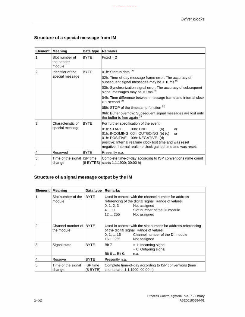
Driver blocks
Process Control System PCS 7 - Library2-62 A5E00180684-01
Structure of a special message from IM
Element Meaning Data type Remarks
1 Slot number ofthe headermodule
BYTE Fixed = 2
2 Identifier of thespecial message
BYTE 01h: Startup data (a)
02h: Time-of-day message frame error. The accuracy ofsubsequent signal messages may be < 10ms (b)
03h: Synchronization signal error: The accuracy of subsequentsignal messages may be < 1ms (b)
04h: Time difference between message frame and internal clock> 1 second (d)
05h: STOP of the timestamp function (b)
06h: Buffer overflow: Subsequent signal messages are lost untilthe buffer is free again (b)
3 Characteristic ofspecial message
BYTE For further specification of the event
01h: START 00h: END (a) or01h: INCOMING 00h: OUTGOING (b) (c) or01h: POSITIVE 00h: NEGATIVE (d)positive: Internal realtime clock lost time and was resetnegative: Internal realtime clock gained time and was reset:
4 Reserved BYTE Presently n.a.
5 Time of the signalchange
ISP time(8 BYTES)
Complete time-of-day according to ISP conventions (time countstarts 1.1.1900; 00:00 h)
Structure of a signal message output by the IM
Element Meaning Data type Remarks
1 Slot number of themodule
BYTE Used in context with the channel number for addressreferencing of the digital signal. Range of values:0, 1, 2, 3 Not assigned4 ... 11 Slot number of the DI module12 ... 255 Not assigned
2 Channel number ofthe module
BYTE Used in context with the slot number for address referencingof the digital signal. Range of values:0, 1, ... 15 Channel number of the DI module16 … 255 Not assigned
3 Signal state BYTE Bit 7 = 1: Incoming signal= 0: Outgoing signal
Bit 6 ... Bit 0: n.a.
4 Reserve BYTE Presently n.a.
5 Time of the signalchange
ISP time(8 BYTE)
Complete time-of-day according to ISP conventions (timecount starts 1.1.1900; 00:00 h)
21.02.2003

Driver blocks
Process Control System PCS 7 - LibraryA5E00180684-01 2-63
2.2.12 MOD_1: Monitoring 16-channel S7-300/400 SM modules withoutdiagnostic functions
2.2.12.1 MOD_1: Description
Object name (type + number)
FB 91
Area of application
This block monitors up to 16 channels of S7-300/400 SM modules withoutdiagnostic functions (no mixed modules). H systems support only the modules ofactive module racks.
The calling OBs
The block must be installed in the run sequence of following OBs:(automatically in CFC):
OB1 Cyclic program
OB83 Insertion/removal interrupt
OB85 Program execution error
OB86 Rack failure
OB100 Restart (warm start)
21.02.2003

Driver blocks
Process Control System PCS 7 - Library2-64 A5E00180684-01
Use in the CFC
The CFC function "Generate module drivers" automatically:
• Installs the MOD_1 block in its runtime group, downstream of the runtimegroup of the RACK block in the OBs mentioned above.
• Configures
- The MODE_xx inputs (mode of the channels xx of the module).
- The logical basic address of the LADDR module.
• Interconnects
- The OUT structures CPU_DIAG of the OB_BEGIN block and RAC_DIAGof the RACK block to the INOUT structures of the same name of theMOD_1.
- The EN input to the output of an AND blockwhose inputs are interconnected with the outputs EN_SUBx (x = Numberof the DP Master system) of the OB_BEGIN block, with EN_Rxxx (xxx =Rack/station number) of the SUBNET block and with EN_Mxx (xx =Module number) of the RACK block.
Function
The block (acyclic service) analyzes all events affecting a module and its channels.It forms a channel-specific MODE and quality code for the signal processingblocks. Events are reported via ALARM_8P.
The higher-priority RACK block enables the run sequence of the block. Thediagnostic event is entered in the start information (CPU_DIAG) of the OB_DIAGblock. Each signal channel of the module is assigned an input (MODE_xx), whichis used to set the HW Config configuration data for the module channels.MODE_xx data are written to the low word of output OMODE_xx only duringstartup/initial start or if you set ACC_MODE = TRUE. The actual value status of thechannel is entered in the high byte. If good, OMODE_xx = 16#80xxxxxx is set.
The following events lead to a value status "invalid value due to higher priorityerror" (OMODE_xx = 16#40xxxxxx):
Rack failure (OB86) (output parameter QRACKF = TRUE)
21.02.2003

Driver blocks
Process Control System PCS 7 - LibraryA5E00180684-01 2-65
The above events are evaluated by the RACK block. The following ones by the MOD block
I/O access error (OB85) (output parameter QPERAF = TRUE)
Module withdrawn (OB83) (output parameter QMODF = TRUE)
"Module removed" and "I/O access error" events are reported to the operatorstations via ALARM_8P. When a diagnostic interrupt is triggered, a difference ismade between module and channel errors, whereby a message number isassigned to each channel.
The system verifies during startup that the module is available (plugged) and readsthe module status data. These data are made available as service outputparameters at MOD_INF.
For detailed error information, refer to the manual "System Software forS7-300/400 – System and Standard Functions".
Redundancy
The master RACK block monitors redundancy of a DP master systems in anH system.
MODE setting
Input parameters MODE_xx are available for a maximum of 16 signal channels.Their default value is "Zero" (no signal). Set the coding of the measuring range ofan analog module at the MODE_xx input for each signal channel xx, if necessary.
Refer to MODE
Note
Modifications of the configuration of MODE_xx inputs during runtime are notaccepted at the outputs until you set input ACC_MODE = 1.
OMODE structure
Refer to OMODE
Addressing
Refer to Addressing
Error handling
The plausibility of input parameters is not checked.
Also refer to: MSG_STAT: Error information of the output parameter MSG_STAT
21.02.2003

Driver blocks
Process Control System PCS 7 - Library2-66 A5E00180684-01
Service information
You can read the module status information that is entered during startup from thestructured output parameter MOD_INF to analyze errors (refer to the referencemanual "System software for S7-300/400 – System and standard functions",system state list, module status information).
Startup characteristics
After a restart or initial startup the system verifies that the module is availableunder its logical base address. A restart (OB100) is reported via the LSB in byte 2of the outputs OMODE_xx.
Time response
n.a.
Message characteristics
MOD_1 uses ALARM_8P to report module errors. The DELAY1 and DELAY2inputs can be set to delay signaling of I/O access errors. DELAY1 determines thetime in [s] which the block waits for an incoming higher-priority error (rack failure orremoval/insertion interrupt) before it outputs the I/O access error (OB85) message.It outputs the message only if no higher-priority error was detected within this setdelay time. DELAY2 determines the number of seconds which the block waits toreport the I/O access error after an existing higher-priority error has passed. Thedefault of both values is 2 seconds.You can set EN_MSG = FALSE to disable the message function.
Operator control and monitoring
The block does not have a faceplate.
Note: In the OCM column of the "MOD_1: I/Os" table, the "+" character identifiesthe variables to be transferred to the OS, if you have set the "enable operatorcontrol and monitoring" attribute in the block object properties. Default: This optionis not set.
21.02.2003

Driver blocks
Process Control System PCS 7 - LibraryA5E00180684-01 2-67
2.2.12.2 MOD_1 / MOD_2: I/Os
The MOD_1 and MOD_2 block I/Os are identical with the exception of theMODE_xx and OMODE_xx number. The number of monitored channelsdetermines the number of input and outputs (xx) required.
The factory setting of the block display in CFC is identified in the I/O column: I/Oname in bold characters = I/O visible, in normal characters = hidden.
I/Os(parameter)
Meaning Data type Default I/O OCM
ACC_MODE 1 = accept MODE settings BOOL 0 I/O
CPU_DIAG system structure STRUCT I/O
DELAY1 interrupt delay 1 (s) INT 2 I
DELAY2 interrupt delay 2 (s) INT 2 I
EN_MSG 1 = enable message BOOL 1 I
EV_ID Message ID DWORD 0 I
LADDR Logical address of module INT 0 I
MOD_INF System structure: Module information STRUCT O
MODE_xx Mode Channel (xx = 00 - 15 / 00 - 31) WORD 0 I
MSG_ACK Message acknowledged WORD 0 O
MSGSTAT Message error status WORD 0 O
OMODE_xx Mode Channel (xx = 00 - 15 / 00 - 31) DWORD 0 O +
QERR 1 = program error BOOL O
QMODF 1 = module removed/faulty BOOL 0 O +
QPERAF 1 = module I/O access error BOOL 0 O
QRACKF 1 = rack/station error BOOL 0 O
RAC_DIAG Rack diagnostics (system structure) STRUCT I/O
RACK_NO Rack number BYTE 0 I
SLOT_NO Slot number BYTE 0 I
SUBN_TYP 1 = external DP interface BOOL 0 I
SUBN1_ID ID of the primary DP master system BYTE 255 I
SUBN2_ID ID of the redundant DP master system BYTE 255 I
21.02.2003

Driver blocks
Process Control System PCS 7 - Library2-68 A5E00180684-01
2.2.12.3 MOD_1 / MOD_2 / MOD_3: Message texts and auxiliary processvalues
Message texts and classes assigned to the block parameters of MOD_1 / MOD_2
Message blockALARM_8P
Messagenumber
Blockparameter
Default message text Messageclass
1 Module1%d@/@2%d@/@3%d@: Removed S
2 QPERAF Module1%d@/@2%d@/@3%d@: Access error S
EV_ID
3 QMODF Module1%d@/@2%d@/@3%d@:@4W%t#MOD_n_TXT@ (n = 1 or 2)
S
Assignment of auxiliary process values to the block parameters of MOD_1 /MOD_2
Message blockALARM_8P
Auxiliaryprocessvalue
Block parameter Meaning
1 MOD_INF.SUBN_ID DP Master system ID (byte)
2 MOD_INF.RACK_NO rack/station number (byte)
3 MOD_INF.SLOT_NO slot number (byte)
EV_ID
4 text number from MOD_n_TXT (n =1or 2)(Message 1)
The corresponding message texts and their numbers in the text libraryMOD_n_TXT are found in the text library for signal modules
21.02.2003

Driver blocks
Process Control System PCS 7 - LibraryA5E00180684-01 2-69
2.2.13 MOD_2: Monitoring 32-channel S7-300/400 SM modules withoutdiagnostic functions
2.2.13.1 MOD_2: Description
Object name (type + number)
FB 92
Area of application
The block monitors up to 32 channels of S7-300/400 SM modules (not mixed I/Omodules) without diagnostics functions.
The calling OB
The block must be installed in the run sequence of following OBs (automatically inCFC):
OB1 Cyclic program
OB83 Module removal/insertion interrupt
OB85 Runtime error
OB86 Rack failure
OB100 Restart (warm start)
Use in the CFC
The CFC function "Generate module drivers" automatically:
• Installs the MOD_2 block in its assigned runtime group in the OBs shownabove, downstream of the runtime group of the RACK block.
• Configures
- The MODE_xx inputs (mode of the channels xx of the module)
- The logical basic address of the LADDR module.
• Interconnects
- The OUT structures CPU_DIAG of the OB_BEGIN block and RAC_DIAGof the RACK block with the MOD_2 INOUT structures of the same name.
- The EN input to the output of an AND blockwhose inputs are interconnected with the outputs EN_SUBx (x = Numberof the DP Master system) of the OB_BEGIN block, with EN_Rxxx (xxx =Rack/station number) of the SUBNET block and with EN_Mxx (xx =Module number) of the RACK block.
21.02.2003

Driver blocks
Process Control System PCS 7 - Library2-70 A5E00180684-01
Function
The block (acyclic service) analyzes all events affecting a module and its channels,and forms a channel-specific MODE and value status (quality code) for the signalprocessing blocks. ALARM_8P reports these events.
The RACK master block enables the run sequence of the block. The diagnosticevent is entered in the start information (CPU_DIAG) of the OB_DIAG block. Eachsignal channel of the module is assigned a A MODE_xx input for enteringconfiguration data of HW Config for the module channels. The function writes theMODE_xx parameters to the least significant byte of output OMODE_xx, i.e. onlyduring the startup/initial startup or if you set ACC_MODE = TRUE. It writes theactual channel value status to the most significant byte. If good, OMODE_xx =16#80xxxxxx is set.
The following events lead to a value status "invalid value due to higher-priorityerror" (OMODE_xx = 16#40xxxxxx):
Rack failure (OB86) (output parameter QRACKF = TRUE)
The above events are evaluated by the RACK block. The following ones by theMOD block:
I/O access error (OB85) (output parameter QPERAF = TRUE)
module removed (OB83) (output parameter QMODF = TRUE)
"Module removed" and "I/O access error" events are reported to the OS by meansof ALARM_8P. When a diagnostic interrupt has been triggered, a differentiation ismade between module and channel errors; each channel is assigned a messagenumber.
The system verifies during startup that the module is available (plugged). It readsthe module status information provides these data as service output parameters(MOD_INF).
For detailed error information refer to the manual "System Software for S7-300/400– System and Standard Functions".
Redundancy
Redundancy of the DP Master systems at an H system is monitored by the RACKmaster block.
21.02.2003

Driver blocks
Process Control System PCS 7 - LibraryA5E00180684-01 2-71
MODE setting
MODE_xx inputs are available for a maximum of 16 signal channels. The defaultsetting is "Null" (no signal). You must set the type and, if applicable the measuringrange coding of analog modules at the MODE_xx input according to the eachsignal channel xx.
Refer to MODE
Note
Modifications of the MODE_xx input configuration during runtime are not acceptedat the outputs until input ACC_MODE = 1.
OMODE structure
Refer to OMODE
Addressing
Refer to Addressing
Error handling
The plausibility of input parameters is not checked.
Also refer to: MSG_STAT: Error information on output parameters
Service information
You can read the module status information generated during the startup at thestructured output parameter MOD_INF to analyze errors (refer to the referencemanual "System software for S7-300/400 – System and standard functions",system state list, module status information).
Startup characteristics
After a restart/initial startup, the system verifies that the module is available underits logical base address. A restart (OB100) is reported via the LSB in byte 2 of theoutputs OMODE_xx.
Time response
n.a.
21.02.2003

Driver blocks
Process Control System PCS 7 - Library2-72 A5E00180684-01
Message characteristics
MOD_1 uses ALARM_8P to report module errors. The DELAY1 and DELAY2inputs can be set to delay signaling of I/O access errors. DELAY1 determines thetime in [s] which the block waits for an incoming higher-priority error (rack failure orremoval/insertion interrupt) before it outputs the I/O access error (OB85) message.It outputs the message only if no higher-priority error was detected within this setdelay time. DELAY2 determines the number of seconds which the block waits toreport the I/O access error after an existing higher-priority error has passed. Thedefault of both values is 2 seconds.You can set EN_MSG = FALSE to disable the message function.
Operator control and monitoring
The block does not have a faceplate.
Note: In the OCM column of the "MOD_2" table, the "+" character identifies thevariables to be transferred to the OS, if you have set the "enable operator controland monitoring" attribute in the block object properties. Default: This option is notset.
21.02.2003

Driver blocks
Process Control System PCS 7 - LibraryA5E00180684-01 2-73
2.2.14 MOD_3: Monitoring 16-channel S7-200/300/400 SM moduleswithout diagnostic functions
2.2.14.1 MOD_3: Description
Object name (type + number)
FB 95
Area of application
The block monitors up to 16 channels S7-300/400 SM mixed (I/O) modules withoutdiagnostics functions (no mixed I/O modules). H systems support only modules inactive racks.
The calling OBs
The block must be installed in the run sequence of following OBs (automatically inCFC):
OB1 Cyclic program
OB83 Module removal/insertion interrupt
OB85 Runtime error
OB86 Module rack failure
OB100 Restart (warm start)
Use in the CFC
The CFC function "Generate module drivers" automatically:
• Installs the MOD_3 block in its assigned runtime group, downstream of theruntime group of the RACK block, in the OBs shown above.
• Configures
- The MODE_xx inputs (mode of the channels xx of the module)
- The logical basic address LADDR and LADDR1.
• Interconnects
- The structures CPU_DIAG of the OB_BEGIN block and RAC_DIAG of theRACK block with the MOD_3 block structures of the same name.
21.02.2003

Driver blocks
Process Control System PCS 7 - Library2-74 A5E00180684-01
Function
The block cyclically analyzes all events affecting a module and its channels andforms a channel-specific MODE and value status (quality code) for the signalprocessing blocks. ALARM_8P reports the events.
The master RACK block enabeles the runsequence of the block. The diagnostic isentered in the start information (CPU_DIAG) of the OB_DIAG block.
Each signal channel of the module is assigned a MODE_xx input. Configurationdata of HW Config for the module channels is entered at these inputs.
Inputs available for channel encoding:MODE_00 … MODE_15 -> maximum of 16 input channels.MODE_16 … MODE_31 -> maximum of 16 output channels.
The function writes the MODE_xx parameters to the least significant byte of outputOMODE_xx, i.e. only during the startup/initial startup routine or if ACC_MODE =TRUE, and the actual channel value status to the most significant byte. If valid,OMODE_xx = 16#80xxxxxx is set.
The following events lead to a value status "invalid value due to higher-priorityerror" (OMODE_xx = 16#40xxxxxx):
segment failure (OB86) (output parameter QRACKF = TRUE)
rack failure (OB86) (output parameter QRACKF = TRUE)
The above events are evaluated by the RACK block. The following ones by theMOD block:
I/O access error (OB85) (output parameter QPERAF = TRUE)
module removed (OB83) (output parameter QMODF = TRUE)
"Module removed" and "I/O access error" events are reported to the OS by meansof ALARM_8P. If a diagnostic interrupt has occurred, a differentiation is madebetween module and channel errors; a message number is assigned to eachchannel.
The system verifies during startup that the module is available (plugged), reads themodule status information provides these data as service output parameters(MOD_INF).
For detailed error information, refer to the manual "System Software forS7 300/400 – System and Standard Functions".
Redundancy
This block supports segment redundancy of H systems operating with distributedI/O. You need to assign the numbers of the redundant segments to the SUBNETblock inputs SUBN1_ID (interconnection to CPU 0) and SUBN2_ID(interconnection to CPU 1). If the segments are not redundant, the value 16#FF(default) must be set at the remaining input.
21.02.2003

Driver blocks
Process Control System PCS 7 - LibraryA5E00180684-01 2-75
MODE setting
MODE_xx input parameters area available for a maximum of 2 x 16 signalchannels. The default setting is "Null" (no signal). You must set the type and, ifapplicable the measuring range coding of analog modules at the MODE_xx inputfor each signal channel xx.
See MODE setting
Note
Modifications of the MODE_xx input configuration during runtime are not acceptedat the outputs until you set input ACC_MODE = 1.
Structure of OMODE
See OMODE
Addressing
See Addressing
Error handling
The plausibility of input parameters is not checked.
Also refer to: MSG_STAT: Error information on output parameters
Service information
You can analyze errors by using the module status information returned by thestartup routine via the structured output parameter MOD_INF (refer to thereference manual "System software for S7-300/400 – System and standardfunctions", system state list, module status information).
Startup characteristics
After a restart/initial startup, the system verifies that the module is available underits logical base address. A restart (OB100) is reported via the LSB in byte 2 of theoutputs OMODE_xx.
Time response
n.a.
21.02.2003

Driver blocks
Process Control System PCS 7 - Library2-76 A5E00180684-01
Message characteristics
MOD_1 uses ALARM_8P to report module errors. The DELAY1 and DELAY2inputs are used to delay signaling of I/O access errors. DELAY1 is used to specifythe time in seconds which the block waits after an I/O access error (OB85) for aparent error (rack failure or withdrawn/plugged), before it outputs the message. Itoutputs the message only if no parent error was detected within the set delay time.DELAY2 determines the number of seconds which the block waits to report the I/Oaccess error after an existing parent error has passed. The default of both values is2 seconds.The setting EN_MSG = FALSE can be used to disable messages.
Operator control and monitoring
The block does not have a faceplate.
Note: In the OCM column of the "MOD_3: I/Os" table, the "+" character identifiesthe variables to be transferred to the OS, if you have set the "enable operatorcontrol and monitoring" attribute in the block object properties. Default: This optionis not set.
21.02.2003

Driver blocks
Process Control System PCS 7 - LibraryA5E00180684-01 2-77
2.2.14.2 MOD_3: I/O
The factory setting of the block display in CFC is identified in the I/O column: I/Oname in bold characters = I/O visible, in normal characters = hidden.
I/O(Parameter)
Meaning Data type Default Type OCM
ACC_MODE 1 = accept MODE setting BOOL 0 I/O
CPU_DIAG CPU diagnostics STRUCT I/O
DELAY1 Interrupt delay 1 (s) INT 2 I
DELAY2 Interrupt delay 2 (s) INT 2 I
EN_MSG 1 = enable message BOOL 1 I
EV_ID Message ID DWORD 0 I
LADDR logical address of input channels INT 0 I
LADDR1 logical address of output channels INT 0 I
MOD_INF Module parameters STRUCT O
MODE_xx Mode Channel xx WORD 0 I
MSG_ACK Message acknowledged WORD 0 O
MSG_STAT Message error status WORD 0 O
OMODE_xx Mode Channel xx DWORD 0 O +
QERR 1 = runtime error BOOL 1 O
QMODF 1 = module removed/faulty BOOL 0 O +
QPERAF 1 = I/O access error BOOL 0 O
QRACKF 1 = rack failure BOOL 0 O
RAC_DIAG Rack diagnostics (system structure) STRUCT I/O
RACK_NO Rack number BYTE 0 I
SLOT_NO Slot number BYTE 0 I
SUBN_TYP 1 = external DP interface BOOL 0 I
SUBN1_ID ID of the primary DP master system BYTE 255 I
SUBN2_ID ID of the redundant DP master system BYTE 255 I
21.02.2003

Driver blocks
Process Control System PCS 7 - Library2-78 A5E00180684-01
2.2.15 MOD_CP: Diagnose CP 341/441
2.2.15.1 MOD_CP: Description
Object name (type + number)
FB 98
Area of application
This block monitors a serial communication module CP341 or CP441. H systemsonly support modules in switched racks.
The calling OBs
The block must be installed in the run sequence of following OBs (automatically inCFC):
OB1 Cyclic program
OB82 Diagnostics interrupt
OB83 Module removal/insertion interrupt
OB85 Runtime error
OB86 Module rack failure
OB100 Restart (warm start)
Use in the CFC
The CFC function Generate module drivers automatically:
• Integrates the OBs shown above into the MOD_CP block in its assignedruntime group, downstream of the runtime group of the RACK block.
• Configures
- the inputs SUBN1_ID, SUBN2_ID, SUBN_TYP, RACK_NO andSLOT_NO,
- the basic logical address LADDR of the module.
21.02.2003

Driver blocks
Process Control System PCS 7 - LibraryA5E00180684-01 2-79
• Interconnects
- the OUT structures CPU_DIAG of the OB_BEGIN block and RAC_DIAG ofthe RACK block to the MOD_CP INOUT structures of the same name.
- The EN input to the output of an AND blockwhose inputs will be interconnected to the outputs EN_SUBx (x = DPmaster system ID) of the OB_BEGIN block, EN_Rxxx (xxx = rack/stationnumber) of the SUBNET block and to EN_Mxx (xx = module number) ofthe RACK block.
Function and operating principle
The block (acyclic service) analyzes all events affecting a module and its channelsand generates value status data for the serial communication blocks (e.g.RCV_341). ALARM_8P reports the events.
The master RACK block enables runtime of the MOD_CP block. The event to beevaluated is stored in the startup/diagnostics information (CPU_DIAG) of thefunction block OB_BEGIN. A MODE_1 input is assigned to the communicationchannel of the module. Input MODE_2 is reserved for the second CP441communication channel, which can be used to input channel configuration data ofHW Config. Since the driver generator currently cannot access those data, theSND_341 or RCV_341 blocks do not evaluate those data. At input MODE, the usercan set a defined code for any existing user-specific blocks. MODE_x will bewritten to the Low Word of output OMODE_xx, and only by the startup/initialstartup routines or if you set ACC_MODE = TRUE. The most significant bytecontains the actual value status of the communication channel. If good, thenOMODE_xx = 16#80xxxxxx.
The following events result in a value status "invalid data due to higher-priorityerror " (OMODE_xx = 16#40xxxxxx):
Rack failure (OB86) (output parameter QRACKF = TRUE)
The RACK block evaluates the OB above, the MOD block the OBs below:
I/O access error (OB85) (output parameter QPERAF = TRUE)
Module removed (OB83) (output parameter QMODF = TRUE)
Diagnostic interrupt (OB82) differentiation between model and channelerror
21.02.2003

Driver blocks
Process Control System PCS 7 - Library2-80 A5E00180684-01
The following events are classed as module error(output parameter QMODF = TRUE):
The system uses ALARM_8P to report "module removed", "I/O access error" and"diagnostic interrupt" events to WinCC.
The system differentiates only at the CP441 between module and channel errorsafter a diagnostic interrupt has been generated; two message numbers (parameterassignment error, line break) are here assigned to each channel.
Redundancy
The master RACK block monitors the redundancy of DP master system in an Hsystem.
Error handling
The system does not check the plausibility of input data.
Startup characteristics
After a restart/initial start the system verifies that the module is available under itsbasic logical address. Restart (OB100) is reported via the LSB in byte 2 of theOMODE_xx outputs.
Reaction to overload
The MOD_CP block counts OB82 calls. and the counter is reset ion OB1. If morethan five OB82 events occur in succession before the scan cycle check point isreached (OB1), these events are discarded and the message "OB82 DP masterfailure:x Rack:y Slot: z" is output.
Time response
n.a.
Message characteristics
MOD_CP uses ALARM_8P to report module errors. The DELAY1 and DELAY2inputs are used to delay the output of the I/O access error message. At theDELAY1 parameter you can specify the interval in [s] the block has to wait forhigher-priority errors (module removal/insertion or rack failure) after OB85 hasreported an I/O access error until it outputs the message. The message is outputonly under the condition that no higher-priority error is reported within this delaytime. DELAY2 determines which time in seconds the block delays the output of aqueued I/O access error after the higher-priority error was reported outgoing.Default = 2 seconds.EN_MSG = FALSE can be used to disable reporting.
21.02.2003

Driver blocks
Process Control System PCS 7 - LibraryA5E00180684-01 2-81
Operator control and monitoring
The block does not have a faceplate.
Note: In the OCM column of the "MOD_C" table, the "+" character identifies thevariables to be transferred to the OS, if you have set the "enable operator controland monitoring" attribute in the block object properties. Default: This option is notset.
Default: This option is not set
2.2.15.2 MOD_CP: I/Os
The factory setting of the block display in CFC is identified in the I/O column: I/Oname in bold characters = I/O visible, in normal characters = hidden.
I/O(Parameter)
Meaning Data type Default Type OCM
ACC_MODE 1 = accept MODE setting BOOL 0 I/O
CPU_DIAG CPU diagnostics (system structure) STRUCT I/O
DELAY1 Alarm delay 1 (s) INT 2 I
DELAY2 Alarm delay 2 (s) INT 2 I
DIAG_INF Diagnostics information STRUCT O
EN_MSG 1 = enable message BOOL 1 I
EV_ID Message number DWORD 0 I
LADDR Logical address of the module INT 0 I
MOD_INF Module parameter STRUCT O
MODE_1 Mode channel 1 WORD 0 I
MODE_2 Mode channel 2 (only CP 441) WORD 0 I
MSG_ACK Message acknowledged WORD 0 O
MSG_STAT Error message status WORD 0 O
OMODE_1 Value status/mode channel 1 DWORD 0 O +
OMODE_2 Value status/mode channel 2 (only CP 441) DWORD 0 O +
QERR 1 = program error BOOL 1 O
QMODF 1 = removed/faulty module BOOL 0 O +
QPERAF 1 = I/O access error BOOL 0 O
QRACKF 1 = rack error BOOL 0 O
RAC_DIAG Rack diagnostics STRUCT I/O
RACK_NO Rack number BYTE 0 I
SLOT_NO Slot number BYTE 0 I
SUBN_TYP 1 = external DP interface BOOL 0 I
SUBN1_ID ID of the primary DP master system BYTE 255 I
SUBN2_ID ID of the redundant DP master systems BYTE 255 I
21.02.2003

Driver blocks
Process Control System PCS 7 - Library2-82 A5E00180684-01
2.2.15.3 MOD_CP: Message texts and auxiliary process values
Assignment of the message text/class
Message blockALARM_8P
Messagenumber
Blockparameter
Default message text Messageclass
EV_ID 1 QMODF CP @1%d@/@2%d@/@3%d@: Removed S
2 QPERAF CP @1%d@/@2%d@/@3%d@: I/O access error S
3 CP @1%d@/@2%d@/@3%d@:@4W%t#MOD_CP_TXT@
S
4 CP @1%d@/@2%d@/@3%d@: Wrongparameters
S
5 CP @1%d@/@2%d@/@3%d@: Cable break S
6 CP @1%d@/@2%d@/@3%d@/2: Wrongparameters
S
7 CP @1%d@/@2%d@/@3%d@/2: Cable break S
8 CP @1%d@/@2%d@/@3%d@: Repeateddiagnostic interrupt
S
Assignment of auxiliary process values
Message blockALARM_8P
Associatedvalue
Block parameter Meaning
EV_ID 1 SUBN_ID DP master system ID (byte)
2 RACK_NO Rack/station number (byte)
3 SLOT_NO Slot number (byte)
SUBN_ID = SUBN1_ID. If SUBN1_ID = 16#FF, the auxiliary process value issubstituted with SUBN2_ID.
21.02.2003
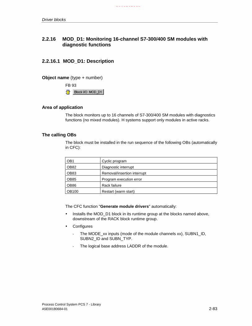
Driver blocks
Process Control System PCS 7 - LibraryA5E00180684-01 2-83
2.2.16 MOD_D1: Monitoring 16-channel S7-300/400 SM modules withdiagnostic functions
2.2.16.1 MOD_D1: Description
Object name (type + number)
FB 93
Area of application
The block monitors up to 16 channels of S7-300/400 SM modules with diagnosticsfunctions (no mixed modules). H systems support only modules in active racks.
The calling OBs
The block must be installed in the run sequence of the following OBs (automaticallyin CFC):
OB1 Cyclic program
OB82 Diagnostic interrupt
OB83 Removal/insertion interrupt
OB85 Program execution error
OB86 Rack failure
OB100 Restart (warm start)
The CFC function "Generate module drivers" automatically:
• Installs the MOD_D1 block in its runtime group at the blocks named above,downstream of the RACK block runtime group.
• Configures
- The MODE_xx inputs (mode of the module channels xx), SUBN1_ID,SUBN2_ID and SUBN_TYP.
- The logical base address LADDR of the module.
21.02.2003

Driver blocks
Process Control System PCS 7 - Library2-84 A5E00180684-01
• Interconnects
- The OUT structures CPU_DIAG of the OB_BEGIN block and RAC_DIAGof the RACK block with the MOD_D1 INOUT structures of the same name.
- The EN input to the output of an AND block,whose inputs are interconnected with the outputs EN_SUBx (x = Numberof the DP Master system) of the OB_BEGIN block, with EN_Rxxx(xxx = Rack/station number) of the SUBNET block and with EN_Mxx(xx = Module number) of the RACK block.
Function and Operating Principle
The block (acyclic service) analyzes all events affecting a module and its channelsand forms the channel-specific MODE and value status (quality code) for the signalprocessing blocks. ALARM_8P reports the events.
The master RACK block enables runtime of the MOD_D1 block. The event to beevaluated is stored in the startup/diagnostics information (CPU_DIAG) of theOB_BEGIN block. Each signal channel of the module is assigned a MODE_xxinput for receiving module channel configuration data from HW Config. MODE_xxwill be written to the Low Word of output OMODE_xx. This happens only during thestartup/initial startup routine or if you set ACC_MODE = TRUE. The mostsignificant byte contains the actual value status of the channel. If valid, OMODE_xx= 16#80xxxxxx.
The following events lead to a variable status "invalid value due to higher-priorityerror" (OMODE_xx = 16#40xxxxxx):
Rack failure (OB86) (output parameter QRACKF = TRUE)
The RACK block evaluates the event above, the MOD block the events below.
• I/O access error (OB85) (output parameter QPERAF = TRUE)
• Module removed (OB83) (output parameter QMODF = TRUE)
• Diagnostic interrupt (OB82) Differentiation between module andchannels errors
21.02.2003

Driver blocks
Process Control System PCS 7 - LibraryA5E00180684-01 2-85
The following events represent module errors(output parameter QMODF = TRUE):
• Missing auxiliary voltage
• Front connector missing
• Module not configured
• Wrong module parameters
• Missing/wrong module
• Communication error at a CPU module
• Timeout (watchdog)
• Loss of the internal power supply of the module
• Rack failure
• CPU failure
• EPROM error
• RAM error
• ADC/DAC error
• Fuse tripped
The following events represent channel errors(value status "invalid", OMODE_xx = 16#00xxxx):
• Configuration/parameter assignment errors
• Common-mode errors (only analog I/O)
• Short-circuit to P
• Short circuit to M
• Interruption at the output transistor
• Wire break
• Reference channel error (only analog input)
• Measuring range underflow (only analog input)
• Measuring range overflow (only analog input)
• Missing load voltage (analog and digital output only)
• Missing sensor power supply (only digital output)
• Fuse tripped (only digital output)
• Chassis ground fault (only digital I/O)
• Excess temperature (only digital output)
ALARM_8P reports "Module removed", "I/O access error" and "Diagnosticinterrupt" events to WinCC.
The system distinguishes in the case of diagnostic interrupt between module andchannel errors, whereby a message number is assigned to each channel. Only oneincoming/outgoing event can be reported per channel. Further events will be lost atthis channel if an incoming event is queued.
21.02.2003

Driver blocks
Process Control System PCS 7 - Library2-86 A5E00180684-01
The system enters the corresponding text in the message, if the diagnosticinformation refers to a unique event. If this information contains ambiguous entries,the text of the first set bit of the error byte in the diagnostic data will be displayed.For modules with diagnostic function and more than one error byte in thediagnostic data, only the text "error channel xx" will be output, if the first error bytedoes not show the error information.
During its startup routine the system verifies that the module is available (plugged).Module status information read here is available in the form of service outputparameters (MOD_INF).
Detailed error information is written to the output parameter DIAG_INF of the datatype STRUCT (refer to the reference manual "System software for S7-300/400 –System- and standard functions", diagnostic data, Byte0 to Byte8, structure of thechannel-specific diagnostic data).
Note
Even if you operate a HART module in the HART operating MODEMODE=16#070C, possible HART protocol errors/configuration changes aremasked by the MOD_D1 driver block and not signaled as channel error.
Redundancy
The master block RACK monitors redundancy of the DP Master systems in an Hsystem.
MODE setting
MODE_xx inputs are available for a maximum of 16 signal channels. Their defaultsetting is "Zero" (no signal). For each signal channel xx, you need to set the typeand, if applicable, the coding of the measuring range of an analog module at inputMODE_xx.
See MODE settings
Note
Modifications of parameters at the MODE_xx inputs during runtime are notaccepted at the outputs until input ACC_MODE = 1.
OMODE structure
See OMODE
21.02.2003
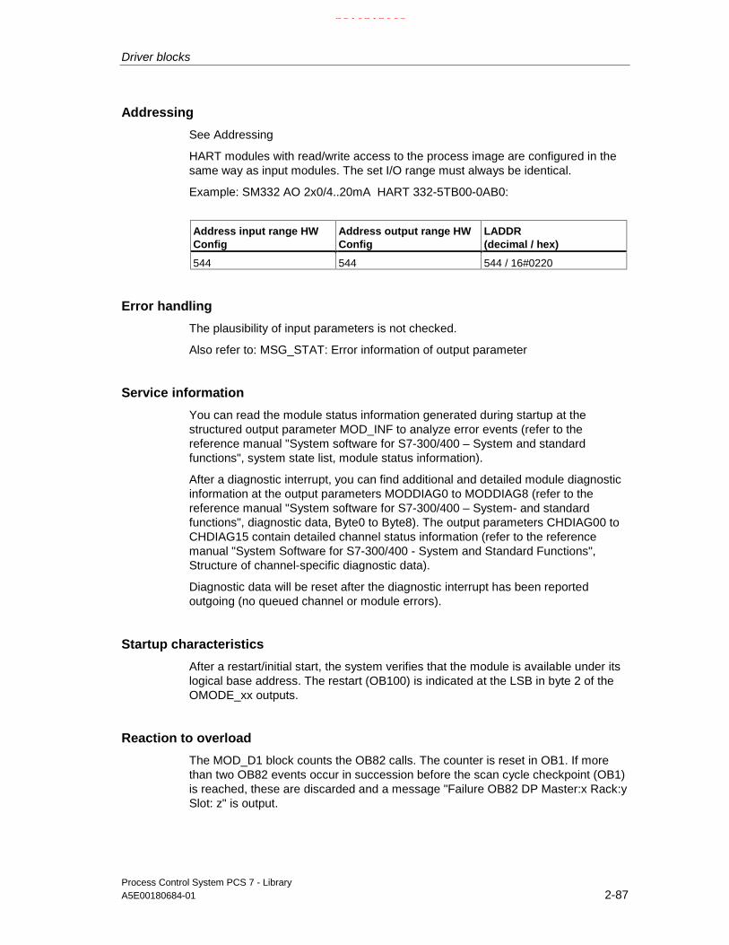
Driver blocks
Process Control System PCS 7 - LibraryA5E00180684-01 2-87
Addressing
See Addressing
HART modules with read/write access to the process image are configured in thesame way as input modules. The set I/O range must always be identical.
Example: SM332 AO 2x0/4..20mA HART 332-5TB00-0AB0:
Address input range HWConfig
Address output range HWConfig
LADDR(decimal / hex)
544 544 544 / 16#0220
Error handling
The plausibility of input parameters is not checked.
Also refer to: MSG_STAT: Error information of output parameter
Service information
You can read the module status information generated during startup at thestructured output parameter MOD_INF to analyze error events (refer to thereference manual "System software for S7-300/400 – System and standardfunctions", system state list, module status information).
After a diagnostic interrupt, you can find additional and detailed module diagnosticinformation at the output parameters MODDIAG0 to MODDIAG8 (refer to thereference manual "System software for S7-300/400 – System- and standardfunctions", diagnostic data, Byte0 to Byte8). The output parameters CHDIAG00 toCHDIAG15 contain detailed channel status information (refer to the referencemanual "System Software for S7-300/400 - System and Standard Functions",Structure of channel-specific diagnostic data).
Diagnostic data will be reset after the diagnostic interrupt has been reportedoutgoing (no queued channel or module errors).
Startup characteristics
After a restart/initial start, the system verifies that the module is available under itslogical base address. The restart (OB100) is indicated at the LSB in byte 2 of theOMODE_xx outputs.
Reaction to overload
The MOD_D1 block counts the OB82 calls. The counter is reset in OB1. If morethan two OB82 events occur in succession before the scan cycle checkpoint (OB1)is reached, these are discarded and a message "Failure OB82 DP Master:x Rack:ySlot: z" is output.
21.02.2003

Driver blocks
Process Control System PCS 7 - Library2-88 A5E00180684-01
Time response
n.a.
Message characteristics
MOD_CP uses ALARM_8P to report module errors. The function also callsALARM_8P_2 and ALARM_8P_3, which are both relevant for channel-specificerrors. The DELAY1 and DELAY2 parameters are used to delay the output of I/Oaccess error messages. In DELAY1 parameter you can set the interval in [s] whichthe block has to wait, after OB85 has reported an I/O access error, for higher-priority errors (module rack removal/insertion/failure) before it outputs themessage. The message is output only if no higher-priority error is reported withinthis delay time. DELAY2 determines which time in seconds the block delays theoutput of a queued I/O access error after the higher-priority error was reportedoutgoing. Default = 2 seconds.You can set EN_MSG = FALSE to disable messages.
Operator control and monitoring
The block does not have a faceplate.
Note: In the OCM column of the "MOD_D1" table, the "+" character identifies thevariables to be transferred to the OS, if you have set the "enable operator controland monitoring" attribute in the block object properties. Default: This option is notset.
21.02.2003

Driver blocks
Process Control System PCS 7 - LibraryA5E00180684-01 2-89
2.2.16.2 MOD_D1 / MOD_D2: I/Os
The I/Os are identical at both the MOD_D1 and the MOD_D2 block, with theexception of the number of MODE_xx and OMODE_xx. The number of monitoredchannels determines the corresponding number of I/O parameters (xx).
The factory setting of the block display in CFC is identified in the I/O column: I/Oname in bold characters = I/O visible, in normal characters = hidden.
Connection(parameter)
Meaning Data type Default I/O OCM
ACC_MODE 1 = accept MODE settings BOOL 0 I/O
CPU_DIAG CPU diagnostics (system structure) STRUCT I/O
DELAY1 Interrupt delay 1 (s) INT 2 I
DELAY2 Interrupt delay 2 (s) INT 2 I
DIAG_INF Diagnostic information STRUCT O
EN_MSG 1 = enable message BOOL 1 I
EV_Idx Message ID (x = 1 - 3) DWORD 0 I
LADDR Logical address of the module INT 0 I
MOD_INF Module parameter STRUCT O
MODE_xx Mode channel xx WORD 0 I
MSG_ACKx Message acknowledgement (x = 1 - 3) WORD 0 O
MSGSTATx Message error status (x = 1 - 3) WORD 0 O
OMODE_xx Channel xx mode (xx = 00 – 15 / 00 - 31) DWORD 0 O +
QERR 1 = program runtime error BOOL 0 O
QMODF 1 = module removed/faulty BOOL 0 O +
QPERAF 1 = module I/O access error BOOL 0 O
QRACKF 1 = rack error BOOL 0 O
RAC_DIAG Rack diagnostic STRUCT I/O
RACK_NO Rack number BYTE 0 I
SLOT_NO Slot number BYTE 0 I
SUBN_TYP 1 = external DP interface BOOL 0
SUBN1_ID ID of the primary DP master system BYTE 255 I
SUBN2_ID ID of the redundant DP master system BYTE 255 I
21.02.2003

Driver blocks
Process Control System PCS 7 - Library2-90 A5E00180684-01
2.2.16.3 MOD_D1: Message texts and auxiliary process values
Assignment of message texts and classes to the MOD_D1 parameters
Message blockALARM_8P
Messagenumber
Blockparameter
Default message text Messageclass
1 QMODF Module @1%d@/@2%d@/@3%d@:removed
S
2 QPERAF Module @1%d@/@2%d@/@3%d@:I/O access error
S
3 QMODF Module @1%d@/@2%d@/@3%d@:@5W%t#MOD_D1_TXT@
S
4 Module @1%d@/@2%d@/@3%d@: Multiplediagnostic interrupt
S
EV_ID1
5 Module @1%d@/@2%d@/@3%d@:@4W%t#MOD_D1_TXT@
S
1 - Module @1%d@/@2%d@/@3%d@:Missing Channel 00 @4W%t#MOD_D1_TXT
S
...
.........
...
...
EV_ID2
8 - Module @1%d@/@2%d@/@3%d@:Error channel 07 @4W%t#MOD_D1_TXT@
S
1 - Module @1%d@/@2%d@/@3%d@:Missing Channel 08 @4W%t#MOD_D1_TXT@
S
...
.........
...
...
EV_ID3
8 - Module @1%d@/@2%d@/@3%d@:Missing Channel 15 @4W%t#MOD_D1_TXT@
S
For information on message texts and their numbers in the text libraryMOD_D1_TXT refer to the section text library for signal modules
21.02.2003

Driver blocks
Process Control System PCS 7 - LibraryA5E00180684-01 2-91
Assignment of auxiliary process values to MOD_D1 parameters
MessageblockALARM_8P
Associatedvalue
Block parameter Meaning
1 MOD_INF.SUBN_ID DP master system ID (byte)
2 MOD_INF.RACK_NO Rack/station number (byte)
3 MOD_INF.SLOT_NO Slot number (byte)
4 Text number (message 5) from MOD_D1_TXT
EV_ID1
5 Text number (message 3) from MOD_D1_TXT
1 MOD_INF.SUBN_ID DP master system ID (byte)
2 MOD_INF.RACK_NO Rack/station number (byte)
3 MOD_INF.SLOT_NO Slot number (byte)
4 Text number (messages 1 - 8) fromMOD_D1_TXT
EV_ID2
1 MOD_INF.SUBN_ID DP master system ID (byte)
2 MOD_INF.RACK_NO Rack/station number (byte)
3 MOD_INF.SLOT_NO Slot number (byte)
EV_ID3
4 Text number (messages 1 - 8) fromMOD_D1_TXT
21.02.2003

Driver blocks
Process Control System PCS 7 - Library2-92 A5E00180684-01
2.2.17 MOD_D2: Monitoring 32-channel S7-300/400 SM modules withdiagnostic functions
2.2.17.1 MOD_D2: Description
Object name (type + number)
FB 94
Area of application
The block monitors the 32 channels of S7-300/400 SM modules with diagnosticfunctions (no mixed modules). H systems supports only the modules in activeracks.
The calling OBs
The block must be installed in the run sequence of the following OBs (automaticallyin CFC):
OB1 Cyclic program
OB82 Diagnostic interrupt
OB83 Removal/insertion interrupt
OB85 Program runtime error
OB86 Rack failure
OB100 Restart (warm start)
Use in the CFC
The CFC function "Generate module drivers" automatically:
• Installs the MOD_D2 block in its runtime group at the blocks named above,after the runtime group of the RACK block.
• Configures
- The MODE_xx inputs (mode of the channels xx of the module),SUBN1_ID, SUBN2_ID and SUBN_TYP.
- The logical basic address (LADDR) of the module.
21.02.2003

Driver blocks
Process Control System PCS 7 - LibraryA5E00180684-01 2-93
• Interconnects
- The OUT structures CPU_DIAG of the OB_BEGIN block and RAC_DIAGof the RACK block with the MOD_D2 INOUT structures of the same name.
- The EN input to the output of an AND block,whose inputs are interconnected with the outputs EN_SUBx (x = number ofthe DP Master system) of the OB_BEGIN block, with EN_Rxxx (xxx =Rack/station number) of the SUBNET block and with EN_Mxx (xx =Module number) of the RACK block.
Function and operating principle
The block (acyclic service) analyzes all events affecting a module and its channels.It forms the MODE and value status (quality code) for the signal processing blocksof specific channels. ALARM_8P reports the events. This message function can bedisabled.
The master block RACK enables runtime of the MOD_CP block. The diagnosticevent is stored in the startup/diagnostics information (CPU_DIAG) of function blockOB_BEGIN. Each signal channel of the module is assigned a MODE_xx input usedfor the input of module channel configuration data from HW Config. MODE_xx willbe written to the least significant word of output OMODE_xx. This happens onlyduring the startup/initial startup, or if you set ACC_MODE = TRUE. The mostsignificant byte contains the actual value status of the channel. If valid, OMODE_xx= 16#80xxxxxx.
The following events lead to the status "invalid value due to higher-priority error"(OMODE_xx = 16#40xxxxxx):
Rack failure (OB86) (output parameter QRACKF = TRUE)
The above events are evaluated by the RACK block. The following ones by theMOD block
• I/O access error (OB85) (output parameter QPERAF = TRUE)
• Module removed (OB83) (output parameter QMODF = TRUE)
• Diagnostic interrupt (OB82) Differentiation between module faults andchannels faults
21.02.2003

Driver blocks
Process Control System PCS 7 - Library2-94 A5E00180684-01
The following events represent module errors(output parameter QMODF = TRUE):
• External auxiliary voltage missing
• Front connector missing
• Module not configured
• Wrong module parameters
• Wrong/missing module
• Communication error at a CPU module
• Timeout (watchdog)
• Loss of internal power at a module
• Rack failure
• CPU failure
• EPROM error
• RAM error
• ADC/DAC error
• Fuse tripped
The following events represent channel errors (value status "invalid",OMODE_xx = 16#00xxxx):
• Configuration/parameter assignment errors
• Common-mode errors (only analog I/Os)
• Short-circuit to P
• Short circuit to M
• Interruption at the output transistor
• Cable break
• Reference channel error (only analog inputs)
• Measuring range underflow (only analog inputs)
• Measuring range overflow (only analog inputs)
• Missing load voltage (only analog and digital outputs)
• Missing sensor power supply (only digital outputs)
• Fuse tripped (only digital outputs)
• Chassis ground fault (only digital I/Os)
• Excess temperature (only digital outputs)
ALARM_8P is used to report "Module removed", "I/O access error" and"Diagnostics interrupt" events to WinCC.
The diagnostics interrupt function distinguishes between module and channelerrors, whereby each channel is assigned a message ID. Only one incoming oroutgoing event can be reported for each channel. As long as an incoming messageis queued at a channel, further incoming event at this channel will be lost.
21.02.2003

Driver blocks
Process Control System PCS 7 - LibraryA5E00180684-01 2-95
If the event is defined uniquely in the diagnostic data, the corresponding text will beentered in the message. If ambiguous entries exist, the text of the first set bit in theerror byte of the diagnostic data will be displayed. When using modules assigneddiagnostic functions and more than one error byte for diagnostic information, onlythe channel xx error text will be output if the error information is not displayed in thefirst error byte.
The system verifies during startup that the module is available (plugged in). Modulestatus information read by this routine are available as service output parameter(MOD_INF).
Detailed information on errors (see the reference manual "System Software forS7-300/400 – System and Standard Functions", Diagnostic data, byte 0 to byte 8,Structure of channel-specific diagnostic data) will be entered in the outputparameter DIAG_INF of the data type STRUCT.
Redundancy
The block supports segment redundancy of 417 CPUs operating with distributedI/O. The ID of redundant segments must be assigned to the SUBN1_ID(connection to CPU 0) and SUBN2_ID (connection to CPU 1) inputs accordingly. Ifthe segment is not redundant, the remaining input must be assigned the value16#FF (default).
MODE setting
MODE_xx inputs are available for a maximum of 32 signal channels. Their defaultsetting is "Zero" (no signal). For each signal channel xx, you need to set the typeand, if appropriate, the coding of the measuring range of an analog module at theMODE_xx input.
Refer to MODE
Note
Modifications of the MODE_xx input configuration during runtime will not beaccepted at the outputs until input ACC_MODE = 1.
OMODE structure
Refer to OMODE
Addressing
Refer to Addressing
Error handling
The system does not check the plausibility input parameters.
Also refer to: MSG_STAT: Error information of the output parameter
21.02.2003

Driver blocks
Process Control System PCS 7 - Library2-96 A5E00180684-01
Service information
In order to analyze errors, you can read the module status data entered duringstartup at the structured output parameter MOD_INF (refer to the reference manual"System Software for S7-300/400 - System and Standard Functions", diagnosticdata, Byte 0 to Byte 10).
After a diagnostic interrupt, you can find additional detailed channel statusinformation at the output parameters CHDIAG00 to CHDIAG10 (refer to thereference manual "System Software for S7-300/400 - System and StandardFunctions", diagnostic data, Byte 0 to Byte 10structure of channel-specificdiagnostic data). The output parameters CHDIAG00 to CHDIAG31 (refer to thereference manual "System Software for S7-300/400 - System and StandardFunctions", structure of channel-specific diagnostic data) contain detailed channelstatus information.
Diagnostic data will be reset after the diagnostic interrupt has been reportedoutgoing (no further channel or module error is queued).
Startup characteristicsAfter a restart/initial start, the system verifies that the module is available under itslogical base address. The restart (OB100) is indicated at the LSB in byte 2 of theOMODE_xx outputs.
Time responsen.a.
Message characteristics
MOD_D2 uses ALARM_8P_1 to report module errors. In addition, the error blocksALARM_8P_2, ALARM_8P_3, ALARM_8P_4 and ALARM_8P_5 are called. Theinputs DELAY1 and DELAY2 are used to delay the output of I/O access errormessages.At the DELAY1 parameter, you can set the interval in [s] which the block has towait for higher-priority errors (module rack removal/insertion/failure) after OB85 hasreported an I/O access error, before it outputs the message. The message isoutput only under the condition that no higher-priority error is reported within thisdelay time. DELAY2 determines which time in [s] the block delays the output of aqueued I/O access error after the higher-priority error was reported outgoing.Default of both values = 2 seconds.You can set EN_MSG = FALSE to disable messages.
See also: MOD_MS: Message texts and auxiliary process values
Operator control and monitoringThe block does not have a faceplate.
Note: In the OCM column of the "MOD_1 / MOD_2" table, the "+" characteridentifies the variables to be transferred to the OS, if you have set the "enableoperator control and monitoring" attribute in the block object properties. Default:This option is not set.
21.02.2003

Driver blocks
Process Control System PCS 7 - LibraryA5E00180684-01 2-97
2.2.17.2 MOD_D2: Message texts and auxiliary process values
Assignment of message texts and classes to the block parameters of MOD_D2
Message blockALARM_8P
Message ID Blockparameter
Default message text Message class
1 QMODF Module @1%d@/@2%d@/@3%d@:Removed
S
2 QPERAF Module @1%d@/@2%d@/@3%d @:I/O access error
S
3 QMODF Module @1%d@/@2%d@/@3%d @:@5W%t#MOD_D2_TXT@
S
4 - Module @1%d@/@2%d@/@3%d@:Repeated diagnostic interrupt
S
5 - Module @1%d@/@2%d@/@3%d@:@4W%t#MOD_D2_TXT@
S
6 - S7 - S
EV_ID1
8 - S1 - Module @1%d@/@2%d@/@3%d @:
Error channel 00@4W%t#MOD_D2_TXT@
S
... ...
EV_ID2
8 - Module @1%d@/@2%d@/@3%d @:Error channel 07@4W%t#MOD_D2_TXT@
S
1 - BG @1%d@/@2%d@/@3%d @:Error channel 08@4W%t#MOD_D2_TXT@
S
... ...
EV_ID3
8 - Module @1%d@/@2%d@/@3%d @:Error channel 15@4W%t#MOD_D2_TXT@
S
1 - Module @1%d@/@2%d@/@3%d@:Error channel 16@4W%t#MOD_D2_TXT@
S
... ...
EV_ID4
8 - Module @1%d@/@2%d@/@3%d@:Error channel 23@4W%t#MOD_D2_TXT@
S
1 - Module @1%d@/@2%d@/@3%d@:Error channel 24@4W%t#MOD_D2_TXT@
S
... ...
EV_ID5
8 - Module @1%d@/@2%d@/@3%d@:Error channel 31@4W%t#MOD_D2_TXT@
S
The message texts and their text numbers of the text library MOD_D2_TXT arelisted in the text library for signal modules
21.02.2003

Driver blocks
Process Control System PCS 7 - Library2-98 A5E00180684-01
Assignment of auxiliary process values to the block parameters of MOD_D2
Message blockALARM_8P
Associatedvalue
Block parameter Meaning
1 MOD_INF.SUBN_ID DP master system ID (byte)
2 MOD_INF.RACK_NO Rack / station number (byte)
3 MOD_INF.SLOT_NO Slot number (byte)
4 - Text number (message 1 - 3) from MOD_D2_TXT
EV_ID1
1 MOD_INF.SUBN_ID DP master system ID (byte)
2 MOD_INF.RACK_NO Rack / station number (byte)
3 MOD_INF.SLOT_NO Slot number (byte)
4 - Text number (message 5) of MOD_D2_TXT
5 Text number (message 3) of MOD_D2_TXT
EV_ID2
1 MOD_INF.SUBN_ID DP master system ID (byte)
2 MOD_INF.RACK_NO Rack / station number (byte)
3 MOD_INF.SLOT_NO Slot number (byte)
4 - Text number (messages 1 - 8) of MOD_D2_TXT
EV_ID3
1 MOD_INF.SUBN_ID DP master system ID (byte)
2 MOD_INF.RACK_NO Rack / station number (byte)
3 MOD_INF.SLOT_NO Slot number (byte)
4 - Text number (messages 1 - 8) of MOD_D2_TXT
EV_ID4
1 MOD_INF.SUBN_ID DP master system ID (byte)
2 MOD_INF.RACK_NO Rack / station number (byte)
3 MOD_INF.SLOT_NO Slot number (byte)
EV_ID5
4 - Text number (messages 1 - 8) of MOD_D2_TXT
21.02.2003

Driver blocks
Process Control System PCS 7 - LibraryA5E00180684-01 2-99
2.2.18 MOD_MS: Monitoring 16-channel ET200S/X Motor startermodules with diagnostic functions
2.2.18.1 MOD_MS: Description
Object name (type + number)
FB 96
Area of application
The block monitors 16-channel (max.) motor starter modules (ET200S or ET200X).H systems support only the modules installed in switched racks.
The calling OBs
The block must be installed into the run sequence of the following blocks(automatically in CFC):
OB1 Cyclic program
OB82 Diagnostic interrupt
OB83 Removal/insertion interrupt
OB85 Program runtime error
OB86 Rack failure
OB100 Restart (warm start)
Use in CFC
The CFC function "Generate module drivers" automatically
• Integrates the MOD_MS block into its runtime group at the end of the runtimegroup of the RACK block in the OBs specified above.
• Configures
- the inputs MODE_xx, SUBN1_ID, SUBN2_ID and SUBN_TYP
- the logical addresses LADDR and LADDR1
• Interconnects
- the OUT structures CPU_DIAG of the OB_BEGIN block and RAC_DIAG ofthe RACK block to the INOUT structures of MOD_MS of the same name.
21.02.2003

Driver blocks
Process Control System PCS 7 - Library2-100 A5E00180684-01
Function and operating principle
The block (acyclic service) analyses all events affecting a module and its channels.It forms the channel-specific MODE and value status for the signal processingblocks. ALARM_8P is used to report these events. The messages can be disabled.
Runtime of the block is enabled by the RACK master block. The diagnostic event isstored in the startup/diagnostic information (CPU_DIAG) of the OB_BEGIN block.Each signal channel of the module is assigned an input (MODE_xx), which usedfor the input of module channel configuration data created in HW Config.MODE_xx is written to the low word of output parameter OMODE_xx. This onlyhappens during the initial startup/startup or if you set ACC_MODE = TRUE. Thecurrent channel status value is entered at the most significant byte. If the result ispositive, the system sets OMODE_xx = 16#80xxxxxx.
The following events will lead to the value status "invalid value due to higher-priority error " (OMODE_xx = 16#40xxxxxx):
• Segment failure (OB86) (output parameter QRACKF = TRUE)
• Rack failure (OB85) (output parameter QRACKF = TRUE)
The RACK block evaluates the events above; the MOD block evaluates thefollowing events:
• I/O access error (OB85) (output parameter QPERAF = TRUE)
• Module removed (OB83) (output parameter QMODF = TRUE)
• Diagnostic interrupt (OB82) Distinguishes between module errors andchannel errors
The following events (channel errors) are indicated with 16#40xxxxxx ("higher-priority error") in OMODE. At the same time, output parameter QMODF = TRUE:
• Configuration/parameter assignment error
• Overload
• Short-circuit
• Error
• Actuator OFF
• Cable break
• Safety-relevant OFF
• Out of high limit value range
• Out of low limit value range
• Missing power supply
• Switching element overload
• External error
21.02.2003

Driver blocks
Process Control System PCS 7 - LibraryA5E00180684-01 2-101
ALARM_8P is used to report "module removed", "I/O access error" and the above"channel error" events to WinCC.
During startup the system verifies that the module is available (plugged in). Themodule status information read in this phase are made available as service outputparameters (MOD_INF).
Detailed error information (see Reference Manual "System software for S7-300/400 - System and Standard Functions", Diagnostic data, byte 0 to byte 8,structure of channel-specific diagnostic data) will be entered in output parameterDIAG_INF of the data type STRUCT (see service information).
Redundancy
The block supports segment redundancy of CPU 417H for distributed I/O. Toenable this function, the ID of the redundant segments must be set at the inputsSUBN1_ID (connection to CPU 0) and SUBN2_ID (connection to CPU 1). Ifsegment redundancy doe not exist, the (default) value 16#FF must be set at theremaining input.
MODE setting
The input parameters MODE_xx are available for up to 16 signal channels. Theirdefault setting is zero (no signal). For each signal channel xx, you must define thetype (digital input or output) of motor starter module at input MODE_xx:
See MODE setting
Note
Modifications of MODE_xx input configuration data will not be applied to theoutputs until after input ACC_MODE = 1.
OMODE structure
See OMODE
Addressing
See Addressing
Error handling
The plausibility of input parameters is not checked..
See also: MSG_STAT: Error information of the output parameter
21.02.2003

Driver blocks
Process Control System PCS 7 - Library2-102 A5E00180684-01
Service information
Errors can be analyzed by reading the module status information entered duringstartup via the structured output parameter MOD_INF (see the Reference Manual"System Software for S7-300/400 -– System and Standard Functions", SystemStatus List, module status information).
After a diagnostic interrupt, you can find additional detailed information at theoutput parameters MODDIAG0 to MODDIAG8 (see the Reference Manual "SystemSoftware for S7-300/400 ´- System and Standard Functions", Diagnostic data, byte0 to Byte 10). The output parameters CHDIAG00 to CHDIAG15 (see the ReferenceManual "System Software for S7-300/400 - System and Standard Functions",structure of channel-specific diagnostic data) contain detailed channel statusinformation. Of the motor starter module channels, only channel 0 is assigned thediagnostic function. The error code is stored in CHDIAG00 – CHDIAG03 (see theReference Manual "ET200S, Motor Starter Safety System SIGUARD, Diagnosticsand monitoring by the user program " or the "ET 200X Reference Manual").
The system resets these diagnostic data after a diagnostic interrupt has beenreported outgoing (no further channel or module errors are queued).
Startup characteristics
After a restart/initial startup, the system verifies that the module is available underits logical base address. A restart (OB100) is reported via the LSB in byte 2 of theoutputs OMODE_xx.
Time response
n.a.
Message characteristics
MOD_MS reports module and motor starter errors by means of ALARM_8P_1 andALARM_8P_2. The inputs DELAY1 and DELAY2 are used to delay the I/O accesserror message. At DELAY1 you can specify which time in seconds the block waitsfor higher-priority errors (rack failure or removal/insertion) after an I/O access error(OB85 has occurred until it outputs the message. DELAY2 determines the numberof seconds the block waits after the higher-priority error has been reportedoutgoing until it outputs the queued I/O access error as well. The default of bothvalues is 2 seconds.
See also: MOD_MS: Message texts and auxiliary process values
Operator control and monitoring
The block does not have a faceplate.
Note: In the OCM column of the "MOD_MS…" table, the "+" character identifiesthe variables to be transferred to the OS, if you have set the "enable operatorcontrol and monitoring" attribute in the block object properties. Default: This optionis not set.
21.02.2003

Driver blocks
Process Control System PCS 7 - LibraryA5E00180684-01 2-103
2.2.18.2 MOD_MS: I/Os
The factory setting of the block display in CFC is identified in the I/O column: I/Oname in bold characters = I/O visible, in normal characters = hidden.
I/O(parameter)
Meaning Data type Default Type OCM
ACC_MODE 1 = accept MODE settings BOOL 0 I/O
CPU_DIAG CPU diagnostics STRUCT I/O
DELAY1 Interrupt delay 1 (s) INT 2 I
DELAY2 Interrupt delay 2 (s) INT 2 I
DIAG_INF Diagnostics information STRUCT O
EN_MSG 1 = enable message BOOL 1 I
EV_IDx Message ID x DWORD 0 I
LADDR Logical address of the input channels INT 0 I
LADDR1 Logical address of the output channels INT 0 I
MOD_INF Module parameters STRUCT O
MODE_xx Channel xx mode WORD 0 I
MSG_ACKx Message acknowledgement x WORD 0 O
MSGSTATx Message status information x WORD 0 O
OMODE_xx Channel xx mode DWORD 0 O +
QERR 1 = Program runtime error BOOL 1 O
QMODF 1 = Removed/faulty module BOOL 0 O +
QPERAF 1 = I/O access error BOOL 0 O
QRACKF 1 = Rack failure BOOL 0 O
RAC_DIAG Rack diagnostics STRUCT I/O
RACK_NO Rack number BYTE 0 I
SLOT_NO Slot number BYTE 0 I
SUBN_TYP 1 = External DP interface BOOL 0 I
SUBN1_ID ID of the primary DP master system BYTE 255 I
SUBN2_ID ID of the redundant DP master system BYTE 255 I
21.02.2003

Driver blocks
Process Control System PCS 7 - Library2-104 A5E00180684-01
2.2.18.3 MOD_MS: Message texts and auxiliary process values
Assignment of message texts and classes to the block parameters MOD_MS
Message blockALARM_8P
MessageID
Blockparameter
Default message text Messageclass
1 QMODF Module @1%d@/@2%d@/@3%d@: Removed S
2 QPERAF Module @1%d@/@2%d@/@3%d @: I/Oaccess error
S
3 No message
4 - Module @1%d@/@2%d@/@3%d@:Repeated diagnostic interrupt
S
5 - Module @1%d@/@2%d@/@3%d@:@4W%t#MOD_MS_TXT@
S
6 - Module @1%d@/@2%d@/@3%d@:Short-circuit
S
7 - Module @1%d@/@2%d@/@3%d@: Overload S
EV_ID1
8 - Module @1%d@/@2%d@/@3%d@:Error
S
1 Module @1%d@/@2%d@/@3%d@:Out of high limits
S
2 Module @1%d@/@2%d@/@3%d@:Out of low limits
S
3 Module @1%d@/@2%d@/@3%d@:Parameter assignment error
S
4 - Module @1%d@/@2%d@/@3%d@:Actuator OFF
S
5 - Module @1%d@/@2%d@/@3%d@:Emergency OFF
S
6 - Module @1%d@/@2%d@/@3%d@:External error
S
7 - Module @1%d@/@2%d@/@3%d@:Switching element overload
S
EV_ID2
8 - Module @1%d@/@2%d@/@3%d@:Missing supply voltage
S
For information on the message texts and their numbers in the text libraryMOD_MS_TXT refer to text library for signal modules
21.02.2003

Driver blocks
Process Control System PCS 7 - LibraryA5E00180684-01 2-105
Assignment of auxiliary process values to the block parameters MOD_MS
Message blockALARM_8P
Associated value Block parameter Meaning
1 SUBN_ID DP master system ID (byte)
2 RACK_NO Rack/station number (byte)
3 SLOT_NO Slot number (byte)
4 - Text number (message 5) of MOD_MS_TXT
EV_ID1
1 SUBN_ID DP master system ID (byte)
2 RACK_NO Rack/station number (byte)
3 SLOT_NO Slot number (byte)
EV_ID2
21.02.2003

Driver blocks
Process Control System PCS 7 - Library2-106 A5E00180684-01
2.2.19 MOD_HA: Monitoring device-specific diagnostics of HART fielddevices
2.2.19.1 MOD_HA: Description
Object name (type + number)
FB 97
Area of application
This block reports diagnostic events at a HART field device that is connected the achannel of an SM 300 HART module (6ES7 331-7TB00-0AB0 or 6ES7 332-5TB00-0AB0). H systems support only the modules in active racks.
The calling OBs
The block must be installed in the following OBs:
OB1 Cyclic program
OB82 Diagnostic interrupt
OB83 Removal/insertion interrupt
OB85 Program runtime error
OB86 Rack failure
OB100 Restart (warm start)
Use in CFC
The CFC function "Generate module drivers" automatically
• Integrates the block downstream of the MOD_D1 block that is assigned to theHART module.
• Configures
- The LADDR (logical base address of the HART module)
- The geographical addresses SUBN1_ID, SUBN2_ID, RACK_NO,SLOT_NO and CHAN_NO (channel number of the HART module to whichthe HART field device is connected)
21.02.2003

Driver blocks
Process Control System PCS 7 - LibraryA5E00180684-01 2-107
• Interconnects
- The structures CPU_DIAG of the OB_BEGIN block
- EN with an AND block whose inputs are interconnected with EN_SUBx ofOB_BEGIN (x=DP master system x), R_ENxxx of the SUBNET block (xxx= Rack/station number) and EN_Mxx of the RACK block (xx = modulenumber) and MODE with OMODE_xx of the MOD_D1 block.
Function and operating principle
The block (acyclic service) analyzes events relevant to a HART field device. Theseevents are reported by means of ALARM_8P. Reporting can be disabled.
Block runtime is enabled by the RACK master block. In the startup and diagnosticsinformation (CPU_DIAG) of the OB_BEGIN block, bit 5 of byte 8 for channel 0 andbyte 9 for channel 1 of data record 1 indicate a "HART channel error". TheMOD_HA block function is based by default on synchronous diagnostics data inOB82 (supplementary interrupt information via SFB54 call in OB_BEGIN). if bit 5 =TRUE, these additional diagnostics data are read with SFB 52 (RDREC), i.e. withdata record 128 for channel 0 or 129 for channel 1.
The structures of the diagnostic data records 128 for channel 0 and 129 forchannel 1 are identical and return detailed HART diagnostics information on theprevious transfer. The table below also shows the specific errormessages/warnings.
Byte / bit no. 7 6 5 4 3 2 1 0
0: general 1 =modulecomm.
no. of the (triggering) client,if module comm. no. = 0
polling address (of the HART transducer),always 0 for monodrop
1: fault groups=group error
channelfault(L+,DrBr)
HARTchannelfault
HARTslavecommu-nication
HARTcommanderror
devicestatus <>0 (e.g.configu-rationchanged)
morestatus
rejectedcommand
0 = notused
the bytes - 2 8 8 9 - - -
2: HART cf ="communication faults”:Field devicesto module
HARTaccess notpossible
parityerror inresponse
overrunerror inresponse
framingerror inresponse
wrongchecksuminresponse
wrongchartiming
too manychars inresponse
wrongtelegramtiming
3 to 6:timestamp
Broadcast system time: milliseconds (10s and 100s digits), seconds, minutes and hoursin two-digit BCD code respectively. If the timestamp function does not exist:Content = 0
7: HART/module
last HART or module command
8: HART ce 10
"Communication error bits” of the "slave”, (first status byte)"Command response” list - no errors, but warnings
9: HART ds Device status bits (second status byte)
21.02.2003

Driver blocks
Process Control System PCS 7 - Library2-108 A5E00180684-01
Two HART status bytes are reserved in the HART protocol for the indication oferrors and warnings and are entered in the diagnostic data records 128 and 129without changes: The meaning of the HART status bytes is defined in the HARTStandard.
• The first HART status byte: has two meanings, depending on the status ofbit 7:
- Bit 7 = 1: Communication error during the transmission of a HARTcommand to the field device
- Bit 7 = 0: Only a warning the field device transmits in return to a command
Bit 7 / Bit no. 7 6 5 4 3 2 1 0
eitherBit 7 = 1 :HART"Communication error”:Module to fielddevice
1 parityerrorin command
overrunerrorin command
framingerror incommand
wrongchecksumincommand
re-ser-ved= 0
too manycharactersincommand(rx bufferoverflow)
(un-defined)
orBit 7 = 0 :HART"Response toa command”
0 The messages in bits 0 - 6 are coded in integer:
0 = No error in command1 = undefined2 = Invalid section3 = Transferred parameter too large4 = Transferred parameter too small5 = Received insufficient number of data bytes6 = Device-specific command error (rarely used)7 = In write-protected mode8-15 = of diverse significance (see code commands)16 = Limited access28 = diverse significance (see code commands)32 = Device is busy64 = Command not implemented
Code Commands Alternative meanings
8 *) 1,2,3,33,60,61,62,110,34,55,64,48
update error,set to next possible value,update is busy
9 35,65,36,37,43,52,45,46,67,68 low limit too high,applied process to high,not in correct current mode (set to 4 mA or 20 mA)
10 6,35,65,36,37,43,52 multidrop is not supported,low limit too low,applied process too low
11 35,65,40,45,46,66,67,68,53 high limit too high,in multidrop mode,faulty transmitter variable code
12 35,65,53,66,67,68 high limit too low,faulty unit code
21.02.2003

Driver blocks
Process Control System PCS 7 - LibraryA5E00180684-01 2-109
Code Commands Alternative meanings
13 35,65,69 high/low limits out of range,fault transfer function code
14 *) 35,36,65,37 span too narrow,pushed high range limit out of range
15 65,66,67,68,69 faulty code for the number of the analog output
28 65 faulty range units code
• Second HART status byte: Device status of the HART field device after acommunication error has occurred(otherwise, byte = 0)
Bit no. 7 6 5 4 3 2 1 0
HARTdevice status:
field devicestatus
Faultyfunction ofthe fielddevice
Configu-rationchanged(CC)”
Com-pleterestart
morestates”
fixed analogoutputcurrent
saturatedanalogoutput
non-primaryvariable outof range
primaryvariableout ofrange
Control system messages are generated when "communication errors" and HARTfield device errors (byte 9 <> 0) occur. System messages with acknowledgementattribute are generated, if bit 7 = 0 (byte 8) and the remaining bits <> 0. The lastread data record 128 or 129 (depending on the channel number) will be written tothe output structure DIAG_H.
OB1 evaluates the bytes 8 and 9 and generates the event messages (seemessage texts MOD_HA).
Input MODE is interconnected with the corresponding output OMODE_xx of theMOD_D1 block. The module channel configurations set in HW Config are reportedat these locations. MODE is written to the low word of output parameter OMODE.This happens only during initial startup/startup or if you set ACC_MODE = TRUE.The most significant byte contains the actual value status of the channel. If valid,OMODE = 16#80xxxxxx. The MOD_D1 block contains the events that lead to thevalue status "invalid value due to higher-priority error" (OMODE = 16#40xxxxxx) orto channel error (OMODE = 16#00xxxxxx).
HART errors are output by the OMODE block as "channel error".
Redundancy
In H systems, the master RACK block evaluates the redundancy of the DP mastersystem. Redundant HART field devices are not supported.
Error handling
The plausibility of input parameters is not checked.
21.02.2003

Driver blocks
Process Control System PCS 7 - Library2-110 A5E00180684-01
Startup characteristics
A restart (OB100) is reported via the LSB in byte 2 of output OMODE.
ALARM_8P will be initialized.
Reaction to overload
The block MOD_HA counts the OB82. The counter is reset in OB1. A diagnosticmessage will not be generated if more than five OB82 events occur before thescan cycle checkpoint is reached (OB1). A "recursive diagnostics interrupt"message will not be generated, since the MOD_D1 block takes over this action.
Time response
n.a.
Message characteristics
MOD_HA reports diagnostics information of a HART field device by means ofALARM_8P.You can set EN_MSG = FALSE to disable reporting.
Operator control and monitoring
The block does not have a faceplate.
Note: In the OCM column of the "MOD_HA…" table, the "+" character identifies thevariables to be transferred to the OS, if you have set the "enable operator controland monitoring" attribute in the block object properties. Default: This option is notset.
21.02.2003
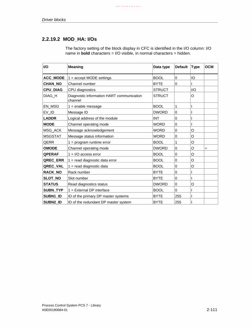
Driver blocks
Process Control System PCS 7 - LibraryA5E00180684-01 2-111
2.2.19.2 MOD_HA: I/Os
The factory setting of the block display in CFC is identified in the I/O column: I/Oname in bold characters = I/O visible, in normal characters = hidden.
I/O Meaning Data type Default Type OCM
ACC_MODE 1 = accept MODE settings BOOL 0 IO
CHAN_NO Channel number BYTE 0 I
CPU_DIAG CPU diagnostics STRUCT I/O
DIAG_H Diagnostic information HART communicationchannel
STRUCT O
EN_MSG 1 = enable message BOOL 1 I
EV_ID Message ID DWORD 0 I
LADDR Logical address of the module INT 0 I
MODE Channel operating mode WORD 0 I
MSG_ACK Message acknowledgement WORD 0 O
MSGSTAT Message status information WORD 0 O
QERR 1 = program runtime error BOOL 1 O
OMODE Channel operating mode DWORD 0 O +
QPERAF 1 = I/O access error BOOL 0 O
QREC_ERR 1 = read diagnostic data error BOOL 0 O
QREC_VAL 1 = read diagnostic data BOOL 0 O
RACK_NO Rack number BYTE 0 I
SLOT_NO Slot number BYTE 0 I
STATUS Read diagnostics status DWORD 0 O
SUBN_TYP 1 = External DP interface BOOL 0 I
SUBN1_ID ID of the primary DP master systems BYTE 255 I
SUBN2_ID ID of the redundant DP master system BYTE 255 I
21.02.2003

Driver blocks
Process Control System PCS 7 - Library2-112 A5E00180684-01
2.2.19.3 MOD_HA: Message texts and auxiliary process values
Assignment of message text and classes
Message blockALARM_8P
MessageID
Blockparameter
Default message text Message class
1 HART field device@1%d@/@2%d@/@3%d@/@4%d@: Communication error
S
2 HART field device@1%d@/@2%d@/@3%d@/@4%d@: Error
S
3 HART field device@1%d@/@2%d@/@3%d@/@4%d@: Reconfiguration
S
4 HART field device@1%d@/@2%d@/@3%d@/@4%d@: Complete restart
S
5 HART field device@1%d@/@2%d@/@3%d@/@4%d@: Fixed analog value
S
6 HART field device@1%d@/@2%d@/@3%d@/@4%d@: Saturated analog value
S
EV_ID
7 HART field device@1%d@/@2%d@/@3%d@/@4%d@: Access error
S
Assignment of auxiliary process values
Message blockALARM_8P
Associated value Block parameter Meaning
1 SUBN_ID DP master system ID (byte)
2 RACK_NO Rack/station number (byte)
3 SLOT_NO Slot number (byte)
EV_ID
4 CHAN_NO Channel error text number
If SUBN1_ID = 16#FF, then SUBN2_ID is entered as auxiliary process value.
21.02.2003

Driver blocks
Process Control System PCS 7 - LibraryA5E00180684-01 2-113
2.2.20 OB_BEGIN: CPU diagnostics and AS communication diagnostics
2.2.20.1 OB_BEGIN: Description
Object name (type + number)
FB 100
Area of application
The block is used for CPU and connection diagnostics of the automation system(AS). By installing the block in CFC, the system creates all acyclic run sequences(OBs) for the driver blocks of the PCS7 library.
OB_BEGIN is installed automatically if the CFC function "Generate moduledrivers" is used.
The calling OBs:
OB1 Cyclic processingOB32 Watchdog interrupt (connection diagnostics with SFC 87) *)OB40 - 47 OB40 - OB47 Process interrupt (not in PCS7 V6.0)OB55 Status interrupt (only if a DP/PA slave is required)OB56 Update interrupt (only if a DP/PA slave is required)OB57 Manufacturer-specific interrupt (only if a DP/PA slave is required)OB60 Multicomputing interrupt (not in PCS7 V6.0)OB60 - 61 Clocked interrupt (not in PCS7 V6.0)OB70 I/O redundancy errorOB72 CPU redundancy errorOB80 TimeoutOB81 Power supply faultOB82 Diagnostic interruptOB83 Removal/insertion interruptOB85 Program runtime errorOB86 Rack failureOB88 Stop preventionOB100 Restart:OB121 Programming errorOB122 I/O access error*) If you manually insert the OB_BEGIN block into a CFC chart instead of doing so by means of the
"generate module drivers" function, it will be installed at the OB specified by the"block insert position". This might not be OB32.Please take into accout that only one watchdog interrupt OB is allowed in this case.
21.02.2003

Driver blocks
Process Control System PCS 7 - Library2-114 A5E00180684-01
Function and operating principle
The block is used to report and display CPU events and states. It reads the startupinformation of the run sequences (OBs), diagnostic data of the I/O and enables therelevant blocks on the basis of the start events.
OB_BEGIN reads the startup information of SFC6 (RD_SINFO) or SFB54(RALRM) to determine its current run sequence (OB).
If not available, the block reads the logical base address from the startupinformation and converts it into the geographic address, which is available at therelevant OBs of the output structure CPU_DIAG the lower-level blocks can alsoaccess. On the basis of the geographic address, it releases the relevant SUBNETblocks for further diagnostics of startup data.
The data of diagnostic (interrupt) events (OB82) are written synchronouslyalongside with the startup information to the structure CPU_DIAG.OB82 withSFB54. Diagnostic (interrupt) data of a length exceeding 59 bytes must contain thecall of the relevant driver blocks.
OB_BEGIN generates messages which are output to WinCC via ALARM_8P (seemessage characteristics). SFC87 C_DIAG is called for connection diagnosis in awatchdog interrupt OB (OB32) after 10 cycles have expired. Up to 64 connectionsare monitored.
In H systems, the current status of the two H CPUs is determined in the samewatchdog interrupt OB by reading the System Status List 71 (SSL71). A detaileddescription of the SSL71 is found in the "System Software for S7-300/400 Systemand Standard Functions" reference manual.
Note
The messages "Loss or redundancy loss of the connection ID" are generated byeach CPU of the two connected AS. Exception in case of the failure of a CPU (orof both H CPUs) of an AS.
The system uses the connection ID to determine whether a message is to beoutput or not. If the connection ID >= 16#C00, it does not generate a message.
OB_BEGIN provides the diagnostic data of OB55, OB56 and OB57 in its outputstructure CPU_OB_5X to the downstream blocks.
The block reports diagnostic events of an OB88 block.
All OB88 events are incoming only. OB1 generates the relevant outgoing eventmessage after a delay time of approx. 10 seconds in order to allow the reporting ofnew events at OB88.
21.02.2003

Driver blocks
Process Control System PCS 7 - LibraryA5E00180684-01 2-115
Error handling
The block evaluates the error information of ALARM_8P and writes it to thecorresponding output parameters.See Error information of the MSG_STAT output parameter.The block may be installed in one watchdog interrupt OB only. Otherwise QERR =TRUE is set and operation is continued with the watchdog interrupt OB which firstcalled the block after the restart/initial start.
If the block installation sequence OB_BEGIN, xx blocks, ..., OB_END is notobserved, the message " OB_END integration error, no OB8x processing" is outputand QERR = TRUE is set. In this case the acyclic OBs do not evaluate the dataand the downstream blocks will not be enabled.
Error information at output parameter STATUS of SFB54 (RALRM) is handled asfollows
• The values 16#8096, 16#80A7,16#80C0, 16#80C2, 16#80C3 or 16#80C4 atSTATUS[2] and STATUS[3] indicate temporary error events. STATUS[3] of thecorresponding OB will be set in the structure CPU_DIAG = 16#C4.Downstream blocks can read access the diagnostic data asynchronously.
After any other error event, SFC6 (RD_SINFO) reads the startup information onceagain and the message "OB_BEGIN diagnostic error RALRM STATUS = xxxxxxxx“will be output. OB1 generates the outgoing message after a delay time ofapproximately 10 seconds has expired.
Startup characteristics
OB_BEGIN initializes the messages of ALARM_8P. In H systems(CPU_DIAG.H_MODE = TRUE), the current status of the two H CPUs isdetermined by reading SSL71 (see "Functions and operating principles").
Connection diagnostics will be initialized, provided the CPU contains an SFC87,and connection diagnostic messages will be generated after a delay timedetermine by 120 cycles of the watchdog interrupt OB has expired.
Reaction to overload
Outgoing messages of OB121, OB122 and OB88 are generated with a delay timeof approx. 10 seconds. This on the one hand prevents blocking of the WinCCconnection due to a high message transfer volume of these OBs, while OB eventsmay be lost on the other.
Time response
During structuring, the ES automatically integrates the block into the required OBs(refer to the Function section) as well as into watchdog interrupt OB32. You canmodify the latter integration as required.
21.02.2003

Driver blocks
Process Control System PCS 7 - Library2-116 A5E00180684-01
Message characteristics
ALARM_8P multiple instances are only called if OB_BEGIN is to output amessage. Acknowledgments of preceding messages are updated by the relevantALARM block only at this point of time. If the connection to WinCC is down, eachALARM_8P block can save a maximum of two states of its event ID messages.
The CPU generates a programming error (OB121) only as incoming event. OB1resets the relevant message to outgoing status. In order to avoid overload due toan excessive number of programming error messages, these will not be reportedoutgoing unless a delay time of 10 seconds has expired. The same applies todirect access errors (OB122) and OB88 events.
OB_DIAG messages
OB-DIAG blocks are interconnected with the system structure OB_LOCK. WhenOB_DIAG blocks OB82, the message "OB82 failure SUBNET:xx RACK:yySLOT:zz" will be generated, and if it blocks OB86, the message "OB86 failureSUBNET:xx RACK:yy SLOT:zz" will be generated.
The block generates the following messages in the OBs listed below:
OB Start event Message
OB1 Cyclic processing • Outgoing message with 10 s delay: Timeout (OB80)
• Program runtime error (OB80)
• Programming error (OB121)
• Direct write access error (OB122)
• Direct read access error (OB122)
• Error code B#16#71: Nesting stack error (OB88)
• Error code B#16#72: Master control relay stack error (OB88)
• Error code B#16#73: Synchronous error nesting depthexceeded (OB88)
• Error code B#16#74: U stack nesting depth exceeded in priorityclass stack (OB88)
• Error code B#16#75: B stack nesting depth exceeded in priorityclass stack (OB88)
• Error code B#16#76: Error when allocating local data (OB88)
• Error code B#16#78: Unknown opcode (OB88)
• Error code B#16#7A: Code length error (OB88)
OB32 1 sec. watchdog interruptor alternative watchdoginterrupt OB
Loss of connection ID: xx incoming/outgoingRedundancy loss connection ID: xx incoming/outgoing
OB72 CPU redundancy loss CPU redundancy loss/return
OB80 Timeout Incoming message at timeout:- Cycle time exceeded- OB request: OBxx is busy- OB request: Overflow PRIOxx- TOD interrupt xx expired
21.02.2003

Driver blocks
Process Control System PCS 7 - LibraryA5E00180684-01 2-117
OB Start event Message
OB81 Power supply loss - CPU backup battery failure incoming/outgoing- CPU buffer voltage loss, incoming/outgoing- CPU 24 V power supply loss incoming/outgoing- Redundant CPU backup battery failure incoming/outgoing- Redundant CPU buffer voltage loss incoming/outgoing- Redundant CPU 24 V power supply loss incoming/outgoing
OB84 CPU hardware error incoming/outgoing MPSS error
OB85 Program execution error Incoming message at program execution error- OBxx not loaded- Access-error error xx: ...
OB88 Stop prevention Incoming message at OB88 events:
- Error code B#16#71: Nesting stack error
- Error code B#16#72: Master control relay stack error
- Error code B#16#73: Synchronous error nesting depthexceeded
- Error code B#16#74: U stack nesting depth exceeded in priorityclass stack
- Error code B#16#75: B stack nesting depth exceeded in priorityclass stack
- Error code B#16#76: Error when allocating local data
- Error code B#16#78: Unknown opcode
- Error code B#16#7A: Code length error
OB100 Restart: Initialization of ALARM_8P
OB121 Programming error Programming error incoming
OB122 I/O access error Direct read access, incoming
Direct write access, incoming
Operator control and monitoring
The block does not have a faceplate
Note: In the OCM column of the "OB_BEGIN" table, the "+" character identifies thevariables to be transferred to the OS, if you have set the "enable operator controland monitoring" attribute in the block object properties. Default: This option is notset.
21.02.2003

Driver blocks
Process Control System PCS 7 - Library2-118 A5E00180684-01
2.2.20.2 OB_BEGIN: I/Os
The factory setting of the block display in CFC is identified in the I/O column: I/Oname in bold characters = I/O visible, in normal characters = hidden.
I/O(Parameter)
Meaning Data type Default Type OCM Permittedvalues
CPU_DIAG CPU diagnostics (system structure) STRUCT O
CPU_OB_5X Startup information OB55, OB56, OB57 STRUCT O
CPU_OB_6X Startup information OB60 - OB64 STRUCT O
CPU_OB_4X Startup information OB40 - OB47 STRUCT O
CPUERR_0 1 = CPU error in rack 0 BOOL 0 O +
CPUERR_1 1 = CPU error in rack 1 BOOL 0 O +
EN_SUBx Enable SUBNET x (x = 0 - 14) BOOL 0 O
EV_Idx Message number ALARM_8P_x(x = 1 - 20)
DWORD 0 I (assigned byES)
MASTER_0 1 = Master CPU in rack 0 BOOL 0 O +
MASTER_1 1 = Master CPU in rack 1 BOOL 0 O +
MSGSTATx STATUS output of ALARM_8P_x(x = 1 - 20)
WORD 0 O
OB_LOCK Locked OB STRUCT O
QERR 1 = error processing busy BOOL 1 O
QMSGERx Error output of ALARM_8P_x(x = 1 - 20)
BOOL 0 O
SUB0Idxx DP master system 1 IDxx(xx = 00 - 14)
BYTE 255 I
SUB1Idxx DP master system 2 IDxx(xx = 00 - 14)
BYTE 255 I
SZL_71 System status list SSL71 STRUCT O
The structure of the CPU_DIAG is integrated as OUT in the OB_BEGIN, and in allother blocks with this connection as IN_OUT (column: I/O).
21.02.2003
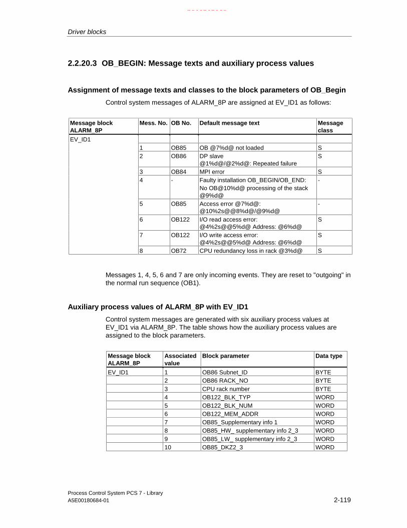
Driver blocks
Process Control System PCS 7 - LibraryA5E00180684-01 2-119
2.2.20.3 OB_BEGIN: Message texts and auxiliary process values
Assignment of message texts and classes to the block parameters of OB_Begin
Control system messages of ALARM_8P are assigned at EV_ID1 as follows:
Message blockALARM_8P
Mess. No. OB No. Default message text Messageclass
1 OB85 OB @7%d@ not loaded S2 OB86 DP slave
@1%d@/@2%d@: Repeated failureS
3 OB84 MPI error S4 - Faulty installation OB_BEGIN/OB_END:
No OB@10%d@ processing of the stack@9%d@
-
5 OB85 Access error @7%d@:@10%2s@@8%d@/@9%d@
-
6 OB122 I/O read access error:@4%2s@@5%d@ Address: @6%d@
S
7 OB122 I/O write access error:@4%2s@@5%d@ Address: @6%d@
S
EV_ID1
8 OB72 CPU redundancy loss in rack @3%d@ S
Messages 1, 4, 5, 6 and 7 are only incoming events. They are reset to "outgoing" inthe normal run sequence (OB1).
Auxiliary process values of ALARM_8P with EV_ID1
Control system messages are generated with six auxiliary process values atEV_ID1 via ALARM_8P. The table shows how the auxiliary process values areassigned to the block parameters.
Message blockALARM_8P
Associatedvalue
Block parameter Data type
EV_ID1 1 OB86 Subnet_ID BYTE2 OB86 RACK_NO BYTE3 CPU rack number BYTE4 OB122_BLK_TYP WORD5 OB122_BLK_NUM WORD6 OB122_MEM_ADDR WORD7 OB85_Supplementary info 1 WORD8 OB85_HW_ supplementary info 2_3 WORD9 OB85_LW_ supplementary info 2_3 WORD10 OB85_DKZ2_3 WORD
21.02.2003

Driver blocks
Process Control System PCS 7 - Library2-120 A5E00180684-01
Control system messages of ALARM_8P are assigned as follows at EV_ID2
Message blockALARM_8P
Mess.No.
OB No. Default message text Messageclass
S
1 OB81 CPU battery failure, rack 0 S
2 OB81 CPU battery failure, rack 1 S
3 OB81 Backup voltage loss CPU in rack 0 S
4 OB81 Backup voltage loss CPU in rack 1 S
5 OB81 24 V power supply loss CPU in rack 0 S
6 OB121 24 V power supply loss CPU in rack 1 S
7 OB121 Programming error@1%d@: @2%2s@@5%d@/@6%d@/@4%d@/@3%d@
S
EV_ID2
8 OB82 DP slave @7%d@/@8%d@/@9%@: Repeateddiagnostic interrupt
S
Message 7 is only an incoming event. It is reset to "outgoing" status during thenormal run sequence (OB1) and to be interpreted as follows, in accordance withthe error code number before the colon:
OB121_BLK_TYP/OB121_BLK_NUM/OB121_PRG_ADDR/OB121_FLT_REG/OB121_RESERVED_1.
A description is found in the "System Software for S7-300/400 System andStandard Functions" reference manual.Example: 10.05.00 10:30:45 Programming error 35: FB44/1234/5/9
Asociated values of ALARM_8P with EV_ID2
Control system messages are generated with six auxiliary process values atEV_ID2 via ALARM_8P. The table below shows how the auxiliary process valuesare assigned to the block parameters.
Message blockALARM_8P
Auxiliaryprocessvalue
Block parameter Data type
1 OB121_SW_FLT BYTE
2 OB121_BLK_TYP WORD
3 OB121_RESERVED_1 BYTE
4 OB121_FLT_REG WORD
5 OB121_BLK_NUM WORD
6 OB121_PRG_ADDR WORD
7 OB82 SUBNET_ID BYTE
8 OB82 RACK_NO BYTE
EV_ID2
9 OB82 SLOT_NO BYTE
21.02.2003

Driver blocks
Process Control System PCS 7 - LibraryA5E00180684-01 2-121
Control system messages of ALARM_8P are assigned as follows at EV_ID3
Message blockALARM_8P
Messagenumber
OB no. Default message text Messageclass
1 OB80 Cycle time exceeded: @1%d@ms OB@2%d@ S
2 OB80 OB request: OB@2%d@ still busy S
3 OB80 TOD interrupt OB @1%d@ expired (TOD jump) S
4 OB80 TOD interrupt OB @1%d@ expired (Stop/Run) S
5 OB80 OB request: Overflow PRIO @3%d S
6 OB80 Clocked interrupt timeout: OB@2%d@ PRIO@3%d@
S
7 OB80 Interrupt lost: OB@2%d@ PRIO @3%d@ S
EV_ID3
8 OB80 CiR synchronization time: @1%d@ ms S
Messages 1 to 8 are only incoming events. They are reset to "outgoing" statusduring the normal run sequence (OB1).
Auxiliary process values of ALARM_8P with EV_ID3
Control system messages are generated with seven auxiliary process values atEV_ID3 via ALARM_8P. The table below shows how the auxiliary process valuesare assigned to the block parameters.
Message blockALARM_8P
Auxiliaryprocessvalue
Block parameter Data type
1 OB80_Supplementary_Info 1 WORD
2 OB80_1. Byte supplementary info 2_3 BYTE
EV_ID3
3 OB80_2. Byte supplementary info 2_3 BYTE
21.02.2003

Driver blocks
Process Control System PCS 7 - Library2-122 A5E00180684-01
Control system messages for ALARM_8 are assigned as follows atEV_ID4 to EV_ID19:
Message blockALARM_8P
Mess. No. Default message text Messageclass
EV_ID4 to EV_ID11
1 Failure connection ID:@1%d@ S
2 Failure connection ID:@2%d@ S
3 Failure connection ID:@3%d@ S
4 Failure connection ID:@4%d@ S
5 Failure connection ID:@5%d@ S
6 Failure connection ID:@6%d@ S
7 Failure connection ID:@7%d@ S
8 Failure connection ID:@8%d@ S
EV_ID12 to EV_ID19
1 Redundancy loss connection ID:@1%d@ S
2 Redundancy loss connection ID:@2%d@ S
3 Redundancy loss connection ID:@3%d@ S
4 Redundancy loss connection ID:@4%d@ S
5 Redundancy loss connection ID:@5%d@ S
6 Redundancy loss connection ID:@6%d@ S
7 Redundancy loss connection ID:@7%d@ S
8 Redundancy loss connection ID:@8%d@ S
Auxiliary process values of ALARM_8P at EV_ID4 to EV_ID19
The control system messages are generated with eight auxiliary process values atEV_ID4 to EV_ID19 via ALARM_8P. The table shows how these auxiliary processvalues are assigned to the block parameters.
Message blockALARM_8P
Associatedvalue
Block parameter Data type
1 Connection_ID 1+x WORD
2 Connection_ID 2+x WORD
3 Connection_ID 3+x WORD
4 Connection_ID 4+x WORD
5 Connection_ID 5+x WORD
6 Connection_ID 6+x WORD
7 Connection_ID 7+x WORD
EV_ID4... EV_ID19
8 Connection_ID 8+x WORD
x = 0 at EV_ID4, x = 8 at EV_ID5, x = 16 at EV_ID6 etc. to x = 56 at EV_ID12
x = 0 EV_ID13, x = 8 at EV_ID14, x = 16 at EV_ID15 etc. to x = 56 at EV_ID19
21.02.2003

Driver blocks
Process Control System PCS 7 - LibraryA5E00180684-01 2-123
The control system messages of ALARM_8P are assigned as follows at EV_ID20:
Message blockALARM_8P
Messagenumber
Blockparameter
Default message text Message class
1 OB88(@6W%t#OB_BEGIN_TXT@):OB@1%d@ PRIO@2%d@@3%2s@@4%d@ /@5%d@
S
2 no message
3 no message
4 no message
5 no message
6 no message
7 no message
EV_ID_20
8 no message
Auxiliary process values of ALARM_8P at EV_ID20
Message blockALARM_8P
Associatedvalue
Blockparameter
Meaning
1 Triggering OB (M_OB88.FLT_OB)
2 Priority class (M_OB88.FLT_OB_PRIO)
3 Block type (M_OB88.BLK_TYP)
4 Block number (M_OB88.FLT_NUM)
5 Error triggering MC7 instructionRelative address (M_OB88.FLT_ADDR)
EV_ID20
6 Error ID in OB_BEGIN_TXT (M_OB88.T_OB88)
OB_BEGIN_TXT_Textnummer
Textnumber
Message text meaning
1 Nested stack Error code B#16#71: Nested stack error
2 Master control relay Error code B#16#72: Master control relay stack error
3 Nesting depth Error code B#16#73: Nesting depth exceeded on synchronization errors
4 U_Stack nesting Error code B#16#74: U-stack nesting depth exceeded in the priorityclass stack
5 B_Stack nesting Error code B#16#75: B-stack nesting depth exceeded in the priorityclass stack
6 Allocation error Error code B#16#76: Local data allocation error
7 Unknown opcode Error code B#16#78: Unknown opcode
8 Code length error Error code B#16#7A: Code length error
21.02.2003

Driver blocks
Process Control System PCS 7 - Library2-124 A5E00180684-01
2.2.21 OB_DIAG: OB diagnostics for avoiding CPU Stop
2.2.21.1 OB_DIAG: Description
Object name (type + number)
FB 124
Area of application
OB_DIAG interfaces DP V0 slaves the PCS 7 driver blocks do not support. Itdetects DP slave failure and is used to avoid CPU stop as a result of such failures.In an H system, it indicates the preferred channel of active DP slaves.
The calling OB
The block must be installed in the run sequence of the following OBs (carried outautomatically in CFC):
OB1 Cyclic program
OB70 I/O redundancy error
OB72 CPU redundancy error
OB82 Diagnostic interrupt
OB83 Removal/insertion interrupt
OB85 Program runtime error
OB86 Rack failure
OB100 Restart (warm start)
Use in the CFC
The CFC function "Generate module drivers" automatically:
• Integrates the OB_DIAG block after the SUBNET block.
• Configures
- The inputs RACK_NO, DADDR, SUBN1_ID, SUBN2_ID and SUBN_TYP.
21.02.2003

Driver blocks
Process Control System PCS 7 - LibraryA5E00180684-01 2-125
• Interconnects
- The EN input with the output of an AND blockwhose inputs are interconnected to the output EN_SUBx (x = No. of the DPMaster System) of the OB BEGIN block and to the output EN_Rxxx (xxx =Rack/Station Number) of the SUBNET block.
- The OUT structure CPU_DIAG of the OB_BEGIN and SUB_DIAG of theSUBNET block with the INOUT structures of the same name of theOB_DIAG block.
Function and operating principle
Before an OB1 can be executed, the block counts the number calls of an acyclicOB of a block instance.
OB_DIAG indicates higher-priority errors of the CPU, DP Master and of the DPSlave (SUBN1ERR, SUBN2ERR). It determines the preferred channel(SUBN1ACT, SUBN2ACT) of active DP slaves. The group error informationQRACKF indicates failure of the DP Master or DP Slave. A redundancy error atactive DP slaves is indicated if one of the output parameters SUBN1ERR orSUBN2ERR = FALSE.
The startup and diagnostic information is read from the structure CPU_DIAG,which is interconnected to the structure CPU_DIAG of the OB_BEGIN block.
The block determines the currently active preferred channel (SUBN1ACT,SUBN2ACT) in the case of redundant PROFIBUS DP interfaces based on the errorevents and, if required, on the diagnostic address ADDR of the DP slave.
V1 MODE = TRUE is set when the DP Slave is connected to a DP Master systemoperating in DPV1 mode.
Reaction to overload
OB_DIAG counts the number of calls of the acyclic OB82 and OB86 (except on DPmaster system failure, see SUBNET block). If counter DIAG82_CNT > 5 orDIAG86_CNT > 5, then EN_F = FALSE (disable function block). The counters arereset in OB1. Output EN_F = TRUE (enable function block) is set in the remainingOBs.
OB82 or OB86 errors are reported by OB_BEGIN either in OB1 or at OB82/OB86;including the geographic address of the DP slave.
This event is not evaluated, since OB82 or OB86 are locked on overload. Theoutputs cannot correspond to the current state of the DP Slave. When an OB islocked and no event on the slave is reported within a delay period of approx. oneminute, in the case of an OB86 lock the state of the slave is checked and theoutputs are updated. A DP slave status update may take several cycles.
If, rather than an OB86 lock , there is an OB82 lock, the variable EN_82DIAG is setto TRUE. The interconnected DP slave block can then fetch the current diagnosticdata of the DP slave.
The outgoing message of the failure is generated when the OB lock is rescindedand either a new event has occurred for this OB or the delay period has expired.
21.02.2003

Driver blocks
Process Control System PCS 7 - Library2-126 A5E00180684-01
Redundancy
In an H system, the block supports redundancy at DP master systems (distributedI/O devices only). The numbers of the redundant DP master systems must beassigned to the inputs of the OB_DIAG block SUBN1_ID (connection to CPU 0)and SUBN2_ID (connection to CPU 1) in order to enable this function. If there is noredundancy of the DP master systems, the remaining input must be assigned thevalue 16#FF (default).
Startup characteristics
The system verifies that the DP slave is available. In of H systems, it determinesthe preferred channel of the DP slave.
Error handling
The plausibility of input parameters is not checked.
Time response
n.a.
Message characteristics
See OB_BEGIN block
Operator control and monitoring
The block has no faceplate.
Note: In the OCM column of the "OB_DIAG" table, the "+" character identifies thevariables to be transferred to the OS, if you have set the "enable operator controland monitoring" attribute in the block object properties. Default: This option is notset.
21.02.2003

Driver blocks
Process Control System PCS 7 - LibraryA5E00180684-01 2-127
2.2.21.2 OB_DIAG: I/Os
The factory setting of the block display in CFC is identified in the I/O column: I/Oname in bold characters = I/O visible, in normal characters = hidden.
I/O(parameter)
Meaning Data type Default Type OCM
ACC_ID 1 = accept MODE settings BOOL 0 I/O
CPU_DIAG System structure: CPU diagnostics STRUCT I/O
DADDR Diagnostics address of the DP slave INT 0 I
EN_82DIAG 1 = read diagnostics data (OB82) BOOL 0 O
EN_86DIAG 1 = read diagnostics data (OB86) BOOL 0 O
EN_F 1 = enable function/function block BOOL 0 O
OB_LOCK System structure: Locked OB STRUCT I/O
QRACKF 1 = slave failure/faulty BOOL 0 O +
RACK_NO Rack (DP slave) number BYTE 0 I
SUB_DIAG OB startup information STRUCT I/O
SUBN_TYP 1 = external DP interface BOOL 0 I/O
SUBN1_ID ID of the primary DP master system BYTE 255 I
SUBN1ACT 1 = slave 1 is active BOOL 0 O +
SUBN1ERR 1 = error in primary DP master system BOOL 0 O +
SUBN2_ID ID of the redundant DP master system BYTE 255 I
SUBN2ACT 1 = slave 2 is active BOOL 0 O +
SUBN2ERR 1 = error in the redundant DP master system BOOL 0 O +
V1_MODE 1 = DPV1 mode BOOL 0 O
21.02.2003

Driver blocks
Process Control System PCS 7 - Library2-128 A5E00180684-01
2.2.22 OB_DIAG1: OB diagnostics for avoiding CPU Stop in DPV1master systems
2.2.22.1 OB_DIAG1: Description
Object name (type + number)
FB 118
Area of application
The block monitors failure and return of DP or PA slaves (referred to as slaves).The slaves can be connected to a DPV0 or V1 DP master system, or to a DPV1DP/PA Link (Y Link). The blocks locks further diagnostic operations if a slave isdefective (frequent producer) in order to avoid a CPU stop. It indicate the preferredchannel of the active slaves of an H system. The indicated preferred channel 1(SUBN1ACT ) is always set TRUE if the active slave operates downstream of aDP/PA Link (Y Link).
The calling OBs
The block must be installed in the run sequence of following OBs (automatically inCFC):
OB1 Cyclic program
OB70 I/O redundancy error
OB72 CPU redundancy error
OB82 Diagnostic interrupt
OB83 Removal/insertion interrupt
OB85 Program runtime error
OB86 Rack failure
OB100 Restart (warm start)
OB55 Status interrupt (only if required)
OB56 Update interrupt (only if required)
OB57 manufacturer-specific interrupt (only if required)
The driver generator integrates the block into OB55, OB56 und OB 57 only ifdiagnostics messages are to be expected from these locations; i.e. the OB5x arenot entered in the task list of this block.
21.02.2003
Driver blocks
Process Control System PCS 7 - LibraryA5E00180684-01 2-129
Use in the CFC
The CFC function "Generate module drivers" automatically
• Integrates the OB_DIAG1 block downstream of the SUBNET block orDPAY_V1 block (when used downstream of a DP/PA or Y Link).
• Configures
- The inputs RACK_NO, LADDR, DADDR, SUBN1_ID, SUBN2_ID andSUBN_TYP.
• Interconnects
- The EN input with the output of an AND block whose inputs will beinterconnected with output EN_SUBx (x = DP master system ID) of theOB_BEGIN block and with output EN_Rxxx (xxx = rack/station number) ofthe SUBNET block.
- The OUT structure CPU_DIAG of OB_BEGIN and SUB_DIAG of theSUBNET block with the OB_DIAG INOUT structure of the same name.
- I_RAC_DIAG with its internal OUT structure RAC_DIAG when used in aDP master system
- I_RAC_DIAG with the OUT structure RAC_DIAG of the DPAY_V1 blockwhen used downstream of a Y Link
Function and operating principle
The block input DPA_LINK receives information on the operational status of theslave, i.e. whether it is operated on a DP master system (DPA_LINK = FALSE) ordownstream of a DP/PA Link (Y-Link). If the slave is connected to a DP mastersystem, a failure is reported in OB86 and if connected downstream of a DP/PALink (Y Link), this is reported in OB83.
The block counts the number of calls of an acyclic OB of a block instance beforean OB1 can be executed.
OB_DIAG1 indicates higher-priority errors of the CPU, DP master/slave (QRACKF,SUBN1ERR, SUBN2ERR). It determines the preferred channel of active DP slaves(SUBN1ACT, SUBN2ACT). The group error message QRACKF indicates failure ofthe DP master or slave. Loss of redundancy at active slaves is indicate at one ofthe output parameters SUBN1ERR or SUBN2ERR = FALSE.
Startup and diagnostic information is read from the CPU_DIAG structure, which isinterconnected with the CPU_DIAG structure of the OB_BEGIN block.
The block evaluates error events and, if required, the diagnostic address DADDRof the slave (only at the DP master system) to determine the currently activepreferred channel (SUBN1ACT, SUBN2ACT) of redundant PROFIBUS DPinterfaces.
21.02.2003

Driver blocks
Process Control System PCS 7 - Library2-130 A5E00180684-01
Slaves downstream of a DP/PA Link (Y Link) are not always active. The diagnosticaddress DADDR is in this case the diagnostic address of the link.
The DP master systems or DP/PA Links (Y Link) must be operated in DPV1 mode(V1-MODE = TRUE).
Failure and return of a slave are reported via ALARM_8P. The message functioncan be disabled.
Reaction to overload
The block counts the frequency of the calls of the acyclic OB55, OB56, OB57,OB82 and OB86 blocks (not in the case of DP master system failure, see SUBNETblock). If OB_DIAG1 is installed downstream of a DP/PA or Y Link, the calls will becounted in OB83, rather than in OB86. The following section deals only with OB86.Each OB is assigned a counter that is checked for the condition > 5. If thiscondition is satisfied, the block sets EN_F = FALSE (disable function block). Thecounters are reset in OB1. In all other OBs the output EN_F = TRUE (enablefunction block) will be set.
OB_DIAG1 reports failure of the blocks mentioned above in OB1, OB82 or OB86,including the geographical address of the slave.
The event is not evaluated in the downstream blocks, due to the locking of OB55,OB56, OB57 or OB82 on overload. The outputs can not correspond to the currentslave status. After a waiting time of approx. 1 minute, the slave status is verifiedand the outputs are updated after an OB86 failure. The slave status update mayrequire several cycles.
The variable EN_DIAG is set TRUE after approx. 1 minute if an OB82 has failed.The interconnected DP slave block can then fetch the current diagnostic data ofthe slave and update its own database. The same goes for OB55, OB56 or OB57.
Redundancy
The block supports redundant DP master systems in an H system (only distributedI/Os). The OB_DIAG1 block inputs SUBN1_ID (connection to CPU 0) andSUBN2_ID (connection to CPU 1) must be assigned the numbers of the redundantDP master system. If the DP master systems are not redundant, the value 16#FF(default) must be set at the remaining input.
Startup characteristics
Availability of the slave is verified. In H systems the preferred channel of the slaveis determined (active slaves only).
Error handling
The block evaluates error information of ALARM_8P and writes it to the relevantoutput parameter. See error information of output parameter MSG_STAT.
21.02.2003

Driver blocks
Process Control System PCS 7 - LibraryA5E00180684-01 2-131
Message characteristics
The multiple instance ALARM_8P are only called if a message is to be output bythis instance. Previously acknowledged messages are updated by thecorresponding ALARM block only at this point of time. if the connection to WinCCis down, each ALARM_8P instance can hold up to two error message states of hisEvent-ID. (usually tow messages max.). The block generates the messages listedbelow:
OBno.
Start event Message
1 Cyclic processing Call of ALARM_8P due to incomplete transfer or unacknowledgedmessage
72 CPU redundancy loss If no redundant diagnostic repeater is connected to the CPU,Message "Slave" failure/return
70 Redundancy loss If no redundant diagnostic repeater is connected to this DP master system,Message "Slave" failure/return
other wise the message "Slave" redundancy loss/return
83 Removal/insertion Message "Slave" failure/return
86 Rack failure Message "Slave" failure/return
100 Restart Initialization ALARM_8P
Operator control and monitoring
The block does not have a faceplate.
Note: In the OCM column of the "OB_DIAG1" table, the "+" character identifies thevariables to be transferred to the OS, if you have set the "enable operator controland monitoring" attribute in the block object properties. Default: This option is notset.
21.02.2003

Driver blocks
Process Control System PCS 7 - Library2-132 A5E00180684-01
2.2.22.2 OB_DIAG1: I/Os
The factory setting of the block display in CFC is identified in the I/O column: I/Oname in bold characters = I/O visible, in normal characters = hidden.
I/O(parameter)
Meaning Data type Default Type OCM
ACC_ID 1 = accept MODE settings BOOL 0 I/O
CPU_DIAG System structure: CPU diagnostics STRUCT I/O
CPU_OB_5X OB_5x start information STRUCT I/O
DPA_LINK Slave connection:0 = DP master system, 1 = Link
BOOL 0 I
DADDR Diagnostic address of the slave INT 0 I
LADDR Logical base address of the slave INT 0 I
EN_DIAG 1 = read diagnostic data with SFC13 BOOL 0 O
EN_F 1 = enable function/function block BOOL 0 O
EN_MSG 1 = enable message BOOL 1 I
EV_ID Message number DWORD 0 I
MOD_INF System structure: Module diagnostics STRUCT O
MSG_ACK Message acknowledgement WORD 0 O
MSG_STAT Error message status WORD 0 O
PADP_ADR Address of the PA/DP slave BYTE 255 I
QRACKF 1 = slave failure / faulty BOOL 0 O +
RACK_NO Rack number BYTE 0 I
RAC_DIAG System structure: RACK diagnostics STRUCT O
RAC_DIAG_I System structure: RACK diagnostics STRUCT I/O
SLOT_NO Slot number 0 of the slave at the DP/PA Link BYTE 255 I
SUB_DIAG System structure: SUBNET diagnostics STRUCT I/O
SUBN_TYP 1 = external DP interface BOOL 0 I
SUBN1_ID ID of the primary DP master system BYTE 255 I
SUBN1ACT 1 = slave 1 is active BOOL 0 O +
SUBN1ERR 1 = error in the primary DP master system BOOL 0 O +
SUBN2_ID ID of the redundant DP master system BYTE 255 I
SUBN2ACT 1 = slave 2 is active BOOL 0 O +
SUBN2ERR 1 = error in the redundant DP master system BOOL 0 O +
V1_MODE 1 = DPV1 mode BOOL 0 O
21.02.2003

Driver blocks
Process Control System PCS 7 - LibraryA5E00180684-01 2-133
2.2.22.3 OB_DIAG1: Message texts and auxiliary process values
Assignment of message text and class
Message no. Default message text Message class
1 DP slave @1%d@/ @2%d@: Redundancy loss S
2 DP slave @1%d@/ @2%d@: Failure S
3 DP slave @1%d@/ @2%d@/@3%d@ : Repeated failure S
4 Device @1%d@/ @2%d@/@3%d@: recursive Alarm (OB82) S
5 Device @1%d@/ @2%d@/@3%d@: recursive Alarm (OB55) S
6 Device @1%d@/ @2%d@/@3%d@: recursive Alarm (OB56) S
7 Device @1%d@/ @2%d@/@3%d@: recursive Alarm (OB57) S
8 Device @1%d@/ @2%d@/@3%d@: Failure S
4 Device @1%d@/ @2%d@/@3%d@: recursive Alarm (OB82) S
5 Device @1%d@/ @2%d@/@3%d@: recursive Alarm (OB55) S
6 Device @1%d@/ @2%d@/@3%d@: recursive Alarm (OB56) S
7 Device @1%d@/ @2%d@/@3%d@: recursive Alarm (OB57) S
Assignment of auxiliary process values
Associated value Block parameter
1 DP master system ID (SUBN_ID)
2 Rack / station number (RACK_NO)
3 Slot number (SLOT_NO)
21.02.2003

Driver blocks
Process Control System PCS 7 - Library2-134 A5E00180684-01
2.2.23 OB_END: Reset stack pointer of OB_BEGIN
2.2.23.1 OB_END: Description
Object name (type + number)
FC 280
Area of application
The block is used to reset the stack pointer of the OB_BEGIN.
The calling OBs
The OB_END block is the final entry at an OB that contains an OB_BEGIN block.OB_END may not be installed in OBs that do not contain an OB_BEGIN block.
When the CFC function "Generate module drivers" is used, OB_END is installedautomatically in the OBs of the run sequence.
OB1 Cyclic processing
OB55 Status interrupt (only as required)
OB56 Update interrupt (only as required)
OB57 Manufacturer-specific interrupts (only as required)
OB32 Watchdog interrupt (connection diagnostics) *)
OB70 I/O redundancy error
OB72 CPU redundancy error
OB80 Timeout
OB81 Power supply error
OB82 Diagnostic interrupt
OB83 Removal / insertion interrupt
OB85 Program runtime error
OB86 Rack failure
OB88 Stop avoidance
OB100 Restart
OB121 Programming error
OB122 I/O access error
*) If you insert the OB_END block manually in the CFC chart, instead of using the"Generate modules drivers" function, it will be inserted at the OB that is determined bythe "Insert position". This may not be OB32.Please take into account that you are using the watchdog interrupt OB of theOB_BEGIN block.
21.02.2003

Driver blocks
Process Control System PCS 7 - LibraryA5E00180684-01 2-135
Function
The block decrements the stack pointer (NUM_CNT) of OB_BEGIN. In case of aninterruption, it enters the last interrupted OB number read from the CPU stack intothe CPU_DIAG structure.
Error handling
n.a.
Startup characteristics
n.a.
Initial startup characteristics
n.a.
Time response
n.a.
Message characteristics
n.a.
Operator control and monitoring
The block does not have a faceplate.
2.2.23.2 OB_END: I/Os
I/O(parameter)
Meaning Data type Type
CPU_DIAG CPU diagnostics (system structure) STRUCT I/O
21.02.2003

Driver blocks
Process Control System PCS 7 - Library2-136 A5E00180684-01
2.2.24 OR_M_16: OR value status of 2 redundant signal modules withmax. 16 channels
2.2.24.1 OR_M_16: Description
Object name (type + number)
FB 97
Area of application
The block is used to form a value status based on two redundant signal modules.
The calling OBs
The block must be installed in OB100 and in the fastest OB upstream of thechannel block CH_x that is interconnected with OR_M_16.
Use in CFC
When the CFC function "Generate module drivers" is used, the systemautomatically
• Installs the OR_M_16 block upstream of its interconnected channel blocksCH_x in their OB.
• Interconnects
- The inputs MODE1_x to the outputs OMODE_xx of the MOD_x block inthe primary module.
- The inputs MODE2_x to the outputs OMODE_xx des MOD_x block in theredundant module.
- The input structure MOD_INF1 with the output structure MOD_INF of theMOD_x block of the primary module.
- The input structure MOD_INF2 with the output structure MOD_INF of theMOD_x block of the redundant module.
- The inputs ACTIV_H and ACTIV_L to the outputs of the same name of theRED_STATUS block at the redundant module.
- The outputs OMODE_xx with the relevant channel blocks CH_x.
- The OUT structure CPU_DIAG of OB_BEGIN with the INOUT structures ofthe same name of the OR_M_16 block.
21.02.2003

Driver blocks
Process Control System PCS 7 - LibraryA5E00180684-01 2-137
Function and operating principle
The status values of a signal module and of a redundant signal module are ORedby the block. Signal modules disabled by the system are considered invalid. Forredundant digital input modules, when a signal discrepancy occurs, no module isset to passive after expiration of the discrepancy time. The module whose signaldoes not change is thereafter set to passive. The events, expiration of thediscrepancy time, redundancy loss and failure of the redundant I/O are reported byALARM_8P. This message function can be disabled.
When module signals are processed in different OB 3x, it may happen under rarecircumstances that a faulty signal value is processed in one cycle by one of thechannel blocks assigned to process the module signals after a control system errorhas occurred at the module. This can be avoided by processing all channel blocksof a module in the OB 3x that also processes the process image partition assignedto this module.
Redundancy
In H systems, the higher-ranking MOD_x block evaluates redundancy of the DPmaster systems.
Error handling
The system does not check the plausibility of input parameters.
Startup characteristics
The outputs OMODE_xx are updated when the "Startup" bit is set.
ALARM_8P is initialized.
Message characteristics
OR_M_16 uses ALARM_8P to report events. This message function can bedisabled by setting EN_MSG = FALSE.
Operator control and monitoring
The block does not have a faceplate.
Note: In the OCM column of the "OR_M_16…" table, the "+" character identifiesthe variables to be transferred to the OS, if you have set the "enable operatorcontrol and monitoring" attribute in the block object properties. Default: This optionis not set.
21.02.2003
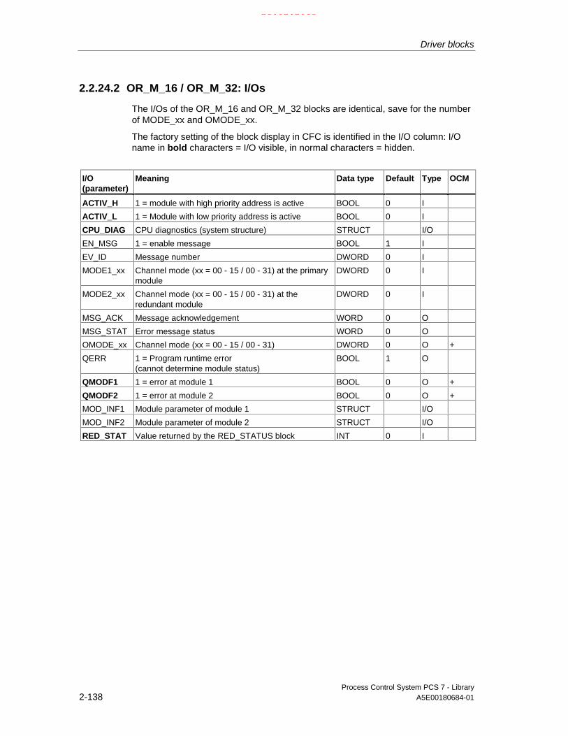
Driver blocks
Process Control System PCS 7 - Library2-138 A5E00180684-01
2.2.24.2 OR_M_16 / OR_M_32: I/Os
The I/Os of the OR_M_16 and OR_M_32 blocks are identical, save for the numberof MODE_xx and OMODE_xx.
The factory setting of the block display in CFC is identified in the I/O column: I/Oname in bold characters = I/O visible, in normal characters = hidden.
I/O(parameter)
Meaning Data type Default Type OCM
ACTIV_H 1 = module with high priority address is active BOOL 0 I
ACTIV_L 1 = Module with low priority address is active BOOL 0 I
CPU_DIAG CPU diagnostics (system structure) STRUCT I/O
EN_MSG 1 = enable message BOOL 1 I
EV_ID Message number DWORD 0 I
MODE1_xx Channel mode (xx = 00 - 15 / 00 - 31) at the primarymodule
DWORD 0 I
MODE2_xx Channel mode (xx = 00 - 15 / 00 - 31) at theredundant module
DWORD 0 I
MSG_ACK Message acknowledgement WORD 0 O
MSG_STAT Error message status WORD 0 O
OMODE_xx Channel mode (xx = 00 - 15 / 00 - 31) DWORD 0 O +
QERR 1 = Program runtime error(cannot determine module status)
BOOL 1 O
QMODF1 1 = error at module 1 BOOL 0 O +
QMODF2 1 = error at module 2 BOOL 0 O +
MOD_INF1 Module parameter of module 1 STRUCT I/O
MOD_INF2 Module parameter of module 2 STRUCT I/O
RED_STAT Value returned by the RED_STATUS block INT 0 I
21.02.2003

Driver blocks
Process Control System PCS 7 - LibraryA5E00180684-01 2-139
2.2.24.3 OR_M_16 / OR_M_32: Message texts and auxiliary processvalues
Assignment of message text and class
Message blockALARM_8P
Message no. Blockparameter
Default message text Messageclass
1 Module @1%d@/@2%d@/@3%d@:Failure redundant pair
S
2 Module @1%d@/@2%d@/@3%d@:Redundancy loss
S
3 Module @1%d@/@2%d@/@3%d@:Cannot determine module status
S
EV_ID
4 Module @1%d@/@2%d@/@3%d@:Discrepancy time expired
S
Assignment of auxiliary process values
Message blockALARM_8P
Associated value Block parameter Meaning
1 SUBN_ID DP master system ID (byte)
2 RACK_NO Rack/station number (byte)
EV_ID
3 SLOT_NO Slot number (byte)
On redundancy loss the geographical address of the failed module is entereddynamically. The message text always shows the geographical address of theprimary module when both modules have failed.
21.02.2003

Driver blocks
Process Control System PCS 7 - Library2-140 A5E00180684-01
2.2.25 OR_M_32: OR-Value Status of 2 redundanten Signal Modules with32 channels
2.2.25.1 OR_M_32: Description
Object name (type + number)
FB 97
Same as OR_M_16, but with 32 instead of 16 channels.
2.2.26 PO_UPDAT: Output process image
2.2.26.1 PO_UPDAT: Description
Object name (type + number)
FC 279
Area of application
The block ensures the functions "Hold last value" and "Apply substitution value" ofthe output modules when a CPU is restarted (OB100).
Run sequence
The block must be installed as final element in the OB100 run sequence. This iscarried out for you by the CFC function "Generate module drivers".
Description of functions
When a CPU is restarted (OB100), the CH_AO, CH U AO, CH_DO and CH_U_DOblocks write the start values to the process image. The PO_UPDAT block sends allprocess image (partition)s to the modules at the end of OB100 in order for thesevalues to be active immediately after the CPU transition to RUN. Output PO_MAPindicates the process image partitions which have been updated or are used in thesystem (BIT0: Process image 0, BIT15: Process image partition 15).
21.02.2003

Driver blocks
Process Control System PCS 7 - LibraryA5E00180684-01 2-141
2.2.27 RACK: Rack monitoring
2.2.27.1 RACK: Description
Object name (type + number)
FB 107
Area of application
The block monitors the state of a rack and reports the corresponding error events.
The calling OBs
The block must be installed in the run sequence of the following OBs (carried outautomatically in CFC):
OB1 Cyclic program
OB70 I/O redundancy error
OB72 CPU redundancy error
OB81 Power supply fault
OB82 Diagnostic interrupt
OB83 Removal/insertion interrupt
OB85 Program runtime error
OB86 Rack failure
OB100 Restart (warm start)
Use in the CFC
The CFC function "Generate module drivers" automatically:
• Installs the RACK block in the run sequence downstream of the SUBNETblock.
• Configures
- The inputs RACK_NO, DADDR, SUBN1_ID, SUBN2_ID and SUBN_TYP.
• Interconnects
- The EN input with the output of an AND block, whose inputs wil beinterconnected to the output EN_SUBx of the OB BEGIN block and to theoutput EN_Rxxx of the SUBNET block.
- The OUT structure CPU_DIAG of the OB_BEGIN and SUB_DIAG of theSUBNET block with the INOUT structures of the same name of the RACKblock.
21.02.2003

Driver blocks
Process Control System PCS 7 - Library2-142 A5E00180684-01
Function and operating principle
The RACK block generates a control system error message for the OS in case ofredundancy loss and rack or station failures. In addition, it indicates internal errorsof the rack / station (SUBN1ERR, SUBN2ERR) as well as the preferred channel(SUBN1ACT, SUBN2ACT) of the active DP slaves at its outputs. The outputstructure RAC_DIAG contains the geographical address of the rack as well as thegroup error information RACK_ERR.If RACK_ERR = 1, the corresponding rack is not available.
The block is installed in the OBs listed above, once at each station or local I/Odevice. The SUBNET block enables the runtime group that contains the RACKblock. Startup and diagnostic information is read from the I/O structure CPU_DIAG.It must be interconnected to the structure CPU_DIAG of the OB_BEGIN block(implemented automatically by the CFC function "Generate module drivers"). TheRACK block is equipped with one enable output for each rack (station) slot.
The RACK block generates the number of a corresponding message (see“Message characteristics”) on the basis of the start information of the calling OBs ifthe current block is affected.
The block determines the currently active preferred channel (SUBN1ACT,SUBN2ACT) at the redundant PROFIBUS DP interfaces by evaluating the errorevents and, if required the diagnostic address ADDR of the DP slave.
If you want to change the inputs SUBN1_ID (connection to CPU 0) and SUBN2_ID(connection to CPU 1) online without using the CFC function "Generate moduledrivers", you have to set the input ACC_ID = TRUE. This updates the outputvalues.
Redundancy
In H systems with distributed I/O devices, the RACK block supports redundancy ofthe DP Master systems. The inputs of RACK block SUBN1_ID (connection to CPU0) and SUBN2_ID (connection to CPU 1) I this case must be assigned thenumbers of the redundant DP Master systems. If there is no redundancy, theremaining input must be assigned the value 16#FF (default).
Error handling
Error handling of the block is limited to the evaluation of the error information ofALARM_8P.
Refer to MSG_STAT: Error information of the output parameter
Startup characteristics
The RACK block initializes ALARM_8P messages. It checks availability of thestation and, in H systems, determines the preferred channel of the station.
The structure SUB_DIAG.V1_MODE (0 = compatibility mode, 1= DPV1 mode) willbe transferred to the structure RAC_DIAG.V1_MODE.
21.02.2003

Driver blocks
Process Control System PCS 7 - LibraryA5E00180684-01 2-143
Reaction to overload
The RACK block counts the OB86 calls (exception: DP Master system failure, seeSUBNET block). The counter is reset in the OB1. If more than two OB86 eventsoccur successively before the scan cycle checkpoint (OB1) is reached, these willbe discarded and a message "Failure OB86 DP Master:x Rack:y" is output. Whenan OB86 call is discarded, the rack (station) is registered as having failed.
Time response
See “Message characteristics”
Message characteristics
After its call by OB70, OB72, OB85 or OB86, the block analyzes the status of itsassigned CPU, DP master and DP slaves. If the rack (station) looses redundancyor fails, the block outputs corresponding messages via ALARM_8P. This messagefunction can be disabled by setting EN_MSG = FALSE.
The block generally reports only the events generated in the rack monitored itmonitors. Redundancy loss and station failures which are caused by the failure of aDP masters or of a CPU, are initially neither signaled nor indicated at the outputsSUBN1ERR and SUBN2ERR.
The DELAY input is used to delay the output of error messages for outgoinghigher-priority errors. This delay time is configurable. If, for example the RACKblock recognizes an outgoing error in its connected DP master, it initially assumesa fault at an assigned DP slave in the monitored rack and sets the correspondingoutput SUBNxERR. The error status is not reset until the DP slave returns (in thiscase: OB86, OB70). The RACK blocks delay error messages relevant to any slavefailure states for a time in seconds as specified in DELAY, in order not to triggerthe output of surge of messages from DP slaves which are not yet synchronizedafter the master has returned. An error message is not output to the OS unless theDP slave has reported its return before this delay time has expired.
Note: You should not set the value of DELAY too high, since messages reportingfaulty DP slaves or their removal during a master failure will be output too late tothe OS after the master returns.
The RACK block generates the following messages in the OBs listed below:
OB Start event Message
OB1 Cyclic processing Repeat the update of ALARM_8P outputs / messages, if necessary
OB70 Redundancy loss Station redundancy loss/return
OB81 Power supply fault Station battery failure, incoming/outgoingStation backup voltage loss, incoming/outgoingStation 24-V power supply loss, incoming/outgoing
OB85 I/O access error Station failure, outgoing
OB86 Rack monitoring Station failure, incoming/outgoing
OB100 Restart: Initialization of ALARM_8P
21.02.2003

Driver blocks
Process Control System PCS 7 - Library2-144 A5E00180684-01
2.2.27.2 RACK: I/Os
The factory setting of the block display in CFC is identified in the I/O column: I/Oname in bold characters = I/O visible, in normal characters = hidden.
I/O(parameter)
Meaning Data type Default Type OCM
ACC_ID 1 = accept MODE settings BOOL 0 I/O
CPU_DIAG CPU diagnostics (system structure) STRUCT I/O
DADDR Diagnostic address of the DP slave INT 0 I
DELAY Interrupt delay (s) INT 15 I
EN_MSG 1 = enable message BOOL 1 I
EN_Mxx 1 = enable module xx (xx = 00 - 30) BOOL 1 I
EV_ID Message number DWORD 0 I
MSG_STAT Error message status WORD 0 O
RAC_DIAG System structure (reserve): STRUCT I
RACK_NO Rack number BYTE 0 I
SUB_DIAG OB_Start information STRUCT I/O
SUBN_TYP 1 = external DP interface BOOL 0 I/O
SUBN1_ID ID of the primary DP master system BYTE 255 I/O
SUBN1ACT 1 = slave 1 is active BOOL 0 O +
SUBN1ERR 1 = Error in the primary DP master system BOOL 0 O +
SUBN2_ID ID of the redundant DP master system BYTE 255 I/O
SUBN2ACT 1 = slave 2 is active BOOL 0 O +
SUBN2ERR 1 = error in the redundant DP master system BOOL 0 O +
21.02.2003

Driver blocks
Process Control System PCS 7 - LibraryA5E00180684-01 2-145
2.2.27.3 RACK: Message texts and auxiliary process values
Assignment of message text and message class
Message no. Default message text Message class
1 Station @1%d@/ @3%d@: Redundancy loss S
2 Station @2%d@/ @3%d@: Redundancy loss S
3 Station @1%d@/ @3%d@: Failure S
4 Station @2%d@/ @3%d@: Failure S
5 Station @1%d@/ @3%d@: Failure of the backup battery S
6 Station @1%d@/ @3%d@: Failure of the backup voltage S
7 Station @1%d@/ @3%d@: 24-V power supply loss S
8 Station @1%d@/ @3%d@: Repeated failure S
Assignment of the auxiliary process values
Value Block parameter
1 ID of the primary DP master system (SUBN1_ID)
2 ID of the redundant DP master system (SUBN2_ID)
3 Rack/station number (RACK_NO)
Special case at OB81 (power supply loss): If SUBN1_ID = 16#FF, then auxiliaryprocess value 1 = SUBN2_ID.
21.02.2003

Driver blocks
Process Control System PCS 7 - Library2-146 A5E00180684-01
2.2.28 RCV_341: Receiving serial data with CP 341
2.2.28.1 RCV_341: Description
Object name (type + number)
FB 121
Area of application
This block is used for receiving serial data via the CP 341 module:
Calling OBs
OB100 and the cyclic OB (100ms recommended) assigned to receive the data.
Use in CFC
The CFC function "Generate module drivers" automatically
• Configures
- The inputs RACK_NO, SUBN1_ID, SUBN2_ID and SLOT_NO.
• Interconnects
- The input MODE with output OMODE_1 of the MOD_CP block.
21.02.2003

Driver blocks
Process Control System PCS 7 - LibraryA5E00180684-01 2-147
How to create a user block for receiving serial data
The installation of the optional package for programming PtP communications(CP PtP Param) is prerequisite.
In HW Config you can set the following transmission types (protocols):
- DK 3964R
- RK 512
- ASCII
- MODBUS master
- MODBUS slave
Insert the RCV_341 block into your CFC chart. Set the logical base address of theCP341 module at the block input LADDR. Define the input buffer for user data in ablock (referred to as RCV_DATA in the following). Install RCV_DATA downstreamof the RCV_341 block in the same cyclic OB. The input buffer definition can be asimple variable or an array of variables. All S7 data types except ANY arepermitted in variable definitions. Interconnect the input buffer with the output of theRCV_DATA block, and then interconnect this output with input R_DATA of theRCV_341 block.
To control and diagnose received data, define the following I/O at the RCV_DATAblock and interconnect them to the corresponding I/O of the RCV_341 block:
I/O Data type Meaning
Inputs:
NDR BOOL Receiving new data
ERROR BOOL Error when receiving new data
STATUS WORD Error status
LEN INT Length in bytes of received data
Outputs:
EN_R BOOL Enable Rx data
R BOOL Reset Rx data
Block RCV_341 is ready to receive data when EN_R = TRUE. NDR = TRUEreports new data in the data area of RCV_DATA block you have interconnectedwith R_DATA. Variable LEN indicates the length of data received. You must savethe new data received in your block or set EN_R = FALSE , since all data will beoverwritten in the next cycle.
21.02.2003

Driver blocks
Process Control System PCS 7 - Library2-148 A5E00180684-01
If the variable ERROR = TRUE, the error event ID is entered in STATUS. (Themeaning of these event IDs is described in the CP 341 manual.). Event class 8 isto be evaluated according to the selected transmission type in order to determinehow to handle faulty received data.
• Procedure DK 3964R
This procedure does not require the assignment or evaluation of furthervariables of the RCV_341 block.
See the CP 341 manual.
• Remote coupler RK512
The variables (hidden outputs) of the RCV_341 block indicate the origin of userdata.
I/O Data type Meaning
L_TYP CHAR Area type of remote CPU
L_NO INT DB number of remote CPU
L_OFFSET INT DB offset of remote CPU
L_CF_BYT INT Comm. Flag byte number of remote CPU
L_CF_BIT INT Comm. Flag bit number of remote CPU
See the CP 341 manual.This manual also explains how to evaluate the variables if RCV_341 is toprovide data for the communication partner (see the section “Providing data“).
• ASCII drivers
Do not require assignment or evaluation of further variables at the RCV_341block.
See the CP 341 manual. If you set a "Delimiter“ in HW Config, please note thatthe length of the input buffer = user data + delimiter.
• MODBUS master
Does not require assignment or evaluation of further variables at the RCV_341block.
User data received from the partner will be entered at the input bufferaccording to the selected function code.
See the manual "Loadable Drivers for PtP CPs MODBUS Protocol RTUFormat, S7 is Master".
• MODBUS slave
In MODBUS SLAVE mode, the driver of the CP341 module controls dataexchange. See the manual "Loadable Drivers for PtP CPs MODBUS ProtocolRTU Format, S7 is Slave".
You must set MODB_SL = TRUE at the RCV_341 block.
21.02.2003

Driver blocks
Process Control System PCS 7 - LibraryA5E00180684-01 2-149
Function and operating principle
The block receives data from a partner connected to a CP341 by means of theP_RCV_RK (FB122) block that is identical to the P_RCV_RK (FB7) block of the CPPtP library. Diagnostic events detected by P_RCV_RK will be reported viaALARM_8P, if no higher-priority error is queued. The message function can bedisabled.
New data are received by setting output NDR = TRUE. NDR will be reset in thenext cycle. Received data must be cleared by the user program during this cycleand are entered in the user program structure that is interconnected to inputR_DATA.
The data at the outputs P_RCV_RK are transferred 1:1 to the outputs of theRCV_341 block. ALARM_8P generates an error message if the receive operationwas cancelled with error, provided there is no queued higher-priority error (MODE= 16#40xxxxxx).
In MODBUS slave mode, the MODB_341 (FB80) block controls data exchangebetween the CP341 by operating as MODBUS slave and MODBUS master.MODB_341 is identical to MODB_341 of the MODBUS library.
Redundancy
In an H system, the higher-priority MOD_CP block monitors redundancy of the DPmaster systems. A redundant structure of serial communication is not supportedand must be controlled by the user separately from this block.
Error handling
The plausibility of input parameters is not checked.
Startup characteristics
A restart (OB100) is reported via the LSB in byte 2 of output OMODE.
ALARM_8P will be initialized.
Reaction to overload
n.a.
Time response
n.a.
Message characteristics
The block uses ALARM_8P to report diagnostic information of P_RCV_RK. Themessage function can be disabled by setting EN_MSG = FALSE.
21.02.2003

Driver blocks
Process Control System PCS 7 - Library2-150 A5E00180684-01
Operator control and monitoring
The block does not have a faceplate.
Note: In the OCM column of the "RCV_341…" table, the "+" character identifiesthe variables to be transferred to the OS, if you have set the "enable operatorcontrol and monitoring" attribute in the block object properties. Default: This optionis not set.
2.2.28.2 RCV_341: I/Os
The factory setting of the block display in CFC is identified in the I/O column: I/Oname in bold characters = I/O visible, in normal characters = hidden.
I/O(parameter)
Meaning Data type Default Type OCM
ACC_MODE 1 = accept MODE settings BOOL 0 I/O
EN_MSG 1 = enable message BOOL 1 I
EN_R Enable receive/fetch BOOL 0 I
ERROR 1 = error when receiving data BOOL 0 O +
EV_ID Message number DWORD 0 I
L_CF_BIT Protocol RK512: Comm. flag bit number, remote CPU INT 0 O
L_CF_BYT Protocol RK512: Comm. flag byte number, remoteCPU
INT 255 O
L_NO Protocol RK512: DB number of the remote CPU INT 0 O
L_OFFSET Protocol RK512: DB offset the remote CPU INT 0 O
L_TYP Protocol RK512: Area type on the remote CPU CHAR ‘ ‘ O
LADDR Logical address of CP341 INT 0 I
LEN Length of received data INT 0 O
MOD_INF Module parameter (MOD_CP) STRUCT I/O
MODE Module mode (xx = 00 – 06 / 00 - 15 / 00 – 31) DWORD 0 I
MSG_ACK Message acknowledgement WORD 0 O
MSG_STAT Error message status WORD 0 O
NDR 1 = no error when receiving new data BOOL 0 O
QERR 1 = program error BOOL 1 O
QMODF 1 = CP341 error BOOL 0 O
STATUS Error status WORD 0 O +
R Reset BOOL 0 I
R_DATA Received data ANY I
RACK_NO Rack number BYTE 0 I
SLOT_NO Slot number BYTE 0 I
SUBN1_ID ID of the primary DP master system BYTE 255 I
SUBN2_ID ID of the redundant DP master system BYTE 255 I
21.02.2003

Driver blocks
Process Control System PCS 7 - LibraryA5E00180684-01 2-151
2.2.28.3 RCV_341: Message texts and auxiliary process values
Assignment of message text and class
Message blockALARM_8P
Messageno.
Blockparameter
Default message text Message class
1 CP 341 @1%d@/@2%d@/@3%d@Event class @4%d@ no. @5%d@
S
2 No message
3 No message
4 - No message
5 - No message
6 No message
7 No message
EV_ID
8 No message
Assignment of auxiliary process values
Message blockALARM_8P
Associatedvalue
Block parameter Meaning
1 SUBN_ID DP master system ID (byte)
2 RACK_NO Rack/station number (byte)
3 SLOT_NO Slot number (byte)
4 STATUS(EV_CLAS) Event class
EV_ID
5 STATUS(EV_NO) Event number
21.02.2003
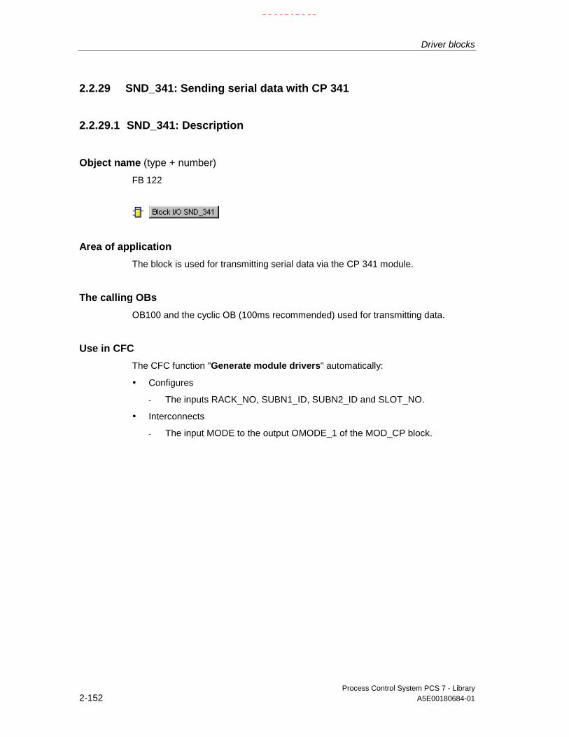
Driver blocks
Process Control System PCS 7 - Library2-152 A5E00180684-01
2.2.29 SND_341: Sending serial data with CP 341
2.2.29.1 SND_341: Description
Object name (type + number)
FB 122
Area of application
The block is used for transmitting serial data via the CP 341 module.
The calling OBs
OB100 and the cyclic OB (100ms recommended) used for transmitting data.
Use in CFC
The CFC function "Generate module drivers" automatically:
• Configures
- The inputs RACK_NO, SUBN1_ID, SUBN2_ID and SLOT_NO.
• Interconnects
- The input MODE to the output OMODE_1 of the MOD_CP block.
21.02.2003

Driver blocks
Process Control System PCS 7 - LibraryA5E00180684-01 2-153
How to create a user block for transmitting serial data
The installation of the optional package for programming PtP communications(CP PtP Param) is prerequisite.
In HW Config you can set the following transmission types (protocols):
- DK 3964R
- RK 512
- ASCII
- MODBUS master
- MODBUS slave
Install the SND_341 block into your CFC chart. Set the logical base address of theCP341 module at the block input LADDR. Define the input buffer for user data in ablock (referred to as SND_DATA in the following). Install SND_DATA upstream ofthe SND_341 block at the same cyclic OB. The send buffer definition can be avariable or a structure of variables. All S7 data types except ANY are permitted inthe variable definitions. Interconnect the send buffer to the output of theSND_DATA block, and then interconnect this output to input S_DATA of theSND_341 block. The length of the interconnected data determines the length of thetransmitted protocol.
To control and evaluate received data, define the following I/O at the SND_DATAblock and interconnect them to the corresponding I/O of the SND_341 block:
I/O Data type Meaning
Inputs:
DONE BOOL Send request end without error
ERROR BOOL Send request end with error
STATUS WORD Error status
Outputs:
REQ BOOL Initialize send request
R BOOL Reset Tx data
Block SND_341 initializes a send request when input REQ = TRUE. After the sendrequest has been completed with DONE = TRUE, the next send request will beinitialized automatically as long as REQ = TRUE, i.e. you must set REQ = FALSE ifthe Tx data are not yet available. When the variable ERROR = TRUE, an errorevent is entered in STATUS. For information on event numbers refer to the CP 341manual, chapter 8.3. The event class is to be evaluated according to the selectedtransmission type in order to determine how to handle faulty data or data nottransmitted.
• Procedure DK 3964R
This procedure does not require any further evaluation or assignment ofvariables at the SND_341 block.
See the CP 341 manual.
21.02.2003
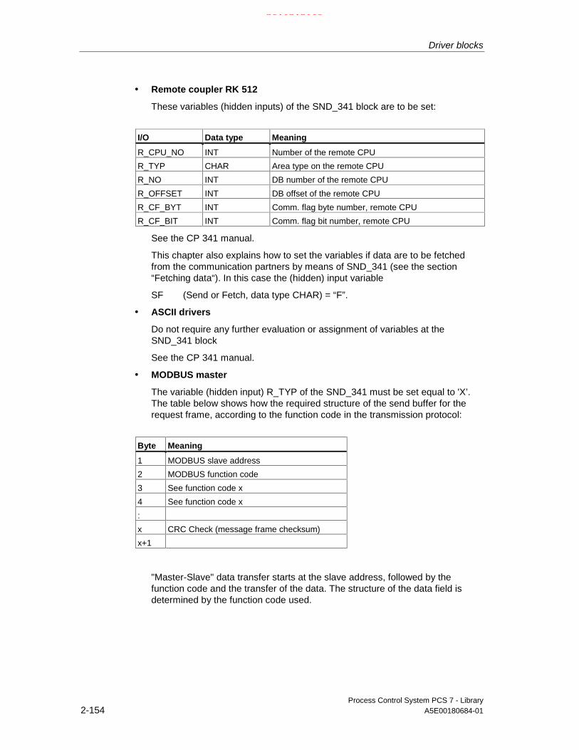
Driver blocks
Process Control System PCS 7 - Library2-154 A5E00180684-01
• Remote coupler RK 512
These variables (hidden inputs) of the SND_341 block are to be set:
I/O Data type Meaning
R_CPU_NO INT Number of the remote CPU
R_TYP CHAR Area type on the remote CPU
R_NO INT DB number of the remote CPU
R_OFFSET INT DB offset of the remote CPU
R_CF_BYT INT Comm. flag byte number, remote CPU
R_CF_BIT INT Comm. flag bit number, remote CPU
See the CP 341 manual.
This chapter also explains how to set the variables if data are to be fetchedfrom the communication partners by means of SND_341 (see the section“Fetching data“). In this case the (hidden) input variable
SF (Send or Fetch, data type CHAR) = “F”.
• ASCII drivers
Do not require any further evaluation or assignment of variables at theSND_341 block
See the CP 341 manual.
• MODBUS master
The variable (hidden input) R_TYP of the SND_341 must be set equal to 'X’.The table below shows how the required structure of the send buffer for therequest frame, according to the function code in the transmission protocol:
Byte Meaning
1 MODBUS slave address
2 MODBUS function code
3 See function code x
4 See function code x
:
x CRC Check (message frame checksum)
x+1
"Master-Slave" data transfer starts at the slave address, followed by thefunction code and the transfer of the data. The structure of the data field isdetermined by the function code used.
21.02.2003
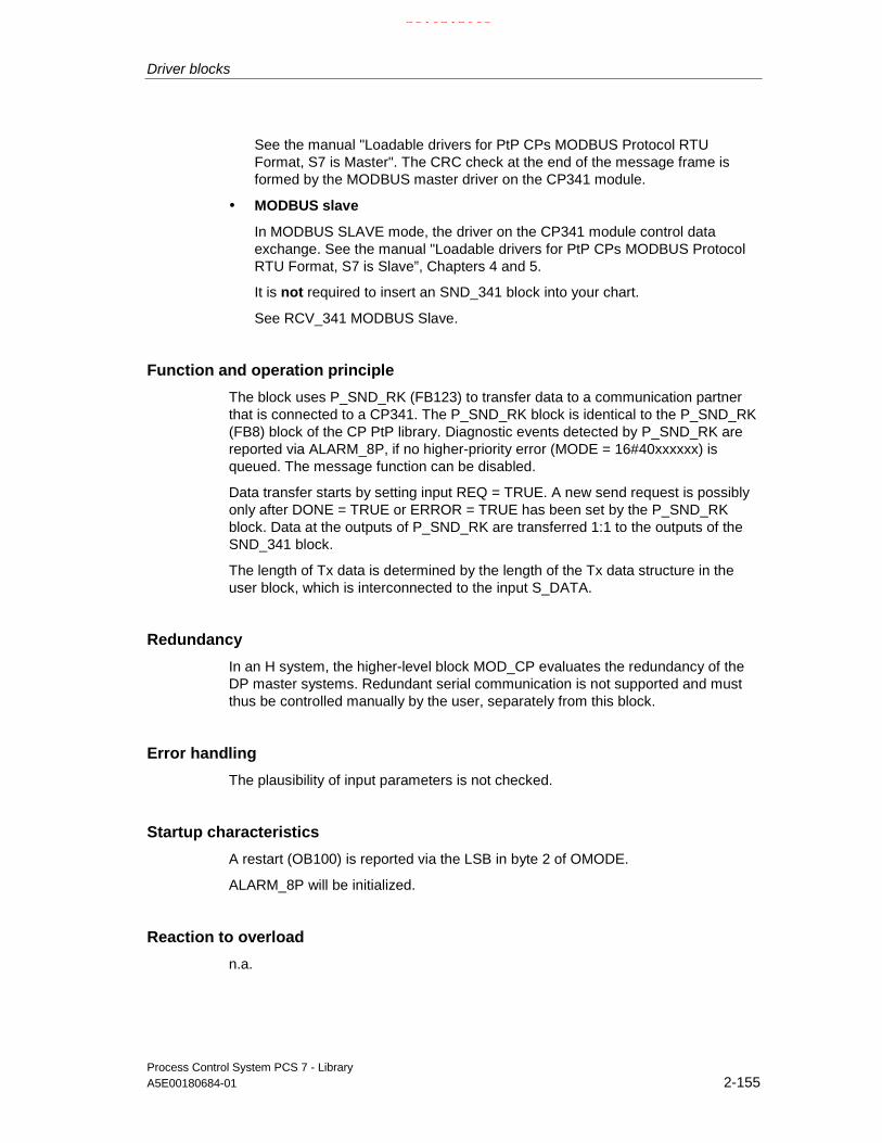
Driver blocks
Process Control System PCS 7 - LibraryA5E00180684-01 2-155
See the manual "Loadable drivers for PtP CPs MODBUS Protocol RTUFormat, S7 is Master". The CRC check at the end of the message frame isformed by the MODBUS master driver on the CP341 module.
• MODBUS slave
In MODBUS SLAVE mode, the driver on the CP341 module control dataexchange. See the manual "Loadable drivers for PtP CPs MODBUS ProtocolRTU Format, S7 is Slave”, Chapters 4 and 5.
It is not required to insert an SND_341 block into your chart.
See RCV_341 MODBUS Slave.
Function and operation principle
The block uses P_SND_RK (FB123) to transfer data to a communication partnerthat is connected to a CP341. The P_SND_RK block is identical to the P_SND_RK(FB8) block of the CP PtP library. Diagnostic events detected by P_SND_RK arereported via ALARM_8P, if no higher-priority error (MODE = 16#40xxxxxx) isqueued. The message function can be disabled.
Data transfer starts by setting input REQ = TRUE. A new send request is possiblyonly after DONE = TRUE or ERROR = TRUE has been set by the P_SND_RKblock. Data at the outputs of P_SND_RK are transferred 1:1 to the outputs of theSND_341 block.
The length of Tx data is determined by the length of the Tx data structure in theuser block, which is interconnected to the input S_DATA.
Redundancy
In an H system, the higher-level block MOD_CP evaluates the redundancy of theDP master systems. Redundant serial communication is not supported and mustthus be controlled manually by the user, separately from this block.
Error handling
The plausibility of input parameters is not checked.
Startup characteristics
A restart (OB100) is reported via the LSB in byte 2 of OMODE.
ALARM_8P will be initialized.
Reaction to overload
n.a.
21.02.2003

Driver blocks
Process Control System PCS 7 - Library2-156 A5E00180684-01
Time response
n.a.
Message characteristics
The block uses ALARM_8P to report diagnostic information of P_SND_RK.The message function can be disabled by setting EN_MSG = FALSE.
Operator control and monitoring
The block does not have a faceplate.
Note: In the OCM column of the "SND_341…" table, the "+" character identifiesthe variables to be transferred to the OS, if you have set the "enable operatorcontrol and monitoring" attribute in the block object properties. Default: This optionis not set.
2.2.29.2 SND_341: I/Os
The factory setting of the block display in CFC is identified in the I/O column:I/O name in bold characters = I/O visible, in normal characters = hidden.
I/O(parameter)
Meaning Data type Default Type OCM
ACC_MODE 1 = accept MODE settings BOOL 0 I/O
DONE 1 = request end without error BOOL 0 O
EN_MSG 1 = enable message BOOL 1 I
ERROR 1 = request end with error BOOL 0 O +
EV_ID Message number DWORD 0 I
LADDR Logical address of the CP341 INT 0 I
MODE Module mode (xx = 00 - 06 / 00 - 15 / 00 – 31) DWORD 0 I
MSG_ACK Message acknowledgement WORD 0 O
MSG_STAT Error message status WORD 0 O
QERR 1 = Program runtime error BOOL 1 O
QMODF 1 = CP341 error BOOL 0 O
R Reset BOOL 0 I
R_CF_BIT Protocol RK512: Number of the remote CPU INT 0 I
R_CF_BYT Protocol RK512: Number of the remote CPU INT 255 I
R_CPU_NO Protocol RK512: Number of the remote CPU INT 1 I
R_NO Protocol RK512: Number of the remote CPU INT 0 I
R_OFFSET Protocol RK512: Number of the remote CPU INT 0 I
R_TYP Protocol RK512: Number of the remoteCPU/MODBUS master = X
CHAR ‘X‘ I
RACK_NO Rack number BYTE 0 I
REQ Request init BOOL 0 I
21.02.2003

Driver blocks
Process Control System PCS 7 - LibraryA5E00180684-01 2-157
I/O(parameter)
Meaning Data type Default Type OCM
S_DATA Transmit data ANY I
SF Transmit (Tx) or receive (Rx) CHAR ‘S‘ I
SLOT_NO Slot number BYTE 0 I
STATUS Error status WORD 0 O +
SUBN1_ID ID of the primary DP master system BYTE 255 I
SUBN2_ID ID of the redundant DP master system BYTE 255 I
2.2.29.3 SND_341: Message texts and auxiliary process values
Assignment of message text and class
Message blockALARM_8P
Message no. Blockparameter
Default message text Message class
1 CP 341 @1%d@/@2%d@/@3%d@Event class @4%d@ no. @5%d@
S
2 - No message
3 - No message
4 - No message
5 - No message
6 - No message
7 - No message
EV_ID
8 - No message
Assignment of auxiliary process values
Message blockALARM_8P
Associated value
Block parameter Meaning
1 SUBN_ID DP master system ID (byte)
2 RACK_NO Rack/station number (byte)
3 SLOT_NO Slot number (byte)
4 STATUS(EV_CLAS) Event class
EV_ID
5 STATUS(EV_NO) Event number
21.02.2003

Driver blocks
Process Control System PCS 7 - Library2-158 A5E00180684-01
2.2.30 SUBNET: DP master system monitoring
2.2.30.1 SUBNET: Description
Object name (type + number)
FB 106
Area of application
The block is used to reduce processing times of the acyclic OB. Only the blocksactually affected can be called in case of an acyclic event.
The calling OBs
The block must be installed in the run sequence of the following OBs (carried outautomatically in CFC):
OB1 Cyclic program
OB55 Status interrupt (only if a DP/PA slave is required)
OB56 Update interrupt (only if a DP/PA slave is required)
OB57 Manufacturer-specific interrupt (only if a DP/PA slave is required)
OB70 I/O redundancy error
OB72 CPU redundancy error
OB81 Power supply fault
OB82 Diagnostic interrupt
OB83 Removal / insertion interrupt
OB85 Program runtime error
OB86 Rack failure
OB100 Restart (warm start)
21.02.2003

Driver blocks
Process Control System PCS 7 - LibraryA5E00180684-01 2-159
Use in the CFC
The CFC function "Generate module drivers" automatically:
• Creates runtime groups with driver blocks organized by racks.
• Configures
- the inputs SUBN1_ID, SUBN2_ID and SUBN_TYP.
• Interconnects
- the outputs EN_Rxxx with the relevant blocks (for example RACK).
- the INOUT structure CPU_DIAG with the OUT structure of the OB_BEGINblock.
- the OUT structure SUB_DIAG with the INOUT structures of the relevantblocks (e.g. RACK).
Function and operating principle
The SUBNET block monitors a DP Master system and enables the blocks (e.g.RACK) for processing the connected DP slaves (for example ET200M).Corresponding messages are generated and the output variables SUBN1ERR andSUBN2ERR set on failure or redundancy loss at a DP master system. The outputstructure SUB_DIAG contains the geographical address of the DP Master system(and of DP Master system 2 in H systems), as well as the group error informationSUBN0_ERR (for DP master system 1) and SUBN1_ERR (for DP master system2). If SUBN0_ERR = 1 or SUBN1_ERR = 1, the corresponding DP Master systemis not available.
The SUBNET block is installed in each connected DP Master system or once intothe OBs listed above for the local I/O devices. It is enabled by the OB_BEGINblock. Startup and diagnostic information is read from the I/O structure CPU_DIAG.It must be interconnected to the structure CPU_DIAG of the OB_BEGIN block(implemented automatically when the CFC function "Generate module drivers" isused). The SUBNET block is assigned one enable output for each connectablerack or DP Master system (for each expansion rack in the case of local I/Odevices). By means of the startup information of the calling OB, it determineswhether the event reported has occurred at its DP master (or at the local I/Odevices) and then sets the output for the relevant rack or DP Master system(EN_Rx).
When redundant DP master systems are used (only for H CPUs), a rack (e.g.ET200M) is connected to the two DP masters and is assigned the same stationnumber at both. The SUBNET block provides two inputs (SUBNx_ID) and the typeidentifier SUBN_TYP for this function. If the integrated interface of the CPU moduleis the DP master, SUBN_TYP = FALSE must be set. SUBN_TYP = TRUE is to beset otherwise.
If a DP master fails, the system sets all EN_Rxxx = TRUE and reports redundancyloss or failure. On return of redundancy or of the DP master, it reports this eventafter the failed DP slave has reestablished the connection.
The status of the DP master system as well as the set SUBNx_ID including thetype identifier are saved in the output structure SUB_DIAG.
21.02.2003

Driver blocks
Process Control System PCS 7 - Library2-160 A5E00180684-01
If a "power supply fault" (OB81) occurs, the SUBNET block enables RACK blocksonly if these represent expansion racks, which is indicated by SUBNx_ID = 0.
If you want to modify the inputs SUBN1_ID (connection to CPU 0) and SUBN2_ID(connection to CPU 1) online without using the CFC function "Generate moduledrivers", you must set input ACC_ID = TRUE in order to update the output values.
Redundancy
The SUBNET block supports redundancy of DP master systems of the 417H CPUwhen operating with distributed I/O. The inputs SUBN1_ID (connection to CPU 0)and SUBN2_ID (connection to CPU 1) must be assigned the IDs of the redundantDP master systems in this case. If there is no redundancy, the remaining inputmust be assigned the value 16#FF (default).
Error handling
The block handles only the error information of ALARM_8P. Refer to MSG_STAT:Error information of the output parameters
Startup/initial startup characteristics
The SUBNET block initializes the messages of ALARM_8P.
The operating mode of the DP Master system is sampled and entered in thestructure SUB_DIAG.V1_MODE with SSL 0X90H (0 = compatibility mode, 1=DPV1 mode). If the DPV1 mode is active, the structure CPU_DIAG.MODE_V1 isalso set to TRUE.
Overload behavior
The SUBNET block counts the OB86 calls (only failures). The counter is reset inOB1. If more than two OB86 failure events occur successively before the scancycle checkpoint (OB1) is reached, these are discarded and a message "FailureOB86 DP Master system:x" is output. If an OB86 call is rejected, the DP mastersystem is registered as having failed.
Time response
n.a.
Message characteristics
After being called by an OB86, OB70 and OB72, the block analyzes the status ofits assigned DP master system, generates corresponding messages relevant toredundancy loss or DP Master system failure and then outputs this message via anALARM_8P.The message function can be disabled by setting EN_MSG = FALSE.
21.02.2003

Driver blocks
Process Control System PCS 7 - LibraryA5E00180684-01 2-161
The SUBNET block generally reports only events triggered in the DP mastersystem it monitors.
Exception: CPU failure in the H system:
- Primary DP master system: Message "DP master failure".
- Redundant DP master system: Message "DP master redundancy loss".
Operator Control and Monitoring
The block has no faceplate.
Note: In the OCM column of the " SUBNET …" table, the "+" character identifiesthe variables to be transferred to the OS, if you have set the "enable operatorcontrol and monitoring" attribute in the block object properties. Default: This optionis not set.
2.2.30.2 SUBNET: I/Os
The factory setting of the block display in CFC is identified in the I/O column: I/Oname in bold characters = I/O visible, in normal characters = hidden.
I/O(parameter)
Meaning Data type Default Type OCM
ACC_ID 1 = accept MODE settings BOOL 0 I/O
CPU_DIAG CPU diagnostics STRUCT I/O
CPU_OB_5X OB_5x startup information STRUCT I/O
EN_MSG 1 = enable message BOOL 1 I
EN_Rxxx 1 = enable rack (xxx = 0 - 127) BOOL 0 O
EV_ID Message number DWORD 0 I
MSG_STAT Error message status WORD 0 O
SUB_DIAG System structure: CPU diagnostics STRUCT O
SUBN_TYP 1 = external DP interface BOOL 0 I
SUBN1_ID ID of the primary DP master system BYTE 255 I
SUBN1ERR 1 = error in DP master system 1 BOOL 0 O +
SUBN2_ID ID of the redundant DP master system BYTE 255 I
SUBN2ERR 1 = error in DP master system 2 BOOL 0 O +
Note
The maximum number of racks is determined by the address volume ofPROFIBUS. All available CPUs can thus be used. The entire address volume isused by the CPU 417-4.
21.02.2003

Driver blocks
Process Control System PCS 7 - Library2-162 A5E00180684-01
2.2.30.3 SUBNET: Message texts and auxiliary process values
Assignment of message text and class
Message no. Default message text Messageclass
1 DP master @1%d@: Redundancy loss S
2 DP master @2%d@: Redundancy loss S
3 DP master @1%d@: Failure S
4 DP master @2%d@: Failure S
5 DP master @2%d@: Repeated failure
Assignment of the auxiliary process values
Value Block parameter
1 ID of the primary DP master system (SUBN1_ID)
2 ID of the redundant DP master system (SUBN2_ID)
21.02.2003

Driver blocks
Process Control System PCS 7 - LibraryA5E00180684-01 2-163
2.3 PROFIBUS PA - Blocks
2.3.1 DPAY_V0: Monitoring DP/PA and Y Links operating as V0 slave
2.3.1.1 DPAY_V0: Description
Object name (type + number)
FB 108
Area of application
The block monitors the status of a DP/PA- or Y-Link as a V0 slave (IM157) andreports the corresponding error events.
The DP/PA Link is a PA master for the sublevel PA field devices and a slave at theDP bus. The Y-Link is a DP master for the sublevel DP field devices and a slave atthe higher-level DP bus.
The calling OBs
The block has to be installed in the run sequence of the following OBs (carried outautomatically in CFC):
OB1 Cyclic program
OB70 I/O redundancy error
OB72 CPU redundancy error
OB82 Diagnostic interrupt
OB85 Program runtime error
OB86 Rack failure
OB100 Restart (warm start)
The CFC function "Generate module drivers" automatically integrates the block inthe run sequence downstream of the SUBNET block and upstream of thePADP_L0x block. It also
• Configures
- the RACK_NO (rack/station number)
- the DADDR (diagnostic address of the DP/PA Link or Y Link)
- the DPPA_xx (slave xx address, 1st module (slot) address of the slave xxin the link, number of slots of the slave xx)
21.02.2003

Driver blocks
Process Control System PCS 7 - Library2-164 A5E00180684-01
• Interconnects
- the OUT structures CPU_DIAG of the OB_BEGIN block and SUB_DIAG ofthe SUBNET block with the INOUT structures of the same name of theDPAY_V0.
- PADP_L0x at PA or DP field devices,
Function and operating principle
Redundancy losses and link failures trigger a control system error message at theDPAY_V0 block and its output to the OS. The block also indicates error events atactive links (SUBN1ERR,SUBN2ERR) and at the preferred channel(SUBN1ACT,SUBN2ACT) in the output status bar. The output structureRAC_DIAG contains the geographic address of the link as well as the group errorinformation RACK_ERR. The corresponding link is not available if RACK_ERR = 1.
The block requires an interface to PROFIBUS DP, which can be integrated eitherin the CPU or provided by means of an external DP interface (CP). PROFIBUS DPis converted to PROFIBUS PA by means of a SIMATIC DP/PA-Link.
The field devices of a link are always addressed at the higher-level DP bus via theDP address of IM157.
The AS addresses the field devices indirectly via the link. The topological structureof the PA bus is mapped in the flat structure of the slave interface. A maximum of64 field devices can be operated downstream of a link. Each field device can useany number of virtual slots at the link, up to 223 maximum. In order to enable theassignment of diagnostic data to the field devices, the block provides each fielddevice a DPPA_xx input structure consisting of 3 bytes with the following contents:
• Byte (SLAV_NO) = node number (address) of the field device at the PA or DPmaster system of the LINK
• Byte (SLOT_NO) = 1st module address of the field device in the LINK
• Byte (SLAV_SL) = number of slots of the field device
The CFC function "Generate module drivers" fetches these data from HW Config.
The startup information is read from the I/O structure CPU_DIAG and must beinterconnected to the structure CPU_DIAG of the OB_BEGIN block (carried outautomatically by the CFC function "Generate module drivers").
The block generates a corresponding message (see Message behavior) on thebasis of the startup information of the calling OBs, if the current instance isaffected.
When operating with redundant PROFIBUS DP interfaces, the block determinesthe currently active preferred channel (SUBN1ACT, SUBN2ACT) by evaluating theerror events as well as the diagnostic address ADDR of the link.
SFC13 (DPNRM_DG, Diagnostic data consistent) reads the diagnostic data(OB82). It is possible in few cases that the triggering diagnostic event cannot berecognized, since this read operation requires several cycles (OB1).
Diagnostic user data contain information about the status of the link and ofconnected field devices. The structure DPPA_ST indicates the link status.
21.02.2003

Driver blocks
Process Control System PCS 7 - LibraryA5E00180684-01 2-165
The status of a field device is entered in the structure DPA_M_xx.A field device can have a maximum of 32 slots (modules). Three block types areavailable, according to the number of slots at the field device:
• PADP_L00 (field device with max. 7 slots)
• PADP_L01 (field device with max. of 16 slots)
• PADP_L02 (field device with max. of 32 slots)
The structure DPA_M_xx is interconnected to the structure DPA_M and the outputEN_Mx with EN of one of the PADP_Lxx blocks (carried out automatically the CFCfunction "Generate module drivers").
The DPA_M_xx structure consists of two DWORD value (S_01 for modules 1 to 16and S_02 for modules 17 to 32) and one BOOL value (S_ERR = DP/PA fielddevice faulty). Each DP/PA field device is assigned two bits of the DWORD,whereby bit 0 and bit 1 belong to slot 1 (module 1) of the DP/PA field device, etc.These bits are defined as follows:
Status bit 0 Status bit 1 Meaning
0 0 Module x OK (valid user data)
0 1 Module x error (invalid user data)
1 0 Wrong module x (invalid user data)
1 1 No Module x (invalid user data)
DPA_M_xx.S_ERR = TRUE if the diagnostic interrupt affects the entire DP/PA fielddevice.
You must set input ACC_ID = TRUE at the corresponding block if you do not usethe CFC function "Generate module drivers" for online modification of inputs at theSUBNET block SUBN1_ID (connection to CPU 0) and SUBN2_ID (connection toCPU 1). This action initiates a verification of the link states and the update ofoutput values.
Redundancy
The block supports redundant DP master systems in an H system (only distributedI/O devices). The SUBNET block SUBN1_ID (connection to CPU 0) andSUBN2_ID (connection to CPU 1) inputs must be assigned the IDs of theredundant DP master systems. The value 16#FF (default) must be assigned to theremaining input if the DP master system is not redundant..
Error handling
Error handling of the block is limited to the error information of ALARM_8P.
See MSG_STAT: Error information of the output parameter.
21.02.2003

Driver blocks
Process Control System PCS 7 - Library2-166 A5E00180684-01
Startup characteristics
The block initializes the messages of ALARM_8P. The system verifies that the linkis available, and determines the preferred channel of the links in H systems.
Reaction to overload
The block counts OB86 and OB82 calls (not DP master system failures, seeSUBNET block). Both counters are reset in OB1. If more than two OB86s or morethan two OB82 events occur successively before the scan cycle checkpoint (OB1)is reached, these are discarded and either the message "Failure OB86 DPMaster:x Rack:y" or the message "Failure OB82 DP Master:x Rack:y Slot: z" will beoutput. If an OB86 is discarded, the DP/PA link / Y link is registered as failed. If anOB82 is discarded, the corresponding DP slave is registered as failed.
Time response
n.a.
Message characteristics
After its call by OB70, OB72, OB85 or OB86, the block analyzes the status of itsassigned CPU, DP master and link. It generates and outputs a redundancy lossand link failure error messages via ALARM_8P if necessary.
The block generally reports only the events of the link it monitors. Redundancylosses and link failures due to failures of a DP Master or CPU, are initially neitherreported nor indicated at the outputs SUBN1ERR and SUBN2ERR.
The configurable DELAY input can be used to delay outgoing higher-priority errormessages. For example, when the block recognizes an outgoing error at itsinterconnected DP master, it initially assumes that there is a faulty assigned DPslave in the link it monitors and sets the corresponding output SUBNxERR. Theerror is not cleared until the DP slave returns (in this case: OB86, OB70). Theblocks suppress the potential slave failure within the DELAY time in seconds, inorder not to trigger a surge of messages which would be output by DP slaveswhich are not yet synchronized after the master returns. An error message is notoutput to the OS unless a DP slave does not report its return before this period hasexpired.
You should not set the value of DELAY too high. Faulty DP slaves, or slavesremoved while the master is in error state, would otherwise be reported too late tothe OS after the master returns.
21.02.2003

Driver blocks
Process Control System PCS 7 - LibraryA5E00180684-01 2-167
The block generates the following messages in the OBs listed below:
OB No. Starting event Message
OB1 Cyclic processing Repeat update of ALARM_8P outputs / messages, if necessary
OB70 Redundancy loss Link redundancy loss/return
OB85 I/O access error Link failure outgoing
OB86 Rack monitoring Link failure incoming/outgoing
OB100 Restart Initializing ALARM_8P
Operator control and monitoring
The block does not have a faceplate.
Note: In the OCM column of the "DPAY_V0 …" table, the "+" character identifiesthe variables to be transferred to the OS, if you have set the "enable operatorcontrol and monitoring" attribute in the block object properties. Default: This optionis not set.
2.3.1.2 DPAY_V0: I/Os
The factory setting of the block display in CFC is identified in the I/O column: I/Oname in bold characters = I/O visible, in normal characters = hidden.
I/O(parameter)
Meaning Data type Default Type OCM
ACC_ID 1 = accept MODE settings BOOL 0 I/OCPU_DIAG CPU diagnostics (system structure) STRUCT I/ODADDR Diagnostic address of the DP slave INT 0 IDELAY Interrupt delay (s) INT 15 IDPA_M_xx Status of the DP/PA slave (xx = 00 - 63) STRUCT ODPPA_ST DP/PA/Y Link status STRUCT ODPPA_xx Information of the DP/PA slave (xx = 00 - 63) STRUCT IEN_MSG 1 = enable message BOOL 1 IEN_Mxx 1 = enable module (xx = 00 - 63) BOOL 0 OEV_ID Message number DWORD 0 IMSG_STAT Error message status WORD 0 ORAC_DIAG Rack diagnostics BOOL 0 ORACK_NO Rack/station number WORD 0 ISUB_DIAG OB startup information STRUCT I/OSUBN_TYP 1 = external DP interface BOOL 0 ISUBN1_ID ID of primary Dp master system BYTE 255 ISUBN1ACT 1 = slave 1 is active BOOL 0 O +SUBN1ERR 1 = error in DP master system 1 BOOL 0 O +SUBN2_ID ID of the redundant DP master system BYTE 255 ISUBN2ACT 1 = slave 2 is active BOOL 0 O +SUBN2ERR 1 = error in DP master system 2 BOOL 0 O +
21.02.2003

Driver blocks
Process Control System PCS 7 - Library2-168 A5E00180684-01
2.3.1.3 DPAY_V0: Message texts and auxiliary process values
Assignment of message text and message class
Message no. Default message text Message class
1 DP Link @1%d@/ @3%d@: Redundancy loss S
2 DP Link @2%d@/ @3%d@: Redundancy loss S
3 DP Link @1%d@/ @3%d@: Failure S
4 DP Link @2%d@/ @3%d@: Failure S
5 - -
6 - -
7 - -
8 - -
Assignment of auxiliary process values
Value Block parameter
1 ID of the primary DP master system (SUBN1_ID)
2 ID of the redundant DP master system (SUBN2_ID)
3 Rack / station number (RACK_NO)
21.02.2003

Driver blocks
Process Control System PCS 7 - LibraryA5E00180684-01 2-169
2.3.2 DPAY_V1: Enabling blocks downstream of a DP/PA and Y Linkoperating as V1 slave
2.3.2.1 DPAY_V1: Description
Object name (type + number)
FB 115
Area of application
The block enables field device-specific blocks installed downstream of the DP/PAor Y Links.
The DP/PA Link operates as PA master for the sublevel PA field devices and asslave on the DP bus. The Y Link operates as DP master for the sublevel DP fielddevices and as slave on the DP bus.
The calling OBs
The block must be installed into the run sequence of the following OBs (carried outautomatically in CFC):
OB1 Cyclic program
OB55 Status interrupt
OB56 Update interrupt
OB57 Manufacturer-specific interrupt
OB70 I/O redundancy error
OB72 CPU redundancy error
OB82 Diagnostic interrupt
OB83 Removal / insertion interrupt
OB85 Program runtime error
OB86 Rack failure
OB100 Restart (warm start)
21.02.2003

Driver blocks
Process Control System PCS 7 - Library2-170 A5E00180684-01
The CFC function "Generate module drivers" automatically installs the block intothe run sequence downstream of the OB_DIAG1 block and
• Configures the
- SUBN_1ID (ID of the primary DP master system)
- SUBN_2ID (ID of the secondary DP master system)
- RACK_NO (rack / station number)
• Interconnects
- the OUT structure CPU_DIAG of the OB_BEGIN block with the INOUTstructures of the same name at DPAY_V1
- the OUT structure CPU_OB_5X of the OB_BEGIN block with the INOUTstructures of the same name at DPAY_V1
- EN_Mxx and EN with OB_DIAG1 and PADP_L10 at each field device
Function and operating principle
The startup information is read from the I/O structure CPU_DIAG. It must beinterconnected to the CPU_DIAG structure of the OB_BEGIN block (carried outautomatically by the CFC function "Generate module drivers"). The downstreamblocks will be enabled according to the startup information.
OB5x characteristics
Enables the output for the relevant field device.
Redundancy
OB_DIAG1 evaluates redundancy.
Error handling
The plausibility of input parameters is not checked.
Startup characteristics
The block initializes its outputs.
Reaction to overload
OB_DIAG1 disables the block on overload.
Time response
n.a.
21.02.2003

Driver blocks
Process Control System PCS 7 - LibraryA5E00180684-01 2-171
Message characteristics
n.a.
Operator control and monitoring
The block does not have a faceplate.
2.3.2.2 DPAY_V1: I/Os
The factory setting of the block display in CFC is identified in the I/O column: I/Oname in bold characters = I/O visible, in normal characters = hidden.
I/O(parameter)
Meaning Data type Default Type
CPU_DIAG CPU diagnostics (system structure) STRUCT I/O
CPU_OB_5X OB_5x startup information STRUCT I/ODPPA_xx Information of the DP/PA slave (xx = 00 - 63) STRUCT I
EN_Mxx 1 = enable slave (xx = 00 - 63) BOOL 0 O
RACK_NO Rack/station number WORD 0 I
SUBN1_ID ID of the primary DP master system BYTE 255 I
SUBN2_ID ID of the redundant DP master system BYTE 255 I
21.02.2003

Driver blocks
Process Control System PCS 7 - Library2-172 A5E00180684-01
2.3.3 MOD_PAL0: Diagnostics of a DPV0 PA slave (via DP/PA couplerdownstream of a DPV1 DP/PA Link)
2.3.3.1 MOD_PAL0: Description
Object name (type + number)
FB 99
Area of application
The block reports diagnostics information of a PA field device that is operated asDPV0 slave downstream of a DPV1 DP/PA link. The field devices must conformwith the PROFIBUS PA V3.0 profile.
The calling OBs
Installation of the block with the same instance in OB100, OB82, OB83, OB85,OB86, OB1 after the PADP_L10 block.
Use in CFC
When the CFC function "Generate module drivers" is used, the systemautomatically
• Inserts
the block downstream of the PADP_L10 block
• Configures
the inputs SUBN1_ID, SUBN2_ID, RACK_NO, SLOT_NO, PADP_ADR,DADDR, PROF_V30.
• Interconnects
- the inputsto output CPU_DIAG of the block OB_BEGINto output RAC_DIAG of the block OB_DIAG1
- enable with EN_M0 of the block PADP_L10 (via AND block)
Note: The CFC function "Generate module drivers" can only be used if the PAfield device belongs to slave family 12.
21.02.2003

Driver blocks
Process Control System PCS 7 - LibraryA5E00180684-01 2-173
Function and operating principle
The block (acyclic service) analyzes all events affecting the slot of a PA fielddevice. These event are reported by means of ALARM_8P. The message functioncan be disabled.
The higher-ranking block PADP_L10-Baustein enables runtime of this block. Thestart information (CPU_DIAG) of he OB_BEGIN block contains the event to beevaluated. The block confirms his assignment to this event via the geographicaladdress of the field device.
SFB54 is used to read diagnostic data from OB_BEGIN synchronously.
Diagnostic information relevant to the PA field device are stored in the additionalinterrupt info at byte 11 to 14 as follows (see block PADP_L10, Additional interruptinfo).
Only the bytes 10, 11 and 12 of the additional interrupt info, will be stored in theoutput structure DINFO.
The I/O generates only messages derived from byte 11 and 12, as well as errorswhen accessing user data of the PA field device.
Input PROF_V30 must be set to zero if the PA field device used does not conformwith profile 3.0 (will be set by the CFC function "generate module drivers").
Following a diagnostic event, the block thus reports "PA field device diagnostics“.
Redundancy
In H systems, the higher-ranking block evaluates the redundancy of the DP mastersystems.
Error handling
The plausibility of input parameters is not checked. If synchronous read access todiagnostic data is not possible with SFB54 due to a temporary error, SFC13 iscalled once to attempt asynchronous read access. If this attempt fails also, the twomessages "incoming/outgoing diagnostic event at PA device“ will be output.
Startup characteristics
Initialization of ALARM_8P.
Time response
n.a.
21.02.2003
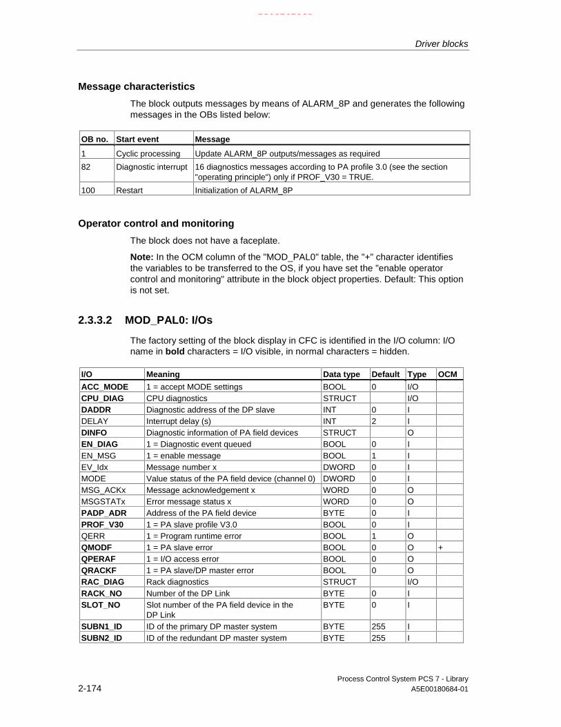
Driver blocks
Process Control System PCS 7 - Library2-174 A5E00180684-01
Message characteristics
The block outputs messages by means of ALARM_8P and generates the followingmessages in the OBs listed below:
OB no. Start event Message
1 Cyclic processing Update ALARM_8P outputs/messages as required
82 Diagnostic interrupt 16 diagnostics messages according to PA profile 3.0 (see the section"operating principle") only if PROF_V30 = TRUE.
100 Restart Initialization of ALARM_8P
Operator control and monitoring
The block does not have a faceplate.
Note: In the OCM column of the "MOD_PAL0" table, the "+" character identifiesthe variables to be transferred to the OS, if you have set the "enable operatorcontrol and monitoring" attribute in the block object properties. Default: This optionis not set.
2.3.3.2 MOD_PAL0: I/Os
The factory setting of the block display in CFC is identified in the I/O column: I/Oname in bold characters = I/O visible, in normal characters = hidden.
I/O Meaning Data type Default Type OCM
ACC_MODE 1 = accept MODE settings BOOL 0 I/OCPU_DIAG CPU diagnostics STRUCT I/ODADDR Diagnostic address of the DP slave INT 0 IDELAY Interrupt delay (s) INT 2 IDINFO Diagnostic information of PA field devices STRUCT OEN_DIAG 1 = Diagnostic event queued BOOL 0 IEN_MSG 1 = enable message BOOL 1 IEV_Idx Message number x DWORD 0 IMODE Value status of the PA field device (channel 0) DWORD 0 IMSG_ACKx Message acknowledgement x WORD 0 OMSGSTATx Error message status x WORD 0 OPADP_ADR Address of the PA field device BYTE 0 IPROF_V30 1 = PA slave profile V3.0 BOOL 0 IQERR 1 = Program runtime error BOOL 1 OQMODF 1 = PA slave error BOOL 0 O +QPERAF 1 = I/O access error BOOL 0 OQRACKF 1 = PA slave/DP master error BOOL 0 ORAC_DIAG Rack diagnostics STRUCT I/ORACK_NO Number of the DP Link BYTE 0 ISLOT_NO Slot number of the PA field device in the
DP LinkBYTE 0 I
SUBN1_ID ID of the primary DP master system BYTE 255 ISUBN2_ID ID of the redundant DP master system BYTE 255 I
21.02.2003

Driver blocks
Process Control System PCS 7 - LibraryA5E00180684-01 2-175
2.3.3.3 MOD_PAL0: Message texts and auxiliary process values
Assignment of message texts and classes to the block parameters of MOD_PAL0
Message blockALARM_8P
MessageID
Blockparameter
Default message text Message class
1 - PA device @1%d@/ @2%d@/@3%d@:Electronic hardware error
S
2 - PA device @1%d@/ @2%d@/@3%d@:Mechanical hardware error
S
3 - PA device @1%d@/ @2%d@/@3%d@:Excess motor temperature
S
4 - PA device @1%d@/ @2%d@/@3%d@:Excess temperature, electronic circuit
S
5 - PA device @1%d@/ @2%d@/@3%d@:@4W%t#MOD_PAL0_TXT@
S
6 - PA device @1%d@/ @2%d@/@3%d@:Measurement data acquisition error
S
7 - PA device @1%d@/ @2%d@/@3%d@:Not initialized
S
8 - PA device @1%d@/ @2%d@/@3%d@:auto-tuning error
S
EV_ID1
1 - PA device @1%d@/ @2%d@/@3%d@:zero error
S
2 - PA device @1%d@/ @2%d@/@3%d@:Power supply error
S
3 - PA device @1%d@/ @2%d@/@3%d@:Invalid configuration
S
4 - PA device @1%d@/ @2%d@/@3%d@:@4W%t#MOD_PAL0_TXT@
OM = OperationalMessage:mandatoryacknowledgement
5 - PA device @1%d@/ @2%d@/@3%d@:I/O access error
S
6 - PA device @1%d@/ @2%d@/@3%d@:Service request
M
7 - PA device @1%d@/ @2%d@/@3%d@:Wrong name
S
EV_ID2
8 - PA device @1%d@/ @2%d@/@3%d@:Error in PB ID
S
Assignment of auxiliary process values to the block parameters of MOD_PAL0
21.02.2003

Driver blocks
Process Control System PCS 7 - Library2-176 A5E00180684-01
Message blockALARM_8P
Associatedvalue
Block parameter Meaning
1 SUBN_ID DP master system ID (byte)
2 RACK_NO Rack/station number (byte)
3 PADPADR PA field device address (byte)
4 Text number MOD_PAL0
EV_ID1
1 SUBN_ID DP master system ID (byte)
2 RACK_NO Rack/station number (byte)
3 PADPADR PA field device address (byte)
EV_ID2
4 Text number MOD_PAL0
If the PA field device is connected downstream of an inactive DP/PA Link V1andSUBN1_ID = 16#FF, the auxiliary process variable is substituted by SUBN2_ID.
MOD_PAL0_TXT text numbers
Text number Message text Meaning
1 Warm start PA field devices diagnostics "warm start"
2 Complete restart PA field devices diagnostics "Complete restart"
3 Diagnostics PROF_V30 = False (PA does not report to profile 3.0)
4 Memory error Memory error in the PA field device
21.02.2003

Driver blocks
Process Control System PCS 7 - LibraryA5E00180684-01 2-177
2.3.4 MOD_PAX0: Diagnostics of a DPV0 PA slave (via DP/PA coupleron DP master system)
2.3.4.1 MOD_PAX0: Description
Object name (type + number)
FB 112
Area of application
The block reports diagnostics information of a PA field device that is operated asDP V0 slave on a DP master system. The PA field devices must conform with thePROFIBUS PA V3.0 profile.
The calling OBs
Insertion of a bock with the same instance in OB100, OB82, OB83, OB85, OB86,OB1
Use in CFC
When using the CFC function "Generate module drivers", the systemautomatically:
• Inserts
the block downstream of the OB_DIAG1 block
• Configures
the inputs SUBN1_ID, SUBN2_ID, SUBN_TYP, PADP_ADR, DADDR,PROF_V30, MODE_xx
• Interconnects
- the inputswith output CPU_DIAG of the OB_BEGIN blockwith output RAC_DIAG of the OB_DIAG1 blockwith output EN_DIAG of the OB_DIAG1 block
- Enable with EN_F of the OB_DIAG1 block (via AND block)
- the outputs
- OMODExx with input MODE of the block PA_x
Note: The CFC function "Generate module drivers" can only be used if the PAfield device belongs to slave family 12.
21.02.2003
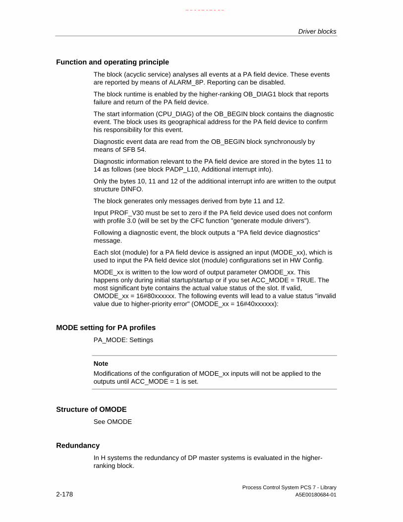
Driver blocks
Process Control System PCS 7 - Library2-178 A5E00180684-01
Function and operating principle
The block (acyclic service) analyses all events at a PA field device. These eventsare reported by means of ALARM_8P. Reporting can be disabled.
The block runtime is enabled by the higher-ranking OB_DIAG1 block that reportsfailure and return of the PA field device.
The start information (CPU_DIAG) of the OB_BEGIN block contains the diagnosticevent. The block uses its geographical address for the PA field device to confirmhis responsibility for this event.
Diagnostic event data are read from the OB_BEGIN block synchronously bymeans of SFB 54.
Diagnostic information relevant to the PA field device are stored in the bytes 11 to14 as follows (see block PADP_L10, Additional interrupt info).
Only the bytes 10, 11 and 12 of the additional interrupt info are written to the outputstructure DINFO.
The block generates only messages derived from byte 11 and 12.
Input PROF_V30 must be set to zero if the PA field device used does not conformwith profile 3.0 (will be set by the CFC function "generate module drivers").
Following a diagnostic event, the block outputs a "PA field device diagnostics“message.
Each slot (module) for a PA field device is assigned an input (MODE_xx), which isused to input the PA field device slot (module) configurations set in HW Config.
MODE_xx is written to the low word of output parameter OMODE_xx. Thishappens only during initial startup/startup or if you set ACC_MODE = TRUE. Themost significant byte contains the actual value status of the slot. If valid,OMODE_xx = 16#80xxxxxx. The following events will lead to a value status "invalidvalue due to higher-priority error" (OMODE_xx = 16#40xxxxxx):
MODE setting for PA profiles
PA_MODE: Settings
Note
Modifications of the configuration of MODE_xx inputs will not be applied to theoutputs until ACC_MODE = 1 is set.
Structure of OMODE
See OMODE
Redundancy
In H systems the redundancy of DP master systems is evaluated in the higher-ranking block.
21.02.2003

Driver blocks
Process Control System PCS 7 - LibraryA5E00180684-01 2-179
Error handling
The plausibility of input parameters is not checked. If it is not possible to readdiagnostic information synchronously with SFB54 due to a temporary error, SFC13is called once to fetch these diagnostic data asynchronously with. If this attemptfails also, the two messages "incoming/outgoing PA device diagnostics event “ willbe output.
Startup characteristics
A restart (OB100) is reported via the LSB in byte 2 of the outputs OMODE_xx.Initialization of ALARM_8P.
Time response
n.a.
Message characteristics
The block uses ALARM_8P to output messages and generates the followingmessage in the OBs listed below:
OBno.
Start event Message
1 cyclic processing update of ALARM_8P outputs/messages if required
82 diagnostic interrupt 16 diagnostic messages according to PA Profile 3.0(see the section "operating principle" ), only if EN_PR30 = TRUE.
100 restart initialization of ALARM_8P
Operator control and monitoring
The block does not have a faceplate
Note: In the OCM column of the "MOD_PAX0" table, the "+" character identifiesthe variables to be transferred to the OS, if you have set the "enable operatorcontrol and monitoring" attribute in the block object properties. Default: This optionis not set.
21.02.2003

Driver blocks
Process Control System PCS 7 - Library2-180 A5E00180684-01
2.3.4.2 MOD_PAX0: I/Os
The factory setting of the block display in CFC is identified in the I/O column: I/Oname in bold characters = I/O visible, in normal characters = hidden.
I/O Meaning Data type Default Type OCM
ACC_MODE 1 = accept MODE settings BOOL 0 IO
CPU_DIAG CPU diagnostics STRUCT I/O
DADDR Diagnostic address of the DP slave INT 0 I
DELAY Interrupt delay (s) INT 2 I
DINFO Diagnostic data of field devices STRUCT O
EN_DIAG 1 = diagnostic event queued BOOL 0 I
EN_MSG 1 = enable message BOOL 1 I
EV_IDx Message number x DWORD 0 I
MODE_XX Mode channel xx WORD 0 I
MSG_ACKx Message acknowledgement x WORD 0 O
MSGSTATx Error message status x WORD 0 O
OMODE_XX Mode channel xx DWORD 0 O +
PADP_ADR Address of the PA field device BYTE 0 I
PROF_V30 1 = PA slave profile V3.0 BOOL 1 I
QERR 1 = program runtime error BOOL 1 O
QMODF 1 = PA slave error BOOL 0 O +
QPERAF 1 = I/O access error BOOL 0 O
QRACKF 1 = PA slave/DP master error BOOL 0 O
RAC_DIAG Rack diagnostics STRUCT I/O
SUBN1_ID ID of the primary DP master system BYTE 255 I
SUBN2_ID ID of the redundant DP-Master system BYTE 255 I
SUBN_TYP 1 = external DP interface BOOL 0 I
21.02.2003
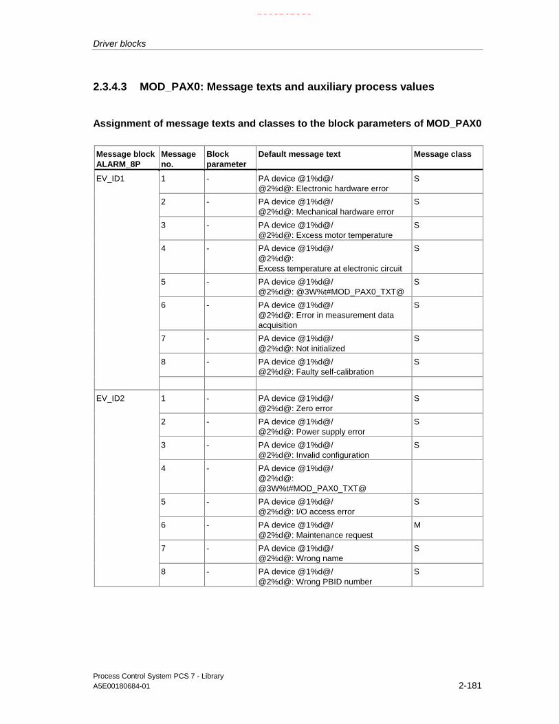
Driver blocks
Process Control System PCS 7 - LibraryA5E00180684-01 2-181
2.3.4.3 MOD_PAX0: Message texts and auxiliary process values
Assignment of message texts and classes to the block parameters of MOD_PAX0
Message blockALARM_8P
Messageno.
Blockparameter
Default message text Message class
1 - PA device @1%d@/@2%d@: Electronic hardware error
S
2 - PA device @1%d@/@2%d@: Mechanical hardware error
S
3 - PA device @1%d@/@2%d@: Excess motor temperature
S
4 - PA device @1%d@/@2%d@:Excess temperature at electronic circuit
S
5 - PA device @1%d@/@2%d@: @3W%t#MOD_PAX0_TXT@
S
6 - PA device @1%d@/@2%d@: Error in measurement dataacquisition
S
7 - PA device @1%d@/@2%d@: Not initialized
S
8 - PA device @1%d@/@2%d@: Faulty self-calibration
S
EV_ID1
1 - PA device @1%d@/@2%d@: Zero error
S
2 - PA device @1%d@/@2%d@: Power supply error
S
3 - PA device @1%d@/@2%d@: Invalid configuration
S
4 - PA device @1%d@/@2%d@:@3W%t#MOD_PAX0_TXT@
5 - PA device @1%d@/@2%d@: I/O access error
S
6 - PA device @1%d@/@2%d@: Maintenance request
M
7 - PA device @1%d@/@2%d@: Wrong name
S
EV_ID2
8 - PA device @1%d@/@2%d@: Wrong PBID number
S
21.02.2003

Driver blocks
Process Control System PCS 7 - Library2-182 A5E00180684-01
Assignment of auxiliary process values to the block parameters of MOD_PAX0
Message blockALARM_8P
Associatedvalue
Block parameter Meaning
1 SUBN_ID DP master system ID (byte)
2 PADPADR PA field device address (byte)
3 Text number MOD_PAX0
EV_ID1
1 SUBN_ID DP master system ID (byte)
2 PADPADR PA field device address (byte)
EV_ID2
3 Text number MOD_PAX0
If SUBN1_ID = 16#FF, then SUBN2_ID will be entered as auxiliary process value.
MOD_PAX0 text numbers
Text number Message text Meaning
1 Warm start PA field device diagnostics "warm start"
2 Complete restart PA field device diagnostics "complete restart"
3 PA field devicediagnostics
EN_PR30 = False (PA field device message does not conform withprofile 3.0)
4 Memory error Error in the memory of a PA field device
21.02.2003

Driver blocks
Process Control System PCS 7 - LibraryA5E00180684-01 2-183
2.3.5 PA_AI: Analog value input PROFIBUS PA
2.3.5.1 PA_AI: Description
Object name (type + number)
FB 101
Area of application
The block processes (cyclic service) the PA profile "Transmitter" of a PROFIBUSPA 3.0 Class A and B PA field device.
The calling OBs
Watchdog interrupt OB3x is the calling OB in which you install the block (e.g.OB32.
Use in the CFC
The CFC function "Generate module drivers" automatically:
• Interconnects the symbol for the Quality Code of the analog input channel withinput QC.
• Interconnects the MODE input with the corresponding OMODE_xx output ofthe PADP_L0x block.
Function and operating principle
The block reads the process value cyclically with status byte (QC) of thePROFIBUS PA field device (structure in accordance with the analog input of thePA profiles) from the process image (partition). This process variable is availableas physical unit. The status byte contains information relevant to the measuredvalue and the status of the PROFIBUS PA field device.
In addition to the status byte and to improve interconnectability, the output interfaceprovides BOOL values containing further important detailed information. Theseconform with the bit combinations defined in PROFIBUS PA 3.0 "GeneralRequirements". Device-specific control system messages are generated viaALARM_8P on the basis of the OC.
The block recognizes a higher-priority error (for example failure of DP/PA-Link) viathe MODE input. If the high byte value of input MODE = 16#80, the values in theprocess image (partition) are valid. If the high byte value of MODE input = 16#40(value status = higher-priority error), the analog value is handled as being invalid.The Quality Code (status) is set to 16#44. No error messages are generated forhigher-priority errors.
21.02.2003

Driver blocks
Process Control System PCS 7 - Library2-184 A5E00180684-01
The operating mode set in the low word of the MODE input parameter will beignored.
Addressing
The symbol of the analog input channel is generated and entered in the symboltable via HW Config. You must interconnect it with the VALUE input. The QCsymbol for the analog input channel automatically interconnects the CFC function"Generate module drivers" with input parameter QC.
Simulation mode
When input parameter SIM_ON = TRUE, the value of the input parameter SIM_V isoutput with Quality Code (QUALITY =) 16#60. Simulation mode takes highestpriority. QBAD = FALSE if a higher-priority error has occurred. QSIM = TRUE whenthe block is in simulation mode. If there is no higher-priority error queued and thePA field device displays the QC “BAD”, either the substitute value SUBS_V(SUBS_ON= TRUE) or the last value is output.
Substitute value
If input parameter SUBS_ON = TRUE, the value at input SUBS_V is output assubstitute value, in as far as the values are invalid. The Quality Code will be set to(STATUS =) 16#48 and QBAD = 1.
Hold last value
If input parameter SUBS_ON = FALSE, the last valid output parameter will beoutput, if the values are invalid. The Quality Code is set to (STATUS =) 16#44 andQBAD = 1.
Value limiting
You can limit the maximum high/low range of process variables output at theprocess image (partition).
If the parameter LIMIT_ON = TRUE, the process variables (V) are limited:
- To V_HL, if V > V_HL.
- To LL_V, if V < V_LL.
Error handling
The plausibility of input parameters is not checked.
Start-up characteristics
Input MODE = 16#xx01xxxx: Initializing ALARM_8P.
21.02.2003

Driver blocks
Process Control System PCS 7 - LibraryA5E00180684-01 2-185
Time response
n.a.
Message characteristics
The block reports the current status of the Quality Code (status byte) when there isa change, provided no higher-priority error is queued. These messages must beacknowledged.
The DELAY input (default = 2 seconds) is used to delay an event message whenthere is a change in the Quality Code. At the DELAY input, you can specify a delaytime in seconds to delay the output of the message at the block after the QC haschanged due to an outgoing higher-priority error (failure of the DP master system /DP/PA / device, or I/O access error) (MODE = 16#40xxxxxx). The block outputsthe message only if no higher-priority error is reported after this time has expired.The message function can be disabled by setting EN_MSG = FALSE.
Operator control and monitoring
n.a.
2.3.5.2 PA_AI: I/Os
The factory setting of the block display in CFC is identified in the I/O column: I/Oname in bold characters = I/O visible, in normal characters = hidden.
I/O(parameter)
Meaning Data type Default Type
DELAY Interrupt delay (s) INT 2 I
EN_MSG 1 = enable interrupt BOOL 1 I
EV_ID Message number DWORD 0 I
LIMIT_ON 1 = set limit of input value BOOL 0 I
LL_V Value if V < V_LL REAL 0 I
MSG_STAT Error message information of Alarm_8P WORD 0 O
MODE Value status and operating mode DWORD 0 O
QA_1 1 = alarm/warning 1 BOOL 0 O
QA_2 1 = alarm/warning 2 BOOL 0 O
QBAD 1 = group event QBAD_X BOOL 0 O
QBAD_0 1 = non-specific BOOL 0 O
QBAD_1 1 = configuration error BOOL 0 O
QBAD_2 1 = not connected BOOL 0 O
QBAD_3 1 = device failure BOOL 0 O
QBAD_4 1 = sensor failure BOOL 0 O
QBAD_5 1 = no communication (last usable value) BOOL 0 O
QBAD_6 1 = no communication (no usable value) BOOL 0 O
QBAD_7 1 = out of service BOOL 0 O
21.02.2003

Driver blocks
Process Control System PCS 7 - Library2-186 A5E00180684-01
I/O(parameter)
Meaning Data type Default Type
QBAD_HL 1 = high limit of physical range of sensor has beenreached
BOOL 0 O
QBAD_LL 1 = low limit of physical range of sensor has beenreached
BOOL 0 O
QC Value status of the process image of inputs BYTE 0 I
QCASCAD0 1 = OK (cascade) BOOL 0 O
QCASCAD1 1 = initialization acknowledged BOOL 0 O
QCASCAD2 1 = initialization request BOOL 0 O
QCASCAD3 1 = not requested BOOL 0 O
QCASCAD4 1 = reserved BOOL 0 O
QCASCAD5 1 = do not select BOOL 0 O
QCASCAD6 1 = local override BOOL 0 O
QCASCAD7 1 = reserved BOOL 0 O
QCASCAD8 1 = start in fail safe mode BOOL 0 O
QCONST 1 = constant BOOL 0 O
QERR 1 = output error (inverted value of ENO) BOOL 1 O
QOUT_HHL 1 = critical interrupt, high limit of OUT has been exceeded BOOL 0 O
QOUT_HL 1 = warning, high limit of OUT has been exceeded BOOL 0 O
QOUT_LL 1 = warning, low limit of OUT has been exceeded BOOL 0 O
QOUT_LLL 1 = critical interrupt, low limit of OUT has been exceeded BOOL 0 O
QNONCAS0 1 = OK (non-cascade) BOOL 0 O
QNONCAS1 1 = update event BOOL 0 O
QNONCAS2 1 = warning (priority < 8) BOOL 0 O
QNONCAS3 1 = critical interrupt triggered (priority > 8) BOOL 0 O
QNONCAS4 1 = unacknowledged update event BOOL 0 O
QNONCAS5 1 = anacknowledged warning BOOL 0 O
QNONCAS6 1 = Unacknowledged critical interrupt BOOL 0 O
QNONCAS7 1 = start in fail safe mode BOOL 0 O
QNONCAS8 1 = maintenance required BOOL 0 O
QSIM 1 = simulation mode enabled BOOL 0 O
QSUBS 1 = substitution enabled BOOL 0 O
QUALITY Quality Code of the process value BYTE 0 O
QUNCERT 1 = group message QUNCERTx BOOL 0 O
QUNCERT0 1 = non-specific BOOL 0 O
QUNCERT1 1 = last usable value BOOL 0 O
QUNCERT2 1 = substitute value set BOOL 0 O
QUNCERT3 1 = initial value BOOL 0 O
QUNCERT4 1 = unacknowledged update event BOOL 0 O
QUNCERT5 1 = engineering unit violation (unit not in the valid set) BOOL 0 O
QUNCERT6 1 = below normal BOOL 0 O
QUNCERT7 1 = configuration error BOOL 0 O
QUNCERT8 1 = sensor calibration BOOL 0 O
21.02.2003

Driver blocks
Process Control System PCS 7 - LibraryA5E00180684-01 2-187
I/O(parameter)
Meaning Data type Default Type
QUNCERT9 1 = simulated value BOOL 0 O
SIM_ON 1 = enable simulation mode BOOL 0 I
SIM_V Simulation value REAL 0 I
STATUS Process value status BYTE 0 O
SUBS_ON 1 = enable substitution value BOOL 0 I
SUBS_V Substitute value REAL 0 I
V Process value REAL 0 O
VALUE Process Image Input Value REAL 0 I
V_HL High limit input value REAL 0 I
V_LL Low limit input value REAL 0 I
2.3.5.3 PA_AI: Message texts
Assignment of message texts and classes to the block parameters of PA_AI
Message blockALARM_8P
Messagenumber
Block parameter Default message text Message class
EV_ID 1 QBAD Device error S
2 QUNCERT Uncertain value S
3 QNONCAS1 Parameter change S
4 QNONCAS7 Initiate fail safe S
5 QNONCAS8 Maintenance required M
6 QOUT_LLL Low limit interrupt AL
7 QOUT_HHL High limit interrupt AH
8 No message
The block is not assigned auxiliary process values. If QBAD = TRUE because of ahigher-priority error a message will not be generated.
21.02.2003

Driver blocks
Process Control System PCS 7 - Library2-188 A5E00180684-01
2.3.6 PA_AO: Analog value output PROFIBUS PA
2.3.6.1 PA_AO: Description
Object name (type + number)
FB 103
Area of application
The block processes (cyclic service) the PA Profile "Actuator" of aPROFIBUS PA 3.0 Class A and B PA field device.
The calling OBs
Restart OB100 and the watchdog interrupt OB3x in which you install the block (e.g.OB32).
Use in the CFC
When the CFC function "Generate module drivers" is used, the systemautomatically:
• Installs the block in OB100.
• Interconnects the symbol for the Quality Code of the analog output channelO_SP with the output QC_SP and other selected options.
• Interconnects the MODE input to the corresponding output OMODE_xx of thePADP_L0x block.
Function and operating principle
The block reads the user data from the process image (partition) and writes theminto the process image (partition), depending on the selection (with HW Config orSIMATIC PDM) of the user data configuration of the PA-Profile "Analog Output" inaccordance with PROFIBUS PA 3.0.
The low word of the input variable MODE contains the coding of the user dataconfiguration of the PROFIBUS PA 3.0 Profile "Analog Output" and specifies whichvariables are to be read and written in the process image (partition).
The block cyclically writes the setpoint (SP) with Quality Code (configuration of thesetpoints and process values in accordance with the Analog Output of the PAprofiles, REAL with 1 byte Quality Code) into the process image (partition). ThePA-Profile contains the setpoint and other analog values as physical units. TheQuality Code contains the information on the state of the setpoint. The coding ofthe Quality Code is described in the PROFIBUS PA 3.0 "General Requirements".
21.02.2003

Driver blocks
Process Control System PCS 7 - LibraryA5E00180684-01 2-189
The reference variable (RCAS_IN) with Quality Code can be transferred optionallyin the same cycle to the process image (partition).
The data of the PROFIBUS PA field device, as well as the process variable(READBACK) and the discrete position feedback (POS_D) are read cyclically fromthe process image (partition). Optionally you can also read the active referencevariable (RCAS_OUT) and the detailed device information (CHECKBACK). Thedevice information is available in bit segments at the block output. The data areread from the process image (partition). In order to improve the interconnectability,important detailed information is offered from the status bytes read (READBACK)as Boolean (BOOL) values at the output interface. They correspond to the bitcombinations specified in the PROFIBUS PA 3.0 "General Requirements".
If a higher-priority error has occurred (QMOD_ERR = TRUE), the data continue tobe written into the process image (partition) and no data are read from the processimage (partition). As long as the higher-priority error exists, the last values are heldwith QBAD = TRUE.
Note
Default value of the status byte of the setpoint (ST_SP) and of the referencevariable (ST_RCAS_IN) is zero. The setpoint or the reference variable onlybecomes active in the PROFIBUS PA field device if you set the correspondingQuality Code to 16#80.
Addressing
You have to interconnect one of the symbols configured with HW Config (forexample SP) for the analog output channel (PROFIBUS PA 3.0 Profile "AnalogOutput") with the corresponding I/O:
Connection Data type
I_READBACK REAL
I_RCAS_OUT REAL
I_POS_D BYTE
O_SP REAL
O_RCAS_IN REAL
In CFC the "Generate module drivers" function automatically interconnects thesymbol for the corresponding Quality Code (if it exists) of the I/O and the remainingconfigured symbols of the analog output channel (with Quality Code).
21.02.2003

Driver blocks
Process Control System PCS 7 - Library2-190 A5E00180684-01
Simulation
If input parameter SIM_ON = TRUE, then the value at input SIM_SP (and theoptions SIM_RCAS_IN) is output with Quality Code (QUALITY) = 16#60. A validmode must also be set in the simulation mode at the low word of the MODE input.Otherwise QBAD = 1 is output. Simulation takes highest priority. QBAD = FALSE ifa higher-priority error has occurred. QSIM = TRUE when the block is operating insimulation mode.
Value limiting
You can limit the maximum low an high range of process variables in the processimage (partition).
The process variables "V" (READBACK and RCAS_OUT) are limited whenLIMIT_ON = TRUE:
- To V_HL, if V > V_HL.
- To LL_V, if V < V_LL.
Error handling
The plausibility of input parameters is not checked.
Start-up characteristics
Input MODE = 16#xx01xxxx: Initializing ALARM_8P.
Time response
n.a.
Message characteristics
As long as no higher-priority error is queued, the block reports specific states of theQuality Code (status byte) and CHECKBACK when there is a change. Thesemessages must be acknowledged
You can use the DELAY function to specify a delay interrupt for message output atthe block when the Quality Code has changed after an outgoing higher-priorityerror event (DP master system / DP/PA device failure, or an I/O access error)(MODE = 16#40xxxxxx). The block outputs the message only if no higher-priorityerror has been reported after this time has expired. The message function can bedisabled by setting EN_MSG = FALSE.
Operator control and monitoring
The block does not have a faceplate.
21.02.2003

Driver blocks
Process Control System PCS 7 - LibraryA5E00180684-01 2-191
2.3.6.2 PA_AO: I/Os
The factory setting of the block display in CFC is identified in the I/O column: I/Oname in bold characters = I/O visible, in normal characters = hidden.
Connection(parameter)
Meaning Data type Default I/O
CHECK_0 Checkback Field Device BYTE 0 I
CHECK_1 Checkback Field Device BYTE 0 I
CHECK_2 Checkback Field Device BYTE 0 I
DELAY Interrupt delay (s) INT 2 I
EN_MSG 1 = enable interrupt BOOL 1 I
EV_ID Message number DWORD 0 I
I_POS_D Current position of the valve (discrete) (symbol) BYTE 0 I
I_RCAS_OUT Function block setpoint REAL 0 I
I_READBACK The actual position of the final control element withinthe travel span (between OPEN and CLOSE position)in PV units. (symbol)
REAL 0 I
LIMIT_ON 1 = set limiting of input value BOOL 0 I
LL_V High limit input value. Value if V < V_LL REAL I
MODE MODE input parameter BYTE 0 I/O
MSG_STAT Error message status WORD 0 O
O_RCAS_IN Target setpoint provided by a monitoring host to theanalog control or output block (symbol)
REAL 0 O
O_SP Setpoint (symbol) REAL 0 O
POS_D The current position of the valve (discrete).The coding of the POS bytes is as follows:0 = not initialized 1 = closed2 = opened 3 = intermediate
BYTE 0 O
QA_1 1 = alarm/warning 1 BOOL 0 O
QA_2 1 = alarm/warning 2 BOOL 0 O
QBAD 1 = group event QBAD_X BOOL 0 O
QBAD_0 1 = non-specific BOOL 0 O
QBAD_1 1 = configuration error BOOL 0 O
QBAD_2 1 = not connected BOOL 0 O
QBAD_3 1 = device failure BOOL 0 O
QBAD_4 1 = sensor failure BOOL 0 O
QBAD_5 1 = no communication (last usable value) BOOL 0 O
QBAD_6 1 = no communication (no usable value) BOOL 0 O
QBAD_7 1 = out of service BOOL 0 O
QCASCAD0 1 = OK (cascade) BOOL 0 O
QCASCAD1 1 = initialization acknowledged BOOL 0 O
QCASCAD2 1 = initialization request BOOL 0 O
QCASCAD3 1 = not requested BOOL 0 O
QCASCAD4 1 = reserved BOOL 0 O
21.02.2003

Driver blocks
Process Control System PCS 7 - Library2-192 A5E00180684-01
Connection(parameter)
Meaning Data type Default I/O
QCASCAD5 1 = do not select BOOL 0 O
QCASCAD6 1 = local override BOOL 0 O
QCASCAD7 1 = reserved BOOL 0 O
QCASCAD8 1 = initiate fail safe BOOL 0 O
QCB_0 1 = field device in fail-safe position active BOOL 0 O
QCB_1 1 = request for local operation BOOL 0 O
QCB_2 1 = field device under local control, LOCKED OUTswitch is active.
BOOL 0 O
QCB_3 1 = emergency override active BOOL 0 O
QCB_4 1 = actual position feedback different from expectedposition
BOOL 0 O
QCB_5 1 = torque limit in OPEN direction is exceeded BOOL 0 O
QCB_6 1 = torque limit in CLOSE direction is exceeded BOOL 0 O
QCB_7 1 = Indicates status of travel monitoring equipment.If YES, travel time for actuator has exceeded
BOOL 0 O
QCB_8 1 = actuator is being opened BOOL 0 O
QCB_9 1 = actuator being closed BOOL 0 O
QCB_10 1 = The interupt generated by any change to the staticdata (function and transducer block)
BOOL 0 O
QCB_11 1 = simulation of process values is enabled BOOL 0 O
QCB_12 not used BOOL 0 O
QCB_13 1 = internal control loop is interrupted BOOL 0 O
QCB_14 1 = Positioner inactive (OUT status = BAD) BOOL 0 O
QCB_15 1 = Device under self test BOOL 0 O
QCB_15 1 = Device under self test ( MODE = out of service) BOOL 0 O
QCB_16 1 = Indicates valve stroke limit is exceeded BOOL 0 O
QCB_17 1 = additional input (i.e. for diagnostics) is enabled BOOL 0 O
QCONST 1 = constant BOOL 0 O
QC_POS_D Quality Code POS BYTE 0 I
QC_RCAS_IN Quality Code RCAS_IN (symbol) BYTE 0 O
QC_RCAS_OUT Quality Code function block setpoint BYTE 0 I
QC_READBACK Quality Code function block setpoint (symbol) BYTE 0 I
QC_SP Quality Code setpoint (symbol) BYTE 0 O
QERR 1 = output error (inverted value of ENO) BOOL 1 O
QNONCAS0 1 = OK (non-cascade) BOOL 0 O
QNONCAS1 1 = update event BOOL 0 O
QNONCAS2 1 = warning (priority <8) BOOL 0 O
QNONCAS3 1 = critical interrupt (priority >8) BOOL 0 O
QNONCAS4 1 = unacknowledged update event BOOL 0 O
QNONCAS5 1 = unacknowledged warning BOOL 0 O
QNONCAS6 1 = unacknowledged critical interrupt BOOL 0 O
QNONCAS7 1 = initialize fail-safe mode BOOL 0 O
21.02.2003

Driver blocks
Process Control System PCS 7 - LibraryA5E00180684-01 2-193
Connection(parameter)
Meaning Data type Default I/O
QNONCAS8 1 = maintenance required BOOL 0 O
QSIM 1 = simulation mode enabled BOOL 0 O
QUNCERT 1 = group event QUNCERTx BOOL 0 O
QUNCERT0 1 = non-specific BOOL 0 O
QUNCERT1 1 = last usable value BOOL 0 O
QUNCERT2 1 = substitute value set BOOL 0 O
QUNCERT3 1 = initial value BOOL 0 O
QUNCERT4 1 = sensor conversion not accurate BOOL 0 O
QUNCERT5 1 = engineering unit violation (unit not in the valid set) BOOL 0 O
QUNCERT6 1 = below normal BOOL 0 O
QUNCERT7 1 = configuration error BOOL 0 O
QUNCERT8 1 = sensor calibration BOOL 0 O
QUNCERT9 1 = simulated value BOOL 0 O
RCAS_IN Target setpoint provided by a monitoring host to theanalog control or output block
REAL 0 I
RCAS_OUT Function block setpoint REAL 0 O
READBACK The actual position of the final control element withinthe travel span (between OPEN and CLOSE position)in PV units.
REAL 0 O
SIM_ON 1 = enable simulation mode BOOL 0 I
SIM_SP Simulation setpoint REAL 0 I
SIM_RCAS_IN Simulation RCAS_IN REAL 0 I
SP Setpoint REAL 0 I
ST_POS_D Status POS BYTE 0 O
ST_READBACK Function block readback value status BYTE 0 O
ST_RCAS_IN RCAS_IN status BYTE 0 I
ST_RCAS_OUT Function block setpoint status BYTE 0 O
ST_SP Status setpoint BYTE 0 I
V_HL High limit input value REAL 0 I
V_LL Low limit input value REAL 0 I
21.02.2003

Driver blocks
Process Control System PCS 7 - Library2-194 A5E00180684-01
2.3.6.3 PA_AO: Message texts
Assignment of message texts and classes to the block parameters of PA_AO
Message blockALARM_8P
Messagenumber
Block parameter Default message text Messageclass
1 QBAD Device failure S
2 QUNCERT Uncertain value S
3 QNONCAS1 Update event S
4 QNONCAS7 Initiate fail safe S
5 QNONCAS8 Maintenance required M
6 QCB_0 Field device in fail safe position S
7 QCB_3 or QCB_11 Emergency override active/simulation enabled
S
EV_ID
8 QCB_4 or QCB_7or QCB_16
Discrepancy in direction S
The block has no auxiliary process values. If QBAD = TRUE because of a higher-priority error, no message is generated.
21.02.2003

Driver blocks
Process Control System PCS 7 - LibraryA5E00180684-01 2-195
2.3.7 PA_DI: Digital value input PROFIBUS PA
2.3.7.1 PA_DI: Description
Object name (type + number)
FB 104
Area of application
The block (cyclic service) is used for the input of digital values (discrete Input) via aPROFIBUS PA field device Class A and B.
The calling OBs
The watchdog interrupt OB3x in which you install the block (for example OB32).
Use in the CFC
The CFC function "Generate module drivers" automatically:
• Interconnects the symbol for the Quality Code of the digital input channel withthe QC input.
• Interconnects the MODE input Setting_PA_MODE with the correspondingoutput OMODE_xx of the PADP_L0x block.
Function and operating principle
The block interfaces a PROFIBUS PA field device and the blocks of the SIMATICPCS 7 libraries and can be also be interconnected with other SIMATIC S7 blocksand requires a PROFIBUS DP interface, i.e. either an internal CPU interface or anexternal DP interface (CP). PROFIBUS DP is converted to PROFIBUS PA bymeans of a SIMATIC segment DP/PA Link (alternative: DP/PA coupler) orcomparable segment couplers that satisfy the standards EN 50170, Vol.2, EN61158-2 and IEC 1158-2.
The block cyclically reads the process value (OUT_D) with status byte (STATUS)of the PROFIBUS PA field device (structure in accordance with discrete inputs ofthe PA profiles) from the process image (partition). The status byte containsinformation on the measured value and the status of the PROFIBUS PA fielddevice. The process value and status bytes (2 bytes) are read directly andconsistently as a WORD.
The output interface provides the process variable in bit segments. BOOL valuescontaining important details are added to the status byte in order to improveinterconnectability. These conform with the bit combinations specified inPROFIBUS PA "General Requirements".
21.02.2003

Driver blocks
Process Control System PCS 7 - Library2-196 A5E00180684-01
Addressing
The symbol generated with HW Config in the symbol table for the digital inputchannel has to be interconnected to the I_OUT_D input. The CFC function"Generate module drivers" interconnects the symbol for the Quality Code of thedigital input channel to the input parameter QC.
Simulation
When input parameter SIM_ON = TRUE, the value of input SIM_I is output withQuality Code (QUALITY =) 16#60. Simulation takes highest priority. QBAD =FALSE if a higher-priority error (QMOD_ERR = TRUE ) has occurred. QSIM =TRUE indicates that the block is in simulation mode. If there is no higher-priorityerror queued (QMOD_ERR = FALSE) and the PA field device displays a “BAD”Quality Code; either the substitute value SUBS_I (SUBS_ON= TRUE) or the lastvalue is output.
Substitute value
If input parameter SUBS_ON = TRUE, the value of input SUBS_I is output assubstitute value, in as far as the values are invalid. In this case, Quality Code is setto (STATUS =) 16#48 and QBAD = 1.
Hold last value
If input parameter SUBS_ON = FALSE, the last valid output parameter is output ifthe values are invalid. The Quality Code is set to (QUALITY =) 16#44 andQBAD = 1.
Error handling
The plausibility of input parameters is not checked.
Startup characteristics
Input MODE: Initializing ALARM_8P.
Time response
n.a.
21.02.2003

Driver blocks
Process Control System PCS 7 - LibraryA5E00180684-01 2-197
Message characteristics
The block reports changes of the current Quality Code (status byte) status if nohigher-priority error is queued. These messages must be acknowledged.
The DELAY input (default = 2 s) is used to delay an event message. At DELAY youcan specify the period in seconds which the block waits when there is a change inthe Quality Code following an outgoing higher-priority error (DP Master systemfailure, DP/PA-Link failure, device failure or I/O access error), (MODE =16#40xxxxxx), until it outputs the message. The message function can be disabledby setting EN_MSG = FALSE.
Operator control and monitoring
n.a.
2.3.7.2 PA_DI: I/Os
The factory setting of the block display in CFC is identified in the I/O column: I/Oname in bold characters = I/O visible, in normal characters = hidden.
I/O(parameter)
Meaning Data type Default Type
DELAY Interrupt delay (s) INT 2 I
EN_MSG 1 = enable interrupt BOOL 1 I
EV_ID Message number DWORD 0 I
I_OUT_D Process value of the process image BYTE 0 I
MODE MODE input parameter DWORD 0 I
MSG_STAT Error message status WORD 0 O
OUT_D Process value BYTE 0 O
QA_1 1 = interrupt /warning 1 BOOL 0 O
QA_2 1 = interrupt /warning 2 BOOL 0 O
QBAD 1 = group event QBAD_X BOOL 0 O
QBAD_0 1 = non-specific BOOL 0 O
QBAD_1 1 = configuration error BOOL 0 O
QBAD_2 1 = not connected BOOL 0 O
QBAD_3 1 = device failure BOOL 0 O
QBAD_4 1 = sensor failure BOOL 0 O
QBAD_5 1 = no communication (last usable value) BOOL 0 O
QBAD_6 1 = no communication (no usable value) BOOL 0 O
QBAD_7 1 = out of service BOOL 0 O
QC Quality Code value of process image BYTE 0 I
QCONST 1 = constant BOOL 0 O
QERR 1 = output error (inverted value of ENO) BOOL 1 O
QMOD_ERR 1 = higher-priority error BOOL 0 O
QNONCAS0 1 = OK (no cascade) BOOL 0 O
21.02.2003

Driver blocks
Process Control System PCS 7 - Library2-198 A5E00180684-01
I/O(parameter)
Meaning Data type Default Type
QNONCAS1 1 = update event BOOL 0 O
QNONCAS4 1 = unacknowledged update event BOOL 0 O
QNONCAS7 1 = initiate fail-safe BOOL 0 O
QNONCAS8 1 = maintenance required BOOL 0 O
QSIM 1 = simulation mode active BOOL 0 O
QSUBS 1 = substitution active BOOL 0 O
QUALITY Value status of the process value BYTE 0 O
QUNCERT 1 = group event QUNCERTx BOOL 0 O
QUNCERT0 1 = non-specific BOOL 0 O
QUNCERT1 1 = last usable value BOOL 0 O
QUNCERT2 1 = substitute value set BOOL 0 O
QUNCERT3 1 = initial value BOOL 0 O
QUNCERT4 1 = sensor conversion not accurate BOOL 0 O
QUNCERT5 1 = engineering unit violation (unit not in the valid set) BOOL 0 O
QUNCERT6 1 = below normal BOOL 0 O
QUNCERT7 1 = configuration error BOOL 0 O
QUNCERT8 1 = sensor calibration BOOL 0 O
QUNCERT9 1 = simulated value BOOL 0 O
Q0 Process variable bit 0 BOOL 0 O
Q1 Process variable bit 1 BOOL 0 O
Q2 Process variable bit 2 BOOL 0 O
Q3 Process variable bit 3 BOOL 0 O
Q4 Process variable bit 4 BOOL 0 O
Q5 Process variable bit 5 BOOL 0 O
Q6 Process variable bit 6 BOOL 0 O
Q7 Process variable bit 7 BOOL 0 O
SIM_I Simulation value BYTE 0 I
SIM_ON 1 = enable simulation mode BOOL 0 I
STATUS Process value status BYTE 0 O
SUBS_I Substitute value BYTE 0 I
SUBS_ON 1 = Enable substitute value BOOL 0 I
21.02.2003

Driver blocks
Process Control System PCS 7 - LibraryA5E00180684-01 2-199
2.3.7.3 PA_DI: Message texts
Assignment of message texts and classes to the block parameters of PA_DI
Message blockALARM_8P
Messagenumber
Block parameter Default message text Message class
1 QBAD Device failure S
2 QUNCERT Uncertain value S
3 QNONCAS1 Update event S
4 QNONCAS7 Initiate fail safe S
5 QNONCAS8 Maintenance required M
6 No message
7 No message
EV_ID
8 - - No message
The block has no auxiliary process values. If QBAD = TRUE because of a higher-priority error, no message is generated.
21.02.2003

Driver blocks
Process Control System PCS 7 - Library2-200 A5E00180684-01
2.3.8 PA_DO: Digital value output PROFIBUS PA
2.3.8.1 PA_DO: Description
Object name (type + number)
FB 105
Area of application
The block (cyclic service) is used to output digital values (SP or RCAS_IN, max.of 8) via a PROFIBUS Class A and B PA field device.
The calling OBs
The watchdog interrupt OB3x is the calling OB, in which you install the block (forexample OB32) and the restart OB100.
Use in the CFC
The CFC function "Generate module drivers" automatically:
• Installs the block in OB100.
• Interconnects the symbol for the Quality Code of the digital output channelO_SP with the output QC_SP and other selected options.
• The MODE input Setting_PA_MODE with the corresponding outputOMODE_xx of the PADP_L0x block.
Function and operating principle
The block reads the user data from the process image (partition) and writes theminto the process image (partition), depending on the selection (with HW Config orSIMATIC PDM) of the user data configuration of the PA Profile "Digital Output" inaccordance with PROFIBUS PA 3.0.
The low word of the input variable MODE contains the coding of the set user dataconfiguration of the PROFIBUS PA 3.0 Profile "Discrete Output". This specifieswhich variables are to be read and written in the process image (partition).
The block writes the setpoint (SP) with Quality Code (configuration of the setpointsand process values in accordance with the Digital Output of the PA Profiles, 1 bytewith 1 byte Quality Code) into the process image (partition). The Quality Codecontains the information on the setpoint status. Its coding is described in thePROFIBUS PA 3.0 "General Requirements". The setpoint in the status RCAS(Remote Cascade) (RCAS_IN) can optionally be transferred with Quality Code tothe process image (partition) in the same cycle.
21.02.2003

Driver blocks
Process Control System PCS 7 - LibraryA5E00180684-01 2-201
The data of the PROFIBUS PA field device, the status of the valve (READBACK),the process value of the valve setting in the state RCAS (RCAS_OUT) and thedetailed device information (CHECKBACK) are read cyclically from the processimage (partition) as an option. The device information is available at the blockoutput in bit segments.
In order to improve the interconnectability, the output interface provides BOOLvalues that contain important details read from the status bytes. These conformwith the bit combinations specified in PROFIBUS PA "General Requirements". IfREADBACK and RCAS_OUT exist simultaneously, the detailed information isderived from the READBACK status byte.
If a higher-priority error has occurred, the data continue to be written into theprocess image (partition) and no data are read from the process image (partition).As long as the higher-priority error exists, the last values are held with QBAD =TRUE.
Note
The default value of the setpoint status byte (ST_SP) and of the reference variable(ST_RCAS_IN) is zero. The setpoint or the reference variable becomes active inthe PROFIBUS PA field device only if you set the corresponding status byte to16#80.
Addressing
You have to interconnect one of the symbols configured with HW Config (forexample SP) for the digital output channel (PROFIBUS PA 3.0 Profile "AnalogOutput") with the corresponding I/O:
I/O Data type
I_READBACK BYTE
I_RCAS_OUT BYTE
O_SP BYTE
O_RCAS_IN BYTE
In CFC the "Generate module drivers" function automatically interconnects thesymbol for the corresponding Quality Code (if it exists) of the I/O with the remainingconfigured symbols of the digital output channel (with Quality Code).
Simulation
If the input parameter SIM_ON = TRUE, the value of the input SIM_SP (and theoption SIM_RCAS_IN) is output with Quality Code (QUALITY) = 16#60. A validmode must also be set in the simulation mode in the Low Word of the MODE input.Otherwise QBAD = 1 is output. Simulation has the highest priority. QBAD = FALSEif a higher priority error has occurred. QSIM = TRUE when the block is insimulation mode.
21.02.2003

Driver blocks
Process Control System PCS 7 - Library2-202 A5E00180684-01
Error handling
The plausibility of input parameters is not checked.
Start-up characteristics
Input MODE = 16#xx01xxxx: Initialization of ALARM_8P.
Time response
n.a.
Message characteristics
As long as there is no higher-priority error, the block signals the state of the QualityCode (status byte) of READBACK and the state of CHECKBACK when there is achange. If the options READBACK or CHECKBACK are not activated, nomessages are output.
The messages are event messages which do not have to be acknowledged andare only stored in the chronic list of the OS. If the QBAD, QCB and QUNCERToutputs are interconnected to the CSF input (external error) of the technologicalblock, this block generates a control system message if a malfunction arises.
In DELAY you can specify a time in seconds the block has to wait before it outputsthe message after the Quality Code has been changed due to an outgoing higher-priority error (failure of the DP master system, DP/PA Link or of a device, or I/Oaccess errors), (MODE = 16#40xxxxxx). The message is output only if no higher-priority error has been reported after this time has expired. EN_MSG = FALSE canbe used to disable the message function.
Operator control and monitoring
The block does not have a faceplate.
21.02.2003

Driver blocks
Process Control System PCS 7 - LibraryA5E00180684-01 2-203
2.3.8.2 PA_DO: I/Os
The factory setting of the block display in CFC is identified in the I/O column: I/Oname in bold characters = I/O visible, in normal characters = hidden.
I/O(parameter)
Meaning Data type Default Type
CHECK_0 Checkback field device BYTE 0 I
CHECK_1 Checkback field device BYTE 0 I
CHECK_2 Checkback field device BYTE 0 I
DELAY Message delay (s) INT 2 I
EN_MSG 1 = enable interrupt BOOL 1 I
EV_ID Message number DWORD 0 I
I_RCAS_OUT Function block setpoint BYTE 0 I
I_READBACK Process variable (READBACK) (symbol) BYTE 0 I
MODE MODE input parameter BYTE 0 I/O
MSG_STAT Error message status WORD 0 O
O_RCAS_IN Process image target setpoint provided by a monitoringhost to the analog control or output block (symbol)
BYTE 0 O
O_SP Setpoint (symbol) BYTE 0 OI
QA_1 1 = alarm/warning 1 BOOL 0 O
QA_2 1 = alarm/warning 2 BOOL 0 O
QBAD 1 = group event QBAD_X BOOL 0 O
QBAD_0 1 = non-specific BOOL 0 O
QBAD_1 1 = configuration error BOOL 0 O
QBAD_2 1 = not connected BOOL 0 O
QBAD_3 1 = device failure BOOL 0 O
QBAD_4 1 = sensor failure BOOL 0 O
QBAD_5 1 = no communication (last usable value) BOOL 0 O
QBAD_6 1 = no communication (no usable value) BOOL 0 O
QBAD_7 1 = out of service BOOL 0 O
QCONST 1 = constant BOOL 0 O
QCB_0 1 = field device in fail-safe position BOOL 0 O
QCB_1 1 = request for manual operation at device BOOL 0 O
QCB_2 1 = field device under manual control BOOL 0 O
QCB_3 1 = emergency override active BOOL 0 O
QCB_4 1 = the actuator left the final position it had alreadyreached
BOOL 0 O
QCB_5 1 = valve connection break BOOL 0 O
QCB_6 1 = indicates a short-circuit at the valve connection BOOL 0 O
QCB_7 not used BOOL 0 O
QCB_8 1 = actuator is moving towards open position BOOL 0 O
QCB_9 1 = actuator is moving towards close position BOOL 0 O
21.02.2003

Driver blocks
Process Control System PCS 7 - Library2-204 A5E00180684-01
I/O(parameter)
Meaning Data type Default Type
QCB_10 1 = the interrupt generated by a change of static data ofFB and TB
BOOL 0 O
QCB_11 1 = simulation of process values is enabled BOOL 0 O
QCB_12 Not used BOOL 0 O
QCB_13 1 = internal control loop interrupted BOOL 0 O
QCB_14 1 = valve inactive (status OUT_D bad) BOOL 0 O
QCB_15 1 = device under self test BOOL 0 O
QCB_16 1 = valve stroke limit is exceeded BOOL 0 O
QCB_17 1 = break time exceeded when changing from OPEN toCLOSE
BOOL 0 O
QCB_18 1 = break time exceeded when changing from CLOSE toOPEN
BOOL 0 O
QCB_19 1 = error occurred in the internal cycle test BOOL 0 O
QCB_20 1 = timeout during the transition from OPEN to CLOSE BOOL 0 O
QCB_21 1 = timeout during the transition from CLOSE to OPENexceeded
BOOL 0 O
QCB_22 1 = valve blocked mechanically BOOL 0 O
QC_RCAS_IN Quality Code target setpoint (symbol) BYTE 0 O
QC_RCAS_OUT Quality Code FB setpoint (symbol) BYTE 0 I
QC_READBACK Quality Code FB setpoint (symbol) BYTE 0 I
QC_SP Quality Code setpoint (symbol) BYTE 0 O
QERR 1 = output error (inverted value of ENO) BOOL 1 O
QMOD_ERR 1 = higher-priority error BOOL 0 O
QNONCAS0 1 = OK (no cascade) BOOL 0 O
QNONCAS1 1 = update event BOOL 0 O
QNONCAS4 1 = unacknowledged update event BOOL 0 O
QNONCAS7 1 = initiate fail-safe mode BOOL 0 O
QNONCAS8 1 = maintenance required BOOL 0 O
QSIM 1 = simulation mode is active BOOL 0 O
QSUBS 1 = substitution BOOL 0 O
QUNCERT 1 = group event QUNCERTx BOOL 0 O
QUNCERT0 1 = non-specific BOOL 0 O
QUNCERT1 1 = last usable value BOOL 0 O
QUNCERT2 1 = substitute value set BOOL 0 O
QUNCERT3 1 = initial value BOOL 0 O
QUNCERT4 1 = sensor conversion error BOOL 0 O
QUNCERT5 1 = engineering unit violation (unit not in the valid set) BOOL 0 O
QUNCERT6 1 = below normal BOOL 0 O
QUNCERT7 1 = configuration error BOOL 0 O
QUNCERT8 1 = sensor calibration BOOL 0 O
QUNCERT9 1 = simulated value BOOL 0 O
RCAS_IN Target setpoint BYTE 0 I
21.02.2003

Driver blocks
Process Control System PCS 7 - LibraryA5E00180684-01 2-205
I/O(parameter)
Meaning Data type Default Type
RCAS_OUT Function block setpoint BYTE 0 O
READBACK Process value (READBACK) BYTE 0 O
SIM_ON 1 = enable simulation BOOL 0 I
SIM_RCAS_IN Simulation target setpoint BYTE 0 I
SIM_SP Simulation setpoint BYTE 0 I
SP Setpoint REAL 0 I
ST_READBACK Function block setpoint status BYTE 0 O
ST_RCAS_IN RCAS_IN status BYTE 0 I
ST_RCAS_OUT Function block setpoint status BYTE 0 O
ST_SP Setpoint status BYTE 0 I
V_HL High limit input value REAL 0 I
V_LL Low limit input value REAL 0 I
2.3.8.3 PA_DO: Message texts
Assignment of message texts and classes to the block parameters of PA_DO
Message blockALARM_8P
Messagenumber
Block parameter Default message text Messageclass
1 QBAD Device failure S
2 QUNCERT Uncertain value S
3 QNONCAS1 Update event S
4 QNONCAS7 Initiate fail safe S
5 QNONCAS8 Maintenance required M
6 QCB_0 Field device in fail-safe position S
7 QCB_3 or QCB_11 Emergency override active/simulation started
S
EV_ID
8 QCB_17, QCB_18,QCB_20 or QCB_21
Break/transitional time OPEN /CLOSE
S
The block has no auxiliary process value. If QBAD = TRUE because of a higher-priority error, no message is generated.
21.02.2003

Driver blocks
Process Control System PCS 7 - Library2-206 A5E00180684-01
2.3.9 PA_TOT: Totalizer PROFIBUS PA
2.3.9.1 PA_TOT: Description
Object name (type + number)
FB 102
Area of application
The block processes the cyclic parameters of the PA profile "Totalizer" of a PA fielddevice, in accordance with PROFIBUS PA 3.0 Class A and B.
The calling OBs
Watchdog interrupt OB3x is the calling OB, in which you install the block (e.g.OB32.
Use in the CFC
The CFC function "Generate module drivers" automatically:
• Interconnects the symbol for the Quality Code of the analog input channel withthe input QC and other selected options.
• Interconnects the MODE input with the corresponding output OMODE_xx ofthe PADP_L0x block.
Function and operating principle
The block (cyclic service) reads the process variable (TOTAL) including the statusbyte (Quality Code) of the PROFIBUS PA field device (structure in accordance withthe Totalizer of the PA profiles) from the process image (partition). The processvariable is available in a physical unit. The status byte contains information on themeasured value and the status of the PROFIBUS PA field device.
In addition to the status byte and to improve interconnectability, the output interfaceprovides further Boolean (BOOL) values, which contain important details. Theyconform bit combinations specifications in PROFIBUS PA 3.0 "GeneralRequirements". Device-specific control system messages are generated viaALARM_8P on the basis of the status of the status byte.
The input variables SET_TOT and MODE_TOT can also be written to the processimage (partition).
21.02.2003

Driver blocks
Process Control System PCS 7 - LibraryA5E00180684-01 2-207
The block recognizes a higher-priority error (for example failure of DP/PA Link) viathe MODE input. If the high byte at input MODE = 16#80, then the values in theprocess image (partition) are valid. If the high byte at input MODE = 16#40 (valuestatus = higher-priority error), the analog value is handled as invalid. The QualityCode (status) is set to zero. In case of a higher-priority error no messages will begenerated.
Addressing
You must interconnect the symbol generated under HW Config in the symbol tablefor the analog input channel with the TOTAL input. The CFC function "Generatemodule drivers" automatically interconnects the QC symbol of the analog inputchannel with input QC and, as far as they exist, to the outputs O_SET_TOT andO_MODE_TOT.
Simulation mode
If input parameter SIM_ON = TRUE, the value of input SIM_V is output with QualityCode (QUALITY =) 16#60. Simulation has the highest priority. QBAD = FALSEafter a higher-priority error has occurred. QSIM = TRUE when the block is insimulation mode. If there is no higher-priority error queued and the PA field devicedisplays a “BAD” Quality Code, either the substitute value SUBS_V(SUBS_ON= TRUE) or the last value is output.
Substitute value
If input parameter SUBS_ON = TRUE, the value of input parameter SUBS_V isoutput as substitute value, in as far as the values are invalid. The Quality Code isset to (STATUS =) 16#48 and QBAD = 1.
Hold last value
If input parameter SUBS_ON = FALSE, the last valid output parameter is output ifthe values are invalid. The Quality Code is set to (QUALITY =) 16#44 andQBAD = 1.
Value limiting
You can limit the maximum high/low range of process variables from the processimage (partition).
LIMIT_ON = TRUE limits process variables (V):
- To V_HL, if V > V_HL.
- To LL_V, if V < V_LL.
21.02.2003

Driver blocks
Process Control System PCS 7 - Library2-208 A5E00180684-01
Error handling
The plausibility of input parameters is not checked.
Start-up characteristics
Input MODE: Initializing ALARM_8P.
Time response
n.a.
Message characteristics
As long as no higher-priority error is queued, the block signals the current status ofthe Quality Code (status byte) when there is a change. These messages must beacknowledged.
The DELAY input (default = 2 seconds) is used to delay event messages. You canspecify a DELAY time interval in seconds between a change in the Quality Codeafter an outgoing higher-priority error (DP Master system failure, DP/PA-Linkfailure, device failure or I/O access error), (MODE = 16#40xxxxxx) and the outputof the block message. You can set EN_MSG = FALSE to disable the messagefunction.
Operator control and monitoring
n.a.
2.3.9.2 PA_TOT: I/Os
The factory setting of the block display in CFC is identified in the I/O column: I/Oname in bold characters = I/O visible, in normal characters = hidden.
Connection(parameter)
Meaning Data type Default I/O
DELAY Interrupt delay (s) INT 2 I
EN_MSG 1 = enable message BOOL 1 I
EV_ID message number DWORD 0 I
LIMIT_ON 1 = limit input value ON BOOL 0 I
LL_V Input value when V < V_LL REAL 0 I
MODE MODE input parameter DWORD 0 I
MODE_TOT Totalizer mode: 0 = balanced, 1 = pos_only,2 = neg_only, 3 = hold
BYTE 0 I
MSG_STAT Error message status WORD 0 O
O_SET_TOT Totalizer algorithm BYTE 0 O
O_MODE_TOT Totalizer mode BYTE 0 O
21.02.2003

Driver blocks
Process Control System PCS 7 - LibraryA5E00180684-01 2-209
Connection(parameter)
Meaning Data type Default I/O
QA_1 1 = interrupt/warning 1 BOOL 0 O
QA_2 1 = interrupt/warning 2 BOOL 0 O
QBAD 1 = group event QBAD_X BOOL 0 O
QBAD_0 1 = non-specific BOOL 0 O
QBAD_1 1 = configuration error BOOL 0 O
QBAD_2 1 = not connected BOOL 0 O
QBAD_3 1 = device failure BOOL 0 O
QBAD_4 1 = sensor failure BOOL 0 O
QBAD_5 1 = no communication (last usable value) BOOL 0 O
QBAD_6 1 = no communication (no usable value) BOOL 0 O
QBAD_7 1 = out of service BOOL 0 O
QBAD_HL 1 = physical high limit of sensor has been reached BOOL 0 O
QBAD_LL 1 = physical low limit of sensor has been reached BOOL 0 O
QC Input process value Quality Code BYTE O I
QCASCAD0 1 = OK (cascade) BOOL 0 O
QCASCAD1 1 = initialization acknowledged BOOL 0 O
QCASCAD2 1 = initialization request BOOL 0 O
QCASCAD3 1 = not required BOOL 0 O
QCASCAD4 1 = reserved BOOL 0 O
QCASCAD5 1 = do not select BOOL 0 O
QCASCAD6 1 = local override BOOL 0 O
QCASCAD7 1 = reserved BOOL 0 O
QCASCAD8 1 = initiate fail-safe BOOL 0 O
QCONST 1 = constant BOOL 0 O
QERR 1 = output error (inverted value of ENO) BOOL 1 O
QMOD_ERR 1 = higher-priority error BOOL 0 O
QNONCAS0 1 = OK (non-cascade) BOOL 0 O
QNONCAS1 1 = update event BOOL 0 O
QNONCAS2 1 = warning (priority <8) BOOL 0 O
QNONCAS3 1 = critical interrupt (priority >8) BOOL 0 O
QNONCAS4 1 = unacknowledged update event BOOL 0 O
QNONCAS5 1 = unacknowledged warning BOOL 0 O
QNONCAS6 1 = unacknowledged critical interrupt BOOL 0 O
QNONCAS7 1 = initiate fail-safe BOOL 0 O
QNONCAS8 1 = maintenance required BOOL 0 O
QOUT_HHL 1 = critical interrupt, high limit of OUT has been exceeded BOOL 0 O
QOUT_HL 1 = warning, high limit of OUT has been exceeded BOOL 0 O
QOUT_LL 1 = warning, low limit of OUT has been exceeded BOOL 0 O
QOUT_LLL 1 = critical interrupt, low limit of OUT has been exceeded BOOL 0 O
QSIM 1 = simulation mode enabled BOOL 0 O
QSUBS 1 = substitution BOOL 0 O
21.02.2003
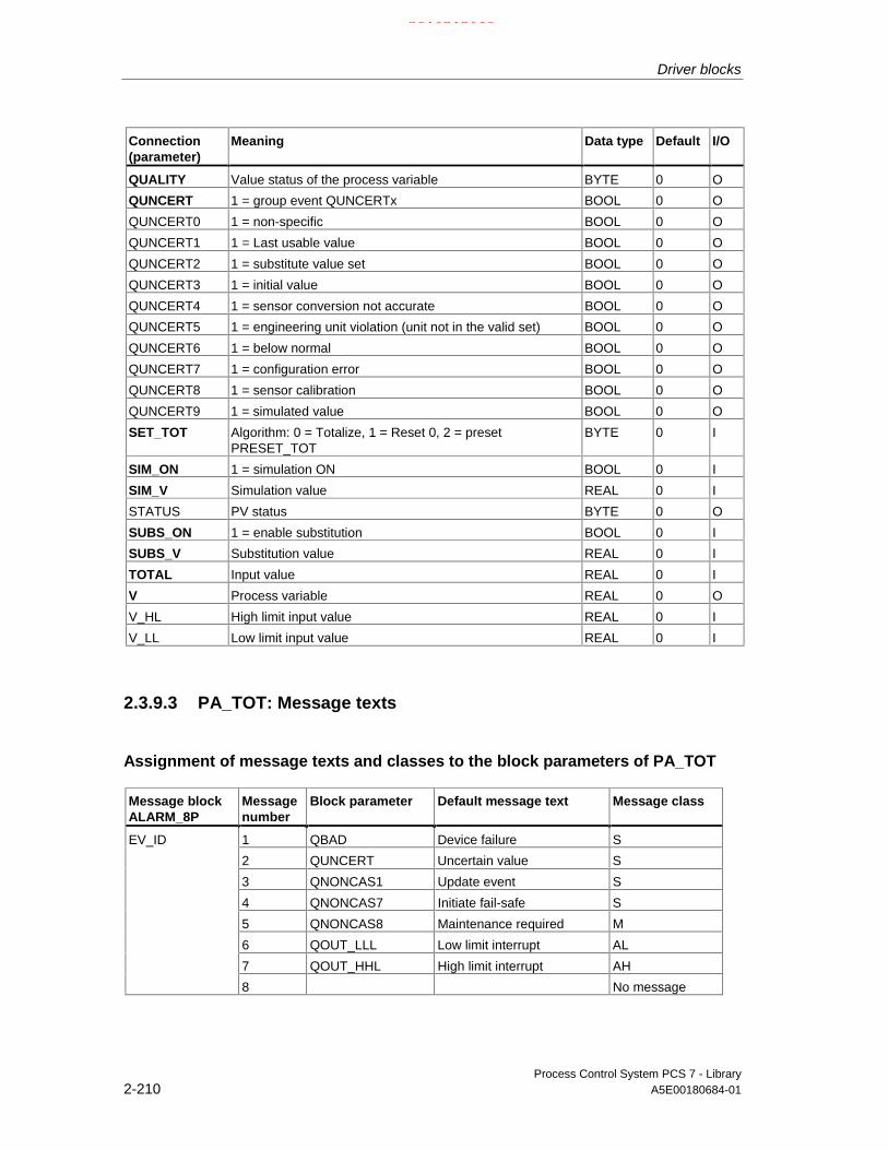
Driver blocks
Process Control System PCS 7 - Library2-210 A5E00180684-01
Connection(parameter)
Meaning Data type Default I/O
QUALITY Value status of the process variable BYTE 0 O
QUNCERT 1 = group event QUNCERTx BOOL 0 O
QUNCERT0 1 = non-specific BOOL 0 O
QUNCERT1 1 = Last usable value BOOL 0 O
QUNCERT2 1 = substitute value set BOOL 0 O
QUNCERT3 1 = initial value BOOL 0 O
QUNCERT4 1 = sensor conversion not accurate BOOL 0 O
QUNCERT5 1 = engineering unit violation (unit not in the valid set) BOOL 0 O
QUNCERT6 1 = below normal BOOL 0 O
QUNCERT7 1 = configuration error BOOL 0 O
QUNCERT8 1 = sensor calibration BOOL 0 O
QUNCERT9 1 = simulated value BOOL 0 O
SET_TOT Algorithm: 0 = Totalize, 1 = Reset 0, 2 = presetPRESET_TOT
BYTE 0 I
SIM_ON 1 = simulation ON BOOL 0 I
SIM_V Simulation value REAL 0 I
STATUS PV status BYTE 0 O
SUBS_ON 1 = enable substitution BOOL 0 I
SUBS_V Substitution value REAL 0 I
TOTAL Input value REAL 0 I
V Process variable REAL 0 O
V_HL High limit input value REAL 0 I
V_LL Low limit input value REAL 0 I
2.3.9.3 PA_TOT: Message texts
Assignment of message texts and classes to the block parameters of PA_TOT
Message blockALARM_8P
Messagenumber
Block parameter Default message text Message class
1 QBAD Device failure S
2 QUNCERT Uncertain value S
3 QNONCAS1 Update event S
4 QNONCAS7 Initiate fail-safe S
5 QNONCAS8 Maintenance required M
6 QOUT_LLL Low limit interrupt AL
7 QOUT_HHL High limit interrupt AH
EV_ID
8 No message
21.02.2003

Driver blocks
Process Control System PCS 7 - LibraryA5E00180684-01 2-211
2.3.10 PADP_L0x: monitoring DP/PA slaves
2.3.10.1 PADP_L00: Description
Object name (type + number)
FB 109
Area of application
The block monitors DP/PA field devices operating as DPV0 or DPV1 slavedownstream of a DP/PA or Y link that is operated as DPV0 slave. The PA fielddevices must conform with the PROFIBUS PA V3.0. Individual blocks must beavailable for the diagnostic and signal processing functions of DP field devices.
The calling OBs
The block must be installed into the run sequence of the following OBs (carried outautomatically in CFC):
OB1 Cyclic program
OB82 Diagnostic interrupt
OB85 Program runtime error
OB86 Rack failure
OB100 Restart (warm start)
Use in the CFC
The CFC function "Generate module drivers" automatically:
• Installs the PADP_L00 block in the run sequence downstream of the DPAY_V0block
• Configures
- The MODE_xx input (mode of slot xx of a field device).
- The PADP_ADR input (DP/PA slave address downstream of a DP/PA orY link).
21.02.2003

Driver blocks
Process Control System PCS 7 - Library2-212 A5E00180684-01
• Interconnects
- The inputs to the inputs of the DPAY_V0
- The OUT structure CPU_DIAG of the OB_BEGIN and RAC_DIAG of theDPAY_V0 block to the INOUT structures of the same name at thePADP_L00 block.
Note: The CFC function "Generate module drivers" can only be used if the PAfield device belongs to slave family 12.
Function and operating principle
The block (acyclic service) analyzes all events affecting a DP or PA field deviceand its slots. It forms the corresponding DP_MODE or PA_MODE and value statusfor the DP or PA signal processing blocks for each individual slot. The permissiblePA_MODE is already defined for the PA signal processing blocks, whileDP_MODE has to be defined individually for the blocks of the DP field devices. Theevents are reported via ALARM_8P. The message function can be disabled.
The higher-level DPAY_V0 block enables runtime of the block. The startupinformation (CPU_DIAG) of the OB_BEGIN block contains the event to beevaluated.
Diagnostic data are already evaluated by the LINK block (DPAY_V0). Thediagnostic data affecting the PA field device are stored in the structure DPA_M.The structure consists of two DWORD (S_01 for modules 1 to 16 and S_02 formodules 17 to 32) and one BOOL (S_ERR = DP/PA field device faulty) variables.Two bits of the DWORD are assigned to each slot of the DP/PA field device,whereby bit 0 and bit 1 belong to slot 1 of the DP/PA field device, etc. The blockevaluates slots 1 to 7. The bit states are defined as follows:
Status bit 0 Status bit 1 Meaning
0 0 Module x OK (valid user data)
0 1 Module x fault (invalid user data)
1 0 Wrong module x (invalid user data)
1 1 No module x (invalid user data)
Each slot (module) of the DP/PA field device is assigned an input (MODE_xx) usedto enter HW Config data for the slots (modules).
At DP field devices the user must enter his code manually at the MODE input.
MODE_xx is written to the low word of output OMODE_xx. This happens onlyduring the startup/initial start or if you set ACC_MODE = TRUE. The current valuestatus of the slot is entered in the most significant byte. If no error has occurred,OMODE_xx = 16#80xxxxxx. The following events lead to the value status "Invalidvalue due to higher-priority error" (OMODE_xx = 16#40xxxxxx):
21.02.2003

Driver blocks
Process Control System PCS 7 - LibraryA5E00180684-01 2-213
The DPAY_V0 block evaluates these events:
• Rack failure (OB86) (output parameter QRACKF = TRUE)
• Diagnostic interrupt, specific to the fielddevice (OB82)
(output parameter QMODF = TRUE,if DPA_M.S_ERR = TRUE)
• Diagnostic interrupt, specific to slot xxof a field device (OB82):
(output parameter OMODE_xx =module (slot-) error-specific DPA_M)
The block ALARM_8P to report diagnostic interrupts specific to a field device toWinCC. It distinguishes between the field device and its slots and assigns amessage number to each slot.
Redundancy
The higher-level DPAY_V0 block evaluates the redundancy of DP Master systemsoperating in an H system.
MODE setting for PA profiles
PA_MODE: Setting
Note
If you change the configuration of the MODE_xx inputs during runtime, the changeis not accepted at the outputs until input ACC_MODE = 1.
OMODE structure
Refer to OMODE
Error handling
The plausibility of input parameters is not checked.
Startup characteristics
After a restart or an initial start the system verifies that the PA field device isavailable under its logical base address. A restart (OB100) is reported via the LSBin byte 2 of outputs OMODE_xx.
Time response
n.a.
21.02.2003

Driver blocks
Process Control System PCS 7 - Library2-214 A5E00180684-01
Message characteristics
The block uses ALARM_8P to report field device errors and generates thefollowing messages in the OBs listed below:
OB no. Startup event Message
OB1 Cyclic processing Repeat update of ALARM_8P outputs / messages, if necessary
OB82 Diagnostic interrupt Device error incoming/outgoingDevice module xx fault incoming/outgoingDevice module xx incorrect incoming/outgoingDevice module xx missing incoming/outgoing
OB100 Restart Initializing ALARM_8P
Operator control and monitoring
The block does not have a faceplate.
Note: In the OCM column of the "PADP_L00 …" table, the "+" character identifiesthe variables to be transferred to the OS, if you have set the "enable operatorcontrol and monitoring" attribute in the block object properties. Default: This optionis not set.
2.3.10.2 PADP_L0x: I/Os
The I/Os of the PADP_L00, PADP_L01 and PADP_L02 blocks are identical savefor the number of MODE_xx and OMODE_xx. The number of monitored slotsdetermines the number of corresponding I/O parameters.
The factory setting of the block display in CFC is identified in the I/O column: I/Oname in bold characters = I/O visible, in normal characters = hidden.
I/O(parameter)
Meaning Data type Default Type OCM
ACC_MODE 1 = accept MODE settings BOOL 0 I/O
CPU_DIAG CPU diagnostics STRUCT I/O
DPA_M Status modules of DP/PA slave STRUCT I
EN_MSG 1 = enable message BOOL 1 I
EV_ID Message number DWORD 0 I
MODE_xx Module mode (xx = 00 - 06 / 00 - 15 / 00 - 31) WORD 0 I
MSG_ACK Message acknowledgement WORD 0 O
MSGSTAT Error message status WORD 0 O
OMODE_xx Module mode (xx = 00 - 06 / 00 - 15 / 00 - 31) DWORD 0 O +
PADP_ADR Address of the DP/PA field device BYTE 0 I
QERR 1 = program error BOOL 1 O
QMODF 1 = removed/ faulty module BOOL 0 O +
QRACKF 1 = rack/station fault BOOL 0 O
RAC_DIAG 1 = DPV1 mode STRUCT I/O
21.02.2003

Driver blocks
Process Control System PCS 7 - LibraryA5E00180684-01 2-215
2.3.10.3 PADP_L00: Message texts and auxiliary process values
Assignment of message texts and classes to the block parameters of PADP_L00
Message blockALARM_8P
Messagenumber
Blockparameter
Default message text Messageclass
1 QMODF Device @1%d@/@2%d@/@3%d@: Failure S
2 - Device @1%d@/@2%d@/@3%d@:Module 00 @4W%t#PADP_L00_TXT@
S
... ...
EV_ID
8 - Device @1%d@/@2%d@/@3%d@:Module 06 @10W%t#PADP_L00_TXT@
S
The message texts and their numbers in the text library PADP_L00_TXT are listedin Text Library for DP-/PA slaves downstream of a PA / Y LINK DP V0
Assignment of the auxiliary process values for the block parameters ofPADP_L00
Message blockALARM_8P
Value Blockparameter
Meaning
1 SUBN_ID DP master system ID (byte)
2 RACK_NO Rack / station number (byte)
3 PADP_ADR DP/PA device address (byte)
EV_ID
4 Text number (messages 2 - 8) from PADP_L00_TXT
If the PA field device is connected downstream of an inactive DP/PA Link V0 andSUBN1_ID = 16#FF, then SUBN2_ID is entered as auxiliary process value.
21.02.2003

Driver blocks
Process Control System PCS 7 - Library2-216 A5E00180684-01
2.3.10.4 PADP_L01: Description
Object name (type + number)
FB 110
Area of application
The block monitors DP/PA field devices operating as DPV0 or DPV1 slavedownstream of a DP/PA or Y link that is operated as DPV0 slave. The PA fielddevices must conform with the PROFIBUS PA V3.0 profile. Individual blocks mustbe available for the diagnostic and signal processing functions of DP field devices.H systems support only the PA field devices connected to an active DP/PA link.
The calling OBs
The block must be installed in the run sequence of the following OBs (carried outautomatically in CFC):
OB1 Cyclic program
OB82 Diagnostic interrupt
OB85 Program execution error
OB86 Rack failure
OB100 Restart (warm start)
Use in the CFC
The CFC function "Generate module drivers" automatically:
• Installs the PADP_L01 block in the run sequence downstream of the DPAY_V0block
• Configures
- The MODE_xx input (mode of slot xx of a field device).
- The PADP_ADR input (DP/PA slave address downstream of a DP/PA or Ylink).
• Interconnects
- The inputs to the inputs of DPAY_V0
- The OUT structure CPU_DIAG of OB_BEGIN and RAC_DIAG ofDPAY_V0 with the INOUT structures of the same name at the PADP_L01block.
Note: The CFC function "Generate module drivers" can only be used if the PAfield device belongs to slave family 12.
21.02.2003

Driver blocks
Process Control System PCS 7 - LibraryA5E00180684-01 2-217
Function and operating principle
The block (acyclic service) analyzes all events affecting a DP or PA field deviceand its slots. It forms the corresponding DP_MODE or PA_MODE and value statusfor the DP or PA signal processing blocks for each individual slot. The permissiblePA_MODE is already defined for the PA signal processing blocks, whileDP_MODE has to be defined individually for the blocks of the DP field devices. Theevents are reported via ALARM_8P. The message function can be disabled.
The higher-level DPAY_V0 block enables runtime of the block. The startupinformation (CPU_DIAG) of the OB_BEGIN block contains the event to beevaluated.
Diagnostic data are already evaluated by the LINK block (DPAY_V0). Thediagnostic data affecting the PA field device are stored in the structure DPA_M.The structure consists of two DWORD (S_01 for modules 1 to 16 and S_02 formodules 17 to 32) and one BOOL (S_ERR = DP/PA field device faulty) variables.Two bits of the DWORD are assigned to each slot of the DP/PA field device,whereby bit 0 and bit 1 belong to slot 1 of the DP/PA field device, etc. The blockevaluates slots 1 to 7. The bit states are defined as follows:
Status bit 0 Status bit 1 Meaning
0 0 Module x OK (valid user data)
0 1 Module x fault (invalid user data)
1 0 Wrong module x (invalid user data)
1 1 No module x (invalid user data)
Each slot (module) of the DP/PA field device is assigned an input (MODE_xx) thatis used to read in HW Config data for the slots (modules).
At DP field devices the user must enter his code manually at the MODE input.
MODE_xx is written to the low word of output parameter OMODE_xx. Thishappens only during the startup/initial start or if you set ACC_MODE = TRUE. Thecurrent value status of the slot is entered in the most significant byte. If valid,OMODE_xx = 16#80xxxxxx. The following events lead to the value status "Invalidvalue due to higher-priority error" (OMODE_xx = 16#40xxxxxx):
• Rack failure (OB86) (output parameter QRACKF = TRUE)
• Diagnostic interrupt concerning acomplete field device (OB82)
(output parameter QMODF = TRUE,if DPA_M.S_ERR = TRUE)
• Diagnostic interrupt slot xx concerninga field device (OB82):
(output parameter OMODE_xx =Module-(slot-)error specific DPA_M)
The above events are evaluated by the DPAY_V0 block.
The block uses ALARM_8P to report diagnostic interrupts specific to a field deviceto WinCC. It distinguishes between the field device and its slots, and assigns amessage number to each slot.
21.02.2003

Driver blocks
Process Control System PCS 7 - Library2-218 A5E00180684-01
Redundancy
The higher-level DPAY_V0 block evaluates the redundancy of DP Master systemsoperating in an H system.
MODE setting for PA profiles
PA_MODE: Setting
Note
Modifications of the configuration of MODE_xx inputs during runtime are notaccepted at the outputs until input ACC_MODE = 1.
OMODE structure
Refer to OMODE
Error handling
The plausibility of input parameters is not checked.
Startup characteristics
After a restart or an initial start the system verifies that the PA field device isavailable under its logical base address. A restart (OB100) is reported via the LSBin byte 2 of outputs OMODE_xx.
Time response
n.a.
Message characteristics
The block uses ALARM_8P to report field device errors and generates thefollowing messages in the OBs listed below:
OB no. Startup event Message
OB1 Cyclic processing Repeat update of ALARM_8P outputs / messages, if necessary
OB82 Diagnostic interrupt Device error incoming/outgoingDevice module xx fault incoming/outgoingDevice module xx incorrect incoming/outgoingDevice module xx missing incoming/outgoing
OB100 Restart Initializing ALARM_8P
21.02.2003

Driver blocks
Process Control System PCS 7 - LibraryA5E00180684-01 2-219
Operator control and monitoring
The block does not have a faceplate.
Note: In the OCM column of the "PADP_L01" table, the "+" character identifies thevariables to be transferred to the OS, if you have set the "enable operator controland monitoring" attribute in the block object properties. Default: This option is notset.
2.3.10.5 PADP_L01: Message texts and auxiliary process values
Assignment of message texts and classes to the block parameters of PADP_L01
Message blockALARM_8P
Messagenumber
Blockparameter
Default message text Messageclass
1 QMODF Device @1%d@/@2%d@/@3%d@:Failure
S
2 - Device @1%d@/@2%d@/@3%d@:Module 07 @4W%t#PADP_L01_TXT@
S
EV_ID1
3 - Device @1%d@/@2%d@/@3%d@:Module 15 @5W%t#PADP_L01_TXT@
S
1 - Device @1%d@/@2%d@/@3%d@:Module 00 @4W%t#PADP_L01_TXT@
S
... ...
EV_ID2
7 - Device @1%d@/@2%d@/@3%d@:Module 06 @10W%t#PADP_L01_TXT@
S
1 - Device @1%d@/@2%d@/@3%d@:Module 08 @5W%t#PADP_L01_TXT@
S
2 - -
... ...
EV_ID3
7 - Device @1%d@/@2%d@/@3%d@:Module 14 @10W%t#PADP_L01_TXT@
S
The message texts and their numbers in the text library PADP_L01_TXT are listedin the Text Library for DP/PA slaves downstream of a PA or Y LINK DP V0
21.02.2003

Driver blocks
Process Control System PCS 7 - Library2-220 A5E00180684-01
Assignment of the auxiliary process values to the block parameters ofPADP_L01
Message blockALARM_8P
Value Blockparameter
Meaning
1 SUBN_ID DP master system ID (byte)
2 RACK_NO Rack / station number (byte)
3 PADP_ADR DP/PA device address (byte)
EV_ID1
4 - Text number (message 2 - 8) from PADP_L01_TXT
1 SUBN_ID DP master system ID(byte)
2 RACK_NO Rack / station number (byte)
3 PADP_ADR DP/PA device address (byte)
EV_ID2
4 - Text number (message 1 - 8) from PADP_L01_TXT
1 SUBN_ID DP master system ID (byte)
2 RACK_NO Rack / station number (byte)
3 PADP_ADR DP/PA device address (byte)
EV_ID3
4 - Text number (message 1) from PADP_L01_TXT
At PA field devices connected downstream of an inactive DP/PA Link V0 andSUBN1_ID = 16#FF, the auxiliary process variable is substituted by SUBN2_ID.
21.02.2003

Driver blocks
Process Control System PCS 7 - LibraryA5E00180684-01 2-221
2.3.10.6 PADP_L02: Description
Object name (type + number)
FB 111
Area of application
The block monitors DP/PA field devices operating as DPV0 or DPV1 slavedownstream of a DP/PA or Y link that is operated as DPV0 slave. The PA fielddevices must conform with the PROFIBUS PA V3.0 profile. Individual blocks mustbe available for the diagnostic and signal processing functions of DP field devices.H systems support only the PA field devices connected to an active DP/PA link.
The calling OBs
The block must be installed in the run sequence of the following OBs (carried outautomatically in CFC):
OB1 Cyclic program
OB82 Diagnostic interrupt
OB85 Program execution error
OB86 Rack failure
OB100 Restart (warm start)
Use in the CFC
The CFC function "Generate module drivers" automatically:
• Installs the PADP_L02 block in the run sequence downstream of the DPAY_V0block
• Configures
- The MODE_xx input (mode of slot xx of a field device).
- The PADP_ADR input (DP/PA slave address downstream of a DP/PA or Ylink).
• Interconnects
- The inputs with the inputs of DPAY_V0
- The OUT structure CPU_DIAG of OB_BEGIN and RAC_DIAG ofDPAY_V0 with the INOUT structures of the same name at the PADP_L01block.
Note: The CFC function "Generate module drivers" can only be used if the PAfield device belongs to slave family 12.
21.02.2003

Driver blocks
Process Control System PCS 7 - Library2-222 A5E00180684-01
Function and operating principle
The block (acyclic service) analyzes all events affecting a DP or PA field deviceand its slots. It forms the corresponding DP_MODE or PA_MODE and value statusfor the DP or PA signal processing blocks for each individual slot. The permissiblePA_MODE is already defined for the PA signal processing blocks, whileDP_MODE has to be defined individually for the blocks of the DP field devices. Theevents are reported via ALARM_8P. The message function can be disabled.
The higher-level DPAY_V0 block enables runtime of the block. The startupinformation (CPU_DIAG) of the OB_BEGIN block contains the event to beevaluated.
Diagnostic data are already evaluated by the LINK block (DPAY_V0). Thediagnostic data affecting the PA field device are stored in the structure DPA_M.The structure consists of two DWORD (S_01 for modules 1 to 16 and S_02 formodules 17 to 32) and one BOOL (S_ERR = DP/PA field device faulty) variables.Two bits of the DWORD are assigned to each slot of the DP/PA field device,whereby bit 0 and bit 1 belong to slot 1 of the DP/PA field device, etc. The blockevaluates slots 1 to 7. The bit states are defined as follows:
Status bit 0 Status bit 1 Meaning
0 0 Module x OK (valid user data)
0 1 Module x fault (invalid user data)
1 0 Wrong module x (invalid user data)
1 1 No module x (invalid user data)
Each slot (module) of the DP/PA field device is assigned an input (MODE_xx) thatis used to read in HW Config data for the slots (modules).
At DP field devices the user must enter his code manually at the MODE input.
MODE_xx is written to the low word of output OMODE_xx. This happens onlyduring the startup/initial start or if you set ACC_MODE = TRUE. The current valuestatus of the slot is entered in the most significant byte. If no error has occurred,OMODE_xx = 16#80xxxxxx. The following events lead to the value status "Invalidvalue due to higher-priority error" (OMODE_xx = 16#40xxxxxx):
• Rack failure (OB86) (output parameter QRACKF = TRUE)
• Diagnostic interrupt concerning acomplete field device (OB82)
(output parameter QMODF = TRUE,if DPA_M.S_ERR = TRUE)
• Diagnostic interrupt slot xx concerninga field device (OB82):
(output parameter OMODE_xx =Module-(slot-)error specific DPA_M)
The above events are evaluated by the DPAY_V0 block.
The block ALARM_8P to report diagnostic interrupts specific to a field device toWinCC. It distinguishes between the field device and its slots, and assigns amessage number to each slot.
21.02.2003

Driver blocks
Process Control System PCS 7 - LibraryA5E00180684-01 2-223
Redundancy
The higher-level DPAY_V0 block evaluates the redundancy of DP Master systemsoperating in an H system.
MODE setting for PA profiles
PA_MODE: Setting
Note
Modifications of the configuration of MODE_xx inputs during runtime are notaccepted at the outputs until input ACC_MODE = 1.
OMODE structure
Refer to OMODE
Error handling
The plausibility of input parameters is not checked.
Startup characteristics
After a restart or an initial start the system verifies that the PA field device isavailable under its logical base address. A restart (OB100) is reported via the LSBin byte 2 of outputs OMODE_xx.
Time response
n.a.
Message characteristics
The block uses ALARM_8P to report field device errors and generates thefollowing messages in the OBs listed below:
OB no. Startup event Message
OB1 Cyclic processing Repeat update of ALARM_8P outputs / messages, if necessary
OB82 Diagnostic interrupt Device error incoming/outgoingDevice module xx fault incoming/outgoingDevice module xx incorrect incoming/outgoingDevice module xx missing incoming/outgoing
OB100 Restart Initializing ALARM_8P
21.02.2003

Driver blocks
Process Control System PCS 7 - Library2-224 A5E00180684-01
Operator control and monitoring
The block does not have a faceplate.
Note: In the OCM column of the "PADP_L02 …" table, the "+" character identifiesthe variables to be transferred to the OS, if you have set the "enable operatorcontrol and monitoring" attribute in the block object properties. Default: This optionis not set.
2.3.10.7 PADP_L02: Message texts and auxiliary process values
Assignment of message texts and classes to the block parameters of PADP_L02
Message blockALARM_8P
Messagenumber
Blockparameter
Default message text Messageclass
1 QMODF Device @1%d@/@2%d@/@3%d@:Failure
S
2 - Device @1%d@/@2%d@/@3%d@:Module 07@4W%t#PADP_L02_TXT@
S
3 - Device @1%d@/@2%d@/@3%d@:Module 15@5W%t#PADP_L02_TXT@
S
4 - Device @1%d@/@2%d@/@3%d@:Module 23@6W%t#PADP_L02_TXT@
S
EV_ID1
5 - Device @1%d@/@2%d@/@3%d@:Module 31@7W%t#PADP_L02_TXT@
S
1 - Device @1%d@/@2%d@/@3%d@:Module 00@4W%t#PADP_L02_TXT@
S
... ...
EV_ID2
7 - Device @1%d@/@2%d@/@3%d@:Module 06@10W%t#PADP_L02_TXT@
S
1 - Device @1%d@/@2%d@/@3%d@:Module 08@4W%t#PADP_L02_TXT@
S
... ...
EV_ID3
7 - Device @1%d@/@2%d@/@3%d@:Module 14@10W%t#PADP_L02_TXT@
S
1 - Device @1%d@/@2%d@/@3%d@:Module 16@4W%t#PADP_L02_TXT@
S
... ...
EV_ID4
- Device @1%d@/@2%d@/@3%d@:Module 22@10W%t#PADP_L02_TXT@
S
21.02.2003

Driver blocks
Process Control System PCS 7 - LibraryA5E00180684-01 2-225
Message blockALARM_8P
Messagenumber
Blockparameter
Default message text Messageclass
1 - Device @1%d@/@2%d@/@3%d@:Module 24@4W%t#PADP_L02_TXT@
S
... ...
EV_ID5
7 - Device @1%d@/@2%d@/@3%d@:Module 30@10W%t#PADP_L02_TXT@
S
The message texts and their numbers in the text library PADP_L02_TXT are listedin the Text Library for DP/PA slaves downstream of a PA or Y LINK DP V0
Assignment of the auxiliary process values to the block parameters ofPADO_L02
Message blockALARM_8P
Value Block parameter Meaning
1 SUBN_ID DP master system ID (byte)
2 RACK_NO Rack / station number (byte)
3 PADP_ADR DP/PA device address (byte)
EV_ID1
4 - Text number (message 2 - 8) from PADP_L02_TXT
1 SUBN_ID DP master system ID(byte)
2 RACK_NO Rack / station number (byte)
3 PADP_ADR DP/PA device address (byte)
EV_ID2
4 - Text number (message 1 - 8) from PADP_L02_TXT
1 SUBN_ID DP master system ID (byte)
2 RACK_NO Rack / station number (byte)
3 PADP_ADR DP/PA device address (byte)
EV_ID3
4 - Text number (message 1 - 8) from PADP_L02_TXT
1 SUBN_ID DP master system ID (byte)
2 RACK_NO Rack / station number (byte)
3 PADP_ADR DP/PA device address (byte)
EV_ID4
4 - Text number (message 1 - 8) from PADP_L02_TXT
1 SUBN_ID DP master system ID (byte)
2 RACK_NO Rack / station number (byte)
3 PADP_ADR DP/PA device address (byte)
EV_ID5
4 - Text number (message 1) from PADP_L02_TXT
At PA field device is connected downstream of an inactive DP/PA Link V0 andSUBN1_ID = 16#FF, the SUBN2_ID will be entered as auxiliary process variable.
21.02.2003

Driver blocks
Process Control System PCS 7 - Library2-226 A5E00180684-01
2.3.11 PADP_L10 :Monitoring DPV0 PA with max. 16 slots
2.3.11.1 PADP_L10: Description
Object name (type + number)
FB 116
Area of application
The block monitors DPV0 PA field devices with max. 16 slots, which are operatedas DP V0 slaves via a DP/PA coupler that is connected downstream of a DP/PALink DP V1. The PA field devices must conform with the PROFIBUS PA V3.0profile. H systems support only the PA field devices at an active DP/PA Link.
The calling OBs
The block must be installed in the run sequence downstream of the OB_DIAG1block in the following OBs (carried out automatically in CFC):
OB1 Cyclic program
OB55 Status interrupt (only if a PA slave is required)
OB56 Update interrupt (only if a PA slave is required)
OB57 Manufacturer-specific interrupt (only if a PA slave is required)
OB82 Diagnostic interrupt
OB83 Removal/insertion interrupt (failure/return of a field device)
OB85 Program runtime error
OB86 Rack failure
OB100 Restart (warm start)
21.02.2003

Driver blocks
Process Control System PCS 7 - LibraryA5E00180684-01 2-227
Use in CFC
The CFC -function "Generate module drivers" automatically
• Inserts OB_DIAG1 upstream of the PADP_L10 block
• Configures
- The diagnostic address DADDR of the PA field device
- The geographical address (SUBN1_ID, SUBN2_ID, RACK_NO of theDP/PA link)
- The geographical address PA field device in the DP/PA link (SLOT0_NO =Slot 0 no. for the PA field device, SLOTS_NO = number of slots of the PAfield device)
- The PA address of the PA field device (PADP_ADR)
- MODE_xx (mode of slots xx of a PA field device)
• Interconnects
- The OUT structures CPU_DIAG and CPU_OB_5X of the OB_BEGIN blockand RAC_DIAG of the OB_DIAG1 block with the INOUT structures of thesame name at PADP_L10.
- The EN input to the output of an AND blockwhose inputs are interconnected to the outputs EN_SUBx (x = ID of the DPmaster system) of the OB_BEGIN block, with EN_Rxxx (xxx = rack/stationnumber) of the SUBNET block, with EN_Mx (x= number of the PA device)of the DPAY_V1 block and with EN_F of the OB_DIAG1 block.
- EN_DIAG with output EN_DIAG of the OB_DIAG1 block
Note: The CFC function "Generate module drivers" can only be used if the PAfield device belongs to slave family 12.
Functions
The block analyzes all events affecting a PA field device. It forms the slot-specificMODE (PA_MODE) and the value status for signal processing blocks. Thepermissible PA_MODE is defined for PA field devices.
When operating with modular PA field devices (DP V0), the downstream block(MOD_PAL0) always reports the events in slot 0 of the PA field device in theDP/PA link. The affected MOD_PAL0 block will be enabled.
21.02.2003

Driver blocks
Process Control System PCS 7 - Library2-228 A5E00180684-01
Operating principle
Block runtime is enabled by the higher-level OB_DIAG1 block. The startupinformation (CPU_DIAG) of OB_BEGIN contains the event to be evaluated. Theblock analyzes its geographical address and the number of slots (SLOT_NO) inorder to determine whether it is responsible for this event.
SFB54 is used to read information of diagnostic events (OB82, OB55, OB56,OB57)synchronously from the OB_BEGIN block.
If diagnostic data of OB_BEGIN could not be read synchronously or by means of arequest of OB_DIAG1 (EN_DIAG = TRUE), SFC13 is used to read thesediagnostic data asynchronously.
Byte 9 of the additional interrupt information contains the slot number of the fielddevice that has triggered the diagnostic interrupt. The corresponding slot will beenabled.
The following diagnostic data are interpreted as higher-priority error in the block:
Additional interrupt information
Byte no. DPV1 name Bit no. Value Info
Byte 1 to 6 DDLM_SLAVE_DIAG
Byte 7 Header Bit 7
Bit 6
Bit 5 to bit 0
0
0
8 or optional
fixed
fixed
Length of diagnostic data
Byte 8 Status_Type Bit 7
Bit 6 to bit 0
1
126
Status
Highest manufacturer-specific status.not used in the future.
Byte 9 Slot_number Slot number of the PB The PB contains thediagnostic data.
Byte 10 Specifier Bit 7 to bit 2
Bit 1 to bit 0
reserved
1: status is displayed
2: status is not displayed
Depends on the content ofdiagnostics data.
Byte 11 to 14 Diagnostics
optionalByte 11 to 20
At a DPV0 PA field device the diagnostic data are always assigned to slot 0.
It is also possible to generate slot-specific data for PA field device to DP V1. Thesehave not yet been defined. Only the diagnostic event triggering slot of a DPV1 fielddevice will be enabled. Evaluation of the coding in the context of higher-priorityerrors at the slot-specific outputs OMODExx is based only on the diagnosticinformation at slot 0.
MODE setting for PA profiles (PA_MODE)Input parameters MODE_xx are available for a maximum of 16 slots at a PA fielddevice. Their default setting is zero (no read/write access). You must set the
21.02.2003

Driver blocks
Process Control System PCS 7 - LibraryA5E00180684-01 2-229
combination selected from the options of the PROFIBUS PA 3.0 profile at theMODE_xx input of each slot channel xx:
See "MODE settings for PA devices"
MODE_xx is written to the low word of output parameter OMODE_xx. This onlyhappens during startup/initial startup, or if you set ACC_MODE = TRUE. The mostsignificant byte contains the actual value status of the slot. If no error has occurred,OMODE_xx = 16#80xxxxxx. The following event will lead to a value status "invalidvalue due to higher-priority error " (OMODE_xx = 16#40xxxxxx):
• Rack failure (OB86) (output parameter QRACKF = TRUE)
• Failure/return of a field device (OB83)
• Slot-specific diagnostic interrupt (OB82)
Byte 11 and 12 of the additional interrupt information are evaluated to form the slot-specific value status:
Byte Bit Mnemonics Description Displayclass
11 0123456
7
DIA_HW_ELECTRDIA HW MECHDIA_TEMP_MOTORDIA TEMP ELECTRDIA MEM CHKSUMDIA_MEASUREMENTDIA NOT INIT
DIA_INIT_ERR
Electronic hardware failureMechanical hardware failureExcess motor temperatureExcess temperature at electronic circuitMemory errorMeasurement failureDevice not initialized(no self-calibrationAuto-calibration error
RRRRRRR
R12 0
1234567
DIA ZERO ERRDIA_SUPPLYDIA CONV INVALDIA_WARMSTARTDIA COLDSTARTDIA MAINTAINANCEDIA_CHARACTIDENT NUMBER Violation
Zero error (limit position)no power supply (electropneumaticcircuit)Invalid configurationRestart (warm start) executedRestart (complete restart) executedMaintenance requiredInvalid IDSet to 1 if the ID numbers of thecurrent cyclic data transferand the value of the parameters IDENTNUMBER of the physical block are notidentical
RRRAARRR
13 0...7 reserved Reserved for use in the PNO1414
0...67
reservedEXTENSION_AVAILABLE
Reserved for use in the PNOadditional diagnostic information isavailable
Higher-priority errors relating to the value status (OMODE_xx = 16#40xxxxxx) allevents are assigned bit 0, 1 and 2 in byte 11 and byte 12.
21.02.2003
Driver blocks
Process Control System PCS 7 - Library2-230 A5E00180684-01
Peculiarities of PA_AO und PA_DO field devices
At the field devices mentioned above, the PA profiles can be defined at twodifferent slots. The driver generator will in this case assign the mode code of thePA field device to the first slot and the mode code 16#8000 to the second at thecorresponding MODE input of the block. The diagnostic information of the first andof the second slot are linked by a logical OR operation, which allows the generationof a uniform value status for the PA_x block.
Redundancy
IN H systems the higher-level block is always used to evaluate redundancy of theDP master systems.
Structure of OMODE
See OMODE
Addressing
See Addressing
Error handling
The plausibility of input parameters is not checked.
Startup characteristics
A restart (OB100) is reported via the LSB in byte 2 of the OMODE_xx outputs.
Time response
n.a.
Message characteristics
n.a.
Operator control and monitoring
The block does not have a faceplate.
Note: In the OCM column of the "PADP_L10 …" table, the "+" character identifiesthe variables to be transferred to the OS, if you have set the "enable operatorcontrol and monitoring" attribute in the block object properties. Default: This optionis not set.
21.02.2003

Driver blocks
Process Control System PCS 7 - LibraryA5E00180684-01 2-231
2.3.11.2 PADP_L10: I/Os
The factory setting of the block display in CFC is identified in the I/O column:I/O name in bold characters = I/O visible, in normal characters = hidden.
I/O(parameter)
Meaning Data type Default Type OCM
ACC_MODE 1 = accept MODE settings BOOL 0 IO
CPU_DIAG CPU diagnostics STRUCT I/O
CPU_OB_5X OB_5x startup information STRUCT I/O
DADDR Diagnostic address of the PA field device INT 0 I
DELAY Interrupt delay (s) INT 2 I
DINFO Diagnostic status of the PA field device STRUCT O
EN_DIAG 1 = diagnostic error event has occurred BOOL 0 I
EN_M_xx Enable slot xx BOOL 0 O
MODE_xx Mode slot xx WORD 0 I
OMODE_xx Mode slot xx DWORD 0 O +
PADP_ADR Address of the PA field device BYTE 0 I
PROF_V30 1 = PA slave profile V3.0 BOOL 0 I
QERR 1 = program error BOOL 0 O
QMODF 1 = field device error/fault BOOL 0 O +
QPERAF 1 = I/O access error BOOL 0 O
QRACKF 1 = (Link) rack/station error BOOL 0 O
RAC_DIAG Link diagnostics STRUCT I/O
RACK_NO Rack number BYTE 0 I
SLOT0_NO Slot number 0 of the field device in the DP/PA or Ylink
BYTE 0 I
SLOTS_NO Number of slots of the field device BYTE 0 I
SUBN_TYP 1 = external DP interface BOOL 0 I
SUBN1_ID ID of the primary DP master system BYTE 255 I
SUBN2_ID ID of the redundant DP master system BYTE 255 I
21.02.2003

Driver blocks
Process Control System PCS 7 - Library2-232 A5E00180684-01
2.4 Appendix
2.4.1 Addressing
If you do not use the CFC function "Generate module drivers", you must set thelogical basic address of the module created with HW Config at the input LADDR. Ifinput SUBN_TYP = FALSE, the RACK of the module is connected to an integratedDP interface (distributed I/O device interface) of the CPU module by means of aline. Otherwise set SUBN_TYP = TRUE.
The following points are generally to be observed for all SM and PA modules:
• The basic address of modules equipped only with inputs, i.e. modules whichwrite data only to the input area of the CPU process image, can be fetcheddirectly from HW Config.
• For example: the module SM331 AI 8x12Bit 331-7KF01-0AB0:
Address input range HWConfig
Address output range HWConfig
LADDR(decimal / hex)
512 - 512 / 16#0200
• The MSB (most significant bit) must be set in the basic address fetched fromHW Config for modules equipped only with outputs, that is modules which readdata only from the output range of the CPU process image.
• For example, the module SM332 AO 4x12Bit 332-5HD01-0AB0:
Address input range HWConfig
Address output range HWConfig
LADDR(decimal / hex)
- 512 -32256 / 16#8200
• At mixed modules, i.e. the modules writing data to the input area of the processimage of the CPU and reading data from this process image, the base addressof the input area (HW Config) must be set at input LADDR and the baseaddress (from HW Config) of the output area must be set at input LADDR1;e.g. the modules SM323 DI/O 8x24V/05A 6ES7 323-1BH81-0AA0:
Address input area(HW Config)
Address output area(HW Config)
LADDR(decimal/hex)
LADDR1(decimal/hex)
12 12 12 / 16# 000C 12 / 16# 000C
21.02.2003

Driver blocks
Process Control System PCS 7 - LibraryA5E00180684-01 2-233
2.4.2 MSG_STAT: Error information of the output parameter
The messages can be disabled by setting EN_MSG = FALSE (output parameterMSG_STAT(_x) remains unchanged).
ALARM8_P(_x) is called in the acyclic OBs and in OB1 if message suppression isnot enabled. Error information of ALARM_8P(_x) - (messages can not be output) -are indicated at output parameter MSG_STAT(_x).
Details on the error information of output parameter MSG_STAT and on theacknowledgment word MSG_ACK(_x) of ALARM_8P are found in the Online Helpof SFB35 (ALARM_8P).
2.4.3 MODE settings for signal modules
Measuring range coding of the analog input module
Depending on the measuring range coding of the analog input modules, theparameter MODE_xx (measuring range coding) corresponding to the channel mustbe specified in accordance with the table. When thermocouples are used (due tothe various options of combining the measuring type (Coding A) and the measuringrange (Coding B)) this must be calculated based on the following formula. Theresult must be entered as INTEGER at the MODE input:
MODE = 256 ∗ Coding A + Coding B
Please note: The table displays the codings A and B in binary format, and the asMODE parameter in hexadecimal format.
Measuring type Coding (A) Measuring range Coding(B)
MODE(256∗A+B)
Voltage 2#0001 ± 25 mV 2#1010 16#010A
± 50 mV 2#1011 16#010B
± 80 mV 2#0001 16#0101
± 250 mV 2#0010 16#0102
± 500 mV 2#0011 16#0103
± 1 V 2#0100 16#0104
± 2.5 V 2#0101 16#0105
± 5 V 2#0110 16#0106
1 to 5 V 2#0111 16#0107
0 to 10 V 2#1000 16#0108
± 10 V 2#1001 16#0109
± 100 V 2#1100 16#010C
4-wire measuring transducer 2#0010 ± 3.2 mA 2#0000 16#0200
± 5 mA 2#0101 16#0205
± 10 mA 2#0001 16#0201
21.02.2003

Driver blocks
Process Control System PCS 7 - Library2-234 A5E00180684-01
Measuring type Coding (A) Measuring range Coding(B)
MODE(256∗A+B)
0 mA to 20 mA 2#0010 16#0202
4 mA to 20 mA 2#0011 16#0203
± 20 mA 2#0100 16#0204
HART interface 2#0111 4 mA to 20 mA 2#1100 16#070C
2-wire measuring transducer 2#0011 4 mA to 20 mA 2#0011 16#0303
Resistor 4-wire connection 2#0100 48 Ω 2#0000 16#0400
150 Ω 2#0010 16#0402
300 Ω 2#0100 16#0404
600 Ω 2#0110 16#0406
6000 Ω 2#1000 16#0408
Resistor 3-wire connection 2#0101 48 Ω 2#0000 16#0500
150 Ω 2#0010 16#0502
300 Ω 2#0100 16#0504
600 Ω 2#0110 16#0506
6000 Ω 2#1000 16#0508
Resistor 2-wire connection 2#0110 48 Ω 2#0000 16#0600
150 Ω 2#0010 16#0602
300 Ω 2#0100 16#0604
600 Ω 2#0110 16#0606
6000 Ω 2#1000 16#0608
Resistive thermocouple + linearization4-wire connection
2#1000 Pt 100 climate range 2#0000 16#0800
Pt 200 climate range 2#0111 16#0807
Pt 500 climate range 2#1000 16#0808
Pt 1000 climate range 2#1001 16#0809
Ni 100 climate range 2#0001 16#0801
Ni 1000 climate range 2#1010 16#080A
Pt 100 standard range 2#0010 16#0802
Pt 200 standard range 2#0011 16#0803
Pt 500 standard range 2#0100 16#0804
Pt 1000 standard range 2#0101 16#0805
Ni 100 standard range 2#1011 16#080B
Ni 1000 standard range 2#0110 16#0806
Ni 120 standard range 2#1100 16#080C
Ni 120 climate range 2#1101 16#080D
Cu10 climate range 2#1110 16#080E
Cu10 standard range 2#1111 16#080F
Ni 200 standard range 2#10000 16#0810
Ni 200 climate range 2#10001 16#0811
Ni 500 standard range 2#10010 16#0812
Ni 500 climate range 2#10011 16#0813
21.02.2003

Driver blocks
Process Control System PCS 7 - LibraryA5E00180684-01 2-235
Measuring type Coding (A) Measuring range Coding(B)
MODE(256∗A+B)
Resistive thermocouple + linearization3-wire connection
2#1001 Pt 100 climate range 2#0000 16#0900
Pt 200 climate range 2#0111 16#0907
Pt 500 climate range 2#1000 16#0908
Pt 1000 climate range 2#1001 16#0909
Ni 100 climate range 2#0001 16#0901
Ni 1000 climate range 2#1010 16#090A
Pt 100 standard range 2#0010 16#0902
Pt 200 standard range 2#0011 16#0903
Pt 500 standard range 2#0100 16#0904
Pt 1000 standard range 2#0101 16#0905
Ni 100 standard range 2#1011 16#090B
Ni 1000 standard range 2#0110 16#0906
Ni 120 standard range 2#1100 16#090C
Ni 120 climate range 2#1101 16#090D
Cu10 climate range 2#1110 16#090E
Cu10 standard range 2#1111 16#090F
Ni 200 standard range 2#10000 16#0910
Ni 200 climate range 2#10001 16#0911
Ni 500 standard range 2#10010 16#0912
Ni 500 climate range 2#10011 16#0913
Resistive thermocouple + linearization2-wire connection
2#1100 Pt 100 climate range 2#0000 16#0C00
Pt 200 climate range 2#0111 16#0C07
Pt 500 climate range 2#1000 16#0C08
Pt 1000 climate range 2#1001 16#0C09
Ni 100 climate range 2#0001 16#0C01
Ni 1000 climate range 2#1010 16#0C0A
Pt 100 standard range 2#0010 16#0C02
Pt 200 standard range 2#0011 16#0C03
Pt 500 standard range 2#0100 16#0C04
Pt 1000 standard range 2#0101 16#0C05
Ni 100 standard range 2#1011 16#0C0B
Ni 1000 standard range 2#0110 16#0C06
Ni 120 standard range 2#1100 16#0C0C
Ni 120 climate range 2#1101 16#0C0D
Cu10 climate range 2#1110 16#0C0E
Cu10 standard range 2#1111 16#0C0F
Ni 200 standard range 2#10000 16#0C10
Ni 200 climate range 2#10001 16#0C11
Ni 500 standard range 2#10010 16#0C12
Ni 500 climate range 2#10011 16#0C13
21.02.2003

Driver blocks
Process Control System PCS 7 - Library2-236 A5E00180684-01
Measuring type Coding (A) Measuring range Coding(B)
MODE(256∗A+B)
Thermocouples internal comparison 2#1010 Type B [PtRh-PtRh]
Type N [NiCrSi-NiSi]
Type E [NiCr-CuNi]
Type R [PtRh-Pt]
Type S [PtRh-Pt]
Type J [Fe-CuNi IEC]
Type L [Fe-CuNi DIN]
Type T [Cu-CuNi IEC]
Type K [NiCr-Ni]
Type U [Cu-CuNi DIN]
2#0000
2#0001
2#0010
2#0011
2#0100
2#0101
2#0110
2#0111
2#1000
2#1001
16#0A00
16#0A01
16#0A02
16#0A03
16#0A04
16#0A05
16#0A06
16#0A07
16#0A08
16#0A09
Thermocouples external comparison 2#1011 Type B [PtRh-PtRh]
Type N [NiCrSi-NiSi]
Type E [NiCr-CuNi]
Type R [PtRh-Pt]
Type S [PtRh-Pt]
Type J [Fe-CuNi IEC]
Type L [Fe-CuNi DIN]
Type T [Cu-CuNi IEC]
Type K [NiCr-Ni]
Type U [Cu-CuNi DIN]
2#0000
2#0001
2#0010
2#0011
2#0100
2#0101
2#0110
2#0111
2#1000
2#1001
16#0B00
16#0B01
16#0B02
16#0B03
16#0B04
16#0B05
16#0B06
16#0B07
16#0B08
16#0B09
Thermocouples + linearization internalcomparison
2#1101 Type B [PtRh-PtRh]
Type N [NiCrSi-NiSi]
Type E [NiCr-CuNi]
Type R [PtRh-Pt]
Type S [PtRh-Pt]
Type J [Fe-CuNi IEC]
Type L [Fe-CuNi DIN]
Type T [Cu-CuNi IEC]
Type K [NiCr-Ni]
Type U [Cu-CuNi DIN]
2#0000
2#0001
2#0010
2#0011
2#0100
2#0101
2#0110
2#0111
2#1000
2#1001
16#0D00
16#0D01
16#0D02
16#0D03
16#0D04
16#0D05
16#0D06
16#0D07
16#0D08
16#0D09
Thermocouples + linearizationexternal comparison
2#1110 Type B [PtRh-PtRh]
Type N [NiCrSi-NiSi]
Type E [NiCr-CuNi]
Type R [PtRh-Pt]
Type S [PtRh-Pt]
Type J [Fe-CuNi IEC]
Type L [Fe-CuNi DIN]
Type T [Cu-CuNi IEC]
Type K [NiCr-Ni]
Type U [Cu-CuNi DIN]
2#0000
2#0001
2#0010
2#0011
2#0100
2#0101
2#0110
2#0111
2#1000
2#1001
16#0E00
16#0E01
16#0E02
16#0E03
16#0E04
16#0E05
16#0E06
16#0E07
16#0E08
16#0E09
21.02.2003

Driver blocks
Process Control System PCS 7 - LibraryA5E00180684-01 2-237
Measuring range coding of the analog output modules
Depending on the coding of the measuring range of the analog output modules, theparameter MODE_xx (measuring range coding) corresponding to the channel mustbe set in accordance with the table.
Measuring type Measuring range MODE
Voltage 1 to 5 V 16#0107
0 to 10 V 16#0108
± 10 V 16#0109
Current 0 mA to 20 mA 16#0202
4 mA to 20 mA 16#0203
± 20 mA 16#0204
HART interface 4 mA to 20 mA 16#070C
Measuring range coding of the digital input and digital output modules
There is neither a measuring type nor a measuring range for digital input anddigital output modules:
MODE = 16#FFFF (at DI)MODE = 16#FFFE (at DO)
OMODE structure
The table below shows the structure and meaning of the outputs OMODE_xx ofdata type DWORD:
Byte 3: 16#80: Value status "valid value"16#00: Value status "invalid value"16#40: Value status "invalid value"
(channel error)(higher-priority error)
Byte 2: 16#01: Restart (OB100) executed
Byte 1, 0 (LowWord):
MODE (see above)
Example:
16#80010203 = value state "valid value", restart has been carried out, current4 mA to 20mA.
21.02.2003

Driver blocks
Process Control System PCS 7 - Library2-238 A5E00180684-01
2.4.4 MODE settings for PA devices
MODE_xx inputs are available for max. 32 slots of a PA field device. Their initialvalue is zero (no read/write access). You must set the combination selected fromthe options of the PROFIBUS PA 3.0 profile at the MODE_xx input of each slot xx:
Block I/O (parameter)(cyclic data),
permitted combinationand sequence
Input (I) / Output (O)
(PLS view)
MODE 16#xxyy,O=xx I=yy
Analog input (PA_AI) OUT I 16#0001
Totalizer (PA_TOT) TOTAL I 16#000F
Totalizer (PA_TOT) TOTALSET_TOT
IO
16#070F
Totalizer (PA_TOT) TOTALSET_TOTMODE_TOT
IOO
16#080F
Analog output (PA_AO) SP O 16#0100
Analog output (PA_AO) SPREADBACKPOS_D
OII
16#0103
Analog output (PA_AO) SPCHECK_BACK
OI
16#0104
Analog Output (PA_AO) SPREADBACKPOS_DCHECK_BACK
OIII
16#0105
Analog output (PA_AO) RCAS_IN,RCAS_OUT
OI
16#0206
Analog output (PA_AO) RCAS_IN,RCAS_OUT,CHECK_BACK
OII
16#0207
Analog output (PA_AO) SPRCAS_INREADBACKRCAS_OUTPOS_DCHECK_BACK
OOIIII
16#0308
Discrete input (PA_DI) OUT_D I 16#0002
Discrete output (PA_DO) SP_D O 16#0400
Discrete output (PA_DO) SP_DREADBACK_D
OI
16#0409
Discrete output (PA_DO) SP_DCHECKBACK_D
OI
16#040A
Discrete Output (PA_DO) SP_DREADBACK_DCHECK_BACK_D
OII
16#040B
Discrete output (PA_DO) RCAS_IN_DRCAS_OUT_D
OI
16#050C
21.02.2003

Driver blocks
Process Control System PCS 7 - LibraryA5E00180684-01 2-239
Block I/O (parameter)(cyclic data),
permitted combinationand sequence
Input (I) / Output (O)
(PLS view)
MODE 16#xxyy,O=xx I=yy
Discrete output (PA_DO) RCAS_IN_DRCAS_OUT_DCHECK_BACK_D
OII
16#0D05
Discrete output (PA_DO) SP_DRCAS_IN_DREADBACK_DRCAS_OUT_DCHECK_BACK_D
OOIII
16#0E06
2.4.5 Text library for signal modules
The event class/event ID, their message texts and text IDs of the text librariesMOD_1_TXT / MOD_2_TXT / MOD_3_TXT / MOD_D1_TXT / MOD_D2_TXT /MOD_MS_TXT are summarized in the following table:
Text ID. Message text Remark
1 Configuration error
2 Common mode error
3 P short circuit
4 M short circuit
5 Wire break
6 Reference channel error
7 Below measuring range
8 Above measuring range
9 Load voltage missing
10 Chassis ground error
11 Sensor supply missing
12 Excess temperature
13 Module OK
14 Internal error
15 External error
16 External auxiliary voltage missing
17 Front connector missing
18 No configuration
19 Wrong parameter in BG
20 Wrong/missing user module
21 Communication error
22 Operating state RUN/STOP STOP: incoming, RUN: outgoing
23 Timeout
21.02.2003

Driver blocks
Process Control System PCS 7 - Library2-240 A5E00180684-01
Text ID. Message text Remark
24 Loss of module internal supply voltage
25 Battery 1 low
26 Total backup failure
27 CPU failure
28 EPROM error
29 RAM error
30 ADC/DAC error
31 Fuse tripped
32 Process interrupt lost
33 Removed
34 Plugged
35 Wrong module inserted
36 Faulty module inserted
37 Module inserted (parameter error)
38 Chatter error
39 Changeover contact diagnostics
Sensor or load voltage loss
Faulty fuse
AI hardware error
AI wire break
AI measurement range underflow
AI measurement range overflow
AO wire break
AO short-circuit
CIR parameter assignment
21.02.2003

Driver blocks
Process Control System PCS 7 - LibraryA5E00180684-01 2-241
2.4.6 Text library for DP/PA slaves downstream of a DPV0 PA or Y LINK
PADP_L00_TXT
PADP_L01_TXT
PADP_L02_TXT
Text ID. Message text
1 Module error
2 Wrong module
3 Module missing
2.4.7 Technical data "Driver blocks"
Meaning:
Block type name
The symbolic identifier in the symbol table of the library for the relevant FB or FC.Must be unique within the project.
Object name
Consists of the block type (FB, FC) and number.
Typical runtime
CPU runtime for processing the corresponding block program under normalcircumstances (for example, for a driver this is the execution time in the watchdoginterrupt OB (OB3x) without generation of a channel error message).
The table below shows the runtime of blocks in a 417-4 CPU. The block runtime onother CPUs depends on the CPU performance.
Block length in load/work memory
Memory requirements of the program code, once for each block type.
Length of instance data in load/work memory
Memory requirement of an instance DB.
21.02.2003

Driver blocks
Process Control System PCS 7 - Library2-242 A5E00180684-01
Temporary memoryThe local-data memory required in a priority class when the block is called. This limit isCPU specific. When it is exceeded, you have to check the CPU configuration and, ifnecessary, distribute it amongst the (OBs) to meet the real requirements.
Multiple instance blockThe specified blocks are used by the driver block and must exist in the user program.They can be found in the same library.
Block(Type name)
FB/FCno.
TypicalruntimeCPU 417-4(ms)
Block lengthin load/usermemory(byte)
Instance datalengthin load/usermemory(byte)
Temporarymemory(byte)
Multipleinstanceblock
CH_AI FC 275 0.08 5208 / 4482 - / - 28
CH_AO FC 276 0.07 1592 / 1338 - / - 26
CH_DI FC 277 0.02 402 / 304 - / - 4
CH_DO FC 278 0.02 358 / 274 - / - 2
CH_U_AI FC 283 0.09 5498 / 4726 - / - 28
CH_U_AO FC 284 0.07 1706 / 1432 - / - 26
CH_U_DI FC 285 0.03 660 / 522 - / - 4
CH_U_DO FC 286 0.03 530 / 422 - / - 2
IM_DRV FB 90 0.22 13122 / 10438 5930 / 4056 112 16 x SFB35
MOD_1 FB 91 0.20 44996 / 3978 1086 / 326 60 SFB35
MOD_2 FB 92 0.20 5612 / 4528 1246 / 422 58 SFB35
MOD_D1 FB 93 0.21 11054 / 9412 1692 / 666 72 3 x SFB35
MOD_D2 FB 94 0.21 10138 / 8324 2364 / 1070 70 5 x SFB35
MOD_3 FB 95 0.20 5072 / 3988 1254 / 428 58 SFB35
OR_M_16 FB 81 0.47 2930 / 2050 1122 / 386 38 SFB35
OR_M_32 FB 82 0.75 3026 / 2050 1410 / 578 38 SFB35
MOD_MS FB 96 0.22 6898 / 6184 1780 / 720 76 2 x SFB35
MOD_HA FB 97 0.20 3846 / 2862 1100 / 328 52 SFB35
MOD_CP FB 98 0.25 6680 / 5510 1114 / 320 72 SFB35
MOD_PAL0 FB 99 0.38 4458 / 3464 1108 / 356 54 2 x SFB35
MOD_PAX0 FB 112 0.38 4602 / 3534 1260 / 448 54 2 x SFB35
DREP FB 113 0.38 6450 / 5236 1386 / 474 48 2 x SFB35
DREP_L FB 125 0.38 6576 / 5352 1394/ 476 48 2 x SFB35
RCV_341 FB 121 0.74 1908 / 1044 1686 / 870 8 SFB35
SND_341 FB 120 0.19 1576 / 1200 608 / 284 8 SFB35
P_RCV_RK FB 122 0.57 3542 / 2982 306 / 96 106
P_SND_RK FB 123 1.13 3256 / 2728 306 / 100 32
MODB_341 FB 80 0.58 3014 / 2270 1206 / 630 120
OB_BEGIN FB 100 0.33 23816 / 19238 7832 / 4284 204 9 x SFB35
21.02.2003

Driver blocks
Process Control System PCS 7 - LibraryA5E00180684-01 2-243
Block(Type name)
FB/FCno.
TypicalruntimeCPU 417-4(ms)
Block lengthin load/usermemory(byte)
Instance datalengthin load/usermemory(byte)
Temporarymemory(byte)
Multipleinstanceblock
OB_END FC 280 0.01 514 / 86 - / - 4
OB_DIAG FB 124 0.03 5604 / 4646 668 / 80 92
OB_DIAG1 FB 118 0.21 9708 / 7836 1642 / 280 92
DPAY_V0 FB 108 0.57 9986 / 7362 3556 / 1372 134 SFB35
DPAY_V1 FB 115 0.40 3980 / 2184 1794 / 190 66
PADP_L00 FB 109 0.03 3552 / 2722 888 / 254 40 SFB35
PADP_L01 FB 110 0.20 4704 / 3668 1394 / 570 40 3 x SFB35
PADP_L02 FB 111 0.21 6178 / 4904 1992 / 944 40 5 x SFB35
PADP_L10 FB 116 0.30 4694 / 3258 1992 / 944 60
PA_AI FB 101 0.05 2064 / 1718 516 / 228 12 SFB35
PA_AO FB 103 0.08 3120 / 2664 626 / 270 16 SFB35
PA_DI FB 104 0.04 1758 / 1458 452 / 198 12 SFB35
PA_DO FB 105 0.08 2850 / 2438 556 / 220 18 SFB35
PA_TOT FB 102 0.05 2184 / 1818 532 / 232 18 SFB35
PO_UPDAT FC 279 0.37 328 / 256 - / - 10
RACK FB 107 0.31 8434 / 7108 1104 / 234 98 SFB35
SUBNET FB 106 0.93 6074 / 4316 1648 / 210 108 SFB35
21.02.2003

Driver blocks
Process Control System PCS 7 - Library2-244 A5E00180684-01
21.02.2003

Process Control System PCS 7 - LibraryA5E00180684-01 3-1
3 Communication blocks
3.1 REC_BO: Receive 128 BOOL values with BRCV
3.1.1 REC_BO: Description
Object name (type + number)
FB 208
Area of application
This block represents a simple user interface to SFB13 "BRCV".
It receives 128 BOOL values via an MPI, PROFIBUS or Ethernet connection fromanother S7 CPU. This CPU needs to call the function block type "SEND_BO"(FB207) of the PCS 7 Library in order to send data. In STEP 7, a homogeneouscommunication must be installed at both communication partners and downloadedto the AS.
Data are only available after the request has been completed and after a 0 -> 1signal transition change at output NDR.
The calling OB
This is the watchdog interrupt OB in which you install the block (for exampleOB35).
21.02.2003

Communication blocks
Process Control System PCS 7 - Library3-2 A5E00180684-01
Operating principle
The internal SFB13 "BRCV" allows a maximum of 128 Boolean values to beexchanged between communication partners. Data are received by the operatingsystem of the CPU and entered in the instance DB of the receive FB (REC_BO).Before new data can be received, the operating system must transmit an internalacknowledgment of data received. Data is entered in the data blockasynchronously to user program execution. After REC_BO has been called, data ofthe instance DB may not be computed as long as the current job is busy(NDR = 0). When the job is completed without error, output NDR is set to 1 for theduration of one cycle. In the next cycle, the FB automatically outputs the receiveenable signal to the CPU operating system (NDR is reset to 0 as of this call).
The receive enable signal can be effective prior to the first incoming request. In thiscase, it is stored by the operating system.
The ID parameter is the connection number determined in your I/O configuration. Itis always assigned during the first call after a cold restart.
The R_ID parameter is a random number (suggestion: message frameidentification). However, it must be identical at the corresponding send and receiveblocks. This parameter is assigned only during the first call after a cold restart.
"REC_BO" must be called for each ID/R_ID pair and in each program cycle(cyclically or also via timeout interrupt). Each message frame requires two calls of"REC_BO".
The outputs ERR (Error) and STAT (Status) indicate error information relevant toSFB13 (see: Error handling).
If an error has occurred, substitute values may be output as received data (see:Error handling).
Error handling
Block error handling is restricted to the evaluation of error information receivedfrom the subordinate SFB13 "BRCV" (refer to the "System software for S7-300/400- System and standard functions" manual for information on the outputs ERR andSTAT).
If input SUBS_ON = TRUE and if a receive error has occurred or new data werenot received, substitute values will be output to REC_MON (number of cycles).
Startup characteristics
n.a.
Time response
n.a.
Message characteristics
n.a.
Operator control and monitoring
n.a.
21.02.2003

Communication blocks
Process Control System PCS 7 - LibraryA5E00180684-01 3-3
3.1.2 I/O of REC_BO
In CFC, the default block display is indicated in the "I/O" column. I/O name in boldcharacters = I/O visible, in standard characters = hidden.
I/O(parameter)
Meaning Data type Default I/O
ERR 1 = error (for error type see STAT) BOOL 0 O
ID connection ID WORD 0 I
NDR 1 = New Data Received BOOL 0 O
QNO_REC 1 = No Data Received BOOL 0 I
QSUBS_ON 1 = substitute values BOOL 0 I
R_ID message frame ID DWORD 0 I
RD_BO_00 received value_00 BOOL 0 O
...
RD_BO_15 received value_15 BOOL 0 O
RD_BO_16 received value_16 BOOL 0 O
...
RD_BO_127 received value_127 BOOL 0 O
REC_MON Receive Monitoring (cycles) INT 3 I
STAT error ID WORD 0 O
SUBBO_00 substitute value_00 BOOL 0 I
...
SUBBO_15 substitute value_15 BOOL 0 I
SUBBO_16 substitute value_16 BOOL 0 I
...
SUBBO127 substitute value_127 BOOL 0 I
SUBS_ON 1 = substitute values if an error occurs BOOL 0 I
21.02.2003

Communication blocks
Process Control System PCS 7 - Library3-4 A5E00180684-01
3.2 REC_R: Receive 32 BOOL and 32 REAL values withBRCV
3.2.1 REC_R: Description
Object name (type + number)
FB 210
Area of application
The block represents a simple user interface to SFB13 "BRCV".
It receives 32 BOOL and 32 REAL values via an MPI, PROFIBUS or Ethernetconnection from another S7 CPU. This CPU needs to call up the function blocktype "SEND_R" (FB209) of the PCS 7 Library in order to send data. In STEP 7, ahomogeneous connection must be configured for both communication partners anddownloaded to the AS.
Data are only available after the job is completed, and after a 0 -> 1 transition ofthe signal at output NDR.
The calling OB
This is the watchdog interrupt OB in which you install the block (for exampleOB35).
Operating principle
The internal SFB13 "BRCV" allows a maximum of 32 BOOL and 32 REAL valuesto be exchanged between communication partners. Data are received by the CPUoperating system and entered in the instance DB of the receive FB (REC_R).Before new data can be received, the operating system must transmit an internalacknowledgment of data received.
Data are written to the data block asynchronously to user program execution. After"REC_R" has been called, data in the instance DB may not be computed as longas the job is being executed (NDR = 0). If the job is completed without error, outputNDR = 1 for the duration of one cycle. In the next cycle, the FB automaticallyoutputs the receive enable signal to the CPU operating system (NDR is reset to 0as of this call).
The receive enable signal can be effective prior to the first incoming receive job. Inthis case, it is stored by the operating system.
The ID parameter represents the I/O number in your the I/O configuration data. It isonly taken over at the first call after a cold restart.
The R_ID parameter is a random number (suggestion: message frame ID).However, it must be identical at the corresponding send and receive blocks. Theparameter is applied only at the first call after a cold restart.
21.02.2003

Communication blocks
Process Control System PCS 7 - LibraryA5E00180684-01 3-5
"REC_R" must be called for each ID/R_ID pair and in each program cycle(cyclically or via timeout interrupts). Each message frame requires two calls ofREC_R.
The outputs ERR (error) and STAT (status) indicate specific error informationrelevant to SFB13 (see: Error handling).
If an error occurs, substitute values can be output as received data (see: Errorhandling).
Error handling
Block error handling is restricted to error information of the subordinate SFB13"BRCV" (refer to the "System software for S7-300/400 - System and standardfunctions" manual for information on the outputs ERR and STAT).
If input SUBS_ON = TRUE, then substitute values will be output to REC_MON(number of cycles) if receive errors occur or after new data are not received.
Startup characteristics
n.a.
Time response
n.a.
Message response
n.a.
Operator control and monitoring
n.a.
21.02.2003

Communication blocks
Process Control System PCS 7 - Library3-6 A5E00180684-01
3.2.2 I/Os of REC_R
In CFC, the default block display attribute is indicated in the "I/O" column: I/O namein bold characters = the I/O is visible, in standard characters = the I/O is hidden.
I/O(parameter)
Meaning Data type Default I/O
ERR 1 = error (for error type see STAT) BOOL 0 O
ID connection ID WORD 0 I
NDR 1 = New Data Received BOOL 0 O
QNO_REC 1 = No Data Received BOOL 0 I
QSUBS_ON 1 = substitute values BOOL 0 I
R_ID message ID DWORD 0 I
RD_BO_00 Received value_BOOL_00 BOOL 0 O
...
RD_BO_07 Received value_BOOL_07 BOOL 0 O
RD_BO_08 Received value_BOOL_08 BOOL 0 O
...
RD_BO_31 Received value_BOOL_31 BOOL 0 O
RD_R_00 Received value_REAL_00 REAL 0 O
...
RD_R_07 Received value_REAL_07 REAL 0 O
RD_R_08 Received value_REAL_08 REAL 0 O
...
RD_R_31 Received value_REAL_31 REAL 0 O
REC_MON Receive monitoring (cycles) INT 3 I
STAT Error ID WORD 0 O
SUBBO_00 Substitute value_BOOL_00 BOOL 0 I
...
SUBBO_07 Substitute value_BOOL_07 BOOL 0 I
SUBBO_08 Substitute value_BOOL_08 BOOL 0 I
...
SUBBO_31 Substitute value_BOOL_31 BOOL 0 I
SUBR_00 Substitute value_REAL_00 REAL 0 I
...
SUBR_07 Substitute value_REAL_07 REAL 0 I
SUBR_08 Substitute value_REAL_08 REAL 0 I
...
SUBR_31 Substitute value_REAL_31 REAL 0 I
SUBS_ON 1 = Substitute Values On by Error BOOL 0 I
21.02.2003

Communication blocks
Process Control System PCS 7 - LibraryA5E00180684-01 3-7
3.3 SEND_BO: Send 128 BOOL values with BSEND
3.3.1 SEND_BO: Description
Object name (type + number)
FB 207
Area of application
The block forms a simple interface to the block SFB12 "BSEND" for the user.
It sends up to 128 BOOL values via an MPI, PROFIBUS or Industrial Ethernetconnections to a further S7 CPU. This CPU must call the function block type"REC_BO" (FB 208) of the PCS 7 Library in order to receive data.
Data are available at REC_BO when the job has been completed (i.e. after theacknowledgment DONE = TRUE signal has been received). The acknowledgmentis indicated by the 1 -> 0 signal transition at output CIW.
If parameter FAST = 1, the FB allows the transmission of one message frameduring each call of a function block, because in this case it calls SFB12 "BSEND"twice internally (A positive edge at control input REQ is required to enable SFB12).However, such periodic send requests should only be initiated if sufficient time isavailable between two FB calls.
The calling OB
This is the watchdog interrupt OB in which you install the block (for exampleOB35).
Operating principle
The internal SFB12 "BSEND" allows the exchange of 128 BOOL values betweenthe communication partners. The CPU operating system sends those data to thecommunication partner and writes them automatically to the instance DB of thereceiving FB (REC_BO). Before any new 128 BOOL values are sent, the systemwaits for the operating system to transfer an internal data receivedacknowledgment.
The send request is initiated when control input COM =1 when the block is called.The block must be called at least once (regardless of the cycle) in order to transferall data. The block forwards the request to the CPU operating system forexecution. Further calls of the block via the same ID and R_ID during transmissionare permitted, but they do not have any effect (i.e. the block can be called once percycle). Instead, the value 11 is output at STAT. Data are read from user memoryasynchronously to user program execution. CIW = 0 when the job is completedwithout error. (if an error has occurred, ERR = 1 and a new requests will beinitiated automatically until all data has been transferred). If input COM = 0, datatransfer will be aborted and not resumed, and CIW = 0.
21.02.2003

Communication blocks
Process Control System PCS 7 - Library3-8 A5E00180684-01
The parameter ID represents the I/O number specified in your I/O configurationand is always assigned at the first call after a cold restart.
The R_ID parameter is a random number (suggestion: message frame ID).However, it must be identical for the corresponding send and receive blocks. Theparameter is assigned only at the first call after a cold restart.
When parameter FAST =1, a new message can be transmitted with each call ofthe FB. In this case, the FB calls the SFB12 "BSEND" twice internally, since apositive edge at control input REQ is required in order to enable SFB12. Cycliccalls of the FB enables the transfer of one message frame in each cycle.However, such periodic send requests should only be initiated if sufficient time isavailable between two FB calls. Also, frequent send requests should only beinitiated if the call of "REC_BO" in the receiving CPU requires less time than the"SEND_BO" in the transmitting CPU (the receiving CPU requires two calls(=2 cycles) for each message frame of "REC_BO").
When parameter FAST = 0, new send requests can be initiated at every secondFB call.
Error handling
Block error handling is restricted to the evaluation of error information receivedfrom the subordinate SFB12 "BSEND" (refer to the "System software forS7-300/400 - System and standard functions" manual for information on theoutputs ERR and STAT).
(If an error has occurred, new requests will be initiated automatically until all datahave been transferred).
Startup characteristics
n.a.
Time response
n.a.
Message characteristics
n.a.
Operator control and monitoring
n.a.
21.02.2003
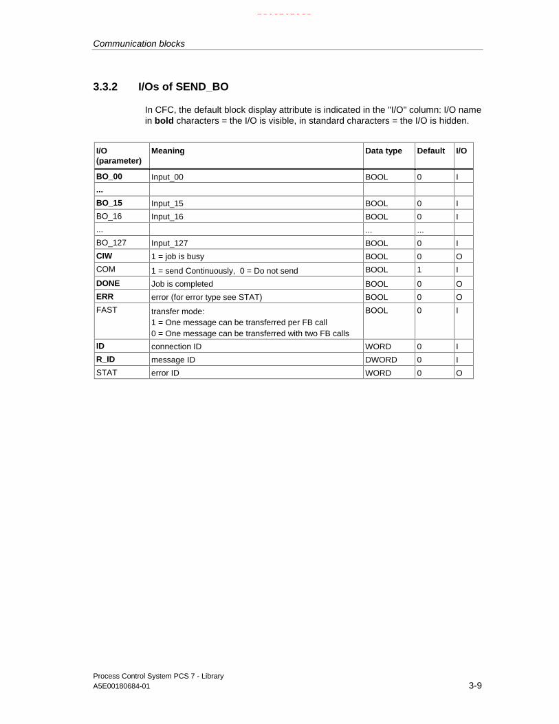
Communication blocks
Process Control System PCS 7 - LibraryA5E00180684-01 3-9
3.3.2 I/Os of SEND_BO
In CFC, the default block display attribute is indicated in the "I/O" column: I/O namein bold characters = the I/O is visible, in standard characters = the I/O is hidden.
I/O(parameter)
Meaning Data type Default I/O
BO_00 Input_00 BOOL 0 I
...
BO_15 Input_15 BOOL 0 I
BO_16 Input_16 BOOL 0 I
... ... ...
BO_127 Input_127 BOOL 0 I
CIW 1 = job is busy BOOL 0 O
COM 1 = send Continuously, 0 = Do not send BOOL 1 I
DONE Job is completed BOOL 0 O
ERR error (for error type see STAT) BOOL 0 O
FAST transfer mode:1 = One message can be transferred per FB call0 = One message can be transferred with two FB calls
BOOL 0 I
ID connection ID WORD 0 I
R_ID message ID DWORD 0 I
STAT error ID WORD 0 O
21.02.2003

Communication blocks
Process Control System PCS 7 - Library3-10 A5E00180684-01
3.4 SEND_R: Send 32 BOOL and 32 REAL values driven bychanges with BSEND
3.4.1 SEND_R: Description
Object name (type + number)
FB 209
Area of application
The block forms a simple user interface to the block SFB12 "BSEND".
It is driven by changes and sends up to 32 BOOL and 32 REAL values to anotherS7 CPU via MPI, PROFIBUS or Industrial Ethernet. This CPU needs to call thefunction block type "REC_R" (FB 210) of the PCS 7 Library in order to receivethose data.
Data are available at "REC_R" when the request has been completed (i.e. after theacknowledgment signal DONE = TRUE has been received). This acknowledgmentis indicated by means of a 1 0 transition at output CIW.
If parameter FAST = 1, the FB enables the transmission of one message framewith each FB call, since it calls SFB12 "BSEND" twice internally (a positive atcontrol input REQ is required in order to enable SFB12). However, such periodicsend requests should only be initiated if sufficient time is available between two FBcalls.
The calling OB
This is the watchdog interrupt OB into which you install the block (for exampleOB35).
Operating principle
The block monitors the data at 32 BOOL and 32 REAL inputs in order to detectchanges to previously received data. A hysteresis (absolute value) is set for REALvalues in every monitoring cycle. Data transfer can be locked or forced via theEDC_MIN and EDC_MAX parameters.
At EDC_MIN, you set the number of cycles to wait until the next send request,regardless of any changes in data.
At EDC_MAX, you set the number of cycles to wait after the last valid data transferuntil the next transfer of actual input data, regardless of any changes in data orwhether changes of REAL values are within the set hysteresis.
The theoretical time based on the set number of cycles cannot be guaranteed dueto the asynchronous data transfer between "SEND_R" and "REC_R" (see below).
21.02.2003

Communication blocks
Process Control System PCS 7 - LibraryA5E00180684-01 3-11
The internal SFB12 "BSEND" can be used to exchange 32 BOOL values betweenthe communication partners. They are sent to the partner by The CPU operatingsystem transfers the data to the communication partner and writes the dataautomatically to the instance DB of the receiving FB (REC_R) by the operatingsystem. Before the new values are sent, the system waits for the internal sendacknowledgment signal of the operating system.
Data transfer is initiated if control input COM = 1 when the block is called. Theblock must be called at least once (regardless of the cycle) in order to transfer alldata. It transfers the job to the CPU operating system for complete processing ofthe job. Further calls of the block with the same ID and R_ID during data transferare permitted, however they do not have any function (i.e. the block can be calledonce in each cycle). Instead, the value 11 is output at STAT. Data are read fromuser memory asynchronously to user program execution. CIW = 0 if the job wascompleted without errors. (if an error has occurred, ERR = 1. The request will beresumed automatically until all data have been transferred). If input COM = 0, allincomplete data transfers will be aborted and not resumed and CIW = 0.
The ID parameter represents the I/O number specified in your I/O configuration.The parameter is assigned only at the first call after a cold restart.
The R_ID parameter is a random number (suggestion: message frame ID).However, it must be identical at the corresponding send and receive blocks and isapplied only at the first call after a cold restart.
If parameter FAST = 1, new message frames can be transferred with each call ofthe FB. In this case the FB internally calls SFB12 "BSEND" twice, since a positiveedge at control input REQ is required to enable SFB12. Whenever the FB is called,one message frame can be transferred in each cycle.
However, we advise you do not initiate such frequent send requests unless
• there is sufficient time between two FB calls to transfer the message frame.
• the call of the "REC_R" in the receiving CPU is faster than that of the"SEND_R" in the sending CPU (the receiving CPU requires two calls(=2 cycles) of "REC_R" for each message frame).
If parameter FAST = 0, a new send request can be initiated only at every secondFB call.
Error handling
Block error handling is restricted to the evaluation of error information from thesubordinate SFB12 "BSEND" (refer to the "System software for S7-300/400 -System and standard functions" manual for information on the outputs ERR andSTAT).
(If an error has occurred, the request will be repeated automatically until data havebeen transferred).
21.02.2003

Communication blocks
Process Control System PCS 7 - Library3-12 A5E00180684-01
Startup characteristics
n.a.
Time response
n.a.
Message response
n.a.
Operator control and monitoring
n.a.
21.02.2003

Communication blocks
Process Control System PCS 7 - LibraryA5E00180684-01 3-13
3.4.2 I/Os of SEND_R
In CFC, the default block display attribute is indicated in the "I/O" column: I/O namein bold characters = the I/O is visible, in standard characters = the I/O is hidden.
I/O(parameter)
Meaning Data type Default I/O
BO_00 BOOL input_00 BOOL 0 I
...
BO_07 BOOL input_07 BOOL 0 I
BO_08 BOOL input_08 BOOL 0 I
...
BO_31 BOOL input_31 BOOL 0 I
CIW 1 = job is busy BOOL 0 O
COM 1 = send continuously, 0 = do not send BOOL 1 I
DONE 1 = job is completed BOOL 0 O
EDC_MAX force transfer after n cycles if changes weremade
INT 10 I
EDC_MIN earliest transfer after n cycles if changes weremade
INT 1 I
ERR error (for error type see STAT) BOOL 0 O
FAST transfer mode:1 = one message frame with each FB call0 = one message frame within two 2 FB calls
BOOL 0 I
ID connection ID WORD 0 I
R_00 REAL input_00 REAL 0 I
...
R_07 REAL input_07 REAL 0 I
R_08 REAL input_08 REAL 0 I
... ...
R_31 REAL-Input_31 REAL 0 I
R_ID message ID DWORD 0 I
STAT error ID WORD 0 O
21.02.2003

Communication blocks
Process Control System PCS 7 - Library3-14 A5E00180684-01
3.5 Appendix
3.5.1 Technical data "Communication blocks"
Meaning:
Block type name
The symbolic identifier in the symbol table of the library for the relevant FB. Mustbe unique within the project.
Object name
Consists of the block type (FB) and number.
Typical runtime
CPU runtime for processing the corresponding block program under normalcircumstances (for example, for a driver this is the execution time in the watchdoginterrupt OB (OB3x) without generation of a channel error message).
The table below shows the runtime of blocks in a 417-4 CPU. The block runtime onother CPUs depends on the CPU performance.
Block length in load/work memory
Memory requirements of the program code, once for each block type.
Length of instance data in load/work memory
Memory requirement of an instance DB.
Temporary memory
The local-data memory required in a priority class when the block is called. Thislimit is CPU specific. When it is exceeded, you have to check the CPUconfiguration and, if necessary, distribute it amongst the (OBs) to meet the realrequirements.
21.02.2003

Communication blocks
Process Control System PCS 7 - LibraryA5E00180684-01 3-15
Multiple instance block
The specified blocks are used by the communication block and must exist in theuser program. They can be found in the same library.
Block(Typename)
FB no. TypicalruntimeCPU 417-4(ms)
Block lengthin load/usermemory(byte)
Instance datalengthin load/usermemory(byte)
Temporarymemory(byte)
Multipleinstanceblock
REC_BO FB208 0.16 3246 / 2356 992 / 128 2 SFB13
REC_R FB210 0.16 1838 / 1332 956 / 476 2 SFB13
SEND_BO FB207 0.20 2298 / 1668 718 / 110 2 SFB12
SEND_R FB209 0.19 4486 / 3886 908 / 478 2 SFB12
21.02.2003

Communication blocks
Process Control System PCS 7 - Library3-16 A5E00180684-01
21.02.2003
Process Control System PCS 7 - LibraryA5E00180684-01 Glossary-1
Glossary
Aspect
Attributes of a block with regard to its application in the AS (FB, FC), ES (display inthe library or in CFC, display for testing and commissioning) and OS (texts formessages and operations, corresponding faceplate for visualization in the OS).
Block
Object of a library or block structure, subdivided into function blocks (executable onan automation system) and faceplates (executable on an OS). The block hasaspects for AS, OS and ES, which are defined by their attributes. Both block typesare configured in ES. The library contains the block type. ES is used to create aninstance data block and to configure it further.
Block body
Section of the block with function-specific information (for example values in datablocks, program code of functions).
Block header
Section of the block with management information on its assignment (for exampletype name, block name etc.).
Block library
Software package that contains block types with common features. Installation viaES.
Block type
Library object, which transfers its object properties to the corresponding instancedata block when used in a block structure. The block type (method, database andaspect definition) is stored in the ES.
CS
Bus system for data exchange between components.
21.02.2003

Glossary
Process Control System PCS 7 - LibraryGlossary-2 A5E00180684-01
Data block
Used for storing data which are processed by programs or functions.
Driver block
Block for reading/writing AS values to/from a module. It forms the softwareinterface to the field process, converts physical values into process variables (andvice versa) and provides additional information with regard to the availability of thehardware addressed.
Enable input
Used to enable/disable processing of an FB (only exists in CFC display mode).
Faceplate
Block which is executable on the OS and used to operate and monitor thecorresponding AS block. It is supplied for certain block types in the libraries.Included in the faceplate function is the verification of manipulated values.
Function
Defined in IEC 1131-3 as a software unit, which when executed delivers a singleresult (which can also be a complex data type) and which does not have thecapability of saving data (memory).The essential difference between an FC and an FB is the lack of a database(instance DB). The result of the FC call must therefore either be saved explicitly bythe user or be used immediately. The ES (CFC chart) displays the FC similarly toan FB.
Function block
IEC TC65/WG6 draft standard of May 1995 defines this term as follows:A function block (FB instance) is a functional software unit, which consists of adesignated individual copy of the data structure defined by the function block typeand retains its data structure for the duration of one call of the function block.The main features of the FB instance are as follows:
• Type and instance identifier
• I/O events, which use algorithms of the OB in which the FB instance isprocessed or are used by these algorithms.
• I/O variables, which are read or changed respectively by the FB algorithm.
Functional features, which are defined by the type description and are generallyimplemented via the FB algorithm.
21.02.2003

Glossary
Process Control System PCS 7 - LibraryA5E00180684-01 Glossary-3
GET principle
The value which is interconnected to an input of a block is only updated (fetched)by the method associated with the block of the interconnected input - and notearlier. If this block is not processed, the input will not have an updated value.
Initial startup
In the context of blocks, the term refers to the initial block execution after has beeninstantiated. This routine sets a defined state of the block parameters andoperating modes.
Instance DB
Data block derived from a block type. Serves as storage unit for a definedapplication of this type. In a project, for example the "control" block type isrepresented by several instances (instance DBs) in order to be able to save therespective setpoint value, operating mode, parameters, etc. for each control task.
Integration
Process by means of which a block (FB or FC) in an OB is logged in forprocessing. Usually an existing processing sequence must be observed, which iswhy the term "install" is used.
Limit
Reference value for an analog variable. Triggers a reaction when the value isreached or exceeded.
LSB
Least Significant Bit/Byte = Bit/Byte in a word or double word with the lowest value
Message class
Classification of messages based on their cause. The following message classesare used in the SIMATIC process control system:
• Process signals; triggered when process-specific monitoring values (forexample: alarms, interrupts, high/low tolerances; general process messages)are reached or exceeded.
• Control system messages; output by the control system (system messages) orthe I/O units (errors in the field), or for preventive maintenance.
Requests for operator input which, in the case of certain operation sequences,draw the operator's attention to the necessity of an operator intervention (forexample, request to acknowledge a stepping operation manually in order to enabletransition) or operation logs.
21.02.2003

Glossary
Process Control System PCS 7 - LibraryGlossary-4 A5E00180684-01
Table of possible message classes and their meaning
Message class Meaning
AH Alarm high (high limit alarm)
WH Warning high (high alarm)
WL Warning low (low alarm)
AL Alarm low (low limit alarm)
TH Tolerance high
TL Tolerance low
F Process error (field)
S Control system message (system)
S* OS control system message (fault)
M Preventive maintenance
PM Process message
- Operation message
OR Operator request
OM*1) Operation message
*1) If the block is used for operation messages, the inputs I_1, ... have to besupplied with pulses. Assignment of the static value "1" would lead to multiplemessages.
Monitoring
Part of the tasks of an OS, which allows visualization of process parameters andstates in various forms (numerical, graphical).
MSB
Most Significant Bit/Byte = Bit/Byte in a word or double word with the highest value
Multiple instance block
We speak of multiple instances in cases where additional function blocks are calledby one block using its own (meaning without an additional) instance DB.
Prerequisite is, that FBs to be called are registered as static variables in thevariable declaration of the calling FB.
This achieves a concentration of instance data in one instance data block, i.e.improves utilization of the number of DBs available.
21.02.2003

Glossary
Process Control System PCS 7 - LibraryA5E00180684-01 Glossary-5
Operating mode
Characteristic of a block, which marks a certain application-specific processingphase of block program execution in various situations.MANUAL mode at a control block signifies a program sequence in which thecontroller algorithm is not executed and the output variable (manipulated variable)is set manually by the operator, for example.
Operator control
Operator control of values or states at a block. Changes are usually entered on theOS, verified and transferred via the CS to the operator control block in theautomation system. The AS finally verifies received data before they are assignedto the block, since process conditions may have changed during the data transfer.
Operator control block
This block verifies operator input at the OS and, if valid, transfers it to itsinterconnected block input in the automation system. It also allowsacknowledgement of this input at the operator station.
Operator control text
Text which is assigned to a block input and used for picture display or for loggingoperations on the OS.
Picture element
Object of the faceplate. Corresponds to a specific I/O element of a block type.
Redundancy
Multiple components assigned to tasks which can be performed by each one (forexample in case of errors or faults).
Sampling time
Time interval between two consecutive block execution cycles in a processingclass with constant cycle time (e.g. watchdog interrupt OB). It is determined by theES on the basis of the configured runtime group.
Standard block/faceplate
Generic term for all objects in standard libraries which are supplied by Siemens.
21.02.2003

Glossary
Process Control System PCS 7 - LibraryGlossary-6 A5E00180684-01
Startup
CPU transition from STOP (internal STOP, i.e. CPU is ready) to RUN (e.g. userprogram execution) mode. The following startup modes can be distinguished onthe basis of the organization blocks (CPU-specific):Cold restart; results and states are ignored during an interrupt (OB100).Restart; results and states of the user program at the interrupt are taken intoaccount.
Startup characteristics
Transition of a block into a defined state after its execution in a startup OB. In thislibrary only a cold restart is relevant (OB100).
Tracking
Executable status of a block, during which the block program overwrites a (tracked)parameter with the value of another parameter (tracking value), i.e. the user canforce a defined parameter value which is usually determined by a process orprogram.
User block/faceplate
Generic term for all user objects (customer, engineering office, departmentengineering a project for a customer or a project) in user-specific libraries.
21.02.2003

Process Control System PCS 7 - LibraryA5E00180684-01 Index-1
Index
AADD4_P
I/Os.........................................................1-179ADD4_P Description .................................1-179ADD8_P
I/Os.........................................................1-180ADD8_P Description .................................1-180Addition of up to 4 values ...........................1-179Addition of up to 8 values ...........................1-180Addressing .................................................2-232Addressing a controller channel ...................1-63Addressing o a controller channel ................1-85Analog value operation...............................1-228Analog value operation (limiting) ................1-230Analog value operation (rejecting)..............1-234AS ........................................2-114, 2-115, 2-116Auto mode....................................................1-89Automatic mode ..................................1-66, 1-67Automatic mode of CTRL_PID .....................1-12Automatic operation of CTRL_S...................1-37auxiliary process values .............................2-224AVER_P ..........................................1-181, 1-182
Connections ...........................................1-182Description .............................................1-181Description .............................................1-181I/Os.........................................................1-182
BBackup mode of the FM355 .........................1-74
CCH_AI......................................................2-3, 2-7
I/Os.............................................................2-7CH_AO..................................................2-8, 2-11
I/Os...........................................................2-11I/Os...........................................................2-11
CH_DI .................................................2-12, 2-15I/Os...........................................................2-15
CH_DO................................................2-16, 2-18I/Os...........................................................2-18I/Os...........................................................2-18
CH_U_AI .............................................2-21, 2-24I/Os...........................................................2-24
CH_U_AO ................................. 2-26, 2-27, 2-30I/Os...........................................................2-30
CH_U_AO I/Os.............................................2-30CH_U_DI.............................................2-31, 2-34
I/Os .......................................................... 2-34CH_U_DO........................................... 2-35, 2-38
I/Os .......................................................... 2-38channel error................................................ 1-93Channel error............................................... 1-70Conifguration error....................................... 1-93Connections............................................... 2-114Connections of OP_A_RJC ....................... 1-237Connections of REC_R.................................. 3-6Connections of SWIT_CNT........................ 1-219Connections of VALVE .............................. 1-174Controller ................................................ 1-7, 1-8Controller block............................................ 1-62Conversion blocks ..................................... 1-222COUNT_P....................................... 1-183, 1-184
Beschreibung......................................... 1-183Description............................................. 1-183I/Os ........................................................ 1-184I/Os ........................................................ 1-184
CPU ...............2-113, 2-114, 2-115, 2-116, 2-117CTRL_PID ................................. 1-11, 1-21, 1-25
Changing operating modes...................... 1-14Creation of the manipulated variable ....... 1-11Description................................................. 1-7Error handling .......................................... 1-16Generation of the manipulated variable ... 1-11I/Os .......................................................... 1-21Manual
automatic and tracking mode............... 1-12Operator control and monitoring .............. 1-25Setpoint
limit and error signal formation:.............. 1-9CTRL_PID Startup time and message
characteristics.......................................... 1-17CTRL_S...........................1-29, 1-32, 1-34, 1-37,
..................................... 1-40, 1-42, 1-43, 1-48Changing operating modes...................... 1-40Control signal generation......................... 1-34CTRL_S
Manualautomatic and tracking mode........... 1-37
Description............................................... 1-29Error handling .......................................... 1-42Error handling .......................................... 1-42I/Os .......................................................... 1-48Message characteristics .......................... 1-43Operator control and monitoring .............. 1-43Signal processing .................................... 1-32
21.02.2003
Index
Process Control System PCS 7 - LibraryIndex-2 A5E00180684-01
Startuptime and message characteristics........ 1-43
Startup characteristics ............................. 1-43Time characteristics ................................. 1-43
CTRL_S VSTATUS..................................... 1-45
DData .................................................... 1-70, 1-91
reading............................................ 1-70, 1-91Dead time element....................................... 1-53DEADT_P ........................................... 1-53, 1-54
Description............................................... 1-53I/Os .......................................................... 1-54
Description of MEAS_MON........................ 1-113Description of MESSAGE .......................... 1-254Description of MUL8_P .............................. 1-213Description of OP_A .................................. 1-228Description of SWIT_CNT.......................... 1-216Determining the degree of CPU utilization . 1-214DIF_P........................................................... 1-56
Description............................................... 1-55I/Os .......................................................... 1-56
Differentiation............................................... 1-55DIG_MON ..................................1-58, 1-60, 1-61
Description............................................... 1-57I/Os .......................................................... 1-60Operator control and monitoring .............. 1-61
DIG_MON VSTATUS.................................. 1-61Digital value monitoring................................ 1-57Digital value operation (1 pushbutton) ....... 1-247Digital value operation (2 pushbuttons)...... 1-238Digital value operation (3 pushbuttons)...... 1-242Display blocks................................................ 1-6DOSE.............1-185, 1-188, 1-192, 1-193, 1-194
Connections........................................... 1-190Description............................................. 1-185Operator control and monitoring ............ 1-194VSTATUS .............................................. 1-197
Download of parameters to the module ....... 1-91DP/PA ........................................................ 2-216
Monitoring .............................................. 2-216DPAY_V0.............................2-164, 2-167, 2-168
auxiliary process values......................... 2-168I/Os ........................................................ 2-167I/Os ........................................................ 2-167Message texts........................................ 2-168Message texts and auxiliary
process values ................................... 2-168DPAY_V1........................................ 2-170, 2-171
I/Os ........................................................ 2-171I/Os ........................................................ 2-171
DREP.................................................. 2-43, 2-44Diagnose repeaters on the
DP master system................................ 2-39I/Os .......................................................... 2-43I/Os .......................................................... 2-43Message texts and auxiliary
process values ..................................... 2-44DREP_L....................................................... 2-50
Diagnostic repeaters downstreamof a Y Link ............................................2-46
I/Os...........................................................2-50I/Os...........................................................2-50Message texts and auxiliary
process values .....................................2-51
EELAP_CNT......................................1-198, 1-201
Description .............................................1-198Description .............................................1-198ELAP_CNT
Operator control and monitoring.........1-202I/Os.........................................................1-201I/Os.........................................................1-201VSTATUS...............................................1-203
error..............................................................1-93Error .............................................................1-70Error during configuration .............................1-70Error handling..................................... 1-70, 1-93Error signal generation .................................1-65
FFM 355 ............................................... 1-74, 1-95
Backup mode ................................. 1-74, 1-95FM355-2
Backup mode ...........................................1-95FMCS_PID ....................... 1-62, 1-64, 1-74, 1-79
Description ...............................................1-62Description ...............................................1-62Functions..................................................1-64I/Os...........................................................1-74I/Os...........................................................1-74Operator control and monitoring...............1-79VSTATUS.................................................1-83
FMT_PID ............................................ 1-84, 1-86Description ...............................................1-84Function....................................................1-86Function....................................................1-86I/OS ..........................................................1-95Operator control and monitoring.............1-101VSTATUS...............................................1-105
FMT_PID startup characteristics ..................1-93FMT_PID time response...............................1-93FMT_PIDmessage characteristics................1-93
GGeneral information on the block description .1-1General information on the display blocks......1-6Generation of error signal.............................1-87Generation of limits ......................................1-87Generation of manipulated variables............1-87Generation of setpoints ................................1-87
21.02.2003

Index
Process Control System PCS 7 - LibraryA5E00180684-01 Index-3
II/O acccess error ..........................................1-93I/O access error............................................1-70I/O of REC_BO...............................................3-3I/Os.............................................................2-161I/Os CH_DI...................................................2-15I/Os CH_U_AI ..............................................2-24I/Os of PADP_L00 / L01 / L02 ....................2-214I/Os of SEND_BO...........................................3-9I/Os of SEND_R ...........................................3-13IM 151-2 .......................................................2-60IM 153-2 .......................................................2-60IM_DRV..................................... 2-55, 2-56, 2-58
auxiliary process values ...........................2-58I/Os...........................................................2-58I/Os...........................................................2-58Message texts ..........................................2-58Message texts and auxiliary
process values .....................................2-58Implementation of FM 355............................1-62INT_P .........................................................1-110
I/Os.........................................................1-110I/Os.........................................................1-110
INT_P Description .....................................1-106Interlocking display.....................................1-204INTERLOK ...........................1-204, 1-206, 1-207
Description .............................................1-204Description .............................................1-204I/Os.........................................................1-206I/Os.........................................................1-206Operator control and monitoring.............1-207Operator control and monitoring.............1-207VSTATUS...............................................1-208
LLag element of the 1st order ......................1-122Limit generation............................................1-65Limiter ........................................................1-209LIMITS_P ........................................1-210, 1-211
Connections ...........................................1-211Description .............................................1-209Description .............................................1-209I/Os.........................................................1-211
MManipulated variable generation ..................1-66manipulated variable tracking.......................1-89Manipulated variable tracking.......................1-68Manual
auto and tracking mode............................1-88automatic and tracking mode ...................1-66
Manual mode ................... 1-66, 1-67, 1-88, 1-89Manual mode of CTRL_PID .........................1-12Manual operation of CTRL_S.......................1-37Mean time value generation .......................1-111MEANTM_P ....................................1-111, 1-112
Description .............................................1-111
Description............................................. 1-111I/Os ........................................................ 1-112I/Os ........................................................ 1-112
MEAS_MON ................................... 1-115, 1-117Description............................................. 1-113I/Os ........................................................ 1-115I/Os ........................................................ 1-115Measured value monitoring.................... 1-113Operator control and monitoring ............ 1-117Operator control and monitoring ............ 1-117VSTATUS .............................................. 1-119
MESSAGE................1-254, 1-255, 1-256, 1-257Description............................................. 1-254I/Os ........................................................ 1-257I/Os ........................................................ 1-257
Message block(configurable messages)............. 1-252, 1-254
Message blocks ......................................... 1-251Overview................................................ 1-251
Message characteristics of FMCS_PID ....... 1-71MOD_1 .............................2-64, 2-66, 2-67, 2-68
Auxiliary process values .......................... 2-68I/Os .......................................................... 2-67Message texts.......................................... 2-68
MOD_1 / MOD_2I/Os .......................................................... 2-67
MOD_1 / MOD_2 / MOD_3Message texts and auxiliary
process values..................................... 2-68MOD_2 ...................................... 2-67, 2-68, 2-69
Auxiliary process values .......................... 2-68I/Os .......................................................... 2-67Message texts.......................................... 2-68
MOD_3 ...................................... 2-68, 2-73, 2-77Auxiliary process values .......................... 2-68I/Os .......................................................... 2-77I/Os .......................................................... 2-77Message texts.......................................... 2-68
MOD_CP .................2-78, 2-79, 2-80, 2-81, 2-82Auxiliary process values .......................... 2-82I/Os .......................................................... 2-81I/Os .......................................................... 2-81message texts.......................................... 2-82Message texts and auxiliary
process values..................................... 2-82MOD_D1..........................2-83, 2-84, 2-86, 2-87,
............................................... 2-89, 2-90, 2-91auxiliary process values........................... 2-91I/Os .......................................................... 2-89Message texts.......................................... 2-90Message texts and auxiliary
process values..................................... 2-90MOD_D1 / MOD_D2
I/Os .......................................................... 2-89MOD_D2.........2-89, 2-92, 2-93, 2-96, 2-97, 2-98
auxiliary process values........................... 2-98I/OS.......................................................... 2-89Message texts.......................................... 2-97Message texts and auxiliary
process values..................................... 2-97MOD_HA ..................2-107, 2-110, 2-111, 2-112
21.02.2003
Index
Process Control System PCS 7 - LibraryIndex-4 A5E00180684-01
auxiliary process values......................... 2-112I/Os ........................................................ 2-111I/Os ........................................................ 2-111Message texts........................................ 2-112Message texts and auxiliary
process values ................................... 2-112MOD_MS .........2-99, 2-102, 2-103, 2-104, 2-105
I/Os ........................................................ 2-103I/Os ........................................................ 2-103Message texts and auxiliary
process values ................................... 2-104Message texts and auxiliary
process values ................................... 2-104MOD_PAL0...............2-172, 2-174, 2-175, 2-176
auxiliary process values......................... 2-175I/Os ........................................................ 2-174I/Os ........................................................ 2-174Message texts........................................ 2-175Message texts and auxiliary
process values ................................... 2-175MOD_PAX0 ..............2-177, 2-180, 2-181, 2-182
auxiliary process values......................... 2-182I/Os ........................................................ 2-180I/Os ........................................................ 2-180Message texts........................................ 2-181Message texts and auxiliary
process values ................................... 2-181MODE ............................................. 2-233, 2-237MODE settings for PA devices................... 2-238MODE settings for signal modules............. 2-233Mode switching ............................................ 1-89Monitoring .................................................. 2-219
DP/PA ......................................... 2-216, 2-217MOT_REV............................1-136, 1-138, 1-141
Connections........................................... 1-138Description............................................. 1-133Description............................................. 1-133I/Os ........................................................ 1-138Operator control and monitoring ............ 1-141Operator control and monitoring ............ 1-141VSTATUS .............................................. 1-142
MOT_SPED .........................1-146, 1-147, 1-150Description............................................. 1-143Description............................................. 1-143I/Os ........................................................ 1-147I/Os ........................................................ 1-147Operator control and monitoring ............ 1-150Operator control and monitoring ............ 1-150VSTATUS .............................................. 1-151
MOTOR....................1-152, 1-153, 1-154, 1-155,.........................................1-156, 1-157, 1-158Description............................................. 1-152Description............................................. 1-152I/Os ........................................................ 1-156I/Os ........................................................ 1-156Operator control and monitoring ............ 1-158VSTATUS .............................................. 1-159
Motor valve control..................................... 1-160Motor with a control signal ......................... 1-152Motor with two speeds ............................... 1-143MOTOR. Operator control and monitoring . 1-158
MSG_NACK ....................................1-252, 1-253description ..............................................1-252Description .............................................1-252I/Os.........................................................1-253I/Os.........................................................1-253
MSG_STAT ................................................2-233Error information of the
output parameter ................................2-233MUL4_P .....................................................1-212
Description .............................................1-212Description .............................................1-212I/Os.........................................................1-212
MUL8_P .....................................................1-213Description .............................................1-213I/Os.........................................................1-213
Multiplication of a maximum of 4 values.....1-212Multiplication of a maximum of 8 values.....1-213
NNotes on using driver blocks ..........................2-1
OOB_BEGIN ......................... 2-113, 2-114, 2-115,
.................. 2-116, 2-118, 2-119, 2-134, 2-135Control system messages .....................2-119,
......................... 2-120, 2-121, 2-122, 2-123I/Os.........................................................2-118I/Os.........................................................2-118Message texts and auxiliary
process values ...................................2-119OB_DIAG ................. 2-124, 2-125, 2-126, 2-127
I/Os.........................................................2-127I/Os.........................................................2-127
OB_DIAG1 ............... 2-129, 2-130, 2-132, 2-133auxiliary process values .........................2-133I/Os.........................................................2-132I/Os.........................................................2-132Message texts ........................................2-133Message texts and auxiliary
process values ...................................2-133OB_END..........................................2-134, 2-135
I/Os.........................................................2-135I/Os.........................................................2-135
OB1_TIME.......................................1-214, 1-215Description .............................................1-214Description .............................................1-214I/Os.........................................................1-215I/Os.........................................................1-215
OP_A..........................................................1-230Description .............................................1-228I/Os.........................................................1-230I/Os.........................................................1-230Operator control and monitoring.............1-230Operator control and monitoring.............1-230
OP_A_LIM........................... 1-231, 1-232, 1-233Description .............................................1-230Description .............................................1-230I/Os.........................................................1-233
21.02.2003

Index
Process Control System PCS 7 - LibraryA5E00180684-01 Index-5
I/Os.........................................................1-233Operator control and monitoring.............1-233Operator control and monitoring.............1-233
OP_A_RJC............... 1-234, 1-235, 1-236, 1-237Description .............................................1-234Description .............................................1-234I/Os.........................................................1-237Operator control and monitoring.............1-237Operator control and monitoring.............1-237
OP_D ....................... 1-238, 1-239, 1-240, 1-241Description .............................................1-238Description .............................................1-238I/Os.........................................................1-240I/Os.........................................................1-240Operator control and monitoring.............1-241Operator control and monitoring.............1-241
OP_D3 .......... 1-242, 1-243, 1-244, 1-245, 1-246Description .............................................1-242Description .............................................1-242I/Os.........................................................1-245I/Os.........................................................1-245Operator control and monitoring.............1-246Operator control and monitoring.............1-246
OP_TRIG..............................1-248, 1-249, 1-250Description .............................................1-247Description .............................................1-247I/Os.........................................................1-249I/Os.........................................................1-249Operator control and monitoring.............1-250Operator control and monitoring.............1-250
Operating error.............................................1-70Operating hours counter.............................1-198Operating mode selection ............................1-68Operator control and monitoring
of ELAP_CNT.........................................1-202Operator control blocks ........1-224, 1-225, 1-226
Overview ................................................1-225Operator error ..............................................1-93Optimization (overview)................................1-91OR_M_16........................................2-136, 2-137OR_M_16 / OR_M_32.....................2-138, 2-139
auxiliary process values .........................2-139I/Os.........................................................2-138I/Os.........................................................2-138Message texts ........................................2-139Message texts and auxiliary
process values ...................................2-139OR_M_32...................................................2-140Overview of the message blocks................1-251Overview of the operator control blocks .....1-224
PPA_AI ...................................2-183, 2-185, 2-187
I/Os.........................................................2-185I/Os.........................................................2-185Message texts ........................................2-187Message texts ........................................2-187
PA_AO .......................................................2-191I/Os.........................................................2-191
I/Os ........................................................ 2-191Message texts........................................ 2-194PA_AO
Message texts.................................... 2-194PROFIBUS PA analog output ................ 2-188
PA_DI .................................. 2-195, 2-197, 2-199I/Os ........................................................ 2-197I/Os ........................................................ 2-197Message texts........................................ 2-199Message texts........................................ 2-199
PA_DO................................. 2-200, 2-203, 2-205I/Os ........................................................ 2-203I/Os ........................................................ 2-203Message texts........................................ 2-205Message texts........................................ 2-205
PA_MODE ................................................. 2-238Settings.................................................. 2-238
PA_TOT............................... 2-206, 2-208, 2-210auxiliary process values......................... 2-210I/Os ........................................................ 2-208I/Os ........................................................ 2-208Message texts........................................ 2-210
PADP_L00........................... 2-211, 2-212, 2-215auxiliary process values......................... 2-215Message texts........................................ 2-215Message texts and auxiliary
process values................................... 2-215PADP_L00/ L01/ L02 ................................. 2-214
I/Os ........................................................ 2-214PADP_L01........................... 2-216, 2-219, 2-220
auxiliary process values......................... 2-220Message texts........................................ 2-219Message texts and auxiliary
process values................................... 2-219PADP_L02...................................... 2-221, 2-224
Message texts............................. 2-224, 2-225Message texts and auxiliary
process values................................... 2-224PADP_L10...................................... 2-227, 2-231
I/Os ........................................................ 2-231I/Os ........................................................ 2-231
Parameters ......................................... 1-70, 1-91transfer..................................................... 1-91transferring............................................... 1-70
PID controller block........................................ 1-7PO_UPDAT ............................................... 2-140POLYG_P.................................................. 1-120
Description............................................. 1-120Description............................................. 1-120
POLYG_P I/Os ......................................... 1-121Polygon with a maximum of 8 time slices .. 1-120PT1_P........................................................ 1-122
Description............................................. 1-122Description............................................. 1-122
PT1_P I/Os ............................................... 1-123
RR_TO_DW ................................................. 1-223
Description............................................. 1-223
21.02.2003
Index
Process Control System PCS 7 - LibraryIndex-6 A5E00180684-01
Description............................................. 1-223I/Os ........................................................ 1-223I/Os ........................................................ 1-223
RACK.............2-141, 2-142, 2-143, 2-144, 2-145auxiliary process values......................... 2-145I/Os ........................................................ 2-144I/Os ........................................................ 2-144Message texts........................................ 2-145Message texts and auxiliary
process values ................................... 2-145rack failure ................................................... 1-93Rack failure.................................................. 1-70Ramp generation ....................................... 1-124RAMP_P ......................................... 1-123, 1-125
Description............................................. 1-123Description............................................. 1-123I/Os ........................................................ 1-125I/Os ........................................................ 1-125
RATIO_P...................1-125, 1-126, 1-127, 1-128Description............................................. 1-125Description............................................. 1-125I/Os ........................................................ 1-127I/Os ........................................................ 1-127Operator control and monitoring ............ 1-128Operator control and monitoring ............ 1-128VSTATUS .............................................. 1-129
RCV_341 .......2-147, 2-148, 2-149, 2-150, 2-151auxiliary process values......................... 2-151I/Os ........................................................ 2-150I/Os ........................................................ 2-150Message texts........................................ 2-151Message texts and auxiliary
process values ................................... 2-151reading data from the module ...................... 1-70Reading module data................................... 1-91REC_BO ................................................. 3-2, 3-3
I/O .............................................................. 3-3REC_R.................................................... 3-5, 3-6
Connections............................................... 3-6Receive 32 BOOL and 32 REAL values
with BRCV.............................................. 3-4Receive 128 BOOL values with BRCV
(REC_BO).................................................. 3-1Reversing motor......................................... 1-133
SSafety mode................................................. 1-91Safety operation........................................... 1-69Send 128 BOOL values with BSEND
(SEND_BO) ............................................... 3-7SEND_BO............................................... 3-7, 3-9
I/O .............................................................. 3-9SEND_R ...................................................... 3-13
I/Os .......................................................... 3-13Send 32 BOOL and 32 REAL values
driven by changes with BSEND ........... 3-10Setpoint generation...................................... 1-65setpoint tracking........................................... 1-89Setpoint tracking .......................................... 1-68
Signal processing in the setpoint andprocess-variable branches of CTRL_PID ...1-9
SND_341....... 2-153, 2-154, 2-155, 2-156, 2-157Auxiliary process values .........................2-157I/Os.........................................................2-156I/Os.........................................................2-156Message texts ........................................2-157Message texts and auxiliary
process values ...................................2-157Split Range.................................................1-130SPLITR_P .......................................1-131, 1-132
Description .............................................1-130Description .............................................1-130I/Os.........................................................1-132I/Os.........................................................1-132
Startup characteristics of FMCS_PID...........1-71SUBNET................... 2-159, 2-160, 2-161, 2-162
auxiliary process values .........................2-162I/Os.........................................................2-161I/Os.........................................................2-161Message texts ........................................2-162Message texts and auxiliary
process values ...................................2-162SWIT_CNT.......................... 1-217, 1-219, 1-220
Connections ...........................................1-219Description .............................................1-216Operator control and monitoring.............1-220Operator control and monitoring.............1-220VSTATUS...............................................1-221
Switching between differentPID parameter sets...................................1-92
Switching operation counter .......................1-216
TTechnical data ....................... 1-258, 3-14, 2-241
Communication blocks .............................3-14Driver blocks...........................................2-241Technological blocks ..............................1-258
Temperature control block............................1-84Text library for DP/PA slaves downstream
of a DPV0 PA or Y LINK.........................2-241Text library for signal modules....................2-239Time average .............................................1-181Time characteristics of FMCS_PID...............1-71Tracking mode.................................... 1-67, 1-89Tracking mode of CTRL_PID .......................1-12Tracking operation of CTRL_S .....................1-37Transferring parameters to the module ........1-70
VVAL_MOT............................ 1-163, 1-165, 1-168
Description .............................................1-160Description .............................................1-160I/Os.........................................................1-165I/Os.........................................................1-165Operator control and monitoring.............1-168Operator control and monitoring.............1-168VSTATUS...............................................1-169
21.02.2003

Index
Process Control System PCS 7 - LibraryA5E00180684-01 Index-7
VALVE..................... 1-170, 1-171, 1-172, 1-173,.........................................1-175, 1-176, 1-177Connections ...........................................1-174Description .............................................1-170Operator control and monitoring.............1-177VSTATUS...............................................1-178
Valve control .............................................. 1-170
ZCounter...................................................... 1-183
21.02.2003

Index
Process Control System PCS 7 - LibraryIndex-8 A5E00180684-01
21.02.2003