simatic ti500/ti505 tiway 1 gateway - siemens ag · simatic ti500/ti505 tiway 1 gateway user manual...
TRANSCRIPT

SIMATIC TI500/TI505
TIWAY 1 Gateway
User Manual
Order Number PPX:TIWAY-8104-02Manual Assembly Number: 2587871-0004Second Edition

01/21/92
Copyright 1992 by Siemens Industrial Automation, Inc. All Rights Reserved — Printed in USA
Reproduction, transmission or use of this document orcontents is not permitted without express consent ofSiemens Industrial Automation, Inc. All rights, including rightscreated by patent grant or registration of a utility model ordesign, are reserved.
Since Siemens Industrial Automation, Inc. does not possessfull access to data concerning all of the uses and applicationsof customer’s products, we do not assume responsibility eitherfor customer product design or for any infringements of patentsor rights of others which may result from our assistance.
Technical data is subject to change.
We check the contents of every manual for accuracy at thetime it is approved for printing; however, there may beundetected errors. Any errors found will be corrected insubsequent editions. Any suggestions for improvement arewelcomed.

MANUAL PUBLICATION HISTORY
SIMATIC TI500/TI505 TIWAY I Gateway User ManualOrder Manual Number: PPX:TIWAY–8104–2
Refer to this history in all correspondence and/or discussion about this manual.
Event Date Description
Original Issue 09/85 Original Issue (2491964–0001)Second Edition 09/92 Second Edition (2491964–0002)

LIST OF EFFECTIVE PAGES
Pages Description Pages Description
Cover/Copyright SecondHistory/Effective Pages Secondiii — x Second
1-1 — 1-4 Second2-1 — 2-12 Second3-1 — 3-14 SecondA-1 — A-4 SecondB-1 — B-3 SecondC-1 — C-28 SecondD-1 — D-11 Second
Index-1 — Index-3 SecondRegistration Second

Contents iii
Contents
Preface
Chapter 1 Product Overview1.1 Introduction 1-2. . . . . . . . . . . . . . . . . . . . . . . . . . . . . . . . . . . . . . . . . . . . . . . . . . . . . . . . . . . . . . . . . . . .
The Gateway Interface 1-2. . . . . . . . . . . . . . . . . . . . . . . . . . . . . . . . . . . . . . . . . . . . . . . . . . . . . . . . . Distributed Control Systems 1-2. . . . . . . . . . . . . . . . . . . . . . . . . . . . . . . . . . . . . . . . . . . . . . . . . . . . . .
1.2 Basic Operating Features 1-3. . . . . . . . . . . . . . . . . . . . . . . . . . . . . . . . . . . . . . . . . . . . . . . . . . . . . . . . Interface Ports 1-3. . . . . . . . . . . . . . . . . . . . . . . . . . . . . . . . . . . . . . . . . . . . . . . . . . . . . . . . . . . . . . . . . . Translating Commands between Host and PLC Network 1-4. . . . . . . . . . . . . . . . . . . . . . . . . . Data Transmission Rates Supported 1-4. . . . . . . . . . . . . . . . . . . . . . . . . . . . . . . . . . . . . . . . . . . . . . Types of Data Accessed 1-4. . . . . . . . . . . . . . . . . . . . . . . . . . . . . . . . . . . . . . . . . . . . . . . . . . . . . . . .
Chapter 2 Network Installation2.1 TIWAY I Network and Gateway Installation Checklist 2-2. . . . . . . . . . . . . . . . . . . . . . . . . . . . . .
Quick Reference Installation Steps 2-2. . . . . . . . . . . . . . . . . . . . . . . . . . . . . . . . . . . . . . . . . . . . . . . Basic Installation Procedures 2-3. . . . . . . . . . . . . . . . . . . . . . . . . . . . . . . . . . . . . . . . . . . . . . . . . . . . . Requirements for Installing the Gateway 2-3. . . . . . . . . . . . . . . . . . . . . . . . . . . . . . . . . . . . . . . . .
2.2 Network Media Installation — Local Line 2-4. . . . . . . . . . . . . . . . . . . . . . . . . . . . . . . . . . . . . . . . . Overview 2-4. . . . . . . . . . . . . . . . . . . . . . . . . . . . . . . . . . . . . . . . . . . . . . . . . . . . . . . . . . . . . . . . . . . . . . . Local Line Cable Characteristics 2-4. . . . . . . . . . . . . . . . . . . . . . . . . . . . . . . . . . . . . . . . . . . . . . . . . TIWAY I Network Characteristics 2-5. . . . . . . . . . . . . . . . . . . . . . . . . . . . . . . . . . . . . . . . . . . . . . . . . . Local Line Hardware Components 2-6. . . . . . . . . . . . . . . . . . . . . . . . . . . . . . . . . . . . . . . . . . . . . . . Tap Housing 2-6. . . . . . . . . . . . . . . . . . . . . . . . . . . . . . . . . . . . . . . . . . . . . . . . . . . . . . . . . . . . . . . . . . . . Terminating the Main Line Cable 2-7. . . . . . . . . . . . . . . . . . . . . . . . . . . . . . . . . . . . . . . . . . . . . . . . Twisted-Pair Cabling 2-7. . . . . . . . . . . . . . . . . . . . . . . . . . . . . . . . . . . . . . . . . . . . . . . . . . . . . . . . . . . . Important Planning Considerations 2-7. . . . . . . . . . . . . . . . . . . . . . . . . . . . . . . . . . . . . . . . . . . . . . Local Line Tap Spacing Rules 2-8. . . . . . . . . . . . . . . . . . . . . . . . . . . . . . . . . . . . . . . . . . . . . . . . . . . . Basic Considerations 2-8. . . . . . . . . . . . . . . . . . . . . . . . . . . . . . . . . . . . . . . . . . . . . . . . . . . . . . . . . . . . Primary Rule 2-8. . . . . . . . . . . . . . . . . . . . . . . . . . . . . . . . . . . . . . . . . . . . . . . . . . . . . . . . . . . . . . . . . . . . Double Drops 2-9. . . . . . . . . . . . . . . . . . . . . . . . . . . . . . . . . . . . . . . . . . . . . . . . . . . . . . . . . . . . . . . . . . . Short Drops 2-9. . . . . . . . . . . . . . . . . . . . . . . . . . . . . . . . . . . . . . . . . . . . . . . . . . . . . . . . . . . . . . . . . . . . . Multidrop Taps 2-9. . . . . . . . . . . . . . . . . . . . . . . . . . . . . . . . . . . . . . . . . . . . . . . . . . . . . . . . . . . . . . . . . . Cable Routing 2-10. . . . . . . . . . . . . . . . . . . . . . . . . . . . . . . . . . . . . . . . . . . . . . . . . . . . . . . . . . . . . . . . . . Obstructions 2-11. . . . . . . . . . . . . . . . . . . . . . . . . . . . . . . . . . . . . . . . . . . . . . . . . . . . . . . . . . . . . . . . . . . . Noise Avoidance 2-11. . . . . . . . . . . . . . . . . . . . . . . . . . . . . . . . . . . . . . . . . . . . . . . . . . . . . . . . . . . . . . .
2.3 Network Media Installation — RS-232-C Modem Interface 2-12. . . . . . . . . . . . . . . . . . . . . . . . . Data Transmission Characteristics 2-12. . . . . . . . . . . . . . . . . . . . . . . . . . . . . . . . . . . . . . . . . . . . . . . . RS-232 Pin Assignments 2-12. . . . . . . . . . . . . . . . . . . . . . . . . . . . . . . . . . . . . . . . . . . . . . . . . . . . . . . . . .
iv Contents
Chapter 3 Gateway Installation and Configuration3.1 Installing the TIWAY I Gateway 3-2. . . . . . . . . . . . . . . . . . . . . . . . . . . . . . . . . . . . . . . . . . . . . . . . . . .
Basic Mounting Guidelines 3-2. . . . . . . . . . . . . . . . . . . . . . . . . . . . . . . . . . . . . . . . . . . . . . . . . . . . . . Power Connections and Initialization 3-3. . . . . . . . . . . . . . . . . . . . . . . . . . . . . . . . . . . . . . . . . . . . .
3.2 Dipswitch Configuration and Function 3-6. . . . . . . . . . . . . . . . . . . . . . . . . . . . . . . . . . . . . . . . . . . . Overview 3-6. . . . . . . . . . . . . . . . . . . . . . . . . . . . . . . . . . . . . . . . . . . . . . . . . . . . . . . . . . . . . . . . . . . . . . . Dipswitch Settings for the Host Interface Port 3-7. . . . . . . . . . . . . . . . . . . . . . . . . . . . . . . . . . . . . Dipswitch Settings for the Network Interface Port 3-8. . . . . . . . . . . . . . . . . . . . . . . . . . . . . . . . .
3.3 Switches and Indicator Lights 3-10. . . . . . . . . . . . . . . . . . . . . . . . . . . . . . . . . . . . . . . . . . . . . . . . . . . . Online/Offline Switch 3-10. . . . . . . . . . . . . . . . . . . . . . . . . . . . . . . . . . . . . . . . . . . . . . . . . . . . . . . . . . . . Self-Test Button 3-10. . . . . . . . . . . . . . . . . . . . . . . . . . . . . . . . . . . . . . . . . . . . . . . . . . . . . . . . . . . . . . . . . Reset Button 3-10. . . . . . . . . . . . . . . . . . . . . . . . . . . . . . . . . . . . . . . . . . . . . . . . . . . . . . . . . . . . . . . . . . . . Status Indicator Lights 3-11. . . . . . . . . . . . . . . . . . . . . . . . . . . . . . . . . . . . . . . . . . . . . . . . . . . . . . . . . . . Gateway Good 3-11. . . . . . . . . . . . . . . . . . . . . . . . . . . . . . . . . . . . . . . . . . . . . . . . . . . . . . . . . . . . . . . . Comm Active 3-11. . . . . . . . . . . . . . . . . . . . . . . . . . . . . . . . . . . . . . . . . . . . . . . . . . . . . . . . . . . . . . . . . . Online 3-11. . . . . . . . . . . . . . . . . . . . . . . . . . . . . . . . . . . . . . . . . . . . . . . . . . . . . . . . . . . . . . . . . . . . . . . . . . Receive 3-11. . . . . . . . . . . . . . . . . . . . . . . . . . . . . . . . . . . . . . . . . . . . . . . . . . . . . . . . . . . . . . . . . . . . . . . . Transmit 3-11. . . . . . . . . . . . . . . . . . . . . . . . . . . . . . . . . . . . . . . . . . . . . . . . . . . . . . . . . . . . . . . . . . . . . . . . Test Mode 3-11. . . . . . . . . . . . . . . . . . . . . . . . . . . . . . . . . . . . . . . . . . . . . . . . . . . . . . . . . . . . . . . . . . . . . .
3.4 Diagnostic Tests 3-12. . . . . . . . . . . . . . . . . . . . . . . . . . . . . . . . . . . . . . . . . . . . . . . . . . . . . . . . . . . . . . . . . Built-In Diagnostic Tests 3-12. . . . . . . . . . . . . . . . . . . . . . . . . . . . . . . . . . . . . . . . . . . . . . . . . . . . . . . . . . Power-On Test 3-12. . . . . . . . . . . . . . . . . . . . . . . . . . . . . . . . . . . . . . . . . . . . . . . . . . . . . . . . . . . . . . . . . . Operational Diagnostic Test 3-12. . . . . . . . . . . . . . . . . . . . . . . . . . . . . . . . . . . . . . . . . . . . . . . . . . . . . User-Initiated Test 3-13. . . . . . . . . . . . . . . . . . . . . . . . . . . . . . . . . . . . . . . . . . . . . . . . . . . . . . . . . . . . . . . Burn-In and Final Tests 3-14. . . . . . . . . . . . . . . . . . . . . . . . . . . . . . . . . . . . . . . . . . . . . . . . . . . . . . . . . . .
Appendix A Data Type IdentificationA.1 Corresponding Data Types A-2. . . . . . . . . . . . . . . . . . . . . . . . . . . . . . . . . . . . . . . . . . . . . . . . . . . . . .
A.2 SIMATIC TI PLCs Supported by TIWAY I Gateway A-3. . . . . . . . . . . . . . . . . . . . . . . . . . . . . . . . . . .
A.3 TIWAY I Gateway Specifications A-4. . . . . . . . . . . . . . . . . . . . . . . . . . . . . . . . . . . . . . . . . . . . . . . . . .
Appendix B System Configuration FormsB.1 System Configuration B-2. . . . . . . . . . . . . . . . . . . . . . . . . . . . . . . . . . . . . . . . . . . . . . . . . . . . . . . . . . .
B.2 V-Memory Offset Tables B-3. . . . . . . . . . . . . . . . . . . . . . . . . . . . . . . . . . . . . . . . . . . . . . . . . . . . . . . . .
Contents v
Appendix C Modbus CommandsC.1 Modbus Protocol Overview C-2. . . . . . . . . . . . . . . . . . . . . . . . . . . . . . . . . . . . . . . . . . . . . . . . . . . . . .
The RTU Transmission Frame C-2. . . . . . . . . . . . . . . . . . . . . . . . . . . . . . . . . . . . . . . . . . . . . . . . . . . . . . Message Delineation C-3. . . . . . . . . . . . . . . . . . . . . . . . . . . . . . . . . . . . . . . . . . . . . . . . . . . . . . . . . . . The Address Field C-3. . . . . . . . . . . . . . . . . . . . . . . . . . . . . . . . . . . . . . . . . . . . . . . . . . . . . . . . . . . . . . . The Function Field C-3. . . . . . . . . . . . . . . . . . . . . . . . . . . . . . . . . . . . . . . . . . . . . . . . . . . . . . . . . . . . . . . The Data Field C-3. . . . . . . . . . . . . . . . . . . . . . . . . . . . . . . . . . . . . . . . . . . . . . . . . . . . . . . . . . . . . . . . . . Checksum C-3. . . . . . . . . . . . . . . . . . . . . . . . . . . . . . . . . . . . . . . . . . . . . . . . . . . . . . . . . . . . . . . . . . . . . Invalid Characters and Messages C-4. . . . . . . . . . . . . . . . . . . . . . . . . . . . . . . . . . . . . . . . . . . . . . . . Modbus Functions C-4. . . . . . . . . . . . . . . . . . . . . . . . . . . . . . . . . . . . . . . . . . . . . . . . . . . . . . . . . . . . . . Addressing C-5. . . . . . . . . . . . . . . . . . . . . . . . . . . . . . . . . . . . . . . . . . . . . . . . . . . . . . . . . . . . . . . . . . . . . Address Limits C-5. . . . . . . . . . . . . . . . . . . . . . . . . . . . . . . . . . . . . . . . . . . . . . . . . . . . . . . . . . . . . . . . . . .
C.2 Modbus Function Descriptions C-6. . . . . . . . . . . . . . . . . . . . . . . . . . . . . . . . . . . . . . . . . . . . . . . . . . . Introduction C-6. . . . . . . . . . . . . . . . . . . . . . . . . . . . . . . . . . . . . . . . . . . . . . . . . . . . . . . . . . . . . . . . . . . . Code 01 — Read Coil Status C-6. . . . . . . . . . . . . . . . . . . . . . . . . . . . . . . . . . . . . . . . . . . . . . . . . . . . Code 02 — Read Input Status C-8. . . . . . . . . . . . . . . . . . . . . . . . . . . . . . . . . . . . . . . . . . . . . . . . . . . Code 03 — Read Output Registers C-10. . . . . . . . . . . . . . . . . . . . . . . . . . . . . . . . . . . . . . . . . . . . . . . Code 04 — Read Input Registers C-11. . . . . . . . . . . . . . . . . . . . . . . . . . . . . . . . . . . . . . . . . . . . . . . . . Code 05 — Write a Single Coil C-12. . . . . . . . . . . . . . . . . . . . . . . . . . . . . . . . . . . . . . . . . . . . . . . . . . . Code 06 — Write a Single Register C-14. . . . . . . . . . . . . . . . . . . . . . . . . . . . . . . . . . . . . . . . . . . . . . . Code 07 — Read Exception Status C-15. . . . . . . . . . . . . . . . . . . . . . . . . . . . . . . . . . . . . . . . . . . . . . . Code 08 — Execute Diagnostics C-17. . . . . . . . . . . . . . . . . . . . . . . . . . . . . . . . . . . . . . . . . . . . . . . . . Code 11 — Get Comms Event Counter C-20. . . . . . . . . . . . . . . . . . . . . . . . . . . . . . . . . . . . . . . . . . Code 12 — Get Comms Event Log C-21. . . . . . . . . . . . . . . . . . . . . . . . . . . . . . . . . . . . . . . . . . . . . . Code 15 — Write Multiple Coils C-23. . . . . . . . . . . . . . . . . . . . . . . . . . . . . . . . . . . . . . . . . . . . . . . . . . Code 16 — Write Multiple Registers C-25. . . . . . . . . . . . . . . . . . . . . . . . . . . . . . . . . . . . . . . . . . . . . .
C.3 User-Defined Modbus Commands C-26. . . . . . . . . . . . . . . . . . . . . . . . . . . . . . . . . . . . . . . . . . . . . . . Command 65 — Read C Memory C-26. . . . . . . . . . . . . . . . . . . . . . . . . . . . . . . . . . . . . . . . . . . . . . . Command 66 — Read K Memory C-27. . . . . . . . . . . . . . . . . . . . . . . . . . . . . . . . . . . . . . . . . . . . . . . . Command 67 — Read WY Memory C-27. . . . . . . . . . . . . . . . . . . . . . . . . . . . . . . . . . . . . . . . . . . . . .
C.4 Error Responses C-28. . . . . . . . . . . . . . . . . . . . . . . . . . . . . . . . . . . . . . . . . . . . . . . . . . . . . . . . . . . . . . . . .
Appendix D Configuring the PLC for Fisher PROVOXD.1 Considerations for Configuring a TIWAY I/PROVOX System D-2. . . . . . . . . . . . . . . . . . . . . . . . .
PLC Configuration Requirements D-2. . . . . . . . . . . . . . . . . . . . . . . . . . . . . . . . . . . . . . . . . . . . . . . . Network Design Considerations D-2. . . . . . . . . . . . . . . . . . . . . . . . . . . . . . . . . . . . . . . . . . . . . . . . . .
D.2 PLC Programming Considerations D-3. . . . . . . . . . . . . . . . . . . . . . . . . . . . . . . . . . . . . . . . . . . . . . . . Blocking Network Data D-3. . . . . . . . . . . . . . . . . . . . . . . . . . . . . . . . . . . . . . . . . . . . . . . . . . . . . . . . . . Writing to Integer Registers D-3. . . . . . . . . . . . . . . . . . . . . . . . . . . . . . . . . . . . . . . . . . . . . . . . . . . . . . Writing to Discrete Points D-3. . . . . . . . . . . . . . . . . . . . . . . . . . . . . . . . . . . . . . . . . . . . . . . . . . . . . . . . PLC Status Register D-3. . . . . . . . . . . . . . . . . . . . . . . . . . . . . . . . . . . . . . . . . . . . . . . . . . . . . . . . . . . . . .
D.3 PLC Programming Example D-4. . . . . . . . . . . . . . . . . . . . . . . . . . . . . . . . . . . . . . . . . . . . . . . . . . . . . . Data to be Accessed D-4. . . . . . . . . . . . . . . . . . . . . . . . . . . . . . . . . . . . . . . . . . . . . . . . . . . . . . . . . . . Relay Ladder Logic Program D-5. . . . . . . . . . . . . . . . . . . . . . . . . . . . . . . . . . . . . . . . . . . . . . . . . . . .
vi Contents
List of Figures
1-1 TIWAY I Gateway as Interface Between PLC Network and Host System 1-2. . . . . . . . . . . . . 1-2 TIWAY I Gateway 1-3. . . . . . . . . . . . . . . . . . . . . . . . . . . . . . . . . . . . . . . . . . . . . . . . . . . . . . . . . . . . . . . .
2-1 Basic Installation and Set-up Steps 2-2. . . . . . . . . . . . . . . . . . . . . . . . . . . . . . . . . . . . . . . . . . . . . . . 2-2 Number of Local Line Secondaries vs. Cable Distance 2-5. . . . . . . . . . . . . . . . . . . . . . . . . . . . 2-3 TIWAY I Tap Housing 2-6. . . . . . . . . . . . . . . . . . . . . . . . . . . . . . . . . . . . . . . . . . . . . . . . . . . . . . . . . . . . . 2-4 Terminating the Local Line 2-7. . . . . . . . . . . . . . . . . . . . . . . . . . . . . . . . . . . . . . . . . . . . . . . . . . . . . . . 2-5 Basic Tap Spacing Rules 2-8. . . . . . . . . . . . . . . . . . . . . . . . . . . . . . . . . . . . . . . . . . . . . . . . . . . . . . . . . 2-6 Additional Tap Spacing Rules 2-9. . . . . . . . . . . . . . . . . . . . . . . . . . . . . . . . . . . . . . . . . . . . . . . . . . . .
3-1 Possible Bracket Locations for Mounting Gateway 3-2. . . . . . . . . . . . . . . . . . . . . . . . . . . . . . . . 3-2 AC Power Connections 3-3. . . . . . . . . . . . . . . . . . . . . . . . . . . . . . . . . . . . . . . . . . . . . . . . . . . . . . . . . 3-3 Dipswitch Settings for the Network and Host Ports 3-5. . . . . . . . . . . . . . . . . . . . . . . . . . . . . . . . . 3-4 Dipswitch Settings for Network Data Transmission Rates 3-8. . . . . . . . . . . . . . . . . . . . . . . . . . . 3-5 Gateway Operation Switches 3-10. . . . . . . . . . . . . . . . . . . . . . . . . . . . . . . . . . . . . . . . . . . . . . . . . . . 3-6 Indicator Lights 3-11. . . . . . . . . . . . . . . . . . . . . . . . . . . . . . . . . . . . . . . . . . . . . . . . . . . . . . . . . . . . . . . . . 3-7 Indicator Status 3-14. . . . . . . . . . . . . . . . . . . . . . . . . . . . . . . . . . . . . . . . . . . . . . . . . . . . . . . . . . . . . . . . .
C-1 RTU Transmission Frame C-2. . . . . . . . . . . . . . . . . . . . . . . . . . . . . . . . . . . . . . . . . . . . . . . . . . . . . . . . . . C-2 Bit Orientation C-4. . . . . . . . . . . . . . . . . . . . . . . . . . . . . . . . . . . . . . . . . . . . . . . . . . . . . . . . . . . . . . . . . . C-3 Read Coil Status Example — Request C-6. . . . . . . . . . . . . . . . . . . . . . . . . . . . . . . . . . . . . . . . . . . . C-4 Read Coil Status Example — Response C-7. . . . . . . . . . . . . . . . . . . . . . . . . . . . . . . . . . . . . . . . . . . C-5 Read Coil Status Example — Data Field C-7. . . . . . . . . . . . . . . . . . . . . . . . . . . . . . . . . . . . . . . . . . C-6 Read Input Status Example — Request C-8. . . . . . . . . . . . . . . . . . . . . . . . . . . . . . . . . . . . . . . . . . . C-7 Read Input Status Example — Response C-8. . . . . . . . . . . . . . . . . . . . . . . . . . . . . . . . . . . . . . . . . . C-8 Read Input Status Example — Data Field C-9. . . . . . . . . . . . . . . . . . . . . . . . . . . . . . . . . . . . . . . . . C-9 Read Output Register Example — Request C-10. . . . . . . . . . . . . . . . . . . . . . . . . . . . . . . . . . . . . . . C-10 Read Output Register Example — Response C-10. . . . . . . . . . . . . . . . . . . . . . . . . . . . . . . . . . . . . . C-11 Read Input Register Example — Request C-11. . . . . . . . . . . . . . . . . . . . . . . . . . . . . . . . . . . . . . . . . C-12 Read Input Register Example — Response C-11. . . . . . . . . . . . . . . . . . . . . . . . . . . . . . . . . . . . . . . . C-13 Write a Single Coil Example — Request C-12. . . . . . . . . . . . . . . . . . . . . . . . . . . . . . . . . . . . . . . . . . . C-14 Read Input Register Example — Response C-13. . . . . . . . . . . . . . . . . . . . . . . . . . . . . . . . . . . . . . . . C-15 Write a Single Register Example — Request C-14. . . . . . . . . . . . . . . . . . . . . . . . . . . . . . . . . . . . . . . C-16 Write a Single Register Example — Response C-14. . . . . . . . . . . . . . . . . . . . . . . . . . . . . . . . . . . . . C-17 Read Exception Status Example — Request C-15. . . . . . . . . . . . . . . . . . . . . . . . . . . . . . . . . . . . . . C-18 Read Exception Status Example — Response C-15. . . . . . . . . . . . . . . . . . . . . . . . . . . . . . . . . . . . . C-19 Exception Status Bits C-16. . . . . . . . . . . . . . . . . . . . . . . . . . . . . . . . . . . . . . . . . . . . . . . . . . . . . . . . . . . . C-20 Execute Diagnostics Example — Request C-17. . . . . . . . . . . . . . . . . . . . . . . . . . . . . . . . . . . . . . . . . C-21 Execute Diagnostics Example — Response C-17. . . . . . . . . . . . . . . . . . . . . . . . . . . . . . . . . . . . . . . C-22 Get Comms Event Counter Example — Request C-20. . . . . . . . . . . . . . . . . . . . . . . . . . . . . . . . . . C-23 Get Comms Event Counter Example — Response C-20. . . . . . . . . . . . . . . . . . . . . . . . . . . . . . . . C-24 Get Comms Event Log Example — Request C-21. . . . . . . . . . . . . . . . . . . . . . . . . . . . . . . . . . . . . . C-25 Get Comms Event Log Example — Response C-21. . . . . . . . . . . . . . . . . . . . . . . . . . . . . . . . . . . . .

Contents vii
C-26 Write Multiple Coils Example — Request C-23. . . . . . . . . . . . . . . . . . . . . . . . . . . . . . . . . . . . . . . . . . C-27 Coil Bit Pattern C-23. . . . . . . . . . . . . . . . . . . . . . . . . . . . . . . . . . . . . . . . . . . . . . . . . . . . . . . . . . . . . . . . . . C-28 Write Multiple Coils Example — Response C-24. . . . . . . . . . . . . . . . . . . . . . . . . . . . . . . . . . . . . . . . C-29 Write Multiple Registers Example — Request C-25. . . . . . . . . . . . . . . . . . . . . . . . . . . . . . . . . . . . . . C-30 Write Multiple Registers Example — Response C-25. . . . . . . . . . . . . . . . . . . . . . . . . . . . . . . . . . . . . C-31 Command 65 — Request C-26. . . . . . . . . . . . . . . . . . . . . . . . . . . . . . . . . . . . . . . . . . . . . . . . . . . . . . . C-32 Command 65 — Response C-26. . . . . . . . . . . . . . . . . . . . . . . . . . . . . . . . . . . . . . . . . . . . . . . . . . . . . . C-33 Command 66 — Request C-27. . . . . . . . . . . . . . . . . . . . . . . . . . . . . . . . . . . . . . . . . . . . . . . . . . . . . . . C-34 Command 66 — Response C-27. . . . . . . . . . . . . . . . . . . . . . . . . . . . . . . . . . . . . . . . . . . . . . . . . . . . . . C-35 Command 67 — Request C-27. . . . . . . . . . . . . . . . . . . . . . . . . . . . . . . . . . . . . . . . . . . . . . . . . . . . . . . C-36 Command 67 — Response C-27. . . . . . . . . . . . . . . . . . . . . . . . . . . . . . . . . . . . . . . . . . . . . . . . . . . . . . C-37 Exception Response Frame C-28. . . . . . . . . . . . . . . . . . . . . . . . . . . . . . . . . . . . . . . . . . . . . . . . . . . . . .

viii Contents
List of Tables
1 TIWAY I Gateway Models ix. . . . . . . . . . . . . . . . . . . . . . . . . . . . . . . . . . . . . . . . . . . . . . . . . . . . . . . .
1-1 Data Transmission Rates Supported 1-4. . . . . . . . . . . . . . . . . . . . . . . . . . . . . . . . . . . . . . . . . . . . . .
2-1 Pin Assignments for Local Line Connector 2-4. . . . . . . . . . . . . . . . . . . . . . . . . . . . . . . . . . . . . . . . 2-2 RS-232-C Connector Pin Assignments 2-12. . . . . . . . . . . . . . . . . . . . . . . . . . . . . . . . . . . . . . . . . . . .
3-1 Host Port Dipswitch Configuration 3-6. . . . . . . . . . . . . . . . . . . . . . . . . . . . . . . . . . . . . . . . . . . . . . . . 3-2 Network Port Dipswitch Configuration 3-6. . . . . . . . . . . . . . . . . . . . . . . . . . . . . . . . . . . . . . . . . . . . 3-3 Data Transmission Rates Supported 3-7. . . . . . . . . . . . . . . . . . . . . . . . . . . . . . . . . . . . . . . . . . . . . . 3-4 RS-232-C/423 Loopback Connections 3-13. . . . . . . . . . . . . . . . . . . . . . . . . . . . . . . . . . . . . . . . . . . . 3-5 Indicator Status after User-Initiated Test 3-14. . . . . . . . . . . . . . . . . . . . . . . . . . . . . . . . . . . . . . . . . . .
A-1 Data Type Identification A-2. . . . . . . . . . . . . . . . . . . . . . . . . . . . . . . . . . . . . . . . . . . . . . . . . . . . . . . . A-2 SIMATIC TI PLCs Supported and Accessible Data A-3. . . . . . . . . . . . . . . . . . . . . . . . . . . . . . . . . . A-3 TIWAY I Gateway Features A-4. . . . . . . . . . . . . . . . . . . . . . . . . . . . . . . . . . . . . . . . . . . . . . . . . . . . . . . A-4 TIWAY I Gateway Physical and Environmental Specifications A-4. . . . . . . . . . . . . . . . . . . . . .
B-1 System Configuration Form B-2. . . . . . . . . . . . . . . . . . . . . . . . . . . . . . . . . . . . . . . . . . . . . . . . . . . . . . B-2 V-Memory Offset Table (Resident Information) B-3. . . . . . . . . . . . . . . . . . . . . . . . . . . . . . . . . . . . B-3 V-Memory Offset Table (Received Information) B-3. . . . . . . . . . . . . . . . . . . . . . . . . . . . . . . . . . .
C-1 Modbus Functions Supported C-2. . . . . . . . . . . . . . . . . . . . . . . . . . . . . . . . . . . . . . . . . . . . . . . . . . . . C-2 RTU Timing C-3. . . . . . . . . . . . . . . . . . . . . . . . . . . . . . . . . . . . . . . . . . . . . . . . . . . . . . . . . . . . . . . . . . . . . . C-3 Terminology Differences C-5. . . . . . . . . . . . . . . . . . . . . . . . . . . . . . . . . . . . . . . . . . . . . . . . . . . . . . . . . C-4 Diagnostic Codes Supported C-18. . . . . . . . . . . . . . . . . . . . . . . . . . . . . . . . . . . . . . . . . . . . . . . . . . . . C-5 Event Byte Types C-22. . . . . . . . . . . . . . . . . . . . . . . . . . . . . . . . . . . . . . . . . . . . . . . . . . . . . . . . . . . . . . . . C-6 Exception Responses C-28. . . . . . . . . . . . . . . . . . . . . . . . . . . . . . . . . . . . . . . . . . . . . . . . . . . . . . . . . . . .
D-1 PLC Data to be Accessed D-4. . . . . . . . . . . . . . . . . . . . . . . . . . . . . . . . . . . . . . . . . . . . . . . . . . . . . . . D-2 V-Memory Block D-4. . . . . . . . . . . . . . . . . . . . . . . . . . . . . . . . . . . . . . . . . . . . . . . . . . . . . . . . . . . . . . . .

Preface ixTIWAY I Gateway User Manual
Preface
This manual describes the basic features, operation, and installation of theTIWAY I Gateway . The Gateway provides an interface between theSIMATIC TIWAY I network and a distributed control system host usingModbus protocol.
The TIWAY I Gateway translates Modbus commands from a host into theTIWAY I protocol format. Since the Modbus and TIWAY I systems areentirely different in protocol and interface requirements, the Gatewayserves as a protocol translator and as a type of network monitor.
For example, the TIWAY I Gateway can provide protocol translation for thefollowing host systems.
• The Honeywell TDC 2000 Data Highway Port (DHP) with oneGateway can monitor up to eight programmable controller (PLC)stations with one Network Interface Module (NIM) for each PLC.
• The Foxboro SPECTRUM FOXNET Device Interface (FDG) withone Gateway can monitor up to 64 stations equipped with NIMs.
• The Fisher PROVOX Programmable Controller Interface Unit(PCIU) can monitor up to 8 stations with NIMs.
The TIWAY I Gateway is available in four models, offering a choice ofcommunication ports and voltage supplies, as listed in Table 1.
Table 1 TIWAY I Gateway Models
Model Number Communication Ports Supply Voltage
PPX:500–7301 RS-232-C/Local Line 120 VAC
PPX:500–7302 Dual RS-232-C 120 VAC
PPX:500–7303 RS-232-C/Local Line 240 VAC
PPX:500–7304 Dual RS-232-C 240 VAC
NOTE: These models replace the previously available model PPX:500–7200series of the TIWAY I Gateway.
Purpose of thisManual
Gateway SystemCapacities
TIWAY I GatewayModels

Prefacex TIWAY I Gateway User Manual
The information in this manual is supplemented by the following Siemensmanuals. You may find it helpful to refer to these or other related manualswhen using the TIWAY I Gateway.
• TIWAY I Systems Manual (2587871–0001)
• TIWAY I Series 505 Network Interface User’s Manual (2587871–0053)
• TIWAY I Series 500 Network Interface User’s Manual (2587871–0054)
• SIMATIC TI520C /TI530C /TI530T Manual Set (2462158–0026)
• SIMATIC TI545 Manual Set, Volumes 1 and 2 (2586546–0023)
• SIMATIC TI545 System Manual (2586546–0053)
• SIMATIC TI560T /TI565T System Manual (2597773–0035)
• SIMATIC TI500 /TI505 TISOFT2 Release 4.2 User Manual(2588081–0019)
You should also refer to the appropriate user manual(s) for the Modbus hostsystem’s device interface.
Related Manuals

Product Overview 1-1TIWAY I Gateway User Manual
Chapter 1
Product Overview
1.1 Introduction 1-2. . . . . . . . . . . . . . . . . . . . . . . . . . . . . . . . . . . . . . . . . . . . . . . . . . . . . . . . . . . . . . . . . . . . The Gateway Interface 1-2. . . . . . . . . . . . . . . . . . . . . . . . . . . . . . . . . . . . . . . . . . . . . . . . . . . . . . . . . Distributed Control Systems 1-2. . . . . . . . . . . . . . . . . . . . . . . . . . . . . . . . . . . . . . . . . . . . . . . . . . . . . .
1.2 Basic Operating Features 1-3. . . . . . . . . . . . . . . . . . . . . . . . . . . . . . . . . . . . . . . . . . . . . . . . . . . . . . . . Interface Ports 1-3. . . . . . . . . . . . . . . . . . . . . . . . . . . . . . . . . . . . . . . . . . . . . . . . . . . . . . . . . . . . . . . . . . Translating Commands between Host and PLC Network 1-4. . . . . . . . . . . . . . . . . . . . . . . . . . Data Transmission Rates Supported 1-4. . . . . . . . . . . . . . . . . . . . . . . . . . . . . . . . . . . . . . . . . . . . . . Types of Data Accessed 1-4. . . . . . . . . . . . . . . . . . . . . . . . . . . . . . . . . . . . . . . . . . . . . . . . . . . . . . . .
Product Overview1-2 TIWAY I Gateway User Manual
1.1 Introduction
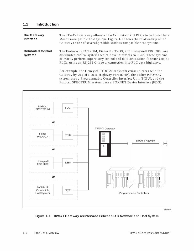
The TIWAY I Gateway allows a TIWAY I network of PLCs to be hosted by aModbus-compatible host system. Figure 1-1 shows the relationship of theGateway to one of several possible Modbus-compatible host systems.
The Foxboro SPECTRUM, Fisher PROVOX, and Honeywell TDC 2000 aredistributed control systems which have interfaces to PLCs. These systemsprimarily perform supervisory control and data acquisition functions to thePLCs, using an RS-232-C type of connection into PLC data highways.
For example, the Honeywell TDC 2000 system communicates with theGateway by way of a Data Highway Port (DHP), the Fisher PROVOXsystem uses a Programmable Controller Interface Unit (PCIU), and theFoxboro SPECTRUM system uses a FOXNET Device Interface (FDG).
I000000
FoxboroSPECTRUM
FisherPROVOX
HoneywellTDC 2000
MODBUSCompatible
Host System
or
or
or
TIWAY I Gateway
Programmable Controllers
TIWAY I Network
FDG
PCIU
DHP
“xyz”
Figure 1-1 TIWAY I Gateway as Interface Between PLC Network and Host System
The GatewayInterface
Distributed ControlSystems
Product Overview 1-3TIWAY I Gateway User Manual
1.2 Basic Operating Features
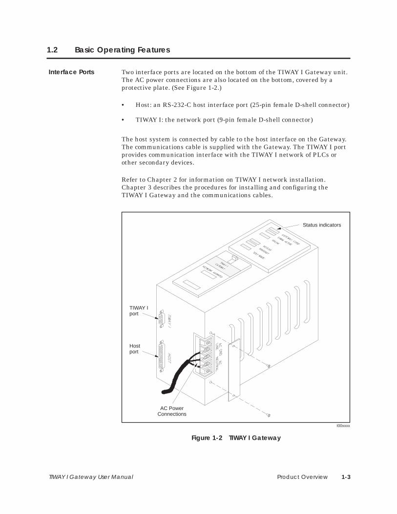
Two interface ports are located on the bottom of the TIWAY I Gateway unit.The AC power connections are also located on the bottom, covered by aprotective plate. (See Figure 1-2.)
• Host: an RS-232-C host interface port (25-pin female D-shell connector)
• TIWAY I: the network port (9-pin female D-shell connector)
The host system is connected by cable to the host interface on the Gateway.The communications cable is supplied with the Gateway. The TIWAY I portprovides communication interface with the TIWAY I network of PLCs orother secondary devices.
Refer to Chapter 2 for information on TIWAY I network installation.Chapter 3 describes the procedures for installing and configuring theTIWAY I Gateway and the communications cables.
TIWAY Iport
I00xxxx
AC PowerConnections
Hostport
Status indicators
Figure 1-2 TIWAY I Gateway
Interface Ports
Product Overview1-4 TIWAY I Gateway User Manual
Basic Operating Features (continued)
The Gateway provides protocol and electrical interface conversion. Acommand issued by the host system is transmitted to the Gateway. Once itreceives the command, the Gateway converts the protocol and electricalsignals and then relays the command to the PLC which was addressed.After the PLC responds, the Gateway re-translates the information andsends it back to the host system through the interface device.
The primary function of the Gateway, then, is to translate host commandsinto TIWAY I commands. These commands are described in Appendix C.
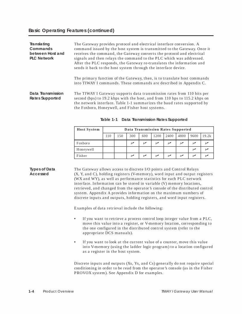
The TIWAY I Gateway supports data transmission rates from 110 bits persecond (bps) to 19.2 kbps with the host, and from 110 bps to 115.2 kbps onthe network interface. Table 1-1 summarizes the baud rates supported bythe Foxboro, Honeywell, and Fisher host systems.
Table 1-1 Data Transmission Rates Supported
Host System Data Transmission Rates Supported
110 150 300 600 1200 2400 4800 9600 19.2k
Foxboro � � � � � � �
Honeywell � �
Fisher � � � � � � �
The Gateway allows access to discrete I/O points and Control Relays(X, Y, and C), holding registers (V-memory), word input and output registers(WX and WY), as well as performance statistics for each PLC networkinterface. Information can be stored in variable (V) memory locations,retrieved, and changed from the operator’s console of the distributed controlsystem. Appendix A provides information on the maximum numbers ofdiscrete inputs and outputs, holding registers, and word input registers.
Examples of data retrieval include the following:
• If you want to retrieve a process control loop integer value from a PLC,move this value into a register, or V-memory location, corresponding tothe one configured in the distributed control system (refer to theappropriate DCS manuals).
• If you want to look at the current value of a counter, move this valueinto V-memory (using the ladder logic program) to a location configuredas a register in the host system.
Discrete inputs and outputs (Xs, Ys, and Cs) generally do not require specialconditioning in order to be read from the operator’s console (as in the FisherPROVOX system). See Appendix D for examples.
TranslatingCommandsbetween Host andPLC Network
Data TransmissionRates Supported
Types of DataAccessed

Network Installation 2-1TIWAY I Gateway User Manual
Chapter 2
Network Installation
2.1 TIWAY I Network and Gateway Installation Checklist 2-2. . . . . . . . . . . . . . . . . . . . . . . . . . . . . . Quick Reference Installation Steps 2-2. . . . . . . . . . . . . . . . . . . . . . . . . . . . . . . . . . . . . . . . . . . . . . . Basic Installation Procedures 2-3. . . . . . . . . . . . . . . . . . . . . . . . . . . . . . . . . . . . . . . . . . . . . . . . . . . . . Requirements for Installing the Gateway 2-3. . . . . . . . . . . . . . . . . . . . . . . . . . . . . . . . . . . . . . . . .
2.2 Network Media Installation — Local Line 2-4. . . . . . . . . . . . . . . . . . . . . . . . . . . . . . . . . . . . . . . . . Overview 2-4. . . . . . . . . . . . . . . . . . . . . . . . . . . . . . . . . . . . . . . . . . . . . . . . . . . . . . . . . . . . . . . . . . . . . . . Local Line Cable Characteristics 2-4. . . . . . . . . . . . . . . . . . . . . . . . . . . . . . . . . . . . . . . . . . . . . . . . . TIWAY I Network Characteristics 2-5. . . . . . . . . . . . . . . . . . . . . . . . . . . . . . . . . . . . . . . . . . . . . . . . . . Local Line Hardware Components 2-6. . . . . . . . . . . . . . . . . . . . . . . . . . . . . . . . . . . . . . . . . . . . . . . Tap Housing 2-6. . . . . . . . . . . . . . . . . . . . . . . . . . . . . . . . . . . . . . . . . . . . . . . . . . . . . . . . . . . . . . . . . . . . Terminating the Main Line Cable 2-7. . . . . . . . . . . . . . . . . . . . . . . . . . . . . . . . . . . . . . . . . . . . . . . . Twisted-Pair Cabling 2-7. . . . . . . . . . . . . . . . . . . . . . . . . . . . . . . . . . . . . . . . . . . . . . . . . . . . . . . . . . . . Important Planning Considerations 2-7. . . . . . . . . . . . . . . . . . . . . . . . . . . . . . . . . . . . . . . . . . . . . . Local Line Tap Spacing Rules 2-8. . . . . . . . . . . . . . . . . . . . . . . . . . . . . . . . . . . . . . . . . . . . . . . . . . . . Basic Considerations 2-8. . . . . . . . . . . . . . . . . . . . . . . . . . . . . . . . . . . . . . . . . . . . . . . . . . . . . . . . . . . . Primary Rule 2-8. . . . . . . . . . . . . . . . . . . . . . . . . . . . . . . . . . . . . . . . . . . . . . . . . . . . . . . . . . . . . . . . . . . . Double Drops 2-9. . . . . . . . . . . . . . . . . . . . . . . . . . . . . . . . . . . . . . . . . . . . . . . . . . . . . . . . . . . . . . . . . . . Short Drops 2-9. . . . . . . . . . . . . . . . . . . . . . . . . . . . . . . . . . . . . . . . . . . . . . . . . . . . . . . . . . . . . . . . . . . . . Multidrop Taps 2-9. . . . . . . . . . . . . . . . . . . . . . . . . . . . . . . . . . . . . . . . . . . . . . . . . . . . . . . . . . . . . . . . . . Cable Routing 2-10. . . . . . . . . . . . . . . . . . . . . . . . . . . . . . . . . . . . . . . . . . . . . . . . . . . . . . . . . . . . . . . . . . Obstructions 2-11. . . . . . . . . . . . . . . . . . . . . . . . . . . . . . . . . . . . . . . . . . . . . . . . . . . . . . . . . . . . . . . . . . . . Noise Avoidance 2-11. . . . . . . . . . . . . . . . . . . . . . . . . . . . . . . . . . . . . . . . . . . . . . . . . . . . . . . . . . . . . . .
2.3 Network Media Installation — RS-232-C Modem Interface 2-12. . . . . . . . . . . . . . . . . . . . . . . . . Data Transmission Characteristics 2-12. . . . . . . . . . . . . . . . . . . . . . . . . . . . . . . . . . . . . . . . . . . . . . . . RS-232 Pin Assignments 2-12. . . . . . . . . . . . . . . . . . . . . . . . . . . . . . . . . . . . . . . . . . . . . . . . . . . . . . . . . .

Network Installation2-2 TIWAY I Gateway User Manual
2.1 TIWAY I Network and Gateway Installation Checklist
Figure 2-1 is a quick reference list of steps to be taken when installing theTIWAY I Gateway. Refer to Chapter 3 for specific procedures and cautions.
Attach AC power cable to the Gateway.
Run diagnostic tests.
Connect the network and host interface cables.
Configure the host system.
Configure the Gateway dipswitches.
Configure the variable memory of PLCs on the TIWAY I network.
Check Gateway indicators for proper operation.
Figure 2-1 Basic Installation and Set-up Steps
Quick ReferenceInstallation Steps

Network Installation 2-3TIWAY I Gateway User Manual
Some basic procedures to follow when installing a Gateway system includethe following.
• Be sure you have all components necessary to install the Gateway andthe network cables. (Refer to the checklist below for required parts.)
• Install the TIWAY I network and host system interface cables (seeSection 2.2). Also refer to the appropriate host system installationmanuals for specific information on cabling between the host and theGateway.
• Install the Gateway in a NEMA panel or other suitable enclosure (seeChapter 3 for more details).
The items below are required to install the TIWAY I Gateway and to connectit to a host system and the TIWAY I network.
TIWAY I Gateway
L-shaped mounting brackets and bracket screws, or optional rackmount kit.
Host interface cable (included; PPX:2462553–0003)
Mounting screws (customer-supplied)
AC power cable (customer-supplied)
Loopback connector(s) for user-initiated diagnostic test (included;PPX:2703834–0001)
TIWAY I Tap Housing (for Local Line installation) (PPX:500–5606)
Tap cable for use with Local Line (customer-supplied), or
RS-232-C/423 cable for use with modems (both cables and modems arecustomer-supplied)
Basic InstallationProcedures
Requirements forInstalling theGateway
Network Installation2-4 TIWAY I Gateway User Manual
2.2 Network Media Installation — Local Line
TIWAY I is a multi-drop communications network. It consists of a maintrunk cable (the “spine”) and dropline cables. The network can connect up to248 secondaries to a host computer.
NOTE: Although addresses can range from 1 to 254 on TIWAY I, addresses248 through 254 cannot be used because of the limitations of the Modbusprotocol.
The selection of the media interface depends primarily upon two criteria:the distance to be spanned and the cost of installation. The main trunk canbe up to 25,000 feet long, and each dropline can be up to 100 feet long, withLocal Line. For distances exceeding 25,000 feet, the use of RS-232-C mediainterfaces and modems is required.
If cable redundancy is required (two TIWAY I cables), you will need twoGateways, two cables, and two host system interface devices. Refer to theappropriate host system user manuals for more specific information onredundant connections.
The TIWAY I Local Line is a physical signalling technique (baseband,differential current drive) which operates over shielded, twisted-paircabling. The Local Line cable may be up to 25,000 feet long. The Local Lineuses tap housings to simplify the addition of connections onto TIWAY I.
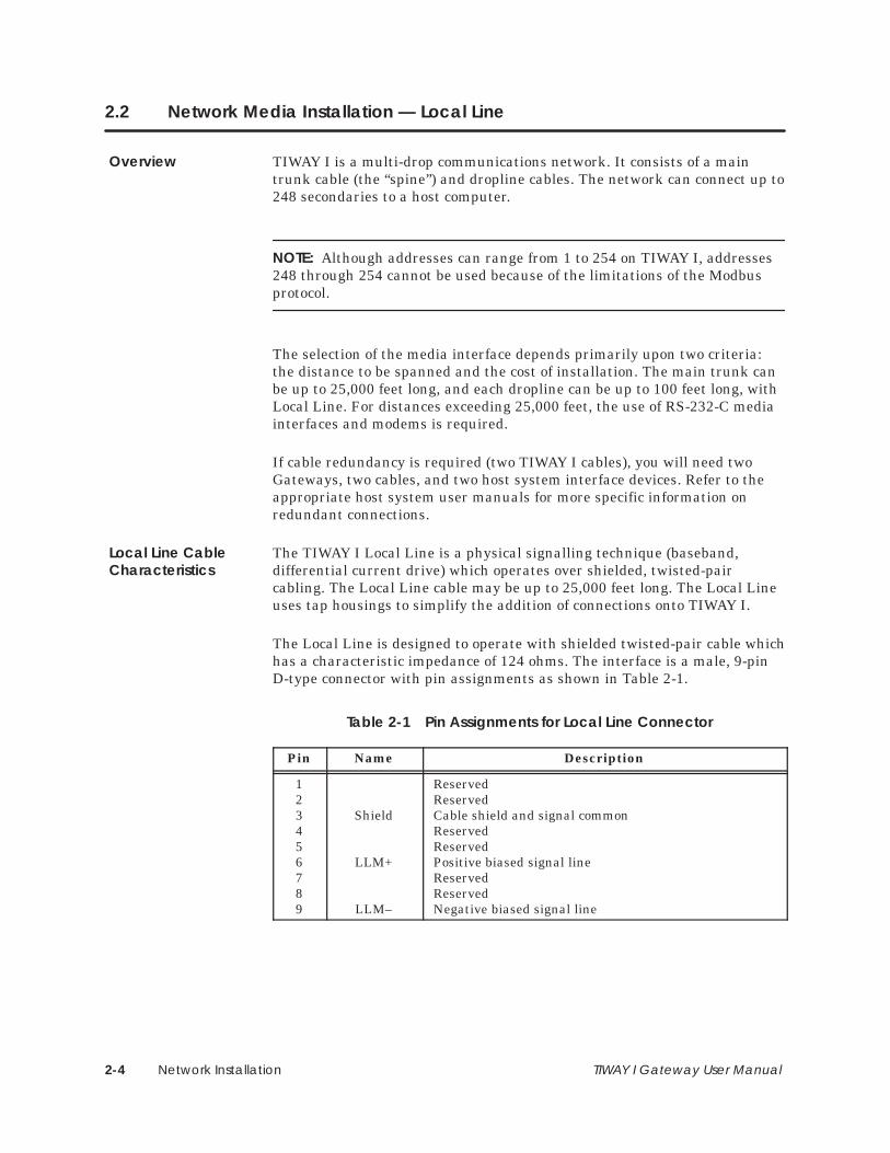
The Local Line is designed to operate with shielded twisted-pair cable whichhas a characteristic impedance of 124 ohms. The interface is a male, 9-pinD-type connector with pin assignments as shown in Table 2-1.
Table 2-1 Pin Assignments for Local Line Connector
Pin Name Description
123456789
Shield
LLM+
LLM–
ReservedReservedCable shield and signal commonReservedReservedPositive biased signal lineReservedReservedNegative biased signal line
Overview
Local Line CableCharacteristics
Network Installation 2-5TIWAY I Gateway User Manual
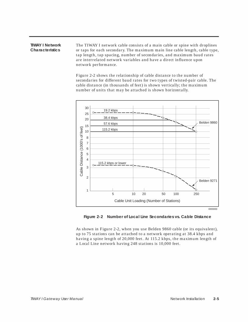
The TIWAY I network cable consists of a main cable or spine with droplinesor taps for each secondary. The maximum main line cable length, cable type,tap length, tap spacing, number of secondaries, and maximum baud ratesare interrelated network variables and have a direct influence uponnetwork performance.
Figure 2-2 shows the relationship of cable distance to the number ofsecondaries for different baud rates for two types of twisted-pair cable. Thecable distance (in thousands of feet) is shown vertically; the maximumnumber of units that may be attached is shown horizontally.
30
25
20
15
10
8
5
4
3
2
1
6
7
10 50 100 250
Cable Unit Loading (Number of Stations)
19.2 kbps
38.4 kbps
57.6 kbps
115.2 kbps
115.2 kbps or lower
Belden 9860
Belden 9271
Cab
le D
ista
nce
(100
0’s
of fe
et)
205
I000000
Figure 2-2 Number of Local Line Secondaries vs. Cable Distance
As shown in Figure 2-2, when you use Belden 9860 cable (or its equivalent),up to 75 stations can be attached to a network operating at 38.4 kbps andhaving a spine length of 20,000 feet. At 115.2 kbps, the maximum length ofa Local Line network having 248 stations is 10,000 feet.
TIWAY I NetworkCharacteristics
Network Installation2-6 TIWAY I Gateway User Manual
Network Media Installation — Local Line (continued)
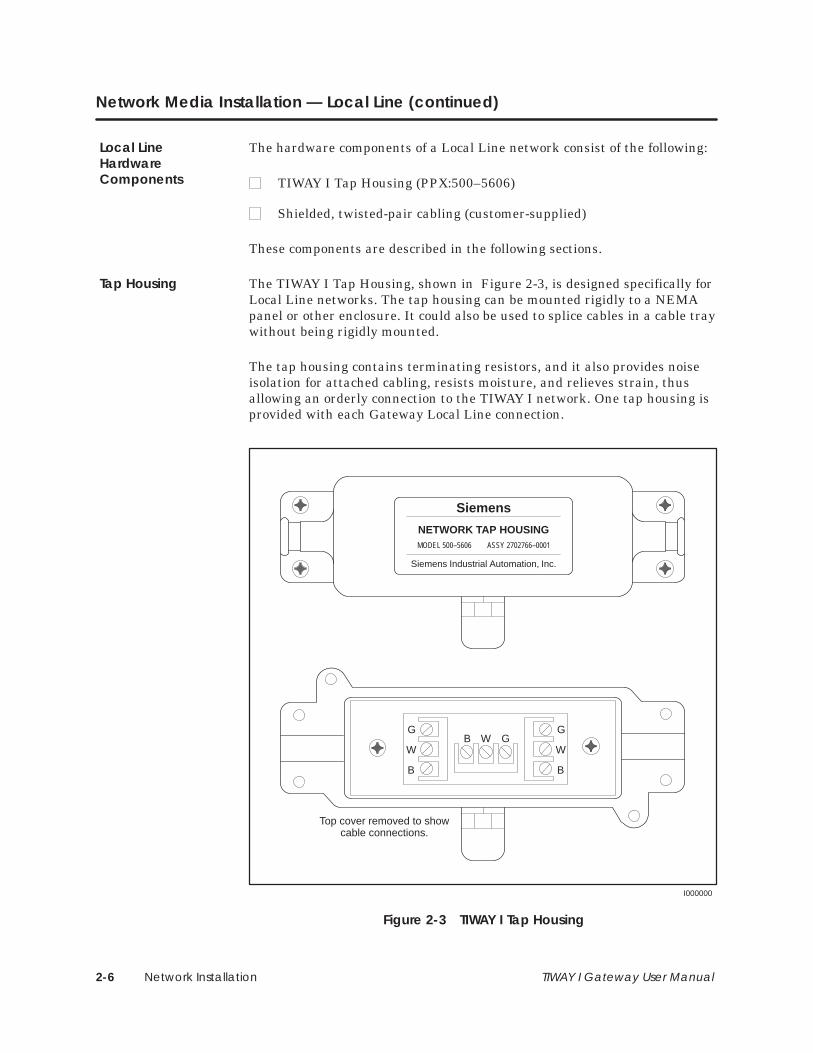
The hardware components of a Local Line network consist of the following:
TIWAY I Tap Housing (PPX:500–5606)
Shielded, twisted-pair cabling (customer-supplied)
These components are described in the following sections.
The TIWAY I Tap Housing, shown in Figure 2-3, is designed specifically forLocal Line networks. The tap housing can be mounted rigidly to a NEMApanel or other enclosure. It could also be used to splice cables in a cable traywithout being rigidly mounted.
The tap housing contains terminating resistors, and it also provides noiseisolation for attached cabling, resists moisture, and relieves strain, thusallowing an orderly connection to the TIWAY I network. One tap housing isprovided with each Gateway Local Line connection.
Siemens
NETWORK TAP HOUSINGMODEL 500–5606 ASSY 2702766–0001
Siemens Industrial Automation, Inc.
G
W
B
G
W
B
GWB
Top cover removed to showcable connections.
I000000
Figure 2-3 TIWAY I Tap Housing
Local LineHardwareComponents
Tap Housing

Network Installation 2-7TIWAY I Gateway User Manual
The terminating resistors must be used to ensure that the main line cable isproperly terminated and biased for improved reliability. Each tap housing issupplied with terminating resistors to connect to the ends of the main linecable. At each end, a terminating resistor must be connected between LLM+and the cable shield and also between LLM– and the cable shield inside thetap housing.
I000000
G
W
B
G
W
B
GWB
TerminationResistors:68 ohms
5%1/4 wattCable to Module
Network Cable
Input Output
Figure 2-4 Terminating the Local Line
Siemens Industrial Automation recommends Belden 9860 twisted-paircabling or its equivalent for use as the Local Line network spine. Belden9271 or its equivalent should be used for the dropline. Brands other thanthose listed here will be specified by Siemens upon request.
Some major points to consider during the planning phase of a Local Linenetwork are the following.
• From the start, allow for system growth. Make provisions for theattachment of additional computing devices by routing cables throughall probable areas of future plant expansion.
• Always make the network flexible enough to allow for re-arrangementof plant equipment.
• Since network system noise is usually picked up by its interconnectingwiring, take steps during installation to bypass or eliminate noisesources.
• If cable redundancy is required, make sure the two cables are neverrouted along the same path, since the environmental and other factorswhich disable one cable will very likely disable the second cable.
Terminating theMain Line Cable
Twisted-PairCabling
Important PlanningConsiderations

Network Installation2-8 TIWAY I Gateway User Manual
Network Media Installation — Local Line (continued)
Local Line networks must adhere to specific tap spacing requirements tomaintain signal integrity. These requirements are outlined in the followingsections.
60′
100′
100′ 100′
50′ min 50′ min 50′ 30′20′
I000000
Figure 2-5 Basic Tap Spacing Rules
The rules for determining the correct distances between taps exist simplyfor the prevention of signal degradation caused by reflections.
Prior to configuring the distances between taps in the network cable, selecta single tap as a physical point to use as reference. This tap should be one ofthe taps on the end of the network.
The primary rule is that the minimum distance from one tap to the nextcannot be less than one half the distance of the previous tap cable(drop line) length. This rule should be applied starting at the first tap on thenetwork all the way to the end. Then, from the last tap on the network, thesame rule should be applied back to the first tap again.
Local Line TapSpacing Rules
BasicConsiderations
Primary Rule

Network Installation 2-9TIWAY I Gateway User Manual
100′
80′100′max
30″30′
Double Drop Drop lines lessthan 36 inchescan be ignored.
100′
50′ min
I000000
36″ max
Figure 2-6 Additional Tap Spacing Rules
If a tap cable is installed less than the minimum distance as stated in theprimary rule, then the two drops, the previous one and the one beinginstalled, are considered a double drop.
Double drops are allowed, but triple drops are not allowed.
After installing a double drop, the next tap must be placed at the minimumdistance or farther. In this case, the minimum distance would be one halfthe distance of the longest of the two tap lines making up the double drop.
Drops that have a tap line that is less than 36 inches can be ignored incalculating the minimum distance between taps.
There is no limit to the number of drop stations that can be connected to thesame tap line.
Each station must have its own tap, and the overall drop line length cannotexceed 100 feet. The cable used to attach each station to the drop linecannot exceed the 36-inch maximum.
Double Drops
Short Drops
Multidrop Taps
Network Installation2-10 TIWAY I Gateway User Manual
Network Media Installation — Local Line (continued)
Cable routing should be planned as if the path between all stations on thenetwork were free of obstructions. The next step is to modify the firstrouting to account for obstructions, then calculate the amount of cableneeded.
Observe all local and national electrical and fire codes wheninstalling wiring.
In general, there are three types of network cabling routes:
• Under-floor
• In-ceiling
• Surface ducting
Any combination of these three routes may be used on a single network. Thechoice is often determined by whether or not the building (or buildings) inwhich the network is being installed is new construction or an existingbuilding. The following paragraphs describe some of the advantages anddisadvantages of each type of cable routing.
Under-floor — For under-floor routing, the cable can be enclosed withinducts or, with raised flooring, in the “open air.” Under-floor systems enclosedin ducts are usually expensive, and while they are better-protected againstunauthorized taps than are open-air systems, they often make futureexpansion of the network more difficult and expensive.
Open-air under-floor cabling systems usually provide good access, and allowmaximum network expansion and flexibility.
In-ceiling — For in-ceiling routing, network cables are usually supportedin troughs or with hooks and clamps every 10 or 15 feet. Some advantagesof in-ceiling installation are the following.
• Flexibility
• Low-cost installation
• Accessibility to cabling
Cable Routing
CAUTION!

Network Installation 2-11TIWAY I Gateway User Manual
Some disadvantages are the following.
• Is is impractical for buildings without drop ceilings
• Working in high ceilings can be hazardous
• Ceilings often collect dust and other debris
Surface ducting — Surface ducting for network cabling is usuallyinstalled along the baseboards or is attached to walls at desktop height.While surface ducting ordinarily protects cables from both physical and EMIeffects, it may also require that network computing devices be positionednear a wall.
Aside from physical obstructions such as posts, walls, and partitions,electrical interference should also be avoided. Some sources of interferenceare the following.
• Power distribution mains
• Arcing motors
• Fluorescent lighting
• Teletypes
• Undesired signal transfer (cross-talk) between adjacent circuits
• Poor cable-to-equipment impedance matching
In general, network cabling should never come into direct contact with anyelectrical conductor. If cabling is installed inside a conduit, the conduitshould be grounded in accordance with applicable electrical codes. Keep aminimum of three feet of distance between all network cabling and thefollowing sources of noise.
• Power lines • Generators
• Electric motors • Electric welders
• Transformers • Induction furnaces and heaters
• Rectifiers • All sources of microwave radiation
Obstructions
Noise Avoidance

Network Installation2-12 TIWAY I Gateway User Manual
2.3 Network Media Installation — RS-232-C Modem Interface
The physical layer in TIWAY I provides a modem interface for synchronousor asynchronous communications at data transmission rates up to 115.2 Kbps. The modem interface provides standard signals for control of two-wayalternate data transmission using both half and full duplex modems.
The modem interface is a standard Type E DTE configuration as defined inthe EIA RS-232-C standard. This interface uses a male 25-pin D-typeconnector plug on the communication cable. The pin assignments are listedin Table 2-2.
Table 2-2 RS-232-C Connector Pin Assignments
Pin No. Description
1 Protective Ground
2 Transmit Data
3 Receive Data
4 Request to Send (RTS)
5 Clear to Send (CTS)
6 Data Set Ready (DSR)
7 Signal Ground
8 Receive Line Signal Detector/Data Carrier Detect (RLSD/DCD)
15 Transmitter Signal Element Timing
17 Receiver Signal Element Timing
20 Data Terminal Ready (DTR)
Data TransmissionCharacteristics
RS-232 PinAssignments
Gateway Installation and Configuration 3-1TIWAY I Gateway User Manual
Chapter 3
Gateway Installation and Configuration
3.1 Installing the TIWAY I Gateway 3-2. . . . . . . . . . . . . . . . . . . . . . . . . . . . . . . . . . . . . . . . . . . . . . . . . . . Basic Mounting Guidelines 3-2. . . . . . . . . . . . . . . . . . . . . . . . . . . . . . . . . . . . . . . . . . . . . . . . . . . . . . Power Connections and Initialization 3-3. . . . . . . . . . . . . . . . . . . . . . . . . . . . . . . . . . . . . . . . . . . . .
3.2 Dipswitch Configuration and Function 3-6. . . . . . . . . . . . . . . . . . . . . . . . . . . . . . . . . . . . . . . . . . . . Overview 3-6. . . . . . . . . . . . . . . . . . . . . . . . . . . . . . . . . . . . . . . . . . . . . . . . . . . . . . . . . . . . . . . . . . . . . . . Dipswitch Settings for the Host Interface Port 3-7. . . . . . . . . . . . . . . . . . . . . . . . . . . . . . . . . . . . . Dipswitch Settings for the Network Interface Port 3-8. . . . . . . . . . . . . . . . . . . . . . . . . . . . . . . . .
3.3 Switches and Indicator Lights 3-10. . . . . . . . . . . . . . . . . . . . . . . . . . . . . . . . . . . . . . . . . . . . . . . . . . . . Online/Offline Switch 3-10. . . . . . . . . . . . . . . . . . . . . . . . . . . . . . . . . . . . . . . . . . . . . . . . . . . . . . . . . . . . Self-Test Button 3-10. . . . . . . . . . . . . . . . . . . . . . . . . . . . . . . . . . . . . . . . . . . . . . . . . . . . . . . . . . . . . . . . . Reset Button 3-10. . . . . . . . . . . . . . . . . . . . . . . . . . . . . . . . . . . . . . . . . . . . . . . . . . . . . . . . . . . . . . . . . . . . Status Indicator Lights 3-11. . . . . . . . . . . . . . . . . . . . . . . . . . . . . . . . . . . . . . . . . . . . . . . . . . . . . . . . . . . Gateway Good 3-11. . . . . . . . . . . . . . . . . . . . . . . . . . . . . . . . . . . . . . . . . . . . . . . . . . . . . . . . . . . . . . . . Comm Active 3-11. . . . . . . . . . . . . . . . . . . . . . . . . . . . . . . . . . . . . . . . . . . . . . . . . . . . . . . . . . . . . . . . . . Online 3-11. . . . . . . . . . . . . . . . . . . . . . . . . . . . . . . . . . . . . . . . . . . . . . . . . . . . . . . . . . . . . . . . . . . . . . . . . . Receive 3-11. . . . . . . . . . . . . . . . . . . . . . . . . . . . . . . . . . . . . . . . . . . . . . . . . . . . . . . . . . . . . . . . . . . . . . . . Transmit 3-11. . . . . . . . . . . . . . . . . . . . . . . . . . . . . . . . . . . . . . . . . . . . . . . . . . . . . . . . . . . . . . . . . . . . . . . . Test Mode 3-11. . . . . . . . . . . . . . . . . . . . . . . . . . . . . . . . . . . . . . . . . . . . . . . . . . . . . . . . . . . . . . . . . . . . . .
3.4 Diagnostic Tests 3-12. . . . . . . . . . . . . . . . . . . . . . . . . . . . . . . . . . . . . . . . . . . . . . . . . . . . . . . . . . . . . . . . . Built-In Diagnostic Tests 3-12. . . . . . . . . . . . . . . . . . . . . . . . . . . . . . . . . . . . . . . . . . . . . . . . . . . . . . . . . . Power-On Test 3-12. . . . . . . . . . . . . . . . . . . . . . . . . . . . . . . . . . . . . . . . . . . . . . . . . . . . . . . . . . . . . . . . . . Operational Diagnostic Test 3-12. . . . . . . . . . . . . . . . . . . . . . . . . . . . . . . . . . . . . . . . . . . . . . . . . . . . . User-Initiated Test 3-13. . . . . . . . . . . . . . . . . . . . . . . . . . . . . . . . . . . . . . . . . . . . . . . . . . . . . . . . . . . . . . . Burn-In and Final Tests 3-14. . . . . . . . . . . . . . . . . . . . . . . . . . . . . . . . . . . . . . . . . . . . . . . . . . . . . . . . . . .
Gateway Installation and Configuration3-2 TIWAY I Gateway User Manual
3.1 Installing the TIWAY I Gateway
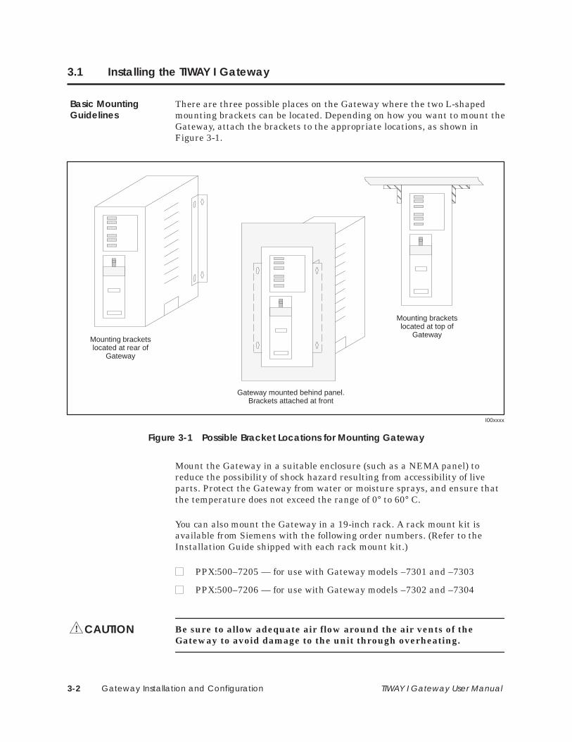
There are three possible places on the Gateway where the two L-shapedmounting brackets can be located. Depending on how you want to mount theGateway, attach the brackets to the appropriate locations, as shown inFigure 3-1.
ÇÇÇÇÇÇ
I00xxxx
ÇÇÇÇÇÇ
Mounting bracketslocated at rear of
Gateway
Mounting bracketslocated at top of
Gateway
Gateway mounted behind panel.Brackets attached at front
Figure 3-1 Possible Bracket Locations for Mounting Gateway
Mount the Gateway in a suitable enclosure (such as a NEMA panel) toreduce the possibility of shock hazard resulting from accessibility of liveparts. Protect the Gateway from water or moisture sprays, and ensure thatthe temperature does not exceed the range of 0° to 60° C.
You can also mount the Gateway in a 19-inch rack. A rack mount kit isavailable from Siemens with the following order numbers. (Refer to theInstallation Guide shipped with each rack mount kit.)
PPX:500–7205 — for use with Gateway models –7301 and –7303
PPX:500–7206 — for use with Gateway models –7302 and –7304
Be sure to allow adequate air flow around the air vents of theGateway to avoid damage to the unit through overheating.
Basic MountingGuidelines
CAUTION!

Gateway Installation and Configuration 3-3TIWAY I Gateway User Manual
After mounting the unit in an appropriate location, follow these steps forconnecting the power supply and running diagnostic tests.
1. Remove the shield covering the three AC terminals (Line, Ground, andNeutral).
2. With power off, attach all three connections according to Figure 3-2 andthen replace the shield.
I00xxxx
AC PowerConnections
Figure 3-2 AC Power Connections
3. Apply power to the unit.
4. Install loopback connector on each RS-232 port.
5. Set the Online/Offline switch on the Gateway to the OFFLINE position.
Power Connectionsand Initialization

Gateway Installation and Configuration3-4 TIWAY I Gateway User Manual
Installing the TIWAY I Gateway (continued)
6. Run the user-initiated test. (Refer to the Diagnostics Tests section.)
7. Remove loopback connector.
8. Set the Online/Offline switch on the Gateway to the ONLINE position.
9. Connect the Local Line or RS-232 interface cable to the TIWAY I port.
10. Connect the host system interface cable to to the host port.
11. Configure the communications parameters on the host system. Makesure that the host system baud rate matches the rate you plan to set onthe Gateway.
12. Set the dipswitches on the Gateway. Be sure to set the parity, duplex,and synchronous/asynchronous selections to match the correspondingsettings on the host system. (See Figure 3-3 and Section 3.2.)
13. Check to see that the GATEWAY GOOD, TRANSMIT, and RECEIVEindicators on the Gateway are on, and that TEST is flashing.
14. Configure the data and status registers in the variable memory of thePLCs on the TIWAY I network. (Refer to the appropriate PLC manualsfor more information if necessary.)
15. Press the RESET button on the Gateway.
16. Begin program execution.
Gateway Installation and Configuration 3-5TIWAY I Gateway User Manual
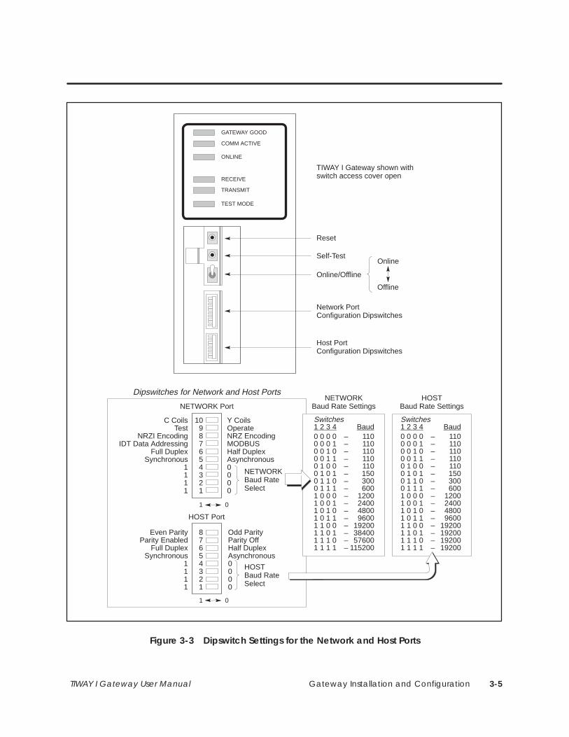
10987654321
87654321
Y CoilsOperateNRZ EncodingMODBUSHalf DuplexAsynchronous0000
NETWORKBaud RateSelect
Odd ParityParity OffHalf DuplexAsynchronous0000
C CoilsTest
NRZI EncodingIDT Data Addressing
Full DuplexSynchronous
1111
NETWORKBaud Rate Settings
0 0 0 0 – 1100 0 0 1 – 1100 0 1 0 – 1100 0 1 1 – 1100 1 0 0 – 1100 1 0 1 – 1500 1 1 0 – 3000 1 1 1 – 6001 0 0 0 – 12001 0 0 1 – 24001 0 1 0 – 48001 0 1 1 – 96001 1 0 0 – 192001 1 0 1 – 384001 1 1 0 – 576001 1 1 1 – 115200
Switches1 2 3 4 Baud
Even ParityParity Enabled
Full DuplexSynchronous
1111
NETWORK Port
HOST Port
HOST Baud RateSelect
1 0
HOSTBaud Rate Settings
0 0 0 0 – 1100 0 0 1 – 1100 0 1 0 – 1100 0 1 1 – 1100 1 0 0 – 1100 1 0 1 – 1500 1 1 0 – 3000 1 1 1 – 6001 0 0 0 – 12001 0 0 1 – 24001 0 1 0 – 48001 0 1 1 – 96001 1 0 0 – 192001 1 0 1 – 192001 1 1 0 – 192001 1 1 1 – 19200
Switches1 2 3 4 Baud
Dipswitches for Network and Host Ports
1 0
GATEWAY GOOD
COMM ACTIVE
ONLINE
RECEIVE
TRANSMIT
TEST MODE
Reset
Self-Test
Online/Offline
Network Port Configuration Dipswitches
Host Port Configuration Dipswitches
TIWAY I Gateway shown withswitch access cover open
Online
Offline
Figure 3-3 Dipswitch Settings for the Network and Host Ports
Gateway Installation and Configuration3-6 TIWAY I Gateway User Manual
3.2 Dipswitch Configuration and Function
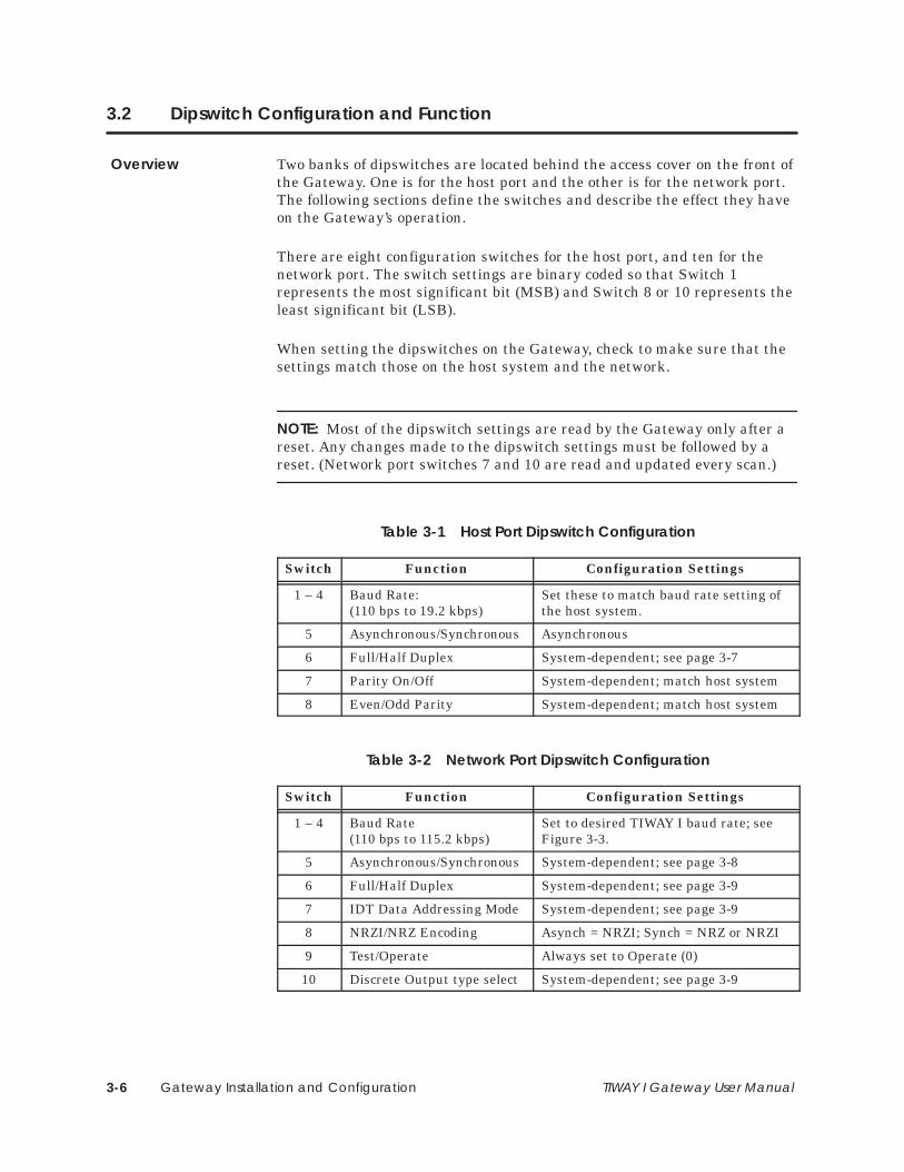
Two banks of dipswitches are located behind the access cover on the front ofthe Gateway. One is for the host port and the other is for the network port.The following sections define the switches and describe the effect they haveon the Gateway’s operation.
There are eight configuration switches for the host port, and ten for thenetwork port. The switch settings are binary coded so that Switch 1represents the most significant bit (MSB) and Switch 8 or 10 represents theleast significant bit (LSB).
When setting the dipswitches on the Gateway, check to make sure that thesettings match those on the host system and the network.
NOTE: Most of the dipswitch settings are read by the Gateway only after areset. Any changes made to the dipswitch settings must be followed by areset. (Network port switches 7 and 10 are read and updated every scan.)
Table 3-1 Host Port Dipswitch Configuration
Switch Function Configuration Settings
1 – 4 Baud Rate: (110 bps to 19.2 kbps)
Set these to match baud rate setting ofthe host system.
5 Asynchronous/Synchronous Asynchronous
6 Full/Half Duplex System-dependent; see page 3-7
7 Parity On/Off System-dependent; match host system
8 Even/Odd Parity System-dependent; match host system
Table 3-2 Network Port Dipswitch Configuration
Switch Function Configuration Settings
1 – 4 Baud Rate(110 bps to 115.2 kbps)
Set to desired TIWAY I baud rate; seeFigure 3-3.
5 Asynchronous/Synchronous System-dependent; see page 3-8
6 Full/Half Duplex System-dependent; see page 3-9
7 IDT Data Addressing Mode System-dependent; see page 3-9
8 NRZI/NRZ Encoding Asynch = NRZI; Synch = NRZ or NRZI
9 Test/Operate Always set to Operate (0)
10 Discrete Output type select System-dependent; see page 3-9
Overview

Gateway Installation and Configuration 3-7TIWAY I Gateway User Manual
The 8-switch bank governs the host interface. The following paragraphsdescribe the switch-selectable options for setting the host interfaceparameters.
Data Transmission Rate Selection (Switches 1 through 4): For the hostport, Table 3-3 shows what data transmission rates are supported on thelisted host systems. (Refer to Figure 3-3 for the host baud rate dipswitchsettings.)
Table 3-3 Data Transmission Rates Supported
Host System Data Transmission Rates Supported
110 150 300 600 1200 2400 4800 9600 19.2k
Foxboro � � � � � � �
Honeywell � �
Fisher � � � � � � �
Asynchronous/Synchronous Operation (Switch 5): The Synch/Asynchswitch is used for modem operation. In the synchronous mode, transmittersignal element timing is used to send transmit data. The transmitter andreceiver signal timing elements are supplied by the modem. In theasynchronous position, the modem does not supply receiver or transmittertiming elements and the Gateway uses internal clocks to determine receivedata sample points and to send transmit data. You should use theasynchronous setting.
Full/Half Duplex Operation (Switch 6): the Full/Half Duplex switchselects operation compatible with full or half duplex modems even thoughcommunication with the Gateway is half duplex only. When you selectHalf-duplex operation, the Gateway does not activate the Request to Sendcircuit before Data Carrier Detect becomes inactive. Timing relationshipsbetween Data Carrier Detect and Request to Send are ignored when fullduplex is selected. When you are using a half-duplex modem, you should usethe Half-duplex setting; with a full-duplex modem, use the Full-duplexsetting.
Parity Enable/Disable (Switch 7): This will either enable or disable parityin all data transmissions.
Even/Odd Parity (Switch 8): If Switch 7 (Parity Enable/Disable) is set toenable parity, switch 8 selects even or odd parity.
Dipswitch Settingsfor the HostInterface Port

Gateway Installation and Configuration3-8 TIWAY I Gateway User Manual
Dipswitch Configuration and Function (continued)
The 10-dipswitch bank governs the network communications port. Thefollowing paragraphs describe the switch-selectable options available for thenetwork port.
Data Transmission Rate Selection (Switches 1 through 4): The TIWAY Inetwork supports the following data transmission rates: 110, 150, 300, 600,1200, 2400, 4800, 9600, 19200, 38400, 57600, and 115,200 bits per second.Set the dipswitches according to the chart in Figure 3-4.
I000000
0 0 0 0 – 1100 0 0 1 – 1100 0 1 0 – 1100 0 1 1 – 1100 1 0 0 – 1100 1 0 1 – 1500 1 1 0 – 3000 1 1 1 – 6001 0 0 0 – 12001 0 0 1 – 24001 0 1 0 – 48001 0 1 1 – 96001 1 0 0 – 192001 1 0 1 – 384001 1 1 0 – 576001 1 1 1 – 115200
Switches1 2 3 4 Baud
10987654321
NETWORKBaud RateSelect
1 0
Figure 3-4 Dipswitch Settings for Network Data Transmission Rates
Asynchronous/Synchronous Operation (Switch 5): The Synch/Asynchswitch is used for modem operation. In the Synchronous mode, the Gatewayuses the transmitter signal element timing to transmit data. Thetransmitter and receiver signal timing elements are both supplied by themodem. In the Asynchronous position, the modem does not supply receiveror transmitter timing elements and the Gateway uses internal clocks todetermine receive data sample points and to send transmit data. You shouldselect Asynchronous operation when you are using the Local Line.
Dipswitch Settingsfor the NetworkInterface Port

Gateway Installation and Configuration 3-9TIWAY I Gateway User Manual
Full/Half Duplex Operation (Switch 6): the Full/Half Duplex switchselects operation compatible with full or half-duplex modems even thoughcommunication with the Gateway is half-duplex only. When you selectHalf-duplex operation, the Gateway does not activate the Request to Sendcircuit before Data Carrier Detect becomes inactive. Timing relationshipsbetween Data Carrier Detect and Request to Send are ignored when fullduplex is selected. When you are using a half-duplex modem, you should usethe Half-duplex setting; with a full-duplex modem, select Full-duplex.
Modbus/IDT Data Addressing (Switch 7): Set this switch to the On (1)position to implement a data addressing scheme for the IDT family ofoperator interface products. Set this switch to the Off (0) position to selectstandard Modbus data addressing.
NRZI/NRZ Encoding (Switch 8): The NRZI/NRZ (non-return to zeroinverted/non-return to zero) switch selects the type of encoding to be usedduring network communication. The NRZI encoding option is required forasynchronous operation. Either NRZI or NRZ may be used withsynchronous operation, but NRZ encoding is recommended.
Test/Operate (Switch 9): This switch selects either Test or Operate mode.You should always set this switch to Operate.
Y/C Coil Type Select (Switch 10): This switch collects coil data from asecondary’s Control Relay (C) memory when set to On (1). In the Off (0)position, coil information is collected from Discrete Output (Y) memory.

Gateway Installation and Configuration3-10 TIWAY I Gateway User Manual
3.3 Switches and Indicator Lights
I000000
Reset
Self-Test
Online/Offline
Online
Offline
Figure 3-5 Gateway Operation Switches
The Online/Offline switch, when placed in the Online position, allows theGateway to communicate with the network and the other systems connectedto the Gateway. In the Offline position, the Gateway is disconnected fromthe network. This prevents access to the network while secondaries arebeing changed or while maintenance is being performed. The position of thisswitch is read before each communication cycle, so a reset of the Gateway isnot necessary each time the Online/Offline switch position is changed.
The Self-Test button initiates a set of Gateway diagnostic tests, including astandalone Gateway communications loopback test. This test requires aspecial hardware set-up, using the loopback connector supplied with theGateway. This procedure is described more fully in the section on DiagnosticTests. The Gateway must have the Online/Offline switch in the Offlineposition to initiate the diagnostic tests.
Pressing the Reset button causes a hardware reset of the Gateway andinitiates the power-on diagnostic test. The power-on test is explained inmore detail in the section on Diagnostic Tests.
Online/OfflineSwitch
Self-Test Button
Reset Button

Gateway Installation and Configuration 3-11TIWAY I Gateway User Manual
I000000
GATEWAY GOOD
COMM ACTIVE
ONLINE
RECEIVE
TRANSMIT
TEST MODE
ON = All tests passed successfully
ON = Receiving data
ON = Communication in progress
ON = Communicating with network
ON = Transmitting data
ON = In test mode (test button pressed)Flashing = Tests completed successfully
Figure 3-6 Indicator Lights
The six indicator lights on the front panel of the Gateway show module andcommunication status, as described in the following paragraphs.
If the GATEWAY GOOD indicator is lit, it means that all power-on/reset orrun-time diagnostic tests have been passed successfully. If the indicator isflashing or not lit, one of the Gateway components has failed a diagnostictest, and the Gateway is inoperable. If a reset does not remedy thesituation, you should return the unit for repair.
The COMM ACTIVE indicator is lit continuously while any communicationis in progress. It is not lit while the Gateway is in Test mode.
The ONLINE indicator is lit while the Gateway is communicating with thenetwork. However, if you have taken the Gateway off-line by placing theOnline/Offline switch in the Offline position, the Online indicator will not belit at any time.
The RECEIVE indicator is lit when the Gateway is receiving data on eitherport.
The TRANSMIT indicator is lit when the Gateway is transmitting data oneither port.
The TEST MODE indicator lights when you press the Self-Test button andthe Gateway is in Test mode. The indicator remains lit while the diagnostictests are being performed, and flashes when they are successfullycompleted.
Status IndicatorLights
Gateway Good
Comm Active
Online
Receive
Transmit
Test Mode

Used only in qualityassurance tests bymanufacturer
Gateway Installation and Configuration3-12 TIWAY I Gateway User Manual
3.4 Diagnostic Tests
The Gateway has five levels of built-in tests, three of which are designed forthe user.
• Power-on test
• Operational Diagnostic test
• User-initiated test
• Burn-in test
• Final test
The Power-on test executes the initialization routine following a masterreset. All indicators light for approximately one second before any subtestsbegin. The only indicator which will be lit while the tests are running is theTEST MODE indicator. If the Gateway passes all tests successfully, theGATEWAY GOOD indicator will light.
The subtests include a RAM data and address integrity test, a ROM CRCintegrity test, and a communications controller internal loopback test.
If the Gateway fails any of the power-on tests, the GATEWAY GOODindicator will flash.
The Operational Diagnostic test executes during all normal modes ofGateway operation, off-line or on-line. The subtests do not disturb normaloperation of the network. They are performed at least once per minuteunder all conditions.
An operational diagnostics failure is treated in the same way as a power-ontest failure. The GATEWAY GOOD indicator will flash if the Gateway failsany diagnostic test.
Built-In DiagnosticTests
Power-On Test
OperationalDiagnostic Test

Gateway Installation and Configuration 3-13TIWAY I Gateway User Manual
You should run the user-initiated test only when the Gateway is in Off-linemode (that is, when the On-line/Off-line switch is in the OFFLINE position).Normal Gateway operation is suspended during this test mode.
NOTE: Before initiating the diagnostic routine, make sure that the networkand host computer cables are disconnected from the Gateway, and that theGateway is in off-line mode. Only the GATEWAY GOOD indicator should belit. If ONLINE is lit, you must first reset the Gateway before running thetest.
1. Install a loopback connector on each RS-232-C port; (without one, theport will fail the external loopback subtest). Table 3-4 shows the signalline connections made by the loopback connector.
Table 3-4 RS-232-C/423 Loopback Connections
Pin # to Pin # Signal to Signal
2 3 Data out Data In
4 5 Request to Send (RTS) Clear to Send (CTS)
20 6,8 Data Terminal Ready (DTR) Data Set Ready (DSR) /Data Carrier Detect (DCD)
2. Press the SELF-TEST button to start the user-initiated test.
The diagnostics will perform internal and external loopback, jabberstop*,and data rate subtests to each channel. If a media card is missing or is bad,the test will fail. The subtests for the user-initiated diagnostic test includethe following.
• RAM data and address line verification (internal and external RAM)
• ROM integrity using CRC and checksum
• Serial Communications Chip (SCC) using internal loopback and baud rate
• Transmitter/Receiver via external loopback and jabberstop
• Verification of watchdog timer
• Indicator operation
*The jabberstop is a Gateway feature which prevents a device from monopolizing the network.
User-Initiated Test

Gateway Installation and Configuration3-14 TIWAY I Gateway User Manual
Diagnostic Tests (continued)
Table 3-5 shows how to interpret the results of the user-initiated diagnostictest according to the status of the indicator lights.
Table 3-5 Indicator Status after User-Initiated Test
Indicator Pass Fail Subtests Included
GATEWAY GOOD On Off ROM, RAM, watchdog
TRANSMIT On Off Network Port: loopback, jabberstop,network baud rate
RECEIVE On Off Host Port: loopback, jabberstop, hostport baud rate
TEST MODE Flashing Flashing Test Completed
Note: During the test, the COMM ACTIVE and ONLINE indicators are off.
3. If GATEWAY GOOD, TRANSMIT, and RECEIVE are not lit at the endof the test, first make sure that the loopback connector(s) are onsecurely, and repeat the test. If these indicators are still not on, contactyour Siemens Industrial Automation, Inc. distributor for assistance.
I000000
GATEWAY GOOD
COMM ACTIVE
ONLINE
RECEIVE
TRANSMIT
TEST MODE
ON = CPU board tests passed
ON = Host port tests passed
ON = Network port tests passed
Flashing = Tests completed
Figure 3-7 Indicator Status
4. To exit TEST mode, press the RESET button.
The burn-in and final tests are primarily factory quality tests and arenormally not used in any applications.
Burn-In and FinalTests

Data Type Identification A-1TIWAY I Gateway User Manual
Appendix A
Data Type Identification
A.1 Corresponding Data Types A-2. . . . . . . . . . . . . . . . . . . . . . . . . . . . . . . . . . . . . . . . . . . . . . . . . . . . . .
A.2 SIMATIC TI PLCs Supported by TIWAY I Gateway A-3. . . . . . . . . . . . . . . . . . . . . . . . . . . . . . . . . . .
A.3 TIWAY I Gateway Specifications A-4. . . . . . . . . . . . . . . . . . . . . . . . . . . . . . . . . . . . . . . . . . . . . . . . . .

Data Type IdentificationA-2 TIWAY I Gateway User Manual
A.1 Corresponding Data Types
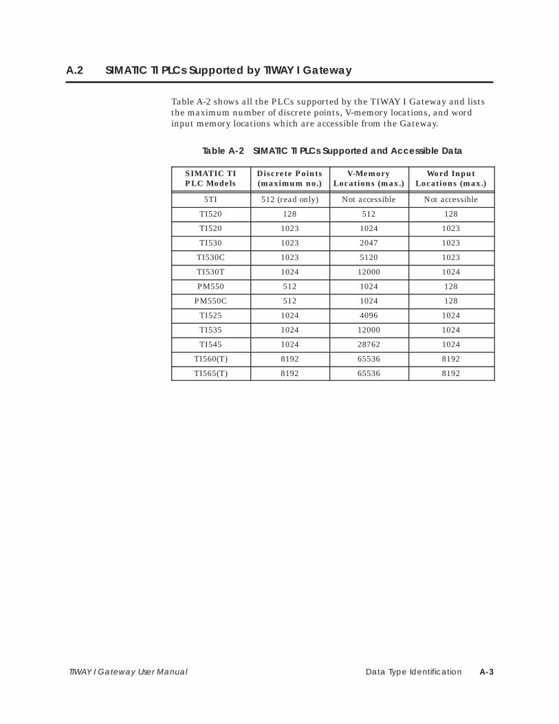
This appendix provides information on which Siemens PLCs are supportedby the Gateway, and how SIMATIC TI data types correspond to those ofthe host systems. Also included in this appendix are a list of features addedto the latest release of the Gateway and a list of hardware specifications.
Table A-1 shows the correspondence between data types configured in thehost systems and the data retrieved from SIMATIC TI PLCs.
Table A-1 Data Type Identification
PLC Data Type FisherData Type
FoxboroData Type
HoneywellData Type
V-Memory(12 LSBs*)
N/A 12-bit Binary fromHolding Registers
N/A
WX-Memory(12 LSBs*)
N/A 12-bit Binary fromInput Registers
N/A
Y (discrete outputs) orC (control relays)
Digital Points Discrete Coils Digital Outputs
X (discrete inputs) N/A Discrete Contacts Digital Inputs
V-Memory Words Input Register 16-bit Word fromHolding Registers
Analog Outputs
WX-Memory N/A 16-bit Word fromInput Registers
Analog Inputs
V-Memory N/A N/A AccumulatedValue
*Least significant bits
Data Type Identification A-3TIWAY I Gateway User Manual
A.2 SIMATIC TI PLCs Supported by TIWAY I Gateway
Table A-2 shows all the PLCs supported by the TIWAY I Gateway and liststhe maximum number of discrete points, V-memory locations, and wordinput memory locations which are accessible from the Gateway.
Table A-2 SIMATIC TI PLCs Supported and Accessible Data
SIMATIC TIPLC Models
Discrete Points(maximum no.)
V-MemoryLocations (max.)
Word InputLocations (max.)
5TI 512 (read only) Not accessible Not accessible
TI520 128 512 128
TI520 1023 1024 1023
TI530 1023 2047 1023
TI530C 1023 5120 1023
TI530T 1024 12000 1024
PM550 512 1024 128
PM550C 512 1024 128
TI525 1024 4096 1024
TI535 1024 12000 1024
TI545 1024 28762 1024
TI560(T) 8192 65536 8192
TI565(T) 8192 65536 8192
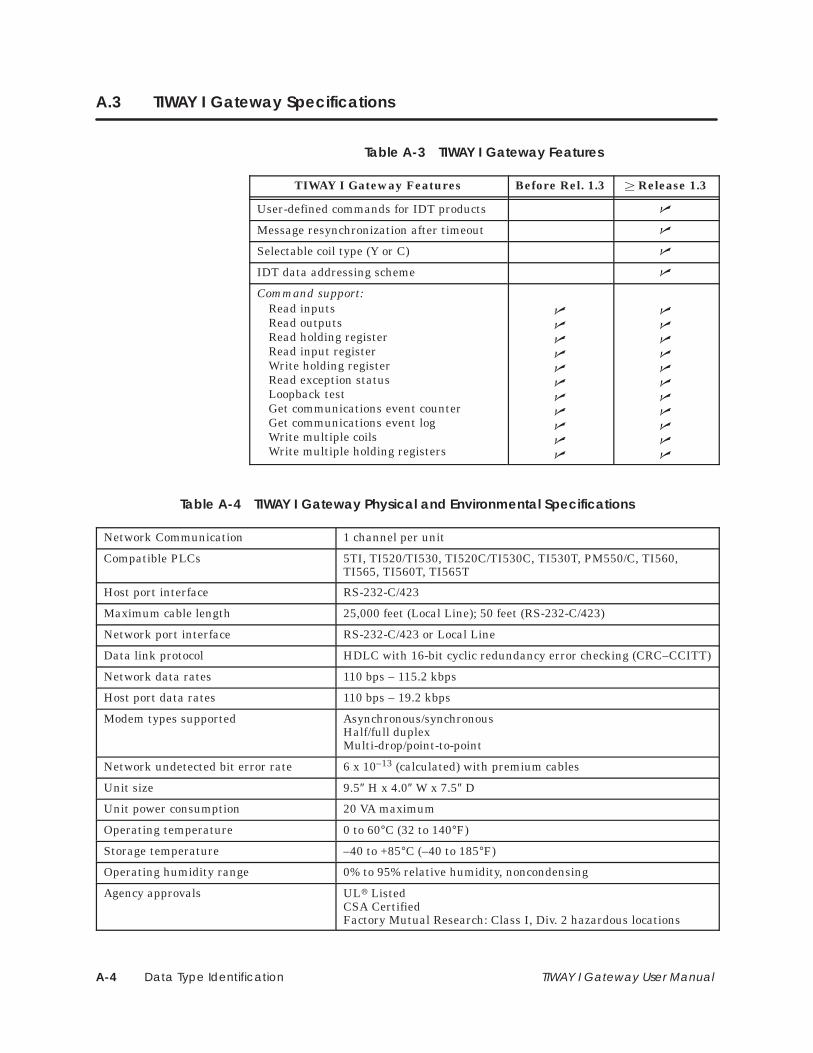
Data Type IdentificationA-4 TIWAY I Gateway User Manual
A.3 TIWAY I Gateway Specifications
Table A-3 TIWAY I Gateway Features
TIWAY I Gateway Features Before Rel. 1.3 � Release 1.3
User-defined commands for IDT products �
Message resynchronization after timeout �
Selectable coil type (Y or C) �
IDT data addressing scheme �
Command support:Read inputsRead outputsRead holding registerRead input registerWrite holding registerRead exception statusLoopback testGet communications event counterGet communications event logWrite multiple coilsWrite multiple holding registers
�
�
�
�
�
�
�
�
�
�
�
�
�
�
�
�
�
�
�
�
�
�
Table A-4 TIWAY I Gateway Physical and Environmental Specifications
Network Communication 1 channel per unit
Compatible PLCs 5TI, TI520/TI530, TI520C/TI530C, TI530T, PM550/C, TI560,TI565, TI560T, TI565T
Host port interface RS-232-C/423
Maximum cable length 25,000 feet (Local Line); 50 feet (RS-232-C/423)
Network port interface RS-232-C/423 or Local Line
Data link protocol HDLC with 16-bit cyclic redundancy error checking (CRC–CCITT)
Network data rates 110 bps – 115.2 kbps
Host port data rates 110 bps – 19.2 kbps
Modem types supported Asynchronous/synchronousHalf/full duplexMulti-drop/point-to-point
Network undetected bit error rate 6 x 10–13 (calculated) with premium cables
Unit size 9.5″ H x 4.0″ W x 7.5″ D
Unit power consumption 20 VA maximum
Operating temperature 0 to 60°C (32 to 140°F)
Storage temperature –40 to +85°C (–40 to 185°F)
Operating humidity range 0% to 95% relative humidity, noncondensing
Agency approvals UL� ListedCSA CertifiedFactory Mutual Research: Class I, Div. 2 hazardous locations
System Configuration Forms B-1TIWAY I Gateway User Manual
Appendix B
System Configuration Forms
B.1 System Configuration B-2. . . . . . . . . . . . . . . . . . . . . . . . . . . . . . . . . . . . . . . . . . . . . . . . . . . . . . . . . . .
B.2 V-Memory Offset Tables B-3. . . . . . . . . . . . . . . . . . . . . . . . . . . . . . . . . . . . . . . . . . . . . . . . . . . . . . . . .
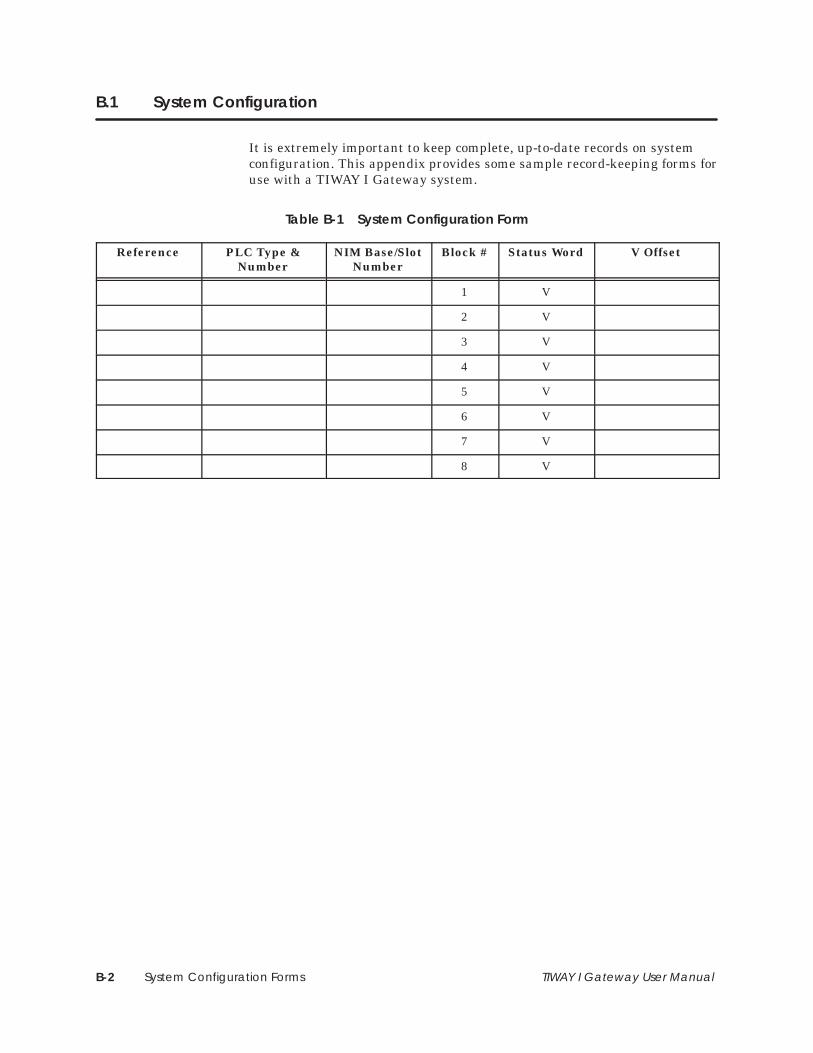
System Configuration FormsB-2 TIWAY I Gateway User Manual
B.1 System Configuration
It is extremely important to keep complete, up-to-date records on systemconfiguration. This appendix provides some sample record-keeping forms foruse with a TIWAY I Gateway system.
Table B-1 System Configuration Form
Reference PLC Type &Number
NIM Base/SlotNumber
Block # Status Word V Offset
1 V
2 V
3 V
4 V
5 V
6 V
7 V
8 V

System Configuration Forms B-3TIWAY I Gateway User Manual
B.2 V-Memory Offset Tables
Table B-2 V-Memory Offset Table (Resident Information)
PLC # Base/Slot # Number of Words V Offset
Word # Moved From Word/Image Register Comments
1
2
3
4
5
6
7
8
Table B-3 V-Memory Offset Table (Received Information)
PLC # Base/Slot # Number of Words V Offset
Word # Moved To Word/Image Register Comments
1
2
3
4
5
6
7
8

Modbus Commands C-1TIWAY I Gateway User Manual
Appendix C
Modbus Commands
C.1 Modbus Protocol Overview C-2. . . . . . . . . . . . . . . . . . . . . . . . . . . . . . . . . . . . . . . . . . . . . . . . . . . . . . The RTU Transmission Frame C-2. . . . . . . . . . . . . . . . . . . . . . . . . . . . . . . . . . . . . . . . . . . . . . . . . . . . . . Message Delineation C-3. . . . . . . . . . . . . . . . . . . . . . . . . . . . . . . . . . . . . . . . . . . . . . . . . . . . . . . . . . . The Address Field C-3. . . . . . . . . . . . . . . . . . . . . . . . . . . . . . . . . . . . . . . . . . . . . . . . . . . . . . . . . . . . . . . The Function Field C-3. . . . . . . . . . . . . . . . . . . . . . . . . . . . . . . . . . . . . . . . . . . . . . . . . . . . . . . . . . . . . . . The Data Field C-3. . . . . . . . . . . . . . . . . . . . . . . . . . . . . . . . . . . . . . . . . . . . . . . . . . . . . . . . . . . . . . . . . . Checksum C-3. . . . . . . . . . . . . . . . . . . . . . . . . . . . . . . . . . . . . . . . . . . . . . . . . . . . . . . . . . . . . . . . . . . . . Invalid Characters and Messages C-4. . . . . . . . . . . . . . . . . . . . . . . . . . . . . . . . . . . . . . . . . . . . . . . . Modbus Functions C-4. . . . . . . . . . . . . . . . . . . . . . . . . . . . . . . . . . . . . . . . . . . . . . . . . . . . . . . . . . . . . . Addressing C-5. . . . . . . . . . . . . . . . . . . . . . . . . . . . . . . . . . . . . . . . . . . . . . . . . . . . . . . . . . . . . . . . . . . . . Address Limits C-5. . . . . . . . . . . . . . . . . . . . . . . . . . . . . . . . . . . . . . . . . . . . . . . . . . . . . . . . . . . . . . . . . . .
C.2 Modbus Function Descriptions C-6. . . . . . . . . . . . . . . . . . . . . . . . . . . . . . . . . . . . . . . . . . . . . . . . . . . Introduction C-6. . . . . . . . . . . . . . . . . . . . . . . . . . . . . . . . . . . . . . . . . . . . . . . . . . . . . . . . . . . . . . . . . . . . Code 01 — Read Coil Status C-6. . . . . . . . . . . . . . . . . . . . . . . . . . . . . . . . . . . . . . . . . . . . . . . . . . . . Code 02 — Read Input Status C-8. . . . . . . . . . . . . . . . . . . . . . . . . . . . . . . . . . . . . . . . . . . . . . . . . . . Code 03 — Read Output Registers C-10. . . . . . . . . . . . . . . . . . . . . . . . . . . . . . . . . . . . . . . . . . . . . . . Code 04 — Read Input Registers C-11. . . . . . . . . . . . . . . . . . . . . . . . . . . . . . . . . . . . . . . . . . . . . . . . . Code 05 — Write a Single Coil C-12. . . . . . . . . . . . . . . . . . . . . . . . . . . . . . . . . . . . . . . . . . . . . . . . . . . Code 06 — Write a Single Register C-14. . . . . . . . . . . . . . . . . . . . . . . . . . . . . . . . . . . . . . . . . . . . . . . Code 07 — Read Exception Status C-15. . . . . . . . . . . . . . . . . . . . . . . . . . . . . . . . . . . . . . . . . . . . . . . Code 08 — Execute Diagnostics C-17. . . . . . . . . . . . . . . . . . . . . . . . . . . . . . . . . . . . . . . . . . . . . . . . . Code 11 — Get Comms Event Counter C-20. . . . . . . . . . . . . . . . . . . . . . . . . . . . . . . . . . . . . . . . . . Code 12 — Get Comms Event Log C-21. . . . . . . . . . . . . . . . . . . . . . . . . . . . . . . . . . . . . . . . . . . . . . Code 15 — Write Multiple Coils C-23. . . . . . . . . . . . . . . . . . . . . . . . . . . . . . . . . . . . . . . . . . . . . . . . . . Code 16 — Write Multiple Registers C-25. . . . . . . . . . . . . . . . . . . . . . . . . . . . . . . . . . . . . . . . . . . . . .
C.3 User-Defined Modbus Commands C-26. . . . . . . . . . . . . . . . . . . . . . . . . . . . . . . . . . . . . . . . . . . . . . . Command 65 — Read C Memory C-26. . . . . . . . . . . . . . . . . . . . . . . . . . . . . . . . . . . . . . . . . . . . . . . Command 66 — Read K Memory C-27. . . . . . . . . . . . . . . . . . . . . . . . . . . . . . . . . . . . . . . . . . . . . . . . Command 67 — Read WY Memory C-27. . . . . . . . . . . . . . . . . . . . . . . . . . . . . . . . . . . . . . . . . . . . . .
C.4 Error Responses C-28. . . . . . . . . . . . . . . . . . . . . . . . . . . . . . . . . . . . . . . . . . . . . . . . . . . . . . . . . . . . . . . . .

Modbus CommandsC-2 TIWAY I Gateway User Manual
C.1 Modbus Protocol Overview
This appendix describes the Modbus protocol in detail. For each of theModbus functions described, examples of requests and responses are given.
Table C-1 describes the Modbus functions supported by the Gateway.
Table C-1 Modbus Functions Supported
Code Type Description
01 Read Coil Status Get current status of a group of coils.
02 Read Input Status Get current status of a group of discreteinputs.
03 Read Holding Register Get current values from holding registers.
04 Read Input Register Get current values from input registers.
05 Force a Single Coil Change the state of a logic coil to On orOff, forced On or forced Off, or unforced.
06 Write a Single Register Write a value into a holding register.
07 Read Exception Status Get the 8 internal status coil values.
08 Execute Diagnostics Send diagnostic tests to a slave.
11 Get CommunicationsEvent Counter
Enable the success or failure of a query tobe determined.
12 Get CommunicationsEvent Log
Get the communications log for Modbusnetwork transactions.
15 Write Multiple Coils Change a number of consecutive coils.
16 Write Multiple Registers Write values into a series of consecutiveholding registers.
The TIWAY I Gateway operates in the RTU transmission mode. The RTUmode determines the start and finish of a message based on a time period ofsilence (no transmission) equivalent to the time it would take to transmit3.5 characters at the chosen baud rate. The RTU transmission frame isshown in Figure C-1.
8 bits 8 bits n x 8 bits 16 bits
Address Function Data Checksum
T1 T2 T3
T1 T2 T3 . . . represents a time of 3.5 characters at given baud rate.
I000000
No data
Figure C-1 RTU Transmission Frame
The RTUTransmission Frame
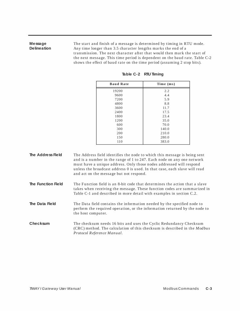
Modbus Commands C-3TIWAY I Gateway User Manual
The start and finish of a message is determined by timing in RTU mode.Any time longer than 3.5 character lengths marks the end of atransmission. The next character after that would then mark the start ofthe next message. This time period is dependent on the baud rate. Table C-2shows the effect of baud rate on the time period (assuming 2 stop bits).
Table C-2 RTU Timing
Baud Rate Time (ms)
192009600720048003600240018001200600300200150110
2.24.45.98.8
11.717.523.435.070.0
140.0210.0280.0383.0
The Address field identifies the node to which this message is being sentand is a number in the range of 1 to 247. Each node on any one networkmust have a unique address. Only those nodes addressed will respondunless the broadcast address 0 is used. In that case, each slave will readand act on the message but not respond.
The Function field is an 8-bit code that determines the action that a slavetakes when receiving the message. These function codes are summarized inTable C-1 and described in more detail with examples in section C.2.
The Data field contains the information needed by the specified node toperform the required operation, or the information returned by the node tothe host computer.
The checksum needs 16 bits and uses the Cyclic Redundancy Checksum(CRC) method. The calculation of this checksum is described in the ModbusProtocol Reference Manual.
MessageDelineation
The Address Field
The Function Field
The Data Field
Checksum

Modbus CommandsC-4 TIWAY I Gateway User Manual
Modbus Protocol Overview (continued)
The Gateway ignores messages that contain invalid characters. Messagescontaining the following errors will also be ignored.
• Incorrect checksum
• Parity error
• Framing errors
• Incomplete transmission
This section outlines some of the differences between Modbus and TIWAY Inetwork commands.
• Whereas Modbus uses Functions Codes, TIWAY I uses Primitives.Primitives differ from Function codes in one important way: primitivesuse TT-types to allow one primitive to address different types of data.With Modbus a different function code is required for each type of data.
• For all SIMATIC TI Series 505 PLCs, the first address for each type ofmemory is always 1. Modbus PLCs by comparison allow 0 as the firstlegal address.
• If each system were to return one byte (8 bits) representing eightdiscrete coils, they would each be positioned as shown in Figure C-2.
8
I000000
7 6 5 4 3 2 1 87654321
Coil No. Coil No.
Modbus PLCs SIMATIC TI PLCs
MSB LSB< < < MSB LSB< < <
Figure C-2 Bit Orientation
Invalid Charactersand Messages
Modbus Functions

Modbus Commands C-5TIWAY I Gateway User Manual
• Terminology is another area in which differences occur. Some of thedifferences in terms are given in Table C-3.
Table C-3 Terminology Differences
Modbus-based PLCs SIMATIC TI PLCs
Coil Discrete output (Y) or Control Relay (C)
Input Register Word Image Register (WX/WY)
Holding Register Variable Memory (V-memory)
Slave Secondary Node
P/C (Programmable Controller) PLC
Function code Primitive
Modbus TIWAY I
Disabled (coil) Forced
Enabled (coil) Unforced
The TIWAY I Gateway uses the absolute position of the data for the address.That is, if you want to address the 3066th coil, then that is the address youpass with the command (as hexadecimal value BFA). The maximum addressis 65535 (FFFF hex). For example, if you want to access 1000 coils startingat the 703rd coil, the Function Code 01 would be as follows:
01 01 02 BF 03 E8 0C E8
Modbus imposes a buffer size limit of 256 bytes. Because of this restriction,TIWAY I Gateway requests have been limited to the following values.
Function Code Quantity
010203041516
2000 coils2000 discrete inputs125 output registers125 input registers800 coils100 registers
The command checking will reject requests for data greater than the limitsshown above. What the checking does not do is check the request againstthe available PLC memory. When a request goes beyond the memory of aparticular PLC, the command will be rejected by the PLC and the hostcomputer will be notified by the Exception Code 02.
Addressing
Address Limits

Modbus CommandsC-6 TIWAY I Gateway User Manual
C.2 Modbus Function Descriptions
In the descriptions that follow, each function starts on a separate page andincludes the TIWAY primitive sent to the secondary in square brackets. Foreach function, an example of request and response is given.
Code 01 enables the user to read the On/Off values of logic coils. The datapassed with this command is the start address and the number of coils to beread. Addressing is sequential up to the maximum memory size for aparticular PLC. The maximum number of coils that can be addressed withone command is 2000. If more are requested, the whole command will berejected with an Exception code 03.
SIMATIC TI PLCs number memory locations starting at address 1.Modbus PLCs number areas of memory starting from address 0.Failure to alter host computer application programs may result inthe wrong bits being read.
Example:
I000000
Request: 07 01 000A 0005 XXXXChecksum (XXXX)Number of points (0005)Start point (000A)Function code (01)Slave address (07)
Figure C-3 Read Coil Status Example — Request
This request is asking the Gateway to return the data from 5 coils (On/Off)starting at the 10th coil.
[This is equivalent to sending a TIWAY Primitive 20 request using TT-type 7(Packed Discrete Outputs) or TT-type 8 (C Packed), depending on theposition of Switch 10 of the network dipswitch bank in the Gateway.]
Introduction
Code 01 — ReadCoil Status
WARNING!

Modbus Commands C-7TIWAY I Gateway User Manual
I000000
Response: 07 01 01 1A XXXXChecksum (XXXX)Data (1A)Number of bytes (01)Function code (01)Slave address (07)
Figure C-4 Read Coil Status Example — Response
The response returns in the data field a single byte (1A) which contains the1’s or 0’s for the 5 coils, packed out with zeros for the three high bits.
I000000
1A = 0 0 0 1 1 0 1 0Coil 0A (OFF)Coil 0B (ON)Coil 0C (OFF)Coil 0D (ON)Coil 0E (ON)Packed with zeros (000)
Figure C-5 Read Coil Status Example — Data Field

Modbus CommandsC-8 TIWAY I Gateway User Manual
Modbus Function Descriptions (continued)
Code 02 allows the application to read a series of discrete inputs. Thecommand includes the start address and the number of points to be read.
Addressing is sequential up to the maximum memory size for a particularPLC. The maximum number of inputs that can be addressed with onecommand is 2000. If more are requested, the whole command will berejected with an Exception code 03.
Example:
I000000
Request: 07 02 000A 0005 XXXXChecksum (XXXX)Number of points (0005)Start point (000A)Function code (02)Slave address (07)
Figure C-6 Read Input Status Example — Request
This request is for the data from 5 discrete inputs (On/Off) starting at the10th input.
[This command is equivalent to sending a TIWAY I Primitive 20 requestusing TT-type 6 (Packed Discrete Inputs)].
I000000
Response: 07 02 01 1A XXXXChecksum (XXXX)Data (1A)Number of bytes (01)Function code (02)Slave address (07)
Figure C-7 Read Input Status Example — Response
Code 02 — ReadInput Status

Modbus Commands C-9TIWAY I Gateway User Manual
The response returns in the data field a single byte (1A) containing the 1’sor 0’s for the 5 discrete inputs, packed out with zeros for the three high bits.
I000000
1A = 0 0 0 1 1 0 1 0Input 0A (OFF)Input 0B (ON)Input 0C (OFF)Input 0D (ON)Input 0E (ON)Packed with zeros (000)
Figure C-8 Read Input Status Example — Data Field

Modbus CommandsC-10 TIWAY I Gateway User Manual
Modbus Function Descriptions (continued)
Code 03 allows you to read the contents of holding registers in the attachedsecondary device. The data field of this command includes the start addressof the registers and the number of registers to be read.
Addressing is sequential up to the maximum memory size for a particularPLC. The maximum number of registers that can be addressed with onecommand is 125. If more are requested, the whole command will be rejectedwith an Exception code 03.
[This command is equivalent to issuing a TIWAY I Primitive 20 request witha TT-type 01 (Variable Memory)].
Example:
I000000
Request: 07 03 0064 0003 XXXXChecksum (XXXX)Number of registers (0003)Address of first register (0064)Function code (03)Slave address (07)
Figure C-9 Read Output Register Example — Request
This request is for secondary address 7 to read the contents of registers0064, 0065, and 0066 (100, 101, and 102 decimal).
I000000
Response: 07 03 06 032C 0001 0030 XXXXChecksum (XXXX)3rd register value (0030)2nd register value (0001)1st register value (032C)Number of bytes (06)Function code (03)Slave address (07)
Figure C-10 Read Output Register Example — Response
The response has returned the number of bytes of data (06) and the valuesfor the requested registers; these are 032C, 0001, and 0030 respectively(812, 1, and 48 decimal).
Code 03 — ReadOutput Registers

Modbus Commands C-11TIWAY I Gateway User Manual
Code 04 allows you to read the contents of input registers in the attachedPLC. These registers hold the values returned by the I/O devices. The datafield of this command includes the start address of the registers and thenumber of registers to be read.
Addressing is sequential up to the maximum memory size for a particularPLC. The maximum number of registers that can be addressed with onecommand is 125. If more are requested, the whole command will be rejectedwith an Exception code 03.
[This command is equivalent to issuing a TIWAY I Primitive 20 request witha TT-type 09 (Word input WX)].
Example:
I000000
Request: 07 04 0008 0001 XXXXChecksum (XXXX)Number of registers (0001)Address of first register (0008)Function code (04)Slave address (07)
Figure C-11 Read Input Register Example — Request
This request is for secondary address 7 to read and return the value storedin input register 0008.
I000000
Response: 07 04 02 0020 XXXX
Checksum (XXXX)Input register value (0020)Number of bytes (02)Function code (04)Slave address (07)
Figure C-12 Read Input Register Example — Response
The response has returned the number of bytes of data (02) and the value0020 (32 decimal) from the requested input register (0008).
Code 04 — ReadInput Registers

Modbus CommandsC-12 TIWAY I Gateway User Manual
Modbus Function Descriptions (continued)
Code 05 allows a designated coil [discrete output Y or C, depending on theposition of Switch 10 on the network dipswitches] to be written. Dependingon the code passed in the data field, it can be changed to On (1) or Off (0),forced On or Off, or unforced. The two-byte codes are the following.
FF00 (hex) ON. . . . . . . . . . 0000 (hex) OFF. . . . . . . . . . .
NOTE: All other values are illegal and will result in error response 03.
Where the Broadcast address (00) is used, the Gateway will send the changecoil command to all attached secondaries.
[This command is comparable to Primitive 30, using TT-type 4 (Y coils) ortype 5 (Cs).]
Because of differences in memory mapping between Modbus PLCsand SIMATIC TI PLCs, you should be quite certain of the effects ofthe broadcast command before issuing it.
Example:
I000000
Request: 07 05 0064 FF00 XXXXChecksum (XXXX)OFF/ON code (FF00 = On)Coil address (0064)Function code (05)Slave address (07)
Figure C-13 Write a Single Coil Example — Request
This request to secondary 7 is asking for coil 0064 (100 decimal) to bechanged to the on state.
Code 05 — Write aSingle Coil
WARNING!

Modbus Commands C-13TIWAY I Gateway User Manual
I000000
Response: 07 05 0064 FF00 XXXXChecksum (XXXX)OFF/ON code (FF00 = ON)Coil address (0064)Function code (05)Slave address (07)
Figure C-14 Read Input Register Example — Response
The response to Function Code 05 is to return the request as received. Inthe case of a broadcast request, there is no response.

Modbus CommandsC-14 TIWAY I Gateway User Manual
Modbus Function Descriptions (continued)
Code 06 allows the contents of a holding register to be changed. Addressingis sequential up to the maximum memory size for a particular PLC. Thisfunction is limited to integer values contained in V-memory. The Gatewaywill also direct any broadcast address (00) to all attached secondaries.
[This command is comparable to a TIWAY I request using Primitive 30 andTT-type 01 (Variable memory)].
Example:
I000000
Request: 07 06 0064 0220 XXXXChecksum (XXXX)Data value (0220)Register address (0064)Function code (06)Slave address (07)
Figure C-15 Write a Single Register Example — Request
This request to secondary 7 is asking for the value of holding register 0064(100 decimal) to be changed to 0220 (544 decimal).
I000000
Response: 07 06 0064 0220 XXXXChecksum (XXXX)Data value (0220)Register address (0064)Function code (06)Slave address (07)
Figure C-16 Write a Single Register Example — Response
The response to Function Code 06 is to return the request as received. Inthe case of a broadcast request, there is no response.
Code 06 — Write aSingle Register
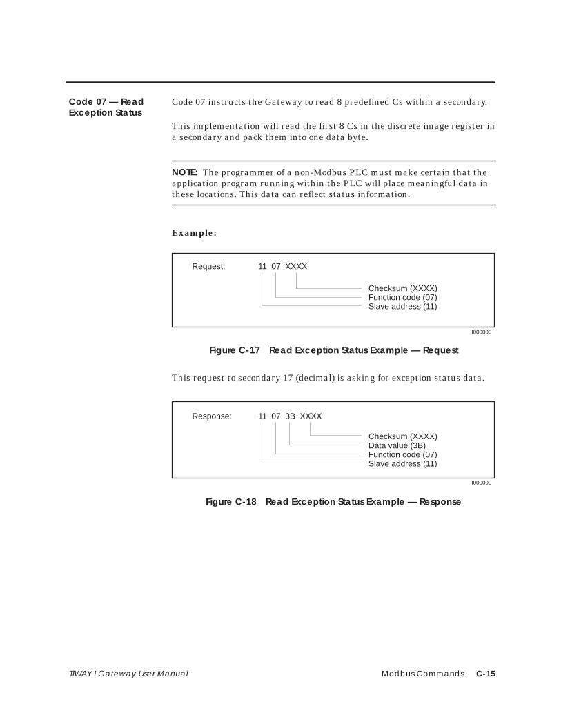
Modbus Commands C-15TIWAY I Gateway User Manual
Code 07 instructs the Gateway to read 8 predefined Cs within a secondary.
This implementation will read the first 8 Cs in the discrete image register ina secondary and pack them into one data byte.
NOTE: The programmer of a non-Modbus PLC must make certain that theapplication program running within the PLC will place meaningful data inthese locations. This data can reflect status information.
Example:
I000000
Request: 11 07 XXXX
Checksum (XXXX)Function code (07)Slave address (11)
Figure C-17 Read Exception Status Example — Request
This request to secondary 17 (decimal) is asking for exception status data.
I000000
Response: 11 07 3B XXXX
Checksum (XXXX)Data value (3B)Function code (07)Slave address (11)
Figure C-18 Read Exception Status Example — Response
Code 07 — ReadException Status

Modbus CommandsC-16 TIWAY I Gateway User Manual
Modbus Function Descriptions (continued)
The response shows that 3B (hex) has been returned. If the individual bitsare examined, they indicate the status of each bit.
I000000
Coil 1 (ON)Coil 2 (ON)Coil 3 (OFF)Coil 4 (ONCoil 5 (ON)Coil 6 (ON)Coil 7 (OFF)Coil 8 (OFF)
0 0 1 1 1 0 1 1
Coils3B (hex)
Figure C-19 Exception Status Bits
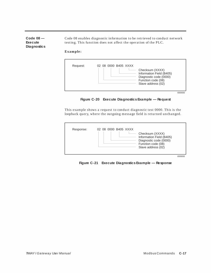
Modbus Commands C-17TIWAY I Gateway User Manual
Code 08 enables diagnostic information to be retrieved to conduct networktesting. This function does not affect the operation of the PLC.
Example:
I000000
Request: 02 08 0000 B405 XXXXChecksum (XXXX)Information Field (B405)Diagnostic code (0000)Function code (08)Slave address (02)
Figure C-20 Execute Diagnostics Example — Request
This example shows a request to conduct diagnostic test 0000. This is theloopback query, where the outgoing message field is returned unchanged.
I000000
Response: 02 08 0000 B405 XXXXChecksum (XXXX)Information Field (B405)Diagnostic code (0000)Function code (08)Slave address (02)
Figure C-21 Execute Diagnostics Example — Response
Code 08 —ExecuteDiagnostics

Modbus CommandsC-18 TIWAY I Gateway User Manual
Modbus Function Descriptions (continued)
Table C-4 details the diagnostic codes supported.
Table C-4 Diagnostic Codes Supported
Code(hex)
Diagnostic Description Is CodeSupported?
00 Return request message Yes
01 Restart communications with the slave Yes
02 Return diagnostics register No
03 Change message end character No
04 Set slave in listen only mode No
0A Clear counters and diagnostics No
0B Return message count No
0C Return checksum error count No
0D Return exception count No
0E Return slave message count No
0F Return slave no response count No
10 Return slave NAK count No
11 Return slave busy count No
12 Return character overrun count No
13 Return overrun error count No
14 Clear character overrun count No

Modbus Commands C-19TIWAY I Gateway User Manual
The diagnostics codes supported are described in the following paragraphs.
Diagnostic Code — 00
I000000
0000 | any data
Diagnostic code
Information frame
When Function Code 08 uses diagnostic code 0000, any data passed in theinformation field is returned to the host computer by the Gateway. TheGateway will send Primitive 02 to the secondary. If the secondary has afatal error, communications loopback is not performed to indicate fatal error.The purpose of this command is to determine if the communications arefunctioning correctly, and may be used in conjunction with diagnostic testsdescribed later.
Diagnostic Code — 01
I000000
0001 | 00 000001 | FF 00
Diagnostic code
Information frame
or
When Function Code 08 uses diagnostic code 0001, the information framecan contain 0000 or FF00. This function causes the Gateway to clear allinternal counters and registers. If the information frame contains FF00, theCommunications Event Log will be cleared. If any other value is passed inthe information field, the Communications Event Log will not be cleared,and no response will be returned.

Modbus CommandsC-20 TIWAY I Gateway User Manual
Modbus Function Descriptions (continued)
Code 11 returns a 2-byte status word and an associated 2-byte eventcounter. The status word is defined in the Modbus Protocol ReferenceSpecification as being 0 for no command in progress and FFFF if a previouscommand is in progress. The status will always be 0 in the Gateway.
The event counter is incremented for every successful message; it is notincremented for exceptions or polls, or for this code or Code 12. This codecan be used to determine if a single command was successful when acommunication error occurred during the request or response.
The event counter will increment to the value FFFF (65535 decimal), thenbegin again from zero.
Example:
I000000
Request: 15 0B XXXX
Checksum (XXXX)Function code (0B)Slave address (15)
Figure C-22 Get Comms Event Counter Example — Request
In this example, secondary node 21 (15 hex) has been asked to return theevent counter and the associated status word.
I000000
Response: 15 0B 0000 0143 XXXXChecksum (XXXX)Number of events (0143)Status word (0000)Function code 11 (0B hex)Slave address 21 (15 hex)
Figure C-23 Get Comms Event Counter Example — Response
The response shows that the status word is 0000 and that 323 (decimal)events have occurred.
Code 11 — GetComms EventCounter

Modbus Commands C-21TIWAY I Gateway User Manual
Code 12 returns the same information as Function Code 11 plus a messagecount and an additional 64-event byte. This means that a 2-byte statusword, a 2-byte event counter, a message count, and the most recent 64events are returned. A buffer records each send or receive operation andoverwrites the oldest event with the latest event. No events are recorded forthis code or Code 11. The Event Byte types are shown in Table C-5.
I000000
Request: 10 0C XXXX
Checksum (XXXX)Function code (0C)Slave address (10)
Figure C-24 Get Comms Event Log Example — Request
This request to address 16 (decimal) is for the Exception Event Log.
I000000
10 0C 46 0000 0204 020B C0 00 . . . XXXXChecksum (XXXX)2nd latest event (00)Latest event (C0)Message count (020B)Event count (0204)Status word (0000)Byte count (46)Function code 12 (0C hex)Slave address (10)
Response:
Figure C-25 Get Comms Event Log Example — Response
The response has returned 70 bytes of data (2 status bytes + 2 event counterbytes + 2 message counts + 64 event bytes). Only two of the event bytes areshown; these indicate the secondary node was reset (00) and then received abroadcast message (C0). The most recent events are returned first.
Code 12 — GetComms Event Log

Modbus CommandsC-22 TIWAY I Gateway User Manual
Modbus Function Descriptions (continued)
Table C-5 Event Byte Types
Event Byte Bit Definitions
Slave Bus Receive. Bytestored on receipt of message
Bit 0 – ReservedBit 1 – Set if communications errorBit 2 – ReservedBit 3 – ReservedBit 4 – Set if character overrunBit 5 – Set if in Listen Only modeBit 6 – Set if BroadcastBit 7 – 1
Slave Bus Transmit. Bytestored when message sent
Bit 0 – Set if an exception (1–3) is sentBit 1 – Set if secondary abort exception (6) is sentBit 2 – Set if secondary busy exception (6) is sentBit 3 – Not usedBit 4 – Set if write timeout occurredBit 5 – Set if in Listen Only modeBit 6 – 1Bit 7 – 0
Initiate CommunicationsReset. Complete log is setto zeros.
Bit 0 – 0Bit 1 – 0Bit 2 – 0Bit 3 – 0Bit 4 – 0Bit 5 – 0

Modbus Commands C-23TIWAY I Gateway User Manual
Code 15 allows the host computer to write multiple coils. When thiscommand is given, successive coils are changed, by an associated bitpattern, to the indicated state; where each bit indicates: 1 = ON 0 = OFF
Addressing is sequential up to the maximum memory size for a particularsecondary. The maximum number of coils that can be addressed with onecommand is 800. If more are given, the whole command will be rejected withan Exception code 03.
The broadcast address (00) can be used to change the same coils in allnetworked programmable controllers.
[This command is equivalent to TIWAY Primitive 30 using data types 04, 07(Y unpacked, packed) or data types 05, 08 (C unpacked, packed), dependingon the position of network port Switch 10.]
I000000
Request: 07 0F 0012 000C 02 DC08 XXXXChecksum (XXXX)Coil status (DC08)Number of bytes (02)Number of coils (000C)Start coil address (0012)Function code (0F)Slave address (07)
Figure C-26 Write Multiple Coils Example — Request
This request is for the secondary node to change the values of 12 (0C hex)coils starting at address 12 (18 decimal) to the states given by the followingbit pattern.
I000000
1 1 0 1
D
1 1 1 0
C
0 0 0 0
0
1 0 0 0
8
Coil 25 (ON) Coil 18 (OFF)Coil 29 (ON)
Coil 26 (OFF)
Figure C-27 Coil Bit Pattern
The bit pattern indicates that coils 19, 20, 21, 22, 24, 25, and 29 are to bechanged to ON and 18, 23, 26, 27, and 28 changed to OFF.
Code 15 — WriteMultiple Coils

Modbus CommandsC-24 TIWAY I Gateway User Manual
Modbus Function Descriptions (continued)
I000000
Response: 07 0F 0012 000C XXXX
Checksum (XXXX)Number of coils (000C)Start coil address (0012)Function code (0F)Slave address (07)
Figure C-28 Write Multiple Coils Example — Response

Modbus Commands C-25TIWAY I Gateway User Manual
Code 16 allows the host computer to write multiple values into successiveregisters. Addressing is sequential up to the maximum memory size for aparticular PLC. The maximum number of registers that can be addressedwith one command is 100. If more are given, the whole command will berejected with an Exception code 03.
[This command is equivalent to a TIWAY I request using Primitive 30 withTT-type 01 (Variable memory)].
I000000
02 10 0078 0002 04 000B 0201 XXXX
Checksum (XXXX)2nd register data (0201)1st register data (000B)Number of bytes (04)Number of registers (0002)Start register address (0078)Function code 16 (10 hex)Slave address (02)
Request:
Figure C-29 Write Multiple Registers Example — Request
This request is to the secondary node to change the values of 2 holdingregisters, starting at address 0078 (120 decimal) to 11 and 513 respectively.
I000000
Response: 02 10 0078 0002 XXXX
Checksum (XXXX)Number of registers (0002)Start register address (0078)Function code 16 (10 hex)Slave address (02)
Figure C-30 Write Multiple Registers Example — Response
The response to this command is to return the address, code, startingaddress, and the numbers of registers to be changed.
Code 16 — WriteMultiple Registers
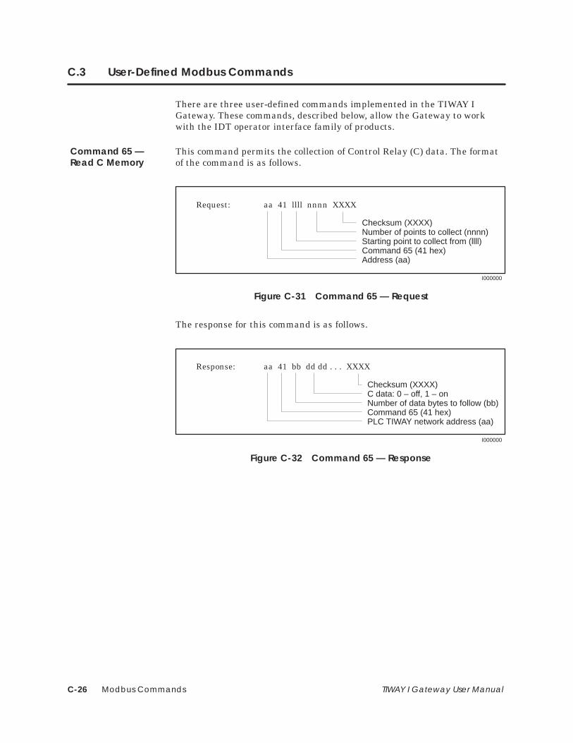
Modbus CommandsC-26 TIWAY I Gateway User Manual
C.3 User-Defined Modbus Commands
There are three user-defined commands implemented in the TIWAY IGateway. These commands, described below, allow the Gateway to workwith the IDT operator interface family of products.
This command permits the collection of Control Relay (C) data. The formatof the command is as follows.
I000000
Request: aa 41 llll nnnn XXXX
Checksum (XXXX)Number of points to collect (nnnn)Starting point to collect from (llll)Command 65 (41 hex)Address (aa)
Figure C-31 Command 65 — Request
The response for this command is as follows.
I000000
Response: aa 41 bb dd dd . . . XXXX
Checksum (XXXX)C data: 0 – off, 1 – onNumber of data bytes to follow (bb)Command 65 (41 hex)PLC TIWAY network address (aa)
Figure C-32 Command 65 — Response
Command 65 —Read C Memory
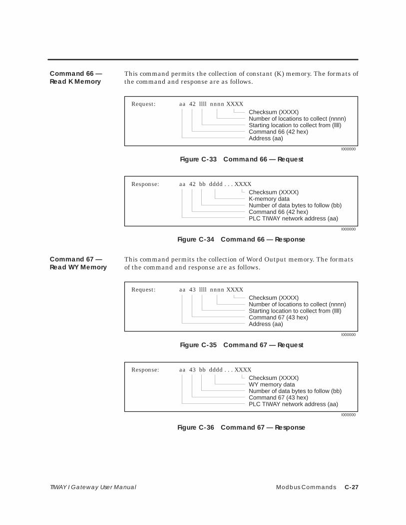
Modbus Commands C-27TIWAY I Gateway User Manual
This command permits the collection of constant (K) memory. The formats ofthe command and response are as follows.
I000000
Request: aa 42 llll nnnn XXXXChecksum (XXXX)Number of locations to collect (nnnn)Starting location to collect from (llll)Command 66 (42 hex)Address (aa)
Figure C-33 Command 66 — Request
I000000
Response: aa 42 bb dddd . . . XXXXChecksum (XXXX)K-memory dataNumber of data bytes to follow (bb)Command 66 (42 hex)PLC TIWAY network address (aa)
Figure C-34 Command 66 — Response
This command permits the collection of Word Output memory. The formatsof the command and response are as follows.
I000000
Request: aa 43 llll nnnn XXXXChecksum (XXXX)Number of locations to collect (nnnn)Starting location to collect from (llll)Command 67 (43 hex)Address (aa)
Figure C-35 Command 67 — Request
I000000
Response: aa 43 bb dddd . . . XXXXChecksum (XXXX)WY memory dataNumber of data bytes to follow (bb)Command 67 (43 hex)PLC TIWAY network address (aa)
Figure C-36 Command 67 — Response
Command 66 —Read K Memory
Command 67 —Read WY Memory

Modbus CommandsC-28 TIWAY I Gateway User Manual
C.4 Error Responses
Errors such as illegal addressing or failure of communications with a PLCare reported by exception responses. Exception responses replace theexpected response to a request and are recognized by the returned FunctionCode with the top bit set high (see example in Figure C-37).
07 01 00000041 XXXX
Address Function Data ChecksumRequest:
I000000
07 81 02 XXXX
Address Function Exception Code ChecksumResponse:
Figure C-37 Exception Response Frame
In this example, the request is for secondary node 07 to return the data for65 (41 hex) coils starting at address 00, which is an illegal address for aSIMATIC TI PLC. The response is an exception indicated by the FunctionCode 81 (01 with the high bit set), with the exception code 02 indicating thatthe data address was illegal.
NOTE: The TIWAY I network uses Exception Primitives. Exceptions sent bySIMATIC TI PLCs are mapped to Modbus Exception Codes.
Table C-6 list the exception responses that apply to the functions supportedby the TIWAY I Gateway.
Table C-6 Exception Responses
Code Name Description
01 Illegal Function The function received is not defined for thisapplication [equivalent to SIMATIC TIexception codes 00, 01, 06, 15].
02 Illegal Data Address The address contained in the data field is notvalid for the secondary being addressed[equivalent to SIMATIC TI code 02]
03 Illegal Data Value The value passed in the data field is notallowable for the secondary being addressed[equivalent to SIMATIC TI codes 10, 19, 1D].

Configuring the PLC for Fisher PROVOX D-1TIWAY I Gateway User Manual
Appendix D
Configuring the PLC for Fisher PROVOX
D.1 Considerations for Configuring a TIWAY I/PROVOX System D-2. . . . . . . . . . . . . . . . . . . . . . . . . PLC Configuration Requirements D-2. . . . . . . . . . . . . . . . . . . . . . . . . . . . . . . . . . . . . . . . . . . . . . . . Network Design Considerations D-2. . . . . . . . . . . . . . . . . . . . . . . . . . . . . . . . . . . . . . . . . . . . . . . . . .
D.2 PLC Programming Considerations D-3. . . . . . . . . . . . . . . . . . . . . . . . . . . . . . . . . . . . . . . . . . . . . . . . Blocking Network Data D-3. . . . . . . . . . . . . . . . . . . . . . . . . . . . . . . . . . . . . . . . . . . . . . . . . . . . . . . . . . Writing to Integer Registers D-3. . . . . . . . . . . . . . . . . . . . . . . . . . . . . . . . . . . . . . . . . . . . . . . . . . . . . . Writing to Discrete Points D-3. . . . . . . . . . . . . . . . . . . . . . . . . . . . . . . . . . . . . . . . . . . . . . . . . . . . . . . . PLC Status Register D-3. . . . . . . . . . . . . . . . . . . . . . . . . . . . . . . . . . . . . . . . . . . . . . . . . . . . . . . . . . . . . .
D.3 PLC Programming Example D-4. . . . . . . . . . . . . . . . . . . . . . . . . . . . . . . . . . . . . . . . . . . . . . . . . . . . . . Data to be Accessed D-4. . . . . . . . . . . . . . . . . . . . . . . . . . . . . . . . . . . . . . . . . . . . . . . . . . . . . . . . . . . Relay Ladder Logic Program D-5. . . . . . . . . . . . . . . . . . . . . . . . . . . . . . . . . . . . . . . . . . . . . . . . . . . .

Configuring the PLC for Fisher PROVOXD-2 TIWAY I Gateway User Manual
D.1 Considerations for Configuring a TIWAY I/PROVOX System
To configure the PLC to operate with the Fisher PROVOX ProgrammableController Interface Unit (PCIU), you need to consider the followingrestrictions and requirements.
• A maximum of eight PLCs can be networked with each PCIU on aPROVOX system.
• A total of 64 data registers can be distributed in V-memory across oneto eight PLCs on the PCIU.
• The PCIU can be configured to access up to 8 blocks of contiguousV-memory. These blocks may encompass up to 64 words of data. Thenetwork cannot access any data that is not defined in one of theseblocks.
• Data can be read from and written to contiguous blocks of V-memory.
• Words within a block of V-memory may be defined as integer or discreteregisters. The values of the discrete registers correspond to the valuesof a contiguous block of 16 Y points.
• For each V-memory block in a PLC that the PCIU is configured to read,the first word in the block must be reserved as a status register. Thisword does not count toward the 64-word limit.
• All registers should be defined in the V-memory of the PLC. Thestarting V-memory address for each PLC register block must beconfigured in the PCIU.
• Each PLC should have an address assigned to it ranging from 1 to 247.
These requirements have several important consequences in network andPLC program design.
The restriction to 8 contiguous memory blocks defined for a given PCIUmeans that there is a maximum of 8 PLCs that the PROVOX system canaccess on a single TIWAY I network. However, if more than one contiguousblock is defined within a single PLC, then for every block after the first inthe PLC, one less PLC on the TIWAY I network can be accessed by thePCIU. For example, if 3 V-memory blocks were defined for each PLCconnected to the PROVOX system, then a maximum of 2 PLCs could beattached to each PCIU, with each PCIU having 2 unused memory blocks.
PLC ConfigurationRequirements
Network DesignConsiderations

Configuring the PLC for Fisher PROVOX D-3TIWAY I Gateway User Manual
D.2 PLC Programming Considerations
The restrictions on data types and numbers of contiguous data blocks thatcan be accessed by a PCIU influence the design of the PLC programs to beused in a PROVOX environment. To increase the number of secondariesthat can be supported by a single PCIU, you should group together the datato be read by the network into a single contiguous block. Similarly, datasupplied to the PLC from the network should be written into a singlecontiguous block. In most cases, data is read from and written to the sameblock of memory. This puts the burden of blocking and unblocking thenetwork data on the PLC.
Box functions in Series 500, Series 505, and PM550 PLCs make thisblocking and unblocking of data a relatively easy task. Refer to theappropriate user manuals for more information about this function.
Another important consideration is that the network writes values into thePLC memory; it does not force the memory to the given value. Thisdistinction implies that if, after a value has been written into a memorylocation, the PLC program writes a value to the same location, the networkdata will be overwritten.
NOTE: The PLC ladder logic program must be carefully designed to avoidthis problem.
The PROVOX system allows you to write discrete values to any Y point thatis defined in a discrete register. However, the PCIU expects the contents ofthe discrete register to accurately reflect the status of the Y points definedin it. The ladder logic program must be designed to ensure that this is thecase. This can be accomplished by moving the contents of the Y points to thediscrete register.
The first word of each contiguous V-memory block serves as the PLC statusregister. This register is used to pass information about the state of the PLCand the process it is controlling to the PROVOX system. The exact contentsof this register are user-definable.
Section D.3 provides an example of network and PLC program design for aFisher PROVOX system.
Blocking NetworkData
Writing to IntegerRegisters
Writing to DiscretePoints
PLC Status Register
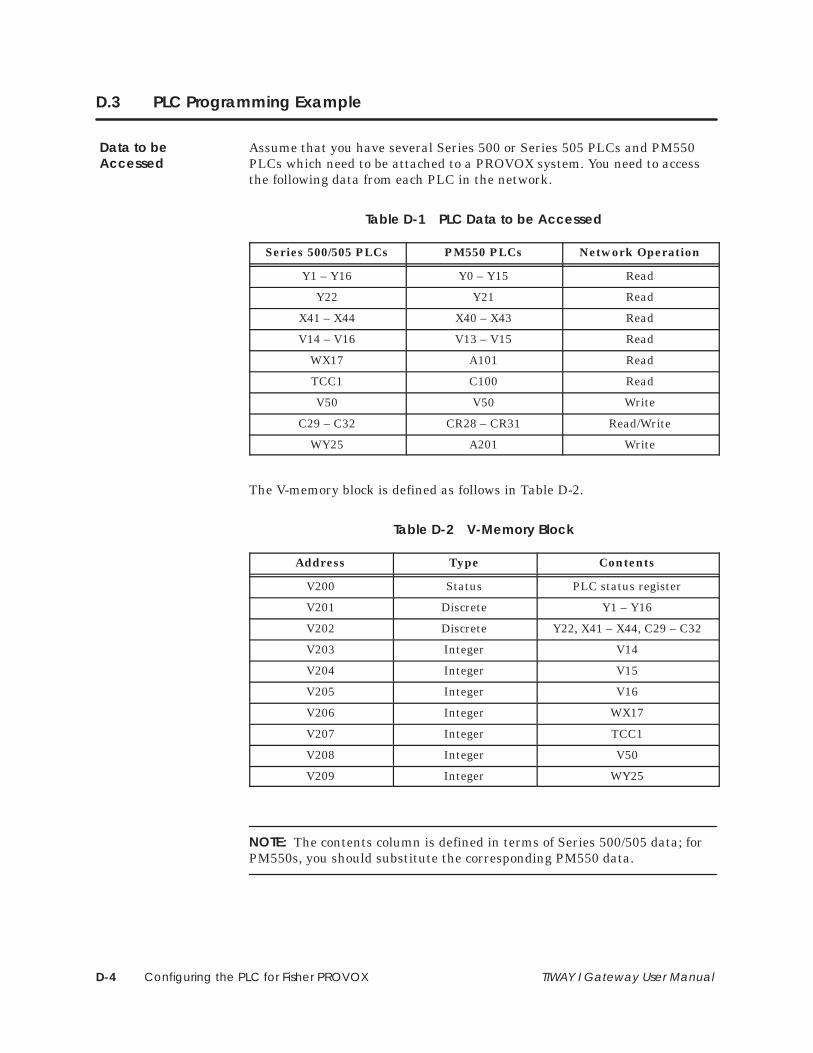
Configuring the PLC for Fisher PROVOXD-4 TIWAY I Gateway User Manual
D.3 PLC Programming Example
Assume that you have several Series 500 or Series 505 PLCs and PM550PLCs which need to be attached to a PROVOX system. You need to accessthe following data from each PLC in the network.
Table D-1 PLC Data to be Accessed
Series 500/505 PLCs PM550 PLCs Network Operation
Y1 – Y16 Y0 – Y15 Read
Y22 Y21 Read
X41 – X44 X40 – X43 Read
V14 – V16 V13 – V15 Read
WX17 A101 Read
TCC1 C100 Read
V50 V50 Write
C29 – C32 CR28 – CR31 Read/Write
WY25 A201 Write
The V-memory block is defined as follows in Table D-2.
Table D-2 V-Memory Block
Address Type Contents
V200 Status PLC status register
V201 Discrete Y1 – Y16
V202 Discrete Y22, X41 – X44, C29 – C32
V203 Integer V14
V204 Integer V15
V205 Integer V16
V206 Integer WX17
V207 Integer TCC1
V208 Integer V50
V209 Integer WY25
NOTE: The contents column is defined in terms of Series 500/505 data; forPM550s, you should substitute the corresponding PM550 data.
Data to beAccessed

Configuring the PLC for Fisher PROVOX D-5TIWAY I Gateway User Manual
The V-memory block now has 9 data words (plus the status register) in eachPLC. From the 64-register limit, you would calculate that there could be amaximum of 7 PLCs (64/9 = 7) configured like this and connected to a singlePCIU.
The following Relay Ladder Logic (RLL) programs for your Series 500/505 orPM550 PLC will block and unblock data to be accessed by way of thenetwork.
BITP
A: STW1
N = 10
BITP 1
A: STW1
N = 11
BITP 2
A: STW1
N = 12
BITP 3
A: STW1
N = 13
(cont’d)
C1
C1C1
C1
C1 C4
C1 C5
C1 C6
C3
I. Series 500 or Series 505 PLC Example Program
Relay Ladder LogicProgram

Configuring the PLC for Fisher PROVOXD-6 TIWAY I Gateway User Manual
PLC Programming Example (continued)
BITP 4
A: STW1
N = 14
BITP 5
A: STW1
N = 15
BITP 6
A: STW1
N = 16
MIRW 7
A: V200
IR = C3
MIRW
A: V201
IR = Y1
N = 7
N = 16
Place Y22, X41–X44, into contiguous Image Register locations
Copy Y1–Y16 to V201
Copy STW01 from Image Registerto V200 (status register)
(cont’d)
C1
C1 C8
C1 C9
C1 C2
C7
C1 C2
Y22 Y800
X41 Y801
X42 Y802

Configuring the PLC for Fisher PROVOX D-7TIWAY I Gateway User Manual
MIRW 1
A: V202
IR = Y800
MOVW 2
A: V14B: V203
N = 3
MOVW 3
A: WX17B: V206
N = 1
N = 9
MOVW 4
A: TCC1B: V207
N = 1
Copy discrete values written via network to C29–C32
Copy discrete points to V202
Copy V14–V16 to V203–V205
Copy WX17 to V206
Copy TCC1 to V207
(cont’d)
C1
C1
C1
C1
C2
X43 Y803
X44
Y805
Y806
Y807
Y808
C2
C2
C2
Y804
C29
C30
C31
C32

Configuring the PLC for Fisher PROVOXD-8 TIWAY I Gateway User Manual
PLC Programming Example (continued)
����
� 0����� 0��
� � �
����
� 0����� 0���
� � �
��
����
�'(/ -�$,� .)"++�& )'% &�+.')# +' ��
�'(/ -�$,� .)"++�& )'% &�+.')# +' ���
�'(/ ����� +' ����
�$'�# ���� ������� "&+' �'&+"!,',* � %�%')/
�'(/ �"*�)�+� -�$,�* .)"++�& -"� &�+.')# +' ���������
(cont’d)
��
��
���
��
��� ����
���
���
���
���
��� ����
��� ����
��
���
����
����
����
����
II. PM550 Example Program
End

Configuring the PLC for Fisher PROVOX D-9TIWAY I Gateway User Manual
PLC Programming Example (continued)
��
���
���
�������
���
�������
���
�������
���
�������
���
������
���
�������
��% �� ���!� ����! !� ����
��% ���� !� ���
��% ��� !� ���
��% #��"� $��!!�� #�� ��!$��� !� ���
��% ������� !� ���������
(cont’d)
����
�� ��
�� ��
���
��
��
��
��
��
��
��
��� ���

Configuring the PLC for Fisher PROVOXD-10 TIWAY I Gateway User Manual
���
��������
���
��� � ��� �
��� � ��� ����
��� � ���� ��
��� �� ���� ��
���� � ���� ����
���� � ���� �
���� � ���� �
���! ����� ������ ��� ��� ��� �� �����

Configuring the PLC for Fisher PROVOX D-11TIWAY I Gateway User Manual
SPECIAL FUNCTION 15I/O MOVE
START ADDRESS: C220 NEXT ADDRESS: C224
ERROR OUTPUT? N. . . . . . . . . . . . . . . . . . . . . . . . . . . . . . . . . . . . . . . . . . . . ERROR OUTPUT DESIGNATOR: . . . . . . . . . . . . . . . . . . . . . . . . . . . . . . . .
NUMBER OF WORDS: 1. . . . . . . . . . . . . . . . . . . . . . . . . . . . . . . . . . . . . . . . .
FROM IR? Y. . . . . . . . . . . . . . . . . . . . . . . . . . . . . . . . . . . . . . . . . . . . . . . . . . . . . FROM IR ADDRESS: Y0. . . . . . . . . . . . . . . . . . . . . . . . . . . . . . . . . . . . . . . . . . .
FROM V, C MEMORY ADDRESS: . . . . . . . . . . . . . . . . . . . . . . . . . . . . . . . .
TO IR? N. . . . . . . . . . . . . . . . . . . . . . . . . . . . . . . . . . . . . . . . . . . . . . . . . . . . . . . . TO IR ADDRESS: . . . . . . . . . . . . . . . . . . . . . . . . . . . . . . . . . . . . . . . . . . . . . .
TO V, C MEMORY ADDRESS V201. . . . . . . . . . . . . . . . . . . . . . . . . . . . . . . . . . .
SPECIAL FUNCTION 15I/O MOVE TABLE
FROM TOADDRESS VALUE ADDRESS VALUE
V201 –2
SPECIAL FUNCTION 15I/O MOVE
START ADDRESS: C224 NEXT ADDRESS: C228
ERROR OUTPUT? N. . . . . . . . . . . . . . . . . . . . . . . . . . . . . . . . . . . . . . . . . . . . ERROR OUTPUT DESIGNATOR: . . . . . . . . . . . . . . . . . . . . . . . . . . . . . . . .
NUMBER OF WORDS: 1. . . . . . . . . . . . . . . . . . . . . . . . . . . . . . . . . . . . . . . . .
FROM IR? Y. . . . . . . . . . . . . . . . . . . . . . . . . . . . . . . . . . . . . . . . . . . . . . . . . . . . . FROM IR ADDRESS: Y240. . . . . . . . . . . . . . . . . . . . . . . . . . . . . . . . . . . . . . . . . . .
FROM V, C MEMORY ADDRESS: . . . . . . . . . . . . . . . . . . . . . . . . . . . . . . . .
TO IR? N. . . . . . . . . . . . . . . . . . . . . . . . . . . . . . . . . . . . . . . . . . . . . . . . . . . . . . . . TO IR ADDRESS: . . . . . . . . . . . . . . . . . . . . . . . . . . . . . . . . . . . . . . . . . . . . . .
TO V, C MEMORY ADDRESS V202. . . . . . . . . . . . . . . . . . . . . . . . . . . . . . . . . . .
SPECIAL FUNCTION 15I/O MOVE TABLE
FROM TOADDRESS VALUE ADDRESS VALUE
V202 484

Index-1
Index
AAC power connections, 1-3, 3-3
Addressing, limits, C-5
BBaud rates, 3-4–3-8
Bracket locations, 3-2
Burn-in test, 3-14
CCable routing
in ceiling, 2-10surface ducting, 2-11under floor, 2-10
Checksum, C-3
Componentsinstalling Gateway, 2-3Local line hardware, 2-6
Configuration, system, B-2
DData
transmission rates, 1-4, 3-7–3-8types accessed, 1-4
Data types, corresponding, A-2
Diagnostic testsoperational, 3-12power-on, 3-12user-initiated, 3-13
Dipswitcheshost port, 3-5, 3-6, 3-7host system, 3-4network port, 3-5, 3-6, 3-8–3-9
Distributed control systems, ix, 1-2
Double drop taps, 2-9
EError responses, C-28
Exception responses, C-28
FFeatures, Gateway Release 1.3, A-4
GGateway models, ix
HHost interface port, 3-7
Host systems, ix
IIndicators, 3-4, 3-11, 3-12–3-14
Initialization, 3-3–3-4
InstallingGateway, 2-2–2-3, 3-2–3-4local line network, 2-4–2-11
See also Local LineRS-232 modem interface, 2-12
Interface ports, 1-3
Invalid characters, C-4

Index-2
LLocal Line
cable characteristics, 2-4cable routing, 2-10hardware components, 2-6installation, 2-4–2-11tap housing, 2-6tap spacing, 2-8–2-9terminating, 2-7
Loopbackconnections, 3-13connector, 3-3
MManuals, x
Modbus commandsfunction code descriptions, C-6–C-25protocol, C-2–C-5user-defined, C-26–C-27
Mounting, 3-2
Multidrop taps, 2-9
NNetwork characteristics, 2-5
Network interface port, 3-8
Network media installationLocal Line, 2-4–2-11RS-232-C modem interface, 2-12
Noise avoidance, 2-11
OOffset tables, V-memory, B-3
Online indicator, 3-11
Online/Offline switch, 3-10
Operational test, 3-12
PPin assignments
local line connector, 2-4RS-232-C interface, 2-12
PLC configurationprogramming, D-3requirements, D-2
PLC programming, example, D-4–D-11
Power connections, 3-3
Power-on test, 3-12
QQuick reference, installation steps, 2-2–2-3
RRack mounting, 3-2
Receive indicator, 3-11
Relay Ladder Logic (RLL), example program,D-5–D-11
Reset button, 3-10
SSelf-test button, 3-10
Spacing rules, network, 2-8–2-9
Specifications, A-4
Status indicator lights, 3-11
Subtests, diagnostic, 3-13–3-14
Switchesfunction, 3-10location, 3-5
System configuration, B-2

Index-3
TTap housing, 2-6
Terminating, main line cable, 2-7
Test mode indicator, 3-11
Test/operate switch, 3-9
Transmit indicator, 3-11
Twisted-pair cable, 2-7
UUser-initiated test, 3-13
VV-memory, offset tables, B-3
YY/C coil selection switch, 3-9

������ '/ � .#%'/0#.#" 0.�"#*�.( ,$ �'#*#+/ ��
���� � ��0#3�5 '/ � 0.�"#*�.( ,$ �'#*#+/ �+"1/0.'�) 10,*�0',+� �+!�
�#.'#/ ���� �#.'#/ ���� ������ ������� ���� �������� �+" ���� �.# 0.�"#*�.(/ ,$ �'#*#+/ �+"1/0.'�) 10,*�0',+� �+!�
�," 1/ '/ � .#%'/0#.#" 0.�"#*�.( ,$ � �,"'!,+���� ���� ��� '/ � .#%'/0#.#" 0.�"#*�.( ,$ �,+#53#)) �+!��� ����� '/ � 0.�"#*�.( ,$ �&# �,4 ,., �,*-�+5����� � '/ � .#%'/0#.#" 0.�"#*�.( ,$ �&# �,4 ,., �,*-�+5������� '/ � .#%'/0#.#" 0.�"#*�.( ,$ �'/&#. �,+0.,)/� �+!����� '/ � 0.�"#*�.( ,$ �'/&#. �,+0.,)/� �+!���� '/ � .#%'/0#.#" 0.�"#*�.( ,$ �+0#%.�0#" �#2'!# �#!&+,),%5� �+!�
�#4�/ �+/0.1*#+0/ �+" �� �.# .#%'/0#.#" 0.�"#*�.(/ ,$ �#4�/ �+/0.1*#+0/ �+!,.-,.�0#"�
������ ������� ������ ������� ������� ������ ������ ������ ������ �+" ����� �.# 0.�"#*�.(/ ,$ �#4�/ �+/0.1*#+0/ �+!,.-,.�0#"�
�� '/ � .#%'/0#.#" 0.�"#*�.( ,$ �+"#.3.'0#./ �� ,.�0,.'#/�

Customer Registration
We would like to know what you think about our user manuals so that we can serve you better.How would you rate the quality of our manuals?
Excellent Good Fair Poor
AccuracyOrganizationClarityCompletenessOverall designSizeIndex
Would you be interested in giving us more detailed comments about our manuals?
Yes! Please send me a questionnaire.
No. Thanks anyway.
Your Name:
Title:
Telephone Number: ( )
Company Name:
Company Address:
Manual Name: TIWAY I Gateway User Manual Edition: Second
Manual Assembly Number: 2587871–0004 Date: 09/92
Order Number: PPX:TIWAY–8104–2

BUSINESS REPLY MAILFIRST CLASS PERMIT NO.3 JOHNSON CITY, TN
FOLD
FOLD
POSTAGE WILL BE PAID BY ADDRESSEE
NO POSTAGENECESSARYIF MAILED
IN THEUNITED STATES
SIEMENS INDUSTRIAL AUTOMATION, INC. 3000 BILL GARLAND RD.P.O. BOX 1255JOHNSON CITY TN 37605–1255
ATTN: Technical Communications M/S 3519