simatic s7-scl v5.3 for s7-300/400 - siemens
TRANSCRIPT

s
First Steps The Getting Started for This product is not a stand-alone description. It is a part of the manual and can be called via "First Steps".
SIMATIC S7-SCL V5.3 for S7-300/400 Getting Started Release 01/2005

Copyright Siemens AG 2005 All rights reserved The reproduction, transmission or use of this document or its contents is not permitted without express written authority. Offenders will be liable for damages. All rights, including rights created by patent grant or registration of a utility model or design, are reserved. Siemens AG Automation and Drives Postfach 4848, 90327 Nuremberg, Germany
Disclaimer of Liability We have checked the contents of this manual for agreement with the hardware and software described. Since deviations cannot be precluded entirely, we cannot guarantee full agreement. However, the data in this manual are reviewed regularly and any necessary corrections included in subsequent editions. Suggestions for improvement are welcomed. © Siemens AG 2005 Technical data subject to change.
Siemens Aktiengesellschaft A5E00324655-01
Safety Guidelines
This manual contains notices intended to ensure personal safety, as well as to protect the products and
connected equipment against damage. These notices are highlighted by the symbols shown below and
graded according to severity by the following texts:
! Danger indicates that death, severe personal injury or substantial property damage will result if proper precautions are not taken.
! Warning indicates that death, severe personal injury or substantial property damage can result if proper precautions are not taken.
! Caution indicates that minor personal injury can result if proper precautions are not taken.
Caution
indicates that property damage can result if proper precautions are not taken.
Note
draws your attention to particularly important information on the product, handling the product, or to a particular part of the documentation.
Qualified Personnel Only qualified personnel should be allowed to install and work on this equipment. Qualified persons are defined as persons who are authorized to commission, to ground and to tag circuits, equipment, and systems in accordance with established safety practices and standards.
Use as intended
Note the following:
! Warning This device and its components may only be used for the applications described in the catalog or the
technical description, and only in connection with devices or components from other manufacturers
which have been approved or recommended by Siemens.
This product can only function correctly and safely if it is transported, stored, set up, and installed correctly, and operated and maintained as recommended.
Trademarks SIMATIC®, SIMATIC HMI® and SIMATIC NET® are trademarks of Siemens AG.
Third parties using for their own purposes any other names in this document which refer to trademarks
might infringe upon the rights of the trademark owners.

S7-SCL V5.3 for S7-300/400 A5E00324650-01 3
Designing an S7-SCL Program
Welcome to "Measured Value Acquisition" - A Sample Program for First-Time Users
What You Will Learn
The sample program for first-time users shows you how to use S7-SCL effectively. At first, you will probably have lots of questions, such as:
• How do I design a program written in S7-SCL?
• Which S7-SCL language functions are suitable for performing the task?
• What debugging functions are available?
These and other questions are answered in this section.
S7-SCL language Elements Used
The sample program introduces the following S7-SCL language functions:
• Structure and use of the various S7-SCL block types
• Block calls with parameter passing and evaluation
• Various input and output formats
• Programming with elementary data types and arrays
• Initializing variables
• Program structures and the use of branches and loops
Required Hardware
You can run the sample program on a SIMATIC S7-300 or SIMATIC S7-400 and you will need the following peripherals:
• One 16-channel input module
• One 16-channel output module
Debugging Functions
The program is constructed in so that you can test the program quickly using the switches on the input module and the displays on the output module. To run a thorough test, use the S7-SCL debugging functions.
You can also use all the other system functions provided by the STEP 7 Standard package.

Designing an S7-SCL Program
S7-SCL V5.3 for S7-300/400 4 A5E00324650-01
Task
Overview
Measured values will be acquired by an input module and then sorted and processed by an S7-SCL program. The results will be displayed on an output module.
Acquire Measured Values
A measured value is set using the 8 input switches. This is then read into the measured value array in memory when an edge is detected at an input switch (see following diagram).
The range of the measured values is 0 to 255. One byte is therefore required for the input.
Processing Measured Values
The measured value array will be organized as a ring buffer with a maximum of eight entries.
When a signal is detected at the Sort switch, the values stored in the measured value array are arranged in ascending order. After that, the square root and the square of each number are calculated. One word is required for the processing functions.
Sort switchMeasured value
Sort measured data Calculate resultsRead in measured data
Calculations
x=Signal detection
Enter switch
1
3
7
15
31
63
127
255
255
127
63
31
15
7
3
1
1
2
3
4
6
8
11
16
1
9
49
225
961
3969
16129
Overflow
Square Root Square
1 1 1 1 1 1 1 1
255
Data Entry:
X X

Designing an S7-SCL Program
S7-SCL V5.3 for S7-300/400 A5E00324650-01 5
Selectable Outputs
Only one value can ever be displayed on the output module. The following selections can therefore be made:
• Selection of an element from a list
• Selection of measured value, square root or square
The displayed value is selected as follows:
• Three switches are used to set a code that is copied if a signal is detected at a fourth switch, the Coding switch. From this, an address is calculated that is used to access the output.
• The same address identifies three values: the measured value, its square root and its square. To select one of these values, two selector switches are required.
Data Entry:
Two changeover switches Code
Sorted data Calculated results
Data Output:
Output
Coding switch
x=Signal detection
X
4
Square rootor Square
Measured value or Calculated result
10
1
3
7
15
31
63
127
255
1
2
3
4
6
8
11
16
1
9
49
225
961
3969
16129
Overflow
SquareRoot
3
Address
1
1
0
Measured Value
Address
Switches on Input Module
Displays on Output Module
SelectOutput
Accessoutput data
Changeover switch
Square

Designing an S7-SCL Program
S7-SCL V5.3 for S7-300/400 6 A5E00324650-01
Design of a Structured S7-SCL Program
Block Types
The task defined above is best solved using a structured S7-SCL program. This means using a modular design; in other words, the program is subdivided into a number of blocks, each responsible for a specific subtask. In S7-SCL, as with the other programming languages in STEP 7, you have the following block types available.
STEP 7-Blocks
OB
FB
FC
DB
UDT
Organization blocks form the interface between the S7 CPU operating system and the user program. The organization blocks specify the sequence in whichthe blocks of the user program are executed.
Function blocks are logic blocks with static data. Since an FB has a "memory", it is possible to access its parameters (for example, outputs) at any point in the user program.
Functions are logic blocks that do not have memory. Since they do not have memory, the calculated values must be processed further immediately af ter the function is called.
Data blocks are data areas in which the usr data are stored. There are shared data blocks that can be accessed by all logic blocks and there are instance data blocks that are assigned to a specific FB call.
User-defined data types are structured data types you can create yourself as required and then use as often as you wish. A user-defined data type is useful for generating a number of data blocks with the same structure. UDTs are handled as if they were blocks.

Designing an S7-SCL Program
S7-SCL V5.3 for S7-300/400 A5E00324650-01 7
Arrangement of Blocks in S7-SCL Source Files
An S7-SCL program consists of one or more S7-SCL source files. A source file can contain a single block or a complete program consisting of various blocks.
One source file for a program
Several source files for a program
.FB22
.
.
.FC2
.
.
.OB1
.
SCL source file
OB1FC2
DB
Block folder offline
SCLsource file for OB1
SCL
FC2
SCL
FB22
FB22
source source file for file for

Designing an S7-SCL Program
S7-SCL V5.3 for S7-300/400 8 A5E00324650-01
Defining the Subtasks
Subtasks
The subtasks are shown in the figure below. The rectangular shaded areas represent the blocks. The arrangement of the logic blocks from left to right is also the order in which they are called.
Organization BlockCYCLE
Function BlockACQUIRE
Function BlockEVALUATE
Sort measured
data
Acquiremeasured
data
Accessand selectoutput data
Calculate results
Cyclic program
call
Data BlockACQUIRE_DATA
Datainput
Dataoutput
Square root, Square
Storedata
FunctionsSQRT
(Square Root)and SQUARE
Program flow Data flow

Designing an S7-SCL Program
S7-SCL V5.3 for S7-300/400 A5E00324650-01 9
Selecting and Assigning the Available Block Types
The individual blocks were selected according to the following criteria:
Function Block Name
User programs can only be started in an OB. Since the measured values will be acquired cyclically, an OB for a cyclic call (OB1) is required. Part of the program - data input and data output - is programmed in the OB.
⇒ "Cycle" OB
The subtask "acquire measured values" requires a block with a memory; in other words, a function block (FB), since certain local block data (for example, the ring buffer) must be retained from one program cycle to the next. The location for storing data (memory) is the instance data block ACQUIRE_DATA. The same FB can also handle the address and select output subtask, since the data is available here.
⇒ "Acquire" FB
When selecting the type of block for the subtasks sort measured values and calculate results, remember that you need an output buffer containing the calculated results "square root" and "square" for each measured value. The only suitable block type is therefore an FB. Since this FB is called by an FB higher up in the call hierarchy, it does not require its own DB. Its instance data can be stored in the instance data block of the calling FB.
⇒ "Evaluate" FB
A function (FC) is best suited for the subtasks calculate square root and square since the result can be returned as a function value. Morevoer, no data used in the calculation needs to be retained for more than one program cycle. The standard S7-SCL function SQRT can be used to calculate the square root. A special function SQUARE will be created to calculate the square and this will also check that the value is within the permitted range.
⇒ ⇒
"SQRT" FC (square root) and "Square" FC

Designing an S7-SCL Program
S7-SCL V5.3 for S7-300/400 10 A5E00324650-01
Defining the Interfaces Between Blocks
Overview
The interface of a block is formed by parameters that can be accessed by other blocks.
Parameters declared in the blocks are placeholders that have a value only when the block is actually used (called). These placeholders are known as formal parameters and the values assigned to them when the block is called are referred to as the actual parameters. When a block is called, input data is passed to it as actual parameters. After the program returns to the calling block, the output data is available for further processing. A function (FC) can pass on its result as a function value.
Block parameters can be subdivided into the categories shown below:
Block Parameter Explanation Declaration
Input parameters Input parameters accept the actual input values when the block is called. They are read-only.
VAR_INPUT
Output parameters Output parameters transfer the current output values to the calling block. Data can be written to and read from them.
VAR_OUTPUT
In/out parameters In/out parameters accept the actual value of a variable when the block is called, process the value, and write the result back to the original variable.
VAR_IN_OUT
Cycle OB
The CYCLE OB has no formal parameters itself. It calls the ACQUIRE FB and passes the measured value and the control data for its formal parameters to it.
Acquire FB
Parameter Name Data Type Declaration Type
Description
measval_in INT VAR_INPUT Measured value
newval BOOL VAR_INPUT Switch for entering measured value in ring buffer
resort BOOL VAR_INPUT Switch for sorting and evaluating measured data
funct_sel BOOL VAR_INPUT Selector switch for square root or square
selection WORD VAR_INPUT Code for selecting output value
newsel BOOL VAR_INPUT Switch for reading in code
result_out DWORD VAR_OUTPUT Output of calculated result
measval_out DWORD VAR_OUTPUT Output of measured value

Designing an S7-SCL Program
S7-SCL V5.3 for S7-300/400 A5E00324650-01 11
Evaluate
The ACQUIRE FB calls the EVALUATE FB. The data they share is the measured value array that require sorting. This array is therefore declared as an in/out parameter. A structured array is created as an output parameter for the calculated results Square Root and Square. The following table shows the formal parameters:
Name Data Type Declaration Type
Description
sortbuffer ARRAY[..] OF REAL
VAR_IN_OUT Measured value array, corresponds to ring buffer
calcbuffer ARRAY[..]OF STRUCT
VAR_OUTPUT Array for results: Structure with "square root" and "square" components of type INT
SQRT and Square
These functions are called by EVALUATE. They require an input value (argument) and return their results as a function value.
Name Data Type Declaration Type
Description
value REAL VAR_INPUT Input for SQRT
SQRT REAL Function value Square root of input value
value INT VAR_INPUT Input for SQUARE
SQUARE INT Function value Square of input value

Designing an S7-SCL Program
S7-SCL V5.3 for S7-300/400 12 A5E00324650-01
Defining the Input/Output Interface
The figure below shows the input/output interface. Note that when input/output is in bytes, the lower-order byte is at the top and the higher-order byte is at the bottom. If input/output is in words, on the other hand, the opposite is true.
Input module
0 Read in measured value 1 Start sorting and calculation 2 Select result: square root or square 3 Select output: measured value or result 4 Coding bit 0 5 Coding bit 1 6 Coding bit 2 7 Read in coding
0 to 7 Input byte: measured value
Output module
0 to 7 Higher-order byte of the output word (bits 8 to 15) only required for calculation of square, otherwise 0
0 to 7 Lower-order byte of the output word (bits 0 to 7): measured value or result: square root or square
Programmable controller
Digital input module
Digital output module
Byte 1
Byte 5
Byte 4
Byte 0
I0.3
I0.4
0
0
1
1
2
2
3
3
4
4
5
5
6
6
7
7
Byte 0
Byte 1 Byte 5
Byte 4

Designing an S7-SCL Program
S7-SCL V5.3 for S7-300/400 A5E00324650-01 13
Defining the Order of the Blocks in the Source File
When arranging the order of the blocks in the S7-SCL source file, remember that a block must exist before you use it; in other words, before it is called by another block. This means that the blocks must be arranged in the S7-SCL source file as shown below:
FC SQUARE
FB EVAL
FB ACQ
OB CYCLE
calls
calls
calls

Designing an S7-SCL Program
S7-SCL V5.3 for S7-300/400 14 A5E00324650-01
Defining Symbols
Using symbolic names for module addresses and blocks makes your program easier to follow. Before you can use these symbols, you must enter them in the symbol table.
The figure below shows the symbol table of the sample program. It describes the symbolic names that you declare in the symbol table so that the source file can be compiled free of errors:

Designing an S7-SCL Program
S7-SCL V5.3 for S7-300/400 A5E00324650-01 15
Creating the SQUARE Function
Statement Section of the SQUARE Function
Statement Section
The program first checks whether the input value exceeds the limit at which the result would be outside the numeric range. If it does, the maximum value for an integer is inserted. Otherwise, the square calculation is performed. The result is passed on as a function value.
FUNCTION SQUARE : INT (********************************************************* This function returns as its function value the square of the input value or if there is overflow, the maximum value that can be represented as an integer. ***********************************************************) VAR_INPUT value : INT; END_VAR BEGIN IF value <= 181 THEN SQUARE := value * value; //Calculation of function value ELSE SQUARE := 32_767; // If overflow, set maximum value END_IF; END_FUNCTION

Designing an S7-SCL Program
S7-SCL V5.3 for S7-300/400 16 A5E00324650-01
Creating the EVALUATE function block
Flow Chart for EVALUATE
The figure shows the algorithm in the form of a flow chart:
Start
I >= 1 ?
sortbuffer [I-1] >sortbuffer[I] ?
Swap the valuesof sortbuffer[I-1] and
sortbuffer[I]
SWAP = TRUE
I := I-1
End
swap := FALSE
I := LIMIT
I := 0
I := I+1
EVALUATEFunction Block
Start of REPEAT loop
Start ofFOR loop
I represents index
no
yes
yes
no
TRUEFALSE
no
yes
End ofFOR loop
End of REPEAT loop swap?
I <= LIMIT ?
Start of FOR loop
SQRT
SQUARE
Enter results in the structured results array
Enter results in the structured results array
End ofFOR loop
Designing an S7-SCL Program
S7-SCL V5.3 for S7-300/400 A5E00324650-01 17
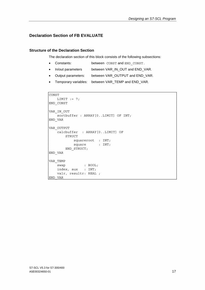
Declaration Section of FB EVALUATE
Structure of the Declaration Section
The declaration section of this block consists of the following subsections:
• Constants: between CONST and END_CONST.
• In/out parameters between VAR_IN_OUT and END_VAR.
• Output parameters: between VAR_OUTPUT and END_VAR.
• Temporary variables: between VAR_TEMP and END_VAR.
CONST LIMIT := 7; END_CONST VAR_IN_OUT sortbuffer : ARRAY[0..LIMIT] OF INT; END_VAR VAR_OUTPUT calcbuffer : ARRAY[0..LIMIT] OF STRUCT squareroot : INT; square : INT; END_STRUCT; END_VAR VAR_TEMP swap : BOOL; index, aux : INT; valr, resultr: REAL ; END_VAR

Designing an S7-SCL Program
S7-SCL V5.3 for S7-300/400 18 A5E00324650-01
Statement Section of FB EVALUATE
Program Sequence
The in/out parameter "sortbuffer" is linked to the ring buffer "measvals" so that the original contents of the buffer are overwritten by the sorted measured values.
The new array "calcbuffer" is created as an output parameter for the calculated results. Its elements are structured so that they contain the square root and the square of each measured value.
The figure below shows you the relationship between the arrays.
EVALUATION
measured values
sort buffer
calculate buffer
This interface shows the heart of the data exchange for processing the measured values. The data is stored in the instance data block ACQUIRE_DATA since a local instance for FB EVALUATE was created in the calling FB ACQUIRE.
Statement Section of EVALUATE
First, the measured values in the ring buffer are sorted and then the calculations are made.
• Sort algorithm The permanent exchange of values method is used to sort the measured value buffer. This means that consecutive values are compared and their order reversed until the final order is obtained throughout. The buffer used is the in/out parameter "sortbuffer".
• Starting the calculation Once sorting is completed, a loop is executed in which the functions SQUARE for squaring and SQRT for extracting the square root are called. Their results are stored in the structured array "calcbuffer".

Designing an S7-SCL Program
S7-SCL V5.3 for S7-300/400 A5E00324650-01 19
Statement Section of EVALUATE
The statement section of the logic block is as follows:
BEGIN (******************************************************** Part 1 Sorting : According to the "bubble sort" method: Swap pairs of values until the measured value buffer is sorted. **********************************************************) REPEAT swap := FALSE; FOR index := LIMIT TO 1 BY -1 DO IF sortbuffer[index-1] > sortbuffer[index] THEN aux :=sortbuffer[index]; sortbuffer[index] := sortbuffer[index-1]; sortbuffer[index-1] := aux; swap := TRUE; END_IF; END_FOR; UNTIL NOT swap END_REPEAT; (********************************************************** Part 2 Calculation : Square root with standard function SQRT and squaring with the SQUARE function. ************************************************************) FOR index := 0 TO LIMIT BY 1 DO valr := INT_TO_REAL(sortbuffer[index]); resultr := SQRT(valr); calcbuffer[index].squareroot := REAL_TO_INT(resultr); calcbuffer[index].square := SQUARE(sortbuffer[index]); END_FOR; END_FUNCTION_BLOCK

Designing an S7-SCL Program
S7-SCL V5.3 for S7-300/400 20 A5E00324650-01
Creating the function block ACQUIRE
Flow Chart for ACQUIRE
The following figure shows the algorithm in the form of a flow chart:
Start
End
newval yes
yes
yes
no
no
no
TRUE
FALSE
new code
resort
functionchoice?
changed?
changed?
changed?
RECORDFunction Block
Copy measured value to cyclic buffer, recalculate index
Cyclic buffer is implemented by means of MOD operation:when limit is reached start from beginning again
Sort cyclic buffer and perform calculations (set up results array)
Load from instance data block
First shift relevant bits to right margin then hide spaces not required by means of AND
Load:Write list items with output addresses to the output parameters so that their values can be displayed afterwards.
Copy calculated resultsto results array
Analyze code and calculate output address
Load square root result Load square result
Load measured value
ANALYZE

Designing an S7-SCL Program
S7-SCL V5.3 for S7-300/400 A5E00324650-01 21
Declaration Section of FB ACQUIRE
Structure of the Declaration Section
The declaration section in this block consists of the subsections:
• Constants: between CONST and END_CONST.
• Input parameters: between VAR_INPUT and END_VAR.
• Output parameters: between VAR_OUTPUT and END_VAR.
• Static variables: between VAR and END_VAR. This also includes declaration of the local instance for the EVALUATE block.
CONST LIMIT := 7; QUANTITY := LIMIT + 1; END_CONST VAR_INPUT measval_in : INT ; // New measured value newval : BOOL; // Measured value in "measvals" ring buffer resort : BOOL; // Sort measured values funct_sel: BOOL; // Select calculation square root/square newsel : BOOL; // Take output address selection : WORD; // Output address END_VAR VAR_OUTPUT result_out : INT; // Calculated value measval_out : INT; // Corresponding measured value END_VAR VAR measvals : ARRAY[0..LIMIT] OF INT := 8(0); resultbuffer : ARRAY[0..LIMIT] OF STRUCT squareroot : INT; square : INT; END_STRUCT; pointer : INT := 0; oldval : BOOL := TRUE; oldsort : BOOL := TRUE; oldsel : BOOL := TRUE; address : INT := 0; // Converted output address outvalues_instance: EVALUATE; // Define local instance END_VAR

Designing an S7-SCL Program
S7-SCL V5.3 for S7-300/400 22 A5E00324650-01
Static Variables
The FB block type was chosen because some data needs to be retained from one program cycle to the next. These are the static variables declared in the declaration subsection "VAR, END_VAR".
Static variables are local variables whose values are retained throughout the processing of every block. They are used to save values of a function block and are stored in the instance data block.
Initializing Variables
Note the initialization values that are entered in the variables when the block is initialized (after being downloaded to the CPU). The local instance for the EVALUATE FB is also declared in the declaration subsection "VAR, END_VAR". This name is used subsequently for calling and accessing the output parameters. The shared instance ACQUIRE_DATA is used to store the data.
Name Data Type Initialization Value
Description
measvals ARRAY [..] OF INT
8(0) Ring buffer for measured values
resultbuffer ARRAY [..] OF STRUCT
- Array for structures with the components "square root" and "square" of the type INT
index INT 0 Index for ring buffer identifying location for next measured value
oldval BOOL FALSE Previous value for reading in measured value using "newval"
oldsort BOOL FALSE Previous value for sorting using "resort"
oldsel BOOL FALSE Previous value for reading in code using "newsel"
address INT 0 Address for output of measured value or result
eval_instance Local instance - Local instance for the EVALUATE FB

Designing an S7-SCL Program
S7-SCL V5.3 for S7-300/400 A5E00324650-01 23
Statement Section of FB ACQUIRE
Structure of the Statement Section
The statement section of ACQUIRE is divided into three subsections:
• Acquire measured values: If the input parameter "newval" is different from the "oldval", a new measured value is read into the ring buffer.
• Start sorting and calculation Sorting and calculation are started by calling the EVALUATE function block when the input parameter "resort" has changed compared with "oldsort".
• Evaluating the coding and preparing output data The coding is read word by word. According to SIMATIC conventions, this means that the upper group of switches (byte 0) contains the higher-order eight bits of the input word and the lower group of switches (byte 1) the lower-order bits. The figure below shows the location of the coding switches.
Calculating the Address
The figure below shows how the address is calculated: Bits 12 to 14 of input word IW0 contain the coding that is read in when an edge is detected at the coding switch (bit 15). The "address" is obtained by shifting right using the standard function SHR and masking the relevant bits using an AND mask.
This address is used to write the array elements (calculated result and corresponding measured value) to the output parameters. Whether square root or square is output depends on "funct_sel".
An edge at the coding switch is detected because "newsel" is different from "oldsel".
01234567
012
3456
Switches for codenumber
Codingswitch
012
34567
891011
15
121314
Switches onmodule
Word inmemory
After SHRby 12 places
After AND,mask 0007
012
34567
891011
15
121314
012
34567
891011
15
121314
address"
7
Byte 0
Byte 1 IW0

Designing an S7-SCL Program
S7-SCL V5.3 for S7-300/400 24 A5E00324650-01
Statement Section
The statement section of the logic block is shown below:
BEGIN (*********************************************************** Part 1 : Acquiring measured values. If "newval" changes, the measured value is entered. The MOD operation is used to implement a ring buffer for measured values. **********************************************) IF newval <> oldval THEN pointer := pointer MOD QUANTITY; measvals[pointer] := measval_in; pointer := pointer + 1; END_IF; oldval := newval; (************************************************************ Part 2 : Start sorting and calculation if "resort" changes, start sorting the ring buffer and run calculations with the measured values. Results are stored in a new array called "calcbuffer". ************************************************************) IF resort <> oldsort THEN pointer := 0; //Reset ring buffer pointer eval_instance(sortbuffer := measvals); //Call EVALUATE END_IF; oldsort := resort; resultbuffer := eval_instance.calcbuffer; //Square and square root (************************************************************ Part 3 : Evaluate coding and prepare output: If "newsel" changes, the coding for addressing the array element for output is recalculated: The relevant bits of "selection" are masked and converted to integer. Depending on the setting of the "funct_sel" switch, "squareroot" or "square" is selected for output. ************************************************************) IF newsel <> oldsel THEN address := WORD_TO_INT(SHR(IN := selection, N := 12) AND 16#0007); END_IF; oldsel := newsel; IF funct_sel THEN result_out := resultbuffer[address].square; ELSE result_out := resultbuffer[address].squareroot; END_IF; measval_out := measvals[address]; //Measured value display END_FUNCTION_BLOCK

Designing an S7-SCL Program
S7-SCL V5.3 for S7-300/400 A5E00324650-01 25
Creating the CYCLE Organization Block
Tasks of the CYCLE OB
An OB1 was chosen because it is called cyclically. It performs the following tasks for the program:
• Calls and supplies the ACQUIRE function block with input and control data.
• Reads in the data returned by the ACQUIRE function block.
• Outputs the values to the display
At the beginning of the declaration section, there is the 20-byte temporary data array "system data".

Designing an S7-SCL Program
S7-SCL V5.3 for S7-300/400 26 A5E00324650-01
Program Code of the CYCLE OB
ORGANIZATION_BLOCK CYCLE (*********************************************************** CYCLE is like an OB1, i.e. it is called cyclically by the S7 system. Part 1 : Function block call and transfer of the input values Part 2 : Reading in of the output values and output with output switchover ***********************************************************) VAR_TEMP systemdata : ARRAY[0..20] OF BYTE; // Area for OB1 END_VAR BEGIN (* Part 1 : ***************************************************) ACQUIRE.ACQUIRE_DATA( measval_in:= WORD_TO_INT(input), newval := "Input 0.0", //Input switch as signal identifier resort := Sort_switch, funct_sel := Function_switch, newsel := Coding_switch, selection := Coding); (* Part 2 : **************************************************) IF Output_switch THEN //Output changeover Output := ACQUIRE_DATA.result_out; //Square root or square ELSE Output := ACQUIRE_DATA.measval_out; //Measured value END_IF; END_ORGANIZATION_BLOCK
Data Type Conversion
The measured value is applied to the input as a BYTE data type. It must be converted to the INT data type. You will need to convert it from WORD to INT (the prior conversion from BYTE to WORD is made implicitly by the compiler). The output on the other hand requires no conversion, since this was declared as INT in the symbol table.

Designing an S7-SCL Program
S7-SCL V5.3 for S7-300/400 A5E00324650-01 27
Test Data
Requirements
To perform the test, you require an input module with address 0 and an output module with address 4.
Before performing the test, set all eight switches in the upper group to the left ("0") and all eight switches in the lower group to the right ("1").
Reload the blocks on the CPU, since the initial values of the variables must also be tested.
Test Procedure
Run the test as described in the table .
Test Action Result
1 Set the code to "111" (I0.4, I0.5 and I0.6) and enter this with the coding switch (I0.7).
All outputs on the output module (lower-order byte) are activated and the LEDs light up.
2 Display the corresponding square root by setting the output switch (I0.3) to "1".
The LEDs on the output module indicate the binary number "10000" (=16).
3 Display the corresponding square by setting the function switch (I0.2) to "1".
15 LEDs on the output module light up. This indicates an overflow since the result of 255 x 255 is too high for the integer range.
4a Reset the output switch (I0.3) back to "0".
The measured value is displayed again. All LEDs on the outputs of the lower-order output byte are set.
4b Set the value 3 (binary "11") as the new measured value at the input.
The output does not change at this stage.
5a Monitor reading in of the measured value: Set the code to "000" and enter it with coding switch (I0.7) so that you can later watch the value input.
The output module shows 0; i.e none of the LEDs lights up.
5b Switch over the input switch "Input 0.0" (I0.0). This reads in the value set in test stage 4.
The output displays measured value 3, binary "11".
6 Start sorting and calculation by switching over the sort switch (I0.1).
The output again indicates 0 since the sorting process has moved the measured value to a higher position in the array.
7 Display the measured value after sorting: Set the code "110" (I0.6 = 1, I0.5 = 1, I0.4 = 0 of IB0; corresponds to bit 14, bit 13 and bit 12 of IW0) and read it in by switching over the coding switch.
The output now indicates the measured value "11" again since it is the second highest value in the array.
8a Display the corresponding results as follows: Switching over the output switch (I0.3) displays the square of the measured value from the 7th step.
The output value 9 (binary "1001") is displayed.
8b Switch over the function switch (I0.2) to obtain the square root.
The output value 2 (binary "10") is displayed.

Designing an S7-SCL Program
S7-SCL V5.3 for S7-300/400 28 A5E00324650-01
Additional Test
The following tables describe the switches on the input module and the examples for square and square root. These descriptions will help you to define your own tests:
• Input is made using switches. You can control the program with the top eight switches and you can set the measured value with the bottom 8 switches.
• Output is indicated by LEDs. The top group displays the higher-order output byte, the bottom group the lower-order byte.
Switch Parameter Name Description
Channel 0 Enter switch Switch over to read in measured value
Channel 1 Sort switch Switch over to start sorting/calculation
Channel 2 Function switch Switch left ("0"): Square root, Switch right ("1"): Square
Channel 3 Output switch Switch left ("0"): Measured value, Switch right ("1"): Result
Channel 4 Code Output address bit 0
Channel 5 Code Output address bit 1
Channel 6 Code Output address bit 2
Channel 7 Code switch Switch over to enter code
The following table contains eight examples of measured values that have already been sorted.
You can enter the values in any order. Set the bit combination for each value and transfer this value by operating the input switch. Once all values have been entered, start sorting and calculation by changing over the sort switch. You can then view the sorted values or the results (square root or square).
Measured Value Square Root Square
0000 0001 = 1 0, 0000 0001 = 1 0000 0000, 0000 0001 = 1
0000 0011 = 3 0, 0000 0010 = 2 0000 0000, 0000 1001 = 9
0000 0111 = 7 0, 0000 0011 = 3 0000 0000, 0011 0001 = 49
0000 1111 = 15 0, 0000 0100 = 4 0000 0000, 1110 0001 = 225
0001 1111 = 31 0, 0000 0110 = 6 0000 0011, 1100 0001 = 961
0011 1111 = 63 0, 0000 1000 = 8 0000 1111, 1000 0001 = 3969
0111 1111 = 127 0, 0000 1011 = 11 0011 1111, 0000 0001 = 16129
1111 1111 = 255 0, 0001 0000 = 16 0111 111, 1111 1111 = Overflow!