simatic field pg m4 - siemens ag · simatic field pg m4 ... 4.2 unpacking and checking the delivery...
TRANSCRIPT
�SIMATIC Field PG M4�
___________________
___________________
___________________
___________________
___________________
___________________
___________________
___________________
___________________
___________________
___________________
___________________
___________________
___________________
___________________
___________________
___________________
SIMATIC
Programming device SIMATIC Field PG M4
Operating Instructions
10/2012 A5E31347320-AA
Introduction 1
Safety notes 2
Description 3
Application planning 4
Positioning 5
Connecting 6
Commissioning 7
Integration into an automation system
8
Operating 9
Expansions and parameter assignment
10
Service and maintenance 11
Troubleshooting/FAQs 12
Technical data 13
Detailed descriptions 14
Appendix A
ESD guidelines B
List of abbreviations C
Siemens AG Industry Sector Postfach 48 48 90026 NÜRNBERG GERMANY
A5E31347320-AA Ⓟ 10/2012 Technical data subject to change
Copyright © Siemens AG 2012. All rights reserved
Legal information Warning notice system
This manual contains notices you have to observe in order to ensure your personal safety, as well as to prevent damage to property. The notices referring to your personal safety are highlighted in the manual by a safety alert symbol, notices referring only to property damage have no safety alert symbol. These notices shown below are graded according to the degree of danger.
DANGER indicates that death or severe personal injury will result if proper precautions are not taken.
WARNING indicates that death or severe personal injury may result if proper precautions are not taken.
CAUTION indicates that minor personal injury can result if proper precautions are not taken.
NOTICE indicates that property damage can result if proper precautions are not taken.
If more than one degree of danger is present, the warning notice representing the highest degree of danger will be used. A notice warning of injury to persons with a safety alert symbol may also include a warning relating to property damage.
Qualified Personnel The product/system described in this documentation may be operated only by personnel qualified for the specific task in accordance with the relevant documentation, in particular its warning notices and safety instructions. Qualified personnel are those who, based on their training and experience, are capable of identifying risks and avoiding potential hazards when working with these products/systems.
Proper use of Siemens products Note the following:
WARNING Siemens products may only be used for the applications described in the catalog and in the relevant technical documentation. If products and components from other manufacturers are used, these must be recommended or approved by Siemens. Proper transport, storage, installation, assembly, commissioning, operation and maintenance are required to ensure that the products operate safely and without any problems. The permissible ambient conditions must be complied with. The information in the relevant documentation must be observed.
Trademarks All names identified by ® are registered trademarks of Siemens AG. The remaining trademarks in this publication may be trademarks whose use by third parties for their own purposes could violate the rights of the owner.
Disclaimer of Liability We have reviewed the contents of this publication to ensure consistency with the hardware and software described. Since variance cannot be precluded entirely, we cannot guarantee full consistency. However, the information in this publication is reviewed regularly and any necessary corrections are included in subsequent editions.
SIMATIC Field PG M4 Operating Instructions, 10/2012, A5E31347320-AA 3
Table of contents
1 Introduction................................................................................................................................................ 7
1.1 Preface...........................................................................................................................................7
1.2 Guideline to the operating instructions ..........................................................................................8
2 Safety notes............................................................................................................................................... 9
2.1 General safety instructions ............................................................................................................9
2.2 Security information .....................................................................................................................11
2.3 Additional safety information when using wireless LAN ..............................................................11
3 Description............................................................................................................................................... 13
3.1 Overview ......................................................................................................................................13
3.2 Application areas .........................................................................................................................13
3.3 Highlights .....................................................................................................................................14
3.4 Features .......................................................................................................................................15
3.5 Design ..........................................................................................................................................17 3.5.1 Exterior design .............................................................................................................................17 3.5.2 Operator controls .........................................................................................................................20 3.5.2.1 On/off button ................................................................................................................................20 3.5.2.2 Touchpad .....................................................................................................................................22 3.5.2.3 Keyboard......................................................................................................................................22 3.5.3 Status displays.............................................................................................................................25
4 Application planning................................................................................................................................. 27
4.1 Transport......................................................................................................................................27
4.2 Unpacking and checking the delivery unit ...................................................................................28
4.3 Device identification data .............................................................................................................29
5 Positioning ............................................................................................................................................... 31
5.1 Positioning the device ..................................................................................................................31
6 Connecting .............................................................................................................................................. 33
6.1 Connecting peripherals ................................................................................................................33
6.2 Connecting the device to power...................................................................................................34
6.3 Connect the PG to the S5 automation device..............................................................................36
6.4 Connect the PG to the S7 automation system or the PROFIBUS network .................................37
7 Commissioning ........................................................................................................................................ 39
7.1 Requirements for commissioning.................................................................................................39
7.2 Initial commissioning - initial startup ............................................................................................39
Table of contents
SIMATIC Field PG M4 4 Operating Instructions, 10/2012, A5E31347320-AA
7.3 Notes on operation...................................................................................................................... 42 7.3.1 Rechargeable battery.................................................................................................................. 42 7.3.2 HDD/SSD .................................................................................................................................... 44 7.3.3 Optical drive ................................................................................................................................ 44 7.3.4 SIMATIC S5 memory module ..................................................................................................... 46 7.3.5 SIMATIC Memory Card............................................................................................................... 47 7.3.6 Integrated Multi Media Card Reader........................................................................................... 48 7.3.7 SIMATIC Micro Memory Card..................................................................................................... 49 7.3.8 USB socket with charging function ............................................................................................. 49 7.3.9 PC Cards..................................................................................................................................... 50 7.3.10 Wireless LAN and Bluetooth ....................................................................................................... 51 7.3.10.1 General information about WLAN and Bluetooth........................................................................ 51 7.3.10.2 Safety information for WLAN operation ...................................................................................... 52
8 Integration into an automation system ..................................................................................................... 53
8.1 System environments and networks ........................................................................................... 53
8.2 Intel Active Management Technology......................................................................................... 54
8.3 Trusted Platform Module (TPM).................................................................................................. 55
9 Operating................................................................................................................................................. 57
9.1 SIMATIC Software ...................................................................................................................... 57
10 Expansions and parameter assignment................................................................................................... 59
10.1 Installing / removing memory modules ....................................................................................... 59
11 Service and maintenance ........................................................................................................................ 63
11.1 Removing and installing hardware components ......................................................................... 63 11.1.1 Replacing HDDs/SSDs ............................................................................................................... 63 11.1.2 Hard disk kit ................................................................................................................................ 65 11.1.3 Replace the battery ..................................................................................................................... 65 11.1.4 Replacing the backup battery ..................................................................................................... 67
11.2 Reinstalling the software............................................................................................................. 68 11.2.1 General installation procedure .................................................................................................... 68 11.2.2 Restoring the delivery state......................................................................................................... 68 11.2.3 Installing Windows ...................................................................................................................... 70 11.2.3.1 Installing Windows XP................................................................................................................. 70 11.2.3.2 Installing Windows 7 ................................................................................................................... 72 11.2.4 Setting up the language selection by means of the Multilanguage User Interface (MUI)........... 74 11.2.5 Installing drivers and software .................................................................................................... 75 11.2.5.1 Installing the drivers .................................................................................................................... 75 11.2.5.2 Creating an AHCI controller drive disk........................................................................................ 76 11.2.5.3 Installing the SIMATIC software from the "Software for Field PG M4" DVD .............................. 76 11.2.6 Installing the optional burner or DVD software ........................................................................... 77 11.2.7 Updating the operating system ................................................................................................... 77 11.2.8 Data backup / subsequent modification of partitions .................................................................. 78 11.2.8.1 Hardware supported.................................................................................................................... 78 11.2.8.2 Creating an image....................................................................................................................... 78 11.2.8.3 Modifying the partitions ............................................................................................................... 78
Table of contents
SIMATIC Field PG M4 Operating Instructions, 10/2012, A5E31347320-AA 5
12 Troubleshooting/FAQs............................................................................................................................. 79
12.1 General problems ........................................................................................................................79
12.2 Problems with Wireless LAN........................................................................................................80
13 Technical data ......................................................................................................................................... 83
13.1 General specifications..................................................................................................................83
14 Detailed descriptions ............................................................................................................................... 87
14.1 Interfaces .....................................................................................................................................87 14.1.1 External interfaces .......................................................................................................................87
14.2 Connecting cables .......................................................................................................................93
14.3 System resources ........................................................................................................................93
14.4 BIOS Setup ..................................................................................................................................94 14.4.1 Overview ......................................................................................................................................94 14.4.2 SCU (Setup Configuration Utility) - Main Menu ...........................................................................95 14.4.3 Advanced Menu ...........................................................................................................................96 14.4.4 Security Menu ............................................................................................................................105 14.4.5 Power menu...............................................................................................................................106 14.4.6 Boot menu..................................................................................................................................108 14.4.7 Exit menu ...................................................................................................................................111
A Appendix................................................................................................................................................ 113
A.1 Guidelines and declarations.......................................................................................................113
A.2 Certificates and approvals .........................................................................................................114
A.3 Service and support ...................................................................................................................115
A.4 Accessories................................................................................................................................116
B ESD guidelines ...................................................................................................................................... 117
C List of abbreviations............................................................................................................................... 119
C.1 Abbreviations .............................................................................................................................119
Glossary ................................................................................................................................................ 125
Index...................................................................................................................................................... 137

Table of contents
SIMATIC Field PG M4 6 Operating Instructions, 10/2012, A5E31347320-AA
SIMATIC Field PG M4 Operating Instructions, 10/2012, A5E31347320-AA 7
Introduction 11.1 Preface
Purpose of this documentation This manual contains all the information you need to commission and use the SIMATIC Field PG M4.
It is intended both for programming and testing/debugging personnel who commission the device and connect it with other units (automation systems, further programming devices), as well as for service and maintenance personnel who install expansions or carry out fault/error analyses.
Validity of this documentation This documentation is valid for all available versions of the SIMATIC Field PG M4 and describes the delivery state as of December 2012.
Position in the information scheme These operating instructions are part of the supplied "Software for Field PG" DVD.
For supplementary instructions on how to handle the software, please refer to the corresponding manuals.
Conventions The abbreviation "PG", or the term "device", are also used in this documentation instead of the designation SIMATIC Field PG M4.
History Currently released versions of this operating manual: Issue Comment 10/2012 First edition
Introduction 1.2 Guideline to the operating instructions
SIMATIC Field PG M4 8 Operating Instructions, 10/2012, A5E31347320-AA
1.2 Guideline to the operating instructions Contents format Contents Table of Contents Organization of the documentation, including the index of pages and chapters Introduction Purpose, layout and description of the important topics Safety-related notices Refers to all the valid safety-technological aspects which are derived from statutory
regulations and should be adhered to when installing, commissioning and operating the product/system
Description Fields of application, the features and the structure of the product/system Application Planning Preparatory considerations relating to storage, transport, environmental and EMC
conditions. Connecting Options of connecting the product and connection instructions Commissioning Commissioning the product/system. Integration Options of integrating the product into existing or planned system environments/networks Operation Operating the SIMATIC software Expansions / Configuration Procedure for installing expansion devices (memory). Maintenance and service Replacement of hardware components, restoring and setup of the operating system,
installation of drivers and software Troubleshooting/FAQs Problems, cause, remedy Specifications General specifications in compliance with relevant standards and current/voltage values Detailed descriptions Structure, function and features of the vital components, allocation of system resources and
use of the BIOS Setup Appendix Guidelines and certifications, service and support ESD guidelines General ESD guidelines.
SIMATIC Field PG M4 Operating Instructions, 10/2012, A5E31347320-AA 9
Safety notes 22.1 General safety instructions
CAUTION Please observe the safety instructions on the back of the cover sheet of this documentation. You should not expand your device unless you have read the relevant safety instructions.
This device is compliant with the relevant safety measures to IEC, EN, VDE, UL, and CSA. If you have questions about the validity of the installation in the planned environment, please contact your service representative.
Repairs
Only qualified personnel are permitted to repair the device.
WARNING Unauthorized opening and improper repairs can cause considerable damage to property or danger for the user.
System expansions
Only install system expansion devices designed for this device. The installation of other expansions can damage the system and violate the radio-interference suppression regulations. Contact your technical support team or where you purchased your PC to find out which system expansion devices may safely be installed.
NOTICE If you install or exchange system expansions and damage your device, the warranty becomes void.
Safety notes 2.1 General safety instructions
SIMATIC Field PG M4 10 Operating Instructions, 10/2012, A5E31347320-AA
Battery
This device is equipped with a Lithium battery. Batteries may only be replaced by qualified personnel.
CAUTION There is the risk of an explosion if the battery is not replaced as directed. Replace only with the same type or with an equivalent type recommended by the manufacturer. Dispose of used batteries in accordance with local regulations.
WARNING Risk of explosion and release of harmful substances!
Do not throw lithium batteries into an open fire, do not solder, or open the cell body, do not short-circuit, or reverse polarity, do not heat up above 100 °C, follow the disposal instructions, and protect against direct exposure to sunlight, humidity, and condensation.
ESD guidelines
Modules containing electrostatic sensitive devices (ESDs) can be identified by the following label:
Strictly follow the guidelines mentioned below when handling modules which are sensitive to ESD:
● Always discharge any static electricity from your body before handling modules that are sensitive to electrostatic discharge (for example, by touching a grounded object).
● All devices and tools must be free of static charge.
● Always pull the mains connector and disconnect the battery before you install or remove modules which are sensitive to ESD.
● Handle modules fitted with ESDs by their edges only.
● Do not touch any wiring posts or conductors on modules containing ESDs.
Safety notes 2.2 Security information
SIMATIC Field PG M4 Operating Instructions, 10/2012, A5E31347320-AA 11
2.2 Security information Siemens offers IT security mechanisms for its portfolio of automation and drive products in order to support safe operation of the plant/machine. We recommend that you stay informed about the IT security developments for your products. For information on this topic, refer to: Industry Online Support (http://www.siemens.de/automation/csi_en_WW): You can register for a product-specific newsletter here.
For the safe operation of a plant/machine, however, it is also necessary to integrate the automation components into an overall IT security concept for the entire plant/machine, which corresponds to the state-of-the-art IT technology. You can find information on this under: Industrial Security (http://www.siemens.com/industrialsecurity).
Products used from other manufacturers should also be taken into account here.
2.3 Additional safety information when using wireless LAN As your device has an integrated WLAN card, you must observe the following safety information:
● The transmitted radio waves can cause an unpleasant droning in hearing aids.
● Switch off the device if traveling by aircraft or car.
● Switch off the radio components on the device if you are in a hospital or in the proximity of a medical electronic system. The transmitted radio waves can have a negative effect on the function of medical equipment.
● Keep the device at least 20 cm away from pacemakers, otherwise the radio waves may interfere with the pacemaker.
● When the radio components are switched on, do not bring the device in the vicinity of flammable gases, or into a potentially-explosive atmosphere (paint shop, for example), as the transmitted radio waves could trigger an explosion or a fire.
● The range of the radio connection depends on the environmental and surrounding conditions.
● With data traffic via a wireless connection, it is also possible for unauthorized third parties to receive data.
Siemens is not responsible for radio or television interference that has been caused by unauthorized changes to this device. Furthermore, Siemens shall not be held responsible for the use or replacement of connection lines and devices that have not been recommended by Siemens. The user alone is responsible for remedying faults that have been caused by such an unauthorized change, or for the use or the replacement of the device.

Safety notes 2.3 Additional safety information when using wireless LAN
SIMATIC Field PG M4 12 Operating Instructions, 10/2012, A5E31347320-AA
SIMATIC Field PG M4 Operating Instructions, 10/2012, A5E31347320-AA 13
Description 33.1 Overview
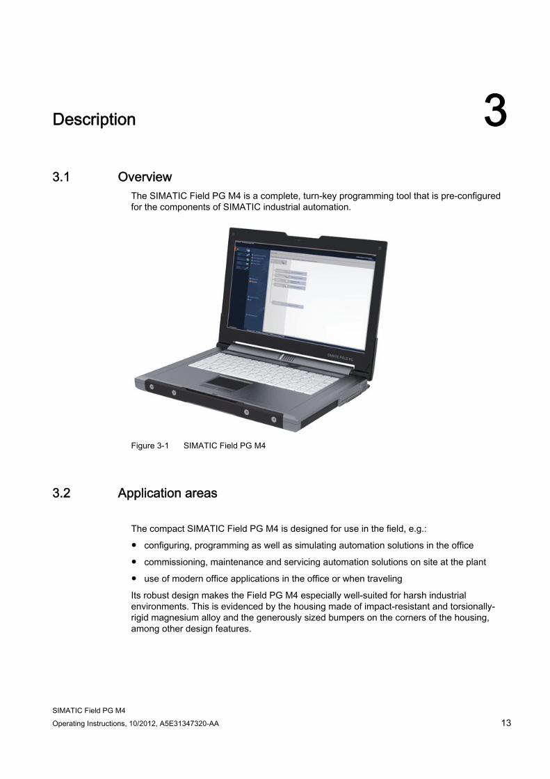
The SIMATIC Field PG M4 is a complete, turn-key programming tool that is pre-configured for the components of SIMATIC industrial automation.
Figure 3-1 SIMATIC Field PG M4
3.2 Application areas
The compact SIMATIC Field PG M4 is designed for use in the field, e.g.:
● configuring, programming as well as simulating automation solutions in the office
● commissioning, maintenance and servicing automation solutions on site at the plant
● use of modern office applications in the office or when traveling
Its robust design makes the Field PG M4 especially well-suited for harsh industrial environments. This is evidenced by the housing made of impact-resistant and torsionally-rigid magnesium alloy and the generously sized bumpers on the corners of the housing, among other design features.
Description 3.3 Highlights
SIMATIC Field PG M4 14 Operating Instructions, 10/2012, A5E31347320-AA
3.3 Highlights
Greatest possible mobility guaranteed ● Notebook structure (dimensions, weight) optimal for use in cramped spaces at the plant
as well as when traveling
● High-performance lithium-ion accumulator with rated capacity of 97 Wh for extended cordless operation.
● Housing made of magnesium alloy housing with soft plastic corners – providing good protection for the electronics inside
● High-performance graphics controller for dual display support
● Large 15.6" internal display, Full HD or HD-Ready with 16:9 format for ergonomic working
Industrial functionality ● Integrated PROFIBUS DP/MPI interface that supports operation on virtual operating
systems
● COM/TTY interface
The TTY interface used is dependent on the selected hardware.
● Programming interfaces for SIMATIC Memory Card, Micro Memory Card, and S5 EPROM modules
● Integrated card reader for SIMATIC Memory Card (SMC), SD, SDHC, MS, XD Card, and MMC
● Card reader for SIMATIC MMC on the right side of the device
● Link to company networks and WAN without additional hardware costs due to two integrated independent and fully-fledged Gigabit Ethernet interfaces
● Wireless LAN corresponding to IEEE 802.11 a/b/g/n
● Integrated Bluetooth in accordance with standard 4.0
● Fast, easy to replace SATA hard disk
● Two USB 2.0 ports (high-current capable); two USB 3.0 ports (rear) with USB 2.0 functionality on the Windows XP OS
● One USB port with charger function
● HDA (High Definition Audio) sound port
● Integrated Trusted Platform Module to TPM 1.2 standard
System availability ● Optional data backup software Image & Partition Creator
Description 3.4 Features
SIMATIC Field PG M4 Operating Instructions, 10/2012, A5E31347320-AA 15
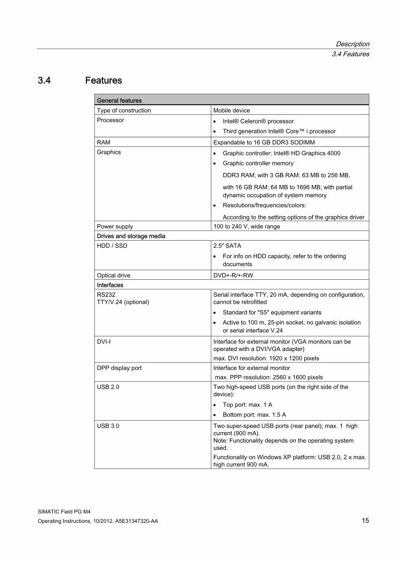
3.4 Features General features Type of construction Mobile device Processor Intel® Celeron® processor
Third generation Intel® Core™ i processor
RAM Expandable to 16 GB DDR3 SODIMM Graphics Graphic controller: Intel® HD Graphics 4000
Graphic controller memory
DDR3 RAM; with 3 GB RAM: 63 MB to 256 MB,
with 16 GB RAM: 64 MB to 1696 MB; with partial dynamic occupation of system memory
Resolutions/frequencies/colors:
According to the setting options of the graphics driver Power supply 100 to 240 V, wide range Drives and storage media HDD / SSD 2.5" SATA
For info on HDD capacity, refer to the ordering documents
Optical drive DVD+-R/+-RW Interfaces RS232 TTY/V.24 (optional)
Serial interface TTY, 20 mA, depending on configuration, cannot be retrofitted Standard for "S5" equipment variants Active to 100 m, 25-pin socket, no galvanic isolation
or serial interface V.24
DVI-I
Interface for external monitor (VGA monitors can be operated with a DVI/VGA adapter) max. DVI resolution: 1920 x 1200 pixels
DPP display port Interface for external monitor max. PPP resolution: 2560 x 1600 pixels
USB 2.0 Two high-speed USB ports (on the right side of the device): Top port: max. 1 A Bottom port: max. 1.5 A
USB 3.0 Two super-speed USB ports (rear panel); max. 1 high current (900 mA). Note: Functionality depends on the operating system used. Functionality on Windows XP platform: USB 2.0, 2 x max. high current 900 mA.
Description 3.4 Features
SIMATIC Field PG M4 16 Operating Instructions, 10/2012, A5E31347320-AA
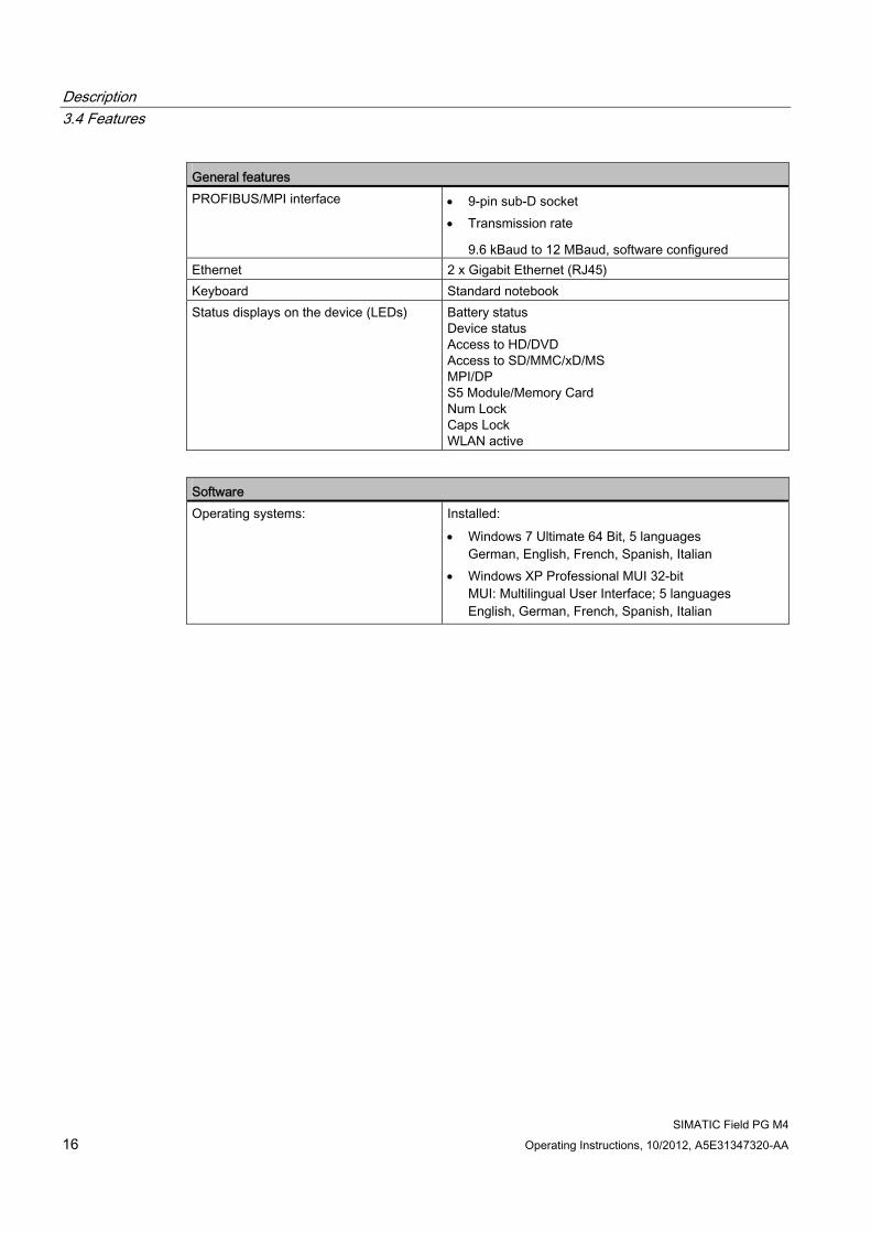
General features PROFIBUS/MPI interface 9-pin sub-D socket
Transmission rate
9.6 kBaud to 12 MBaud, software configured Ethernet 2 x Gigabit Ethernet (RJ45) Keyboard Standard notebook Status displays on the device (LEDs) Battery status
Device status Access to HD/DVD Access to SD/MMC/xD/MS MPI/DP S5 Module/Memory Card Num Lock Caps Lock WLAN active
Software Operating systems: Installed:
Windows 7 Ultimate 64 Bit, 5 languages German, English, French, Spanish, Italian
Windows XP Professional MUI 32-bit MUI: Multilingual User Interface; 5 languages English, German, French, Spanish, Italian
Description 3.5 Design
SIMATIC Field PG M4 Operating Instructions, 10/2012, A5E31347320-AA 17
3.5 Design
3.5.1 Exterior design
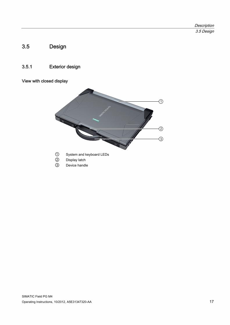
View with closed display
① System and keyboard LEDs ② Display latch ③ Device handle
Description 3.5 Design
SIMATIC Field PG M4 18 Operating Instructions, 10/2012, A5E31347320-AA
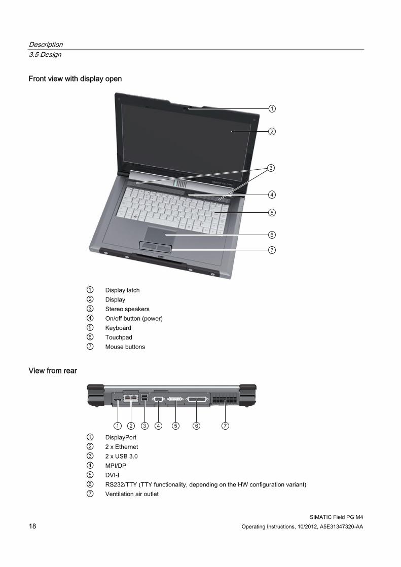
Front view with display open
① Display latch ② Display ③ Stereo speakers ④ On/off button (power) ⑤ Keyboard ⑥ Touchpad ⑦ Mouse buttons
View from rear
① DisplayPort ② 2 x Ethernet ③ 2 x USB 3.0 ④ MPI/DP ⑤ DVI-I ⑥ RS232/TTY (TTY functionality, depending on the HW configuration variant) ⑦ Ventilation air outlet
Description 3.5 Design
SIMATIC Field PG M4 Operating Instructions, 10/2012, A5E31347320-AA 19
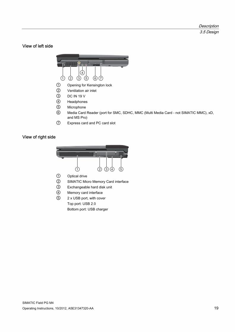
View of left side
① Opening for Kensington lock ② Ventilation air inlet ③ DC IN 19 V ④ Headphones ⑤ Microphone ⑥ Media Card Reader (port for SMC, SDHC, MMC (Multi Media Card - not SIMATIC MMC), xD,
and MS Pro) ⑦ Express card and PC card slot
View of right side
① Optical drive ② SIMATIC Micro Memory Card interface ③ Exchangeable hard disk unit ④ Memory card interface ⑤ 2 x USB port, with cover
Top port: USB 2.0 Bottom port: USB charger
Description 3.5 Design
SIMATIC Field PG M4 20 Operating Instructions, 10/2012, A5E31347320-AA
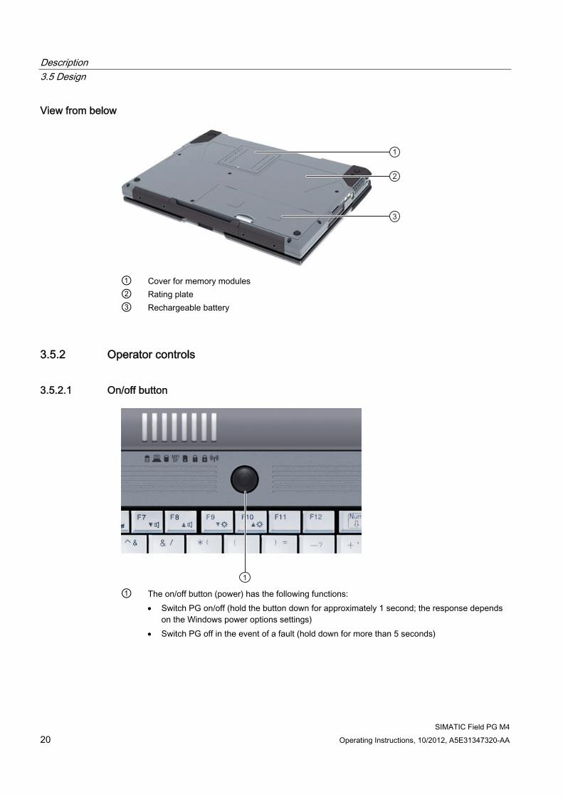
View from below
① Cover for memory modules ② Rating plate ③ Rechargeable battery
3.5.2 Operator controls
3.5.2.1 On/off button
① The on/off button (power) has the following functions:
Switch PG on/off (hold the button down for approximately 1 second; the response depends on the Windows power options settings)
Switch PG off in the event of a fault (hold down for more than 5 seconds)
Description 3.5 Design
SIMATIC Field PG M4 Operating Instructions, 10/2012, A5E31347320-AA 21
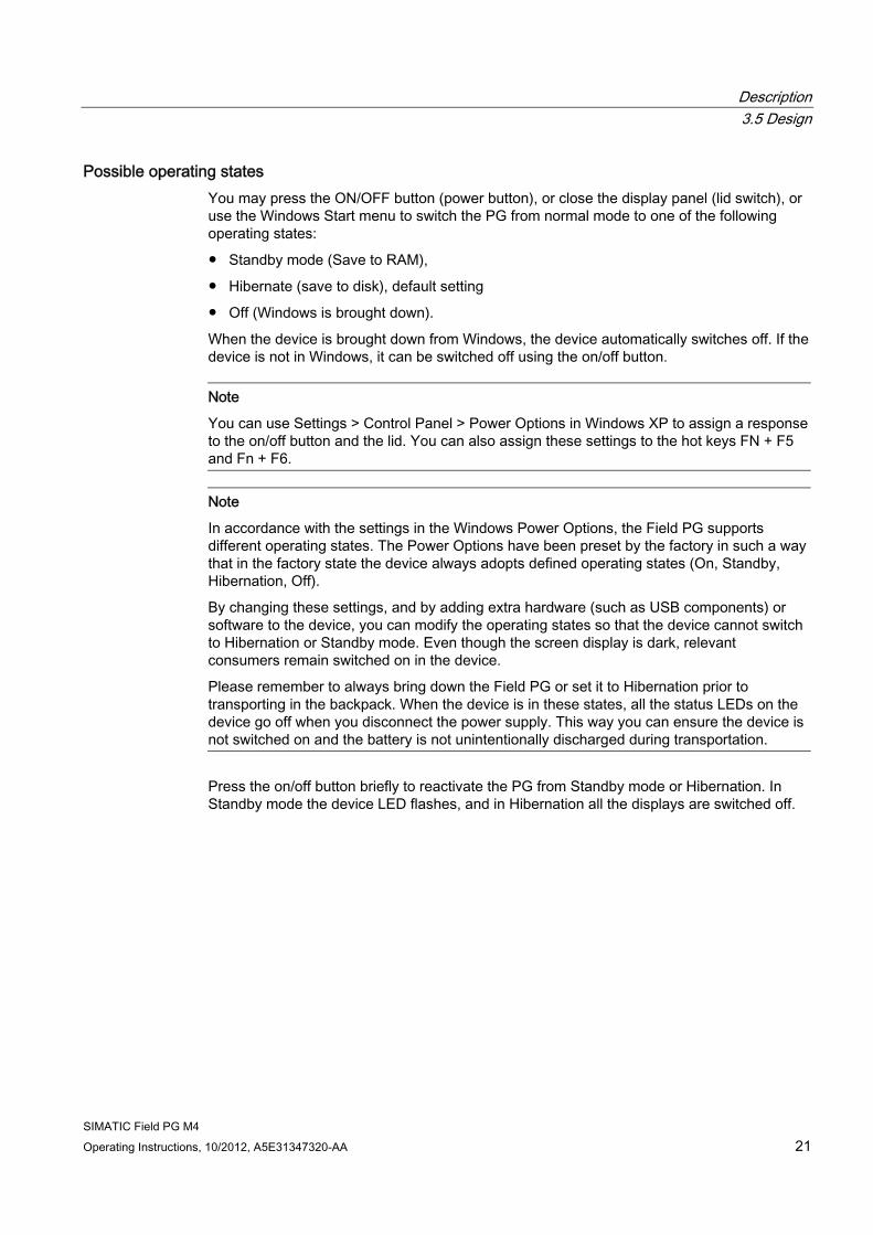
Possible operating states You may press the ON/OFF button (power button), or close the display panel (lid switch), or use the Windows Start menu to switch the PG from normal mode to one of the following operating states:
● Standby mode (Save to RAM),
● Hibernate (save to disk), default setting
● Off (Windows is brought down).
When the device is brought down from Windows, the device automatically switches off. If the device is not in Windows, it can be switched off using the on/off button.
Note
You can use Settings > Control Panel > Power Options in Windows XP to assign a response to the on/off button and the lid. You can also assign these settings to the hot keys FN + F5 and Fn + F6.
Note
In accordance with the settings in the Windows Power Options, the Field PG supports different operating states. The Power Options have been preset by the factory in such a way that in the factory state the device always adopts defined operating states (On, Standby, Hibernation, Off).
By changing these settings, and by adding extra hardware (such as USB components) or software to the device, you can modify the operating states so that the device cannot switch to Hibernation or Standby mode. Even though the screen display is dark, relevant consumers remain switched on in the device.
Please remember to always bring down the Field PG or set it to Hibernation prior to transporting in the backpack. When the device is in these states, all the status LEDs on the device go off when you disconnect the power supply. This way you can ensure the device is not switched on and the battery is not unintentionally discharged during transportation.
Press the on/off button briefly to reactivate the PG from Standby mode or Hibernation. In Standby mode the device LED flashes, and in Hibernation all the displays are switched off.
Description 3.5 Design
SIMATIC Field PG M4 22 Operating Instructions, 10/2012, A5E31347320-AA
3.5.2.2 Touchpad
Touchpad and mouse buttons
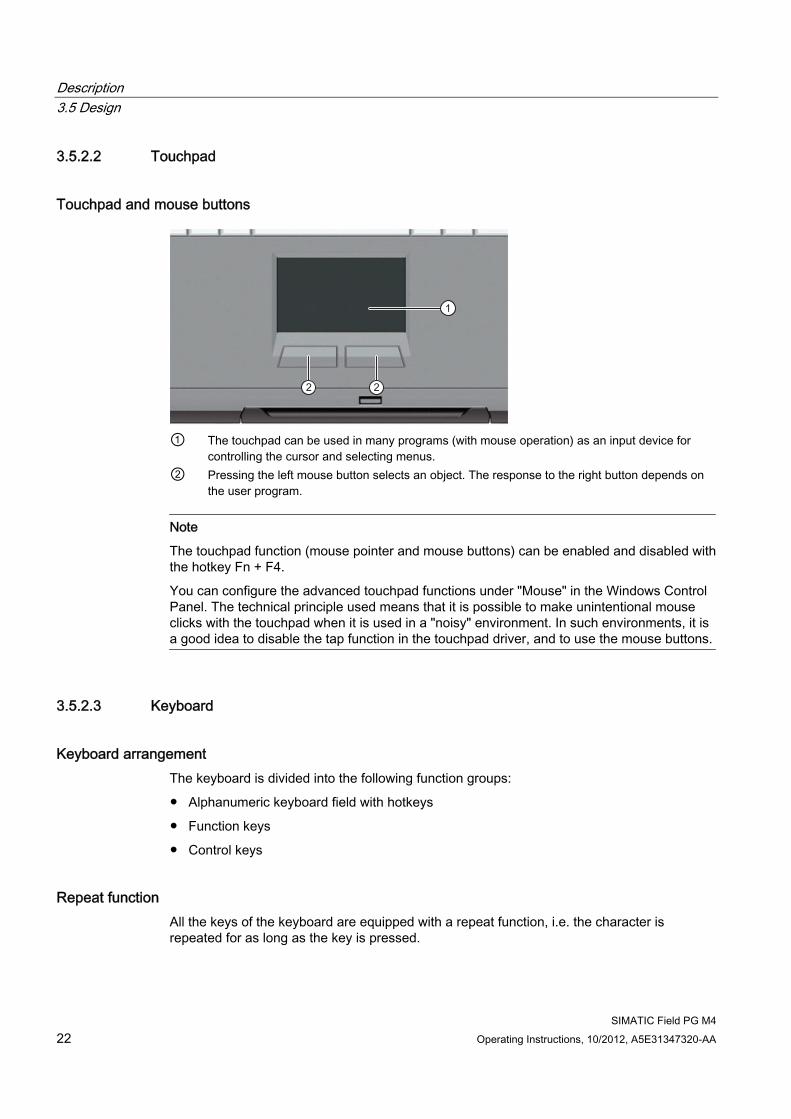
① The touchpad can be used in many programs (with mouse operation) as an input device for
controlling the cursor and selecting menus. ② Pressing the left mouse button selects an object. The response to the right button depends on
the user program.
Note
The touchpad function (mouse pointer and mouse buttons) can be enabled and disabled with the hotkey Fn + F4.
You can configure the advanced touchpad functions under "Mouse" in the Windows Control Panel. The technical principle used means that it is possible to make unintentional mouse clicks with the touchpad when it is used in a "noisy" environment. In such environments, it is a good idea to disable the tap function in the touchpad driver, and to use the mouse buttons.
3.5.2.3 Keyboard
Keyboard arrangement The keyboard is divided into the following function groups:
● Alphanumeric keyboard field with hotkeys
● Function keys
● Control keys
Repeat function All the keys of the keyboard are equipped with a repeat function, i.e. the character is repeated for as long as the key is pressed.
Description 3.5 Design
SIMATIC Field PG M4 Operating Instructions, 10/2012, A5E31347320-AA 23
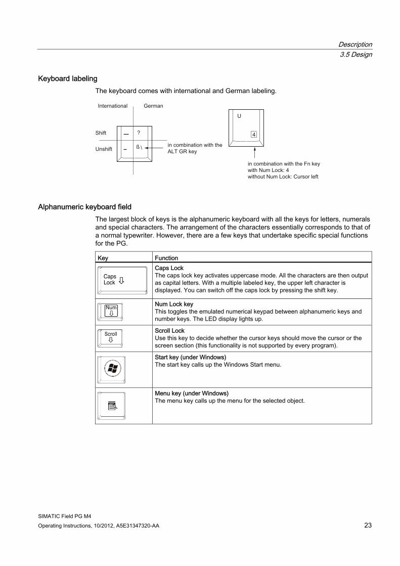
Keyboard labeling The keyboard comes with international and German labeling.
Alphanumeric keyboard field The largest block of keys is the alphanumeric keyboard with all the keys for letters, numerals and special characters. The arrangement of the characters essentially corresponds to that of a normal typewriter. However, there are a few keys that undertake specific special functions for the PG. Key Function
Caps Lock The caps lock key activates uppercase mode. All the characters are then output as capital letters. With a multiple labeled key, the upper left character is displayed. You can switch off the caps lock by pressing the shift key.
Num Lock key This toggles the emulated numerical keypad between alphanumeric keys and number keys. The LED display lights up.
Scroll Lock Use this key to decide whether the cursor keys should move the cursor or the screen section (this functionality is not supported by every program).
Start key (under Windows) The start key calls up the Windows Start menu.
Menu key (under Windows) The menu key calls up the menu for the selected object.
Description 3.5 Design
SIMATIC Field PG M4 24 Operating Instructions, 10/2012, A5E31347320-AA
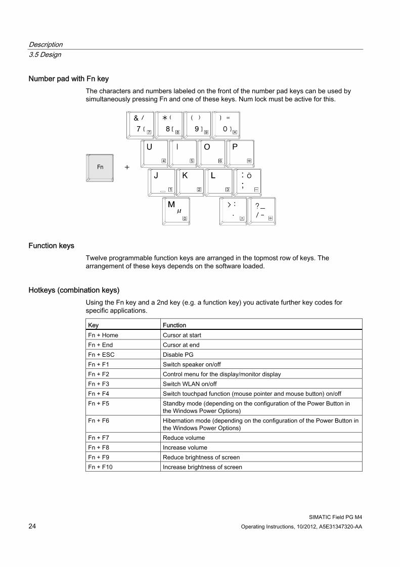
Number pad with Fn key The characters and numbers labeled on the front of the number pad keys can be used by simultaneously pressing Fn and one of these keys. Num lock must be active for this.
Function keys Twelve programmable function keys are arranged in the topmost row of keys. The arrangement of these keys depends on the software loaded.
Hotkeys (combination keys) Using the Fn key and a 2nd key (e.g. a function key) you activate further key codes for specific applications. Key Function Fn + Home Cursor at start Fn + End Cursor at end Fn + ESC Disable PG Fn + F1 Switch speaker on/off Fn + F2 Control menu for the display/monitor display Fn + F3 Switch WLAN on/off Fn + F4 Switch touchpad function (mouse pointer and mouse button) on/off Fn + F5 Standby mode (depending on the configuration of the Power Button in
the Windows Power Options) Fn + F6 Hibernation mode (depending on the configuration of the Power Button in
the Windows Power Options) Fn + F7 Reduce volume Fn + F8 Increase volume Fn + F9 Reduce brightness of screen Fn + F10 Increase brightness of screen
Description 3.5 Design
SIMATIC Field PG M4 Operating Instructions, 10/2012, A5E31347320-AA 25
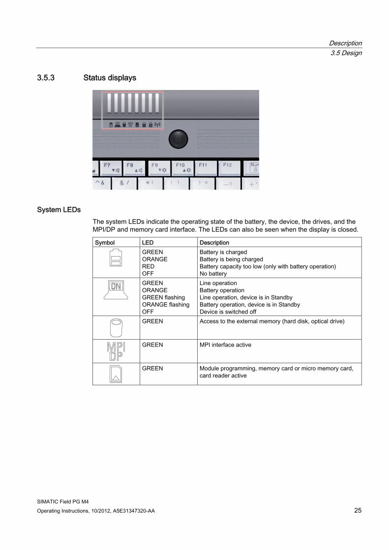
3.5.3 Status displays
System LEDs The system LEDs indicate the operating state of the battery, the device, the drives, and the MPI/DP and memory card interface. The LEDs can also be seen when the display is closed. Symbol LED Description
GREEN ORANGE RED OFF
Battery is charged Battery is being charged Battery capacity too low (only with battery operation) No battery
GREEN ORANGE GREEN flashing ORANGE flashing OFF
Line operation Battery operation Line operation, device is in Standby Battery operation, device is in Standby Device is switched off
GREEN Access to the external memory (hard disk, optical drive)
GREEN MPI interface active
GREEN Module programming, memory card or micro memory card, card reader active
Description 3.5 Design
SIMATIC Field PG M4 26 Operating Instructions, 10/2012, A5E31347320-AA
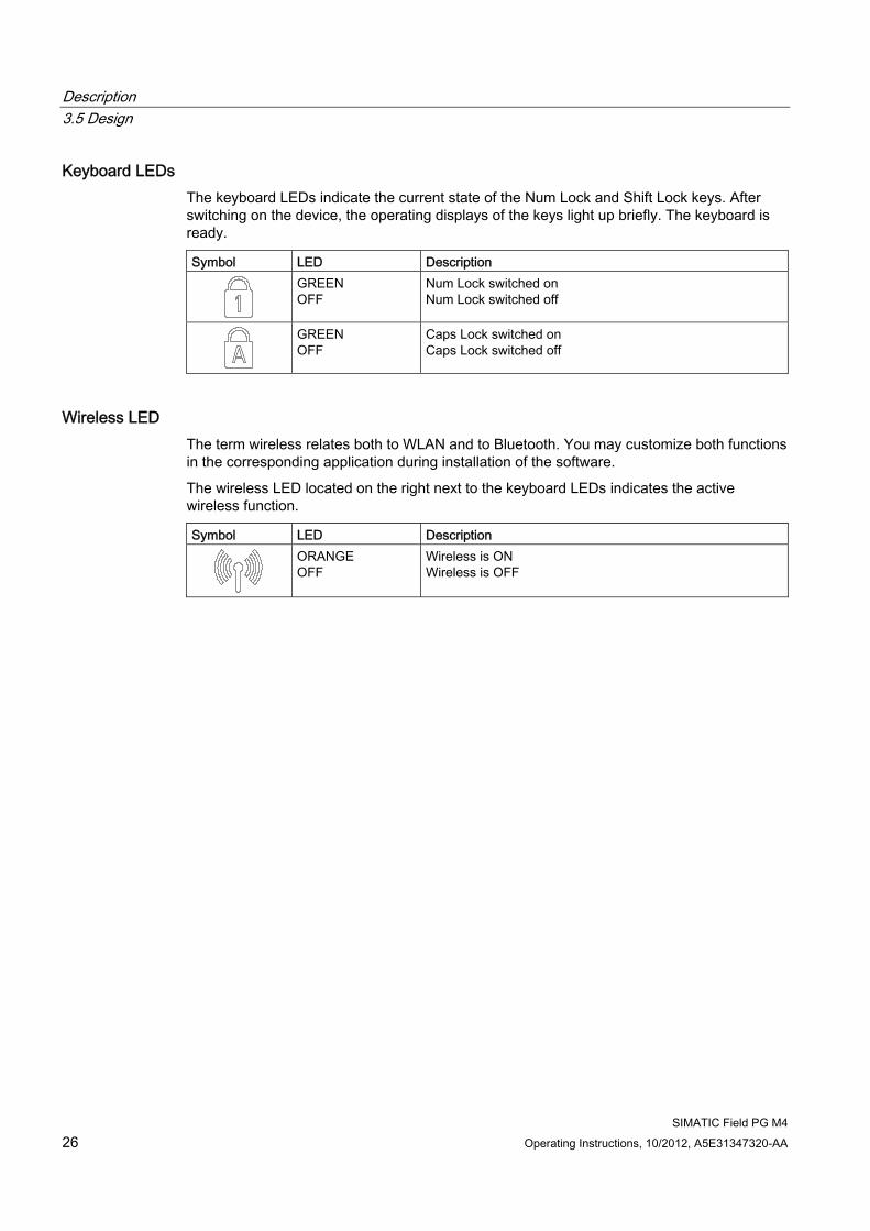
Keyboard LEDs The keyboard LEDs indicate the current state of the Num Lock and Shift Lock keys. After switching on the device, the operating displays of the keys light up briefly. The keyboard is ready. Symbol LED Description
GREEN OFF
Num Lock switched on Num Lock switched off
GREEN OFF
Caps Lock switched on Caps Lock switched off
Wireless LED The term wireless relates both to WLAN and to Bluetooth. You may customize both functions in the corresponding application during installation of the software.
The wireless LED located on the right next to the keyboard LEDs indicates the active wireless function. Symbol LED Description
ORANGE OFF
Wireless is ON Wireless is OFF
SIMATIC Field PG M4 Operating Instructions, 10/2012, A5E31347320-AA 27
Application planning 44.1 Transport
Before you set off Observe the following information when you are traveling with the PG:
● Save important data from the hard drive.
● For safety reasons, switch off the radio components (Wireless LAN) if you can´t be sure that the transmitted radio waves will not interfere with any electric or electronic equipment in your vicinity.
● If you want to use your PG during a flight, first of all ask the airline company if you are permitted to do so.
● When traveling abroad, ensure the power adapter can be used with the local mains voltage. If this is not the case, you must acquire the appropriate adapter for your PG. Do not use any other voltage transformers!
Note Using the Field PG in different countries
Verify the compatibility of local mains and power cable specifications are compatible when using the PG abroad. If this is not the case, purchase a power cable that complies with the local conditions. Do not use connection adapters for electrical appliances in order to connect the PG to them.
Transport Despite the fact that the device is of a rugged design, its internal components are sensitive to severe vibrations or shock. With just a few simple transport precautions you can help to create a trouble-free operation.
● Make sure that the PG is no longer accessing the drives, and remove all data media (such as CDs) from the drives.
● Switch off the PG (see Section On/off button (Page 20)).
● Disconnect the peripheral devices from the PG.
● Close the display and the interface covers on the back of the device.
● Use the integrated handle for brief transportation.
● For longer transport, put the PG with all its accessories into the provided backpack.
Application planning 4.2 Unpacking and checking the delivery unit
SIMATIC Field PG M4 28 Operating Instructions, 10/2012, A5E31347320-AA
You should always use the original packaging for shipping and transporting the device.
NOTICE Risk of damage to the device!
If you are transporting the PG in extreme weather conditions with large fluctuations in temperature, care must be take to ensure that no moisture form on or in the device (condensation).
If you notice any condensation, wait around 12 hours before you switch on the device.
4.2 Unpacking and checking the delivery unit
Unpacking the device Note the following points when you unpack the unit
● It is advisable not to dispose of the original packing material. Keep it in case you have to transport the unit again.
● Please keep the documentation in a safe place. It is required for initial commissioning and is part of the device.
● Check the delivery unit for any visible transport damage.
● Check the delivery and your specially ordered accessories against the packaging list to ensure nothing is missing. Please inform your local dealer of any disagreements or transport damages.
Application planning 4.3 Device identification data
SIMATIC Field PG M4 Operating Instructions, 10/2012, A5E31347320-AA 29
4.3 Device identification data
Noting the device identification data The device can be identified uniquely with the help of these numbers in case of repairs or theft. Serial number S VP ... Order No. 6ES ... Microsoft Windows Product Key Ethernet address 1 Ethernet address 2
Enter the following data in the table:
● Serial number
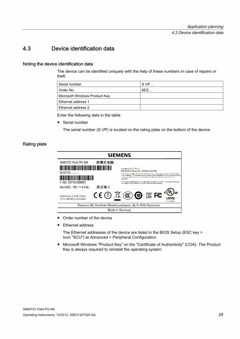
The serial number (S VP) is located on the rating plate on the bottom of the device.
Rating plate
● Order number of the device
● Ethernet address
The Ethernet addresses of the device are listed in the BIOS Setup (ESC key > Icon "SCU") at Advanced > Peripheral Configuration.
● Microsoft Windows "Product Key" on the "Certificate of Authenticity" (COA). The Product Key is always required to reinstall the operating system.
Application planning 4.3 Device identification data
SIMATIC Field PG M4 30 Operating Instructions, 10/2012, A5E31347320-AA
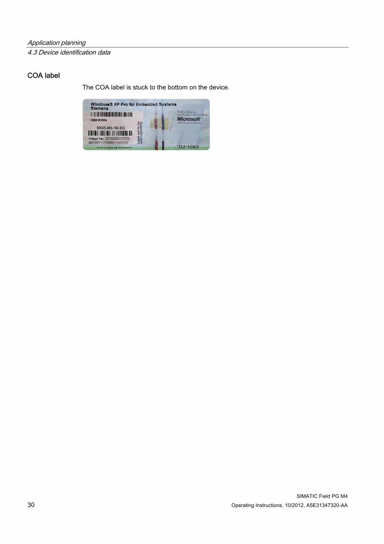
COA label The COA label is stuck to the bottom on the device.
SIMATIC Field PG M4 Operating Instructions, 10/2012, A5E31347320-AA 31
Positioning 55.1 Positioning the device
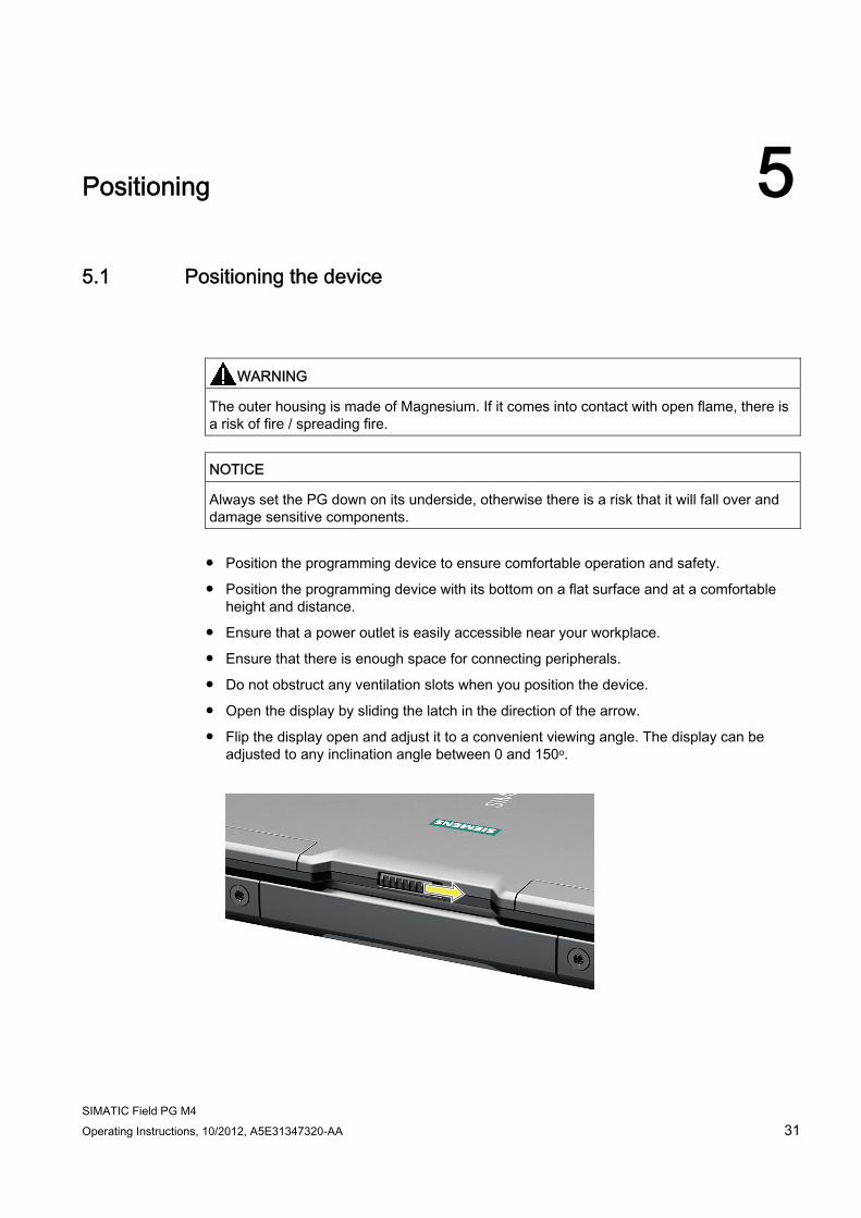
WARNING The outer housing is made of Magnesium. If it comes into contact with open flame, there is a risk of fire / spreading fire.
NOTICE Always set the PG down on its underside, otherwise there is a risk that it will fall over and damage sensitive components.
● Position the programming device to ensure comfortable operation and safety.
● Position the programming device with its bottom on a flat surface and at a comfortable height and distance.
● Ensure that a power outlet is easily accessible near your workplace.
● Ensure that there is enough space for connecting peripherals.
● Do not obstruct any ventilation slots when you position the device.
● Open the display by sliding the latch in the direction of the arrow.
● Flip the display open and adjust it to a convenient viewing angle. The display can be adjusted to any inclination angle between 0 and 150o.

Positioning 5.1 Positioning the device
SIMATIC Field PG M4 32 Operating Instructions, 10/2012, A5E31347320-AA
SIMATIC Field PG M4 Operating Instructions, 10/2012, A5E31347320-AA 33
Connecting 66.1 Connecting peripherals
To be noted before you connect the device
NOTICE I/O devices that do not support hot-plugging
Peripheral devices that are incapable of hot-plugging may only be connected after the device has been disconnected from the power supply.
NOTICE Observe the documentation of your I/O devices
Strictly adhere to the specifications for peripheral equipment.
WARNING Equipotential bonding of the signal cable shields
When you connect long signal cables (particularly with connections between buildings), make sure the signal cables are always integrated into the local equipotential bonding system (connecting the cable shielding to the protective conductor).
Connect USB devices Connect devices such as drives, mouse, keyboard, and printer to the USB 2.0 and USB 3.0 ports.
Connect the microphone You can connect an external microphone to the 3.5 mm jack for the microphone (pink).
To run a microphone recording, select:
● The Windows XP Start menu: All Programs > Accessories > Multimedia > Audio recorder
● In Windows 7: All Programs > Accessories > Audio recorder.
Connecting 6.2 Connecting the device to power
SIMATIC Field PG M4 34 Operating Instructions, 10/2012, A5E31347320-AA
Connect headphones You can connect headphones or external speakers that are equipped with a 3.5 mm stereo jack plug to the headphones jack (green).
You can control the volume using the speaker button on the taskbar, or using hotkey Fn + F7 / F8.
See also General specifications (Page 83)
6.2 Connecting the device to power
To be noted before you connect the device
Note
The external power unit supplies power to the Field PG in line operation with 120 V and 230 V power supply networks. The setting of the voltage range takes place automatically.
WARNING Do not connect or disconnect power and data cables during thunderstorms.
WARNING The device is designed only to be used in grounded power supply systems (TN systems to VDE 0100, part 300, or IEC 60364-3).
It must not be used in ungrounded, or impedance-grounded power systems (IT systems).
WARNING The Field PG may only be operated using the supplied power supply and / or using the supplied battery.
The external power supply may not be covered (risk of overheating).
CAUTION The mains connector must be disconnected to fully isolate the device from mains.
Connecting 6.2 Connecting the device to power
SIMATIC Field PG M4 Operating Instructions, 10/2012, A5E31347320-AA 35
Localized information Outside of the USA and Canada, operation on a 230 V power supply:
This device is equipped with a safety-tested power cord. If you choose not to use this cable, you must use a flexible cable of the following type: At least 18 AWG (0.82 mm2) conductor cross-section, and 15 A/250 V connector. The cable set must conform to the safety regulations of the country in which the devices are installed, and bear the prescribed markings in each case.
For the USA and Canada:
For the United States and Canada, a CSA or UL-listed power cord must be used.
The connector must be compliant with NEMA 1-15P.
120 V/240 V supply voltage
A flexible cable with UL approval and CSA marking must be used. In addition, the cable must exhibit the following properties:
● 3-wire SPT-2 or SVT,
● At least 18 AWG conductor cross-section
● Max. length of 4.5 m
● Connector 15 A, min. 125 V
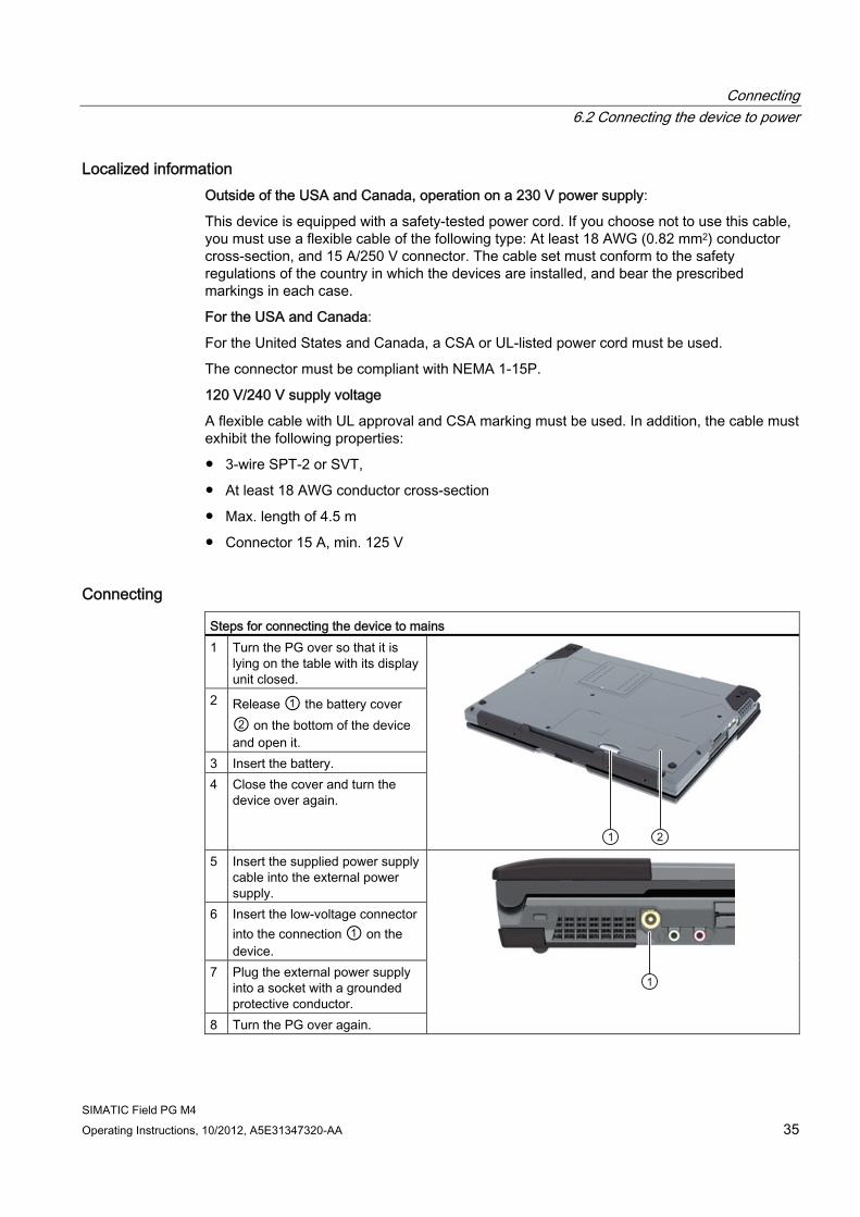
Connecting Steps for connecting the device to mains 1 Turn the PG over so that it is
lying on the table with its display unit closed.
2 Release ① the battery cover ② on the bottom of the device and open it.
3 Insert the battery. 4 Close the cover and turn the
device over again.
5 Insert the supplied power supply
cable into the external power supply.
6 Insert the low-voltage connector into the connection ① on the device.
7 Plug the external power supply into a socket with a grounded protective conductor.
8 Turn the PG over again.
Connecting 6.3 Connect the PG to the S5 automation device
SIMATIC Field PG M4 36 Operating Instructions, 10/2012, A5E31347320-AA
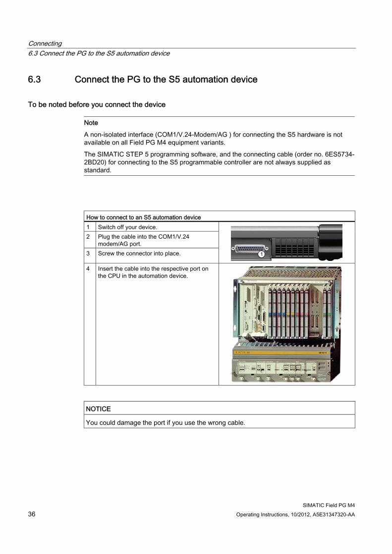
6.3 Connect the PG to the S5 automation device
To be noted before you connect the device
Note
A non-isolated interface (COM1/V.24-Modem/AG ) for connecting the S5 hardware is not available on all Field PG M4 equipment variants.
The SIMATIC STEP 5 programming software, and the connecting cable (order no. 6ES5734-2BD20) for connecting to the S5 programmable controller are not always supplied as standard.
How to connect to an S5 automation device 1 Switch off your device. 2 Plug the cable into the COM1/V.24
modem/AG port. 3 Screw the connector into place.
4 Insert the cable into the respective port on
the CPU in the automation device.
NOTICE You could damage the port if you use the wrong cable.
Connecting 6.4 Connect the PG to the S7 automation system or the PROFIBUS network
SIMATIC Field PG M4 Operating Instructions, 10/2012, A5E31347320-AA 37
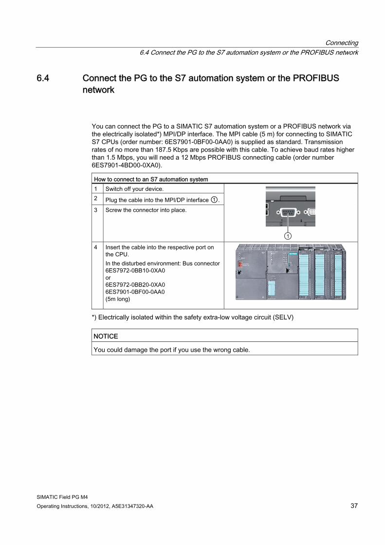
6.4 Connect the PG to the S7 automation system or the PROFIBUS network
You can connect the PG to a SIMATIC S7 automation system or a PROFIBUS network via the electrically isolated*) MPI/DP interface. The MPI cable (5 m) for connecting to SIMATIC S7 CPUs (order number: 6ES7901-0BF00-0AA0) is supplied as standard. Transmission rates of no more than 187.5 Kbps are possible with this cable. To achieve baud rates higher than 1.5 Mbps, you will need a 12 Mbps PROFIBUS connecting cable (order number 6ES7901-4BD00-0XA0). How to connect to an S7 automation system 1 Switch off your device. 2 Plug the cable into the MPI/DP interface ①. 3 Screw the connector into place.
4 Insert the cable into the respective port on
the CPU. In the disturbed environment: Bus connector 6ES7972-0BB10-0XA0 or 6ES7972-0BB20-0XA0 6ES7901-0BF00-0AA0 (5m long)
*) Electrically isolated within the safety extra-low voltage circuit (SELV)
NOTICE You could damage the port if you use the wrong cable.

Connecting 6.4 Connect the PG to the S7 automation system or the PROFIBUS network
SIMATIC Field PG M4 38 Operating Instructions, 10/2012, A5E31347320-AA
SIMATIC Field PG M4 Operating Instructions, 10/2012, A5E31347320-AA 39
Commissioning 77.1 Requirements for commissioning
The operating system and system software of your device are preinstalled on the hard disk.
NOTICE Risk of damage to the device!
Allow the device to warm up slowly to room temperature before you start it up. If you notice any condensation, wait around 12 hours before you switch on the device.
7.2 Initial commissioning - initial startup
Note
The programming device may not be switched off at any time during the installation process.
Do not change the default BIOS settings, otherwise the operating system setup may become corrupted.
Procedure The operating system is set up automatically on the programming device when it is first started. The following tasks need to be performed:
1. Press the ON/OFF button for approximately 1 second.
The PG conducts a self-test. The following message is output during the self-test:
Press Esc for boot options
2. Wait until this message is cleared, then follow the instructions on the screen.
3. Type in the Product Key as required.
You find this key on the "Certificate of Authentication", in the "Product Key" line.
4. Automatic restart
Commissioning 7.2 Initial commissioning - initial startup
SIMATIC Field PG M4 40 Operating Instructions, 10/2012, A5E31347320-AA
After you have entered all necessary information and set up the operating system, the PG is automatically restarted and then displays the user interface of the respective operating system.
From now on, after you switch on the PC, the user interface of the operating system is automatically opened when the startup routine is completed.
Startup with Microsoft Windows The menus, dialogs, and keyboard layout are set up in English under Windows. Use the Control Panel to change to another language and keyboard layout.
For Windows XP
1. Select:
"Start > Control Panel > Regional and Language"
2. You can make the desired changes in the "Regional Settings", "Languages" and "Advanced" tabs.
For Windows 7
Editing the settings for language, region and formats of the registered user account
1. Select:
"Start > Control Panel > Clock, Language, and Region > Regional and Language Options"
2. You can make your changes in the "Formats" and "Location und Keyboards and Languages" tabs.
Editing the settings for language, region and formats of the system account and default user account
1. Select:
"Start > Control Panel > Clock, Language, and Region > Regional and Language Options"
2. You can make your changes in the "Administrative" tab. Click the respective button to copy the settings.
For more information, refer to chapter "Setting up the language selection by means of Multilingual User Interface (MUI) (Page 74)".
Commissioning 7.2 Initial commissioning - initial startup
SIMATIC Field PG M4 Operating Instructions, 10/2012, A5E31347320-AA 41
Authorization / License key A product specific authorization or a License Key (user authorization) is required to use the STEP 5-, STEP 7- and WinCC flexible programming software. This protected software may only be used with the relevant authorization. The License Keys for your SIMATIC software are stored on the included USB memory stick.
Remove the cap from the USB stick and insert the stick into a free USB port of your computer to access the License Keys.
After a short time a drive named "License_Key" will appear in Windows Explorer.
During a new installation, you will be notified by the Setup program if a matching license key has not been installed on your computer. You can then choose to have the Setup program install the license or to install the license later with the Automation License Manager you are going to install.
If you want to transfer the license key later, follow these steps:
1. Close the Automation License Manager. Locate the drive named "License_Key" in the left pane.
2. Click the drive named "License_Key".
This displays an overview of the license keys found on the license stick.
3. Use a drag-and-drop operation to move the desired license key to one of your drives.
4. After the transfer, the license key is located on the corresponding drive and you can now use the activated software.
Prior to removing the license stick, make sure to give notice according to Windows specifications ("Safely remove hardware").
You may also use the USB License Stick to transfer the License Keys to a different computer, or for intermediate storage of the License Keys.
Note
Software installed on the PG for which there is no authorization or a license key in the delivery package, cannot be used or will only run in Trial mode. Transferring the SIMATIC STEP 5 authorization
Run "install.exe" from the License Key in the USB_Stick:>\UCL directory to transfer the STEP 5 authorization. Follow the instructions on the screen to transfer the authorization.
Commissioning 7.3 Notes on operation
SIMATIC Field PG M4 42 Operating Instructions, 10/2012, A5E31347320-AA
7.3 Notes on operation
7.3.1 Rechargeable battery
Battery operation The battery (lithium ion) enables mobile use of the device, independently of an external power supply. It also protects against data loss in the even of a power failure.
As soon as the external power supply is connected, the battery will start charging. In doing so, the following conditions are important:
● When the device is switched off the charging process takes around 3 hours.
● When the device is switched on, the charging process takes between 3 and 6 hours (depending on the system load).
● The charging process is terminated as soon as the battery is fully charged.
● A charged battery will discharge itself during storage (depending on the temperature, and whether or not it is installed) over a few weeks. It will then have to be recharged.
● The battery charging is terminated when the battery is fully charged or if, for example, the upper temperature limit for charging is exceeded. You can check the battery charge level in Windows.
If, with a connected power supply, the battery LED lights up green, the battery is full and will not be charged any further.
Current consumption in battery operation You can reduce the off-state battery power consumption of your device to the minimum by disabling the Intel® AMT and USB charging functions in the BIOS. However, you should remove the battery pack from the Field PG if you do not use the computer for several months. Ideal storage conditions for the battery pack: Ambient temperature of approximately 20 °C and battery charging state of approximately 50%.
Note
The battery pack may by completely or partially discharged (e.g. due to self-discharge) during commissioning. Prior to completion of the discharge, when merely a residual charge is existent, the LED battery in the battery operation lights up red as a warning. End your work and save your data. There are now only a few minutes battery running time left.
Please note that for a complete disconnection from the mains the mains connector must be removed.
Commissioning 7.3 Notes on operation
SIMATIC Field PG M4 Operating Instructions, 10/2012, A5E31347320-AA 43
Information The capacity of the lithium ion battery used in the PG reduces with each charge/discharge; this is inherent in the technology. A gradual reduction in capacity also takes place if stored at too high or too low temperatures. The operating times of one battery charge in a network-independent operation can therefore gradually reduce over time.
The battery has a typical life span of c. 300 charges and is therefore designed in such a way that with standard handling within six months after purchase of your PG it can still be charged and discharged. A loss of capacity over time is technology-dependent and, as with all manufacturers of comparable devices, it is excluded from the warranty. In the case of a significant drop of efficiency we recommend that you replace the battery. Buy only original Siemens batteries.
You should note the following with regard to the life span of the battery:
● If possible, the battery should always be completely discharged/charged.
● Frequency of use: The more often the battery is used, the faster it reaches the end of its effective life span. A lithium ion battery has a typical life of around 300 charge cycles.
● If you run the computer primarily on mains voltage, you should charge the battery pack to approximately 50% and then remove it from the computer for separate storage.
WARNING
Risk of personal injury or damage to property due to improper handling of the battery pack
Do not dismantle or damage. Batteries can cause combustion.
Do not light or heat up. Batteries can cause combustion, can explode or release toxic substances.
Do not short circuit. This can cause combustion.
Keep away from children.
WARNING
Risk of personal injury or damage to property due to incorrect type of battery pack
Always replace the battery with another battery of the same type.
The battery is available as a spare part. You will find the ordering data in the catalog.
Commissioning 7.3 Notes on operation
SIMATIC Field PG M4 44 Operating Instructions, 10/2012, A5E31347320-AA
7.3.2 HDD/SSD
Hard disk drives with differing capacities can be used.
Note
Please use only hard disk drives recommended by Siemens. The order data for removable hard disks can be found in the catalog.
The respective system LED indicates access to the HDD. See section Status displays (Page 25).
CAUTION Drives are sensitive to inadmissible vibrations. Shocks during operation can lead to the loss of data or damage to the drive or data carrier.
7.3.3 Optical drive This drive allows you, for example, to read the operating instructions on the supplied "Software for Field PG" DVD.
Burner/DVD player software ● If you are using Windows XP, the following applies:
You need to to install additional software (burner or DVD player software) to fully utilize the functionality of our DVD±R/±RW drive. This software is included on the CD supplied with the device. Insert the CD in the drive, run setup and follow the instructions on the screen.
● The Windows 7 operating system provides functions for the burning and playback of CDs and DVDs. Additional burner or DVD player software is therefore not supplied with Windows 7.
Commissioning 7.3 Notes on operation
SIMATIC Field PG M4 Operating Instructions, 10/2012, A5E31347320-AA 45
Information on burning CD-RWs or DVD±RWs
NOTICE Danger of data loss!
Burning is permissible only in an undisturbed environment, i.e. shock and vibration stress must be avoided. Because of heavy fluctuation in the quality of CD-Rs, data may be corrupted in a burning session, even if no error message is initially displayed. The written data can only be verified by comparing these with the source. To be on the safe side, data should be verified after every burning session.
Emergency removal When the device is switched off, you can use a pin (e.g. bent paperclip) to forcibly remove the disk.
Note
To avoid too much force being used on the pulled out drawer, when inserting removing a disk always hold one hand against it by touching/holding the drawer on the front facing.
After closing the drawer, the data medium is initially tested and then the access display on the drive starts to flash: Continuous flashing means that the medium is bad but still readable Continuous flashing followed by steady illumination means the inserted data medium is
no longer readable and is defective.
Commissioning 7.3 Notes on operation
SIMATIC Field PG M4 46 Operating Instructions, 10/2012, A5E31347320-AA
7.3.4 SIMATIC S5 memory module
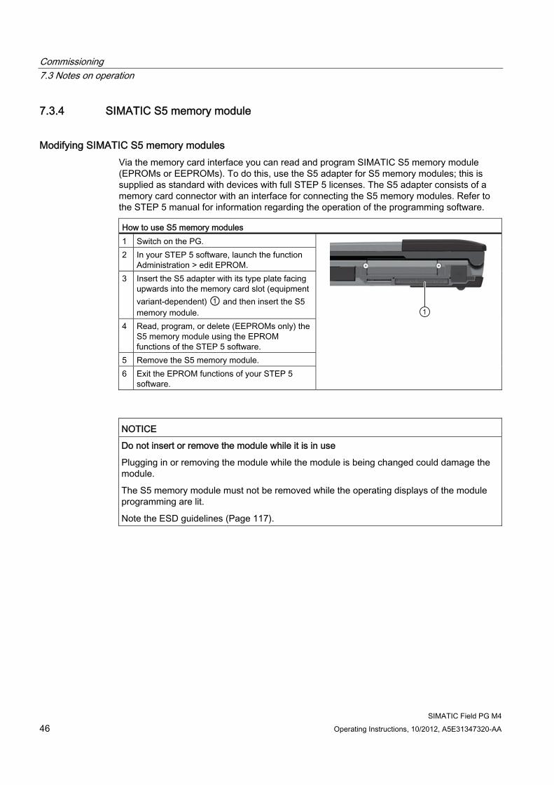
Modifying SIMATIC S5 memory modules Via the memory card interface you can read and program SIMATIC S5 memory module (EPROMs or EEPROMs). To do this, use the S5 adapter for S5 memory modules; this is supplied as standard with devices with full STEP 5 licenses. The S5 adapter consists of a memory card connector with an interface for connecting the S5 memory modules. Refer to the STEP 5 manual for information regarding the operation of the programming software. How to use S5 memory modules 1 Switch on the PG. 2 In your STEP 5 software, launch the function
Administration > edit EPROM. 3 Insert the S5 adapter with its type plate facing
upwards into the memory card slot (equipment variant-dependent) ① and then insert the S5 memory module.
4 Read, program, or delete (EEPROMs only) the S5 memory module using the EPROM functions of the STEP 5 software.
5 Remove the S5 memory module. 6 Exit the EPROM functions of your STEP 5
software.
NOTICE Do not insert or remove the module while it is in use
Plugging in or removing the module while the module is being changed could damage the module.
The S5 memory module must not be removed while the operating displays of the module programming are lit.
Note the ESD guidelines (Page 117).
Commissioning 7.3 Notes on operation
SIMATIC Field PG M4 Operating Instructions, 10/2012, A5E31347320-AA 47
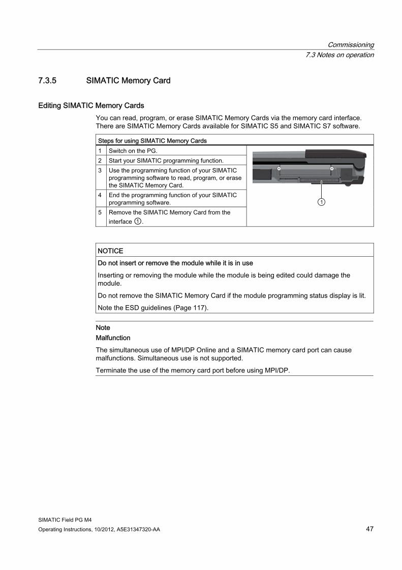
7.3.5 SIMATIC Memory Card
Editing SIMATIC Memory Cards You can read, program, or erase SIMATIC Memory Cards via the memory card interface. There are SIMATIC Memory Cards available for SIMATIC S5 and SIMATIC S7 software. Steps for using SIMATIC Memory Cards 1 Switch on the PG. 2 Start your SIMATIC programming function. 3 Use the programming function of your SIMATIC
programming software to read, program, or erase the SIMATIC Memory Card.
4 End the programming function of your SIMATIC programming software.
5 Remove the SIMATIC Memory Card from the interface ①.
NOTICE Do not insert or remove the module while it is in use
Inserting or removing the module while the module is being edited could damage the module.
Do not remove the SIMATIC Memory Card if the module programming status display is lit.
Note the ESD guidelines (Page 117).
Note Malfunction
The simultaneous use of MPI/DP Online and a SIMATIC memory card port can cause malfunctions. Simultaneous use is not supported.
Terminate the use of the memory card port before using MPI/DP.
Commissioning 7.3 Notes on operation
SIMATIC Field PG M4 48 Operating Instructions, 10/2012, A5E31347320-AA
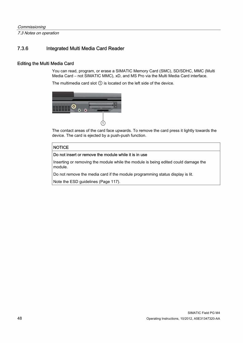
7.3.6 Integrated Multi Media Card Reader
Editing the Multi Media Card You can read, program, or erase a SIMATIC Memory Card (SMC), SD/SDHC, MMC (Multi Media Card – not SIMATIC MMC), xD, and MS Pro via the Multi Media Card interface.
The multimedia card slot ① is located on the left side of the device.
The contact areas of the card face upwards. To remove the card press it lightly towards the device. The card is ejected by a push-push function.
NOTICE Do not insert or remove the module while it is in use
Inserting or removing the module while the module is being edited could damage the module.
Do not remove the media card if the module programming status display is lit.
Note the ESD guidelines (Page 117).
Commissioning 7.3 Notes on operation
SIMATIC Field PG M4 Operating Instructions, 10/2012, A5E31347320-AA 49
7.3.7 SIMATIC Micro Memory Card
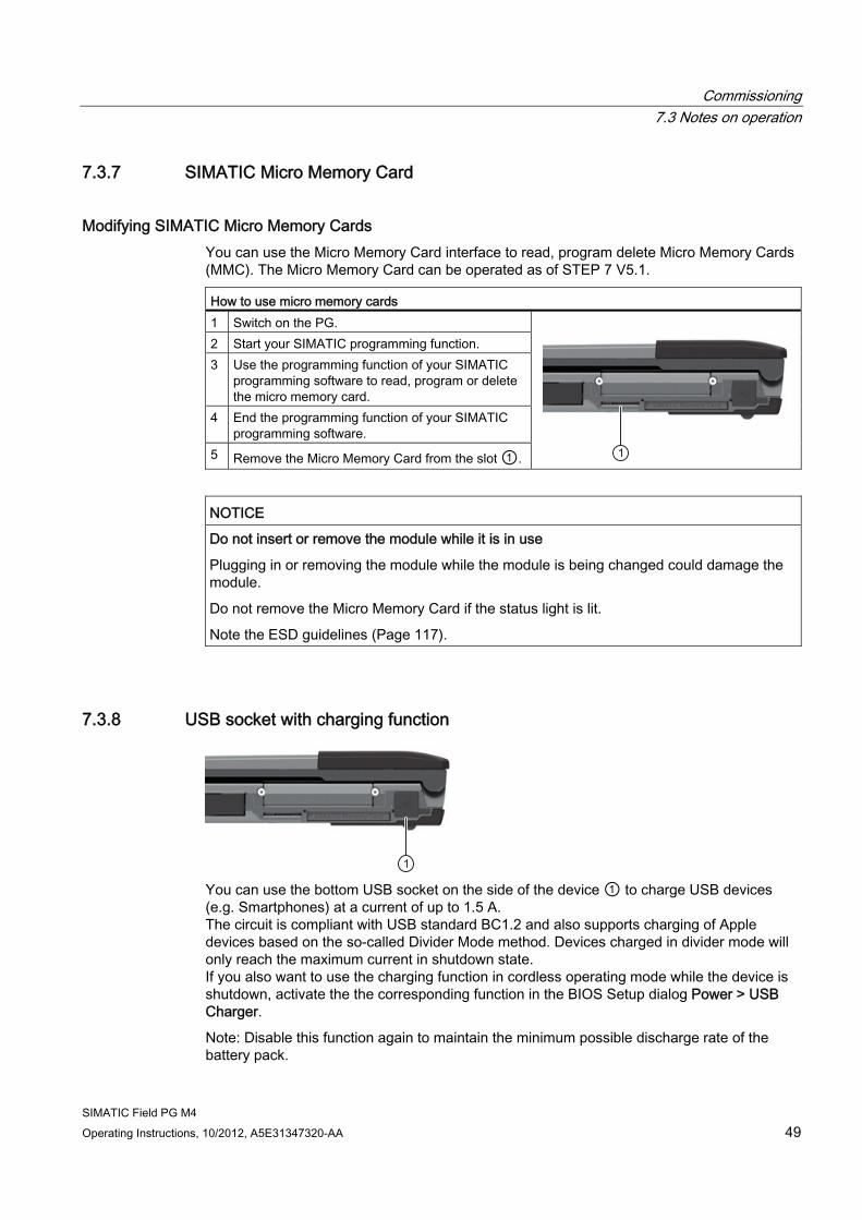
Modifying SIMATIC Micro Memory Cards You can use the Micro Memory Card interface to read, program delete Micro Memory Cards (MMC). The Micro Memory Card can be operated as of STEP 7 V5.1. How to use micro memory cards 1 Switch on the PG. 2 Start your SIMATIC programming function. 3 Use the programming function of your SIMATIC
programming software to read, program or delete the micro memory card.
4 End the programming function of your SIMATIC programming software.
5 Remove the Micro Memory Card from the slot ①.
NOTICE Do not insert or remove the module while it is in use
Plugging in or removing the module while the module is being changed could damage the module.
Do not remove the Micro Memory Card if the status light is lit.
Note the ESD guidelines (Page 117).
7.3.8 USB socket with charging function
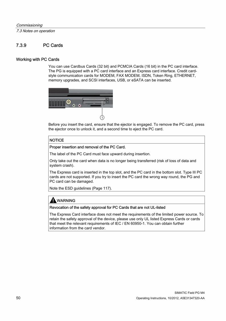
You can use the bottom USB socket on the side of the device ① to charge USB devices (e.g. Smartphones) at a current of up to 1.5 A. The circuit is compliant with USB standard BC1.2 and also supports charging of Apple devices based on the so-called Divider Mode method. Devices charged in divider mode will only reach the maximum current in shutdown state. If you also want to use the charging function in cordless operating mode while the device is shutdown, activate the the corresponding function in the BIOS Setup dialog Power > USB Charger.
Note: Disable this function again to maintain the minimum possible discharge rate of the battery pack.
Commissioning 7.3 Notes on operation
SIMATIC Field PG M4 50 Operating Instructions, 10/2012, A5E31347320-AA
7.3.9 PC Cards
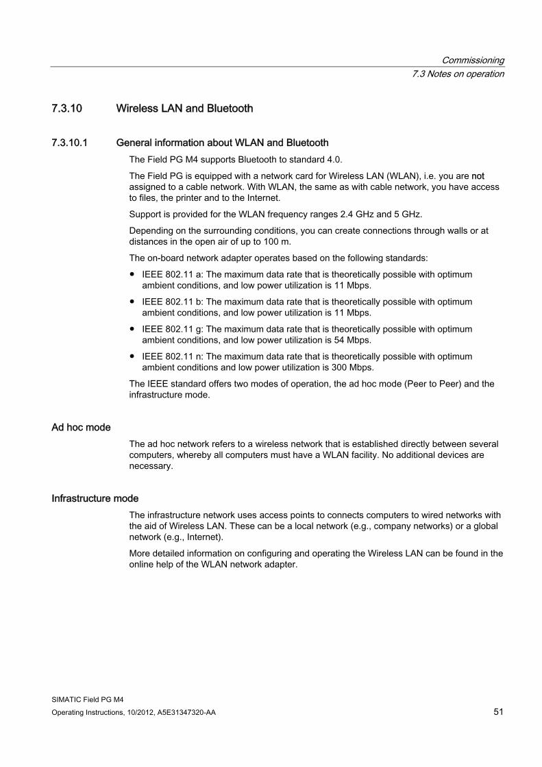
Working with PC Cards You can use Cardbus Cards (32 bit) and PCMCIA Cards (16 bit) in the PC card interface. The PG is equipped with a PC card interface and an Express card interface. Credit card-style communication cards for MODEM, FAX MODEM, ISDN, Token Ring, ETHERNET, memory upgrades, and SCSI interfaces, USB, or eSATA can be inserted.
Before you insert the card, ensure that the ejector is engaged. To remove the PC card, press the ejector once to unlock it, and a second time to eject the PC card.
NOTICE Proper insertion and removal of the PC Card.
The label of the PC Card must face upward during insertion.
Only take out the card when data is no longer being transferred (risk of loss of data and system crash).
The Express card is inserted in the top slot, and the PC card in the bottom slot. Type III PC cards are not supported. If you try to insert the PC card the wrong way round, the PG and PC card can be damaged.
Note the ESD guidelines (Page 117).
WARNING Revocation of the safety approval for PC Cards that are not UL-listed
The Express Card interface does not meet the requirements of the limited power source. To retain the safety approval of the device, please use only UL listed Express Cards or cards that meet the relevant requirements of IEC / EN 60950-1. You can obtain further information from the card vendor.
Commissioning 7.3 Notes on operation
SIMATIC Field PG M4 Operating Instructions, 10/2012, A5E31347320-AA 51
7.3.10 Wireless LAN and Bluetooth
7.3.10.1 General information about WLAN and Bluetooth The Field PG M4 supports Bluetooth to standard 4.0.
The Field PG is equipped with a network card for Wireless LAN (WLAN), i.e. you are not assigned to a cable network. With WLAN, the same as with cable network, you have access to files, the printer and to the Internet.
Support is provided for the WLAN frequency ranges 2.4 GHz and 5 GHz.
Depending on the surrounding conditions, you can create connections through walls or at distances in the open air of up to 100 m.
The on-board network adapter operates based on the following standards:
● IEEE 802.11 a: The maximum data rate that is theoretically possible with optimum ambient conditions, and low power utilization is 11 Mbps.
● IEEE 802.11 b: The maximum data rate that is theoretically possible with optimum ambient conditions, and low power utilization is 11 Mbps.
● IEEE 802.11 g: The maximum data rate that is theoretically possible with optimum ambient conditions, and low power utilization is 54 Mbps.
● IEEE 802.11 n: The maximum data rate that is theoretically possible with optimum ambient conditions and low power utilization is 300 Mbps.
The IEEE standard offers two modes of operation, the ad hoc mode (Peer to Peer) and the infrastructure mode.
Ad hoc mode The ad hoc network refers to a wireless network that is established directly between several computers, whereby all computers must have a WLAN facility. No additional devices are necessary.
Infrastructure mode The infrastructure network uses access points to connects computers to wired networks with the aid of Wireless LAN. These can be a local network (e.g., company networks) or a global network (e.g., Internet).
More detailed information on configuring and operating the Wireless LAN can be found in the online help of the WLAN network adapter.
Commissioning 7.3 Notes on operation
SIMATIC Field PG M4 52 Operating Instructions, 10/2012, A5E31347320-AA
7.3.10.2 Safety information for WLAN operation The radio waves necessary for Wireless LAN can cause interference in hearing aids and in the onboard electronics of vehicles. To prevent interference, switch off the Field PG in aircraft, or when driving a vehicle.
The radio waves caused by wireless LAN can interfere with life-support systems, so you should switch off the WLAN device when in the vicinity of such systems (use hotkey Fn + F3 to disable the Field PG's WLAN).
CAUTION To prevent adverse effects on pacemakers, a minimum distance of 20 cm from pacemakers should be maintained while the WLAN is in use.
Note
Please note that the device is not suitable for operation in potentially explosive atmospheres.
The range and the attainable data transmission rate depends on the environment. A Wireless LAN connection is not bug-proof.
To protect the transmitted data, Wireless LAN has different encoding methods. We recommend that you activate an encoding in accordance with your Wireless LAN environment.
If possible, do not bring the WLAN connection in the vicinity of the following devices:
● Microwaves
● Wireless video-audio transmission systems
● Wireless telephones (DECT)
These can lead to interference or the complete breakdown of the WLAN connection.
SIMATIC Field PG M4 Operating Instructions, 10/2012, A5E31347320-AA 53
Integration into an automation system 88.1 System environments and networks
The following options are available for the integration of the device in existing or planned system environments/networks:
Ethernet The integrated Ethernet interfaces (10/100/1000 Mbps) can be used for communication and data exchange with programmable controllers, such as SIMATIC S7.
PROFIBUS / MPI The potential-free Profibus interface (12 Mbps) can be used to interconnect distributed field devices or to link to SIMATIC S7.
The "PROFIBUS" software package is needed to link to S7 automation systems.
COM1/TTY You can connect the Field PG to a SIMATIC S5 programmable controller via the optional TTY interface.
You will need the "SIMATIC STEP 5 V7.23" software to link to S5 programmable controllers.
WLAN You can link the Field PG to an Industrial Wireless LAN network using the integrated WLAN interface.
Information on Industrial Wireless LAN can be found in SIMATIC NET (http://www.automation.siemens.com/mcms/automation/en/industrial-communications/ iwlan-industrial-wireless-communication)
Further information Additional information is available in the catalog and the online ordering system Industry Automation and Drive Technologies - Homepage (http://www.siemens.com/automation/service&support).
Integration into an automation system 8.2 Intel Active Management Technology
SIMATIC Field PG M4 54 Operating Instructions, 10/2012, A5E31347320-AA
8.2 Intel Active Management Technology Intel® Active Management Technology is a technology for remote maintenance of computers (AMT PCs). This remote maintenance encompasses the following functions:
● Remote power management:
AMT PCs can be switched on/off and be restarted from another PC.
● Keyboard–Video–Mouse-Redirection (KVM-Redirection)
Keyboard–Video–Mouse redirection. This enables remote access to the AMT PC, and operation of AMT PCs without functioning operating system.
● BIOS Setup Management
You can start and change the BIOS Setup remotely.
● Remote reboot:
An AMT PC can be booted from a bootable ISO file made available by another PC.
● SOL (Serial over LAN):
You can redirect data of a serial interface to the network. The function is used primarily for text-based remote control of an AMT PC in console mode.
● IDE redirection:
An ISO file contains a memory image of the content of a CD or DVD with ISO 9660 structure. An ISO file can be implemented on the AMT PC for use as virtual DVD drive on the help desk PC.
Configuration of the AMT PC You configure AMT in the BIOS Setup and MEBx (Management Engine BIOS Extension). MEBx is a BIOS extension for configuring AMT.
Press <ESC> when the BIOS appears briefly during startup and select the BIOS start page MEBx.
Note Password protection for the AMT PC
AMT enables virtually unrestricted access to the AMT PC. Protect access to the AMT PC by means of password.
See also Advanced Menu (Page 96)
Integration into an automation system 8.3 Trusted Platform Module (TPM)
SIMATIC Field PG M4 Operating Instructions, 10/2012, A5E31347320-AA 55
8.3 Trusted Platform Module (TPM) The Field PG features a so-called Trusted Platform Module (TPM) to standard 1.2. You can enable this module in the Security dialog of BIOS-Setup. Follow the instructions in BIOS Setup.
The Trusted Platform Module can be used in combination with the BitLocker drive encryption in Windows 7. Follow the instructions of the OS.
Note
Improper usage poses the risk of data loss. Always keep the keys and passwords in a secure place. Encrypted data cannot be retrieved. The Siemens warranty does not cover a hardware reset after loss of the password.

Integration into an automation system 8.3 Trusted Platform Module (TPM)
SIMATIC Field PG M4 56 Operating Instructions, 10/2012, A5E31347320-AA
SIMATIC Field PG M4 Operating Instructions, 10/2012, A5E31347320-AA 57
Operating 99.1 SIMATIC Software
Starting STEP 5 (not included in all delivery variants) Please note that an authorization is required to work with STEP 5. For more information, refer to Initial commissioning - initial startup (Page 39).
In Windows, click on the Start button and select the desired program with Simatic > STEP 5.
Note
When using the P tools supplied with STEP 5 (for editing PCP/M files), remember that these are no longer supported fully by Windows XP Professional.
Note Running SIMATIC STEP 5 on devices that have Dual-Core processors
A "blue screen" can occur on rare occasions when SIMATIC STEP 5 is run on devices that have Dual-Core processors. The Field PG M4 features an additional boot menu entry that is used to set a single core mode. If you run SIMATIC STEP 5, please select the boot menu entry "Microsoft Windows XP Professional for STEP 5 Operation". SIMATIC STEP 5
Please note that the enclosed software SIMATIC STEP 5 is released solely for Windows XP. If an unsuitable operating system is used, we recommend that you can create a further boot option with Windows XP. If you have any questions about creating further boot options or require product support, please contact the Customer Support SIMATIC Hotline:
Technical Support (http://www.siemens.de/automation/csi_en_WW). STEP 5 authorization
To transfer the STEP 5 authorization, run install.exe from the License Key in the folder USB_Stick:>\UCL. Follow the instructions on the screen to transfer the authorization.
Operating 9.1 SIMATIC Software
SIMATIC Field PG M4 58 Operating Instructions, 10/2012, A5E31347320-AA
Starting STEP 7 Please note that a license key is required to work with STEP 7. For more information, refer to Initial commissioning - initial startup (Page 39).
● In the Windows desktop, click the SIMATIC Manager icon, or
● Click the Start button, and select the desired program with Simatic > STEP 7.
Note
The Archive/Retrieve function in STEP 7 is used to transfer a STEP 7 project from one PG to another. To transmit, in the SIMATIC Manager select File > Archive or File > Retrieve. A detailed description of the procedure is given in section "Steps for File Archiving/Retrieval" of the online help for STEP 7.
Starting WinCC flexible Please note that a license key is required to use WinCC flexible.
● In the Windows desktop, click on the SIMATIC Manager icon, or
● Click the Start button, and select the desired program with Simatic > WinCC flexible.
Starting the TIA Portal How to start the TIA Portal:
● Click the TIA Portal icon on the Windows Desktop:
● Click the Start button and select the following path:
All Programs > Siemens Automation > Totally Integrated Automation Portal
SIMATIC Field PG M4 Operating Instructions, 10/2012, A5E31347320-AA 59
Expansions and parameter assignment 1010.1 Installing / removing memory modules
Memory expansion options The motherboard is equipped with 2 slots for DDR3 memory modules. You can use these to expand PG RAM to a maximum of 16 GB. The memory modules may not exceed the maximum size of 8 GB.
Preparation 1. Switch off the device. Make sure the device is not in Standby mode (unsaved data could
be lost) and that the device cannot get damaged.
2. Close the display unit.
3. Remove all connecting cables from the device.
4. Place the PG with the display unit face down on an level surface.
NOTICE
Observe the ESD guidelines
The electronic components on the PCBS are highly sensitive to electrostatic discharge. It is therefore vital to take precautionary measures when handling these components. Refer to the ESD guidelines (Page 117) for a description of these measures.
Note
Please use only Siemens memory modules as these have been qualified and cleared for use in this device. You will find the order data in the catalog.
5. Open the battery pack cover; see chapter "Replace the battery (Page 65)".
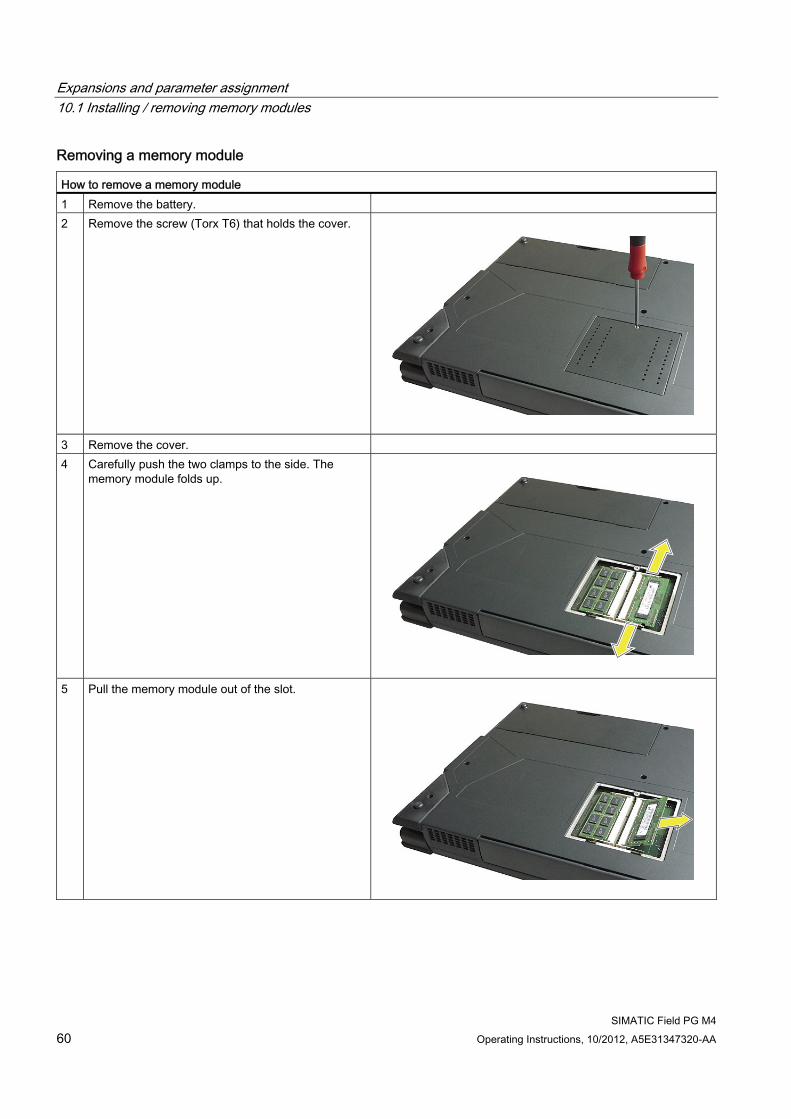
Expansions and parameter assignment 10.1 Installing / removing memory modules
SIMATIC Field PG M4 60 Operating Instructions, 10/2012, A5E31347320-AA
Removing a memory module How to remove a memory module 1 Remove the battery. 2 Remove the screw (Torx T6) that holds the cover.
3 Remove the cover. 4 Carefully push the two clamps to the side. The
memory module folds up.
5 Pull the memory module out of the slot.
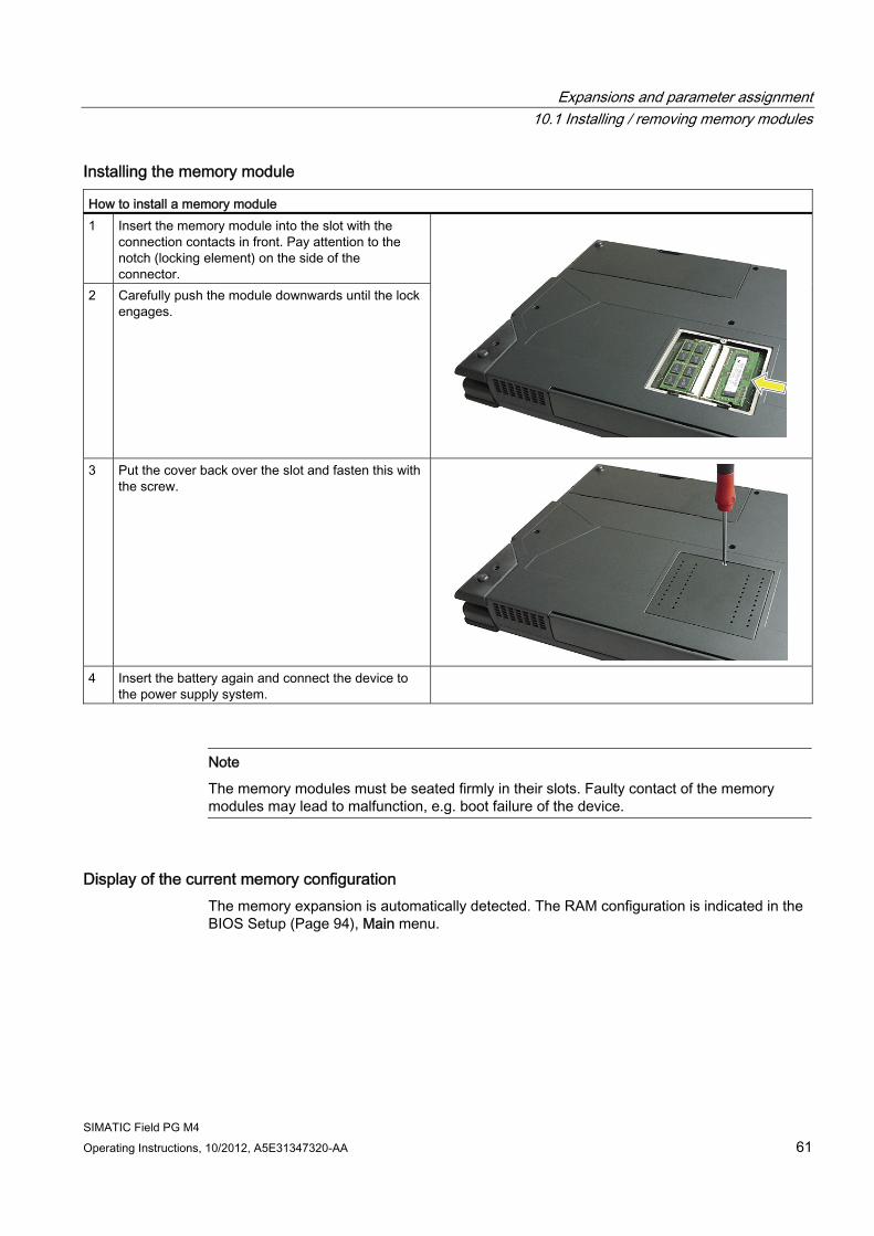
Expansions and parameter assignment 10.1 Installing / removing memory modules
SIMATIC Field PG M4 Operating Instructions, 10/2012, A5E31347320-AA 61
Installing the memory module How to install a memory module 1 Insert the memory module into the slot with the
connection contacts in front. Pay attention to the notch (locking element) on the side of the connector.
2 Carefully push the module downwards until the lock engages.
3 Put the cover back over the slot and fasten this with the screw.
4 Insert the battery again and connect the device to
the power supply system.
Note
The memory modules must be seated firmly in their slots. Faulty contact of the memory modules may lead to malfunction, e.g. boot failure of the device.
Display of the current memory configuration The memory expansion is automatically detected. The RAM configuration is indicated in the BIOS Setup (Page 94), Main menu.
Expansions and parameter assignment 10.1 Installing / removing memory modules
SIMATIC Field PG M4 62 Operating Instructions, 10/2012, A5E31347320-AA
SIMATIC Field PG M4 Operating Instructions, 10/2012, A5E31347320-AA 63
Service and maintenance 1111.1 Removing and installing hardware components
11.1.1 Replacing HDDs/SSDs
To be noted prior to replacing 1. Make sure the device is not in Standby or Hibernate mode. Unsaved data might be lost
and the device can get damaged.
2. Disconnect the device from the power supply system and remove the battery. See: Replace the battery (Page 65).
3. Remove all connecting cables from the device.
CAUTION
Note the ESD guidelines (Page 117).
WARNING
Always replace the HDD/SSD with a drive of the same type. The hard disk is available as a spare part. You will find the order data in the catalog.
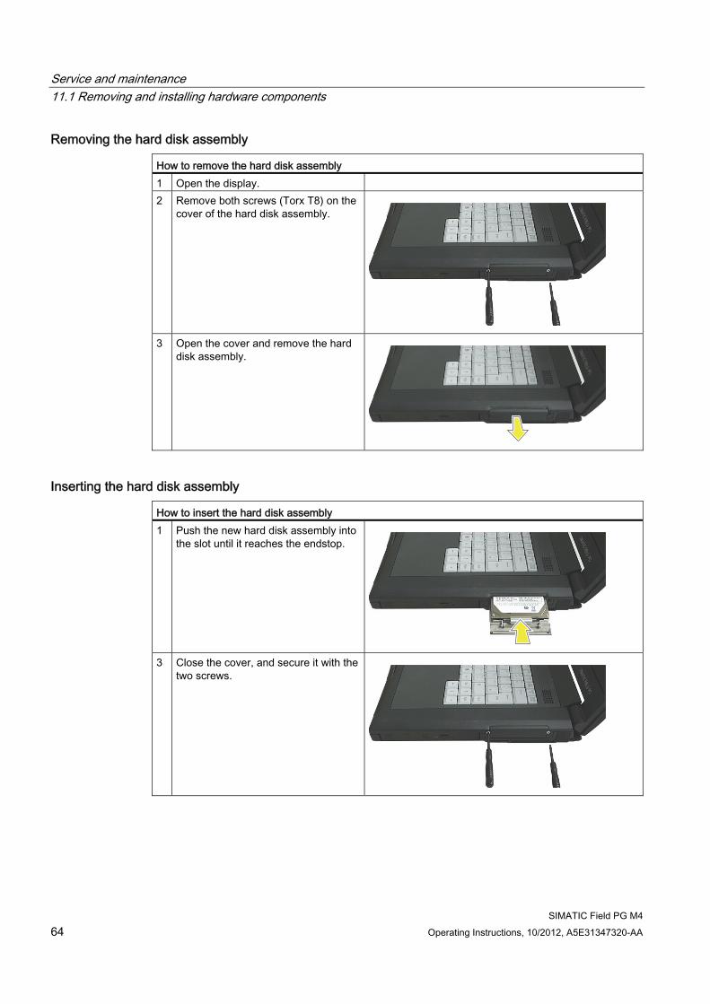
Service and maintenance 11.1 Removing and installing hardware components
SIMATIC Field PG M4 64 Operating Instructions, 10/2012, A5E31347320-AA
Removing the hard disk assembly How to remove the hard disk assembly 1 Open the display. 2 Remove both screws (Torx T8) on the
cover of the hard disk assembly.
3 Open the cover and remove the hard
disk assembly.
Inserting the hard disk assembly How to insert the hard disk assembly 1 Push the new hard disk assembly into
the slot until it reaches the endstop.
3 Close the cover, and secure it with the
two screws.
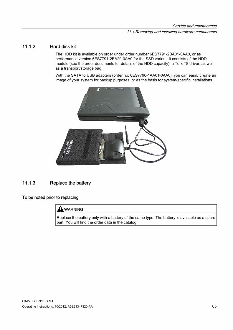
Service and maintenance 11.1 Removing and installing hardware components
SIMATIC Field PG M4 Operating Instructions, 10/2012, A5E31347320-AA 65
11.1.2 Hard disk kit The HDD kit is available on order under order number 6ES7791-2BA01-0AA0, or as performance version 6ES7791-2BA20-0AA0 for the SSD variant. It consists of the HDD module (see the order documents for details of the HDD capacity), a Torx T8 driver, as well as a transport/storage bag.
With the SATA to USB adapters (order no. 6ES7790-1AA01-0AA0), you can easily create an image of your system for backup purposes, or as the basis for system-specific installations.
11.1.3 Replace the battery
To be noted prior to replacing
WARNING Replace the battery only with a battery of the same type. The battery is available as a spare part. You will find the order data in the catalog.
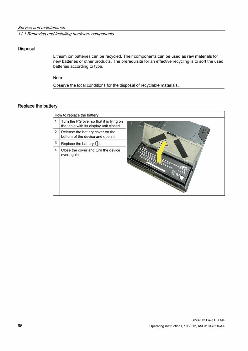
Service and maintenance 11.1 Removing and installing hardware components
SIMATIC Field PG M4 66 Operating Instructions, 10/2012, A5E31347320-AA
Disposal Lithium ion batteries can be recycled. Their components can be used as raw materials for new batteries or other products. The prerequisite for an effective recycling is to sort the used batteries according to type.
Note
Observe the local conditions for the disposal of recyclable materials.
Replace the battery How to replace the battery 1 Turn the PG over so that it is lying on
the table with its display unit closed. 2 Release the battery cover on the
bottom of the device and open it. 3 Replace the battery ①. 4 Close the cover and turn the device
over again.
Service and maintenance 11.1 Removing and installing hardware components
SIMATIC Field PG M4 Operating Instructions, 10/2012, A5E31347320-AA 67
11.1.4 Replacing the backup battery The Field PG has a backup battery. This supplies the hardware clock with power even when the device has been switched off.
Batteries are subject to wear and tear and should be replaced after five years to make sure that your PG works correctly.
Note
The backup battery should only be replaced by the repair center. If you have any queries, please contact your service office or your sales partner.
NOTICE Risk of damage!
The lithium battery must only be replaced with an identical battery, or with a type recommended by the manufacturer (order no: A5E00047601).
WARNING Danger of explosion and the release of harmful substances!
Do not throw lithium batteries into an open fire, do not solder, or open the cell body, do not short-circuit, or reverse polarity, do not heat up above 100 °C, follow the disposal instructions, and protect against direct exposure to sunlight, humidity, and condensation.
NOTICE Batteries must be disposed of in accordance with local regulations.
Service and maintenance 11.2 Reinstalling the software
SIMATIC Field PG M4 68 Operating Instructions, 10/2012, A5E31347320-AA
11.2 Reinstalling the software
11.2.1 General installation procedure If ever your software fails you can use the Recovery DVD, the "Software for Field PG M4" DVD, or the Restore DVD sets to reinstall the software.
Recovery DVD:
The recovery DVD contains the installation program with tools for configuring the hard drives and installing the operating system and the languages supported by the operating system (MUI package).
The basic language of the installed operating system is English. To add other languages, install these languages from the Recovery DVD at a later time.
DVD "Software for Field PG M4":
The "Software for Field PG M4" DVD contains the documentation, the SIMATIC software, and the hardware drivers.
Restore DVD set:
The Restore DVD set is included if you have ordered a device with operating system. The DVD contains a HD image with the original software package: Operating system with installed HW drivers and and SIMATIC software.
Note
Place the data medium from which the operating system is to be booted later at the first position in the boot folder. Make this setting in the "Boot" menu of BIOS Setup.
11.2.2 Restoring the delivery state You can restore the original factory software using the Restore DVD set. The DVDs contain the necessary images and tools for transferring the software package to the drive of your device. Restoration of the all drives C: (system) and D: (data), or only of drive C: (system) is possible. This allows you to retain any user data on drive D: (data).
Service and maintenance 11.2 Reinstalling the software
SIMATIC Field PG M4 Operating Instructions, 10/2012, A5E31347320-AA 69
Retrieving authorization or license ● Check whether you can retrieve your authorization or License Key from the HDD to a
License Key memory stick or other data volume with the help of Automation License Manager .
● If backup is not possible, please contact Customer Support. There you can obtain information necessary for software authorization.
NOTICE
Option "Restore only system partition" formats C: (System)
If "Restore system partition only" is set all data on drive C: (system partition) will be deleted. All data, user settings and all authorizations or license keys on drive C: (System) will be lost! All data on drive C: (System) will be completely deleted, reformatted and overwritten with the original factory software.
If "Restore entire hard disk" is set ALL data, user settings, authorizations or license keys will be lost on the entire drive.
Procedure 1. Place the first DVD of the Restore-DVD sets (Restore-DVD 1-2) into the optical CD/DVD
drive.
2. Restart the device.
3. Press <ESC> when the following BIOS message is output.
Press Esc for Boot Options
The "Boot Menu" is displayed when initialization is completed.
4. Select the Boot Manager to boot from the Restore DVD.
5. Select the optical CD/DVD drive from the boot manager.
Example:
Optiarc DVD RW AD-7710H
6. Follow the on-screen instructions.
NOTICE
All data will be deleted
All data, programs, user settings and authorizations/License Keys will be deleted from the drives and are lost irrevocably.
Service and maintenance 11.2 Reinstalling the software
SIMATIC Field PG M4 70 Operating Instructions, 10/2012, A5E31347320-AA
11.2.3 Installing Windows
11.2.3.1 Installing Windows XP
Note
For specific information related to the use of Windows XP, refer to the following manual (not included in the scope of delivery):
Microsoft Windows XP Professional, Technical Reference (MSPress No. 934)
Requirement You need the recovery DVD for the Windows XP operating system. It is included in the product package.
Windows XP does not provide suitable native AHCI drivers for the SATA controller, which means that you need to set the "IDE" mode in the BIOS Setup prior to installation of Windows XP. This setting can be made in "Advanced > IDE configuration > HDC configure AS".
You may optionally install an AHCI controller for Windows XP by loading the driver from a 3.5" floppy disk during Windows Setup. For this purpose, connect a 3.5" floppy drive to one of the USB 2.0 ports on this side of the Field PG M4 before you run Windows XP Setup and have the AHCI controller driver disk at hand.
For more information about implementation of the AHCI controllers, refer to section "Procedure for installing an AHCI Controller".
You can create an AHCI controller driver disk with the help of the "Softwar for Field PG M4" DVD. For more information about the creation of an AHCI controller driver disk, refer to section "Creating an AHCI controller driver disk".
For more information, refer to section Installing the drivers (Page 75).
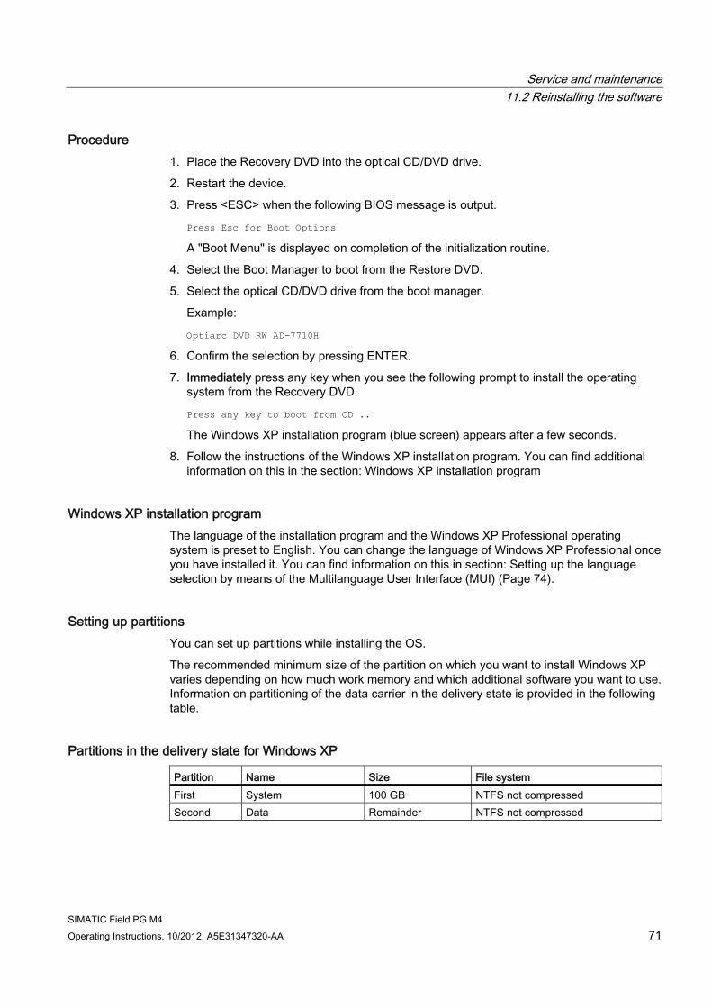
Service and maintenance 11.2 Reinstalling the software
SIMATIC Field PG M4 Operating Instructions, 10/2012, A5E31347320-AA 71
Procedure 1. Place the Recovery DVD into the optical CD/DVD drive.
2. Restart the device.
3. Press <ESC> when the following BIOS message is output.
Press Esc for Boot Options
A "Boot Menu" is displayed on completion of the initialization routine.
4. Select the Boot Manager to boot from the Restore DVD.
5. Select the optical CD/DVD drive from the boot manager.
Example:
Optiarc DVD RW AD-7710H
6. Confirm the selection by pressing ENTER.
7. Immediately press any key when you see the following prompt to install the operating system from the Recovery DVD.
Press any key to boot from CD ..
The Windows XP installation program (blue screen) appears after a few seconds.
8. Follow the instructions of the Windows XP installation program. You can find additional information on this in the section: Windows XP installation program
Windows XP installation program The language of the installation program and the Windows XP Professional operating system is preset to English. You can change the language of Windows XP Professional once you have installed it. You can find information on this in section: Setting up the language selection by means of the Multilanguage User Interface (MUI) (Page 74).
Setting up partitions You can set up partitions while installing the OS.
The recommended minimum size of the partition on which you want to install Windows XP varies depending on how much work memory and which additional software you want to use. Information on partitioning of the data carrier in the delivery state is provided in the following table.
Partitions in the delivery state for Windows XP Partition Name Size File system First System 100 GB NTFS not compressed Second Data Remainder NTFS not compressed
Service and maintenance 11.2 Reinstalling the software
SIMATIC Field PG M4 72 Operating Instructions, 10/2012, A5E31347320-AA
Procedure for installing an AHCI controller Data carrier controllers that are unknown to the operating system must be made known to the operating system during installation. Proceed as follows:
1. Connect a USB floppy drive and insert the AHCI driver disk.
2. Start the Windows installation process as described above.
3. Initiate installation of the AHCI controller by pressing <F6> when prompted at the start of the Windows Setup (blue screen).
After a few seconds, a dialog for installation of the data carrier controllers appears.
4. Select the corresponding driver on the driver disk.
Note
Select the driver "Intel(R) 7 Series Chipset Family SATA AHCI Controller" for the on-board AHCI controller.
For RAID controller: "Intel(R) ICH8M-E/ICH9M-E/5 Series SATA RAID Controller"
11.2.3.2 Installing Windows 7
Note
For specific information about using Windows 7refer to the "Windows 7, Technical Reference (MS Press No. 5913)", manual (not included in the scope of delivery).
Requirement You need the Recovery DVD for the operating system you want to install. It is included in the product package.
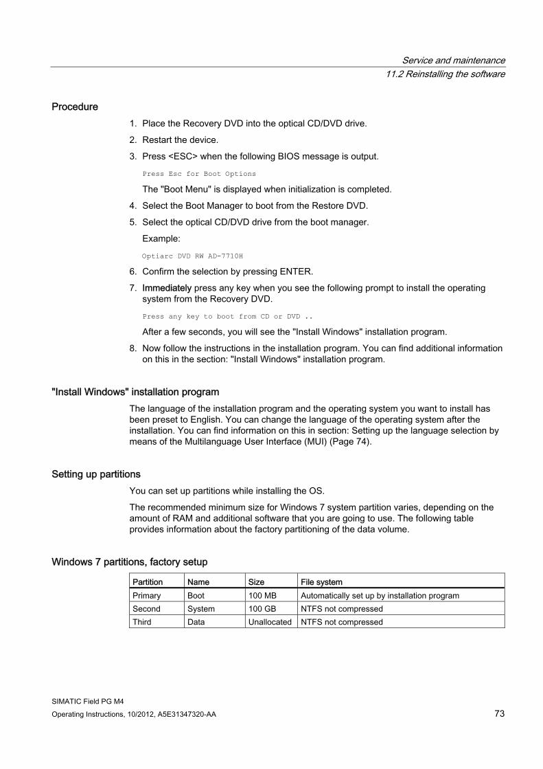
Service and maintenance 11.2 Reinstalling the software
SIMATIC Field PG M4 Operating Instructions, 10/2012, A5E31347320-AA 73
Procedure 1. Place the Recovery DVD into the optical CD/DVD drive.
2. Restart the device.
3. Press <ESC> when the following BIOS message is output.
Press Esc for Boot Options
The "Boot Menu" is displayed when initialization is completed.
4. Select the Boot Manager to boot from the Restore DVD.
5. Select the optical CD/DVD drive from the boot manager.
Example:
Optiarc DVD RW AD-7710H
6. Confirm the selection by pressing ENTER.
7. Immediately press any key when you see the following prompt to install the operating system from the Recovery DVD.
Press any key to boot from CD or DVD ..
After a few seconds, you will see the "Install Windows" installation program.
8. Now follow the instructions in the installation program. You can find additional information on this in the section: "Install Windows" installation program.
"Install Windows" installation program The language of the installation program and the operating system you want to install has been preset to English. You can change the language of the operating system after the installation. You can find information on this in section: Setting up the language selection by means of the Multilanguage User Interface (MUI) (Page 74).
Setting up partitions You can set up partitions while installing the OS.
The recommended minimum size for Windows 7 system partition varies, depending on the amount of RAM and additional software that you are going to use. The following table provides information about the factory partitioning of the data volume.
Windows 7 partitions, factory setup Partition Name Size File system Primary Boot 100 MB Automatically set up by installation program Second System 100 GB NTFS not compressed Third Data Unallocated NTFS not compressed
Service and maintenance 11.2 Reinstalling the software
SIMATIC Field PG M4 74 Operating Instructions, 10/2012, A5E31347320-AA
11.2.4 Setting up the language selection by means of the Multilanguage User Interface (MUI)
You can set the display of menus, dialogs or other information, such as date and time, to a different language. For this purpose, you can either select one of the preinstalled languages or install a new language package.
The following command sequences are described in English. Depending on the default setting, they can be displayed in another language.
Setting up the language selection in Windows XP
Note
Specific information for setting up the language for Windows XP Professional is available in the following manual (not included in the product package): "Microsoft Windows XP Professional, Technical Reference" (MSPress No 934)
Changing the settings for language, region and formats of a registered user account
1. Choose:
"Start > Control Panel > Regional and Language"
2. You can make the desired changes in the "Regional Settings", "Languages" and "Advanced" tabs.
Installing new language packages
1. Start the "MUISETUP.EXE" program in the "MUI" folder from the Recovery DVD.
All languages that can be installed are displayed.
Setting up the language selection in Windows 7
Note
Specific information for setting up the language selection for Windows operating systems is available in the following manuals (not included in the product package): Windows 7 Technical Reference (MS Press No. 5913) Windows Server 2008 Technical Reference (MS Press No. 5919)
Changing the settings for language, region and formats of a registered user account
1. Choose:
"Start > Control Panel > Clock, Language, and Region > Regional and Language Options"
2. You can make your changes in the "Formats" and "Location und Keyboards and Languages" tabs.
Service and maintenance 11.2 Reinstalling the software
SIMATIC Field PG M4 Operating Instructions, 10/2012, A5E31347320-AA 75
Changing the settings for language, region and formats of the system account and the standard user account
You can change the settings for language, region and formats of the system account (for example, the language in the user login dialog) and the settings of the standard user account (standard setting for new users). The settings of the registered user are copied to the system account and the standard user account for this purpose.
1. Choose:
"Start > Control Panel > Clock, Language, and Region > Regional and Language Options"
2. You can make your changes in the "Administrative" tab. You copy the settings by clicking the respective button.
Installing new language packages
Some language packages are available on the Recovery DVD in the "Languagepacks" folder.
1. Choose:
"Start > Control Panel > Clock, Language, and Region > Regional and Language Options"
2. Select the "Keyboards and Languages" tab.
3. Click the "Install/uninstall languages" button and make the required changes.
11.2.5 Installing drivers and software
11.2.5.1 Installing the drivers
Note
In the case of multilingual operating systems (MUI versions), you have to set the regional settings for menus and dialogs and the default language to English (US) before you install new drivers or operating system updates.
Install the drivers and software from the "Software for Field PG M4" DVD included with your product. Proceed as follows:
1. Insert the "Software for Field PG M4" DVD into the optical CD/DVD drive.
2. If the suite does not start automatically, run "START.CMD" from the DVD.
3. Select "Drivers" from the index.
4. Select the operating system.
5. Select the required driver.
Service and maintenance 11.2 Reinstalling the software
SIMATIC Field PG M4 76 Operating Instructions, 10/2012, A5E31347320-AA
6. Click the link next to "Driver path" to open the folder containing the driver data.
7. Run Setup from the folder.
Note
The chipset driver must be installed before you install any other drivers for new installations of Windows operating systems.
11.2.5.2 Creating an AHCI controller drive disk Create an AHCI controller drive disk with the help of the "Softwar for Field PG M4" DVD and a 3.5 inch floppy drive.
Proceed as follows:
1. Connect a 3.5 inch USB floppy drive to your device.
2. Insert a 3.5 inch floppy disk into the drive
3. Insert the "Software for Field PG M4" DVD into the optical CD/DVD drive.
4. If the suite does not start automatically, run "START.CMD" from the DVD.
5. Select "Drivers" from the index.
6. Select the operating system.
7. Select the "Intel Rapid Storage Technology" driver.
8. Click the floppy disk icon next to "Driver disk".
9. Verify or set the correct floppy drive in the "Writing on Floppy" area.
10. Click "OK" to create the AHCI controller driver disk.
11.2.5.3 Installing the SIMATIC software from the "Software for Field PG M4" DVD Install the SIMATIC software from the "Software for Field PG M4" included with your product. Proceed as follows:
1. Insert the "Software for Field PG M4" DVD into the optical CD/DVD drive.I
2. If the suite does not start automatically, run "START.CMD" from the DVD.
3. Select "Software" from the index.
4. Click "SIMATIC Software" to run the SIMATIC software setup.
5. Follow the Setup instructions.
6. Run Setup from the folder.
Service and maintenance 11.2 Reinstalling the software
SIMATIC Field PG M4 Operating Instructions, 10/2012, A5E31347320-AA 77
Note
The license key USB sticks containing authorizations or license keys that are necessary for running the SIMATIC software are only available for delivery variants that include the respective SIMATIC software.
For more information about installation of the authorizations or License Key activation, refer to chapter Initial commissioning – initial power on (Page 39).
Installing additional SIMATIC software
Proceed as follows to install additional SIMATIC software:
1. Insert the respective software DVD into the optical CD/DVD drive.
2. If Setup does not start automatically, run Setup manually from the DVD.
3. Follow the Setup instructions.
For more information about installation, refer to the respective SIMATIC software documentation.
11.2.6 Installing the optional burner or DVD software Information about installation of the burner / DVD software for Windows XP is available on the included CD.
The Windows 7 OS provides native functions for burning data volumes, i.e. it is not necessary to install additional burner/DVD software.
11.2.7 Updating the operating system
Windows The latest updates for the Windows operating system are available in the Internet at Microsoft (http://www.microsoft.com).
Note
Before you install new drivers or operating system updates for Windows MUI versions, set the default language to US English in the regional settings for menus and dialogs.
Other operating systems Contact the corresponding manufacturer.
Service and maintenance 11.2 Reinstalling the software
SIMATIC Field PG M4 78 Operating Instructions, 10/2012, A5E31347320-AA
11.2.8 Data backup / subsequent modification of partitions
11.2.8.1 Hardware supported
Note
Older versions of the SIMATIC IPC Image Creators do not support the hardware of the device.
Support is available as of SIMATIC IPC Image & Partition Creator Version 3.3.
For information on SIMATIC IPC Image & Partition Creator, refer to the corresponding product documentation.
11.2.8.2 Creating an image To backup your data under Windows, we recommend that you use the "SIMATIC IPC Image & Partition Creator" software tool. This tool is a simple and efficient backup and restore solution for HDD contents and individual partitions (images).
"SIMATIC IPC Image & Partition Creator" supports burning to DVD media.
The software can be ordered from the SIEMENS online ordering system. For detailed information about "SIMATIC IPC Image & Partition Creator", please refer to the corresponding product documentation.
11.2.8.3 Modifying the partitions Siemens recommends that you use "SIMATIC IPC Image & Partition Creator" to modify partitions. The software is available on order from the SIEMENS Online Ordering System.
For more information on using "SIMATIC IPC Image & Partition Creator", refer to the corresponding documentation.
Note
To run the "Restore system partition only" option from the Restore DVD, the size of the partitions must correspond to the factory default. The factory settings for the partition sizes are listed in chapter "Installing Windows (Page 70)".
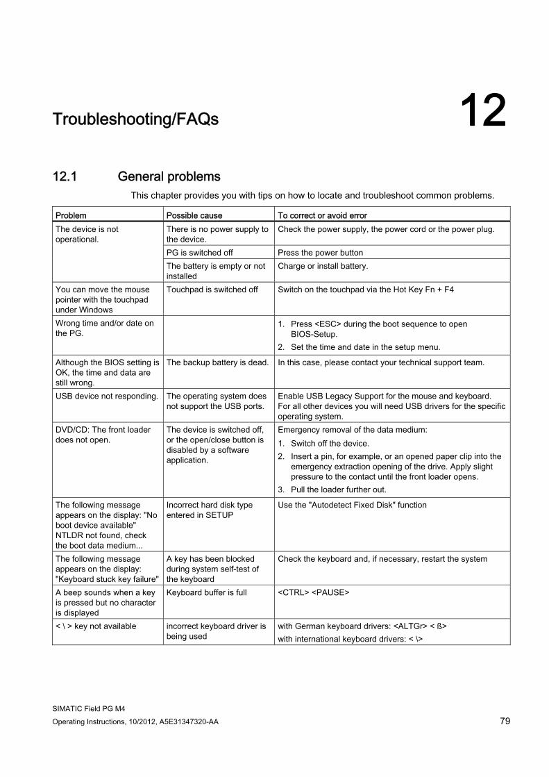
SIMATIC Field PG M4 Operating Instructions, 10/2012, A5E31347320-AA 79
Troubleshooting/FAQs 1212.1 General problems
This chapter provides you with tips on how to locate and troubleshoot common problems. Problem Possible cause To correct or avoid error
There is no power supply to the device.
Check the power supply, the power cord or the power plug.
PG is switched off Press the power button
The device is not operational.
The battery is empty or not installed
Charge or install battery.
You can move the mouse pointer with the touchpad under Windows
Touchpad is switched off Switch on the touchpad via the Hot Key Fn + F4
Wrong time and/or date on the PG.
1. Press <ESC> during the boot sequence to open BIOS-Setup.
2. Set the time and date in the setup menu.
Although the BIOS setting is OK, the time and data are still wrong.
The backup battery is dead. In this case, please contact your technical support team.
USB device not responding. The operating system does not support the USB ports.
Enable USB Legacy Support for the mouse and keyboard. For all other devices you will need USB drivers for the specific operating system.
DVD/CD: The front loader does not open.
The device is switched off, or the open/close button is disabled by a software application.
Emergency removal of the data medium: 1. Switch off the device. 2. Insert a pin, for example, or an opened paper clip into the
emergency extraction opening of the drive. Apply slight pressure to the contact until the front loader opens.
3. Pull the loader further out.
The following message appears on the display: "No boot device available" NTLDR not found, check the boot data medium...
Incorrect hard disk type entered in SETUP
Use the "Autodetect Fixed Disk" function
The following message appears on the display: "Keyboard stuck key failure"
A key has been blocked during system self-test of the keyboard
Check the keyboard and, if necessary, restart the system
A beep sounds when a key is pressed but no character is displayed
Keyboard buffer is full <CTRL> <PAUSE>
< \ > key not available incorrect keyboard driver is being used
with German keyboard drivers: <ALTGr> < ß> with international keyboard drivers: < \>
Troubleshooting/FAQs 12.2 Problems with Wireless LAN
SIMATIC Field PG M4 80 Operating Instructions, 10/2012, A5E31347320-AA
12.2 Problems with Wireless LAN The following lists the possible causes for problems with Wireless LAN:
Cannot connect with WLAN ● Verify that WLAN is activated.
You can use the Fn + F3 hotkey to activate/deactivate the WLAN.
● Check that the other WLAN partner is active.
● Check the WLAN connection settings Observe the corresponding notes on WLAN configuration and operation in the Online Help of the WLAN adapter.
Data transmission speed is too low ● Please note that the data rate stipulated and visible under Windows is only a theoretical
value / corresponds to the gross value. Determined by the transmission procedure, the actual applicable data rate for the data transmission is usually around 50% of the gross value.
● The maximum data transmission speed depends on many factors. Start by verifying that the transmission mode of all network components is set up in accordance with the IEEE 802.11 a/b/g/n standard.
● The spatial arrangement of the network components can also negatively influence the transmission.
– The distances between the components should be as short as possible.
– Masonry or reinforced concrete walls have a negative effect on the transmission performance and can, under some circumstances, prevent a connection from being established. For the best performance, a line-of-sight connection of the network components is preferred.
– A high load on the network, perhaps from too many simultaneous access attempts from different nodes, can lead to lower data rates or communication problems.
Operation in the environment with EMC interference Due to the structural principle of the Field PG M4, a high degree of ambient interference may, in rare cases, cause malfunction of the integrated touchpad.
The malfunction manifests itself in the triggering of unintentional key clicks or delays in the movement of the cursor. In such cases we recommend eliminating the cause of the interference or establishing a greater distance to the source of the interference.
If working in an interference-prone environment cannot be avoided, deactivate the tap function (mouse button emulation) by using the touchpad driver. Afterwards use the touchpad keys below the touchpad for operation.
Troubleshooting/FAQs 12.2 Problems with Wireless LAN
SIMATIC Field PG M4 Operating Instructions, 10/2012, A5E31347320-AA 81
Procedure – deactivating the tap function of the touchpad 1. Click "Start" and open the "Control Panel".
2. In the "Category view" first select "Printers and other hardware" and then the "Mouse" menu. In the "classical view" you can select the "Mouse" menu directly.
3. Select the "Device settings" tab and click the "Settings" tab.
4. Select the "Tap" button and deactivate the "Activate tapping" check box.
5. Click "Apply".

Troubleshooting/FAQs 12.2 Problems with Wireless LAN
SIMATIC Field PG M4 82 Operating Instructions, 10/2012, A5E31347320-AA
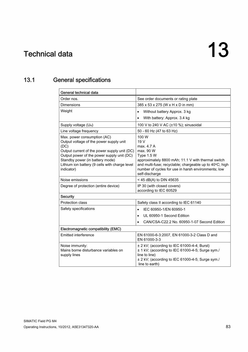
SIMATIC Field PG M4 Operating Instructions, 10/2012, A5E31347320-AA 83
Technical data 1313.1 General specifications
General technical data Order nos. See order documents or rating plate Dimensions 385 x 53 x 275 (W x H x D in mm) Weight Without battery Approx. 3 kg
With battery: Approx. 3.4 kg
Supply voltage (UN) 100 V to 240 V AC (±10 %); sinusoidal Line voltage frequency 50 - 60 Hz (47 to 63 Hz) Max. power consumption (AC) Output voltage of the power supply unit (DC) Output current of the power supply unit (DC)Output power of the power supply unit (DC)Standby power (in battery mode) Lithium ion battery (9 cells with charge level indicator)
100 W 19 V max. 4.7 A max. 90 W Type 1.5 W approximately 8800 mAh; 11.1 V with thermal switch and multi-fuse; recyclable; chargeable up to 40oC; high number of cycles for use in harsh environments; low self-discharge
Noise emissions < 45 dB(A) to DIN 45635 Degree of protection (entire device) IP 30 (with closed covers)
according to IEC 60529 Security Protection class Safety class II according to IEC 61140 Safety specifications IEC 60950-1/EN 60950-1
UL 60950-1 Second Edition CAN/CSA-C22.2 No. 60950-1-07 Second Edition
Electromagnetic compatibility (EMC) Emitted interference EN 61000-6-3:2007, EN 61000-3-2 Class D and
EN 61000-3-3 Noise immunity: Mains borne disturbance variables on supply lines
± 2 kV; (according to IEC 61000-4-4; Burst) ± 1 kV; (according to IEC 61000-4-5; Surge sym./ line to line) ± 2 kV; (according to IEC 61000-4-5; Surge sym./ line to earth)
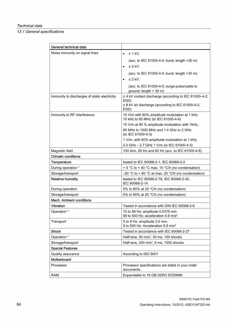
Technical data 13.1 General specifications
SIMATIC Field PG M4 84 Operating Instructions, 10/2012, A5E31347320-AA
General technical data Noise immunity on signal lines ± 1 kV;
(acc. to IEC 61000-4-4; burst; length <30 m) ± 2 kV;
(acc. to IEC 61000-4-4; burst; length >30 m) ± 2 kV;
(acc. to IEC 61000-4-5; surge pulse/cable to ground; length > 30 m)
Immunity to discharges of static electricity ± 4 kV contact discharge (according to IEC 61000–4-2; ESD) ± 8 kV air discharge (according to IEC 61000-4-2; ESD)
Immunity to RF interference 10 V/m with 80% amplitude modulation at 1 kHz, 10 kHz to 80 MHz (to IEC 61000-4-6) 10 V/m at 80 % amplitude modulation with 1kHz, 80 MHz to 1000 MHz and 1.4 GHz to 2 GHz (to IEC 61000-4-3) 1 V/m, with 80% amplitude modulation at 1 kHz, 2.0 GHz – 2.7 GHz 1 V/m (to IEC 61000-4-3)
Magnetic field 100 A/m, 50 Hz and 60 Hz (acc. to IEC 61000-4-8) Climatic conditions Temperature tested to IEC 60068-2-1, IEC 60068-2-2 During operation * + 5 °C to + 40 °C max. 10 °C/h (no condensation) Storage/transport –20 °C to + 60 °C at max. 20 °C/h (no condensation) Relative humidity tested to IEC 60068-2-78, IEC 60068-2-30,
IEC 60068-2-14 During operation 5% to 80% at 25 °C/h (no condensation) Storage/transport 5% to 95% at 25 °C/h (no condensation) Mech. Ambient conditions Vibration Tested in accordance with DIN IEC 60068-2-6 Operation * 10 to 58 Hz; amplitude 0.0375 mm
58 to 500 Hz; acceleration 4.9 m/s2 Transport 5 to 9 Hz; amplitude 3.5 mm,
9 to 500 Hz: Acceleration 9.8 m/s2 Shock Tested in accordance with IEC 60068-2-27 Operation * Half-sine, 50 m/s2, 30 ms, 100 shocks Storage/transport Half-sine, 250 m/s2, 6 ms, 1000 shocks Special Features Quality assurance According to ISO 9001 Motherboard Processor Processor specifications are listed in your order
documents. RAM Expandable to 16 GB DDR3 SODIMM
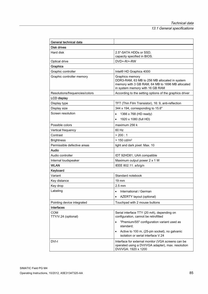
Technical data 13.1 General specifications
SIMATIC Field PG M4 Operating Instructions, 10/2012, A5E31347320-AA 85
General technical data Disk drives Hard disk 2.5"-SATA HDDs or SSD,
capacity specified in BIOS. Optical drive DVD+-R/+-RW Graphics Graphic controller Intel® HD Graphics 4000 Graphic controller memory Graphics memory
DDR3-RAM, 63 MB to 256 MB allocated in system memory with 3 GB RAM, 64 MB to 1696 MB allocated in system memory with 16 GB RAM
Resolutions/frequencies/colors According to the setting options of the graphics driver LCD display Display type TFT (Thin Film Transistor), 16: 9, anti-reflection Display size 344 x 194, corresponding to 15.6" Screen resolution 1366 x 768 (HD ready)
1920 x 1080 (full HD)
Possible colors maximum 256 k Vertical frequency 60 Hz Contrast > 200 : 1 Brightness > 150 cd/m2 Permissible defective areas light and dark pixel: Max. 10 Audio Audio controller IDT 92HD81, UAA compatible Internal loudspeaker Maximum output power 2 x 1 W WLAN IEEE 802.11. a/b/g/n Keyboard Variant Standard notebook Key distance 19 mm Key drop 2.5 mm Labeling International / German
AZERTY layout (optional)
Pointing device integrated Touchpad with 2 mouse buttons Interfaces COM TTY/V.24 (optional)
Serial interface TTY (20 mA), depending on configuration, cannot be retrofitted "Premium/S5" configuration variant used as
standard; Active to 100 m, (25-pin socket), no galvanic
isolation or serial interface V.24
DVI-I Interface for external monitor (VGA screens can be operated using a DVI/VGA adapter), max. resolution DVI/VGA: 1920 x 1200
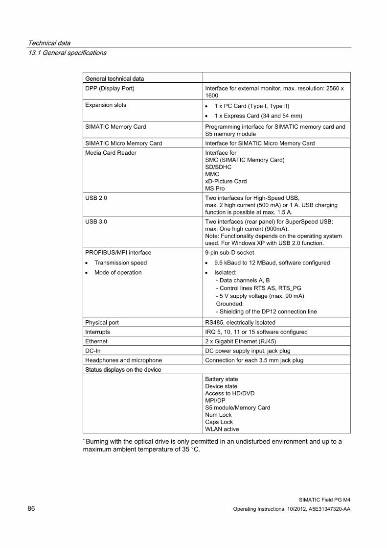
Technical data 13.1 General specifications
SIMATIC Field PG M4 86 Operating Instructions, 10/2012, A5E31347320-AA
General technical data DPP (Display Port) Interface for external monitor, max. resolution: 2560 x
1600 Expansion slots 1 x PC Card (Type I, Type II)
1 x Express Card (34 and 54 mm)
SIMATIC Memory Card Programming interface for SIMATIC memory card and S5 memory module
SIMATIC Micro Memory Card Interface for SIMATIC Micro Memory Card Media Card Reader Interface for
SMC (SIMATIC Memory Card) SD/SDHC MMC xD-Picture Card MS Pro
USB 2.0 Two interfaces for High-Speed USB, max. 2 high current (500 mA) or 1 A. USB charging function is possible at max. 1.5 A.
USB 3.0 Two interfaces (rear panel) for SuperSpeed USB; max. One high current (900mA). Note: Functionality depends on the operating system used. For Windows XP with USB 2.0 function.
PROFIBUS/MPI interface Transmission speed Mode of operation
9-pin sub-D socket 9.6 kBaud to 12 MBaud, software configured Isolated:
- Data channels A, B - Control lines RTS AS, RTS_PG - 5 V supply voltage (max. 90 mA) Grounded: - Shielding of the DP12 connection line
Physical port RS485, electrically isolated Interrupts IRQ 5, 10, 11 or 15 software configured Ethernet 2 x Gigabit Ethernet (RJ45) DC-In DC power supply input, jack plug Headphones and microphone Connection for each 3.5 mm jack plug Status displays on the device Battery state
Device state Access to HD/DVD MPI/DP S5 module/Memory Card Num Lock Caps Lock WLAN active
* Burning with the optical drive is only permitted in an undisturbed environment and up to a maximum ambient temperature of 35 °C.
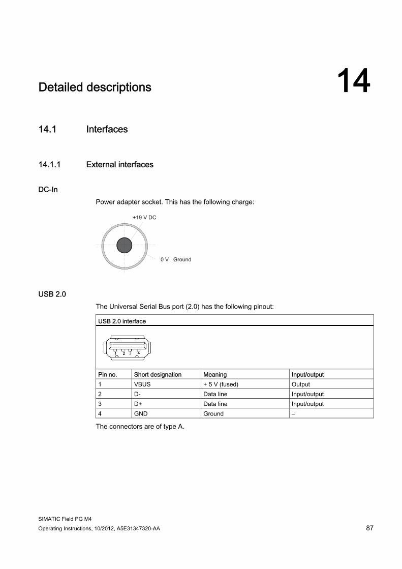
SIMATIC Field PG M4 Operating Instructions, 10/2012, A5E31347320-AA 87
Detailed descriptions 1414.1 Interfaces
14.1.1 External interfaces
DC-In Power adapter socket. This has the following charge:
USB 2.0 The Universal Serial Bus port (2.0) has the following pinout: USB 2.0 interface
Pin no. Short designation Meaning Input/output 1 VBUS + 5 V (fused) Output 2 D- Data line Input/output 3 D+ Data line Input/output 4 GND Ground –
The connectors are of type A.
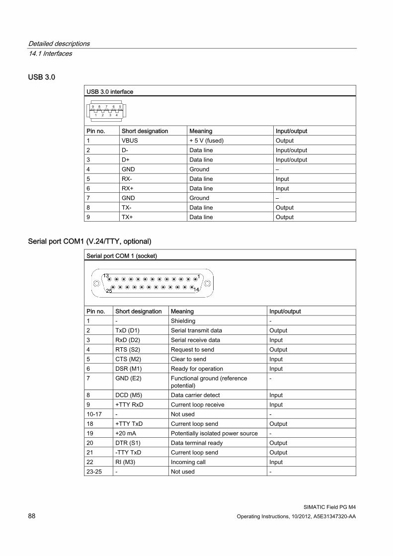
Detailed descriptions 14.1 Interfaces
SIMATIC Field PG M4 88 Operating Instructions, 10/2012, A5E31347320-AA
USB 3.0 USB 3.0 interface
Pin no. Short designation Meaning Input/output 1 VBUS + 5 V (fused) Output 2 D- Data line Input/output 3 D+ Data line Input/output 4 GND Ground – 5 RX- Data line Input 6 RX+ Data line Input 7 GND Ground – 8 TX- Data line Output 9 TX+ Data line Output
Serial port COM1 (V.24/TTY, optional) Serial port COM 1 (socket)
Pin no. Short designation Meaning Input/output 1 - Shielding - 2 TxD (D1) Serial transmit data Output 3 RxD (D2) Serial receive data Input 4 RTS (S2) Request to send Output 5 CTS (M2) Clear to send Input 6 DSR (M1) Ready for operation Input 7 GND (E2) Functional ground (reference
potential) -
8 DCD (M5) Data carrier detect Input 9 +TTY RxD Current loop receive Input 10-17 - Not used - 18 +TTY TxD Current loop send Output 19 +20 mA Potentially isolated power source - 20 DTR (S1) Data terminal ready Output 21 -TTY TxD Current loop send Output 22 RI (M3) Incoming call Input 23-25 - Not used -
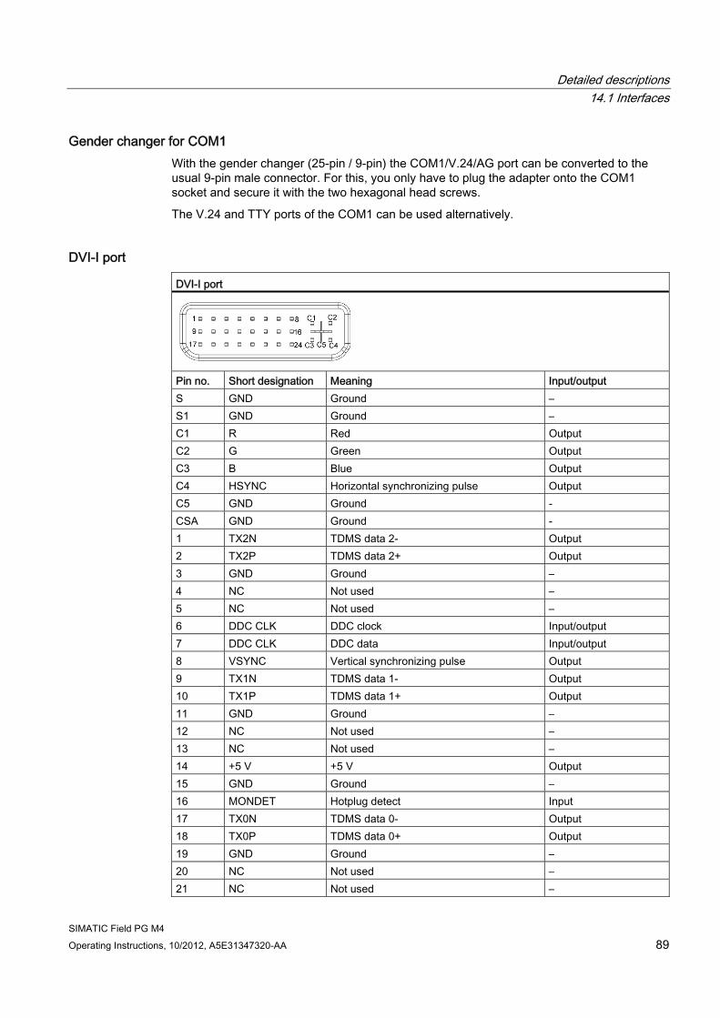
Detailed descriptions 14.1 Interfaces
SIMATIC Field PG M4 Operating Instructions, 10/2012, A5E31347320-AA 89
Gender changer for COM1 With the gender changer (25-pin / 9-pin) the COM1/V.24/AG port can be converted to the usual 9-pin male connector. For this, you only have to plug the adapter onto the COM1 socket and secure it with the two hexagonal head screws.
The V.24 and TTY ports of the COM1 can be used alternatively.
DVI-I port DVI-I port
Pin no. Short designation Meaning Input/output S GND Ground – S1 GND Ground – C1 R Red Output C2 G Green Output C3 B Blue Output C4 HSYNC Horizontal synchronizing pulse Output C5 GND Ground - CSA GND Ground - 1 TX2N TDMS data 2- Output 2 TX2P TDMS data 2+ Output 3 GND Ground – 4 NC Not used – 5 NC Not used – 6 DDC CLK DDC clock Input/output 7 DDC CLK DDC data Input/output 8 VSYNC Vertical synchronizing pulse Output 9 TX1N TDMS data 1- Output 10 TX1P TDMS data 1+ Output 11 GND Ground – 12 NC Not used – 13 NC Not used – 14 +5 V +5 V Output 15 GND Ground – 16 MONDET Hotplug detect Input 17 TX0N TDMS data 0- Output 18 TX0P TDMS data 0+ Output 19 GND Ground – 20 NC Not used – 21 NC Not used –
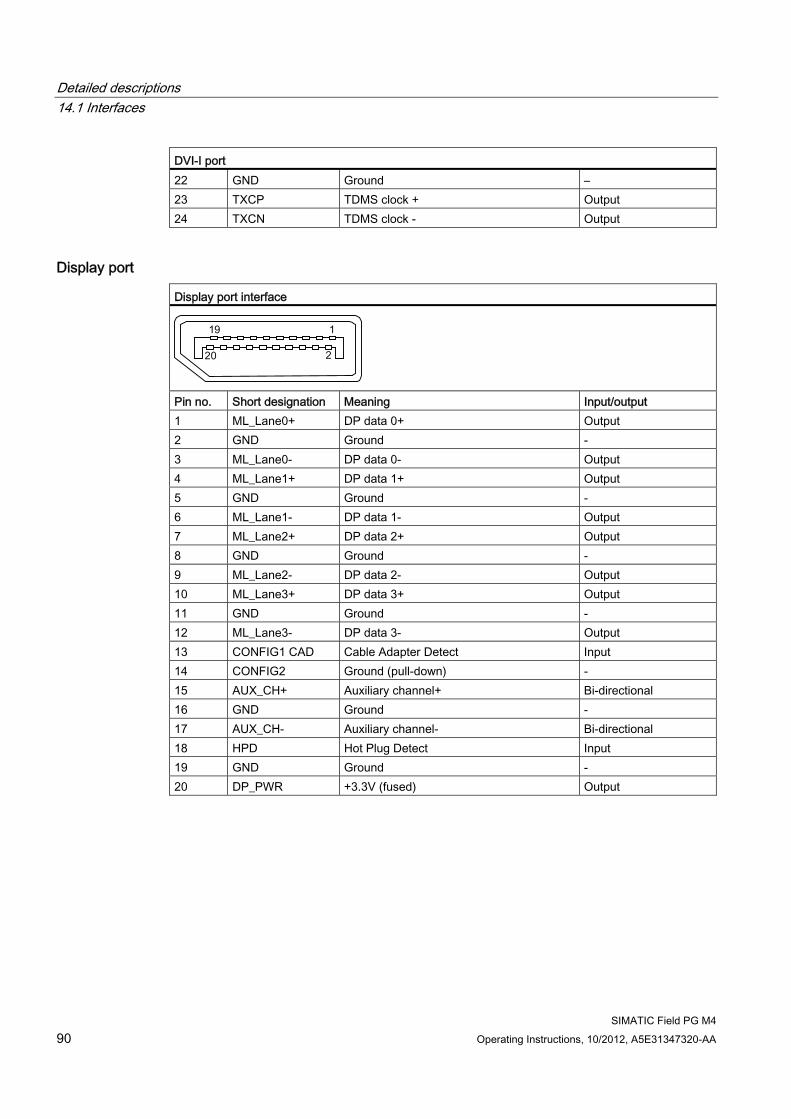
Detailed descriptions 14.1 Interfaces
SIMATIC Field PG M4 90 Operating Instructions, 10/2012, A5E31347320-AA
DVI-I port 22 GND Ground – 23 TXCP TDMS clock + Output 24 TXCN TDMS clock - Output
Display port Display port interface
Pin no. Short designation Meaning Input/output 1 ML_Lane0+ DP data 0+ Output 2 GND Ground - 3 ML_Lane0- DP data 0- Output 4 ML_Lane1+ DP data 1+ Output 5 GND Ground - 6 ML_Lane1- DP data 1- Output 7 ML_Lane2+ DP data 2+ Output 8 GND Ground - 9 ML_Lane2- DP data 2- Output 10 ML_Lane3+ DP data 3+ Output 11 GND Ground - 12 ML_Lane3- DP data 3- Output 13 CONFIG1 CAD Cable Adapter Detect Input 14 CONFIG2 Ground (pull-down) - 15 AUX_CH+ Auxiliary channel+ Bi-directional 16 GND Ground - 17 AUX_CH- Auxiliary channel- Bi-directional 18 HPD Hot Plug Detect Input 19 GND Ground - 20 DP_PWR +3.3V (fused) Output
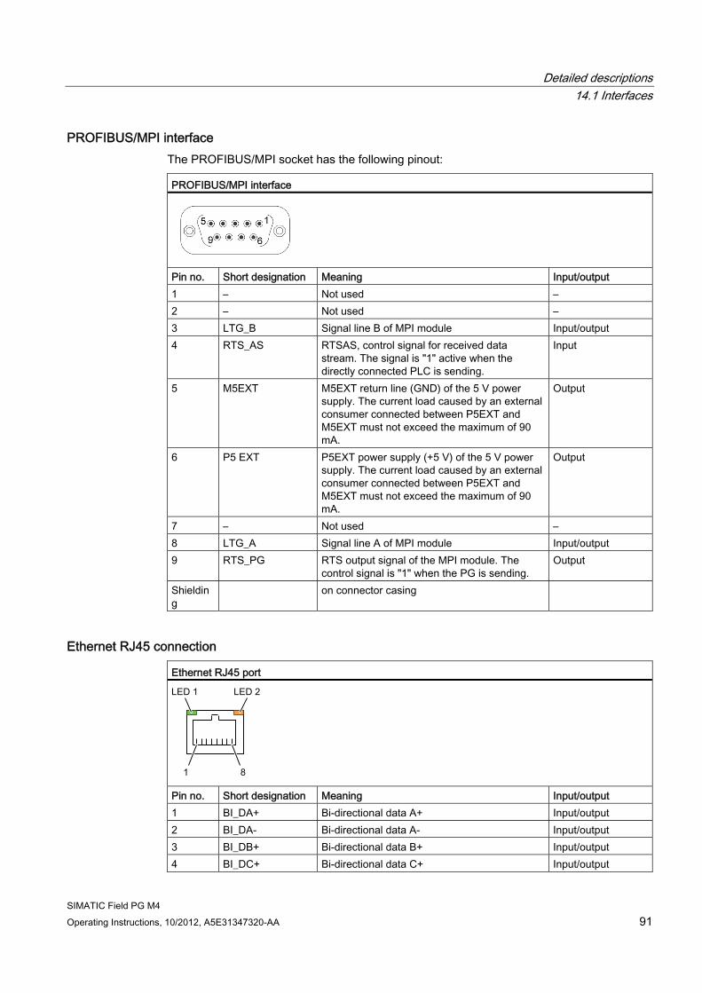
Detailed descriptions 14.1 Interfaces
SIMATIC Field PG M4 Operating Instructions, 10/2012, A5E31347320-AA 91
PROFIBUS/MPI interface The PROFIBUS/MPI socket has the following pinout: PROFIBUS/MPI interface
Pin no. Short designation Meaning Input/output 1 – Not used – 2 – Not used – 3 LTG_B Signal line B of MPI module Input/output 4 RTS_AS RTSAS, control signal for received data
stream. The signal is "1" active when the directly connected PLC is sending.
Input
5 M5EXT M5EXT return line (GND) of the 5 V power supply. The current load caused by an external consumer connected between P5EXT and M5EXT must not exceed the maximum of 90 mA.
Output
6 P5 EXT P5EXT power supply (+5 V) of the 5 V power supply. The current load caused by an external consumer connected between P5EXT and M5EXT must not exceed the maximum of 90 mA.
Output
7 – Not used – 8 LTG_A Signal line A of MPI module Input/output 9 RTS_PG RTS output signal of the MPI module. The
control signal is "1" when the PG is sending. Output
Shielding
on connector casing
Ethernet RJ45 connection Ethernet RJ45 port
Pin no. Short designation Meaning Input/output 1 BI_DA+ Bi-directional data A+ Input/output 2 BI_DA- Bi-directional data A- Input/output 3 BI_DB+ Bi-directional data B+ Input/output 4 BI_DC+ Bi-directional data C+ Input/output
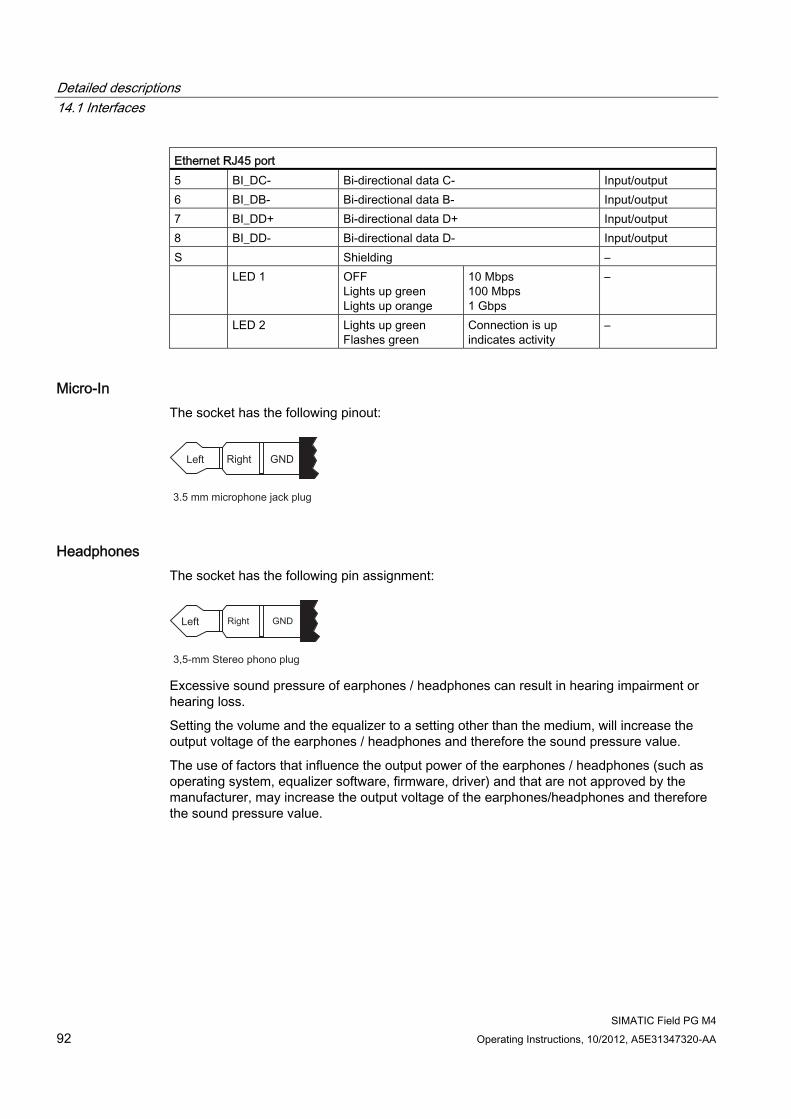
Detailed descriptions 14.1 Interfaces
SIMATIC Field PG M4 92 Operating Instructions, 10/2012, A5E31347320-AA
Ethernet RJ45 port 5 BI_DC- Bi-directional data C- Input/output 6 BI_DB- Bi-directional data B- Input/output 7 BI_DD+ Bi-directional data D+ Input/output 8 BI_DD- Bi-directional data D- Input/output S Shielding – LED 1 OFF
Lights up green Lights up orange
10 Mbps 100 Mbps 1 Gbps
–
LED 2 Lights up green Flashes green
Connection is up indicates activity
–
Micro-In The socket has the following pinout:
Headphones The socket has the following pin assignment:
Excessive sound pressure of earphones / headphones can result in hearing impairment or hearing loss.
Setting the volume and the equalizer to a setting other than the medium, will increase the output voltage of the earphones / headphones and therefore the sound pressure value.
The use of factors that influence the output power of the earphones / headphones (such as operating system, equalizer software, firmware, driver) and that are not approved by the manufacturer, may increase the output voltage of the earphones/headphones and therefore the sound pressure value.
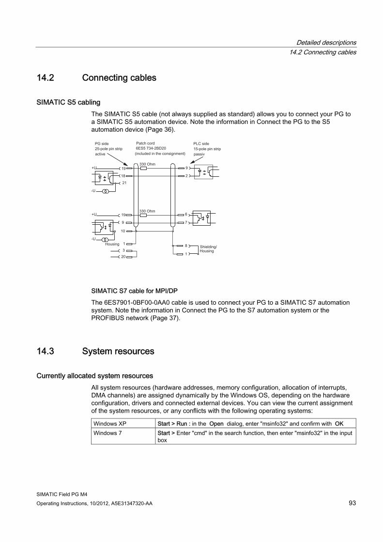
Detailed descriptions 14.2 Connecting cables
SIMATIC Field PG M4 Operating Instructions, 10/2012, A5E31347320-AA 93
14.2 Connecting cables
SIMATIC S5 cabling The SIMATIC S5 cable (not always supplied as standard) allows you to connect your PG to a SIMATIC S5 automation device. Note the information in Connect the PG to the S5 automation device (Page 36).
SIMATIC S7 cable for MPI/DP
The 6ES7901-0BF00-0AA0 cable is used to connect your PG to a SIMATIC S7 automation system. Note the information in Connect the PG to the S7 automation system or the PROFIBUS network (Page 37).
14.3 System resources
Currently allocated system resources All system resources (hardware addresses, memory configuration, allocation of interrupts, DMA channels) are assigned dynamically by the Windows OS, depending on the hardware configuration, drivers and connected external devices. You can view the current assignment of the system resources, or any conflicts with the following operating systems: Windows XP Start > Run : in the Open dialog, enter "msinfo32" and confirm with OK Windows 7 Start > Enter "cmd" in the search function, then enter "msinfo32" in the input
box
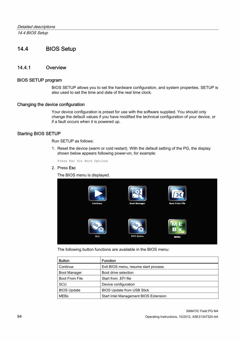
Detailed descriptions 14.4 BIOS Setup
SIMATIC Field PG M4 94 Operating Instructions, 10/2012, A5E31347320-AA
14.4 BIOS Setup
14.4.1 Overview
BIOS SETUP program BIOS SETUP allows you to set the hardware configuration, and system properties. SETUP is also used to set the time and date of the real time clock.
Changing the device configuration Your device configuration is preset for use with the software supplied. You should only change the default values if you have modified the technical configuration of your device, or if a fault occurs when it is powered up.
Starting BIOS SETUP Run SETUP as follows:
1. Reset the device (warm or cold restart). With the default setting of the PG, the display shown below appears following power-on, for example:
Press Esc for Boot Options
2. Press Esc
The BIOS menu is displayed.
The following button functions are available in the BIOS menu:
Button Function Continue Exit BIOS menu, resume start process Boot Manager Boot drive selection Boot From File Start from .EFI file SCU Device configuration BIOS Update BIOS Update from USB Stick MEBx Start Intel Management BIOS Extension
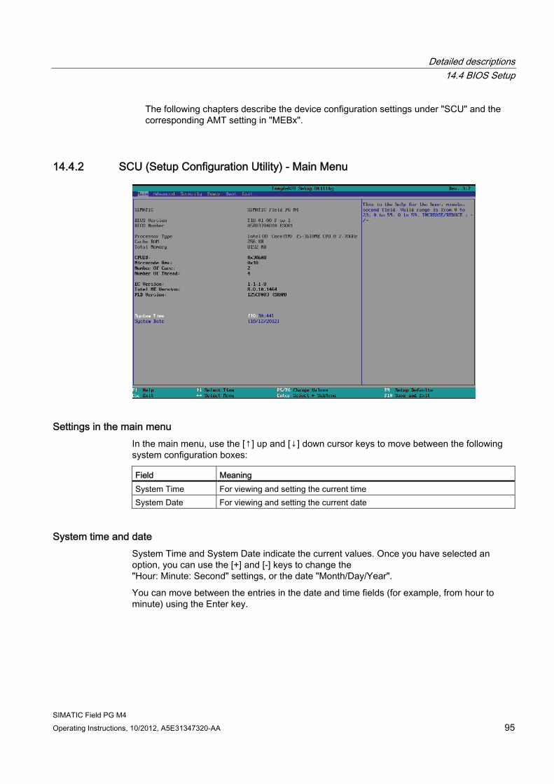
Detailed descriptions 14.4 BIOS Setup
SIMATIC Field PG M4 Operating Instructions, 10/2012, A5E31347320-AA 95
The following chapters describe the device configuration settings under "SCU" and the corresponding AMT setting in "MEBx".
14.4.2 SCU (Setup Configuration Utility) - Main Menu
Settings in the main menu In the main menu, use the [↑] up and [↓] down cursor keys to move between the following system configuration boxes: Field Meaning System Time For viewing and setting the current time System Date For viewing and setting the current date
System time and date System Time and System Date indicate the current values. Once you have selected an option, you can use the [+] and [-] keys to change the "Hour: Minute: Second" settings, or the date "Month/Day/Year".
You can move between the entries in the date and time fields (for example, from hour to minute) using the Enter key.
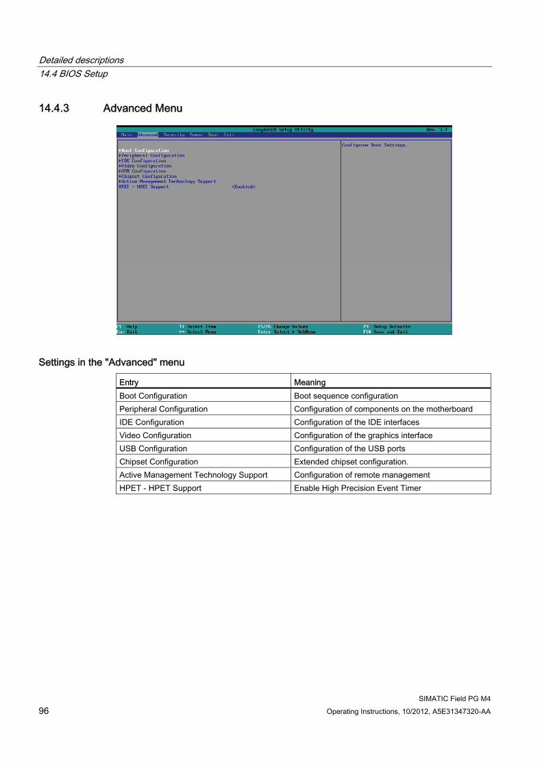
Detailed descriptions 14.4 BIOS Setup
SIMATIC Field PG M4 96 Operating Instructions, 10/2012, A5E31347320-AA
14.4.3 Advanced Menu
Settings in the "Advanced" menu Entry Meaning Boot Configuration Boot sequence configuration Peripheral Configuration Configuration of components on the motherboard IDE Configuration Configuration of the IDE interfaces Video Configuration Configuration of the graphics interface USB Configuration Configuration of the USB ports Chipset Configuration Extended chipset configuration. Active Management Technology Support Configuration of remote management HPET - HPET Support Enable High Precision Event Timer
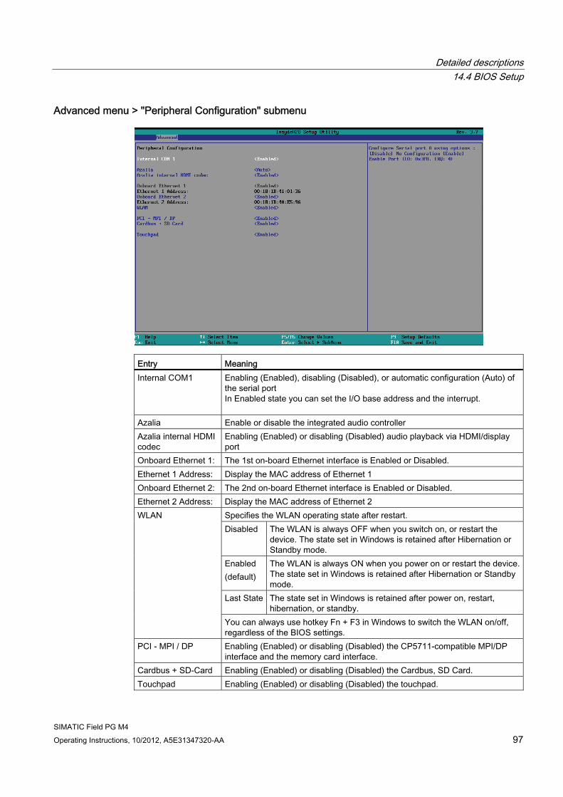
Detailed descriptions 14.4 BIOS Setup
SIMATIC Field PG M4 Operating Instructions, 10/2012, A5E31347320-AA 97
Advanced menu > "Peripheral Configuration" submenu
Entry Meaning Internal COM1
Enabling (Enabled), disabling (Disabled), or automatic configuration (Auto) of the serial port In Enabled state you can set the I/O base address and the interrupt.
Azalia Enable or disable the integrated audio controller Azalia internal HDMI codec
Enabling (Enabled) or disabling (Disabled) audio playback via HDMI/display port
Onboard Ethernet 1: The 1st on-board Ethernet interface is Enabled or Disabled. Ethernet 1 Address: Display the MAC address of Ethernet 1 Onboard Ethernet 2: The 2nd on-board Ethernet interface is Enabled or Disabled. Ethernet 2 Address: Display the MAC address of Ethernet 2
Specifies the WLAN operating state after restart. Disabled
The WLAN is always OFF when you switch on, or restart the device. The state set in Windows is retained after Hibernation or Standby mode.
Enabled (default)
The WLAN is always ON when you power on or restart the device. The state set in Windows is retained after Hibernation or Standby mode.
Last State The state set in Windows is retained after power on, restart, hibernation, or standby.
WLAN
You can always use hotkey Fn + F3 in Windows to switch the WLAN on/off, regardless of the BIOS settings.
PCI - MPI / DP Enabling (Enabled) or disabling (Disabled) the CP5711-compatible MPI/DP interface and the memory card interface.
Cardbus + SD-Card Enabling (Enabled) or disabling (Disabled) the Cardbus, SD Card. Touchpad Enabling (Enabled) or disabling (Disabled) the touchpad.

Detailed descriptions 14.4 BIOS Setup
SIMATIC Field PG M4 98 Operating Instructions, 10/2012, A5E31347320-AA
Note
The second Ethernet interface support is OS dependent. For DOS-based applications (e.g. SIMATIC IPC Image & Partition Creator), use Ethernet interface 1 and disable Ethernet interface 2 in BIOS Setup.
Advanced menu > "IDE Configuration" submenu
Entry Meaning HDC Configure As Configures the type of HDD controller IDE SATA HDD in non-AHCI mode AHCI SATA HDD in AHCI mode Serial ATA Port # Specification of the type of built-in IDE drive
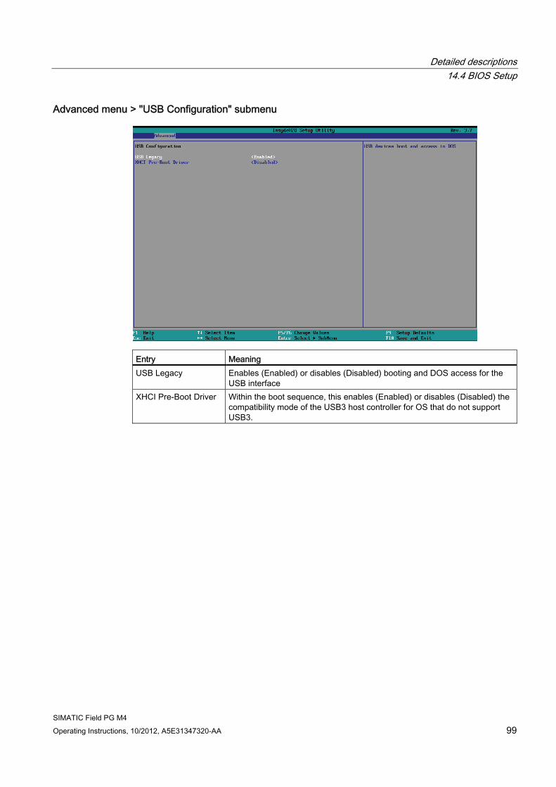
Detailed descriptions 14.4 BIOS Setup
SIMATIC Field PG M4 Operating Instructions, 10/2012, A5E31347320-AA 99
Advanced menu > "USB Configuration" submenu
Entry Meaning USB Legacy Enables (Enabled) or disables (Disabled) booting and DOS access for the
USB interface XHCI Pre-Boot Driver Within the boot sequence, this enables (Enabled) or disables (Disabled) the
compatibility mode of the USB3 host controller for OS that do not support USB3.
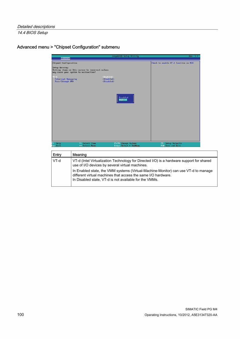
Detailed descriptions 14.4 BIOS Setup
SIMATIC Field PG M4 100 Operating Instructions, 10/2012, A5E31347320-AA
Advanced menu > "Chipset Configuration" submenu
Entry Meaning VT-d VT-d (Intel Virtualization Technology for Directed I/O) is a hardware support for shared
use of I/O devices by several virtual machines. In Enabled state, the VMM systems (Virtual-Machine-Monitor) can use VT-d to manage different virtual machines that access the same I/O hardware. In Disabled state, VT-d is not available for the VMMs.
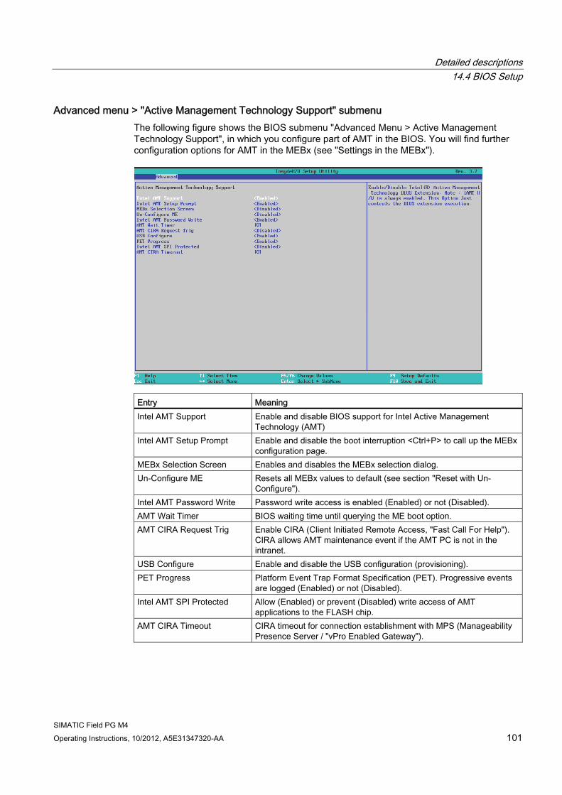
Detailed descriptions 14.4 BIOS Setup
SIMATIC Field PG M4 Operating Instructions, 10/2012, A5E31347320-AA 101
Advanced menu > "Active Management Technology Support" submenu The following figure shows the BIOS submenu "Advanced Menu > Active Management Technology Support", in which you configure part of AMT in the BIOS. You will find further configuration options for AMT in the MEBx (see "Settings in the MEBx").
Entry Meaning Intel AMT Support Enable and disable BIOS support for Intel Active Management
Technology (AMT) Intel AMT Setup Prompt Enable and disable the boot interruption <Ctrl+P> to call up the MEBx
configuration page. MEBx Selection Screen Enables and disables the MEBx selection dialog. Un-Configure ME Resets all MEBx values to default (see section "Reset with Un-
Configure"). Intel AMT Password Write Password write access is enabled (Enabled) or not (Disabled). AMT Wait Timer BIOS waiting time until querying the ME boot option. AMT CIRA Request Trig Enable CIRA (Client Initiated Remote Access, "Fast Call For Help").
CIRA allows AMT maintenance event if the AMT PC is not in the intranet.
USB Configure Enable and disable the USB configuration (provisioning). PET Progress Platform Event Trap Format Specification (PET). Progressive events
are logged (Enabled) or not (Disabled). Intel AMT SPI Protected Allow (Enabled) or prevent (Disabled) write access of AMT
applications to the FLASH chip. AMT CIRA Timeout CIRA timeout for connection establishment with MPS (Manageability
Presence Server / "vPro Enabled Gateway").
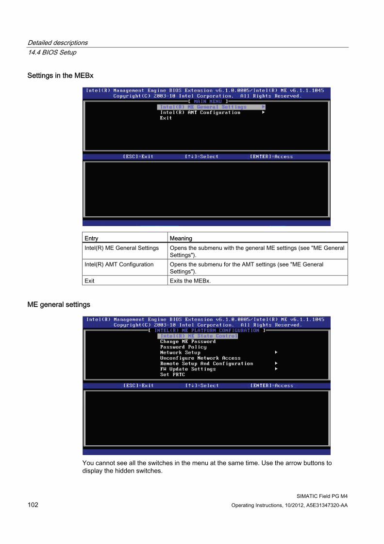
Detailed descriptions 14.4 BIOS Setup
SIMATIC Field PG M4 102 Operating Instructions, 10/2012, A5E31347320-AA
Settings in the MEBx
Entry Meaning Intel(R) ME General Settings Opens the submenu with the general ME settings (see "ME General
Settings"). Intel(R) AMT Configuration Opens the submenu for the AMT settings (see "ME General
Settings"). Exit Exits the MEBx.
ME general settings
You cannot see all the switches in the menu at the same time. Use the arrow buttons to display the hidden switches.
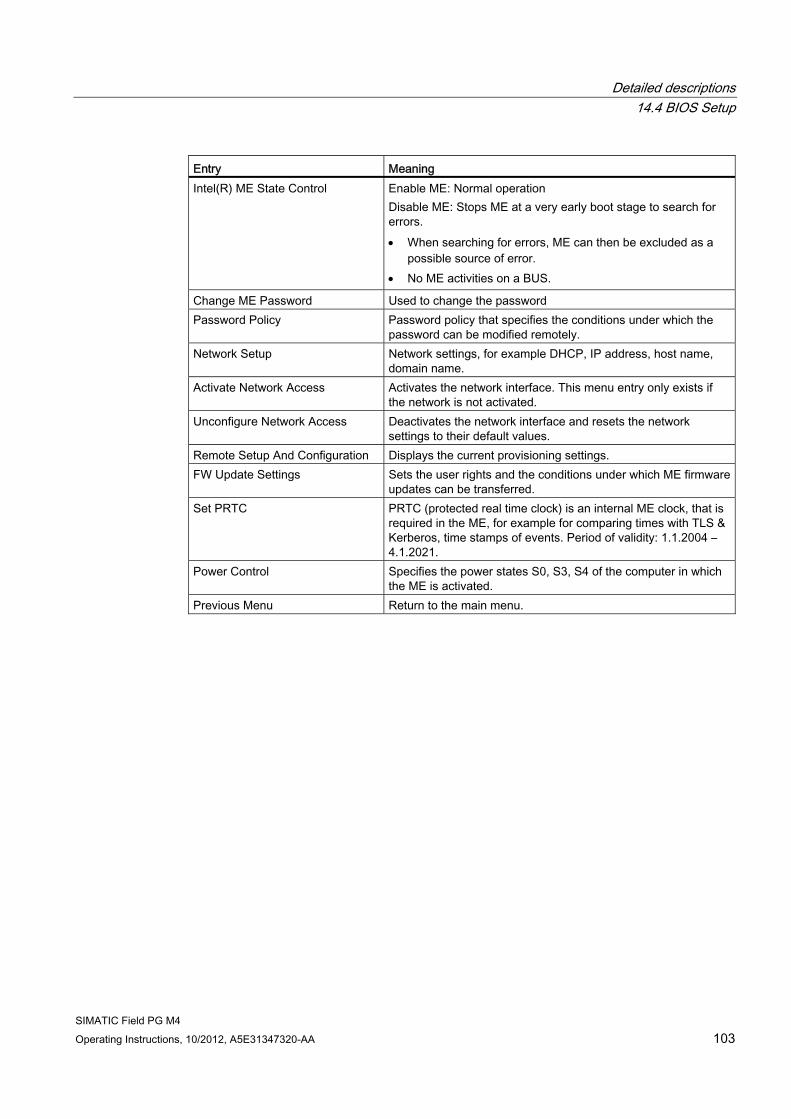
Detailed descriptions 14.4 BIOS Setup
SIMATIC Field PG M4 Operating Instructions, 10/2012, A5E31347320-AA 103
Entry Meaning Intel(R) ME State Control Enable ME: Normal operation
Disable ME: Stops ME at a very early boot stage to search for errors. When searching for errors, ME can then be excluded as a
possible source of error. No ME activities on a BUS.
Change ME Password Used to change the password Password Policy Password policy that specifies the conditions under which the
password can be modified remotely. Network Setup Network settings, for example DHCP, IP address, host name,
domain name. Activate Network Access Activates the network interface. This menu entry only exists if
the network is not activated. Unconfigure Network Access Deactivates the network interface and resets the network
settings to their default values. Remote Setup And Configuration Displays the current provisioning settings. FW Update Settings Sets the user rights and the conditions under which ME firmware
updates can be transferred. Set PRTC PRTC (protected real time clock) is an internal ME clock, that is
required in the ME, for example for comparing times with TLS & Kerberos, time stamps of events. Period of validity: 1.1.2004 – 4.1.2021.
Power Control Specifies the power states S0, S3, S4 of the computer in which the ME is activated.
Previous Menu Return to the main menu.
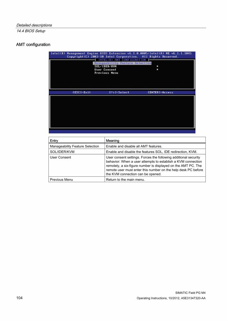
Detailed descriptions 14.4 BIOS Setup
SIMATIC Field PG M4 104 Operating Instructions, 10/2012, A5E31347320-AA
AMT configuration
Entry Meaning Manageability Feature Selection Enable and disable all AMT features. SOL/IDER/KVM Enable and disable the features SOL, IDE redirection, KVM. User Consent User consent settings. Forces the following additional security
behavior: When a user attempts to establish a KVM connection remotely, a six-figure number is displayed on the AMT PC. The remote user must enter this number on the help desk PC before the KVM connection can be opened.
Previous Menu Return to the main menu.
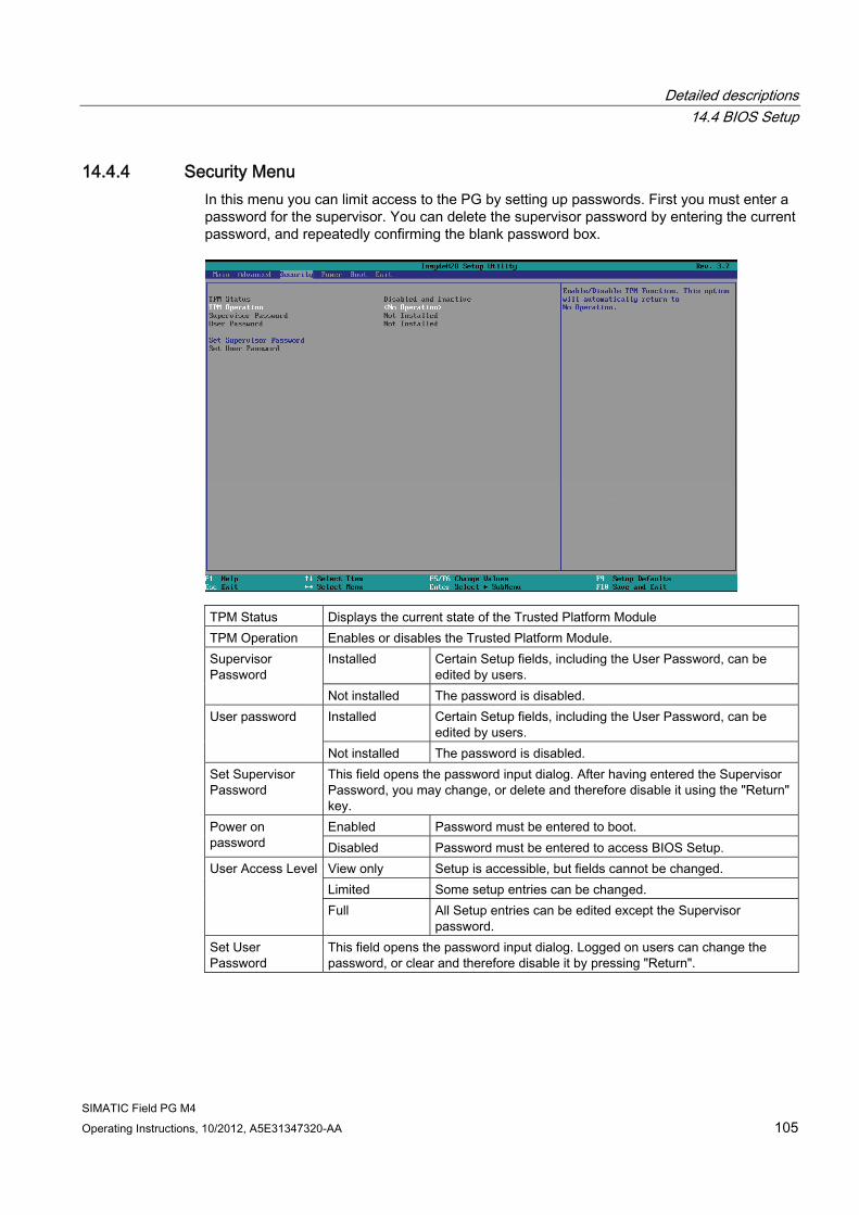
Detailed descriptions 14.4 BIOS Setup
SIMATIC Field PG M4 Operating Instructions, 10/2012, A5E31347320-AA 105
14.4.4 Security Menu In this menu you can limit access to the PG by setting up passwords. First you must enter a password for the supervisor. You can delete the supervisor password by entering the current password, and repeatedly confirming the blank password box.
TPM Status Displays the current state of the Trusted Platform Module TPM Operation Enables or disables the Trusted Platform Module.
Installed Certain Setup fields, including the User Password, can be edited by users.
Supervisor Password
Not installed The password is disabled. Installed Certain Setup fields, including the User Password, can be
edited by users. User password
Not installed The password is disabled. Set Supervisor Password
This field opens the password input dialog. After having entered the Supervisor Password, you may change, or delete and therefore disable it using the "Return" key. Enabled Password must be entered to boot. Power on
password Disabled Password must be entered to access BIOS Setup. View only Setup is accessible, but fields cannot be changed. Limited Some setup entries can be changed.
User Access Level
Full All Setup entries can be edited except the Supervisor password.
Set User Password
This field opens the password input dialog. Logged on users can change the password, or clear and therefore disable it by pressing "Return".
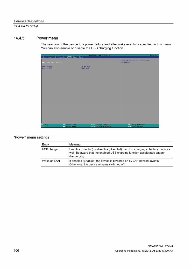
Detailed descriptions 14.4 BIOS Setup
SIMATIC Field PG M4 106 Operating Instructions, 10/2012, A5E31347320-AA
14.4.5 Power menu The reaction of the device to a power failure and after wake events is specified in this menu. You can also enable or disable the USB charging function.
"Power" menu settings Entry Meaning USB charger Enables (Enabled) or disables (Disabled) the USB charging in battery mode as
well. Be aware that the enabled USB charging function accelerates battery discharging.
Wake on LAN If enabled (Enabled) the device is powered on by LAN network events. Otherwise, the device remains switched off.
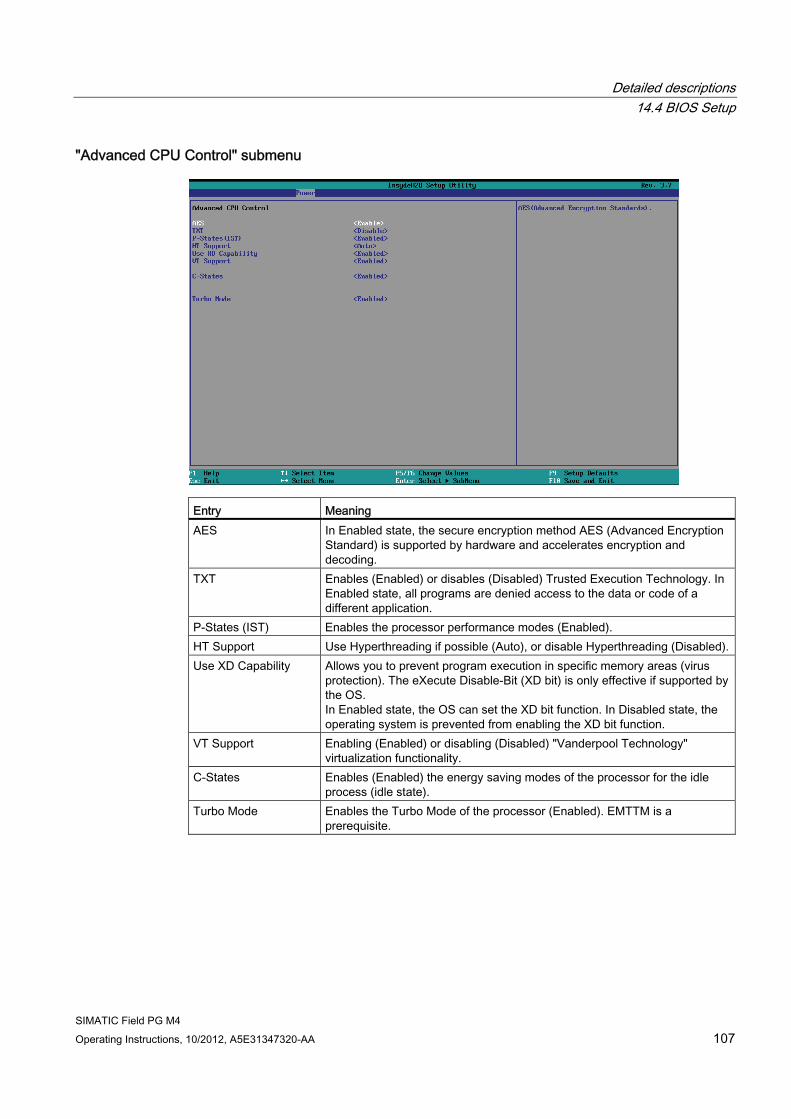
Detailed descriptions 14.4 BIOS Setup
SIMATIC Field PG M4 Operating Instructions, 10/2012, A5E31347320-AA 107
"Advanced CPU Control" submenu
Entry Meaning AES In Enabled state, the secure encryption method AES (Advanced Encryption
Standard) is supported by hardware and accelerates encryption and decoding.
TXT Enables (Enabled) or disables (Disabled) Trusted Execution Technology. In Enabled state, all programs are denied access to the data or code of a different application.
P-States (IST) Enables the processor performance modes (Enabled). HT Support Use Hyperthreading if possible (Auto), or disable Hyperthreading (Disabled).Use XD Capability Allows you to prevent program execution in specific memory areas (virus
protection). The eXecute Disable-Bit (XD bit) is only effective if supported by the OS. In Enabled state, the OS can set the XD bit function. In Disabled state, the operating system is prevented from enabling the XD bit function.
VT Support Enabling (Enabled) or disabling (Disabled) "Vanderpool Technology" virtualization functionality.
C-States Enables (Enabled) the energy saving modes of the processor for the idle process (idle state).
Turbo Mode Enables the Turbo Mode of the processor (Enabled). EMTTM is a prerequisite.
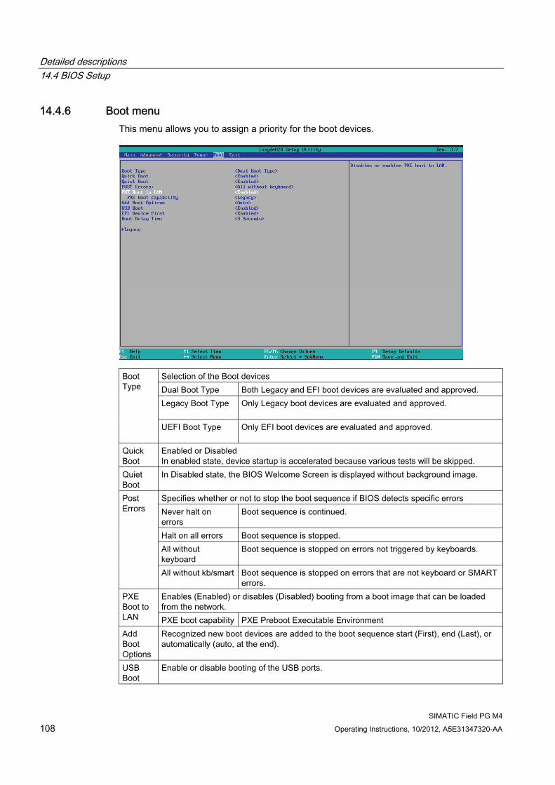
Detailed descriptions 14.4 BIOS Setup
SIMATIC Field PG M4 108 Operating Instructions, 10/2012, A5E31347320-AA
14.4.6 Boot menu This menu allows you to assign a priority for the boot devices.
Selection of the Boot devices Dual Boot Type Both Legacy and EFI boot devices are evaluated and approved. Legacy Boot Type Only Legacy boot devices are evaluated and approved.
Boot Type
UEFI Boot Type Only EFI boot devices are evaluated and approved.
Quick Boot
Enabled or Disabled In enabled state, device startup is accelerated because various tests will be skipped.
Quiet Boot
In Disabled state, the BIOS Welcome Screen is displayed without background image.
Specifies whether or not to stop the boot sequence if BIOS detects specific errors Never halt on errors
Boot sequence is continued.
Halt on all errors Boot sequence is stopped. All without keyboard
Boot sequence is stopped on errors not triggered by keyboards.
Post Errors
All without kb/smart Boot sequence is stopped on errors that are not keyboard or SMART errors.
Enables (Enabled) or disables (Disabled) booting from a boot image that can be loaded from the network.
PXE Boot to LAN PXE boot capability PXE Preboot Executable Environment Add Boot Options
Recognized new boot devices are added to the boot sequence start (First), end (Last), or automatically (auto, at the end).
USB Boot
Enable or disable booting of the USB ports.
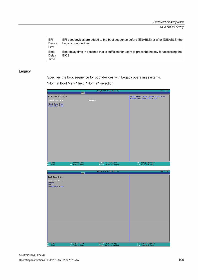
Detailed descriptions 14.4 BIOS Setup
SIMATIC Field PG M4 Operating Instructions, 10/2012, A5E31347320-AA 109
EFI Device First
EFI boot devices are added to the boot sequence before (ENABLE) or after (DISABLE) the Legacy boot devices.
Boot Delay Time
Boot delay time in seconds that is sufficient for users to press the hotkey for accessing the BIOS.
Legacy Specifies the boot sequence for boot devices with Legacy operating systems.
"Normal Boot Menu" field, "Normal" selection:
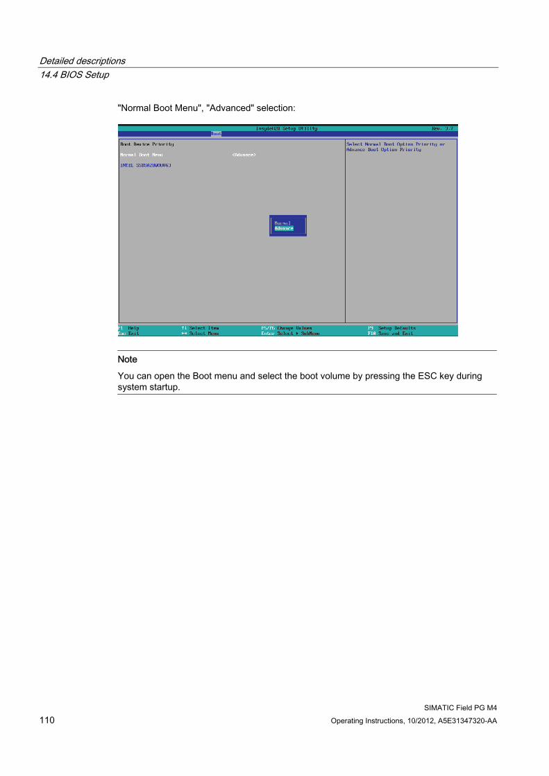
Detailed descriptions 14.4 BIOS Setup
SIMATIC Field PG M4 110 Operating Instructions, 10/2012, A5E31347320-AA
"Normal Boot Menu", "Advanced" selection:
Note
You can open the Boot menu and select the boot volume by pressing the ESC key during system startup.
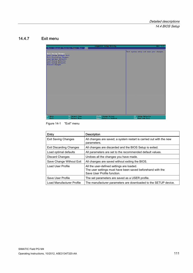
Detailed descriptions 14.4 BIOS Setup
SIMATIC Field PG M4 Operating Instructions, 10/2012, A5E31347320-AA 111
14.4.7 Exit menu
Figure 14-1 "Exit" menu
Entry Description Exit Saving Changes All changes are saved; a system restart is carried out with the new
parameters. Exit Discarding Changes All changes are discarded and the BIOS Setup is exited. Load optimal defaults All parameters are set to the recommended default values. Discard Changes Undoes all the changes you have made. Save Change Without Exit All changes are saved without exiting the BIOS. Load User Profile All the user-defined settings are loaded.
The user settings must have been saved beforehand with the Save User Profile function.
Save User Profile The set parameters are saved as a USER profile. Load Manufacturer Profile The manufacturer parameters are downloaded to the SETUP device.

Detailed descriptions 14.4 BIOS Setup
SIMATIC Field PG M4 112 Operating Instructions, 10/2012, A5E31347320-AA
SIMATIC Field PG M4 Operating Instructions, 10/2012, A5E31347320-AA 113
Appendix AA.1 Guidelines and declarations
Notes on the CE mark The following applies to the SIMATIC product described in this documentation:
RTTE directive This product is designed for the following applications: Application Requirement for Emissions Immunity Residential, business and commercial operations, and small businesses
EN 61000-6-3 EN 61000-6-1
Industrial applications EN 61000-6-4 EN 61000-6-2
The devices are compliant with EN 61000-3-2 (Transient currents) and EN 61000-3-3 (Voltage fluctuation and Flicker).
This product meets the requirements of EC directive 1999/5/EEC ”Radio Equipment and Telecommunications Terminal Equipment - Use of the Radio Spectrum”: EN 300 328 / EN 301 893 / EN 301 489-17 / EN 302 489-1
Directive 1999/5/EC contains the requirements of Directive 2004/108/EC "Directive of the Council on the Approximation of the Laws of Member States relating to Electromagnetic Compatibility (EMC Directive).
● Safety: see Low voltage directive
Low voltage directive This product fulfills the Directive 2006/95/EEC of the European Parliament and of the Council on the harmonization of the laws of Member States relating to electrical equipment designed for use within certain voltage limits.
Requirements of EC Directive 2006/95/EEC "Low voltage directive". Compliance with this standard was validated in accordance with EN 60950-1.
Declaration of conformity The EC declaration of conformity and the corresponding documentation are made available to authorities in accordance with the EC directives stated above. Your sales representative can provide these on request.
Appendix A.2 Certificates and approvals
SIMATIC Field PG M4 114 Operating Instructions, 10/2012, A5E31347320-AA
Installation guidelines The installation guidelines and safety notices specified in the supplied documentation must be adhered to during commissioning and operation.
Connecting peripherals The requirements for noise immunity are met when you connect a peripheral suitable for an industrial environment according to EN 61000-6-2:2005. Peripheral devices must only be connected using shielded cables.
A.2 Certificates and approvals
DIN ISO 9001 certificate The Siemens quality management system for all production processes (development, production, and sales) meets DIN ISO 9001:2000 requirements.
This has been certified by DQS (the German society for the certification of quality management systems).
Q-Net certificate no.: DE-001108 QM
Software License Agreement The device is shipped with preinstalled software. Please observe the corresponding license agreements.
Certifications for the United States, Canada, and Australia Product safety.
The following approval is available for the device:
Underwriters Laboratories (UL) to Standard UL 60950-1 Second Edition and Canadian Standard CAN/CSA-C22.2 No. 60950-1-07 Second Edition.
WLAN The integrated wireless LAN conforming to IEEE 802.11 a/b/g/n is certified for Europe, the USA and Canada:
Appendix A.3 Service and support
SIMATIC Field PG M4 Operating Instructions, 10/2012, A5E31347320-AA 115
A.3 Service and support You can find additional information and support for the products described on the Internet at the following addresses:
● Technical support (http://www.siemens.com/automation/service&support)
● Support request form (http://www.siemens.com/automation/support-request)
● After-sales information system for SIMATIC PC / PG (http://www.siemens.com/asis)
● SIMATIC Documentation Collection (http://www.siemens.com/simatic-tech-doku-portal)
● Your local representative (http://www.siemens.com/automation/partner)
● Training center (http://www.sitrain.com)
● Industry Mall (http://mall.automation.siemens.com)
When contacting your local representative or Technical Support, please have the following information at hand:
● Order number of the device (MLFB)
● BIOS version (industry PC) or image version (HMI device)
● Installed additional hardware
● Installed additional software
Tools & downloads Please check regularly if updates and hotfixes are available for download to your device. The downloads are available on the Internet under "After Sales Information System SIMATIC PC/PG" (see above).
Appendix A.4 Accessories
SIMATIC Field PG M4 116 Operating Instructions, 10/2012, A5E31347320-AA
A.4 Accessories Accessories for the Field PG M4 are available on order from the SIEMENS Industry Mall.
Procedure 1. Navigate to the Internet URL of the SIEMENS Industry Mall
(http://www.siemens.com/automation/mall).
2. Log in with your customer data (Login on the top right).
3. Select the user language.
4. Navigate to the programming devices in the product catalog (tree structure on the left): "Automation technology > Automation systems > SIMATIC Industrial automation systems > Programming devices"
5. In the tree structure on the left, click: Field PG M4.
6. Select "Accessories" in the display area.
SIMATIC Field PG M4 Operating Instructions, 10/2012, A5E31347320-AA 117
ESD guidelines B
Definition of ESD All electronic modules are equipped with large-scale integrated ICs or components. Due to their design, these electronic elements are highly sensitive to overvoltage, and thus to any electrostatic discharge.
The electrostatic sensitive components/modules are commonly referred to as ESD devices. This is also the international abbreviation for such devices.
ESD modules are identified by the following symbol:
NOTICE ESD devices can be destroyed by voltages well below the threshold of human perception. These static voltages develop when you touch a component or electrical connection of a device without having drained the static charges present on your body. The electrostatic discharge current may lead to latent failure of a module, that is, this damage may not be significant immediately, but in operation may cause malfunction.
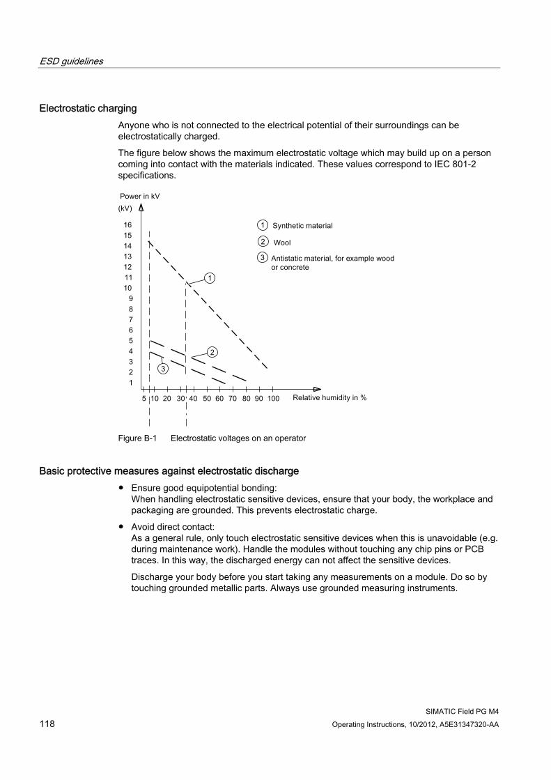
ESD guidelines
SIMATIC Field PG M4 118 Operating Instructions, 10/2012, A5E31347320-AA
Electrostatic charging Anyone who is not connected to the electrical potential of their surroundings can be electrostatically charged.
The figure below shows the maximum electrostatic voltage which may build up on a person coming into contact with the materials indicated. These values correspond to IEC 801-2 specifications.
Figure B-1 Electrostatic voltages on an operator
Basic protective measures against electrostatic discharge ● Ensure good equipotential bonding:
When handling electrostatic sensitive devices, ensure that your body, the workplace and packaging are grounded. This prevents electrostatic charge.
● Avoid direct contact: As a general rule, only touch electrostatic sensitive devices when this is unavoidable (e.g. during maintenance work). Handle the modules without touching any chip pins or PCB traces. In this way, the discharged energy can not affect the sensitive devices.
Discharge your body before you start taking any measurements on a module. Do so by touching grounded metallic parts. Always use grounded measuring instruments.
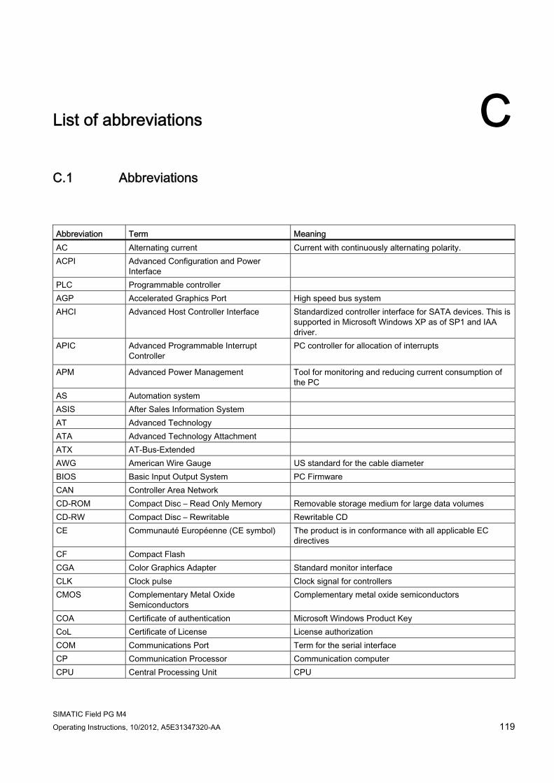
SIMATIC Field PG M4 Operating Instructions, 10/2012, A5E31347320-AA 119
List of abbreviations CC.1 Abbreviations
Abbreviation Term Meaning AC Alternating current Current with continuously alternating polarity. ACPI Advanced Configuration and Power
Interface
PLC Programmable controller AGP Accelerated Graphics Port High speed bus system AHCI Advanced Host Controller Interface Standardized controller interface for SATA devices. This is
supported in Microsoft Windows XP as of SP1 and IAA driver.
APIC Advanced Programmable Interrupt Controller
PC controller for allocation of interrupts
APM Advanced Power Management Tool for monitoring and reducing current consumption of the PC
AS Automation system ASIS After Sales Information System AT Advanced Technology ATA Advanced Technology Attachment ATX AT-Bus-Extended AWG American Wire Gauge US standard for the cable diameter BIOS Basic Input Output System PC Firmware CAN Controller Area Network CD-ROM Compact Disc – Read Only Memory Removable storage medium for large data volumes CD-RW Compact Disc – Rewritable Rewritable CD CE Communauté Européenne (CE symbol) The product is in conformance with all applicable EC
directives CF Compact Flash CGA Color Graphics Adapter Standard monitor interface CLK Clock pulse Clock signal for controllers CMOS Complementary Metal Oxide
Semiconductors Complementary metal oxide semiconductors
COA Certificate of authentication Microsoft Windows Product Key CoL Certificate of License License authorization COM Communications Port Term for the serial interface CP Communication Processor Communication computer CPU Central Processing Unit CPU
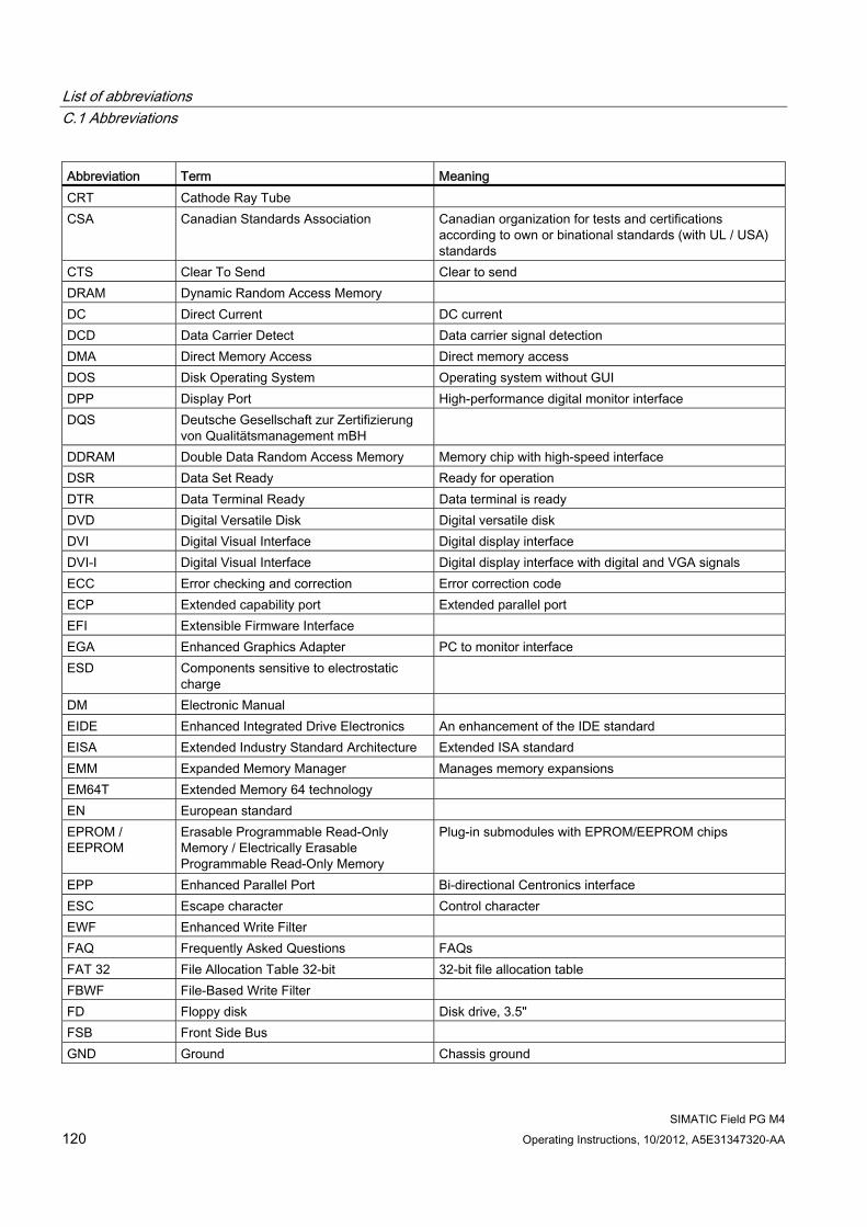
List of abbreviations C.1 Abbreviations
SIMATIC Field PG M4 120 Operating Instructions, 10/2012, A5E31347320-AA
Abbreviation Term Meaning CRT Cathode Ray Tube CSA Canadian Standards Association Canadian organization for tests and certifications
according to own or binational standards (with UL / USA) standards
CTS Clear To Send Clear to send DRAM Dynamic Random Access Memory DC Direct Current DC current DCD Data Carrier Detect Data carrier signal detection DMA Direct Memory Access Direct memory access DOS Disk Operating System Operating system without GUI DPP Display Port High-performance digital monitor interface DQS Deutsche Gesellschaft zur Zertifizierung
von Qualitätsmanagement mBH
DDRAM Double Data Random Access Memory Memory chip with high-speed interface DSR Data Set Ready Ready for operation DTR Data Terminal Ready Data terminal is ready DVD Digital Versatile Disk Digital versatile disk DVI Digital Visual Interface Digital display interface DVI-I Digital Visual Interface Digital display interface with digital and VGA signals ECC Error checking and correction Error correction code ECP Extended capability port Extended parallel port EFI Extensible Firmware Interface EGA Enhanced Graphics Adapter PC to monitor interface ESD Components sensitive to electrostatic
charge
DM Electronic Manual EIDE Enhanced Integrated Drive Electronics An enhancement of the IDE standard EISA Extended Industry Standard Architecture Extended ISA standard EMM Expanded Memory Manager Manages memory expansions EM64T Extended Memory 64 technology EN European standard EPROM / EEPROM
Erasable Programmable Read-Only Memory / Electrically Erasable Programmable Read-Only Memory
Plug-in submodules with EPROM/EEPROM chips
EPP Enhanced Parallel Port Bi-directional Centronics interface ESC Escape character Control character EWF Enhanced Write Filter FAQ Frequently Asked Questions FAQs FAT 32 File Allocation Table 32-bit 32-bit file allocation table FBWF File-Based Write Filter FD Floppy disk Disk drive, 3.5" FSB Front Side Bus GND Ground Chassis ground
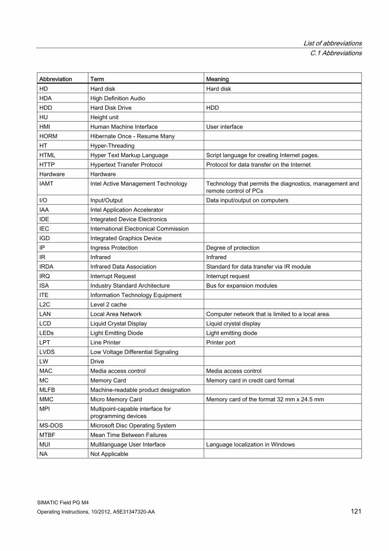
List of abbreviations C.1 Abbreviations
SIMATIC Field PG M4 Operating Instructions, 10/2012, A5E31347320-AA 121
Abbreviation Term Meaning HD Hard disk Hard disk HDA High Definition Audio HDD Hard Disk Drive HDD HU Height unit HMI Human Machine Interface User interface HORM Hibernate Once - Resume Many HT Hyper-Threading HTML Hyper Text Markup Language Script language for creating Internet pages. HTTP Hypertext Transfer Protocol Protocol for data transfer on the Internet Hardware Hardware IAMT Intel Active Management Technology Technology that permits the diagnostics, management and
remote control of PCs I/O Input/Output Data input/output on computers IAA Intel Application Accelerator IDE Integrated Device Electronics IEC International Electronical Commission IGD Integrated Graphics Device IP Ingress Protection Degree of protection IR Infrared Infrared IRDA Infrared Data Association Standard for data transfer via IR module IRQ Interrupt Request Interrupt request ISA Industry Standard Architecture Bus for expansion modules ITE Information Technology Equipment L2C Level 2 cache LAN Local Area Network Computer network that is limited to a local area. LCD Liquid Crystal Display Liquid crystal display LEDs Light Emitting Diode Light emitting diode LPT Line Printer Printer port LVDS Low Voltage Differential Signaling LW Drive MAC Media access control Media access control MC Memory Card Memory card in credit card format MLFB Machine-readable product designation MMC Micro Memory Card Memory card of the format 32 mm x 24.5 mm MPI Multipoint-capable interface for
programming devices
MS-DOS Microsoft Disc Operating System MTBF Mean Time Between Failures MUI Multilanguage User Interface Language localization in Windows NA Not Applicable
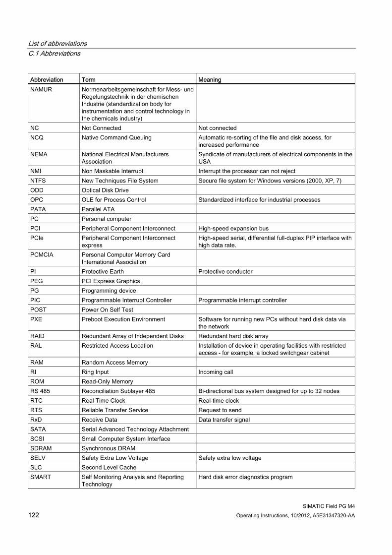
List of abbreviations C.1 Abbreviations
SIMATIC Field PG M4 122 Operating Instructions, 10/2012, A5E31347320-AA
Abbreviation Term Meaning NAMUR Normenarbeitsgemeinschaft for Mess- und
Regelungstechnik in der chemischen Industrie (standardization body for instrumentation and control technology in the chemicals industry)
NC Not Connected Not connected NCQ Native Command Queuing Automatic re-sorting of the file and disk access, for
increased performance NEMA National Electrical Manufacturers
Association Syndicate of manufacturers of electrical components in the USA
NMI Non Maskable Interrupt Interrupt the processor can not reject NTFS New Techniques File System Secure file system for Windows versions (2000, XP, 7) ODD Optical Disk Drive OPC OLE for Process Control Standardized interface for industrial processes PATA Parallel ATA PC Personal computer PCI Peripheral Component Interconnect High-speed expansion bus PCIe Peripheral Component Interconnect
express High-speed serial, differential full-duplex PtP interface with high data rate.
PCMCIA Personal Computer Memory Card International Association
PI Protective Earth Protective conductor PEG PCI Express Graphics PG Programming device PIC Programmable Interrupt Controller Programmable interrupt controller POST Power On Self Test PXE Preboot Execution Environment Software for running new PCs without hard disk data via
the network RAID Redundant Array of Independent Disks Redundant hard disk array RAL Restricted Access Location
Installation of device in operating facilities with restricted access - for example, a locked switchgear cabinet
RAM Random Access Memory RI Ring Input Incoming call ROM Read-Only Memory RS 485 Reconciliation Sublayer 485 Bi-directional bus system designed for up to 32 nodes RTC Real Time Clock Real-time clock RTS Reliable Transfer Service Request to send RxD Receive Data Data transfer signal SATA Serial Advanced Technology Attachment SCSI Small Computer System Interface SDRAM Synchronous DRAM SELV Safety Extra Low Voltage Safety extra low voltage SLC Second Level Cache SMART Self Monitoring Analysis and Reporting
Technology Hard disk error diagnostics program
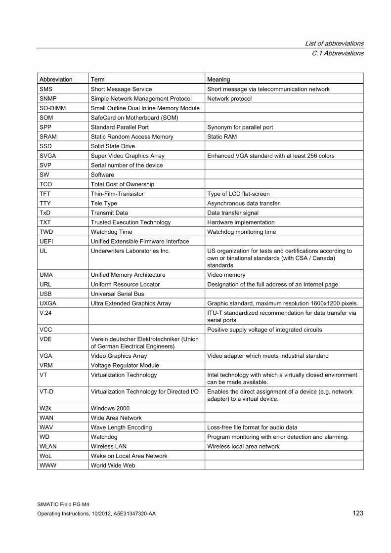
List of abbreviations C.1 Abbreviations
SIMATIC Field PG M4 Operating Instructions, 10/2012, A5E31347320-AA 123
Abbreviation Term Meaning SMS Short Message Service Short message via telecommunication network SNMP Simple Network Management Protocol Network protocol SO-DIMM Small Outline Dual Inline Memory Module SOM SafeCard on Motherboard (SOM) SPP Standard Parallel Port Synonym for parallel port SRAM Static Random Access Memory Static RAM SSD Solid State Drive SVGA Super Video Graphics Array Enhanced VGA standard with at least 256 colors SVP Serial number of the device SW Software TCO Total Cost of Ownership TFT Thin-Film-Transistor Type of LCD flat-screen TTY Tele Type Asynchronous data transfer TxD Transmit Data Data transfer signal TXT Trusted Execution Technology Hardware implementation TWD Watchdog Time Watchdog monitoring time UEFI Unified Extensible Firmware Interface UL Underwriters Laboratories Inc. US organization for tests and certifications according to
own or binational standards (with CSA / Canada) standards
UMA Unified Memory Architecture Video memory URL Uniform Resource Locator Designation of the full address of an Internet page USB Universal Serial Bus UXGA Ultra Extended Graphics Array Graphic standard, maximum resolution 1600x1200 pixels. V.24 ITU-T standardized recommendation for data transfer via
serial ports VCC Positive supply voltage of integrated circuits VDE Verein deutscher Elektrotechniker (Union
of German Electrical Engineers)
VGA Video Graphics Array Video adapter which meets industrial standard VRM Voltage Regulator Module VT Virtualization Technology Intel technology with which a virtually closed environment
can be made available. VT-D Virtualization Technology for Directed I/O Enables the direct assignment of a device (e.g. network
adapter) to a virtual device. W2k Windows 2000 WAN Wide Area Network WAV Wave Length Encoding Loss-free file format for audio data WD Watchdog Program monitoring with error detection and alarming. WLAN Wireless LAN Wireless local area network WoL Wake on Local Area Network WWW World Wide Web
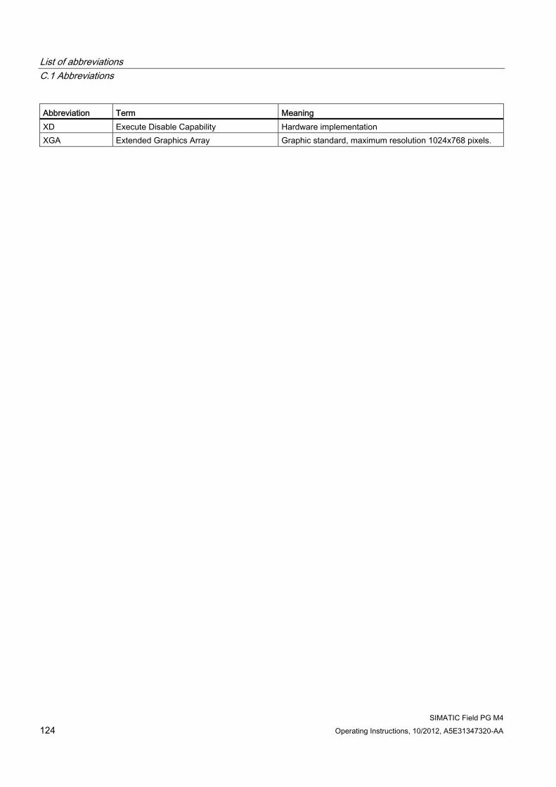
List of abbreviations C.1 Abbreviations
SIMATIC Field PG M4 124 Operating Instructions, 10/2012, A5E31347320-AA
Abbreviation Term Meaning XD Execute Disable Capability Hardware implementation XGA Extended Graphics Array Graphic standard, maximum resolution 1024x768 pixels.
SIMATIC Field PG M4 Operating Instructions, 10/2012, A5E31347320-AA 125
Glossary
AHCI mode AHCI is a standardized method to address the SATA controller. AHCI describes a structure in the RAM, which contains a general area for control and status, as well as a command list.
APIC mode Advanced peripheral interrupt controller. 24 interrupt lines are available.
ATAPI CD-ROM Drive AT Bus Attachment Packet Interface (connected to AT bus) CD-ROM drive
Automation system (AS) A programmable controller (PLC) of the SIMATIC S7 system consist of a central controller, one or several CPUs, and various I/O modules.
Backup Duplicate of a program, data medium or database, used either for archiving purposes or for the protection of vital and non-replaceable data against loss when the working copy is corrupted. Certain applications automatically generate backup copies of data files, and manage both the current and the previous versions on the hard disk.
Baud Physical unit for the step speed in signal transmission. Defines the number of transferred signal states per second. With only two states, one baud is equivalent to a transmission rate of 1 bps.
Boot disk A boot disk is a disk with a "Boot" sector. This can be used to load the operating system from the disk.
Cache High-speed access buffer for interim storage (buffering) of requested data.
Glossary
SIMATIC Field PG M4 126 Operating Instructions, 10/2012, A5E31347320-AA
CE marking Communauté Européene The CE mark confirms compliance of the product with corresponding EC Directives, for example, with the EMC Directive.
Chipset Located on the motherboard, connects the processor with the RAM, the graphics controller, the PCI bus, and the external interfaces.
Cold restart A start sequence, starting when the computer is switched on. The system usually performs some basic hardware checks within the cold start sequence, and then loads the operating system from the hard disk to work memory -> boot
COM interface The COM interface is a serial V.24 interface. The interface is suitable for asynchronous data transfer.
Compact Flash cards (CF) Compact Flash is a digital storage medium in card format and without moving parts. The CF card contains the non-volatile memory and the controller. The interface of the CF card corresponds with the IDE interface. CF cards can be operated without additional electronics on PCMCIA or IDE hard disk controllers using a plug and socket adapter. There are two design forms: CF-I (42.6 x 36.4 x 3.3 mm) and CF-II (42.8 x 36.4 x 5 mm).
Configuration files These are files containing data which define the configuration after restart. Examples of such files are CONFIG.SYS, AUTOEXEC.BAT and the registry files .
Configuration software The configuration software updates the device configuration when new modules are installed . This is done either by copying the configuration files supplied with the module or by manual configuration using the configuration utility.
Controller Integrated hardware and software controllers that control the functions of certain internal or I/O devices (for example, the keyboard controller).
Glossary
SIMATIC Field PG M4 Operating Instructions, 10/2012, A5E31347320-AA 127
Device configuration The configuration of a PC or programming device contains information on hardware and device options, such as memory configuration, drive types, monitor, network address, etc. The data are stored in a configuration file and enable the operating system to load the correct device drivers and configure the correct device parameters. . If changes are made to the hardware configuration, the user can change entries in the configuration file using the SETUP program. .
Disc-at-once With this burning technique, data are written to a CD in a single session, and the CD is then closed. Further write access is then no longer possible.
DPP Display Port: digital monitor interface.
Drivers Program parts of the operating system. They adapt user program data to the specific formats required by I/O devices such as hard disk, printers, and monitors.
Dual Core CPU Dual-core processors significantly increase the speed of computing and program execution compared to the previous generation of single-core processors with hyperthreading technology.
ECC Error checking and correction is a method for detecting and correcting errors when saving and transferring data, frequently used in conjunction with RAM modules with and without ECC.
EMC directive Directive concerning Electromagnetic Compatibility. Compliance is confirmed by the CE symbol and the EC certificate of conformity.
Energy management The energy management functions of a modern PC allow individual control over the current consumption of vital computer components (e.g. of the monitor, hard disk and CPU), by restricting their activity based on the current system or component load. Energy management is of particular importance for mobile PCs.
Glossary
SIMATIC Field PG M4 128 Operating Instructions, 10/2012, A5E31347320-AA
Energy options The energy options can be used to reduce energy consumption of the computer, while keeping it ready for immediate use. This can be configured in Windows by selecting Settings > Control Panel > Energy options.
Enhanced Write Filter (EWF) Configurable write filter that allows you, for example, to boot Windows Embedded Standard from write-protected media (such as CD-ROM), to write protect individual partitions and adapt the performance of the file system to your needs (when using Compact Flash cards).
ESD directive Directive for using electrostatic sensitive components.
Ethernet Local network (bus structure) for text and data communication with a transfer rate of 10/100/1000 Mbps.
Execute Disable Capability Hardware implementation that prevents mutual memory accesses by programs and applications. It is only effective when all relevant system components, such as processors, operating systems and applications are supported.
Extensible Firmware Interface (EFI) Refers to the central interface between the firmware, the individual components of a computer and the operating system. EFI is located logically beneath the operating system and represents the successor to PC BIOS, focusing on 64-bit systems.
File Based Write Filter (FBWF) Configurable write filter to protect individual files from write access.
Formatting Basic partitioning of memory space on a magnetic data medium into tracks and segments. Formatting deletes all data on a data medium. All data media must be formatted prior to their first use.
Gender changer Using the gender changer (25-pin / 25-pin), the COM1/V24/AG interface of the SIMATIC PC family can be converted to the usual 25-pin male connector.
Glossary
SIMATIC Field PG M4 Operating Instructions, 10/2012, A5E31347320-AA 129
HORM Hibernate once, resume many is a method for fast booting from a single Hibernate file that only needs to be created once. HORM ensures restoration of a uniform, saved system state when booting. This reduces the writing to a CompactFlash medium to a minimum, for example, when starting up and shutting down Windows Embedded Standard 2009.
Hot plug The SATA interface gives the device's hard drive system hot plugging capability. Prerequisite for this configuration is a RAID1 system with SATA RAID controller (onboard, or slot module), and at least two SATA removable cartridges. The advantage of hot plugging is that defective hard disks can be replaced without having to reboot the computer.
Hub A term in network technology. In a network, a device joining communication lines at a central location, providing a common connection to all devices on the network.
Hyper Threading HT technology (multi-threading) enables the parallel computing of processes. HT is only effective when all relevant system components, such as processors, operating systems and applications are supported.
IGD Integrated Graphics Device. Graphics interface integrated in the chipset.
Image This refers to the image, for example, of hard disk partitions saved to a file in order to restore them when necessary.
Intel Active Management Technology (iAMT) This technology permits the diagnostics, management and remote control of PCs. It is only effective when all relevant system components, such as processors, operating systems and applications are supported.
Intel VT The Intel Virtualization Technology (IVT) is the implementation of a secure closed environment for applications. Special (visualization) software an a VT-capable processor is required for its use.
Glossary
SIMATIC Field PG M4 130 Operating Instructions, 10/2012, A5E31347320-AA
Interface ● Physical interconnection (cable) of hardware elements such as PLCs, PCs, programming
devices, printers or monitors.
● Interface for interactive software applications.
Interface, multi-point MPI is the programming interface of SIMATIC S7/M7. Allows remote access to programmable modules, text-based displays and OPs from central locations. The MPI nodes can intercommunicate.
LAN Local Area Network: LAN is a local network that consists of a group of computers and other devices that are distributed across a relatively restricted range and are linked with communication cables. The devices connected to a LAN are called nodes. The purpose of networks is the mutual use of files, printers or other resources.
Legacy Boot Device Conventional drives can be used as USB devices.
Legacy USB support Support of USB devices (e.g. mouse, keyboard) on the USB ports without driver.
License key The license key represents the electronic license stamp of a license. Siemens provides the license keys for protected software.
License key disk The license key disk contains the authorizations or license keys required to enable protected SIMATIC software.
Low-voltage directive EC Product Safety Directive relating to the safety of products which are operated on low voltage (50 V AC to 1000 V AC, 70 V DC to 1500 V DC) and not specified in other directives. Compliance is confirmed by the CE symbol and the EC certificate of conformity.
Memory card Memory cards in credit card format. Memory for user programs and parameters, for example, for programmable modules and CPs.
Glossary
SIMATIC Field PG M4 Operating Instructions, 10/2012, A5E31347320-AA 131
Module Modules are plug-in units for PLCs, programming devices or PCs. They are available as local modules, expansion modules, interfaces or mass storage (Mass storage module).
Motherboard The motherboard is the core of the computer. Here, data are processed and stored, and interfaces and device I/Os are controlled and managed.
Operating system Generic term which describes all functions for controlling and monitoring user program execution, distribution of system resources to the user programs and the operating mode in cooperation with the hardware (for example Windows XP Professional).
Packet writing The CD-RW is used as a disk medium. The CD can then be read only by packet–writing compatible software or has to be finalized. Finalization of a CD closes the CD within an ISO9660 shell. You can still write to the CD-RW several times in spite of finalization. Not all CD drives can read packet-written CDs . There are restrictions to using this method in general data transfer.
PC card Trademark of the Personal Computer Memory Card International Association (PCMCIA). Designation for auxiliary cards that conform with PCMCIA specifications. A PC card that has roughly the size of a credit card can be plugged into a PCMCIA slot. Version 1 specifies cards of Type I with a thickness of 3.3 millimeters, which are designed mainly for use as external memory. Version 2 of the PCMCIA specification also defines cards of Type II with a thickness of 5 mm and cards of Type III with a thickness of 10.5 mm. Type II cards can realize devices such as modems, fax cards and network interface cards. Type III cards are equipped with devices that require more space, for example wireless communications modules, or rotary storage media such as hard disk drives, for example.
PC/104 / PC/104-Plus Two bus architectures are especially fashionable today in the industrial world. PC/104 and PC/104-Plus. Both are standard in single-board computers of the PC class. The electrical and logical layout of the two bus systems is identical with ISA (PC/104) and PCI (PC/104-Plus). Software cannot usually detect a difference between them and normal desktop bus systems. Their advantage is the compact design and the resulting space they save.
PCMCIA Association consisting of approx. 450 member companies of the computer industry whose focus is set on providing worldwide standards for miniaturization and flexible use of PC expansion cards in order to provide basic technologies to the market.
Glossary
SIMATIC Field PG M4 132 Operating Instructions, 10/2012, A5E31347320-AA
PIC mode Peripheral interrupt controller. 15 interrupt lines are available.
Pixel PixElement (picture point). The pixel represents the smallest element that can be reproduced on-screen or on a printer.
Plug&Play Generally, a reference to the ability of a computer to automatically configure the system for communication with peripheral devices (for example monitors, modems or printers). The user can plug in a peripheral and "play" it at once without manually configuring the system. A Plug&Play PC requires both a BIOS that supports Plug&Play and a Plug&Play expansion card.
POST Self-test performed by the BIOS after the computer is switched on. Performs a RAM test and a graphics controller test, for example. The system outputs audible signals (beep codes) if the BIOS detects any errors; the relevant message indicating cause of error is output on the screen.
PROFIBUS/MPI Process Field Bus (standard bus system for process applications)
PROFINET PROFINET is the name of the standard for Industrial Ethernet developed and maintained by the PROFIBUS user organization. PROFINET unites protocols and specifications with which Industrial Ethernet meets the requirements of industrial automation technology.
Programmable controller (PLC) The programmable controllers (PLC) of the SIMATIC S5 system consist of a central controller, one or more CPUs, and various other modules (e.g. I/O modules).
PXE server A Preboot Execution Environment server is part of a network environment and can provide software to connected computers even before they boot. This can involve operating system installations or servicing tools, for example.
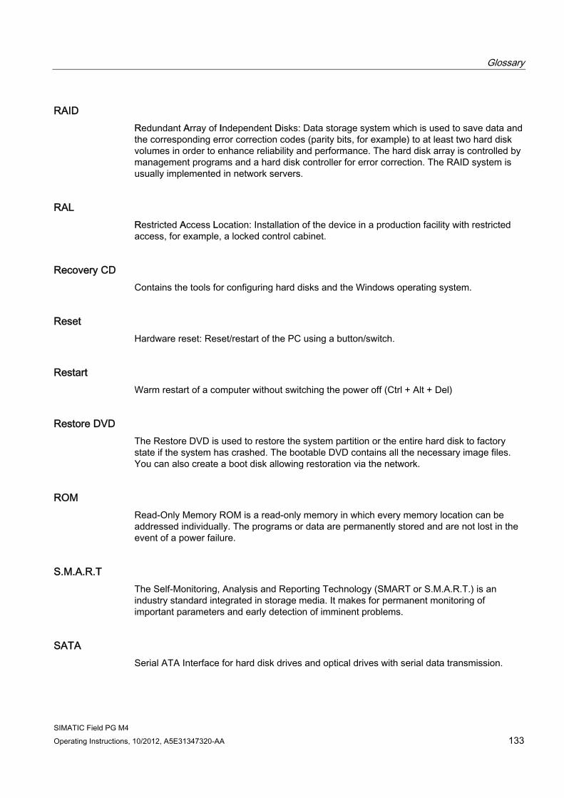
Glossary
SIMATIC Field PG M4 Operating Instructions, 10/2012, A5E31347320-AA 133
RAID Redundant Array of Independent Disks: Data storage system which is used to save data and the corresponding error correction codes (parity bits, for example) to at least two hard disk volumes in order to enhance reliability and performance. The hard disk array is controlled by management programs and a hard disk controller for error correction. The RAID system is usually implemented in network servers.
RAL Restricted Access Location: Installation of the device in a production facility with restricted access, for example, a locked control cabinet.
Recovery CD Contains the tools for configuring hard disks and the Windows operating system.
Reset Hardware reset: Reset/restart of the PC using a button/switch.
Restart Warm restart of a computer without switching the power off (Ctrl + Alt + Del)
Restore DVD The Restore DVD is used to restore the system partition or the entire hard disk to factory state if the system has crashed. The bootable DVD contains all the necessary image files. You can also create a boot disk allowing restoration via the network.
ROM Read-Only Memory ROM is a read-only memory in which every memory location can be addressed individually. The programs or data are permanently stored and are not lost in the event of a power failure.
S.M.A.R.T The Self-Monitoring, Analysis and Reporting Technology (SMART or S.M.A.R.T.) is an industry standard integrated in storage media. It makes for permanent monitoring of important parameters and early detection of imminent problems.
SATA Serial ATA Interface for hard disk drives and optical drives with serial data transmission.
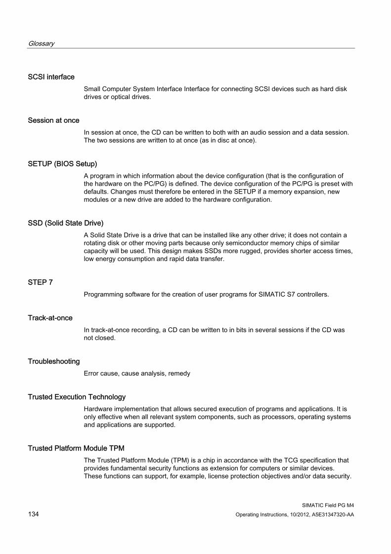
Glossary
SIMATIC Field PG M4 134 Operating Instructions, 10/2012, A5E31347320-AA
SCSI interface Small Computer System Interface Interface for connecting SCSI devices such as hard disk drives or optical drives.
Session at once In session at once, the CD can be written to both with an audio session and a data session. The two sessions are written to at once (as in disc at once).
SETUP (BIOS Setup) A program in which information about the device configuration (that is the configuration of the hardware on the PC/PG) is defined. The device configuration of the PC/PG is preset with defaults. Changes must therefore be entered in the SETUP if a memory expansion, new modules or a new drive are added to the hardware configuration.
SSD (Solid State Drive) A Solid State Drive is a drive that can be installed like any other drive; it does not contain a rotating disk or other moving parts because only semiconductor memory chips of similar capacity will be used. This design makes SSDs more rugged, provides shorter access times, low energy consumption and rapid data transfer.
STEP 7 Programming software for the creation of user programs for SIMATIC S7 controllers.
Track-at-once In track-at-once recording, a CD can be written to in bits in several sessions if the CD was not closed.
Troubleshooting Error cause, cause analysis, remedy
Trusted Execution Technology Hardware implementation that allows secured execution of programs and applications. It is only effective when all relevant system components, such as processors, operating systems and applications are supported.
Trusted Platform Module TPM The Trusted Platform Module (TPM) is a chip in accordance with the TCG specification that provides fundamental security functions as extension for computers or similar devices. These functions can support, for example, license protection objectives and/or data security.
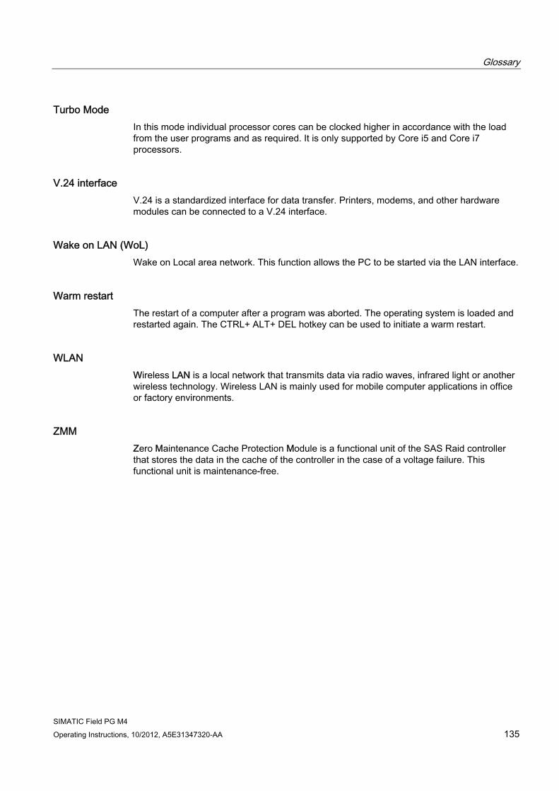
Glossary
SIMATIC Field PG M4 Operating Instructions, 10/2012, A5E31347320-AA 135
Turbo Mode In this mode individual processor cores can be clocked higher in accordance with the load from the user programs and as required. It is only supported by Core i5 and Core i7 processors.
V.24 interface V.24 is a standardized interface for data transfer. Printers, modems, and other hardware modules can be connected to a V.24 interface.
Wake on LAN (WoL) Wake on Local area network. This function allows the PC to be started via the LAN interface.
Warm restart The restart of a computer after a program was aborted. The operating system is loaded and restarted again. The CTRL+ ALT+ DEL hotkey can be used to initiate a warm restart.
WLAN Wireless LAN is a local network that transmits data via radio waves, infrared light or another wireless technology. Wireless LAN is mainly used for mobile computer applications in office or factory environments.
ZMM Zero Maintenance Cache Protection Module is a functional unit of the SAS Raid controller that stores the data in the cache of the controller in the case of a voltage failure. This functional unit is maintenance-free.

Glossary
SIMATIC Field PG M4 136 Operating Instructions, 10/2012, A5E31347320-AA
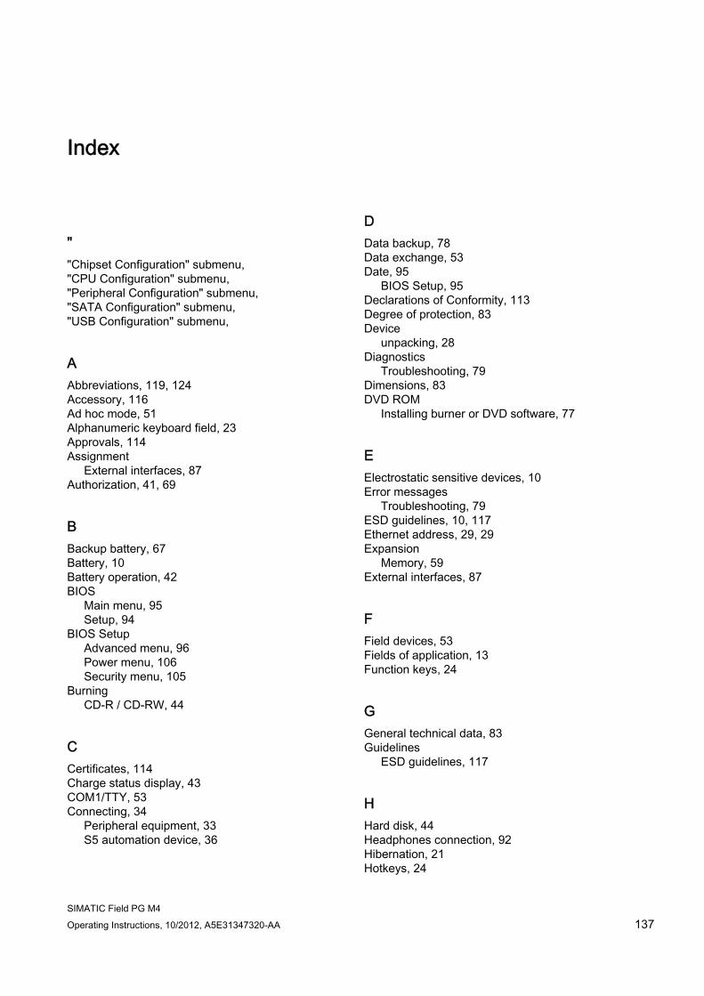
SIMATIC Field PG M4 Operating Instructions, 10/2012, A5E31347320-AA 137
Index
" "Chipset Configuration" submenu, "CPU Configuration" submenu, "Peripheral Configuration" submenu, "SATA Configuration" submenu, "USB Configuration" submenu,
A Abbreviations, 119, 124 Accessory, 116 Ad hoc mode, 51 Alphanumeric keyboard field, 23 Approvals, 114 Assignment
External interfaces, 87 Authorization, 41, 69
B Backup battery, 67 Battery, 10 Battery operation, 42 BIOS
Main menu, 95 Setup, 94
BIOS Setup Advanced menu, 96 Power menu, 106 Security menu, 105
Burning CD-R / CD-RW, 44
C Certificates, 114 Charge status display, 43 COM1/TTY, 53 Connecting, 34
Peripheral equipment, 33 S5 automation device, 36
D Data backup, 78 Data exchange, 53 Date, 95
BIOS Setup, 95 Declarations of Conformity, 113 Degree of protection, 83 Device
unpacking, 28 Diagnostics
Troubleshooting, 79 Dimensions, 83 DVD ROM
Installing burner or DVD software, 77
E Electrostatic sensitive devices, 10 Error messages
Troubleshooting, 79 ESD guidelines, 10, 117 Ethernet address, 29, 29 Expansion
Memory, 59 External interfaces, 87
F Field devices, 53 Fields of application, 13 Function keys, 24
G General technical data, 83 Guidelines
ESD guidelines, 117
H Hard disk, 44 Headphones connection, 92 Hibernation, 21 Hotkeys, 24
Index
SIMATIC Field PG M4 138 Operating Instructions, 10/2012, A5E31347320-AA
I Identification data, 29 Image
creating, 78 Industrial WLAN, 53 Infrastructure mode, 51 Initial commissioning, 39 Installation
Burner / DVD software, 77 Memory modules, 60
Installation of operating system Windows 7, 72 Windows XP, 70
Integration Profibus, 53 RJ45 Ethernet, 53
Interconnection to SIMATIC S5, 53 Interconnection to SIMATIC S7, 53 Interface assignment
DVI, 89 Interfaces
Keyboard, 16 PROFIBUS, 53 PROFIBUS / MPI, 86 RJ45 Ethernet, 53 RS485, 86 Serial, 87, 88 USB, 15, 86
IT communication, 53 IT Security, 11
K Keyboard, 16 Keyboard arrangement, 22 Keyboard labeling, 23 Keyboard LEDs, 26
L License key, 41, 69 Lithium battery, 67 Localized information, 35 Low voltage directive, 113
M Memory
Expansion, 59 Memory card interface, 47
Memory configuration, 61 Memory modules, 46
installation, 60 Micro Memory Card, 49 Micro-In, 92 Microsoft Windows Product Key, 29 Modules
installation, 59 Motherboard
External interfaces, 87 Mouse buttons, 22 MUI, 74
N Network card, 51 Numeric pad, 24
O On/off button, 20 Online ordering system, 53 Operating system, 39
Starting for the first time, 39 Updates, 77
Optical drive, 44 Order No., 29 Order number, 29
P Partition
Windows XP delivery state, 71 Peripheral equipment, 33 Pin assignment of the interfaces on the motherboard
COM1, X30, 88 PROFIBUS / MPI, 91
Positioning the device, 31 Power Button, 21 Power consumption, 83 Power supply
Connecting, 34 Processor, 84 PROFIBUS, 53
Integration, 53 PROFIBUS/MPI interface, 91 PS/2 port, 16
Index
SIMATIC Field PG M4 Operating Instructions, 10/2012, A5E31347320-AA 139
R Recovery DVD, 68 Repairs, 9 Replace the battery, 66 Replacing
Rechargeable battery, 65 Replacing the hard disk assembly, 64 Restart, 39 Restore DVD, 68 Restore DVD set, 68 Restoring the delivery state, 69 RJ45 Ethernet, 53 RS232, 15 RTTE directive, 113
S S5 cabling, 93 S5 memory module, 46 S7 cable, 93 Safety instructions, 9 Safety-related notices
Wireless LAN, 11 Security information, 11 Serial number, 29 Serial port, 87 Setting up partitions
Windows 7, 73 Windows XP, 71
Setting up the language selection, 74 SIMATIC S7
Integration, 53 SOFTNET for PROFIBUS, 53 Softnet S7
Integration, 53 Software, 68
STEP 5, 57 STEP 7, 58
Software for Field PG M4, 68 Standard versions, 16 Standby mode, 21 Starting for the first time, 39 Status displays, 25, 86 STEP 5 software, 57 STEP 7 software, 58 Supply voltage, 35, 83 System Date
BIOS Setup, 95 System Date, 95 System LEDs, 25 System partition, 69
System resources, 93 System Time
BIOS Setup, 95 System Time, 95
T Temperature, 84 Time, 95
BIOS Setup, 95 Touchpad, 22 Transport precautions, 27 Troubleshooting/FAQs, 79 Troubleshooting/WLAN, 80 TTY interface, 53
U Unpacking
Unpacking the device, 28 Updates
Operating system, 77 USB, 15, 86
Technical data, 15, 86 User password, 105
W Warranty, 9 Weight, 83 Windows 7
Installation, 72 Windows XP
Installation, 70 Wireless LAN, 51, 53
Regulations, 114 Safety-related notices, 11
WLAN Troubleshooting, 80

Index
SIMATIC Field PG M4 140 Operating Instructions, 10/2012, A5E31347320-AA