simatic et 200eco distributed i/o station - eandmpublic.eandm.com/public_docs/et200eco_e.pdf ·...
TRANSCRIPT
Preface, Contents
Product Overview1
Installation2
Wiring3
Commissioning and diagnostics4
General Technical Data5
Technical Data6
Appendices
Order Numbers A
Dimensional Drawings B
I/O Address Area C
Glossary, Index
Edition 02/2003A5E00158716-02
ET 200ecoDistributed I/O Station
Manual
SIMATIC
This manual has the order number6ES7198-8GA00-8BA0

!Danger
indicates that death, severe personal injury or substantial property damage will result if proper precautionsare not taken.
!Warning
indicates that death, severe personal injury or substantial property damage can result if properprecautions are not taken.
!Caution
indicates that minor personal injury can result if proper precautions are not taken.
Caution
indicates that property damage can result if proper precautions are not taken.
Notice
draws your attention to particularly important information on the product, handling the product, or to aparticular part of the documentation.
Qualified PersonnelOnly qualified personnel should be allowed to install and work on this equipment. Qualified persons aredefined as persons who are authorized to commission, to ground and to tag circuits, equipment, andsystems in accordance with established safety practices and standards.
Correct UsageNote the following:
!Warning
This device and its components may only be used for the applications described in the catalog or thetechnical description, and only in connection with devices or components from other manufacturers whichhave been approved or recommended by Siemens.
This product can only function correctly and safely if it is transported, stored, set up, and installedcorrectly, and operated and maintained as recommended.
TrademarksSIMATIC, SIMATIC HMI and SIMATIC NET are registered trademarks of SIEMENS AG.
Third parties using for their own purposes any other names in this document which refer to trademarksmight infringe upon the rights of the trademark owners.
Safety GuidelinesThis manual contains notices intended to ensure personal safety, as well as to protect the products andconnected equipment against damage. These notices are highlighted by the symbols shown below andgraded according to severity by the following texts:
We have checked the contents of this manual for agreementwith the hardware and software described. Since deviationscannot be precluded entirely, we cannot guarantee fullagreement. However, the data in this manual are reviewedregularly and any necessary corrections included insubsequent editions. Suggestions for improvement arewelcomed.
Disclaim of LiabilityCopyright Siemens AG 2002-2003 All rights reserved
The reproduction, transmission or use of this document or itscontents is not permitted without express written authority.Offenders will be liable for damages. All rights, including rightscreated by patent grant or registration of a utility model ordesign, are reserved.
Siemens AGBereich Automation and DrivesGeschaeftsgebiet Industrial Automation SystemsPostfach 4848, D- 90327 Nuernberg
Siemens AG 2003Technical data subject to change.
Siemens Aktiengesellschaft A5E00158716-02

iiiET 200eco Distributed I/O StationA5E00158716-02
Preface
Purpose of this manual
The information in this manual helps you to operate the ET 200eco distributedI/O station as DP slave on PROFIBUS DP.
Basic knowledge required
To understand the manual, you require general experience in the field ofautomation engineering.
This manual edition contains a description of the components valid at the time ofits release. We reserve the right to append a Product Information that containsup–to–date information on new components or components of a new version.
Range of validity of this manual
This manual is valid for the ET 200eco distributed I/O station.
Changes as compared to the previous version
This manual contains the following changes and additions as compared to theprevious manual:
• I/O module 16 DO 0.5 A (6ES7 142-3BH00-0XA0)
• I/O module 8 DI / 8 DO 1.3 A (6ES7 143-3BH00-0XA0)
Note: You tell the previous version of the ET 200eco manual by the numberindicated in the footer: A5E00158716-01.
The number of this manual is: A5E00158716-02.
CE label
The product series SIMATIC S7- ET 200eco distributed I/O station is compliantwith requirements and protective aims of following EU guidelines.
• EU guideline 73/23/EEC “Low–voltage guidelines”
• EU guideline 89/336/EEC “EMC compatibility”
C-Tick-Mark
The product series SIMATIC S7- ET 200eco distributed I/O station is compliantwith the standard AS/NZS 2064 (Australia and New Zealand).

Preface
ivET 200eco Distributed I/O Station
A5E00158716-02
Standards
The product series SIMATIC S7 ET 200eco distributed I/O station is compliant withrequirements and criteria of IEC 61131–2.
The ET 200eco distributed I/O station is based on the IEC 61784-1:2002 Ed1CP 3/1 standard.
Its place in information technology
In addition to this documentation, you require the corresponding manual for yourDP master.
Manual
This manual describes the hardware of your ET 200eco distributed I/O station. Itconsists of introductory chapters and reference chapters (technical specifications).
The manual deals with the following topics:
• Installation and wiring of the ET 200eco distributed I/O station
• Commissioning and diagnostics of the ET 200eco distributed I/O station
• Components of the ET 200eco distributed I/O station
• Order Numbers
• The glossary contains explanations of important terms.
• The index helps you to quickly find textual information on important keywords.
Recycling and disposal
ET 200eco equipment can be recycled due to the low content of harmfulsubstances in its components.
Please contact a company certified for disposal of electronic waste material forenvironment friendly recycling and disposal of your old equipment.

Preface
vET 200eco Distributed I/O StationA5E00158716-02
Further support
Please contact your local SIEMENS partner if you have any further queries on theproducts described in this manual.
http://www.ad.siemens.de/partner
Training Centers
We offer a range of courses to help you get started with the ET 200eco distributedI/O station and the SIMATIC S7 PLCs. Please contact your local training center orthe central training center in D 90327 Nuremberg. Phone: +49 (911) 895-3200.
Internet: http://www.sitrain.com

Preface
viET 200eco Distributed I/O Station
A5E00158716-02
A&D Technical Support
Open round the clock, worldwide:
Johnson City
Nuremberg
Beijing
Technical Support
Worldwide (Nuremberg)
Technical Support
Local time: 0:00 to 24:00 / 365 days
Phone: +49 (0) 180 5050-222
Phone: +49 (0) 180 5050-223
E-Mail: [email protected]
GMT: +1:00
Europe/Africa (Nuremberg)
Authorization
Local time: 8:00 to 17:00
Phone: +49 (0) 180 5050-222
Phone: +49 (0) 180 5050-223
E-Mail: [email protected]
GMT: +1:00
United States (Johnson City)
Technical Support andAuthorizationLocal time: 8:00 to 17:00
Phone: +1 (0) 423 262 2522
Fax: +1 (0) 423 262 2289
E-Mail: [email protected]
GMT: –5:00
Asia/Australia (Beijing)
Technical Support andAuthorizationLocal time: 8:00 to 17:00
Phone: +86 10 64 75 75 75
Fax: +86 10 64 74 74 74
E-mail: [email protected]
GMT: +8:00
German and English spoken at the Technical Support and Authorization hotlines.

Preface
viiET 200eco Distributed I/O StationA5E00158716-02
Service & Support on the Internet
In addition to our documentation services, we also offer you our knowledge baseon the Internet.
http://www.ad.siemens.de/support
Here, you will find:
• our Newsletter, a source that offers updated information on your products
• your appropriate documentation via our Service & Support search engine
• a forum for the exchange of information between users and specialistsworldwide
• your local Automation & Drives partner via our partner database.
• information on repairs, replacement parts and on–site service. Please refer toour ”Service” pages for further topics.

Preface
viiiET 200eco Distributed I/O Station
A5E00158716-02
ixET 200eco Distributed I/O StationA5E00158716-02
Contents
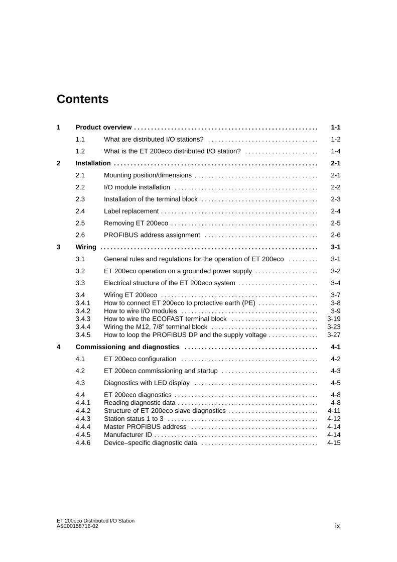
1 Product overview 1-1. . . . . . . . . . . . . . . . . . . . . . . . . . . . . . . . . . . . . . . . . . . . . . . . . . . . . . .
1.1 What are distributed I/O stations? 1-2. . . . . . . . . . . . . . . . . . . . . . . . . . . . . . . . .
1.2 What is the ET 200eco distributed I/O station? 1-4. . . . . . . . . . . . . . . . . . . . . .
2 Installation 2-1. . . . . . . . . . . . . . . . . . . . . . . . . . . . . . . . . . . . . . . . . . . . . . . . . . . . . . . . . . . . .
2.1 Mounting position/dimensions 2-1. . . . . . . . . . . . . . . . . . . . . . . . . . . . . . . . . . . . .
2.2 I/O module installation 2-2. . . . . . . . . . . . . . . . . . . . . . . . . . . . . . . . . . . . . . . . . . .
2.3 Installation of the terminal block 2-3. . . . . . . . . . . . . . . . . . . . . . . . . . . . . . . . . . .
2.4 Label replacement 2-4. . . . . . . . . . . . . . . . . . . . . . . . . . . . . . . . . . . . . . . . . . . . . . .
2.5 Removing ET 200eco 2-5. . . . . . . . . . . . . . . . . . . . . . . . . . . . . . . . . . . . . . . . . . . .
2.6 PROFIBUS address assignment 2-6. . . . . . . . . . . . . . . . . . . . . . . . . . . . . . . . . .
3 Wiring 3-1. . . . . . . . . . . . . . . . . . . . . . . . . . . . . . . . . . . . . . . . . . . . . . . . . . . . . . . . . . . . . . . . .
3.1 General rules and regulations for the operation of ET 200eco 3-1. . . . . . . . .
3.2 ET 200eco operation on a grounded power supply 3-2. . . . . . . . . . . . . . . . . . .
3.3 Electrical structure of the ET 200eco system 3-4. . . . . . . . . . . . . . . . . . . . . . . .
3.4 Wiring ET 200eco 3-7. . . . . . . . . . . . . . . . . . . . . . . . . . . . . . . . . . . . . . . . . . . . . . . 3.4.1 How to connect ET 200eco to protective earth (PE) 3-8. . . . . . . . . . . . . . . . . . 3.4.2 How to wire I/O modules 3-9. . . . . . . . . . . . . . . . . . . . . . . . . . . . . . . . . . . . . . . . . 3.4.3 How to wire the ECOFAST terminal block 3-19. . . . . . . . . . . . . . . . . . . . . . . . . . 3.4.4 Wiring the M12, 7/8” terminal block 3-23. . . . . . . . . . . . . . . . . . . . . . . . . . . . . . . . 3.4.5 How to loop the PROFIBUS DP and the supply voltage 3-27. . . . . . . . . . . . . . .
4 Commissioning and diagnostics 4-1. . . . . . . . . . . . . . . . . . . . . . . . . . . . . . . . . . . . . . . .
4.1 ET 200eco configuration 4-2. . . . . . . . . . . . . . . . . . . . . . . . . . . . . . . . . . . . . . . . .
4.2 ET 200eco commissioning and startup 4-3. . . . . . . . . . . . . . . . . . . . . . . . . . . . .
4.3 Diagnostics with LED display 4-5. . . . . . . . . . . . . . . . . . . . . . . . . . . . . . . . . . . . .
4.4 ET 200eco diagnostics 4-8. . . . . . . . . . . . . . . . . . . . . . . . . . . . . . . . . . . . . . . . . . . 4.4.1 Reading diagnostic data 4-8. . . . . . . . . . . . . . . . . . . . . . . . . . . . . . . . . . . . . . . . . . 4.4.2 Structure of ET 200eco slave diagnostics 4-11. . . . . . . . . . . . . . . . . . . . . . . . . . . 4.4.3 Station status 1 to 3 4-12. . . . . . . . . . . . . . . . . . . . . . . . . . . . . . . . . . . . . . . . . . . . . 4.4.4 Master PROFIBUS address 4-14. . . . . . . . . . . . . . . . . . . . . . . . . . . . . . . . . . . . . . 4.4.5 Manufacturer ID 4-14. . . . . . . . . . . . . . . . . . . . . . . . . . . . . . . . . . . . . . . . . . . . . . . . . 4.4.6 Device–specific diagnostic data 4-15. . . . . . . . . . . . . . . . . . . . . . . . . . . . . . . . . . .

Contents
xET 200eco Distributed I/O Station
A5E00158716-02
5 General technical data 5-1. . . . . . . . . . . . . . . . . . . . . . . . . . . . . . . . . . . . . . . . . . . . . . . . . .
5.1 Standards and approvals 5-2. . . . . . . . . . . . . . . . . . . . . . . . . . . . . . . . . . . . . . . . .
5.2 EMC compatibility, shipping and storage conditions 5-3. . . . . . . . . . . . . . . . . .
5.3 Mechanical and climatic ambient conditions 5-5. . . . . . . . . . . . . . . . . . . . . . . . .
5.4 Specification of isolation tests, protection class,type of protection and rated voltage for ET 200eco 5-7. . . . . . . . . . . . . . . . . . .
6 Technical data 6-1. . . . . . . . . . . . . . . . . . . . . . . . . . . . . . . . . . . . . . . . . . . . . . . . . . . . . . . . . .
6.1 ECOFAST terminal block (6ES7 194-3AA00-0AA0) 6-2. . . . . . . . . . . . . . . . . .
6.2 Terminal block M12, 7/8” (6ES7 194-3AA00-0BA0) 6-4. . . . . . . . . . . . . . . . . . .
6.3 I/O module 8 DI (6ES7 141-3BF00-0XA0) 6-7. . . . . . . . . . . . . . . . . . . . . . . . . .
6.4 I/O module 16 DI (6ES7 141-3BH00-0XA0) 6-10. . . . . . . . . . . . . . . . . . . . . . . . .
6.5 I/O module 8 DO 2A (6ES7 142-3BF00-0XA0) 6-13. . . . . . . . . . . . . . . . . . . . . .
6.6 I/O module 16 DO 0.5 A (6ES7 142-3BH00-0XA0) 6-16. . . . . . . . . . . . . . . . . . .
6.7 I/O module 8 DI / 8 DO 2 A (6ES7 143-3BH00-0XA0) 6-19. . . . . . . . . . . . . . . .
6.8 I/O module 8 DI / 8 DO 1.3 A (6ES7 143-3BH00-0XA0) 6-22. . . . . . . . . . . . . . . . . . . . . . . . . . . . . . . . . . . . . . . . .
A Order numbers A-1. . . . . . . . . . . . . . . . . . . . . . . . . . . . . . . . . . . . . . . . . . . . . . . . . . . . . . . . .
B Dimensional drawings B-1. . . . . . . . . . . . . . . . . . . . . . . . . . . . . . . . . . . . . . . . . . . . . . . . . .
C I/O address area C-1. . . . . . . . . . . . . . . . . . . . . . . . . . . . . . . . . . . . . . . . . . . . . . . . . . . . . . . .
Glossary Glossary-1. . . . . . . . . . . . . . . . . . . . . . . . . . . . . . . . . . . . . . . . . . . . . . . . . . . . . . . . . .
Index Index-1. . . . . . . . . . . . . . . . . . . . . . . . . . . . . . . . . . . . . . . . . . . . . . . . . . . . . . . . . . . . . . . .

Contents
xiET 200eco Distributed I/O StationA5E00158716-02
Figures
1-1 Typical structure of a PROFIBUS-DP network 1-3. . . . . . . . . . . . . . . . . . . . . . . 1-2 View of the ET 200eco distributed I/O station 1-4. . . . . . . . . . . . . . . . . . . . . . . . 2-1 Mounting the I/O module onto the base 2-3. . . . . . . . . . . . . . . . . . . . . . . . . . . . . 2-2 Inserting and screw–tightening the terminal block at the I/O module 2-4. . . . 2-3 Removing labels 2-5. . . . . . . . . . . . . . . . . . . . . . . . . . . . . . . . . . . . . . . . . . . . . . . . 2-4 How to set the PROFIBUS-DP address at terminal block M12, 7/8” 2-7. . . . 2-5 How to unscrew the configuration module 2-8. . . . . . . . . . . . . . . . . . . . . . . . . . . 2-6 How to set the PROFIBUS address at the configuration module 2-8. . . . . . . 3-1 ET 200eco operation with reference potential bonded to
equipotential earth 3-4. . . . . . . . . . . . . . . . . . . . . . . . . . . . . . . . . . . . . . . . . . . . . . . 3-2 Potentials in an ET 200eco installation with M12, 7/8” terminal block 3-5. . . 3-3 Potentials in an ET 200eco installation with ECOFAST terminal block 3-6. . 3-4 Connecting the I/O module to protective earth 3-9. . . . . . . . . . . . . . . . . . . . . . . 3-5 How to connect the M12 plug 3-14. . . . . . . . . . . . . . . . . . . . . . . . . . . . . . . . . . . . . 3-6 Y connector 3-15. . . . . . . . . . . . . . . . . . . . . . . . . . . . . . . . . . . . . . . . . . . . . . . . . . . . 3-7 Connecting the ECOFAST connector 3-21. . . . . . . . . . . . . . . . . . . . . . . . . . . . . . 3-8 Connecting the ECOFAST connector 3-22. . . . . . . . . . . . . . . . . . . . . . . . . . . . . . 3-9 How to wire the M12, 7/8” plug 3-25. . . . . . . . . . . . . . . . . . . . . . . . . . . . . . . . . . . . 3-10 How to connect the M12 terminating resistor 3-26. . . . . . . . . . . . . . . . . . . . . . . . 3-11 Loop–through of the PROFIBUS DP and power bus 3-27. . . . . . . . . . . . . . . . . 4-1 ET 200eco startup 4-4. . . . . . . . . . . . . . . . . . . . . . . . . . . . . . . . . . . . . . . . . . . . . . . 4-2 LED display on the ET 200eco 4-5. . . . . . . . . . . . . . . . . . . . . . . . . . . . . . . . . . . . 4-3 Structure of ET 200eco slave diagnostics data 4-11. . . . . . . . . . . . . . . . . . . . . . 4-4 Structure of ET 200eco device–specific diagnostics data 4-15. . . . . . . . . . . . . . 6-1 Block diagram of the ECOFAST terminal block 6-3. . . . . . . . . . . . . . . . . . . . . . 6-2 Block diagram of the M12, 7/8” terminal module 6-6. . . . . . . . . . . . . . . . . . . . . 6-3 Block diagram of I/O module 8 DI 6-8. . . . . . . . . . . . . . . . . . . . . . . . . . . . . . . . . . 6-4 Block diagram of I/O module 16 DI 6-11. . . . . . . . . . . . . . . . . . . . . . . . . . . . . . . . 6-5 Block diagram of I/O module 8 DO 2A 6-14. . . . . . . . . . . . . . . . . . . . . . . . . . . . . . 6-6 Block diagram of I/O module 16 DO 0.5 A 6-17. . . . . . . . . . . . . . . . . . . . . . . . . . 6-7 Block diagram of I/O module 8 DI / 8 DO 2A 6-20. . . . . . . . . . . . . . . . . . . . . . . . 6-8 Block diagram of I/O module 8 DI / 8 DO 1.3 A 6-24. . . . . . . . . . . . . . . . . . . . . . B-1 Dimensional drawing of an I/O module with installed M12, 7/8”
terminal block B-1. . . . . . . . . . . . . . . . . . . . . . . . . . . . . . . . . . . . . . . . . . . . . . . . . . . B-2 Dimensional drawing of an I/O module with installed ECOFAST
terminal block B-2. . . . . . . . . . . . . . . . . . . . . . . . . . . . . . . . . . . . . . . . . . . . . . . . . . . C-1 Address area of I/O module 8 DI C-1. . . . . . . . . . . . . . . . . . . . . . . . . . . . . . . . . . C-2 Address space of I/O module 16 DI C-2. . . . . . . . . . . . . . . . . . . . . . . . . . . . . . . . C-3 Address area of I/O module 8 DO 2 A C-2. . . . . . . . . . . . . . . . . . . . . . . . . . . . . . C-4 Address area of I/O module 16 DO 0.5 A C-3. . . . . . . . . . . . . . . . . . . . . . . . . . . C-5 Address area of I/O module 8 DI / 8 DO 2 A C-4. . . . . . . . . . . . . . . . . . . . . . . . C-6 Address area of I/O module 8 DI / 8 DO 1.3 A C-5. . . . . . . . . . . . . . . . . . . . . . .
Contents
xiiET 200eco Distributed I/O Station
A5E00158716-02
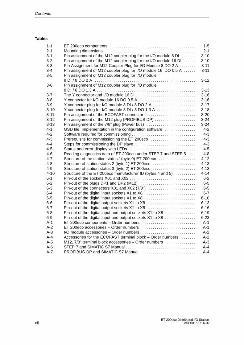
Tables
1-1 ET 200eco components 1-5. . . . . . . . . . . . . . . . . . . . . . . . . . . . . . . . . . . . . . . . . . 2-1 Mounting dimensions 2-1. . . . . . . . . . . . . . . . . . . . . . . . . . . . . . . . . . . . . . . . . . . . 3-1 Pin assignment of the M12 coupler plug for the I/O module 8 DI 3-10. . . . . . . 3-2 Pin assignment of the M12 coupler plug for the I/O module 16 DI 3-10. . . . . . 3-3 Pin Assignment for M12 Coupler Plug for I/O Module 8 DO 2 A 3-11. . . . . . . . 3-4 Pin assignment of M12 coupler plug for I/O module 16 DO 0.5 A 3-11. . . . . . 3-5 Pin assignment of M12 coupler plug for I/O module
8 DI / 8 DO 2 A 3-12. . . . . . . . . . . . . . . . . . . . . . . . . . . . . . . . . . . . . . . . . . . . . . . . . 3-6 Pin assignment of M12 coupler plug for I/O module
8 DI / 8 DO 1.3 A 3-13. . . . . . . . . . . . . . . . . . . . . . . . . . . . . . . . . . . . . . . . . . . . . . . . 3-7 The Y connector and I/O module 16 DI 3-16. . . . . . . . . . . . . . . . . . . . . . . . . . . . . 3-8 Y connector for I/O module 16 DO 0.5 A 3-16. . . . . . . . . . . . . . . . . . . . . . . . . . . . 3-9 Y connector plug for I/O module 8 DI / 8 DO 2 A 3-17. . . . . . . . . . . . . . . . . . . . . 3-10 Y connector plug for I/O module 8 DI / 8 DO 1.3 A 3-18. . . . . . . . . . . . . . . . . . . 3-11 Pin assignment of the ECOFAST connector 3-20. . . . . . . . . . . . . . . . . . . . . . . . . 3-12 Pin assignment of the M12 plug (PROFIBUS DP) 3-24. . . . . . . . . . . . . . . . . . . . 3-13 Pin assignment of the 7/8” plug (Power bus) 3-24. . . . . . . . . . . . . . . . . . . . . . . . 4-1 GSD file Implementation in the configuration software 4-2. . . . . . . . . . . . . . . 4-2 Software required for commissioning 4-3. . . . . . . . . . . . . . . . . . . . . . . . . . . . . . . 4-3 Prerequisite for commissioning the ET 200eco 4-3. . . . . . . . . . . . . . . . . . . . . . 4-4 Steps for commissioning the DP slave 4-3. . . . . . . . . . . . . . . . . . . . . . . . . . . . . 4-5 Status and error display with LEDs 4-5. . . . . . . . . . . . . . . . . . . . . . . . . . . . . . . . 4-6 Reading diagnostics data of ET 200eco under STEP 7 and STEP 5 4-8. . . 4-7 Structure of the station status 1(byte 0) ET 200eco 4-12. . . . . . . . . . . . . . . . . . 4-8 Structure of station status 2 (byte 1) ET 200eco 4-13. . . . . . . . . . . . . . . . . . . . . 4-9 Structure of station status 3 (byte 2) ET 200eco 4-13. . . . . . . . . . . . . . . . . . . . . 4-10 Structure of the ET 200eco manufacturer ID (bytes 4 and 5) 4-14. . . . . . . . . . 6-1 Pin-out of the sockets X01 and X02 6-2. . . . . . . . . . . . . . . . . . . . . . . . . . . . . . . . 6-2 Pin-out of the plugs DP1 and DP2 (M12) 6-5. . . . . . . . . . . . . . . . . . . . . . . . . . . 6-3 Pin-out of the connectors X01 and X02 (7/8”) 6-5. . . . . . . . . . . . . . . . . . . . . . . 6-4 Pin-out of the digital input sockets X1 to X8 6-7. . . . . . . . . . . . . . . . . . . . . . . . . 6-5 Pin-out of the digital input sockets X1 to X8 6-10. . . . . . . . . . . . . . . . . . . . . . . . . 6-6 Pin-out of the digital output sockets X1 to X8 6-13. . . . . . . . . . . . . . . . . . . . . . . . 6-7 Pin-out of the digital output sockets X1 to X8 6-16. . . . . . . . . . . . . . . . . . . . . . . . 6-8 Pin-out of the digital input and output sockets X1 to X8 6-19. . . . . . . . . . . . . . . 6-9 Pin-out of the digital input and output sockets X1 to X8 6-23. . . . . . . . . . . . . . . A-1 ET 200eco components – Order numbers A-1. . . . . . . . . . . . . . . . . . . . . . . . . . A-2 ET 200eco accessories – Order numbers A-1. . . . . . . . . . . . . . . . . . . . . . . . . . A-3 I/O module accessories – Order numbers A-2. . . . . . . . . . . . . . . . . . . . . . . . . . A-4 Accessories for the ECOFAST terminal block – Order numbers A-2. . . . . . . A-5 M12, 7/8” terminal block accessories – Order numbers A-3. . . . . . . . . . . . . . A-6 STEP 7 and SIMATIC S7 Manual A-4. . . . . . . . . . . . . . . . . . . . . . . . . . . . . . . . . . A-7 PROFIBUS DP and SIMATIC S7 Manual A-4. . . . . . . . . . . . . . . . . . . . . . . . . . .
1-1ET 200eco Distributed I/O StationA5E00158716-02
Product overview
In this chapter
This product information shows you
• the place of the ET 200eco distributed I/O station in the ET 200 distributed I/Ostation and
• the components comprising the ET 200eco distributed I/O station.
Chapter overview
Chapter Topic Page
1.1 What are distributed I/O stations? 1-2
1.2 What is the ET 200eco distributed I/O system? 1-4
1
Product overview
1-2ET 200eco Distributed I/O Station
A5E00158716-02
1.1 What are distributed I/O stations?
Distributed I/O systems – Field of application
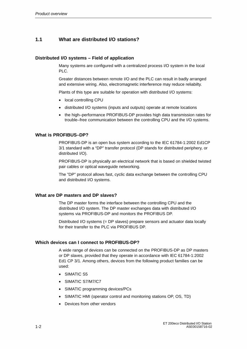
Many systems are configured with a centralized process I/O system in the localPLC.
Greater distances between remote I/O and the PLC can result in badly arrangedand extensive wiring. Also, electromagnetic interference may reduce reliabilty.
Plants of this type are suitable for operation with distributed I/O systems:
• local controlling CPU
• distributed I/O systems (inputs and outputs) operate at remote locations
• the high–performance PROFIBUS-DP provides high data transmission rates fortrouble–free communication between the controlling CPU and the I/O systems.
What is PROFIBUS–DP?
PROFIBUS-DP is an open bus system according to the IEC 61784-1:2002 Ed1CP3/1 standard with a “DP” transfer protocol (DP stands for distributed periphery, ordistributed I/O).
PROFIBUS-DP is physically an electrical network that is based on shielded twistedpair cables or optical waveguide networking.
The ”DP” protocol allows fast, cyclic data exchange between the controlling CPUand distributed I/O systems.
What are DP masters and DP slaves?
The DP master forms the interface between the controlling CPU and thedistributed I/O system. The DP master exchanges data with distributed I/Osystems via PROFIBUS-DP and monitors the PROFIBUS DP.
Distributed I/O systems (= DP slaves) prepare sensors and actuator data locallyfor their transfer to the PLC via PROFIBUS DP.
Which devices can I connect to PROFIBUS-DP?
A wide range of devices can be connected on the PROFIBUS-DP as DP mastersor DP slaves, provided that they operate in accordance with IEC 61784-1:2002Ed1 CP 3/1. Among others, devices from the following product families can beused:
• SIMATIC S5
• SIMATIC S7/M7/C7
• SIMATIC programming devices/PCs
• SIMATIC HMI (operator control and monitoring stations OP, OS, TD)
• Devices from other vendors

Product overview
1-3ET 200eco Distributed I/O StationA5E00158716-02
Structure of a PROFIBUS-DP network
The figure below shows you a typical PROFIBUS DP network structure. The DPmasters are integrated in the corresponding unit, e.g. the S7-400 or S7-300 isequipped with a PROFIBUS-DP interface. The DP slaves, namely the distributedI/O, are interconnected to the DP masters via PROFIBUS DP.
DP master
DP slaves
PROFIBUS-DP
S7-300 PG/PC
ET 200SET 200M S5-95U-DP
further field devices
ET 200X OP/OS
S7-200drive DP/AS–I LinkET200eco
S7-400
Figure 1-1 Typical structure of a PROFIBUS-DP network
Product overview
1-4ET 200eco Distributed I/O Station
A5E00158716-02
1.2 What is the ET 200eco distributed I/O station?
Definition
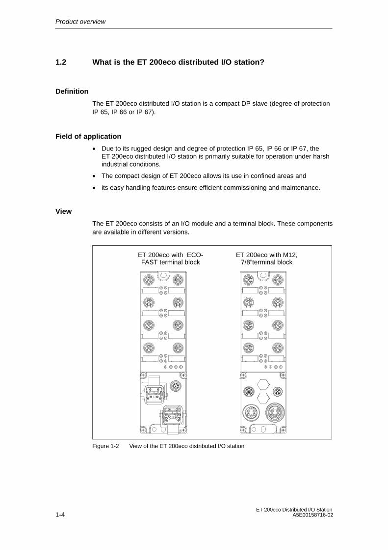
The ET 200eco distributed I/O station is a compact DP slave (degree of protectionIP 65, IP 66 or IP 67).
Field of application
• Due to its rugged design and degree of protection IP 65, IP 66 or IP 67, theET 200eco distributed I/O station is primarily suitable for operation under harshindustrial conditions.
• The compact design of ET 200eco allows its use in confined areas and
• its easy handling features ensure efficient commissioning and maintenance.
View
The ET 200eco consists of an I/O module and a terminal block. These componentsare available in different versions.
ET 200eco with ECO-FAST terminal block
ET 200eco with M12,7/8”terminal block
Figure 1-2 View of the ET 200eco distributed I/O station

Product overview
1-5ET 200eco Distributed I/O StationA5E00158716-02
ET200eco components
The table provides an overview of the major components of ET 200eco:
Table 1-1 ET 200eco components
Component Function Figure
I/O module You connect sensors and actuators tothe I/O module. The I/O module isavailable in the following versions:
• 8 DI
• 16 DI
• 8 DO 2A
• 16 DO 0.5 A
• 8 DI / 8 DO 2A
• 8 DI / 8 DO 1.3 A
Terminal block You connect the ET 200eco powersupply and the PROFIBUS-DP cable tothe terminal block. The terminal block isavailable in the following versions:
• ECOFAST
• M12, 7/8”
DP master
The ET 200eco station can communicate with all DP masters that operateaccording to IEC 61784-1:2002 Ed1 CP 3/1.

Product overview
1-6ET 200eco Distributed I/O Station
A5E00158716-02
2-1ET 200eco Distributed I/O StationA5E00158716-02
Installation
Easy installation
The design of the ET 200eco distributed I/O station allows easy installation.
Chapter overview
Chapter Topic Page
2.1 Mounting position/dimensions 2-1
2.2 I/O module installation 2-2
2.3 Installation of the terminal block 2-3
2.4 Label replacement 2-4
2.5 Removing ET 200eco 2-5
2.6 Setting the PROFIBUS address 2-6
2.1 Mounting position/dimensions
Mounting position
The ET 200eco can be mounted in any position
Mounting and spacing dimensions
Table 2-1 Mounting dimensions
Dimensions
Mounting width 60 mm
Mounting height 210 mm
Mounting depth • with terminal block ECOFAST: 60 mm (without plug)
• with terminal block M12, 7/8”: 54 mm (without plug)
2

Installation
2-2ET 200eco Distributed I/O Station
A5E00158716-02
2.2 I/O module installation
Properties
• The I/O module must be mounted onto a solid base.
• The I/O module (without terminal block) can be prewired.
Requirements
Screws:
Screw type Explanation
M5 cylindrical head screw to ISO1207/ISO 1580 (DIN 84/DIN 85)
Minimum screw length: 20 mm.
Additionally required: DIN 125 washers.
Cylindrical head screw with M5hexagonal socket to DIN 912
Additionally required: DIN 125 washers.
Tools required
Medium size Pillipps screwdriver or 8 mm socket wrench
Installation
2-3ET 200eco Distributed I/O StationA5E00158716-02
Procedure
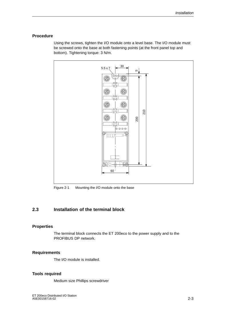
Using the screws, tighten the I/O module onto a level base. The I/O module mustbe screwed onto the base at both fastening points (at the front panel top andbottom). Tightening torque: 3 N/m.
30
200
5.5 x 7
5
210
60
Figure 2-1 Mounting the I/O module onto the base
2.3 Installation of the terminal block
Properties
The terminal block connects the ET 200eco to the power supply and to thePROFIBUS DP network.
Requirements
The I/O module is installed.
Tools required
Medium size Phillips screwdriver
Installation
2-4ET 200eco Distributed I/O Station
A5E00158716-02
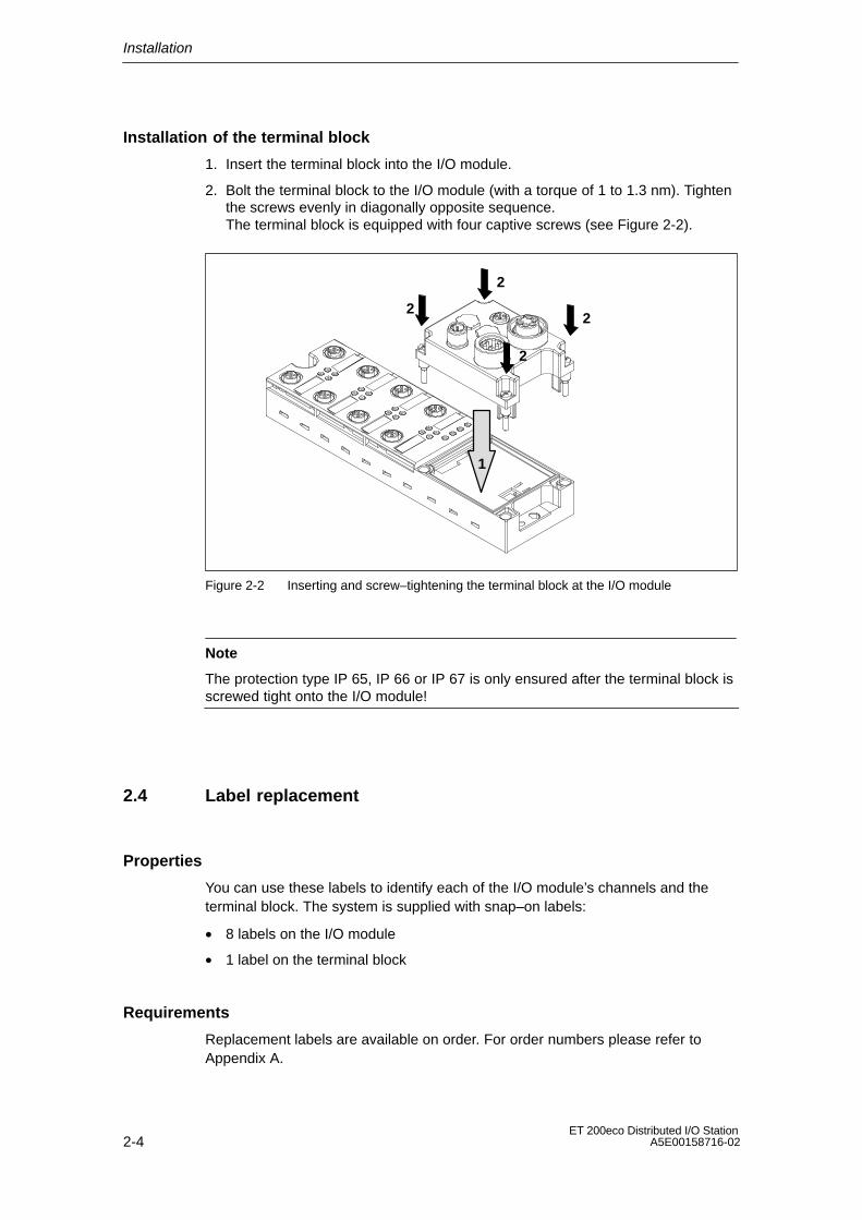
Installation of the terminal block
1. Insert the terminal block into the I/O module.
2. Bolt the terminal block to the I/O module (with a torque of 1 to 1.3 nm). Tightenthe screws evenly in diagonally opposite sequence. The terminal block is equipped with four captive screws (see Figure 2-2).
2
1
2
2
2
Figure 2-2 Inserting and screw–tightening the terminal block at the I/O module
Note
The protection type IP 65, IP 66 or IP 67 is only ensured after the terminal block isscrewed tight onto the I/O module!
2.4 Label replacement
Properties
You can use these labels to identify each of the I/O module’s channels and theterminal block. The system is supplied with snap–on labels:
• 8 labels on the I/O module
• 1 label on the terminal block
Requirements
Replacement labels are available on order. For order numbers please refer toAppendix A.
Installation
2-5ET 200eco Distributed I/O StationA5E00158716-02
Tools required
Screwdriver, 2.5 mm to 4 mm blade
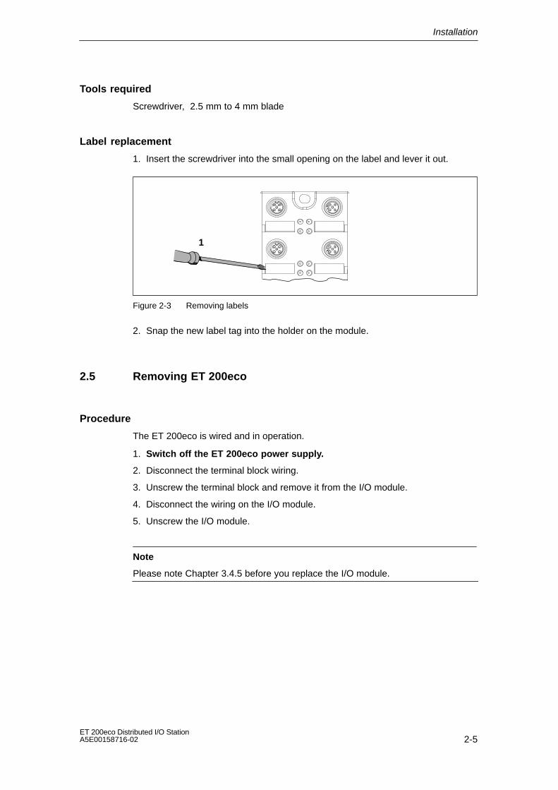
Label replacement
1. Insert the screwdriver into the small opening on the label and lever it out.
1
Figure 2-3 Removing labels
2. Snap the new label tag into the holder on the module.
2.5 Removing ET 200eco
Procedure
The ET 200eco is wired and in operation.
1. Switch off the ET 200eco power supply.
2. Disconnect the terminal block wiring.
3. Unscrew the terminal block and remove it from the I/O module.
4. Disconnect the wiring on the I/O module.
5. Unscrew the I/O module.
Note
Please note Chapter 3.4.5 before you replace the I/O module.

Installation
2-6ET 200eco Distributed I/O Station
A5E00158716-02
2.6 PROFIBUS address assignment
Properties
Specify the PROFIBUS address under which the ET 200eco I/O station isaccessed on PROFIBUS DP.
Requirements
• The PROFIBUS-DP address for ET 200eco is set at the terminal block.
• All PROFIBUS-DP addresses must be unique.
• The set PROFIBUS address must match the PROFIBUS address specified inyour configuration software (for this ET 200eco).
• A change of PROFIBUS–DP address is only valid after the ET 200eco hasbeen powered up (power ON).
Tools required
• 14 mm socket wrench
• Screwdriver with 2.5 mm blade
Installation
2-7ET 200eco Distributed I/O StationA5E00158716-02
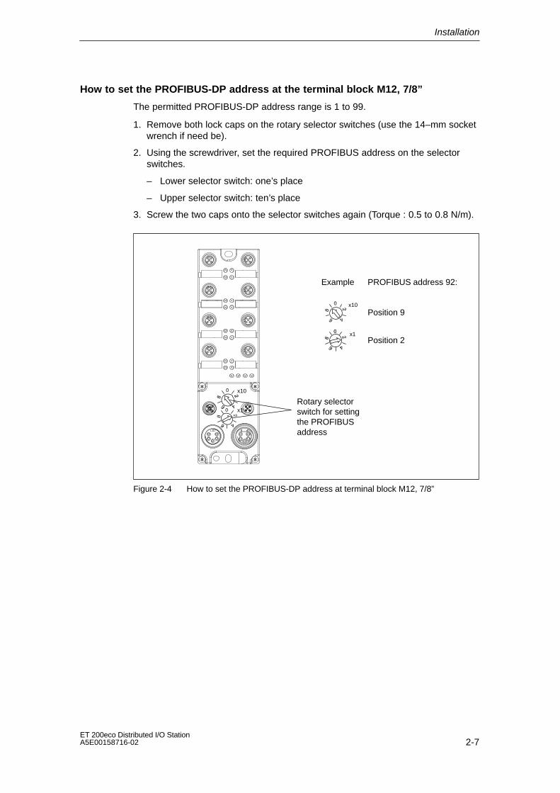
How to set the PROFIBUS-DP address at the terminal block M12, 7/8”
The permitted PROFIBUS-DP address range is 1 to 99.
1. Remove both lock caps on the rotary selector switches (use the 14–mm socketwrench if need be).
2. Using the screwdriver, set the required PROFIBUS address on the selectorswitches.
– Lower selector switch: one’s place
– Upper selector switch: ten’s place
3. Screw the two caps onto the selector switches again (Torque : 0.5 to 0.8 N/m).
Example PROFIBUS address 92:
Position 9
Position 2x1
x10
x10
x1Rotary selectorswitch for settingthe PROFIBUSaddress
Figure 2-4 How to set the PROFIBUS-DP address at terminal block M12, 7/8”
Installation
2-8ET 200eco Distributed I/O Station
A5E00158716-02
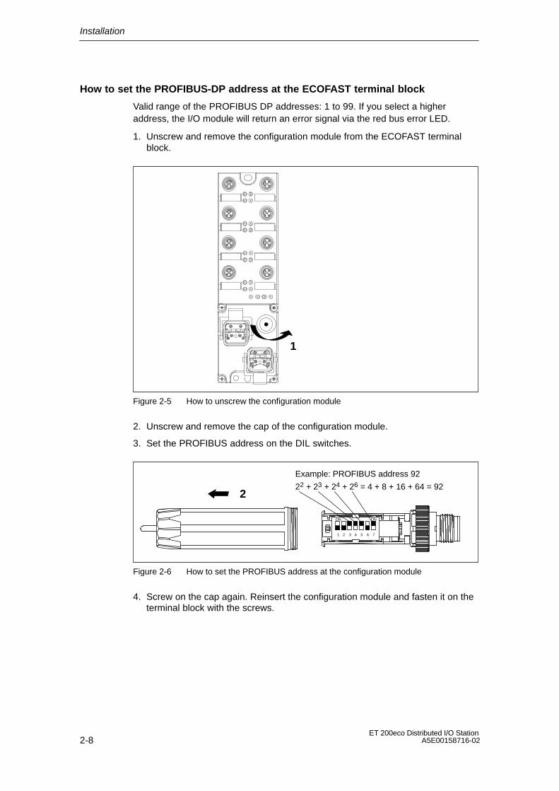
How to set the PROFIBUS-DP address at the ECOFAST terminal block
Valid range of the PROFIBUS DP addresses: 1 to 99. If you select a higheraddress, the I/O module will return an error signal via the red bus error LED.
1. Unscrew and remove the configuration module from the ECOFAST terminalblock.
1
Figure 2-5 How to unscrew the configuration module
2. Unscrew and remove the cap of the configuration module.
3. Set the PROFIBUS address on the DIL switches.
Example: PROFIBUS address 92
22 + 23 + 24 + 26 = 4 + 8 + 16 + 64 = 92
ON ON
1 72 3 4 5 6
2
Figure 2-6 How to set the PROFIBUS address at the configuration module
4. Screw on the cap again. Reinsert the configuration module and fasten it on theterminal block with the screws.

3-1ET 200eco Distributed I/O StationA5E00158716-02
Wiring
Introduction
Special rules and regulations apply to the integration of ET 200eco distributed I/Ostations in plants and systems.
This chapter provides an overview of the essential rules for the integration ofET 200eco distributed I/O stations in plants or systems.
Chapter overview
Chapter Topic Page
3.1 General rules and regulations for the operation of ET 200eco 3-1
3.2 ET 200eco must be operated on a grounded power supply 3-2
3.3 Electrical installation of ET 200eco 3-4
3.4 Wiring ET 200eco 3-7
3.1 General rules and regulations for the operation of ET 200eco
EMERGENCY–OFF devices
All EMERGENCY–OFF devices according to IEC 204 (corresponds toDIN VDE 113) must be enabled for all plant or system operating states.
3

Wiring
3-2ET 200eco Distributed I/O Station
A5E00158716-02
Plant startup after specific events
The table below shows what you need to observe for a restart of the plant afterspecific events.
If... then...
Startup after voltage drop or loss
Startup of ET 200eco after aninterrupt of bus communication
hazardous states must not develop. If necessary,force EMERGENCY–OFF!
Startup after release of the”EMERGENCY–OFF” device
controlled and defined startup must be ensured atall times.
24 VDC power supply
The table below shows what you have to observe when operating the 24 VDCpower supply.
For... always provide...
buildings an external lightningprotection
lightning protection measures
(e.g. lightning protection24 VDC supply lines,signal lines
internal lightning protection(e.g. lightning protectionelements)
24 VDC supply safe (electrical) isolation of the extra–low voltage
Power supply routing Power loss in the through–loop (see Chapter 3.4.5).
Protection against external electrical interference
The table below shows what you have to observe in order to protect your systemfrom electrical interference and faults.
For... ensure that...
all plants or systemsequipped with an ET 200eco,
the plant or system is connected to a grounding conductorin order to discharge electromagnetic interference.
power supply/signal/buscables
correct installation and cable routing.
signal and bus cables a cable/wire break can not cause indefinite plant orsystem states.
3.2 ET 200eco operation on a grounded power supply
Below you can find information on the overall structure of an ET 200eco distributedI/O station that is operated on a grounded power supply (TN-S network). Thetopics treated here are: shutdown devices, short–circuit/overload protection toDIN VDE 0100 and DIN EN 60204-1.
Wiring
3-3ET 200eco Distributed I/O StationA5E00158716-02
Definition: Grounded powersupply
The neutral conductor of grounded power supplies is connected to ground. Anyground fault at a live conductor or grounded part of the system will trigger aresponse of the protection devices.
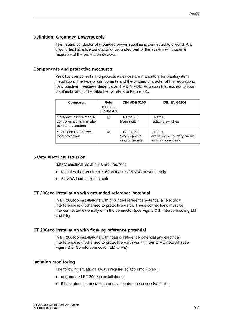
Components and protective measures
Vario1us components and protective devices are mandatory for plant/systeminstallation. The type of components and the binding character of the regulationsfor protective measures depends on the DIN VDE regulation that applies to yourplant installation. The table below refers to Figure 3-1.
Compare... Refe-rence to
Figure 3-1
DIN VDE 0100 DIN EN 60204
Shutdown device for thecontroller, signal transdu-cers and actuators
...Part 460:Main switch
...Part 1:Isolating switches
Short–circuit and over-load protection
...Part 725:Single–pole fu-sing of circuits
...Part 1:grounded secondary circuit:single–pole fusing
Safety electrical isolation
Safety electrical isolation is required for :
• Modules that require a 60 VDC or 25 VAC power supply
• 24 VDC load current circuit
ET 200eco installation with grounded reference potential
In ET 200eco installations with grounded reference potential all electricalinterference is discharged to protective earth. These connections must beinterconnected externally or in the connector (see Figure 3-1: Interconnecting 1Mand PE).
ET 200eco installation with floating reference potential
In ET 200eco installations with floating reference potential any electricalinterference is discharged to protective earth via an internal RC network (seeFigure 3-1: No interconnection 1M to PE).
Isolation monitoring
The following situations always require isolation monitoring:
• ungrounded ET 200eco installations
• if hazardous plant states can develop due to successive faults

Wiring
3-4ET 200eco Distributed I/O Station
A5E00158716-02
Overall structure of ET 200eco
Figure 3-1 shows the overall structure of an ET 200eco distributed I/O station((Load supply voltages and grounding concept) with power supply from a TN-Snetwork.
Grounding bus
1 L+
1M
ET 200eco
L1L2L3n
Low–voltage distribution, e.g. in a TN-S system (3 400 V)
PE
Minternal
Data
P
AC
DC
for ET 200eco with ECOFAST terminal block:24 VDC NS
Terminal block I/O module
1M is not connected to PE in instal-lations without grounding.
ABPROFIBUS-DP
24 VDC
Figure 3-1 ET 200eco operation with reference potential bonded to equipotential earth
3.3 Electrical structure of the ET 200eco system
Isolated potential
The electrical circuit of an ET 200eco is galvanically separated between:
• 1L+ (electronic circuit/sensor supply):Potential isolation to PROFIBUS-DP and 2L+ (load voltage supply),except I/Omodule 8 DI/8 DO 2 A.
• 2L+ (load voltage supply):Potential isolation to all other circuit elements execpt I/O module 8 DI/8 DO 2 A.For I/O module 8 DI/8 DO 2 A, 1M and 2M are interconnected internally.
• PROFIBUS-DP interface:Potential isolation to other circuit components.

Wiring
3-5ET 200eco Distributed I/O StationA5E00158716-02
ET 200eco structure
The figures below show the potentials in an ET 200eco installation with M12, 7/8”terminal block.
Grounding bus
RS485 interface
Data
L1L2L3nPE P
Power supply
AC
DC
AB
1 L+
1 M
AC
DC
2 L+
2 M
Through loop
P5V2M5V2
1 L+
1 M
2 L+
2 M
terminal block M12, 7/8”
I/O module
X1
P5V2M5V2
AB
*
* Only for I/O module 8 DI / 8 DO 2 A
Short-cir–cuit pro–tection
24 VDC
24 VDC
24 VDC
Figure 3-2 Potentials in an ET 200eco installation with M12, 7/8” terminal block

Wiring
3-6ET 200eco Distributed I/O Station
A5E00158716-02
Grounding bus
RS485 interfaceL1L2L3nPE P
Power supply
AC
DC
AB
1 L+
1 M
AC
DC
2 L+
2 M
Through loop
AB
1 L+
1 M
2 L+
2 M
terminal block ECOFAST
I/O module
X1
Short–cir–cuit pro–tection
Data
*
24 VDC
24 VDC
24 VDC
* Only for I/O module 8 DI / 8 DO 2 A
Figure 3-3 Potentials in an ET 200eco installation with ECOFAST terminal block
Note
* For operation of the ET 200eco distributed I/O station with an I/O module8 DI / 8 DO 2 A, the ground potentials of the electronic/sensor supply (1L+) andload voltage supply (2L+) are interconnected.
Wiring
3-7ET 200eco Distributed I/O StationA5E00158716-02
Note
The following applies to an ET 200eco with terminal block:
• The electronic/sensor power supply 1L+ powers the sensors.
• The outputs are powered via by the load voltage supply 2L+.
Protecting components from damage
In order to avoid the destruction of ET200eco components, you must alwaysprovide external line fusing for the electronic/sensor power supply and loadvoltage:
• Fusing of the electronic/sensor power supply (1L+):DC 24 V / 10 A: Tripping characteristics (type) B or C
• Fusing of the load voltage supply: (2L+) 24 VDC / 16 A:Tripping characteristics (type) B or C
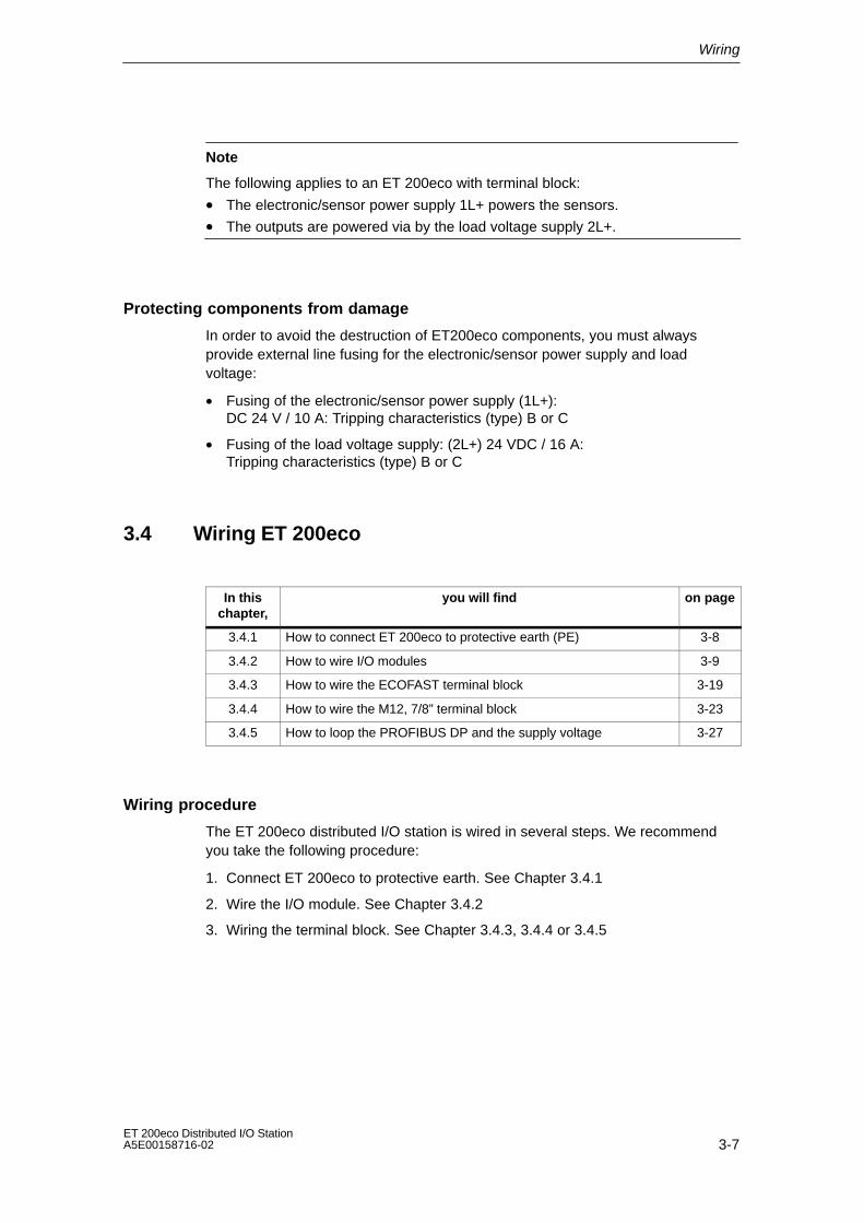
3.4 Wiring ET 200eco
In thischapter,
you will find on page
3.4.1 How to connect ET 200eco to protective earth (PE) 3-8
3.4.2 How to wire I/O modules 3-9
3.4.3 How to wire the ECOFAST terminal block 3-19
3.4.4 How to wire the M12, 7/8” terminal block 3-23
3.4.5 How to loop the PROFIBUS DP and the supply voltage 3-27
Wiring procedure
The ET 200eco distributed I/O station is wired in several steps. We recommendyou take the following procedure:
1. Connect ET 200eco to protective earth. See Chapter 3.4.1
2. Wire the I/O module. See Chapter 3.4.2
3. Wiring the terminal block. See Chapter 3.4.3, 3.4.4 or 3.4.5

Wiring
3-8ET 200eco Distributed I/O Station
A5E00158716-02
3.4.1 How to connect ET 200eco to protective earth (PE)
Properties
• You must always connect the ET 200eco to protective earth. The I/O module isequipped with a grounding bolt for this purpose.
• The connection to protective earth is also required for the discharge of electricalinterference to ground and for EMC compatibility.
Requirements
Always provide a low–impedance connection to protective earth.
Tools required
• Wire stripper
• Crimp tool
• Screwdriver
Accessories required
• M5 x 10 fastening bolt and washers
• Grounding conductor (copper braid cable), minimum conductor cross–section4 mm2.
• Cable lug

Wiring
3-9ET 200eco Distributed I/O StationA5E00158716-02
How to connect ET 200eco to protective earth
1. Strip the grounding cable and crimp on the cable lug.
2. Screw the cable lug onto the M5 bolt of the I/O module. Tightening torque:3 N/m.
Figure 3-4 Connecting the I/O module to protective earth
3.4.2 How to wire I/O modules
Properties
• Connect the digital inputs/outputs to the round 5–pin M12 sockets on the frontpanel of the I/O module.
• Here you can also use 5–pin M12 coupler plugs or Y connectors. Ordernumbers are found in Appendix A.
Requirements
Switch off the power supply or disconnect the terminal block before you wire theI/O modules.
Tools required
Wire stripper and screwdriver for wiring the M12 coupler plug, if you do not useprefabricated cables.
Wiring
3-10ET 200eco Distributed I/O Station
A5E00158716-02
Accessories required
• prefabricated cable with 5–pin M12 coupler plug
• or 3-, 4- or 5–conductor flexible copper cable (conductor cross–section mustbe: 0.75 mm2) and a 5–pin M12 coupler plug(see Tables 3-1, 3-2, 3-3 and 3-6).
• M12 caps
• For order numbers please refer to Appendix A.
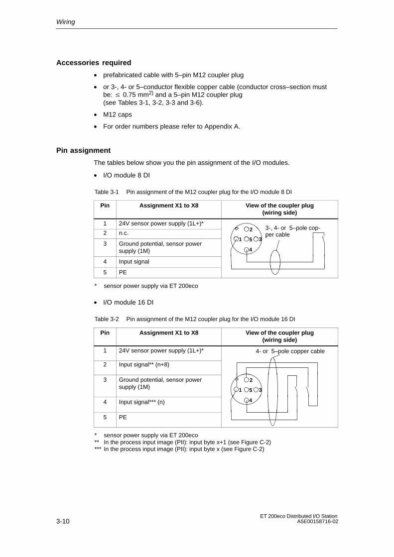
Pin assignment
The tables below show you the pin assignment of the I/O modules.
• I/O module 8 DI
Table 3-1 Pin assignment of the M12 coupler plug for the I/O module 8 DI
Pin Assignment X1 to X8 View of the coupler plug(wiring side)
1 24V sensor power supply (1L+)*
2 n.c.2 3-, 4- or 5–pole cop-
per cable
3 Ground potential, sensor powersupply (1M)
1 3
4
5per cable
4 Input signal
5 PE
* sensor power supply via ET 200eco
• I/O module 16 DI
Table 3-2 Pin assignment of the M12 coupler plug for the I/O module 16 DI
Pin Assignment X1 to X8 View of the coupler plug(wiring side)
1 24V sensor power supply (1L+)* 4- or 5–pole copper cable
2 Input signal** (n+8)
3 Ground potential, sensor powersupply (1M) 1
2
35
4 Input signal*** (n) 4
5 PE
* sensor power supply via ET 200eco** In the process input image (PII): input byte x+1 (see Figure C-2)*** In the process input image (PII): input byte x (see Figure C-2)

Wiring
3-11ET 200eco Distributed I/O StationA5E00158716-02
• I/O module 8 DO 2 A
Table 3-3 Pin Assignment for M12 Coupler Plug for I/O Module 8 DO 2 A
Pin Assignment X1 to X8 View of the coupler plug(wiring side)
1 n.c.
2 n.c.2 3- or
4–pole cable3 Ground potential, load voltage supply
(2M)
1 3
4
5 4–pole cable
4 Output signal
5 PE
• I/O module 16 DO 0.5 A
Table 3-4 Pin assignment of M12 coupler plug for I/O module 16 DO 0.5 A
Pin Assignment X1 to X8 View of the coupler plug(wiring side)
1 n.c. 4- or 5–pole copper cable
2 Output signal* (n+8)
3 Ground potential, load voltage supply(2M) 1
2
35
4 Output signal** (n) 4
5 PE
* In the process output image (POI): output byte x+1 (see Figure C-4)** In the process output image (POI): output byte x (see Figure C-4)

Wiring
3-12ET 200eco Distributed I/O Station
A5E00158716-02
• I/O module 8 DI / 8 DO 2 A
Table 3-5 Pin assignment of M12 coupler plug for I/O module8 DI / 8 DO 2 A
Pin Assignment View of the coupler plug(wiring side)
1 24V sensor power supply (1L+)* 4- or 5–pole copper cable
2 Input signal
3 Ground potential, sensor/load voltagesupply (1M / 2M )** 1
2
35
4 Output signal 4
5 PE
* sensor power supply via ET 200eco** common ground potential for sensor/load voltage supply (1M and 2M internally
interconnected)

Wiring
3-13ET 200eco Distributed I/O StationA5E00158716-02
• I/O module 8 DI / 8 DO 1.3 A
Table 3-6 Pin assignment of M12 coupler plug for I/O module8 DI / 8 DO 1.3 A
Pin Assignment X1, X3, X5, X7 View of the coupler plug(wiring side)
1 24V sensor power supply (1L+)* 4- or 5–pole copper cable
2 Input signal** (n+1)
3 Ground potential, sensor powersupply (1M) 1
2
35
4 Input signal** (n) 4
5 PE
Pin Assignment X2, X4, X6, X8 View of the coupler plug(wiring side)
1 n.c. 4- or 5–pole copper cable
2 Output signal*** (n+1)
3 Ground potential, load voltage supply(2M) 1
2
35
4 Output signal*** (n) 4
5 PE
* sensor power supply via ET 200eco** In the process input image (PII): input byte x (see Figure C-6)*** In the process output image (POI): output byte x (see Figure C-6)

Wiring
3-14ET 200eco Distributed I/O Station
A5E00158716-02
How to connect the M12 plug
1. Insert the plug into the corresponding round socket on the I/O module. Ensurethat the plug and socket interlock (slot and groove).
2. Tighten the knurled screw of the plug.
1
Figure 3-5 How to connect the M12 plug

Wiring
3-15ET 200eco Distributed I/O StationA5E00158716-02
How to connect the Y connector
The Y connector can be used to connect two actuators or sensors to theinputs/outputs of the ET 200eco.
We recommend the use of this Y connector for configurations in which twochannels are assigned per module socket:
• I/O module 16 DI
• I/O module 16 DO 0.5 A
• I/O module 8 DI / 8 DO 2 A
• I/O module 8 DI / 8 DO 1.3 A
The Y connector distributes the two channels to two coupler plugs (pin assignment,see Tables 3-7 and 3-10).
Note: You can not combine the Y connector with the angled M12 coupler plug,5–pin, order no. 3RX1 668.
1. Insert the Y connector into the corresponding round socket on the I/O module.Ensure that the plug and socket interlock (slot and groove).
2. Tighten the knurled screw of the plug.
ÓÓÓÓÓÓÓÓÓÓÓÓ
ÓÓÓÓÓÓscrew it onto the ET 200eco
Connection of the I/O viaM12 coupler plug
A (top)
B (lower)
Figure 3-6 Y connector
Wiring
3-16ET 200eco Distributed I/O Station
A5E00158716-02
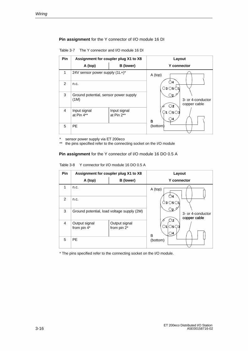
Pin assignment for the Y connector of I/O module 16 DI
Table 3-7 The Y connector and I/O module 16 DI
Pin Assignment for coupler plug X1 to X8 Layout
A (top) B (lower) Y connector
1 24V sensor power supply (1L+)*A (top)
2 n.c.13
4
5
3 Ground potential, sensor power supply(1M)
2
2
3- or 4-conductorcopper cable
4 Input signal at Pin 4**
Input signal at Pin 2**
1
2
3
4
5
B 5 PE
B (bottom)
* sensor power supply via ET 200eco** the pins specified refer to the connecting socket on the I/O module
Pin assignment for the Y connector of I/O module 16 DO 0.5 A
Table 3-8 Y connector for I/O module 16 DO 0.5 A
Pin Assignment for coupler plug X1 to X8 Layout
A (top) B (lower) Y connector
1 n.c. A (top)
2 n.c.13
4
5
3 Ground potential, load voltage supply (2M) 23- or 4-conductorcopper cable
4 Output signal from pin 4*
Output signal from pin 2* 1
2
3
4
5
copper cable
5 PEB (bottom)
* The pins specified refer to the connecting socket on the I/O module.

Wiring
3-17ET 200eco Distributed I/O StationA5E00158716-02
Pin assignment for the Y connector of I/O module 8 DI / 8 DO 2 A
Table 3-9 Y connector plug for I/O module 8 DI / 8 DO 2 A
Pin Assignment for coupler plug X1 to X8 Layout
A (top) B (lower) Y connector
1 24V sensor power supply (1L+)*A (top)
2 n.c.13
4
5
3 Ground potential, sensor/load voltagesupply (1M / 2M)***
2
2
3- or 4-conductorcopper cable
4 Output signal at pin 4**
Output signal at pin 2**
1
2
3
4
5
B 5 PE
B (bottom)
* sensor power supply via ET 200eco** the pins specified refer to the connecting socket on the I/O module*** common ground potential for sensor/load voltage supply (1M and 2M internally
interconnected)
Wiring
3-18ET 200eco Distributed I/O Station
A5E00158716-02
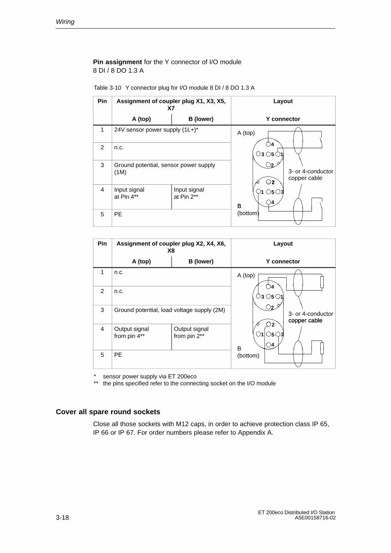
Pin assignment for the Y connector of I/O module 8 DI / 8 DO 1.3 A
Table 3-10 Y connector plug for I/O module 8 DI / 8 DO 1.3 A
Pin Assignment of coupler plug X1, X3, X5,X7
Layout
A (top) B (lower) Y connector
1 24V sensor power supply (1L+)* A (top)
2 n.c.13
4
5
3 Ground potential, sensor power supply(1M)
2
2
3- or 4-conductorcopper cable
4 Input signal at Pin 4**
Input signal at Pin 2**
1
2
3
4
5
B 5 PE
B (bottom)
Pin Assignment of coupler plug X2, X4, X6,X8
Layout
A (top) B (lower) Y connector
1 n.c. A (top)
2 n.c.13
4
5
3 Ground potential, load voltage supply (2M) 23- or 4-conductorcopper cable
4 Output signal from pin 4**
Output signal from pin 2** 1
2
3
4
5
copper cable
5 PEB (bottom)
* sensor power supply via ET 200eco** the pins specified refer to the connecting socket on the I/O module
Cover all spare round sockets
Close all those sockets with M12 caps, in order to achieve protection class IP 65,IP 66 or IP 67. For order numbers please refer to Appendix A.
Wiring
3-19ET 200eco Distributed I/O StationA5E00158716-02
3.4.3 How to wire the ECOFAST terminal block
Properties
• Connect the supply voltages and PROFIBUS DP to the ECOFAST terminalblock via ECOFAST connector.
• You can loop the supply voltages and PROFIBUS DP through an additionalECOFAST connector.
• Always terminate the first and the last ET 200eco (node) on the PROFIBUS-DPwith a terminating resistor.
Requirements
You have set the PROFIBUS address (according to your project configuration).
Tools required
Screwdriver, wire stripper and crimp tool for wiring the ECOFAST connector – ifyou are not using a ready–made ECOFAST connector.
Accessories required
• ECOFAST hybrid prefabricated cable with ECOFAST plug. The cable isavailable in various lengths.
• If you do not use an ECOFAST hybrid prefabricated cable (see Table 3-11):
– Han Brid Cu plug or Han Brid Cu terminal box
– ECOFAST hybrid cable
• Terminating resistor (ECOFAST) for PROFIBUS DP
• For order numbers please refer to Appendix A.

Wiring
3-20ET 200eco Distributed I/O Station
A5E00158716-02
How to wire the ECOFAST connector
Table 3-11 shows you the pin assignment of the ECOFAST connector
Table 3-11 Pin assignment of the ECOFAST connector
Pin Assignment View of the ECOFAST connector(terminal side for incoming signals and
loop–through)
A PROFIBUS DP Signal A Signal A
B PROFIBUS DP Signal B Signal B*
1 Electronic/sensor power supply(1L+) 2 3
A BECOFAST hybridcable
*
2 Ground potential, sensor powersupply (1M)
1 4
2 L+
3 Ground potential, load voltagesupply (2M) 1 L+
4 Load voltage supply (2L+)
* Installation instructions are supplied with the Han Brid Cu plug or Han Brid Cu terminal boxpackage.
Wiring
3-21ET 200eco Distributed I/O StationA5E00158716-02
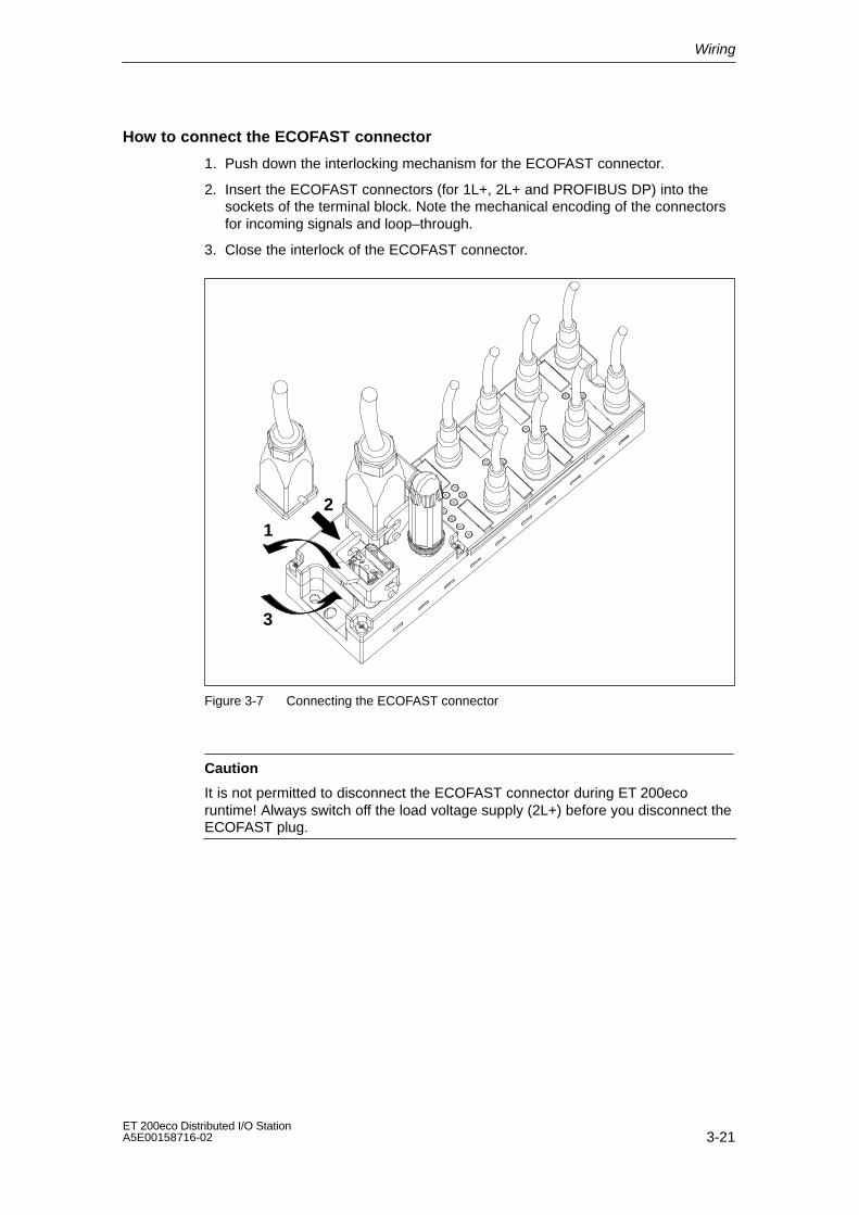
How to connect the ECOFAST connector
1. Push down the interlocking mechanism for the ECOFAST connector.
2. Insert the ECOFAST connectors (for 1L+, 2L+ and PROFIBUS DP) into thesockets of the terminal block. Note the mechanical encoding of the connectorsfor incoming signals and loop–through.
3. Close the interlock of the ECOFAST connector.
12
3
Figure 3-7 Connecting the ECOFAST connector
Caution
It is not permitted to disconnect the ECOFAST connector during ET 200ecoruntime! Always switch off the load voltage supply (2L+) before you disconnect theECOFAST plug.

Wiring
3-22ET 200eco Distributed I/O Station
A5E00158716-02
How to install the PROFIBUS DP terminating resistor
The first and the last node of a PROFIBUS DP segment must be terminated with awave impedance.
At the last bus node, plug the terminal resistor module onto the right–sideconnector of the corresponding ECOFAST terminal block. For procedures pleaserefer to Connecting the ECOFAST connector. For order numbers please refer toAppendix A.
Figure 3-8 Connecting the ECOFAST connector
Note
The terminating resistor is powered via the electronic/sensor power supply (1L+).
Trouble–free operation of the terminating resistor is only ensured if it is connectedto an electronic/sensor power supply (1L+) with a tolerance of range of ±10%.
Closing unused sockets
Close all unused ECOFAST sockets with caps in order to achieve protection classIP 65, IP 66 or IP 67. For order numbers please refer to Appendix A.

Wiring
3-23ET 200eco Distributed I/O StationA5E00158716-02
3.4.4 Wiring the M12, 7/8” terminal block
Properties
• Connect the power supplies and PROFIBUS DP to the M12, 7/8” terminalblock:
– M12 terminals: PROFIBUS DP
– 7/8” terminals: Power bus
• You can loop the power supplies and PROFIBUS DP through the M12 or 7/8”round sockets.
• Always terminate the first and the last ET 200eco (node) on the PROFIBUS-DPwith a terminating resistor.
Requirements
• Always switch off the power supply before you wire the M12, 7/8” terminalblock.
• You have set the PROFIBUS address (according to your project configuration.The terminating resistor is enabled if required)
Tools required
Stripping tool and screwdriver for wiring the M12 or 7/8” plug – if you are not usingready–made plugs.
Accessories required
• Prefabricated cable with plug
• If you do not use a ready–made plug:
– M12: 2–conductor shielded cable (bus cable) and an M12 plug (seeTable 3-12)
– 7/8”: 5–conductor cable and 7/8” plug (see Table 3-13)
• M12 terminating resistor for PROFIBUS DP
• For order numbers please refer to Appendix A.

Wiring
3-24ET 200eco Distributed I/O Station
A5E00158716-02
How to wire the M12, 7/8” plug
Table 3-12 or 3-13 shows you the pin assignment of the M12, 7/8” plug:
Table 3-12 Pin assignment of the M12 plug (PROFIBUS DP)
Pin Assignment View of the M12 plug(wiring side)
1 Power supply + (P5V2)*Signal A (green)
Supply DP1
2 Data line A (RxD / TxD-N) 12
3 45Shielding
3 Data reference potential (M5V2)* Signal B (red)
4 Data line B (RxD / TxD-P)
Signal A (green)
Bus cable(2–wire, shielded)Through–loop DP2
5 Shielding1 2
Shielding
Thread Shielding34 5
Signal B (red)
* Can only be used for the M12 terminating resistor. It is not permitted to loop the voltage tothe next plug via a 5–wire cable.
Table 3-13 Pin assignment of the 7/8” plug (Power bus)
Pin Assignment View of the 7/8” plug(wiring side)
1 Ground potential, load voltage sup-ply (2M)
2 L+
Supply X01
2 Ground potential, sensor powersupply (1M)
1
23
4
5
1 L+
3 PE5–conductor cableThrough–loop X02
4 Electronic/sensor power supply(1L+) 1
23
4
52 L+
5 Load voltage supply (2L+)3
1 L+
Wiring
3-25ET 200eco Distributed I/O StationA5E00158716-02
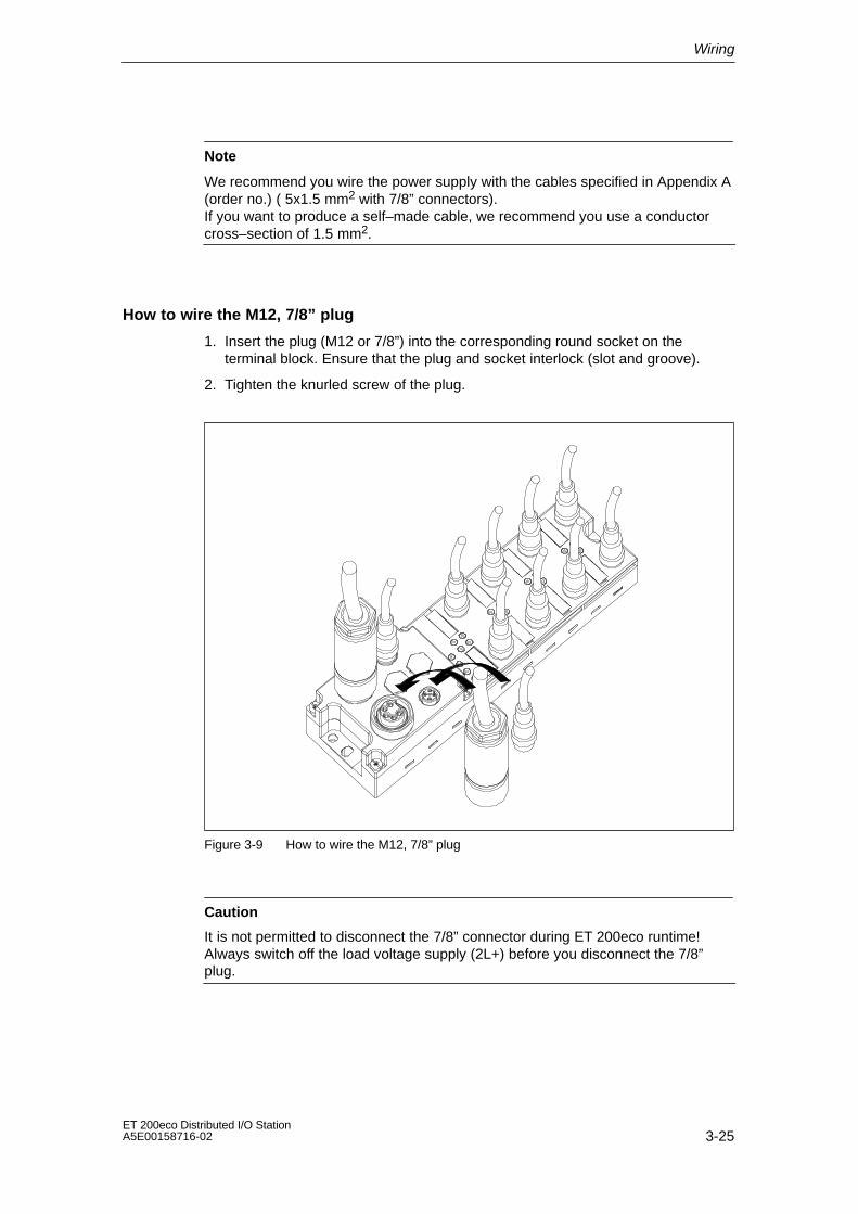
Note
We recommend you wire the power supply with the cables specified in Appendix A(order no.) ( 5x1.5 mm2 with 7/8” connectors). If you want to produce a self–made cable, we recommend you use a conductorcross–section of 1.5 mm2.
How to wire the M12, 7/8” plug
1. Insert the plug (M12 or 7/8”) into the corresponding round socket on theterminal block. Ensure that the plug and socket interlock (slot and groove).
2. Tighten the knurled screw of the plug.
Figure 3-9 How to wire the M12, 7/8” plug
Caution
It is not permitted to disconnect the 7/8” connector during ET 200eco runtime!Always switch off the load voltage supply (2L+) before you disconnect the 7/8”plug.

Wiring
3-26ET 200eco Distributed I/O Station
A5E00158716-02
M12 How to install the PROFIBUS DP terminating resistor
The first and the last node of a PROFIBUS DP segment must be terminated with awave impedance.
Always terminate the PROFIBUS DP with an M12 terminating resistor if theET 200eco is the last PROFIBUS node. For order numbers please refer toAppendix A.
1. Insert the M12 terminating resistor into the right–side round M12Loop–through socket of the terminal block. Make sure it is interlockedcorrectly.
2. Tighten the knurled screw of the M12 terminating resistor module.
Figure 3-10 How to connect the M12 terminating resistor
Closing unused sockets
Close all those sockets with M12 or 7/8” caps, in order to achieve protection classIP 65, IP 66 or IP 67. For order numbers please refer to Appendix A.
Wiring
3-27ET 200eco Distributed I/O StationA5E00158716-02
3.4.5 How to loop the PROFIBUS DP and the supply voltage
Properties
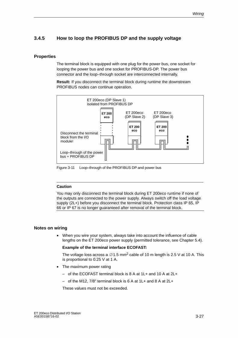
The terminal block is equipped with one plug for the power bus, one socket forlooping the power bus and one socket for PROFIBUS-DP. The power busconnector and the loop–through socket are interconnected internally.
Result: If you disconnect the terminal block during runtime the downstreamPROFIBUS nodes can continue operation.
ET 200eco
ET 200eco
ET 200eco (DP Slave 2)
ET 200eco
ET 200eco (DP Slave 1)isolated from PROFIBUS DP
ET 200eco (DP Slave 3)
Loop–through of the powerbus + PROFIBUS DP
Disconnect the terminalblock from the I/Omodule!
Figure 3-11 Loop–through of the PROFIBUS DP and power bus
Caution
You may only disconnect the terminal block during ET 200eco runtime if none ofthe outputs are connected to the power supply. Always switch off the load voltagesupply (2L+) before you disconnect the terminal block. Protection class IP 65, IP66 or IP 67 is no longer guaranteed after removal of the terminal block.
Notes on wiring
• When you wire your system, always take into account the influence of cablelengths on the ET 200eco power supply (permitted tolerance, see Chapter 5.4).
Example of the terminal interface ECOFAST:
The voltage loss across a 1.5 mm2 cable of 10 m length is 2.5 V at 10 A. Thisis proportional to 0.25 V at 1 A.
• The maximum power rating
– of the ECOFAST terminal block is 8 A at 1L+ and 10 A at 2L+
– of the M12, 7/8” terminal block is 6 A at 1L+ and 8 A at 2L+
These values must not be exceeded.

Wiring
3-28ET 200eco Distributed I/O Station
A5E00158716-02
!Caution
If you ignore the stipulated maximum power supply currents and requiredconductor cross–sections, you may cause excessive heating of the cableinsulation and contact and damage to your equipment.

4-1ET 200eco Distributed I/O StationA5E00158716-02
Commissioning and diagnostics
Chapter overview
Chapter Topic Page
4.1 ET 200eco configuration 4-2
4.2 ET 200eco commissioning and startup 4-3
4.3 Diagnostics with LED display 4-5
4.4 Diagnostics with STEP 5 and STEP 7 4-8
4
Commissioning and diagnostics
4-2ET 200eco Distributed I/O Station
A5E00158716-02
4.1 ET 200eco configuration
GSD file
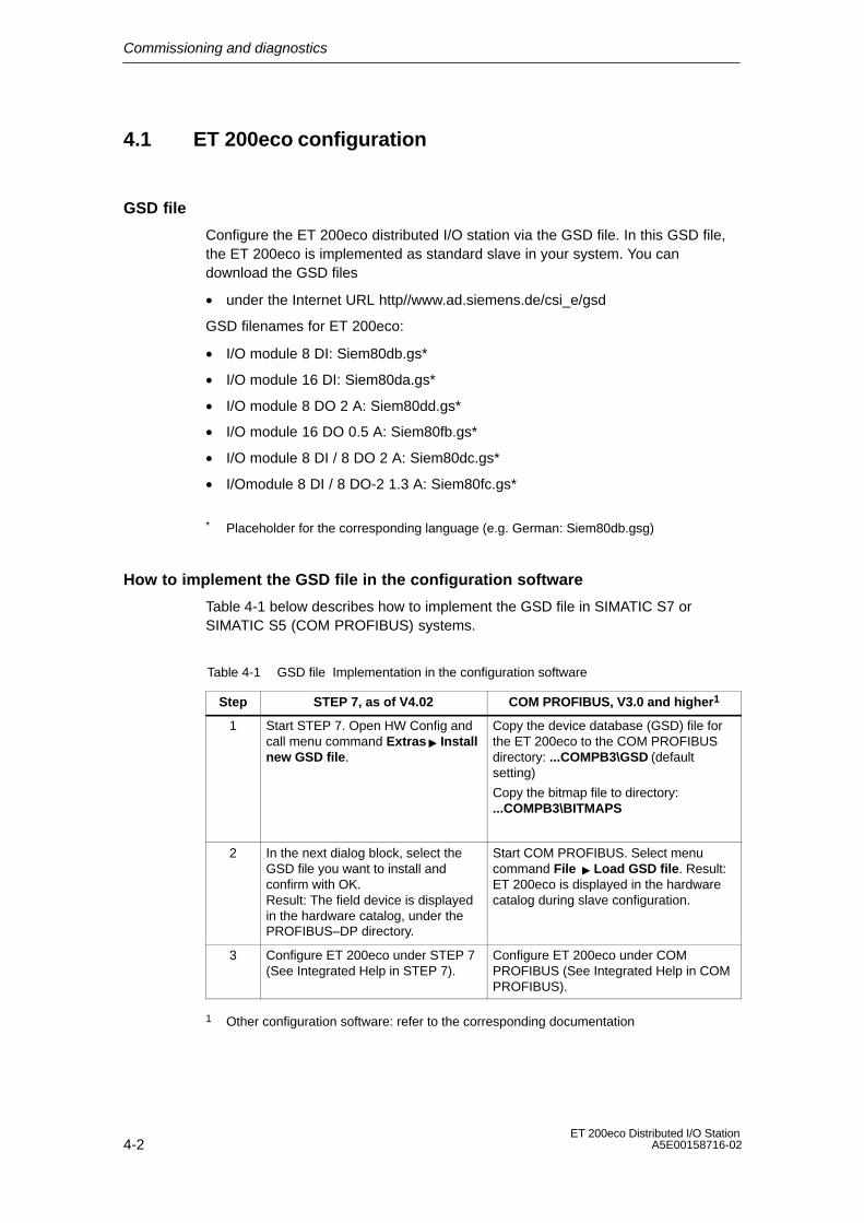
Configure the ET 200eco distributed I/O station via the GSD file. In this GSD file,the ET 200eco is implemented as standard slave in your system. You candownload the GSD files
• under the Internet URL http//www.ad.siemens.de/csi_e/gsd
GSD filenames for ET 200eco:
• I/O module 8 DI: Siem80db.gs*
• I/O module 16 DI: Siem80da.gs*
• I/O module 8 DO 2 A: Siem80dd.gs*
• I/O module 16 DO 0.5 A: Siem80fb.gs*
• I/O module 8 DI / 8 DO 2 A: Siem80dc.gs*
• I/Omodule 8 DI / 8 DO-2 1.3 A: Siem80fc.gs*
* Placeholder for the corresponding language (e.g. German: Siem80db.gsg)
How to implement the GSD file in the configuration software
Table 4-1 below describes how to implement the GSD file in SIMATIC S7 orSIMATIC S5 (COM PROFIBUS) systems.
Table 4-1 GSD file Implementation in the configuration software
Step STEP 7, as of V4.02 COM PROFIBUS, V3.0 and higher1
1 Start STEP 7. Open HW Config andcall menu command Extras Installnew GSD file.
Copy the device database (GSD) file forthe ET 200eco to the COM PROFIBUSdirectory: ...COMPB3\GSD (defaultsetting)
Copy the bitmap file to directory:...COMPB3\BITMAPS
2 In the next dialog block, select theGSD file you want to install andconfirm with OK.Result: The field device is displayedin the hardware catalog, under thePROFIBUS–DP directory.
Start COM PROFIBUS. Select menucommand File Load GSD file. Result:ET 200eco is displayed in the hardwarecatalog during slave configuration.
3 Configure ET 200eco under STEP 7(See Integrated Help in STEP 7).
Configure ET 200eco under COMPROFIBUS (See Integrated Help in COMPROFIBUS).
1 Other configuration software: refer to the corresponding documentation

Commissioning and diagnostics
4-3ET 200eco Distributed I/O StationA5E00158716-02
4.2 ET 200eco commissioning and startup
Software requirements
Table 4-2 Software required for commissioning
Configurationsoftware used
Version Notes
STEP 7 V4.02 or higher You have implemented the GSD file for ET 200eco inSTEP 7.
V 5.1 or higher;ServicePack 4
The GSD file is included in the scope of delivery.
COM PROFIBUS V3.0 or higher You have implemented the GSD file for ET 200eco in COM PROFIBUS.
Configuration softwarefor the DP masterused
You require the GSD file for ET 200eco.
Prerequisite for commissioning
Table 4-3 Prerequisite for commissioning the ET 200eco
Prior activity See...
1. The DP slave is installed Chapter 2
2. The PROFIBUS address is set at the DP slave Chapter 2.6
3. The DP slave is wired Chapter 3
4. The DP slave is configured Chapter4.1
5. The power supply to the DP master is switched on The DP master manual
6. The DP master is set to RUN mode The DP master manual
Commissioning ET 200eco
Table 4-4 Steps for commissioning the DP slave
Step Procedure
1. Switch on the electronic/sensor power supply to the DP slave.
2. If required, switch on the load voltage supply.
Commissioning and diagnostics
4-4ET 200eco Distributed I/O Station
A5E00158716-02
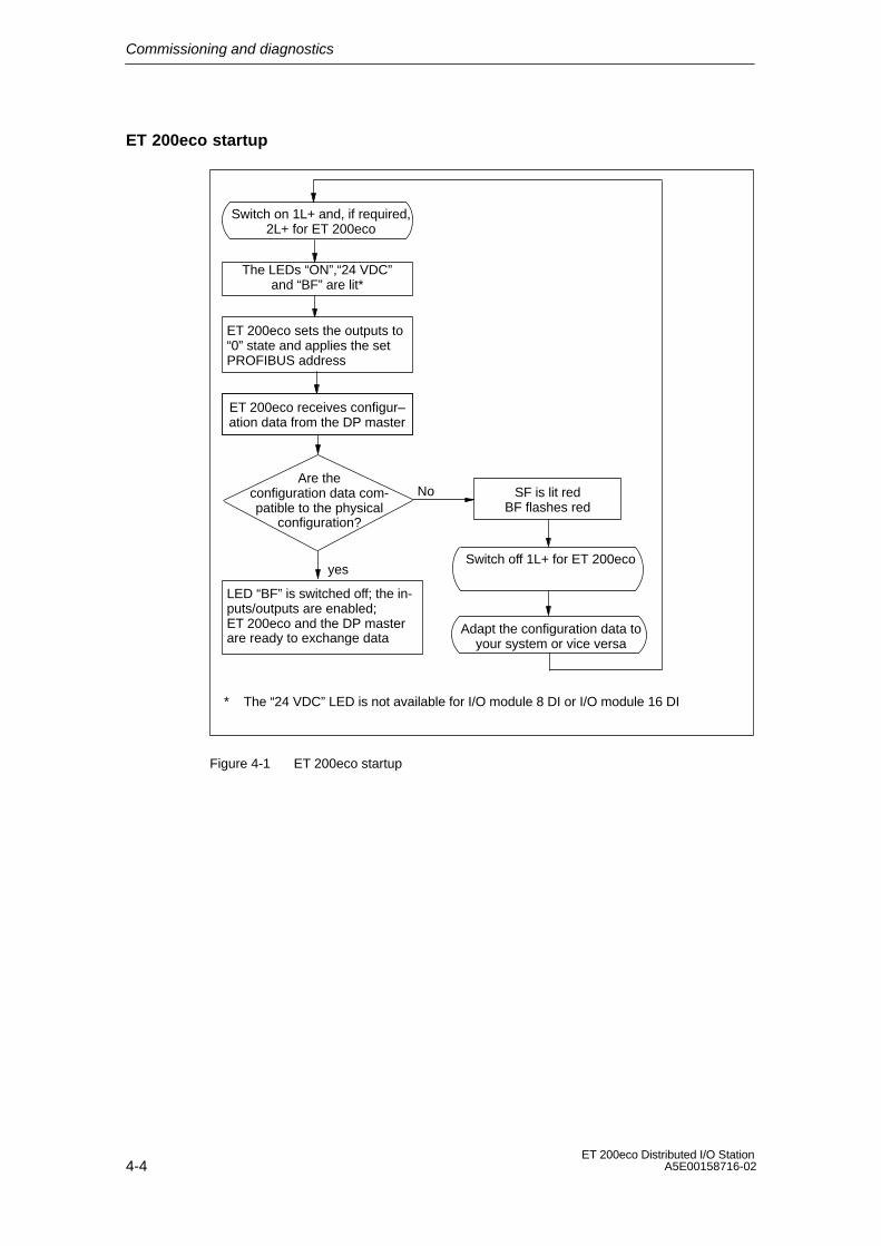
ET 200eco startup
LED “BF” is switched off; the in-puts/outputs are enabled; ET 200eco and the DP masterare ready to exchange data
Switch off 1L+ for ET 200eco
Switch on 1L+ and, if required,2L+ for ET 200eco
yes
No
ET 200eco sets the outputs to“0” state and applies the setPROFIBUS address
ET 200eco receives configur–ation data from the DP master
Are theconfiguration data com-patible to the physical
configuration?
Adapt the configuration data toyour system or vice versa
The LEDs “ON”,“24 VDC”and “BF” are lit*
SF is lit redBF flashes red
* The “24 VDC” LED is not available for I/O module 8 DI or I/O module 16 DI
Figure 4-1 ET 200eco startup

Commissioning and diagnostics
4-5ET 200eco Distributed I/O StationA5E00158716-02
4.3 Diagnostics with LED display
I/O module
SF BF ON 24 VDC
Load voltage supply 2L+ (green)(no LED on I/O module 8 DI and I/O module16 DI)
Electronic/sensor power supply 1L+ (green)
Bus error (red)
Group error (red)
Status display per channel (green)
Figure 4-2 LED display on the ET 200eco
Status and error displays SF, BF, ON
Table 4-5 Status and error display with LEDs
LEDs Meaning Remedy
SF BF ON
off off off • Either the DP slave’selectronic/sensor voltage is missingor too low.
• Switch on the electronic/sensorpower supply (1L+) to the DP slave.
• Hardware is defective. • Replace the I/O module.
* * on The DP slave is in POWER ON mode(electronic/sensor power supply).
–

Commissioning and diagnostics
4-6ET 200eco Distributed I/O Station
A5E00158716-02
Table 4-5 Status and error display with LEDs
LEDs Meaning Remedy
SF BF ON
* on on • DP slave is in startup mode. –
• Communication to the DP master isdown.
• The DP slave does not recognizeany transmission rate.
• Check the PROFIBUS DPconnection.
• Check the DP master.
• Bus interrupt
• The DP master is out of operation
• Check all cables of yourPROFIBUS DP network.
• Verify that the PROFIBUS DPconnector is seated firmly on theterminal block.
off on on • Wrong PROFIBUS address at theconfiguration plug or address > 99.
• Select a PROFIBUS addressbetween 1 to 991
on off on • A diagnostic message is queued.
• Defective hardware in the DP slave.
• Evaluate the diagnostic information.
off on on • Configuration data sent to the DPslave by the DP master isincompatible to the physicalstructure of the DP slave.
• Check your DP slave configuration(I/O, PROFIBUS address).
off on on • The DP slave has recognized thetransmission rate, but is notaddressed by the DP master.
• The DP slave was not configured.
• Check the PROFIBUS address setin the DP slave or in yourconfiguration software.
• Check the configuration of the DPslave (station type).
off flashes off • Overload of the ET200eco sensorpower supply.
• Check the connectedsensors/actuators. Remove theconnected sensors/ actuators, oneafter the other. Result: The BF LED stops flashingand the ON LED is lit when youremove the sensor that has causedthe overload.
• Evidently there is a hardware fault ifthe BF LED continues to flash evenif no more sensors/actuators areconnected to the I/O module.
* Irrelevant1 After modification of the PROFIBUS address, you must switch POWER OFF/ POWER ON. The
PROFIBUS address is applied after POWER ON.
Commissioning and diagnostics
4-7ET 200eco Distributed I/O StationA5E00158716-02
Status display 24 VDC
The 24 VDC LED is lit green after you have connected the load voltage supply2L+. This LED is only available for I/O module 8 DO 2 A, 8 DI / 8 DO 2 A and I/Omodule 8 DI / 8 DO-2 1.3 A.
Channel status display
The status of each input/output of the ET 200eco is displayed by a correspondingseparate LED. The LED is lit green after the input/output is enabled.
• I/O module 8 DI: 8 input status LEDs
• I/O module 16 DI: 16 input status LEDs
• I/O module 8 DO 2 A: 8 status LEDs for the outputs
• I/O module 16 DO 0,5A: 16 status LEDs for the outputs
• I/O module 8 DI / 8 DO 2 A and I/O module 8 DI / 8 DO-2 1.3 A: 8 status LEDsfor the inputs and 8 status LEDs for the outputs

Commissioning and diagnostics
4-8ET 200eco Distributed I/O Station
A5E00158716-02
4.4 ET 200eco diagnostics
Slave diagnostics
The slave diagnostics function in accordance with IEC 61784-1:2002 Ed1 CP 3/1.For all DP slaves that operate in accordance to this standard, the slave diagnosticscan be read out with STEP 5 or STEP 7 in conjunction with the DP master.
4.4.1 Reading diagnostic data
Options for reading diagnostic data
Table 4-6 Reading diagnostics data of ET 200eco under STEP 7 and STEP 5
PLC with DP master Block or tabs underSTEP 7
Application See...
SIMATIC S7/M7/C7 ”DP slave diagnostics”tab
Display slave diagnosticdata in plain text on theSTEP 7 user interface
“Hardware diagnostics” inthe STEP 7
Online Help
SFC 13 “DP NRM_DG”
Fetching diagnostics datafrom the slave (save to thedatabase of the userprogram)
For information on thestructure please refer to Chapter 4.4.2; SFC, see the System andstandard functions
reference manual
FB 125/FC 125 Slave diagnosticsevaluation
Download FB/FC 125under the Internet URL:http://www.ad.siemens.de/simatic-cs, product ID= 387 257
SIMATIC S5 withIM 308-C as DPmaster
FB 192 “IM308C” Fetching diagnostics datafrom the slave (save to thedatabase of the userprogram)
For installation informationplease refer to Chapter 4.4.2; FB, see the Distributed I/Ostation ET 200Manual
Download FB/FC 192 under the Internet URL:http://www.ad.siemens.de/simatic-cs, product ID= 113 141
SIMATIC S5 withS5-95U as DP master
FB 230 “S_DIAG” For installation informationplease refer to Chapter 4.4.2; FB, see the Distributed I/Ostation ET 200Manual
Commissioning and diagnostics
4-9ET 200eco Distributed I/O StationA5E00158716-02
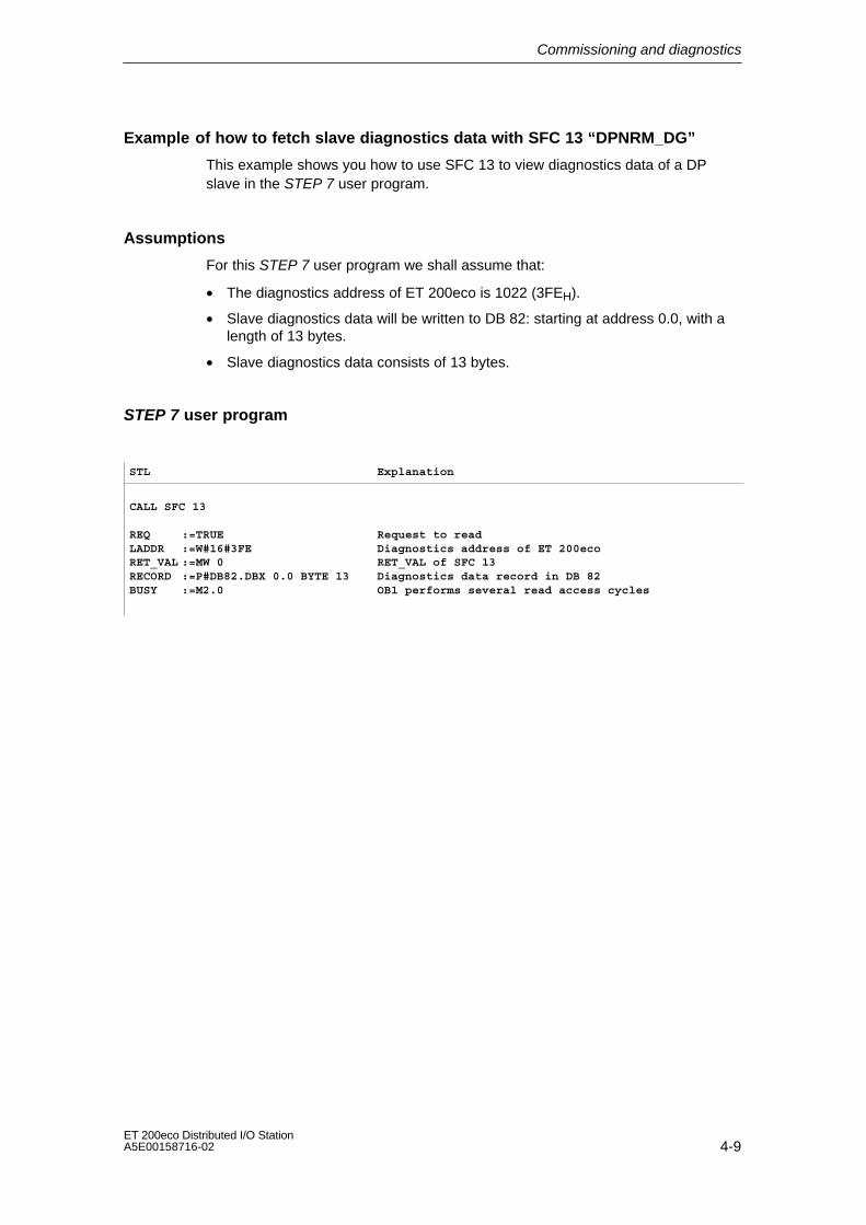
Example of how to fetch slave diagnostics data with SFC 13 “DPNRM_DG”
This example shows you how to use SFC 13 to view diagnostics data of a DPslave in the STEP 7 user program.
Assumptions
For this STEP 7 user program we shall assume that:
• The diagnostics address of ET 200eco is 1022 (3FEH).
• Slave diagnostics data will be written to DB 82: starting at address 0.0, with alength of 13 bytes.
• Slave diagnostics data consists of 13 bytes.
STEP 7 user program
STL Explanation
CALL SFC 13
REQ :=TRUELADDR :=W#16#3FERET_VAL :=MW 0RECORD :=P#DB82.DBX 0.0 BYTE 13BUSY :=M2.0
Request to readDiagnostics address of ET 200ecoRET_VAL of SFC 13Diagnostics data record in DB 82OB1 performs several read access cycles

Commissioning and diagnostics
4-10ET 200eco Distributed I/O Station
A5E00158716-02
Example of how to use FB 192 “IM308C” to read slave diagnostic data
This example shows you how to use SFC 192 to view diagnostics data of a DPslave in the STEP 5 user program.
Assumptions
For this STEP 5 user program we shall assume that:
• The DP master IM 308-C uses page frames 0 to 15 (Number 0 of IM 308-C).
• The DP slave’s PROFIBUS address is ”3”.
• Slave diagnostics data are to be written to DB 20. You can also use any otherDB.
• Slave diagnostics data consists of 13 bytes.
STEP 5 user program
STL Explanation
:A DB 30:SPA FB 192
Name :IM308CDPAD : KH F800IMST : KY 0, 3FCT : KC SDGCGR : KM 0TYP : KY 0, 20STAD : KF +1LENG : KF –1ERR : DW 0
Default address area of IM 308-CIM ID = 0, PROFIBUS address of the DP slave = 3Function: Read slave diagnostics datanot evaluatedS5 data area: DB 20Diagnostic data starting at dataword 1Diagnostic length = wildcard length (all permittedbytes)Error code written to DW 0 of DB 30

Commissioning and diagnostics
4-11ET 200eco Distributed I/O StationA5E00158716-02
4.4.2 Structure of ET 200eco slave diagnostics
Structure of ET 200eco slave diagnostic data
Byte 0Byte 1 Station status 1 to 3Byte 2
Byte 3
Byte 4Byte 5 Low byte
High byteManufacturer ID(see Table 4-10)
Byte 6
Byte 7
Master PROFIBUS address
Device–specific diagnostic data
Byte 8Byte 9Byte 10Byte 11Byte 12
00H00H
00H00H00H
80H
DxH
Figure 4-3 Structure of ET 200eco slave diagnostics data

Commissioning and diagnostics
4-12ET 200eco Distributed I/O Station
A5E00158716-02
4.4.3 Station status 1 to 3
Definition
Station status 1 to 3 provides an overview of the status of a DP slave.
Station status 1
Table 4-7 Structure of the station status 1(byte 0) ET 200eco
Bit Meaning Cause / Remedy
0 1: The DP master can not access theDP slave. This bit is always ”0” on the DPslave.
• Is the correct PROFIBUS address set onthe DP slave?
• Is the bus connector plugged in?
• Is the power supply to the DP slaveswitched on?
• Correct setup of the RS485 repeater?
• A RESET was performed on the DP slave(off/on)?
1 1: The DP slave is not ready to ex-change data.
• Wait, the DP slave is currently starting up.
2 1: Configuration data sent to the DPslave by the DP master is incompa-tible to the physical structure of theDP slave.
• Has the correct station type or configurationof the DP slave been entered in theconfiguration software?
3 0: The bit is always ”0”. –––
4 1: The DP slave does not support therequested function (e.g.SYNC/FREEZE).
• Check the configuration.
5 1: When the station status is beingread from the DP master, is the bit“1”?
The DP master is unable to interpret the DPslave’s answer.
6 1: The DP slave type is incompatiblewith the software configuration.
• Compare the program and the actual setup.
7 1: The DP slave parameters were as-signed by a different DP master (notby the DP master currently acces-sing the DP slave).
• The bit is always 1 when you access the DPslave from a PG or other DP master, forexample.
The PROFIBUS address of the DP masterthat has assigned the DP slave parametersis found in the diagnostic byte ”MasterPROFIBUS address”.
Commissioning and diagnostics
4-13ET 200eco Distributed I/O StationA5E00158716-02
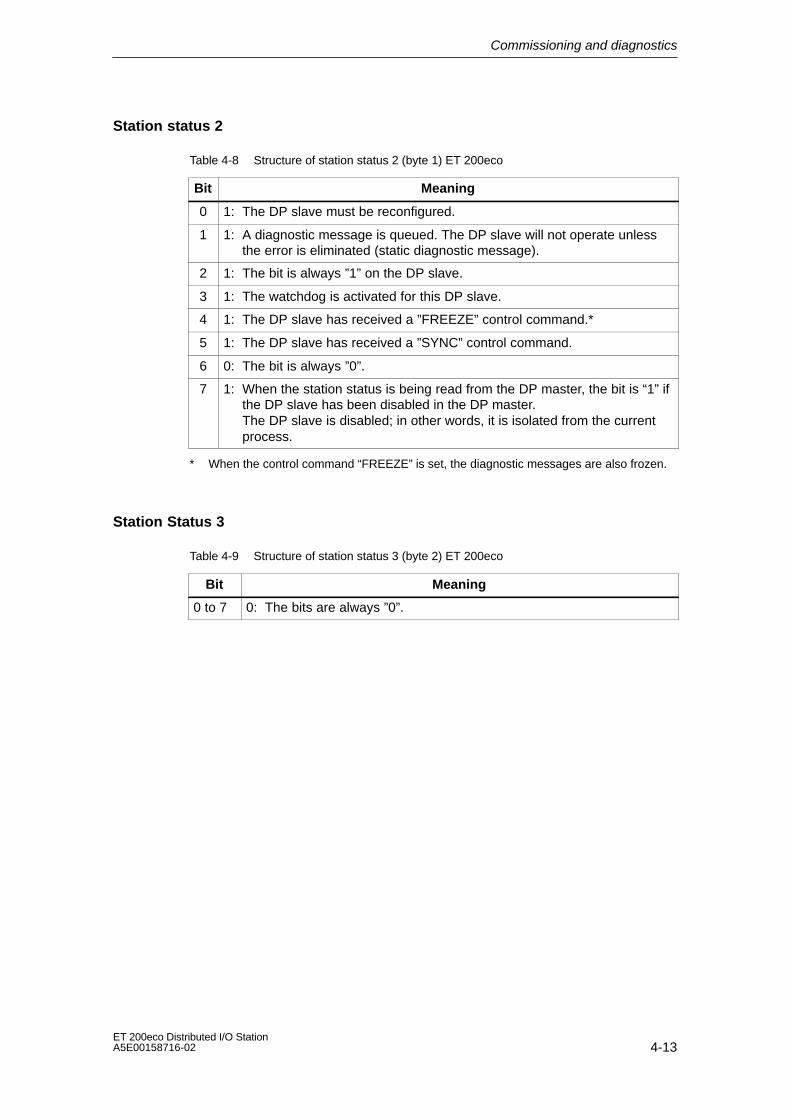
Station status 2
Table 4-8 Structure of station status 2 (byte 1) ET 200eco
Bit Meaning
0 1: The DP slave must be reconfigured.
1 1: A diagnostic message is queued. The DP slave will not operate unlessthe error is eliminated (static diagnostic message).
2 1: The bit is always ”1” on the DP slave.
3 1: The watchdog is activated for this DP slave.
4 1: The DP slave has received a ”FREEZE” control command.*
5 1: The DP slave has received a ”SYNC” control command.
6 0: The bit is always ”0”.
7 1: When the station status is being read from the DP master, the bit is “1” ifthe DP slave has been disabled in the DP master.The DP slave is disabled; in other words, it is isolated from the currentprocess.
* When the control command “FREEZE” is set, the diagnostic messages are also frozen.
Station Status 3
Table 4-9 Structure of station status 3 (byte 2) ET 200eco
Bit Meaning
0 to 7 0: The bits are always ”0”.
Commissioning and diagnostics
4-14ET 200eco Distributed I/O Station
A5E00158716-02
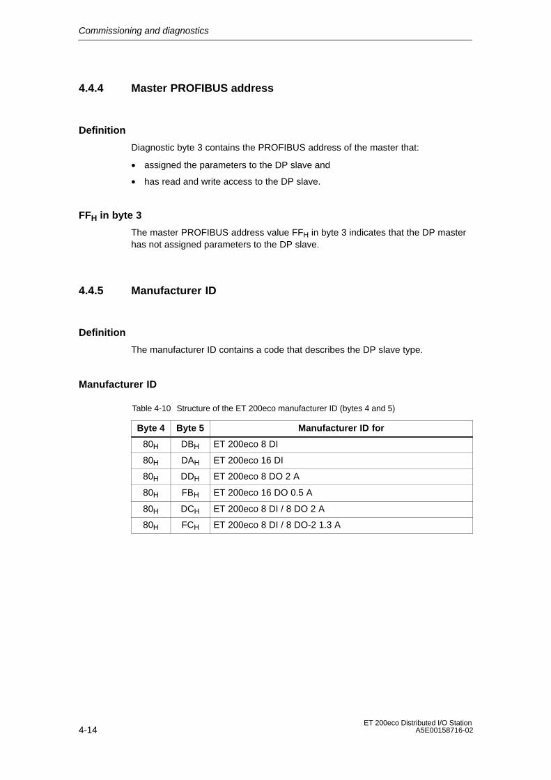
4.4.4 Master PROFIBUS address
Definition
Diagnostic byte 3 contains the PROFIBUS address of the master that:
• assigned the parameters to the DP slave and
• has read and write access to the DP slave.
FFH in byte 3
The master PROFIBUS address value FFH in byte 3 indicates that the DP masterhas not assigned parameters to the DP slave.
4.4.5 Manufacturer ID
Definition
The manufacturer ID contains a code that describes the DP slave type.
Manufacturer ID
Table 4-10 Structure of the ET 200eco manufacturer ID (bytes 4 and 5)
Byte 4 Byte 5 Manufacturer ID for
80H DBH ET 200eco 8 DI
80H DAH ET 200eco 16 DI
80H DDH ET 200eco 8 DO 2 A
80H FBH ET 200eco 16 DO 0.5 A
80H DCH ET 200eco 8 DI / 8 DO 2 A
80H FCH ET 200eco 8 DI / 8 DO-2 1.3 A
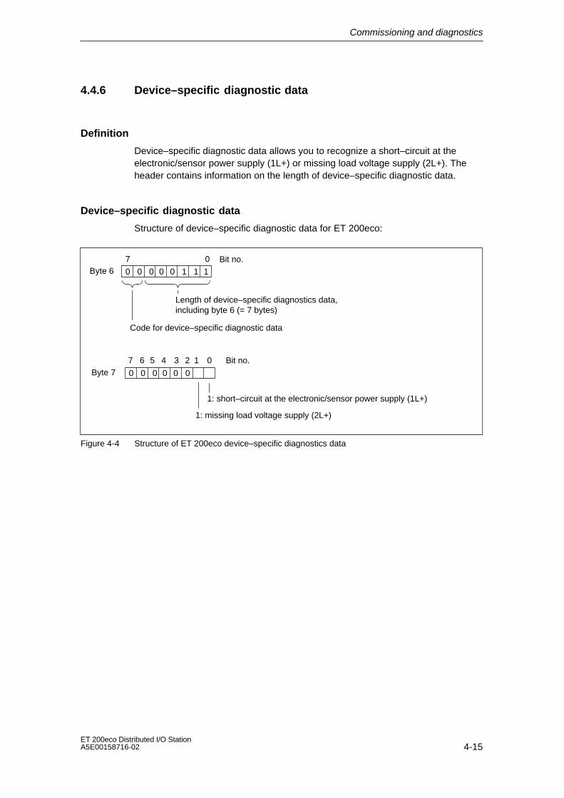
Commissioning and diagnostics
4-15ET 200eco Distributed I/O StationA5E00158716-02
4.4.6 Device–specific diagnostic data
Definition
Device–specific diagnostic data allows you to recognize a short–circuit at theelectronic/sensor power supply (1L+) or missing load voltage supply (2L+). Theheader contains information on the length of device–specific diagnostic data.
Device–specific diagnostic data
Structure of device–specific diagnostic data for ET 200eco:
Byte 67 0 Bit no.
Length of device–specific diagnostics data,including byte 6 (= 7 bytes)
Byte 7
1: missing load voltage supply (2L+)
Code for device–specific diagnostic data
0 0 0 0 0 1 1 1
7 6 5 4 13 Bit no.0
1: short–circuit at the electronic/sensor power supply (1L+)
0 0 0 0 0 0
2
Figure 4-4 Structure of ET 200eco device–specific diagnostics data

Commissioning and diagnostics
4-16ET 200eco Distributed I/O Station
A5E00158716-02

5-1ET 200eco Distributed I/O StationA5E00158716-02
General technical data
What are general technical data?
These general technical data contain the standards and test values the ET200ecodistributed I/O station is compliant with, or the criteria for testing the ET 200ecodistributed I/O station.
Chapter overview
Chapter Topic Page
5.1 Standards and approvals 5-2
5.2 EMC compatibility, shipping and storage conditions 5-3
5.3 Mechanical and ambient climatic conditions 5-5
5.4 Information on isolation tests, protection class, degree of protection andrated voltages of ET 200eco
5-7
5
General technical data
5-2ET 200eco Distributed I/O Station
A5E00158716-02
5.1 Standards and approvals
PROFIBUS standard
The ET 200eco distributed I/O system is based on the IEC 61784-1:2002 Ed1CP 3/1 standard.
IEC 61131
The ET 200eco distributed I/O system is compliant with requirements and criteriaaccording to IEC 61131-2.
CE label
Our products meet the requirements and protection objectives of the followingEC directives and comply with the harmonized European standards (EN) for PLCsthat have been published in the Official Gazettes of the European Community:
• 89/336/EEC ”EMC compatibility” (EMC guideline)
• 73/23/EEC ”Electrical equipment designed for operation within specific voltagelimits” (Low–voltage guideline
EU Declarations of Conformity are kept available for relevant authorities at:
Siemens Corporation,Automation and Drives A & D AS RD 4,PO Box 1963D-92209 Amberg
Mark for Australia
Our products are compliant with AS/NZS 2064 (Class A).
cULus approval (in preparation)
Underwriters Laboratories Inc. in accordance with
UL 508 (Industrial Control Equipment)
CSA C22.2 No. 142 (Process Control Equipment)

General technical data
5-3ET 200eco Distributed I/O StationA5E00158716-02
5.2 EMC compatibility, shipping and storage conditions
Definition
EMC compatibility refers to the ability of electrical equipment to operate efficientlyin an electromagnetic environment, without emission of electromagneticdisturbance.
The ET 200eco distributed I/O station is also compliant with EMC legislation of theEuropean common market. Prerequisite is here that the electrical installation of theET 200eco distributed I/O station is compliant with corresponding regulations andguidelines.
Disturbance spikes
The table below shows EMC compatibility of the ET 200eco distributed I/O stationwith reference to disturbance spikes.
Disturbance spikes Tested with correspondingseverity
Electrostatic dischargeaccording to IEC 61000-4-2.
8 kV6 kV
3 (air discharge)2 (contact discharge)
Burst pulses (fast transient disturbance va-riables) according toIEC 61000-4-4.
2 kV (power supplyline)
2 kV (signal line)
3
3
High–energy surge pulse according to IEC 61000-4-5Applies only to lightning protection elements (see the DP master manual and the description of SIMATIC NETPROFIBUS Networks)
• asymmetrical coupling 2 kV (power supplyline)
2 kV (signal/dataline)
3
• symmetrical coupling 1 kV (power supplyline)
1 kV (signal/dataline)

General technical data
5-4ET 200eco Distributed I/O Station
A5E00158716-02
Sinusoidal disturbance variables
The table below shows the EMC compatibility of the ET 200eco distributed I/Ostation in relation to sinusoidal disturbances.
RF coupling toIEC 6100043Electromagnetic RF field
RF coupling toIEC 61000
amplitude–modulated pulse–modulated
80 to 1000 MHz 900 MHz 5 MHz 0.15 to 80 MHz
10 V/m 10 Vr.m.s., unmodulated
80 % AM (1 kHz) 50 % ED 80 % AM (1 kHz)
200 Hz repetitive frequency 150 Source impedance
Emission of RF interference
Emitted electromagnetic interference to EN 55011: Limit value class A, Group 1(measured at a distance of 10 m).
Frequency Emitted interference
from 30 to 230 MHz < 40 dB (V/m)Q
from 230 to 1000 MHz < 47 dB (V/m)Q
Shipping and storage conditions
The shipping and storage conditions for the ET 200eco distributed I/O stationexceed IEC 61131-2 requirements. The specifications below apply to modulesstored or shipped in their original packaging.
Type of condition Permitted range
Drop test 1 m
Temperature – 40 C to + 70 C
Temperature change 20 K/h
Atmospheric pressure 1080 to 660 hPa (proportional to an altitudeof -1000 to 3500 m)
Relative humidity 5 to 95 %, without condensation

General technical data
5-5ET 200eco Distributed I/O StationA5E00158716-02
5.3 Mechanical and climatic ambient conditions
Climatic ambient conditionsThe following climatic ambient conditions apply:
Ambient conditions Fields of application Remarks
Temperature range 0 to 55 C all mounting positions
Temperature change 10 K/h
Relative humidity 15 to max. 95 % without condensation
Atmospheric pressure 1080 to 795 hPa Proportional to an altitude of-1000 to 2000 m
Contaminant concentrationSO2: < 0.5 ppm;relative humidity < 60 %, no dewingH2S: < 0.1 ppm;relative humidity < 60 %, no dewing
Test:10 ppm; 4 days
1 ppm; 4 days
Mechanical ambient conditions
The sine–wave diagrams in the table below specify mechanical ambient conditions.
Frequencyrange
Continuous test at ...
10 f 58 Hz 0.35 mm amplitude 0.75 mm amplitude
58 f 150 Hz 5 g constant acceleration 10 g constant acceleration
General technical data
5-6ET 200eco Distributed I/O Station
A5E00158716-02
Tests for determining mechanical ambient conditions
The table below provides information on the type and scope of the tests formechanical ambient conditions.
Test object Testing stan-dard
terminal blocks and electronic modules
Vibration Vibration test ac-cording toIEC 60068-2-8
Type of oscillation: Frequency test cycles at a rate of change of 1 oc-tave/minute.10 Hz f 58 Hz, constant amplitude of 0.75 mm58 Hz f 150 Hz, constant acceleration of 10 gDuration of the vibration test: 10 frequency test cycles per axis for eachone of the correlated vertical axes
Surge Surge test toIEC 60068-2-27
Type of surge: Sinusoidal, half–waveSurge strength: Peak value = 30 g, duration = 18 msDirection of surge: Three surges in both +/– directions on each of thethree correlated vertical axes
Continuoussurge
Surge test toIEC 60068-29
Type of surge: Sinusoidal, half–waveSurge strength: Peak value = 25 g, duration = 6 msDirection of surge: 1000 surges in both +/– directions on each of thethree correlated vertical axes
General technical data
5-7ET 200eco Distributed I/O StationA5E00158716-02
5.4 Specification of isolation tests, protection class,type of protection and rated voltage for ET 200eco
Test voltage
The dielectric strength is verified during routine testing using the following testvoltages according to IEC 61131-2:
Circuits with a rated voltage of Ue againstother circuits or ground
Test voltage
< 50 V 500 VDC
< 150 V 2500 VDC
< 250 V 4000 VDC
Degree of contamination/overvoltage category according to IEC 61131
• Degree of contamination 2
• Overvoltage category
– at UN = 24 VDC: II
Degree of protection IP 65
Degree of protection according to IEC 529
• Protected against the ingress of dust and full touch protection
• Jet water–proof from all directions to the case (the water must not causedamage).
Degree of protection IP 66 and 67
Degree of protection according to IEC 529
• Protected against the ingress of dust and full touch protection
• IP 66: Protected for operation in heavy sea or under strong water jets (ingressof water must be restricted to harmless quantities).
• IP 67: Water–proof. Immersion test of the case in water under specifiedconditions of pressure and duration (ingress of water must be restricted toharmless quantities).

General technical data
5-8ET 200eco Distributed I/O Station
A5E00158716-02
Rated operating voltage
The table below shows the rated voltage and corresponding tolerances for theoperation of the ET 200eco distributed I/O station.
Rated voltage Tolerance range
24 VDC 20.4 to 28.8 VDC
Note
Trouble–free operation of the terminating resistor is only ensured if it is connectedto an electronic/sensor power supply (1L+) with a tolerance of range of ±10%.
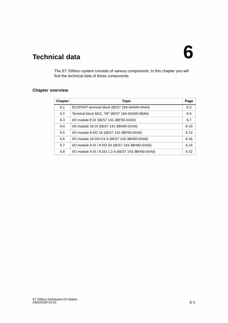
6-1ET 200eco Distributed I/O StationA5E00158716-02
Technical data
The ET 200eco system consists of various components. In this chapter you willfind the technical data of those components.
Chapter overview
Chapter Topic Page
6.1 ECOFAST terminal block (6ES7 194-3AA00-0AA0) 6-2
6.2 Terminal block M12, 7/8” (6ES7 194-3AA00-0BA0) 6-4
6.3 I/O module 8 DI (6ES7 141-3BF00-0XA0) 6-7
6.4 I/O module 16 DI (6ES7 141-3BH00-0XA0) 6-10
6.5 I/O module 8 DO 2A (6ES7 142-3BF00-0XA0) 6-13
6.6 I/O module 16 DO 0.5 A (6ES7 142-3BH00-0XA0) 6-16
6.7 I/O module 8 DI / 8 DO 2A (6ES7 143-3BH00-0XA0) 6-19
6.8 I/O module 8 DI / 8 DO 1.3 A (6ES7 143-3BH00-0XA0) 6-22
6

Technical data
6-2ET 200eco Distributed I/O Station
A5E00158716-02
6.1 ECOFAST terminal block (6ES7 194-3AA00-0AA0)
Properties
Characteristics of the ECOFAST terminal block:
• Can be plugged in and screwed on to any I/O module.
• Connection to power supplies and PROFIBUS DP via ECOFAST connector (atsocket X01, supply lines).
• Looping the power bus and PROFIBUS DP to the next PROFIBUS node viaadditional ECOFAST connector (at socket X02, loop–through).
• Internally interconnected supply line socket X01 and loop–through socket X02(T functionality).
• Adjustable PROFIBUS address (1 to 99) via configuration plug.
Note
The ECOFAST terminal block may only be operated with the I/O modules 6ES7 14*-3B*00-0XA0.
Pin assignment of the ECOFAST sockets
The table below shows the pin assignment of the two ECOFAST sockets for theconnection to the power supplies and PROFIBUS DP.
Table 6-1 Pin-out of the sockets X01 and X02
Pin Assignment of theinfeed socket X01
Assignment of thethrough–loop socket
X02
View of the socket (Frontview of the terminal
blocks)
A PROFIBUS DP Signal A
B PROFIBUS DP Signal B A B1 Electronic/sensor power supply (1L+)
A B
2 Ground potential, sensor power supply (1M) 1 2 34
3 Ground potential, load voltage supply (2M)
4 Load voltage supply (2L+)

Technical data
6-3ET 200eco Distributed I/O StationA5E00158716-02
Block diagram
The figure below shows the ECOFAST terminal block.
1 L+
A
B
2 L+
2 1
3 4
A
B
3 4
2 1
ECOFAST connector
PROFIBUSaddress
1 L+
A
2 L+
1 M
2 M
B
Figure 6-1 Block diagram of the ECOFAST terminal block
Technical data
Dimensions and weight
DimensionsW H D (mm)
79 60 30
Weight approx. 313 g
Power loss
Power loss of the module typically 2 W1
1 Power loss depends on the feed–through currentacross the terminal block.
Note
The maximum power supply current may not exceed 8 A at 1L and 10 A at 2L+.

Technical data
6-4ET 200eco Distributed I/O Station
A5E00158716-02
6.2 Terminal block M12, 7/8” (6ES7 194-3AA00-0BA0)
Properties
Characteristics of the M12, 7/8” terminal block:
• Can be plugged in and screwed on to any I/O module.
• Connection of
– PROFIBUS DP via M12 connector (at infeed socket DP1)
– the power supplies via 7/8” connector (at infeed socket X01)
• PROFIBUS DP and power bus loop–through connection to the next PROFIBUSnode via an additional M12 or 7/8” connector (at loop–through socket DP2 orX02).
• Internal connection of infeed socket DP1 or X01 and loop–through socket DP2or X02 (T functionality).
• Adjustable PROFIBUS address (1 to 99, via two rotary selector switches).
Note
The M12, 7/8” terminal block may only be operated with the I/O modules 6ES7 14*-3B*00-0XA0.

Technical data
6-5ET 200eco Distributed I/O StationA5E00158716-02
Pin assignment of the M12-, 7/8” sockets
The table below shows the pin assignment of the two M12, 7/8” sockets for theconnection to the power supplies and PROFIBUS DP.
Table 6-2 Pin-out of the plugs DP1 and DP2 (M12)
Pin Assignment of the M12 sockets DP1(infeed) and DP2 (loop–through)
(PROFIBUS DP)
View of the plug(Front view of the terminal blocks)
1 Power supply + (P5V2) Supply DP1 Through–loop DP2
2 Data line A (RxD / TxD-N)Supply DP1 Through–loop DP2
3 Data reference potential (M5V2) 125
1 2
4 Data line B (RxD / TxD-P) 3 45
345
5 Shielding
Thread ShieldingPin Socket
Table 6-3 Pin-out of the connectors X01 and X02 (7/8”)
Pin Pin out of the 7/8” sockets X01(infeed) and X02 (loop–through)
(PROFIBUS-DP)
View of the plug(Front view of the terminal blocks)
1 Ground potential, load voltage supply(2M) Supply
X01Through–loopX02
2 Ground potential, electronic/sensorpower supply (1M)
1 5 15
X01 X02
3 PE2 3
4 234
4 Electronic/sensor power supply (1L+) Pi Socke5 Load voltage supply (2L+)
Pin
Socket
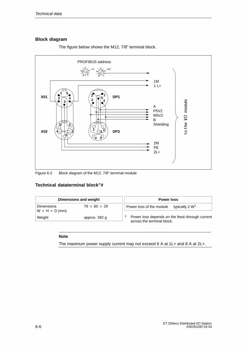
Technical data
6-6ET 200eco Distributed I/O Station
A5E00158716-02
Block diagram
The figure below shows the M12, 7/8” terminal block.
123 4
5
1 2
34
5
1
23
4
5
x1 x10
PROFIBUS address
1M1 L+
2MPE2L+
AP5V2M5V2BShielding1
23
4
5
X01
X02
DP1
DP2
Figure 6-2 Block diagram of the M12, 7/8” terminal module
Technical dataterminal block”#
Dimensions and weight
DimensionsW H D (mm)
79 60 29
Weight approx. 392 g
Power loss
Power loss of the module typically 2 W1
1 Power loss depends on the feed–through currentacross the terminal block.
Note
The maximum power supply current may not exceed 6 A at 1L+ and 8 A at 2L+.
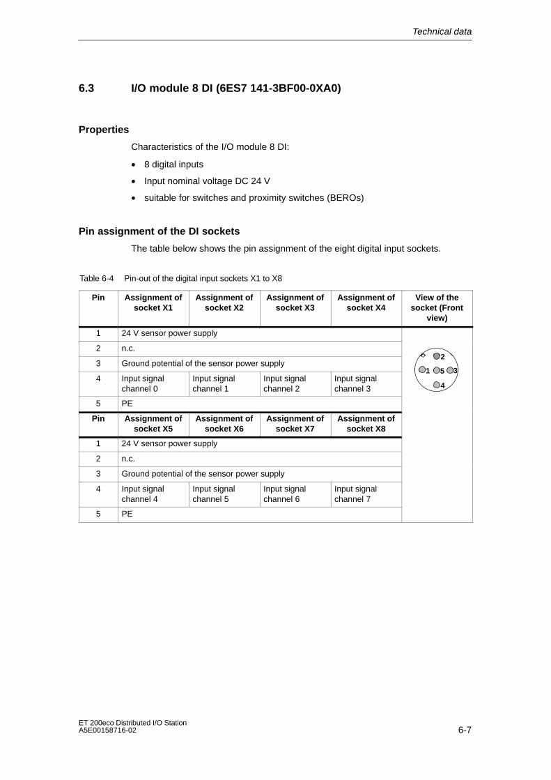
Technical data
6-7ET 200eco Distributed I/O StationA5E00158716-02
6.3 I/O module 8 DI (6ES7 141-3BF00-0XA0)
Properties
Characteristics of the I/O module 8 DI:
• 8 digital inputs
• Input nominal voltage DC 24 V
• suitable for switches and proximity switches (BEROs)
Pin assignment of the DI sockets
The table below shows the pin assignment of the eight digital input sockets.
Table 6-4 Pin-out of the digital input sockets X1 to X8
Pin Assignment ofsocket X1
Assignment ofsocket X2
Assignment ofsocket X3
Assignment ofsocket X4
View of thesocket (Front
view)
1 24 V sensor power supply
2 n.c.
3 Ground potential of the sensor power supply2
4 Input signalchannel 0
Input signalchannel 1
Input signalchannel 2
Input signalchannel 3
1 3
4
5
5 PE
Pin Assignment ofsocket X5
Assignment ofsocket X6
Assignment ofsocket X7
Assignment ofsocket X8
1 24 V sensor power supply
2 n.c.
3 Ground potential of the sensor power supply
4 Input signalchannel 4
Input signalchannel 5
Input signalchannel 6
Input signalchannel 7
5 PE
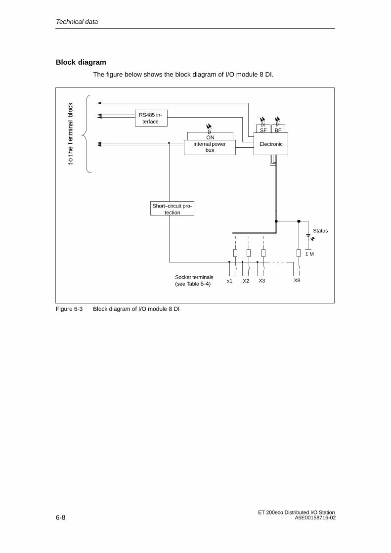
Technical data
6-8ET 200eco Distributed I/O Station
A5E00158716-02
Block diagram
The figure below shows the block diagram of I/O module 8 DI.
Electronicinternal powerbus
ONSF BF
RS485 in-terface
Short–circuit pro-tection
x1 X8 X3 X2Socket terminals(see Table 6-4)
Status
1 M
Figure 6-3 Block diagram of I/O module 8 DI

Technical data
6-9ET 200eco Distributed I/O StationA5E00158716-02
Technical data of I/O module 8 DI
Dimensions and weight
DimensionsW H D (mm)
60 210 28
Weight approx. 210 g
Module–specific data
Transmission rates 9.6/19.2/45.45/93.75/187.5/500 kbps1.5/3/6/12 Mbps
Bus protocol PROFIBUS-DP
Number of channels 8 digital inputs
Cable length
• Unshielded max. 30m
Manufacturer ID 80DBH
Voltages, currents, potentials
Rated voltage of theelectronic/sensor powersupply 1L+
24 VDC
• Reverse polarityprotection
yes
Number of inputs that canbe addressedsimultaneously
8
• all mounting positions
up to 55C
Isolated potential
• between channels no
• between PROFIBUSDP and other circuitcomponents
yes
Permitted potentialdifference
• between differentcircuits
75 VDC, 60 VAC
Isolation test voltage 500 VDC
Current load
• on power supply 1L+ typically 70 mA
Power loss of the module typically 2.4 W
Status, interrupts, diagnostics
Status display Green LED perchannel
Interrupts no
Diagnostic functions
• Group error display Red LED (SF)
• Channel error display no
• Read access todiagnostics data
possible
Encoder power supply outputs
Number of outputs 8
Output current up to 55 C max. 1A(cumulative current)
Short–circuit protection yes, electronic
Encoder selection data
Input voltage
• Rated value
• for ”1” signal
• for ”0” signal
24 VDC
13 to 30 V
– 3 to 5 V
Input current
• at signal 1
• at signal 0
typically 7 mA
Input delay
• “0” to “1” transition
• “1” to “0” transition
typically 3 ms
typically 3 ms
Input characteristic curve according to IEC61131, Type 1
Connection of 2–wireBERO
possible
• permitted no–loadcurrent
max. 1.5 mA

Technical data
6-10ET 200eco Distributed I/O Station
A5E00158716-02
6.4 I/O module 16 DI (6ES7 141-3BH00-0XA0)
Properties
Characteristics of I/O module 16 DI:
• 16 digital inputs
• Input nominal voltage DC 24 V
• suitable for switches and proximity switches (BEROs)
Pin assignment of the DI sockets
The table below shows the pin assignment of the eight digital input sockets.
Table 6-5 Pin-out of the digital input sockets X1 to X8
Pin Assignment ofsocket X1
Assignment ofsocket X2
Assignment ofsocket X3
Assignment ofsocket X4
View of thesocket (Front
view)
1 24 V sensor power supply
2 Input signalchannel 8
Input signalchannel 9
Input signalchannel 10
Input signalchannel 11 2
3 Ground potential of the sensor power supply 1
2
35
4 Input signalchannel 0
Input signalchannel 1
Input signalchannel 2
Input signalchannel 3
1 3
4
5
5 PE
Pin Assignment ofsocket X5
Assignment ofsocket X6
Assignment ofsocket X7
Assignment ofsocket X8
1 24 V sensor power supply
2 Input signalchannel 12
Input signalchannel 13
Input signalchannel 14
Input signalchannel 15
3 Ground potential of the sensor power supply
4 Input signalchannel 4
Input signalchannel 5
Input signalchannel 6
Input signalchannel 7
5 PE

Technical data
6-11ET 200eco Distributed I/O StationA5E00158716-02
Block diagram
The figure below shows the block diagram of I/O module 16 DI.
internal powerbus
ON
x1 X8 X3 X2Socket terminals(see Table 6-5)
Status
1 M
Electronic
SF BF
Short–circuit pro-tection
RS485 in-terface
Figure 6-4 Block diagram of I/O module 16 DI
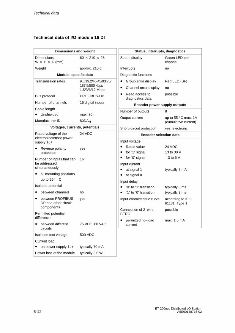
Technical data
6-12ET 200eco Distributed I/O Station
A5E00158716-02
Technical data of I/O module 16 DI
Dimensions and weight
DimensionsW H D (mm)
60 210 28
Weight approx. 210 g
Module–specific data
Transmission rates 9.6/19.2/45.45/93.75/187.5/500 kbps1.5/3/6/12 Mbps
Bus protocol PROFIBUS-DP
Number of channels 16 digital inputs
Cable length
• Unshielded max. 30m
Manufacturer ID 80DAH
Voltages, currents, potentials
Rated voltage of theelectronic/sensor powersupply 1L+
24 VDC
• Reverse polarityprotection
yes
Number of inputs that canbe addressedsimultaneously
16
• all mounting positions
up to 55C
Isolated potential
• between channels no
• between PROFIBUSDP and other circuitcomponents
yes
Permitted potentialdifference
• between differentcircuits
75 VDC, 60 VAC
Isolation test voltage 500 VDC
Current load
• on power supply 1L+ typically 70 mA
Power loss of the module typically 3.6 W
Status, interrupts, diagnostics
Status display Green LED perchannel
Interrupts no
Diagnostic functions
• Group error display Red LED (SF)
• Channel error display no
• Read access todiagnostics data
possible
Encoder power supply outputs
Number of outputs 8
Output current up to 55 C max. 1A(cumulative current)
Short–circuit protection yes, electronic
Encoder selection data
Input voltage
• Rated value
• for ”1” signal
• for ”0” signal
24 VDC
13 to 30 V
– 3 to 5 V
Input current
• at signal 1
• at signal 0
typically 7 mA
Input delay
• “0” to “1” transition
• “1” to “0” transition
typically 3 ms
typically 3 ms
Input characteristic curve according to IEC61131, Type 1
Connection of 2–wireBERO
possible
• permitted no–loadcurrent
max. 1.5 mA

Technical data
6-13ET 200eco Distributed I/O StationA5E00158716-02
6.5 I/O module 8 DO 2A (6ES7 142-3BF00-0XA0)
Properties
The I/O module 8 DO 2A has the following features:
• 8 digital outputs
• output current = 2 A per output
• rated load voltage = 24 VDC
• suitable for magnetic solenoid valves, DC contactors and signal lamps
Pin assignment of the DO sockets
The table below shows the pin assignment of the eight digital output sockets.
Table 6-6 Pin-out of the digital output sockets X1 to X8
Pin Assignment ofsocket X1
Assignment ofsocket X2
Assignment ofsocket X3
Assignment ofsocket X4
View of thesocket (Front
view)
1 n.c.
2 n.c.
3 Ground potential, load voltage supply (2M)2
4 Output signalChannel 0
Output signalChannel 1
Output signalChannel 2
Output signalChannel 3
1 3
4
5
5 PE
Pin Assignment ofsocket X5
Assignment ofsocket X6
Assignment ofsocket X7
Assignment ofsocket X8
1 n.c.
2 n.c.
3 Ground potential, load voltage supply (2M)
4 Output signalChannel 4
Output signalChannel 5
Output signalChannel 6
Output signalChannel 7
5 PE
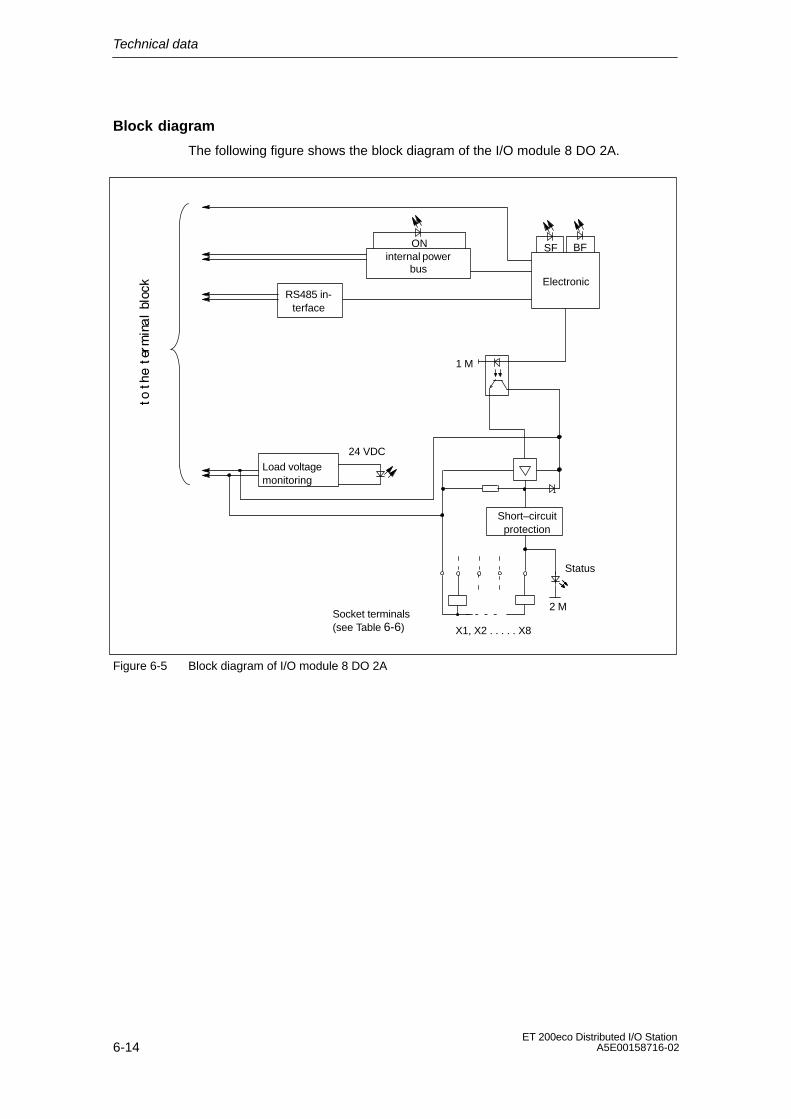
Technical data
6-14ET 200eco Distributed I/O Station
A5E00158716-02
Block diagram
The following figure shows the block diagram of the I/O module 8 DO 2A.
internal powerbus
ON
24 VDCLoad voltagemonitoring
Socket terminals(see Table 6-6)
1 M
X1, X2 . . . . . X8
Short–circuitprotection
Status
2 M
Electronic
SF BF
RS485 in-terface
Figure 6-5 Block diagram of I/O module 8 DO 2A

Technical data
6-15ET 200eco Distributed I/O StationA5E00158716-02
Technical data of I/O Module 8 DO 2A
Dimensions and weight
DimensionsW H D (mm)
60 210 28
Weight approx. 210 g
Module–specific data
Transmission rates 9.6/19.2/45.45/93.75/187.5/500 kbps1.5/3/6/12 Mbps
Bus protocol PROFIBUS-DP
Number of channels 8 digital outputs
Cable length
• Unshielded max. 30m
Manufacturer ID 80DDH
Voltages, currents, potentials
Rated voltage of theelectronic/sensor powersupply 1L+
24 VDC
• Reverse polarityprotection
yes
Rated load voltage 2L+ 24 VDC
• Reverse polarityprotection
yes
Cumulative current of theoutputs
• all mounting positions
up to 55C each 4 A1), 2)
Isolated potential
• between channels no
• between PROFIBUSDP and other circuitcomponents
yes
Permitted potentialdifference
• between differentcircuits
75 VDC, 60 VAC
Isolation test voltage 500 VDC
Current load
• on power supply 1L+
• on load voltage supply2L+
typically 70 mA
typically 60 mA
Power loss of the module typically 4 W
Status, interrupts, diagnostics
Status display Green LED perchannel
Interrupts no
Diagnostic functions
• Group error display Red LED (SF)
• Channel error display no
• Read access todiagnostics data
possible
Actuator selection data
Output voltage
• at signal 1 min. 2L+ (– 0.8 V)
Output current
• at signal 1
Rated value
Permitted range
2 A
5 mA to 2.4 A
• at ”0” signal (residualcurrent)
Max. 0.5 mA
Resistive load range 12 Ω to 4 kΩ
Lamp load max. 10 W
Parallel connection oftwo outputs
• for load controlredundancy
possible
• for power increase No
Digital input control possible
Switching frequency
• resistive load max. 100 Hz
• inductive loadaccording to IEC947-5-1, DC13
max. 0.5 Hz
• lamp load max. 1 Hz
Limiting (internal) ofinductive cut–off voltageto
typically 2L+ (– 44 V)
Short–circuit protection ofoutputs• response threshold
Yes, electronic
typically 4 A (perchannel)
1) 4 A cumulative current for sockets X1, X3, X5,and X7; 4 A cumulative current for sockets X2,X4, X6, and X8.
2) Please note the current capacity of the cable

Technical data
6-16ET 200eco Distributed I/O Station
A5E00158716-02
6.6 I/O module 16 DO 0.5 A (6ES7 142-3BH00-0XA0)
Properties
The I/O module 16 DO 0.5 A has the followng features:
• 16 digital outputs
• output current = 0,5 A per output
• rated load voltage = 24 VDC
• suitable for magnetic solenoid valves, DC contactors and signal lamps
Pin assignment of the DO sockets
The table below shows the pin assignment of the eight digital output sockets.
Table 6-7 Pin-out of the digital output sockets X1 to X8
Pin Assignment ofsocket X1
Assignment ofsocket X2
Assignment ofsocket X3
Assignment ofsocket X4
View of thesocket (Front
view)
1 n.c.
2 Output signalChannel 8
Output signalChannel 9
Output signalChannel 10
Output signalChannel 11 2
3 Ground potential, load voltage supply (2M) 1
2
35
4 Output signalChannel 0
Output signalChannel 1
Output signalChannel 2
Output signalChannel 3
1 3
4
5
5 PE
Pin Assignment ofsocket X5
Assignment ofsocket X6
Assignment ofsocket X7
Assignment ofsocket X8
1 n.c.
2 Output signalChannel 12
Output signalChannel 13
Output signalChannel 14
Output signalChannel 15
3 Ground potential, load voltage supply (2M)
4 Output signalChannel 4
Output signalChannel 5
Output signalChannel 6
Output signalChannel 7
5 PE

Technical data
6-17ET 200eco Distributed I/O StationA5E00158716-02
Block diagram
The following figure shows the block diagram of the I/O module 16 DO 0.5 A.
internal powerbus
ON
24 VDCLoad voltagemonitoring
Socket terminals(see Table 6-6)
1 M
X1, X2 . .. . . X8
Short–circuitprotection
Status
2 M
Electronic
SF BF
RS485 in-terface
Figure 6-6 Block diagram of I/O module 16 DO 0.5 A

Technical data
6-18ET 200eco Distributed I/O Station
A5E00158716-02
Technical Data of I/O Module 16 DO 0.5 A
Dimensions and weight
DimensionsW H D (mm)
60 210 28
Weight approx. 210 g
Module–specific data
Transmission rates 9.6/19.2/45.45/93.75/187.5/500 kbps1.5/3/6/12 Mbps
Bus protocol PROFIBUS-DP
Number of channels 16 digital outputs
Cable length
• Unshielded max. 30m
Manufacturer ID 80FBH
Voltages, currents, potentials
Rated voltage of theelectronic/sensor powersupply 1L+
24 VDC
• Reverse polarityprotection
yes
Rated load voltage 2L+ 24 VDC
• Reverse polarityprotection
yes
Cumulative current of theoutputs
• all mounting positions
up to 55C 4 A1)
Isolated potential
• between channels no
• between PROFIBUSDP and other circuitcomponents
yes
Permitted potentialdifference
• between differentcircuits
75 VDC, 60 VAC
Isolation test voltage 500 VDC
Current load
• on power supply 1L+
• on load voltage supply2L+
typically 70 mA
typically 80 mA
Power loss of the module typically 4 W
Status, interrupts, diagnostics
Status display Green LED perchannel
Interrupts no
Diagnostic functions
• Group error display Red LED (SF)
• Channel error display no
• Read access todiagnostics data
possible
Actuator selection data
Output voltage
• at signal 1 min. 2L+ (– 0.8 V)
Output current
• at signal 1
Rated value
Permitted range
0.5 A
5 mA to 1 A
• at ”0” signal (residualcurrent)
Max. 0.1 mA
Resistive load range 12 Ω to 4 kΩ
Lamp load Max. 5 W
Parallel connection oftwo outputs
• for load controlredundancy
possible
• for power increase No
Digital input control possible
Switching frequency
• resistive load max. 100 Hz
• inductive loadaccording to IEC947-5-1, DC13
max. 0.5 Hz
• lamp load max. 1 Hz
Limiting (internal) ofinductive cut–off voltageto
typically 2L+ (– 47 V)
Short–circuit protection ofoutputs• response threshold
Yes, electronic
typically 1,4 A (perchannel)
1) Please note the current capacity of the cable
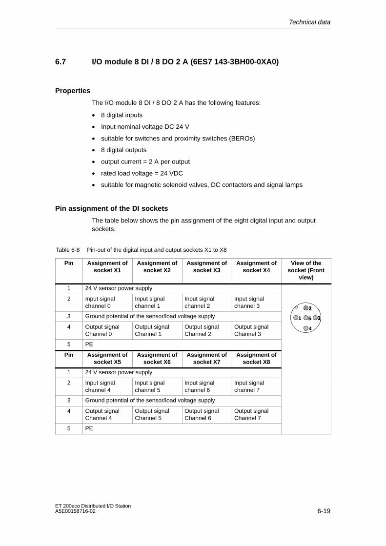
Technical data
6-19ET 200eco Distributed I/O StationA5E00158716-02
6.7 I/O module 8 DI / 8 DO 2 A (6ES7 143-3BH00-0XA0)
Properties
The I/O module 8 DI / 8 DO 2 A has the following features:
• 8 digital inputs
• Input nominal voltage DC 24 V
• suitable for switches and proximity switches (BEROs)
• 8 digital outputs
• output current = 2 A per output
• rated load voltage = 24 VDC
• suitable for magnetic solenoid valves, DC contactors and signal lamps
Pin assignment of the DI sockets
The table below shows the pin assignment of the eight digital input and outputsockets.
Table 6-8 Pin-out of the digital input and output sockets X1 to X8
Pin Assignment ofsocket X1
Assignment ofsocket X2
Assignment ofsocket X3
Assignment ofsocket X4
View of thesocket (Front
view)
1 24 V sensor power supply
2 Input signalchannel 0
Input signalchannel 1
Input signalchannel 2
Input signalchannel 3 2
3 Ground potential of the sensor/load voltage supply 1
2
35
4 Output signalChannel 0
Output signalChannel 1
Output signalChannel 2
Output signalChannel 3
1 3
4
5
5 PE
Pin Assignment ofsocket X5
Assignment ofsocket X6
Assignment ofsocket X7
Assignment ofsocket X8
1 24 V sensor power supply
2 Input signalchannel 4
Input signalchannel 5
Input signalchannel 6
Input signalchannel 7
3 Ground potential of the sensor/load voltage supply
4 Output signalChannel 4
Output signalChannel 5
Output signalChannel 6
Output signalChannel 7
5 PE

Technical data
6-20ET 200eco Distributed I/O Station
A5E00158716-02
Block Diagram
The following figure depicts the block diagram of the I/O module 8 DI / 8 DO 2A.
internal powerbus
24 VDC
Load voltagemonitoring
Socket terminals(see Table 6-8)
1 M
x1 . . . . . X2
X3 X8 x1 . . . . . X8
ON
Short–circuitprotection
Status
2 M
Status
1 M
Short–circuit pro-tection
Electronic
SF BF
RS485 in-terface
Figure 6-7 Block diagram of I/O module 8 DI / 8 DO 2A

Technical data
6-21ET 200eco Distributed I/O StationA5E00158716-02
Technical Data of the I/O Module 8 DI / 8 DO 2A
Dimensions and weight
DimensionsW H D (mm)
60 210 28
Weight approx. 210 g
Module–specific data
Transmission rates 9.6/19.2/45.45/93.75/187.5/500 kbps1.5/3/6/12 Mbps
Bus protocol PROFIBUS-DP
Number of channels 8 digital outputs
Cable length
• Unshielded max. 30m
Manufacturer ID 80DCH
Voltages, currents, potentials
Rated voltage of theelectronic/sensor powersupply 1L+
24 VDC
• Reverse polarityprotection
no
Rated load voltage 2L+ 24 VDC
• Reverse polarityprotection
no
Number of inputs that canbe addressedsimultaneously
8
• all mounting positions
up to 55C
Cumulative current of theoutputs
• all mounting positions
up to 55C each 4 A1), 2)
Isolated potential
• between channels no
• between PROFIBUSDP and other circuitcomponents
yes
Permitted potentialdifference
• between differentcircuits
75 VDC, 60 VAC
Isolation test voltage 500 VDC
Current load
• on power supply 1L+
• on load voltage supply2L+
typically 70 mA
typically 60 mA
Power loss of the module typically 5 W
Status, interrupts, diagnostics
Status display Green LED perchannel
Interrupts no
Diagnostic functions
• Group error display Red LED (SF)
• Channel error display no
• Read access todiagnostics data
possible
Encoder power supply outputs
Number of outputs 8
Output current up to 55 C max.0,75A (cumulativecurrent)
Short–circuit protection yes, electronic
Encoder selection data
Input voltage
• Rated value
• for ”1” signal
• for ”0” signal
24 VDC
13 to 30 V
– 3 to 5 V
Input current
• at signal 1
• at signal 0
typically 7 mA
Input delay
• “0” to “1” transition
• “1” to “0” transition
typically 3 ms
typically 3 ms
Input characteristic curve according to IEC61131, Type 1
Connection of 2–wireBERO
possible
• permitted no–loadcurrent
max. 1.5 mA
1) 4 A cumulative current for sockets X1, X3, X5,and X7; 4 A cumulative current for sockets X2,X4, X6, and X8.
2) Please note the current capacity of the cable

Technical data
6-22ET 200eco Distributed I/O Station
A5E00158716-02
Actuator selection data
Output voltage
• at signal 1 min. 2L+ (– 0.8 V)
Output current
• at signal 1
Rated value
Permitted range
2 A
5 mA to 2.4 A
• at ”0” signal (residualcurrent)
Max. 0.5 mA
Resistive load range 12 Ω to 4 kΩ
Lamp load max. 10 W
Parallel connection oftwo outputs
• for load controlredundancy
possible
• for power increase No
Digital input control possible
Switching frequency
• resistive load max. 100 Hz
• inductive loadaccording to IEC947-5-1, DC13
max. 0.5 Hz
• lamp load max. 1 Hz
Limiting (internal) ofinductive cut–off voltageto
typically 2L+ (– 44 V)
Short–circuit protection ofoutputs
• response threshold
Yes, electronic
typically 4 A perchannel
6.8 I/O module 8 DI / 8 DO 1.3 A (6ES7 143-3BH00-0XA0)
Properties
The I/O module 8 DI / 8 DO 1.3 A has the following features:
• 8 digital inputs
• Input nominal voltage DC 24 V
• suitable for switches and proximity switches (BEROs)
• 8 digital outputs
• output current = 1,3 A per output
• rated load voltage = 24 VDC
• suitable for magnetic solenoid valves, DC contactors and signal lamps
Pin assignment of the DI sockets
The table below shows the pin assignment of the eight digital input and outputsockets.
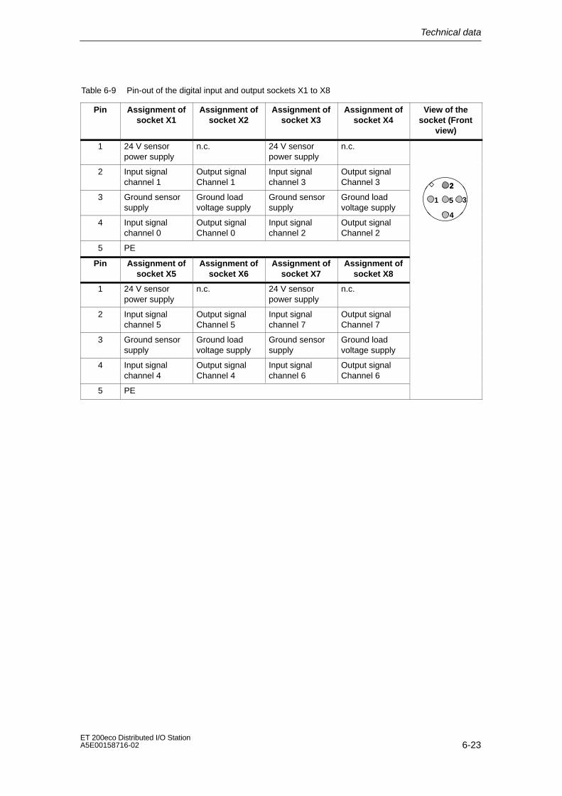
Technical data
6-23ET 200eco Distributed I/O StationA5E00158716-02
Table 6-9 Pin-out of the digital input and output sockets X1 to X8
Pin Assignment ofsocket X1
Assignment ofsocket X2
Assignment ofsocket X3
Assignment ofsocket X4
View of thesocket (Front
view)
1 24 V sensorpower supply
n.c. 24 V sensorpower supply
n.c.
2 Input signalchannel 1
Output signalChannel 1
Input signalchannel 3
Output signalChannel 3 2
3 Ground sensorsupply
Ground loadvoltage supply
Ground sensorsupply
Ground loadvoltage supply
1
2
35
4 Input signalchannel 0
Output signalChannel 0
Input signalchannel 2
Output signalChannel 2
4
5 PE
Pin Assignment ofsocket X5
Assignment ofsocket X6
Assignment ofsocket X7
Assignment ofsocket X8
1 24 V sensorpower supply
n.c. 24 V sensorpower supply
n.c.
2 Input signalchannel 5
Output signalChannel 5
Input signalchannel 7
Output signalChannel 7
3 Ground sensorsupply
Ground loadvoltage supply
Ground sensorsupply
Ground loadvoltage supply
4 Input signalchannel 4
Output signalChannel 4
Input signalchannel 6
Output signalChannel 6
5 PE

Technical data
6-24ET 200eco Distributed I/O Station
A5E00158716-02
Block Diagram
The following figure shows the block diagram of the I/O module8 DI / 8 DO 1.3 A.
internal powerbus
24 VDC
Load voltagemonitoring
Socket terminals(see Table 6-8)
1 M
x1 X3 X5 X7
ON
Short–circuitprotection
Status
2 M
Status
1 M
Short–circuit pro-tection
Electronic
SF BF
RS485 in-terface
X2 X4 X6 X8
Figure 6-8 Block diagram of I/O module 8 DI / 8 DO 1.3 A
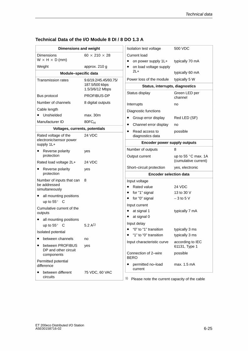
Technical data
6-25ET 200eco Distributed I/O StationA5E00158716-02
Technical Data of the I/O Module 8 DI / 8 DO 1.3 A
Dimensions and weight
DimensionsW H D (mm)
60 210 28
Weight approx. 210 g
Module–specific data
Transmission rates 9.6/19.2/45.45/93.75/187.5/500 kbps1.5/3/6/12 Mbps
Bus protocol PROFIBUS-DP
Number of channels 8 digital outputs
Cable length
• Unshielded max. 30m
Manufacturer ID 80FCH
Voltages, currents, potentials
Rated voltage of theelectronic/sensor powersupply 1L+
24 VDC
• Reverse polarityprotection
yes
Rated load voltage 2L+ 24 VDC
• Reverse polarityprotection
yes
Number of inputs that canbe addressedsimultaneously
8
• all mounting positions
up to 55C
Cumulative current of theoutputs
• all mounting positions
up to 55C 5.2 A1)
Isolated potential
• between channels no
• between PROFIBUSDP and other circuitcomponents
yes
Permitted potentialdifference
• between differentcircuits
75 VDC, 60 VAC
Isolation test voltage 500 VDC
Current load
• on power supply 1L+
• on load voltage supply2L+
typically 70 mA
typically 60 mA
Power loss of the module typically 5 W
Status, interrupts, diagnostics
Status display Green LED perchannel
Interrupts no
Diagnostic functions
• Group error display Red LED (SF)
• Channel error display no
• Read access todiagnostics data
possible
Encoder power supply outputs
Number of outputs 8
Output current up to 55 C max. 1A(cumulative current)
Short–circuit protection yes, electronic
Encoder selection data
Input voltage
• Rated value
• for ”1” signal
• for ”0” signal
24 VDC
13 to 30 V
– 3 to 5 V
Input current
• at signal 1
• at signal 0
typically 7 mA
Input delay
• “0” to “1” transition
• “1” to “0” transition
typically 3 ms
typically 3 ms
Input characteristic curve according to IEC61131, Type 1
Connection of 2–wireBERO
possible
• permitted no–loadcurrent
max. 1.5 mA
1) Please note the current capacity of the cable

Technical data
6-26ET 200eco Distributed I/O Station
A5E00158716-02
Actuator selection data
Output voltage
• at signal 1 min. 2L+ (– 1.2 V)
Output current
• at signal 1
Rated value
Permitted range
1.3 A
5 mA to 1.8 A
• at ”0” signal (residualcurrent)
Max. 0.5 mA
Resistive load range 12 Ω to 4 kΩ
Lamp load max. 10 W
Parallel connection oftwo outputs
• for load controlredundancy
possible
• for power increase No
Digital input control possible
Switching frequency
• resistive load max. 100 Hz
• inductive loadaccording to IEC947-5-1, DC13
max. 0.5 Hz
• lamp load max. 1 Hz
Limiting (internal) ofinductive cut–off voltageto
typically 2L+ (– 44 V)
Short–circuit protection ofoutputs
• response threshold
Yes, electronic
typically 4 A perchannel
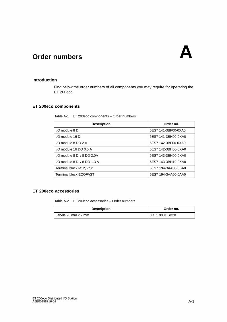
A-1ET 200eco Distributed I/O StationA5E00158716-02
Order numbers
Introduction
Find below the order numbers of all components you may require for operating theET 200eco.
ET 200eco components
Table A-1 ET 200eco components – Order numbers
Description Order no.
I/O module 8 DI 6ES7 141-3BF00-0XA0
I/O module 16 DI 6ES7 141-3BH00-0XA0
I/O module 8 DO 2 A 6ES7 142-3BF00-0XA0
I/O module 16 DO 0.5 A 6ES7 142-3BH00-0XA0
I/O module 8 DI / 8 DO 2.0A 6ES7 143-3BH00-0XA0
I/O module 8 DI / 8 DO 1.3 A 6ES7 143-3BH10-0XA0
Terminal block M12, 7/8” 6ES7 194-3AA00-0BA0
Terminal block ECOFAST 6ES7 194-3AA00-0AA0
ET 200eco accessories
Table A-2 ET 200eco accessories – Order numbers
Description Order no.
Labels 20 mm x 7 mm 3RT1 9001 SB20
A

Order numbers
A-2ET 200eco Distributed I/O Station
A5E00158716-02
I/O module accessories
Table A-3 I/O module accessories – Order numbers
Description Order no.
M12 caps 3RX9 802-0AA00
Y connector M12, 5–pin (for dual connection of actuatorsand sensors to digital inputs/outputs.
6ES7 194-1KA01-0XA0
Angled coupler plug M12, 5–pin (for connecting actuators orsensors; not for use with Y connector M12)
on request
User–specific configuration of the sensor/actuator cable:
• Coupler plug M12
on request
Accessories for the ECOFAST Terminal block
Table A-4 Accessories for the ECOFAST terminal block – Order numbers
Description Order no.
Configuration plug (1 piece) for setting the PROFIBUS address (replacement part)
6ES7 194-1KB00-0XA0
ECOFAST hybrid prefabricated cable (2 and 2x2 copperconductors, ∅ 1.5 mm2 ) of various lengths, with ECOFASTconnector:
1.5 m
3.0 m
5.0 m
10.0 m
15.0 m
20.0 m
25.0 m
30.0 m
35.0 m
40.0 m
45.0 m
50.0 m
6XV1 830-7BH15
6XV1 830-7BH30
6XV1 830-7BH50
6XV1 830-7BN10
6XV1 830-7BN15
6XV1 830-7BN20
6XV1 830-7BN25
6XV1 830-7BN30
6XV1 830-7BN35
6XV1 830-7BN40
6XV1 830-7BN45
6XV1 830-7BN50
ECOFAST terminating resisitor for PROFIBUS DP
1 unit
5 units
6GK1 905-0DA10
6GK1 905-0DA00
For user–specific configuration of the hybrid cable:
• PROFIBUS ECOFAST Hybrid Plug 180 (ECOFAST Cu,5–piece package)
Pin insert (for loop–through)
Socket insert (for power supply)
6GK1 905-0CA00
6GK1 905-0CB00
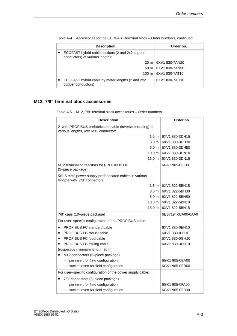
Order numbers
A-3ET 200eco Distributed I/O StationA5E00158716-02
Table A-4 Accessories for the ECOFAST terminal block – Order numbers, continued
Description Order no.
• ECOFAST hybrid cable sections (2 and 2x2 copperconductors) of various lengths:
20 m
50 m
100 m
6XV1 830-7AN20
6XV1 830-7AN50
6XV1 830-7AT10
• ECOFAST hybrid cable by meter lengths (2 and 2x2copper conductors)
6XV1 830-7AH10
M12, 7/8” terminal block accessories
Table A-5 M12, 7/8” terminal block accessories – Order numbers
Description Order no.
2–wire PROFIBUS prefabricated cable (inverse encoding) ofvarious lengths, with M12 connector:
1.5 m
3.0 m
5.0 m
10.0 m
15.0 m
6XV1 830-3DH15
6XV1 830-3DH30
6XV1 830-3DH50
6XV1 830-3DN10
6XV1 830-3DN15
M12 terminating resistors for PROFIBUS DP(5–piece package)
6GK1 905-0EC00
5x1.5 mm2 power supply prefabricated cables in variouslengths with 7/8” connectors:
1.5 m
3.0 m
5.0 m
10.0 m
15.0 m
6XV1 822-5BH15
6XV1 822-5BH30
6XV1 822-5BH50
6XV1 822-5BN10
6XV1 822-5BN15
7/8” caps (10–piece package) 6ES7194-3JA00-0AA0
For user–specific configuration of the PROFIBUS cable:
• PROFIBUS FC standard cable
• PROFIBUS FC robust cable
• PROFIBUS FC food cable
• PROFIBUS FC trailing cable
(respective minimum length: 20 m)
• M12 connectors (5–piece package)
– pin insert for field configuration
– socket insert for field configuration
6XV1 830-0EH10
6XV1 830-0JH10
6XV1 830-0GH10
6XV1 830-3EH10
6GK1 905-0EA00
6GK1 905-0EB00
For user–specific configuration of the power supply cable:
• 7/8” connectors (5–piece package)
– pin insert for field configuration
– socket insert for field configuration
6GK1 905-0FA00
6GK1 905-0FB00
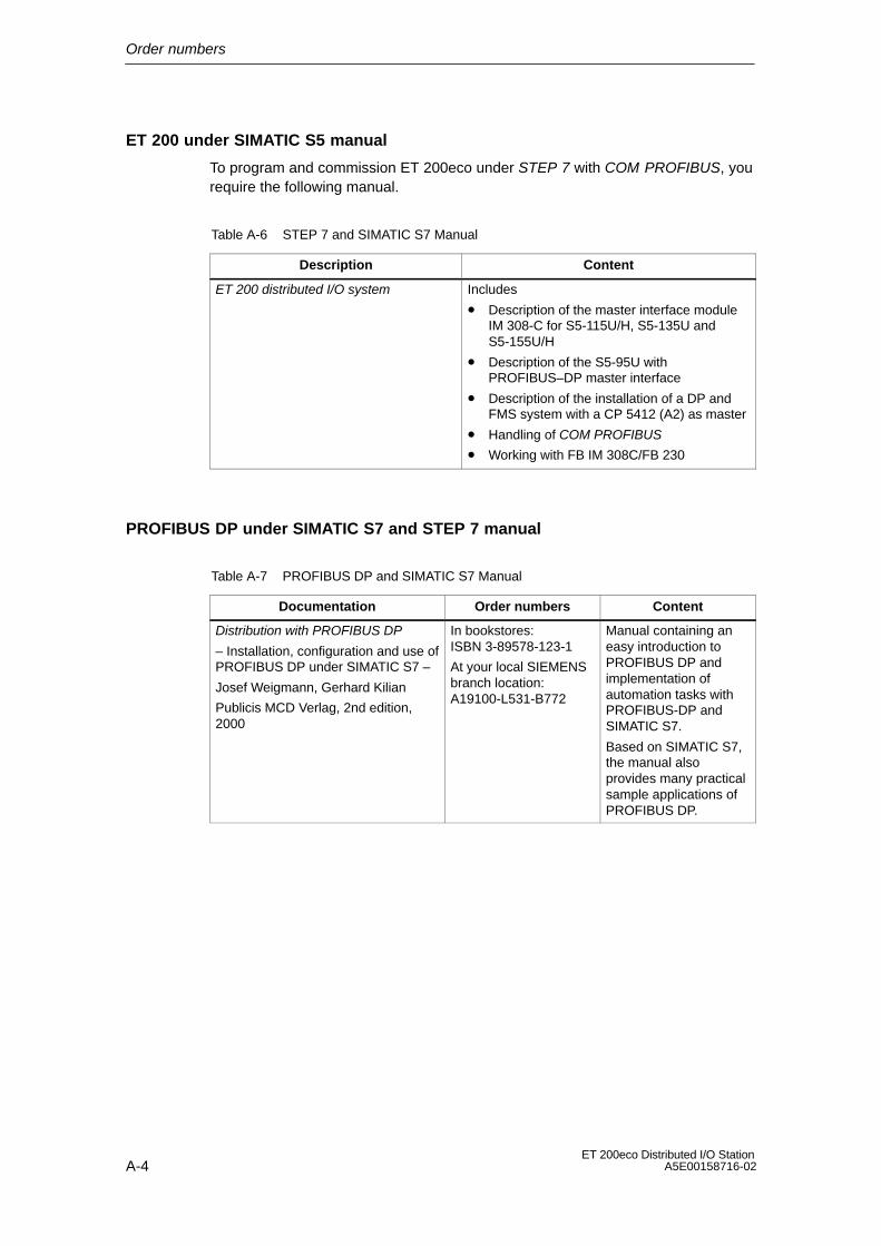
Order numbers
A-4ET 200eco Distributed I/O Station
A5E00158716-02
ET 200 under SIMATIC S5 manual
To program and commission ET 200eco under STEP 7 with COM PROFIBUS, yourequire the following manual.
Table A-6 STEP 7 and SIMATIC S7 Manual
Description Content
ET 200 distributed I/O system Includes
• Description of the master interface moduleIM 308-C for S5-115U/H, S5-135U andS5-155U/H
• Description of the S5-95U withPROFIBUS–DP master interface
• Description of the installation of a DP andFMS system with a CP 5412 (A2) as master
• Handling of COM PROFIBUS
• Working with FB IM 308C/FB 230
PROFIBUS DP under SIMATIC S7 and STEP 7 manual
Table A-7 PROFIBUS DP and SIMATIC S7 Manual
Documentation Order numbers Content
Distribution with PROFIBUS DP
– Installation, configuration and use ofPROFIBUS DP under SIMATIC S7 –
Josef Weigmann, Gerhard Kilian
Publicis MCD Verlag, 2nd edition,2000
In bookstores:ISBN 3-89578-123-1
At your local SIEMENSbranch location:A19100-L531-B772
Manual containing aneasy introduction toPROFIBUS DP andimplementation ofautomation tasks withPROFIBUS-DP andSIMATIC S7.
Based on SIMATIC S7,the manual alsoprovides many practicalsample applications ofPROFIBUS DP.
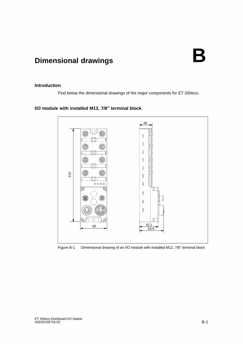
B-1ET 200eco Distributed I/O StationA5E00158716-02
Dimensional drawings
Introduction
Find below the dimensional drawings of the major components for ET 200eco.
I/O module with installed M12, 7/8” terminal block
28
42,153,9
60
210
Figure B-1 Dimensional drawing of an I/O module with installed M12, 7/8” terminal block
B

Dimensional drawings
B-2ET 200eco Distributed I/O Station
A5E00158716-02
I/O module with installed ECOFAST terminal block
28
38,5
53
59,85
60
210
79
Figure B-2 Dimensional drawing of an I/O module with installed ECOFAST terminal block

C-1ET 200eco Distributed I/O StationA5E00158716-02
I/O address area
I/O module 8 DI
Assignment of the module inputs in the process image:
Input byte x
Input signal X1 at pin 4
0
Input signal X3 at pin 4
27
Input signal X2 at pin 4
Input signal X4 at pin 4
Input signal X7 at pin 4
136
Input signal X5 at pin 4
45
Input signal X6 at pin 4
Input signal X8 at pin 4
Figure C-1 Address area of I/O module 8 DI
C

I/O address area
C-2ET 200eco Distributed I/O Station
A5E00158716-02
I/O module 16 DI
Assignment of the module inputs in the process image:
Input byte x027
Input signal X4 at pin 4
Input signal X7 at pin 4
136
Input signal X5 at pin 4
45
Input signal X6 at pin 4
Input signal X8 at pin 4
Input bytex+1
027
Input signal X4 at pin 2
Input signal X7 at pin 2
136
Input signal X5 at pin 2
45
Input signal X6 at pin 2
Input signal X8 at pin 2
Input signal X1 at pin 4
Input signal X3 at pin 4
Input signal X2 at pin 4
Input signal X1 at pin 2
Input signal X3 at pin 2
Input signal X2 at pin 2
Figure C-2 Address space of I/O module 16 DI
I/O module 8 DO 2 A
Assignment of module outputs in the process image table:
Outputbyte x
027
Output signal X4 at pin 4
Output signal X7 at pin 4
136
Output signal X5 at pin 4
45
Output signal X6 at pin 4
Output signal X6 at pin 4
Output signal X1 at pin 4
Output signal X3 at pin 4
Output signal X2 at pin 4
Figure C-3 Address area of I/O module 8 DO 2 A
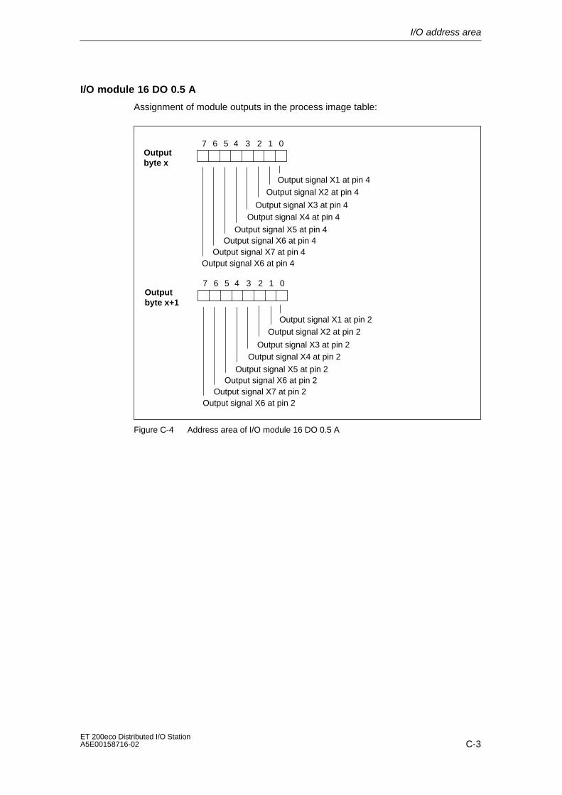
I/O address area
C-3ET 200eco Distributed I/O StationA5E00158716-02
I/O module 16 DO 0.5 A
Assignment of module outputs in the process image table:
Outputbyte x
027
Output signal X4 at pin 4
Output signal X7 at pin 4
136
Output signal X5 at pin 4
45
Output signal X6 at pin 4
Output signal X6 at pin 4
Outputbyte x+1
027
Output signal X4 at pin 2
Output signal X7 at pin 2
136
Output signal X5 at pin 2
45
Output signal X6 at pin 2
Output signal X6 at pin 2
Output signal X1 at pin 4
Output signal X3 at pin 4
Output signal X2 at pin 4
Output signal X1 at pin 2
Output signal X3 at pin 2
Output signal X2 at pin 2
Figure C-4 Address area of I/O module 16 DO 0.5 A

I/O address area
C-4ET 200eco Distributed I/O Station
A5E00158716-02
I/O module 8 DI / 8 DO 2 A
Assignment of module inputs/outputs in the process image table:
Input byte x027
Input signal X4 at pin 2
Input signal X7 at pin 2
136
Input signal X5 at pin 2
45
Input signal X6 at pin 2
Input signal X8 at pin 2
Outputbyte x
027
Output signal X4 at pin 4
Output signal X7 at pin 4
136
Output signal X5 at pin 4
45
Output signal X6 at pin 4
Output signal X6 at pin 4
Input signal X1 at pin 2
Input signal X3 at pin 2
Input signal X2 at pin 2
Output signal X1 at pin 4
Output signal X3 at pin 4
Output signal X2 at pin 4
Figure C-5 Address area of I/O module 8 DI / 8 DO 2 A

I/O address area
C-5ET 200eco Distributed I/O StationA5E00158716-02
I/O module 8 DI / 8 DO 1.3 A
Assignment of module inputs/outputs in the process image table:
Input byte x027
Input signal X3 at pin 2
Input signal X7 at pin 4
136
Input signal X5 at pin 4
45
Input signal X5 at pin 2
Input signal X7 at pin 2
Outputbyte x
027
Output signal X4 at pin 2
Output signal X6 at pin 4
136
Output signal X6 at pin 4
45
Output signal X6 at pin 2
Output signal X6 at pin 2
Input signal X1 at pin 4
Input signal X3 at pin 4
Input signal X1 at pin 2
Output signal X2 at pin 4
Output signal X4 at pin 4
Output signal X2 at pin 2
Figure C-6 Address area of I/O module 8 DI / 8 DO 1.3 A

I/O address area
C-6ET 200eco Distributed I/O Station
A5E00158716-02

Glossary-1ET 200eco Distributed I/O StationA5E00158716-02
Glossary
Automation system
An AS is a PLC (Programmable Logic Controller) which consists of at least oneCPU and various I/O modules, plus operator control and monitoring devices.
Chassis ground
The term refers to the equipotential bonding of all equipment parts that may notcarry a hazardous touch voltage in the event of faults.
Configuration
Refers to the arrangement of individual modules in a distributed I/O system.
Diagnostics
Refers to the detection, localization, classification, display and further evaluationof errors, disturbances and messages.
Diagnostics provides monitoring functions that run automatically when the plantis in operation. This increases plant availability by reducing commissioning anddown times.
Distributed I/O devices
Distributed I/O units are not installed in the PLC rack, but are rather distributed toremote locations, e.g.:
• ET 200M, ET 200S, ET 200X, ET 200L, ET 200eco
• DP/AS–I Link
• S5-95U with PROFIBUS DP slave interface
• other DP slaves made by SIEMENS or third parties
Distributed I/Os are interconnected to the DP master via PROFIBUS DP.
DP Address
→ PROFIBUS address
Glossary
Glossary-2ET 200eco Distributed I/O Station
A5E00158716-02
DP master
A master that operates in accordance with IEC 61784-1:2002 Ed1 CP 3/1 isreferred to as a DP master.
DP-Norm
The DP standard is the bus protocol of the ET 200S distributed I/O system inaccordance with IEC 61784-1:2002 Ed1 CP 3/1.
DP slave
A slave that operates on PROFIBUS with the PROFIBUS-DP protocol andfunctions in accordance with IEC 61784-1:2002 Ed1 CP 3/1 is called a DP slave.
ET 200eco
Distributed I/O station for modular for I/O installation.
ECOFAST
Energy and Communication Field Installation System) Refers to a system fordistributed and modular installation as well as comprehensive diagnostics oncomponent level.
Equipotential bonding
Refers to an electrical connection (equipotential bonding conductor) that keepselectrical equipment and extraneous conductive objects to the same or almostthe same potential in order to prevent disturbing or hazardous voltages betweenthese objects.
Error handling
→ Diagnostics
Floating
The reference potential for the control and load circuits of floating–potential I/Omodules is galvanically isolated; e.g. via optocoupler, relay or transformer. I/Ocircuits can be connected to the same source potential.
Ground
Refers to conductive ground, with arbitrary zero point of the electrical potential.In the vicinity of grounding elements, the ground may have a potential other thanzero. For this reason, the term ”reference ground” is often used.

Glossary
Glossary-3ET 200eco Distributed I/O StationA5E00158716-02
Grounding
The term refers to the grounding of electrically conductive components a metallicconductor.
I/O module
Sensors and actuators are connected to the I/O module via coupler plug or Yconnector.
Master
who are in possession of the token may send data to other nodes and alsorequest data from other nodes (= active node). DP masters are theCPU 315-2 DP or IM 308-C, for example.
Node
Refers to a device that can send, receive and amplify data via the bus, e.g.DP master, DP slave, RS485 repeater.
Node address
→ PROFIBUS address
Non–floating
Refers to the electrical interconnection of the reference potential in the controland load circuit of I/O modules.
PE sheath
Cable with polyethylene (PE) sheath (protective sheath).
PROFIBUS
PROcess FIeld BUS, the German process and field bus standard specified inIEC 61784-1:2002 Ed1 CP 3/1. This specifies the functional, electrical andmechanical characteristics of a bit-serial fieldbus system.
Available PROFIBUS protocols are: DP (= Distributed Peripherals), FMS(= Fieldbus Message Specification), PA (= Process Automation) or TF(= Technological Functions).
Glossary
Glossary-4ET 200eco Distributed I/O Station
A5E00158716-02
PROFIBUS address
All bus nodes must be assigned a unique PROFIBUS address for theiridentification on the PROFIBUS network. Available PROFIBUS addresses forET 200eco: 1 to 99.
PUR sheath
Cable with polyurethane (PUR) sheath (protective sheath).
Reference potential
Arbitrary electrical point of reference (zero potential) for the measurement and/ormonitoring of voltages in circuits referenced to this potential.
Slave
A slave may only exchange data with a master on request. Slaves are, forexample, all DP slaves such as ET 200S, ET 200X, ET 200M, ET 200eco etc.
Station ID
→ PROFIBUS address
T functionality
This functionality is integrated in all terminal blocks by default. Refers to thethrough–loop of PROFIBUS DP and of the power bus to the next PROFIBUSnode. Result: When you disconnect the terminal block during runtime, thedownstream PROFIBUS nodes can continue operation.
Terminal block
Plug–in module for quick change of the terminal configuration. Availableversions: ECOFAST and M12 / 7/8”.
Voltage designations for ECOFAST
Alternative voltage designations for ECOFAST:
• Electronic/sensor power supply (1L+) = load voltage, not switched (NS)
• Load voltage supply (2L+) = load voltage, switched (S)

Index-1ET 200eco Distributed I/O StationA5E00158716-02
Index
Numbers24 VDC power supply, 3-2
AAutomation system, Glossary-1
BBasic knowledge required, iiiBasic module BM 141 ECOFAST 8 DI,
technical data, 6-3, 6-6Burst pulses, 5-3
CCE label, 5-2Changes, compared to previous version, iiiChassis ground, Glossary-1Climatic ambient conditions, 5-5Commissioning, 4-1, 4-3
prerequisite, 4-3Commissioning ET 200eco, 4-3Common potential, Glossary-3Components and protective measures, 3-3Configuration, Glossary-1Configuring, 4-2
ET 200eco, 4-2Continuous surge, 5-6
DDefinition
EMC compatibility, 5-3station status, 4-12
Degree of contamination, 5-7Diagnostic, reading, 4-8Diagnostics, 4-1, Glossary-1
ID–relevant, 4-15under STEP 5 or STEP 7, 4-8
Diagnostics with LED display, 4-5Dimensional drawings, B-1Disposal, ivDistributed I/O station, Glossary-1
Distributed I/O system ET 200ecodefinition, 1-4, 1-5field of application, 1-4view, 1-4
Distributed I/O systems-field of application, 1-2Disturbance spikes, 5-3Double connection, of actuators/sensors, 3-15DP-address, Glossary-1DP-master, 1-2, Glossary-2DP-slave, 1-2, Glossary-2DP-standard, Glossary-2
EECOFAST connector
connecting, 3-21wiring, 3-20
Electrical structure, 3-5Electrostatic discharge, 5-3EMC, 5-3EMC compatibility, 5-3EMERGENCY–OFF devices, 3-1Emission of RF interference, 5-4Equipotential bonding, Glossary-2Error handling, Glossary-2ET 200eco, 3-4, 4-2, 4-3
configuring, 4-2operation on a power supply that is
connected to ground potential, 3-4startup, 4-4status and error displays, 4-5
ET200eco, 3-2components, 1-5operation on a grounded power supply, 3-2
FFB 192 ”IM308C”, 4-10FB 230, 4-8Floating potential, Glossary-2Further support, vFusing, external, 3-7
Index
Index-2ET 200eco Distributed I/O Station
A5E00158716-02
GGeneral rules, 3-1General technical data, 5-1Ground, Glossary-2Grounded power supply, 3-3GSD file, 4-2Guide, for this manual, iv
HHow to implement the GSD file in the
configuration software, 4-2
II/O address area, C-1I/O module 16 DI
block diagram, 6-11pin assignment, digital inputs, 6-10pin assignment of the M12-coupler plug,
3-10pin assignment Y-coupler, 3-16
I/O module 16 DO 0.5 Ablock diagram, 6-17pin assignment for Y-coupler plug, 3-16pin-assignment, digital inputs, 6-16
I/O module 8 DIblock diagram, 6-8pin assignment, digital inputs, 6-7pin assignment of the M12-coupler plug,
3-10I/O module 8 DI / 8 DO 1.3 A, pin assignment
of the M12–coupler plug, 3-13I/O module 8 DI / 8 DO 2 A
pin assignment for Y-connector plug, 3-18pin assignment for Y-coupler plug, 3-17
I/O module 8 DI/8 DO 1.3 Ablock diagram, 6-24pin-assignment, digital inputs, 6-22
I/O module 8 DI/8 DO 2 A, pin-assignment,digital inputs, 6-19
I/O module 8 DI/8 DO 2A, block diagram, 6-20I/O module 8 DO / 8 DI 2 A, pin assignment of
the M12-coupler plug, 3-12I/O module 8 DO 2 A, pin assignment of the
M12-coupler plug, 3-11I/O module 8 DO 2A
block diagram, 6-14pin-assignment, digital inputs, 6-13
ID–relevant diagnostic data, 4-15IEC 204, 3-1IEC 61131, 5-2Installation, 2-1Isolation test, 5-7
MM12 plug, connecting, 3-14M12, 7/8 terminal block, wiring, 3-23Manual, purpose, iiiManufacturer ID, structure, 4-14Master, Glossary-3Master-PROFIBUS-address, structure, 4-14Mechanical ambient conditions, 5-5Mounting dimensions, 2-1Mounting position, 2-1
NNode, Glossary-3Node address, Glossary-3
OOrder numbers, A-1
ET 200 under SIMATIC S5 manual, A-4PROFIBUS DP under SIMATIC S7 and
STEP 7 manual, A-4Overall structure in a TN-S network, 3-4
PPlant startup after specific events, 3-2Potential isolation, between..., 3-4PROFIBUS, Glossary-3PROFIBUS address, Glossary-4PROFIBUS address assignment, 2-6PROFIBUS DP, 1-2
devices, 1-2PROFIBUS standard, 5-2PROFIBUS-DP, 1-2PROFIBUS-DP-network, structure, 1-3Protection against external electrical
interference, 3-2Protection class, 5-7
RRange of validity, of this manual, iiiRated voltage, 5-8Recycling, ivReference potential, Glossary-4Regulations, 3-1
SSafety electrical isolation, 3-3SFC 13 ”DP NRM_DG”, 4-8
Index
Index-3ET 200eco Distributed I/O StationA5E00158716-02
Shipping conditions, 5-3Sinusoidal disturbance variables, 5-4Slave, Glossary-4Slave diagnostics, 4-8
structure of extended diagnostic data, 4-11Software-requirements, 4-3Standard EN 50170, volume 2, PROFIBUS,
1-2Standards and approvals, 5-2Startup, 4-3Station ID, Glossary-4Station status
definition, 4-12structure, 4-12
Status and error displays, 4-5ET 200eco, 4-5
Storage conditions, 5-3Structure, electrical, 3-5Support, further, vSurge, 5-6
TTarget group, for this manual, ivTechnical data, 6-1
climatic ambient conditions, 5-5ECOFAST terminal block, 6-3EMC compatibility, 5-3I/O module 16 DI, 6-12I/O module 16 DO 0.5 A, 6-18I/O module 8 DI, 6-9I/O module 8 DI /8 DO 1.3 A, 6-25I/O module 8 DI /8 DO 2A, 6-21I/O module 8 DO 2A, 6-15M12, 7/8, 6-6mechanical ambient conditions, 5-5shipping and storage conditions, 5-3
Temperature, 5-4Terminating resistor, 3-22, 3-26Test voltage, 5-7TN-S network, 3-4
VVibration, 5-6
WWiring, procedure, 3-7Wiring , 3-1
YY- connector, 3-15

Index
Index-4ET 200eco Distributed I/O Station
A5E00158716-02