silo unloader model 880-sk
TRANSCRIPT

SILO UNLOADER
MODEL 880-SK
OWNER’S MANUAL
Transcanada Highway, Exit 170
230 Boul. Industriel, St-Germain
Quebec, Canada
J0C 1KO
Tel.: (819) 395-4282
Fax: (819) 395-2030
www.valmetal.com
2013/01 [email protected]

880 SK silo unloader Revision : 2013/01/21

880 SK silo unloader Revision : 2013/01/21 1
CONTENTS
FOREWORD……………………………………………………………………………………...2
WARRANTY……………………………………………………………………………………..3
SAFETY PRECAUTIONS………………………………………………………………………..4
WARNING ON SILO UNLOADER………………………………………………………………5
DANGER: GAS FROM SILAGE ………………………………………………………………..6
SILO UNLOADER INSTALLATION INSTRUCTIONS………………………………………..7
ELECTRICAL INSTALLATION INSTRUCTIONS………………………………………..……23
ADJUSTING THE SILO UNLOADER…………………………………………………………..40
OPERATING THE SILO UNLOADER…………………………………………..………………41
LUBRICATION…………………………………………………………………………………...42
CONVERTING FROM UNLOADING TO DISTRIBUTING…………………………………...47
SILO UNLOADER PARTS MANUAL……………………………………………………….….53
HOIST PARTS MANUAL……………………………………………………………………….68
DISTRIBUTOR PARTS MANUAL……………………………………………………………...70
HEXAPOD SUSPENSION PARTS MANUAL………………………………………………….73
880 SK silo unloader Revision : 2013/01/21 2
FOREWORD
This manual describes the installation, operation and maintenance of the silo unloader model 880
from VALMETAL. Be sure to read it carefully before operating the machine or providing
maintenance for it, in order to obtain a thorough knowledge of efficient and safe procedures.
IDENTIFICATION
A name plate riveted to the side of the auger frame bears specifications and serial numbers of the
unit. Refer to these numbers when ordering parts.
Serial number : _______________________
Model number : _______________________
WARRANTY
This piece of equipment is covered by warranty. Your dealer will explain the warranty
agreement and will complete the delivery and warranty registration form.
NOTE: The warranty is valid only if both dealer and customer or their representatives have
completed and signed the warranty registration form, and that the completed form is received by
VALMETAL within 15 days from the date of installation.
SAFETY ALERT SYMBOL
Pay special attention to this safety alerts symbol, it indicates an important safety message. For
your protection, we urge you to read all safety messages found in the manual and on safety signs
adhered to the machine.

880 SK silo unloader Revision : 2013/01/21 3
LIMITED WARRANTY
BASIC WARRANTY AND REMEDIES
All VALMETAL products are warranted against defects in workmanship and materials for one
year from date of delivery to the first purchaser. The warranty repair period for equipment used
for commercial or rental purposes is limited to 90 days from date of delivery to the first retail
purchaser.
VALMETAL will repair or replace, free of charge, at its option, F.O.B. factory, freight prepaid,
any parts proved defective in workmanship or materials. It is agreed that such replacement or
repair is the exclusive remedy available from Valmetal, should any of Valmetal’s products or parts
prove defective. Valmetal will not be responsible for freight and labor charges involved for
removing and replacing defective parts.
EXCEPTIONS FROM THIS WARRANTY
This warranty covers equipments under normal use and service, does not cover conditions
resulting from misuse, negligence, alteration, accident or lack of performance of required
maintenance. Replacement of maintenance items such as belts, spout liners, digger knives, blades,
etc... are not covered.
EXCEPTIONS FROM THE WARRANTY
Motors are warranted directly by the motor manufacturer only and not by Valmetal.
LIMITATION OF LIABILITY
This warranty is in lieu of all other warranties, express or implied, written or oral. No employee,
agent, dealer or any other person is authorized to give any warranties on behalf of Valmetal, nor to
assume for Valmetal any other liability in connection with any its products. IN NO EVENT
SHALL THE OWNER BE ENTITLED TO RECOVER FOR INCIDENTAL OR
CONSEQUENTIAL DAMAGES SUCH AS, BUT NOT LIMITED TO, LOSS OF CROPS, LOSS
OF PROFITS OR REVENUE, OTHER COMMERCIAL LOSSES, INCONVENIENCE OR
COST OF RENTAL OR REPLACEMENT EQUIPMENT.
AN ADDITION TO LIMITED WARRANTY FOR SILO UNLOADERS 880
MODEL ONLY
In addition to the regular 1 year limited written warranty, any parts that are determined by Valmetal Inc.
to be defective in material and workmanship under normal use and service, in the second and third year
from date of delivery to the first retail purchaser, will be covered by this limited warranty. Valmetal
liability under this warranty is for repair or replacement of parts only but not for such labor involved for
removing and replacing defective parts. Replacement of maintenance items such as belts, spout liners,
digger knives, blades, blower paddles, bearings, etc... are not covered.

880 SK silo unloader Revision : 2013/01/21 4
IMPORTANT MESSAGE
YOU are responsible for the SAFE operation and maintenance of your Valmetal SILO UNLOADER
MODEL 880-SK. YOU must ensure that you and anyone else who is going to install, operate,
maintain or work around the SILO UNLOADER be familiar with the installation, operation and
maintenance procedures and related SAFETY information contained in this manual. This manual will
alert you to all good safety practices that should be adhered to while operating the SILO UNLOADER.
Remember, YOU are the key to safety. Good safety practices not only protect you but also the people
around you. Make these practices a working part of your safety program. Be certain that
EVERYONE operating this equipment is familiar with the recommended operation and maintenance
procedures and follows all the safety precautions. Most accidents can be prevented. Do not risk injury
or death by ignoring good safety practices.
SILO UNLOADER owners must give operation instructions to operators or employees before allowing
them to operate the machine, and at least annually thereafter per OSHA 1928.57.
The most important safety device on this equipment is a SAFE operator. It is the operator’s
responsibility to read and understand ALL Safety and Operating instructions in the manual and to
follow these. All accidents can be avoided.
A person who has not read and understood all installation, operating and safety instructions is not
qualified to operate the machine. An untrained operator exposes himself and bystanders to possible
serious injury or death.
Do not modify the equipment in any way. Unauthorized modification may impair the function and/or
safety and could affect the life of the equipment.
Think SAFETY! Work SAFELY!

880 SK silo unloader Revision : 2013/01/21 5
WARNINGS ON SILO UNLOADER

880 SK silo unloader Revision : 2013/01/21 6
This sign must be installed at the silo base near the ladder (chute)… TO BE SEEN BY ALL.

880 SK silo unloader Revision : 2013/01/21 7
Silage fermentation may produce several kinds of
gas, including carbon dioxide and nitric oxide
(which then produces nitrogen dioxide). Carbon
dioxide is non-poisonous, although it can cause
suffocation.
Nitrogen dioxide (NO2), however is poisonous. It
kills and injures people as well as livestock.
Nitrogen dioxide is a hazard on the farm because:
1. Exposure can be fatal.
2. Formation of nitrogen dioxide from nitric oxide
may occur whenever silage is made.
WHAT IS THIS GAS ?
The lethal gas is yellowish-brown and smells like
some laundry bleaches. After more oxidation, it
forms N2O5 which then forms highly-corrosive nitric
acid when combined with water. Since oxidation
may occur in the body, nitrogen dioxide can produce
permanent lung damage.
WHERE DOES IT HIDE?
Since nitrogen dioxide is heavier than air, it remains
beneath the air mass over the silage. It layers on top
of the silage below the upper edge of the top door or
settles down through the chute. It may also seep
through the drain at the base of the silo. If often
concentrates in the silo room and move into the
barn. It will leave a yellow stain on silage, wood or
other materials it contacts.
HOW TO MINIMIZE THE DANGER
While growing the crop :
1. Apply adequate nitrogen, but don’t over do. As
a guide, corn needs 1.2 lbs. of N per bushel
yield; oats and/or sudangrasse used for silage
should have no more than 75 lbs. of N available
for each harvest. Since this includes both N in
the soil and that applied, follow the
recommendations on soil analysis reports.
2. After a drought, rapid nitrate uptake occurs in
plants following rain. So, harvest the crop
before fall rains, or wait at least five days after a
rain.
3. Plants damaged by hail or frost should be
harvested immediately before they take up
nitrates.
4. To reduce the amount of nitrate going into
silage, cut higher than normally (10-12 inches).
Most nitrates are in the lower stalk.
While filling the silo :
1. Be on the alert for bleach-like odors and/or
yellowish-brown fumes in or near the silo.
Small amounts of the gas may not be visible or
easily detected by smell, but are still dangerous.
(Greatest danger is 12 to 60 hours after filling
silo).
2. If you must enter the silo, run the silage blower
for 15 or 20 minutes first. Never enter the silo
alone during the danger period and always have
someone outside of the silo to communicate
with.
3. If you experience the slightest throat irritation or
coughing while in the silo, get into fresh air
immediately. Call your doctor as soon as
possible, indicating that you have been exposed
to silo gas.
DANGER
NEVER ATTEMPT TO RESCUE A PERSON
WHO HAS BEEN OVERCOME BY SILO GAS
WITHOUT THE AID OF OXYGEN-
SUPPLYING BREATHING EQUIPMENT.
FAILURE TO HEED MYA RESULT IN
SERIOUS PERSON INJURY OR DEATH.
After filling the silo :
1. Ventilate silo room to outdoor air for at least
two weeks.
2. Keep any door between silo room and barn
closed to minimize any risk to livestock.
3. Remove upper silo chute doors down to the
settled silage level to prevent build-up of gases
in silo.
DANGER: SILO GAS IS HAZARDOUS

880 SK silo unloader Revision : 2013/01/21 8
2.1 GENERAL SAFETY
1. Read and understand the Operator’s Manual and all
safety signs before operating, maintaining or
adjusting the SILO UNLOADER.
2. Have a first-aid kit available for use should the need
arise and know how to use it.
3. Have a fire extinguisher available for use should the
need arise and know how to use it.
4. Wear appropriate protective gear. This list includes
but is not limited to :
- A hard hat
- Protective shoes with slip resistant soles
- Protective glasses or goggles
- Heavy gloves
- Hearing protection
5. Install and secure all guards before starting.
6. Wear appropriate ear protection for prolonged
exposure to excessive noise.
7. Clear the area of people before starting the unit.
8. Review safety related items annually with all
personnel who will be operating or maintaining the
SILO UNLOADER.
9. Always call upon a qualified electrician for electrical
problems.
10. Do not get near the Unloader auger when it is in
operation. The auger is equipped with very
sharp knives. These knives can seriously injure
anyone who gets close to the auger. Keep hands
and feet away from auger. Also, make sure no
on is near the auger when it is operating.
2.2 OPERATING SAFETY
1. Read and understand the Operator’s Manual and
all safety signs before operating, servicing,
adjusting, repairing or unplugging.
2. Be certain that all guards and shields are secured
before starting or operating.
3. Make certain everyone is clear of equipment
before applying power.
4. Always lock out power source before entering a
silo.
5. Keep hands, feet, hair and clothing away from
moving parts.
6. Be sure main switch is off before resetting
motor thermals.
7. Never stand underneath a suspended silo
unloader.
8. Never work or crawl on a silo unloader that is
suspended. Always lower silo unloader to silage
level to work on it.
9. Always leave at least three feet of suspension
cable between the suspension arms and the cable
pulleys. Snubbing the unloader any tighter at
the top could cause undue strain on the
suspension, which might cause the unloader to
fall.
10. Never go into a silo to work on a moving silo
unloader, stay in silo chute to observe operation.
11. Never disconnect the electrical cord connector if
the silo unloader is running because moisture
conditions inside the silo could give you a
severe shock.
12. Always inspect suspension cables carefully
before you raise unloader to top of silo.
13. Beware of silo gases, read carefully page 6.
THINK SAFETY and live longer.
A careful operator is the best insurance against an accident.
The complete observance of one simple rule would prevent many thousands of serious injuries each year.
That rule is ¨NEVER ATTEMPT TO CLEAN, OIL, OR ADJUST A MACHINE WHILE IT IS IN MOTION¨.
Regardless of care used in the design and construction of farm equipment, there are many points that cannont be
completely safeguarded without interfering with accessibility and efficient operation.

880 SK silo unloader Revision : 2013/01/21 9
2.3 MAINTENANCE SAFETY
1. Follow ALL the operating, maintenance and
safety information in the manual.
2. never go into a silo to work on a moving silo
unloader. Stay in silo chute to observe
operation.
3. Always shut off and lock up main power switch
before entering silo.
4. Never walk or crawl on the unloader when it is
suspended above the silage surface or when it is
operating.
5. Be sure electrical outlets and tools are properly
grounded.
6. Use adequate light for the job at hand.
7. Keep hands, feet, hair and clothing away from
moving parts.
8. Never wear ill-fitting, baggy or frayed clothing
when working around or on any of the drive
system components.
9. Clear the area of bystanders, especially small
children, when carrying out any maintenance
and repairs or making any adjustments.
10. Never use a suspended unloader as a substitute
for a scaffold.
2.4 SAFETY DECALS
1. Keep safety decals and signs clean and legible at
all times.
2. Replace safety decals and signs that are missing
or have become illegible.
3. Replaced parts that displayed a safety sign
should also display the current sign.
4. Safety decals or signs are available from you
Dealer Parts Department or the factory.
How to install Safety Decals :
Be sure that the installation area is clean and
dry.
Decide on the exact position before you remove
the backing paper.
Remove the smallest portion of the split backing
paper.
Align the decal over the specified area and
carefully press the small portion with the
exposed adhesive in place.
Slowly peel back the remaining paper and
carefully smooth the remaining portion of the
decal in place.
Small air pockets can be pierced with a pin and
smoothed out using the piece of decal backing
paper.
DANGER
Stay away, a rotating auger can kill or dismemeber, never push, pull or handle…
You can slip and be caught in the Auger.
Always disconnect and lock out power source before servicing unit.
FAILURE TO HEED WILL RESULT IN DEATH OR PERSONAL INJURY.

880 SK silo unloader Revision : 2013/01/21 10
2.4 SIGN-OFF FORM
Valmetal follows the general Safety Standards specified by the society of Automotive Engineers (SAE) and the
Occupational Safety and health Administration (OSHA). Anyone who will be operating and/or maintaining the
SILO UNLOADER must read and clearly understand ALL Safety, Operating and Maintenance information
presented in this manual.
Do not operate or allow anyone else to operate this equipment until such information has been reviewed.
Annually review this information before the season start-up.
Make these periodic reviews of SAFETY and OPERATION a standard practice for all of your equipment. We
feel that an untrained operator is unqualified to operate this machine.
A sign-off sheet is provided for your recorded keeping to show that all personnel who will be working with the
equipment have read and understood the information in the Operator’s Manual and have been instructed in the
operation of the equipment.
SIGN-OFF FORM
DATE EMPLOYEE’S SIGNATURE EMPLOYER’S SIGNATURE

880 SK silo unloader Revision : 2013/01/21 11
SILO UNLOADER
MODEL 880-SK
INSTALLATION INSTRUCTIONS

880 SK silo unloader Revision : 2013/01/21 12
ASSEMBLE DRIVE RING :
2
3 1
NOTE : DO NOT TIGHT BOLTS UNTIL THE WHOLE ASSEMBLY IS COMPLETED.
Assemble the drive ring segments on the silo floor or on the silage surface. Level the silage surface to make assembly easier.
Install splice plates in the upper holes of drive ring segment with 1/2" x 1 1/2" hex. bolts and nylon lock nuts.
Note : Splice plate with round holes on the outside and splice plate with slotted holes on the inside.
Install the drive ring brackets in the middle holes of splice plates with 1/2" x 1 3/4" hex. bolts and nylon lock nuts.

880 SK silo unloader Revision : 2013-01-21 13
ASSEMBLE DRIVE RING AND SUSPENSION ARMS:
NOTE : Do not tight bolts until the whole assembly is completed.
Join the 3 suspension arms with 1/2" x 6 1/2" hex. bolts and nylon lock nuts.
IMPORTANT : Insert bolts from bottom side up.
Attach arms so the angle on arms are in the position shown.
Install collector ring supports to the collector ring with 1/2" x 1 1/4" hex. bolts, lock washers and washers.
Install the discharge chute base on the collector ring with chute hold down clips and spacers , use
3/8" x 1" hex. bolts, lock washers and washers.
Secure the collector ring assembly to the suspension arms with 1/2" x 6 1/2" hex. bolts and nylon lock nuts.
IMPORTANT : Insert bolts from bottom side up.
Attach suspension arms to the drive ring brackets with 1/2" x 1 1/2" hex. bolts and nylon lock nuts.
Attach the suspension cables to the suspension arms with 5/16" cable clamps. Be sure drive ring is level and
cables tight before tightening the cable clamps.
Cable clamps should be as close as possible to the suspension arms.
NOTE : If power cord looping kit will be used, slide looping ring over one of the suspension cable before
installing cable clamps. See page 21
Assemble the anchor chain over the suspension cable at the right side of the silo door, looking from the silo
chute (standard version without torque arm).
NOTE 2 : The mounting procedure for the offset arms (optionnal) is the same except for the suspension cables
that have to be attached to the U-bracket as shown. TIGHT ALL BOLTS AND NUTS

880 SK silo unloader Revision : 2013-01-21 14
REINFORCING ARMS (SILO 24` ONLY) :
Assemble the reinforcing arms with left and right attachments, use 1/2" x 3" hex. bolts and nylon lock nuts.
Attach the reinforcing attachments to the drive ring segments with 1/2" x 1-1/2" hex. bolts, washers and nylon lock nuts.
OFFSET SUSPENSION ARM (OPTIONAL)
The mounting procedure for the offset arms is the same except for the suspension cables, that have to be attached to the U-
bracket as shown.
FASTEN IMPELLER TO SHROUD ASSEMBLY
NOTE: Operating the hoist, raise the
assembled parts of the unloader so the
drive ring is approximately 24" from the
floor or silage surface.
Remove blower upper housing to
provide clearance to pass blower assembly
through silo door.
Attach blower housing to frame
assembly with 3/8" x 2 3/4" carriage bolts
and nylon lock nut.
Attach long side angle to blower
with 3/8" x 1" carriage bolts and nylon lock
nut and to gearbox mount with 3/8" x 1 1/4"
carriage bolts and nylon lock nuts.
Attach shield mount angle to long
side angle with 3/8" x 1" carriage bolts and
lock nuts.

880 SK silo unloader Revision : 2013-01-21 15
ASSEMBLE MOTOR MOUNT
Attach upper housing to
blower assembly with 3/8" x
3/4" carriage bolts, washers and
nuts.
Attach short side angle to
gear reducer mount with 3/8" x
1" hex. bolts and nylon lock
nuts.
Attach the end tie to short
and long side angles with 3/8" x
1" carriage bolts,washers and
nylon lock nuts.
Fix the "J" bolt to end tie
with a nylon lock nut.
Install the motor mount on
short and long side angles with
one 3/8" x 3" hex. bolt, three
3/8" x 1 1/4" carriage bolts,
washers and nylon lock nuts.
Fix the two 1/2" x 4" adjusting
bolts with nuts underneath the
motor mount bracket.
ATTACH COLLECTOR RING TO IMPELLER Fasten access
door
to auger frame
with 3/8" x 2 3/4"
hex. bolts, washers
and nylon lock nuts.
Fix the impeller
assembly to the four
studs underneath the
collector ring with
½ lock washers and
nuts.
One of the studs is
off center and must
align according with
blower flange.
Note : Attach
wheel tube braces
as shown for
(18’, 20’, 24’
models only).

880 SK silo unloader Revision : 2013-01-21 16
INSTALL RING DRIVE SUPPORT, VERTICAL RAISING WHEEL
AND WALL WHEELS
Loosen 3/8" nuts on mobile supports and install mobile supports on the drive ring .
Push the gliding blocks close to lateral face of the ring, gliding blocks should ride flat on lip ring, tighten.
Attach support brackets to ends of gearbox support with 1/2" x 1 1/2" carr. bolts, washers and nylon lock nuts.
Attach gearbox support assembly to ring drive assembly with an adjusting collar at each end.
Note : Be sure guide wheel brace (11) is installed at position shown.
Install set screws and nuts in adjusting collars . Do not tighten at this time.
Attach gearbox support to shroud assembly with 1/2" x 2 1/2" hex. bolts, washers and nylon lock nuts.
Fasten wall wheel assembly to frame with 3/8" x 3 1/4" hex. bolts, washers and nylon lock nuts.
Install 1/2" x 4" adjusting bolts and nuts to frame sides. Turn adjusting bolt to push wall wheels out until chipper
blades clear silo wall by 1/8". Tighten nuts of adjusting bolts and 3/8" x 3 1/4" hex bolts attaching wall wheel
assembly to shroud.
Install vertical raising wheel to shroud assembly with 3/8" x 2 3/4" hex. bolt and nylon lock nut.

880 SK silo unloader Revision : 2013-01-21 17
INSTALL RING DRIVE ASSEMBLY
Attach the ring drive assembly to the floating gearbox support with 3/4"Ø rods,
washers and 3/16" x 1 1/2" cutter pins.
Adjust collars so gearbox is level and the ends of the rods are in middle of the oblong holes when teeth of
the drive sprocket are engaged in the holes of the ring segment.
Install back-up roll on the gearbox.
Unscrew the rear left bolt that secure the auger gearbox to its mount and fasten support bracket using
the same bolt .
Attach female drive shaft to ring drive gearbox and male drive shaft to jack shaft with universal joints
and 3/16" x 3/16" x 1 1/4" keys, tighten set screws.
Mount pulleys on auger gearbox and on jack shaft. Install belt and tighten with the adjusting screw.
When belt is properly tensioned, tighten all bolts and lock nuts.
Fix long line shaft guard support with 3/8" x 1" carriage bolt, washer and lock nut.
Fix short line shaft guard support with 3/8" x 3/4" hex. bolt, washer and lock nut.
Fix the guards and with 3/8" x 3/4" hex. bolts, washers and lock nut.

880 SK silo unloader Revision : 2013-01-21 18
VS-3000
(INDEPENDANT RING DRIVE ONLY)
Attach the ring drive assembly to the floating gearbox support with 3/4"Ø rods , washers
and 3/16" x 1 1/2" cotter pins.
Adjust collars so gearbox is level and the ends of the rods are in middle of the oblong holes when teeth of
the drive sprocket are engaged in the holes of the ring segment.
Install back-up roll on the gearbox.
Attach control box mount to frame with 3/8" x 3" hex. bolts and lock nuts.
Attach control box to control box mount with 1/4" x 5/8" hex. bolts and lock nuts.
880 SK silo unloader Revision : 2013-01-21 19
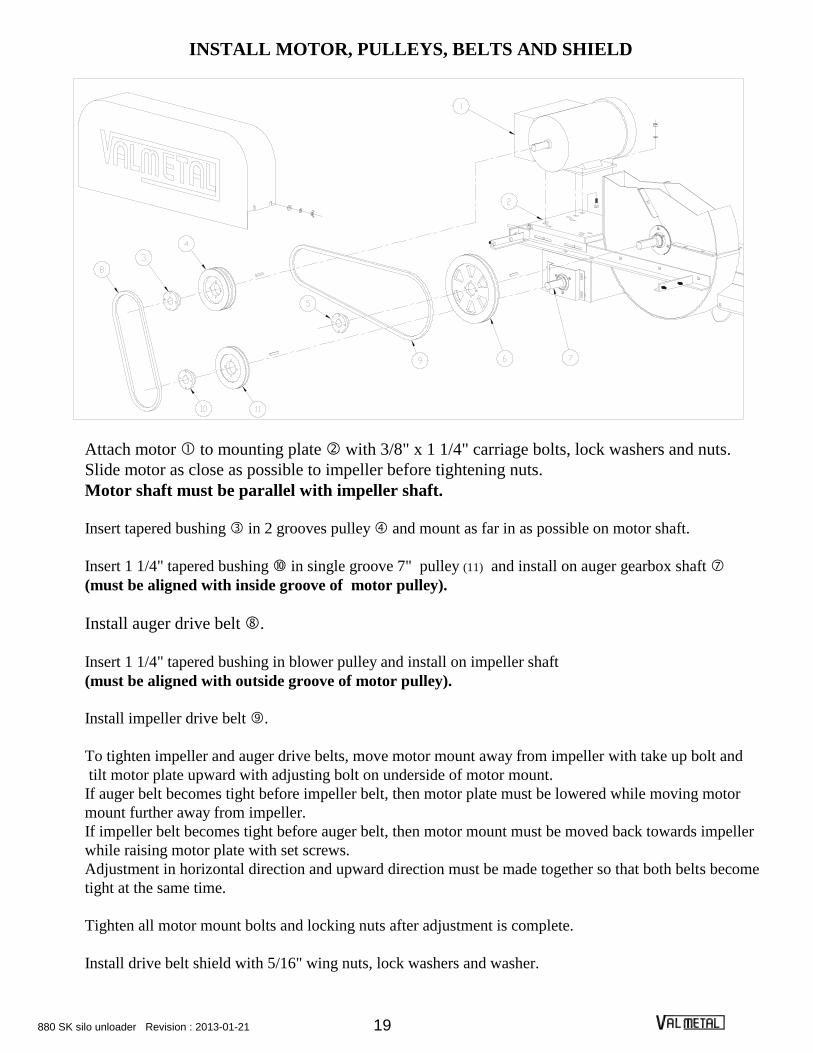
INSTALL MOTOR, PULLEYS, BELTS AND SHIELD
Attach motor to mounting plate with 3/8" x 1 1/4" carriage bolts, lock washers and nuts.
Slide motor as close as possible to impeller before tightening nuts.
Motor shaft must be parallel with impeller shaft.
Insert tapered bushing in 2 grooves pulley and mount as far in as possible on motor shaft.
Insert 1 1/4" tapered bushing in single groove 7" pulley (11) and install on auger gearbox shaft
(must be aligned with inside groove of motor pulley).
Install auger drive belt .
Insert 1 1/4" tapered bushing in blower pulley and install on impeller shaft
(must be aligned with outside groove of motor pulley).
Install impeller drive belt .
To tighten impeller and auger drive belts, move motor mount away from impeller with take up bolt and
tilt motor plate upward with adjusting bolt on underside of motor mount.
If auger belt becomes tight before impeller belt, then motor plate must be lowered while moving motor
mount further away from impeller.
If impeller belt becomes tight before auger belt, then motor mount must be moved back towards impeller
while raising motor plate with set screws.
Adjustment in horizontal direction and upward direction must be made together so that both belts become
tight at the same time.
Tighten all motor mount bolts and locking nuts after adjustment is complete.
Install drive belt shield with 5/16" wing nuts, lock washers and washer.

880 SK silo unloader Revision : 2013-01-21 20
INSTALL CASTER BRACKET AND WHEEL ASSEMBLY
Slide collar over end of guide wheel tube.
Insert the caster bracket and wheel assembly without holes into guide wheel tube .
Attach guide wheel tube to shroud assembly with 3/8" x 4 1/2" hex. bolts and nylon lock nuts.
Adjust caster bracket and wheel assembly so the distance from the near side of impeller housing
to silo wall is one-half the maximum diameter of silo. Note: Locking screw must extend through hole at end of tube. Place wheel in horizontal position
and tighten locking screw.
Attach pressure wheel tube to motor mount angle with 3/8" x 2 3/4" hex. bolts and nylon lock nuts.
On 18’ to 24’ silo, attach wheel tube braces to wheel tubes using 3/8" x 1" hex. bolts, washers
and nylon lock nuts.
Attach caster bracket and wheel assembly to pressure wheel tube with 3/8" x 3" hex. bolt and
nylon lock nut.
Bolt handle under locking tab (on pressure wheel tube) with 3/8" x 1" hex. bolt and nylon lock nut.
Do not overtighten. Handle must pivot. Insert 3/8" x 1" hex. bolt through slot in locking tab and slot
in handle and secure with lock nut. Do not overtighten. Bolt must slide in slot.
Insert eye bolt of spring assembly throught caster bracket tube and secure with nylon lock nut.
Install S-hook between handle and chain.
When unloading, extend spring by swinging handle toward pressure wheel tube and lock by sliding
bolt into slot of locking tab. Proper tension is about 4" of extension. Adjust chain if necessary.
Unlatch handle for filling silo.
Attach guide and pressure wheel braces onto guide and pressure wheel tubes with 3/8" x 1" hex.
bolts and nylon lock nuts.

880 SK silo unloader Revision : 2013-01-21 21
ASSEMBLE DISCHARGE CHUTE
Attach braces to discharge chute with 5/16" x 1" round head machine screws and nylon lock nuts.
Note : Attach one cord clip with brace at the top of the discharge chute.
Attach brace plate to braces with 5/16" x 3/4" round head machine screws and nylon lock nuts.
Attach the other cord clip to the discharge chute with 5/16" x 3/4" round head machine screws and nylon lock nuts.
Attach the chute support brackets to discharge chute with 5/16"x 1" round head machine screws and nylon lock
nuts.
Cut the power cord from the collector ring to lenght required. (BE SURE THERE IS APPROXIMATELY 2’ LOOP IN POWER CORD BETWEEN END CLIP ON DISCHARGE
CHUTE AND THE SILO DOOR.)
Install male connector to power cord end.
Place cord grip over power cord in silo chute. Allow 3’ to 4’ of cord to extend into silo.
Install female connector to power cord end.
Using s-hook, hang cord from ladder rung or other convenient location.
NOTE :
Disregard next steps if a distributor has been ordered and the unloader will be used first for
filling. Refer to separate instructions packed with the distributor. If no distributor is ordered
or the unloader will be used first for unloading, install the parts illustrated above.
Attach discharge chute base with 5/16" x 1 1/4" hex. bolts, washers and nylon lock nuts. Slide chute support through chute rollers. Adjust height of chute so stream of silage will go through the top
center of the door. Hook chain to the ladder rung.
Place the power cord from the collector ring in cord clips.
Secure anchor chain. Note : If the unloader is equipped with a torque arm, refer to next page.

880 SK silo unloader Revision : 2013-01-21 22
INSTALL TORQUE ARM
(OPTIONAL)
Assemble the torque arm main plate with two rollers (13) (4
halves) and a roller plate (11) at the end of the plate with three
holes, use 1/2" x 4" hex. bolts and nylon lock nuts. In the
middle hole assemble the two braces and with 1/2" x 1
1/2" hex. bolt and nylon lock nut. Use holes corresponding to
silo size, as shown.
Assemble two rollers ( 4 halves) and the two torque arm tube
at the other end of the main plate, use
1/2" x 4" hex. bolts and nylon lock nuts.
Install the discharge chute support bracket to main plate with
1/2" x 1 1/2" hex. bolts and nylon lock nuts.
FOR 12’ TO 20’ MODELS ,
Attach the torque arm bracket to ring segment with 1/2" x 1-
1/2" hex. bolts and nylon lock nuts.
FOR 24’ MODEL,
Drill 1/2" holes trough the upper part of the ring segments, use the torque arm bracket as templates.

880 SK silo unloader Revision : 2013-01-21 23
NOTE : THE TORQUE ARM BRACKETS
SHOULD BE SECURED TO THE RING SEGMENT
IN A SYMETRIC WAY AND IN ORDER TO LET A
MINIMUM OF 12" BETWEEN THE MAIN TORQUE
ARM PLATE AND THE SILO DOOR.
Attach the torque arm tubes to bracketswith
1/2" "U" bolts and nylon lock nuts.
Attach the torque arm tubes to braces and
with 3/8" x 2 1/8" U bolts and nylon lock
nuts.
Slide the torque arm between rollers.
Slide the discharge chute support extension
on the the discharge chute support and secure
with the locking screw.
Attach the discharge chute support assembly to
the discharge chute support bracket with 3/16 x
2" cotter pins.
ASSEMBLE DISCHARGE CHUTE
Attach braces to discharge chute with
5/16" x 1" round head machine screws and
nylon lock nuts.
Note : Attach one cord clip with brace at
the top of the discharge chute.
Attach brace plate to braces with 5/16" x
3/4" round head machine screws and nylon
lock nuts.
Attach the other cord clip to the discharge
chute with 5/16" x 3/4" round head
machine screws and nylon lock nuts.
Attach the chute support bracket to
discharge chute with 5/16" x 1" round head
machine screws and nylon lock nuts.

880 SK silo unloader Revision : 2013-01-21 24
INSTALL DISCHARGE CHUTE AND POWER CORD
Cut the power cord from the collector ring to lenght required. (BE SURE THERE IS APPROXIMATELY 2’ LOOP IN POWER CORD BETWEEN END CLIP ON DISCHARGE
CHUTE AND THE SILO DOOR.)
Install male connector to power cord end.
Place cord grip over power cord in silo chute. Allow 3’ to 4’ of cord to extend into silo.
Install female connector to power cord end.
Using s-hook, hang cord from ladder rung or other convenient location.
NOTE :
Disregard next steps if a distributor has been ordered and the unloader will be used first
for filling. Refer to separate instructions packed with the distributor. If no distributor is
ordered or if the unloader will be used first for unloading, install the parts illustrated
above.
Attach discharge chute base with 5/16" x 1 1/4" hex. bolts, washers and nylon lock nuts.
Slide the discharge chute support extension on chute support bracket and lock with 3/16" x 2" cotter pins.
Place the power cord from the collector ring in cord clips.

880 SK silo unloader Revision : 2013-01-21 25
POWER CORD LOOPING KIT
(OPTIONAL)
96-8090
cableclamp
15"
5'
Install one looping clamp on the power cable every 5 feet.
IMPORTANT : The first looping ring must be attached to the suspension cable at
15 from the suspension arm to prevent any damages to power cord as the unloader
pivots underneath. Use one 5/16 cable clamp.

880 SK silo unloader Revision : 2013-01-21 26
INSTALL AUGER KNIVES
Install auger knives to auger with 1/4" x 5/8" hex. bolts and nylon lock nuts
SECURE ANCHOR CHAIN
Note : Disregard if the unloader is equipped with a torque
arm.
Assemble the anchor chain over the suspension cable at the
right side of the silo door (looking from the silo chute).
Attach the chain to a silo hoop or the door sill. Allow
about one foot of sag at the center of the chain.
TEST RUN
Raise the unloader above the silage to do a test run and check the following :
1- Make sure the skates slide freely and the ring segments are flush. If not, bend ring flange so there is no
interference.
2- Be sure chipper blades are held close to, but not in contact with the silo wall all the way around.
3- Be sure the belts are running true and the sheaves are in line.

880 SK silo unloader Revision : 2013-01-21 27
SILO UNLOADER
MODEL 880
ELECTRICAL INSTALLATION INSTRUCTIONS
NOTE : Notwithstanding these instructions, the complete electrical installation shall be
subject to the inspection of the local Inspection Authorities having jurisdiction.
STORE THESE INSTRUCTIONS IN A SAFE PLACE FOR
FUTURE REFERENCE.
SPECIFICATIONS
MAIN DRIVE MOTOR
5 HP 7½ HP 10 HP
230 V.
30 Amps
60 Hz
1 Phase
575 V.
5 Amps
60 Hz
3 Phases
230 V.
40 Amps
60 Hz
1 Phase
575 V.
8 Amps
60 Hz
3 Phases
230 V.
50 Amps
60 Hz
1 Phase
575V.
10 Amps
60 Hz
3 Phases
880 SK silo unloader Revision : 2013-01-21 28
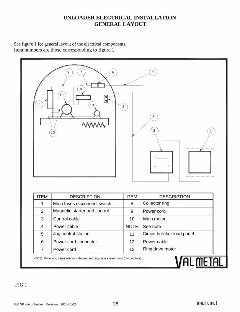
UNLOADER ELECTRICAL INSTALLATION
GENERAL LAYOUT
See figure 1 for general layout of the electrical components.
Item numbers are those corresponding to figure 1.
Main motorControl cable 103
Following items are for independant ring drive system only ( two motors).
Power cord connector
Power cable
Jog control station
Power cord
6
NOTE:
7
5
4
Circuit breaker load panel
Power cable
Ring drive motor
12
13
11
NOTE See note
5
12
DESCRIPTION
Magnetic starter and control
Main fuses disconnect switch
2
ITEM
1
9 7 6
10
11
8
13
3
1
DESCRIPTION
Collector ring
Power cord9
ITEM
8
2
4
FIG.1

880 SK silo unloader Revision : 2013-01-21 29
1- MAIN FUSIBLE DISCONNECT SWITCH
NOTE: The main fusible disconnect switch is normally supplied by the customer.
For 230 Volts motors :
Type: Two pole, fusible (with solid neutral) (neutral not grounded)
and with a ground terminal.
For 575 Volts motors :
Type: Three poles, fusibles.
Enclosure type: "CSA ENCL 3" (weatherproof)
5 HP MOTOR
Rating 230 Volts - 1 Phase 575 VOLTS - 3 Phases
Fuse holder rating 250 V., 60 Amps 600 V., 20 Amps
Fuse 250 V., 40 Amps 600 V., 7 Amps
Fuse type D Time delay
7½ HP MOTOR
Rating 230 Volts - 1 Phase 575 VOLTS - 3 Phases
Fuse holder rating 250 V., 100 Amps 600 V., 20 Amps
Fuse 250 V., 60 Amps 600 V., 10 Amps
Fuse type D Time delay
10 HP MOTOR
Rating 230 Volts - 1 Phase 575 VOLTS - 3 Phases
Fuse holder rating 250 V., 100 Amps 600 V., 20 Amps
Fuse 250 V., 60 Amps 600 V., 15 Amps
Fuse type D Time delay
NOTE : The electrical Code requires a disconnecting means to be located within sight of the
motor starter, and requires each ungrounded conductor to have overcurrent
protection, which is afforded by the main fuses.

880 SK silo unloader Revision : 2013-01-21 30
2- MAGNETIC STARTER AND CONTROL PANEL
The control panel must be mounted on vertical surface only. See pages 34 to 38 for electrical diagram.
Enclosure: Lume 3544 F
Nema 5
Magnetic starter: Leeson Electric (Canada) Ltd
See the following table for starter and overload relay model.
MOTOR
SIZE
HP
VOLTAGE PHASE MODEL (LOVATO) HEATER ELEMENT
(LOVATO)
5
7.5
10
5 & 3/4
7.5 & 3/4
10 & 1
230
230
230
230
230
230
1
1
1
1
1
1
B 32
B 46
B 63
B 32
B 46
B 63
RC80-Q
RC80-S
RC80-X
RC80-R
RC80-S
RC80-X
3/4
5
7.5
10
550
550
550
550
3
3
3
3
(same as main motor)
B 12
B 16
B 22
* KTA3-1.6
* KTA3-10
* KTA3-10
* KTA3-16
* NOTE: Those thermal elements are located in the control panel and are from sprecher schuh.
Push button: Breter
Switch for drive motor: (230 Volts only) Carling EK 204-73, 2 poles wired in parallel.
Voltage transformer: Marcus EXA 50-39
Circuit protector: A-0701 3A, Sang Mao
Current transformer: SEW ST 30 CT
Ammeter: SEW ST96-25/5
Terminals: Entrelec M6/8, M10/10, M16/12 or M35/16
IMPORTANT :The jumper between terminal block 2 and 3 must be removed if remote
control station is used.

880 SK silo unloader Revision : 2013-01-21 31
3- CONTROL CABLE
Type : SOW Cab Tyre - 16 AWG
Number of conductors : 4, one of which is green
Length : As required. Do not splice smaller length.
Strain relief : Use strain relief connectors, Thomas & Betts # 2-050-464.
4- POWER CABLE
Type: SOW or SJOW
Number of conductors: Three (3) for 230 Volts - single phase, one motor system only (no ring drive
motor). One conductor is coloured green and is to be used only for grounding.
Four (4) conductors for all other models. One conductor is coloured green and is
to be used only for grounding.
Size of conductors: The size of conductors varies according to the length of cable required as shown
in the table below. This is based on the recommanded code requirement of not
more than a 3 percent voltage drop.

880 SK silo unloader Revision : 2013-01-21 32
TABLE NO. 1
Motor(s)
size
Number
of
Phase
Voltage
AC
Nominal
current
AWG Size Total cable length
between the control
panel and the silo
unloader(in feet).
(Horse power) (Volts) (Ampere) < 100 < 150 <200 <250
5 1 230 29 8 6 6 4
5 and 3/4 1 230 36 8 6 6 4
7.5 1 230 41 6 6 4 4
7.5 and 3/4 1 230 48 6 6 4 4
10 1 230 50 6 4 4 4
10 and 3/4 1 230 57 4 4 3 3
5 and 3/4 3 575 6 12 12 12 12
7.5 and 3/4 3 575 9 12 12 12 12
10 and 3/4 3 575 11 12 12 12 12
Grounding: The green grounding conductor shall be terminated securely at the grounding terminal
in the magnetic starter and the ground terminal of the connector at the main motor.
Strain relief: Thomas & Betts (see table No. 2 for size). A strain relief bushing shall be used at the
magnetic starter and the strain relief of the connector shall be properly secured.
TABLE NO. 2
AWG SIZE CAT. NO MANUFACTURER
16 - 4
14 - 3
12 - 3
12 - 4
8 - 3
8 - 4
6 - 3
6 - 4
4 - 4
2 - 050 - 464
2 - 050 - 464
2 - 050 - 464
2 - 050 - 465
2 - 050 - 466
2 - 075 - 468
2 - 075 - 467
2 - 075 - 468
2 - 100 - 469
THOMAS & BETTS
THOMAS & BETTS
THOMAS & BETTS
THOMAS & BETTS
THOMAS & BETTS
THOMAS & BETTS
THOMAS & BETTS
THOMAS & BETTS
THOMAS & BETTS
Protection of cord: Route the cord up the silo to support it and protect it from mechanical
damage. Do not splice cords together.
880 SK silo unloader Revision : 2013-01-21 33
5- JOG CONTROL STATION
Purpose : This station affords remote control of the motor starter installed at the base of the silo.
It permits positive lockout control which will prevent the starting of the motor from
any other location.
Always store this pendant hand-held control in a convenient location so that positive
lockout control can be made before entering the silo.
See pages 34 to 38 for electric diagrams
Manufacturer :Multico Electrique (1988) Inc.
Enclosure :LUME 3520F
Push button :Breter M6065R for stop button, Breter RT010 for start push button
6- POWER CORD CONNECTOR (OPTIONAL)
This connector is on the power cord of the unloader.
For 230 Volts - single phase system with only one motor :
Connector : KH RODALE C 650 DF
Plug : KH RODALE P 650 DF
Rating :50 Amps, 250 Volts - 2 Poles, 3 wires
For 230 Volts - single phase system with independant ring drive motor (2 motors)
(requesting 50 amps maximum) :
Connector : KH RODALE P 1450 DF
Plug : KH RODALE C 1450 DF
Rating :50 Amps, 250 Volts - 3 poles, 4 wires

880 SK silo unloader Revision : 2013-01-21 34
For 230 Volts - single phase system with independant ring drive motor requesting
more than 50 Amps.(i.e.: 10 HP and 3/4 HP):
Connector : Harrow Hart # 26427
Plug : Harrow Hart # 26426
Rating : 60 Amps, 600 Volts - 3 poles, 4 wires
For 575 Volts - 3 phases system with independant ring drive motor (2 motors)
(requesting 30 Amps maximum)
Connector : LEVITON # 2743
Plug : LEVITON # 2741
Rating : 30 Amps, 600 Volts - 3 poles, 4 wires
The electrical codes require a suitable disconnecting means within sight of the motor, and in some
localities, this weatherproof connector may serve of this disconnect means, subject to the acceptance
of the local Electrical Inspection Authority having jurisdiction.
NOTE: Do not use this connector to start or stop the motor.
Always open the main disconnect switch at the base of the silo before connecting
and disconnecting this connector.

880 SK silo unloader Revision : 2013-01-21 35
8- SLIP RING
The slip ring is supplied with two (2) cables already installed. One of them must be connected to the
male connector and fixed along the discharge chute. The other cable must be connected to the circuit
breaker load panel mounted on side of auger frame on independant ring drive system or to the motor
on system with only one motor.
(See Installation Instruction Manual)
10- MAIN MOTORS (OPTIONAL)
Type: Totally enclosed (TEFC). Internal overload protected with manual reset for 230 Volts
motor only.
MOTOR SIZE 230 VOLTS - 1 PHASE 575 VOLTS - 3 PHASES
5 HP
BALDOR :
Cat. No. L3731M
MARATHON :
Cat. No. Z117
BALDOR :
Cat. No. EM3665T-5
MARATHON :
Cat. No. H675
7.5 HP
BALDOR :
Cat. No. L3732M
MARATHON :
Cat. No. Z115
BALDOR :
Cat. No. EM3770T-5
MARATHON :
Cat. No. H676
10 HP
BALDOR :
Cat. No. L3737TM
MARATHON :
Cat. No. Z116
BALDOR :
Cat. No. EM3774T-5
MARATHON :
Cat. No. H677

880 SK silo unloader Revision : 2013-01-21 36
11- CIRCUIT BREAKER LOAD PANEL
This CIRCUIT BREAKER LOAD PANEL permits to shut off power from inside the silo.
for 230V. motors: Model : Square D QO cat. Q08L100RB
Enclosure : CEMA 3
Max. No. of single poles 8 - 100 Amps
Single phase - 120 / 240 Volts A.C.
1 breaker 60 Amps for main motor
1 breaker 15 Amps for drive motor
for 575V. motors : Model : Multico
Enclosure : Hoffman A-1086CHQRFG
CEMA 4 X
Terminals : Entrelec M6/8
Thermal relay : Sprecher Schuh
KTA3-1.6 for 1 HP motors
KTA3-10 for 5 and 7.5 HP motors
KTA3-16 for 10 HP motors
Push button for reset / stop and start : Breter
NOTE : This panel is not required for system using only one motor.
880 SK silo unloader Revision : 2013-01-21 37
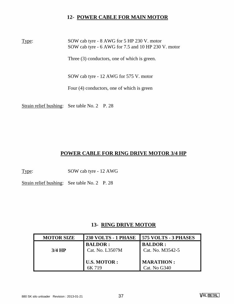
12- POWER CABLE FOR MAIN MOTOR
Type: SOW cab tyre - 8 AWG for 5 HP 230 V. motor
SOW cab tyre - 6 AWG for 7.5 and 10 HP 230 V. motor
Three (3) conductors, one of which is green.
SOW cab tyre - 12 AWG for 575 V. motor
Four (4) conductors, one of which is green
Strain relief bushing: See table No. 2 P. 28
POWER CABLE FOR RING DRIVE MOTOR 3/4 HP
Type: SOW cab tyre - 12 AWG
Strain relief bushing: See table No. 2 P. 28
13- RING DRIVE MOTOR
MOTOR SIZE 230 VOLTS - 1 PHASE 575 VOLTS - 3 PHASES
3/4 HP
BALDOR :
Cat. No. L3507M
U.S. MOTOR :
6K 719
BALDOR :
Cat. No. M3542-5
MARATHON :
Cat. No G340

880 SK silo unloader Revision : 2013-01-21 38
WIT
H I
ND
EP
EN
DA
NT
RIN
G D
RIV
E M
OT
OR
(2
MO
TO
RS
)
EL
EC
TR
ICA
L D
IAG
RA
M F
OR
57
5 V
OL
TS
- 3
PH
AS
ES
SY
ST
EM
SU
PP
LIE
D B
Y C
OS
TU
ME
RD
ISC
ON
NE
CT
AN
D F
US
ES
EL
EC
TR
ICA
L C
OD
E IP
PLY
CO
NT
RO
L P
AN
EL
FO
R S
ILO
UN
LO
AD
ER
115 V
.
575 V
.
3
ST
OP
/RE
SE
T B
UT
TO
N
L2
L1
D1
0.1
A
L3
0.1
A
X1
H1
X2
H2
CT
3 A
MP
S
BR
EA
KE
R
ST
OP
3
L2
T2
T1
ST
AR
T B
UT
TO
N
ST
OP
BU
TT
ON
L1
12
3
UN
LO
AD
ER
CO
LLE
CT
OR
RIN
G
T3
AM
ME
TR
E
L3
45
6
BR
EA
KE
R P
AN
EL
CIR
CU
IT ST
AR
T B
UT
TO
N
ST
AR
T
EX
TE
RN
AL C
ON
TR
OL S
TA
TIO
N
JU
MP
ER
ST
OP
21
D1
N
ST
AR
T
RE
MO
VE
TH
E J
UM
PE
R B
ET
WE
EN
TE
RM
INA
L
2 A
ND
3 W
HE
N IN
ST
ALLIN
G A
N E
XT
ER
NA
L
D1
CO
NT
RO
L S
TA
TIO
N.
2
2
3/4
HP
MO
TO
R575V
3 P
HA
SE
S
RIN
G D
RIV
E
5 O
R 7
.5 O
R 1
0 H
P M
OT
OR
575V
3 P
HA
SE
S
BL
OW
ER
& A
UG
ER

880 SK silo unloader Revision : 2013-01-21 39
5 O
R 7
.5 O
R 1
0 H
P M
OT
OR
UN
LO
AD
ER
CO
LL
EC
TO
R R
ING
EL
EC
TR
ICA
L D
IAG
RA
M F
OR
57
5 V
OL
TS
- 3
PH
AS
ES
SY
ST
EM
WIT
H O
NE
MO
TO
R
CT
57
5V
3 P
HA
SE
S
SU
PP
LIE
D B
Y C
OS
TU
ME
RD
ISC
ON
NE
CT
AN
D F
US
ES
L2
L1
L3
T1
D1 R
S
O/L
O/L
RS
T2
RS
O/L
T3
EL
EC
TR
ICA
L C
OD
E IP
PL
Y
BL
OW
ER
AN
D D
RIV
E
AM
ME
TR
E
CO
NT
RO
L P
AN
EL
FO
R S
ILO
UN
LO
AD
ER
EX
TE
RN
AL
CO
NT
RO
L S
TA
TIO
N
ST
AR
T
ST
AR
T
H2
H1
0.1
A1
15
V.
57
5 V
.
0.1
A
X1
X2
ST
OP
BR
EA
KE
R
3 A
MP
S
3
ST
OP
JU
MP
ER
32
2
2D
1
D1
1N
RE
MO
VE
TH
E J
UM
PE
R B
ET
WE
EN
TE
RM
INA
L
2 A
ND
3 W
HE
N I
NS
TA
LL
ING
AN
EX
TE
RN
AL
CO
NT
RO
L S
TA
TIO
N.

880 SK silo unloader Revision : 2013-01-21 40
EL
EC
TR
ICA
L D
IAG
RA
M F
OR
230 V
OLT
S 1
PH
AS
E
WIT
H O
NE
MO
TO
R
UN
LO
AD
ER
CO
LL
EC
TO
R R
ING
CT
RS
/D1
5 O
R 7
.5 O
R 1
0 H
P M
OT
OR
230V
1 P
HA
SE
DIS
CO
NN
EC
T A
ND
FU
SE
S
L1
RS
/D1
D1
T1
L2
T2
SU
PP
LIE
D B
Y C
OS
TU
ME
RE
LE
CT
RIC
AL C
OD
E IP
PLY
D1
CO
NT
RO
L P
AN
EL
FO
R S
ILO
UN
LO
AD
ER
EX
TE
RN
AL C
ON
TR
OL S
TA
TIO
N
3 A
MP
S
BR
EA
KE
R
ST
OP
3
JU
MP
ER
ST
OP
ST
AR
T
2
ST
AR
T
3A
1D
1R
S/D
1
2 A
ND
3 W
HE
N IN
ST
ALLIN
G A
N E
XT
ER
NA
L
RE
MO
VE
TH
E J
UM
PE
R B
ET
WE
EN
TE
RM
INA
L
AM
ME
TR
E
CO
NT
RO
L S
TA
TIO
N.

880 SK silo unloader Revision : 2013-01-21 41
EL
EC
TR
ICA
L D
IAG
RA
M F
OR
23
0 V
OL
TS
1 P
HA
SE
SY
ST
EM
WIT
H I
ND
EP
EN
DA
NT
RIN
G D
RIV
E M
OT
OR
(2
MO
TO
RS
).
CT UN
LO
AD
ER
CO
LL
EC
TO
R R
ING
SU
PP
LIE
D B
Y C
OS
TU
ME
RD
ISC
ON
NE
CT
AN
D F
US
ES
EL
EC
TR
ICA
L C
OD
E IP
PLY
L1
L1
L2
SW
ITC
H
D1
RS
/D1
T1
15A
T1 A
RS
/D1
T2
23
0V
1 P
HA
SE1
5A
L1
3/4
HP
MO
TO
R
60AL
2
DR
IVE
BL
OW
ER
EX
TE
RN
AL
CO
NT
RO
L S
TA
TIO
N
CO
NT
RO
L P
AN
EL
FO
R S
ILO
UN
LO
AD
ER
BR
EA
KE
R
3 A
MP
S
ST
OP
AM
ME
TR
E
3
JU
MP
ER
ST
OP
ST
AR
T
ST
AR
T
2
D1
RS
/D1
3A
1D
1
2 A
ND
3 W
HE
N I
NS
TA
LLIN
G A
N E
XT
ER
NA
L
RE
MO
VE
TH
E J
UM
PE
R B
ET
WE
EN
TE
RM
INA
L
23
0V
1 P
HA
SE
5 O
R 7
.5 O
R 1
0 H
P M
OT
OR
60A
BR
EA
KE
R P
AN
EL
CIR
CU
IT
CO
NT
RO
L S
TA
TIO
N.

880 SK silo unloader Revision : 2013-01-21 42
BO
TH
MO
TO
RS
ST
AR
T O
R S
TO
P S
IMU
LT
AN
EO
US
LY
EL
EC
TR
ICA
L D
IAG
RA
M F
OR
23
0 V
OL
TS
1 P
HA
SE
SY
ST
EM
WIT
H T
WO
MO
TO
RS
.
UN
LO
AD
ER
CO
LL
EC
TO
R R
ING
SU
PP
LIE
D B
Y C
OS
TU
ME
RD
ISC
ON
NE
CT
AN
D F
US
ES
ELE
CT
RIC
AL C
OD
E IP
PLY
L1
L1
L2
D1
RS
/D1
T1
CT
RS
/D1
T2
3/4
HP
MO
TO
R2
30
V 1
PH
AS
E
15A
15A
T1
40AT
2
DR
IVE
BL
OW
ER
EX
TE
RN
AL C
ON
TR
OL S
TA
TIO
N
CO
NT
RO
L P
AN
EL
FO
R S
ILO
UN
LO
AD
ER
3 A
MP
S
BR
EA
KE
R
ST
OP
AM
ME
TR
E
3
JU
MP
ER
ST
OP
ST
AR
T
ST
AR
T
2
D1
RS
/D1
3A
1D
1
RE
MO
VE
TH
E J
UM
PE
R B
ET
WE
EN
TE
RM
INA
L
2 A
ND
3 W
HE
N I
NS
TA
LLIN
G A
N E
XT
ER
NA
L
23
0V
1 P
HA
SE
5 O
R 7
.5 O
R 1
0 H
P M
OT
OR
40A
CIR
CU
ITB
RE
AK
ER
PA
NE
L
CO
NT
RO
L S
TA
TIO
N.

880 SK silo unloader Revision : 2013-01-21 43
RE
MO
VE
TH
E J
UM
PE
R B
ET
WE
EN
TE
RM
INA
LS
2 A
ND
3
JUMPER
3
CO
NT
RO
L P
AN
EL
1 2
IMP
OR
TA
NT
EX
TE
RN
AL C
ON
TR
OL S
TA
TIO
N
1
ST
AR
T
3
2
ST
OP

880 SK silo unloader Revision : 2013-01-21 44
ADJUSTING THE SILO UNLOADER
PRESSURE WHEEL, GUIDE WHEEL AND WALL WHEELS.
1-The pressure wheel should run against the silo wall at all times. Its purpose is to hold the auger wall wheels in contact with the silo
wall and to insure that all material is removed from the wall area. Normal adjustment of the pressure wheel is when the spring is extended
4". During extremely frozen conditions, it may be necessary to increase the spring force. This is done by moving the hook on the spring to
a different chain link when tension is released. After changing pressure wheel adjustment, you should always watch the unloader rotate
around the silo at least once to make sure that your adjustment will not cause the pressure wheel to exert force on the unloader. Observe
operation from safety of silo chute.
2-The unloader is kept centered in the silo by the side guide wheel , this is the one extending out at approximately a 90 degree angle
from the auger. The guide wheel should run against the silo whall at all times. You can get the correct setting for this wheel by first
measuring the maximum silo diameter. Then extend the wheel so that the distance from near side of the impeller housing to the edge of
the wheel is equal to one half the maximum diameter of the silo. You can tell when this adjustment is incorrect by a pile of undisturbed
silage being left in the center of the silo directly under the impeller housing. If this occurs, the wheel is probably not extended out far
enough.
3-The position of the wall wheels in relation to the auger, determines the closeness of the chipper knives to the silo wall. This is very
critical in freezing weather and should be set so the chipper knives are within 1/8" of the silo wall. Adjust by loosening the bolts wich
secure the wall wheel bracket to the auger frame and turn the adjusting screw out or in to obtain the correct adjustment. After you make
any change in the wall wheel setting, rotate the unloader around the silo to make sure the chipper blades do not hit the wall at any place.
Observe operation from safety of silo chute. The trailing wheel will generally be in contact with the silo wall except near the silo doors.
As the machine approaches a door, the lead wheel will come in contact with the flattened wall and protect it from being damaged by the
chipper knives.

880 SK silo unloader Revision : 2013-01-21 45
OPERATING THE SILO UNLOADER
For trouble-free operation of your silo unloader, the following operator schedule is recommended.
After turning off the silo unloader at the end of feeding, raise the machine off the silage pack.
During extreme cold weather if the motor switch is turned on and off momentarily after raising, this will clear the impeller
of any material left in it for easier starting at the next feeding. To begin feeding again, lower the unloader the same
amount that it was raised previously. Now turn on the motor switch.
When you turn on the silo unloader, the needle will flick over to a maximum reading. The ammeter is designed so that this
initial surge of current will not damage it. A couple of seconds after starting, the ammeter will level off at the normal load
current for your motor. Most reliable, efficient operation and highest capacity will be obtained when you operate your silo
unloader motor in its proper amperage range.
After the unloader has completed its revolution around the dilo, the silage flow will decrease and the unloader should
again be lowered the amount necessary to load the motor to rated current. Observation will tell you how many turns of the
crank are necessary to do this. Five turns lower the unloader about one inch. Slight overloading or underloading will not
damage the equipment and is much better for it than continuous jockeying up and down the hoist.
A complete revolution around the silo will take about 5 minutes. Should any obstruction occur in the silo during this 5
minutes period, a built in clutch will prevent damage to the equipment.
If the impeller should become plugged due to long hard-to-handle material or rotten material from the top of the silo, the
stall current of the motor is such that it will trip the overload device in the control box at the bottom of the silo before
damage is done to the motor or the unloader. Whenever this happens, you should go up and find the cause of the
stoppage before attempting to restart the unloader.
The curved discharge chute is designed to allow maximum lowering for a given size of silo before it is necessary to move
the discharge chute down to another silo door. This discharge chute should be lowered every two doors. This would
be a good opportunity for you to take the time to check your unloader.
DISCONNECT AND LOCK OUT POWER SOURCE BEFORE ADJUSTING
OR SERVICING UNIT.
1- Before entering the silo chute be sure the power to the unloader has been turned off and locked.
2- If your unloader is equiped with a remote control switch, lock the stop button down so the unloader cannot be
started accidentally and take the remote switch with you.
3- As soon as you climb the silo chute to the door through which the material was being thrown out, reach into the
silo and unplug the power cord to the silo unloader.
4- Remove the torque arm bracket from the door frame and lower it.
5- Unless equiped with cord looping, unhook the power cord grip and reattach it to a ladder rung just above
the next discharge door you will use.
6- Before leaving the silo you should check the machine over thoroughly.
7- After you are out in the silo chute, plug the cord connectors together before climbing down.

880 SK silo unloader Revision : 2013-01-21 46
LUBRICATION TO BE MADE BEFORE
STARTING-UP UNLOADER AND MONTHLY
COLLECTOR RING
Grease both grease fittings on the upper support bearing of the collector ring with two pumps from a hand
grease gun. Avoid over greasing as it is possible to damage the collector ring seal and get grease down
into the electrical contact area.
LINE SHAFT RING DRIVE
Grease the drive shaft

880 SK silo unloader Revision : 2013-01-21 47
TORQUE LIMITER
VS-1000
VS-3000
The torque limiter is located on the output shaft of the ring drive gearbox. It was factory set and does not
require any adjustements. Grease the torque limiter monthly.
TURBINE
Grease impeller flanged bearing once a month

880 SK silo unloader Revision : 2013-01-21 48
CHECK OIL LEVEL
SIGHT
GLASS
OIL FILLER
PLUG
VS-1000
VS-3000
Lubricant level should be check in the ring drive gearbox every time you go into the silo to change
door; this is accomplished by viewing the oil level through the sight plug located on the gearbox. If
lubricant level is low, add EP 80-90 high pressure gear lubricant.
The gear lubricant level in the auger gearbox should also be checked every time you go into the silo to
change door. If lubricant level is low, add synthetic oil Shell Spirax S75W90.
SIGHT PLUG
OIL LEVEL

880 SK silo unloader Revision : 2013-01-21 49
VERTICAL RAISING WHEEL AND PIVOT
Oil the vertical raising wheel and pivot.
WORM GEAR HOIST
OIL LEVEL
OIL FILLER PLUG
The lubrication level in the worm gear hoist should be checked every 6 months and every time you will raise the
unloader to the top of silo. The oil level should be visible in the oil level sight plug. If oil is low, add
EP 80-90 extreme pressure gear lubricant. Lubricant should be changed annually.
The hoist cable assembly will have a much longer life if lubricated with motor oil or gear lubricant.
You should do this when the unloader has been raised to the top of the silo and all the cable is wrapped on the
hoist.Paint on a liberal coat and allow it to drip off.

880 SK silo unloader Revision : 2013-01-21 50
IMPELLER BLADES AND V-BELTS
IMPELLER BLADES
The impeller on this silo unloader can be operated with the blades rigid, as sent from the factory, or as swinging
blades by removal of 3 locking bolts. If the blades are left rigid, the maximum throwing power will be achieved. It
is recommended to remove the 3 locking bolts to allow the blades to swing if material being unloaded causes
extreme gumming or during extreme cold weather operation. If the blades are allowed to swing, silage will fall out
from the discharge chute when the machine is started or stopped and anytime the unloader is overloaded causing
drop in motor speed.
The blades are also adjustable by loosening the 3 grade 5 carriage bolts securing the cupped blade to the blade
bracket. The clearance between the blade tip and rim sheet should always be within 1/32". Proper tightening torque
on these bolts is 40 lbs-ft.
V-BELTS
During initial unloading operation, some stretch of the impeller and auger belts may occur, and belts should be
readjusted. To tighten these drive belts, loosen the 4 horizontal carriage bolts through the motor mount, move
motor mount away from impeller with take-up "J" bolt and tilt motor plate upward with 1/2" hex. bolts on under
side of motor mount. If auger belt becomes tight before impeller belt, then motor plate must be lowered while
moving motor mount further away from impeller. If impeller belt becomes tight before auger belt, then motor
mount must be moved back toward impeller while raising motor plate with set screws. Adjustment in the
horizontal direction and upward direction must be made together so that both belts become tight at the same time.
The correct tension for the impeller belt may be determined by placing a 6 pounds force at the mid-point between
the 2 pulleys. This should depress the belt 1/4" to 3/8". The correct tension for the auger drive belt may be
determined by placing a 6 pounds force at the mid-point between the 2 pulleys. This should depress the belt 1/8" to
3/16".
Avoid overtightening belts. It may cause bearing damage.
After the belts are properly tensioned, tighten the 1/2" lock nuts on the 1/2" adjusting bolts, lock the 3/8" nut on
take-up "J" bolt, and tighten four horizontal carriage bolts.

880 SK silo unloader Revision : 2013-01-21 51
CONVERTING FROM UNLOADING TO DISTRIBUTING
DANGER
DISCONNECT AND LOCK OUT POWER SOURCE BEFORE
CONVERTING TO UNLOADING.
IMPORTANT :
Impeller must not be turning when using distributor.
On the line shaft drive model, the impeller V-belt must be removed to prevent
the impeller from turning.
On independent ring drive only :
Cut power to impeller and auger motor by switching to off the 60 amp. Breaker
located in the breaker box mounted on the auger frame.
CAUTION :
Failure to do this will result in severe equipment damage.
DEFLECTOR IN ITS STORAGE SUPPORT
fig. 1

880 SK silo unloader Revision : 2013-01-21 52
INSTALLATION OF THE DEFLECTOR DISTRIBUTOR
fig. 2
Attach the discharge chute on guide wheel tube and pressure wheel tube using two tie wraps.
Remove distributor assembly from storage bracket and insert pedestal into collector ring throat.
IMPORTANT : DEFLECTOR PLATE MUST BE SLANTED OVER THE IMPELLER
BELT SHIELD AS SHOWN TO PREVENT ANY BUILD UP OF
SILAGE ON THE UNLOADER DURING FILLING.
fig. 3

880 SK silo unloader Revision : 2013-01-21 53
POWERED DISTRIBUTOR INSTALLATION
Secure the nylon disc to the top of collector ring with
the existing six hexagonal bolts.
Install the distributor storage bracket on a suspension
arm with 1/2" x 4" hex bolts, nylon lock nuts.
fig. 4
Turn power unit until rotor assembly is directly over impeller belt shield so discharge is over the belt
shield.Remove distributor assembly from storage bracket and insert pedestal through power unit and into
collector ring throat. Drive pin on pedestal disc must engage clearance hole in power unit.
Secure the pedestal disc to the top of the collector ring or top of power unit by sliding the top hold down
clips inward and tighten.
IMPORTANT : BLADE
ASSEMBLY MUST SLANT
OVER THE IMPELLER
BELT SHIELD AS SHOWN
TO PREVENT ANY BUILD UP
OF SILAGE ON THE
UNLOADER DURING
FILLING.
fig. 5

880 SK silo unloader Revision : 2013-01-21 54
POWER CORD:
REMEMBER : ON INDEPENDANT RING DRIVE SYSTEM THE 60 AMP, BREAKER MUST
BE IN THE « OFF » POSITION TO PREVENT THE IMPELLER FROM
TURNING.
ON THE LINE SHAFT DRIVE SYSTEM, THE IMPELLER V-BELT MUST
BE REMOVED TO PREVENT THE IMPELLER FROM TURNING.
On powered distributor, guide the motor cord through the upper pedestal hole and down through the pedestal
and impeller.
Pull cord through lower opening in impeller and connect to female connector from the circuit breaker box.
880 SK silo unloader Revision : 2013-01-21 55
Release spring pressure on the pressure wheel.
Loosen the lock screw for the guide wheel and slide the wheel all the way in. Leave the set screw loose so the
wheel can pivot for raising.
Lubricate all grease points and check oil level in the gearboxes.
Adjust the wall wheels so they are all the way out (toward silo wall).
Check for condition and proper tension of belt on powered distributor. Operate the unloader around the silo at
least once to make sure it moves freely. Observe from the safety of the silo chute. Stop the unloader with
the auger near the main leg of the suspension system or leg nearest chute. You must be able to reach the auger
shroud from the silo door.
Flip the vertical raising wheel against the silo wall. Make sure it turns freely.
Check the condition of the support cables and the cable clamps. Replace the cables if they are frayed.
Place the main power cord connector on the auger shroud so it can be reached from the silo doors.
Raise the unloader to the top of the silo. Always leave about 6’ of suspension cable between the
suspension arms and the cable pulley on the hexapod. This reduces lateral forces on the hexapod. The
unloader can be raised higher for additional silo capacity at the very end of silo filling after the silo
has been filled to this level.
ATTENTION : Always have someone available to observe the unloader from the safety cage platform
or from the top of the silo chute to announce when the unloader is nearing the top.
Never enter a silo under a suspended silo unloader.
Take the power cord up the silo chute and hang the cord support on a ladder rung near the top of the silo.
(Unless unloader is equipped with a cord looping kit.)
Flip the vertical raising wheel to the stored position (away from the silo wall).
Plug in the unloader-distributor (make sure there is sufficient slack in the power cord to prevent pulling the
connection apart) and let it rotate around the silo until the guide wheel is near the silo door.
Turn the guide wheel caster to a level position and tighten its set screw.
Continue operating the unloader around the silo at least one to make sure it moves freely.
Do not connect torque chain to door frame during filling. If optional torque arm is used, store it in storage
bracket. Do not put in door frame during filling.

880 SK silo unloader Revision : 2013-01-21 56
OPERATING THE DISTRIBUTOR
Always make sure that the unloader-distributor is operating when filling. If the time between loads is less than
three minutes, it may be advisable to allow it to operate continuously to reduce the likelihood of filling with the
distributor not moving.
A normal fill pattern is one which is high and level around the silo wall and sloppes into a low point at the center,
making a large inverted cone. The standard distributor will achieve the pattern in 12’ through 18’ silos. A
powered distributor should be added for larger size silos.
Should the fill pattern become uneven, the distributor should be deliberately parked and fill pattern evened out by
running one or two loads toward the low side.
When the silo is nearly full (check this often), someone must watch from the outside to insure that material is not
dumped on the unloader. The unloader may be raised as high as possible and still keep the wall wheels below the
hexapod plates for topping off the silo (see note below). When using powered distributor the inverted cone may
be filled by disconnecting the powered distributor and operating the unloader, thus allowing the material to fall
near the center of the silo and fill in the inverted cone.
IMPORTANT :
Note : Always have someone available to observe the unloader from the safety cage platform or from the
top of the silo chute to announce when the unloader is nearing the top.
After the silo has been topped off and leveled, the unloader-distributor should be cleaned off and raised out of
contact with the acidic rust producing silage during the fermentation process. It is also a good idea to convert the
machine to unloading at this time since the silo filling blower is usually still set up and can be run to provide
fresh air to the persons in the silo. This is accomplished by reversing the conversion steps listed in the converting
to distributing section.
6"
6`-0``
880 SK silo unloader Revision : 2013-01-21 57
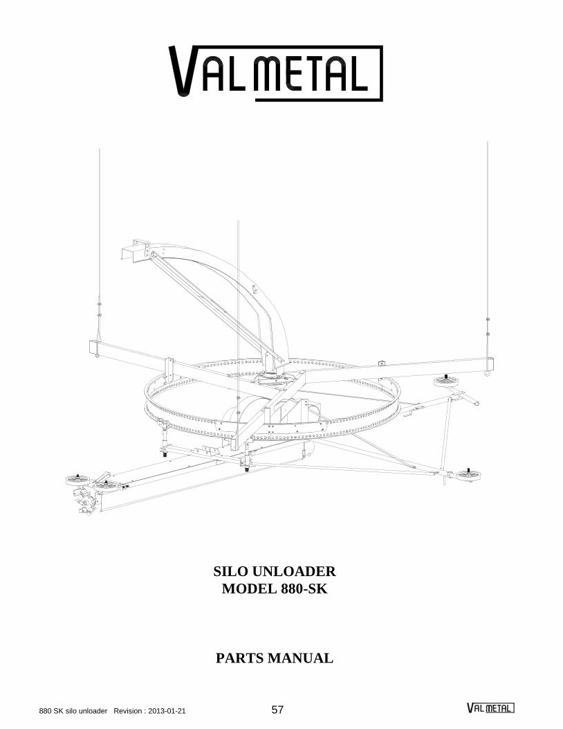
SILO UNLOADER
MODEL 880-SK
PARTS MANUAL

880 SK silo unloader Revision : 2013-01-21 58
24'
SUSPENSION ARM AND DRIVE RING
ITEM PART# DESCRIPTION
1 VS-1801-12 Suspension arm for 12’ silo
VS-1801 Suspension arm for 14’ silo
VS-1802 Suspension arm for 16’ silo
VS-1803 Suspension arm for 18’ silo
VS-1804 Suspension arm for 20’ silo
VS-1805 Suspension arm for 24’-25' silo (before 04/12/15)
VS-1806 Suspension arm for 24'-25' silo (after 04/12/15)
2 VS-1921 Drive ring bracket for 24’ (before 04/12/15 only)
VS-1906 Drive ring bracket (others)
3 VS-1908 Inside splice plate
4 VS-1910 Outside splice plate
5 VS-1912 Drive ring segment (12’ to 20’)
VS-1904 Drive ring segment (24’ before 04/12/15)
VS-1830 Drive ring segment (24'-25' after 04/12/15)
6 VS-2600-3 Collector ring assembly (3 wires)
VS-2600-4 Collector ring assembly (4 wires)
7 VS-2001 Collector ring support
8 96-031-SS Discharge chute base
9 VS-2003 Chute hold down spacer
10 VS-2002 Chute hold down clip
11 99-536 5/16" Cable clamp
99-537 3/8" Cable clamp
ITEM PART# DESCRIPTION
12 99-318 1/2" nylon lock nut
13 99-176 1/2" x 1¾" Hex. bolt
14 99-175 1/2" x 1½" Hex. bolt
15 99-197 1/2" x 6½" Hex. bolt
16 99-174 1/2" x 1¼" Hex. bolt
17 99-353 1/2" Lock washer
18 99-343 1/2" Washer
19 99-143 3/8" x 1" Hex. bolt
20 99-352 3/8" Lock washer
21 99-342 3/8" Washer
22 VS-4144 Offset suspension arm 16’
VS-4145 Offset suspension arm 18’
VS-4146 Offset suspension arm 20’
VS-4147 Offset suspension arm 24’ (before 04/12/15)
VS-4149 Offset suspension arm 24'-25' (after 04/12/15)
23 VS-1808 Anchor chain
24 VS-2002-K Hold down kit
25 VS-1827 Right attachment (24’-25')
26 VS-1829 Reinforcing arm (24’-25')
27 VS-1828 Left attachment (24’-25')
28 99-181 ½" x 3" Hex. bolt
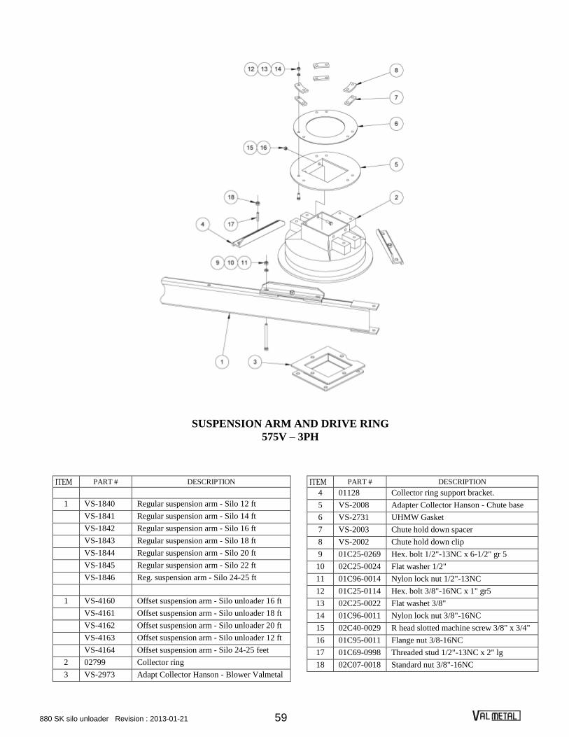
880 SK silo unloader Revision : 2013-01-21 59
SUSPENSION ARM AND DRIVE RING
575V – 3PH
ITEM PART # DESCRIPTION
1 VS-1840 Regular suspension arm - Silo 12 ft
VS-1841 Regular suspension arm - Silo 14 ft
VS-1842 Regular suspension arm - Silo 16 ft
VS-1843 Regular suspension arm - Silo 18 ft
VS-1844 Regular suspension arm - Silo 20 ft
VS-1845 Regular suspension arm - Silo 22 ft
VS-1846 Reg. suspension arm - Silo 24-25 ft
1 VS-4160 Offset suspension arm - Silo unloader 16 ft
VS-4161 Offset suspension arm - Silo unloader 18 ft
VS-4162 Offset suspension arm - Silo unloader 20 ft
VS-4163 Offset suspension arm - Silo unloader 12 ft
VS-4164 Offset suspension arm - Silo 24-25 feet
2 02799 Collector ring
3 VS-2973 Adapt Collector Hanson - Blower Valmetal
ITEM PART # DESCRIPTION
4 01128 Collector ring support bracket.
5 VS-2008 Adapter Collector Hanson - Chute base
6 VS-2731 UHMW Gasket
7 VS-2003 Chute hold down spacer
8 VS-2002 Chute hold down clip
9 01C25-0269 Hex. bolt 1/2"-13NC x 6-1/2" gr 5
10 02C25-0024 Flat washer 1/2"
11 01C96-0014 Nylon lock nut 1/2"-13NC
12 01C25-0114 Hex. bolt 3/8"-16NC x 1" gr5
13 02C25-0022 Flat washet 3/8"
14 01C96-0011 Nylon lock nut 3/8"-16NC
15 02C40-0029 R head slotted machine screw 3/8" x 3/4"
16 01C95-0011 Flange nut 3/8-16NC
17 01C69-0998 Threaded stud 1/2"-13NC x 2" lg
18 02C07-0018 Standard nut 3/8"-16NC

880 SK silo unloader Revision : 2013-01-21 60
TORQUE ARM
ITEM PART# DESCRIPTION
1 96-032 Right attachment plate
2 96-033 Left attachment plate
3 96-004 Torque arm brace (12’silo)
96-005 Torque arm brace (14’ and 16’ silo)
96-006 Torque arm brace (18’ and 20’ silo)
96-007 Torque arm brace (24' and 25' silo)
4 96-008 Torque arm plate (before 04/01/15)
96-038 Torque arm plate (after 04/01/15)
5 96-036 Lower brace
6 96-037 Upper brace
7 96-011 Roller
8 96-012 Torque arm roller plate (before 04/01/15)
96-041 Torque arm roller plate (after 04/01/15)
9 96-034 Torque arm extension (12’ to 16’ silo) (before 04/01/15)
96-039 Torque arm extension (12’ to 16’ silo) (after 04/01/15)
96-035 Torque arm extension (18’ to 25’ silo) (before 04/01/15)
96-040 Torque arm extension (18’ to 25’ silo) (after 04/01/15)
10 PD-5452 Upper chute support bracket
11 96-016 Discharge chute support bracket
12 96-017 Discharge chute support
13 96-018 Discharge chute support extension
14 VS-3129 Locking screw
15 99-299 1/2" U bolt
16 99-318 ½" Nylon lock nut
17 99-175 1/2" X 1½" Hex. Bolt
18 01C17-0259 1/2" X 4" Hex. Bolt
19 01C17-0259 1/2" X 4" Hex. Bolt
20 01C69-0161 3/16" X 2" Cotter pin
21 99-295 3/8" X 2 1/8" U bolt
22 99-317 3/8" Nylon lock nut
23 01C69-0161 3/16" X 2" Cotter pin
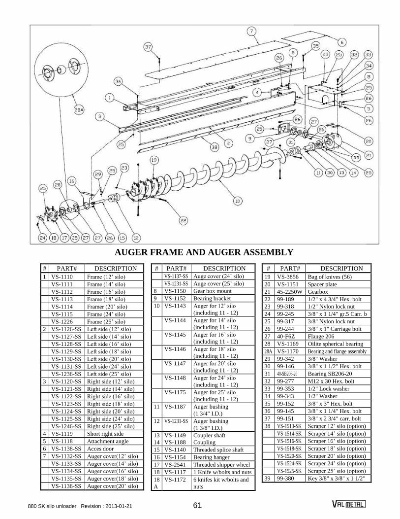
880 SK silo unloader Revision : 2013-01-21 61
AUGER FRAME AND AUGER ASSEMBLY
# PART# DESCRIPTION
1 VS-1110 Frame (12’ silo)
VS-1111 Frame (14’ silo)
VS-1112 Frame (16’ silo)
VS-1113 Frame (18’ silo)
VS-1114 Framer (20’ silo)
VS-1115 Frame (24’ silo)
VS-1226 Frame (25’ silo)
2 VS-1126-SS Left side (12’ silo)
VS-1127-SS Left side (14’ silo)
VS-1128-SS Left side (16’ silo)
VS-1129-SS Left side (18’ silo)
VS-1130-SS Left side (20’ silo)
VS-1131-SS Left side (24’ silo)
VS-1236-SS Left side (25’ silo)
3 VS-1120-SS Right side (12’ silo)
VS-1121-SS Right side (14’ silo)
VS-1122-SS Right side (16’ silo)
VS-1123-SS Right side (18’ silo)
VS-1124-SS Right side (20’ silo)
VS-1125-SS Right side (24’ silo)
VS-1246-SS Right side (25’ silo)
4 VS-1119 Short right side
5 VS-1118 Attachment angle
6 VS-1138-SS Acces door
7 VS-1132-SS Auger cover(12’ silo)
VS-1133-SS Auger cover(14’ silo)
VS-1134-SS Auger cover(16’ silo)
VS-1135-SS Auger cover(18’ silo)
VS-1136-SS Auger cover(20’ silo)
# PART# DESCRIPTION
VS-1137-SS Auge cover (24’ silo)
VS-1231-SS Auge cover (25’ silo)
8 VS-1150 Gear box mount
9 VS-1152 Bearing bracket
10 VS-1143 Auger for 12’ silo
(including 11 - 12)
VS-1144 Auger for 14’ silo
(including 11 - 12)
VS-1145 Auger for 16’ silo
(including 11 - 12)
VS-1146 Auger for 18’ silo
(including 11 - 12)
VS-1147 Auger for 20’ silo
(including 11 - 12)
VS-1148 Auger for 24’ silo
(including 11 - 12)
VS-1175 Auger for 25’ silo
(including 11 - 12)
11 VS-1187 Auger bushing
(1 3/4" I.D.)
12 VS-1231-SS Auger bushing
(1 3/8" I.D.)
13 VS-1149 Coupler shaft
14 VS-1188 Coupling
15 VS-1140 Threaded splice shaft
16 VS-1154 Bearing hanger
17 VS-2541 Threaded shipper wheel
18 VS-1117 1 Knife w/bolts and nuts
18
A
VS-1172 6 knifes kit w/bolts and
nuts
# PART# DESCRIPTION
19 VS-3856 Bag of knives (56)
20 VS-1151 Spacer plate
21 45-2250W Gearbox
22 99-189 1/2" x 4 3/4" Hex. bolt
23 99-318 1/2" Nylon lock nut
24 99-245 3/8" x 1 1/4" gr.5 Carr. b
25 99-317 3/8" Nylon lock nut
26 99-244 3/8" x 1" Carriage bolt
27 40-F6Z Flange 206
28 VS-1169 Oilite spherical bearing
28A VS-1170 Bearing and flange assembly
29 99-342 3/8" Washer
30 99-146 3/8" x 1 1/2" Hex. bolt
31 40-SB206-20 Bearing SB206-20
32 99-277 M12 x 30 Hex. bolt
33 99-353 1/2" Lock washer
34 99-343 1/2" Washer
35 99-152 3/8" x 3" Hex. bolt
36 99-145 3/8" x 1 1/4" Hex. bolt
37 99-151 3/8" x 2 3/4" carr. bolt
38 VS-1513-SK Scraper 12’ silo (option)
VS-1514-SK Scraper 14’ silo (option)
VS-1516-SK Scraper 16’ silo (option)
VS-1518-SK Scraper 18’ silo (option)
VS-1520-SK Scraper 20’ silo (option)
VS-1524-SK Scraper 24’ silo (option)
VS-1525-SK Scraper 25’ silo (option)
39 99-380 Key 3/8" x 3/8" x 1 1/2"

880 SK silo unloader Revision : 2013-01-21 62
RING DRIVE SUPPORT AND WALL WHEEL ASSEMBLY
ITEM PART# DESCRIPTION
1 VS-2938 Floating gearbox support
3 VS-2911 Ring support bracket
5 VS-2914 Adjusting collar
6 VS-2906 Support tube
7 VS-2910 Saddle
8 VS-2907 Roller bracket (before 2006-10-10)
9 VS-2912 Ring drive cleaner (before 2006-10-10)
10 VS-2913 Roller (discontinued; order item #47)
11 VS-2909 Roller (before 2006-10-10)
12 VS-1510 Left wall wheel bracket
13 VS-1511 Right wall wheel bracket
14 01549 10" wheel
15 VS-1512 Wheel bracket
16 99-450 2 1/2" x 1 1/4" x 3/8" Wheel
17 99-151 3/8" x 2 3/4" Hex. Bolt
18 99-317 3/8" Nylon lock nut
19 99-254 3/8" x 3 1/4" Carriage bolt
20 99-342 3/8" Washer
21 99-186 1/2" x 4" Adjusting bolt
22 99-304 1/2" Nut
23 99-179 1/2" x 2 1/2" Hex. Bolt
24 99-318 1/2" Nylon lock nut
ITEM PART# DESCRIPTION
25 99-343 1/2" Washer
26 99-265 1/2" x 1 1/2" Carriage bolt
29 99-282 5/16" x 1" Square head set screw
30 99-301 5/16" Nut
31 99-145 3/8" x 1 1/4" Hex. Bolt
32 99-244 3/8" x 1" Carriage bolt
33 99-344 5/8" Washer
34 99-402 3/16" x 1 1/2" Cotter pin
35 99-412 1/8" NPT straight Grease fitting
36 99-414 1/8" NPT 90 Grease fitting
37 VS-2905 Ring support ass'y (before 2006-10-10)
(discontinued; order item #46)
38 01C69-0179 ¼" x 1 ½" cotter pin
39 02C22-0016 ¾" Washer
40 96-050 Dual block bracket (after 2006-10-10)
41 96-051 Single block bracket (after 2006-10-10)
42 96-052 Gliding block (after 2006-10-10)
43 01C17-0062 Hex. bolt 5/16" x 1 ½"
44 01C04-0110 Carriage bolt 3/8" x 1 ¼"
45 02C32-0012 Lock washer 3/8"
46 96-054 Ring support ass'y (after 2006-10-10)
47 96-055 Ring support (after 2006-10-10)

880 SK silo unloader Revision : 2013-01-21 63
GUIDE AND PRESSURE WHEEL
# PART# DESCRIPTION
1 VS-3151 Guide wheel tube for 12’ silo
VS-3152 Guide wheel tube for 14’ silo
VS-3153 Guide wheel tube for 16’ silo
VS-3154 Guide wheel tube for 18’ silo
VS-3155 Guide wheel tube for 20’ silo
VS-3156 Guide wheel tube for 24’ silo
VS-3170 Guide wheel tube for 25’ silo
2 VS-3137 Caster bracket assembly
3 VS-3130 Collar
4 VS-3129 Locking screw
5 VS-3113 Guide wheel tube brace for 12’ silo
VS-3114 Guide wheel tube brace for 14’ silo
VS-3115 Guide wheel tube brace for 16’ silo
VS-3116 Guide wheel tube brace for 18’ silo
VS-3117 Guide wheel tube brace for 20’ silo
VS-3118 Guide wheel tube brace for 24'-25' silo
6 VS-2914 Adjusting collar
7 VS-3157 Pressure wheel tube for 12’ silo
VS-3158 Pressure wheel tube for 14’ silo
VS-3159 Pressure wheel tube for 16’ silo
VS-3160 Pressure wheel tube for 18’ silo
VS-3161 Pressure wheel tube for 20’ silo
VS-3162 Pressure wheel tube for 24’ silo
VS-3163 Pressure wheel tube for 25’ silo
8 VS-3128 Handle
# PART# DESCRIPTION
9 VS-3119 Pressure wheel tube brace for 12’ silo
VS-3120 Pressure wheel tube brace for 14’ silo
VS-3121 Pressure wheel tube brace for 16’ silo
VS-3122 Pressure wheel tube brace for 18’ silo
VS-3123 Pressure wheel tube brace for 20’ silo
VS-3124 Pressure wheel tube brace for 24'-25' silo
10 VS-3134 Wheel tube support brace (18’-25’silo only)
11 01549 10" Wheel
12 99-338 SAE 13/16" Washer
13 99-320 3/4" Nylon lock nut
14 99-503 Spring
14A AS-3124 Assembly including items 8-14-15-16-17
15 99-CHAIN.25 1/4" X 12" Chain
16 99-910 3/8" S-Hook
17 99-421 3/8" X 2 1/2" Eye bolt
18 99-317 3/8" Nylon lock nut
19 99-342 3/8" Washer
20 99-152 3/8" X 3" Hex. bolt
21 99-143 3/8" X 1" Hex. bolt
22 99-158 3/8" X 4 1/2" Hex. bolt
23 99-151 3/8" X 2 3/4" Hex. bolt
24 99-231 5/16" X 1" Square head set screw
25 99-301 5/16" Nut
26 VS-3136 Caster bracket and guide wheel assembly
27 VS-3139 Caster bracket ass’y
28 VS-3138 Caster bracket and pressure wheel assembly

880 SK silo unloader Revision : 2013-01-21 64
MOTOR MOUNT, PULLEYS, BELTS AND SHIELD
ITEM PART# DESCRIPTION
1 VS-2207 Long side angle
2 VS-2273 Short side angle
3 VS-2274 End tie
4 VS-2272 Motor mount bracket
5 VS-2271 Motor base plate
6 VS-2275 Hinge rod
7 VS-3131 Right belt shield mount angle
8 VS-3132 Left belt shield mount angle
9 VS-2801 Belt shield
10 41-2B66-SDS Motor pulley 2B66
11 41-SDS-1.125 Pulley hub
12 41-1B94-SDS Impeller pulley 1B94
13 41-1B66-SDS Auger gear box pulley 1B66
14 41-SDS-1.25 Pulley hub SDS 1.25" bore
15 42-B71 B71 Belt
16 42-B47 B47 Belt
17 99-368 1/4" x 1/4" x 1 3/4" Key
ITEM PART# DESCRIPTION
18 Motor
19 99-246 3/8" x 1 1/4" Carriage bolt
20 99-342 3/8" Washer
21 99-352 3/8" Lock washer
22 99-302 3/8" Nut
23 99-186 1/2" x 4" Adjusting bolt
24 99-304 1/2" Nut
25 99-317 3/8" Nylon lock nut
26 99-244 3/8" x 1" Carriage bolt
27 99-146 3/8" x 1 1/2" Hex. bolt
28 99-341 5/16" Washer
29 99-351 5/16" Lock washer
30 99-325 5/16" Wing nut
31 VS-2204 J Bolt
32 99-391 1/8" x 1" Cotter pin
33 VS-1700-SK Impeller assembly
34 VS-2280 Motor base assembly

880 SK silo unloader Revision : 2013-01-21 65
INDEPENDANT RING DRIVE MODEL (VS-3000)
ITEM PART# DESCRIPTION
1 VS-3038 Motor and gear box mount
2 VS-2941 Rod
3 VS-3000 Gear box
4 VS-3030 Spacer
5 VS-3033 Hub for back-up roll
7 VS-2400-19 Back up roll
8 VS-3040W Torque limiter
9 VS-2550 Drive sprocket
10 VS-3023 Shield
11 VS-3043 Motor cover
14 VS-2208 Control box mount
VS-2208-3PH Control box mount 3PH
15 97-2829 Breaker box
16 97-2832 60 amp. breaker
17 97-2831 15 amp. Breaker double
97-2830 15 amp. Breaker single
18 Motor
19 98-3J Coupling flange
20 98-3JE Coupling sleeve
21 99-402 3/16" x 1 1/2" Cotter pin
22 99-345 3/4" Washer
ITEM PART# DESCRIPTION
23 99-143 3/8" x 1" Hex. bolt
24 99-352 3/8" Lock washer
25 99-128 5/16" x 1" Hex. bolt
26 99-341 5/16" Washer
27 99-351 5/16" Lock washer
28 99-316 5/16" Nylon lock nut
29 99-128 5/16" x 1" Hex. bolt
30 99-154 3/8" x 3 1/2" gr.5 Hex. bolt
31 99-342 3/8" Washer
32 99-152 3/8" x 3" Hex. bolt
33 99-317 3/8" Nylon lock nut
34 99-102 1/4" x 5/8" Hex. bolt
35 99-315 1/4" Nylon lock nut
36 99-365 1/4" x ¼" x 1" Key
37 VS-3041-1 Spring (big)
38 VS-3041-2 Spring (small)
39 VS-3041W Repair kit (8X)
40 VS-3056 "R" Flex coupling
41 VS-3035 Back up roll kit

880 SK silo unloader Revision : 2013-01-21 66
LINE SHAFT RING DRIVE MODEL (VS-1000)
ITEM PART# DESCRIPTION
1 VS-1197 Base
2 VS-2941 Rod
3 VS-1000 Gear box
4 VS-3033 Hub for back-up roll
6 VS-2400-19 Back-up roll
7 VS-3040W Torque limiter
8 VS-2550 Drive sprocket
9 VS-1153 Drive sprocket guard
10 VS-1160 Female drive shaft
for 12’ to 20’
VS-1174 Female drive shaft
for 24’-25' silo
11 VS-1159 Male drive shaft
12 VS-1164 Long support
13 VS-1165 Short support
14 VS-1163 Guard for 12’ to 20’ silo
VS-1171 Guard for 24’-25' silo
15 VS-1158 Shaft
16 VS-1156 Support
17 VS-1157 Belt tightener
18 VS-1162 Belt shield
19 99-142 3/8" x 3/4" Hex. bolt
20 99-352 3/8" lock washer
21 42-A38 A38 Belt
ITEM PART# DESCRIPTION
22 41-MA38-1 MA38 Pulley X 1" bore
23 41-MA38-.625 MA38 Pulley X 5/8" bore
24 99-149 3/8" x 1 3/4" Hex. bolt
25 40-UCFL202-10 Flange bearing
26 99-317 3/8" Nylon lock nut
27 99-342 3/8" Washer
28 99-302 3/8" Nut
29 99-244 3/8" x 1" Carriage bolt
30 99-253 3/8" x 3" Carriage bolt
31 99-151 3/8" x 2 3/4" Hex. bolt
32 99-361 3/16" x 3/16" x 1 1/4" Key
33 99-367 1/4" x ¼" x 1 1/4" Key
34 VS-1161 Universal joint
35 99-143 3/8" x 1" Hex. bolt
36 99-345 3/4" Washer
37 99-402 3/16" x 1 1/2" Cotter pin
38 VS-3030 Spacer
39 99-154 3/8" x 3 1/2" gr.5 Hex. bolt
40 99-410 Straight 1/4" NPT Grease fitting
41 99-127 5/16" x 3/4" Hex. bolt
42 VS-3035 Back up roller kit
43 VS-3041-1 Spring (big)
44 VS-3041-2 Spring (small)
45 VS-3041W Repair kit (8X)

880 SK silo unloader Revision : 2013-01-21 67
DISCHARGE CHUTE & AIMING ROD
ITEM PART# DESCRIPTION
1 VS-2062 Discharge chute for 12’ and 14’silo (including item 2)
VS-2066 Discharge chute for 16’silo (including item 2)
VS-2068 Discharge chute for 18’ and 20’silo (including item 2)
VS-2074 Discharge chute for 24' and 25' silo (including item 2)
2 VS-2024-UHMW UHMW wear band with bolts (included with item 1)
3 VS-2028 Brace (12 ‘ and 14’silo) (pair)
VS-2029 Brace (16’silo) (pair)
VS-2030 Brace (18' and 20’silo) (pair)
VS-2031 Brace (24' and 25’silo) (pair)
4 VS-2017 Brace plate
5 VS-2033 Roller wheel bracket assembly
6 VS-2013 Roller
7 VS-2005 Discharge chute support (12’ to 16’silo)
VS-2044 Discharge chute support (18’ to 25’silo)
8 VS-2011 Roller bracket
9 VS-2007 Cord clip
10 99-292 5/16" x 1" round head machine screw
11 99-316 5/16" nylon lock nut
12 99-107 1/4" x 2" hex. Bolt
13 99-315 1/4" nylon lock nut
14 99-291 5/16" x 3/4" round head machine screw
15 99-201 #10-24 X 3/4" round head machine screw
16 99-310 #10 nut
17 VS-2072 Complete discharge chute (12’ and 14’ silo)
VS-2076 Complete discharge chute (16’ silo)
VS-2078 Complete discharge chute (18’ and 20’ silo)
VS-2084 Complete discharge chute (24’ and 25' silo)
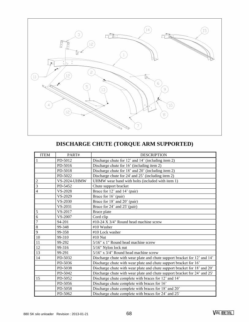
880 SK silo unloader Revision : 2013-01-21 68
DISCHARGE CHUTE (TORQUE ARM SUPPORTED)
ITEM PART# DESCRIPTION
1 PD-5012 Discharge chute for 12’ and 14’ (including item 2)
PD-5016 Discharge chute for 16’ (including item 2)
PD-5018 Discharge chute for 18’ and 20’ (including item 2)
PD-5022 Discharge chute for 24' and 25’ (including item 2)
2 VS-2024-UHMW UHMW wear band with bolts (included with item 1)
3 PD-5452 Chute support bracket
4 VS-2028 Brace for 12’ and 14’ (pair)
VS-2029 Brace for 16’ (pair)
VS-2030 Brace for 18’ and 20’ (pair)
VS-2031 Brace for 24’ and 25' (pair)
5 VS-2017 Brace plate
6 VS-2007 Cord clip
7 94-201 #10-24 X 3/4" Round head machine screw
8 99-348 #10 Washer
9 99-358 #10 Lock washer
10 99-310 #10 Nut
11 99-292 5/16" x 1" Round head machine screw
12 99-316 5/16" Nylon lock nut
13 99-291 5/16" x 3/4" Round head machine screw
14 PD-5032 Discharge chute with wear plate and chute support bracket for 12’ and 14’
PD-5036 Discharge chute with wear plate and chute support bracket for 16’
PD-5038 Discharge chute with wear plate and chute support bracket for 18’ and 20’
PD-5042 Discharge chute with wear plate and chute support bracket for 24’ and 25'
15 PD-5052 Discharge chute complete with braces for 12’ and 14’
PD-5056 Discharge chute complete with braces for 16’
PD-5058 Discharge chute complete with braces for 18’ and 20’
PD-5062 Discharge chute complete with braces for 24’ and 25'

880 SK silo unloader Revision : 2013-01-21 69
25
COLLECTOR RING
ITEM PART# DESCRIPTION
1 VS-2608 Support plate w/ ring holder supports ass'y
2 VS-2613 Ring holder support
3 VS-2607 Ring holder 1 PH
VS-2607-600 Ring holder 3 PH
4 VS-2606 Ring 1 PH
VS-2606-575 Ring 3 PH
5 VS-2605 Transition
6 VS-2601 Collector ring housing
7 VS-2604 Clamp ring (2 parts)
8 VS-2602 Support bearing
9 VS-2615 Cover
10 VS-2622 Brush holder 1 PH
VS-2622-575 Brush holder 3 PH
11 99-529 1/2" X 2" Stud
12 99-921 3/16" X 1/2" Rivet
13 94-202 #10 X 1" Machine screw
14 99-358 #10 Lock washer
15 99-310 #10 Nut
16 99-352 3/8" Lock washer
ITEM PART# DESCRIPTION
17 99-143 3/8" X 1" Hex. bolt
18 99-412 1/8" NPT Grease fitting
19 VS-2618 Brush 1 PH
VS-2618-600 Brush 3 PH
20 VS-2621 Lug
21 94-200 #10 X 3/8" Machine screw
22 99-357 #8 Lock washer
23 99-330 #8 Nut
24 VS-2619 Spring 1 PH
VS-2619-575 Spring 3 PH
25 VS-2623 Speed nut
26 VS-2603 O ring
27 VS-2609 Connector 1 PH
VS-2609-600 Connector 3 PH
28 VS-2624 Connector 1 PH
VS-2609-600 Connector 3 PH
29 VS-2606-1 Insulation ring for 3 PH
30 VS-2620-1210 Terminal

880 SK silo unloader Revision : 2013-01-21 70
9
IMPELLER (VS-1700-SK)
ITEM PART# DESCRIPTION
1 VS-1701-SS Housing assembly with stainless steel band
2 VS-1702 Cover
3 VS-1700-4 Impeller hub (includes item#15)
4 VS-1708 Shaft
5 VS-1705A Blade bracket (including pin stopper)
MU3119 Pin stopper (included with blade bracket)
6 VS-1704-SS Stainless steel blade (with bolts and nuts)
7 VS-1714 Shear plate
9 40-HCFCT207-20 Flanged bearing with collar
10 01C07-0110 3/8" x 1 1/4" gr.5 Carriage bolt
11 99-242 3/8" x 3/4" Carriage bolt
12 99-352 3/8" Lock washer
13 99-302 3/8" Nut
14 99-369 1/4" x 1/4" x 2" Key
15 40-121616 3/4" x 1" x 1" Oilite bushing
16 VS-1712 Pin
17 99-401 3/16" x 1 1/4" Cotter pin
18 99-243 3/8" x 1" Carriage bolt
19 99-148 3/8" x 2" Hex. Bolt
20 99-283 3/8" x 1 1/4" Square head set screw

880 SK silo unloader Revision : 2013-01-21 71
GEAR BOX (VS-1000)
ITEM PART# DESCRIPTION
1 VS-1007 Gear housing
2 VS-1003 Gear housing cover
3 VS-1004 Worm gear
4 VS-1009 Input worm shaft
5 VS-1005 Output shaft 1"
6 99-365 ¼" X ¼" X 1" Key
7 40-162016 Oilite bushing 1" X 1¼" X 1"
8 39-1-1.25-.125 Seal 1-1.25-0.125
9 40-NJK51102 Ball thrust bearing NJK51102
10 40-6003 Ball bearing 6003
11 94-001 Circlip D-1300-0350
12 39-17-35-7-TC Oil seal 17-35-7-TC
13 94-060 Sight glass 1"
14 94-110 Oil filler plug 3/8"-14 NPT
15 99-103 ¼" X 1"Hex. bolt
16 99-350 ¼" Lock washer
GEAR BOX (VS-3000)
ITEM PART# DESCRIPTION
1 VS-3002 Gear housing
2 VS-3001 Gear housing cover
3 VS-3003 Worm gear
4 VS-3005 Spur gear
5 VS-3004-1 Worm shaft 5/8"
6 VS-3006-1 Gear
7 VS-3008 Idler shaft 3/4"
8 VS-3007 Output shaft 1"
9 39-.625-1.375-.25 Seal 5/8 X 1 3/8 X 1/4
10 94-002 Snap ring 1300-137
11 40-99R10 Ball bearing 99R10
12 40-121620 Oilite bearing ¾ X 1 X 1 1/4
13 99-367 ¼" X ¼" X 1¼" Key
14 40-162024 Oilite bearing 1 X 1 ¼ X 1 1/2
15 39-1-1.25-.125 Seal 1 X 1¼ X 1/8
16 99-145 Hex. bolt 3/8" X 1 ¼"
17 99-352 Lock washer 3/8"
18 99-302 Nut 3/8"
19 94-060 Sight glass 1"
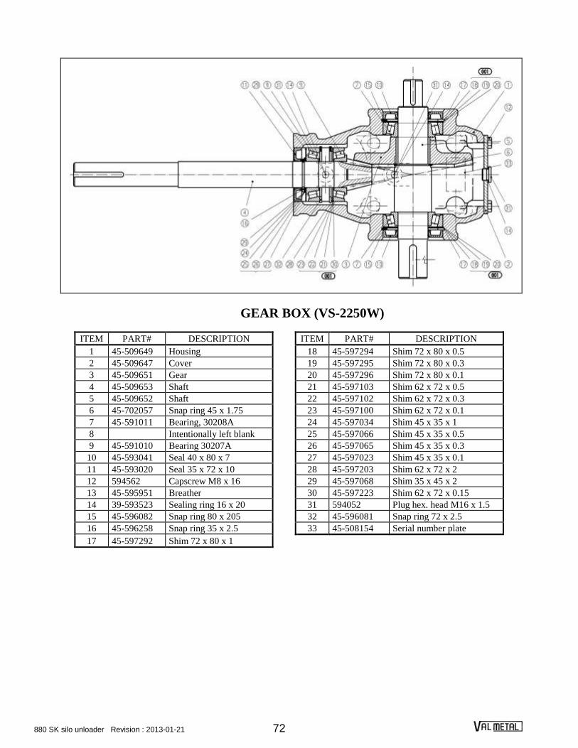
880 SK silo unloader Revision : 2013-01-21 72
GEAR BOX (VS-2250W)
ITEM PART# DESCRIPTION ITEM PART# DESCRIPTION
1 45-509649 Housing 18 45-597294 Shim 72 x 80 x 0.5
2 45-509647 Cover 19 45-597295 Shim 72 x 80 x 0.3
3 45-509651 Gear 20 45-597296 Shim 72 x 80 x 0.1
4 45-509653 Shaft 21 45-597103 Shim 62 x 72 x 0.5
5 45-509652 Shaft 22 45-597102 Shim 62 x 72 x 0.3
6 45-702057 Snap ring 45 x 1.75 23 45-597100 Shim 62 x 72 x 0.1
7 45-591011 Bearing, 30208A 24 45-597034 Shim 45 x 35 x 1
8 Intentionally left blank 25 45-597066 Shim 45 x 35 x 0.5
9 45-591010 Bearing 30207A 26 45-597065 Shim 45 x 35 x 0.3
10 45-593041 Seal 40 x 80 x 7 27 45-597023 Shim 45 x 35 x 0.1
11 45-593020 Seal 35 x 72 x 10 28 45-597203 Shim 62 x 72 x 2
12 594562 Capscrew M8 x 16 29 45-597068 Shim 35 x 45 x 2
13 45-595951 Breather 30 45-597223 Shim 62 x 72 x 0.15
14 39-593523 Sealing ring 16 x 20 31 594052 Plug hex. head M16 x 1.5
15 45-596082 Snap ring 80 x 205 32 45-596081 Snap ring 72 x 2.5
16 45-596258 Snap ring 35 x 2.5 33 45-508154 Serial number plate
17 45-597292 Shim 72 x 80 x 1

880 SK silo unloader Revision : 2013-01-21 73
VM-2125 WORM GEAR HOIST
ITEM PART# DESCRIPTION
1 VS-2132 Hoist drum assembly
2 40-242824 Bushing with shoulder 1½" x 1¾" x 1½"
3 VS-2129 Bearing (oilite bushing included)
4 VS-2128 Base
5 VS-2161 Housing
6 40-242824 Bushing with shoulder 1½" x 1¾" x 1½"
7 VS-2162 Worm gear
8 VS-2164 Cover
9 39-25627 Oil seal
10 94-1300-244 Snap ring
11 40-15101 Bearing
12 40-15245 Cup
13 VS-2140 Spacer
14 94-1460-98 Snap ring
15 VS-2192 Shaft
16 VS-2193 Worm
17 VS-2149 Crank
18 VS-2153 Pulley
19 VS-2155 Brake mount
ITEM PART# DESCRIPTION
20 VS-2154 Belt brake
21 VS-2100 Hoist mount chanel
22 VS-2160 Socket head cap screw 5/16" x 1/2"
23 94-110 Plug 3/8"-14 npt
24 94-060 Oil level
25 94-110 Plug 3/8"-14 npt
26 02C46-0020 5/16" x 1" square head setscrew
27 --- #8 x 3/4" Round head machine screw
28 02C22-0006 #8 washer
29 02C07-0013 #8 nut
30 99-380 3/8" x 3/8" x 1½" key
31 VS-2194 Spring
32 99-173 1/2" x 1" hex. bolt
33 99-343 1/2" washer
34 99-353 1/2" lock washer
35 99-143 3/8" x 1" hex. bolt
36 99-352 3/8" lock washer
37 99-299 "U" bolt 1/2"
38 01C69-0140 1/8" x 1" cotter pin

880 SK silo unloader Revision : 2013-01-21 74
MOTORIZED WORM GEAR HOIST
ITEM PART# DESCRIPTION
1 VM-2125-SEUL Worm gear hoist
2 VS-2118 Shield brace
3 VS-2102 Reversing switch
5 17-041-.75 3/4 hp motor, 120-240 volts
17-043-.75 3/4 hp motor, 575 volts
7 VS-2110 Locking bolt
10 VS-2119 Shield bracket
11 99-338 Washer SAE 13/16
13 60-35B72-1 Sprocket 35-B-72 x 1
14 60-35-94 Roller chain
15 VS-2120 Shield
16 41-MA100-.75 Pulley MA100 x ¾
17 42-A38 Belt A38
18 41-4-2 Step pulley
19 VS-2107-99 Motor mount pin 3/8
20 VS-2117 Shield mount
21 VS-2108 Tension rod
22 VS-2106 Motor mount
23 VM-2164 Motor guard (including guard bracket CV-4423) (Option)
24 CV-4423 Guard bracket (included with guard) (Option)
25 VS-2111 Mount bracket ass’y
25-1 VS-2115-99 Shaf ¾" Auxiliary motorised winch
25-2 40-EFL-12J Spherifical roller ¾" with 2 holes flanges
25-3 VS-2112-99 Auxiliary shaft support
25-4 60-35B15-.75 Sprocket 35B15H x 3/4 x 3/4 LG, KW 3/16, 2 SS 1/4
25-5 02C25-0014 Flat washer ¾" SAE
25-6 99-007 Key 3/16" x 3/16" x 2-1/2"
25-7 01C69-0461 Spring pin 1/4" X 1 1/2"

880 SK silo unloader Revision : 2013-01-21 75
DISTRIBUTOR
ITEM PART# DESCRIPTION
1 VS-2701 Discharge plate
2 VS-2702 Discharge plate
3 VS-2703 Extension
4 VS-2704 Extension
5 VS-2705 Upper pedestal
6 VS-2706 Lower pedestal
7 VS-2707 Handle
8 VS-2708 Pedestal disk
9 VS-2709 Drive pin (motorized
distributor only)
10 99-142 Hex. bolt 3/8 x ¾
ITEM PART# DESCRIPTION
11 VS-2710 Machine screw 3/8 x ¾
12 99-342 Washer 3/8
13 99-351 Lock washer 3/8
14 99-302 Nut 3/8
15 99-119 Hex. bolt ¼ x 5
16 99-350 Lock washer ¼
17 99-300 Nut ¼
18 99-353 Lock washer ½
19 99-304 Nut ½
20 99-252 Carr. bolt 3/8 x 2-3/4
21 VS-2711 Distributor storage bracket

880 SK silo unloader Revision : 2013-01-21 76
MOTORIZED DISTRIBUTOR
ITEM PART# DESCRIPTION
1 VS-2730 Distributor bracket
2 VS-2731 Pedestal bearing
3 VS-2732 Side plate
4 40-UCFL205-16 Bearing
5 VS-2734 Cord bracket
6 99-302 Hex. nut ½
7 99-352 Lock washer ½
8 99-232 Hex. Bolt ½ x 1¼
ITEM PART# DESCRIPTION
9 VS-2735 Rotor
10 99-242 Carr. bolt 3/8 x ¾
11 VS-2736 Motor bracket
12 13C25-0245 Re-usable tie wrap ½" x 22"
13 VS-2732-S Side plate with slot
13

880 SK silo unloader Revision : 2013-01-21 77
MOTOR AND DRIVE
ITEM PART# DESCRIPTION
1 VS-2720 Motor tightener
2 1 1/2 h.p. motor
3 VS-2002 Upper hold down clip
4 VS-2003 Lower hold down clip
5 41-2MA25-.625 2.5 pulley (silo 12’-20’)
41-2MA30-.625 3 pulley (silo 24’)
6 99-341 Washer 5/16
7 99-351 Lock washer 5/16
8 99-301 Hex. nut 5/16
9 99-232 Carr. bolt 5/16 x ¾
10 99-186 Adjusting screw ½
11 99-304 Hex. nut ½
12 99-246 Carr. bolt 3/8x 1-¼
13 99-352 Lock washer 3/8
14 99-302 Hex. nut 3/8
15 VS-2727 Shield
16 42-A56 Belt A-56
17 41-2MA60-1 6 x 1 pulley
ELECTRIC CONNECTORS
ITEM PART# DESCRIPTION
18 97-CL615-DF Female conn. 15A, 250V, 1PH
97-C30A600V Female conn. 30A, 600V, 3PH
97-C20A250V Female conn. 20A, 250V, 3PH
19 97-PL615-DF Male conn. 15A, 250V, 1PH
97-P30A600V Male conn. 30A, 600V, 3PH
97-P20A250V Male conn. 20A, 250V, 3PH
20 97-SL615-DF Kit male+fem. 15A, 250V, 1PH
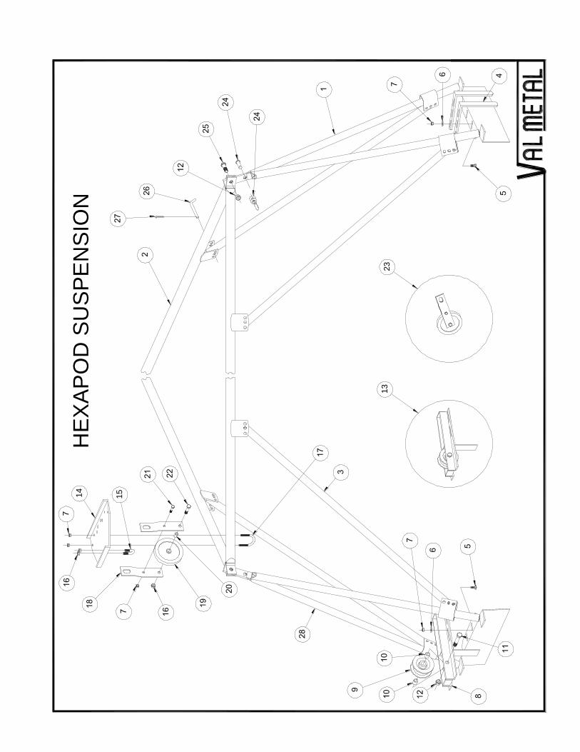
HE
XA
PO
D S
US
PE
NS
ION
14
15
13
23

HEXAPOD SUSPENSION
ITEM PART# DESCRIPTION
1 VS-1601-12 Leg assembly (12’ silo)
VS-1601-14 Leg assembly (14’ silo)
VS-1601 Leg assembly (16’-25’ silo)
2 VS-1621 Tie tube assembly (12’ silo)
VS-1622 Tie tube assembly (14’ silo)
VS-1623 Tie tube assembly (16’ silo)
VS-1624 Tie tube assembly (18’ silo)
VS-1625 Tie tube assembly (20’ silo)
VS-1626 Tie tube assembly (24’ silo)
VS-1640 Tie tube assembly (25’ silo)
3 VS-1627 Hexapod brace
4 VS-1629 Wall bracket clamp
5 99-244 3/8" x 1" Carriage bolt
6 99-342 3/8" washer
7 99-317 3/8" nylon lock nut
8 VS-1631 Bracket
9 VS-1616 Roller (including bushings)
10 40-101418 5/8" x 7/8" x 1 1/8" oilite bushing (included with item 9)
11 99-218 5/8" x 4" hex. bolt
12 99-319 5/8" nylon lock nut
13 VS-1630 Roller & bracket ass’y
14 VS-1606 Mounting plate
15 99-299 1/2" x 1" U bolt
16 99-318 1/2" nylon lock nut
17 99-296 3/8" x 2 3/8" U bolt
18 VS-1604 Pulley bracket
19 VS-1620 Pulley (including item 20)
20 40-81218 1/2" x 3/4" x 1 1/8" oilite bushing (included with item 19)
21 99-148 3/8" x 2" hex. bolt
22 99-178 1/2" x 2 1/4" hex. bolt
23 VS-1620-1 Pulley & bracket ass’y
24 VS-1602 1/2" shackle
25 99-210 5/8" x 2 1/2" hex. bolt
26 VS-1628 Pin
27 99-391 1/8" x 1" cutter pin
28 VS-1601-12 Main leg assembly (12' silo)
VS-1601-14 Main leg assembly (14' silo)
VS-1601 Main leg assembly (16'-18'-20' silo)
20-250 Main leg assembly (24'-25' silo)

VALMETAL INC.
230, BOUL. INDUSTRIEL
ST-GERMAIN, QUEBEC
CANADA, J0C 1K0
TEL: (819) 395-4282
FAX.: (819) 395-2030
www.valmetal.com
PRINTED IN CANADA JANUARY 2013 PART NUMBER: 880-98-0510