sika application guide - sika norge | sika norge as...4 sika marine - application guides vi tar...
TRANSCRIPT
PB 1SIKA MARINE - APPLICATION GUIDES SIKA MARINE - APPLICATION GUIDESVi tar forbehold om trykkfeil, informasjon angående våre salgs og leveringsbetingelser se www.sika.no
SIKA APPLICATION GUIDE GENERAL MARINE SEALING AND BONDING TECHNOLOGY

2 3SIKA MARINE - APPLICATION GUIDES SIKA MARINE - APPLICATION GUIDESWWW.SIKA.NO
SIKAFLEX????????????????????????Bruksområde: ????????
Egenskaper:n??????? n??????????n??????????n????????n?????????n???????????n????????????n????????? ??????????
QR-kode til produktdatablad
Teknisk data:?????? • Patron ???, Pose ??? ml • ???? • Temp. bestandig ??????? • Herdetid: ????? • Mange farger

2 3SIKA MARINE - APPLICATION GUIDES SIKA MARINE - APPLICATION GUIDES
CONTENT
04 Preface
05 Explanation Of Different Fixing Methods
07 Different Between Rigid And Elastic Adhesives
09 Bonding Construction Design
12 Cost Advantage Of Elastic Bonding
13 Tips And Tricks
17 Product Selector, Calculation Tools
18 Adhesie Primer Consumption
19 Conversions And Calculations
20 Quality Assurance
22 Product Datasheets And Safety Datasheets
24 Bedding And Sealing Fittings And Hardware
26 Bonding Of Rub Rails And Fenders
28 Bonding Decorative Panels And Work Surfaces
30 Bonding Lightweight Internal Partitions
32 Elastic Thick Layer Bonding
34 Sika Solutions For Structural Bonding
36 Direct Glazing
39 Sealing And Bonding Organic Windows
42 Sealing And Bonding Mineral Glazing
45 Flybridge Bonding
47 Deck And Keel To Hull Bonding
50 Glossary Of Terms
DNV SERTIFISERT
4 5SIKA MARINE - APPLICATION GUIDES SIKA MARINE - APPLICATION GUIDESWWW.SIKA.NO
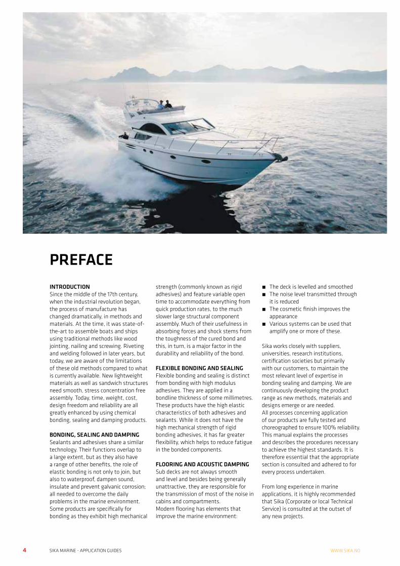
INTRODUCTION Since the middle of the 17th century, when the industrial revolution began, the process of manufacture has changed dramatically, in methods and materials. At the time, it was state-of-the-art to assemble boats and ships using traditional methods like wood jointing, nailing and screwing. Riveting and welding followed in later years, but today, we are aware of the limitations of these old methods compared to what is currently available. New lightweight materials as well as sandwich structures need smooth, stress concentration free assembly. Today, time, weight, cost, design freedom and reliability are all greatly enhanced by using chemical bonding, sealing and damping products.
BONDING, SEALING AND DAMPINGSealants and adhesives share a similar technology. Their functions overlap to a large extent, but as they also have a range of other benefits, the role of elastic bonding is not only to join, but also to waterproof, dampen sound, insulate and prevent galvanic corrosion; all needed to overcome the daily problems in the marine environment.Some products are specifically for bonding as they exhibit high mechanical
strength (commonly known as rigid adhesives) and feature variable open time to accommodate everything from quick production rates, to the much slower large structural component assembly. Much of their usefulness in absorbing forces and shock stems from the toughness of the cured bond and this, in turn, is a major factor in the durability and reliability of the bond.
FLEXIBLE BONDING AND SEALINGFlexible bonding and sealing is distinct from bonding with high modulus adhesives. They are applied in a bondline thickness of some millimetres. These products have the high elastic characteristics of both adhesives and sealants. While it does not have the high mechanical strength of rigid bonding adhesives, it has far greater flexibility, which helps to reduce fatigue in the bonded components.
FLOORING AND ACOUSTIC DAMPINGSub decks are not always smooth and level and besides being generally unattractive, they are responsible for the transmission of most of the noise in cabins and compartments.Modern flooring has elements that improve the marine environment:
• The deck is levelled and smoothed• The noise level transmitted through
it is reduced• The cosmetic finish improves the
appearance• Various systems can be used that
amplify one or more of these.
Sika works closely with suppliers, universities, research institutions, certification societies but primarily with our customers, to maintain the most relevant level of expertise in bonding sealing and damping. We are continuously developing the product range as new methods, materials and designs emerge or are needed.All processes concerning application of our products are fully tested and choreographed to ensure 100% reliability. This manual explains the processes and describes the procedures necessary to achieve the highest standards. It is therefore essential that the appropriate section is consulted and adhered to for every process undertaken.
From long experience in marine applications, it is highly recommended that Sika (Corporate or local Technical Service) is consulted at the outset of any new projects.
PREFACE
4 5SIKA MARINE - APPLICATION GUIDES SIKA MARINE - APPLICATION GUIDESVi tar forbehold om trykkfeil, informasjon angående våre salgs og leveringsbetingelser se www.sika.no
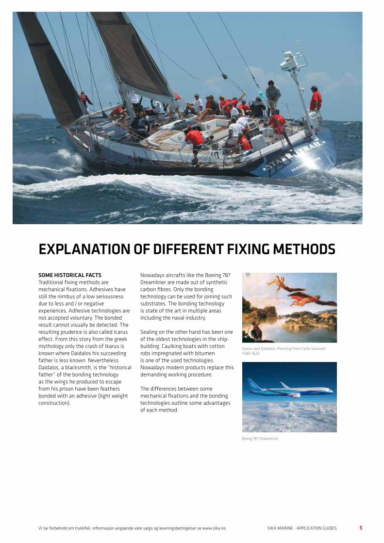
SOME HISTORICAL FACTSTraditional fixing methods are mechanical fixations. Adhesives have still the nimbus of a low seriousness due to less and / or negative experiences, Adhesive technologies are not accepted voluntary. The bonded result cannot visually be detected. The resulting prudence is also called Icarus effect. From this story from the greek mythology only the crash of Ikarus is known where Daidalos his succeeding father is less known. Nevertheless Daidalos, a blacksmith, is the “historical father” of the bonding technology as the wings he produced to escape from his prison have been feathers bonded with an adhesive (light weight construction).
Nowadays aircrafts like the Boeing 787 Dreamliner are made out of synthetic carbon fibres. Only the bonding technology can be used for joining such substrates. The bonding technology is state of the art in multiple areas including the naval industry.
Sealing on the other hand has been one of the oldest technologies in the ship- building. Caulking boats with cotton robs impregnated with bitumen is one of the used technologies. Nowadays modern products replace this demanding working procedure.
The differences between some mechanical fixations and the bonding technologies outline some advantages of each method.
EXPLANATION OF DIFFERENT FIXING METHODS
Ikarus and Daidalos. Painting from Carlo Saraceni 1580-1620
Boing 787 Dreamliner
6 7SIKA MARINE - APPLICATION GUIDES SIKA MARINE - APPLICATION GUIDESWWW.SIKA.NO
Production Riveting / srewing Spot weld Rigid bonding Elastic bonding
Process speed Fast Fast Medium to fast Medium
Substrate preparation Low Low Medium to important Medium to important
Substrate deformation (heatprocess) Low High Low None
Tolerance gapping Low Low Low Very good
Calculation of the bondline Yes Yes Possible Possible
Industrial hygiene Low Low Medium Medium
Noise emission during manufactoring High to low Medium Low Low
Quality control Easy Easy Needs QC Needs QC
Obtained characteristics Riveting / srewing Spot weld Rigid bonding Elastic bonding
Joining different materials Possible / limited Not possible Possible Possible
Sealing Separate operation Separate operation Yes Very good
Acoustical improvements No No Limited Yes
Joining of thin substrates Not recommended No Possible Ideal method
Durability Danger of corrosion Danger of corrosion Good Good
PRINCIPAL DIFFERENCES OF THE FIXING METHODS
Adhesive bonding is a modern and highly effective joining technique with a number of innovative performance characteristics, which forms a welcome addition to the standard repertoire of rigid fastening technologies. Through the selective use of these adhesives and careful attention to the specific application techniques associated with them, engineers and designers are now able to design technically sophisticated products that can be manufactured economically.
The use of this bonding technology permits to use all kind of substrates permitting an optimised construction. Just to mention some advantages:• Freedom of styling (use of
GRP / plastics / metals to optimise material cost)
• Weight savings (thinner substrates / plastics)
• Sound reduction (especially with elastic adhesives)
• Corrosion resistance (bonding on anticorrosive paints, no injury of the anticorrosive layer)
The highest economic and technical benefit of the bonding technology is based on these multiple advantage which is achieved in a single operation.
The bonding technology is a new tool for engineers and designer to realise modern and innovative solutions in the Marine Industry.
6 7SIKA MARINE - APPLICATION GUIDES SIKA MARINE - APPLICATION GUIDESVi tar forbehold om trykkfeil, informasjon angående våre salgs og leveringsbetingelser se www.sika.no
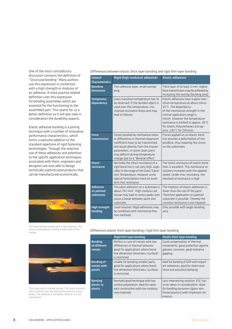
Elastic adhesives differ in their functionality to the rigid systems. Rigid (high modulus) adhesives are normally used in thin layers of about some hundred microns. In contrast elastic adhesives are used in a thickness of some millimeters. Therefore the expression of thick layer bonding has been created for such application types.
The function of these systems differs in their way to transmit forces. Rigid ad- hesives transmit forces directly without noticeable deformation. Elastic adhesives lower the forces by bond line deformation and uniform stress
distribution over the whole bonding surface.
Both of these systems have their advantages as well as their limitation. The following article describes the principal characteristics, knowing that this classification is not complete as semi flexible products may be situated somewhere in between.To show the difference, studies have been done at the University of Munich to demonstrate this difference. Tensile lap shear samples of PMMA (Polymethylmetacrylate, ex. Plexiglas) have been bonded and stressed. By
using polarized light, lines of different colours (stress levels) could be visualized.
The uniform stress distribution of the elastic adhesive permits to utilize the whole bonding surface for the force transmission.
Elastic thick layer bonding permits therefore to use thinner substrates, or just to bond directly on painted surfaces for better corrosion resistance, just to mention two of the multiple advantages by using this fixation method.
DIFFERENCE BETWEEN RIGID AND ELASTIC ADHESIVES
Test sample. Lap shear test with PMMA substrate bonded with different adhesives. One sample has been screwed
Screwed sample. The force line indicate a direct transmission of the forces from one part of the sample through the screw to the other part of the sample
Same sample plan view. Here stress concentration around the bolts is visible (stress peaks around the screw).
8 9SIKA MARINE - APPLICATION GUIDES SIKA MARINE - APPLICATION GUIDESWWW.SIKA.NO
One of the most contradictory discussion concerns the definition of “Structural bonding” Many authors use this expression in connection with a high strength or modulus of an adhesive. A more practice related definition uses this expression for bonding assemblies which are essential for the functioning to the assembled part. This seams for us a better definition as it will also take in consideration the durability aspects.
Elastic adhesive bonding is a joining technique with a number of innovative performance characteristics, which forms a welcome addition to the standard repertoire of rigid fastening technologies. Through the selective use of these adhesives and attention to the specific application techniques associated with them, engineers and designers are now able to design technically sophisticated products that can be manufactured economically.
Thin layer bonded sample with a rigid adhesive. The stress concentration is visible at both ends of the sample.
Thick layer elastic bonded sample. The stress transmis-sion is uniform over the hole bonding area (no stress peaks). The adhesive is not easily visible as it is not transparent.
Differences between elastic thick layer bonding and rigid thin layer bonding
General Characteristics
Rigid (high modulus) adhesives Elastic adhesives
Bondline dimension
Thin adhesive layer, small overlap-ping
Thick layer of at least 2 mm. Higher force transmission may be achieved by increasing the overlap (bonding area)
Temperatur dependency
Glass transition temperature has to be observed. If the bonded object is used over this temperature, me-chanical resistance drops and may lead to failures
Elastic adhesives have a glass tran-sition temperature at about minus 50 °C. The dependency of the mechanical strength in the normal application range is minim. However the temperature resistance is limited to approx. 90 °C for elastic Polyurethanes and ap-prox. 120 °C for Silicones
Force transmission
Forces resulted by mechanical stress or differences in thermal expansion coefficient have to be transmitted and result directly from the chosen parameters. In some cases parts may deform during temperature change due to a “Bimetal effect”
Forces applied on an elastic bond line provoke a deformation of the bondline, thus lowering the stress on the substrates
Shock resistance
Normally the shock resistance of a rigid bond line is not very high, espe-cially in the range of the Glass Transi-tion Temperature. However some special formulations have an excel-lent choc resistance
The shock resistance of elastic bond lines is excellent. The mechanical re-sistance increases with the applied speed. Under choc resistance, the mechanical resistance is high
Adhesion on painted substrates
The paint adhesion on a substrate is about 7N / mm2. High modulus ad-hesive may lead to stress peaks and cause a break between paint and substrate
The modulus of elastic adhesives is lower than the one of the paint. Therefore application on painted substrate is possible. Thereby the corrosion resistance is not impaired
High strength bonding
Good solution. Rigid adhesives may be combined with mechanical fixa-tion methods
Only possible with larger bonding area
Differences elastic thick layer bonding / rigid thin layer bonding
Rigid thin layer bonding Elastic thick layer bondingBonding of different metals
Perfect in case of metals with low differences in thermal behavior, good for applications where bond-line dimension (thickness /surface) is restricted
Good compensation of thermal movements, good protection against galvanic corrosion, good tolerance gapping
Bonding of metals with plastic
Usable for bonding smaller parts, good for applications where bond-line dimension (thickness /surface) is restricted.
Ideal for bonding of GRP with import-ant tolerances, good for shock resis-tence and acoustical damping
Bonding plastic to plastic
Normally good technique with low surface preparation, ideal for sand-wich construction with low modulus core materials
Less interresting solution. ESC has to be taken in consideration. Ideal for bonding duromers (glass rein-forced plastics) with important tol-erances

8 9SIKA MARINE - APPLICATION GUIDES SIKA MARINE - APPLICATION GUIDESVi tar forbehold om trykkfeil, informasjon angående våre salgs og leveringsbetingelser se www.sika.no
PRINCIPALS Joining of two materials means to connect them to a unit which is capable to transmit forces resulting from dynamic, static or other stress during the use of the subject. Normal joint technologies are mechanical joining methods which are known since long times.
Glues however have been reported to be used about 3000 years before JC. Asphalt and natural resins have been used to tighten up ships and clay has been used to build houses.
However structural bonding started in the 30ties of this century. One of them is unsaturated polyester which are still in use today. The development of epoxy resins opened up a vast area of bonding applications
Elastic adhesives or sealants started in 1964 in the USA using an elastic adhesive for windscreen bonding. This technology is state of the art in all type of windscreen bonding in all market fields.
In the 80ties elastic bonding was used in busses followed by trains and trams in 1992. Structural bonding in Marine started at the beginning of the 90ties. In the meantime, elastic bonding technology was established in other sectors of the manufacturing industry, such as for containers, refrigerators and washing machines, facades, floors, windows and many applications.
The following chapter will help to understand the bonding technology and how to design an adhesive joining case.
The strength of a joint is basically determined by the area of the bond, the inherent strength of the adhesive or the substrate and the stress distribution within the joint. A poorly designed joint can lead to high stress concentrations in the joint itself and / or in the substrates connected, which in turn can lead to premature failure. Good joint design, which takes into account the practicalities of application as well as the geometry of the joint, is essential for a long service life in a demanding Marine environment.
Peel forces are the most difficult to counter and must be avoided by changing the design of the joint.
BONDING CONSTRUCTION DESIGN

10 11SIKA MARINE - APPLICATION GUIDES SIKA MARINE - APPLICATION GUIDESWWW.SIKA.NO
Generally forces which in praxis occur are the following:
Tensile (ok if force is symmetric)
Tensile lap shear (best solution for bonding)
Compression (ok)
Torsion (ok)
Asymmetric torsion (to avoid)
Peel (to avoid)
Asymmetric peel (to avoid)
Peel (to avoid)
Here an example: by changing the construction the risk of peel forces could be minimised
Asymmetric tension
Compression
10 11SIKA MARINE - APPLICATION GUIDES SIKA MARINE - APPLICATION GUIDESVi tar forbehold om trykkfeil, informasjon angående våre salgs og leveringsbetingelser se www.sika.no
Traditional mechanical joint design has to cope with the inherent strength of an adhesive.
The following examples show some of an adhesive alternative to welding.
CALCULATION OF THE BONDING AREAThe dimensioning of a bond line depends mainly of the forces to be transmitted, and the mechanical resistance of the substrates and adhesives.
One of the most common errors is to calculate the bond line on the bases of the data’s in the Product Datasheets. These data’s are based on static tests. In praxis a lot of factors have to be considered. Temperature influence, type and frequency of the stress, aging etc. are factors on which the bond line is subjected.
Detailed calculation procedures can be ordered from your local Sika Industry branch or in appropriated literature (Example: “Elastic bonding, the principles of adhesive technology and a guide to its cost effective use in Industry“ Verlag Moderne Industrie)
In praxis a rule of thumb can be used as a first approximation. The lap shear strength has to be reduced to 3% of the Product Datasheet value.
Example: Tensile lap shear force needed is 200 kg equal to 2000 Newton.The Product Datasheet value of a particular adhesive is 2 N / mm2
The calculation value for the applicable tensile lap shear strength is only 3 % of this Product Datasheet value: 2 N / mm2 x 0.03 = 0.06 N / mm2
The required bond surface is therefore: 2000 N / 0.06 N / mm2 = 33’000 mm2 = 330 cm2
Considering a bond line width of 15 mm, the required length of the joint is: 330 cm2 / 1.5 cm = 220 cm or 2.2 m
Note:For exact calculation with the FEM-Methods we recommend to consult the Technical Service Sika Industry
Present joining method Adhesive design
12 13SIKA MARINE - APPLICATION GUIDES SIKA MARINE - APPLICATION GUIDESWWW.SIKA.NO
COST COMPENSATIONAdhesives compared to riveting or spot welding result in an advantage of the mechanical fixations.
However, a cost comparison has to be done taking all factors of the realisation in consideration. As an example spot welding may increase the expenditure of the filling of a surface prior to painting, thus increasing the overall costs.
The following list gives thought provoking impulse to realise a correct cost comparison.
COST ADVANTAGE OF ELASTIC BONDING
COST ADVANTAGE OF ELASTIC BONDING
Properties Benefits (manufacturing)Bond / seal simultaneously Reduction of process steps / No additional
sealant costs
Compensates for tolerances Less work to prepare substrate
Application at room temperature (no thermal deformation)
Less spatula work / Low energy costs
Curing at room temperature Lower energy costs
Bonding different substrates Optimised choice of materials / lightweight construction / No bimetallic plates necessary
No sink marks on thin sheets Thinner sheets / savings
Less tools Lower investment costs
Properties Benefits (enduser)Not corrosion-prone fixing Longer life expectancy
Reduced maintenance Lower costs
Weight-reduction Lower fuel consumption
No built-in tensions Increased longevity
Design with low cw (drag coeff.) Lower fuel consumption
Application and curing at room temperature Simple repair
Even surfaces Easy to clean
Noise reduction Increased comfort
Freedom of design Increased brand awareness

12 13SIKA MARINE - APPLICATION GUIDES SIKA MARINE - APPLICATION GUIDESVi tar forbehold om trykkfeil, informasjon angående våre salgs og leveringsbetingelser se www.sika.no
SURFACE PREPARATION
General remarks The surface preparation is beside the material choice and the joint dimensioning the key for a long lasting bond. Therefore it is essential to execute the surface preparation very accurately.
Surface cleaningDirty surfaces have to be pre cleaned. For oily or fatty surfaces, steam cleaning with detergents and consecutive rinsing with clean water are recommended for large areas. Smaller areas may be pre cleaned with solvents such as Sika® Remover-208.
Dust on surfaces is best removed with a vacuum cleaner. Compressed air as alternative can be used if it is deoiled.
Rust, other oxydes or loose paints have to be eliminated mechanically. Methods are sandblasting, and grinding. In case of sandblasting the type of blasting
material has to be chosen according to substrate to clean. If necessary contact an abrasive producer.
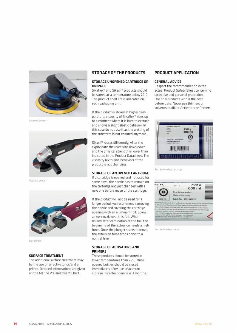
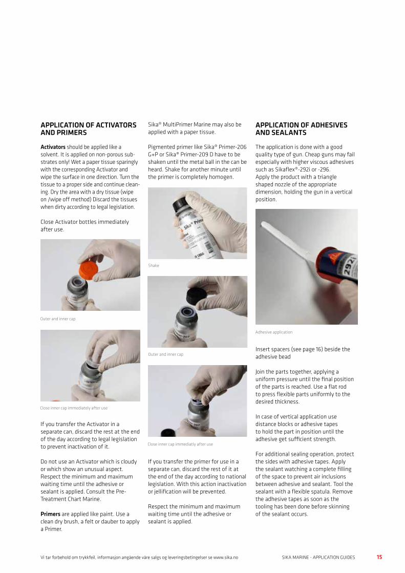
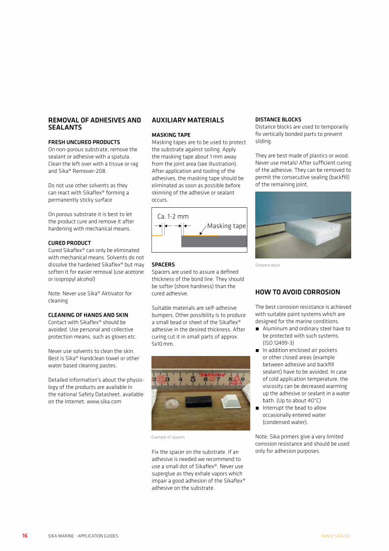
Grinding with sand paper may be done with belt grinder, excentric grinder, rotation grinder or manually. The grit to choose depends on the material to eliminate. Usually grit 40-80 is used.
After grinding the dust has to be eliminated with a vacuum cleaner.
TIPS AND TRICKSCOST ADVANTAGE OF ELASTIC BONDING
Steam cleaner
Deoiler for compressed airSandblasting
14 15SIKA MARINE - APPLICATION GUIDES SIKA MARINE - APPLICATION GUIDESWWW.SIKA.NO
Excenter grinder
Rotative grinder
Belt grinder
SURFACE TREATMENTThe additional surface treatment may be the use of an activator or/and a primer. Detailed informations are given on the Marine Pre-Treatment Chart.
STORAGE OF THE PRODUCTS
STORAGE UNOPENED CARTRIDGE OR UNIPACKSikaflex® and Sikasil® products should be stored at a temperature below 25°C. The product shelf life is indicated on each packaging unit.
If the product is stored at higher tem- perature, viscosity of Sikaflex® rises up to a moment where it is hard to extrude and shows a slight elastic behavior. In this case do not use it as the wetting of the substrate is not ensured anymore.
Sikasil® reacts differently. After the expiry date the reactivity slows down and the physical strength is lower than indicated in the Product Datasheet. The viscosity (extrusion behavior) of the product is not changing.
STORAGE OF AN OPENED CARTRIDGEIf a cartridge is opened and not used for some days, the nozzle has to remain on the cartridge and just changed with a new one before reuse of the cartridge.
If the product will not be used for a longer period, we recommend removing the nozzle and covering the cartridge opening with an aluminum foil. Screw a new nozzle over this foil. When reused after elimination of the foil, the beginning of the extrusion needs a high force. Once the plunger starts to move, the extrusion force drops down to a normal level.
STORAGE OF ACTIVATORS AND PRIMERSThese products should be stored at lower temperatures than 25°C. Once opened bottles should be closed immediately after use. Maximum storage life after opening is 3 months.
PRODUCT APPLICATION
GENERAL ADVICERespect the recommendation in the actual Product Safety Sheet concerning collective and personal protection.Use only products within the best before date. Never use thinners or solvents to dilute Activators or Primers.
Best before date cartridge
Best before date unipac
14 15SIKA MARINE - APPLICATION GUIDES SIKA MARINE - APPLICATION GUIDESVi tar forbehold om trykkfeil, informasjon angående våre salgs og leveringsbetingelser se www.sika.no
APPLICATION OF ACTIVATORS AND PRIMERS
Activators should be applied like a solvent. It is applied on non-porous sub-strates only! Wet a paper tissue sparingly with the corresponding Activator and wipe the surface in one direction. Turn the tissue to a proper side and continue clean-ing. Dry the area with a dry tissue (wipe on /wipe off method) Discard the tissues when dirty according to legal legislation.
Close Activator bottles immediately after use.
If you transfer the Activator in a separate can, discard the rest at the end of the day according to legal legislation to prevent inactivation of it.
Do not use an Activator which is cloudy or which show an unusual aspect.Respect the minimum and maximum waiting time until the adhesive or sealant is applied. Consult the Pre-Treatment Chart Marine.
Primers are applied like paint. Use a clean dry brush, a felt or dauber to apply a Primer.
Sika® MultiPrimer Marine may also be applied with a paper tissue.
Pigmented primer like Sika® Primer-206 G+P or Sika® Primer-209 D have to be shaken until the metal ball in the can be heard. Shake for another minute until the primer is completely homogen.
If you transfer the primer for use in a separate can, discard the rest of it at the end of the day according to national legislation. With this action inactivation or jellification will be prevented.
Respect the minimum and maximum waiting time until the adhesive or sealant is applied.
APPLICATION OF ADHESIVES AND SEALANTS
The application is done with a good quality type of gun. Cheap guns may fail especially with higher viscous adhesives such as Sikaflex®-292i or -296.Apply the product with a triangle shaped nozzle of the appropriate dimension, holding the gun in a vertical position.
Insert spacers (see page 16) beside the adhesive bead
Join the parts together, applying a uniform pressure until the final position of the parts is reached. Use a flat rod to press flexible parts uniformly to the desired thickness.
In case of vertical application use distance blocks or adhesive tapes to hold the part in position until the adhesive get sufficient strength.
For additional sealing operation, protect the sides with adhesive tapes. Apply the sealant watching a complete filling of the space to prevent air inclusions between adhesive and sealant. Tool the sealant with a flexible spatula. Remove the adhesive tapes as soon as the tooling has been done before skinning of the sealant occurs.
Outer and inner cap
Close inner cap immediately after use
Shake
Outer and inner cap
Close inner cap immediatly after use
Adhesive application
16 17SIKA MARINE - APPLICATION GUIDES SIKA MARINE - APPLICATION GUIDESWWW.SIKA.NO
REMOVAL OF ADHESIVES AND SEALANTS
FRESH UNCURED PRODUCTSOn non-porous substrate, remove the sealant or adhesive with a spatula. Clean the left over with a tissue or rag and Sika® Remover-208.
Do not use other solvents as they can react with Sikaflex® forming a permanently sticky surface
On porous substrate it is best to let the product cure and remove it after hardening with mechanical means.
CURED PRODUCTCured Sikaflex® can only be eliminated with mechanical means. Solvents do not dissolve the hardened Sikaflex® but may soften it for easier removal (use acetone or isopropyl alcohol)
Note: Never use Sika® Aktivator for cleaning
CLEANING OF HANDS AND SKINContact with Sikaflex® should be avoided. Use personal and collective protection means, such as gloves etc.
Never use solvents to clean the skin. Best is Sika® Handclean towel or other water based cleaning pastes.
Detailed information’s about the physio- logy of the products are available in the national Safety Datasheet, available on the Internet. www.sika.com
AUXILIARY MATERIALS
MASKING TAPEMasking tapes are to be used to protect the substrate against soiling. Apply the masking tape about 1 mm away from the joint area (see illustration). After application and tooling of the adhesives, the masking tape should be eliminated as soon as possible before skinning of the adhesive or sealant occurs.
SPACERSSpacers are used to assure a defined thickness of the bond line. They should be softer (shore hardness) than the cured adhesive.
Suitable materials are self-adhesive bumpers. Other possibility is to produce a small bead or sheet of the Sikaflex® adhesive in the desired thickness. After curing cut it in small parts of approx. 5x10 mm.
Fix the spacer on the substrate. If an adhesive is needed we recommend to use a small dot of Sikaflex®. Never use superglue as they exhale vapors which impair a good adhesion of the Sikaflex® adhesive on the substrate.
DISTANCE BLOCKSDistance blocks are used to temporarily fix vertically bonded parts to prevent sliding.
They are best made of plastics or wood. Never use metals! After sufficient curing of the adhesive. They can be removed to permit the consecutive sealing (backfill) of the remaining joint.
HOW TO AVOID CORROSION
The best corrosion resistance is achieved with suitable paint systems which are designed for the marine conditions. • Aluminum and ordinary steel have to
be protected with such systems. (ISO 12499-3)
• In addition enclosed air pockets or other closed areas (example between adhesive and backfill sealant) have to be avoided. In case of cold application temperature, the viscosity can be decreased warming up the adhesive or sealant in a water bath. (Up to about 40°C)
• Interrupt the bead to allow occasionally entered water (condensed water).
Note: Sika primers give a very limited corrosion resistance and should be used only for adhesion purposes.
Ca. 1-2 mmMasking tape
Example of spacers
Distance block
16 17SIKA MARINE - APPLICATION GUIDES SIKA MARINE - APPLICATION GUIDESVi tar forbehold om trykkfeil, informasjon angående våre salgs og leveringsbetingelser se www.sika.no
PRODUCT SELECTOR, CALCULATION TOOLSAdhesives / sealants
Sika
flex®
-290
DC
PRO
Sika
flex®
-291
i
Sika
flex®
-292
i
Sika
flex®
-295
UV
Sika
flex®
-296
Sika
flex®
-298
Sika
sil®
WS-
605S
Sika
Fire
sil®
Mar
ine
N
Sika
sil®
N-P
lus
Sika
Tran
sfloo
r®-3
52 S
T an
d SL
APPLICATIONS
General sealing overpaintable - l l l l l - - - - - - -
General sealing, weathering resistant - - - l l l l l - l l l - - -
Fire retardent sealing - - - - - - - l l l - -
Organic glass bonding - - - l l l l - - - - -
Mineral glass bonding - - - - l l l - - - - -
Deck levelling - - - - - - - - - l l l
Wodden deck bonding - l l - - - l l l - - - -
Caulking l l l - - - - - - - - -
Bonding of coverings - l l - - - l l l - - - -
Sanitary sealing - l - - - - - - l l l -
SERVICE CONDITIONS
High temperature > -40 °C to 150 °C - - - - - - - l l l l l -
Normal temperature -40 °C to 90 °C - l l l l l l l l l l l l l l l l l l - - l l l
See also Pre-Treatment Chart for Marine Applications
KEY TO SYMBOLS
l l l Best solution
l l Good solution
l Possible solution

18 19SIKA MARINE - APPLICATION GUIDES SIKA MARINE - APPLICATION GUIDESWWW.SIKA.NO
ADHESIVE PRIMER CONSUMPTIONDESIGN OF ADHESIVE LAYER GEOMETRYThe elastic adhesive can only fully develop its positive properties (movement compensation, peeling and impact resistance) if the adhesive layer geometry is correct.
Above all, this means keeping to a minimum layer thickness that must be individually suited to the bond. A layer thickness of 2-3 mm has proved best for most applications. Thicker layers may be required where considerable movement is expected.
Depths over 20 mm should be avoided with standard Sikaflex® grades because the adhesive would take too long to harden.
8 mm
8 mm
8 mm
10 mm
10 mm
12 mm
12 mm
12 mm
12 mm
15 mm
8 mm
4 mm
8 mm
5 mm
10 mm
6 mm
12 mm
6 mm
12 mm
7.5 mm
NO. OF METRES PER 300 ML CARTRIDGE
NO. OF METRES PER 100 ML TUBE
JOINTWIDTH 5 10 15 5 10 15
DEPT
H / L
AYER
THI
CKN
ESS
OF B
OND
(MM
) 1 62.00 31.00 20.60 20.00 10.00 6.60
2 31.00 15.50 10.30 10.00 5.00 3.30
3 20.60 10.30 6.88 6.60 3.30 2.20
4 15.50 7.75 5.15 5.00 2.50 1.60
5 12.40 6.20 4.10 4.00 2.00 1.30
6 10.30 5.16 3.44 3.30 1.60 1.10
7 8.85 4.40 2.95 2.80 1.40 0.90
8 7.75 3.90 2.60 2.50 1.20 0.80
9 6.90 3.50 2.30 2.20 1.10 0.70
10 6.20 3.10 2.00 2.00 1.00 0.60
PRODUCT YIELD PER 100 ML AT 20 MM WIDTH(m)
BRUSH APPLI- CATION TISSUE APPLICATION*( l / m2)
Sika® Aktivator / Sika® Aktivator-205
25-30 0.04*
Sika® Primer-206 G+P 17-22 0.1-0.15
Sika® Primer-209 D 12-15 0.15-0.2
Sika® MultiPrimer Marine
12-15 0.15-0.2
Make sure that:• The primed areas coincide with the bonding areas• The right primer for the material surface is used• The primer is completely dry and cured before bonding
i.e. watch the evaporation time• Primers are shaken if necessary
PRIMER AND CLEANER CONSUMPTION

18 19SIKA MARINE - APPLICATION GUIDES SIKA MARINE - APPLICATION GUIDESVi tar forbehold om trykkfeil, informasjon angående våre salgs og leveringsbetingelser se www.sika.no
WEIGHT
1 ounce = 28.3495 g
1 pound = 0.45359 kg
1 hundredweight = 50.8023 kg
VOLUME
1 pint (UK) = 0.5683 l
1 pint (USA) = 0.4732 l
1 gallon (UK) = 4.5461 l
1 gallon (USA) = 3.7854 l
LENGTH
1 inch = 25.4 mm
1 foot = 0.3048 m
1 yard = 0.9144 m
1 furlong = 201.17 m
1 mile = 1.6093 km
AREA
1 inch2 = 645.16 mm2
1 foot2 = 0.0929 m2
1 yard2 = 0.8361 m2
1 acre = 4046.86 m2
1 mile2 = 2.59 km2
PRESSURE
1 bar = 0.1 MPa
1 Pascal = 1 N / m2
1 kgf / cm2 = 0.09807 MPa
1 psi = 6894.76 Pa
SI PREFIXES
NAME SYMBOL FACTOR
giga G 109
mega M 106
kilo k 103
hecto h 102
deca da 101
deci d 10-1
centi c 10-2
milli m 10-3
micro μ 10-6
nano n 10-9
TEMPERATURE SCALES
°C °F
100 212
80 176
60 140
40 104
35 95
30 86
25 77
20 68
15 59
10 50
5 41
0 32
The information, and, in particular, the recommendations relating to the application and end-use of Sika products, are given in good faith based on Sika’s current knowledge and experience of the products when properly stored, handled and applied under normal conditions. In practice, the differences in materials, substrates and actual site conditions are such that no warranty in respect of merchantability or of fitness for a particular purpose, nor any liability arising out of any legal relationship whatsoever, can be inferred either from this information, or from any written recommendations, or from any other advice offered.
The proprietary rights of third parties must be observed. All orders are accepted subject to our current terms of sale and delivery. Users should always refer to the most recent issue of the Sika Product Datasheet for the product concerned, copies of which will be supplied on request.
FORMULAETO ESTIMATE THE NUMBER OF LITRES REQUIRED
Normal bead application;Quantity in litres = bead width (mm) x bead thickness (mm) x joint length (metres) 1000(Dimensions are for wet adhesive in rectangular cross section)
Large area bonding and laminating;Quantity in litres = width (metres) x length (metres) x wet film adhesive thickness (mm).
TO DETERMINE THE VOLUME OF A SEMI-CIRCULAR BEAD
Quantity in litres = 3.142 x diameter (mm) x diameter (mm) x length (metres) 8000
TO DETERMINE THE VOLUME OF A TRIANGULAR BEAD
Quantity in litres = width (mm) x height (mm) x length (metres) 2000
TO CONVERT KILOGRAMS TO LITRESQuantity in litres = weight in kilograms density (grams / ml or kg / l)
TO CONVERT BETWEEN TEMPERATURE SCALESFahrenheit = (degrees celsius (°C) x 5) - 32 9Celsius = (degrees fahrenheit (°F) x 9) + 32 5
CONVERSIONS AND CALCULATIONS

20 21SIKA MARINE - APPLICATION GUIDES SIKA MARINE - APPLICATION GUIDESWWW.SIKA.NO
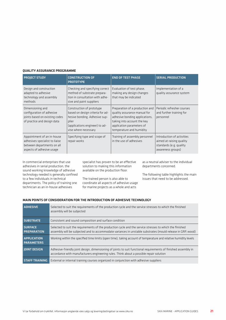
QUALITY ASSURANCEPRACTICAL HINTS
This chapter examines the practical issues of quality assurance for elastic adhesive and sealant applications
The proposals outlined here should be viewed as a general checklist to be adapted to the specific requirements of each marine manufacturing environment.
Particular attention needs to be paid to establishing an effective system of quality assurance for adhesive connections.
Testing of the adhesion, and therefore the reliability, is only possible by destructive means.
Visible inspection is only effective to a limited degree, so the quality of the bond line has to be assured by the following:
• Ensure the constance of the surface quality of the substrates to be bonded
• Correctly prepare the surfaces to be bonded
• Select the correct adhesive (as specified by the manufacturer)
• Apply (and cure) the adhesives correctly
• Respect engineering rules such as joint dimensions, etc.
If these parameters are maintained within the prescribed limits, then the quality, strength and durability of the adhesive bond is ensured.
In addition, there is little or no need to supplement these measures with time-consuming and costly destructive testing.
The following table (Quality Assurance Programme) shows that quality assurance begins at the project stage and continues throughout construction, right up to the final roll out of the product. It outlines a typical quality management programme for adhesive applications. This model has been adopted with very satisfactory results in many areas of OEM ship building and in the subcontractor segment of the marine industry.
20 21SIKA MARINE - APPLICATION GUIDES SIKA MARINE - APPLICATION GUIDESVi tar forbehold om trykkfeil, informasjon angående våre salgs og leveringsbetingelser se www.sika.no
QUALITY ASSURANCE
QUALITY ASSURANCE PROGRAMME
PROJECT STUDY CONSTRUCTION OF PROTOTYPE
END OF TEST PHASE SERIAL PRODUCTION
Design and construction adapted to adhesive technology and assembly methods
Checking and specifying correct method of substrate prepara-tion in consultation with adhe-sive and paint suppliers
Evaluation of test phase, making any design changes that may be indicated
Implementation of a quality assurance system
Dimensioning and configuration of adhesive joints based on existing codes of practice and design data
Construction of prototype based on design criteria for ad-hesive bonding. Adhesive sup-plier (applications engineer) to ad-vise where necessary
Preparation of a production and quality assurance manual for adhesive bonding applications, taking into account the key application parameters of temperature and humidity
Periodic refresher courses and further training for personnel
Appointment of an in-house adhesives specialist to liaise between departments on all aspects of adhesive usage
Specifying type and scope of repair works
Training of assembly personnel in the use of adhesives
Introduction of activities aimed at raising quality standards (e.g. quality awareness groups)
MAIN POINTS OF CONSIDERATION FOR THE INTRODUCTION OF ADHESIVE TECHNOLOGY
ADHESIVE Selected to suit the requirements of the production cycle and the service stresses to which the finished assembly will be subjected
SUBSTRATE Consistent and sound composition and surface condition
SURFACE PREPARATION
Selected to suit the requirements of the production cycle and the service stresses to which the finished assembly will be subjected and to accommodate variances in unstable substrates (mould release in GRP, wood)
APPLICATION PARAMETERS
Working within the specified time limits (open time), taking account of temperature and relative humidity levels
JOINT DESIGN Adhesive-friendly joint design, dimensioning of joints to suit functional requirements of finished assembly in accordance with manufacturers engineering rules. Think about a possible repair solution
STAFF TRAINING External or internal training courses organized in conjunction with adhesive suppliers
In commercial enterprises that use adhesives in serial production, the sound working knowledge of adhesive technology needed is generally confined to a few individuals in technical departments. The policy of training one technician as an in-house adhesives
specialist has proven to be an effective solution to making this information available on the production floor.
The trained person is also able to coordinate all aspects of adhesive usage for marine projects as a whole and acts
as a neutral adviser to the individual departments concerned.
The following table highlights the main issues that need to be addressed.

22 23SIKA MARINE - APPLICATION GUIDES SIKA MARINE - APPLICATION GUIDESWWW.SIKA.NO
The following table is a guide to the pre- paration of a quality assurance concept. The scope and frequency of the test regime will need to be adjusted to
the scale of the project and to the availability of technical and manpower resources.
A GUIDE TO THE PREPARATION OF A QUALITY ASSURANCE CONCEPT
AREA OF RESPONSIBILITY CHECKS AND CONTROLS DEPARTMENT / PERSON RESPONSIBLE
ENSURING CONSISTENT QUALITY OF SUBSTRATE
Specification (name, brand, grade, supplier, chemical composition, manufacturing processes, details on mould release systems used, etc.) Release system (open mould, infusion)
Design and engineering
Contractual agreements specifying quality and condition of substrate (duty to inform in event of changes)
Purchasing
Checks on incoming deliveries (name, brand, grade, product characteristics) with adhesion tests (see Pre-Treatment Chart)
Quality assurance
Correct storage (temperature, humidity, prevention of soiling, first-in first-out stock rotation)
Quality assurance / Logistics
PREPARATION OF SUBSTRATE
Specification (mechanical surface preparation, chemical products, type of application, processing schedule)
Design and engineering / Adhesives technician / Adhesive supplier
Checks on incoming deliveries (name, brand, grade, visual inspection of packaging, labelling, product characteristics)
Quality assurance
Correct storage (temperature, humidity, prevention of soiling, use of stock by expiry date)
Quality assurance / Logistics
Subjective checks for visible defects in primers, etc. (E.g. cloudiness, sedimentation, thickening, smell), plus checks on expiry date
Quality assurance / Foreman
Periodic checks on the correct application procedures (method of application, observation of recommended drying times, correct handling of primed components prior to assembly, etc.)
Quality assurance / Adhesive technicianAdhesive specialist
APPLICATION OF ADHESIVE
Checks on incoming deliveries (name, brand, grade product character-istics, visual inspection of packaging, labelling, periodic adhesion tests1))
Quality assurance
Correct storage (temperature, humidity, conditioning of stock to room temperature, use of stock by expiry date)
Quality assurance / Logistics
Subjective checks for visible defects in adhesives (changes in consistency, flow behaviour, etc.), plus checks on expiry date
Quality assurance /Foreman
Periodic checks on correct application procedures (method of application, observance of specified open times, correct joint assembly sequence, waiting times prior to further processing, etc.)
Quality assurance/ Adhesive technician Adhesive specialist
1) Adhesion tests are based on DIN 54457
PRODUCT DATASHEETS AND SAFETY DATASHEETS
22 23SIKA MARINE - APPLICATION GUIDES SIKA MARINE - APPLICATION GUIDESVi tar forbehold om trykkfeil, informasjon angående våre salgs og leveringsbetingelser se www.sika.no
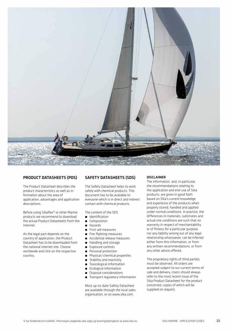
PRODUCT DATASHEETS (PDS)
The Product Datasheet describes the product characteristics as well as in- formation about the area of application, advantages and application descriptions.
Before using Sikaflex® or other Marine products we recommend to download the actual Product Datasheets from the Internet.
As the legal part depends on the country of application, the Product Datasheet has to be downloaded from the national internet site. Choose worldwide and click on the respective country.
SAFETY DATASHEETS (SDS)
The Safety Datasheet helps to work safely with chemical products. This document has to be available to everyone which is in direct and indirect contact with chemical products.
The content of the SDS• Identification• Composition• Hazards• First-aid measures• Fire-fighting measures• Accidental release measures• Handling and storage• Exposure controls• Personal protection• Physical / chemical properties • Stability and reactivity• Toxicological information• Ecological information• Disposal considerations• Transport regulatory information
Most up-to-date Safety Datasheet are available through the local sales organisation, or on www.sika.com.
DISCLAIMERThe information, and, in particular, the recommendations relating to the application and end-use of Sika products, are given in good faith based on Sika’s current knowledge and experience of the products when properly stored, handled and applied under normal conditions. In practice, the differences in materials, substrates and actual site conditions are such that no warranty in respect of merchantability or of fitness for a particular purpose, nor any liability arising out of any legal relationship whatsoever, can be inferred either from this information, or from any written recommendations, or from any other advice offered.
The proprietary rights of third parties must be observed. All orders are accepted subject to our current terms of sale and delivery. Users should always refer to the most recent issue of the Sika Product Datasheet for the product concerned, copies of which will be supplied on request.
24 25SIKA MARINE - APPLICATION GUIDES SIKA MARINE - APPLICATION GUIDESWWW.SIKA.NO
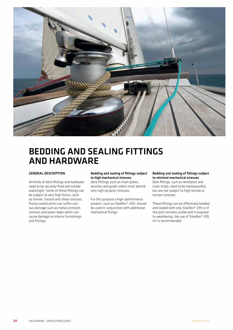
GENERAL DESCRIPTION
All kinds of deck fittings and hardware need to be securely fixed and totally watertight. Some of these fittings can be subject to very high forces, such as tensile, torsion and shear stresses.Poorly sealed joints can suffer seri-ous damage such as metal corrosion, osmosis and water leaks which can cause damage to interior furnishings and fittings.
Bedding and sealing of fittings subject to high mechanical stressesDeck fittings such as chain plates, winches and guide rollers must absorb very high dynamic stresses.
For this purpose a high-performance product, such as Sikaflex®-292i, should be used in conjunction with additional mechanical fixings.
Bedding and sealing of fittings subject to minimal mechanical stressesDeck fittings, such as ventilators and cover strips, need to be waterproofed, but are not subject to high tensile or torsion stresses.
These fittings can be effectively bedded and sealed with only Sikaflex®-291i or if the joint remains visible and is exposed to weathering, the use of Sikaflex®-295 UV is recommended.
BEDDING AND SEALING FITTINGS AND HARDWARE
24 25SIKA MARINE - APPLICATION GUIDES SIKA MARINE - APPLICATION GUIDESVi tar forbehold om trykkfeil, informasjon angående våre salgs og leveringsbetingelser se www.sika.no
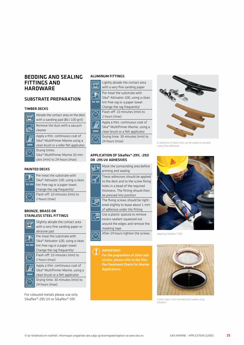
BEDDING AND SEALING FITTINGS AND HARDWARE
SUBSTRATE PREPARATION
TIMBER DECKS
Abrade the contact area on the deck with a sanding pad (80 / 100 grit)
Remove the dust with a vacuum cleaner
SMM
Apply a thin, continuous coat of Sika® MultiPrimer Marine using a clean brush or a roller felt applicator.Drying times: Sika® MultiPrimer Marine 30 min-utes (min) to 24 hours (max)
PAINTED DECKS
SA 100
Pre-treat the substrate with Sika® Aktivator-100, using a clean, lint-free rag or a paper towel. Change the rag frequently!Flash-off: 10 minutes (min) to 2 hours (max)
BRONZE, BRASS OR STAINLESS STEEL FITTINGS
Slightly abrade the contact area with a very fine sanding paper or abrasive pad
SA 100
Pre-treat the substrate with Sika® Aktivator-100, using a clean, lint-free rag or a paper towel. Change the rag frequently!Flash-off: 10 minutes (min) to 2 hours (max)
SMM
Apply a thin, continuous coat of Sika® MultiPrimer Marine, using a clean brush or a felt applicatorDrying time: 30 minutes (min) to 24 hours (max)
For coloured metals please use only Sikaflex®-295 UV or Sikaflex®-591.
ALUMINUM FITTINGS
Lightly abrade the contact area with a very fine sanding paper
SA 100
Pre-treat the substrate with Sika® Aktivator-100, using a clean, lint-free rag or a paper towel. Change the rag frequently!Flash-off: 10 minutes (min) to 2 hours (max)
SMM
Apply a thin, continuous coat of Sika® MultiPrimer Marine, using a clean brush or a felt applicatorDrying time: 30 minutes (min) to 24 hours (max)
APPLICATION OF Sikaflex®-291i, -292i OR -295 UV ADHESIVES
Mask the surrounding area before priming and sealing
These adhesives should be applied to the deck and to the screw fixing holes in a bead of the required thickness. The fitting should then be pressed into positionThe fixing screws should be tight-ened slightly to leave about 1 mm of adhesive under the fittingUse a plastic spatula to remove excess sealant squeezed out around the edges and remove the masking tapeAfter 24 hours tighten the screws
IMPORTANT:For the preparation of other sub-strates, please refer to the Sika Pre-Treatment Charts for Marine Applications.
A port-hatch, both bonded and sealed using Sikaflex®
Applying Sikaflex®-292i
A selection of cleats that can be sealed or bonded using Sika adhesives
26 27SIKA MARINE - APPLICATION GUIDES SIKA MARINE - APPLICATION GUIDESWWW.SIKA.NO
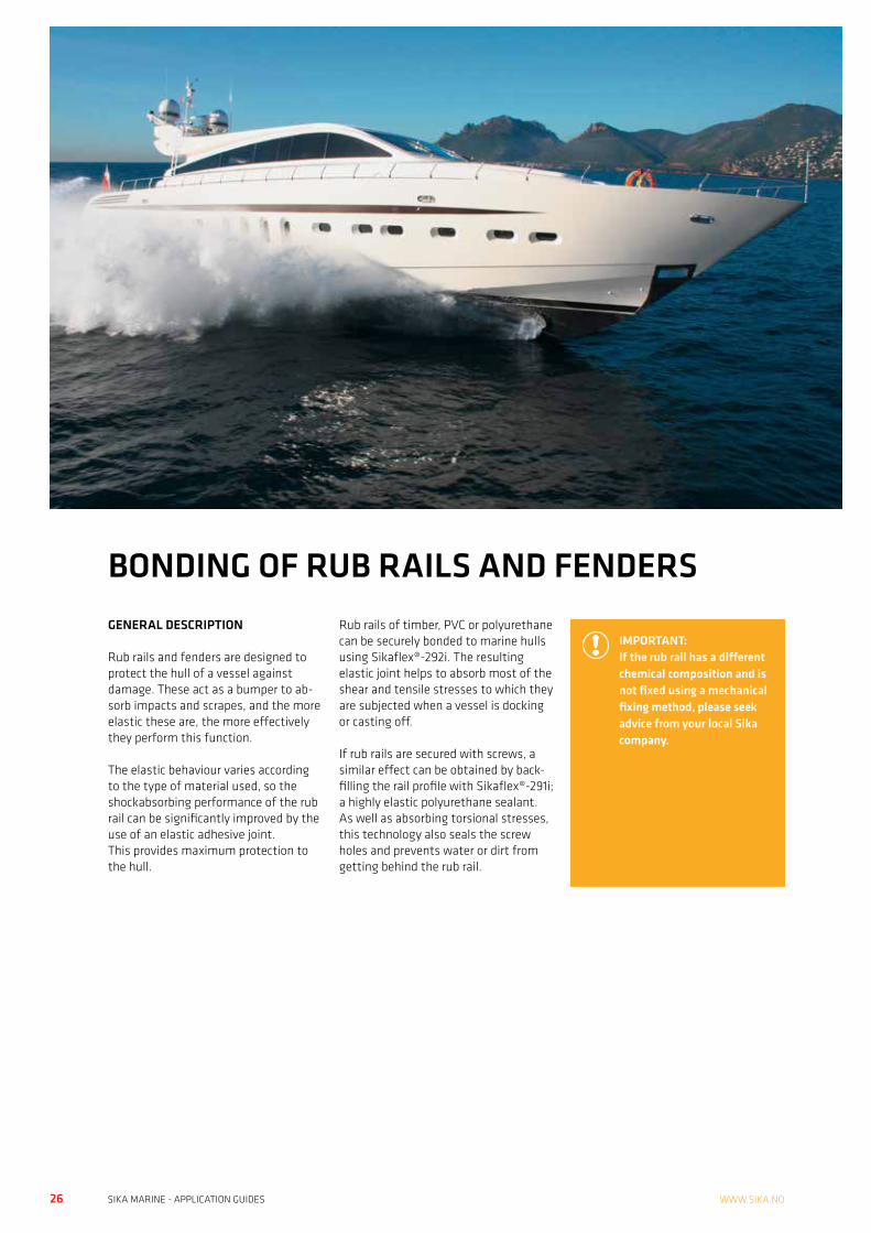
GENERAL DESCRIPTION
Rub rails and fenders are designed to protect the hull of a vessel against damage. These act as a bumper to ab-sorb impacts and scrapes, and the more elastic these are, the more effectively they perform this function.
The elastic behaviour varies according to the type of material used, so the shockabsorbing performance of the rub rail can be significantly improved by the use of an elastic adhesive joint. This provides maximum protection to the hull.
Rub rails of timber, PVC or polyurethane can be securely bonded to marine hulls using Sikaflex®-292i. The resulting elastic joint helps to absorb most of the shear and tensile stresses to which they are subjected when a vessel is docking or casting off.
If rub rails are secured with screws, a similar effect can be obtained by back- filling the rail profile with Sikaflex®-291i; a highly elastic polyurethane sealant. As well as absorbing torsional stresses, this technology also seals the screw holes and prevents water or dirt from getting behind the rub rail.
BONDING OF RUB RAILS AND FENDERS
IMPORTANT:If the rub rail has a different chemical composition and is not fixed using a mechanical fixing method, please seek advice from your local Sika company.
26 27SIKA MARINE - APPLICATION GUIDES SIKA MARINE - APPLICATION GUIDESVi tar forbehold om trykkfeil, informasjon angående våre salgs og leveringsbetingelser se www.sika.no
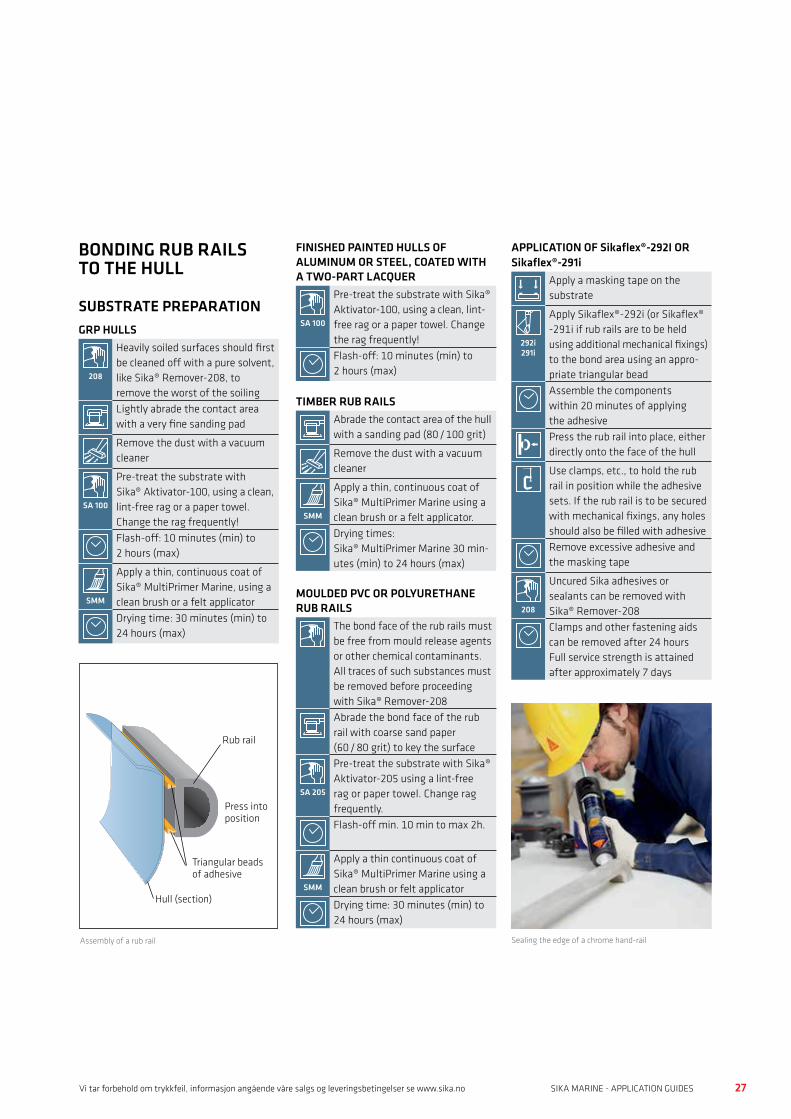
APPLICATION OF Sikaflex®-292I OR Sikaflex®-291i
Apply a masking tape on the substrate
292i291i
Apply Sikaflex®-292i (or Sikaflex® -291i if rub rails are to be held using additional mechanical fixings) to the bond area using an appro-priate triangular bead Assemble the components within 20 minutes of applying the adhesivePress the rub rail into place, either directly onto the face of the hull
Use clamps, etc., to hold the rub rail in position while the adhesive sets. If the rub rail is to be secured with mechanical fixings, any holes should also be filled with adhesiveRemove excessive adhesive and the masking tape
208
Uncured Sika adhesives or sealants can be removed with Sika® Remover-208Clamps and other fastening aids can be removed after 24 hoursFull service strength is attained after approximately 7 days
Sealing the edge of a chrome hand-rail
FINISHED PAINTED HULLS OF ALUMINUM OR STEEL, COATED WITH A TWO-PART LACQUER
SA 100
Pre-treat the substrate with Sika® Aktivator-100, using a clean, lint-free rag or a paper towel. Change the rag frequently!Flash-off: 10 minutes (min) to 2 hours (max)
TIMBER RUB RAILS
Abrade the contact area of the hull with a sanding pad (80 / 100 grit)
Remove the dust with a vacuum cleaner
SMM
Apply a thin, continuous coat of Sika® MultiPrimer Marine using a clean brush or a felt applicator.Drying times: Sika® MultiPrimer Marine 30 min-utes (min) to 24 hours (max)
MOULDED PVC OR POLYURETHANE RUB RAILS
The bond face of the rub rails must be free from mould release agents or other chemical contaminants. All traces of such substances must be removed before proceeding with Sika® Remover-208Abrade the bond face of the rub rail with coarse sand paper (60 / 80 grit) to key the surface
SA 205
Pre-treat the substrate with Sika® Aktivator-205 using a lint-free rag or paper towel. Change rag frequently.Flash-off min. 10 min to max 2h.
SMM
Apply a thin continuous coat of Sika® MultiPrimer Marine using a clean brush or felt applicatorDrying time: 30 minutes (min) to 24 hours (max)
BONDING RUB RAILS TO THE HULL
SUBSTRATE PREPARATIONGRP HULLS
208
Heavily soiled surfaces should first be cleaned off with a pure solvent, like Sika® Remover-208, to remove the worst of the soilingLightly abrade the contact area with a very fine sanding pad
Remove the dust with a vacuum cleaner
SA 100
Pre-treat the substrate with Sika® Aktivator-100, using a clean, lint-free rag or a paper towel. Change the rag frequently!Flash-off: 10 minutes (min) to 2 hours (max)
SMM
Apply a thin, continuous coat of Sika® MultiPrimer Marine, using a clean brush or a felt applicatorDrying time: 30 minutes (min) to 24 hours (max)
Assembly of a rub rail
Rub rail
Triangular beads of adhesive
Hull (section)
Press intoposition

28 29SIKA MARINE - APPLICATION GUIDES SIKA MARINE - APPLICATION GUIDESWWW.SIKA.NO
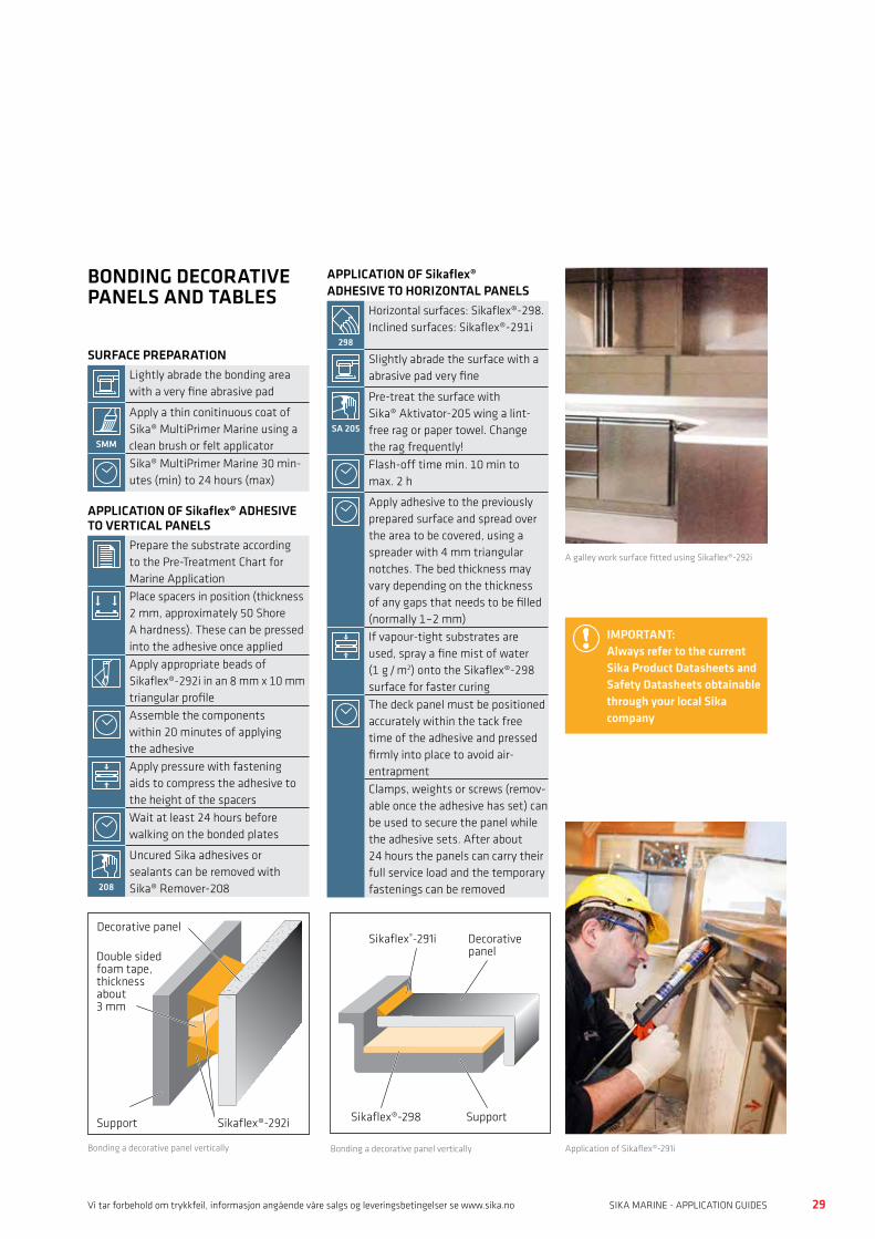
GENERAL DESCRIPTION
The interiors of many boats are based on a variety of traditional and modern materials including mirrored glass. These panels can be used functionally as working surfaces (galley worktops, etc.) or cosmetically. Either way, elastic bonding provides an easy, durable method of fixing without visible and unsightly mechanical fixings.
As the variety of materials used for panels, surfaces and supporting substrates is so vast, please consult the local Technical Service of Sika Industry or proceed to preliminary trials.
BONDING DECORATIVE PANELS AND WORK SURFACES
28 29SIKA MARINE - APPLICATION GUIDES SIKA MARINE - APPLICATION GUIDESVi tar forbehold om trykkfeil, informasjon angående våre salgs og leveringsbetingelser se www.sika.no
APPLICATION OF Sikaflex® ADHESIVE TO HORIZONTAL PANELS
298
Horizontal surfaces: Sikaflex®-298. Inclined surfaces: Sikaflex®-291i
Slightly abrade the surface with a abrasive pad very fine
SA 205
Pre-treat the surface with Sika® Aktivator-205 wing a lint-free rag or paper towel. Change the rag frequently!Flash-off time min. 10 min to max. 2 h
Apply adhesive to the previously prepared surface and spread over the area to be covered, using a spreader with 4 mm triangular notches. The bed thickness may vary depending on the thickness of any gaps that needs to be filled (normally 1–2 mm)If vapour-tight substrates are used, spray a fine mist of water (1 g / m2) onto the Sikaflex®-298 surface for faster curingThe deck panel must be positioned accurately within the tack free time of the adhesive and pressed firmly into place to avoid air- entrapmentClamps, weights or screws (remov-able once the adhesive has set) can be used to secure the panel while the adhesive sets. After about 24 hours the panels can carry their full service load and the temporary fastenings can be removed
BONDING DECORATIVE PANELS AND TABLES
SURFACE PREPARATIONLightly abrade the bonding area with a very fine abrasive pad
SMM
Apply a thin conitinuous coat of Sika® MultiPrimer Marine using a clean brush or felt applicatorSika® MultiPrimer Marine 30 min-utes (min) to 24 hours (max)
APPLICATION OF Sikaflex® ADHESIVE TO VERTICAL PANELS
Prepare the substrate according to the Pre-Treatment Chart for Marine ApplicationPlace spacers in position (thickness 2 mm, approximately 50 Shore A hardness). These can be pressed into the adhesive once applied
Apply appropriate beads of Sikaflex®-292i in an 8 mm x 10 mm triangular profileAssemble the components within 20 minutes of applying the adhesiveApply pressure with fastening aids to compress the adhesive to the height of the spacersWait at least 24 hours before walking on the bonded plates
208
Uncured Sika adhesives or sealants can be removed with Sika® Remover-208
IMPORTANT:Always refer to the current Sika Product Datasheets and Safety Datasheets obtainable through your local Sika company
A galley work surface fitted using Sikaflex®-292i
Application of Sikaflex®-291i
Decorative panel
Support
Sikaflex®-291i
Sikaflex®-298Sikaflex®-292iSupport
Decorative panel
Double sided foam tape, thickness about 3 mm
Bonding a decorative panel vertically Bonding a decorative panel vertically

30 31SIKA MARINE - APPLICATION GUIDES SIKA MARINE - APPLICATION GUIDESWWW.SIKA.NO
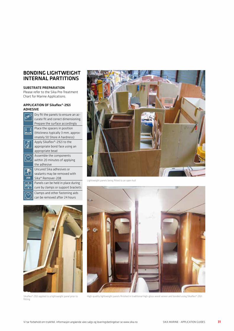
GENERAL DESCRIPTION
These lightweight panels are usually constructed of wood sandwiches with internal polyurethane foam or honey-comb core. They are particularly suited as partitions for cabins and technical rooms as they are of lighter weight than wood filled panels and have good soundproofing properties.
Due to the low density core, lightweight panels cannot be mechanically fixed to the hull structures in the same way as traditional plywood panels.
However, bonding with Sikaflex®-292i is an ideal replacement fixing method that also possesses the flexibility to re-spond to the movements and stresses of the assembly.
The uniform stress distribution pre-vents damages which may be result of stress concentration (example screw).
This process is also endorsed by the manufacturers of the lightweight pan-els.
BONDING LIGHTWEIGHT INTERNAL PARTITIONS
Partition
Support
Trim
Sikaflex®-292i
Sikaflex®-292i bead application for bonding to the support
30 31SIKA MARINE - APPLICATION GUIDES SIKA MARINE - APPLICATION GUIDESVi tar forbehold om trykkfeil, informasjon angående våre salgs og leveringsbetingelser se www.sika.no
BONDING LIGHTWEIGHT INTERNAL PARTITIONSSUBSTRATE PREPARATIONPlease refer to the Sika Pre-Treatment Chart for Marine Applications.
APPLICATION OF Sikaflex®-292i ADHESIVE
Dry fit the panels to ensure an ac-curate fit and correct dimensioning. Prepare the surface accordinglyPlace the spacers in position (thickness typically 3 mm, approx-imately 50 Shore A hardness)Apply Sikaflex®-292i to the appropriate bond face using an appropriate beadAssemble the components within 20 minutes of applying the adhesive
208
Uncured Sika adhesives or sealants may be removed with Sika® Remover-208Panels can be held in place during cure by clamps or support brackets
Clamps and other fastening aids can be removed after 24 hours
Lightweight panels being fitted to an open hull
High-quality lightweight panels finished in traditional high-gloss wood veneer and bonded using Sikaflex®-292iSikaflex®-292i applied to a lightweight panel prior to fitting
32 33SIKA MARINE - APPLICATION GUIDES SIKA MARINE - APPLICATION GUIDESWWW.SIKA.NO
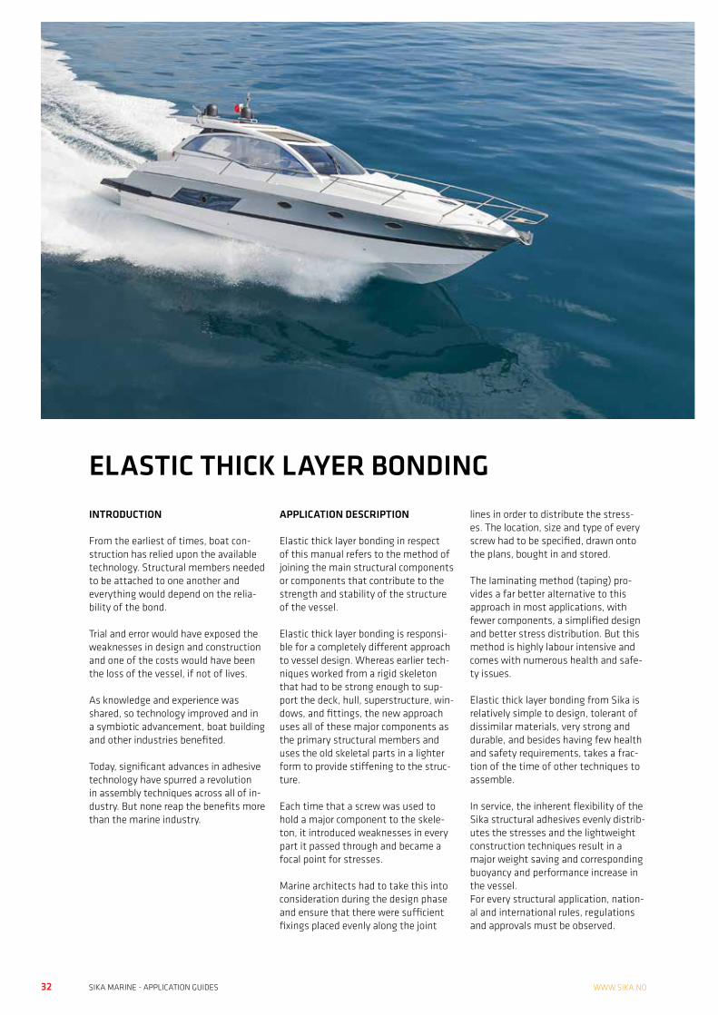
INTRODUCTION
From the earliest of times, boat con-struction has relied upon the available technology. Structural members needed to be attached to one another and everything would depend on the relia-bility of the bond.
Trial and error would have exposed the weaknesses in design and construction and one of the costs would have been the loss of the vessel, if not of lives.
As knowledge and experience was shared, so technology improved and in a symbiotic advancement, boat building and other industries benefited.
Today, significant advances in adhesive technology have spurred a revolution in assembly techniques across all of in-dustry. But none reap the benefits more than the marine industry.
APPLICATION DESCRIPTION
Elastic thick layer bonding in respect of this manual refers to the method of joining the main structural components or components that contribute to the strength and stability of the structure of the vessel.
Elastic thick layer bonding is responsi-ble for a completely different approach to vessel design. Whereas earlier tech-niques worked from a rigid skeleton that had to be strong enough to sup-port the deck, hull, superstructure, win-dows, and fittings, the new approach uses all of these major components as the primary structural members and uses the old skeletal parts in a lighter form to provide stiffening to the struc-ture.
Each time that a screw was used to hold a major component to the skele-ton, it introduced weaknesses in every part it passed through and became a focal point for stresses.
Marine architects had to take this into consideration during the design phase and ensure that there were sufficient fixings placed evenly along the joint
lines in order to distribute the stress-es. The location, size and type of every screw had to be specified, drawn onto the plans, bought in and stored.
The laminating method (taping) pro-vides a far better alternative to this approach in most applications, with fewer components, a simplified design and better stress distribution. But this method is highly labour intensive and comes with numerous health and safe-ty issues.
Elastic thick layer bonding from Sika is relatively simple to design, tolerant of dissimilar materials, very strong and durable, and besides having few health and safety requirements, takes a frac-tion of the time of other techniques to assemble.
In service, the inherent flexibility of the Sika structural adhesives evenly distrib-utes the stresses and the lightweight construction techniques result in a major weight saving and corresponding buoyancy and performance increase in the vessel.For every structural application, nation-al and international rules, regulations and approvals must be observed.
ELASTIC THICK LAYER BONDING

32 33SIKA MARINE - APPLICATION GUIDES SIKA MARINE - APPLICATION GUIDESVi tar forbehold om trykkfeil, informasjon angående våre salgs og leveringsbetingelser se www.sika.no
34 35SIKA MARINE - APPLICATION GUIDES SIKA MARINE - APPLICATION GUIDESWWW.SIKA.NO
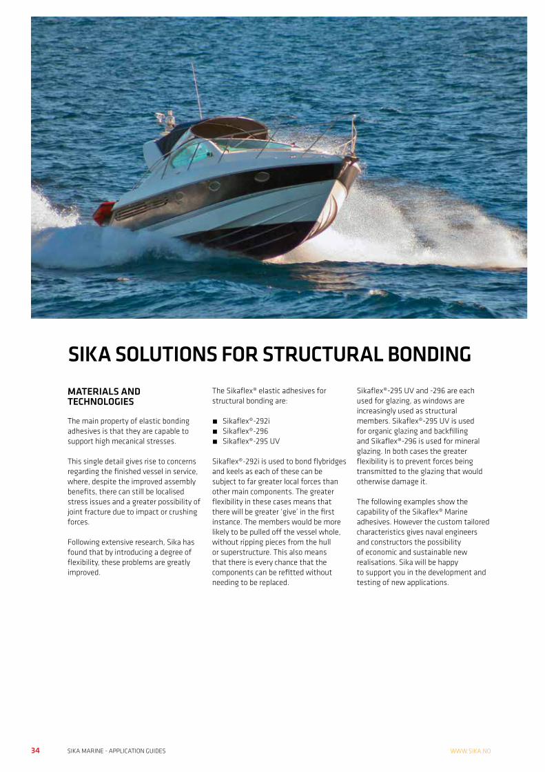
SIKA SOLUTIONS FOR STRUCTURAL BONDINGMATERIALS AND TECHNOLOGIES
The main property of elastic bonding adhesives is that they are capable to support high mecanical stresses.
This single detail gives rise to concerns regarding the finished vessel in service, where, despite the improved assembly benefits, there can still be localised stress issues and a greater possibility of joint fracture due to impact or crushing forces.
Following extensive research, Sika has found that by introducing a degree of flexibility, these problems are greatly improved.
The Sikaflex® elastic adhesives for structural bonding are:
• Sikaflex®-292i• Sikaflex®-296• Sikaflex®-295 UV
Sikaflex®-292i is used to bond flybridges and keels as each of these can be subject to far greater local forces than other main components. The greater flexibility in these cases means that there will be greater ‘give’ in the first instance. The members would be more likely to be pulled off the vessel whole, without ripping pieces from the hull or superstructure. This also means that there is every chance that the components can be refitted without needing to be replaced.
Sikaflex®-295 UV and -296 are each used for glazing, as windows are increasingly used as structural members. Sikaflex®-295 UV is used for organic glazing and backfilling and Sikaflex®-296 is used for mineral glazing. In both cases the greater flexibility is to prevent forces being transmitted to the glazing that would otherwise damage it.
The following examples show the capability of the Sikaflex® Marine adhesives. However the custom tailored characteristics gives naval engineers and constructors the possibility of economic and sustainable new realisations. Sika will be happy to support you in the development and testing of new applications.
34 35SIKA MARINE - APPLICATION GUIDES SIKA MARINE - APPLICATION GUIDESVi tar forbehold om trykkfeil, informasjon angående våre salgs og leveringsbetingelser se www.sika.no
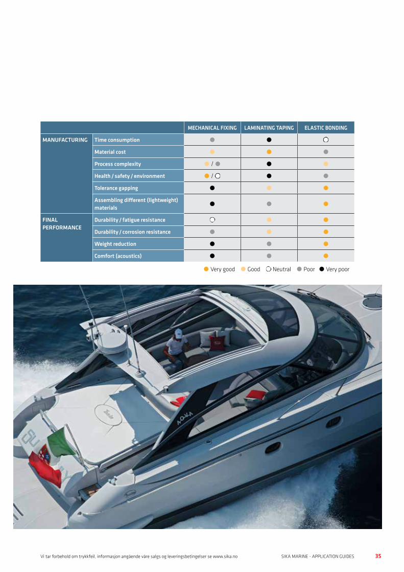
SIKA SOLUTIONS FOR STRUCTURAL BONDING
MECHANICAL FIXING LAMINATING TAPING ELASTIC BONDING
MANUFACTURING Time consumption l l l
Material cost l l l
Process complexity l / l l l
Health / safety / environment l / l l l
Tolerance gapping l l l
Assembling different (lightweight) materials l l l
FINAL PERFORMANCE
Durability / fatigue resistance l l l
Durability / corrosion resistance l l l
Weight reduction l l l
Comfort (acoustics) l l l
l Very good l Good l Neutral l Poor l Very poor
36 37SIKA MARINE - APPLICATION GUIDES SIKA MARINE - APPLICATION GUIDESWWW.SIKA.NO
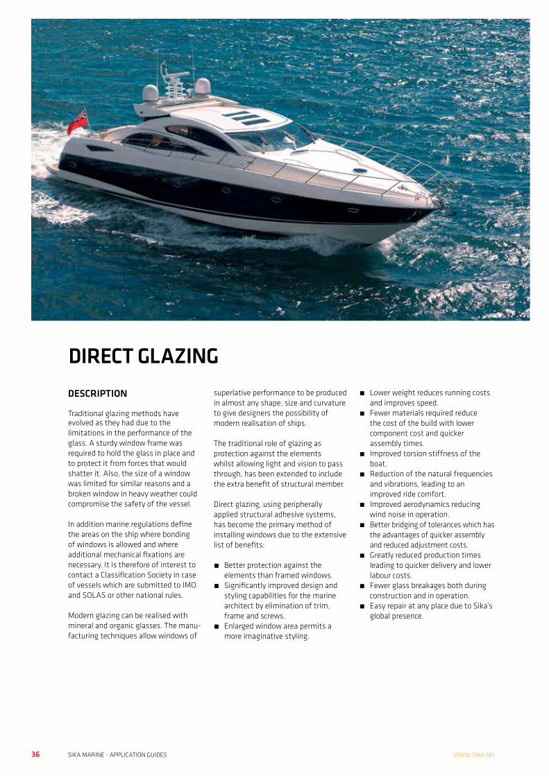
DIRECT GLAZINGDESCRIPTION
Traditional glazing methods have evolved as they had due to the limitations in the performance of the glass. A sturdy window frame was required to hold the glass in place and to protect it from forces that would shatter it. Also, the size of a window was limited for similar reasons and a broken window in heavy weather could compromise the safety of the vessel.
In addition marine regulations define the areas on the ship where bonding of windows is allowed and where additional mechanical fixations are necessary. It is therefore of interest to contact a Classification Society in case of vessels which are submitted to IMO and SOLAS or other national rules.
Modern glazing can be realised with mineral and organic glasses. The manu- facturing techniques allow windows of
superlative performance to be produced in almost any shape, size and curvature to give designers the possibility of modern realisation of ships.
The traditional role of glazing as protection against the elements whilst allowing light and vision to pass through, has been extended to include the extra benefit of structural member.
Direct glazing, using peripherally applied structural adhesive systems, has become the primary method of installing windows due to the extensive list of benefits:
• Better protection against the elements than framed windows.
• Significantly improved design and styling capabilities for the marine architect by elimination of trim, frame and screws.
• Enlarged window area permits a more imaginative styling.
• Lower weight reduces running costs and improves speed.
• Fewer materials required reduce the cost of the build with lower component cost and quicker assembly times.
• Improved torsion stiffness of the boat.
• Reduction of the natural frequencies and vibrations, leading to an improved ride comfort.
• Improved aerodynamics reducing wind noise in operation.
• Better bridging of tolerances which has the advantages of quicker assembly and reduced adjustment costs.
• Greatly reduced production times leading to quicker delivery and lower labour costs.
• Fewer glass breakages both during construction and in operation.
• Easy repair at any place due to Sika’s global presence.
36 37SIKA MARINE - APPLICATION GUIDES SIKA MARINE - APPLICATION GUIDESVi tar forbehold om trykkfeil, informasjon angående våre salgs og leveringsbetingelser se www.sika.no
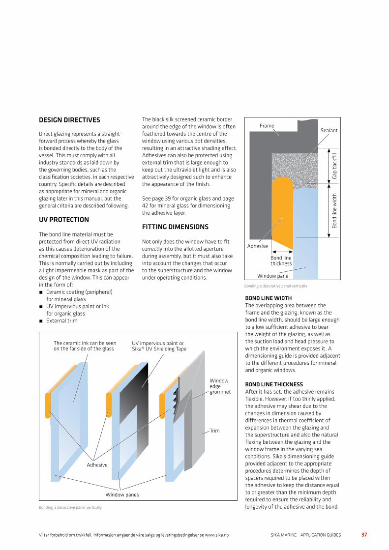
DIRECT GLAZING
Window panes
Trim
UV impervious paint or Sika® UV Shielding Tape
The ceramic ink can be seen on the far side of the glass
Adhesive
Window edge grommet
Bonding a decorative panel vertically
BOND LINE WIDTHThe overlapping area between the frame and the glazing, known as the bond line width, should be large enough to allow sufficient adhesive to bear the weight of the glazing, as well as the suction load and head pressure to which the environment exposes it. A dimensioning guide is provided adjacent to the different procedures for mineral and organic windows.
BOND LINE THICKNESSAfter it has set, the adhesive remains flexible. However, if too thinly applied, the adhesive may shear due to the changes in dimension caused by differences in thermal coefficient of expansion between the glazing and the superstructure and also the natural flexing between the glazing and the window frame in the varying sea conditions. Sika’s dimensioning guide provided adjacent to the appropriate procedures determines the depth of spacers required to be placed within the adhesive to keep the distance equal to or greater than the minimum depth required to ensure the reliability and longevity of the adhesive and the bond.
DESIGN DIRECTIVES
Direct glazing represents a straight-forward process whereby the glass is bonded directly to the body of the vessel. This must comply with all industry standards as laid down by the governing bodies, such as the classification societies, in each respective country. Specific details are described as appropriate for mineral and organic glazing later in this manual, but the general criteria are described following.
UV PROTECTION
The bond line material must be protected from direct UV radiation as this causes deterioration of the chemical composition leading to failure. This is normally carried out by including a light impermeable mask as part of the design of the window. This can appear in the form of:• Ceramic coating (peripheral)
for mineral glass• UV impervious paint or ink
for organic glass • External trim
The black silk screened ceramic border around the edge of the window is often feathered towards the centre of the window using various dot densities, resulting in an attractive shading effect. Adhesives can also be protected using external trim that is large enough to keep out the ultraviolet light and is also attractively designed such to enhance the appearance of the finish.
See page 39 for organic glass and page 42 for mineral glass for dimensioning the adhesive layer.
FITTING DIMENSIONS
Not only does the window have to fit correctly into the allotted aperture during assembly, but it must also take into account the changes that occur to the superstructure and the window under operating conditions.
Bond line thickness
Gap
back
fill
Bond
line
wid
th
Frame
Window pane
Adhesive
Sealant
Bonding a decorative panel vertically
38 39SIKA MARINE - APPLICATION GUIDES SIKA MARINE - APPLICATION GUIDESWWW.SIKA.NO
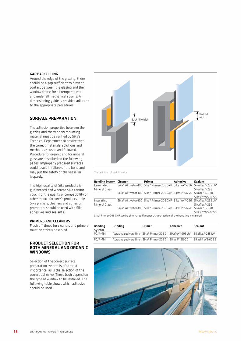
GAP BACKFILLINGAround the edge of the glazing, there should be a gap sufficient to prevent contact between the glazing and the window frame for all temperatures and under all mechanical strains. A dimensioning guide is provided adjacent to the appropriate procedures.
SURFACE PREPARATION
The adhesion properties between the glazing and the window mounting material must be verified by Sika’s Technical Department to ensure that the correct materials, solutions and methods are used and followed. Procedure for organic and for mineral glass are described on the following pages. Improperly prepared surfaces could result in failure of the bond and may put the safety of the vessel in jeopardy.
The high quality of Sika products is guaranteed and whereas Sika cannot vouch for the quality or compatibility of other manu- facturer’s products, only Sika primers, cleaners and adhesion promoters should be used with Sika adhesives and sealants.
PRIMERS AND CLEANERSFlash off times for cleaners and primers must be strictly observed.
PRODUCT SELECTION FOR BOTH MINERAL AND ORGANIC WINDOWS
Selection of the correct surface preparation system is of utmost importance; as is the selection of the correct adhesive. These both depend on the type of window to be installed. The following table shows which adhesive should be used:
The definition of backfill width
Backfill width
Backfill width
Bonding System Cleaner Primer Adhesive SealantLaminated Mineral Glass
Sika® Aktivator-100 Sika® Primer-206 G+P Sikaflex®-296 Sikaflex®-295 UVSikaflex®-296
Sika® Aktivator-100 Sika® Primer-206 G+P Sikasil® SG-20 Sikasil® SG-20Sikasil® WS-605 S
Insulating Mineral Glass
Sika® Aktivator-100 Sika® Primer-206 G+P Sikaflex®-296 Sikaflex®-295 UVSikaflex®-296
Sika® Aktivator-100 Sika® Primer-206 G+P Sikasil® SG-20 Sikasil® SG-20Sikasil® WS-605 S
Sika® Primer-206 G+P can be eliminated if proper UV-protection of the bond line is ensured.
Bonding System
Grinding Primer Adhesive Sealant
PC/PMM Abrasive pad very fine Sika® Primer-209 D Sikaflex®-295 UV Sikaflex®-295 UV
PC/PMM Abrasive pad very fine Sika® Primer-209 D Sikasil® SG-20 Sikasil® WS-605 S
38 39SIKA MARINE - APPLICATION GUIDES SIKA MARINE - APPLICATION GUIDESVi tar forbehold om trykkfeil, informasjon angående våre salgs og leveringsbetingelser se www.sika.no
SEALING AND BONDING ORGANIC WINDOWSAPPLICATION DESCRIPTION
Most of the organic glazing materials used in boat building are clear acrylic sheet (PMMA).
Plastic glazing products have a high coefficient of thermal expansion. In general, incorrectly installed plastic glazing panels are prone to environmental stress cracking (ESC). This can be aggravated by the use of the wrong adhesives or wrong dimensioned adhesive / sealant.
Plastic glazing products have a higher coefficient of thermal expansion than conventional glass.
Therefore, when designing glazing installations, an expansion gap of at least 8 mm all round the periphery must be incorporated between the window rebate and the plastic glazing panel to accommodate thermal movement. In case of additional mechanical fixations any clearance holes for fixing screws must be drilled oversize; slightly larger than the diameter of the screw shank. See also plastic manufacturer recommandations.
To minimise the risk of environmental stress cracking, flat sheets of plastic glazing material should be installed completely flat; they should not be forced to take up a curvature by the use of mechanical fastenings.
When the design calls for curved glazing panels, these should be prefabricated to order and properly tempered by a specialist supplier to ensure installation with no remaining stresses.
As many varieties of organic window exist, it is recommended to ensure that the specific grade selected is suitable for use with Sikaflex® -295 UV. Please note that the extruded type of organic glazing (XT) exhibits a higher tendency to environmental stress cracking than the cast type (GS).
Please contact your local Sika company for technical advice.

40 41SIKA MARINE - APPLICATION GUIDES SIKA MARINE - APPLICATION GUIDESWWW.SIKA.NO
GRP FRAME
Lightly abrade the gel coat of the contact area with a very fine sanding padRemove the dust with a vacuum cleaner
Mask off any areas that need it
SA 205
Pre-treat the substrate with Sika® Aktivator-205, using a clean, lint-free rag or paper towel. Change the rag frequently!Flash-off: 10 minutes (min) to 2 hours (max)
SMM
Apply a thin, continuous coat of Sika® MultiPrimer Marine, using a clean brush or felt applicatorDrying time: 30 minutes (min) to 24 hours (max)
ALUMINUM FRAMEMask off any areas that need it
Lightly abrade the contact area with a fine sand pad
Remove the dust with a vacuum cleaner
SA 205
Pre-treat with Sika® Aktivator-205, using a clean, lint-free rag or paper towel. Change the rag frequently!Flash-off: 10 minutes (min) to 2 hours (max)
SMM
Apply a thin, continuous coat of Sika® MultiPrimer Marine, using a clean brush or felt applicatorDrying time: 30 minutes (min) to 24 hours (max)
Mask off any areas that need it
SA 100
Pre-treat the substrate with Sika® Aktivator-100, using a clean, lint-free rag or paper towel. Change the rag frequently!Flash-off: 10 minutes (min) to 2 hours (max)
ALUMINUM OR TIMBER FRAME COATED WITH TWO-PART LACQUER
SUBSTRATE PREPARATIONPROCEDURE FOR BONDING AND SEALING WITH Sikaflex®-295 UV ORGANIC WINDOWS
Organic windows have a high thermal movement which creates stress in the bond line. Additionally dynamic stress due to the boat movement and the wind load have to be taken in consideration.
The following graphs are a result of theoretical and practical experience, considering all parameters of a boat under the conditions to which a window is subjected.
BONDLINE CONFIGURATION
Basis of calculation are substrates MMA/GFK, wind load 2 kN/m2, ∆T = 30° C
ADHESIVE WIDTH (BITE)
JOINT THICKNESS
JOINT WIDTH
Note: For important projects consult Corporate Technical Service Sika Industry
Adhesivebite (width)15 – 25 mm
Joint thickness14
12
10
8
6
4
2
0
0 1 2
Biggest window dimension [m]
Min
imal
join
t thi
ckne
ss [m
m]
Too thin
ok
Joint thickness
Joint widthwith backfill
Joint without backfill
Joint width14
12
10
8
6
4
2
0
0 1 2
Biggest window dimension [m]
Min
imal
join
t wid
th [m
m]
ok Acceptable areawithout backfill
Too small
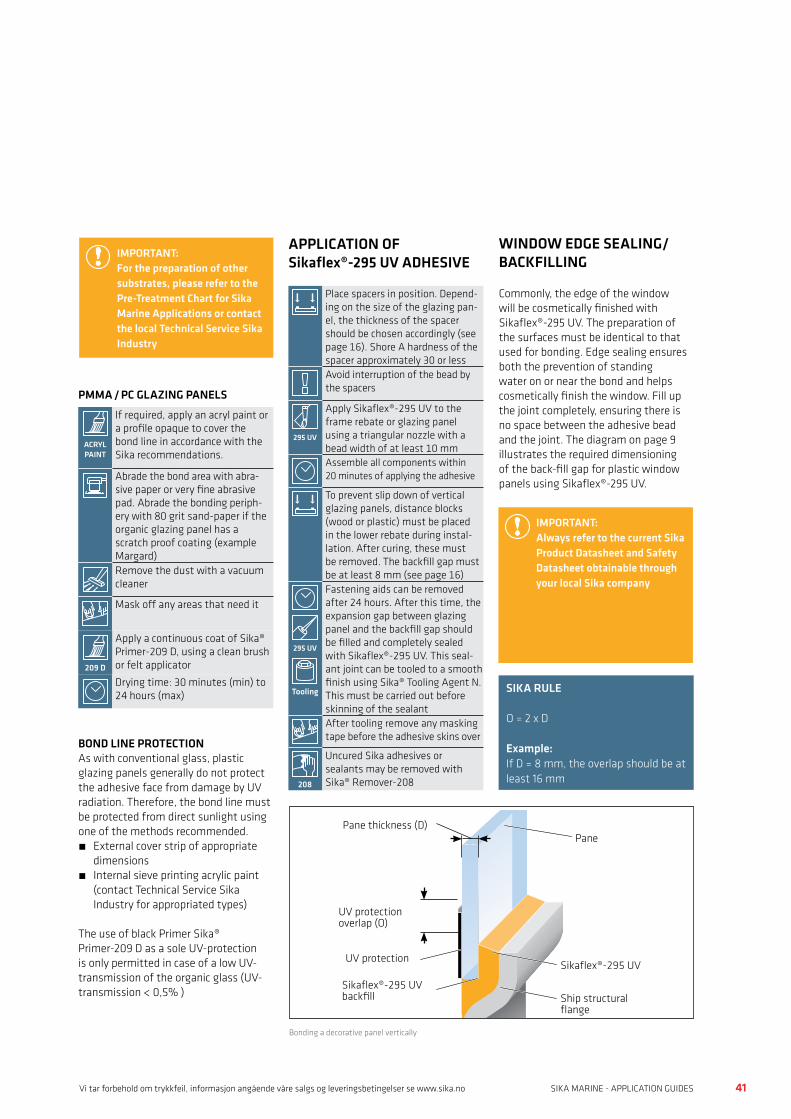
40 41SIKA MARINE - APPLICATION GUIDES SIKA MARINE - APPLICATION GUIDESVi tar forbehold om trykkfeil, informasjon angående våre salgs og leveringsbetingelser se www.sika.no
Pane
Sikaflex®-295 UVUV protection
Pane thickness (D)
UV protection overlap (O)
Ship structural flange
Sikaflex®-295 UVbackfill
Bonding a decorative panel vertically
Place spacers in position. Depend-ing on the size of the glazing pan-el, the thickness of the spacer should be chosen accordingly (see page 16). Shore A hardness of the spacer approximately 30 or lessAvoid interruption of the bead by the spacers
295 UV
Apply Sikaflex®-295 UV to the frame rebate or glazing panel using a triangular nozzle with a bead width of at least 10 mmAssemble all components within 20 minutes of applying the adhesive
To prevent slip down of vertical glazing panels, distance blocks (wood or plastic) must be placed in the lower rebate during instal-lation. After curing, these must be removed. The backfill gap must be at least 8 mm (see page 16)
295 UV
Tooling
Fastening aids can be removed after 24 hours. After this time, the expansion gap between glazing panel and the backfill gap should be filled and completely sealed with Sikaflex®-295 UV. This seal-ant joint can be tooled to a smooth finish using Sika® Tooling Agent N. This must be carried out before skinning of the sealantAfter tooling remove any masking tape before the adhesive skins over
208
Uncured Sika adhesives or sealants may be removed with Sika® Remover-208
APPLICATION OF Sikaflex®-295 UV ADHESIVE
SIKA RULE
O = 2 x D
Example: If D = 8 mm, the overlap should be at least 16 mm
IMPORTANT:Always refer to the current Sika Product Datasheet and Safety Datasheet obtainable through your local Sika company
WINDOW EDGE SEALING/BACKFILLING
Commonly, the edge of the window will be cosmetically finished with Sikaflex®-295 UV. The preparation of the surfaces must be identical to that used for bonding. Edge sealing ensures both the prevention of standing water on or near the bond and helps cosmetically finish the window. Fill up the joint completely, ensuring there is no space between the adhesive bead and the joint. The diagram on page 9 illustrates the required dimensioning of the back-fill gap for plastic window panels using Sikaflex®-295 UV.
IMPORTANT:For the preparation of other substrates, please refer to the Pre-Treatment Chart for Sika Marine Applications or contact the local Technical Service Sika Industry
PMMA / PC GLAZING PANELS
ACRYL PAINT
If required, apply an acryl paint or a profile opaque to cover the bond line in accordance with the Sika recommendations.
Abrade the bond area with abra-sive paper or very fine abrasive pad. Abrade the bonding periph-ery with 80 grit sand-paper if the organic glazing panel has a scratch proof coating (example Margard)Remove the dust with a vacuum cleaner
Mask off any areas that need it
209 D
Apply a continuous coat of Sika® Primer-209 D, using a clean brush or felt applicator
Drying time: 30 minutes (min) to 24 hours (max)
BOND LINE PROTECTIONAs with conventional glass, plastic glazing panels generally do not protect the adhesive face from damage by UV radiation. Therefore, the bond line must be protected from direct sunlight using one of the methods recommended.• External cover strip of appropriate
dimensions• Internal sieve printing acrylic paint
(contact Technical Service Sika Industry for appropriated types)
The use of black Primer Sika® Primer-209 D as a sole UV-protection is only permitted in case of a low UV-transmission of the organic glass (UV-transmission < 0,5% )
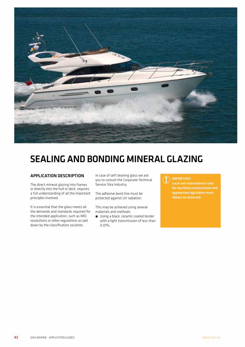
42 43SIKA MARINE - APPLICATION GUIDES SIKA MARINE - APPLICATION GUIDESWWW.SIKA.NO
SEALING AND BONDING MINERAL GLAZINGAPPLICATION DESCRIPTION
The direct mineral glazing into frames or directly into the hull or deck, requires a full understanding of all the important principles involved.
It is essential that the glass meets all the demands and standards required for the intended application, such as IMO resolutions or other regulations as laid down by the classification societies.
In case of self cleaning glass we ask you to consult the Corporate Technical Service Sika Industry.
The adhesive bond line must be protected against UV radiation. This may be achieved using several materials and methods:• Using a black, ceramic coated border
with a light transmission of less than 0.01%.
IMPORTANT:Local and international rules for maritime constructions and appropriate legislation must always be observed.
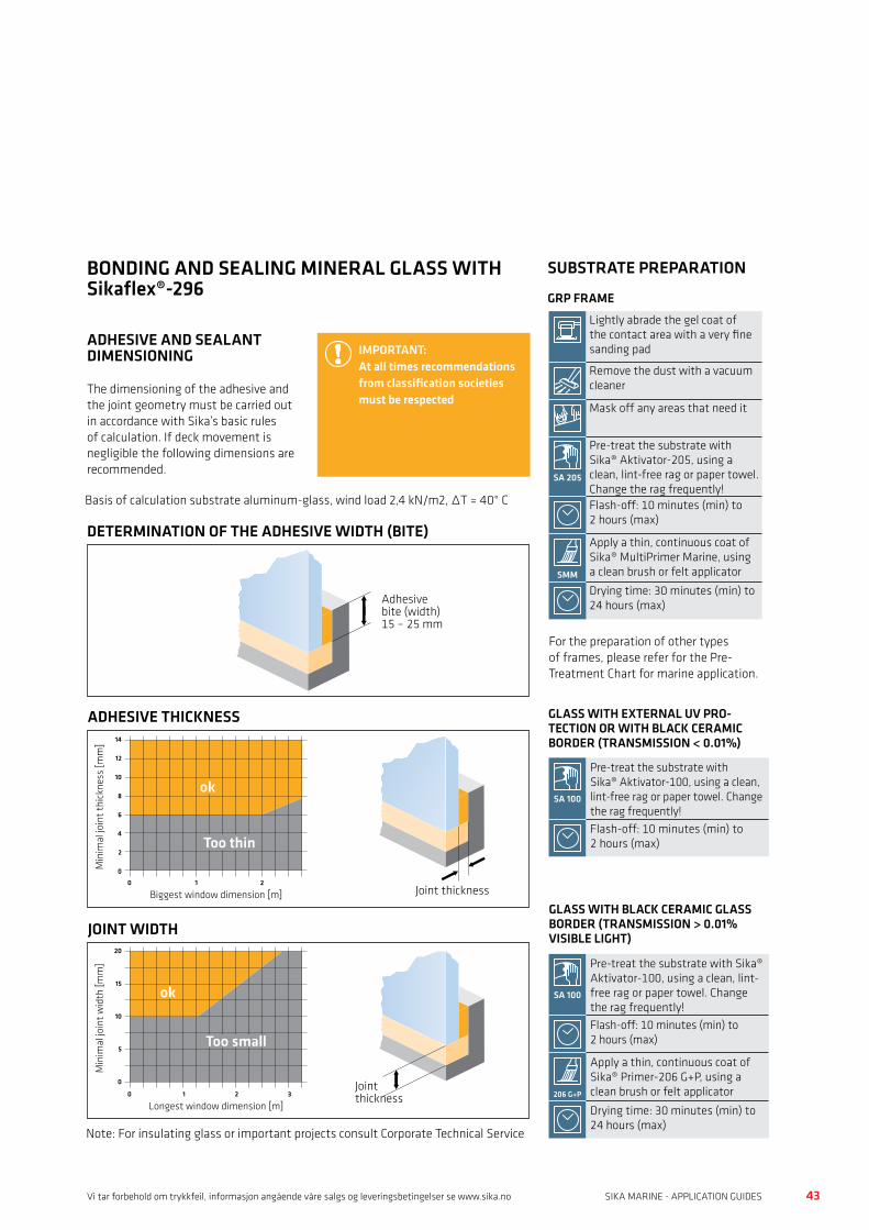
42 43SIKA MARINE - APPLICATION GUIDES SIKA MARINE - APPLICATION GUIDESVi tar forbehold om trykkfeil, informasjon angående våre salgs og leveringsbetingelser se www.sika.no
SEALING AND BONDING MINERAL GLAZINGAdhesivebite (width)15 – 25 mm
Adhesive thickness14
12
10
8
6
4
2
0
0 1 2
Biggest window dimension [m]
Min
imal
join
t thi
ckne
ss [m
m]
ok
Too thin
Joint thickness
Joint width20
15
10
5
0
0 1 2 3
Longest window dimension [m]
Min
imal
join
t wid
th [m
m]
ok
Too small
Joint thickness
JOINT WIDTH
ADHESIVE THICKNESS
DETERMINATION OF THE ADHESIVE WIDTH (BITE)
Note: For insulating glass or important projects consult Corporate Technical Service
SUBSTRATE PREPARATION
GRP FRAME
Lightly abrade the gel coat of the contact area with a very fine sanding pad
Remove the dust with a vacuum cleaner
Mask off any areas that need it
SA 205
Pre-treat the substrate with Sika® Aktivator-205, using a clean, lint-free rag or paper towel. Change the rag frequently!Flash-off: 10 minutes (min) to 2 hours (max)
SMM
Apply a thin, continuous coat of Sika® MultiPrimer Marine, using a clean brush or felt applicator
Drying time: 30 minutes (min) to 24 hours (max)
For the preparation of other types of frames, please refer for the Pre-Treatment Chart for marine application.
SA 100
Pre-treat the substrate with Sika® Aktivator-100, using a clean, lint-free rag or paper towel. Change the rag frequently!Flash-off: 10 minutes (min) to 2 hours (max)
SA 100
Pre-treat the substrate with Sika® Aktivator-100, using a clean, lint-free rag or paper towel. Change the rag frequently!Flash-off: 10 minutes (min) to 2 hours (max)
206 G+P
Apply a thin, continuous coat of Sika® Primer-206 G+P, using a clean brush or felt applicator
Drying time: 30 minutes (min) to 24 hours (max)
GLASS WITH EXTERNAL UV PRO- TECTION OR WITH BLACK CERAMIC BORDER (TRANSMISSION < 0.01%)
GLASS WITH BLACK CERAMIC GLASS BORDER (TRANSMISSION > 0.01% VISIBLE LIGHT)
BONDING AND SEALING MINERAL GLASS WITH Sikaflex®-296
ADHESIVE AND SEALANT DIMENSIONING
The dimensioning of the adhesive and the joint geometry must be carried out in accordance with Sika’s basic rules of calculation. If deck movement is negligible the following dimensions are recommended.
IMPORTANT:At all times recommendations from classification societies must be respected
Basis of calculation substrate aluminum-glass, wind load 2,4 kN/m2, ∆T = 40° C
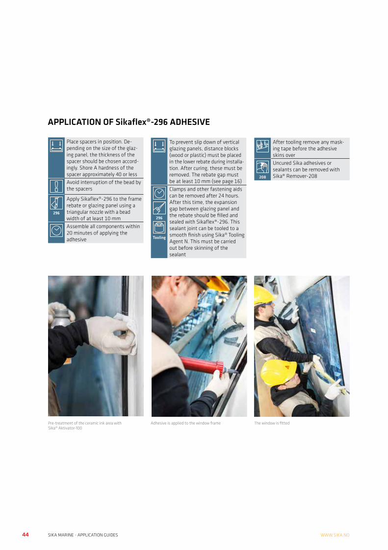
44 45SIKA MARINE - APPLICATION GUIDES SIKA MARINE - APPLICATION GUIDESWWW.SIKA.NO
Place spacers in position. De-pending on the size of the glaz-ing panel, the thickness of the spacer should be chosen accord-ingly. Shore A hardness of the spacer approximately 40 or lessAvoid interruption of the bead by the spacers
296
Apply Sikaflex®-296 to the frame rebate or glazing panel using a triangular nozzle with a bead width of at least 10 mmAssemble all components within 20 minutes of applying the adhesive
To prevent slip down of vertical glazing panels, distance blocks (wood or plastic) must be placed in the lower rebate during installa-tion. After curing, these must be removed. The rebate gap must be at least 10 mm (see page 16)
296
Tooling
Clamps and other fastening aids can be removed after 24 hours. After this time, the expansion gap between glazing panel and the rebate should be filled and sealed with Sikaflex®-296. This sealant joint can be tooled to a smooth finish using Sika® Tooling Agent N. This must be carried out before skinning of the sealant
After tooling remove any mask-ing tape before the adhesive skins over
208
Uncured Sika adhesives or sealants can be removed with Sika® Remover-208
APPLICATION OF Sikaflex®-296 ADHESIVE
Pre-treatment of the ceramic ink area with Sika® Aktivator-100
Adhesive is applied to the window frame The window is fitted

44 45SIKA MARINE - APPLICATION GUIDES SIKA MARINE - APPLICATION GUIDESVi tar forbehold om trykkfeil, informasjon angående våre salgs og leveringsbetingelser se www.sika.no
FLYBRIDGE BONDINGAPPLICATION DESCRIPTION
Many modern motor yachts have fly- bridges. Conventional fixing methods such as mechanical fixings or rigid adhesives have concentrations of peak stresses which lead to breaching of the substrate allowing access to moisture.
Bonding of flybridges using flexible adhesive systems evens the distribution of stresses and optimises resistance to impact and fatigue effects.
In service, flybridges are subjected to substantial stress on the joints at high speeds. The main reason that
makes Sikaflex®-292i perfect for this application is the high modulus characteristic that ensure the integrity of the joint under stress.
A perfect cosmetic finish is obtained with the weather resistance Sikaflex®- 295 UV in white colour.
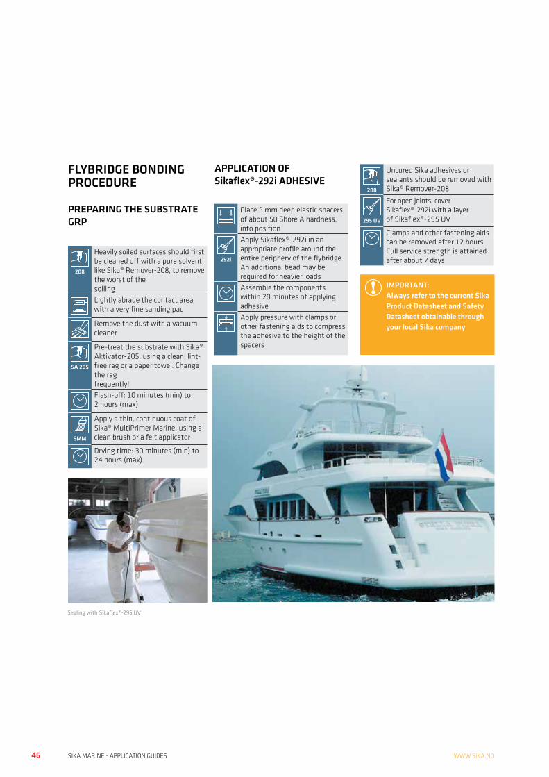
46 47SIKA MARINE - APPLICATION GUIDES SIKA MARINE - APPLICATION GUIDESWWW.SIKA.NO
208
Heavily soiled surfaces should first be cleaned off with a pure solvent, like Sika® Remover-208, to remove the worst of the soilingLightly abrade the contact area with a very fine sanding pad
Remove the dust with a vacuum cleaner
SA 205
Pre-treat the substrate with Sika® Aktivator-205, using a clean, lint-free rag or a paper towel. Change the rag frequently!Flash-off: 10 minutes (min) to 2 hours (max)
SMM
Apply a thin, continuous coat of Sika® MultiPrimer Marine, using a clean brush or a felt applicator
Drying time: 30 minutes (min) to 24 hours (max)
Place 3 mm deep elastic spacers, of about 50 Shore A hardness, into position
292i
Apply Sikaflex®-292i in an appropriate profile around the entire periphery of the flybridge. An additional bead may be required for heavier loadsAssemble the components within 20 minutes of applying adhesiveApply pressure with clamps or other fastening aids to compress the adhesive to the height of the spacers
208
Uncured Sika adhesives or sealants should be removed with Sika® Remover-208
295 UV
For open joints, cover Sikaflex®-292i with a layer of Sikaflex®-295 UV
Clamps and other fastening aids can be removed after 12 hours Full service strength is attained after about 7 days
IMPORTANT:Always refer to the current Sika Product Datasheet and Safety Datasheet obtainable through your local Sika company
Sealing with Sikaflex®-295 UV
APPLICATION OF Sikaflex®-292i ADHESIVE
FLYBRIDGE BONDING PROCEDURE
PREPARING THE SUBSTRATE GRP
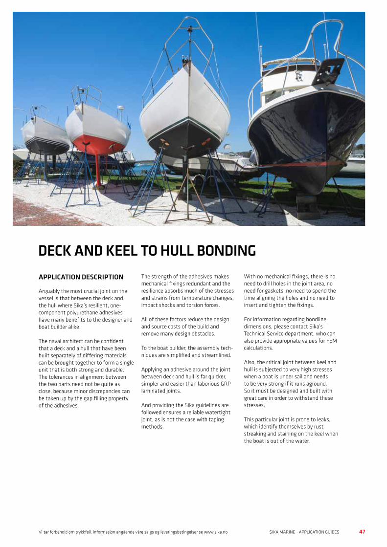
46 47SIKA MARINE - APPLICATION GUIDES SIKA MARINE - APPLICATION GUIDESVi tar forbehold om trykkfeil, informasjon angående våre salgs og leveringsbetingelser se www.sika.no
DECK AND KEEL TO HULL BONDINGAPPLICATION DESCRIPTION
Arguably the most crucial joint on the vessel is that between the deck and the hull where Sika’s resilient, one-component polyurethane adhesives have many benefits to the designer and boat builder alike.
The naval architect can be confident that a deck and a hull that have been built separately of differing materials can be brought together to form a single unit that is both strong and durable. The tolerances in alignment between the two parts need not be quite as close, because minor discrepancies can be taken up by the gap filling property of the adhesives.
The strength of the adhesives makes mechanical fixings redundant and the resilience absorbs much of the stresses and strains from temperature changes, impact shocks and torsion forces.
All of these factors reduce the design and source costs of the build and remove many design obstacles.
To the boat builder, the assembly tech- niques are simplified and streamlined.
Applying an adhesive around the joint between deck and hull is far quicker, simpler and easier than laborious GRP laminated joints.
And providing the Sika guidelines are followed ensures a reliable watertight joint, as is not the case with taping methods.
With no mechanical fixings, there is no need to drill holes in the joint area, no need for gaskets, no need to spend the time aligning the holes and no need to insert and tighten the fixings.
For information regarding bondline dimensions, please contact Sika’s Technical Service department, who can also provide appropriate values for FEM calculations.
Also, the critical joint between keel and hull is subjected to very high stresses when a boat is under sail and needs to be very strong if it runs aground. So it must be designed and built with great care in order to withstand these stresses.
This particular joint is prone to leaks, which identify themselves by rust streaking and staining on the keel when the boat is out of the water.
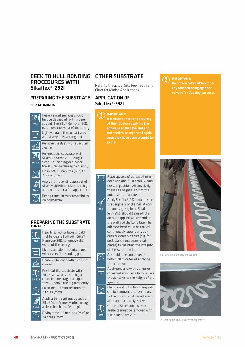
48 49SIKA MARINE - APPLICATION GUIDES SIKA MARINE - APPLICATION GUIDESWWW.SIKA.NO
IMPORTANT:Do not use Sika® Aktivator or any other cleaning agent or solvent for cleaning purposes
Hull and deck are brought together
A locating pin ensures perfect alignment
Place spacers of at least 4 mm deep and about 50 shore A hard-ness, in position. Alternatively, these can be pressed into the adhesive once applied
292i
Apply Sikaflex®-292i onto the en-tire periphery of the hull. A con-tinuous zig-zag bead Sikaf-lex®-292i should be used; the amount applied will depend on the width of the bond face. The adhesive bead must be carried continuously around any cut-outs or clearance holes (e.g. for deck stanchions, pipes, chain plates) to maintain the integrity of the watertight jointAssemble the components within 20 minutes of applying the adhesiveApply pressure with clamps or other fastening aids to compress the adhesive to the height of the spacersClamps and other fastening aids can be removed after 24 hours. Full service strength is attained after approximately 7 days
208
Uncured Sika® adhesives or sealants must be removed with Sika® Remover-208
OTHER SUBSTRATERefer to the actual Sika Pre-Treatment Chart for Marine Applications.
APPLICATION OF Sikaflex®-292I
208
Heavily soiled surfaces should first be cleaned off with a pure solvent, like Sika® Remover-208, to remove the worst of the soilingLightly abrade the contact area with a very fine sanding pad
Remove the dust with a vacuum cleaner
SA 205
Pre-treat the substrate with Sika® Aktivator-205, using a clean, lint-free rag or a paper towel. Change the rag frequently!Flash-off: 10 minutes (min) to 2 hours (max)
SMM
Apply a thin, continuous coat of Sika® MultiPrimer Marine, using a clean brush or a felt applicator
Drying time: 30 minutes (min) to 24 hours (max)
DECK TO HULL BONDING PROCEDURES WITH Sikaflex®-292I
PREPARING THE SUBSTRATE FOR ALUMINUM
PREPARING THE SUBSTRATE FOR GRP
208
Heavily soiled surfaces should first be cleaned off with Sika® Remover-208, to remove the worst of the soilingLightly abrade the contact area with a very fine sanding pad
Remove the dust with a vacuum cleaner
SA 205
Pre-treat the substrate with Sika® Aktivator-205, using a clean, lint-free rag or a paper towel. Change the rag frequently!Flash-off: 10 minutes (min) to 2 hours (max)
SMM
Apply a thin, continuous coat of Sika® MultiPrimer Marine, using a clean brush or a felt applicator
Drying time: 30 minutes (min) to 24 hours (max)
IMPORTANT:It is vital to check the accuracy of the fit before applying the adhesive so that the parts do not need to be separated again once they have been brought to-gether
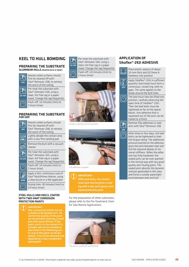
48 49SIKA MARINE - APPLICATION GUIDES SIKA MARINE - APPLICATION GUIDESVi tar forbehold om trykkfeil, informasjon angående våre salgs og leveringsbetingelser se www.sika.no
KEEL TO HULL BOMDING
PREPARING THE SUBSTRATE ALUMINUM HULLS (PAINTED WITH 2C PAINT)
PREPARING THE SUBSTRATE FOR GRP
208
Heavily soiled surfaces should first be cleaned off with Sika® Remover-208, to remove the worst of the soiling
SA 100
Pre-treat the substrate with Sika® Aktivator-100, using a clean, lint-free rag or a paper towel. Change the rag frequently!Flash-off: 10 minutes (min) to 2 hours (max)
208
Heavily soiled surfaces should first be cleaned off with Sika® Remover-208, to remove the worst of the soilingLightly abrade the contact area with a very fine sanding pad
Remove the dust with a vacuum cleaner
SA 205
Pre-treat the substrate with Sika® Aktivator-205, using a clean, lint-free rag or a paper towel. Change the rag frequently!Flash-off: 10 minutes (min) to 2 hours (max)
SMM
Apply a thin, continuous coat of Sika® MultiPrimer Marine, using a clean brush or a felt applicator
Drying time: 30 minutes (min) to 24 hours (max)
STEEL HULLS AND KEELS, COATED WITH TWO-PART CORROSION PROTECTION PAINTS
IMPORTANT:One-component paints are not suitable to be bonded on it. To control the quality of the paint we recommend cleaning a small part with paint thinner. If the paint resists to the solvent it is suitable and can be bonded as described in the following part. In case of the paint can be dis-solved, it has to be removed and replaced by a two-component epoxy paint
SA 100
Pre-treat the substrate with Sika® Aktivator-100, using a clean, lint-free rag or a paper towel. Change the rag frequently!Flash-off: 10 minutes (min) to 2 hours (max)
A keel is carefully slid into position
The adhesive is applied
IMPORTANT:With lead keels, the contact area must also be given a coat-ing with a two-part epoxy-resin based protective paint
For the preparation of other substrates, please refer to the Pre-Treatment Chart for Sika Marine Applications.
The joint is tooled off and finished
APPLICATION OF Sikaflex®-292I ADHESIVE
Place elastic spacers of about 10 mm thick and 50 Shore A hardness into position
292i
Apply Sikaflex®-292i in sufficient quantity. Each bead must form a continuous, closed ring, with no gaps. The same applies to the beads around the bolt holesThe keel must then be lifted into position, carefully observing the open time of Sikaflex®-292i. Then the keel bolts must be tightened as far as the spacer blocks. Any adhesive that is squeezed out of the joint can be tooled to a finish
208
Remove Sika adhesives or seal-ants with Sika® Remover-208
After three or four days, the keel bolts can be tightened to their full torque rating. The additional pressure exerted on the adhesive, gives the joint between keel and hull the required degree of tor-sional stiffness. When the adhe-sive has fully hardened, the sealed joint can be over-painted in the normal way with any good quality anti-fouling paint. The sealed joint absorbs the dynamic stresses generated in this area and forms a totally watertight bond between keel and hull
50 51SIKA MARINE - APPLICATION GUIDES SIKA MARINE - APPLICATION GUIDESWWW.SIKA.NO
GLOSSARY OF TERMS
ActivatorSolvent containing adhesion promoters that increase the adhesion of an adhesive on a substrate.
AdhesionAdherence of an adhesive to a substrate.
Adhesive joint (bond-line)Gap between two components that must be filled with adhesive.
AgingBehaviour of the adhesive layer under the influence of time, temperature and environmental conditions.
Balanced moisture contentMoisture content of a material (specially wood) when allowed to stabilize relative to ambient levels of atmospheric temperature and air humidity.
Bonding jointGap between two bonding surfaces filled with adhesive.
BondlineContact area between adhesive and substrate.
Breaking stressStress required to produce failure or fracture in a material.
ClampingTemporary securing of components in the desired position by mechanical means, with or without the application of pressure, while the adhesive is setting.
CleanerChemical agent used to clean surfaces prior to bonding.
Coefficient of thermal expansionA factor that expresses the dimensional changes in a component as a function of temperature change.
CohesionInherent strength of a material.
Contact adhesiveLaminating adhesive, applied to both surfaces of the joint. Once ready, the adhesive surface is not tacky and the bonding force results only on contact of the two adhesives surfaces.
Cross-linkingCreation of a three-dimensional network through the formation of chemical bonds between molecular chains.
Curing / SettingSetting or hardening of an adhesive due to physical or chemical reaction.
Curing conditionsFactors that influence the curing of adhesives, e.g. temperature, relative humidity.
Dew pointTemperature at which a condensation of the air humidity occurs (depending on environmental temperature and relative humidity).
DiffusionMigration of gases or liquids through materials. The hardening process of one-component PUR and silicones is limited by the speed of diffusion of water through the hardened skin or layer of the adhesive.
Drying timeDuration required for a primer to reach a state that will safely allow the process that follows it to be started (e.g. adhesive application).
DuromerCrosslinked, mostly unmeltable plastics.
ElastomersElastomers are macromolecules with an open network structure which do not undergo plastic flow even at high temperatures approaching the point of chemical decomposition, but undergo reversible elastic deformation instead.
Elongation at breakElongation that takes place before a material fails or fractures.
ESCEnvironmental stress cracking. Cracking of thermoplastics under internal or external stress and chemicals.
Final strengthStrength of an adhesive joint when the adhesive has attained full cure.
FillersAdditives (mostly inorganic) to improve the properties of the adhesive.
Flash-off timeDuration required for a primer, solvent, cleaner or activator to reach a state that will safely allow the process that follows it to be started (e.g. adhesive application).
FEM (Finite Element Method)Calculation using interactive analysis methods. Calculation values are available from Technical Service Sika Industry.
Fracture energyEnergy that is required to cause a material to fail or fracture.
Galvanic corrosionCorrosion due to the electrical contact of metals with different electrochemical potential (e.g. aluminum, steel).The use of nonconductive adhesives can stop this effect.
Handling strengthStrength level development at which the bonded assembly can be handled and passed on to the next stage of processing.
Heat resistanceThe ability of a material to withstand heat without altering its state as a result of exposure to a specified temperature over a fixed period of time.
Hygric movementMovement as a result of humidity content in the material. Particularly applies to wood but also affects other materials like PA (brand name Nylon).The values from wood depend on the type and the orientation of the grain (radial, tangential).
Joint assemblyProcess of bringing the substrates together under light pressure so that the adhesive is compressed to form the adhesive bond.
Impact resistanceResistance against abrupt forces (crash).
Modulus of elasticityModulus of elasticity describes the ratio of stress to strain in a rod under tension whose sides are unconstrained.
Non-sag propertiesResistance of an adhesive to collapse or slump when extruded as a bead.
One-component polyurethane adhesiveAdhesive containing isocyanate groups that cure on exposure to moisture.
Open or working timeMaximum period of time that may elapse between application of the adhesive and assembly of the joint.

50 51SIKA MARINE - APPLICATION GUIDES SIKA MARINE - APPLICATION GUIDES
Organic windowTransparent plastic such as PMMA and PC (e.g. Brand names; Plexiglas / Lexan). Thermoplastics which are prone to ESC.
Pot-lifePeriod of time during which multi-component adhesives can be processed after their components have been mixed. Pot-life depends on the ambient temperature and the quantity of batch mixed. It decreases with higher temperature and increased batch quantities.
PrimerA special paint coating designed to improve adhesion between adhesive and substrate. They may also have additional functions such as UV-protection of the bond line, reinforcing the substrate and some corrosion protection.
QAQuality assurance.Reactive adhesivesAdhesives that cure or set when exposed to heat, moisture, radiation, etc.
ResistanceBehaviour of an adhesive under changed environmental conditions.Sag resistance (see Viscosity)
SealantSubstance that separates a joint from any medium to which it is exposed.
Setting Solidification of adhesive through physical and / or chemical process.
Shear modulusDefined as the ratio of the shear stress to the shear strain in a body that undergoes simple angular deformation.
Shelf lifePeriod of time that can elapse between the manufacture of an adhesive and its use, subject to storage of the product under controlled conditions.
SolventOrganic liquid that dissolves the base materials and other soluble adhesive constituents without changing their chemistry.
Solids contentNonvolatile portion of components.
SpacersElastic parts, mostly self-adhesive, used to control the thickness of the adhesive. The shore hardness of the spacer should be equal to or lower than that of the adhesive.
SubstratesThe base materials to be bonded, e.g. fabric, steel, wood, GRP.
Tack-free or skinning timeTime between the application of a one- component adhesive and the formation of a skin on its surface, after which point bonding can no longer take place.
Tensile lap-shear strengthBreaking strength of the adhesive bond joining two parallel surfaces in a single lap joint when the joint is subjected to a shearing stress by applying a tensile load centrically to the two lapped substrates.
Tensile strengthBreaking stress of a material under tension.
Thermoplastic adhesivePlastics that soften under the application of heat (e.g. PVC, PMMA, ABS).
Thermosetting resinsClosely cross-linked macromolecules that do not undergo plastic deformation, even at high temperatures (e.g. Polyester, Epoxy).
Thick-layer elastic bondingElastic bonding application where the thickness of the adhesive layer exceeds 3 mm.
Tie-coatingAn industry specific term used to indicate a bonding coat or layer applied to a material to facilitate ready adhesion with other media.
TransmissionRatio of the intensity of a beam of light passing through a body, related to its original intensity. Measured in the UV (organic glazing) and visible range (mineral glazing). Sika stipulates limits for primerless glass bonding.
TV-valueMaximum workplace concentration or highest admissible concentration of evaporating solvent at a workplace.Two-part polyurethane adhesiveAdhesive formed by the addition reaction of two components; main component and hardener.
UV-radiationHigh energy part of sunlight, mainly responsible for surface degradation of organic materials like paint, sealants, etc.
ViscosityResistance to flow exhibited by fluids or paste-like substances as a result of internal friction.
White spiritPetroleum spirit solvent, common used for thinning and cleaning.
WettingAbility of liquids to disperse themselves uniformly over solid materials.
Wet bondingMethod of bonding whereby the adhesive is applied by wetting.
DisclaimerThe information, and, in particular, the recommendations relating to the application and end-use of Sika products, are given in good faith based on Sika’s current knowledge and experience of the products when properly stored, handled and applied under normal conditions. In practice, the differences in materials, substrates and actual site conditions are such that no warranty in respect of merchantability or of fitness for a particular purpose, nor any liability arising out of any legal relationship whatsoever, can be inferred either from this information, or from any written recommendations, or from any other advice offered.
The proprietary rights of third parties must be observed. All orders are accepted subject to our current terms of sale and delivery. Users should always refer to the most recent issue of the Sika Product Datasheet for the product concerned, copies of which will be supplied on request.
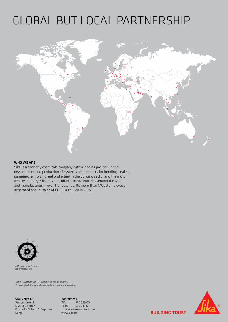
Sika Norge ASSanitetsveien 1N-2013 SkjettenPostboks 71, N-2026 SkjettenNorge
Kontakt ossTlf.: 67 06 79 00Faks: 67 06 15 [email protected]
WHO WE ARESika is a specialty chemicals company with a leading position in the development and production of systems and products for bonding, sealing,damping, reinforcing and protecting in the building sector and the motorvehicle industry. Sika has subsidiaries in 94 countries around the worldand manufactures in over 170 factories. Its more than 17,000 employeesgenerated annual sales of CHF 5.49 billion in 2015.
All Products and Systems are Wheelmarked
GLOBAL BUT LOCAL PARTNERSHIP
Our most current General Sales Conditions shall apply. Please consult the Data Sheet prior to any use and processing.