sika and tricosal waterstops for the waterproofing of ... · and concepts with sika® and...
TRANSCRIPT
Sika® and Tricosal® WaterstopsFor the Waterproofing of Expansion and Construction Joints
s i n c e
1 9 1 0
Innovat ion &
Consistency


2 I 3
Content
Sika was originally founded in 1910 by Kaspar Winkler in Switzerland. The company
has grown to become one of the world´s leading suppliers of construction chemicals,
with the focus on complete and integrated system solutions. Sika has now extended
its operations to more than 70 countries around the world with our international
network of R&D, production and marketing organisations. In 2008 Sika acquired the
well known Tricosal business which was founded in 1916 and based in Germany.
Tricosal is also internationally renowned, particularly for its expertise and experience
in the development, production and installation of watertight jointing products and
systems, always focussed on providing the optimised sealing solutions.
Now you benefit from the combination of Sika and Tricosal expertise and
experience.
Watertight Jointing Technology and Concepts with Sika® and Tricosal® Waterstop Systems
Sika® and Tricosal® Waterstops – Introduction 4
Sika® and Tricosal® Waterstops – Typical Applications and Structures 5
Types of Joints 6
Waterstop Design and Function 7
Alternative Materials for Waterstops 8 / 9
Selection of the Correct Waterstop – Sika® Waterbar 10 / 11
Waterstop Selection in Accordance with DIN V 18197 12 / 13
Construction Joint Waterstops, Internal 14 / 15
Construction Joint Waterstops, External 16 / 17
Expansion Joint Waterstops, Internal 18 / 19
Expansion Joint Waterstops, External 20 / 21
Waterstops for Capping Joints 22 / 23
Compression Seals 24
Waterstops for Hydraulic Civil Engineering Structures 25
Waterstops for Potable (Drinking) Water Structures 26 / 27
Flanged Retrofit Joint Sealing Waterstops 28 – 32
Waterstops Combined with Injection Hoses 33
Waterstops Combined with Sika® Membrane Systems 34 / 35
Tricosal® Westec® Waterstops with High Chemical Environmental Protection 36 / 37
Preformed Junctions and Joints 38
Custom Made Waterstop Systems 39
Waterstop Specification 40 / 41
Waterstop Handling and Installation Guidelines 42 – 45
Equipment, Tools and Accessories for Welding and Vulcanizing 46 – 49
Case Studies 50 / 51

Waterstops for capping joints
Construction joint waterstops, internal
Construction joint waterstops, external
Introduction Key Advantages
n 50 years’ technical and
application experience
n Many different applications
n Alternative materials dependent
on the requirements
n Alternative sizes and profiles
n Individual and customized
solutions
n High performance sealing
systems
Sika® and Tricosal® Waterstops – Typical Applications
For Construction and Expansion Joints, all Types of Joints in Transitions, Connections and Special Applications
Sika® and Tricosal® Waterstops High Quality Joint Waterproofing Solutions
Sika and Tricosal have unrivalled experience of water-
proofing all types of expansion and construction joints in
reinforced concrete structures. Our continuous research
and development also ensure the application of the latest
available technologies in waterproofing, especially to
modern methods of concrete construction and require-
ments. Providing cost effective, economic and reliably
secure solutions for our customers is our priority. Due to
the nature of these materials, concrete and reinforced
concrete structures must always be built divided into
sections, by forming joints – construction (daywork and
isolation) joints and/or expansion (movement) joints.
For sealing and waterproofing of the concrete structure,
waterstops are installed in all of these necessary
joints. The selection of the right waterstop material, its
overall waterproofing concept, design and profiles are
dependent on the specific structure, its exposure and
the construction process.
The functions of these waterstops are primarily to act
as a waterproofing seal in the joint, plus to allow the
two sections to move independently of each other –
without restriction (free of tension).
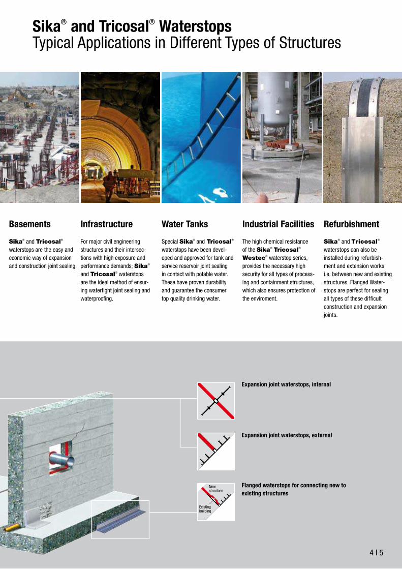
Expansion joint waterstops, external
Flanged waterstops for connecting new to
existing structures
Expansion joint waterstops, internal
4 I 5
Basements Sika® and Tricosal®
waterstops are the easy and
economic way of expansion
and construction joint sealing.
Industrial Facilities
The high chemical resistance
of the Sika® Tricosal®
Westec® waterstop series,
provides the necessary high
security for all types of process-
ing and containment structures,
which also ensures protection of
the enviroment.
Refurbishment
Sika® and Tricosal®
waterstops can also be
installed during refurbish-
ment and extension works
i.e. between new and existing
structures. Flanged Water-
stops are perfect for sealing
all types of these difficult
construction and expansion
joints.
Water Tanks
Special Sika® and Tricosal®
waterstops have been devel-
oped and approved for tank and
service reservoir joint sealing
in contact with potable water.
These have proven durability
and guarantee the consumer
top quality drinking water.
Infrastructure
For major civil engineering
structures and their intersec-
tions with high exposure and
performance demands; Sika®
and Tricosal® waterstops
are the ideal method of ensur-
ing watertight joint sealing and
waterproofing.
Sika® and Tricosal® Waterstops Typical Applications in Different Types of Structures
New structure
Existing building

Types of Joints
Type of Joint Type of Waterstop
Expansion Joints
Expansion joint waterstop, internal
Waterstop for capping joint
Expansion joint waterstop, external
Construction Joints
Construction joint waterstop, internal Construction joint waterstop, external
Special Joints Joint with big width
Expansion joint waterstop with encased centre-bulb, internal
Pressed joint
Expansion joint waterstop with encased centre-bulb, internal
Shrinkage crack joint Sealing element for reduction of cross section, e.g. crack inducer

6 I 7
Waterstop Design and Function
Type of waterstop Design and Function
Expansion joint waterstop, internal
Expansion joint waterstop with
steel plates, internal
Expansion joint waterstop, external
Waterstop for capping joints
Centre bulbSealing ribs
Sealing part Sealing partExpansion part
Anchoring rib Edge key
Steel plate
70
Centre bulb Anchoring rib
Sealing part
70
Sealing partExpansion part
Sealing ribs
Centre bulb Anchoring rips
Sealing part Sealing partExpansion part
Edge key
Protection foil
Nailing plate
Sealing part
Expansion part
Height of loop
Anchoring rib
Height of profile
Nailing plate

Alternative Materials for Waterstops
Physical Properties (standard test specification)
No. Property Tests to DIN NB
1 Tensile strength in N/mm2 53455 ≥10
2 Elongation at break in %
Waterstops for construction
joints53455 ≥200
Waterstops for expansion
joints53455 ≥300
3 Shore-A-Hardness 53505 70±5
Only type Forte 53505 80±5
Material Quality Tests to DIN Joining
technique
PVC-P Not bitumen resistant standard quality welding
Tricomer® Bitumen resistant DIN 18541 welding
ElastomerStandard quality SBR,
other qualities on requestDIN 7865 vulcanisation
TPOThermoplastic Polyolefin of
high flexibility
as Sikaplan® TPO
membraneswelding
Sika® Waterbar PVC-PWidely Tested and Approved
This material has many excellent properties for waterstops and also
allows cost effective solutions. It has been in use with an out-
standing track record for more than 70 years.
Sika® Waterbar PVC-P based waterstops are resistant against
naturally occuring acidic and alkaline ground water, resistant to ageing,
and suitable for totally homogeneous welding off and on site.
The following grades are available:
Standard quality waterstops, not resistant to bitumen
Sika® Waterbar’s connected by welding.(s. pages 46/47)
Introduction
Waterstops are available in different materials and qualitites. The antici-
pated loading, i.e. the water pressure and movement, will determine the
selection of the appropriate material, its quality and design. A securely
closed solution for all of the expansion and construction joints must be
achieved to achieve a watertight structure. Our engineers and techni-
cians will assist you to find the right sealing system solution for your
structure. We have the largest available range of joint sealing and water-
proofing products, including many special jointing solutions. This ensures
customized sealing system solutions for different technical, practical and
economic requirements.
Base colours of Sika® and Tricosal® Waterstops:
Sika® Waterbar PVC-P waterstops:
for construction joints black
for expansion joints yellow
Tricosal® Tricomer® waterstops: black
Tricosal® Elastomer waterstops: black
Sika® Waterbar TPO waterstops: grey

8 I 9
Physical Properties (DIN 18541 Part 2)
No. Property DIN Standard Tricomer
BV
1 Tensile strength in N/mm2 53455 ≥10
2 Elongation at break in % 53455 ≥350
3 Shore-A-Hardness 53505 67±5
4 Tear strength in N/mm2 53507 ≥12
5
Behaviour at low temperatures
(-20 °C),
Elongation at break in N/mm2
53455 ≥200
6 Behaviour after storage
on bitumen (28 days / 70 °C)
Change in %:
Tensile strength
Elongation at break
Modulus of elasticity
53455
53455
53455
≥±20
≥±20
≥±50
Tricosal® Tricomer® Produced in accordance with the requirements of DIN 18541
Tricomer® is a combination of PVC-P and NBR (nitrile butadiene
rubber) compounds. This special polymer was developed and modified
in our laboratories to meet DIN requirements.
The Tricosal® Tricomer® material has now been used success-
fully for nearly 30 years in the secure waterproofing of joints in concrete
structures.
Tricosal® Tricomer® based products have a high elongation at
break, excellent resistance to chemicals and ageing, together with
a constant elasticity similar to rubber elastomers. It is used where
a higher performance of the structure and the joint waterproofing is
required.
The Tricosal® Tricomer® waterstops are connected by thermo-
plastic welding which makes them easy and practical to use. (s. pages
46/47)
Tricosal® Tricomer® waterstops are produced in the grade BV
(bitumen resistant according to DIN 18541).
Tricosal® ElastomerProduced in accordance with the requirements of DIN 7865
An Elastomer is an artifical rubber compound based on long chain
polymers, cross linked to control their shape and deformation / move-
ment under stress possibilities, by vulcanising them.
Their production process is non-reversible, therefore a special jointing
process is also required.
Tricosal® Elastomer waterstops (internal and external types) are
used for structures with large potential joint movement, frequent load
changes and/ or low temperature exposure, as well as for resistance to
very high water pressures.
The visible surface of the Tricosal® Elastomer FAE capping joint
profiles have a grey cover plate. The profiles are manufactured from a
UV-stable elastomer compound to suit this type of application.
Tricosal® Elastomer waterstops are connected by vulcanising. (see
pages 48/49)
Physical Properties (DIN 7865 Part 2)
No. Property DIN Standard Performance
level
1 Tensile Strength in N/mm2 53504 ≥10
2 Elongation at break in % 53504 ≥380
3 Shore-A-Hardness 53505 62±5
4 Tear Strength in N/mm2 53507 ≥8
5
Behaviour at low tempera-
tures (-20 °C),
Shore-A-Hardness
53505 ≥90
6Dimensional stability when
exposed to hot bitumen7865
No change in
shape
7 Metal adhesion 7865
Structural
fracture in the
Elastomer

Selection of the Correct Waterstops –Sika® Waterbar
Introduction
Waterstops are used for the waterproof sealing of construction and
expansion joints against water penetration from percolating ground
water and water under hydrostatic pressure, as well as for surface /
end capping joints.
Joint waterstops in combination with watertight concrete construction
techniques must ensure the watertightness of the whole structure.
There are standard international or national design standards and
requirements which must always be complied with and maintained.
The correct selection of the most suitable expansion and construc-
tion joint waterstops is determined primarily by the anticipated water
pressure, joint movement requirements and the exposure of the joint
waterstop.
The maximum design water pressure resistance for each waterstop is
given in the following tables; these are indicative figures based on our
experience and subject, to the correct embedding of the waterstop into
the concrete structure. The nominal width of the joints should normally
be 20 mm to 30 mm, dependent on the specific waterstop and profile
to be used.

10 I 11
Waterstops for Expansion Joints Water pressure
[m]
Movement [mm]
Expansion Shear
Internal:
Sika® Waterbar 0-20 L
Sika® Waterbar 0-25 L
Sika® Waterbar 0-32 L
5
5
10
10
15
10
10
5
10
5
5
10
5
10
5
Waterstops for Expansion Joints Water pressure
[m]
Movement [mm]
Expansion Shear
Internal:
Sika® Waterbar DK-19
Sika® Waterbar DK-24
Sika® Waterbar 0-15
Sika® Waterbar 0-20
Sika® Waterbar 0-22
Sika® Waterbar 0-25
Sika® Waterbar 0-32
5
5
15
2
5
10
5
15
10
20
10
10
10
10
10
10
10
10
10
10
10
15
10
5
10
10
15
10
15
5
External:
Sika® Waterbar DR-21
Sika® Waterbar DR-26
Sika® Waterbar DR-29
Sika® Waterbar DR-32
2
5
8
10
10
10
10
10
5
5
10
10
Waterstops for Construction Joints Water pressure
[m]
Movement
[mm]
Internal:
Sika® Waterbar AK-19
Sika® Waterbar AK-24
Sika® Waterbar V-15
Sika® Waterbar V-20
Sika® Waterbar V-24
Sika® Waterbar V-32
5
15
5
12
15
25
no anticipated
movement
~ 3 mm
External:
Sika® Waterbar AR-20
Sika® Waterbar AR-25
Sika® Waterbar AR-28
Sika® Waterbar AR-31
Sika® Waterbar AR-50
2
5
8
10
25
no anticipated
movement
~ 3 mm

Waterstop Selection in Accordance with DIN V 18197Tricosal® Waterstops
FM 250 250FM 300 300FM 350 350FM 400 400FM 500 500FMS 350 350FMS 400 400FMS 500 500
250300350400500350400500
AM 250 * A 250AM 350 * A 350AM 500 * A 500
For high water pressures Ws > 14m, e.g. for dam constructions,there are references and experiences with higher dimension waterstops.
* free of choice * free of choice
Each additional Millimeter of waterstop thickness increases the permitted water pressure by 10%, max. by 50% (see e.g. D 320/9)
check in single case
check in single case
check in single case
check in single case
resulting movement vr [mm], vy ≤ wnom
wat
er p
ress
ure
Ws
[0,1
bar
= m
wat
er h
ead]
DA 240 240320500
4,54,5
4,54,5
* AA 240DA 320 * AA 320DA 500 * AA 500
D 240 240 ≥ 250D 320 320 ≥ 300D 500 500 ≥ 500D 250/6~/9 250 ≥ 250D 320/6~/9 320 ≥ 300
A 240A 320A 500A 240A 320resulting movement vr [mm], vy ≤ wnom resulting movement vr [mm], vy wnom
resulting movement vr [mm], vy wnom
total width[mm]
thicknessof waterstop
[mm]
Tricomer®
DIN 18541recommendedthickness of
construction [mm]
compatibleconstruction
joint waterstop
total width[mm]
thicknessof waterstop
[mm]
Tricomer®
DIN 18541compatible
construction joint waterstop
total width[mm]
thicknessof waterstop
[mm]
ElastomerDIN 7865
compatibleconstruction
joint waterstop
total width[mm]
thicknessof waterstop
[mm]
ElastomerDIN 7865
compatibleconstruction
joint waterstop
D expansion joint waterstop, internal FM expansion joint waterstop, internal
FMS expansion joint waterstop, with steel plates, internal
DA expansion joint waterstop, external AM expansion joint waterstop, external
wat
er p
ress
ure
Ws
[0,1
bar
= m
wat
er h
ead]
wat
er p
ress
ure
Ws
[0,1
bar
= m
wat
er h
ead]
wat
er p
ress
ure
Ws
[0,1
bar
= m
wat
er h
ead]
recommendedthickness of
construction [mm]
456
6/96/9
recommendedthickness of
construction [mm]
recommendedthickness of
construction [mm]
910121213101112
F 200F 200F 250F 250F 300FS 310FS 310FS 310
250350500
666
Tricosal® Tricomer® waterstops are produced according to DIN 18541.
The Tricosal® Tricomer® based waterstops generally have a higher performance than PVC-P waterstops.
If the waterstop specification is to be in accordance with DIN V 18197, then the following product selection tables should be used:
Ground water level:
The highest anticipated ground water or flood level,
or for tanks the maximum filling level
The resulting load and movement vr:
vr = resulting movement vx = deformation in x-axis
vy = deformation in y-axis vz = deformation in z-axis
Still water level
wat
er p
ress
ure

12 I 13
FM 250 250FM 300 300FM 350 350FM 400 400FM 500 500FMS 350 350FMS 400 400FMS 500 500
250300350400500350400500
AM 250 * A 250AM 350 * A 350AM 500 * A 500
For high water pressures Ws > 14m, e.g. for dam constructions,there are references and experiences with higher dimension waterstops.
* free of choice * free of choice
Each additional Millimeter of waterstop thickness increases the permitted water pressure by 10%, max. by 50% (see e.g. D 320/9)
check in single case
check in single case
check in single case
check in single case
resulting movement vr [mm], vy wnom
wat
er p
ress
ure
Ws
[0,1
bar
= m
wat
er h
ead]
DA 240 240320500
4,54,5
4,54,5
* AA 240DA 320 * AA 320DA 500 * AA 500
D 240 240 250D 320 320 300D 500 500 500D 250/6~/9 250 250D 320/6~/9 320 300
A 240A 320A 500A 240A 320resulting movement vr [mm], vy wnom resulting movement vr [mm], vy ≤ wnom
resulting movement vr [mm], vy ≤ wnom
total width[mm]
thicknessof waterstop
[mm]
Tricomer®
DIN 18541recommendedthickness of
construction [mm]
compatibleconstruction
joint waterstop
total width[mm]
thicknessof waterstop
[mm]
Tricomer®
DIN 18541compatible
construction joint waterstop
total width[mm]
thicknessof waterstop
[mm]
ElastomerDIN 7865
compatibleconstruction
joint waterstop
total width[mm]
thicknessof waterstop
[mm]
ElastomerDIN 7865
compatibleconstruction
joint waterstop
D expansion joint waterstop, internal FM expansion joint waterstop, internal
FMS expansion joint waterstop, with steel plates, internal
DA expansion joint waterstop, external AM expansion joint waterstop, external
wat
er p
ress
ure
Ws
[0,1
bar
= m
wat
er h
ead]
wat
er p
ress
ure
Ws
[0,1
bar
= m
wat
er h
ead]
wat
er p
ress
ure
Ws
[0,1
bar
= m
wat
er h
ead]
recommendedthickness of
construction [mm]
456
6/96/9
recommendedthickness of
construction [mm]
recommendedthickness of
construction [mm]
910121213101112
F 200F 200F 250F 250F 300FS 310FS 310FS 310
250350500
666
These selection graphs are based on the initial joint width (wnom)
– wnom 20 – 30 mm for internal expansion joint waterstops and
waterstops for capping joints
– wnom 20 mm for external expansion joint waterstops following DIN V 18197: tickness of structure d>= 30 cm for waterstop D 320
Concrete cover:
anchorage depth t <= concrete cover ü
thickness of structure d >= total width of waterstop a
Tricosal® Elastomer waterstops are produced according to DIN 7865.
Tricosal® Elastomer waterstops generally have an even higher performance than the Tricosal® Tricomer® waterstops.
If the waterstop specification is to be in accordance with DIN V 18197, then the following product selection tables should to be used:
Waterstop Design/ type Width of joint w nom
FM, FMS/DA20 – 30 mm
20 mm
FAE/FA
AM, DAwidth of waterstop a
concrete coverthickness of structured
anchoringdepth t
ü

Construction Joint Waterstops – Internal
AK
V
Tricomer®
DIN 18541
SAP
Art. Nr.
Total
width
Width of
expansion
part
Thickness
of expan-
sion part
Width of
sealing
part
Height of
anchoring
ribs
a b c s f
Tricosal® A 190 Tricomer®
Tricosal® A 240 Tricomer®
Tricosal® A 320 Tricomer®
176001
176002
176003
190
240
320
75
85
110
3.5
4
5
57.5
77.5
105
15
15
15
PVC-P SAP
Art. Nr.
Total
width
Width of
expansion
part
Thickness
of expan-
sion part
Width of
sealing
part
Height of
anchoring
ribs
a b c s f
Sika® Waterbar AK 19
Sika® Waterbar AK 24
Sika® Waterbar V -15
Sika® Waterbar V -20
Sika® Waterbar V -24
Sika® Waterbar V -32
53283
53284
5559
5557
5556
8287
190
240
150
200
240
320
30
30
60
68
80
113
3
4
5
7
4
5,5
80
105
45
66
80
113
16
16
12
13
15
15
PVC-P SAP
Art. Nr.
Total
width
Width of
expansion
part
Thickness
of expan-
sion part
Width of
sealing
part
Height of
anchoring
ribs
a b c s f
Sika® Waterbar SI 80
Sika® Waterbar SI 120
175886
175887
80
120
–
–
–
–
–
–
–
–
Elastomer (Rubber)
DIN 7865
SAP
Art. Nr.
Total
width
Width of
expansion
part
Thickness
of expan-
sion part
Width of
sealing
part
Height of
anchoring
ribs
a b c s f
Tricosal® F 200 Elastomer
Tricosal® F 250 Elastomer
Tricosal® F 300 Elastomer
175754
175755
175756
200
250
300
75
80
100
7
8
8
62.5
85
100
32
32
32

14 I 15
Construction Joint Waterstops – InternalSpecial Types
PVC-P SAP
Art. Nr.
Total
width
Width of
expansion
part
Thickness
of expan-
sion part
Width of
sealing
part
Height of
anchoring
ribs
a b c s f
Sika® Waterbar Forte 19
Sika® Waterbar Forte 24
Sika® Waterbar Forte 32
8750
53335
53337
190
240
320
–
–
–
3
3
3,5
–
–
–
10
10
11
Construction joint waterstops, externally reinforced with rigid PVC bars
PVC-P SAP
Art. Nr.
Total
width
Width of
expansion
part
Thickness
of expan-
sion part
Width of
sealing
part
Height of
anchoring
ribs
a b c s f
Sika® Waterbar Fix 20
Sika® Waterbar Fix 24
Sika® Waterbar Fix 32
176343
176344
176345
200
240
320
70
80
100
3,5
3,5
4
65
80
110
15
15
15
Construction joint waterstops, with internal steel bar reinforcement
Elastomer
DIN 7865
SAP
Art. Nr.
Total
width
Width of
expansion
part
Thickness
of expan-
sion part
Width of
sealing
part
Height of
anchoring
ribs
a b c s f
Tricosal® FS 310 Elastomer 175788 310 80 8 115 22

Construction Joint Waterstops – External
Tricomer®
DIN 18541
SAP
Art. Nr.
Total
width
Width of
expansion
part
Web
thickness
Sealing ribs
Height Number
a b c f N
Tricosal® AA 240 Tricomer®
Tricosal® AA 320 Tricomer®
176049
176051
240
330
90
104
4.5
4.5
20
20
4
6
Other geometries available on request
PVC-P SAP
Art. Nr.
Total
width
Width of
expansion
part
Web
thickness
Sealing ribs
Height Number
a b c f N
Sika® Waterbar AR-20
Sika® Waterbar AR-25
Sika® Waterbar AR-28
Sika® Waterbar AR-31
Sika® Waterbar AR-50
5561
5560
5563
5562
53308
200
250
280
310
500
80
105
80
90
50
3.5
3.5
3,5
4
3,5
19,5
19,5
19,5
20
19,6
4
4
6
6
8
Elastomer (Rubber)
DIN 7865
SAP
Art. Nr.
Total
width
Width of
expansion
part
Web
thickness
Sealing ribs
Height Number
a b c f N
Tricosal® A 250 Elastomer
Tricosal® A 350 Elastomer
Tricosal® A 500 Elastomer
175739
175741
175743
250
350
500
100
100
150
6
6
6
31
31
31
4
6
8

16 I 17
Construction Joint Waterstops – ExternalSpecial Types
f
f
c
c
b1
b1
b2
a1
a1
a2
a2
Tricomer®
DIN 18541 Part 2
SAP
Art. Nr.
Total
width
Width of
expansion
part
Web
thickness
Sealing ribs
Height Number
a1/a2 b1/b2 c f N
Tricosal® AA 240 edge A Tricomer®
Tricosal® AA 240 edge W Tricomer®
Tricosal® AA 320 edge A Tricomer®
Tricosal® AA 320 edge W Tricomer®
176058
176059
176061
176062
136/120
136/120
181/165
181/165
61/45
61/45
68/52
68/52
4.5
4.5
4.5
4.5
30
30
30
30
4
4
6
6
A = external anchors
W = internal/external anchors
PVC-P SAP
Art. Nr.
Total
width
Width of
expansion
part
Web
thickness
Sealing ribs
Height Number
a b c f N
Sika® Waterbar AR-20
Sika® Waterbar AR-25
Sika® Waterbar AR-31
Sika® Waterbar AR-40*
Sika® Waterbar AR-50*
Sika® Waterbar AR-60*
5561
5560
5562
61760
107275
61929
200
250
310
400
500
600
80
105
90
86
120
220
3,5
3,5
4
4
4
4
19,5
19,5
20
30
34
34
4
4
6
6
6
6
Waterstops in combination with membrane system: there is a full compatibility guaranty through equal material base of waterstop and membrane.* with injection channels
TPO SAP
Art. Nr.
Total
width
Width of
expansion
part
Web
thickness
Sealing ribs
Height Number
a b c f N
Sika® Waterbar WT AF 130
Sika® Waterbar WT AF 210
Sika® Waterbar WT AF 240
Sika® Waterbar WT AF 310
Sika® Waterbar WT AF 400
Sika® Waterbar WT AF 500
Sika® Waterbar WT AF 600 Inject*
110765
176232
176233
176234
176236
176227
113624
130
210
240
310
400
500
600
–
45
110
110
110
170
215
4
4
4
4
4
4,5
4
30
30
30
30
30
30
34
3
3
4
4
6
6
6
Waterstops in combination with membrane system: there is a full compatibility guaranty through equal material base of waterstop and membrane.* with injection channels

Expansion Joint Waterstops – Internal
Tricomer®
DIN 18541
SAP
Art. Nr.
Total
width
Width
of
expansion
part
Thickness
of
expansion
part
Width
of
sealing
part
Width
of
centre
bulb
Height
of
anchoring
ribs
a b c s k f
Tricosal® D 190 Tricomer®
Tricosal® D 240 Tricomer®
Tricosal® D 320 Tricomer®
Tricosal® D 500 Tricomer®
175987
175988
175989
175990
190
240
320
500
75
85
110
155
4
4.5
5.5
6.5
58
78
105
173
10
20
20
20
15
15
15
20
Other geometries available on request
Elastomer (Rubber)
DIN 7865
SAP
Art. Nr.
Total
width
Width
of
expansion
part
Thickness
of
expansion
part
Width
of
sealing
part
Width
of
centre
bulb
Height
of
anchoring
ribs
a b c s k f
Tricosal® FM 200 Elastomer
Tricosal® FM 250 Elastomer
Tricosal® FM 300 Elastomer
Tricosal® FM 350 Elastomer
Tricosal® FM 400 Elastomer
Tricosal® FM 500 Elastomer
175766
175767
175768
175769
175770
175771
200
250
300
350
400
500
110
125
175
180
230
300
9
9
10
12
12
13
45
63
63
85
85
100
20
20
20
20
20
20
32
32
32
38
38
38
Expansion joint waterstop with encased centre bulb
Tricosal® FM 350 HS Elastomer 175800 350 180 12 85 35 38
FM ...
HS
FM
PVC-P SAP
Art. Nr.
Total
width
Width
of
expansion
part
Thickness
of
expansion
part
Width
of
sealing
part
Width
of
centre
bulb
Height
of
anchoring
ribs
a b c s k f
Sika® Waterbar DK-19
Sika® Waterbar DK-24
Sika® Waterbar 0-15
Sika® Waterbar 0-20
Sika® Waterbar 0-22
Sika® Waterbar 0-25
Sika® Waterbar 0-32
53319
53501
5704
5546
5705
5545
5542
190
240
150
200
220
250
320
94
95
62
70
88
108
114
3
3
2,5
3
3
5
5
48
73
44
65
66
70,5
103
15
20
20
22
24
24
30
15
15
8
9
8,5
8,5
10
PVC-P light SAP
Art. Nr.
Total
width
Width
of
expansion
part
Thickness
of
expansion
part
Width
of
sealing
part
Width
of
centre
bulb
Height
of
anchoring
ribs
a b c s k f
Sika® Waterbar 0-20 L
Sika® Waterbar 0-25 L
Sika® Waterbar 0-32 L
5554
5548
5555
200
250
320
77,5
99
117
3,5
2
2,5
61
75,5
101,5
20
25
25
8
9
10

18 I 19
Expansion Joint Waterstops – InternalSpecial Types
Tricomer®
DIN18541, part 2
SAP
Art. Nr.
Total
width
Width
of
expansion
part
Thickness
of
expansion
part
Width
of
sealing
part
Width
of
centre
bulb
Height
of
anchoring
ribs
a b c s k f
Expansion joint waterstops, thick sections
Tricosal® D 260 TS Tricomer®
Tricosal® D 350 TS Tricomer®
Tricosal® D 400 TS Tricomer®
175997
175998
175999
260
345
395
125
175
195
9*
11*
11*
68
85
103
20
20
20
24
27
29
* at the centre bulb
Elastomer (Rubber)
DIN 7865
SAP
Art. Nr.
Total
width
Width
of
expansion
part
Thickness
of
expansion
part
Width
of
sealing
part
Width
of
centre
bulb
Height
of
anchoring
ribs
a b c s k f
Expansion joint waterstops with steel plates
Tricosal® FMS 350 Elastomer
Tricosal® FMS 400 Elastomer
Tricosal® FMS 500 Elastomer
175798
175772
175773
350
400
500
120
170
230
10
11
12
45
45
65
20
20
20
32
32
32
DIN 7865 Part 2 Expansion joint waterstops with steel plates and pre-formed, encased centre-bulb
Tricosal® FMS 400 HS Elastomer
Tricosal® FMS 500 HS Elastomer
175776
175816
400
500
170
230
11
12
45
65
35
35
32
32
The profile range FMS … HS is especially suitable for wide joints and contraction joints (joints not allowing
expansion), but also for normal expansion joints when subsidence and seismic movements are expected.
For further details see separate leaflet.
* width of Elastomer (rubber) sealing part without steel plates

Expansion Joint Waterstops – External
Tricomer®
DIN 18541
SAP
Art. Nr.
Total
width
Width of
expansion
part
Web
thickness
Sealing ribs
Height Number
a b c f N
Tricosal® DA 240 Tricomer®
Tricosal® DA 240 / 2 Tricomer®
Tricosal® DA 320 Tricomer®
Tricosal® DA 320 / 2 Tricomer®
Tricosal® DA 500 Tricomer®
Tricosal® DA 500 / 3 Tricomer®
176024
176025
176027
176028
176030
176032
240
240
330
330
500
500
90
90
104
104
124
124
4.5
4.5
4.5
4.5
4.5
5
20
25
20
25
20
35
4
4
6
6
8
8
Other geometries available on request
Elastomer (Rubber)
DIN 7865
SAP
Art. Nr.
Total
width
Width of
expansion
part
Web
thickness
Sealing ribs
Height Number
a b c f N
Tricosal® AM 250 Elastomer
Tricosal® AM 350 Elastomer
Tricosal® AM 500 Elastomer
175744
175746
174750
250
350
500
100
100
150
6
6
6
31
31
31
4
6
8
PVC-P SAP
Art. Nr.
Total
width
Width of
expansion
part
Web
thickness
Sealing ribs
Height Number
a b c f N
Sika® Waterbar DR-21
Sika® Waterbar DR-26
Sika® Waterbar DR-29
Sika® Waterbar DR-32
5549
3661
1408
5544
210
260
290
320
90
110
90
100
3.5
3.5
3,5
4
19,5
19,5
19,5
22
4
4
6
6

20 I 21
Expansion Joint Waterstops – ExternalAngled Profiles and Special Types of Waterstop
b2
b2a2
c
c
f
f
a2
a1
a1
b1
b1
Tricomer®
DIN 18541 Part 2
SAP
Art. Nr.
Total
width
Width of
expansion
part
Web
thickness
Sealing ribs
Height Number
a1/a2 b1/b2 c f N
Tricosal® DA 240 edge A Tricomer®
Tricosal® DA 240 edge W Tricomer®
Tricosal® DA 320 edge A Tricomer®
Tricosal® DA 320 edge W Tricomer®
176034
176035
176037
176038
146/131
146/131
192/176
192/176
71/55
71/55
79/63
79/63
4.5
4.5
4.5
4.5
30
30
30
30
4
4
6
6
A = external anchors
W = internal/external anchors
TPO SAP
Art. Nr.
Total
width
Width of
expansion
part
Web
thickness
Sealing ribs
Height Number
a b c f N
Sika® Waterbar WT DF 400 176392 400 20/12 4 30 4
Waterstop in combination with membrane systems:
There is full compatibility guaranteed using the same material basis for the waterstops and the membrane
PVC-P SAP
Art. Nr.
Total
width
Width of
expansion
part
Web
thickness
Sealing ribs
Height Number
a b c f N
Sika® Waterbar DR-32
Sika® Waterbar DR-50*
5544
107278
320
500
100
120
4
4
22
34
6
6
Waterstop in combination with membrane systems:
There is full compatibility guaranteed using the same material basis for the waterstops and the membrane
* with injection channels

Waterstops for Capping JointsWith Grey Coloured Cover Parts
bc
a
fk
Tricomer®
DIN 18541
SAP
Art. Nr.
Total
width
Height
of
loop
Width
of joint
cover
part
Thick-
ness of
cover
plate
Joint
width
Sealing ribs
HeightNum-
ber
a l b c k f N
Tricosal® FA 50/3/2 Tricomer®
Tricosal® FA 90/3/2 Tricomer®
Tricosal® FA 130/3/2
Tricomer®
176073
176077
176079
50
95
140
35
35
35
30
30
30
5.5
5.5
5.5
20
20
20
25
25
25
2
4
6
Other dimensions available on request
PVC-P SAP
Art. Nr.
Total
width
Height
of
loop
Width
of joint
cover
part
Thick-
ness of
cover
plate
Joint
width
Sealing ribs
Height Number
a l b c k f N
Sika® Waterbar FF 5/3
Sika® Waterbar FF 10/3
176379
176384
50
95
35
35
30
30
5
5
20
20
25
25
2
4
Other dimensions available on request
Elastomer (Rubber)
DIN 7865 Part 2
SAP
Art. Nr.
Total
width
Height
of
loop
Width
of joint
cover
part
Thick-
ness of
cover
plate
Joint
width
Sealing ribs
Height Number
a l b c k f N
Tricosal® FAE 50
Elastomer
Tricosal® FAE 100
Elastomer
175759
175758
55
100
35
35
30
30
5
5
20
20
30
30
2
4
Other dimensions available on request

22 I 23
Waterstops for Capping JointsSpacers and Joint Formers
g
e
bk
Spacers and Joint Formers
For capping joint waterstops
SAP
Art. Nr.
Total
width
Visible
width
Height of
chamber
Width
of
spacer
Length
k b e g
Tricosal® TFL 20
Tricosal® TFL 30
Tricosal® TFL 40
Tricosal® TFL 50
177133
177134
177135
177136
10
20
30
40
20
30
40
50
15
15
15
15
50
60
70
80
1000
1000
1000
1000
The spacers and joint formers are adjusted to the width of the joint cover parts of the capping joint profile.
The size “k” of the spacers corresponds to the size “b” of the profiles.

Compression SealsUV-Light and Weathering Resistant
H
B
K
C
B
H
C
K
B1
HC
K
B2
Tricomer®, grey
DIN 18541 Part 2
SAP
Art. Nr.
Joint
width
Width of
profile
Height of
profile
Thickness
K B H C
Tricosal® MK 15 Tricomer®
Tricosal® MK 20 Tricomer®
Tricosal® MK 30 Tricomer®
176212
176213
176214
13-17
20-25
30-35
20
30
40
22
30
40
2
3
4
Special profiles and colours on request
Depending on site requirements, installation with a stop plate for height adjustment or bondet to joint
edges with Sikaflex® 11 FC elastic adhesive.
Tricomer®, grey
DIN 18541 Part 2
SAP
Art. Nr.
Joint
width
Width of
profile
Height of
profile
Thickness
K B H C
Tricosal® F 10 Tricomer®
Tricosal® F 20 Tricomer®
Tricosal® F 25 Tricomer®
Tricosal® F 30 Tricomer®
Tricosal® F 25/66 Tricomer®
Tricosal® F 20/80* Tricomer®
176215
176216
176217
176218
176219
176221
10 – 13
13 – 20
21 – 25
22 – 35
20 – 28
15 – 20
15
30
35
50
66
80
35
30
35
45
43
50
6
4
5
5.5
14**
5
* with wide cover plate for overlapping the joint flanges by approx. 15 mm
** multi hollow chambers, see MK types
Special profiles and colours on request
Tricomer®, grey
DIN 18541 part 2
SAP
Art. Nr.
Joint
width
Width of
profile
Height of
profile
Thickness
K B H C
Tricosal® F 20 edge Tricomer® 176220 17 – 23 21/23 34 5
Special profiles and colours on request

24 I 25
Special Waterstopping Profiles For Hydraulic Civil Engineering Structures
b
f
c
A...TS
D...TS
a
Elastomer SAP
Art. Nr.
Total
width
Width of
expansion
part
Thickness
of expansion
part
Width of
centre bulb
Thickness of
end bulb
a b c1/c2 k f
Expansion joint waterstop with steel plates
Tricosal FMS 450 S
Elastomer175817 450 186 11/14 32 35
Materials as DIN 7865:
SBR Styrene Butadiene Rubber
EPDM Ethylene Propylene Diene Rubber
CR Chloroprene Rubber (available on special
request)
Joint width:
30 mm standard, with a centre bulb 32 mm wide
(other joint widths such as 40 and 50 mm available
on special request)
e.g. for use in joints between sections or segments in
hydraulic structures
Tricomer® SAP
Art. Nr.
Total
width
Width of
expansion part
Thickness of
expansion part
Width of
centre bulb
Height of
anchoring ribs
a b c1/c2 k f
Expansion joint waterstops, thick sections
Tricosal® D 260 TS Tricomer®
Tricosal® D 350 TS Tricomer®
Tricosal® D 400 TS Tricomer®
175997
175998
175999
260
350
400
125
175
195
9 *
11*
11*
20
20
20
24
27
29
Construction joint waterstops, thick sections
Tricosal® A 260 TS Tricomer®
Tricosal® A 320 TS Tricomer®
176006
176007
260
320
113
165
9
10
--
--
24
26
Waterproofing of block joint in concrete dams Additional security by combination with SikaFuko®
injection hose system
Elastomer SAP
Art. Nr.
Total
width
Width of
expansion
part
Thickness
of expansion
part
Width of
centre bulb
Thickness of
end bulb
a b c1/c2 k f
Omega profiles for subsequent joint waterproofing
Fields of application:
Flood protection wall
Connection joints in channels
Immersed tunnel elements
Hydraulic gates / navigation locks
Special solutions (e.g. connections for bored rail
tunnels entry into railway stations))
Further options with Elastomer waterstops, e.g. FMS 350, FMS 400, FMS 400 HS* web thickness of expansion part, measured next to the centre bulb

Potable Water StructuresWaterstops Approved for Drinking Water
Introduction
For potable (drinking) water to be collected and held in service res-
ervoirs without water loss or contamination, watertight construction
and joint sealing which is efficient, food-safe, harmless to health and
durable is needed.
Given the rise in environmental awareness, public and private custom-
ers and designers are demanding and specifying higher ecological
standards to be used for the waterproofing and sealing materials.
All of the products to be used should comply with the strict internation-
al and national regulations and approvals covering materials in contact
with drinking water.
Tricosal® waterstops for use in contact with potable water have
proven durability and guarantee top quality drinking water, with their
functionality being maintained for many years.
With our extensive range of many other different types of products that
are also approved for contact with drinking water, Sika has the right
sealing and waterproofing solution for every project, including concrete
and steel protection for contact with aggressive soft water.
Fields of Application
Drinking water tanks and reservoirs
Dams, river and canal structures
Food processing industry
All types of wet areas
All types of structure where micro-organism and pollutants must be kept
under control

26 I 27
Tricosal waterstops for use in potable water structures are material compatible
with Sikaplan® WT 4220 waterproof sheet membranes that are also approved
for use in contact with drinking water.
TPO-Waterstops SAP
Art. Nr.
Total
width
Width
of
expansion
part
Thickness
of
expansion
part
Width
of
sealing
part
Width
of
centre
bulb
Height
of
anchoring
ribs
a b c s k f
Waterstop for expansion joint
Tricosal® D 320/5 DW
Waterstop for Construction joint
Tricosal® A 240/4 DW
176401
176095
320
240
110
85
5
3,5
105
77,5
20
–
15
15
Drinking Water Quality
According to the requirements of the German specifications DVGW, worksheet W 270, microbial
growth can only take place to a very low limit and according to the German KTW recommendations,
no harmful contents shall enter into the drinking water. Similar regulations apply in most countries.
The Tricosal® waterstop range for use in drinking water structures is tested according to the
German DVGW and KTW specifications and fulfils all of the performance requirements.
They are also approved by the Hygienic Institute in Gelsenkirchen for use in contact with food
stuffs and drinking water. Tricosal® waterstops are made out high quality TPO material and have
excellent physical performance properties and can be connected by the usual waterstop welding
technology. Handling and installation on site are therefore the same as for general thermoplastic
PVC or Tricomer® waterstops.
Tricosal® D 320/5 DW
Tricosal® A 240/4 DW
Technical Data
> 600% Elongation at break
> 15 N/mm2 Tensile strength
Weldable

Flanged Retrofit Joint Seals should be installed by Professional
Applicators to ensure watertightness in the longterm even in
extremely exposed conditions and with high joint movements.
Flanged Retrofit Joint Sealing Waterstops
Introduction
Flanged retrofitted joint seals for waterproofing joints connecting ‘new
to existing structures’ are typically one side flanged and one side
embedded in new concrete.
In addition flanged joint seals can also be used for retrofit waterproof-
ing of existing joints i.e. both sides fixed to the existing concrete; or for
sealing joints between separate sections of bridge superstructures for
example.
There is a wide range of flanged profiles available for use in most
difficult applications and highest loads, allowing secure waterproofing
even in extreme exposed conditions.
These factory made waterstopping systems can also be used for loose
flange seals or for combinations of loose and fixed flange joint sealing.
28 I 29
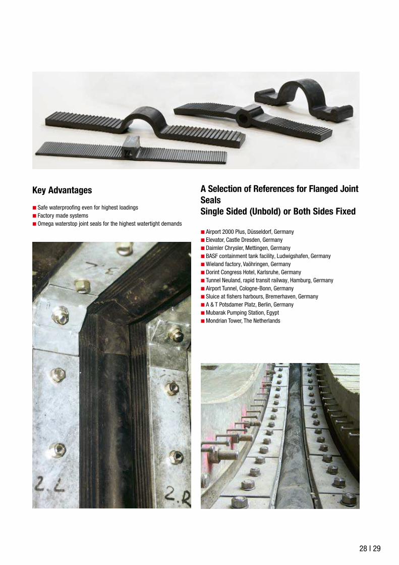
Key Advantages
Safe waterproofing even for highest loadings
Factory made systems
Omega waterstop joint seals for the highest watertight demands
A Selection of References for Flanged Joint
Seals
Single Sided (Unbold) or Both Sides Fixed
Airport 2000 Plus, Düsseldorf, Germany
Elevator, Castle Dresden, Germany
Daimler Chrysler, Mettingen, Germany
BASF containment tank facility, Ludwigshafen, Germany
Wieland factory, Vaöhringen, Germany
Dorint Congress Hotel, Karlsruhe, Germany
Tunnel Neuland, rapid transit railway, Hamburg, Germany
Airport Tunnel, Cologne-Bonn, Germany
Sluice at fishers harbours, Bremerhaven, Germany
A & T Potsdamer Platz, Berlin, Germany
Mubarak Pumping Station, Egypt
Mondrian Tower, The Netherlands
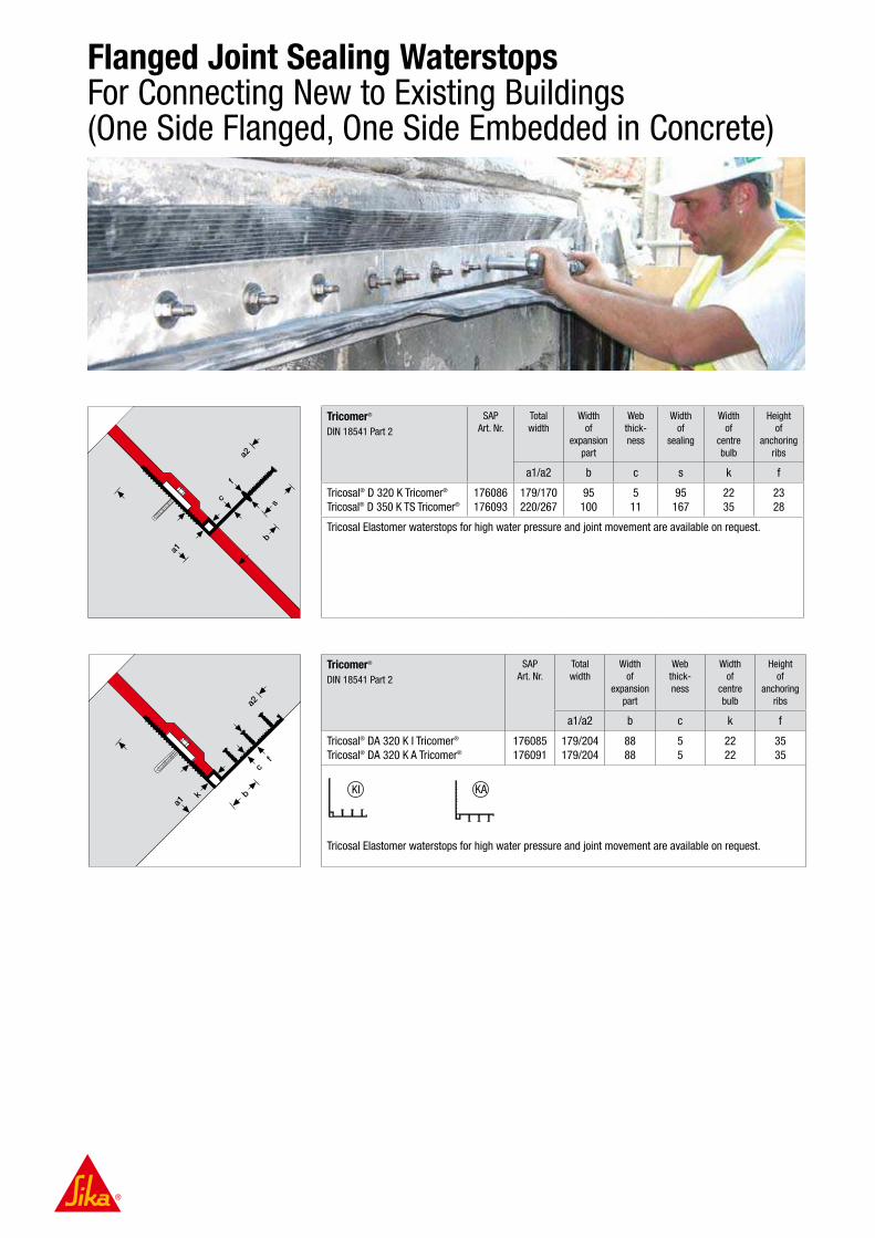
Flanged Joint Sealing Waterstops For Connecting New to Existing Buildings (One Side Flanged, One Side Embedded in Concrete)
c
k b
f
a1
a2
s
c
k b
f
a1
a2
Tricomer®
DIN 18541 Part 2
SAP
Art. Nr.
Total
width
Width
of
expansion
part
Web
thick-
ness
Width
of
sealing
Width
of
centre
bulb
Height
of
anchoring
ribs
a1/a2 b c s k f
Tricosal® D 320 K Tricomer®
Tricosal® D 350 K TS Tricomer®
176086
176093
179/170
220/267
95
100
5
11
95
167
22
35
23
28
Tricosal Elastomer waterstops for high water pressure and joint movement are available on request.
Tricomer®
DIN 18541 Part 2
SAP
Art. Nr.
Total
width
Width
of
expansion
part
Web
thick-
ness
Width
of
centre
bulb
Height
of
anchoring
ribs
a1/a2 b c k f
Tricosal® DA 320 K I Tricomer®
Tricosal® DA 320 K A Tricomer®
176085
176091
179/204
179/204
88
88
5
5
22
22
35
35
Tricosal Elastomer waterstops for high water pressure and joint movement are available on request.
KI KA

30 I 31
ac
k
f
KSP Protection Profile
for one-sided flanging constructions
SAP
Art. Nr.
Height Width
of
chamber
Joint width Length
h b k
Tricosal® KSP 230 177158 240 65 50 1500
KSP provides space for joint movements in
one-sided fixed flanged joint seals
Accessories for Loose Flange Joint Seals
Basic details, additional dimensions on request
Waterstopping-flanged profile, see pages 28 – 32
Raw rubber sealing strip
Sizes in mm: 50 × 4, 80 × 4, 100 × 4, 120 × 4
Metal flange (galvanised or stainless steel)
Sizes in mm: 40 × 6, 80 × 8, 80 × 10, 100 × 10, 100 × 12, 120 × 10, 120 × 12
Distance of holes e = 150 mm, in case of size 40 × 6 : e = 200 mm
90° Internal and external edges in galvanized or stainless steel quality: 80 × 10, 100 × 10
Chemical anchor
with anchor bolt, washer and nut in galvanized or stainless steel quality
M 10 × 115 for metal flange 40 × 6
M 12 × 160 for metal flange 80 × 8
M 16 × 190 for metal flange 80 × 10, 100 × 8/10/12
M 20 × 260 for metal flange 120 × 10/12
Patching mortar for surface repair / making good
Protection profile KSP 230
Tricomer®
DIN 18541 Part 2
SAP
Art. Nr.
Total
width
Web
thickness
Width
of
centre
bulb
Height
of
sealing
ribs
a c k f
Tricosal® DA 320 KF Tricomer® 176087 320 5 20 35
Tricosal Elastomer waterstops for high water pressure and joint movement are available on request.
New structure
Existing building
Fixing strip
Movement chamber

Retrofit Waterproofing of Existing Joints With Flanged Joint Sealing Waterstops
Tricomer®
DIN 18541 Part 2
SAP
Art. Nr.
Total
width
Web
thickness
a b
Tricosal® FP 300 Tricomer® 176089 300 5
Tricosal Elastomer material, particularly resistant to weathering and UV-light
Additional dimensions on request
Tricomer®
DIN 18541 Part 2
SAP
Art. Nr.
Total
width
Width of expansion
part
Webthickness
Widthof centre
bulb
Heightof centre
bulb
a b c k f
Tricosal® LF 320 Tricomer® 176090 320 – 5 20 25
Tricosal® Elastomer waterstops for high water pressure and joint movement are available on request
Tricomer®
DIN 18541 Part 2
SAP
Art. Nr.
Total
width
Width of
expansion
part
Web
thickness
Width
of
loop
Height
of
loop
a b c k f
Tricosal® ZW 360 Tricomer® 176092 360 66 7 40 60
Loose- / fixed flange construction
The flanged waterstop profile ZW 360 can be used for both, loose flange or
loose-/fixed flange joint sealing

32 I 33
Waterstops Combined with Injection Hoses
Waterstops can be combined with injection hoses such as
SikaFuko® VT1 or SikaFuko® Eco 1 as a back up security
system for critical or extremely exposed structures.
This allows easy access to repair or reseal the waterstops and joints
in case of:
Leaks due to bad concreting work
Leaks in case of inadequate embedding of the waterstops into the
concrete
Maintanance for extended live expectancy
Additionally the SikaFuko® injection hose systems allow the water-
tightness to be tested and are re-injectable in case of future damage
etc. The watertightness of the joints can be tested by applying a de-
fined water pressure through the injection hose system SikaFuko®
VT1 or SikaFuko® Eco 1

Waterstops Combined with Sika Membrane SystemsFor Watertight Basement and Tunnel Constructions
TPO SAP
Art. Nr.
Total
width
Width of
expansion
part
Web
thickness
Sealing ribs
Height Number
a b c f N
Sika® Waterbar WT DF 400 176392 400 20/12 4 30 4
Waterstop in combination with membrane systems:
There is full compatibility guaranteed using the same material basis for the waterstops and the membrane
PVC-P SAP
Art. Nr.
Total
width
Width of
expansion
part
Web
thickness
Sealing ribs
Height Number
a b c f N
Sika® Waterbar AR-20
Sika® Waterbar AR-25
Sika® Waterbar AR-31
Sika® Waterbar AR-40*
Sika® Waterbar AR-50*
Sika® Waterbar AR-60*
5561
5560
5562
61760
107275
61929
200
250
310
400
500
600
80
105
90
86
120
220
3,5
3,5
4
4
4
4
19,5
19,5
20
30
34
34
4
4
6
6
6
6
Waterstops in combination with membrane system:
There is full compatibility guaranteed using the same material basis for the waterstops and the membrane* with injection channels
TPO SAP
Art. Nr.
Total
width
Width of
expansion
part
Web
thickness
Sealing ribs
Height Number
a b c f N
Sika® Waterbar WT AF 130
Sika® Waterbar WT AF 210
Sika® Waterbar WT AF 240
Sika® Waterbar WT AF 310
Sika® Waterbar WT AF 400
Sika® Waterbar WT AF 500
Sika® Waterbar WT AF 600 Inject*
110765
176232
176233
176234
176236
176227
113624
130
210
240
310
400
500
600
–
45
110
110
110
170
215
4
4
4
4
4
4,5
4
30
30
30
30
30
30
34
3
3
4
4
6
6
6
Waterstops in combination with membrane system: There is full compatibility guaranteed using the same material basis for the waterstops and the membrane* with injection channels
PVC-P SAP
Art. Nr.
Total
width
Width of
expansion
part
Web
thickness
Sealing ribs
Height Number
a b c f N
Sika® Waterbar DR-32
Sika® Waterbar DR-50*
5544
107278
320
500
100
120
4
4
22
34
6
6
Waterstop in combination with membrane systems:
There is full compatibility guaranteed using the same material basis for the waterstops and the membrane
* with injection channels

34 I 35
A compartmental waterstopping system composed of Sika® Waterbar
and welded single or double layer Sikaplan® sheet membranes is
combined with Sika injectable pipes and ports casted into the concrete
structure, to provide the security of complete watertightness control,
Waterstops Combined with Sika Membrane SystemsFor Compartment Systems and Around Pile Heads
allowing fast location, then fast and easy repairs using Sika® injection
resins, if this is ever required at any time during the construction
period or the entire service life of the structure. Around pile heads
Sikaplan® membranes are welded to Sika® Waterbar.

Tricosal® Westec® Waterstops For the Environmental Protection in Industrial Facilities
Introduction
Approved by the German Institute for Construction Technology DIBt
for the waterproofing of LAU-facilities (containment facilities for the
storage, filling and transfer of water contaminating substances)
European Technical Approval
Highest chemical resistance
Homogeneously weldable waterproofing system
Installation and processing by trained applicators
(WHG specialist contractor)
Chemical Resistance of the Tricosal® Westec
® Waterstops
1.
2.
3.
4.
4a.
4b.
5.
5a.
6.
6a.6b.
7.
8.
8a.
9.
9a.
10.
11.
12.
13.
14.
Gasoline according to DIN 51 600 and DIN EN 228
Aircraft fuel
Heating oil, diesel fuel, unused combustion motor oil, unused motorized vehicle gear oil,
Mixture of saturated and aromatic hydrocarbons with an aromatic content All Hydrocarbons including 2 and 3, except 4a and 4b, and used combus-tion motor oils and used motorized vehicle gear oils
Benzene and benzene-containing mixtures (including 2 – 4b)
Crude oils
Univalent and polyvalent alcohols, glycol ether
All alcohols and glycol ether (including 5)
Aliphatic halogenated hydrocarbons C2 (including 6b)
All halogenated hydrocarbons
Aromatic halogenated hydrocarbons
All organic esters and ketones
Aqueous solutions of aliphatic aldehydes up to 40%
Aliphatic aldehydes and their aqueous solutions
Aqueous solutions of organic acids and their salts,
Organic acids (carbonic acids, not including formic acid) as well as their salts (in aqueous solution) Mineral acids up to 20% as well as acidic hydrolyzing, inorganic salts in aqueous solution (pH < 6), not including hydrofluoric acid and oxidizing acids and their salts
Inorganic lyes as well as alkaline hydrolyzing inorganic salts in aqueous solution (pH > 8), except for ammonia solutions and oxidizing solutions of salts (for example hyprochloride)
Aqueous solutions of non oxidizing salts with a pH value between 6 and 8
Amines and their salts (in aqueous solution)
Aqueous solutions of organic surfactants
PE
High
High
High
High
High
High
High
High
High
High
High
High
High
High
High
High
High
For the design, installation and use of these special waterstop systems the requirements of the local building regulations and any relevant processing guidelines must also be taken into account.
A Selection of Recent References
Containment tank Grünau, Illertissen, Germany
BASF, Ludwigshafen, Germany
Bio energy plant, Zörbig, Germany
Containment tank facility Infraserv, Gendorf, Germany
German BP, Cologne, Germany
Dachser storage facilities for hazardous goods, Langenau, Germany
Reinstatement of aircraft fuelling, Fritzlar, Germany
Storage facilities, Solvay, Besigheim, Germany
Railway Station, St. Petersburg, Russia
Crude oil storage facilities, Middle East

36 I 37
for c
appin
g join
ts
for c
onstru
ction
joints
for e
xpan
sion
joints
Waterstops
for Capping Joints
SAP
Art. Nr.
Total
width
Height
of
profile
Width
of joint
cover part
Web
thick-
ness
Joint
width
Sealing ribs
Height Number
a l b c k f N
Polyethylene PE
Westec® Type 631 176097 104.5 76.2 34.9 3.2 19.0 38.1 2
Profile is approved for the use in LAU-facilities (facilities for the storage, filling and transfer of water-
contaminating substances)
European Technical Approval: ETA-04/0044
Profiles are trafficable for vehicles with air-filled tires, (up to SLW 60) and a traffic load III (VB 900 to 300)
and (VB 300 to 60) (Guidelines for the Standardization of Traffic Surface Finishes)
Internal
Waterproofing
SAP
Art. Nr.
Total
width
Width of
expansion
part
Thickness
of expansion
part
Width
of sealing
part
Height
of centre
bulb
a b c s k
Polyethylene PE
Westec® Type 050 176098 152.4 50.8 4.7 50.8 11.1
Profile is approved for the use in LAU-facilities (facilities for the storage, filling and transfer of water-
contaminating substances)
European Technical Approval: ETA-04/0044
Profiles are suitable for Expansion and Construction Joints
Easy and safe installation with lateral eyelets
For the Protection of Our Environment Tested and Approved!
Today the environment has to be protected against a multitude of
chemical substances, which are stored and processed in many
facilities. Appropriate containment bunds and secondary containment
tanks built in reinforced concrete, therefore require joint waterproofing
materials with sufficient chemical resistance.
The Tricosal® Westec® waterstop range is produced in a special
chemically resistant PE polyethylene material.
In comparison with standard waterstopping materials according to DIN
7865 or DIN 18541 this material is considerably more resistant to most
aggressive chemical media. This applies in particular to dangerous
hydrocarbon based chemicals (fuels, oils, solvents, etc.).
In order to meet strict safety requirements, the Tricosal® Westec®
waterstop system was tested according to The Approval Principles for
Joint Waterproofing Systems in facilities for the storage, filling and
transfer of water-contaminating substances ( “LAU-facilities” ), to con-
firm their suitability for both function and resistance. It was approved by
the German Institute for Construction Technology.
Information for design and installation, together with full product details
and their chemical resistance, are given in the corresponding approval
document or our separate installation guides.

Preformed Junctions and Joints For Sika® Waterbar and Tricosal® Waterstops
Standard Junctions
PVC-P and TPO
Tricomer®
Available Types:
Available Types:
1 – 13
1 – 13
Elastomer Available Types: 1 – 11
Symmetric corner, type 12 – on request
Angle corner, type 13 – on request
PE Available Types: 1, 2, 3, 5
1. flat cross2. flat T3. flat edge4. vertical T
5. vertical edge6. vertical cross7. vertical T8. vertical edge
9. flat edge,10. cover plate external11. flat edge,12. cover plate internal
13. symmetric corner14. angle corner
Composite Junctions
PVC-P and TPO
Tricomer®
Available Types:
Available Types:
14 – 19
14 – 19
Elastomer on request
The types shown (14 – 19) are only a selection of the possible composite types
1 2 3 4 5
6 7 8 9
10 11 12 13
14 15
16 17
18 19
Performed Junctions / Jointing Pieces
A wide range of standard preformed
junction pieces are available for Sika®
Waterbar and Tricosal® waterstop
connections and jointing on request.
All have a 50 cm free wing, allowing easy
butt-jointing on site. Non standard sections
are also available and can be produced, to
your engineering drawings giving the exact
details and measurements required.
38 I 39
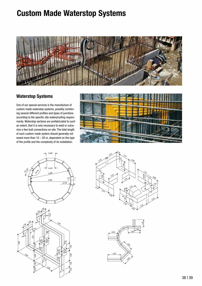
Custom Made Waterstop Systems
Waterstop Systems
One of our special services is the manufacture of
custom made waterstop systems, possibly combin-
ing several different profiles and types of junctions
according to the specific site waterproofing require-
ments. Waterstop sections are prefabricated to such
an extent, that it is only necessary to weld or vulca-
nize a few butt connections on site. The total length
of such custom made system should generally not
exeed more than 10 – 20 m, dependent on the type
of the profile and the complexity of its installation.
Baustel
lenstoß
Baustel
lenstoß
3,70
2,00
3,20
2,50
2,60
2,601,30
1,20
130°
3,70
3,70
3,70
0,50
0,50
1,35
0,50
0,55
3,70
3,70
3,70
0,162,74
5,64
0,75
3,20
1,00
1,00
1,00
0,60
1,00
1,00
1,00
1,00
0,65
3,00
0,30
1,80
0,60
1,00
0,30
1,80
0,60
6,40
1,70
1,70
6,60
6,60
0,162,74
6,40
64°
116°
116°
64°
64°
64°
64°64°
64°
64°
64°
64°
0,540
0,470
101,25°
157,50
2,408
2,362
0,176
A A
Baustel
lenstoß
Baustel
lenstoß
3,70
2,00
3,20
2,50
2,60
2,601,30
1,20
130°
3,70
3,70
3,70
0,50
0,50
1,35
0,50
0,55
3,70
3,70
3,70
0,162,74
5,64
0,75
3,20
1,00
1,00
1,00
0,60
1,00
1,00
1,00
1,00
0,65
3,00
0,30
1,80
0,60
1,00
0,30
1,80
0,60
6,40
1,70
1,70
6,60
6,60
0,162,74
6,40
64°
116°
116°
64°
64°
64°
64°64°
64°
64°
64°
64°
0,540
0,470
101,25°
157,50
2,408
2,362
0,176
A A

Waterstop Specification
Waterstop width a
CoverComponent thicknessd
Embedmentdepth
Mitred angled joint (factory made joint)
≥ 25 cm
≥ 15 cm
Otherwise
Bending radius r
≥ 30 x Profilhöhe a
(Example: f = 30 mm r ≥ 1,50 m)
(Example: a = 70 mm r ≥ 2,10 m)
≥ 50 x Stop anchor depth f
Waterstop Width Rule
The component thickness d around internal waterstops should be at least equivalent to the water-
stop width a (embedment depth ≤ cover). A component thickness of 300 mm is sufficient for
320 mm wide waterstops according to DIN 18541 (types D and A). The choice of waterstops is
based on the load and exposure, e.g. in accordance with DIN V18197. Our Product Engineering
department will be pleased to assist you in your projects.
Closed Waterproofing System
Waterstops must create a closed waterproofing system within the reinforced concrete structure.
Joint intersections with each other and with penetrations and edges of the structure should be
made as square as possible. The clearance from the edges of the structure should generally be
0.5 m minimum. The overall waterstop section system specification and method statement for a
project are divided into logical sections. These are linked to the drawings of the system and its
components, their factory prefabrication or assembly and for their installation on site. This also
provides part of the project documentation and confirmation of the specific waterstop qualities
required. The waterstops should conform with the local regulations and specifications.
Bending Radius r
When there are changes of direction perpendicular to the waterstop
level, waterstops may be bended strictly regarding the indicated
minumum bending radius r. If the required bending radius r cannot
be maintained, a factory-made vertical angle should be specified.
Concrete and Reinforcement Cover
The clearance between waterstop and reinforcement shall be at least 20 mm.
Design
Bending radius r
x
z
y
x
z
y
��� ��
��� ��
��� ��
��� ��

40 I 41
Horizontal Waterstop Installation in Slabs
Internal waterstops in horizontal base or deck slabs should be installed in a v-shape at an angle
of about 15° upwards, to allow the waterstop sides to be embedded without voids and to prevent
concrete honeycombing (from grout loss / segregation during concreting).
Use of External Waterstops
External waterstops are always fitted on the water contact side. They must not be casted in on the
top of horizontal and low angled components (due to the risk of air entrapment and voids). External
waterstops must be given adequate durable protection against mechanical damage (e.g. by backfill-
ing with soil, sand, similar fillers without angular crushed stone).
Design of Constraction Joints
Expansion joint waterstops are also used in contraction joints. If shear movement can occur in a
contraction joint, a deformation void must be created using an encased centre-bulb (e.g. waterstop
type Tricosal® FMS 500 HS Elastomer).
Design of Wide Joints
For expansion joints with a nominal joint width Wnom≥30 mm and if shear force VY>Wnom
occurs, measures must be taken to prevent any possible damage to the waterstop from the con-
crete edges (e.g. use encased centre-bulb waterstop type: Tricosal® FMS 500 HS Elastomer).
Minimum Joint Width
For the joints in service, under their intended deformation, the joint width at a nominal width of
Wnom = 20 mm must not be less than 15 mm and at a nominal width of Wnom = 30 mm, not less
than 20 mm. Otherwise a deformation void must be created by forming an encased centre bulb
(e.g. waterstop type Tricosal® FMS 500 HS Elastomer – see Contraction Joint above).
Joint Seal at Open and Below Ground Ends
To protect joints from contamination, external waterstop should be installed at below ground ends
with a suitable joint sealant or capping waterstop at the open air ends.
��� ��
��� ��
Joint filler plate
ca15˚
≥20 mm
≥20 mm
≥15 mm
Ceiling
Floor slab/wall

Waterstop Handling Guidelines
Protected Storage
When delivered to site, the waterstop products must be unloaded carefully and inspected im-
mediately for completeness and integrity, including form and dimensions. Before installation the
waterstops must be kept in a sheltered place on boards or some other firm base (e.g. pallets,
concrete surfaces) and protected from contamination or damage.
Storage
Storage in Winter
Waterstops should be kept in covered storage if possible and then be put in heated rooms for at
least one full day prior to their installation, to make their handling and installation easier and less
prone to damage (thermoplastic material).
Storage in Summer
Waterstops must be protected from direct sunlight, specially in summer, e.g. by covering. In high
outside temperatures waterstops must be taken to the point of installation and laid out under no
tension.

42 I 43
Waterstop Installation Guidelines
Cleanliness and Integrity
Waterstops must not be installed if they have suffered deformation or damage which might
impair their function. Waterstops must be installed without creasing or distortion. Deformation in
external PCV-P, TPO or Tricomer® waterstops caused during storage or handling (e.g. creasing
or distortion of the anchors) should be corrected by stretching on a level base and heat treatment.
Waterstops can only be installed at a material temperature of over ±0 °C and in weather conditions
not endangering the safe installation of the whole waterproofing system.
Installation and Fixing
Fixed in a Stable Position
Waterstops should be installed in their specified position, symmetrical to the joint axis, and be
fixed so that their position can not change or move during the concreting works.
Concrete and Reinforcement Cover
The minimum clearance and concrete cover shall be at least 20 mm.
� ��
� ��
� ��
� ��

Waterstop Installation Guidelines on Site
Fixing Internal Waterstops
Internal waterstops are anchored to the reinforcement. The waterstops are fixed to the edge
anchors with the special waterstop clip or, in the case of waterstops with steel plates (FMS, FS)
to the edge perforation of the steel plates at maximum intervals of 25 cm.
During the Waterstop Installation
Horizontal Waterstop Positioning in Slabs
To prevent honeycombing or concreting voids, the internal waterstops in bases and decks should
be installed in a v-shape at an angle of about ≥15° upwards.
Spacing Between Joints in the Waterstops Themselves
The spacing between two joins in the waterstops themselves should be 0.50 m minimum. In
every configuration the length of the free waterstop ends should be 1.00 m minimum so that these
connection joints can be formed easily and correctly on site.
Tight Bulkhead Formwork
When installing the waterstop system, ensure that the bulkhead formwork is tight, stable and
immovable. The stopend formwork must lie tight against the waterstops. The waterstop must be
protected from damage before and during the concreting works.
Fixing of External Waterstops
External waterstops for walls are fixed with nails to the formwork at the edges, nailing plates with
an embedment depth maximum 1/3 of nail length and bent around approx. 45°. If there is a risk
of a stop end anchor snapping (e.g. due to concrete dropping too heavily by mistake), it should
be fixed to the reinforcement with waterstop clips every 25 cm, e.g. the top stop end anchors of
the waterstop system in the base / wall joints. External waterstops for horizontal installation under
bases are fixed directly to the concrete blinding.
Reinforcement
Fixing interval:
≤ 25 cm
ca.45°
� � ��
� � ��
Joint filler plate
ca15˚
≥20 mm
≥20 mm
� ��� �
≥ 1,0 m
Butt joint
Butt joint
Free waterstop end
waterstop end
1st Concreting section
≥ 0,5 m≥ 1,0 m
≥ 0,5 m
Butt jointFree

44 I 45
Protection of Exposed Waterstops On Site
The waterstops should be protected from damage until they are fully casted in. Examples of
suitable protective measures are:
For waterstops in walls: cover reinforcement ends with boarding, box in or roll up and suspend
the waterstop till later
For waterstops to be trafficked: completely cover or bed in sand
For waterstop ends to be exposed for some time: box in to fully protect
Protection
Striking Around External Waterstops
Take great care that external waterstops do not come loose during striking of adjacent or attached
formwork. Extend the time before striking these areas if necessary.
Striking of Formwork
Embedding of External Waterstops
Waterstops must be free from contamination and ice when casted in. If necessary they should be
cleaned before concreting (e.g. removal of any accumulated site debris such as sawdust, sand,
concrete residues, cement laitance, oil, grease, snow, ice etc.). This is particularly important for
external waterstops in the base of a structure.
During the Concreting Works
Casting Without Honeycombing or Voids
The waterstops must be fully enclosed in concrete and the concrete must be free from voids.
Make sure that there is a low concrete drop height, good flow without segregation and even
distribution.
Clearance Between Poker Vibrators and Waterstops
The poker vibrators must never touch the waterstop or its fixings (minimum clearance ≥10 cm).
It is usually preferable to compact around external waterstops with external vibrators, which will
also give better compaction around stop end anchors.
Poker vibrator
Poker vibrator
≥10 cm

Equipment, Tools and AccessoriesFor the Welding of Thermoplastic Waterstops
Introduction
Joints between thermoplastic waterstops are made with a heat weld-
ing process.
This process is reversible. The principle of welding consists of soften-
ing the mating surfaces of both of the two parts to be joined by heating
them to the melting temperature, quickly pressing them together, and
allowing them to cool.
Welding is not possible merely by heating and softening one of the two
pieces to be welded together.
Although the welding of thermoplastic materials is easier and cheaper
on site than the vulcanising of Elastomers (artificial rubber based
materials), it demands more manual skill and dexterity, as well as
ensuring good workmanship and quality control .

46 I 47
Welding Equipment for Sika® Waterbar PVC-P and Tricosal® Tricomer® Waterstops
Semi-Automatic Tools
Welding equipment type SG 320 L
Semi automatic Welding equipment with clamping moulds, dependant on profiles
Tools for Hand Welding
Axe-shaped welding tool 200 W
Welding tip 50 W
Welding tongue 125 W
Hot air blower:
– round nozzle, short
– round nozzle, long
– flat nozzle
– quick welding nozzle, round
Welding Accessories
Welding foil
Welding strip
Tools
Special knife
Special tongue for waterstop clips
Accessories for Installation
Waterstop clip type 1
Waterstop round clip
Clip for Sika® Waterbar
Clamping Plates
– KS 12
– KS 15
– KS 24
– KS 32
All electrical tools are 220 V as standard, 110 V models are available to meet some countries regulations on request. For equipment, tools and accessories for installing Tricosal flanged waterstops see page 31.
Welding of Sika® Waterbar and Tricosal® Waterstops Made of PVC-P, TPO and Tricomer®
Axe-shaped welding tool
Overlapping joint with hotair
blower
Preparation of overlapping Strengthening with welding foil
using hot air gun
Strengthening with welding strip
using welding tip
Welding equipment type SG 320 L SparktesterMeasuring, marking, cutting
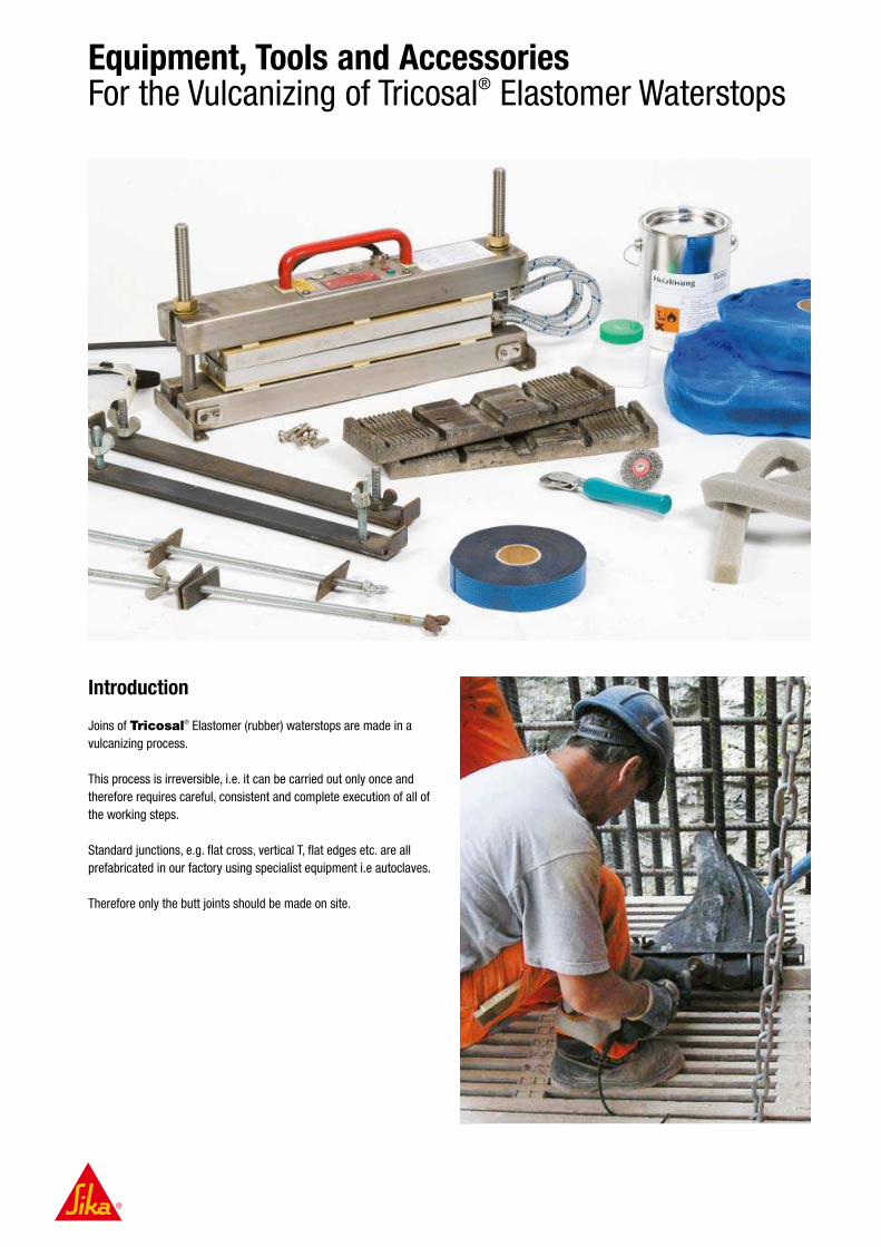
Introduction
Joins of Tricosal® Elastomer (rubber) waterstops are made in a
vulcanizing process.
This process is irreversible, i.e. it can be carried out only once and
therefore requires careful, consistent and complete execution of all of
the working steps.
Standard junctions, e.g. flat cross, vertical T, flat edges etc. are all
prefabricated in our factory using specialist equipment i.e autoclaves.
Therefore only the butt joints should be made on site.
Equipment, Tools and AccessoriesFor the Vulcanizing of Tricosal® Elastomer Waterstops

48 I 49
Vulcanizing of Tricosal® Waterstops Made of Elastomer Rubber Material
Measuring, marking, cutting Grinding of the rubber surface Applying the vulcanizing
solution to the rubber surface
Plugging of the centre bulb with a
cellular foam plug and inserting a
raw rubber plug
Applying the adhesion strip Jointing the waterstop, tightening
with the fixing Clamps
Application of cover strips; pres-
sing home of both cover strips
Powdering of waterstop and inserting
into the vulcanizing equipment
Vulcanizing Equipment for Tricosal® Elastomer Rubber Waterstops
Vulcanizing equipment VG 450
with moulds, dependant on equipment and profiles
Vulcanizing equipment VG 600
with moulds, dependant on equipment and profiles
Vulcanizing Accessories
Vulcanizing Solvent
Adhesion foil
Strip type 0
Strip type 1
Bonding agent for steel/rubber
connections, including primer
Talcum
Plug
Tools
Special knife
Roller
Taping Rod
Grinder
Accessories
Waterstop clip type 2

Case Studies
Fürstenaupark Apartment Buildings Wil, Switzerland
Project Description
New apartment buildings with underground parking garages
Construction Period: 2000 – 2005
Sika Solution
Sealing of the below ground expansion and construction joints with
Sika® Waterbar.
Sika Products
Sika® Waterbar AR-26
Sika® Waterbar DR-29
Grouft Road Tunnel Luxemburg
Project Description
The longest structure on the Route du Nord
Construction Period: 2005 – 2009
Sika Solution
Compartmentalization of the tunnel waterproof membrane lining sys-
tem for localised injection and sealing of any leaks or damage.
Sika Products
Sika® Waterbar AR-60/6 PVC Inject

50 I 51
City-Tunnel Leipzig, Germany
Project Description
New main arteriel railway tunnel in the city and region of Leipzig
Construction Period: 2003 – 2012
Sika Solution
Sealing of the expansion and construction joints, including the under-
ground station entries with Tricosal® Tricomer® and Elastomer
high performance waterstops.
Sika Products
Tricosal® FMS 400 Elastomer
Tricosal® FMS 400 HS Elastomer
Tricosal® FAE 100 Elastomer
Tricosal® AM 250 Elastomer
Tricosal® FM 350 K Elastomer
Tricosal® A 250 Elastomer and others
Tricosal® FA 50/30/2 Tricomer®
Flanging constructions
Tricosal® FM 350 K Elastomer
Tricosal® OKB 30 Elastomer
Naga Hammadi Barrage Dam Egypt
Project Description
A major new dam to provide water for irrigration and produce hydro
electric energy.
Construction Period: 2002 – 2008
Sika Solution
Sealing of the expansion and construction joints with Tricosal®
Elastomer high performance waterstops.
Sika Products
Tricosal® FS 310 Elastomer
Tricosal® FM 300 Elastomer
Tricosal® FMS 500 Elastomer
Tricosal® FMS 500 HS Elastomer

© S
ika
Ser
vice
s A
G /
BU
Con
trac
tors
/ W
ater
stop
/ 0
1.2
010 /
CM
S /
rb
Other Available Sika Waterproofing Brochures
Joint Sealing
Sikaflex®
Sikasil®
Grouting
Sikadur®
SikaGrout®
Roofing
Sarnafil®
Sikaplan®
SikaRoof® MTC®
Concrete Production
Sika® ViscoCrete®
Sika® Retarder®
Sika® SikaAer®
Waterproofing
Sikaplan®, Sikalastic®
Sika® & Tricosal® Waterstops
Sika® Injection Systems
Flooring
Sikafloor®
SikaBond®
Sika Full Range Solutions for Construction
Corrosion and Fire Protection
SikaCor®
Sika® Unitherm®
Concrete Repair and Protection
Sika® MonoTop®
Sikagard®
Sikadur®
Structural Strengthening
Sika® CarboDur®
SikaWrap®
Sikadur®
Sika Services AG
Business Unit Contractors
Speckstrasse 22
CH-8330 Pfäffikon
Switzerland
Phone +41 58 436 23 80
Fax +41 58 436 23 77
www.sika.com
s i n c e
1 9 1 0
Innovat ion &
Consistency
®
Flexible Waterproofing of Tunnels with Sikaplan® Membranes
Watertight Concrete Basements with Sika® Concrete, Jointing, and Injection Technology
® ®
Sika® Injection Systems for Concrete Structures
®
Flexible Waterproofing of Basement Structures with Sikaplan®
SikaFuko® Injection Hose SystemsUnique Waterproofing Solutions for Construction Joints
s i n c e 1 9 1 0
Innovat ion &
Consistency
Our most current General Sales
Conditions shall apply.
Please consult the Product Data Sheet
prior to any use and processing.