significant high-grade sop resource delineated … · 1.26 25.5 0.03 0.03 indicated (paleochannel)...
TRANSCRIPT

18 MARCH 2019
ASX ANNOUNCEMENT
SIGNIFICANT HIGH-GRADE SOP RESOURCE
DELINEATED AT LAKE WAY
Highlights:
Initial Mineral Resource Estimate for the whole of Lake Way contains 73 million tonnes of SOP, including:
o Measured Resource – Lake Way Playa 6.9Mt @ 15.4kg/m3
o Measured Resource – Williamson Pit 32Kt @ 25.5kg/m3
o Indicated Resource – Paleochannel 3.7Mt @ 13.6kg/m3
o Inferred Resource – Lake Way Playa & Paleovalley Sediment 62Mt @ 15.2kg/m3
Lake Way confirmed as very high-grade with consistent brine chemistry both laterally and at depth, with an average grade of 14.5kg of SOP per cubic metre of brine across the Lake Way tenements (Measured and Indicated)
The Company has successfully delineated a Paleochannel in excess of 30km in length along the eastern boundary of Lake Way, which supports the ability and optionality to produce brine from two separate sources (lake playa and paleochannel)
Test pumping of historical bores at Lake Way has provided important data that
supports efficient production by pumping from the paleochannel resource
The Mineral Resource Estimate for the ‘whole of lake’ will enable the Company to finalise technical studies for a larger production scenario with an anticipated release date towards the end of Q2 2019
Salt Lake Potash Limited (the Company or Salt Lake Potash) (ASX/AIM:SO4) is pleased to advise
of a significant extension of the Mineral Resource Estimate at Lake Way following completion of an
exploration program across the ‘whole of the lake’. The estimated total Mineral Resource Estimate
at Lake Way has increased to 73 million tonnes (Mt) of SOP calculated using Total Porosity and
8.2Mt of SOP calculated using Drainable Porosity.
TABLE 1: RESOURCE TABLE
Classification
Bulk Volume
(Million m3)
Porosity (%)
Brine Volume
(Million m3)
Average SOP (K2SO4)
Concentration (kg/m3)
SOP Tonnage – Total Porosity
(Mt)
SOP Tonnage – Drainable Porosity1
(Mt)
Measured (Lake) 1,060 43 456 15.4 6.9 1.8
Measured
(Williamson Pit) 1.26 25.5 0.03 0.03
Indicated
(Paleochannel) 686 40 274 13.6 3.7 1.4
Inferred 10,216 40 4,096 15.2 62.2 5.0
Total 11,963 4,826 72.83 8.2
1 An average Drainable Porosity ranging from 3-15% has been applied

ASX ANNOUNCEMENT | 18 March 2019
2
Salt Lake Potash’s Chief Executive Officer, Mr Tony Swiericzuk said:
“It is extremely pleasing to present the Lake Way Mineral Resource Estimate for the ‘whole of lake” that confirms the significant size and very high-grade resource at Lake Way.
It reinforces our current review process to consider a larger scale scenario at Lake Way and we anticipate releasing the technical results of the larger scale scenario towards the end of Q2 2019.”
FIGURE 1 LAKE WAY RESOURCE CLASSIFICATION

ASX ANNOUNCEMENT | 18 March 2019
3
Lake Way Project
Salt Lake Potash is focussed on the rapid development of the Lake Way Project, being a high grade
salt-lake brine Sulphate of Potash (SOP) operation. Lake Way’s location and logistical advantages
make it the ideal Lake for the Company’s first SOP operation.
Lake Way is located in the Northern Goldfields Region of Western Australia, less than 15km south
of Wiluna. The surface area of the Lake is over 270km2. The northern end of the Lake is largely
covered by a number of Mining Leases, held by Blackham Resources Limited (Blackham), the owner
of the Wiluna Gold Mine. The Company’s Memorandum of Understanding with Blackham (see ASX
Announcement dated 12 March 2018) allows for an expedited path to development at Lake Way.
Introduction
The maiden Mineral Resource Estimate reported in July 2018 was limited to the area within the
Blackham Tenement boundary. Subsequent to this, the Company has undertaken an extensive
exploration program covering the remaining areas of Lake Way including the delineation of the
Paleochannel which runs along the eastern boundary of the Lake Way Project.
Salt Lake Potash has now finalised the exploration program that has supported a ‘whole of lake’
Mineral Resource Estimate, covering the playa surface and the Paleochannel aquifers of Lake Way.
The Mineral Resource Estimate for the ‘whole of lake’ will enable Salt Lake Potash to finalise
technical studies for a larger production scenario with an anticipated release date towards the end
of Q2 2019.
Mineral Resource Estimate
The Company engaged an independent hydrogeological consultant with substantial salt lake brine
expertise, Groundwater Science Pty Ltd, to complete the Mineral Resource Estimate for the Lake
Way Project.
The Lake Way Mineral Resource Estimate describes a brine hosted resource. The minerals are
dissolved in brine, and the brine is contained within pore spaces of the host sediment. A small
portion of the resource is contained in the Williamson Pit Lake.
The Mineral Resource Estimate of 73Mt is hosted within approximately 15 billion cubic metres of
sediment ranging in thickness from a few metres to over 100m, beneath 189km2 of Playa Lake
surface including the paleochannel basal sand unit of 20m thickness and 30km length.
The Mineral Resource Estimate for Lake Way is divided into resource classifications that are
controlled by the host geological units:
Lake Bed Sediment
Paleovalley Sediment
Paleochannel Basal Sands
The mineral resource estimate is summarised in the Tables below. An overview of each resource
classification is provided in the subsequent paragraphs. Details of the estimation methodology are
provided in the body of this report.

ASX ANNOUNCEMENT | 18 March 2019
4
The estimated SOP tonnage represents the SOP within the in-situ contained brine with no recovery
factor applied. The amount of contained brine which can be extracted depends on many factors
including the permeability of the sediments, the drainable porosity, and the recharge dynamics of
the aquifers.
TABLE 2: MEASURED RESOURCE
Total Volume Brine Concentration
Mineral Tonnage Calculated from Total Porosity
Mineral Tonnage Calculated from Drainable Porosity
K Mg SO4
Total Porosity
Brine Volume
SOP Tonnage
Drainable Porosity2
Brine Volume
SOP Tonnage
(Mm3) (kg/m3) (kg/m3) (Kg/m3) (Mm3) (Mt) (Mm3) (Mt)
North Lakebed (0.4-8.0 m) 1,060 6.8 8.0 27.6 0.42 445 6.8 0.11 117 1.8
Williamson Pit 1.26 11.4 14.7 48.0 1.26 0.03
Total 6.8 1.83
TABLE 3: INDICATED RESOURCE
Total Volume Brine Concentration
Mineral Tonnage Calculated from Total Porosity
Mineral Tonnage Calculated from Drainable Porosity
K Mg SO4
Total Porosity
Brine Volume
SOP Tonnage
Drainable Porosity
Brine Volume
SOP Tonnage
(Mm3) (kg/m3) (kg/m3) (Kg/m3) (Mm3) (Mt) (Mm3) (Mt)
Basal Sands (Paleochannel)
686 6.1 8.2 25.0 0.40 274 3.7 15 103 1.4
TABLE 4: INFERRED RESOURCE
Total Volume Brine Concentration
Mineral Tonnage Calculated from Total Porosity
Mineral Tonnage Calculated from Drainable Porosity
K Mg SO4
Total Porosity
Brine Volume
SOP Tonnage
Drainable
Porosity Brine
Volume SOP
Tonnage
(Mm3) (kg/m3) (kg/m3) (Kg/m3) (Mm3) (Mt) (Mm3) (Mt)
South Lakebed (0.4-8.0 m) 316 6.8 8.0 27.6 0.42 133 2.0 0.11 35 0.5
Lakebed (8m to Base) 9,900 6.8 8.0 27.6 0.40 3,960 60.0 0.03 297 4.5
Total 62.0 5.0
The northern section of Mineral Resource Estimate (including the Blackham tenements) has been
classified into a Measured category for the upper 8m of lakebed sediments. The resources contained
within the lakebed sediments below 8m, and the southern section of the lake at all depths, are all
classified in the Inferred category. The Paleochannel running along the eastern boundary of the lake
has been classified in the Indicated category.
2 The Drainable Porosity does not include the significant resource potentially available through the recharge cycle. Refer Appendix 1.

ASX ANNOUNCEMENT | 18 March 2019
5
The Company will continue the exploration program as it looks to increase the resource definition in
the southern section of the lake and ultimately convert the Mineral Resource Estimate into Ore
Reserves following further technical studies.
FIGURE 2: GEOLOGICAL SETTING
2018 Resource Estimate for Lake Way
In July 2018, the Company completed a scoping study for a 50,000tpa demonstration plant
supported by an indicated resource for the 55.4km2 area of the Blackham tenements on Lake Way
totaling 1.9Mt of SOP with an excellent brine chemistry of 15.49Kg/m3 K2SO4 and a measured
resource from the Williamson pit of 32kt with a highly concentrated chemistry of 25.5Kg/m3 K2SO4.
The Resource was calculated on the shallow (6m average depth) Playa Lake Sediment only. This
resource has now been extended to 8m depth and to include 87km2 of Salt Lake Potash’s tenement
covering the open playa area of Lake Way and upgraded to measured. The Williamson Pit resource
remains unchanged.
Williamson Pit – Measured Resource Estimate
The Measured Resource dissolved in the Williamson Pit Lake Comprises 32Kt SOP dissolved in
1.26Mm3 brine at an average grade of 24.4kg/m3 SOP.

ASX ANNOUNCEMENT | 18 March 2019
6
FIGURE 3: WILLIAMSON PIT
Lakebed Sediment (North) – Measured Resource Estimate
The Measured Resource is hosted in the Lake Bed Sediments in the northern part of the lake where
data density is sufficient to support the Measured Resource classification.
The resource comprises 6.9Mt SOP hosted in the total porosity of the sediment which includes 1.8Mt
SOP within the drainable porosity of the sediment.
The resource is contained within the top 8m of sediment, which can reasonably be drained by
pumping from trenches and occupies an area of 139.5km2 of the Lake Way playa surface. Islands
and a zone of dewatered sediment have been removed from the area used to calculate the resource.
Brine chemistry was defined by assay of brine samples taken from 9 hand dug pits, 13 Auger
drillholes, and 49 excavated test pits. The average brine grade is 15.2kg/m3 SOP.
Total Porosity was defined by laboratory determination of 16 intact samples obtained by hollow core
auger drilling and 24 Shelby Tubes advanced during excavation of test pits. Total porosity averages
42%.
Drainable porosity was defined by laboratory determination of 24 intact samples obtained by hollow
core auger drilling and Shelby Tubes advanced during excavation of test pits. Extended duration
pumping trials were undertaken to provide field estimates of drainable porosity to validate the
laboratory determination. Drainable porosity by all methods averaged 11%.

ASX ANNOUNCEMENT | 18 March 2019
7
FIGURE 4: TEST TRENCH AT LAKE WAY
FIGURE 5: TRENCH TEST PUMPING AT LAKE WAY

ASX ANNOUNCEMENT | 18 March 2019
8
Lakebed Sediment (South) – Inferred Resource Estimate
The Inferred Resource is hosted in the Lake Bed Sediments in the southern part of the lake where
data density is insufficient to support a higher classification. In this area continuity of brine grade
and sediment porosity is assumed which constrains the resource classification to Inferred.
The resource comprises 2.1Mt SOP hosted in the total porosity of the sediment which includes 0.5Mt
SOP within the drainable porosity of the sediment.
The resource is contained within the top 8m of sediment, which can reasonably be drained by
pumping from trenches and occupies the 41.6km2 area of the Lake Way playa surface. Islands on
the Playa surface have been removed from the area used to calculate the resource.
Brine chemistry and sediment porosity was assumed to be equivalent to the average of the northern
part of the lake.
FIGURE 6: SLUG TESTING A PIEZOMETER
ASX ANNOUNCEMENT | 18 March 2019
9
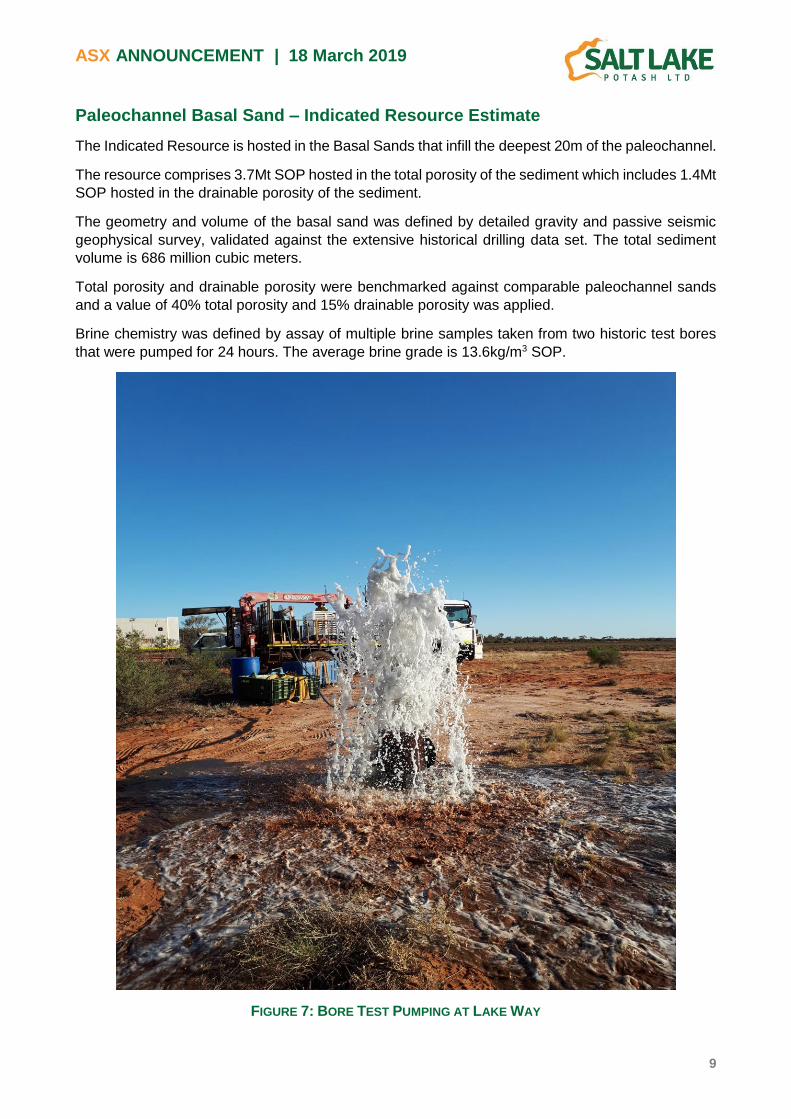
Paleochannel Basal Sand – Indicated Resource Estimate
The Indicated Resource is hosted in the Basal Sands that infill the deepest 20m of the paleochannel.
The resource comprises 3.7Mt SOP hosted in the total porosity of the sediment which includes 1.4Mt
SOP hosted in the drainable porosity of the sediment.
The geometry and volume of the basal sand was defined by detailed gravity and passive seismic
geophysical survey, validated against the extensive historical drilling data set. The total sediment
volume is 686 million cubic meters.
Total porosity and drainable porosity were benchmarked against comparable paleochannel sands
and a value of 40% total porosity and 15% drainable porosity was applied.
Brine chemistry was defined by assay of multiple brine samples taken from two historic test bores
that were pumped for 24 hours. The average brine grade is 13.6kg/m3 SOP.
FIGURE 7: BORE TEST PUMPING AT LAKE WAY

ASX ANNOUNCEMENT | 18 March 2019
10
Paleovalley Sediment - Inferred Resource Estimate
The Inferred Resource is hosted in the predominately silt and clay sediments that infill the paleovalley
from the base of the Lake Bed Sediments to basement or the Basal Sands.
The resource comprises 60Mt SOP hosted in the total porosity of the sediment which includes 4.5Mt
SOP within the drainable porosity of the sediment. The proportion of the brine held in drainable
porosity is much lower in this unit due to the fine-grained lithology.
The geometry and volume of the Paleovalley Sediment was defined by detailed gravity and passive
seismic geophysical survey, validated against the extensive historical drilling data set. The total
sediment volume is 9,900 million cubic meters.
Brine chemistry is assumed to be continuous from the surface of the playa to the base of the
Paleovalley Sediment based on comparable assay results from the lake bed sediments and the
paleochannel sands.
Porosity was estimated against comparable sediments, and 40% total porosity and 3% drainable
porosity has been applied in the resource estimation.
Future Work
The Mineral Resource Estimate for the ‘whole of lake’ will enable Salt Lake Potash to finalise
technical studies for a larger production scenario with an anticipated release date towards the end
of Q2 2019.
The Company will continue the exploration program at Lake Way as it looks to increase the resource
definition in the southern section of the lake and ultimately convert the Mineral Resource Estimate
into Ore Reserves following further technical studies.
Construction of the first phase of the Lake Way Evaporation Ponds is progressing well. The first
phase will enable de-watering of the Williamson Pit. The utilisation of the Williamson Pit brine will
accelerate Salt Lake Potash’s pathway to first production of SOP at Lake Way.
Enquiries: Tony Swiericzuk (Perth)
Telephone: +61 (8) 6559 5800
Jo Battershill (London)
Telephone: +44 207 478 3900

ASX ANNOUNCEMENT | 18 March 2019
11
Summary of Resource Estimate and Reporting Criteria
This ASX Announcement has been prepared in compliance with JORC Code 2012 Edition and the
ASX Listing Rules. The following is a summary of the pertinent information used in the Mineral
Resource Estimate with full details provided in the JORC Code Table 1 included as Appendix 4.
Geology and Geological Interpretation
The investigation area is in the Northern Goldfields Province on the Archaean Yilgarn Craton.
The province is characterised by granite–greenstone rocks that exhibit a prominent northwest
tectonic trend and low to medium-grade metamorphism. The Archaean rocks are intruded by east–
west dolerite dykes of Proterozoic age, and in the eastern area there are small, flat-lying outliers of
Proterozoic and Permian sedimentary rocks. The basement rocks are generally poorly exposed
owing to low relief, extensive superficial cover, and widespread deep weathering. A key
characteristic of the goldfields is the occurrence of paleochannel aquifers. These palaeodrainages
are incised into the Archean basement and in-filled with a mixed Tertiary and Quaternary
sedimentary sequence.
The paleochannel sediments of Lake Way are characterised by a mixed sedimentary sequence
including sand, silts and clays of lacustrine, aeolian, fluvial and colluvial depositional origins. These
near-surface deposits also include chemically-derived sediments of calcrete, silcrete and ferricrete.
Beneath eastern parts of the playa, there is a deep paleochannel that is infilled with Tertiary-aged
palaeochannel clay and basal sands in the deepest portion.
Figure 8 illustrates the inferred basement and sedimentary structure.
The Sediments infilling the paleochannel are described below:
Lake Bed Sediment Recent (Cainozoic), unconsolidated silt, sand and clay sediment containing variable abundance of
evaporite minerals, particularly gypsum. The unit is ubiquitous across the salt lake surface. The
thickness of the unit ranges from approximately 3 to 20m. This unit hosts the Measured and Inferred
Resource.
The upper part of the unit comprises unconsolidated, gypsiferous sand and silt from surface to
around 1.5m depth. The unit is widespread, homogeneous and continuous with the thickest parts in
the centre and southern portion of the lake. This is underlain by well sorted, lacustrine silt and clay.
Palaeovalley Sediment The Paleovalley sediment consists of Tertiary clay and silt that overlies basement or the Basal Sand.
Paleochannel Basal Sand Tertiary, unconsolidated fine, medium to coarse grained sand interbedded with silt, clay and some
lignite horizons.

ASX ANNOUNCEMENT | 18 March 2019
12
FIGURE 8: CROSS SECTIONS SHOWING GEOLOGICAL UNITS AND OBLIQUE VIEW SHOWING PRESENCE OF
PALEOCHANNEL BASAL SAND AQUIFER.

ASX ANNOUNCEMENT | 18 March 2019
13
Hydrological Setting
Surface Water
Lake Way receives episodic surface water inflow from West and East Creeks which lie to the north
of the playa and other smaller creek lines to the west. The Playa is a terminal feature in the surface
water system, i.e. there are no drainage lines that exit the playa.
Surface water recharge is a significant part of the water balance for salt-lake playa brine potash
operations as described in Turk’s (1972) description of the Bonneville Salt Flats (now Wendover
Potash Mine) and EPM’s (2013) proposed potash operation at Sevier Lake.
The morphology of the playa shape and surface is consistent with the classification system described
by Bowler (1986), shown on Figure 9. The northern part of the Playa exhibits morphology typical of
significant surface water influence and periodic inundation (smooth playa edges, one island). The
southern part of the playa exhibits morphology consistent with a groundwater dominated playa with
rare inundation (irregular shoreline, numerous islands). The frequency of inundation across the lake
may be influenced by prevailing south-easterly winds driving water to the north eastern end of the
Lake.
FIGURE 9: LAKE MORPHOLOGY, FROM GA (2013), ORIGINALLY DEVELOPED BY BOWLER (1986)

ASX ANNOUNCEMENT | 18 March 2019
14
The Lake Way catchment area is 3,767km2. The catchment was defined using Geoscience
Australia’s 1 second DEM and MapInfo Discover Hydrology Package.
A runoff model was developed for the Lake Way Catchment using the WaterCress software package
(Groundwater Science 2018b). The model was constructed and calibrated to the adjacent and
analogous Gascoyne River catchment, and then run using the catchment area defined for Lake Way
and historic rainfall data from the Wiluna BOM station from 1907 to 2017.
The average annual rainfall for the Lake Way Catchment is 260mm/year. The run-off model
estimates that on average 3.9% of rainfall runs off to the Lake. Most of the heavy rainfall occurs in
December to March and as such 71% of significant runoff events (runoff depth >5mm) occur during
this period. The average annual modelled run-off to the Playa is 38GL/year but this is highly variable
and ranges from zero in years 1910 and 1936, up to a maximum of 314GL in 1936 and more recently
283GL in 1995.
Groundwater
The Lake is inferred to be a terminal groundwater sink on the basis of the large area of the lake and
the shallow water table observed at all sites beneath the lake which will facilitate evaporative loss.
Groundwater beneath the lake is hypersaline and comprises the brine potash resource.
The drilling undertaken at Lake Way has identified 2 aquifer units:
Cainozoic Playa Lake Sediments exhibit variable lithology comprising sand, silt and clay.
Permeability is higher in the surface gypsiferous sands from which brine flows freely. The lake
sediments beneath the surface sands are higher in clay content and rely on flow from macro
and micro remnant structures.
Tertiary Palaeochannel basal sands comprising fine to coarse grained, well sorted sand. The
extent of the paleochannel has been defined through the passive seismic geophysical survey
and can be seen to be several hundred metres wide throughout.
Geological Interpretation
The geological model of the deposit was developed in Leapfrog by Zephyr Professional Ltd.
The basement topography model is based on interpretation of the passive seismic survey data tied
to the historic drilling data set. The Basal Sand is then modelled to infill the channel to a depth of
20m above the channel thalweg.
The geological model provides the volumes that were then used to estimate dissolved mineral
tonnage contained in the pore space of the host rock.
The model development and structure is illustrated in Figures 10 to 12.

ASX ANNOUNCEMENT | 18 March 2019
15
FIGURE 10: 3D VIEW OF HVSR INTERPRETED CROSS-SECTIONS OVERLAIN WITH THE SALT LAKE
POTASH TENEMENTS. LOOKING NORTH.
FIGURE 11: 3D VIEW OF HVSR INTERPRETED CROSS-SECTIONS SHOWN WITH BASEMENT MODEL AND
HISTORIC DRILLING DATA POINTS (YELLOW POINTS). LOOKING SOUTH WEST.

ASX ANNOUNCEMENT | 18 March 2019
16
FIGURE 12: 3D VIEW OF BASEMENT MODEL WITH INTERPRETED BASAL SAND FILL (LOOKING NORTH)
Drilling and Sampling Techniques
Auger Drilling
Thirteen auger holes were drilled to a maximum depth of 7m. The hollow stem auger method was
applied, this enables a continuous core to be captured.
Drilling the top 1.5m was achieved with little difficulty however, as the hole got deeper the denser,
stiffer clays made progress difficult leading to refusal at around 5m for most holes.
Once the holes were drilled the bores were completed with slotted PVC to just below the water table,
gravel packed to 0.5mbgl and a bentonite seal to the surface. Before the installation of the Bentonite
seal each piezometer was developed using a hand held Wattera development system.
Excavator Test Pits
Test pits were dug using an amphibious digger to a depth of approximately 4m or refusal.
Excavator Test Trenches
Test trenches were dug using an amphibious digger to a depth of approximately 4m or refusal. The
trenches were nominally 100m long and the slopes were battered for stability.

ASX ANNOUNCEMENT | 18 March 2019
17
Historic Production Bores
Two historic investigation bores were used to obtain brine samples and test the hydraulic parameters
of the aquifer. These bores were installed by AGC Woodward Clyde in 1992 on behalf of WMC
Engineering to identify a mine water supply.
Prior to testing, the integrity of the bores was checked by downhole camera survey of the bore holes.
Historic Drilling
An extensive historic drillhole dataset was obtained from WAMEX. Drill logs were re-interpreted to
provide stratigraphic intersections to inform the geological model and provide control to the
geophysical model described below.
Geophysics
A Horizontal to Vertical Spectral Ratio (HVSR) passive seismic survey was completed over 20 survey
transects (Figure 13) on the Salt Lake Potash tenements. The aim of the survey was to determine
depth to bedrock, identify paleochannels and estimate their volumes.
The final HVSR passive seismic data has been processed and velocity analysis completed with
amplitude-depth cross-sections generated for each survey transect. The data highlighted an
interpreted fresh bedrock interface below Lake Way as an acoustic impedance contrast layer, as
well as highlighting shallower layering within the unconsolidated sedimentary cover deposits
(paleochannel sands). This is interpreted as the upper and lower extents of the paleochannel sands.
FIGURE 13: INTERPRETED HVSR PASSIVE SURVEY DATA CROSS-SECTION FOR SURVEY LINE 04-21

ASX ANNOUNCEMENT | 18 March 2019
18
Brine samples
Brine samples were obtained from all test pits, test trenches, water bores and auger holes completed
as piezometers. In all instances the brine sample represents a bulk average sample of the open
interval of each drillhole and excavation.
Geological Samples
Geological samples were taken from each drilling and excavation method and geologically logged.
Porosity Samples
Porosity samples were obtained from test pit excavation by pushing Shelby Tubes into the sediment
and nominally 1m depth intervals. These samples were sealed to prevent moisture loss and
submitted to the laboratory for total and drainable porosity determination.
Hollow core auger samples were taken at nominally 1m depth intervals. These samples were sealed
to prevent moisture loss and submitted to the laboratory for total and drainable porosity
determination.
Hydraulic Testing
Trench Pumping Trials Test Trenches were pumped for between 5 and 90 days. The brine drawdown around the trench
was measured using piezometer areas extending 100m from the trench. This data was used to
determine drainable porosity and aquifer hydraulic conductivity.
Brine samples were taken at regular intervals during pumping to assess the stability of brine
composition over time.
Test Pit Recharge tests
The aquifer hydraulic conductivity at each test pit was tested by pumping brine out of the pits and
then measuring the rate of water level recovery with a pressure transducer as the pits were refilled
by brine inflow from the surrounding aquifer.
Auger Piezometer Slug Tests Auger drillholes completed as piezometers were hydraulically tested by slug tests that comprise
instantaneously introducing, then removing a slug (cylinder) of know volume from the piezometer.
The rate of water level recovery following slug insertion and withdrawal is measured with a pressure
transducer and the rate of recovery is analysed to determine hydraulic conductivity.
Historic Production Bores Two historic investigation bores were test pumped to determine aquifer parameters. The bores were
pumped by Global Groundwater Pty Ltd at a constant rate for 24 hours. Water level drawdown in
the pumped bore, and in nearby observation bores was monitored manually and by data logger. The
data was analysed to determine aquifer properties of transmissivity (Product of bulk average
hydraulic conductivity and aquifer thickness), Storage coefficient and boundary conditions.

ASX ANNOUNCEMENT | 18 March 2019
19
FIGURE 14: DATA SUPPORTING THE RESOURCE ESTIMATE
Sample Analysis Method
Brine Chemistry Determination
The Primary Laboratory was Bureau Veritas Minerals Laboratory in Perth. Duplicate samples were
sent to the secondary laboratory; Intertek, Perth.
Porosity
Porosity determination was undertaken by Core Laboratories Australia Pty Ltd, Perth.
Total Porosity was determined gravimetrically by weighing before and after drying at 60 degrees to
stable final weight.

ASX ANNOUNCEMENT | 18 March 2019
20
Drainable Porosity was determined gravimetrically by re-saturating samples with formation brine
and spinning in a centrifuge at 3,700 rpm until brine production stopped. The samples were
weighed before and after re-saturation and centrifuge.
Verification and QA/QC
QA/QC of brine chemistry determination comprised
Duplicate samples send to a secondary laboratory
Ionic ratio checks to identify outliers
Charge Balance Check
Resource Estimation Methodology
The resource is calculated as the tonnage of minerals dissolved in the liquid brine contained in
pores within the host rock. Tonnages are calculated as dissolved minerals in brine on a dry weight
by volume basis e.g. kilograms potassium per cubic meter of brine. The potassium tonnage of the
resource is then calculated as:
Rock volume x volumetric porosity = brine volume
Brine volume x concentration = tonnage.
Williamson Pit
The mineralisation contained within the Williamson Pit was previously reported in the Company’s
ASX Announcement dated 31 July 2018. That estimate remains unchanged and comprises 0.032Mt
SOP dissolved in 1.26Mm3 brine at an average grade of 24.4kg/m3 SOP.
Lake Bed Sediment
Area The lateral extent of the resource is defined by the tenement boundaries and the playa boundary as
defined in Geoscience Australia’s 1:250K topographic dataset.
The islands in the north and south of the playa have been removed from the resource.
The Williamson pit has resulted in a zone of dewatered material extending out some 500m from the
mine pit. This area has been removed from the resource estimate.
The lake was then split into 2 areas, the north portion where almost all test work has been completed,
and the south portion where little test work has been completed due to accessibility and the only
very recent granting of the final Exploration lease on the lake. The North end of the lake is being
reported here as a measured resource and the south as an inferred resource.
The total area of the North and South of the lake are 139.5 and 41.6km2 respectively.
Thickness
The thickness of the resource estimate has been constrained to 8 m below ground surface on the
basis that production trenches are unlikely to exceed that depth.
Porosity Drainable porosity determined from field pumping trials averages 11% by volume. Drainable porosity
determined from laboratory analysis of intact samples averages 10% by volume.

ASX ANNOUNCEMENT | 18 March 2019
21
Total porosity determined from laboratory analysis of intact samples averages 42% by volume.
TABLE 5: TOTAL POROSITY AND DRAINABLE POROSITY
Test Pit or Trench ID
Sample Depth (m)
Total Porosity
(%)
Drainable Porosity
(%)
Test Pit or Trench ID
Sample Depth (m)
Total Porosity
(%)
Drainable Porosity
(%)
LYAG01 2.0 - 3.0 45 10.3 LYTT010 0.5 – 4.0 38 3
LYAG01 3.0 - 4.0 35 8 LYTT014 0.3 – 0.8 52
LYAG01 5.0 - 6.0 39 7.4 LYTT014 0.3 – 0.6 46 11
LYAG02 1.0 - 2.0 29 9.3 LYTT015 1.5 – 2.0 41 5
LYAG02 4.0 - 5.0 53 11.1 LYTT017 0.6 – 1.1 50
LYAG06 1.0 - 2.0 45 14.6 LYTT019 0.6 – 1.1 48
LYAG06 2.0 - 3.0 42 10.4 LYTT019 0.3 – 0.6 26 16
LYAG06 3.0 - 4.0 42 11.5 LYTT019 1.5 – 2.0 47 13
LYAG06 5.0 - 6.0 42 10 LYTT019 3.0 – 4.0 35 8
LYAG07 1.0 - 2.0 43 14 LYTT020 0.5 – 1.0 54
LYAG07 3.0 - 4.0 41 8 LYTT020 3.0 – 4.0 50 6
LYAG08 1.0 - 2.0 35 9.4 LYTT021 0.6 – 1.1 50
LYAG08 2.0 - 3.0 32 10 LYTT024 0.5 – 0.9 50
LYAG08 3.0 - 4.0 26 8 LYTT026 0.3 – 0.6 39 10
LYAG15 2.0 - 3.0 33 7.4 LYTT026 3.0 – 4.0 47 24
LYAG15 4.0 - 5.0 36 8.8 LYTT029 4.0 – 5.0 38 5.2
LYTR01 0.5 – 1.5 48 14.2 LYTT029 1.0 – 4.0 47 3
LYTR01 1.0 – 1.2 37 26 LYTT032 0 – 0.5 38 13.8
LYTR01 1.5 – 3.0 48 1.5 LYTT035 3.0 – 3.5 43 5
LYTR01 3.0 - 4.0 36 5 LYTT035 0 – 0.5 39 12
Average 42 10
Solute Concentration
Brine chemistry has been interpolated using Ordinary Kriging with a grid size of 100m x 100m, a
search distance of 6,000m and 2 search passes. Average concentrations have been calculated from
the grid for the Measured Resource (North portion of the lake), this average has been used to
calculate the Resource for the southern, inferred resource.
Treatment of Islands
The islands have been removed from the Lake Bed Sediment Resource. Experience at other lakes
has consistently shown that shallow brine beneath islands is diluted, likely by infiltrating rainfall.
Furthermore, brine harvesting by trenches is unlikely to be practical through the sand dunes and
elevated topography of the islands.
Paleovalley Sediment
Area The lateral extent of the resource is defined by the tenement boundaries and the playa edge. The
total area is 181.1km2.

ASX ANNOUNCEMENT | 18 March 2019
22
Volume
The volume of sediment infilling the paleovalley has been exported from the geological model. The
Volume is 9,900Mm3. This yields an average sediment thickness of 54m for the sediment extending
from 8m depth (base of lake bed sediment) to the top of basement or Paleochannel Basal Sand.
Porosity
The Total Porosity and Drainable Porosity has been estimated from lithology and benchmarking
against other studies completed in comparable geological settings. Total porosity is applied as 40%.
Drainable porosity is applied as a low value of 3% based on the fine-grained lithology of the host
sediment which will retain much of the contained brine.
Solute Concentration Solute concentration is inferred to be continuous from the Playa Surface to the base of the
Paleovalley Sediment. The average value is 15.2kg/m3 SOP.
Paleochannel Basal Sand
Area The extent and thickness of the Paleochannel Basal Sand Resource is defined by the geological
model. The total volume of the unit is estimated to be 686Mm3.
Porosity
The Total Porosity and Drainable Porosity has been estimated from lithology and benchmarking
against other studies completed in comparable geological settings. Total porosity is applied as 40%.
Drainable porosity is applied as 15%.
Solute Concentration
Solute concentration is derived as the average value of the two pumping test bores completed in the
basal sand unit, LW5-7 and LW3-4. Multiple samples were taken from each bore during the 24 hour
constant rate pumping test undertaken at each bore. The average SOP concentration is 13.6kg/m3
SOP. No spatial interpolation was undertaken.
Classification Criteria
Williamson pit
The estimated resource hosted in the Williamson Pit mine lake has a very high degree of confidence,
since the geometry of the mine pit was accurately surveyed and the concentration of the brine was
samples at numerous locations and depths and is quite consistent.
The resource is reported as a Measured Resource on the basis that the estimate is adequate to
support a mine plan (in this case pumping infrastructure and pumping rate).
Lake Bed Sediments (North)
The estimated resource in the northern part of the lake has a high degree of confidence.
The resource estimate and associated hydrological data set are considered adequate to support a
mine plan. In this case the mine plan comprises design of a production trench network and
construction of a groundwater flow simulation model to estimate and plan brine production rates.
The resource is reported as a Measured Resource.
The thickness of the geological unit is well defined, being simply 8m; the assumed limit of excavation.
The area is well defined by the extent of the playa surface.

ASX ANNOUNCEMENT | 18 March 2019
23
Brine concentration is defined by a high density or data points and is quite consistent spatially. There
is a high degree of confidence that the brine concentration is accurately defined.
Aquifer total porosity and drainable porosity are well defined by a large number of samples at a range
of depths, and drainable porosity values are validated by extended pumping field trials that comprise
the drainage of very large volumes of sediment.
Aquifer properties of hydraulic conductivity are well defined by a well distributed data set of test pits
and extended duration pumping trials.
The lake water balance due to rainfall and inundation is understood from a reasonably constrained
catchment run-off model.
The Measured Resource estimate is based on 49 test pits, 5 trench tests and 13 auger holes. Data
points are distributed on an approximate 500m by 500m grid in the northwest and on a 5km x 5km
grid for the remainder of the lake. There is irregularity due to greater density of pits around the
proposed pond locations, the causeway, the Williamson Pit dewatered zone and tenure access
constraints to the immediate east of the playa.
Lake Bed Sediments (South)
The estimated resource in the southern part of the lake has a low degree of confidence.
The resource estimate is based on assumed continuity of grade and porosity and is not adequate to
support a mine plan. The resource is reported as an Inferred Resource.
The thickness of the geological unit is well defined, being simply 8m; the assumed limit of excavation.
The area is well defined by the extent of the playa surface.
Brine grade is assumed to be continuous and consistent from the north to the south of the lake. This
assumption is not yet confirmed by test work.
Total Porosity and Drainable Porosity are assumed to be continuous and consistent from the north
to the south of the lake. This assumption is based on lithology logged in historic drilling but is not
yet confirmed by test work.
Hydraulic properties are assumed to are assumed to be continuous and consistent from the north to
the south of the lake. This assumption is based on lithology logged in historic drilling but is not yet
confirmed by test work.
The Inferred Resource Estimate is based on a very limited number of drillholes. The geology is
defined by 10 historic drillholes oriented on a transect across the southern end of the Lake, and the
geophysical survey. Brine Grade is assumed to be continuous from the data in the northern part of
the Lake.
Potash Brine projects typically exhibit low spatial variability in brine grade since the brine resource
is generated in-situ by evaporation of a fairly consistent groundwater source which is subject to
sporadic mixing and dilution due to infiltration of rainwater, and subsequent re-concentration by
evaporation. Drill spacing in the range of 2.5km to 10km is typical (Houston et al 2011).
Paleovalley Sediment
The estimated resource in Paleovalley sediment has a low degree of confidence. The Resource
estimate is based on assumed continuity of grade and porosity and is not adequate to support a
mine plan. The resource is reported as an Inferred Resource.

ASX ANNOUNCEMENT | 18 March 2019
24
The volume of the geological unit is well defined by a geological model based on detailed geophysical
survey validated to an extensive drilling data set.
The area is well defined by the extent of the playa surface.
Brine grade is assumed to be continuous and consistent from the Playa surface to the base of the
geological unit. This assumption is supported by only a limited number of data points where brine
chemistry at surface and at depth are available.
Total Porosity and Drainable Porosity values are based on lithology logged in historic drilling and on
benchmarking of comparable projects in Tertiary paleochannels in Western Australia. The values
are not yet confirmed by test work.
Hydraulic properties of the units inferred from the lithology of the unit, and the response to pumping
of two test bores.
For this unit a mine plan comprises design of a production bore array to depressurise the underlying
basal sand and induce downward vertical leakage from the paleovalley sediment. A groundwater
flow simulation model calibrated to long term pumping trials will be needed to estimate and plan the
rate at which vertical leakage of brine can be induced.
The Inferred Resource Estimate is based on a limited number of drillholes. The 49 test pits, 5 trench
tests and 13 auger holes terminate above the top of the unit, and continuity of brine grade with depth
is assumed based on consistent experience at other salt lake playas, and data demonstrating
continuous brine grade in the underlying Basal Sand unit. The geological model that defines the
volume is based on 224 historic drillholes and the geophysical survey.
Paleochannel Basal Sand
The estimated resource in Paleochannel Basal Sand has a moderate degree of confidence.
The data is adequate to allow confident interpretation of the geological framework which is based on
a good density of drilling and geophysical data. The continuity of brine concentration between very
widely spaced samples is however assumed. The estimate is adequate to apply modifying factors
in a Feasibility Study but is not adequate to support a detailed mine plan. The resource is reported
as an Indicated Resource.
Total Porosity and Drainable Porosity values are based on lithology logged in historic drilling and on
benchmarking of comparable projects in Tertiary paleochannels in Western Australia. The values
are not yet confirmed by test work.
Hydraulic properties of the units inferred from the lithology of the unit, and the response to pumping
of two test bores.
The Indicated Resource Estimate is based on two data points that inform brine grade and
hydrogeological properties. The geological model is based on a larger number of drillholes (23 of
224 drillholes are within the paleochannel extent) and the geophysical survey.
Results
The results of the Mineral Resource Estimate are summarised in the tables below.

ASX ANNOUNCEMENT | 18 March 2019
25
TABLE 6: MEASURED RESOURCE
Total Volume Brine Concentration
Mineral Tonnage Calculated from Total Porosity
Mineral Tonnage Calculated from Drainable Porosity
K Mg SO4
Total Porosity
Brine Volume
SOP Tonnage
Drainable Porosity
Brine Volume
SOP Tonnage
(Mm3) (kg/m3) (kg/m3) (Kg/m3) (Mm3) (Mt) (Mm3) (Mt)
North Lakebed (0.4-8.0m) 1,060 6.8 8.0 27.6 0.42 445 6.8 0.11 117 1.8
Williamson Pit 1.26 11.4 14.7 48.0 1.26 0.032
Total 6.8 1.832
TABLE 7: INDICATED RESOURCE
Total Volume Brine Concentration
Mineral Tonnage Calculated from Total Porosity
Mineral Tonnage Calculated from Drainable Porosity
K Mg SO4
Total Porosity
Brine Volume
SOP Tonnage
Drainable Porosity
Brine Volume
SOP Tonnage
(Mm3) (kg/m3) (kg/m3) (Kg/m3) (Mm3) (Mt) (Mt) (Mm3)
Basal Sands 686 6.1 8.2 25.0 0.40 274 3.7 15 103 1.4
TABLE 8: INFERRED RESOURCE
Total Volume Brine Concentration
Mineral Tonnage Calculated from Total Porosity
Mineral Tonnage Calculated from Drainable Porosity
K Mg So4
Total Porosity
Brine Volume
SOP Tonnage
Drainable Porosity
Brine Volume
SOP Tonnage
(Mm3) (kg/m3) (kg/m3) (Kg/m3) (Mm3) (Mt) (Mm3) (Mt)
South Lakebed (0.4-8.0m) 316 6.8 8.0 27.6 0.42 133 2.0 0.11 35 0.5
Lakebed (8m to Base) 9,900 6.8 8.0 27.6 0.40 3,960 60.0 0.03 297 4.5
Total 62.0 5.0
Note: 1) Conversion factor of K to SOP (K2SO4 equivalent) is 2.23
2) Williamson Pit and Lakebed Sediment (North - Blackham tenements only) resource estimate reported previously as
maiden resource 31 July 2018.
Cut-off Grades
Within the salt-lake extent no low-grade cut-off or high-grade capping has been implemented due to
the consistent nature of the brine assay data. No aggregate intercepts have been calculated.
ASX ANNOUNCEMENT | 18 March 2019
26
Mining and Metallurgical Methods and Parameters
It is assumed that the Brine resource will be mined by gravity drainage to a network of trenches
excavated into the Playa Surface and an array of production bores completed in the paleochannel
basal sand.
Validation test work has been completed to confirm the process flowsheet to be used at the Lake
Way Project to recovery SOP from the Lake Brine (refer ASX Announcement 31 October 2018).
Environmental impacts are expected to be; localized reduction in saline groundwater level, surface
disturbance associated with trench, bore, and pond construction and accumulation of salt tails. The
project is in a remote area and these impacts are not expected to prevent project development.
The project is located with the Goldfields Groundwater Proclamation Area. A license to take
groundwater will be required under the Rights in Water and Irrigation Act 1914. This Act is
administered by the Government of Western Australia Department of Water and Environmental
Regulation.
Forward Looking Statements
This announcement may include forward-looking statements. These forward-looking statements are based on Salt Lake’s expectations and beliefs concerning future events. Forward looking statements are necessarily subject to risks, uncertainties and other factors, many of which are outside the control of Salt Lake, which could cause actual results to differ materially from such statements. Salt Lake makes no undertaking to subsequently update or revise the forward-looking statements made in this announcement, to reflect the circumstances or events after the date of that announcement.
Competent Person Statement
The information in this report that relates to Mineral Resources and Exploration Results for Lake Way is based on information compiled by Mr Ben Jeuken, who is a member Australian Institute of Mining and Metallurgy and a member of the International Association of Hydrogeologists. Mr Jeuken is employed by Groundwater Science Pty Ltd, an independent consulting company. Mr Jeuken has sufficient experience, which is relevant to the style of mineralisation and type of deposit under consideration and to the activity, which he is undertaking to qualify as a Competent Person as defined in the 2012 Edition of the ‘Australasian Code for Reporting of Exploration Results, Mineral Resources and Ore Reserves’. Mr Jeuken consents to the inclusion in the report of the matters based on his information in the form and context in which it appears.
Production Target
The Lake Way Demonstration Plant Production Target stated in this report is based on the Company’s Scoping Study as released to the ASX on 31 July 2018. The information in relation to the Production Target that the Company is required to include in a public report in accordance with ASX Listing Rule 5.16 and 5.17 was included in the Company’s ASX Announcement released on 31 July 2018. The Company confirms that the material assumptions underpinning the Production Target referenced in the 31 July 2018 release continue to apply and have not materially changed.

ASX ANNOUNCEMENT | 18 March 2019
27
Appendix 1: Extraction Method and Implication for Resource Estimate
Overview
Mining methods employed for brines is different to those required for mining solid minerals. The
typical mining method for brines is to pump the brine resource from trenches or bores that are
installed in the geological unit that hosts the brine. The rate that the brine can be pumped is
controlled by the hydraulic conductivity (permeability) of the host rock. For the Lake Way Project,
the mining methods for each host geological unit are summarised in the table below.
TABLE 9: MINING METHOD
Host Unit Mining Method Controls on the mining rate and resource
Williamson Pit Lake Pumping from Pit Lake None
Lake Bed Sediment Pumping from trenches Hydraulic conductivity of lake sediment, Recharge via rainfall and inundation Total Porosity
Paleovalley Fill Vertical drainage to Basal Sand Vertical hydraulic conductivity Drainable porosity, and compressible storage.
Basal Sand Pumping from bores Hydraulic conductivity, Total porosity Aquifer Boundary conditions (vertical and lateral inflow under pumping)
Williamson Pit Lake
Brine from the Williamson Pit Lake will be pumped directly from the pit into the evaporation pond for
processing. The mining rate is controlled only by the capacity of the pumping infrastructure.
Lake Bed Sediment
The shallow Lake Bed Sediments aquifer will be mined by pumping brine from a network of trenches
excavated into the playa surface to a depth of nominally 6m, though trenches may be deepened
over time.
The production of brine is cyclic as shown in Figure 15 and described below.
Stage 1 - Initial Resource
The initial brine resource comprises:
Brine dissolved in water held in Drainable Porosity, (5% of the total aquifer volume).
Brine dissolved in water held in Retained Porosity, (35% of total aquifer volume).
The remaining volume is occupied by solid material (sand, silt and clay grains comprising 60% of
the aquifer volume).
The combined porosity (Total Porosity) then comprises the total SOP brine resource held in the Lake
Bed Sediments aquifer.

ASX ANNOUNCEMENT | 18 March 2019
28
Stage 2 - Production Cycle
During production the brine drains under gravity toward the trench and is subsequently removed by
pumping. This creates a hydraulic gradient toward the trench and brine is drawn some distance
through the aquifer toward the trench (typically hundreds of meters depending on aquifer
permeability).
Over time the aquifer immediately surrounding the trench is partially dewatered. This means that
the drainable brine has been removed from the sediment, but the retained brine is still held in place
by surface tension.
Stage 3 - Recharge Cycle
Western Australian Salt Lake playas receive some water input from rainfall and run-off annually.
Direct rainfall lands on the playa each year, and most years, heavy, cyclonic rain events cause run-
off from the surrounding catchment onto the Playa. This water infiltrates the playa surface and re-
fills the drainable pores in the aquifer. The larger rainfall events usually occur from January through
to March.
Stage 4 - Mixing Cycle The water that has infiltrated and refilled the drainable porosity then mixes (by physical diffusion)
with the brine held in retained porosity.
Through repeated production cycles the total brine resource is mined. The concentration of brine
pumped from the production trenches will decline over time as the total resource is depleted over
repeated production cycles.
The pumping rate is controlled by the hydraulic conductivity of the host sediment. The concentration
of produced brine will change over time and will be controlled by the tonnage contained in total
porosity and the mechanism of mixing between repeated production cycles.
FIGURE 15: LAKE WAY INITIAL RESOURCE

ASX ANNOUNCEMENT | 18 March 2019
29
FIGURE 16: LAKE BED SEDIMENT SOP PRODUCTION CYCLE
Paleovalley Sediment
The paleovalley sediment is predominately fine grain and exhibits low permeability. The brine held
in these sediments cannot be drained directly to bores because the permeability is too low to allow
useful bore yields.
A proportion of the brine held in these sediments can be removed by underdrainage to the
underlying Basal Sand unit.
Brine is removed from the Basal Sand unit by pumping from bores. This depressurises the Basal
Sand unit and induces downward brine leakage from the overlying sediment. The rate of leakage
will be very low; however, the areal extent is very large and significant volumes can be abstracted
in this way.
Only a relatively small fraction of the total porosity can be removed from a fine-grained unit by this
method.

ASX ANNOUNCEMENT | 18 March 2019
30
Paleochannel Basal Sand
The brine will be produced by pumping from bores constructed into the Paleochannel Basal Sand.
Pumping from a deep, confined aquifer results in reduced pressure in the aquifer and this induces
brine flow toward the bores. Brine flow is sourced via downward vertical leakage from the overlying
fine-grained silts and clays, and by lateral flow from the adjacent basement aquifer that surrounds
the channel.
It is important to understand that the aquifer is not dewatered. This means that the pore spaces are
not drained under gravity to be filled with air. The aquifer is only depressurised, and this results in
flow through fully saturated pores toward the pumped bore.

ASX ANNOUNCEMENT | 18 March 2019
31
Appendix 2: Location Details for Drill Holes / Test Pits
HOLE_ID EAST NORTH Hole Type
HA003 235863 7032512 Hand Auger
HA006 235652 7033571 Hand Auger
HA008 234918 7033057 Hand Auger
HA010 235063 7034408 Hand Auger
HA012 234299 7033837 Hand Auger
HA013 234890 7035481 Hand Auger
HA014 234458 7035223 Hand Auger
HA017 234302 7035685 Hand Auger
HA019 234752 7036712 Hand Auger
HA021 233742 7036709 Hand Auger
HA022 234734 7037719 Hand Auger
HA024 233715 7039225 Hand Auger
HA025 233868 7032968 Hand Auger
HA029 231655 7036814 Hand Auger
HA031 231874 7037525 Hand Auger
LYTR001 233590 7036757 Test Trench
LYTR002 235090 7035280 Test Trench
LYTR003 230650 7041000 Test Trench
LYTR004 232330 7035720 Test Trench
LYTR005 238875 7035948 Test Trench
LYTT002 229968 7036837 Test Pit
LYTT003 230702 7036399 Test Pit
LYTT004 231815 7035595 Test Pit
LYTT005 232341 7035793 Test Pit
LYTT006 232183 7035073 Test Pit
LYTT007 231817 7034412 Test Pit
LYTT012 233601 7037586 Test Pit
LYTT013 233600 7034800 Test Pit
LYTT014 233600 7034000 Test Pit
LYTT015 233600 7033200 Test Pit
LYTT016 234600 7032000 Test Pit
LYTT017 235300 7032400 Test Pit
LYTT018 235300 7033200 Test Pit
LYTT019 236300 7033200 Test Pit
LYTT020 234600 7033200 Test Pit

ASX ANNOUNCEMENT | 18 March 2019
32
HOLE_ID EAST NORTH Hole Type
LYTT021 234600 7034000 Test Pit
LYTT022 235650 7034000 Test Pit
LYTT023 235300 7034800 Test Pit
LYTT024 234600 7034800 Test Pit
LYTT025 234600 7035600 Test Pit
LYTT026 234600 7036800 Test Pit
LYTT027 235511 7040910 Test Pit
LYTT028 237073 7040940 Test Pit
LYTT028 237073 7040940 Test Pit
LYTT030 230700 7041600 Test Pit
LYTT031 229531 7041686 Test Pit
LYTT032 229551 7040432 Test Pit
LYTT033 230700 7040400 Test Pit
LYTT034 230700 7039200 Test Pit
LYTT035 230700 7037600 Test Pit
LYTT036 231800 7037200 Test Pit
LYTT037 238858 7037915 Test Pit
LYTT039 240934 7032003 Test Pit
LYTT041 242068 7026888 Test Pit
LYTT042 244658 7026362 Test Pit
LYTT043 243355 7028717 Test Pit
LYTT045 241951 7033872 Test Pit
LYTT048 235845 7038688 Test Pit
LYTT049 236788 7034678 Test Pit
LYPIEZ01 236853 7032051 Auger
LYPIEZ03 238851 7037911 Auger
LYPIEZ04 239481 7030505 Auger
LYPIEZ06 238854 7035878 Auger
LYPIEZ07 238747 7034697 Auger
LYPIEZ08 235865 7038720 Auger
LYPIEZ09 240944 7031987 Auger
LYPIEZ11 243089 7032074 Auger
LYPIEZ13 238602 7039558 Auger
LW3-4 247448 7031876 Historic Pumped bore
LW5-7 242593 7034360 Historic Pumped bore
Note: All holes are vertical, with an RL of approximately 492m

ASX ANNOUNCEMENT | 18 March 2019
33
Appendix 3: Brine Assay Results
Lake Bed Sediment
HOLE_ID K
mg/L
Cl
mg/L
Na
mg/L
Ca
mg/L
Mg
mg/L
SO4
mg/L
pH
SG
HA003 7210 131450 77200 499 7510 26200 6.87 1.16
HA006 6910 128050 78600 528 7000 25500 6.9 1.16
HA008 7280 121350 73900 537 6530 28200 6.91 1.16
HA010 6350 112150 68100 621 6180 23900 6.99 1.14
HA012 6550 115700 68600 574 6690 25300 6.95 1.14
HA013 6070 108500 65900 623 6070 24000 7 1.14
HA014 6050 104250 63900 666 5620 23700 7.03 1.13
HA017 3320 52500 33000 804 2790 14800 7.31 1.07
HA017 6090 101600 63100 664 5450 24200 7.04 1.13
HA019 6030 113600 67600 591 7010 25700 6.96 1.15
HA021 5960 110250 65000 610 6150 23300 7.03 1.14
HA022 6550 111400 68500 636 6050 23600 7.02 1.14
HA024 6100 130850 75000 536 8650 25300 6.89 1.17
HA025 6810 126800 76500 519 7160 26300 6.96 1.16
HA029 6730 131200 79500 447 8070 33000 6.94 1.17
HA031 5910 117600 70200 615 6940 23400 6.98 1.15
LYTR001 6300 125550 74000 534 7410 26300 6.19 1.17
LYTR002 6270 118300 73600 526 7280 27300 6.23 1.16
LYTR003 7060 130450 83900 476 7670 29700 6.57 1.18
LYTR004 7115 129675 83050 502 7660 28900 6.62 1.18
LYTR005 6620 144550 82500 411 9930 32400 6.54 1.19
LYTT002 7350 145050 90000 367 10900 38700 6.36 1.20
LYTT003 8160 151150 91400 305 12200 42600 6.5 1.21
LYTT004 6700 126350 76200 441 8090 29400 6.74 1.17
LYTT005 6760 122700 74500 553 7100 25100 6.79 1.16
LYTT006 6970 129000 78700 514 7500 26600 6.69 1.17
LYTT007 6600 130400 78100 484 8010 28900 6.53 1.17
LYTT012 6470 120100 74300 575 7240 25800 6.65 1.16
LYTT013 6510 117750 72500 562 7000 25400 6.92 1.15
LYTT014 6840 123700 76000 586 7020 26100 6.9 1.16

ASX ANNOUNCEMENT | 18 March 2019
34
HOLE_ID K
mg/L
Cl
mg/L
Na
mg/L
Ca
mg/L
Mg
mg/L
SO4
mg/L
pH
SG
LYTT015 7150 128750 78900 517 7300 28000 6.88 1.17
LYTT016 6990 137650 86000 458 8290 29300 6.71 1.18
LYTT017 7150 129450 80300 498 7400 27200 6.88 1.17
LYTT018 7270 128050 78500 492 7340 28800 6.88 1.17
LYTT019 6800 121600 73500 532 7040 26600 6.88 1.16
LYTT020 6840 124050 74900 549 7020 26100 6.83 1.16
LYTT021 6390 117100 71600 571 6890 26000 6.86 1.16
LYTT022 6630 119150 74600 543 7010 26700 6.93 1.16
LYTT023 6510 123700 72000 556 6790 25100 6.85 1.16
LYTT024 6240 113400 70100 581 6850 26300 6.88 1.15
LYTT025 6330 115700 71500 559 6960 27300 6.85 1.16
LYTT026 7060 125450 77700 519 7030 26200 6.79 1.16
LYTT027 7080 133850 83300 390 9930 37800 6.89 1.18
LYTT028 6360 130350 80800 410 10200 36900 6.95 1.18
LYTT028 7210 145150 87000 358 11600 37800 6.83 1.20
LYTT030 7300 133500 81200 362 9150 33000 6.86 1.19
LYTT031 8760 147100 89700 347 11300 41100 6.82 1.21
LYTT032 7030 137850 81900 408 10400 29900 6.88 1.18
LYTT033 6930 131750 81300 444 10300 33600 6.79 1.13
LYTT034 7190 127750 78200 526 7630 26100 6.74 1.17
LYTT035 6740 134050 80600 418 11000 35400 6.75 1.19
LYTT036 6570 137350 81400 369 12700 38100 6.82 1.20
LYTT037 6780 150000 86100 371 10300 35400 6.7 1.20
LYTT039 7390 133450 78700 563 6670 23900 6.68 1.16
LYTT041 7660 135300 80700 577 6730 24400 6.79 1.17
LYTT042 7520 149250 86000 522 8340 23900 6.62 1.19
LYTT043 5980 110400 65200 726 5820 19700 6.59 1.14
LYTT045 7600 139300 79400 502 6740 24200 6.57 1.18
LYTT048 6910 131100 77300 501 7600 26500 6.55 1.17
LYTT049 7160 139850 82000 485 7850 27600 6.57 1.18
LYPIEZ01 6000 139715 82900 446 10100 26000 6.42 1.18
LYPIEZ03 4560 97584 63400 439 7580 24700 6.97 1.14
LYPIEZ04 6450 145100 82500 478 9340 26200 6.57 1.18
LYPIEZ06 6140 137254 82900 416 9810 31500 6.59 1.18

ASX ANNOUNCEMENT | 18 March 2019
35
HOLE_ID K
mg/L
Cl
mg/L
Na
mg/L
Ca
mg/L
Mg
mg/L
SO4
mg/L
pH
SG
LYPIEZ07 6660 130087 82800 504 7710 27100 6.73 1.18
LYPIEZ08 7030 136000 77400 473 8040 27800 6.48 1.18
LYPIEZ09 6950 131300 75500 552 7420 24100 6.52 1.16
LYPIEZ11 6590 115300 68200 679 5350 19400 6.7 1.15
LYPIEZ13 7000 138485 85800 453 8800 31200 6.63 1.19
Paleochannel Basal Sand
HOLE_ID K
mg/L
Cl
mg/L
Na
mg/L
Ca
mg/L
Mg
mg/L
SO4
mg/L
pH
SG
LW3-4 6160 149053.85 83000 455 8290 25600 6.5 1.18
LW3-4 5880 145796.24 78300 435 7900 23400 6.54 1.18
LW5-7 6080 151515.16 78600 397 8360 26100 6.38 1.19
LW5-7 6270 150501.68 84400 402 8520 26600 6.41 1.18

ASX ANNOUNCEMENT | 18 March 2019
36
Appendix 4: JORC Code, 2012 Edition – Table 1
Section 1 Sampling Techniques and Data
Criteria JORC Code explanation Commentary
Sampling techniques Nature and quality of sampling (e.g. cut channels, random chips, or specific specialised industry standard measurement tools appropriate to the minerals under investigation, such as downhole gamma sondes, or handheld XRF instruments, etc.). These examples should not be taken as limiting the broad meaning of sampling.
Include reference to measures taken to ensure sample presentively and the appropriate calibration of any measurement tools or systems used.
Aspects of the determination of mineralisation that are Material to the Public Report.
In cases where ‘industry standard’ work has been done, this would be relatively simple (e.g. ‘reverse circulation drilling was used to obtain 1 m samples from which 3 kg was pulverised to produce a 30 g charge for fire assay’). In other cases, more explanation may be required, such as where there is coarse gold that has inherent sampling problems. Unusual commodities or mineralisation types (e.g. submarine nodules) may warrant disclosure of detailed information.
Sampling involved the excavation of test pits over the tenement area to a depth of 4mbgl or weathered basement whichever was encountered first. Five trenches were also dug to 4m depth, A brine sample and duplicate were taken from each test pit and trench for analysis. Samples were taken manually by initially rinsing out the bottle with brine from the pit or trench and then placing the bottle in the test pit or trench and allowing it to fill. Samples were analysed for K, Mg, Ca, Na, Cl, SO4, HCO3, NO3, pH, TDS and specific gravity. Each test pit was geologically logged and a sample taken each 1m depth. Shelby Tubes were pushed into the sediment during test pit excavation to obtain intact samples for porosity determination. Test pumping entailed pumping from the trenches and test pits using a diesel driven submersible pump coupled to a level switch. Water levels in the piezometer, test pits and trenches were logged manually and by pressure transducer with barometric pressure and brine density correction. Auger drilling comprised hollow core augers. Samples were taken from the recovered core.
Drilling techniques Drill type (e.g. core, reverse circulation, open-hole hammer, rotary air blast, auger, Bangka, sonic, etc.) and details (e.g. core diameter, triple or standard tube, depth of diamond tails, face-sampling bit or other type, whether core is oriented and if so, by what method, etc.).
Test pits and trenches were dug with an excavator. Drillholes were drilled by hollow core auger. Auger holes were cased with 50mm PVC slotted liner to allow hydraulic testing and repeated sampling.
Drill sample recovery Method of recording and assessing core and chip sample recoveries and results assessed.
Measures taken to maximise sample recovery and ensure representative nature of the samples.
Whether a relationship exists between sample recovery and grade and whether sample bias may have occurred due to preferential loss/gain of fine/coarse material.
Samples from the test pits were logged each bucket and a representative sample bagged. 100% of excavated sample was available for sampling. The ability to see the bulk sample facilitated the selection of a representative sample. There is no relationship between sample recovery and grade and no loss of material as a result of excavation.
Logging Whether core and chip samples have been geologically and geotechnically logged to a level of detail to support appropriate Mineral Resource estimation, mining studies and metallurgical studies.
Whether logging is qualitative or quantitative in nature. Core (or costean, channel, etc.) photography.
The total length and percentage of the relevant intersections logged.
The geological logging is sufficient for the purposes of identifying variations in sand/ clay and silt fraction within the top 4m. For a brine abstraction project, the key parameters are the hydraulic conductivity and storage of the host rock. The logging is qualitative. The entire pit depth was logged in every case.
ASX ANNOUNCEMENT | 18 March 2019
37
Criteria JORC Code explanation Commentary
Sub-sampling
techniques and sample
preparation
If core, whether cut or sawn and whether quarter, half or all core taken.
If non-core, whether riffled, tube sampled, rotary split, etc. and whether sampled wet or dry.
For all sample types, the nature, quality and appropriateness of the sample preparation technique.
Quality control procedures adopted for all sub-sampling stages to maximise representivity of samples.
Measures taken to ensure that the sampling is representative of the insitu material collected, including for instance results for field duplicate/second-half sampling.
Whether sample sizes are appropriate to the grain size of the material being sampled.
Full core was used for porosity determination. Not applicable, core drilling. At all test pits brine samples were taken from the pit after 24hours or once the pit had filled with brine. The brine samples taken from the pits are bulk samples which is an appropriate approach given the long-term abstraction technique of using many kilometres of trenches to abstract brine from the upper 4m. All the samples taken were incorporated into a rigorous QA / QC program in which Standards and Duplicates were taken. The samples were taken in sterile plastic bottles of 250ml capacity. Excavated lake bed samples were sealed in plastic bags. For all brine samples (original or check samples) the samples were labelled with the alphanumeric code Y8001, Y80002 ... Lake bed samples were labelled with the test pit locator LYTT01, LYTT02 etc. and the depth from which they were taken.
Quality of assay data
and laboratory tests
The nature, quality and appropriateness of the assaying and laboratory procedures used and whether the technique is considered partial or total.
For geophysical tools, spectrometers, handheld XRF instruments, etc., the parameters used in determining the analysis including instrument make and model, reading times, calibrations factors applied and their derivation, etc.
Nature of quality control procedures adopted (e.g. standards, blanks, duplicates, external laboratory checks) and whether acceptable levels of accuracy (i.e. lack of bias) and precision have been established.
The brine samples were sent to Bureau Veritas Laboratories in Perth, WA with the duplicates being held by Salt Lake Potash. Every 10th duplicate was sent to Intertek, an alternate laboratory for comparison purposes. No laboratory analysis was undertaken with geophysical tools. Soil samples and laboratory derived hydraulic conductivity, total porosity and drainable porosity samples were analysed by Core Laboratories in Perth WA. All laboratories used are NATA certified.
Verification of sampling
and assaying
The verification of significant intersections by either independent or alternative company personnel.
The use of twinned holes.
Documentation of primary data, data entry procedures, data verification, data storage (physical and electronic) protocols.
Discuss any adjustment to assay data.
Not applicable due to consistent brine concentration. No twin holes drilled. All sampling and assaying is well documented and contained on Salt Lake Potash’s internal database. No adjustments have been made to assay data.
Location of data points Accuracy and quality of surveys used to locate drill holes (collar and down-hole surveys), trenches, mine workings and other locations used in Mineral Resource estimation.
Specification of the grid system used.
Quality and adequacy of topographic control.
All coordinates were collected by handheld GPS. The grid system is the Australian National Grid Zone MGA 51 (GDA 94). The is no specific topographic control as the lake surface can essentially be considered flat.
Data spacing and
distribution
Data spacing for reporting of Exploration Results.
Whether the data spacing and distribution is sufficient to establish the degree of geological and grade continuity appropriate for the Mineral Resource and Ore Reserve estimation procedure(s) and classifications applied.
Whether sample compositing has been applied.
Data spacing is addressed in the body of the Announcement. Sample compositing not applied.

ASX ANNOUNCEMENT | 18 March 2019
38
Criteria JORC Code explanation Commentary
Orientation of data in
relation to geological
structure
Whether the orientation of sampling achieves unbiased sampling of possible structures and the extent to which this is known, considering the deposit type.
If the relationship between the drilling orientation and the orientation of key mineralised structures is considered to have introduced a sampling bias, this should be assessed and reported if material.
The orientation of sampling was suited to the geological structure. Geological influence on the brine is limited to the aquifer parameters of the host rock, namely the hydraulic conductivity, Total Porosity and drainable porosity.
Sample security The measures taken to ensure sample security.
Salt Lake Potash field geologists were responsible for bagging and tagging samples prior to shipping to the BV lab in Perth and the Salt Lake Potash offices. The security measures for the material and type of sampling at hand was appropriate.
Audits or reviews The results of any audits or reviews of sampling techniques and data.
Data review is summarised in the report and included an assessment of the quality of assay data and laboratory tests and verification of sampling and assaying. No audits of sampling techniques and data have been undertaken.
Section 2 Reporting of Exploration Results
Criteria JORC Code explanation Commentary
Mineral tenement and
land tenure status
Type, reference name/number, location and ownership including agreements or material issues with third parties such as joint ventures, partnerships, overriding royalties, native title interests, historical sites, wilderness or national park and environmental settings.
The security of the tenure held at the time of reporting along with any known impediments to obtaining a licence to operate in the area.
The Lake Way Project comprises tenements
held by Salt Lake Potash and Blackham
Resources Limited (Blackham).
Salt Lake Potash holds tenements covering the
south east of the lake, including granted
Exploration licences E53/1878, E53/1897 and
Exploration Licence Applications E53/2057,
E53/2059 and E53/2060.
On the 9th March 2018 Salt Lake Potash and
Blackham Resources Ltd signed a gold and
brine minerals memorandum of understanding.
Under this MOU Blackham has granted the
brine rights on its Lake Way tenement free from
encumbrances to Salt Lake Potash.
Tenure granted to Blackham Resources Ltd.
and its subsidiaries that is covered by the MOU
includes:
Exploration licences E53/1288, E53/1862,
E53/1905, E53/1952,
Mining Licences, M53/121, M53/122, M53/123,
M53/147, M53/253, M53/796, M53/797,
M53/798, M53/910, and
Prospecting Licences P53/1642, P53/1646,
P53/1666, P53/1667, P53/1668.
Exploration done by
other parties
Acknowledgment and appraisal of exploration by other parties.
There is a database of approximately 6200
boreholes across Lake Way, of which some
1000 are within the Blackham tenement area.
The primary source for the information is the
publicly available Western Australian Mineral
Exploration (WAMEX) report data base.
Recent sterilisation drilling has also been
undertaken by Blackham to the south and east
of the Blackham tenement area.
The majority of previous work has been
concerned with investigating the bedrock and
calcrete for gold and Uranium, it is of limited
value in defining the stratigraphy of the lakebed
sediments.
The data has been shown to be useful in the
determination of the depth to base of lakebed
sediments and has been used to develop an
ASX ANNOUNCEMENT | 18 March 2019
39
Criteria JORC Code explanation Commentary
overall estimate of the volume of lake bed
sediments that has been applied to the mineral
resource calculations.
Geology Deposit type, geological setting and style of mineralisation.
The deposit is a salt-lake brine deposit.
The lake setting is typical of a Western
Australian palaeovalley environment. Ancient
hydrological systems have incised palaeovalleys
into Archaean basement rocks, which were then
infilled by Tertiary-aged sediments typically
comprising a coarse-grained fluvial basal sand
overlaid by palaeovalley clay with some coarser
grained interbeds. The clay is overlaid by recent
Cainozoic material including lacustrine
sediment, calcrete, evaporite and aeolian
deposits.
Drill hole Information A summary of all information material to the understanding of the exploration results including a tabulation of the following information for all Material drill holes:
easting and northing of the drill hole collar
elevation or RL (Reduced Level – elevation above sea level in metres) of the drill hole collar
dip and azimuth of the hole
downhole length and interception depth
hole length.
If the exclusion of this information is justified on the basis that the information is not Material and this exclusion does not detract from the understanding of the report, the Competent Person should clearly explain why this is the case.
All drillhole test pit and trench details and
locations of all data points are presented in
Appendices 2 and 3.
All holes and test pits are vertical.
Data aggregation
methods
In reporting Exploration Results, weighting averaging techniques, maximum and/or minimum grade truncations (e.g. cutting of high grades) and cut-off grades are usually Material and should be stated.
Where aggregate intercepts incorporate short lengths of high grade results and longer lengths of low grade results, the procedure used for such aggregation should be stated and some typical examples of such aggregations should be shown in detail.
The assumptions used for any reporting of metal equivalent values should be clearly stated.
Within the salt-lake extent no low-grade cut-off
or high-grade capping has been implemented
due to the consistent nature of the brine assay
data.
No aggregate intercepts have been calculated.
Relationship between
mineralisation widths
and intercept lengths
These relationships are particularly important in the reporting of Exploration Results.
If the geometry of the mineralisation with respect to the drill hole angle is known, its nature should be reported.
If it is not known and only the downhole lengths are reported, there should be a clear statement to this effect (e.g. ‘down hole length, true width not known’).
The chemical analysis from each of the test pits
has shown the that the brine resource is
consistent and continuous through the full
thickness of the Lake Playa sediments unit. The
unit is flat lying.
The intersected depth is equivalent to the
vertical depth and the thickness of
mineralisation.
Diagrams Appropriate maps and sections (with scales) and tabulations of intercepts should be included for any significant discovery being reported These should include, but not be limited to a plan view of drill hole collar locations and appropriate sectional views.
All location maps and sections are contained
within the body of the Announcement.
Balanced reporting Where comprehensive reporting of all Exploration Results is not practicable, representative reporting of both low and high
All results have been included in the body of the
Announcement.

ASX ANNOUNCEMENT | 18 March 2019
40
Criteria JORC Code explanation Commentary
grades and/or widths should be practiced to avoid misleading reporting of Exploration Results.
Other substantive
exploration data
Other exploration data, if meaningful and material, should be reported including (but not limited to): geological observations; geophysical survey results; geochemical survey results; bulk samples – size and method of treatment; metallurgical test results; bulk density, groundwater, geotechnical and rock characteristics; potential deleterious or contaminating substances.
All material exploration data has been reported.
Further work The nature and scale of planned further work (e.g. tests for lateral extensions or depth extensions or large-scale step-out drilling).
Diagrams clearly highlighting the areas of possible extensions, including the main geological interpretations and future drilling areas, provided this information is not commercially sensitive.
Field trials of brine harvesting will be undertaken.
Additional drilling and testing will be undertaken to upgrade the Inferred and Indicated portions of the resource.
Section 3 Estimation and Reporting of Mineral Resources (Criteria listed in section 1, and where relevant in section 2, also apply to this section.)
Criteria JORC Code explanation Commentary
Database integrity Measures taken to ensure that data has not been corrupted by, for example, transcription or keying errors, between its initial collection and its use for Mineral Resource estimation purposes.
Data validation procedures used.
Cross-check of laboratory assay reports and database. Extensive QA/QC as described in the report
Site visits Comment on any site visits undertaken by the Competent Person and the outcome of those visits.
If no site visits have been undertaken indicate why this is the case.
A site visit was undertaken by the Competent Person (CP) from 29th to 30th April 2018. The CP visit was documented in Letter Report Salt Lake Potash-18-1-L001 (Groundwater Science, 2018).
Geological interpretation Confidence in (or conversely, the uncertainty of ) the geological interpretation of the mineral deposit.
Nature of the data used and of any assumptions made.
The effect, if any, of alternative interpretations on Mineral Resource estimation.
The use of geology in guiding and controlling Mineral Resource estimation.
The factors affecting continuity both of grade and geology.
The shallow geological profile beneath the lake is relatively homogenous. The porosity of the material is consistent with depth; hence the geological interpretation has little impact on the resource except to define its thickness.
The islands are is excluded from the shallow resource estimate as access is not permitted. Mining the Williamson Pit has resulted in an area of approximately 4km2 being dewatered, this area has also been excluded from the resource estimate.
Confidence in the geological model and the assumptions are described in the Announcement.
Dimensions The extent and variability of the Mineral Resource expressed as length (along strike or otherwise), plan width, and depth below surface to the upper and lower limits of the Mineral Resource.
Addressed in the body of the Announcement.
Estimation and modelling techniques
The nature and appropriateness of the estimation technique(s) applied and key assumptions, including treatment of extreme grade values, domaining, interpolation parameters and maximum distance of extrapolation from data points. If a computer assisted estimation method was chosen include a description of computer software and
Addressed in the body of the Announcement.
There are no production records for reconciliation.
There are no assumptions made regarding recovery of by-products.
Deleterious elements are Salt (NaCl) waste.

ASX ANNOUNCEMENT | 18 March 2019
41
Criteria JORC Code explanation Commentary
parameters used.
The availability of check estimates, previous estimates and/or mine production records and whether the Mineral Resource estimate takes appropriate account of such data.
The assumptions made regarding recovery of by-products.
Estimation of deleterious elements or other non-grade variables of economic significance (eg sulphur for acid mine drainage characterisation).
In the case of block model interpolation, the block size in relation to the average sample spacing and the search employed.
Any assumptions behind modelling of selective mining units.
Any assumptions about correlation between variables.
Description of how the geological interpretation was used to control the resource estimates.
Discussion of basis for using or not using grade cutting or capping.
The process of validation, the checking process used, the comparison of model data to drill hole data, and use of reconciliation data if available.
NaCl tonnage has not been estimated.
Moisture Whether the tonnages are estimated on a dry basis or with natural moisture, and the method of determination of the moisture content.
Not applicable to brine resources. See discussion of moisture content under Bulk Density.
Cut-off parameters The basis of the adopted cut-off grade(s) or quality parameters applied.
No cut-off parameters were used.
Mining factors or assumptions
Assumptions made regarding possible mining methods, minimum mining dimensions and internal (or, if applicable, external) mining dilution. It is always necessary as part of the process of determining reasonable prospects for eventual economic extraction to consider potential mining methods, but the assumptions made regarding mining methods and parameters when estimating Mineral Resources may not always be rigorous. Where this is the case, this should be reported with an explanation of the basis of the mining assumptions made.
The Brine resource will be mined by gravity drainage to a network of trenches excavated into the Playa Surface and an array bore bores completed in the paleochannel basal sand. Validation test work has been completed to confirm the process flowsheet to be used at the Lake Way Project to recovery SOP from the Lake Brine (refer ASX Announcement 31 October 2018).
Metallurgical factors or assumptions
The basis for assumptions or predictions regarding metallurgical amenability. It is always necessary as part of the process of determining reasonable prospects for eventual economic extraction to consider potential metallurgical methods, but the assumptions regarding metallurgical treatment processes and parameters made when reporting Mineral Resources may not always be rigorous. Where this is the case, this should be reported with an explanation of the basis of the metallurgical assumptions made.
Validation test work has been completed to confirm the process flowsheet to be used at the Lake Way Project to recovery SOP from the Lake Brine (Refer ASX Announcement 31 October 2018).
Environmental factors or assumptions
Assumptions made regarding possible waste and process residue disposal options. It is always necessary as part of the process of determining reasonable prospects for eventual economic extraction to consider the potential environmental impacts of the mining and processing operation. While at this stage the determination of potential environmental impacts, particularly for a greenfields project, may not always be well advanced, the status of early consideration of these potential environmental impacts should be reported. Where these aspects have not been
Environmental impacts are expected to be; localized reduction in saline groundwater level, surface disturbance associated with trench, bore, and pond construction and accumulation of salt tails. The project is in a remote area and these impacts are not expected to prevent project development.
The project is located with the Goldfields Groundwater Proclamation Area. A license to take groundwater will be required under the Rights in Water and Irrigation Act 1914. This Act is administered by the Government of Western

ASX ANNOUNCEMENT | 18 March 2019
42
Criteria JORC Code explanation Commentary
considered this should be reported with an explanation of the environmental assumptions made.
Australia Department of Water and Environmental Regulation.
Bulk density Whether assumed or determined. If assumed, the basis for the assumptions. If determined, the method used, whether wet or dry, the frequency of the measurements, the nature, size and representativeness of the samples.
The bulk density for bulk material must have been measured by methods that adequately account for void spaces (vugs, porosity, etc), moisture and differences between rock and alteration zones within the deposit.
Discuss assumptions for bulk density estimates used in the evaluation process of the different materials.
Bulk density is not relevant to brine resource estimation.
Volumetric moisture content or volumetric porosity was applied in the resource estimate as follows:
Lake Bed Sediment: determined
Paleovalley Sediment: Assumed
Paleochannel Basal Sand: Assumed
Classification The basis for the classification of the Mineral Resources into varying confidence categories.
Whether appropriate account has been taken of all relevant factors (ie relative confidence in tonnage/grade estimations, reliability of input data, confidence in continuity of geology and metal values, quality, quantity and distribution of the data).
Whether the result appropriately reflects the Competent Person’s view of the deposit.
Classification of the mineral resources into varying confidence categories is described in detail in the report.
The result reflects the view of the Competent Person.
Audits or reviews The results of any audits or reviews of Mineral Resource estimates.
No audit or reviews were undertaken.
Discussion of relative accuracy/ confidence
Where appropriate a statement of the relative accuracy and confidence level in the Mineral Resource estimate using an approach or procedure deemed appropriate by the Competent Person. For example, the application of statistical or geostatistical procedures to quantify the relative accuracy of the resource within stated confidence limits, or, if such an approach is not deemed appropriate, a qualitative discussion of the factors that could affect the relative accuracy and confidence of the estimate.
The statement should specify whether it relates to global or local estimates, and, if local, state the relevant tonnages, which should be relevant to technical and economic evaluation. Documentation should include assumptions made and the procedures used.
These statements of relative accuracy and confidence of the estimate should be compared with production data, where available.
Relative accuracy and confidence of the estimate is described in detail in the body of the Announcement.
The estimated tonnage represents the in-situ brine with no recovery factor applied. It will not be possible to extract all of the contained brine by pumping from trenches. The amount which can be extracted depends on many factors including the permeability of the sediments, the drainable porosity, and the recharge dynamics of the aquifers.
No production data are available for comparison.