(signature of author) joel henry orion gn&c sof tware ... · cev flight dynamics team
TRANSCRIPT

CEV Flight Dynamics Team
To: Distribution Document Number: FltDyn-CEV-08-148
From: Joel Henry - ORION GN&C Software Functional Manager
Subject: Orion GN&C MATLAB/Simulink Standards (SIA Action #2)
Date: October 1st, 2011
Executive Summary
This document satisfies Action #2 of the GN&C Flight Software (FSW) Structured Improvement
Activity (SIA) project and represents the efforts of the MATLAB/Simulink standards splinter
group formed soon after the SIA event.
The MATLAB/Simulink standards splinter group was tasked to define an initial version of the
MATLAB/Simulink guidelines and standards. These standards and guidelines are to be used in
the GN&C Flight Software (FSW) algorithm development effort by each of the GN&C MODE
teams.
(Signature of Author)
Joel Henry
ORION GN&C Software Functional Manager
NASA/JSC

ii
Orion GN&C
MATLAB/Simulink Standards
Version 15
October 1st, 2011GN&C Structured Improvement Activity/LM21 Project Team

iii
REVISION HISTORY
Ver. Date Originator Description 0.0 07/19/08 CSDL/Ian T. Mitchell
1.0 09/02/08 CSDL/Ian T. Mitchell Added memo format.
2.0 11/03/08 CSDL/Ian T. Mitchell Feedback from splinter group.
3.0 12/03/08 CSDL/Ian T. Mitchell Splinter group review.
4.0 04/09/09 CSDL/Joel Henry Further splinter group review and feedback from the Entry Pathfinder
project
5.0 04/15/09 CSDL/Joel Henry Minor corrections
6.0 4/30/2009 CSDL/Joel Henry Added ORION specific naming standards for models, m-files, and root-
level buses
7.0 7/15/2009 CSDL/Joel Henry Minor corrections and clarifications
8.0 11/17/2009 CSDL/Joel Henry Added/modified standards based on lessons learned from the
Entry/Orbit/Ascent Translation process
9.0 11/1/2010 NASA/Joel Henry •Added MA Check field to every standard to indicate whether an
automated Model Advisor check exists for this standard
Updated the following standards:
jh_0070: Model Configuration Settings
jh_0109: Merge Blocks
jh_0042: Required Software
Added the following standards
mj_0001: CSU Input Bus Naming
jh_0111: Bus Ordering and Alignment
jh_0117: Shared CSUs Across Domains
jr_0001: Use of Atomic functions for Subsystems
mj_0002: Junction Box Composition
jy_0010: Graphical Functions
jr_0002: Number of nested if/for statement blocks
Removed the following standards
db_1037: States in state machines
10.0 NASA/Joel Henry Added the following standards
dm_0001: Signal and Bus Element Naming Convention
Updated the following standards:
jh_0006: Setup files for bus initialization
hyl_0204: Standard Units
11.0 NASA/Joel Henry Updated the following standards:
dm_0001: Signal and Bus Element Naming Convention
12.0 4/11/2011 LM/David Shoemaker
NASA/Joel Henry
Added the following standards
jph_0010: Use of Masks
Updated the following Standards:
dm_0002: Enumerated Types Usage
dm_0003: Enumerated Types Header Files
dm_0004: Enumerated Types RTW Settings
dm_0005: Enumerated Types Description
jr_0003: Enumeration Name Convention
ek_0002: Recursive Functions (changed to mandatory)
Removed the following standards
jh_0055: Use of Masks (replaced with jph_0010)
13.0 5/5/2011 NASA/Joel Henry Added the following standards
jh_0202: Testable Unit
jh_0200: Guidelines for Managing Model Complexity

iv
jh_0201: eML Function Types
jr_0004: Error Handling
Removed the following standards
hyl_0206: Only Boolean inputs to encoder blocks
jr_0001: Use of Atomic Functions for Subsystems
jh_0001: Use of ARINC blocks for partition to partition data flow
jh_0005: Setup files for model parameter initialization
jh_0006: Setup files for bus initialization
bd_0137: States in state machines
jy_0010: Graphical Functions
hyl_0208: Prevention of divide-by-zero
hyl_0209: Prevention of negative square root
hyl_0203: Model Publishing
jh_0011: Model release
Updated the following Standards:
jh_0042: Required Software
jh_0079: Model and Matlab Filenames
na_0004: Simulink model appearance
na_0004: Port block name visibility in Simulink models
jm_0010: Port block names in Simulink models
dm_0001: Signal and Bus Element Naming Convention
hyl_0301: Block naming convention
db_0112: Indexing
db_0144: Use of Subsystems
jh_0049: Use of Model References or Reusable Subsystems
jph_0010: Use of Masks
na_0012: Use of Switch vs. Case vs. If-Then-Else Action
Subsystem
db_0116: Simulink patterns for logical constructs with logical
blocks
jr_0001: Enumeration Name Convention
na_0006: Guidelines for mixed use of Simulink and Stateflow
na_0007: Guidelines for use of Flow Charts, Truth Tables and State
Machines
im_0001: Guidelines for mixed use of Simulink and eML
im_0008: Source lines of eML
im_0009: Number of called function levels
jh_0110: eML Function Reuse
jh_0029: m-files
jh_0030: Extrinsic function
jh_0073: eML Header
Modeling Guidelines Chart
14.0 9/1/2011 NASA/Joel Henry Added the following standards
jh_0050: Model References Simulation Mode
jh_0052: Directory Structure
Updated the following Standards:
dm_0001: Signal and Bus Element Naming Convention
jc_0141: Use of Switch block
jh_0021: Restricted Variable Names
15.0 10/1/2010 NASA/Joel Henry Added the following standards
do_0001: Declaring Local Variables in eml
Updated the following Standards:
jh_0064: eML if statement

v
TABLE OF CONTENTS
TABLES ...................................................................................................................................... viii ABBREVIATIONS AND ACRONYMS .................................................................................... viii
1 INTRODUCTION .................................................................................................................... 1 2 RELATED DOCUMENTATION............................................................................................ 1 2.1 Applicable Documents .......................................................................................................... 1 2.2 Information Documents ........................................................................................................ 1 3 PURPOSE AND DESCRIPTION ............................................................................................ 1
4 STANDARDS .......................................................................................................................... 2 4.1 System Requirements ........................................................................................................ 2
4.1.1 jh_0042: Required Software .................................................................................................................. 2 4.1.2 jh_0043: Approved Platforms ................................................................................................................ 3
4.2 File and Directory Naming Conventions ........................................................................... 3 4.2.1 ar_0001: Filenames ............................................................................................................................... 3 4.2.2 jh_0079: Model and Matlab Filenames ................................................................................................. 4 4.2.3 ar_0002: Directory names ..................................................................................................................... 5 4.2.4 jh_0052: Directory Structure ................................................................................................................. 6
4.3 Simulink............................................................................................................................. 6 4.3.1 Diagram Appearance ............................................................................................................................. 6
4.3.1.1 na_0004: Simulink model appearance................................................................................................................ 6 4.3.1.2 jh_0007: Blocks in a model ............................................................................................................................... 7 4.3.1.3 db_0043: Simulink font and font size ................................................................................................................ 8 4.3.1.4 hyl_0103: Model color coding ........................................................................................................................... 9
4.3.2 Model Configuration Options .............................................................................................................. 10 4.3.2.1 jh_0070: Model Configuration Settings ........................................................................................................... 10
4.3.3 Model Documentation.......................................................................................................................... 10 4.3.3.1 hyl_0112: Title on each page ........................................................................................................................... 10 4.3.3.2 hyl_0113: Notes on each page ......................................................................................................................... 11 4.3.3.3 hyl_0202: Use of revision/trace block .............................................................................................................. 12 4.3.3.4 hyl_0114: Documentation of deviations to standards....................................................................................... 13
4.3.4 Inports and Outports ............................................................................................................................ 14 4.3.4.1 jc_0211: Usable characters for Inport block and Outport block ....................................................................... 14 4.3.4.2 mdb_0042: Port block in Simulink models ...................................................................................................... 14 4.3.4.3 na_0005: Port block name visibility in Simulink models ................................................................................. 15 4.3.4.4 jc_0081: Icon display for Port block ................................................................................................................ 16 4.3.4.5 jm_0010: Port block names in Simulink models .............................................................................................. 17 4.3.4.6 jh_0018: Variable type casting ......................................................................................................................... 17
4.3.5 Signals and Buses ................................................................................................................................ 18 4.3.5.1 jc_0221: Usable characters for signal line name .............................................................................................. 18 4.3.5.2 jh_0040: Usable characters for Simulink Bus names ....................................................................................... 19 4.3.5.3 bn_0002: Signal name length limit .................................................................................................................. 20 4.3.5.4 jh_0041: Simulink Bus Name Length Limit .................................................................................................... 20 4.3.5.5 jh_0051: Simulink Bus Format ........................................................................................................................ 21 4.3.5.6 dm_0001: Signal and Bus Element Naming Convention ................................................................................. 24 4.3.5.7 mj_0001: CSU Input Bus Naming ................................................................................................................... 24 4.3.5.8 jh_0111: Bus Ordering and Alignment ............................................................................................................ 26 4.3.5.9 jh_0117: Shared CSUs Across Domains .......................................................................................................... 27 4.3.5.10 na_0010: Grouping data flows into signals ................................................................................................. 28 4.3.5.11 na_0009: Entry versus propagation of signal labels ..................................................................................... 30 4.3.5.12 hyl_0311: Naming of signals passed through multiple subsystems ............................................................. 31 4.3.5.13 na_0008: Display of labels on signals.......................................................................................................... 32 4.3.5.14 db_0097: Position of labels for signals and buses........................................................................................ 33 4.3.5.15 hyl_0110: Branching line format ................................................................................................................. 34 4.3.5.16 mdb_0032: Simulink signal appearance ...................................................................................................... 35 4.3.5.17 db_0081: Unconnected signals, block inputs and block outputs .................................................................. 35 4.3.5.18 jh_0061: Use of Parameters ......................................................................................................................... 36
4.3.6 Blocks ................................................................................................................................................... 37 4.3.6.1 hyl_0302: Usable characters for Block Names ................................................................................................ 37

vi
4.3.6.2 hyl_0305: Block name uniqueness ................................................................................................................... 38 4.3.6.3 hyl_0309: Block name usage ........................................................................................................................... 39 4.3.6.4 jh_0062: Constant Block Naming .................................................................................................................... 39 4.3.6.5 jm_0002: Block resizing .................................................................................................................................. 40 4.3.6.6 db_0142: Position of block names ................................................................................................................... 40 4.3.6.7 jc_0061: Display of block names ..................................................................................................................... 41 4.3.6.8 db_0140: Display of basic block parameters .................................................................................................... 42 4.3.6.9 mdb_0141: Signal flow in Simulink models .................................................................................................... 43 4.3.6.10 jc_0171: Maintaining signal flow when using Goto and From blocks ......................................................... 43 4.3.6.11 jc_0281: Naming of Trigger Port block and Enable Port block ................................................................... 44
4.3.7 Block Usage ......................................................................................................................................... 45 4.3.7.1 hyl_0201: Use of standard library blocks only ................................................................................................. 45 4.3.7.2 jh_0101: Use of Right-Handed Quaternions only ............................................................................................ 46 4.3.7.3 na_0003: Simple logical expressions in If Condition block ............................................................................. 46 4.3.7.4 na_0002: Appropriate implementation of fundamental logical and numerical operations ............................... 48 4.3.7.5 na_0011: Scope of Goto and From blocks ....................................................................................................... 49 4.3.7.6 jc_0141: Use of the Switch block..................................................................................................................... 50 4.3.7.7 hyl_0207: Limiting input to multiport switches ............................................................................................... 52 4.3.7.8 jc_0121: Use of the Sum block ........................................................................................................................ 52 4.3.7.9 jc_0131: Use of Relational Operator block ...................................................................................................... 54 4.3.7.10 hyl_0211: Prohibit use of test points ........................................................................................................... 54 4.3.7.11 jh_0109: Merge Blocks ................................................................................................................................ 55 4.3.7.12 mjc_0111: Direction of Subsystem .............................................................................................................. 55
4.3.8 Block Parameters ................................................................................................................................. 56 4.3.8.1 db_0112: Indexing ........................................................................................................................................... 56 4.3.8.2 db_0110: Tunable parameters in basic blocks .................................................................................................. 58
4.3.9 Subsystems ........................................................................................................................................... 59 4.3.9.1 jc_0201: Usable Characters for Subsystem Names .......................................................................................... 59 4.3.9.2 bn_0001 Subsystem name length limit ............................................................................................................ 60 4.3.9.3 hyl_0307: Use of subsystem name ................................................................................................................... 60 4.3.9.4 db_0144: Use of Subsystems ........................................................................................................................... 61 4.3.9.5 jh_0049: Use of Model References or Reusable Subsystems ........................................................................... 61 4.3.9.6 jh_0050: Model References Simulation Mode ................................................................................................. 63 4.3.9.7 db_0146: Triggered, enabled, conditional Subsystems .................................................................................... 65 4.3.9.8 jph_0010: Use of Masks ................................................................................................................................... 66 4.3.9.9 hyl_0308: Use of reference model name .......................................................................................................... 68
4.3.10 Subsystem Patterns .............................................................................................................................. 69 4.3.10.1 na_0012: Use of Switch vs. Case vs. If-Then-Else Action Subsystem ........................................................ 69 4.3.10.2 db_0114: Simulink patterns for If-then-else-if constructs............................................................................ 72 4.3.10.3 db_0115: Simulink patterns for case constructs ........................................................................................... 73 4.3.10.4 bn_0003: Use of If-Then-Else Action Subsystem to Replace Multiple Switches ........................................ 75 4.3.10.5 db_0116: Simulink patterns for logical constructs with logical blocks ........................................................ 77 4.3.10.6 db_0117: Simulink patterns for vector signals ............................................................................................. 78 4.3.10.7 jc_0351: Methods of initialization ............................................................................................................... 80
4.3.11 Enumerations ....................................................................................................................................... 82 4.3.11.1 dm_0002: Enumerated Types Usage ........................................................................................................... 82 4.3.11.2 dm_0003: Enumerated Types Header Files ................................................................................................. 82 4.3.11.3 dm_0004: Enumerated Types RTW Settings ............................................................................................... 83 4.3.11.4 dm_0005: Enumerated Types Description ................................................................................................... 83 4.3.11.5 jr_0003: Enumeration Name Convention .................................................................................................... 84
4.4 Model Architecture .......................................................................................................... 85 4.4.1 Simulink
®, eML, and Stateflow
® Partitioning ...................................................................................... 85
4.4.1.1 jh_0202: Testable Units ................................................................................................................................... 85 4.4.1.2 na_0006: Guidelines for mixed use of Simulink and Stateflow ....................................................................... 88 4.4.1.3 na_0007: Guidelines for use of Flow Charts, Truth Tables and State Machines .............................................. 93 4.4.1.4 im_0001: Guidelines for mixed use of Simulink and eML .............................................................................. 93 4.4.1.5 jh_0200: Guidelines for Managing Model Complexity .................................................................................... 96 4.4.1.6 ek_0010: Simulink algorithm States recommendations .................................................................................. 97
4.4.2 Subsystem Hierarchies ......................................................................................................................... 98 4.4.2.1 mdb_0143: Similar block types on the model levels ........................................................................................ 98
4.4.3 ORION GN&C Model Architecture Decomposition ............................................................................ 99 4.4.3.1 im_0015: ORION GN&C Model Architecture ................................................................................................ 99 4.4.3.2 im_0003: Controller model ............................................................................................................................ 100

vii
4.4.3.3 im_0004: Top layer / root level ...................................................................................................................... 101 4.4.3.4 im_0005: Trigger layer .................................................................................................................................. 101 4.4.3.5 im_0006: Structure layer ................................................................................................................................ 102 4.4.3.6 mj_0002: Junction Box Composition ............................................................................................................. 103 4.4.3.7 im_0007: Data flow layer ............................................................................................................................... 104 4.4.3.8 jh_0056: Sample Times.................................................................................................................................. 105
4.5 Stateflow ........................................................................................................................ 106 4.5.1 Chart Appearance .............................................................................................................................. 106
4.5.1.1 db_0123: Stateflow port names ...................................................................................................................... 106 4.5.1.2 db_0129: Stateflow transition appearance ...................................................................................................... 106 4.5.1.3 db_0133: Use of patterns for Flowcharts ....................................................................................................... 107 4.5.1.4 db_0132: Transitions in Flowcharts ............................................................................................................... 108 4.5.1.5 mjc_0501: Format of entries in a State block ................................................................................................. 109 4.5.1.6 jc_0511: Setting the return value from a graphical function .......................................................................... 110 4.5.1.7 jc_0531: Placement of the default transition .................................................................................................. 111 4.5.1.8 jc_0521: Use of the return value from graphical functions ............................................................................ 112
4.5.2 Stateflow data and operations ........................................................................................................... 113 4.5.2.1 na_0001: Bitwise Stateflow operators ............................................................................................................ 113 4.5.2.2 jc_0451: Use of unary minus on unsigned integers in Stateflow .................................................................... 114 4.5.2.3 na_0013: Comparison operation in Stateflow ................................................................................................ 115 4.5.2.4 db_0122: Stateflow and Simulink interface signals and parameters .............................................................. 116 4.5.2.5 db_0125: Scope of internal signals and local auxiliary variables ................................................................... 117 4.5.2.6 jc_0481: Use of hard equality comparisons for floating point numbers in Stateflow ..................................... 117 4.5.2.7 jc_0491: Reuse of variables within a single Stateflow scope ......................................................................... 118 4.5.2.8 jc_0541: Use of tunable parameters in Stateflow ........................................................................................... 120 4.5.2.9 db_0127: MATLAB commands in Stateflow ................................................................................................ 120 4.5.2.10 jm_0011: Pointers in Stateflow .................................................................................................................. 121
4.5.3 Events ................................................................................................................................................. 121 4.5.3.1 db_0126: Scope of events .............................................................................................................................. 121 4.5.3.2 jm_0012: Event broadcasts ............................................................................................................................ 122
4.5.4 Statechart Patterns ............................................................................................................................ 123 4.5.4.1 db_0150: State machine patterns for conditions ............................................................................................. 123 4.5.4.2 db_0151: State machine patterns for transition actions .................................................................................. 124
4.5.5 Flowchart Patterns ............................................................................................................................ 125 4.5.5.1 db_0148: Flowchart patterns for conditions ................................................................................................... 125 4.5.5.2 db_0149: Flowchart patterns for condition actions ....................................................................................... 127 4.5.5.3 db_0134: Flowchart patterns for If constructs ................................................................................................ 128 4.5.5.4 db_0159: Flowchart patterns for case constructs ........................................................................................... 130 4.5.5.5 db_0135: Flowchart patterns for loop constructs ........................................................................................... 131
4.6 Embedded MATLAB (eML) ......................................................................................... 133 4.6.1 jh_0201: eML Function Types .......................................................................................................... 133 4.6.2 im_0008: Source lines of eML .......................................................................................................... 136 4.6.3 im_0009: Number of called function levels ...................................................................................... 137 4.6.4 jr_0002: Number of nested if/for statement blocks ........................................................................... 137 4.6.5 jh_0110: eML Function Reuse .......................................................................................................... 138 4.6.6 im_0010: Number of inline function calls......................................................................................... 139 4.6.7 jh_0063: eML block input/output settings ........................................................................................ 139 4.6.8 jh_0021: Restricted Variable Names ................................................................................................ 140 4.6.9 jh_0064: eML if statement ................................................................................................................ 140 4.6.10 jh_0023: Arrays ................................................................................................................................ 141 4.6.11 jh_0024: Strings ................................................................................................................................ 142 4.6.12 jh_0025: Structures........................................................................................................................... 143 4.6.13 jh_0026: Switch/case statements ...................................................................................................... 143 4.6.14 jh_0027: Multiple Code Paths .......................................................................................................... 144 4.6.15 jh_0029: m-files ................................................................................................................................ 146 4.6.16 jh_0030: Extrinsic function............................................................................................................... 146 4.6.17 ek_0002: Recursive functions ........................................................................................................... 146 4.6.18 ek_0003: Global Variables ............................................................................................................... 147 4.6.19 jh_0073: eML Header ....................................................................................................................... 148 4.6.20 jh_0093: Parameter Bus for eML ..................................................................................................... 149 4.6.21 jh_0084: eML Comments .................................................................................................................. 149
viii
4.6.22 do_0001: Declaring Local Variables in eML ................................................................................... 149 4.7 Code Development Standards ....................................................................................... 150
4.7.1 hyl_0204: Standard units ................................................................................................................... 150 4.7.2 jr_0004: Error Handling ................................................................................................................... 152
4.8 Configuration Management ........................................................................................... 152 4.8.1 jh_0004: MATLAB artifacts under configuration control ................................................................ 152
5 Appendix .................................................................................................................................. 1 5.1 Modeling Guidelines Chart ............................................................................................... 1 5.2 Configuration Settings ....................................................................................................... 1
5.3 Model Advisor Standards Checks Summary ..................................................................... 1 5.4 Subsystem Masking Methods and Guidelines ................................................................... 5
TABLES Table 1 - Applicable Documents .................................................................................................... 1
Table 2 - Information Documents ................................................................................................... 1
ABBREVIATIONS AND ACRONYMS CEV Crew Exploration Vehicle
FDT Flight Dynamics Team
FSW Flight Software
GN&C Guidance, Navigation and Control
UML Unified Modeling Language
CSU Computer Software Unit
PSP Pilot Support Package
MAAB Mathworks Automotive Advisory Board
SDP Software Development Plan
eML Embedded Matlab
ARINC Avionics Application Standard Software Interface
SDK Software Development Kit
MRB Model Reference Block
V&V Verification and Validation

1 INTRODUCTION
This document describes the standards and guidelines that the Orion Crew Exploration Vehicle
(CEV) Flight Dynamics Team (FDT) will use while developing the Guidance, Navigation and
Control (GN&C) algorithms in the MATLAB/Simulink environment.
The GN&C algorithms developed in this manner will be delivered to the Flight Software (FSW)
team and C++ source code will be auto-generated and integrated with other flight software
components.
This standards and guidelines document has been developed using the Mathworks Automotive
Advisory Board (MAAB) guidelines document as a starting point with additions from the joint
Orion NASA/Contractor team.
2 RELATED DOCUMENTATION
2.1 Applicable Documents
This document is a child document to the Orion GN&C Algorithm Development Plan, which
specifies the overall plan for FDT development, testing and delivery of GN&C algorithms.
Table 1 lists the documents applicable to this MATLAB Standards document.
Table 1 - Applicable Documents
Reference No. Title
Control Algorithm Modeling Guidelines Using MATLAB®, Simulink®,
and Stateflow®, Version 2.0, MathWorks Automotive Advisory Board
(MAAB), July 27, 2007
CEV-GNC-11-014 GNC Model Development Cyclomatic Complexity Guidelines Memo
FltDyn-CEV-11-52 Error Handling and Logging Guidance
2.2 Information Documents Table 2 - Information Documents
Reference No. Title
LM CEV-T-005 LM Software Development Plan (SDP)
3 PURPOSE AND DESCRIPTION
The purpose of this document is to define standards and guidelines for how the FDT will implement
and model their GN&C algorithms in the MATLAB/Simulink environment. Such standards will
foster consistency across all of the FDT‟s five mode teams (Ascent Abort, Orbit, Entry, Navigation
and Integrated GN&C), and provide for tighter cohesion in the GN&C design, improve readability
and interpretation, and ultimately expedite module integration and testing.

2
The Priority field in each of the standards indicates the importance. The three priority types are
Mandatory, Strongly Recommended, and Recommended. The descriptions of each of these types
are below:
o Mandatory – flagged in inspection, must be fixed before any release (no schedule
relief, “shall”)
o Strongly Recommended, flagged in inspection, should be high-priority to fixing
before release, but –if resource limited – could be released in engineering releases,
but must be fixed prior to flight (i.e., there may be some schedule relief for fixing
this, is a “shall“) and required approval for acceptance.
o Recommended – flagged in inspection, not required fixed before release or flight.
(“nice to have”, or “guideline”, a “should”)
4 STANDARDS
4.1 System Requirements
4.1.1 jh_0042: Required Software
ID: Title jh_0042: Required Software
Priority Mandatory
Scope ORION
MATLAB
Version See Description/Version
MA Check No
Prerequisites None
Description
The minimum required software for use with the ORION GN&C FSW models is as
follows:
The use of blocks from Simulink toolboxes are prohibited for CSU development.
Description Software Version
Minimum Required for
Simulation at CSU level
Matlab
Simulink
Stateflow
C++ Compiler (ex. Visual Studio C++ 2008
for Win32)
2010b SP1
2010b SP1
2010b SP1
Minimum Required for
Simulation at Domain
Level
Those listed above
ARINC PSP (Pilot Support Package)
2.1
Required for Code
Generation
Real-Time Workshop
Real-time Workshop Embedded Coder
2010b SP1
2010b SP1

3
Stateflow Coder
Trick PSP
Microsoft SDK (needed for ARINC PSP on
Win32)
2010b SP1
1.8
6.1 or later
Required for Advanced
Model Analysis
Simulink Verification and Validation
2010b SP1
Required for Running
Unit Tests
System Test 2010b SP1
Rationale
Readability
Workflow
Simulation
Verification and Validation
Code Generation
Last Change V1.3
4.1.2 jh_0043: Approved Platforms
ID: Title jh_0043: Approved Platforms
Priority Mandatory
Scope ORION
MATLAB
Version 2010b
MA Check No
Prerequisites None
Description
The supported OS environments are listed below:
Windows 32-bit
Linux 32-bit
Environments other than these are not compatible with the PSPs (Pilot Support
Packages) and the USA S-function utilities
Rationale
Readability
Workflow
Simulation
Verification and Validation
Code Generation
Last Change V1.1
4.2 File and Directory Naming Conventions
4.2.1 ar_0001: Filenames
ID: Title ar_0001: Filenames
Priority Mandatory
Scope MAAB
MATLAB All

4
Version
MA Check Yes
Prerequisites None
Description
A filename conforms to the following constraints:
FORM filename = name.extension
name: no leading digits, no blanks
extension: no blanks
UNIQUENESS all filenames within the parent project directory
ALLOWED
CHARACTERS name a b c d e f g h i j k l m n o p q r s t u v w x y z A B C D E F G
H I J K L M N O P Q R S T U V W X Y Z 0 1 2 3 4 5 6 7 8 9 _
extension:
a b c d e f g h i j k l m n o p q r s t u v w x y z A B C D E F G
H I J K L M N O P Q R S T U V W X Y Z 0 1 2 3 4 5 6 7 8 9
UNDERSCORES name:
can use underscores to separate parts
cannot have more than one consecutive underscore
cannot start with an underscore
cannot end with an underscore
extension:
should not use underscores
Rationale
Readability
Workflow
Simulation
Verification and Validation
Code Generation
Last Change V1.0
4.2.2 jh_0079: Model and Matlab Filenames
ID: Title jh_0079: Model and Matlab Filenames
Priority Mandatory
Scope ORION
MATLAB
Version All
MA Check No
Prerequisites None
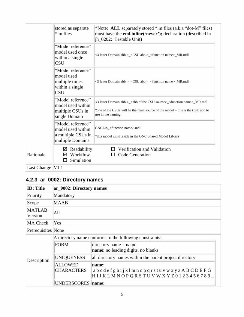
Description
The file names for the Simulink model files and embedded Matlab script files must
conform to the following guidelines:
CSU Simulink
model name <3 letter Domain abb.>_<CSU abb.>_CSU.mdl
Eml functions <3 letter Domain abb.>_<CSU abb.>_<function name>.m
5
stored as separate
*.m files
*Note: ALL separately stored *.m files (a.k.a “dot-M” files)
must have the eml.inline(„never‟); declaration (described in
jh_0202: Testable Unit)
“Model reference”
model used once
within a single
CSU
<3 letter Domain abb.>_<CSU abb.>_<function name>_MR.mdl
“Model reference”
model used
multiple times
within a single
CSU
<3 letter Domain abb.>_<CSU abb.>_<function name>_MR.mdl
“Model reference”
model used within
multiple CSUs in
single Domain
<3 letter Domain abb.>_<abb of the CSU source>_<function name>_MR.mdl
*one of the CSUs will be the main source of the model – this is the CSU abb to
use in the naming
“Model reference”
model used within
a multiple CSUs in
multiple Domains
GNCLib_<function name>.mdl
*this model must reside in the GNC Shared Model Library
Rationale
Readability
Workflow
Simulation
Verification and Validation
Code Generation
Last Change V1.1
4.2.3 ar_0002: Directory names
ID: Title ar_0002: Directory names
Priority Mandatory
Scope MAAB
MATLAB
Version All
MA Check Yes
Prerequisites None
Description
A directory name conforms to the following constraints:
FORM directory name = name
name: no leading digits, no blanks
UNIQUENESS all directory names within the parent project directory
ALLOWED
CHARACTERS
name:
a b c d e f g h i j k l m n o p q r s t u v w x y z A B C D E F G
H I J K L M N O P Q R S T U V W X Y Z 0 1 2 3 4 5 6 7 8 9 _
UNDERSCORES name:

6
can use underscores to separate parts
cannot have more than one consecutive underscore
cannot start with an underscore
cannot end with an underscore
Rationale
Readability
Workflow
Simulation
Verification and Validation
Code Generation
Last Change V1.0
4.2.4 jh_0052: Directory Structure
ID: Title jh_0052: Directory Structure
Priority Mandatory
Scope ORION
MATLAB
Version All
MA Check No
Prerequisites ar_0002: Directory Names
Description
The directory structure for the ORION project shall mimic the example below:
Junction Box models should be placed in the following directory:
<3 Letter Domain> / <JBox_Name>.mdl
CSUs should be placed in the following directory:
<3 Letter Domain> / <CSU Name> / <CSU_Name>.mdl
CSU Memos should be placed in the following directory:
<3 Letter Domain> / <CSU Name> / Memo
Unit Tests should be placed in the following directory:
<3 Letter Domain> / <CSU Name> / Unit_Tests
Rationale
Readability
Workflow
Simulation
Verification and Validation
Code Generation
Last Change V1.0
4.3 Simulink
4.3.1 Diagram Appearance
4.3.1.1 na_0004: Simulink model appearance
ID: Title na_0004 Simulink model appearance
7
Priority Recommended
Scope MAAB
MATLAB
Version All
MA Check Yes
Prerequisites None
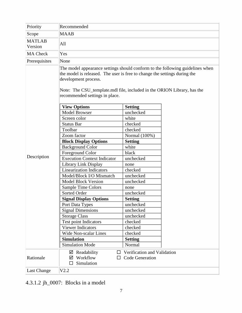
Description
The model appearance settings should conform to the following guidelines when
the model is released. The user is free to change the settings during the
development process.
Note: The CSU_template.mdl file, included in the ORION Library, has the
recommended settings in place.
View Options Setting
Model Browser unchecked
Screen color white
Status Bar checked
Toolbar checked
Zoom factor Normal (100%)
Block Display Options Setting
Background Color white
Foreground Color black
Execution Context Indicator unchecked
Library Link Display none
Linearization Indicators checked
Model/Block I/O Mismatch unchecked
Model Block Version unchecked
Sample Time Colors none
Sorted Order unchecked
Signal Display Options Setting
Port Data Types unchecked
Signal Dimensions unchecked
Storage Class unchecked
Test point Indicators checked
Viewer Indicators checked
Wide Non-scalar Lines checked
Simulation Setting
Simulation Mode Normal
Rationale
Readability
Workflow
Simulation
Verification and Validation
Code Generation
Last Change V2.2
4.3.1.2 jh_0007: Blocks in a model

8
ID: Title jh_0007: Blocks in a model
Priority Recommended
Scope ORION
MATLAB
Version All
MA Check No
Prerequisites None
Description
Each layer of a model must be printable and readable on 11x17 size paper.
The use of the CSU_template.mdl file and the ORION library will enforce this
standard using borders.
Rationale
Readability
Workflow
Simulation
Verification and Validation
Code Generation
Last Change V1.2
4.3.1.3 db_0043: Simulink font and font size
ID: Title db_0043: Simulink font and font size
Priority Strongly recommended
Scope MAAB
MATLAB
Version All
MA Check Yes
Prerequisites jh_0007: Blocks in a Model
Description
All text elements (block names, block annotations and signal labels) except free text
annotations within a model must have the same font style and font size. Fonts and
font size should be selected for legibility.
Note: The ORION Library blocks adhere to this standard and do not need to be
changed.
Note: The selected font should be directly portable (e.g. Simulink/Stateflow default
font) or convertible between platforms (e.g. Arial/Helvetica 12pt).
Note: The CSU_template.mdl file, included in the ORION Library, has a Title text
box and Description text box that are of the recommended format.
Rationale
Readability
Workflow
Simulation
Verification and Validation
Code Generation
Last Change V2.1

9
4.3.1.4 hyl_0103: Model color coding
ID: Title hyl_0103: Model color coding
Priority Strongly recommended
Scope ORION
MATLAB
Version All
MA Check Yes
Prerequisites None
Description
The background color shall be set to:
a) Light blue for subsystems blocks
b) Orange for referenced models
c) Cyan for inport and outport blocks
d) Yellow for From, Goto, and Goto Visibility tags
e) Red for non-ORION Library blocks
(Colorspec RGB value = [1.000000, 0.501961, 0.501961])
f) White for Library blocks
g) Gray for Embedded Matlab Blocks
h) Light Brown for Domain level blocks (non-CSU)
(Colorspec RGB value = [0.792157, 0.772549, 0.725490])
Note: The blocks in the ORION Library are set to the required background color
Example:
Rationale
Readability
Workflow
Simulation
Verification and Validation
Code Generation
Last Change V2.1

10
4.3.2 Model Configuration Options
The model configuration options should be set to those indicated in the Appendix 5.1.
4.3.2.1 jh_0070: Model Configuration Settings
ID: Title jh_0070: Model Configuration Settings
Priority Mandatory
Scope ORION
MATLAB
Version All
MA Check No
Prerequisites None
Description
Each CSU must have the model configuration settings set to the configuration object
specified below – which are included in the latest version of the ORION Library.
CSUs: set to CSUCfgSet or CSUCfgSetMR
Junction Boxes: set to JBoxCfgSet
Domains and above: EmptyBoxCfgSet
Note: These settings will ensure consistency and compatibility across all CSUs and
allow proper generation of autocode.
Note: The ORION Library includes the CSUCfgSet which is a configuration object
that complies with all of these settings. Also, the CSU_template model included in
the ORION Library uses this config file.
Rationale
Readability
Workflow
Simulation
Verification and Validation
Code Generation
Last Change V1.1
4.3.3 Model Documentation
4.3.3.1 hyl_0112: Title on each page
ID: Title hyl_0112: Title on each page
Priority Strongly recommended
Scope ORION
MATLAB
Version All
MA Check No
Prerequisites None

11
Description
Each page shall have a title. This allows pages to be easily identified when printed.
Example:
Note: The title will not transfer to the autocode
Rationale
Readability
Workflow
Simulation
Verification and Validation
Code Generation
Last Change V2.1
4.3.3.2 hyl_0113: Notes on each page
ID: Title hyl_0113: Notes on each page
Priority Strongly recommended
Scope ORION
MATLAB
Version All
MA Check No
Prerequisites None
Description At least one note should be placed on each page explaining the function contained on
that page. Additional notes should be placed on the page as needed. The goal is to

12
document each page with the rationale, assumptions, and intent of the design. The
notes should not contain algorithms. Instead, references should be made in the notes
to the algorithm specification.
Comments should not be index specific because the index used in the autocode may
differ.
Example:
Note: The notes will not transfer to the autocode
Rationale
Readability
Workflow
Simulation
Verification and Validation
Code Generation
Last Change V2.0
4.3.3.3 hyl_0202: Use of revision/trace block
ID: Title hyl_0202: Use of revision/trace block
Priority Strongly recommended
Scope ORION
MATLAB
Version All
MA Check Yes

13
Prerequisites None
Description
Each model shall have a revision block that maintains a unique identification trace
tag, a version number which matches the version in the Configuration Management
system, modification date, and author.
This block is included in the ORION library as the Model_Info block. It contains
the following info:
Author
Date Modified
Version and Instance (controlled by the CM Synergy database)
CSU name
Current System Name
Parent system Name
This block is automatically included in the CSU_template.mdl and in all new
subsystems from the ORION Library.
Example:
Rationale
Readability
Workflow
Simulation
Verification and Validation
Code Generation
Last Change V2.2
4.3.3.4 hyl_0114: Documentation of deviations to standards
ID: Title hyl_0114: Documentation of deviations to standards
Priority Strongly recommended
Scope ORION
MATLAB
Version All
MA Check No
Prerequisites hyl_0113: Notes on each page
Description Any deviations from the standards shall be documented in the notes.
Rationale
Readability
Workflow
Simulation
Verification and Validation
Code Generation
Last Change V2.0

14
4.3.4 Inports and Outports
4.3.4.1 jc_0211: Usable characters for Inport block and Outport block
ID: Title jc_0211: Usable characters for Inport block and Outport block
Priority Strongly recommended
Scope MAAB
MATLAB
Version All
MA Check Yes
Prerequisites None
Description
The names of all Inport blocks and Outport blocks should conform to the following
constraints:
FORM name:
should not start with a number
should not have blank spaces
carriage returns are not allowed
ALLOWED
CHARACTERS
name:
a b c d e f g h i j k l m n o p q r s t u v w x y z
A B C D E F G H I J K L M N O P Q R S T U V W X Y Z
0 1 2 3 4 5 6 7 8 9 _
UNDERSCORES name:
can use underscores to separate parts
cannot have more than one consecutive underscore
cannot start with an underscore
cannot end with an underscore
Rationale
Readability
Workflow
Simulation
Verification and Validation
Code Generation
Last Change V2.1
4.3.4.2 mdb_0042: Port block in Simulink models
ID: Title mdb_0042: Port block in Simulink models
Priority Strongly recommended
Scope ORION (modified MAAB db_0042)
MATLAB
Version All
MA Check No

15
Prerequisites None
Description
In a Simulink model, the ports comply with the following rules:
Inports should be placed on the left side of the diagram, but they can be moved
in to prevent signal crossings.
Outports should be placed on the right side, but they can be moved in to
prevent signal crossings.
Duplicate Inports shall not be used.
Inputs and outputs should be left and right justified
Correct
Incorrect
Notes on the incorrect model
Inport 2 should be moved in so it does not cross the feed back loop lines.
Outport 1 should be moved to the right hand side of the diagram.
Rationale
Readability
Workflow
Simulation
Verification and Validation
Code Generation
Last Change V2.0
4.3.4.3 na_0005: Port block name visibility in Simulink models
ID: Title na_0005: Port block name visibility in Simulink models
Priority Strongly recommended
16
Scope MAAB
MATLAB
Version All
MA Check Yes
Prerequisites None
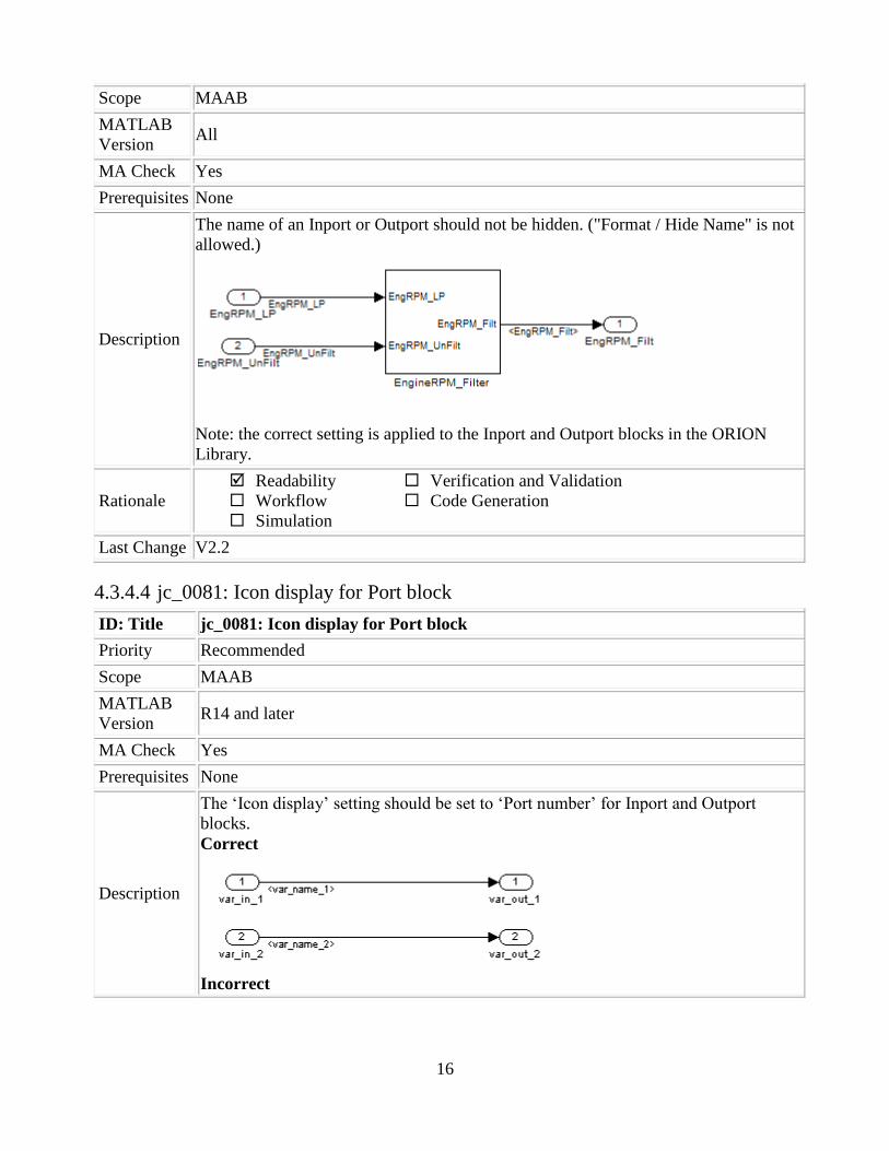
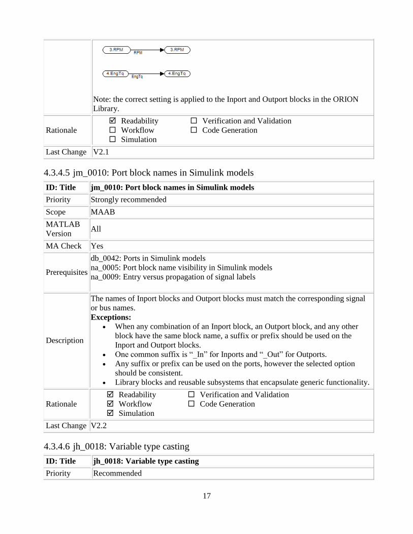
Description
The name of an Inport or Outport should not be hidden. ("Format / Hide Name" is not
allowed.)
Note: the correct setting is applied to the Inport and Outport blocks in the ORION
Library.
Rationale
Readability
Workflow
Simulation
Verification and Validation
Code Generation
Last Change V2.2
4.3.4.4 jc_0081: Icon display for Port block
ID: Title jc_0081: Icon display for Port block
Priority Recommended
Scope MAAB
MATLAB
Version R14 and later
MA Check Yes
Prerequisites None
Description
The „Icon display‟ setting should be set to „Port number‟ for Inport and Outport
blocks.
Correct
Incorrect
17
Note: the correct setting is applied to the Inport and Outport blocks in the ORION
Library.
Rationale
Readability
Workflow
Simulation
Verification and Validation
Code Generation
Last Change V2.1
4.3.4.5 jm_0010: Port block names in Simulink models
ID: Title jm_0010: Port block names in Simulink models
Priority Strongly recommended
Scope MAAB
MATLAB
Version All
MA Check Yes
Prerequisites
db_0042: Ports in Simulink models
na_0005: Port block name visibility in Simulink models
na_0009: Entry versus propagation of signal labels
Description
The names of Inport blocks and Outport blocks must match the corresponding signal
or bus names.
Exceptions: When any combination of an Inport block, an Outport block, and any other
block have the same block name, a suffix or prefix should be used on the
Inport and Outport blocks.
One common suffix is “_In” for Inports and “_Out” for Outports.
Any suffix or prefix can be used on the ports, however the selected option
should be consistent.
Library blocks and reusable subsystems that encapsulate generic functionality.
Rationale
Readability
Workflow
Simulation
Verification and Validation
Code Generation
Last Change V2.2
4.3.4.6 jh_0018: Variable type casting
ID: Title jh_0018: Variable type casting
Priority Recommended

18
Scope ORION
MATLAB
Version All
MA Check No
Prerequisites None
Description
All CSU top level inputs and outputs must be set to the appropriate Simulink bus
object. The bus explicitly defines all of the attributes of the data including the type,
dimension, and rate. This will ensure compatibility with the higher level empty box
architecture.
Also, if model reference blocks are used within a CSU, the input and output data
attributes should be explicitly defined in the ports (dimension, bus type, data type)
Rationale
Readability
Workflow
Simulation
Verification and Validation
Code Generation
Last Change V1.0
4.3.5 Signals and Buses
Signal labels are used to make model functionality more understandable from the Simulink
diagram. They can also be used to control the variable names used in simulation and code
generation. Signal labels should be entered only once (at the point of signal origination). Often it is
desirable to also display the signal name elsewhere in the model. In these cases, the signal name
should be inherited until the signal is functionally transformed. (Passing a signal through an
integrator is functionally transforming. Passing a signal through an Inport into a nested subsystem is
not.) Once a named signal is functionally transformed, a new name should be associated with it.
Signals may be scalars, vectors, or buses. They may carry data or control flows. Unless explicitly
stated otherwise, the following naming rules apply to all types of signals.
4.3.5.1 jc_0221: Usable characters for signal line name
ID: Title jc_0221: Usable characters for signal line names
Priority Strongly recommended
Scope MAAB
MATLAB
Version All
MA Check Yes
Prerequisites None
Description
All named signals should conform to the following constraints:
FORM name:
should not start with a number
19
should not have blank spaces
carriage returns are not allowed
ALLOWED
CHARACTERS
name:
a b c d e f g h i j k l m n o p q r s t u v w x y z
A B C D E F G H I J K L M N O P Q R S T U V W X Y Z
0 1 2 3 4 5 6 7 8 9 _
UNDERSCORES name:
can use underscores to separate parts
cannot have more than one consecutive underscore
cannot start with an underscore
cannot end with an underscore
Rationale
Readability
Workflow
Simulation
Verification and Validation
Code Generation
Last Change V2.1
4.3.5.2 jh_0040: Usable characters for Simulink Bus names
ID: Title jh_0040: Usable characters for Simulink Bus Names
Priority Strongly recommended
Scope MAAB
MATLAB
Version All
MA Check Yes – this check is covered by jc_0221
Prerequisites None
Description
All Simulink Bus names should conform to the following constraints:
FORM name:
should not start with a number
should not have blank spaces
carriage returns are not allowed
ALLOWED
CHARACTERS
name:
a b c d e f g h i j k l m n o p q r s t u v w x y z
A B C D E F G H I J K L M N O P Q R S T U V W X Y Z
0 1 2 3 4 5 6 7 8 9 _
UNDERSCORES name:
can use underscores to separate parts
cannot have more than one consecutive underscore
cannot start with an underscore
cannot end with an underscore
Rationale
Readability
Workflow
Simulation
Verification and Validation
Code Generation

20
Last Change V1.0
4.3.5.3 bn_0002: Signal name length limit
ID: Title bn_0002: Signal name length limit
Priority Strongly recommended
Scope ORION
MATLAB
Version All
MA Check Yes
Prerequisites jc_0221: Usable characters for signal line names
Description
The names of all signals must be unique. The Compiler limit of 32 characters must be
observed when creating signal names that are used for variable names in code.
32 characters is the maximum limit
Example:
Signal_Value_Argument_Variable_Example - should be changed to
signal_Value_Argument_Variable_Ex
Rationale
Readability
Workflow
Simulation
Verification and Validation
Code Generation
Last Change V2.2
4.3.5.4 jh_0041: Simulink Bus Name Length Limit
ID: Title jh_0041: Simulink Bus name length limit
Priority Strongly recommended
Scope ORION
MATLAB
Version All
MA Check Yes – this check is covered by bn_0002
Prerequisites jh_0040: Usable characters for Simulink Bus Names
Description
The names of all Buses must be unique for the entire software model unless the
contents of the bus are identical. Bus names must start with a capital letter. The
Compiler limit of 32 characters must be observed when creating signal names that are
used for variable names in code.
32 characters is the maximum limit
Example:
BUS_Value_Argument_Variable_Example - should be changed to
BUS_Value_Argument_Variable_Ex

21
Rationale
Readability
Workflow
Simulation
Verification and Validation
Code Generation
Last Change V1.1
4.3.5.5 jh_0051: Simulink Bus Format
ID: Title jh_0051: Simulink Bus Format
Priority Mandatory
Scope ORION
MATLAB
Version All
MA Check Yes
Prerequisites jh_0040: Usable characters for Simulink Bus Names
Description
The root level of a CSU should have 2 inports and 1 outport and follow the following
standard:
Input port and bus object name:
<3 letter Domain abb.>_<CSU abb.>_IN
Input parameter port and bus object name:
<3 letter Domain abb.>_<CSU abb.>_PRM
Output port and bus object name:
<3 letter Domain abb.>_<CSU abb.>_OUT
Internal bus object name (these are buses that are not used outside of the CSU):
<3 letter Domain abb.>_<CSU abb.>_<your_internal_bus_name>
The script that loads the CSU input, output, and parameter buses to the workspace
should use the following naming convention:
loadCSUBuses_<3 letter Domain abb>_<CSU abb>.m
The script that loads the internal bus to the workspace should use the following
naming convention:
loadIntlBuses_<3 letter Domain abb>_<CSU abb>.m
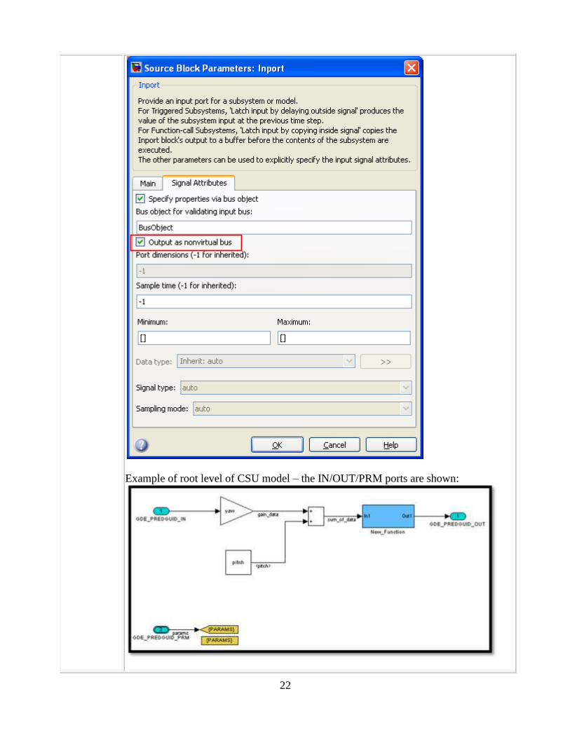
The top level IO ports should be set to non-virtual to ensure that the bus structure is
retained in the autocode. The following diagram shows the dialog box for an input
port with the “Output as non-virtual bus” option checked. Version 2.0 of the Orion
Library has this option set by default for the input ports/output ports/ and bus creator
blocks.
22
Example of root level of CSU model – the IN/OUT/PRM ports are shown:
23
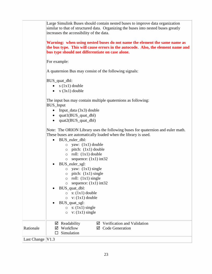
Large Simulink Buses should contain nested buses to improve data organization
similar to that of structured data. Organizing the buses into nested buses greatly
increases the accessibility of the data.
Warning: when using nested buses do not name the element the same name as
the bus type. This will cause errors in the autocode. Also, the element name and
bus type should not differentiate on case alone.
For example:
A quaternion Bus may consist of the following signals:
BUS_quat_dbl:
s (1x1) double
v (3x1) double
The input bus may contain multiple quaternions as following:
BUS_Input
Input_data (3x3) double
quat1(BUS_quat_dbl)
quat2(BUS_quat_dbl)
Note: The ORION Library uses the following buses for quaternion and euler math.
These buses are automatically loaded when the library is used.
BUS_euler_dbl:
o yaw: (1x1) double
o pitch: (1x1) double
o roll: (1x1) double
o sequence: (1x1) int32
BUS_euler_sgl:
o yaw: (1x1) single
o pitch: (1x1) single
o roll: (1x1) single
o sequence: (1x1) int32
BUS_quat_dbl:
o s: (1x1) double
o v: (1x1) double
BUS_quat_sgl:
o s: (1x1) single
o v: (1x1) single
Rationale
Readability
Workflow
Simulation
Verification and Validation
Code Generation
Last Change V1.3
24
4.3.5.6 dm_0001: Signal and Bus Element Naming Convention
ID: Title dm_0001: Signal and Bus Element Naming Convention
Priority Strongly recommended
Scope ORION
MATLAB
Version All
MA Check No
Prerequisites
Description
Signal and Bus Element names shall adhere to the following convention:
The first letter of each word contained in a signal or bus element name shall
be capitalized.
Each word contained within a signal or bus element name shall be separated
with a single underscore or with no space at all.
For multi-word signal or bus element names the first letter of second and
subsequent words shall be capitalized (example: Multi_Word_Identifier or
MultiWordIdentifier).
Blank characters shall not be used to separate words use to form signal or bus
element names.
When a signal or bus element name contains an acronym, the acronym should
be represented in uppercase letters (upper case capitalization).
Note: This does not apply to the common quaternion and euler buses used by blocks
in the ORION Library.
Rationale
Readability
Workflow
Simulation
Verification and Validation
Code Generation
Last Change V1.3
4.3.5.7 mj_0001: CSU Input Bus Naming
ID: Title mj_0001: CSU input Bus Naming
Priority Recommended
Scope ORION
MATLAB
Version All
MA Check No
Prerequisites jh_0051: Simulink Bus Format
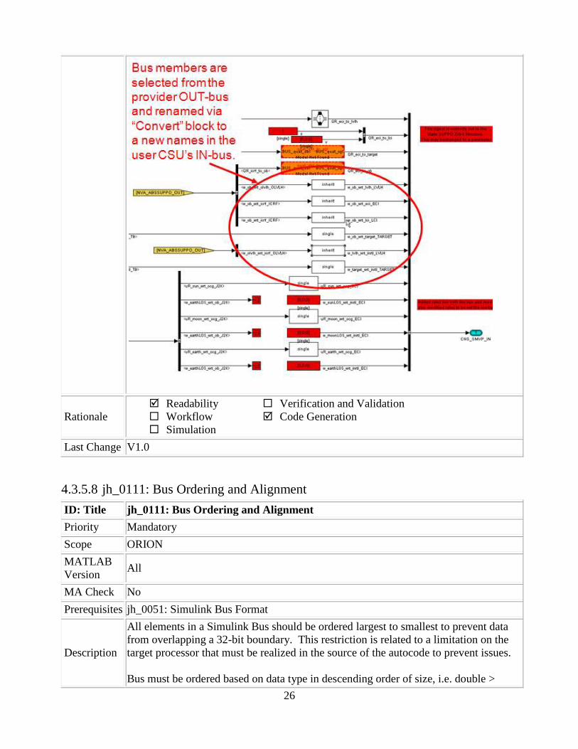
Description
CSU input bus types should have field names identical to their upstream CSU output
bus field names whenever possible. This facilitates traceability and reduces error
potential. Exceptions may be made on a case by case basis to keep CSUs generic or
for other reasons. Variable name changes inside of CSUs are permissible at the CSU
developer‟s discretion.

25
Example of acceptable internal signal name changes with selected CSU inputs feeding
subsystems with differing input port names:
Do not change the variable names at the Junction Box Level (shown below)
26
Rationale
Readability
Workflow
Simulation
Verification and Validation
Code Generation
Last Change V1.0
4.3.5.8 jh_0111: Bus Ordering and Alignment
ID: Title jh_0111: Bus Ordering and Alignment
Priority Mandatory
Scope ORION
MATLAB
Version All
MA Check No
Prerequisites jh_0051: Simulink Bus Format
Description
All elements in a Simulink Bus should be ordered largest to smallest to prevent data
from overlapping a 32-bit boundary. This restriction is related to a limitation on the
target processor that must be realized in the source of the autocode to prevent issues.
Bus must be ordered based on data type in descending order of size, i.e. double >

27
single > uint32 > uint16 > uint8 (Boolean is treated like an uint8).
For Example, the following bus will correctly fall on 32-bit boundary.
float a;
float b
uint8 c[3];
However, this bus will not:
float a;
uint8 c[3];
float b;
Rationale
Readability
Workflow
Simulation
Verification and Validation
Code Generation
Last Change V1.0
4.3.5.9 jh_0117: Shared CSUs Across Domains
ID: Title jh_0117: Shared CSUs Across Domains
Priority Mandatory
Scope ORION
MATLAB
Version All
MA Check No
Prerequisites jh_0051: Simulink Bus Format
Description
In some rare cases, a CSU may be used in more than one domain. This CSU will
perform the same function in each CSU and is not modified in any way.
If this is the case one of the domains should be selected as the owner of the CSU. The
CSU will be named using the domain prefix of the parent Domain. In the other/non-
owner Domain, the CSU is referenced in a Junction box with I/O/PRM naming
specific to the domain and function of the CSU. Within this Junction box, the signals
will be renamed to correspond to the naming convention of the referenced CSU
model:
Note: The configuration set of the CSU must be set to use “CSUCfgSetMR”. This
will ensure that the code produced for the CSU can be called from multiple domains.
Example:
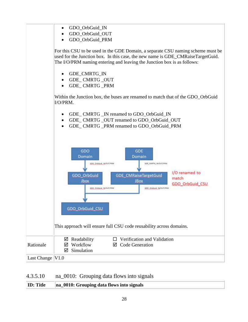
The GDO_OrbGuid_CSU is used within both the GDO and GDE domains. The GDO
domain is chosen as the parent. The I/O/PRM naming is tied to the GDO Domain:
28
GDO_OrbGuid_IN
GDO_OrbGuid_OUT
GDO_OrbGuid_PRM
For this CSU to be used in the GDE Domain, a separate CSU naming scheme must be
used for the Junction box. In this case, the new name is GDE_CMRaiseTargetGuid.
The I/O/PRM naming entering and leaving the Junction box is as follows:
GDE_CMRTG_IN
GDE_ CMRTG _OUT
GDE_ CMRTG _PRM
Within the Junction box, the buses are renamed to match that of the GDO_OrbGuid
I/O/PRM.
GDE_ CMRTG _IN renamed to GDO_OrbGuid_IN
GDE_ CMRTG _OUT renamed to GDO_OrbGuid_OUT
GDE_ CMRTG _PRM renamed to GDO_OrbGuid_PRM
This approach will ensure full CSU code reusability across domains.
Rationale
Readability
Workflow
Simulation
Verification and Validation
Code Generation
Last Change V1.0
4.3.5.10 na_0010: Grouping data flows into signals
ID: Title na_0010: Grouping data flows into signals

29
Priority Strongly recommended
Scope MAAB
MATLAB
Version All
MA Check Yes
Prerequisites None
Description
Vectors
The individual scalar signals composing a vector must have common functionality,
data types, dimensions and units. The most common example of a vector signal is
sensor or actuator data that is grouped into an array indexed by location. The output
of a Mux block must always be a vector. The inputs to a Mux block must always be
scalars.
All vectors must be Column vectors (nx1)
Buses
Signals that do not meet the vectorization criteria described above must only be
grouped into bus signals. Bus selector blocks may only be used with a bus signal
input; they must not be used to extract scalar signals from vector signals.
Examples
Some examples of vector signals include:
Vector type Size
Column vector [n 1]
Wheel speed vector [Number of wheels 1]
Cylinder vector [Number of cylinders 1]
Position vector based on 2-D
coordinates [2 1]
Position vector based on 3-D
coordinates [3 1]
Some examples of bus signals include:
Bus Type Elements
Sensor Bus
Force Vector [Fx; Fy; Fz]
Position
Wheel Speed Vector [Θlf ; Θrf ; Θlr ; Θrr]
Acceleration
Pressure
Controller Bus Sensor Bus
Actuator Bus
Serial Data Bus Coolant Temperature

30
Engine Speed,
Passenger Door Open
Rationale
Readability
Workflow
Simulation
Verification and Validation
Code Generation
Last Change V2.1
4.3.5.11 na_0009: Entry versus propagation of signal labels
ID: Title na_0009: Entry versus propagation of signal labels
Priority Strongly recommended
Scope MAAB
MATLAB
Version All
MA Check Yes
Prerequisites na_0008: Display of labels on signals
Description
If a label is present on a signal, the following rules define whether that label shall be
created there (entered directly on the signal) or propagated from its true source
(inherited from elsewhere in the model by using the „<‟ character).
1. Any displayed signal label must be entered for signals that:
a. Originate from an Inport at the Root (top) Level of a model
b. Originate from a basic block that performs a transformative operation
(For the purpose of interpreting this rule only, the Bus Creator block,
Mux block and Selector block shall be considered to be included among
the blocks that perform transformative operations.)
2. Any displayed signal label must be propagated for signals that:
a. Originate from an Inport block in a nested subsystem
Exception: If the nested subsystem is a library subsystem, a label may
be entered on the signal coming from the Inport to accommodate reuse
of the library block.
b. Originate from a basic block that performs a non-transformative
operation
c. Originate from a Subsystem or Stateflow chart block
Exception: If the connection originates from the output of a library
subsystem block instance, a new label may be entered on the signal to
accommodate reuse of the library block.

31
Rationale
Readability
Workflow
Simulation
Verification and Validation
Code Generation
Last Change V2.0
4.3.5.12 hyl_0311: Naming of signals passed through multiple subsystems
ID: Title hyl_0311: Naming of signals passed through multiple subsystems
Priority Strongly recommended
Scope ORION
MATLAB
Version All
MA Check Yes
Prerequisites None
Description
Names of inports/outports should not change between a subsystem and its parent, with
the allowable exception that the first layer of subsystems may change a top-level
in/out name (at the CSU root level). If such a change is performed, all first layer
subsystems shall use the same name change for consistency. [Example: A signal
called "pitchAngle" can be input, and changed to "pitch" on a 1st subsystem layer, but
you cannot change this name to "theta" in a lower subsystem.] This standard is
completed for convenience within the model.
Example:
Incorrect

32
Rationale
Readability
Workflow
Simulation
Verification and Validation
Code Generation
Last Change V2.1
4.3.5.13 na_0008: Display of labels on signals
ID: Title na_0008: Display of labels on signals
Priority Recommended
Scope MAAB
MATLAB
Version All
MA Check Yes
Prerequisites None
33
Description
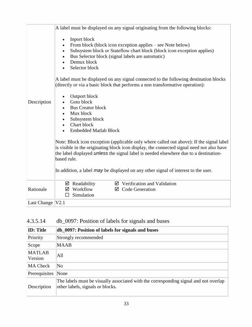
A label must be displayed on any signal originating from the following blocks:
Inport block
From block (block icon exception applies – see Note below)
Subsystem block or Stateflow chart block (block icon exception applies)
Bus Selector block (signal labels are automatic)
Demux block
Selector block
A label must be displayed on any signal connected to the following destination blocks
(directly or via a basic block that performs a non transformative operation):
Outport block
Goto block
Bus Creator block
Mux block
Subsystem block
Chart block
Embedded Matlab Block
Note: Block icon exception (applicable only where called out above): If the signal label
is visible in the originating block icon display, the connected signal need not also have
the label displayed unless the signal label is needed elsewhere due to a destination-
based rule.
In addition, a label may be displayed on any other signal of interest to the user.
Rationale
Readability
Workflow
Simulation
Verification and Validation
Code Generation
Last Change V2.1
4.3.5.14 db_0097: Position of labels for signals and buses
ID: Title db_0097: Position of labels for signals and buses
Priority Strongly recommended
Scope MAAB
MATLAB
Version All
MA Check No
Prerequisites None
Description
The labels must be visually associated with the corresponding signal and not overlap
other labels, signals or blocks.

34
Labels should be located consistently below horizontal lines and close to the
corresponding source or destination block.
Correct:
Rationale
Readability
Workflow
Simulation
Verification and Validation
Code Generation
Last Change V2.0
4.3.5.15 hyl_0110: Branching line format
ID: Title hyl_0110: Branching line format
Priority Strongly recommended
Scope ORION
MATLAB
Version All
MA Check No
Prerequisites None
Description
All branch lines shall have a "solder-joint" showing the connection point. Line
branches should be made as short as possible, avoid crossing other lines as much as
possible and not cut across blocks.
Examples of Incorrect Signal Line Usage
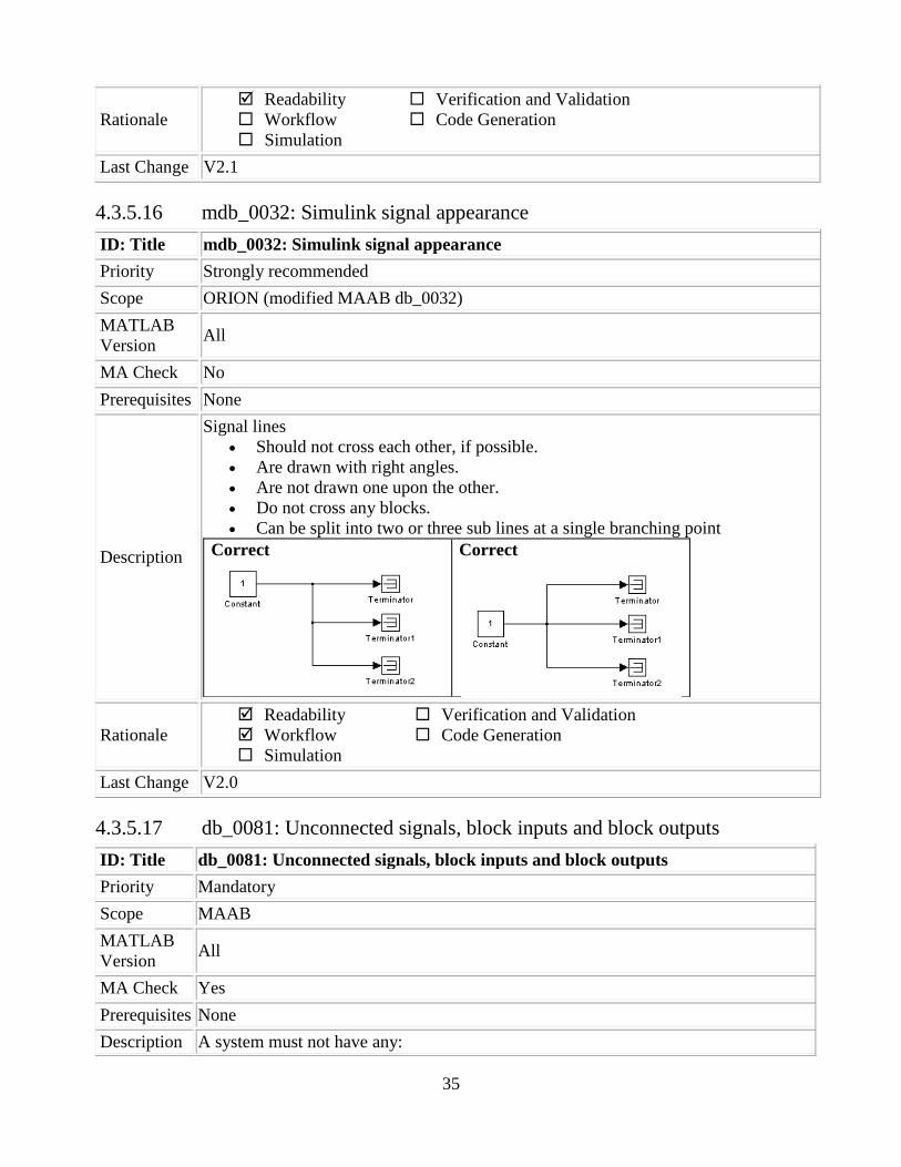
35
Rationale
Readability
Workflow
Simulation
Verification and Validation
Code Generation
Last Change V2.1
4.3.5.16 mdb_0032: Simulink signal appearance
ID: Title mdb_0032: Simulink signal appearance
Priority Strongly recommended
Scope ORION (modified MAAB db_0032)
MATLAB
Version All
MA Check No
Prerequisites None
Description
Signal lines
Should not cross each other, if possible.
Are drawn with right angles.
Are not drawn one upon the other.
Do not cross any blocks.
Can be split into two or three sub lines at a single branching point
Correct
Correct
Rationale
Readability
Workflow
Simulation
Verification and Validation
Code Generation
Last Change V2.0
4.3.5.17 db_0081: Unconnected signals, block inputs and block outputs
ID: Title db_0081: Unconnected signals, block inputs and block outputs
Priority Mandatory
Scope MAAB
MATLAB
Version All
MA Check Yes
Prerequisites None
Description A system must not have any:

36
Unconnected subsystem or basic block inputs.
Unconnected subsystem or basic block outputs
Unconnected signal lines
An otherwise unconnected input should be connected to a ground block
An otherwise unconnected output should be connected to a terminator block
Correct
Incorrect
Rationale
Readability
Workflow
Simulation
Verification and Validation
Code Generation
Last Change V2.0
4.3.5.18 jh_0061: Use of Parameters
ID: Title jh_0061: Use of Parameters
Priority Mandatory
Scope ORION
MATLAB
Version All
MA Check No
Prerequisites None
Description
Parameters may be accessed without connecting signal lines throughout the CSU
model. The following blocks make up the Parameter interface for the ORION Library:
Param_Gain
Param_Const
Param_Goto
Param_Visibility
Param_From
The data on the parameter bus can be accessed by using the Param_Gain,
Param_Const, and Param_Goto blocks. The Param_Gain and Param_Const let you
select any data that is on the Parameter bus directly without using a bus selector and
connecting the signal line to the root level.
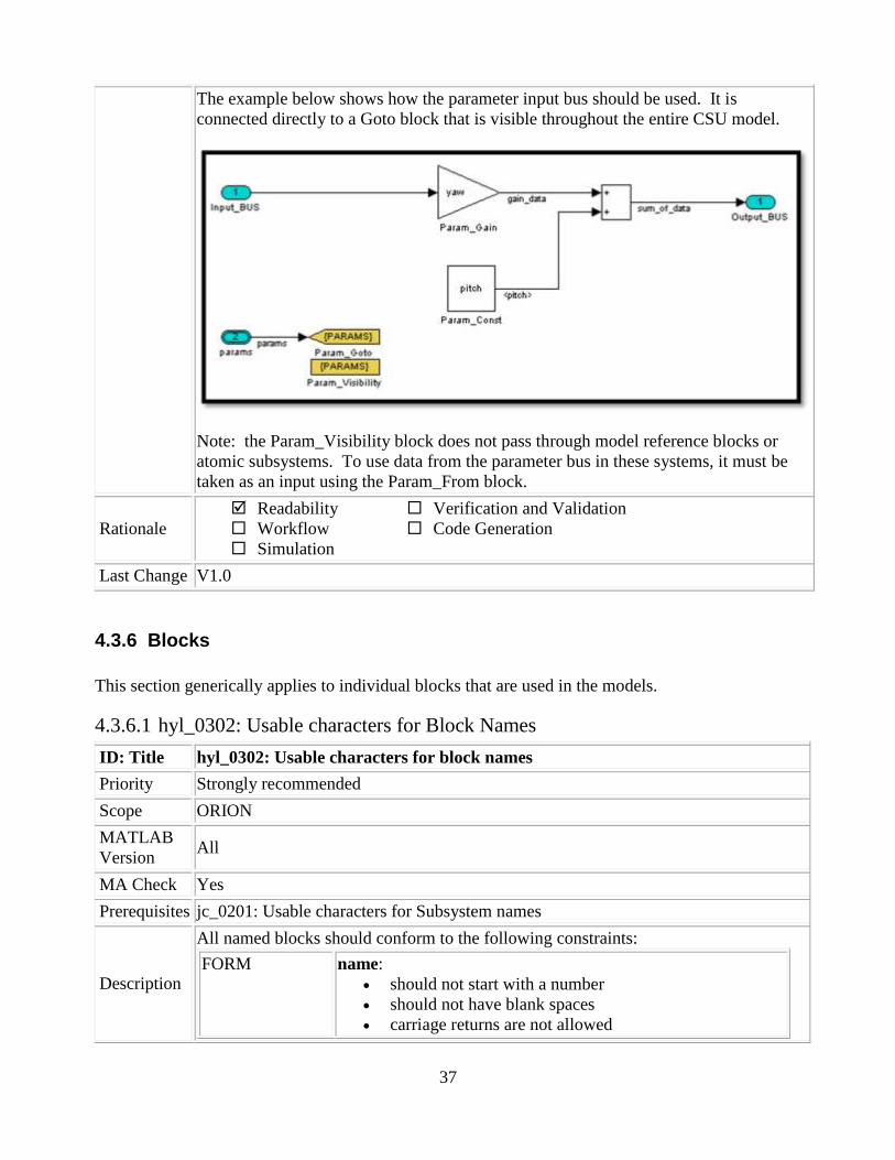
37
The example below shows how the parameter input bus should be used. It is
connected directly to a Goto block that is visible throughout the entire CSU model.
Note: the Param_Visibility block does not pass through model reference blocks or
atomic subsystems. To use data from the parameter bus in these systems, it must be
taken as an input using the Param_From block.
Rationale
Readability
Workflow
Simulation
Verification and Validation
Code Generation
Last Change V1.0
4.3.6 Blocks
This section generically applies to individual blocks that are used in the models.
4.3.6.1 hyl_0302: Usable characters for Block Names
ID: Title hyl_0302: Usable characters for block names
Priority Strongly recommended
Scope ORION
MATLAB
Version All
MA Check Yes
Prerequisites jc_0201: Usable characters for Subsystem names
Description
All named blocks should conform to the following constraints:
FORM name:
should not start with a number
should not have blank spaces
carriage returns are not allowed
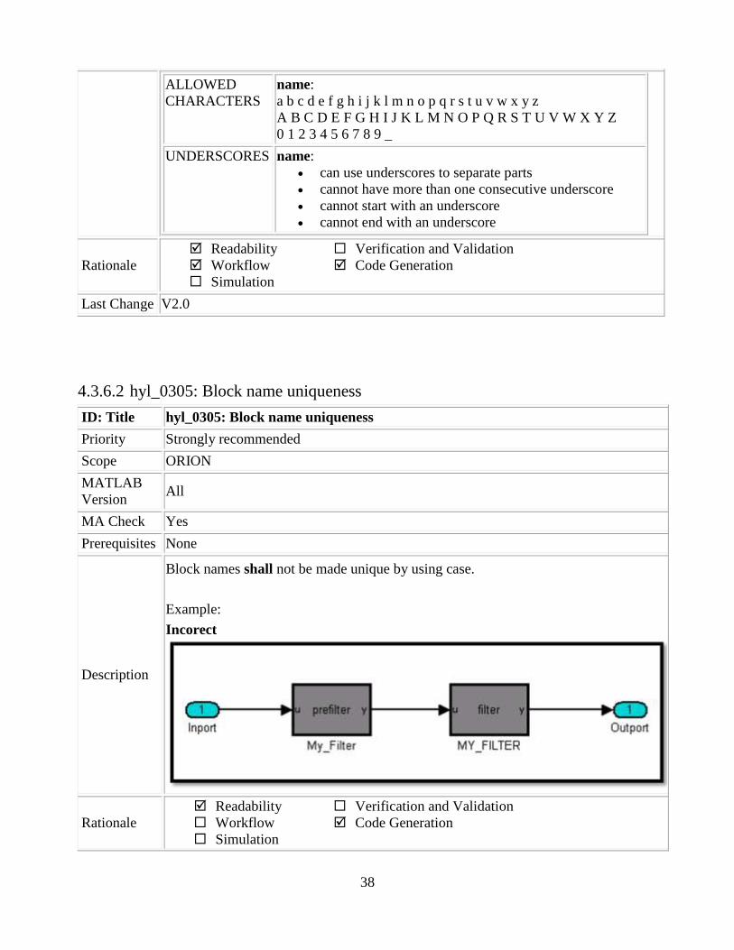
38
ALLOWED
CHARACTERS
name:
a b c d e f g h i j k l m n o p q r s t u v w x y z
A B C D E F G H I J K L M N O P Q R S T U V W X Y Z
0 1 2 3 4 5 6 7 8 9 _
UNDERSCORES name:
can use underscores to separate parts
cannot have more than one consecutive underscore
cannot start with an underscore
cannot end with an underscore
Rationale
Readability
Workflow
Simulation
Verification and Validation
Code Generation
Last Change V2.0
4.3.6.2 hyl_0305: Block name uniqueness
ID: Title hyl_0305: Block name uniqueness
Priority Strongly recommended
Scope ORION
MATLAB
Version All
MA Check Yes
Prerequisites None
Description
Block names shall not be made unique by using case.
Example:
Incorect
Rationale
Readability
Workflow
Simulation
Verification and Validation
Code Generation
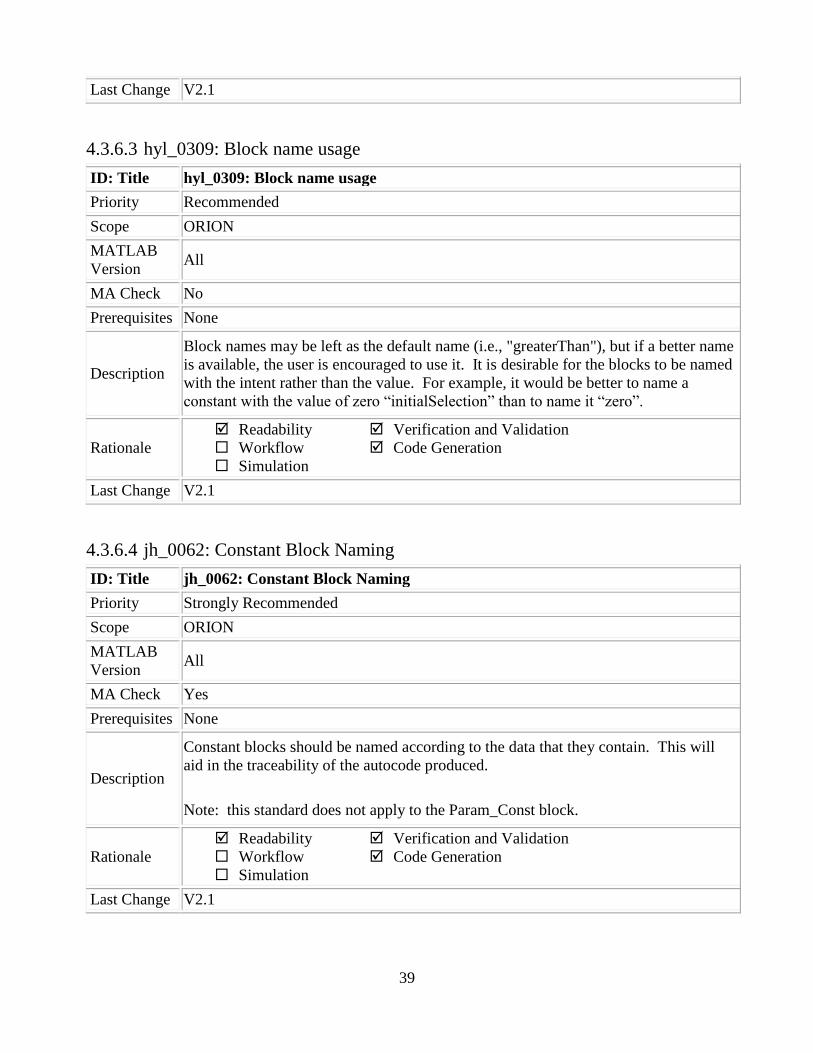
39
Last Change V2.1
4.3.6.3 hyl_0309: Block name usage
ID: Title hyl_0309: Block name usage
Priority Recommended
Scope ORION
MATLAB
Version All
MA Check No
Prerequisites None
Description
Block names may be left as the default name (i.e., "greaterThan"), but if a better name
is available, the user is encouraged to use it. It is desirable for the blocks to be named
with the intent rather than the value. For example, it would be better to name a
constant with the value of zero “initialSelection” than to name it “zero”.
Rationale
Readability
Workflow
Simulation
Verification and Validation
Code Generation
Last Change V2.1
4.3.6.4 jh_0062: Constant Block Naming
ID: Title jh_0062: Constant Block Naming
Priority Strongly Recommended
Scope ORION
MATLAB
Version All
MA Check Yes
Prerequisites None
Description
Constant blocks should be named according to the data that they contain. This will
aid in the traceability of the autocode produced.
Note: this standard does not apply to the Param_Const block.
Rationale
Readability
Workflow
Simulation
Verification and Validation
Code Generation
Last Change V2.1

40
4.3.6.5 jm_0002: Block resizing
ID: Title jm_0002: Block resizing
Priority Mandatory
Scope MAAB
MATLAB
Version All
MA Check No
Prerequisites None
Description
All blocks in a model must be sized such that their icon is completely visible and
recognizable. In particular, any text displayed (e.g. tunable parameters, filenames,
equations) in the icon must be readable.
This guideline requires resizing of blocks with variable icons or blocks with a variable
number of inputs and outputs. In some cases it may not be practical or desirable to
resize the block icon of a subsystem block so that all of the input and output names
within it are readable. In such cases, the user may hide the names in the icon by using
a mask or by hiding the names in the subsystem associated with the icon. In this
approach, the signal lines coming into and out of the subsystem block should be
clearly labeled in close proximity to the block.
Correct
Incorrect
Rationale
Readability
Workflow
Simulation
Verification and Validation
Code Generation
Last Change V2.0
4.3.6.6 db_0142: Position of block names
ID: Title db_0142: Position of block names
Priority Strongly recommended
Scope MAAB
MATLAB All

41
Version
MA Check Yes
Prerequisites None
Description
If shown, the name of each block should be placed below the block.
Rationale
Readability
Workflow
Simulation
Verification and Validation
Code Generation
Last Change V2.0
4.3.6.7 jc_0061: Display of block names
ID: Title jc_0061: Display of block names
Priority Recommended
Scope MAAB
MATLAB
Version All
MA Check Yes
Prerequisites None
Description
The block name should be displayed when it provides descriptive information.
The block name should not be displayed if the block function is known from its
appearance.

42
Rationale
Readability
Workflow
Simulation
Verification and Validation
Code Generation
Last Change V2.1
4.3.6.8 db_0140: Display of basic block parameters
ID: Title db_0140: Display of basic block parameters
Priority Recommended
Scope MAAB
MATLAB
Version All
MA Check Yes
Prerequisites None
Description
Important parameters with values other than the block‟s default values should be
displayed. Many blocks within the ORION Library have important parameter values
displayed by default.
Note: The attribute string is one method to support this. The block annotation tab
allows the users to add the desired attribute information.
Correct

43
Rationale
Readability
Workflow
Simulation
Verification and Validation
Code Generation
Last Change V2.1
4.3.6.9 mdb_0141: Signal flow in Simulink models
ID: Title mdb_0141: Signal flow in Simulink models
Priority Strongly recommended
Scope ORION (modified MAAB db_0141)
MATLAB
Version All
MA Check No
Prerequisites None
Description
The signal flow in a model is from left to right.
Exception: Feedback loops
Sequential blocks or subsystems are arranged from left to right.
Exception: Feedback loops
Parallel blocks or subsystems are arranged from top to bottom.
Rationale
Readability
Workflow
Simulation
Verification and Validation
Code Generation
Last Change V2.0
4.3.6.10 jc_0171: Maintaining signal flow when using Goto and From blocks
ID: Title jc_0171: Maintaining signal flow when using Goto and From blocks
Priority Strongly recommended
Scope MAAB
MATLAB All
Signal flow should be drawn from left to rightSignal flow should be drawn from left to right

44
Version
MA Check No
Prerequisites None
Description
Visual depiction of signal flow must be maintained between subsystems.
Use of Goto and From blocks is allowed provided that
At least one signal line is used between connected subsystems.
If the subsystems are connected both in a feed forward and feedback loop
then at least one signal line for each direction must be connected.
Correct
Incorrect
Rationale
Readability
Workflow
Simulation
Verification and Validation
Code Generation
Last Change V2.0
4.3.6.11 jc_0281: Naming of Trigger Port block and Enable Port block
ID: Title jc_0281: Naming of Trigger Port block and Enable Port block
Priority Strongly recommended
Scope J-MAAB
MATLAB All
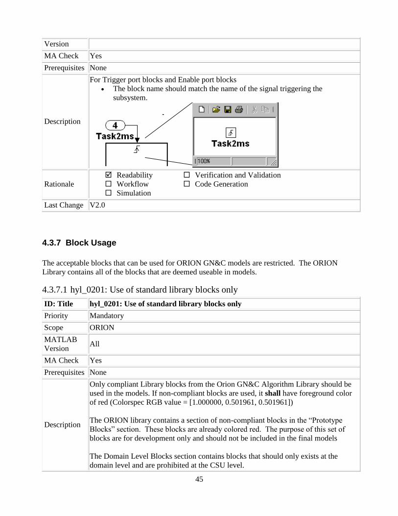
45
Version
MA Check Yes
Prerequisites None
Description
For Trigger port blocks and Enable port blocks
The block name should match the name of the signal triggering the
subsystem.
Rationale
Readability
Workflow
Simulation
Verification and Validation
Code Generation
Last Change V2.0
4.3.7 Block Usage
The acceptable blocks that can be used for ORION GN&C models are restricted. The ORION
Library contains all of the blocks that are deemed useable in models.
4.3.7.1 hyl_0201: Use of standard library blocks only
ID: Title hyl_0201: Use of standard library blocks only
Priority Mandatory
Scope ORION
MATLAB
Version All
MA Check Yes
Prerequisites None
Description
Only compliant Library blocks from the Orion GN&C Algorithm Library should be
used in the models. If non-compliant blocks are used, it shall have foreground color
of red (Colorspec RGB value = [1.000000, 0.501961, 0.501961])
The ORION library contains a section of non-compliant blocks in the “Prototype
Blocks” section. These blocks are already colored red. The purpose of this set of
blocks are for development only and should not be included in the final models
The Domain Level Blocks section contains blocks that should only exists at the
domain level and are prohibited at the CSU level.

46
Rationale
Readability
Workflow
Simulation
Verification and Validation
Code Generation
Last Change V2.1
4.3.7.2 jh_0101: Use of Right-Handed Quaternions only
ID: Title jh_0101: Use of Right-Handed Quaternions Only
Priority Mandatory
Scope ORION
MATLAB
Version All
MA Check Yes
Prerequisites None
Description
Orion GN&C models shall only use right-handed quaternions. The ORION GN&C
Library does not support the use of left-handed quaternions.
Rationale
Readability
Workflow
Simulation
Verification and Validation
Code Generation
Last Change V1.0
4.3.7.3 na_0003: Simple logical expressions in If Condition block
ID: Title na_0003: Simple logical expressions in If Condition block
Priority Mandatory

47
Scope MAAB
MATLAB
Version All
MA Check Yes
Prerequisites None
Description
A logical expression may be implemented within an If Condition block instead of
building it up with logical operation blocks if the expression contains two or fewer
primary expressions. All inputs to an If Condition block must be the same data type.
A primary expression is defined here to be one of the following:
An input
A constant
A constant parameter
A parenthesized expression containing no operators except zero or one
instances of the following operators: < , <= , > , >= , ~=, ==, ~ . (See below
for examples)
Exception:
A logical expression may contain more than two primary expressions if both of the
following are true:
The primary expressions are all inputs
Only one type of logical operator is present
Examples of acceptable exceptions:
u1 | u2 | u3 | u4 | u5
u1 & u2 & u3 & u4
Examples of primary expressions include:
u1
5
K
(u1 > 0)
(u1 <= G)
(u1 > U2)
(~u1)
Examples of acceptable logical expressions include:
u1 | u2
(u1 > 0) & (u1 < 20)
(u1 > 0) & (u2 < u3)
(u1 > 0) & (~u2)
Examples of unacceptable logical expressions include:

48
u1 & u2 | u3 (too many primary expressions)
u1 & (u2 | u3) (unacceptable operator within primary
expression)
(u1 > 0) & (u1 < 20) & (u2 > 5) (too many primary expressions that are
not inputs)
(u1 > 0) & ((2*u2) > 6) (unacceptable operator within
primary expression)
Rationale
Readability
Workflow
Simulation
Verification and Validation
Code Generation
Last Change V2.1
4.3.7.4 na_0002: Appropriate implementation of fundamental logical and numerical
operations
ID: Title na_0002: Appropriate implementation of fundamental logical and numerical
operations
Priority Mandatory
Scope MAAB
MATLAB
Version All
MA Check No
Prerequisites None
Description
Blocks that are intended to perform numerical operations must not be used to
perform logical operations.
Incorrect
A logical output should never be directly connected to the input of blocks
that operate on numerical inputs.
The result of a logical expression fragment should never be operated on by a
numerical operator.
Incorrect

49
Blocks that are intended to perform logical operations must not be used to
perform numerical operations.
A numerical output should never be connected to the input of blocks that
operate on logical inputs.
Incorrect
Rationale
Readability
Workflow
Simulation
Verification and Validation
Code Generation
Last Change V2.0
4.3.7.5 na_0011: Scope of Goto and From blocks
ID: Title na_0011: Scope of Goto and From blocks
Priority Strongly recommended
Scope MAAB
MATLAB
Version All
MA Check Yes
Prerequisites None
Description For signal flows the following rules apply:
From and Goto blocks must use local scope.
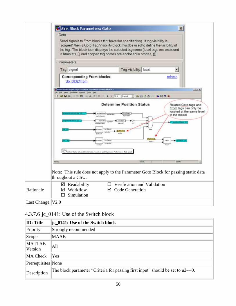
50
Note: This rule does not apply to the Parameter Goto Block for passing static data
throughout a CSU.
Rationale
Readability
Workflow
Simulation
Verification and Validation
Code Generation
Last Change V2.0
4.3.7.6 jc_0141: Use of the Switch block
ID: Title jc_0141: Use of the Switch block
Priority Strongly recommended
Scope MAAB
MATLAB
Version All
MA Check Yes
Prerequisites None
Description The block parameter “Criteria for passing first input” should be set to u2~=0.

51
The block parameter “Criteria for passing first input” must not be set to u2>Threshold
for R13 versions of MATLAB.
The logic for the switch block should be defined on the same level as the switch block
itself.
Correct
Incorrect
Note: This criteria is not available to change in the ORION Library. The criteria is
locked to “u2 ~= 0”.
Rationale
Readability
Workflow
Simulation
Verification and Validation
Code Generation
Last Change V2.1

52
4.3.7.7 hyl_0207: Limiting input to multiport switches
ID: Title hyl_0207: Limiting input to multiport switches
Priority Mandatory
Scope ORION
MATLAB
Version All
MA Check No
Prerequisites None
Description
Logic input to Multiport Switch Blocks shall never be less than one, or greater than
the number of switch ports on the block. The user ensures this by the model-design
or upstream limiting.
Note: One based indexing [1, 2, 3,…] is used for Matlab/Simulink
Rationale
Readability
Workflow
Simulation
Verification and Validation
Code Generation
Last Change V2.1
4.3.7.8 jc_0121: Use of the Sum block
ID: Title jc_0121: Use of the Sum block
Priority Recommended
Scope MAAB
MATLAB
Version All
MA Check Yes
Prerequisites None
Description
Sum blocks should:
Use the “rectangular” shape.
Be sized so that the input signals do not overlap.
Correct Incorrect

53
The round shape can be used in feedback loops.
There should be no more than 3 inputs.
The inputs may be positioned at 90,180,270 degrees.
The output should be positioned at 0 degrees.
Correct
Incorrect
Correct
Incorrect
Rationale
Readability
Workflow
Simulation
Verification and Validation
Code Generation
Last Change V2.0

54
4.3.7.9 jc_0131: Use of Relational Operator block
ID: Title jc_0131: Use of Relational Operator block
Priority Recommended
Scope J-MAAB
MATLAB
Version All
MA Check Yes
Prerequisites None
Description
When the relational operator is used to compare a signal to a constant value the
constant input should be the second (lower) input.
Correct
Incorrect
Rationale
Readability
Workflow
Simulation
Verification and Validation
Code Generation
Last Change V2.0
4.3.7.10 hyl_0211: Prohibit use of test points
ID: Title hyl_0211: Prohibit use of test points
Priority Strongly recommended
Scope ORION
MATLAB
Version All
MA Check Yes
Prerequisites None
Description
Test points shall not be used in the final models. However, the use of test points can
be used during development for testing purposes.
The configuration set used by the ORION GN&C FSW models ignores test points
when autocode is produced so there is not affect to code generation.
Rationale
Readability
Workflow
Simulation
Verification and Validation
Code Generation
Last Change V2.1

55
4.3.7.11 jh_0109: Merge Blocks
ID: Title jh_0109: Merge Blocks
Priority Strongly Recommended
Scope ORION
MATLAB
Version All
MA Check No
Prerequisites None
Description
Care must be taken when using the Merge Block. There are a few rules of thumb
that must be followed when using merge blocks:
The signals entering a merge block must not branch off to any other block. The
merge block must be the signals‟ only destination
When using Merge Blocks with buses:
o All buses must be absolutely identical. The number of elements, element
names, element order, element data type, and element size must match
exactly between all buses being merged
o All buses must be of the same virtuality (i.e. all non-virtual or all virtual).
It is recommended to use non-virtual buses and create a bus object for the
buses being merged. This is the most fail safe way to prevent
inconsistencies.
o All bus lines entering a merge block must not branch off to any other
block. The merge block must be the bus lines only destination
o Do not use the Signal_Conversion block on signals feeding Merge
blocks. The Signal_Conversion block may create an intermediate
variable that is assigned every cycle. This may force the Merge block to
use the data from that signal, regardless of the state of the other signals.
Rationale
Readability
Workflow
Simulation
Verification and Validation
Code Generation
Last Change V1.1
4.3.7.12 mjc_0111: Direction of Subsystem
ID: Title mjc_0111: Direction of Subsystem
Priority Strongly recommended
Scope ORION (modified J-MAAB jc_0111)
MATLAB
Version All
MA Check No

56
Prerequisites None
Description
Subsystems must not be reversed except when used in feedback loops.
Correct
Correct
Rationale
Readability
Workflow
Simulation
Verification and Validation
Code Generation
Last Change V2.0
4.3.8 Block Parameters
4.3.8.1 db_0112: Indexing
ID: Title db_0112: Indexing
Priority Strongly recommended
Scope MAAB
MATLAB
Version All
MA Check Yes
Prerequisites None
Description
One based indexing [1, 2, 3,…] is used for
MATLAB
Workspace variables and structures
Local variables of m-functions
Global variables
Simulink
Signal vectors and matrices
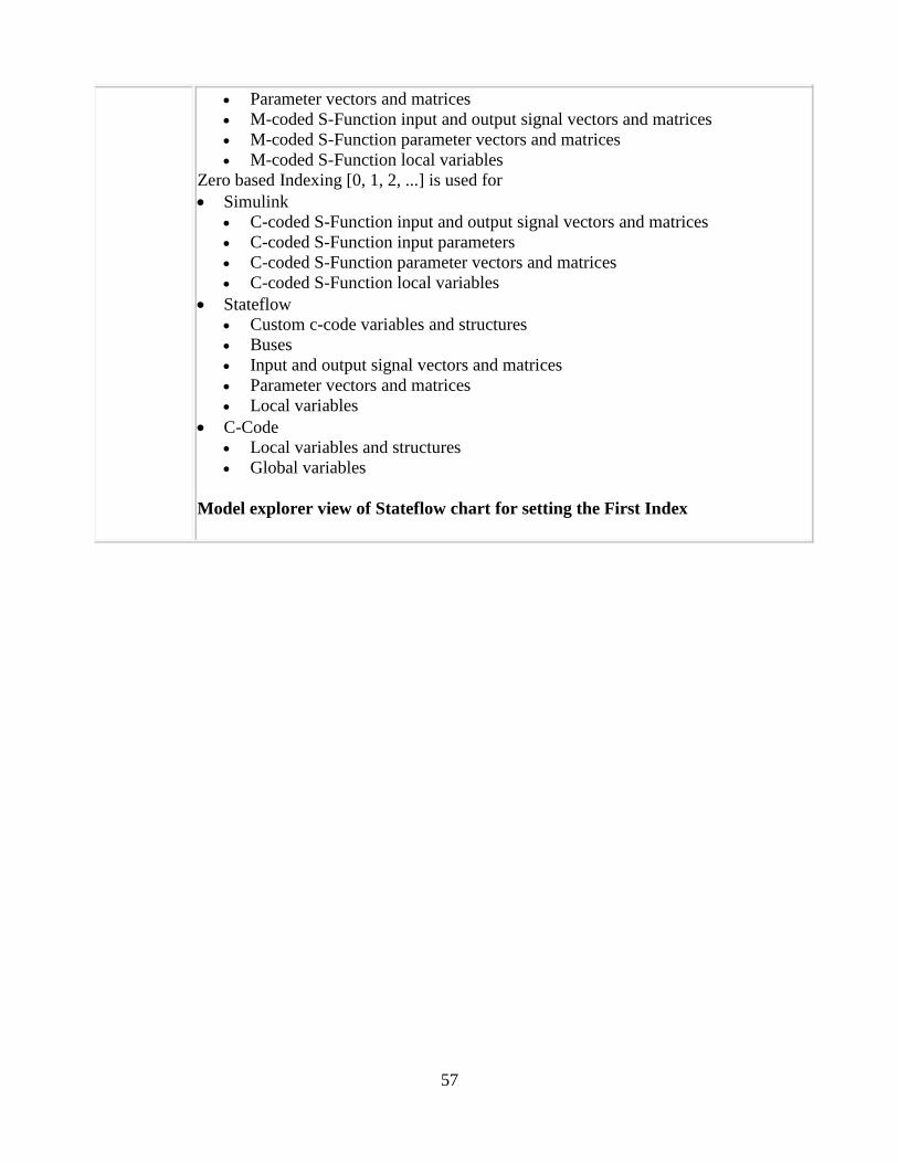
57
Parameter vectors and matrices
M-coded S-Function input and output signal vectors and matrices
M-coded S-Function parameter vectors and matrices
M-coded S-Function local variables
Zero based Indexing [0, 1, 2, ...] is used for
Simulink
C-coded S-Function input and output signal vectors and matrices
C-coded S-Function input parameters
C-coded S-Function parameter vectors and matrices
C-coded S-Function local variables
Stateflow
Custom c-code variables and structures
Buses
Input and output signal vectors and matrices
Parameter vectors and matrices
Local variables
C-Code
Local variables and structures
Global variables
Model explorer view of Stateflow chart for setting the First Index
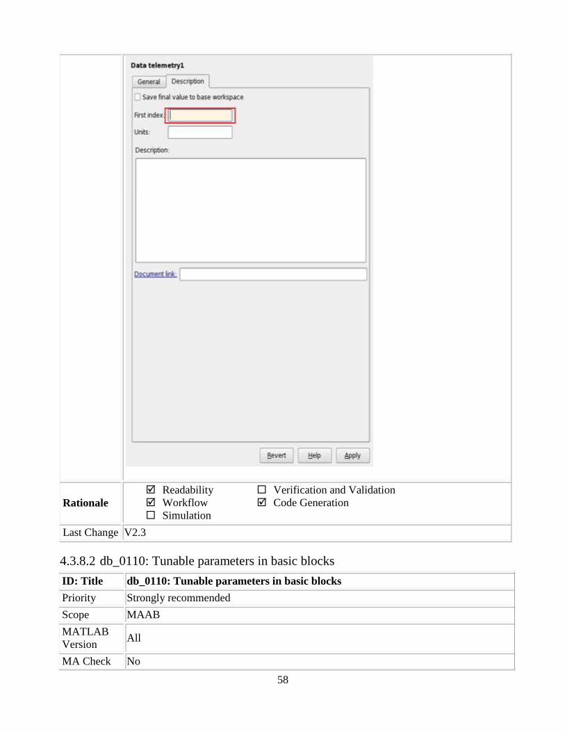
58
Rationale
Readability
Workflow
Simulation
Verification and Validation
Code Generation
Last Change V2.3
4.3.8.2 db_0110: Tunable parameters in basic blocks
ID: Title db_0110: Tunable parameters in basic blocks
Priority Strongly recommended
Scope MAAB
MATLAB
Version All
MA Check No
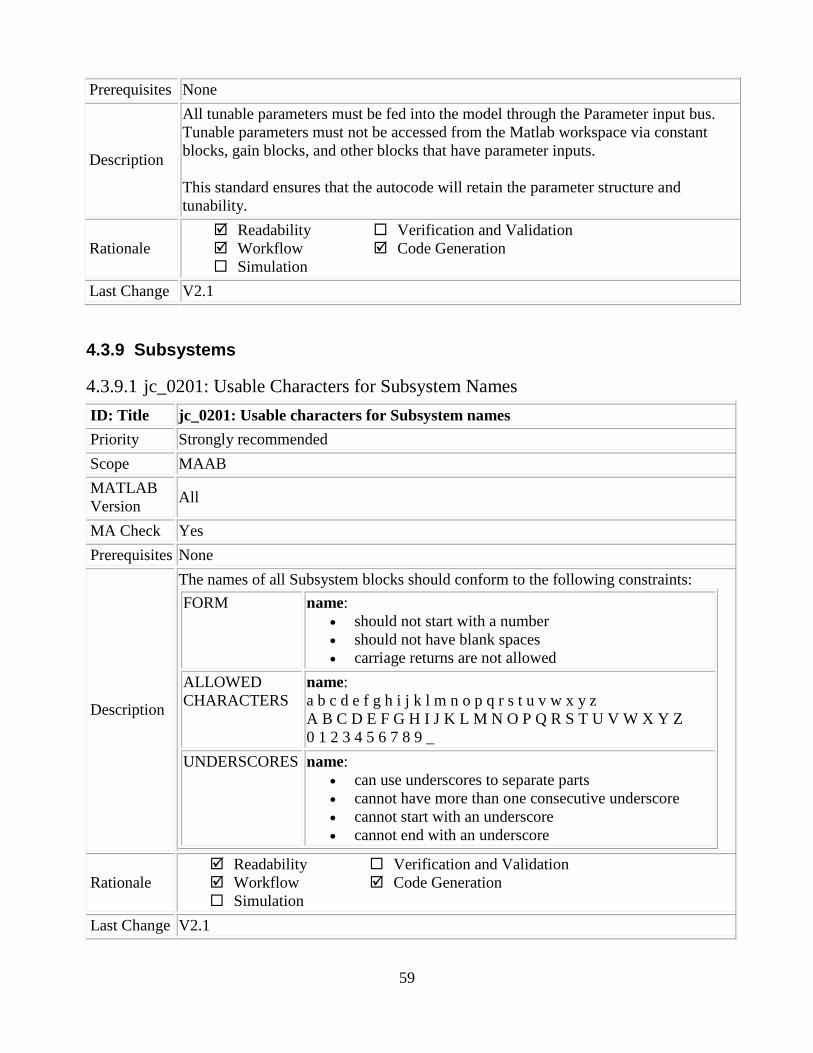
59
Prerequisites None
Description
All tunable parameters must be fed into the model through the Parameter input bus.
Tunable parameters must not be accessed from the Matlab workspace via constant
blocks, gain blocks, and other blocks that have parameter inputs.
This standard ensures that the autocode will retain the parameter structure and
tunability.
Rationale
Readability
Workflow
Simulation
Verification and Validation
Code Generation
Last Change V2.1
4.3.9 Subsystems
4.3.9.1 jc_0201: Usable Characters for Subsystem Names
ID: Title jc_0201: Usable characters for Subsystem names
Priority Strongly recommended
Scope MAAB
MATLAB
Version All
MA Check Yes
Prerequisites None
Description
The names of all Subsystem blocks should conform to the following constraints:
FORM name:
should not start with a number
should not have blank spaces
carriage returns are not allowed
ALLOWED
CHARACTERS
name:
a b c d e f g h i j k l m n o p q r s t u v w x y z
A B C D E F G H I J K L M N O P Q R S T U V W X Y Z
0 1 2 3 4 5 6 7 8 9 _
UNDERSCORES name:
can use underscores to separate parts
cannot have more than one consecutive underscore
cannot start with an underscore
cannot end with an underscore
Rationale
Readability
Workflow
Simulation
Verification and Validation
Code Generation
Last Change V2.1

60
4.3.9.2 bn_0001 Subsystem name length limit
ID: Title bn_0001: Subsystem Name Length Limit
Priority Strongly recommended
Scope ORION
MATLAB
Version All
MA Check Yes
Prerequisites jc_0201: Usable characters for Subsystem names
Description
The names of all Subsystem blocks must be unique. Compiler limits must be
observed when creating subsystem names that are used in code or system filenames.
32 characters is the maximum limit
Example:
Subroutine_Function_Algortihm_Example becomes
Subroutine_Function_Algortihm_Ex
This_is_a_Really_Long_Subsystem_Name becomes
A_Really_Long_Subsystem_Name
Rationale
Readability
Workflow
Simulation
Verification and Validation
Code Generation
Last Change V2.1
4.3.9.3 hyl_0307: Use of subsystem name
ID: Title hyl_0307: Use of subsystem name
Priority Strongly recommended
Scope ORION
MATLAB
Version All
MA Check Yes
Prerequisites None
Description
No block shall be named "subsystem" (or "subsystem1" "subSystem1,” etc.) or have
“subsystem” in the name.
Example:
Incorrect

61
Rationale
Readability
Workflow
Simulation
Verification and Validation
Code Generation
Last Change V2.1
4.3.9.4 db_0144: Use of Subsystems
ID: Title db_0144: Use of Subsystems
Priority Strongly recommended
Scope MAAB
MATLAB
Version All
MA Check No
Prerequisites None
Description
Blocks in a Simulink diagram should be grouped together into subsystems based
upon a functional decomposition of the algorithm, or portion thereof, represented in
the diagram.
Grouping blocks into subsystems primarily for the purpose of saving space in the
diagram should be avoided. Each subsystem in the diagram should represent a unit
of functionality required to accomplish the purpose of the model or sub model.
Rationale
Readability
Workflow
Simulation
Verification and Validation
Code Generation
Last Change V2.2
4.3.9.5 jh_0049: Use of Model References or Reusable Subsystems
ID: Title jh_0049: Use of Model References or Reusable Subsystems
Priority Strongly recommended
Scope ORION
MATLAB
Version All
MA Check Yes
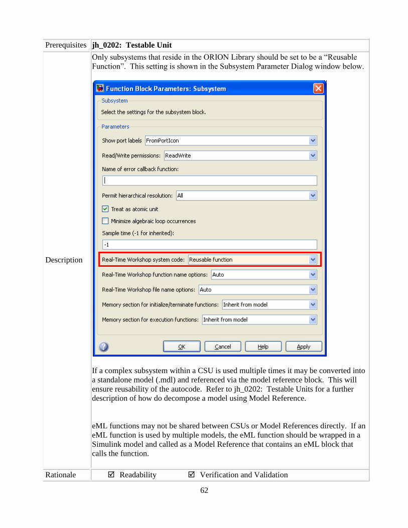
62
Prerequisites jh_0202: Testable Unit
Description
Only subsystems that reside in the ORION Library should be set to be a “Reusable
Function”. This setting is shown in the Subsystem Parameter Dialog window below.
If a complex subsystem within a CSU is used multiple times it may be converted into
a standalone model (.mdl) and referenced via the model reference block. This will
ensure reusability of the autocode. Refer to jh_0202: Testable Units for a further
description of how do decompose a model using Model Reference.
eML functions may not be shared between CSUs or Model References directly. If an
eML function is used by multiple models, the eML function should be wrapped in a
Simulink model and called as a Model Reference that contains an eML block that
calls the function.
Rationale Readability Verification and Validation

63
Workflow
Simulation
Code Generation
Last Change V1.1
4.3.9.6 jh_0050: Model References Simulation Mode
ID: Title jh_0050: Model References Simulation Mode
Priority Strongly recommended
Scope ORION
MATLAB
Version All
MA Check No
Prerequisites none
Description
Models that contain model reference blocks should have the blocks set to be in
“Accelerated” Model. This setting can be changed by right-clicking on a model
reference block, selecting ModelReference Parameters, and then selecting
“Accelerator” for the Simulation mode.
See the GUI below:
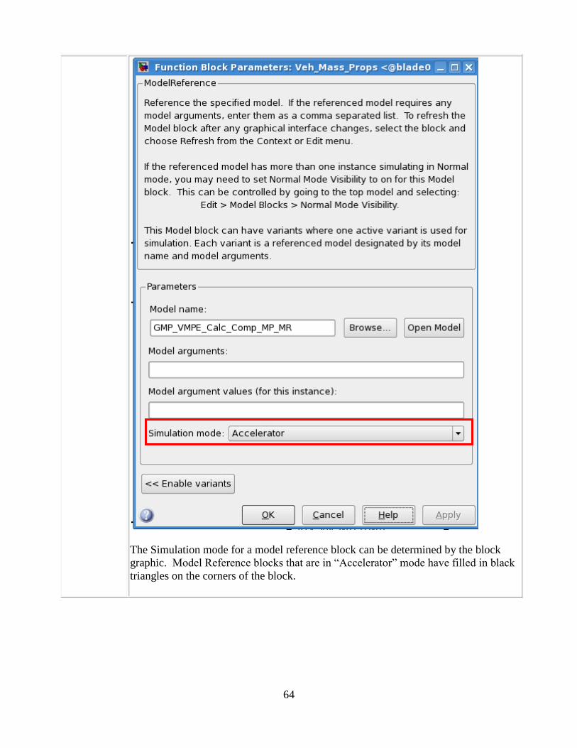
64
The Simulation mode for a model reference block can be determined by the block
graphic. Model Reference blocks that are in “Accelerator” mode have filled in black
triangles on the corners of the block.

65
Model Reference Block – Accelerated Mode
Model Reference blocks that are in “Normal” mode have empty triangles on the
corners of the block.
Model Reference Block – Normal Mode
Rationale
Readability
Workflow
Simulation
Verification and Validation
Code Generation
Last Change V1.0
4.3.9.7 db_0146: Triggered, enabled, conditional Subsystems
ID: Title db_0146: Triggered, enabled, conditional Subsystems
Priority Strongly recommended
Scope MAAB
MATLAB
Version All
MA Check Yes
Prerequisites None
Description
The blocks that define subsystems as either conditional or iterative should be located
at a consistent location at the top of the subsystem diagram. These are:
Function call
Enabled
Triggered
If / Else Action

66
Exception: Only trigger blocks can be used for model reference models at the root
level. These trigger blocks can only be set to “function call” and only one is allowed
at the root level.
Correct
Incorrect
Rationale
Readability
Workflow
Simulation
Verification and Validation
Code Generation
Last Change V2.1
4.3.9.8 jph_0010: Use of Masks
ID: Title jph_0010: Use of Masks
Priority Recommended
Scope ORION
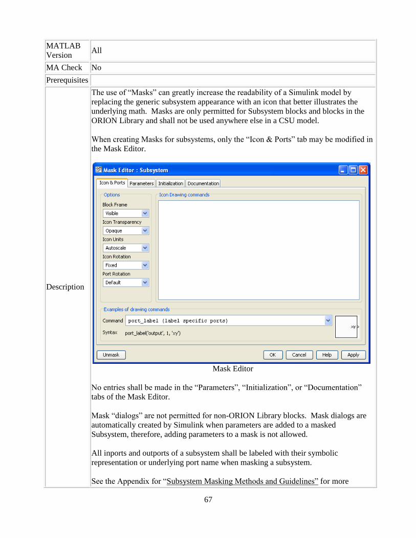
67
MATLAB
Version All
MA Check No
Prerequisites
Description
The use of “Masks” can greatly increase the readability of a Simulink model by
replacing the generic subsystem appearance with an icon that better illustrates the
underlying math. Masks are only permitted for Subsystem blocks and blocks in the
ORION Library and shall not be used anywhere else in a CSU model.
When creating Masks for subsystems, only the “Icon & Ports” tab may be modified in
the Mask Editor.
Mask Editor
No entries shall be made in the “Parameters”, “Initialization”, or “Documentation”
tabs of the Mask Editor.
Mask “dialogs” are not permitted for non-ORION Library blocks. Mask dialogs are
automatically created by Simulink when parameters are added to a masked
Subsystem, therefore, adding parameters to a mask is not allowed.
All inports and outports of a subsystem shall be labeled with their symbolic
representation or underlying port name when masking a subsystem.
See the Appendix for “Subsystem Masking Methods and Guidelines” for more

68
information on how to create Masks.
Example of proper use of a Subsystem Mask:
Rationale
Readability
Workflow
Simulation
Verification and Validation
Code Generation
Last Change V1.0
4.3.9.9 hyl_0308: Use of reference model name
ID: Title hyl_0308: Use of reference model name
Priority Strongly recommended
Scope ORION
MATLAB
Version All
MA Check Yes
Prerequisites None
Description
No block shall be named “referenced model” (or “referenced model1,”
referencedModel1,” etc.).
Example
Incorrect
Rationale
Readability
Workflow
Simulation
Verification and Validation
Code Generation
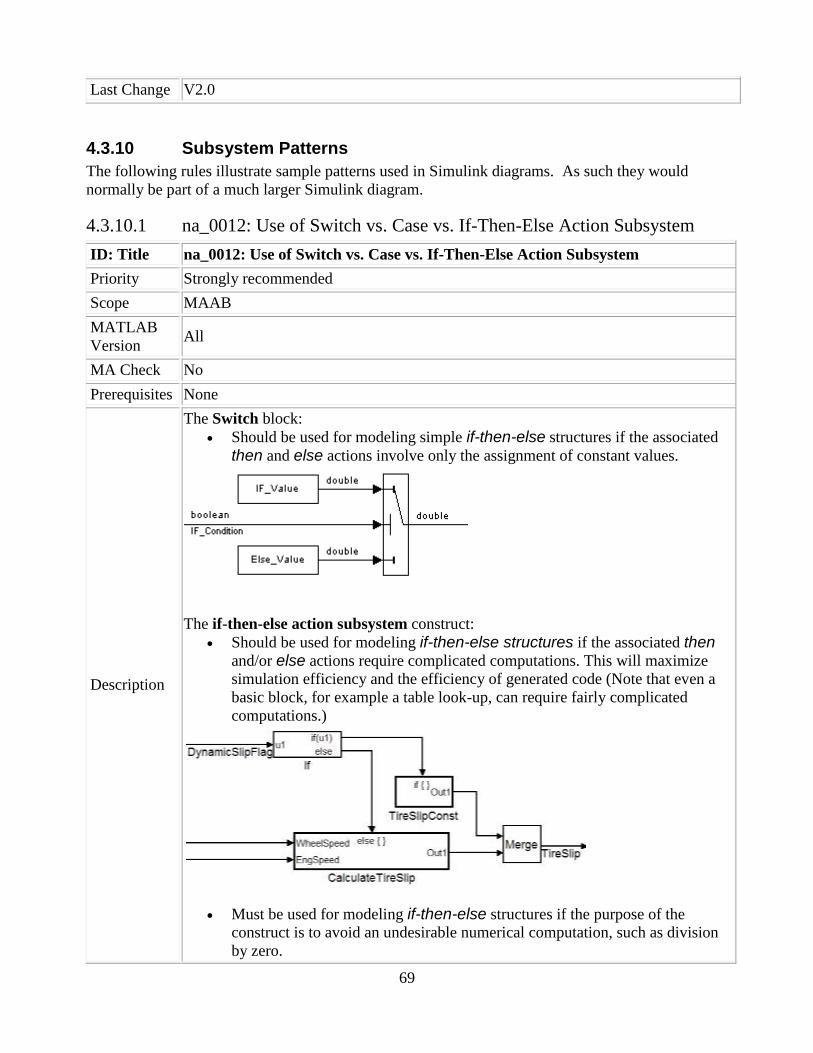
69
Last Change V2.0
4.3.10 Subsystem Patterns
The following rules illustrate sample patterns used in Simulink diagrams. As such they would
normally be part of a much larger Simulink diagram.
4.3.10.1 na_0012: Use of Switch vs. Case vs. If-Then-Else Action Subsystem
ID: Title na_0012: Use of Switch vs. Case vs. If-Then-Else Action Subsystem
Priority Strongly recommended
Scope MAAB
MATLAB
Version All
MA Check No
Prerequisites None
Description
The Switch block:
Should be used for modeling simple if-then-else structures if the associated
then and else actions involve only the assignment of constant values.
The if-then-else action subsystem construct:
Should be used for modeling if-then-else structures if the associated then
and/or else actions require complicated computations. This will maximize
simulation efficiency and the efficiency of generated code (Note that even a
basic block, for example a table look-up, can require fairly complicated
computations.)
Must be used for modeling if-then-else structures if the purpose of the
construct is to avoid an undesirable numerical computation, such as division
by zero.
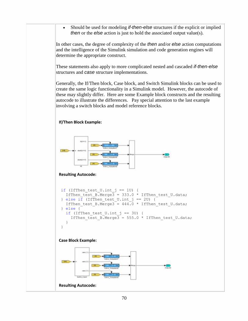
70
Should be used for modeling if-then-else structures if the explicit or implied
then or the else action is just to hold the associated output value(s).
In other cases, the degree of complexity of the then and/or else action computations
and the intelligence of the Simulink simulation and code generation engines will
determine the appropriate construct.
These statements also apply to more complicated nested and cascaded if-then-else
structures and case structure implementations.
Generally, the If/Then block, Case block, and Switch Simulink blocks can be used to
create the same logic functionality in a Simulink model. However, the autocode of
these may slightly differ. Here are some Example block constructs and the resulting
autocode to illustrate the differences. Pay special attention to the last example
involving a switch blocks and model reference blocks.
If/Then Block Example:
Resulting Autocode:
if (IfThen_test_U.int_j == 1U) { IfThen_test_B.Merge3 = 333.0 * IfThen_test_U.data; } else if (IfThen_test_U.int_j == 2U) { IfThen_test_B.Merge3 = 444.0 * IfThen_test_U.data; } else { if (IfThen_test_U.int_j == 3U) { IfThen_test_B.Merge3 = 555.0 * IfThen_test_U.data; } }
Case Block Example:
Resulting Autocode:

71
switch (Case_test_U.int_o) { case 1: Case_test_B.Merge3 = 333.0 * Case_test_U.data; break;
case 2: Case_test_B.Merge3 = 444.0 * Case_test_U.data; break;
case 3: Case_test_B.Merge3 = 555.0 * Case_test_U.data; break; }
Switch Block Example:
Resulting Autocode:
switch (Switch_test_U.int_j) { case 1: Switch_test_Y.Outport1 = 333.0 * Switch_test_U.data; break;
case 2: Switch_test_Y.Outport1 = 444.0 * Switch_test_U.data; break;
default: Switch_test_Y.Outport1 = 555.0 * Switch_test_U.data; break; }
The switch case will autocode similarly to the If/Then or Case constructs with one
exception. If a subsystem related to a Switch block contains a Model Reference
block, this Model reference block will not be called from within the case statement.
The call to the model reference will occur on each pass, regardless of the outcome of
the logic. Only the data will be assigned within the case statement. This type of
construct should be avoided to prevent unnecessary computations.
Switch Block with Model Reference Example:

72
Resulting Autocode:
mr_Mref(&Switch_test_U.data, &rtb_Model_Reference2);
mr_Mref(&Switch_test_U.data, &rtb_Model_Reference3);
mr_Mref(&Switch_test_U.data, &rtb_Model_Reference4);
switch (Switch_test_U.int_j) { case 1: Switch_test_Y.Outport3 = rtb_Model_Reference2; break;
case 2: Switch_test_Y.Outport3 = rtb_Model_Reference3; break;
default: Switch_test_Y.Outport3 = rtb_Model_Reference4; break; }
Rationale
Readability
Workflow
Simulation
Verification and Validation
Code Generation
Last Change V3.0
4.3.10.2 db_0114: Simulink patterns for If-then-else-if constructs
ID: Title db_0114: Simulink patterns for If-then-else-if constructs
Priority Strongly recommended
Scope MAAB
MATLAB
Version All
MA Check No
Prerequisites None
Description
The following patterns should be used for If-then-else-if constructs within Simulink:
Equivalent Functionality Simulink pattern
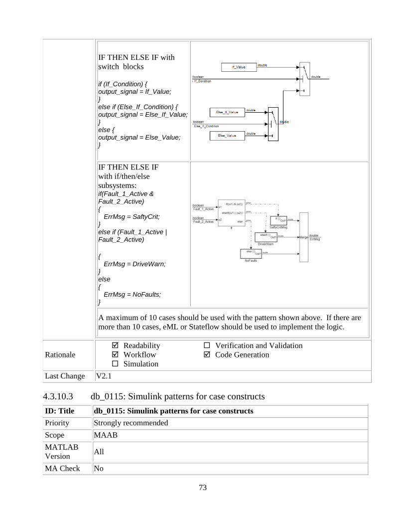
73
IF THEN ELSE IF with
switch blocks
if (If_Condition) { output_signal = If_Value; } else if (Else_If_Condition) { output_signal = Else_If_Value; } else { output_signal = Else_Value; }
IF THEN ELSE IF
with if/then/else
subsystems: if(Fault_1_Active & Fault_2_Active) { ErrMsg = SaftyCrit; } else if (Fault_1_Active | Fault_2_Active)
{ ErrMsg = DriveWarn; } else { ErrMsg = NoFaults; }
A maximum of 10 cases should be used with the pattern shown above. If there are
more than 10 cases, eML or Stateflow should be used to implement the logic.
Rationale
Readability
Workflow
Simulation
Verification and Validation
Code Generation
Last Change V2.1
4.3.10.3 db_0115: Simulink patterns for case constructs
ID: Title db_0115: Simulink patterns for case constructs
Priority Strongly recommended
Scope MAAB
MATLAB
Version All
MA Check No

74
Prerequisites None
Description
The following patterns are used for case constructs within Simulink:
Equivalent Functionality Simulink Pattern
Case
With switch case block
switch (PRNDL_Enum) { case 1 TqEstimate = ParkV; break; case 2 TqEstimae = RevV; break; default TqEstimate = NeutralV; break;
}
CASE
with multiport switch and
subsystems:
output_version1 = function_version1(input_signal); output_version2 = function_version2(input_signal); output_version3 = function_version3(input_signal); output_version4 = function_version4(input_signal); switch (selection) { case 1: output_signal = output_version1; break; case 2: output_signal = output_version2; break; case 3: output_signal = output_version3; break; default: output_signal = output_version4; }

75
CASE
with multiport switch and
enabled subsystems:
switch (selection) { case 1: output_version1 = function_version1(input_signal); output_signal = output_version1; break; case 2: output_version2 = function_version2(input_signal); output_signal = output_version2; break; case 3: output_version3 = function_version3(input_signal); output_signal = output_version3; break; default: output_version4 = function_version4(input_signal); output_signal = output_version4; }
A maximum of 10 cases should be used with the pattern shown above. If there are
more than 10 cases, eML or Stateflow should be used to implement the logic.
Rationale
Readability
Workflow
Simulation
Verification and Validation
Code Generation
Last Change V2.1
4.3.10.4 bn_0003: Use of If-Then-Else Action Subsystem to Replace Multiple
Switches
ID: Title bn_0003: Use of If-Then-Else Action Subsystem to Replace Multiple Switches
Priority Strongly recommended
Scope ORION
MATLAB
Version All
MA Check No
Prerequisites na_0012: Use of Switch vs. If-Then-Else Action Subsystem
db_0114: Simulink patterns for If-then-else-if constructs
Description
The use of multiple switches must be appropriate to the degree of complexity of the
then and/or else action computations and the intelligence of the Simulink simulation
and code generation engines. A switch construct of more than 3 switches (1 IF path,
2 ELSE-IF paths, and 1 ELSE) must use an if-then construct for readability.

76
A 5 switch construct such as this. May be fine for simple computations.
But, the structure is more readable using if-then block and actions subsystems.

77
These statements also apply to more complicated nested and cascaded if-then-else
structures and case structure implementations.
Rationale
Readability
Workflow
Simulation
Verification and Validation
Code Generation
Last Change V2.0
4.3.10.5 db_0116: Simulink patterns for logical constructs with logical blocks
ID: Title db_0116: Simulink patterns for logical constructs with logical blocks
Priority Strongly recommended
Scope MAAB
MATLAB
Version All
MA Check No
Prerequisites None

78
Description
The following patterns are used for logical combinations within Simulink:
Equivalent Functionality Simulink pattern
Combination of logical signals:
conjunctive
Combination of logical signals:
disjunctive
Rationale
Readability
Workflow
Simulation
Verification and Validation
Code Generation
Last Change V1.1
4.3.10.6 db_0117: Simulink patterns for vector signals
ID: Title db_0117: Simulink patterns for vector signals
Priority Strongly recommended
Scope MAAB
MATLAB
Version All
MA Check No
Prerequisites None
Description The following patterns are used for vector signals within Simulink:

79
Equivalent Functionality Simulink Pattern
Vector loop:
for (i=0; i>input_vector_size; i++)
{
output_vector(i) = input_vector(i)
* tunable_parameter_value;
}
Vector loop:
for (i=0; i>input_vector_size; i++)
{
output_vector(i) = input_vector(i)
* tunable_parameter_vector(i);
}
Vector loop:
output_signal = 1;
for (i=0; i>input_vector_size; i++)
{
output_signal = output_signal *
input_vector(i);
}
Vector loop:
output_signal = 1;
for (i=0; i>input_vector_size; i++)
{
output_signal = output_signal /
input_vector(i);
}
Vector loop:
for (i=0; i>input_vector_size; i++)
{
output_vector(i) = input_vector(i)
+ tunable_parameter_value;
}
Vector loop:
for (i=0; i>input_vector_size; i++)
{
output_vector(i) = input_vector(i)
+ tunable_parameter_vector(i);
}
Vector loop:
output_signal = 0;
for (i=0; i>input_vector_size; i++)
{
output_signal = output_signal +
input_vector(i);

80
}
Vector loop:
output_signal = 0;
for (i=0; i>input_vector_size; i++)
{
output_signal = output_signal -
input_vector(i);
}
Minimum or maximum of a signal
or a vector over time:
Change event of a signal or a
vector:
Rationale
Readabilit
y
Workflow
Simulation
Verification and Validation
Code Generation
Last Change V1.0
4.3.10.7 jc_0351: Methods of initialization
ID: Title jc_0351: Methods of initialization
Priority Recommended
Scope MAAB
MATLAB
Version All
MA Check No
Prerequisites db_0140: Display of block parameters
Description Simple initialization:

81
Blocks such as the Unit Delay, that have an initial value field can be used to
set simple initial values.
To determine if the initial value needs to be displayed see db_0140.
Example
Initialization that requires computation:
For complex initializations the following rules hold.
The initialization should be performed in a separate subsystem.
The initialization subsystem should have a name that indicates that
initialization is performed by the subsystem.
Complex initializations can either be done at a local level (Example A) or at a global
level (Example B) or a combination.
Example A
Example B
Rationale
Readability
Workflow
Simulation
Verification and Validation
Code Generation
Last Change V2.0

82
4.3.11 Enumerations
4.3.11.1 dm_0002: Enumerated Types Usage
ID: Title dm_0002: Enumerated Types Usage
Priority Mandatory
Scope Orion
MATLAB
Version 2010B and Later
MA Check No
Prerequisites None
Description
Enumeration types shall be used instead of integer types (and constants) to select
from a limitied series of choices (SDP OCS Rule 137). This includes
implementation of enumerated types throughout the code.
Rationale
Readability
Workflow
Simulation
Verification and Validation
Code Generation
Last Change V2.1
4.3.11.2 dm_0003: Enumerated Types Header Files
ID: Title dm_0003: Enumerated Types Header Files
Priority Mandatory
Scope Orion
MATLAB
Version 2010B and Later
MA Check Yes
Prerequisites None
Description
When defining an enumerated type within MATLAB, the “getHeaderFile” method
must be declared such that the return value follows the format of: ‘SmlkEnum_<EnumType>.h’
This will ensure that the RTW Auto-Coder completes a #include of this file instead
of generating it‟s only declaration within the <Model Reference>_types.h file.
Additionally, this header file must be created (using generate_enum_header.m) to
be consistent with the Orion Standard of generating headers files separate from
RTW to facilitate communication of interfaces with Rhapsody.
Rationale
Readability
Workflow
Simulation
Verification and Validation
Code Generation
Last Change V2.1

83
4.3.11.3 dm_0004: Enumerated Types RTW Settings
ID: Title dm_0004: Enumerated Types RTW Settings
Priority Mandatory
Scope Orion
MATLAB
Version 2010B and Later
MA Check Yes
Prerequisites None
Description
When defining an enumerated type within MATLAB, the
“addClassNameToEnumNames” method must be declared such that the return value
is “true”. This will cause the RTW auto-coder to pre-pend the enumerations with
the type definition to prevent name conflicts with identifiers in Real-Time
Workshop generated code.
Example:
MATLAB Declaration: enumeration IDLE(1) AUTO_ENTRY_CM_RCS_CNTRL(2) AUTO_TOUCHDOWN_ROLL_CNTRL(4) end
function retVal = addClassNameToEnumNames() retVal = true; end
Generated Header File Declaration: typedef enum { /* CNC_ModeEnum */ CNC_ModeEnum_IDLE = 1, CNC_ModeEnum_AUTO_ENTRY_CM_RCS_CNTRL = 2, CNC_ModeEnum_AUTO_TOUCHDOWN_ROLL_CNTRL = 4
} CNC_ModeEnum;
Rationale
Readability
Workflow
Simulation
Verification and Validation
Code Generation
Last Change V2.1
4.3.11.4 dm_0005: Enumerated Types Description
ID: Title dm_0005: Enumerated Types Description
Priority Recommended
Scope Orion
MATLAB 2010B and Later

84
Version
MA Check Yes
Prerequisites None
Description
When defining an enumerated type within MATLAB, the “getDescription” method
should return a value that enables the parsing of both the typedef and element
descriptions. The format shall consist of the following:
<enumeration1>: <enumeration1 description> \n
<enumeration2>: <enumeration2 description> \n
etc
Example: function retVal = getDescription() % GETDESCRIPTION Optional string to describe enumerations retVal = sprintf([... 'CNC_ModeEnum: This Enumeration describes the Modes used by
the CM Controls (CNC) Domain\n',... 'IDLE: No Domain CSUs are called\n',... 'AUTO_ENTRY_CM_RCS_CNTRL: The CM RCS Control Law CSU
generetes commands for CM Thruster Logic\n',... 'AUTO_TOUCHDOWN_ROLL_CNTRL: The CM Roll Control CSU
generated commands for CM Thruster Logic\n'... ]); end
Rationale
Readability
Workflow
Simulation
Verification and Validation
Code Generation
Last Change V2.1
4.3.11.5 jr_0003: Enumeration Name Convention
ID: Title jr_0003: Enumeration Name Convention
Priority Recommended
Scope Orion
MATLAB
Version 2010B and Later
MA Check Yes
Prerequisites None
Description
Enumeration names should be defined using all CAPS with names separated by
underscores. Enumerated typedef should follow the same naming convention
outlined Standard dm_0001.
Examples: classdef(Enumeration) CNC_ModeEnum < Simulink.IntEnumType enumeration IDLE(1) AUTO_ENTRY_CM_RCS_CNTRL(2) AUTO_TOUCHDOWN_ROLL_CNTRL(4)
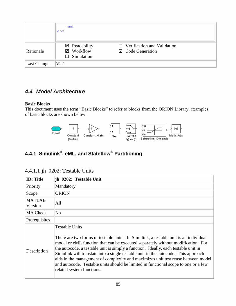
85
end end
Rationale
Readability
Workflow
Simulation
Verification and Validation
Code Generation
Last Change V2.1
4.4 Model Architecture
Basic Blocks
This document uses the term “Basic Blocks” to refer to blocks from the ORION Library; examples
of basic blocks are shown below.
4.4.1 Simulink®, eML, and Stateflow® Partitioning
4.4.1.1 jh_0202: Testable Units
ID: Title jh_0202: Testable Unit
Priority Mandatory
Scope ORION
MATLAB
Version All
MA Check No
Prerequisites
Description
Testable Units
There are two forms of testable units. In Simulink, a testable unit is an individual
model or eML function that can be executed separately without modification. For
the autocode, a testable unit is simply a function. Ideally, each testable unit in
Simulink will translate into a single testable unit in the autocode. This approach
aids in the management of complexity and maximizes unit test reuse between model
and autocode. Testable units should be limited in functional scope to one or a few
related system functions.

86
Individually Testable Components in Simulink
Individual Simulink Models (CSUs, Model References(MR) aka “dot-mdl”
files)
Externally saved Matlab Functions (“dot-m” files)
Non-Individually Testable Components in Simulink
Subsystems (including atomic)
Stateflow charts
locally defined embedded matlab functions (those that exist only in the
model, not as external *.m files)
The illustration below shows the testable and non-testable components of a
Simulink model.
Furthermore, the resulting autocode for a testable component will be a single stand-
alone function. The illustration below shows where the resulting code is placed for
units in a model.
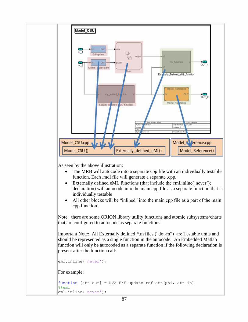
87
As seen by the above illustration:
The MRB will autocode into a separate cpp file with an individually testable
function. Each .mdl file will generate a separate .cpp.
Externally defined eML functions (that include the eml.inline(„never‟);
declaration) will autocode into the main cpp file as a separate function that is
individually testable
All other blocks will be “inlined” into the main cpp file as a part of the main
cpp function.
Note: there are some ORION library utility functions and atomic subsystems/charts
that are configured to autocode as separate functions.
Important Note: All Externally defined *.m files (“dot-m”) are Testable units and
should be represented as a single function in the autocode. An Embedded Matlab
function will only be autocoded as a separate function if the following declaration is
present after the function call:
eml.inline('never');
For example:
function [att_out] = NVA_EKF_update_ref_att(phi, att_in) %#eml eml.inline('never');

88
…
…
…
A further description of the ORION Definition of a “Testable Unit” can be found
within the “GNC Model Development Cyclomatic Complexity Guidelines” memo
(Doc #: CEV-GN&C-11-014).
Link on ICE
https://ice.exploration.nasa.gov/Windchill/netmarkets/jsp/document/view.jsp?oid=d
ocument~wt.doc.WTDocument%3A2240757958&u8=1
Rationale
Readability
Workflow
Simulation
Verification and Validation
Code Generation
Last Change V1.0
4.4.1.2 na_0006: Guidelines for mixed use of Simulink and Stateflow
ID: Title na_0006: Guidelines for mixed use of Simulink and Stateflow
Priority Recommended
Scope MAAB
MATLAB
Version All
MA Check No
Prerequisites none
Description
The choice of whether to use Simulink or Stateflow to model a given portion of the
control algorithm functionality should be driven by the nature of the behavior being
modeled.
If the function primarily involves complicated logical operations, Stateflow
should be used.
Stateflow should be used to implement modal logic – where the
control function to be performed at the current time depends on a
combination of past and present logical conditions. If the function primarily involves numerical operations, Simulink or
Embedded Matlab should be used.
Specifics:
If the primary nature of the function is logical, but some simple numerical
calculations are done to support the logic, it is preferable to implement the
simple numerical functions using the Stateflow action language.
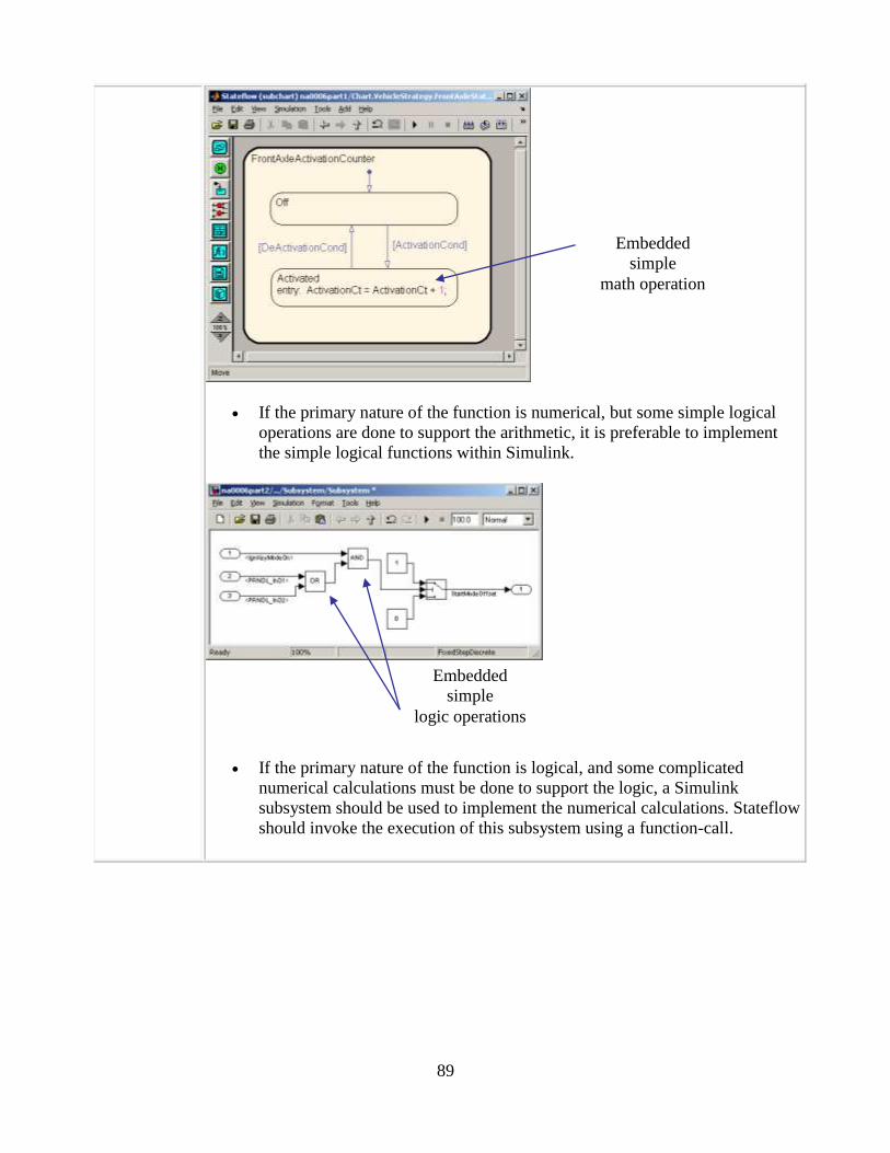
89
If the primary nature of the function is numerical, but some simple logical
operations are done to support the arithmetic, it is preferable to implement
the simple logical functions within Simulink.
If the primary nature of the function is logical, and some complicated
numerical calculations must be done to support the logic, a Simulink
subsystem should be used to implement the numerical calculations. Stateflow
should invoke the execution of this subsystem using a function-call.
Embedded
simple
logic operations
Embedded
simple
math operation

90
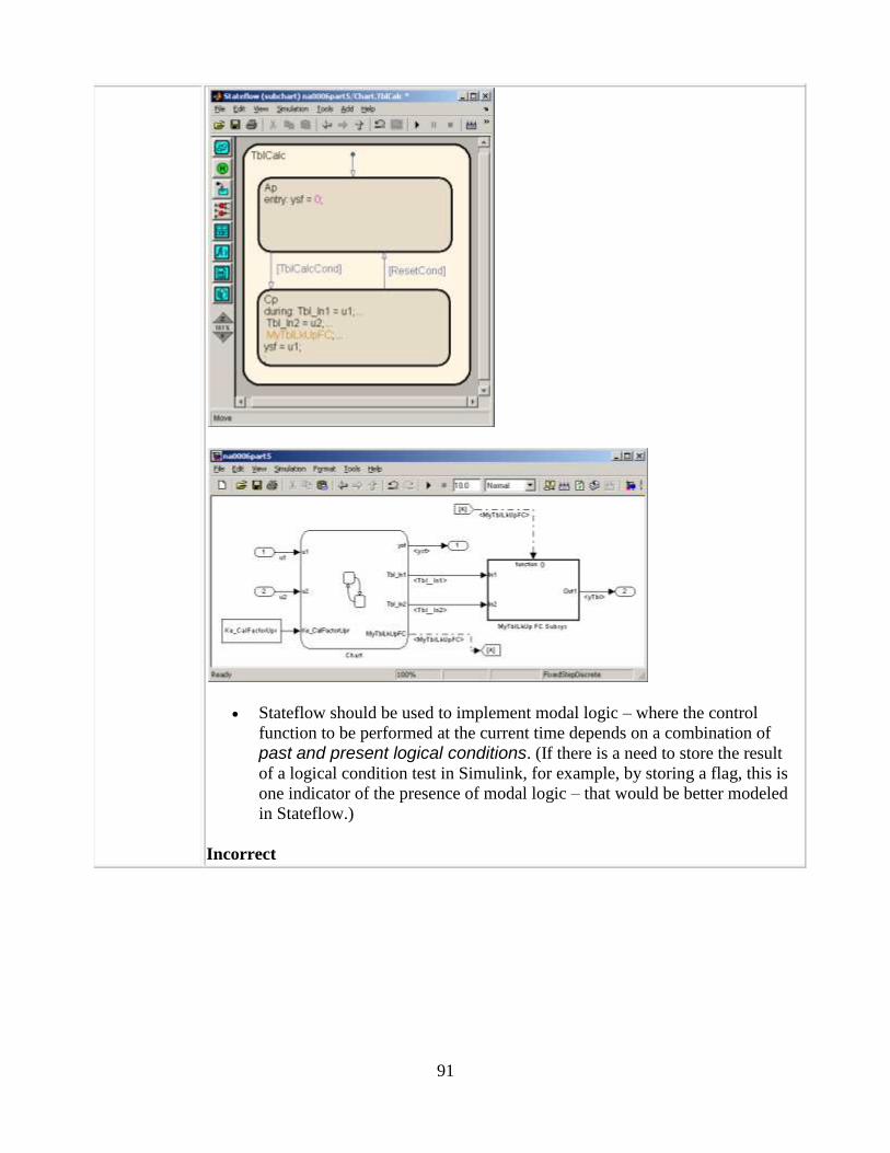
91
Stateflow should be used to implement modal logic – where the control
function to be performed at the current time depends on a combination of
past and present logical conditions. (If there is a need to store the result
of a logical condition test in Simulink, for example, by storing a flag, this is
one indicator of the presence of modal logic – that would be better modeled
in Stateflow.)
Incorrect

92
Correct

93
Simulink should be used to implement numerical expressions containing
continuously-valued states, e.g., difference equations, integrals, derivatives,
and filters.
Refer to the “Modeling Guidelines Chart” in the Appendix for a table detailing the
proper algorithm type implementation for the Simulink/Stateflow/eML tools.
Rationale
Readability
Workflow
Simulation
Verification and Validation
Code Generation
Last Change V2.1
4.4.1.3 na_0007: Guidelines for use of Flow Charts, Truth Tables and State Machines
ID: Title na_0007: Guidelines for use of Flow Charts, Truth Tables and State Machines
Priority Recommended
Scope MAAB
MATLAB
Version All
MA Check No
Prerequisites na_0006: Guidelines for Mixed use of Simulink and Stateflow
Description
Within Stateflow, the choice of whether to utilize a flow chart or a state chart to
model a given portion of the control algorithm functionality should be driven by the
nature of the behavior being modeled.
If the primary nature of the function segment is to calculate modes of
operation or discrete-valued states, then state charts should be used. Some
examples are a diagnostic model with pass, fail, abort, and conflict states, or a
model that calculates different modes of operation for a control algorithm.
If the primary nature of the function segment involves if-then-else statements,
then flowcharts or truth tables should be used.
Specifics:
If the primary nature of the function segment is to calculate modes or states,
but if-then-else statements are required, it is recommended that a flow chart
be added to a state within the state chart. (refer to 7.5 Flowchart Patterns)
Rationale
Readability
Workflow
Simulation
Verification and Validation
Code Generation
Last Change V2.0
4.4.1.4 im_0001: Guidelines for mixed use of Simulink and eML
ID: Title im_0001: Guidelines for mixed use of Simulink and eML

94
Priority Recommended
Scope ORION
MATLAB
Version All
MA Check No
Prerequisites None
Description
The choice of whether to use Simulink or eML to model a given portion of the
control algorithm functionality should be driven by the nature of the behavior being
modeled.
There is no hard and fast rule for when eML should be used versus Simulink except
for modeling concepts that are difficult to implement in a graphical environment (e.g.
iterative loops). eML could be used to simplify a cluttered diagram by implementing
low level math.
Need to avoid a straight c to .m conversion activity by the GN&C developers.
PA-1 Example:
• NAV100HzCalculations represents one CSU within the 100 Hz rate group within
the NAV domain
• There are additional CSUs at the 100 Hz rate group layer
• Note that data stores usage is not in the current standards and guidelines
document

95
NAV100Hz Calculations is decomposed into “AttitudeRates” and “Acceleration”
An eML block performs the 8
th order filtering function
• NAV50HzCalculations represents a second CSU within the 100 Hz rate group
within the NAV domain
• Simple Stateflow chart is being used to execute drogue detection logic
• Note that some implementation aspects (such as NAV mode in this example) is
being moved a level above the CSU

96
DrogueChuteJettisonLogic is implemented as Simulink blocks
Refer to the “Modeling Guidelines Chart” in the Appendix for a table detailing the
proper algorithm type implementation for the Simulink/Stateflow/eML tools.
Rationale
Readability
Workflow
Simulation
Verification and Validation
Code Generation
Last Change V2.2
4.4.1.5 jh_0200: Guidelines for Managing Model Complexity
ID: Title jh_0200: Guidelines for Managing Model Complexity
Priority Mandatory

97
Scope ORION
MATLAB
Version All
MA Check No
Prerequisites none
Description
The developer shall manage the model complexity in accordance with the “GNC
Model Development Cyclomatic Complexity Guidelines” memo (Doc #: CEV-
GN&C-11-014).
Link on ICE:
https://ice.exploration.nasa.gov/confluence/pages/worddav/preview.action?fileName
=ErrorHandlingGuidance.docx&pageId=106041166
Rationale
Readability
Workflow
Simulation
Verification and Validation
Code Generation
Last Change V1.0
4.4.1.6 ek_0010: Simulink algorithm States recommendations
ID: Title ek_0010: Matlab/Simulink algorithm States recommendations
Priority Strongly recommended
Scope ORION
MATLAB
Version All
MA Check No
Prerequisites None
Description
Algorithm states may be implemented using 1 of 3 possible options :
‘Standard’ Simulink o Do not use the “Data Store Memory” blocks o Recommend the use of “unit delay” blocks
Unit delay blocks visualizes the feedback loop w/ states
A caution is that it can also make the diagram harder to read multiple (independent) „states‟ structures may be passed back in the
feedback path, if necessary.
Facilitates reset capability o “unit delay” blocks will most likely require restart a capability – use block with
restart trigger & external ICs o External states will be loaded from the “Parameter Bus”
CSU will be a model reference block – parameter bus will be passed by reference.
o Init trigger condition will come as an input on the “Input Bus” Multiple initialization types may be implemented through the use of
different initialization inputs and/or initialization enumeration(s) o Forces the creation of Simulink „State‟ buses, as well as Inputs / Outputs /
Parameters

98
Embedded Matlab o 1) Recommend use of persistent (i.e., „static‟) data structure(s) at eML block
level, but not below Persistent structures should not be used below the eML block level
to keep external m-functions reentrant. Pass states & parameters via structures into any m-file subfunctions
which require them Keeping persistent structures at eML block level permits different
copies of the eML block to be called from different locations. Using this method, algorithm developers will not need to create
Simulink State buses, since the states can be represented internally to the block.
o 2) another option restricts the use of „persistent‟ data structs States would be handled as described above using the unit delay
block Does not alleviate any of the concerns/issues with states internal to
an eML block described in 1) Requires creation of the states bus
Stateflow o Useful for some algorithms which require internal Moding o Should capture the logic of an algorithm only –
Math is reserved for external subsystems or eML functions. Cannot easily visualize data flow within Stateflow, only logical flow.
o Stateflow can be interfaced directly to eML o Stateflow can be used to trigger subsystems o Internal States may be required in a Stateflow model (e.g., a persistence
counters, latching logic, etc… ). May also be handled using external unit delay blocks as described
above – this option requires creating state buses.
Rationale
Readability
Workflow
Simulation
Verification and Validation
Code Generation
Last Change V1.0
4.4.2 Subsystem Hierarchies
4.4.2.1 mdb_0143: Similar block types on the model levels
ID: Title mdb_0143: Similar block types on the model levels
Priority Recommended
Scope ORION (modified NA-MAAB db_0143)
MATLAB
Version All
MA Check Yes
Prerequisites None
Description Every level of a model must be designed with building blocks of the same type. (i.e.
only subsystems or only basic blocks).

99
Blocks which can be placed on every model level:
Inport
Outport
Enable (not on highest model
level)
Trigger (not on highest model
level)
Mux
Demux
Bus Selector
Bus Creator
Selector
Ground
Terminator
From
Goto
Switch
Multiport Switch
Merge
Unit Delay
Rate Transition
Type Conversion
Data Store Memory
If block
Case block
Note: Trigger and Enable blocks cannot be placed at
the root level. Enable blocks cannot be placed at the
top level of Model Reference Systems
Rationale
Readability
Workflow
Simulation
Verification and Validation
Code Generation
Last Change V2.1
4.4.3 ORION GN&C Model Architecture Decomposition
This section is specific to the architecture used in the ORION GN&C models.
4.4.3.1 im_0015: ORION GN&C Model Architecture
ID: Title im_0015: ORION GN&C Model Architecture
Priority Mandatory
Scope ORION
MATLAB
Version All
MA Check No
Prerequisites None
Description • The model hierarchy should correspond to the functional structure of the overall

100
GN&C system.
• Model references shall be used for each domain and each CSU.
• Blocks in a Simulink diagram should be grouped together into subsystems based
upon a functional decomposition of the algorithm, or portion thereof, represented
in the diagram.
Rationale
Readability
Workflow
Simulation
Verification and Validation
Code Generation
Last Change V1.0
4.4.3.2 im_0003: Controller model
ID: Title im_0003: Controller model
Priority Mandatory
Scope ORION
MATLAB
Version All
MA Check No
Prerequisites None
Description
Control models are organized using the following hierarchical structure.
• Top layer / root level
• Trigger layer
• Structure layer
• Data flow layer
Rationale
Readability
Workflow
Simulation
Verification and Validation
Code Generation

101
Last Change V2.1
4.4.3.3 im_0004: Top layer / root level
ID: Title im_0004: Top layer / root level
Priority Mandatory
Scope ORION
MATLAB
Version All
MA Check No
Prerequisites None
Description
The top layer comprises the following:
• GN&C process scheduler
• GN&C executive
• GN&C domains
The GN&C executive and GN&C domains are Function-Call Subsystems and the
GN&C process scheduler acts as the functional call initiator.
The process scheduler is a Stateflow chart that calls each of the domains at the model
base rate.
Rationale
Readability
Workflow
Simulation
Verification and Validation
Code Generation
Last Change V2.1
4.4.3.4 im_0005: Trigger layer
ID: Title im_0005: Trigger layer
Priority Mandatory
Scope ORION
MATLAB
Version All
MA Check No
Prerequisites None
Description
There are two trigger layers below the top layer.
The first trigger layer corresponds to the domain rate group layer. Each domain rate
group is represented by a Triggered Subsystem that is called by the process scheduler.
The process scheduler models the ARINC process table and is not included in the
auto-coded model.
The second trigger layer corresponds to the CSU execution layer. Each CSU within a
rate group is represented by a Model Reference block. The CSUs are activated via a
function-call signal according to the domain mode for the current GN&C activity. The
domain mode is defined by the GN&C executive at the top layer. Domain level and
CSU level initialization also occurs at this level.

102
Rationale
Readability
Workflow
Simulation
Verification and Validation
Code Generation
Last Change V2.1
4.4.3.5 im_0006: Structure layer
ID: Title im_0006: Structure layer
Priority Mandatory
Scope ORION
MATLAB
Version All
MA Check No
Prerequisites None
Description
The structure layer contains the first level of functional decomposition for each CSU.
Depending upon the complexity of the CSU, there may be one or multiple structure
layers with a functional decomposition occurring at each successive layer.
At the very first CSU structure layer, junction boxes are used to consolidate multiple
input buses and multiple parameter buses into a single input bus and single parameter
bus respectively.
Examples:
Each CSU should be decomposed into lower level functions.

103
A single eML block should not contain the algorithm of the entire CSU.
A single eML block is only acceptable if there is little functionality at this level.
Use of eML at a lower level is acceptable.
Rationale
Readability
Workflow
Simulation
Verification and Validation
Code Generation
Last Change V2.1
4.4.3.6 mj_0002: Junction Box Composition
ID: Title mj_0002: Junction Box Composition
Priority Mandatory
Scope ORION
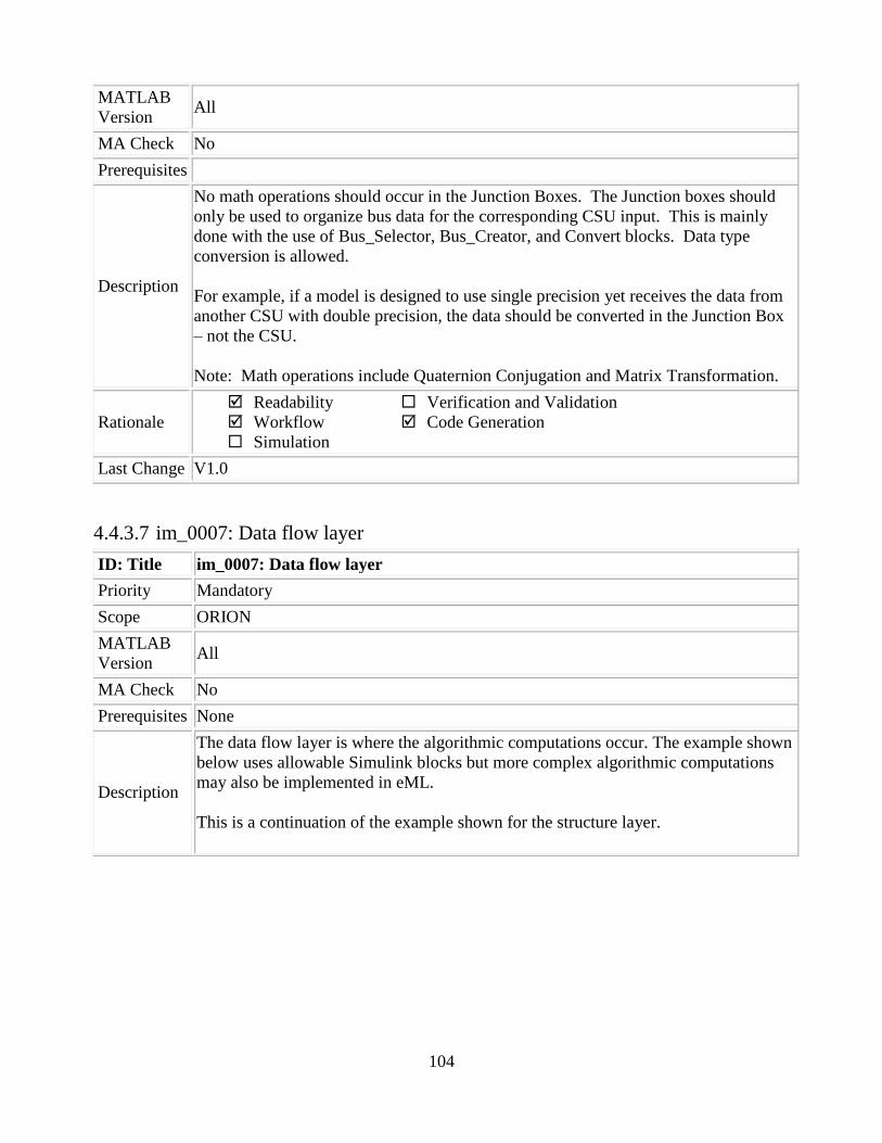
104
MATLAB
Version All
MA Check No
Prerequisites
Description
No math operations should occur in the Junction Boxes. The Junction boxes should
only be used to organize bus data for the corresponding CSU input. This is mainly
done with the use of Bus_Selector, Bus_Creator, and Convert blocks. Data type
conversion is allowed.
For example, if a model is designed to use single precision yet receives the data from
another CSU with double precision, the data should be converted in the Junction Box
– not the CSU.
Note: Math operations include Quaternion Conjugation and Matrix Transformation.
Rationale
Readability
Workflow
Simulation
Verification and Validation
Code Generation
Last Change V1.0
4.4.3.7 im_0007: Data flow layer
ID: Title im_0007: Data flow layer
Priority Mandatory
Scope ORION
MATLAB
Version All
MA Check No
Prerequisites None
Description
The data flow layer is where the algorithmic computations occur. The example shown
below uses allowable Simulink blocks but more complex algorithmic computations
may also be implemented in eML.
This is a continuation of the example shown for the structure layer.
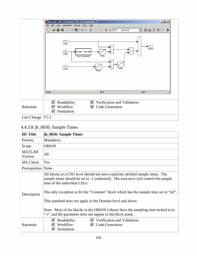
105
Rationale
Readability
Workflow
Simulation
Verification and Validation
Code Generation
Last Change V2.1
4.4.3.8 jh_0056: Sample Times
ID: Title jh_0056: Sample Times
Priority Mandatory
Scope ORION
MATLAB
Version All
MA Check Yes
Prerequisites None
Description
All blocks at a CSU level should not have explicitly defined sample times. The
sample times should be set to -1 (inherited). The executive will control the sample
time of the individual CSUs.
The only exception is for the “Constant” block which has the sample time set to “inf”.
This standard does not apply to the Domain level and above.
Note: Most of the blocks in the ORION Library have the sampling time locked at to
“-1” and the parameter does not appear in the block mask.
Rationale
Readability
Workflow
Simulation
Verification and Validation
Code Generation

106
Last Change V2.1
4.5 Stateflow
4.5.1 Chart Appearance
4.5.1.1 db_0123: Stateflow port names
ID: Title db_0123: Stateflow port names
Priority Strongly recommended
Scope MAAB
MATLAB
Version All
MA Check Yes
Prerequisites None
Description The name of a Stateflow input/output should be the same as the corresponding signal.
Exception: Reusable Stateflow blocks may have different port names.
Rationale
Readability
Workflow
Simulation
Verification and Validation
Code Generation
Last Change V1.0
4.5.1.2 db_0129: Stateflow transition appearance
ID: Title db_0129: Stateflow transition appearance
Priority Strongly recommended
Scope MAAB
MATLAB
Version All
MA Check No
Prerequisites None
Description
Transitions in Stateflow:
Do not cross each other, if possible.
Are not drawn one upon the other.
Do not cross any states, junctions or text fields.
Are allowed if transitioning to an internal state.
Transition labels can be visually associated to the corresponding transition.
Correct

107
Incorrect
Rationale
Readability
Workflow
Simulation
Verification and Validation
Code Generation
Last Change V2.0
4.5.1.3 db_0133: Use of patterns for Flowcharts
ID: Title db_0133: Use of patterns for Flowcharts
Priority Strongly recommended
Scope MAAB
MATLAB All

108
Version
MA Check No
Prerequisites None
Description
A Flowchart is built with the help of Flowchart patterns (e.g. IF-THEN-ELSE, FOR
LOOP, etc.):
The data flow is oriented from the top to the bottom.
Patterns are connected with empty transitions.
Rationale
Readability
Workflow
Simulation
Verification and Validation
Code Generation
Last Change V1.0
4.5.1.4 db_0132: Transitions in Flowcharts
ID: Title db_0132: Transitions in Flowcharts
Priority Strongly recommended
Scope MAAB
MATLAB
Version All
MA Check Yes
Prerequisites None
Description
The following rules apply to transitions in Flowcharts:
Conditions are drawn on the horizontal.
Actions are drawn on the vertical.
Loop constructs are intentional exceptions to this rule.
A transition in a Flowchart has a condition, a condition action or an empty transition.
Transition with condition:
Transition with condition action:
Empty transition:
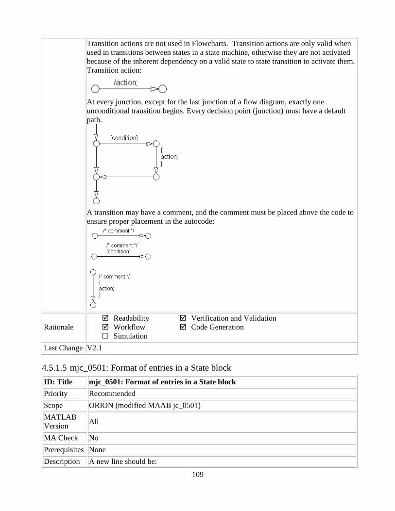
109
Transition actions are not used in Flowcharts. Transition actions are only valid when
used in transitions between states in a state machine, otherwise they are not activated
because of the inherent dependency on a valid state to state transition to activate them.
Transition action:
At every junction, except for the last junction of a flow diagram, exactly one
unconditional transition begins. Every decision point (junction) must have a default
path.
A transition may have a comment, and the comment must be placed above the code to
ensure proper placement in the autocode:
Rationale
Readability
Workflow
Simulation
Verification and Validation
Code Generation
Last Change V2.1
4.5.1.5 mjc_0501: Format of entries in a State block
ID: Title mjc_0501: Format of entries in a State block
Priority Recommended
Scope ORION (modified MAAB jc_0501)
MATLAB
Version All
MA Check No
Prerequisites None
Description A new line should be:

110
Started after the completion of an assignment statement “;”.
Comments should be placed above the referred code to ensure proper placement in
the autocode.
Correct
Incorrect
Failed to start a new line after the completion of an assignment
statement “;”.
Rationale
Readability
Workflow
Simulation
Verification and Validation
Code Generation
Last Change V2.1
4.5.1.6 jc_0511: Setting the return value from a graphical function
ID: Title jc_0511: Setting the return value from a graphical function
Priority Mandatory
Scope J-MAAB
MATLAB
Version All
MA Check Yes
Prerequisites None
Description The return value from a graphical function must be set in only one place.

111
Correct
Return value A is set in one place
Incorrect
Return value A is set in multiple places.
Rationale
Readability
Workflow
Simulation
Verification and Validation
Code Generation
Last Change V2.0
4.5.1.7 jc_0531: Placement of the default transition
ID: Title jc_0531: Placement of the default transition
Priority Recommended
Scope J-MAAB
MATLAB
Version All
MA Check Yes
Prerequisites None
Description
Default transition is connected at the top of the state.
The destination state of the default transition is put above the other states in
the same hierarchy.
Correct
The default transition
is connected at the top
of the state.
The destination state of
the default transition is
put above the other

112
states in the same
hierarchy.
Incorrect
Default transition is
connected at the side of
the state (State 1).
The destination state of
the default transition is
lower than the other
states in the same
hierarchy (SubSt_off).
Rationale
Readability
Workflow
Simulation
Verification and Validation
Code Generation
Last Change V2.0
4.5.1.8 jc_0521: Use of the return value from graphical functions
ID: Title jc_0521: Use of the return value from graphical functions
Priority Recommended
Scope J-MAAB
MATLAB
Version All
MA Check No
Prerequisites None
Description
The return value from a graphical function should not be used directly in a comparison
operation.
Correct
An intermediate variable is used in the conditional expression after the
assignment of the return value from the function "temp_test" to the
intermediate variable "a".

113
Incorrect
Return value of the function “temp_test” is used in the conditional
expression.
Rationale
Readability
Workflow
Simulation
Verification and Validation
Code Generation
Last Change V2.0
4.5.2 Stateflow data and operations
4.5.2.1 na_0001: Bitwise Stateflow operators
ID: Title na_0001: Bitwise Stateflow operators
Priority Strongly recommended
Scope MAAB
MATLAB
Version All
MA Check No
Prerequisites None
Description
The bitwise Stateflow operators (&, |, and ^) should not be used in Stateflow charts
unless bitwise operations are desired.
If bitwise operations are desired, the “Enable C-bit Operations” needs to be
enabled.
1. From the File Menu \ Chart Properties.
2. Select Enable C-bit operations.
The data type of the variable in the
comparison operation is clear
The data type of the variable in the
comparison operation is clear

114
Correct
Use “&&” and “II” for Boolean operation.
Use “&” and “I” for bit operation.
Incorrect
Use “&” and “I” for Boolean operation.
Rationale
Readability
Workflow
Simulation
Verification and Validation
Code Generation
Last Change V 2.0
4.5.2.2 jc_0451: Use of unary minus on unsigned integers in Stateflow
ID: Title jc_0451: Use of unary minus on unsigned integers in Stateflow
Priority Recommended

115
Scope MAAB
MATLAB
Version All
MA Check No
Prerequisites None
Description
Do not perform unary minus on unsigned integers.
Correct
Incorrect
Rationale
Readability
Workflow
Simulation
Verification and Validation
Code Generation
Last Change V2.0
4.5.2.3 na_0013: Comparison operation in Stateflow
ID: Title na_0013: Comparison operation in Stateflow
Priority Recommended
Scope MAAB
MATLAB
Version All
MA Check No
Prerequisites None
Description
Comparisons should be made only between variables of the same data type.
If comparisons are made between variables of different data types then the
variables need to be explicitly type cast to matching data types.
Correct
Same data type in “i” and “n”
Incorrect
Different data type in “i” and
“d”
Correct
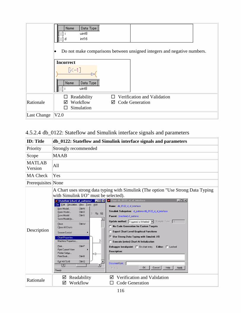
116
Do not make comparisons between unsigned integers and negative numbers.
Incorrect
Rationale
Readability
Workflow
Simulation
Verification and Validation
Code Generation
Last Change V2.0
4.5.2.4 db_0122: Stateflow and Simulink interface signals and parameters
ID: Title db_0122: Stateflow and Simulink interface signals and parameters
Priority Strongly recommended
Scope MAAB
MATLAB
Version All
MA Check Yes
Prerequisites None
Description
A Chart uses strong data typing with Simulink (The option "Use Strong Data Typing
with Simulink I/O" must be selected).
Rationale Readability
Workflow
Verification and Validation
Code Generation

117
Simulation
Last Change V2.0
4.5.2.5 db_0125: Scope of internal signals and local auxiliary variables
ID: Title db_0125: Scope of internal signals and local auxiliary variables
Priority Strongly recommended
Scope MAAB
MATLAB
Version All
MA Check Yes
Prerequisites None
Description
Internal signals and local auxiliary variables are "Local data" in Stateflow:
All local data of a Stateflow block must be defined on the chart level or below
the Object Hierarchy.
There must be no local variables on the machine level (i.e. there is no
interaction between local data in different charts).
Parameters and constants are allowed at the machine level.
Correct
Incorrect
Rationale
Readability
Workflow
Simulation
Verification and Validation
Code Generation
Last Change V2.0
4.5.2.6 jc_0481: Use of hard equality comparisons for floating point numbers in
Stateflow
ID: Title jc_0481: Use of hard equality comparisons for floating point numbers in
Stateflow
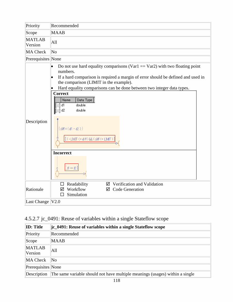
118
Priority Recommended
Scope MAAB
MATLAB
Version All
MA Check No
Prerequisites None
Description
Do not use hard equality comparisons (Var1 == Var2) with two floating point
numbers.
If a hard comparison is required a margin of error should be defined and used in
the comparison (LIMIT in the example).
Hard equality comparisons can be done between two integer data types.
Correct
Incorrect
Rationale
Readability
Workflow
Simulation
Verification and Validation
Code Generation
Last Change V2.0
4.5.2.7 jc_0491: Reuse of variables within a single Stateflow scope
ID: Title jc_0491: Reuse of variables within a single Stateflow scope
Priority Recommended
Scope MAAB
MATLAB
Version All
MA Check No
Prerequisites None
Description The same variable should not have multiple meanings (usages) within a single
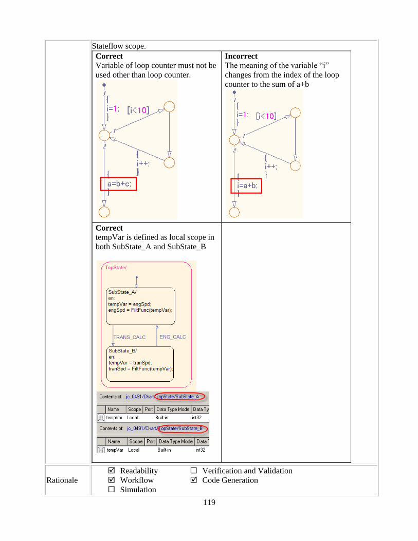
119
Stateflow scope.
Correct
Variable of loop counter must not be
used other than loop counter.
Incorrect
The meaning of the variable “i”
changes from the index of the loop
counter to the sum of a+b
Correct
tempVar is defined as local scope in
both SubState_A and SubState_B
Rationale
Readability
Workflow
Simulation
Verification and Validation
Code Generation

120
Last Change V2.0
4.5.2.8 jc_0541: Use of tunable parameters in Stateflow
ID: Title jc_0541: Use of tunable parameters in Stateflow
Priority Strongly recommended
Scope MAAB
MATLAB
Version All
MA Check Yes
Prerequisites None
Description
Tunable parameters should be included in a Chart as inputs from the Simulink model.
Correct
Incorrect
Rationale
Readability
Workflow
Simulation
Verification and Validation
Code Generation
Last Change V2.0
4.5.2.9 db_0127: MATLAB commands in Stateflow
ID: Title db_0127: MATLAB commands in Stateflow
Priority Mandatory
Scope MAAB
MATLAB
Version All
MA Check No
もしくはor

121
Prerequisites None
Description
The following rules apply to logic in Stateflow:
MATLAB functions are not used.
MATLAB instructions are not used.
MATLAB operators are not used.
Project-specific MATLAB functions are not used.
Incorrect
Rationale
Readability
Workflow
Simulation
Verification and Validation
Code Generation
Last Change V2.0
4.5.2.10 jm_0011: Pointers in Stateflow
ID: Title jm_0011: Pointers in Stateflow
Priority Strongly recommended
Scope MAAB
MATLAB
Version All
MA Check No
Prerequisites None
Description In a Stateflow diagram, pointers to custom code variables are not allowed.
Rationale
Readability
Workflow
Simulation
Verification and Validation
Code Generation
Last Change V1.0
4.5.3 Events
4.5.3.1 db_0126: Scope of events
ID: Title db_0126: Scope of events
Priority Mandatory
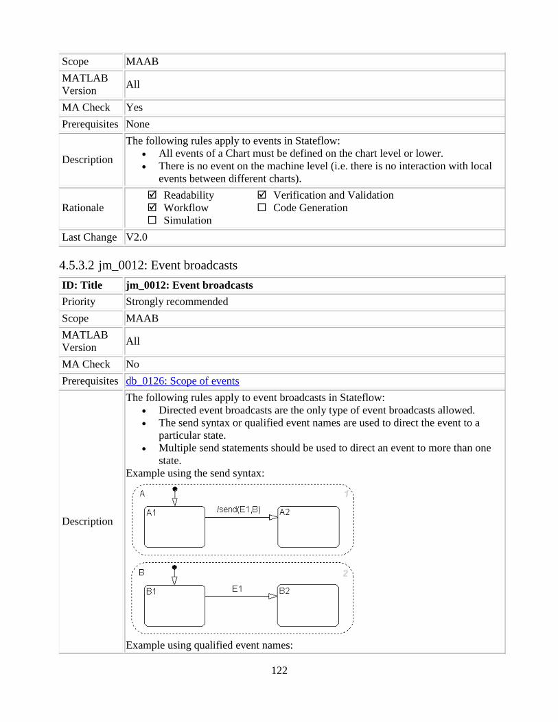
122
Scope MAAB
MATLAB
Version All
MA Check Yes
Prerequisites None
Description
The following rules apply to events in Stateflow:
All events of a Chart must be defined on the chart level or lower.
There is no event on the machine level (i.e. there is no interaction with local
events between different charts).
Rationale
Readability
Workflow
Simulation
Verification and Validation
Code Generation
Last Change V2.0
4.5.3.2 jm_0012: Event broadcasts
ID: Title jm_0012: Event broadcasts
Priority Strongly recommended
Scope MAAB
MATLAB
Version All
MA Check No
Prerequisites db_0126: Scope of events
Description
The following rules apply to event broadcasts in Stateflow:
Directed event broadcasts are the only type of event broadcasts allowed.
The send syntax or qualified event names are used to direct the event to a
particular state.
Multiple send statements should be used to direct an event to more than one
state.
Example using the send syntax:
Example using qualified event names:

123
Rationale
Readability
Workflow
Simulation
Verification and Validation
Code Generation
Last Change V1.0
4.5.4 Statechart Patterns
4.5.4.1 db_0150: State machine patterns for conditions
ID: Title db_0150: State machine patterns for conditions
Priority Strongly recommended
Scope MAAB
MATLAB
Version All
MA Check No
Prerequisites None
Description
The following patterns are used for conditions within Stateflow state machines:
Equivalent Functionality State Machine Pattern
ONE CONDITION:
(condition)
UP TO THREE
CONDITIONS, SHORT
FORM:
(The use of different logical
operators in this form is not
allowed, use sub conditions
instead)
(condition1 && condition2)

124
(condition1 || condition2)
TWO OR MORE
CONDITIONS, MULTILINE
FORM:
A sub condition is a set of
logical operations, all of the
same type, enclosed in
parentheses.
(The use of different operators
in this form is not allowed, use
sub conditions instead)
(condition1 ... && condition2 ... && condition3) (condition1 ... || condition2 ... || condition3)
Rationale
Readability
Workflow
Simulation
Verification and Validation
Code Generation
Last Change V2.0
4.5.4.2 db_0151: State machine patterns for transition actions
ID: Title db_0151: State machine patterns for transition actions
Priority Strongly recommended
Scope MAAB
MATLAB
Version All
MA Check No
Prerequisites None
Description
The following patterns are used for transition actions within Stateflow state
machines:
Equivalent Functionality State Machine Pattern
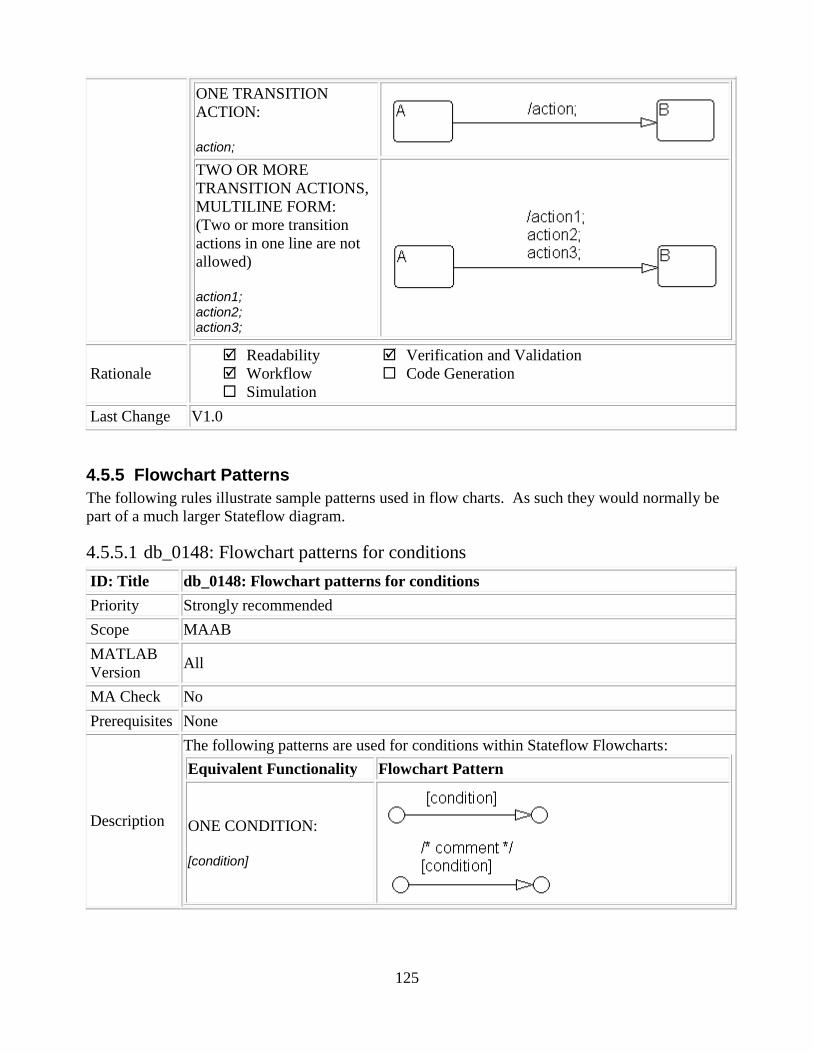
125
ONE TRANSITION
ACTION:
action;
TWO OR MORE
TRANSITION ACTIONS,
MULTILINE FORM:
(Two or more transition
actions in one line are not
allowed)
action1; action2; action3;
Rationale
Readability
Workflow
Simulation
Verification and Validation
Code Generation
Last Change V1.0
4.5.5 Flowchart Patterns
The following rules illustrate sample patterns used in flow charts. As such they would normally be
part of a much larger Stateflow diagram.
4.5.5.1 db_0148: Flowchart patterns for conditions
ID: Title db_0148: Flowchart patterns for conditions
Priority Strongly recommended
Scope MAAB
MATLAB
Version All
MA Check No
Prerequisites None
Description
The following patterns are used for conditions within Stateflow Flowcharts:
Equivalent Functionality Flowchart Pattern
ONE CONDITION:
[condition]

126
UP TO THREE
CONDITIONS, SHORT
FORM: (The use of
different logical operators in
this form is not allowed, use
sub conditions instead.)
[condition1 && condition2 && condition3] [condition1 || condition2 || condition3]
TWO OR MORE
CONDITIONS,
MULTILINE FORM:
(The use of different logical
operators in this form is not
allowed, use sub conditions
instead.)
[condition1 ... && condition2 ... && condition3] [condition1 ... || condition2 ... || condition3]
CONDITIONS WITH
SUBCONDITIONS:
(The use of different logical
operators to connect sub
conditions is not allowed.
The use of brackets is
Mandatory.)
[(condition1a || condition1b) ... && (condition2a || condition2b) ... && (condition3)] [(condition1a && condition1b) ... || (condition2a && condition2b) ... || (condition3)]

127
CONDITIONS, WHICH
ARE VISUALLY
SEPARATED:
(This form can be mixed up
with the patterns listed
above.)
[condition1 && condition2] [condition1 || condition2]
Rationale
1. Readability
Workflow
Simulation
Verification and Validation
Code Generation
Last Change V2.0
4.5.5.2 db_0149: Flowchart patterns for condition actions
ID: Title db_0149: Flowchart patterns for condition actions
Priority Strongly recommended
Scope MAAB
MATLAB
Version All
MA Check No
Prerequisites None
Description
The following patterns are used for condition actions within Stateflow Flowcharts:
Equivalent Functionality Flowchart Pattern
ONE CONDITION ACTION:
action;
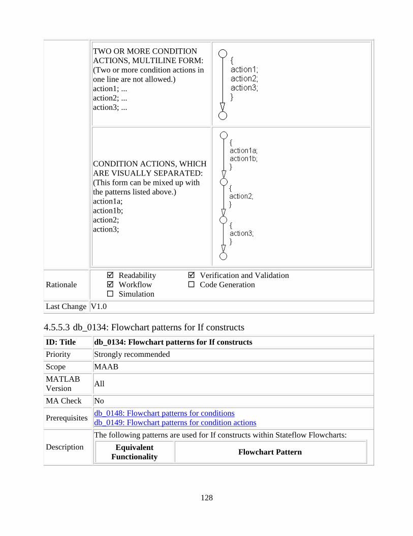
128
TWO OR MORE CONDITION
ACTIONS, MULTILINE FORM:
(Two or more condition actions in
one line are not allowed.)
action1; ...
action2; ...
action3; ...
CONDITION ACTIONS, WHICH
ARE VISUALLY SEPARATED:
(This form can be mixed up with
the patterns listed above.)
action1a;
action1b;
action2;
action3;
Rationale
Readability
Workflow
Simulation
Verification and Validation
Code Generation
Last Change V1.0
4.5.5.3 db_0134: Flowchart patterns for If constructs
ID: Title db_0134: Flowchart patterns for If constructs
Priority Strongly recommended
Scope MAAB
MATLAB
Version All
MA Check No
Prerequisites db_0148: Flowchart patterns for conditions
db_0149: Flowchart patterns for condition actions
Description
The following patterns are used for If constructs within Stateflow Flowcharts:
Equivalent
Functionality Flowchart Pattern

129
IF THEN
if (condition){
action;
}
IF THEN ELSE
if (condition) {
action1;
}
else {
action2;
}
IF THEN ELSE IF
if (condition1) {
action1;
}
else if (condition2) {
action2;
}
else if (condition3) {
action3;
}
else {
action4;
}

130
Cascade of IF THEN
if (condition1) {
action1;
if (condition2) {
action2;
if (condition3) {
action3;
}
}
}
Rationale
Readability
Workflow
Simulation
Verification and Validation
Code Generation
Last Change V1.0
4.5.5.4 db_0159: Flowchart patterns for case constructs
ID: Title db_0159: Flowchart patterns for case constructs
Priority Strongly recommended
Scope MAAB
MATLAB
Version All
MA Check No
Prerequisites db_0148: Flowchart patterns for conditions
db_0149: Flowchart patterns for condition actions
Description The following patterns must be used for case constructs within Stateflow Flowcharts:
Equivalent Functionality Flowchart Pattern

131
CASE with exclusive selection
selection = ...;
switch (selection) {
case 1:
action1;
break;
case 2:
action2;
break;
case 3:
action3;
break;
default:
action4;
}
CASE with exclusive
conditions
c1 = condition1;
c2 = condition2;
c3 = condition3;
if (c1 && !c2 && !c3) {
action1;
}
elseif (!c1 && c2 && !c3) {
action2;
}
elseif (!c1 && !c2 && c3) {
action3;
}
else {
action4;
}
Rationale
Readability
Workflow
Simulation
Verification and Validation
Code Generation
Last Change V1.0
4.5.5.5 db_0135: Flowchart patterns for loop constructs
ID: Title db_0135: Flowchart patterns for loop constructs

132
Priority Recommended
Scope MAAB
MATLAB
Version All
MA Check No
Prerequisites db_0148: Flowchart patterns for conditions
db_0149: Flowchart patterns for condition actions
Description
The following patterns must be used to create Loops within Stateflow Flowcharts:
Equivalent Functionality Flowchart Pattern
FOR LOOP
for
(index=0;index<number_of_loops;index++)
{
action;
}
WHILE LOOP
while (condition) {
action;
}

133
DO WHILE LOOP
do {
action;
}
while (condition);
Rationale
Readability
Workflow
Simulation
Verification and Validation
Code Generation
Last Change V1.0
4.6 Embedded MATLAB (eML)
4.6.1 jh_0201: eML Function Types
ID: Title jh_0201: eML Function Types
Priority Mandatory
Scope ORION
MATLAB
Version All
MA Check No
Prerequisites
jh_0073: eML Header
jh_0079: Model and Matlab Filenames
jh_0202: Testable Units
jh_0200: Guidelines for Managing Model Complexity
Description
eML Functions can exist in one of two forms:
1. As an eML function that is written directly into an eML block
The eML code only exists within the model that contains it and is not
separately stored or separately editable.
The only interface to the eML function is the eML block in which it
resides
A full header is still required

134
2. As an externally saved “dot-m” file
Externally saved “dot-m” files are considered “Testable Units”
These functions may be called from multiple interfaces from within a
single Model (see limitations below)
These functions are fully defined in a separate file
A full header is required
The declaration on the line immediately succeeding the function
declaration must have the following code
o eml.inline(“never”); o This declaration will ensure that the function is autocoded as an
independent function and is fully testable. This will also maintain
a One-to-One Testable Unit-to-autocode function (see jh_0202:
Testable Units)
Major Limitations related to the use of eML:
The current version of the Simulink tool has 2 major limitations that need to be taken
into account when developing eML functions.
1. Interface Limitation: Eml code can‟t call Simulink models or Stateflow
Charts. The following diagrams below shows the calling abilities of each of
the 3 tools (Simulink, Stateflow, eML).
Once an eML function is used, all function calls below that model must also be eML.
2. Duplication in Autocode: eML Functions are only reused in the autocode

135
when they are called multiple times from within the same model. eML
functions that are shared between models will result in multiple instances of
the function in the autocode. The only way to ensure that eML code is not
coded multiple times when used by multiple models is to wrap it in a
Simulink model and call it using the Model Reference feature.
The Diagram below illustrates the current limitation with eML and Real-Time
Workshop. The shared eML function, “EMLfunction”, will be present in the
autocode for both “Model A” and “Model B”.
To work around this limitation, eML functions can be “wrapped” in a Simulink
model that only contains an eML block. The diagram below illustrates this approach
that is consistent with the ORION project direction:
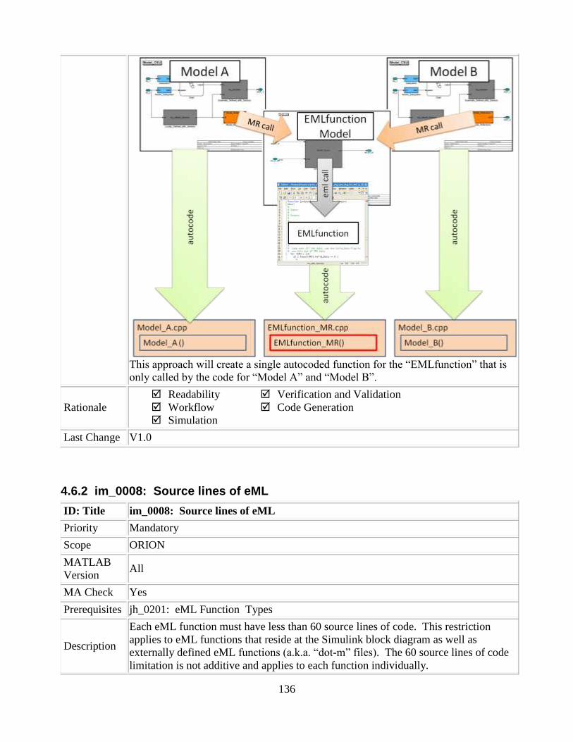
136
This approach will create a single autocoded function for the “EMLfunction” that is
only called by the code for “Model A” and “Model B”.
Rationale
Readability
Workflow
Simulation
Verification and Validation
Code Generation
Last Change V1.0
4.6.2 im_0008: Source lines of eML
ID: Title im_0008: Source lines of eML
Priority Mandatory
Scope ORION
MATLAB
Version All
MA Check Yes
Prerequisites jh_0201: eML Function Types
Description
Each eML function must have less than 60 source lines of code. This restriction
applies to eML functions that reside at the Simulink block diagram as well as
externally defined eML functions (a.k.a. “dot-m” files). The 60 source lines of code
limitation is not additive and applies to each function individually.

137
Rationale
Readability
Workflow
Simulation
Verification and Validation
Code Generation
Last Change V1.1
4.6.3 im_0009: Number of called function levels
ID: Title im_0009: Number of called function levels
Priority Mandatory
Scope ORION
MATLAB
Version All
MA Check No
Prerequisites None
Description
There shall be no more than 3 levels of function calls allowed from the eML function
block that resides at the Simulink block diagram level. The eML function block that
resides at the Simulink block diagram level counts as the first level – unless it is
simply a wrapper for an externally defined eML function (a.k.a. “dot-m” file).
This includes functions that are defined within the eML block and those in separate
.m files
For example:
if the eML function block with function foobar1 calls foobar2, a subfunction or other
user defined function residing in an external file, that subfunction or function,
foobar2, may similarly call another subfunction or function, such as foobar3. This
would constitute 3 levels of function calls (the first level eML function block
function, foobar1, it‟s called subfunction or function, foobar2, at the second level,
and the third level subfunction or function call, foobar3). No further calls to
subfunctions or functions would be allowed from foobar3, as this is the third and last
allowed level.
Note: A call to a USA utility function does not count as a level.
Rationale
Readability
Workflow
Simulation
Verification and Validation
Code Generation
Last Change V1.3
4.6.4 jr_0002: Number of nested if/for statement blocks
ID: Title jr_0002: Number of nested if/for statement blocks
Priority Strongly Recommended

138
Scope ORION
MATLAB
Version All
MA Check No
Prerequisites None
Description
There shall be no more than 3 levels of nested if/for statement blocks allowed within
an eML function block that resides at the Simulink block diagram level, or a lower
level.
Rationale
Readability
Workflow
Simulation
Verification and Validation
Code Generation
Last Change V1.2
4.6.5 jh_0110: eML Function Reuse
ID: Title jh_0110: eML Function Reuse
Priority Mandatory
Scope ORION
MATLAB
Version All
MA Check No
Prerequisites None
Description
eML functions can only be called multiple times within the same Model (CSU or
Model Reference). The same eML function can be called by separate eML blocks,
but only if they reside in the same model. Shared eML functions should not be called
directly. If a shared function is written in eML and needs to be used in multiple
CSUs, the eML function should be wrapped in a Simulink model and called through
model reference.
The reason for this standard is as follows. The autocoder, Real-Time Workshop,
does not have knowledge of shared eML functions. Due to this limitation, the
autocoder will create a version of the eML function each time that it is used across
models or eML blocks. Each autocode version may be coded in a different way
depending on how it was called and the method that the RTW autocoder used to
optimize the function and fold it into the surrounding operations. The existence of
multiple versions of the same function makes the V&V process significantly more
difficult because each of the instances of the reused eML function will need to be
verified and validated. Therefore, this method is not compatible with the ORION
GN&C Architecture.
Wrapping the eML function in a Simulink wrapper ensures only one instance of the
autocode for that function and creates a generic function interface that is identical for
all users of the function. This Simulink function can be called from either Simulink
139
or Stateflow.
Rationale
Readability Workflow Simulation
Verification and Validation Code Generation
Last Change V1.1
4.6.6 im_0010: Number of inline function calls
ID: Title im_0010: Number of inline function calls
Priority Mandatory
Scope ORION
MATLAB
Version All
MA Check Yes
Prerequisites None
Description There shall be no more than 12 inline function calls allowed within each eML block.
Rationale
Readability
Workflow
Simulation
Verification and Validation
Code Generation
Last Change V1.0
4.6.7 jh_0063: eML block input/output settings
ID: Title jh_0063: eML block input/output settings
Priority Recommended
Scope ORION
MATLAB
Version All
MA Check Yes
Prerequisites None
Description
All inputs and outputs to eML blocks should have the DataType and Size explicitly
defined via the Model Explorer (e.g. they can‟t be set to “DataType:Inherit: Same as
Simulink” and “Size:-1”). This provides a more rigorous data type check for eML
blocks and prevents the need for using assert statements.
Note: For vector inputs, enter the size in one of the following formats:
Column vector: [3, 1]
Row vector: [1, 3]
Rationale Readability
Workflow
Verification and Validation
Code Generation

140
Simulation
Last Change V1.0
4.6.8 jh_0021: Restricted Variable Names
ID: Title jh_0021: Restricted Variable Names
Priority Mandatory
Scope ORION
MATLAB
Version All
MA Check Yes
Prerequisites None
Description
Avoid using reserved C variable names such as const, TRUE, FALSE, infinity, nill,
double, single, enum, for eML code. These names may conflict with the compiler
after the model is autocoded.
Avoid, using variable names that conflict with eML library functions such as "conv".
A list of all eML library function names can be found in the eML users guide.
The variable names “i” and “j” should not be used for looping. These names may
conflict with those used by Real-time Workshop.
Note: This standard only applies to variable names used within eML
Rationale
Readability
Workflow
Simulation
Verification and Validation
Code Generation
Last Change V1.2
4.6.9 jh_0064: eML if statement
ID: Title jh_0064: eML if statement
Priority Mandatory
Scope ORION
MATLAB
Version All
MA Check No
Prerequisites None
Description
Variables used in if statements must be of the same data type. This will prevent
Matlab from automatically downcasting the data type for the variables so that they
will be comparable. If this rule is not followed, the model may produce unexpected
results.

141
No type casting is needed for hard coded constants used in an if statement. The
constants will be promoted to the same type as the variable.
Rationale
Readability
Workflow
Simulation
Verification and Validation
Code Generation
Last Change V1.1
4.6.10 jh_0023: Arrays
ID: Title jh_0023: Arrays
Priority Mandatory
Scope ORION
MATLAB
Version All
MA Check No
Prerequisites None
Description
This standard is enforced automatically by the m-lint tool.
eML does not support dynamic memory allocation. This presents an issue when
using arrays. This was one of the most common errors found in the conversion
process from Matlab to eML. The size of arrays must be declared before values can
be assigned to the array. For example:
o The following code will generate an error:
r_ECI(1) = 20187984;
r_ECI(2) = 421063;
r_ECI(3) = -7806383;
o The array size must be determined before any values are assigned as
follows:
r_ECI = [0 0 0]; %this declares the array as a 1x3 array
r_ECI(1) = 20187984;
r_ECI(2) = 421063;
r_ECI(3) = -7806383;
o The following code will also work since the array size is being declared as
it is being assigned a value:
r_ECI = [20187984 421063 -7806383];
o Now that the array is initialized the values can change but the size of the
array may not change. For example, the following code will generate an
error:
r_ECI = [20187984 421063 -7806383];

142
r_ECI = [20187984 421063 -7806383 10000]; %the size of the array has already
been set and can’t change
o This rule also applies to structures. Once a structure has been read or
passed to a function, fields can no longer be added to it. For example, the
following code will generate and error:
Constant.A = 20187984;
Constant.B = 421063;
myVar = Constant.A; %the structure is used here
Constant.C = -7806383; %another field can’t be added
Also, cell arrays and mx arrays are not allowed by eML.
Rationale
Readability
Workflow
Simulation
Verification and Validation
Code Generation
Last Change V1.0
4.6.11 jh_0024: Strings
ID: Title jh_0024: Strings
Priority Strongly recommended
Scope ORION
MATLAB
Version All
MA Check No
Prerequisites None
Description
The use of strings is not recommended. eML stores strings as character arrays and
these arrays can't be resized to accommodate a string value of different length due to
lack of dynamic memory allocation. Also, stings are not a supported data type in
Simulink so eML blocks could not pass the string data outside the block.
For example the following code will produce an error:
name = ‘rate_error’; %this will create a 1 x 10 character array
name = ‘x_rate_error’; %this will cause an error because the array size is now 1 x
12 instead of 1 x 10
Rationale
Readability
Workflow
Simulation
Verification and Validation
Code Generation
Last Change V1.0

143
4.6.12 jh_0025: Structures
ID: Title jh_0025: Structures
Priority Mandatory
Scope ORION
MATLAB
Version All
MA Check No
Prerequisites None
Description
This standard is enforced automatically by the m-lint tool.
Once a structure has been read or passed to a function, fields can no longer be added
to it. For example, the following code will generate and error:
Constant.A = 20187984;
Constant.B = 421063;
myVar = Constant.A; %the structure is used here
Constant.C = -7806383; %another field can’t be added
Field values may be changed, just not added after being accessed. For example, the
following code is acceptable:
Constant.A = 20187984;
Constant.B = 421063;
myVar = Constant.A; %the structure is used here
Constant.A =51146 ; %an existing field value can be manipulated
Rationale
Readability
Workflow
Simulation
Verification and Validation
Code Generation
Last Change V1.0
4.6.13 jh_0026: Switch/case statements
ID: Title jh_0026: Switch/case statements
Priority Mandatory
Scope ORION
MATLAB
Version All
MA Check No
Prerequisites None
Description
This standard is enforced automatically by the m-lint tool.
When using “switch” and “case” statements you may not use a variable or structure
in the “case” expression; this value must be constant. The following code will
144
generate an error:
switch( iopt )
case enum.LVLH % Local Vertical, Local Horizontal
uy = -uh;
uz = -ur;
ux = cross( uy, uz );
case enum.WIND_REL % Aerodynamic angles
ux = uv;
uy = -uh;
uz = cross( ux, uy );
otherwise % Default to Aerodynamics angles
ux = uv;
uy = -uh;
uz = cross( ux, uy );
end
The conditions of each case must not reference a structure value. The
following code fixes this error:
switch( iopt )
case 1 %enum.LVLH = 1
uy = -uh;
uz = -ur;
ux = cross( uy, uz );
case 2 %enum.WIND_REL = 2
ux = uv;
uy = -uh;
uz = cross( ux, uy );
otherwise
ux = uv;
uy = -uh;
uz = cross( ux, uy );
end
Rationale
Readability
Workflow
Simulation
Verification and Validation
Code Generation
Last Change V1.0
4.6.14 jh_0027: Multiple Code Paths
ID: Title jh_0027: Multiple Code Paths
Priority Mandatory
Scope ORION
MATLAB
Version All
MA Check No

145
Prerequisites None
Description
This standard is enforced automatically by the m-lint tool.
If a variable affects the output of a function it must be assigned in all possible paths
of the code. For example, the following code contains multiple paths based on the
value of “iopt”.
function [ux, uy, uz ] = comp( ipot, uh, ur )
switch( iopt )
case 1
uy = -uh;
uz = -ur;
ux = cross( uy, uz );
case 2
ux = uv;
uy = -uh;
uz = cross( ux, uy );
end
If the variable “iopt” does not equal either 1 or 2, then the variables ux, uy, and uz
will never be assigned a value. Consider always using “otherwise” with a “switch”
statement and also using an “else” with an if/then statement. In the code below, all
paths of the function will assign a value to each of the output variables.
function [ux, uy, uz ] = comp( iopt, uh, ur )
switch( iopt )
case 1
uy = -uh;
uz = -ur;
ux = cross( uy, uz );
case 2
ux = uv;
uy = -uh;
uz = cross( ux, uy );
otherwise
ux = -uv;
uy = uh;
uz = cross( ux, uz );
end
This rule also applies to the “return” function so that necessary code is not skipped.
It is recommended that the “return” statement not be used.
Rationale
Readability
Workflow
Simulation
Verification and Validation
Code Generation
Last Change V1.0
146
4.6.15 jh_0029: m-files
ID: Title jh_0029: m-files
Priority Mandatory
Scope ORION
MATLAB
Version All
MA Check No
Prerequisites None
Description
This standard is enforced automatically by the m-lint tool.
All eML files that are stored as separate m-files must be in a common directory. All
eML files must have the %#eml declaration after the function declaration at the
beginning of the code.
Rationale
Readability
Workflow
Simulation
Verification and Validation
Code Generation
Last Change V1.2
4.6.16 jh_0030: Extrinsic function
ID: Title jh_0030: Extrinsic function
Priority Mandatory
Scope ORION
MATLAB
Version All
MA Check No
Prerequisites None
Description
This standard is enforced automatically by the m-lint tool.
Use of extrinsic functions is not allowed.
Rationale
Readability
Workflow
Simulation
Verification and Validation
Code Generation
Last Change V1.1
4.6.17 ek_0002: Recursive functions
ID: Title ek_0002: Recursive functions
Priority Mandatory
Scope ORION
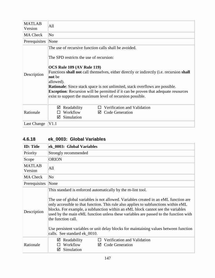
147
MATLAB
Version All
MA Check No
Prerequisites None
Description
The use of recursive function calls shall be avoided.
The SPD restricts the use of recursion:
OCS Rule 109 (AV Rule 119) Functions shall not call themselves, either directly or indirectly (i.e. recursion shall
not be
allowed).
Rationale: Since stack space is not unlimited, stack overflows are possible.
Exception: Recursion will be permitted if it can be proven that adequate resources
exist to support the maximum level of recursion possible.
Rationale
Readability
Workflow
Simulation
Verification and Validation
Code Generation
Last Change V1.1
4.6.18 ek_0003: Global Variables
ID: Title ek_0003: Global Variables
Priority Strongly recommended
Scope ORION
MATLAB
Version All
MA Check No
Prerequisites None
Description
This standard is enforced automatically by the m-lint tool.
The use of global variables is not allowed. Variables created in an eML function are
only accessible to that function. This rule also applies to subfunctions within eML
blocks. For example, a subfunction within an eML block cannot see the variables
used by the main eML function unless these variables are passed to the function with
the function call.
Use persistent variables or unit delay blocks for maintaining values between function
calls. See standard ek_0010.
Rationale
Readability
Workflow
Simulation
Verification and Validation
Code Generation

148
Last Change V1.0
4.6.19 jh_0073: eML Header
ID: Title jh_0073: eML Header
Priority Mandatory
Scope ORION
MATLAB
Version All
MA Check Yes
Prerequisites None
Description
eML functions should have a header that contains the following information before
the function declaration:
Function name
Description of function
Assumptions and Limitations
Developer Name, email, and phone number
Description of changes from previous versions is applicable
Lists of inputs and outputs
Example:
%*******************************************************************
% FUNCTION NAME:
% util_vec_unitize
%
% DESCRIPTION:
% Normalizes/unitizes a vector of size 3
%
% INPUT:
% double b – input 3 vector
%
% OUTPUT:
% double y – normalized/unitized 3 vector
%
% ASSUMPTIONS AND LIMITATIONS:
% None
%
% MODIFICATION HISTORY (INCLUDING INITIAL IMPLEMENTATION):
% 01/02/03 – Louis Breger (CSDL), email, phone #
% * Initial implementation
%
% 02/06/03 – Chinwe Nyenke (CSDL), email, phone #
% * Added protection for divide by zero
Rationale
Readability
Workflow
Simulation
Verification and Validation
Code Generation

149
Last Change V1.1
4.6.20 jh_0093: Parameter Bus for eML
ID: Title jh_0093: Parameter Bus for eML
Priority Recommended
Scope ORION
MATLAB
Version All
MA Check No
Prerequisites None
Description
For embedded Matlab blocks, the entire parameter bus should be input if used and
the separate elements of the bus accessed within the code instead of passing each
element used as a function argument.
Rationale
Readability
Workflow
Simulation
Verification and Validation
Code Generation
Last Change V1.0
4.6.21 jh_0084: eML Comments
ID: Title jh_0084: eML Comments
Priority Mandatory
Scope ORION
MATLAB
Version All
MA Check No
Prerequisites None
Description All eML functions should be properly commented to describe functionality.
Rationale
Readability
Workflow
Simulation
Verification and Validation
Code Generation
Last Change V1.0
4.6.22 do_0001: Declaring Local Variables in eML
ID: Title do_0001: Declaring Local Variables in eML
Priority Mandatory
Scope ORION

150
MATLAB
Version All
MA Check No
Prerequisites None
Description
A local eML variable shall be explicitly type cast when it is intend to have a data
type other than an inherited type or double. The properties (class, size and
complexity) of a variable are inherited from the right side of an assignment when the
variable is first assigned. First assignments to a constant results in a data type of
“double”
For example:
State = prevState; % State is set to the type of “prevState”
Num_Of_Samples = 0; % Num_Of_Samples is of type double
Buff_Size = uint32(6) % Buff_Size is of type uint32
Local eML variables used as counters should be typed as an int or uint. This will
prevent the code from having logic comparisons to reals.
Local eML variables used as an array index should be typed to an int. This will
prevent the code from having extra (int32_t) type casts.
Exceptions:
The index variable of a for-loop does not require a type cast if the index variable is
first assigned in the for-loop expression. The index variable will default to a type
int32.
Rationale
Readability
Workflow
Simulation
Verification and Validation
Code Generation
Last Change V1.0
4.7 Code Development Standards
4.7.1 hyl_0204: Standard units
ID: Title hyl_0204: Standard units
Priority Mandatory
Scope ORION
MATLAB
Version All
MA Check No
Prerequisites None
Description The models shall output signals in English units unless otherwise required by external
interfaces.
Force, mass, and length units shall be LBF, SLUG, and FT (respectively) unless
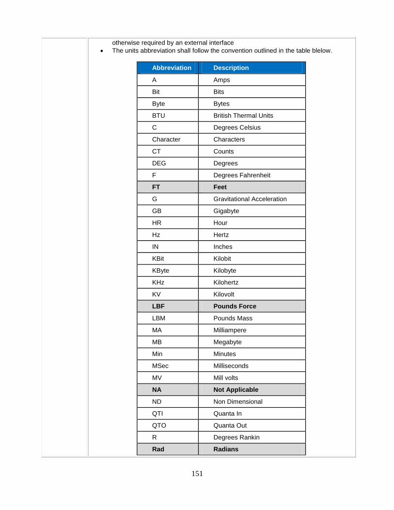
151
otherwise required by an external interface
The units abbreviation shall follow the convention outlined in the table blelow.
Abbreviation Description
A Amps
Bit Bits
Byte Bytes
BTU British Thermal Units
C Degrees Celsius
Character Characters
CT Counts
DEG Degrees
F Degrees Fahrenheit
FT Feet
G Gravitational Acceleration
GB Gigabyte
HR Hour
Hz Hertz
IN Inches
KBit Kilobit
KByte Kilobyte
KHz Kilohertz
KV Kilovolt
LBF Pounds Force
LBM Pounds Mass
MA Milliampere
MB Megabyte
Min Minutes
MSec Milliseconds
MV Mill volts
NA Not Applicable
ND Non Dimensional
QTI Quanta In
QTO Quanta Out
R Degrees Rankin
Rad Radians
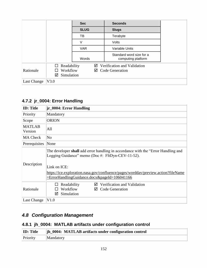
152
Sec Seconds
SLUG Slugs
TB Terabyte
V Volts
VAR Variable Units
Words Standard word size for a
computing platform
Rationale
Readability
Workflow
Simulation
Verification and Validation
Code Generation
Last Change V3.0
4.7.2 jr_0004: Error Handling
ID: Title jr_0004: Error Handling
Priority Mandatory
Scope ORION
MATLAB
Version All
MA Check No
Prerequisites None
Description
The developer shall add error handling in accordance with the “Error Handling and
Logging Guidance” memo (Doc #: FltDyn-CEV-11-52).
Link on ICE:
https://ice.exploration.nasa.gov/confluence/pages/worddav/preview.action?fileName
=ErrorHandlingGuidance.docx&pageId=106041166
Rationale
Readability
Workflow
Simulation
Verification and Validation
Code Generation
Last Change V1.0
4.8 Configuration Management
4.8.1 jh_0004: MATLAB artifacts under configuration control
ID: Title jh_0004: MATLAB artifacts under configuration control
Priority Mandatory

153
Scope ORION
MATLAB
Version all
MA Check No
Prerequisites None
Description
If a Configuration Management tool is used the following files should be included for
each project:
• *.mdl files
• *.m setup scripts
• *.h files used for buses and ARINC blocks
• Utility files and models needed for simulation (*.c, *.cpp, etc.)
Some Simulink generated files are specific to the environment in which the
simulation is executed. This may cause issues when simulating the model in a
different environment. These files are not needed for simulation and will be
recreated once the model is run again. To avoid potential issued do not include the
following files in a project:
• *.mex* files
• slprj directory
• sfprj directory
• *_rtw directory
• *.mat files created by running model
• Other files generated from running the model
Rationale
Readability
Workflow
Simulation
Verification and Validation
Code Generation
Last Change V1.0

5 Appendix
5.1 Modeling Guidelines Chart
The following table shows a guideline for which tool to use for different types of algorithms
Algorithm Type Simulink Stateflow eML Notes/examplesSimple Logic•if/then•switch/case•for/while loops
X X X Ex: If/then with <5 paths and no nesting
Complex Logic•nested if/then•nested switch/case •nested for/while loops
Xpreferred
X Ex: If/then with numerous paths and multiple levels of nesting
Simple/ShortNumerical Expressions X Ex: <6 consecutive operations, <6
variables/signals
Complex/LengthyNumerical Expressions X X
preferred
Ex: >6 consecutive operations, >6variables/signals
Numerical Expressions containing continuously valued states
X*Ex: Difference equations, integrals, derivatives, filters*The actual integrator function can be written in eML
Combination of:•Complex Logic•Simple Numerical Expressions
X iterating a counter is considered a simple numeric calculation
Combination of:•Simple Logic•Complex Numerical Expressions
XFor Logic
XFor Math
•Can use only Simulink, only eML or use Simulink for the logic and eML for the math
Combination of•Complex logic •Complex Numerical Expressions
Xfor Logic
Xfor Logic
and/or Math
•Use Simulink or eML for the numerical calculations•Stateflow should invoke the execution of this subsystem using a function-call
Modal Logic XWhere the control function to be performed at the current time depends on a combination of past and present logical conditions
5.2 Configuration Settings
List of configuration settings
5.3 Model Advisor Standards Checks Summary
ID: Title Priority Scope MA Check
ar_0001: Filenames Mandatory MAAB YES
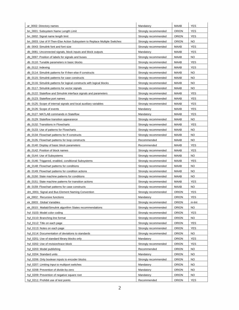
2
ar_0002: Directory names Mandatory MAAB YES
bn_0001: Subsystem Name Length Limit Strongly recommended ORION YES
bn_0002: Signal name length limit Strongly recommended ORION YES
bn_0003: Use of If-Then-Else Action Subsystem to Replace Multiple Switches Strongly recommended ORION NO
db_0043: Simulink font and font size Strongly recommended MAAB YES
db_0081: Unconnected signals, block inputs and block outputs Mandatory MAAB YES
db_0097: Position of labels for signals and buses Strongly recommended MAAB NO
db_0110: Tunable parameters in basic blocks Strongly recommended MAAB YES
db_0112: Indexing Strongly recommended MAAB YES
db_0114: Simulink patterns for If-then-else-if constructs Strongly recommended MAAB NO
db_0115: Simulink patterns for case constructs Strongly recommended MAAB NO
db_0116: Simulink patterns for logical constructs with logical blocks Strongly recommended MAAB NO
db_0117: Simulink patterns for vector signals Strongly recommended MAAB NO
db_0122: Stateflow and Simulink interface signals and parameters Strongly recommended MAAB YES
db_0123: Stateflow port names Strongly recommended MAAB YES
db_0125: Scope of internal signals and local auxiliary variables Strongly recommended MAAB YES
db_0126: Scope of events Mandatory MAAB YES
db_0127: MATLAB commands in Stateflow Mandatory MAAB YES
db_0129: Stateflow transition appearance Strongly recommended MAAB NO
db_0132: Transitions in Flowcharts Strongly recommended MAAB YES
db_0133: Use of patterns for Flowcharts Strongly recommended MAAB NO
db_0134: Flowchart patterns for If constructs Strongly recommended MAAB NO
db_0135: Flowchart patterns for loop constructs Recommended MAAB NO
db_0140: Display of basic block parameters Recommended MAAB YES
db_0142: Position of block names Strongly recommended MAAB YES
db_0144: Use of Subsystems Strongly recommended MAAB NO
db_0146: Triggered, enabled, conditional Subsystems Strongly recommended MAAB YES
db_0148: Flowchart patterns for conditions Strongly recommended MAAB NO
db_0149: Flowchart patterns for condition actions Strongly recommended MAAB NO
db_0150: State machine patterns for conditions Strongly recommended MAAB NO
db_0151: State machine patterns for transition actions Strongly recommended MAAB YES
db_0159: Flowchart patterns for case constructs Strongly recommended MAAB NO
dm_0001: Signal and Bus Element Naming Convention Strongly recommended ORION YES
ek_0002: Recursive functions Mandatory ORION YES
ek_0003: Global Variables Strongly recommended ORION m-lint
ek_0010: Matlab/Simulink algorithm States recommendations Strongly recommended ORION NO
hyl_0103: Model color coding Strongly recommended ORION YES
hyl_0110: Branching line format Strongly recommended ORION NO
hyl_0112: Title on each page Strongly recommended ORION YES
hyl_0113: Notes on each page Strongly recommended ORION YES
hyl_0114: Documentation of deviations to standards Strongly recommended ORION NO
hyl_0201: Use of standard library blocks only Mandatory ORION YES
hyl_0202: Use of revision/trace block Strongly recommended ORION YES
hyl_0203: Model publishing Recommended ORION NO
hyl_0204: Standard units Mandatory ORION NO
hyl_0206: Only boolean inputs to encoder blocks Strongly recommended ORION NO
hyl_0207: Limiting input to multiport switches Mandatory ORION NO
hyl_0208: Prevention of divide-by-zero Mandatory ORION NO
hyl_0209: Prevention of negative square root Mandatory ORION NO
hyl_0211: Prohibit use of test points Recommended ORION YES

3
hyl_0301: Block naming convention Strongly recommended ORION YES
hyl_0302: Usable characters for block names Strongly recommended ORION YES
hyl_0305: Block name uniqueness Strongly recommended ORION YES
hyl_0307: Use of subsystem name Strongly recommended ORION YES
hyl_0308: Use of reference model name Strongly recommended ORION YES
hyl_0309: Block name usage Recommended ORION NO
hyl_0311: Naming of signals passed through multiple subsystems Strongly recommended ORION YES
im_0001: Guidelines for mixed use of Simulink and eML Strongly recommended ORION NO
im_0003: Controller model Mandatory ORION NO
im_0004: Top layer / root level Mandatory ORION NO
im_0005: Trigger layer Mandatory ORION NO
im_0006: Structure layer Mandatory ORION NO
im_0007: Data flow layer Mandatory ORION NO
im_0008: Source lines of eML Mandatory ORION YES
im_0009: Number of called function levels Mandatory ORION NO
im_0010: Number of inline function calls Mandatory ORION YES
im_0015: ORION GN&C Model Architecture Mandatory ORION NO
jc_0061: Display of block names Recommended MAAB YES
jc_0081: Icon display for Port block Recommended MAAB YES
jc_0121: Use of the Sum block Recommended MAAB YES
jc_0131: Use of Relational Operator block Recommended J-MAAB YES
jc_0141: Use of the Switch block Strongly recommended MAAB YES
jc_0171: Maintaining signal flow when using Goto and From blocks Strongly recommended MAAB NO
jc_0201: Usable characters for Subsystem names Strongly recommended MAAB YES
jc_0211: Usable characters for Inport block and Outport block Strongly recommended MAAB YES
jc_0221: Usable characters for signal line names Strongly recommended MAAB YES
jc_0281: Naming of Trigger Port block and Enable Port block Strongly recommended J-MAAB YES
jc_0351: Methods of initialization Recommended MAAB NO
jc_0451: Use of unary minus on unsigned integers in Stateflow Recommended MAAB YES
jc_0481: Use of hard equality comparisons for floating point numbers in Stateflow Recommended MAAB YES
jc_0491: Reuse of variables within a single Stateflow scope Recommended MAAB NO
jc_0511: Setting the return value from a graphical function Mandatory J-MAAB YES
jc_0521: Use of the return value from graphical functions Recommended J-MAAB YES
jc_0531: Placement of the default transition Recommended J-MAAB YES
jc_0541: Use of tunable parameters in Stateflow Strongly recommended MAAB YES
jh_0001: Use of ARINC blocks for partition to partition data flow Mandatory ORION NO
jh_0004: MATLAB artifacts under configuration control Mandatory ORION NO
jh_0005: Setup files for model parameter initialization Strongly recommended ORION NO
jh_0006: Setup files for bus initialization Strongly recommended ORION NO
jh_0007: blocks in a model Recommended ORION YES
jh_0011: Model release Mandatory ORION NO
jh_0018: Variable type casting Recommended ORION YES
jh_0021: Restricted Variable Names Mandatory ORION YES
jh_0023: Arrays Mandatory ORION m-lint
jh_0024: Strings Strongly recommended ORION YES
jh_0025: Structures Mandatory ORION m-lint
jh_0026: Switch/case statements Mandatory ORION m-lint
jh_0027: Multiple Code Paths Mandatory ORION m-lint
jh_0029: m-files Mandatory ORION m-lint
jh_0030: Extrinsic function Strongly recommended ORION m-lint
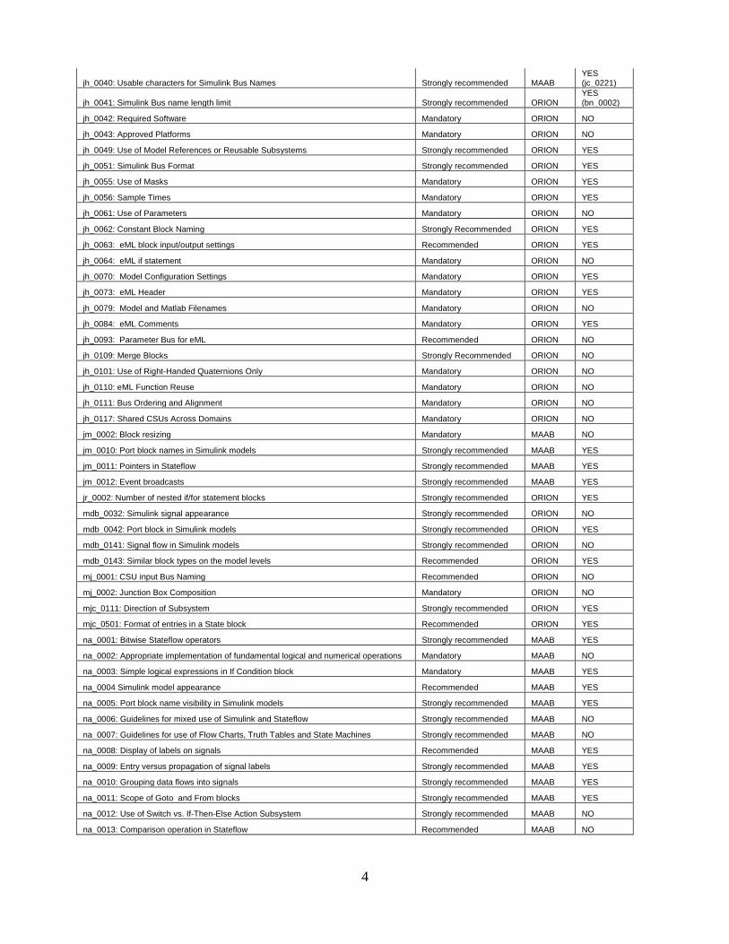
4
jh_0040: Usable characters for Simulink Bus Names Strongly recommended MAAB YES (jc_0221)
jh_0041: Simulink Bus name length limit Strongly recommended ORION YES (bn_0002)
jh_0042: Required Software Mandatory ORION NO
jh_0043: Approved Platforms Mandatory ORION NO
jh_0049: Use of Model References or Reusable Subsystems Strongly recommended ORION YES
jh_0051: Simulink Bus Format Strongly recommended ORION YES
jh_0055: Use of Masks Mandatory ORION YES
jh_0056: Sample Times Mandatory ORION YES
jh_0061: Use of Parameters Mandatory ORION NO
jh_0062: Constant Block Naming Strongly Recommended ORION YES
jh_0063: eML block input/output settings Recommended ORION YES
jh_0064: eML if statement Mandatory ORION NO
jh_0070: Model Configuration Settings Mandatory ORION YES
jh_0073: eML Header Mandatory ORION YES
jh_0079: Model and Matlab Filenames Mandatory ORION NO
jh_0084: eML Comments Mandatory ORION YES
jh_0093: Parameter Bus for eML Recommended ORION NO
jh_0109: Merge Blocks Strongly Recommended ORION NO
jh_0101: Use of Right-Handed Quaternions Only Mandatory ORION NO
jh_0110: eML Function Reuse Mandatory ORION NO
jh_0111: Bus Ordering and Alignment Mandatory ORION NO
jh_0117: Shared CSUs Across Domains Mandatory ORION NO
jm_0002: Block resizing Mandatory MAAB NO
jm_0010: Port block names in Simulink models Strongly recommended MAAB YES
jm_0011: Pointers in Stateflow Strongly recommended MAAB YES
jm_0012: Event broadcasts Strongly recommended MAAB YES
jr_0002: Number of nested if/for statement blocks Strongly recommended ORION YES
mdb_0032: Simulink signal appearance Strongly recommended ORION NO
mdb_0042: Port block in Simulink models Strongly recommended ORION YES
mdb_0141: Signal flow in Simulink models Strongly recommended ORION NO
mdb_0143: Similar block types on the model levels Recommended ORION YES
mj_0001: CSU input Bus Naming Recommended ORION NO
mj_0002: Junction Box Composition Mandatory ORION NO
mjc_0111: Direction of Subsystem Strongly recommended ORION YES
mjc_0501: Format of entries in a State block Recommended ORION YES
na_0001: Bitwise Stateflow operators Strongly recommended MAAB YES
na_0002: Appropriate implementation of fundamental logical and numerical operations Mandatory MAAB NO
na_0003: Simple logical expressions in If Condition block Mandatory MAAB YES
na_0004 Simulink model appearance Recommended MAAB YES
na_0005: Port block name visibility in Simulink models Strongly recommended MAAB YES
na_0006: Guidelines for mixed use of Simulink and Stateflow Strongly recommended MAAB NO
na_0007: Guidelines for use of Flow Charts, Truth Tables and State Machines Strongly recommended MAAB NO
na_0008: Display of labels on signals Recommended MAAB YES
na_0009: Entry versus propagation of signal labels Strongly recommended MAAB YES
na_0010: Grouping data flows into signals Strongly recommended MAAB YES
na_0011: Scope of Goto and From blocks Strongly recommended MAAB YES
na_0012: Use of Switch vs. If-Then-Else Action Subsystem Strongly recommended MAAB NO
na_0013: Comparison operation in Stateflow Recommended MAAB NO
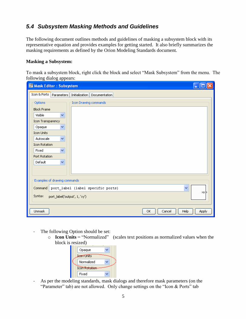
5
5.4 Subsystem Masking Methods and Guidelines
The following document outlines methods and guidelines of masking a subsystem block with its
representative equation and provides examples for getting started. It also briefly summarizes the
masking requirements as defined by the Orion Modeling Standards document.
Masking a Subsystem:
To mask a subsystem block, right click the block and select “Mask Subsystem” from the menu. The
following dialog appears:
- The following Option should be set:
o Icon Units = “Normalized” (scales text positions as normalized values when the
block is resized)
- As per the modeling standards, mask dialogs and therefore mask parameters (on the
“Parameter” tab) are not allowed. Only change settings on the “Icon & Ports” tab

6
- All further mask settings are made by calling functions from within the “Icon Drawing
Commands” pane.
- To make changes to a mask after the dialog is closed, right click the block and select “Edit
Mask” from the menu.
Displaying text:
Use Matlab‟s disp() function to center a single line of text on the mask.
- Example: o disp('Y = MX + B','texmode','on')
- Use “disp” function for masks whose equation occupies a single line. “disp”
automatically centers its text string on the subsystem.
- “disp” does not permit multiple lines to be displayed. To display multiple lines, use
text()
Use Matlab‟s text() function to display multiple lines of text on the mask.
- Example: o text(.3,.6,'Y = MX+B','texmode','on')
o text(.3,.4,'M = 1','texmode','on')
- The “text” function requires x & y positions as the first two arguments. To display
multiple lines, call text() once for each line, giving each call different position
coordinates.
- Set “Icon Units” equal to “Normalized” in the left hand Options pane of the mask editor
in order to make the position values scale as normalized values when the block is
resized.
Labeling a Port:
Once a block is masked, the underlying port names will no longer be displayed on the subsystem.
To enhance readability and understandability, the inputs and the outputs of the subsystem model
should be labeled to match variables in its function. Matlab‟s port_label() function permits this.

7
Note: The port label function permits the use of TeX commands to label a port with a symbol. If
you choose not to label the port with its representative symbol, then it is suggested to label the port
with the same name as the underlying inport/outport for consistency.
- Extend the previous example by adding the following lines: o port_label('input',1,'X','texmode','on')
o port_label('output',1,'Y','texmode','on')
Using TeX commands:
The previous examples set the “texmode” parameter to “on”; however, they did not make use of
TeX commands within the text string. From the Matlab Help documentation:
“When the text Interpreter property is Tex (the default), you can use a subset of TeX
commands embedded in the string to produce special characters such as Greek letters and
mathematical symbols.” 2
The following example shows how to set the mask‟s text and port labels to bold and 14 point font
using TeX commands:
port_label('input',1,'\bf\fontsize{14}X','texmode','on') port_label('output',1,'\bf\fontsize{14}Y','texmode','on')
disp('\bf\fontsize{14}Y = MX + B','texmode','on')
Note:
- The „\‟ character indicates an embedded TeX command to Matlab‟s TeX interpreter
- All mask disp() and text() strings should be boldface and 14 point font for readability.
- There are many more TeX commands supported by Matlab‟s TeX interpreter, search the
help file for “TeX Character Sequence Table” for a table of supported commands, or see the
Appendix in this document.
Advanced TeX Example:

8
port_label('input',1,'I','texmode','on') port_label('input',2,'F','texmode','on') port_label('input',3,'\Delta *t','texmode','on') port_label('output',1,'\Phi','texmode','on') text(.26,.7,'\bf \fontsize{14}\Phi \approx I + F\Deltat + .5F^2
\Deltat^2','texmode','on') text(.15,.3,'\bf \fontsize{14}I - \Phi^{-1} \approx F\Deltat -
.5F^2\Deltat^2','texmode','on')
Note – The Matlab TeX interpreter does not recognize TeX numerator/denominator commands for
representing fractions.
Reference:
1 - Summary of Requirements
- Mask dialogs are not allowed, therefore creating mask parameters is not allowed (because
they automatically create mask dialogs)
- Port Labeling commands are to be grouped together ahead of Disp() or Text() commands in
the Icon Drawing Commands pane
- All mask disp() and text() strings are to be bold and 14 point font; port labels can be left at
their default settings
- All ports are to be labeled with their representative symbol or underlying port name
- Set option Icon Units = “Normalized”
2 - MathWorks – Matlab TeX Character Sequence Table
http://www.mathworks.com/help/techdoc/ref/text_props.html#String
Character Sequence Symbol Character Sequence Symbol Character Sequence Symbol
\alpha α
\upsilon ς
\sim ~
\angle ∠
\phi Φ
\leq ≤
\ast * \chi σ
\infty ∞
\beta β
\psi τ
\clubsuit ♣

9
Character Sequence Symbol Character Sequence Symbol Character Sequence Symbol
\gamma γ
\omega υ
\diamondsuit ♦
\delta δ
\Gamma Γ
\heartsuit ♥
\epsilon ɛ
\Delta Δ
\spadesuit ♠
\zeta δ
\Theta Θ
\leftrightarrow ↔
\eta ε
\Lambda Λ
\leftarrow ←
\theta Θ
\Xi Ξ
\Leftarrow ⇐
\vartheta ϑ
\Pi Π
\uparrow ↑
\iota ι
\Sigma Σ
\rightarrow →
\kappa κ
\Upsilon ϒ
\Rightarrow ⇒
\lambda λ
\Phi Φ
\downarrow ↓
\mu µ
\Psi Ψ
\circ º
\nu ν
\Omega Ω
\pm ±
\xi ξ
\forall ∀
\geq ≥
\pi π
\exists ∃
\propto ∝
\rho π
\ni ∍
\partial ∂
\sigma σ
\cong ≅
\bullet •
\varsigma ρ
\approx ≈
\div ÷
\tau τ
\Re ℜ
\neq ≠
\equiv ≡
\oplus ⊕
\aleph ℵ

10
Character Sequence Symbol Character Sequence Symbol Character Sequence Symbol
\Im ℑ
\cup ∪
\wp ℘
\otimes ⊗
\subseteq ⊆
\oslash ∅
\cap ∩
\in ∈
\supseteq ⊇
\supset ⊃
\lceil ⌈
\subset ⊂
\int ∫
\cdot ·
\o ο
\rfloor ⌋
\neg ¬
\nabla ∇
\lfloor ⌊
\times x
\ldots ...
\perp ⊥
\surd √
\prime ´
\wedge ∧
\varpi ϖ \0 ∅
\rceil ⌉
\rangle 〉
\mid |
\vee ∨
\copyright ©
\langle 〈