signaling a modular layout - nmra hub division - home€¢ 1925: tri-color (g type) signals - grs...
TRANSCRIPT

Signaling a Modular Layout
Dick Johannes
& the HUB Division Signal Committee
July 2014
9/2/2014 1

The HUB Division
Signal Committee Members
9/2/2014 2

Humble Beginings
9/2/2014 3

Hoosac, Upton & Boston RR
• Now over 65 members
• David Haralambou is the current Co-ordinator
• Very large setups including the annual Amherst Railway
Society Show & our New England Model Train Expo
• Annual displays at Children’s Hospital Boston & the
National Heritage Museum in Lexington, MA
• Shown internationally: Canada, Germany, Netherlands
• Very early adopter of DCC (after all, Stan and Debbie
Ames are members) Has always been Lenz driven
• 1st Place awards at NMRA Nationals both in individual
modules and modular railroad categories.
9/2/2014 4

You Can Learn a Lot in 8 sq ft
• At the outset we had:
– 5 bus wiring harness supports 2 mainlines buses, a local track
bus, an accessory DCC bus, and an18 volt AC accessory bus
– 2 Cat5 buses: XpressNet bus & a 2nd unused Cat5 bus
• Replete with high-end craftsman structures and scratch-
built structures
• Numerous experiments with scenic techniques
• Remember, the overarching goal is to serve our
members
• Why not Signaling next??
9/2/2014 5

The R3C3 Approach
• Research, research, research
– Reading
– NMRA Convention Visits
– Formed a Signaling Committee
– Created a Requirements Specification
• Communicate, communicate, communicate
– Spring Training
– RailFun nights
– The “Headlight”
– Get a master involved (Dr. Bruce Chubb)
9/2/2014 6

Goals & Rationale
• Increase the knowledge and curiosity in
signaling within HUB Division members
• Add a new level of operating interest to the
modular layout
• Enhance the viewing experience for
spectators of the layout
• Sounded like fun!!
9/2/2014 7

Key historical events
• 1840: Ball signals: LTC Rolt
• 1841: Semaphore – Charles Gregory
• 1851:Telegraph – Chas Minot
• 1870: Track Circuit – William Robinson
• 1871: Disk (Banjo) Signal – Thomas Hall
• 1904: Color light signals – William Churchill
• 1915: Position-light signals – Arthur Rudd
• 1920: Searchlight Signals – Hall Signal Co.
• 1924: Color Position signals – Frank Patenall
• 1925: Tri-color (G type) signals - GRS
9/2/2014 8

Two types of “regions”
9/2/2014 9
Block C Block D Block E Block F
Interlockings (Junctions & Sidings)
Linear Blocks
Block A Block B Block G

The Distinctions
• Linear blocks – Unsupervised (e.g. totally automated)
– Default is “clear” or “green”
– ABS (Automatic Block Signaling)
– APB (Absolute Permissive Block)
• Interlockings (Junctions & Sidings) – Human operated (e.g. human controlled)
– Default is “stop” or “red”
– Mechanical interlocks
– US&S panels
– Computerized CTC
9/2/2014 10

Aspect Combinatorics
& (NORAC)
UPPER
HEAD
LOWER
HEAD Signal RULE (Aspect)
GREEN GREEN 281
GREEN YELLOW Not Used
GREEN RED 281
YELLOW GREEN 282
YELLOW YELLOW 284
YELLOW RED 285
RED GREEN 283
RED YELLOW 290
RED RED 291

Aspects: NORAC*
9/2/2014
Rule: 281
Name: Clear
Indication: Proceed not
exceeding Normal Speed
Rule: 281c
Name: Limited Clear
Indication: Proceed at Limited
Speed until entire train clears
all interlocking or spring
switches
Rule: 281a
Name: Cab Speed
Indication: Proceed in
accordance with cab signal
indication
Rule: 281b
Name: Approach Limited
Indication: Proceed
approaching the next signal
at Limited Speed
Rule: 282
Name: Approach Medium
Indication: Proceed
approaching the next signal at
Medium Speed
Rule: 282a
Name: Advance Approach
Indication: Proceed prepared to
stop at the second signal.
Trains exceeding Limited Speed
must reduce to Limited Speed
as engine passed the signal
* 9th Edition, 2008 - Flashing
12

Aspects: NORAC* (cont)
9/2/2014 13
Rule: 283
Name: Medium-Clear
Indication: Proceed at Medium
Speed until entire train clears
all interlocking or spring
switches, then proceed at
Normal Speed
Rule: 285
Name: Approach
Indication: Proceed prepared to
stop at the next signal. Reduce
to Medium Speed as engine
passes signal
Rule: 283a
Name: Medium Approach
Medium
Indication: Proceed at Medium
Speed until entire train clears
all interlocking or spring
switches, then approach next
signal at Medium Speed
Rule: 284
Name: Approach Slow
Indication: Proceed
approaching the next signal
at Slow Speed
Rule: 286
Name: Medium Approach
Indication: Proceed prepared to
stop at the next signal. Reduce
to Medium Speed as soon as
signal is clearly visible
Rule: 287
Name: Slow Clear
Indication: Proceed at Slow
Speed until entire train clears
all interlocking or spring
switches, then proceed at
Normal Speed
* 9th Edition, 2008 - Flashing

Advice We Were Given
• Pay attention to modeling details just as you
would in any other aspect of model
railroading
• Separate the signaling bus from train control
• Solve occupancy then move to signals
• You won’t regret using either C/MRI or
Digitrax
• Largely, we took this advice but made some
compromises
9/2/2014 14

Frame the Issues
• This is a classical data processing issue 1. What are the inputs and where do they come from?
2. How do we process the incoming data transforming
it into information?
3. How do we output the processed information?
• We were looking for a hardware AND a
software solution
9/2/2014 15

Experiment, Experiment, Experiment
• We adopted JMRI early
– Broad support for multivendor solutions
– Already had experience with
DecoderPro & WiThrottle
– We got to the point where we
could build US&S style panel
using PanelPro. • JMRI website
• Dick Bronson’s NMRA online clinics
9/2/2014 16

US&S CTC Panels
9/2/2014
17
Screen shot from
Dick Bronson’s
Hartford National
Clinics

But There Was Interest in a
Modern CRT-based Panel
• We looked at the Layout Editor
• Using the JMRI Website, we found CATS
(Computer Automated Traffic System)
• Open Source JAVA software layered atop
PanelPro
• Written by Rodney Black. Like JMRI, it has
an online user forum
• Based upon prototype Digicon system
9/2/2014 18

Direct Comparison
9/2/2014 19
Screenshot of
the Digicon
Prototype
CATS Rendering
of the Prototype

CATS Screen Shot
9/2/2014 20

CATS
• Several outstanding features
– Uses all the debugging tools in JMRI
– Great benefits even without signals
– Signaling based on 4 track speed / 2 or 3 block rules
– “Pre-programmed” signal logic
– CTC signals are visible whereas intermediate signals
are not visible on the dispatcher panel
– Can grant track authority
– Can take track out of service
– Allows train tracking by train symbol or locomotive #
– Well written online manuals
9/2/2014 21

CATS Suite is 3 Programs
• DESIGNER
– Used to describe the panel (e.g. track, turnouts & signals)
– Creates a permanent stored XML file
– Detector and signal definitions & address mapping
– Many display options
• CATS
– The runtime application
– Many runtime controls and display options
• TRAINSTAT
– Tool to allow documenting train location and time (either real
time or fast clock)
– Can be stored to file for archiving
9/2/2014 22

The Signal Template
Default Settings
9/2/2014 23

Define Your Signal Rules
9/2/2014 24

The Signal Template
Edited Settings
9/2/2014 25

The Testing Environment
9/2/2014 26
2. CATS Runtime
3, JMRI Sensor Table
4, JMRI Signal Head Table
5, The System Monitor
1, JMRI (simulator)

The Difficult Requirements
• Modular specification forbids circuitry in-line
with the DCC signal
• Minimal (if any) changes to existing modules
if the builder choose not to add signals
• Cost
• Railroad can operate even if the signals don’t
• Must be able to shuffle modules in any order
at each setup and signaling must work with
no wiring changes and minimal setup effort
9/2/2014 27

Arbitrary Module Order
• How does one swap module order and
preserve signal logic?
• The File → Import function • File->Import reads in a saved layout (a library) without erasing any existing work. It is a way to
merge multiple layouts together, add some pre-canned design elements to the existing layout,
insert existing signal definitions, etc. When a file is selected, designer will grab the track plan from
the file and insert the upper grid corner of the trackplan at the grid cursor location. It will expand
the layout in the horizontal and vertical directions as needed. Note that the library is not inserted,
but replaces existing track; thus, preserving any track not overlaid
• Tracks, information associated with tracks (e.g. Block definitions), Stations, Signals, etc. will be
added to the existing work. File->Import will also merge any Devices (Section 8) defined in the
file, but not any Appearances (Section 14.1), Trains (Section 10), Crew (Section 12), or Jobs
(Section 11). “Merging” is defined as “if something in the file does not exist in the current
trackplan, it is added”. This means that things in the library file will not replace things with the
same name in the trackplan.
9/2/2014 28

We Built 5 “Test” Modules
• Two were “passive” (e.g. do not have a signaling card)
– No detection
– No signals
– These represented unchanged modules
• Three were “active” modules (e.g. have a signaling card)
– These 3 modules all contained signals
– Each module used a different type of signal
• 1 used G-type, 1 used Searchlight, 1 used D-type
• All wired as common anode
– NCE AIU & DB20s used for detection, Oaktree signal boards
• Wiring strategy:
– Inner main supplies power & detection to the left
– Outer main supplies power & detection to the right
9/2/2014 29

The Test Modules
9/2/2014 30
Three “Active Modules
Two “Passive” Modules
OS Module
Crossover Module Straight Module
Passive #1 Passive #2
CTC
CTC

Signals in 90 Minutes
9/2/2014 31
Starting Point: Ordinary DCC Trackage
Step 1: Add Detection
Step 2: Add Signals

The Six Permutations
9/2/2014 32

Wiring Scheme
9/2/2014 33

Current MU-ing
9/2/2014 34
Existing
Newly Added

Terminal Strip Color
Conventions
9/2/2014 35

Mainline Wiring
9/2/2014 36

Outer Main Detail
9/2/2014 37
1. PASSIVE
End
Segment
3. ACTIVE
End
Segment
2. INTERMEDIATE TRACK

Wiring scheme
9/2/2014 38
WEST EAST

Simple Oval
9/2/2014 39

“Splicing” in Active Modules
9/2/2014 40

Linearize the Layout
9/2/2014 41
Linear sequence left to right for CATS “insertion”
Cut Point

Each Module Has It’s Own
Designer File
9/2/2014 42
OS Module
Cross-Over Module
Straight Module

CATS Runtime
9/2/2014 43
OS Module
Cross-Over Module
Straight Module

Insertion Demonstration
9/2/2014 44

Runtime 3 Module Section
9/2/2014 45

THE ROLLING MEET
9/2/2014 46

The Anxious Dispatcher
9/2/2014 47

Hardware Evaluation Table
9/2/2014 48
Manufacturer Strengths Reason for Elimination
C/MRI Passed all tests
Oaktree Systems Reasonable price. Lots of
positive testing results Minor failure on turnout positioning. No simulator
Digitrax Full hardware support Signal board does not fully support all 3 color blinking
aspects.
CTI Acela Very modular, relatively low
cost
Self recognizing network redefines addresses with
module rearrangement. No simulator
ProTrack Grapevine Very Modular Possible issues with detection method. No simulator
Custom Signals
Manufactures signals as well
as boards. Source for the
Atlas system
Does not support JMRI. Fails a major requirement
Signals by Spreadsheet
Very clever combination of
hardware and software for
signaling
Does not support JMRI. Fails a major requirement
Integrated Signal Systems Long time Manufacturer of
high end signals Does not support JMRI. Fails a major requirement

Turnout Wiring
9/2/2014 49

DCC Turnouts Welcome!
• We could use more crossovers on the mainlines
• All/Most mainline turnouts should be DCC controllable
• 3 ways to throw: throttle, pushbutton, CATS – must agree
• All accessory decoders are fine
• Costs:
9/2/2014 50
List # TOs Cost/TO On-line$ Cost/TO
NCE (SW-8) 59.95$ 8 7.49$ 49.95$ 6.24$
Digitrax (NF) 39.99$ 4 10.00$ 31.95$ 7.99$
NCE (SW-IT) 19.95$ 2 9.98$ 16.95$ 8.48$
CVP 35.00$ 4 8.75$ 35.00$ 8.75$
Team Digital 99.95$ 8 12.49$ 84.95$ 10.62$
Digitrax 59.95$ 4 14.99$ 49.95$ 12.49$
MRC 69.98$ 4 17.50$ 49.99$ 12.50$
Wabbit 31.95$ 2 15.98$ 27.95$ 13.98$
Lenz 74.87$ 4 18.72$ 59.95$ 14.99$
RR-Cirkits† 32.25$ 8 4.03$ 27.95$ 3.49$
† Not a DCC stationary decoder

Signal types
• The module group standard will be the
three triangular light G-Type signal with
any number of heads. Green on the right.
• However, based upon modeler preference,
any physical signal type is acceptable.
• Electrically, we will only support common anode, lighting one LED
or bulb per output. Common anode B&O or PRR signals are fine.
Common cathode signals can be made to work but with
considerable effort that will come only from the module owner.
• We are considering and working on approaches to removable plugs.
Currently nothing formal to report
9/2/2014 51

Signal Connections
Work in progress
9/2/2014 52

CHUBB to HUB
9/2/2014 53

2 lead bipolor LED 3 lead Common
Cathode LED
4 lead Common
Anode LED
COMMON
ANODE
COMMON
CATHODE
3 Choices for Searchlights

Commercial Signals
9/2/2014 55
#1053
$32.99 #1054
$34.99
#1056
$36.99 #H-855
$26.30
#H-865
$49.70
#116
$11.95
#538
$19.95
NJ International Tomar Oregon Rail Supply (KITS)
SB-G
$20.00
South Bend
#235
$34.95
#238
$44.95
#239
$44.95
Custom Signal (Atlas) Integrated Signal Systems Common
Cathode Custom Signal
Systems
G-Double
$30.00

Detection – Chubb DCCOD
• How is it powered? 12v unregulated DC
• Does it use transformer coupling? YES
• Is the sensitivity adjustable? YES
• Built-in de-bounce (3.5 sec off, 250 ms on)
• How much resistance in cars? 4700 Ohms
• Fraction of cars with resistors? 100% - 1 Axle
• Low cost source of resisted wheelsets
• C/MRI DCCODs as kits (around $10)
9/2/2014 56

New Kids on the Block
9/2/2014 57
C/MRInet
5v DC
cpNode •Arduino based
•16 Configurable ports
•Configurable node address
•Configurable baud rate
•Behaves like an SMINI
•Small: 3 x 2 ½ inches
•Low cost
•Built-in Turnout control
•Expandable
USB

Straightforward Modules
9/2/2014 58
Requirements: 3 Sensors
6 Outputs
cpNode: 10 outputs, 6 inputs
SMINI: 48 outputs, 24 inputs

If I Only Had a Few More Pins
9/2/2014 59
Requirements:
4 two headed G-type
Signals: 24 LEDS
6 DDCODs
cpNode with an IOX16
•6 Sensors (inputs)
•26 Turnouts (outputs)

Corner Modules
9/2/2014 60
Joiner
Tracks
Joiner
Tracks
Double Gapped
(Power Gap)
Single Gapped
(Signal Gap)
Single Gapped
(Signal Gap)

Pasture (documentation) Chubb Board Address = 2
TRACK Segment Inner 3 (active East ditzel)
Block Name: Pasture IM-W – TS3
Station: Pasture
Signal Discipline: APB-2
Occupied:
Address: CS 2001
Position: Close
Unoccupied:
Address: CS 2001
Position: Throw
TRACK Segment Outer 0
Undefined Outer Main End Track Segment
TRACK Segment Inner 0
Undefined Inner Main End Track Segment
TRACK Segment Outer 3 (active West ditzel)
Block Name: Pasture OM-E – TS3
Station: Pasture
Signal Discipline: APB-2
Occupied:
Address: CS 2006
Position: Close
Unoccupied:
Address: CS 2006
Position: Throw
TRACK Segment Outer 2
Block Name: Pasture OM-E – TS2
Station: Pasture
Signal Discipline: APB-2
Occupied:
Address: CS 2004
Position: Close
Unoccupied:
Address: CS 2004
Position: Throw
TRACK Segment Outer 1
Block Name: Pasture OM-E – TS1
Station: Pasture
Signal Discipline: APB-2
Occupied:
Address: CS 2002
Position: Close
Unoccupied:
Address: CS 2002
Position: Throw
TRACK Segment Inner 2
Block Name: Pasture IM-W – TS2
Station: Pasture
Signal Discipline: APB-2
Occupied:
Address: CS 2003
Position: Close
Unoccupied:
Address: CS 2003
Position: Throw
TRACK Segment Inner 1
Block Name: Pasture IM-W – TS1
Station: Pasture
Signal Discipline: ABP-2
Occupied:
Address: CS 2005
Position: Close
Unoccupied:
Address: CS 2005
Position: Throw

Manual Documentation
9/2/2014 62

CatNip
9/2/2014 63
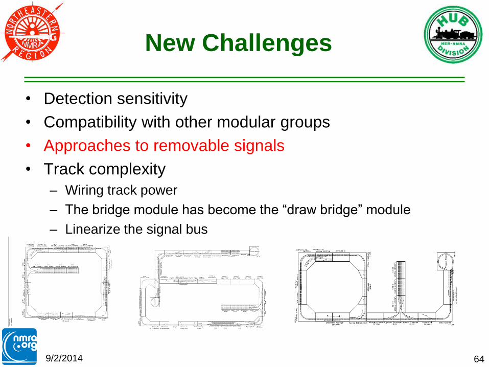
New Challenges
• Detection sensitivity
• Compatibility with other modular groups
• Approaches to removable signals
• Track complexity
– Wiring track power
– The bridge module has become the “draw bridge” module
– Linearize the signal bus
9/2/2014 64

Clearance Form “A”
9/2/2014 65
• This is the
form that makes
a train a train
• We use it to fill
in the needed
info for train
tracking

Architecture
WIFI WIFI
RS 485
Cable XpressNet
DCC Track Power
DCC Accessory Power Turnout
Motor
WiThrottle
and
Engine
Commander
Point Feedback
Occupancy Feedback
Command Station
Booster 1
Booster 2
DCCOD
Stationary Decoder
JMRI & CATS
Lenz LAN/USB
C/MRI
Net
C/MRI Outputs

Summary
• Signaling a modular layouts can be done without
constraining either the sequence of modules or limiting
the function of the signaling system
• Can run with or without a dispatcher
• Pre-setup: Create linear list of modules “importing” the
layout plan for that particular setup into CATS
• Setup = 1) Link the physical modules 2) Load the CATS
equivalent 3) Run
• HUB modular railroad uses:
1. Lenz DCC with a LAN-USB connection
2. C/MRI SMINI boards + (cpNodes & SMicros)
3. C/MRI DCCOD occupancy detectors
4. JMRI & CATS software 9/2/2014 67

9/2/2014 68
References (Books)
• Railroad Signaling. Brian Soloman, MBI Publishing 2003.
• How to operate your model railroad. Bruce A Chubb, 2nd Edition, Kalmbach, 1977.
• Realistic Model Railroad Operation. Tony Koester. Kalmbach 2003.
• The Model Railroaders Guide to Junctions. Jeff Wilson. Kalmbach 2006.
• Railroader's C/MRI Applications Handbook V3.0 (Volumes 1,2,&3 Especially Vol 2). Bruce Chubb. Available through JLC Enterprises.
• Railroad Operation and Railway Signaling. Edmund J Phillips. Simmons-Boardman 1942
• Compendium of Signals. Roger F.R Karl. Boynton, 1971.
• All About Signals. John Armstrong, Kalmbach, 1967.
• 34 New Electronic Projects for Model Railroaders. Peter J Thorne, Kalmbach, 1982.

9/2/2014 69
References (Journals)
• Operating signals with software. Model Railroader, October 2007,
page 50.
• The Computer/Model Railroad Interface - A Case Study. Model
Railroading, December 1999/January 2000, page 32.
• Using State-of-the-art Electronics to Enhance Operation. NMRA
Bulletin, March 2007 page 38.
• Where to place trackside signals. Model Railroader, October 2007,
page 52.
• Signaling made easier (3 part article). Model Railroader, January
2004, page 130.
• Absolute-Permissive Block Signals (3 part article). Model
Railroader, November 1991 page 128.
• Centralized traffic control for the Cat Mountain Line. Model
Railroader, May 1984, page 74.

9/2/2014 70
References (Web Sites)
• Carsten Lundstens site: http://www.lundsten.dk/us_signaling/index.html
• Norac Simulator: http://raildata.railfan.net/java/DivRte/NORAC.htm
• Railroad Signals: http://www.railroadsignals.net/
• Railroad Signals of the US: http://www.railroadsignals.us/
• JMRI: http://jmri.sourceforge.net/
• CATS: http://home.comcast.net/~kb0oys/
• CMRI: http://www.jlcenterprises.net/
• Custom Signals: http://www.customsignals.com/
• ISS: http://www.integratedsignalsystems.com/
• Signals by Spreadsheet: http://www.signalsbyspreadsheet.com/
• Railroad Circuits: http://rr-cirkits.com/
• Logic Rail: http://www.logicrailtech.com/

HUB Division Website http://www.hubdiv.org/signalComm.htm
9/2/2014 71
