sifts cale ladder...• intergraphs pds and smartplant 3d • aveva’s pdms • bentley systems...
TRANSCRIPT
Swifts®
cable ladderbuilding on innovation
PRODUCT TECHNICAL GUIDE /INCLUDING SWIFTRACK
AND SUPPORTING SYSTEMS
LTG11 OBC_OFC v2.indd 1 26/01/2012 09:42

CONTENTS
INTRODUCTION
Swifts cable ladder features 2 Legrand worldwide 4Sustainable development 4UK manufacturing, design and accreditation 5Case studies 6Intergraph 7
PRODUCT SELECTION
SWIFTS CABLE LADDER SYSTEMSSelection charts 10-13Straight lengths, couplers and fi ttings Medium duty (Topaz) 14-15 Heavy duty (Sapphire) 16-17 Extra heavy duty (Emerald) 18-19Supports 20Ancillary items 21-23Covers 23Fasteners 24
SWIFTRACK CHANNEL SUPPORT SYSTEMChannel and channel nuts 25Cantilever arms 26Framework brackets, clamps and accessories 27-28Standard fi xings and fasteners 29-30 CEILING SUPPORT SYSTEMHeavy duty 31
TECHNICAL SPECIFICATIONS
SWIFTS CABLE LADDER SYSTEMSStraight lengths 34-36Rung details 37Diagonal bracing 37Couplers – straight lengths 38-42Pre-fabrication of cable ladder runs 43Identifi cation and recognition of fi ttings 43Couplers – fi ttings 44-45Flat bends 46-49Inside and outside risers 50-61Equal tees 62Unequal tees 63-68Branch pieces 694 way crosspieces 70-71Reducers – straight / offset 72-73Supports 74-78Ancillary items 79-94Covers 95-98 SWIFTRACK CHANNEL SUPPORT SYSTEMSingle channels – plain and slotted 99Back-to-back channels 100Assembly – fasteners and channel nuts 101Cantilever arms 102-103Framework brackets 104-107Beam clamps, pipe clamps and accessories 107-108 CEILING SUPPORT SYSTEMHeavy duty 109
DESIGN NOTES
Selecting the right fi nish 112-117Finishes 118-121Installation of services 122-131Structural support characteristics 132-139Packaging, handling, storage and safety 140-141Relevant British standards 142-143
1
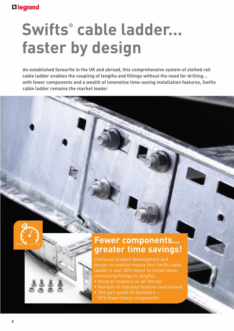
Swifts® cable ladder...faster by designAn established favourite in the UK and abroad, this comprehensive system of slotted rail
cable ladder enables the coupling of lengths and fi ttings without the need for drilling…
with fewer components and a wealth of innovative time-saving installation features, Swifts
cable ladder remains the market leader
Continual product development and design innovation means that Swifts cable ladder is over 50% faster to install when connecting fi ttings to lengths...• Integral couplers on all fi ttings• Number of required fastener sets halved• Two part quick-fi t fasteners –
50% fewer fi xing components
Fewer components... greater time savings!
2

Save time... save money!The long-term success of Swifts cable ladder is built on design innovation and
time-saving features that put us yet another rung ahead of the rest!
The inclusion of integral couplers on all ladder fi ttings used together with
our quick-fi t fasteners more than halves the number of required fi xings
and dramatically cuts installation time and cost. Supplied as standard on all
Topaz, Sapphire and Emerald fi ttings, this coupling technique benefi ts every
installation type, from medium duty right through to extra heavy duty.
EMERALD - EXTRA HEAVY DUTY
• Generally suitable for spans up to 4 m
• Side rail height: 150 mm
• Available cabling space: 119 mm
• Supplied as standard in 3 m lengths
(lengths up to 6 m available on request)
• Finishes: G (hot dip galvanised),
D (deep galvanised) and
S (stainless steel)
SAPPHIRE - HEAVY DUTY
• Generally suitable for spans up to 3.5 m
• Side rail height: 125 mm
• Available cabling space: 94 mm
• Supplied as standard in 3 m lengths
(lengths up to 6 m available on request)
• Finishes: G (hot dip galvanised),
D (deep galvanised), S (stainless steel)
and E (powder coated)
TOPAZ - MEDIUM DUTY
• Generally suitable for spans up to 3 m
• Side rail height: 100 mm
• Available cabling space: 69 mm
• Supplied as standard in 3 m lengths
• Finishes: G (hot dip galvanised),
D (deep galvanised) and
S (stainless steel)
PRODUCT RANGES
Time-saving innovations reduce man hours and energy usage on site, including fewer components for improved assembly times
3

Legrand - global strength built on local knowledge
With a 15% share of the global market, the Legrand Group is
the world specialist in cable management systems… and with
our established Swifts, Salamandre and Arena-Walsall ranges,
our cable management division has a fi rm leadership position
in the UK.
Sustainable developmentFrom design through to manufacturing, the Legrand Group
selects materials and processes that respect people and
the environment.
• Effi cient and environmentally aware product design
• Product functions that help to avoid energy waste
• Management of manufacturing and logistics sites
• Integration of environmental concerns and ISO 14001
procedures at the Group’s global sites. *
* 84% of sites are ISO 14001:2004 accredited including all UK sites.
Legrand in the UK - powered by specialistsIn the UK Legrand has developed a customer focused
structure which harnesses the power of its market
leading specialist brands to deliver innovative,
integrated solutions for every phase of construction.
4

Quality assured UK manufacturingSwifts cable management ranges have been designed and manufactured at our
Scarborough (UK) site since the 1960’s. And with its own in-house galvanising
facility, every product is fi nished to the highest possible standard following
strict quality control guidelines.
Legrand Electric holds ISO 9001 : 2008 Quality Assessment Registrations from
Intertek Systems Certifi cation UK and Bureau Veritas
All of Legrand’s UK manufacturing sites are accredited to ISO 14001 : 2004
Environmental Management System
Registered
Support from design to installationWith in-depth knowledge and experience, our expert cable management team
provides customers with support and advice for any installation… including
bespoke solutions (specials) from our in-house design team that can cope with
the most demanding requirements for the most challenging projects.
Reg no. 10042065
5

Legrand - the cable management experts
Process, power and marine
Tengiz Second Generation -
Kazakhstan
Vesta Wind Turbine Manufacturing
Plant - Isle of Wight
Norilisk Nickel Slag Cleaning
Furnaces Upgrade - Siberia
Ling Au Nuclear Plant - China
Shell EA and KC upgrades - Nigeria
Dukhan Facilities Upgrade - Qatar
Clare Offshore Platform - Shetlands
Eggborough Power Station - UK
Transport and infrastructure
Dublin Airport - Ireland
Dubai Airport - Dubai
Kings Cross regeneration - London
Channel Tunnel Rail Link - UK/France
Millau Viaduct - France
Tyne Tunnel - UK
Heathrow T2/T3/T4/T5 - UK
National Convention Centre
Car Park - Qatar
General
MOD, Corsham - Wiltshire
Grand Mosque - Dubai
Hong Kong Jockey Club - Hong Kong
Landmark Tower - Dubai
St. Davids II - Cardiff, Wales
Diwan Al Amiri Utility Building - Qatar
Arcapita Bank - Bahrain
Tianjin Electronics Plant - China
Trusted for installations large and small Swifts cable ladder has been tried and tested in installations of all sizes
throughout the UK and beyond, from medium duty requirements in small
commercial buildings through to extra heavy duty installations in refi neries
and heavy industry applications.
Cable management project examples
6
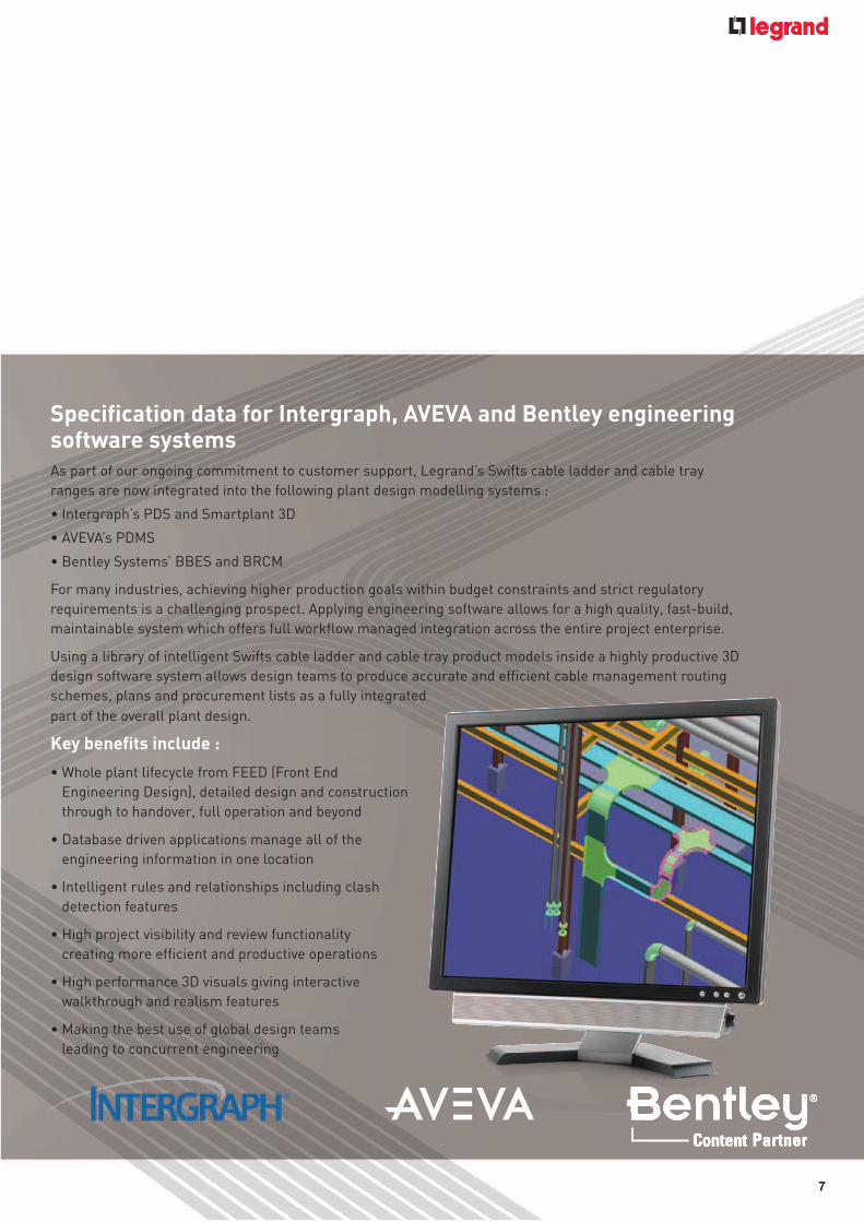
Specifi cation data for Intergraph, AVEVA and Bentley engineering software systemsAs part of our ongoing commitment to customer support, Legrand’s Swifts cable ladder and cable tray
ranges are now integrated into the following plant design modelling systems :
• Intergraph’s PDS and Smartplant 3D
• AVEVA’s PDMS
• Bentley Systems’ BBES and BRCM
For many industries, achieving higher production goals within budget constraints and strict regulatory
requirements is a challenging prospect. Applying engineering software allows for a high quality, fast-build,
maintainable system which offers full workfl ow managed integration across the entire project enterprise.
Using a library of intelligent Swifts cable ladder and cable tray product models inside a highly productive 3D
design software system allows design teams to produce accurate and effi cient cable management routing
schemes, plans and procurement lists as a fully integrated
part of the overall plant design.
Key benefi ts include :
• Whole plant lifecycle from FEED (Front End
Engineering Design), detailed design and construction
through to handover, full operation and beyond
• Database driven applications manage all of the
engineering information in one location
• Intelligent rules and relationships including clash
detection features
• High project visibility and review functionality
creating more effi cient and productive operations
• High performance 3D visuals giving interactive
walkthrough and realism features
• Making the best use of global design teams
leading to concurrent engineering
7

PRODUCT SELECTION
IN THIS SECTION
SWIFTS CABLE LADDER SYSTEMSSelection charts 10-13
Medium duty (Topaz)Straight lengths 14Couplers – straight lengths 14Couplers – fi ttings 14Flat bends 14Inside and outside risers 14Equal tees 15Unequal tees 15Branch pieces 154 way crosspieces 15Straight reducers 15Offset reducers 15
Heavy duty (Sapphire)Straight lengths 16Couplers – straight lengths 16Couplers – fi ttings 16Flat bends 16Inside and outside risers 16Equal tees 17Unequal tees 17Branch pieces 174 way crosspieces 17Straight reducers 17Offset reducers 17
Extra heavy duty (Emerald)Straight lengths 18Couplers – straight lengths 18Couplers – fi ttings 18Flat bends 18Inside and outside risers 18Equal tees 19Unequal tees 19Branch pieces 194 way crosspieces 19Straight reducers 19Offset reducers 19
Supports 20Ancillary items 21-23Covers 23Fasteners 24
SWIFTRACK CHANNEL SUPPORT SYSTEMChannel and channel nuts 25Cantilever arms 26Framework brackets, clamps and accessories 27-28Standard fi xings and fasteners 29-30
CEILING SUPPORT SYSTEMHeavy duty 31
9
10
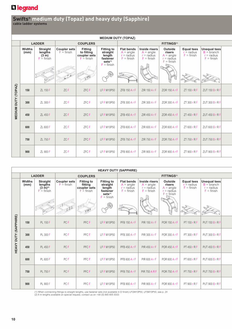
Swifts® medium duty (Topaz) and heavy duty (Sapphire)cable ladder systems
LADDER
MEDIUM DUTY (TOPAZ)
FITTINGS(1)
Straightlengths
(3 m)F = finish
Coupler setsF = finish
Fitting to fitting
coupler setsF = finish
Fitting to straight length
fastener sets(1)
F = finish
Flat bendsA = angler = radiusF = finish
Inside risersA = angler = radiusF = finish
Outside risers
A = angler = radiusF = finish
Equal teesr = radiusF = finish
Unequal teesB = branchr = radiusF = finish
Widths (mm)
ME
DIU
M D
UT
Y (
TO
PA
Z)
150 ZL 150 F ZC F ZFC F LF F M10P50 ZFB 150 A r F ZIR 150 A r F ZOR 150 A r F ZT 150 r R F ZUT 150 B r R F
300 ZL 300 F ZC F ZFC F LF F M10P50 ZFB 300 A r F ZIR 300 A r F ZOR 300 A r F ZT 300 r R F ZUT 300 B r R F
450 ZL 450 F ZC F ZFC F LF F M10P50 ZFB 450 A r F ZIR 450 A r F ZOR 450 A r F ZT 450 r R F ZUT 450 B r R F
600 ZL 600 F ZC F ZFC F LF F M10P50 ZFB 600 A r F ZIR 600 A r F ZOR 600 A r F ZT 600 r R F ZUT 600 B r R F
750 ZL 750 F ZC F ZFC F LF F M10P50 ZFB 750 A r F ZIR 750 A r F ZOR 750 A r F ZT 750 r R F ZUT 750 B r R F
900 ZL 900 F ZC F ZFC F LF F M10P50 ZFB 900 A r F ZIR 900 A r F ZOR 900 A r F ZT 900 r R F ZUT 900 B r R F
COUPLERS
(1) When connecting fittings to straight lengths, use fastener sets (not available in D finish) LFGM10P50, LFSM10P50, see p. 24(2) 6 m lengths available on special request, contact us on +44 (0) 845 605 4333
HE
AV
Y D
UT
Y (
SA
PP
HIR
E)
150 PL 150 F PC F PFC F LF F M10P50 PFB 150 A r F PIR 150 A r F POR 150 A r F PT 150 r R F PUT 150 B r R F
300 PL 300 F PC F PFC F LF F M10P50 PFB 300 A r F PIR 300 A r F POR 300 A r F PT 300 r R F PUT 300 B r R F
450 PL 450 F PC F PFC F LF F M10P50 PFB 450 A r F PIR 450 A r F POR 450 A r F PT 450 r R F PUT 450 B r R F
600 PL 600 F PC F PFC F LF F M10P50 PFB 600 A r F PIR 600 A r F POR 600 A r F PT 600 r R F PUT 600 B r R F
750 PL 750 F PC F PFC F LF F M10P50 PFB 750 A r F PIR 750 A R F POR 750 A r F PT 750 r R F PUT 750 B r R F
900 PL 900 F PC F PFC F LF F M10P50 PFB 900 A r F PIR 900 A r F POR 900 A r F PT 900 r R F PUT 900 B r R F
HEAVY DUTY (SAPPHIRE)
Widths (mm)
Straightlengths (3 m)(2)
F = finish
Coupler setsF = finish
Fitting to fitting
coupler setsF = finish
Fitting to straight length
fastener sets(1)
F = finish
Flat bendsA = angler = radiusF = finish
Inside risersA = angler = radiusF = finish
Outside risers
A = angler = radiusF = finish
Equal teesr = radiusF = finish
Unequal teesB = branchr = radiusF = finish
COUPLERSLADDER FITTINGS(1)
11
FITTINGS(1)
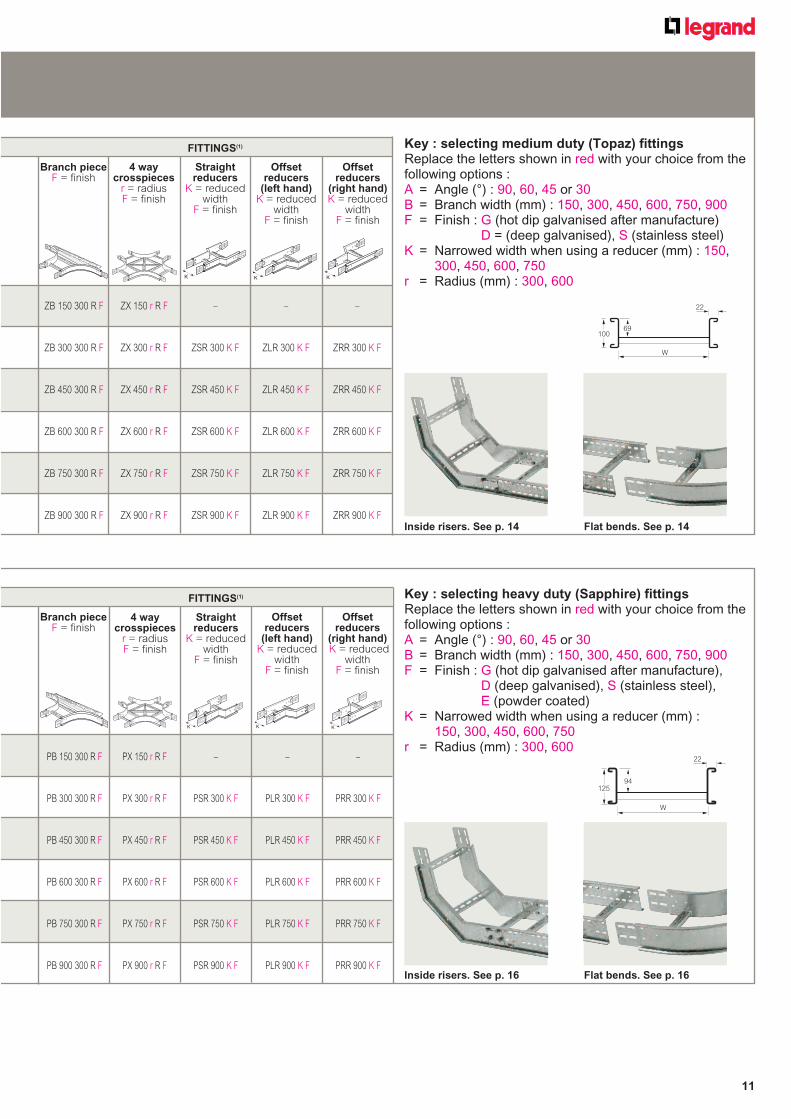
4 waycrosspieces
r = radiusF = finish
Straightreducers
K = reduced width
F = finish
Offsetreducers
(left hand)K = reduced
widthF = finish
Offsetreducers
(right hand)K = reduced
widthF = finish
ZB 150 300 R F ZX 150 r R F – – –
ZB 300 300 R F ZX 300 r R F ZSR 300 K F ZLR 300 K F ZRR 300 K F
ZB 450 300 R F ZX 450 r R F ZSR 450 K F ZLR 450 K F ZRR 450 K F
ZB 600 300 R F ZX 600 r R F ZSR 600 K F ZLR 600 K F ZRR 600 K F
ZB 750 300 R F ZX 750 r R F ZSR 750 K F ZLR 750 K F ZRR 750 K F
ZB 900 300 R F ZX 900 r R F ZSR 900 K F ZLR 900 K F ZRR 900 K F
K K K
100
W
69
22
Key : selecting medium duty (Topaz) fittingsReplace the letters shown in red with your choice from the following options :A = Angle (°) : 90, 60, 45 or 30B = Branch width (mm) : 150, 300, 450, 600, 750, 900F = Finish : G (hot dip galvanised after manufacture)
D = (deep galvanised), S (stainless steel)K = Narrowed width when using a reducer (mm) : 150,
300, 450, 600, 750r = Radius (mm) : 300, 600
Branch pieceF = finish
Inside risers. See p. 14 Flat bends. See p. 14
PB 150 300 R F PX 150 r R F – – –
PB 300 300 R F PX 300 r R F PSR 300 K F PLR 300 K F PRR 300 K F
PB 450 300 R F PX 450 r R F PSR 450 K F PLR 450 K F PRR 450 K F
PB 600 300 R F PX 600 r R F PSR 600 K F PLR 600 K F PRR 600 K F
PB 750 300 R F PX 750 r R F PSR 750 K F PLR 750 K F PRR 750 K F
PB 900 300 R F PX 900 r R F PSR 900 K F PLR 900 K F PRR 900 K F
4 waycrosspieces
r = radiusF = finish
Straightreducers
K = reduced width
F = finish
Offsetreducers
(left hand)K = reduced
widthF = finish
Offsetreducers
(right hand) K = reduced
widthF = finish
Key : selecting heavy duty (Sapphire) fittingsReplace the letters shown in red with your choice from the following options :A = Angle (°) : 90, 60, 45 or 30B = Branch width (mm) : 150, 300, 450, 600, 750, 900F = Finish : G (hot dip galvanised after manufacture),
D (deep galvanised), S (stainless steel), E (powder coated)
K = Narrowed width when using a reducer (mm) : 150, 300, 450, 600, 750
r = Radius (mm) : 300, 600
K K K
125
W
94
22
Inside risers. See p. 16 Flat bends. See p. 16
Branch pieceF = finish
FITTINGS(1)
12
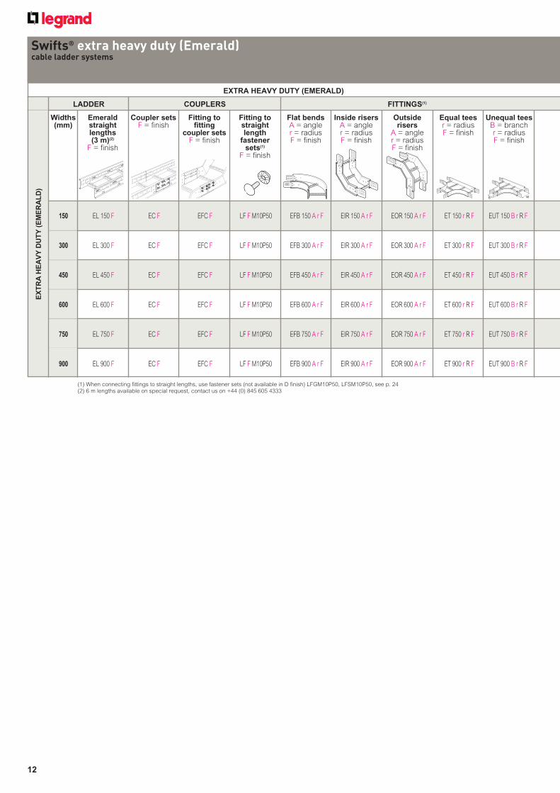
Swifts® extra heavy duty (Emerald)cable ladder systems
EX
TR
A H
EA
VY
DU
TY
(E
ME
RA
LD
)
LADDER
EXTRA HEAVY DUTY (EMERALD)
FITTINGS(1)
Widths (mm)
Emerald straightlengths (3 m)(2)
F = finish
Coupler setsF = finish
Fitting to fitting
coupler setsF = finish
Fitting to straight length
fastener sets(1)
F = finish
Flat bendsA = angler = radiusF = finish
Inside risersA = angler = radiusF = finish
Outside risers
A = angler = radiusF = finish
Equal teesr = radiusF = finish
Unequal teesB = branchr = radiusF = finish
E ETW EQUAL TEE
(1) When connecting fittings to straight lengths, use fastener sets (not available in D finish) LFGM10P50, LFSM10P50, see p. 24(2) 6 m lengths available on special request, contact us on +44 (0) 845 605 4333
COUPLERS
150 EL 150 F EC F EFC F LF F M10P50 EFB 150 A r F EIR 150 A r F EOR 150 A r F ET 150 r R F EUT 150 B r R F
300 EL 300 F EC F EFC F LF F M10P50 EFB 300 A r F EIR 300 A r F EOR 300 A r F ET 300 r R F EUT 300 B r R F
450 EL 450 F EC F EFC F LF F M10P50 EFB 450 A r F EIR 450 A r F EOR 450 A r F ET 450 r R F EUT 450 B r R F
600 EL 600 F EC F EFC F LF F M10P50 EFB 600 A r F EIR 600 A r F EOR 600 A r F ET 600 r R F EUT 600 B r R F
750 EL 750 F EC F EFC F LF F M10P50 EFB 750 A r F EIR 750 A r F EOR 750 A r F ET 750 r R F EUT 750 B r R F
900 EL 900 F EC F EFC F LF F M10P50 EFB 900 A r F EIR 900 A r F EOR 900 A r F ET 900 r R F EUT 900 B r R F
13
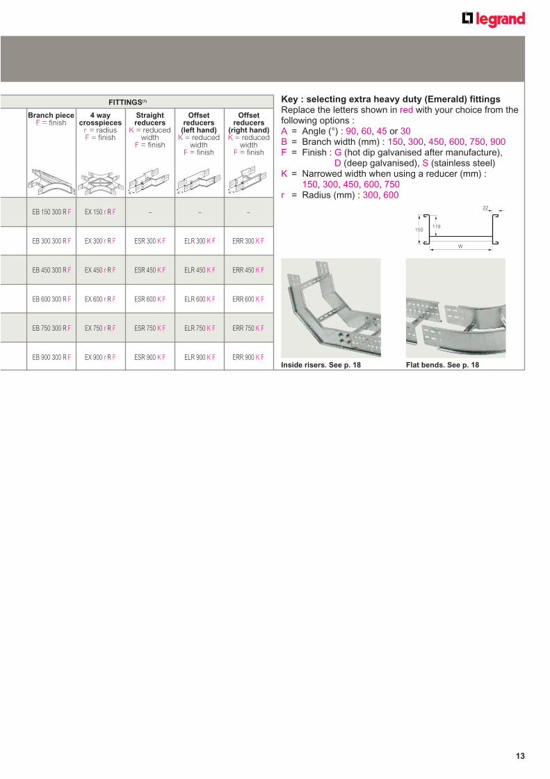
EB 150 300 R F EX 150 r R F – – –
EB 300 300 R F EX 300 r R F ESR 300 K F ELR 300 K F ERR 300 K F
EB 450 300 R F EX 450 r R F ESR 450 K F ELR 450 K F ERR 450 K F
EB 600 300 R F EX 600 r R F ESR 600 K F ELR 600 K F ERR 600 K F
EB 750 300 R F EX 750 r R F ESR 750 K F ELR 750 K F ERR 750 K F
EB 900 300 R F EX 900 r R F ESR 900 K F ELR 900 K F ERR 900 K F
FITTINGS(1)
4 waycrosspieces
r = radiusF = finish
Branch pieceF = finish
Straightreducers
K = reduced width
F = finish
Offsetreducers
(left hand)K = reduced
widthF = finish
Offsetreducers
(right hand)K = reduced
widthF = finish
Key : selecting extra heavy duty (Emerald) fittingsReplace the letters shown in red with your choice from the following options :A = Angle (°) : 90, 60, 45 or 30B = Branch width (mm) : 150, 300, 450, 600, 750, 900F = Finish : G (hot dip galvanised after manufacture),
D (deep galvanised), S (stainless steel)K = Narrowed width when using a reducer (mm) :
150, 300, 450, 600, 750r = Radius (mm) : 300, 600K K K
150
W
119
22
Inside risers. See p. 18 Flat bends. See p. 18
14
When connecting fittings to straight lengths, use fastener sets (see below)Rung spacing : 300 mm between centresStandard radius for fittings : 300 and 600 mm
Pack Cat. Nos. Straight lengths – 3 m
1 ZL 150 F 150 mm width 1 ZL 300 F 300 mm width 1 ZL 450 F 450 mm width 1 ZL 600 F 600 mm width 1 ZL 750 F 750 mm width 1 ZL 900 F 900 mm width For technical information, see p. 34
Coupler sets
Straight length to straight length 1 ZC F Supplied in pairs, with fasteners (4 per
coupler) Use to couple straight lengths to straight
lengths For technical information, see p. 38-39
Fitting to fitting 1 ZFC F Supplied in pairs, with fasteners (4 per
coupler) Use to couple fitting to fitting For technical information, see p. 44-45
Fastener sets Comprise M10 coach bolt and
flange nut 50 LFGM10P50 Hot dip galvanised 50 LFSM10P50 Stainless steel
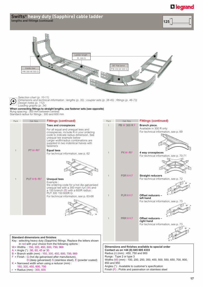
Selection chart (p. 10-11)Dimensions and technical information : lengths (p. 34) ; coupler sets (p. 38-45) ; fittings (p. 46-73)Design notes (p. 112)Loading graphs (p. 34)
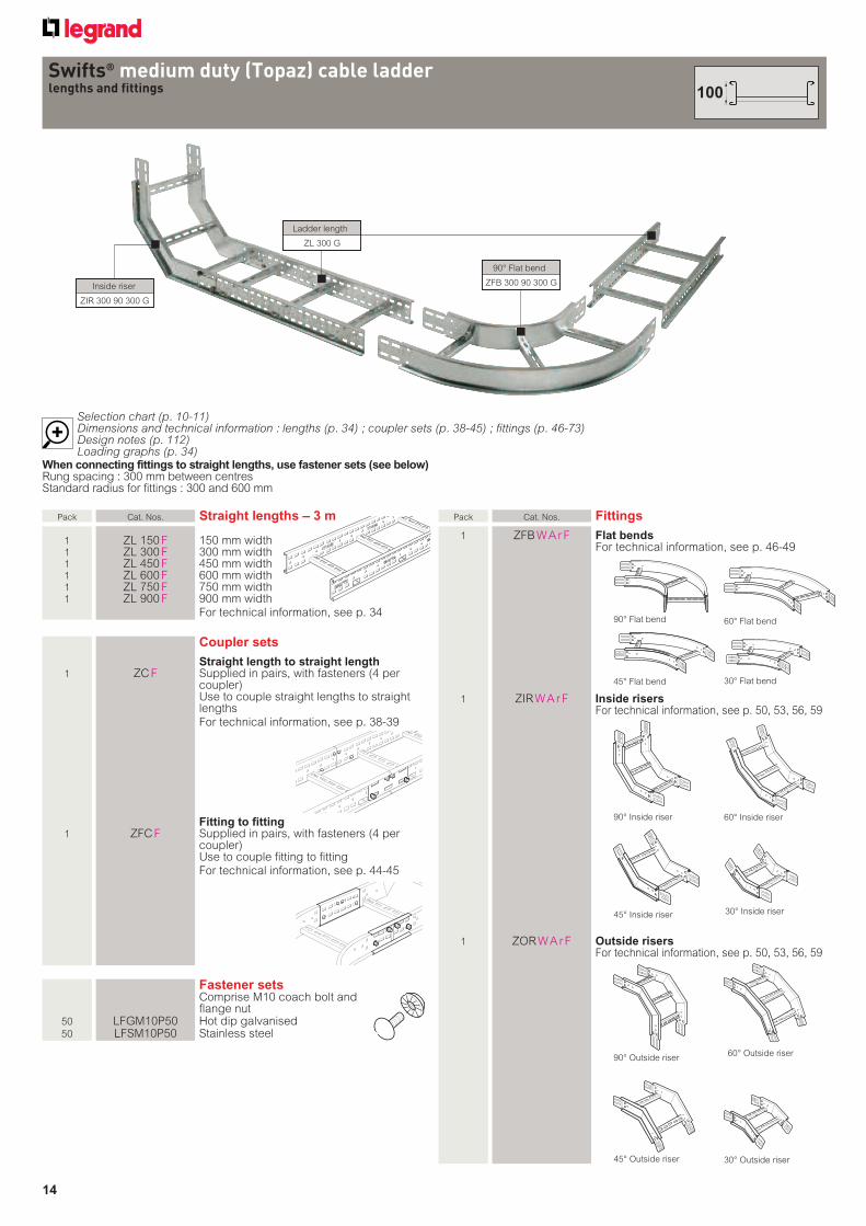
Inside riser
ZIR 300 90 300 G
Ladder length
ZL 300 G
90° Flat bend
ZFB 300 90 300 G
Swifts® medium duty (Topaz) cable ladderlengths and fittings
Pack Cat. Nos. Fittings
1 ZFB W A r F Flat bends For technical information, see p. 46-49
1 ZIR W A r F Inside risers For technical information, see p. 50, 53, 56, 59
1 ZOR W A r F Outside risers For technical information, see p. 50, 53, 56, 59
90° Outside riser
45° Outside riser
90° Flat bend
45° Flat bend
60° Flat bend
30° Flat bend
90° Inside riser
45° Inside riser
60° Inside riser
30° Inside riser
60° Outside riser
30° Outside riser
100
15
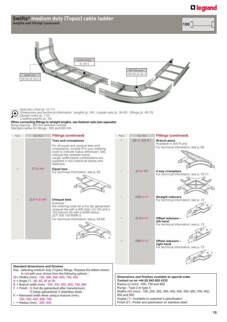
Pack Cat. Nos. Fittings (continued)
Tees and crosspieces
For all equal and unequal tees and crosspieces, include R in your ordering code to indicate radius dimension. See unequal tee example belowLarger width/radius combinations are supplied in two indentical halves with fasteners
1 ZT W r R F Equal tees For technical information, see p. 62
1 ZUT W B r R F Unequal tees
Example : the ordering code for a hot dip galvanised
unequal tee with a 300 main run (W) and a 150 branch (B) with a 600R radius : ZUT 300 150 600R G
For technical information, see p. 63-68
Selection chart (p. 10-11)Dimensions and technical information : lengths (p. 34) ; coupler sets (p. 38-45) ; fittings (p. 46-73)Design notes (p. 112)Loading graphs (p. 34)
W
Swifts® medium duty (Topaz) cable ladderlengths and fittings (continued)
Standard dimensions and finishes
Key : selecting medium duty (Topaz) fittings. Replace the letters shown
in red with your choice from the following options :
W = Widths (mm) : 150, 300, 450, 600, 750, 900
A = Angle (°) : 90, 60, 45 or 30
B = Branch width (mm) : 150, 300, 450, 600, 750, 900
F = Finish : G (hot dip galvanised after manufacture),
D (deep galvanised) S (stainless steel)
K = Narrowed width when using a reducer (mm) :
150, 300, 450, 600, 750
r = Radius (mm) : 300, 600
Pack Cat. Nos. Fittings (continued)
1 ZB W 300 R F Branch piece Available in 300 R only For technical information, see p. 69
1 ZX W r R F 4 way crosspiece For technical information, see p. 70-71
1 ZSR W K F Straight reducers For technical information, see p. 72
1 ZLR W K F Offset reducers – left hand
For technical information, see p. 73
1 ZRR W K F Offset reducers – right hand
For technical information, see p. 73
K
W
W
K
K
W
When connecting fittings to straight lengths, use fastener sets (see opposite)Rung spacing : 300 mm between centresStandard radius for fittings : 300 and 600 mm
Inside riser
ZIR 300 90 300 G
Ladder length
ZL 300 G
90° Flat bend
ZFB 300 90 300 G
100
Dimensions and finishes available to special order
Contact us on +44 (0) 845 605 4333
Radius (r) (mm) : 450, 750 and 900
Rungs : Type 2 or type 3
Widths (W) (mm) : 100, 200, 250, 350, 400, 500, 550, 650, 700, 800,
850 and 950
Angles (°) : Available to customer’s specification
Finish (F) : Pickle and passivation on stainless steel
16
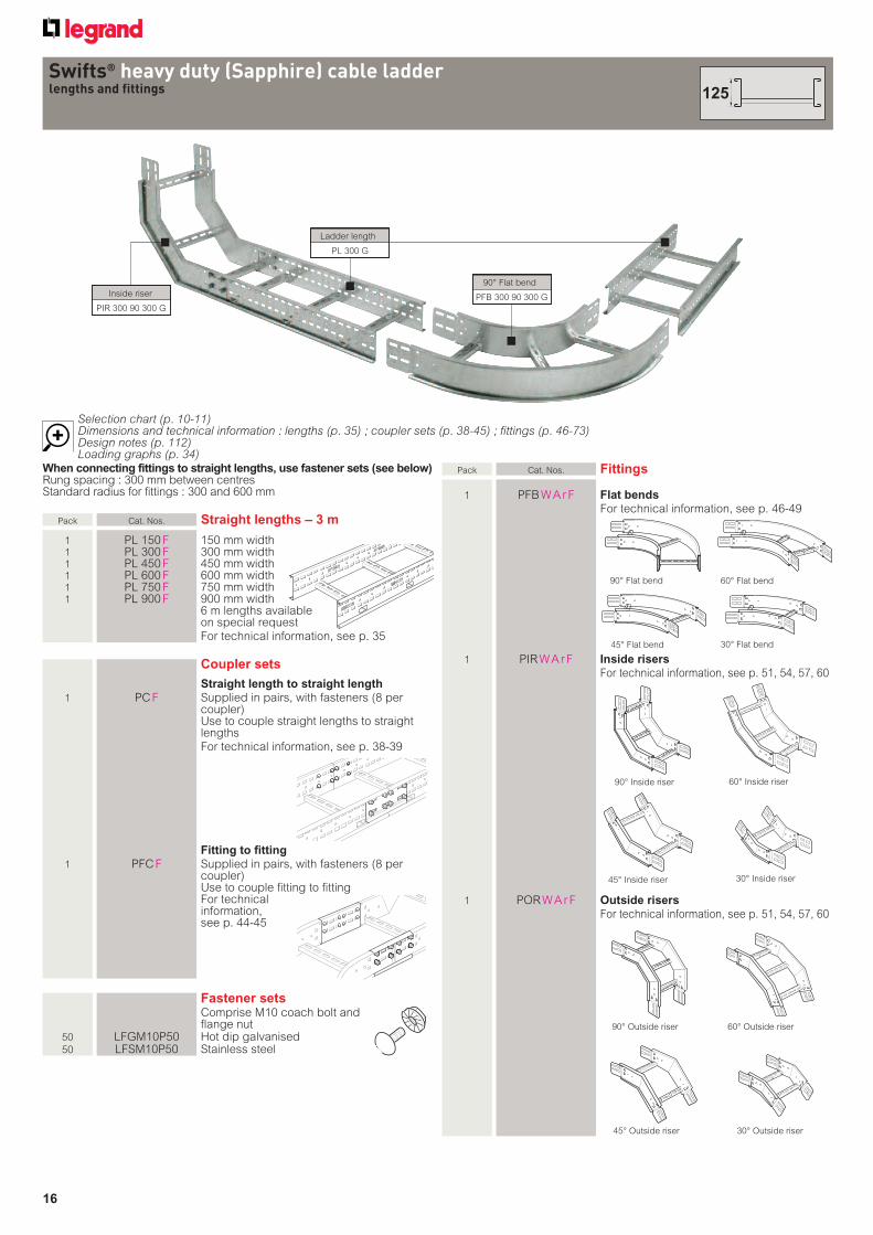
Pack Cat. Nos. Fittings
1 PFB W A r F Flat bends
For technical information, see p. 46-49
1 PIR W A r F Inside risers
For technical information, see p. 51, 54, 57, 60
1 POR W A r F Outside risers
For technical information, see p. 51, 54, 57, 60
When connecting fittings to straight lengths, use fastener sets (see below)Rung spacing : 300 mm between centresStandard radius for fittings : 300 and 600 mm
Pack Cat. Nos. Straight lengths – 3 m
1 PL 150 F 150 mm width 1 PL 300 F 300 mm width 1 PL 450 F 450 mm width 1 PL 600 F 600 mm width 1 PL 750 F 750 mm width 1 PL 900 F 900 mm width 6 m lengths available
on special request For technical information, see p. 35
Coupler sets
Straight length to straight length
1 PC F Supplied in pairs, with fasteners (8 per coupler)
Use to couple straight lengths to straight lengths
For technical information, see p. 38-39
Fitting to fitting
1 PFC F Supplied in pairs, with fasteners (8 per coupler)
Use to couple fitting to fitting For technical
information, see p. 44-45
Fastener sets Comprise M10 coach bolt and
flange nut 50 LFGM10P50 Hot dip galvanised 50 LFSM10P50 Stainless steel
Swifts® heavy duty (Sapphire) cable ladderlengths and fittings
Selection chart (p. 10-11)Dimensions and technical information : lengths (p. 35) ; coupler sets (p. 38-45) ; fittings (p. 46-73)Design notes (p. 112)Loading graphs (p. 34)
Inside riser
PIR 300 90 300 G
Ladder length
PL 300 G
90° Flat bend
PFB 300 90 300 G
90° Flat bend
45° Flat bend
90° Outside riser
45° Outside riser
60° Flat bend
30° Flat bend
90° Inside riser
45° Inside riser
60° Inside riser
30° Inside riser
60° Outside riser
30° Outside riser
125
17
Swifts® heavy duty (Sapphire) cable ladderlengths and fittings (continued)
Selection chart (p. 10-11)Dimensions and technical information : lengths (p. 35) ; coupler sets (p. 38-45) ; fittings (p. 46-73)Design notes (p. 112)Loading graphs (p. 34)
Inside riser
PIR 300 90 300 G
Ladder length
PL 300 G
90° Flat bend
PFB 300 90 300 G
Pack Cat. Nos. Fittings (continued)
Tees and crosspieces
For all equal and unequal tees and crosspieces, include R in your ordering code to indicate radius dimension. See unequal tee example belowLarger width/radius combinations are supplied in two indentical halves with fasteners
1 PT W r R F Equal tees
For technical information, see p. 62
1 PUT W B r R F Unequal tees
Example : the ordering code for a hot dip galvanised
unequal tee with a 300 main run (W) and a 150 branch (B) with a 600R radius : PUT 300 150 600R G
For technical information, see p. 63-68
W
Pack Cat. Nos. Fittings (continued)
1 PB W 300 R F Branch piece.
Available in 300 R only For technical information, see p. 69
1 PX W r R F 4 way crosspieces
For technical information, see p. 70-71
1 PSR W K F Straight reducers
For technical information, see p. 72
1 PLR W K F Offset reducers – left hand
For technical information, see p. 73
1 PRR W K F Offset reducers – right hand
For technical information, see p. 73
W
K
W
K
W
K
When connecting fittings to straight lengths, use fastener sets (see opposite)Rung spacing : 300 mm between centresStandard radius for fittings : 300 and 600 mm
125
Standard dimensions and finishes
Key : selecting heavy duty (Sapphire) fittings. Replace the letters shown
in red with your choice from the following options :
W = Widths : 150, 300, 450, 600, 750, 900
A = Angle (°) : 90, 60, 45 or 30
B = Branch width (mm) : 150, 300, 450, 600, 750, 900
F = Finish : G (hot dip galvanised after manufacture),
D (deep galvanised) S (stainless steel), E (powder coated)
K = Narrowed width when using a reducer (mm) :
150, 300, 450, 600, 750
r = Radius (mm) : 300, 600
Dimensions and finishes available to special order
Contact us on +44 (0) 845 605 4333
Radius (r) (mm) : 450, 750 and 900
Rungs : Type 2 or type 3
Widths (W) (mm) : 100, 200, 250, 350, 400, 500, 550, 650, 700, 800,
850 and 950
Angles (°) : Available to customer’s specification
Finish (F) : Pickle and passivation on stainless steel
18
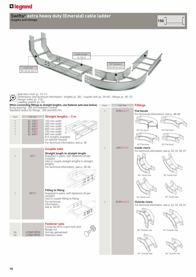
Selection chart (p. 10-11)Dimensions and technical information : lengths (p. 36) ; coupler sets (p. 38-45) ; fittings (p. 46-73)Design notes (p. 112)Loading graphs (p. 34)
90° Flat bend
Swifts® extra heavy duty (Emerald) cable ladderlengths and fittings
Inside riser
EIR 300 90 300 G
Ladder length
EL 300 G
90° Flat bend
EFB 300 90 300 G
Pack Cat. Nos. Fittings
1 EFB W A r F Flat bends
For technical information, see p. 46-49
1 EIR W A r F Inside risers
For technical information, see p. 52, 55, 58, 61
1 EOR W A r F Outside risers
For technical information, see p. 52, 55, 58, 61
When connecting fittings to straight lengths, use fastener sets (see below)Rung spacing : 300 mm between centresStandard radius for fittings : 300 and 600 mm
Pack Cat. Nos. Straight lengths – 3 m
1 EL 150 F 150 mm width 1 EL 300 F 300 mm width 1 EL 450 F 450 mm width 1 EL 600 F 600 mm width 1 EL 750 F 750 mm width 1 EL 900 F 900 mm width 6 m lengths available
on special request For technical information, see p. 36
Coupler sets
Straight length to straight length 1 EC F Supplied in pairs, with fasteners (8 per
coupler) Use to couple straight lengths to straight
lengths For technical information, see p. 38-39
Fitting to fitting
1 EFC F Supplied in pairs, with fasteners (8 per coupler)
Use to couple fitting to fitting For technical
information, see p. 44-45
Fastener sets Comprise M10 coach bolt and
flange nut 50 LFGM10P50 Hot dip galvanised 50 LFSM10P50 Stainless steel
90° Outside riser
45° Outside riser
60° Flat bend
30° Flat bend
90° Inside riser
45° Inside riser
60° Inside riser
30° Inside riser
60° Outside riser
30° Outside riser
45° Flat bend
150
19
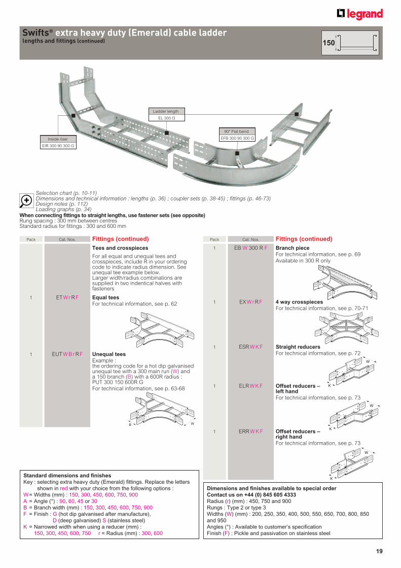
Selection chart (p. 10-11)Dimensions and technical information : lengths (p. 36) ; coupler sets (p. 38-45) ; fittings (p. 46-73)Design notes (p. 112)Loading graphs (p. 34)
Swifts® extra heavy duty (Emerald) cable ladderlengths and fittings (continued)
Inside riser
EIR 300 90 300 G
Ladder length
EL 300 G
90° Flat bend
EFB 300 90 300 G
Pack Cat. Nos. Fittings (continued)
Tees and crosspieces
For all equal and unequal tees and crosspieces, include R in your ordering code to indicate radius dimension. See unequal tee example below.Larger width/radius combinations are supplied in two indentical halves with fasteners
1 ET W r R F Equal tees
For technical information, see p. 62
1 EUT W B r R F Unequal tees
Example : the ordering code for a hot dip galvanised
unequal tee with a 300 main run (W) and a 150 branch (B) with a 600R radius : PUT 300 150 600R G
For technical information, see p. 63-68
Pack Cat. Nos. Fittings (continued)
1 EB W 300 R F Branch piece
For technical information, see p. 69 Available in 300 R only
1 EX W r R F 4 way crosspieces
For technical information, see p. 70-71
1 ESR W K F Straight reducers
For technical information, see p. 72
1 ELR W K F Offset reducers – left hand
For technical information, see p. 73
1 ERR W K F Offset reducers – right hand
For technical information, see p. 73
WB
W
K
W
K
W
K
When connecting fittings to straight lengths, use fastener sets (see opposite)Rung spacing : 300 mm between centresStandard radius for fittings : 300 and 600 mm
150
Standard dimensions and finishes
Key : selecting extra heavy duty (Emerald) fittings. Replace the letters
shown in red with your choice from the following options :
W = Widths (mm) : 150, 300, 450, 600, 750, 900
A = Angle (°) : 90, 60, 45 or 30
B = Branch width (mm) : 150, 300, 450, 600, 750, 900
F = Finish : G (hot dip galvanised after manufacture),
D (deep galvanised) S (stainless steel)
K = Narrowed width when using a reducer (mm) :
150, 300, 450, 600, 750 r = Radius (mm) : 300, 600
Dimensions and finishes available to special order
Contact us on +44 (0) 845 605 4333
Radius (r) (mm) : 450, 750 and 900
Rungs : Type 2 or type 3
Widths (W) (mm) : 200, 250, 350, 400, 500, 550, 650, 700, 800, 850
and 950
Angles (°) : Available to customer’s specification
Finish (F) : Pickle and passivation on stainless steel
20
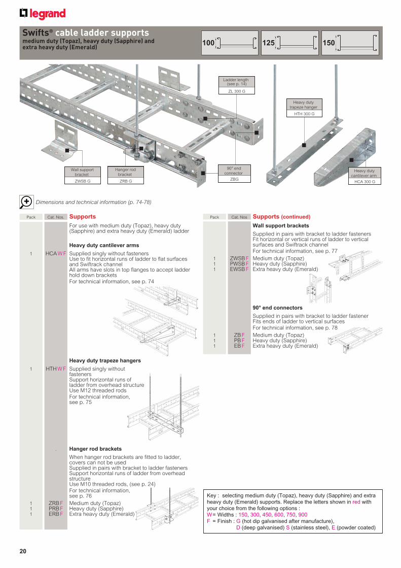
Dimensions and technical information (p. 74-78)
Swifts® cable ladder supportsmedium duty (Topaz), heavy duty (Sapphire) and extra heavy duty (Emerald)
Key : selecting medium duty (Topaz), heavy duty (Sapphire) and extra
heavy duty (Emerald) supports. Replace the letters shown in red with
your choice from the following options :
W = Widths : 150, 300, 450, 600, 750, 900
F = Finish : G (hot dip galvanised after manufacture),
D (deep galvanised) S (stainless steel), E (powder coated)
Hanger rod
bracket
ZRB G
Wall support
bracket
ZWSB G
Heavy duty
trapeze hanger
HTH 300 G
Heavy duty
cantilever arm
HCA 300 G
Ladder length(see p. 14)
ZL 300 G
Pack Cat. Nos Supports (continued)
Wall support brackets
Supplied in pairs with bracket to ladder fasteners Fit horizontal or vertical runs of ladder to vertical
surfaces and Swiftrack channel For technical information, see p. 77
1 ZWSB F Medium duty (Topaz) 1 PWSB F Heavy duty (Sapphire) 1 EWSB F Extra heavy duty (Emerald)
90° end connectors
Supplied in pairs with bracket to ladder fastener Fits ends of ladder to vertical surfaces For technical information, see p. 78
1 ZB F Medium duty (Topaz) 1 PB F Heavy duty (Sapphire) 1 EB F Extra heavy duty (Emerald)
Pack Cat. Nos. Supports
For use with medium duty (Topaz), heavy duty (Sapphire) and extra heavy duty (Emerald) ladder
Heavy duty cantilever arms
1 HCA W F Supplied singly without fasteners Use to fit horizontal runs of ladder to flat surfaces
and Swiftrack channel All arms have slots in top flanges to accept ladder
hold down brackets For technical information, see p. 74
Heavy duty trapeze hangers
1 HTH W F Supplied singly without fasteners
Support horizontal runs of ladder from overhead structure
Use M12 threaded rods For technical information,
see p. 75
. Hanger rod brackets
When hanger rod brackets are fitted to ladder, covers can not be used
Supplied in pairs with bracket to ladder fasteners Support horizontal runs of ladder from overhead
structure Use M10 threaded rods, (see p. 24) For technical information,
see p. 76
1 ZRB F Medium duty (Topaz) 1 PRB F Heavy duty (Sapphire) 1 ERB F Extra heavy duty (Emerald)
90° end
connector
ZBG
150125100
21
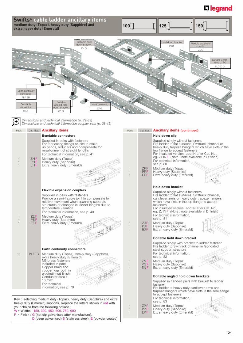
Dimensions and technical information (p. 79-83)Dimensions and technical information coupler sets (p. 38-45)
Swifts® cable ladder ancillary itemsmedium duty (Topaz), heavy duty (Sapphire) and extra heavy duty (Emerald)
Flexible expansion coupler
ZE G
Earth continuity
connector
PLF EB
Hold down clip
ZF G
Boltable hold down bracket
ZN G
Bendable
connector
ZH G
Boltable angled hold
down bracket
ZP G
Ladder length(see p. 14)
ZL 300 G
Pack Cat. Nos. Ancillary items
Bendable connectors
Supplied in pairs with fasteners For fabricating fittings on site to make
up bends, reducers and compensate for misalignment of straight lengths
For technical information, see p. 41
1 ZH F Medium duty (Topaz) 1 PH F Heavy duty (Sapphire) 1 EH F Extra heavy duty (Emerald)
Flexible expansion couplers
Supplied in pairs with fasteners Provide a semi-flexible joint to compensate for
relative movement when spanning separate structures or changes in ladder lengths due to temperature variation
For technical information, see p. 40
1 ZE F Medium duty (Topaz) 1 PE F Heavy duty (Sapphire) 1 EE F Extra heavy duty (Emerald)
Earth continuity connectors
10 PLFEB Medium duty (Topaz), heavy duty (Sapphire), extra heavy duty (Emerald)
M6 brass fasteners included in packCopper braid and copper lugs both in electrotinned finish
Conductor area : 16 mm2
For technical information, see p. 79
Pack Cat. Nos. Ancillary items (continued)
Hold down clip
Supplied singly without fasteners Fits ladder to flat surfaces, Swiftrack channel or
heavy duty trapeze hangers which have slots in the top flange to accept fasteners For insulated version, add IN after Cat. No.,eg. ZF IN F. (Note : note available in D finish)
For technical information, see p. 80
1 ZF F Medium duty (Topaz) 1 PF F Heavy duty (Sapphire) 1 EF F Extra heavy duty (Emerald)
Hold down bracket
Supplied singly without fasteners Fits ladder to flat surfaces, Swiftrack channel,
cantilever arms or heavy duty trapeze hangers which have slots in the top flange to accept fasteners For insulated version, add IN after Cat. No.,eg. ZJ IN F. (Note : note available in D finish)
For technical information, see p. 81
1 ZJ F Medium duty (Topaz) 1 PJ F Heavy duty (Sapphire) 1 EJ F Extra heavy duty (Emerald)
Boltable hold down bracket
Supplied singly with bracket to ladder fastener Fits ladder to Swiftrack channel in fabricated steel support structure
For technical information, see p. 82
1 ZN F Medium duty (Topaz) 1 PN F Heavy duty (Sapphire) 1 EN F Extra heavy duty (Emerald)
Boltable angled hold down brackets
Supplied in handed pairs with bracket to ladder fastener
Fits ladder to heavy duty cantilever arms and trapeze hangers which have slots in the side flange to accept fasteners
For technical information, see p. 83
1 ZP F Medium duty (Topaz) 1 PP F Heavy duty (Sapphire) 1 EP F Extra heavy duty (Emerald)
Hold down bracket
ZJ G
Key : selecting medium duty (Topaz), heavy duty (Sapphire) and extra
heavy duty (Emerald) supports. Replace the letters shown in red with
your choice from the following options :
W = Widths : 150, 300, 450, 600, 750, 900
F = Finish : G (hot dip galvanised after manufacture),
D (deep galvanised) S (stainless steel), E (powder coated)
150125100
22
Key : selecting ancillary items. Replace the letters shown in red with
your choice from the following options :
W = Widths (mm) : 150, 300, 450, 600, 750, 900
F = Finish : G (hot dip galvanised after manufacture),
D (deep galvanised) S (stainless steel), E (powder coated)
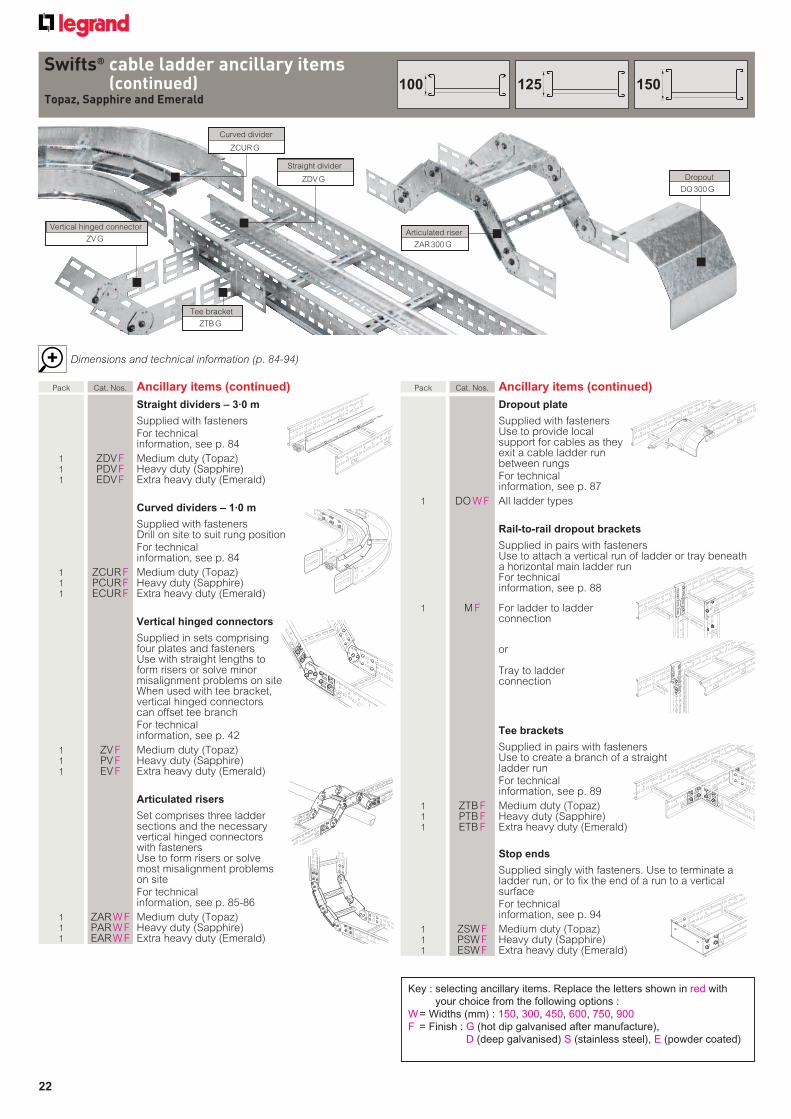
Dimensions and technical information (p. 84-94)
Swifts® cable ladder ancillary items(continued)
Topaz, Sapphire and Emerald
Straight divider
ZDV G Dropout
DO 300 G
Tee bracket
ZTB G
Articulated riser
ZAR 300 G
Curved divider
ZCUR G
Vertical hinged connector
ZV G
Pack Cat. Nos. Ancillary items (continued)
Dropout plate
Supplied with fasteners Use to provide local
support for cables as they exit a cable ladder run between rungs
For technical information, see p. 87
1 DO W F All ladder types
Rail-to-rail dropout brackets
Supplied in pairs with fasteners Use to attach a vertical run of ladder or tray beneath
a horizontal main ladder run For technical
information, see p. 88
1 M F For ladder to ladderconnection
or
Tray to ladder connection
Tee brackets
Supplied in pairs with fastenersUse to create a branch of a straightladder run
For technical information, see p. 89
1 ZTB F Medium duty (Topaz) 1 PTB F Heavy duty (Sapphire) 1 ETB F Extra heavy duty (Emerald)
Stop ends
Supplied singly with fasteners. Use to terminate a ladder run, or to fix the end of a run to a vertical surface
For technical information, see p. 94
1 ZSW F Medium duty (Topaz) 1 PSW F Heavy duty (Sapphire) 1 ESW F Extra heavy duty (Emerald)
Pack Cat. Nos. Ancillary items (continued)
Straight dividers – 3·0 m
Supplied with fasteners For technical
information, see p. 84
1 ZDV F Medium duty (Topaz) 1 PDV F Heavy duty (Sapphire) 1 EDV F Extra heavy duty (Emerald)
Curved dividers – 1·0 m
Supplied with fasteners Drill on site to suit rung position For technical
information, see p. 84
1 ZCUR F Medium duty (Topaz) 1 PCUR F Heavy duty (Sapphire) 1 ECUR F Extra heavy duty (Emerald)
Vertical hinged connectors
Supplied in sets comprising four plates and fasteners
Use with straight lengths to form risers or solve minor misalignment problems on siteWhen used with tee bracket, vertical hinged connectors can offset tee branch
For technical information, see p. 42
1 ZV F Medium duty (Topaz) 1 PV F Heavy duty (Sapphire) 1 EV F Extra heavy duty (Emerald)
Articulated risers
Set comprises three ladder sections and the necessary vertical hinged connectors with fasteners
Use to form risers or solve most misalignment problems on site
For technical information, see p. 85-86
1 ZAR W F Medium duty (Topaz) 1 PAR W F Heavy duty (Sapphire) 1 EAR W F Extra heavy duty (Emerald)
150125100
23
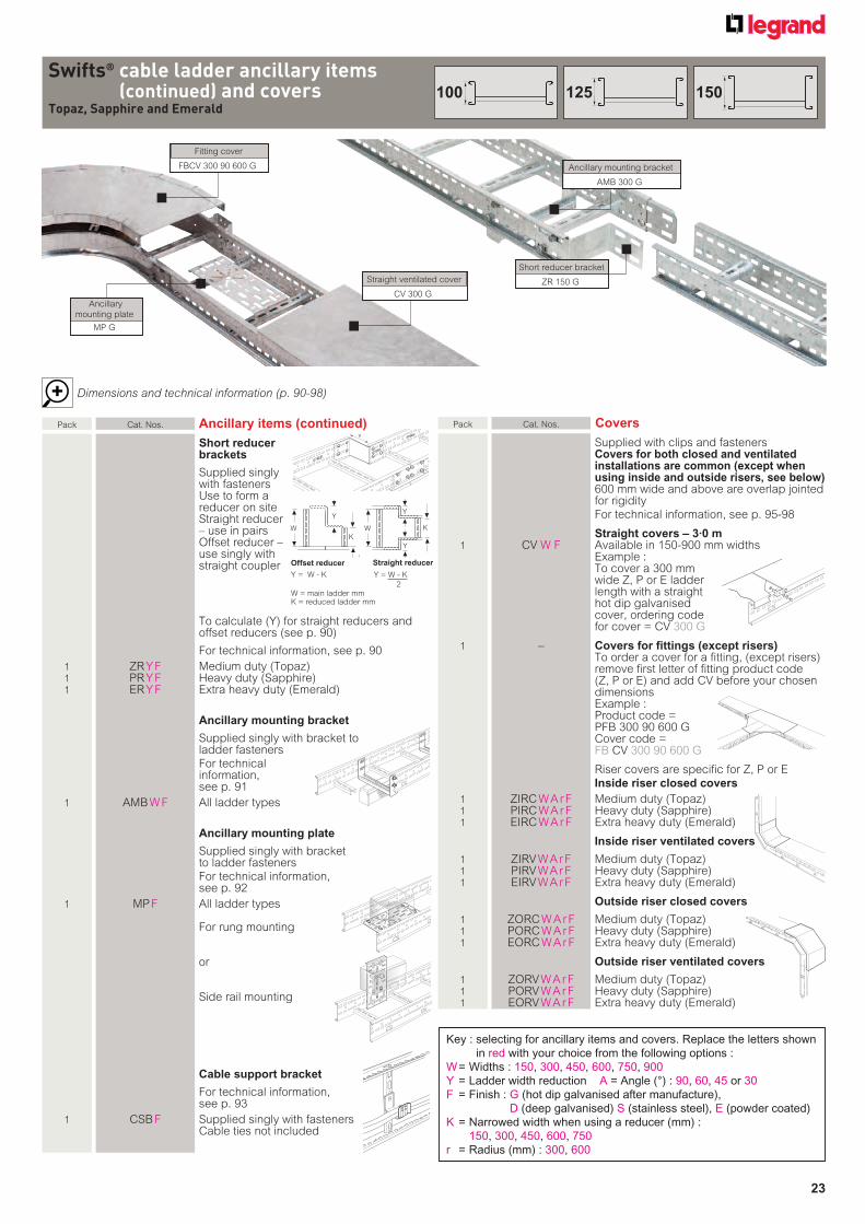
Dimensions and technical information (p. 90-98)
Y
Swifts® cable ladder ancillary items (continued) and covers
Topaz, Sapphire and Emerald
Pack Cat. Nos. Covers
Supplied with clips and fasteners Covers for both closed and ventilated installations are common (except when using inside and outside risers, see below) 600 mm wide and above are overlap jointed for rigidity
For technical information, see p. 95-98
Straight covers – 3·0 m 1 CV W F Available in 150-900 mm widths
Example : To cover a 300 mm wide Z, P or E ladder length with a straight hot dip galvanised cover, ordering code for cover = CV 300 G
1 – Covers for fittings (except risers) To order a cover for a fitting, (except risers)
remove first letter of fitting product code (Z, P or E) and add CV before your chosen dimensions
Example :Product code = PFB 300 90 600 GCover code = FB CV 300 90 600 G
Riser covers are specific for Z, P or E Inside riser closed covers
1 ZIRC W A r F Medium duty (Topaz) 1 PIRC W A r F Heavy duty (Sapphire) 1 EIRC W A r F Extra heavy duty (Emerald)
Inside riser ventilated covers
1 ZIRV W A r F Medium duty (Topaz) 1 PIRV W A r F Heavy duty (Sapphire) 1 EIRV W A r F Extra heavy duty (Emerald)
Outside riser closed covers
1 ZORC W A r F Medium duty (Topaz) 1 PORC W A r F Heavy duty (Sapphire) 1 EORC W A r F Extra heavy duty (Emerald)
Outside riser ventilated covers
1 ZORV W A r F Medium duty (Topaz) 1 PORV W A r F Heavy duty (Sapphire) 1 EORV W A r F Extra heavy duty (Emerald)
Key : selecting for ancillary items and covers. Replace the letters shown
in red with your choice from the following options :
W = Widths : 150, 300, 450, 600, 750, 900
Y = Ladder width reduction A = Angle (°) : 90, 60, 45 or 30
F = Finish : G (hot dip galvanised after manufacture),
D (deep galvanised) S (stainless steel), E (powder coated)
K = Narrowed width when using a reducer (mm) :
150, 300, 450, 600, 750
r = Radius (mm) : 300, 600
W
K
W K
Y
Y
Y
Ancillary
mounting plate
MP G
Straight ventilated cover
CV 300 G
Ancillary mounting bracket
AMB 300 G
Fitting cover
FBCV 300 90 600 G
Short reducer bracket
ZR 150 G
Offset reducer
Y = W - K
W = main ladder mmK = reduced ladder mm
Y = W - K
2
Straight reducer
Pack Cat. Nos. Ancillary items (continued)
Short reducer brackets
Supplied singly with fasteners
Use to form a reducer on siteStraight reducer – use in pairsOffset reducer –use singly withstraight coupler
To calculate (Y) for straight reducers and offset reducers (see p. 90)
For technical information, see p. 90
1 ZR Y F Medium duty (Topaz) 1 PR Y F Heavy duty (Sapphire) 1 ER Y F Extra heavy duty (Emerald)
Ancillary mounting bracket
Supplied singly with bracket to ladder fasteners
For technical information, see p. 91
1 AMB W F All ladder types
Ancillary mounting plate
Supplied singly with bracket to ladder fasteners
For technical information, see p. 92
1 MP F All ladder types
For rung mounting
or
Side rail mounting
Cable support bracket
For technical information, see p. 93
1 CSB F Supplied singly with fastenersCable ties not included
150125100
24
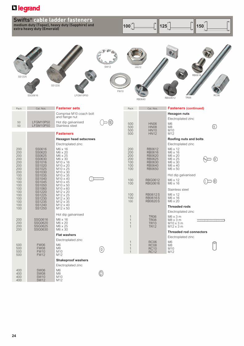
Pack Cat. Nos. Fastener sets
Comprise M10 coach bolt and flange nut
50 LFGM10P50 Hot dip galvanised 50 LFSM10P50 Stainless steel
Fasteners
Hexagon head setscrews
Electroplated zinc
200 SS0616 M6 x 16 200 SS0620 M6 x 20 200 SS0625 M6 x 25 200 SS0630 M6 x 30 200 SS1016 M10 x 16 200 SS1020 M10 x 20 200 SS1025 M10 x 25 200 SS1030 M10 x 30 100 SS1035 M10 x 35 100 SS1040 M10 x 40 100 SS1045 M10 x 45 100 SS1050 M10 x 50 100 SS1060 M10 x 60 100 SS1220 M12 x 20 100 SS1225 M12 x 25 100 SS1230 M12 x 30 100 SS1235 M12 x 35 100 SS1240 M12 x 40 100 SS1250 M12 x 50
Hot dip galvanised
200 SSG0616 M6 x 16 200 SSG0620 M6 x 20 200 SSG0625 M6 x 25 200 SSG0630 M6 x 30
Flat washers
Electroplated zinc
500 FW06 M6 500 FW08 M8 500 FW10 M10 500 FW12 M12
Shakeproof washers
Electroplated zinc
400 SW06 M6 400 SW08 M8 400 SW10 M10 400 SW12 M12
Pack Cat. Nos. Fasteners (continued)
Hexagon nuts
Electroplated zinc
500 HN06 M6 500 HN08 M8 500 HN10 M10 500 HN12 M12
Roofing nuts and bolts
Electroplated zinc
200 RB0612 M6 x 12 200 RB0616 M6 x 16 200 RB0620 M6 x 20 200 RB0625 M6 x 25 100 RB0630 M6 x 30 100 RB0640 M6 x 40 100 RB0650 M6 x 50
Hot dip galvanised
100 RBG0612 M6 x 12 100 RBG0616 M6 x 16
Stainless steel
100 RB0612 S M6 x 12 100 RB0616 S M6 x 16 100 RB0620 S M6 x 20
Threaded rods
Electroplated zinc
1 TR06 M6 x 3 m 1 TR08 M8 x 3 m 1 TR10 M10 x 3 m 1 TR12 M12 x 3 m
Threaded rod connectors
Electroplated zinc
1 RC06 M6 1 RC08 M8 1 RC10 M10 1 RC12 M12
Swifts® cable ladder fastenersmedium duty (Topaz), heavy duty (Sapphire) and extra heavy duty (Emerald)
SS1225
SSG0616
SS1235
SW12 HN12
RB0640RBG0612
RB0616
TR06RC06
FW10
LFGM10P50
150125100
25
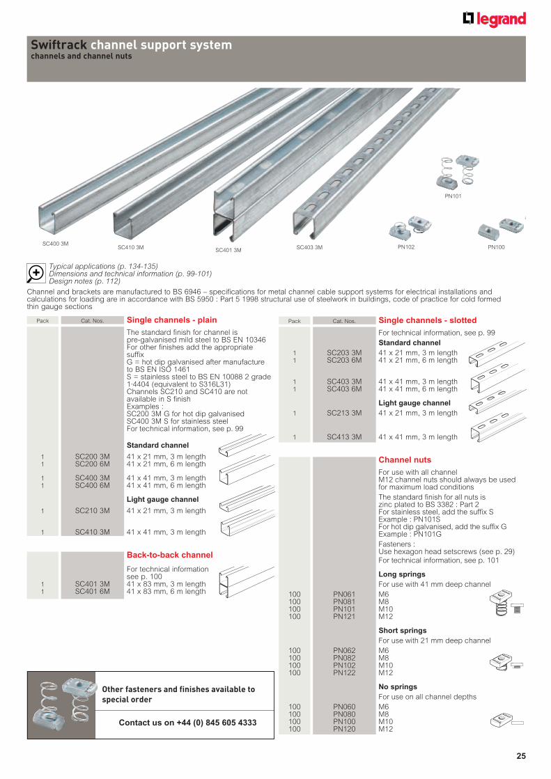
Pack Cat. Nos. Single channels - plain
The standard finish for channel is pre-galvanised mild steel to BS EN 10346 For other finishes add the appropriate suffixG = hot dip galvanised after manufacture to BS EN ISO 1461
S = stainless steel to BS EN 10088 2 grade 1·4404 (equivalent to S316L31)
Channels SC210 and SC410 are not available in S finish
Examples :SC200 3M G for hot dip galvanisedSC400 3M S for stainless steel
For technical information, see p. 99
Standard channel
1 SC200 3M 41 x 21 mm, 3 m length 1 SC200 6M 41 x 21 mm, 6 m length
1 SC400 3M 41 x 41 mm, 3 m length 1 SC400 6M 41 x 41 mm, 6 m length
Light gauge channel
1 SC210 3M 41 x 21 mm, 3 m length
1 SC410 3M 41 x 41 mm, 3 m length
Back-to-back channel
For technical information see p. 100 1 SC401 3M 41 x 83 mm, 3 m length 1 SC401 6M 41 x 83 mm, 6 m length
Pack Cat. Nos. Single channels - slotted
For technical information, see p. 99
Standard channel
1 SC203 3M 41 x 21 mm, 3 m length 1 SC203 6M 41 x 21 mm, 6 m length
1 SC403 3M 41 x 41 mm, 3 m length 1 SC403 6M 41 x 41 mm, 6 m length
Light gauge channel
1 SC213 3M 41 x 21 mm, 3 m length
1 SC413 3M 41 x 41 mm, 3 m length
Channel nuts
For use with all channel M12 channel nuts should always be used
for maximum load conditions
The standard finish for all nuts is zinc plated to BS 3382 : Part 2 For stainless steel, add the suffix SExample : PN101S
For hot dip galvanised, add the suffix GExample : PN101G
Fasteners :Use hexagon head setscrews (see p. 29)
For technical information, see p. 101
Long springs
For use with 41 mm deep channel
100 PN061 M6 100 PN081 M8 100 PN101 M10 100 PN121 M12
Short springs
For use with 21 mm deep channel
100 PN062 M6 100 PN082 M8 100 PN102 M10 100 PN122 M12
No springs
For use on all channel depths
100 PN060 M6 100 PN080 M8 100 PN100 M10 100 PN120 M12
Swiftrack channel support systemchannels and channel nuts
SC400 3MSC410 3M
SC401 3MSC403 3M PN102
Other fasteners and finishes available to special order
Contact us on +44 (0) 845 605 4333
Channel and brackets are manufactured to BS 6946 – specifications for metal channel cable support systems for electrical installations and calculations for loading are in accordance with BS 5950 : Part 5 1998 structural use of steelwork in buildings, code of practice for cold formed thin gauge sections
Typical applications (p. 134-135)Dimensions and technical information (p. 99-101)Design notes (p. 112)
PN101
PN100
26
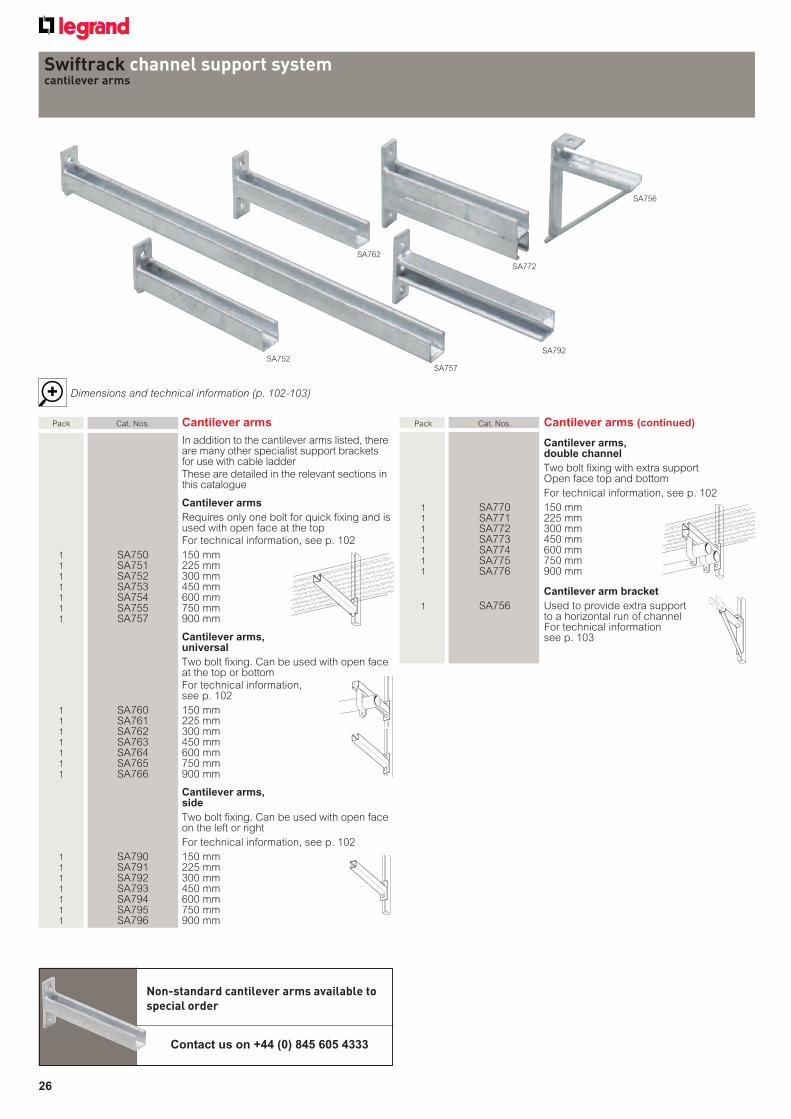
Pack Cat. Nos. Cantilever arms
In addition to the cantilever arms listed, there are many other specialist support brackets for use with cable ladder
These are detailed in the relevant sections in this catalogue
Cantilever arms
Requires only one bolt for quick fixing and is used with open face at the top
For technical information, see p. 102
1 SA750 150 mm 1 SA751 225 mm 1 SA752 300 mm 1 SA753 450 mm 1 SA754 600 mm 1 SA755 750 mm 1 SA757 900 mm
Cantilever arms, universal
Two bolt fixing. Can be used with open face at the top or bottom
For technical information, see p. 102
1 SA760 150 mm 1 SA761 225 mm 1 SA762 300 mm 1 SA763 450 mm 1 SA764 600 mm 1 SA765 750 mm 1 SA766 900 mm
Cantilever arms, side
Two bolt fixing. Can be used with open face on the left or right
For technical information, see p. 102
1 SA790 150 mm 1 SA791 225 mm 1 SA792 300 mm 1 SA793 450 mm 1 SA794 600 mm 1 SA795 750 mm 1 SA796 900 mm
Pack Cat. Nos. Cantilever arms (continued)
Cantilever arms, double channel
Two bolt fixing with extra supportOpen face top and bottom
For technical information, see p. 102
1 SA770 150 mm 1 SA771 225 mm 1 SA772 300 mm 1 SA773 450 mm 1 SA774 600 mm 1 SA775 750 mm 1 SA776 900 mm
Cantilever arm bracket
1 SA756 Used to provide extra supportto a horizontal run of channel For technical information
see p. 103
Swiftrack channel support systemcantilever arms
SA757SA752
SA762
SA792
SA756
SA772
Non-standard cantilever arms available to special order
Contact us on +44 (0) 845 605 4333
Dimensions and technical information (p. 102-103)
27
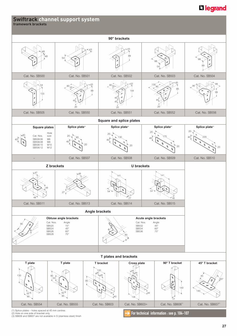
90° brackets
Cat. No. SB500 Cat. No. SB501 Cat. No. SB502 Cat. No. SB503 Cat. No. SB504
48
48
88
54
99
9043
50
45
20
9088
99
Cat. No. SB505 Cat. No. SB550 Cat. No. SB551 Cat. No. SB552 Cat. No. SB556
54
43
88
99
90
144
4350
45
20
45
99
43
133
5490
45
20
45
95
130
Swiftrack channel support systemframework brackets
Square and splice plates
Z brackets U brackets
– Cat. No. SB507 Cat. No. SB508 Cat. No. SB509 Cat. No. SB510
Cat. No. SB511 Cat. No. SB513 Cat. No. SB514 Cat. No. SB515
17540
20
20
22040
20
20
85
40
20
20
40
40130
40
20
20
Square plates
HoleCat. Nos. size
SB506 06 M6SB506 08 M8SB506 10 M10SB506 12 M12
47
48
48
27
48
Angle brackets
T plates and brackets
Cat. No. SB554 Cat. No. SB555 Cat. No. SB603 Cat. No. SB603+ Cat. No. SB606(3)
Cat. No. SB607(3)
141
54
27
(2)
141
48
54
90
ϑ
A
90
ϑ
Cat. Nos. Angle
SB532 45° SB534 60° SB536 75°
Obtuse angle brackets
140
51
45
140
45°
130
90
50
5090
90
50
120
40
80
40
40 138
4848
48
(1) Splice plates – holes spaced at 45 mm centres (2) Hole on one side of bracket only (3) SB606 and SB607 are not available in S (stainless steel) finish
T plate T plate T bracket Cross plate 90° T bracket 45° T bracket
Splice plate(1) Splice plate(1) Splice plate(1) Splice plate(1)
For technical information : see p. 104-107➔
Cat. Nos. Angle
SB520 15° SB524 45° SB526 60° SB528 75°
Acute angle brackets
28
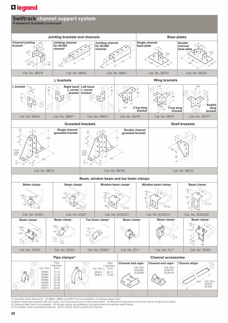
Jointing brackets and channels
Cat. No. SB518 Cat. No. SB650 Cat. No. SB651 Cat. No. SB704 Cat. No. SB705
Swiftrack channel support systemframework brackets (continued)
175
45
175
23
8598
41
48
40
95
80
40
19080
40
140
Base plates
L brackets Wing brackets
150
88
54
Cat. No. SB600 Cat. No. SB601(2) Cat. No. SB602(2) Cat. No. SB700 Cat. No. SB701
Cat. No. SB707(2)
80
40
80
90 9086
150
49
49
Gusseted brackets Shelf brackets
Cat. No. SB702 Cat. No. SB706
175
252
OuterholesØ20
45 6320
43
55
20
55
175
OuterholesØ20
45 6320
55
20
55
84293
88
99
Beam, window beam and toe beam clamps
Cat. No. SC850 Cat. No. SC851 Cat. No. SC852/21 Cat. No. SC852/41 Cat. No. SC852/82
Cat. No. SC853 Cat. No. SC854 Cat. No. SC856(4) Cat. No. ZC1(5) Cat. No. FL2(5) Cat. No. SC855
30
48
(1)28
(1)25
40(1)23
(1)20
(1)37
40
47
(1)25
(1)65 (1)65
80
(1)22
(1)40
(1)87
80
(1)22
(1)40
(1)17
(1)67
19
80
(1)22
(1)128
(1)40
80
ø8
(1)46
(1)1280
(1)46
(1)12
110°
Beam clamp(3) Beam clamp(3) Window beam clamp(3) Window beam clamp(3) Beam clamp(3)
Beam clamp(3) Beam clamp(3) Beam clamp(3) Beam clamp(3) Beam clamp(3)Toe beam clamp(3)
Pipe clamps(6)
– – – – –
Channel accessories
Pipe diameterCat. Nos. (mm)
SP960 10-14 SP964 17-22 SP965 22-26 SP968 25-35 SP969 32-42 SP972 42-59 SP973 54-65
3000 Cat. Nos.SC952SC953
(1) Indicates inside dimensions (2) SB601, SB602 and SB707 are not available in S (stainless steel) finish (3) Beam clamps are supplied with nuts, bolts, cone point screws and U bolts where shown (4) Requires 2 setscrews and channel nuts for fixing (not included) (5) Stainless steel finish is not available (6) All pipe clamps are available in pre-galvanised and stainless steel finishes (7) For SC400, SC401 and SC403 channels (8) For SC200, SC201 and SC203 channels
Channel jointing bracket
Jointing channel for SC200 channel
Jointing channel for SC400 channel
Single channel base plate
Double channel base plate
L bracket Right hand L corner bracket
Left hand L corner bracket
2 lug wing bracket
3 lug wing bracket
Angled wing
bracket
Cat. No. SB703
Single channel gusseted bracket
Double channel gusseted bracket
Pipe diameterCat. Nos. (mm)
SP975 62-71 SP976 73-83
Channel end caps(7)
Cat. Nos.SC950BSC950W
Cat. Nos.SC951BSC951W
Channel end caps(8) Closure strips
29
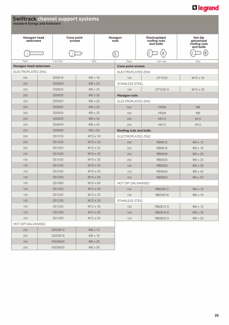
Swiftrack channel support systemsstandard fixings and fasteners
Hexagon head Cone point Hexagon setscrews screws nuts
Electroplatedroofing nuts
and bolts
Hot dip galvanised
roofing nuts and bolts
Pack Cat. Nos. Size
Hexagon head setscrews
ELECTROPLATED ZINC
200 SS0616 M6 x 16
200 SS0620 M6 x 20
200 SS0625 M6 x 25
200 SS0630 M6 x 30
200 SS0820 M8 x 20
200 SS0825 M8 x 25
200 SS0830 M8 x 30
200 SS0835 M8 x 35
200 SS0840 M8 x 40
200 SS0850 M8 x 50
200 SS1016 M10 x 16
200 SS1020 M10 x 20
200 SS1025 M10 x 25
200 SS1030 M10 x 30
100 SS1035 M10 x 35
100 SS1040 M10 x 40
100 SS1045 M10 x 45
100 SS1050 M10 x 50
100 SS1060 M10 x 60
100 SS1220 M12 x 20
100 SS1225 M12 x 25
100 SS1230 M12 x 30
100 SS1235 M12 x 35
100 SS1240 M12 x 40
100 SS1250 M12 x 50
HOT DIP GALVANISED
200 SSG0612 M6 x 12
200 SSG0616 M6 x 16
200 SSG0620 M6 x 20
200 SSG0635 M6 x 35
Pack Cat. Nos. Size
Cone point screws
ELECTROPLATED ZINC
100 CP1035 M10 x 35
STAINLESS STEEL
100 CP1035 S M10 x 35
Hexagon nuts
ELECTROPLATED ZINC
500 HN06 M6
500 HN08 M8
200 HN10 M10
200 HN12 M12
Roofing nuts and bolts
ELECTROPLATED ZINC
200 RB0612 M6 x 12
200 RB0616 M6 x 16
200 RB0620 M6 x 20
200 RB0625 M6 x 25
100 RB0630 M6 x 30
100 RB0640 M6 x 40
100 RB0650 M6 x 50
HOT DIP GALVANISED
100 RBG0612 M6 x 12
100 RBG0616 M6 x 16
STAINLESS STEEL
100 RB0612 S M6 x 12
100 RB0616 S M6 x 16
100 RB0620 S M6 x 20
30
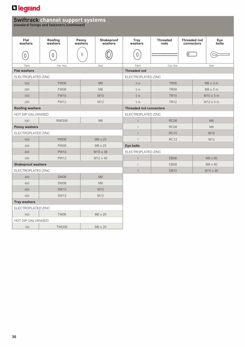
Flat Roofing Penny Shakeproof Tray Threaded Threaded rod Eye washers washers washers washers washers rods connectors bolts
Swiftrack channel support systemsstandard fixings and fasteners (continued)
Pack Cat. Nos. Size
Threaded rod
ELECTROPLATED ZINC
3 m TR06 M6 x 3 m
3 m TR08 M8 x 3 m
3 m TR10 M10 x 3 m
3 m TR12 M12 x 3 m
Threaded rod connectors
ELECTROPLATED ZINC
1 RC06 M6
1 RC08 M8
1 RC10 M10
1 RC12 M12
Eye bolts
ELECTROPLATED ZINC
1 EB06 M6 x 80
1 EB08 M8 x 80
1 EB10 M10 x 80
Pack Cat. Nos. Size
Flat washers
ELECTROPLATED ZINC
500 FW06 M6
500 FW08 M8
500 FW10 M10
200 FW12 M12
Roofing washers
HOT DIP GALVANISED
500 RWG06 M6
Penny washers
ELECTROPLATED ZINC
400 PW06 M6 x 25
400 PW08 M8 x 25
400 PW10 M10 x 38
400 PW12 M12 x 40
Shakeproof washers
ELECTROPLATED ZINC
400 SW06 M6
400 SW08 M8
400 SW10 M10
400 SW12 M12
Tray washers
ELECTROPLATED ZINC
400 TW06 M6 x 20
HOT DIP GALVANISED
100 TWG06 M6 x 20
31
Dimensions and technical information (p. 109)
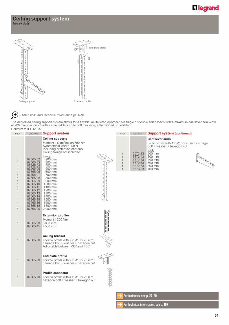
Ceiling support systemheavy duty
Pack Cat. Nos. Support system
Ceiling supports
Moment 1% deflection 780 Nm Symmetrical load 6 000 N Including protection end cap
Ceiling fixings not included
Length 1 87665 02 200 mm 1 87665 03 300 mm 1 87665 04 400 mm 1 87665 05 500 mm 1 87665 06 600 mm 1 87665 07 700 mm 1 87665 08 800 mm 1 87665 09 900 mm 1 87665 10 1 000 mm 1 87665 11 1 100 mm 1 87665 12 1 200 mm 1 87665 13 1 300 mm 1 87665 14 1 400 mm 1 87665 15 1 500 mm 1 87665 16 1 600 mm 1 87665 18 1 800 mm 1 87665 20 2 000 mm
Extension profiles
Moment 1 200 Nm 1 87665 30 3 000 mm 1 87665 45 4 500 mm
Ceiling bracket
1 87665 50 Lock to profile with 2 x M10 x 25 mm carriage bolt + washer + hexagon nut Adjustable between -30° and +30°
End plate profile
1 87665 60 Lock to profile with 2 x M10 x 25 mm carriage bolt + washer + hexagon nut
Profile connector
1 87665 70 Lock to profile with 4 x M10 x 20 mm hexagon bolt + washer + hexagon nut
For technical information, see p. 109➔
Pack Cat. Nos. Support system (continued)
Cantilever arms
Fix to profi le with 1 x M10 x 25 mm carriage bolt + washer + hexagon nut
Width 1 5572 33 200 mm 1 5572 43 300 mm 1 5572 53 400 mm 1 5572 63 500 mm 1 5572 73 600 mm 1 5573 83 700 mm
Extension profile
End plate profile
Ceiling support
For fasteners, see p. 29-30➔
The dedicated ceiling support system allows for a flexible, multi-tiered approach for single or double sided loads with a maximum cantilever arm width of 700 mm to accept Swifts cable ladders up to 600 mm wide, either lidded or unlidded
Conform to IEC 61537
TECHNICAL SPECIFICATIONS
33
IN THIS SECTION
SWIFTS CABLE LADDER SYSTEMSStraight lengths
Medium duty (Topaz) 34Heavy duty (Sapphire) 35Extra heavy duty (Emerald) 36Rung details / diagonal bracing 37
Couplers – straight lengthsStraight length to straight length couplers 38-39Flexible expansion couplers 40Connectors – bendable and vertical hinged 41-42
Pre-fabrication of cable ladder runs 43Identifi cation and recognition of fi ttings 43Couplers – fi ttings
Integral fi tting couplers 44Fitting to fi tting couplers 44-45
Fittings Flat bends 46-49Inside and outside risers 50-61Equal and unequal tees 62-68Branch pieces 694 way crosspieces 70-71Straight and offset reducers 72-73
Supports Heavy duty cantilever arms 74Heavy duty trapeze hangers 75Hanger rod brackets 76Wall support brackets 7790° end connectors 78
Ancillary itemsEarth continuity connectors 79Hold down clips and brackets 80-81Boltable hold down brackets 82Boltable angled hold down brackets 83Dividers - straight / curved 84Articulated risers 85-86Dropout plates 87Rail to rail dropout plates 88Tee brackets 89Short reducer brackets 90Ancillary mounting brackets and plates 91-92Cable support brackets 93Stop ends 94
CoversStraight lengths and fi ttings 95-98
SWIFTRACK CHANNEL SUPPORT SYSTEMSingle channels – plain and slotted 99Back-to-back channels 100Assembly – fasteners and channel nuts 101Cantilever arms 102-103Framework brackets 104-107Beam clamps, pipe clamps and accessories 107-108
CEILING SUPPORT SYSTEMHeavy duty 109
34
■ Dimensions and weights
For cable load capacity see loading graphs opposite
3 000
150 300
Rungpitch
37·519W - 4
W + 40
22
25
5069
100
Internal width
Ø7·5 drain holesat 300 centres
22 x 11 bolt slots at 37·5 pitch
Ø7·5 earthbonding holesat 75 pitch
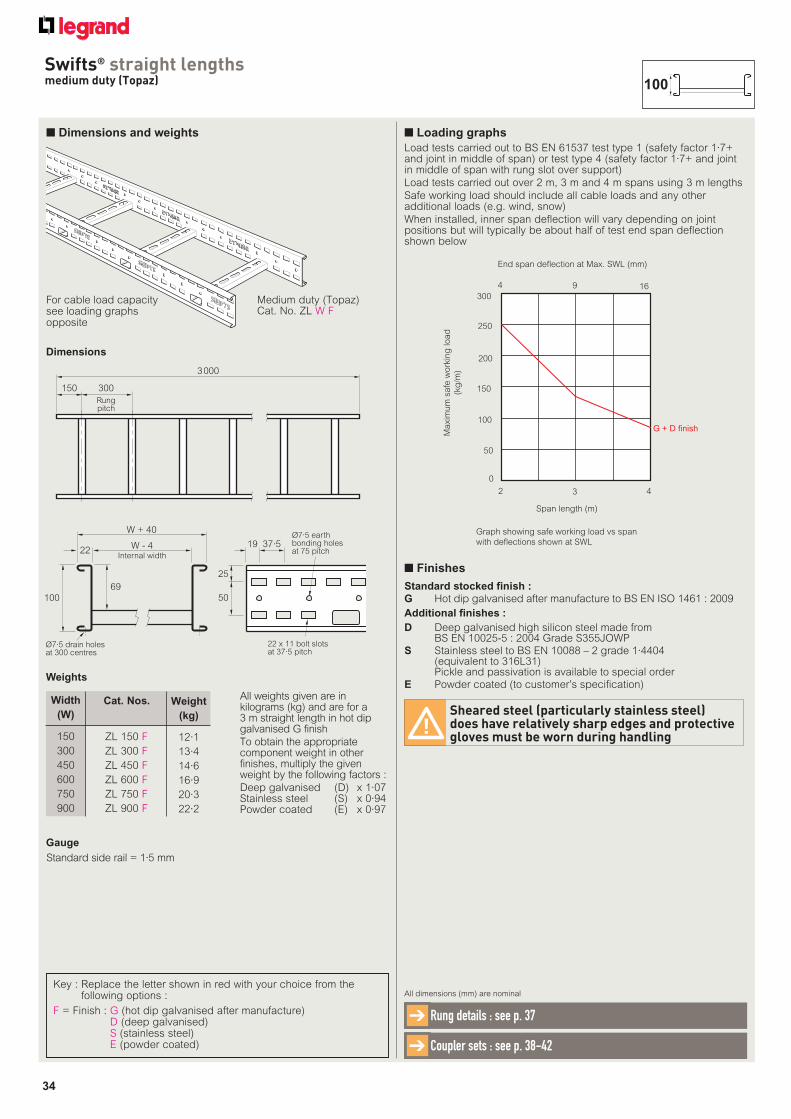
All weights given are in kilograms (kg) and are for a 3 m straight length in hot dip galvanised G finish
To obtain the appropriate component weight in other finishes, multiply the given weight by the following factors :
Deep galvanised (D) x 1·07Stainless steel (S) x 0·94Powder coated (E) x 0·97
150
300
450
600
750
900
Cat. Nos. Weight
(kg)
Width
(W)
12·1
13·4
14·6
16·9
20·3
22·2
ZL 150 F
ZL 300 F
ZL 450 F
ZL 600 F
ZL 750 F
ZL 900 F
Medium duty (Topaz) Cat. No. ZL W F
■ Loading graphs
Load tests carried out to BS EN 61537 test type 1 (safety factor 1·7+ and joint in middle of span) or test type 4 (safety factor 1·7+ and joint in middle of span with rung slot over support)
Load tests carried out over 2 m, 3 m and 4 m spans using 3 m lengths
Safe working load should include all cable loads and any other additional loads (e.g. wind, snow)
When installed, inner span deflection will vary depending on joint positions but will typically be about half of test end span deflection shown below
Standard stocked finish :
G Hot dip galvanised after manufacture to BS EN ISO 1461 : 2009
Additional finishes :
D Deep galvanised high silicon steel made from BS EN 10025-5 : 2004 Grade S355JOWP
S Stainless steel to BS EN 10088 – 2 grade 1·4404(equivalent to 316L31)Pickle and passivation is available to special order
E Powder coated (to customer’s specification)
Sheared steel (particularly stainless steel) does have relatively sharp edges and protective gloves must be worn during handling
■ Finishes
End span deflection at Max. SWL (mm)
4 9 16300
250
200
150
100
50
0
2 3 4
Span length (m)
Graph showing safe working load vs span
with deflections shown at SWL
Maxim
um
safe
work
ing
load
(kg
/m)
G + D finish
Key : Replace the letter shown in red with your choice from the following options :
F = Finish : G (hot dip galvanised after manufacture)D (deep galvanised)S (stainless steel)E (powder coated)
Swifts® straight lengthsmedium duty (Topaz)
Dimensions
Weights
100
All dimensions (mm) are nominal
Rung details : see p. 37➔
Coupler sets : see p. 38-42➔
Gauge
Standard side rail = 1·5 mm
35
■ Dimensions and weights
3 000 or 6 000
150 300
Rungpitch
37·519W - 4
W + 40
22
25
5094
125
Internal width
Ø7·5 drain holesat 300 centres
22 x 11 bolt slotsat 37·5 pitch
Ø7·5 earthbonding holesat 75 pitch
All weights given are in kilograms (kg) and are for a 3 m straight length in hot dip galvanised G finish
To obtain the appropriate component weight in other finishes, multiply the given weight by the following factors :
Deep galvanised (D) x 1·07Stainless steel (S) x 0·94Powder coated (E) x 0·97
150
300
450
600
750
900
Cat. Nos.
Weight
(kg)
Width
(W)
13·8
15·0
16·3
18·5
22·0
23·9
PL 150 F
PL 300 F
PL 450 F
PL 600 F
PL 750 F
PL 900 F
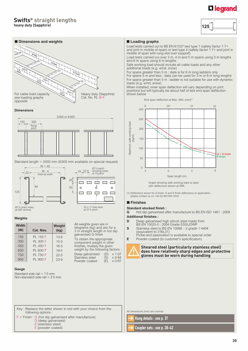
Heavy duty (Sapphire)Cat. No. PL W F
Key : Replace the letter shown in red with your choice from the following options :
F = Finish : G (hot dip galvanised after manufacture)D (deep galvanised)S (stainless steel)E (powder coated)
■ Loading graphs
Load tests carried out to BS EN 61537 test type 1 (safety factor 1·7+ and joint in middle of span) or test type 4 (safety factor 1·7+ and joint in middle of span with rung slot over support)
Load tests carried out over 3 m, 4 m and 5 m spans using 3 m lengths and 6 m spans using 6 m lengths
Safe working load should include all cable loads and any other additional loads (e.g. wind, snow)
For spans greater than 5 m : data is for 6 m long ladders onlyFor spans 5 m and less : data can be used for 3 m or 6 m long lengths
For spans greater than 5 m : ladder is not suitable for use with dynamic loads (e.g. wind, snow)
When installed, inner span deflection will vary depending on joint positions but will typically be about half of test end span deflection shown below
Swifts® straight lengthsheavy duty (Sapphire)
Dimensions
Weights
Standard length = 3 000 mm (6 000 mm available on special request)
For cable load capacity see loading graphs opposite
125
All dimensions (mm) are nominal
Rung details : see p. 37➔
Coupler sets : see p. 38-42➔
(1) Defl ections shown for G fi nish. D and S fi nish defl ections on application,
please contact us on +44 (0) 845 605 4333
Gauge
Standard side rail = 1·5 mmNon-standard side rail = 2·0 mm
Standard stocked finish :
G Hot dip galvanised after manufacture to BS EN ISO 1461 : 2009
Additional finishes :
D Deep galvanised high silicon steel made from BS EN 10025-5 : 2004 Grade S355JOWP
S Stainless steel to BS EN 10088 – 2 grade 1·4404(equivalent to 316L31)Pickle and passivation is available to special order
E Powder coated (to customer’s specification)
Sheared steel (particularly stainless steel) does have relatively sharp edges and protective gloves must be worn during handling
■ Finishes
End span deflection at Max. SWL (mm)(1)
9 20 27 32300
250
200
150
100
50
0
3 4 5 6
Span length (m)
Graph showing safe working load vs span
with deflections shown at SWL
Maxim
um
safe
work
ing
load
(kg
/m)
G + D finish
S finish
36
■ Extra heavy duty (Emerald)
150
300
450
600
750
900
Cat. Nos. Weight
(kg)
Width
(W)
20·7
22·1
23·5
25·0
28·8
30·8
EL 150 F
EL 300 F
EL 450 F
EL 600 F
EL 750 F
EL 900 F
All weights given are in kilograms (kg) and are for a 3m straight length in hot dip galvanised G finish
To obtain the appropriate component weight in other finishes, multiply the given weight by the following factors :
Deep galvanised (D) x 1·07Stainless steel (S) x 0·94Powder coated (E) x 0·97
For cable load capacity see loading graphs opposite
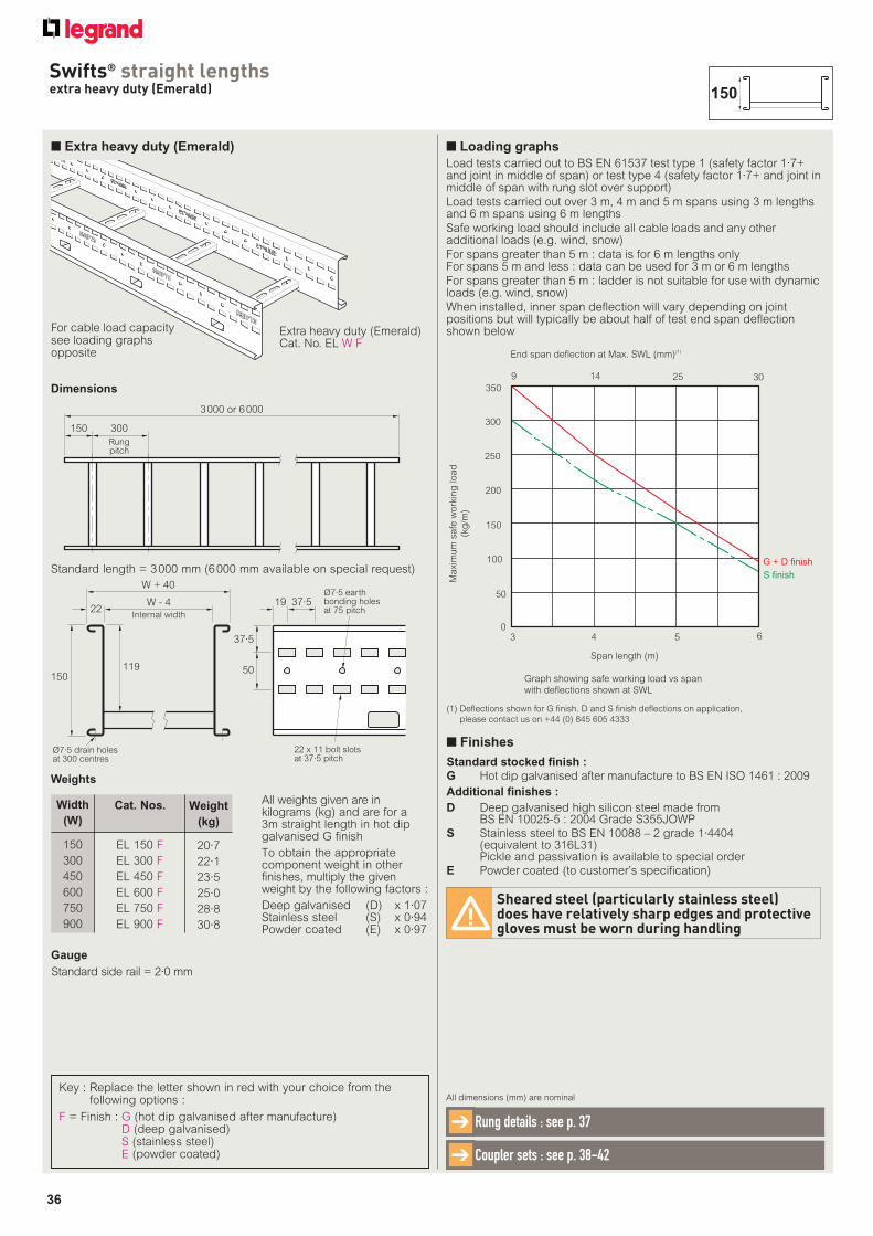
Extra heavy duty (Emerald)Cat. No. EL W F
3 000 or 6 000
150 300
Rungpitch
37·519W - 4
W + 40
22
37·5
50119150
Internal width
Ø7·5 drain holesat 300 centres
22 x 11 bolt slotsat 37·5 pitch
Ø7·5 earthbonding holesat 75 pitch
■ Loading graphs
Load tests carried out to BS EN 61537 test type 1 (safety factor 1·7+ and joint in middle of span) or test type 4 (safety factor 1·7+ and joint in middle of span with rung slot over support)
Load tests carried out over 3 m, 4 m and 5 m spans using 3 m lengths and 6 m spans using 6 m lengths
Safe working load should include all cable loads and any other additional loads (e.g. wind, snow)
For spans greater than 5 m : data is for 6 m lengths onlyFor spans 5 m and less : data can be used for 3 m or 6 m lengths
For spans greater than 5 m : ladder is not suitable for use with dynamic loads (e.g. wind, snow)
When installed, inner span deflection will vary depending on joint positions but will typically be about half of test end span deflection shown below
End span deflection at Max. SWL (mm)(1)
9 14 25 30
300
250
200
150
100
50
03 4 5 6
Span length (m)
Graph showing safe working load vs span
with deflections shown at SWL
Maxim
um
safe
work
ing
load
(kg
/m)
G + D finish
S finish
350
Key : Replace the letter shown in red with your choice from the following options :
F = Finish : G (hot dip galvanised after manufacture)D (deep galvanised)S (stainless steel)E (powder coated)
Swifts® straight lengthsextra heavy duty (Emerald)
Dimensions
Weights
Standard length = 3 000 mm (6 000 mm available on special request)
All dimensions (mm) are nominal
Rung details : see p. 37➔
Coupler sets : see p. 38-42➔
150
Gauge
Standard side rail = 2·0 mm
(1) Defl ections shown for G fi nish. D and S fi nish defl ections on application,
please contact us on +44 (0) 845 605 4333
Standard stocked finish :
G Hot dip galvanised after manufacture to BS EN ISO 1461 : 2009
Additional finishes :
D Deep galvanised high silicon steel made from BS EN 10025-5 : 2004 Grade S355JOWP
S Stainless steel to BS EN 10088 – 2 grade 1·4404(equivalent to 316L31)Pickle and passivation is available to special order
E Powder coated (to customer’s specification)
Sheared steel (particularly stainless steel) does have relatively sharp edges and protective gloves must be worn during handling
■ Finishes
37
Slot pattern may differ on stainless steel type 3 rungs
Contact us on +44 (0) 845 605 4333
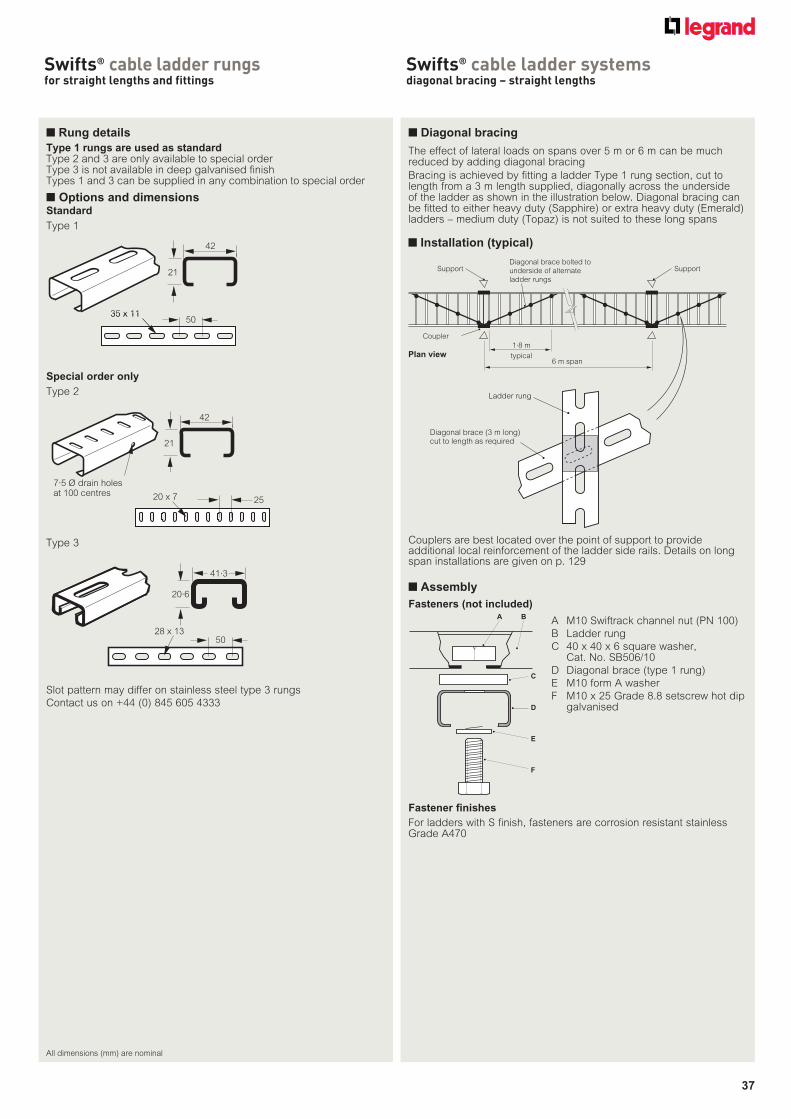
Swifts® cable ladder rungsfor straight lengths and fittings
■ Diagonal bracing
The effect of lateral loads on spans over 5 m or 6 m can be much reduced by adding diagonal bracing
Bracing is achieved by fitting a ladder Type 1 rung section, cut to length from a 3 m length supplied, diagonally across the underside of the ladder as shown in the illustration below. Diagonal bracing can be fitted to either heavy duty (Sapphire) or extra heavy duty (Emerald) ladders – medium duty (Topaz) is not suited to these long spans
Couplers are best located over the point of support to provide additional local reinforcement of the ladder side rails. Details on long span installations are given on p. 129
Diagonal brace (3 m long)cut to length as required
Ladder rung
6 m span
1·8 m
typical
Diagonal brace bolted to
underside of alternate
ladder rungs
Support Support
Coupler
Plan view
A M10 Swiftrack channel nut (PN 100)
B Ladder rung
C 40 x 40 x 6 square washer, Cat. No. SB506/10
D Diagonal brace (type 1 rung)
E M10 form A washer
F M10 x 25 Grade 8.8 setscrew hot dip galvanised
Fastener finishes
For ladders with S finish, fasteners are corrosion resistant stainless Grade A470
A
C
B
D
E
F
■ Assembly
Fasteners (not included)
■ Installation (typical)
Swifts® cable ladder systemsdiagonal bracing – straight lengths
■ Rung details
Type 1 rungs are used as standardType 2 and 3 are only available to special orderType 3 is not available in deep galvanised finishTypes 1 and 3 can be supplied in any combination to special order
■ Options and dimensions
42
21
35 x 1135 x 1150
Type 1
41·3
20·6
28 x 1350
Type 2
7·5 Ø drain holesat 100 centres
42
21
20 x 7 25
Special order only
Type 3
Standard
All dimensions (mm) are nominal
38
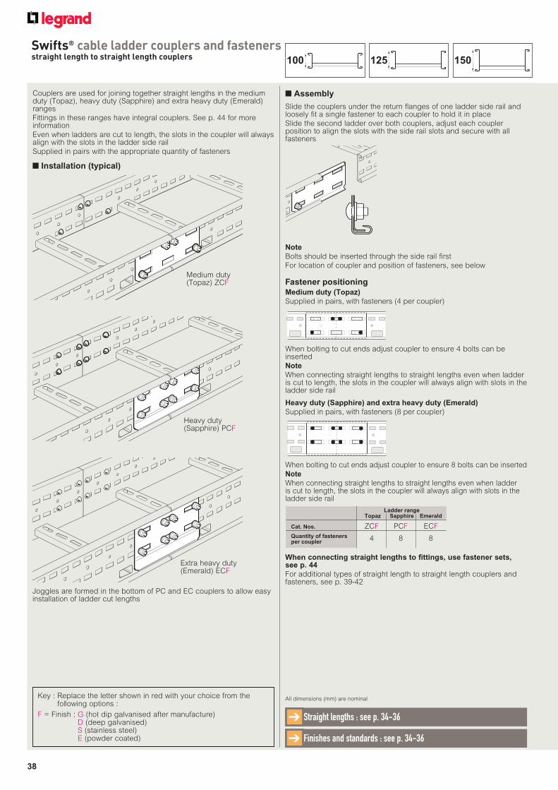
Swifts® cable ladder couplers and fastenersstraight length to straight length couplers
All dimensions (mm) are nominal
Straight lengths : see p. 34-36➔
Finishes and standards : see p. 34-36➔
Fastener positioning
Joggles are formed in the bottom of PC and EC couplers to allow easy installation of ladder cut lengths
Couplers are used for joining together straight lengths in the medium duty (Topaz), heavy duty (Sapphire) and extra heavy duty (Emerald) ranges
Fittings in these ranges have integral couplers. See p. 44 for more information
Even when ladders are cut to length, the slots in the coupler will always align with the slots in the ladder side rail
Supplied in pairs with the appropriate quantity of fasteners
Medium duty (Topaz) ZCF
Heavy duty (Sapphire) PCF
Extra heavy duty (Emerald) ECF
■ Installation (typical)
Slide the couplers under the return flanges of one ladder side rail and loosely fit a single fastener to each coupler to hold it in place
Slide the second ladder over both couplers, adjust each coupler position to align the slots with the side rail slots and secure with all fasteners
■ Assembly
Note
Bolts should be inserted through the side rail first
For location of coupler and position of fasteners, see below
Medium duty (Topaz)
Supplied in pairs, with fasteners (4 per coupler)
When bolting to cut ends adjust coupler to ensure 4 bolts can be inserted
Note
When connecting straight lengths to straight lengths even when ladder is cut to length, the slots in the coupler will always align with slots in the ladder side rail
Heavy duty (Sapphire) and extra heavy duty (Emerald)
Supplied in pairs, with fasteners (8 per coupler)
When bolting to cut ends adjust coupler to ensure 8 bolts can be inserted
Note
When connecting straight lengths to straight lengths even when ladder is cut to length, the slots in the coupler will always align with slots in the ladder side rail
When connecting straight lengths to fittings, use fastener sets, see p. 44
For additional types of straight length to straight length couplers and fasteners, see p. 39-42
Ladder range Topaz Sapphire Emerald
Cat. Nos. ZCF PCF ECF
Quantity of fasteners per coupler 4 8 8
Key : Replace the letter shown in red with your choice from the following options :
F = Finish : G (hot dip galvanised after manufacture)D (deep galvanised)S (stainless steel)E (powder coated)
150125100
39
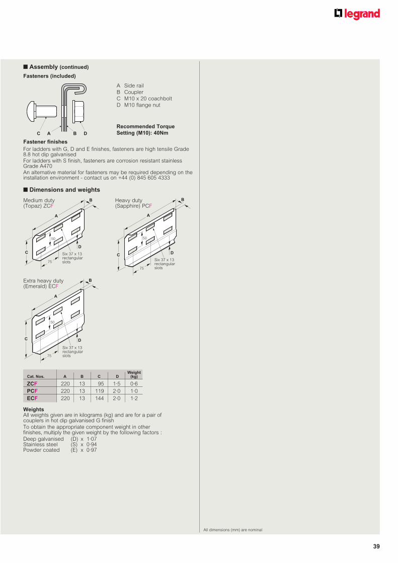
■ Dimensions and weights
Fasteners (included)
A Side rail
B Coupler
C M10 x 20 coachbolt
D M10 flange nut
Recommended Torque
Setting (M10): 40NmC A B D
WeightsAll weights given are in kilograms (kg) and are for a pair of couplers in hot dip galvanised G finish
To obtain the appropriate component weight in other finishes, multiply the given weight by the following factors :
Deep galvanised (D) x 1·07Stainless steel (S) x 0·94Powder coated (E) x 0·97
WeightCat. Nos. A B C D (kg)
ZCF 220 13 95 1·5 0·6
PCF 220 13 119 2·0 1·0
ECF 220 13 144 2·0 1·2
C
B
A
50
75
D
Six 37 x 13rectangularslots
C
B
A
50
75
D
Six 37 x 13rectangularslots
C
B
A
50
75
D
Six 37 x 13rectangularslots
■ Assembly (continued)
Fastener finishes
For ladders with G, D and E finishes, fasteners are high tensile Grade 8.8 hot dip galvanisedFor ladders with S finish, fasteners are corrosion resistant stainless Grade A470An alternative material for fasteners may be required depending on the installation environment - contact us on +44 (0) 845 605 4333
Medium duty (Topaz) ZCF
Heavy duty (Sapphire) PCF
Extra heavy duty (Emerald) ECF
All dimensions (mm) are nominal

40
Swifts® cable ladder couplers and fastenersflexible expansion couplers
All dimensions (mm) are nominal
Straight lengths : see p. 34-36➔
Finishes and standards : see p. 34-36➔
Flexible expansion couplers can be used to :
a. provide a semi-flexible joint where ladder runs span separate structures between which some relative movement is possible
b. provide compensation for changes in the length of a straight cable ladder run due to temperature variations
Supplied in pairs with fasteners
■ Installation (typical)
Ladder range Topaz Sapphire Emerald
Cat. Nos. ZEF PEF EEF
Quantity of fasteners per coupler(1) 4 8 8
Flexible expansion couplers should normally be installed with the ridges facing outward, away from the bed of the ladder
If necessary, the stiffness of each joint can be increased by mounting pairs of couplers back-to-back (with one set of ridges facing inwards and the other set facing outwards as shown above) on either side of the cable ladder. The allowance for differential movement remains unchanged (see below)
Note
Rigid support for the cable ladder should be provided on both sides adjacent to each joint
Normal installation
Heavy duty (Sapphire) PEF (ZEF and EEF similar)
D
B
A
C
Eight 37 x 13rectangularslots
D
A
B
C
Eight 37 x 13rectangularslots
D
B
A
C
Eight 37 x 13rectangularslots
■ Assembly
■ Assembly (continued)
(1) for normal installation, or per pair (each side) for stiffened installation
■ Dimensions and weights
Fasteners (included)
A Side rail
B Coupler
C M10 x 20 coachbolt
D M10 flange nut
Recommended Torque
Setting (M10): 40NmC A B D
Medium duty (Topaz) ZEF Heavy duty
(Sapphire) PEF
Extra heavy duty (Emerald) EEF
WeightCat. Nos. A B C D (kg)
ZEF 320 84 113·0 1·0 0·6
PEF 317 115 111·5 1·5 1·1
EEF 317 138 111·5 1·5 1·4
WeightsAll weights given are in kilograms (kg) and are for a pair of couplers in hot dip galvanised G finish
To obtain the appropriate component weight in other finishes, multiply the given weight by the following factors :
Deep galvanised (D) x 1·07Stainless steel (S) x 0·94Powder coated (E) x 0·97
Stiffened installation
Heavy duty (Sapphire) PEF (ZEF and EEF similar)
Fastener finishes
For ladders with G, D and E finishes, fasteners are high tensile Grade 8.8 hot dip galvanisedFor ladders with S finish, fasteners are corrosion resistant stainless Grade A470An alternative material for fasteners may be required depending on the installation environment - contact us on +44 (0) 845 605 4333
Key : Replace the letter shown in red with your choice from the following options :
F = Finish : G (hot dip galvanised after manufacture)D (deep galvanised)S (stainless steel)E (powder coated)
Each joint formed by flexible expansion couplers provides for up to 10 mm of linear movement between the two adjacent ladders
To calculate the ideal distance between flexible expansion coupler installations use the formula : L = KS T
Where : L = distance between flexible expansion couplers, in metresKS = 909 for mild steel, 625 for stainless steelT = temperature range (in °C) for which allowance is to be made
Note Coefficients of linear expansion : mild steel = 11 x 10-6/ °C stainless steel = 16 x 10-6/ °C
150125100
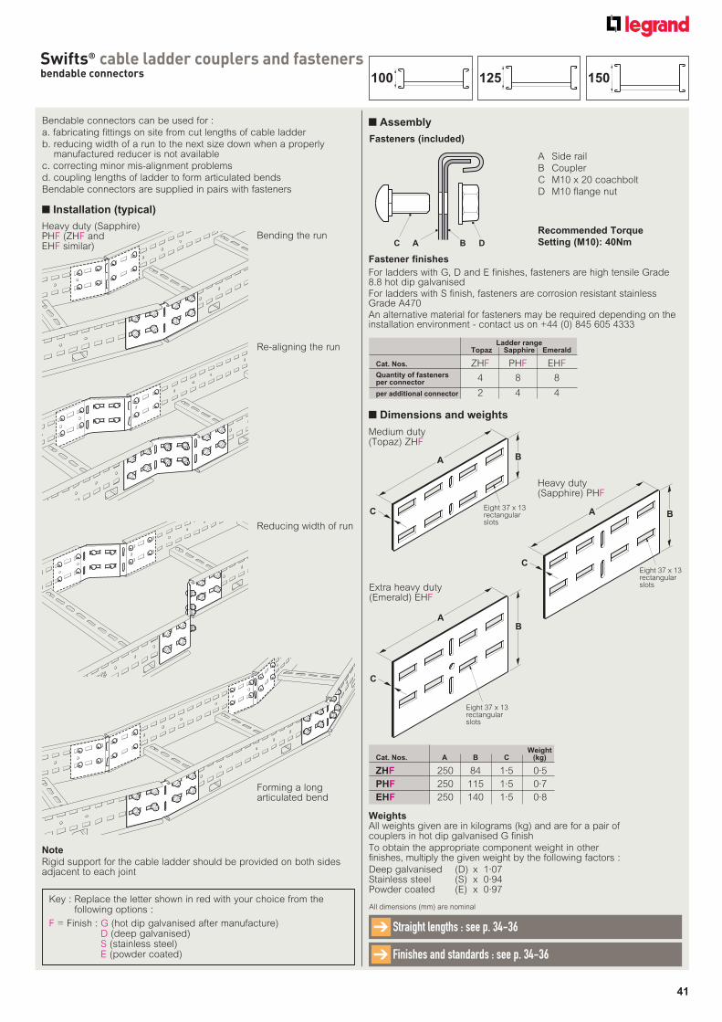
41
Swifts® cable ladder couplers and fastenersbendable connectors
■ Dimensions and weights
All dimensions (mm) are nominal
Straight lengths : see p. 34-36➔
Finishes and standards : see p. 34-36➔
Bendable connectors can be used for :
a. fabricating fittings on site from cut lengths of cable ladder
b. reducing width of a run to the next size down when a properly manufactured reducer is not available
c. correcting minor mis-alignment problems
d. coupling lengths of ladder to form articulated bends
Bendable connectors are supplied in pairs with fasteners
■ Installation (typical)
Note
Rigid support for the cable ladder should be provided on both sides adjacent to each joint
C
A B
Eight 37 x 13rectangularslots
C
AB
Eight 37 x 13rectangularslots
C
A B
Eight 37 x 13rectangularslots
Medium duty (Topaz) ZHF
Re-aligning the run
Reducing width of run
Forming a long articulated bend
WeightCat. Nos. A B C (kg)
ZHF 250 84 1·5 0·5
PHF 250 115 1·5 0·7
EHF 250 140 1·5 0·8
Ladder range Topaz Sapphire Emerald
Cat. Nos. ZHF PHF EHFQuantity of fasteners per connector 4 8 8
per additional connector 2 4 4
WeightsAll weights given are in kilograms (kg) and are for a pair of couplers in hot dip galvanised G finish
To obtain the appropriate component weight in other finishes, multiply the given weight by the following factors :
Deep galvanised (D) x 1·07Stainless steel (S) x 0·94Powder coated (E) x 0·97
■ Assembly
Fasteners (included)
A Side rail
B Coupler
C M10 x 20 coachbolt
D M10 flange nut
Recommended Torque
Setting (M10): 40NmC A B D
Heavy duty (Sapphire) PHF
Fastener finishes
For ladders with G, D and E finishes, fasteners are high tensile Grade 8.8 hot dip galvanisedFor ladders with S finish, fasteners are corrosion resistant stainless Grade A470An alternative material for fasteners may be required depending on the installation environment - contact us on +44 (0) 845 605 4333
Extra heavy duty (Emerald) EHF
Key : Replace the letter shown in red with your choice from the following options :
F = Finish : G (hot dip galvanised after manufacture)D (deep galvanised)S (stainless steel)E (powder coated)
150125100
Bending the runHeavy duty (Sapphire) PHF (ZHF and EHF similar)
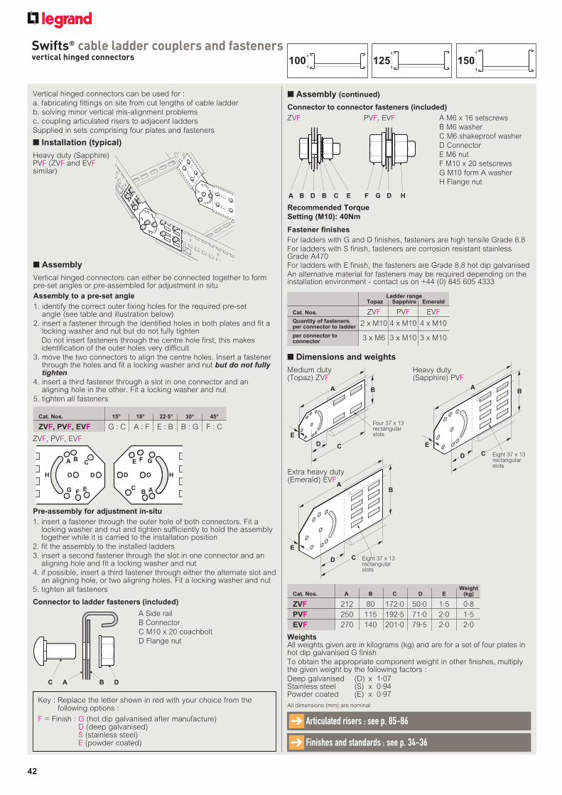
42
Swifts® cable ladder couplers and fastenersvertical hinged connectors
Vertical hinged connectors can be used for :
a. fabricating fittings on site from cut lengths of cable ladder
b. solving minor vertical mis-alignment problems
c. coupling articulated risers to adjacent ladders
Supplied in sets comprising four plates and fasteners
■ Installation (typical)
Heavy duty (Sapphire) PVF (ZVF and EVF similar)
Connector to ladder fasteners (included)
Recommended Torque
Setting (M10): 40Nm
A M6 x 16 setscrews
B M6 washer
C M6 shakeproof washer
D Connector
E M6 nut
F M10 x 20 setscrews
G M10 form A washer
H Flange nut
A Side rail
B Connector
C M10 x 20 coachbolt
D Flange nut
ZVF PVF, EVF
C A B D
A D B C EB F D HG
Ladder range Topaz Sapphire Emerald
Cat. Nos. ZVF PVF EVFQuantity of fasteners per connector to ladder 2 x M10 4 x M10 4 x M10
per connector toconnector 3 x M6 3 x M10 3 x M10
Fastener finishes
For ladders with G and D finishes, fasteners are high tensile Grade 8.8For ladders with S finish, fasteners are corrosion resistant stainless Grade A470For ladders with E finish, the fasteners are Grade 8.8 hot dip galvanisedAn alternative material for fasteners may be required depending on the installation environment - contact us on +44 (0) 845 605 4333
■ Assembly
■ Assembly (continued)
Vertical hinged connectors can either be connected together to form pre-set angles or pre-assembled for adjustment in situ
Assembly to a pre-set angle
1. identify the correct outer fixing holes for the required pre-set angle (see table and illustration below)
2. insert a fastener through the identified holes in both plates and fit a locking washer and nut but do not fully tighten
Do not insert fasteners through the centre hole first, this makes identification of the outer holes very difficult
3. move the two connectors to align the centre holes. Insert a fastener through the holes and fit a locking washer and nut but do not fully tighten
4. insert a third fastener through a slot in one connector and an aligning hole in the other. Fit a locking washer and nut
5. tighten all fasteners
Pre-assembly for adjustment in-situ
1. insert a fastener through the outer hole of both connectors. Fit a locking washer and nut and tighten sufficiently to hold the assembly together while it is carried to the installation position
2. fit the assembly to the installed ladders
3. insert a second fastener through the slot in one connector and an aligning hole and fit a locking washer and nut
4. if possible, insert a third fastener through either the alternate slot and an aligning hole, or two aligning holes. Fit a locking washer and nut
5. tighten all fasteners
A BC
D
EFG
H O
E F G
O HD
CB A
Cat. Nos. 15° 18° 22·5° 30° 45°
ZVF, PVF, EVF G : C A : F E : B B : G F : C
ZVF, PVF, EVF
All dimensions (mm) are nominal
Articulated risers : see p. 85-86➔
Finishes and standards : see p. 34-36➔
Key : Replace the letter shown in red with your choice from the following options :
F = Finish : G (hot dip galvanised after manufacture)D (deep galvanised)S (stainless steel)E (powder coated)
■ Dimensions and weights
BA
E
CD Eight 37 x 13rectangularslots
BA
E
CD Eight 37 x 13rectangularslots
B
E
CD
A
Four 37 x 13rectangularslots
Medium duty (Topaz) ZVF
Heavy duty (Sapphire) PVF
WeightsAll weights given are in kilograms (kg) and are for a set of four plates in hot dip galvanised G finish
To obtain the appropriate component weight in other finishes, multiply the given weight by the following factors :
Deep galvanised (D) x 1·07Stainless steel (S) x 0·94Powder coated (E) x 0·97
WeightCat. Nos. A B C D E (kg)
ZVF 212 80 172·0 50·0 1·5 0·8
PVF 250 115 192·5 71·0 2·0 1·5
EVF 270 140 201·0 79·5 2·0 2·0
Extra heavy duty (Emerald) EVF
Connector to connector fasteners (included)
150125100
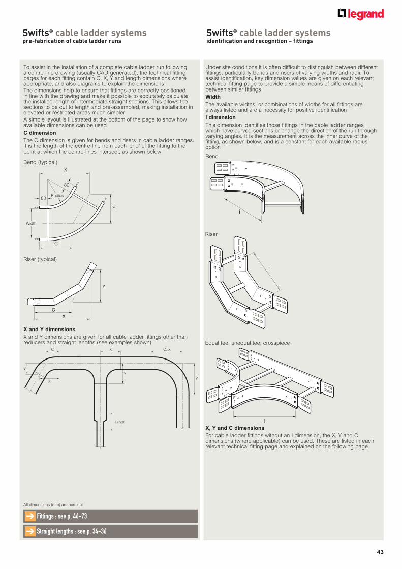
43
Swifts® cable ladder systemspre-fabrication of cable ladder runs
All dimensions (mm) are nominal
Fittings : see p. 46-73➔
Straight lengths : see p. 34-36➔
To assist in the installation of a complete cable ladder run following a centre-line drawing (usually CAD generated), the technical fitting pages for each fitting contain C, X, Y and length dimensions where appropriate, and also diagrams to explain the dimensions
The dimensions help to ensure that fittings are correctly positioned in line with the drawing and make it possible to accurately calculate the installed length of intermediate straight sections. This allows the sections to be cut to length and pre-assembled, making installation in elevated or restricted areas much simpler
A simple layout is illustrated at the bottom of the page to show how available dimensions can be used
C dimension
The C dimension is given for bends and risers in cable ladder ranges. It is the length of the centre-line from each ‘end’ of the fitting to the point at which the centre-lines intersect, as shown below
X and Y dimensions
X and Y dimensions are given for all cable ladder fittings other than reducers and straight lengths (see examples shown)
C
X
Y
Riser (typical)
X
80
80Radius
C
Width
Y
Y
C, XXC
Y
X
Y
Length
Bend (typical)
Under site conditions it is often difficult to distinguish between different fittings, particularly bends and risers of varying widths and radii. To assist identification, key dimension values are given on each relevant technical fitting page to provide a simple means of differentiating between similar fittings
Width
The available widths, or combinations of widths for all fittings are always listed and are a necessity for positive identification
i dimension
This dimension identifies those fittings in the cable ladder ranges which have curved sections or change the direction of the run through varying angles. It is the measurement across the inner curve of the fitting, as shown below, and is a constant for each available radius option
i
i
i
Equal tee, unequal tee, crosspiece
Riser
Bend
X, Y and C dimensions
For cable ladder fittings without an I dimension, the X, Y and C dimensions (where applicable) can be used. These are listed in each relevant technical fitting page and explained on the following page
Swifts® cable ladder systemsidentification and recognition – fittings
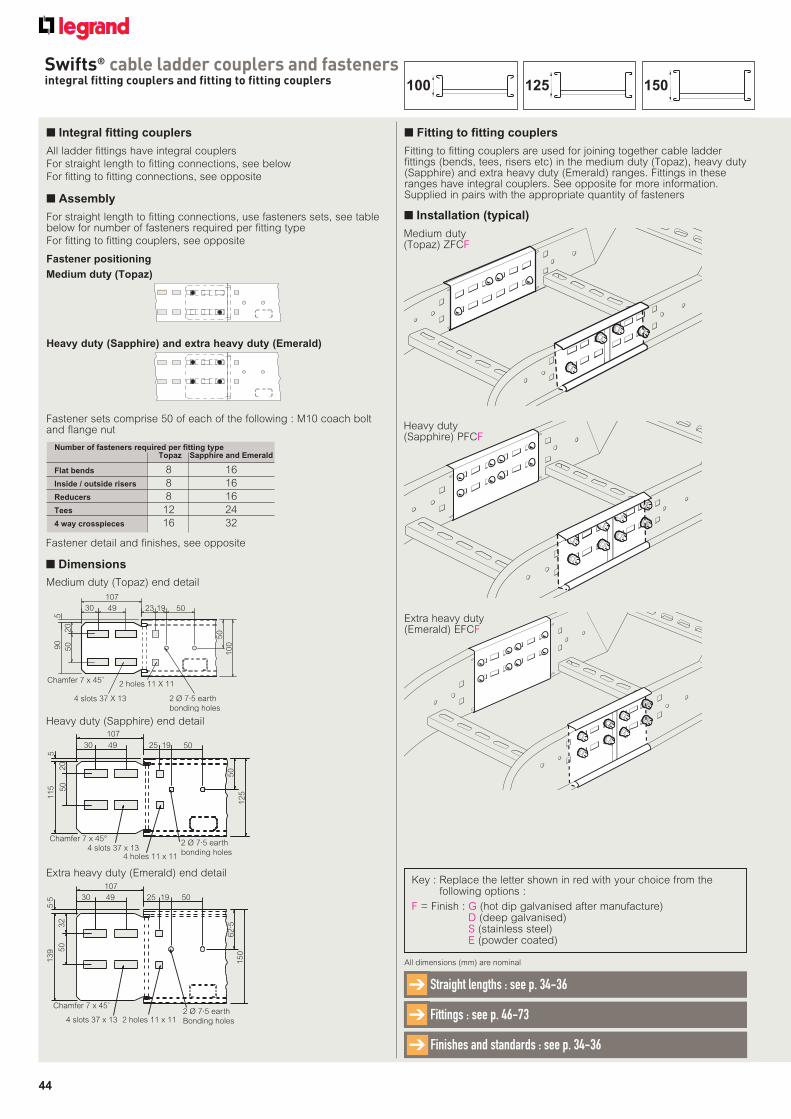
44
Swifts® cable ladder couplers and fastenersintegral fitting couplers and fitting to fitting couplers
■ Integral fitting couplers
■ Dimensions
All dimensions (mm) are nominal
Finishes and standards : see p. 34-36➔
Straight lengths : see p. 34-36➔
Fittings : see p. 46-73➔
All ladder fittings have integral couplers
For straight length to fitting connections, see below
For fitting to fitting connections, see opposite
Number of fasteners required per fitting type Topaz Sapphire and Emerald
Flat bends 8 16
Inside / outside risers 8 16
Reducers 8 16
Tees 12 24
4 way crosspieces 16 32
Fastener sets comprise 50 of each of the following : M10 coach bolt and flange nut
Fastener detail and finishes, see opposite
Heavy duty (Sapphire) end detail
Medium duty (Topaz) end detail
Extra heavy duty (Emerald) end detail
Medium duty (Topaz)
Heavy duty (Sapphire) and extra heavy duty (Emerald)
107
30 49 23 19 50
90
50
20
50
100
Chamfer 7 x 45˚
4 slots 37 X 13
2 holes 11 X 11
2 Ø 7·5 earth
bonding holes
5
107
30 49 25 19 50
5115
20
50
Chamfer 7 x 45°4 slots 37 x 13
4 holes 11 x 11
2 Ø 7·5 earth
bonding holes
50
125
30 49
107
25 19 50
62·5
150
139 5
032
5·5
Chamfer 7 x 45˚
4 slots 37 x 13 2 holes 11 x 112 Ø 7·5 earth
Bonding holes
■ Assembly
Fastener positioning
For straight length to fitting connections, use fasteners sets, see table below for number of fasteners required per fitting type
For fitting to fitting couplers, see opposite
■ Fitting to fitting couplers
Fitting to fitting couplers are used for joining together cable ladder fittings (bends, tees, risers etc) in the medium duty (Topaz), heavy duty (Sapphire) and extra heavy duty (Emerald) ranges. Fittings in these ranges have integral couplers. See opposite for more information. Supplied in pairs with the appropriate quantity of fasteners
■ Installation (typical)
Medium duty (Topaz) ZFCF
Heavy duty (Sapphire) PFCF
Extra heavy duty (Emerald) EFCF
Key : Replace the letter shown in red with your choice from the following options :
F = Finish : G (hot dip galvanised after manufacture)D (deep galvanised)S (stainless steel)E (powder coated)
150125100
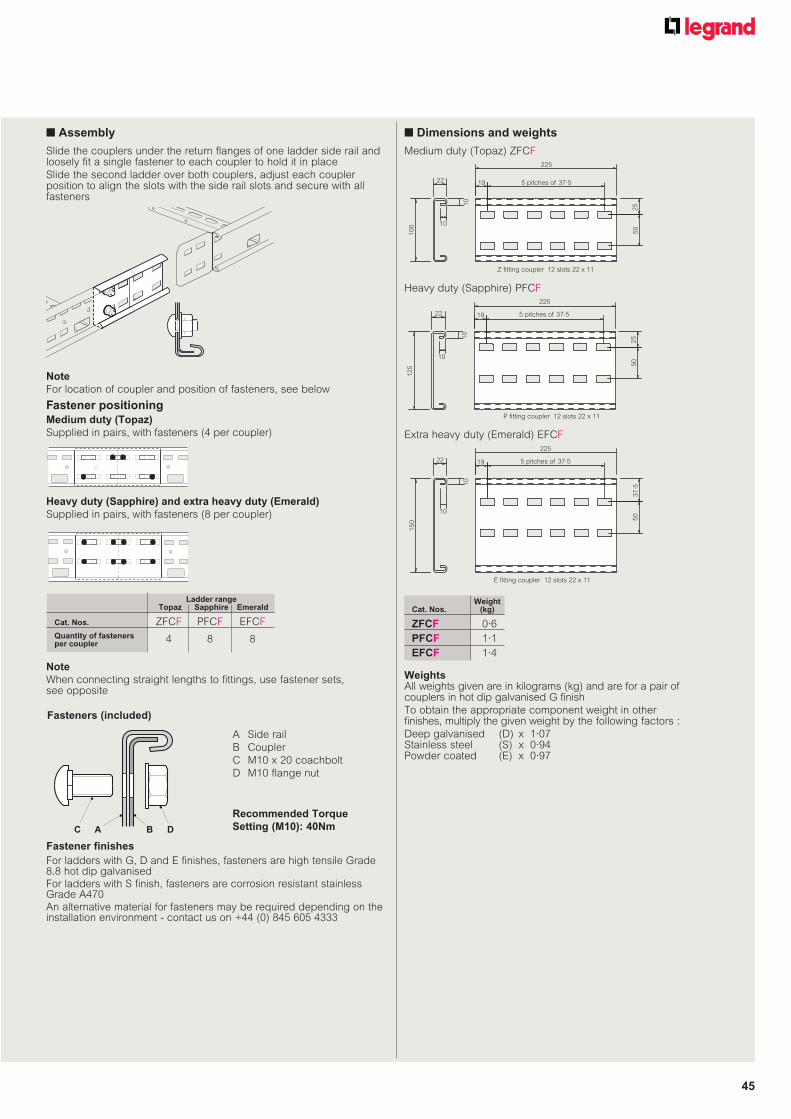
45
Fastener positioning
Slide the couplers under the return flanges of one ladder side rail and loosely fit a single fastener to each coupler to hold it in place
Slide the second ladder over both couplers, adjust each coupler position to align the slots with the side rail slots and secure with all fasteners
■ Assembly
Note
For location of coupler and position of fasteners, see below
Medium duty (Topaz)
Supplied in pairs, with fasteners (4 per coupler)
Note
When connecting straight lengths to fittings, use fastener sets, see opposite
Ladder range Topaz Sapphire Emerald
Cat. Nos. ZFCF PFCF EFCF
Quantity of fasteners per coupler 4 8 8
225
5 pitches of 37·5
P fitting coupler 12 slots 22 x 11
50
251
0
10
22
12
5
19
225
5 pitches of 37·5
Z fitting coupler 12 slots 22 x 11
50
251
0
10
22
10
0
19
225
5 pitches of 37·5
E fitting coupler 12 slots 22 x 11
50
37
·5
10
10
22
15
0
19
■ Dimensions and weights
Fasteners (included)
A Side rail
B Coupler
C M10 x 20 coachbolt
D M10 flange nut
Recommended Torque
Setting (M10): 40NmC A B D
Fastener finishes
For ladders with G, D and E finishes, fasteners are high tensile Grade 8.8 hot dip galvanisedFor ladders with S finish, fasteners are corrosion resistant stainless Grade A470An alternative material for fasteners may be required depending on the installation environment - contact us on +44 (0) 845 605 4333
WeightsAll weights given are in kilograms (kg) and are for a pair of couplers in hot dip galvanised G finish
To obtain the appropriate component weight in other finishes, multiply the given weight by the following factors :
Deep galvanised (D) x 1·07Stainless steel (S) x 0·94Powder coated (E) x 0·97
Medium duty (Topaz) ZFCF
Heavy duty (Sapphire) PFCF
Extra heavy duty (Emerald) EFCF
Heavy duty (Sapphire) and extra heavy duty (Emerald)
Supplied in pairs, with fasteners (8 per coupler)
WeightCat. Nos. (kg)
ZFCF 0·6
PFCF 1·1
EFCF 1·4
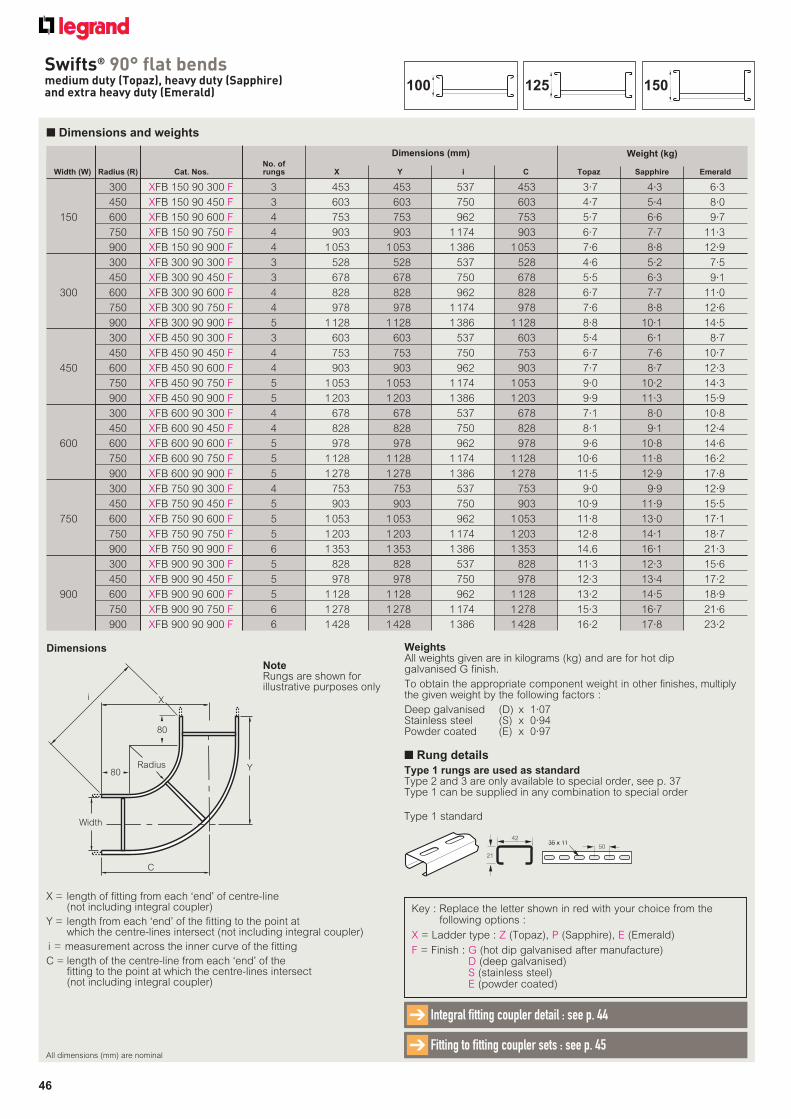
46
Swifts® 90° flat bendsmedium duty (Topaz), heavy duty (Sapphire) and extra heavy duty (Emerald)
WeightsAll weights given are in kilograms (kg) and are for hot dip galvanised G finish.
To obtain the appropriate component weight in other finishes, multiply the given weight by the following factors :
Deep galvanised (D) x 1·07Stainless steel (S) x 0·94Powder coated (E) x 0·97
No. of Width (W) Radius (R) Cat. Nos. rungs X Y i C Topaz Sapphire Emerald
300 XFB 150 90 300 F 3 453 453 537 453 3·7 4·3 6·3
450 XFB 150 90 450 F 3 603 603 750 603 4·7 5·4 8·0
150 600 XFB 150 90 600 F 4 753 753 962 753 5·7 6·6 9·7
750 XFB 150 90 750 F 4 903 903 1 174 903 6·7 7·7 11·3
900 XFB 150 90 900 F 4 1 053 1 053 1 386 1 053 7·6 8·8 12·9
300 XFB 300 90 300 F 3 528 528 537 528 4·6 5·2 7·5
450 XFB 300 90 450 F 3 678 678 750 678 5·5 6·3 9·1
300 600 XFB 300 90 600 F 4 828 828 962 828 6·7 7·7 11·0
750 XFB 300 90 750 F 4 978 978 1 174 978 7·6 8·8 12·6
900 XFB 300 90 900 F 5 1 128 1 128 1 386 1 128 8·8 10·1 14·5
300 XFB 450 90 300 F 3 603 603 537 603 5·4 6·1 8·7
450 XFB 450 90 450 F 4 753 753 750 753 6·7 7·6 10·7
450 600 XFB 450 90 600 F 4 903 903 962 903 7·7 8·7 12·3
750 XFB 450 90 750 F 5 1 053 1 053 1 174 1 053 9·0 10·2 14·3
900 XFB 450 90 900 F 5 1 203 1 203 1 386 1 203 9·9 11·3 15·9
300 XFB 600 90 300 F 4 678 678 537 678 7·1 8·0 10·8
450 XFB 600 90 450 F 4 828 828 750 828 8·1 9·1 12·4
600 600 XFB 600 90 600 F 5 978 978 962 978 9·6 10·8 14·6
750 XFB 600 90 750 F 5 1 128 1 128 1 174 1 128 10·6 11·8 16·2
900 XFB 600 90 900 F 5 1 278 1 278 1 386 1 278 11·5 12·9 17·8
300 XFB 750 90 300 F 4 753 753 537 753 9·0 9·9 12·9
450 XFB 750 90 450 F 5 903 903 750 903 10·9 11·9 15·5
750 600 XFB 750 90 600 F 5 1 053 1 053 962 1 053 11·8 13·0 17·1
750 XFB 750 90 750 F 5 1 203 1 203 1 174 1 203 12·8 14·1 18·7
900 XFB 750 90 900 F 6 1 353 1 353 1 386 1 353 14.6 16·1 21·3
300 XFB 900 90 300 F 5 828 828 537 828 11·3 12·3 15·6
450 XFB 900 90 450 F 5 978 978 750 978 12·3 13·4 17·2
900 600 XFB 900 90 600 F 5 1 128 1 128 962 1 128 13·2 14·5 18·9
750 XFB 900 90 750 F 6 1 278 1 278 1 174 1 278 15·3 16·7 21·6
900 XFB 900 90 900 F 6 1 428 1 428 1 386 1 428 16·2 17·8 23·2
Weight (kg)
■ Dimensions and weights
X = length of fitting from each ‘end’ of centre-line (not including integral coupler)
Y = length from each ‘end’ of the fitting to the point at which the centre-lines intersect (not including integral coupler)
i = measurement across the inner curve of the fitting
C = length of the centre-line from each ‘end’ of the fitting to the point at which the centre-lines intersect (not including integral coupler)
Dimensions
Key : Replace the letter shown in red with your choice from the following options :
X = Ladder type : Z (Topaz), P (Sapphire), E (Emerald)
F = Finish : G (hot dip galvanised after manufacture)D (deep galvanised)S (stainless steel)E (powder coated)
Dimensions (mm)
All dimensions (mm) are nominal
Integral fitting coupler detail : see p. 44➔
Fitting to fitting coupler sets : see p. 45➔
■ Rung details
Type 1 rungs are used as standardType 2 and 3 are only available to special order, see p. 37Type 1 can be supplied in any combination to special order
42
21
35 x 1135 x 1150
Type 1 standard
X
C
Width
YRadius
80
i
80
NoteRungs are shown for illustrative purposes only
150125100
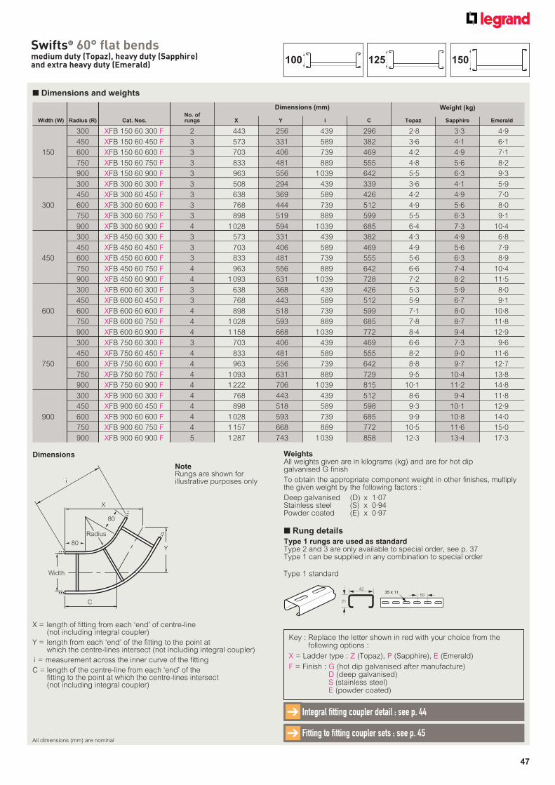
47
Swifts® 60° flat bendsmedium duty (Topaz), heavy duty (Sapphire) and extra heavy duty (Emerald)
No. of Width (W) Radius (R) Cat. Nos. rungs X Y i C Topaz Sapphire Emerald
300 XFB 150 60 300 F 2 443 256 439 296 2·8 3·3 4·9
450 XFB 150 60 450 F 3 573 331 589 382 3·6 4·1 6·1
150 600 XFB 150 60 600 F 3 703 406 739 469 4·2 4·9 7·1
750 XFB 150 60 750 F 3 833 481 889 555 4·8 5·6 8·2
900 XFB 150 60 900 F 3 963 556 1 039 642 5·5 6·3 9·3
300 XFB 300 60 300 F 3 508 294 439 339 3·6 4·1 5·9
450 XFB 300 60 450 F 3 638 369 589 426 4·2 4·9 7·0
300 600 XFB 300 60 600 F 3 768 444 739 512 4·9 5·6 8·0
750 XFB 300 60 750 F 3 898 519 889 599 5·5 6·3 9·1
900 XFB 300 60 900 F 4 1 028 594 1 039 685 6·4 7·3 10·4
300 XFB 450 60 300 F 3 573 331 439 382 4·3 4·9 6·8
450 XFB 450 60 450 F 3 703 406 589 469 4·9 5·6 7·9
450 600 XFB 450 60 600 F 3 833 481 739 555 5·6 6·3 8·9
750 XFB 450 60 750 F 4 963 556 889 642 6·6 7·4 10·4
900 XFB 450 60 900 F 4 1 093 631 1 039 728 7·2 8·2 11·5
300 XFB 600 60 300 F 3 638 368 439 426 5·3 5·9 8·0
450 XFB 600 60 450 F 3 768 443 589 512 5·9 6·7 9·1
600 600 XFB 600 60 600 F 4 898 518 739 599 7·1 8·0 10·8
750 XFB 600 60 750 F 4 1 028 593 889 685 7·8 8·7 11·8
900 XFB 600 60 900 F 4 1 158 668 1 039 772 8·4 9·4 12·9
300 XFB 750 60 300 F 3 703 406 439 469 6·6 7·3 9·6
450 XFB 750 60 450 F 4 833 481 589 555 8·2 9·0 11·6
750 600 XFB 750 60 600 F 4 963 556 739 642 8·8 9·7 12·7
750 XFB 750 60 750 F 4 1 093 631 889 729 9·5 10·4 13·8
900 XFB 750 60 900 F 4 1 222 706 1 039 815 10·1 11·2 14·8
300 XFB 900 60 300 F 4 768 443 439 512 8·6 9·4 11·8
450 XFB 900 60 450 F 4 898 518 589 598 9·3 10·1 12·9
900 600 XFB 900 60 600 F 4 1 028 593 739 685 9·9 10·8 14·0
750 XFB 900 60 750 F 4 1 157 668 889 772 10·5 11·6 15·0
900 XFB 900 60 900 F 5 1 287 743 1 039 858 12·3 13·4 17·3
Weight (kg)
■ Dimensions and weights
X = length of fitting from each ‘end’ of centre-line (not including integral coupler)
Y = length from each ‘end’ of the fitting to the point at which the centre-lines intersect (not including integral coupler)
i = measurement across the inner curve of the fitting
C = length of the centre-line from each ‘end’ of the fitting to the point at which the centre-lines intersect (not including integral coupler)
Dimensions
Key : Replace the letter shown in red with your choice from the following options :
X = Ladder type : Z (Topaz), P (Sapphire), E (Emerald)
F = Finish : G (hot dip galvanised after manufacture)D (deep galvanised)S (stainless steel)E (powder coated)
Dimensions (mm)
WeightsAll weights given are in kilograms (kg) and are for hot dip galvanised G finish
To obtain the appropriate component weight in other finishes, multiply the given weight by the following factors :
Deep galvanised (D) x 1·07Stainless steel (S) x 0·94Powder coated (E) x 0·97
All dimensions (mm) are nominal
Integral fitting coupler detail : see p. 44➔
Fitting to fitting coupler sets : see p. 45➔
X
Radius
C
Width
Y
80
i
80
NoteRungs are shown for illustrative purposes only
150125100
■ Rung details
Type 1 rungs are used as standardType 2 and 3 are only available to special order, see p. 37Type 1 can be supplied in any combination to special order
42
21
35 x 1135 x 1150
Type 1 standard
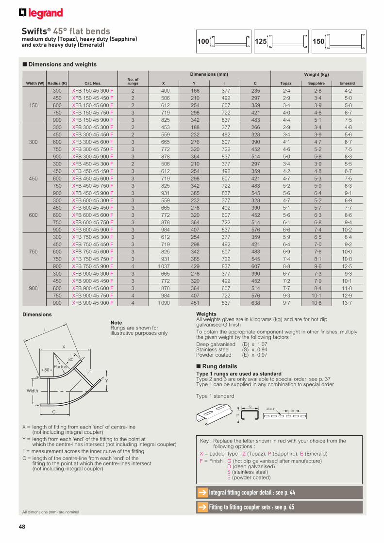
48
Swifts® 45° flat bendsmedium duty (Topaz), heavy duty (Sapphire) and extra heavy duty (Emerald)
No. of Width (W) Radius (R) Cat. Nos. rungs X Y i C Topaz Sapphire Emerald
300 XFB 150 45 300 F 2 400 166 377 235 2·4 2·8 4·2
450 XFB 150 45 450 F 2 506 210 492 297 2·9 3·4 5·0
150 600 XFB 150 45 600 F 2 612 254 607 359 3·4 3·9 5·8
750 XFB 150 45 750 F 3 719 298 722 421 4·0 4·6 6·7
900 XFB 150 45 900 F 3 825 342 837 483 4·4 5·1 7·5
300 XFB 300 45 300 F 2 453 188 377 266 2·9 3·4 4·8
450 XFB 300 45 450 F 2 559 232 492 328 3·4 3·9 5·6
300 600 XFB 300 45 600 F 3 665 276 607 390 4·1 4·7 6·7
750 XFB 300 45 750 F 3 772 320 722 452 4·6 5·2 7·5
900 XFB 300 45 900 F 3 878 364 837 514 5·0 5·8 8·3
300 XFB 450 45 300 F 2 506 210 377 297 3·4 3·9 5·5
450 XFB 450 45 450 F 3 612 254 492 359 4·2 4·8 6·7
450 600 XFB 450 45 600 F 3 719 298 607 421 4·7 5·3 7·5
750 XFB 450 45 750 F 3 825 342 722 483 5·2 5·9 8·3
900 XFB 450 45 900 F 3 931 385 837 545 5·6 6·4 9·1
300 XFB 600 45 300 F 3 559 232 377 328 4·7 5·2 6·9
450 XFB 600 45 450 F 3 665 276 492 390 5·1 5·7 7·7
600 600 XFB 600 45 600 F 3 772 320 607 452 5·6 6·3 8·6
750 XFB 600 45 750 F 3 878 364 722 514 6·1 6·8 9·4
900 XFB 600 45 900 F 3 984 407 837 576 6·6 7·4 10·2
300 XFB 750 45 300 F 3 612 254 377 359 5·9 6·5 8·4
450 XFB 750 45 450 F 3 719 298 492 421 6·4 7·0 9·2
750 600 XFB 750 45 600 F 3 825 342 607 483 6·9 7·6 10·0
750 XFB 750 45 750 F 3 931 385 722 545 7·4 8·1 10·8
900 XFB 750 45 900 F 4 1 037 429 837 607 8·8 9·6 12·5
300 XFB 900 45 300 F 3 665 276 377 390 6·7 7·3 9·3
450 XFB 900 45 450 F 3 772 320 492 452 7·2 7·9 10·1
900 600 XFB 900 45 600 F 3 878 364 607 514 7·7 8·4 11·0
750 XFB 900 45 750 F 4 984 407 722 576 9·3 10·1 12·9
900 XFB 900 45 900 F 4 1 090 451 837 638 9·7 10·6 13·7
Weight (kg)
■ Dimensions and weights
X = length of fitting from each ‘end’ of centre-line (not including integral coupler)
Y = length from each ‘end’ of the fitting to the point at which the centre-lines intersect (not including integral coupler)
i = measurement across the inner curve of the fitting
C = length of the centre-line from each ‘end’ of the fitting to the point at which the centre-lines intersect (not including integral coupler)
Dimensions
Key : Replace the letter shown in red with your choice from the following options :
X = Ladder type : Z (Topaz), P (Sapphire), E (Emerald)
F = Finish : G (hot dip galvanised after manufacture)D (deep galvanised)S (stainless steel)E (powder coated)
Dimensions (mm)
X
Radius
C
Width
Y
80
i
80
WeightsAll weights given are in kilograms (kg) and are for hot dip galvanised G finish
To obtain the appropriate component weight in other finishes, multiply the given weight by the following factors :
Deep galvanised (D) x 1·07Stainless steel (S) x 0·94Powder coated (E) x 0·97
All dimensions (mm) are nominal
Integral fitting coupler detail : see p. 44➔
Fitting to fitting coupler sets : see p. 45➔
NoteRungs are shown for illustrative purposes only
150125100
■ Rung details
Type 1 rungs are used as standardType 2 and 3 are only available to special order, see p. 37Type 1 can be supplied in any combination to special order
42
21
35 x 1135 x 1150
Type 1 standard
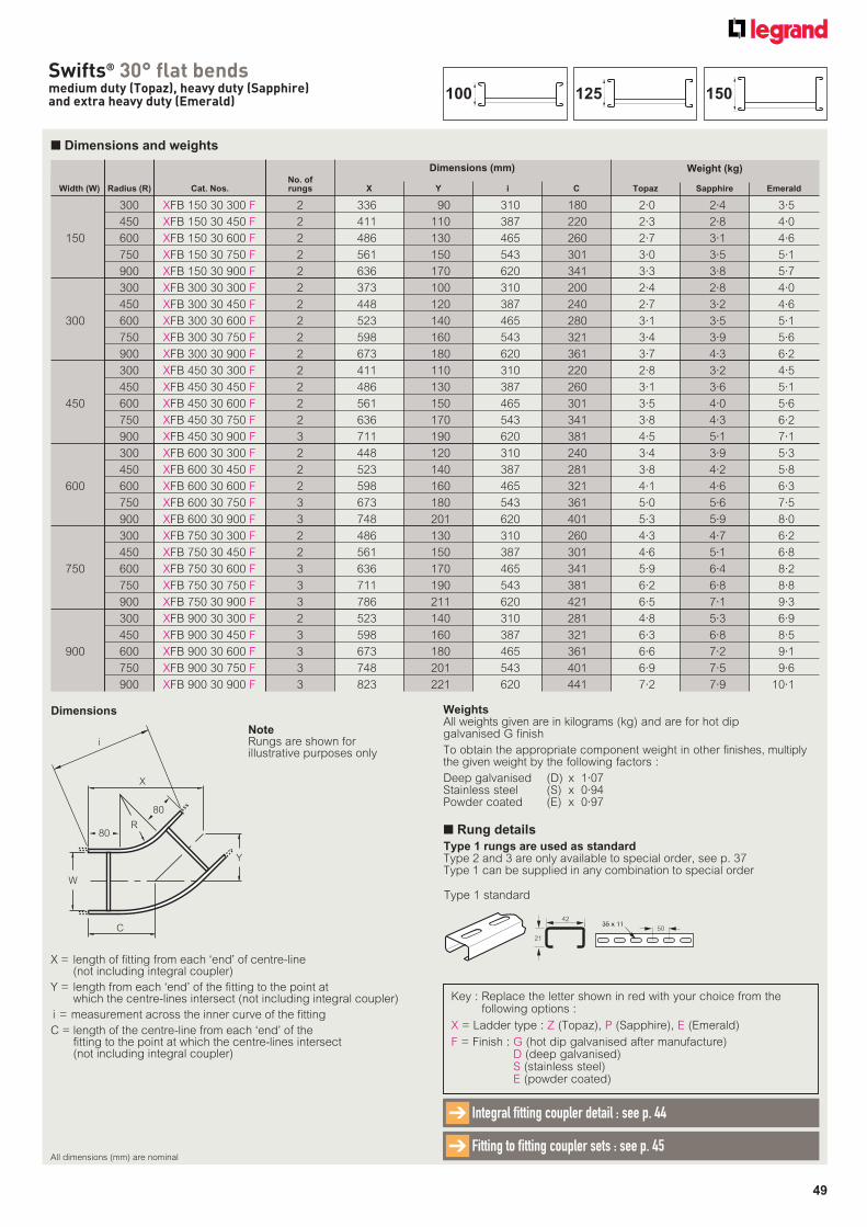
49
Swifts® 30° flat bendsmedium duty (Topaz), heavy duty (Sapphire) and extra heavy duty (Emerald)
No. of Width (W) Radius (R) Cat. Nos. rungs X Y i C Topaz Sapphire Emerald
300 XFB 150 30 300 F 2 336 90 310 180 2·0 2·4 3·5
450 XFB 150 30 450 F 2 411 110 387 220 2·3 2·8 4·0
150 600 XFB 150 30 600 F 2 486 130 465 260 2·7 3·1 4·6
750 XFB 150 30 750 F 2 561 150 543 301 3·0 3·5 5·1
900 XFB 150 30 900 F 2 636 170 620 341 3·3 3·8 5·7
300 XFB 300 30 300 F 2 373 100 310 200 2·4 2·8 4·0
450 XFB 300 30 450 F 2 448 120 387 240 2·7 3·2 4·6
300 600 XFB 300 30 600 F 2 523 140 465 280 3·1 3·5 5·1
750 XFB 300 30 750 F 2 598 160 543 321 3·4 3·9 5·6
900 XFB 300 30 900 F 2 673 180 620 361 3·7 4·3 6·2
300 XFB 450 30 300 F 2 411 110 310 220 2·8 3·2 4·5
450 XFB 450 30 450 F 2 486 130 387 260 3·1 3·6 5·1
450 600 XFB 450 30 600 F 2 561 150 465 301 3·5 4·0 5·6
750 XFB 450 30 750 F 2 636 170 543 341 3·8 4·3 6·2
900 XFB 450 30 900 F 3 711 190 620 381 4·5 5·1 7·1
300 XFB 600 30 300 F 2 448 120 310 240 3·4 3·9 5·3
450 XFB 600 30 450 F 2 523 140 387 281 3·8 4·2 5·8
600 600 XFB 600 30 600 F 2 598 160 465 321 4·1 4·6 6·3
750 XFB 600 30 750 F 3 673 180 543 361 5·0 5·6 7·5
900 XFB 600 30 900 F 3 748 201 620 401 5·3 5·9 8·0
300 XFB 750 30 300 F 2 486 130 310 260 4·3 4·7 6·2
450 XFB 750 30 450 F 2 561 150 387 301 4·6 5·1 6·8
750 600 XFB 750 30 600 F 3 636 170 465 341 5·9 6·4 8·2
750 XFB 750 30 750 F 3 711 190 543 381 6·2 6·8 8·8
900 XFB 750 30 900 F 3 786 211 620 421 6·5 7·1 9·3
300 XFB 900 30 300 F 2 523 140 310 281 4·8 5·3 6·9
450 XFB 900 30 450 F 3 598 160 387 321 6·3 6·8 8·5
900 600 XFB 900 30 600 F 3 673 180 465 361 6·6 7·2 9·1
750 XFB 900 30 750 F 3 748 201 543 401 6·9 7·5 9·6
900 XFB 900 30 900 F 3 823 221 620 441 7·2 7·9 10·1
Weight (kg)
■ Dimensions and weights
X = length of fitting from each ‘end’ of centre-line (not including integral coupler)
Y = length from each ‘end’ of the fitting to the point at which the centre-lines intersect (not including integral coupler)
i = measurement across the inner curve of the fitting
C = length of the centre-line from each ‘end’ of the fitting to the point at which the centre-lines intersect (not including integral coupler)
Dimensions
Key : Replace the letter shown in red with your choice from the following options :
X = Ladder type : Z (Topaz), P (Sapphire), E (Emerald)
F = Finish : G (hot dip galvanised after manufacture)D (deep galvanised)S (stainless steel)E (powder coated)
Dimensions (mm)
X
R
C
W
Y
80
i
80
WeightsAll weights given are in kilograms (kg) and are for hot dip galvanised G finish
To obtain the appropriate component weight in other finishes, multiply the given weight by the following factors :
Deep galvanised (D) x 1·07Stainless steel (S) x 0·94Powder coated (E) x 0·97
All dimensions (mm) are nominal
Integral fitting coupler detail : see p. 44➔
Fitting to fitting coupler sets : see p. 45➔
NoteRungs are shown for illustrative purposes only
150125100
■ Rung details
Type 1 rungs are used as standardType 2 and 3 are only available to special order, see p. 37Type 1 can be supplied in any combination to special order
42
21
35 x 1135 x 1150
Type 1 standard
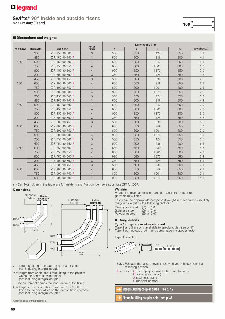
50
Swifts® 90° inside and outside risersmedium duty (Topaz)
■ Dimensions and weights
X = length of fitting from each ‘end’ of centre-line (not including integral coupler)
Y = length from each ‘end’ of the fitting to the point at which the centre-lines intersect (not including integral coupler)
i = measurement across the inner curve of the fitting
C = length of the centre-line from each ‘end’ of the fitting to the point at which the centre-lines intersect (not including integral coupler)
Dimensions
Key : Replace the letter shown in red with your choice from the following options :
F = Finish : G (hot dip galvanised after manufacture)D (deep galvanised)S (stainless steel)E (powder coated)
No. of Width (W) Radius (R) Cat. Nos.(1) rungs X Y i C
300 ZIR 150 90 300 F 3 350 350 424 350 3·1
450 ZIR 150 90 450 F 3 500 500 636 500 4·1
150 600 ZIR 150 90 600 F 4 650 650 849 650 5·1
750 ZIR 150 90 750 F 4 800 800 1 061 800 6·0
900 ZIR 150 90 900 F 4 950 950 1 273 950 7·0
300 ZIR 300 90 300 F 3 350 350 424 350 3·5
450 ZIR 300 90 450 F 3 500 500 636 500 4·5
300 600 ZIR 300 90 600 F 4 650 650 849 650 5·6
750 ZIR 300 90 750 F 4 800 800 1 061 800 6·5
900 ZIR 300 90 900 F 4 950 950 1 273 950 7·5
300 ZIR 450 90 300 F 3 350 350 424 350 3·8
450 ZIR 450 90 450 F 3 500 500 636 500 4·8
450 600 ZIR 450 90 600 F 4 650 650 849 650 6·0
750 ZIR 450 90 750 F 4 800 800 1 061 800 7·0
900 ZIR 450 90 900 F 4 950 950 1 273 950 8·0
300 ZIR 600 90 300 F 3 350 350 424 350 4·5
450 ZIR 600 90 450 F 3 500 500 636 500 5·5
600 600 ZIR 600 90 600 F 4 650 650 849 650 7·0
750 ZIR 600 90 750 F 4 800 800 1 061 800 7·9
900 ZIR 600 90 900 F 4 950 950 1 273 950 8·9
300 ZIR 750 90 300 F 3 350 350 424 350 5·5
450 ZIR 750 90 450 F 3 500 500 636 500 6·5
750 600 ZIR 750 90 600 F 4 650 650 849 650 8·3
750 ZIR 750 90 750 F 4 800 800 1 061 800 9·3
900 ZIR 750 90 900 F 4 950 950 1 273 950 10·3
300 ZIR 900 90 300 F 3 350 350 424 350 6·1
450 ZIR 900 90 450 F 3 500 500 636 500 7·1
900 600 ZIR 900 90 600 F 4 650 650 849 650 9·1
750 ZIR 900 90 750 F 4 800 800 1 061 800 10·1
900 ZIR 900 90 900 F 4 950 950 1 273 950 11·0
Weight (kg)
Dimensions (mm)
(1) Cat. Nos. given in the table are for inside risers. For outside risers substitute ZIR for ZOR
X,C
Y
R300
R450
3 sidesegments
Nominal radius
X,C
R600
R750
R900
Y
4 sidesegments
Nominal radius
i
WeightsAll weights given are in kilograms (kg) and are for hot dip galvanised G finish
To obtain the appropriate component weight in other finishes, multiply the given weight by the following factors :
Deep galvanised (D) x 1·07Stainless steel (S) x 0·94Powder coated (E) x 0·97
All dimensions (mm) are nominal
Integral fitting coupler detail : see p. 44➔
Fitting to fitting coupler sets : see p. 45➔
■ Rung details
Type 1 rungs are used as standardType 2 and 3 are only available to special order, see p. 37Type 1 can be supplied in any combination to special order
42
21
35 x 1135 x 1150
Type 1 standard
100
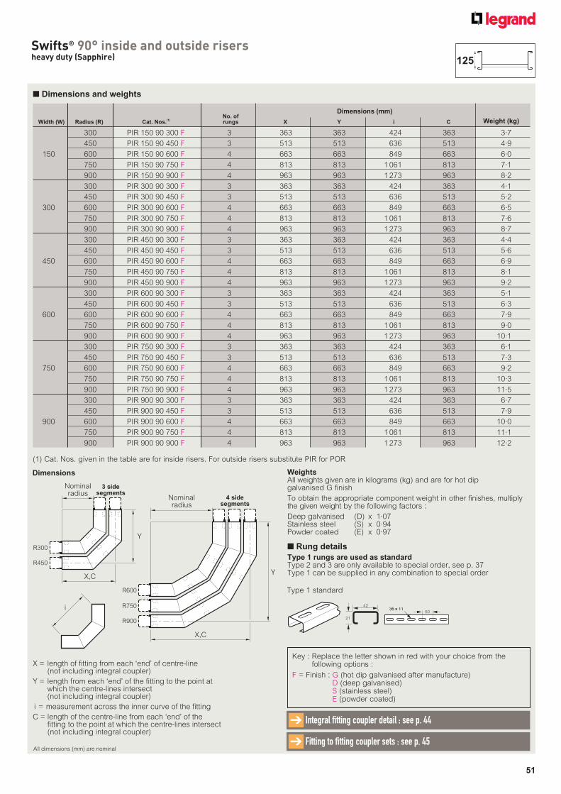
51
Swifts® 90° inside and outside risersheavy duty (Sapphire)
■ Dimensions and weights
No. of Width (W) Radius (R) Cat. Nos.
(1) rungs X Y i C
300 PIR 150 90 300 F 3 363 363 424 363 3·7
450 PIR 150 90 450 F 3 513 513 636 513 4·9
150 600 PIR 150 90 600 F 4 663 663 849 663 6·0
750 PIR 150 90 750 F 4 813 813 1 061 813 7·1
900 PIR 150 90 900 F 4 963 963 1 273 963 8·2
300 PIR 300 90 300 F 3 363 363 424 363 4·1
450 PIR 300 90 450 F 3 513 513 636 513 5·2
300 600 PIR 300 90 600 F 4 663 663 849 663 6·5
750 PIR 300 90 750 F 4 813 813 1 061 813 7·6
900 PIR 300 90 900 F 4 963 963 1 273 963 8·7
300 PIR 450 90 300 F 3 363 363 424 363 4·4
450 PIR 450 90 450 F 3 513 513 636 513 5·6
450 600 PIR 450 90 600 F 4 663 663 849 663 6·9
750 PIR 450 90 750 F 4 813 813 1 061 813 8·1
900 PIR 450 90 900 F 4 963 963 1 273 963 9·2
300 PIR 600 90 300 F 3 363 363 424 363 5·1
450 PIR 600 90 450 F 3 513 513 636 513 6·3
600 600 PIR 600 90 600 F 4 663 663 849 663 7·9
750 PIR 600 90 750 F 4 813 813 1 061 813 9·0
900 PIR 600 90 900 F 4 963 963 1 273 963 10·1
300 PIR 750 90 300 F 3 363 363 424 363 6·1
450 PIR 750 90 450 F 3 513 513 636 513 7·3
750 600 PIR 750 90 600 F 4 663 663 849 663 9·2
750 PIR 750 90 750 F 4 813 813 1 061 813 10·3
900 PIR 750 90 900 F 4 963 963 1 273 963 11·5
300 PIR 900 90 300 F 3 363 363 424 363 6·7
450 PIR 900 90 450 F 3 513 513 636 513 7·9
900 600 PIR 900 90 600 F 4 663 663 849 663 10·0
750 PIR 900 90 750 F 4 813 813 1 061 813 11·1
900 PIR 900 90 900 F 4 963 963 1 273 963 12·2
Weight (kg)
Dimensions (mm)
(1) Cat. Nos. given in the table are for inside risers. For outside risers substitute PIR for POR
X = length of fitting from each ‘end’ of centre-line (not including integral coupler)
Y = length from each ‘end’ of the fitting to the point at which the centre-lines intersect (not including integral coupler)
i = measurement across the inner curve of the fitting
C = length of the centre-line from each ‘end’ of the fitting to the point at which the centre-lines intersect (not including integral coupler)
Dimensions
X,C
R600
R750
R900
Y
4 sidesegments
Nominalradius
X,C
Y
R300
R450
3 sidesegments
Nominalradius
Key : Replace the letter shown in red with your choice from the following options :
F = Finish : G (hot dip galvanised after manufacture)D (deep galvanised)S (stainless steel)E (powder coated)
i
WeightsAll weights given are in kilograms (kg) and are for hot dip galvanised G finish
To obtain the appropriate component weight in other finishes, multiply the given weight by the following factors :
Deep galvanised (D) x 1·07Stainless steel (S) x 0·94Powder coated (E) x 0·97
All dimensions (mm) are nominal
Integral fitting coupler detail : see p. 44➔
Fitting to fitting coupler sets : see p. 45➔
125
■ Rung details
Type 1 rungs are used as standardType 2 and 3 are only available to special order, see p. 37Type 1 can be supplied in any combination to special order
42
21
35 x 1135 x 1150
Type 1 standard
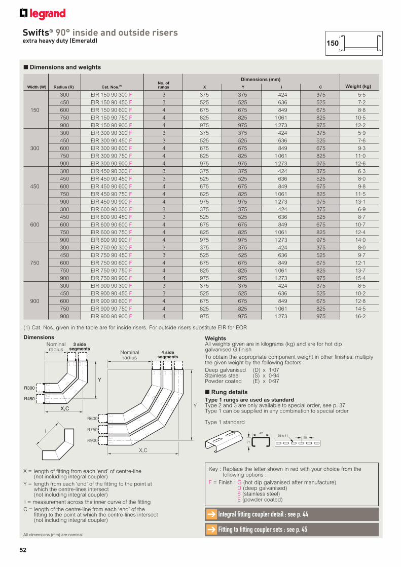
52
Swifts® 90° inside and outside risersextra heavy duty (Emerald)
■ Dimensions and weights
No. of Width (W) Radius (R) Cat. Nos.
(1) rungs X Y i C
300 EIR 150 90 300 F 3 375 375 424 375 5·5
450 EIR 150 90 450 F 3 525 525 636 525 7·2
150 600 EIR 150 90 600 F 4 675 675 849 675 8·8
750 EIR 150 90 750 F 4 825 825 1 061 825 10·5
900 EIR 150 90 900 F 4 975 975 1 273 975 12·2
300 EIR 300 90 300 F 3 375 375 424 375 5·9
450 EIR 300 90 450 F 3 525 525 636 525 7·6
300 600 EIR 300 90 600 F 4 675 675 849 675 9·3
750 EIR 300 90 750 F 4 825 825 1 061 825 11·0
900 EIR 300 90 900 F 4 975 975 1 273 975 12·6
300 EIR 450 90 300 F 3 375 375 424 375 6·3
450 EIR 450 90 450 F 3 525 525 636 525 8·0
450 600 EIR 450 90 600 F 4 675 675 849 675 9·8
750 EIR 450 90 750 F 4 825 825 1 061 825 11·5
900 EIR 450 90 900 F 4 975 975 1 273 975 13·1
300 EIR 600 90 300 F 3 375 375 424 375 6·9
450 EIR 600 90 450 F 3 525 525 636 525 8·7
600 600 EIR 600 90 600 F 4 675 675 849 675 10·7
750 EIR 600 90 750 F 4 825 825 1 061 825 12·4
900 EIR 600 90 900 F 4 975 975 1 273 975 14·0
300 EIR 750 90 300 F 3 375 375 424 375 8·0
450 EIR 750 90 450 F 3 525 525 636 525 9·7
750 600 EIR 750 90 600 F 4 675 675 849 675 12·1
750 EIR 750 90 750 F 4 825 825 1 061 825 13·7
900 EIR 750 90 900 F 4 975 975 1 273 975 15·4
300 EIR 900 90 300 F 3 375 375 424 375 8·5
450 EIR 900 90 450 F 3 525 525 636 525 10·2
900 600 EIR 900 90 600 F 4 675 675 849 675 12·8
750 EIR 900 90 750 F 4 825 825 1 061 825 14·5
900 EIR 900 90 900 F 4 975 975 1 273 975 16·2
Weight (kg)
Dimensions (mm)
Key : Replace the letter shown in red with your choice from the following options :
F = Finish : G (hot dip galvanised after manufacture)D (deep galvanised)S (stainless steel)E (powder coated)
X = length of fitting from each ‘end’ of centre-line (not including integral coupler)
Y = length from each ‘end’ of the fitting to the point at which the centre-lines intersect (not including integral coupler)
i = measurement across the inner curve of the fitting
C = length of the centre-line from each ‘end’ of the fitting to the point at which the centre-lines intersect (not including integral coupler)
Dimensions
X,C
R600
R750
R900
Y
4 sidesegments
Nominalradius
X,C
Y
R300
R450
3 sidesegments
Nominalradius
i
(1) Cat. Nos. given in the table are for inside risers. For outside risers substitute EIR for EOR
WeightsAll weights given are in kilograms (kg) and are for hot dip galvanised G finish
To obtain the appropriate component weight in other finishes, multiply the given weight by the following factors :
Deep galvanised (D) x 1·07Stainless steel (S) x 0·94Powder coated (E) x 0·97
All dimensions (mm) are nominal
Integral fitting coupler detail : see p. 44➔
Fitting to fitting coupler sets : see p. 45➔
150
■ Rung details
Type 1 rungs are used as standardType 2 and 3 are only available to special order, see p. 37Type 1 can be supplied in any combination to special order
42
21
35 x 1135 x 1150
Type 1 standard
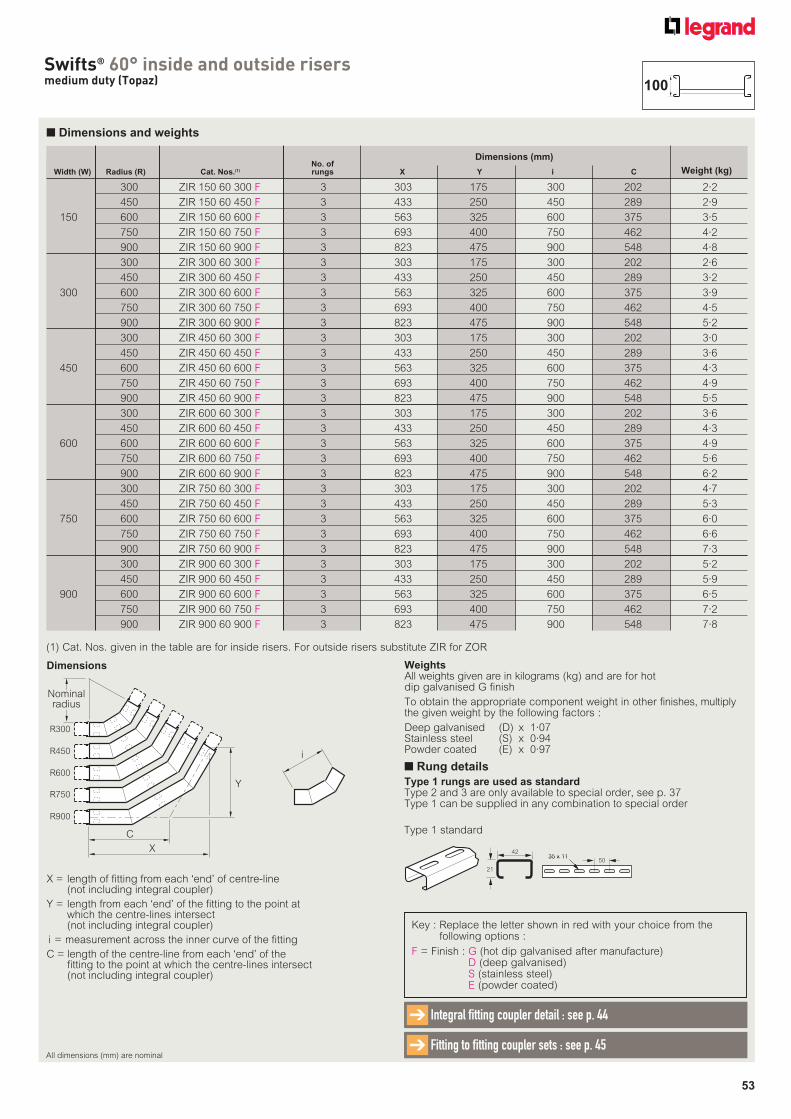
53
Swifts® 60° inside and outside risersmedium duty (Topaz)
■ Dimensions and weights
X = length of fitting from each ‘end’ of centre-line (not including integral coupler)
Y = length from each ‘end’ of the fitting to the point at which the centre-lines intersect (not including integral coupler)
i = measurement across the inner curve of the fitting
C = length of the centre-line from each ‘end’ of the fitting to the point at which the centre-lines intersect (not including integral coupler)
Dimensions
Key : Replace the letter shown in red with your choice from the following options :
F = Finish : G (hot dip galvanised after manufacture)D (deep galvanised)S (stainless steel)E (powder coated)
No. of Width (W) Radius (R) Cat. Nos.(1) rungs X Y i C
300 ZIR 150 60 300 F 3 303 175 300 202 2·2
450 ZIR 150 60 450 F 3 433 250 450 289 2·9
150 600 ZIR 150 60 600 F 3 563 325 600 375 3·5
750 ZIR 150 60 750 F 3 693 400 750 462 4·2
900 ZIR 150 60 900 F 3 823 475 900 548 4·8
300 ZIR 300 60 300 F 3 303 175 300 202 2·6
450 ZIR 300 60 450 F 3 433 250 450 289 3·2
300 600 ZIR 300 60 600 F 3 563 325 600 375 3·9
750 ZIR 300 60 750 F 3 693 400 750 462 4·5
900 ZIR 300 60 900 F 3 823 475 900 548 5·2
300 ZIR 450 60 300 F 3 303 175 300 202 3·0
450 ZIR 450 60 450 F 3 433 250 450 289 3·6
450 600 ZIR 450 60 600 F 3 563 325 600 375 4·3
750 ZIR 450 60 750 F 3 693 400 750 462 4·9
900 ZIR 450 60 900 F 3 823 475 900 548 5·5
300 ZIR 600 60 300 F 3 303 175 300 202 3·6
450 ZIR 600 60 450 F 3 433 250 450 289 4·3
600 600 ZIR 600 60 600 F 3 563 325 600 375 4·9
750 ZIR 600 60 750 F 3 693 400 750 462 5·6
900 ZIR 600 60 900 F 3 823 475 900 548 6·2
300 ZIR 750 60 300 F 3 303 175 300 202 4·7
450 ZIR 750 60 450 F 3 433 250 450 289 5·3
750 600 ZIR 750 60 600 F 3 563 325 600 375 6·0
750 ZIR 750 60 750 F 3 693 400 750 462 6·6
900 ZIR 750 60 900 F 3 823 475 900 548 7·3
300 ZIR 900 60 300 F 3 303 175 300 202 5·2
450 ZIR 900 60 450 F 3 433 250 450 289 5·9
900 600 ZIR 900 60 600 F 3 563 325 600 375 6·5
750 ZIR 900 60 750 F 3 693 400 750 462 7·2
900 ZIR 900 60 900 F 3 823 475 900 548 7·8
Weight (kg)
Dimensions (mm)
(1) Cat. Nos. given in the table are for inside risers. For outside risers substitute ZIR for ZOR
R300
R450
R900
R600
R750
C
X
Y
Nominalradius
i
WeightsAll weights given are in kilograms (kg) and are for hot dip galvanised G finish
To obtain the appropriate component weight in other finishes, multiply the given weight by the following factors :
Deep galvanised (D) x 1·07Stainless steel (S) x 0·94Powder coated (E) x 0·97
All dimensions (mm) are nominal
Integral fitting coupler detail : see p. 44➔
Fitting to fitting coupler sets : see p. 45➔
100
■ Rung details
Type 1 rungs are used as standardType 2 and 3 are only available to special order, see p. 37Type 1 can be supplied in any combination to special order
42
21
35 x 1135 x 1150
Type 1 standard
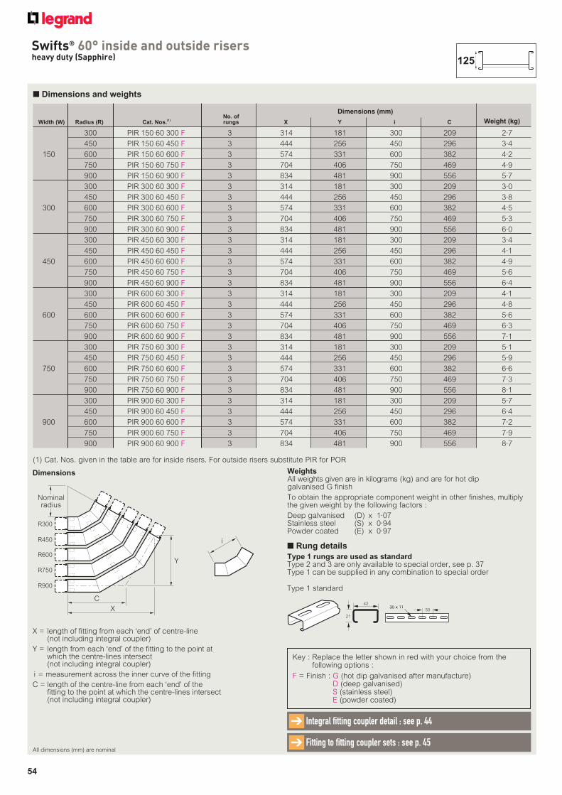
54
Swifts® 60° inside and outside risersheavy duty (Sapphire)
■ Dimensions and weights
No. of Width (W) Radius (R) Cat. Nos.
(1) rungs X Y i C
300 PIR 150 60 300 F 3 314 181 300 209 2·7
450 PIR 150 60 450 F 3 444 256 450 296 3·4
150 600 PIR 150 60 600 F 3 574 331 600 382 4·2
750 PIR 150 60 750 F 3 704 406 750 469 4·9
900 PIR 150 60 900 F 3 834 481 900 556 5·7
300 PIR 300 60 300 F 3 314 181 300 209 3·0
450 PIR 300 60 450 F 3 444 256 450 296 3·8
300 600 PIR 300 60 600 F 3 574 331 600 382 4·5
750 PIR 300 60 750 F 3 704 406 750 469 5·3
900 PIR 300 60 900 F 3 834 481 900 556 6·0
300 PIR 450 60 300 F 3 314 181 300 209 3·4
450 PIR 450 60 450 F 3 444 256 450 296 4·1
450 600 PIR 450 60 600 F 3 574 331 600 382 4·9
750 PIR 450 60 750 F 3 704 406 750 469 5·6
900 PIR 450 60 900 F 3 834 481 900 556 6·4
300 PIR 600 60 300 F 3 314 181 300 209 4·1
450 PIR 600 60 450 F 3 444 256 450 296 4·8
600 600 PIR 600 60 600 F 3 574 331 600 382 5·6
750 PIR 600 60 750 F 3 704 406 750 469 6·3
900 PIR 600 60 900 F 3 834 481 900 556 7·1
300 PIR 750 60 300 F 3 314 181 300 209 5·1
450 PIR 750 60 450 F 3 444 256 450 296 5·9
750 600 PIR 750 60 600 F 3 574 331 600 382 6·6
750 PIR 750 60 750 F 3 704 406 750 469 7·3
900 PIR 750 60 900 F 3 834 481 900 556 8·1
300 PIR 900 60 300 F 3 314 181 300 209 5·7
450 PIR 900 60 450 F 3 444 256 450 296 6·4
900 600 PIR 900 60 600 F 3 574 331 600 382 7·2
750 PIR 900 60 750 F 3 704 406 750 469 7·9
900 PIR 900 60 900 F 3 834 481 900 556 8·7
Weight (kg)
Dimensions (mm)
(1) Cat. Nos. given in the table are for inside risers. For outside risers substitute PIR for POR
X = length of fitting from each ‘end’ of centre-line (not including integral coupler)
Y = length from each ‘end’ of the fitting to the point at which the centre-lines intersect (not including integral coupler)
i = measurement across the inner curve of the fitting
C = length of the centre-line from each ‘end’ of the fitting to the point at which the centre-lines intersect (not including integral coupler)
Dimensions
Key : Replace the letter shown in red with your choice from the following options :
F = Finish : G (hot dip galvanised after manufacture)D (deep galvanised)S (stainless steel)E (powder coated)
i
R300
R450
R900
R600
R750
C
X
Y
Nominalradius
WeightsAll weights given are in kilograms (kg) and are for hot dip galvanised G finish
To obtain the appropriate component weight in other finishes, multiply the given weight by the following factors :
Deep galvanised (D) x 1·07Stainless steel (S) x 0·94Powder coated (E) x 0·97
All dimensions (mm) are nominal
Integral fitting coupler detail : see p. 44➔
Fitting to fitting coupler sets : see p. 45➔
125
■ Rung details
Type 1 rungs are used as standardType 2 and 3 are only available to special order, see p. 37Type 1 can be supplied in any combination to special order
42
21
35 x 1135 x 1150
Type 1 standard
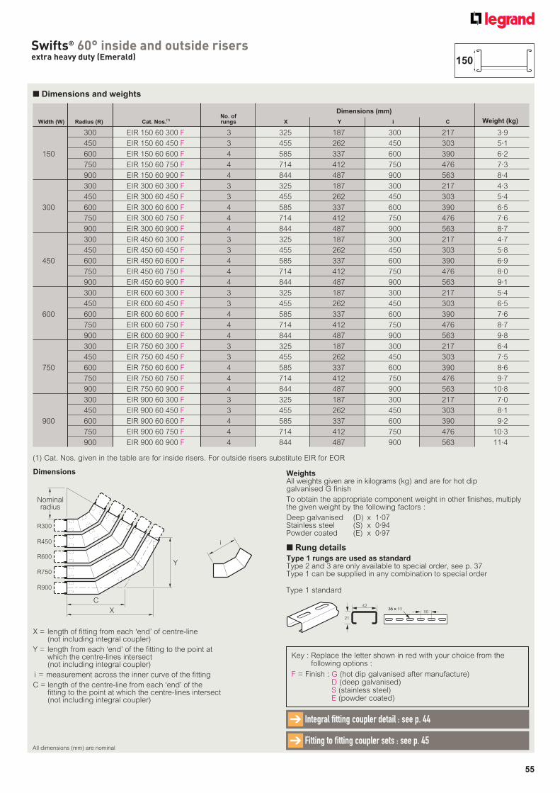
55
Swifts® 60° inside and outside risersextra heavy duty (Emerald)
■ Dimensions and weights
No. of Width (W) Radius (R) Cat. Nos.
(1) rungs X Y i C
300 EIR 150 60 300 F 3 325 187 300 217 3·9
450 EIR 150 60 450 F 3 455 262 450 303 5·1
150 600 EIR 150 60 600 F 4 585 337 600 390 6·2
750 EIR 150 60 750 F 4 714 412 750 476 7·3
900 EIR 150 60 900 F 4 844 487 900 563 8·4
300 EIR 300 60 300 F 3 325 187 300 217 4·3
450 EIR 300 60 450 F 3 455 262 450 303 5·4
300 600 EIR 300 60 600 F 4 585 337 600 390 6·5
750 EIR 300 60 750 F 4 714 412 750 476 7·6
900 EIR 300 60 900 F 4 844 487 900 563 8·7
300 EIR 450 60 300 F 3 325 187 300 217 4·7
450 EIR 450 60 450 F 3 455 262 450 303 5·8
450 600 EIR 450 60 600 F 4 585 337 600 390 6·9
750 EIR 450 60 750 F 4 714 412 750 476 8·0
900 EIR 450 60 900 F 4 844 487 900 563 9·1
300 EIR 600 60 300 F 3 325 187 300 217 5·4
450 EIR 600 60 450 F 3 455 262 450 303 6·5
600 600 EIR 600 60 600 F 4 585 337 600 390 7·6
750 EIR 600 60 750 F 4 714 412 750 476 8·7
900 EIR 600 60 900 F 4 844 487 900 563 9·8
300 EIR 750 60 300 F 3 325 187 300 217 6·4
450 EIR 750 60 450 F 3 455 262 450 303 7·5
750 600 EIR 750 60 600 F 4 585 337 600 390 8·6
750 EIR 750 60 750 F 4 714 412 750 476 9·7
900 EIR 750 60 900 F 4 844 487 900 563 10·8
300 EIR 900 60 300 F 3 325 187 300 217 7·0
450 EIR 900 60 450 F 3 455 262 450 303 8·1
900 600 EIR 900 60 600 F 4 585 337 600 390 9·2
750 EIR 900 60 750 F 4 714 412 750 476 10·3
900 EIR 900 60 900 F 4 844 487 900 563 11·4
Weight (kg)
Dimensions (mm)
Key : Replace the letter shown in red with your choice from the following options :
F = Finish : G (hot dip galvanised after manufacture)D (deep galvanised)S (stainless steel)E (powder coated)
X = length of fitting from each ‘end’ of centre-line (not including integral coupler)
Y = length from each ‘end’ of the fitting to the point at which the centre-lines intersect (not including integral coupler)
i = measurement across the inner curve of the fitting
C = length of the centre-line from each ‘end’ of the fitting to the point at which the centre-lines intersect (not including integral coupler)
Dimensions
(1) Cat. Nos. given in the table are for inside risers. For outside risers substitute EIR for EOR
R300
R450
R900
R600
R750
C
X
Y
Nominalradius
i
WeightsAll weights given are in kilograms (kg) and are for hot dip galvanised G finish
To obtain the appropriate component weight in other finishes, multiply the given weight by the following factors :
Deep galvanised (D) x 1·07Stainless steel (S) x 0·94Powder coated (E) x 0·97
All dimensions (mm) are nominal
Integral fitting coupler detail : see p. 44➔
Fitting to fitting coupler sets : see p. 45➔
150
■ Rung details
Type 1 rungs are used as standardType 2 and 3 are only available to special order, see p. 37Type 1 can be supplied in any combination to special order
42
21
35 x 1135 x 1150
Type 1 standard
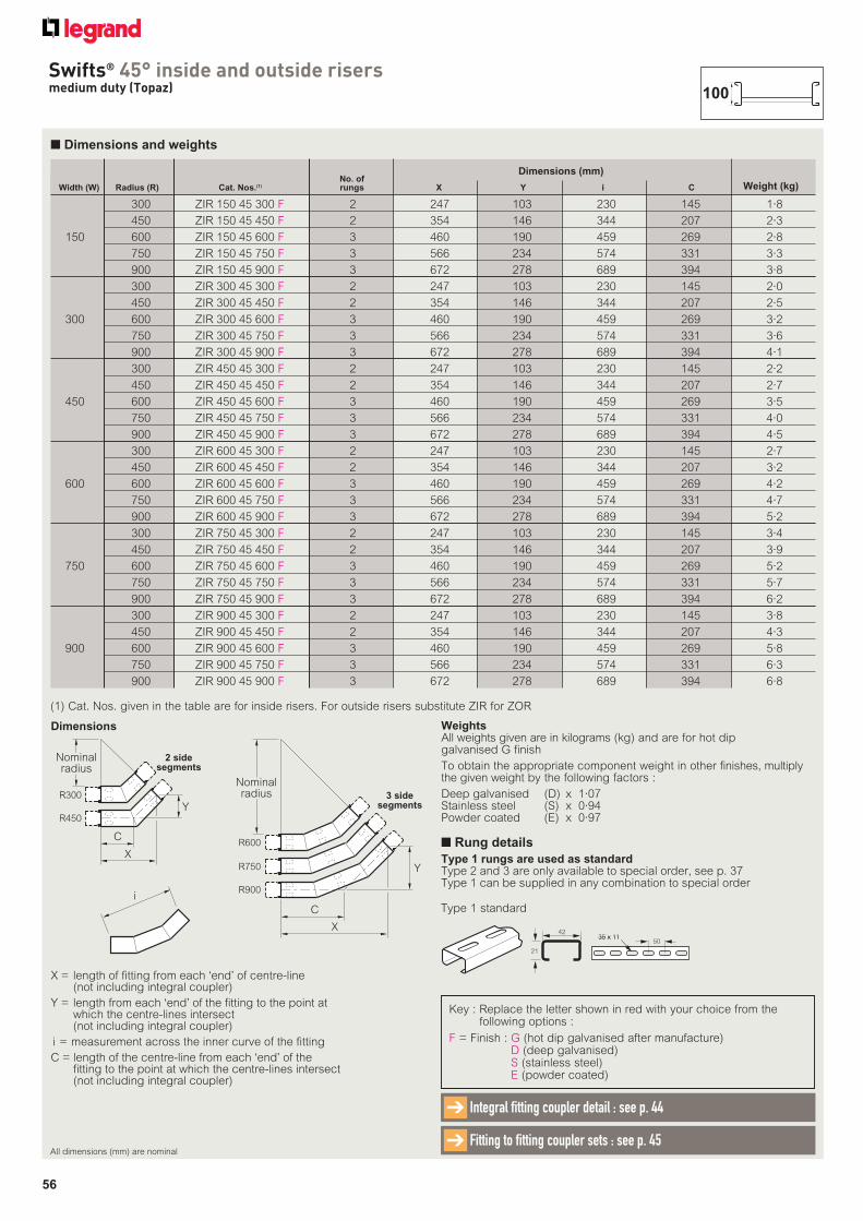
56
Swifts® 45° inside and outside risersmedium duty (Topaz)
■ Dimensions and weights
X = length of fitting from each ‘end’ of centre-line (not including integral coupler)
Y = length from each ‘end’ of the fitting to the point at which the centre-lines intersect (not including integral coupler)
i = measurement across the inner curve of the fitting
C = length of the centre-line from each ‘end’ of the fitting to the point at which the centre-lines intersect (not including integral coupler)
Dimensions
Key : Replace the letter shown in red with your choice from the following options :
F = Finish : G (hot dip galvanised after manufacture)D (deep galvanised)S (stainless steel)E (powder coated)
No. of Width (W) Radius (R) Cat. Nos.(1) rungs X Y i C
300 ZIR 150 45 300 F 2 247 103 230 145 1·8
450 ZIR 150 45 450 F 2 354 146 344 207 2·3
150 600 ZIR 150 45 600 F 3 460 190 459 269 2·8
750 ZIR 150 45 750 F 3 566 234 574 331 3·3
900 ZIR 150 45 900 F 3 672 278 689 394 3·8
300 ZIR 300 45 300 F 2 247 103 230 145 2·0
450 ZIR 300 45 450 F 2 354 146 344 207 2·5
300 600 ZIR 300 45 600 F 3 460 190 459 269 3·2
750 ZIR 300 45 750 F 3 566 234 574 331 3·6
900 ZIR 300 45 900 F 3 672 278 689 394 4·1
300 ZIR 450 45 300 F 2 247 103 230 145 2·2
450 ZIR 450 45 450 F 2 354 146 344 207 2·7
450 600 ZIR 450 45 600 F 3 460 190 459 269 3·5
750 ZIR 450 45 750 F 3 566 234 574 331 4·0
900 ZIR 450 45 900 F 3 672 278 689 394 4·5
300 ZIR 600 45 300 F 2 247 103 230 145 2·7
450 ZIR 600 45 450 F 2 354 146 344 207 3·2
600 600 ZIR 600 45 600 F 3 460 190 459 269 4·2
750 ZIR 600 45 750 F 3 566 234 574 331 4·7
900 ZIR 600 45 900 F 3 672 278 689 394 5·2
300 ZIR 750 45 300 F 2 247 103 230 145 3·4
450 ZIR 750 45 450 F 2 354 146 344 207 3·9
750 600 ZIR 750 45 600 F 3 460 190 459 269 5·2
750 ZIR 750 45 750 F 3 566 234 574 331 5·7
900 ZIR 750 45 900 F 3 672 278 689 394 6·2
300 ZIR 900 45 300 F 2 247 103 230 145 3·8
450 ZIR 900 45 450 F 2 354 146 344 207 4·3
900 600 ZIR 900 45 600 F 3 460 190 459 269 5·8
750 ZIR 900 45 750 F 3 566 234 574 331 6·3
900 ZIR 900 45 900 F 3 672 278 689 394 6·8
Weight (kg)
Dimensions (mm)
(1) Cat. Nos. given in the table are for inside risers. For outside risers substitute ZIR for ZOR
i
C
R750
R900
Y
R600
X
3 sidesegments
Nominalradius
YR300
R450
C
X
2 sidesegments
Nominalradius
WeightsAll weights given are in kilograms (kg) and are for hot dip galvanised G finish
To obtain the appropriate component weight in other finishes, multiply the given weight by the following factors :
Deep galvanised (D) x 1·07Stainless steel (S) x 0·94Powder coated (E) x 0·97
All dimensions (mm) are nominal
Integral fitting coupler detail : see p. 44➔
Fitting to fitting coupler sets : see p. 45➔
100
■ Rung details
Type 1 rungs are used as standardType 2 and 3 are only available to special order, see p. 37Type 1 can be supplied in any combination to special order
42
21
35 x 1135 x 1150
Type 1 standard
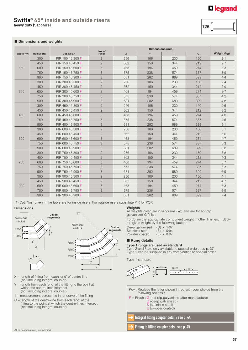
57
Swifts® 45° inside and outside risersheavy duty (Sapphire)
■ Dimensions and weights
No. of Width (W) Radius (R) Cat. Nos.(1) rungs X Y i C
300 PIR 150 45 300 F 2 256 106 230 150 2·1
450 PIR 150 45 450 F 2 362 150 344 212 2·7
150 600 PIR 150 45 600 F 3 468 194 459 274 3·3
750 PIR 150 45 750 F 3 575 238 574 337 3·9
900 PIR 150 45 900 F 3 681 282 689 399 4·4
300 PIR 300 45 300 F 2 256 106 230 150 2·4
450 PIR 300 45 450 F 2 362 150 344 212 2·9
300 600 PIR 300 45 600 F 3 468 194 459 274 3·7
750 PIR 300 45 750 F 3 575 238 574 337 4·2
900 PIR 300 45 900 F 3 681 282 689 399 4·8
300 PIR 450 45 300 F 2 256 106 230 150 2·6
450 PIR 450 45 450 F 2 362 150 344 212 3·2
450 600 PIR 450 45 600 F 3 468 194 459 274 4·0
750 PIR 450 45 750 F 3 575 238 574 337 4·6
900 PIR 450 45 900 F 3 681 282 689 399 5·1
300 PIR 600 45 300 F 2 256 106 230 150 3·1
450 PIR 600 45 450 F 2 362 150 344 212 3·6
600 600 PIR 600 45 600 F 3 468 194 459 274 4·7
750 PIR 600 45 750 F 3 575 238 574 337 5·3
900 PIR 600 45 900 F 3 681 282 689 399 5·8
300 PIR 750 45 300 F 2 256 106 230 150 3·8
450 PIR 750 45 450 F 2 362 150 344 212 4·3
750 600 PIR 750 45 600 F 3 468 194 459 274 5·7
750 PIR 750 45 750 F 3 575 238 574 337 6·3
900 PIR 750 45 900 F 3 681 282 689 399 6·9
300 PIR 900 45 300 F 2 256 106 230 150 4·1
450 PIR 900 45 450 F 2 362 150 344 212 4·7
900 600 PIR 900 45 600 F 3 468 194 459 274 6·3
750 PIR 900 45 750 F 3 575 238 574 337 6·9
900 PIR 900 45 900 F 3 681 282 689 399 7·4
Weight (kg)
Dimensions (mm)
(1) Cat. Nos. given in the table are for inside risers. For outside risers substitute PIR for POR
X = length of fitting from each ‘end’ of centre-line (not including integral coupler)
Y = length from each ‘end’ of the fitting to the point at which the centre-lines intersect (not including integral coupler)
i = measurement across the inner curve of the fitting
C = length of the centre-line from each ‘end’ of the fitting to the point at which the centre-lines intersect (not including integral coupler)
Dimensions
Key : Replace the letter shown in red with your choice from the following options :
F = Finish : G (hot dip galvanised after manufacture)D (deep galvanised)S (stainless steel)E (powder coated)
i
C
R750
R900
Y
R600
X
3 sidesegments
Nominalradius
Y
R300
R450
C
X
2 sidesegmentsNominal
radius
WeightsAll weights given are in kilograms (kg) and are for hot dip galvanised G finish
To obtain the appropriate component weight in other finishes, multiply the given weight by the following factors :
Deep galvanised (D) x 1·07Stainless steel (S) x 0·94Powder coated (E) x 0·97
All dimensions (mm) are nominal
Integral fitting coupler detail : see p. 44➔
Fitting to fitting coupler sets : see p. 45➔
125
■ Rung details
Type 1 rungs are used as standardType 2 and 3 are only available to special order, see p. 37Type 1 can be supplied in any combination to special order
42
21
35 x 1135 x 1150
Type 1 standard
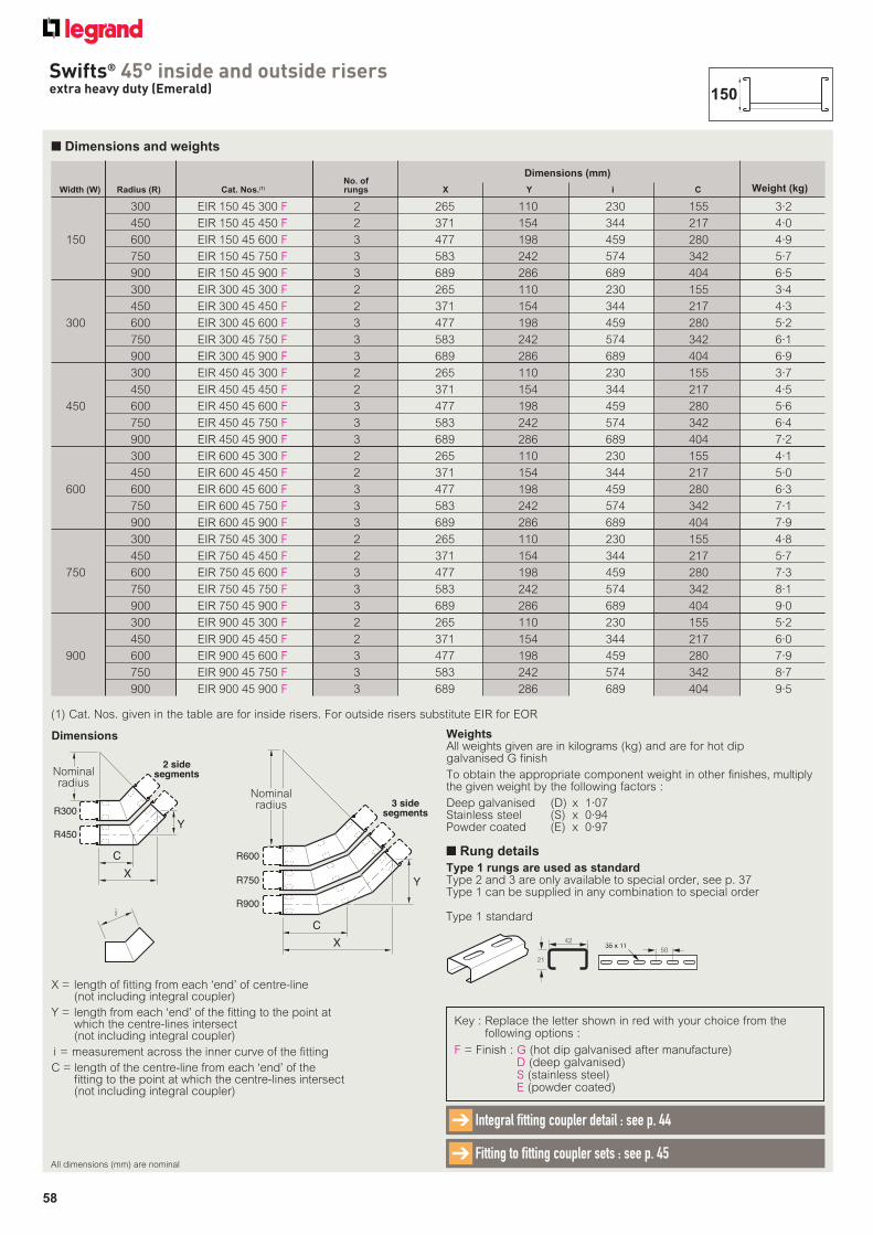
58
Swifts® 45° inside and outside risersextra heavy duty (Emerald)
■ Dimensions and weights
No. of Width (W) Radius (R) Cat. Nos.(1) rungs X Y i C
300 EIR 150 45 300 F 2 265 110 230 155 3·2
450 EIR 150 45 450 F 2 371 154 344 217 4·0
150 600 EIR 150 45 600 F 3 477 198 459 280 4·9
750 EIR 150 45 750 F 3 583 242 574 342 5·7
900 EIR 150 45 900 F 3 689 286 689 404 6·5
300 EIR 300 45 300 F 2 265 110 230 155 3·4
450 EIR 300 45 450 F 2 371 154 344 217 4·3
300 600 EIR 300 45 600 F 3 477 198 459 280 5·2
750 EIR 300 45 750 F 3 583 242 574 342 6·1
900 EIR 300 45 900 F 3 689 286 689 404 6·9
300 EIR 450 45 300 F 2 265 110 230 155 3·7
450 EIR 450 45 450 F 2 371 154 344 217 4·5
450 600 EIR 450 45 600 F 3 477 198 459 280 5·6
750 EIR 450 45 750 F 3 583 242 574 342 6·4
900 EIR 450 45 900 F 3 689 286 689 404 7·2
300 EIR 600 45 300 F 2 265 110 230 155 4·1
450 EIR 600 45 450 F 2 371 154 344 217 5·0
600 600 EIR 600 45 600 F 3 477 198 459 280 6·3
750 EIR 600 45 750 F 3 583 242 574 342 7·1
900 EIR 600 45 900 F 3 689 286 689 404 7·9
300 EIR 750 45 300 F 2 265 110 230 155 4·8
450 EIR 750 45 450 F 2 371 154 344 217 5·7
750 600 EIR 750 45 600 F 3 477 198 459 280 7·3
750 EIR 750 45 750 F 3 583 242 574 342 8·1
900 EIR 750 45 900 F 3 689 286 689 404 9·0
300 EIR 900 45 300 F 2 265 110 230 155 5·2
450 EIR 900 45 450 F 2 371 154 344 217 6·0
900 600 EIR 900 45 600 F 3 477 198 459 280 7·9
750 EIR 900 45 750 F 3 583 242 574 342 8·7
900 EIR 900 45 900 F 3 689 286 689 404 9·5
Weight (kg)
Dimensions (mm)
Key : Replace the letter shown in red with your choice from the following options :
F = Finish : G (hot dip galvanised after manufacture)D (deep galvanised)S (stainless steel)E (powder coated)
X = length of fitting from each ‘end’ of centre-line (not including integral coupler)
Y = length from each ‘end’ of the fitting to the point at which the centre-lines intersect (not including integral coupler)
i = measurement across the inner curve of the fitting
C = length of the centre-line from each ‘end’ of the fitting to the point at which the centre-lines intersect (not including integral coupler)
Dimensions
(1) Cat. Nos. given in the table are for inside risers. For outside risers substitute EIR for EOR
i
C
R750
R900
Y
R600
X
3 sidesegments
Nominalradius
Y
R300
R450
C
X
2 sidesegmentsNominal
radius
WeightsAll weights given are in kilograms (kg) and are for hot dip galvanised G finish
To obtain the appropriate component weight in other finishes, multiply the given weight by the following factors :
Deep galvanised (D) x 1·07Stainless steel (S) x 0·94Powder coated (E) x 0·97
All dimensions (mm) are nominal
Integral fitting coupler detail : see p. 44➔
Fitting to fitting coupler sets : see p. 45➔
150
■ Rung details
Type 1 rungs are used as standardType 2 and 3 are only available to special order, see p. 37Type 1 can be supplied in any combination to special order
42
21
35 x 1135 x 1150
Type 1 standard
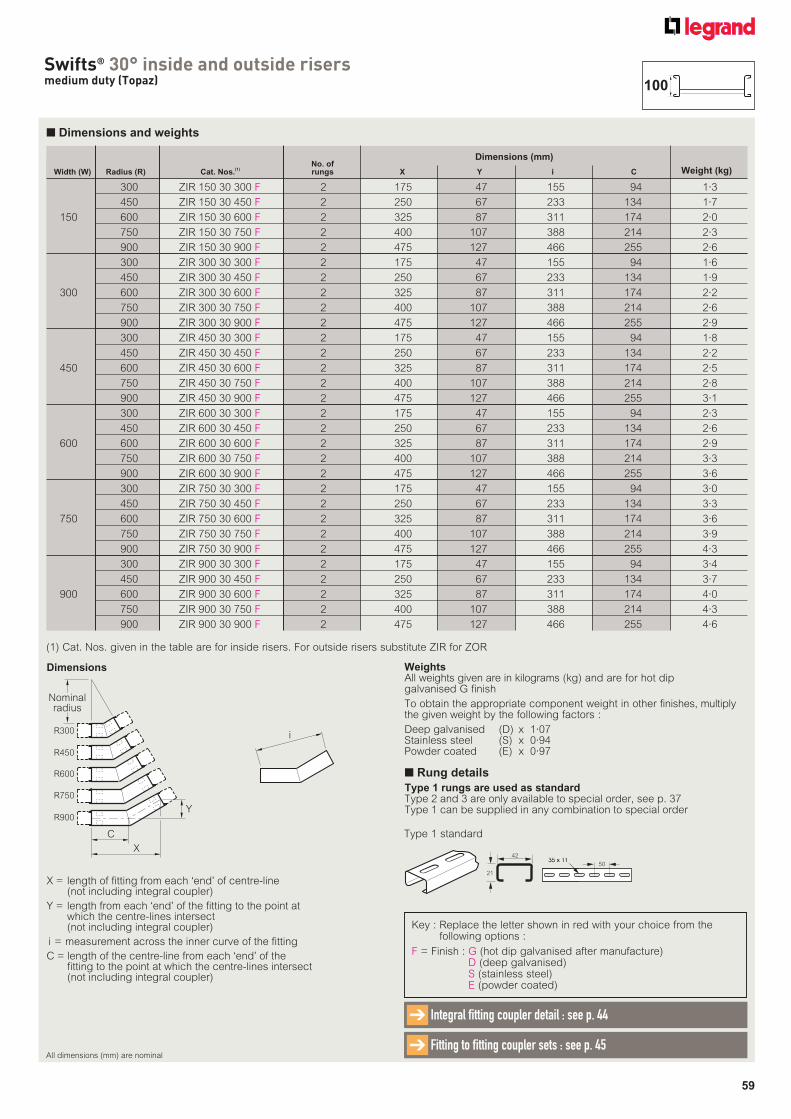
59
Swifts® 30° inside and outside risersmedium duty (Topaz)
■ Dimensions and weights
X = length of fitting from each ‘end’ of centre-line (not including integral coupler)
Y = length from each ‘end’ of the fitting to the point at which the centre-lines intersect (not including integral coupler)
i = measurement across the inner curve of the fitting
C = length of the centre-line from each ‘end’ of the fitting to the point at which the centre-lines intersect (not including integral coupler)
Dimensions
Key : Replace the letter shown in red with your choice from the following options :
F = Finish : G (hot dip galvanised after manufacture)D (deep galvanised)S (stainless steel)E (powder coated)
No. of Width (W) Radius (R) Cat. Nos.
(1) rungs X Y i C
300 ZIR 150 30 300 F 2 175 47 155 94 1·3
450 ZIR 150 30 450 F 2 250 67 233 134 1·7
150 600 ZIR 150 30 600 F 2 325 87 311 174 2·0
750 ZIR 150 30 750 F 2 400 107 388 214 2·3
900 ZIR 150 30 900 F 2 475 127 466 255 2·6
300 ZIR 300 30 300 F 2 175 47 155 94 1·6
450 ZIR 300 30 450 F 2 250 67 233 134 1·9
300 600 ZIR 300 30 600 F 2 325 87 311 174 2·2
750 ZIR 300 30 750 F 2 400 107 388 214 2·6
900 ZIR 300 30 900 F 2 475 127 466 255 2·9
300 ZIR 450 30 300 F 2 175 47 155 94 1·8
450 ZIR 450 30 450 F 2 250 67 233 134 2·2
450 600 ZIR 450 30 600 F 2 325 87 311 174 2·5
750 ZIR 450 30 750 F 2 400 107 388 214 2·8
900 ZIR 450 30 900 F 2 475 127 466 255 3·1
300 ZIR 600 30 300 F 2 175 47 155 94 2·3
450 ZIR 600 30 450 F 2 250 67 233 134 2·6
600 600 ZIR 600 30 600 F 2 325 87 311 174 2·9
750 ZIR 600 30 750 F 2 400 107 388 214 3·3
900 ZIR 600 30 900 F 2 475 127 466 255 3·6
300 ZIR 750 30 300 F 2 175 47 155 94 3·0
450 ZIR 750 30 450 F 2 250 67 233 134 3·3
750 600 ZIR 750 30 600 F 2 325 87 311 174 3·6
750 ZIR 750 30 750 F 2 400 107 388 214 3·9
900 ZIR 750 30 900 F 2 475 127 466 255 4·3
300 ZIR 900 30 300 F 2 175 47 155 94 3·4
450 ZIR 900 30 450 F 2 250 67 233 134 3·7
900 600 ZIR 900 30 600 F 2 325 87 311 174 4·0
750 ZIR 900 30 750 F 2 400 107 388 214 4·3
900 ZIR 900 30 900 F 2 475 127 466 255 4·6
Weight (kg)
Dimensions (mm)
(1) Cat. Nos. given in the table are for inside risers. For outside risers substitute ZIR for ZOR
i
R900
R600
R750
C
X
Y
R300
R450
Nominalradius
WeightsAll weights given are in kilograms (kg) and are for hot dip galvanised G finish
To obtain the appropriate component weight in other finishes, multiply the given weight by the following factors :
Deep galvanised (D) x 1·07Stainless steel (S) x 0·94Powder coated (E) x 0·97
All dimensions (mm) are nominal
Integral fitting coupler detail : see p. 44➔
Fitting to fitting coupler sets : see p. 45➔
100
■ Rung details
Type 1 rungs are used as standardType 2 and 3 are only available to special order, see p. 37Type 1 can be supplied in any combination to special order
42
21
35 x 1135 x 1150
Type 1 standard
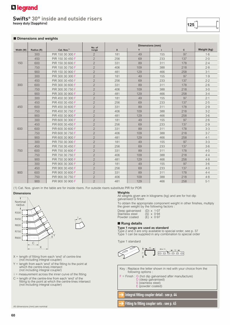
60
Swifts® 30° inside and outside risersheavy duty (Sapphire)
■ Dimensions and weights
No. of Width (W) Radius (R) Cat. Nos.
(1) rungs X Y i C
300 PIR 150 30 300 F 2 181 49 155 97 1·6
450 PIR 150 30 450 F 2 256 69 233 137 2·0
150 600 PIR 150 30 600 F 2 331 89 311 178 2·4
750 PIR 150 30 750 F 2 406 109 388 218 2·8
900 PIR 150 30 900 F 2 481 129 466 258 3·1
300 PIR 300 30 300 F 2 181 49 155 97 1·9
450 PIR 300 30 450 F 2 256 69 233 137 2·2
300 600 PIR 300 30 600 F 2 331 89 311 178 2·6
750 PIR 300 30 750 F 2 406 109 388 218 3·0
900 PIR 300 30 900 F 2 481 129 466 258 3·4
300 PIR 450 30 300 F 2 181 49 155 97 2·1
450 PIR 450 30 450 F 2 256 69 233 137 2·5
450 600 PIR 450 30 600 F 2 331 89 311 178 2·9
750 PIR 450 30 750 F 2 406 109 388 218 3·2
900 PIR 450 30 900 F 2 481 129 466 258 3·6
300 PIR 600 30 300 F 2 181 49 155 97 2·6
450 PIR 600 30 450 F 2 256 69 233 137 2·9
600 600 PIR 600 30 600 F 2 331 89 311 178 3·3
750 PIR 600 30 750 F 2 406 109 388 218 3·7
900 PIR 600 30 900 F 2 481 129 466 258 4·1
300 PIR 750 30 300 F 2 181 49 155 97 3·3
450 PIR 750 30 450 F 2 256 69 233 137 3·6
750 600 PIR 750 30 600 F 2 331 89 311 178 4·0
750 PIR 750 30 750 F 2 406 109 388 218 4·4
900 PIR 750 30 900 F 2 481 129 466 258 4·8
300 PIR 900 30 300 F 2 181 49 155 97 3·6
450 PIR 900 30 450 F 2 256 69 233 137 4·0
900 600 PIR 900 30 600 F 2 331 89 311 178 4·4
750 PIR 900 30 750 F 2 406 109 388 218 4·8
900 PIR 900 30 900 F 2 481 129 466 258 5·1
Weight (kg)
Dimensions (mm)
(1) Cat. Nos. given in the table are for inside risers. For outside risers substitute PIR for POR
X = length of fitting from each ‘end’ of centre-line (not including integral coupler)
Y = length from each ‘end’ of the fitting to the point at which the centre-lines intersect (not including integral coupler)
i = measurement across the inner curve of the fitting
C = length of the centre-line from each ‘end’ of the fitting to the point at which the centre-lines intersect (not including integral coupler)
Dimensions
Key : Replace the letter shown in red with your choice from the following options :
F = Finish : G (hot dip galvanised after manufacture)D (deep galvanised)S (stainless steel)E (powder coated)
i
R900
R600
R750
C
X
Y
R300
R450
Nominalradius
WeightsAll weights given are in kilograms (kg) and are for hot dip galvanised G finish
To obtain the appropriate component weight in other finishes, multiply the given weight by the following factors :
Deep galvanised (D) x 1·07Stainless steel (S) x 0·94Powder coated (E) x 0·97
All dimensions (mm) are nominal
Integral fitting coupler detail : see p. 44➔
Fitting to fitting coupler sets : see p. 45➔
125
■ Rung details
Type 1 rungs are used as standardType 2 and 3 are only available to special order, see p. 37Type 1 can be supplied in any combination to special order
42
21
35 x 1135 x 1150
Type 1 standard
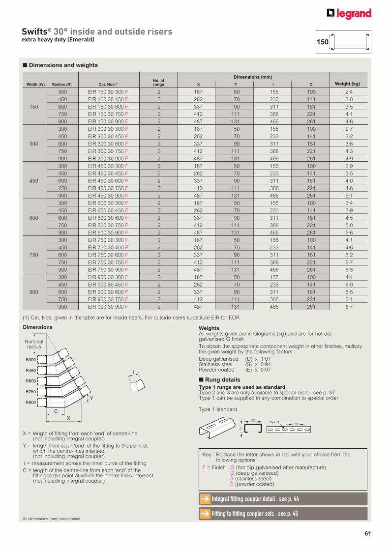
61
Swifts® 30° inside and outside risersextra heavy duty (Emerald)
■ Dimensions and weights
No. of Width (W) Radius (R) Cat. Nos.(1) rungs X Y i C
300 EIR 150 30 300 F 2 187 50 155 100 2·4
450 EIR 150 30 450 F 2 262 70 233 141 3·0
150 600 EIR 150 30 600 F 2 337 90 311 181 3·5
750 EIR 150 30 750 F 2 412 111 388 221 4·1
900 EIR 150 30 900 F 2 487 131 466 261 4·6
300 EIR 300 30 300 F 2 187 50 155 100 2·7
450 EIR 300 30 450 F 2 262 70 233 141 3·2
300 600 EIR 300 30 600 F 2 337 90 311 181 3·8
750 EIR 300 30 750 F 2 412 111 388 221 4·3
900 EIR 300 30 900 F 2 487 131 466 261 4·9
300 EIR 450 30 300 F 2 187 50 155 100 2·9
450 EIR 450 30 450 F 2 262 70 233 141 3·5
450 600 EIR 450 30 600 F 2 337 90 311 181 4·0
750 EIR 450 30 750 F 2 412 111 388 221 4·6
900 EIR 450 30 900 F 2 487 131 466 261 5·1
300 EIR 600 30 300 F 2 187 50 155 100 3·4
450 EIR 600 30 450 F 2 262 70 233 141 3·9
600 600 EIR 600 30 600 F 2 337 90 311 181 4·5
750 EIR 600 30 750 F 2 412 111 388 221 5·0
900 EIR 600 30 900 F 2 487 131 466 261 5·6
300 EIR 750 30 300 F 2 187 50 155 100 4·1
450 EIR 750 30 450 F 2 262 70 233 141 4·6
750 600 EIR 750 30 600 F 2 337 90 311 181 5·2
750 EIR 750 30 750 F 2 412 111 388 221 5·7
900 EIR 750 30 900 F 2 487 131 466 261 6·3
300 EIR 900 30 300 F 2 187 50 155 100 4·4
450 EIR 900 30 450 F 2 262 70 233 141 5·0
900 600 EIR 900 30 600 F 2 337 90 311 181 5·5
750 EIR 900 30 750 F 2 412 111 388 221 6·1
900 EIR 900 30 900 F 2 487 131 466 261 6·7
Weight (kg)
Dimensions (mm)
Key : Replace the letter shown in red with your choice from the following options :
F = Finish : G (hot dip galvanised after manufacture)D (deep galvanised)S (stainless steel)E (powder coated)
X = length of fitting from each ‘end’ of centre-line (not including integral coupler)
Y = length from each ‘end’ of the fitting to the point at which the centre-lines intersect (not including integral coupler)
i = measurement across the inner curve of the fitting
C = length of the centre-line from each ‘end’ of the fitting to the point at which the centre-lines intersect (not including integral coupler)
Dimensions
(1) Cat. Nos. given in the table are for inside risers. For outside risers substitute EIR for EOR
i
R900
R600
R750
C
X
Y
R300
R450
Nominalradius
WeightsAll weights given are in kilograms (kg) and are for hot dip galvanised G finish
To obtain the appropriate component weight in other finishes, multiply the given weight by the following factors :
Deep galvanised (D) x 1·07Stainless steel (S) x 0·94Powder coated (E) x 0·97
All dimensions (mm) are nominal
Integral fitting coupler detail : see p. 44➔
Fitting to fitting coupler sets : see p. 45➔
150
■ Rung details
Type 1 rungs are used as standardType 2 and 3 are only available to special order, see p. 37Type 1 can be supplied in any combination to special order
42
21
35 x 1135 x 1150
Type 1 standard
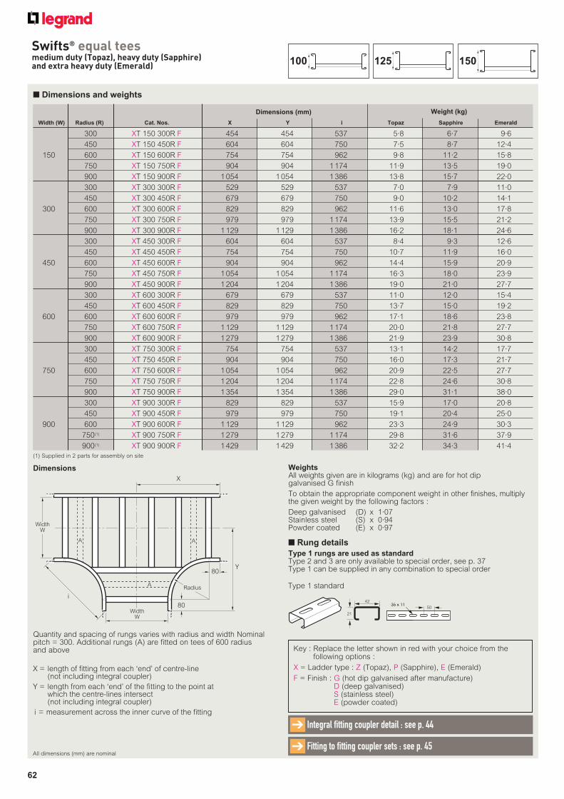
62
Swifts® equal teesmedium duty (Topaz), heavy duty (Sapphire) and extra heavy duty (Emerald)
■ Dimensions and weights
Key : Replace the letter shown in red with your choice from the following options :
X = Ladder type : Z (Topaz), P (Sapphire), E (Emerald)
F = Finish : G (hot dip galvanised after manufacture)D (deep galvanised)S (stainless steel)E (powder coated)
Width (W) Radius (R) Cat. Nos. X Y i Topaz Sapphire Emerald
300 XT 150 300R F 454 454 537 5·8 6·7 9·6
450 XT 150 450R F 604 604 750 7·5 8·7 12·4
150 600 XT 150 600R F 754 754 962 9·8 11·2 15·8
750 XT 150 750R F 904 904 1 174 11·9 13·5 19·0
900 XT 150 900R F 1 054 1 054 1 386 13·8 15·7 22·0
300 XT 300 300R F 529 529 537 7·0 7·9 11·0
450 XT 300 450R F 679 679 750 9·0 10·2 14·1
300 600 XT 300 600R F 829 829 962 11·6 13·0 17·8
750 XT 300 750R F 979 979 1 174 13·9 15·5 21·2
900 XT 300 900R F 1 129 1 129 1 386 16·2 18·1 24·6
300 XT 450 300R F 604 604 537 8·4 9·3 12·6
450 XT 450 450R F 754 754 750 10·7 11·9 16·0
450 600 XT 450 600R F 904 904 962 14·4 15·9 20·9
750 XT 450 750R F 1 054 1 054 1 174 16·3 18·0 23·9
900 XT 450 900R F 1 204 1 204 1 386 19·0 21·0 27·7
300 XT 600 300R F 679 679 537 11·0 12·0 15·4
450 XT 600 450R F 829 829 750 13·7 15·0 19·2
600 600 XT 600 600R F 979 979 962 17·1 18·6 23·8
750 XT 600 750R F 1 129 1 129 1 174 20·0 21·8 27·7
900 XT 600 900R F 1 279 1 279 1 386 21·9 23·9 30·8
300 XT 750 300R F 754 754 537 13·1 14·2 17·7
450 XT 750 450R F 904 904 750 16·0 17·3 21·7
750 600 XT 750 600R F 1 054 1 054 962 20·9 22·5 27·7
750 XT 750 750R F 1 204 1 204 1 174 22·8 24·6 30·8
900 XT 750 900R F 1 354 1 354 1 386 29·0 31·1 38·0
300 XT 900 300R F 829 829 537 15·9 17·0 20·8
450 XT 900 450R F 979 979 750 19·1 20·4 25·0
900 600 XT 900 600R F 1 129 1 129 962 23·3 24·9 30·3
750(1) XT 900 750R F 1 279 1 279 1 174 29·8 31·6 37·9
900(1) XT 900 900R F 1 429 1 429 1 386 32·2 34·3 41·4
Weight (kg)Dimensions (mm)
X = length of fitting from each ‘end’ of centre-line (not including integral coupler)
Y = length from each ‘end’ of the fitting to the point at which the centre-lines intersect (not including integral coupler)
i = measurement across the inner curve of the fitting
Dimensions
Y80
80
Radius
i
WidthW
WidthW
X
A A
A
Quantity and spacing of rungs varies with radius and width Nominal pitch = 300. Additional rungs (A) are fitted on tees of 600 radius and above
(1) Supplied in 2 parts for assembly on site
WeightsAll weights given are in kilograms (kg) and are for hot dip galvanised G finish
To obtain the appropriate component weight in other finishes, multiply the given weight by the following factors :
Deep galvanised (D) x 1·07Stainless steel (S) x 0·94Powder coated (E) x 0·97
All dimensions (mm) are nominal
Integral fitting coupler detail : see p. 44➔
Fitting to fitting coupler sets : see p. 45➔
150125100
■ Rung details
Type 1 rungs are used as standardType 2 and 3 are only available to special order, see p. 37Type 1 can be supplied in any combination to special order
42
21
35 x 1135 x 1150
Type 1 standard
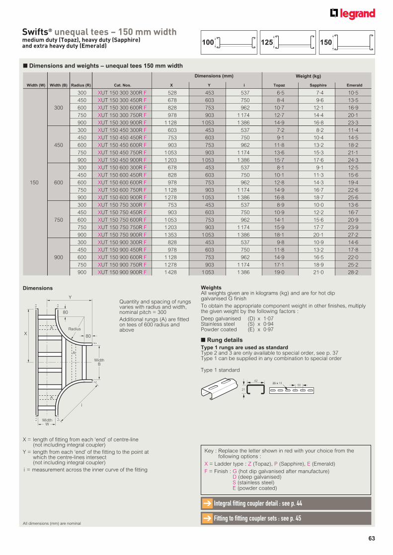
63
Swifts® unequal tees – 150 mm widthmedium duty (Topaz), heavy duty (Sapphire)and extra heavy duty (Emerald)
Width (W) Width (B) Radius (R) Cat. Nos. X Y i Topaz Sapphire Emerald
300 XUT 150 300 300R F 528 453 537 6·5 7·4 10·5
450 XUT 150 300 450R F 678 603 750 8·4 9·6 13·5
300 600 XUT 150 300 600R F 828 753 962 10·7 12·1 16·9
750 XUT 150 300 750R F 978 903 1 174 12·7 14·4 20·1
900 XUT 150 300 900R F 1 128 1 053 1 386 14·9 16·8 23·3
300 XUT 150 450 300R F 603 453 537 7·2 8·2 11·4
450 XUT 150 450 450R F 753 603 750 9·1 10·4 14·5
450 600 XUT 150 450 600R F 903 753 962 11·8 13·2 18·2
750 XUT 150 450 750R F 1 053 903 1 174 13·6 15·3 21·1
900 XUT 150 450 900R F 1 203 1 053 1 386 15·7 17·6 24·3
300 XUT 150 600 300R F 678 453 537 8·1 9·1 12·5
450 XUT 150 600 450R F 828 603 750 10·1 11·3 15·6
150 600 600 XUT 150 600 600R F 978 753 962 12·8 14·3 19·4
750 XUT 150 600 750R F 1 128 903 1 174 14·9 16·7 22·6
900 XUT 150 600 900R F 1 278 1 053 1 386 16·8 18·7 25·6
300 XUT 150 750 300R F 753 453 537 8·9 10·0 13·6
450 XUT 150 750 450R F 903 603 750 10·9 12·2 16·7
750 600 XUT 150 750 600R F 1 053 753 962 14·1 15·6 20·9
750 XUT 150 750 750R F 1 203 903 1 174 15·9 17·7 23·9
900 XUT 150 750 900R F 1 353 1 053 1 386 18·1 20·1 27·2
300 XUT 150 900 300R F 828 453 537 9·8 10·9 14·6
450 XUT 150 900 450R F 978 603 750 11·8 13·2 17·8
900 600 XUT 150 900 600R F 1 128 753 962 14·9 16·5 22·0
750 XUT 150 900 750R F 1 278 903 1 174 17·1 18·9 25·2
900 XUT 150 900 900R F 1 428 1 053 1 386 19·0 21·0 28·2
Weight (kg)
■ Dimensions and weights – unequal tees 150 mm width
Dimensions (mm)
X = length of fitting from each ‘end’ of centre-line (not including integral coupler)
Y = length from each ‘end’ of the fitting to the point at which the centre-lines intersect (not including integral coupler)
i = measurement across the inner curve of the fitting
Dimensions
Y
80
80
Radius
i
X
A
A
A
WidthW
WidthB
Quantity and spacing of rungs varies with radius and width, nominal pitch = 300
Additional rungs (A) are fitted on tees of 600 radius and above
Key : Replace the letter shown in red with your choice from the following options :
X = Ladder type : Z (Topaz), P (Sapphire), E (Emerald)
F = Finish : G (hot dip galvanised after manufacture)D (deep galvanised)S (stainless steel)E (powder coated)
WeightsAll weights given are in kilograms (kg) and are for hot dip galvanised G finish
To obtain the appropriate component weight in other finishes, multiply the given weight by the following factors :
Deep galvanised (D) x 1·07Stainless steel (S) x 0·94Powder coated (E) x 0·97
All dimensions (mm) are nominal
Integral fitting coupler detail : see p. 44➔
Fitting to fitting coupler sets : see p. 45 ➔
150125100
■ Rung details
Type 1 rungs are used as standardType 2 and 3 are only available to special order, see p. 37Type 1 can be supplied in any combination to special order
42
21
35 x 1135 x 1150
Type 1 standard
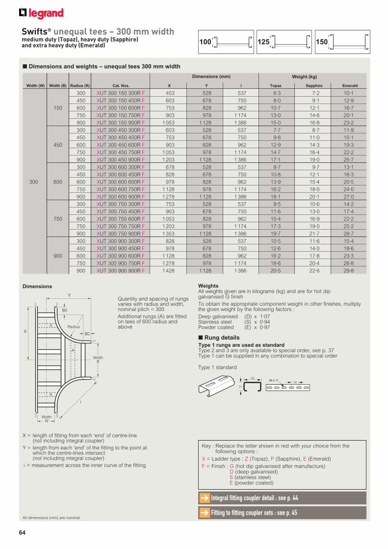
64
Swifts® unequal tees – 300 mm widthmedium duty (Topaz), heavy duty (Sapphire)and extra heavy duty (Emerald)
■ Dimensions and weights – unequal tees 300 mm width
Width (W) Width (B) Radius (R) Cat. Nos. X Y i Topaz Sapphire Emerald
300 XUT 300 150 300R F 453 528 537 6·3 7·2 10·1
450 XUT 300 150 450R F 603 678 750 8·0 9·1 12·9
150 600 XUT 300 150 600R F 753 828 962 10·7 12·1 16·7
750 XUT 300 150 750R F 903 978 1 174 13·0 14·6 20·1
900 XUT 300 150 900R F 1 053 1 128 1 386 15·0 16·8 23·2
300 XUT 300 450 300R F 603 528 537 7·7 8·7 11·9
450 XUT 300 450 450R F 753 678 750 9·8 11·0 15·1
450 600 XUT 300 450 600R F 903 828 962 12·9 14·3 19·3
750 XUT 300 450 750R F 1 053 978 1 174 14·7 16·4 22·2
900 XUT 300 450 900R F 1 203 1 128 1 386 17·1 19·0 25·7
300 XUT 300 600 300R F 678 528 537 8·7 9·7 13·1
450 XUT 300 600 450R F 828 678 750 10·8 12·1 16·3
300 600 600 XUT 300 600 600R F 978 828 962 13·9 15·4 20·5
750 XUT 300 600 750R F 1 128 978 1 174 16·2 18·0 24·0
900 XUT 300 600 900R F 1 278 1 128 1 386 18·1 20·1 27·0
300 XUT 300 750 300R F 753 528 537 9·5 10·6 14·2
450 XUT 300 750 450R F 903 678 750 11·6 13·0 17·4
750 600 XUT 300 750 600R F 1 053 828 962 15·4 16·9 22·2
750 XUT 300 750 750R F 1 203 978 1 174 17·3 19·0 25·2
900 XUT 300 750 900R F 1 353 1 128 1 386 19·7 21·7 28·7
300 XUT 300 900 300R F 828 528 537 10·5 11·6 15·4
450 XUT 300 900 450R F 978 678 750 12·6 14·0 18·6
900 600 XUT 300 900 600R F 1 128 828 962 16·2 17·8 23·3
750 XUT 300 900 750R F 1 278 978 1 174 18·6 20·4 26·8
900 XUT 300 900 900R F 1 428 1 128 1 386 20·5 22·6 29·8
Weight (kg) Dimensions (mm)
X = length of fitting from each ‘end’ of centre-line (not including integral coupler)
Y = length from each ‘end’ of the fitting to the point at which the centre-lines intersect (not including integral coupler)
i = measurement across the inner curve of the fitting
Dimensions
Y
80
80
Radius
i
X
A
A
A
WidthW
WidthB
Quantity and spacing of rungs varies with radius and width, nominal pitch = 300
Additional rungs (A) are fitted on tees of 600 radius and above
Key : Replace the letter shown in red with your choice from the following options :
X = Ladder type : Z (Topaz), P (Sapphire), E (Emerald)
F = Finish : G (hot dip galvanised after manufacture)D (deep galvanised)S (stainless steel)E (powder coated)
WeightsAll weights given are in kilograms (kg) and are for hot dip galvanised G finish
To obtain the appropriate component weight in other finishes, multiply the given weight by the following factors :
Deep galvanised (D) x 1·07Stainless steel (S) x 0·94Powder coated (E) x 0·97
All dimensions (mm) are nominal
Integral fitting coupler detail : see p. 44➔
Fitting to fitting coupler sets : see p. 45➔
150125100
■ Rung details
Type 1 rungs are used as standardType 2 and 3 are only available to special order, see p. 37Type 1 can be supplied in any combination to special order
42
21
35 x 1135 x 1150
Type 1 standard
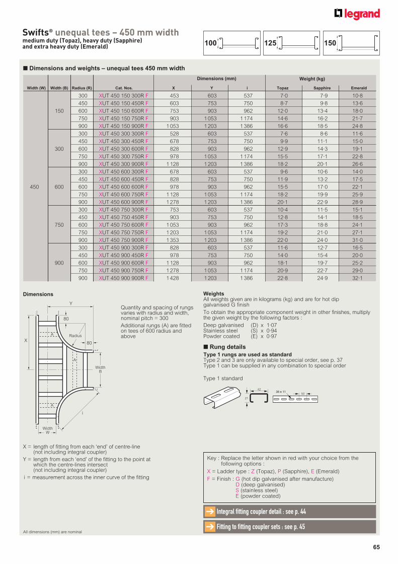
65
Swifts® unequal tees – 450 mm widthmedium duty (Topaz), heavy duty (Sapphire)and extra heavy duty (Emerald)
■ Dimensions and weights – unequal tees 450 mm width
Width (W) Width (B) Radius (R) Cat. Nos. X Y i Topaz Sapphire Emerald
300 XUT 450 150 300R F 453 603 537 7·0 7·9 10·8
450 XUT 450 150 450R F 603 753 750 8·7 9·8 13·6
150 600 XUT 450 150 600R F 753 903 962 12·0 13·4 18·0
750 XUT 450 150 750R F 903 1 053 1 174 14·6 16·2 21·7
900 XUT 450 150 900R F 1 053 1 203 1 386 16·6 18·5 24·8
300 XUT 450 300 300R F 528 603 537 7·6 8·6 11·6
450 XUT 450 300 450R F 678 753 750 9·9 11·1 15·0
300 600 XUT 450 300 600R F 828 903 962 12·9 14·3 19·1
750 XUT 450 300 750R F 978 1 053 1 174 15·5 17·1 22·8
900 XUT 450 300 900R F 1 128 1 203 1 386 18·2 20·1 26·6
300 XUT 450 600 300R F 678 603 537 9·6 10·6 14·0
450 XUT 450 600 450R F 828 753 750 11·9 13·2 17·5
450 600 600 XUT 450 600 600R F 978 903 962 15·5 17·0 22·1
750 XUT 450 600 750R F 1 128 1 053 1 174 18·2 19·9 25·9
900 XUT 450 600 900R F 1 278 1 203 1 386 20·1 22·9 28·9
300 XUT 450 750 300R F 753 603 537 10·4 11·5 15·1
450 XUT 450 750 450R F 903 753 750 12·8 14·1 18·5
750 600 XUT 450 750 600R F 1 053 903 962 17·3 18·8 24·1
750 XUT 450 750 750R F 1 203 1 053 1 174 19·2 21·0 27·1
900 XUT 450 750 900R F 1 353 1 203 1 386 22·0 24·0 31·0
300 XUT 450 900 300R F 828 603 537 11·6 12·7 16·5
450 XUT 450 900 450R F 978 753 750 14·0 15·4 20·0
900 600 XUT 450 900 600R F 1 128 903 962 18·1 19·7 25·2
750 XUT 450 900 750R F 1 278 1 053 1 174 20·9 22·7 29·0
900 XUT 450 900 900R F 1 428 1 203 1 386 22·8 24·9 32·1
Weight (kg) Dimensions (mm)
X = length of fitting from each ‘end’ of centre-line (not including integral coupler)
Y = length from each ‘end’ of the fitting to the point at which the centre-lines intersect (not including integral coupler)
i = measurement across the inner curve of the fitting
Dimensions
Y
80
80
Radius
i
X
A
A
A
WidthW
WidthB
Quantity and spacing of rungs varies with radius and width, nominal pitch = 300
Additional rungs (A) are fitted on tees of 600 radius and above
Key : Replace the letter shown in red with your choice from the following options :
X = Ladder type : Z (Topaz), P (Sapphire), E (Emerald)
F = Finish : G (hot dip galvanised after manufacture)D (deep galvanised)S (stainless steel)E (powder coated)
WeightsAll weights given are in kilograms (kg) and are for hot dip galvanised G finish
To obtain the appropriate component weight in other finishes, multiply the given weight by the following factors :
Deep galvanised (D) x 1·07Stainless steel (S) x 0·94Powder coated (E) x 0·97
All dimensions (mm) are nominal
Integral fitting coupler detail : see p. 44➔
Fitting to fitting coupler sets : see p. 45➔
150125100
■ Rung details
Type 1 rungs are used as standardType 2 and 3 are only available to special order, see p. 37Type 1 can be supplied in any combination to special order
42
21
35 x 1135 x 1150
Type 1 standard
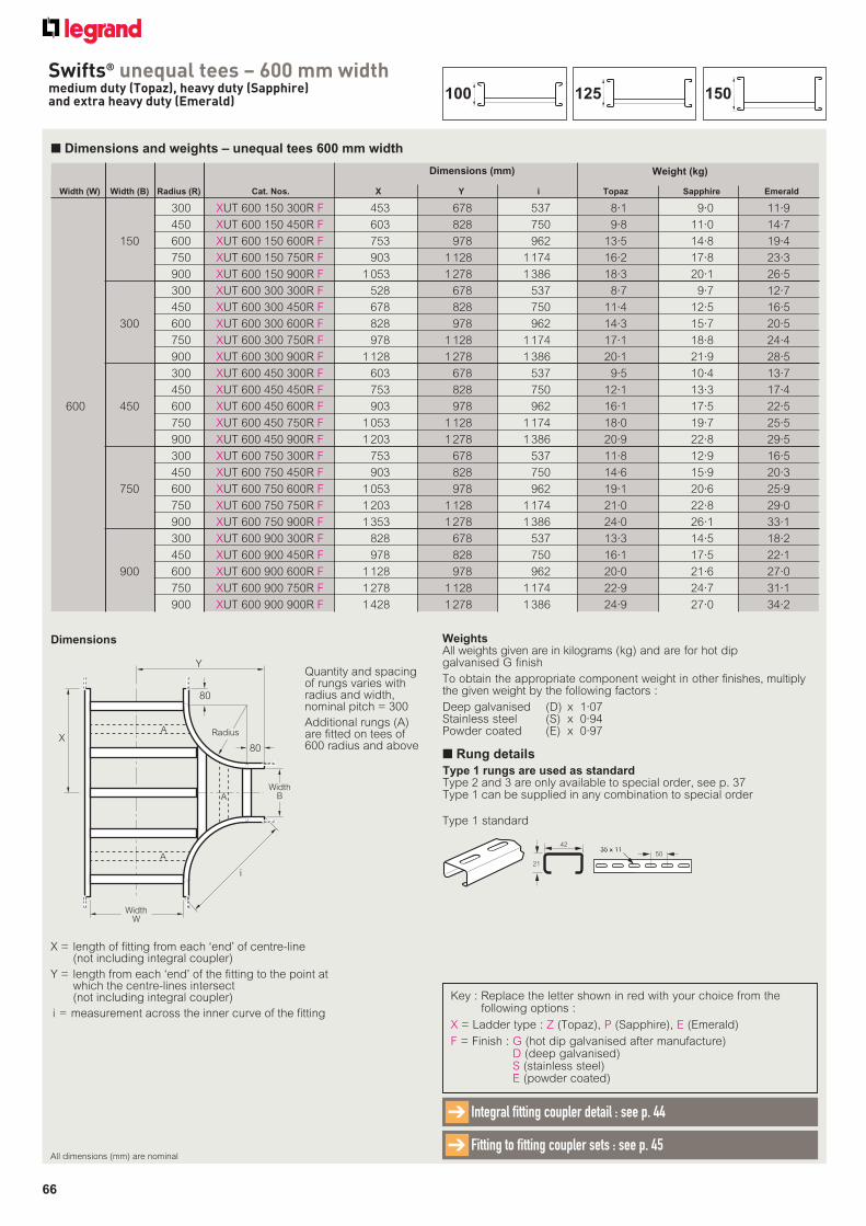
66
Swifts® unequal tees – 600 mm widthmedium duty (Topaz), heavy duty (Sapphire)and extra heavy duty (Emerald)
■ Dimensions and weights – unequal tees 600 mm width
Width (W) Width (B) Radius (R) Cat. Nos. X Y i Topaz Sapphire Emerald
300 XUT 600 150 300R F 453 678 537 8·1 9·0 11·9
450 XUT 600 150 450R F 603 828 750 9·8 11·0 14·7
150 600 XUT 600 150 600R F 753 978 962 13·5 14·8 19·4
750 XUT 600 150 750R F 903 1 128 1 174 16·2 17·8 23·3
900 XUT 600 150 900R F 1 053 1 278 1 386 18·3 20·1 26·5
300 XUT 600 300 300R F 528 678 537 8·7 9·7 12·7
450 XUT 600 300 450R F 678 828 750 11·4 12·5 16·5
300 600 XUT 600 300 600R F 828 978 962 14·3 15·7 20·5
750 XUT 600 300 750R F 978 1 128 1 174 17·1 18·8 24·4
900 XUT 600 300 900R F 1 128 1 278 1 386 20·1 21·9 28·5
300 XUT 600 450 300R F 603 678 537 9·5 10·4 13·7
450 XUT 600 450 450R F 753 828 750 12·1 13·3 17·4
600 450 600 XUT 600 450 600R F 903 978 962 16·1 17·5 22·5
750 XUT 600 450 750R F 1 053 1 128 1 174 18·0 19·7 25·5
900 XUT 600 450 900R F 1 203 1 278 1 386 20·9 22·8 29·5
300 XUT 600 750 300R F 753 678 537 11·8 12·9 16·5
450 XUT 600 750 450R F 903 828 750 14·6 15·9 20·3
750 600 XUT 600 750 600R F 1 053 978 962 19·1 20·6 25·9
750 XUT 600 750 750R F 1 203 1 128 1 174 21·0 22·8 29·0
900 XUT 600 750 900R F 1 353 1 278 1 386 24·0 26·1 33·1
300 XUT 600 900 300R F 828 678 537 13·3 14·5 18·2
450 XUT 600 900 450R F 978 828 750 16·1 17·5 22·1
900 600 XUT 600 900 600R F 1 128 978 962 20·0 21·6 27·0
750 XUT 600 900 750R F 1 278 1 128 1 174 22·9 24·7 31·1
900 XUT 600 900 900R F 1 428 1 278 1 386 24·9 27·0 34·2
Weight (kg) Dimensions (mm)
X = length of fitting from each ‘end’ of centre-line (not including integral coupler)
Y = length from each ‘end’ of the fitting to the point at which the centre-lines intersect (not including integral coupler)
i = measurement across the inner curve of the fitting
Dimensions
Y
80
80
Radius
i
X
A
A
A
WidthW
WidthB
Quantity and spacing of rungs varies with radius and width, nominal pitch = 300
Additional rungs (A) are fitted on tees of 600 radius and above
Key : Replace the letter shown in red with your choice from the following options :
X = Ladder type : Z (Topaz), P (Sapphire), E (Emerald)
F = Finish : G (hot dip galvanised after manufacture)D (deep galvanised)S (stainless steel)E (powder coated)
WeightsAll weights given are in kilograms (kg) and are for hot dip galvanised G finish
To obtain the appropriate component weight in other finishes, multiply the given weight by the following factors :
Deep galvanised (D) x 1·07Stainless steel (S) x 0·94Powder coated (E) x 0·97
All dimensions (mm) are nominal
Integral fitting coupler detail : see p. 44➔
Fitting to fitting coupler sets : see p. 45➔
150125100
■ Rung details
Type 1 rungs are used as standardType 2 and 3 are only available to special order, see p. 37Type 1 can be supplied in any combination to special order
42
21
35 x 1135 x 1150
Type 1 standard
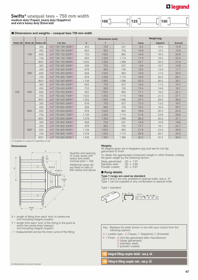
67
Swifts® unequal tees – 750 mm widthmedium duty (Topaz), heavy duty (Sapphire)and extra heavy duty (Emerald)
■ Dimensions and weights – unequal tees 750 mm width
Width (W) Width (B) Radius (R) Cat. Nos. X Y i Topaz Sapphire Emerald
300 XUT 750 150 300R F 453 753 537 9·2 10·0 12·9
450 XUT 750 150 450R F 603 903 750 10·9 12·0 15·8
150 600 XUT 750 150 600R F 753 1 053 962 14·9 16·3 20·9
750 XUT 750 150 750R F 903 1 203 1 174 17·9 19·5 25·0
900(1) XUT 750 150 900R F 1 053 1 353 1 386 23·7 25·5 31·8
300 XUT 750 300 300R F 528 753 537 9·8 10·7 13·8
450 XUT 750 300 450R F 678 903 750 12·6 13·8 17·7
300 600 XUT 750 300 600R F 828 1 053 962 15·8 17·2 22·0
750 XUT 750 300 750R F 978 1 203 1 174 18·8 20·4 26·1
900(1) XUT 750 300 900R F 1 128 1 353 1 386 24·3 26·2 32·7
300 XUT 750 450 300R F 603 753 537 10·5 11·5 14·7
450 XUT 750 450 450R F 753 903 750 13·4 14·6 18·7
750 450 600 XUT 750 450 600R F 903 1 053 962 17·7 19·2 24·1
750 XUT 750 450 750R F 1 053 1 203 1 174 19·6 21·3 27·1
900(1) XUT 750 450 900R F 1 203 1 353 1 386 27·5 29·4 36·0
300 XUT 750 600 300R F 678 753 537 12·3 13·3 16·7
450 XUT 750 600 450R F 828 903 750 15·2 16·4 20·7
600 600 XUT 750 600 600R F 978 1 053 962 18·8 20·3 25·4
750 XUT 750 600 750R F 1 128 1 203 1 174 21·8 23·6 29·6
900(1) XUT 750 600 900R F 1 278 1 353 1 386 28·3 30·3 37·1
300 XUT 750 900 300R F 828 753 537 14·8 15·9 19·6
450 XUT 750 900 450R F 978 903 750 17·7 19·1 23·7
900 600 XUT 750 900 600R F 1 128 1 053 962 21·8 23·4 28·8
750 XUT 750 900 750R F 1 278 1 203 1 174 24·9 26·7 33·0
900(1) XUT 750 900 900R F 1 428 1 353 1 386 30·2 32·3 39·4
Weight (kg) Dimensions (mm)
X = length of fitting from each ‘end’ of centre-line (not including integral coupler)
Y = length from each ‘end’ of the fitting to the point at which the centre-lines intersect (not including integral coupler)
i = measurement across the inner curve of the fitting
Dimensions
Y
80
80
Radius
i
X
A
A
A
WidthW
WidthB
Quantity and spacing of rungs varies with radius and width, nominal pitch = 300
Additional rungs (A) are fitted on tees of 600 radius and above
Key : Replace the letter shown in red with your choice from the following options :
X = Ladder type : Z (Topaz), P (Sapphire), E (Emerald)
F = Finish : G (hot dip galvanised after manufacture)D (deep galvanised)S (stainless steel)E (powder coated)
(1) Supplied in 2 parts for assembly on site
WeightsAll weights given are in kilograms (kg) and are for hot dip galvanised G finish
To obtain the appropriate component weight in other finishes, multiply the given weight by the following factors :
Deep galvanised (D) x 1·07Stainless steel (S) x 0·94Powder coated (E) x 0·97
All dimensions (mm) are nominal
Integral fitting coupler detail : see p. 44➔
Fitting to fitting coupler sets : see p. 45➔
150125100
■ Rung details
Type 1 rungs are used as standardType 2 and 3 are only available to special order, see p. 37Type 1 can be supplied in any combination to special order
42
21
35 x 1135 x 1150
Type 1 standard
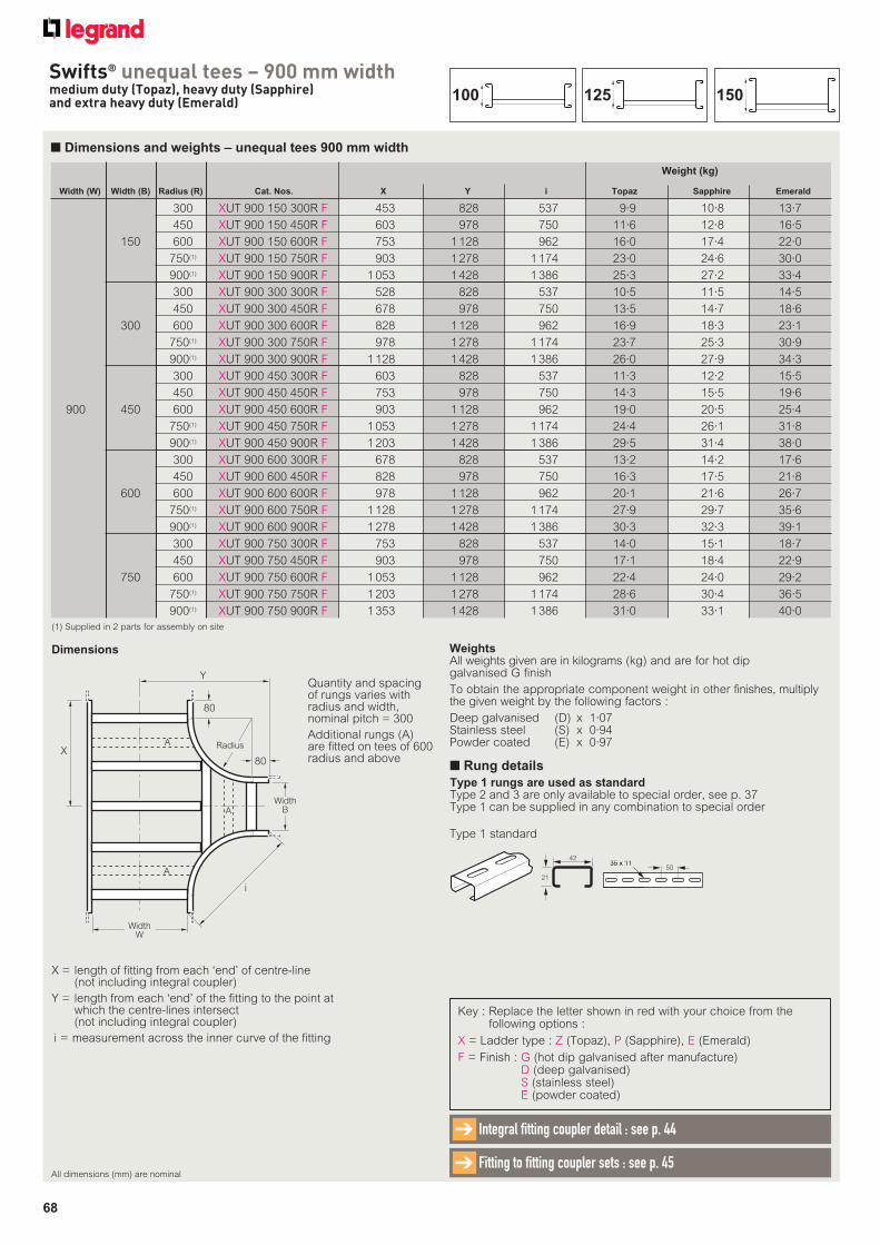
68
Swifts® unequal tees – 900 mm widthmedium duty (Topaz), heavy duty (Sapphire)and extra heavy duty (Emerald)
X = length of fitting from each ‘end’ of centre-line (not including integral coupler)
Y = length from each ‘end’ of the fitting to the point at which the centre-lines intersect (not including integral coupler)
i = measurement across the inner curve of the fitting
Dimensions
■ Dimensions and weights – unequal tees 900 mm width
Width (W) Width (B) Radius (R) Cat. Nos. X Y i Topaz Sapphire Emerald
300 XUT 900 150 300R F 453 828 537 9·9 10·8 13·7
450 XUT 900 150 450R F 603 978 750 11·6 12·8 16·5
150 600 XUT 900 150 600R F 753 1 128 962 16·0 17·4 22·0
750(1) XUT 900 150 750R F 903 1 278 1 174 23·0 24·6 30·0
900(1) XUT 900 150 900R F 1 053 1 428 1 386 25·3 27·2 33·4
300 XUT 900 300 300R F 528 828 537 10·5 11·5 14·5
450 XUT 900 300 450R F 678 978 750 13·5 14·7 18·6
300 600 XUT 900 300 600R F 828 1 128 962 16·9 18·3 23·1
750(1) XUT 900 300 750R F 978 1 278 1 174 23·7 25·3 30·9
900(1) XUT 900 300 900R F 1 128 1 428 1 386 26·0 27·9 34·3
300 XUT 900 450 300R F 603 828 537 11·3 12·2 15·5
450 XUT 900 450 450R F 753 978 750 14·3 15·5 19·6
900 450 600 XUT 900 450 600R F 903 1 128 962 19·0 20·5 25·4
750(1) XUT 900 450 750R F 1 053 1 278 1 174 24·4 26·1 31·8
900(1) XUT 900 450 900R F 1 203 1 428 1 386 29·5 31·4 38·0
300 XUT 900 600 300R F 678 828 537 13·2 14·2 17·6
450 XUT 900 600 450R F 828 978 750 16·3 17·5 21·8
600 600 XUT 900 600 600R F 978 1 128 962 20·1 21·6 26·7
750(1) XUT 900 600 750R F 1 128 1 278 1 174 27·9 29·7 35·6
900(1) XUT 900 600 900R F 1 278 1 428 1 386 30·3 32·3 39·1
300 XUT 900 750 300R F 753 828 537 14·0 15·1 18·7
450 XUT 900 750 450R F 903 978 750 17·1 18·4 22·9
750 600 XUT 900 750 600R F 1 053 1 128 962 22·4 24·0 29·2
750(1) XUT 900 750 750R F 1 203 1 278 1 174 28·6 30·4 36·5
900(1) XUT 900 750 900R F 1 353 1 428 1 386 31·0 33·1 40·0
Weight (kg)
Y
80
80
Radius
i
X
A
A
A
WidthW
WidthB
Quantity and spacing of rungs varies with radius and width, nominal pitch = 300
Additional rungs (A) are fitted on tees of 600 radius and above
Key : Replace the letter shown in red with your choice from the following options :
X = Ladder type : Z (Topaz), P (Sapphire), E (Emerald)
F = Finish : G (hot dip galvanised after manufacture)D (deep galvanised)S (stainless steel)E (powder coated)
(1) Supplied in 2 parts for assembly on site
WeightsAll weights given are in kilograms (kg) and are for hot dip galvanised G finish
To obtain the appropriate component weight in other finishes, multiply the given weight by the following factors :
Deep galvanised (D) x 1·07Stainless steel (S) x 0·94Powder coated (E) x 0·97
All dimensions (mm) are nominal
Integral fitting coupler detail : see p. 44➔
Fitting to fitting coupler sets : see p. 45➔
150125100
■ Rung details
Type 1 rungs are used as standardType 2 and 3 are only available to special order, see p. 37Type 1 can be supplied in any combination to special order
42
21
35 x 1135 x 1150
Type 1 standard
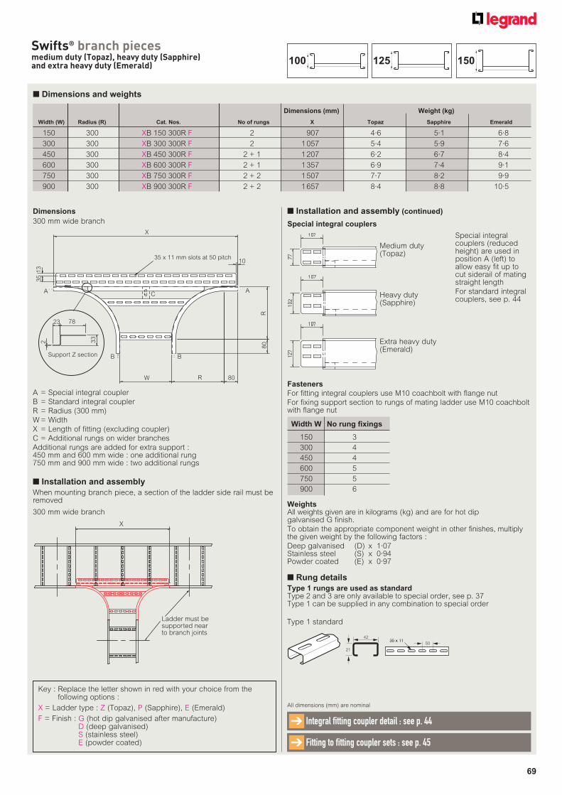
69
Swifts® branch piecesmedium duty (Topaz), heavy duty (Sapphire)and extra heavy duty (Emerald)
■ Dimensions and weights
Dimensions
Key : Replace the letter shown in red with your choice from the following options :
X = Ladder type : Z (Topaz), P (Sapphire), E (Emerald)
F = Finish : G (hot dip galvanised after manufacture)D (deep galvanised)S (stainless steel)E (powder coated)
Width (W) Radius (R) Cat. Nos. No of rungs X Topaz Sapphire Emerald
150 300 XB 150 300R F 2 907 4·6 5·1 6·8
300 300 XB 300 300R F 2 1 057 5·4 5·9 7·6
450 300 XB 450 300R F 2 + 1 1 207 6·2 6·7 8·4
600 300 XB 600 300R F 2 + 1 1 357 6·9 7·4 9·1
750 300 XB 750 300R F 2 + 2 1 507 7·7 8·2 9·9
900 300 XB 900 300R F 2 + 2 1 657 8·4 8·8 10·5
Weight (kg)Dimensions (mm)
X
35 x 11 mm slots at 50 pitch
Support Z section
A
10
C
R80
80R
BB
W
A
13
35
23 78
33
2
X
Ladder must be supported nearto branch joints
Fasteners
For fitting integral couplers use M10 coachbolt with flange nut
For fixing support section to rungs of mating ladder use M10 coachbolt with flange nut
Width W No rung fi xings
150 3
300 4
450 4
600 5
750 5
900 6
WeightsAll weights given are in kilograms (kg) and are for hot dip galvanised G finish.
To obtain the appropriate component weight in other finishes, multiply the given weight by the following factors :
Deep galvanised (D) x 1·07Stainless steel (S) x 0·94Powder coated (E) x 0·97
All dimensions (mm) are nominal
Integral fitting coupler detail : see p. 44➔
Fitting to fitting coupler sets : see p. 45 ➔
300 mm wide branch
300 mm wide branch
Special integral couplers
Special integral couplers (reduced height) are used in position A (left) to allow easy fit up to cut siderail of mating straight length
For standard integral couplers, see p. 44
A = Special integral coupler
B = Standard integral coupler
R = Radius (300 mm)
W = Width
X = Length of fitting (excluding coupler)
C = Additional rungs on wider branches
Additional rungs are added for extra support :450 mm and 600 mm wide : one additional rung750 mm and 900 mm wide : two additional rungs
■ Installation and assembly
When mounting branch piece, a section of the ladder side rail must be removed
■ Installation and assembly (continued)
Medium duty(Topaz)
Heavy duty(Sapphire)
Extra heavy duty(Emerald)
■ Rung details
Type 1 rungs are used as standardType 2 and 3 are only available to special order, see p. 37Type 1 can be supplied in any combination to special order
42
21
35 x 1135 x 1150
Type 1 standard
150125100
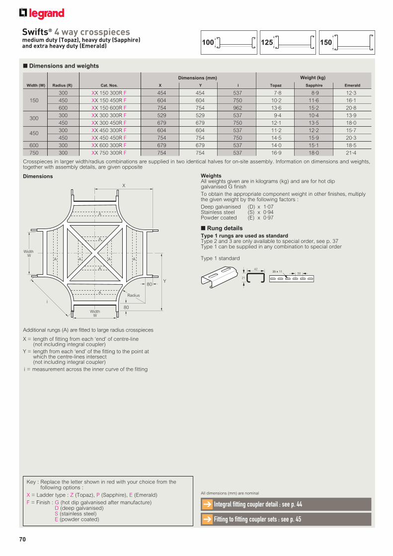
70
Swifts® 4 way crosspiecesmedium duty (Topaz), heavy duty (Sapphire)and extra heavy duty (Emerald)
■ Dimensions and weights
X = length of fitting from each ‘end’ of centre-line (not including integral coupler)
Y = length from each ‘end’ of the fitting to the point at which the centre-lines intersect (not including integral coupler)
i = measurement across the inner curve of the fitting
Dimensions
Key : Replace the letter shown in red with your choice from the following options :
X = Ladder type : Z (Topaz), P (Sapphire), E (Emerald)
F = Finish : G (hot dip galvanised after manufacture)D (deep galvanised)S (stainless steel)E (powder coated)
Width (W) Radius (R) Cat. Nos. X Y i Topaz Sapphire Emerald
300 XX 150 300R F 454 454 537 7·8 8·9 12·3
150 450 XX 150 450R F 604 604 750 10·2 11·6 16·1
600 XX 150 600R F 754 754 962 13·6 15·2 20·8
300 XX 300 300R F 529 529 537 9·4 10·4 13·9 300
450 XX 300 450R F 679 679 750 12·1 13·5 18·0
300 XX 450 300R F 604 604 537 11·2 12·2 15·7 450
450 XX 450 450R F 754 754 750 14·5 15·9 20·3
600 300 XX 600 300R F 679 679 537 14·0 15·1 18·5
750 300 XX 750 300R F 754 754 537 16·9 18·0 21·4
Weight (kg)Dimensions (mm)
Additional rungs (A) are fitted to large radius crosspieces
Crosspieces in larger width/radius combinations are supplied in two identical halves for on-site assembly. Information on dimensions and weights, together with assembly details, are given opposite
WeightsAll weights given are in kilograms (kg) and are for hot dip galvanised G finish
To obtain the appropriate component weight in other finishes, multiply the given weight by the following factors :
Deep galvanised (D) x 1·07Stainless steel (S) x 0·94Powder coated (E) x 0·97
All dimensions (mm) are nominal
Integral fitting coupler detail : see p. 44➔
Fitting to fitting coupler sets : see p. 45➔
Y80
80
Radius
i
Width W
WidthW
X
A A
A
A
A A
A
A
■ Rung details
Type 1 rungs are used as standardType 2 and 3 are only available to special order, see p. 37Type 1 can be supplied in any combination to special order
150125100
42
21
35 x 1135 x 1150
Type 1 standard
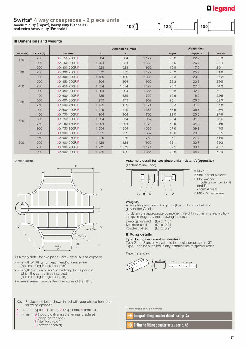
71
Swifts® 4 way crosspieces - 2 piece unitsmedium duty (Topaz), heavy duty (Sapphire)and extra heavy duty (Emerald)
■ Dimensions and weights
X = length of fitting from each ‘end’ of centre-line (not including integral coupler)
Y = length from each ‘end’ of the fitting to the point at which the centre-lines intersect (not including integral coupler)
i = measurement across the inner curve of the fitting
Dimensions
Key : Replace the letter shown in red with your choice from the following options :
X = Ladder type : Z (Topaz), P (Sapphire), E (Emerald)
F = Finish : G (hot dip galvanised after manufacture)D (deep galvanised)S (stainless steel)E (powder coated)
Width (W) Radius (R) Cat. Nos. X Y i Topaz Sapphire Emerald
750 XX 150 750R F 904 904 1 174 20·8 22·7 29·3 150
900 XX 150 900R F 1 054 1 054 1 386 24·5 26·7 34·4
600 XX 300 600R F 829 829 962 15·9 17·6 23·1
300 750 XX 300 750R F 979 979 1 174 23·3 25·2 31·8
900 XX 300 900R F 1 129 1 129 1 386 27·3 29·5 37·2
600 XX 450 600R F 904 904 962 22·3 23·9 29·5
450 750 XX 450 750R F 1 054 1 054 1 174 25·7 27·6 34·3
900 XX 450 900R F 1 204 1 204 1 386 29·8 32·0 39·7
450 XX 600 450R F 829 829 750 16·6 18·0 22·5
600 XX 600 600R F 979 979 962 25·1 26·8 32·3 600
750 XX 600 750R F 1 129 1 129 1 174 29·3 31·2 37·8
900 XX 600 900R F 1 279 1 279 1 386 33·5 35·7 43·4
450 XX 750 450R F 904 904 750 22·0 23·3 27·8
600 XX 750 600R F 1 054 1 054 962 29·4 31·0 36·6 750
750 XX 750 750R F 1 204 1 204 1 174 32·9 34·9 41·5
900 XX 750 900R F 1 354 1 354 1 386 37·6 39·9 47·5
300 XX 900 300R F 829 829 537 19·0 20·0 23·5
450 XX 900 450R F 979 979 750 25·7 27·1 31·6
900 600 XX 900 600R F 1 129 1 129 962 32·1 33·7 39·3
750 XX 900 750R F 1 279 1 279 1 174 37·2 39·1 45·7
900 XX 900 900R F 1 429 1 429 1 386 42·5 44·7 52·4
Weight (kg)Dimensions (mm)
80
80
Radius
i
WidthW
X
Y
A
Y
Assembly detail for two piece units - detail A, see opposite
WeightsAll weights given are in kilograms (kg) and are for hot dip galvanised G finish
To obtain the appropriate component weight in other finishes, multiply the given weight by the following factors :
Deep galvanised (D) x 1·07Stainless steel (S) x 0·94Powder coated (E) x 0·97
All dimensions (mm) are nominal
Integral fitting coupler detail : see p. 44➔
Fitting to fitting coupler sets : see p. 45➔
Assembly detail for two piece units - detail A (opposite)
(Fasteners included)
A M6 nut
B Shakeproof washer
C Flat washer - roofing washers for G and D - form A for S
D M6 x 16 set screwA B C DC
■ Rung details
Type 1 rungs are used as standardType 2 and 3 are only available to special order, see p. 37Type 1 can be supplied in any combination to special order
150125100
42
21
35 x 1135 x 1150
Type 1 standard
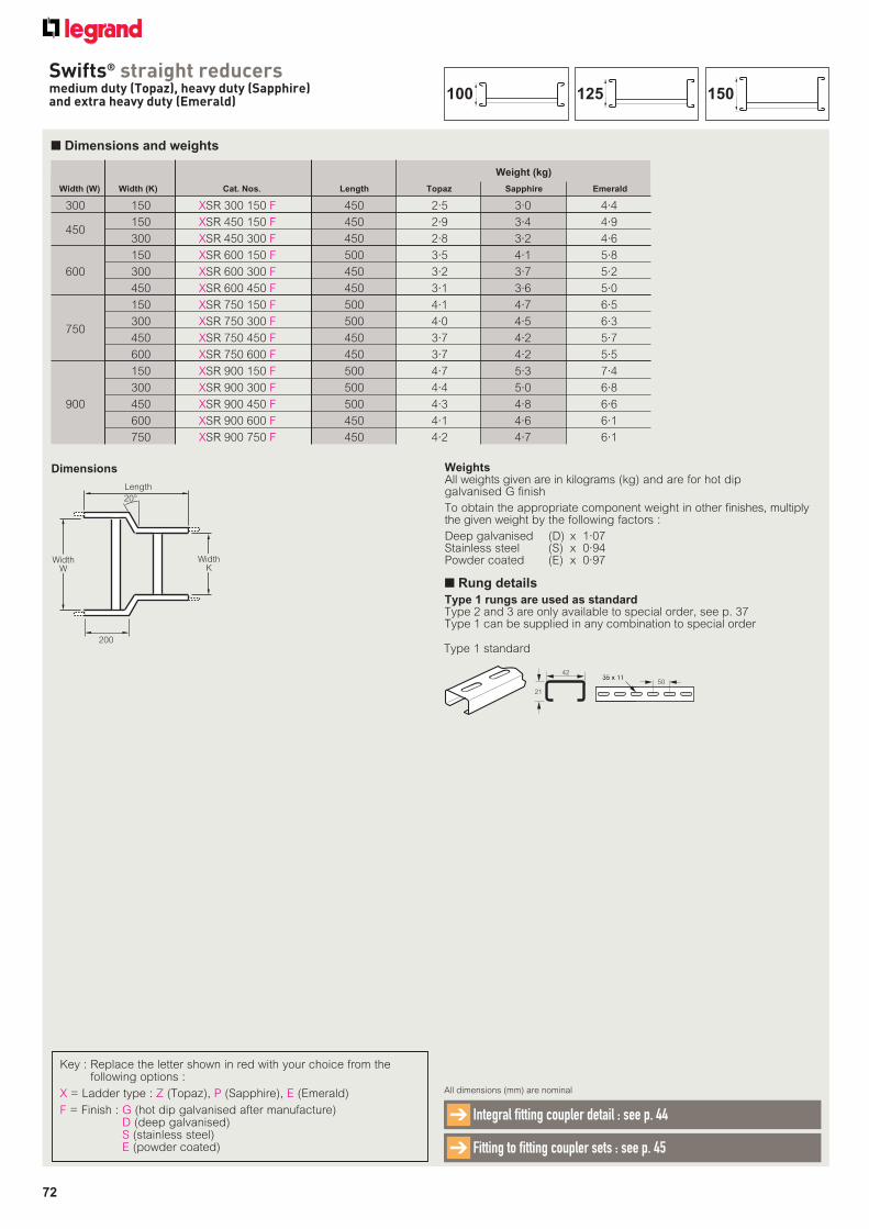
72
Swifts® straight reducersmedium duty (Topaz), heavy duty (Sapphire) and extra heavy duty (Emerald)
■ Dimensions and weights
Dimensions
Width (W) Width (K) Cat. Nos. Length Topaz Sapphire Emerald
300 150 XSR 300 150 F 450 2·5 3·0 4·4
150 XSR 450 150 F 450 2·9 3·4 4·9 450
300 XSR 450 300 F 450 2·8 3·2 4·6
150 XSR 600 150 F 500 3·5 4·1 5·8
600 300 XSR 600 300 F 450 3·2 3·7 5·2
450 XSR 600 450 F 450 3·1 3·6 5·0
150 XSR 750 150 F 500 4·1 4·7 6·5
300 XSR 750 300 F 500 4·0 4·5 6·3 750
450 XSR 750 450 F 450 3·7 4·2 5·7
600 XSR 750 600 F 450 3·7 4·2 5·5
150 XSR 900 150 F 500 4·7 5·3 7·4
300 XSR 900 300 F 500 4·4 5·0 6·8
900 450 XSR 900 450 F 500 4·3 4·8 6·6
600 XSR 900 600 F 450 4·1 4·6 6·1
750 XSR 900 750 F 450 4·2 4·7 6·1
Weight (kg)
Key : Replace the letter shown in red with your choice from the following options :
X = Ladder type : Z (Topaz), P (Sapphire), E (Emerald)
F = Finish : G (hot dip galvanised after manufacture)D (deep galvanised)S (stainless steel)E (powder coated)
WeightsAll weights given are in kilograms (kg) and are for hot dip galvanised G finish
To obtain the appropriate component weight in other finishes, multiply the given weight by the following factors :
Deep galvanised (D) x 1·07Stainless steel (S) x 0·94Powder coated (E) x 0·97
All dimensions (mm) are nominal
Integral fitting coupler detail : see p. 44➔
Fitting to fitting coupler sets : see p. 45 ➔
Length
WidthW
WidthK
200
20°
■ Rung details
Type 1 rungs are used as standardType 2 and 3 are only available to special order, see p. 37Type 1 can be supplied in any combination to special order
150125100
42
21
35 x 1135 x 1150
Type 1 standard
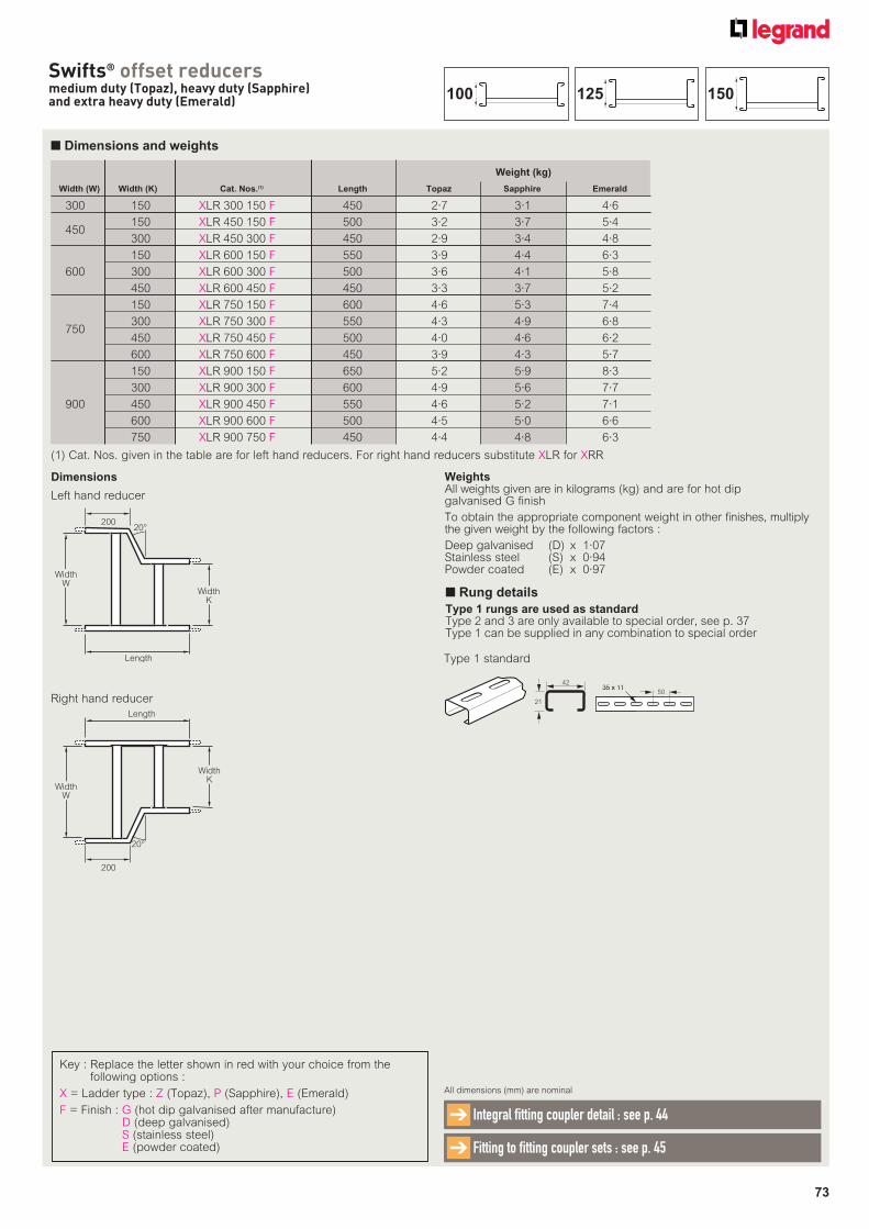
73
Swifts® offset reducersmedium duty (Topaz), heavy duty (Sapphire) and extra heavy duty (Emerald)
■ Dimensions and weights
Dimensions
Key : Replace the letter shown in red with your choice from the following options :
X = Ladder type : Z (Topaz), P (Sapphire), E (Emerald)
F = Finish : G (hot dip galvanised after manufacture)D (deep galvanised)S (stainless steel)E (powder coated)
Width (W) Width (K) Cat. Nos.(1) Length Topaz Sapphire Emerald
300 150 XLR 300 150 F 450 2·7 3·1 4·6
150 XLR 450 150 F 500 3·2 3·7 5·4 450
300 XLR 450 300 F 450 2·9 3·4 4·8
150 XLR 600 150 F 550 3·9 4·4 6·3
600 300 XLR 600 300 F 500 3·6 4·1 5·8
450 XLR 600 450 F 450 3·3 3·7 5·2
150 XLR 750 150 F 600 4·6 5·3 7·4
300 XLR 750 300 F 550 4·3 4·9 6·8 750
450 XLR 750 450 F 500 4·0 4·6 6·2
600 XLR 750 600 F 450 3·9 4·3 5·7
150 XLR 900 150 F 650 5·2 5·9 8·3
300 XLR 900 300 F 600 4·9 5·6 7·7
900 450 XLR 900 450 F 550 4·6 5·2 7·1
600 XLR 900 600 F 500 4·5 5·0 6·6
750 XLR 900 750 F 450 4·4 4·8 6·3
Weight (kg)
(1) Cat. Nos. given in the table are for left hand reducers. For right hand reducers substitute XLR for XRR
WeightsAll weights given are in kilograms (kg) and are for hot dip galvanised G finish
To obtain the appropriate component weight in other finishes, multiply the given weight by the following factors :
Deep galvanised (D) x 1·07Stainless steel (S) x 0·94Powder coated (E) x 0·97
All dimensions (mm) are nominal
Integral fitting coupler detail : see p. 44➔
Fitting to fitting coupler sets : see p. 45➔
Right hand reducer
Left hand reducer
Length
WidthW
WidthK
20020°
Length
20°
200
WidthW
WidthK
■ Rung details
Type 1 rungs are used as standardType 2 and 3 are only available to special order, see p. 37Type 1 can be supplied in any combination to special order
150125100
42
21
35 x 1135 x 1150
Type 1 standard
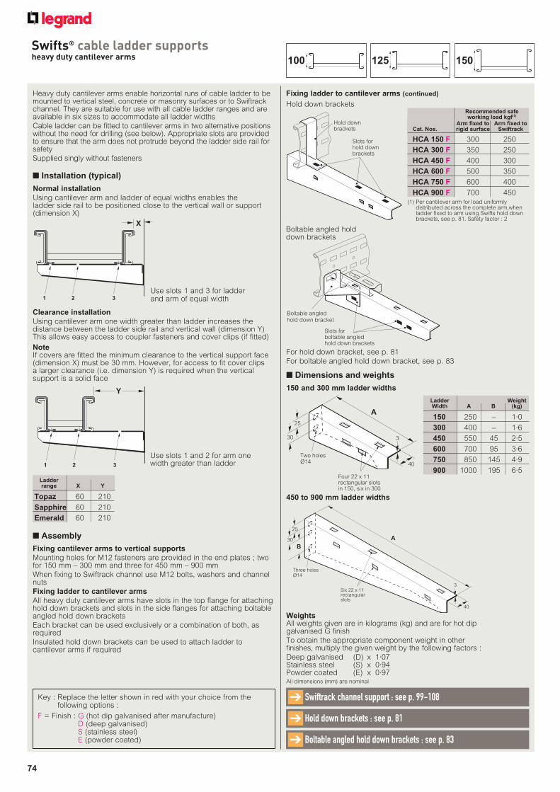
74
Swifts® cable ladder supportsheavy duty cantilever arms
Key : Replace the letter shown in red with your choice from the following options :
F = Finish : G (hot dip galvanised after manufacture)D (deep galvanised)S (stainless steel)E (powder coated)
Heavy duty cantilever arms enable horizontal runs of cable ladder to be mounted to vertical steel, concrete or masonry surfaces or to Swiftrack channel. They are suitable for use with all cable ladder ranges and are available in six sizes to accommodate all ladder widths
Cable ladder can be fitted to cantilever arms in two alternative positions without the need for drilling (see below). Appropriate slots are provided to ensure that the arm does not protrude beyond the ladder side rail for safety
Supplied singly without fasteners
■ Dimensions and weights
■ Installation (typical)
Use slots 1 and 3 for ladder and arm of equal width1 2 3
X
Use slots 1 and 2 for arm one width greater than ladder1 2 3
Y
Normal installation
Using cantilever arm and ladder of equal widths enables the ladder side rail to be positioned close to the vertical wall or support (dimension X)
Clearance installation
Using cantilever arm one width greater than ladder increases the distance between the ladder side rail and vertical wall (dimension Y) This allows easy access to coupler fasteners and cover clips (if fitted)
NoteIf covers are fitted the minimum clearance to the vertical support face (dimension X) must be 30 mm. However, for access to fit cover clips a larger clearance (i.e. dimension Y) is required when the vertical support is a solid face
For hold down bracket, see p. 81
For boltable angled hold down bracket, see p. 83
Fixing ladder to cantilever arms (continued)
Slots forhold down brackets
Hold down brackets
Arm fixed to Arm fixed toCat. Nos. rigid surface Swiftrack
HCA 150 F 300 250
HCA 300 F 350 250
HCA 450 F 400 300
HCA 600 F 500 350
HCA 750 F 600 400
HCA 900 F 700 450
Recommended safe working load kgf(1)
Boltable angledhold down bracket
Slots forboltable angledhold down brackets
Fixing cantilever arms to vertical supports
Mounting holes for M12 fasteners are provided in the end plates ; two for 150 mm – 300 mm and three for 450 mm – 900 mm
When fixing to Swiftrack channel use M12 bolts, washers and channel nuts
Fixing ladder to cantilever arms
All heavy duty cantilever arms have slots in the top flange for attaching hold down brackets and slots in the side flanges for attaching boltable angled hold down brackets
Each bracket can be used exclusively or a combination of both, as required
Insulated hold down brackets can be used to attach ladder to cantilever arms if required
■ Assembly
150 250 – 1·0
300 400 – 1·6
450 550 45 2·5
600 700 95 3·6
750 850 145 4·9
900 1000 195 6·5
Ladder Weight Width A B (kg)
(1) Per cantilever arm for load uniformly distributed across the complete arm,when ladder fixed to arm using Swifts hold down brackets, see p. 81. Safety factor : 2
A
Four 22 x 11 rectangular slotsin 150, six in 300
Two holesØ14
25
30
40
3
150 and 300 mm ladder widths
Hold down brackets
Boltable angled hold down brackets
Six 22 x 11 rectangular slots
Three holes Ø14
B
25
30 A
40
3
450 to 900 mm ladder widths Topaz 60 210
Sapphire 60 210
Emerald 60 210
Ladder range X Y
All dimensions (mm) are nominal
Hold down brackets : see p. 81➔
Swiftrack channel support : see p. 99-108➔
Boltable angled hold down brackets : see p. 83➔
WeightsAll weights given are in kilograms (kg) and are for hot dip galvanised G finish
To obtain the appropriate component weight in other finishes, multiply the given weight by the following factors :
Deep galvanised (D) x 1·07Stainless steel (S) x 0·94Powder coated (E) x 0·97
150125100
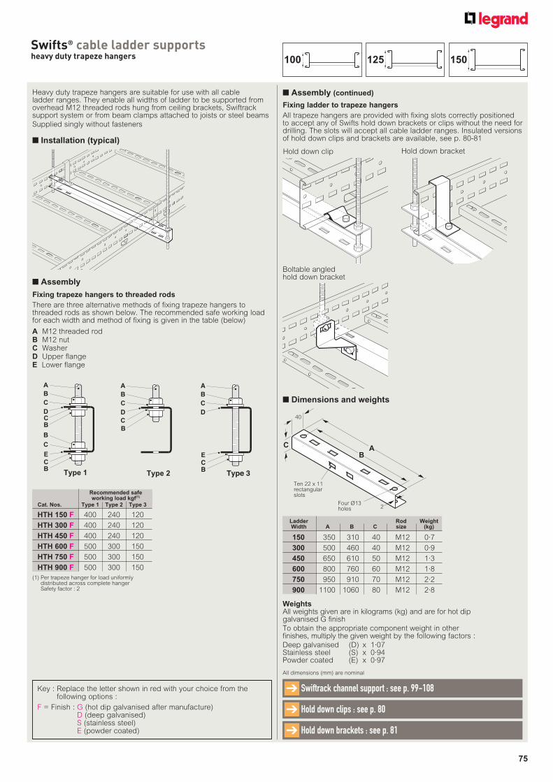
75
Swifts® cable ladder supportsheavy duty trapeze hangers
Heavy duty trapeze hangers are suitable for use with all cable ladder ranges. They enable all widths of ladder to be supported from overhead M12 threaded rods hung from ceiling brackets, Swiftrack support system or from beam clamps attached to joists or steel beams
Supplied singly without fasteners
■ Installation (typical)
A M12 threaded rodB M12 nutC WasherD Upper flangeE Lower flange
Fixing trapeze hangers to threaded rods
There are three alternative methods of fixing trapeze hangers to threaded rods as shown below. The recommended safe working load for each width and method of fixing is given in the table (below)
A
B
C
D
B
C
E
Type 1
CB
CB
A
B
C
D
Type 2
B
C
A
B
C
D
E
Type 3BC
Fixing ladder to trapeze hangers
All trapeze hangers are provided with fixing slots correctly positioned to accept any of Swifts hold down brackets or clips without the need for drilling. The slots will accept all cable ladder ranges. Insulated versions of hold down clips and brackets are available, see p. 80-81
Hold down bracket
Boltable angledhold down bracket
Hold down clip
■ Dimensions and weights
Four Ø13holes 2
Ten 22 x 11rectangularslots
40
C AB
Ladder Rod Weight Width A B C size (kg)
150 350 310 40 M12 0·7
300 500 460 40 M12 0·9
450 650 610 50 M12 1·3
600 800 760 60 M12 1·8
750 950 910 70 M12 2·2
900 1100 1060 80 M12 2·8
(1) Per trapeze hanger for load uniformly distributed across complete hanger Safety factor : 2
Cat. Nos. Type 1 Type 2 Type 3
HTH 150 F 400 240 120
HTH 300 F 400 240 120
HTH 450 F 400 240 120
HTH 600 F 500 300 150
HTH 750 F 500 300 150
HTH 900 F 500 300 150
Recommended safe working load kgf(1)
Key : Replace the letter shown in red with your choice from the following options :
F = Finish : G (hot dip galvanised after manufacture)D (deep galvanised)S (stainless steel)E (powder coated)
All dimensions (mm) are nominal
Hold down clips : see p. 80➔
Swiftrack channel support : see p. 99-108➔
Hold down brackets : see p. 81➔
WeightsAll weights given are in kilograms (kg) and are for hot dip galvanised G finish
To obtain the appropriate component weight in other finishes, multiply the given weight by the following factors :
Deep galvanised (D) x 1·07Stainless steel (S) x 0·94Powder coated (E) x 0·97
■ Assembly
■ Assembly (continued)
150125100
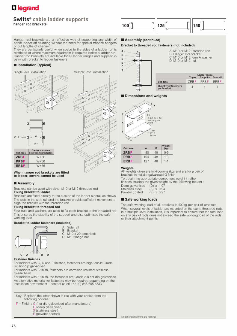
76
Swifts® cable ladder supportshanger rod brackets
All dimensions (mm) are nominal
■ Dimensions and weights
Hanger rod brackets are an effective way of supporting any width of cable ladder off studding without the need for special trapeze hangers or cut lengths of channelThey are particularly useful when space to the sides of a ladder run is restricted or where maximum headroom is required below a ladder runHanger rod brackets are available for all ladder ranges and supplied in pairs with bracket to ladder fasteners
When hanger rod brackets are fitted to ladder, covers cannot be used
■ Installation (typical)
120
A
15
B
TwoØ13holes
Four 37 x 13rectangularslots
3·0
Ladder range Topaz Sapphire Emerald
Cat. Nos. ZRB F PRB F ERB F
Quantity of fasteners per bracket 4 4 4
Bracket to threaded rod fasteners (not included)
A M10 or M12 threaded rod B Hanger rod bracket C M10 or M12 form A washer D M10 or M12 nut
A
B
C
D
C
B
■ Assembly (continued)
Brackets can be used with either M10 or M12 threaded rodFixing bracket to ladder
Brackets are fixed directly to the outside of the ladder siderail as shown
The slots in the side rail and the bracket provide sufficient movement to align the bracket with the threaded rod
Fixing bracket to threaded rod
Four nuts and washers are used to fix each bracket to the threaded rod
This ensures the stability of the support and also optimises the safe working load
WeightCat. Nos. A B (kg)
ZRB F 80 48 0·9
PRB F 104 48 1·0
ERB F 127 48 1·1
Centre distance Cat. Nos. between fixing holes
ZRB F W+66
PRB F W+66
ERB F W+66
The safe working load of all brackets is 400kg per pair of brackets
When several levels of ladder are mounted on the same threaded rods in a multiple level installation, it is important to ensure that the total load on any pair of rods does not exceed the safe working load of the rods or their attachment points
■ Safe working loads
W
W+
Ø11 Holes
Multiple level installationSingle level installation
Bracket to ladder fasteners (included)
C A B D
A Side rail B Bracket C M10 x 20 coachbolt D M10 flange nut
Fastener finishes
For ladders with G, D and E finishes, fasteners are high tensile Grade 8.8 hot dip galvanisedFor ladders with S finish, fasteners are corrosion resistant stainless Grade A470For ladders with E finish, the fasteners are Grade 8.8 hot dip galvanisedAn alternative material for fasteners may be required depending on the installation environment – contact us on +44 (0) 845 605 4333
■ Assembly
WeightsAll weights given are in kilograms (kg) and are for a pair of brackets in hot dip galvanised G finish
To obtain the appropriate component weight in other finishes, multiply the given weight by the following factors :
Deep galvanised (D) x 1·07Stainless steel (S) x 0·94Powder coated (E) x 0·97
Key : Replace the letter shown in red with your choice from the following options :
F = Finish : G (hot dip galvanised after manufacture)D (deep galvanised)S (stainless steel)E (powder coated)
150125100
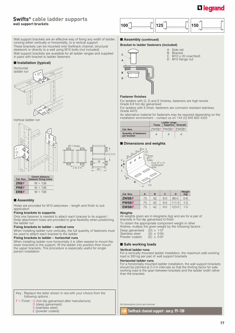
77
Swifts® cable ladder supportswall support brackets
■ Dimensions and weights
Wall support brackets are an effective way of fixing any width of ladder, running either vertically or horizontally, to a vertical support
These brackets can be mounted onto Swiftrack channel, structural steelwork or directly to a wall using M10 bolts (not included)
Wall support brackets are available for all ladder ranges and supplied in pairs with bracket to ladder fasteners
■ Installation (typical)
■ Assembly
■ Assembly (continued)
Holes are provided for M10 setscrews – length and finish to suit application
Fixing brackets to supports
Only one fastener is needed to attach each bracket to its support ; three attachment holes are provided to give flexibility when positioning the ladder run
Fixing brackets to ladder – vertical runs
When installing ladder runs vertically, the full quantity of fasteners must be used to attach each bracket to the ladder
Fixing brackets to ladder – horizontal runs
When installing ladder runs horizontally it is often easiest to mount the lower brackets to the support, lift the ladder into position then mount the upper brackets. This procedure is especially useful for single person installation
Vertical ladder runsFor a vertically mounted ladder installation, the maximum safe working load is 300 kg per pair of wall support brackets
Horizontal ladder runsFor a horizontally mounted ladder installation, the wall support brackets should be pitched at 2-3 m intervals so that the limiting factor for safe working load is the span between brackets and the ladder width rather than the brackets
■ Safe working loads
Horizontalladder run
Vertical ladder run
BA
D
C
3·0
3030
3030 22
ThreeØ11holes
Four 37 x 13rectangularslots
WeightCat. Nos. A B C D (kg)
ZWSB F 75 42 9·0 86·0 0·8
PWSB F 75 42 9·0 111·0 1·0
EWSB F 75 42 9·0 123·5 1·0
Ladder range Topaz Sapphire Emerald
Cat. Nos. ZWSB F PWSB F EWSB F
Quantity of fasteners per bracket 4 4 4
Key : Replace the letter shown in red with your choice from the following options :
F = Finish : G (hot dip galvanised after manufacture)D (deep galvanised)S (stainless steel)E (powder coated)
Bracket to ladder fasteners (included)
A Side rail B Bracket C M10 x 20 coachbolt D M10 flange nut
C
A
B
D
Fastener finishes
For ladders with G, D and E finishes, fasteners are high tensile Grade 8.8 hot dip galvanisedFor ladders with S finish, fasteners are corrosion resistant stainless Grade A470An alternative material for fasteners may be required depending on the installation environment – contact us on +44 (0) 845 605 4333
W
W+2 to 3 m
2 to 3 m
Ø11 Holes
All dimensions (mm) are nominal
Swiftrack channel support : see p. 99-108➔
WeightsAll weights given are in kilograms (kg) and are for a pair of brackets in hot dip galvanised G finish
To obtain the appropriate component weight in other finishes, multiply the given weight by the following factors :
Deep galvanised (D) x 1·07Stainless steel (S) x 0·94Powder coated (E) x 0·97
Centre distance Cat. Nos. between fixing holes
ZRB F W + 106
PRB F W + 106
ERB F W + 106
150125100
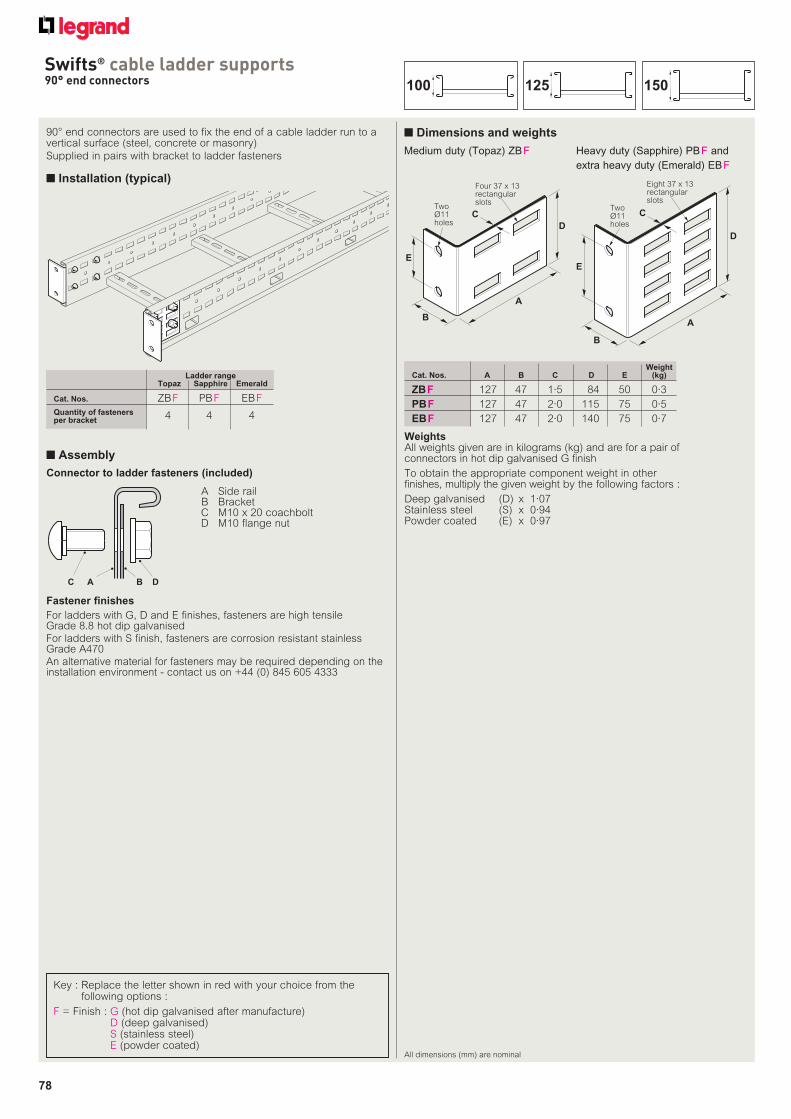
78
Swifts® cable ladder supports90° end connectors
All dimensions (mm) are nominal
■ Dimensions and weights90° end connectors are used to fix the end of a cable ladder run to a vertical surface (steel, concrete or masonry)
Supplied in pairs with bracket to ladder fasteners
■ Installation (typical)
Connector to ladder fasteners (included)
A Side rail B Bracket C M10 x 20 coachbolt D M10 flange nut
C A B D
WeightCat. Nos. A B C D E (kg)
ZB F 127 47 1·5 84 50 0·3
PB F 127 47 2·0 115 75 0·5
EB F 127 47 2·0 140 75 0·7
C
A
D
B
E
TwoØ11holes
Four 37 x 13rectangularslots
Medium duty (Topaz) ZB F Heavy duty (Sapphire) PB F and
extra heavy duty (Emerald) EB F
A
D
B
E
C
Eight 37 x 13rectangularslots
TwoØ11holes
Ladder range Topaz Sapphire Emerald
Cat. Nos. ZB F PB F EB F
Quantity of fasteners per bracket 4 4 4
Fastener finishes
For ladders with G, D and E finishes, fasteners are high tensile Grade 8.8 hot dip galvanisedFor ladders with S finish, fasteners are corrosion resistant stainless Grade A470An alternative material for fasteners may be required depending on the installation environment - contact us on +44 (0) 845 605 4333
WeightsAll weights given are in kilograms (kg) and are for a pair of connectors in hot dip galvanised G finish
To obtain the appropriate component weight in other finishes, multiply the given weight by the following factors :
Deep galvanised (D) x 1·07Stainless steel (S) x 0·94Powder coated (E) x 0·97
■ Assembly
Key : Replace the letter shown in red with your choice from the following options :
F = Finish : G (hot dip galvanised after manufacture)D (deep galvanised)S (stainless steel)E (powder coated)
150125100
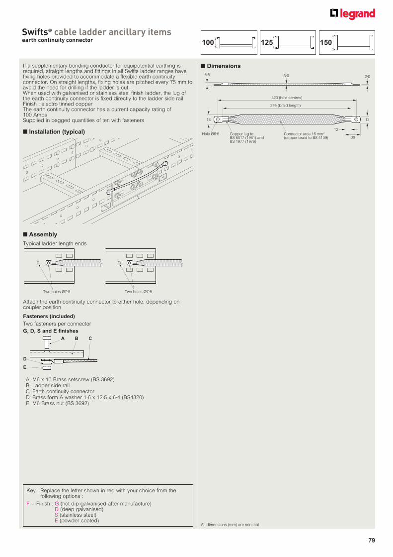
79
Swifts® cable ladder ancillary itemsearth continuity connector
All dimensions (mm) are nominal
■ DimensionsIf a supplementary bonding conductor for equipotential earthing is required, straight lengths and fittings in all Swifts ladder ranges have fixing holes provided to accommodate a flexible earth continuity connector. On straight lengths, fixing holes are pitched every 75 mm to avoid the need for drilling if the ladder is cutWhen used with galvanised or stainless steel finish ladder, the lug of the earth continuity connector is fixed directly to the ladder side rail Finish : electro tinned copperThe earth continuity connector has a current capacity rating of 100 AmpsSupplied in bagged quantities of ten with fasteners
■ Installation (typical)
Fasteners (included)
A M6 x 10 Brass setscrew (BS 3692) B Ladder side rail C Earth continuity connector D Brass form A washer 1·6 x 12·5 x 6·4 (BS4320) E M6 Brass nut (BS 3692)
A B C
D
E
G, D, S and E finishes
Copper lug toBS 6017 (1981) andBS 1977 (1976)
1318
30
12
295 (braid length)
320 (hole centres)
Hole Ø6·5 Conductor area 16 mm(copper braid to BS 4109)
2
3·05·52·0
■ Assembly
Two holes Ø7·5Two holes Ø7·5
Attach the earth continuity connector to either hole, depending on coupler position
Typical ladder length ends
Two fasteners per connector
150125100
Key : Replace the letter shown in red with your choice from the following options :
F = Finish : G (hot dip galvanised after manufacture)D (deep galvanised)S (stainless steel)E (powder coated)
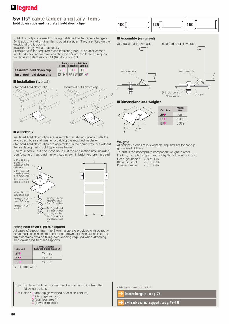
80
Swifts® cable ladder ancillary itemshold down clips and insulated hold down clips
Hold down clips are used for fixing cable ladder to trapeze hangers, Swiftrack channel or other flat support surfaces. They are fitted on the outside of the ladder railSupplied singly without fastenersSupplied with the required nylon insulating pad, bush and washerInsulated versions for stainless steel ladder are available on request, for details contact us on +44 (0) 845 605 4333
■ Assembly (continued)
Ladder range Cat. Nos. Topaz Sapphire Emerald
Standard hold down clip ZFF PFF EFF
Insulated hold down clip ZF INF PF INF EF INF
Nylon padØ15 nylon bush
Nylon washer
Hold down clipHold down clip
■ Dimensions and weights
WeightCat. Nos. (kg)
ZFF 0·069
PFF 0·069
EFF 0·069
One holeØ11
3
4065
15
WeightsAll weights given are in kilograms (kg) and are for hot dip galvanised G finish
To obtain the appropriate component weight in other finishes, multiply the given weight by the following factors :
Deep galvanised (D) x 1·07Stainless steel (S) x 0·94Powder coated (E) x 0·97
Key : Replace the letter shown in red with your choice from the following options :
F = Finish : G (hot dip galvanised after manufacture)D (deep galvanised)S (stainless steel)E (powder coated)
All dimensions (mm) are nominal
Trapeze hangers : see p. 75➔
Swiftrack channel support : see p. 99-108➔
■ Installation (typical)
■ Assembly
Insulated hold down clips are assembled as shown (typical) with the nylon pad, bush and washer providing the required insulation
Standard hold down clips are assembled in the same way, but without the insulating parts (bold type – see below)
Use M10 screw, nut and washers to suit the application (not included)
Use fasteners illustrated – only those shown in bold type are included
Insulated hold down clipStandard hold down clip
M10 x 40 longgrade A4-70stainless steel setscrew
M10 grade A4stainless steel form A washer
Nylon 66insulating pad
M10 nylon 66bush 7·5 long
M10 nylon 66washer
Stainless steel hold down clip
M10 grade A4stainless steel nut
M10 grade A4stainless steel spring washer
M10 grade A4stainless steel form A washer
Fixing hold down clips to supports
All types of support from the Swifts range are provided with correctly positioned fixing holes to accept hold down clips without drilling. The table contains data on fixing hole spacing required when attaching hold down clips to other supports
W = ladder width
W
X
Insulated hold down clipStandard hold down clip
Centre distanceCat. Nos. between fixing holes
ZFF W + 95
PFF W + 95
EFF W + 95
x
150125100

81
Swifts® cable ladder ancillary itemshold down brackets and insulated hold down brackets
Hold down brackets are used for fixing cable ladder to cantilever arms, trapeze hangers, Swiftrack channel or other flat support surfaces. They can be fitted on the inside or the outside of the ladder rail
When used with other items from the Swifts range refer to the relevant product page for specific orientation details
Supplied singly without fasteners
Insulated versions for stainless steel ladder are available, contact us on +44 (0) 845 605 4333
Insulated hold down brackets are supplied with the required nylon insulating pad, bush and washer
■ Installation (typical)
■ Assembly
Insulated hold down bracketStandard hold down bracket
Hold down bracket
Nylon padØ15 nylon bush
Nylon washer
Hold down bracket
Key : Replace the letter shown in red with your choice from the following options :
F = Finish : G (hot dip galvanised after manufacture)D (deep galvanised)S (stainless steel)E (powder coated)
All dimensions (mm) are nominal
Cantilever arms : see p. 74➔
Swiftrack channel support : see p. 99-108➔
Ladder range Topaz Sapphire Emerald
Standard hold down bracket ZJF PJF EJF
Insulated hold down bracket ZJ INF PJ INF EJ INF
■ Dimensions and weights
WeightCat. Nos. A B (kg)
ZJF 103 31 0·16
PJF 128 31 0·19
EJF 153 31 0·22
40B
A3
One holeØ11
39
18
WeightsAll weights given are in kilograms (kg) and are for hot dip galvanised G finish
To obtain the appropriate component weight in other finishes, multiply the given weight by the following factors :
Deep galvanised (D) x 1·07Stainless steel (S) x 0·94Powder coated (E) x 0·97
■ Assembly
Insulated hold down brackets are assembled as shown (typical) with the nylon pad, bush and washer providing the required insulation. Standard hold down brackets are assembled in the same way, but without the insulating parts (bold type – see below)
Use M10 screw, nut and washers to suit the application (not included)
Use fasteners illustrated – only those shown in bold type are included
Fixing hold down brackets to supports
All types of support from the Swifts range are provided with correctly positioned fixing holes to accept hold down brackets without drilling. The table contains data on fixing hole spacing required when attaching hold down brackets to other supports
M10 x 40 longgrade A4-70stainless steel setscrew
M10 grade A4stainless steel form A washer
Nylon 66insulating pad
M10 nylon 66bush 7·5 long
M10 nylon 66washer
Stainless steel hold downbracket
M10 grade A4-70stainless steel nut
M10 grade A4stainless steel spring washer
M10 grade A4stainless steel form A washer
W
X
Y
Insulated hold down bracketStandard hold down bracket
W = ladder width
Centre distance between fixing holesCat. Nos. inside ladder outside ladder
ZJF W – 44 W + 80
PJF W – 44 W + 80
EJF W – 44 W + 80
Y x
150125100
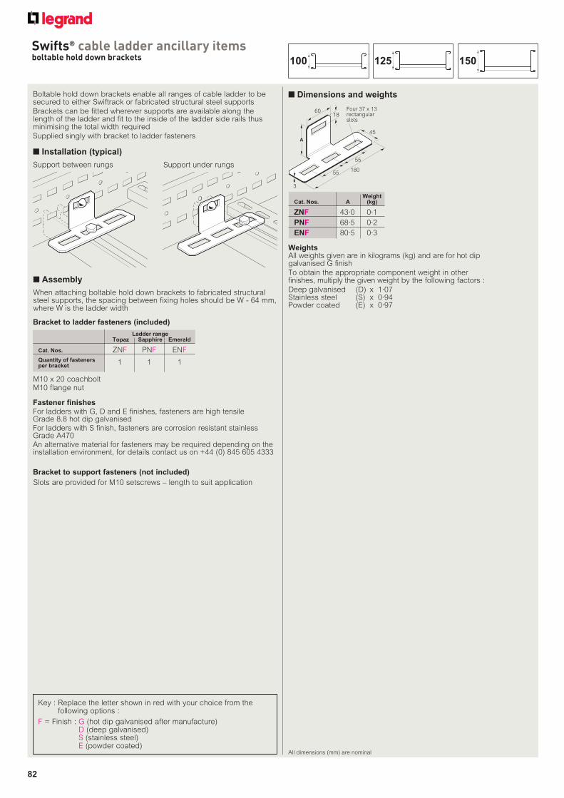
82
Swifts® cable ladder ancillary itemsboltable hold down brackets
All dimensions (mm) are nominal
■ Dimensions and weightsBoltable hold down brackets enable all ranges of cable ladder to be secured to either Swiftrack or fabricated structural steel supports
Brackets can be fitted wherever supports are available along the length of the ladder and fit to the inside of the ladder side rails thus minimising the total width required
Supplied singly with bracket to ladder fasteners
■ Installation (typical)
WeightCat. Nos. A (kg)
ZNF 43·0 0·1
PNF 68·5 0·2
ENF 80·5 0·3
18
3
Four 37 x 13rectangularslots
55
55
180
45
A
60
Bracket to ladder fasteners (included)
M10 x 20 coachboltM10 flange nut
Bracket to support fasteners (not included)
Slots are provided for M10 setscrews – length to suit application
When attaching boltable hold down brackets to fabricated structural steel supports, the spacing between fixing holes should be W - 64 mm, where W is the ladder width
WeightsAll weights given are in kilograms (kg) and are for hot dip galvanised G finish
To obtain the appropriate component weight in other finishes, multiply the given weight by the following factors :
Deep galvanised (D) x 1·07Stainless steel (S) x 0·94Powder coated (E) x 0·97
■ Assembly
Key : Replace the letter shown in red with your choice from the following options :
F = Finish : G (hot dip galvanised after manufacture)D (deep galvanised)S (stainless steel)E (powder coated)
Support under rungsSupport between rungs
Fastener finishes
For ladders with G, D and E finishes, fasteners are high tensile Grade 8.8 hot dip galvanisedFor ladders with S finish, fasteners are corrosion resistant stainless Grade A470An alternative material for fasteners may be required depending on the installation environment, for details contact us on +44 (0) 845 605 4333
Ladder range Topaz Sapphire Emerald
Cat. Nos. ZNF PNF ENF
Quantity of fasteners per bracket 1 1 1
150125100

83
Swifts® cable ladder ancillary itemsboltable angled hold down brackets
■ Dimensions and weightsBoltable angled hold down brackets enable the Swifts ranges of cable ladder to be secured to Swifts heavy duty cantilever arms and trapeze hangers. Brackets can be fitted wherever supports are available along the length of the ladder and fit to the inside of the ladder side rails thus minimising the total width required
Boltable angled hold down brackets are supplied in handed pairs with bracket to ladder fasteners
For fixing cable ladder to Swiftrack channel or structural steel supports use boltable hold down bracket, see p. 82
■ Installation (typical)
Cantilever arm between rungs
WeightCat. Nos. A (kg)
ZPF 43·0 0·4
PPF 68·0 0·4
EPF 80·5 0·6
Two 22 x 11rectangularslots
29
5325
60
A
6018
3·0
One 37 x 13rectangularslot
■ Assembly
Slots are provided for M10 setscrews – length to suit application
Trapeze hanger under rung (1)
Trapeze hanger between rungs
Trapeze hanger under rung (2)
Key : Replace the letter shown in red with your choice from the following options :
F = Finish : G (hot dip galvanised after manufacture)D (deep galvanised)S (stainless steel)E (powder coated)
All dimensions (mm) are nominal
Cantilever arms : see p. 74➔
Trapeze hangers : see p. 75➔
WeightsAll weights given are in kilograms (kg) and are for a pair of brackets in hot dip galvanised G finish
To obtain the appropriate component weight in other finishes, multiply the given weight by the following factors :
Deep galvanised (D) x 1·07Stainless steel (S) x 0·94Powder coated (E) x 0·97
Ladder range Topaz Sapphire Emerald
Cat. Nos. ZPF PPF EPF
Quantity of fasteners per bracket 1 1 1
Bracket to ladder fasteners (included)
M10 x 20 coachboltM10 flange nut
Bracket to support fasteners (not included)
Fastener finishes
For ladders with G, D and E finishes, fasteners are high tensile Grade 8.8 hot dip galvanisedFor ladders with S finish, fasteners are corrosion resistant stainless Grade A470An alternative material for fasteners may be required depending on the installation environment, for details contact us on +44 (0) 845 605 4333
150125100
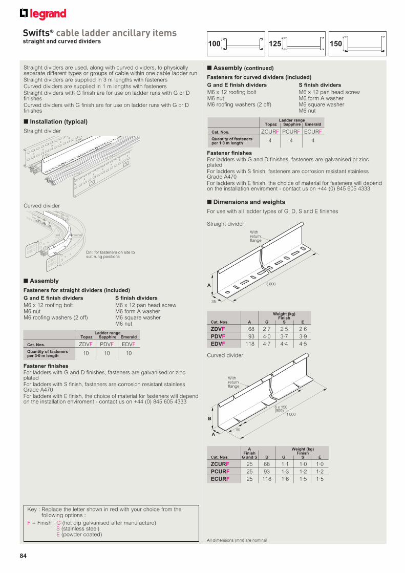
84
Swifts® cable ladder ancillary itemsstraight and curved dividers
All dimensions (mm) are nominal
■ Dimensions and weights
Straight dividers are used, along with curved dividers, to physically separate different types or groups of cable within one cable ladder run
Straight dividers are supplied in 3 m lengths with fasteners
Curved dividers are supplied in 1 m lengths with fasteners
Straight dividers with G finish are for use on ladder runs with G or D finishes
Curved dividers with G finish are for use on ladder runs with G or D finishes
■ Installation (typical)
Fasteners for straight dividers (included)
Fasteners for curved dividers (included)
G and E finish dividers
M6 x 12 roofing boltM6 nutM6 roofing washers (2 off)
S finish dividers
M6 x 12 pan head screwM6 form A washerM6 square washerM6 nut
G and E finish dividers
M6 x 12 roofing boltM6 nutM6 roofing washers (2 off)
S finish dividers
M6 x 12 pan head screwM6 form A washerM6 square washerM6 nut
Ladder range Topaz Sapphire Emerald
Cat. Nos. ZDVF PDVF EDVF
Quantity of fasteners per 3·0 m length 10 10 10
Ladder range Topaz Sapphire Emerald
Cat. Nos. ZCURF PCURF ECURF
Quantity of fasteners per 1·0 m length 4 4 4
Drill for fasteners on site to suit rung positions
A
35
3 000A
35
Withreturnflange
1 000B
A50
6 x 150(900)
Withreturn flange
B
For use with all ladder types of G, D, S and E finishes
Key : Replace the letter shown in red with your choice from the following options :
F = Finish : G (hot dip galvanised after manufacture)S (stainless steel)E (powder coated)
Straight divider
Curved divider
Fastener finishes
For ladders with G and D finishes, fasteners are galvanised or zinc platedFor ladders with S finish, fasteners are corrosion resistant stainless Grade A470For ladders with E finish, the choice of material for fasteners will depend on the installation enviroment - contact us on +44 (0) 845 605 4333
■ Assembly
■ Assembly (continued)
A Weight (kg) Finish FinishCat. Nos. G and S B G S E
ZCURF 25 68 1·1 1·0 1·0
PCURF 25 93 1·3 1·2 1·2
ECURF 25 118 1·6 1·5 1·5
Weight (kg) FinishCat. Nos. A G S E
ZDVF 68 2·7 2·5 2·6
PDVF 93 4·0 3·7 3·9
EDVF 118 4·7 4·4 4·5
150125100
Straight divider
Curved divider
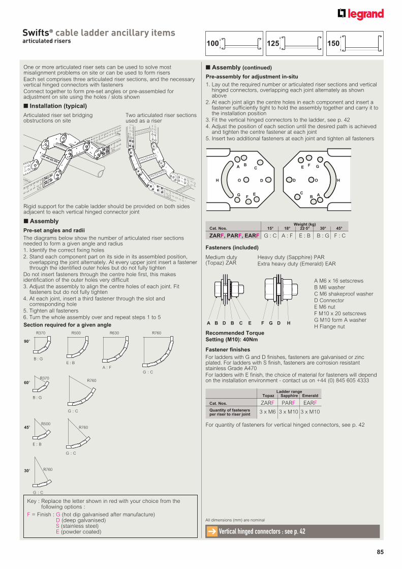
85
Swifts® cable ladder ancillary itemsarticulated risers
One or more articulated riser sets can be used to solve most misalignment problems on site or can be used to form risers
Each set comprises three articulated riser sections, and the necessary vertical hinged connectors with fasteners
Connect together to form pre-set angles or pre-assembled for adjustment on site using the holes / slots shown
■ Installation (typical)
Two articulated riser sections used as a riser
Rigid support for the cable ladder should be provided on both sides adjacent to each vertical hinged connector joint
Fasteners (included)
Medium duty (Topaz) ZAR
Heavy duty (Sapphire) PAR
Extra heavy duty (Emerald) EAR
Articulated riser set bridging obstructions on site
Key : Replace the letter shown in red with your choice from the following options :
F = Finish : G (hot dip galvanised after manufacture)D (deep galvanised)S (stainless steel)E (powder coated)
All dimensions (mm) are nominal
Vertical hinged connectors : see p. 42➔
Ladder range Topaz Sapphire Emerald
Cat. Nos. ZARF PARF EARF
Quantity of fasteners per riser to riser joint 3 x M6 3 x M10 3 x M10
For quantity of fasteners for vertical hinged connectors, see p. 42
Fastener finishes
For ladders with G and D finishes, fasteners are galvanised or zinc plated. For ladders with S finish, fasteners are corrosion resistant stainless Grade A470
For ladders with E finish, the choice of material for fasteners will depend on the installation environment - contact us on +44 (0) 845 605 4333
■ Assembly
■ Assembly (continued)
Pre-set angles and radii
Weight (kg)Cat. Nos. 15° 18° 22·5° 30° 45°
ZARF, PARF, EARF G : C A : F E : B B : G F : C
Section required for a given angle
The diagrams below show the number of articulated riser sections needed to form a given angle and radius
1. Identify the correct fixing holes
2. Stand each component part on its side in its assembled position, overlapping the joint alternately. At every upper joint insert a fastener through the identified outer holes but do not fully tighten
Do not insert fasteners through the centre hole first, this makes identification of the outer holes very difficult
3. Adjust the assembly to align the centre holes of each joint. Fit fasteners but do not fully tighten
4. At each joint, insert a third fastener through the slot and corresponding hole
5. Tighten all fasteners
6. Turn the whole assembly over and repeat steps 1 to 5
Pre-assembly for adjustment in-situ
1. Lay out the required number or articulated riser sections and vertical hinged connectors, overlapping each joint alternately as shown above
2. At each joint align the centre holes in each component and insert a fastener sufficiently tight to hold the assembly together and carry it to the installation position
3. Fit the vertical hinged connectors to the ladder, see p. 42
4. Adjust the position of each section until the desired path is achieved and tighten the centre fastener at each joint
5. Insert two additional fasteners at each joint and tighten all fasteners
A BC
D
EF
G
H O
EF G
O HD
CB A
R370 R500 R630 R760
B : G E : B
A : FG : C
R370
R760
90°
60°
B : G
G : C
45°
R500
R760
E : B
G : C
30° R760
G : C
150125100
Recommended Torque
Setting (M10): 40Nm
A M6 x 16 setscrews
B M6 washer
C M6 shakeproof washer
D Connector
E M6 nut
F M10 x 20 setscrews
G M10 form A washer
H Flange nutA D B C EB F D HG
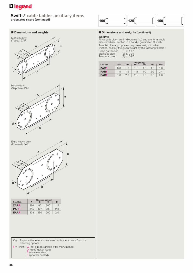
86
Swifts® cable ladder ancillary itemsarticulated risers (continued)
■ Dimensions and weights ■ Dimensions and weights (continued)
BA
CD
Dimensions (mm)Cat. Nos. A B C D
ZARF 280 90 200 1·5
PARF 315 127 200 2·0
EARF 338 150 200 2·0
BA
C
D
BA
C
D
Weight (kg)Cat. Nos. 150 300 450 600 750 900
ZARF 0·8 1·0 1·1 1·3 1·6 1·8
PARF 1·5 1·6 1·8 1·9 2·2 2·4
EARF 1·8 2·0 2·1 2·3 2·6 2·8
WeightsAll weights given are in kilograms (kg) and are for a single articulated riser section in a hot dip galvanised G finish
To obtain the appropriate component weight in other finishes, multiply the given weight by the following factors :
Deep galvanised (D) x 1·07Stainless steel (S) x 0·94Powder coated (E) x 0·97
150125100
Medium duty (Topaz) ZAR
Extra heavy duty (Emerald) EAR
Heavy duty (Sapphire) PAR
Key : Replace the letter shown in red with your choice from the following options :
F = Finish : G (hot dip galvanised after manufacture)D (deep galvanised)S (stainless steel)E (powder coated)
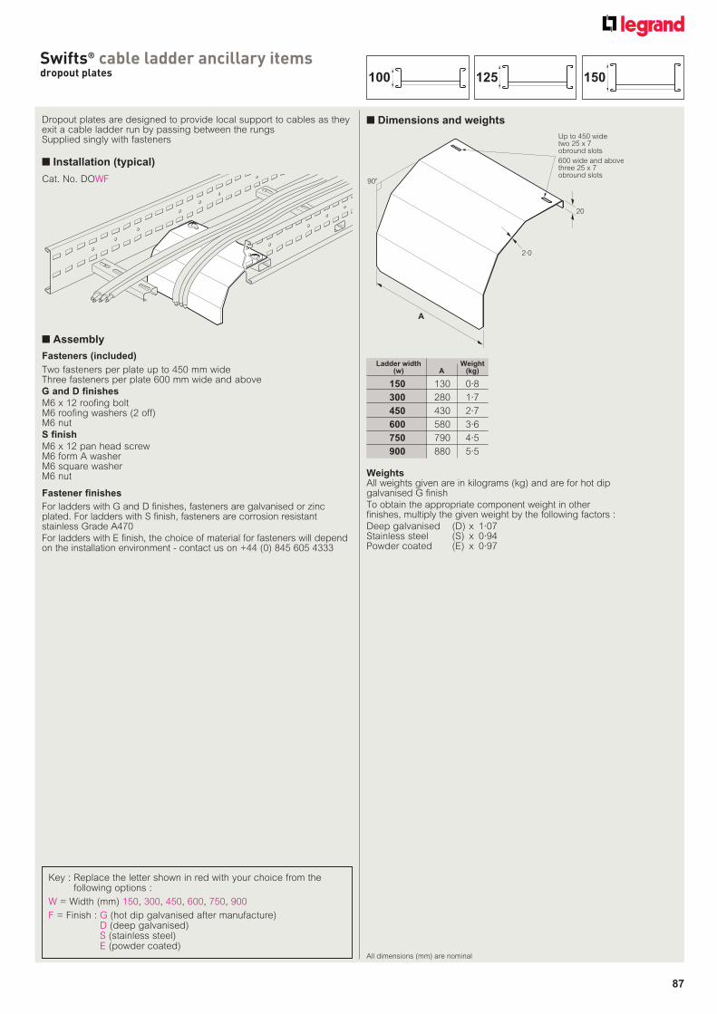
87
Swifts® cable ladder ancillary itemsdropout plates
All dimensions (mm) are nominal
Dropout plates are designed to provide local support to cables as they exit a cable ladder run by passing between the rungsSupplied singly with fasteners
■ Installation (typical)
■ Dimensions and weights
Fasteners (included)
Two fasteners per plate up to 450 mm wideThree fasteners per plate 600 mm wide and above
G and D finishes
M6 x 12 roofing boltM6 roofing washers (2 off)M6 nut
S finish
M6 x 12 pan head screwM6 form A washerM6 square washerM6 nut Weights
All weights given are in kilograms (kg) and are for hot dip galvanised G finish
To obtain the appropriate component weight in other finishes, multiply the given weight by the following factors :
Deep galvanised (D) x 1·07Stainless steel (S) x 0·94Powder coated (E) x 0·97
A
2·0
20
Up to 450 widetwo 25 x 7obround slots
600 wide and abovethree 25 x 7obround slots
90o
Ladder width Weight (w) A (kg)
150 130 0·8
300 280 1·7
450 430 2·7
600 580 3·6
750 790 4·5
900 880 5·5
■ Assembly
Fastener finishes
For ladders with G and D finishes, fasteners are galvanised or zinc plated. For ladders with S finish, fasteners are corrosion resistant stainless Grade A470
For ladders with E finish, the choice of material for fasteners will depend on the installation environment - contact us on +44 (0) 845 605 4333
Cat. No. DOWF
Key : Replace the letter shown in red with your choice from the following options :
W = Width (mm) 150, 300, 450, 600, 750, 900
F = Finish : G (hot dip galvanised after manufacture)D (deep galvanised)S (stainless steel)E (powder coated)
150125100
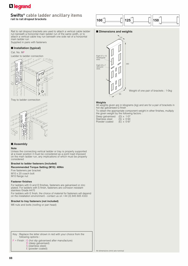
88
Swifts® cable ladder ancillary itemsrail to rail dropout brackets
All dimensions (mm) are nominal
Rail to rail dropout brackets are used to attach a vertical cable ladder run beneath a horizontal main ladder run of the same width, or to attach a vertical cable tray run beneath one side rail of a horizontal main ladder run
Supplied in pairs with fasteners
■ Installation (typical)
■ Dimensions and weights
Five fasteners per bracket
M10 x 20 coach boltM10 flange nut
WeightsAll weights given are in kilograms (kg) and are for a pair of brackets in hot dip galvanised G finish
To obtain the appropriate component weight in other finishes, multiply the given weight by the following factors :
Deep galvanised (D) x 1·07Stainless steel (S) x 0·94Powder coated (E) x 0·97
23
260
85
3
Eight 20 x 7obroundslots
Eight 37 x 13rectangularslots
Ladder to ladder connection
Tray to ladder connection
Cat. No. MF
Note
Unless the connecting vertical ladder or tray is properly supported at a lower position it must be considered as a point load imposed on the main ladder run, any implications of which must be properly considered
Recommended Torque Setting (M10): 40Nm
Bracket to tray fasteners (not included)
M6 nuts and bolts (roofing or pan head)
Weight of one pair of brackets : 1·0kg
■ Assembly
Key : Replace the letter shown in red with your choice from the following options :
F = Finish : G (hot dip galvanised after manufacture)D (deep galvanised)S (stainless steel)E (powder coated)
Fastener finishes
For ladders with G and D finishes, fasteners are galvanised or zinc plated. For ladders with S finish, fasteners are corrosion resistant stainless Grade A470
For ladders with E finish, the choice of material for fasteners will depend on the installation environment - contact us on +44 (0) 845 605 4333
Bracket to ladder fasteners (included)
150125100
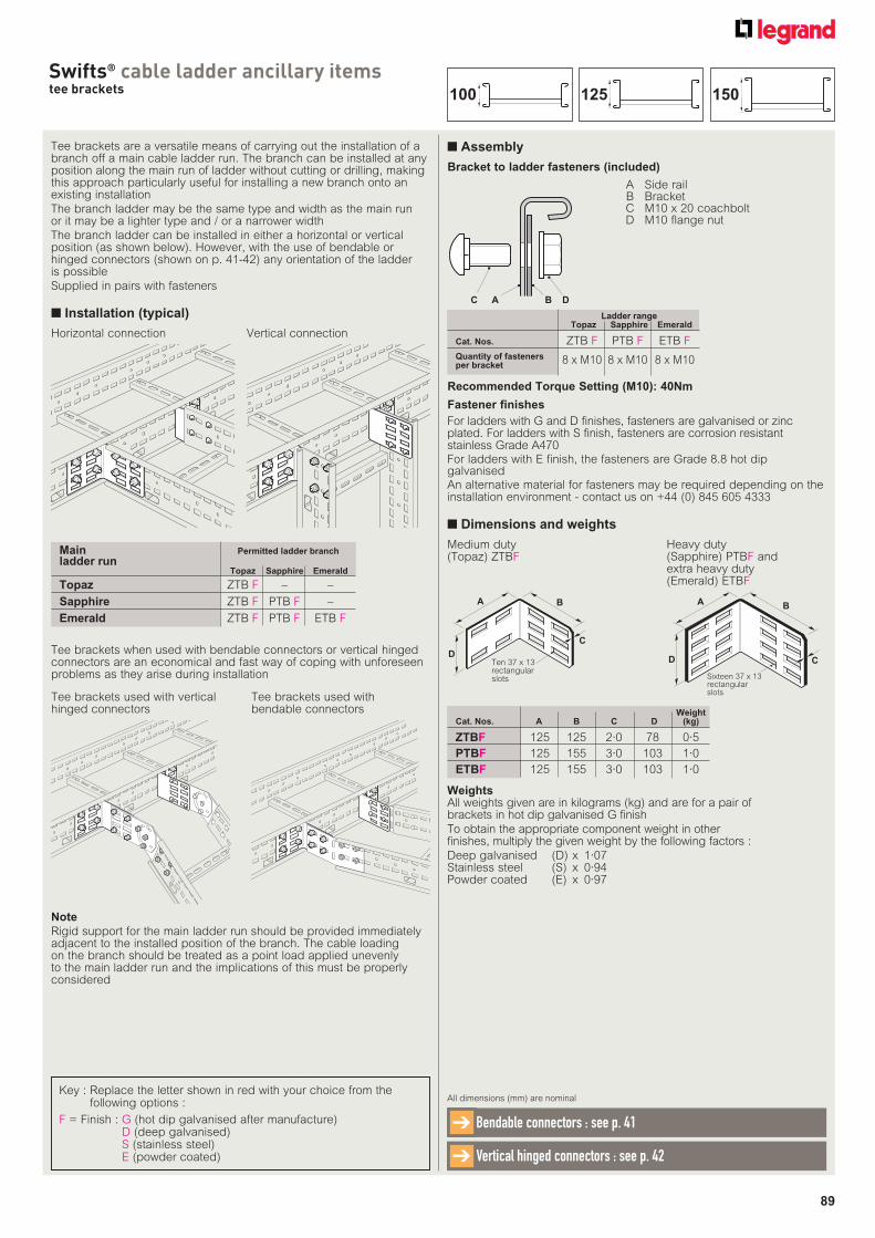
89
Swifts® cable ladder ancillary itemstee brackets
Tee brackets are a versatile means of carrying out the installation of a branch off a main cable ladder run. The branch can be installed at any position along the main run of ladder without cutting or drilling, making this approach particularly useful for installing a new branch onto an existing installation
The branch ladder may be the same type and width as the main run or it may be a lighter type and / or a narrower width
The branch ladder can be installed in either a horizontal or vertical position (as shown below). However, with the use of bendable or hinged connectors (shown on p. 41-42) any orientation of the ladder is possible
Supplied in pairs with fasteners
■ Installation (typical)
Tee brackets when used with bendable connectors or vertical hinged connectors are an economical and fast way of coping with unforeseen problems as they arise during installation
Main Permitted ladder branch
ladder run Topaz Sapphire Emerald
Topaz ZTB F – –
Sapphire ZTB F PTB F –
Emerald ZTB F PTB F ETB F
Ladder range Topaz Sapphire Emerald
Cat. Nos. ZTB F PTB F ETB F
Quantity of fasteners per bracket 8 x M10 8 x M10 8 x M10
Tee brackets used with bendable connectors
Tee brackets used with vertical hinged connectors
■ Assembly
Bracket to ladder fasteners (included)
C A B D
A Side rail B Bracket C M10 x 20 coachbolt D M10 flange nut
WeightsAll weights given are in kilograms (kg) and are for a pair of brackets in hot dip galvanised G finish
To obtain the appropriate component weight in other finishes, multiply the given weight by the following factors :
Deep galvanised (D) x 1·07Stainless steel (S) x 0·94Powder coated (E) x 0·97
■ Dimensions and weights
C
A
D
B
Ten 37 x 13rectangularslots
Heavy duty (Sapphire) PTBF andextra heavy duty (Emerald) ETBF
Medium duty (Topaz) ZTBF
C
A
D
B
Sixteen 37 x 13rectangularslots
WeightCat. Nos. A B C D (kg)
ZTBF 125 125 2·0 78 0·5
PTBF 125 155 3·0 103 1·0
ETBF 125 155 3·0 103 1·0
Note
Rigid support for the main ladder run should be provided immediately adjacent to the installed position of the branch. The cable loading on the branch should be treated as a point load applied unevenly to the main ladder run and the implications of this must be properly considered
Recommended Torque Setting (M10): 40Nm
Horizontal connection Vertical connection
Key : Replace the letter shown in red with your choice from the following options :
F = Finish : G (hot dip galvanised after manufacture)D (deep galvanised)S (stainless steel)E (powder coated)
All dimensions (mm) are nominal
Bendable connectors : see p. 41➔
Vertical hinged connectors : see p. 42➔
Fastener finishes
For ladders with G and D finishes, fasteners are galvanised or zinc plated. For ladders with S finish, fasteners are corrosion resistant stainless Grade A470For ladders with E finish, the fasteners are Grade 8.8 hot dip galvanised An alternative material for fasteners may be required depending on the installation environment - contact us on +44 (0) 845 605 4333
150125100
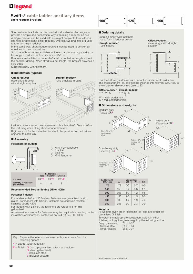
90
Swifts® cable ladder ancillary itemsshort reducer brackets
All dimensions (mm) are nominal
Key : Replace the letter shown in red with your choice from the following options :
Y = Ladder width reduction
F = Finish : G (hot dip galvanised after manufacture)D (deep galvanised)S (stainless steel)E (powder coated)
Short reducer brackets can be used with all cable ladder ranges to provide a simple and economical way of forming a reducer on site
A single bracket can be used with a straight coupler to form either a left hand or right hand offset reducer, whereas two brackets are used to form a straight reducer
In the same way, short reducer brackets can be used to convert an equal tee into an unequal tee
Six sizes of bracket are available to fit each ladder range, providing a full range of reductions from 75 mm to 750 mm
Brackets can be fitted to the end of a full or cut ladder length without the need for drilling. When fitted to a cut length, the bracket provides a safe edge
Supplied singly with fasteners
■ Installation (typical)
Ladder cut ends must have a minimum clear length of 150mm before the first rung when fitting short reducer brackets
Rigid support for the cable ladder should be provided on both sides adjacent to each joint
Ladder range Topaz Sapphire Emerald
Cat. Nos. ZRYF PRYF ERYF
Quantity of fasteners per bracket 4 8 8
WeightsAll weights given are in kilograms (kg) and are for hot dip galvanised G finish
To obtain the appropriate component weight in other finishes, multiply the given weight by the following factors :
Deep galvanised (D) x 1·07Stainless steel (S) x 0·94Powder coated (E) x 0·97
■ Dimensions and weights
Offset reducer(Use single bracket with straight coupler)
Straight reducer(Use brackets in pairs)
■ Ordering details
slots
A
125
128
115
3
Sixteen 37 x 13rectangularslots
Extra heavy duty (Emerald) ERF
Ladder width Weight (kg) difference A ZR PR ER
75 78 0·6 0·7 1·0
150 153 0·7 0·8 1·1
300 303 1·0 1·2 1·5
450 453 1·3 1·5 2·0
600 603 1·7 1·9 2·4
750 753 2·0 2·3 2·9
■ Assembly
Fasteners (included)
C A B D
A M10 x 20 coachbolt B Bracket C Side rail D M10 flange nut
Recommended Torque Setting (M10): 40Nm
125
128
84
A
3
Eight 37 x 13rectangularslots
Medium duty (Topaz) ZRF
A
125
128
115
3
Sixteen 37 x 13rectangularslots
Heavy duty (Sapphire) PRF
Fastener finishes
For ladders with G and D finishes, fasteners are galvanised or zinc plated. For ladders with S finish, fasteners are corrosion resistant stainless Grade A470For ladders with E finish, the fasteners are Grade 8.8 hot dip galvanised An alternative material for fasteners may be required depending on the installation environment - contact us on +44 (0) 845 605 4333
W
K
Y
W K
Y
Y
Offset reducerY = W - K
W = main ladder mmK = reduced ladder mm
Y = W - K2
Straight reducer
Use the following calculations to establish ladder width reductionThis measurement (Y), can then be inserted into relevant Cat. Nos. to show bracket size required (see p. 23)
Supplied singly with fastenersUse to form a reducer on site
Straight reducer– use in pairs
Offset reducer– use singly with straight coupler
150125100
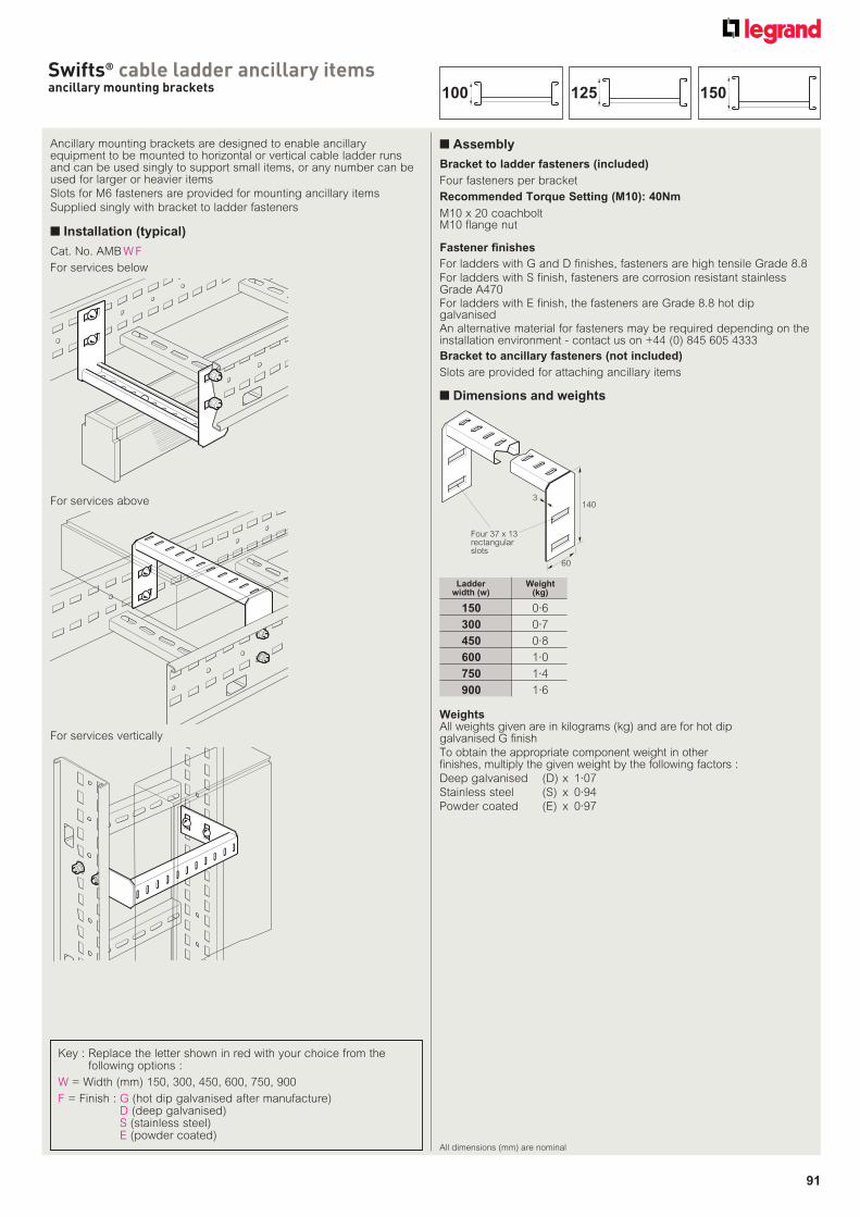
91
Swifts® cable ladder ancillary itemsancillary mounting brackets
All dimensions (mm) are nominal
Ancillary mounting brackets are designed to enable ancillary equipment to be mounted to horizontal or vertical cable ladder runs and can be used singly to support small items, or any number can be used for larger or heavier items
Slots for M6 fasteners are provided for mounting ancillary items
Supplied singly with bracket to ladder fasteners
■ Installation (typical)
Bracket to ancillary fasteners (not included)
Bracket to ladder fasteners (included)
■ Assembly
M10 x 20 coachboltM10 flange nut
Four fasteners per bracket
Slots are provided for attaching ancillary items
WeightsAll weights given are in kilograms (kg) and are for hot dip galvanised G finish
To obtain the appropriate component weight in other finishes, multiply the given weight by the following factors :
Deep galvanised (D) x 1·07
Stainless steel (S) x 0·94
Powder coated (E) x 0·97
■ Dimensions and weights
3
60
Four 37 x 13rectangularslots
140
Ladder Weight width (w) (kg)
150 0·6
300 0·7
450 0·8
600 1·0
750 1·4
900 1·6
Recommended Torque Setting (M10): 40Nm
For services below
Cat. No. AMB W F
For services above
For services vertically
Fastener finishes
For ladders with G and D finishes, fasteners are high tensile Grade 8.8
For ladders with S finish, fasteners are corrosion resistant stainless Grade A470For ladders with E finish, the fasteners are Grade 8.8 hot dip galvanised An alternative material for fasteners may be required depending on the installation environment - contact us on +44 (0) 845 605 4333
Key : Replace the letter shown in red with your choice from the following options :
W = Width (mm) 150, 300, 450, 600, 750, 900
F = Finish : G (hot dip galvanised after manufacture)D (deep galvanised)S (stainless steel)E (powder coated)
150125100
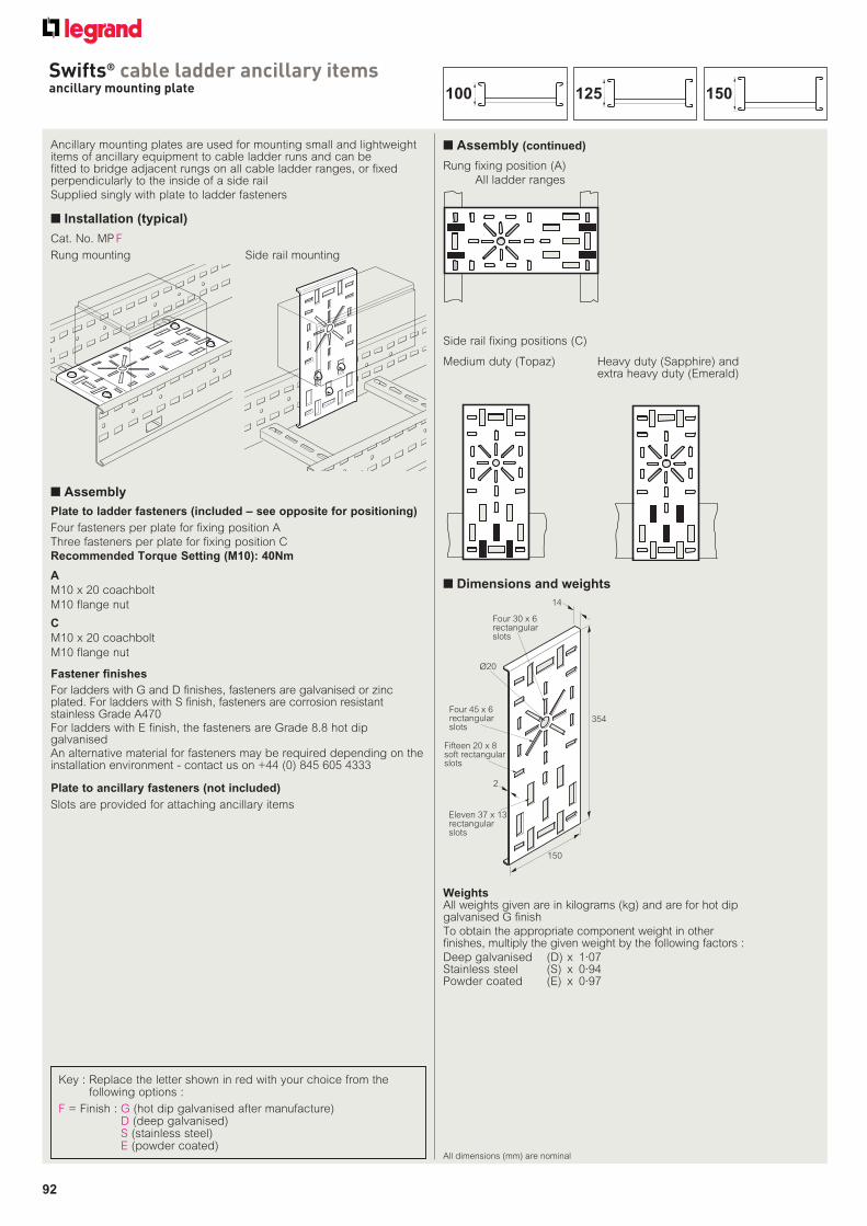
92
Swifts® cable ladder ancillary itemsancillary mounting plate
All dimensions (mm) are nominal
Ancillary mounting plates are used for mounting small and lightweight items of ancillary equipment to cable ladder runs and can be fitted to bridge adjacent rungs on all cable ladder ranges, or fixed perpendicularly to the inside of a side rail
Supplied singly with plate to ladder fasteners
■ Installation (typical)
Plate to ladder fasteners (included – see opposite for positioning)
■ Assembly
WeightsAll weights given are in kilograms (kg) and are for hot dip galvanised G finish
To obtain the appropriate component weight in other finishes, multiply the given weight by the following factors :
Deep galvanised (D) x 1·07Stainless steel (S) x 0·94Powder coated (E) x 0·97
■ Dimensions and weights
Four 30 x 6rectangularslots
354
150
2
14
Fifteen 20 x 8soft rectangularslots
Eleven 37 x 13rectangularslots
Four 45 x 6rectangularslots
Ø20
Rung mounting Side rail mounting
A
M10 x 20 coachbolt
M10 flange nut
Plate to ancillary fasteners (not included)
Slots are provided for attaching ancillary items
C
M10 x 20 coachbolt
M10 flange nut
■ Assembly (continued)
Rung fixing position (A)
All ladder ranges
Side rail fixing positions (C)
Medium duty (Topaz) Heavy duty (Sapphire) and extra heavy duty (Emerald)
Four fasteners per plate for fixing position A
Three fasteners per plate for fixing position C
Recommended Torque Setting (M10): 40Nm
Fastener finishes
For ladders with G and D finishes, fasteners are galvanised or zinc plated. For ladders with S finish, fasteners are corrosion resistant stainless Grade A470For ladders with E finish, the fasteners are Grade 8.8 hot dip galvanised An alternative material for fasteners may be required depending on the installation environment - contact us on +44 (0) 845 605 4333
Key : Replace the letter shown in red with your choice from the following options :
F = Finish : G (hot dip galvanised after manufacture)D (deep galvanised)S (stainless steel)E (powder coated)
Cat. No. MP F
150125100
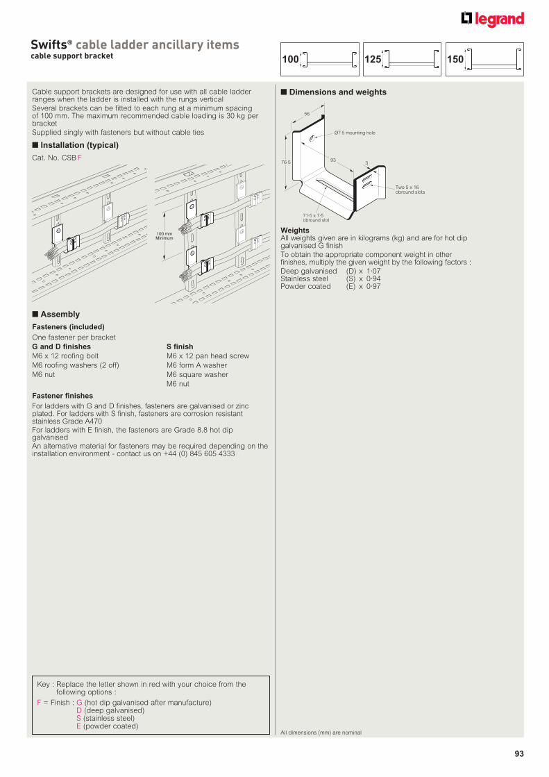
93
Swifts® cable ladder ancillary itemscable support bracket
All dimensions (mm) are nominal
Cable support brackets are designed for use with all cable ladder ranges when the ladder is installed with the rungs vertical
Several brackets can be fitted to each rung at a minimum spacing of 100 mm. The maximum recommended cable loading is 30 kg per bracket
Supplied singly with fasteners but without cable ties
■ Installation (typical)
Fasteners (included)
■ Assembly
One fastener per bracket
G and D finishes
M6 x 12 roofing bolt
M6 roofing washers (2 off)
M6 nut
WeightsAll weights given are in kilograms (kg) and are for hot dip galvanised G finish
To obtain the appropriate component weight in other finishes, multiply the given weight by the following factors :
Deep galvanised (D) x 1·07Stainless steel (S) x 0·94Powder coated (E) x 0·97
■ Dimensions and weights
Ø7·5 mounting hole
3
56
76·5
Two 5 x 16obround slots
71·5 x 7·5obround slot
93
100 mmMinimum
S finish
M6 x 12 pan head screw
M6 form A washer
M6 square washer
M6 nut
Fastener finishes
For ladders with G and D finishes, fasteners are galvanised or zinc plated. For ladders with S finish, fasteners are corrosion resistant stainless Grade A470For ladders with E finish, the fasteners are Grade 8.8 hot dip galvanised An alternative material for fasteners may be required depending on the installation environment - contact us on +44 (0) 845 605 4333
Key : Replace the letter shown in red with your choice from the following options :
F = Finish : G (hot dip galvanised after manufacture)D (deep galvanised)S (stainless steel)E (powder coated)
Cat. No. CSB F
150125100
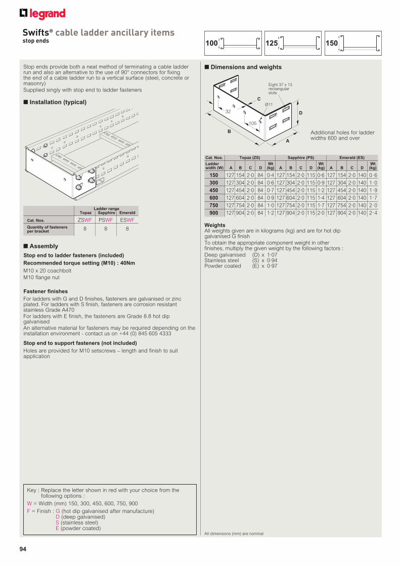
94
Swifts® cable ladder ancillary itemsstop ends
All dimensions (mm) are nominal
Stop ends provide both a neat method of terminating a cable ladder run and also an alternative to the use of 90° connectors for fixing the end of a cable ladder run to a vertical surface (steel, concrete or masonry)
Supplied singly with stop end to ladder fasteners
■ Installation (typical)
Stop end to ladder fasteners (included)
■ Assembly
Recommended torque setting (M10) : 40Nm
M10 x 20 coachbolt
M10 flange nut
WeightsAll weights given are in kilograms (kg) and are for hot dip galvanised G finish
To obtain the appropriate component weight in other finishes, multiply the given weight by the following factors :
Deep galvanised (D) x 1·07Stainless steel (S) x 0·94Powder coated (E) x 0·97
■ Dimensions and weights
C
A
D
B
Ø11
32
105
Eight 37 x 13rectangularslots
Ladder range Topaz Sapphire Emerald
Cat. Nos. ZSWF PSWF ESWF
Quantity of fasteners per bracket 8 8 8
Stop end to support fasteners (not included)
Holes are provided for M10 setscrews – length and finish to suit application
Additional holes for ladder widths 600 and over
Ladder Wt Wt Wtwidth (W) A B C D (kg) A B C D (kg) A B C D (kg)
150 127 154 2·0 84 0·4 127 154 2·0 115 0·6 127 154 2·0 140 0·6
300 127 304 2·0 84 0·6 127 304 2·0 115 0·9 127 304 2·0 140 1·0
450 127 454 2·0 84 0·7 127 454 2·0 115 1·2 127 454 2·0 140 1·9
600 127 604 2·0 84 0·9 127 604 2·0 115 1·4 127 604 2·0 140 1·7
750 127 754 2·0 84 1·0 127 754 2·0 115 1·7 127 754 2·0 140 2·0
900 127 904 2·0 84 1·2 127 904 2·0 115 2·0 127 904 2·0 140 2·4
Cat. Nos. Topaz (ZS) Sapphire (PS) Emerald (ES)
Fastener finishes
For ladders with G and D finishes, fasteners are galvanised or zinc plated. For ladders with S finish, fasteners are corrosion resistant stainless Grade A470For ladders with E finish, the fasteners are Grade 8.8 hot dip galvanised An alternative material for fasteners may be required depending on the installation environment - contact us on +44 (0) 845 605 4333
Key : Replace the letter shown in red with your choice from the following options :
W = Width (mm) 150, 300, 450, 600, 750, 900
F = Finish : G (hot dip galvanised after manufacture)D (deep galvanised)S (stainless steel)E (powder coated)
150125100
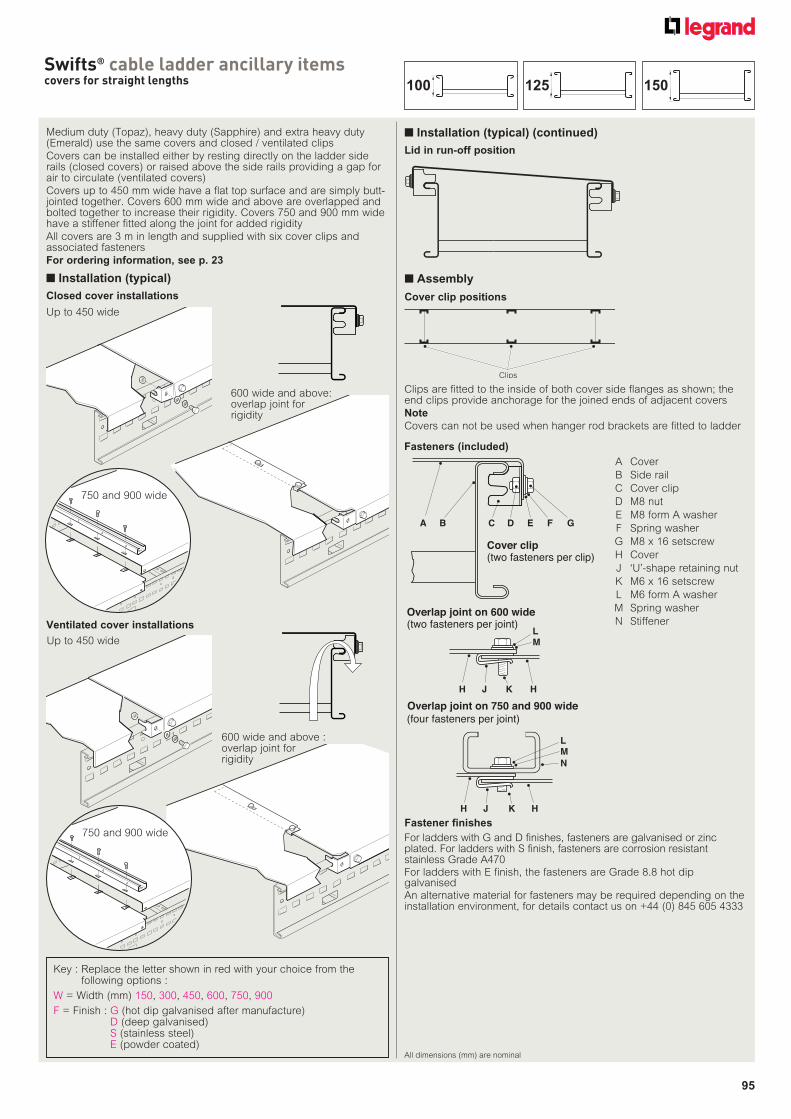
95
Swifts® cable ladder ancillary itemscovers for straight lengths
All dimensions (mm) are nominal
Medium duty (Topaz), heavy duty (Sapphire) and extra heavy duty (Emerald) use the same covers and closed / ventilated clips
Covers can be installed either by resting directly on the ladder side rails (closed covers) or raised above the side rails providing a gap for air to circulate (ventilated covers)
Covers up to 450 mm wide have a flat top surface and are simply butt-jointed together. Covers 600 mm wide and above are overlapped and bolted together to increase their rigidity. Covers 750 and 900 mm wide have a stiffener fitted along the joint for added rigidity
All covers are 3 m in length and supplied with six cover clips and associated fasteners
For ordering information, see p. 23
■ Installation (typical)
■ Installation (typical) (continued)
Up to 450 wide
600 wide and above:overlap joint for rigidity
Closed cover installations
Lid in run-off position
Up to 450 wide
600 wide and above :overlap joint for rigidity
Ventilated cover installations
750 and 900 wide
750 and 900 wide
Fasteners (included)
■ Assembly
A B C D E F G
Cover clip(two fasteners per clip)
Overlap joint on 600 wide(two fasteners per joint)
H J K H
LM
N
(four fasteners per joint)
H J K H
LM
Overlap joint on 750 and 900 wide
A Cover
B Side rail
C Cover clip
D M8 nut
E M8 form A washer
F Spring washer
G M8 x 16 setscrew
H Cover
J ‘U’-shape retaining nut
K M6 x 16 setscrew
L M6 form A washer
M Spring washer
N Stiffener
Clips are fitted to the inside of both cover side flanges as shown; the end clips provide anchorage for the joined ends of adjacent covers
Note
Covers can not be used when hanger rod brackets are fitted to ladder
Clips
Cover clip positions
Fastener finishes
For ladders with G and D finishes, fasteners are galvanised or zinc plated. For ladders with S finish, fasteners are corrosion resistant stainless Grade A470For ladders with E finish, the fasteners are Grade 8.8 hot dip galvanised An alternative material for fasteners may be required depending on the installation environment, for details contact us on +44 (0) 845 605 4333
Key : Replace the letter shown in red with your choice from the following options :
W = Width (mm) 150, 300, 450, 600, 750, 900
F = Finish : G (hot dip galvanised after manufacture)D (deep galvanised)S (stainless steel)E (powder coated)
150125100
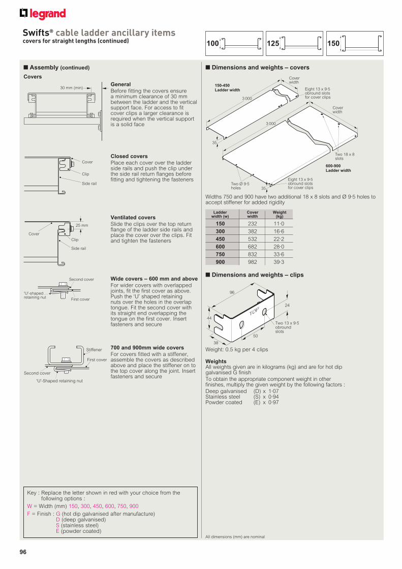
96
Swifts® cable ladder ancillary itemscovers for straight lengths (continued)
■ Dimensions and weights – covers
Coverwidth
35
600-900 Ladder width
150-450 Ladder width
Coverwidth
3 000
35
Eight 13 x 9·5obround slotsfor cover clips
Two Ø 9·5holes
Two 18 x 8slots
Eight 13 x 9·5obround slotsfor cover clips
3 000
Widths 750 and 900 have two additional 18 x 8 slots and Ø 9·5 holes to accept stiffener for added rigidity
■ Assembly (continued)
Covers
Ladder Cover Weight width (w) width (kg)
150 232 11·0
300 382 16·6
450 532 22·2
600 682 28·0
750 832 33·6
900 982 39·3
■ Dimensions and weights – clips
Weight: 0.5 kg per 4 clips
TOPTOPTOP
44
96
38
Two 13 x 9·5obround slots
50
24
WeightsAll weights given are in kilograms (kg) and are for hot dip galvanised G finish
To obtain the appropriate component weight in other finishes, multiply the given weight by the following factors :
Deep galvanised (D) x 1·07Stainless steel (S) x 0·94Powder coated (E) x 0·97
30 mm (min)General
Before fitting the covers ensure a minimum clearance of 30 mm between the ladder and the vertical support face. For access to fit cover clips a larger clearance is required when the vertical support is a solid face
Cover
Clip
Side rail
Closed covers
Place each cover over the ladder side rails and push the clip under the side rail return flanges before fitting and tightening the fasteners
25 mm
Clip
Side rail
Cover
Ventilated covers
Slide the clips over the top return flange of the ladder side rails and place the cover over the clips. Fit and tighten the fasteners
'U'-shapedretaining nut
First cover
Second cover Wide covers – 600 mm and above
For wider covers with overlapped joints, fit the first cover as above. Push the ‘U’ shaped retaining nuts over the holes in the overlap tongue. Fit the second cover with its straight end overlapping the tongue on the first cover. Insert fasteners and secure
'U'-Shaped retaining nut
First cover
Second cover
Stiffener 700 and 900mm wide covers
For covers fitted with a stiffener, assemble the covers as described above and place the stiffener on to the top cover along the joint. Insert fasteners and secure
150125100
All dimensions (mm) are nominal
Key : Replace the letter shown in red with your choice from the following options :
W = Width (mm) 150, 300, 450, 600, 750, 900
F = Finish : G (hot dip galvanised after manufacture)D (deep galvanised)S (stainless steel)E (powder coated)
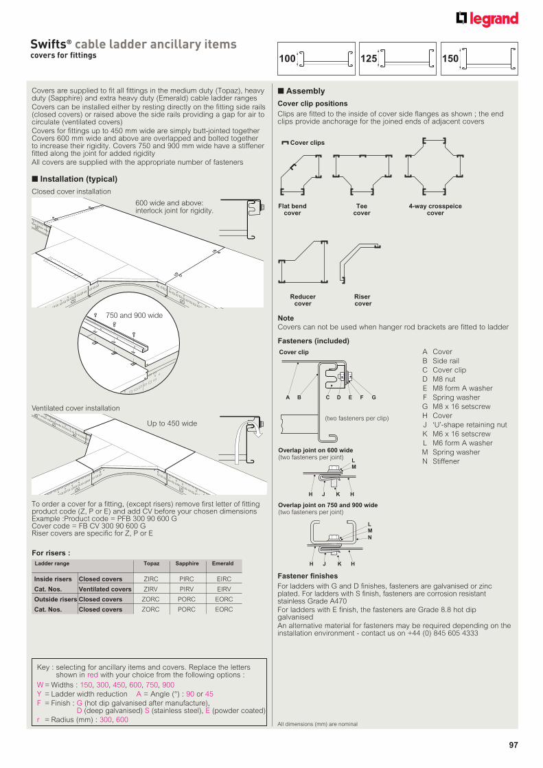
97
Swifts® cable ladder ancillary itemscovers for fittings
All dimensions (mm) are nominal
Covers are supplied to fit all fittings in the medium duty (Topaz), heavy duty (Sapphire) and extra heavy duty (Emerald) cable ladder ranges
Covers can be installed either by resting directly on the fitting side rails (closed covers) or raised above the side rails providing a gap for air to circulate (ventilated covers)
Covers for fittings up to 450 mm wide are simply butt-jointed together Covers 600 mm wide and above are overlapped and bolted together to increase their rigidity. Covers 750 and 900 mm wide have a stiffener fitted along the joint for added rigidity
All covers are supplied with the appropriate number of fasteners
■ Installation (typical)
Cover clip positions
Flat bendcover
Teecover
4-way crosspeicecover
Cover clips
Reducercover
Riser cover
600 wide and above:interlock joint for rigidity.
750 and 900 wide
Up to 450 wide
To order a cover for a fitting, (except risers) remove first letter of fitting product code (Z, P or E) and add CV before your chosen dimensions Example :Product code = PFB 300 90 600 GCover code = FB CV 300 90 600 GRiser covers are specific for Z, P or E
Closed cover installation
Ventilated cover installation
Clips are fitted to the inside of cover side flanges as shown ; the end clips provide anchorage for the joined ends of adjacent covers
Fasteners (included)
A B C D E F G
(two fasteners per clip)
Overlap joint on 600 wide(two fasteners per joint)
H J K H
L
M
N
H J K H
L
M
Cover clip
Overlap joint on 750 and 900 wide(two fasteners per joint)
A Cover
B Side rail
C Cover clip
D M8 nut
E M8 form A washer
F Spring washer
G M8 x 16 setscrew
H Cover
J ‘U’-shape retaining nut
K M6 x 16 setscrew
L M6 form A washer
M Spring washer
N Stiffener
Note
Covers can not be used when hanger rod brackets are fitted to ladder
Fastener finishes
For ladders with G and D finishes, fasteners are galvanised or zinc plated. For ladders with S finish, fasteners are corrosion resistant stainless Grade A470For ladders with E finish, the fasteners are Grade 8.8 hot dip galvanised An alternative material for fasteners may be required depending on the installation environment - contact us on +44 (0) 845 605 4333
Ladder range Topaz Sapphire Emerald
Inside risers Closed covers ZIRC PIRC EIRC
Cat. Nos. Ventilated covers ZIRV PIRV EIRV
Outside risers Closed covers ZORC PORC EORC
Cat. Nos. Closed covers ZORC PORC EORC
For risers :
■ Assembly
Key : selecting for ancillary items and covers. Replace the letters shown in red with your choice from the following options :
W = Widths : 150, 300, 450, 600, 750, 900
Y = Ladder width reduction A = Angle (°) : 90 or 45
F = Finish : G (hot dip galvanised after manufacture), D (deep galvanised) S (stainless steel), E (powder coated)
r = Radius (mm) : 300, 600
150125100
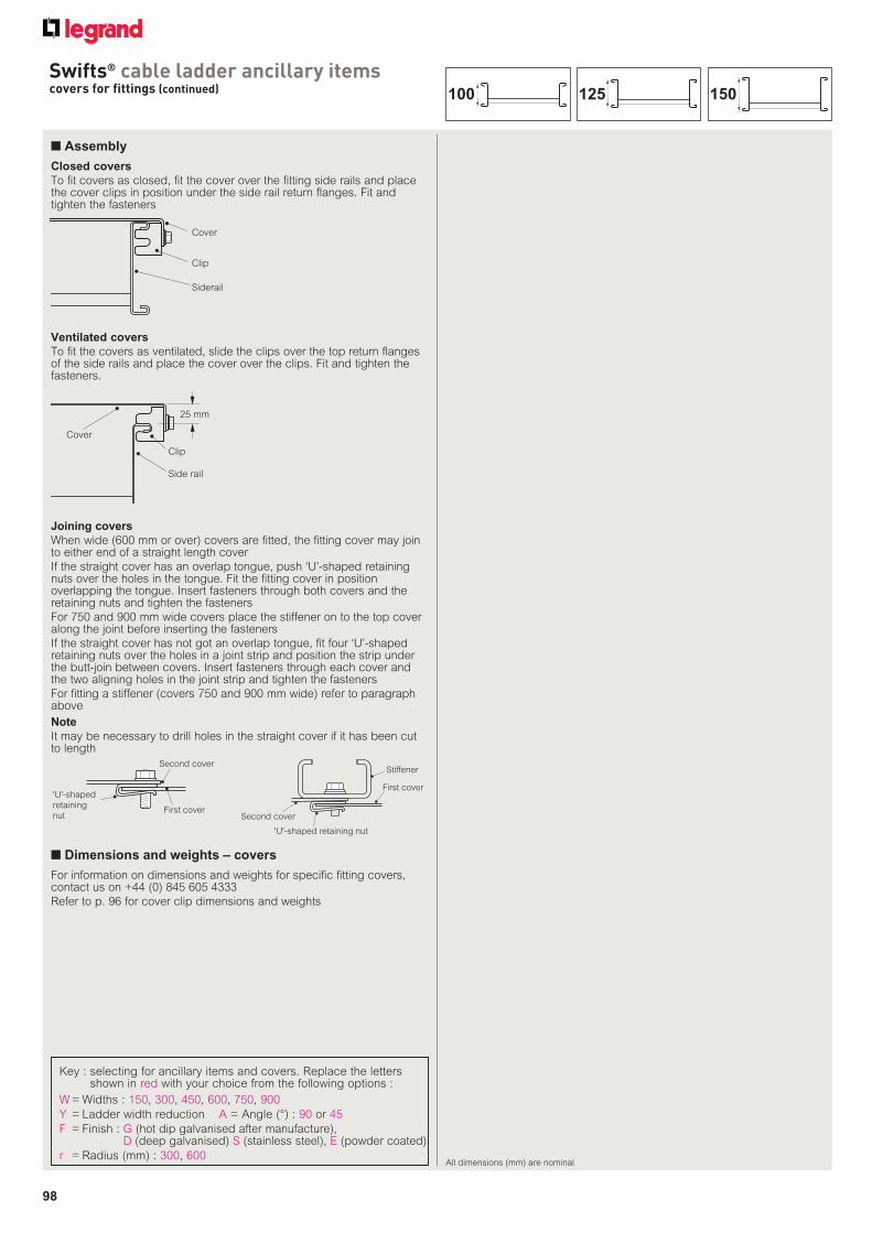
98
Swifts® cable ladder ancillary itemscovers for fittings (continued)
■ Dimensions and weights – covers
For information on dimensions and weights for specific fitting covers, contact us on +44 (0) 845 605 4333
Refer to p. 96 for cover clip dimensions and weights
■ Assembly
Cover
Clip
Siderail
Closed covers
To fit covers as closed, fit the cover over the fitting side rails and place the cover clips in position under the side rail return flanges. Fit and tighten the fasteners
25 mm
Clip
Side rail
Cover
Ventilated covers
To fit the covers as ventilated, slide the clips over the top return flanges of the side rails and place the cover over the clips. Fit and tighten the fasteners.
Joining covers
When wide (600 mm or over) covers are fitted, the fitting cover may join to either end of a straight length cover
If the straight cover has an overlap tongue, push ‘U’-shaped retaining nuts over the holes in the tongue. Fit the fitting cover in position overlapping the tongue. Insert fasteners through both covers and the retaining nuts and tighten the fasteners
For 750 and 900 mm wide covers place the stiffener on to the top cover along the joint before inserting the fasteners
If the straight cover has not got an overlap tongue, fit four ‘U’-shaped retaining nuts over the holes in a joint strip and position the strip under the butt-join between covers. Insert fasteners through each cover and the two aligning holes in the joint strip and tighten the fasteners
For fitting a stiffener (covers 750 and 900 mm wide) refer to paragraph above
Note
It may be necessary to drill holes in the straight cover if it has been cut to length
'U'-shaped
retaining
nutFirst cover
Second cover
'U'-shaped retaining nut
First cover
Second cover
Stiffener
150125100
All dimensions (mm) are nominal
Key : selecting for ancillary items and covers. Replace the letters shown in red with your choice from the following options :
W = Widths : 150, 300, 450, 600, 750, 900
Y = Ladder width reduction A = Angle (°) : 90 or 45
F = Finish : G (hot dip galvanised after manufacture), D (deep galvanised) S (stainless steel), E (powder coated)
r = Radius (mm) : 300, 600
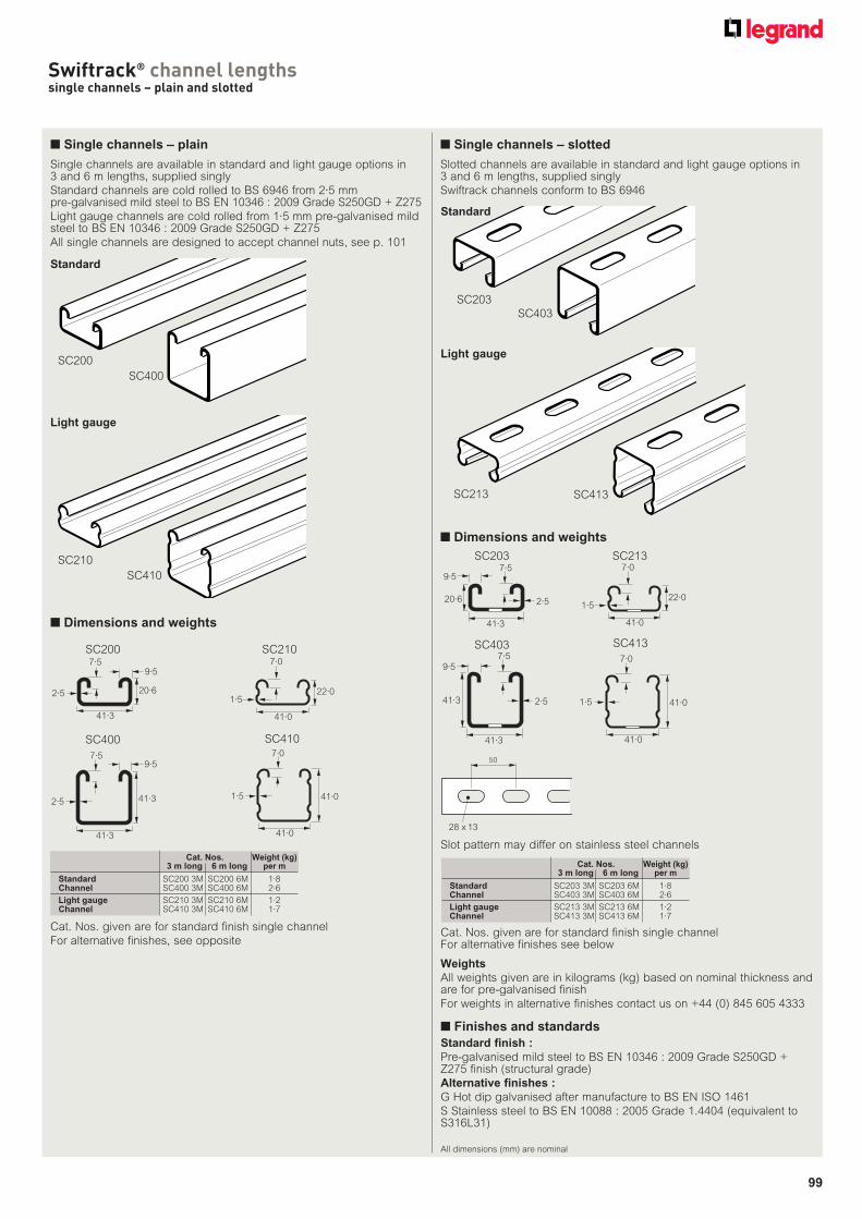
99
Swiftrack® channel lengthssingle channels – plain and slotted
Single channels are available in standard and light gauge options in 3 and 6 m lengths, supplied singly
Standard channels are cold rolled to BS 6946 from 2·5 mm pre-galvanised mild steel to BS EN 10346 : 2009 Grade S250GD + Z275
Light gauge channels are cold rolled from 1·5 mm pre-galvanised mild steel to BS EN 10346 : 2009 Grade S250GD + Z275
All single channels are designed to accept channel nuts, see p. 101
Cat. Nos. Weight (kg) 3 m long 6 m long per m
Standard SC200 3M SC200 6M 1·8Channel SC400 3M SC400 6M 2·6
Light gauge SC210 3M SC210 6M 1·2Channel SC410 3M SC410 6M 1·7
SC200
SC400
SC210
SC410
■ Dimensions and weights
7·59·5
20·6
41·3
2·5
SC200
7·5
41·3
41·3
9·5
2·5
SC400
22·0
41·0
7·0
1·5
SC210
41·0
41·0
7·0
1·5
SC410
Cat. Nos. given are for standard finish single channel
For alternative finishes, see opposite
Weights
All weights given are in kilograms (kg) based on nominal thickness and are for pre-galvanised finish
For weights in alternative finishes contact us on +44 (0) 845 605 4333
■ Finishes and standards
Standard finish :
Pre-galvanised mild steel to BS EN 10346 : 2009 Grade S250GD + Z275 finish (structural grade)
Alternative finishes :
G Hot dip galvanised after manufacture to BS EN ISO 1461
S Stainless steel to BS EN 10088 : 2005 Grade 1.4404 (equivalent to S316L31)
■ Single channels – plain
Slotted channels are available in standard and light gauge options in 3 and 6 m lengths, supplied singly
Swiftrack channels conform to BS 6946
Cat. Nos. Weight (kg) 3 m long 6 m long per m
Standard SC203 3M SC203 6M 1·8Channel SC403 3M SC403 6M 2·6
Light gauge SC213 3M SC213 6M 1·2Channel SC413 3M SC413 6M 1·7
■ Dimensions and weights
Cat. Nos. given are for standard finish single channel For alternative finishes see below
■ Single channels – slotted
SC203
SC213 SC413
SC403
7·59·5
20·6
41·3
2·5
SC203
41·3
7·59·5
41·3
2·5
SC403
22·0
41·0
7·0
1·5
SC213
41·0
41·0
7·0
1·5
SC413
Slot pattern may differ on stainless steel channels
50
28 x 13
Standard
Light gauge
Standard
All dimensions (mm) are nominal
Light gauge
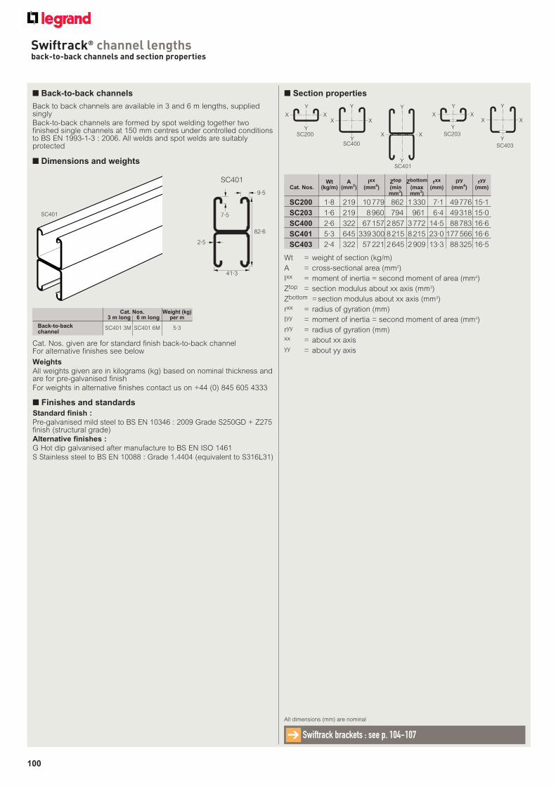
100
Swiftrack® channel lengthsback-to-back channels and section properties
Back to back channels are available in 3 and 6 m lengths, supplied singly
Back-to-back channels are formed by spot welding together two finished single channels at 150 mm centres under controlled conditions to BS EN 1993-1-3 : 2006. All welds and spot welds are suitably protected
Cat. Nos. Weight (kg) 3 m long 6 m long per m
Back-to-backchannel
SC401 3M SC401 6M
5·3
■ Dimensions and weights
Cat. Nos. given are for standard finish back-to-back channel For alternative finishes see below
■ Back-to-back channels
SC401
7·5
82·6
9·5
2·5
41·3
SC401
Weights
All weights given are in kilograms (kg) based on nominal thickness and are for pre-galvanised finish
For weights in alternative finishes contact us on +44 (0) 845 605 4333
■ Finishes and standards
Standard finish :
Pre-galvanised mild steel to BS EN 10346 : 2009 Grade S250GD + Z275 finish (structural grade)
Alternative finishes :
G Hot dip galvanised after manufacture to BS EN ISO 1461
S Stainless steel to BS EN 10088 : Grade 1.4404 (equivalent to S316L31)
All dimensions (mm) are nominal
Swiftrack brackets : see p. 104-107➔
Wt = weight of section (kg/m)
A = cross-sectional area (mm2)
Ixx = moment of inertia = second moment of area (mm4)
Ztop = section modulus about xx axis (mm3)
Zbottom = section modulus about xx axis (mm3)
rxx = radius of gyration (mm)
Iyy = moment of inertia = second moment of area (mm4)
ryy = radius of gyration (mm)xx = about xx axisyy = about yy axis
■ Section properties
Y
Y
X X
SC200Y
X X
Y
SC400
Y
X X
X
Y
SC203
X X
Y
Y
SC403
Wt A Ixx Ztop Zbottom rxx Iyy ryy
Cat. Nos. (kg/m) (mm2) (mm4) (min (max (mm) (mm4) (mm) mm3) mm3)
SC200 1·8 219 10 779 862 1 330 7·1 49 776 15·1
SC203 1·6 219 8 960 794 961 6·4 49 318 15·0
SC400 2·6 322 67 157 2 857 3 772 14·5 88 783 16·6
SC401 5·3 645 339 300 8 215 8 215 23·0 177 566 16·6
SC403 2·4 322 57 221 2 645 2 909 13·3 88 325 16·5
Y
X X
Y
SC401
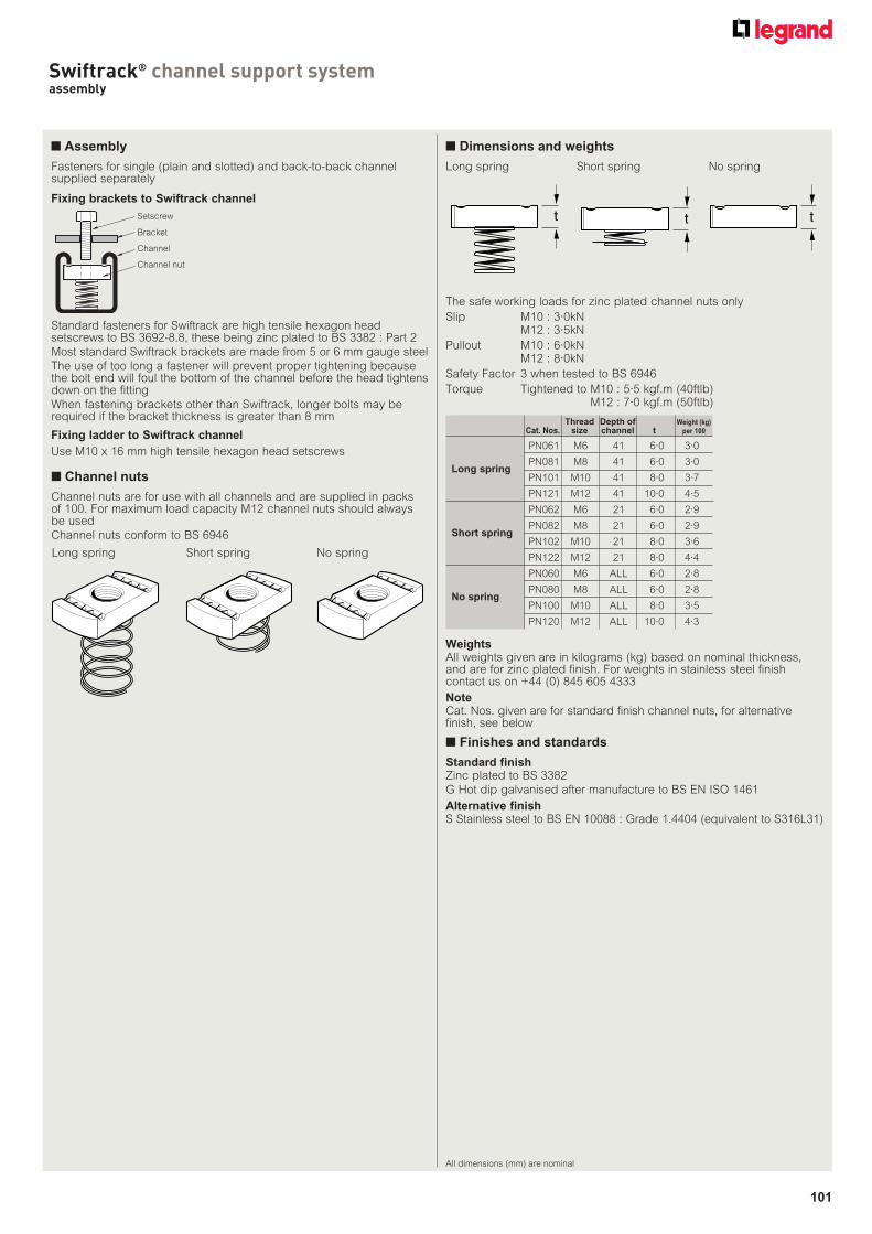
101
Swiftrack® channel support systemassembly
All dimensions (mm) are nominal
Channel nuts are for use with all channels and are supplied in packs of 100. For maximum load capacity M12 channel nuts should always be used
Channel nuts conform to BS 6946
■ Channel nuts
Long spring Short spring No spring
t t t
Long spring Short spring No spring
The safe working loads for zinc plated channel nuts only
Slip M10 : 3·0kNM12 : 3·5kN
Pullout M10 : 6·0kNM12 : 8·0kN
Safety Factor 3 when tested to BS 6946
Torque Tightened to M10 : 5·5 kgf.m (40ftlb)M12 : 7·0 kgf.m (50ftlb)
■ Dimensions and weights
Thread Depth of Weight (kg)
Cat. Nos. size channel t per 100
PN061 M6 41 6·0 3·0
PN081 M8 41 6·0 3·0Long spring
PN101 M10 41 8·0 3·7
PN121 M12 41 10·0 4·5
PN062 M6 21 6·0 2·9
PN082 M8 21 6·0 2·9Short spring
PN102 M10 21 8·0 3·6
PN122 M12 21 8·0 4·4
PN060 M6 ALL 6·0 2·8
PN080 M8 ALL 6·0 2·8No spring
PN100 M10 ALL 8·0 3·5
PN120 M12 ALL 10·0 4·3
Standard finishZinc plated to BS 3382
G Hot dip galvanised after manufacture to BS EN ISO 1461
Alternative finishS Stainless steel to BS EN 10088 : Grade 1.4404 (equivalent to S316L31)
WeightsAll weights given are in kilograms (kg) based on nominal thickness, and are for zinc plated finish. For weights in stainless steel finish contact us on +44 (0) 845 605 4333
NoteCat. Nos. given are for standard finish channel nuts, for alternative finish, see below
■ Finishes and standards
■ Assembly
Standard fasteners for Swiftrack are high tensile hexagon head setscrews to BS 3692-8.8, these being zinc plated to BS 3382 : Part 2
Most standard Swiftrack brackets are made from 5 or 6 mm gauge steel
The use of too long a fastener will prevent proper tightening because the bolt end will foul the bottom of the channel before the head tightens down on the fitting
When fastening brackets other than Swiftrack, longer bolts may be required if the bracket thickness is greater than 8 mm
Fixing ladder to Swiftrack channel
Use M10 x 16 mm high tensile hexagon head setscrews
Fixing brackets to Swiftrack channel
Setscrew
Bracket
Channel
Channel nut
Fasteners for single (plain and slotted) and back-to-back channel supplied separately
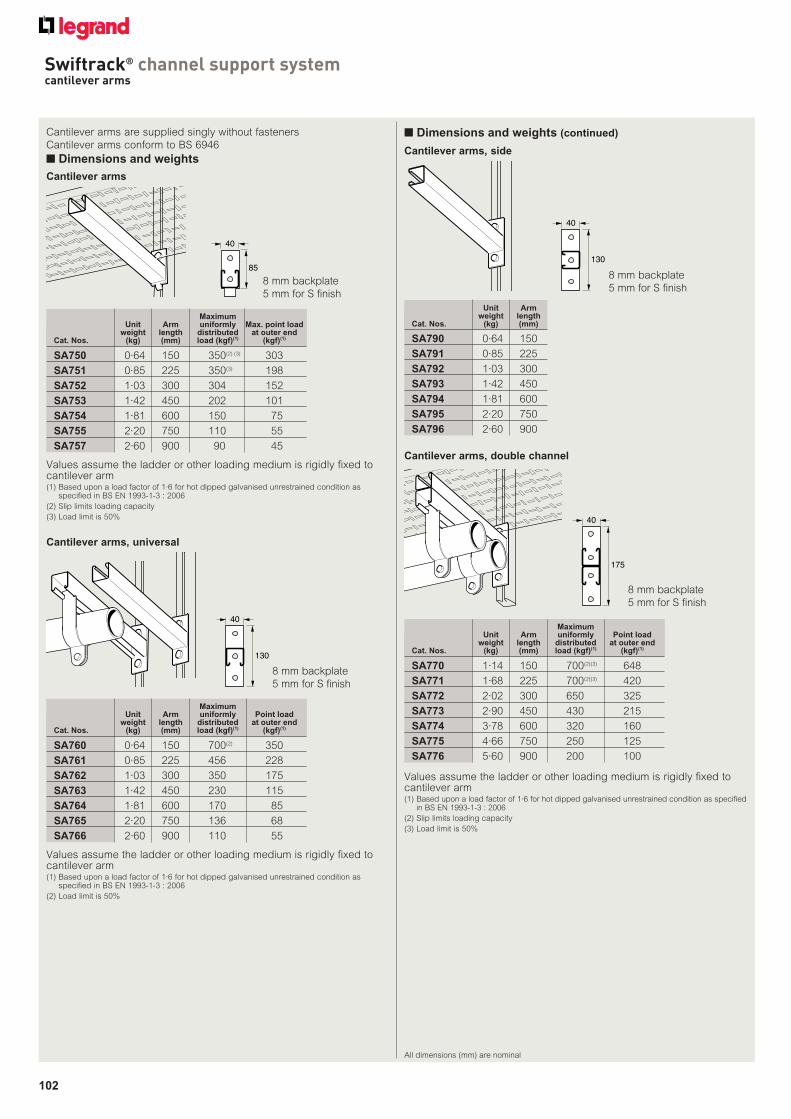
102
Swiftrack® channel support systemcantilever arms
All dimensions (mm) are nominal
Cantilever arms are supplied singly without fasteners
Cantilever arms conform to BS 6946
■ Dimensions and weights
■ Dimensions and weights (continued)
Maximum Unit Arm uniformly Max. point load weight length distributed at outer endCat. Nos. (kg) (mm) load (kgf)(1) (kgf)(1)
SA750 0·64 150 350(2) (3) 303
SA751 0·85 225 350(3) 198
SA752 1·03 300 304 152
SA753 1·42 450 202 101
SA754 1·81 600 150 75
SA755 2·20 750 110 55
SA757 2·60 900 90 45
Cantilever arms
Values assume the ladder or other loading medium is rigidly fixed to cantilever arm(1) Based upon a load factor of 1·6 for hot dipped galvanised unrestrained condition as
specified in BS EN 1993-1-3 : 2006
(2) Slip limits loading capacity
(3) Load limit is 50%
40
85
8 mm backplate
5 mm for S finish
Cantilever arms, universal
Values assume the ladder or other loading medium is rigidly fixed to cantilever arm(1) Based upon a load factor of 1·6 for hot dipped galvanised unrestrained condition as
specified in BS EN 1993-1-3 : 2006
(2) Load limit is 50%
40
130
8 mm backplate
5 mm for S finish
Maximum Unit Arm uniformly Point load weight length distributed at outer endCat. Nos. (kg) (mm) load (kgf)(1) (kgf)(1)
SA760 0·64 150 700(2) 350
SA761 0·85 225 456 228
SA762 1·03 300 350 175
SA763 1·42 450 230 115
SA764 1·81 600 170 85
SA765 2·20 750 136 68
SA766 2·60 900 110 55
Cantilever arms, side
Unit Arm weight lengthCat. Nos. (kg) (mm)
SA790 0·64 150
SA791 0·85 225
SA792 1·03 300
SA793 1·42 450
SA794 1·81 600
SA795 2·20 750
SA796 2·60 900
40
130
8 mm backplate
5 mm for S finish
Cantilever arms, double channel
Maximum Unit Arm uniformly Point load weight length distributed at outer endCat. Nos. (kg) (mm) load (kgf)(1) (kgf)(1)
SA770 1·14 150 700(2)(3) 648
SA771 1·68 225 700(2)(3) 420
SA772 2·02 300 650 325
SA773 2·90 450 430 215
SA774 3·78 600 320 160
SA775 4·66 750 250 125
SA776 5·60 900 200 100
40
175
8 mm backplate
5 mm for S finish
Values assume the ladder or other loading medium is rigidly fixed to cantilever arm(1) Based upon a load factor of 1·6 for hot dipped galvanised unrestrained condition as specified
in BS EN 1993-1-3 : 2006
(2) Slip limits loading capacity
(3) Load limit is 50%
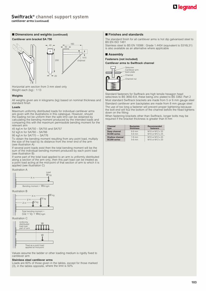
103
Swiftrack® channel support systemcantilever arms (continued)
All weights given are in kilograms (kg) based on nominal thickness and standard finish
The standard finish for all cantilever arms is hot dip galvanised steel to BS EN ISO 1461
Stainless steel to BS EN 10088 : Grade 1.4404 (equivalent to S316L31) is also available as an alternative where applicable
Stainless steel cantilever armsLoads are 60% of those given in the tables, except for those marked (3), in the tables opposite, where the limit is 50%
Fasteners (not included)
Channel Backplate Recommendedtype thickness fasteners
Deep channel 6-8 mm M10 or M12 x 35
SC400 series 5-6 mm M10 or M12 x 25
Shallow channel 7-8 mm M10 or M12 x 25
SC200 series 5-6 mm M10 or M12 x 20
Weights
Cantilever arm bracket SA 756
200
50
160
channel
40
20
14·5
Horizontal arm section from 3 mm steel only
Weight each (kg) : 1·13
■ Dimensions and weights (continued)
■ Assembly
Standard fasteners for Swiftrack are high tensile hexagon head setscrews to BS 3692-8.8, these being zinc plated to BS 3382: Part 2
Most standard Swiftrack brackets are made from 5 or 6 mm gauge steel
Standard cantilever arm backplates are made from 8 mm gauge steel
The use of too long a fastener will prevent proper tightening because the bolt end will foul the bottom of the channel before the head tightens down on the fitting
When fastening brackets other than Swiftrack, longer bolts may be required if the bracket thickness is greater than 8 mm
Cantilever arms to Swiftrack channel
Loads
Maximum uniformly distributed loads for individual cantilever arms are given with the illustrations in this catalogue. However, should the loading not be uniform then the safe limit can be obtained by calculating the bending moment produced by the intended loads and comparing this with the maximum permissible bending moment for the relevant arm
45 kgf.m for SA750 – SA755 and SA757
52 kgf.m for SA760 – SA766
95 kgf.m for SA770 –- SA776
To obtain the bending moment resulting from any point load, multiply the size of the load by its distance from the inner end of the arm (see illustration A)
If several point loads exist then the total bending moment will be the sum of the individual bending moment produced by each point load (see illustration B)
If some part of the total load applied to an arm is uniformly distributed along a section of the arm only, then this part load can be treated as a point load acting at the mid-point of that section of arm to which it is applied (see illustration C)
Setscrew
Bracket
Channel
Channel nut
Cantilever arm back plate
W
W
Uniformlydistributedload overpart of arm
Treat as a point loadapplied at mid-point
Illustration C
z m U kg
y m
x m
V kg
W kg
Total bending moment =
(Uz + Vy + Wx) kgm
Illustration B
Load
W kg
x m
Bending moment = Wx kgm
Illustration A
■ Finishes and standards
Values assume the ladder or other loading medium is rigidly fixed to cantilever arm

104
All dimensions (mm) are nominal
All framework brackets are manufactured to BS 6946 from steel which complies with BS EN 10025 Grade S275JRC and are supplied singly. Channel nuts and setscrews are not supplied with brackets, therefore must be ordered separately
■ Dimensions and weights
■ 90° brackets
The standard finish for all framework brackets and beam clamps is hot dip galvanised steel to BS EN ISO 1461
Stainless steel to BS EN 10088 : Grade 1.4404 (equivalent to S316L31) is also available as an alternative where applicable. To order stainless steel finish add S to the end of the standard catalogue number For example : SB500S
Fasteners (not included)
Made from 5 or 6 mm thick steel unless otherwise stated
Brackets are 40 mm wide and have 14 mm diameter holes to accept M12 (or smaller) setscrews
All bend radii are 5 mm unless otherwise stated
Weights
All weights given are in kilograms (kg) based on nominal thickness and are for hot dip galvanised finish. For weights in stainless steel finish contact us on +44 (0) 845 605 4333
Loads
All loads are for hot dip galvanised brackets fixed with M12 setscrews and M12 zinc plated channel nuts. Loads for stainless steel brackets are available on request - contact us on +44 (0) 845 605 4333
Minimum Yield Stress of material is 275 N/mm2
Only M10 or M12 channel nuts and bolts should be used for the attachment of load-bearing brackets
In most cases the mode of failure will be slippage of the bracket along the channel. However there are few channel/bracket combinations where the maximum load is dependant upon the strength of the bracket itself
47
47
SB500B
A
Maximum load on each bracket with both ends supported : A = 350kgf. B = 174kgf
Unit weight (kg) : 0·125
131
53
SB505
Maximum load on each bracket : A = 300kgf
Unit weight (kg) : 0·257
52
42
SB501
Maximum load on each bracket : A = 180kgf
Unit weight (kg) : 0·125
98
42
SB502
Maximum load on each bracket : A = 230kgf
Unit weight (kg) : 0·191
86
53
SB503
Maximum load on each bracket with both ends supported : A = 120kgf
Unit weight (kg) : 0·191
87
98
SB504
Maximum load on each bracket : A = 120kgf
Unit weight (kg) : 0·257
■ Assembly
Standard fasteners for Swiftrack are high tensile hexagon head setscrews to BS 3692-8.8, these being zinc plated to BS 3382 : Part 2
The use of too long a fastener will prevent proper tightening because the bolt end will foul the bottom of the channel before the head tightens down on the fitting
When fastening brackets other than Swiftrack, longer bolts may be required if the bracket thickness is greater than 8 mm
For channel nuts, see p. 101
Fixing brackets to Swiftrack channel
Setscrew
Bracket
Channel
Channel nut
A
A
A
A
A
■ Finishes and standards
(1) The use of too long a fastener will prevent proper tightening because the bolt end will foul the bottom of the channel before the head tightens down on the fitting
(2) When fastener brackets other than Swiftrack, longer bolts may be required if the bracket thickness is greater than 8 mm
Channel Backplate Recommendedtype thickness fasteners(1)
Deep channel 6 mm and 8 mm M10 or M12 x 35 mm(2)
SC400 series 5 mm and 6 mm M10 or M12 x 20 mm
Shallow channel 7 mm and 8 mm M10 or M12 x 25 mm(2)
SC200 series 5 mm and 6 mm M10 or M12 x 20 mm
Swiftrack® channel support systemframework brackets
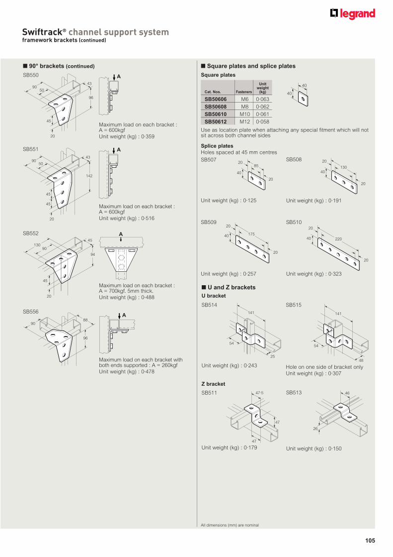
105
■ 90° brackets (continued)
SB552
90
45
20
45
94
130
Maximum load on each bracket : A = 700kgf. 5mm thick.
Unit weight (kg) : 0·488
96
9043
50
45
20
Maximum load on each bracket : A = 600kgf
Unit weight (kg) : 0·359
SB550
Unit weightCat. Nos. Fasteners (kg)
SB50606 M6 0·063
SB50608 M8 0·062
SB50610 M10 0·061
SB50612 M12 0·058
Use as location plate when attaching any special fitment which will not sit across both channel sides
40
40
Square plates
■ Square plates and splice plates
Splice plates
Holes spaced at 45 mm centres
SB50785
40
20
20
Unit weight (kg) : 0·125
13040
20
20
Unit weight (kg) : 0·191
SB508
22040
20
20
SB510
Unit weight (kg) : 0·323
17540
20
20
Unit weight (kg) : 0·257
SB509
■ U and Z brackets
U bracket
Unit weight (kg) : 0·179
47·5
47
47
SB513
26
46
Unit weight (kg) : 0·150
SB511
Unit weight (kg) : 0·243
141
54
25
141
48
54
Hole on one side of bracket only
Unit weight (kg) : 0·307
SB514 SB515
All dimensions (mm) are nominal
90
142
43
50
45
20
45
SB551
Maximum load on each bracket : A = 600kgf
Unit weight (kg) : 0·516
9088
96
SB556
Maximum load on each bracket with both ends supported : A = 260kgf
Unit weight (kg) : 0·478
A
A
A
A
Z bracket
Swiftrack® channel support systemframework brackets (continued)
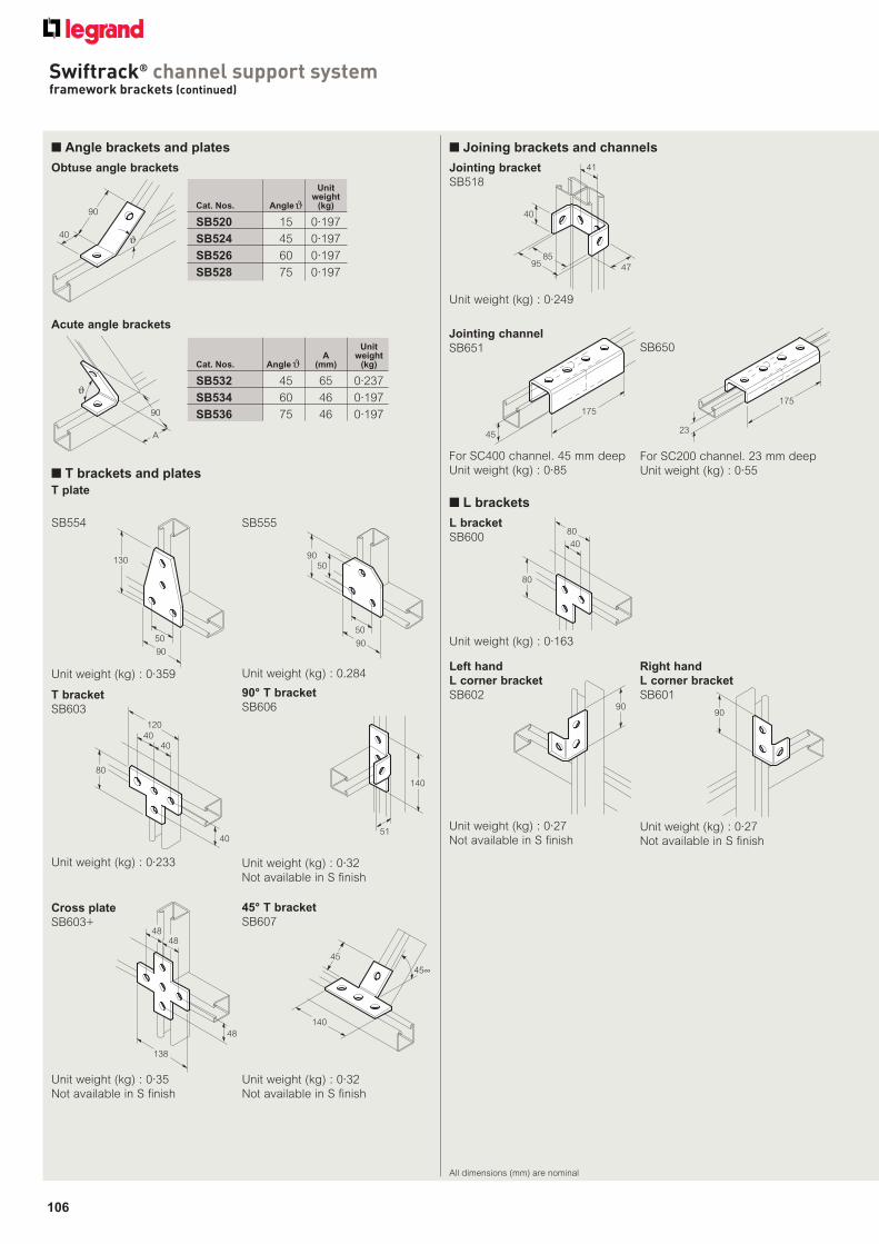
106
■ Angle brackets and plates
90
40ϑ
A
90
ϑ
Obtuse angle brackets
Acute angle brackets
138
4848
48
Cross plate
SB603+
Unit weight (kg) : 0·35
Not available in S finish
45
140
45∞
Unit weight (kg) : 0·32
Not available in S finish
■ T brackets and plates
T plate
SB555
5090
90
50
Unit weight (kg) : 0.284
SB554
130
90
50
Unit weight (kg) : 0·359
90° T bracket
SB606
140
51
Unit weight (kg) : 0·32
Not available in S finish
120
40
80
40
40
Unit weight (kg) : 0·233
T bracket
SB603
45° T bracket
SB607
All dimensions (mm) are nominal
■ Joining brackets and channels
175
45
175
23
8595
41
47
40
For SC400 channel. 45 mm deep
Unit weight (kg) : 0·85For SC200 channel. 23 mm deep
Unit weight (kg) : 0·55
Jointing channel
SB651
Jointing bracket
SB518
Unit weight (kg) : 0·249
SB650
■ L brackets
L bracket
SB600
Unit weight (kg) : 0·163
80
40
80
9090
Unit weight (kg) : 0·27
Not available in S finish
Right hand
L corner bracket
SB601
Unit weight (kg) : 0·27
Not available in S finish
Left hand
L corner bracket
SB602
Unit weightCat. Nos. Angle (kg)
SB520 15 0·197
SB524 45 0·197
SB526 60 0·197
SB528 75 0·197
Unit A weightCat. Nos. Angle (mm) (kg)
SB532 45 65 0·237
SB534 60 46 0·197
SB536 75 46 0·197
Swiftrack® channel support systemframework brackets (continued)
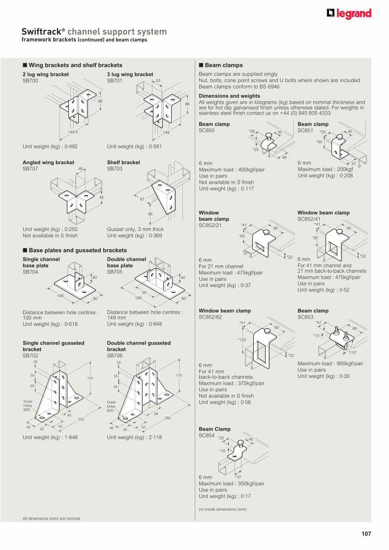
107
All dimensions (mm) are nominal
■ Wing brackets and shelf brackets
86
148·5 149
86
53
48
48
87
98
2 lug wing bracket
SB700
Unit weight (kg) : 0·492
3 lug wing bracket
SB701
Unit weight (kg) : 0·581
Angled wing bracket
SB707
Shelf bracket
SB703
Gusset only, 3 mm thick
Unit weight (kg) : 0·369
Unit weight (kg) : 0·250
Not available in S finish
■ Base plates and gusseted brackets
Distance between hole centres : 100 mm
Unit weight (kg) : 0·618
80
40
14095
80
40
189
175
252
OuterholesØ20
45 6320
43
55
20
55
175
OuterholesØ20
45 6320
55
20
55
84
293
Single channel
base plate
SB704
Double channel
base plate
SB705
Distance between hole centres : 149 mm
Unit weight (kg) : 0·848
Single channel gusseted
bracket
SB702
Unit weight (kg) : 1·848
Double channel gusseted
bracket
SB706
Unit weight (kg) : 2·118
Beam clamps are supplied singly
Nut, bolts, cone point screws and U bolts where shown are included
Beam clamps conform to BS 6946
Dimensions and weights
All weights given are in kilograms (kg) based on nominal thickness and are for hot dip galvanised finish unless otherwise stated. For weights in stainless steel finish contact us on +44 (0) 845 605 4333
Beam clamp
SC850 30
48
*28
*25
6 mm
Maximum load : 400kgf/pair
Use in pairs
Not available in S finish
Unit weight (kg) : 0.117
40
47
*25
*65
Beam clamp
SC851
6 mm
Maximum load : 200kgf
Unit weight (kg) : 0·208
*87
80
*22
*41
Window beam clamp
SC852/41
6 mm
For 41 mm channel and 21 mm back-to-back channels
Maximum load : 475kgf/pair
Use in pairs
Unit weight (kg) : 0·52
80
*22
*125
*41
Window beam clamp
SC852/82
6 mm
For 41 mm back-to-back channels.
Maximum load : 375kgf/pair
Use in pairs
Not available in S finish
Unit weight (kg) : 0·56
*65
80
*22
*41
Window
beam clamp
SC852/21
6 mm
For 21 mm channel
Maximum load : 475kgf/pair
Use in pairs
Unit weight (kg) : 0·37
40*25
*16
*37
Beam Clamp
SC854
6 mm
Maximum load : 350kgf/pair
Use in pairs
Unit weight (kg) : 0·17
Beam clamp
SC853
80
*47
*13
110°
Maximum load : 900kgf/pair
Use in pairs
Unit weight (kg) : 0·30
■ Beam clamps
(*) Inside dimensions (mm)
Swiftrack® channel support systemframework brackets (continued) and beam clamps
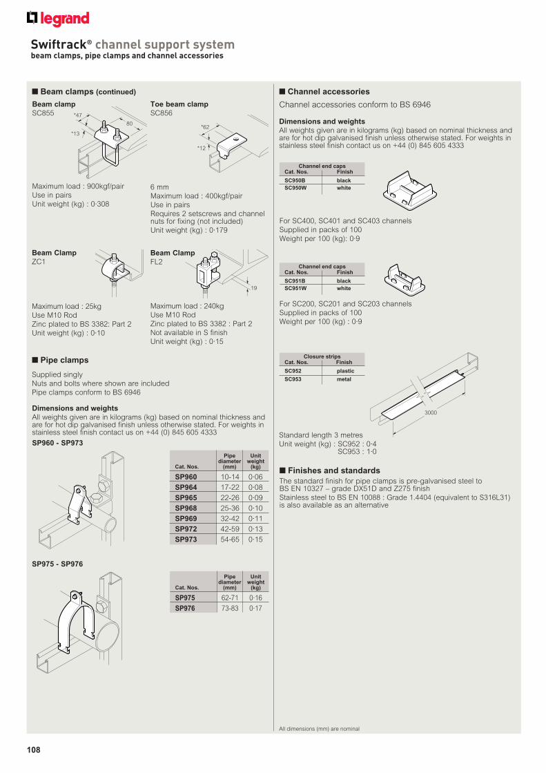
108
Swiftrack® channel support systembeam clamps, pipe clamps and channel accessories
All dimensions (mm) are nominal
80
*47
*13
Beam clamp
SC855
Maximum load : 900kgf/pair
Use in pairs
Unit weight (kg) : 0·308
*12
*62
19
Beam Clamp
ZC1
Maximum load : 25kg
Use M10 Rod
Zinc plated to BS 3382: Part 2
Unit weight (kg) : 0·10
Beam Clamp
FL2
Maximum load : 240kg
Use M10 Rod
Zinc plated to BS 3382 : Part 2
Not available in S finish
Unit weight (kg) : 0·15
Toe beam clamp
SC856
6 mm
Maximum load : 400kgf/pair
Use in pairs
Requires 2 setscrews and channel nuts for fixing (not included)
Unit weight (kg) : 0·179
Supplied singly
Nuts and bolts where shown are included
Pipe clamps conform to BS 6946
Dimensions and weights
All weights given are in kilograms (kg) based on nominal thickness and are for hot dip galvanised finish unless otherwise stated. For weights in stainless steel finish contact us on +44 (0) 845 605 4333
SP960 - SP973
SP975 - SP976
Pipe Unit diameter weightCat. Nos. (mm) (kg)
SP960 10-14 0·06
SP964 17-22 0·08
SP965 22-26 0·09
SP968 25-36 0·10
SP969 32-42 0·11
SP972 42-59 0·13
SP973 54-65 0·15
■ Finishes and standards
The standard finish for pipe clamps is pre-galvanised steel to BS EN 10327 – grade DX51D and Z275 finish
Stainless steel to BS EN 10088 : Grade 1.4404 (equivalent to S316L31) is also available as an alternative
Pipe Unit diameter weightCat. Nos. (mm) (kg)
SP975 62-71 0·16
SP976 73-83 0·17
■ Channel accessories
■ Pipe clamps
Channel accessories conform to BS 6946
For SC200, SC201 and SC203 channels
Supplied in packs of 100
Weight per 100 (kg) : 0·9
Dimensions and weights
All weights given are in kilograms (kg) based on nominal thickness and are for hot dip galvanised finish unless otherwise stated. For weights in stainless steel finish contact us on +44 (0) 845 605 4333
Channel end capsCat. Nos. Finish
SC950B black
SC950W white
For SC400, SC401 and SC403 channels
Supplied in packs of 100
Weight per 100 (kg): 0·9
Channel end capsCat. Nos. Finish
SC951B black
SC951W white
3000
Standard length 3 metres
Unit weight (kg) : SC952 : 0·4SC953 : 1·0
Closure stripsCat. Nos. Finish
SC952 plastic
SC953 metal
■ Beam clamps (continued)
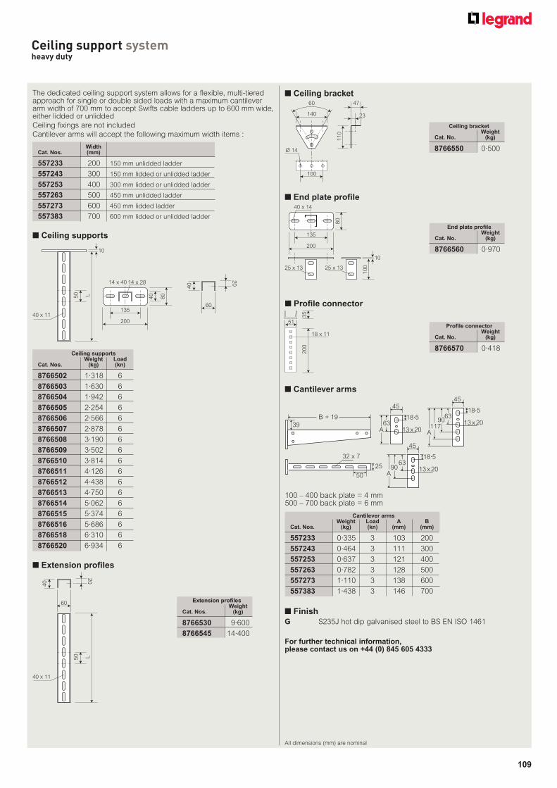
109
All dimensions (mm) are nominal
Ceiling support systemheavy duty
■ Ceiling supports
135
200
40
80
40 x 11
50 L
14 x 40 14 x 28
10
WidthCat. Nos. (mm)
557233 200 150 mm unlidded ladder
557243 300 150 mm lidded or unlidded ladder
557253 400 300 mm lidded or unlidded ladder
557263 500 450 mm unlidded ladder
557273 600 450 mm lidded ladder
557383 700 600 mm lidded or unlidded ladder
The dedicated ceiling support system allows for a flexible, multi-tiered approach for single or double sided loads with a maximum cantilever arm width of 700 mm to accept Swifts cable ladders up to 600 mm wide, either lidded or unlidded
Ceiling fixings are not included
Cantilever arms will accept the following maximum width items :
■ Finish
G S235J hot dip galvanised steel to BS EN ISO 1461
Ceiling supports Weight LoadCat. Nos. (kg) (kn)
8766502 1·318 6
8766503 1·630 6
8766504 1·942 6
8766505 2·254 6
8766506 2·566 6
8766507 2·878 6
8766508 3·190 6
8766509 3·502 6
8766510 3·814 6
8766511 4·126 6
8766512 4·438 6
8766513 4·750 6
8766514 5·062 6
8766515 5·374 6
8766516 5·686 6
8766518 6·310 6
8766520 6·934 6
■ Extension profi les
20
60
40
40 x 11
50 L
Extension profiles WeightCat. Nos. (kg)
8766530 9·600
8766545 14·400
20
60
40
For further technical information, please contact us on +44 (0) 845 605 4333
45
A
B + 19 18·5
18·5
18·5
63
45
A
6390
45
A
6390
117
13 x 20
13 x 2013 x 20
32 x 7
25
50
39
■ Cantilever arms
100 – 400 back plate = 4 mm500 – 700 back plate = 6 mm
■ Ceiling bracket60
140 23
100
11
0
Ø 14
47
Ceiling bracket WeightCat. No. (kg)
8766550 0·500
135
200
40 x 14
80
25 x 13
10
025 x 13
10
■ End plate profi le
End plate profile WeightCat. No. (kg)
8766560 0·970
20
03
5
51
18 x 11
■ Profi le connector
Profile connector WeightCat. No. (kg)
8766570 0·418
Cantilever arms Weight Load A BCat. Nos. (kg) (kn) (mm) (mm)
557233 0·335 3 103 200
557243 0·464 3 111 300
557253 0·637 3 121 400
557263 0·782 3 128 500
557273 1·110 3 138 600
557383 1·438 3 146 700

DESIGN NOTES
IN THIS SECTION
Selecting the right fi nishPreventing corrosion
- Chemical corrosion 112- Electrochemical corrosion 112- Galvanic Series 113- The merits of Zinc 114-115- Common corrosion situations 116
Suitability of fi nishes- Metallic fi nishes 116-117- Organic fi nishes 116-117
FinishesBritish standards 118Hot dip galvanised (G) 119Deep galvanised (D) 119Pre-galvanised (PG) 120Stainless steel (S) 120Powder coated (E) 121
Installation of servicesCable ladder systems
- Design factors to consider 122-128- Recommended support locations 125-126- 6 m lengths over long spans 128-129- Loading graphs 130-131
Structural support characteristicsStructural characteristics
- Cable ladder 132- Beams 132-133- Columns 133- Defl ection 133
Designing a support system- Ceiling to fl oor applications 134- Ceiling mounted applications 135- Wall mounted applications 135- Floor mounted applications 135
Swiftrack channel support- Channels 136- Channel nuts 136- Framework brackets 136- Fasteners 136- Cantilever arms 137- Maximum safety recommended loadings 137- Channels used as beams 138- Channels used as columns 138- Fully restrained and unrestrained loads 138- Beam loads 139
Packaging, handling, storage and safetyExport packaging 140Handling and storage 141Safety during installation phase 141
Relevant British, European and International Standards 142-143
111
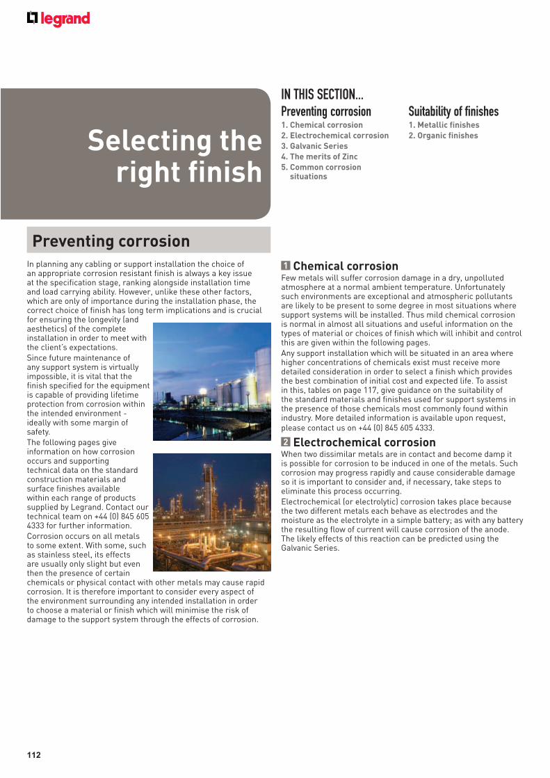
112
In planning any cabling or support installation the choice of an appropriate corrosion resistant finish is always a key issue at the specification stage, ranking alongside installation time and load carrying ability. However, unlike these other factors, which are only of importance during the installation phase, the correct choice of finish has long term implications and is crucial for ensuring the longevity (and aesthetics) of the complete installation in order to meet with the client’s expectations.Since future maintenance of any support system is virtually impossible, it is vital that the finish specified for the equipment is capable of providing lifetime protection from corrosion within the intended environment - ideally with some margin of safety.The following pages give information on how corrosion occurs and supporting technical data on the standard construction materials and surface finishes available within each range of products supplied by Legrand. Contact our technical team on +44 (0) 845 605 4333 for further information.Corrosion occurs on all metals to some extent. With some, such as stainless steel, its effects are usually only slight but even then the presence of certain chemicals or physical contact with other metals may cause rapid corrosion. It is therefore important to consider every aspect of the environment surrounding any intended installation in order to choose a material or finish which will minimise the risk of damage to the support system through the effects of corrosion.
1 Chemical corrosionFew metals will suffer corrosion damage in a dry, unpolluted atmosphere at a normal ambient temperature. Unfortunately such environments are exceptional and atmospheric pollutants are likely to be present to some degree in most situations where support systems will be installed. Thus mild chemical corrosion is normal in almost all situations and useful information on the types of material or choices of finish which will inhibit and control this are given within the following pages.Any support installation which will be situated in an area where higher concentrations of chemicals exist must receive more detailed consideration in order to select a finish which provides the best combination of initial cost and expected life. To assist in this, tables on page 117, give guidance on the suitability of the standard materials and finishes used for support systems in the presence of those chemicals most commonly found within industry. More detailed information is available upon request, please contact us on +44 (0) 845 605 4333.
2 Electrochemical corrosionWhen two dissimilar metals are in contact and become damp it is possible for corrosion to be induced in one of the metals. Such corrosion may progress rapidly and cause considerable damage so it is important to consider and, if necessary, take steps to eliminate this process occurring.Electrochemical (or electrolytic) corrosion takes place because the two different metals each behave as electrodes and the moisture as the electrolyte in a simple battery; as with any battery the resulting flow of current will cause corrosion of the anode. The likely effects of this reaction can be predicted using the Galvanic Series.
Preventing corrosion
IN THIS SECTION...Preventing corrosion1. Chemical corrosion
2. Electrochemical corrosion
3. Galvanic Series
4. The merits of Zinc
5. Common corrosion situations
Suitability of finishes1. Metallic finishes
2. Organic finishesSelecting the right finish
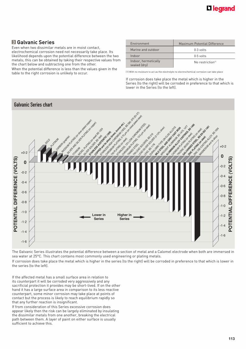
113
Galvanic Series chart
3 Galvanic SeriesEven when two dissimilar metals are in moist contact, electrochemical corrosion need not necessarily take place. Its likelihood depends upon the potential difference between the two metals; this can be obtained by taking their respective values from the chart below and subtracting one from the other.When the potential difference is less than the values given in the table to the right corrosion is unlikely to occur. (1) With no moisture to act as the electrolyte no electrochemical corrosion can take place
+0·2
0
PO
TE
NT
IAL
DIF
FE
RE
NC
E (
VO
LT
S)
-0·2
-0·4
-0·6
-0·8
-1·0
-1·2
-1·4
-1·6
TITA
NIUM
NICKEL
PLATI
NG (on
steel)
BS 1
224
SILVER S
OLDER, B
S 184
5
STAIN
LESS A
USTENIT
IC (1
8/8)
COPPER and
its
allo
ys (b
rass
, bro
nze
etc.
)
STAIN
LESS H
IGH C
HROMIU
M (1
8/2)
, BS S
80, 9
70 (E
n 57
)
CHROMIU
M P
LATI
NG, 0·7
5 µm
(on
nicke
l plat
ed st
eel)
TIN P
LATI
NG (on
steel)
STAIN
LESS, 1
2% L
OW C
HROMIU
M S
TEEL
CHROMIU
M P
LATI
NG, 13·
0 µm
(on
steel)
TIN-L
EAD SOLD
ERS, BS 2
19
LEAD-S
ILVER S
OLDER (2
-1/2
% si
lver)
DURALUM
IN T
YPE UN-C
LAD A
LLOYS
MIL
D STE
EL AND G
REY CAST
IRON
WROUGHT
ALUM
INIU
M, B
S 147
0, 1
477
ALUM
INIU
M A
LLOY C
ASTINGS, B
S 149
0
CADMIU
M P
LATI
NG (on
steel)
TIN/Z
INC (8
0/20
) PLA
TING (o
n ste
el)
GALVANIS
ED STE
EL, B
S EN IS
O 146
1
ZINC P
LATI
NG (on
stee
l)
ZINC D
IE-C
ASTING A
LLOY, B
S 100
4
MAGNESIU
M a
nd its
allo
ys
SILVER A
ND SIL
VER PLA
TING (o
n co
pper
)
PLATI
NUMCARBON (g
raph
ite)
RHODIUM
PLA
TING (o
n sil
ver p
lated
copp
er)
GOLD
TINNED S
TEEL
LEAD, B
S 117
8
PO
TE
NT
IAL
DIF
FE
RE
NC
E (
VO
LT
S)
+0·2
0
-0·2
-0·4
-0·6
-0·8
-1·0
-1·2
-1·4
-1·6
Lower in
Series
Higher in
Series
The Galvanic Series illustrates the potential difference between a section of metal and a Calomel electrode when both are immersed in sea water at 25°C. This chart contains most commonly used engineering or plating metals.
If corrosion does take place the metal which is higher in the series (to the right) will be corroded in preference to that which is lower in the series (to the left).
Maximum Potential Difference
0·3 volts
0·5 volts
No restriction(1)
Environment
Marine and outdoor
Indoor
Indoor, hermetically sealed (dry)
If corrosion does take place the metal which is higher in the Series (to the right) will be corroded in preference to that which is lower in the Series (to the left).
If the affected metal has a small surface area in relation to its counterpart it will be corroded very aggressively and any sacrificial protection it provides may be short-lived. If on the other hand it has a large surface area in comparison to its less reactive counterpart, some minor corrosion may take place at points of contact but the process is likely to reach equilibrium rapidly so that any further reaction is insignificant.If from consideration of this Series excessive corrosion does appear likely then the risk can be largely eliminated by insulating the dissimilar metals from one another, breaking the electrical path between them. A layer of paint on either surface is usually sufficient to achieve this.
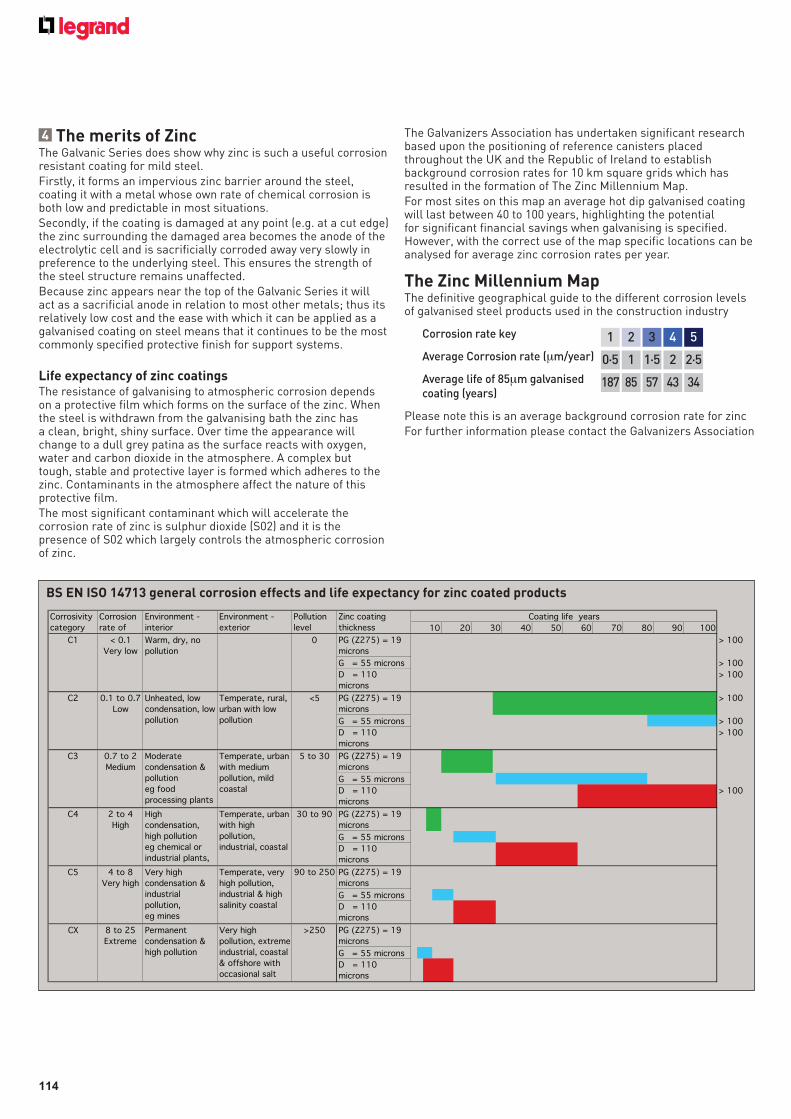
114
4 The merits of ZincThe Galvanic Series does show why zinc is such a useful corrosion resistant coating for mild steel. Firstly, it forms an impervious zinc barrier around the steel, coating it with a metal whose own rate of chemical corrosion is both low and predictable in most situations. Secondly, if the coating is damaged at any point (e.g. at a cut edge) the zinc surrounding the damaged area becomes the anode of the electrolytic cell and is sacrificially corroded away very slowly in preference to the underlying steel. This ensures the strength of the steel structure remains unaffected. Because zinc appears near the top of the Galvanic Series it will act as a sacrificial anode in relation to most other metals; thus its relatively low cost and the ease with which it can be applied as a galvanised coating on steel means that it continues to be the most commonly specified protective finish for support systems.
Life expectancy of zinc coatingsThe resistance of galvanising to atmospheric corrosion depends on a protective film which forms on the surface of the zinc. When the steel is withdrawn from the galvanising bath the zinc has a clean, bright, shiny surface. Over time the appearance will change to a dull grey patina as the surface reacts with oxygen, water and carbon dioxide in the atmosphere. A complex but tough, stable and protective layer is formed which adheres to the zinc. Contaminants in the atmosphere affect the nature of this protective film.The most significant contaminant which will accelerate the corrosion rate of zinc is sulphur dioxide (S02) and it is the presence of S02 which largely controls the atmospheric corrosion of zinc.
The Galvanizers Association has undertaken significant research based upon the positioning of reference canisters placed throughout the UK and the Republic of Ireland to establish background corrosion rates for 10 km square grids which has resulted in the formation of The Zinc Millennium Map.For most sites on this map an average hot dip galvanised coating will last between 40 to 100 years, highlighting the potential for significant financial savings when galvanising is specified. However, with the correct use of the map specific locations can be analysed for average zinc corrosion rates per year.
1 32 4 5
0·5 1·51 2 2·5
187 5785 43 34
Corrosion rate key
Average Corrosion rate (μm/year)
Average life of 85μm galvanised coating (years)
The Zinc Millennium MapThe definitive geographical guide to the different corrosion levels of galvanised steel products used in the construction industry
Please note this is an average background corrosion rate for zincFor further information please contact the Galvanizers Association
PG (Z275) = 19
microns
> 100
G = 55 microns > 100
D = 110
microns
> 100
PG (Z275) = 19
microns
> 100
G = 55 microns > 100
D = 110
microns
> 100
PG (Z275) = 19
microns
G = 55 microns
D = 110
microns
> 100
PG (Z275) = 19
microns
G = 55 microns
D = 110
microns
PG (Z275) = 19
microns
G = 55 microns
D = 110
microns
PG (Z275) = 19
microns
G = 55 microns
D = 110
microns
C4 2 to 4
High
High
condensation,
high pollution
eg chemical or
industrial plants,
Temperate, urban
with high
pollution,
industrial, coastal
C1 < 0.1
Very low
Warm, dry, no
pollution
C2 0.1 to 0.7
Low
Unheated, low
condensation, low
pollution
Temperate, rural,
urban with low
pollution
C3 0.7 to 2
Medium
Moderate
condensation &
pollution
eg food
processing plants
Temperate, urban
with medium
pollution, mild
coastal
60 70 8010 20 30 40 90 100
Coating life yearsCorrosivity
category
Corrosion
rate of
Environment -
interior
Environment -
exterior
Zinc coating
thickness
Pollution
level 50
0
<5
5 to 30
30 to 90
90 to 250
CX 8 to 25
Extreme
Permanent
condensation &
high pollution
Very high
pollution, extreme
industrial, coastal
& offshore with
occasional salt
>250
C5 4 to 8
Very high
Very high
condensation &
industrial
pollution,
eg mines
Temperate, very
high pollution,
industrial & high
salinity coastal
BS EN ISO 14713 general corrosion effects and life expectancy for zinc coated products

115
The Zinc Millennium Map
is supplied courtesy of
The Galvanizers
Association.
Further information is available at www.galvanizing.org.uk
116
5 Common corrosion situationsFinally, the most common occurrences of contact between dissimilar metals within support systems are :a. Where stainless steel components are being fixed to a carbon steel structureb. Where galvanised or zinc plated components are being fixed onto a stainless steel support systemc. Where copper components (e.g. copper tubing or MICC cable) are being installed onto a galvanised steel support systemIn relation to these three sets of conditions the following comments apply :
(i) Stainless steel – mild steelThis situation has been the subject of much consideration and debate over recent years, particularly in the offshore energy industry. Whilst Legrand can supply kits of components (including, according to the circumstances, insulating pads, sleeves for fasteners or insulating coatings) the latest metallurgical advice from both the manufacturers of stainless steel and other bodies is that these metals are sufficiently close together in the Galvanic Series for any electrolytic effects to be ignored in normal offshore environments. One exception is when a small mild steel (or galvanised mild steel) component is in direct contact with a large mass of stainless steel.It is now accepted that the application of a simple paint coating to one of the juxtaposed surfaces will provide sufficient insulation to break the electrical circuit, effectively eliminating any problems.
(ii) Small galvanised components on stainless steelThe zinc coating will provide very limited protection to its underlying steel because of the rapidity with which it will erode away. Once exposed the base steel (often a fastener) will be aggressively corroded causing unsightly staining of the stainless steel and premature failure to the component. In the case of fasteners such failure could be catastrophic to the installation so appropriate stainless steel fasteners should always be used with a stainless steel support system.
(iii) Copper on zincIf copper is laid directly onto a galvanised surface the zinc will rapidly erode. Thus MICC cable should always have an insulating sheath if it is to be installed on galvanised cable ladder.
1 Metallic finishesThe table on the following page outlines the suitability of metallic finishes under a variety of conditions. The following notes apply to the data :1. Hard water promotes the formation of a stable protective film on a hot dip galvanised coating.2. Salt spray testing should not be used on galvanised coatings; the data provided by such accelerated weathering tests is misleading and inaccurate on this finish since the formation of the protective film (patina) is prevented from forming under the artificial conditions.3. No information is available on the resistance of galvanised coatings to contact with this type of oil. However, in general terms galvanised coatings are resistant to oil-based products.4. Resistant provided that the oil is stable, free from acidity and of mineral origin.5. Under immersed conditions contact with this chemical is not recommended and over-coating with a paint or powder system is necessary. When this chemical is an airborne aerosol the coating performance depends on various factors specific to the particular application. Corrosion rates will be high and if condensation is likely to be heavy and its pH value is outside the range pH5 - pH12.5 then overpainting or coating of the galvanising is normally recommended. If the galvanised surface is frequently washed by fresh water and allowed to periodically dry out then the level of corrosion will be less severe.
2 Organic finishesRefer to the table on the following page for information on the suitability of organic finishes under a variety of conditions.
Suitability of finishes
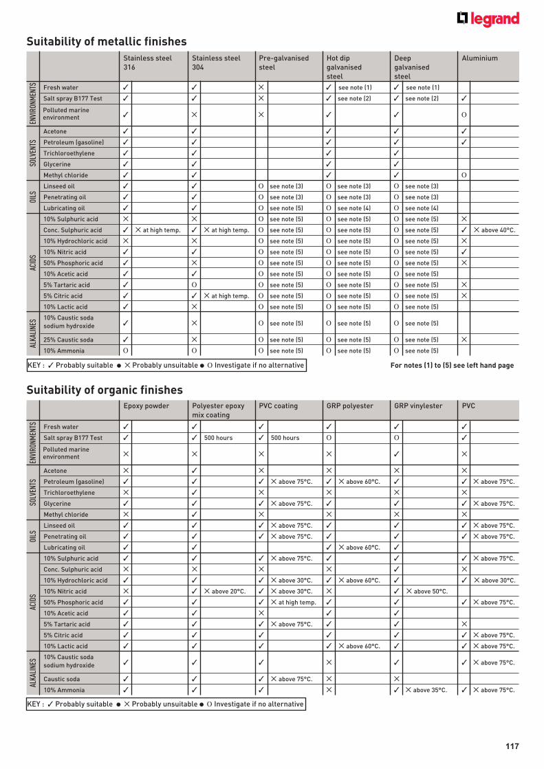
117
Suitability of metallic finishes
Suitability of organic finishes
Fresh water ✓ ✓ ✕ ✓ see note (1) ✓ see note (1)
Salt spray B177 Test ✓ ✓ ✕ ✓ see note (2) ✓ see note (2) ✓
✓ ✕ ✕ ✓ ✓ Ο
Acetone ✓ ✓ ✓ ✓ ✓
Petroleum (gasoline) ✓ ✓ ✓ ✓ ✓
Trichloroethylene ✓ ✓ ✓ ✓
Glycerine ✓ ✓ ✓ ✓
Methyl chloride ✓ ✓ ✓ ✓ Ο
Linseed oil ✓ ✓ Ο see note (3) Ο see note (3) Ο see note (3)
Penetrating oil ✓ ✓ Ο see note (3) Ο see note (3) Ο see note (3)
Lubricating oil ✓ ✓ Ο see note (5) Ο see note (4) Ο see note (4)
10% Sulphuric acid ✕ ✕ Ο see note (5) Ο see note (5) Ο see note (5) ✕
Conc. Sulphuric acid ✓ ✕ at high temp. ✓ ✕ at high temp. Ο see note (5) Ο see note (5) Ο see note (5) ✓ ✕ above 40°C.
10% Hydrochloric acid ✕ ✕ Ο see note (5) Ο see note (5) Ο see note (5) ✕
10% Nitric acid ✓ ✓ Ο see note (5) Ο see note (5) Ο see note (5) ✓
50% Phosphoric acid ✓ ✕ Ο see note (5) Ο see note (5) Ο see note (5) ✕
10% Acetic acid ✓ ✓ Ο see note (5) Ο see note (5) Ο see note (5)
5% Tartaric acid ✓ Ο Ο see note (5) Ο see note (5) Ο see note (5) ✕
5% Citric acid ✓ ✓ ✕ at high temp. Ο see note (5) Ο see note (5) Ο see note (5) ✕
10% Lactic acid ✓ ✕ Ο see note (5) Ο see note (5) Ο see note (5)
✓ ✕ Ο see note (5) Ο see note (5) Ο see note (5)
25% Caustic soda ✓ ✕ Ο see note (5) Ο see note (5) Ο see note (5) ✕
10% Ammonia Ο Ο Ο see note (5) Ο see note (5) Ο see note (5)
ALKALINES
OILS
ACIDS
SOLVENTS
ENVIRONMENTS
Stainless steel Stainless steel Pre-galvanised Hot dip Deep Aluminium 316 304 steel galvanised galvanised steel steel
Polluted marine environment
10% Caustic soda
sodium hydroxide
Fresh water ✓ ✓ ✓ ✓ ✓ ✓
Salt spray B177 Test ✓ ✓ 500 hours ✓ 500 hours Ο Ο ✓
✕ ✕ ✕ ✕ ✓ ✕
Acetone ✕ ✓ ✕ ✕ ✕ ✕
Petroleum (gasoline) ✓ ✓ ✓ ✕ above 75°C. ✓ ✕ above 60°C. ✓ ✓ ✕ above 75°C.
Trichloroethylene ✕ ✓ ✕ ✕ ✕ ✕
Glycerine ✓ ✓ ✓ ✕ above 75°C. ✓ ✓ ✓ ✕ above 75°C.
Methyl chloride ✕ ✓ ✕ ✕ ✕ ✕
Linseed oil ✓ ✓ ✓ ✕ above 75°C. ✓ ✓ ✓ ✕ above 75°C.
Penetrating oil ✓ ✓ ✓ ✕ above 75°C. ✓ ✓ ✓ ✕ above 75°C.
Lubricating oil ✓ ✓ ✓ ✕ above 60°C. ✓
10% Sulphuric acid ✓ ✓ ✓ ✕ above 75°C. ✓ ✓ ✓ ✕ above 75°C.
Conc. Sulphuric acid ✕ ✕ ✕ ✕ ✓ ✕
10% Hydrochloric acid ✓ ✓ ✓ ✕ above 30°C. ✓ ✕ above 60°C. ✓ ✓ ✕ above 30°C.
10% Nitric acid ✕ ✓ ✕ above 20°C. ✓ ✕ above 30°C. ✕ ✓ ✕ above 50°C.
50% Phosphoric acid ✓ ✓ ✓ ✕ at high temp. ✓ ✓ ✓ ✕ above 75°C.
10% Acetic acid ✓ ✓ ✕ ✓ ✓
5% Tartaric acid ✓ ✓ ✓ ✕ above 75°C. ✓ ✓ ✕
5% Citric acid ✓ ✓ ✓ ✓ ✓ ✓ ✕ above 75°C.
10% Lactic acid ✓ ✓ ✓ ✓ ✕ above 60°C. ✓ ✓ ✕ above 75°C.
✓ ✓ ✓ ✕ ✓ ✓ ✕ above 75°C.
Caustic soda ✓ ✓ ✓ ✕ above 75°C. ✕ ✕
10% Ammonia ✓ ✓ ✓ ✕ ✓ ✕ above 35°C. ✓ ✕ above 75°C.
ALKALINES
OILS
ACIDS
SOLVENTS
ENVIRONMENTS
Epoxy powder Polyester epoxy PVC coating GRP polyester GRP vinylester PVC mix coating
Polluted marine environment
10% Caustic soda
sodium hydroxide
KEY : ✓ Probably suitable ● ✕ Probably unsuitable ● Ο Investigate if no alternative
KEY : ✓ Probably suitable ● ✕ Probably unsuitable ● Ο Investigate if no alternative For notes (1) to (5) see left hand page
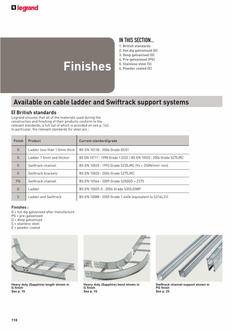
118
Available on cable ladder and Swiftrack support systems
1 British standardsLegrand ensures that all of the materials used during the construction and finishing of their products conform to the relevant standards, a full list of which is provided on see p. 142. In particular, the relevant standards for steel are :
Finish Product Current standard/grade
G Ladder less than 1·5mm thick BS EN 10130 : 2006 Grade DC01
G Ladder 1·5mm and thicker BS EN 10111 : 1998 Grade 1.0332 / BS EN 10025 : 2004 Grade S275JRC
G Swiftrack channel BS EN 10025 : 1993 Grade S235JRC (Ys = 250N/mm2 min)
G Swiftrack brackets BS EN 10025 : 2004 Grade S275JRC
PG Swiftrack channel BS EN 10346 : 2009 Grade S250GD + Z275
D Ladder BS EN 10025-5 : 2004 Grade S355JOWP
S Ladder and Swiftrack BS EN 10088 : 2005 Grade 1.4404 (equivalent to S316L31)
IN THIS SECTION...1. British standards
2. Hot dip galvanised (G)
3. Deep galvanised (D)
4. Pre-galvanised (PG)
5. Stainless steel (S)
6. Powder coated (E)Finishes
Finishes :G = hot dip galvanised after manufacturePG = pre-galvanisedD = deep galvanised S = stainless steel E = powder coated
Heavy duty (Sapphire) length shown in G finish
See p. 16
Heavy duty (Sapphire) bend shown in G finish
See p. 16
Swiftrack channel support shown in PG finish
See p. 25
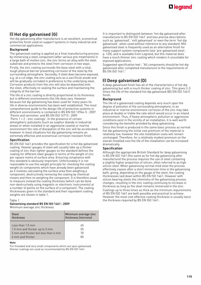
119
2 Hot dip galvanised (G)Hot dip galvanising after manufacture is an excellent, economical protective finish used on support systems in many industrial and commercial applications.
BackgroundThe galvanised coating is applied as a final manufacturing process by immersing a steel component (after various pre-treatments) in a large bath of molten zinc; the zinc forms an alloy with the steel substrate and protects the steel from corrosion in two ways.Firstly, the zinc coating surrounds the base steel with a total, tough physical barrier preventing corrosion of the steel by the surrounding atmosphere. Secondly, if steel does become exposed, e.g. at a cut edge, the zinc coating acts as a sacrificial anode and will be gradually corroded in preference to the underlying steel. Corrosion products from the zinc will also be deposited onto the steel, effectively re-sealing the surface and maintaining the integrity of the barrier.The life of a zinc coating is directly proportional to its thickness but in different environments this life does vary. However because hot dip galvanising has been used for many years its life in diverse environments has been well established. The most comprehensive guide to the design life of protective systems in different environments is contained in BS EN ISO 12944-5 : 2007 ‘Paints and varnishes’ and BS EN ISO 14713 : 2009 ‘Parts 1 + 2 - zinc coatings’. In the presence of certain atmospheric pollutants (such as sulphur dioxide in industrial areas) or when installed in an aggressive coastal or marine environment the rate of dissipation of the zinc will be accelerated; however in most situations hot dip galvanising remains an extremely effective and economical corrosion resistant finish.
SpecificationBS EN ISO 1461 provides the specification for a hot dip galvanised coating. Heavier gauges of steel will usually take up a thicker coating of zinc than lighter gauges so the standard defines the coating for different steel gauges in terms of the weight of zinc per square metre of surface area. Ensuring compliance with this standard is obviously important. Unfortunately it is not reasonable to use this weight principle for checking the coating weight on components which have already been galvanised as it involves calculating the surface area then weighing a component, destructively removing the coating by chemical means and then re-weighing the component. It is therefore usual to measure instead the coating thickness (which can be done non-destructively using magnetic or electronic instruments) at a number of points on the surface of a component. The coating thicknesses given in the standard and their equivalent coating weights are shown in table 1.
Table 1Galvanising standard BS EN ISO 1461 : 2009Minimum average zinc thickness
Steel thickness
Less than 1·5 mm1·5 mm and thicker up to 3 mm3 mm and thicker but less than 6 mm6 mm and thicker
Minimum average zinc thickness (microns)
45 55 70 85
Note
For threaded and very small components which are spun galvanised, thinner coatings are used as recommended by BS EN ISO 1461.
It is important to distinguish between ‘hot dip galvanised after manufacture to BS EN ISO 1461’ and less precise descriptions such as ‘galvanised’, ‘mill galvanised’ or even the term ‘hot dip galvanised’, when used without reference to any standard. Mill galvanised steel is frequently used as an alternative finish for many support system components (see ‘pre-galvanised steel’, p. 120), and is available from Legrand, but this material does have a much thinner zinc coating which renders it unsuitable for exposed applications.Suggested specification text : “All components should be hot dip galvanised after completed manufacture to the requirements of BS EN ISO 1461.”
3 Deep galvanised (D)A deep galvanised finish has all of the characteristics of hot dip galvanising but with a much thicker coating of zinc. This gives 2-3 times the life of the standard hot dip galvanised (BS EN ISO 1461) finish.
BackgroundThe life of a galvanised coating depends very much upon the degree of pollution of the surrounding atmosphere; in an industrial or marine environment corrosion of the zinc may take place at double or treble the rate which would occur in an inland environment. Thus, if heavy atmospheric pollution or aggressive conditions exist in the vicinity of an installation, it is well worth considering the benefits provided by deep galvanising. Since this finish is produced in the same basic process as normal hot dip galvanising the initial cost premium of the material is relatively low; however the site installation costs will remain unchanged. Therefore, for a relatively modest premium on the overall installed cost the life of the installation can be increased dramatically.
SpecificationAlthough the appropriate British Standard for deep galvanising is BS EN ISO 1461 (the same as for hot dip galvanising after manufacture) the process requires the use of steel containing a slightly higher proportion of silicon; often referred to as high silicon steel. When galvanising normal mild steel the process effectively ceases after a short immersion time in the galvanising bath, giving, depending on the gauge of the steel, the coating thicknesses laid down within BS EN ISO 1461. However with silicon bearing steels the chemistry of the galvanising process changes, resulting in the zinc coating continuing to increase in thickness as long as the steel remains immersed in the zinc.Coatings up to three times as thick as the minimum requirements of BS EN ISO 1461 are both possible and practical to achieve. However the most cost effective coating thickness is usually twice the thickness required by BS EN ISO 1461.
120
Pickling and passivationA stainless steel surface will have excellent corrosion resistance due to the chromium oxide layer on the surface of the product. With some stainless steels however, the surface areas can become subject to corrosion due to the depletion of chromium during welding, or the introduction of iron during a machining process (not applicable to most cable management products).Where a uniform appearance is important after carrying out welding processes, it is often specified that all surfaces should be pickled and passivated to remove the smoke stain from the welding process. Also where extreme corrosion resistance is called for, this process may help to remove crevice corrosion from around the welding area. Experience has shown that this is not normally necessary for the majority of cable management products.
PicklingThe pickling process involves the article being immersed in a blend of acids which dissolve iron and iron oxides which adhere to, or are embedded in, the surface of the stainless steel. These acids cause a removal of the surface layer of between 1 and 3 microns. The article is finally rinsed with water to complete this stage of the process.
PassivationPassivation of the stainless steel will occur naturally after pickling when the oxygen in the air will react with the surface of the steel to form a passive chromium oxide layer. However it is usual for this passivation process to be speeded up by immersing the article in a nitric acid or other passivating agent.Pickle and passivation is available as a special order finish, for more information please contact us on +44 (0) 845 605 4333.
ElectropolishingIn various industries such as food, pharmaceutical and electronics, there is a requirement for easier cleaning and reduced bacterial growth on the surface of the stainless steel. This increased surface smoothness is achieved by a process called electropolishing.Electropolishing is, in principle, a reversal of the electroplating process. The article is submerged in a special acid electrolyte and a DC current passed into the article and through the electrolyte. This process removes the high spots from the surface micro roughness leaving a surface which is bright and smooth.
4 Pre-galvanised (PG)A zinc coating can be economically applied to steel sheet immediately after its manufacture; the result, pre-galvanised steel (to BS EN 10346) can be an attractive, bright material which is suitable for non-arduous environments.
BackgroundPre-galvanised (or mill galvanised) steel is produced by unwinding steel coil and passing it continuously through a bath of molten zinc and then past air jets to remove excess zinc from the surface. The process is closely controlled to produce a thin, even and ripple-free zinc coating with very few imperfections.Because this pre-galvanised steel coil must then be cut to shape during subsequent manufacture of support equipment, the edges of the finished components will have no zinc coating; this aspect, together with the relatively light zinc coating provided by the process, make pre-galvanised services supports suitable for indoor, non-corrosive environments (particularly where an aesthetically attractive appearance is important) but unsuitable for humid indoor or outdoor applications.
SpecificationFor steel for Swiftrack channel, steel grade is BS EN 10346 : 2009 Grade S250GD + Z275
5 Stainless steel (S)For all practical purposes most stainless steel services supports can be regarded as maintenance free and suffering no corrosion. Inevitably there is a relatively high price to pay for these attractive properties but, in aggressive environments or where the cost or inconvenience of gaining subsequent maintenance access is prohibitive, this initial cost premium may well be justified.
BackgroundStainless steel contains a high proportion of chromium (usually at least 17%) and the steel’s remarkable immunity to corrosive attack is conferred by the chromium-rich oxide film which occurs naturally on its surface. This invisible film is not only inert and tightly bonded to the surface, it also re-forms quickly if the surface is damaged in any way.The fire resistance of stainless steel is particularly noteworthy; tests have demonstrated that stainless steel cable supports can be expected to maintain their integrity for considerable periods even when exposed to direct flame temperatures exceeding 1,000°C. This may be an important consideration where the electrical circuits being supported provide for emergency power or control systems.Stainless steel is also used where hygiene is a major consideration. Its advantages in such applications are again its excellent resistance to the various chemicals and washes which are frequently used for cleaning purposes and the smoothness of surface (depending on the finish specified) which minimises the soiling or contamination that can take place.
SpecificationMany grades of stainless steel are available but the one generally used in aggressive marine environments is BS EN 10088 Grade 1-4404 (equivalent to S316L31, BS 1449: Part 2). This grade has improved corrosion resistance (particularly in the presence of chlorides) and high temperature strength. It is much used in the chloride-laden marine conditions which exist on offshore installations and in coastal regions.For less aggressive environments BS EN 10088 Grade 1-4301 (equivalent to 304, BS 1449: Part 2) is the normal grade. This grade offers good corrosion resistance in internal applications and also has a good aesthetic quality, often used in the dairy and food industries. Final finishes with mechanical brushing or polishing are often used to provide a good looking and robust surface finish.
121
6 Powder coated (E)Powder coated finishes give excellent protection against scratches as they are normally between 50 - 100% harder than the equivalent wet paint finishes.They are available in a wide range of colours and can have matt or various gloss finishes. In addition to the aesthetic qualities powder coating are available in various grades to cope with different site conditions. Grades are produced to cope with exterior applications where there can be high levels of ultra violet light or low smoke and fume applications for fire risk areas such as occur in tunnels.Because powder coated finishes are inherently resilient and resistant to chemical or corrosive attack, these finishes are frequently used for protection only where there is no aesthetic requirement.
BackgroundThe process of powder coating is carried out by applying the electrostatically charged powder to the article, and then passing the article into an oven where the powder is baked onto the surface of the article.The application of the powder, and the associated stoving, can vary with different types of finish so the careful control of the process is required.
SpecificationWith such a wide variety of types of powder available it is necessary to specify in addition to the colour what the finish is required to do.The colour can be specified by BS or RAL number, or by exact colour match if a sample of the colour is provided. The required gloss level should also be given.The usual finish is for aesthetic indoor use, but if other qualities are required they should be clearly indicated at the outset as the powder cost and application cost can vary considerably between different types of powder.
Epoxy coatedEpoxy coatings are based on thermo-setting epoxy resins and give a very hard, durable finish suitable for internal applications. Epoxy coatings are usually quite thin but they have good chemical resistance with excellent adhesion and coating flexibility.
Polyester epoxy mixSome modern coating developments consist of both polyester and epoxy. These give properties which are very suitable for use with cable support systems. The finish is thick and fairly soft and gives good protection to the cables being installed. The coating has strong adhesive properties and in cases of fire is halogen free with low smoke and fume characteristics. There are many types and grades of these materials and when using them advice should be sought from our technical sales support team, please contact us on +44 (0) 845 605 4333.
Architectural powder coatingsThese powder coatings are formulated to meet the particular requirements of exterior environments. They are inherently resilient and resistant to damage and chemical or corrosive attack, providing maximum protection to the substrate. When subjected to high levels of ultra violet light present within sunlight the coatings have excellent gloss retention and resistance to chalking. These coatings would normally be applied over a galvanised finish.

122
Cable ladder systems are intended for the support of a combination of cables, electrical equipment and/or communication system installations. Where necessary cable ladder systems may be used for the segregation of cables.Note : these systems are designed for use as supports for cables and not as enclosures giving full mechanical protection.
These systems are covered by BS EN 61537.
1 Design factors to considerConsideration should be given to the following factors when undertaking the design of a support system although some of these (e.g. snow/wind loads) may not be relevant to every installation.(i) Distributed loads (eg. cables, pipes)
(ii) Point loads
(iii) Snow, wind and external forces
(iv) Safety factor
(v) Deflection
(vi) Spacing of supports
(vii) Location of couplers
(viii) Installation of cables within a support system
(ix) Earth protection
(x) Electromagnetic compatibility (EMC)
(xi) Thermal expansion and contraction
The following sections provide a wealth of useful information on each of these design aspects.
(i) Distributed loadsBefore commencing the design process for a new installation it is usual to consider whether future changes in the pattern of demand for building services will impose increased loading requirements on the support system. If so, it is good design practice to allow both the physical space and sufficient load carrying capacity for the future addition of 25% more cables or other loading medium.
Estimation of cable loadsIf full details of the cabling layout are available then the likely cable load can be calculated using either manufacturer’s published information or the tables of cable weights and diameters which are given opposite. However, it is often necessary to select a ladder design in the absence of accurate information on the likely cable load. To assist this selection process a useful approach can be to choose a likely size of ladder and then to estimate the maximum cable weight which is capable of being contained within it. This estimate may be arrived at using the following guide :
Note : this formula only provides an estimate of the maximum load which can be physically contained within a ladder. The ability of that ladder to support such a load depends upon the spacing of its supports. Cable weights and diameters
Tables 1 and 2 below give typical weights and diameters (D) for PVC sheathed, steel wire armoured cables with stranded copper conductors.Tables 3 and 4 give typical weights and diameters for PVC sheathed, unarmoured stranded copper power cables. Cables with XLPE (cross linked polyethylene) insulation are usually slightly lighter so the information given may also be used for these cables too.For all other types of cable (e.g. paper insulated cable or cable with aluminium conductors) refer to the cable manufacturer’s catalogue for details and guidance.Values show approx weight and diameter of typical cables. D = Overall cable diameter.
Max. cabling capacity (kg/m) = cable laying area (m2) x 2 800
w
h
Cable laying area
Cable laying area (m2) = w (m) x h (m)Applicable to cable ladder
Cable ladder systems
IN THIS SECTION...Cable ladder systems1. Design factors to consider
2. Cable ladder – 6 m lengths over long spans
3. Loading graphsInstallation of
services
Table 1 : PVC armoured power/control cables to BS 6346 Nom. area 2 core 3 core 4 core of conductor (mm2) kg/m D in mm kg/m D in mm kg/m D in mm
1·5 0·3 12·3 0·3 12·8 0·4 13·5
2·5 0·4 13·6 0·4 14·1 0·5 15·0
4·0 0·5 15·1 0·5 15·8 0·7 17·8
6·0 0·6 16·5 0·7 18·0 0·9 19·2
10·0 0·9 20·1 1·0 21·2 1·2 22·8
16·0 1·0 21·9 1·2 23·1 1·7 26·3
Table 2 : PVC insulated and sheathed circular surface wiring Nom. area 2 core 3 core 4 core of conductor (mm2) kg/m D in mm kg/m D in mm kg/m D in mm
1·5 0·1 7·7 0·1 8·2 0·1 9·1
2·5 0·1 9·2 0·2 9·7 0·2 10·6
4·0 0·2 10·2 0·3 11·0 0·3 12·6
6·0 0·2 12·0 0·3 12·8 0·4 14·2
10·0 0·4 14·6 0·5 15·6 0·7 17·4
16·0 0·6 16·9 0·7 18·0 0·9 20·0
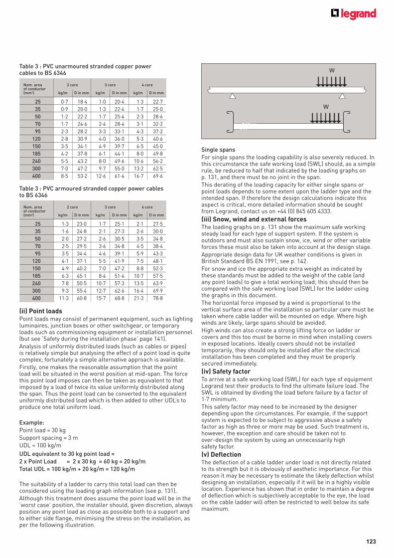
123
(ii) Point loads Point loads may consist of permanent equipment, such as lighting luminaires, junction boxes or other switchgear, or temporary loads such as commissioning equipment or installation personnel (but see ‘Safety during the installation phase’ page 141).Analysis of uniformly distributed loads (such as cables or pipes) is relatively simple but analysing the effect of a point load is quite complex; fortunately a simple alternative approach is available.Firstly, one makes the reasonable assumption that the point load will be situated in the worst position at mid-span. The force this point load imposes can then be taken as equivalent to that imposed by a load of twice its value uniformly distributed along the span. Thus the point load can be converted to the equivalent uniformly distributed load which is then added to other UDL’s to produce one total uniform load.
Example:Point load = 30 kg Support spacing = 3 m UDL = 100 kg/m
UDL equivalent to 30 kg point load = 2 x Point Load = 2 x 30 kg = 60 kg = 20 kg/m Total UDL = 100 kg/m + 20 kg/m = 120 kg/m
The suitability of a ladder to carry this total load can then be considered using the loading graph information (see p. 131).Although this treatment does assume the point load will be in the ‘worst case’ position, the installer should, given discretion, always position any point load as close as possible both to a support and to either side flange, minimising the stress on the installation, as per the following illustration.
Single spansFor single spans the loading capability is also severely reduced. In this circumstance the safe working load (SWL) should, as a simple rule, be reduced to half that indicated by the loading graphs on p. 131, and there must be no joint in the span.This derating of the loading capacity for either single spans or point loads depends to some extent upon the ladder type and the intended span. If therefore the design calculations indicate this aspect is critical, more detailed information should be sought from Legrand, contact us on +44 (0) 845 605 4333.
(iii) Snow, wind and external forces The loading graphs on p. 131 show the maximum safe working steady load for each type of support system. If the system is outdoors and must also sustain snow, ice, wind or other variable forces these must also be taken into account at the design stage.Appropriate design data for UK weather conditions is given in British Standard BS EN 1991, see p. 142.For snow and ice the appropriate extra weight as indicated by these standards must be added to the weight of the cable (and any point loads) to give a total working load; this should then be compared with the safe working load (SWL) for the ladder using the graphs in this document.The horizontal force imposed by a wind is proportional to the vertical surface area of the installation so particular care must be taken where cable ladder will be mounted on edge. Where high winds are likely, large spans should be avoided.High winds can also create a strong lifting force on ladder or covers and this too must be borne in mind when installing covers in exposed locations. Ideally covers should not be installed temporarily, they should only be installed after the electrical installation has been completed and they must be properly secured immediately.
(iv) Safety factorTo arrive at a safe working load (SWL) for each type of equipment Legrand test their products to find the ultimate failure load. The SWL is obtained by dividing the load before failure by a factor of 1·7 minimum.This safety factor may need to be increased by the designer depending upon the circumstances. For example, if the support system is expected to be subject to aggressive abuse a safety factor as high as three or more may be used. Such treatment is, however, the exception and care should be taken not to over-design the system by using an unnecessarily high safety factor.
(v) DeflectionThe deflection of a cable ladder under load is not directly related to its strength but it is obviously of aesthetic importance. For this reason it may be necessary to estimate the likely deflection whilst designing an installation, especially if it will be in a highly visible location. Experience has shown that in order to maintain a degree of deflection which is subjectively acceptable to the eye, the load on the cable ladder will often be restricted to well below its safe maximum.
W
W
Table 3 : PVC unarmoured stranded copper power cables to BS 6346
Nom. area 2 core 3 core 4 core of conductor (mm2) kg/m D in mm kg/m D in mm kg/m D in mm
25 0·7 18·4 1·0 20·4 1·3 22·7
35 0·9 20·0 1·3 22·4 1·7 25·0
50 1·2 22·2 1·7 25·4 2·3 28·6
70 1·7 24·6 2·4 28·4 3·1 32·2
95 2·3 28·2 3·3 33·1 4·3 37·2
120 2·8 30·9 4·0 36·0 5·3 40·6
150 3·5 34·1 4·9 39·7 6·5 45·0
185 4·2 37·8 6·1 44·1 8·0 49·8
240 5·5 43·2 8·0 49·6 10·6 56·2
300 7·0 47·2 9·7 55·0 13·2 62·5
400 8·5 53·2 12·6 61·4 16·7 69·6
Table 3 : PVC armoured stranded copper power cables to BS 6346
Nom. area 2 core 3 core 4 core of conductor (mm2) kg/m D in mm kg/m D in mm kg/m D in mm
25 1·3 23·0 1·7 25·1 2·1 27·5
35 1·6 24·8 2·1 27·3 2·6 30·0
50 2·0 27·2 2·6 30·5 3·5 34·8
70 2·5 29·5 3·6 34·8 4·5 38·4
95 3·5 34·4 4·6 39·1 5·9 43·3
120 4·1 37·1 5·5 41·9 7·5 48·1
150 4·9 40·2 7·0 47·2 8·8 52·3
185 6·3 45·1 8·4 51·4 10·7 57·5
240 7·8 50·5 10·7 57·3 13·5 63·9
300 9·3 55·4 12·7 62·6 16·4 69·9
400 11·3 60·8 15·7 68·8 21·3 78·8
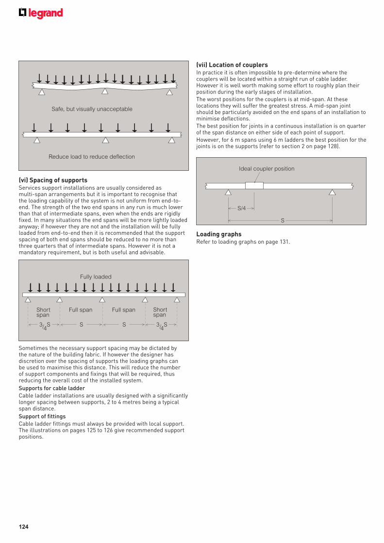
124
(vi) Spacing of supportsServices support installations are usually considered as multi-span arrangements but it is important to recognise that the loading capability of the system is not uniform from end-to-end. The strength of the two end spans in any run is much lower than that of intermediate spans, even when the ends are rigidly fixed. In many situations the end spans will be more lightly loaded anyway; if however they are not and the installation will be fully loaded from end-to-end then it is recommended that the support spacing of both end spans should be reduced to no more than three quarters that of intermediate spans. However it is not a mandatory requirement, but is both useful and advisable.
Sometimes the necessary support spacing may be dictated by the nature of the building fabric. If however the designer has discretion over the spacing of supports the loading graphs can be used to maximise this distance. This will reduce the number of support components and fixings that will be required, thus reducing the overall cost of the installed system.
Supports for cable ladderCable ladder installations are usually designed with a significantly longer spacing between supports, 2 to 4 metres being a typical span distance.
Support of fittingsCable ladder fittings must always be provided with local support. The illustrations on pages 125 to 126 give recommended support positions.
(vii) Location of couplersIn practice it is often impossible to pre-determine where the couplers will be located within a straight run of cable ladder. However it is well worth making some effort to roughly plan their position during the early stages of installation.The worst positions for the couplers is at mid-span. At these locations they will suffer the greatest stress. A mid-span joint should be particularly avoided on the end spans of an installation to minimise deflections. The best position for joints in a continuous installation is on quarter of the span distance on either side of each point of support.However, for 6 m spans using 6 m ladders the best position for the joints is on the supports (refer to section 2 on page 128).
Loading graphsRefer to loading graphs on page 131.
Reduce load to reduce deflection
Safe, but visually unacceptable
3/4S S S 3/4
S
Fully loaded
Short span
Short span
Full spanFull span
S/4
S
Ideal coupler position
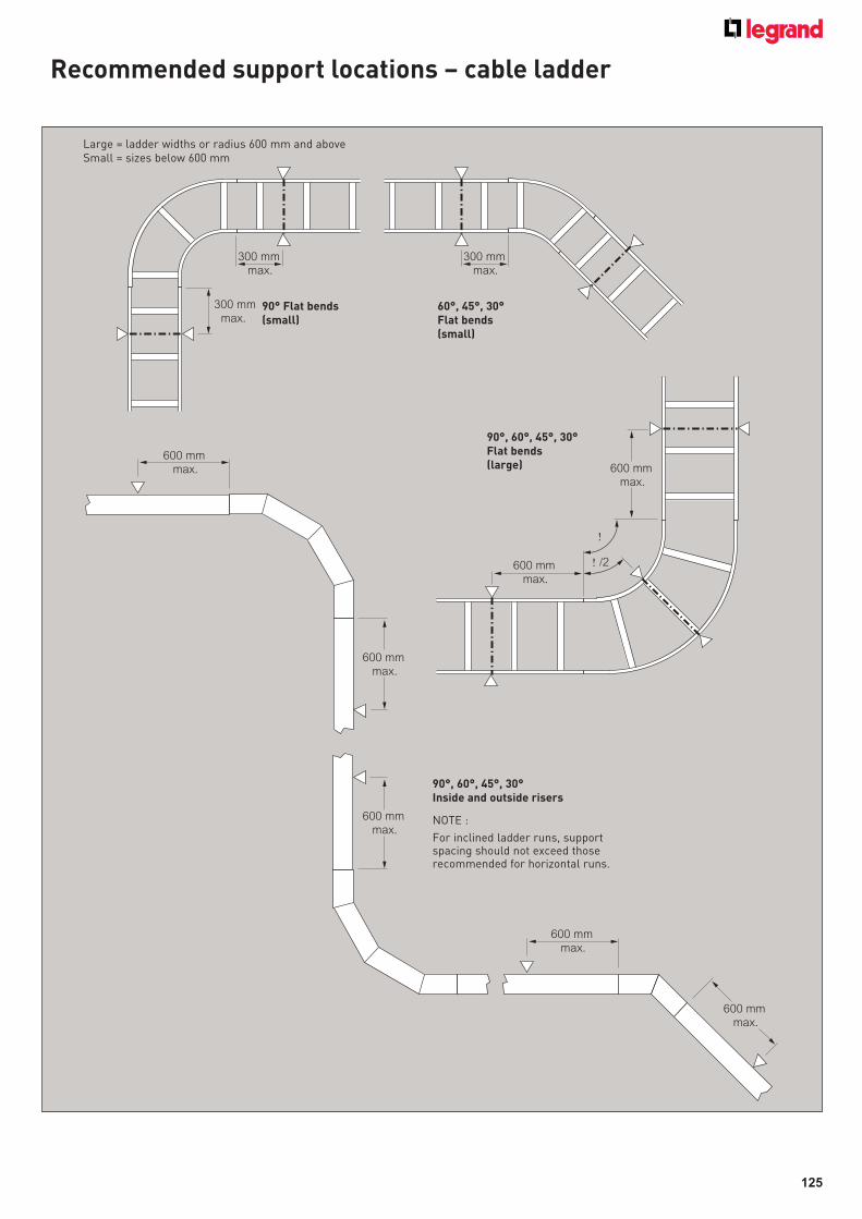
125
Recommended support locations – cable ladder
300 mm
max.
300 mm
max.
300 mm
max.
600 mm
max.
600 mm
max.
600 mm
max.
600 mm
max.
600 mm
max.
600 mm
max.
!
/2
600 mm
max.
!
Large = ladder widths or radius 600 mm and aboveSmall = sizes below 600 mm
90° Flat bends(small)
60°, 45°, 30°Flat bends(small)
90°, 60°, 45°, 30°Flat bends(large)
90°, 60°, 45°, 30°Inside and outside risers
NOTE :
For inclined ladder runs, supportspacing should not exceed thoserecommended for horizontal runs.
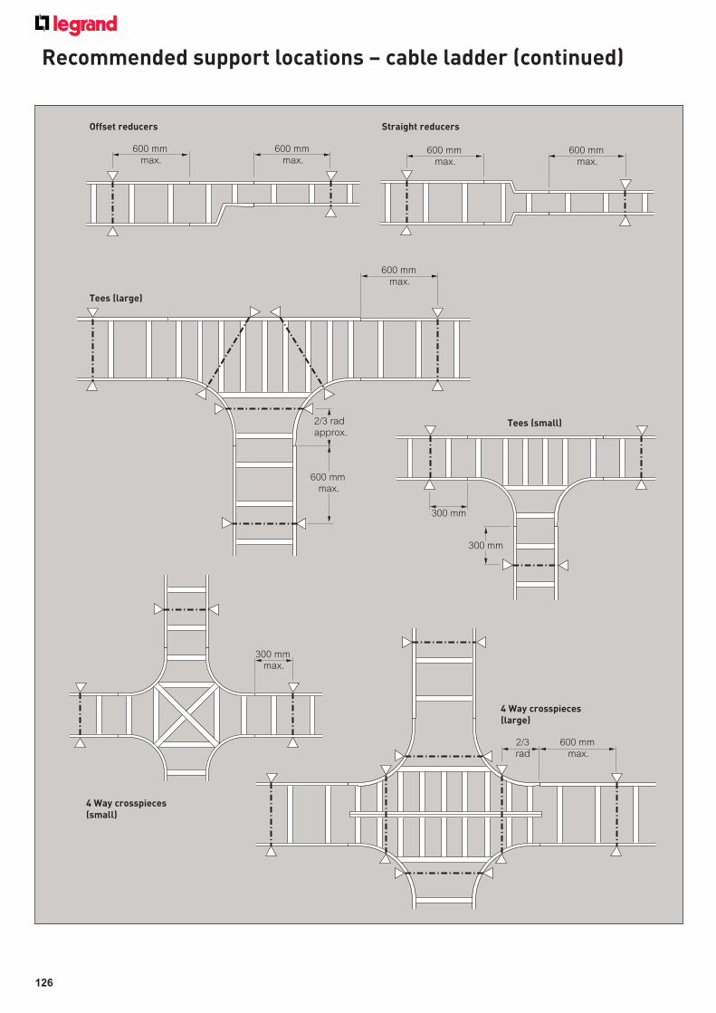
126
Recommended support locations – cable ladder (continued)
600 mm
max.
600 mm
max.600 mm
max.
600 mm
max.
600 mm
max.
2/3 rad
approx.
600 mm
max.
300 mm
300 mm
600 mm
max.
2/3
rad
300 mm
max.
Offset reducers
Tees (large)
Tees (small)
4 Way crosspieces(large)
4 Way crosspieces(small)
Straight reducers
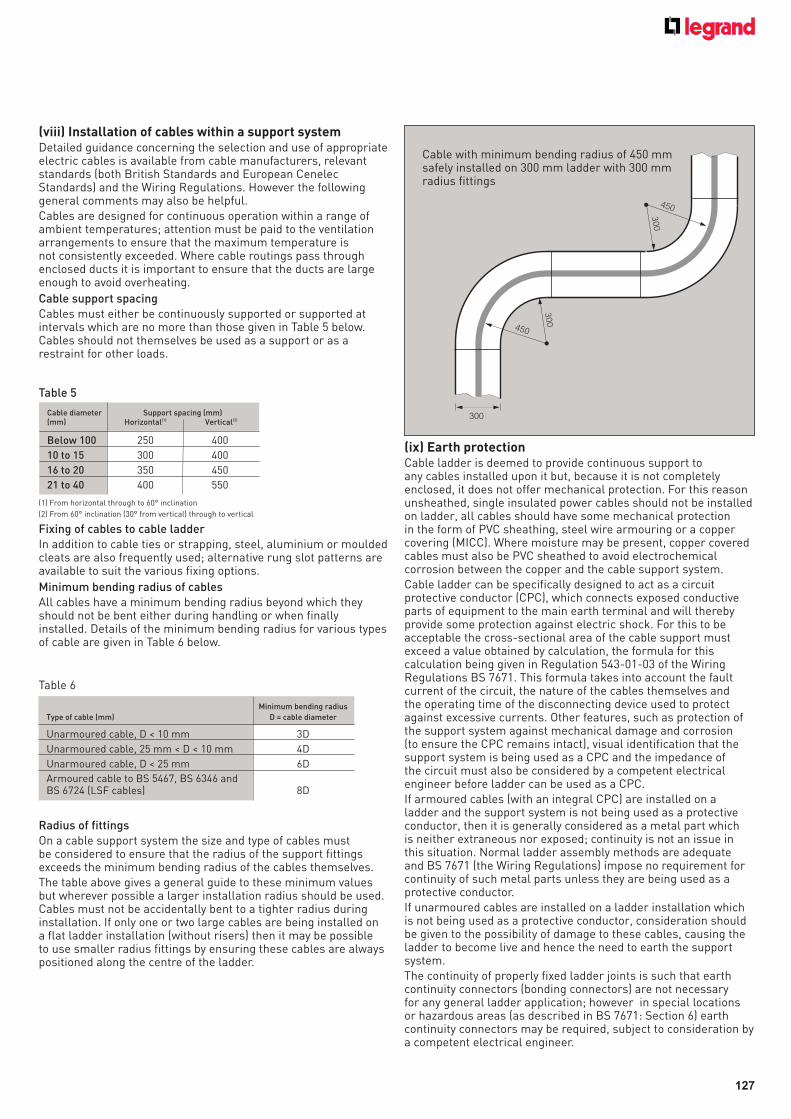
127
(viii) Installation of cables within a support system Detailed guidance concerning the selection and use of appropriate electric cables is available from cable manufacturers, relevant standards (both British Standards and European Cenelec Standards) and the Wiring Regulations. However the following general comments may also be helpful.Cables are designed for continuous operation within a range of ambient temperatures; attention must be paid to the ventilation arrangements to ensure that the maximum temperature is not consistently exceeded. Where cable routings pass through enclosed ducts it is important to ensure that the ducts are large enough to avoid overheating.
Cable support spacingCables must either be continuously supported or supported at intervals which are no more than those given in Table 5 below. Cables should not themselves be used as a support or as a restraint for other loads.
(1) From horizontal through to 60° inclination
(2) From 60° inclination (30° from vertical) through to vertical
Fixing of cables to cable ladderIn addition to cable ties or strapping, steel, aluminium or moulded cleats are also frequently used; alternative rung slot patterns are available to suit the various fixing options.
Minimum bending radius of cablesAll cables have a minimum bending radius beyond which they should not be bent either during handling or when finally installed. Details of the minimum bending radius for various types of cable are given in Table 6 below.
Radius of fittingsOn a cable support system the size and type of cables must be considered to ensure that the radius of the support fittings exceeds the minimum bending radius of the cables themselves.The table above gives a general guide to these minimum values but wherever possible a larger installation radius should be used. Cables must not be accidentally bent to a tighter radius during installation. If only one or two large cables are being installed on a flat ladder installation (without risers) then it may be possible to use smaller radius fittings by ensuring these cables are always positioned along the centre of the ladder.
(ix) Earth protectionCable ladder is deemed to provide continuous support to any cables installed upon it but, because it is not completely enclosed, it does not offer mechanical protection. For this reason unsheathed, single insulated power cables should not be installed on ladder, all cables should have some mechanical protection in the form of PVC sheathing, steel wire armouring or a copper covering (MICC). Where moisture may be present, copper covered cables must also be PVC sheathed to avoid electrochemical corrosion between the copper and the cable support system.Cable ladder can be specifically designed to act as a circuit protective conductor (CPC), which connects exposed conductive parts of equipment to the main earth terminal and will thereby provide some protection against electric shock. For this to be acceptable the cross-sectional area of the cable support must exceed a value obtained by calculation, the formula for this calculation being given in Regulation 543-01-03 of the Wiring Regulations BS 7671. This formula takes into account the fault current of the circuit, the nature of the cables themselves and the operating time of the disconnecting device used to protect against excessive currents. Other features, such as protection of the support system against mechanical damage and corrosion (to ensure the CPC remains intact), visual identification that the support system is being used as a CPC and the impedance of the circuit must also be considered by a competent electrical engineer before ladder can be used as a CPC.If armoured cables (with an integral CPC) are installed on a ladder and the support system is not being used as a protective conductor, then it is generally considered as a metal part which is neither extraneous nor exposed; continuity is not an issue in this situation. Normal ladder assembly methods are adequate and BS 7671 (the Wiring Regulations) impose no requirement for continuity of such metal parts unless they are being used as a protective conductor.If unarmoured cables are installed on a ladder installation which is not being used as a protective conductor, consideration should be given to the possibility of damage to these cables, causing the ladder to become live and hence the need to earth the support system.The continuity of properly fixed ladder joints is such that earth continuity connectors (bonding connectors) are not necessary for any general ladder application; however in special locations or hazardous areas (as described in BS 7671: Section 6) earth continuity connectors may be required, subject to consideration by a competent electrical engineer.
300
450
300
450
300
Cable with minimum bending radius of 450 mm safely installed on 300 mm ladder with 300 mm radius fittings
Table 5
Cable diameter Support spacing (mm)(mm) Horizontal(1) Vertical(2)
Below 100 250 400
10 to 15 300 400
16 to 20 350 450
21 to 40 400 550
Table 6
Minimum bending radius
Type of cable (mm) D = cable diameter
Unarmoured cable, D < 10 mm 3D
Unarmoured cable, 25 mm < D < 10 mm 4D
Unarmoured cable, D < 25 mm 6D
Armoured cable to BS 5467, BS 6346 andBS 6724 (LSF cables) 8D
128
(x) Electromagnetic Compatibility (EMC)In normal use cable ladder is considered as passive in respect of electromagnetic influences. The installation of current carrying media may cause emissions and these media may also be influenced by electromagnetic signals from elsewhere but the degree of influence will depend on the nature of the installation and the apparatus connected to the system.A draft technical report IEC1000-S-1 provides details of the cable separation required according to the type of signal being considered and the IEE Guidance Note No.1 provides further information on the subject of EMC. However, as a basic principle, if power and signal cables can be run separately on different ladders then this will significantly reduce any possibility of one electrical circuit having any undesirable influence upon another.
(xi) Thermal expansion and contractionIn locations where large variations in temperature are anticipated the design of the support system should make allowance for changes in the length of the support system due to the expansion and the contraction of the metal.For cable ladder, Swifts flexible couplers provide for 10 mm of linear movement between adjacent ladders. They should be installed instead of standard couplers at regular intervals with their spacing being determined using the following formula :
L = Ks
Twhere:L = Distance between flexible couplers, in metresKs = 909 for mild steel or 962 for stainless steelT = Range of temperature variation (in Celcius degrees) for
which allowance is to be madeFor information, the relevant coefficients of linear expansion are : Mild steel 11 x 10-6/ °C Stainless steel 10·4 x 10-6/ °C
When expansion couplers are used, the ladder must be supported either side of the joint.
2 Cable ladder – 6 m lengths over long spansThe maximum acceptable deflection for cable ladder is normally considered to be 1/200th of the span distance. However, when cable ladder is to be installed on long spans of 5 m or 6 m the limiting factor which determines the loading capacity is the maximum allowable stress in the ladder side rails rather than the deflection. Deeper side rails can withstand higher stresses and for this reason 125 mm deep Sapphire or 150 mm deep Emerald ladder should be used for long spans. The use of 3 m ladder lengths is not recommended for long spans. The end span of any installation cannot safely support the same maximum load as the inner spans. If therefore the applied cable load is uniform from one end of a run to the other then it is advisable to incorporate at the design stage some reduction in the length of the two end spans. If using 6 m ladders over 6 m spans, with joints on supports, then end span reduction will require cut lengths.The designer should also endeavour to provide supports which are wider than normal, 80-100 mm is ideal on a long span installation. This reduces the local stresses at the contact footprint where the full weight of the installation is carried by the bottom flange of the ladder. On most ladder installations it is good practice to locate the couplers within the span where the bending moments are lowest. However on 6 m spans the couplers should be located directly over the points of support as this will also provide additional local reinforcement of the ladder side rails.For external installations a maximum ladder width of 600 mm is recommended in order to reduce the possible effect of wind and snow, these being exaggerated on longer spans. On cable ladder installed internally these unpredictable loads are less of a problem. Nevertheless, they cannot be totally disregarded as the careless application of temporary loads to one side rail of a fully loaded system (e.g. a carelessly placed access ladder) can be potentially damaging.Care is also needed with regard to any dynamic loads which may cause oscillations in long ladder spans; this is much less likely after the cables have been installed as their stiffness (especially with larger cables) will heavily dampen the system and reduce any tendency for oscillations to develop.
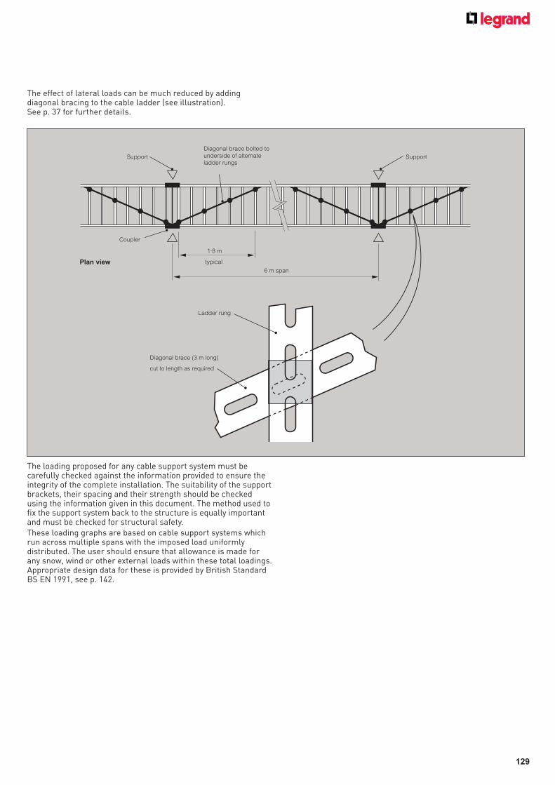
129
The effect of lateral loads can be much reduced by adding diagonal bracing to the cable ladder (see illustration). See p. 37 for further details.
The loading proposed for any cable support system must be carefully checked against the information provided to ensure the integrity of the complete installation. The suitability of the support brackets, their spacing and their strength should be checked using the information given in this document. The method used to fix the support system back to the structure is equally important and must be checked for structural safety.These loading graphs are based on cable support systems which run across multiple spans with the imposed load uniformly distributed. The user should ensure that allowance is made for any snow, wind or other external loads within these total loadings. Appropriate design data for these is provided by British Standard BS EN 1991, see p. 142.
Diagonal brace (3 m long)
cut to length as required
Ladder rung
6 m span
1·8 m
typical
Diagonal brace bolted to
underside of alternate
ladder rungsSupport Support
Coupler
Plan view
130
3 Use of loading graphsProvided the relevant graph line lies above the intersection of the load/span lines the proposed arrangement is acceptable. (See the illustration opposite). The deflection will often be less than 1/200th of the span and in most cases it will be less than 1/360th of the span. However where point loads will be imposed or where there are short runs with three spans or less, the deflection will increase and the safe working loads (SWL) may need to be reduced from the values given.Further information on this subject is given on pages 122 to 124.These graphs should not be extrapolated to longer spans than shown, nor should they be used for situations where the bed of the ladder is vertically orientated. In exposed situations the use of long spans requires particularly careful consideration, see page 128. Any further information on loads and deflections for such circumstances should be sought from Legrand, contact us on +44 (0) 845 605 4333.The values given in this document have been obtained from extensive testing of our cable support equipment. They are given as a guide, so that their customers may use Legrand’s products to the best advantage; they are nevertheless average figures which are given in good faith, but without accepting any liability in contract, tort or otherwise in the event of different performance by equipment which is actually supplied.
The cable support systems in this document are not designed for use as walkways or to support personnel during cable installation.
Loading graphs
The loads shown on all graphs are the safe recommended maximum loads that can be applied and must include wind, snow and any other external forces in addition to the cable load.The graphs show the maximum load for ladder installed at a support spacing within its recommended range.When the graph line is above the intersection of the required load and span lines, the support equipment is suitable for use within those load and span conditions.The graphs shown are for hot dip galvanised finish, with an indication of stainless steel where applicable.Load tests carried out to BS EN 61537 test type 1 (safety factor 1·7+ and joint in middle of span) or test type 4 (safety factor 1·7+ and joint in middle of span with rung slot over support).Load tests for medium duty (Topaz) carried out over 2 m, 3 m and 4 m spans using 3 m lengths.For heavy duty (Sapphire) and extra heavy duty (Emerald) cable ladder, load tests carried out over 3 m, 4 m, and 5 m spans using 3 m lengths and 6 m spans using 6 m lengths.For spans 5 m and less : data can be used for 3 m or 6 m lengthsFor spans greater than 5 m : data is for 6 m lengths only.For spans greater than 5 m : ladder is not suitable for use with dynamic loads (e.g. wind, snow).When installed, inner span deflection will vary depending on joint positions but will typically be about half of test end span deflection shown on following page.
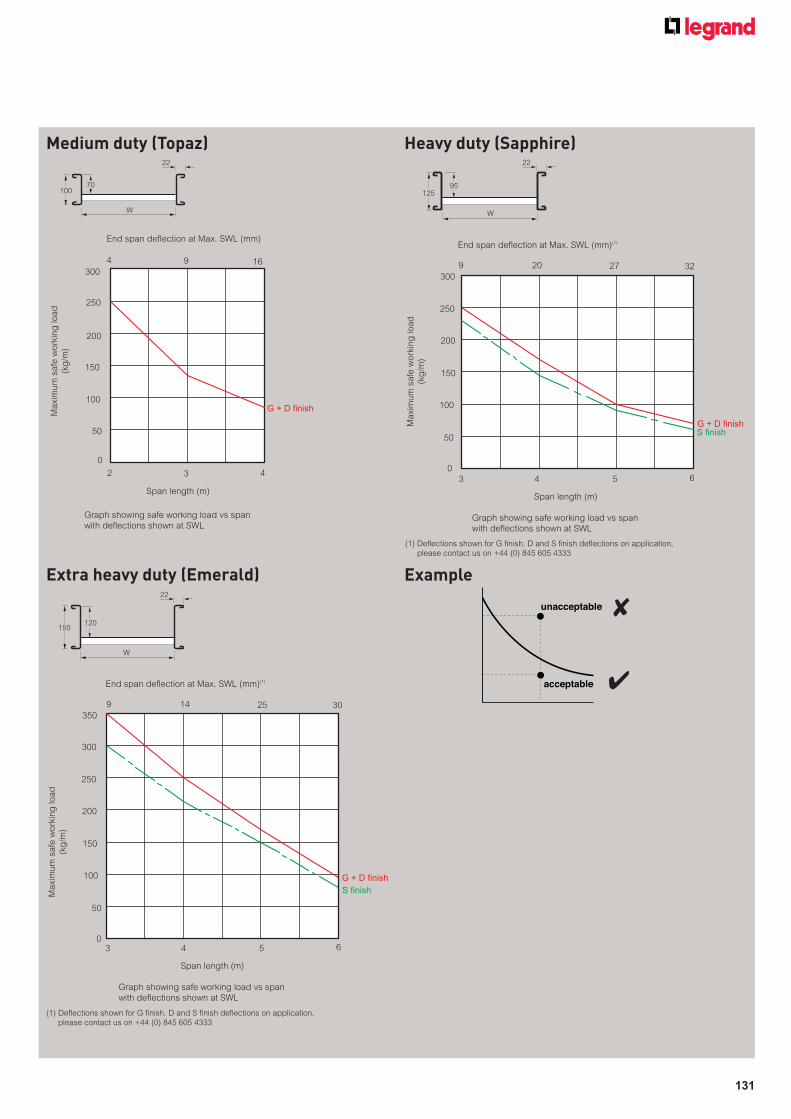
131
unacceptable
acceptable
Example
✘
✔
Extra heavy duty (Emerald)
150
W
120
22
End span deflection at Max. SWL (mm)(1)
9 14 25 30
300
250
200
150
100
50
03 4 5 6
Span length (m)
Graph showing safe working load vs span
with deflections shown at SWL
Ma
xim
um
sa
fe w
ork
ing
lo
ad
(kg
/m)
G + D finish
S finish
350
Heavy duty (Sapphire)
125
W
95
22
End span deflection at Max. SWL (mm)(1)
9 20 27 32300
250
200
150
100
50
0
3 4 5 6
Span length (m)
Graph showing safe working load vs span
with deflections shown at SWL
Ma
xim
um
sa
fe w
ork
ing
lo
ad
(kg
/m)
G + D finish
S finish
Medium duty (Topaz)
100
W
70
22
End span deflection at Max. SWL (mm)
4 9 16300
250
200
150
100
50
0
2 3 4
Span length (m)
Graph showing safe working load vs span
with deflections shown at SWL
Ma
xim
um
sa
fe w
ork
ing
lo
ad
(kg
/m)
G + D finish
(1) Defl ections shown for G fi nish. D and S fi nish defl ections on application,
please contact us on +44 (0) 845 605 4333
(1) Defl ections shown for G fi nish. D and S fi nish defl ections on application,
please contact us on +44 (0) 845 605 4333
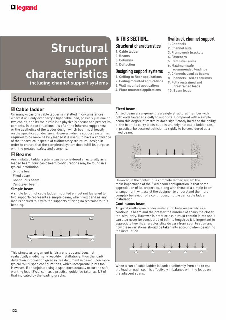
132
1 Cable ladderOn many occasions cable ladder is installed in circumstances where it will only ever carry a light cable load, possibly just one or two cables, and its main role is to physically secure and protect its contents. In these situations it is often the inherent ruggedness or the aesthetics of the ladder design which bear most heavily on the specification decision. However, when a support system is required to be more heavily loaded it is useful to have a knowledge of the theoretical aspects of rudimentary structural design in order to ensure that the completed system does fulfil its purpose with the greatest safety and economy.
2 BeamsAny installed ladder system can be considered structurally as a loaded beam; four basic beam configurations may be found in a typical installation : Simple beam Fixed beam Continuous beam Cantilever beam
Simple beamA single length of cable ladder mounted on, but not fastened to, two supports represents a simple beam, which will bend as any load is applied to it with the supports offering no restraint to this bending.
This simple arrangement is fairly onerous and does not realistically model many real-life installations; thus the load/deflection information given in this document is based upon more typical multi-span configurations, which incorporate joints too. However, if an unjointed single span does actually occur the safe working load (SWL) can, as a practical guide, be taken as 1/2 of that indicated by the loading graphs.
Fixed beamA fixed beam arrangement is a single structural member with both ends fastened rigidly to supports. Compared with a simple beam this degree of restraint does significantly increase the ability of the beam to carry loads but it is unlikely that cable ladder can, in practice, be secured sufficiently rigidly to be considered as a fixed beam.
However, in the context of a complete ladder system the main importance of the fixed beam configuration is that some appreciation of its properties, along with those of a simple beam arrangement, will assist the designer to understand the more complex behaviour of a continuous, multi-span cable ladder installation.
Continuous beamA typical multi-span ladder installation behaves largely as a continuous beam and the greater the number of spans the closer the similarity. However in practice a run must contain joints and it can also never be considered of infinite length so it is important to appreciate how its characteristics do vary from span to span and how these variations should be taken into account when designing the installation.
When a run of cable ladder is loaded uniformly from end to end the load on each span is effectively in balance with the loads on the adjacent spans.
Structural characteristics
IN THIS SECTION...Structural characteristics1. Cable ladder
2. Beams
3. Columns
4. Deflection
Designing support systems1. Ceiling to floor applications
2. Ceiling mounted applications
3. Wall mounted applications
4. Floor mounted applications
Swiftrack channel support1. Channels
2. Channel nuts
3. Framework brackets
4. Fasteners
5. Cantilever arms
6. Maximum safe recommended loadings
7. Channels used as beams
8. Channels used as columns
9. Fully restrained and unrestrained loads
10. Beam loads
Structural support
characteristics including channel support systems
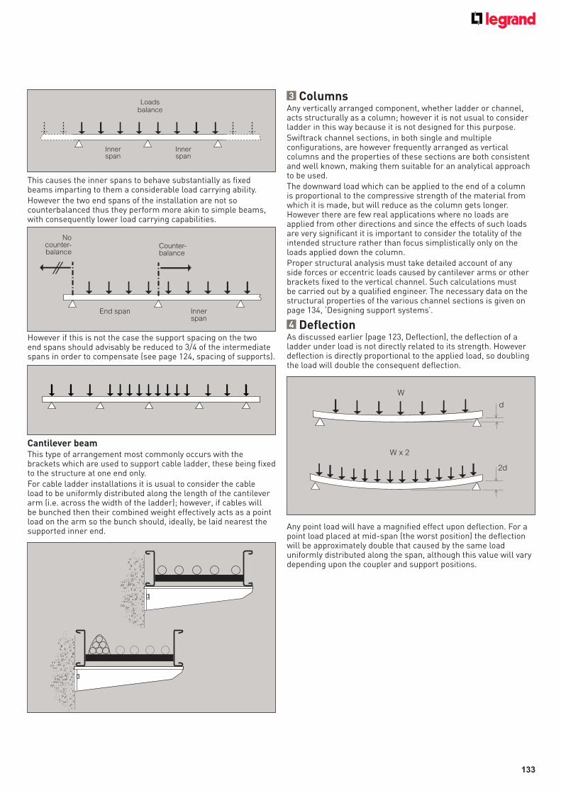
133
This causes the inner spans to behave substantially as fixed beams imparting to them a considerable load carrying ability. However the two end spans of the installation are not so counterbalanced thus they perform more akin to simple beams, with consequently lower load carrying capabilities.
However if this is not the case the support spacing on the two end spans should advisably be reduced to 3/4 of the intermediate spans in order to compensate (see page 124, spacing of supports).
Cantilever beamThis type of arrangement most commonly occurs with the brackets which are used to support cable ladder, these being fixed to the structure at one end only.For cable ladder installations it is usual to consider the cable load to be uniformly distributed along the length of the cantilever arm (i.e. across the width of the ladder); however, if cables will be bunched then their combined weight effectively acts as a point load on the arm so the bunch should, ideally, be laid nearest the supported inner end.
Loadsbalance
Innerspan
Innerspan
Nocounter-balance
Counter-balance
End span Innerspan
3 ColumnsAny vertically arranged component, whether ladder or channel, acts structurally as a column; however it is not usual to consider ladder in this way because it is not designed for this purpose.Swiftrack channel sections, in both single and multiple configurations, are however frequently arranged as vertical columns and the properties of these sections are both consistent and well known, making them suitable for an analytical approach to be used.The downward load which can be applied to the end of a column is proportional to the compressive strength of the material from which it is made, but will reduce as the column gets longer. However there are few real applications where no loads are applied from other directions and since the effects of such loads are very significant it is important to consider the totality of the intended structure rather than focus simplistically only on the loads applied down the column.Proper structural analysis must take detailed account of any side forces or eccentric loads caused by cantilever arms or other brackets fixed to the vertical channel. Such calculations must be carried out by a qualified engineer. The necessary data on the structural properties of the various channel sections is given on page 134, ‘Designing support systems’.
4 DeflectionAs discussed earlier (page 123, Deflection), the deflection of a ladder under load is not directly related to its strength. However deflection is directly proportional to the applied load, so doubling the load will double the consequent deflection.
Any point load will have a magnified effect upon deflection. For a point load placed at mid-span (the worst position) the deflection will be approximately double that caused by the same load uniformly distributed along the span, although this value will vary depending upon the coupler and support positions.
W
d
W x 2
2d
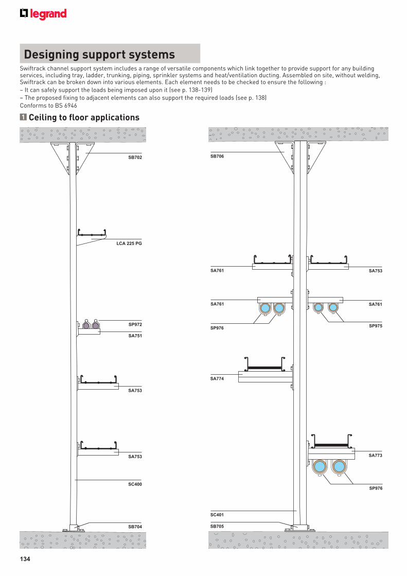
134
Swiftrack channel support system includes a range of versatile components which link together to provide support for any building services, including tray, ladder, trunking, piping, sprinkler systems and heat/ventilation ducting. Assembled on site, without welding, Swiftrack can be broken down into various elements. Each element needs to be checked to ensure the following :– It can safely support the loads being imposed upon it (see p. 138-139)– The proposed fixing to adjacent elements can also support the required loads (see p. 138)Conforms to BS 6946
SB702
LCA 225 PG
SP972
SA751
SA753
SA753
SC400
SB704
SA761
SP975
SA753
SA774
SA761
SA761
SB706
SP976
SB705
SC401
SP976
SA773
1 Ceiling to floor applications
Designing support systems
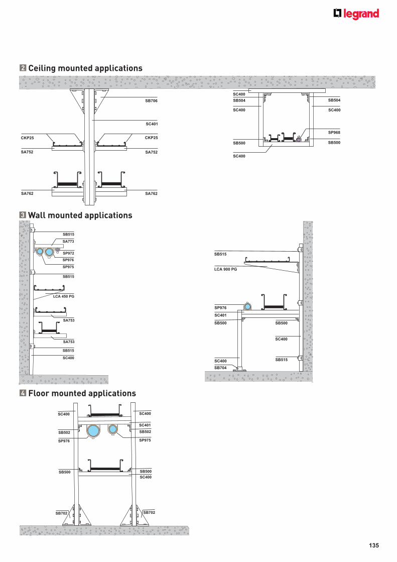
135
2 Ceiling mounted applications
3 Wall mounted applications
4 Floor mounted applications
SA752
SA762
SB706
SC401
CKP25CKP25
SA762
SA752
SP972
SB515
SB515
SB515
SC400
SA753
SA753
LCA 450 PG
SP976
SP975
SA773
SB515
LCA 900 PG
SP976
SC401
SB500
SC400
SB704
SC400
SB500
SB515
SC400
SB504
SC400
SP968
SB500
SB504
SC400
SB500
SC400
SC400
SC401
SB502
SB500
SC400
SB702
SC400
SB502
SP975SP976
SB500
SB702
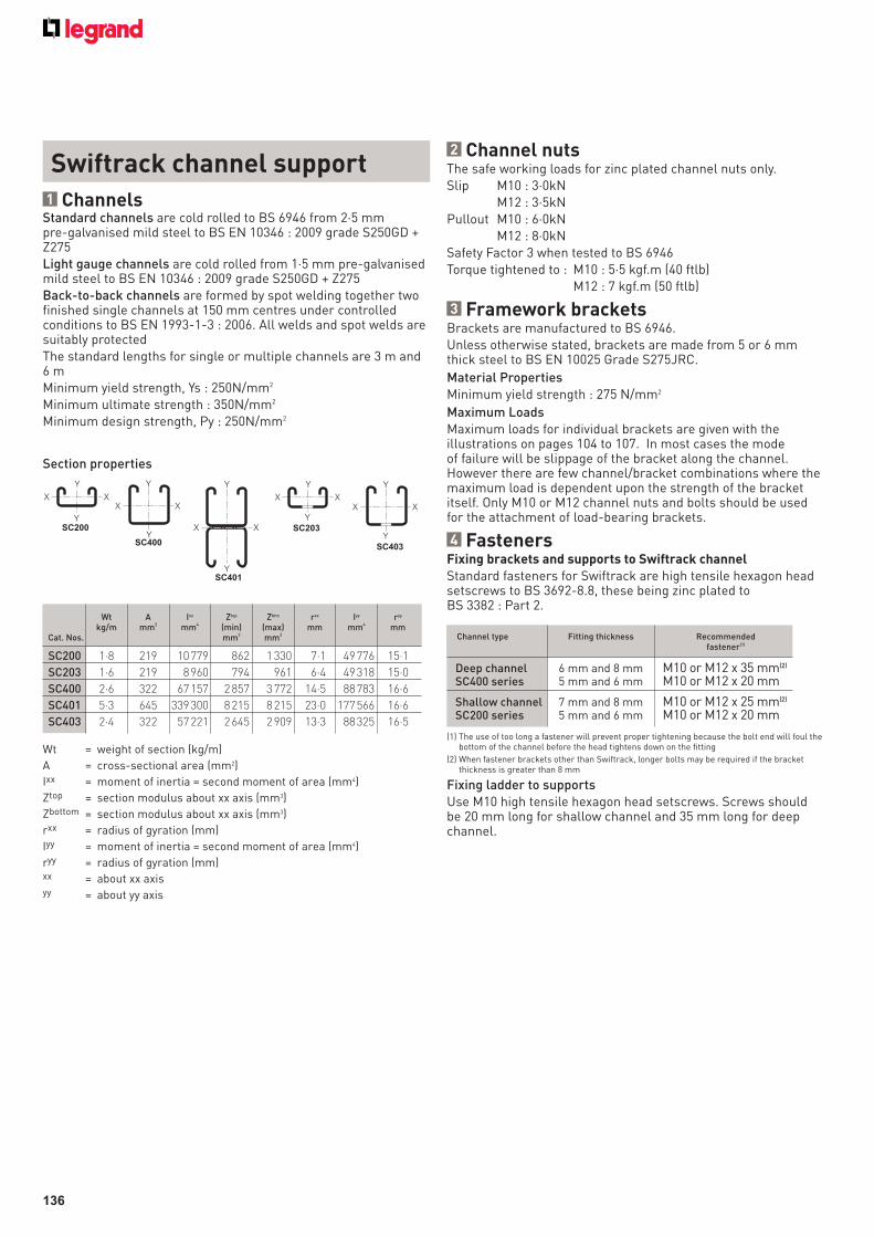
136
2 Channel nutsThe safe working loads for zinc plated channel nuts only.Slip M10 : 3·0kN M12 : 3·5kNPullout M10 : 6·0kN M12 : 8·0kNSafety Factor 3 when tested to BS 6946Torque tightened to : M10 : 5·5 kgf.m (40 ftlb) M12 : 7 kgf.m (50 ftlb)
3 Framework bracketsBrackets are manufactured to BS 6946.Unless otherwise stated, brackets are made from 5 or 6 mm thick steel to BS EN 10025 Grade S275JRC.
Material PropertiesMinimum yield strength : 275 N/mm2
Maximum LoadsMaximum loads for individual brackets are given with the illustrations on pages 104 to 107. In most cases the mode of failure will be slippage of the bracket along the channel. However there are few channel/bracket combinations where the maximum load is dependent upon the strength of the bracket itself. Only M10 or M12 channel nuts and bolts should be used for the attachment of load-bearing brackets.
4 FastenersFixing brackets and supports to Swiftrack channel
Standard fasteners for Swiftrack are high tensile hexagon head setscrews to BS 3692-8.8, these being zinc plated to BS 3382 : Part 2.
(1) The use of too long a fastener will prevent proper tightening because the bolt end will foul the bottom of the channel before the head tightens down on the fitting
(2) When fastener brackets other than Swiftrack, longer bolts may be required if the bracket thickness is greater than 8 mm
Fixing ladder to supportsUse M10 high tensile hexagon head setscrews. Screws should be 20 mm long for shallow channel and 35 mm long for deep channel.
Standard channels are cold rolled to BS 6946 from 2·5 mm pre-galvanised mild steel to BS EN 10346 : 2009 grade S250GD + Z275Light gauge channels are cold rolled from 1·5 mm pre-galvanised mild steel to BS EN 10346 : 2009 grade S250GD + Z275Back-to-back channels are formed by spot welding together two finished single channels at 150 mm centres under controlled conditions to BS EN 1993-1-3 : 2006. All welds and spot welds are suitably protectedThe standard lengths for single or multiple channels are 3 m and 6 mMinimum yield strength, Ys : 250N/mm2
Minimum ultimate strength : 350N/mm2
Minimum design strength, Py : 250N/mm2
1 Channels
Section properties
Swiftrack channel support
Wt = weight of section (kg/m)
A = cross-sectional area (mm2)
Ixx = moment of inertia = second moment of area (mm4)
Ztop = section modulus about xx axis (mm3)
Zbottom = section modulus about xx axis (mm3)
rxx = radius of gyration (mm)
Iyy = moment of inertia = second moment of area (mm4)
ryy = radius of gyration (mm)xx = about xx axisyy = about yy axis
Y
Y
X X
SC200Y
X X
Y
SC400
Y
X X
X
Y
SC203
X X
Y
Y
SC403
Y
X X
Y
SC401
Wt A Ixx Ztop Zbtm rxx Iyy ryy
kg/m mm2 mm4 (min) (max) mm mm4 mmCat. Nos. mm3 mm3
SC200 1·8 219 10 779 862 1 330 7·1 49 776 15·1
SC203 1·6 219 8 960 794 961 6·4 49 318 15·0
SC400 2·6 322 67 157 2 857 3 772 14·5 88 783 16·6
SC401 5·3 645 339 300 8 215 8 215 23·0 177 566 16·6
SC403 2·4 322 57 221 2 645 2 909 13·3 88 325 16·5
Channel type Fitting thickness Recommended fastener(1)
Deep channel 6 mm and 8 mm M10 or M12 x 35 mm(2)
SC400 series 5 mm and 6 mm M10 or M12 x 20 mm
Shallow channel 7 mm and 8 mm M10 or M12 x 25 mm(2)
SC200 series 5 mm and 6 mm M10 or M12 x 20 mm
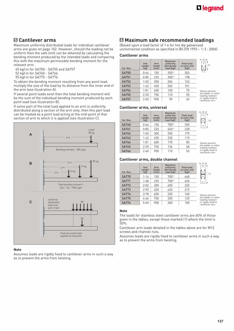
137
Load
W kg
x m
Bending moment = Wx kgm
A
z mU kg
y m
x m
V kg
W kg
Total bending moment =
(Uz + Vy + Wx) kgm
B
WUniformlydistributedload overpart of arm
W
Treat as a point loadapplied at mid-point
C
5 Cantilever armsMaximum uniformly distributed loads for individual cantilever arms are given on page 102. However, should the loading not be uniform then the safe limit can be obtained by calculating the bending moment produced by the intended loads and comparing this with the maximum permissible bending moment for the relevant arm. 45 kgf.m for SA750 - SA755 and SA757 52 kgf.m for SA760 - SA76695 kgf.m for SA770 - SA776
To obtain the bending moment resulting from any point load, multiply the size of the load by its distance from the inner end of the arm (see illustration A).If several point loads exist then the total bending moment will be the sum of the individual bending moment produced by each point load (see illustration B).If some part of the total load applied to an arm is uniformly distributed along a section of the arm only, then this part load can be treated as a point load acting at the mid-point of that section of arm to which it is applied (see illustration C).
Maximum Unit Arm uniformly Point load weight length distributed at outer endCat. Nos. (kg) (mm) load (kgf) (kgf)
SA750 0·64 150 350(1) 303
SA751 0·85 225 350(1) 198
SA752 1·03 300 304 152
SA753 1·42 450 202 101
SA754 1·81 600 150 75
SA755 2·20 750 110 55
SA757 2·60 900 90 45
Cantilever arms40
85
Values assume the ladder or other loading medium is rigidly fixed to cantilever arm
Cantilever arms, universal
Maximum Unit Arm uniformly Point load weight length distributed at outer endCat. Nos. (kg) (mm) load (kgf) (kgf)
SA760 0·64 150 700(1) 350
SA761 0·85 225 456(1) 228
SA762 1·03 300 350 175
SA763 1·42 450 230 115
SA764 1·81 600 170 85
SA765 2·20 750 136 68
SA766 2·60 900 110 55
40
130
Values assume the ladder or other loading medium is rigidly fixed to cantilever arm
6 Maximum safe recommended loadings(Based upon a load factor of 1·6 for hot dip galvanised unrestrained condition as specified in BS EN 1993 – 1-3 : 2006)
Note
The loads for stainless steel cantilever arms are 60% of those given in the tables, except those marked (1) where the limit is 50%.Cantilever arm loads detailed in the tables above are for M12 screws and channel nuts.Assumes loads are rigidly fixed to cantilever arms in such a way as to prevent the arms from twisting.
Cantilever arms, double channel
Maximum Unit Arm uniformly Point load weight length distributed at outer endCat. Nos. (kg) (mm) load (kgf) (kgf)
SA770 1·14 150 700(1) 648
SA771 1·68 225 700(1) 420
SA772 2·02 300 650 325
SA773 2·90 450 430 215
SA774 3·78 600 320 160
SA775 4·66 750 250 125
SA776 5·60 900 200 100
40
175
Values assume the ladder or other loading medium is rigidly fixed to cantilever arm
Note
Assumes loads are rigidly fixed to cantilever arms in such a way as to prevent the arms from twisting.
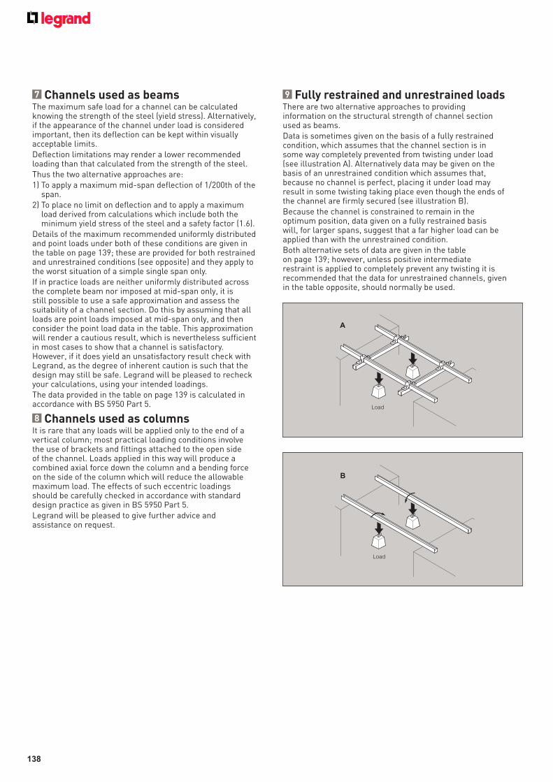
138
7 Channels used as beams The maximum safe load for a channel can be calculated knowing the strength of the steel (yield stress). Alternatively, if the appearance of the channel under load is considered important, then its deflection can be kept within visually acceptable limits.Deflection limitations may render a lower recommended loading than that calculated from the strength of the steel.Thus the two alternative approaches are:1) To apply a maximum mid-span deflection of 1/200th of the
span.2) To place no limit on deflection and to apply a maximum
load derived from calculations which include both the minimum yield stress of the steel and a safety factor (1.6).
Details of the maximum recommended uniformly distributed and point loads under both of these conditions are given in the table on page 139; these are provided for both restrained and unrestrained conditions (see opposite) and they apply to the worst situation of a simple single span only.If in practice loads are neither uniformly distributed across the complete beam nor imposed at mid-span only, it is still possible to use a safe approximation and assess the suitability of a channel section. Do this by assuming that all loads are point loads imposed at mid-span only, and then consider the point load data in the table. This approximation will render a cautious result, which is nevertheless sufficient in most cases to show that a channel is satisfactory. However, if it does yield an unsatisfactory result check with Legrand, as the degree of inherent caution is such that the design may still be safe. Legrand will be pleased to recheck your calculations, using your intended loadings.The data provided in the table on page 139 is calculated in accordance with BS 5950 Part 5.
8 Channels used as columnsIt is rare that any loads will be applied only to the end of a vertical column; most practical loading conditions involve the use of brackets and fittings attached to the open side of the channel. Loads applied in this way will produce a combined axial force down the column and a bending force on the side of the column which will reduce the allowable maximum load. The effects of such eccentric loadings should be carefully checked in accordance with standard design practice as given in BS 5950 Part 5. Legrand will be pleased to give further advice and assistance on request.
A
Load
9 Fully restrained and unrestrained loadsThere are two alternative approaches to providing information on the structural strength of channel section used as beams.Data is sometimes given on the basis of a fully restrained condition, which assumes that the channel section is in some way completely prevented from twisting under load (see illustration A). Alternatively data may be given on the basis of an unrestrained condition which assumes that, because no channel is perfect, placing it under load may result in some twisting taking place even though the ends of the channel are firmly secured (see illustration B).Because the channel is constrained to remain in the optimum position, data given on a fully restrained basis will, for larger spans, suggest that a far higher load can be applied than with the unrestrained condition.Both alternative sets of data are given in the table on page 139; however, unless positive intermediate restraint is applied to completely prevent any twisting it is recommended that the data for unrestrained channels, given in the table opposite, should normally be used.
Load
B
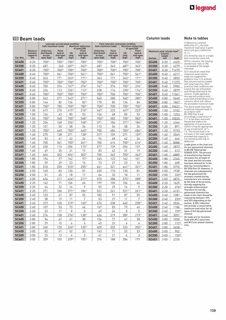
139
10 Beam loads Column loads Note to tables
Laterally unrestrained condition Fully laterally restrained condition Safe maximum loads Maximum deflection Safe maximum loads Maximum deflection of span/200 of span/200 Distance Uniformly Point Point Uniformly Point Point between distributed load at UD load at distributed load at UD load at supports across mid-span load mid-span across mid-span load mid-spanCat. Nos. (m) span (kgf) (kgf) (kgf) (kgf) span (kgf) (kgf) (kgf) (kgf)
SC400 0·20 700(2) 700(2) 700(2) 700(2) 700(2) 700(2) 700(1) 700(1)
SC200 0·20 687 343 687(1) 343(1) 687 343 687(1) 343(1)
SC401 0·20 700(2) 700(2) 700(2) 700(2) 700(2) 700(2) 700(1) 700(1)
SC400 0·40 700(2) 561 700(2) 561(1) 700(2) 561 700(1) 561(1)
SC200 0·40 343 171 343(1) 171(1) 343 171 343(1) 171(1)
SC401 0·40 700(2) 700(2) 700(2) 700(2) 700(2) 700(2) 700(1) 700(1)
SC400 0·60 700 374 747(1) 374(1) 747 374 700(1) 374(1)
SC200 0·60 226 113 226(1) 113(1) 228 114 228(1) 114(1)
SC401 0·60 700(2) 700(2) 700(2) 700(2) 700(2) 700 700(1) 700(1)
SC400 0·80 543 271 543(1) 271(1) 560 280 560(1) 280(1)
SC200 0·80 164 82 134 82(1) 170 85 134 84
SC401 0·80 700(2) 700 700(2) 700(1) 700(2) 700 700(1) 700(1)
SC400 1·00 419 210 419(1) 210(1) 447 223 447(1) 223(1)
SC200 1·00 126 63 85 53 136 68 85 53
SC401 1·00 700(2) 548 700(2) 548(1) 700(2) 582 700(1) 582(1)
SC400 1·20 336 168 336(1) 168(1) 371 186 371(1) 186(1)
SC200 1·20 101 50 58 36 113 56 58 36
SC401 1·20 700(2) 440 700(2) 440(1) 700 484 700(1) 484(1)
SC400 1·40 275 138 271 138(1) 317 159 271 159(1)
SC200 1·40 83 41 42 26 96 48 42 26
SC401 1·40 700 361 700(1) 361(1) 700 414 700(1) 414(1)
SC400 1·60 230 115 206 115(1) 277 139 206 129
SC200 1·60 69 35 31 19 83 42 31 19
SC401 1·60 604 302 604(1) 302(1) 700 362 700(1) 362(1)
SC400 1·80 194 97 162 97(1) 245 123 162 101
SC200 1·80 59 29 23 15 73 37 23 15
SC401 1·80 510 255 510(1) 255(1) 641 321 641(1) 321(1)
SC400 2·00 165 83 130 81 220 110 130 81
SC200 2·00 51 25 18 11 66 33 18 11
SC401 2·00 434 217 434(1) 217(1) 575 288 575(1) 288(1)
SC400 2·20 142 71 106 66 199 100 106 66
SC200 2·20 44 22 14 9 59 29 14 9
SC401 2·20 371 186 371(1) 186(1) 521 261 521(1) 261(1)
SC400 2·40 123 61 87 55 182 91 87 55
SC200 2·40 38 19 11 7 53 27 11 7
SC401 2·40 319 160 319(1) 160(1) 476 238 460 238(1)
SC400 2·60 107 53 73 46 167 83 73 46
SC200 2·60 33 17 8 5 49 24 8 5
SC401 2·60 276 138 276(1) 138(1) 436 219 389 219(1)
SC400 2·80 94 47 61 38 154 77 61 38
SC200 2·80 29 15 6 4 45 22 6 4
SC401 2·80 240 120 240(1) 120(1) 405 202 333 202(1)
SC400 3·00 82 41 52 33 143 71 52 33
SC200 3·00 25 13 4 3 41 21 4 3
SC401 3·00 209 105 209(1) 105(1) 376 188 286 179
Maximum axial column load(4)
Column heightSection (m) (kgf)
SC400 0·20 6325
SC200 0·20 4279
SC401 0·20 11475
SC400 0·40 6217
SC200 0·40 3850
SC401 0·40 11375
SC400 0·60 5982
SC200 0·60 2879
SC401 0·60 11041
SC400 0·80 5640
SC200 0·80 1867
SC401 0·80 10621
SC400 1·00 5102
SC200 1·00 1253
SC401 1·00 10035
SC400 1·20 4346
SC200 1·20 891
SC401 1·20 9193
SC400 1·40 3549
SC200 1·40 664
SC401 1·40 8088
SC400 1·60 2872
SC200 1·60 513
SC401 1·60 6889
SC400 1·80 2345
SC200 1·80 408
SC401 1·80 5792
SC400 2·00 1938
SC200 2·00 332(3)
SC401 2·00 4874
SC400 2·20 1625
SC200 2·20 276(3)
SC401 2·20 4131
SC400 2·40 1381
SC200 2·40 233(3)
SC401 2·40 3534
SC400 2·60 1186
SC200 2·60 199(3)
SC401 2·60 3051
SC400 2·80 1030
SC200 2·80 172(3)
SC401 2·80 2658
SC400 3·00 902
SC200 3·00 150(3)
SC401 3·00 2335
(1) Based on a limited deflection of , the safe maximum load value is given which will give a deflection of < (2) Limited by slip on a single bolt connection each end
(3) For columns, the limiting slenderness ratio of 180 is exceeded at the length indicated
(4) It should be noted that maximum axial column loads are supplied for guidance only. It is unlikely that columns will be loaded with axial load only. Most practical load conditions will involve the use of brackets and fittings attached to the column. Loads applied in this way will produce both axial load and bending on the columns which will reduce the allowable maximum load
The above loads have been treated as imposed loads in accordance with BS 5950 Part 5 and accordingly a load factor of f = 1·6 has been assumed. Should the loads to be applied be of a permanent nature it may be appropriate to use a load factor of f = 1·4. This would lead to an increase in the load capacity provided that capacity is not limited by bolt slip or deflection
Loads given in the chart are for pre-galvanised channels to BS EN 10346 grade S250GD Z275. The process of manufacturing channel increases the strength of the steel and this increase has been allowed for in the data (as recommended in BS 5950 Part 5). However, if channels are subsequently hot dip galvanised the stresses created during manufacture are relieved by the heat of the process, thereby negating the strength enhancementTherefore for hot dip galvanised channels the loads in the chart should be reduced by between 10% and 20% depending on the section. A 20% reduction will provide a conservative maximum load value for all types of hot dip galvanised channel
All loads are for brackets fixed with M12 setscrews and M12 zinc plated channel nuts
L200
L200
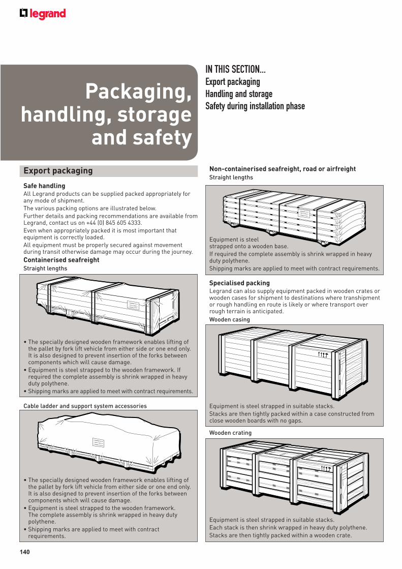
140
Export packaging
Safe handlingAll Legrand products can be supplied packed appropriately for any mode of shipment.The various packing options are illustrated below.Further details and packing recommendations are available from Legrand, contact us on +44 (0) 845 605 4333.Even when appropriately packed it is most important that equipment is correctly loaded.All equipment must be properly secured against movement during transit otherwise damage may occur during the journey.
Containerised seafreightStraight lengths
IN THIS SECTION...Export packaging
Handling and storage
Safety during installation phasePackaging,
handling, storage and safety
• The specially designed wooden framework enables lifting of the pallet by fork lift vehicle from either side or one end only. It is also designed to prevent insertion of the forks between components which will cause damage.
• Equipment is steel strapped to the wooden framework. If required the complete assembly is shrink wrapped in heavy duty polythene.
• Shipping marks are applied to meet with contract requirements.
Cable ladder and support system accessories
• The specially designed wooden framework enables lifting of the pallet by fork lift vehicle from either side or one end only. It is also designed to prevent insertion of the forks between components which will cause damage.
• Equipment is steel strapped to the wooden framework.The complete assembly is shrink wrapped in heavy duty polythene.
• Shipping marks are applied to meet with contract requirements.
Wooden crating
Equipment is steel strapped in suitable stacks.Each stack is then shrink wrapped in heavy duty polythene. Stacks are then tightly packed within a wooden crate.
Specialised packingLegrand can also supply equipment packed in wooden crates or wooden cases for shipment to destinations where transhipment or rough handling en route is likely or where transport over rough terrain is anticipated.
Wooden casing
Equipment is steel strapped in suitable stacks.Stacks are then tightly packed within a case constructed from close wooden boards with no gaps.
Non-containerised seafreight, road or airfreightStraight lengths
Equipment is steel strapped onto a wooden base.If required the complete assembly is shrink wrapped in heavy duty polythene.Shipping marks are applied to meet with contract requirements.
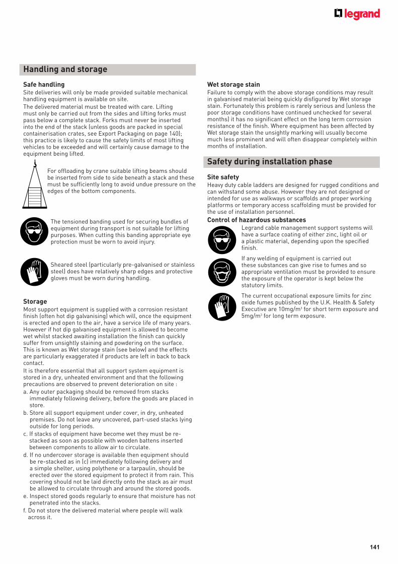
141
Wet storage stainFailure to comply with the above storage conditions may result in galvanised material being quickly disfigured by Wet storage stain. Fortunately this problem is rarely serious and (unless the poor storage conditions have continued unchecked for several months) it has no significant effect on the long term corrosion resistance of the finish. Where equipment has been affected by Wet storage stain the unsightly marking will usually become much less prominent and will often disappear completely within months of installation.
Safe handlingSite deliveries will only be made provided suitable mechanical handling equipment is available on site.The delivered material must be treated with care. Lifting must only be carried out from the sides and lifting forks must pass below a complete stack. Forks must never be inserted into the end of the stack (unless goods are packed in special containerisation crates, see Export Packaging on page 140); this practice is likely to cause the safety limits of most lifting vehicles to be exceeded and will certainly cause damage to the equipment being lifted.
For offloading by crane suitable lifting beams should be inserted from side to side beneath a stack and these must be sufficiently long to avoid undue pressure on the edges of the bottom components.
The tensioned banding used for securing bundles of equipment during transport is not suitable for lifting purposes. When cutting this banding appropriate eye protection must be worn to avoid injury.
Sheared steel (particularly pre-galvanised or stainless steel) does have relatively sharp edges and protective gloves must be worn during handling.
StorageMost support equipment is supplied with a corrosion resistant finish (often hot dip galvanising) which will, once the equipment is erected and open to the air, have a service life of many years. However if hot dip galvanised equipment is allowed to become wet whilst stacked awaiting installation the finish can quickly suffer from unsightly staining and powdering on the surface. This is known as Wet storage stain (see below) and the effects are particularly exaggerated if products are left in back to back contact.It is therefore essential that all support system equipment is stored in a dry, unheated environment and that the following precautions are observed to prevent deterioration on site :a. Any outer packaging should be removed from stacks
immediately following delivery, before the goods are placed in store.
b. Store all support equipment under cover, in dry, unheated premises. Do not leave any uncovered, part-used stacks lying outside for long periods.
c. If stacks of equipment have become wet they must be re-stacked as soon as possible with wooden battens inserted between components to allow air to circulate.
d. If no undercover storage is available then equipment should be re-stacked as in (c) immediately following delivery and a simple shelter, using polythene or a tarpaulin, should be erected over the stored equipment to protect it from rain. This covering should not be laid directly onto the stack as air must be allowed to circulate through and around the stored goods.
e. Inspect stored goods regularly to ensure that moisture has not penetrated into the stacks.
f. Do not store the delivered material where people will walk across it.
Handling and storage
Safety during installation phase
Site safetyHeavy duty cable ladders are designed for rugged conditions and can withstand some abuse. However they are not designed or intended for use as walkways or scaffolds and proper working platforms or temporary access scaffolding must be provided for the use of installation personnel.
Control of hazardous substances Legrand cable management support systems will
have a surface coating of either zinc, light oil or a plastic material, depending upon the specified finish.
If any welding of equipment is carried out these substances can give rise to fumes and so appropriate ventilation must be provided to ensure the exposure of the operator is kept below the statutory limits.
The current occupational exposure limits for zinc oxide fumes published by the U.K. Health & Safety Executive are 10mg/m3 for short term exposure and 5mg/m3 for long term exposure.
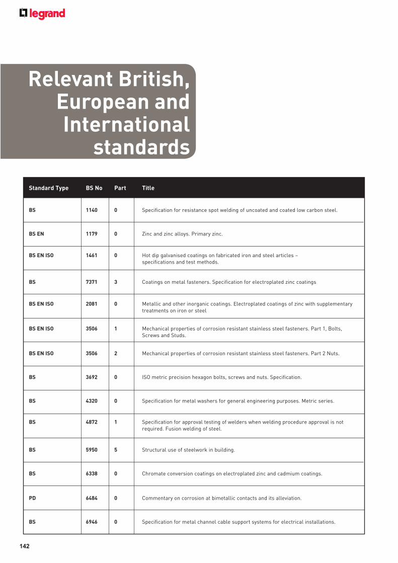
142
Relevant British, European and International
standards
Standard Type BS No Part Title
BS 1140 0 Specification for resistance spot welding of uncoated and coated low carbon steel.
BS EN 1179 0 Zinc and zinc alloys. Primary zinc.
BS EN ISO 1461 0 Hot dip galvanised coatings on fabricated iron and steel articles – specifications and test methods.
BS 7371 3 Coatings on metal fasteners. Specification for electroplated zinc coatings
BS EN ISO 2081 0 Metallic and other inorganic coatings. Electroplated coatings of zinc with supplementary treatments on iron or steel
BS EN ISO 3506 1 Mechanical properties of corrosion resistant stainless steel fasteners. Part 1, Bolts, Screws and Studs.
BS EN ISO 3506 2 Mechanical properties of corrosion resistant stainless steel fasteners. Part 2 Nuts.
BS 3692 0 ISO metric precision hexagon bolts, screws and nuts. Specification.
BS 4320 0 Specification for metal washers for general engineering purposes. Metric series.
BS 4872 1 Specification for approval testing of welders when welding procedure approval is not required. Fusion welding of steel.
BS 5950 5 Structural use of steelwork in building.
BS 6338 0 Chromate conversion coatings on electroplated zinc and cadmium coatings.
PD 6484 0 Commentary on corrosion at bimetallic contacts and its alleviation.
BS 6946 0 Specification for metal channel cable support systems for electrical installations.
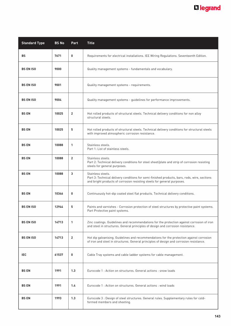
143
Standard Type BS No Part Title
BS 7671 0 Requirements for electrical installations. IEE Wiring Regulations. Seventeenth Edition.
BS EN ISO 9000 Quality management systems - fundamentals and vocabulary.
BS EN ISO 9001 Quality management systems - requirements.
BS EN ISO 9004 Quality management systems - guidelines for performance improvements.
BS EN 10025 2 Hot rolled products of structural steels. Technical delivery conditions for non alloy structural steels.
BS EN 10025 5 Hot rolled products of structural steels. Technical delivery conditions for structural steels with improved atmospheric corrosion resistance.
BS EN 10088 1 Stainless steels.Part 1: List of stainless steels.
BS EN 10088 2 Stainless steels.Part 2: Technical delivery conditions for steel sheet/plate and strip of corrosion resisting steels for general purposes.
BS EN 10088 3 Stainless steels.Part 3: Technical delivery conditions for semi-finished products, bars, rods, wire, sections and bright products of corrosion resisting steels for general purposes.
BS EN 10346 0 Continuously hot-dip coated steel flat products. Technical delivery conditions.
BS EN ISO 12944 5 Paints and varnishes - Corrosion protection of steel structures by protective paint systems.Part Protective paint systems.
BS EN ISO 14713 1 Zinc coatings. Guidelines and recommendations for the protection against corrosion of iron and steel in structures. General principles of design and corrosion resistance.
BS EN ISO 14713 2 Hot dip galvanising. Guidelines and recommendations for the protection against corrosion of iron and steel in structures. General principles of design and corrosion resistance.
IEC 61537 0 Cable Tray systems and cable ladder systems for cable management.
BS EN 1991 1.3 Eurocode 1 : Action on structures. General actions : snow loads
BS EN 1991 1.4 Eurocode 1 : Action on structures. General actions : wind loads
BS EN 1993 1.3 Eurocode 3 : Design of steel structures. General rules. Supplementary rules for cold-formed members and sheeting.
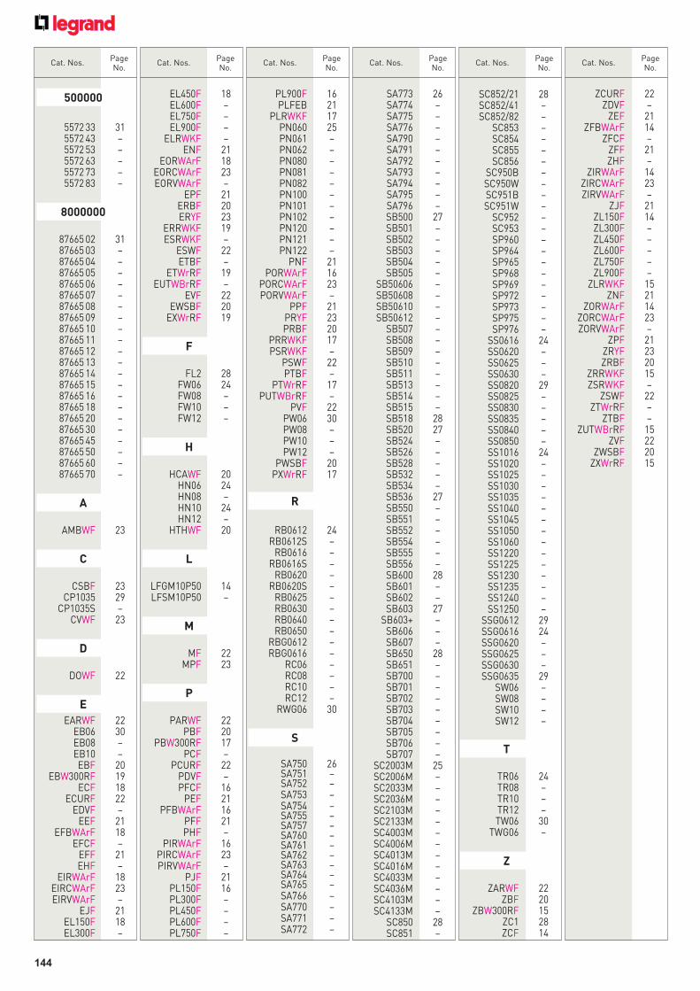
Cat. Nos.
Page No.
Cat. Nos.
Page No.
Cat. Nos.
Page No.
Cat. Nos.
Page No.
Cat. Nos.
Page No.
Cat. Nos.
Page No.
5572 33 31 5572 43 – 5572 53 – 5572 63 – 5572 73 – 5572 83 –
8000000
87665 02 31 87665 03 – 87665 04 – 87665 05 – 87665 06 – 87665 07 – 87665 08 – 87665 09 – 87665 10 – 87665 11 – 87665 12 – 87665 13 – 87665 14 – 87665 15 – 87665 16 – 87665 18 – 87665 20 – 87665 30 – 87665 45 – 87665 50 – 87665 60 – 87665 70 –
A
AMBWF 23
C
CSBF 23 CP1035 29 CP1035S – CVWF 23
D
DOWF 22
E
EARWF 22 EB06 30 EB08 – EB10 – EBF 20 EBW300RF 19 ECF 18 ECURF 22 EDVF – EEF 21 EFBWArF 18 EFCF – EFF 21 EHF – EIRWArF 18 EIRCWArF 23 EIRVWArF – EJF 21 EL150F 18 EL300F –
EL450F 18 EL600F – EL750F – EL900F – ELRWKF – ENF 21 EORWArF 18 EORCWArF 23 EORVWArF – EPF 21 ERBF 20 ERYF 23 ERRWKF 19 ESRWKF – ESWF 22 ETBF – ETWrRF 19 EUTWBrRF – EVF 22 EWSBF 20 EXWrRF 19
F
FL2 28 FW06 24 FW08 – FW10 – FW12 –
H
HCAWF 20 HN06 24 HN08 – HN10 24 HN12 – HTHWF 20
L
LFGM10P50 14 LFSM10P50 –
M
MF 22 MPF 23
P
PARWF 22 PBF 20 PBW300RF 17 PCF – PCURF 22 PDVF – PFCF 16 PEF 21 PFBWArF 16 PFF 21 PHF – PIRWArF 16 PIRCWArF 23 PIRVWArF – PJF 21 PL150F 16 PL300F – PL450F – PL600F – PL750F –
PL900F 16 PLFEB 21 PLRWKF 17 PN060 25 PN061 – PN062 – PN080 – PN081 – PN082 – PN100 – PN101 – PN102 – PN120 – PN121 – PN122 – PNF 21 PORWArF 16 PORCWArF 23 PORVWArF – PPF 21 PRYF 23 PRBF 20 PRRWKF 17 PSRWKF – PSWF 22 PTBF – PTWrRF 17 PUTWBrRF – PVF 22 PW06 30 PW08 – PW10 – PW12 – PWSBF 20 PXWrRF 17
R
RB0612 24 RB0612S – RB0616 – RB0616S – RB0620 – RB0620S – RB0625 – RB0630 – RB0640 – RB0650 – RBG0612 – RBG0616 – RC06 – RC08 – RC10 – RC12 – RWG06 30
S
SA750 26 SA751 – SA752 – SA753 – SA754 – SA755 – SA757 – SA760 – SA761 – SA762 – SA763 – SA764 – SA765 – SA766 – SA770 – SA771 – SA772 –
SA773 26 SA774 – SA775 – SA776 – SA790 – SA791 – SA792 – SA793 – SA794 – SA795 – SA796 – SB500 27 SB501 – SB502 – SB503 – SB504 – SB505 – SB50606 – SB50608 – SB50610 – SB50612 – SB507 – SB508 – SB509 – SB510 – SB511 – SB513 – SB514 – SB515 – SB518 28 SB520 27 SB524 – SB526 – SB528 – SB532 – SB534 – SB536 27 SB550 – SB551 – SB552 – SB554 – SB555 – SB556 – SB600 28 SB601 – SB602 – SB603 27 SB603+ – SB606 – SB607 – SB650 28 SB651 – SB700 – SB701 – SB702 – SB703 – SB704 – SB705 – SB706 – SB707 – SC2003M 25 SC2006M – SC2033M – SC2036M – SC2103M – SC2133M – SC4003M – SC4006M – SC4013M – SC4016M – SC4033M – SC4036M – SC4103M – SC4133M – SC850 28 SC851 –
SC852/21 28 SC852/41 – SC852/82 – SC853 – SC854 – SC855 – SC856 – SC950B – SC950W – SC951B – SC951W – SC952 – SC953 – SP960 – SP964 – SP965 – SP968 – SP969 – SP972 – SP973 – SP975 – SP976 – SS0616 24 SS0620 – SS0625 – SS0630 – SS0820 29 SS0825 – SS0830 – SS0835 – SS0840 – SS0850 – SS1016 24 SS1020 – SS1025 – SS1030 – SS1035 – SS1040 – SS1045 – SS1050 – SS1060 – SS1220 – SS1225 – SS1230 – SS1235 – SS1240 – SS1250 – SSG0612 29 SSG0616 24 SSG0620 – SSG0625 – SSG0630 – SSG0635 29 SW06 – SW08 – SW10 – SW12 –
T
TR06 24 TR08 – TR10 – TR12 – TW06 30 TWG06 –
Z
ZARWF 22 ZBF 20 ZBW300RF 15 ZC1 28 ZCF 14
ZCURF 22 ZDVF – ZEF 21 ZFBWArF 14 ZFCF – ZFF 21 ZHF – ZIRWArF 14 ZIRCWArF 23 ZIRVWArF – ZJF 21 ZL150F 14 ZL300F – ZL450F – ZL600F – ZL750F – ZL900F – ZLRWKF 15 ZNF 21 ZORWArF 14 ZORCWArF 23 ZORVWArF – ZPF 21 ZRYF 23 ZRBF 20 ZRRWKF 15 ZSRWKF – ZSWF 22 ZTWrRF – ZTBF – ZUTWBrRF 15 ZVF 22 ZWSBF 20 ZXWrRF 15
144
500000

LEGRAND WORLDWIDE
AlgeriaLegrand Tel. : (213) 21 91 38 32Fax : (213) 21 91 26 39
AustraliaLegrandTel. : (61) 2 87 19 43 33Fax : (61) 2 87 19 43 45
AustriaLegrand OsterreichTel. : (43) 1 277 62Fax : (43) 1 277 62 225
BelarusLegrandTel. : (375) 17 205 04 78/79Fax : (375) 17 205 04 78/79
BelgiumLegrand Belgique S.A.Tel. : (32) 2 719 17 11Fax : (32) 2 719 17 00
Bosnia-HerzegovinaLegrandTel. : (387) 33 71 10 25Fax : (387) 33 52 17 84
BrazilGL Electro-Eletronicos LtdaTel. : (55) 11 56 44 26 00Fax : (55) 11 51 81 06 04/59 14
BulgariaLegrandTel. : (359) 2 489 92 97Fax : (359) 2 489 94 70
CanadaPass & Seymour Canada IncTel. : (1) 905 738 91 95Fax : (1) 905 738 97 21
ChileLegrand Electro Andina Ltda (EAL)Tel. : (56) 2 550 52 00Fax : (56) 2 550 53 09
ChinaLegrand ChinaTel. : (86) 21 52 11 01 11Fax : (86) 21 52 11 00 86
ColombiaLegrand Colombia S.A.Tel. : (57) 1 437 67 00Fax : (57) 1 436 26 54
Costa RicaBticino Costa RicaTel. : (506) 22 98 56 00Fax : (506) 22 39 04 72
CroatiaLegrandTel. : (385) 1 606 43 50Fax : (385) 1 606 43 59
CyprusLegrandTel. : (357) 22 318 588Fax : (357) 22 318 588
Czech RepublicLegrand s.r.o.Tel. : (420) 2 46 00 76 68Fax : (420) 2 46 00 76 69
EgyptEMB Electrical Industries SAETel. : (202) 23 78 61 50Fax : (202) 23 80 70 32
EstoniaLegrand SNCTel. : (372) 67 99 110Fax : (372) 67 99 113
FranceLegrand S.A.Tel. : (33) 5 55 06 87 87Fax : (33) 5 55 06 88 88
GermanyLegrand GmbHTel. : (49) 29 21 10 40Fax : (49) 29 21 10 42 02
GreeceHelliniki Legrand S.A.Tel. : (30) 2 10 67 97 500Fax : (30) 2 10 67 97 540
Hong KongLegrand (HK) LtdTel. : (852) 26 87 42 00Fax : (852) 26 87 43 00
HungaryLegrand ZrtTel. : (36) 63 51 02 00Fax : (36) 63 51 02 10
IndiaLegrand (India) Pvt LtdTel. : (91) 22 30 41 62 00Fax : (91) 22 24 93 31 58
IndonesiaPT Legrand IndonesiaTel. : (62) 21 525 06 08Fax : (62) 21 525 59 35
IranAlborz Electrical Industries LtdTel. : (98) 218 873 94 57/86 70Fax : (98) 218 873 79 03
ItalyBticino S.p.a.Tel. : (39) 03 32 27 91 11Fax : (39) 03 32 26 56 61
JordanLegrandTel. : (962) 64 65 59 02Fax : (962) 64 65 59 03
KazakhstanLegrand KazakhstanTel. : (7) 32 72 26 03 63Fax : (7) 32 72 26 03 63
KoreaAnam Legrand Co. LtdTel. : (82) 25 50 32 00Fax : (82) 25 50 32 99
KuwaitLegrandTel. : (965) 22 25 18 20Fax : (965) 22 25 18 19
LebanonLegrandTel. : (961) 1 422 166Fax : (961) 1 422 167
LithuaniaLegrandTel. : (370) 523 56 500Fax : (370) 523 56 700
MalaysiaLegrandTel. : (603) 62 04 06 88Fax : (603) 62 04 07 88
MauritiusLegrandTel. : (230) 249 14 00Fax : (230) 249 15 00
MexicoBticino Mexico S.A. of C.V.Tel. : (52) 442 238 04 00Fax : (52) 442 238 04 82
MoroccoSimapelTel. : (212) 2 235 93 73Fax : (212) 2 235 58 30
NetherlandsLegrand Netherlands B.V.Tel. : (31) 411 653 111Fax : (31) 411 653 158
New CaledoniaLegrandTel. : (687) 76 49 28Fax : (687) 25 95 64
New ZealandHPM LegrandTel. : (64) 9 442 08 000Fax : (64) 9 442 08 003
OuzbekistanLegrandTel. : (998) 71 138 9948Fax : (998) 71 138 9947
PeruBticino del Peru S.A.Tel. : (51) 1242 60 00Fax : (51) 1242 41 00
PhilippinesBticino Philippines Inc.Tel. : (63) 2 89 28 972Fax : (63) 2 89 28 971
PolandLegrand PolskaTel. : (48) 748 162 300Fax : (48) 748 152 149
PortugalLegrand Electrica S.A.Tel. : (351) 21 454 88 00Fax : (351) 21 454 88 86
QatarLegrandTel. : (974) 456 90 83Fax : (974) 465 99 16
ReunionLegrand Indian OceanTel. : 02 62 90 01 80Fax : 02 62 90 01 89
RomaniaLegrand Romania SRLTel. : (40) 21 232 07 77Fax : (40) 21 232 07 76
RussiaFirelec Legrand P.T.Tel. : (7) 495 660 75 50/60Fax : (7) 495 660 75 51/61
Saudi ArabiaLegrandTel. : (966) 2 651 28 48Fax : (966) 2 651 74 34
SenegalLegrandTel. : (221) 33 865 00 01Fax : (221) 33 820 63 69
Serbia and MontenegroLegrandTel. : (381) 11 26 05 308Fax : (381) 11 26 05 267
SingaporeLegrand (S) Pte LtdTel. : (65) 6416 1550Fax : (65) 6416 1580
SlovakiaLegrandTel. : (421) 232 153 601Fax : (421) 232 153 609
SloveniaLegrand SLV d.o.oTel. : 386 (0) 1 562 01 70Fax : 386 (0) 1 562 13 12
South AfricaLegrand electrical accessoriesTel. : (27) 11 444 79 71Fax : (27) 11 444 79 80
SpainLegrand Group España Tel. : (34) 91 656 18 12Fax : (34) 91 656 67 88
SwitzerlandLegrand (Suisse) S.A.Tel. : (41) 56 464 67 67Fax : (41) 56 464 67 60
SyriaLegrandTel. : (963) 11 33 22 920/970Fax : (963) 11 33 22 512
ThailandBticino (Thailand) LimitedTel. : (66) 2 656 91 62/67Fax : (66) 2 656 91 97
TunisiaLegrandTel. : (216) 71 964 022Fax : (216) 71 963 297
TurkeyLegrand Elektrik San. A.S.Tel. : (90) 262 648 90 00Fax : (90) 262 751 12 67
U.A.E.Legrand SNC FZETel. : (971) 48 137 111Fax : (971) 48 864 784
UkraineLegrand Ukraine LtdTel. : (38) 044 494 00 10Fax : (38) 044 490 67 56
United StatesLegrand North AmericaTel. : (1) 860 233 6251Fax : (1) 860 570 2813
VenezuelaBticino De Venezuela C.A. Tel. : (58) 212 361 33 33Fax : (58) 212 362 25 25
VietnamLegrand Vietnam Tel. : (848) 9 307 448Fax : (848) 9 307 449
West IndiesLegrand Tel. : (0) 5 90 86 18 53Fax : (0) 5 90 86 23 05
Other countries :www.legrandgroup.com
International department direct :Tel. : 33 5 55 06 87 87Fax : 33 5 55 06 74 55
Ca
ble
la
dd
er
pro
du
ct t
ech
nic
al
gu
ide
01
/20
12
.15
KHead offi ce (UK and Ireland):
Legrand Electric LimitedGreat King Street North, Birmingham, B19 2LFTel: +44 (0) 870 608 9000 Fax: +44 (0) 870 608 9004Website: www.legrand.co.uk
The Legrand logo is a registered trademark of the Legrand group of companies.
Contact details
United Kingdom
Great King Street North, Birmingham, B19 2LF
Customer Sevices: Tel: +44 (0) 845 605 4333 Fax: +44 (0) 845 605 4334E-mail: [email protected]
Technical Support: Tel: +44 (0) 870 608 9020 Fax: +44 (0) 870 608 9021E-mail: [email protected]
Republic of Ireland: Tel: 01 295 9673 Fax: 01 295 4671E-mail: [email protected]
Distributor:
This document is printed on sustainably sourced paper. Please recycle.
LTG11 OBC_OFC v2.indd 1 26/01/2012 09:42