siemens coordinación de protección
TRANSCRIPT

SIPROTECNumerical Protection Relays
Protection Systems
CatalogSIP × 2002

2 Overview
Typical ProtectionSchemes
Siemens SIP · 2002
2
2/20
Application Circuitnumber
Circuit equipment protected Page
Cables and overhead lines 1 Radial feeder circuit 2/21
2 Ring-main circuit 2/21
3 Switch-onto-fault-protection 2/22
4 Directional comparison protection (cross-coupling) 2/22
5 Distribution feeder with reclosers 2/22
6 3-pole multishot auto-reclosure (AR, ANSI 79) 2/23
7 Parallel feeder circuit 2/23
8 Cables or short overhead lines with infeed from both ends 2/24
9 Overhead lines or longer cables with infeed from both ends 2/24
10 Subtransmission line 2/24
11 Transmission line with reactor 2/26
12 Transmission line or cable (with wide-band communication) 2/27
13 Transmission line, breaker-and-a-half terminal 2/27
Transformers 14 Small transformer infeed 2/29
15 Large or important transformer infeed 2/29
16 Dual-infeed with single transformer 2/30
17 Parallel incoming transformer feeders 2/30
18 Parallel incoming transformer feeders with bus tie 2/30
19 Three-winding transformer 2/31
20 Autotransformer 2/31
21 Large autotransformer bank 2/32
Motors 22 Small and medium-sized motors < about 1 MW 2/32
23 Large HV motors > about 1 MW 2/33
24 Cold load pickup 2/33
Generators 25 Very small generators < 500 kW 2/34
26 Small generator, typically 1–3 MW 2/34
27 Small generators > 1–3 MW 2/34
28 Medium-sized generators > 5–10 MWfeeding into a network with isolated neutral 2/35
29 Large generators > 50–100 MWin generator transformer unit connection
2/36
Busbars 30 Busbar protection by o/c relays with reverse interlocking 2/37
31 High-impedance busbar protection 2/37
32 Low-impedance busbar protection 2/37
Networks 33 Load shedding 2/38
34 Load shedding with rate-of-frequency-change protection 2/38
35 Trip circuit supervision (ANSI 74TC) 2/38

Siemens SIP · 2002
2 Overview
2
2/21
Cables and overhead lines
1 Radial feeder circuit
Notes:1) Auto-reclosure 79 only with overhead lines.2) Negative sequence overcurrent protection 46 as
sensitive backup protection against unsymmet-rical faults.
General hints:• The relay at the far end (D) is set with shortest
operating time.Relays further upstream have to be time-gradedagainst the next down-stream relay in steps ofabout 0.3 seconds.
• Inverse time or definite time can be selectedaccording to the following criteria:
Definite time:Source impedance large compared to the lineimpedance, i.e. small current variation betweennear and far end faults
Inverse time:Longer lines, where the fault current is muchless at the far end of the line than at the localend.
Very or extremely inverse time:Lines where the line impedance is large com-pared to the source impedance (high differencefor close-in and remote faults) or lines, wherecoordination with fuses or reclosers is neces-sary. Steeper characteristics also provide higherstability on service restoration (cold load pickupand transformer inrush currents).
2 Ring-main circuit
General hints:
• Operating time of overcurrent relays to be coordi-nated with downstream fuses of load transformers.(Preferably very inverse-time characteristic withabout 0.2 s grading-time delay)
• Thermal overload protection for the cables(option)
• Negative sequence overcurrent protection 46 assensitive protection against unsymmetrical faults(option).
Fig. 2/35
Fig. 2/36*) Alternatives:
7SJ45/46, 7SJ61
*) Alternatives:7SJ45/46, 7SJ61

2 Overview
Typical ProtectionSchemes
Siemens SIP · 2002
2
2/22
Fig. 2/37
3 Switch-onto-fault protection
If switched onto a fault, instantaneous trippingcan be effected. If the internal control function isused (local, via binary input or via serial inter-face), the manual closing function is availablewithout any additional wiring. If the controlswitch is connected to a circuit-breaker bypassingthe internal control function, manual detectionusing a binary input is implemented.
4 Directional comparison protection(cross-coupling)
It is used for selective protection of sections fedfrom two sources with instantaneous tripping, i.e.without the disadvantage of time coordination.The directional comparison protection is suitableif the distances between the protection stations arenot significant and pilot wires are available forsignal transmission. In addition to the directionalcomparison protection, the directional coordi-nated time-overcurrent protection is used forcomplete selective backup protection. If operatedin a closed-circuit connection, an interruption ofthe transmission line is detected.
5 Distribution feeder with reclosers
General hints:• The feeder relay operating characteristics, delay
times and auto-reclosure cycles must be carefullycoordinated with downstream reclosers, sectio-nalizers and fuses.The 50/50N instantaneous zone is normally set toreach out to the first main feeder sectionalizingpoint. It has to ensure fast clearing of close-infaults and prevent blowing of fuses in this area(“fuse saving”). Fast auto-reclosure is initiated inthis case.Further time-delayed tripping and reclosure steps(normally 2 or 3) have to be graded against therecloser.
• The o/c relay should automatically switch over toless sensitive characteristics after long breaker in-terruption times to enable overriding of subse-quent cold load pickup and transformer inrushcurrents.
Fig. 2/38
Fig. 2/39
*) Alternative:7SJ61
Siemens SIP · 2002
2 Overview
2
2/23
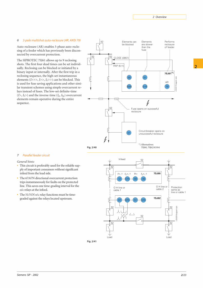
6 3-pole multishot auto-reclosure (AR, ANSI 79)
Auto-reclosure (AR) enables 3-phase auto-reclo-sing of a feeder which has previously been discon-nected by overcurrent protection.
The SIPROTEC 7SJ61 allows up to 9 reclosingshots. The first four dead times can be set individ-ually. Reclosing can be blocked or initiated by abinary input or internally. After the first trip in areclosing sequence, the high-set instantaneouselements (I>>>, I>>, IE>>) can be blocked. Thisis used for fuse saving applications and other simi-lar transient schemes using simple overcurrent re-lays instead of fuses. The low-set definite-time(I>, IE>) and the inverse-time (Ip, IEp) overcurrentelements remain operative during the entiresequence.
7 Parallel feeder circuit
General hints:• This circuit is preferably used for the reliable sup-
ply of important consumers without significantinfeed from the load side.
• The 67/67N directional overcurrent protectiontrips instantaneously for faults on the protectedline. This saves one time-grading interval for theo/c relays at the infeed.
• The 51/51N o/c relay functions must be time-graded against the relays located upstream.
Fig. 2/40
Fig. 2/41
*) Alternatives:7SJ60, 7SJ62/63/64

2 Overview
Typical ProtectionSchemes
Siemens SIP · 2002
2
2/24
Fig. 2/42
8 Cables or short overhead lines with infeedfrom both ends
Notes:1) Auto-reclosure only with overhead lines2) Differential protection options:
– Type 7SD52 or 7SD610 with direct fiber-optic connection up to about 20 km or via a64 kbit/s channel (optical fiber, microwave)
– Type 7SD600 with 2 pilot-wiresup to about 10 km
– Type 7SD502 with 2 pilot-wiresup to about 20 km
– Type 7SD503 with 3 pilot-wiresup to about 10km.
3) Functions 49 and 79 only with 7SD5 and7SD610 relays. 7SD600 is a cost-effective solu-tion where only the function 87L is required(external current summation transformer4AM4930 to be ordered separately).
9 Overhead lines or longer cables with infeedfrom both ends
Notes:1) Teleprotection logic 85 for transfer trip or
blocking schemes. Signal transmission via pilotwire, power-line carrier, digital network oroptical fiber (to be provided separately). Theteleprotection supplement is only necessary iffast fault clearance on 100 % line length is re-quired, i.e. second zone tripping (about 0.3 sdelay) cannot be accepted for far end faults.
2) Directional earth-fault protection 67N withinverse-time delay against high-resistance faults
3) Single or multishot auto-reclosure 79 only withoverhead lines.
10 Subtransmission line
Note:1) Connection to open delta winding if available.
Relays 7SA6/522 and 7SJ62 can, however, alsobe set to calculate the zero-sequence voltageinternally.
General hints:• Distance teleprotection is proposed as main, and
time-graded directional overcurrent as backupprotection.
• The 67N function of 7SA6/522 provides addi-tional high-resistance earth-fault protection.It can be used in parallel with the 21/21N function.
• Recommended schemes:PUTT on medium and long lines with phase shiftcarrier or other secure communication channelPOTT on short lines.BLOCKING with On/Off carrier (all line lengths).
Fig. 2/43
Fig. 2/44

Siemens SIP · 2002
2 Overview
2
2/25
Permissible underreachtransfer trip (PUTT)
Permissible overreachtransfer trip (POTT)
Blocking Unblocking
Preferredapplication
Signaltransmission
Safe and reliable channel:
• Frequency shift power-line carrier(phase-to-phase HF coupling to the protected line,better: HF coupling to a parallel tunning line toavoid transmission through the fault)
• Microwave, in particular digital (PCM)
• Fiber-optic cables
• Reliable channel(only needed withexternal faults)
• Amplitude modulatedON/OFFpower line carrier(same frequency canbe used at all terminals)
Applicable only with
• Frequency shiftpower-line carrier
Line con-figuration
Normally used withmedium and long lines
(7SA6/522 relays allowuse with short linesdue to their independentX and R setting of alldistance zones).
• Short lines in particularwhen high fault resistan-ce coverage is required
• Multi-terminal andtapped lines with inter-mediate infeed effects
All kinds of line(Preferred US practice)
Extra-high voltage lines
Advantages • Simple method
• Tripping of underrea-ching zone does notdepend on the channel(release signal from theremote line end notnecessary).
• No distance zone ortime coordinationbetween line ends ne-cessary, i.e. this modecan easily be used withdifferent relay types.
• No distance zone over-reaching problems, whenapplied with CCVTs onshort lines
• Applicable to extremeshort lines below theminimum zone settinglimit
• No problems with theinfluence of parallel linecoupling.
same asfor POTT
same asfor POTT
Drawbacks • Parallel, teed and tappedlines may cause under-reach problems. Carefulconsideration of zero-sequence coupling andintermediate infeedeffects is necessary.
• Not suitable on weakinfeed terminals.
• Distance zone and timecoordination withremote line end relaysnecessary
• Tripping depends onreceipt of remote endsignal (additional inde-pendent underreachingzone of 7SA6/522 relaysavoids this problem).
• Weak infeed supplementcan be applied.
same asfor POTT
Except that a weak in-feed supplement isnot necessary
No continuous onlinesupervision of thechannel possible!
Same as for POTT,however, loss of the re-mote end signal does notcompletely block theprotection scheme.Tripping is in this casereleased with a short timedelay of about 20 ms(unblocking logic).
Application criteria for frequentlyused teleprotection schemes

2 Overview
Typical ProtectionSchemes
Siemens SIP · 2002
2
2/26
11 Transmission line with reactor
Notes:1) 51N only applicable with earthed reactor
neutral.
2) If phase CTs at the low-voltage reactor side arenot available, the high-voltage phase CTs andthe CT in the neutral can be connected to arestricted earth-fault protection using one7VH60 high-impedance relay.
General hints:• Distance relays are proposed as main 1 and main 2
protection. Duplicated 7SA513 is recommendedfor series-compensated lines.
• Operating time of the distance relays in the rangeof 15 to 25 ms depending on the particular faultcondition.These tripping times are valid for faults in theunderreaching distance zone (80 to 85 % of theline length). Remote end faults must be clearedby the superimposed teleprotection scheme.Its overall operating time depends on the signaltransmission time of the channel, typically 15 to20 ms for frequency shift audio-tone PLC ormicrowave channels, and lower than 10 ms forON/OFF PLC or digital PCM signalling viaoptical fibers.
Teleprotection schemes based on distance relayshave therefore operating times in the order of40 ms and 50 ms. With state-of-the-art two-cyclecircuit-breakers, fault clearing times well below100 ms (4 to 5 cycles) can normally be achieved.
• Dissimilar carrier schemes are recommendedfor main 1 and main 2 protection, for examplePUTT, and POTT or Blocking/Unblocking.
• Both 7SA522 and 7SA6 provide selectivesingle-pole and/or three-pole tripping and auto-reclosure.The earth-current directional comparisonprotection 67N of the 7SA513 relay uses phaseselectors based on symmetrical components.Thus, single-pole auto-reclosure can also beexecuted with high-resistance faults.The 67N function of the 7SA6/522 relay canalso be used as time-delayed directional over-current backup.
• The 67N functions are provided as high-impe-dance fault protection. 67N is often used with anadditional channel as separate carrier scheme. Useof a common channel with distance protection isonly possible if the mode is compatible (e.g.POTT with directional comparison). The 67Nmay be blocked when function 21/21N picks up.Alternatively, it can be used as time-delayedbackup protection.
Fig. 2/45

Siemens SIP · 2002
2 Overview
2
2/27
12 Transmission line or cable(with wide-band communication)
General hints:• Digital PCM-coded communication
(with n x 64 kBit/s channels) between line ends isbecoming more and more frequently available,either directly by optical or microwavepoint-to-point links, or via a general purposedigital communication network.
In both cases, the relay type current differentialprotection 7SD52/61 can be applied. It providesabsolute phase and zone-selectivity by phase-segregated measurement, and is not affected bypower swing or parallel line zero-sequence cou-pling effects. It is further more a current-onlyprotection that does not need VT connection.For this reason, the adverse effects of CVT tran-sients are not applicable.
This makes it in particular suitable for doubleand multicircuit lines where complex fault situ-ations can occur.
The 7SD52/61 can be applied to lines up toabout 20 km in direct relay-to-relay connectionvia dedicated optical fiber cores (see also appli-cation 8), and also to much longer distances upto about 100 km by using separate PCM devicesfor optical fiber or microwave transmission.
The 7SD52/61 then uses only a small part(64-512 kBit/s) of the total transmission capac-ity being in the order of Mbits/s.
• The 7SD52/61 protection relays can be combinedwith the distance relay 7SA52 or 7SA6 to form aredundant protection system with dissimilar mea-suring principles complementing each other. Thisprovides the highest degree of availability. Also,separate signal transmission ways should be usedfor main 1 and main 2 line protection, e.g. opticalfiber or microwave, and power-line carrier (PLC).
The current comparison protection has a typicaloperating time of 15 ms for faults on 100 % linelength including signalling time.
13 Transmission line,breaker-and-a-half terminal
Notes:1) When the line is switched off and the line isola-
tor is open, high through-fault-currents in thediameter may cause maloperation of the dis-tance relay due to unequal CT errors (satura-tion).
Normal practice is therefore to block the dis-tance protection (21/21N) and the directionalearth-fault protection (67N) under thiscondition via an auxiliary contact of the lineisolator. Instead, a standby overcurrent func-tion (50/51N, 51/51N) is released to protect theremaining stub between the breakers (“stub”protection).
2) Overvoltage protection only with 7SA6/52.
General hints:• The protection functions of one diameter of a
breaker-and-a-half arrangement are shown.
• The currents of two CTs have each to be summedup to get the relevant line currents as input formain 1 and 2 line protection.
Fig. 2/46

2 Overview
Typical ProtectionSchemes
Siemens SIP · 2002
2
2/28
The location of the CTs on both sides of the cir-cuit-breakers is typical for substations with dead-tank circuit-breakers. Live-tank circuit-breakersmay have CTs only on one side to reduce cost. Afault between circuit-breakers and CT (end fault)may then still be fed from one side even when thecircuit-breaker has opened. Consequently, finalfault clearing by cascaded tripping has to be ac-cepted in this case.
The 7SV512 relay provides the necessary end faultprotection function and trips the circuit-breakersof the remaining infeeding circuits.
• For the selection of the main 1 and main 2 lineprotection schemes, the comments of applicationexamples 11 and 12 apply.
• Auto-reclosure (79) and synchro-check function(25) are each assigned directly to the circuit-breakers and controlled by main 1 and 2 line pro-tection in parallel. In case of a line fault, both adja-cent circuit-breakers have to be tripped by the lineprotection. The sequence of auto-reclosure ofboth circuit-breakers or, alternatively, the auto-reclosure of only one circuit-breaker and the man-ual closure of the other circuit-breaker, may bemade selectable by a control switch.
• A coordinated scheme of control circuits is neces-sary to ensure selective tripping interlocking andreclosing of the two circuit-breakers of one line(or transformer feeder).
• The voltages for synchro-check have to be selectedaccording to the circuit-breaker and disconnector(isolator) position by a voltage replica circuit.
Fig. 2/47
Siemens SIP · 2002
2 Overview
2
2/29
Transformers
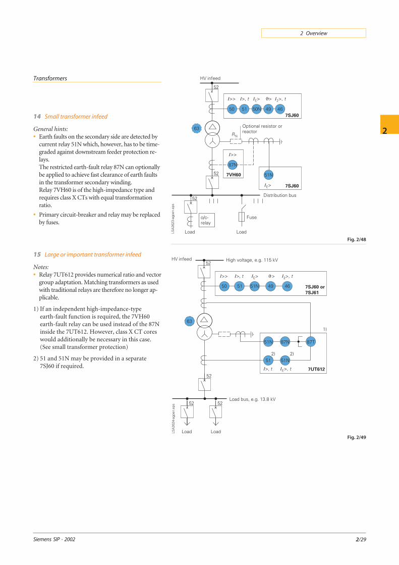
14 Small transformer infeed
General hints:• Earth faults on the secondary side are detected by
current relay 51N which, however, has to be time-graded against downstream feeder protection re-lays.The restricted earth-fault relay 87N can optionallybe applied to achieve fast clearance of earth faultsin the transformer secondary winding.Relay 7VH60 is of the high-impedance type andrequires class X CTs with equal transformationratio.
• Primary circuit-breaker and relay may be replacedby fuses.
15 Large or important transformer infeed
Notes:• Relay 7UT612 provides numerical ratio and vector
group adaptation. Matching transformers as usedwith traditional relays are therefore no longer ap-plicable.
1) If an independent high-impedance-typeearth-fault function is required, the 7VH60earth-fault relay can be used instead of the 87Ninside the 7UT612. However, class X CT coreswould additionally be necessary in this case.(See small transformer protection)
2) 51 and 51N may be provided in a separate7SJ60 if required.
Fig. 2/48
Fig. 2/49

2 Overview
Typical ProtectionSchemes
Siemens SIP · 2002
2
2/30
16 Dual infeed with single transformer
General hints:• Line CTs are to be connected to separate stabiliz-
ing inputs of the differential relay 87T in order toassure stability in case of line through-fault cur-rents.
• Relay 7UT513 provides numerical ratio and vectorgroup adaptation. Matching transformers, as usedwith traditional relays, are therefore no longer ap-plicable.
17 Parallel incoming transformer feeders
Note:1) The directional functions 67 and 67N do
not apply for cases where the transformersare equipped with transformer differentialrelays 87T.
18 Parallel incoming transformer feederswith bus tie
General hints:• Overcurrent relay 51, 51N each connected as a
partial differential scheme. This provides simpleand fast busbar protection and saves one time-grading step.
Fig. 2/50
Fig. 2/51
Fig. 2/52 *) Version 7UT613 available as of end 2002.

Siemens SIP · 2002
2 Overview
2
2/31
19 Three-winding transformer
Notes:1) The zero-sequence current must be blocked be-
fore entering the differential relay with a deltawinding in the CT connection on the trans-former sides with earthed starpoint. This is toavoid false operation during external earthfaults (numerical relays provide this functionby calculation). About 30 % sensitivity, how-ever, is then lost in case of internal faults.
Optionally, the zero-sequence current can beregained by introducing the winding neutralcurrent in the differential relay (87T). Relaytype 7UT513 provides two current inputs forthis purpose. By using this feature, the earth-fault sensitivity can be upgraded again to itsoriginal value.
2) Restricted earth-fault protection (87T) is op-tional. It provides backup protection for earthfaults and increased earth-fault sensitivity(about 10 % IN, compared to about 20 to 30 %IN of the transformer differential relay).
Separate class X CT-cores with equal transmis-sion ratio are additionally required for this pro-tection.
General hint:• In this example, the transformer feeds two differ-
ent distribution networks with cogeneration.Restraining differential relay inputs are thereforeprovided at each transformer side.
If both distribution networks only consumeload and no through-feed is possible from oneMV network to the other, parallel connection ofthe CTs of the two MV transformer windings isadmissible allowing the use of a two-windingdifferential relay (7UT612).
20 Autotransformer
Notes:1) 87N high-impedance protection requires spe-
cial class X current transformer cores withequal transformation ratio.
2) The 7SJ60 relay can alternatively be connectedin series with the 7UT513 relay to save this CTcore.
General hint:• Two different protection schemes are provided:
87T is chosen as low-impedance three-windingversion (7UT513). 87N is a single-phase high-impedance relay (7VH60) connected as restrictedearth-fault protection. (In this example,it is assumed that the phase-ends of the trans-
former-winding are not accessible on the neutralside, i.e. there exists a CT only in the neutralearthing connection.)
Fig. 2/53
Fig. 2/54
*) Version 7UT613 available as of end 2002.

2 Overview
Typical ProtectionSchemes
Siemens SIP · 2002
2
2/32
21 Large autotransformer bank
General hints:• The transformer bank is connected in a
1½ circuit-breaker arrangement.Duplicated differential protection is proposed:
Main 1: Low-impedance differential protection87TL (7UT513) connected to the transformerbushing CTs.
Main 2: High-impedance differential overallprotection 87TL (7VH60). Separate class Xcores and equal CT ratios are required for thistype of protection.
• Backup protection is provided by distance protec-tion relay (7SA52 and 7SA6), each “looking” withan instantaneous first zone about 80 % into thetransformer and with a time-delayed zone beyondthe transformer
• The tertiary winding is assumed to feed a smallstation supply network with isolated neutral.
Motors
22 Small and medium-sized motors< about 1 MW
a)With effective or low-resistanceearthed infeed (IE³ IN Motor)
General hint:• Applicable to low-voltage motors and high-vol-
tage motors with low-resistance earthed infeed(IE ≥ IN Motor)
b) With high-resistance earthed infeed
(IE ≤ IN Motor)
Notes:1) Core-balance CT.2) Sensitive directional earth-fault protection
67N only applicable with infeed from isolatedor Peterson-coil-earthed network(For dimensioning of the sensitive directionalearth-fault protection, see also applicationcircuit No. 28)
3) If 67N is not applicable, the 7SJ602 relay can beapplied.
Fig. 2/55
Fig. 2/56
Fig. 2/57

Siemens SIP · 2002
2 Overview
2
2/33
23 Large HV motors > about 1 MW
Notes:1) Core-balance CT.
2) Sensitive directional earth-fault protection67N only applicable with infeed from isolatedor Peterson-coil-earthed network
3) This function is only needed for motors wherethe startup time is longer than the safe stalltime tE. According to IEC 60079-7, the tE-timeis the time needed to heat up AC windings,when carrying the starting current IA, from thetemperature reached in rated service and atmaximum ambient temperature to the limitingtemperature. A separate speed switch is used tosupervise actual starting of the motor. The mo-tor circuit-breaker is tripped if the motor doesnot reach speed in the preset time. The speedswitch is part of the motor supply itself.
4) Pt100, Ni100, Ni120
5) 49T only available with external temperaturemonitoring device (7XV5662)
24 Cold load pickup
By means of a binary input which can be wiredfrom a manual close contact, it is possible toswitch the overcurrent pickup settings to less sen-sitive settings for a programmable amount oftime. After the set time has expired, the pickupsettings automatically return to their original set-ting. This can compensate for initial inrush whenenergizing a circuit without compromising thesensitivity of the overcurrent elements duringsteady state conditions.
Fig. 2/58
Fig. 2/59

2 Overview
Typical ProtectionSchemes
Siemens SIP · 2002
2
2/34
25 Very small generators < 500 kW(Fig. 2/60 and 2/61)
Note:1) If a core-balance CT is provided for sensitive
earth-fault protection relay 7SJ602 with sepa-rate earth-current input can be used.
26 Small generators, typically 1–3 MW(Fig. 2/62)
Note:1) Two VTs in V connection are also sufficient.
27 Small generators > 1–3 MW(Fig. 2/63)
Notes:1) Functions 81 and 59 are only required where
prime mover can assume excess speed and thevoltage regulator may permit rise of outputvoltage above upper limit.
2) Differential relaying options:– Low-impedance differential protection 87.– Restricted earth-fault protection with low ohmic
resistance-earthed neutral (see Fig. 2/61).
Fig. 2/60
With solidlyearth neutral
Generators
Fig. 2/61
With resistance-earthedneutral
Fig. 2/62
Fig. 2/63

Siemens SIP · 2002
2 Overview
2
2/35
28 Medium-sized generators > 5–10 MWfeeding into a network with isolated neutral(Fig. 2/64)
General hints:• The setting range of the directional earth-fault
protection 67N in the 7UM6 relay is 2–1000 mA.Depending on the current transformer accuracya certain minimum setting is required to avoidfalse operation on load or transient currents.
• In practice, efforts are generally made to protectabout 90 % of the machine winding, measuredfrom the machine terminals. The full earth currentfor a terminal fault must then be ten times the set-ting value which corresponds to the fault currentof a fault at 10 % distance from the machine neu-tral.
For the most sensitive setting of 2 mA, we there-fore need 20 mA secondary earth current, corre-sponding to (60/1) x 20 mA = 1.2A primary
If sufficient capacitive earth current is not avail-able, an earthing transformer with resistivezero-sequence load can be installed as earth-current source at the station busbar.The smallest standard earthing transformerTGAG 3541 has a 20 s short time rating ofSG = 27 kVA
In a 5 kV network, it would deliver:
IS
VG 20 s
G
N
VA
5000 VA= ⋅ = ⋅ =3 3 27 000
9 4,
.
Relay earth-currentinput connected to:
Minimum relay setting: Comments
Core-balance CT 60/1 A:1 single CT2 parallel CTs3 parallel Cts4 parallel CTs
2 mA5 mA8 mA
12 mA
Three-phase CTs inresidual (Holmgreen)connection
1 A CT: 50 mA5 A CT: 200 mA
In general not suitablefor sensitive earth-faultprotection
Three-phase CTs inresidual (Holmgreen)connection with specialfactory calibration tominimum residual falsecurrents (£ 2 mA)
2 - 3 ‰ of secondaryrated CT current In SEC
10 - 15 mA with 5 A CTs
1 A CTs are notrecommended inthis case
Fig. 2/64
corresponding to a relay input current of9.4 A x 1/60 A = 156 mA. This would provide a90 % protection range with a setting of about15 mA, allowing the use of 4 parallel connectedcore-balance CTs. The resistance at the 500 Vopen-delta winding of the earthing transformerwould then have to be designed for
RB = V2SEC /SG = 500 V2 / 27,000 VA = 9.26 Ω
(27 kW, 20 s).
For a 5 MVA machine and 600/5 A CTs withspecial calibration for minimum residual falsecurrent, we would get a secondary current ofIG SEC = 9.4 A/ (600/5) = 78 mA.
With a relay setting of 12 mA, the protection
range would in this case be 100 112
78−
= 85 %.
Notes:See following page

2 Overview
Typical ProtectionSchemes
Siemens SIP · 2002
2
2/36
Fig. 2/65
Notes to Fig. 2/64:1) The standard core-balance CT 7XR96 has a
transformation ratio of 60/1 A.
2) Instead of an open-delta winding at theterminal VT, a single-phase VT at the machineneutral could be used as zero-sequence polariz-ing voltage.
3) The earthing transformer is designed for ashort-time rating of 20 seconds. To preventoverloading, the load resistor is automaticallyswitched off by a time-delayed zero-sequencevoltage relay (59N + 62) and a contactor (52).
4) During the startup time of the generator withopen circuit-breaker the earthing source is notavailable. To ensure earth-fault protectionduring this time interval, an auxilliary contactof the circuit-breaker can be used to changeover the directional earth-fault relay function(67N) to a zero-sequence voltage detectionfunction via binary input.
29 Large generators > 50 - 100 MWin generator transformer unit connection(Fig. 2/65)
Notes:1) 100 % stator earth-fault protection based on
20 Hz voltage injection
2) Sensitive rotor earth-fault protection based on1–3 Hz voltage injection
3) Non-electrical signals can be incoupled in theprotection via binary inputs (BI)
4) Only used functions shown, further integratedfunctions available in each relay type(see Product Selection, pages 1/2 – 1/5).
*) Version 7UT613 available as of end 2002.

Siemens SIP · 2002
2 Overview
2
2/37
Fig. 2/66
Busbars
30 Busbar protection by o/c relayswith reverse interlocking
General hint:• Applicable to distribution busbars without sub-
stantial (< 0.25 x IN) backfeed from the outgoingfeeders.
31 High-impedance busbar protection
General hints:• Normally used with single busbar and
1½ breaker schemes.
• Requires separate class X current transformercores. All CTs must have the same transformationratio.
Note:1) A varistor is normally applied across the relay
input terminals to limit the voltage to a valuesafely below the insulation voltage of the sec-ondary circuits (see page 2/46).
32 Low-impedance busbar protection
General hints:• Preferably used for multiple busbar schemes
where an isolator replica is necessary
• The numerical busbar protection 7SS5 providesadditional breaker failure protection
• CT transformation ratios can be different, e.g.600/1 A in the feeders and 2000/1 A at the bus tie
• The protection system and the isolator replica arecontinuously self-monitored by the 7SS5
• Feeder protection can be connected to the sameCT core.
Fig. 2/67
Fig. 2/68

2 Overview
Typical ProtectionSchemes
Siemens SIP · 2002
2
2/38
Networks
33 Load shedding(Fig. 2/69 and 2/71)
In unstable networks (e.g. solitary networks,emergency power supply in hospitals), it may benecessary to isolate selected loads from the net-work to prevent overload of the overall network.The overcurrent-time protection functions areeffective only in the case of a short-circuit.Overloading of the generator can be measured asa frequency or voltage drop.(Protection functions 27 and 81 available in7RW600 and 7SJ6..)
34 Load sheddingwith rate-of-frequency-change protection(Fig. 2/70)
The rate-of-frequency-change protection calcu-lates, from the measured frequency, the gradientor frequency change df/dt. It is thus possible todetect and record any major active power loss inthe power system, to disconnect certain consum-ers accordingly, and to restore the system to sta-bility. Unlike frequency protection, rate-of-fre-quency-change protection already reacts beforethe frequency threshold is undershot. To ensureeffective protection settings, it is recommended toconsider requirements throughout the power sys-tem as a whole. The rate-of-frequency-changeprotection function can also be used for the pur-poses of system decoupling.
Rate-of-frequency-change protection can also beenabled by an underfrequency state.
35 Trip circuit supervision (ANSI 74TC)(Fig. 2/72)
One or two binary inputs can be used for the tripcircuit supervision.
Fig. 2/69
Fig. 2/70
Fig. 2/71
Fig. 2/72

Siemens SIP · 2002
2 Overview
2
Protection Coordination
2/39
Typical applications
Relay operating characteristics and their settingmust be carefully coordinated in order to achieveselectivity. The aim is basically to switch off onlythe faulted component and to leave the rest of thepower system in service in order to minimize sup-ply interruptions and to assure stability.
Sensitivity
Protection should be as sensitive as possible todetect faults at the lowest possible current level.At the same time, however, it should remainstable under all permissible load, overload andthrough-fault conditions. The Siemens engineer-ing programs SINCAL and SIGRADE are espe-cially designed for selective protection grading ofprotection relay systems. They provide short-circuit calculations, international standard charac-teristics of relays, fuses and circuit-breakers foreasy protection grading with respect to motorstarting, inrush phenomena and equipment dam-age curves.
Phase-fault o/c relays
The pickup values of phase o/c relays are normallyset 30 % above the maximum load current, providedthat sufficient short-circuit current is available.This practice is recommended in particular formechanical relays with reset ratios of 0.8 to 0.85.Numerical relays have high reset ratios near 0.95and allow therefore about 10 % lower setting.Feeders with high transformer and/or motor loadrequire special consideration.
Transformer feeders
The energizing of transformers causes inrush cur-rents that may last for seconds, depending ontheir size (Fig. 2/73).Selection of the pickup current and assigned timedelay have to be coordinated so that the inrushcurrent decreases below the relay o/c reset valuebefore the set operating time has elapsed.The inrush current typically contains only about50 % fundamental frequency component.Numerical relays that filter out harmonics and theDC component of the inrush current can there-fore be set more sensitive. The inrush currentpeak values of Fig. 2/73 will be more than reducedto one half in this case.
Some digital relay types have an inrush detectionfunction which may block the trip of the over-current protection resulting from inrush currents.
Peak value of inrush current
Time constant of inrush currentNominal power 0.5 … 1.0 1.0 … 10 > 10(MVA)
Time constant 0.16 … 0.2 0.2 … 1.2 1.2 … 720(s)
Fig. 2/73
Earth-fault protection relays
Earth current relays enable a much more sensitivesetting, as currents do not have to be considered (ex-cept 4-wire circuits with single- phase load). In sol-idly and low-resistance earthed systems a setting of10 to 20 % rated load current is generally applied.High-resistance earthing requires much more sen-sitive setting in the order of some amperes primary.The earth-fault current of motors and generators,for example, should be limited to values below10 A in order to avoid iron burning.
Residual-current relays in the star point connec-tion of CTs can in this case not be used, in partic-ular with rated CT primary currents higher than200 A. The pickup value of the zero-sequence re-lay would in this case be in the order of the errorcurrents of the CTs.A special core-balance CT is therefore used in thiscase as earth-current sensor. The core-balance cur-rent transformer 7XR96 is designed for a ratio of60/1 A. The detection of 6 A primary would thenrequire a relay pickup setting of 0.1 A secondary.
An even more sensitive setting is applied in isolat-ed or Peterson- coil-earthed networks where verylow earth currents occur with single-phase-to-earth faults. Settings of 20 mA and less may thenbe required depending on the minimum earth-fault current.Sensitive directional earth-fault relays (integratedin the relays 7SJ62, 63 and 7SA6) allow settings aslow as 5 mA.

2 Overview
Protection Coordination
Siemens SIP · 2002
2
2/40
Fig. 2/74
Typical motor current-timecharacteristics
Differential relay (87)
Transformer differential relays are normally set topickup values between 20 and 30 % of the ratedcurrent. The higher value has to be chosen whenthe transformer is fitted with a tap changer.
Restricted earth-fault relays and high-resistancemotor / generator differential relays are, as a rule,set to about 10 % of the rated current.
lnstantaneous overcurrent protection (50)
This is typically applied on the final supply load oron any protection relay with sufficient circuit im-pedance between itself and the next downstreamprotection relay. The setting at transformers, forexample, must be chosen about 20 to 30 % higherthan the maximum through-fault current.
Motor feeders
The energizing of motors causes a starting currentof initially 5 to 6 times rated current (locked rotorcurrent).
A typical time-current curve for an induction mo-tor is shown in Fig. 2/74.
In the first 100 ms, a fast decaying asymetrical in-rush current appears additionally. With conven-tional relays it was common practice to set theinstantaneous overcurrent stage of the short-circuit protection 20 to 30 % above the locked-rotor current with a short-time delay of 50 to100 ms to override the asymmetrical inrush pe-riod.
Numerical relays are able to filter out the asym-metrical current component very rapidly so thatthe setting of an additional time delay is no longerapplicable.
The overload protection characteristic should fol-low the thermal motor characteristic as closely aspossible. The adaptation is made by setting thepickup value and the thermal time constant, usingthe data supplied by the motor manufacturer.Further, the locked-rotor protection timer has tobe set according to the characteristic motor value.
Time grading of o/c relays (51)
The selectivity of overcurrent protection is basedon time grading of the relay operating characteris-tics. The relay closer to the infeed (upstream re-lay) is time-delayed against the relay further awayfrom the infeed (downstream relay).This is shown in Fig. 2/76 by an example fordefinite-time overcurrent relays.
The overshoot times take into account the factthat the measuring relay continues to operate dueto its inertia, even when the fault current is inter-rupted. This may be high for mechanical relays(about 0.1 s) and negligible for numerical relays(20 ms).
Inverse-time relays (51)
For the time grading of inverse-time relays, inprinciple the same rules apply as for the definite-time relays. The time grading is first calculated forthe maximum fault level and then checked forlower current levels (Fig. 2/75).
If the same characteristic is used for all relays, orwhen the upstream relay has a steeper characteris-tic (e.g. very much over normal inverse), thenselectivity is automatically fulfilled at lowercurrents.
Fig. 2/75
Coordination ofinverse-time relays

Siemens SIP · 2002
2 Overview
2
2/41
Calculation example
The feeder configuration of Fig. 2/77 and the asso-ciated load and short-circuit currents are given.Numerical o/c relays 7SJ60 with normal inverse-time characteristic are applied.
The relay operating times, depending on current,can be derived from the diagram or derived withthe formula given in Fig. 2/78.
The Ip/IN settings shown in Fig. 2/77 have beenchosen to get pickup values safely above maxi-mum load current.
This current setting shall be lowest for the relayfarthest downstream. The relay further upstreamshall each have equal or higher current setting.
The time multiplier settings can now be calculatedas follows:
Station C:
• For coordination with the fuses, we consider thefault in location F1.The short-circuit current related to 13.8 kVis 523 A.This results in 7.47 for I/Ip at the o/c relay inlocation C.
• With this value and Tp = 0.05 we derive fromFig. 2/78 an operating time of tA = 0.17 s.
This setting was selected for the o/c relay to get asafe grading time over the fuse on the transformerlow-voltage side.The setting values for the relay at station C aretherefore:
• Current tap: Ip/IN = 0.7
• Time multiplier: Tp = 0.05
Station B:
The relay in B has a backup function for therelay in C.The maximum through-fault current of 1.395 Abecomes effective for a fault in location F2.For the relay in C, we obtain an operating time of0.11 s (I/Ip = 19.9).
We assume that no special requirements for shortoperating times exist and can therefore choose anaverage time grading interval of 0.3 s. The operat-ing time of the relay in B can then be calculated.
• tB = 0.11 + 0.3 = 0.41 s
• Value of Ip/IN =1395
220
A
A= 6.34 (see Fig. 2/77)
• With the operating time 0.41 s andIp/IN = 6.34, we can now derive Tp = 0.11 from Fig.2/78.
Fig. 2/76
Time grading ofovercurrent-time relays
Time gradingtrs = t51M – t51F = t52F + tOS + tM
Example 1 tTG =0.10 s + 0.15 s + 0.15 s = 0.40 s
Oil circuit-breaker t52F = 0.10 s
Mechanical relays tOS = 0.15 s
Safety margin formeasuring errors etc.: tM = 0.15 s
Example 2 tTG =0.08 + 0.02 + 0.10 = 0.20 s
Vacuum circuit-breaker t52F = 0.08 s
Numerical relays tOS = 0.02 s
Safety margin tM = 0.10 s
Station Max. LoadA
ISCC. max:* CT ratio Ip/IN** Iprim***A
I/Ip =I
ISCC.
prim
max
A 300 4500 400/5 1.0 400 11.25
B 170 2690 200/5 1.1 220 12.23
C 50 1395 100/5 0.7 70 19.33
D – 523 – – – –
*) ISCC.max = Maximum short-circuit current**) Ip/IN = Relay current multiplier setting***) Iprim = Primary setting current corresponding to Ip/IN
Fig. 2/77Time grading ofinverse-time relaysfor a radial feeder

2 Overview
Protection Coordination
Siemens SIP · 2002
2
2/42
The setting values for the relay at station B are:
• Current tap: Ip/IN = 1.1
• Time multiplier Tp = 0.11
Given these settings, we can also check the operat-ing time of the relay in B for a close-in fault in F3:The short-circuit current increases in this case to2690 A (see Fig. 2/77).The corresponding I/Ip value is 12.23.
• With this value and the set value of Tp = 0.11we obtain again an operating time of 0.3 s(see Fig. 2/78).
Station A:
• We add the time grading interval of 0.3 sand find the desired operating timetA = 0.3 + 0.3 = 0.6 s.
Following the same procedure as for the relay instation B we obtain the following values for therelay in station A:
• Current tap: Ip/IN = 1.0
• Time multiplier Tp = 0.17
• For the close-in fault at location F4 we obtain anoperating time of 0.48 s.
Fig. 2/78
Normally inverse-time charac-teristic of the 7SJ60 relay
Normally inverse
( )t
I IT s=
−⋅
014
10 02
.( )
.
p
p
The normal way
To prove the selectivity over the whole range ofpossible short-circuit currents, it is normalpractice to draw the set of operating curves in acommon diagram with double log scales. Thesediagrams can be calculated manually and drawnpoint-by-point or constructed by using templates.
Today computer programs are also available forthis purpose. Fig. 2/79 shows the relay coordina-tion diagram for the example selected, as calcu-lated by the Siemens program SIGRADE(Siemens Grading Program).
Note:
To simplify calculations, only inverse-time char-acteristics have been used for this example. About0.1 s shorter operating times could have beenreached for high-current faults by additionallyapplying the instantaneous zones I>> of the 7SJ60relays.
Coordination of o/c relays with fusesand low-voltage trip devices
The procedure is similar to the above-describedgrading of o/c relays. Usually a time interval be-tween 0.1 and 0.2 seconds is sufficient for a safetime coordination.
Very and extremely inverse characteristics are of-ten more suitable than normally inverse charac-teristics in this case. Fig. 2/80 shows typicalexamples.
Simple consumer-utility interrupts use of a powerfuse on the primary side of the supply transform-ers (Fig. 2/80a).
In this case, the operating characteristic of theo/c relay at the infeed has to be coordinated withthe fuse curve.
Very inverse characteristics may be used with ex-pulsion-type fuses (fuse cutouts) while extremelyinverse versions adapt better to current limitingfuses.
In any case, the final decision should be made byplotting the curves in the log-log coordinationdiagram.
Electronic trip devices of LV breakers have long-delay, short-delay and instantaneous zones.Numerical o/c relays with one inverse-time andtwo definite-time zones can closely be adapted tothis (Fig. 2/80b).

Siemens SIP · 2002
2 Overview
2
2/43
Fig. 2/79 O/c time grading diagram
Setting range Setting
Ip = 0.10 - 4.00 IN
Tp = 0.05 - 3.2 s
I>> = 0.1 - 25 IN
Ip = 1.0 IN
Tp = 0.17 s
I>> =¥
Ip = 0.10 - 4.00 IN
Tp = 0.05 - 3.2 s
I>> = 0.1 - 25 IN
Ip = 1.0 IN
Tp = 0.11 s
I>> =¥
Ip = 0.10 - 4.00 IN
Tp = 0.05 - 3.2 s
I>> = 0.1 - 25 IN
Ip = 0.7 IN
Tp = 0.05 s
I>> =¥
HRC fuse 160 A
a)
Fig. 2/80
Coordination of an o/c relay with an MV fuseand low-voltage breaker trip device
b)

2 Overview
Protection Coordination
Siemens SIP · 2002
2
2/44
Z1A = 0.85 · ZLA-B
Z2A = 0.85 · (ZLA-B + Z1B)
Z2A = 0.85 · (ZLA-B + Z2B)
Fig. 2/81 Grading of distance zones
Coordination of distance relays
The distance relay setting must take into accountthe limited relay accuracy including transientoverreach (5 % according to IEC 60255-6), the CTerror (1 % for class 5P and 3 % for class 10P) and asecurity margin of about 5 %. Further, the line pa-rameters are normally only calculated, not mea-sured. This is a further source of errors. A settingof 80-85 % is therefore common practice; 80 % isused for mechanical relays while 85 % can be usedfor the more accurate numerical relays.
Where measured line or cable impedances areavailable, the protected zone setting may be ex-tended to 90 %. The second and third zones haveto keep a safety margin of about 15 to 20 % to thecorresponding zones of the following lines. Theshortest following line has always to be considered(Fig. 2/81).
As a general rule, the second zone should at leastreach 20 % over the next station to ensure backupfor busbar faults, and the third zone should coverthe longest following line as backup for the lineprotection.
Fig. 2/82
Operating characteristicsof Siemens distance relays
Grading of zone times
The first zone normally operates nondelayed. Forthe grading of the time delays of the second andthird zones, the same rules as for o/c relays apply(see Fig. 2/76).
For the quadrilateral characteristics (relays 7SA6and 7SA5) only the reactance values (X values)have to be considered for the protected zonesetting. The setting of the R values should coverthe line resistance and possible arc or faultresistances. The arc resistance can be roughlyestimated as follows:
RV
Arcarc
SCC Min
l 2 k /m= ⋅I
larc = arc length
ISCC Min = minimum short-circuit current
• Typical settings of the ratio R/X are:
– Short lines and cables (£ 10 km): R/X = 2 to 6– Medium line lengths < 25 km: R/X = 2– Longer lines 25 to 50 km: R/X = 1
Shortest feeder protectable by distance relays
The shortest feeder that can be protected byunderreaching distance zones without the needfor signaling links depends on the shortest settablerelay reactance.
XPrim Min = XVT
CTRelay Min
ratio
ratio
⋅
lX
Xmin
Prim Min
Line
=′
The shortest setting of the numerical Siemens re-lays is 0.05W for 1 A relays, corresponding to0.01W for 5 A relays.
This allows distance protection of distributioncables down to the range of some 500 meters.

Siemens SIP · 2002
2 Overview
2
2/45
Breaker failure protection setting
Most numerical relays in this guide providebreaker failure (BF) protection as an integralfunction. The initiation of the BF protection bythe internal protection functions then takes placevia software logic. However, the BF protectionfunction may also be initiated from external viabinary inputs by an alternate protection. In thiscase the operating time of intermediate relays (BFItime) may have to be considered. Finally, the trip-ping of the infeeding breakers requires auxiliaryrelays which add a small time delay (BFI) to theoverall fault clearing time. This is in particular thecase with 1½-breaker or ring bus arrangementswhere a separate breaker failure relay (7SV600 or7SV512) is used per breaker (see application ex-ample 13).
The decisive criterion of BF protection time coor-dination is the reset time of the current detector(50BF) which must not be exceeded under anycondition during normal current interruption.The reset times specified in the Siemens numericalrelay manuals are valid for the worst-case condi-tion: interruption of a fully offset short-circuitcurrent and low current pickup setting (0.1 to 0.2times rated CT current).
The reset time is 1 cycle for EHV relays (7SA6/52,7SV512) and 1.5 to 2 cycles for distribution typerelays (7SJ***).
Fig. 2/84 shows the time chart for a typical breakerfailure protection scheme. The stated times inparentheses apply for transmission system protec-tion and the times in square brackets for distribu-tion system protection.
High-impedance differential protection:Verification of design
The following design data must be established:
CT data
The CTs must all have the same ratio and shouldbe of low leakage flux design according toClass TPS of IEC 60044-6 (Class X of BS 3938).The excitation characteristic and the secondarywinding resistance are to be provided by the man-ufacturer.The knee-point voltage of the CT must be at leasttwice the relay pickup voltage to assure depend-able operation with internal faults.
Differential relayThe differential relay must be a high-impedancerelay designed as sensitive current relay (7VH60:20 mA) with series resistor. If the series resistor isintegrated in the relay, the setting values may bedirectly calibrated in volts, as with the relay7VH60 (6 to 60 V or 24 to 240 V).
Fig. 2/83
Breaker failure logic
Fig. 2/84
Time coordination ofBF time setting
SensitivityFor the relay to operate in case of an internal fault,the primary current must reach a minimum valueto supply the set relay pickup current (IR-set), thevaristor leakage current (Ivar) and the magnetizingcurrents of all parallel-connected CTs (n×/mR).Low relay voltage setting and CTs with low mag-netizing demand therefore increase the protectionsensitivity.
Stability during external faultsThis check is made by assuming an external faultwith maximum through-fault current and fullsaturation of the CT in the faulted feeder. The sat-urated CT is then substituted with its secondarywinding resistance RCT and the appearing relayvoltage VR corresponds to the voltage drop of theinfeeding currents (through-fault current) acrossRTC and RL. The current at the relay must underthis condition reliably stay below the relay pickupvalue.
In practice, the wiring resistances RL may not beequal. In this case, the worst condition with thehighest relay voltage (corresponding to the highestrelay current) must be sought by considering allpossible external feeder faults.

2 Overview
Protection Coordination
Siemens SIP · 2002
2
2/46
Fig. 2/85
Principal connection diagram
Sensitivity:
IFmin = N × IRset + IVar + n · ImR
Stability:
I NR
R RIR
F max. ThroughL CT
Rset> ⋅+
⋅
N = CT ratio
IRset = Set relay pickup current
IVar = Varistor spill current
ImR = CT magnetizing current at relay pickupvoltage
Voltage limitation by a varistor is required if:
VRmax ( )= − >2 2 2V V VK F KN kV
with VF ( )I
NR R RThroughF max
CT L R+ ⋅ +2
Calculation example:
Given: n = 8 feeders
N = 600/1 A
VK = 500 V
RCT = 4W
ImR = 30 mA (at relay setpoint)
RL = 3W
IRset = 20 mA
RR = 10 kW
IVar = 50 mA (at relay setpoint)
Sensitivity
IFmin = N (IRset + IVar + n · ImR)
IFmin =600
1× (0.02 + 0.05 + 8 x 0.03)
IFmin = 186 A (31 % IN)
Stability:
IF max Through < NR
R RI⋅
+⋅R
L CTRset
IF max Through <100
1
10 000
3 40 02⋅
+⋅,
.
IF max Through < 17 kA (28 x IN)
VK = CT knee-pointvoltage
VR = RR × IRset
VK = ≥ 2 × VR
Setting
The setting is always a trade-off between sensitiv-ity and stability. A higher voltage setting leads notonly to enhaced through-fault stability, but also tohigher CT magnetizing and varistor leakage cur-rents resulting consequently in a higher primarypickup current.
A higher voltage setting also requires a higherknee-point voltage of the CTs and thereforegreater size of the CTs.
A sensitivity of 10 to 20 % IN is normal for motorand transformer differential protection, or forrestricted earth-fault protection.
With busbar protection a pickup value³ IN isnormally applied.
An increased pickup value can be achieved byconnecting a resistor in parallel to the relay.
Varistor
Voltage limitation by a varistor is needed if peakvoltages near or above the insulation voltage(2 kV) are expected. A limitation to 1500 Vrms isthen recommended.
This can be checked for the maximum internalfault current by applying the formula shown forVR max.
A restricted earth-fault protection may normallynot require a varistor but a busbar protection ingeneral does.
The electrical varistor characteristic can be ex-pressed as V = K × IB × K and B are the varistorconstants.
Relay settingVrms
K B Varistor type
£ 125 450 0.25 600 A /S1/S256
125 – 240 900 0.25 600 A /S1/S1088

Siemens SIP · 2002
2 Overview
2
2/47
Instrument transformers
Instrument transformers
Instrument transformers must comply with theapplicable IEC recommendations IEC 60044,formerly IEC 60185 (CT) and 60186 (PT),ANSI/IEEE C57.13 or other comparable stan-dards.
Potential transformers
Potential transformers (PT) in single or double-pole design for all primary voltages have typicalsingle or dual secondary windings of 100, 110 or
115 V/ 3 with output ratings between 10 and300 VA, and accuracies of 0.2, 0.5 or 1 % to suitthe particular application. Primary BIL values areselected to match those of the associatedswitchgear.
Current transformers
Current transformers (CT) are usually of thesingle-ratio type with wound or bar-type prima-ries of adequate thermal rating. Single, dual or tri-ple secondary windings of 1 or 5 A are standard.1 A rating however should be preferred,particularly in HV and EHV stations, to reducethe burden of the connection lines. Output power(rated burden in VA), accuracy and saturationcharacteristics (accuracy limiting factor) of thecores and secondary windings must meet the par-ticular application.
The CT classification code of IEC is used in thefollowing:
Measuring cores
These are normally specified with 0.5 % or 1.0 %accuracy (class 0.5 FS or 1.0 FS), and an accuracylimiting factor of 5 or 10.
The required output power (rated burden) shouldbe higher than the actually connected burden.Typical values are 5, 10, 15 VA. Higher values arenormally not necessary when only electronic me-ters and recorders are connected.
A typical specification could be: 0.5 FS 10, 15 VA.
Cores for billing values metering
In this case, class 0.2 FS is normally required.
Protection cores
The size of the protection core depends mainly onthe maximum short-circuit current and the totalburden (internal CT burden, plus burden of con-necting lines plus relay burden).
Further, an overdimensioning factor has to beconsidered to cover the influence of the DC com-ponent in the short-circuit current.
In general, an accuracy of 1 % in the range of 1 to2 times nominal current (class 5 P) is specified.The accuracy limiting factor KnALF should nor-mally be selected so that at least the maximumshort- circuit current can be transmitted withoutsaturation (DC component not considered).
This results, as a rule, in rated accuracy limitingfactors of 10 or 20 depending on the rated burdenof the CT in relation to the connected burden. Atypical specification for protection cores for distri-bution feeders is 5P10, 10 VA or 5P20, 5 VA.
The requirements for protective current trans-formers for transient performance are specified inIEC 60044-6.
In many practical cases, iron-core CTs cannot bedesigned to avoid saturation under all circum-stances because of cost and space reasons, particu-larly with metal-enclosed switchgear.
The Siemens relays are therefore designed to toler-ate CT saturation to a large extent. The numericalrelays proposed in this guide are particularly sta-ble in this case due to their integrated saturationdetection function.
CT dimensioning formulae
KnALF ≥ P P
P PKBC i
BN ioALF
++
⋅
KnALF = Nominal CT accuracy limiting factor
KoALF = Operating CT accuracy limiting factor
PBN = Nominal burden resistance
PBC = Connected burden
Pi = Internal CT burden (resistance of the CTsecondary winding)
with KoALF ≥ ⋅KOFSCC max
N
I
I
ISCC max = Maximum short-circuit current
IN = Nominal primary CT current
KOF = Overdimensioning factor
The required CT accuracy limiting factor KnALF
can be determined by calculation, as shown inthe table above.
The overdimensioning factor KOF depends on thetype of relay and the primary DC time constant.For most applications, with short-circuit timeconstants lower than 100 ms, the necessary valuefor KoALF can be taken from the table above.

2 Overview
Protection Coordination
Siemens SIP · 2002
2
2/48
CT design according to BS 3938
In this case the CT is definded by the knee-pointvoltage VK and the internal secondary resistanceRi. The design values according to IEC 60044 canbe approximately transfered into the BS standarddefinition by following formula:
BS CT definition
VK =( )R R IBn i 2N nALFK+ ⋅ ⋅
1 3.
I2N Rated secondary current
Example:IEC60044:
600/1, 5P10, 15 VA, Ri = 4 Ω
BS:( )
VK1.3
V V=+ ⋅ ⋅
=15 4 1 10
146
Ri = 4 Ω
Required effective accuracy limiting factor KoALF
CT design according to ANSI/IEEE C 57.13
Class C of this standard defines the CT by ist sec-ondary terminal voltage at 20 times rated current,for which the ratio error shall not exceed10 %. Standard classes are C100, C200, C400 andC800 for 5 A rated secondary current.
This terminal voltage can be approximately calcu-lated from the IEC data as follows:
Vs.t.max = 20 ⋅ 5 A ⋅ RBN ⋅ Ko LFA
20
withRBN =
P
II ABN
Nsec
Nsecand we get2
5= ,
Vs.t.max =PBN nALFK
A
⋅5
Example:IEC60044:
600/5, 5P20, 25 VA
ANSIC57.13: Vs.t.max =
( )25 20
5
VA
A
⋅= 100 V, acc. to class C100
ANSI CT definition
Relay type Minimum KoALF
Overcurrent-time protection7SJ511, 512, 5317S45, 46, 60, 61, 62, 63, 64
=I
I
High set point
N
at least 20
Transformerdifferential protection7UT51, 7UT6
≥ 40 for TS ≤ 100 ms for each side≥ 50 for TS > 100 ms for each side
Line differential(fiber-optic) protection7SD52/61
=I
ISCC. max. (external fault)
NoALFand K ≥ 30
Line differential(fiber-optic) protection7SD511/512
=I
I
ISCC. max. (external fault)
N
oALF N (lineandK1
3≤
⋅ −( ) end 1)
oALF N (line end 2)K3
( )⋅≤
−I
Line differential(pilot wire)protection7SD502/503/600
=I
I
ISCC. max. (external fault)
N
oALF N (lineandK3
4≤
⋅ −( ) end 1)
oALF N (line end 2)K( )⋅≤
−I
4
3
Numerical busbar protection(low impedance type)7SS5, 7SS600
=1
2⋅
I
I
SCC. max. (outflowing current for ext. fault)
N
and KoALF ≤ 100 ifI
I
SCC max.
N
≥ 100
for stabilizing factors k ≥ 0.5
Distance protection7SA510, 7SA511 = a
I
I⋅ −SCC. max. (close in fault)
N
T
aS 50ms≤
= 2
T
aS 100ms
3
≤=
and
= 10 ⋅ −I
I
SCC. max. (zone 1 end fault)
N
Distance protection7SA522, 7SA6 = a
I
I⋅ −SCC. max. (close in fault)
N
T
ab
S 30ms≤==
14
T
ab
S 50ms≤==
25
T
ab
S 200ms≤==
45and
= bI
I⋅ −SCC. max. (zone 1 end fault)
N
Siemens SIP · 2002
2 Overview
2
2/49
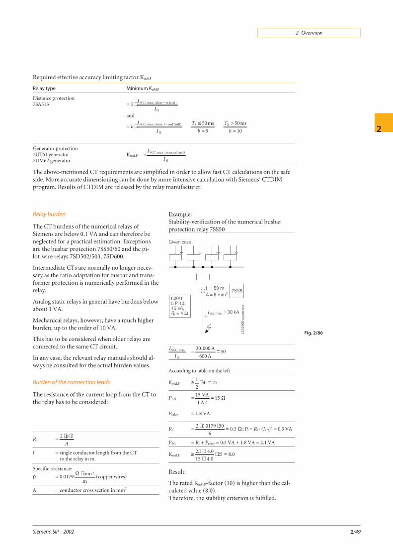
Relay burden
The CT burdens of the numerical relays ofSiemens are below 0.1 VA and can therefore beneglected for a practical estimation. Exceptionsare the busbar protection 7SS50/60 and the pi-lot-wire relays 7SD502/503, 7SD600.
Intermediate CTs are normally no longer neces-sary as the ratio adaptation for busbar and trans-former protection is numerically performed in therelay.
Analog static relays in general have burdens belowabout 1 VA.
Mechanical relays, however, have a much higherburden, up to the order of 10 VA.
This has to be considered when older relays areconnected to the same CT circuit.
In any case, the relevant relay manuals should al-ways be consulted for the actual burden values.
Burden of the connection leads
The resistance of the current loop from the CT tothe relay has to be considered:
R1 =2 ⋅ ⋅ρ l
A
l = single conductor length from the CTto the relay in m.
Specific resistance:
ρ = 0.0179Ω ⋅ mm
m
2(copper wires)
A = conductor cross section in mm2
Example:Stability-verification of the numerical busbarprotection relay 7SS50
Fig. 2/86
I
ISCC. max.
N
=30 000
60050
, A
A=
According to table on the left
KoALF ≥ 1
250 25⋅ =
PBN =15
15VA
1 A 2= Ω
Prelay = 1.8 VA
Rl =2 0 0179 50
60 3
⋅ ⋅ =.. Ω ; Pl = Rl · (I2N)2 = 0.3 VA
PBC = Rl + Prelay = 0.3 VA + 1.8 VA = 2.1 VA
KnALF ≥ 2 1 4 0
15 4 025 8 0
. .
..
++
⋅ =
Result:
The rated KnALF-factor (10) is higher than the cal-culated value (8.0).Therefore, the stability criterion is fulfilled.
Relay type Minimum KoALF
Distance protection7SA513 = 2 ⋅ −I
ISCC. max. (close in fault)
N
and
= bI
I⋅ −SCC. max. (zone 1 end fault)
N
T
bS 50ms≤
= 5
T
bS > 50ms
1= 0
Generator protection7UT61 generator7UM62 generator
KoALF = 5I
I
SCC. max. (external fault)
N
The above-mentioned CT requirements are simplified in order to allow fast CT calculations on the safeside. More accurate dimensioning can be done by more intensive calculation with Siemens’ CTDIMprogram. Results of CTDIM are released by the relay manufacturer.
Required effective accuracy limiting factor KoALF

Siemens SIP · 2002
2
2/50