siemens-allis information and instruction guide information and instruction guide f frame types fj6,...
TRANSCRIPT

SIEMENS-ALLIS
Information and Instruction Guide F Frame Types FJ6, F6, HF6
® Molded Case Circuit Breakers
Bulletin IB-2.2.7-4C www . El
ectric
alPar
tMan
uals
. com

1-T-E Molded Case Circuit Breakers
Page 2
Information and Instruction Guide
I·T·E F Frame Types FJ6, F6, HF6
Models ET, ETI, ET·H 2 and 3 Pole 70·250 Amperes
WARNING
Dangerous voltages are present inside the enclosures, or panels in which this circuit breaker is installed. Serious injury, electrocution, and/or equipment damage is possible unless extreme caution is used when examining this circuit breaker while it is still in service.
De-energize all incoming power if conditions exist which are contrary to those described in this instruction book or which are otherwise unusual.
www . El
ectric
alPar
tMan
uals
. com

TABLE OF CONTENTS
Important Notices . . . . . . . . . . . . . . . . . . . . . . . . . . . . . . . . . . . . . . . . . . . . . . . . . . . . . . . . . . . . . . . . . . . . . . . . . . . . . . . . . . . . . . . . . . . . . . . . . . . . . . 2,4 General Instructions . . . . . . . . . . . . . . . . . . . . . . . . . . . . . . . . . . . . . . . . . . . . . . . . . . . . . . . . . . . . . . . . . . . . . . . . . . . . . . . . . . . . . . . . . . . . . . . . . . . . . 5 Dimensional Reference Drawings . . . . . . . . . . . . . . . . . . . . . . . . . . . . . . . . . . . . . . . . . . . . . . . . . . . . . . . . . . . . . . . . . . . . . . . . . . . . . . . . 6 Trip Unit Assembly . . . . . . . . . . . . . . . . . . . . . . . . . . . . . . . . . . . . . . . . . . . . . . . . . . . . . . . . . . . . . . . . . . . . . . . . . . . . . . . . . . . . . . . . . . . . . . . . . . . . . . . 7 Handle Blocking Device . . . . . . . . . . . . . . . . . . . . . . . . . . . . . . . . . . . . . . . . . . . . . . . . . . . . . . . . . . . . . . . . . . . . . . . . . . . . . . . . . . . . . . . . . . . . . . . . 8 Padlocking Device . . . . . . . . . . . . . . . . . . . . . . . . . . . . . . . . . . . . . . . . . . . . . . . . . . . . . . . . . . . . . . . . . . . . . . . . . . . . . . . . . . . . . . . . . . . . . . . . . . . . . . . . 8 Rear Connecting Studs For Circuit Breaker . . . . . . . . . . . . . . . . . . . . . . . . . . . . . . . . . . . . . . . . . . . . . . . . . . . . . . . . . . . . . . . . . 9 Plug-In Adapters For Circuit Breaker . . . . . . . . . . . . . . . . . . . . . . . . . . . . . . . . . . . . . . . . . . . . . . . . . . . . . . . . . . . . . . . . . . . . . 10,11 Walking Beam Interlock, Panel Mount . . . . . . . . . . . . . . . . . . . . . . . . . . . . . . . . . . . . . . . . . . . . . . . . . . . . . . . . . . . . . . . . . . . 12,13 Walking Beam Interlock, Plug-In Mount . . . . . . . . . . . . . . . . . . . . . . . . . . . . . . . . . . . . . . . . . . . . . . . . . . . . . . . . . . . . . . . . 14,15
Accessories:
Shunt Trip Installation . . . . . . . . . . . . . . . . . . . . . . . . . . . . . . . . . . . . . . . . . . . . . . . . . . . . . . . . . . . . . . . . . . . . . . . . . . . . . . . . . . . . . . . . 16,17 Undervoltage Trip Installation . . . . . . . . . . . . . . . . . . . . . . . . . . . . . . . . . . . . . . . . . . . . . . . . . . . . . . . . . . . . . . . . . . . . . . . . . . . . 16,17 Auxiliary Switch Installation . . . . . . . . . . . . . . . . . . . . . . . . . . . . . . . . . . . . . . . . . . . . . . . . . . . . . . . . . . . . . . . . . . . . . . . . . . . 16, 17,18 Auxiliary Switch Kits . . . . . . . . . . . . . . . . . . . . . . . . . . . . . . . . . . . . . . . . . . . . . . . . . . . . . . . . . . . . . . . . . . . . . . . . . . . . . . . . . . . . . . . . . . . . . . . . 18 Accessory Combinations Recommended . . . . . . . . . . . . . . . . . . . . . . . . . . . . . . . . . . . . . . . . . . . . . . . . . . . . . . . . . . . . . . . 18 Electrical Data, Shunt Trip . . . . . . . . . . . . . . . . . . . . . . . . . . . . . . . . . . . . . . . . . . . . . . . . . . . . . . . . . . . . . . . . . . . . . . . . . . . . . . . . . . . . . . 19 Electrical Data, Undervoltage Trip . . . . . . . . . . . . . . . . . . . . . . . . . . . . . . . . . . . . . . . . . . . . . . . . . . . . . . . . . . . . . . . . . . . . . . . . . . 19 Bell alarm Installation . . . . . . . . . . . . . . . . . . . . . . . . . . . . . . . . . . . . . . . . . . . . . . . . . . . . . . . . . . . . . . . . . . . . . . . . . . . . . . . . . . . . . 20,21 ,22 Connecting Straps . . . . . . . . . . . . . . . . . . . . . . . . . . . . . . . . . . . . . . . . . . . . . . . . . . . . . . . . . . . . . . . . . . . . . . . . . . . . . . . . . . . . . . . . . . . . . . . . . . 23 Handle Extension For Enclosures . . . . . . . . . . . . . . . . . . . . . . . . . . . . . . . . . . . . . . . . . . . . . . . . . . . . . . . . . . . . 24,25,26,26 Side Handle Operators . . . . . . . . . . . . . . . . . . . . . . . . . . . . . . . . . . . . . . . . . . . . . . . . . . . . . . . . . . . . . . . . . . . . . . . . . . . . . . . . . . . . . . 28,29 Rotary Handle Operators . . . . . . . . . . . . . . . . . . . . . . . . . . . . . . . . . . . . . . . . . . . . . . . . . . . . . . . . . . . . . . . . . . . . . . . . . . . . . . . . . . . . . . . . 30
Enclosures . . . . . . . . . . . . . . . . . . . . . . . . . . . . . . . . . . . . . . . . . . . . . . . . . . . . . . . . . . . . . . . . . . . . . . . . . . . . . . . . . . . . . . . . . . . . . . . . . . . . . . . . . . . . . . 31
Operating Characteristics:
Time Current Curves . . . . . . . . . . . . . . . . . . . . . . . . . . . . . . . . . . . . . . . . . . . . . . . . . . . . . . . . . . . . . . . . . . . . . . . . . . . . . . . . . . . . . . . . . . . . . . . 32
Ordering Information . . . . . . . . . . . . . . . . . . . . . . . . . . . . . . . . . . . . . . . . . . . . . . . . . . . . . . . . . . . . . . . . . . . . . . . . . . . . . . . . . . . . . . . . . . . . . . 33,34
Miscellaneous:
UL Listings and File Number . . . . . . . . . . . . . . . . . . . . . . . . . . . . . . . . . . . . . . . . . . . . . . . . . . . . . . . . . . . . . . . . . . . . . . . . . . . . . . . . . . . 35
Page 3
www . El
ectric
alPar
tMan
uals
. com

Page 4
IMPORTANT
The informat ion contained herein is general in nature and is n ot intende d for specific application purposes nor is it intended as a t rain ing manual for unqualified personnel. Refer to Note for definit ion of a qualified person*. It does not relieve the user of respon sibility to use sound practices in application , installation , operat ion and maintenance of the equipment purchased or in personnel safety precautions. Should a conflict arise between the general informat ion contained in this publication an d the c ontents of drawings or supplementary material or both, the latter shall take precedence. ITE Electrical Products reserves the right to make chan ges in specficiat ions shown herein or add improvements at an y t ime without notice or obligat ion .
NOTE *Authorized and qualifed personnel-For the purpose of this manual a q ualified person is one who is fami liar with the installat ion , construct ion or operat ion of the equi pment and the hazards in volved. In addit i on , he has the following qualifications:
( a ) is trained and authorized to de-energize, clear. ground, and tag circuits and equipment in accordance with established safety practices.
( b ) is trained in the proper care and use of protect ive equipment such as rubber gloves, hard hat, safety glasses or face shields, flash clothing, etc. , in accordance with established safety practices .
( c ) is trained in renderin g first aid.
WARRANTY DISCLAIMER These instructions do not purport to cover all details or variations in eq uipment, n or to provide for e very possible contingency to be met in connecti on with installati on, operati on or maintenance. Should further informati on be desired or should particular problems arise which are not covered sufficiently for the purchaser's purposes, the matter should be referred to the local Siemens-Allis sales office. The contents of this instruction manual shall not become part of or modify any prior or existing agreement, commitment or relationship. The sales contract contains the entire obligation of Siemens- Allis. The warranty contained in the contract between the parties is the sole warranty of Siemens- Allis. Any statements contained herein do n ot create new warranties or modify the existi ng warranty.
www . El
ectric
alPar
tMan
uals
. com

GENERAL INFORMATION FOR 1-T-E F FRAME CIRCUIT BREAKERS AND
SWITCHES 2 AND 3 POLE, 70-250 AMPERES
General
F-Frame circu i t breakers, as shown i n drawings on page 6, are for use i n indi vidual enclosu res, swi tchboards, and i n power and distribu tion panelboards. They are available as thermal magnetic, with interchangeable tnp u n1ts (Types F6 and HF6) and with non-i nterchangeable tnp u n1ts (Type FJ6) , i nstantaneous magnetic tri p only (Type FJ6 ETI ) and molded case swi tches.
Pressure wire connectors, sui table for use with aluminum or copper wire are avai lable for all F-Frame circuit breakers. Rear connecti on studs or plug-in connector assemblies are also avai lable (2 and 3 pole) . The latter type of arrangement permits the removal of the circu i t breaker from i ts leads wi thou t physically coming i n contact with either the line or load terminals. Special features such as shunt trip, auxiliary and alarm swi tches and undervoltage trip devices are avai lable for field adaptation. These devices are mounted internally and UL listed, page 35. I nformation concerning these special devices can be found on page 34.
Thermal Magnetic F6, FJ6, H F6 circu i t breakers provide complete overload and short circu i t protecti on by use of a time-delay thermal tri p element and a n i nstantaneous magneti c tri p device. Nominal i nstantaneou s tri p values are ex ternally adjustable wi th eight tri p points as shown below:
Breaker NOMINAL INSTANTANEOUS VALUES Ampere Rating Low 2 3 4 5 6 7 HI
70 - 90 600 640 690 730 770 810 850 900 100 - 110 700 770 840 920 990 1060 1140 1200 125 - 150 800 900 1000 1100 1200 1300 1400 1500 175 - 200 900 1060 1210 1370 1520 1780 1930 2000 225 - 250 1100 1300 1500 1700 1900 2100 2300 2500
All values ::+: 25% on Low Setting ::+: 20% on High Setting based on UL 489 Standards.
Circu i t breakers are calibrated at the factory, under controlled temperature condi ti ons of a 40 °C (104°F) ambient. The cover on the trip u ni t is sealed to prevent access to the trip elements. Alterations of the calibration of these elements shou ld not be attempted. Removal of the special sealed line cover voids the Underwriters' Laboratories, Inc. listing for that speci fi c circu i t breaker. Catalog numbers for ordering and informational purposes can be found pages 33, 34.
Instantaneous Trip
ETI circu i t breakers (adju stable instantaneous magnetic tri p only) are des1gned for use i n weldi ng circui ts, motor circuits and combination starters where short circu i t protection only
�s req�1red .. When used in combination starters, they serve m conJ�nctlon w1th motor protecti ve relays to offer complete protect1on. The relays guard against motor overloads, the circu i t breaker provides short circu i t protecti on.
The available instantaneou s adjustments are as follows:
NOMINAL INSTANTANEOUS VALUES Rating
LOW I 2 l 3 I 4 I 5 I 6 I 7 I H I
250 1100 1 1300 1 1500 1 1700 !1900 1 2100 1 2300 1 2500
All Values ±20%
Molded Case Switch
A molded case swi tch i s avai lable i n the FJ6 type ci rcu i t breaker. This device employs the same operating mechanism as the thermal magnetic and magnetic only u ni ts. A preset
instantaneous function is factory installed to allow the switch to trip and protect i tself at a high fault condi ti on. No overload or low fault current protection is provided. This protection must be supplied by separate overcurrent devices. Catalog information is located on page 33 .
Interrupting Ratings The interru pting ratings of the FJ6, FJ, H F6 circu i t breakers are based on circuits adj usted to the rated short circu i t (at spec1f1ed voltage) before the insertion of the circu i t breaker.
Based on UL 489 Standards Symmetrical Rms Amperes
Breaker 240VAC 480VAC 600VAC 250V DC
Type
F6-FJ6 25,000 22,000 18,000 10,000 HF6 65,000 35,000 22,000 20,000
Circuit Breaker Operation
With the mechanism latched and the contacts open, the operating handle will be in the "OFF" posi tion. M oving the handle to the "ON" posi tion closes the contacts and establishes a circu i t through the breaker. Under overload or short circu i t condi tions su fficient to tri p or open the breaker au tomatically, the operating handle moves to a posi tion between "ON" and "OFF" as previou sly described. To relatch the circu i t breaker after au tomati c operation, move the operating handle to the extreme "OFF" posi tion. The circu i t breaker i s now ready for reclosing. The overcenter toggle mechanism is tri p free of the operating handle. The circu i t breaker, therefore, cannot be held closed by means of the handle shou ld a tripping condi tion exist. The handle will assume an intermediate posi tion between "ON" and "OFF" after au tomatic operation, thu s giving a clear indication of tri pping.
Warning for Circuit Breaker Removal
The circu i t breaker shou ld always be in the "TRIPPED" or "OFF" posi tion; and i f practical, the swi tchboard de-energi zed before inspecting, changing, installing or removing the circu i t breaker. Never attempt to add features pod with the circu i t breaker mounted in any panel or swi tchboard. I f the bus cannot be de-energized, u se insulated hand tools, rubber gloves and a rubber floormat.
Maintenance
Speci fi c maintenance schedules are recommended in order to assure a proper functioning circu i t breaker. This schedule should inclu de the following i tems:
1) Breaker shou ld tri p when push to tri p bu tton is pu shed.
2) All terminal connector screws are at recommended torqu e values.
3) V isual inspecti on for broken or cracked case. (Damage caused by ex ternal sources)
4) Tri p u ni t attachment screws are at recommended torque valu e.
5) For additi onal testing i nformation consult NEM A PROCEDURES FOR VERIFYING PERFORM ANCE OF M OLDED CASE CIR CUIT BREAKERS.
SPECIAL NOTE: FJ6 circu i t breakers are not UL listed as interchangeable trips-DO NOT REM OVE TRIP UNIT and replace with another. Removal of tri p u ni t voids UL listing.
Page 5 www . El
ectric
alPar
tMan
uals
. com

Page 6
1 000
1-T-E F-FRAME OUTLINE DRAWINGS
�11 225
It:
ON
FRONT VIEW
II�
�
- 1.209
__ ,1.0621-END
VIEW
9.500
1.209-
1------5125----- 1 ---4.000-------o�l
SIDE VIEW
DIMENSIONS IN INCHES
NOTE: 2 and 3 pole breakers are the sam e physical size; in the 2 pole breakers the current carrying parts are omitted from the center pole. www .
Elec
tricalP
artM
anua
ls . c
om

INSTRUCTIONS FOR INSTALLING 1-T-E TRIP UNITS
0 Captive Screws
Instantaneous Adjustment Buttons
Trip Unit Assembly 0
Cable Screw
Terminal ---- A Mounting
Screw
Non-removable Line Shield
WARNI NG H AZARD OF ELECTRI CAL SHOCK OR BURN. TURN OFF POWER SUPPLYI NG TH IS DEVI CE BEFORE REMOVING COVER OR DEVICE. FOR THE PURPOSE OF TH IS MANUAL AND PRODUCT L ABELS, WARNING INDI CATES DE ATH , SEVERE PERSONAL INJURY OR SUBSTANTI AL PROPERTY DAMAGE CAN RESULT I F PROPE R PRECAUTI ONS ARE NOT TAKEN.
NOTE : CI RCUI T BRE AKER MUST BE IN TH E "TRIPPED" POSI TION BEFORE REMOVING ACCESS COVER. TO TRIP TH E BRE AKER SIMPLY DEPRESS THE RED "PUSH TO TRIP" BUTTON.
To Add Trip Unit To Breaker Frame:
CD Remove cover attachment screws and cover. Note: If breaker frame is mounted , load-end breaker mounting screws must also be backed-out before cover can be removed . ® Remove operating hand le. ® Lower trip unit assembly into base. Make sure trip unit latch pin engages s lots in mechanism frame. ® Tighten (3) three trip unit captive screws. (Recommended torque 6 ft. lbs .) ® Add the load lugs and fasten per instructions furnished with connector kits.
6. Apply rating label, supplied with trip unit, to recessed area on top of operating 11andle. Note: Make sure rating label agrees with amperage rating of trip unit installed.
7. Replace operating hand le. Operating handle must be installed with word "On" toward trip unit . Note: Make sure
operating handle is seated squarely on metal handle arm and that spherical embossments engage holes on each side of operating handle.
8. Replace access cover and cover attachment screws. (Recommended torque 8 in. lbs . ) Replace load-side breaker mounting screws if applicable.
9. Move operating handle to extreme "Off" position (reset) .
Solderless Connector Torque values
Cat. No. "/>\ ' Torque "B" Torque Cable Range
TAI F350 175 in. -lbs. 375 i n. -lbs. #6-350 MCM CU. #4-350 MCM AL.
TCI F350 175 i n. -lbs. 375 in. -lbs. #6-350 MCM CU.
To Replace Trip Unit In Breaker Frame:
NOTE: CI RCUI T BRE AKER MUST BE I N THE "TRIPPED" POS I TI ON AND BRE AKE R TERMI NALS MUST BE DISENG AGED FROM ANY SOURCE OF POWER BEFORE REMOVING COVER.
1. Remove cover attachment screws and cover. Note: If circuit breaker is mounted , load-end breaker mounting screws must also be backed-out before cover can be removed .
2. Remove operating hand le. 3. Back-out (3) three trip attachment screws .
Note: Attachment screws will remain captive to trip unit assembly.
4. Remove load-end cable connector mounting screws and connectors if applicable.
5. Lift trip unit assembly from circuit breaker. 6, Add new trip u nit as out lined under steps 3 to 9 of "Add
Trip Unit" instructions.
Page 7 www . El
ectric
alPar
tMan
uals
. com

INSTALLATION INSTRUCTIONS
ATTACHING 1-T-E HANDLE BLOCKING DEVICE CAT. NO . F6HB1
To Block Handle "On".
Turn Breaker "On". Assemble blocking device to breaker by positioning over handle as shown, with handle opening of blocking device toward the line end. Insert tab A into slot A1. Push toward handle and downward in area shown unt i l tab B drops into slot B1 as shown in Fig. 2.
To Block Handle "Off".
Turn breaker "Off". Reverse handle blocking device so that handle opening of blocking device i s toward the load end . I nsert tab A into slot B1. Push toward handle and downward in area shown unti l tab B seats in slot A1.
PUSH FORWARD AND DOWNWARD IN THIS AREA
SLOT
FIG.1
PROPERLY ENGAGED DEVICE
SLOT FIG.2
Page 8
ATTACHING 1-T-E PADLOCKING DEVICE CAT. NO . F6PL 1
With breaker in tripped position, assemble padlocking device to breaker by positioning over handle as shown. I nsert tab A into slot A1. Pivot tab B into slot B1 until surfaceD is resting on surface C.
I nstall 6-32 x .188 non-removable screws (2PLS) . To padlock handle in "Off" position move breaker handle to off and move slider to the left as shown below until .375 dia. holes line up allowing padlock to be installed. NOTE: To padlock circuit breaker in "On" position, enlarge . 12 dia. hole of slider to .375 dia. before assembly to breaker. File away burrs after dri lling. Assemble padlocking device to breaker as explained above, then turn breaker "On" and install pad lock .
.12 DIA. HOLE
LOAD--
SLIDER
PADLOCK BAIL
.375 DIA. HOLE
--LINE
www . El
ectric
alPar
tMan
uals
. com

5 t-.12 t i ro
J
.so-
INSTRUCTIONS FOR INSTALLATION OF 1-T-E REAR CONNECTING STUDS
L.:::::������t __ lower End Shield (Insert with beveled end facing breaker and press into slots provided at line -load end of breaker.)
Insulating ,;--- Tubing
Cat. No. RS4756
POLE
2
3
Holding Nut
Double Face Nuts
V2·13 Stud
QUANTITY REQUIRED PER BREAKER
4 of RS4755
4 of RS4755 plus 2 of RS4756
ng Cover Screws r Note: Add label Pc. No. 60229 between Mounti
4.48
•2.65; I ·� =1� r-2.24
I � LJ
i 4.34
I I l t I
omo I I l 1.00 Max. I I L NOTE: Panel
I • I I I I I Must be Insulating I Matenal I I
I I F-Frame 3 Pole Shown
Center Pole Omitted For Two Pole Breaker
I
I 7.90 I _. 1.5ol--l
Side View Drilling Plan End View
Cat. No. RS4755
Page 9
www . El
ectric
alPar
tMan
uals
. com

INSTRUCTIONS FOR INSTALLATION OF 1-T-E CIRCUIT BREAKER PLUG-IN ADAPTERS
A complete plug-i n installation req uires one line end adapter assembly (consist ing of mounting block, tulip connectors and associated h ardware) , one load end adapter assembly. An opti onal switchboard mount ing pan is available or customer can supply a mounting means to suit h is requirements.
LINE END LOAD END SWI TCHBOARD
NO. ADAPTER ADAPTER M TG . PAN APPLICATION POLES CAT. NO. CAT. NO. CAT. NO. I N FORMA TION
2 PC4753 PC4753 PL4762
3 PC4754 PC4754 PL4762
Mounting Preparation (Figs. 1 & 2) A. If the switchboard mounting pan (1) is to be used, pro
vide dri lling as shown in Fig. 1. B. If oth e r mounting means are to be used, provide the
cutouts and drilling required to mount the adapter blocks as shown in Fi g. 2.
Switchboard Mounting Plate, if used, (Fig. 3) C. Place switchboard mounting pan (1) in position at loca
t ion previ ously prepared in step 1 above. Secure in place with 5/1s" hardware (hardware furnished by customer) .
Mounting Block (Fig. 3) D. Align mounting block (2) with cutouts in switchboard
mounting pan (or customer's mounting means as previously prepared in Step 2 above) and secure in place with 3/s flatwashers (3) , lockwashers (4) and %-16 hex nuts (5) furnished.
Page 10
Breaker Preparation (Fig. 4) Remove pressure wire connectors from breaker if present.
E. Place tulip cli p assembly (6) on back of breaker in recess provided in base molding. Secure in place with 5/1s" flatwashers (7) , lockwashers (8) & 5/1s-18 x 1% round head screws (9) furnished. Recommended tightening torque for these bolts is 5-6 ft. lbs. to assure a good electrical connection. Repeat thi s procedure for the remaining tulip cli p assemblies.
F. Slide upper end shields (10) and insert lower and shie lds (11) with beveled and facing breaker and press i nto slots provided at line & load end of breaker.
G. Add accessory label (12) to top of breaker as indicated on Instruction Sheet .
Final Assembly (Fig. 5) H. Make bus and/or cable connect ion to rear of mounting
block studs using hex nuts (13) furni shed to secure this connection.
CAUTION: Make certain that breaker operat ing handle i s i n the "OFF" positi on before proceeding with the next step.
I. Align breaker with mounti ng blocks and force female tulip clips over male studs in mounting block until breaker base bottoms against mounting block. Secure breaker i n place with 114-20 x 4114 long mounting screws (14), lockwashers (15), and flatwashers (16) furnished.
J. If installation requires the use of front panel trim, provide cut out for breaker escut cheon as shown in Fig. 6.
www . El
ectric
alPar
tMan
uals
. com

0 "' "' ...
� 0
Bus Or Cable
Center
Fig. 1
DIAGRAMS FOR INSTALLATION OF 1-T-E CIRCUIT BREAKER PLUG-IN ADAPTERS
.344 Oia. Hole -
4 Pis. (For 51,6 Mtg. Hardware)
1) Cat. No. PL4762
Breaker Mtg. Locations
- --t--- 4.80 _____,
Fig. 2
Breaker Outline
Customer's Mtg. Sheet (Optional)
Breaker Outline
Cutout
FrontPanel Trim
l' I
Fig. 3
Mounting Locations
't_ Breaker
Fig. 6
�'16 Mtg. Hardware
(By Customer)
Page 11
www . El
ectric
alPar
tMan
uals
. com

INSTRUCTIONS FOR ASSEMBLING 1-T-E WALKING BEAM TYPE INTERLOCK
PANEL MOUNTED CIRCUIT BREAKER
A. Drill panel per panel drilling instruction sheet. B. Break out proper knock-out (see Fig. 1 below) using
screwdriver. Use needle file to smoothen opening in base to indicated dimensions. I n both cases, prevent loose plast ic from entering base, and test to see that plunger (8) moves freely within opening.
C. Assemble support (1) and spacers (2) to rear of panel using screws (3) , lockwashers (4) and nuts (5) suppli ed as shown in Fig. 2. Note: Fi ve spacers, each .015 in. thick, are provided; and depending on customer panel gage no., use quantity of spacers indicated on chart in upper right hand corner. Example: If customer panel i s 12 ga. , use two spacers.
D. Add circuit breakers (as prepared in Step 2) to customer panel for panel mounted units.
Breaker Outline� Bottom View --- - ---
E. Assemble rocker arm sub-ass'y (6) to support (1) with rocker arm pin (7). Be sure rocker arm spring (part of rocker arm sub-ass'y) rests on top of project ions on support (1) as shown in Fig. 2. Insert rocker arm pin (7) through rocker arm sub-ass'y (6) and through upper hole in plunger (8), one on each side of support. Note Position Of Plunger (See Fig. 2). Insert cotter pins (9) into holes of all three rocker arm pins (7). Spread cotter pins. Note: Heads of rocker arm pins (7) must be on upper side of assembly, and cotter pins (9) on lower side.
F. With both ci rcuit breakers in " Off" positi on, interlock must move freely.
G . With one ci rcuit breaker "On", the other circuit breaker must not close.
Remove this knock-out when breaker IS mounted R1ght of center
r-156 0l o..,/ �I I :Ocn= CD
--.520
L_jt: ([)� 0i'
Page 12
\U I c::�l I c::� I
-----+-Remove this knock-out when breaker 1s mounted Left of center
Fig. 1
0 ..J
0
www . El
ectric
alPar
tMan
uals
. com

INSTRUCTIONS FOR ASSEMBLING 1-T-E WALKING BEAM TYPE INTERLOCK - Ml5426
PANEL MOUNTED CIRCUIT BREAKER
I
I I
REAR OF PA NEL - LINE SIDE PANEL MOUNTING J[' �0-�
���f-+ rrl.ifi+r��oo I I ' I I ! II I ;r;o�:;nl mff ,. , 1·1°42 9.
50 : 1-0;)�+(·,+-EBf- · -1 ''" I I I
. 196 Dia. (2 holes) C sink 80'-82' to .385 Dia.
r�r�� : r��� ! I 1+' I I ' 1 '
LL � j_-\:: �,;� L�! z-�-i�----l---(8 ho_____J_Ies) 4.50 = �Breaker Outlines
REA R OF PANEL - LOAD SIDE
BREAKERS ON A B c D
4 50 IN CENTERS 1 273 2 546 2 . 25 4 50
6 00 IN CENTERS 2 023 4 046 3 00 6 00
Gage No. Nominal Quantity
Thickness ln. Of Spacers
Customer Panel-- 1 0 0 1 35 0
1 1 0 1 20 1
1 2 0 105 2
13 0 090 3
14 0 075
1 6 0 060
' I r--
Assemble plungers II here tor breakers � on 4.50 in. centers
I Assemble plungers here for � breakers on 6.00 in. centers -I
Page 13
www . El
ectric
alPar
tMan
uals
. com
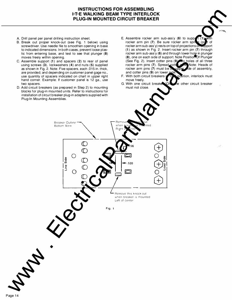
INSTRUCTIONS FOR ASSEMBLING 1-T-E WALKING BEAM TYPE INTERLOCK PLUG-IN MOUNTED CIRCUIT BREAKER
A. Drill panel per panel drilling instruction sheet. B. Break out proper knock-out (see Fig. 1 below) using
screwdriver. Use needle file to smoothen o pening in base to i nd icated dimensions. I n both cases, prevent loose plast ic from entering base, and test to see that plunger (8) moves freely with in opening.
C. Assemble support (1) and spacers (2) to rear of panel using screws (3) , lockwashers (4) and nuts (5) suppli ed as shown in Fig. 2. Note: Five spacers, each .015 in. th ick , are provided; and depending on customer panel gage no. , use quantity of spacers indicated on chart in upper right hand corner. Example: If customer panel is 12 ga. , use two spacers.
D. Add circuit breakers (as prepared in Step 2) to mounting blocks for plug-i n mounted units. Refer to instructions for installation of circuit breaker plug-in adapters supplied with Plug-In Mounting Assembli es.
Bottom V1ew B'""' Oc"'"
~ co co
Cl> 0 IQJ
Page 14
:2 co (/) 1.� (()
I" 0 2 _
�
II=:JI
Fig. 1
E. Assemble rocker arm sub-ass'y (6) to support (1) with rocker arm pi n (7) . Be sure rocker arm spri ng (part of rocker arm sub-ass'y) rests on top of projections on support (1) as shown in Fig. 2. I nsert rocker arm pin (7) th rough rocker arm sub-ass'y (6) and through lower hole in plunger (8), one on each side of support. Note Position Of Plunger (See Fig. 2). I nsert cotter pins (9) into holes of all three rocker arm pi ns (7) . Spread cotter pins. Note: Heads of rocker arm pins (7) must be on upper side of assembly, and cotter pins (9) on lower side .
F. With both circuit breakers in "Off" position, i nterlock must move freely.
G. With one circuit breaker "On", the other circuit breaker must not close.
Remove th1s knock-out when breaker IS mounted R1ght ot center
r .156 0 ELiol 0 Cl>
"tl
-.520 c±Jil [Q) 0 ....J
Q e Remove th1s knock-out when breaker IS mounted Lett ot center
www . El
ectric
alPar
tMan
uals
. com

PANEL DRILLING DIAGRAMS FOR 1-T-E WALKING BEAM TYPE INTERLOCK- Ml5443
PLUG-IN MOUNTED CIRCUIT BREAKER
REAR OF PANEL - LINE SIDE PLUG- IN MOUNTING
0 ----�-C-----....1 .69R �- B _,
\- , � � (cA:=t=�)EA 1 I-\� --h:D-1 I :- (£11 +--11- -:fiT I I I I L. .44 Oia. I ·
75
r:J=. (8 holes) 4.242
ir�o��:iT&1 1! .375 i _lj7.9o I + 1 � -1 y; I
I --1 (i ( ,_- W �- I
9.5o I I .196 Ooa
1(2 holes) I r 3.00 4 c sink 80'·82' to .385 Ooa.
r,�, I 1 -0----+--e- - e--- -- e-1 � :�1 I '
' I"" t •� ,tfS:. ... o.::�- "'I j REAR OF PANEL - LOAD SIDE
BREAKERS ON A B
4 . 50 IN. CENTERS 1 . 273 2.546
6.00 IN. CENTERS 2 023 4.046
Gage No.
Customer Panel
Assemble plungers here for I breakers on 6.00 in. centers �
1 0 1 1 1 2 1 3 14 1 6
c
2.25
3.00
Nominal Thickness ln.
0.135 0. 1 20
0 . 1 0 5
0.090 0.075
0.060
Fig. 2
D
4.50
6.00
Quantity Of Spacers
0 1
2 3
4 5
Page 15 www . El
ectric
alPar
tMan
uals
. com

Page 16
ACCESSORY INS TALLATION INS TRUC TIONS FOR 1-T-E SHUN T TRIP, UNDERVOLTAGE TRIP & AUXILIARY SWI TCH UNITS
CIRCUIT BREAKER PREPARATION
W ARNING: H AZARD OF ELECTRICAL SHOCK OR BURN! BREAKER M US T BE COMPLETELY DISCONNECTED AND REM OVED FROM ANY ELECTRICAL EQUIPMENT BEFORE ACCESSORIES ARE INSTALLED. FOR THE PURPOSE OF THIS M ANUAL AND PRODUCT L ABELS, W ARNING INDICATES DEATH, SEVERE PERSONAL INJURY OR SUBSTANTIAL PROPERTY DAM AGE CAN RESULT IF PROPER PRECAUTIONS ARE NOT TAKEN.
STEP 1. Depress tri p button (See Fig. 1) to tri p circuit breaker prior to rem oving cover. Before attach ing accessory u nit, ci rcu it breaker MUST be in t ripped positi on.
STEP 2. Rem ove fou r load end cover screws (A, Fig. 1) and, if breaker is m ou nted , also rem ove m ou nt ing screws (B, Fig. 1). Rem ove load end cover only. Accessory u nits can be m ou nted in either right or left poles of the circuit breaker.
Push To Trip Button
ACCESSORY MOUNTING INSTRUCTIONS
STEP 3. Feed accessory leads down and through% x 5/32 elongated opening (C, Fig. 2) to bring leads ou t of bottom of circu it breaker. Note: Leads must be brought out in th e same ord er as they exit wire retainer of accessory case. H�
J
A
Line Shield Do Not Attempt
To Remove
Load End Cover
Fig. 1 Cover Screw location
Fig. 2 Installing Accessory
www . El
ectric
alPar
tMan
uals
. com

STEP 4.
Accessory is located in circu i t breaker by two ribs (E, Fig. 2), one on each side of accessory. Slide accessory ribs down into two grooves (D, Fig. 2) in base. When accessory i s installed correct ly, tops of ribs on side of accessory wi ll be at same level as top ou tside edge of circu i t breaker base and front of accessory (F, Fig. 2) will rest on pad (G, Fig. 2) of line shield. Pull gently and evenly on accessory wi re leads (2 to 6 wi res) whi le lowering accessory into base. M ake sure all the slack is removed from lead s
i nside breaker. NOTE: On shu nt trip and u ndervoltage tri p
u ni ts, be sure to guide t ransfer link (H, Fig. 2) i nto opening (J, Fig. 2) at the top of tri p u ni t .
STEP 5. Replace load end cover and cover screws (quanti ty 4) and mou nting screws (quantity 4) if mounted .
STEP 6. Add two labels to circu i t breaker. At tach identification label (K, Fig. 4) to top of circui t breaker on right h and side. M ake sure correct identification square or squares h ave been checked (v). Attach wiring label (L, Fig. 4) on side of circu i t breaker base as sh own.
STEP 7. Refer to Electri cal Check. page 19.
Fig. 3 Accessory Installed
in Left Pole
Identification Label K
Fig. 4 Adding Labels
to Circuit Breaker
Location
Page 17 www . El
ectric
alPar
tMan
uals
. com

1-T-E AUXILIARY SWITCH INFORMATION
AUXILIARY SWITCH KITS
Number Ampere Rating of Switch
Cat. No. Of AC Voltage DC Voltage Switches 120 v 240 v 480 v 125 v 250 v
A0 1F62 1 7.2 7. 2 0 .5 0 . 25 A0 2F62 2 7.2 7.2 0 .5 0 . 25 A0 1F64 1 7.2 7.2 7.2 0 .5 0 . 25 A02F64 2 7. 2 7.2 7.2 0 .5 0 . 25
ALL SWITCHES HAVE THREE LEADS AND ARE IDENTIFIED AS FOLLOWS:
Wire Wire Markings Color Switch Terminals or Contacts
C or C1 White C- Common term inal
A or A1 Black A - Contact open when breaker is open, closed when breaker is closed .
B or 81 Red B - Contact closed when breaker is open, open when breaker is closed .
MECHANICAL/ELECTRICAL CHECK
1. Use a buzzer or light ind i cator attached to switch leads A and C. With breaker in "ON" position, a light or buzz should be observed .
2. Move handle to "OFF" position. I nd icator light or buzzer should turn off.
3. Attach test to leads B and C. L ight or buzzer should turn on.
4. Move handle to "ON" position. I ndicator light or buzzer should turn off.
SHOULD THE INDICATOR NOT FUNCTION PROPERLY DURING CHECK PROCEDURE, CHECK FOR INCORRECT INSTALLATI ON OR WI RING .
MAXIMUM ACCESSORY COMBINATIONS THAT CAN BE INSTALLED
ONE SHUNT TRIP*+ ONE UNDERVOL TAGE TRIP+ ONE AUXI L I ARY SWI TCH ONE SHUNT TRIP* +TWO AUXI L I ARY SWITCHES ONE SHUNT TRIP* + ONE BELLALARM + ONE AUXILIARY SWITCH ONE UNDERVOL TAGE TRIP+ THREE AUXILIARY SWI TCHES ONE UNDERVOL TAGE TRIP+ ONE BELLALARM + TWO AUXILI ARY SWITCHES ONE BELLALARM +THREE AUXILI ARL Y SWITCHES FOUR AUXIL I ARY SWITCHES
*SHUNT TRIP UNI TS I NCLUDE A COIL CLE ARI NG SWITCH
Page 18 www . El
ectric
alPar
tMan
uals
. com

ELECTRICAL CHECK
SHUNT TRIP ACCESSORY
1. Reset and turn circuit breaker ON.
2. Attach test circui t to accessory leads. When the test voltage reaches 55 percent or more of the rated coi l voltage, the circuit breaker should tri p.
3. Wi th breaker TRIPPED or OFF, check to make sure coi l circuit has opened .
ELECTRICAL DATA FOR SHUNT TRIP
Coil Inrush Current
Vol tage At Rated Voltage Cat. No.
(Amperes)
60 CYCLES AC
120 0.395 S01F60
208 0. 265 S02F60
240 0. 165 S03F60
277 0.190 S 15F60
480 0. 145 S04F60
600 0.080 S06F60
DC
24 2 .2 S07F60
48 1 .2 S09F60
125 0. 5 S11 F60
250 0.35 S 13F60
UNDERVOLTAGE TRIP ACCESSORY
1. With breaker i n TRIPPED position, connect test circuit to accessory leads. Energize und ervoltage tri p device at 85 percent of the marked rated voltage of the coi l. Reset and turn breaker handle ON.
2. Reduce voltage to 35 percent of rated coi l voltage. Circuit breaker m ust tri p. (Undervoltage devi ce must tri p between 70 and 35% of rated voltage.)
ELECTRICAL DATA FOR UNDERVOLTAGE (UV) TRIP
Coi l Sealed-I n Current
Vol tage At Rated Voltage Cat. No.
(Am peres)
1 UV Trip 1 UV T rip 60 CYCLES AC Plus
1 Aux. Sw. Only
120 .03 W01F64 U01F60
208 .018 W02F64 U02F60
240 .016 W03F64 U03F60
277 . 013 W16F64 U16F60
480 . 008 W06F64 U06F60
*600 . 008 W08F64 U08F60
DC
24 . 11 W13F64 U13F60
48 .06 W 14F64 U14F60
125 . 027 W10F64 U10F60
**250 . 02 W 12F64 U12F60
Kit includ es a 30k ohm, 25 watt resistor (Ciarostat Cat. No . VP-25-K or equivalent).
Kit includes a 2.5k ohm, 25 watt resistor (Ciarostat Cat. No . VP-25-K or eq uivalent).
Note: Resistor to be mounted externally of circui t breaker & connected by i nstaller.
Note: All auxilliary swi tch ratings are the same as auxi lliary swi tch kit A01 F64.
Page 19 www . El
ectric
alPar
tMan
uals
. com

INSTALLATION INSTRUCTIONS FOR 1-T-E BELLALARM UNITS
WARNING: H AZARD OF ELECTRICAL SH OCK OR BURN! BREAKER M US T BE COMPLETELY DISCONNECTED AND REM OVED FROM ANY ELECTRICAL EQUIPMENT BEFORE ACCESSORIES ARE INSTALLED. FOR THE PURPOSE OF THIS M ANUAL AND PRODUCT L ABELS, WARNING INDICATES DEATH , SEVERE PERSONAL INJURY OR SUBSTANTIAL PROPERTY DAM AGE CAN RESULT IF PROPER PRECAUTIONS ARE NOT TAKEN.
STEP 1.
Depress trip button (See Fig. 1) to tri p circuit breaker pri or to removing cover. Before attaching accessory unit, circuit breaker M UST be in tri pped positi on.
STEP 2.
Remove four load end cover screws (A, Fig. 1) and, if breaker is mounted, also remove mounting screws ( B, Fig. 1). Remove load end cover and handle with barri er. Accessory units can be mounted i n either right or left poles of the circuit breaker.
CIRCUIT BREAKER PREPARATION
B
A
Push To
Trip Button
ACCESSORY MOUNTING INSTRUCTIONS
S TEP 3. Snap-in actuator member (C, Fig. 2) at 5/,6 square opening of accessory h ousing i nto microswitch actuator (.050 x .232 slot). Fig. 2 sh ows accessory unit ready for installation in r ight pole of circuit breaker. If left pole mount ing i s desi red, i nsert actuator member on opposite side. CAUTI ON: DO NOT DISTORT ACTUATOR
S TEP 4. Feed accessory leads down and through 7/a x 5j32 e longated opening (D, Fig. 3) to bring leads out the bottom of circuit breaker. NOTE: Leads must be brought out i n the same order as they exit wire retainer of accessory case.
STEP 5.
Accessory is located in circuit breaker by two ribs (F, Fig. 3), one on each side of the accessory. S li de accessory ribs down i nto two grooves (E , Fig. 3) in base. When accessory is installed correctly, tops of the r ibs on side of the accessory will be at the same level as the top outside edge of the circuit breaker base and front of the accessory (G, Fig. 3) wi ll rest on pad (H , Fig. 3) of line shield. Pull gently and evenly on accessory wire leads (3 to 6 wires) whi le lowering accessory i nto base. Make sure actuator member (C, Fig. 2) rests i n the recess of the circuit breaker frame (pi voting point) and all the S L ACK i s removed from leads inside breaker.
Page 20
F
D
E
Line Shield Do Not Attempt
To Remove
--- Load End Cover
Handle With Barrier
Fig. 1 Cover Screw Location
c
Fig. 2 Installing Actuator Member
Fig. 3 Installing Accessory www .
Elec
tricalP
artM
anua
ls . c
om

STEP 6. Replace handle with barrier, load end cover and cover screws (quan tity 4) and mounting screws (quantity 4) if mounted . See Fig. 1.
STEP 7.
Add the two labels provided to circuit breaker. Attach identification label (J, Fig. 5) to top of the circuit breaker on the right hand side. Make sure correct identifi cati on square or squares have been checked (v). Attach wiring label (K, Fig. 5) on side of the ci rcui t breaker base as shown.
Fig. 4 Accessory Installed
in Left Pole
Identification Label (J)
Wiring Label (K)
Fig. 5
Adding Labels to Circuit Breaker
Page 21 www . El
ectric
alPar
tMan
uals
. com

1-T-E BELLALARM INFORMATION
BELL A LA RM SWITCH KITS
Number Ampere Rating of Switch
Cat. N o. Of AC V oltage DC Voltage Auxiliary
Switches 125 v 250 v 480 v 1 25 v 250 v
BOOF64 0 7.2 7.2 7.2 0.50 0.25 C01 F64 1 7.2 7.2 7.2 0.50 0 25
BELLALARM HAS THREE LEA DS AND ARE IDENTIFIED AS FOLLOWS:
Wire Wire Markings Color Switch Terminals or Contacts.
c White c - Common terminal
A Yellow N.C. - Normally closed contact (Closed when circuit breaker 1s tripped).
B Brown N.O.- Normally open contact (Open when circuit breaker is tripped).
MECHA NICAL/ ELECTRICA L CHECK
1 Use a buzzer or l1ght 1nd1cator attached to switch leads A and C With breaker in "ON" position. tr1p breaker by depressIng red tnp button Indicator light or buzzer should operate.
2. Reset breaker to "OFF". lnd1cator light or buzzer should turn ott
3. Move breaker handle to "ON" Indicator light or buzzer should remain off.
SHOULD T HE INDI CATOR NOT FUNCT ION PROPERLY DURING CHECK PROCEDURE. CHECK FOR INCORRECT INSTALLATION OR WIRING
Page 22 www . El
ectric
alPar
tMan
uals
. com

1-T-E PANELBOARD CONNECTOR STRAPS
/
188 DIA EXTRUSION____-/
OUTSIDE CONNECTOR STRAP
1-------- 5.644
INSULATION THICKNESS: .062�
114-20 THREADS .500 DEEP
\
CAT. NO. ''X
''
CS361 0R 1 .875
CS3612R 3.437
INSIDE CONNECTOR STRAP
l.687 r �t; l\jl ----,
't.lf
CAT. NO. "X
''
CS3611 R 1.875
CS3613R 3.437
20 Tf-f?EAJS , SOC �)EtP
NOTE: THESE STRAPS ARE NOT USED BY 1-T-E IN SERIES 6 PANELBOARDS.
Page 23
www . El
ectric
alPar
tMan
uals
. com

Page 24
INSTRUCTIONS FOR 1-T-E VARIABLE-DEPTH ROTARY-HANDLE
ENCLOSURE MECHANISM
OUTLINE DRAWING AND DRILLING PLAN
DIMENSIONAL CHART
A C• D F R s T u X y v
4 2% 5 % 55/16 7% 4% 3j4 1f4 -20 3fe 41/s l '2 Pole- 3 Pole
ENCLOSURE DEPTH DIMENSIONS
Maximum and M i nimum
3 Inch Pipe 5 Inch Pipe 7 Inch Pipe 9 Inch Pipe I B MAX. B MIN. B MAX. B MIN. B MAX. B MIN. B MAX. B MIN l
11112 9112 1 3112 11112 15 112 1 3112 171!2 15112
VIEW FROM LOAD END OF BREAKER
DRILLING OF ENCLOSURE AND ENCLOSURE COVER
1. Dri ll four breaker m ounting h oles (U) per drilling plan on outline drawing.
2. Place tem plate on breaker m ounting surface so that th e four centers i n the template l ine up with th e breaker m ounting h oles. Make sure "ON"-"OFF" i ndi cations on template are i n same di rection as "ON"-"OFF" i ndications on breaker. Use 2" breaker m ounting screws to h old tem plate i n place.
3. M easure distances "A" and "8" from walls of enclosure. See Fig. 1.
Breaker Mounting Surface
Fig. 1
A I
4. Relocate tem plate on enclosure cover by adding enclosure thi ckness and cover overhang (C) to dimensions "A" and "B". See Fig . 2.
5. Remove backing from tem plate and secure tem plate on door.
6. Dri ll h oles "X" (.375 diam. ) and "Y" (4. 12 diam. ) on tem plate.
Enclosure Cover Fig . 2
c �-----l.J _ _ _ _ _ _ _ _
A
'
c .. --a '
X OFF
www . El
ectric
alPar
tMan
uals
. com

ASSEMBLY OF MECHANISM
Lower Flange
Adaptor Bushing
1. With adapter bush i ng in place on beari ng of l ower m echani sm , place lower flange (flange with th e 4 tapped holes) on to th e l ower m echanism . Secure with four flat head screws.
------- "B" less "F"
3. Cu t square shaft to desi red d imensi on. To do th is subtract d imension "F" (see dim ension chart) from "B" dim ension which is th e di stance from th e back of th e breaker to i nside of enclosure door.
5. Place square shaft i nto bushing on lower m echanism and then place support pipe over th is shaft and i nto collar of flange.
7. Lay assem bly on flat su rface (th is wi ll square assem bl y). If "B" dimension is the minimum, as sh own on dimensional chart, tighten pi pe clamps with su pport pipe seated fully mto both flange collars. If "B" d im ensi on is oth er than minimum, adjust su pport pi pe so that approximately same amou nt of pipe is in each of th e u pper and lower flange collars. (A m inimum of 112 inch of pipe must be in each flange collar) . Ti gh ten pipe clamps.
Latch
Slot
2. Place u pper m echanism on upper flange (flange with 4 tapped holes) and secu re with four flat head screws. Be sure latch on mechanism fits into elongated slot in flange.
P1pe Clamps
4. Place pipe clamp on th e collar of each flange. Do not tighten.
6. With both lower and u pper m echanisms in "OFF" posi tion (lower m echani sm is "OFF" when square shaft is tu rned fully to th e righ t) place u pper m echanism on to su pport pi pe. Make sure square shaft engages upper m echanism .
Page 25 www . El
ectric
alPar
tMan
uals
. com

Page 26
INSTRUCTIONS FOR 1-T-E STANDARD-DEPTH ROTARY-HANDLE
ENCLOSURE MECHANISM - F6RH1
OUTLINE DRAWING AND DRILLING PLAN
,- -��-��----,
i (Y6{_fii'( · !
FRONT VIEW
0
�c-
I TOP OR LINE END OF � T � C/UIT BREAKER
r J-=l l i' -y_ I J I'/ i '',\fy DIA
-r--rL-�- - -+:
• • I ��· I �. I l1 X OIA
",,"
/ -
-'------ '; I U·l41 BREAKER ,--+-.,--t-- MTG HOLES
LEFT S I D E /L--------.J OF CIRCUIT
BREAKER DRILLING PLAN
A B
4 513116
DIMENSIONAL CHART
c D E A s T u X
21/4 8112 227/32 7112 41!4 % 114-20 .177
«�-.-
'• I •
I � "' I �
� � BREAKER
MOUNTING j / SURFACE
.���_,r-��-� VIEW FROM LOAD E ND
y
3%
DRILLING OF ENCLOSURE AND ENCLOSURE COVER
1. Drill four breaker mounting holes (U) per drilling plan on outline drawing.
2. Place template on breaker mounting surface so that the four centers in the template line up with the breaker mountmg holes. Make sure "ON"-"OFF" indications on template are in same direction as "ON"-"OFF" indications on breaker. Use 2 breaker mounting screws to hold template m place.
3. Measure distances "A" and "B" from walls of enclosure . See Fig 1.
Breaker Mounting Surface
Fig. 1
B �
A I
(B" . . OFF
4. Relocate template on enclosure cover by adding enclosure thickness and cover overhang (C) to dimensions "A" and "8". See Fig. 2.
5. Remove backing from template and secure template on door.
6. Drill holes " X" (.375 diam. ) and "Y" (4.12 diam.) or, template.
Enclosure Cover Fig . 2
' c .. -a '
X
y
www . El
ectric
alPar
tMan
uals
. com

MOUNTING INSTRUCTIONS FOR 1-T-E ROTARY-HANDLE ENCLOSURE MECHANISMS
Fig. 1
VARIABLE-DEP TH RO TARY-HANDLE
ENCLOS URE MECHANISM
1. With breaker in "OFF" position and rotary handle mechanisms in "OFF" position, mount mechanism on breaker using 4 screws (1!4-20 x 43/8). Make sure opening in mechanism lever engages breaker operating handle. Tighten screws.
2. Loosely secure the door rings with the 3 screws provided (6-32 x %). Position the interior ring (has the latch tabs and threaded holes) as shown in Fig. 1. The exterior ring mounts on the outside of the door with the small flange to the inside (as shown in Fig. 2).
3. Close enclosure door and adjust external ring on door so it is concentric with handle ring. Tighten the 3 screws.
4. Check door operation. Latch on mechanism should engage latch tab interior ring when breaker is "ON" and disengage latch tab when operating handle is rotated to "Open Door" position.
5. Enclosure door may be opened when breaker is "ON" by turning defeater screw clockwise.
F'g. 2
S TANDARD-DEP TH RO TARY-HANDLE
ENCLOS URE MECHANISM
1. With breaker in "OFF" position and rotary handle mechanisms in "OFF" position, mount mechanism on breaker using 4 screws (%-20 x 41!4 ). Make sure opening in mechanism lever engages breaker operating handle. Tighten screws.
2. Loosely secure the door rings with the 3 screws provided (6-32 x %). Position the interior ring (has the latch tabs and threaded holes) as shown in Fig. 1. The exterior ring mounts on the outside of the door with the small flange to the inSide (as shown in F1g. 2).
3. Close enclosure door and adjust external ring on door so it is concentric with handle ring. Tighten the 3 screws.
4. Check door operation. Latch on mechanism should engage latch tab interior ring when breaker is "ON" and disengage latch tab when operating handle is rotated to ''Open Door" position.
5. Enclosure door may be opened when breaker is "ON" by turning defeater screw clockwise.
Page 27 www . El
ectric
alPar
tMan
uals
. com

INSTRUCTIONS FOR MOUNTING 1-T-E SIDE HANDLE OPERATOR - D1 1 FLU
Add openings to enclosure flange as shown in Fig. 1. Weld interlock latch to inside of cover. Note: If vault handle kit is used, the interlock latch is not required and may be discarded. Refer to vault h andle kit instruction sheet.
The handle mechanism and interlock mechanism are suppli ed preassembled. Before disassembling, note the posit ion of the levers (Items A & B) of the interlock mechanism with respect to (Item C) of the h andle mechanism in Fig. 2. Lever (A) must be placed in back of h andle mechanism (Item C) and lever (B) in front. Care must be taken to insure this relationship is maintained when the device is reassembled.
Assemble h andle mechanism from the outside of the enclosure . (Operating handle must be moved to the approximate middle of its stroke for ease of assembly.) Assemble mounting frame and interlock mechanism from inside of encl osure. When properly assembled th e operating handle cann ot be moved from the " Off" position to the "On" positi on while the cover is open .
Recommended for adequate top gutter space.
Fig. 1
Assemble Circuit breaker mounting plate to mounting frame with four %-20 screws suppli ed and provide end support as shown in Fig. 4 below . M ount Circuit Breaker operating mechanism and Circuit Breaker on mounting plate with four %-20 x 4-% l ong screws as shown in Fig. 3.
Interlock Mechanism -
NOTE: Slot of rocker arm must engage roller of handle mechanism.
Nominal position (%-20 screw) covers elongated slot of mechanism bracket, adjust if necessary.
Operation : T h e h andle cannot be moved from th e " Off" posit ion to th e "On"
positi on while the door is open, unless the Interlock mech anism is deliberately voided. This involves turning the screw in the h andle h ousing counter-clockwise before moving the operating handle.
To open door whi le the h andle is in the "On" position the same screw is turned clockwise.
MIN. MAX.
- :Y4 Dimension can be larger if in- 1 -1/1 s Max. Dim -1 '1•-j terlock latch is spaced out to
-- 21132 -- equal additional distance. For when used conjunction
i wit
n h
MIN. up to ± 3/32 variation spacer vault handle ki r- can be omitted since interlock Cat. No. D 1 1 VL1
t
latch can be bent as required. � �u_D t / L_7/s
J. '.I.Ji t f �k 4"
Latch - -- -- -- -- -
I� 59/16 � - -- -· � - -- -- :; � Mounting Fram
IN. - e
Handle / Mechanism
Slot of Rocker Arm
M 6 '14 r-
-1--�--�---------- '14-20 Hex. Hea d Screws
Page 28
- 1-1 0 --- 0 � CI•rui< "'"'" � L_.------ = = End Support Fu
Mounting Plate
rnished
fTii : - I by Custom
""'-\� � [:o = =�,, �� Fig. 4
er
'14-20 X 4-1/4
long screw
Fig. 2
Fig. 3
7/1s Dia.
Circuit Breaker Operating Mechanism
www . El
ectric
alPar
tMan
uals
. com

'14-20
End by c
INS TRUC TIONS FOR MOUN TING 1-T-E SIDE HANDLE OPERATOR - D1 1 FRU
Add openings to enclosure flange as shown in Fig. 1 . Weld interlock latch to inside of cover. N ote: If vault handle kit is used, the interlock latch is not requi red and may be discarded. Refer to vault handle kit instruction sheet.
The handle mechanism and interlock mechanism are supplied preassembled. Before disassembling, note the position of the levers (Items A & B) of the interlock mechanism with respect to (Item C) of the handle mechani sm in Fig. 2. Lever ( A) must be placed in back of handle mechanism ( Item C) and le ver ( B) in front. Care must be taken to insure this relationship is maintained when the device is reassembled .
Assemble handle mechanism from the outside of the enclosure. ( Operating handle must be moved to the approximate middle of its stroke for e ase of assembly.) Assemble mounting frame and interlock mechanism from inside of enclosure. When properly assembled the operating handle cannot be moved from the "Off" position to the "On" positi on while the cover is open.
Assemble Circuit breaker mounting plate to mounting frame with four %-20 screws supplied and provide end support as shown in Fig. 4 below. Mount Circuit Breaker operating mechanism and Circuit Breaker on mounting plate with four %-20 x 4-V4 long screws as shown in Fig. 3.
N OTE: Slot of rocker arm must engage roller of handle mechanism.
Nominal position (%-20 screw) covers elongated slot of mechanism bracket, adjust if necessary.
Operation: The handle cannot be moved from the "Off" positi on to the "On"
position while the d oor is open, unless the Interlock mechanism is deliberately voided . This in volves turning the screw in the handle housing clockwise before moving the operating handle.
To open door while the handle is in the "On" position the same screw i s turned counter-clockwise.
MAX. MIN. 1 -'!1 s Max. Dim. when used in conjunction with vault 1- 1 '14 - 3!4 �
handle kit Cat. No. D 1 1 V R 1 . � 21/32 �
Dimension can be larger if Interlock MIN. latch is spaced out to equal additional distance. For up to ± 3132 variation spacer can be omitted since Interlock t latch can be bent as required. \ w \ ?fs �
� t H IL '
U--Interlock - - Latch - -- -- -
. � - - � 59116 !§ -Mountmg Frame-----
--- 61;\ =--Hex Head Screws
------------- - t- M l N .
Circuit Breaker Mounting Plate�
Support Furnished ustomer __ ,, 5
).J
---
El
- --
= ----
Fig. 4
�� .. l� �
-I 1 '/2
[ I 1-- Recommended
for adequate top gutter t space.
If Vault Handle t 7/16 Dia. - ......._ kit is used, t
� / "'
dim. to top of ---e- , _ __,__ enclosure r r - - 11 $. 1 opening must L;_ II .--I- t be 3-% min. '!!. --lJ
r-'h ..... Interlock Latch I � TIL!-11 ! � lWJT
Fig. 1
Mounting Frame
Fig. 2
Handle Mechanism
Slot of Rocker Arm
c
:J-.-- Circuit Breaker Operating Mechanism
'14-20 X 4·%
long screw
Fig. 3
P age 29 www . El
ectric
alPar
tMan
uals
. com

Page 30
INSTRUCTIONS FOR 1-T-E VARIABLE DEPTH - D1 1 CFU2 and STANDARD DEPTH - D1 1 CFU1
ROTARY HANDLE ENCLOSURE MECHANISM
General Information
Insert Screwdriver Here To Void
7
H andle will permit locking the disconnect device in the "OFF" posi ti on using up to th ree locks h aving shackl es up to 3fs inches in diameter. Provisi on for locking in "ON" posi ti on i s provided, but the h andle plate must h ave the material covering the locking notch removed. This can be done with a h acksaw or fi le. The h andle h as a voidable interlock. Voiding the interlock requires inserting a small screwdriver into the rectangular opening in the handle plate, which will release the handle .
Mounting Instructions
Drill and tap breaker mounting h oles as sh own. Two (2) addi tional h oles may be required for CLF curren t limi ting circui t breakers. Measure distances "A" and "B" from mounting h oles to walls of the enclosure.
Find h andle cen ter dimensions "D" and "E" by adding enclosure thickness and cover overhang "C" to "A" - 1 1!1 6 and "B" + 57116. Drill h ole "X" (2'14 dia.) and drill e i th er h oles " Y" or "Z" (5/16 dia.) depending on h andle ori entati on required.
If i nstalling variable depth ki t, measure distance "F" from breaker mounting surface to outside of cover. If distance "F" is less than 8 inches then remove shaft guide bracket. Find length "G" by subtracting "F" from 16% inches. Mark length "G" from end of operating shaft and cut shaft squarely at mark . Breaker must be "tri pped" during installati on . Push red button marked "Push to trip".
Using screws suppli ed wi th kit, attach mechanism plate to breaker and mount in enclosure in posi ti on shown.
Insert end of operating shaft into square socket in cast operating arm so that top of shaft h as proper relationsh ip to h andle. Tighten set screw in operating arm (Recommended Torque: 75 in. lb.)
Place handle and c ork gasket on outside of cover and place h andle mounting bracket on inside of cover; fasten together loosely through cover wi th the two short screws provided.
Adjust h andle so that cover will n ot open when h andle is in " OFF" posi tion but will open when h andle is between "OFF" and "RESET/OPEN" posi ti ons. Tighten Screws and operate h andle "ON" and "OFF" to see that circuit breaker operates satisfactorily.
��1%1-/,Top or line End I � Of Circuit Breaker ,-�- · --....L...--.-
V.-20 +::;1 � : Tapped I I
Holes 1 1 I I
i · -· -+! __ l;-y, 2 Extra Holes For
L --'-� - -�' - J ) CLF Circuit Breaker � 4'jYs
Only
NOTE: Drill only The "Y" holes or the ··z·· Holes not both
f F
- � ----'-
X(2V. Dia.)
www . El
ectric
alPar
tMan
uals
. com

1-T-E ENCLOSURES
TYPE I - F6N1 S
G en eral pu rpose indoor, sh eet-steel enclosu re for u se in normal atmosph ere, listed as service-entrance equ ipment.
r- c �
D
3.00; 2 50: 2.00; 1 75: 1 .38; 1 . 1 2
K . O . ' S - 6 P l aces
- 3 . 62; 3.00; 2 . 50; 2 00
t K . O. - 2 REO'D. T
---.--. 1..- L M 1 . 1 2 · 8: K . O - 2 REQ ' D L . __� .
TYPE 12K - F6N1 2K A special-industry, sheet-steel enclosure for indoor u se in atmosphere containing part icles of lint, dust, dirt, sawdust and other foreign matter.
A
TYPE 3R - F6N3R An outdoor, sheet-steel enclosure providing protection against dri vin g rain , sleet or snow. Listed as service-entrance equ ipment.
'(
A
KNOCKOUTS BACKSIDE OF BOX
w -
3 00; 2 . 50 : 2.00; 1 . 75
D
1 . 38 ; 1 . 1 2; K.O - 3 REO'D.
3 0 0 ; 2 . 50; 2 . 0 0 ; 1 75 ' 1 . 38; 1 . 1 2
K . O . - 1 REQ'D I -'f----1---t-s T
��--r-��-.-. 1 . 1 2 : 88 K 0 - 1 REO' D.
ENCLOSURE DIMENSIONS - INCHES
CAT. N O . REF.
F6N 1 S F6N3R F6N1 2K
A 38.4 38 . 6 38 . 6
8 1 1 .5 1 4 . 1 1 4 . 2
c 5 . 1 7 .8 7 .0
0 33.0 33.3 34 .0
E 8.0 8 .0 1 3 0
F 1 .56 1 .56 .62
G 32.6 - -
H 2.8 2.7 -
J 5.8 5 .6 -
K - - -
L 2.6 2 . 6 2 .6
M 6.4 6.4 6.4
N 5 . 9 6 .0 6 .0
p - - -
R - - -
s 1 . 1 1 . 1 1 1
T 2 . 3 2 . 3 2 .3
w 2 . 2 2 3 -
X - 1 2 .50 -
y - .8 1 -
Page 31 www . El
ectric
alPar
tMan
uals
. com

Page 32
10,000 9,000 8,000 7,000 6,000
5.000
4,000
3.000
2,000
1 �gg
rJ) c z 0
BOO 700 600
500
400
300
200
100 90 80 70 60
50
40
30 20 1�
8 7 6
� 4 rJ) !!: w :; ;:::
1 9 8
. 7 6
1 09 08 � 0
u 06 >7
u 0 5 ���04 03
02
f---
f-f-
1li 7 _i 0 009
008 00 006 00 004
5 003 -� 002 f-
00 1
1-T-E TIME/CURRENT CURVES - F FRAME 600 VOLTS, 60 HZ, 250 VOLTS DC 70-250 AMPERES
\ \ 1\ \
� \ \ : ' \
\ 1\
'
Low Instantaneous Setting ::!::: 25% ** I
� N '"
Maximum Single Pole Trip Time at 25oC
300 Sec. (a 300%
� :\
[\
\: "' ' "'"
......
" I() C.O t--- a:>O:l;? i<l
I ·T·E CIRCUIT BREAKER
TIME-CURRENT CURVES
F FRAME, TYPES FJ6, F6, & HF6 2,3-POLE
For appltcafton and coordmatton purposes only Based on 40 oc ambtent cold start Connected wtlh 4 teet of rated w1re (75°C) per term mal Tested 1 n open atr wtlh current 1n all poles
TYPES FJ6, F6, & HF6
600 VOLTS 60 HZ 250 VOLTS DC.
INSTANTANEOUS TRIP
Rating In lns'::::::..u@Trlp t: Amperes 70-90 600·900
100- 1 1 0 700-1200 125-150 800-1500 1 75-200 900-2000 225-250 1 100-2500
INTERRUPTING RATING
BREAKER l SYMMETRICAL RMS AMPERES !DC AMPS FRAME ..... v 'MIUY auuv 20UV
FJ6 & F6 25kA 22kA 18kA 10kA HF6 t>OkA JOKA lOKA lUKA
"Smgle pole test data at 25°C based on test method tn NEMA Procedures tm Venlymg Performance of Molded Case Ctrcuit Breakers
-® Instantaneous Tnp Tolerance :±; 25% on Low Setting
='=" 20% on High Setting ---
'-· H_-
+ LJ f-1-j --"- r -r--- r-:.rt- �- -·
High Instantaneous 1 Setting ± 20%** J
•• Sample I nstantaneous Shown for 250 Amp Breakers Only. For Other Instantaneous Values, See Table .
I -
r--� '-�
' -� t
Maximum Clearing Time
6o0v"1 480V
-; ·: •( 240V
........ I : / r-I
: I
I ! l I I
J l 0 0 0 0 0 0 00 0 0 0
1 g: 7, u 5,
4,
3, 000
2 ,000
I 9 &go .3 7 ,,
00 00 00 00 00
; •
3 00
2 00
1 00 90 80 70 60 50 40
30
"0 <
1 0 9 8 7
5
2 1
1
.... i: "' z rJ) "' (') 0 z c rJ)
09 08 -07 (") 06 -<
(") OS J;;
�4 3 2
01 009 008 007 006 005 004 003
002 001 '" " lO (l) t--- CO C'! O g 0 g g � 0 0
0 0
0 o8 0 0 o 8 o 8oo �; <.C) <0 r--" a:iai�
Mu ltipl es of Cir cuit Br eaker Continu ous Cu rr ent R ating www . El
ectric
alPar
tMan
uals
. com

Instantaneous Trip Range
Breaker Ampere
1-T-E ORDERING INFORMATION CIRCUIT BREAKER CATALOG NUMBERS
Complete Breaker Frame Trip Unit Unenclosed Only Only
UL Interrupting Ratings (kA) (RMS Symmetrical Amperes)
VAC
Frame Rating Min. Max. Cat. No. Cat. No. Cat. No. 1 20 1 20/240 240 277 480 600
FJ6 70 600 900 FJ62B070 25 22 1 8 80 600 900 FJ62BOBO 25 22 1 8 2 Pole 0 90 600 900 FJ62B090 25 22 1 8
600V AC 1 00 700 1 200 FJ62B1 00 25 22 1 8 250V DC 1 1 0 700 1 200 FJ62B 1 1 0 25 22 1 8
1 25 800 1 500 FJ62 B 1 25 25 22 1 8 1 50 800 1 500 FJ62 B 1 50 Non-Interchangeable 25 22 1 8 1 75 900 2000 FJ62 B 1 75 Trip 25 22 1 8 200 900 2000 FJ62B200 25 22 1 8 225 1 1 00 2500 FJ62B225 25 22 1 8
250 1 1 00 2500 FJ62B250 25 22 1 8
250 Molded Case FJ62S250A Switch 0
SHIPPING: 12 lbs. each.
FJ6 70 600 900 FJ63B070 25 22 1 8 80 600 900 FJ63B080 25 22 1 8
3 Pole 90 600 900 FJ63B090 25 22 1 8 600V AC 1 00 700 1 200 FJ63B100 25 22 1 8
1 1 0 700 1 200 FJ63B1 1 0 25 22 1 8 1 25 800 1 500 FJ63 B 1 25 25 22 1 8 1 50 800 1 500 FJ63 B 1 50 Non-I nterchangeable 25 22 1 8 1 75 900 2000 FJ63B1 75 Trip 25 22 1 8 200 900 2000 FJ63B200 25 22 1 8 225 1 1 00 2500 FJ63B225 25 22 1 8
250 1 1 00 2500 FJ63B250 25 22 1 8
250 Molded Case FJ63S250A Switc h 0
SHIPPING: 12 lbs. each.
F6 70 600 900 F62B070 F62F250 F62T070 25 22 1 8 80 600 900 F62B080 F62F250 F62T080 25 22 1 8 2 Pole CD 90 600 900 F62B090 F62F250 F62T090 25 22 1 8
600V AC 1 00 700 1 200 F62 B 1 00 F62F250 F62T100 25 22 1 8 250V DC 1 1 0 700 1 200 F62B 1 1 0 F62F250 F62T 1 1 0 25 22 1 8
1 25 800 1 500 F62B1 25 F62F250 F62T 1 2 5 2 5 2 2 1 8 1 50 800 1 500 F62 B 1 50 F62F250 F62T 1 50 25 22 1 8 1 75 900 2000 F62B 1 75 F62F250 F62T 1 75 25 22 1 8 200 900 2000 F62B200 F62F250 F62T200 25 22 1 8 225 1 1 00 2500 F62B225 F62F250 F62T225 25 22 1 8
250 1 1 00 2500 F62B250 F62F250 F62T250 25 22 1 8
SHIPPING: 12 lbs . each. 9 lbs. each 3 lbs each
F6 70 600 900 F63B070 F63F250 F63T070 25 22 1 8 80 600 900 F63B080 F63F250 F63TOBO 25 22 1 8
3 Pole 90 600 900 F63B090 F63F250 F63T090 25 22 1 8 600V AC 1 00 700 1 200 F63 B 1 00 F63F250 F63T 1 00 25 22 1 8
1 1 0 700 1 200 F63B 1 1 0 F63F250 F63T1 1 0 25 22 1 8 1 25 800 1 500 F63B 1 25 F63F250 F63T 1 25 25 22 1 8 1 50 800 1 500 F63B1 50 F63F250 F63T 1 50 25 22 1 8 1 75 900 2000 F63 B 1 75 F63F250 F63T 1 75 25 22 1 8 200 900 2000 F63B200 F63F250 F63T200 25 22 1 8 225 1 1 00 2500 F63B225 F63F250 F63T225 25 22 1 8
250 1 1 00 2500 F63B250 F63F250 F63T250 25 22 1 8
SHIPPING: 12 lbs. each. 9 lbs. each 3 lbs. each
HF6 70 600 900 HF62B070 H F62F250 F62T070 65 35 22 80 600 900 HF62B080 HF62F250 F62T080 65 35 22 2 Pole 0 90 600 900 HF62B090 H F62F250 F62T090 65 35 22
600V AC 1 00 700 1 200 HF62B1 00 HF62F250 F62T 1 00 65 35 22 250V DC 1 1 0 700 1 200 HF62B 1 1 0 H F62F250 F62T1 1 0 65 35 22
1 25 800 1 500 HF62 B 1 25 H F62F250 F62T 1 25 65 35 22 1 50 BOO 1 500 HF62B1 50 HF62F250 F62T150 65 35 22 1 75 900 2000 HF62B 1 75 H F62F250 F62T 1 75 65 35 22 200 900 2000 HF62 B200 H F62F250 F62T200 65 35 22 225 1 1 00 2500 HF62B225 H F62F250 F62T225 65 35 22
250 1 1 00 2500 HF62B250 H F62F250 F62T250 65 35 22
S H I PPING: 12 lbs. each. 9 lbs. each 3 lbs. each
HF6 70 600 900 HF63B070 HF63F250 F63T070 65 35 22 80 600 900 HF63B080 H F63F250 F63T080 65 35 22
3 Pole 90 600 900 HF63B090 H F63F250 F63T090 65 35 22 600V AC 1 00 700 1 200 HF63 B 1 00 H F63F250 F63T100 65 35 22
1 1 0 700 1 200 HF63B1 1 0 HF63F250 F63T1 1 0 65 35 22 1 25 800 1 500 HF63B 1 25 H F63F250 F63T1 25 65 35 22 1 50 800 1 500 HF63B 1 50 HF63F250 F63T 1 50 65 35 22 1 75 900 2000 HF63B 1 75 H F63F250 F63T 1 75 65 35 22 200 900 2000 HF63B200 H F63F250 F63T200 65 35 22 225 1 1 00 2500 HF63B225 H F63F250 F63T225 65 35 22
250 1 1 00 2500 HF63B250 HF63F250 F63T250 65 35 22
S H I P P I NG: 12 lbs . each 9 lbs. each 3 lbs. each
CD Two Pole Available in 3 Po le Width Only 0 I ncludes Self Protect ing Instantaneous Element .
vee 1 2 5 250
1 0 1 0 1 0 1 0 1 0 1 0 1 0 1 0 1 0 1 0
1 0
1 0 1 0 1 0 1 0 1 0 1 0 1 0 1 0 1 0 1 0
1 0
20 20 20 20 20 20 20 20 20 20
20
SPECIAL NOTE: For 50°C application re place " B" l etter in catalog num ber with the letter "M" for orderin g purposes. If tri p unit only is required , replace the l etter " T" with the letter "W", for ordering purposes.
Page 33 www . El
ectric
alPar
tMan
uals
. com

Page 34
1-T-E ORDERING INFORMATION CIRCUIT BREAKER ACCESSORIES
AUXILIARY SWITCH COMBINATIONS
1 Alarm Switch & Control Voltage 1 Auxiliary Switch 1 Auxiliary Switch 2 Auxiliary Switches
AC DC Cat. No. Cat. No. Cat. No.
1 20 A01 F62 C01 F64 A02F62 208 A01 F62 C01 F64 A02F62 240 A01 F62 C01 F64 A02F62 277 A01 F64 C01 F64 A02F64 480 A01 F64 C01 F64 A02F64 600 - - -
24 A01 F62 C01 F64 A02F62 48 A01 F62 C01 F64 A02F62
1 25 A01 F62 C01 F64 A02F62 250 A01 F62 C01 F64 A02F62
UNDERVOLTAGE TRIP COMBINATIONS ALARM SWITCH COMBINATIONS
1 Undv. Trip & 1 Alarm Switch & Control Voltage 1 Undv. Trip 1 Aux. Switch Control Voltage 1 Alarm Switch 1 Auxiliary Switch
AC DC Cat. No. Cat. No. AC DC Cat. No. Cat. No.
1 20 U01 F60 W01 F64 1 20 BOOF64 C01 F64 208 U02F60 W02F64 208 BOOF64 C01 F64 240 U03F60 W03F64 240 BOOF64 C01 F64 277 U1 6F60 W1 6F64 277 BOOF64 C01 F64 480 U06F60 W06F64 480 BOOF64 C01 F64 600 U08F60 W08F64 600 - -
24 U1 3F60 W1 3F64 24 BOOF64 C01 F64 48 U1 4F60 W1 4F64 48 BOOF64 C01 F64
1 25 U1 0F60 W1 0F64 125 BOOF64 C01 F64 250 U1 2F60 W1 2F64 250 BOOF64 C01 F64
SHUNT TRIP COMBINATIONS
Control Voltage 1 Shunt Trip
AC DC Cat. No.
1 20 S01 F60 208 S02F60 240 S03F60 277 S1 5F60 480 S04F60 600 S06F60
24 S07F60 48 S09F60
125 S1 1 F60 250 S1 3F60
ADDITIONAL ACCESSORIES
Item Catalog No. Item Catalog No.
Door M ou nted Rotary Operat ing Handle Enclosures Standard Depth - N E M A 1 F6N 15
Interior Encl osure N E M A 3R F6N3R Depth 513/, 6 D11CFU1
N E M A 12 F6N 12 Variable Depth -
Padlocking De vi ce F6PL 1 Interior En closure Depth 513;, 6 to 16% D11CFU2 Handle Blocking De vi ce F6H B1
Side Flange M ounting Mechan ical Interl ock
R ight Hand - Minimu m Enclosure Breaker Panel M ounted Ml5426
Depth 59/, 6 (Flange to Back) D11FRU Breaker Plu g-In M ounted Ml5443
Left Hand - Min imum Enclosures Handle Operators Encl osure Depth 59/, 6 (Flange to Back) D11 FLU Standard Depth Rotary F6R H 1
Rear Connect ing Studs Variable Depth Rotary 9" Depth F6RHV9 Sh ort Len gth AS 4756 7" Depth F6RHV7 Lon g Length AS 4755 5" Depth F6RHV5
Plug In Adapters 3" Depth F6RHV3
2 Pole (2 Requ ired Per Breaker) PC 4753 3 Pole (2 Requ ired Per Breaker) PC 4754 www .
Elec
tricalP
artM
anua
ls . c
om

MISCELLANEOUS INFORMATION
1-T-E Item
Breakers Terminal Connectors Plug-in Connectors Rear Studs I nternal Accessories
Shunt tr ips U ndervoltage Aux. Switch Bell alarm
M olded Case Switch Enclosures Connector Straps
Circuit Breaker M ount ing Screws 1!4 -20 x 4.00"
UL File Number
- E 10848 - E 23615 (Sp) - E 69435 - E 69435 - E 69455
- E 6831 2 - E 1 0848 - E 69435
PROCEDURES FOR VERI FYING PEFORM ANCE OF M OLDED CASE CIRCUIT BREAKERS - AB2 National Electrical Manufacturers Association 210 1 L Street N .W. Suite 300 Washi ngton, DC 20037
Page 35 www . El
ectric
alPar
tMan
uals
. com

SIEMENS -ALLIS
1-T-E Electrical Products Sales Offices
For more information, contact your 1-T-E Electrical Products distributor or your locai i-T-E sales office listed below
Alabama Florida Iowa Birmingham Fort Myers Davenport (205) 879-7030 (813) 656-3605 (319) 359-1357 Mobile Jacksonville Des Moines (205) 666-5818 (904) 396-9659 (515) 223-1277
Miami Alaska (305) 592-4106 Kansas Anchorage Orlando Kansas City (907) 346-2489 (305) 894-7771 (913) 383-3004
Tallahassee Wichita Arizona (904) 386-8926 (316) 942-1409 Phoenix
Tampa (602) 267-7521 (813) 886-2551 Kentucky
West Palm Beach Louisville
Arkansas (502) 426-4647 Little Rock (305) 683-5185 (501) 758-9595 Louisiana
Georgia Baton Rouge
California Atlanta (504) 293-6874 Fresno (404) 458-4353 (209) 264-5018 Macon
Lafayette
(912) 477-6259 (318) 988-3719 Los Angeles New Orleans (714) 857-4450 Savannah (504) 885-3622 Sacramento (912) 897-5049
Shreveport (916) 441-0273 (318) 227-1656 San Diego
Hawaii
(619) 569-8015 Honolulu Maine (808) 533-7135
San Francisco Portland (415) 786-9240 Idaho (207) 772-0021 Stockton Boise (209) 465-7264 (208) 342-6852 Massachusetts
Boston Colorado Illinois (617) 470-3660 Denver Chicago (303) 694-3770 (312) 640-4600 Michigan
Detroit Connecticut
Peoria (313) 358-2470 (309) 688-8729 Rocky Hill Grand Rapids (203) 563-2190 Indiana (616) 247-7611
Evansville District of Columbia (812) 422-9176 Minnesota (301) 459-2044
Fort Wayne Minneapolis
(219) 436-1739 (612) 835-1560 Indianapolis (317) 842-0500
Your 1-T-E Distributor is:
Bulletin 18-2.2. 7-4C (Supersedes 18-2.2.7-4 8) Pnnted in U.S.A 5M 385 AP
Mississippi North Dakota Jackson Bismarck (601) 982-2274 (701) 258-9555
Fargo Missouri (701) 293-7709 Kansas City (913) 383-3004 Ohio Springfield Cincinnati (417) 883-7186 (513) 793-3880 St. Louis Cleveland (314) 567-3900 (216) 442-6740
Columbus Montana (614) 771-1100 Big Fork Dayton (406) 837-5092 (513) 298-2289 Nebraska
Toledo
Omaha (419) 865-8823
(402) 397-1940 Oklahoma
New Hampshire Oklahoma City (405) 236-0531
Manchester Tulsa (603) 623-6264 (918) 665-1806
New Jersey Oregon
Totowa (201) 890-1260 Eugene
(503) 683-2111 New Mexico Portland
Albuquerque (503) 684-3750 (505) 881-1611
Pennsylvania
New York Philadelphia
Buffalo (215) 825-5300 (716) 631-5454 Pittsburgh
Long Island (412) 923-0330 (516) 484-3490 New York
Rhode Island Providence (201) 890-1260 (401) 942-8524
Syracuse (315) 446-8660 South Carolina
North Carolina Columbia
Charlotte (803) 799-5995 Greenville (704) 372-9540 (803) 288-3490
Greensboro (919) 373-1849 South Dakota Raleigh Sioux Falls (919) 782-3365 (605) 334-5707
International-TWX 810-757-0150 ITEINTL
Tennessee Chattanooga (615) 886-6664 Elizabethton (615) 543-3212 Knoxville (615) 690-5172 Memphis (901) 761-2123 Nashville (615) 367-9403 Texas Austin (512) 472-3746 Beaumont (409) 835-7634 Dallas (214) 258-5913 Fort Worth (817) 735-1947 Houston (713) 987-8700 Lubbock (806) 793-2377 McAllen (512) 687-2072 San Antonio (512) 824-7421 Utah Salt Lake City (801) 521-4159 Virginia Richmond (804) 288-8311 Roanoke (703) 982-2776 Virginia Beach (804) 481-2440 Washington Seattle (206) 828-6600 Spokane (509) 325-2582 Wisconsin Milwaukee (414) 258-8535
' 1 985 Siemens-Allis. Inc.
""'
www . El
ectric
alPar
tMan
uals
. com