sichtbarkeit von nanopartikeln im rem auf verschiedenen - dguv
TRANSCRIPT
Translation of:
Mattenklott, M.; Thomas, P.: Zählkriterien für Carbon Nanotubes und andere nanoskalige Partikel bei rasterelektronenmikroskopischer Auswertung. Gefahrstoffe – Reinhalt. Luft (2012) no.11/12, p. 477-483 (by courtesy of Spinger-VDI-Verlag, Düsseldorf)
Counting rules for carbon nanotubes and other nanoscale particles during SEM analysis
Abstract
When used for determining the concentration of carbon nanotubes (CNTs) in airborne dusts,
scanning electron microscopic methods reach the limits of their capacity. This article describes
the accompanying conditions that have to be controlled and optimized so that the dusts
collected by active sampling on gold-coated nucleopore filters can be evaluated by scanning
electron microscope analysis. The focus here is on enhancing the visibility of CNTs on filters.
No criteria are as yet available for the counting of CNTs. The paper presents a strategy for
discussion according to which CNTs can be evaluated in the context of the other particles
occurring in dusts. Evaluation is performed in three stages. First, any large CNTs hairballs
(particles > 20 µm) are identified at low magnification (200-fold). At the 2,000-fold magnification
also specified for established fibre counting methods, smaller CNTs hairballs and fibre
composite particles, for example, are detected (particles of 1 to 20 µm in size). Individual CNTs
are then counted at a 20,000- to 50,000-fold magnification (particles < 100 nm and particles
from 100 nm to 1 µm in size). Criteria for counting are proposed.
1 Introduction
Determining the concentration of nanoscale particles, particularly carbon nanotubes (CNTs), in
workplace atmospheres is an essential aspect of prevention activity in such areas. At present,
established procedures for this purpose do not exist. The descriptions below firstly address the
issues and constraints associated with the determining of concentrations of CNTs and granular
nanoscale particles by means of microscopic methods and present the proposals for analytical

Page 2 of 15
parameters to be applied during scanning electron microscope (SEM) analysis. Secondly, they
list possible counting rules for nanoscale particles in context with the other, accompanying dust
fractions. The list is to be regarded as a maximum requirement.
2 Visibility of nanoparticles under the scanning electron microscope
In order for particles to be classified and counted, they must first be made visible. For nanoscale
particles, this requirement is by no means trivial, since the boundary between visible and
invisible is fluid. The visibility of objects (or more generally of structures) under the SEM is
dependent upon the resolution that can be attained with the apparatus in question (i.e. the
smallest interval that can be recognized as a boundary between two objects) and the contrast
between the objects and the substrate. Under ideal conditions (maximum acceleration voltage,
smallest aperture and smallest possible working distance), a modern field emission scanning
electron microscope (FESEM) has a possible resolution of approximately 1 to 2 nm. This
optimum resolution cannot be attained in practice, however: the ideal settings for good contrast
are in some cases different to those for the ideal resolution. The contrast in images generated
by means of secondary electron detectors is dependent upon the topography of the specimen,
the difference in elementary composition between the object and the substrate (material
contrast), and the type of secondary electrons employed for imaging (as a result of different
detectors and/or detector settings).
3 Visibility of CNTs on gold-coated capillary pore membrane filters
The secondary electrons (SEs) used for imaging occur not only just below the surface of the
specimen (SE1), but to a substantial degree at a certain depth below the surface (SE2). The
penetration depth of the primary beam is therefore relevant. This in turn is dependent upon the
energy of the primary electrons (i.e. the acceleration voltage) and the density of the penetrated
material. At an acceleration voltage of 15 kV, a gold particle with a thickness of 100 nm absorbs
virtually all primary electrons, whereas a carbon particle of the same size allows approximately
90% to pass. A carbon particle with a thickness of 100 nm, such as a CNT, on a gold substrate,
such as a gold-coated capillary pore membrane filter, thus supplies a signal of [10% C + 90%
Au]. Since gold emits approximately four times as many secondary electrons as carbon, the
signal from the particle is therefore only approximately 10% weaker than that from the
substrate, making the particle virtually invisible (Figure 1a).

Page 3 of 15
Conversely, the signal from a gold particle of the same size on carbon [100% Au + 0% C] is
300% stronger than that from the substrate, and therefore clearly visible. In order for the beam
not to pass (significantly) through a carbon particle with a thickness of 100 nm and for good
contrast thus to be obtained to the (gold) substrate, the acceleration voltage must be sub-
stantially below 10 kV. This, however, yields a significantly weaker resolution and a poorer
overall signal, i.e. one with stronger noise (Figure 1b).
In nanostructures, topographical contrast does not contribute substantially to the overall
contrast. Substantially better images can, however, be obtained by means of an in-lens
detector, since compared to the standard SE detector (Everhart-Thornley), the former gives
greater consideration to the secondary electrons emitted close to the surface than to those
emitted from a greater depth (Figure 1c). Nanoparticles are also even more easily recognizable
at lower primary voltage with an in-lens detector (Figure 1d).
Figure 1: CNTs on gold-coated capillary pore filters with different primary voltages and detectors; a) SE 15 kV, b) SE 3 kV, c) in-lens 15 kV, d) in-lens 1 kV.
Page 4 of 15
4 Visibility of nanoparticles on gold-coated capillary pore membrane filters
Gold-coated (sputter-coated) polycarbonate capillary pore membrane filters are frequently used
as the specimen holders for SEM and energy-dispersive x-ray analysis (EDXA) of particles.
Such filters have a very smooth gold surface with an even appearance at medium
magnifications (e.g. 2,000x). The gold coating is necessary in order for the specimen to be
made electrically conductive; otherwise it would become highly charged locally by the incident
primary electrons, which would make imaging impossible. In addition, EDXA results in (virtually)
no peak overlaps between gold and the other relevant elements, at least during the study of
mineral dusts. Gold-coated capillary pore membrane filters are ideal for particle analyses in the
micrometre range.
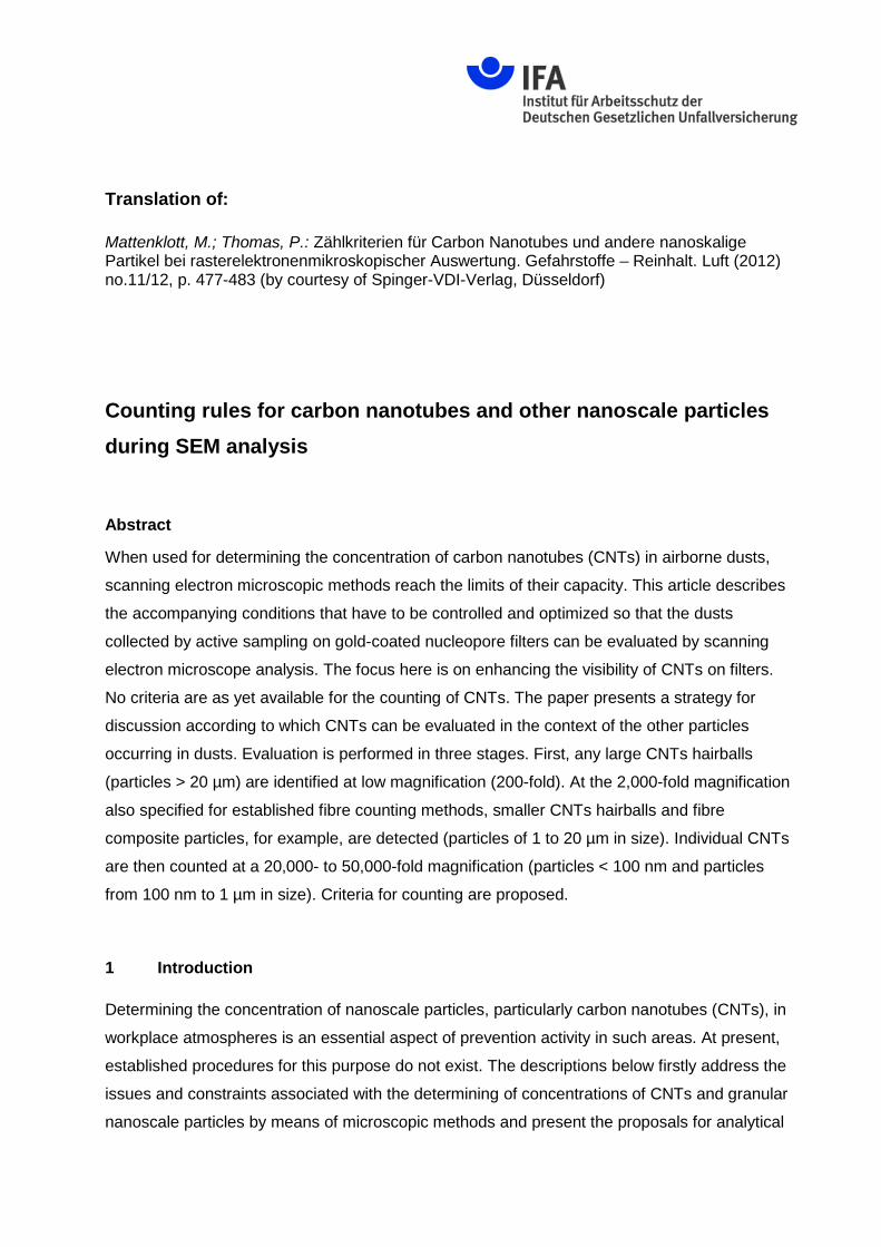
In order for nanoscale particles, for example around and below 50 nm, to be made visible and
still to be analysed morphologically albeit with limitations, magnification of around 20,000x to
50,000x is required. At this level of magnification, the grain structure of the sputter layer is
clearly visible; the grain size is in the order of 30 to 50 nm. Individual granular particles below
50 nm can be distinguished poorly or not at all from the gold grains (Figure 2). The granularity
is only weakly dependent upon the layer depth and process parameters of the sputter process.
Weaker sputtering yields a slightly better surface. For granular nanoscale particles, the visibility
threshold on gold-coated capillary pore membrane filters can thus be assumed to be around
30 to 40 nm.
Figure 2: Nano particles on gold-coated capillary pore membrane filters.
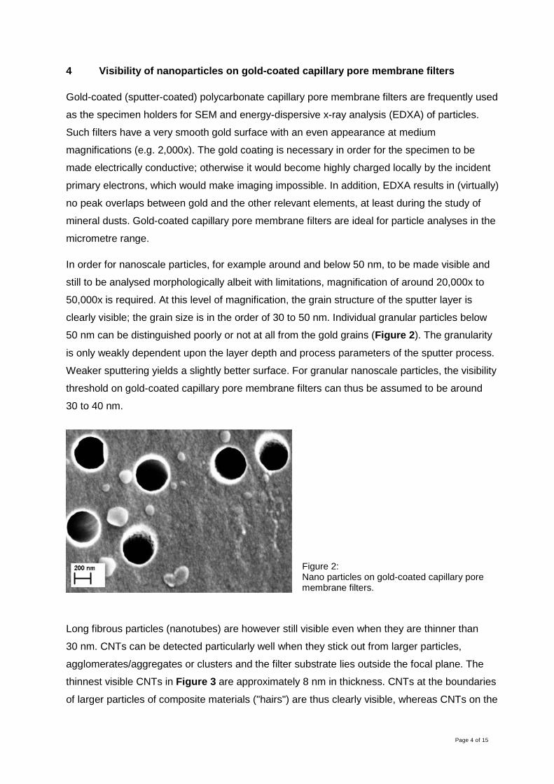
Long fibrous particles (nanotubes) are however still visible even when they are thinner than
30 nm. CNTs can be detected particularly well when they stick out from larger particles,
agglomerates/aggregates or clusters and the filter substrate lies outside the focal plane. The
thinnest visible CNTs in Figure 3 are approximately 8 nm in thickness. CNTs at the boundaries
of larger particles of composite materials ("hairs") are thus clearly visible, whereas CNTs on the
Page 5 of 15
surface of such particles cannot always be readily distinguished from steps or edges of the
particle itself (Figure 4).
Figure 3: CNTs at the edge of a cluster.
Figure 4: Inorganic particles of a composite material with CNT sticking out.
5 Alternative specimen holders
Polished silicon discs yield a very smooth substrate for SEM imaging. This also enables
granular particles in the order of magnitude of the gold structures to be made visible. During
imaging of carbon particles, the contrast is better on this structureless surface than on gold, and
at low acceleration voltages the (low) conductivity of the silicon is sufficient to prevent charges
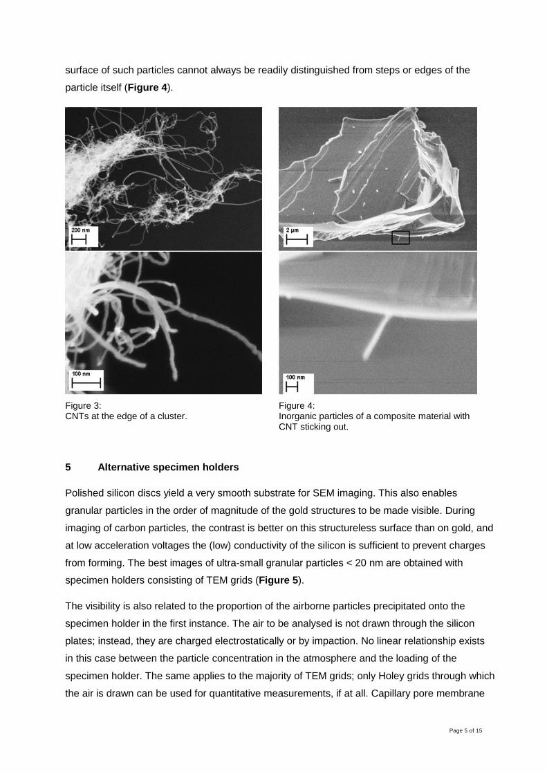
from forming. The best images of ultra-small granular particles < 20 nm are obtained with
specimen holders consisting of TEM grids (Figure 5).
The visibility is also related to the proportion of the airborne particles precipitated onto the
specimen holder in the first instance. The air to be analysed is not drawn through the silicon
plates; instead, they are charged electrostatically or by impaction. No linear relationship exists
in this case between the particle concentration in the atmosphere and the loading of the
specimen holder. The same applies to the majority of TEM grids; only Holey grids through which
the air is drawn can be used for quantitative measurements, if at all. Capillary pore membrane
Page 6 of 15
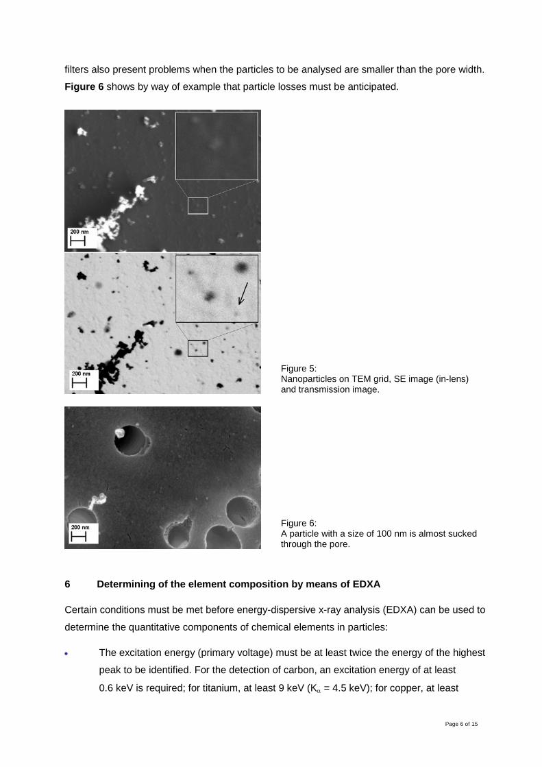
filters also present problems when the particles to be analysed are smaller than the pore width.
Figure 6 shows by way of example that particle losses must be anticipated.
Figure 5: Nanoparticles on TEM grid, SE image (in-lens) and transmission image.
Figure 6: A particle with a size of 100 nm is almost sucked through the pore.
6 Determining of the element composition by means of EDXA
Certain conditions must be met before energy-dispersive x-ray analysis (EDXA) can be used to
determine the quantitative components of chemical elements in particles:
• The excitation energy (primary voltage) must be at least twice the energy of the highest
peak to be identified. For the detection of carbon, an excitation energy of at least
0.6 keV is required; for titanium, at least 9 keV (Kα = 4.5 keV); for copper, at least
Page 7 of 15
16 keV (Kα = 8 keV); and for lead, 21 keV (Lα = 10.6 keV). In many cases however, the
Lα or Mα lines can be used for identification, even for heavy elements, in which case an
excitation energy of approximately 4 keV is sufficient. The peaks of these lines of the
heavy elements overlap the peaks of the Kα lines of lighter elements, however.
• The ideal working distance for EDXA is always greater than that for optimum imaging of
nanoscale particles, and is in the order of 6 to 10 mm for a modern SEM. In favourable
cases, analysis is still possible at a somewhat lower working distance. At a working
distance of 1 to 2 mm (for optimum image quality and visibility of the smallest particles)
the x-ray detector is blind, however.
• Since the x-rays are produced not at the surface of the specimen but at a certain depth
(which is dependent upon the primary voltage), virtually only the x-ray radiation of the
substrate would be measured in the case of a very small particle, and barely the particle
itself. The limit lies at a particle size of approximately 200 nm, or somewhat lower in
favourable cases.
A chemical element present in a single nanoscale particle cannot therefore be identified with the
use of SEM. If however larger aggregates/agglomerates of morphologically similar particles are
present on the specimen in addition to discrete particles, they can be exploited for identification.
7 Recommendations for analysis
For analysis of capillary pore membrane filters loaded with CNTs a modern SEM with field-
emission cathode (FESEM) is recommended; the resolutions required for nanoscale particles
are unlikely to be reached easily in an SEM with tungsten cathode. For determining of the
elements – which is necessary for example for distinction between CNTs and chrysotile fibrils –
an energy-dispersive x-ray microanalysis system with light-element detector is required.
For the search for coarser particles, 200x magnification at a relatively large working distance is
sufficient (Everhart-Thornley secondary electron detector). For particles and fibres in the order
of magnitude of WHO fibres, a magnification of 2,000x should be used at the most favourable
working distance for EDXA; the primary voltage should be 15 kV.
A magnification of 20,000x to 50,000x is required for the detection of nanoscale particles and
CNTs. The necessary conditions for resolution and contrast can be met in this case only by
means of an in-lens detector. Optimum images are possible at a primary voltage of substantially
below 10 kV at a working distance of a few millimetres.

Page 8 of 15
At an excitation voltage of 4 kV, EDXA is also able to detect carbon in CNTs with a thickness of
50 nm, since at such a low voltage the electron beam no longer significantly penetrates the gold
layer of the capillary pore membrane filter and the carbon in the filter material thus barely emits
x-rays. At 4 kV, the magnesium K peak can also be registered, thereby permitting differentiation
between CNTs and chrysotile fibrils. The silicon K peak however cannot be separated from the
gold M lines.
8 Proposed counting rules
Besides the constraints described above upon the visibility of nanoscale particles during SEM
analysis, a further problem that is presented is that of the definitions for differentiation. The
formulation of counting rules for nanoscale particles requires clear definitions; these, however.
do not yet exist or are still the subject of controversial debate.
The relevant morphological criteria for the evaluation of nanoparticles from the perspective of
occupational hygiene have also not yet been conclusively defined. If the analysis of air samples
is limited to a few narrowly defined criteria, and if as a result certain nanoscale particles are
determined only selectively, the results may be of severely limited benefit during subsequent
analyses. Documentation of the most far-reaching qualitative and quantitative recording
possible of particles is therefore considered important for the microscopic analysis of air
samples from areas in which tasks involving nanomaterials are performed.
Based upon this approach, a phased procedure is proposed below for detection by scanning
electron microscope of the nanoparticles in air samples. This proposal constitutes a maximum
requirement by way of which ideally all particle types occurring in dusts are detected, i.e.
including the coarser dusts accompanying the nanoparticles. The procedure is designed such
that the relevant parts of the catalogue of requirements can be applied during analysis in a
given case.
The focus of the criteria for analysis lies upon CNTs. These are primarily fibres; from an
occupational hygiene perspective however, nanotubes – despite their fibrous geometry – do not
necessarily satisfy the WHO criteria1[1], according to which respirable fibres have to date been
counted and distinguished from granular particles. Whereas CNTs satisfy the WHO criteria in
their diameter and length-to-diameter aspect ratio, they do not always reach the required
minimum length of 5 µm. In addition it is questionable whether CNTs – in contrast to asbestos
1 WHO criteria for the differentiation of respirable fibres: diameter < 3 µm, length > 5 µm, length-to-diameter aspect ratio > 3 : 1

Page 9 of 15
fibres – should generally be regarded as rigid fibres which cannot be incorporated by alveolar
macrophages at a length of > 5 µm. Furthermore, CNTs with a length of > 5 µm may also
assume a coiled form, in which case their greatest measurable dimension may be substantially
below 5 µm. A simple count of CNTs is also exacerbated by the fact that they can occur as
hairballs which may well attain or exceed a dimension of 20 µm more (such as "Baytubes" or
"Graphistrength"). Particles in the magnitude of several µm are also observed during the
application of composite materials containing CNT components from which CNTs stick out
(nanofibre composite material particles).
Accordingly, for detection of the particle types associated with CNTs, SEM analysis would have
to be performed in at least three stages of magnification (see Table 1).
Table 1: Particle dimension and proposed magnification for analysis during SEM analysis of air samples from areas in which tasks are performed involving nanomaterials, particularly CNTs.
Particle dimension
Typical kind of particles Suggested magnification for SEM-analysis
> ca. 20 µm - hairballs of CNTs (e.g. “Baytubes”, “Graphistrength”) - in addition granular particles and fibres
200 : 1
x µm - dust particles emitted from CNT composite materials (e.g. “Zentallium”)
- in addition granular particles and WHO fibres
2,000 : 1
x to 100 nm - one-dimensional: flaky particles (e.g. „Graphen“), nanoscale surface structure of coarser particles
- two-dimensional: CNTs and other nanofibres - three-dimensional: “granular” nanoparticles - agglomerates und aggregates of nanoscale particles - in addition particles with size from 100 up to 1,000 nm
20,000 : 1 to 50,000 : 1
The incidence of larger CNT hairballs can be studied at a magnification of 200x. At the 2,000x
magnification typical for determination of the WHO fibre concentration, it would be necessary to
check whether exposure arises to particles from CNT composite materials. For the identification
of both CNT hairballs and particles of CNT composites, the particles must be examined at a
greater magnification (felt-like structure with visibly discrete CNTs in the case of CNT hairballs;
discrete CNTs sticking out from particles of composites). Finally, the individual nanoscale
particles and their aggregates and agglomerates are counted at a magnification of 20,000x to
50,000x.

Page 10 of 15
The division into particle types shown in Table 1 is intended in the first instance to be
schematic; it is to some degree arbitrary and should be modified on a case-by-case basis. CNT
hairballs for example may also exhibit particle sizes below 20 µm. Owing to their very low
density of approximately 0.1 g/cm³ however, it must be considered that CNT hairballs of a
particle size of up to approximately 30 µm may, albeit with decreasing probability, still form part
of the respirable dust fraction and thus be capable of reaching the lower parts of the respiratory
tract2. Use of an established system for fibre dust measurements (such as the PGP-FAP with
37 mm filter) and a flow rate of at least 2 l/minute ensures that particles up to an aerodynamic
diameter of approximately 30 µm are sampled.
Certain boundary conditions must be set out for the analysis which is to be performed in three
stages. Corresponding proposals are made below. The descriptive terms are summarized in
Table 2. The stages of analysis are summarized in Table 3 and described in greater detail
below.
Table 2: Parameters of the particles and definitions.
parameter definition
length (L) rectified visible length of a fibre or a particle
diameter (D) mean visible width of a fibre or a particle
particle size (G) maximum extent of a particle or a fibre (diameter of the surrounding circle)
granular particle particle with L : D ≤ 3 : 1
fibre particle with L : D ≥ 3 : 1
composite particle particles which are emitted of a used or treated composite material at a working place, e.g. carbon fibre composite materiel including a CNT portion
2 CNT hairballs typically have a density of approximately 0.12 to 0.17 g/cm³ (e.g. [2]). Accordingly, CNT hairballs with particle sizes of 12 to 14 µm and 24 to 29 µm have an aerodynamic diameter of 5 to 10 µm respectively.
Page 11 of 15
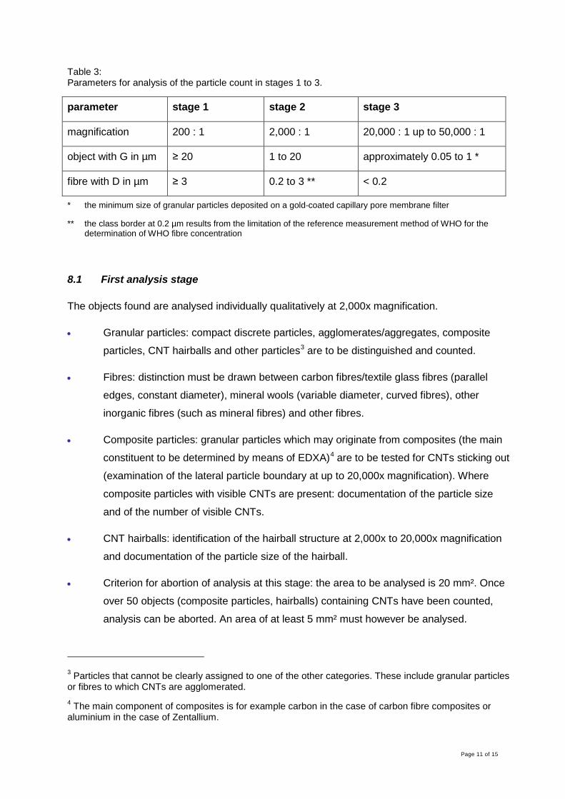
Table 3: Parameters for analysis of the particle count in stages 1 to 3.
parameter stage 1 stage 2 stage 3
magnification 200 : 1 2,000 : 1 20,000 : 1 up to 50,000 : 1
object with G in µm ≥ 20 1 to 20 approximately 0.05 to 1 *
fibre with D in µm ≥ 3 0.2 to 3 ** < 0.2
* the minimum size of granular particles deposited on a gold-coated capillary pore membrane filter
** the class border at 0.2 µm results from the limitation of the reference measurement method of WHO for the determination of WHO fibre concentration
8.1 First analysis stage
The objects found are analysed individually qualitatively at 2,000x magnification.
• Granular particles: compact discrete particles, agglomerates/aggregates, composite
particles, CNT hairballs and other particles3 are to be distinguished and counted.
• Fibres: distinction must be drawn between carbon fibres/textile glass fibres (parallel
edges, constant diameter), mineral wools (variable diameter, curved fibres), other
inorganic fibres (such as mineral fibres) and other fibres.
• Composite particles: granular particles which may originate from composites (the main
constituent to be determined by means of EDXA)4 are to be tested for CNTs sticking out
(examination of the lateral particle boundary at up to 20,000x magnification). Where
composite particles with visible CNTs are present: documentation of the particle size
and of the number of visible CNTs.
• CNT hairballs: identification of the hairball structure at 2,000x to 20,000x magnification
and documentation of the particle size of the hairball.
• Criterion for abortion of analysis at this stage: the area to be analysed is 20 mm². Once
over 50 objects (composite particles, hairballs) containing CNTs have been counted,
analysis can be aborted. An area of at least 5 mm² must however be analysed.
3 Particles that cannot be clearly assigned to one of the other categories. These include granular particles or fibres to which CNTs are agglomerated. 4 The main component of composites is for example carbon in the case of carbon fibre composites or aluminium in the case of Zentallium.

Page 12 of 15
Evaluation may comprise, in the first instance, marking of the positions of all relevant objects
during assessment at 200x magnification, followed by selective viewing of these positions in
turn at 2,000x magnification for identification of the objects.
8.2 Second analysis stage
The objects found are analysed individually qualitatively.
• Granular particles: compact discrete particles, agglomerates/aggregates, composite
particles, CNT hairballs and other particles are to be distinguished and counted.
• Fibres: distinction is to be made between asbestos, fibrous fragments of carbon
fibres/textile glass fibres (requires determining of the product fibre by means of EDXA),
other inorganic fibres (e.g. mineral fibres), possibly product fibres (by means of EDXA
with the use of reference material) and other fibres. The counting rules to BGI 505-46 [4]
are to be applied. CNT hairballs which satisfy the fibre dimensions of the WHO must be
counted separately.
• Composite particles: granular particles which may originate from composites (the main
constituent to be determined by means of EDXA)4 are to be examined for CNTs sticking
out (examination of the lateral particle boundary at up to 20,000x magnification). Where
composite particles with visible CNTs are present, documentation of the particle size
and of the number of visible CNTs.
• CNT hairballs: identification of the hairball structure at 2,000x to 20,000x magnification
and documentation of the particle size of the hairball.
• Criterion for abortion of analysis at this stage: the area to be analysed is 0.5 mm². Once
over 50 objects (composite particles, hairballs) containing CNTs have been counted,
analysis can be aborted. An area of at least 0.15 mm² must however be analysed.
8.3 Third analysis stage
• Granular particles: four particle types must be counted separately (see Figure 7).
• a) Primary particles of 0.05 µm ≤ G ≤ 0.1 µm
b) Primary particles of 0.1 µm < G < 1 µm
c) Agglomerates/aggregates containing primary particles ≤ 0.1 µm
d) Agglomerates/aggregates containing no primary particles ≤ 0.1 µm

Page 13 of 15
If possible, the geometry of the particles (spherical, angular, etc.) should be
documented.
• Fibres: counting of CNTs according to the following criteria (see Figure 8):
- Individual CNTs are counted. G (determined), L (measured or estimated) and D (determined) respectively are stated.
- The number of CNTs of L > 5 µm is stated separately.
- Overlapping CNTs are counted separately if they can still be distinguished from each other.
- Should the overlap of fibres consist of an agglomerate that can no longer be differentiated, it is counted as a cluster; G (estimated from the size of the agglomerated region) and the number of CNT ends sticking out are stated in this case.
• Criterion for abortion of analysis at this stage: the area to be analysed is 0.005 mm² in
size. Once over 50 objects containing CNTs (fibres, clusters) have been counted,
analysis can be aborted. An area of at least 0.0015 mm² must however be analysed.
Figure 7: Schematic diagram of categories for the counting of nanoscale granular particles, a) primary particles of 0.05 µm ≤ G ≤ 0.1 µm, b) primary particles of 0.1 µm < G < 1 µm, c) agglomerates/aggregates containing primary particles ≤ 0.1 µm, d) agglome-rates/aggregates containing no primary particles ≤ 0.1 µm.
Figure 8: Schematic diagram of the categories for the counting of CNTs. Distinction is made between discrete CNTs, overlapping CNTs and clusters of CNTs (dotted grey line: boundary of the agglome-rated region of a CNT cluster for the estimation of G).
It must be considered that analysis of filters may not be possible owing to excessive loading.
Experience gained with the use of a SEM analysis for determining the fibre concentration from
filter specimens indicates that approximately one-eighth of the area of an image field is the
maximum filter loading at which specimens can still be analysed. Should an image field exhibit a

Page 14 of 15
higher loading, it is to be rejected. Once more than ten image fields in total have been rejected,
the sample itself is deemed not suitable for analysis [4; 5]. This procedure can be adopted for
stages 1 and 2 of the analysis proposed here. Experience has not yet been gained with the
proposed stage 3. The filter must also be examined for homogeneous loading.
The level of the detection limit for counting of the different particles also differs between the
three analysis stages. For determining the concentration of CNTs in accordance with stage 3 of
the analysis at 20,000x magnification, a detection limit of 1.5 million CNTs/m³ is calculated
mathematically based upon the boundary conditions of the established analysis methods
(sampling in accordance with BGI 505-46 on a 37 mm capillary pore membrane filter with a
sample air volume of 280 l) and an analysed surface area of 0.005 mm².
9 Future prospects
The criteria described here for the counting of nanoscale particles and the other dust particles
arising in combination with them constitute a preliminary proposal for a classification of particles
during microscopic analysis that is to be as comprehensive as possible. An attempt has been
made here to differentiate between relevant particle fractions and classes and to permit detailed
analysis at justifiable analytical effort. The intention is for a discussion to be launched with the
objective of developing a catalogue of criteria, with the widest possible acceptance and scope
for application, for the analysis of air samples for nanoscale particles with particular focus upon
CNTs.
References
[1] Convention concerning safety in the use of asbestos (C162 Asbestos Convention). Entry
into force 16 June 1989. Ed.: International Labour Organization (ILO), Geneva, 1986.
[2] Baytubes® C 150 P. Product data sheet. Published May 2010. Ed.: Bayer Material
Science, Leverkusen 2010.
[3] Determination of airborne fibre number concentrations. A recommended method, by
phase-contrast optical microscopy (membrane filter method). Ed.: World Health
Organisation (WHO), Geneva, 1997.
[4] Verfahren zur getrennten Bestimmung der Konzentration von anorganischen Fasern in
Arbeitsbereichen – Rasterelektronenmikroskopisches Verfahren. Von den Berufsge-
nossenschaften anerkannte Analysenverfahren zur Feststellung der Konzentration
Page 15 of 15
krebserzeugender Arbeitsstoffe in der Luft am Arbeitsplatz. BGI 505-46 (previously ZH
1/120.46). Ed.: Hauptverband der gewerblichen Berufsgenossenschaften (HVBG), Sankt
Augustin. Cologne: Carl Heymanns 2004.
[5] VDI 3492: Indoor air measurement. Ambient air measurement. Measurement of inorganic
fibrous particles – Scanning electron microscopy method (Issue 10/2004). Berlin: Beuth
2004.
Dr. rer. nat. Markus Mattenklott, Peter Thomas,
Institut für Arbeitsschutz der Deutschen Gesetzlichen Unfallversicherung (IFA), Sankt Augustin.