si1287 electrochemical interface - molecular...
TRANSCRIPT

SI1287ElectrochemicalInterface
USER GUIDE


SI1287Electrochemical Interface
USER GUIDE
Solartron
a division of Solartron Group Ltd
Victoria Road, Farnborough, Issue AG : June 1999
Hampshire GU14 7PW. UK. Solartron Part No. : 12876000
19 99

SolartronVictoria Road, FarnboroughHampshire GU14 7PW England.Telephone +44 (0) 1252 376666Fax: +44 (0) 1252 544981
Solartron964 Marcon Blvd., Suite 200Allentown, PA 18103, USATelephone: +1 610-264-5034Fax: +1 610-264-5329
Solartron37 rue du Saule Trapu91882 Massy, CedexFranceTelephone: +33 (0)1 69 53 63 53Fax: +33 (0)1 60 13 37 06
SolartronBeijing Liaison OfficeRoom 327, Ya Mao BuildingNo. 16 Bei Tu Chen Xi RoadBeijing 100101, P R ChinaTelephone: +86 10-6238 1199 ext 2327 Fax: +86 10-6238 4687
For details of our agents in other countries, please contact our Farnborough, UK, office.
Solartron pursues a policy of continuous development and product improvement.The specification in this document may therefore be changed without notice.

GENERAL SAFETY PRECAUTIONS
The equipment described in this manual has been designed in accordance withIEC publication 1010 Safety Requirements for Electronic Measuring Apparatus,and has been supplied in a safe condition. To avoid injury to an operator orservice technician the safety precautions given below, and throughout the manual,must be strictly adhered to, whenever the equipment is operated, serviced orrepaired. For specific safety details, please refer to the relevant sections withinthe manual.
The equipment is designed solely for electronic measurement and should be usedfor no other purpose. Solartron accept no responsibility for accidents or damageresulting from any failure to comply with these precautions.
GROUNDING To minimize the hazard of electrical shock it is essential that the equipment isconnected to a protective ground whenever the power supply, measurement orcontrol circuits are connected, even if the equipment is switched off.
PROTECTIVE GROUND is connected via the ac supply cord. The cord must beplugged into an ac line outlet with a protective ground contact. When an extensionlead is used, this must also contain a ground conductor. Always connect the acsupply cord to the supply outlet before connecting the control and signal cables;and, conversely, always disconnect control and signal cables before disconnectingthe ac supply cord. The ac ground connection must have a continuous currentrating of 25A.
AC SUPPLY VOLTAGE Never operate the equipment from a line voltage or frequency in excess of thatspecified. Otherwise, the insulation of internal components may break down andcause excessive leakage currents.
FUSES Before switching on the equipment check that the fuses accessible from theexterior of the equipment are of the correct rating. The rating of the ac line fusemust be in accordance with the voltage of the ac supply.
Should any fuse continually blow, do not insert a fuse of a higher rating. Switchthe equipment off, clearly label it "unserviceable" and inform a service technician.
EXPLOSIVE ATMOSPHERES NEVER OPERATE the equipment, or any sensors connected to the equipment, ina potentially explosive atmosphere. It is NOT intrinsically safe and could possiblycause an explosion.
NOTES, CAUTIONS AND WARNINGS For the guidance and protection of the user, Notes, Cautions and Warnings appearthroughout the manual. The significance of these is as follows:
NOTES highlight important information for the reader’s special attention. CAUTIONS guide the reader in avoiding damage to the equipment.WARNINGS guide the reader in avoiding a hazard that could cause injury or
death.
Continued overleaf.

SAFETY PRECAUTIONS (continued from previous page)
SAFETY SYMBOLS
For the guidance and protection of the user, the following safety symbols appearon the equipment:
SYMBOL MEANING
AVOID UNSAFE EQUIPMENT The equipment may be unsafe if any of the following statements apply:
• Equipment shows visible damage.• Equipment has failed to perform an intended operation.• Equipment has been subjected to prolonged storage under unfavorable
conditions.• Equipment has been subjected to severe physical stress.
If in any doubt as to the serviceability of the equipment, don’t use it. Get itproperly checked out by a qualified service technician.
LIVE CONDUCTORS When the equipment is connected to its measurement inputs or supply, theopening of covers or removal of parts could expose live conductors. Theequipment must be disconnected from all power and signal sources before it isopened for any adjustment, replacement, maintenance or repair. Adjustments,maintenance or repair, must be done only by qualified personnel, who shouldrefer to the Servicing Manual.
EQUIPMENT MODIFICATION To avoid introducing safety hazards, never install non-standard parts in theequipment, or make any unauthorized modification. To maintain safety, alwaysreturn the equipment to Solartron for service and repair.
Refer to operating manual for detailed instructions of use.
Hazardous voltages.
Protective conductor terminal. This must be connected toground before operating the equipment.
!

Contents
0.1 CSB/SI1287 User Guide/Issue AA
SI1287 Electrochemical InterfaceContents
CHAPTER
1 Introduction
Introduces the facilities of the SI1287 Electrochemical Interface, gives acomparison to the 1286, and summarizes the content of the manual.
2 Using the SI1287
Guides you through some simple uses of the SI1287 and signposts the wayto more advanced uses.
3 SI1287 Parameters and Commands
Provides a logical breakdown of the facilities and the commands that areused to drive them.
4 Remote Control
Describes the RS232 and GPIB facilities of the SI1287.
5 Using the SI1287 with an FRA
Guides you through connection and setup of the SI1287 when used with anFRA.
APPENDIX
A Installation Procedure
B Error Codes
C SI1287 Specification
INDEX

0.2 CSB/SI1287 User Guide/Issue AA
Contents

Introduction
1.1 CSB/SI1287 User Guide/Issue AA
Chapter 1Introduction
Section Page
1 Electrochemistry and SI1287 .......................................... 1.3
2 Features of the SI1287 ..................................................... 1.3
3 The Structure of the SI1287 ........................................... 1.3
4 SI1287 Improvements over 1286 .................................... 1.6
5 Application Software ....................................................... 1.7
6 Further Reading .............................................................. 1.7
7 Using the SI1287 User Guide .......................................... 1.8
Figure
1.1 SI1287 Block Schematic .................................................... 1.4

1.2 CSB/SI1287 User Guide/Issue AA
Chapter 1

Introduction
1.3 CSB/SI1287 User Guide/Issue AA
1 ELECTROCHEMISTRY AND SI1287
Electrochemical measurements rely on the electrical aspect of chemical processesto provide readable data. This is based on Faraday’s law which relates the changein mass per unit area of a substance, to the magnitude of the current flowingthrough it. Measurements are made of the voltage and current acting in anelectrochemical "cell", whose basic form is a pair of metal electrodes immersedin an electrolyte.
The wide range of studies to which electrochemical measurements can beusefully applied includes: corrosion, effectiveness of protective coatings,batteries, and biological processes.
For these measurements the SI1287 Electrochemical Interface can provideaccurate d.c. polarization to establish the rate of ionization in the cell andfrequency response analysis to study the cell impedance characteristics. The fullspectrum of electrochemical measurement techniques can thus be employed toestablish or study the mechanisms of various electrochemical phenomena.
2 FEATURES OF THE SI1287
The SI1287 Advanced Electrochemical Interface is an exceptional adaptableinstrument. It can stand alone, or form the center of a powerful measurementsystem.
The SI1287 can be used either as a potentiostat or galvanostat, with selectablecontrol loop bandwidth to ensure stable operation for various types of cell. Fullcompensation and correction facilities are provided to enable you to extract themost useful information from your experimental data, with the utmost precision.
Control of the SI1287 is managed manually from the front panel keyboard, or bysimple commands that are applied from a controller, such as a personal computer,via the GPIB. Data from the SI1287 may be output in the form most suitable foryour analysis requirements. ASCII and binary coded data is available, as well asASCII coded status messages.
3 THE STRUCTURE OF THE SI1287
Figure 1.1 is a block diagram of the SI1287. The structure can be considered inthree parts:
- Polarization control- Voltage (Reference electrode) measurement- Current measurement.
In addition to the blocks shown in Figure 1.1, the SI1287 also includes:
• two independent DVMs,
• results store,
• front panel display and keyboard,
• battery for retaining the set up and results store when power is removed,

1.4
Chapter 1
CSB/SI1287 User Guide/Issue AA
Fig 1.1 SI1287 Block Schematic
FRA
RejectAmps
RejectVolts
Sweep
DC Ref SummingAmp
Feedback/
×1× 0.01
×1×10
Filter /Buffer
Sum
Sum
P StatG Stat
Current to Voltage Converter
Sum
IR COMP
RE1 RE2
CE WE
×1×10
Filter /Buffer
Bandwidth control
∆RE-Bi
POL
ΣPOL
∆RE
CE
RE1 RE2 I
I-Bi
VoltsOutput
CurrentOutput
PolarityInput
Polarization Control
Voltage measurement
Current measurement
PowerAmplifier
DifferentialAmp

Introduction
1.5 CSB/SI1287 User Guide/Issue AA
• GPIB and Serial input/output ports
• control circuitry to integrate all these facilities.
Although FRA connections are shown in the diagram for completeness, theSI1287 does not need one to make dc measurements.
DVM
SI1287 has two independent DVMs which have a ’5 x 9s’ output. The DVMscan be switched to measure a variety of different parameters independently, andthese are indicated in Figure 1.1, thus: ∆RE-Bi
POLARIZATION CONTROL
Polarization of the cell is a combination of dc, swept dc and an external voltage,which normally comes from a Frequency Response Analyzer (FRA). Internalgenerators within the SI1287 generate an accurate and stable dc voltage (POL)which is added to the external (ac) signal from the FRA, to give ΣPOL. Thissignal is used to control the current through the cell, or the voltage across thereference electrodes, depending on whether the ECI is in galvanostat (i.e., currentcontrolled) or potentiostat (voltage controlled) mode.
Feedback from the relevant cell parameter is used to control the polarization. Inaddition, the bandwidth of the feedback mechanism can be selected by the user toprevent unwanted oscillations from occurring. The polarization signal is alsomodified when IR compensation is used, either by adding a compensationvoltage, or by interrupting the polarization to the cell.
VOLTAGE MEASUREMENT
The voltage across the reference electrodes (∆RE) is measured by a differentialamplifier, and this voltage is used to control the polarization when the SI1287 isin potentiostat mode.
In order to reject any unwanted steady dc level on the cell, a stable programmablevoltage, generated within SI1287, can be subtracted from the measured voltage. If sampled IR compensation is being used, the resultant voltage is passed througha sample-and-hold circuit. The signal (∆RE-Bi) is then buffered, optionallyfiltered, and output to one channel of the FRA.
CURRENT MEASUREMENT
The current from the working electrode is measured by passing it through auser-selectable resistor; this generates a voltage proportional to the current whichis then measured by a differential amplifier. This allows the working electrode tobe floating, and not connected to the instrument ground. If sampled IRcompensation is invoked, the output of the differential amplifier is passed througha sample-and-hold circuit, to yield I. A programmable rejection voltage,representing a steady current through the cell which is to be offset, can besubtracted from the measured voltage to give (I-Bi) before it is buffered,optionally filtered and output as a voltage (proportional to the current in the cell)to the FRA.
RESULTS STORE
The History file is capable of storing up to 450 results, depending on the numberof instrument set-ups stored in memory (each stored set-up reduces this numberby 16).

1.6 CSB/SI1287 User Guide/Issue AA
Chapter 1
4 SI1287 IMPROVEMENTS OVER 1286
The SI1286A ECI has been established for a number of years as one of the mostadvanced instruments of its type, and has an impressive specification. TheSI1287A has an enhanced specification that enables even more sensitivemeasurements to be made, and opens up new areas of application.
A summary of the improvements is given below:
• Extra current range, giving increased current sensitivity: 1pA compared to10pA on 1286;
• Floating Working Electrode;
• Reduced measurement noise;
• Improved DC sweep rate: 6mV/min up to 6000V/min with a resolution of150µV/min, compared to 1286’s 6mV/min resolution;
• Increased maximum DC polarization: ±14.5V, compared to ±12.8V for 1286;
• Sweep freeze capability;
• Conformance to EMC standards.
Some of the benefits of these improved specifications are listed below.
The 1287 has an additional current measurement resistor which adds a 200nArange with a resolution of 1pA. Together with the 1µV voltage sensitivity, andthe improved measurement noise, the 1287 can measure effects which werepreviously hidden to the researcher. This improvement also adds another decadeof impedance range, allowing measurements in excess of 1GΩ to be madeaccurately.
The extra current range and lower measurement noise also means that frequencysweep measurements can be made more quickly, since the integration time on theFRA can be reduced.
A further benefit of this extra sensitivity and lower noise is that ElectrochemicalNoise measurements - which require the accurate simultaneous measurement ofvery low voltages and currents - can now be made to yield useful results.
The ability to float the working electrode is of great benefit in many industrialapplications where the working electrode has to be grounded - for tests on oilpipelines, for example. Even in the laboratory, equipment may need to begrounded for safety reasons, and this can now be handled by 1287.
The increased maximum polarization voltage enables experiments to beconducted on 12volt accumulators, which typically have a rest potential of >13V.
The 1287 can be programmed to freeze the polarization after a DC sweep, ratherthan return it to zero. This allows any number of sweeps to be performed insequence without the need to turn the polarization off, to minimize disturbancesto the cell.

Introduction
1.7 CSB/SI1287 User Guide/Issue AA
5 APPLICATION SOFTWARE
SI1287 works equally well as a stand-alone instrument, or as part of a computercontrolled system. The advantages of using a PC for control and data storage are:
• Complex set-ups can be stored and downloaded rapidly, avoiding the need fortime consuming (and error prone) manual set-ups
• Easy-to-use mouse-driven menu selections to set up and display data
• Wide variety of display formats available
• Results can be stored on disk for later analysis and trending
• Polarization sweeps, impedance tests, harmonic analysis and EC noise testscan be run with ease
• Equivalent circuit simulation and curve fitting facilities give greater insightinto reactions mechanisms
Other facilities include direct readout of corrosion rate and polarizationresistance, 3-dimensional plotting routines, Tafel fitting software, and batch tests(including automatic test sequencing and full multiplexer support).
Our application software portfolio is constantly being updated. Please contactSolartron for more information and a free copy of the latest demonstrationsoftware.
6 FURTHER READING
Understanding Electrochemical Cells, by A.M. Kauffman. (Technical Report017/85) This book gives a simple non-mathematical treatment of what happensin an electrochemical cell during a corrosion process. It is intended fortechnicians who wish to obtain an intuitive grasp of the phenomena involved.
Identification of Electrochemical Processes by Frequency Response Analysis, byClaude Gabrielli. (Technical Report 004/83) This book gives a broadintroduction to the many different techniques that can be used inelectrochemistry. Although written by an electrochemist for electrochemists thebook does not aim to be a deep study, but it does contain an extensivebibliography. You are thus directed to a number of classical treatises andscientific papers on many subjects of interest.
Use and Applications of Electrochemical Impedance Techniques, by ClaudeGabrielli. (Technical Report No. 24) This book complements the author’s otherbook (above), but is more application oriented. Again, reference is made to manyscientific papers.
Use and Analysis of EIS Data for Metals and Alloys, by Florian Mansfeld.(Technical Report No. 26) This is a collection of reports, previously published bySchlumberger Technologies, which describes in some detail the differentanalytical processes required for data acquired by electrochemical impedancespectroscopy. The models proposed for the simulation and fitting of EIS data arediscussed and each is illustrated by the interpretation of actual experimental data.

1.8 CSB/SI1287 User Guide/Issue AA
Chapter 1
7 USING THE SI1287 USER GUIDE
The aim of the SI1287 User Guide is to provide useful information on how best toemploy your Advanced Electrochemical Interface. To guide you in reading themanual a synopsis of Chapters 2 through 6 is given below:
2Chapter
Using the SI1287 with an FRA
Guides you through the connection and setup of theinstrument when used with an FRA.
SI1287 Parameters and Commands
Provides a logical breakdown of the SI1287 facilities and liststhe commands that are used to drive them.
Remote Control
Describes the RS423 and GPIB facilities of the SI1287 andgives details of the remote commands available.4
Chapter
3Chapter
5Chapter
Installation
Gives full details of how to install the SI1287.
Error Codes
Lists the error codes and explains the meaning of each one.
BApp’dix
A
SI1287 Specification
Contains the full specification of the SI1287.
CApp’dix
Using the SI1287
Guides you through some simple uses of the SI1287 andsignposts the way to more advanced uses.
App’dix
Index
Cross references major topics within the manual. Index

Using the SI1287
2.1 CSB/SI1287 User Guide/Issue AF
Chapter 2Using the SI1287
Section Page
1 Introduction ..................................................................... 2.3
2 Front Panel Key Operation ............................................ 2.32.1 Key Operation ................................................................... 2.32.2 Modes of Operation ........................................................... 2.42.3 Power Up ........................................................................... 2.4
3 Connecting to the SI1287 ................................................ 2.53.1 Measurement of Grounded Electrodes .............................. 2.5
4 Setting Parameters for a Potentiodynamic Polarization Curve .......................................................... 2.7
4.1 External Connections ........................................................ 2.74.2 Initializing SI1287 ............................................................. 2.84.3 Setting up Parameters ........................................................ 2.8
5 Using the Display ........................................................... 2.14
Figure
2.1 SI1287 Front Panel : Keys and display section ................ 2.32.2 Cell Connections ............................................................... 2.42.3 12861 Test Module Circuit ................................................ 2.72.4 Plot of the Sweep ............................................................. 2.132.5 Plot of the Potentiodynamic Polarisation Curve ............. 2.13

2.2 CSB/SI1287 User Guide/Issue AF
Chapter 2

Using the SI1287
2.3 CSB/SI1287 User Guide/Issue AF
1 INTRODUCTION
This chapter demonstrates how to set up and use the SI1287, using the front panelmenus. The SI1287 can also be controlled remotely via RS423 and GPIB, referto Chapter 4 for Remote Control details. Connections to a test cell module arealso detailed, followed by the initial set up and relevant steps to produce resultson the display.
The chapter aims to make you aware of the set-up and control facilities of theSI1287 and help build your confidence in the use of the instrument.
It should be noted that before attempting to use the SI1287, the installation andsafety instructions should be followed; refer to the Safety notes at the start of themanual and the Installation procedure, Appendix A.
2 FRONT PANEL KEY OPERATION
There are three principal groups of keys on the SI1287 front panel; shift keys,main keys and stepping keys, see Fig 2.1.
Fig 2.1 SI1287 Front Panel : Keys and display section
2.1 KEY OPERATIONLEDs (light emitting diodes) on the keys indicate if they are active. On keys withmore than one active state (e.g. ’P STAT/G STAT’) the appropriate LED on thekey face lights to show which state is ’on’.
Shift KeysThe Shift keys have a push-for-on (LED flashing), push-for-off (LED off) action.Both shift keys cannot be ’on’ together, except during some parts of the self testroutine.
Main KeysThe main keys when used in ’normal mode’ are operated by repeated pushing toreach the required state, e.g. the ’IR COMP/RPC’ key selects ’IR COMP’ (topLED lit) at the first push, ’RPC’ (lower LED lit) at the second push and neither(both LEDs off) at the third push.
STORE /
SI1287 Electrochemical Interface
SET UP
NUMBER
RETURN
ONSTANDBY
P STATG STAT
IR COMP RPC
LIMITB’WIDTH
BIASREJECT
PLOTSWEEP FILE /STATUS
LOCAL BREAK /SELF TEST RECALL
CLEAR ENTER
SELECT
I MEASURE POLARISATION IR COMP/RPC BANDWIDTH CONDITION DVM SWEEP PLOT DATA OUTPUT
0 1 2 3 54 6 7 8 · / exp + / -9
DIGIT/[ ] DIGIT/[ ]
SELECT
RANGE/[ ]RANGE/[ ]
á
â
ß à
á
â
Main KeysShift Keys Stepping Keys
DVM RUN
[ ∆ RE + 1.2345 V ] I +0.1234 A
solartrons

2.4 CSB/SI1287 User Guide/Issue AF
Chapter 2
Stepping KeysThe stepping keys are used to step through lists of menu selections (etc.) in eitherdirection. They step once per press, but auto-repeat when held down.
2.2 MODES OF OPERATIONNormal ModeWhen both shift keys are off, the main keys act according to the label on each keyface. This is called "normal" mode, and in this mode the keys are referred to as"action keys".
Parameter Set-up ModeWhen the "SET UP" shift key is "on", the main keys act according to the labelabove each key. This is "parameter set-up" mode.
Number Entry ModeWhen the "NUMBER RETURN" shift key is "on", the main keys act as a numberkeypad, according to the label below each key. This is "number entry" mode.
2.3 POWER UPAt power up, one of three messages is displayed:
"Power Restored"This means that, after an interruption in the mains supply (whether deliberate oraccidental), the SI1287 remembers all the existing menu settings, history file, andstored menu set-ups, using its internal battery.
"Reset"This means that the SI1287 has returned all the menu settings to the default state,but left the history file and stored set-ups as they were.
This happens if the SI1287 detects a fault in its data base (existing menu settings).It may occur, for example, if the SI1287 has been without power for more thanthe 100 hours, which the internal battery is guaranteed to maintain the memory(but not long enough to corrupt the history file and stored menu set-ups).
"Initialised"This means that all menu settings have been returned to the default state, and thehistory file and stored menu set-ups have been erased. This appears at power upwhen the SI1287 has been switched off for more than 100 hours.

Using the SI1287
2.5 CSB/SI1287 User Guide/Issue AF
3 CONNECTING TO THE SI1287
The following diagrams show how to connect a four-, three-, or two-terminalelectrochemical cell to the terminals on the front panel of the SI1287.
Fig 2.2 Cell Connections
The outer screen connections on the bnc connectors are connected internally toscreen driver amplifiers, and must be left to float; they must not be connected toground, each other, or any other voltage.
3.1 MEASUREMENT OF GROUNDED ELECTRODESThe polarization and measurement circuits share a common reference, which isconnected to the LO terminal. Under most circumstances, where none of the cellterminals are grounded, the LO terminal should be connected to chassis groundby a link across the GROUND (green) and LO (black) binding posts at the rear ofthe SI1287, see figure 2.2. This will give the best accuracy in Impedancemeasurement.
RE1 RE2
CE WELOCALBREAK /
SELF TESTCLEAR ENTER
SELECT
· / exp + / -
DIGIT/[ ] DIGIT/[ ]
SELECT
RANGE/[ ]RANGE/[ ]
á
â
ß à
á
â
STORE /FILE /STATUS RECALL
DATA OUTPUT
8 9
4-TERMINAL CELL
3-TERMINAL CELL
2-TERMINAL CELL
SI1287 FRONT PANEL
CE WERE1 RE2
CE WERE1 RE2
Driven Shields DO NOT EARTH !
Remember to connect LO to GND on the rear panel or ground WE,see section 3.1

2.6 CSB/SI1287 User Guide/Issue AF
Chapter 2
However, in many field applications the WE electrode may be grounded, eitherdeliberately or inherently (e.g., a steel joist or pipe buried in the ground). In thiscase, leave the LO terminal unconnected, to avoid having two grounded points inthe circuit (which can cause polarization instability).
It is permissible to ground the WE, either at the instrument or at a point of theusers choice (provided that the GROUND-LO link is disconnected). It is notadvisable to ground the WE with the 20µA, 2µA and 200µA ranges selected. Forgrounded WE the impedance measurement errors will vary smoothly from zero atdc to ±10% at 10kHz.
If the cell container is metal and grounded, it is usually best to ground the CEelectrode. However, this reduces the frequency response of the polarization loop.

Using the SI1287
2.7 CSB/SI1287 User Guide/Issue AF
4 SETTING PARAMETERS FOR A POTENTIODYNAMICPOLARIZATION CURVE
The purpose of this section is to give you a brief introduction to the front paneloperation; how to set up parameters, read measurements and plot results. Onceyou have achieved this, you will be sufficiently familiar with the SI1287 to set upyour own experiments. The 12861 Test Module is used to simulate the cell.
This exercise will plot current as a function of swept potential. This sort of plotprovides a general overview of corrosion reactions in a wide potential range andis useful for applications where screening tests of inhibitors, alloying elements,passivity and electrode kinetics are required.
Section 4.1 details the connections to be made from the 12861 Test Cell Moduleand the plotter to the SI1287. When the connections have been made theinstrument should then be initialized (section 4.2).
With the instrument in the default state the following parameters will be entered:I Measure, DVM, Sweep, Data Output, and Plot. Other parametersare left in the default state; see section 4.3.
I Measure - sets the current measuring resistor and protection levels.DVM - set the display parameters.Sweep - set the limits for the sweep.(Data Output - sets the output data.(Plot - sets the parameters for plotting, such as the grid coordinates,
size of paper, grid on/off, etc.
4.1 EXTERNAL CONNECTIONSFor this example the three-terminal cell connection is used, using the 12861 TestModule to simulate the cell. The connection details for the 12861 Test Modulecan be seen in section 3. The equivalent circuitry for the test module can be seenin the following diagram :
Fig 2.3 12861 Test Module Circuit
Connect an HP plotter via GPIB cable to the GPIB port on the rear panel of theSI1287. Set the SI1287 address to ’talk only’ and the plotter to ’listen always’.Switch the plotter on, then set the plotter up, ie. with paper and pens, ready toplot.
CounterElectrode
ReferenceElectrode 1
ReferenceElectrode 2
WorkingElectrode
6.8k 1k 1k1k 1.8k
0.1µ4.7µ 3.3n

2.8 CSB/SI1287 User Guide/Issue AF
Chapter 2
4.2 INITIALIZING SI1287When the SI1287 is switched on, the following will appear on the display:
The following LEDs will be lit on power up:
• ON/STANDBY with STANDBY lit• P STAT/G STAT with P STAT lit• LIMIT BANDWIDTH lit• LOCAL lit
The instrument should now be initialized so that all parameters are returned totheir default states.
To do this press the "BREAK/SELF TEST" key. Then step through the menuselections by continually pressing the key or by pressing the "SELECT " keys.When the selection initialise is displayed press "ENTER" to initialize theinstrument. The following will appear on the display:
4.3 SETTING UP PARAMETERSPress the "SET UP" key; the led will flash indicating that you are in the set upmode. Once this is pressed the display will change showing:
CURRENT MEASUREMENTSelect I Measure to set up the parameters for the current measurement. This isdone by pressing the "ON/STANDBY" key which, in set up mode, is "IMEASURE" (indicated in small print above the key). The display now shows:
Pressing the "SELECT " keys you can step through the menu selectionsavailable. If an incorrect parameter is entered during this exercise, you can usethe "SELECT " keys to step through until the menu selection reappears andthen correct it.
[ POWER RESTORED ]
[ INITIALISED ]
[ ∆RE ] I SET UP
Resulting DisplayKey Press
RESISTOR [auto] I ONSTANDBY
I MEASURE
0
Resulting DisplayKey Press

Using the SI1287
2.9 CSB/SI1287 User Guide/Issue AF
With "RESISTOR" displayed, pressing the "RANGE/[ ]" keys steps through theavailable measuring resistor values (or by rotating the knob, on the front panel).This, however, can be left as its default, which is "[auto]". Now press ENTER.The display will now change showing:
Leave this to the default of "[2A]" and ENTER. The display will now change tothe next selection:
Press "RANGE/[ ]á " to select "[warning]".
When "[warning]" has been selected continue as follows:
When the display is returns to the "RESISTOR" selection, the set up for IMeasure is complete.
POLARIZATION, IR/COMP, BANDWIDTH AND CONDITIONIn this exercise the following parameters are left as their defaults:
• Polarisation• IR/COMP• Bandwidth• Condition
For details of these parameters refer to Chapter 3. The remote commands and theparameter defaults can be found in Chapter 4, section 6.
I LIMIT [2A]
Resulting DisplayKey Press
ENTER
O/L TYPE [cut-out ] I
Resulting DisplayKey Press
ENTER
O/L TYPE [warning ] I
Resulting DisplayKey Press
RANGE/[ ]
á
STANDBY [all o/c ] I
Resulting DisplayKey Press
ENTER
STANDBY [CE o/c ] I RANGE/[ ]
á
ON MODE [pol V/I ] I ENTER
RESISTOR [auto] I ENTER

2.10 CSB/SI1287 User Guide/Issue AF
Chapter 2
DVMNow press the "DVM" key to set up the parameters for measurement. Thefollowing will be displayed:
The parameters in this menu selection are to be entered as the default settings,except for TRIGGER which should be set to [recycle]. So, as before, use the"SELECT " keys until the TRIGGER is displayed. Then using the"RANGE/[ ]" keys to step through the menu until [recycle] appears, then pressENTER.
To view the display press the "SET UP" key to take the instrument out of set upmode. Then press the "DVM RUN" key; the following will be displayed (thevalues displayed may differ slightly):
The two DVMs can measure and display a variety of parameters. At present thedisplay is reading ∆RE and I, but these can be changed if other parameterreadings are preferred. To do this position the [ ] brackets to the left or rightreading using the "DIGIT/[ ]" keys. Then step through the menu list using the"RANGE/[ ]" keys until the preferred reading appears, see section 5 for furtherdetails.
SWEEPPress the "SET UP" key to take the instrument back to set up mode. Now pressthe "SWEEP" key to set the sweep parameters. The following will be displayed:
The segments parameter defines how many steps there will be in the sweep. Toenter a numeric value press the "NUMBER RETURN" key. This now allows youto enter a number as dictated below the keys. Select 8, (the "FILE STATUS"key):
DIGITS [5 × 9] I
Resulting DisplayKey Press
DVM
DVM
5
RUN
[ ∆RE 0.054mV ] I 3.153nA
Resulting DisplayKey Press
DVM
DVM
5
RUN
SEGMENTS 00002 I 3.188nA
Resulting DisplayKey Press
SWEEP
SWEEP
6

Using the SI1287
2.11 CSB/SI1287 User Guide/Issue AF
Set the other sweep parameters to the following:
• OFF MODE to [standby]
• DELAY to 1 second
• V1 RMP to -1 volt
• T1 RMP to 10 seconds
• V2 RMP to 1 volt
• T2 RMP to 15 seconds
• V3 RMP to 1 volt
• T3 RMP to 10 seconds
• V4 RMP to -1 volt
• T4 RMP to 15 seconds
The ramp rate can be calculated by: (V2-V1)/T1 in V/seconds. For further details of the sweep parameters refer to Chapter 3, section 8.
DATA OUTPUTNow press the "DATA OUTPUT" key. The following will be displayed:
Set the following parameters:
• PAR1 to [I]• PAR2 to [POL]
Leave the other parameters as the default settings; refer to Chapter 3, section 15further details of parameters and the defaults.
DVMNow press the "DVM" key again, and change the TRIGGER from [Recycle] to[Sync.]
SEGMENTS 00002 ( )
Resulting DisplayKey Press
SEGMENTS 00008 ( 8 ) FILE /STATUS
DATA OUTPUT
8
NUMBERRETURN
ENTER
RS-423 [ off ] I 3.188nA
Resulting DisplayKey Press
FILE /STATUS
DATA OUTPUT
8

2.12 CSB/SI1287 User Guide/Issue AF
Chapter 2
PLOTNow press the "PLOT" key. The following will be displayed:
Set the plot parameters to the following. This first set of parameters will allowyou to make a plot of the sweep that has been entered:
• XITEM to [TIME] ; at this point pressing the "SELECT " keys wouldstep to YITEM. Pressing ENTER, however, allowsyou to set up the plot coordinates for XMIN,XMAX and XORIGIN. For details of the plotfacility refer to Chapter 3, section 9.
• XMIN to 0• XMAX to 100• XORIGIN to 0
• YITEM to [PAR2]• YMIN to -2• YMAX to 2• YORIGIN to 0
• MODE to [vector]
The other parameters can be left as the defaults, these are Size [A4], Text[on], Title [off], Grid [off], and Device [HPGL].
PLOTTING THE SWEEPNow exit the set up mode by pressing the "SET UP" key and press the "PLOT"key. This now allows you to do a plot of the sweep parameters that you haveentered.
Ensure that the plotter is ready then select the Plot Axes ENTER, to plot theframe. Then select Plot Graph ENTER, which will set the instrument ready toplot, once the sweep has been started.
Press the "ON/STANDBY" key so that the "ON" led is lit. Then press the"SWEEP" key and select sweep ramp ENTER.
The SI1287 will take a few seconds before the sweep/plot starts due to theinstrument’s own integration delay, plus the delay that you entered in the sweepparameters.
When complete the SI1287 will return to the "STANDBY" mode with therespective led lit. The plot should resemble figure 2.4.
XITEM [PAR1] I 3.188nA
Resulting DisplayKey Press
PLOT
PLOT
7

Using the SI1287
2.13 CSB/SI1287 User Guide/Issue AF
Fig 2.4 Plot of the Sweep
PARAMETERS FOR PLOTTING THE POLARIZATION CURVEIf you now go back into set up mode and select "PLOT" you can change theparameters to allow you to make a plot of the polarization curve. The parametersfor the plot are as follows:
• XITEM to [PAR1] • XMIN to -100.000E-06• XMAX to 100.000E-06• XORIGIN to 0• YITEM to [PAR2]• YMIN to -1• YMAX to 1• YORIGIN to 0• MODE to [vector]
The other parameters can be left as the defaults, which are Size [A4], Text[on], Title [off], Grid [off], and Device [HPGL]. When the parametershave been entered continue as before when plotting the sweep. The plot shouldresemble figure 2.5
Fig 2.5 Plot of the Potentiodynamic Polarisation Curve
-20 100
2
X ITEM = TIMEY ITEM = POL
-1-100.000E-06 100.000E-06
1
X ITEM = IY ITEM = POL

2.14 CSB/SI1287 User Guide/Issue AF
Chapter 2
5 USING THE DISPLAY
SELECTING THE DISPLAY
In normal mode the display shows two readings measured by the internalDVM(s). For example:
To change the displayed parameters position the [ ] brackets to the left or rightparameter using the "DIGIT/[ ]" keys. Then step through the list of parametersavailable for display, using the "RANGE/[ ]" keys, until the chosen readingappears between the brackets. Both halves of the display may show the sameparameter if wanted.
The complete list of readings and functions which may be displayed are:
VARYING ONE PARAMETER WHILST OBSERVING ANOTHERAn example of varying one parameter whilst observing another would beadjusting POL V (polarisation voltage) to reduce I (total cell current) to zero,whilst the SI1287 is in ’on’ mode.
Start by setting the DVM parameters back to recycle (in set up mode), then, innormal mode, switch the cell on by pressing the "ON/STANDBY" key. Nextpress the DVM Run.
Then press the "SET UP" key so that the instrument is again in set up mode. Then select the parameter that is to be changed; in this case the polarization. Thekey sequences and resulting displays for this exercise are:
[ ∆ RE + 1.2345 V ] I +0.1234 A
Symbol Parameter
CERE1RE2∆RE∆RE-BiII-Biδ∆RE/δIδI/δ∆REPOL∑POLDVM I/PTIME(blank)
Counter electrode (CE) voltage.Reference electrode 1 (RE1) voltage.Reference electrode 2 (RE2) voltage.Total voltage across RE1 and RE2 (RE1-RE2).∆RE with bias rejected.Total current flowing through the cell.Total current flowing through the cell with d.c. bias rejected.Ratio of ∆RE increment to I increment (resistance).Ratio of I increment to ∆RE increment (conductance).Internal d.c. polarisation level (menu-set level).Total d.c. polarisation level (POL I/P + POL).External voltage input to internal DVM (rear panel).Instrument Time (no DVM measurements are made).A blank space (no DVM measurements are made).

Using the SI1287
2.15 CSB/SI1287 User Guide/Issue AF
Vary the value of POL V, using the knob together with the "DIGIT/[ ]" and"RANGE/[ ]" keys, whilst observing the value of "I" in the right half of thedisplay.
The displayed parameter values are set up immediately without having to pressENTER (except to terminate the set up).
[ ∆ RE + 1.2345 V ] I +0.1234 A
POL V + 0.2468 V I +0.1234 A
POL V + 0.2461 V I +0.1200 A
P STAT
G STAT
POLARISATION
1
Resulting DisplayKey Press
SET UP

2.16 CSB/SI1287 User Guide/Issue AF
Chapter 2

SI1287 Parameters and Commands
3.1 JWS / SI1287 User Guide / Issue AF
Chapter 3SI1287 Parameters and Commands
Section Page
1 Introduction ..................................................................... 3.5
2 I Measure .......................................................................... 3.52.1 Resistor .......................................................................... 3.52.2 O/L Type........................................................................ 3.62.3 Standby .......................................................................... 3.62.4 On Mode ........................................................................ 3.7
3 Polarisation ...................................................................... 3.83.1 POL V ............................................................................ 3.83.2 POL I ............................................................................. 3.83.3 POL I/P .......................................................................... 3.8
4 IR Comp/RPC .................................................................. 3.94.1 IR COMP ....................................................................... 3.94.2 RPC Ω .......................................................................... 3.12
5 Bandwidth ...................................................................... 3.135.1 P STAT BW................................................................. 3.135.2 G STAT BW ................................................................ 3.13
6 SI1287 Output Conditioning ........................................ 3.156.1 V Reject ....................................................................... 3.156.2 I Reject ......................................................................... 3.156.3 LP Filter ....................................................................... 3.156.4 V×10 ............................................................................ 3.166.5 I×10 .............................................................................. 3.16
7 DVM ............................................................................... 3.177.1 Digits ........................................................................... 3.177.2 Range ........................................................................... 3.187.3 Trigger ......................................................................... 3.187.4 Drift Corr. .................................................................... 3.197.5 Averaging .................................................................... 3.197.6 Null .............................................................................. 3.20
8 Sweep .............................................................................. 3.218.1 Delay ............................................................................ 3.218.2 Off Standby.................................................................. 3.228.3 Segments ...................................................................... 3.228.4 V1 RMP ....................................................................... 3.228.5 I1 RMP ........................................................................ 3.228.6 V1 STP ........................................................................ 3.228.7 I1 STP .......................................................................... 3.23
Continued on next page.

3.2 JWS / SI1287 User Guide / Issue AF
Chapter 3
Section Page
8.8 Stepped Sweep ................................................................ 3.248.9 Commands not allowed durring sweep ........................... 3.24
9 Plot .................................................................................. 3.259.1 X Item .......................................................................... 3.259.2 Y Item .......................................................................... 3.259.3 Size .............................................................................. 3.259.4 Text .............................................................................. 3.269.5 Title .............................................................................. 3.269.6 Grid .............................................................................. 3.279.7 Mode ............................................................................ 3.279.8 Device .......................................................................... 3.27
10 Data Output ................................................................... 3.2810.1 RS423 .......................................................................... 3.2810.2 GPIB ............................................................................ 3.2810.3 File ............................................................................... 3.2910.4 File Size ....................................................................... 3.2910.5 PAR1and PAR2 ....................................................... 3.2910.6 FL O/P ......................................................................... 3.2910.7 Heading ........................................................................ 3.2910.8 Error Beep.................................................................... 3.29
11 Direct Action Keys ......................................................... 3.3011.1 On/Standby ...................................................................... 3.3011.2 P Stat/G Stat .................................................................... 3.3011.3 IR Comp/RPC.................................................................. 3.3011.4 Limit Bandwidth .............................................................. 3.3011.5 Bias Reject ....................................................................... 3.3111.6 DVM Run ........................................................................ 3.3111.7 Store/Recall ..................................................................... 3.3111.8 Local ................................................................................ 3.32
12 Indirect Action Keys ..................................................... 3.3312.1 Sweep .............................................................................. 3.3312.2 Plot ................................................................................... 3.3312.3 File/Status ........................................................................ 3.3412.4 Break/Self Test ................................................................ 3.34
13 Menu Summary ............................................................. 3.36
Figure Page
3.1 Four-terminal electrochemical cell ................................... 3.53.2 Three-terminal electrochemical cell
and equivalent circuit ........................................................ 3.93.3 Example waveforms for sampled IR Compensation ........ 3.103.4 Cell current in "sampled" IR Compensation ................... 3.113.5 Effect of real part correction ........................................... 3.123.6 Unity gain "cell" .............................................................. 3.143.7 Flow diagram showing SI1287 sweep menu key
sequence .......................................................................... 3.21
Continued on next page.

SI1287 Parameters and Commands
3.3 JWS / SI1287 User Guide / Issue AF
Figure Page
3.8 Analog Ramp sweep cycle ............................................... 3.223.9 Digitally stepped sweep cycle .......................................... 3.233.10 The plotting field ............................................................. 3.253.11 Coordinates of the plotting field ...................................... 3.26
Table Page
3.1 Standard Resistor Selection .............................................. 3.53.2 Polarisation ON sequence ................................................. 3.73.3 Bandwidths available ...................................................... 3.133.4 Readings available .......................................................... 3.173.5 Minimum time/step values ............................................... 3.24

3.4 JWS / SI1287 User Guide / Issue AF
Chapter 3

SI1287 Parameters and Commands
3.5 JWS / SI1287 User Guide / Issue AF
1 INTRODUCTION
This chapter describes all the facilities of the SI1287 Advanced ElectrochemicalInterface. The facilities appear under the names given to them on the front panel.The set-up parameters are detailed first, followed by the direct action keys. Thereis also a reference to the equivalent remote commands in Chapter 4.
In the following sections, as in Chapter 2, the brackets denote a choice via theSELECT keys, e.g. RESISTOR. The [ ] brackets denote choice via theRANGE/[ ] keys, or the rotary knob, e.g. [auto].
2 I MEASURE
The value of the current flowing through an electrochemical cell is measured bysensing the voltage developed across a standard resistor connected in series withthe cell, and dividing this voltage by the resistance value. A positive current issaid to be flowing when it passes into the counter electrode (CE) and out of theworking electrode (WE).
Fig 3.1 Four-terminal electrochemical cell
2.1 RESISTORØØ Remote command RRI . Refer to Chapter 4, Section 6.5.
The current range of the SI1287 is determined by selecting a standard resistorwhich develops 200mV at full scale current. See Table 3.1. This selection may befixed, or made automatically.
Table 3.1 Standard Resistor Selection
[auto]On auto-range an appropriate standard resistor is switched in automatically, tosuit the current presently being measured. However, slight discontinuities occurin the cell drive whenever the range changes: so, with sensitive cells, it isadvisable to use a fixed range. The following limitations also apply:
• Auto-range is not suitable for a.c. work, i.e. with the FRA.
• Auto-range is not allowed with the following facilities in action: current biasrejection, IR compensation or real part correction.
RE1 RE2
CE WE
Positive Current Flow Standard Resistor
Standard Resistor (Ω) 0.1 1 10 100 1k 10k 100k 1M
Full-Scale Current (±A)(At 200mV) 2 200m 20m 2m 200µ 20µ 2µ 200n

3.6 JWS / SI1287 User Guide / Issue AF
Chapter 3
• Auto-range operates by sensing the cell current and connecting theappropriate standard resistor just before a measurement is made. Thereforeit is possible for a rapidly rising current to be measured on too low a range,resulting in an off-limit condition.
I Limit
ØØ The remote command is ILI . Refer to Chapter 4, Section 6.6.
The current limit defines the highest current range to be used in auto rangemode. Should the measured current exceed the full scale value of this rangethen an overload action is triggered (see section 2.2); enter after selecting[auto].
2.2 O/L TYPEØØ The remote command is OLn. Refer to Chapter 4, Section 6.7.
If the current flow through the cell exceeds (by more than ~25% maximum) thefull-scale value for that range, an overload condition is triggered. The action to betaken is selected by the user via this menu:
[warning]A ’beep’ sounds, and a warning message is displayed.
Caution: [warning] does not itself limit the current in any way and so cannotprevent excessive current damaging a cell. If this is at risk select [limit] or[cut-out].
[limit]The current is allowed to rise to the full-scale value, or ILimit if in auto, but itis inhibited from exceeding it by negative feedback.
[cut-out]Current flow is cut off completely when the overload condition arises, by theSI1287 switching to the ’standby’ state.
2.3 STANDBYØØ The remote command is BYI. Refer to Chapter 4, Section 6.2.
Selects which cell connections are isolated in the ’standby’ state. Either of twostates may be selected: "full standby" and "half standby". Full standby is thedefault state. Should you require half standby, this must be selected prior topolarizing the cell.
[all o/c]Known as "full standby", in which CE, RE1 and RE2 are isolated, leaving onlyWE connected. In full standby, only the following measurements are valid:
DVM I/P, POL, ∑POL, CE.
Invalid measurements are not displayed by the SI1287; the measurement titleonly is shown followed by a space.

SI1287 Parameters and Commands
3.7 JWS / SI1287 User Guide / Issue AF
[CE o/c]Known as "half standby", in which only CE is isolated. In half standby, onlythe following measurements are valid:
RE1, RE2, ∆RE, ∆RE-Bi, DVM I/P, POL, ∑POL, CE, I, I-Bi.
Invalid measurements are not displayed, as stated in [all o/c].
2.4 ON MODEØØ The remote command is ONn. Refer to Chapter 4, Section 6.3.
Selects the initial polarisation conditions of the cell when the SI1287 is switchedfrom the ’standby’ state to ’on’ mode. The use of this parameter prevents the cellfrom experiencing high voltages or currents at switch on, in the short time beforethe SI1287 feedback loops gain full control.
On completion of the "polarization on" sequence the cell may be polarized either"at rest" or at a previously defined level. This is known as the polarization "onmode".
[pol V/I] selected with full standbyWhen the ’ON’ action key is pressed, the SI1287 goes through a controlledpolarization sequence, from full standby to the setup of POL V (or POL I) tothe cell. The following Table 3.2 shows the sequences that occur, for both PSTAT and G STAT modes, except where indicated.
Table 3.2 Polarization ON Sequence
* For the G STAT mode Polarisation current is set to zero and bandwidth Type C is selected.
[pol V/I] selected with half standbyThe sequence starts from half standby and no pause is required.
[rest V/I] selected with full standbyThe full sequence is performed, except step 9. This means that the polarisationwill remain at the rest level.
Sequence Followed
Pol V/I& Full
Standby
Pol V/I& Half
Standby
Rest V/I & Full
Standby
Rest V/I & Half
Standby
Full Sequence
12345
6789
-2-45
6789
12345
678-
-2-45
678-
1. Full Standby. (Initial state)2. Half Standby.3. One second pause. (RE1 and RE2 settle.)4. ∆RE Measured. (Cell’s rest potential) 5. Polarisation set to rest potential and
bandwidth Type J* selected.6. All electrodes connected.7. 40ms pause (for polarization to stabilize).8. Selected bandwidth is set.9. Selected polarization applied to each cell.

3.8 JWS / SI1287 User Guide / Issue AF
Chapter 3
[rest V/I] selected with half standbyThe sequence starts at half standby and ends at the rest level.
Switching from ’ON’ to ’STANDBY’When the ’standby’ action key is pressed, the cell is switched from its present’on’ state directly to either full or half standby (according to the STANDBYmenu set up).
3 POLARIZATION
The polarization voltage, current and input of the cell are selected using this keyin SET UP mode.
3.1 POL VØØ Remote command PVF. Refer to Chapter 4, Section 6.1.
Polarization Voltage. In potentiostatic mode, the SI1287 applies a controlled d.c.potential difference across RE1 and RE2. This voltage is set up via POL V menu.
3.2 POL IØØ Remote command PCF. Refer to Chapter 4, Section 6.1.
Polarization Current. In galvanostatic mode, the SI1287 drives a controlled d.c.current through the cell This current is set up via POL I menu.
The polarisation current selected must be within the range dictated by thestandard resistor in use, as given in section 2.1.
3.3 POL I/PØØ Remote command PII. Refer to Chapter 4, Section 6.1.
Polarization Input. This is an externally generated polarization voltage signal,which may be added to the internal d.c. polarization voltage set.
The external signal (e.g. from the generator of an FRA) may be left at unity gainor attenuated by ×0.01 (40dB) by selecting the appropriate POL I/P menu option:[×1] or [×.01].
Selecting [×.01] improves the signal-to-noise ratio if the external signal noise isproportionally lower at high signal levels.
SI1287 Parameters and Commands
3.9 JWS / SI1287 User Guide / Issue AF
4 IR COMP/RPC
4.1 IR COMPØØ The remote commands are CTI for selecting feedback or sampled and CCI
for selecting IR COMP on/off. Refer to Chapter 4, Section 6.8.
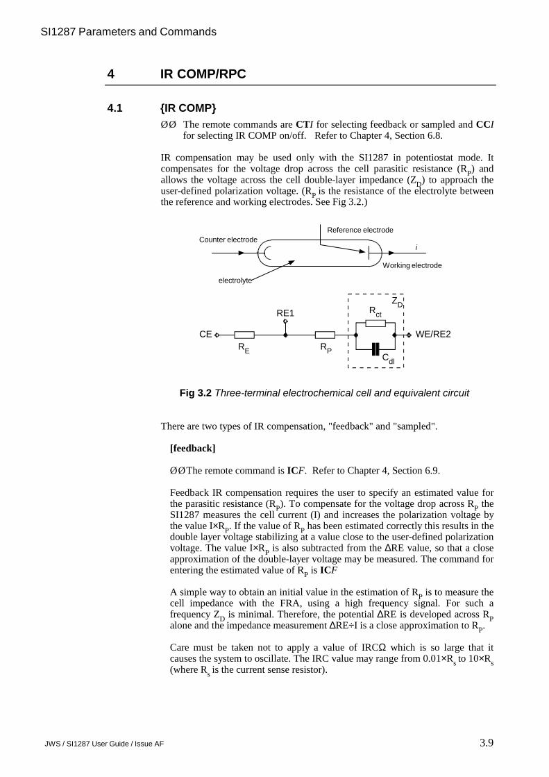
IR compensation may be used only with the SI1287 in potentiostat mode. It compensates for the voltage drop across the cell parasitic resistance (RP) and allows the voltage across the cell double-layer impedance (ZD) to approach the user-defined polarization voltage. (RP is the resistance of the electrolyte between the reference and working electrodes. See Fig 3.2.)
Fig 3.2 Three-terminal electrochemical cell and equivalent circuit
There are two types of IR compensation, "feedback" and "sampled".
[feedback]
ØØThe remote command is ICF. Refer to Chapter 4, Section 6.9.
Feedback IR compensation requires the user to specify an estimated value forthe parasitic resistance (RP). To compensate for the voltage drop across RP theSI1287 measures the cell current (I) and increases the polarization voltage bythe value I×RP. If the value of RP has been estimated correctly this results in thedouble layer voltage stabilizing at a value close to the user-defined polarizationvoltage. The value I×RP is also subtracted from the ∆RE value, so that a closeapproximation of the double-layer voltage may be measured. The command forentering the estimated value of RP is ICF
A simple way to obtain an initial value in the estimation of RP is to measure thecell impedance with the FRA, using a high frequency signal. For such afrequency ZD is minimal. Therefore, the potential ∆RE is developed across RPalone and the impedance measurement ∆RE÷I is a close approximation to RP.
Care must be taken not to apply a value of IRCΩ which is so large that itcauses the system to oscillate. The IRC value may range from 0.01×Rs to 10×Rs(where Rs is the current sense resistor).
WE/RE2
iCounter electrode
Working electrode
Reference electrode
electrolyte
CE
RE1
RP
ZD
RE
Rct
Cdl

3.10 JWS / SI1287 User Guide / Issue AF
Chapter 3
[sampled]Sampled IR compensation periodically interrupts the cell current. During the current off time the IRP drop disappears immediately and allows thedouble-layer impedance voltage (which decays relatively slowly) to be sampledand held. The SI1287 feedback circuit monitors this voltage and maintains it atthe user-defined polarization value.
Figure 3.3 shows an example of the cell voltage and current waveforms. Eitherthe actual cell waveforms or the sampled-and-held ones may be selected foroutput to the FRA and the front panel display DVMs.
Fig 3.3 Example waveforms for sampled IR compensation.
Note: With a.c. impedance measurements the frequency of the a.c. perturbationsignal is limited to about 10% of the interrupt frequency.
OFF TIME ØØRemote command is INF. Refer to Chapt 4, Sect. 6.10.Defines the cell current off time. Refer to figure 3.4.
OFF:ON ØØRemote command is IPF. Refer to Chapt 4, Sect. 6.10.Defines the cell current off:on ratio. Refer to figure 3.4.
REAR O/P ØØRemote command is ROI. Refer to Chapt 4, Sect. 6.10.Defines the output from the rear panel Vand I terminals. This selection alsoaffects the front panel DVMs, which display the appropriate d.c. averagelevels.
[actual]Selects actual (interrupted) current and voltage waveforms being appliedto the cell for output.
[sample+hold]Selects signals which have been sampled + held at the appropriate timesin the interrupt cycle.
Time
fixed timesample+hold
actual
Cell Current
I
Time
fixed time
sample+hold
actual
Cell Voltage
V

SI1287 Parameters and Commands
3.11 JWS / SI1287 User Guide / Issue AF
Fig 3.4 Cell current in ’sampled’ IR Compensation
When working with IR compensation, be guided by the followingconstraints:
• In estimating Rct (ohms) and Cdl (farads) for the cell under test, the off-timeshould be less than 0.1×(Rct×Cdl) seconds and greater than 1.5E-8×(Re+Rp)seconds. There will be cells for which these criteria cannot be met. For thesecells sampled IR compensation is inappropriate and should not be used.
• The choice of loop bandwidth is important. The aim is to achieve stable cellpolarization, and this may be checked by observing the CE with anoscilloscope. The waveform displayed should have two levels: a non-zerovoltage of user-selected polarity during the on-time, and a decay to zero voltsduring the off-time. Should this simple pattern not be obtained, progressivelyreduce the loop bandwidth until it is. A further indication that a lower loopbandwidth should be used is given by the error message, ‘RE1 O/L’ or‘RE1-RE2 O/L’.
• The maximum value of parasitic resistance Rp that can be compensated forcan be calculated from the following constraint:
POL V×(Re+Rp+Rct)÷Rct should be less than 20V.
• The current measurement is a peak value. To obtain the average value,multiply the peak value by the following correction factor:
1÷(off-on ratio +1).
ON
OFF
ONTIME
OFFTIME
PERIOD TIME
CURRENT

3.12 JWS / SI1287 User Guide / Issue AF
Chapter 3
4.2 RPC Ω Ω Ω Ω ØØ The remote commands are CCI for selecting RPC on/off and RPF for the
value of the parasitic resistance RP. Refer to Chapter 4, Section 6.11.
Real part correction is an alternative to IR compensation and it is applicable both to potentiostatic and galvanostatic measurements. Whereas IR compensation is applied to the cell itself (via the polarization control loop), real part correction simply adjusts the measured cell voltage to offset the effect of parasitic resistance (RP). Real part correction is thus a post-measurement function and does not effect polarization stability.
To set up real part correction you are required to enter an estimated value for RP, with the command RPF. For three terminal measurements this value is multiplied by the measured value of cell current to obtain the IRP drop and the result subtracted from the measured cell voltage. For two-terminal measurements the same approach is used to eliminate the voltage drop across the electrolyte resistance RE.
Real part correction is useful when measuring a.c. impedance in cases where the voltage across the parasitic resistance is significant compared to the double-layer voltage being measured. As shown in Figure 3.5, the IRP drop displaces the cell impedance plot along the positive real axis, which lowers the measurement accuracy. Applying real part correction shifts the origin towards the imaginary axis, thus allowing a more sensitive FRA range to be selected and the measurement accuracy to be improved.
Fig 3.5 Effect of real part correction
a-a
b
a
New Scale Selected
Previous Scale
Real Part CorrectionShifts Origin
SI1287 Parameters and Commands
3.13 JWS / SI1287 User Guide / Issue AF
5 BANDWIDTH
Various bandwidths may be selected for the cell polarization control loop. This isto ensure the stable operation of the SI1287, as a potentiostat or galvanostat, inthe measurement of various cells.
5.1 P STAT BWØØ The remote command for the Potentiostatic Bandwidth is PBI. Refer to
Chapter 4, Section 6.4.
There is a selection of ten types of bandwidth ([type A] to [type J]) to suit the celltype; this is detailed in Section 5.3.
5.2 G STAT BWØØ The remote command for the Galvanostatic Bandwidth is GBI. Refer to
Chapter 4, Section 6.4.
There is a selection of three types of bandwidth ([type A] to [type C]) to suit thecell type; this is detailed in Section 5.3.
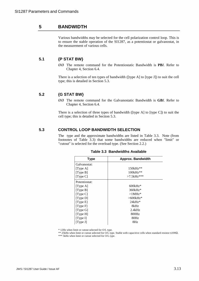
5.3 CONTROL LOOP BANDWIDTH SELECTIONThe type and the approximate bandwidths are listed in Table 3.3. Note (fromfootnotes of Table 3.3) that some bandwidths are reduced when "limit" or"cutout" is selected for the overload type. (See Section 2.2.)
Table 3.3 Bandwidths Available
* 12Hz when limit or cutout selected for O/L type.** 25kHz when limit or cutout selected for O/L type. Stable with capacitive cells when standard resistor ≤100Ω.*** 5kHz when limit or cutout selected for O/L type.
Type Approx. BandwidthGalvanostat:[Type A][Type B][Type C]
150kHz**100kHz**
>7.5kHz***
Potentiostat:[Type A][Type B][Type C][Type D][Type E][Type F][Type G][Type H][Type I][Type J]
600kHz*360kHz*>1MHz*
>600kHz*24kHz*8kHz
2.4kHz800Hz80Hz8Hz

3.14 JWS / SI1287 User Guide / Issue AF
Chapter 3
Note also that the bandwidths quoted are approximate and are based on the unitygain cell configuration shown in figure 3.6.
Fig 3.6 Unity gain "cell"
When in doubt as to the stability of the cell polarization, start with a lowbandwidth, e.g. type J for the potentiostat, and increase the bandwidth forsuccessive measurements until an unstable point (if any) is reached. Then reducethe bandwidth sufficiently to achieve stable operation. For particularly unstablesystems, of course, you may have to reduce the bandwidth well below the stableoperating point and start again.
CE RE1 RE2 WE
R (=RS ) (RS =standard resistor)

SI1287 Parameters and Commands
3.15 JWS / SI1287 User Guide / Issue AF
6 CONDITION
The measured cell voltage and current outputs of the SI1287 can be conditionedso that useful information is emphasised in relation to noise and signal offsets.The facilities available for this are listed in Section 13.
6.1 V REJECT ØØ Remote command for Voltage Bias Rejection is VTI. Refer to Chapter 4,
Section 6.12.
Voltage Bias Rejection may be used to cancel out the d.c. component of themeasured voltage output of the SI1287. This allows a more sensitive FRA rangeto be used and thus improves the measurement accuracy. The level of biasrejection may be entered automatically or as a fixed value.
[auto]Select prior to a single measurement, then switch on (using the Bias Rejectaction key) and perform the measurement. The d.c. bias detected during thatmeasurement is rejected from all later readings. Assumes no subsequent drift ofd.c. bias.
[fixed]Allows a specific d.c. bias reject value (V VAL) to be entered for use whenrequired.
6.2 I REJECTØØ Remote command for Current Bias Rejection is ITI. Refer to Chapter 4,
Section 6.12.
Current Bias Rejection. As for V Reject but operating on the currentmeasurement channel.
Note: The [fixed] current bias rejection value selected (I VAL) must be within therange dictated by the standard resistor in use, as given in the section 2.1.
6.3 LP FILTERØØ Remote command for the Low Pass Filter is FII. Refer to Chapter 4, Section
6.12.
A 10Hz low-pass filter may be switched into the measured voltage and currentoutputs. This reduces wideband noise in low frequency and d.c. measurementsand allows the more sensitive FRA ranges to be used for improved measurementaccuracy. Do not filter a signal of frequency greater than 5Hz, however, otherwise it will be attenuated.

3.16 JWS / SI1287 User Guide / Issue AF
Chapter 3
6.4 V××××10ØØ Remote command for the Voltage Amplification is VXI. Refer to Chapter 4,
Section 6.12.
Voltage Amplification. Measured voltage signals of very low amplitude may beamplified by a factor of ten.
6.5 I××××10ØØ Remote command for Current Amplification is IXI. Refer to Chapter 4,
Section 6.12.
Current Amplification. Measured current signals of very low amplitude may beamplified by a factor of ten.

SI1287 Parameters and Commands
3.17 JWS / SI1287 User Guide / Issue AF
7 DVM
Two DVMs are built into the SI1287: a 200mV fixed full-scale DVM dedicatedto current measurement and a variable-range DVM dedicated to voltagemeasurement. The measurements taken by the DVMs can be shown on thedisplay as they occur. They can also be sent to the GPIB or RS423 interfaces, andrecorded in a history file for later review.
You can select which values are measured and shown on the display using thearrow keys as described in chapter 2 section 4.3 under the heading
ØØ The remote commands for this selection are URI and ULI. Refer to Chapter4, Section 6.23.
You can also select which values are to be measured and sent to the GPIB, RS423or history file. This is described in Chapter 3 section 10.5.
The readings selected for display and for output may be different if required.Table 3.4 shows the readings which may be selected for display or output and thesymbols used to describe them in the menus:
Table 3.4 Readings Available
7.1 DIGITS ØØ Remote command is DGI. Refer to Chapter 4, Section 6.16.
This menu enables the reading precision of the DVMs to be selected, from [3×9s]to [5×9s]. [4×9s. 50Hz] must be used in countries where the mains frequency is50Hz; [4×9s. 60Hz] is for use with mains frequencies of 60Hz.
Symbol ParameterCERE1RE2∆RE∆RE-BiII-Biδ∆RE/δIδI/δ∆REPOL∑POLDVM I/PTIME(blank)
Counter electrode (CE) voltage.Reference electrode 1 (RE1) voltage.Reference electrode 2 (RE2) voltage.Total voltage across RE1 and RE2 (RE1-RE2).∆RE with bias rejected.Total current flowing through the cell.Total current flowing through the cell with d.c. bias rejected.Ratio of ∆RE increment to I increment (resistance).Ratio of I increment to ∆RE increment (conductance).Internal d.c. polarisation level (menu-set level).Total d.c. polarisation level (POL I/P + POL).External voltage input to internal DVM (rear panel).Instrument Time (no DVM measurements are made).A blank space (no DVM measurements are made).
Precision [3×9s] [4×9s] [5×9s]
Reading Rate (readings/second) 16 13 2

3.18 JWS / SI1287 User Guide / Issue AF
Chapter 3
7.2 RANGE ØØ Remote command is DGI. Refer to Chapter 4, Section 6.16.
The voltage DVM may either be set for [auto] or any one of four fixed inputranges may be selected; [200mV], [2V], [20V] or [50V]. Autoranging allows aninput range in keeping with the measured voltage to be selected automatically.
The current DVM has an input voltage range of 200mV. Various ranges of cellcurrent are provided for by a choice of standard resistor values. (See Section 2.1.)
7.3 TRIGGERØØ Remote command is TRI. Refer to Chapter 4, Section 6.16.
Measurements may be triggered in any one of four ways, single, recycled,external or sweep synchronized, as described below.
[single]When single measurement triggering is selected, pressing the DVM RUNaction key causes a single set of measurements to be started (withinapproximately 30ms). Single measurement triggering is always selected oninitialization, e.g. on power up or after RECALL is used.
[recycle]When recycled measurement triggering is selected, pressing the DVM RUNaction key causes the DVMs to make measurements continuously at a readingrate corresponding to the DVM precision selected. Pressing DVM RUN againcauses recycled measurements to be halted.
[external]External measurement. A single measurement is performed whenever atriggering pulse is received via the BNC connector on the rear panel of theSI1287 (labelled TRIGGER). The trigger pulse may be a TTL pulse, or a shortcircuit.
The maximum triggering pulse frequency permitted depends on the precisionselected and on how many voltages each of the two DVMs must measure perreading cycle. This, however, depends on what parameters have been selectedfor PAR1, PAR2 and the left and right display windows.
The highest maximum triggering rate occurs when only one voltage is beingmeasured and equals the appropriate reading rate given in section 7.1. E.g. with3×9s selected PAR1=PAR2=∆RE, and TIME or ’blank’ (which do not involveDVMs) in each display window, the triggering rate can be upto 30Hz.
The lowest maximum triggering rate occurs when four different voltages mustbe measured per cycle, which is very often required in practice. In this case therate is quartered. E.g. with 3×9s selected PAR1=RE1, PAR2=RE2, anddisplays set to ∆RE and CE, the triggering rate is only 7Hz maximum.
Another slowing factor might apply; whether or not the RS232 or GPIB portsare in use. This further reduces the maximum possible triggering rate, by anamount dependent on the particular configuration and peripherals being used.Maximum rates for specific set-ups must be determined by the user.

SI1287 Parameters and Commands
3.19 JWS / SI1287 User Guide / Issue AF
[sync.]Synchronized measurement triggering is selected when the DVMs measureonly during the actual sweep segments, not during sweep initialization or delay,etc.
During a ramp sweep the DVMs measure continuously, at a rate determined bythe measurement resolution.
During a stepped sweep a measurement is made at each voltage level within thesweep. Each measurement is made as late as possible, to give the cell themaximum settling time. Any drift correction (see Section 7.4) is made just afterthe measurement and is applied before the result is output.
Should the requested sweep step time be too short for the DVMs to complete ameasurement within each step, then an error code is made available for outputand the original step time is retained.
The remedy is either to select parameters that will increase the measurementrate, or to increase the step time. See Section 8.8 for details of minimum steptime versus the measurement resolution.
Problems may also arise if a GPIB controller, or peripheral equipment, is beingused which operates too slowly for the chosen sweep step time. Eg. thecontroller cannot process a DVM measurement.
7.4 DRIFT CORR.ØØ Remote command is DCI. Refer to Chapter 4, Section 6.16.
With drift correct is switched [on], correction is applied every ten seconds to theDVM(s) presently engaged in measuring. For the voltage measuring DVM,correction is applied only to the particular range(s) in use. With drift correct [off]is selected, correction is no longer applied.
In either case, a drift correction is performed automatically whenever a greaterreading precision is selected or a DVM range is changed.
7.5 AVERAGINGØØ Remote command is AVI. Refer to Chapter 4, Section 6.16.
With averaging is switched [on] the DVM results are output as a cumulativearithmetic mean. The mean value develops over the first ten measurements andthereafter is output, once per measurement cycle, as a running mean of the last tenresults. (This is sometimes known as "walking window" averaging.)

3.20 JWS / SI1287 User Guide / Issue AF
Chapter 3
7.6 NULLØØ Remote command is NUI. Refer to Chapter 4, Section 6.16.
Nulling compensates for stray voltages induced in the cell leads. The threecommands involved are:
[off]Null values no longer applied, but retained for further use (when they arere-applied in accordance with the Null ON command). These values may beoverwritten by another evaluate sequence.
[on]Re-applies previously evaluated null values, after Null OFF has been selected.
[Evaluate]This starts the nulling sequence in which the stray voltages are measured,stored and then applied as null values. The instruction;
GDN RE1&2 S/C DVM I/P O/C WE&CE ENTER
is displayed indicating that the user must:
1/ Ground RE1 and RE22/ Short circuit DVM I/P3/ Open circuit WE and CE4/ Press ENTER (to continue).
During the evaluation "NULLING" is displayed. Do not alter any connectionsor enter commands at this time.
A "NULL COMPLETED" message appears briefly and the SI1287 beeps,when the nulling offsets have been evaluates and stored for future use. TheSI1287 switches to standby, and the NULL is left set to ’on’.
SI1287 Parameters and Commands
3.21 JWS / SI1287 User Guide / Issue AF
8 SWEEP
The d.c. polarisation signal may be applied to the cell as a specified number ofsmooth analog ramps, or as a number of digitally stepped ’staircase’ voltages orcurrents. A cycle of four sweep "segments" is defined by the user and this cycle isrepeated in accordance with a user-defined number of segments (1 to 99,999). Atthe end of the sweep the SI1287 switches automatically to ’Standby’or ’freeze’depending on the setting of "OFF MODE", see section 8.2.
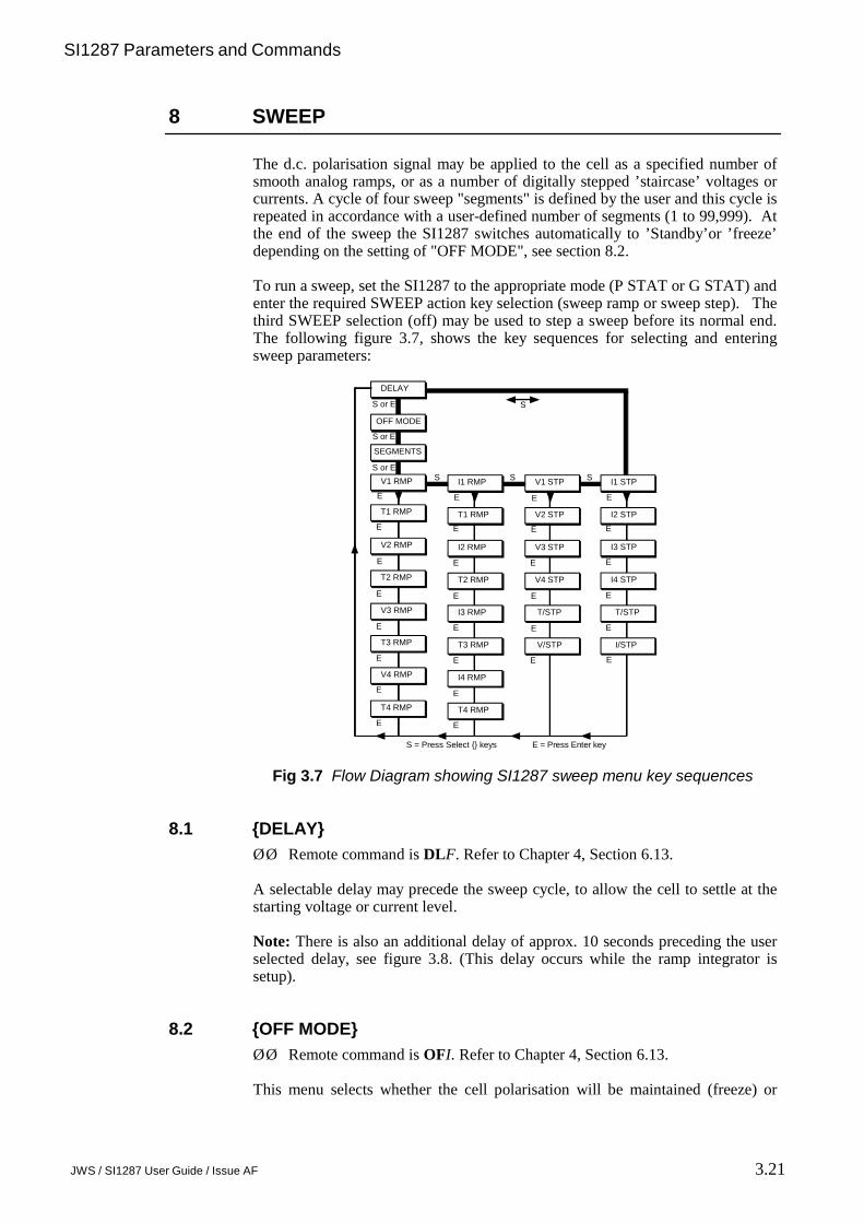
To run a sweep, set the SI1287 to the appropriate mode (P STAT or G STAT) andenter the required SWEEP action key selection (sweep ramp or sweep step). Thethird SWEEP selection (off) may be used to step a sweep before its normal end.The following figure 3.7, shows the key sequences for selecting and enteringsweep parameters:
Fig 3.7 Flow Diagram showing SI1287 sweep menu key sequences
8.1 DELAY ØØ Remote command is DLF. Refer to Chapter 4, Section 6.13.
A selectable delay may precede the sweep cycle, to allow the cell to settle at thestarting voltage or current level.
Note: There is also an additional delay of approx. 10 seconds preceding the userselected delay, see figure 3.8. (This delay occurs while the ramp integrator issetup).
8.2 OFF MODE ØØ Remote command is OFI. Refer to Chapter 4, Section 6.13.
This menu selects whether the cell polarisation will be maintained (freeze) or
I1 RMP V1 STP I1 STP
T1 RMP T1 RMP V2 STP I2 STP
DELAY
OFF MODE
SEGMENTS
V1 RMP
V2 RMP
T2 RMP
V3 RMP
T3 RMP
V4 RMP
T4 RMP
I2 RMP V3 STP I3 STP
T2 RMP V4 STP I4 STP
I3 RMP T/STP T/STP
T3 RMP V/STP I/STP
I4 RMP
T4 RMP
E
E
E
E
E
E
EE
E
EE
E E
E
E
E
EE
E
E
EEE E
EEE E
SSSS or E
S or E
S or E S
S = Press Select keys E = Press Enter key

3.22 JWS / SI1287 User Guide / Issue AF
Chapter 3
whether the cell will be disconnected (standby), when the sweep ends or isstopped by the user.
8.3 SEGMENTS ØØ Remote command is SMF. Refer to Chapter 4, Section 6.13.
This menu selects the number of segments, ie. distinct ramps, or ’staircases’ to beapplied to the cell during the sweep. After segment number 4 the cycle begins torepeat itself.
8.4 V1 RMP ØØ Remote command is VAF to VDF. Refer to Chapter 4, Section 6.14.
This menu enables the analog ramp voltage sweep to be set up for use inpotentiostatic mode. The significance of the delay, the four RMP voltage levels(V1 to V4) and RMP time periods (T1 to T4), is shown in figure 3.8. In thisexample, five segments of the sweep cycle have been specified. At the end of thesweep, POL V is left set at the ’final level’ defined by this menu.
Limits on Ramp RateThe Ramp Rate (i.e., [Vn+1 - Vn]/Tn) must be in the range 100µV/s to 100V/s.
8.5 I1 RMP ØØ Remote command is JAF to JDF. Refer to Chapter 4, Section 6.14. This
menu enables the analog ramp current sweep to be set up for use ingalvanostatic mode.
It is exactly analogous to V1 RMP (figure 3.8), with four current (instead ofvoltage) levels (I1 to I4), and four time periods (T1 to T4) to be entered. At theend of the sweep, POL I is left set at the ’final level’ defined by this menu.
Note: It is not possible to set up the V1 RMP menu totally independently of theI1 RMP menu, because the two sets of time periods (T1 to T4) are stored atshared locations in the SI1287 memory.
Fig 3.8 Analog ramp sweep cycle
Volts
Time
FinalLevelV1
V2
V1
V2
V4
V3
USER
SEGMENT 1
SEGMENT 2
SEGMENT 3
SEGMENT 4
SEGMENT 5
T1 T2 T3 T4DELAY
RAMPSETUPTIME
≈10 secs

SI1287 Parameters and Commands
3.23 JWS / SI1287 User Guide / Issue AF
8.6 V1 STP ØØ Remote command is SAF to SDF. Refer to Chapter 4, Section 6.15.
This menu enables the digitally stepped voltage sweep to be set up for use inpotentiostatic mode.
Figure 3.9 shows the significance of the delay, the four STP voltage levels (V1 toV4), the time per step (T/STP) and the voltage change per step (V/STP). In thisexample, four segments have been specified.
Limits on V/STP ValuesThere are minimum permitted values of V/STP which depend on the maximumvoltage excursion of any part of the sweep from STP V1. These limits are asfollows:
When max. excursion from RMP V1 > 200mV:V/STP (or I/STP × standard resistor) must be >100µV;
When max. excursion from RMP V1 < 200mV and >20mV:V/STP (or I/STP × standard resistor) must be >50µV;
When max. excursion from RMP V1 < 20mV:V/STP (or I/STP × standard resistor) must be >5µV;
Fig 3.9 Digitally stepped sweep cycle
8.7 I1 STP ØØ Remote command is KAF to KDF. Refer to Chapter 4, Section 6.15.
This menu enables the digitally stepped current sweep to be set up for use ingalvanostatic mode.
It is analogous to V1 STP (Figure 3.9), with four current levels (I1 to I4), a timeper step (T/STP), and a current change per step (I/STP) to be entered. The limitson I/STP values are also analogous as in section 8.5.
Note: The V1 STP menu cannot be set up totally independently of the I1 STPmenu because the T/STP values are stored at a shared memory location.
V1
V2
V3
V4
V1
SEGMENT1
SEGMENT2
SEGMENT3
SEGMENT4
FINALLEVEL
TIMEDELAY
VSTP
TSTP
VOLTS

3.24 JWS / SI1287 User Guide / Issue AF
Chapter 3
8.8 STEPPED SWEEP: MINIMUM PERMITTED VALUES OF T/STP
The minimum permitted values of T/STP (seconds) for a stepped sweep, with theDVM TRIGGER set to sync, are shown in Table 3.5. If these limits are notobserved then error 52 will appear indicating ’Measurement rate not achievable insync. sweep’.
A maximum of four different DVM measurements can be made per sweep step;the SI1287 left-hand display window, right-hand display window, PAR1 andPAR2. This number may be reduced by either selecting ’blank’ for a displaywindow, or by selecting any of the four measurements to be the same quantity.
For example, if PAR1 and PAR2 are both POL, with both display windows set to’blank’, the ’number of measurements’ would be 1.
Table 3.5 Minimum Time/Step Values
Fast measurement, ’fast 3×9’, rely on setting the DVMs for their optimummeasurement rate, as follows :
For 1 or 2 measurements;(i) Use as a fixed DVM input range.(ii) Use a fixed standard resistor.(iii) Set DVM drift correct to OFF.(iv) Left-hand and right-hand DVM displays both TIME.
For 3 or 4 measurements;As above but excluding number (iv).
8.9 COMMANDS NOT ALLOWED DURING SWEEPThe following menu-change commands (via SI1287 front panel or Remotecontrol) are not allowed whilst a sweep is in progress. Error code 51 is madeavailable in each case.
I Measure: Resistor and I Limit (galvanostat), DVM: Averaging, Sweep: all settings.
The following action keys (or equivalent remote control commands) are notallowed whilst a sweep is in progress. Error code 51 is made available in eachcase.
P’STAT/G’STAT, BIAS REJECT and STORE/RECALL.
Updating the left-hand or right-hand front panel DVM displays, or PAR1 orPAR2, during a stepped sweep (with DVM TRIGGER set to’sync’) may causeError 52 to be signalled.
DVM DigitsNumber of Measurements 5×9 4×9 3×9 fast 3×9
1 or 2 2.22 0.82 0.52 0.123 or 4 4.32 1.52 0.92 0.32

SI1287 Parameters and Commands
3.25 JWS / SI1287 User Guide / Issue AF
9 PLOT
The measurement results may be plotted on a suitable digital plotter via the GPIBport of SI1287.
Note: During plotting, set the DATA OUTPUT GPIB menu to [off], to preventcorruption of the signals to the plotter.
9.1 X ITEM ØØ Remote command is XII. Refer to Chapter 4, Section 6.21.
The item to be plotted along the X-axis is selected via this menu. Item selectionsare in terms of PAR1 and PAR2 (see section 9.5). Any item choice requires theentry of values for X MIN, X MAX and X ORIGIN, which are defined below:
Fig 3.10 The plotting field
9.2 Y ITEM ØØ Remote command is YII. Refer to Chapter 4, Section 6.21.
Corresponds to the X ITEM menu.
9.3 SIZE ØØ Remote command is PZI. Refer to Chapter 4, Section 6.21.
Two standard plot sizes are avaliable for selection: [A4] or [A3].
Alternatively, the size, aspect ratio, and plot position may be selected via the[variable] menu.
Figure 3.11 defines the plotting field coordinates VX MIN, VY MIN, VX MAXand VY MAX. They are measured in units of 0.025mm from a reference originwhich is nominally at the lower left-hand limit of the plotting area.
PLOT BORDER
X MIN X ITEM X MAX
Y MAX
Y ITEM
Y MIN
AXES
ORIGIN
(X ORIGIN, Y ORIGIN)

3.26 JWS / SI1287 User Guide / Issue AF
Chapter 3
9.4 TEXT ØØ Remote command is PTI. Refer to Chapter 4, Section 6.21.
With TEXT selected as [ON] during axes plotting, the X- and Y-axis areannotated with their minimum and maximum values, items and units ifappropriate. Otherwise, axes appear without any annotation.
Fig 3.11 Coordinates of the plotting field
9.5 TITLE ØØ Remote command is PHI. Refer to Chapter 4, Section 6.21.
This menu enables a title of upto 20 alphanumeric characters to be printed at thetop of the plot, just above the border.
The title appears on the top left-hand side or the top right-hand side of the plot,according to whether the selected plot X ORIGIN is nearer the left-hand or theright-hand side, respectively. This feature enables two plots, with separate titlesand Y ITEMs, to be superimposed on a share X-axis.
[off]No title is printed.
[on]A title is printed according to what is selected for STRING:
1. [old]The title already stored in this menu appears.
2. [new]A new title may be entered and stored in CHARACTERS. It is displayedbetween the < > brackets. Use the DIGIT/[ ] keys to move the cursor, andthe rotary knob to select the character required at each cursor position.Finally press ENTER to store the title.
3. [copy]The title printed is a copy of the last title to be called up via theSTORE/RECALL RECALL menu.
REFERENCE
PLOTTING
(VX MIN, VY MIN)
ORIGIN
(VX MAX, VY MAX)
FIELD
PAPER

SI1287 Parameters and Commands
3.27 JWS / SI1287 User Guide / Issue AF
9.6 GRID ØØ Remote command is GTI. Refer to Chapter 4, section 6.21.
With GRID selected [off] during axes plotting, the divisions along the X- andY-directions of the plot borders are marked by short lines only. With GRIDselected [on], the division marks are extended completely across the graph in bothdimensions to form a grid superimposed on the plot.
9.7 MODE ØØ Remote command is VEI. Refer to Chapter 4, Section 6.21.
[point]Plotted points are left unconnected.
[vector]Adjacent plotted points are joined by straight lines.
9.8 DEVICE ØØ Remote command is PDI. Refer to Chapter 4, Section 6.21.
The plotter type is selected via this menu. The GPIB plotter section of the SI1287is compatible only with digital plotters using either of the following two systems:
[HPGL]Hewlett-Packard Graphics Language.
[ESGL]Enertec Schlumberger Graphics Language.

3.28 JWS / SI1287 User Guide / Issue AF
Chapter 3
10 DATA OUTPUT
This section of the menu allows the user to enable or disable any of the possibledevices, configure the GPIB for remote control and set up the filing ofmeasurements. The various output formats are described in Chapter 4.
10.1 RS-423 ØØ Remote command is RSI. Refer to Chapter 4, Section 6.19.
The RS-423 serial interface port. Two selections are possible, other than [off]:[on] and [dump] (see chapter 4 for descriptions of these output formats).
10.2 GPIB ØØ Remote command is GPI. Refer to Chapter 4, Section 6.19.
General Purpose Interface Bus. Four selections are possible, other than [off]:[long on], [short on], [long dump], and [short dump] (see chapter 4 fordescriptions of these output formats).
After selecting one of these four options, further selections are made available ;
• Serial Poll ØØ Remote command is SVI.Enter an integer to configure the SI1287 to interrupt the GPIB controllerwhen a particular event (defined by the integer) occurs.
• Parallel Poll ØØ Remote command is PPI.Enter an integer to define which of the eight GPIB data lines is to be usedby the SI1287 to give a parallel poll response, indicating whether it isrequesting service or not.
• PP Sense ØØ Remote command is SEI.Parallel Poll Sense.
[true]signifies that when the data line carries a "1" the SI1287 is requestingservice.
[false]signifies that when the line carries a "0" the SI1287 is requesting service.
• O/P Terminator Ø Ø Remote command is OTI.Output Terminator. The character terminating each line of data.
cr = carriage returnlf = line feedEOI = end or identify.
• O/P Separator Ø Ø Remote command is OSI.Output Separator. The character separating the line of data into fields.
If [term.] is selected, the separator character is set to be the same as theterminator character.

SI1287 Parameters and Commands
3.29 JWS / SI1287 User Guide / Issue AF
10.3 FILE ØØ Remote command is FLI. Refer to Chapter 4, Section 6.18.
A section of memory used to store DVM measurement results, for later recall orfurther external processing if required. Each result is stored as a block of threeitems; parameter 1, parameter 2, and time. Parameters 1 and 2 should be chosenbefore the file is switched on, form the list of possible parameters (via the PAR1and PAR2 menus, see section 10.5).
10.4 FILE SIZE ØØ Remote command is FSI. Refer to Chapter 4, Section 6.18.
The number of memory blocks (up to ~ 450) allocated to the file.
File memory is shared with up to 10 menu set-up stores, which use 16 memoryblocks each. Thus the maximum number available to the file varies with howmany stores are in use.
A result is sent to the file whenever it is switched [on] and a measurement hasbeen completed. If more results are sent to the file than its size permits, theearliest filed results are discarded to make room for the latest.
10.5 PAR1 and PAR2ØØ Remote command is PXI and PYI. Refer to Chapter 4, Section 6.17.
These select the two items to be filed as parameter 1 and parameter 2,respectively. ’Time’ is always filed.
PAR1 and PAR2 also limit the choice of X ITEM and Y ITEM in the PLOTmenu and what can be transmitted via the SI1287 output ports to external devices.
10.6 FL O/PØØ Remote command is FDI. Refer to Chapter 4, Section 6.18.
This menu selects which two of the three measurement items stored in each fileblock are to be displayed.
10.7 HEADINGØØ Remote command is RHI. Refer to Chapter 4, Section 6.19.
Controls the output of headings above the columns of measurements sent to theRS423 port and to the GPIB when it is in Talk Only mode. When selected [on]column headings are printed above a set of measurements and also whenevermenu changes are made which invalidate the existing column headings.
10.8 ERROR BEEP
ØØ Remote command is EBI. Refer to Chapter 4, Section 6.25.
Error tone switch. Selecting [off] stops the error ’beep’.
3.30 JWS / SI1287 User Guide / Issue AF
Chapter 3
11 DIRECT ACTION KEYS
This section refers to the action keys, which apply previously set up parameters tothe cell, as soon as they are pressed.
11.1 ON/STANDBYØØ Remote command is PWI. Refer to Chapter 4, Section 6.1.
Controls connections to three of the cell terminals: CE, RE1 and RE2.
/on/ all connections made and polarisation drive applied, in a sequencedetermined by what has been selected for the I MEASURESTANDBY and ON MODE menus.
/standby/ connections isolated, as determined by what has been selected forthe I MEASURE STANDBY menu.
11.2 P STAT/G STATØØ Remote command is POI. Refer to Chapter 4, Section 6.1.
Selects potentiostatic or galvanostatic cell drive.
11.3 IR COMP/RPCØØ Remote command is CCI. Refer to Chapter 4, Section 6.8 & 6.11.
In potentiostatic mode, this key is three-state and selects IR Compensation, orReal Part Correction (as set up via the IR COMP/RPC menu), or neither. Ingalvanostatic mode the key becomes two-state, selecting RPC or ’off’.
11.4 LIMIT B’WIDTHØØ Remote command is SYI. Refer to Chapter 4, Section 6.4.
Applies the reduced bandwidth operation (as set up via the BANDWIDTH menu)to the cell drive amplifier. With limit bandwidth ’ON’ (LED illuminated) thebandwidth setup via the BANDWIDTH menu will be used. With limit bandwidth’OFF’ a default bandwidth type C is used.

SI1287 Parameters and Commands
3.31 JWS / SI1287 User Guide / Issue AF
11.5 BIAS REJECTØØ Remote command is BRI. Refer to Chapter 4, Section 6.12.
Rejects the d.c. component from the SI1287 voltage and current outputs (as set upvia the CONDITION menu).
[fixed] rejection set up: key has ’on’/’off’ action.
[auto] rejection set up: switching ’on’ (with the SI1287 is ’on’ mode)causes the d.c. component of the measurement presently beingmade to be evaluated, stored, and rejected from all subsequentmeasurements, until BIAS REJECT is switched ’off’.
To re-evaluate the biases, switch ’off’ then ’on’ again.
11.6 DVM RUNØØ Remote command is RUI. Refer to Chapter 4, Section 6.16.
Operates the DVMs according to what has been selected via the DVMTRIGGER menu. Pressing the DVM RUN key has no effect if [external] or[sync] have been selected for the TRIGGER menu. The LED on the key glowsonly whilst a measurement is actually taking place; this includes measurementstriggered externally or during a sweep cycle.
11.7 STORE/RECALLAllows up to ten menu selections to be stored and recalled. Each stored selectionmay be titled with a string of up to 20 characters and spaces chosen from thefollowing:
ABCDEFGHIJKLMNOPQRSTUVWXYZabcdefghijklmnopqrstuvwxyz%+-,./:0123456789
Note: This facility shares memory with the history file, so its use affects theFILE SIZE.
STOREØØ Remote command is SRI,S. Refer to Chapter 4, Section 6.25.
Enter an integer ’n’ to copy existing menu selections to store number ’n’. Thesequence after selecting STORE is:
NUMBER RECALL STORE ( ) (e.g.) 8 STORE (8) ENTER STORE 8 <_ >
Use the DIGIT/[ ] keys to move the cursor, and the rotary knob to select thecharacter required at each cursor position. Finally, press ENTER to store theexisting menu setup.

3.32 JWS / SI1287 User Guide / Issue AF
Chapter 3
RECALLØØ Remote command is RCI. Refer to Chapter 4, Section 6.25.
Enter an integer ’n’ to recall the contents of store ’n’ to set up the stored menuselections.
The sequence is then similiar to that for STORE, except that ENTERing therequired store number, the relevant title is displayed to confirm the user’s choice.Press CLEAR to exit from the sequence if the wrong store has been selected.Otherwise, press ENTER to recall the stored menu setup.
RECALL also erases the file contents and sets FILE SIZE to 200 blocks,switches the SI1287 to ’standby’, DVM RUN to ’off’, PLOT to ’off’, DVMNULL to ’off’ and DVM TRIGGER to ’single’.
CLEARØØ Remote command is CLI. Refer to Chapter 4, Section 6.25.
Enter an integer ’n’ to erase the contents of store ’n’.
As in RECALL, the title of the store (if any) is displayed as a check before anyerasure takes place.
11.8 LOCALØØ Remote command is LL. Refer to Chapter 4, Section 6.25.
Returns the SI1287 to local control (i.e. via the front panel) from the remote stateprovided Local Lockout has not been asserted by an external controller.

SI1287 Parameters and Commands
3.33 JWS / SI1287 User Guide / Issue AF
12 INDIRECT ACTION KEYS
This section refers to the action keys, which are pressed repeatedly to stepthrough a list of selections until the one required is displayed.
12.1 SWEEPØØ Remote command is SWI. Refer to Chapter 4, Section 6.13.
Applies the sweep polarisation to the cell (as set up via the SWEEP menu). Avoltage or current sweep is initiated, if the SI1287 is in P STAT or G STATmode, respectively. Selecting sweep ramp or sweep step initiates an analogramp or a digitally stepped sweep, respectively.
When the SWEEP action key is pressed, its LED flashes on and off during asweep initialisation period (possibly several seconds), and continues to flashduring the user-selected delay (if any). It glows steadily, only when the sweepitself starts, switching off at the end. For stepped sweeps the initialisation periodmay be too short to cause the LED to flash.
Selecting sweep off will cause the sweep to halt. The polarisation will be heldat the current level if OFF MODE is set to freeze. Otherwise the cell will bedisconnected.
CAUTION: During the sweep initialisation period the existing value of POL V(or POL I) applied briefly to the cell before the sweep generator has settled to theproper starting value. To avoid risk of damage to sensitive cells, set ON MODE,in the I MEASURE menu, to rest V/I.
12.2 PLOTØØ Remote command is PLI. Refer to Chapter 4, Section 6.21.
Allows the selection of a plotting action (as set up via the PLOT menu).
graph Causes measurements to be plotted, if available. Only the graphitself is drawn by means of this selection; plot borders, axes,title, grid and annotations are not output.
axes Draws the plot borders, division marks (or grid if GRID is’on’), annotations (if TEXT is ’on’), title (if TITLE and TEXTare ’on’) and axes. If the origin is set to coincide with a cornerof the plotting field, the axes are not separately visible in theplot.
min. & min. These selections move the plotter pen (in the ’up’ position)to the lower left-hand corner, or to the upper right-hand cornerrespectively, of the plotting field set up via the PLOT SIZEmenu. These two selections can be used to check the size andposition of the plotting field before a plot is run.
zero ’Parks’ the plotter pen currently in use in its home position.
off Stops the plotting of the graph (not the axes), and ’parks’ thepen.

3.34 JWS / SI1287 User Guide / Issue AF
Chapter 3
12.3 FILE/STATUSØØ Remote command is VFI. Refer to Chapter 4, Section 6.18 & 24.
display file Displays the first line (according to the FL O/P menu setup).The SELECT á â keys, or rotary knob, are used to step upor down the file.
clear file Erases the file contents.
list file Lists every line of the file in quick succession. The sequence istoo fast to follow on the display, and is intended for listing thefile to an external device via the SI1287 output ports.
This selection is used to plot data from the file. First enterPLOT graph to enable plotting; then enter list file to plotthe filed data (according to the PLOT menu selections inoperation).
status Displays nine lines of SI1287 status information. The lines arestepped to, in either direction, as for display file:
• [Free memory blocks. Last three error codes]• [Upper limit of last floating point parameter entered]• [Lower limit of last floating point parameter entered]• [History file status: number of readings; number filed]• [Menu set up stores in use]• [RS423: baud rate]• [GPIB: mode, state]• [GPIB: address, control]• [GPIB: STB, I/P terminator]
The DVM(s) must not be running when the file is displayed,cleared, or listed, otherwise Error 45 occurs; stating illegal fileaccess.
12.4 BREAK/SELF TESTØØ Remote command is BKI. Refer to Chapter 4, Section 6.20.
break Halts the present operation and transfers the SI1287 to thestandby state (as set up via the I MEASURE STANDBYmenu). DVM RUN, SWEEP and PLOT are switched ’off’.
check Starts a self test routine on all SI1287 digital circuitry, displayspixels and symbols, keyboard LEDs and key functioning. Theuser presses ENTER at appropriate stages to move to the nextgroup of checks. On completion the standby state is entered;DVM RUN, SWEEP and PLOT are switched to ’off’.
Any failure causes the test routine to abort and a fail code isgenerated. A successful check results in a ’PASS’ message,which also shows the SI1287 software issue number in use.

SI1287 Parameters and Commands
3.35 JWS / SI1287 User Guide / Issue AF
test Note: The 12861 Test Module must be connected to the SI1287before this selection is entered.
Starts a self test routine which includes the entire checksequence. Additionally, the SI1287 analog circuitry is selftested.
Success or failure of the test routine is the same as check. Oncompletion the standby state is entered.
reset Clears any existing menu set ups, returning all parameters totheir default states except the file and stores, which areretained.
initialise As for reset, but the file and stores are also cleared.
time Ø Ø Remote command is TMI,I. Refer to Chapter 4, Section 6.24.
The SI1287 internal clock stops whenever the power isswitched off and restarts from zero at every power up, or whenthe instrument is initialized or reset.
This selection allows the clock to be reset to a specific timewhenever required:
HOUR ( ) Enter the required hour between the round brackets.
HOUR MIN. ( ) Enter the required minute between the round brackets.
Note: After break, check, test, reset, or initialize has beencommanded (via the front panel or remotely), a 1 second pausemust be allowed before the next command. This is to give theSI1287 time to execute the BREAK/SELF TEST command.

3.36 JWS / SI1287 User Guide / Issue AF
Chapter 3
13 MENU SUMMARY
This summary is intend as a memory aid for experienced users.
The following tables summarise all the SI1287 menus and action keys.
Note: a) Bold typeface denotes default value.
b) Braces denote a choice via the SELECT keys, e.g. RESISTOR.
c) Square brackets denote choice via the RANGE/[ ] keys, or the rotaryknob, e.g. [auto].
d) Round brackets denote that a numerical entry is required, e.g. (0).Limits are shown for numerical values.

SI1287 Parameters and Commands
3.37JWS / SI1287 User Guide / Issue AF
SET UP MENU PARAMETER SELECTION
[auto] I LIMIT [2µA] [20µA] [200µA] [2mA] [20mA] [200mA] [2A]RESISTOR
[0.1Ω] [1Ω] [10Ω] [100Ω] [1kΩ] [10kΩ] [100kΩ] [1MΩ]
O/L TYPE [cut-out] [limit] [warning]
STANDBY [all o/c] [CE o/c]
I MEASURE
ON MODE [pol V/I] [rest V/I]
POL V (0) -14.5 TO +14.5V [V] [mV] [µV]
POL I (0) -2 TO +2A [A] [mA] [µA] [nA]
POLARISATION
POL I/P [×.01] [×1]
[feedback] IRC Ω (0) 0 TO 1E+6Ω [mΩ] [Ω] [kΩ] [MΩ]
OFF TIME (27µs) 27E-6 TO 1.3E-3s [µs] [ms]
OFF:ON (1:1) 1 TO 255
IR COMP
[sampled]
REAR O/P [actual] [sample + hold]
IR COMP/RPC
RPC Ω (0) 0 TO 1E+6Ω [mΩ] [Ω] [kΩ] [MΩ]
P STAT BW [type A] [type B] [type C] [type D] [type E] [type F] [type G] [type H] [type I] [type J]
BANDWIDTH
G STAT BW [type A] [type B] [type C]
[auto]V REJECT
[fixed] V VAL (0) -14.5 TO +14.5V [V] [mV] [µV]
[auto]I REJECT
[fixed] I VAL (0) -2 TO +2A [A] [mA] [µA] [nA]
LP FILTER [off] [on]
V×10 [off] [on]
CONDITION
I×10 [off] [on]
DIGITS [5×9] [4×9 50Hz] [4×9 60Hz] [3×9]
RANGE [auto] [200mV] [2V] [20V] [50V]
TRIGGER [single] [recycle] [external] [sync]
DRIFT CORR. [off] [on]
AVERAGING [off] [on]
DVM
NULL [off] [on] [evaluate]
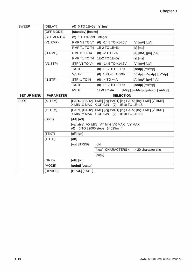
3.38 JWS / SI1287 User Guide / Issue AF
Chapter 3
DELAY (0) 0 TO 1E+5s [s] [ms]
OFF MODE [standby] [freeze]
SEGMENTS (2) 1 TO 99999 integer
RMP V1 TO V4 (0) -14.5 TO +14.5V [V] [mV] [µV]V1 RMP
RMP T1 TO T4 1E-2 TO 1E+5s [s] [ms]
RMP I1 TO I4 (0) -2 TO +2A [A] [mA] [µA] [nA]I1 RMP
RMP T1 TO T4 1E-2 TO 1E+5s [s] [ms]
STP V1 TO V4 (0) -14.5 TO +14.5V [V] [mV] [µV]
T/STP (0) 1E-2 TO 1E+5s [s/stp] [ms/stp]
V1 STP
V/STP (0) 100E-6 TO 29V [V/stp] [mV/stp] [µV/stp]
STP I1 TO I4 (0) -4 TO +4A [A] [mA] [µA] [nA]
T/STP (0) 1E-2 TO 1E+5s [s/stp] [ms/stp]
SWEEP
I1 STP
I/STP 1E-9 TO 4A [A/stp] [mA/stp] [µA/stp] [ nA/stp]
SET UP MENU PARAMETER SELECTION
X ITEM [PAR1] [PAR2] [TIME] [log PAR1] [log PAR2] [log TIME] [√ TIME] X MIN X MAX X ORIGIN (0) -1E18 TO 1E+18
Y ITEM [PAR1] [PAR2] [TIME] [log PAR1] [log PAR2] [log TIME] [√ TIME] Y MIN Y MAX Y ORIGIN (0) -1E18 TO 1E+18
[A4] [A3] SIZE
[variable] VX MIN VY MIN VX MAX VY MAX(0) 0 TO 32000 steps (×.025mm)
TEXT [off] [on]
[off]
[old]
[new] CHARACTERS < > 20 character title
TITLE
[on] STRING
[copy]
GRID [off] [on]
MODE [point] [vector]
PLOT
DEVICE [HPGL] [ESGL]

SI1287 Parameters and Commands
3.39JWS / SI1287 User Guide / Issue AF
RS-423 [off] [on] [dump]
[off]
SERIAL POLL (0) 0 TO 255 integer
PARALLEL POLL (0) 0 TO 8 integer
PP SENSE [true] [false]
O/P TERMINATOR [cr lf] [cr lf+EOI] [cr] [cr+EOI]
GPIB
[long on] or[short on]
or[long dump] or[short dump]
O/P SEPARATOR [comma] [term.]
FILE [off] [on]
FILE SIZE (200) 1 TO ~450 blocks
PAR1 [CE] [RE1] [RE2] [∆RE] [∆RE-Bi] [I] [I-Bi] [δ∆RE/δI] [δI/δ∆RE][POL] [∑POL] [DVM I/P]
PAR2 [CE] [RE1] [RE2] [∆RE] [∆RE-Bi] [I] [I-Bi] [δ∆RE/δI] [δI/δ∆RE][POL] [∑POL] [DVM I/P]
FL O/P [par1, par2] [time, par1] [time, par2]
HEADING [off] [on]
DATA OUPUT
ERROR BEEP [off] [on]
SET UP MENU SELECTION
ONSTANDBY
«standby» «on»
P STATG STAT
«P stat» «G stat»
IR COMPRPC
«neither» «IR COMP» * «RPC» *P STAT only
LIMITBANDWIDTH
«off» «on» (setting limit bandwidth to off causes a default bandwidth ’c’ to be used).
[fixed] set up : «off» «on»BIAS REJECT
[auto] set up : «off», measure, «on»
DVM RUN «off» «on»
SWEEP sweep off sweep ramp sweep step
PLOT graph axes min. max. zero off
FILE/STATUS display file clear file list file status
STORE ( ) 0 TO 9 < > 20 character title
RECALL ( ) 0 TO 9
STORE/RECALL
CLEAR ( ) 0 TO 9
LOCAL «go to local»
break check test reset initialise
HOUR ( ) 0 TO 99
BREAK/SELF TEST time
HOUR MIN ( ) 0 TO 59

3.40 JWS / SI1287 User Guide / Issue AF
Chapter 3

Remote Control
4.1 CSB/SI1287 User Guide/Issue AA
Chapter 4Remote Control
Section Page
1 Introduction .................................................................... 4.3
2 RS423 Interface ............................................................... 4.42.1 RS423 Connector .............................................................. 4.42.2 Serial Link Settings ........................................................... 4.42.3 Baud Rate Settings ............................................................ 4.42.4 Input Terminator ............................................................... 4.4
3 GPIB Interface ................................................................ 4.53.1 GPIB Capability Codes ..................................................... 4.53.2 GPIB Connector ................................................................ 4.53.3 GPIB Switches .................................................................. 4.63.3.1 Device Address ............................................................... 4.63.3.2 Input Terminator ............................................................. 4.63.3.3 Talk Only ....................................................................... 4.63.4 Serial Poll/Parallel Poll ..................................................... 4.73.4.1 Serial Poll ....................................................................... 4.73.4.2 Parallel Poll .................................................................... 4.83.5 GPIB Plotting .................................................................... 4.9
4 Remote/Local Facility ................................................... 4.104.1 Local Lock-out ................................................................ 4.12
5 Output Formats ............................................................. 4.135.1 RS423 Port : Tabular Output Format .............................. 4.135.2 GPIB Port : Tabular Output Format ................................ 4.135.3 GPIB Port : Compressed ASCII Output ......................... 4.135.4 GPIB & RS423 Ports : Dump Mode (Binary) Format .... 4.145.4.1 4-Byte Floating Point Format : Dump Mode ................ 4.155.5 Output Terminators & Separators ................................... 4.165.5.1 RS423 Port .................................................................... 4.165.5.2 GPIB Port ..................................................................... 4.16
6 SI1287 Remote Commands .......................................... 4.17
Figure
4.1 RS423 Serial Interface Connector .................................... 4.44.2 Baud Rate Switches ........................................................... 4.44.3 GPIB Interface .................................................................. 4.54.4 GPIB Switches ................................................................... 4.64.5 Remote/Local state diagram ........................................... 4.104.6 Remote/Local state diagram with Local Lock-out .......... 4.11

4.2 CSB/SI1287 User Guide/Issue AA
Chapter 4

Remote Control
4.3 CSB/SI1287 User Guide/Issue AA
1 INTRODUCTION
The instrument is fitted, as standard, with a GPIB interface and an RS423interface for communication with remote devices.
The RS423 is intended mainly for data output to a printer, VDU, etc, but may beused for instrument control if required. The RS423 Serial Interface is alsocompatible with RS232.
The GPIB allows full control and data input/output. For those unfamiliar with theGPIB, here are the meanings of the more commonly used terms.
• A "Device" is any instrument compatible with GPIB operation.
• The term "Interface", with regard to a GPIB device, means the logiccircuitry and bus drivers that deal with the signals sent on the bus, inaccordance with the GPIB protocol.
• A "Talker" is a device that can send information via the GPIB, whilst a"Listener" is a device that can receive this information.
• A "Controller" is a device that is able to assign Talker and Listener roles toitself and to other devices on the GPIB. This allows the controller to sendcontrol messages to devices on the GPIB and to receive measurement andcontrol status information from them. The overall purpose of a controller isto coordinate the operation of all devices on the GPIB, in accordance with acontrol program.
The documents which fully define the GPIB are the IEEE Standard 488-1978, theIEC 625-1 and the ANSI Standard MC1.1 (from the first standard, the GPIB isalso widely known as the IEEE 488 Interface).

4.4 CSB/SI1287 User Guide/Issue AA
Chapter 4
2 RS423 INTERFACE
2.1 RS423 CONNECTION DETAILSConnection to the RS423 Serial Interface port is made via the 25-way subminiature D-type connector on the rear panel. The pin connections are shown inFigure 4.1. The SI1287 is configured as DCE (Data Communication Equipment).
Fig 4.1 RS423 Serial Interface Connector
Pin 1 = Ground Pin 6 = DSR (Data Set Ready) from SI1287Pin 2 = Serial Data to SI1287 Pin 7 = GroundPin 3 = Serial Data from SI1287 Pin 8 = DCD (Data Carrier Detect) from SI1287Pin 4 = RTS (Request to Send) to SI1287 Pin 20 = DTR (Data Terminal Ready) to SI1287Pin 5 = CTS (Clear to Send) from SI1287
RTS is biased active within the SI1287. If this signal is left unconnected then theSI1287 will output data when available. DCD is always active while theinstrument is on. The DSR output follows the state of the DTR input.
2.2 SERIAL LINK SETTINGS• Data Bits: 8• Stop Bits: 1• Parity: None• Baud Rate: 110 to 9600 (switch selectable)• Handshake: Hardware (CTS, RTS)
2.3 BAUD RATE SETTINGSThe Baud Rate is set to the required value (from 110 to 9600) via the 8-wayswitch block on the SI1287 rear panel.
Fig 4.2 Baud Rate Switches
Only one of the eight switches should be set in the down position, towards therequired baud rate.
2.4 INPUT TERMINATORThe Command Code terminator character is fixed as CR (Carriage Return).
13 1
25 14viewed from rear the of SI1287
Baud Rate
110
1200 600 300 150 2400
9600 4800

Remote Control
4.5 CSB/SI1287 User Guide/Issue AA
3 GPIB INTERFACE
3.1 GPIB CAPABILITY CODESThe capability of a device interface can be identified by the series ofalphanumeric codes, which normally appear against the bus connector. Thealphabetic part of the codes represent a basic interface function, such as a talkeror listener, whilst the numeric part represents the capability of that function.
The GPIB Interface in the instrument conforms to the following sub-functionswithin the standard, as listed on the rear panel:
SH1 Source handshake.AH1 Acceptor handshake.T5 Basic talker, Serial poll, Talk only selectable, unaddressed if MLA
(My Listener Address).TE0 No Extended talker capability.L4 Basic listener, no listen only mode, unaddressed if MTA
(My Talker Address).LE0 No extended listener capability.SR1 Complete service request capability.RL1 Complete Remote/Local capability, with Local Lock-Out.PP2 Parallel poll with Local configuration. DC1 Complete device clear capability, including selective device clear.C0 No controller capability. DT0 No device trigger capability.E1 Open Collector drivers.
3.2 GPIB CONNECTORConnection to the GPIB is made via the 24-way connector on the IEEE 488/GPIBinterface; see Figure 4.3. The pin connections conform to the IEEE 488, 1978standard.
Fig 4.3 GPIB Interface
IEEE 488 GPIB INTERFACE
SH1 AH1 T5 TE0 L4 LE0SR1 RL1 PP2 DC1 C0 DT0 E1
0
11 16 8 4 2
F1
TALK ONLY F2 ADDRESS

4.6 CSB/SI1287 User Guide/Issue AA
Chapter 4
3.3 GPIB SWITCHESSome interface functions are set by miniature toggle switches on the rear panel ofthe instrument. These functions are described in the following sections.
Once the GPIB switches have been set the instrument must read them, so thattheir settings can be implemented. The switches are read automatically atpower-on, or when an INITIALIZE or RESET instruction is given. The GPIBswitch functions are as follows :
Fig 4.4 GPIB switches (all switches shown in off position)
3.3.1 Device AddressThe ADDRESS switches select the GPIB address for the SI1287. To avoidproblems associated with mixing binary and ASCII information, two GPIB portsare provided. The two ports are serviced through the same GPIB connector, buteach has its own software address.
The address for the ASCII input/output port is the Major address. This addressshould always be an even number, so the left-hand switch "1" should always be inthe ’off’ position. If an odd address is selected on the switches, the SI1287responds to the preceding even address. This address +1 is the Minor address andis assigned automatically, for high speed binary dump outputs.
3.3.2 Input TerminatorSwitches F1 and F2 select the terminating character for the GPIB inputcommands to the SI1287 as follows :
The choice of command terminator is usually determined by the type of controllerused and should be defined in the relevant controller handbook. Any commandterminator other than the one selected is ignored by the interface. The outputterminator is set by the command OTI see section 6.19.
3.3.3 Talk Only SwitchThe Talk only mode can be selected for the GPIB interface by switching the TalkOnly switch to the ’on’ position. When switched on the instrument can act as atalker only, to drive a listen-only device, such as a plotter, without the aid of aGPIB controller. When switched off the instrument can act as a listener or as atalker, as commanded by the GPIB controller.
1 16 8 4 2 F1
TALK ONLY F2
0 (0FF)
1 (ON)
ADDRESS
Switch F1 Switch F2 Terminator Selected
0101
0011
LF (Line Feed).CR (Carriage return).
; (Semicolon).EOI (End or Identify).

Remote Control
4.7 CSB/SI1287 User Guide/Issue AA
3.4 SERIAL POLL/PARALLEL POLLThe instrument can be configured to request service from a GPIB controller whena particular event has occurred, e.g. on end of operation, or measurement ready.The controller may then poll the devices on the GPIB to find the source of therequest. Two types of polling can be used, serial or parallel.
3.4.1 Serial PollA serial poll interrogates each device in turn, to examine its status byte. Thestatus byte holds the status of all events for which it is possible to request service.
Status Byte
To display the contents of the status byte (STB) on the SI1287 front panel, pressthe FILE/STATUS action key and select status. The ninth line of status ’GPIB:STB, I/P terminator’ shows the STB bit values, updated every second.
When an event occurs the corresponding bit is set to ’1’. The events representedare:
Bit Event Comment
128 Data Ready. Set when data is available for ASCII or binaryoutput to the GPIB.
64 Request for service. Set to ’1’ when the instrument requests service.This bit allows the controller to identify thesource of the request. All 8 bits of the statusbyte appear on the DIO lines when theinstrument is serial polled.
32 Not Used.
16 End of File. Final result written to, or read from, historyfile.
8 End of Plot. Instrument has finished a plot..
4 End of Sweep. Intrument has finished a sweep.
2 End of Measure. Instrument has finished a measurement.
1 Error. Set when an error affecting the other bits in theSTB is detected. It does not register all possibleSI1287 errors.
The values of all the bits, except bit 1 and bit 64, continuously follow statuschanges. If, for example, the instrument is measuring repetitively RECYCLE bit2 is set to ’1’ as each measurement is completed, then reset to ’0’ as a newmeasurement starts.
128Data
Ready
32Spare
1Error
2End of
Measure
4End ofSweep
8End of
Plot
16End of
File
64RQS
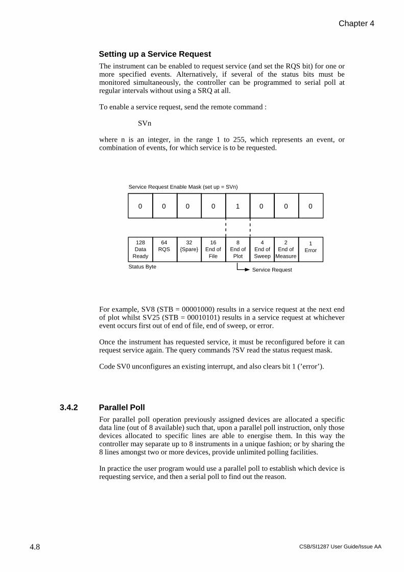
4.8 CSB/SI1287 User Guide/Issue AA
Chapter 4
Setting up a Service RequestThe instrument can be enabled to request service (and set the RQS bit) for one ormore specified events. Alternatively, if several of the status bits must bemonitored simultaneously, the controller can be programmed to serial poll atregular intervals without using a SRQ at all.
To enable a service request, send the remote command :
SVn
where n is an integer, in the range 1 to 255, which represents an event, orcombination of events, for which service is to be requested.
For example, SV8 (STB = 00001000) results in a service request at the next endof plot whilst SV25 (STB = 00010101) results in a service request at whicheverevent occurs first out of end of file, end of sweep, or error.
Once the instrument has requested service, it must be reconfigured before it canrequest service again. The query commands ?SV read the status request mask.
Code SV0 unconfigures an existing interrupt, and also clears bit 1 (’error’).
3.4.2 Parallel PollFor parallel poll operation previously assigned devices are allocated a specificdata line (out of 8 available) such that, upon a parallel poll instruction, only thosedevices allocated to specific lines are able to energise them. In this way thecontroller may separate up to 8 instruments in a unique fashion; or by sharing the8 lines amongst two or more devices, provide unlimited polling facilities.
In practice the user program would use a parallel poll to establish which device isrequesting service, and then a serial poll to find out the reason.
0 0 0 0 1 0 0 0
128Data
Ready
32Spare
1Error
2End of
Measure
4End ofSweep
8End of
Plot
16End of
File
64RQS
Status Byte
Service Request Enable Mask (set up = SVn)
Service Request

Remote Control
4.9 CSB/SI1287 User Guide/Issue AA
Setting up a Parallel PollThe instrument can be configured to give a parallel poll true/false response on aselected GPIB data line, to indicate whether or not the instrument is requestingservice. However, the instrument must first be configured for serial poll.
To set up a parallel poll configuration send the remote command :
PPn
where n is an integer from 1 to 8, defining which GPIB data line is to carry theresponse.
Sending PP0 unconfigures parallel poll.
To select the sense of the parallel poll line send the remote command SEn, wheren=1 signifies true and n=0 signifies false.
The parallel poll response is also cleared by any change to the serial poll value,and by power-off. Unlike serial poll, parallel poll need not be reconfigured aftereach service request.
3.5 GPIB PLOTTINGThe GPIB plot facility is compatible only with plotters using Hewlett-PackardGraphic Language (HPGL), or Enertec Schlumberger Graphics Language. Theseplotters require that the SI1287 output has ’comma’ as the output separator and’cr lf’ as the output terminator; both are default characters.
If the GPIB plotter can be put into Listen Only mode, it can be driven directlyfrom the SI1287 without needing a controller on the bus. To operate in this way,ensure that the DATA OUTPUT GPIB menu is set to [off], the default state, sothat only plotter commands are passed to the GPIB. Set the plotter to ListenOnly, and the SI1287 rear panel switch to Talk Only.
However, if the plotter has no Listen Only mode, a controller is necessary toinstruct the plotter to ’listen’ to the SI1287. To operate using a controller on theGPIB, set both plotter and SI1287 to normal Talker/Listener modes, and switchthe DATA OUTPUT GPIB menu to [off]. SRQ can be used to signal the endof plotting. In this case, configure the SI1287 to set bit 8 of the status byte at ’EndPlot’.
The PLOT menu is detailed in Chapter 3, section 9.

4.10 CSB/SI1287 User Guide/Issue AA
Chapter 4
4 REMOTE/LOCAL FACILITY
The REMOTE/LOCAL facility enables the SI1287 to receive commands fromeither a remote or a local source. The remote facility is provided via the GPIBInterface and has priority over other devices.
The SI1287 offers two forms of control under the heading LOCAL:
LOCAL 1 Commands accepted from the SI1287 front panel and/or from theRS423 port; the two sources have equal priority.
LOCAL 2 Commands accepted from the RS423 port only. No settings can bechanged from the front panel, but the LOCAL key and the mainON/OFF switch are still operative. The menu keys can be used toverify, but not alter, the state of the controls.
The status display shows "remote" when the instrument is inLOCAL 2 mode.
Fig 4.5 REMOTE/LOCAL state diagram.
On power up the SI1287 adopts LOCAL mode. The state diagram indicates howcontrol can be transferred from LOCAL 1 to LOCAL 2 to REMOTE and backagain.
Note: If the controller sends a REMOTE command, then the LOCAL state whichwas previously in force is resumed, once the REMOTE mode is relinquished.
The full set of instructions to transfer from LOCAL to REMOTE and vice-versais given in the IEEE Standard, where LOCAL 1 and LOCAL 2 are simplyreferred to as LOCAL.
LOCAL 1KEYBOARDAND RS423
PORTENABLED
LOCAL 2RS423PORTONLY
REMOTEGPIB
INTERFACEENABLED
LOCALKEY
PRESSED
RS423DEVICESENDS
LL
CONTROLLERASSERTSREMOTE
CONTROLLER SENDS"GO TO LOCAL" OR LOCAL KEY
PRESSED
CONTROLLERASSERTSREMOTE
CONTROLLER SENDS
"GO TO LOCAL" OR RS423 DEVICE
SENDS LL
POWERON STATE

Remote Control
4.11 CSB/SI1287 User Guide/Issue AA
Fig 4.6 REMOTE/LOCAL state diagram with LOCAL LOCK-OUT
LOCAL 1KEYBOARDAND RS423
PORTENABLED
LOCAL 2RS423PORTONLY
REMOTEGPIB
INTERFACEENABLED
LOCALKEY
PRESSED
RS423DEVICESENDS
LL
CONTROLLER SENDS"GO TO LOCAL" OR LOCAL KEY
PRESSED
CONTROLLERASSERTSREMOTE
CONTROLLER SENDS
"GO TO LOCAL" OR RS423 DEVICE
SENDS LL
POWERON STATE
CONTROLLERASSERTSREMOTE
LOCALLOCK-OUT
ON
CONTROLLERSENDS
"GO TO LOCAL"
CONTROLLER ASSERTS REMOTE
REMOTEGPIB
INTERFACEENABLED
WITH LOCALLOCK-OUT
LOCAL 2RS423PORT
WITH LOCALLOCK-OUT
REMOTEKEYBOARDAND RS423
PORT ENABLEDWITH LOCALLOCK-OUT
CONTROLLER SENDS"GO TO LOCAL"
CONTROLLERASSERTS REMOTE
LOCALLOCK-OUT
ON
LOCALLOCK-OUT
ON
REN FROM CONTROLLERCANCELS LOCAL LOCK-OUT

4.12 CSB/SI1287 User Guide/Issue AA
Chapter 4
4.1 LOCAL LOCK-OUTThe REMOTE/LOCAL facility described above can also have a LOCALLOCK-OUT condition superimposed by a command from the controller. OnceLOCAL LOCK-OUT is on, transfer of control from one device to another can beaccomplished only by the GPIB controller.
This facility can be used, for example, to prevent unauthorised front panelmanipulations affecting the settings of the SI1287. The state diagram in figure4.6 shows the relationship between the LOCAL LOCK-OUT feature to theREMOTE and LOCAL states previously shown in figure 4.5.
The LOCAL LOCK-OUT state is cancelled when the REMOTE ENABLE signal
from the controller is false, i.e. the controller sends REN.
Note that if the controller sends "GO TO LOCAL", then the LOCAL state whichwas previously in force is resumed.

Remote Control
4.13 CSB/SI1287 User Guide/Issue AA
5 OUTPUT FORMATS
Measurement results can be output as ASCII characters or as Binary data. TheASCII output can be interpreted by a controller or a printer whereas the binarycan only be interpreted by a controller. These outputs have the following formats.
5.1 RS423 PORT: TABULAR OUTPUT FORMAT In this mode, the ASCII coded results are presented in the form of a table,suitable for use with an RS423 compatible printer having a line width of 80characters or more. Carriage return plus line feed, plus several ASCII ’nul’characters (delay for carriage return), are automatically added as the outputterminator. Column headings may be either printed or suppressed.
To obtain tabular output, set the DATA OUTPUT RS423 menu to [on].
A 5 column sequence of headings is output:
(PARAMETER 1) (PARAMETER 2) ERROR 1 ERROR 2 TIME (units) (units)
Parameters 1 and 2 (with appropriate units) are chosen under DATA OUTPUTPAR1 and PAR2. Error 1 and 2 relate to PAR1 and PAR2 respectively, andreport any measurement errors (e.g. error 31, voltage DVM Overload). Time isgiven as hours, minutes, seconds and hundredths of seconds.
A sixth column, ’FILE No.’, is output when the file is listed via the RS423 port,and indicates the index number of the result.
5.2 GPIB PORT: TABULAR OUTPUT FORMATTo obtain a tabular output, set the DATA OUTPUT GPIB menu to either [longon] or [short on] and the Talk Only switch on the SI1287 rear panel to ’ON’. TheSI1287 then sends data to the GPIB ASCII port in a format suitable for GPIBcompatible printers. The [long on] column format is the same as for the RS423port and the column headings may either be printed or suppressed. With [shorton] selected, the TIME column is omitted.
For both long and short GPIB formats, the output terminator must be selected asdescribed in section 5.5.
5.3 GPIB PORT: COMPRESSED ASCII OUTPUTIn this mode the ASCII coded results are output in relatively compressed from,suitable for interpretation by a controller on the bus.
The SI1287 gives each parameter a constant field width of 12 ASCII characters(bytes), comprising a 6-digit fixed point part with polarity sign, and a 2-digitexponent with polarity sign :
±n.nnnnnE±nn

4.14 CSB/SI1287 User Guide/Issue AA
Chapter 4
Time is coded as four pairs of digits for hours (h), minutes (m), seconds andhundredths of seconds (s) respectively.
h h / m m / s s / s s
To obtain compressed ASCII output, set the DATA OUTPUT GPIB menu toeither [long on] or [short on] and the Talk Only switch on the SI1287 rear panelto ’OFF’.
With [long on] selected, each set of readings is output with the format:
±p.pppppE±pp / ±q.qqqqqE±qq / e1 / e2 / hh/mm/ss/ss//
PAR1 PAR2 ERRORS TIME
where errors 1 and 2 relate to PAR1 and PAR2, respectively; / represents theoutput separator, and // the output terminator. Select the required separator andterminator via the DATA OUTPUT GPIB menu; as described in section 5.5.
With [short on] selected, the TIME data are omitted and the output terminator issent after error 2.
5.4 GPIB & RS423 PORTS: DUMP MODE (BINARY) FORMAT Dump Mode format, in which results are compressed into a binary form tooccupy fewer bytes, is the fastest way to output data from the SI1287.
Each parameter consists of a four-byte floating-point number, compared with thetwelve bytes needed for ASCII.
Error codes and time output are expressed in BCD format. Thus each two digiterror code uses one byte and time uses four bytes giving tens and units of hours,tens and units of minutes, tens and units of seconds, and tenths and hundredths ofseconds:
h h m m s s s s
To obtain dump mode output, set the DATA OUTPUT GPIB menu to either[long dump] or [short dump], and the Talk Only switch on the SI1287 rear panelto ’OFF’ (for GPIB operation). Set the RS423 menu to [dump], which producesthe same format as the GPIB [long dump] selection.
With [long dump] selected, each set of readings is output with the format:
p p p p q q q q e1 e2 h h m m s s s s
PAR1 PAR2 ERRORS TIME
The following section 5.4.1 explains how to decode the four parameter bytesfrom binary to decimal notation. Output separators and terminators are not sentin dump mode format. However, in the case of GPIB operation only, EOI (EndOr Identify) is automatically asserted simultaneously with the last byte if either[cr + EOI] or [cr lf + EOI] has been selected via the DATA OUTPUT GPIBmenu.
With [short dump] selected, the bytes representing TIME are omitted, but theoutput format is otherwise identical.

Remote Control
4.15 CSB/SI1287 User Guide/Issue AA
5.4.1 4 - Byte Floating Point Format : Dump ModeA parameter is output in dump mode as a group of four 8-bit bytes. Encoded inthese bytes are the sign of the parameter, a binary exponent, and a mantissa:
The sign bit is 0 for a positive number, 1 for a negative number. The remainingseven bits of byte 1 give the binary exponent, in 2’s complement format. (Therefore negative exponents are indicated by the first of the seven bits being 1).
011 11112 ≡ 263 = 9.2 × 10¹⁸
. . . . . .
000 00102 ≡ 22 = 4000 00012 ≡ 21 = 2000 00002 ≡ 20 = 1111 11112 ≡ 2-1 = 0.5111 11102 ≡ 2-2 = 0.25
. . . . . .
100 00002 ≡ 2-64 = 5.4 × 10⁻²⁰
Bytes 2, 3 and 4 contain the mantissa part of the floating point number. Themantissa is always less than unity, so the ’binary point’ is shown preceding thefirst bit of byte 2.
Converting a four-byte binary number to decimal.
Example: Byte 1 11111110 (=25410)Byte 2 10000000 (=12810)Byte 3 00000000 (=010)Byte 4 00000000 (=010)
The msb of Byte 1 is 1, so the number is negative. The remaining bits of Byte 1gives a binary exponent of -2. The mantissa is formed as:
= 0.5 + 0 + 0
The complete number is: - [ 2-2 × (0.5 + 0 + 0)]
= - 0.25 × 0.5 = - 0.125
3 ByteMantissa
msb
Byte 1
Byte 2
Byte 3
Byte 4
SIGN
•
lsb
msb
Exponent lsb
binary point
(Byte 2)10 (Byte 3)10 (Byte 4)10
25610 256102 25610
3 + +

4.16 CSB/SI1287 User Guide/Issue AA
Chapter 4
5.5 OUTPUT TERMINATORS & SEPARATORS
5.5.1 RS423 PortIn tabular output mode, each line of data sent from the SI1287 via the RS423 portis automatically terminated with ’carriage return line feed’, plus padding ’nul’characters.
In dump mode, neither output terminators nor separators are sent via the RS423port.
5.5.2 GPIB PortEach line of data output by the SI1287 via the GPIB port must be closed by anoutput terminator (except in dump mode). The requirements of the externaldevice govern the choice of terminator. The instrument generates ’carriage returnline feed’ as the default terminator, but others may be selected via the DATAOUTPUT GPIB O/P TERMINATOR menu or the OT command.
Each line of data consists of several ’fields’ which require output separatorcharacters between them (except in dump mode). The instrument defaults to’comma’, but others may be selected via the DATA OUTPUT GPIB O/PSEPARATOR menu or the OS command.

Remote Control
4.17 CSB/SI1287 User Guide/Issue AA
6 SI1287 REMOTE COMMANDS
This section lists the instruments remote commands. The commands are the samefor both RS423 and GPIB operation. The majority of codes are qualified by anumeric arguement. In the following list:
I is an integer of up to 3 digits.I,I is two integers of up to 2 digits each, separated by a comma.F is a floating point number +n.nnnnE±xx.S is a string of up to 20 ASCII characters.
Note that the underlined commands relate to the default settings.
6.1 CELL POLARIZATION
6.2 STANDBY STATE
6.3 POLARIZATION ON MODE
Command Function
PO0PO1
Sets SI1287 to operate as a potentiostat.Sets SI1287 to operate as a galvanostat.
PVF
PCF
Defines the d.c. potential, in volts, that is to be applied across RE1and RE2 for the potentiostat. (F=-14.5 to +14.5)Defines the direct current, in amps, that is to flow through the cellfor the galvanostat. (F=-2 to +2)
PI0
PI1
An external signal (typically from an FRA) is added to thepolarization selected by PVF or PC F, at a gain of ×1.An external signal (typically from an FRA) is added to thepolarization selected by PVF or PC F, at a gain of ×0.01 (-40dB)
PW1PW0
Selects polarization ON. (assumes ON mode.)Selects polarization OFF. (assumes standby mode.)
Command Standby State Measurements possible
BY0BY1
Full StandbyHalf Standby
POL, ∑POL, CERE1, RE2, ∆RE, ∆RE-Bi, POL, ∑POL, CE, I, I-Bi
Command On Mode
ON0
ON1
Prepares the instrument for the Pol V/I mode. When polarizationON is selected the cell is polarized at its previously defined level.By default, this is zero volts for the potentiostat and zero currentfor the galvanostat; otherwise, it is the level defined by the lastPVF or PCF command (see Table 6.1).
Prepares the instrument for the Rest V/I mode. When polarizationON is selected the cell is held at its rest potential (potentiostat) or atzero current (galvanostat). Changing to ON0 will then cause thepolarization voltage/current to take up the value defined by PVF orPCF

4.18 CSB/SI1287 User Guide/Issue AA
Chapter 4
6.4 CONTROL LOOP BANDWIDTH
*12kHz when limit or cutout selected for O/L type.** 25kHz when limit or cutout selected for O/L type. Stable with capacitive cells when standard resistor ≤100Ω
*** 5kHz when limit or cutout selected for O/L type.
6.5 STANDARD RESISTOR SELECTION
6.6 CURRENT LIMIT SELECTION (In conjunction with Auto-range RR0)
Command Bandwidth
SY0SY1
Bandwidth set to that defined by GB or PB.Bandwidth set to type C.
GB0GB1GB2
Galvanostat:Type A 150kHz**Type B 100kHz**Type C >7.5kHz***
PB0PB1PB2PB3PB4PB5PB6PB7PB8PB9
Potentiostat:Type A 600kHz*Type B 360kHz*Type C >1MHz*Type D >600kHz*Type E 24kHz*Type F 8kHzType G 2.4kHzType H 800HzType I 80HzType J 8Hz
Command Standard Res. Value
Full-Scale Current(At 200mV)
RR0RR1RR2RR3RR4RR5RR6RR7RR8
Auto-range0.1Ω1Ω10Ω100Ω1kΩ
10kΩ100kΩ1MΩ
2A200mA20mA2mA
200µA20µA2µA
200nA
Command Full-Scale Current (At 200mV)
IL0IL1IL2IL3IL4IL5IL6
2µA20µA200µA2mA
20mA200mA
2A

Remote Control
4.19 CSB/SI1287 User Guide/Issue AA
6.7 CURRENT OFF-LIMIT ACTION
6.8 IR COMPENSATION TYPE AND ON/OFF
6.9 FEEDBACK IR COMPENSATION
6.10 SAMPLED IR COMPENSATION
6.11 REAL PART CORRECTION
Command Overload Action
OL0
OL1
OL2
Cutout. The SI1287 goes to the "standby" state and the cellcurrent is cut off completely.
Limit. The cell current limits at the full-scale value of afixed range (or the I LIMIT value).
No Limit. The cell current is uncontrolled and may rise to >±2A.Caution: Some cells may be damaged by an excessive current flow.
Command Function
CT0CT1
Selects feedback IR compensation.Selects sampled IR compensation.
CC0CC1
IR compensation OFF (also RPC off).IR compensation ON.
Command Function
ICF Defines the value of the parasitic resistance RP (0Ω to 10MΩ)Legal range = (0.01 to 10) Rs
Command Function
INF
IPI
Defines the cell current off time (26.6µs to 1.36ms).
Defines the cell current off:on ratio (1:I) where I=integer 1 to 255.
RO0RO1
Selects actual waveforms for output to FRA.Selects sampled and held waveforms for output to FRA.
Command Function
CC0CC2
Real part correction OFF. (Also IR compensation OFF).Real part correction ON.
RPF Defines the value of the parasitic resistance RP (0Ω to 10MΩ)

4.20 CSB/SI1287 User Guide/Issue AA
Chapter 4
6.12 SI1287 OUTPUT CONDITIONING FACILITIES
6.13 SWEEP DEFINITION
6.14 RAMP SWEEP: SEGMENT DEFINITION
Command Function
VT0VT1VRF
Voltage bias reject, auto.Voltage bias reject, fixed.Fixed rejection voltage. (F= 0V to ±14.5V)
IT0IT1IRF
Current bias reject, auto.Current bias reject, fixed.Fixed rejection current. (F= 0A to ±2A)
BR0BR1
Bias reject OFF.Bias reject ON. For auto bias reject the signal bias is measured,stored, and subtracted from all subsequent measurements. For fixedbias reject a user-defined value is subtracted.
FI0FI1
Filter OFF.Filter ON. A 10Hz low-pass filter is switched into the measuredvoltage and current outputs.
VX0VX1
Voltage amplification OFF. To rear outputs.×10 voltage amplification. " " "
IX0IX1
Current amplification OFF. To rear outputs.×10 current amplification. " " "
Command Function
DLF Delay in seconds (F= 0 to 100,000s)
SMF Number of segments (F= 1 to 99,999; default=2)
OF0OF1
Off mode - Standby- Freeze
SW0SW1SW2
Standby or freeze (depending on setting of OFI.)Start ramp sweep.Start stepped sweep.
?ST Returns the sweep status.
Command Function
VAFJAFTAFVBFJBFTBF
VCFJCFTCFVDFJDFTDF
Voltage level VA (F= 0 to ±14.5V)Current level IA (F= 0 to ±2A)Segment time TA (F= 10ms to 100,000s)Voltage level VB (F= 0 to ±14.5V)Current level IB (F= 0 to ±2A)Segment time TB (F= 10ms to 100,000s)
Voltage level VC (F= 0 to ±14.5V)Current level IC (F= 0 to ±2A)Segment time TC (F= 10ms to 100,000s)Voltage level VD (F= 0 to ±14.5V)Current level ID (F= 0 to ±2A)Segment time TD (F= 10ms to 100,000s)

Remote Control
4.21 CSB/SI1287 User Guide/Issue AA
6.15 STEPPED SWEEP: SEGMENT DEFINITION
6.16 DVM CONTROL FUNCTIONS
* For voltage measurement only.
Command Function
SAFKAF
SBFKBF
SCFKCF
SDFKDF
TEFVSFISF
Voltage level VA (F= 0 to ±14.5V)Current level IA (F= 0 to ±2A)
Voltage level VB (F= 0 to ±14.5V)Current level IB (F= 0 to ±2A)
Voltage level VC (F= 0 to ±14.5V)Current level IC (F= 0 to ±2A)
Voltage level VD (F= 0 to ±14.5V)Current level ID (F= 0 to ±2A)
Time per step (F= 10ms to 100,000s)Volts per step (F= 5µV to 29.0V)Current per step (F= 1nA to 4A)
Command Function
DG0DG1DG2DG3
Number of Digits 5×94×9 (50Hz a.c. supply)4×9 (60Hz a.c. supply)3×9
RG0RG1RG2RG3RG4
Input Range* Autorange200mV2V20V50V
TR0TR1TR2TR3
Measurement Trigger Single measurement.Continuous measurements.External measurements.Sweep synchronised measurements.
DC0DC1
Drift correction ON.Drift correction OFF.
AV0AV1
Averaging OFF.Averaging ON.
NU0NU1NU2
Null OFF.Null ON.Null evaluate.
RU0RU1
Digital voltmeter HALT.Digital voltmeter RUN.

4.22 CSB/SI1287 User Guide/Issue AA
Chapter 4
6.17 OUTPUT PARAMETER SELECTION
* Available only with sweep.
6.18 HISTORY FILE FUNCTIONS
Command
Par 1 Par 2Parameter
PX0PX1PX2PX3PX4PX5PX6PX7PX8PX9
PX10PX11
PY0PY1PY2PY3PY4PY5PY6PY7PY8PY9
PY10PY11
CE Counter electrode.RE1 Reference electrode 1.RE2 Reference electrode 2.∆RE VRE1-VRE2.∆RE-Bi ∆RE-VBIAS.
I Cell Current.I-Bi Cell current - bias current.δ∆RE/δI Polarization resistance.*δI/δ∆RE Polarization conductance.*POL D.C. polarization.∑POL POL + D.C. bias.DVM Zero (for nulling).
Command Function
FL0FL1
Closes the file.Opens the file.
FSIUFI
VF1VF2
Defines the file size (number of results). I=1 to ~450 (default=200)Defines the location from which the file is to be updated andoutputs record to i/f.
Clears the file, i.e. erases the file contents.Outputs the contents of the file to the interface(s).
?FP0?FP1?NR
Returns the number of results filed. (0 to 450).Returns the file pointer (=location of last result filed).Returns the number of readings taken. (0 to 99999).
FD0
FD1FD2
Controls the format of the data output to the display by the ’VF2’command. Outputs file to display as : par1, par2.as time, par1.as time, par2.

Remote Control
4.23 CSB/SI1287 User Guide/Issue AA
6.19 DATA OUTPUT FUNCTIONS
6.20 BREAK AND SELF-TEST FUNCTIONS
Command Function
RH0
RH1
On, headings are pre-pended to results sent to the RS423 and GPIBin talk only mode.Off, all headings are suppressed.
RS0RS1RS2
RS423 Output off.Output on, Compressed ASCII format with time.Dump, Binary format with time.
Note: for all full description of RS423 output formats, see Chapter 4.
GP0GP1GP2GP3GP4
GPIB Output off.Long on: Compressed ASCII format, with time.Short on: Compressed ASCII format, without time.Long dump: Binary format, with time.Short dump: Binary format, without time.
Note: for all full description of GPIBoutput formats, see Chapter 4.
OS0OS1
Output separator=comma (,)Output separator same as terminator.
OT0OT1OT2OT3
GPIB Output terminator=cr lf.GPIB Output terminator=cr lf and EOI.GPIB Output terminator=cr.GPIB Output terminator=cr and EOI.
SVI Specifies which serial poll bit(s) may initiate a service request.I=1, 2, 4, 8, etc, to define a specific bit, or several such integersmay be added together to define several bits, e.g. 10 defines bits 2and 8, see Chapter 4.
PPI
SE0SE1
Specifies which GPIB data line the SI1287 is to assert, to identifyitself in a parallel poll. I=0 to 8, see chapter 4.Parallel poll sense true: "1" (Low on bus)=service request.Parallel poll sense false: "0" (High on bus)=service request.
Command Function
BK0
BK1 orBK2
BK3
BK4
Break Halts the present operation of the SI1287 andreturns it to the standby state, as defined by the BYcommand.
Check Starts a self-test of the SI1287 digital circuitry. Oncompletion of this test, the instrument is set to thestandby state; the DVM and sweep are switchedoff. Any failure causes the test routine to abort anda fail code is generated.
Reset Returns all control setups to the default state, butretains the content of the history file.
Initialize Returns all control setups to the default state andclears the history file.

4.24 CSB/SI1287 User Guide/Issue AA
Chapter 4
6.21 PLOT
Command Function
PL0PL1PL2PL3PL4PL5
Plot - plot graph.- plot axes.- pen moves to min. X and Y.- pen moves to max. X and Y.- zero, pen parked.- off
XI0XI1XI2XI3XI4XI5XI6
X Item - PAR1.- PAR2.- TIME.- log PAR1.- log PAR2.- log TIME.- root TIME.
XLFXHFXOF
X min. value (-1E18 to 1E18)X max. value (-1E18 to 1E18)X origin value (-1E18 to 1E18)
YI0YI1YI2YI3YI4YI5YI6
Y Item - PAR1.- PAR2.- TIME.- log PAR1.- log PAR2.- log TIME.- root TIME.
YLFYHFYOF
Y min. value. (-1E18 to 1E18)Y max. value. (-1E18 to 1E18)Y origin value. (-1E18 to 1E18)
PZ0PZ1PZ2
Size - A4.- A3.- variable.
XBFYBFXTFYTF
VX min. - No. of steps. (0 to 32000)VY min. - No. of steps. (0 to 32000)VX max. - No. of steps. (0 to 32000)VY max. - No. of steps. (0 to 32000)
PT0PT1
Text (axes) - off.- on.
PH0PH1
Title - off.- on.
SG2 Title String - copy title of last recalled settings to be title string.
CHS Set new title string (upto 20 ASCII characters).
GT0GT1
Grid - off.- on.
VE0VE1
Plot mode - point.- vector.
PD0PD1
Device type - HPGL.- ESGL.

Remote Control
4.25 CSB/SI1287 User Guide/Issue AA
6.22 SELF-TEST RESULTS
6.23 Display
6.24 Last Error Query, Clear Error, Software Version, Time, Status
Command Function
?TS?TS1?TS2?TS3?TS4
Overall results of self-test. (01=fail, 00=pass)RAM. (01=fail, 00=pass)ROM. (01=fail, 00=pass)Timer, 1, 2, 3. (01, 02, 03=fail, 00=pass)GPIB.
Command Function
UL0UL1UL2UL3UL4UL5UL6UL7UL8UL9
UL10UL11UL12UL13
LHS display - CE- RE1- RE2- ∆RE- ∆RE-Bi- I- I-Bi- δ∆RE/δΙ- δI/δ∆RE- POL- ΣPOL- DVM I/P- TIME- (blank)
UR0UR1UR2UR3UR4UR5UR6UR7UR8UR9UR10UR11UR12UR13
RHS display - CE- RE1- RE2- ∆RE- ∆RE-Bi- I- I-Bi- δ∆RE/δΙ- δI/δ∆RE- POL- ΣPOL- DVM I/P- TIME- (blank)
Command Function
?ERCE
?VNTM I,IVF3
Returns the code of the last error detected.Clears the "last error" code and the two error codes on the statuspage.
Returns the status and issue of the SI1287 software.Sets a starting value for the elapsed time. (I,I=hh,mm)Output status page.

4.26 CSB/SI1287 User Guide/Issue AA
Chapter 4
6.25 Other Commands
Command Function
SRI,S
RCICLI
?WEI
WLIWSI
LL
Store setting I, title S. 0 to 9 (S≤ 20 ASCII characters)
Recall setting. (I= 0 to 9) Clear setting. (I= 0 to 9)
Store existence. (I= 0 to 9) (0=store I does not exist, 1=store I does exist).
Load from remote device into menu setup store. (I= 0 to 9)Save menu setup store to remote device. (I= 0 to 9)
Local. When sent from RS423 causes all keys except "Local" to bedisabled (see section 4).
EB0EB1
Error Bell - on- off

Using the SI1287 with an FRA
5.1 CSB/SI1287 User Guide/Issue AA
Chapter 5Using the SI1287 with an FRA
Section Page
1 Introduction ..................................................................... 5.3
2 Hardware Connections: A.C. Sweep ............................. 5.4
3 Parameter Settings: A.C. Sweep .................................... 5.53.1 SI1287 Menu Settings ....................................................... 5.53.2 1250,1254 or 1255 Menu Settings .................................... 5.5
4 Running the A.C. Sweep ................................................. 5.6
Figure
5.1 12861 Test Module Circuit ................................................ 5.35.2 A.C. sweep plot .................................................................. 5.35.3 Cell Measurement System .................................................. 5.4

5.2 CSB/SI1287 User Guide/Issue AA
Chapter 5

Using the SI1287 with an FRA
5.3 CSB/SI1287 User Guide/Issue AA
1 INTRODUCTION
This chapter provides an example on how to set up and run a.c. sweeps, inconjunction with an FRA; Solartron 1250, 1254, 1255 or 1260 (1255/60recommended).
Fig 5.1 12861 Test Module Circuit
The 12861 Test Module, shown in Figure 5.1, is subjected to an a.c. sweep by anFrequency Response Analyzer, using the SI1287 as an interface. The SI1287 ’V’and ’I’ on the rear panel analog outputs are processed by the FRA and theresulting impedance values are simultaneously plotted as a complex plane(Nyquist) diagram.
The resulting impedance plot is shown in Figure 5.2.
Fig 5.2 A.C. sweep plot: imaginary impedance component (-b) vs. realimpedance component (a) for the 12861 Test Module
CounterElectrode
ReferenceElectrode 1
ReferenceElectrode 2
WorkingElectrode
6.8k 1k 1k1k 1.8k
0.1µ4.7µ
X- Ch 02/01aY- Ch 02/01b
00
fr max = 10000fr min = 1
-10
10

5.4 CSB/SI1287 User Guide/Issue AA
Chapter 5
2 HARDWARE CONNECTIONS: AC SWEEP
Connect the four 12861 Test Module terminals to the corresponding SI1287 frontpanel sockets using the cables supplied. If, however, a real cell is to be used referto the cell configurations, as detailed in Chapter 2, section 3.
Connect the SI1287 ’V’, ’I’ and ’POL I/P’ rear panel terminals to the FRAchannel 2 (Hi), channel 1 (Hi), and the generator (Hi) rear panel terminalsrespectively. The ’LO’ BNC terminals on the FRA rear panel must have theirinner conductors short-circuited to the shields. This may be done inserting thespecial BNC plugs also supplied with the SI1287.
Connect the digital plotter (HPGL or ESGL types) and the FRA together via aGPIB cable. The SI1287 should not be connected to the GPIB for this sweep.
Set the FRA GPIB to ’Talk Only’ and the plotter to ’Listen Only’.
Figure 5.3, Cell Measurement System, summarises these and other hardwareinterconnections.
Fig 5.3 Cell Measurement System
GPIB
C0NTROLLER
DIGITALPLOTTER
OSCILLOSCOPE
1250 REAR PANELLO
HI
HI
HI
LO
LO
GEN
Ch2
Ch1
SI1287 REAR PANELV I Pol I/P
Y1
Y2

Using the SI1287 with an FRA
5.5 CSB/SI1287 User Guide/Issue AA
3 PARAMETER SETTINGS: A.C. SWEEP
3.1 SI1287 MENU SETTINGSUse of the SI1287 front panel has been explained previously in Chapter 3.
Step 1. Initialize the SI1287.
Step 2. Press SET UP to select parameter set-up mode.
Step 3. Press I MEASURE and select:
RESISTOR = 100ΩO/L TYPE = warning
Step 4. Press SET UP (again) to return the SI1287 to normal mode.
Note: All other menu settings are left to their default (initialized values).
3.2 1250, 1254, 1255 or 1260 MENU SETTINGSRefer to the appropriate operating manuals for details of setting up menus.
Step 1. Initialize the 1255 (1250/54). This action also ’reads’ the GPIB switchsettings.
Step 2. In the GENERATOR menu, select:
AMPL = 10V
Note that for 1255 FRA the amplitude must be 3V or less.
Step 3. In the ANALYZER menu, select:
Note that the analyzer must be set to INPUT=Single-Ended;OUTER=Floating for the 1255 FRA.
(a) ANALYZER COMMON:
∫TIME = 5 cyclesDELAY = 1 cycle
(b) ANALYZER 1:
INPUT = rear
(c) ANALYZER 2:
INPUT = rear
Step 4. In the SWEEP menu, select:
FR MIN = 1HzFR MAX = 10kHz∆ LOG =20st/dec

5.6 CSB/SI1287 User Guide/Issue AA
Chapter 5
Step 5. In the DISPLAY/PLOTTER menu, select:
(a) DISPLAY:
SOURCE = Ch2/Ch1
(b) PLOTTER COMMON:
MODE = vectorSIZE = A4DEVICE = (GPIB-HPGL or GPIB-ESGL depending on plotter type)
(c) PLOTTER X-AXIS:
MINIMUM = 0MAXIMUM = 10
(d) PLOTTER Y-AXIS:
ITEM = b MINIMUM = 0
MAXIMUM = -10
Note: All other 1255 (1250/54) menu settings are left at their default (initialized)values.
4 RUNNING THE A.C. SWEEP
Step 1. Plot the graph axes, by pressing the 1255 (1250/54) (DISPLAY/PLOTTER) PLOT key followed by the AXES soft key.
Step 2. Enable the plotting of the graph itself, by pressing the 1255 (1250/54)PLOT key (again), followed by the GRAPH soft key.
Step 3. Enable the logarithmic sweep, by pressing the 1255 (1250/54)START/CONTINUE key, followed by the á LOG softkey.
Step 4. Press the SI1287 ON/STANDBY key ’on’.
Step 5. Enable the 1255 (1250/54) analyzer by pressing (ANALYZER)RECYCLE.
Step 6. Start the 1255 (1250/54) generator (and hence the sweep) by pressing(GENERATOR) START.
Step 7. At the end of the a.c. sweep, stop the 1255 (1250/54) generator andswitch the SI1287 to ’stand by’.

Installation
A.1 CSB/SI1287 User Guide/Issue AG
Appendix AInstallation
Section Page
1 Safety Precautions .......................................................... A.31.1 Grounding ......................................................................... A.31.2 A.C. Supply voltage ......................................................... A.31.3 Fuses ................................................................................. A.31.4 Explosive Atmospheres .................................................... A.41.5 Safety Symbols ................................................................. A.41.6 Avoid Unsafe Equipment ................................................. A.41.7 Live conductors ................................................................ A.41.8 Equipment Modification ................................................... A.4
2 A.C. Supply ..................................................................... A.52.1 Voltage Selector ............................................................... A.52.2 Power Cable ..................................................................... A.6
3 Accessories ...................................................................... A.7
4 Environmental Information .......................................... A.74.1 EMC ................................................................................. A.74.2 Ventilation ........................................................................ A.74.3 Siting the Instrument ........................................................ A.7
5 Rack Mounting ............................................................... A.85.1 Rack Dimensions .............................................................. A.85.2 Rack Ventilation ............................................................... A.85.3 Fitting a Telescopic Slide Mounting ................................ A.9
Figure
A.1 Line Voltage Selector ....................................................... A.5A.2 IEC power socket connections .......................................... A.6A.3 Removal of trims, handle, feet and tilt bar ....................... A.9A.4 Fitting rack ears and telescopic slide inner members .... A.10A.5 Separating the inner and outer slide members ............... A.10A.6 Fitting a rear bracket ..................................................... A.11A.7 Fitting a front bracket and support bracket ................... A.11A.8 Caged nut insertion in cabinets ...................................... A.12A.9 Fitting the outer slide members into the rack ................. A.13
Table
A.1 Line Voltage Selector Settings .......................................... A.5A.2 Accessories ....................................................................... A.7

A.2 CSB/SI1287 User Guide/Issue AG
Appendix A

Installation
A.3 CSB/SI1287 User Guide/Issue AG
1 SAFETY PRECAUTIONS
The equipment described in this manual has been designed in accordance withIEC publication 1010 Safety Requirements for Electronic Measuring Apparatus,and has been supplied in a safe condition. To avoid injury to an operator orservice technician the safety precautions given below, and throughout the manual,must be strictly adhered to, whenever the equipment is operated, serviced orrepaired.
The equipment is designed solely for electronic measurement and should be usedfor no other purpose. Solartron accept no responsibility for accidents or damageresulting from any failure to comply with these precautions.
1.1 GROUNDINGTo minimize the hazard of electrical shock it is essential that the equipment isconnected to a protective ground whenever the power supply, measurement orcontrol circuits are connected, even if the equipment is switched off.
A PROTECTIVE GROUND is connected via the a.c. supply cord. The cord mustbe plugged into an ac line outlet with a protective ground contact. When anextension lead is used, this must also contain a ground conductor. Always connectthe a.c. supply cord to the supply outlet before connecting the control and signalcables; and, conversely, always disconnect control and signal cables beforedisconnecting the ac supply cord. The a.c. ground connection must have acontinuous current rating of 25A.
A high quality SIGNAL GROUND, for measurement purposes, is provided in theform of a binding post. This is linked internally to PROTECTIVE GROUND.
Where both protective and signal grounds are used it must be ensured that thesegrounds are, and will remain, at the same potential.
1.2 AC SUPPLY VOLTAGEBefore switching on the equipment ensure that the a.c. voltage selector is set tocorrespond with the local a.c. supply voltage.
Never operate the equipment from a line voltage or frequency in excess of thatspecified for the voltage selector setting used. Otherwise, the insulation ofinternal components may break down and cause excessive leakage currents.
1.3 FUSESBefore switching on the equipment check that the fuses accessible from theexterior of the equipment are of the correct rating. The rating of the a.c. line fusemust be in accordance with the voltage of the a.c. supply.
Should any fuse continually blow, do not insert a fuse of a higher rating. Switchthe equipment off, clearly label it "unserviceable" and inform a servicetechnician.

A.4 CSB/SI1287 User Guide/Issue AG
Appendix A
1.4 EXPLOSIVE ATMOSPHERESNEVER OPERATE the equipment, or any sensors connected to the equipment, ina potentially explosive atmosphere. It is NOT intrinsically safe and could possiblycause an explosion.
1.5 SAFETY SYMBOLSFor the guidance and protection of the user, the following safety symbols mayappear on the equipment:
1.6 AVOID UNSAFE EQUIPMENTThe equipment may be unsafe if any of the following statements apply:
• The equipment shows visible damage.• The equipment has failed to perform an intended operation.• The equipment has been subjected to prolonged storage under unfavorable
conditions.• The equipment has been subjected to severe physical stress.
If in any doubt as to the serviceability of the equipment, don’t use it. Get itproperly checked out by a qualified service technician.
1.7 LIVE CONDUCTORSWhen the equipment is connected to its measurement inputs or supply, theopening of covers or removal of parts could expose live conductors. Theequipment must be disconnected from all power and signal sources before it isopened for any adjustment, replacement, servicing or repair. Adjustments,servicing or repair, must be done only by qualified personnel, who should refer tothe Servicing Manual.
1.8 EQUIPMENT MODIFICATIONTo avoid introducing safety hazards, never install non-standard parts in theequipment, or make any unauthorized modification. To maintain safety, alwaysreturn the equipment to Solartron for service and repair.
Refer to operating manual for detailed instructions of use.
Hazardous voltages.
Protective conductor terminal. This must be connected toground before operating the equipment.
!

Installation
A.5 CSB/SI1287 User Guide/Issue AG
2 A.C. SUPPLY
2.1 VOLTAGE SELECTORCheck that the setting of the line voltage selector on the rear panel correspondswith the nominal line voltage of the local a.c. supply. (The setting in use isdisplayed in a small window in the selector flap.)
Fig A.1 Line Voltage Selector
Table A.1 lists the settings available and the corresponding line voltage ranges.
Table A.1 Line Voltage Selector Settings.
In some localities the nominal line voltage may not correspond exactly with anyselector setting. In such a case, choose the selector setting whose line voltagerange includes the nominal line voltage. Should the nominal line voltage becovered by two ranges, choose the lower of the two: this ensures that the d.c.supplies of the SI 1287 are fully attained.
Lever open flapfrom here
Voltage Selectorroller block
Fuse 1(20mm × 5mm) Flap Aperture
Fuse 1(20mm × 5mm)
Selector Setting Line Voltage Range
100V120V220V240V
90-110V108-132V198-242V216-264V

A.6 CSB/SI1287 User Guide/Issue AG
Appendix A
For example: (a) in the case of a 110V supply choose the "100V" setting or (b) inthe case of a 230V supply choose the "220V" setting.
Should you need to change the line voltage setting it is a simple matter to lift theselector flap with a thin-bladed screwdriver and turn the roller block so that thecorrect voltage appears in the window when the flap is closed. Figure A.1 showsthe line voltage selector flap open to reveal the roller block inside.
Changing the line voltage selector setting sometimes necessitates inserting a.c.supply fuses of a different value. There are two fuses, one in the line and one inthe neutral. Both fuses must be the correct rating for the voltage supply. Thesefuses are located below the roller block, as shown in Figure A.1. The fuse valuesare:
1.6A, SLO-BLO for 220V or 240V operation 2A, SLO-BLO for 100V or 120V operation
These fuses must be 20mm x 5mm cartridge type.
2.2 POWER CABLEConnect the SI1287 to the a.c. supply with the power cord provided. At one endthe power cord has an IEC socket, which fits into a mating connector on theSI1287, and at the other end is a power plug appropriate to the country ofdestination.
Some countries have no fixed preference of power plug and for these the powercord is provided only with an IEC socket. The wires at the other end of the cordshould be connected to the user’s power source, via a suitable connector,according to the following color code:
BROWN = LIVEBLUE = NEUTRALGREEN/YELLOW = GROUND
An IEC socket and power cord other than the one supplied may be used, but itmust be correctly wired as shown in Fig A.2.
The ground lead should be capable of carrying 25A.
Fig A.2 IEC power socket connections

Installation
A.7 CSB/SI1287 User Guide/Issue AG
3 ACCESSORIES
Table A.2 lists the accessories which should be supplied with the instrument. Ifany accessories are missing contact your local supplier.
Table A.2 Accessories
4 ENVIRONMENTAL INFORMATION
4.1 EMCThis instrument meets the requirement of EN50081-1 for emission andEN50082-1 for immunity but it should be noted that high levels of radiated orconducted interference may reduce the accuracy of low level measurements. SeeAppendix C, section 1.8 for details.
4.2 VENTILATIONThe instrument has fan-assisted ventilation. Air is drawn in through slots in thefront panel and exhausted through a vent in the rear.
To ensure that the instrument always runs cool, keep the air inlet and outlet clear.Leave a gap of at least 4 inches (100mm) between the rear panel and any verticalobstruction such as a wall. When the instrument is rack-mounted the rack itselfshould be well ventilated.
A thermal sensor monitors the internal temperature of the instrument. If thistemperature approaches the working limit then error code 34 is generated. Youshould then check the ventilation path. If the temperature does not fall to a safevalue within one minute then the instrument goes into the STANDBY state.
4.3 SITING THE INSTRUMENTTo ensure that the instrument remains in a safe and serviceable state it isimportant that its operating, and storage, environment conforms with thelimitations stated in the SI1287 Specification. Although the instrument iscontained in a ruggedized case and conforms to a high standard of safety, itshould be afforded all the precautions normally taken with electrical equipment.
Item Qty
User Guide12861 Test ModuleFuses: 1.6A; 20×5mm, slo blo for 220V to 240V 2A; 20×5mm, slo blo for 100V to 120V 7A; 0.625inch×0.187inch, fast blo as spares for the SI1287 internal pcb-mounted fuses.Power Cord.Color-coded leads, BNC to 4mm, 1m long, to connect a cell to the SI1287.Crocodile clips to fit the ends of the measurement leads.
11224
144

A.8 CSB/SI1287 User Guide/Issue AG
Appendix A
Should the SI1287 be required to operate in a hostile environment then it shouldbe mounted in a protective enclosure. The instrument should always be operatedwithin the limits of temperature, humidity and vibration stated in the SI1287Specification. See Appendix C.
Note that the instrument is not proof against corrosive atmospheres or liquids.
5 RACK MOUNTING
The instrument can be rack mounted in two ways: either by using fixed rails inthe rack to support the underside of the case, or by using telescopic slides tosupport the SI1287 and allow easy withdrawal for servicing.
With either method, the pair of rack mounting ears is substituted for the finishertrims on the SI1287; screws inserted through the ears and into the rack keep theunit in place.
Note 1: The rack mounting ears must be used only to prevent the SI1287 slidingout of the rack. They are not designed to support the whole weight of theinstrument.
Note 2: If the SI1287 is rack mounted on telescopic slides, ensure that the rackwill not tip over when the slides are fully extended.
5.1 RACK DIMENSIONSThe internal rack dimensions required for fitting the SI1287 are :
610mm (24ins) deep × 485mm (19ins) wide for fixed rail mounting, and760mm (30ins) deep × 485mm (19ins) wide for telescopic slide mounting.
5.2 RACK VENTILATIONThe instrument has fan-assisted ventilation. Air is drawn in through slots in thefront panel and exhausted through a vent in the rear. To ensure that the instrumentalways runs cool, keep the air inlet and outlet clear. Leave a gap of at least 4inches (100mm) between the rear panel and any vertical obstruction such as awall. When the instrument is rack-mounted the rack itself should also be wellventilated.

Installation
A.9 CSB/SI1287 User Guide/Issue AG
5.3 FITTING TELESCOPIC SLIDE MOUNTING
5.3.1 Remove the following items from the unit, as shown in Fig A.3:a. Finisher Trim (two off)
Keep the four M4 16 panhead screws and M4 crinkle washers for securingthe rack ears.
b. Handle and Handle Trim
c. Side TrimLocated on the opposite side to the handle, it is normally secured by a pipon the finisher trim, and slides out backwards.
d. Feet (four off) and Tilt BarThe tilt bar is secured by the two front feet.
Fig A.3 Removal of trims, handle, feet and tilt bar
5.3.2 Fit the following items to the unit, as shown in Fig A.4:a. Rack Ears (Solartron part no. 12862010X)
Fit the rack ears in place of the finisher trim, using the same fixings.
The ears may be fitted illustrated, or with their flanges facing the rear of theSI1287, which causes the unit to stand out further in the rack, allowing useof racks too shallow for normal mounting.

A.10 CSB/SI1287 User Guide/Issue AG
Appendix A
b. Slide Mounting Bar (Solartron part no. 12862022A)Screw the bar to the chassis in the former position of the handle, using thefour M4×12 csk screws. The bar only fits one way round; with the threadedholes nearest the front.
The corresponding mounting bar on the left hand side of the unit should aslobe fitted behind the side trim; it is slightly narrower than the right hand bar.
A.4 Fitting rack ears and telescopic slide inner members
c. Telescopic Slide Inner Members (two off)The telescopic slides are supplied with inner and outer members slottedtogether. Slide out the inner member as shown in Figure A.5, depressing thelocking catch at the halfway point.
A.5 Separating the inner and outer slide members, prior to fixing
Screw the slide inner members to the mounting bars using the 12 M4×6

Installation
A.11 CSB/SI1287 User Guide/Issue AG
panhead screws, 6 each side.
5.3.3 Fit the following items to the telescopic slide outer members, asshown in Figures A.6 and A.7:
a. Adjustable Rear Brackets (two off)Fit one rear bracket to each outer member, but do not fully tighten thescrews until the SI1287 is fitted into the rack (see section 5.3.6).
Fig A.6 Fitting a rear bracket
b. Fixed Front Brackets together with Support Brackets (two off each).
Fig A.7 Fitting a front bracket and support bracket

A.12 CSB/SI1287 User Guide/Issue AG
Appendix A
5.3.4 Fit the M6 caged nuts for outer slide members and rack ear fixinginto the rack, in the positions shown in Figure A.8. Details on how toinsert and remove caged nuts are also shown.
Fig A.8 Caged nut insertion in cabinets
5.3.5 Remove the following items from the unit, as shown in Fig A.3:Note that the tapped holes in the nut plate are off center to provide maximumlateral adjustment. Fit the plates, as shown, with the holes offset towards the rackexterior.
Fitting one end of an outer member is made easier if the other end is supported,by hooking the bracket at the other end over an M5 screw pushed into the topcaged nut.
Tighten the M5 screws securing each member until it is held moderately firmly inthe rack, approximately in the centre of its travel. the members must, however, befree enough to take up any adjustment when the SI1287 is first fitted into therack.

Installation
A.13 CSB/SI1287 User Guide/Issue AG
Fig A.9 Fitting the outer slide members into the rack
5.3.6 Finally, fit the SI1287 into the rack, as follows:a. Offer the SI1287 up to the rack and feed the inner telescopic slide members
into the outer members, pushing the unit into the rack until the lockingcatches engage and lock.
b. Depress both catches and push the unit fully into the rack, ensuring that nocables are trapped.
c. Tighten the screws on the outer slide members in the following order:
1. The M5 screws securing the rear bracket to the rack.2. The M5 screws securing the front bracket to the rack.3. The 8-32 UNC screws securing the rear bracket to the outer slide
member.

A.14 CSB/SI1287 User Guide/Issue AG
Appendix A

Error Codes
B.1 CSB/SI1287 User Guide/Issue AA
Appendix BError Codes
Section Page
1 Error / Warning Code Summary .................................. B.31.1 Group 0 : Command Structure Errors .............................. B.31.2 Group 1 : Store Errors ...................................................... B.31.3 Group 2 : Parametric Interaction Errors ........................... B.31.4 Group 3 : Overloads and Warnings .................................. B.31.5 Group 4 : File Errors ........................................................ B.51.6 Group 5 : Run-Time Errors .............................................. B.51.7 Group 6 : Illegal I/O Manipulation ................................... B.51.8 Group 9 : Calibration Errors ............................................. B.5

B.2 CSB/SI1287 User Guide/Issue AA
Appendix B

Error Codes
B.3 CSB/SI1287 User Guide/Issue AA
1 ERROR / WARNING CODE SUMMARY
1.1 GROUP 0 : Command Structure Errors01 Unknown command.02 Argument mismatch.03 Argument out of range.04 Floating point format error.05 Illegal request for value.
1.2 GROUP 1 : Store Errors11 Store does not exist.12 Store check sum error.13 Not enough memory for store.14 Requested store is not complete.15 Linked list in store corrupted.
1.3 GROUP 2 : Parametric Interaction Errors21 IRC not allowed in galvanostatic (G STAT) mode.22 Polarisation current (POL I) and/or current bias rejection
(I REJECT) inconsistent with standard resistor selected.23 Necessary parameter in sweep not entered.24 Zero or negative values not allowed in log plots or √TIME plots.25 VX MIN > VX MAX and/or VY MIN > VY MAX in the PLOT SIZE
menu.26 IRCΩ or RPCΩ inconsistent with standard resistor selected.27 GPIB echo not allowed in plotting.28 Ramp sweep: ramp rate >100V/s
Step sweep: V/STP<100µV when maximum excursion from RMPV1>200mV; I/STP × standard resistor <100µV when maximum excursion (× standard resistor) from STP I1>200mV.
29 Ramp sweep: ramp rate <100µV/s Step sweep: V/STP <50µV when maximum excursion from RMPV1≤200mV and >20mV;I/STP × standard resistor <50µV when maximum excursion from STPI1≤200mV and >20mV.
1.4 GROUP 3 : Overloads and Warnings31 Current DVM overload.32 Voltage DVM overload.33 Both DVMs overload.34 Thermal cut-out. Over-heating of the amplifier output stage has been
detected and the instrument has switched to standby. Over-heating may be caused by: a) excessive ambient temperature (>50C), b) coolingfan failure or blocked vents or c) prolonged high dissipation e.g. battery discharge testing. The output cannot be switched on again until a safe temperature is regained.
35 RE1 overload.36 RE1-RE2 overload.37 Current overload.38 Current limit.39 SI1287 standby.

B.4 CSB/SI1287 User Guide/Issue AA
Appendix B
The SI1287 can generate two types of overloads: measurement overloads andinput overloads.
Measurement Overloads are reported when the voltage or current DVMsmeasure a value which is too large for the measurement range. This means thatthe overloads can only be reported when measurements are taking place.
The measurement overloads are :
Message Error Number Meaning
Current DVM O/L Error 31 Readings from the current DVM have exceeded the range.
Voltage DVM O/L Error 32 Readings from the voltage DVM have exceeded the range.
Both DVM O/L Error 33 Readings from the voltage and current DVMs have exceeded their respective ranges.
Measurement overloads are reported in the following ways :
Display Message flashes on the display and the error beeper sounds (if enabled).
GPIB The error number appears in the output next to the result. (Note : The error bit in the serial poll register is NOT set, although the error can still be queried using the ?ER command.)
RS423 The error number appears in the output next to the result.
Input Overloads are detected by comparators in the instrument hardware and canbe reported at any time provided the appropriate input is enabled internally(SI1287 in half-standby or ON). This ensures the instrument can report situationswhich may be damaging to the test cell even if measurements are not being taken.
The input overloads are :
Message Error Number Meaning
RE1 O/L Error 35 Voltage on RE1 input exceeds a nominal15.4V.
RE1-RE2 O/L Error 36 Voltage between RE1 and RE2 exceeds anominal 15.4V.
Current O/L Error 37 Current into the WE terminal has exceeded the range selected by the sense resistor.
Current Limit Error 38 Current into the WE terminal has exceeded the range selected by the sense resistor and the SI1287 is limiting the current.
SI1287 Standby Error 39 Current into the WE terminal has exceeded the range selected by the sense resistor and the SI1287 has gone into standby.

Error Codes
B.5 CSB/SI1287 User Guide/Issue AA
Input overloads are reported in the following ways :
Display Message flashes on the display and the error beeper sounds (if enabled).
GPIB The error bit in the serial poll register is set. The SI1287 must be queriedwith "?ER" to establish the type of error.
RS423 If the RS423 is being used for output only, then these errors are not reported.If any commands have been sent via the RS423 then the error messages are sent to the RS423.
1.5 GROUP 4 : File Errors44 File empty.45 Illegal file access. Not allowed while the analyzer is running.46 Illegal file size entry.47 File position out of bounds.
1.6 GROUP 5 : Run-Time Errors51 Commands not allowed during sweep. 52 Measurement rate not achievable in sync. sweep.53 Null evaluation not performed or completed.
1.7 GROUP 6 : Illegal I/O Manipulation61 Attempt to change operating conditions from a non-enabled I/O
device.
1.8 GROUP 9 : Calibration Errors91 Commands not allowed if not in calibration mode.92 Offsets or multipliers out of range.93 Calibration constants in error; recalibration recommended.94 Calibration constants in error; recalibration necessary.95 Calibration constants in error; Unit now totally uncalibrated.

B.6 CSB/SI1287 User Guide/Issue AA
Appendix B

SI1287 Specification
C.1 CSB/SI1287 User Guide/Issue AA
Appendix CSI1287 Specification
Section Page
1 SI1287 Specification ....................................................... C.31.1 Measurement Configuration ............................................. C.31.2 Polarisation ....................................................................... C.31.3 Digital Meters ................................................................... C.41.4 Impedance Measurement .................................................. C.41.5 IR Compensation and Real Part Measurement ................. C.41.6 Bias Rejection ................................................................... C.51.7 Interface ............................................................................ C.51.8 General ............................................................................. C.51.9 Ordering Information ....................................................... C.6

C.2 CSB/SI1287 User Guide/Issue AA
Appendix C

SI1287 Specification
C.3 CSB/SI1287 User Guide/Issue AA
1 SI1287 SPECIFICATION
1.1 MEASUREMENT CONFIGURATIONCell connections 2, 3 or 4 Terminal, all floatingWorking electrode
current measurement resistor (Rs) range 0.1Ω to 1MΩfull scale current ranges 2A to 200nAlimit of error 0.1%±0.05% of range
Counter electrodeoutput voltage, wrt LO >±30Vcurrent, subject to thermal protection limits 2Aslew rate, potentiostatic control >10V/µsoutput short-circuit protected
Reference electrodesinput impedance >10GΩcapacitance 50pFcurrent <1nAlimit of error 0.1%±100µVrejection, f<10kHz: 75dB f<1MHz: 40dB
1.2 POLARISATIONDC polarisation
voltage range ±14.5Vlimits of error V<3.2V 0.2%±200µV V>3.2V 0.2%±2mVmaximum resolution 100µVcurrent range ±2Alimit of error 0.2%±0.1% of rangemaximum resolution 100pA
DC sweep : analogue rampramp rate (voltage) 6mV/min to 6000V/minminimum segment duration 10msmaximum segment duration 105s
DC sweep : stepped rampminimum step height 5µV/5pAmaximum step height 29V/4Aminimum step duration 10msmaximum step duration 105s
AC inputvoltage range ±10Vgain ×1, ×0.01impedance 10kΩ
Control Loop Bandwidth, 100Ω resistive load, unity gainpotentiostatic mode, type C stabilility: >1MHzgalvanostatic mode, type B stability: >100kHz

C.4 CSB/SI1287 User Guide/Issue AA
Appendix C
1.3 DIGITAL METERS Resolution 3½, 4½, 5½ digitsAccuracy (null in use),
voltage (3½ digits) 0.05% rdg + 0.25% f.s.voltage (4½ digits) 0.05% rdg + 0.025% f.s.voltage (5½ digits) 0.05% rdg + 0.0025% f.s.maximum resolution 1µVcurrent (3½ digits) 0.1% rdg + 0.25% f.s.current (4½ digits) 0.1% rdg + 0.025% f.s.current (5½ digits) 0.1% rdg + 0.0025% f.s.maximum resolution 1pA
1.4 IMPEDANCE MEASUREMENTLimits of error (for a unity gain cell, Zc=RS, measured with LO grounded) and noerror due to reference electrode bandwidth. RE1 and RE2 input capacitance mustbe corrected to obtain accuracy at high frequency and impedance.
1.5 IR COMPENSATION AND REAL PART CORRECTIONCurrent interruption
interruption time 26.6µs to 1.36msaccuracy ±6µsoff:on range 1:1 to 1:255
Feedback compensation and real part correctionrange 0 to 1000%Rsresolution 1%Rslimit of error f<1kHz 0.2%±1%Rs ,0.2° f<10kHz 2%±1%Rs ,2°
0.1
1G
100M
10M
100k
10k
1k
100
10
1
1M
0.01
200nA/1M
2µA/100k
20µA/10k
200µA/1k
2mA/100
20mA/10
200mA/1
2A/0.1
10 100 1k 10k 100k 10M10µ
5%
0.5%0.5°
5°
0.3%0.3°
3%6°
0.4%0.6°
3%3°
1%1°
10%10°
2%2°
3% + 0.02%/kHz3° + 0.025°/kHz
MeasuredImpedance
(Ω) Current
Range/Rs(Ω)
Frequency (Hz)

SI1287 Specification
C.5 CSB/SI1287 User Guide/Issue AA
1.6 BIAS REJECTIONVoltage, range ±14.5V
limit of error 0.2%±10mVresolution 5mV
Current, ranges (full scale) 200nA to 2Alimit of error 0.2%±1% of rangeresolution 1% of range
1.7 INTERFACESerial Port RS-423 Suitable for use with printers, display units and keyboards compatible with RS423 and RS232.Baud Rate 110 to 9600
Parallel port IEEE 488 (1978) Fully programmable talker/listener switch selectable talk onlymaximum data rate: 1kbyte/s
1.8 GENERALPower supply, Switch selectable 90-110V,108-132V,198-242v,216-264V
48 to 65HzConsumption 150VATemperature
operating 0 to 50°C (32 to 122°F)storage -30 to 70°C (-22 to 158°F)specification limits 10 to 30°C (50 to 86°F)
Humidity, non condensing 95% @40°CSafety
complies with IEC 1010Electromagnetic Compatibility
complies with EN50081-1 & EN50082-1
Note: The following additional errors apply to all voltage and current measurementsand results derived from them when the instrument is subjected to high levels ofradiated or conducted radiofrequency interference as defined in EN50082-1:
Voltage Measurement: additional offset error ± 10mVCurrent Measurement: additional offset error ± 100µA
Dimensionsheight 108mm (4.25ins)
width 432mm (17ins)depth 472mm (18.5ins)
weight 11kg (24lbs)

C.6 CSB/SI1287 User Guide/Issue AA
Appendix C
1.9 ORDERING INFORMATIONSI1287 Advanced Electrochemical Interface
Accessories included:12861 Test ModuleUser GuidePower CordSpare Fuses4 Leads, 1m long, BNC to 4mm4 Croc. Clips
Options:Servicing Manual (12876005) Rack-mount Ears (12862010X)Slide-mount Bars (12862022A)

Index
i.1 CSB/SI1287 User Guide/Issue AD
SI1287 User GuideIndex
A
Accessories, A.7AC Supply, A.5AC Supply Voltage, A.3Application Software, 1.7Averaging, 3.19
B
Bandwidth, 3.13Control Loop Selection, 3.13Limit, 3.30
Baud Rate, 4.4Bias Rejection, 3.31, C.5
Current, 3.15Voltage, 3.15
Break, 3.34
C
Capability Codes (GPIB), 4.5Cell Measurement System, 5.4Condition, 3.15Consumption, C.5
D
Data Output, 2.11, 3.28Dimensions, C.5Display
selecting of, 2.14using of, 2.14
Drift Correct, 3.19DVM, 1.5, 2.10, 3.17, C.4DVM RUN, 3.31
E
Electrochemical Cell, 2.5Electromagnetic Compatibility, C.5EMC, A.7Enviromental Information, A.7Equipment Modification, A.4
Error Codes, B.3Explosive Atmospheres, A.4External Connections, 2.5, 2.7
F
File, 3.34Floating Point Format, 4.15Further Reading, 1.7Fuses, A.3, A.7
G
Galvanostatic Cell Drive, 3.30GPIB, 3.28, 4.5, C.5
Connector, 4.5Output Separator, 3.28, 4.16Output Terminator, 3.28, 4.16Parallel Poll, 3.28, 4.8Plotting, 4.9Serial Poll, 3.28, 4.8
setting up a service request, 4.8Switches, 4.6
Grounding, A.3Grounding Working Electrodes, 2.5
H
Hardware Connections, 5.4Humidity, C.5
I
Impedance Measurement, C.4Initialisation, 2.4, 2.8Input Overloads, B.4Instrument Siting, A.7IR Compensation, 3.9, 3.30I Measure, 3.5
L
Live Conductors, A.4Local Control, 3.32

i.2 CSB/SI1287 User Guide/Issue AD
Index
Local Lock-out, 4.12Low Pass Filter, 3.15
M
MeasurementCurrent, 1.5, 2.8Voltage, 1.5
Measurement Configuration, C.3Measurement Overloads, B.4Menu Summary, 3.36Modes of Operation
Normal Mode, 2.4Number Entry Mode, 2.4Parameter Set-up Mode, 2.4
N
Null, 3.20
O
On/Standby, 3.30Operating Temperature, C.5Ordering Information, C.6Output Format, 4.13
GPIB, 4.13RS423, 4.13
P
Parameter SettingsAC Sweep, 5.5
Plot, 2.12, 3.25, 3.33Plotting Sweeps, 2.12Polarization, 3.8, C.3
Current, 3.8Input, 3.8Voltage, 3.8
Polarization Control, 1.5Potentionstatic Cell Drive, 3.30Power Cable, A.6Power Restored, 2.4Power Up, 2.4
R
Rack Mounting, A.8Real Part Correction, 3.12, 3.30Remote Commands, 4.17Remote/Local Facility, 4.10Reset, 2.4RS423, 3.28, 4.4, C.5
connection details, 4.4Settings, 4.4
S
Safety Precautions, A.3, after title pageSafety Symbols, A.4Schematic, 1.4Self Test, 3.34Service Request, 4.8Setting Parameters, 2.7, 2.8Specifications, C.3Status, 3.34Status Byte, 4.7Stepped Sweep, 3.24Storage Temperature, C.5Store/Recall, 3.31Structure, 1.3Sweep, 2.10, 3.21, 3.33
T
Test Module, 2.7, 5.3Time
setting of, 3.35Time/Step Values, 3.24Trigger, 3.18
V
Ventilation, A.7Voltage Selector, A.5
Settings, A.5
W
Warning Codes, B.3