shotcrete support - rocscience.com · shotcrete is the generic name for cement, sand and fine...
TRANSCRIPT
1
Shotcrete support
Introduction
The use of shotcrete for the support of underground excavations was pioneered by the
civil engineering industry. Reviews of the development of shotcrete technology have
been presented by Rose (1985), Morgan (1993) and Franzén (1992). Rabcewicz (1969)
was largely responsible for the introduction of the use of shotcrete for tunnel support
in the 1930s, and for the development of the New Austrian Tunnelling Method for
excavating in weak ground.
In recent years the mining industry has become a major user of shotcrete for
underground support. It can be expected to make its own contributions to this field as
it has in other areas of underground support. The simultaneous working of multiple
headings, difficulty of access and unusual loading conditions are some of the problems
which are peculiar to underground mining and which require new and innovative
applications of shotcrete technology.
An important area of shotcrete application in underground mining is in the support of
'permanent' openings such as ramps, haulages, shaft stations and crusher chambers.
Rehabilitation of conventional rockbolt and mesh support can be very disruptive and
expensive. Increasing numbers of these excavations are being shotcreted immediately
after excavation. The incorporation of steel fibre reinforcement into the shotcrete is an
important factor in this escalating use, since it minimises the labour intensive process
of mesh installation.
Trials and observations suggest that shotcrete can provide effective support in mild
rockburst conditions (McCreath and Kaiser, 1992, Langille and Burtney, 1992). While
the results from these studies are still too limited to permit definite conclusions to be
drawn, the indications are encouraging enough that more serious attention will
probably be paid to this application in the future.
Shotcrete technology
Shotcrete is the generic name for cement, sand and fine aggregate concretes which are
applied pneumatically and compacted dynamically under high velocity.
Dry mix shotcrete
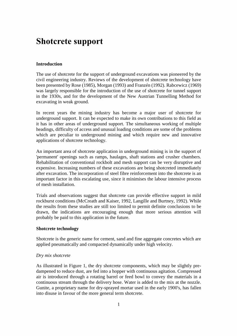
As illustrated in Figure 1, the dry shotcrete components, which may be slightly pre-
dampened to reduce dust, are fed into a hopper with continuous agitation. Compressed
air is introduced through a rotating barrel or feed bowl to convey the materials in a
continuous stream through the delivery hose. Water is added to the mix at the nozzle.
Gunite, a proprietary name for dry-sprayed mortar used in the early 1900's, has fallen
into disuse in favour of the more general term shotcrete.
Shotcrete support
2
Figure 1: Simplified sketch of a typical dry mix shotcrete system. After Mahar et al
(1975).
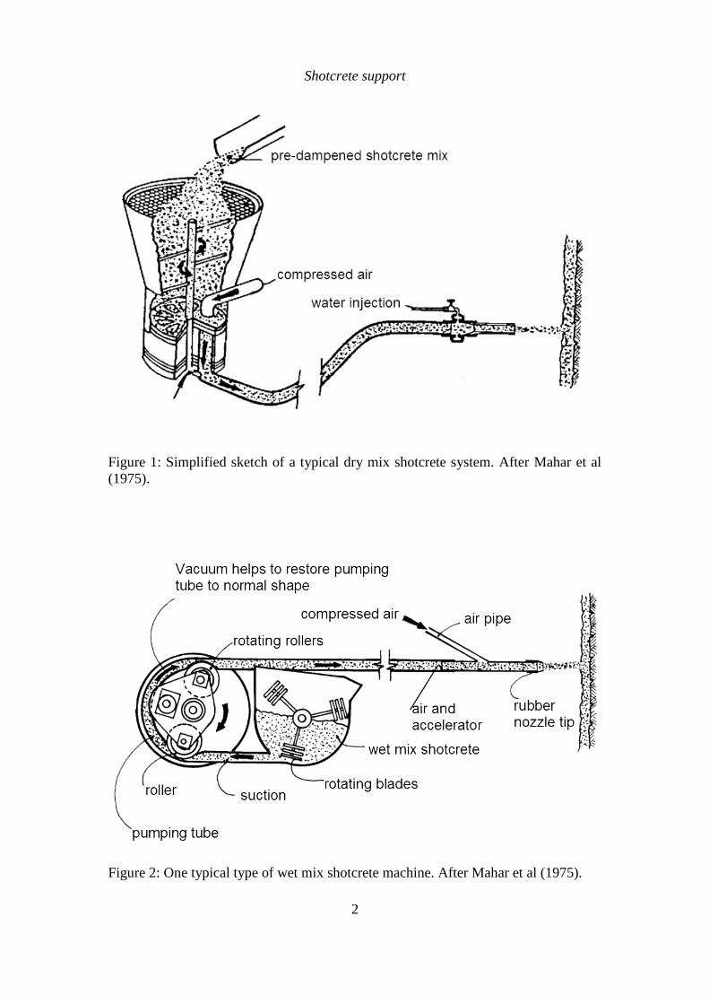
Figure 2: One typical type of wet mix shotcrete machine. After Mahar et al (1975).
Shotcrete support
3
Wet mix shotcrete
In this case the shotcrete components and the water are mixed (usually in a truck
mounted mixer) before delivery into a positive displacement pumping unit, which then
delivers the mix hydraulically to the nozzle where air is added to project the material
onto the rock surface.
The final product of either the dry or wet shotcrete process is very similar. The dry mix
system tends to be more widely used in mining, because of inaccessibility for large
transit mix trucks and because it generally uses smaller and more compact equipment.
This can be moved around relatively easily in an underground mine environment. The
wet mix system is ideal for high production applications in mining and civil
engineering, where a deep shaft or long tunnel is being driven and where access allows
the application equipment and delivery trucks to operate on a more or less continuous
basis. Decisions to use the dry or wet mix shotcrete process are usually made on a site-
by-site basis.
Steel fibre reinforced micro silica shotcrete
Of the many developments in shotcrete technology in recent years, two of the most
significant were the introduction of silica fume, used as a cementitious admixture, and
steel or polypropylene fibre reinforcement.
Silica fume or micro silica is a by-product of the ferro silicon metal industry and is an
extremely fine pozzolan. Pozzolans are cementitious materials which react with the
calcium hydroxide produced during cement hydration. Silica fume, added in quantities
of 8 to 13% by weight of cement, can allow shotcrete to achieve compressive strengths
which are double or triple the value of plain shotcrete mixes. The result is an extremely
strong, impermeable and durable shotcrete. Other benefits include reduced rebound,
improved flexural strength, improved bond with the rock mass and the ability to place
layers of up to 200 mm thick in a single pass because of the shotcrete's 'stickiness'.
However, when using wet mix shotcrete, this stickiness decreases the workability of
the material and superplaticizers are required to restore this workability.
Steel fibre reinforced shotcrete was introduced in the 1970s and has since gained world-
wide acceptance as a replacement for traditional wire mesh reinforced plain shotcrete.
The main role that reinforcement plays in shotcrete is to impart ductility to an otherwise
brittle material. As pointed out earlier, rock support is only called upon to carry
significant loads once the rock surrounding an underground excavation deforms. This
means that unevenly distributed non-elastic deformations of significant magnitude may
overload and lead to failure of the support system, unless that system has sufficient
ductility to accommodate these deformations.
Typical steel fibre reinforced, silica fume shotcrete mix designs are summarised in
Table 1. These mixes can be used as a starting point when embarking on a shotcrete
programme, but it may be necessary to seek expert assistance to 'fine tune' the mix
designs to suit site specific requirements. For many dry mix applications it may be
Shotcrete support
4
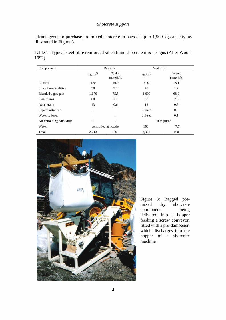
advantageous to purchase pre-mixed shotcrete in bags of up to 1,500 kg capacity, as
illustrated in Figure 3.
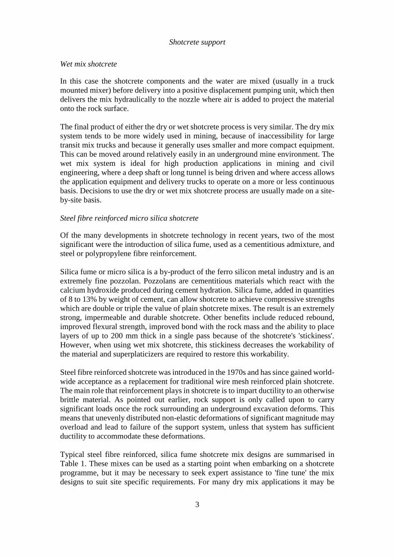
Table 1: Typical steel fibre reinforced silica fume shotcrete mix designs (After Wood,
1992)
Components Dry mix Wet mix
kg./m3 % dry
materials kg./m3 % wet
materials
Cement 420 19.0 420 18.1
Silica fume additive 50 2.2 40 1.7
Blended aggregate 1,670 75.5 1,600 68.9
Steel fibres 60 2.7 60 2.6
Accelerator 13 0.6 13 0.6
Superplasticizer - - 6 litres 0.3
Water reducer - - 2 litres 0.1
Air entraining admixture - - if required
Water controlled at nozzle 180 7.7
Total 2,213 100 2,321 100
Figure 3: Bagged pre-
mixed dry shotcrete
components being
delivered into a hopper
feeding a screw conveyor,
fitted with a pre-dampener,
which discharges into the
hopper of a shotcrete
machine

Shotcrete support
5
Figure 4 shows the steel fibre types which are currently available on the North
American market. In addition to their use in shotcrete, these fibres are also widely used
in concrete floor slabs for buildings, in airport runways and in similar concrete
applications.
Figure 4. Steel fibre types available on the North American market. After
Wood et al (1993). (Note: all dimensions are in mm).
Wood et al (1993) have reported the results of a comprehensive comparative study in
which all of the fibres shown in Figure 4 were used to reinforce shotcrete samples
which were then subjected to a range of tests. Plain and fibre reinforced silica fume
shotcrete samples were prepared by shooting onto vertical panels, using both wet and
dry mix processes. The fibre reinforced samples all contained the same steel fibre
dosage of 60 kg/m3 (see Table 1). All the samples were cured under controlled relative
humidity conditions and all were tested seven days after shooting.
These tests showed that the addition of steel fibres to silica fume shotcrete enhances both the compressive and flexural strength of the hardened shotcrete by up to 20%. A significant increase in ductility was also obtained in all the tests on fibre reinforced samples, compared with plain samples. While different fibres gave different degrees of improvement, all of the fibres tested were found to exceed the levels of performance commonly specified in North America (i.e. 7-day compressive strength of 30 MPa for dry mix, 25 MPa for wet mix and 7-day flexural strength of 4 MPa).
Shotcrete support
6
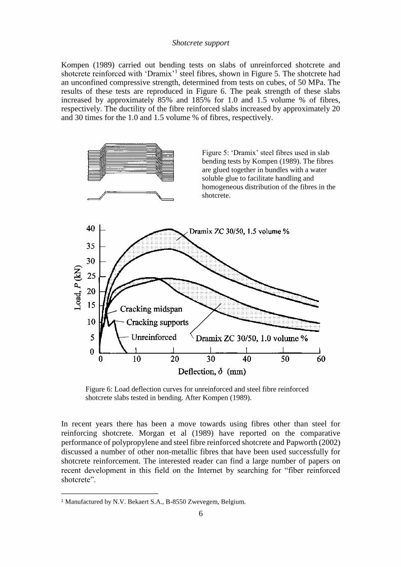
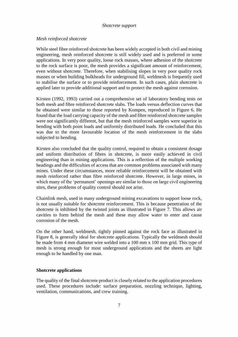
Kompen (1989) carried out bending tests on slabs of unreinforced shotcrete and shotcrete reinforced with ‘Dramix’1 steel fibres, shown in Figure 5. The shotcrete had an unconfined compressive strength, determined from tests on cubes, of 50 MPa. The results of these tests are reproduced in Figure 6. The peak strength of these slabs increased by approximately 85% and 185% for 1.0 and 1.5 volume % of fibres, respectively. The ductility of the fibre reinforced slabs increased by approximately 20 and 30 times for the 1.0 and 1.5 volume % of fibres, respectively.
Figure 5: ‘Dramix’ steel fibres used in slab
bending tests by Kompen (1989). The fibres
are glued together in bundles with a water
soluble glue to facilitate handling and
homogeneous distribution of the fibres in the
shotcrete.
Figure 6: Load deflection curves for unreinforced and steel fibre reinforced
shotcrete slabs tested in bending. After Kompen (1989).
In recent years there has been a move towards using fibres other than steel for
reinforcing shotcrete. Morgan et al (1989) have reported on the comparative
performance of polypropylene and steel fibre reinforced shotcrete and Papworth (2002)
discussed a number of other non-metallic fibres that have been used successfully for
shotcrete reinforcement. The interested reader can find a large number of papers on
recent development in this field on the Internet by searching for “fiber reinforced
shotcrete”.
1 Manufactured by N.V. Bekaert S.A., B-8550 Zwevegem, Belgium.
Shotcrete support
7
Mesh reinforced shotcrete
While steel fibre reinforced shotcrete has been widely accepted in both civil and mining
engineering, mesh reinforced shotcrete is still widely used and is preferred in some
applications. In very poor quality, loose rock masses, where adhesion of the shotcrete
to the rock surface is poor, the mesh provides a significant amount of reinforcement,
even without shotcrete. Therefore, when stabilising slopes in very poor quality rock
masses or when building bulkheads for underground fill, weldmesh is frequently used
to stabilise the surface or to provide reinforcement. In such cases, plain shotcrete is
applied later to provide additional support and to protect the mesh against corrosion.
Kirsten (1992, 1993) carried out a comprehensive set of laboratory bending tests on
both mesh and fibre reinforced shotcrete slabs. The loads versus deflection curves that
he obtained were similar to those reported by Kompen, reproduced in Figure 6. He
found that the load carrying capacity of the mesh and fibre reinforced shotcrete samples
were not significantly different, but that the mesh reinforced samples were superior in
bending with both point loads and uniformly distributed loads. He concluded that this
was due to the more favourable location of the mesh reinforcement in the slabs
subjected to bending.
Kirsten also concluded that the quality control, required to obtain a consistent dosage
and uniform distribution of fibres in shotcrete, is more easily achieved in civil
engineering than in mining applications. This is a reflection of the multiple working
headings and the difficulties of access that are common problems associated with many
mines. Under these circumstances, more reliable reinforcement will be obtained with
mesh reinforced rather than fibre reinforced shotcrete. However, in large mines, in
which many of the ‘permanent’ openings are similar to those on large civil engineering
sites, these problems of quality control should not arise.
Chainlink mesh, used in many underground mining excavations to support loose rock,
is not usually suitable for shotcrete reinforcement. This is because penetration of the
shotcrete is inhibited by the twisted joints as illustrated in Figure 7. This allows air
cavities to form behind the mesh and these may allow water to enter and cause
corrosion of the mesh.
On the other hand, weldmesh, tightly pinned against the rock face as illustrated in
Figure 8, is generally ideal for shotcrete applications. Typically the weldmesh should
be made from 4 mm diameter wire welded into a 100 mm x 100 mm grid. This type of
mesh is strong enough for most underground applications and the sheets are light
enough to he handled by one man.
Shotcrete applications
The quality of the final shotcrete product is closely related to the application procedures
used. These procedures include: surface preparation, nozzling technique, lighting,
ventilation, communications, and crew training.

Shotcrete support
8
Shotcrete should not be applied directly to a dry, dusty or frozen rock surface. The work
area is usually sprayed with an air-water jet to remove loose rock and dust from the
surface to be shot. The damp rock will create a good surface on which to bond the initial
layer of shotcrete paste. The nozzleman commonly starts low on the wall and moves
the nozzle in small circles working his way up towards the back, or roof. Care must be
taken to avoid applying fresh materials on top of rebound or oversprayed shotcrete. It
is essential that the air supply is consistent and has sufficient capacity to ensure the
delivery of a steady stream of high velocity shotcrete to the rock face. Shooting
distances are ideally about 1 to 1.5 metres. Holding the nozzle further from the rock
face will result in a lower velocity flow of materials which leads to poor compaction
and a higher proportion of rebound.
Figure 7: Chainlink mesh, while very
strong and flexible, is not ideal for
shotcrete application because it is
difficult for the shotcrete to penetrate
the mesh.
Figure 8: Welded wire mesh, firmly
attached to the rock surface, provides
excellent reinforcement for shotcrete.
Shotcrete support
9
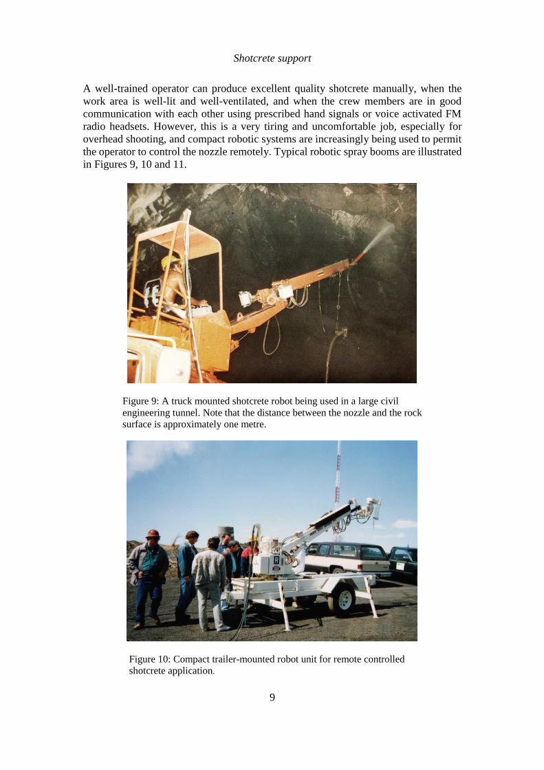
A well-trained operator can produce excellent quality shotcrete manually, when the
work area is well-lit and well-ventilated, and when the crew members are in good
communication with each other using prescribed hand signals or voice activated FM
radio headsets. However, this is a very tiring and uncomfortable job, especially for
overhead shooting, and compact robotic systems are increasingly being used to permit
the operator to control the nozzle remotely. Typical robotic spray booms are illustrated
in Figures 9, 10 and 11.
Figure 9: A truck mounted shotcrete robot being used in a large civil
engineering tunnel. Note that the distance between the nozzle and the rock
surface is approximately one metre.
Figure 10: Compact trailer-mounted robot unit for remote controlled
shotcrete application.
Shotcrete support
10
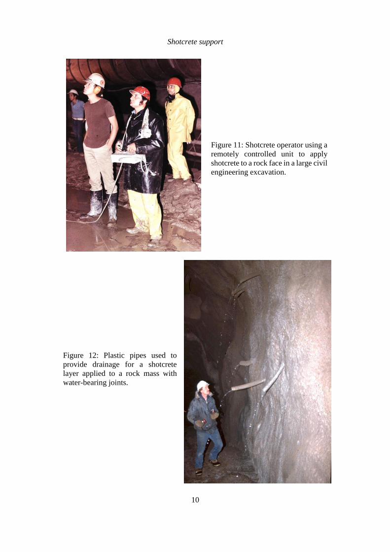
Figure 11: Shotcrete operator using a
remotely controlled unit to apply
shotcrete to a rock face in a large civil
engineering excavation.
Figure 12: Plastic pipes used to
provide drainage for a shotcrete
layer applied to a rock mass with
water-bearing joints.
Shotcrete support
11
When shotcrete is applied to rock masses with well-defined water-bearing joints, it is
important to provide drainage through the shotcrete layer in order to relieve high water
pressures. Drain holes, fitted with plastic pipes as illustrated in Figure 12, are
commonly used for this purpose. Where the water inflow is not restricted to a few
specific features, a porous fibre mat can be attached to the rock surface before the
shotcrete layer is applied. When practical to do so, the water from these drains should
be collected and directed into a drainage ditch or sump.
Design of shotcrete support
The design of shotcrete support for underground excavations is a very imprecise
process. However, one observation, which is commonly made by practical engineers
with years of experience in using shotcrete underground, is that it almost always
performs better than anticipated. There are many examples (very few of which are
documented) where shotcrete has been used as a last act of desperation in an effort to
stabilise the failing rock around a tunnel and, to most people's surprise, it has worked.
The complex interaction between the failing rock mass around an underground
opening, and a layer of shotcrete of varying thickness with properties which change as
it hardens, defies most attempts at theoretical analysis. It is only in recent years, with
the development of powerful numerical tools, that it has been possible to contemplate
realistic analyses, which will explore the possible support-interaction behaviour of
shotcrete. A clear understanding of shotcrete behaviour will require many more years
of experience in the use of and in the interpretation of the results obtained from these
programs. It is also important to recognise that shotcrete is very seldom used alone and
its use in combination with rockbolts, cablebolts, lattice girders or steel sets further
complicates the problem of analysing its contribution to support.
Current shotcrete support 'design' methodology relies very heavily upon rules of thumb
and precedent experience. Wickham et al (1972) related the thickness of a shotcrete
tunnel lining to their Rock Structure Rating (RSR). Bieniawski (1989) gave
recommendations on shotcrete thicknesses (in conjunction with rockbolts or steel sets)
for different Rock Mass Ratings (RMR) for a 10 m span opening. Grimstad and Barton
(1993) have published an updated relating different support systems, including
shotcrete and fibre reinforced shotcrete, to the Tunnelling Quality Index Q.
Vandewalle (1993) collected various rules of thumb from a variety of sources and
included them in his monograph.
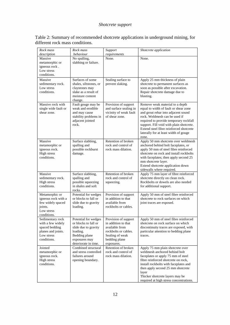
Table 2 is a compilation of current shotcrete practice, combining all of these empirical
rules and adding in my own practical experience. The reader is warned that this table
can only be used as an approximate guide when deciding upon the type and thickness
of shotcrete to be applied in a specific application. Modifications will almost certainly
be required to deal with local variations in rock conditions and shotcrete quality.
Shotcrete support
12
Table 2: Summary of recommended shotcrete applications in underground mining, for
different rock mass conditions.
Rock mass
description
Rock mass
behaviour
Support
requirements
Shotcrete application
Massive
metamorphic or
igneous rock .
Low stress
conditions.
No spalling,
slabbing or failure.
None. None.
Massive
sedimentary rock.
Low stress
conditions.
Surfaces of some
shales, siltstones, or
claystones may
slake as a result of
moisture content
change.
Sealing surface to
prevent slaking.
Apply 25 mm thickness of plain
shotcrete to permanent surfaces as
soon as possible after excavation.
Repair shotcrete damage due to
blasting.
Massive rock with
single wide fault or
shear zone.
Fault gouge may be
weak and erodible
and may cause
stability problems in
adjacent jointed
rock.
Provision of support
and surface sealing in
vicinity of weak fault
of shear zone.
Remove weak material to a depth
equal to width of fault or shear zone
and grout rebar into adjacent sound
rock. Weldmesh can be used if
required to provide temporary rockfall
support. Fill void with plain shotcrete.
Extend steel fibre reinforced shotcrete
laterally for at least width of gouge
zone.
Massive
metamorphic or
igneous rock.
High stress
conditions.
Surface slabbing,
spalling and
possible rockburst
damage.
Retention of broken
rock and control of
rock mass dilation.
Apply 50 mm shotcrete over weldmesh
anchored behind bolt faceplates, or
apply 50 mm of steel fibre reinforced
shotcrete on rock and install rockbolts
with faceplates; then apply second 25
mm shotcrete layer.
Extend shotcrete application down
sidewalls where required.
Massive
sedimentary rock.
High stress
conditions.
Surface slabbing,
spalling and
possible squeezing
in shales and soft
rocks.
Retention of broken
rock and control of
squeezing.
Apply 75 mm layer of fibre reinforced
shotcrete directly on clean rock.
Rockbolts or dowels are also needed
for additional support.
Metamorphic or
igneous rock with a
few widely spaced
joints.
Low stress
conditions.
Potential for wedges
or blocks to fall or
slide due to gravity
loading.
Provision of support
in addition to that
available from
rockbolts or cables.
Apply 50 mm of steel fibre reinforced
shotcrete to rock surfaces on which
joint traces are exposed.
Sedimentary rock
with a few widely
spaced bedding
planes and joints.
Low stress
conditions.
Potential for wedges
or blocks to fall or
slide due to gravity
loading.
Bedding plane
exposures may
deteriorate in time.
Provision of support
in addition to that
available from
rockbolts or cables.
Sealing of weak
bedding plane
exposures.
Apply 50 mm of steel fibre reinforced
shotcrete on rock surface on which
discontinuity traces are exposed, with
particular attention to bedding plane
traces.
Jointed
metamorphic or
igneous rock.
High stress
conditions.
Combined structural
and stress controlled
failures around
opening boundary.
Retention of broken
rock and control of
rock mass dilation.
Apply 75 mm plain shotcrete over
weldmesh anchored behind bolt
faceplates or apply 75 mm of steel
fibre reinforced shotcrete on rock,
install rockbolts with faceplates and
then apply second 25 mm shotcrete
layer
Thicker shotcrete layers may be
required at high stress concentrations.

Shotcrete support
13
Bedded and jointed
weak sedimentary
rock.
High stress
conditions.
Slabbing, spalling
and possibly
squeezing.
Control of rock mass
failure and
squeezing.
Apply 75 mm of steel fibre reinforced
shotcrete to clean rock surfaces as soon
as possible, install rockbolts, with
faceplates, through shotcrete, apply
second 75 mm shotcrete layer.
Highly jointed
metamorphic or
igneous rock.
Low stress
conditions.
Ravelling of small
wedges and blocks
defined by
intersecting joints.
Prevention of
progressive ravelling.
Apply 50 mm of steel fibre reinforced
shotcrete on clean rock surface in roof
of excavation.
Rockbolts or dowels may be needed
for additional support for large blocks.
Highly jointed and
bedded sedimentary
rock.
Low stress
conditions.
Bed separation in
wide span
excavations and
ravelling of bedding
traces in inclined
faces.
Control of bed
separation and
ravelling.
Rockbolts or dowels required to
control bed separation.
Apply 75 mm of fibre reinforced
shotcrete to bedding plane traces
before bolting.
Heavily jointed
igneous or
metamorphic rock,
conglomerates or
cemented rockfill.
High stress
conditions.
Squeezing and
'plastic' flow of rock
mass around
opening.
Control of rock mass
failure and dilation.
Apply 100 mm of steel fibre reinforced
shotcrete as soon as possible and
install rockbolts, with face-plates,
through shotcrete. Apply additional 50
mm of shotcrete if required. Extend
support down sidewalls if necessary.
Heavily jointed
sedimentary rock
with clay coated
surfaces.
High stress
conditions.
Squeezing and
'plastic' flow of rock
mass around
opening. Clay rich
rocks may swell.
Control of rock mass
failure and dilation.
Apply 50 mm of steel fibre reinforced
shotcrete as soon as possible, install
lattice girders or light steel sets, with
invert struts where required, then more
steel fibre reinforced shotcrete to cover
sets or girders. Forepoling or spiling
may be required to stabilise face ahead
of excavation. Gaps may be left in
final shotcrete to allow for movement
resulting from squeezing or swelling.
Gap should be closed once opening is
stable.
Mild rockburst
conditions in
massive rock
subjected to high
stress conditions.
Spalling, slabbing
and mild rockbursts.
Retention of broken
rock and control of
failure propagation.
Apply 50 to 100 mm of shotcrete over
mesh or cable lacing which is firmly
attached to the rock surface by means
of yielding rockbolts or cablebolts.
References
Bieniawski Z.T. 1989. Engineering Rock Mass Classifications. New York:Wiley. 251
pages.
Franzén, T. 1992. Shotcrete for underground support - a state of the art report with
focus on steel fibre reinforcement. In Rock support in mining and underground
construction, proc. int. symp. rock support, Sudbury, (eds P.K. Kaiser and D.R.
McCreath), 91-104. Rotterdam: Balkema.
Grimstad, E. and Barton, N. 1993. Updating the Q-System for NMT. Proc. int. symp.
on sprayed concrete - modern use of wet mix sprayed concrete for underground
support, Fagernes, (eds Kompen, Opsahl and Berg). Oslo: Norwegian Concrete
Assn.
Shotcrete support
14
Kirsten, H.A.D. 1992. Comparative efficiency and ultimate strength of mesh- and fibre-
reinforced shotcrete as determined from full-scale bending tests. J. S. Afr. Inst.
Min. Metall. Nov., 303-322.
Kirsten, H.A.D. 1993. Equivalence of mesh- and fibre-reinforced shotcrete at large
deflections. Can. Geotech. J. 30, 418-440.
Kompen, R. 1989. Wet process steel fibre reinforced shotcrete for rock support and fire
protection, Norwegian practice and experience. In Proc. underground city conf.,
Munich, (ed. D. Morfeldt), 228-237.
Langille, C.C. and Burtney, M.W. 1992. Effectiveness of shotcrete and mesh support
in low energy rockburst conditions at INCO's Creighton mine. In Rock support
in mining and underground construction, proc. int. symp. rock support, Sudbury,
(eds. P.K. Kaiser and D.R. McCreath), 633-638. Rotterdam: Balkema.
Mahar, J.W., Parker, H.W. and Wuellner, W.W. 1975. Shotcrete practice in
underground construction. US Dept. Transportation Report FRA-OR&D 75-90.
Springfield, VA: Nat. Tech. Info. Service.
McCreath, D.R. and Kaiser, P.K. 1992. Evaluation of current support practices in burst-
prone ground and preliminary guidelines for Canadian hardrock mines. In Rock
support in mining and underground construction, proc. int. symp. rock support,
Sudbury, (eds P.K. Kaiser and D.R. McCreath), 611-619. Rotterdam: Balkema.
Morgan, D.R. 1993. Advances in shotcrete technology for support of underground
openings in Canada. In Shotcrete for underground support V, proc. engineering
foundation conf., Uppsala, (eds J.C. Sharp and T. Franzen), 358-382. New York:
Am. Soc. Civ. Engrs.
Morgan, D. R., McAskill, N., Richardson, B. W., and Zellers, R. C. 1989. "A
Comparative evaluation of plain, polypropylene fiber, steel fiber and wire mesh
reinforced shotcretes," Transportation Research Record, No. 1226, Concrete and
Concrete Construction, 78-87. Washington, DC: Transportation Research Board,
National Research, Council.
Papworth, F. 2002. Design guidelines for the use of fiber-reinforced shotcrete for
ground support. American Shotcrete Assn Shotcrete Magazine, Spring.
Rabcewicz, L. 1969. Stability of tunnels under rock load. Water Power 21(6-8) 225-
229, 266-273, 297-304.
Rose, D. 1985. Steel fibre reinforced shotcrete for tunnel linings: the state of the art.
Proc. North American rapid excav. tunneling conf. 1, 392-412. New York: Soc.
Min. Engrs, Am. Inst. Min. Metall. Petrolm Engrs.
Vandewalle, M. 1993. Dramix: Tunnelling the world. 3rd edn. Zwevegem, Belgium:
N.V. Bekaert S.A.
Wickham, G.E., Tiedemann, H.R. and Skinner, E.H. 1972. Support determination
based on geologic predictions. In Proc. North American rapid excav. tunneling
conf., Chicago, (eds K.S. Lane and L.A. Garfield), 43-64. New York: Soc. Min.
Engrs, Am. Inst. Min. Metall. Petrolm Engrs.

Shotcrete support
15
Wood, D.F. 1992. Specification and application of fibre reinforced shotcrete. In Rock
support in mining and underground construction, proc. int. symp. on rock
support, Sudbury, (eds. P.K. Kaiser and D.R. McCreath), 149-156. Rotterdam:
Balkema.
Wood, D.F., Banthia, N. and Trottier, J-F. 1993. A comparative study of different steel
fibres in shotcrete. In Shotcrete for underground support VI, Niagara Falls, 57-
66. New York: Am. Soc. Civ. Engrs.