shot blaster instruction manual...safety 7 phone: 763-315-5300 grounding jobsite receptacles can...
TRANSCRIPT

Caution: Read Manual Before Operating Machine
SHOT BLASTERINSTRUCTION MANUAL
Rev A
032614
Table of Contents
www.nationalequipment.com Phone: 763-315-53003
Table of Contents .......................................................................................................................................................... 3Features and Specifications ......................................................................................................................................... 4Safety ......................................................................................................................................................................... 5-11
General Rules for Safe Operation ...................................................................................................................... 5-6Characteristics of a Defensive Operator ................................................................................................................ 6Grounding .............................................................................................................................................................. 7Extension Cords ................................................................................................................................................. 7-8Organizational Measures ....................................................................................................................................... 9Personnel Qualification .......................................................................................................................................... 9Safety Precautions ............................................................................................................................................ 9-10Safety Off Position ............................................................................................................................................... 10Electrical Engineering Regulations .......................................................................................................................11
Machine Operation ................................................................................................................................................. 12-20General ................................................................................................................................................................ 12Operating Elements ............................................................................................................................................. 12The Blast Wheel .................................................................................................................................................. 12Separator ............................................................................................................................................................. 13Abrasive Feed ...................................................................................................................................................... 14Blast Head Sealing .............................................................................................................................................. 14The Suction System ............................................................................................................................................. 14General Checks ................................................................................................................................................... 15Abrasive Media .................................................................................................................................................... 15Transportation ...................................................................................................................................................... 16Start Up ........................................................................................................................................................... 17-18Daily Operation .................................................................................................................................................... 19Information about Travel Speed and Abrasive Feeding ....................................................................................... 19Switching Off the Machine ................................................................................................................................... 20What to Do If A Fault Occurs ............................................................................................................................... 20Restarting After A Fault ........................................................................................................................................ 20Measures Before Long Stand Stills ..................................................................................................................... 20
Machine Maintenance ............................................................................................................................................ 21-29Recommendations ............................................................................................................................................... 21Maintenance and Inspection List ......................................................................................................................... 22Repairing ............................................................................................................................................................. 22The Blast Pattern ................................................................................................................................................. 23Magnetic Seals .................................................................................................................................................... 24Changing The Blast Wheel ............................................................................................................................. 25-26Changing the Liner ......................................................................................................................................... 27-28Maintenance Intervals .......................................................................................................................................... 29Cecommended Spare Parts List .......................................................................................................................... 29Troubleshooting Guide.................................................................................................................................... 30-31General Errors ................................................................................................................................................ 30-31Electrical Errors ................................................................................................................................................... 31
Complete Parts List ..................................................................................................................................................... 32Parts Lists and Diagrams ...................................................................................................................................... 33-40
Spare Parts .......................................................................................................................................................... 33Seperator Parts .................................................................................................................................................... 34Handle Parts ........................................................................................................................................................ 35Liner Parts ........................................................................................................................................................... 36Wheel Motor Parts ............................................................................................................................................... 37Magnet Parts ....................................................................................................................................................... 38Wheel Parts ......................................................................................................................................................... 39Liner Parts ........................................................................................................................................................... 393395 Wiring Diagram ........................................................................................................................................... 40
Guarantee ..................................................................................................................................................................... 41
Safety
www.nationalequipment.com Phone: 763-315-53005
GENERAL RULES FOR SAFE OPERATIONREAD AND SAVE ALL INSTRUCTIONS FOR FUTURE USE. Before use, ensure operators reads and understand this manual. Read and understand labeling on machine and components. All operators must view the instruction video. Extra copies of the manual and video are avail-able by contacting National Flooring Equipment.
1. KNOW YOUR EQUIPMENT: Read this manual carefully to learn equipment applications and limitations, potential hazards associated with this type of equipment. Keep this manual with the equipment it is associated with.
2. GROUND YOUR EQUIPMENT: See Grounding Page 7.3. AVOID DANGEROUS ENVIRONMENTS: Do not use in rain, damp or wet locations, or in the presence of explosive atmospheres (gas-
eous fumes, dust or flammable materials). Remove materials or debris that may be ignited by sparks.4. KEEP WORK AREA CLEAN AND WELL LIT: Cluttered, dark work areas invite accidents.5. DO NOT USE ON STEPS.6. DRESS PROPERLY: Do not wear loose clothing. These may be caught in moving parts. When working wear gloves and insulated non-skid
footwear. Keep hands and gloves away from moving parts.7. USE SAFETY EQUIPMENT: Proper eye protection should be worn at all times. Wear hearing protection during extended use and a dust
mask for dusty operations. Hard hats, face shields, safety shoes, etc. should be worn when specified or necessary.8. KEEP BYSTANDERS AWAY: Children and other bystanders should be kept at a safe distance from the work area to avoid distracting the
operator and contacting the equipment or extension cord. Operator should be aware of the proximity of bystanders. This equipment is not intended for use by persons (including children) with reduced physical, sensory or mental capabilities or lack of experience and knowledge. Equipment is not to be used by children.
9. PROTECT OTHERS IN THE WORK AREA: Provide barriers or shields as needed to protect others from debris.10. USE PROPER ACCESSORIES: Using accessories that are not recommended may be hazardous. Be sure accessories are properly
installed and maintained. Do not delete a guard or other safety device when installing an accessory or attachment.11. CHECK FOR DAMAGED PARTS: Inspect guards and other parts before use. Check for misalignment, binding of moving parts, improper
mounting, broken parts and other conditions that may affect operation. If abnormal noise or vibration occurs, turn off immediately and have the problem corrected before further use. Do not use damaged equipment. Tag damaged equipment “DO NOT USE” until repaired. Miss-ing or damaged parts should be properly repaired or replaced immediately. For all repairs, use only identical National replacement parts.
12. REMOVE ALL ADJUSTING KEYS AND WRENCHES: Make a habit of checking that the adjusting keys, wrenches, etc. are removed from the tool before turning it on.
13. GUARD AGAINST ELECTRIC SHOCK: Prevent body contact with grounded surfaces such as pipes, radiators, ranges and refrigerators. When making cuts, always check the work area for hidden wires or pipes. Hold your equipment by insulated nonmetal grasping surfaces.
14. AVOID ACCIDENTAL STARTING: Be sure equipment is turned off before plugging in. Do not use equipment if the power switch does not turn the equipment On and Off.
15. DO NOT FORCE EQUIPMENT: Equipment will perform best at the rate for which it was designed. Excessive force only causes operator fatigue, increased wear and reduced control.
16. KEEP HANDS AWAY FROM ALL CUTTING EDGES AND MOVING PARTS. 17. WEAR gloves when changing accessories.18. DO NOT ABUSE CORD: Never unplug by pulling the cord from the outlet. Pull plug rather than cord to reduce the risk of damage. Keep
the cord away from heat, oil, sharp objects, cutting edges and moving parts.19. DO NOT OVERREACH. MAINTAIN CONTROL: Keep proper footing and balance at all times. Maintain a firm grip.20. STAY ALERT: Watch what you are doing, and use common sense. Do not use when you are tired, distracted or under the influence of
drugs, alcohol or any medication causing decreased control.21. STARTING MACHINE: On/Off switch must be in off position before connecting to power source.22. UNPLUG EQUIPMENT: When not in use and before changing accessories or performing recommended maintenance, unplug machine.23. MAINTAIN EQUIPMENT CAREFULLY: Keep handles dry, clean and free from oil and grease. Keep cutting edges sharp and clean. Follow
instructions for lubricating and changing accessories. Inspect tool cords and extension cords for damage. Replace damaged parts. Use only identical National replacement parts.
Features and Specifications
Fax: 763-535-8255 [email protected]
FEATURES
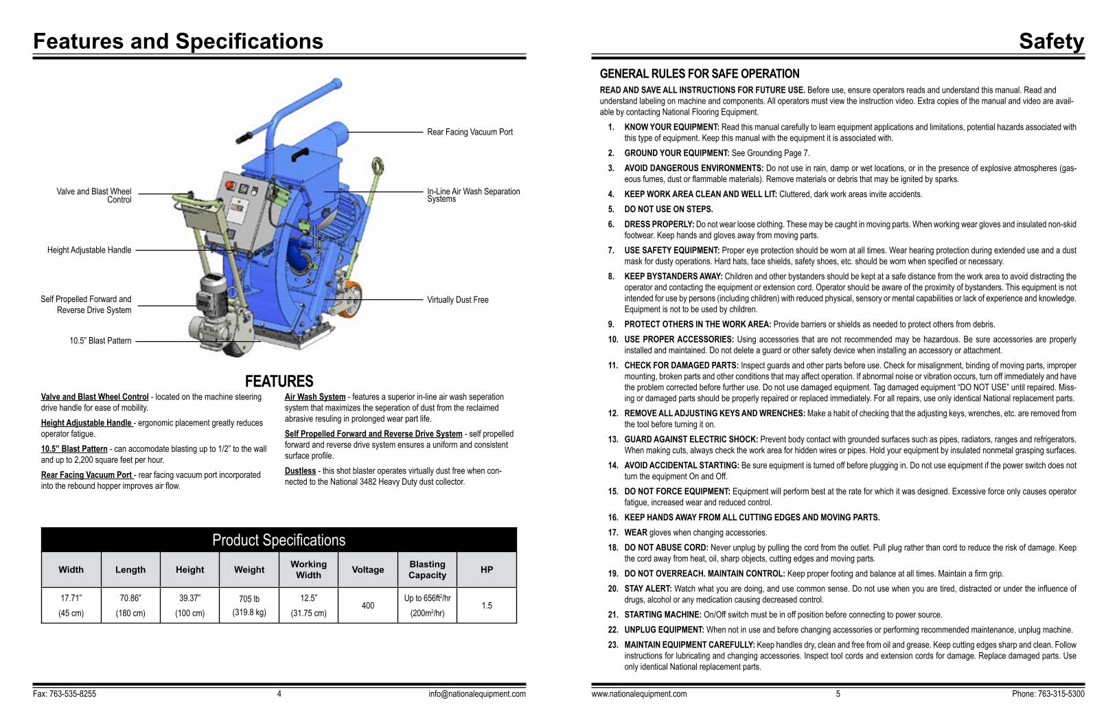
Product SpecificationsWidth Length Height Weight Working
Width Voltage Blasting Capacity HP
17.71”(45 cm)
70.86”(180 cm)
39.37”(100 cm)
705 lb(319.8 kg)
12.5”(31.75 cm)
400Up to 656ft2/hr
(200m2/hr)1.5
Valve and Blast Wheel Control - located on the machine steering drive handle for ease of mobility.Height Adjustable Handle - ergonomic placement greatly reduces operator fatigue.10.5” Blast Pattern - can accomodate blasting up to 1/2” to the wall and up to 2,200 square feet per hour.Rear Facing Vacuum Port - rear facing vacuum port incorporated into the rebound hopper improves air flow.
Air Wash System - features a superior in-line air wash seperation system that maximizes the seperation of dust from the reclaimed abrasive resuling in prolonged wear part life.Self Propelled Forward and Reverse Drive System - self propelled forward and reverse drive system ensures a uniform and consistent surface profile.Dustless - this shot blaster operates virtually dust free when con-nected to the National 3482 Heavy Duty dust collector.
Valve and Blast Wheel Control
Height Adjustable Handle
Rear Facing Vacuum Port
Self Propelled Forward and Reverse Drive System
In-Line Air Wash Separation Systems
10.5” Blast Pattern
Virtually Dust Free

Safety
www.nationalequipment.com Phone: 763-315-53007
GROUNDINGJobsite receptacles can vary. Check the voltage at different receptacles on the jobsite for a more accurate voltage reading. 15 amp GFI outlets are not recommended.
GROUNDED TOOLS: TOOLS WITH THREE PRONG PLUGSEquipment marked “Grounding Required” have a three wire cord and three prong grounding plug. The plug must be connected to a properly grounded outlet (Figure A). If the equipment should electrically malfunction or break down, grounding provides a low resistance path to carry electricity away from the user; reducing the risk of electric shock.The grounding prong in the plug is connected through the green wire inside the cord to the grounding system in the equipment. The green wire in the cord must be the only wire connected to the equipment’s grounding system and must never be attached to an electrically “live” terminal.The equipment must be plugged into an appropriate outlet, one which is properly installed and grounded in accordance with all codes and ordinances. The plug and outlet should look like the example in Figure A.
EXTENSION CORDSGrounded equipment requires a three wire extension cord. As the distance from the supply outlet increases, you must use a heavier gauge extension cord. Using extension cords with inadequately sized wire causes a serious drop in voltage, resulting in loss of power and possible equipment damage.
GUIDELINES FOR USING EXTENSION CORDS• If you are using an extension cord outdoors, make sure it is marked with the suffix
“W-A” (“W” in Canada) to indicate that it is acceptable for outdoor use.• Be sure your extension cord is properly wired and in good electrical condition.
Always replace a damaged extension cord or have it repaired by a qualified person before using it.
• Protect your extension cords from sharp objects, excessive heat and damp or wet areas.
• Keep away from water. Do not use if wet.• Inspect thoroughly before each use. DO NOT USE IF DAMAGED.• Make sure equipment is not running before disconnecting cord.• FULLY INSERT plug into outlet.• Do not remove, bend or modify any metal prongs or pins of cord.
FIG. A
Safety24. STORE IDLE EQUIPMENT: When not in use, store in a dry, secured place. Keep away from children.25. MAINTAIN LABELS AND NAMEPLATES: These carry important information. If unreadable or missing, contact National for a replace-
ment.26. MACHINE IS HEAVY, DO NOT DROP. Ensure proper lifting procedures are followed when transporting.27. DO NOT ALLOW the oscilating plates to come into contact with the supply cord.28. REGULARLY EXAMINE the supply cord for damage, such as cracking or aging. If damaged, replace the cord before further use. Only
replace the supply cord with the type specified in this manual.
CHARACTERISTICS OF A DEFENSIVE OPERATORA Good Operator is a “Defensive” Operator!
QUALITIES INCLUDE:Education: Learns about the machine and the environment.Alert: Stays alert at all times…never lets guard down.Skills: Only performs duties he/she are qualified to do. Always tries to improve.Judgment: Plays it safe. Doesn’t take chances.Common Sense: Does the right thing without having to be told. Applies knowledge.Recognizes the Hazards: Maintains alertness. Anticipates danger.Understands the Defense: Knows that safety isn’t an accident…it’s a thinking person’s choice.Acts Correctly: Does not cave in to peer pressure. Performs correctly when supervised or not.
Fax: 763-535-8255 [email protected]
WARNING: SILICA DUST WARNING SHOTBLASTING/SCRAPING/GRINDING/CUTTING/DRILLING OF MASONRY, CONCRETE, METAL AND OTHER MATERIALS CAN GENERATE DUST, MISTS AND FUMES CONTAINING CHEMICALS KNOWN TO CAUSE SERIOUS FATAL INJURY OR ILLNESS, SUCH AS RESPIRATORY DISEASE, CANCER, BIRTH DEFECTS OR OTHER REPRODUCTIVE HARM. IF
YOU ARE FAMILIAR WITH THE RISKS ASSOCIATED WITH THE PARTICULAR MATERIAL BEING CUT, REVIEW THE MATERIAL SAFETY DATA SHEET AND/OR CONSULT YOU EMPLOYER, THE MATERIAL MANUFACTURER/SUPPLIER, GOVERNMENTAL AGENCIES SUCH AS OSHA AND NIOSH AND OTHER AUTHORITIES ON HAZARDOUS MATERIALS. CALIFORNIA AND SOME OTHER AUTHORITIES, FOR INSTANCE, HAVE PUBLISHED LISTS OF SUBSTANCES KNOWN TO CAUSE CANCER, REPRODUCTIVE TOXICITY, OR OTHER HARMFUL EFFECTS. CONTROL DUST, MIST AND FUMES AT THE SOURCE WHERE POSSIBLE. IN THIS REGARD USE GOOD WORK PRACTICES AND FOLLOW THE RECOMMENDA-TIONS OF THE MANUFACTURER/SUPPLIER, OSHA/NIOSH, AND OCCUPATIONAL AND TRADE ASSOCIATIONS. WHEN THE HAZARDS FROM INHALATION OF DUST, MISTS AND FUMES CANNOT BE ELIMINATED, THE OPERATOR AND ANY BYSTANDERS SHOULD ALWAYS WEAR A RESPIRATOR APPROVED BY OSHA/MSHA FOR THE MATERIAL BEING CUT.
WARNING: ELECTRICAL CORDS CAN BE HAZARDOUS. MISUSE CAN RESULT IN FIRE OR DEATH BY ELECTRICAL SHOCK. READ CAREFULLY AND FOLLOW ALL DIRECTIONS.
CAUTION: IMPROPERLY CONNECTING THE GROUNDING WIRE CAN RESULT IN THE RISK OF ELECTRIC SHOCK. CHECK WITH A QUALIFIED ELECTRI-CIAN IF YOU ARE IN DOUBT AS TO WHETHER THE OUTLET IS PROPERLY GROUNDED. DO NOT MODIFY THE PLUG PROVIDED WITH THE EQUIPMENT. NEVER REMOVE THE GROUNDING PRONG FROM THE PLUG. DO NOT USE THE EQUIPMENT IF THE CORD OR PLUG IS DAMAGED. IF THE PLUG WILL NOT FIT THE OUTLET, HAVE A PROPER OUTLET INSTALLED BY A QUALIFIED ELECTRICIAN.

Safety
www.nationalequipment.com Phone: 763-315-53009
ORGANIZATIONAL MEASURES
In addition to the instruction manual, general and legal regulations regarding accident prevention and environmental protection must be with and indicated every time.Such duties may relate to the handling of hazardous substances, to the provision and wearing of personal protection equipment or compliance with local traffic regulations.The instruction manual must be supplemented by instructions that include the duty to supervise and report relating to particular local working practices for example work organization, work procedures and personnel allocation.Personnel entrusted with working with the machine must have read the instruction manual before starting work, in particular the chapter about Safety (Page 5-11). These have to be done before starting any work with the machine. This particularly applies to incidental activities such as setting up the machine, carrying out maintenance work or training staff to work with the machine.From time to time the working practices of the staff are to be checked regarding awareness of safety and hazards.Personnel must tie back long hair and not wear loose clothing or jewelery rings. There is a risk of injury through getting stuck or being drawn into moving machinery.
This warning applies in particular to the fitting and adjustment of safety devices and to welding on major and load bearing parts.Spare parts must always comply with the technical requirements and the specification of the manufacturer.This is always guaranteed with original spare parts of the manufacturer.Inspection intervals and intervals for recurring checks specified in these operating instructions must be complied with. At the same time it is necessary to meet the legal requirements.To perform maintenance work correctly it is important to be equipped with proper tools for the task in question. The location and the operation of fire extinguishers must be made known on each building site.
PERSONNEL QUALIFICATION• Only reliable personnel should work on the machine.• Only trained personnel should operate the machine. Note the statutory minimum age. Clearly specify the responsibilities of personnel for
operation, set up, service and maintenance work. • Make sure that only authorized personnel operate or work on the machine.• Clearly designate the machine operator. Define his responsibilities also regarding traffic safety regulations and empower him to decline
instructions from third parties which are not complying with the safety requirements.• Personnel being trained or made acquainted with the equipment may only be deployed under constant supervision of an experienced
person.
SAFETY PRECAUTIONS• Avoid any method of working that impairs safety.• All precautions have to be taken to ensure that the machine will only be used in a safe and functional status.• The machine has to be checked visually at least once a day for any damage and/or defect.• In the event of operational malfunctions the machine must be shut down immediately and secured. The fault must be rectified before start-
ing the machine again.
WARNING: CHANGES, ADD-ONS OR CONVERSIONS TO THE MACHINE WHICH MIGHT INFLUENCE THE SAFETY OF THE MACHINE MUST NOT BE UNDERTAKEN WITHOUT THE PERMISSION OF THE MANUFACTURER.
SafetyGUIDELINES FOR USING EXTENSION CORDS (CONTINUED)
• Do not use excessive force to make connections.• Do not connect a three prong plug to a two prong cord. • Avoid overheating. Uncoil cord and do not cover it with any material.• Do not walk on cord.• Do not drive, drag or place objects over cord.• Use a 12 gauge, 115 v cord, 50 ft (15 m) maximum length with this machine. (Included with purchase.)• Regularly examine the supply cord for damage, such as cracking or aging. If damage is found, replace the cord before further use. • Only replace the supply cord with the type specified in the instruction manual.
Fax: 763-535-8255 [email protected]
WARNING: THE PRODUCT MANUAL ARE TO BE KEPT WITH THE MACHINE AND MUST BE ACCESSIBLE AT ALL TIMES.
Safety
www.nationalequipment.com Phone: 763-315-530011
ELECTRICAL ENGINEERING REGULATIONSIf work on wear parts is necessary, a second person must be deployed who can pull out the plug in an emergency. The working area must be sealed with a red and white safety chain and a danger sign. Use tools that are insulated against voltages.
Only start work once you are familar with the electrical engineering regulations that apply to your area.Only use voltage seekers that comply with the regulations when troubleshooting. From time to time check voltage seekers to ensure that they are operationally efficient.Use only proper tools for your work. Damaged tools have to be repaired immediately or be replaced.For your own safety the required safety equipment and clothing used when working with the machine (e.g. safety glasses, safety shoes, safety gloves). Please instruct your operators and the repair personnel about the following points:
• Greasing, cleaning, and repair work is only allowed if the machine is shut off and in the safety off position (See Page 10).• Make sure that during the work on the machine it cannot be started. • It is not allowed to open or remove safety covers while the machine is running. • Do not forget to reinstall all safety covers and safety devices after cleaning, repair and maintenance work. • Do not touch moving parts and do not walk into the working path of the machine. • Please be sure that no person is in the working area and could be endangered before starting the machine.
WARNING: WORK ON THE ELECTRICAL PARTS OF THE EQUIPMENT MAY ONLY BE UNDERTAKEN BY A SKILLED ELECTRICIAN OR BY A TRAINED PERSON UNDER THE GUIDANCE AND SUPERVISION OF A SKILLED ELECTRICIAN AS WELL AS IN ACCORDANCE WITH THE ELECTRICAL ENGINEERING REGULATIONS.
SafetySAFETY PRECAUTIONS (CONTINUED)
• Start up and switch off operations and control devices have to be handled in accordance with the operating instructions.• Before starting the machine make sure that nobody can be endangered when the machines starts running.• Do not switch of or remove the exhaust and ventilation devices when the machine is running.
MECHANICAL SERVICE WORK:Before starting any servicing work on the machine, put the machine in the “Safety Off” position in order to prevent the machine from being switched on accidentally.Please follow any special safety instructions in the Maintenance section (Pages 20-45).Adjustments, servicing and inspection work and inspection intervals specified in these Machine Operation instructions as well as any informa-tion on the replacement on parts and systems of the machine must be undertaken and / or complied with.These activities can only be undertaken by qualified personnel.Before starting any maintenance or repair work the operator of the machine must be informed about it.During all work related to the use, the re-erection or the adjustment of the machine and of the safety devices as well as inspection, maintenance and repair, the start up and shut off procedures must be done in accordance with the instruction manual.Machine must be shut off completely for repair or maintenance work, the plug has to be disconnected in order to prevent the machine from be-ing switched on accidentally.The dust bin of a connected dust collector has to be emptied before transportation. Please handle in accordance with the regulation how to dispose the dust and make sure that you meet the local regulations.Do not use any aggressive cleaning materials! Use lint-free cleaning cloths. Always tighten any screw connection that are undone during servic-ing and maintenance work.If safety devices need to be dismantled during setting up, servicing and/or repair work, these safety devices must be reinstalled and inspected immediately after completion of the servicing and repair work.
Make sure that process materials and replacement parts are disposed of safely and in an environmentally-friendly manner.Make sure that electrical components used for replacement purpose comply with the original parts and are correctely adjusted if necessary.
SAFETY OFF POSITIONThe safety off position is the position of the machine when it cannot generate any hazard.Setting the machine into the safety off position:
• Switch off the blast machine.• Switch off the dust collector.• Wait for standstill of all drives.• Pull out the main plugs.• Secure the machine against accidental start up.
Fax: 763-535-8255 [email protected]
WARNING: WORK ON THE ELECTRICAL PARTS OF THE EQUIPMENT MAY ONLY BE UNDERTAKEN BY A SKILLED ELECTRICIAN OR BY A TRAINED PERSON UNDER THE GUIDANCE AND SUPERVISION OF A SKILLED ELECTRICIAN AS WELL AS IN ACCORDANCE WITH THE ELECTRICAL ENGINEERING REGULATIONS.

Machine Operation
www.nationalequipment.com Phone: 763-315-530013
SPEED CONTROLThe operation speed is set by a Potentiometer (see Figure B-8).Although this indication does not allow direct reading of the actual speed, it shows comparing numbers allowing the operator to set the appropri-ate speed.
FORWARD REVERSE SWITCH TRACTION DRIVEThis switch (see Figure B-9) controls the direction of the blast-machine. Position “2” - Blast cleaning direction – movement is backwards
EMERGENCY STOPPressing the emergency shutdown button (see Figure B-13) switches off immediately, interupts power supply to all machine components.
THE ABRASIVE CONTROL VALVE (FIGURE D)To regulate the flow of abrasive to the blast-wheel there is a magnetic-valve (3) fitted between Storage-Hopper (1) and feed spout (2).This valve has a turn able shutter (3A) that is linked to a lever (4) controlled by the control cable (5)Changing the angle of the shutter position results in a different amount of abrasive flowing to the blast wheel. Feeding more abrasive is causing more work means higher load on the blast-wheel motor.Load on the motor is indicated by the Amp meter.Do not load more abrasive than recommended for the S320, the max load is at 21 Amp.Higher load will cause the motor to fail or damage of the motor.
ABRASIVE CONTROL LEVER (FIGURE E)This Lever (1) is located on the control panel (2) and regulates the magnetic valve (3) to control the flow of abrasive towards the blast wheel. The valve is hand-operated and can be set to each amount of abrasive throughput by changing the lever position. Pulling (P) it forward will open and pushing will close the magnetic valve. (Max. 21 Amp. allowed).
THE DEAD MANS HANDLEThe switch lever (4) below the control handle (5) serves for controlling the drive motor. Actuating the switch lever upwards closes the power circuit to switch on the drive motor. Depending on the setting of the selection-switch (7) the machine will move forward or backward. The speed depends on the setting of the speed control (overdrive (8) not switched). When this lever is released, the drive motor switches off (dead man’s handle). Blast-operation direction is (V) (B) is used to move the machine but can’t be used to blast the surface.
FIG. D
Machine Operation
FIG. B
OPERATIVE RANGEThe National Shot Blaster 3398 is a downward blasting machine with a closed abrasive circuit designed for the pre-treatment of horizontal surfaces. The bouncing impact of me-tallic abrasive onto the surface to be treated thoroughly removes surface contaminants, coats of paint, sealants and thin coatings. A suitable filter unit must be connected to the machine in order to separate the dust from the abrasive. A specially designed dust collection system ensures dust-free operation of the machine and clean air at the workspace.
Control Panel Elements (Figure B)1. Control Panel 9. Switch Forward Backwards2. Key Button Controls 10. Overdrive Switch3. Control Light 11. Abrasive Control Cable4. Switch Wheel ON 12. Amp meter (21 Amp. Max)5. Switch Wheel OFF 13. Emergency Stop Button6. Control Panel Key 14. Hour Meter7. Dead Man Handle Traction Drive 15. Comb. Lifting C-Handle8. Traction Drive Control
KEY BUTTON CONROLS ON, CONTROL LIGHTPushing the Key Button ON (2) will switch the controls on. Control light inside Button (3) lights up.
SWITCH WHEEL ON OFFPushing Button (4) “I” the Wheel Motor will start up.Pushing Button (5) “O” the Wheel Motor will stop
AMPEMETERThe ammeter (12) shows the load consumption of the blast wheel motor. When switch-ing on the motor the current value is high (starting current peak), for no-load current and operating current please see the following values.
Machine Non-Load Current Operating Current3398 ca. 7 Amp Max 21 Amp
HOUR METERThe hour counter (14) shows the sum of the actual working hours performed by the blast wheel.
SWITCH “OVERDRIVE”This switch (10) bypasses the drive speed control and the machine will move at max speed.
DEAD MAN HANDLEThe switch (7) lever below the control handle serves for controlling the drive motor. Ac-tuating the switch lever upwards closes the power circuit to switch “ON” the drive motor. When the lever is released, the drive motor switches “OFF” (Dead man’s handle).
Fax: 763-535-8255 [email protected]
Machine Operation
www.nationalequipment.com Phone: 763-315-530015
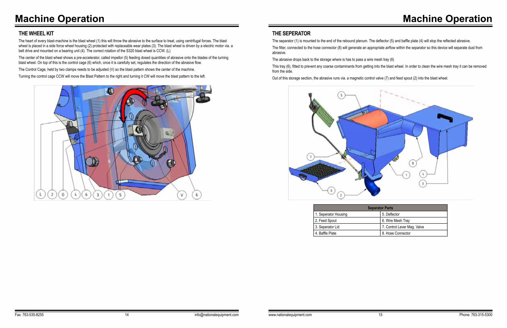
THE SEPERATORThe separator (1) is mounted to the end of the rebound plenum. The deflector (5) and baffle plate (4) will stop the reflected abrasive. The filter, connected to the hose connector (8) will generate an appropriate airflow within the separator so this device will separate dust from abrasive.The abrasive drops back to the storage where is has to pass a wire mesh tray (6)This tray (6), fitted to prevent any coarse contaminants from getting into the blast wheel. In order to clean the wire mesh tray it can be removed from the side. Out of this storage section, the abrasive runs via. a magnetic control valve (7) and feed spout (2) into the blast wheel.
Separator Parts1. Seperator Housing 5. Deflector2. Feed Spout 6. Wire Mesh Tray3. Seperator Lid 7. Control Lever Mag. Valve4. Baffle Plate 8. Hose Connector
Machine OperationTHE WHEEL KITThe heart of every blast-machine is the blast wheel (1) this will throw the abrasive to the surface to treat, using centrifugal forces. The blast wheel is placed in a side force wheel housing (2) protected with replaceable wear plates (3). The blast wheel is driven by a electric motor via. a belt drive and mounted on a bearing unit (4). The correct rotation of the S320 blast wheel is CCW. (L)The center of the blast wheel shows a pre-accelerator, called impellor (5) feeding dosed quantities of abrasive onto the blades of the turning blast wheel. On top of this is the control cage (6) which, once it is carefully set, regulates the direction of the abrasive flow. The Control Cage, held by two clamps needs to be adjusted (V) so the blast pattern shows the center of the machine.Turning the control cage CCW will move the Blast Pattern to the right and turning it CW will move the blast pattern to the left.
Fax: 763-535-8255 [email protected]

Machine OperationTHE TRACTION DRIVEThe 3398 is driven by a 0.55 kW electric drive motor. The power is transmitted via a chain drive. The Drive Wheel (1) and the Drive Sprocket (5) are not linked rigidly. The transmission is build from the traction drive wheel (1), sprocket (5) and chain (7). Drive wheel and drive wheel sprocket are not linked direct, only the quick release pin (4) will link these parts so the energy gets to the drive wheel.Note: They are only linked after insertion of the quick release pin (4).
Traction Drive Parts1. Traction Drive Wheel 5. Drive Sprocket2. Chain Guard 6. Chain Link3. Chain Guard Cover 7. Chain4. Quick Release Pin 8. Motor Sprocket
THE BASE SEALSOn the front and side are magnetic seals (1) surrounded by brush seals (2). On the rear you will find a seal called tail-seal (3) this seal slides over the surface and hinders abrasive getting out of the blast area.All seals should seal against abrasive spray. The correct setting of the magnets is ¼”- ½” over floor depending on the application, also very important for the best function of the machine. The adjustment is done by set screws on the traction drive and the rear (4)
Traction Drive Parts1. Magnetic Seal 4. Adjust Screw2. Brush Seal 5. Magnet Holder3. Tail Seal 6. Seal Plate
Fax: 763-535-8255 [email protected]
Machine Operation
www.nationalequipment.com Phone: 763-315-530017
Machine Operation
www.nationalequipment.com Phone: 763-315-530019
Media: S 330 Steel ShotStandard abrasive suitable for about 50-60 % of all applications. Creates a medium profile on concrete, fulfils the same purpose as Media No. 3 when a higher speed of the machine is required, e.g. on asphalt, in order to keep the thermal load low.
• Removes laitance from new concrete• Roughening of smooth concrete or natural stone• Removes coatings with a thickness of 1/32” - 1/16”• Cleaning of steel surfaces
Media: S 330 Steel Shot• Removes laitance from new concrete• Removing thicker paints or rust from steel surfaces• Removing of flex coatings from parking deck• Removing painted road lines• Retexturing on asphalt surface and concrete roads
Media: S 330 Steel Shot• Removes polyurethane coatings• Removes adhesive remnants• Removes rubber deposits• Penetrates coatings hard to remove• Also suitable to be used on steel
The effectiveness of the 3398 depends on the rebound effect that ensures that the abrasive can be re-used.Please take into account that the use of incorrect abrasive increases wear. Our service engineers have the experience to select the appropriate abrasive for the individual cases of application. Please consult your National customer service department if you have any questions about the selection of the best abrasive for your blast cleaning work.
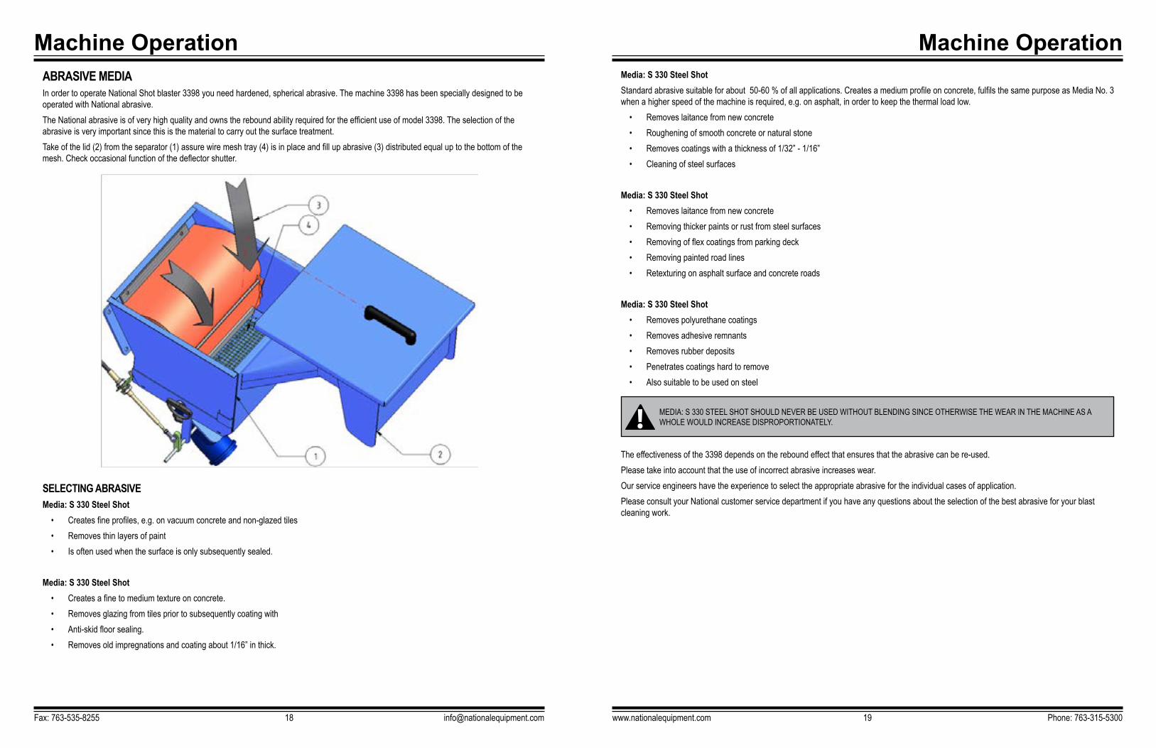
Machine OperationABRASIVE MEDIAIn order to operate National Shot blaster 3398 you need hardened, spherical abrasive. The machine 3398 has been specially designed to be operated with National abrasive. The National abrasive is of very high quality and owns the rebound ability required for the efficient use of model 3398. The selection of the abrasive is very important since this is the material to carry out the surface treatment. Take of the lid (2) from the separator (1) assure wire mesh tray (4) is in place and fill up abrasive (3) distributed equal up to the bottom of the mesh. Check occasional function of the deflector shutter.
SELECTING ABRASIVEMedia: S 330 Steel Shot
• Creates fine profiles, e.g. on vacuum concrete and non-glazed tiles • Removes thin layers of paint• Is often used when the surface is only subsequently sealed.
Media: S 330 Steel Shot• Creates a fine to medium texture on concrete.• Removes glazing from tiles prior to subsequently coating with• Anti-skid floor sealing.• Removes old impregnations and coating about 1/16” in thick.
Fax: 763-535-8255 [email protected]
MEDIA: S 330 STEEL SHOT SHOULD NEVER BE USED WITHOUT BLENDING SINCE OTHERWISE THE WEAR IN THE MACHINE AS A WHOLE WOULD INCREASE DISPROPORTIONATELY.

Machine Operation
www.nationalequipment.com Phone: 763-315-530021
TRANSPORT OF THE MACHINE WITH WHEELSWhen transporting the machine in vehicles, proceed in such a manner that damage due to the effects of use of force or incorrect loading and unloading is avoided. Use straps (S) to tighten the machine to the cabin of the vehicle.Use at least two straps, or tighten the machine with one strap to the cabin wall of the vehicle. Make sure that all parts of the machine are fixed.To reduce the height of the machine, you can slide the handle down. In order to achieve this, you have to slacken the two fixing screws to slide the handle down. Do not forget to fix the fixing screws again, otherwise you will lose them.
OPERATING CONDITIONSCheck the surface to be treated for loose parts (stones, screws, etc.). The surface must be swept if necessary. Make sure that the machine can travel over all inequalities on the surface. Small inequalities like weld seams or floor joints are no barriers for the machine. The machine must be operated in accordance with instructions given in Operation (see Page 26).
Machine OperationGENERAL NOTESBefore the machine used for the first time, National authorised dealers offer a course to familiarise maintenance and operating personnel with all elements of the machine. We are not liable for damage caused by incorrect use of the machine by personnel not trained by National.
TRANSPORT In order to transport the machine from a vehicle to the working area you need to lift the machine up. Use the Toggle Lever Lift at the rear. Push the handle (A) on the top linkage (B) and pull the lever (A) towards direction (L) until the linkage is touching the bracket. To reverse, pull up the lever towards direction M.After the rear Toggle Lever Lift has been set into the upward position, push down the handle on the front and pull the machine towards direction (V) onto the jobsite.Never push the machine, this could cause damage to the rear seals.
When transporting the machine with hoisting equipment like a crane or a lift, check the total weight permitted (see Page 4).Please use only appropriate, allowed and qualified hoisting equipment (A) as well as ropes and chains (A). You will find the weight of the equip-ment in Features and Specification (see Page 4) or on the serial plate on the machine.Do not fix any rope or chain (A) to the handle. Fix ropes and chains only at tie down points as shown. The handle is only fixed with two fixing screws and cannot be used for transport or to fix ropes or hoisting equipment.
Fax: 763-535-8255 [email protected]
Machine Operation
www.nationalequipment.com Phone: 763-315-530023
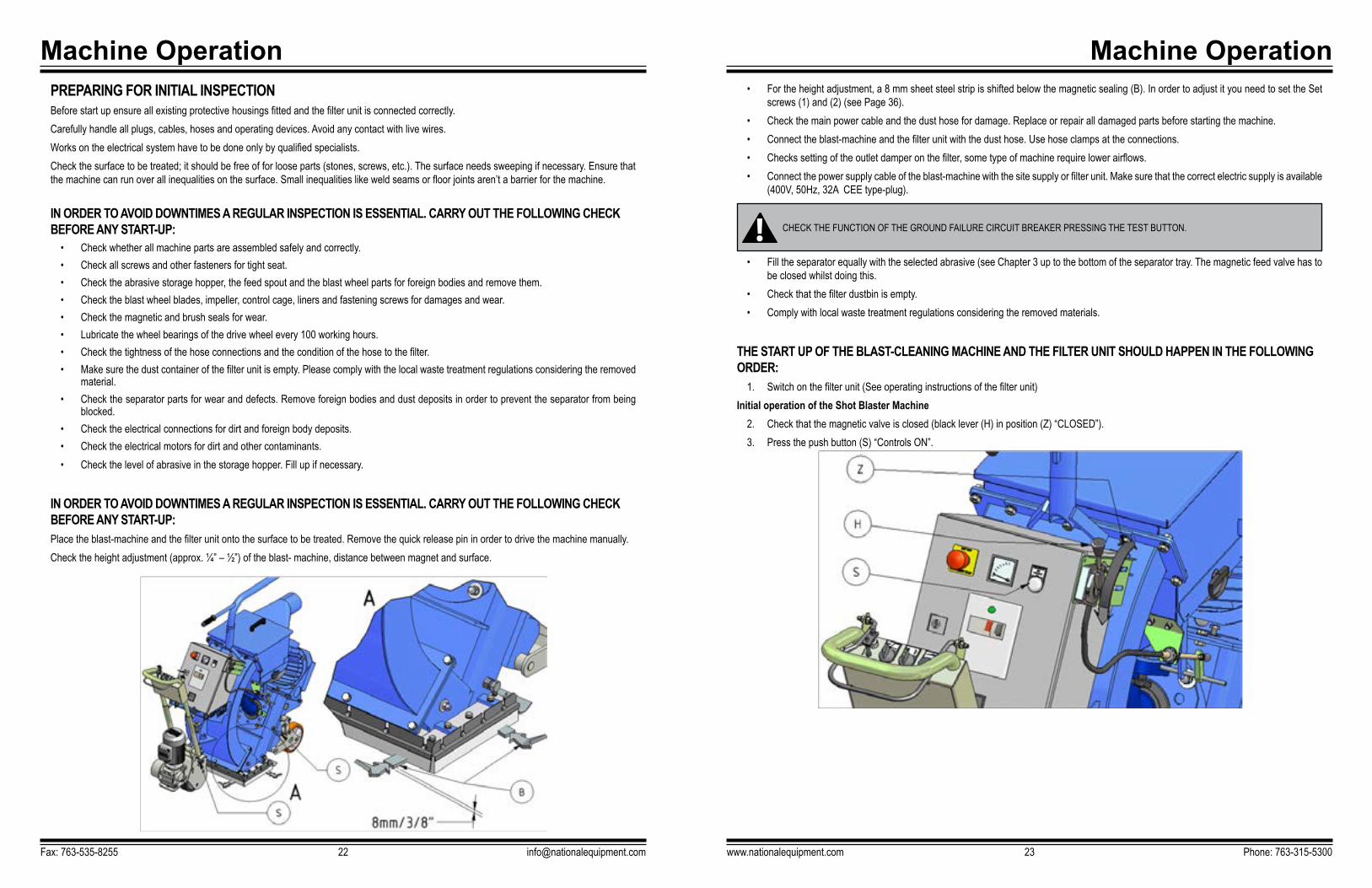
• For the height adjustment, a 8 mm sheet steel strip is shifted below the magnetic sealing (B). In order to adjust it you need to set the Set screws (1) and (2) (see Page 36).
• Check the main power cable and the dust hose for damage. Replace or repair all damaged parts before starting the machine. • Connect the blast-machine and the filter unit with the dust hose. Use hose clamps at the connections. • Checks setting of the outlet damper on the filter, some type of machine require lower airflows.• Connect the power supply cable of the blast-machine with the site supply or filter unit. Make sure that the correct electric supply is available
(400V, 50Hz, 32A CEE type-plug).
• Fill the separator equally with the selected abrasive (see Chapter 3 up to the bottom of the separator tray. The magnetic feed valve has to be closed whilst doing this.
• Check that the filter dustbin is empty.• Comply with local waste treatment regulations considering the removed materials.
THE START UP OF THE BLAST-CLEANING MACHINE AND THE FILTER UNIT SHOULD HAPPEN IN THE FOLLOWING ORDER:
1. Switch on the filter unit (See operating instructions of the filter unit)Initial operation of the Shot Blaster Machine
2. Check that the magnetic valve is closed (black lever (H) in position (Z) “CLOSED”).3. Press the push button (S) “Controls ON”.
Machine OperationPREPARING FOR INITIAL INSPECTIONBefore start up ensure all existing protective housings fitted and the filter unit is connected correctly.Carefully handle all plugs, cables, hoses and operating devices. Avoid any contact with live wires. Works on the electrical system have to be done only by qualified specialists. Check the surface to be treated; it should be free of for loose parts (stones, screws, etc.). The surface needs sweeping if necessary. Ensure that the machine can run over all inequalities on the surface. Small inequalities like weld seams or floor joints aren’t a barrier for the machine.
IN ORDER TO AVOID DOWNTIMES A REGULAR INSPECTION IS ESSENTIAL. CARRY OUT THE FOLLOWING CHECK BEFORE ANY START-UP:
• Check whether all machine parts are assembled safely and correctly. • Check all screws and other fasteners for tight seat. • Check the abrasive storage hopper, the feed spout and the blast wheel parts for foreign bodies and remove them. • Check the blast wheel blades, impeller, control cage, liners and fastening screws for damages and wear. • Check the magnetic and brush seals for wear.• Lubricate the wheel bearings of the drive wheel every 100 working hours. • Check the tightness of the hose connections and the condition of the hose to the filter.• Make sure the dust container of the filter unit is empty. Please comply with the local waste treatment regulations considering the removed
material.• Check the separator parts for wear and defects. Remove foreign bodies and dust deposits in order to prevent the separator from being
blocked.• Check the electrical connections for dirt and foreign body deposits.• Check the electrical motors for dirt and other contaminants.• Check the level of abrasive in the storage hopper. Fill up if necessary.
IN ORDER TO AVOID DOWNTIMES A REGULAR INSPECTION IS ESSENTIAL. CARRY OUT THE FOLLOWING CHECK BEFORE ANY START-UP:Place the blast-machine and the filter unit onto the surface to be treated. Remove the quick release pin in order to drive the machine manually. Check the height adjustment (approx. ¼” – ½”) of the blast- machine, distance between magnet and surface.
Fax: 763-535-8255 [email protected]
CHECK THE FUNCTION OF THE GROUND FAILURE CIRCUIT BREAKER PRESSING THE TEST BUTTON.

Machine Operation
www.nationalequipment.com Phone: 763-315-530025
START UP1. Press the button (SE) “WHEEL ON” on the front of the panel. The wheel motor starts up.2. Watch the Ammeter (A), to control the load of the wheel-motor. During start-up, the motor will need its starting current until max. speed of
the motor is reached.3. When the motor reaches max. speed the amperage drops down to no-load current.4. If the ammeter indicates a high load consumption after having reached the the idle-run speed, the magnetic valve may be partially open
or another disturbance.5. Find out the cause of the disturbance and, if necessary, contact your National customer service engineer.6. Set the direction switch (FR) to “Reverse” (Blast Direction (V). Adjust speed speed by thge Potentiometers (P).7. Pull lever (B) upwards to start up the traction-drive.8. When pulling lever (B) upwards, also pull lever (SH) towards direction (SO) so the feed valve opens and abrasive flow towards the blast-
wheel. Keep eyes on the Amp Meter not exceeding 21 Amps.
When the machine is moving, pull the abrasive control lever (SH) to operate the feed-valve. Observe the ammeter. It may indicate the full load amperage (depending on the selected abrasive up to the operating current (21 Amp max.). An indication exceeding the full load value means overloading of the motor, whereas an indication below the full load value shows that there is not enough abrasive fed to the blast wheel. If necessary, re-adjust the cable to the magnetic valve or refill the hopper with abrasive. After having approx. 3.25 to 6.5 ft (1-2 m) blasted, close the abrasive valve, stop the machine and check the blasted surface. If the blast pattern is irregular, it may be necessary to re-adjust the blast pattern (see Page 32 “Setting the blast pattern”) or select different speed for the machine.
Machine OperationINSERTING THE QUICK RELEASE PIN
1. Open the chain-guard cover (A).2. Turn the Potentiometer (P) in lower 1-2 (low speed).3. Check the Overdrive (O) not selected.4. Switch the direction switch (FR) into forward or reverse.5. Move the Quick Release Pin(S), button (SD) pushed, into the bore (H) of the sprocket hub, keep the button (SD) pushed.6. Pull the lever (B) upwards. The sprocket (K) starts to turn. Push the Quick Release Pin (S) further inwards, still keeping the button (SD
pushed.7. Push inwards until the front ring of the pin (S) is touching the sprocket hub. The machine is now driven by the traction drive motor.8. Close the chain guard cover (A) of the traction drive.
Fax: 763-535-8255 [email protected]
WHEN BLASTING CONCRETE THE ABRASIVE FEED VALVE ONLY MAY BE OPENED WHEN THE BLAST-MACHINE IS IN FORWARD MOTION. IF THE MACHINE IS AT A STANDSTILL AND THE VALVE IS OPENED DEEP GROOVES ARE BLASTED INTO THE CONCRETE SURFACE WITHIN SECONDS.
WHEN THE BLAST HEAD IS LIFTED FROM THE FLOOR, ABRASIVE WILL SPURT OUT OF THE SIDES OF THE BLAST HEAD AT HIGH SPEED. IF THE MACHINE IS MOVED, THE BLAST HEAD RAISED, THE ABRASIVE FEED VALVE MUST BE FULLY CLOSED.
Machine Operation
www.nationalequipment.com Phone: 763-315-530027
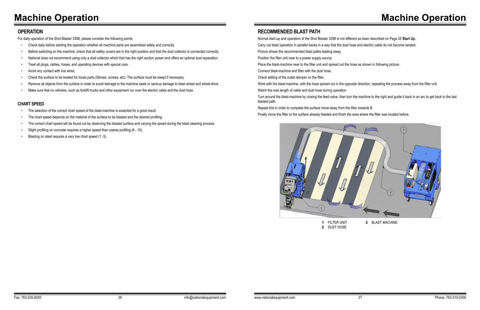
RECOMMENDED BLAST PATHNormal start-up and operation of the Shot Blaster 3398 is not different as been described on Page 25 Start Up.Carry out blast operation in parallel tracks in a way that the dust hose and electric cable do not become twisted. Picture shows the recommended blast paths leading away.Position the filter unit near to a power supply source. Place the blast-machine near to the filter unit and spread out the hose as shown in following picture.Connect blast-machine and filter with the dust hose. Check setting of the outlet damper on the filter.Work with the blast-machine, with the hose spread out in the opposite direction, repeating the process away from the filter unit. Watch the max length of cable and dust hose during operation.Turn around the blast-machine by closing the feed valve, than turn the machine to the right and guide it back in an arc to get back to the last blasted path.Repeat this in order to complete the surface move away from the filter towards B.Finally move the filter to the surface already blasted and finish the area where the filter was located before.
Machine OperationOPERATIONFor daily operation of the Shot Blaster 3398, please consider the following points:
• Check daily before starting the operation whether all machine parts are assembled safely and correctly.• Before switching on the machine, check that all safety covers are in the right position and that the dust collector is connected correctly. • National does not recommend using only a dust collector which that has the right suction power and offers an optimal dust separation. • Treat all plugs, cables, hoses, and operating devices with special care. • Avoid any contact with live wires.• Check the surface to be treated for loose parts (Stones, screws, etc). The surface must be swept if necessary.• Remove all objects from the surface in order to avoid damage to the machine seals or serious damage to blast wheel and wheel-drive.• Make sure that no vehicles, such as forklift trucks and other equipment run over the electric cable and the dust hose.
CHART SPEED• The selection of the correct chart speed of the blast-machine is essential for a good result.• The chart speed depends on the material of the surface to be blasted and the desired profiling. • The correct chart speed will be found out by observing the blasted surface and varying the speed during the blast cleaning process. • Slight profiling on concrete requires a higher speed than coarse profiling (6 - 10). • Blasting on steel requires a very low chart speed (1 -3).
Fax: 763-535-8255 [email protected]
1 FILTER UNIT2 DUST HOSE
3 BLAST MACHINE

Machine Operation
www.nationalequipment.com Phone: 763-315-530029
IF FAILURE OCCURSIn case of an emergency, you can stop the machine immediately by pushing the emergency button (N).
In an emergency press immediately press the RED EMERGENCY BUTTON (N) and afterwards close the Feed Valve pushing lever (H) towards Z.To release the emergency switch, turn the red button and (or) pull it upwards.
RESTARTAfter a fault, ensure that you find the reason of the fault before you restart the machine.Leave the Emergency-Switch pushed down and bring the machine in the Safety-Off Position before you start to find out the fault.
PROCEEDINGS PRIOR AND AFTER LONGER STOPPAGEPrior to long stoppage (longer than 3 months)
• Switch off the machine, see Page 28.• Remove all abrasive out off the machine.• Remove all abrasive from magnets.• Clean the machine and cover it with a foil. • Motors, cable and plugs need to be protected against moisture, dust heat and shock.• Protect bright parts of the machine and power pack with preservative oil.
Machine OperationTURNING OFF THE MACHINE
1. First close the feed valve by the handle (H), push this forward towards towards direction (Z).2. Keep the traction drive switched on so the machines moves towards (S) as long the feed valve (V) is not fully closed to assure no grooves
blasted into the surface.3. Release the traction drive actuator (B) so it swings back into it’s previous position (L). The traction drive switches off and the machine
stops.4. Press the Wheel Motor Off Switch (O).5. Switch off the control circuit by pressing button (K).6. Finally switch off compressor and blower on the filter unit.
Fax: 763-535-8255 [email protected]
ASSURE ALL ROTATING MACHINE PARTS HAVE COME TO STANDSTILL BEFORE INSPECTION OR MAINTENANCE WORK STARTS. ALWAYS ARRANGE THE SAFETY OFF POSITION OF THE MACHINE AS DESCRIBED ON PAGE 10.
Machine Maintenance
www.nationalequipment.com Phone: 763-315-530031
Machine MaintenanceRECOMMENDATIONS
Safety and service life of the machine depend, among other things, on proper maintenance. The following table will show recommendations about time, inspection and maintenance for the normal use of the machine. The time indications are based on uninterrupted operation. When the indicated number of working hours is not achieved during the correspond-ing period, the period can be extended. However a full overhaul must be carried out yearly. Due to different working conditions it cannot be foreseen how frequently inspections for wear checks, inspection, maintenance and repair works ought to be carried out. Prepare a suitable inspection schedule considering your own working conditions.Our specialists will be pleased to assist you with more advice.
Fax: 763-535-8255 [email protected]
PRIOR TO ANY REPAIR WORK ON THE MACHINE AND ITS DRIVES, SECURE THE MACHINE AGAINST UNINTENTIONAL SWITCH-ON. PUT THE MACHINE TO ITS SAFETY OFF POSITION AS DESCRIBED ON PAGE 10.
FAILURES DUE TO INADEQUATE OR INCORRECT MAINTEANANCE MAY GENERATE VERY HIGH REPAIR COSTS AND LONG STOPPAGE PERIODS OF THE MACHINE. REGULAR MAINTENANCE IS ESSENTIAL.
ASSURE ALL ROTATING MACHINE PARTS HAVE COME TO STANDSTILL BEFORE INSPECTION OR MAINTENANCE WORK STARTS. ALWAYS ARRANGE THE SAFETY OFF POSITION OF THE MACHINE AS DESCRIBED ON PAGE 10.
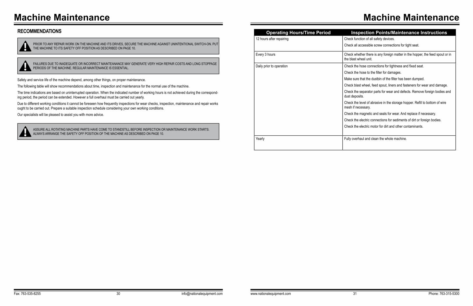
Operating Hours/Time Period Inspection Points/Maintenance Instructions12 hours after repairing Check function of all safety devices.
Check all accessible screw connections for tight seat.
Every 3 hours Check whether there is any foreign matter in the hopper, the feed spout or in the blast wheel unit.
Daily prior to operation Check the hose connections for tightness and fixed seat. Check the hose to the filter for damages. Make sure that the dustbin of the filter has been dumped.Check blast wheel, feed spout, liners and fasteners for wear and damage. Check the separator parts for wear and defects. Remove foreign bodies and dust deposits. Check the level of abrasive in the storage hopper. Refill to bottom of wire mesh if necessary. Check the magnetic and seals for wear. And replace if necessary.Check the electric connections for sediments of dirt or foreign bodies. Check the electric motor for dirt and other contaminants.
Yearly Fully overhaul and clean the whole machine.
Machine Maintenance
www.nationalequipment.com Phone: 763-315-530033
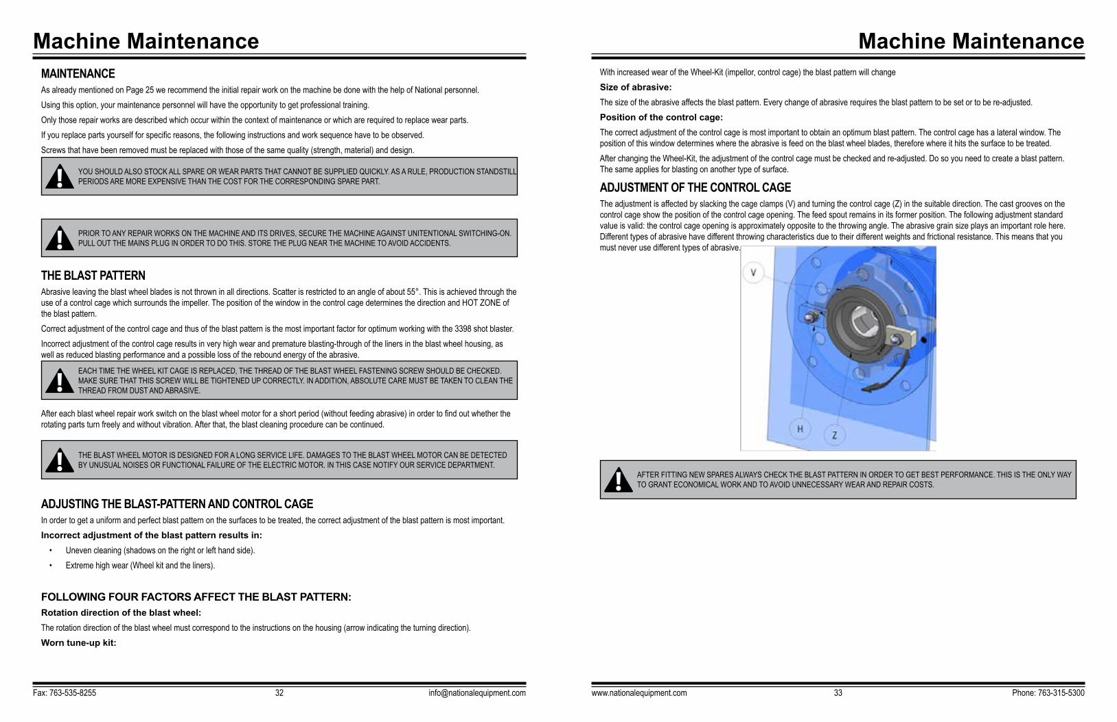
With increased wear of the Wheel-Kit (impellor, control cage) the blast pattern will changeSize of abrasive:The size of the abrasive affects the blast pattern. Every change of abrasive requires the blast pattern to be set or to be re-adjusted. Position of the control cage: The correct adjustment of the control cage is most important to obtain an optimum blast pattern. The control cage has a lateral window. The position of this window determines where the abrasive is feed on the blast wheel blades, therefore where it hits the surface to be treated. After changing the Wheel-Kit, the adjustment of the control cage must be checked and re-adjusted. Do so you need to create a blast pattern. The same applies for blasting on another type of surface.
ADJUSTMENT OF THE CONTROL CAGEThe adjustment is affected by slacking the cage clamps (V) and turning the control cage (Z) in the suitable direction. The cast grooves on the control cage show the position of the control cage opening. The feed spout remains in its former position. The following adjustment standard value is valid: the control cage opening is approximately opposite to the throwing angle. The abrasive grain size plays an important role here. Different types of abrasive have different throwing characteristics due to their different weights and frictional resistance. This means that you must never use different types of abrasive.
Machine MaintenanceMAINTENANCEAs already mentioned on Page 25 we recommend the initial repair work on the machine be done with the help of National personnel.Using this option, your maintenance personnel will have the opportunity to get professional training.Only those repair works are described which occur within the context of maintenance or which are required to replace wear parts.If you replace parts yourself for specific reasons, the following instructions and work sequence have to be observed.Screws that have been removed must be replaced with those of the same quality (strength, material) and design.
THE BLAST PATTERNAbrasive leaving the blast wheel blades is not thrown in all directions. Scatter is restricted to an angle of about 55°. This is achieved through the use of a control cage which surrounds the impeller. The position of the window in the control cage determines the direction and HOT ZONE of the blast pattern. Correct adjustment of the control cage and thus of the blast pattern is the most important factor for optimum working with the 3398 shot blaster.Incorrect adjustment of the control cage results in very high wear and premature blasting-through of the liners in the blast wheel housing, as well as reduced blasting performance and a possible loss of the rebound energy of the abrasive.
After each blast wheel repair work switch on the blast wheel motor for a short period (without feeding abrasive) in order to find out whether the rotating parts turn freely and without vibration. After that, the blast cleaning procedure can be continued.
ADJUSTING THE BLAST-PATTERN AND CONTROL CAGEIn order to get a uniform and perfect blast pattern on the surfaces to be treated, the correct adjustment of the blast pattern is most important.Incorrect adjustment of the blast pattern results in:
• Uneven cleaning (shadows on the right or left hand side). • Extreme high wear (Wheel kit and the liners).
FOLLOWING FOUR FACTORS AFFECT THE BLAST PATTERN:Rotation direction of the blast wheel: The rotation direction of the blast wheel must correspond to the instructions on the housing (arrow indicating the turning direction). Worn tune-up kit:
Fax: 763-535-8255 [email protected]
YOU SHOULD ALSO STOCK ALL SPARE OR WEAR PARTS THAT CANNOT BE SUPPLIED QUICKLY. AS A RULE, PRODUCTION STANDSTILL PERIODS ARE MORE EXPENSIVE THAN THE COST FOR THE CORRESPONDING SPARE PART.
PRIOR TO ANY REPAIR WORKS ON THE MACHINE AND ITS DRIVES, SECURE THE MACHINE AGAINST UNITENTIONAL SWITCHING-ON. PULL OUT THE MAINS PLUG IN ORDER TO DO THIS. STORE THE PLUG NEAR THE MACHINE TO AVOID ACCIDENTS.
EACH TIME THE WHEEL KIT CAGE IS REPLACED, THE THREAD OF THE BLAST WHEEL FASTENING SCREW SHOULD BE CHECKED. MAKE SURE THAT THIS SCREW WILL BE TIGHTENED UP CORRECTLY. IN ADDITION, ABSOLUTE CARE MUST BE TAKEN TO CLEAN THE THREAD FROM DUST AND ABRASIVE.
THE BLAST WHEEL MOTOR IS DESIGNED FOR A LONG SERVICE LIFE. DAMAGES TO THE BLAST WHEEL MOTOR CAN BE DETECTED BY UNUSUAL NOISES OR FUNCTIONAL FAILURE OF THE ELECTRIC MOTOR. IN THIS CASE NOTIFY OUR SERVICE DEPARTMENT.
AFTER FITTING NEW SPARES ALWAYS CHECK THE BLAST PATTERN IN ORDER TO GET BEST PERFORMANCE. THIS IS THE ONLY WAY TO GRANT ECONOMICAL WORK AND TO AVOID UNNECESSARY WEAR AND REPAIR COSTS.
Machine Maintenance
www.nationalequipment.com Phone: 763-315-530035
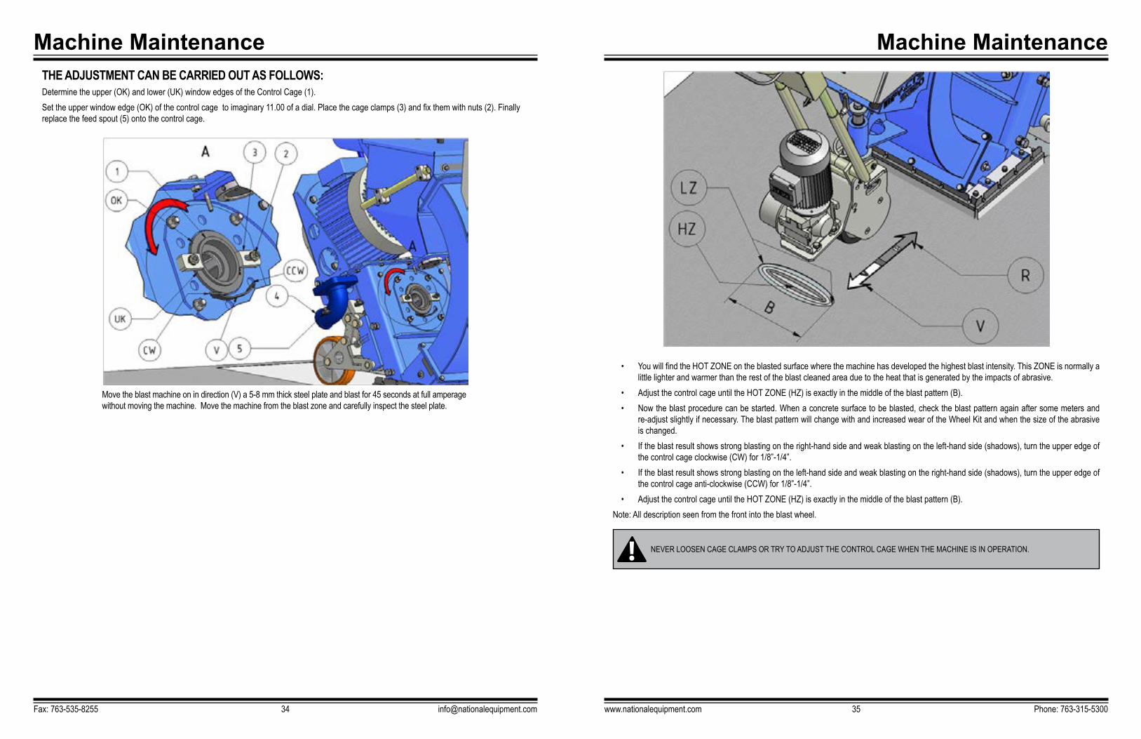
• You will find the HOT ZONE on the blasted surface where the machine has developed the highest blast intensity. This ZONE is normally a little lighter and warmer than the rest of the blast cleaned area due to the heat that is generated by the impacts of abrasive.
• Adjust the control cage until the HOT ZONE (HZ) is exactly in the middle of the blast pattern (B).• Now the blast procedure can be started. When a concrete surface to be blasted, check the blast pattern again after some meters and
re-adjust slightly if necessary. The blast pattern will change with and increased wear of the Wheel Kit and when the size of the abrasive is changed.
• If the blast result shows strong blasting on the right-hand side and weak blasting on the left-hand side (shadows), turn the upper edge of the control cage clockwise (CW) for 1/8”-1/4”.
• If the blast result shows strong blasting on the left-hand side and weak blasting on the right-hand side (shadows), turn the upper edge of the control cage anti-clockwise (CCW) for 1/8”-1/4”.
• Adjust the control cage until the HOT ZONE (HZ) is exactly in the middle of the blast pattern (B).Note: All description seen from the front into the blast wheel.
Machine MaintenanceTHE ADJUSTMENT CAN BE CARRIED OUT AS FOLLOWS:Determine the upper (OK) and lower (UK) window edges of the Control Cage (1). Set the upper window edge (OK) of the control cage to imaginary 11.00 of a dial. Place the cage clamps (3) and fix them with nuts (2). Finally replace the feed spout (5) onto the control cage.
Fax: 763-535-8255 [email protected]
Move the blast machine on in direction (V) a 5-8 mm thick steel plate and blast for 45 seconds at full amperage without moving the machine. Move the machine from the blast zone and carefully inspect the steel plate.
NEVER LOOSEN CAGE CLAMPS OR TRY TO ADJUST THE CONTROL CAGE WHEN THE MACHINE IS IN OPERATION.

Machine Maintenance
www.nationalequipment.com Phone: 763-315-530037
ADJUSTING MAGNET AND SEALS
To achieve a maximum power transfer and live time the correct setting of the belt tension is essential. Often belts are set with the wrong tension and fail before normal service time.Belts that are set with too much tension can cause bearing problems on motors or bearing units.Check the correct pre-tension in accordance with fig. A by pressing down the belt. The distance the belt can be pressed down should be ¼” – ½” (8 to 12 mm). The belt should be displaceable by thumb testing within ¼” – ½” (8 to 12 mm).To adjust the correct belt tension, slacken the motor fixing screws (A) (B) and the locknut (C). Adjust the belt tension by the adjuster screw (D) and tighten afterwards the locknut.Final draw up the motor screws (A)(B) and fit the belt guard again.
Machine MaintenanceADJUSTING MAGNET AND SEALSThe adjusted height of the magnetic seals, parallel to the surface to be treated, should be set equal at about 1/4”-1/2” (8 to 12 mm).
For the height adjustment an 8mm stainless-steel strip (B) is shifted below the magnetic sealing. Front set screw (1) QTY: 2 Rear setscrew (2) QTY: 2 Adjust the height with the setting screws until the correct distance of 1/4” - 1/2” (8-12 mm) has been set. On the National 3398 the adjustment is done by 4 setting screws (one screw (2) each at the rear wheels and two (1) on the inner side of the traction drive bracket. The height of the brush seals should be maximum 1 mm above the surface. The adjustment is possible within the slots of the seal elements.The setting depends on the structure of the surface to be treated, in general the rougher the surface the lower the setting.Working on steel means to set it down as far as possible.
BELT DRIVEThe V-belt is designed for the installed drive power. Forcing the drive to grant a higher output by over tensioning the V-belt results in belt breaks, bearing damage and thus to lower efficiency. A low V-belt tension results in slippage causing an increased belt temperature and thus to prema-ture destruction of the V-belts. Temperatures exceeding 158°F (70°C) for a long period reduce the service life and performance of the V-belts. The grooves of the V-belt pulleys have to be free from rust, grease, dirt and damages. The use of belt wax or similar substances to increase the friction coefficient is unnecessary and damages the V-belts. Avoid any contaminations by oil, grease or chemicals. In order to grant a perfect output transmission, the V-belt drive needs continuous observation.
FITTING BELTSRelease the tension of the V-belt drive by reducing the distance between the shafts of the blast wheel motor and wheel-bearing unit. Insert the V-belt in the V-belt pulley grooves manually without forcing the belt. Tension the V-belt by increasing the distance between the shafts of the blast wheel motor and the wheel-bearing unit as described next. Fit the pertaining protective drive equipment.
Fax: 763-535-8255 [email protected]

Machine Maintenance
www.nationalequipment.com Phone: 763-315-530039
FITTING SPROCKETSChain sprockets must be aligned. In order to achieve this both shafts and the chain sprockets must be parallel and dimensioned according the load. Check the mounting precision by a ruler (L) putted to the chain wheels (K).This has to be done several times with different chain wheel positions. Incorrect mounting makes the internal chain link plates press against the external link plates and accelerates the chain wear or even causes the chain wheels to lock up.
FITTING THE CHAINBefore mounting the chain it must be degreased to prevent any abrasive or abrasive particles from adhering. The chain is supplied as a chain string and has to be prepared during mounting. This is done as follows:
• Place the chain on the chain wheels so that the links lie in tow adjacent gaps between the teeth. • Now close the chain using a chain link. • With heavy chains or big distances between the shafts use a pre-stressing tool in order to bring the two end links so close together that
the coupling link can be inserted without being deformed. Chain Links with springs, their closed sides should point to the running direction (L) of the chain (S). Slide in the link adapter (V) and place the link plate opposite place the spring onto the link plate and press it over the pin into the ring groove by means of a pair of tongs. Demount the spring in the reverse order.
Machine MaintenanceTAPER LOCK BUSHESTaper locks are used to shrink-fit hubs on shafts. Mounting and demounting only requires a screw driver DIN 911 (Allen key). Tightening and loosening is effected with the same threaded pins or screws. Taper locks are cylindrical on the inside, tapered on the outside and slit longitudinally. The smaller bushes 2 and 3 have in the large face their cylindrical blind holes in parallel to the axis, which however, are only placed half in the bush material. The other halves of these blind holes are threaded and are placed inside the hub. Threaded pins or screws are screwed to the stop in the boreholes using an Allen key. When the screws are tightened further using a certain amount of force the hub is drawn up to the tapered bush which is pressed onto the shaft with great force.
DEMOUNTDemount the screws (F) in the belt pulley Lubricate the thread and the tip of the screw and turn it into the bore (L) as shown. Turn the screw until the taper lock (B) gets loose inside the pulley and, thus, the assembly is loose on the shaft. Take the pulley and the taper lock from the shaft.
MOUNTING Assure that all contact surfaces are free from dirt and oil. Place the taper lock into the pulley. Lubricate the screws slightly and insert them into the respecting threaded holes. Clean the shaft, shift the pulley with the taper lock, as one unit, onto the shaft, and position the assembly. Note, that first the taper lock is fixed on the shaft before the pulley reaches its final position on the bush. Use an Allen key to fit the screws. Knock the frontal face of the bush lightly with a hammer to make sure that the bush is seated in the centre of the pulley (use a mandrel to avoid any damages).Now tighten the screws. Repeat the alternating hammering and tightening until all screws fully tightened
THE CHAIN DRIVEThe mounting, demounting and repair work needs always to be done with appropriate tools. With these works the prevailing safety regulations must be strictly observed. Chain drives are relatively robust and reliable even under unfavourable operating conditions. Incorrect mounting and insufficient lubrication and maintenance cause premature wear of the chain and the chain wheels. Careful fitting of the chain drives and appropriate maintenance therefore both contribute to a long service life
Fax: 763-535-8255 [email protected]
REMOVE THE CHAIN GUARD WHEN THE DRIVE MOTOR IS AT A STANDSTILL AND THE MAIN SWITCH OF THE BLAST CLEANING MA-CHINE IS LOCKED (“SAFETY OFF POSITION” SEE PAGE 10).

Machine Maintenance
www.nationalequipment.com Phone: 763-315-530041
WEAR PARTS
Machine MaintenanceMAINTENANCE AND REPAIR OF THE CHAINA chain drive needs little maintenance only if the correct chain has been selected, is mounted correctly, for the application and is not lubricated with grease. A chain guard protects the drive chain. The chain guard prevents excessive contamination and prevents accidents. The chain drive needs to be cleaned every three months. On these occasions, check the alignment of the chain sprockets and the chain ten-sion. In order to clean thoroughly first remove the dirt adhering to the outside of the chain drive using a hard or wire brush. Then wash the chain in petroleum ether or similar. After this, clean the dirt from the internal parts of the chain. To do this put the chain for approx. 24 hours in petroleum ether, diesel or another solvent in order to soften the dirt in the chain joints and the hardened lubricant remnants. Move the chain several times back and forward in the bath to clean the joints.
ADJUSTING CHAIN TENSION OF THE TRACTOR DRIVEThe traction drive motor is mounted on a slotted plate. If necessary to re-tense the chain, it can be done by shifting the motor along the slots. In order to adjust the chain tension, loosen the fixing screws and shift the motor in the direction needed to correct the chain tension. The correct chain tension is set when the chain allows to be dislocated for about ¼” – ½” (8 to 12mm) between the chain sprockets.
Fax: 763-535-8255 [email protected]
1 BLAST WHEEL2 CONTROL CAGE
3 LOCK WASHER4 BOLT
1 TOP LINER2 TOP PLENUM LINER3 SIDE LINER PLENUM RH
4 SIDE LINER PLENUM LH5 BOTTOM PLENUM LINER6 SIDE LINER
LINERS
LINERS
Machine Maintenance
www.nationalequipment.com Phone: 763-315-530043
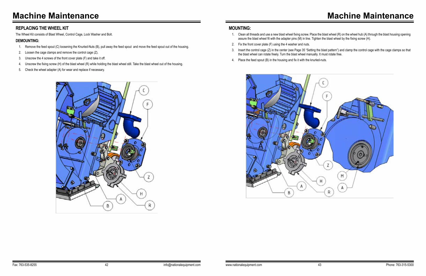
MOUNTING:1. Clean all threads and use a new blast wheel fixing screw. Place the blast wheel (R) on the wheel hub (A) through the blast housing opening
assure the blast wheel fit with the adapter pins (M) in line. Tighten the blast wheel by the fixing screw (H).2. Fix the front cover plate (F) using the 4 washer and nuts. 3. Insert the control cage (Z) in the center (see Page 35 “Setting the blast pattern”) and clamp the control cage with the cage clamps so that
the blast wheel can rotate freely. Turn the blast wheel manually. It must rotate free.4. Place the feed spout (B) in the housing and fix it with the knurled-nuts.
Machine MaintenanceREPLACING THE WHEEL KITThe Wheel Kit consists of Blast Wheel, Control Cage, Lock Washer and Bolt.
DEMOUNTING:1. Remove the feed spout (C) loosening the Knurled-Nuts (B), pull away the feed spout and move the feed spout out of the housing. 2. Loosen the cage clamps and remove the control cage (Z). 3. Unscrew the 4 screws of the front cover plate (F) and take it off. 4. Unscrew the fixing screw (H) of the blast wheel (R) while holding the blast wheel still. Take the blast wheel out of the housing. 5. Check the wheel adapter (A) for wear and replace if necessary.
Fax: 763-535-8255 [email protected]

Machine Operation
www.nationalequipment.com Phone: 763-315-530045
MOUNTING1. Before fitting any new liner, check all threads being clean off dirt and abrasives. Clean where necessary.2. Fist place the bottom (U) and top rebound liner (V), put the nuts on , but do not tighten them.3. Place both side liner (S) into the housing.4. Afterwards place both side liner (N) in the rebound area. Put the nuts on but do not tighten them.5. Place the top liner (O) to the top.6. Close the cover (E) and fit the screws, set the setscrews (F) on the cover so the top liner is supported in the center.7. Slightly tighten the setscrews (D) of the side liners.8. Force the side liners (S) upwards so there is no gap between top and side liners. If necessary, adjust top liner with the set screws (F) to
the side liners. If necessary, adjust top liner with the set screws (F) to the RH or LH side.9. Tighten up the set screws (D)10. Tighten up the nuts (M) both sides of the rebound area.11. Tighten up the nuts of the top and bottom rebound liners.12. Fit the wheel kit and front plate as described on Page 42.13. Swing back the motor bracket, fit belt and belt guard (R).
Machine OperationREPLACING LINERSDEMOUNTING
1. Take off the belt guard. 2. Take off the screws fitted on the inner side of the motor bracket (A) swing the bracket with the handle (H) carefully forward. Take of the3. Remove the front-plate and wheel-kit (G).4. Slacken the setscrews (F) of the top liner. Take of the screws off the belt cover (E) and remove the cover.5. Slacken the setscrews (D) of both side-liner.6. Remove the top liner (O) towards the top.7. Slacken the nuts (M) of the rebound side-liners (N) push the liners in wards. Fully take of the nuts (M) and move both liners (N) downward
away from the housing.8. Push both side-liner (S) towards the bottom out of the housing.9. To remove the rebound bottom (U) and top liner (V), take off the nuts and pull both downwards out of the housing.
Fax: 763-535-8255 [email protected]

Troubleshooting Guide
Problem Cause SolutionReduced performance or no performance Blast wheel or control cage. Blast Wheel or Control Cage worn out.
Replace worn items.
Belt tension. Check and adjust belt.
Valve does not close properly and abrasive is blocking the Blast Wheel when switched on.
Close valve, stop motor. Re-adjust valve.
Too much abrasive admitted when switched on.
Ensure motor got max speed before opening valve.
Feed motion too fast. Reduce speed.
Losing abrasive Bad seals. Check base seals re-adjust and replace when worn.
Elevation adjustment of magnets. Check elevation not to be higher than 1/2”.
Magnets lost field. Replace magnets.
Filter unit. Adjust reducing damper.
Dumping or losing abrasive Poor abrasive quality. Use quality abrasives.
Blast wheel worn. Replace Blast Wheel.
Worn seals. Replace seals.
Elevation adjustment of magnets. Readjust elevation of magnets and adjust seals.
Too much dust and sand in system. Check filter.
Too much dust and other particles in storage. Insufficient air flow towards filtration unit. Check rated performance of the filter unit connected. Check all seals. Check dust hose. Check differential pressure and replace filter elements if pressure too high.
www.nationalequipment.com Phone: 763-315-530047
Troubleshooting Guide
Fax: 763-535-8255 [email protected]
Problem Cause SolutionUnusual Vibrations Uneven wear of the Blast Wheel. Replace Blast Wheel set, check separa-
tor and all other sections of the machine. Remove all broken parts.
Unbalance due to broken parts or blades. Replace wheel hub.
Wheel hub worn out or drive shaft bent. Replace shaft or complete bearing unit.
Unusual Noise Low clearances or bad adjustments of turning parts.
Check part adjustments (Blast wheel and control cage).
Loose or lost screws. Check screws and bolts to be fitted correctly, tighten where necessary.
Shrieking wheels. Apply oil or grease, replace if worn.
Motor bearings worn. Replace bearing.
Reduced performance or no performance Insufficient flow of abrasive in front of the Blast Wheel.
Clean wire mes. Check feed spout to be clean.
Not enough abrasive in storage. Fill up abrasive.
Loose valve lever. Tighten up set screw.
Valve adjustment. Adjust valve lever and valve disk.
Too much dust and sand in the circuit. Check all seals, dust hoses. Check filtration unit to be sealed properly (including dust bin).
TROUBLESHOOTING TROUBLESHOOTING (CONTD)
Troubleshooting Guide
Fax: 763-535-8255 [email protected]
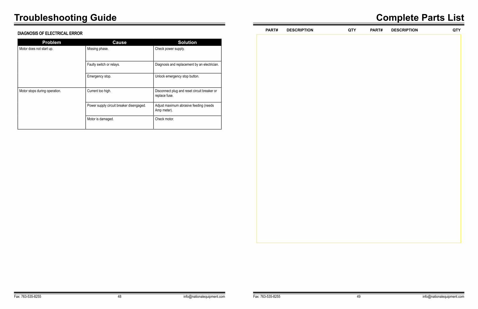
Problem Cause SolutionMotor does not start up. Missing phase. Check power supply.
Faulty switch or relays. Diagnosis and replacement by an electrician.
Emergency stop. Unlock emergency stop button.
Motor stops during operation. Current too high. Disconnect plug and reset circuit breaker or replace fuse.
Power supply circuit breaker disengaged. Adjust maximum abrasive feeding (needs Amp meter).
Motor is damaged. Check motor.
Complete Parts List
Fax: 763-535-8255 [email protected]
PART# DESCRIPTION QTY PART# DESCRIPTION QTYDIAGNOSIS OF ELECTRICAL ERROR
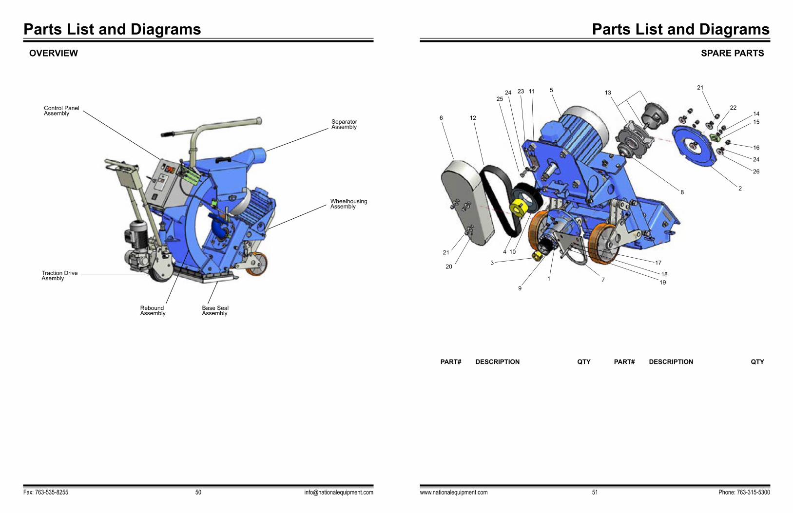
Control Panel Assembly
Traction Drive Asembly
Rebound Assembly
Base SealAssembly
Wheelhousing Assembly
6
20 3
4 10
1 7
17
8
1321
1422
15
16
24
26
2
1819
9
21
12
2524 23 11 5
Separator Assembly
Parts List and Diagrams
Fax: 763-535-8255 [email protected]
OVERVIEW
Parts List and Diagrams
www.nationalequipment.com Phone: 763-315-530051
PART# DESCRIPTION QTY PART# DESCRIPTION QTY
SPARE PARTS

Parts List and Diagrams
Fax: 763-535-8255 [email protected]
PART# DESCRIPTION QTY PART# DESCRIPTION QTY
SPARE PARTS
Parts List and Diagrams
www.nationalequipment.com Phone: 763-315-530053
PART# DESCRIPTION QTY PART# DESCRIPTION QTY
REBOUND ASSEMBLY
7
18
6
10
89
7
7
1
2
5
6
4
11
2
65
12
16
13
19
22
24
17
20
15
23
21
1114
10
131
5
4
25
2
926
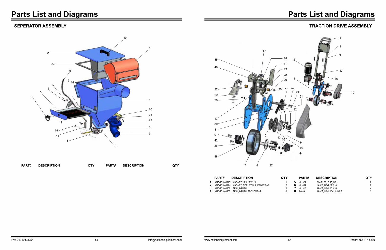
Parts List and Diagrams
Fax: 763-535-8255 [email protected]
PART# DESCRIPTION QTY PART# DESCRIPTION QTY
SEPERATOR ASSEMBLY
Parts List and Diagrams
www.nationalequipment.com Phone: 763-315-530055
1 3395-201000213 MAGNET, 19 X 25 X 228 12 3395-201000214 MAGNET, SIDE, WITH SUPPORT BAR 23 3395-201000202 SEAL, BRUSH 24 3395-201000203 SEAL, BRUSH, FRONT/REAR 2
5 401329 WASHER, FLAT, M8 86 401661 SHCS, M8-1.25 X 16 87 401316 HHCS, M8-1.25 X 30 48 74638 HHCS, M8-1.25X25MM8.8 2
PART# DESCRIPTION QTY PART# DESCRIPTION QTY
TRACTION DRIVE ASSEMBLY
2
10
1
20
186
47
2
1 46
10
3
4
22
47
45
46
3
21
17
17
42
29
28
31
13
11
818
12
65
1517
13 14
9
23
7
4
11
19
22
49
30
2634
3225
3515
43 38
28
29
19 20 16 2829
21
9
4844
14
7 8 27
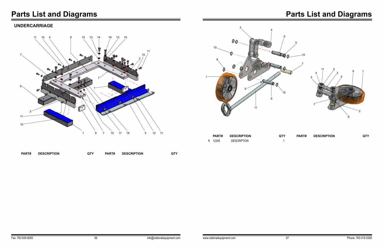
Parts List and Diagrams
www.nationalequipment.com Phone: 763-315-530057
1 12345 DESCRIPTION 1PART# DESCRIPTION QTY PART# DESCRIPTION QTY
Parts List and Diagrams
Fax: 763-535-8255 [email protected]
UNDERCARRIAGE
PART# DESCRIPTION QTY PART# DESCRIPTION QTY
1
10
11
3
6
7
1
7
177 5
11 15 16
2
9 1810 12
10 13 13
10
11
4 14 15
11
3
10
8
1
9
11
6
10
7
54
11 53
6
6 1
2
9
7
10
5
5
4
8

Parts List and Diagrams
www.nationalequipment.com Phone: 763-315-530059
Parts List and Diagrams
Fax: 763-535-8255 [email protected]
1 12345 DESCRIPTION 1PART# DESCRIPTION QTY PART# DESCRIPTION QTY
1615
9
12
10
8
5
46
4
3
13
14
11
Parts List and Diagrams
Fax: 763-535-8255 [email protected]
Guarantee
www.nationalequipment.com Phone: 763-315-530061
National Flooring Equipment, Inc. (National) warrants to the first consumer/purchaser that this National brand product (3398 Shot Blaster) when shipped in its original container, will be free from defective workmanship and materials and agrees that it will, at its option, either repair the defect or replace the defective product or part thereof at no charge to the purchaser for parts or labor for the period(s) set forth below.
This warranty does not apply to any appearance items of the product, to the additional excluded items set forth below, or to any product, the exterior of which has been damaged or defaced, which has been subjected to misuse, abnormal service or handling, or which has been altered or modified in design or construction.In order to enforce the rights under this limited warranty, the purchaser should follow the steps set forth below and provide proof of purchase to National.
The limited warranty described herein is in addition to whatever implied warranties may be granted to purchasers by law. All implied warranties including the warranties of merchantability and fitness for use are limited to the periods from the date of purchase as set forth below. Some states do not allow time limitations on an implied warranty, so the above limitation may not apply to you.
Neither the sales person of the seller, nor any other person, is authorized to make any other warranties other than those described herein, or to extend the duration of any warranties beyond the time period described herein on behalf of National.
The warranties described herein shall be the sole and exclusive warranties granted by National and shall be the sole and exclusive remedy available to the purchaser. Correction of defects in the manner and for the period of time described herein, shall constitute complete fulfillment of all liabilities and responsibilities of National to the purchaser with respect to the product and shall constitute full satisfaction of all claims, whether based on contract, negligence, strict liability or otherwise. In no event shall National be liable, or in any way responsible for any dam-age or defects in the product which were caused by repairs or attempted repairs performed by anyone other than National. Nor shall National be liable, or in any way responsible, for any incidental or consequential, economics or property damage. Some states do not allow the exclusion of incidental or consequential damages, so the above exclusion may not apply to you.
This warranty gives you specific legal rights. You may also have other rights which vary from state to state.
WARRANTY PERIOD
The 3398 Shot Blaster is guaranteed to be free of manufacturer defective workmanship and in quality of materials for a period of one year.
Items excluded from warranty coverage, unless found and reported defective immediately upon removal from the original shipping container and before being used by the original purchaser.
A freight damage claim must be filed with the carrier by the purchaser, the shipper cannot file the freight claim.
TO OBTAIN SERVICE CONTACT NATIONAL FLOORING EQUIPMENT, INC. TOLL FREE AT 800-245-0267 FOR A REPAIR AUTHORIZATION NUMBER. COD FREIGHT RETURNS WILL NOT BE ACCEPTED. FREIGHT COLLECT SHIPMENTS WILL NOT BE ACCEPTED. WARRANTY REPAIRS MUST BE ACCOMPANIED BY DATE OF PURCHASE RECEIPT AND A RETURN/REPAIR AUTHORIZATION NUMBER.
RETURN/REPAIR AUTHORIZATION NUMBER: _____________________________________________MACHINE SERIAL NUMBER: ____________________________________________________________

9250 Xylon Avenue N • Minneapolis, MN 55445 • U.S.A. Toll-free 800-245-0267 • Phone 763-315-5300 • Fax 800-648-7124 • Fax 763-535-8255
Web Site: www.nationalequipment.com • E-Mail: [email protected]