shock ignition modeling ribeyre x., schurtz g., lafon m., weber s., olazabal-loumé m., breil j. and...
TRANSCRIPT

Shock ignition modeling
Ribeyre X., Schurtz G., Lafon M., Weber S., Olazabal-Loumé M., Breil J. and Galera S.
CELIA
Collaborator Canaud B.
CEA/DIF/DPTA
7th Direct Drive and Fast Ignition Workshop

Shock ignition principle: How it works ?
Spike :Converging shock :
Ignition of the hot central region
Divergent return shock duringthe shell stagnation phase
Hotspot
Fuel
Typical laser pulse
Mesh
Laser

Shock ignition : Stagnation conditionsTwo steps process
With convergent shock
Shell stagnation
Standard quasi-isobaric configuration - Low implosion velocity: Vimp < 300 km/s
- Hot spot ignition failsIdentical to fast ignition compression
Non-isobaric configuration (1) Increased central pressure and temperature
ignites a central hot-spot
(1) Betti el al : PRL 98 (2007)
1
2
Compression phase
Ignition phase

ρsh
Phs
rhs rsh
(1) M.D.Rosen and J.D.Lindl (1984) UCRL-50021-83
α adiabat at stagnation
EL laser energy
Non-isobaric fuel assembly and Rosen Model (1)
Psh
ρhs
L
0.17L9.0
27.0
E
cst1EG
Non-isobaric parameter
Rosen model shows the low threshold and high gain possibility of a non-isobaric configuration
G
EL (MJ)

Without SpikeQuasi-isobaric Configuration
With SpikeNo FusionNon-isobaric Configuration
With Spikeand Fusion
Ignition and burn
CHIC 1D SIMULATIONS
Temperature
Temperature
Temperature
Density
Density
Density
Pressure
Pressure
Pressure
Grad P
Grad P
Grad P

Shock convergence model : Spherical NOH problem (1)
Shock Spike
V
Converging shock collision in spherical geometry
Pressure evolution
Radius (normalized)
Accreting shock:Divergent return shock
Pre
ssu
re
t =0 t > 0

Model : Spherical NOH problem (2)
Shock amplification during convergence and collision
Shock amplification during convergence and collision

Shock ignition pressure evolution:
spherical effect • Shock wave pressure amplification during convergence
0.9sP (r) r
CHIC shock pressure
Guderley solution
(1) Guderley 1942, Aleksandrova et al. 2003
Amplification after collision between shock spike and return shock
If pressure balance = X 6
Shock spike convergence
The shock pressure follows approximatively the Guderley solution
Guderley (1) self-similar spherical solution:
Return shock0.69
s 0r =ξ (t -t) 0.9sP (r) r (γ 5 / 3)
300 Gbar
700 Mbar
Shock collision
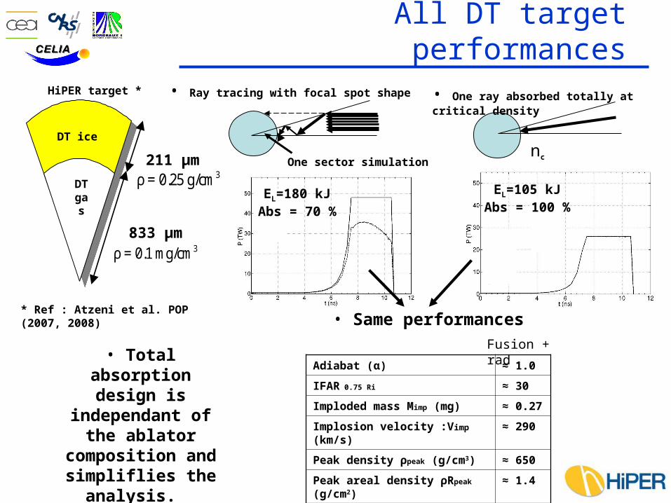
All DT target performances
3ρ = 0.25 g/cm211 µm
833 µm
DT ice
DTgas
3ρ = 0.1 mg/cm
One sector simulation
• Ray tracing with focal spot shape
nc
• One ray absorbed totally at critical density
• Same performances
Adiabat (α) ≈ 1.0
IFAR 0.75 Ri ≈ 30
Imploded mass Mimp (mg) ≈ 0.27
Implosion velocity :Vimp (km/s) ≈ 290
Peak density ρpeak (g/cm3) ≈ 650
Peak areal density ρRpeak (g/cm2) ≈ 1.4
• Total absorption design is
independant of the ablator composition and simpliflies the
analysis.
* Ref : Atzeni et al. POP (2007, 2008)
HiPER target *
Fusion + rad
EL=180 kJAbs = 70 %
EL=105 kJAbs = 100 %

Shock igniting of HiPER target
Iso-energy
Robustness study
Spikepower
250 ps confidence interval at 80 TW
Launching window
180 kJ, 10 ns - 50 TW for compression (3)
+70-100 kJ, ≈ 500 ps – 150-200 TW for
ignitor (3) 20 MJ (TN) : Gain ~ 80(1) Ribeyre et al. : PPCF (2009)
Pabs
tShock launching time

Spike duration effect on target thermonuclear energy
T
RT RT
Spike power time shape
t
Ps
Rise timeRT = 200 ps
500 300 19 40
400 200 18 32
300 100 17 24
250 50 16 20
Spike absorbed energy and powerEs, Ps
Thermonuclear energy ETN
FWHM(ps)
T(ps)
ETN
(MJ)Es
(kJ)
Standard
Target thermonuclear energy vary about 15 % and spike energy about 50 %
Ps/2
Spike duration: FWHM = 2 RT + TSimulation with
T between 50-300 ps with same rise time (RT)
The ignition mainly depends on the spike power and not on the spike energy
ts

Implosion velocity and spike power requirement
Laser absorbed power for compression
Eabs= 105 kJ; Pmax= 26 TW Vimp=290 km/s
Eabs= 80 kJ; Pmax= 15 TW Vimp=225 km/s
Spike threshold: 60 TW
Spike absorbed power required for ignition: Ps
500 ps FWHM
Ps
t
500 ps FWHM
PsSpike threshold:140 TW
Ps ≈ 80 TW : 250 ps
Ps ≈ 200 TW : 200 ps
Low shell implosion velocity requires high power ignition spike, i.e., High intensity spike
tVimp= 290 km/s : Psabs= 80 TW : Plaser = 160 TW (Hyp: 50 % absorption)
Vimp= 225 km/s : Psabs= 200 TW : Plaser = 400 TW (Hyp: 50 % absorption)
Ignition Window

Homothetic targets study
cible
réf
rh=
r2
L LréfcibleP h P
3L LréfcibleE h E3
cible réfM h Mcible reft h t
cible réfρR h ρR
cible refG h G
Compression Energy (kJ) 25 85 180 312 600
h 0.5 0.8 1 1,2 1.5
Target mass (mg) 0.07 0.28 0,59 1,0 2.0
Threshold absorbed Spike power (TW)
60 60 60 60 60
R (g/cm2) 0.79 1.18 1.34 1.60 1.86
Thermonuclear energy (MJ) 1 8 17 38 80
IV = 290 km/s
= 3.5x10¹⁴ W/cm²LI
max = 650 g/cc
if =1.2
522 µm
814 µm1044 µm
1250 µm
1570 µmFor all targets
Spike power required for ignition is the same for all targets
Reference
h scaling factor
shh TR h
aahh RPRP 2/3
La IP
ref0.25
spike WhW
Ignition condition
Guderley model
Ablation pressure
Spike scaling have low
h dependence

Conclusions
• Shock convergence amplification follows approximatively the Guderley solution
• Rosen model is well adapted to give the gain for shock ignition configuration
• Shocks driven by 150 TW (3) peak power ignite HiPER target proposed by S. Atzeni et al., with target gains up to 80. In agreement with Rochester work (Betti et al).
• Shock timing robustness : 250 ps ignition window.
• Ignition: low dependence to spike duration or spike energy
• Low target implosion velocity requires high spike intensity
• Homothetic targets shows that shock ignition power is constant