ship domain in the restricted area simulation research
TRANSCRIPT

152 Scientific Journals 32(104) z. 2
Scientific Journals Zeszyty Naukowe Maritime University of Szczecin Akademia Morska w Szczecinie
2012, 32(104) z. 2 pp. 152–156 2012, 32(104) z. 2 s. 152–156
Ship domain in the restricted area – simulation research
Zbigniew Pietrzykowski, Mirosław Wielgosz, Marek Siemianowicz
Maritime University of Szczecin, Faculty of Navigation 70-500 Szczecin, ul. Wały Chrobrego 1–2, e-mail: {z.pietrzykowski; m.wielgosz}@am.szczecin.pl
Key words: navigational safety, encounter situations, passing distance
Abstract The ship domain – the area around the ship that should be clear of other vessels or objects – depends on many
factors. In this paper authors present results of simulation research on ship domain determination. The
influence of ship size on domain shape and dimensions in the restricted area have been analyzed. The method
of determining ship domain is characterized. The results have been presented. The domains of ships of
different sizes have been compared and conclusions formulated.
Introduction
One of the main tasks of navigation is to ensure
ship's safety during its voyage at sea. Navigational
equipment and systems installed on board are an
important source of information for the navigator
during decision making. The use of up to date
information technologies enables the integration of
information (integrated bridge) and its automatic
processing. This is of particular importance in the
case of information referring to navigational safety,
such as a radar report (ARPA, ECDIS) including
the parameters known as CPA and TCPA. The CPA
as a safety criterion is very useful in open sea navi-
gation. Its use in restricted waters, such as narrow
channels and fairways, in most cases is difficult to
implement. The reason is that a ship has no free
choice of the route. Therefore, a lot of attention is
paid on developing methods and tools for the
determination of an area around the ship that should
be clear of other vessels or objects – ship domain
[1, 2, 3, 4, 5, 7, 8, 9, 10]. This approach is due to
the fact that the concept of domain is intuitively
accepted by the human and enables an analysis and
assessment of the situation and working out deci-
sions on manoeuvring in open and restricted areas.
The concept of domain is applicable on ships, as
well as in land-based vessel traffic centres.
The shape and size of ship domain depend on
many factors, which makes it difficult to define it.
The ship size is one of these factors.
The ship domain and methods of its determination
Domains proposed by various authors can be
divided into two- and three-dimensional ones. The
former describe an area around the ship. Typical
shapes of two-dimensional domains include a cir-
cle, rectangle, ellipsis, polygon and more complex
planar shapes.
The determination of ship domain requires that
its boundary is identified. There are three groups
of methods of ship domain determination. One in-
cludes statistical methods. These consist in record-
ing trajectories of ships' movements to get data for
identifying the area around the ship that navigators
keep clear of other navigational objects [2, 3].
Analytical methods, in turn, are based on the
analytical description of domain area. The domain
boundaries in these methods may be defined on the
basis of the closest point of approach (CPA) and
time to closest point of approach (TCPA), as well
as formulas describing ship's manoeuvrability,
hydrological and meteorological conditions and
relations applicable to ship in motion in a given
area [8, 9].
The application of methods and tools of
knowledge engineering, including artificial intelli-
gence, enables acquiring, representing and using
the procedural and declarative knowledge of expert
navigators for the identification of ship domain.
Examples are provided by artificial neural networks

Ship domain in the restricted area – simulation research
Zeszyty Naukowe 32(104) z. 2 153
used for defining the level of navigational safety,
the basis for outlining the ship domain [6, 7, 11].
Chronologically, statistical methods were first
proposed methods to be used for ship domain
determination [2, 3]. The domain was determined
from registered ship trails indicated by radar. In
restricted areas the ship size has to be taken into
consideration. Using the equipment and systems
used presently on ships’ board and in land-based
centres, capable of registering ship position with
greater accuracy, it can determine ship’s trails that
depend on the ship dimensions (contours).
To determine the domain boundary these
authors adopted the method proposed in [2], based
on the density analysis of ships’ trails around the
central ship. The ships’ trails were assumed to be
the points of waterplane (waterline) of another ship
at preset relative bearings, the nearest to the centre
of the central ship (Fig. 1). Besides, it was assumed
that ship trails would be recorded at fixed time
intervals t at n relative bearings i (i = 1, ..., n) in
the 000÷359 [o] and the discretization step .
Fig. 1. Ship trails determination at defined relative bearings at
instant t
Fig. 2. Ship domain boundaries
The domain boundary is then determined by
a set of points pDi (i = 1, 2, ..., n) at the preset rela-
tive bearings i :
DnDiDDS ppppGD ...,,...,, 21 (1)
such that for a given relative bearing i the trail
density at point pDi, lying at a distance dpDi from the
centre of the central ship is maximum.
Additionally, it can determine the minimum and
maximum boundary of the domain, described, re-
spectively, by points with minimum and maximum
distances of ships’ trails (Fig. 2).
The scope of research
The research aimed at the determination of
domains of various size ships in a restricted area
and an analysis of how encountering ships’ sizes
affect the shape and size of the domain.
The primary method used was that of non-
-autonomous simulations with the participation
of expert navigators, who worked on the ECDIS
simulator at the Maritime University of Szczecin.
The navigators, of varying sea service period, were
trainees attending an ECDIS operation course run
at the same university. The research consisted in
simulated passages of ships conducted according to
pre-determined ship encounter scenarios.
The scenarios assumed good weather conditions
to exclude the influence of hydrological and mete-
orological factors. The passages, then, took place
at daylight, good weather and visibility, with no
current or wind effects.
The Singapore Strait was the area chosen for
tests. This major trading route in South-East Asia is
65.7 Nm long and about 8.6 Nm wide. The strait is
situated between Singapore Island and the Riau
Archipelago. The route traffic intensity is one of the
densest in the world. The beginning of the fairway
leading to the Port of Singapore was selected for
simulations. The port is situated southeast of Jurong
Island, where the fairway neighbours offshore traf-
fic zone, resulting in a variety of ship encounter
situations. Also, this stretch of the fairway includes
an area prohibited for navigation due to construc-
tion work. The construction work area restricts the
fairway on the port side, and the offshore traffic
on the starboard side, which limits the choice of
manoeuvres.
The Navi-Trainer Professional 4000 simulator
offers a selection of 118 ship models for simulation
tests, of which 18 can be handled by the operator.
Having considered all the ship models available,
authors chose three types of ships with various size
for planning the simulated passages. The chosen

Zbigniew Pietrzykowski, Mirosław Wielgosz, Marek Siemianowicz
154 Scientific Journals 32(104) z. 2
models represent a wide spectrum of vessel types
operated in the merchant marine. Table 1 contains
basic parameters of the chosen ship models.
Table 1. Ship models
Ship model River-sea
ship 1
LO-RO
ship VLCC 1
Ship type Coaster LO-RO Tanker
Length overall (Lc) [m] 95.0 174.0 261.0
Breadth (B) [m] 13.0 23.0 48.0
Draft forward (DA) 3.7 7.5 5.8
Draft aft (DF) [m] 3.7 8.1 9.0
Moulded depth (A) [m] 11.1 24.2 37.6
Displacement (D) [t] 3510.0 19512.0 63430.0
Speed over water
(SOW) [w] 11.1/7.0 * 16.3/9.0* 16.3/11.0*
* Speed of the slower ship in scenario 4 (overtaking).
Encounter situations of two ships of the same
type on collision courses were considered, where
one ship was steered by the operator, the other was
automatically handled by a computer. Four basic
scenarios of encounters were developed:
1) encounter of ships on opposite courses;
2) encounter of ships on crossing courses, where
the ship steered by the navigator had the right of
way;
3) encounter of ships on crossing courses, where
the ship steered by the navigator had no right of
way;
4) overtaking situation, where the ship steered by
the navigator was overtaking the other ship, with
no right of way.
Research
384 passages were conducted in total: 128 pas-
sages for each ship type, including 32 passages
following each of the scenarios. The simulations
were executed in real time. The data from the pas-
sages were recorded at the preset discretization step
t = 1 [s].
The ships’ trajectories had to be calculated to
get the relative motion parameters in order to verify
the passing distances between ships and to deter-
mine their domains. The ship’s relative motion was
considered for two cases:
a) the navigator-steered ship motion was displayed
relative to the motion of the computer-operated
ship;
b) the ship operated by the computer was shown
relative to the one handled by the navigator.
Figure 3 shows example relative trajectories of
a river-sea ship 1 for the scenario 4.
The method described in Chapter The ship
domain... was used for the determination of ship
domain limits. To this end the trails of ships located
around the central ship (the one operated by the
computer) were determined. The positions of GPS
antennas on each ship were taken into account. The
ships’ contours were approximated to polygon
shapes.
The ships’ trails recorded at the time interval
t = 5 [s] were analyzed for the relative bearing
discretization = 5 . Figure 4 illustrates the
analyzed trails of river-sea ship 1 for scenario 4.
a) b)
Fig. 3. Relative trajectories of the river-sea ships 1 for the
scenario: 4; a) trajectories of the relative motion of computer-
operated ships; b) trajectories of the relative motion of ships
steered by navigators
Fig. 4. Trails of river-sea ship 1 for scenario 4
On this basis ship partial domains were deter-
mined for each scenario k (k = 1, 2, 3, 4) on preset
relative bearings i : (i = 1, 2, ..., n): domain, min-
imum domain and maximum domain, described,
respectively, by points pD ik, pDmin ik, pDmax ik (com-
pare chapter The ship domain..., Fig. 2).
On the basis of the partial domains determined
for each scenario (four scenarios in the case under
consideration), the limits of total domains GDSC,
GDSCmin and GDSCmax were defined:
-1000 0 1000-3000
-2000
-1000
0
1000
2000
3000
-1500 -1000 -500 0 500 1000 1500-3000
-2000
-1000
0
1000
2000
3000
-1000
-500
0
500
1000-3000 -2500 -2000 -1500 -1000 -500 0 500 1000 1500 2000
[m]
[m]
[m]
[m]

Ship domain in the restricted area – simulation research
Zeszyty Naukowe 32(104) z. 2 155
nDCiDCDCDCSC ppppGD ...,,...,,, 21 (2)
nDCiDCDCDC
SC
pppp
GD
minmin2min1min
min
...,,...,,,
(3)
nDCiDCDCDC
SC
pppp
GD
maxmax2max1max
max
...,,...,,,
(4)
The limits were such that for a given relative
bearing i (i = 1, 2, ..., n)
4,3,2,1;min kddikDpiDCp (5)
4,3,2,1;min minmin kdd ikpDipDC (6)
4,3,2,1;min maxmax kdd ikpDCipDC (7)
where
dpDik – distance from the centre of the central
ship to the limit of the partial domain on
the relative bearing i for the scenario k;
dpD min ik – distance from the centre of the central
ship to the limit of the minimum partial
domain on the relative bearing i for the
scenario k;
dpD max ik – distance from the centre of the central
ship to the limit of the maximum partial
domain on the relative bearing i for the
scenario k.
As an example the determined partial domain
boundaries – minimum, mean and maximum – for
the river-sea ship 1 for scenario 4 are presented in
the figure 5.
Fig. 5. The partial domains of river-sea ship 1 for scenario 4
Figure 6 presents the total domains of the ships
under analysis.
The analysis of the results
The research included an analysis of passing dis-
tances between vessels accounting for their dimen-
sions (ship contours). The program recording ship
movement parameters was logging the position
of GPS receiver antenna. For this reason it was
a) b) c)
Fig. 6. Total ship domains(minimum, mean and maximum) for ships of different size: a) river-sea ship 1; b) LO-RO ship; c) VLCC1
-1000 0 1000-3000
-2000
-1000
0
1000
2000
3000
y [m]
x [m
]
granica minimalna
granica średnia
granica maksymalna
-1000 0 1000-3000
-2000
-1000
0
1000
2000
3000
y [m]
x [m
]
-1000 0 1000-3000
-2000
-1000
0
1000
2000
3000
y [m]
x [m
]
Zbigniew Pietrzykowski, Mirosław Wielgosz, Marek Siemianowicz
156 Scientific Journals 32(104) z. 2
necessary to determine the distances of characteris-
tic points describing the ship contour in relation to
the antenna position.
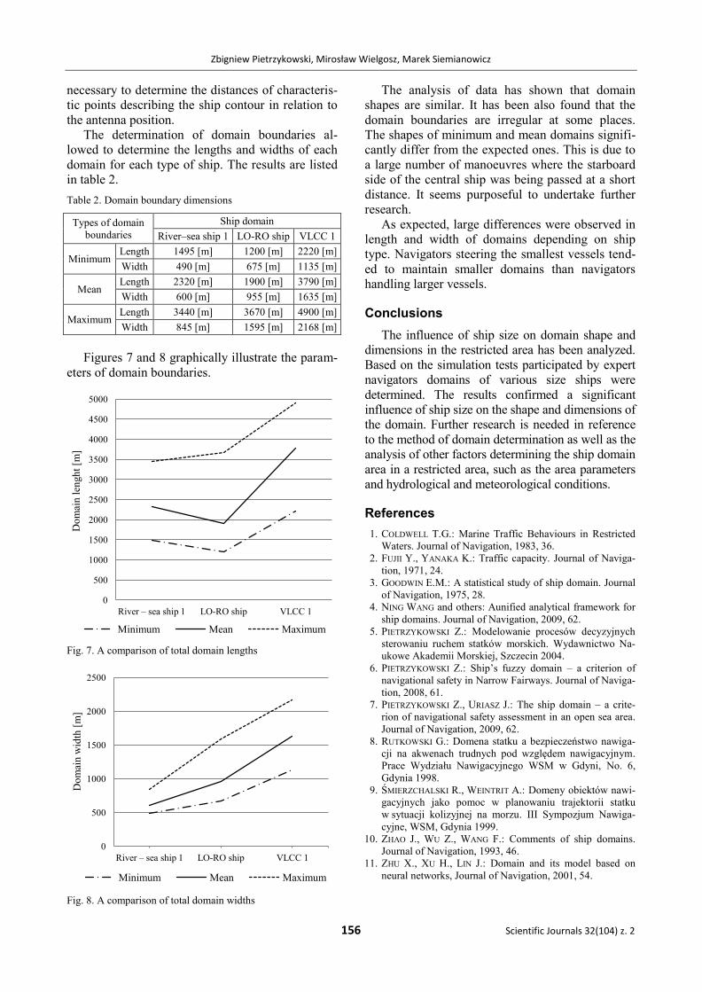
The determination of domain boundaries al-
lowed to determine the lengths and widths of each
domain for each type of ship. The results are listed
in table 2.
Table 2. Domain boundary dimensions
Types of domain
boundaries
Ship domain
River–sea ship 1 LO-RO ship VLCC 1
Minimum Length 1495 [m] 1200 [m] 2220 [m]
Width 490 [m] 675 [m] 1135 [m]
Mean Length 2320 [m] 1900 [m] 3790 [m]
Width 600 [m] 955 [m] 1635 [m]
Maximum Length 3440 [m] 3670 [m] 4900 [m]
Width 845 [m] 1595 [m] 2168 [m]
Figures 7 and 8 graphically illustrate the param-
eters of domain boundaries.
Fig. 7. A comparison of total domain lengths
Fig. 8. A comparison of total domain widths
The analysis of data has shown that domain
shapes are similar. It has been also found that the
domain boundaries are irregular at some places.
The shapes of minimum and mean domains signifi-
cantly differ from the expected ones. This is due to
a large number of manoeuvres where the starboard
side of the central ship was being passed at a short
distance. It seems purposeful to undertake further
research.
As expected, large differences were observed in
length and width of domains depending on ship
type. Navigators steering the smallest vessels tend-
ed to maintain smaller domains than navigators
handling larger vessels.
Conclusions
The influence of ship size on domain shape and
dimensions in the restricted area has been analyzed.
Based on the simulation tests participated by expert
navigators domains of various size ships were
determined. The results confirmed a significant
influence of ship size on the shape and dimensions of
the domain. Further research is needed in reference
to the method of domain determination as well as the
analysis of other factors determining the ship domain
area in a restricted area, such as the area parameters
and hydrological and meteorological conditions.
References
1. COLDWELL T.G.: Marine Traffic Behaviours in Restricted
Waters. Journal of Navigation, 1983, 36.
2. FUJII Y., YANAKA K.: Traffic capacity. Journal of Naviga-
tion, 1971, 24.
3. GOODWIN E.M.: A statistical study of ship domain. Journal
of Navigation, 1975, 28.
4. NING WANG and others: Aunified analytical framework for
ship domains. Journal of Navigation, 2009, 62.
5. PIETRZYKOWSKI Z.: Modelowanie procesów decyzyjnych
sterowaniu ruchem statków morskich. Wydawnictwo Na-
ukowe Akademii Morskiej, Szczecin 2004.
6. PIETRZYKOWSKI Z.: Ship’s fuzzy domain – a criterion of
navigational safety in Narrow Fairways. Journal of Naviga-
tion, 2008, 61.
7. PIETRZYKOWSKI Z., URIASZ J.: The ship domain – a crite-
rion of navigational safety assessment in an open sea area.
Journal of Navigation, 2009, 62.
8. RUTKOWSKI G.: Domena statku a bezpieczeństwo nawiga-
cji na akwenach trudnych pod względem nawigacyjnym.
Prace Wydziału Nawigacyjnego WSM w Gdyni, No. 6,
Gdynia 1998.
9. ŚMIERZCHALSKI R., WEINTRIT A.: Domeny obiektów nawi-
gacyjnych jako pomoc w planowaniu trajektorii statku
w sytuacji kolizyjnej na morzu. III Sympozjum Nawiga-
cyjne, WSM, Gdynia 1999.
10. ZHAO J., WU Z., WANG F.: Comments of ship domains.
Journal of Navigation, 1993, 46.
11. ZHU X., XU H., LIN J.: Domain and its model based on
neural networks, Journal of Navigation, 2001, 54.
0
500
1000
1500
2000
2500
3000
3500
4000
4500
5000
River – sea ship 1 LO-RO ship VLCC 1
Do
mai
n l
engh
t [m
]
Minimum Mean Maximum
0
500
1000
1500
2000
2500
River – sea ship 1 LO-RO ship VLCC 1
Do
mai
n w
idth
[m
]
Minimum Mean Maximum