ship construction- h.j.pursey
TRANSCRIPT
MERCHAI\T SHIPCOI\STRT]CTIOI\
Especially written for
the Merchant Navy
BY
H. J. PURSEYEXTRA MASTER
Formerly Lecturer in Ship Construction to the School of NavigationUniversity of Southampton
GLASGOWBROWN, SON & FERGUSON, LrD., Nlurtclr, Punr.lsneRs
4-10 DexNr,eY STBEET

CONTENTS
SECTION I-GENERAL
Classification of shipsLloyd's dimensionsSections used in shipbuildingConnectionsStrengthening ofjoints and partsRivetingElectric arc weldingGcneral types ofshipsStresses and strains in ships . .Systems of constructionKeelsCellular double bottomsFrames ..Beams .Watertight bulkheadsSystems of pillaringMassed pillaringHatchwaysShell and deck platingSheathed decks and wood decksBilge keelsDeep tanksPeaks and panting arrangementsStcms 92Rudders and sternframes .. 95Sterns 100Shaft tunnelsStern tubes and propcllcrsTwin screwsSuperstructures and deckhouses
decks .
PAGE
2468
l 2l 41 928303438404850546062667280828488
102104106
Engine and boiler roomsHatch beams and covers
Raised quarterBulwarks
Hawsepipes
VentilatorsMasts and derrick posts
108112t t4I t 6l l 8r221241261281301321 3 8
Refrigerated shipsStrengthening for icc navigationPipes to tanks and bilgpsSpecial types
tx
{
CONTENTS
SECTION II_THE CONSTRUCTION OF OIL TANKERS
General requirementsCeneral arrangementsSlructure in the bottomStructure under the deckSide framingLoneitudinal bulkheadsCross t ies'fransverse
bulkheadsFraming at ends of shipCofferdamsHatchwaysSuperstructuesFreeing arrangementsPumping and pipingTests
SECTION III-SHIPYARD PRACTICEPreliminary drawingsPreparations for buildingBuilding the shipPrefabricationLaunching the ship
SECTION
SurveysTypes and testing of steelTonnagesFreeboardLoadlines and tonnage marks
SECTION V-LONGITUDINAL STRESSES AND STRESS DIAGRAMSBending stresses on girdersLongitudinal bending stresses on ships
SECTION VI-DEFINITIONS
Defnitions
PACE
147148152152152152t54154t54156
156156156
156156
IV-SURVEYS, STEEL, TONNAGE, FREEBOARD AND LOADLINES
r601621631 &165
t69172174t77180
185193
201
IEF:

LIST OF PLATES
PurrLloyds dimensions
PAGE
579
l ll 3l 5l 72l2527293 l3537394l+ J
45
495 ls3
596l6365676970I J
t )
77798 l83858789909l9394
Transverse system: Longitudinal systemCombination system: Cantrlever framing
Arrangements at the bilgePrecautions against poundin g
SectionsConnectionsConnectionsStiffeningRivetingRivetingWeldingWeldingWeldingTypesStrains in ships
Keels
Types of frameBeamsBeam Knees
PillaringPillarsDeck girdersHatchwaysHatchways
Bilge keels
Peaks
StemsPlate stem
Transverse framing in bottomLongitudinal framing in bottom
Watertight bulkheadBulkhead detailsBoundary connections
5557
Beams at hatch coamingsShell and deck platingSystems of platingShell and deck platingShell and deck platingSheathed and wood decks
Watertight joints at tank topDeep tank for oil fuel
Panting arrangemenlPanting arrangemenl
s at fore end of ships .
lG,
LIST OF PLATES
PLlreDouble plate ruddersCast sternframes
I l
PAGB
979899
101103105lo7I09l l l1 1 3l t 5lr7l l 9121t23t2512712913 I133135
149150l5 l153155t57
l 6 l
End of superstructureInside superstructure , .Break of raised quarter deck
Shaft tunnelsStern tubesTwin screws
BulwarksEngine roomHatch beams
Hawsepipe
RuddersSterns
Masts
PipingPiping
MacGregor steel hatches
VentilatorsRefrigerated shipIce strengthening
Three-hatch ship: Container ShipBulk carrier: Ore carrierGas tanker: Gas Carrier
General arrangements. .Large tankerSmaller tankerSide and bilge structureStructure in centre tankWelded comrgated bulkheads
SHIPYARD PRACTICEDrawings
Evenly loaded girder: IntegrationSTRESS DIAGRAMS
Curves for lighterCurves for ship in still waterCurves for ship in waves
139l4 l143
OIL TANKER.:
l9 l195197l9E
SECTION I
MERCHANT SHIP CONSTRUCTION

MERCHANT SHIP CONSTRUCTION
PAR.T I
CLASSIFICATION OF SIilPS
Purposes-To ensure that ships are properly built, equipped and main-tained, a number of 'Classification Societies' have been formed and havedrarvn up rules governing the construction of ships. The Societies havesurveyors, who see that the ships are built in accordance with the rules andwho also survey the ships periodically, to make sure that they are kept inproper condition. Each society also keeps and publishes a 'Register Book',in which all the important particulars of each ship are faithfully and accuratelyrecorded.
British classification societies-The British Society is 'Lloyd's Registerof Shipping'. The French Society 'The Bureau Veritas', also has a BritishCommittee.
It should be remembered that the societies only classify ships and are aseparate body from the underwriters who insure them.
The Rules-The rules of the different societies vary somewhat in detail,but are mainly very similar. They are not arbitrary and other forms ofconstruction are allowed if they give equivalent strength.
In order to avoid confusion, Lloyd's Rules have been followed throughoutthis Book.
Classes of Ships-Ships built to the satisfaction of the Societies areassigned a Class, which they normally retain throughout their life, providedthat they submit themselves for the required surveys and are properlymaintained.
Lloyd's Rules quote a number of class notations, principally:-100.c,1. All sea-going ships, built for general service.l00nl bulk carrier. To carry dry cargoes in bulk.l00ll container ship. To carry containers.
2
100.c,1 or l : :100e1 ch:::100a1 l iq ' ; .100e1 l ic; :l00el fcr :
a :Addit ion:^
to any of the =:There ar:
f ishing vessels. :
Equipment-ments, the figu:normally be cl"not be conside:the ship ui l l t l :
Equipme::stream wires.
Ice Class \in ice ma1' be g-Baltic ice conc.
C lass 1* .C lass 1 .Class LClass 3 .There are
strengthening. :
Ships BuiJtrequired ttr b,: :this has bee:: : :Book. thus - r l
The si : : : . -under Sun:. ' , - :
Periodicalcondit ion t . ' :=:^ l - ^ r ^d r s u r 9 : F c ! . : .
e lse*here : : : : .
AssigrcentTrade or b' ' : :
The as . . ; :nOf lS l ! t 3a€ :> '^ . , r r i , . { . 1 r : : . ,P r L
' r s l s ! . . - ,
MERCHANT SHIP CONSTRUCTION
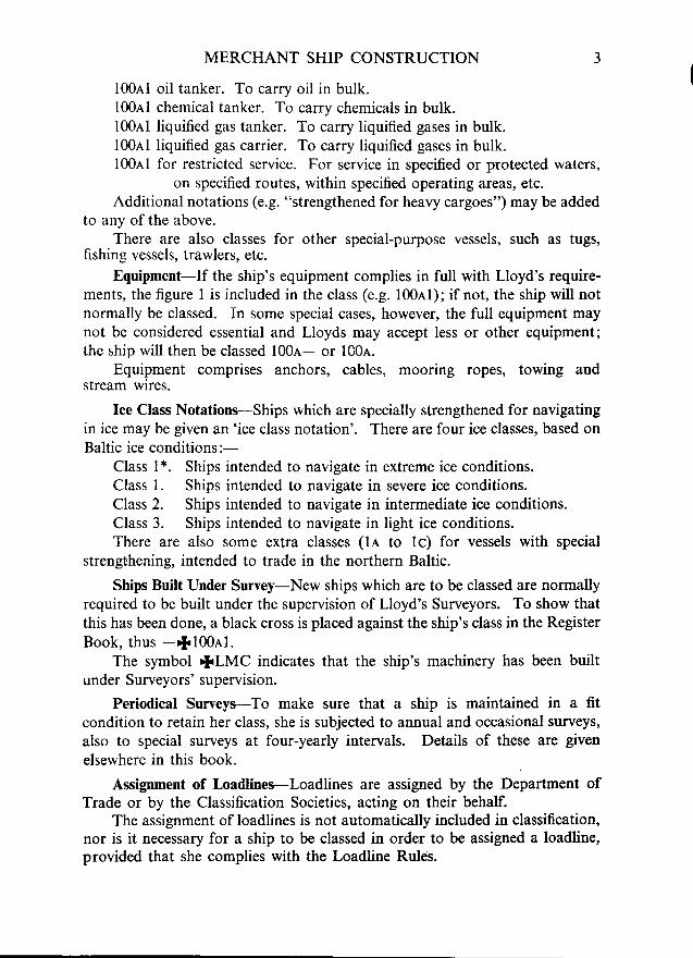
100e1 oil tanker. To carry oil in bulk.10041 chemical tanker. To carry chemicals in bulk.100e1 liquified gas tanker. To carry liquified gases in bulk.l00al liquified gas carrier. To carry liquified gases in bulk.l00,c,l for restricted service. For service in specified or protected waters,
on specified routes, within specified operating areas, etc.Additional notations (e.g. "strengthened for heavy cargoes") may be added
to any ofthe above.There are also classes for other special-purpose vessels, such as tugs,
fishing vessels, trawlers, etc.Equipment-If the ship's equipment complies in full with Lloyd's require-
ments, the figure 1 is jncluded in the class (e.g. l00,rl); if not, the ship will notnormally be classed. In some special cases, however, the full equipment maynot be considered essential and Lloyds may accept less or other equipment;the ship will then be classed l00e- or 100e.
Equipment comprises anchors, cables, mooring ropes, towing andstream wires.
Ice Class Notations--Ships which are specially strenglhened for navigatingin ice may be given an 'ice class notation'. There are four ice classes, based onBaltic ice conditions:-
Class 1*. Ships intended to navigate in extreme ice conditions.Class l. Ships intended to navigate in severe ice conditions.Class 2. Ships intended to navigate in intermediate ice conditions.Class 3. Ships intended to navigate in light ice conditions.There are also some extra classes (ll to lc) for vessels with special
strengthening, intended to trade in the northern Baltic.
Ships Built Under Survey-New ships which are to be classed are normallyrequired to be built under the supervision of Lloyd's Surveyors. To show thatthis has been done, a black cross is placed against the ship's class in the RegisterBook, thus -rl100el.
The symbol {.LMC indicates that the ship's machinery has been builtunder Surveyors' supervision.
Periodical Surveys-To make sure that a ship is maintained in a fitcondition to retain her class, she is subjected to annual and occasional surveys,also to special surveys at four-yearly intervals. Details of these are given
elsewhere in this book.
Assignment o1 lssdlines-Loadlines are assigned by the Department ofTrade or by the Classification Societies, acting on their behalf.
The assignment of loadlines is not automatically included in classification,nor is it necessary for a ship to be classed in order to be assigned a loadline,provided that she complies with the Loadline Rules.
MERCHANT SHIP CONSTRUCTION
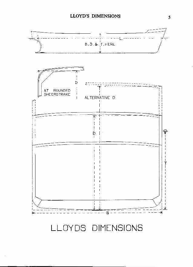
LLOYD'S DIMENSIONS
Purpose-The scantlings (or sizes) of the various parts of the ship dependrnainly on the ship's dimensions and summer draft.
The Dimensions are as follows:-'L,' the length, is measured on the summer loadline, from the fore side
of the stem to the after side the rudder post, or to the centre of the rudderstock if there is no rudder post. It must not in any case be less than 96 percent, but need not be more than 97 per cent of the length overall on thesummer loadline.
'B', the breadth, is thb greatest moulded breadth, measured from side toside, outside the frames, but inside the shell plating.
'D,' the depth is measured vertically, at the middle length of the ship,from the top of the keel to the level of the top of the beams at the side of theuppermost continuous deck: except in certain cases in which it is measured tosuperstructure deck beams. In ships with rounded sheerstrakes, it is measuredto the point at which the moulded lines of the deck and side would meet ifextended.
'?,' the draft, is the summer moulded draft.
LL
- ---:-r:--:t \
K.
LLOYD'S DIMENSIONS
LLOYDS DIMINSIONS
AT ROUNOEDSHEERETRAKf
TI
I
uI
i ;It tt l
t ;r l
l rl gr lI
I '1 lr l
MERCHANT SHIP CONSTRUCTION
SECTIONS USED IN SHIPBUILDING
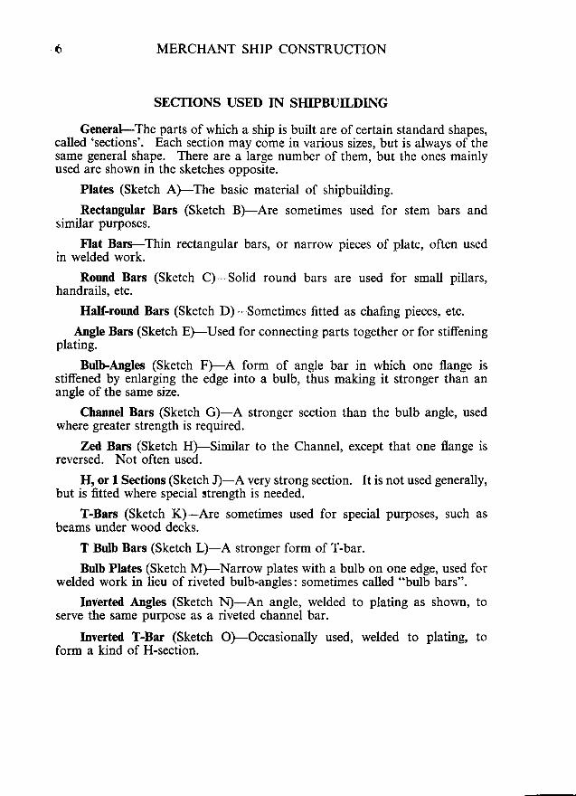
General---The parts of which a ship is built are of certain standard shapes,called 'sections'. Each section may come in various sizes, but is always of thesame general shape. There are a large number of them, but the ones mainlyused are shown in the sketches opposite.
Plates (Sketch A)-The basic material of shipbuilding.
Rectangular Bars (Sketch B)-Are sometimes used for stem bars andsimilar purposes.
Flat Bars-Thin rectangular bars, or narrow pieces of plate, often usedin welded work.
Round Bars (Sketch C)-Solid round bars are used for small pillars,handrails, etc.
Half-round Bars (Sketch D)-Sometimes fitted as chafing pieces, etc.
Angle Bars (Sketch EfUsed for connecting parts together or for stiffeningplating.
BulbAngles (Sketch F)-A form of angle bar in which one flange isstiffened by enlarging the edge into a bulb, thus making it stronger than anangle of the same size.
Channel Bars (Sketch GFA stronger section than the bulb angle, usedwhere greater strength is required.
Zed Bars (Sketch H)-Similar to the Channel, except that one flange isreversed. Not often used.
H, or 1 Sections (Sketch I)-A very strong section. It is not used generally,but is fitted where special strength is needed.
T-Bars (Sketch K)-Are sometimes used for special pu{poses, such asbeams under wood decks.
T Bulb Bars (Sketch LFA stronger form of T-bar.
Bulb Plates (Sketch M)-Narrow plates with a bulb on one edge, used forwelded work in lieu of riveted bulb-angles: sometimes called "bulb bars".
Inverted Angles (Sketch N)-An angle, welded to plating as shown, toserve the same purpose as a riveted channel bar.
Inverted T-Bar (Sketch OFOccasionally used, welded to plating, toform a kind of H-section.
tllF

SECTIONS
Sf CTIONS
TF
MERCHANT SHIP CONSTRUCTION
CONNECTIONS
General-The various parts of a ship must be properly connected togetherif the ship is to be strong and rigid. Ttre strengtli of any connection should,so far as possible, be equa.l to the strength of th-e parts connected.
The forms of connection described here are the more important ones ingeneral use. Where others are used in special parts they are described in thesections relating to those parts.
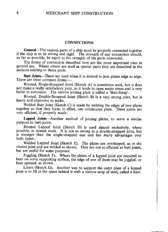
Butt Joints-These are used when it is desired to join plates edge to edge.There are three common forms:-
Riveted, Single-Strapped Joint (Sketch A) is sometimes used, but it doesnotmake a really satisfactory joint, as it tends to open under stress and is veryliable to corrosion. The narrow joining plate is ca[ed a 'Butt-Strap'.
Riveted, Double-Strapped Joint (Sketch B) is a very strong joint, but isheavy and expensive to make.
welded Butt Joint (sketch c) is made by welding the edges of two platestogether so that they form, in effect, one continuous plate. These joinls arevery efficient, if properly niade.
Lapped Joints-Another method of joining plates, to serve a similarpu{pose to butt-joints.
.Riveted .Lapped Joint (Sketch D) is used almost exclusively, wherepossible, in riveted,work. It is not so strong as a double-strapped joint, butis stronger than the single-strapped one and has many advantages overboth types.
. {e.ld.ed Lapped Joint (Sketch E). The plates are overlapped, as in theriveted joint and are welded as shown. They are not so efficieni-as butt joints,but are useful for some purposes.
. Joggling (Sketch F). Where ihe plates of a lapped joint are required tobear on some supporting surface, the edge of one of them may be jolgled, orbent upward, as shown.
Liners (Sketch G). Another way to support the outer plate of a lappedjoint is to fill in the space behind it with a nairow strip of steel, called a liner.
^ r /
G

/o/o o,
/o o//o o//o/
o o o--Pf/o o o
O L I N E R . . . . -
ooooo
CONNECTIONS
tnF
IO MERCHANT SHIP CONSTRUCTION
CONNECTIONS-(Co nr in ue d )
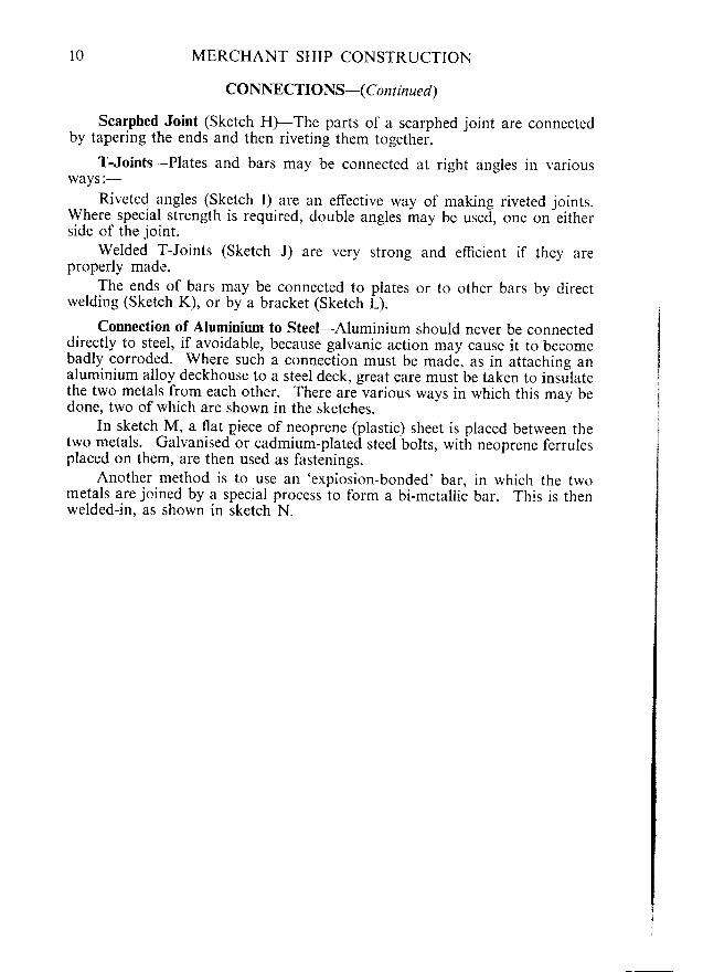
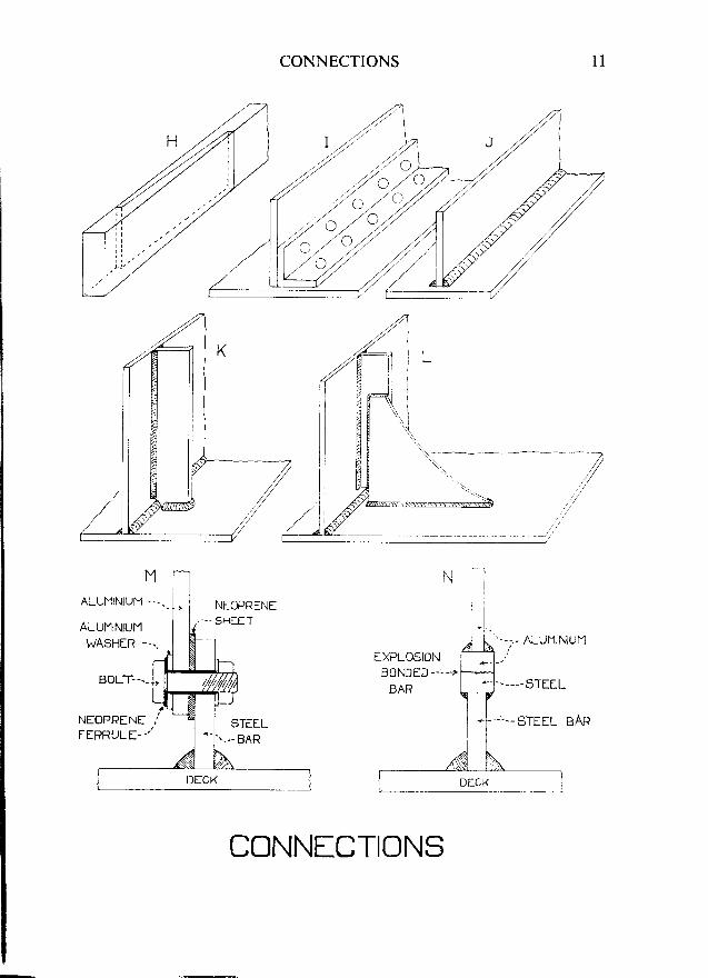
scarphed Joint (Sketch H)-The parts of a scarphed joint are connectedby tapering the ends and then riveting them togethei.
T-Joints-Plates and bars may be connected at right angles in variousways:-
Riveted angles (Sketch I) are an effective way of makine riveted ioints.w_here special strength is required, double angles may be ured-, one on"eitherside of the joint.
welded T-Joints (Sketch J) are very strong and efficient if they areproperly made.
The ends of bars may be connected to plates or to other bars by directwelding (Sketch K), or by a bracket (Sketch L).
Connection of Aluminium to Steel-Aluminium should never be connecteddirectly to steel, if avoidable, because galvanic action may cause it to becomebadly corroded. where such a connection must be made, as in attaching ana-luminium alloy deckhouse to a steel deck, great care must be taken to insrilatethe two metals from each other. There are various ways in which this may bedone, trvo of which are shown in the sketches.
In sketch M, a flat piece of neoprene (plastic) sheet is placed between thetwo metals. Galvanised or cadmium-plated steel bolts, with neoprene ferrulesplaced on them, are then used as fastenings.
Another method is to use an 'expiosion-bonded' bar, in which the twometals are joined by a special process to form a bi-metallic bar. This is thenwelded-in, as shown in sketch N.
MALUt"l lNtuM --..-_,
ALUIIINIUM ,WASHER --\
i-j tj_ii-rruL t__.,], l lLffr
NEoPRENE i'LiirrRRUtE--/
1:{ - - -( r - "
G
CONNECTIONS l l
4
- - - - -5TEEL
' - . . - b I L L L T J A H
CONNfCTIONS
*'
t2 MERCHANT SHIP CONSTRUCTION
STRENGTHENING OF JOINTS AND PARTS
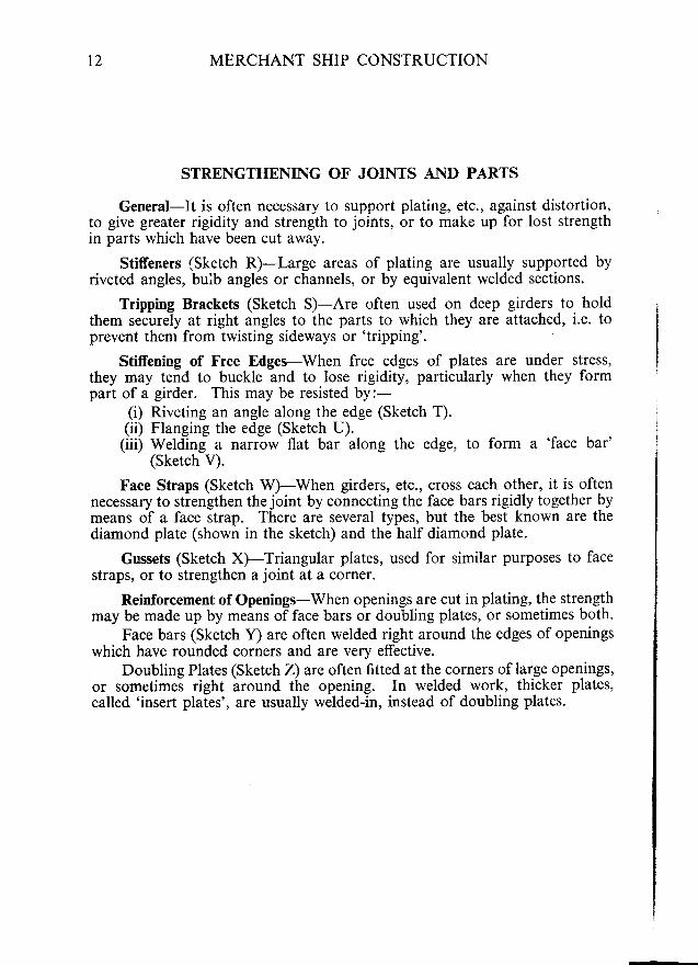
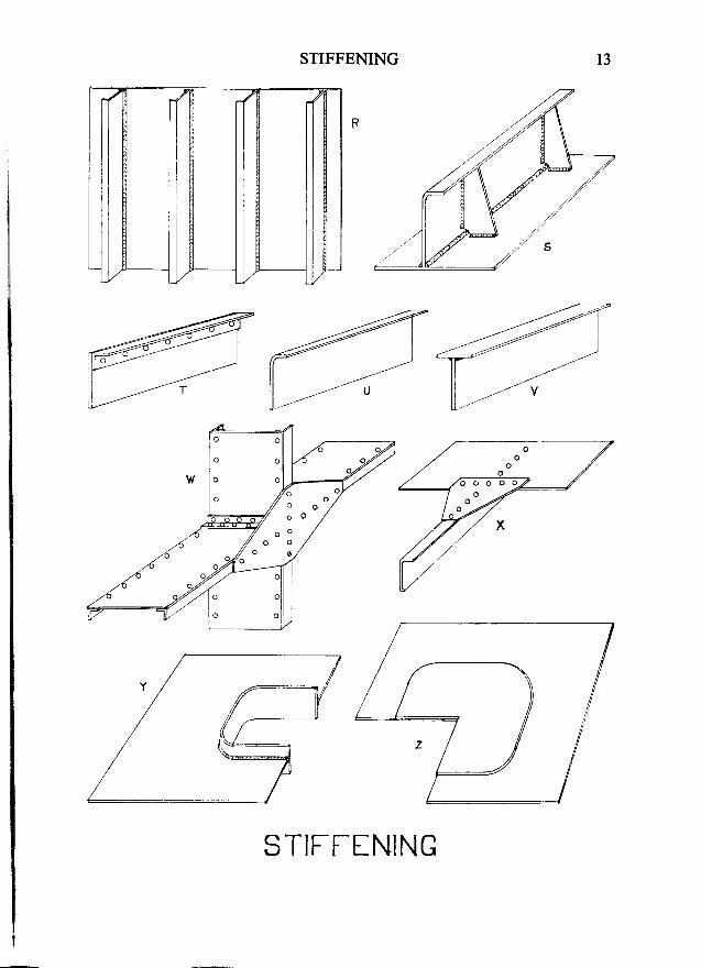
General-It is often necessary to support plating, etc., against distortion,to give greater rigidity and strength to joints, or to make up for lost strengthin parts which have been cut away.
Stiffeners (Sketch R)--Large areas of plating are usually supported byriveted angles, bulb angles or channels, or by equivalent welded sections.
Tripping Brackets (Sketch S)-Are often used on deep girders to holdthem securely at right angles to the parts to which they are attached, i.e. toprevent them from twisting sideways or 'tripping'.
Stiffening of Free Edges-When free edges of platesthey may tend to buckle and to lose rigidity, particularlypart of a girder. This may be resisted by:-
(i) Riveting an angle along the edge (Sketch T).(ii) Flanging the edge (Sketch U).
(iii) Welding a narrow flat bar along the edge, to form a 'face bar'(sketch v).
Face Straps (Sketch W)-When girders, etc., cross each other, it is oftennecessary to strengthen thejoint by connecting the face bars rigidly together bymeans of a face strap. There are several types, but the best known are thediamond plate (shown in the sketch) and the half diamond plate.
Gussets (Sketch X)-Triangular plates, used for similar purposes to facestraps, or to strengthen a joint at a corner.
Reinforcement of Openings-When openings are cut in plating, the strengthmay be made up by means of face bars or doubling plates, or sometimes both.
Face bars (Sketch Y) are often welded right around the edges of openingswhich have rounded corners and are very effective.
Doubling Plates (Sketch Z) are often fitted at the corners of large openings,or sometimes right around the opening. In welded work, thicker plates,called 'insert plates', are usually welded-in, instead of doubling plates.
are under stress,when thev form
z/o.4
,6
#-/ li
/
{-:j
STIFFENING
STIFTf NING
t3
IF
t4 MERCHANT SHIP CONSTRUCTION
RIVETING
Strength-Riveting should have, as nearly as possible, the same strengthas the parts it connects together. The work must be closed efficiently; thatis, the surfaces must be brought close together in order to produce greatfriction, which is the main source of strength in riveted joints.
Each time that a hole is punched in a plate to take a rivet, the plate isweakened. Hence, rivets must not be too closely spaced or the plate will bemade too weak. Rivets must not be within one diameter of the edge of theplate, or they may tear through that edge.
On the other hand, rivets must not be too far apart, or they will not closethe work properly and will also be too weak to stand up under stress. Wherea joint is to be caulked, the rivets must not be too far from the edge of theplate, or the caulking may force the plate edges apart.
The rivets must also fill the holes in the plates properly, or the joint willbe weakened.
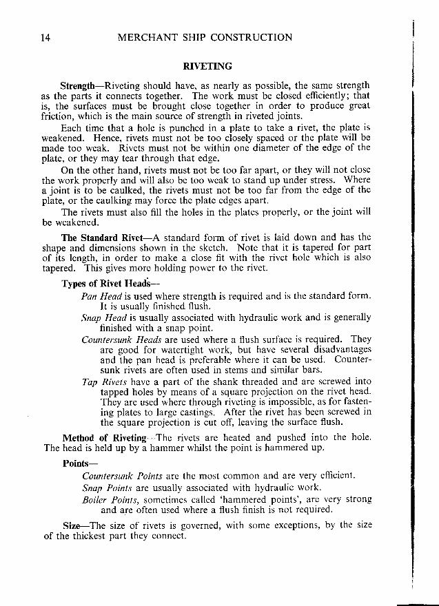
The Standard Rivet-A standard form of rivet is laid down and has theshape and dimensions shown in the sketch. Note that it is tapered for partof its length, in order to make a close fit with the rivet hole which is alsotapered. This gives more holding power to the rivet.
Types of Rivet t{eaili-Pan Head is used where strength is required and is the standard form'
It is usually finished flush.Snap Head is usually associated with hydraulic work and is generally
finished with a snap point.Countersunk Heads are used where a flush surface is required. They
are good for watertight work, but have several disadvantagesand the pan head is preferable where it can be used. Counter-sunk rivets are often used in stems and similar bars.
Tap Rivets have a part of the shank threaded and are screwed intotapped holes by means of a square projection on the rivet head.They are used where through riveting is impossible, as for fasten-ing plates to large castings. After the rivet has been screwed inthe square projection is cut off, leaving the surface flush.
Method of Riveting-The rivets are heated and pushed into the hole.The head is held up by a hammer whilst the point is hammered up.
Points-Countersunk Points are the most common and are very efficient'Snap Points are usually associated with hydraulic work.Boiler Points, sometimes called 'hammered points', are very strong
and are often used where a flush finish is not required.
Size-The size of rivets is governed, with some exceptions, by the sizeof the thickest part they connect.
STANDAR3 ;-: ; .
<>
:::->
-=
=I AF l
G
RIVETING
BOILER. FLUSH FULLCOUNTERSUNK.
ORILLED HOLI . PUNCHED FIOLE. COUNTERSUNK HOLE
l 5
|l-F
SNAP.
STANDARD FORM.
oa)
oo
\,
t
CHAIN.RIVETING
L/ oa) o(,
ZIG.ZAG RIVETING
FAIR AND UNFAIR Hq-ES \^/ITH RIVETII\G.
RIVf TING.
16 MERCHANT SHIP CONSTRUCTION
Rows of Rivets-Single riveting is not considered to be very efficient,but is strong enough for many purposes. Where it is not strong enough, fromtwo to five rows of rivets may be used. The number of rows fitted depends onthe work the joint has to do and on the thickness of the plate.
Seams may be single, double or treble riveted. End laps may be fromdouble to quintuple riveted.
Chain riveting is required for double or treble riveted joints and for allend laps of shell plating. Zig-zag riveting is permitted in other joints andalso in connections to stems, stern frames and bar keels, if desired.
Consecutive rows of rivets are not to be closer than 2l diameters for edgelaps; 3 diameters for butt straps; and 3| diameters for end laps.
Width of Laps, etc.-The width of the overlap of plates is governed bythe Rules. It depends on the size of the rivets and on the number of rowsfitted. End laps are wider than seams for the same riveting.
Pitch-Is the spacing of rivets, centre to centre and is expressed in termsof rivet diameter. The spacing should never be less than 3! diameters, normore than 7 diameters. The rivets in watertight and oiltight joints shouldbe close enough together to resist the opening action of caulking and pressure.Watertight joints should have a spacing of not more than 4{ diameters. Oil-tight joints should have a spacing of not more than 4 diameters.
Tests-After the rivets have been manufactured a number of them are tobe tested as follows:-
(a) The rivet shank is to be bent double when cold, and no fractureis to show on the outside ofthe bend.
(6) The rivet head, when hot, is to be flattened until its diameteris 2| times that of the shank. It must then show no cracksat the edge.
Holes for Rivets-Holes in plates may be either punched or drilled.Punching produces a slight taper which is sufficient to hold the parts
together in much ordinary work. It has a tendency to strain the metalaround the hole and also leaves a'rag', or rough edge, on one side. Thesedisadvantages are not serious, however, and punching is very largely used,as it is quick and cheap. Lloyd's Rules lay down that when holes are punched,they are to be punched from the faying surface (that is, the surface whichbears against the other) and that any 'rag' is to be removed after punching.
For watertight and oiltight work, punching alone does not give sufficienttaper to the holes, which must be countersunk. The Rules require the counter-sinking of all holes in shell plating, weather decks, inner bottoms and peak anddeep tank bulkheads.
Holes which are to be countersunk are sometimes drilled, as this can bedone quite quickly by modern machinery and avoids the strain and rag left bypunching. A drilled hole has parallel sides and hence less holding power;but if it is to be countersunk afterwards, this does not matter.
Fair and Unfair Holes-In good work the holes in the parts to be rivetedtogether should correspond exactly. If they do not do so, faulty rivetingmav result. as shown in the sketch.
oRIFT rulo-/
5
L---___r_
IcA)&_r'
nI--

RIVETING l7
EFIFT PtJ.lCH.
F: *EI ffiORIFTED I-IOLE.
RIVETING
RIMERED Fg-E.
CAULKEO JOINT. CAULKED RIVET.
-
18 MERCHANT SHIP CONSTRUCTION
Holes which correspond are termed 'fair holes', whilst those whicli donot do so are termed 'unfair', 'blind', or 'partially blind'.
Unfair holes must rbe cleared before rivets are put into them. The toolswhich are used for this purpose are Rimers and Drift Punches, each of whichhas its own use and should not be used to do the work of the other. Thedrift punch should be used where holes have been punched correctly, but wherethe plates have not been put together quite truly. In other words, it is usedas a sort of lever to 'square up' the plates. The rimer must be used where oneor two holes of a row are not correctly punched. It is a cutting tool andis put into the hole and turned around until the protruding edges have beenscraped off.
Caulking-Joints and rivets in watertight or oiltight work must alwaysbe caulked. This requires skilful and careful work.
Plates and bars are caulked by cutting into them with a special tool, so asto drive a small piece of steel from the edge hard up against the other surface.Parts which have to be caulked are arranged, wherever possible, so that thecaulking edge faces upward, or to the right, in order that the workman canuse his tools on them the more easily. Where edges which would normallyfinish flush with each other are to be caulked, one is stopped a little short of theother to facilitate the work (as in the connection of the garboard strake toa bar keel).
Rivets may be caulked by cutting into the plate around the rivet, so asto drive a small piece of steel hard up under the rivet head.
General-Or:whilst the othe: .The rod is al lcu:distance. This ,-:.and the plate ed:: ,a sol id joint . T:electrode, coatii:g .
into the joint . , r : : -in the joint and :metal from becc:,
.f,luxes-the ::from attacking l::impurities from ::from the air. so ::unt i l i t has coc- lec.
Oxygen, if r::which may rema::.of the carbon in ::.the steel by remc'. .:in the metal as ir .-
Nitrogen canbecome hard, br:::-
The compos;:-contains four ma::
(i) A combu.burns to :a cloud ,,.:and keep r
(ii) An 'arc-sl.
produce amaterials :which is a
(iii) 'Fluxin_e'r
with oxide,out into r:
(iv) 'Alloying' :be burnedmanganese
G
WELDING
ELECTRIC ARC WELDING
General-One wire from an electric supply is connected to the work,whilst the other is connected to a steel rod, which is called an 'electrode'.
The rod is allowed to touch the work and is then withdrawn for a shortdistance. This creates an electric arc, the heat of which melts the electrodeand the plate edges, forming a pool of molten metal, rvhich later cools to forma solid joint. The electrode is covered with a 'flux', which melts with theelectrode, coating the molten drops of metal as they form and dripping downinto the joint with them. It then floats to the surface of the molten metalin the joint and forms a protective layer of 'slag' which prevents the joint-metal from becoming oxidised. The slag is removed after cooling.
Fluxes-the main purposes of a flux are to prevent oxygen and nitrogenfrom attacking the hot weld-metal and to combine with and to float-out anyimpurities from the molten metal. The oxygen and nitrogen come mainlyfrom the air, so the flux must be capable of keeping air away from the jointuntil it has cooled.
Oxygen, if present, will combine with the hot steel to form iron oxides,which may remain in and weaken the joint. It may also combine with someof the carbon in the steel to form carbon monoxide gas. This would weakenthe steel by removing carbon; whilst some of the gas-bubbles might be trappedin the metal as it cools, causing cavities, called 'blow holes' in the joint.
Nitrogen can be absorbed by molten steel, causing the weld metal tobecome hard, brittle and liable to crack.
The composition of the flux varies in different electrodes, but it usuallycontains four main ingredients:-
(i) A combustible material, such as wood-pulp or 'alpha-flock', whichburns to form carbon monoxide and hydrogen gases. These forma cloud of gas called a 'gas shield' around the arc during weldingand keep out the air.
(ii) An 'arc-stabiliser' to help to maintain a steady electric arc and toproduce a hard, brittle slag which can easily be chipped off. Variousmaterials may be used for this: one common one being 'Rutile',
which is a natural ore of titanium oxide.
(iii) 'Fluxing' materials usually silicates, such as asbestos. These combinewith oxides and other impurities in the molten steel and float themout into the slag.
(iv) 'Alloying' elements, to replace any important constituents which maybe burned out of the steel during welding. These are mainlymanganese and carbon.
l 9
FF

20 MERCHANT SHIP CONSTRUCTION
Building-up of Welds-In hand welding, it is not usually possible to
deposit enough metal to fill the joint in one operation. In this case, a continuous
layer of weld-metal, called a 'run', is first deposited all along the bottom of
the joint. The 'slag', or protective coating of flux, which forms over the top
of this run, is then removed and a second run is made on the top of the first.
This is repeated until the joint has been completely built up.
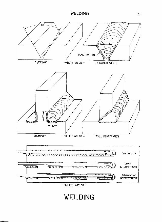
Types of Weld-Butt Welds are usually prepared by chamfering-off, or 'Veeing' the
plate edges, so that the angle between them is about 60o and
by spacing the plates so that there is a small gap between them
at the bottom of the 'V'. A series of runs of welding is made on
the Veed side and when this has been completely filled-in, one
run, called a 'back run', is made on the other side of the joint.
In the figure, the runs are numbered in the order in which theyare made, whilst B indicates the back run. Thick plates may be
double-veed: that is, veed on both sides.
Fillet Welds are used for making T-joints and lapped joints. Theleg length ('L' in figure) is governed by the thickness of the
abutting part of the joint, whilst the throat thickness ('T' in
figure) must be at least 70 per cent of the leg length. Fillet weldsmay be continuous or intermittent.
Full Penetration Fillet Welds are stronger than ordinary fillet weldsand are used where special strength is required in T joints.
The vertical leg of the joint is veed, so that the weld metal canpenetrate right through.
Double Continuous Fillets are used for specially important structural
connections and for watertight and oiltight work.
Intermittent Fillets are used for many joints which are not required
to be watertr'ght. The length and spacing of fillets depend on
the work which the joint is required to do. At the ends of
structural joints, the fillets must be doubled and carried around
the ends. Chain intermictent fillets are used for the more
importanr connections and sraggered intermittent fillets for
others. As compared with conrinuous fillets, intermittent fillets
reduce weighr and disconion, but have some inherent dis-
advantages.
Tack Welds are spots of welding, placed at intervals and used to holdparts temporarily in place whjlst a proper welded joint is
being made.
l
i0RDNr\RY
nlF:
. \EEING'
t!I '
WELDING
-BUTT WELD -
-FILLET WELO5- FULL PEI{ETRATION
2l
CCNTIN-AU3
CHAININTERMITTENT
STAGGEREDINTERMITTENT
WELDING
F
.\EEING'FINISHED WELD
-FILLET WELD8_

22 MERCHANT SHIP CONSTRUCTION
Distortion Effects-The chief cause of distortion is the intense heat setup by the electric arc, as it melts the electrode and the edges of the work.The surrounding metal is also heated and expands, so that the edges beingjoined are actually a little closer together than they were when cold. Afterthe joint has been made and has cooled, the plates on either side of the jointtry ro move slightly towards each other. If they are free ro move, they will doso and they may also buckle to a slight extent, so that visible distortionmay occur.
Some of the stresses causing this will remain in the joint, for variousreasons, and these are known as 'residual stresses'. Thick plates, or thosewhich are held firmly so that they cannot move, may nor be able to buckle orto 'take-up' in this way. The stresses trying to make them do so will stillexist and will remain locked in the joint, in which case they are known as'locked-up stresses'. These stresses may also occur in joints which havebeen badly prepared, where considerable force may be required to pull theparts into their proper positions. When such parts are welded up and therestraining gear has been removed, the stresses will be transferred to the joint.Both residual and locked-up stresses weaken the joint and the metal around it.They cannot usually be entirely eliminated, but great care is necessary to makesure that they are kept to a minimum.
Reducing Distortion Effects-Residual and locked-up stresses can usuallybe kept within safe limits, if certain rules are observed. Residual stresses arereduced by starting from the middle of each joint and working outward tothe ends, using what is k,rown as 'step-back' welding. Locked-up stressesare minimised by planning the work so that at leasr one of rhe parrs beingjoined is free to move, each time a joint is welded. When rhis cannot bedone, the work should be arranged so as to reduce restraint to a minimum.
Where riveted and welded joints are to be used in the same parts of aship (e.g. where welded plating is riveted to frames) the welding shouldusually be done before the riveting. If the riveting were done first, it mightrestrain the movement of the plates during welding, causing locked-up stressesand, possibly, loose rivets. Remember, however, that riveting and weldingmust never be combined in the same joint (see 'General Rules').
Preparation for Welding-It is most important that the work be properlyprepared and that all surfaces are dry and thoroughly clean. The parts mustfit together properly, otherwise extra locked up stresses may be introducedinto the joint; also there is a danger that spaces may be left inside the finishedjoint and if these are large, they may cause the weld to crack.
However carefully the preparation is done, it sometimes happens thatthe parts do not fit properly when they are assembled for welding. In thiscase, any excessive gaps must be corrected before the welding is done. Butt
joints should be buor if the gap is roicut back and an er'
When a ueldeiwhich the various -
be done so that rh:weid is made. thus
General Rules-the same joint. berthus cause the jci:riveted or welded. I
Great care rt;.spread the stresse:concentrations.
Prefabrication.they are built intcand should be usedto design the pren:
Machine \\'etdicalled'submerged afed from a reel; rih:so that the arc is 's'-
In machine rr:lthan is possible u::reduces the amounrmetal comes fromelectrode. This. in .
in fact, it is often pithat the welding ca:
This type of u3'surfaces. It cannorwork on other thanbe used for welding
Crossing and -{ta large amount ofshrinkage in ru'o .-:Since welded parts :to prevent build-up
Where butts ar,butt should alwal's i
c
G:
WELDING 23
joints should be built-up to reduce the gap. T joints may have a liner fitted,or if the gap is too large to allow this to be done, one of the plates should becut back and an extra piece welded in.
When a welded structure is designed, it is important to plan the order inwhich the various joints are to be made, or 'welding sequence'. This shouldbe done so that the parts of the struclure are reasonably free to move as eachweid is made, thus reducing locked up stresses.
General Rules-Riveting and welding must never be used together inthe same joint, because they behave quite differently under stress and maythus cause the joint to break. In other words, any one joint may be eitherriveted or welded, but never both.
Great care must be taken in designing welded structures in order tospread the stresses smoothly from part to part and to avoid dangerous stressconcentrations.
Prefabrication, which is the construction of large sections in a shed beforethey are built into the ship, has many advantages for welded constructionand should be used as much as possible. Great care must, however, be takento design the prefabricated parts so that they fit properly.
Machine Welding-The most common type of machine welding is thatcalled 'subnnerged arc welding'. In this, the electrode consists of a long wire,fed from a reel; whilst a powdered flux is poured on to the joint as it is made,so that the arc is 'submerged' under rhe flux.
In machine welding, the metal is melted much more quickly and deeplythan is possible with hand welding. This gives deeper penetration and thusreduces the amount of veeing requilsd for the plate edges, so that more weldmetal comes from the plates and proportionately less is required from theelectrode. This, in its turn, means that the joint can be filled with fewer runs:in fact, it is often possible to make the joint with a single run. It also meansthat the welding can be done faster, which helps to reduce distortion effects
This type of welding is most suitable for work indoors, on flat, horizontalsurfaces. It cannot be used for welding in awkward places, nor, usually, forwork on other than horizontal surfaces. For many purposes, also, it cannotbe used for welding out of doors.
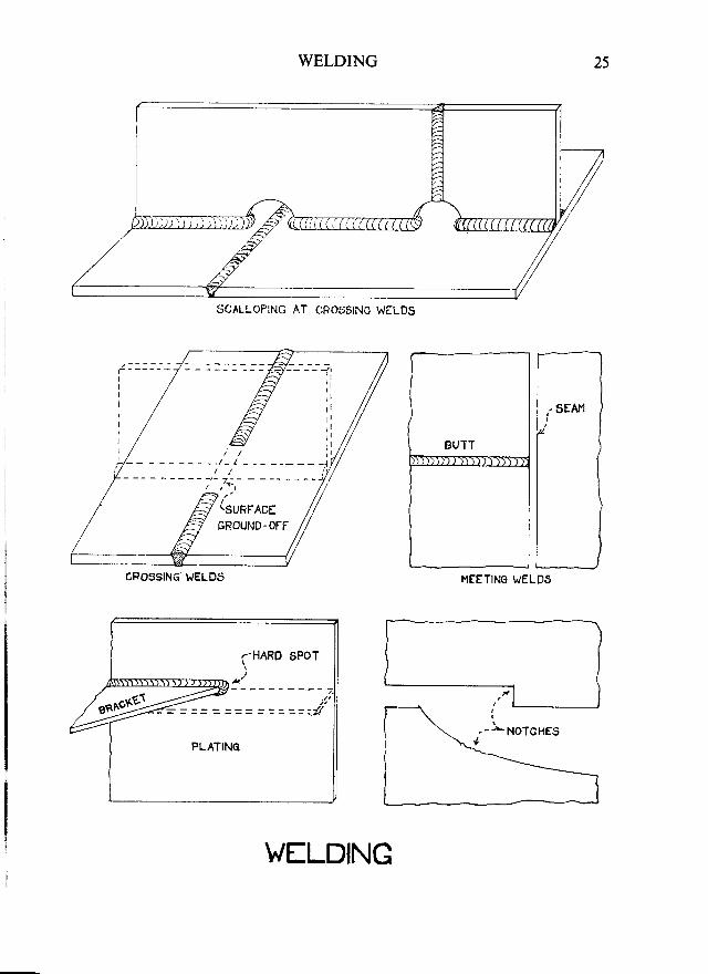
Crossing antl Abutting Welds-If welds cross or meet, there is a risk rhata large amount of weld metal may accumulate at the juncdon, producingshrinkage in two or more directions and thus causing the weld to crack.Since welded parts must necessarily cross or meer in places, it is imponantto prevent build-up of weld metal'at rhe meeting-points.
Where butts and seams meet in flush plating, such as shell plating, thebutt should always be completely welded first. It should be finished full out
c
r-

24 MERCHANT SHIP CONSTRUCTION
and then gouged back to give a fair edge to the seam, which should then bewelded straight through. The reason for this is that if the seam were madefirst, it would prevent movement of the plates on either side of the butt joint
when this was welded, thus causing locked up stresses and possibly crackingof the joint.
When welds meet in a corner, the cure would be to cut away the cornerof the abutting plate in a clearancc hole, or 'snipe'.
When T joints meet butt welds, there is always a danger of a build-upof weld metal, whilst it would also be impossible to make the parts fit properlytogether if the surface of the butt weld were 'proud' of the plate. To preventthis we can either:
(a) Cut a scallop in the vertical member so as to clear the butt weld, or(b) Make the butt weld first and then grind off its surface in the region
of the joint, so that the crossing member is fitted and welded on to aflush surface. Lloyd's Rules require this latter to be done, wheneverpossible, where stiffeners cross finished butt welds in plating.
Haril Spots-A hard spot is a small local area which is considerably morerigid than the surrounding structure. A simple example is where the toe of abracket from, say, a girder is rvelded to an area of plating, as shown in thesketch. The point where the toe of the bracket is welded to the plating isrigid and forms a hard spot. The stresses transmitted from the girder throughthe bracket would concentrate here and might cause the plating to crack.The cure for this is to fit some kind of stiffener to the plating in order to spreadthe load over a bigger area. The sketch shows how a plate or angle (shown
dotted) could be fitted for this purpose.
Notches-When a piece is cut out of a plate so as to leave a square, or
nearly Square corner, or where there is a ragged edge on a plate, the resultant'notches' can cause stress concentrations. These may not be particularly
serious in riveted structures, since the 'give' in the riveting often allows the
worst of the stresses to work themselves out. With welded construction,which is more rigid, however, the notches may cause stress concentrationswhich cannot work themselves out, so great care must be taken to avoid them
wherever possible. For this reason, the corners of cut-outs in plates must be
well-rounded and may have to be reinforced by, say, face bars. Free edges
of plates must be kept smooth. Scallops must have well-rounded corners and
smooth edges and must not be cut where high stresses may occur.
Defects of Workmanship-Weak or faulty joints may be produced if the
welder does not use the proper procedures, current, electrode or length of arc.
The most common defects, which may cause the weld or plate to crack are:-'Undercutting,' which occurs when a groove is burned in the plate close
to the weld. It weakens the plate at a very dangerous point'
cRossthS ,.E_
G
WELDING
CROESINC WELDS
25
MEETING I"/ELDS
V/trLDING
J-
SCALLOPING AT
CROSSING WELDS

26 MERCHANT SHIP CONSTRUCTION
'Poor Penetration' can occur as 'incomplete penetration' if the weld metaldoes not fill the joint properly, so that a gap is left between runs. Alternatively,it may appear as 'lack of fusion', when the heat does not melt sufficient of theplate or of previous runs, so that the weld metal does not bond properly withthe original metal.
A hollow weld-profile must be avoided, as it will weaken the joint. Thesurface should always be convex, whilst the weld must be carried right out andfinished-off square at it's ends. In T-joints, the weld should, wherever possible,
be carried right round the ends of the joint.'Slag Inclusion' occurs if the slag is not completely cleaned off the top of
each run before the next one is made. If this is not done properly, a certainamount of slag may be left in the joint.
'Blow holes' are rounded holes formed by gases trapped in the weld metalas it cools. 'Pipes' are elongated holes, due to the same cause.
Welding of Aluminium-An 'inert gas system' is used for aluminium, for
which the processes used for welding steel are not suitable. For butt-welds,the plates are veed to between 75' and 90" and a backing bar is usually attachedto the underside. Argon gas is blown on to the joint through ducts in thewelding head. A tungsten electrode may be used to produce the arc, whichmelts-down an aluminium rod held in it; or an aluminium wire may be used
as an electrode.
CORPECT PROF]_' -
'.//
7/,
Bl-O'. -

WELDING
STEPS IN THIS ORDIR
2 t 2
DIRICTION OT WELDING
STEP -BACK WILDING
HOLLOV/ PROFILE UNDf RCUTTING
INCOMPL f TE PENI TRATION OT FUSION
INCLUSION
gNIPf AT
WILDING
G
BLOW HOLfS
28 MERCHANT SHIP CONSTRUCTION
GBNERAL TYPES OF SI{IPS
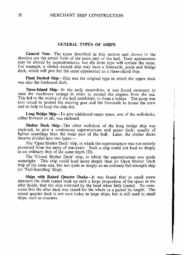
General Note-The types described in tiris section and shown in thesketches are the actual form of the main part of the hull. Their appearancesmay be altered by superstructures, but the form type will remain the same.For example, a_ shelter decked ship may have a forecastle, poop and bridgedeck, which will give her the same appearance as a three-islana snip.
Flush Decked Ship-This was the original type in which the upper deckwas also the freeboard deck.
Three-Island Ship-In the early steamships, it was found necessary torqise the machinery casings in order to protict the engines from the sea.This led to the raising of the hull amidships, to form a bridge. The poop wasalso raised to protect the steering gear and the forecastle io house the crewand to help to keep the ship dry.
Long Bridge Ship-To give additional cargo space, one of the well-decks,either forward or aft, rvas enclosed.
Shelter Deck Ship-The other well-deck of the long bridge ship wasenclosed, to give a continuous superstructure and upper deck: usually oflighter scantlings than the main part of the hull. Laier, the shelter decksbecame divided into two types:-
The 'Open Shelter Deck' ship, in which the superstructure was not entirelyprotected from the entry of sea-water. Such a ship could not load so deeplyas an ordinary ship of the same depth (D).
The 'Closed Shelter Deck' ship, in which the superstructure was madewatertight. This ship could load more deeply than an Open Shelter Deckship of the sarne size, but not quite as deeply as an ordinaryfull-strength ship(or'Full-Scantling' Ship).
Ships with Raised Quarter Decks-It was found that in small screwsteamers the shaft tunnel took up such a large proportion of the space in theafter holds, that the ship trimmed by the head when fully loaded. To over"come this the after deck was raised for the whole or a partof its length. Theraised quarter deck is not seen today in large ships, but is still used in smallships, such as coasters.
t_:\
II
[_--II
G=

GENERAL TYPES
FLUSH OECKED SHIP.
THREE I€}LAND SI{IP.
LOIIG BRIDGE SHIP.
SHELTER DECKED SHIP.
SIIIP VITH RAJSED QUARTEFI DECK.
TYPES
G
30 MERCHANT SHIP CONSTRUCTION
STRESSES AND STRAINS IN SHIPS
Stress and Strain-stress is load put on a piece of material or on a
structure. If the stress is excessive, the material may become permanently
deformed and weakened and it is then said to be'strained'.
Types of Stress-stresses are classified according to the way in which
they act.Tensile stresses try to pull the material apart.Compressive stresses try to crush the material, or to cause it to
buckle.Shearing stresses may be described as the effect of forces which try
to shear material across, or to make the component parts of astructure slide over each other.
Bending stresses are compound stresses produced by forces when theytry to bend a piece of material.
Stress Concentrations-When a section is under load, there will usually
be a large local increase of stress near any notch, hole, or abrupt change of
shape of the section. This local increase is called a 'stress concentration'and it may be as great as two or three times the average stress elsewhere. It
is usually at its worst where the edges of a hole or plate are left jagged, or
where square-cornered holes are cut out of plates. It occurs to a lesser degree
in the region of round holes, or of holes with rounded corners.
Stress concentrations can be dangerous. They may cause the steel to
crack in their vicinity, particularly in welded structures, even where the
normal stress would not be large enough to cause cracking. It is, therefore,
important to design the ship carefully so that stress concentrations are kept
to a minimum, to round off and strengthen the corners of openings, and to
keep the edges of plates and holes smooth and free from notches.
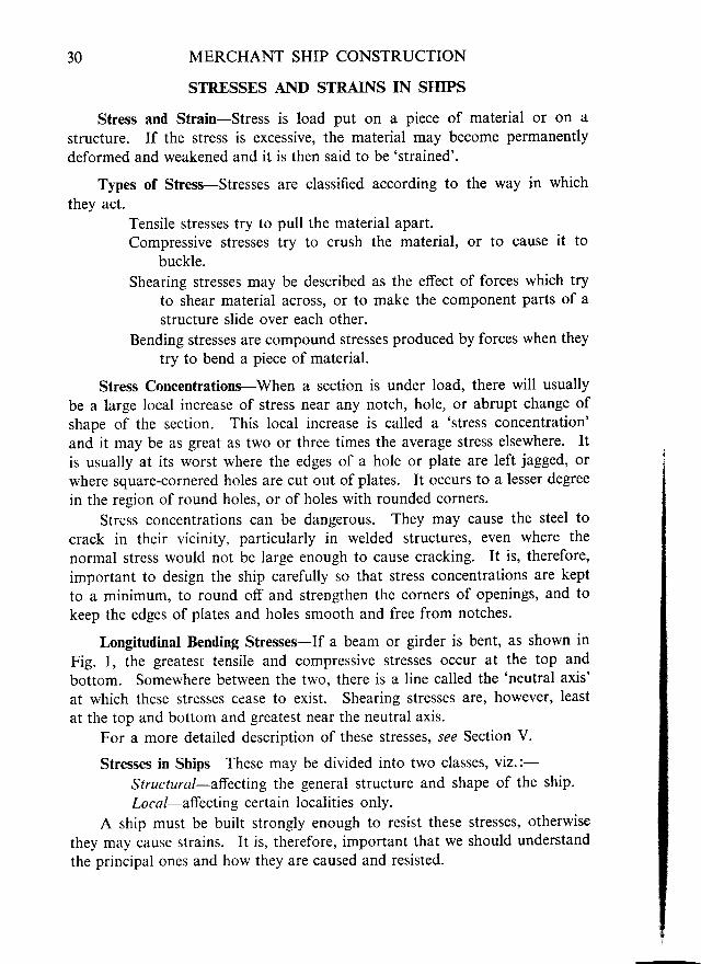
Longitudinal Bending Stresses-If a beam or girder is bent, as shown in
Fig. l, the greatesr tensile and compressive stresses occur at the top and
bottom. Somewhere between the two, there is a line called the 'neutral axis'
at which these stresses cease to exist. Shearing stresses are, however, least
at the top and bottom and greatest near the neutral axis.
For a more detailed description of these stresses, see Section V.
Stresses in Ships-These may be divided into two classes, viz.:-
Structural-affecting the general structure and shape of the ship.
Local-affecting certain localities only.
A ship must be built strongly enough to resist these stresses, otherwise
they may cause strains. It is, therefore, important that we should understand
the principal ones and how they are caused and resisted.
--
STRESSES AND STITAINS IN SHIPS 3 l
TENSION.
STRAINS IN SHIPS
+
32 MERCHANT SHIP CONSTRUCTION
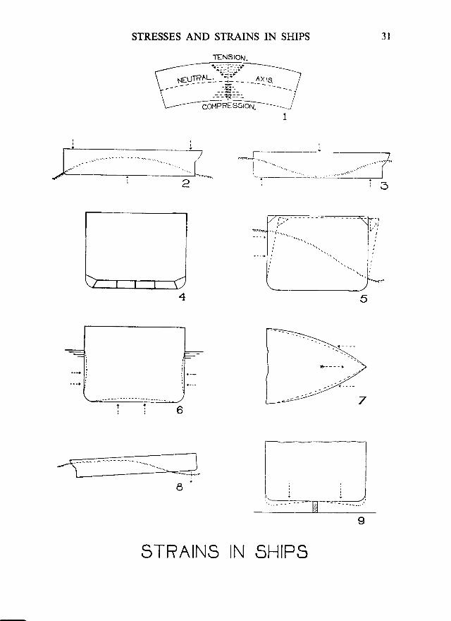
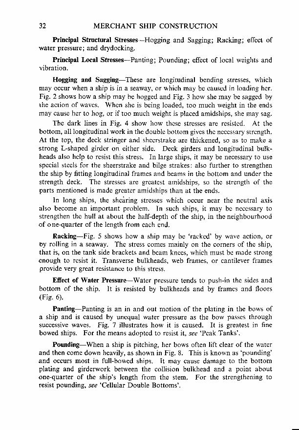
Principal Structural Stresses-Hogging and Sagging; Racking; effect ofwater pressure; and drydocking.
Principal Local Stresses-Panting; Pounding; effect of local weights andvibration.
Hogging and Sagging-These are longirudinal bending stresses, whichmay occur when a ship is in a seaway, or which may be caused in loading her.Fig. 2 shows how a ship may be hogged and Fig. 3 horv she may be sagged byrhe action of waves. When she is being loaded, too much weight in the endsmay cause her to hog. or if too much weight is placed amidships, she may sag.
The dark lines in Fig. 4 show how these stresses are resisted. At thebottom, all longitudinal work in the double bottom gives the necessary strength.At the top, the deck stringer and sheerstrake are thickened, so as to make astrong L-shaped girder on either side. Deck girders and longitudinal bulk-heads also help to resist this stress. In largc ships, it may be necessary to usespecial steels for the sheerstrake and bilge strakes: also further to strengthenthe ship by fitting longitudinal frames and beams in the bottom and under thestrength deck. The stresses are greatest arnidships, so the strength of theparts mentioned is made greater amidships than at the ends.
ln long ships, the sheiring stresses which occur near the neutral axisalso become an important problem. In such ships, it may be necessary tostrengthen the hull at about the half-depth of the ship, in the neighbourhoodof one-quarter of the length from each end.
Racking-Fig. 5 shows how a sliip may be 'racked' by wave action, oroy rolling in a seaway. The stress comes mainly on the corners of the ship,that is, on the tank side brackets and beam knees, which must be made strongenough to resist it. Transverse bulkheads, web frames, or cantilever framesprovide very great resistance to this stress.
Effect of Water Pressure-Water pressure tends to push-in the sides andbottom of the ship. It is resisted by bulkheads and by frames and floors(Fie. 6).
Panting-Panting is an in and out motion of the plating in the bows ofa ship and is caused by unequal water pressure as the bow passes throughsuccessive waves. Fig. 7 illustrates how it is caused. It is greatest in finebowed ships. For the means adopted to resist it, see'Peak Tanks'.
Pounding-When a ship is pitching, her bows often lift clear of the waterand then come down heavily, as shown in Fig. 8. This is knorvn as'pounding'and occurs most in full-bowed ships. It may cause damage to the bottomplating and girderwork between the collision bulkhead and a point aboutone-quarter of the ship's length from the stem. For the strengthening toresist pounding, see'Cellular Double Bottoms'.
Local \\'eiup by local rreiimposing errra
Drydockinlsupported b1 rmodern ships ,enough to resi .light. There isship has muchbe used to preras standard pra
Vibration-in the after pa:double bottomstern and afrer
STRESSES AND STRAINS IN SHIPS
Local Weights-Local strengthening is introduced to resist stresses setup by local rveights in a ship, such as engines. This is also done where cargoesimposing extraordinary local stresses are expected to be carried.
Drydocking-It can be seen from Fig. 9 that a ship, when in drydock andsupported by the keel blocks, will have a tendency to sag at the bilges. Inmodern ships of medium size, the cellular double bottcm is usually strongenough to resist this stress without any further strengthening when the ship islight. There is always a danger, however, that such sagging may occur if theship has much weight on board and, in this case, bilge blocks or shores shouldbe used to prevent it. For this reason, many modern drydocks use bilge blocksas standard practice.
vibration-vibration from engines, propellers, etc., tends to cause strainsin the after part of the ship. It is resisted by special stiffening of the cellulardouble bottom under engine spaces and by local stiffening in the region of thestern and after oeak.
33

34 MERCHANT SHIP CONSTRUCTION
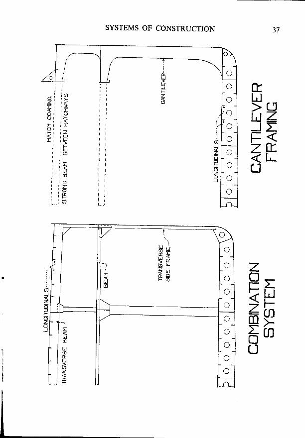
SYSTEMS OF CONSTRUCTION
General-Modern ships vary considerably in the details of their con-struction, according to their size and type, but almost all conform to one ofthree basic systems of construction.
The sketches, here, merely illustrate the main features of each system andare kept as simple as possible, for purposes of comparison. Details of con-struction are described later in this book.
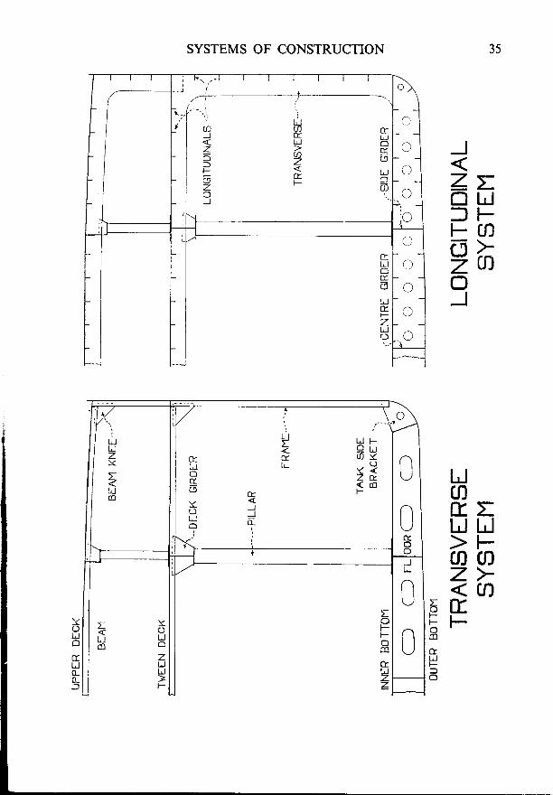
Transverse System-Wooden ships were always built on this system,because closely spaced transverse frames were needed to hold the plankstogether so that the seams could be caulked. It was also necessary to use itbecause sailing ships needed considerable transverse strength to enable themto resist the racking stresses set up by the masts and rigging. Longitudinalstrength was less important in these ships because they were comparativelysmall and hogging and sagging stresses were not large.
This system is not the most efficient for steel steamships, but it hascontinued in general use until recently. This was partly because it was cheapto build and served its purpose; and partly becaus'e a suitable alternative wasnot available for many years.
Longitudinal Systems-With the coming of steamships, racking stressesbecame less important, but hogging and sagging stresses became more seriousas ships grew longer. It soon became obvious that more longitudinal strengthcould be achieved by running the frames longitudinally (fore and aft), providedthat reasonable transverse strength was maintained. Various attempts weremade to do this during the 19th century, but all had serious disadvantagesand none were generally adopted.
Early in this century, a satisfactory system of longitudinal framing wasinvented, which came to be called the 'Isherwood System', after its jnventor.This has longitudinal frames at the bottom, sides and decks, supported bywidely spaced transverse web frames, called 'transverses'. It gives greallongitudinal strength and is much used for oil-tankers and other types olbulk carrier.
A few dry cargo ships were built on this system in the past, but it is notnow used for them because the transverses interfere too much with the stowageof cargo. A dry cargo ship of this type is shown in the sketch, however,because it serves as a good illustration of the system.
YL.lr'\
crULCLf,
I
r-lI,JZ:<
IUc0
35SYSTEMS OF CONSTRUCTION
J
zzclu: ]FFOfT>zaOJ
U0rlfttULJ>Fcu g)z><u)
FtrEFftEc)
l l
i
I
\.lc-l
- " _c
i t l
C
cC
C
c
ILJUz)<ILJco
L I F
O Y(J
Y <z e .< c oF
ft
oc((J
Y(Jtlto
36 MERCHANT SHIP CONSTRUCTION
SYSTEMS OF CONSTRUCTION-(Continued)
Combination System-This was introduced to overcome the disadvantagesof the longitudinal system for dry cargo ships. The longitudinal frames areretained in the bottom and under the strength deck, where they give greatlongitudinal strength; but transverse frames are fitted on the ship's side, wherethe longitudinal stresses are smaller. Plate floors and heavy transverse beamsare fitted at intervals to give transverse strength and to support thelongitudinals.
This system was not widely used for riveted ships, although a numberwere built in this way, but it came more into use with the coming of all-weldedships. This was partly because it was found that, if these ships were builton the transverse system, their decks and bottom tended to corrugate underhogging and sagging stresses: whereas the longitudinal frames prevent thisfrom happening. Lloyds' Rules now require longitudinals to be fitted, ingeneral, in the bottoms and under strength decks of all ships of over 120 metreslong: so jt seems that this system will eventually replace the transverse one forall larger dry cargo ships.
The combination system is also often used for small to medium-sizedoil tankers and for some other types of bulk carrier, for which it has certainslight advantages.
Cantilever Framing-ThiS is really only a modification of the combinationsystem, but is included here because of its special features. It has beendeveloped for some modern types of ship, which have very long and widehatchways. In these ships, there is too little left of the decks and beams togive the llecessary strength to resist longitudinal and transverse stresses; sothe strength has to be made up in other ways.
Transverse strength is maintained by using very strong hatch end beamswherever possible and by fitting special web frames, called 'cantilevers', atfrequent intervals abreast of the hatchways.
To give longitudinal strength, the sheerstrake and deck stringer plateare much heavier than normal; whilst the hatch side coamings are extra deepand are often made continuous throughout the ship. Sometimes, the hull isalso extended upwards at the sheerstrake, to form a strong box girder in placeof the ordinary bulwark or rails. If the ship is of the 'twin hatch type' (withtwo hatches abreast), a deck girder or longitudinal bulkhead is also fitted atthe centre line.
:trJc!
zlvtrth
,-]E
LJm
atrLJ
u)zEF
SYSTEMS OF CONSTRUCTION
ftUd2J:tr<ZE< l,-U
zo-rz->u>F*aHJ>6 rrl(_l
f a u
; i <ti rP
{ D q2 , ,- HF q )
( F/ t r
c\
l l
l l
i r1 ll l
I
1 lt lt i
i l
l l
r l! lr lI tl lr ll l
! l
I rI r
! rt gl - . - l
Jh
z6
a)
LJ
38 MERCHANT SHIP CONSTRUCTION
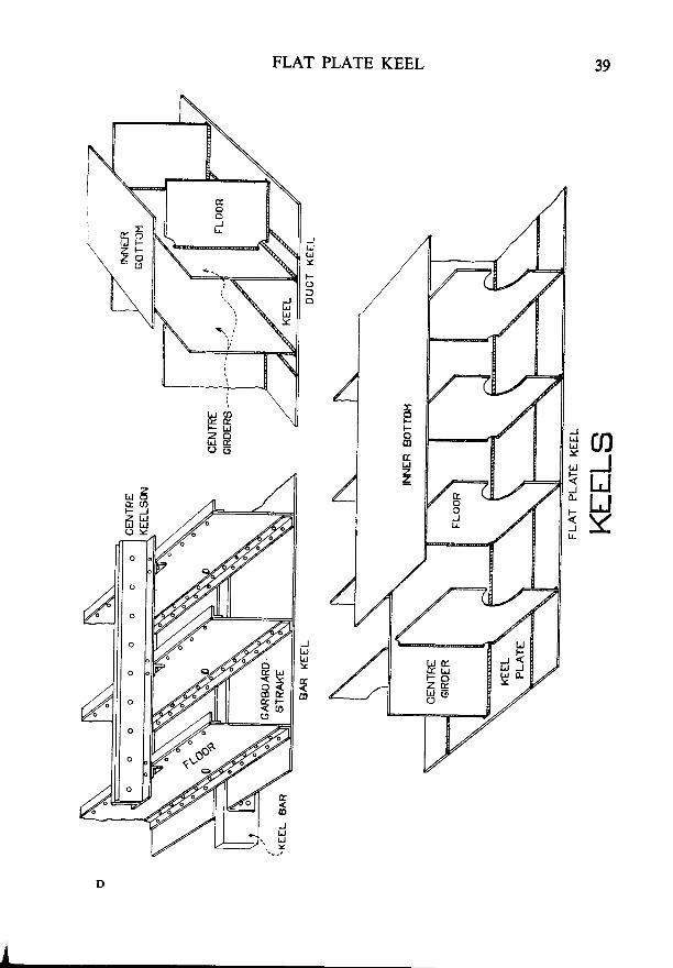
KEELS
General-Bar keels were the type first used when shipbuilding changedfrom wood to iron. It was found that they did not provide sufficient strengthfor large vessels, as there was no direct connection between the keel and thefloors. They are now only used in certain types of small craft. The flat platekeel is the modern type and is in general use.
Bar Keels-The depth of the bar is from three to six times its width.It is made in lengths of from l0 to 20 metres, joined by vertical scarphs. whichhave a length of nine times the thickness of the keel.
Flat Plate Keels-The keel plate may have a width of from I to 2 metres.It must be of full thickness for three-fifths of the length amidships, but thethickness may be gradually reduced towards the ends of the ship.
The centre girder is attached to the keel and inner bottom plating bycontinuous welds and no scallops are permitted in this connection. It isusually made watertight, although this is not required by the Rules.
Duct Keels-Are a form of flat-plate keel, but have two centre girdersinstead of one. They are often fitted between the collision bulkhead and theforward engine-room bulkhead, to provide a convenient tunnel for pipes fromthe tanks. They are not usually fitted abaft the engine-room, because thepipes from the after tanks can be run through the tunnel. Transverse stiffeningbars or brackets are often fitted on the keel plate and inner bottom platingbetween the two centre eirders.
o
o
FLAT PLATE KEEL
Jt JtrJY
F
aJIJUY
JulUJY
ulF
J0.
F
I
Lr-
JIJUY
{o
40 MERCHANT SHIP CONSTRUCTION
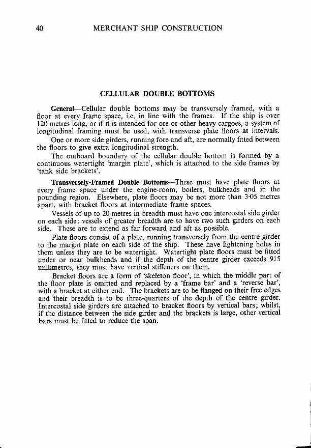
CELLULAR DOUBLE BOTTOMS
General-Cellular double bottoms may be transversely framed, with afloor at every frame space, i.e. in line with the frames. If the ship is over120 metres long, or if it is intended for ore or other heavy cargoes, a system oflongitudinal framing must be used, wirh transverse plate floors at intervals.
One or more side girders, running fore and aft, are normally fitted betweenthe floors to give extra longitudinal strength.
The outboard boundary of the cellular double bottom is formed by acontinuous wateftight 'margin plate', which is attached to the side frames by'tank side brackets'.
Transversely-Framed Double Bottoms-These must have plate floors atevery frame space under the engine-room, boilers, bulkheads and in thepounding region. Elsewhere, plate floors may be not more than 3'05 metresapart, with bracket floors at intermediate frame spaces.
Vessels of up to 20 metres in breadth must have one intercostal side girderon each side: vessels of greater breadth are to have two such girders on eachside. These are to extend as far forward and aft as possible.
Plate floors consist of a plate, running transversely from the centre girderto the margin plate on each side of the ship. These have lightening holes inthem unless they are to be watertight. Watertight plate floors must be fittedunder or near bulkheads and if the depth of the centre girder exceeds 915millimetres, they must have vertical stiffeners on them.
Bracket floors are a form of 'skeleton floor', in which the middle part ofthe floor plate is omitted and replaced by a 'frame bar' and a 'reverse bar',with a bracket at either end. The brackets are to be flanged on their free edgesand their breadth is to be three-quaners of the deprh of the centre girder.Intercostal side girders are attached to bracket floors by vertical bars; whilst,if the distance berween the side girder and the brackets is large, other verticalbars must be fitted to reduce the span.
TRANS\

CELLULAR DOUBLE BOTTOMS
PLATE FLOOR
REVERSE BAR
BRACKET FLOOR
TRANSVERSI FRAMING IN BOTTOM
TANK SIDIB R A C K E T .
INNER BOTTOM
,.-LlcHTENl'G HoLE /f ,.ap nottO \ rr_oon /
(-7 E7 tl
c *)l
O*-' ?\UL'i\-LIMBER HoI-E I on/

42 MERCHANT SHIP CONSTRUCTION
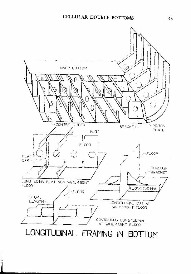
CELLULAR DOUBLE BOTTOMS-(Continued)
Longitudinal Framing in Double Bottoms-Lloyd's Rules now requirethat this shall be fitted, in general, in all ships of over 120 metres long. Thelongitudinals are flat bars, bulb bars, or inverted angles and are supported byplate floors not more than 3'7 metres apart. The longitudinals are attachedto these floors by vertical bars, at least 150 millimetres deep, which mustextend for the full depth of the floor.
Under engines, boiler bearers, bulkheads and the toes of brackets todeep tank stiffeners, plate floors are required to be fitted at every frame space.
At intermediate frame spaces, between the floors, brackets are fitted fromthe margin plate to the nearest longitudinal. The centre girder must besupported by similar brackets, spaced no nore than 1.25 metres apart.
If the plate floors are two or more frame spaces apart, vertical stiffeners,at least 100 mjllimetres deep, must be fitted midway between them to supportthe longitudinals.
One intercostal side girder is fitted on each side if the breadth of the shipexceeds 14 metres; or two on each side if the breadth exceeds 21 metres.
The longitudinals may be cut at watertight floors and attached to themby brackets if the ship is not more than 215 metres long. If the ship is longerthan this, the longitudinals must be continuous: in this case, short lengths oflongitudinal are passed through close-fitting slots in the floor, which areafterwards welded-up to make them watertight.
Inner Bottom Plating-The middle line strake and margin plate mustalways be continuous fore and aft. Other strakes are sometjmes laid athwart-ships under bulkheads, but should be fore and aft elsewhere. The thickness ofthe plating is increased slightly in the engine-room and also under hatchwaysin which a ceiling is not fitted.
/
LONGITUT
CELLULAR DOUBLE BOTTOMS 43
BRACKET___/ ._ MARGIN
PLATf
LONGITL,,DINALS AT NON.WATIRTIGHTf-Lo0R
LONG|TUDINAL CUT AT\JATERTIGHT FLOOR
CONTINUOUS LONGITUDINALAT \,TAT[RTIGHT FLOOR
LONGITUDINAL FRAMING IN BOTTOM

M MERCHANT SHIP CONSTRUCTION
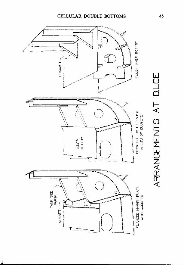
CELLULAR DOUBLE BOTTOMS-(Continued)
Margin Plates and Tank Side Brackets-The margin plate forms the outeredge of the double bottom and must be watertight. In riveted margin plates,thii was achieved by fitting a continuous angle along the lower edge and byflanging the upper edge so that the inner bottom plating could be lapped o-n toit and caulked.- Racking stresses try to pull the tank side brackets away fromthe margin plate, so gussets were fitted at the upper 'corner' to strengthen theconnectircn at this point. Later, it became common practice to fit a narrowcontinuous plate in lieu of the gussets.
Welded margin plates are sometimes flanged, but it has become commonpractice to extend the inner bottom plating beyond the margin plate and toattach it to the top of the tank side brackets, instead of using gussets.
In many ships, the inner bottom is now carried out to the ship's side.When this is done, the frames are usually attached to the inner bottom byflanged brackets, as shown in the sketch. In this case, there are no actualbilges, so 'wells' or 'hat boxes' are let into the inner bottom plating to providedrainage for the holds.
Ceiling-If no ceiling is fitted in the hold, the inner bottom plating mustbe made 2 millimetres thicker than normal under the hatchways. If a woodceiling is fitted, it must be embedded iu some suitable composition, or laid onbattens so as to leave a clear space of 12.5 millimetres between ceiling andtank top.
Welding-Most fillet welds in the bottom may be either continuous orintermittent. Continuous fillet welds must, horvever, be used for connectingflat bar type longitudinals to the shell plating; also for floors and girders in thepounding legion. Scallops are not allowed in keel and centre girder connec-tions, nor within 230 millimetres of any important strength member.
Tests-Cellular double bottoms are tested by filling them to a head ofwater equal to the maximum head that could come on them in practice.Alternatively, they may be air-tested by filling them with air at a pressure of0.14 kg/cm2 and using a soapy solution to detect any leaks.
Y <z =< :
45CELLULAR DOUBLE BOTTOMS
LJclJmF
O
o s )z +
UHNa3 FE .- 7F O e
H: LJ; :2z u
rlztrt
H).PZus- s)< fr oO IU J h
97ILL

46 MERCHANT SHIP CONSTRUCTION
CELLULAR DOUBLE BOTTOMS-(Continued)
Precautions Against Pounding-Pounding stresses are to be expected inthe ship's bottom between points 5\ of the ship's length abaft the stem and25/" of the lenglh abaft the stem; or 30\ in some cases. This is often calledthe'Pounding Region', and the ship must be strengthened here as follorvs:-
The outer bottom plating covering the flat of the bottom must be thickened,in most cases.
The connections of the shell and inner bottom girderwork are madestronger.
In transversely-framed bottoms, plate floors are fitted at every framespace and are connected to the outer bottom plating by continuous welds.Extra intercostal side girders are to be fitted, so that the distance between sidegirders does not exceed 2'2 metres. Further intercostal side girders, of halfthe depth of the main ones, are to be fitted midway between the latter.
In longitudinally-framed bottoms, plate floors are fitted at alternateframes, longitudinals may have to be stronger than normal, and side girdersmust be not more than 2'I metres apart.
Passenger Ships-Most passenger ships must be fitted with a doublebottom, as follows:-
Ships of 50 to 61 metres long: from the machinery space to the collisionbulkhead.
Ships of 61 to 100 metres long: from peak bulkhead to peak bulkhead,excluding the machinery spaces.
Ships of 100 metres long and ovet: from peak bulkhead to peak bulkhead,including the machinery spaces.
Provided that watertight compartments used exclusively for the carriageof liquids are exempt from the above requirements.
The inner bottom of a passenger ship must protect the bottom as far asthe turn of the bilge. The outer edge of the margin plate must not be lowerthan a horizontal plane through the point where the line of the frames amid-ships is intersected by a tranverse line, drawn at an angle of 25' to the baseline and cutting the latter at a point one-half of the ship's moulded breadthfrom the middle line.
PRECAU

PRECAUTIONS AGAINST POUNDING
TRANSVERSE FRAMING
PRECAUTIONS AGAINST POUNDING
REGION OF STFENGTHENINO
O NO INO NO lll O N\O
48 MERCHANT SHIP CONSTRUCTION
FRAMES
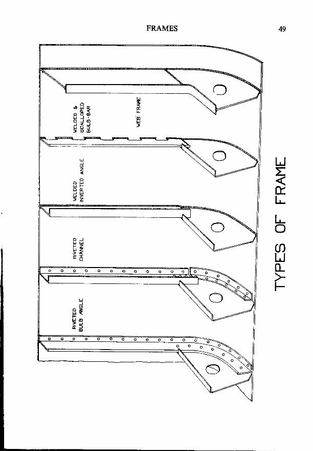
Riveted Frames-These have largely given way to welded frames in modernships, although they are still occasionally fitted, even-in otherwise all-weldedshi^ps. The sictioni most used for these are bulb angles and channels.
welded Frames-Flat bars, bulb bars, or inverted angles may be used forthese. They may be attached to shell plating by intermittent welds, or bycontinuous hllet welds. They are sometimes scalloped, but this is. going outof favour because, although it has some advantages, it adds considerably tothe difficulties and cost of workmanship if it is properly done.
Web Frames-Are heavy plate frames, which are not normally used qs asystem, but are fitted in ceriain parts of a ship _to- give local strength' Tttgymust be fitted in engine-rooms an-d at every fourth frame space in 'tween decksabaft the after peak bulkhead.
A modification of the web frame, called'a 'cantilever frame', is used insome types of bulk carrier and is described in the chapter on 'systems ofconstruction'.
Deep Framing-Is the name given to a system in whic^h ev_gry-frame ismade deiper and-stronger than no-rmal, over a given area of shell plating, toprovide extra local strength.
Frame Spacing-In the main body of the ship, the f1ary_e. spacing may not,in general, ei."edl'00 metres. Between the collision bulkhead and-a pointone"-flfth oithe ship's length abaft the stem, it must not-exce_ed 700 millimetres.In peak tanks and cruisei sterns, it must not exceed 610 millimetres.
Framing in 'Tween Decks-The main framing may extend at its full sizeto tht uppei deck. Alternatively, the framing in the 'tween decfs pal consistof light#sections, scarphed on-io the main-frames at about the level of the'tween deck.
Numbering-Frames are usually numbered from aft to forward, frameNo. 1 being thi first one forward of lhe sternpost. The frames in cruiser sternsare usuallylettered from the sternpost, aft.
-€ _ :
c <I J J
J < -
= : ' :----F.____rF
L J >> z
lrJ !
u Zc r *
FRAMES
UJJ
z
o t !L J F
J Lrllr, >> z _
o O O O O O O o O O O o
O O O O o
50 MERCHANT SHIP CONSTRUCTION
BEAMS
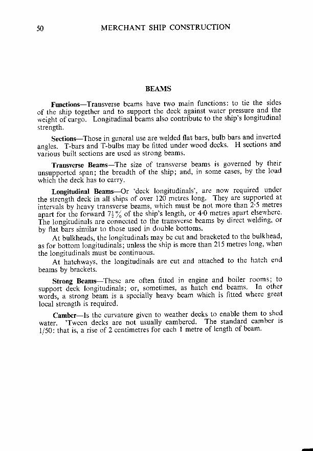
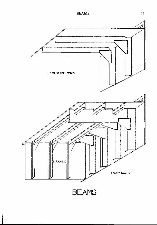
Functions-Transverse beams have two main functions: to tie the sidesof the ship together and to support the deck against water.pressure and theweight of carg5. Longitudinal beams also contribute to the ship's longitudinalstrength.
Sections-Those in general use are welded flat bars, bulb bars and invertedangles. T-bars and T-bilbs may be fitted under wood decks' H sections andvarious built sections are used as strong beams.
Transverse Beams-The size of transverse beams is governed by theirunsufported span; the breadth of the ship; and, in some cases, by the loadwhich the deck has to carry.
Longitutlinal Beams-Or 'deck longitudinals', are 1ow required undelthe strenlth deck in all ships of over 120 metres long. They are supp-orted at
intervals"by heavy transverie beams, which must be not more than 2'5 metres
apart for t"he forward 7i% of the ship's length, or_4'0 metres..apart elsewhere.Tie longitudinals are connected to the transverse beams by direct welding, or
by flat bars similar to those used in double bottoms.
At bulkheads, the longitudinals may be cut and bracketed to the bulkhead,as for bottom longitudinali; unless the ship is more than2l5 metres long, when
the longitudinals must be continuous.At hatchways, the longitudinals are cut and attached to the hatch end
beams by brackets.
Strong Beams-These are often fitted in engine and boiler rooms; to
support d-eck longitudinals; or, sometimes, as hatch end beams. In other
*otdr, a strong beam is a specially heavy beam which is fitted where great
local strength is required.
Camber-Is the curvature given to weather decks to enable them to shed
water. 'Trveen decks are not usually cambered. The standard camber is
1/50: that is, a rise of 2 centimetres for each I metre of length of beam.
,/r/ -
BEAMS
52 MERCHANT SHIP CONSTRUCTION
BEAMS--(Continucd)
Half-Beams--Transverse beams which are cut at hatch side coamings aretermed 'half-beams'. When the coaming does not form part of a deck girder,the half-beams are simply welded directly to it. If the coaming forms part ofthe deck girder, the connection is made by means of alternate flat bars andbrackets (see'Massed Pillaring').
Cargoes Suspended from Beams-When cargo is to be suspended from thebeams, as in the case of chilled beef, the strength of the beams must be increasedby between 50'l and IW%, according to circumstances.
Welding-Beams may be attached to decks by intermittent or continuousfillet welds, or they may be scalloped, in the same way as frames.
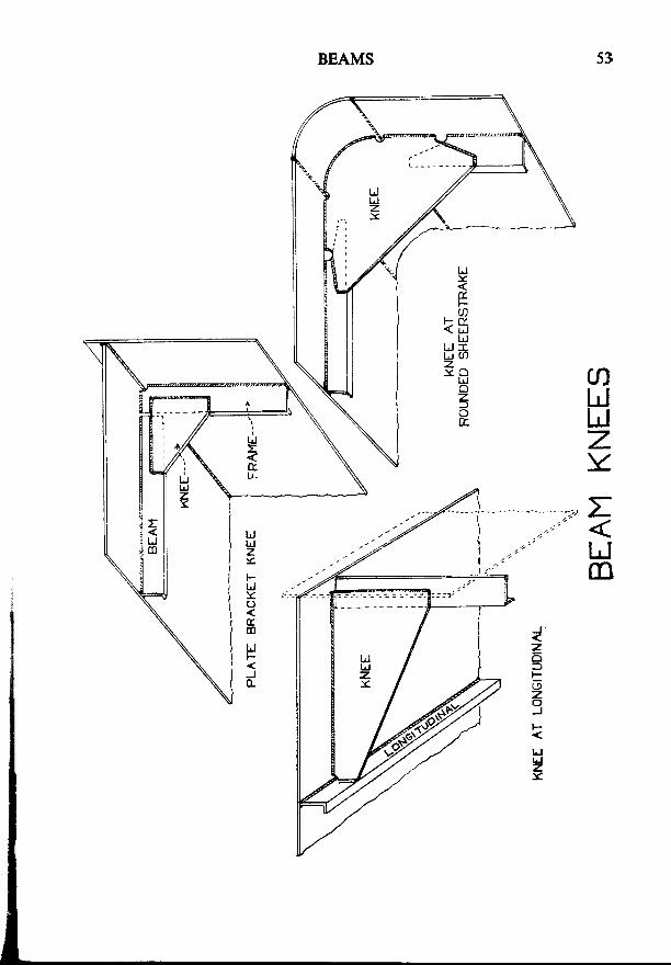
Beam Knees-These are used to connect beams to frames. Therc arevarious types, but for connecting frames to ordinary transverse beams, the'plate bracket knee' is used almost exclusively. Welded plate bracket kneesare not as efficient as they might be, because they have fairly large stressconcentrations at their corners; but they are cheap and easy to fit and arestrong enough for ordinary purposes.
Large knees must have a flange, at least 50 millimetres wide, on their freeedge. Frames and beams need not, in general, overlap, as the knee is con-sidered to be a sufficient connection between them.
When longitudinal beams are fitted, the knees at those frames where thereis no transverse beam, must extend to the first longitudinal.
. .a '
Ljm

54 MERCHANT SHIP CONSTRUCTION
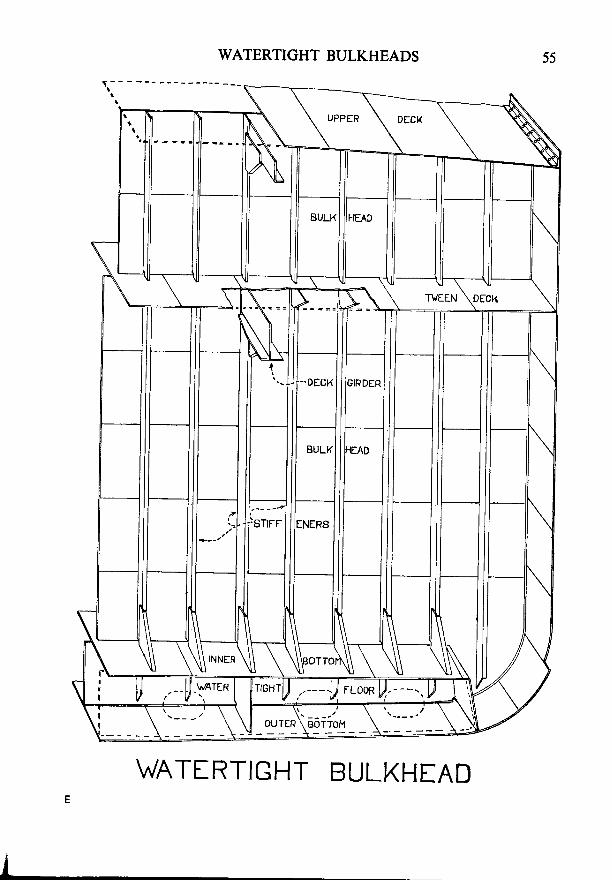
WATERTIGHT BULKHEADS
Uses-Bulkheads are an important element of transverse strength,particularly against racking stresses. By dividing the ship into longitudinalsubdivisions, they also give protection against fire and foundering.
Number to be Fitted-All ships nrust have certain bulkheads, as follows:-A colljsion bulkhead, not less than 5f, nor more than 8o/o of the
ship's length abaft the stem at the load waterline.An after peak bulkhead, to enclose the shaft tube in a watertight
compartment.One bulkhead at each end of the machinery space.
Ships of over 90 metres long must have additional bulkheads, spaced atreasonably uniform intervals. The number to be fitted depends on the lengthof the ship and on whether the engines arc placed amidships or aft.
Passenger Ships-The spacing quoted above is the minimum required forall ships. Passenger ships are, however, required to be subdivided by water-tight bulkheads in accordance with the 'permissible length' of compartments.This is found by multiplying the 'floodable length' by the 'factor of sub-division'. (See Definitions:'Bulkhead Spacing'.)
Height-Collision bulkheads must extend to the upper deck. The afterpeak bulkhead need only extend to the first deck above the load water line,if it forms a watertight flar. All other bulkheads must extend to the bulkheaddeck, which is usually the freeboard deck.
Fitting-Bulkheads are always fitted in lieu of a frame; that is, the frameis omitted and the bulkhead takes its place. They are intercostal betweendecks; the decks being continuous and the bulkhead fitted in 'panels'
between them.
wAt
,'--lf-Y te*
WATERTIGHT BULKHEADS
WATI RTIGHT BULKHIAD
56 MERCHANT SHIP CONSTRUCTION
WATERTIGHT BULKIIEADS{Con t inued)
Plating-Plating may be fitted either vertically or horizontally, but it isusually fitted horizontally, as this allows of a better graduation of thickness.
The thickness may be graduated, increasing from the top downwards. Itis governed in each strake by the spacing and length of the stiffeners and thedepth of the strake below the top of the bulkhead.
Plating in after peak bulkheads must be doubled or thickened around thestern tube to resist vibration.
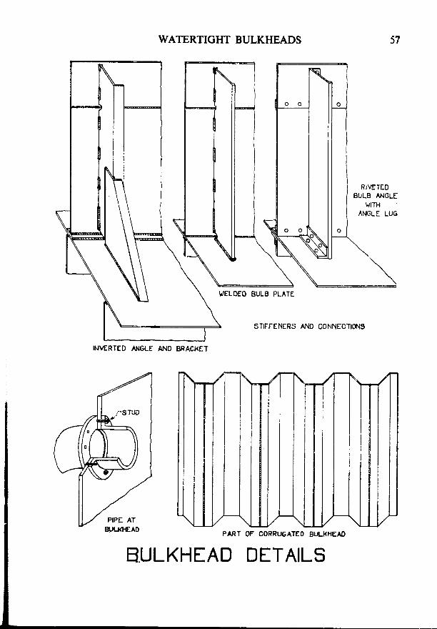
Stiffeners-Stiffeners may be angles, bulb-angles, channels, or equivalentwelded sections and are usually fitted vertically. Their type and size dependon the distance of the top of the bulkhead above the top of the stiffener andon the actual length of the stiffener. They are usually spaced about 75 centi-metres apart. except in collision bulkheads and deep tank bulkheads, wherethe spacing is to be 60 centimetres.
The ends of stiffeners may be welded directly to the inner bottom or deck,or they may be attached by angle lugs or by brackets. Where brackets areused for this purpose, they must extend to the floor next to the bulkhead,whilst large brackets must be flanged. If the ship has longitudinal franting inthe bottom, an extra floor must be fitted undei the toes of the brackets.Stiffeners on collision bulkheads and on bulkheads forming tank boundariesmust be bracketed at the head and foot.
If stiffeners are cut for watertight doors, etc., the opening must be framedstrongly and must have vertical, tapered web plates, extending well above theopening, fitted on each side.
Stiffeners in the way of a deck girder are often made heavier than normaland are attached to the girder by deep, flanged brackets.
Corrugated Bulkheads-These are often fitted in oil tankers and areoccasionally found in dry cargo ships. The type shown in the sketch is oftencalled 'swedged'. The corrugations give stiffness to the plating and ordinarystiffeners are not fitted on them: although widely-spaced web stiffeners, atright angles to the corrugations, are sometimes used.
In transverse bulkheads, the corrugations may run either vertically orhorizontally. In longitudinal bulkheads, only horizontal corrugations areallowed, in order to give longitudinal strength.
The thickness of the plating is governed by the width of its 'flats' and theheight of the bulkhead.
INVERTED /
E
WATERTIGHT BULKHEADS
WELOEO BULE PLATE
IN\ERTED ANGLE Ai.IO BRACXET
STIFFENERS AND CONNECTIOf\IS
PART OF CORRUGATEO BULI(HEAI)
BULKHEAD DETAILS

58 MERCHANT SHIP CONSTRUCTION
WATERTIGHT BULKHEADS-(Co nt i nue d \
Boundaries-Riveted bulkheads are attached to theand inner bottom by single angle bars.
In welded bulkheads, the boundary connections maythe bulkhead plating to the shell plating, etc. Moreconnection is made by welding to a flat bar, angle, orthe sketches.
shell plating, decks
be made by weldingoften, the boundaryT-bar, as shown in
Pipes Passing Through Brrlkheads-Where pipes pass through bulkheads,they are either welded, or fastened to the bulkhead by studs or bolts screwedthrough tapped holes in the'plating. They must not be secured by ordinarybolts passing through clear holes in the plating. This ensures that, if the boltbreaks, parf of it *ilI be left in the bulkhead; otherwise, a clear hole mightbe left in the plating.
Tests-Bulkheads lbrming tank boundaries are tested by testing thetank. Peak bulkheads, other than those forming peak tank boundaries, aretested by filling the peak to the level of the load waterline. Other watertightbulkheads are hose-tested.

BOUNDARY CONNECTIONS
azc)trCJ|Jzzot)
E.
nzfom
UJI:<
o o o o o o . o o o o o o o o
50 MERCHANT SHIP CONSTRUCTION
SYSTEMS OF PILLARING
General-Pillars are intended to support the deck above them and to
tie the beams to the bottom, or deck below. They are usually fitted two ormore beam spaces apart, so-it is necessary to fit a deck girder, running foreand aft undef the beams, to support the intermediate beams.
Ordinarv Pillars-These are solid round bars or tubes, of between 60
millimetres ind 150 millimetres diameter. They are usually fitted at alternatebeams, with a 'deck runner' at their heads.
All ships originally had one rorv of ordinary pillars fitted at the centreline.As ships becamc larger, the pillars r.vere made heavier, or more rows were
introduced.Ordinary pillars have now been superseded as a system by massed pillar-
ing, bnt a..'tiill found in some parts of ships rvhere the deck may requirelocal support.
Quarter Pillars-The large number of ordinary _pilla-rs required in large
st ips,tbstructed the holds. This obstruction was reduced by fitting a_systemof iaiger pillars, spaced further and fitted at_the quarter line only. Becausethere ivere more b'eams to support between pillars, ihe deck runner was madeheavier and came to be called a "deck girder".
Massed Pillars-The modern system of massed pillaring was 4evelopedfrom the quarter pillars by increasing their size and spacing^ still. further'
it"re Aect gird.tt have to-be made very strong, _beca-use of their large,
unsupportei span. Massed pillaring may be fitied- in line. with the hatch
iouniiilgr, in which case the cbamingi form 1 part. of the deck girder. Some-
times, fitlars are omitted entirely, with the deck girder made extra heavy ancl
supported by the bulkheads alone.
Middle Line Longituilinal Bulkheads-Partial longitudinal bulkheads may
be fitted at the centrelline, in lieu of pillars. Their Construction is similar to
ttaioi o.ainary transverse bolkheadsiexcept that they-nee9.not be watertightand that the stiffeners need only be not more than 1500 millimetres apart'
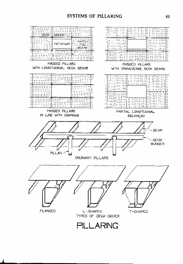
-OECK -GIRDER..
- - - n n l u n -- - - r N t n - -
- - - . R F a M S - -
MASSED PILLARSWITH LONGITUDINAL DECK BEAMS
MASSED PILLARSIN LINE h'ITH COAMINGS
FLANGED
SYSTEMS OF PILLARING
L -SHAPEO
TYPES OF DECK GIRDER
PILLARING
T1ASSED PILLARSWITH TRANSVERSE DECK BEAMS
PARTIAL LONGITUDINALBULKHEAD
6 l
T-SHAPED
I
III
III
;I
II
II
I
ORDINARY PILLARS
62 MERCHANT SHIP CONSTRUCTION
MASSED PILLARING
Pillars-These are usually formed of plates on the round, but are some-times of hollow square section, or built up of angles or channel bars.
Deck Girders-The deck girder usually consists of an intercostal plate,the lower edge of which may be stiffened by a flange, by one or two rivetedbulb angles, or by equivalent welded sections.
Size-The size of pillars and deck girders depends on the work they haveto do: that is, by the length and width of deck supported by them and by theheight of the 'tween decks above them. In the case of pillars, their length isalso taken into consideration.
Fitting of Pillars-It is usual to fit two or three pillars on each side ineach hold. 'Tween deck pillars should be placed directly over lower holdpillars, if possible.
Riveted round pillars are connected at the head and foot by angles.Welded ones are attached directly to the deck girder or plating. In the wayof the heads of pillars, tripping brackets are fitted to the girder: whilst, ifnecessary, the flange may be widened in this region.
Doubling plates, or insert plates, must be fitted to the inner bottom platingunder the heels of massed pillars. The heels of the pillars should rest, ifpossible, on the intersection of a floor and existing intercostal girder in thebottom. If this is impossible, extra intercostal girderwork must be introducedto intersect the floor under the oillar.
TLANGEIN VAY
w t u L l \ L _
n F - p " . :

MASSED PILLARING
PILLARS
FLANCE WIDENED.-.,IN VAY OF PILLAR
HEAO OT h/ELDEO PILLAR
FOOT OT FI\ETFD PILLAR
INTERCOSIAL
OUTER BOTTOH
64 MERCHANT SHIP CONSTRUCTION
MASSED PILLARING-(Continued)
Fitting of Deck Girders-Plate girders are welded directly to the deckabove.
Transverse deck beams, if fitted, are slotted through the girder. If thegirder has a single flange on its lower edge (i.e. if it is L-shaped), it is attachedto every second beam by a bracket on the same side ofthe girder as theflange.If the girder has a double flange (i.e. if it is T-shaped), brackets are fitted onboth sides at every fourth beam. At intermediate beams, between brackets,the beams are attached to the girder by flat bars or by direct welding.
If there are longitudinal beams under the deck, the girder is supportedby brackets which extend to the nearest longitudinal; spaced at the samedistance apart as those for transverse beams.
Deck Girders at Bulkhead-Deck girders are cut at bulkheads. To main-tain strength, they are attached to the bulkhead by welded brackets, whichmust be stiffened by welded face bars on their inner edges.
Hatch Coamings as Deck Girders-Deck girders are often fitted in linewith the hatch coamings and the coaming plate is then built into the girder.In this case, the coaming has to comply with both the rules for the constructionof hatch coamings and with those for deck girders.
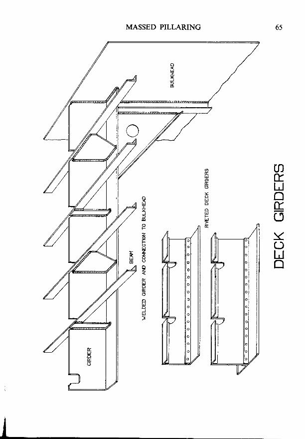
MASSED PILLARING
atrlJntroYC)lrJrl
ulI:<J
F
zotrLlzzo
2
uto
6
Fu
Jlrl
>
66 MERCHANT SHIP CONSTRUCTION
HATCHWAYS
General-The resistance to longitudinal stress is much reduced in theway of hatches, on account of the large amount of material which must be cutout of the deck. Stress concentrations cause a tendency for the deck tofracture at the hatch corners. There is also a loss of resistance to lcads ofwater or cargo on the deck, due to the beams being cut at the hatch coaming.These weaknesses must be compensated for or they might be dangerous. Togive the necessary strength the deck plating must be strengthened or doubled,and the coamings and their connections must be sufficiently strong and rigid.
Deck Openings-With riveted construction, deck openings may havesquare corners, with doubling plates frtted at the corners.
When the deck is welded, square corners are not allowed. The openingsmay be elliptical or parabolic, or the corners may be rounded-off. In the lattercase, the radius at the corners must be at least one-twenty fourth of the breadthof the opening; but not, in any case, less than 300 millimetres. Doubling platesare not allowed in welded decks, so insert plates must be fitted at the hatchcorners instead.
Height of Coamings-Coamings on weather decks must exf.end wellabove the deck, to ensure that water cannot enter the ship's hull.
The height of coamings on freeboard decks, raised quarter decks, orwithin one-quarter of the ship's length from the stem on superstructure decks,is to be 600 millimetres, where they are explosed to the weather. On exposedparts of superstructure decks, abaft one-quarter of the length from the stem,the height is to be 450 millimetres. At other decks, the openings are to besuitablv framed.

HATCHWAYS
HATCH END BEAM
DECK PLATING EXTENDEDTNS|DE SpTJARE -CoRNEREO
r t..HALF
BEAMSHATCH ENO BEAI.I
HATCHWAYS
68 MERCHANT SHIP CONSTRUCTION
HATCHWAYSIContinued)
Coamings-Welded hatch coamings rnay have rounded corners, so as tofit closely inside the deck opening, but this is not common because it is thendifficult to fit hatch-covers.
A common alternative is to fit square-cornered coamings. If this is donewithin 0'6 of the ship's length amidships, the ends of the side coamings mustbe extended beyond the hatch ends to form tapered brackets, if possible. Thedeck plating must be extended inside the coaming so that it can be rounded-offand its edges must be smooth and must not have anything welded to them.
Below the deck, the deck girder may be fitted in line with the side coamings.If this is not done, and if the side coamings cannot be extended, above thedeck, to beyond the hatch ends; then short pieces of girder must be fitted toextend the coamings for at least two frame spaces below the deck. In eithercase, horizontal gussets are fitted under the hatch corners to strengthen theconnection between the side coamings and the hatch end beams.
Great care must be taken in welding hatch coamings to decks, in orderto make a strong and efficient connection. Full penetration fillet welds areoften used for this purpose.
If coamings are 600 millimetres or more in height, they must be stiffenedby bulb-bars, at least 180 millimetres deep, fitted horizontally near the upperedge of the coaming. Vertical stays or brackets must then be fitted, not morethan 3 metres apart, between the stiffener and the deck.
Hatch End Beams-The beam at each end of a hatchway is called a'hatchend beam'. These are usually made stronger than normal and are connectedto the frames by heavy, flanged beam knees, because they carry at least partof the weight of the coaming.
\-
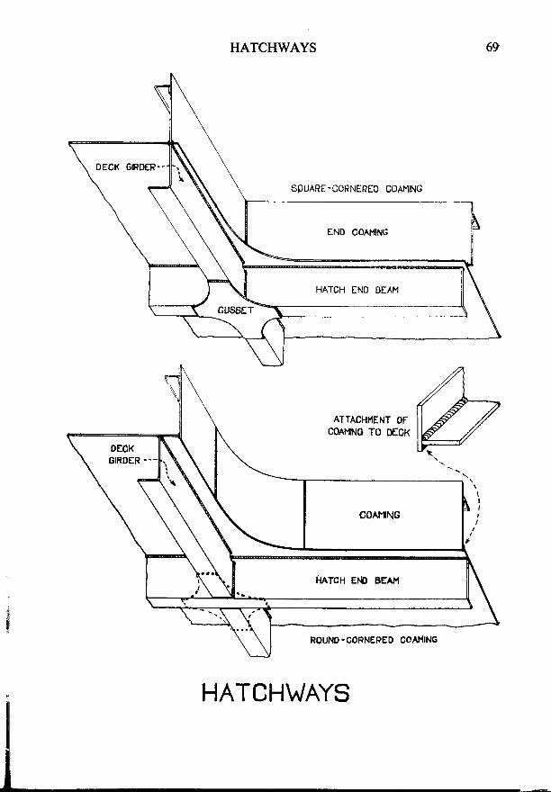
HATCHWAYS
AWrr(-
HATCH\,/AYS
ATTACHI(ENT OFCOAMI}IG TO DEOK
70 MERCHANT SHIP CONSTRUCTION
HATCHWAY S-(C on t inue d)
Half Beams--Transverse beams in the way of the side coamings are cut
at the latter and are called 'half beams'.If the side coamings form part of the deck girder, the half beams are
attached to them by we'ided bari and by brackets at alternate beams; as for
deck girders.If the side coaming does not form part of the deck girder, the connection
is by-diilci *.tding; "unless the deck-girder is at some distance from the
coaming, when brackets may be fitted between the two.
Longitudinal Beams at Coamings-If longitudinal be.aqs are fitted under
tne Aeclittrey are cut at the hatch a-nd coaming and attached to it by brackets'

7lHATCHWAYS
aUZ=
oclIOF
I
F
n:
IJm
(9zE
to&tL
UJ
zF
o
LJEoaF
Eta.l
e
6
F
ot i z
t f t
J t , l< .
o ' -
O IJ
croc
YIJ(f
L
F
o-a
zE
o
F< u )q z: :
< zz t )
'- t-( ' '<z T .-
t9Z
t -
72 MERCHANT SHIP CONSTRUCTION
STIELL AND DECK PLATING
General-Seams, or 'Edge Laps', are jointsis, along the longer edges of the plates'
which run fore and aft; that
athwartships, or verticallY;Butts, or 'End Laps', are joints which runthat is, along the shorter edges of the plates.
Strakes are continuous, fore and aft, lines ofplates.
Garboard strakes are the strakes of shell plating next to the keel on either
side (i.e. the'A Strake').Sheerstrakes are the upper strakes of shell plating on either side, next to
the upper deck. (The 'J stiake' in the sketch opposite.)
The Deck Stringer is the outboard strake of deck plating, which is
connected to the shee-rstrake. (Strake 'E' on the deck plan, opposite.)
Stresses on Plating-The obvious purpose of plating is to keep out water
and to tie together th6 ship's framework.- It also-playsan important part.in
resisting longitudinal bending stresses, so it needs to be stronger.amtdshtpsittu" uitfr" Jnds, particularly"at the deck and bottom. In long ships, it may
also be necessary ^to
strengthen the shell plating {Eainst shearing stresses .atuUoui tir. truf-aipth of th-e ship, in the rigion-of about one-quarter of the
ship's length from either end.
Shell Expansion and Deck Plans-These are plans which show all the
pfut.rln tG hirll, dtu*n to scale. They also show mbny other details, including
t*me", noors, deck edges, stringers, eic. The partial plans shown in the, plate,
6t;;i6;;re'simplifie"d and aie merely intended to illustrate the fitting of
shell and deck plating.
Identifying Plating-strakes of shell plating are distinqgished by- letters
from the k-eel*outwaris, the garboard strake being strake 'A'. The platesin
each strake are usually numbJred from aft to forward. For example, plate D5
would be the fifth plale from aft in the fourth strake from the keel.
Strakes of deck plating are lettered from the centre line, outboard; whilst
deck plates are numbered from aft to forward.
Stealer Plates-The girth of the ship decreases toward the ends and so
tne wiAtn of plates must"be decreased in these pa-rts. To save making the
olates too nariow at the ends of the ship, it is usual to run a number of pairs
6f uAlu".nt strakes into one. This is done by means of a stealer plate.
ihir .un be seen in the upper shell expansion plan, given here; in which
Plate 84 is a stealer, since it runs the B and C strakes into each other' Note
how the stealer and ihe plates beyond it, always take the name of the lower of
the strakes which are run together.
.-
SHEL

6
J 3H 6
J.?J ' ;--t?';:
F 4 l a
G 7t i 3
\ H l
\ . ;
H 2 |
.Ht G 3
2
--T-
E 5
\- Fr F 2F5
t JD 4
D 5E I E 2
D5 C 3D 1 D 2 C 2
b f B 2 R 5 B4 6-a 86 I utA 4 A 5 A 6
K € E L 1 I 2 J ?
SHELL PLATING
SHELL IXPANSION _ SHIP PLATED AT SLIP
SHFLL EXPANSION _ PREFABRICATED SHIP
PLAN OF DECK PLATING
I J
SHILL AND DECK PLATING
J 7l u l r e l . r r o J l l
H 6
G A
H 9 H l o
G ? O
F 9
H r r
ffi G 9
14 l
H1
J3 F 8
A AH 4
E 6 L I E AE 9
nj--frtG 3 ry_w ';4i, D 4 05 D 6 D 7
D N{rxt
U O c 6E 5 c 7L / *-H{E
a4 B 5 B6 B 7 B 8 B 9 B r 0
A4 AC A 6 A7 A A A 9 Ato2 l 5 t + | 5 6 7 a TO u
-_INSERT PLAIE-- . .
HATCH\,VAY

74 MERCHANT SHIP CONSTRUCTION
SHELL AND DECK PLATINGlContinued)
Special Plates-Shoe plates are used to connect the stem to the flat platekeel. (See'Stems').
Coffin Plates are used to connect stern frames to the flat plate keel.(See 'Sternframes'.)
Boss Plates are shield-shaped plates fitted over the boss of the sternframe.
Oxter Plates are peculiarly curved plates which are fitted where the stern-frame meets the overhang of the stern.
Riveted Plating-This has largely given way to welded qlating, but is sJillsometimes used.
*The modern syitems are Joggled Plating and Joggled
Framing, both of which are light and efficient. The butts of the plating wereoriginafy riveted, but are now almost always welded. When.this is done, thebut-ts must be welded first and the seams riveted afterwards, in order that thejoints may be sound.
Welded Plating---The butts and seams are joined by butt welds, rvhichgives a flush surface to the plating and also saves some weight.
Welded plating is more liable to crack, under hogging and sagging stresses,than is rivetid plating; particularly in the region of the sheerstrake and thebilge. Such craiks ari most likely to occur if openings are cut near the upperedfe of the sheerstrake, or if noiches or hard ipots occur at its upper edge.Fo-r this reasou, openings in the sheerstrake should have well-rounded cornersand should be kepi welf clear of the upper edge of the plates. The upper edgeof the sheerstrake should be 'dressed' (ground-off) smooth; whilst other partsshould not be welded to it, if avoidable.
As a further precaution against cracking, special 'notch resistant' steelsare now often used for some parts of the plating. Lloyds' Rules requirg-tlatgrades B, D, or E steels shall Le used for sbme, or all,_of the bottom and bilge
[lating and for the sheerstrake, according to the length of the ship. z
' / ' a :- .4"
tt
- - i -
, ' . i l- : 0 -
: / '
-".r'
- / , t - . ' ^ :
-
-
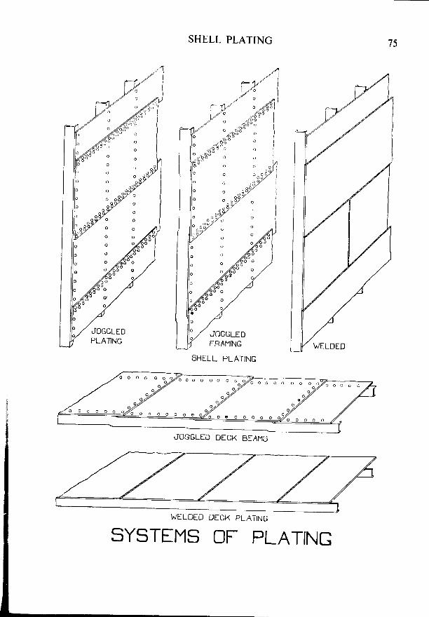
o
o
o
o
o
o
o
o
o
o
o
o
SHELL PLATING
WELDED DICK PLATING
SYSTEMS OF PLATING
75
o o o o o o o o
JOGGLED DICK BfAMS
76 MERCHANT SHIP CONSTRUCTION
SHELL AND DECK PLATING-(Continued)
Connection of Upper Deck Stringer to Sheerstrake-The upper decksheerstrake may be connected to the deck stringer by a welded T-joint, using afull-penetration fillet weld. Alternatively, to reduce the risk of cracks startingat the sheerstrake, the connection may be made by means of a riveted 'deck
stringer angle'; or by a rounded sheerstrake, butt welded to the deck stringerand having a radius of not less than 15 times the thickness of the plate.
Crack Arrestors-Any small crack which occurs in all-welded plating isliable to spread (or 'grow') through adjacent plating, possibly with seriousconsequences. It is much less likely to spread across a riveted seam. Toprevent any cracks from spreading in welded ships, strakes in which cracks aremost likely to occur may have their seams riveted, instead of welded, for aboutthe half-length amidships. Such seams are called 'crack arrestors'.
Crack arrestor seams lvere often used at one time, in any or all of theplaces shown in the sketches opposite. They are now becoming less common,because special notch-resistant steels are being increasingly used for ships'plating, in place of mild steel.
Beyond the half-length amidships, crack arrestors usually revert to weldedseams: the transition from riveting to welding being dealt with as shown inthe sketch. The edge of the in-strake is cut away in the way of the seam;whilst the out-strake is bent inwards for a short distance. to allow it to becomeflush with the in-strake. Welds are then made. inside and outside, to connectthe plates and to seal thejoint.
Shift of Butts-Riveted butts are weaker than the plates which they jointogether. It is, therefore, necessary to stagger them well away from eachother to adjacent strakes of plating, so as to avoid a line of weakness aroundthe ship's hull. This staggering is known as the 'shift of butts' and it must bevery carefully controlled in riveted ships.
Welded butts are very much stronger than riveted ones, so the shift ofbutts is not very important in this case. The butts are, therefore, usuallyarranged as convenient for construction. When the ship is built in pre-fabricated sections, the butts are often only 'shifted' at the sheerstrake andbilge, as shown in the shell expansion plan, here.
l - s : _ _ :
c a ' . . . a
t ,
q
SHfLt

SHELL PLATING
CONNECTION OF SHEERSTRAKE TO DECK STRINGER
i l h r r r - i - -1 - - N | V E - r L U
JC - \^/ELDED
EEnY)
TION FRoM RIVETED To \,/[LDED SEAM
SHILL AND DECK PLATING
r]WtlL_l
TRANSI
DECKSTRINGER
78 MERCHANT SHIP CONSTRUCTION
SIIELL AND DECK PLATING-(Continued)
'Tween Decks at the Ship's Side-The 'tween deck stringer is usuallyslotted to allow the frames to pass through it. At one time, the deck wasmade watertight at the sides by fitting a continuous inner angle and cementchocks. Nowadays, the slots may be sealed by means of a plate collar, or'chock', lightly welded around the frame, as shown in the sketch. Anothercommon method of making a watertight joint at this point is to stop the deckstringer short of the frames and to weld-in sealing plates between the frames,as described in the chapter on 'Deep Tanks'.
Deck Openings-In welded ships, these must have rounded corners andmust be suitably framed-in. For further details, see the chapter on'Hatchways'.
Openings in Shell Plating-Any openings in the shell plating must havespeciaf arrangements to preserve strength and their corners must be rounded.When large openings, such as cargo doors, are cut in the plating, they areusually framed-in by a face bar. In this case, web frames are often placed oneither side of the opening and insert plates are fitted above and below it, orsometimes right around it.
Width of Plates-The Rules lay down a definite width for deck stringers,sheerstrakes, garboard strakes and keel plates. Other strakes may be of anyreasonable width.
Thickness of Plates-Plating varies in thickness in different parts of theship, whilst certain plates and strakes are made thicker than normal.
Shell and deck plating is kept at its midship thickness for four-tenthsof the ship's length ahidships, bui is slightly reduced towards the ends of theship: except for plates covering the flat of the bottom in the pounding region,which are thickened.
Sheerstrakes, upper deck stringers and keel plates are made thicker thanother strakes.
Shell plating in the bottom and bilge is usually thicker than that in thesides of the ship.
Deck plating is thinner than normal within the line of the hatchways;whilst the plating in 'tween decks is thinner than that of upper decks.
SFt

SHELL PLATING
T\^/EEN DECK AT SHIP'S SIDE
79
INSERT PLATIS.-.
PLATING AROUNDSlDf OPfNINC
SHILL AND DfCK PLATINGIN SHILL PLATING
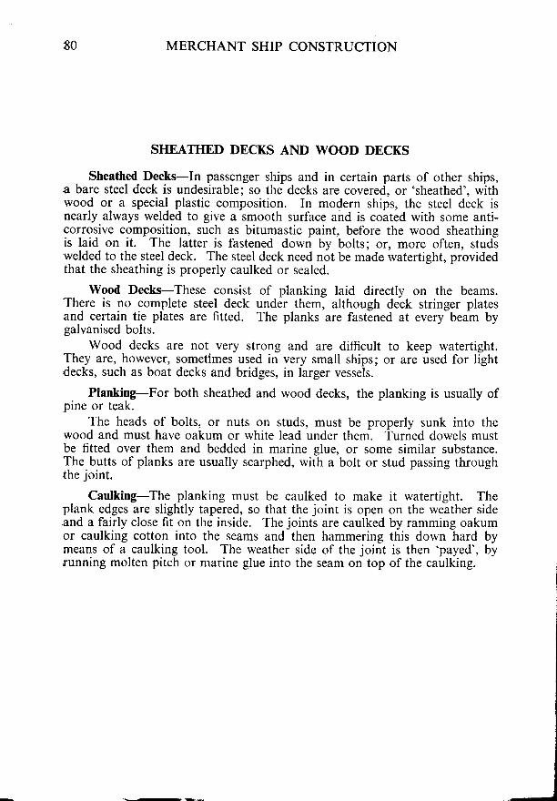
80 MERCHANT SHIP CONSTRUCTION
SI{EATHED DECKS AND WOOD DBCKS
Sheathed Decks-In passenger ships and in certain parts of other ships,a bare steel deck is undesirable; so the decks are covered, or'sheathed', withwood or a special plastic composition. In modern ships, the steel deck isnearly always welded to give a smooth surface and is coated with some anti-corrosive composition, such as bitumastic paint. before the wood sheathingis laid on it. The latter is fastened down by bolts; or, more often, studswelded to the steel deck. The steel deck need not be made watertight, providedthat the sheathing is properly caulked or sealed.
of planking laid directly on the beams.under them, although deck stringer platesThe planks are fastened at every beam by
Wood Decks-These consistThere is no complete steel deckand certain tie plates are fitted.calvanised bolts.
Wood decks are not very strong and are difficult to keep watertight.They are, however, sometimes used in very small ships; or are used for lightdecks, such as boat decks and bridges, in larger vessels.
Planking-For both sheathed and wood decks, the planking is usually ofpine or teak.
The heads of bolts, or nuts on studs, must be properly sunk into thewood and must have oakum or white lead under them. Turned dowels mustbe fitted over them and bedded in marine glue, or some similar substance.The butts of planks are usually scarphed, with a bolt or stud passing throughthe joint.
Caulking-The planking must be caulked to make it watertight. Theplank edges are slightly tapered, so that the joint is open on the weather sideand a fairly close fit on the inside. The joints are caulked by ramming oakumor caulking cotton into the seams and then hammering this down hard bymeans of a caulking tool. The weather side of the joint is then 'payed', byrunning molten pitch or marine glue into the seam on top of the caulking. >-r_
SHf
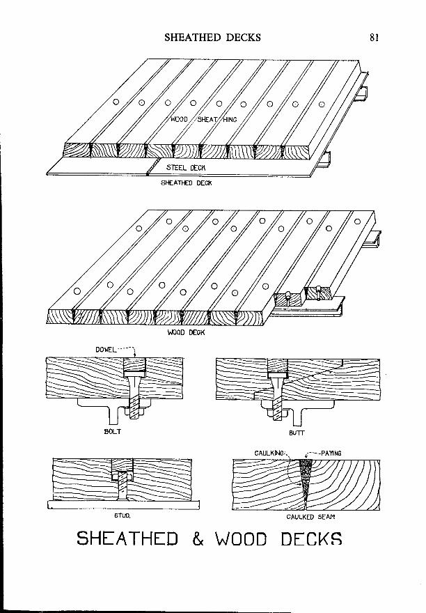
SHEATHED DECKS
SHTATHf D & w00D

82 MERCHANT SHIP CONSTRUCTION
BILGE KEELS
Purpose-Bilge keels are intended to resist rolling. Their effects arecomplex, but may be summarised as follows:-
(a) Direct resistance between bilge keel and water has a comparativelyweak effect.
(b) They slightly increase the ship's period of roll.(c) They upset the transverse streamlines of the ship's hull and
thus set up eddy-currents and increase the 'wave-making
resistance'.(d) They increase water pressure over a large area of the ship's hull
and this pressure acts in such a direction as to damp the rolling.
Position-For their protection, bilge keels should always be arranged tolie within the line of the ship's side and that of the bottom of the floois. Ifthey were to project beyond these limits, they would be more liable to damage.
construction-Bilge keels are sometimes ripped off, however carefullythey are positioned, if the ship touches the ground.
- It is important to construct
them so that, if this happens, the ship's shell plating will remain intact.Riveted bilge keels are connected to the hull by a riveted angle or T-bar,
which is strongly attached to the shell plating, but less strongly connected tothe bulb-plate. If the bilge keel is ripped off, it will then part al ihe outer joint,leaving the hull intact.
In welded ships, the bilge keels are usually attached to a continuous flatbar, welded to the shell plating. The outer joint may then be riveted, or lightlywelded, so that it will part before the connection to the hull. Alternatively,the keel may be attached to the hull by intermittent welds, and is often scallopedthroughout its length, so that the welds will part comparatively easily and willleave the hull undamaged.
,In large ships, where the bilge keels are very deep, they may be constructedas shown in the sketch. Here, again, the outer connection is made less strongthan that to the shell plating.
Unless they are carefully designed, the ends of bilge keels tend to producestress concentrations which can cause the bilge plating to crack. To preventthis, the ends of the bilge keel should be tapered-off gradually and should endover a floor or tank side bracket; whilst a doubling plate should be welded tothe bilge plating at this point.
,L*/ 'T=-
/'
/
t--
l !
/ F/ : F
/ q . -.//
11
POSI T ].B ILG- .
BILGE KEELS
EILGE KEEL
83
V/EBS AT-- INTERVALS
BILGI KffLS
WELDED AND RIVETED
WELDED
\^/ELDED ANo SCALLOPED
.._-DOUBLING PI-ATE
BILGI KEEL FORLARGE VESSEL
POSITION OFBILGC KEEL
84 MERCHANT SHIP CONSTRUCTION
DEEP TANKS
Purpose-When a ship makes a voyage in a light condition. it is usuallydesirable to carry a certain amount of water ballast. If the double bottomtanks alone were used for this purpose, the ship might be unduly 'stiff'; so ithas become the practice to arrange one of the lower holds so that it can befilled with rvater when necessary. This permits a large amount of ballast tobe carried, without unduly lowering the centre of gravity of the ship. Such ahold is called a Deep Tank.
In certain trades, it has been found convenient to utilise deep tanks forthe carriage of liquid cargoes, or for oil fuel bunkers. In other trades, thedeep tanks are still used solely for their original purpose to carry dry cargoesnormally, but to be used as water ballast tanks when the ship is light.
Ordinary Deep Tanks-When a deep tank is intended for its originalpurpose, it is basically the same as any other hold. It must, however, besomewhat modified to enable it to carry water ballast.
A washplate must be fitted at the centre-line, to reduce free surface cffect.The hatchway must be specially constructed so as to prevent water from
escaping from below.Frames are to be 15 per cent stronger than normal.Bulkhead stiffeners must be spaced not more than 600 millimetres apart
and must be bracketed at the head and foot.The deck plating which forms the tank top must be at least 1 millimetre
thicker than that of the boundary bulkheads. It must not, in any case, bethinner than normal.
Beams may be normal, provided that their size is not less than that ofthe bulkhead stiffeners. They must be supported by an intercostal girder oneither side of the centre line.
Where the deck edge meets the ship's side, great care is required to makea completely watertight joint. In rivetpd construction, the frames are oftencut below the deck so that a continuous watertight stringer angle can be fitted.The frames above are then attached to the deck by brackets. In welded con-struction, the frames usually pass through the deck. The slots through whichthey pass may be sealed by welding pieces of plate over them. Alternatively,the deck plating may be stopped short, a few inches inboard of the frames,and sloping sealing-plates welded in, as shown in the sketch.
rc:LJT
/--
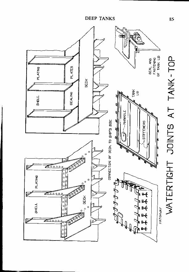
DEEP TANKS
in_:o.Fi l
YzF
F-
coFZ,or)
F-:ECJFt.LJF
:
?T

86 MERCHANT SHIP CONSTRUCTION
DEEP TANKS-(Continued)
Deep Tanks Used as Oil Fuel Bunkers--.In this case, the ship's sides andthe boundary bulkheads may have additional stiffening in the form of deep,horizontal girders, running right round the inside of the tank and spaced notmore than 3 metres apart vertically. These girders, if used, must be stiffenedon their inner edges and are connected together at the tank corners by flangedbrackets. They are supported at each third frame or stiffener by bracketsand are attached to intermediate frames or stiffeners.
A middle line bulkhead must be fitted if the tank extends for the fullbreadth of the ship. This may be perforated if desired. Light intercostalstringers are fitted horizontally across it, in line with the horizontal girders, ifthe latter are fitted in the tank.
Quarterline girders must be fitted at the deckhead; these are often formedby deepening the ordinary deck girder.
Deep Tanks for Carrying Oil as Cargo-Deep tanks may be used for thecarriage of oil cargo, provided that its flash point is not less than 60" C. Inthis case, the tank may be constructed in the same way as one built for oil fuelbunkers, except that a centre-line bulkhead need not be fitted unless the tankis liable only to be partly filled.
Cofferdams-Fuel oil, vegetable oil, and water, may not be carried jnadjacent tanks, unless these are separated from each other by a cofferdam.
Testing-Deep tanks are tested by filling them with water to the maximumhead which can come on them in practice; provided that this is not less than2'44 metres above the tank top.
-f-
rrtITIi-i - - \F \
t 't-
) { . ; :<Qw - Lj
- t \ t ' . , r A V
I
. - STRINGiE
DEEP
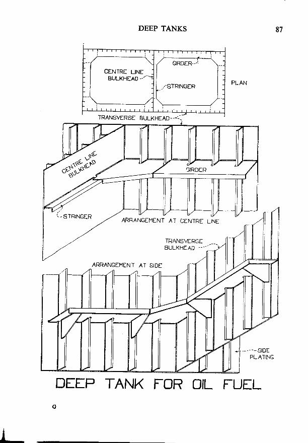
DEEP TANKS 87
ARRANGEMENT AT CENTRE LiNE
TRANS\€RSEBULKHIAD -.---
ARRANGEMENT AT SIDE
---stDEPLATING
DffP TANK FOR OIL FUILG
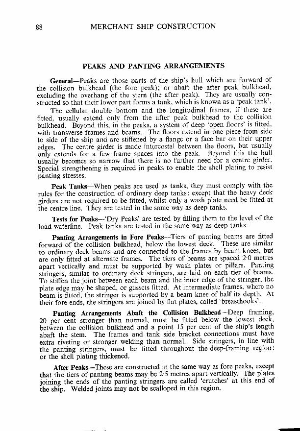
88 MERCHANT SHIP CONSTRUCTION
PEAKS AND PANTING ARRANGEMENTS
General-Peaks are those parts of the ship's hull which are forward ofthe collision bulkhead (the foie peak); or abaft the atter peak bulkhead,excluding the overhang of the stern (the after peak). They are usually con-structed io that their lower part forms a tank, which is known as a 'peak tank'.
The cellular double bottom and the longitudinal frames, if these arefitted, usually extend only from the after peak bulkhead to the collisionbulkhead. B-eyond this, in the peaks, a systetn of deep 'open floors' is fitted.with transvers; frames and beams. The floors extend in one piece from sideto side of the ship and are stiffened by a flange or a face bar on their upperedges. The centie girder is made intercostal between the floors, but usuallyonly extends for a few frame spaces into the peak. Beyond this the hullusu-ally becomes so narrow that there is no further need for a centre girder'Special strengthening is required in peaks to enable lhe shell plating to resistpantlng stresses.
Peak Tanks-When peaks are used as tanks, they must comply with-therules for the construction of ordinary deep tanks: except that the heavy deckgirders are not required to be fitted, whilsi only a wash plate need be fitted atihe centre line. They are tested in the same way as deep tanks'
Tests for Peaks-'Dry Peaks' are tested by filling thr'm to the level of theload waterline. Peak tanks are tested in the same way as deep tanks.
Panting Arrangements in Fore Peaks-Tiers of panting beams are fittedforward of the collision bulkhead, below the lowest deck. These are similarto ordinary deck beams and are connected to the frames by beam knees' butare only fiited at alternate frames. The tiers of beams are spaced 2'0 metresapart vertically and must be supported by wash plates or pillars. ^Pantingsfringers, simiiar to ordinary deCli stringers, are laid orr each tier of beams'To siiffen the joint between
-each beam ahd the inner edge of-the stringer, the
plate edge may be shaped, or gussets fitted. At intermediate frames, where nobeam is fitted, the stringer is supported by a beam knee of half its depth. Attheir fore ends, the stringers are joined by flat plates, called 'breasthooks'.
Panting Arrangements Abaft the collision Bulkhead-Deep framing,20 per cenl strongEr than normal, must be fitted below the lowest deck,between the collision bulkhead and a point 15 per cent of the ship's lengthabaft the stem. The frames and tank side bracket connections must haveextra riveting or stronger welding than normal. Side stringers, in line withthe panting stringers, must be fitted throughout the deep-framing region:or the shell plating thickened.
After Peaks-These are constructed in the same way as fore peaks, exceptthat th e tiers of panting beams may be 2'5 metres apart vertically. The plates
ioining the ends'of thd panting stiingers are called 'crutches' at this end ofihe strip. Welded joints may not be scalloped in this region.
'
lr-
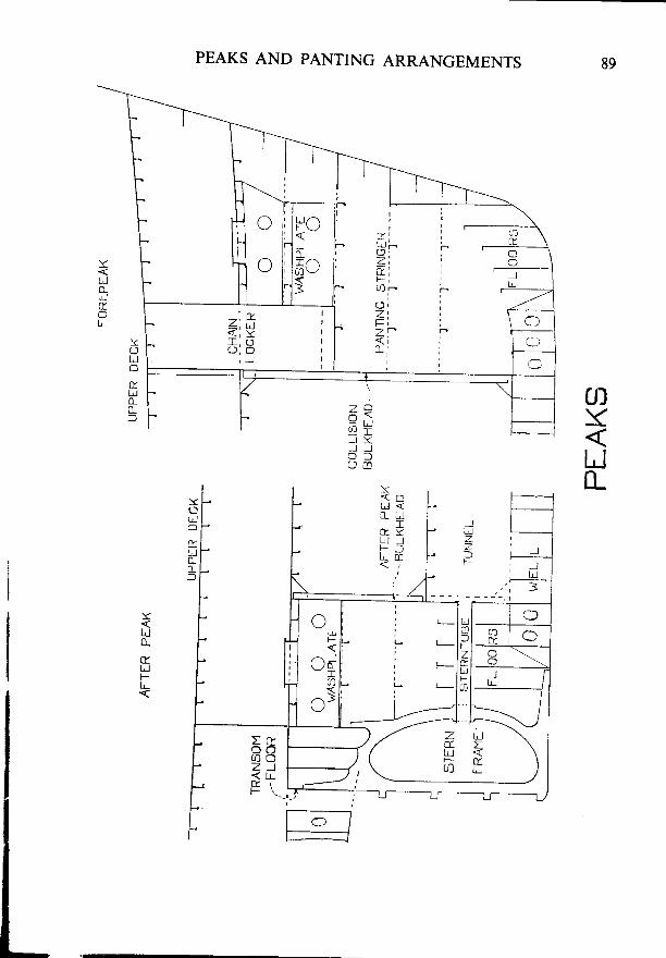
PEAKS AND PANTING ARRANGEMENTS 89
UJY
UtL
Yotdo
tLJ0_0_f
Y
il0_
trI,JFL-
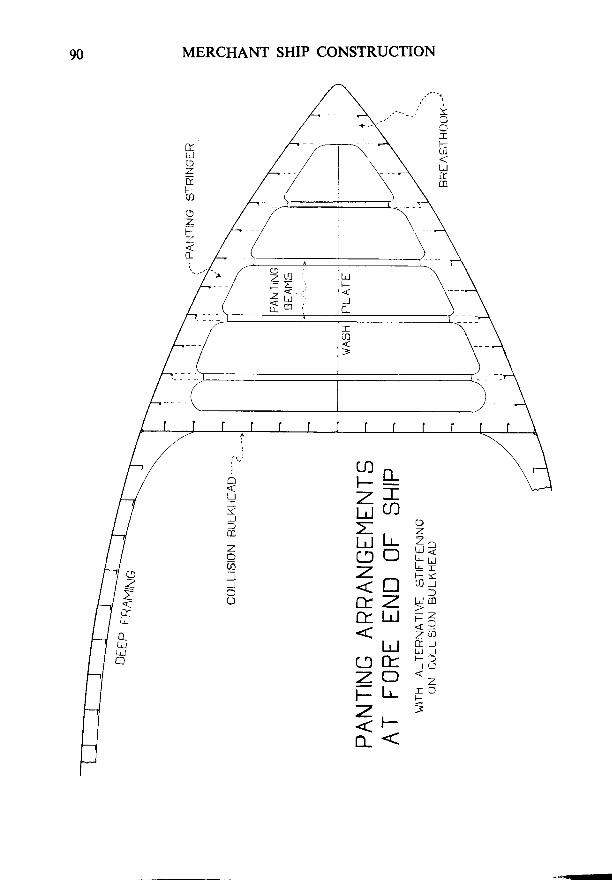
MERCHANT SHIP CONSTRUCTION90
Y
crF0l
Utm
ftLI
ztFU]
zFZ
0_I
UJ^r l I
7T.LI UJ
l-rl lr 7,2r? o F-fiftn6=tZ gdf t lJ ;<
l! f i i(J rL :3z-o :<l - l t
z, ;<r-t {
oLJIY_-)l0
zo
J__J-
r ^z:
lr-
0_LJLrlo
PANTII'
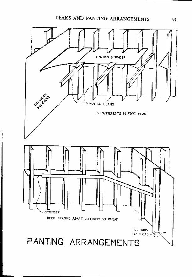
PEAKS AND PANTING ARRANGEMENTS
ARRAI.IGEHENTS IN FORE PEAK
DEEP FRAMING ABAFT COLLI9ION SULKF€^D
coLLtstoN IEULKHEAD -.
PANTING ARRANGEf''lfNTS
PAtlTltlc STRll.lcER
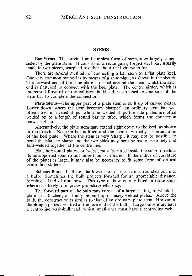
92 MERCHANT SHIP CONSTRUCTION
STEMS
Bar Stems-The original and simplest form of stem, now largely super-seded by the plate stem. It consists of a rectangular, forged steel bar: usuallymade in two pieces, scarphed together about the light waterline.
There are several methods of connecting a bar stem to a flat plate keel.One very common method is by means of a shoe plate, as shown in the sketch.The forward end of the shoe plate is dished around the stem, whilst the afterend is flattened to connect with the keel plate. The centre girder, which isintercostal forward of the collision bulkhead. is attached to one side of thestem bar to complete the connection.
Plate Stems-The upper part of a plate stem is built up of curved plates.Lower down, where the stem becomes 'sharper', an ordinary stem bar wasoften fitted in riveted ships: whilst in welded ships the side plates are oftenwelded on to a length of round bar or tube, which forms the connectionberween them.
Alternarively, the plato srem may extend right down to the keel, as shownin the sketch. No srem bar is fitred and the stem is vinually a continuationof the keel plate. Where the stem is very 'sharp', it may not be possible tobend the plate to shape and the two sides may here be made separately andbutt-welded together at the centre line.
Flat, horizontal plates, or'webs', must be fitted inside the stem to reduceits unsupported span to not more than l'5 metres. If the radius of curvatureof the plates is large, it may also be necessary to fit some form of verticalcentre-line stiffener.
Bulbous Bows-In these, the lower part of the stem is rounded out intoa bulb. Sometimes the bulb projects forward for an appreciable distance,forming a kind of ram bow. This type of bow is only fitted in those shipswhere it is likely to improve propulsive efficiency.
The forward part of the bulb may consist of a large casting, to which theplating is attached; or it may be built up of heavy welded plates. Above thebulb, the construction is similar to that of an ordinary plate stem. Horizontaldiaphragm plates are fitted at the fore end of the bulb. Large bulbs must havea centre-line wash-bulkhead. whilst small ones must have a centre-line web.
sr-oi :_ aATIACHY'" _
PLATING WEt-)::
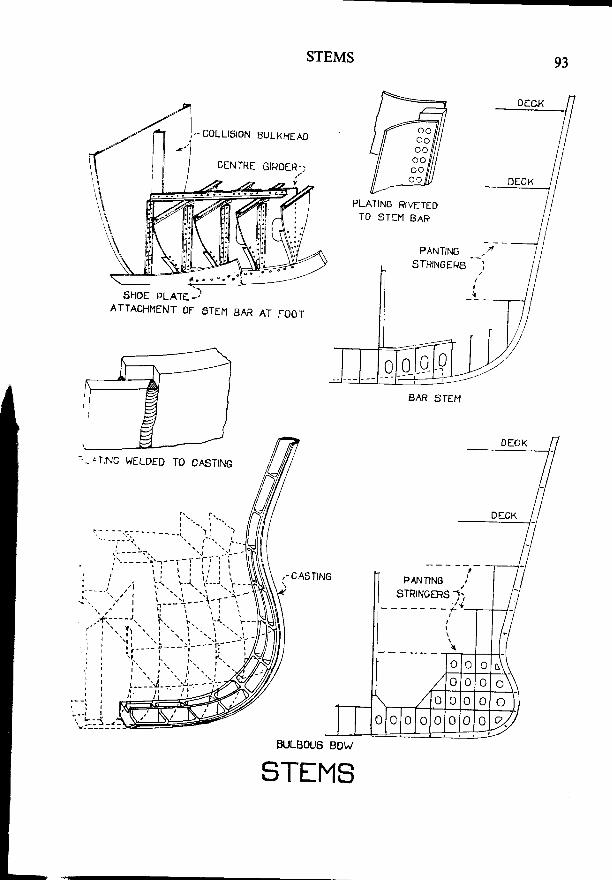
STEMS 93
SHOE PLATE -JATTACHI4ENI OF ATEN BAR AT FOOT
COLLISION EULKHEAO
CENTRE GIRDER-;
PLATING RIVETEDTO STIM BAR
ITING WELDED TO CASTING
PANTING)TR|NGERS l, / ,- - - - - f
I
\
,I
0E(
0E'cK
1rlt
(U n
o o \
no o to o o
0 lo l o n o n l" l 0 l v./
2zuLBOUo BOW
STfMS
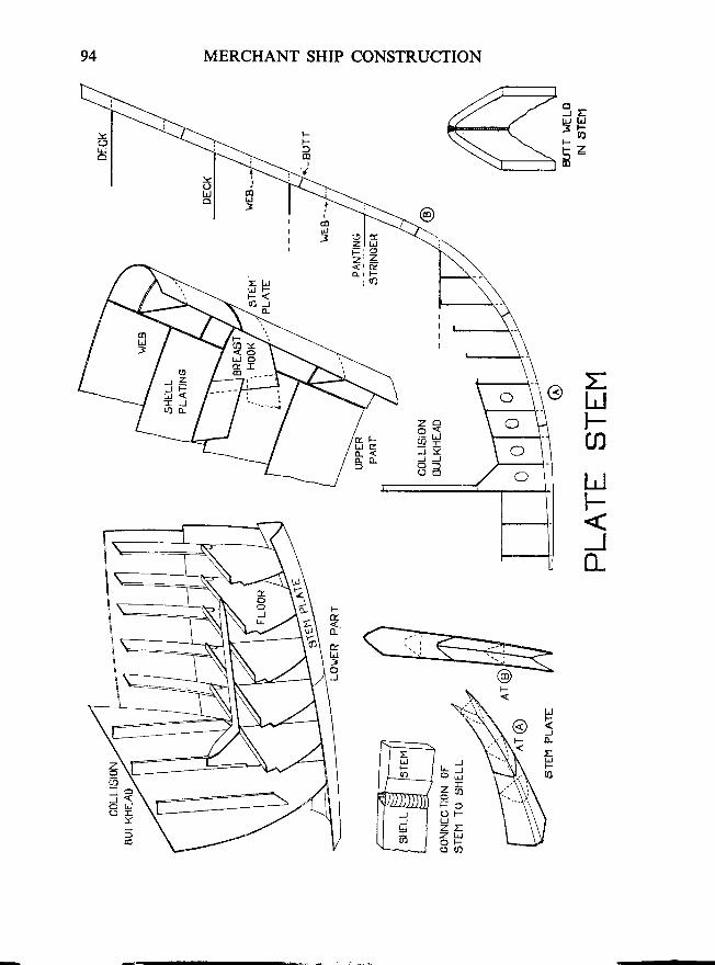
94 MERCHANT SHIP CONSTRUCTION
3:uJ t!36Ft za-
General-AtToday, they areheavy steel plate:the type of rudde
Rudders onriveted on either ,by double platebalanced, or semthey may turn ab,
The stock.steering-gear thr,trunk. It is usu;be disconnecteddisturbing the srithe same line as r
The wei*eht .-at the rudder hea
Double Platrmay be built uprudders are of r:..w i th the i r uhc l :area forward ci :
Streamlini :gthe ship's steeri:
Balanced Ruanced rudder anand steering-eea:pressures on thi :r i i l l be less str :sspressures Varresbalance a rudde:angle of helm .- iof the stock.
Semi-balai,'.is too small t.. Iscrew ships.
Constructionsteel, or it mar I
The plat inebutt welds are ccflat bars are qeld.,
zFz I
I
I
d.U
zdF
I,J
Jo_
tI,JF
7 ,Q= r l
= L
J YJ J
8A
g f -
{ L <o . o -
=LJFaLIF
JIL
@
r '{, \
lo- \
z;lJo
o
l,l-:<J
ETJFo
JJ
r
F
J
:Fh-
v uT
< <r)F OO FLJz zz u
RUDDERS AND STERNFRAMES
RUDDERS AND STERNFRAMES
95
General-At one time sternframes were alwavs solid rectansular bars.Today, they are usually streamlined castings: or ire sometimes 6uilt up ofheavy steel plates, welded together. Their ihape and type depend largely onthe type of rudder fitted.
. R_udders originally consisted of a single plate, with supporting armsriveted on either side of it. This type has no* been superseded, in largei ships"by double plate rudders, which are normally stre-amlined and are oftinbalanced, or semi-balanced. They may be hing6d on pintles and gudgeons, orthey may turn about an axle which passes down througn tne rudder.
-
The stock, which turns the rudder, passes vertically upwards to thesteering-gear through a gland at the shell plating, or a watertight ruddertrunk. It is usually connected to the rudder by a bolted coupling,-which canbe disconnected so that the rudder can be lifted for mainlenance withoutdisturbing the stock. Note that rhe centres of the pintles, or axle, must be inthe same line as the centre of the stock. to enable the rudder to turn.
_ The weight of the rudder may be taken by a bearing pintle, or by a bearingat the rudder head, or by a combination of both.
Double Plate Rudders-The framework of these may be a casting, or itmay be built up of welded plates, with plating on either-side. Most ilodernrudders are of this type and are usually streamlined. They may be unbalanced,with their whole area abaft the rudder stock: or balanced, with part of theirarea forward of the stock.
. ltre-amlining reduces the 'drag' caused by a rudder and may also improvethe ship's steering, particularly in the case of balanced rudders.
Balanced Rudders-water pressure tries to force the blade of an unbal-anced rudder amidships and thus puts considerable stress on the rudder stockand steering-gear. If part of the blade is extended forward of the stock, thepressures on this tends to counterbalance that on the after part, so that therewill be less stress on the steering gear. Unfortunately, the ratio between thepressures varies with the rudder angle, so that it is not usually possible tobalance a rudder for all angles. Most rudders of this type are balanced for anangle of helm of about 15" and have about one-quarteiof their area forwardof the stock.
Semi-balanced rudders are those in which the area forward of the stockis too small to give a full balancing effect. They are often found in twinscrew ships.
Construction of Rudders-The rudder frame mav be of forsed or caststeel, or it may be built of web plates welded togethei.
The plating is usually welded to the frame. Slot welds, or continuousbutt welds are commonly used for this purpose. When plate frames are used,flat bars are welded to their edges to take the slot welds.
'96 MERCHANT SHIP CONSTRUCTION
RUDDERS AND STERNT'RAMES-( Continued)
The inside surface of the rudder is coated with bitumastic, or some similarpreservative, and the space within it is now often filled with foam plastic.There must be some means of draining the rudder.
Sternframes for Single Screw Ships-If the rudder turns on pintles andgudgeons, a rudder post is fitted. This is a hollow section, streamlined, withtransverse webs at intervals and a sealing plate welded-in.
For balanced rudders, various forms of sternframe are used. Most ofthese do not have a complete rudder post, but are usually fitted with a 'skeg' totake the lower bearing of the rudder.
Sternframes for Twin Screrv Ships-Twin screw ships do not usually havea propeller aperture. If the rudder is not balanced, the sternframe consists ofa simple bar or casting. With a balanced rudder, it is rather more complex,often being shaped as shown in the sketch.
Connections at the Head of the Sternframes-The rudder post extendsupwards towards the top of the transom floor, to which it is connected byflanges cast on the post. In single screw ships, the propeller post is usuallyalso extended upwards and connected to a deep floor.
Connections at the Foot of the Sternframe-The sternframe is extendedforward far enough to provide a good connection with the ffat plate keel;usually for two or three frame spaces. The aftermost plate of the keel, whichis called the 'coffin plate', is dished around this extension.
Transom Floor-This is the floor at the head of the rudder post whichsupports the framework of the stern. It must have the same depth as thefloors in the ceilular double bottom.
Gudgeons-These must be forged-on, or cast with, the rudder post. They"are usually bushed with brass or lignum vitae to reduce friction.
Pintles-These must be of the same depth as the gudgeons in which theyturn. They are sometimes fitted with liners, to reduce wear.
The locking pintle has a head on it, below its gudgeon, to prevent therudder from lifting. It is usually the uppermost one.
The bearing pintle is used to take the weight of the rudder, unless abearing at the rudder head is fitted instead. It is usually the lowest one. There.are various types, but that shown in the sketch is common. In this, a hardenedsteel disc is placed in the bottom of the gudgeon to take wear and to reducefriction. A vertical hole in the bottom of the gudgeon allows the disc to bepunched out when it needs renewing.
Couplings-The stock is connected to the rudder by either a vertical or ahorizontal coupling, or by a vertical scarph. The bolts in the coupling must belocked by means of pins, or some s milar arrangement.
I
U N B A L A N C E :
L A ) I : \
€7--
l [€B E A R I \ G
DO

RUDDERS AND STERNFRAMES
B A L A N C E D
@ oc
a
c
0
0
o
C A S T S T E E L F R A M E
B E A R I N G A T R U D D E R H E A D
P A R T O F W E L D E D P L A T E F R A M E
S L O T W E L D S U T T W E L D
DOUBLE PLATE RUDDERS.

cfrr oo o, , j ' 8 .LI
() lrlo oz7E Jf . <' d t
MERCHANT SHIP CONSTRUCTION
=(o
;c.oozEA
L^J=
vLztUFoFac)
2uI L
Hd
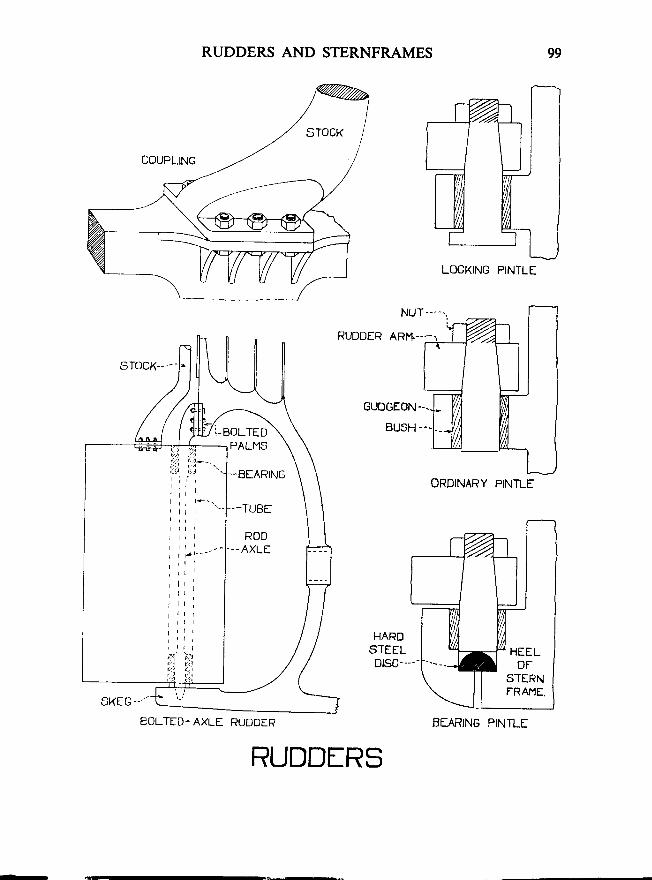
RUDDERS AND STERNFRAMES 99
LOCKING PINTLE
ORDINARY PINTLE
BOLTED. AXLE RUDDER
RUDDfRS
r00 MERCHANT SHIP CONSTRUCTION
STBRNS
General-The upper part of the stern of a ship extends abaft the rudderpost, and there must be a special arrangement of framing to support it.This framing is mainly carried by the 'Transom', which consists of a deep,heavy floor, securely attached to the rudder post, in association with atransverse frame and beam. These are known as the 'Transom Floor','Transom Frame' and 'Transom Beam', respectively.
The transom floor must have the same depth as the floors in the cellulardouble bottom, but must be slightly thicker.
Ordinary Sterns-These were often called 'Counter', or 'Elliptical' sterns.At one time they were used almost exclusively in merchant ships, but they havenow been superseded by the Cruiser Stern, or Transom Stern, and are virtuallyobsolete for large vessels.
Ordinary sterns had a system of 'Cant Framing', which radiated outfrom the transom in much the same way as the spokes of a wheel. The cantframes were attached to the transom floor by brackets; whilst the fore endsof the cant beams were lugged to the transom beam.
Cruiser Sterns-Have a system of ordinary transverse framing which issupported by an intercostal girder at the centre line. This girder has to bedoubled, just abaft the transom floor, to allow the rudder stock to pass. Anumber of 'cant frames' are fitted abaft the aftermost transverse frame.
The frames are to be of the same size as bulb angle frames in peaks andare to extend to the strength deck. The frame spacing is not to exceed610 millimetres.
Where extra strength is required, web frames may be required and alsoextra longitudinal girders to support them.
Transom Stern-This is similar to a cruiser stern, except that the cantframing at the after end is omitted and is replaced by a flat plate, called a'transom'.
Rudder Trunk-This is often formed by carrying-up the doubled centregirder to the deck above in the form of a box. (See sketch.)
STERNFRAMf . .
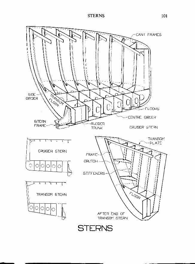
STERNS
STIFFINIRS -.
101
II
ii1iIi \ \t \ \t i l\\,
TERN
--'t--
fl\s AFTIR fND OFTRANSOI'4 STERN
STfRNS
CRUISIR STERN
o lc C o c c
TRANSOM ST
C C C C
t02 MERCHANT SHIP CONSTRUCTION
SHAFT TUNNELS
General-Shaft tunnels are fitted in order that the propeller shaft maybe accessible at all times. They also prevent water from filling the holds ifthe stern tube be broken. ln twin screw ships two shaft tunnels may be fitted,but often the whole width of the ship is decked over and the space between theshafts used for workshops, stores, etc.
At its after end, the tunnel is enlarged to form a 'tunnel recess' in order togive room for the withdrawal of the tail end shaft and for the storage of thespare shaft. Since the ship is very narrow at this part, the recess is often formedby constructing a deck right across from side to side here.
The propeller shaft runs along one side of the tunnel and is supported bybearings, called 'plummer.blocks', which are carried on 'stools' attached to thetunnel and inner bottom. Gratings are laid down to form a walkway and thespace below these is used as a pipe tunnel for the piping from the after tanks.
A watertight door must be fitted at the engine-room bulkhead, to enablethe tunnel to be sealed-off in emergency; whilst an escape shaft must beprovided at the after end.
Drainage from the tunnel is provided for by a 'tunnel well'. This isusually formed by stopping the inner bottom plating four or five floor spacesshort of the after peak bulkhead and fitting a suction in the space thus formed.
Plating and Stiffeners-The tunnel plating is supported by flat bar, orbulb bar stiffeners, which are usually placed over each floor. The plating isthickened slightly in the way of hatches to guard against damage when cargois being worked.
If the tunnel passes through a deep tank, the spacing of the stiffeners is tobe the same as for a bulkhead and they must be bracketed at their feet.
I\
rg>8
)LJ]
tE
:
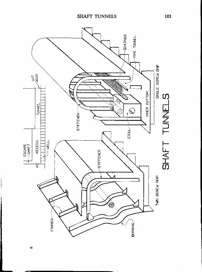
103SHAFT TUNNELS
=
>t-,E
u)UJ
=6A
JUzzfI
Ftr-
ra0--r
3IJ
ot i
zt
I
-r
r
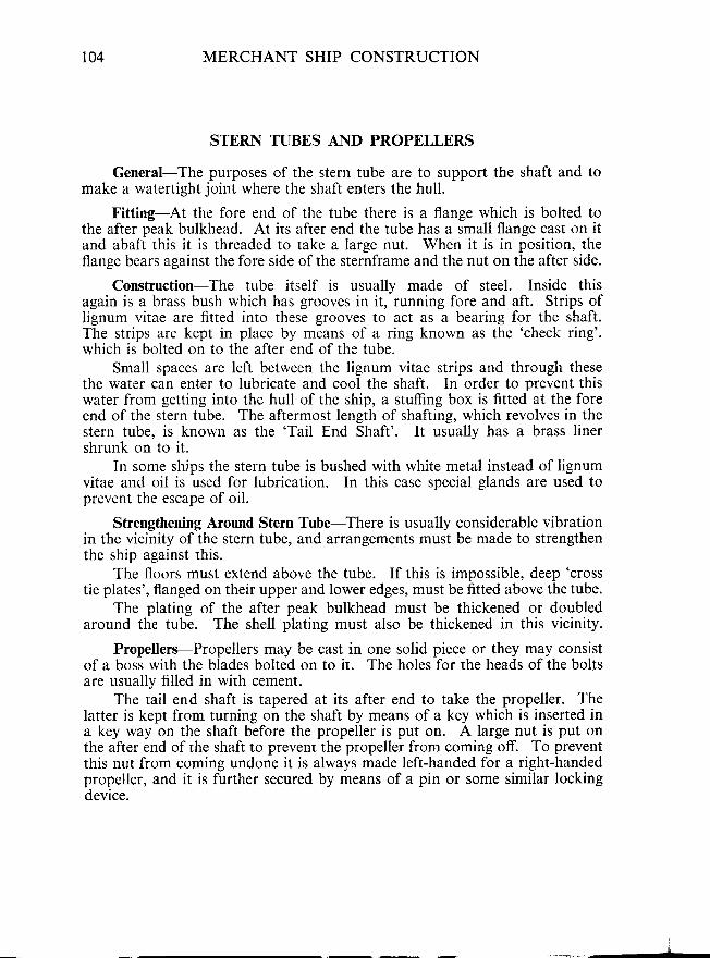
104 MERCHANT SHIP CONSTRUCTION
STERN TUBES AND PROPEI,LBRS
General-The purposes of the stern tube are to support the shaft and tomake a watertight joint where the shaft enters the hull.
Fitting-At the fore end of the tube there is a flange which is bolted tothe after peak bulkhead. At its after end the tube has a small flange cast on itand abaft this it is threaded to take a large nut. When it is in position, theflange bears against the fore side of the sternframe and the nut on the after side.
Construction-The tube itself is usually made of steel. Inside thisagain is a brass bush which has grooves in it, running fore and aft. Strips oflignum vitae are fitted into these grooves to act as a bearing for the shaft.The strips are kept in place by means of a ring known as the 'check ring'.which is bolted on to the after end of the tube.
Small spaces are left between the lignum vitae strips and through thesethe water can enter to lubricate and cool the shaft. In order to prevent thiswater from getting into the hull of the ship, a stuffing box is fitted at the foreend of the stern tube. The aftermost length of shafting, which revolves in thestern tube, is known as the 'Tail End Shaft'. It usually has a brass linershrunk on to it.
In some ships the stern tube is bushed with white metal instead of lignumvitae and oil is used for lubrication. In this case special glands are used toprevent the escape of oil.
Strengthening Around Stern Tube-There is usually considerable vibrationin the vicinity of the stern tube, and arrangements must be made to strengthenthe ship against this.
The floors must extend above the tube. If this is impossible, deep 'cross
tie plates', flanged on their upper and lower edges, must be fitted above the tube.The plating of the after peak bulkhead must be thickened or doubled
around the tube. The shell plating must also be thickened in this vicinity.
Propellers-Propellers may be cast in one solid piece or they may consistof a boss wirh the blades bolted on to ir. The holes for rhe heads of the boltsare usually filled in with cement.
The tail end shaft is tapered at its after end to take the propeller. Thelatter is kept from turning on the shaft by means of a key which is inserted ina key way on the shaft before the propeller is put on. A large nut is put onthe after end of the shaft to prevenr the propeller from coming off. To preventthis nut from coming undone it is always made left-handed for a right-handedpropeller, and it is further secured by means of a pin or some similar lockingdevice.
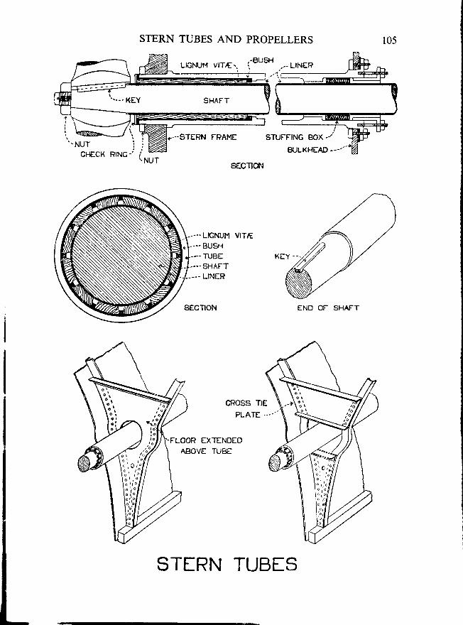
STERN TUBES AND PROPELLERS
----LIGNUM VlT,t---- BUSH--.TUBE-.- SHAFT
.-.. LINER
EXTENDEDAEIOVE TUBC
r05
STIRN TUBES
STUFFING BOX./
BULKHEAD....--
END OF SHAFT
r06 MERCHANT SHIP CONSTRUCTION
TWIN SCREWS
General-In a hull built for twin screws, special arrangements must bemade to support the shafts and to avoid weakness. In some ships, the shaftsleave the hull at a point forward of the propeller and are supported at theirafter ends by brackets, called 'A-Brackets'. In most ships, however, the hullis bossed out so as to enclose the shafts for their whole length.
A-Brackets-When these are used, a bearing and watertight gland arefitted at the point where the shaft leaves the hull.
The struts of the A-brackets are bars of streamlined section. Theirinboard ends are flattened-out into palms, welded or riveted to a heavyhorizontal'palm plate', or stringer: which, in its turn, is connected to speciallystrengthened floors. Where the struts pass through the shell plating, weldingis used to form a watertight seal.
Bossing-When the hull is bossed-out around the shafts, the bossing isformed by welding-in short, specially shaped lengths of frame bar to carry theshell plating. At the after end, the shafts are supported by a strong casting,called a 'spectacle frame', which is welded or riveted to deep, speciallystrengthened floors. For convenience in fitting, the spectacle frame is usuallyin two parts, bolted or riveted together at the centre line: or sometimes inthree parts. That part of the shell plating which forms the bossing, is weldedto the fore end of the spectacle frante.
zC
-:atr_JrgL
: . " ' / -
-c_lt _
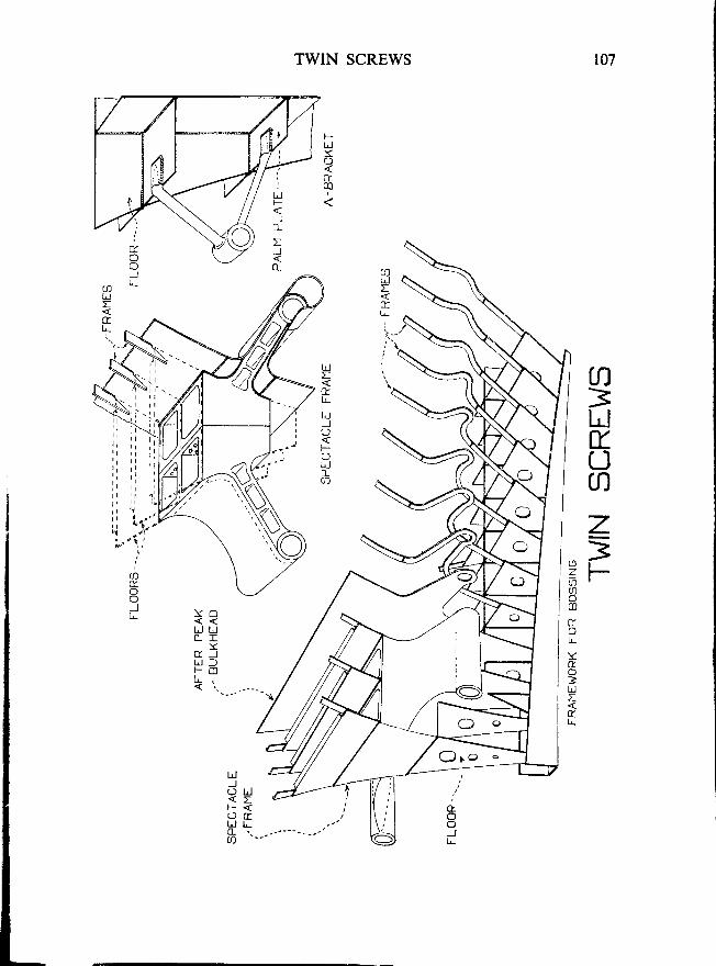
107TWIN SCREWS
FUJsc)
CTm
aLJI
cr.'..
n3lr-JxUnz=F
LLJE
ftL
LJJt )
Fa \Uoct)
(!)E.o
Jt _ ft
oll-
Y&
=U:(
Y O
tJ LJO I
Ycr _Jt l lF C 0
< i ,
Ld)( ) L J< EF <
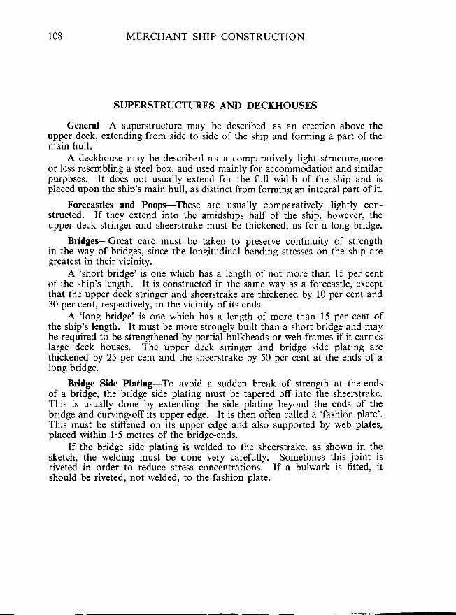
SI108 MERCHANT SHIP CONSTRUCTION
SUPERSTRUCTURES AND DECKHOUSES
General-A superstructure may be described as an erection above theupper deck, extending from side to side of the ship and forming a part of themain hull.
A deckhouse may be described as a comparatively light structure,moreor less resembling a steel box, and used mainly for accommodation and similarpurposes. It does not usually extend for the full width of the ship and isplaced upon the ship's main hull, as distinct from forming an integral part of it.
Forecastles and Poops-These are usually comparatively lightly con-structed. If they extend into the amidships half of the ship, however, theupper deck stringer and sheerstrake must be thickened, as for a long bridge.
Bridges-Great care must be taken to preserve continuity of strengthin the way of bridges, since the longitudinal bending stresses on the ship aregreatest in their vicinity.
A 'short bridge' is one which has a length of not more than 15 per centof the ship's length. It is constructed in the same way as a forecastle, exceptthat the upper deck stringer and sheerstrake are.thickened by 10 per cent and30 per cent, respectively, in the vicinity of its ends.
A 'long bridge' is one which has a length of more than 15 per cent ofthe ship's length. It must be more strongly built than a short bridge and maybe required to be strengthened by partial bulkheads or web frames if it carrieslarge deck houses. The upper deck srringer and bridge side plating arethickened by 25 per cent and the sheerstrake by 50 per cent at the ends of along bridge.
Bridge Side Plating-To avoid a sudden break of strength at the endsof a bridge, the bridge side plating must be tapered off into the sheerstrake.This is usually done by extending the side plating beyond the ends of thebridge and curving-off its upper edge. It is then often called a 'fashion plate'.This must be stiffened on its upper edge and also supported by web plates,placed within 1'5 metres of the bridge-ends.
If the bridge side plating is welded to the sheerstrake, as shown in thesketch, the welding must be done very carefully. Sometimes this joint isriveted in order to reduce stress concentrations. If a bulwark is fitted. itshould be riveted, not welded, to the fashion plate.
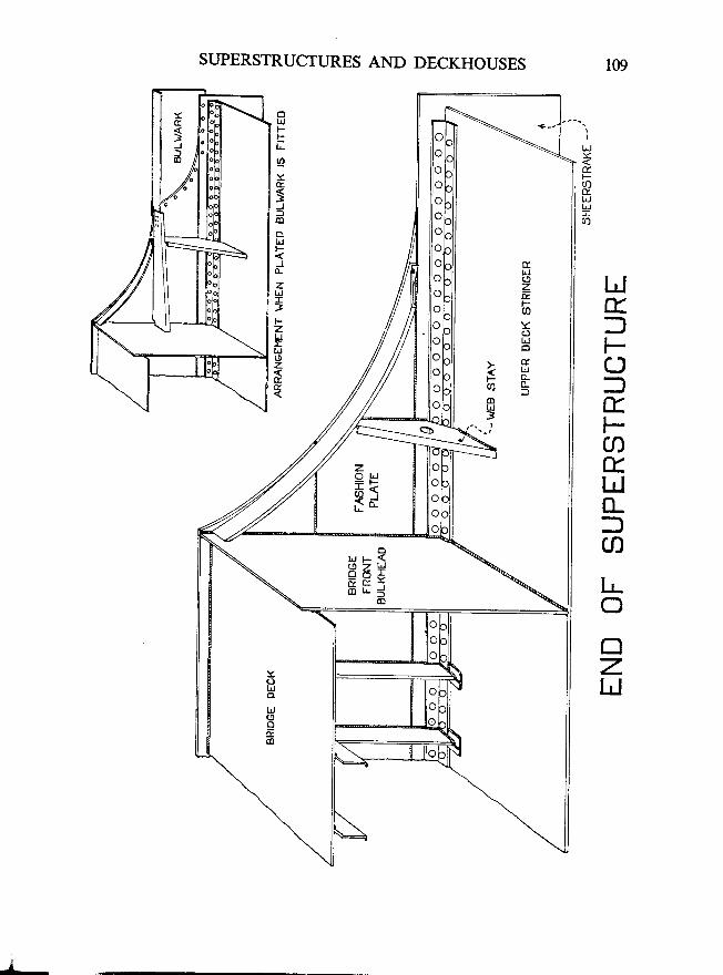
SUPERSTRUCTURES AND DECKHOUSES
LJE=Fcl=EFaE.IdCL3U]
I!cl
EzhJ
ttJr
E.A
Y
5J
olrlF
J
zulT
]FztdL
u
z(t
t.t t- {RZ+- = H =u * l
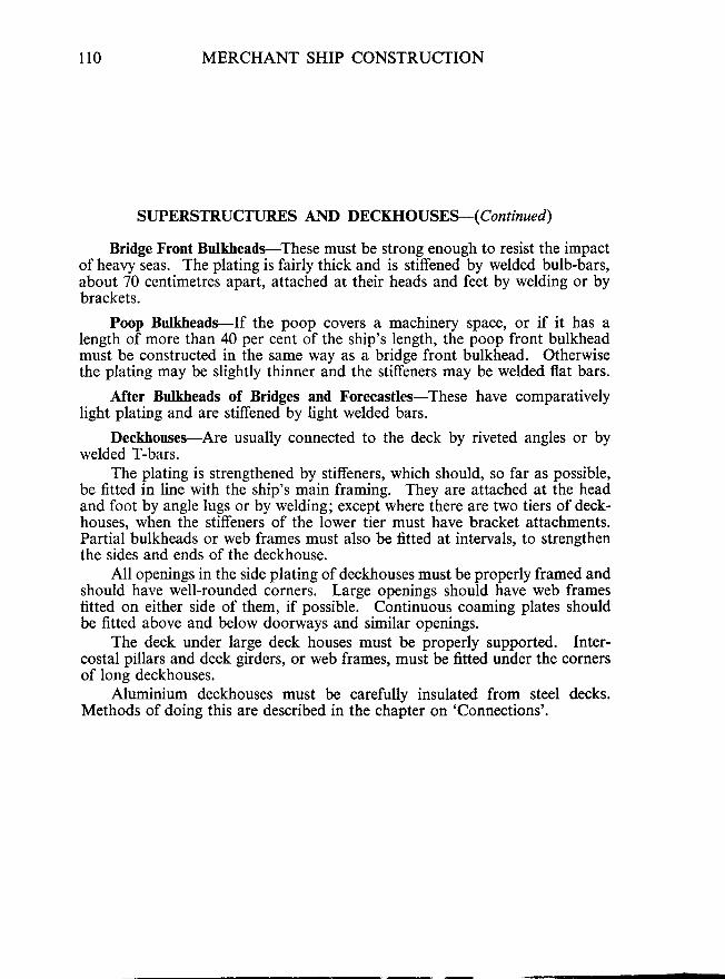
SL110 MERCHANT SHIP CONSTRUCTION
SUPERSTRUCTURES AND DECKHOUSEH Continued)
Bridge Front Bulkheads-These must be strong enough to resist the impactof heavy seas. The plating is fairly thick and is stiffened by welded bulb-bars,about 70 centimetres apart, attached at their heads and feet by welding or bybrackets.
Poop Bulkheads-If the poop covers a machinery space, or if it has alength of more than 40 per cent of the ship's length, the poop front bulkheadmust be constructed in the same way as a bridge front bulkhead. Otherwisethe plating may be slightly thinner and the stiffeners may be welded flat bars.
After Bulkheads of Bridges and Forecastles-These have comparativelylight plating and are stiffened by light welded bars.
Deckhouses-Are usually connected to the deck by riveted angles or bywelded T-bars.
The plating is strengthened by stiffeners, which should, so far as possible,be fitted in line with the ship's main framing. They are attached at the headand foot by angle lugs or by welding; except where there are two tiers of deck-houses, when the stiffeners of the lower tier must have bracket attachments.Partial bulkheads or web frames must also be fitted at intervals, to strengthenthe sides and ends of the deckhouse.
All openings in the side plating of deckhouses must be properly framed andshould have well-rounded corners. Large openings should have web framesfitted on either side of them, if possible. Continuous coaming plates shouldbe fitted above and below doorways and similar openings.
The deck under large deck houses must be properly supported. Inter-costal pillars and deck girders, or web frames, must be fitted under the cornersof long deckhouses.
Aluminium deckhouses must be carefully insulated from steel decks.Methods of doing this are described in the chapter on 'Connections'.
i\
I
i el \
r P-r <I J' 0
I, ( ,' zr .r {' ol o' t rt \I
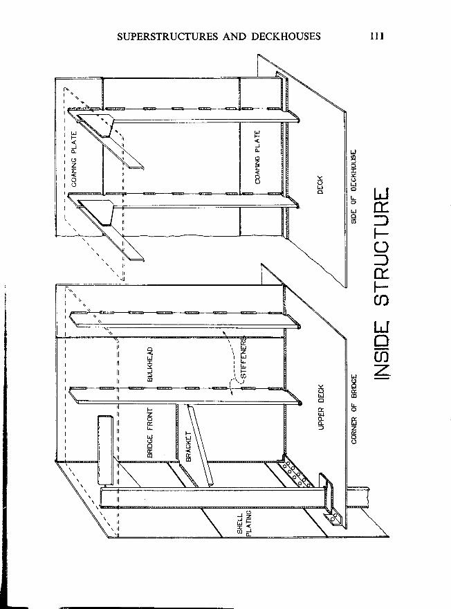
SUPERSTRUCTURES AND DECKHOUSES
IJ
3TY
LJ
: lr-l:EO -6 J
t-t
c-)-l
-,
Ef-t
alrJc]mz
5EID
L
ffizo
irI o .
I
i\Ir Fr <, dI
' zr =r <' ol o' f f' \
t
UJF
2Eo
I
III
II
TJIYJ
=Fz.
LJ
E
i;tlrltll l
1l
IIiItl
tlllrl
rl
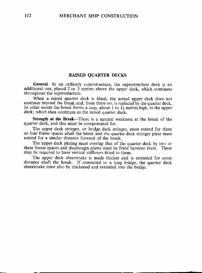
Lt2 MERCHANT SHIP CONSTRUCTION
RAISED QUARTER DECKS
General-In an ordinary superstructure, the superstructure deck is anadditional one, placed 2 or 3 metres above the uppei deck, which continuesthroughout the superstructure.
When a raised quarter deck is fitted, the actual upper deck does notcontinue beyond the break and, from there on, is replaced by the quarter deck.In other words the break forms a step, about I to l$ metres high, in the upperdeck; which then continues as the raised quarter deck.
Strength at the Break-There is a natural weakness at the break of thequarter deck, and this mirst be compensated for.
The upper deck stringer, or bridge deck stringer, must extend for threeor four frame spaces abaft the break and the quarter deck stringer plate mustextend for a similar distance forward of the break.
The upper deck plating must overlap that of the quarter deck by two orthree frame spaces and diaphragm plates must be fitted between them. Thesernay be required to have vertical stiffeners fitted to them.
The upper deck sheerstrake is made thicker and is extended for somedistance abaft the break. If connected to a long bridge, the quarter decksheerstrake must also be thickened and extended into the brid.se.
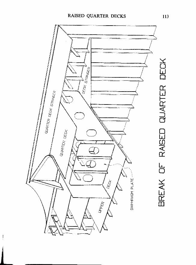
RAISED QUARTER DECKS
YOhJE
El-r.JFtfg
nLJ(,
trlr-oXLlV.m
l f t
€
LJ
LJF
Ior(J
tr0_
r\
o-
LJ
't*/
\'
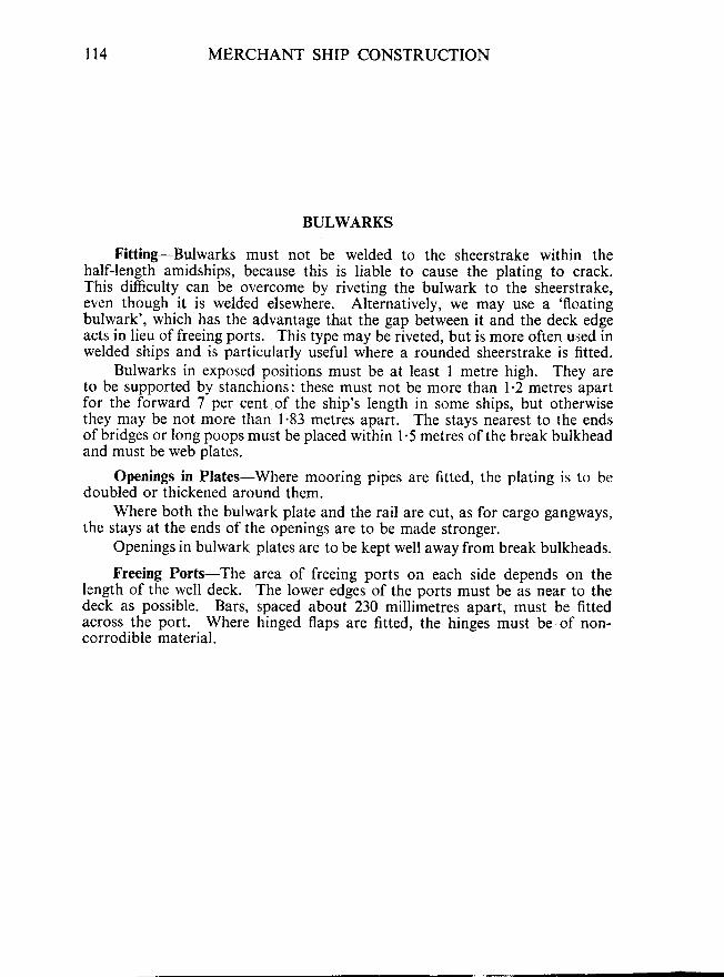
n4 MERCHANT SHIP CONSTRUCTION
BULWARKS
Fitting-Bulwarks must not be welded to the sheerstrake within thehalfJength amidships, because this is liable to cause the plating to crack.This difficulty can be overcome by riveting the bulwark to the sheerstrake,even though it is welded elsewhere. Alternatively, w€ may use a 'floating
bulwark', which has the advantage that the gap between it and the deck edgeacts in lieu of freeing ports. This type may be riveted, but is more often used inwelded ships and is particularly useful where a rounded sheerstrake is fitted.
Bulwarks in exposed positions must be at least I metre high. They areto be supported by stanchions: these must not be more than l'2 metres apartfor the forward 7 per cent of the ship's length in some ships, but otherwisethey may be not more than 1.83 metres apart. The stays nearest to the endsof bridges or long poops must be placed within 1.5 metres of the break bulkheadand must be web plates.
Openings in Plates-Where mooring pipes are fitted, the plating is to bedoubled or thickened around them.
Where both the bulwark plate and the rail are cut, as for cargo gangways,the stays at the ends of the openings are to be made stronger.
Openings in bulwark plates are to be kept well away from break bulkheads.
Freeing Ports-The area of freeing ports on each side depends on thelength of the well deck. The lower edges of the ports must be as near to thedeck as possible. Bars, spaced about 230 millimetres apart, must be fittedacross the port. Where hinged flaps are fitted, the hinges must be of non-corrodible material.
4
pt3
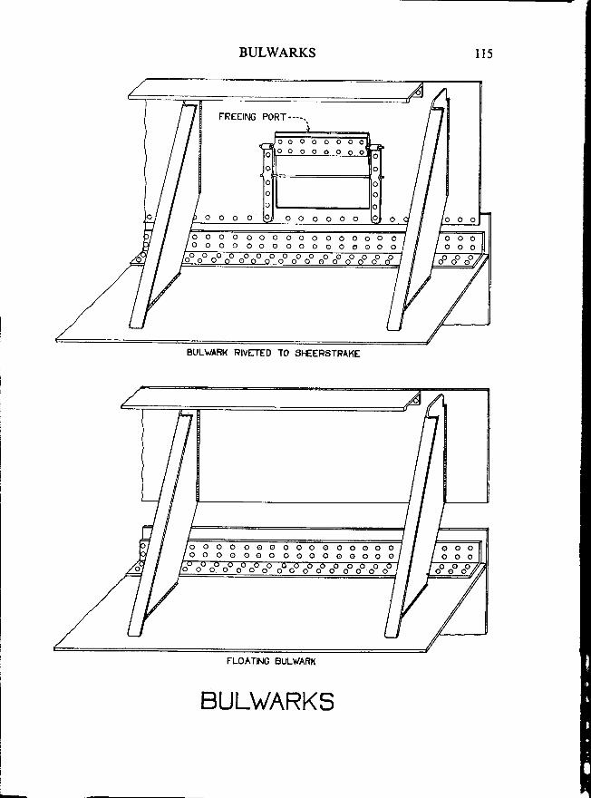
BULWARKS
o o o o o o
o o o o o o o o o o o o o o o oo o o o o o o o o o o o o o o o
BULWAFK RIVETED TO ST€EPSTRAKE
o o - o - o - o
FLOATING BULWARK
BULWARKS
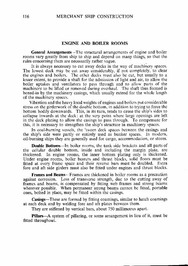
116 MERCHANT SHIP CONSTRUCTION
ENGINE AND BOILER ROOMS
General Arrangements-The structural arrangements of engine and boilerrooms vary greatly from ship to ship and depend on many things, so that therules concerning them are necessarily rather vague.
It is always necessary to cut away decks in the way of machinery spaces.The lowest deck may be cut away considerably, if not completely, to clearthe engines and boilers. The other decks must also be cut, but usually to alesser extent, to provide a shaft for the admission of light and air, to allow theboiler uptakes and ventilators to pass through and to allow parts of themachinery to be lifted or removed during overhaul. The sliaft thus formed isboxed-in by the machinery casings, rvhich usually extend for the whole lengthof the machinery spaces.
Vibration and the heavy local weights of engines and boilers put considerablestress on the girderwork of the double bottom, in addition to trying to force thebottom bodily downwards. This, in its turn, tends to cause the ship's sides tocollapse inwards at the deck: at the very point where large openings are leftin the deck plating to allow the casings to pass through. To compensate forthis, it is necessary to strengthen the ship's structure in machinery spaces.
In coal-burning vessels, the 'tween deck spaces between the casings andthe ship's side were partly or entirely used as bunker spaces. In modern,oil-burning ships they are generally used for cargo, accommodation, or stores.
Double Bottoms-In boiler rooms, the tank side brackets and all parts ofthe cellular double bottom, inside and including the margin plate, arethickened. In engine rooms, the inner bottom plating only is thickened.Under engine rooms, boiler bearers and thrust blocks, solid floors must befitted at every frame space and their reverse bars must be doubled. Extrafore and aft side girders must also be fitted under engines and thrust blocks.
Frames and Beams-Frames are thickened in boiler rooms as a precautionagainst corrosion. Loss of transverse strength, due to the cutting away offrames and beams, is compensated by fitting web frames and strong beamswherever possible. When pennanent strong beams cannot be fitted, portableones, bolted in place, may be fitted within the casings.
Casings-These are formed by fitting coamings, similar to hatch coamingsat each deck and by welding fore and aft plates between them.
They are stiffened by vertical bars, about 750 millimetres apart.
Pillars-A system of pillaring, or some arrangement in lieu of it, must befitted throuehout.
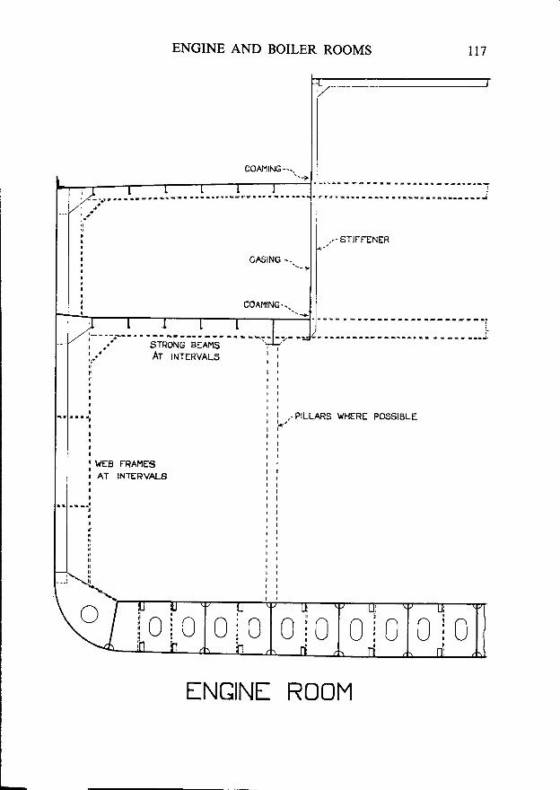
ENGINE AND BOILER ROOMS
INGINf ROOM
t17
coAMlNG --..
, . - STIFFENER
,/'T I r r r J/ z - - . - . . . - - - -
cAstNG --.
COAMING.. .
ilII
!
,l
i T{EB FRAI4ES!
I AT INTERVALSiIT
ttt'
nnn
\ I
l lt l
r lt l
t l' I
,,-PILLARS WHERE POSSIBLEr ft lr lr lt lt ll ll l
t l
r l
l lI t
t l, lt l
t l
l l
t ll ll l
\ l l IJ TJ
i i ninIU :Uii1 h\l
u6 it t : t t\_,/ : \-./
h
u61 lf t .
n0 clc
ri
lJrIn:n
UiL-JI
n!
{ 18 MERCHANT SHIP CONSTRUCTION
HATCI{ BEAMS AND COVERS
General-In some early ships, the hatches were sometimes placed athwart-ships and supported by fore and aft beams, called'fore and afters'. Nowadays,if wooden hatch covers are used, they are placed fore and aft on athwartshipbeams. Steel haich covers of various types, are often fitted in modern ships andhave many advantages.
Beams-The size of hatch beams is governed by their length and spacing.They may be of a built H-section, or a deep built T-section. The ends whichrest in the carriers must have doubling plates, at least 180 millimetres wide.
Roller beams are sometimes used today. These run on a special trackon the hatch side coamings and have special arrangements for fixing them inposition when required.
Carriers-The sockets in which the ends of ordinary hatch beams restare called 'carriers'. At least 75 millimetres of the beam must bear onthe carrier.
Hatch Covers-Wooden hatch covers must be 60 millimetres thick whentheir unsupported span is 1'5 metres, 82 millimetres thick for a span of 2'0metres, or intermediate for intermediate spans. Their ends must be fitted withgalvanised steel bands, about 65 millimetres wide and 3 millimetres thick.
Hatch Rests-The angles which support the ends of the hatches arecalled 'hatch rests'. They must be at least 65 millimetres wide.
Cleats-Cleats must be not less than 65 millimetres wide and must be setto fit the taper of the wedges. They must not be more than 600 millimetresapart and the end cleats must be within 150 millimetres of the hatch ends.
Wedges-These must be of tough wood, at least 200 millimetres long and50 millimetres wide. They must have a taper of I in 6 and must be 13 milli-metres thick a-t the toe. or narrow end.
FffiE ^T€
CARRIE
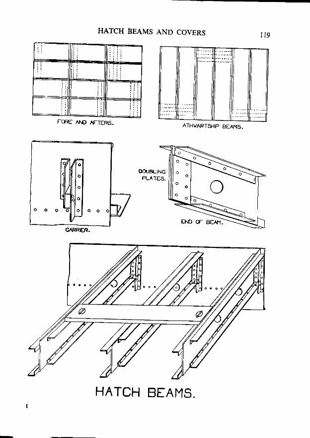
FffiE ^AJO AFTERS.
HATCH BEAMS AND COVERS
OOUBLINGP-ATES.
HATCH BEAMS.
ATH\r'ARTSHIP BEAI\,IS.
cARRCn.
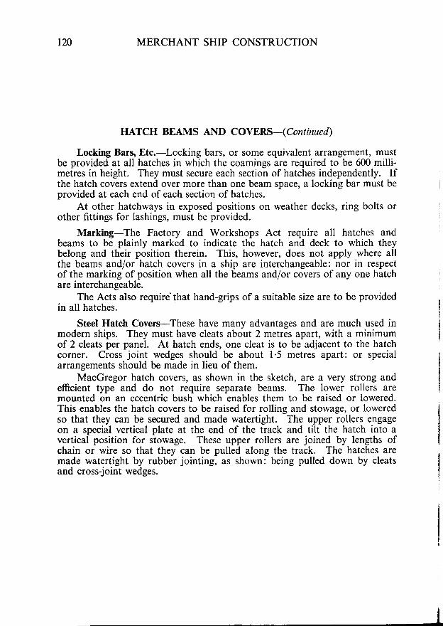
120 MERCHANT SHIP CONSTRUCTION
HATCH BEAMS AND COVERS-(Continued)
Locking Bars, Etc.-Locking bars, or some equivalent arrangement, mustbe provided at all hatches in which the coamings are required to be 600 milli-metres in height. They must secure each section of hatches independently. Ifthe hatch covers extend over more than one beam space, a locking bar must beprovided at each end of each section of hatches.
At other hatchways in exposed positions on weather decks, ring bolts orother fittings for lashings, must be provided.
Marking-The Factory and Workshops Act require all hatches andbeams to be plainly marked to indicate the hatch and deck to which theybelong and their position therein. This, however, does not apply where allthe beams and/or hatch covers in a ship are interchangeable: nor in respectof the marking of position when all the beams and/or covers of any one hatchare interchangeable.
The Acts also require'that hand-grips of a suitable size are to be providedin all hatches.
Steel Hatch Covers-These have many advantages and are much used inmodern ships. They must have cleats about 2 metres apart, with a minimumof 2 cleats per panel. At hatch ends, one cleat is to be adjacent to the hatchcorner. Cross joint wedges should be about 1.5 metres apaft: or specialarrangements should be made in lieu of them.
MacGregor hatch covers, as shown in the sketch, are a very strong andefficient type and do not require separate beams. The lower rollers aremounted on an eccentric bush which enables them to be raised or lowered.This enables the hatch covers to be raised for rolling and stowage, or loweredso that they can be secured and made watertight. The upper rollers engageon a special vertical plate at the end of the track and tilt the hatch into avertical position for stowage. These upper rollers are joined by lengths ofchain or wire so that they can be pulled along the track. The hatches aremade watertight by rubber jointing, as shown: being pulled down by cleatsand cross-joint wedges.
ROLL ING i .
LO !€R R3__ : :
af-=-
i B
t ?
=\
Ti AC{
IATCH IN ROL. . ,S :
MACGF
TRACK FOP , /UPPER . . , , . /Pnl I toq ' . / - - - '
t
, / '^/
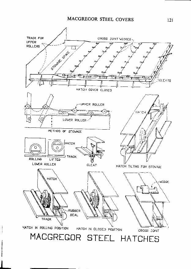
MACGREGOR STEEL COVERS
CROSS JOINT VEDGES-.
HATCH COVER CLOSEO
I,IETHOD OF STOWAGE
t l
loll@1"^"'at=-'F I l---
ROLLING LIFTEO
LOLER ROLLER
-:YAICH N R0LL|N6 postTloN HATCH tN cLOSEo postTtoN CROSS JD|NT
MACGRIGOR STIEL HATCHES
HATCH TILTING FOR STO!/AO[
. -RUBBER
SEAL

r22 MERCHANT SHIP CONSTRUCTION
HAWSEPIPES
Hawsepipes may be made of cast steel, in which case they are usuallycast from wooden models made in place in the ship. They are now oftenbuilt-up of heary plates, usually with cast steel lips welded to them'
The sketch shows one type of welded hawsepipe, with a lip, or fchqlngring', welded to its lowcr edge. At the uppel end it is welded to a block whichhas-a raised lip to take the ihafe of the cable, also slots into which plat_escanslide to close the pipe at sea. The chafing ring and block are riveted or boltedto the shell and deck plating. The lower plate of the pipe may be thickened,as shown here, or doubled to take the chafe of the cable.
The shell plating is doubled or thickened in the way of hawsepipes.
It is usually necessary to cut frames and beams, in orde,r to allow-the_ pipeto pass. In thiS case compensation is made by fitting short fore and aft pieces,calied 'carlings', to support the cut ends, and the frames may be reinforced' ii,
--_
Y
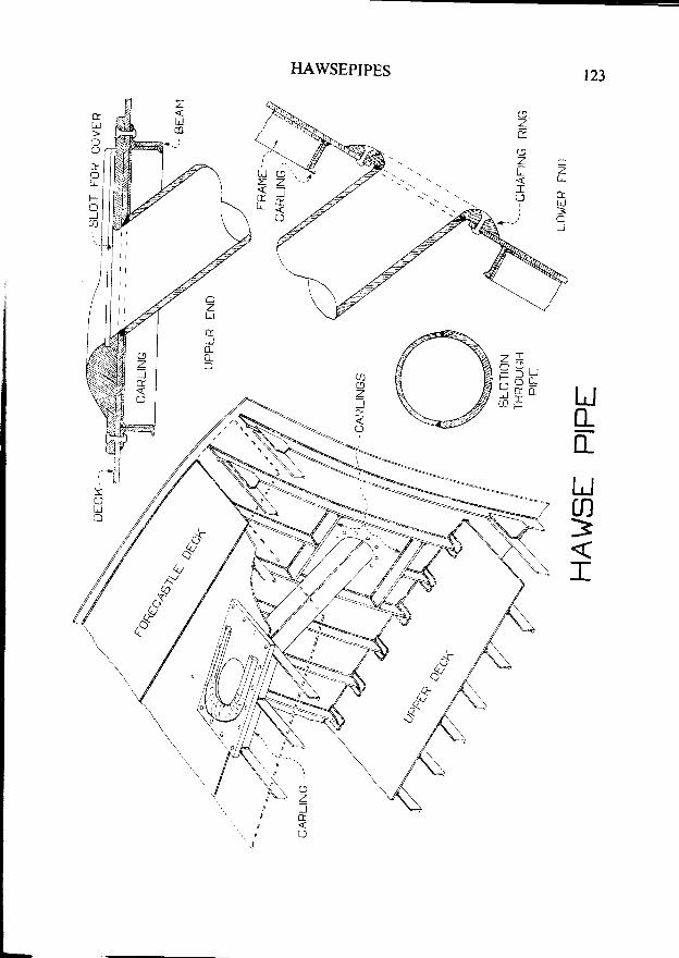
HAWSEPIPES
Un-tr
/\)^</
AV
t24 MERCHANT SHIP CONSTRUCTION
MASTS AND DERRICK POSTS
Size-The size of a mast or derrick post depends on rts length from deckto hounds; on whether it is stayed or not; and on the number and safe workingload of the derricks which it carries.
Construction-Masts and derrick posts are usually built up of two orthree plates on the round. The plating must be doubled or thickened at theheel, deck, derrick supports and hounds. Large masts are sometimes stiffenedby angle s or T-bars, fitted vertically inside them.
Stepping-Masts exert a large downward thrust at their heels and mustbe strongly supported and stepped.
In many modern ships the masts are stepped in the 'tween decks. Inthis case, they are usually placed near a bulkhead, with large brackets fittedunder the deck to transmit the thrust to the bulkhead. If this is not done, the'tween deck must be specially pillared and stiffened below the heel of the mast.
Aftermasts are occasionally stepped on the tunnel. In this case, a special'stool' is fitted on top of the tunnel, which is given extra stiffening.
In single decked ships, the mast may be stepped on the inner bottom.Alternatively, it may be stepped on the upper deck and supported by anarrangement of brackets, known as a 'Tabernacle', or by a 'Mast House'.
Large masts, carrying heavy-lift derricks, may need partial longitudinalbulkheads or other special strengthening arrangements under their heels.
Masts Passing Through Decks-Where a mast passes through a deck, thedeck plating is usually doubled or thickened. A hole, rather larger than themast, is cut in the deck and a flat ring is then welded to the mast and deck tosupport the mast and to make the joint watertight.
The beams often have to be cut, to allow the mast to pass through them.In this case, the cut ends are supported by carlings, called 'mast partners'.
Staying-When masts are stayed, the stays and shrouds are attached tochain plates on the deck stringer or sheerstrake and to lugs or ring bolts onthe mast. Many modern masts are unstayed, in which case they must bespecially constructed and strengthened against the stresses caused by thederricks.
I
I
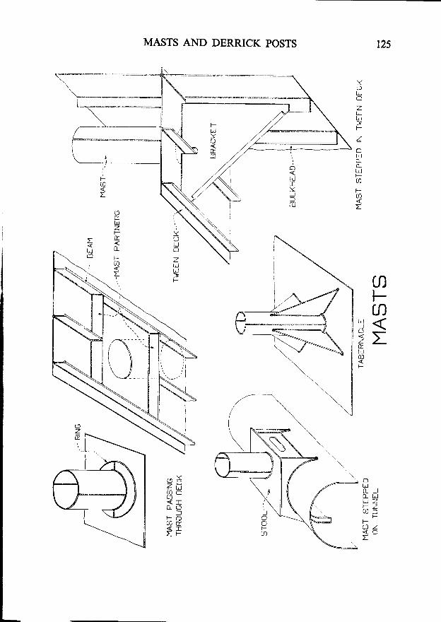
r25MASTS AND DERRICK POSTS
z da< I
:l'tn d
< IT F
YCJ
O
ztrl=
Z
oIrlo_c_LJF
aFa:
aFn
!i:P
oI,J0 _ J0_ t!t r zF - 70 e 5
FFa z< oI
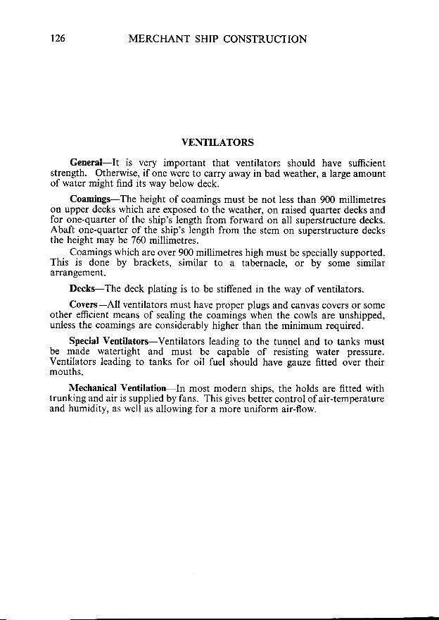
r26 MERCHANT SHIP CONSTRUCTION
VENTILATORS
General-It is very important that ventilators should have sufficientstrength. Otherwise, if one were to carry away in bad weather, a large amountof water might find its way below deck.
Coamings-The height of coamings must be not less than 900 millimetreson upper decks which are exposed to the weather, on raised quarter decks andfor one-quarter of the ship's length from forward on all superstructure decks.Abaft one-quarter of the ship's length from the stem on superstructure decksthe height may be 760 millimetres.
Coamings which are over 900 millimetres high must be specially supported.This is done by brackets, similar to a tabernacle, or by some similararrangement.
Decks-The deck plating is to be stiffened in the way of ventilators.
Covers-All ventilators must have proper plugs and canvas covers or someother efficient means of sealing the coamings when the cowls are unshipped,unless the coamings are considerably higher than the minimum required.
Special Ventilators-Ventilators leading to the tunnel and to tanks mustbe made watertight and must be capable of resisting water pressure.Ventilators leading to tanks for oil fuel should have gauze fitted over theirmouths.
Mechanical Ventilation-In most modern ships. the holds are fitted withtrunking and air is supplied by fans. This gives bett^ercontrol of air-temperatureand humidity, as well as allowing for a more uniform air-flow.
Is
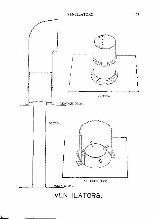
VENTILATORS
VEATHER D[.CK "
t27
COAMING.
AT UPPER DECK.
VENTILATORS.
x28 MERCHANT SHIP CONSTRUCTION
REFRIGERATED SHIPS
General-To prevent heat from entering insulated holds, all steelwork ofthe ship's hull, except the 'tween decks, is insulated. It is necessary to sealall scuppers and drains so that warm air or taint cannot enter through themand also to insulate sounding pipes and thermometer tubes. Special arrange-ments must be made to prevent oil from leaking into the holds fromadjacent tanks.
The holds may be cooled by pumping cold brine through pipes under thedeckheads: alternatively, air may be drawn over nests of Uiine pipes in a'cooler', and then pumped through air ducts into the holds.
Insulation-Various materials may be used for insulation, but glass fibre,cork and plastic foam are the most common. The insulation is kept in placeby a lining of plywood or sheet metal, inside the frames and under the beams.This lining is usually secured by screwing it to wood battens, called 'grounds',
which are bolted to the frames or beams; or by special clips.The hatchways are sealed by wooden 'plug hatches', fitted under the
ordinary hatches. Access to bilges and to manholes in double bottoms isprovided by further plug hatches.
'Tween decks are usually only insulated on their undersides, the uppersurlbce of the steel deck being left bare. A wood 'ribband', about I metrewide, is sometimes fitted on top of the 'tween deck at the ship's side.
The inner bottom usually has insulation laid on it. This insulation iscovered with a wood ceiling, to protect it against damage.
Protection from Oil-If the double bottom under an insulated hold isintended to carry oil, the insulation here must be laid on athwartships battens,so as to leave a 50 millimetre air space between insulation and tank top.Alternatively, the air space may be omitted if the insulation is laid on a thicklayer of oil-impervious composition. Al1 connections to the inner bottom andmargin plate should be welded, to prevent leakage; whilst manhole coverfastenings should not pass through the inner bottom plating.
Deep tanks intended to carry oil must be separated from insulated holdsby cofferdams; unless the bulkhead is completely welded and has a suitablelayer of oil-impervious composition on the side nearest to the hold.
Piping-All pipes, including air and sounding pipes, must be insulated.Thermometer pipes must be insulated from the deck plating and must have aninside diameter of at least 50 millimetres.
All drains which lead to the bilges must have 'brine traps', to preventwarm air and taint from entering the hold.
ffi**-
- - - - f - n A V .
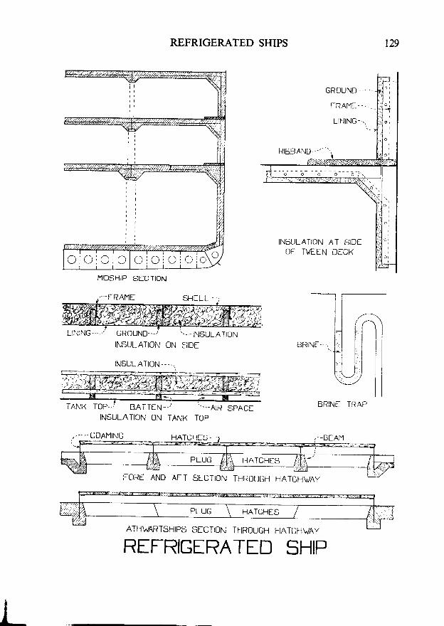
REFRIGERATED SHIPS
MIDSHIP SECTION
SHf LL . - - ;
HATUHES.- -
AFT SfCTION THROUGH HATCHVAY
A]'I1V/AR'1.SHIPS SEOTION THROUGH FIATCHVAY
129
BRINf TRAP
-BfAM
REFRIGIRATED SHIP
INSULATION AT SIDEOT TVEIN DfCK
TANK TOP. , / BATTfN- - / " - . -A IRINSULATION ON TANK TOP
130 MERCHANT SHIP CONSTRUCTION
STRENGIIIEI\ING FOR ICE NAVIGAIION
Ice Strengthening-Ice is liable to cause damage to the shell plating, stem,sternframe, propeller and rudder in the region of the waterline. Ships whichare intended to navigate in ice must, therefore, be strengthened accordingly.
There are four classes of ice strengthening, based on conditions which aremet in the Baltic:-
Class 1*: for extreme ice conditions.Class 1 : for severe ice conditions.Class 2: for intermediate ice conditions.Class 3: for light ice conditions.
Structure-Intermediate frames must be fitted between the main frames,and, except in ice class 3, connected at their ends by horizontal carlings.These intermediate frames are to be of the same size as the main frames andmust be supported by tripping brackets, unless special side stringers arefitted. lVelded frames may not be scalloped in the way of thickened shellplating. Heavy side stringers are required for Class 1*. They need not befitted in the other classes unless lighter intermediate frames are used. ShellPlating is made thicker than normal over an area which depends on the iceclass. A specially designed (i.e. 'icebreaker') bow must be fitted. Either abar stem or a plate stem may be used, but these must be of steel and strongerthan normal. The rudder post, solepiece and all parts of the rudder are tobe made stronger.
Extent of Strengthening-This is shown in the sketch. A is 5-frame spacesabaft the point where the stem starts to rise above keel-level. B is the pointat which the load waterline reaches its greatest width forward. C is at adistance from the bow which is equal to the distance of B from the bow plusl0 per cent of that distance (i.e. x *l}lx). D is at one-quarter of the lengthfrom the stern.
In Class 1* the intermediate frames extend verticallv from the level of thetops of the floors to the upper deck (or to or near the iecond deck in certaincases). In all other classes they extend from 915 millimetres below the lightwaterline to 750 millimetres above the load waterline.
The belt of thickened shell plating extends, in all cases, from 610 milli-metres below the light waterline to 750 millimetres above the load waterline.Note how Class l* ships muSt also have an extra area, 80 per cent thicker,covering the sides and bottom forward, below this belt. The percentagesshown indicate the amount by which the plating is to be thickened in each part.
CLASS Ir€
F- - - l e - - - -i
v777T-=-l / t \ \ \ -
IC
.'r\-.-
. \ ] . \ \ r \
\ ? i i
CLASS I
CLASS 2
CLASS 3

STRENGTHENING FOR NAVIGATION l3 l
?Z--"\N rHrcxENED pLATNG
| | F - - t l. is.ES. I
T--T---.I*-T---1INTERMEDIATE FRAMING
ICf STRINGTHINING