sherwood valve llc
TRANSCRIPT

�
Sherwood Valve LLC
EVERY COUNTRY
EVERY CUSTOMER
EVERY CODE
GVSERIES
Industrial and Chrome Plated Precision Valves

SHERWOOD GLOBAL VALVE FEATURES
Durable forged brass body, precisely machined internal
components and design elements meet the most stringent
International valve performance standards. Automated assembly
and testing processes ensure exceptional quality. All Sherwood GV valves are 100% leak tested.
High durometer back-up ring prevents extrusion of o-ring in extreme applications. Peroxide Curing of elastomeric seals enhances valve longevity.
Direct drive stem design with optimized single o-ring seal reduces friction and operates at exceptionally low torque levels.
Metal-to-metal seal below bonnet threads prevents pressure
accumulation at top of valve body. The unitized plug design of the Pressure Relief D(PRD) provides excellent flow characteristics. Optical Character Recognition technology utilized to verify appropriate burst disc pressure rating.
evice
Sherwood’s exclusive “webbed washer” design protects burst disc during handling and bulk shipment.
Inlet and Outlet thread configurations are available for a
broad spectrum of Customer, Country and Code specifications.
Internal plug threads protected from external impact by design.
STANDARDS CONFORMANCE DESIGN SPECIFICATIONS
CGA V-9 Standard for Gas Cylinder Valves Maximum Working Pressure 6,000 PSIG 413 BAR
CGA S1.1 Standard for Pressure Relief Devices Burst Pressure 15,000 PSIG 1,035 BAR
CGA V-1 Operating Temperature Min: -50°F -45°CCompressed Gas Cylinder Valve Outlet and Inlet Specifications Max: 130°F 55°C
ISO 10297 Storage Temperature Min: -65°F -54°CInternational Standard for Cylinder Valves Design Specifications Max: 155°F 68°C
EN 849 Leak Rate Internal/External International Standard for Cylinder Valves Design Specifications
1X10⁻³ atm cc/s
AS2473 Minimum Cycle Life 2000 Cycles Australian Standard for Compressed Gas Cylinder Valves
TPED Transportable Pressure Equipment Directive Modules B & D
Cv Flow Factor Standard: CO2 / Manifold:
.690 1.23

GV SERIES O-RING SEAL DESIGN INDUSTRIAL VALVES Gas Service
@120ºF CGA
Outlet Outlet
Thread Size Inlet
Thread Size Sherwood
Part Number Air 0 psi TO 3,000 psi 346 .825 – 14 NGO RH Ext. ½ - 14 NGT GV34641-XX
¾ - 14 NGT GV34661-XX 1-11½ NGT GV34681-XX .750 – 16 UNF GV34651-XX-75 1.125 – 12 UNF GV34651-XX
3,001 psi TO 5,500 psi 347 .825 – 14 NGO RH Ext. ¾ - 14 NGT GV34761-XX (long nipple)
5,501 psi TO 7,500 psi 702 1.125 – 14 NGO RH Int. ¾ - 14 NGT GV70261-XX Argon 0 psi TO 3,000 psi 580 .965 – 14 NGO RH Int. ½ - 14 NGT GV58041-XX
¾ - 14 NGT GV58061-XX 1-11½ NGT GV58081-XX .750 – 16 UNF GV58051-XX-75 1.125 – 12 UNF GV58051-XX
3,001 psi TO 5,500 psi 680 1.045 – 14 NGO RH Int. ¾ - 14 NGT GV68061-XX 5,501 psi TO 7,500 psi 677 1.030 – 14 NGO LH Ext. ¾ - 14 NGT GV67761-XX Carbon Dioxide 0 psi TO 3,000 psi 320 .825 – 14 NGO RH Ext. ½ - 14 NGT GV32041-XX
¾ - 14 NGT GV32061-XX 1-11½ NGT GV32081-XX .750 – 16 UNF GV32051-XX-75 1.125 – 12 UNF GV32051-XX
Carbon Monoxide 0 psi TO 3,000 psi 350 .825 – 14 NGO LH Ext. ½ - 14 NGT GV35045-XX
¾ - 14 NGT GV35065-XX 1-11½ NGT GV35085-XX .750 – 16 UNF GV35055-XX-75 1.125 – 12 UNF GV35055-XX
3,001 psi TO 5,500 psi 695 1.045 – 14 NGO LH Int. ¾ - 14 NGT GV69565-XX 5,501 psi TO 7,500 psi 703 1.125 – 14 NGO LH Int. ¾ - 14 NGT GV70365-XX Helium 0 psi TO 3,000 psi 580 .965 – 14 NGO RH Int. ½ - 14 NGT GV58041-XX
¾ - 14 NGT GV58061-XX 1-11½ NGT GV58081-XX .750 – 16 UNF GV58051-XX-75 1.125 – 12 UNF GV58051-XX
3,001 psi TO 5,500 psi 680 1.045 – 14 NGO RH Int. ¾ - 14 NGT GV68061-XX 5,501 psi TO 7,500 psi 677 1.030 – 14 NGO LH Ext. ¾ - 14 NGT GV67761-XX Hydrogen 0 psi TO 3,000 psi 350 .825 – 14 NGO LH Ext. ½ - 14 NGT GV35045-XX
¾ - 14 NGT GV35065-XX 1-11½ NGT GV35085-XX .750 – 16 UNF GV35055-XX-75 1.125 – 12 UNF GV35055-XX
3,001 psi TO 5,500 psi 695 1.045 – 14 NGO LH Ext. ¾ - 14 NGT GV69565-XX 5,501 psi TO 7,500 psi 703 1.125 – 14 NGO LH Int. ¾ - 14 NGT GV70365-XX Krypton 0 psi TO 3,000 psi 580 .965 – 14 NGO RH Int. ½ - 14 NGT GV58041-XX
¾ - 14 NGT GV58061-XX 1-11½ NGT GV58081-XX .750 – 16 UNF GV58051-XX-75 1.125 – 12 UNF GV58051-XX
3,001 psi TO 5,500 psi 680 1.045 – 14 NGO RH Int. ¾ - 14 NGT GV68061-XX 5,501 psi TO 7,500 psi 677 1.030 – 14 NGO LH Ext. ¾ - 14 NGT GV67761-XX

GV SERIES O-RING SEAL DESIGN INDUSTRIAL VALVES Gas Service
@120ºF CGA
Outlet Outlet
Thread Size Inlet
Thread Size Sherwood
Part Number Neon 0 psi TO 3,000 psi 580 .965 – 14 NGO RH Int. ½ - 14 NGT GV58041-XX
¾ - 14 NGT GV58061-XX 1-11½ NGT GV58081-XX .750 – 16 UNF GV58051-XX-75 1.125 – 12 UNF GV58051-XX
3,001 psi TO 5,500 psi 680 1.045 – 14 NGO RH Int. ¾ - 14 NGT GV68061-XX 5,501 psi TO 7,500 psi 677 1.030 – 14 NGO LH Ext. ¾ - 14 NGT GV67761-XX Nitrogen 0 psi TO 3,000 psi 580 .965 – 14 NGO RH Int. ½ - 14 NGT GV58041-XX
¾ - 14 NGT GV58061-XX 1-11½ NGT GV58081-XX .750 – 16 UNF GV58051-XX-75 1.125 – 12 UNF GV58051-XX
3,001 psi TO 5,500 psi 680 1.045 – 14 NGO RH Int. ¾ - 14 NGT GV68061-XX 5,501 psi TO 7,500 psi 677 1.030 – 14 NGO LH Ext. ¾ - 14 NGT GV67761-XX Nitrous Oxide 0 psi TO 3,000 psi 326 .825 – 14 NGO RH Ext. ½ - 14 NGT GV32641-XX
¾ - 14 NGT GV32661-XX 1-11½ NGT GV32681-XX .750 – 16 UNF GV32651-XX-75 1.125 – 12 UNF GV32651-XX
Oxygen 0 psi TO 3,000 psi 540 .903 – 14 NGO RH Ext. ½ - 14 NGT GV54041-XX
¾ - 14 NGT GV54061-XX 1-11½ NGT GV54081-XX .750 – 16 UNF GV54051-XX-75 1.125 – 12 UNF GV54051-XX
3,001 psi TO 4,000 psi 577 .960 – 14 NGO RH Ext.. ¾ - 14 NGT GV57761-XX 4,001 psi TO 5,500 psi 701 1.103 – 14 NGO RH Ext. ¾ - 14 NGT GV70161-XX Sulfur Hexafluoride 0 psi TO 3,000 psi 590 .965 – 14 NGO LH Int. ½ - 14 NGT GV59041-XX
¾ - 14 NGT GV59061-XX 1-11½ NGT GV59081-XX .750 – 16 UNF GV59051-XX-75 1.125 – 12 UNF GV59051-XX
Xenon 0 psi TO 3,000 psi 580 .965 – 14 NGO RH Int. ½ - 14 NGT GV58041-XX
¾ - 14 NGT GV58061-XX 1-11½ NGT GV58081-XX .750 – 16 UNF GV58051-XX-75 1.125 – 12 UNF GV58051-XX
3,001 psi TO 5,500 psi 680 1.045 – 14 NGO RH Int. ¾ - 14 NGT GV68061-XX 5,501 psi TO 7,500 psi 677 1.030 – 14 NGO LH Ext. ¾ - 14 NGT GV67761-XX OPTIONS 4 & 7 & 24 threads oversize inlets: To order, add -4 or -7 or -24 to the end of the part number. e.g. GV35061-XX becomes GV35061-XX-7
Chrome Plating: To order, add letter “A” after letters GV in the part number. e.g. GV34661-XX becomes GVA34661-XX
Lexan® polycarbonate handwheels: To order, add suffix LX to the end of the part number. e.g. GV34661-XX becomes GV34661-XXLX
Fusible backed pressure relief devices in 165°F or 212°F nominal melting temperatures: To order, change 1 in the part number to 4 (165°F) or to 5 (212°F). e.g. GV35061-XX becomes GV35064-XX for 165°F, or GV35065-XX for 212°F
NOTE: GV valves are not approved for CNG service. Not all valves are available in all configurations. Contact factory for availability. Orders may be subject to minimum quantities.
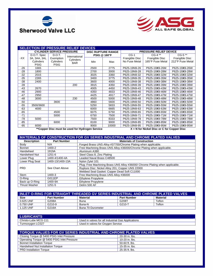
SELECTION OF PRESSURE RELIEF DEVICES CYLINDER SERVICE PRESSURE PRESSURE RELIEF DEVICE DISC RUPTURE RANGE
PSIG @ 160°F -XX
D.O.T. Spec3A, 3AA, 3AL
Cylinders PSIG
D.O.T.Exemption Cylinders
PSIG
International Cylinders
BAR Min Max
CG-1 Frangible Disc No Fuse Metal
CG-4 ** Frangible Disc
165°F Fuse Metal
CG-5 ** Frangible Disc
212°F Fuse Metal
-26 1665 2500 2775 P625-19N9-26 P625-19X9-26M P625-19X9-26W -28 1800 2700 3000 P625-19N9-28 P625-19X9-28M P625-19X9-28W -32 2015 3025 3360 P625-19N9-32 P625-19X9-32M P625-19X9-32W -35 2265 3400 3775 P625-19N9-35 P625-19X9-35M P625-19X9-35W -38 2400 3600 4000 P625-19N9-38 P625-19X9-38M P625-19X9-38W -39 200 3915 4350 P625-19N9-39 P625-19X9-39M P625-19X9-39W -43 2670 4005 4450 P625-19N9-43 P625-19X9-43M P625-19X9-43W -46 2900 4350 4833 P625-19N9-46 P625-19X9-46M P625-19X9-46W -47 2950 4425 4917 P625-19N9-47 P625-19X9-47M P625-19X9-47W -48 3000 230 4500 5000 P625-19N9-48 P625-19X9-48M P625-19X9-48W -50 3600 4860 5600 P625-19N9-50 P625-19X9-50M P625-19X9-50W -55 3500/3600 5250 5833 P625-19N9-55 P625-19X9-55M P625-19X9-55W -63 4000 6000 6665 P625-19N9-63 P625-19X9-63M P625-19X9-63W -65 4500 6075 6750 P625-19N9-65 P625-19X9-65M P625-19X9-65W -71 5000 6750 7500 P625-19N9-71 P625-19X9-71M P625-19X9-71W -78 5000 7500 8333 P625-19N9-78 P625-19X9-78M P625-19X9-78W -85 6000 8100 9000 P625-19N9-85 P625-19X9-85M P625-19X9-85W -95 6000 9000 10000 P625-19N9-95 P625-19X9-95M P625-19X9-95W
**Copper Disc must be used for Hydrogen Service X = N for Nickel Disc or C for Copper Disc
MATERIALS OF CONSTRUCTION FOR GV SERIES INDUSTRIAL AND CHROME PLATED VALVES Description Part Number Materials of Construction
Body N/A Forged Brass UNS Alloy #37700/Chrome Plating when applicable. Bonnet 1400-2 Free Machining Brass UNS Alloy #36000/Chrome Plating when applicable. Handwheel 1919A Aluminum A380Handwheel Nut 1251-6 Steel Class 8, Zinc Plating Lower Plug 1400-4/1400-4A Leaded Naval Brass C48500 Lower Plug Seat 1400-13/1400-13A Nylon Zytel 101
Plug: Free Machining Brass UNS Alloy #36000/ Chrome Plating when applicable. Rupture Disc: Nickel Alloy 201; Copper UNS 22000 PRD See Chart Above Webbed Seal Gasket: Copper Dead Soft C11000
Stem 1400-3 Free Machining Brass UNS Alloy #36000 O-Ring G011EP Ethylene PropyleneBack up O-Ring 1400-9A Ethylene Propylene Thrust Washer 1251-5 Delrin 500 AF
INLET O-RING FOR STRAIGHT THREADED GV SERIES INDUSTRIAL AND CHROME PLATED VALVES Size Part Number Material Part Number Material 0.625 UNF G208A Buna G208T Teflon 0.750 UNF G210-9 Buna-N G210-T Teflon 1.125 UNF G216A Buna 70 Durometer
LUBRICANTS Christo-Lube MCG-111 Used in valves for all Industrial Gas Applications Turmoxygen LC027 Used in valves for Oxygen Service
TORQUE VALUES FOR GV SERIES INDUSTRIAL AND CHROME PLATED VALVES Closing Torque @ 5400 PSIG Inlet Pressure 20-30 in. lbs.Operating Torque @ 5400 PSIG Inlet Pressure 10-20 in. lbs.Bonnet Installation Torque 50-60 ft. lbs.Handwheel Nut Installation Torque 15-35 in. lbs.PRD Installation Torque 25-35 ft. lbs.

REPAIR INSTRUCTIONS FOR GV SERIES INDUSTRIAL AND CHROME PLATED VALVES
DISASSEMBLY OF VALVE 1. Place the valve assembly into a vise or similar holding fixture, taking care not to damage the inlet or outlet threads. The
holding fixture must securely grip the valve body on the wrench flats so that no damage is done to the internal bores,external threads, outlet, or pressure relief device.
2. Chambera. Using a 13 mm socket, remove the handwheel nut from the handwheel by turning it counter clockwise.b. Remove the handwheel from the stem square.c. Using an 11/16” socket wrench or hex box wrench, remove the bonnet by turning it counter clockwise. The stem
subassembly with o-ring and back-up o-ring may remove with the bonnet. If not, remove the stem subassemblyfrom the valve after the bonnet.
d. Being careful not to scratch the bonnet sealing surface in the valve body, use a square drive to remove thelower plug from the valve chamber, by turning it counter clockwise.
3. Pressure Relief Devicea. Being careful not to scratch the sealing surface of the valve body, remove the pressure relief device by turning it
counter clockwise using a 5/8” hex box wrench or socket.
INSPECTION OF VALVE AND COMPONENTS 1. Valve Body
a. Inspect the valve body chamber for dirt, debris or damage. Where possible, blow out the valve body chamberusing clean, dry, Compressed Air or Nitrogen to remove any foreign particles.
b. If the valve body is damaged, do not attempt to repair. Order a new valve assembly.2. Components
a. Always discard the bonnet and stem subassembly and the lower plug. Order replacement parts. NOTE: Thelower plug replacement must correspond with the valve body and its relative application. For example, standardvalves have a .125” or .156” through hole in the body which uses a nylon seat diameter that is relative to thatsize, part number 1400-40. Carbon dioxide and manifold valves – except for oxygen – have a .272” throughhole in the body and use a nylon seat that is relative to that size, part number 1400-40A.
b. Handwheels should only be reused if in good condition. Discard handwheels if damaged.c. Inspect the pressure relief device threads for damage. Inspect the rupture disc and the webbed washer for
scratches. Discard this component if damaged and order replacement parts.
ASSEMBLY OF VALVE 1. Chamber
a. Apply 3 dabs of lubricant around the perimeter of the lower plug threads, approximating the size of a pencileraser for each. Locate lubricant toward the lower most threads closest to the crimped seat but using care notto get lubricant on the nylon seat. NOTE: Use Turmoxygen LC027 lubricant for oxygen service. Use Christo-Lube MCG-111 lubricant for all other gas applications.
b. Being careful not to damage the bonnet sealing surface in the valve body, install the new lower plug into thechamber, seat first and tighten using a square drive until it is fully seated.
c. Engage the new bonnet and stem subassembly into the valve body and hand tighten by turning clockwise.Rotate stem square until it becomes engaged in the lower plug.
d. Using an 11/16” hex torque wrench, tighten the bonnet to 50-60 ft. lbs. NOTE: A properly calibrated torquewrench must be used. Over torquing will damage the bonnet.
e. Place the handwheel over the stem square. Thread the handwheel nut onto the stem thread and tighten to 15-35 in. lbs.
f. To ensure free and smooth operation, open and close the valve several times by turning the handwheel.2. Pressure Relief Device (PRD)
a. NOTE: Refer to CGA S-1.1 latest edition to select the correct pressure relief device type according to thecylinder pressure and application.
b. Thread the proper pressure relief device on the PRD port until hand tight.c. Using a 5/8” socket and a calibrated torque wrench, tighten the PRD to 25-35 ft. lbs. Over torquing will damage
the PRD.
TESTING OF ASSEMBLED VALVE 1. Thoroughly test each repaired valve assembly by inserting and tightening the valve assembly into a cylinder or
suitable test fixture.2. Pressurize the valve assembly with an inert gas to the working pressure of the cylinder of intended use.3. With outlet suitably plugged, open the valve assembly by turning the handwheel counter clockwise. Using leak
detection solution or equipment, check the bonnet, stem, and PRD for leaks.4. Close the valve assembly by turning the handwheel clockwise. Remove the outlet plug and check for seat leakage
through the outlet using proper leak detection solution or equipment.5. If any leakage is detected, in the open or the closed position, the necessary repairs must be made before using the
valve assembly.

STAMPING CROSS REFERENCE FOR GV SERIES INDUSTRIAL AND CHROME PLATED VALVES
A. Inlet Thread Designation
B. Outlet Specification
C. Month/Year of Manufacture
D. Week of Calendar Year
E. International Standard for Cylinder Valve Design Specifications
F. Regulatory Approval (PI Mark)
PARTS BREAKDOWN FOR GV SERIES INDUSTRIAL AND CHROME PLATED VALVES
A. Handwheel Nut 1251-6
B. Handwheel 1919A
C. Bonnet and Stem Assembly 1400-30-100 (Oxygen) Includes: 1400-30-101 (All Others) BonnetBack-Up O-ringO-ringThrust WasherStem
D. Lower Plug and Seat Assembly 1400-40 (Standard)Includes: 1400-40A (CO2/Manifold)
Lower Plug Seat
E. Pressure Relief Device P625-19X9-XX Includes:PlugRupture DiscWebbed Seal Washer
BA C
F D
E
A
B
C
D
E

All Safe Global 26542 Fallbrook Lane Wyoming, MN 55092 866-958-3473
For ordering information or to receive a quotecontact All Safe, Inc.
• Toll free: 866-958-3473
• Local: 612-332-3473
• Fax: 651-408-7163
• Email: [email protected]
• Web: allsafe.net
• Twitter: @allsafeinc
All Safe is a national compressed gas cylinder and valve distributor, full service DOT authorized Ultrasonic Examination and Hydrostatic test facility, and fire protection provider with over 40 years of experience. Our services include cylinder requalification, refurbishing and recycling. As a stocking distributor with unique technical expertise, we sell a broad selection of valves, cylinders, and fire protection supplies. We maintain a large inventory to quickly fulfill most orders. All Safe Global is a leading test facility and compressed gas equipment supplier serving the entire U.S. and certain international markets.