sherpatt: a versatile hybrid wheeled-leg rover
TRANSCRIPT
SherpaTT: A Versatile Hybrid Wheeled-Leg Rover
Florian Cordes1 and Ajish Babu1
1 DFKI Robotics Innovation Center Bremen, Germanye-mail: [email protected]
Abstract
This paper subsumes the first experiences with thehardware of the robotic system SherpaTT. The mobileplatform consists of four legs, each equipped with a wheelat its end. All legs are connected via a central body. Thechosen control design and approach are validated with ex-periments using the robotic hardware. Autonomous ac-tive ground adaption is able to significantly improve thesystem’s stability in terms of ground contact force track-ing and body roll/pitch stability. For adaption, the robotmakes use of a one dimensional force measurement perwheel and the roll and pitch angles as measured by an in-ertial measurement unit in the central body. The results ofthe experiments are an excellent base for further develop-ment of the motion capabilities of the rover.
1 Introduction
Mobile robots provide the possibility to collect datafrom remote locations and explore places that are too faraway or too dangerous to be reached by humans. Sincethis implies that no humans are around once the robot isdeployed, the robot needs to be self-sufficient, robust andpossibly as autonomous as possible. Planetary exploration(currently primarily on Mars) is one example were mobilerobots are deployed for exploration and gathering of sci-entific data.
From nature, walking and climbing seems to be thebest solution for stable locomotion in a wide variety ofterrains. Even though there are promising advancementsin legged robotic locomotion [1, 9], the complexity and apersisting lack of robustness currently prevents these sys-tems from being deployed in space missions.
As opposed to walking systems, wheeled robots offera low complexity and high robustness. When equippedwith appropriate suspension mechanisms these systemscan provide a high mobility in natural terrain. So far,the mobile systems deployed on Moon (e.g. LRV [14],the Lunokhod rovers or Chang’e-3) and Mars (Pathfinder,MER [5], Curiosity [15]) are wheeled systems with pas-sive suspension systems. The passive suspension knownas rocker-bogie reduces the angular displacement the bodyof the robot is experiencing while traversing sloping ter-rain and allows to overcome obstacles such as rocks in the
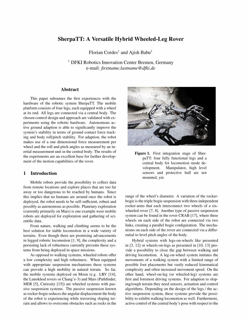
Figure 1. First integration stage of Sher-paTT: four fully functional legs and acentral body for locomotion mode de-velopment. Manipulator, high levelsensors and protective hull are notmounted, yet.
range of the wheel’s diameter. A variation of the rocker-bogie is the triple bogie suspension with three independentrocker-arms that each interconnect two wheels of a six-wheeled rover [7, 8]. Another type of passive suspensionsystem can be found in the rover CRAB [17], where threewheels on each side of the robot are connected via twolinks, creating a parallel bogie configuration. The mecha-nisms on each side of the rover are connected via a differ-ential to level pitch angles of the body.
Hybrid systems with legs-on-wheels like presentedin [3, 12] or wheels-on-legs as presented in [10, 13] pro-vide a possibility to close the gap between walking anddriving locomotion. A leg-on-wheel system imitates themovements of a walking system with a limited range ofpossible foot placements but vastly reduced kinematicalcomplexity and often increased movement speed. On theother hand, wheel-on-leg (or wheeled-leg) systems arefirst and foremost driving systems. For adaption to slop-ing/rough terrain they need sensors, actuation and controlalgorithms. Depending on the design of the legs / the ac-tive suspension system, these systems provide the possi-bility to exhibit walking locomotion as well. Furthermore,active control of the central body’s pose with respect to the
footprint in up to six degrees of freedom (DoF) is possi-ble while simultaneously adapting to the terrain they aredriving on.
This paper presents the first experiences with thehardware of the hybrid wheeled-leg system SherpaTT,which is depicted in Figure 1. The rover consists of fouridentical legs with a wheel at the end. For the experi-ments in this paper the first integration stage with fullyfunctional legs mounted on the central body is used. Inthe final integration stage an additional manipulator willbe mounted on top of the system. SherpaTT is part of amulti-robot team for an aspired lunar sample-return mis-sion [11]. Following this introduction chapter, the secondchapter gives an overview of the kinematics of the sus-pension system that is formed by the four legs, the thirdchapter highlights the motion control system implementedin SherpaTT.
2 SherpaTT: System Overview
In this section the general design of SherpaTT is pre-sented. Currently, SherpaTT is in its first integration stagewith all four leg units attached to a central body and thebasic electronics implemented in the system for hardwaretesting (focus on the suspension system). The last para-graph of this section highlights some of the upcoming ex-tensions of the system, that will be conducted to makeSherpaTT a full member of the planned multi-robot sys-tem in the project TransTerrA [11]. SherpaTT is the suc-cessor of Sherpa, differences of both systems are high-lighted in [4].
2.1 Leg Design and DefinitionsAs can be seen from Figure 1, SherpaTT features four
leg-like units that constitute its active suspension system.A total of 20 active DoF distributed in four identical sus-pension units (“legs”) are present.
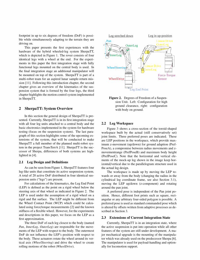
For calculations of the kinematics, the Leg End Point(LEP) is defined as the point on a rigid wheel below thesteering axis of that wheel as indicated in Figure 2. TheLEP is used under the assumption of a rigid wheel on arigid and flat surface. The LEP might be different fromthe Wheel Contact Point (WCP) which could be calcu-lated using force/torque measurements [2] and the knownstiffness of a flexible wheel. However, for the experimentsand descriptions in this paper, we focus on the LEP as afirst approximation.
The three DoF of each leg closest to the body (namedPan, InnerLeg, OuterLeg) are responsible for the move-ments of the LEP with respect to the body. The outermostDoF do not influence the LEP’s position with respect tothe body. These actuators rotate the wheel around its ver-tical axis (WheelSteering) and drive the wheel to createrolling motions of the robot (WheelDrive).
Pan
InnerLeg
OuterLeg
WheelSteering
WheelDrive
Linear DriveInnerLeg
Linear DriveOuterLeg
Force-Torque Sensor
Leg End Point
Leg streched down Leg in up-position
Figure 2. Degrees of Freedom of a Suspen-sion Unit. Left: Configuration for highground clearance, right: configurationwith body on ground.
2.2 Leg WorkspaceFigure 3 shows a cross-section of the toroid-shaped
workspace built by the actual (still conservatively set)joint limits. Three preferred poses are indicated. Theseare LEP positions in the workspace, which provide max-imum z-movement (up/down) for ground adaption (Pref-PoseA), a compromise between radius movements and z-movementrange (PrefPoseB) and maximum body height(PrefPoseC). Note that the horizontal and vertical ele-ments of the mock-up leg shown in the image keep hor-izontal/vertical due to the parallelogram structure used inthe actual leg design.
The workspace is made up by moving the LEP to-wards or away from the body (changing the radius in thecylindrical leg coordinate frame, see also Section 3.1),moving the LEP up/down (z-component) and rotatingaround the pan joint.
A preferred pose is independent of the Pan joint po-sition. Hence, different foot prints such as square, rect-angular or any arbitrary four-sided polygon is possible. Apreferred pose is used as standard commanded pose whichis altered by offsets written from adaptive processes as de-scribed in Section 3.
2.3 Extensions of Current Integration StateCurrently, SherpaTT is in an integration state, where
the active suspension is put into operation while all otherfeatures of the system are still under development. A ma-jor mechanical upgrade is the mounting of the manipula-tor which was already used on the predecessor Sherpa [6].The manipulator is used for payload-handling and option-ally for locomotion support.

Figure 3. Workspace dimensions (crosssection) and preferred poses in cylin-drical leg frame. Inset depicts theoverlapping workspaces of all four legs.Dimensions are in millimeters.
For a seamless integration into the multi-robot sys-tem [11], SherpaTT will be equipped with four payload in-terfaces (EMI: electro-mechanical interface [16]) aroundthe manipulator tower and at the bottom of the body. Theinterfaces are used to transport payloads or to expand therover’s capabilities by attaching additional sensors and de-vices.
Finally a protective hull will be mounted on SherpaTTfor protection against dust and other contaminants.
3 Motion Control
In this section, we present the motion control system(MCS) for SherpaTT. The MCS is the connecting layerbetween low-level control on one hand – i.e. firmwarerunning on the hardware boards such as joint controllers,relay-boards and alike – and high level control (naviga-tion, planning, and other autonomous behaviors) on theother. For the purpose of development of the MCS, agraphical user interface is used to command the robot’smovement (forward, lateral and turn), its body attitudewith respect to gravity (roll, pitch) and body height, andthe footprint of the robot (where the LEPs of the suspen-sion unit are with respect to the body). These are also
BCS LCS
LEP
SCS
BCS BCS
LEP
SCS
Figure 4. Coordinate Frames for Locomotion
the possible inputs for high-level processes to commandthe rover. Generation of joint commands from the men-tioned high-level commands is completely encapsulatedin the MCS.
3.1 Locomotion Coordinate FramesFigure 4 illustrates the most important coordinate
frames used in SherpaTT. The following main coordinateframes are used for locomotion control:• The Body Coordinate System (BCS) is attached to the
center of the main body of SherpaTT. Its z-axis ispointing upwards, the x-y plane is at the same heightas the Leg Coordinate System’s x-y plane (see be-low). This frame is used for all internal computa-tions.• The Leg Coordinate System (LCS) has its origin in
the Pan joint of a leg. It is aligned with the Pan-CSwhen the Pan angle α = 0◦.• The Shadow Coordinate System (SCS) is used to
describe the motion commands independent of thebody posture. The center image and the right handimage of Figure 4 illustrate the SCS. It is a virtualCS that remains at the “nominal pose” of SherpaTT.Body posture changes, externally commanded LegEnd Point (LEP)-positions and movement commandsare described in this frame.
3.2 Basic Structure of the Motion ControlSystem
SherpaTT’s Motion Control System (MCS) is setup toencapsulate the control of the robot’s complex kinemat-ics such that the high level process only needs to providecontrol inputs via a simple command interface. Figure 5shows how the MCS is used to control the robot. In thissimplified diagram the main command inputs are shownat the top:• The Motion Command is used for basic robot move-
ment. The command is three dimensional and allowscommanding forward (x) and lateral (y) as well asturn movements (about z).• BodyPosture commands are used to control the six
DoF of the robot’s main body.• A FootPrint command is used to describe the three
DoF of each LEP.This results in a total of 21 possible command inputs.Three of which are velocity commands, the rest are

MotionCmdMC3D
FootPrint
LEP cmdgenerator
BodyPosture
DriveMode
GAPLEP
Interpolator
InverseKinematics
MCS
hardware
inputs
sensor feedback
jointcommands
Figure 5. Simplified structure of Sher-paTT’s Motion Control System. Onlycentral components are displayed.
position commands. Note that height commands (z-component) for single LEPs can be set freely, howeverthese commands have an influence on the BodyPosture.Hence, even if possible in the actual MCS implementa-tion, direct z-commands for the LEPs should be avoidedby the human operator or the high-level processes.
Internally, the BodyPosture command and the Foot-Print command are merged into one LEP position (inBCS) per leg of the suspension system. The Motion-Command is used to control the WheelSteering andWheelDrive joints according to the DriveMode. The com-manded values are merged together with LEP offsets orig-inating from the Ground Adaption Process (GAP, see Sec-tion 3.3) into the LEP Interpolator. Here the trajectoriesof the LEP positions are generated to reach a new desiredLEP from the actual LEP position.
In each cycle of the MCS (which is executed at100 Hz), the actual LEP command is finally converted intojoint commands by the Inverse Kinematics task and sent tothe joints of the suspension system. The sensor feedbackcontains telemetry from each joint as well as IMU data forthe actual body orientation and data from the force-torquesensors at each wheel.
EGC RPA FLC
Merging
BHC
single component‘soffsets for LEPs
merged offsets
final offsets
sensor feedback
GAP
body posture reference
Figure 6. The components of the GroundAdaption Process (GAP): EnsureGround Contact (EGC), Roll/PitchAdaption (RPA), Force Leveling Con-trol (FLC), and Body Height Correction(BHC).
3.3 Active Ground Adaption
The Ground Adaption Process (GAP) is the part of theMCS that manipulates the LEPs of each leg to conform tothe terrain. This is achieved by following reference valuesfor forces at the LEP and roll and pitch angle of the centralbody as measured by the Inertial Measuring Unit (IMU).The reference values are tracked using PI-controllers foreach of the setpoint goals. Figure 6 displays the generalscheme in which the values for active ground adaption aregenerated.
Currently, three subcomponents constitute the groundadaption. The three offset generating subcomponents ofGAP are described in more detail in the following para-graphs. Each of the components independently calculatesan LEP offset (in z-direction) for each of the wheels. Theoffsets are then merged into one offset for each wheel. Be-fore writing the merged offsets out to the MCS, the BodyHeight Control (BHC) module checks whether all offsetshave the same sign, when this is the case, the offsets arecut such that the smallest offset is set to zero. Hence, abody height drift can be prevented.
Ensure Ground Contact (EGC) This module is re-sponsible for keeping all wheels in continuous groundcontact. Once the measured force on a wheel drops be-low a threshold, the corresponding wheel offset is adaptedsuch that the wheel moves down with zLEP,i = −10 mm/s.
Roll/Pitch Adaption (RPA) In the RPA subcomponent,two separate PI controllers are active for each wheel’s off-set, resulting in eight PI-controllers in total. One con-troller generates offsets to match the commanded roll, thesecond controller to match the commanded pitch angle ofthe body. In the implementation used for the experimentspresented in this paper, both controllers assume a distanceof the wheel to the rotation axis of 1 m. An extension to ar-bitrary foot prints is possible by incorporating the x and ycomponent of the LEP in body coordinates as scaling fac-tor. Both offsets of the RPA module are added and writtenas combined RPA offset.
Force Leveling Control (FLC) The force levelingmodule needs the expected forces at the wheels as inputfor the PI controller. Currently, the forces are calculatedas expected forces for the footprint the robot is driving. Inother words, when driving in a symmetrical square footprint configuration, each wheel is expected to share thesame fraction of the robot’s mass. Wheels that are closerto the body would share a higher load. Since the sys-tem with four ground contact points is underdetermined,an approximation using a Moore-Penrose pseudoinverseis used to generate the reference forces for the wheels.For this static equilibrium is assumed. In later develop-ment stages, other ground adaption modules will activelychange the position of the center of gravity within the sup-port polygon to generate an appropriate force distributionbetween the wheels for locomotion in rough and slopingterrain.
4 Experiments
For validating the systems’s ground adaption capa-bilities, experiments on a wooden obstacle track are con-ducted. The initial experiments using the first integrationstudy of SherpaTT and the results thereof are presented inthis section.
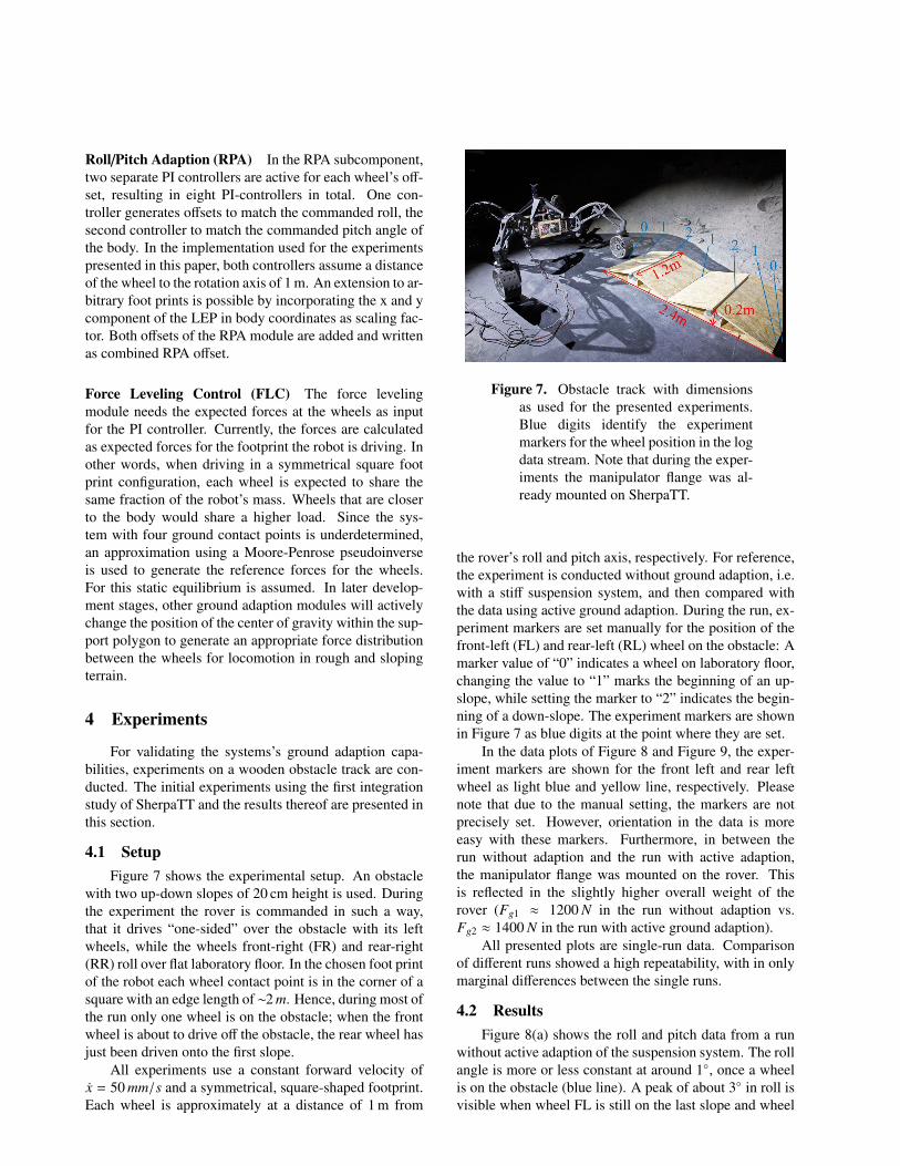
4.1 SetupFigure 7 shows the experimental setup. An obstacle
with two up-down slopes of 20 cm height is used. Duringthe experiment the rover is commanded in such a way,that it drives “one-sided” over the obstacle with its leftwheels, while the wheels front-right (FR) and rear-right(RR) roll over flat laboratory floor. In the chosen foot printof the robot each wheel contact point is in the corner of asquare with an edge length of ∼2 m. Hence, during most ofthe run only one wheel is on the obstacle; when the frontwheel is about to drive off the obstacle, the rear wheel hasjust been driven onto the first slope.
All experiments use a constant forward velocity ofx = 50 mm/s and a symmetrical, square-shaped footprint.Each wheel is approximately at a distance of 1 m from
Figure 7. Obstacle track with dimensionsas used for the presented experiments.Blue digits identify the experimentmarkers for the wheel position in the logdata stream. Note that during the exper-iments the manipulator flange was al-ready mounted on SherpaTT.
the rover’s roll and pitch axis, respectively. For reference,the experiment is conducted without ground adaption, i.e.with a stiff suspension system, and then compared withthe data using active ground adaption. During the run, ex-periment markers are set manually for the position of thefront-left (FL) and rear-left (RL) wheel on the obstacle: Amarker value of “0” indicates a wheel on laboratory floor,changing the value to “1” marks the beginning of an up-slope, while setting the marker to “2” indicates the begin-ning of a down-slope. The experiment markers are shownin Figure 7 as blue digits at the point where they are set.
In the data plots of Figure 8 and Figure 9, the exper-iment markers are shown for the front left and rear leftwheel as light blue and yellow line, respectively. Pleasenote that due to the manual setting, the markers are notprecisely set. However, orientation in the data is moreeasy with these markers. Furthermore, in between therun without adaption and the run with active adaption,the manipulator flange was mounted on the rover. Thisis reflected in the slightly higher overall weight of therover (Fg1 ≈ 1200 N in the run without adaption vs.Fg2 ≈ 1400 N in the run with active ground adaption).
All presented plots are single-run data. Comparisonof different runs showed a high repeatability, with in onlymarginal differences between the single runs.
4.2 ResultsFigure 8(a) shows the roll and pitch data from a run
without active adaption of the suspension system. The rollangle is more or less constant at around 1◦, once a wheelis on the obstacle (blue line). A peak of about 3◦ in roll isvisible when wheel FL is still on the last slope and wheel

(a) Without adaption, the obstacle-course is well visible in the pitch of therobot.
(b) Active adaption limits the values within ±1deg max
Figure 8. Roll/Pitch deviation without and with active GAP.
(a) Without adaption, wheels loose ground contact (Fz ≈0 N). Two diag-onally opposite wheels (FL/RR and FR/RL) share the main load of therobot’s weight.
(b) Active adaption limits the values mostly to ±100 N of the desired value(≈300 N). A higher deviation is visible in the middle of the experiment,where the rear wheel enters the obstacle while the front wheel leaves theobstacle
Figure 9. Wheel-ground contact forces without and with active GAP.
RL drives up the first slope (around t = 60 s).
In the pitch data of the rover, the obstacle is quitewell recognizable, with a negative pitch following the twopeaks of the obstacle when the FL wheel is on the obstacleand a positive pitch, when the rear wheel is on the obsta-cle. From the corresponding force plot in Figure 9(a) itcan be seen that the wheels FR and RR loose ground con-tact (z-force drops close to zero).
The force plot also shows that with the stiff suspen-sion there are always two strong contacts and two weakcontacts. Both types are diagonally opposed to each other,i.e. FL/RR and FR/RL are contact pairs. The robot isdriving with a symmetrical foot print. With a weight ofFg1 ≈ 1200 N, each wheel contact should ideally remainat around 300 N. Actually, due to the stiff suspension andthe resulting lift off the ground of single wheels, the forces
deviate about ±300 N from the desired reference force.
Figure 8(b) and Figure 9(b) show the results of driv-ing over the same obstacle with active GAP. With activecontrol of roll and pitch angles both are kept within ±0.5◦,apart from one deviation of about 1◦ around 50 s (ref. Fig-ure 8(b)). In the second half of the experiment (RL wheelon obstacle) the angles are kept within ±0.2◦.
From the plot of the wheel contact forces, it can beseen that all wheels keep ground contact during the com-plete experiment run. Control oscillations lead to morefrequent switching between strong and weak contact pairs.The oscillations are a result of a limited velocity of thewheel’s z-component, which is due to the single joint ve-locity limits in each leg. Apart from greater force devia-tions during the change over of FL and RL wheel on theobstacle, the force levels are kept approximately ±50 N
around the setpoint of 14 Fg2 = 350 N.
5 Conclusion and Outlook
This paper gives a first impression of the newly inte-grated hybrid driving and walking rover SherpaTT.
The structure and kinematics of the suspension sys-tem are highlighted, and the implemented control systemis presented. Core part of the motion control system isthe active ground adaption process (GAP). This processis implemented in such a way that offsets to the com-manded wheel position are written to adapt to sloping ter-rain. Measurement inputs are currently one-dimensionalforce measurements at the wheels and orientation mea-surements (roll/pitch) in the central body.
The initial experiments presented in this paper showthat a clear reduction in loads of a single wheel by ac-tive force balancing is possible. The deviation of forceswas reduced to ±50 N as opposed to deviations of ±300 Nin case of no adaption to the obstacle. The implementedroll and pitch controller is able to keep the body’s poseclose to the desired values (±0.5◦ vs. ±4.5◦ without ac-tive adaption) on the obstacle used for the experiments,significantly reducing the ground’s effect onto the body’sorientation. In the presented experiments, rough controlgain setting was done, it is to be expected that tuning ofcontrol parameters will improve the oscillating behaviorand reference value tracking. A high repeatability was ob-served, differences between single runs with same settingsare only marginal.
Even though the experiments in this paper indicate agood behavior of the robot concerning the active adap-tion to sloping terrain, only a limited subset of systemconfigurations was investigated so far. Further develop-ments are currently directed into arbitrary foot prints (non-symmetric stance and LEPs in other distances than 1 mfrom rotation axis), three dimensional force tracking andLEP offset generation, and less regular as well as biggerobstacles.
AcknowledgmentThe project TransTerrA is funded by the German
Space Agency (DLR, Grant number: 50RA1301) withfederal funds of the Federal Ministry of Economics andTechnology (BMWi) in accordance with the parliamen-tary resolution of the German Parliament.
References
[1] S. Bartsch. “Development, Control, and EmpiricalEvaluation of the Six-Legged Robot SpaceClimberDesigned for Extraterrestrial Crater Exploration”.In: KI - Kunstliche Intelligenz 28.2 (2014), pp. 127–
131. url: http : / / dx . doi . org / 10 . 1007 /s13218-014-0299-y.
[2] A. Bicchi, J. K. Salisbury, and D. L. Brock. ContactSensing from Force Measurements. A.I. Memo No.1262. Massechusetts Institute of Technology, Arti-ficial Intelligence Laboratory, 1990, pp. 249–262.url: ftp://publications.ai.mit.edu/ai-publications/pdf/AIM-1262.pdf.
[3] Y. C. Chou et al. “Bio-inspired step crossing algo-rithm for a hexapod robot”. In: Intelligent Robotsand Systems (IROS), 2011 IEEE/RSJ InternationalConference on. 2011, pp. 1493–1498.
[4] F. Cordes et al. “An Active Suspension Sys-tem for a Planetary Rover”. In: Proceedings ofthe International Symposium on Artificial Intel-ligence, Robotics and Automation in Space (i-SAIRAS 2014); June 17-19, Montreal, Canada.o.A., June 2014.
[5] R.A. Lindemann and C.J. Voorhees. “Mars Explo-ration Rover mobility assembly design, test andperformance”. In: Systems, Man and Cybernetics,2005 IEEE International Conference on. Vol. 1.2005, 450–455 Vol. 1.
[6] M. Manz et al. “Development of a LightweightManipulator Arm using Heterogeneous Materialsand Manufacturing Technologies”. In: Proceedingsof the International Symposium on Artificial In-telligence, Robotics and Automation in Space (i-SAIRAS 2012); September 4-6, Turin, Italy. o.A.,Sept. 2012.
[7] Paul Meacham, Nuno Silva, and Richard Lan-caster. “The Development of the Locomotion Per-formance Model (LPM) for the ExoMars Rover Ve-hicle”. In: Proceedings of ASTRA 2013. 2013. url:http://robotics.estec.esa.int/ASTRA/
Astra2013/Papers/meacham_2811294.pdf.
[8] S. Michaud et al. “Development of the ExoMarsChassis and Locomotion Subsystem”. In: Proceed-ings of i-SAIRAS 2008 - 9th International Sympo-sium on Artificial Intelligence, Robotics and Au-tomation in Space. 2008. url: http://elib.dlr.de/55365/1/i-sairas2008_ExoMars.pdf.
[9] M. Raibert et al. BigDog, the Rough-TerrainQuadruped Robot. online. 2008. url: http : / /www . bostondynamics . com / img / BigDog _
IFAC_Apr-8-2008.pdf.
[10] W. Reid, A. H. Goktogan, and S. Sukkarieh. “Mov-ing MAMMOTH: Stable Motion for a Reconfig-urable Wheel-On-Leg Rover”. In: Proceedings ofAustralasian Conference on Robotics and Automa-tion. 2014.
[11] R. Sonsalla et al. “Towards a Heterogeneous Mod-ular Robotic Team in a Logistic Chain for Ex-traterrestrial Exploration”. In: Proceedings of theInternational Symposium on Artificial Intelligence,Robotics and Automation in Space (i-SAIRAS2014); June 17-19, Montreal, Canada. o.A., June2014.
[12] R. U. Sonsalla et al. “Design of a High Mo-bile Micro Rover within a Dual Rover Configu-ration for Autonomous Operations”. In: Proceed-ings of the International Symposium on ArtificialIntelligence, Robotics and Automation in Space(iSAIRAS-2014). Montreal, 2014.
[13] J. Townsend, J. Biesiadecki, and C. Collins.“ATHLETE mobility performance with active ter-rain compliance”. In: Aerospace Conference, 2010IEEE. 2010, pp. 1–7.
[14] NASA Webpage. The Apollo Lunar Roving Vehicle.http://nssdc.gsfc.nasa.gov/planetary/
lunar/apollo_lrv.html. last visit: 2016-02-09.
[15] R. Welch et al. “Verification and validation ofMars Science Laboratory surface system”. In: Sys-tem of Systems Engineering (SoSE), 2013 8thInternational Conference on. 2013, pp. 64–69.url: http : / / ieeexplore . ieee . org /xpl / articleDetails . jsp ? arnumber =
6575244&queryText=Verification%20and%
20Validation % 20of % 20the % 20MSL %
20Curiosity%20Rover&newsearch=true.
[16] W. Wenzel, F. Cordes, and F. Kirchner. “A RobustElectro-Mechanical Interface for Cooperating Het-erogeneous Multi-Robot Teams”. In: Proceedingsof the 2015 IEEE International Conference on In-telligent Robots and Systems (IROS-15). Hamburg,2015, pp. 1732–1737.
[17] B. Xu et al. “Composite control based on opti-mal torque control and adaptive Kriging controlfor the CRAB rover”. In: Robotics and Automation(ICRA), 2011 IEEE International Conference on.2011, pp. 1752–1757.