shenzhen bst technology co - szkesu.com...report no.: uni2016121702er-02 page 4 / 23 1. general...
TRANSCRIPT

Report No.: UNI2016121702ER-02 Page 1 / 23
ShenZhen KY Technology Co.,Ltd
RADIO REPORT
Prepared For:
ShenZhen KY Technology Co.,Ltd
No.369, BaoTian 1st RD, TieGang Industrial Park, Xixiang Town, Baoan District, ShenZhen, PRC.
Product Name:
Smart bracelet
Trade Name:
N/A
Model:
BB07S, BB107, BB02, BB03, BB05, BB06, BB07, BB08, BB09
Prepared By:
Laboratory of Shenzhen United Testing Technology Co., Ltd.
Room 316-319, Block B, Honghualing Industrial Park of the Fifth Zone, Taoyuan Street, Nanshan District, Shenzhen, Guangdong, China
Test Date:
Dec., 07, 2016 – Dec., 17, 2016
Date of Report:
Dec., 17, 2016
Report No.:
UNI2016121702ER-02

Report No.: UNI2016121702ER-02 Page 2 / 23
TABLE OF CONTENTS
Test Report Declaration
1. GENERAL INFORMATION .................................................................................. ............ 4
1.1. Description of Device (EUT)................................................................................ 4
1.2. Test Facility ...................................................................................................... 5
1.3. Block Diagram of EUT Configuration ............................................................... 5
1.4. Suppor t Equip ment Lis t ........................ ......................................................... 5
1.5. Operating Condition of E UT ... .............................. ........................................... 5
1.6. Test Conditions ................................................................................................. 5
1.7. Modifications ......................................................................................................... 5
1.8. Abbreviations.............................................................. ...................................... 5
2. TEST RESULTS SUMMARY ........................................ .................................................. 6
3. TEST EQUIPME NTS......................... ............................................................................. 6
4. MEASUREMENT UNCERTAINTY...........................................................................................7
5. EN 300 328 §4.3.1.2 - RF Output Power ........................................................................................8
6. EN 300 328 §4.3.1.4 - Accumulated Transmit Time, Frequency Occupation and Hopping
Sequence......................................................................................................................................... 10
7. EN 300 328 §4.3.1.5 - Hopping Frequency Separation................................................................. 13
8. EN 300 328 §4.3.1.8 - Occupied Channel Bandwidth................................................................... 15
9. EN 300 328 §4.3.1.9 - Transmitter unwanted emissions in the out-of-band domain..................... 16
10. EN 300 328 §4.3.1.10 - Transmitter unwanted emissions in the spurious domain...................... 18
11. EN 300 328 §4.3.1.11 – Receiver spurious emissions................................................................. 19
APPENDIX I (Photos of the EUT) .......................................................... .............................. 20

Report No.: UNI2016121702ER-02 Page 3 / 23
TEST REPORT DECLARATION
Applicant : ShenZhen KY Technology Co.,Ltd
Address : No.369, BaoTian 1st RD, TieGang Industrial Park, Xixiang Town, Baoan District, ShenZhen, PRC.
Manufacturer : ShenZhen KY Technology Co.,Ltd
Address : No.369, BaoTian 1st RD, TieGang Industrial Park, Xixiang Town, Baoan District, ShenZhen, PRC.
EUT Description : Smart bracelet
Model Number : BB07S, BB107, BB02, BB03, BB05, BB06, BB07, BB08, BB09
Test Standards:
ETSI EN300 328 V1.9.1 (2015-02)
The EUT described above is tested by Shenzhen United Testing Technology Co., Ltd. EMC
Laboratory to determine the maximum emissions from the EUT and ensure the EUT to be compliance
with the immunity requirements of the EUT. Shenzhen United Testing Technology Co., Ltd.
Laboratory is assumed full responsibility for the accuracy of the test results. Also, this report shows
that the EUT technically complies with the 2014/53/EU directive and its amendment requirements.
The test report is valid for above tested sample only and shall not be reproduced in part without written approval of the laboratory.

Report No.: UNI2016121702ER-02 Page 4 / 23
1. GENERAL INFORMATION
1.1.Description of Device (EUT)
Description : Smart bracelet
Model Number : BB07S
Applicant : ShenZhen KY Technology Co.,Ltd
No.369, BaoTian 1st RD, TieGang Industrial Park, Xixiang Town, Baoan
District, ShenZhen, PRC.
Manufacturer : ShenZhen KY Technology Co.,Ltd
No.369, BaoTian 1st RD, TieGang Industrial Park, Xixiang Town, Baoan
District, ShenZhen, PRC.
Date of Test : Dec., 07, 2016 – Dec., 17, 2016
Report No.: UNI2016121702ER-02 Page 5 / 23
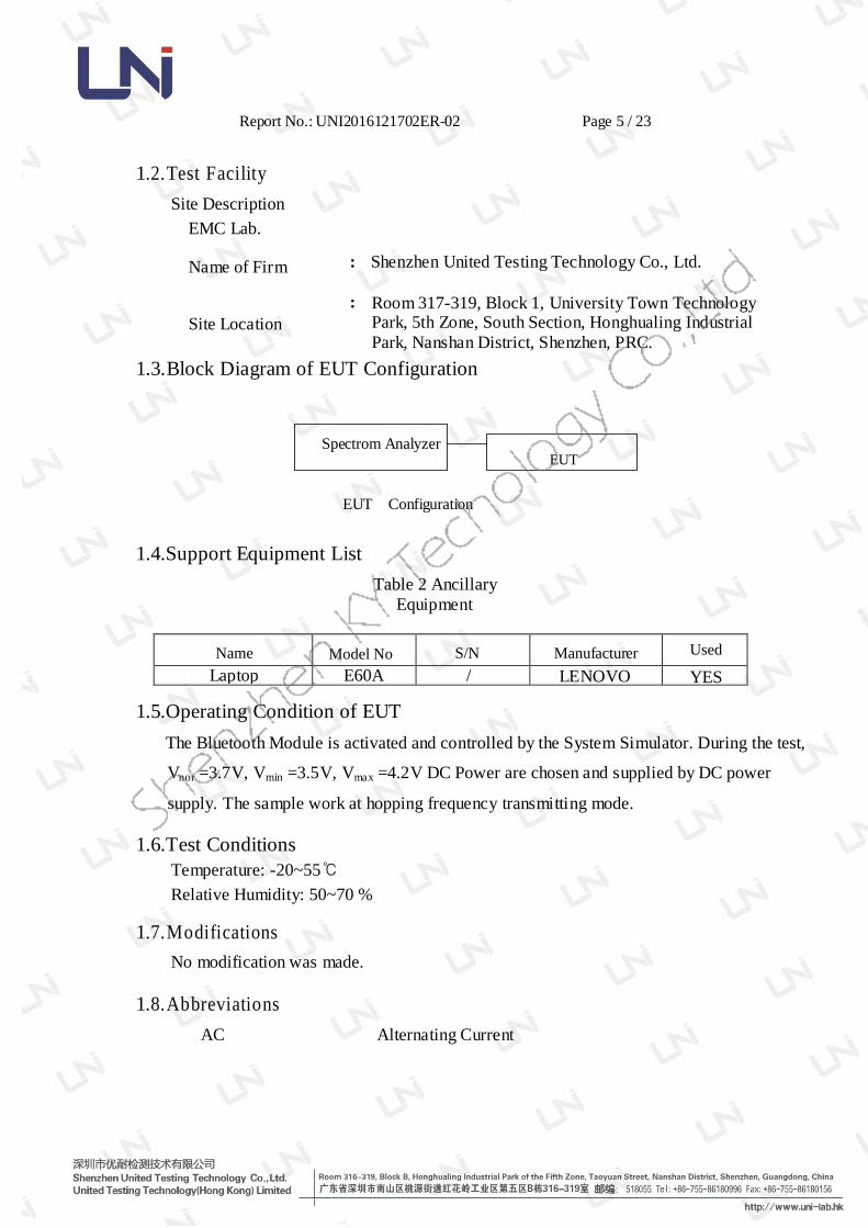
1.2.Test Facility
Site Description
EMC Lab.
Name of Firm
:
Shenzhen United Testing Technology Co., Ltd.
Site Location
:
Room 317-319, Block 1, University Town Technology Park, 5th Zone, South Section, Honghualing Industrial
Park, Nanshan District, Shenzhen, PRC.
1.3.Block Diagram of EUT Configuration
Spectrom Analyzer
EUT
EUT Configuration
1.4.Support Equipment List
Table 2 Ancillary
Equipment
Name
Model No
S/N
Manufacturer Used
Laptop E60A / LENOVO YES
1.5.Operating Condition of EUT
The Bluetooth Module is activated and controlled by the System Simulator. During the test,
Vnor =3.7V, Vmin =3.5V, Vmax =4.2V DC Power are chosen and supplied by DC power
supply. The sample work at hopping frequency transmitting mode.
1.6.Test Conditions
Temperature: -20~55℃
Relative Humidity: 50~70 %
1.7.Modifications
No modification was made.
1.8.Abbreviations
AC Alternating Current
Report No.: UNI2016121702ER-02 Page 6 / 23
AMN Artificial Mains Network
DC Direct Current
EM ElectroMagnetic
EMC ElectroMagnetic Compatibility
EUT Equipment Under Test
IF Intermediate Frequency RF Radio Frequency
rms root mean square
EMI Electromagnetic Interference EMS Electromagnetic Susceptibility
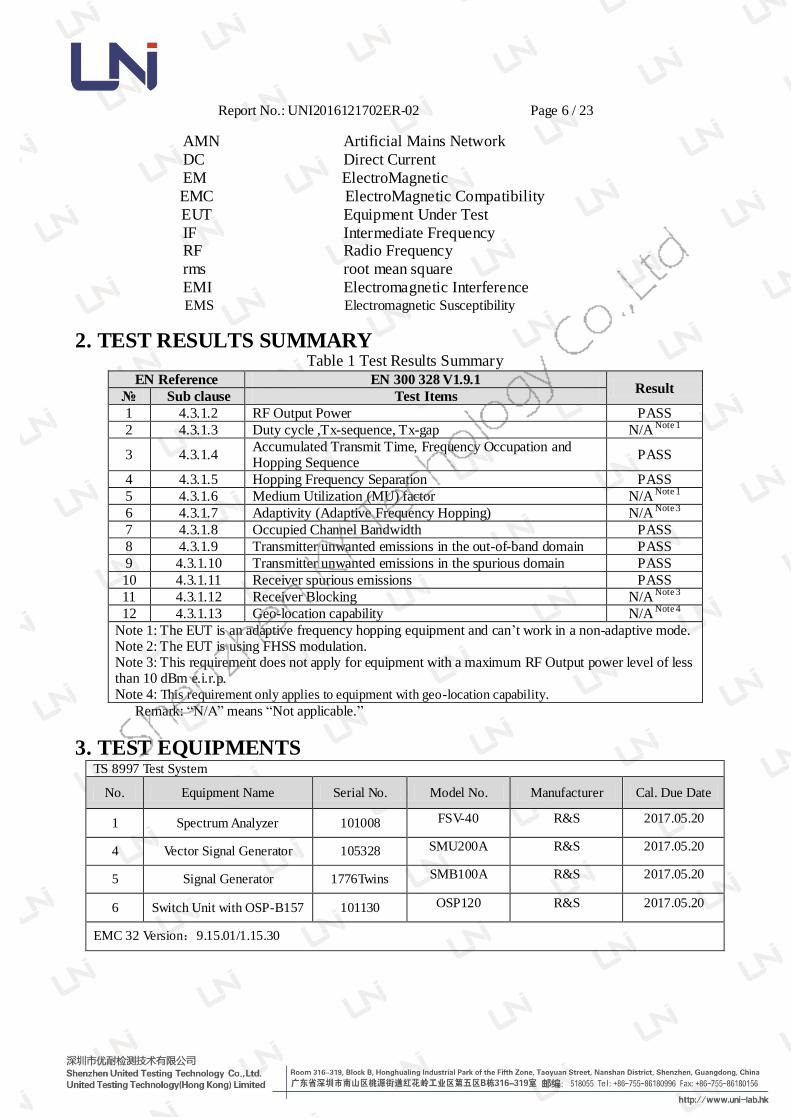
2. TEST RESULTS SUMMARY Table 1 Test Results Summary
EN Reference EN 300 328 V1.9.1 Result
№ Sub clause Test Items
1 4.3.1.2 RF Output Power PASS
2 4.3.1.3 Duty cycle ,Tx-sequence, Tx-gap N/A Note 1
3 4.3.1.4 Accumulated Transmit Time, Frequency Occupation and Hopping Sequence
PASS
4 4.3.1.5 Hopping Frequency Separation PASS
5 4.3.1.6 Medium Utilization (MU) factor N/A Note 1
6 4.3.1.7 Adaptivity (Adaptive Frequency Hopping) N/A Note 3
7 4.3.1.8 Occupied Channel Bandwidth PASS
8 4.3.1.9 Transmitter unwanted emissions in the out-of-band domain PASS
9 4.3.1.10 Transmitter unwanted emissions in the spurious domain PASS
10 4.3.1.11 Receiver spurious emissions PASS
11 4.3.1.12 Receiver Blocking N/A Note 3
12 4.3.1.13 Geo-location capability N/A Note 4
Note 1: The EUT is an adaptive frequency hopping equipment and can’t work in a non-adaptive mode. Note 2: The EUT is using FHSS modulation. Note 3: This requirement does not apply for equipment with a maximum RF Output power level of less than 10 dBm e.i.r.p. Note 4: This requirement only applies to equipment with geo-location capability.
Remark: “N/A” means “Not applicable.”
3. TEST EQUIPMENTS TS 8997 Test System
No. Equipment Name Serial No. Model No. Manufacturer Cal. Due Date
1 Spectrum Analyzer 101008 FSV-40 R&S 2017.05.20
4 Vector Signal Generator 105328 SMU200A R&S 2017.05.20
5 Signal Generator 1776Twins SMB100A R&S 2017.05.20
6 Switch Unit with OSP-B157 101130 OSP120 R&S 2017.05.20
EMC 32 Version:9.15.01/1.15.30
Report No.: UNI2016121702ER-02 Page 7 / 23
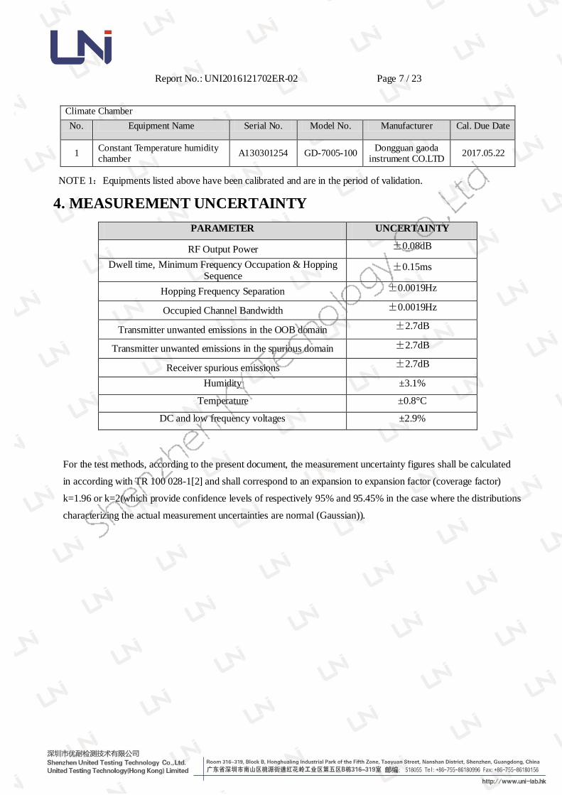
Climate Chamber
No. Equipment Name Serial No. Model No. Manufacturer Cal. Due Date
1 Constant Temperature humidity chamber
A130301254 GD-7005-100 Dongguan gaoda
instrument CO.LTD 2017.05.22
NOTE 1:Equipments listed above have been calibrated and are in the period of validation.
4. MEASUREMENT UNCERTAINTY
PARAMETER UNCERTAINTY
RF Output Power ±0.08dB
Dwell time, Minimum Frequency Occupation & Hopping Sequence
±0.15ms
Hopping Frequency Separation ±0.0019Hz
Occupied Channel Bandwidth ±0.0019Hz
Transmitter unwanted emissions in the OOB domain ±2.7dB
Transmitter unwanted emissions in the spurious domain ±2.7dB
Receiver spurious emissions ±2.7dB
Humidity ±3.1%
Temperature ±0.8°C
DC and low frequency voltages ±2.9%
For the test methods, according to the present document, the measurement uncertainty figures shall be calculated
in according with TR 100 028-1[2] and shall correspond to an expansion to expansion factor (coverage factor)
k=1.96 or k=2(which provide confidence levels of respectively 95% and 95.45% in the case where the distributions
characterizing the actual measurement uncertainties are normal (Gaussian)).

Report No.: UNI2016121702ER-02 Page 8 / 23
5. EN 300 328 §4.3.1.2 - RF Output Power
5.1.Test Requirements
5.1.1.Test Standard
ETSI EN300 328 V1.9.1 (2015-02)
5.1.2.Test Limit
The maximum RF output power for adaptive Frequency Hopping equipment shall be
equal to or less than 20 dBm.
5.2.Test Procedure
Please refer to ETSI EN 300 328 (V1.9.1) Sub-clause 5.3.2.2 for the measurement
method.
5.3.Test Data

Report No.: UNI2016121702ER-02 Page 9 / 23
GFSK Mode
Ambient temperature: 21℃ Relative humidity: 60%
Test conditions Effective radiated power (dBm)
Tnom(20°C) Vnor 2.6
Tmin(-20°C)
Vmin 2.5
Vmax 2.6
Vnom 2.4
Vmax 2.5 Measurement uncertainty 1.5dB
π/4-DQPSK Mode
Ambient temperature: 21℃ Relative humidity: 60%
Test conditions Effective radiated power (dBm)
Tnom(20°C) Vnor 2.1
Tmin(-20°C)
Vmin 2.2
Vmax 2
Vnom 2.1
Vmax 2 Measurement uncertainty 1.5dB
8DPSK Mode
Ambient temperature: 21℃ Relative humidity: 60%
Test conditions Effective radiated power (dBm)
Tnom(20°C) Vnor 1.8
Tmin(-20°C)
Vmin 1.7
Vmax 1.8
Vnom 1.6
Vmax 1.8 Measurement uncertainty 1.5dB

Report No.: UNI2016121702ER-02 Page 10 / 23
6. EN 300 328 §4.3.1.4 –Accumulated Transmit Time, Frequency
Occupation and Hopping Sequence
6.1.Test Requirements
6.1.1.Test Standard
ETSI EN300 328 V1.9.1 (2015-02) 6.1.2.Test Limit
The Accumulated Transmit Time on any hopping frequency shall not be greater than
15 ms within any observation period of 15 ms multiplied by the minimum number of
hopping frequencies (N) that have to be used.
Adaptive Frequency Hopping equipment shall be capable of operating over a
minimum of 70 % of the band specified in clause 1.
The Accumulated Transmit Time on any hopping frequency shall not be greater than
400 ms within any observation period of 400 ms multiplied by the minimum number
of hopping frequencies (N) that have to be used.
6.2.Test Procedure
Please refer to ETSI EN 300 328 (V1.9.1) Sub-clause 5.3.4 for the measurement
method.
6.3.Test Data
GFSK Mode
Accumulated Transmit Time
Test Condition Temperature:20℃,Voltage:3.7V
Channel Frequency(MHz) Accumulated
Dwell Time(ms) Limit(ms)
Measurement Time(ms)
Low Channel 2402.46 35.91 <=400 6000.000
High Channel 2480.35 42.28 <=400 6000.000
Test Verdict PASS
Frequency Occupation
Test Condition Temperature:20℃,Voltage:3.7V
Channel Frequency(MHz)
Minimum
Frequency Occupation(ms)
Limit(ms) Measurement
Time(ms)
Report No.: UNI2016121702ER-02 Page 11 / 23
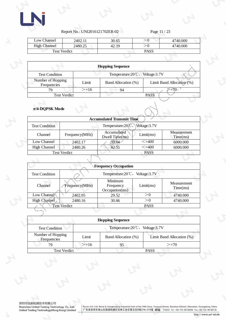
Low Channel 2402.11 30.65 >0 4740.000
High Channel 2480.25 42.19 >0 4740.000
Test Verdict PASS
Hopping Sequence
Test Condition Temperature:20℃,Voltage:3.7V
Number of Hopping Frequencies
Limit Band Allocation (%) Limit Band Allocation (%)
79 >=16 94 >=70
Test Verdict PASS
π/4-DQPSK Mode
Accumulated Transmit Time
Test Condition Temperature:20℃,Voltage:3.7V
Channel Frequency(MHz) Accumulated
Dwell Time(ms) Limit(ms)
Measurement Time(ms)
Low Channel 2402.17 39.64 <=400 6000.000
High Channel 2480.26 42.55 <=400 6000.000
Test Verdict PASS
Frequency Occupation
Test Condition Temperature:20℃,Voltage:3.7V
Channel Frequency(MHz) Minimum Frequency
Occupation(ms) Limit(ms)
Measurement Time(ms)
Low Channel 2402.05 29.52 >0 4740.000
High Channel 2480.16 30.66 >0 4740.000
Test Verdict PASS
Hopping Sequence
Test Condition Temperature:20℃,Voltage:3.7V
Number of Hopping Frequencies
Limit Band Allocation (%) Limit Band Allocation (%)
79 >=16 95 >=70
Test Verdict PASS

Report No.: UNI2016121702ER-02 Page 12 / 23
8-DPSK Mode
Accumulated Transmit Time
Test Condition Temperature:20℃,Voltage:3.7V
Channel Frequency(MHz) Accumulated
Dwell Time(ms) Limit(ms)
Measurement Time(ms)
Low Channel 2402.26 35.45 <=400 6000.000
High Channel 2480.14 40.33 <=400 6000.000
Test Verdict PASS
Frequency Occupation
Test Condition Temperature:20℃,Voltage:3.7V
Channel Frequency(MHz) Minimum Frequency
Occupation(ms)
Limit(ms) Measurement
Time(ms)
Low Channel 2402.17 38.43 >0 4740.000
High Channel 2480.22 41.55 >0 4740.000
Test Verdict PASS
Hopping Sequence
Test Condition Temperature:20℃,Voltage:3.7V
Number of Hopping Frequencies
Limit Band Allocation (%) Limit Band Allocation (%)
79 >=15 95 >=70
Test Verdict PASS
Report No.: UNI2016121702ER-02 Page 13 / 23
7. EN 300 328 §4.3.1.5 – Hopping Frequency Separation
7.1.Test Requirements
7.1.1.Test Standard
ETSI EN300 328 V1.9.1 (2015-02)
7.1.2.Test Limit
For non-adaptive Frequency Hopping equipment, the Hopping Frequency Separation
shall be equal or greater than the Occupied Channel Bandwidth (see clause 4.3.1.8),
with a minimum separation of 100 kHz.
For equipment with a maximum declared RF Output power level of less than 10 dBm
e.i.r.p. or for non-adaptive Frequency Hopping equipment operating in a mode where
the RF Output power is less than 10 dBm e.i.r.p. only the minimum Hopping
Frequency Separation of 100 kHz applies.
7.2.Test Procedure
Please refer to ETSI EN 300 328 (V1.9.1) Sub-clause 5.3.5 for the measurement
method.
7.3.Test Data

Report No.: UNI2016121702ER-02 Page 14 / 23
GFSK Mode
Test Condition Temperature:20℃,Voltage:3.7V
Hopping Frequency Separation(MHz)
Limit(MHz) Center Frequency of Separation(MHz)
0.9998 >= 0.1 2439.202355
Test Verdict PASS
π/4-DQPSK Mode
Test Condition Temperature:20℃,Voltage:3.7V
Hopping Frequency
Separation(MHz) Limit(MHz) Center Frequency of Separation(MHz)
0.9998 >= 0.1 2412.196514
Test Verdict PASS
8-DPSK Mode
Test Condition Temperature:20℃,Voltage:3.7V
Hopping Frequency Separation(MHz)
Limit(MHz) Center Frequency of Separation(MHz)
0.9999 >= 0.1 2424.175247
Test Verdict PASS
Report No.: UNI2016121702ER-02 Page 15 / 23
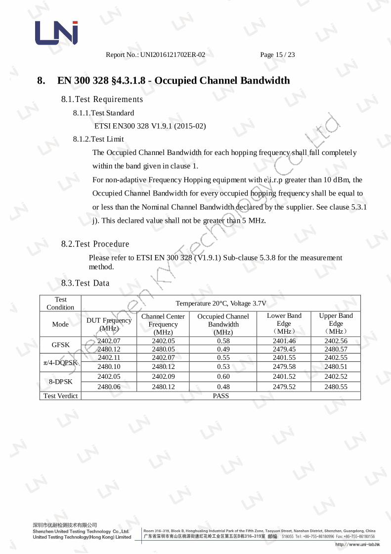
8. EN 300 328 §4.3.1.8 - Occupied Channel Bandwidth
8.1.Test Requirements
8.1.1.Test Standard
ETSI EN300 328 V1.9.1 (2015-02)
8.1.2.Test Limit
The Occupied Channel Bandwidth for each hopping frequency shall fall completely
within the band given in clause 1.
For non-adaptive Frequency Hopping equipment with e.i.r.p greater than 10 dBm, the
Occupied Channel Bandwidth for every occupied hopping frequency shall be equal to
or less than the Nominal Channel Bandwidth declared by the supplier. See clause 5.3.1
j). This declared value shall not be greater than 5 MHz.
8.2.Test Procedure
Please refer to ETSI EN 300 328 (V1.9.1) Sub-clause 5.3.8 for the measurement
method.
8.3.Test Data
Test Condition
Temperature 20°C, Voltage 3.7V
Mode DUT Frequency
(MHz)
Channel Center Frequency
(MHz)
Occupied Channel Bandwidth
(MHz)
Lower Band Edge
(MHz)
Upper Band Edge
(MHz)
GFSK 2402.07 2402.05 0.58 2401.46 2402.56
2480.12 2480.05 0.49 2479.45 2480.57
π/4-DQPSK 2402.11 2402.07 0.55 2401.55 2402.55
2480.10 2480.12 0.53 2479.58 2480.51
8-DPSK 2402.05 2402.09 0.60 2401.52 2402.52
2480.06 2480.12 0.48 2479.52 2480.55
Test Verdict PASS

Report No.: UNI2016121702ER-02 Page 16 / 23
9. EN 300 328 §4.3.1.9 - Transmitter unwanted emissions in the out-of-
band domain
9.1.Test Requirements
9.1.1.Test Standard
ETSI EN300 328 V1.9.1 (2015-02)
9.1.2.Test Limit
The transmitter unwanted emissions in the out-of-band domain but outside the
allocated band, shall not exceed the values provided by the mask in figure 1.
NOTE: Within the 2 400 MHz to 2 483,5 MHz band, the Out-of-band emissions are
fulfilled by compliance with the Occupied Channel Bandwidth requirement in clause
4.3.1.8.
9.2.Test Procedure
Please refer to ETSI EN 300 328 (V1.9.1) Sub-clause 5.3.9 for the measurement
method.
9.3.Test Data
Report No.: UNI2016121702ER-02 Page 17 / 23
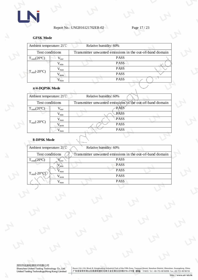
GFSK Mode
Ambient temperature: 21℃ Relative humidity: 60%
Test conditions Transmitter unwanted emissions in the out-of-band domain
Tnom(20°C) Vnor PASS
Tmin(-20°C)
Vmin PASS
Vmax PASS
Vnom PASS
Vmax PASS
π/4-DQPSK Mode
Ambient temperature: 21℃ Relative humidity: 60%
Test conditions Transmitter unwanted emissions in the out-of-band domain
Tnom(20°C) Vnor PASS
Tmin(-20°C)
Vmin PASS
Vmax PASS
Vnom PASS
Vmax PASS
8-DPSK Mode
Ambient temperature: 21℃ Relative humidity: 60%
Test conditions Transmitter unwanted emissions in the out-of-band domain
Tnom(20°C) Vnor PASS
Tmin(-20°C)
Vmin PASS
Vmax PASS
Vnom PASS
Vmax PASS

Report No.: UNI2016121702ER-02 Page 18 / 23
10. EN 300 328 §4.3.1.10 - Transmitter unwanted emissions in the
spurious domain
10.1.Test Requirements
10.1.1.Test Standard
ETSI EN300 328 V1.9.1 (2015-02)
10.1.2.Test Limit
Frequency range
Maximum power,
e.r.p. (≤ 1 GHz)
e.i.r.p. (> 1 GHz)
(dBm)
Bandwidth
30MHz to 47MHz -36 100kHz
47MHz to 74MHz -54 100kHz
74MHz to 87.5MHz -36 100kHz
87.5MHz to 118MHz -54 100kHz
118MHz to 174MHz -36 100kHz
174MHz to 230MHz -54 100kHz
230MHz to 470MHz -36 100kHz
470MHz to 862MHz -54 100kHz
862MHz to 1GHz -36 100kHz
1GHz to 12.75GHz -30 1MHz
10.2.Test Procedure
Please refer to ETSI EN 300 328 (V1.9.1) Sub-clause 5.3.10 for the measurement
method.
10.3.Test Data
Ambient temperature: 21℃ Relative humidity: 60%
Test mode Transmitter unwanted emissions in the spurious domain
GFSK PASS
π/4-DQPSK PASS
8-DPSK PASS
Report No.: UNI2016121702ER-02 Page 19 / 23
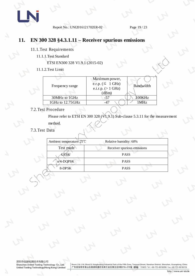
11. EN 300 328 §4.3.1.11 – Receiver spurious emissions
11.1.Test Requirements
11.1.1.Test Standard
ETSI EN300 328 V1.9.1 (2015-02)
11.1.2.Test Limit
Frequency range
Maximum power,
e.r.p. (≤ 1 GHz)
e.i.r.p. (> 1 GHz)
(dBm)
Bandwidth
30MHz to 1GHz -57 100KHz
1GHz to 12.75GHz -47 1MHz
7.2.Test Procedure
Please refer to ETSI EN 300 328 (V1.9.1) Sub-clause 5.3.11 for the measurement
method.
7.3.Test Data
Ambient temperature: 21℃ Relative humidity: 60%
Test mode Receiver spurious emissions
GFSK PASS
π/4-DQPSK PASS
8-DPSK PASS
Report No.: UNI2016121702ER-02 Page 20 / 23
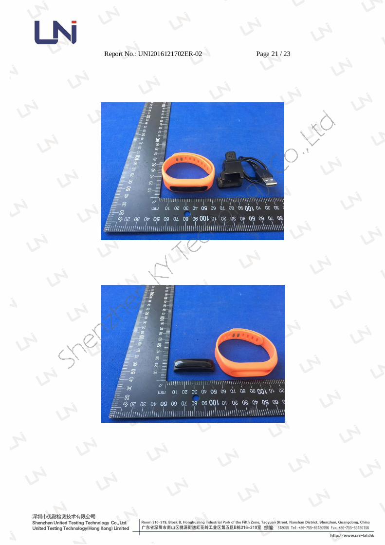
APPENDIX I
Report No.: UNI2016121702ER-02 Page 21 / 23

Report No.: UNI2016121702ER-02 Page 22 / 23

Report No.: UNI2016121702ER-02 Page 23 / 23
***End of the Report***