shen, hendry.pdf
TRANSCRIPT

FACULTY OF SCIENCE AND TECHNOLOGY
MASTER'S THESIS
Study program/specialization: Petroleum Engineering / Drilling
Spring semester, 2007
Open
Author: Hendry Shen
…………………………………………
(signature author)
Instructor: Supervisor(s): Bernt Åadnøy (University supervisor)
Deborah South, Gunnar Rørnes (Chevron Norge A.S Supervisors)
Title of Master's Thesis:
FEASIBILITY STUDIES OF COMBINING DRILLING WITH CASING
AND EXPANDABLE CASING
ECTS: 30 Subject headings:
• Drilling with casing • Expandable casing • Combined method
Pages : 112 + attachments/other : 0
Stavanger, 12th June 2007
ABSTRACT
Nowadays, the biggest challenges in the oil business are the cost of operations versus the
sizes of the prospect. We are drilling smaller targets and over the last few years, rig cost,
service company rates and materials have gone up significantly in accordance to the oil
price. Industry is continuously searching for new technologies to make the drilling of well
safer, more efficient and cheaper. This thesis explores the possibilities of combining
existing technologies to solve these challenges.
Drilling with casing (DwC) is using standard casing as the drillstring, and leaving it in
place to case the well. It has almost no limitations and has a potential of saving 20 – 30%
of rig time by eliminating drillstring tripping and also minimizing downhole problems.
With expandable technology, expanded casing can provide a larger diameter of the
production casing. This can increase the productivity.
Since both technologies have the same operational procedure, they could be combined
into one operation. The concept is to use expandable casing as drillstring which will be
expanded when the target depth is reached. To be able to expand the casing, one needs to
drill with an underreamer to obtain a bigger hole and the BHA must be changed from a
drilling into an expandable BHA.
The conclusion of this thesis is that the drilling with expandable casing concept is
possible. However, there are some technology challenges, especially on tools and on the
strength of post expansion material. Limitations on drilling parameters such as: dog leg
severity, RPM, mud properties etc also need to be considered to achieve a good expansion
result.
of 112 2
The case example analyzed, indicates that we can save almost 23% of the operation time
by running this combined technology. Expenses can be reduced through lowered rig costs
and the operational risk can be mitigated. A better understanding of the technology and
operational procedures will help to further reduce the risks and make the technology more
acceptable. If this new method succeeds, there will have a high potential for cost savings,
higher production and better well control.
ACKNOWLEDGEMENT
Knowledge is a power.
It can break barriers, build the personality, and give us something to contribute to the
society. I believe every single child brings their own hope, gift and inspiration. Teach and
give them a chance and they will find their way. In this acknowledgement I would like to
dedicate my special appreciation to these special people who has taught me a lot and
given me chances:
First to my three supervisors in Chevron Norge:
Lars Øyno, thank for believing in my idea and providing me a way to realize it through
this thesis. To my lovely friend and supervisor South Debbie, for teaching me in how to
present my thought in systematic and good-writing ways and Gunnar Rørnes, who
teaches me in how to package it into an understandable document. Because of their
patient, efforts and time, I have learned and improved myself.
There are too many people I would like to thank for their warm welcome in Houston.
Especially to John Lofton and David Dowell, who always have a time for me. Thank for
your knowledge sharing and companion to the services companies. Grant prideco,
Weatherford, Enventure, Tesco thank for your welcome and information. Moreover, to all
Chevron Houston employees for their friendship and help to make my life more exciting
there.
Tusen takk to my university supervisor Bernt Åadnøy for his positive support and belief
in me, my classmates who have been encouraging each other to finish the thesis.
Moreover, my sincere gratitude to NORAD and Department of Petroleum Engineering at
University of Stavanger for the learning opportunities. Having these experiences to study
in Norway, meet a lot of good people and travel to many new places, I always consider it
as my blessing….
Please consider the environment by printing this thesis both sides
of 112 3
TABLE OF CONTENTS
Abstract 2
Acknowledgements 3
Table of contents 4
List of Figures 6
List of Tables 8
1. Introduction
1.1 Background 9
1.2 The purposes of the thesis 10
1.3 How the report is built 10
2. Relevant Theory and applications
2.1 Drilling with casing 11
2.1.1 Advantages and disadvantages of DwC 12
2.1.2 Industry overview 14
2.1.2.1 Casing drilling 14
2.1.2.2 Liner drilling 19
2.1.3 DwC engineering consideration 20
2.2 Expandable casing 21
2.2.1 Introduction 21
2.2.2 Material overview 24
2.2.3 Industry overview 26
2.3 Combination of drilling with expandable casing 37
3. Analysis and Result
3.1 Analysis of the drilling-expansion methodology 38
3.2 Analysis of the casing connections 42
3.3 Analysis of the expansion performance post-drilling 45
3.4 Analysis of the casing properties post-expansion 50
3.5 Analysis of the cost 56
3.6 Analysis of the operational limitations and risks 58
of 112 4
4. Discussion
4.1 Discussion of the drilling-expansion methodology 63
4.2 Discussion of the casing connections 72
4.3 Discussion of the expansion performance post-drilling 76
4.4 Discussion of the casing properties post-expansion 83
4.5 Discussion of the cost 95
4.6 Discussion of the operational limitation and risks 100
5. Applications of technology
5.1 Wells which drill through trouble zones 104
5.2 Wells which have low formation pressure 106
5.3 Wells where higher production rates are needed 106
5.4 Wells which are drilled on land or in shallow water 108
6. Conclusion 109
of 112 5
7. References 110

LIST OF FIGURES
Fig 2.1 - Drilling with casing systematic 11 Fig 2.2 - Casing drive system 15 Fig 2.3 - Casing drive system (real) 15 Fig 2.4 - Power catwalk for DwC 16 Fig 2.5 - Non-retrievable drilling bit 17 Fig 2.6 - Retrievable drilling bit 17 Fig 2.7 - Retrievable Box assembly 18 Fig 2.8 - Wing underreamer and bit 18 Fig 2.9 - Retrievable Pin assembly 19 Fig 2.10 - Well schematic for conventional and monobore 21 Fig 2.11 - Force acting on material 24 Fig 2.12 - Stress-Strain relationship 24 Fig 2.13 - Expandable material 26 Fig 2.14 - Expandable tubing and cone 26 Fig 2.15 - Enventure Open Hole sequences 30 Fig 2.16 - Cased Hole Enventure sequences 31 Fig 2.17 - Baker expandable cone 32 Fig 2.18 - Baker expansion 33 Fig 2.19 - Corrugated casing 34 Fig 2.19 - Weatherford open hole, expansion sequence 35 Fig 2.21 - Weatherford compliant cone 35 Fig 2.22 - Weatherford expandable technologies – additional information 36 Fig 3.1 - PIN of retrieve tool 39 Fig 3.2 - BOX of retrieve tool 39 Fig 3.3 - Wing underreamer 40 Fig 3.4 - Bushing bit 40 Fig 3.5 - Reelwell system configuration 41 Fig 3.6 - Reelwell concept drawing 41 Fig 3.7 - The casing connection type – flush joint 42 Fig 3.8 - The casing connection type – coupling joint 42 Fig 3.9 - Contingency Plan Profile 43 Fig 3.10 - Comparison of collapse rating 44 Fig 3.11 - Comparison of burst rating 44
of 112 6 of 112
Fig 3.12 - Casing scraper and brush 46
of 112 7 of 112
Fig 3.13 - Different between actual and survey well path 47 Fig 3.14 - Inclination survey drilled with 4½” and 5”casing and full hole bits 47 Fig 3.15 - Off bottom torque without stabilizer 48 Fig 3.16 - Off bottom torque with stabilizer 48 Fig 3.17 - Schematic of whirl 49 Fig 3.18 - Comparison of expansion methods 52 Fig 3.19 - Graphical represent for collapse rating between pre-post expansions 55 Fig 3.20 - General casing hanger design 58 Fig 3.21 - Risk matrix for combined method 62 Fig 4.1 - Casing drilling footage 65 Fig 4.2 - Comparison of trouble zone on DwC 65 Fig 4.3 - Smear effect profiles 66 Fig 4.4 - Cutting comparison between DwC and conventional drilling 66 Fig 4.5 - Smear effect experiment on testing wells 67 Fig 4.6 - Comparison between DwC and conventional drilling based on drill test 68 Fig 4.7 - DWC/C-SR connection 74 Fig 4.8 - Bending stress from pipe curvature 79 Fig 4.9 - Alternating stress for curve drillstring 80 Fig 4.10 - Axial stress concentration factor for die mark 82 Fig 4.11 - Case well profile 83 Fig 4.12 - Hook load profile for case example 85 Fig 4.13 - Torque profile for case example 86 Fig 4.14 - Erkine field W-1 Mud Log 89 Fig 4.15 - Comparison of normalized collapse from different casing 92 Fig 4.16 - 3D image from simulation result of caliper log 93 Fig 4.17 - Reference case DwC plus SET separately 96 Fig 4.18 - Comparison case DwC plus SET continuously 98 Fig 4.19 - Comparison case using monobore 98 Fig 4.20 - Hanger system on subsea wellhead 101 Fig 5.1 - Well profile for the trouble zones 105 Fig 5.2 - Drilling with expandable casing sequence for the trouble zones 105 Fig 5.3 - Well profile for optimizing ID size 107 Fig 5.4 - Drilling with expandable casing sequence for optimizing ID size 107 Fig 5.5 - Well profile using smaller rig 109 Fig 5.6 - Drilling with expandable casing sequence on smaller rig size 109
LIST OF TABLES
Table 2.1 - Comparison monobore and conventional 23
Table 2.2 - Side by side comparison of expandable methods 29
Table 3.1 - Rellwell System 41
Table 3.2 - Enventure connection properties 43
Table 3.3 - Case well parameter 43
Table 3.4 - Comparisons between connections with body 51
Table 3.5 - Pre and Post expansion-casing properties (Data is provided by Enventure) 53
Table 3.6 - Comparison of burst and collapse for pre-post expansion casing 55
Table 3.7 - Costs for conventional rig and equipments 56
Table 3.8 - Costs for drilling with casing operations 57
Table 3.9 - Costs for expandable casing operations 57
Table 4.1 - Comparison Enventure and Hydril connection 72
Table 4.2 - Recorded BHP of Erskine 90
Table 6.1 - Pros and Cons of the combined technology 109
of 112 8

CHAPTER I
INTRODUCTION
1.1 BACKGROUND
Nowadays, higher oil price and world demands on oil and gas supplies, have allowed the
oil companies increase their production. To meet the demand, oil companies also try to
explore new reservoir possibilities in difficult area such as deep water, HPHT reservoir
and salt dome reservoir. Most of the reservoirs that were considered as non-economic are
being developed now. The decisions to increase the production and to drill in the
challenging condition bring consequents on technology challenges.
There are two technologies on drilling which could become the solution for these
challenges; drilling with casing and expandable casing. These two technologies that were
operated separately show promising results even the developments are still on going. On
this thesis author would like to bring a step further by seeing the possibilities of
combining these two technologies both technical and cost effective. The thesis also
included a simple operation risks analysis.
Drilling with casing (DwC) is using standard oilfield casing as the drillstring, and leaving it
in place to case the well. It has almost no limitations and could save 20 – 30% rig time by
eliminating drillstring tripping. Additionally, it also minimizes downhole problems (loss of
circulation, kick and wellbore instability issues). Casing drilling delivers all of the
functionality of conventional drillpipe drilling. This safer and more cost effective process
will change the way we drill the wells.
Expandable technology is next step of the development of mono-diameter technology. The
technology has a potential to increase productivity, extend the reach of the well, and to
make completion easier. Mono-diameter wellbore will become the future shape of oil well
construction.
of 112 9
Since both technologies have the same operational procedure, they could be combined
into one operation. The concept is to use expandable casing as drillstring which will be
expanded when the target depth is reached. Since both technologies are expensive, the
author has studied a new casing configuration that could be more cost competitive. In
additional, it should be remembered that the possibility of combining its disadvantages
and limitations of both technologies also exist.
As our education institution is in an independent position, which gets sponsored by Oil
Company and gets supported by many services companies, we are free to access and to
evaluate the integration of both applications. Moreover, we will contribute the result of
this research back to the E&P business. If the new methods investigated succeed, there
will be a potential of cost saving, higher production and better well control that might
become the answer for the drilling challenges.
1.2 PURPOSES OF THE THESIS
There are two main purposes of this thesis:
1 To see the feasibility of combining drilling with casing and expandable casing
methods. The analysis will be done both on technical and cost effective point of view.
2 To study and propose the appropriate application for this method.
3
There are few questions that need to be answered for analysis:
1. How can this combined method works?
2. Are the expandable casing connections strong enough for drilling with casing?
3. How does the expandable casing perform after being used for drilling?
4. What are the expandable casing properties that need to be considered?
5. Is the cost competitive?
6. Are there any limitations and risks on this process?
1.3 HOW THE REPORT IS BUILT
The report is built in accordance to this structure;
CHAPTER 1: Introduction
CHAPTER 2: Relevant theory
CHAPTER 3: Analysis and results
CHAPTER 4: Discussion
CHAPTER 5: Applications of technology
Chapter I - Introduction of 112 10
CHAPTER 6: Conclusions

CHAPTER II
RELEVANT THEORY
The combination theory which author calls “Drilling with expandable casing” consists of
two main concepts; Drilling with casing and Expandable casing. Since there is no exact
theory for drilling with expandable casing, here is presented separately supporting theory
for drilling with casing and expandable casing.
2.1 DRILLING WITH CASING THEORY [2]
Drilling with Casing (DwC) is a
process of using standard oil field
casing for the drillstring, so the well
is simultaneously drilled and cased
(figure 2.1). Both surface and
downhole tools and components are
necessary to make this process
possible.
While many of the functions and
activities are similar to the
conventional drilling process, there
are sufficiently different to warrant
special drilling consideration. The
drillpipe and drill collars are used and
the logging, coring and perforating
operations are the same with
conventional. To meet the loading
and bottom hole criteria, the
modifications are done in surface
lifting facility and bit.
BOP
PILOT HOLE
UNDERREAMER
CREATING THE TOOLS OF TOMORROW BY WHAT IS
DREAMED OF TODAY
of 112 11
DRILL PIPE
DRILL IN NIPPLE
CASING
CASING SHOE
BIT
ROTATING HEAD
LINER
DIVERTER LINE
Figure 2.1-Drilling with systematic [20]

The connections were not very robust and over time, drillpipe evolved as stronger and
stronger connection was developed and the resulting casing was not been used for drilling.
In 1950’s the idea of drilling with casing re-emerged, while there were many potential
advantages of this technique, it was not commercially accepted because of the limitations in
material and cutting tools that available at that moment. But the initiatives to development
facilitated the process sufficiently so that it will become a successful commercial service in
the future.
A conventional drillstring must be tripped out of the hole each time the bit or bottom hole
assembly needs to be changed, the casing point is reached or the bore hole needs to be
“conditioned”. Casing is then run into the well as a completely separate process to provide
permanent access to the well bore. DwC systems integrate the drilling and casing process to
provide a more efficient well construction system by eliminating these drillstring trips and
allowing the well to be simultaneously drilled and cased.
2.1.1 Advantages and disadvantages of Drilling with casing (DwC)
Advantages of DwC
• Avoiding possibilities of hole problems by eliminating tripping process
Saving result from eliminating cost related to purchasing, handling, inspecting,
transporting and tripping the drillstring, reducing hole problems that are associated with
tripping, reducing trouble time associated with lost circulation, eliminating trouble time
for running casing and the problems within, and also saving on rig equipment capital
costs and operating costs could be achieved. The potential savings from reducing
drillstring tripping and handling can be identified quite easily for any particular
situation, but the savings from reducing hole problems are more difficult to quantify.
There are many situations where problems such as lost circulation, well control
incidents and borehole stability problems can be directly attributed to tripping the
drillstring.
Chapter II –Relevant Theory of 112 12
• Avoiding possibilities of running casing problems
In other cases it is difficult to run the casing after the conventional drillstring is tripped
out because of poor borehole quality. Some of theses difficulties are related to
boreholes stability problems directly attributed to drillstring vibration, while others are

related more to the particular well geometry and formation condition being drilled. The
DwC system reduces these incidents by installing the casing immediately as the well is
drilled.
• Drilling with Casing can make the well deeper
DwC offers the opportunity to drive the casing setting depth deeper than may be
obtained with the conventional drilling. The need to drill with a sufficient mud weight
to provide a trip margin before tripping out the drillstring to run casing is eliminated.
Especially in deep wells the pore pressure and fracture pressure has a close margin.
• Drilling with casing can reduce the lost circulation problems
The DwC process also mechanically enhances the wellbore wall “filter cake” to reduce
lost circulation. The effect of reducing the loss circulation in DwC is not fully
explained, but it seems to be caused by the casing mechanically plastering drilled
solids into the wall of the borehole. This plugs small fractures in the wall and reduces
the effective permeability at the rock face. This affect, which called ”smear effect”,
also reduces fluid flow into the wellbore, making well control safer for casing drilled
well.
• The DwC process is safer than the conventional drilling process
Personal exposure to pipe handling during tripping and casing running operation is
reduced. The DwC process also provides a circulation path to the bottom of the well at
all times which reduces risk associated with well control operation.
• Under balance drilling can be applied using DwC for over pressured formation.
Under balance drilling can be applied with the DwC system for drilling into over
pressured formation with a lower mud weight that this method cannot be implemented
with conventional system. With appropriate well design, surface equipment and
planning, the dynamic friction of the flowing mud can be used for well control.
Chapter II –Relevant Theory of 112 13
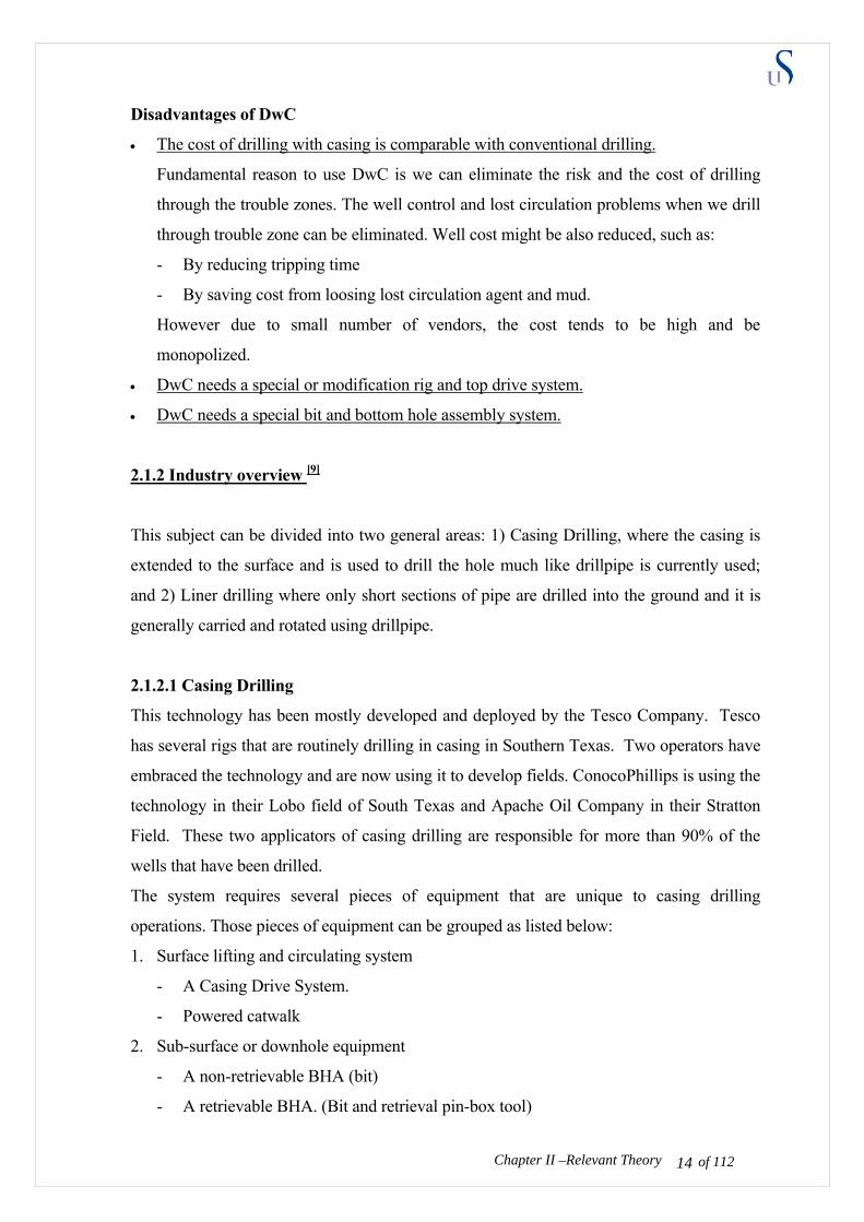
Disadvantages of DwC
• The cost of drilling with casing is comparable with conventional drilling.
Fundamental reason to use DwC is we can eliminate the risk and the cost of drilling
through the trouble zones. The well control and lost circulation problems when we drill
through trouble zone can be eliminated. Well cost might be also reduced, such as:
- By reducing tripping time
- By saving cost from loosing lost circulation agent and mud.
However due to small number of vendors, the cost tends to be high and be
monopolized.
• DwC needs a special or modification rig and top drive system.
• DwC needs a special bit and bottom hole assembly system.
2.1.2 Industry overview [9]
This subject can be divided into two general areas: 1) Casing Drilling, where the casing is
extended to the surface and is used to drill the hole much like drillpipe is currently used;
and 2) Liner drilling where only short sections of pipe are drilled into the ground and it is
generally carried and rotated using drillpipe.
2.1.2.1 Casing Drilling
This technology has been mostly developed and deployed by the Tesco Company. Tesco
has several rigs that are routinely drilling in casing in Southern Texas. Two operators have
embraced the technology and are now using it to develop fields. ConocoPhillips is using the
technology in their Lobo field of South Texas and Apache Oil Company in their Stratton
Field. These two applicators of casing drilling are responsible for more than 90% of the
wells that have been drilled.
The system requires several pieces of equipment that are unique to casing drilling
operations. Those pieces of equipment can be grouped as listed below:
1. Surface lifting and circulating system
- A Casing Drive System.
- Powered catwalk
2. Sub-surface or downhole equipment
- A non-retrievable BHA (bit)
Chapter II –Relevant Theory of 112 14
- A retrievable BHA. (Bit and retrieval pin-box tool)

Each of these pieces of equipment is required to conduct Casing drilling. Each will be
described briefly.
The casing drives system.
The Casing Drive assembly is used to grab and seal
against the casing so torque can be transmitted to the
casing and mud can be pumped through it. Tesco
uses two different drive assemblies, depending on the
size of casing being handled. An external gripping
system is used for casing sized from 4 1/2” to 8 5/8”
and in internal gripping system for 7” to 20” pipe.
Both assemblies use swab-like cups to seal on the
inside of the casing so mud can be circulated down
the pipe (figure 2.2).
The gripper assemblies are hydraulically controlled
and have a 40K ft-lbf torque rating. The external
gripping mechanism has a 350 tons API 8C load
rating while the internal system is rated at 500 tons.
These assemblies both mate to a Top-Drive assemble
that is required conducting the Casing Drilling
operations.
The Top-Drive supplies the torque through these Drive assemblies to make-up the casing
connections and drill. A modified elevator link-tilt mechanism is part of the Casing Drive
assembly, and used to pick
the casing up from the
“V”-door area and to hold
the casing as it is screwed
into the next piece hanging
in the slips (figure 2.3).
The normal procedure is to
lift the casing with the link-
Chapter II –Relevant Theory of 112 15
Figure 2.2-Casing drive system [9]
Figure 2.3-Casing Drive system [9]
tilt mechanism and stab the pin of the casing joint into the box of the casing hanging in the
slips. Once stabbed, the top drive is lowered, stabbing the drive assembly into the new joint
of casing. The drive assembly is then activated to grip the casing and the top drive is used
to spin the casing into the box. Final make-up is also accomplished with the top drive.
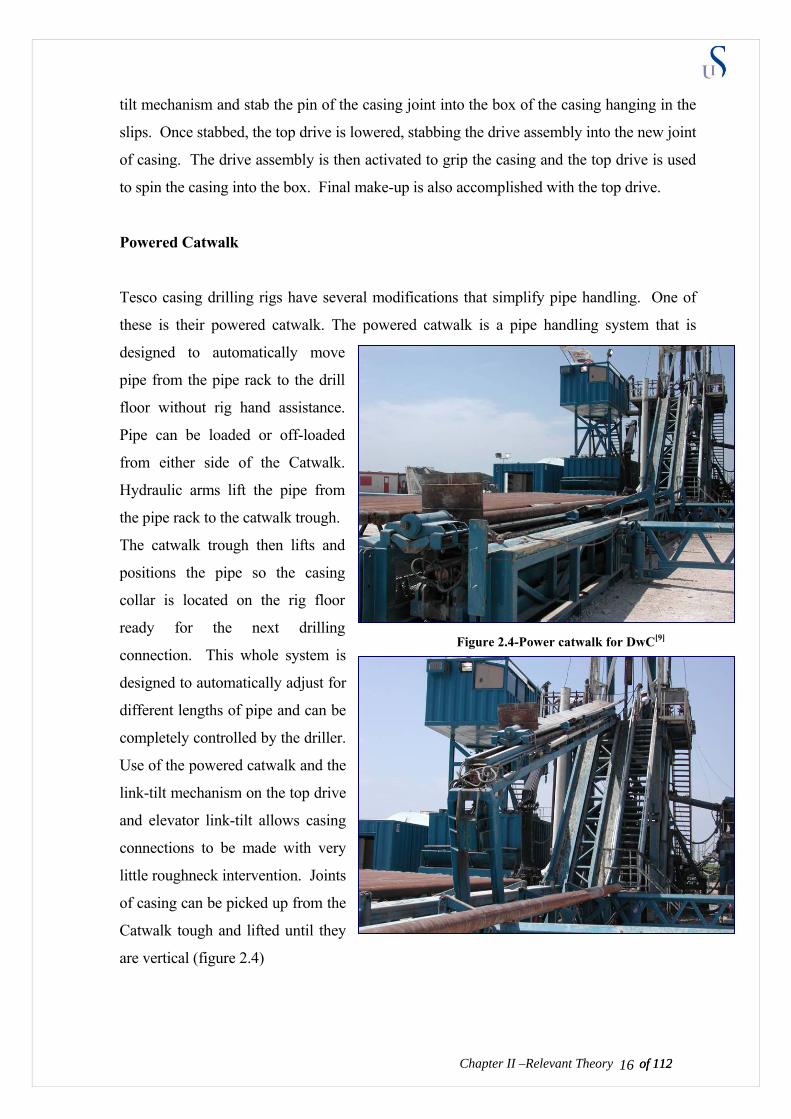
Powered Catwalk
Tesco casing drilling rigs have several modifications that simplify pipe handling. One of
these is their powered catwalk. The powered catwalk is a pipe handling system that is
designed to automatically move
pipe from the pipe rack to the drill
floor without rig hand assistance.
Pipe can be loaded or off-loaded
from either side of the Catwalk.
Hydraulic arms lift the pipe from
the pipe rack to the catwalk trough.
The catwalk trough then lifts and
positions the pipe so the casing
collar is located on the rig floor
ready for the next drilling
connection. This whole system is
designed to automatically adjust for
different lengths of pipe and can be
completely controlled by the driller.
Use of the powered catwalk and the
link-tilt mechanism on the top drive
and elevator link-tilt allows casing
connections to be made with very
little roughneck intervention. Joints
of casing can be picked up from the
Catwalk tough and lifted until they
are vertical (figure 2.4)
of 112 16Chapter II –Relevant Theory of 112
Figure 2.4-Power catwalk for DwC[9]
of 112 17Chapter II –Relevant Theory of 112
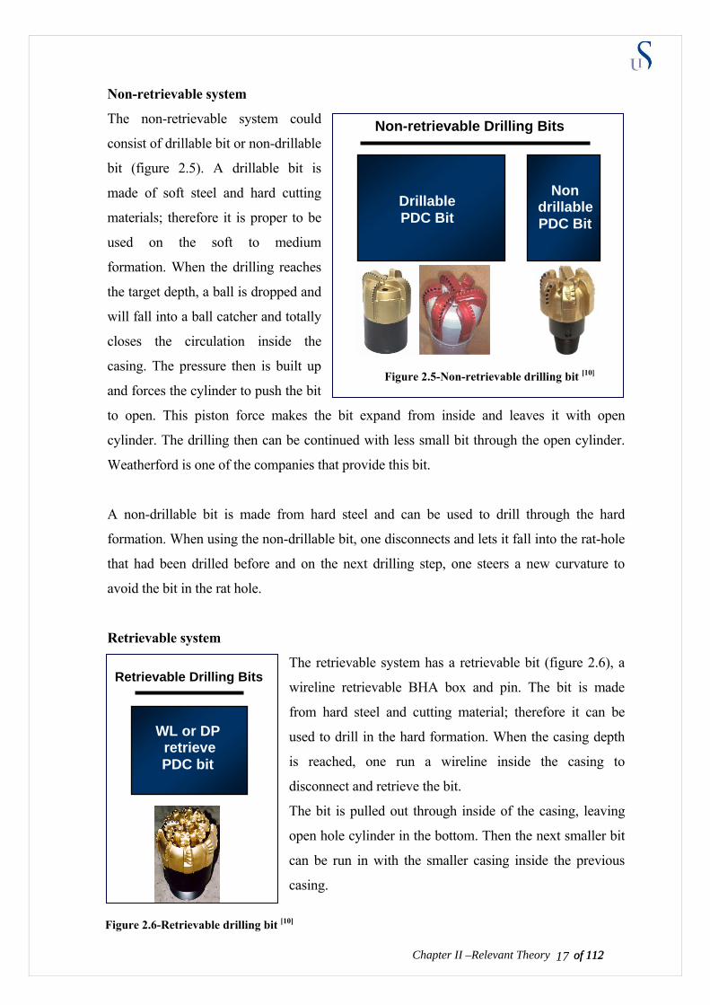
Non-retrievable system
The non-retrievable system could
consist of drillable bit or non-drillable
bit (figure 2.5). A drillable bit is
made of soft steel and hard cutting
materials; therefore it is proper to be
used on the soft to medium
formation. When the drilling reaches
the target depth, a ball is dropped and
will fall into a ball catcher and totally
closes the circulation inside the
casing. The pressure then is built up
and forces the cylinder to push the bit
to open. This piston force makes the bit expand from inside and leaves it with open
cylinder. The drilling then can be continued with less small bit through the open cylinder.
Weatherford is one of the companies that provide this bit.
A non-drillable bit is made from hard steel and can be used to drill through the hard
formation. When using the non-drillable bit, one disconnects and lets it fall into the rat-hole
that had been drilled before and on the next drilling step, one steers a new curvature to
avoid the bit in the rat hole.
Retrievable system
The retrievable system has a retrievable bit (figure 2.6), a
wireline retrievable BHA box and pin. The bit is made
from hard steel and cutting material; therefore it can be
used to drill in the hard formation. When the casing depth
is reached, one run a wireline inside the casing to
disconnect and retrieve the bit.
The bit is pulled out through inside of the casing, leaving
open hole cylinder in the bottom. Then the next smaller bit
can be run in with the smaller casing inside the previous
casing.
Drillable PDC Bit
Non drillable
PDC Bit
Non-retrievable Drilling Bits
Figure 2.5-Non-retrievable drilling bit [10]
WL or DP retrieve PDC bit
Retrievable Drilling Bits
Figure 2.6-Retrievable drilling bit [10]
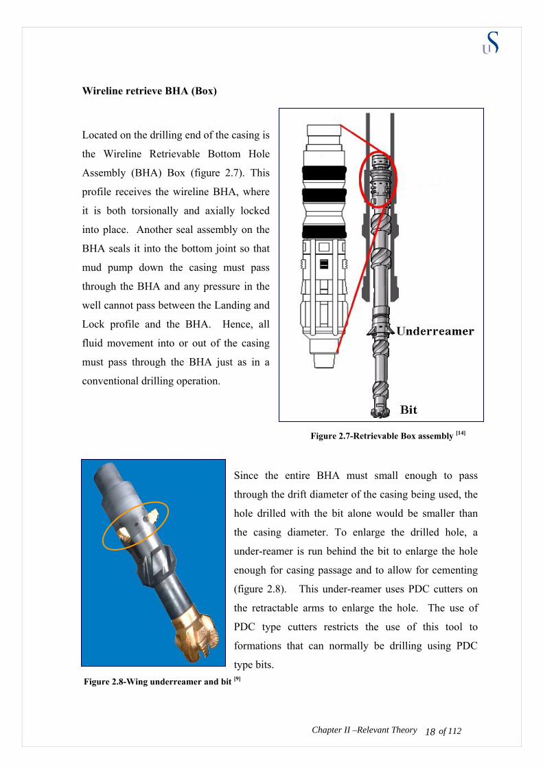
Wireline retrieve BHA (Box)
Located on the drilling end of the casing is
the Wireline Retrievable Bottom Hole
Assembly (BHA) Box (figure 2.7). This
profile receives the wireline BHA, where
it is both torsionally and axially locked
into place. Another seal assembly on the
BHA seals it into the bottom joint so that
mud pump down the casing must pass
through the BHA and any pressure in the
well cannot pass between the Landing and
Lock profile and the BHA. Hence, all
fluid movement into or out of the casing
must pass through the BHA just as in a
conventional drilling operation.
Since the entire BHA must small enough to pass
through the drift diameter of the casing being used, the
hole drilled with the bit alone would be smaller than
the casing diameter. To enlarge the drilled hole, a
under-reamer is run behind the bit to enlarge the hole
enough for casing passage and to allow for cementing
(figure 2.8). This under-reamer uses PDC cutters on
the retractable arms to enlarge the hole. The use of
PDC type cutters restricts the use of this tool to
formations that can normally be drilling using PDC
type bits.
Chapter II –Relevant Theory of 112 18
Figure 2.7-Retrievable Box assembly [14]
Figure 2.8-Wing underreamer and bit [9]
High compressive strength rocks that require roller cone or diamond type bits may not be
drillable with this type of under-reamer. This is one of the limitations of using the
retrievable BHA assembly.
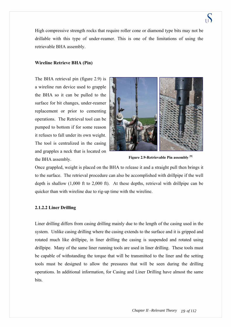
Wireline Retrieve BHA (Pin)
The BHA retrieval pin (figure 2.9) is
a wireline run device used to grapple
the BHA so it can be pulled to the
surface for bit changes, under-reamer
replacement or prior to cementing
operations. The Retrieval tool can be
pumped to bottom if for some reason
it refuses to fall under its own weight.
The tool is centralized in the casing
and grapples a neck that is located on
the BHA assembly.
Once grappled, weight is placed on the BHA to release it and a straight pull then brings it
to the surface. The retrieval procedure can also be accomplished with drillpipe if the well
depth is shallow (1,000 ft to 2,000 ft). At these depths, retrieval with drillpipe can be
quicker than with wireline due to rig-up time with the wireline.
2.1.2.2 Liner Drilling
Liner drilling differs from casing drilling mainly due to the length of the casing used in the
system. Unlike casing drilling where the casing extends to the surface and it is gripped and
rotated much like drillpipe, in liner drilling the casing is suspended and rotated using
drillpipe. Many of the same liner running tools are used in liner drilling. These tools must
be capable of withstanding the torque that will be transmitted to the liner and the setting
tools must be designed to allow the pressures that will be seen during the drilling
operations. In additional information, for Casing and Liner Drilling have almost the same
bits.
Chapter II –Relevant Theory of 112 19
Figure 2.9-Retrievable Pin assembly [9]
2.1.3 CwD Engineering consideration
Considerations such as borehole stability, well control, casing setting depth, directional
planning, and bit selection are treated much like they are conventional drilling. One
significant difference is that the casing may be subjected to different stresses in CwD
situation that it is for conventional uses. In additional, hydraulic power, lost circulation,
cuttings transport, well cleaning, lateral vibration (whirl), torsional oscillation and
directional control also become the main concern in drilling with casing due to the weight
and bigger size of casing.
Chapter II –Relevant Theory of 112 20
2.2 EXPANDABLE CASING THEORY
Two challenges facing on oil and gas industry are 1) accessing new reservoirs that currently
cannot be reached economically, 2) maintaining profitable production from producing older
field. Expandable steel technology, considered as one of the most exciting technologies that
have emerged out of in the oilfield over the last ten years, may be crucial to meet this
industry challenge.
2.2.1 Introduction
Well geometry is generally split into two main types: monobore and conventional
geometry. Conventional wells are lined with production casing which is cemented in place.
Hydrocarbons from the producing zones are brought to the surface in a separate, smaller
piping system (tubing) that is installed inside the production casing.
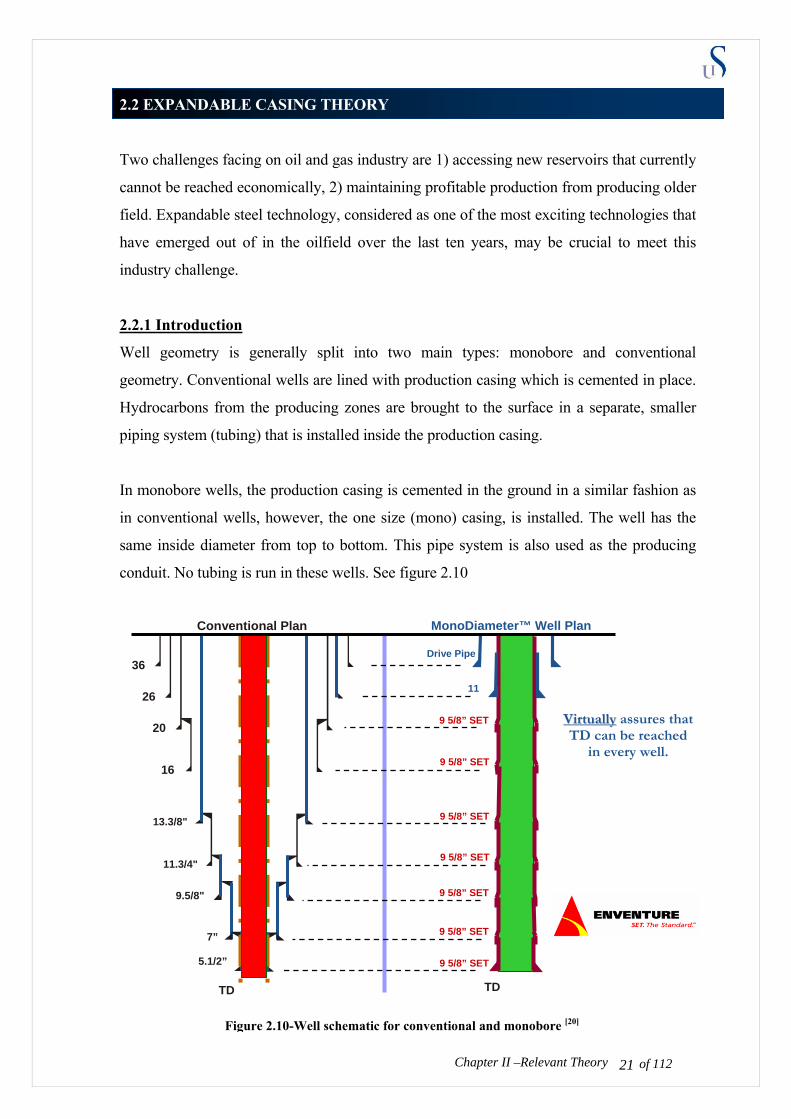
In monobore wells, the production casing is cemented in the ground in a similar fashion as
in conventional wells, however, the one size (mono) casing, is installed. The well has the
same inside diameter from top to bottom. This pipe system is also used as the producing
conduit. No tubing is run in these wells. See figure 2.10
MonoDiameter™ Well Plan
TD
Conventional Plan
36
16
11.3/4"
20
7”
9.5/8"
5.1/2”
13.3/8"
26
TD
Chapter II –Relevant Theory
9 5/8” SET
9 5/8” SET
9 5/8” SET
9 5/8” SET
Drive Pipe
11
9 5/8” SET
9 5/8” SET
9 5/8” SET
VViirrttuuaallllyy assures that TD can be reached
in every well.
of 112 21
Figure 2.10-Well schematic for conventional and monobore [20]
Monobore wells are defined as wells with long monodiameter sections. Multiclad wells are
defined as wells where the casing is expanded to the inner diameter of the previous casing,
so the hole size reduction is only double the wall thickness of the casing.
Why monobore is important?
Nowadays, higher oil price and world demands on oil and gas supplies, has allowed the
company to produce more oil from the same field. For a number of years, the exploration
and production industry has sought to prove the feasibility of monobore as an advantageous
solution to conventional casing designs. Monobore will allow higher production rate and
reach deeper depth with possibilities to do sidetrack or multilateral well. In other word
monobore will become solution to bring more profit for the oil company.
Ideally in High-pressure high temperature (HPHT) or deep water well, we need to have
higher flow rates to compensate the expensive investment. The additional goals of both
monobore and multiclad wells besides to achieve the higher production rate are:
- to reduce casing configuration (less steel consumption and cost for installation)
- to allow the use of smaller risers on offshore rigs and smaller surface equipment
capacity/BOP.
All of these goals will significantly increase the cost saving.
We can obtain a monobore shape with three concepts, which are:
1. We drill with the same size of casing to the TD. This concept is impossible due to the
limitation on surface power, forces and loading.
2. We use solid expandable tubular (SET) to get bigger diameter. This method could be
applied for casing or liner.
3. We can continuously drill with the smaller casing and maintain the same ID, which in
other word uses the better quality of material. This concept is still impossible due to
today material technologies.
From these three concepts, the expandable technology is the most feasible one to obtain
monobore. However, it is a cost expensive technology with technical challenges for E&P
business. The monobore is still a dream for oil companies. There is no exclusively
monobore well that yet has been implemented.
Chapter II –Relevant Theory of 112 22
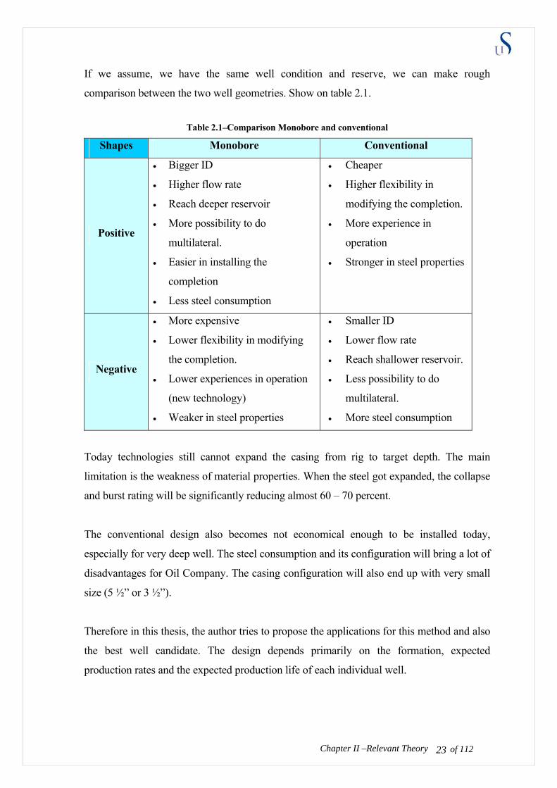
If we assume, we have the same well condition and reserve, we can make rough
comparison between the two well geometries. Show on table 2.1.
Table 2.1–Comparison Monobore and conventional
Shapes Monobore Conventional
Positive
• Bigger ID
• Higher flow rate
• Reach deeper reservoir
• More possibility to do
multilateral.
• Easier in installing the
completion
• Less steel consumption
• Cheaper
• Higher flexibility in
modifying the completion.
• More experience in
operation
• Stronger in steel properties
Negative
• More expensive
• Lower flexibility in modifying
the completion.
• Lower experiences in operation
(new technology)
• Weaker in steel properties
• Smaller ID
• Lower flow rate
• Reach shallower reservoir.
• Less possibility to do
multilateral.
• More steel consumption
Today technologies still cannot expand the casing from rig to target depth. The main
limitation is the weakness of material properties. When the steel got expanded, the collapse
and burst rating will be significantly reducing almost 60 – 70 percent.
The conventional design also becomes not economical enough to be installed today,
especially for very deep well. The steel consumption and its configuration will bring a lot of
disadvantages for Oil Company. The casing configuration will also end up with very small
size (5 ½” or 3 ½”).
Therefore in this thesis, the author tries to propose the applications for this method and also
the best well candidate. The design depends primarily on the formation, expected
production rates and the expected production life of each individual well.
Chapter II –Relevant Theory of 112 23
2.2.2 Material overview [21]
How can the steel be expanded?
In the material engineering, deformation is a change in shape due to an applied force. This
can be a result of tensile (pulling) forces, compressive (pressing forces), shear, bending or
torsion (twisting). Deformation is often described in term of strain.
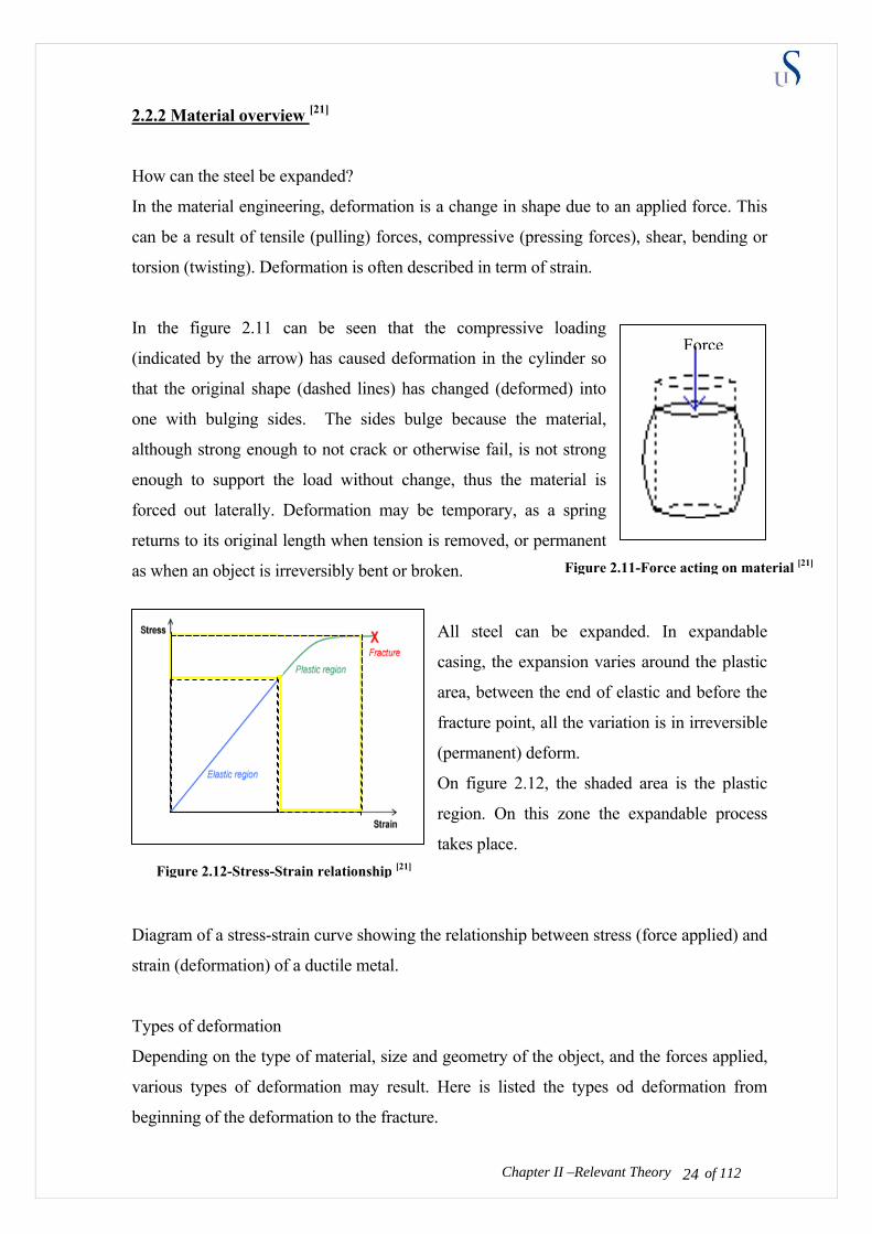
In the figure 2.11 can be seen that the compressive loading
(indicated by the arrow) has caused deformation in the cylinder so
that the original shape (dashed lines) has changed (deformed) into
one with bulging sides. The sides bulge because the material,
although strong enough to not crack or otherwise fail, is not strong
enough to support the load without change, thus the material is
forced out laterally. Deformation may be temporary, as a spring
returns to its original length when tension is removed, or permanent
as when an object is irreversibly bent or broken.
All steel can be expanded. In expandable
casing, the expansion varies around the plastic
area, between the end of elastic and before the
fracture point, all the variation is in irreversible
(permanent) deform.
On figure 2.12, the shaded area is the plastic
region. On this zone the expandable process
takes place.
Diagram of a stress-strain curve showing the relationship between stress (force applied) and
strain (deformation) of a ductile metal.
Types of deformation
Depending on the type of material, size and geometry of the object, and the forces applied,
various types of deformation may result. Here is listed the types od deformation from
beginning of the deformation to the fracture.
Chapter II –Relevant Theory of 112 24
Force
Figure 2.12-Stress-Strain relationship [21]
Figure 2.11-Force acting on material [21]

Elastic deformation
This type of deformation is reversible. Once the forces are no longer applied, the object
returns to its original shape. The elastic (rubber) has a rather large elastic deformation
range. Soft thermoplastics*) and metals have moderate elastic deformation ranges while
ceramics, crystals and hard thermosetting plastic**) undergo almost no elastic deformation.
Metal fatigue
Metal fatigue occurs primarily in ductile metals. It was originally thought that a material
deformed only within the elastic range returned completely to its origin state once the force
is removed. However, faults are introduced at the molecular level with each deformation.
After many deformations, cracks will begin to appear, followed fract soon directly, with no
apparent plastic deformation in between. Depending on the material, shape and how close
to the elastic limit it is deformed; failure may require thousands of deformations.
Plastic deformation
This type of deformation is not reversible. However, an object in the plastic deformation
range will first have undergone elastic deformation, which is reversible, so the object will
return part way to its original shape. Soft thermoplastics have a rather large plastic
deformation range as do ductile metals such as copper; silver and gold, steel do but iron.
Steel is used in SET process; actually it has the same properties with drillpipe or casing. It
is deformed and changed it elasticity when the stress is applied in the plastic region (piston
force by the cone).
Fracture
This type of deformation is also not reversible. A break occurs after the material has
reached the end of the elastic and then plastic, deformation ranges. At this point forces
accumulate until they are sufficient to cause a fracture. All materials will eventually
fracture, if sufficient forces are applied.
Chapter II –Relevant Theory
*) thermoplastic is a material that is plastic or deformable, melts to a liquid when heated and freezes to a brittle, glassy state when cooled
sufficiently
**) thermosetting plastic are polymer materials that cure, through the additional of energy to a stronger form) undergo almost no elastic
deformation.
of 112 25

of 112 26Chapter II –Relevant Theory of 112
On today technology, there are 2 main applications of expandable material in oil and gas
industry which are Solid Expandable Tubular (SET) and Expandable Sand Screen.
Expanded casing applications concentrate on reducing the telescopic profile of well designs
through a downhole tube expansion process. Wider applications of the technology exist for
example water shut off and casing repairs in old wells. Figure 2.13 shows expanded tubular.
To reduce the loss of diameter each time a new casing string or liner is set, a cold working
process has been developed whereby the casing or liner can be expanded by up to 20% in
diameter after being run down-hole. Figure 2.14 shows the process when the cone expands
the casing.
Figure 2.14-Expandable tubing and cone [6]
2.2.3 Industry overview [6]
As an industry overview, each of the three service providers is reviewed (Enventure,
Weatherford, and Baker). The various expansion applications are described below.
• Enventure Data
Enventure did almost 257 installations from both open hole and cased hole. For Chevron
(CVX) to date, Enventure has already installed ten wells. (This system uses hydraulic
pressure to push an expansion mandrel up through the casing – expanding the pipe as it
goes from the bottom up.)
Figure 2.13-Expandable material [20]

of 112 27Chapter II –Relevant Theory of 112
• Baker Data
Baker Hughes has installed approximately twelve cased hole installations (This system
uses a five foot jack system to push the expansion mandrel down through the pipe. The
jacking system is similar to the original Homco Patch –weatherford system.)
• Weatherford Data
Weatherford did approximately six cased hole installations (This system uses a rotary
tool. The expansion starts at the top and goes downward.). However there is a new
technology that is developed. This technology is almost similar to Enventure system
(expansion from bottom to top), and has the expandable cone. The Homco Patch is used
for cased hole and this expandable cone is used for open hole expansion.
Open hole SET should be used in the following situations, according to Chevron [6]:
• No acceptable conventional alternative.
• A tolerance for higher operational risk and possible failure wells.
• No requirement for high burst or collapse rating.
• The best fit for expand is 500 – 1500 foot in under-reamed or bi-centered open hole and
at least 1” above the drift of the base casing.
• Minimum hole angle with no doglegs
• A stable open hole section that will allow a six foot full drift OD plug container to easily
reach TD without problems – losses, gains, doglegs, ledges, or sloughing.
• Minimal rotating hours in the next section of hole.
• The next casing string can easily be lapped back up and hung off in a conventional way
to fully cover the expandable liner.
• Cementing is not critical in the SET liner interval – a good liner lap test and shoe test are
the main objectives.
• The additional ID gained from using SET will yield a major economic benefit to offset
the additional rig time and high cost of the service.
The lists above may sound like it eliminates every possibility. It does not. A short, planned,
drilling liner is the best SET application. The first application of SET in West Cameron,
West Africa in 1999 was a short planned drilling liner. SET works best when run before hole
problems are encountered. Expandable casing needs to be used in a stable, bi-centered hole

that can easily pass the six-foot, full drift, plug container. The benefit is an additional short
drilling liner, used to avoid problems, while starting and finishing the well with conventional
casing sizes. This type of application fits development or delineation wells much more than
exploration. SET may help to solve differential problems that are sometimes encountered in
wells drilled late in the life of a field development. However, the current success ratio in
CVX operations discourages this type of application. Both cost and risk will keep SET from
being used in most wells.
Industry expandable methodology
The clear leader in the solid expandable tubulars (SET) is Enventure. They have run more
than 250 field applications where as Baker and Weatherford have only twelve and six
respectively at midyear 2004. Enventure is the only company with a field proven open hole
liner. However Weatherford has developed a new bottom–top expandable technology which
seems could have a promising future application. Baker focused their business in expandable
sand screen technology than SET.
Here is a side-by-side comparison of the expansion techniques:
Chapter II –Relevant Theory of 112 28
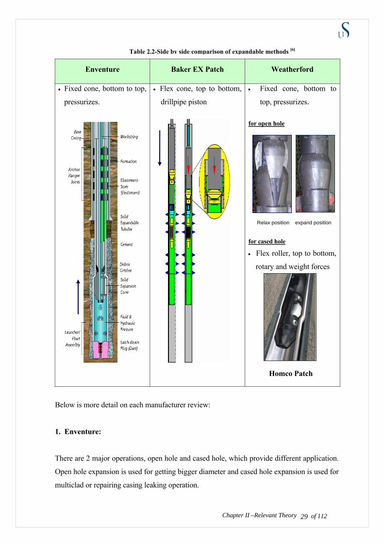
Enventure Baker EX Patch Weatherford
• Fixed cone, bottom to top,
pressurizes.
• Flex cone, top to bottom,
drillpipe piston
• Fixed cone, bottom to
top, pressurizes.
for open hole
Relax position expand position
for cased hole
• Flex roller, top to bottom,
rotary and weight forces
Homco Patch
Below is more detail on each manufacturer review:
1. Enventure:
There are 2 major operations, open hole and cased hole, which provide different application.
Open hole expansion is used for getting bigger diameter and cased hole expansion is used for
multiclad or repairing casing leaking operation.
Chapter II –Relevant Theory of 112 29
Table 2.2-Side by side comparison of expandable methods [6]

Open hole – operation sequences
(1) Drill hole - Drill an oversized open hole
interval. Enventure use bushing bit to
undeream the hole. (However it makes a lot
of string vibration)
(2) Runs Expandable Liner - Pick up the
expandable liner, expansion assembly and
launcher.
(3) Condition Mud, cement liner - Run to the
planned depth and perform cementing
operation and pump plug.
(4) Latch plug, start expansion - seat the latch the plug and
initiate expansion by expanding through the launcher.
(5) Expand hanger joint - expand the liner including the
anchor hanger joint in the overlap between the SET and the
base casing. Expand out of the top of the liner.
(6) Drill out shoe - Continue next drilling operation.
The improvement has been done for reducing the string vibration when underreaming. They
install balancing weight in the bushing.
Cased Hole – operation sequences
(1) Clean Out Casing - Prepare the wellbore for the installation using mills or scrapers, if
necessary.
(2) Run and Position Expandable Liner - Run the expandable CHL System in the well.
Space out and position the liner over the interval to be repaired or reinforced.
Chapter II –Relevant Theory of 112 30
Figure 2.15-Enventure Open Hole sequences [15]

(3) Pump Dart, Start Expansion -
Seat the latch-down plug and
initiate expansion by expanding
through the launcher.
(4) Expand Liner - Pressurize
workstring and pump expansion
cone while pulling upon
workstring.
(5) Expand Anchor Hanger Joint -
Continue expansion until the
cone exits the top of the liner
and pressure test the installation.
(6) Drill Out Shoe - Prepare the well for further completion or production operations.
Enventure uses pressure under an expansion cone to help on expanding the pipe. The cone is
unseated as each connection is broken coming out of the hole. Open hole installations have
ranged from 300 ft to 3400 ft, and cased hole applications from 20 ft to 6100 ft.
2. Baker Hughes:
Methods of expansion vary with applications and products. Baker Oil Tools preferred
methodology is a top-down expansion process that uses hydraulic pressure fed into a piston.
Hydraulic pressure anchors the system in place and opens the piston, which progressively
pushes an expansion cone through the completion assembly, setting the liner hanger,
expanding the blank pipe, setting the isolation packer and expanding the screen. After the
expansion process is complete, the expansion tool is retrieved from the well. Using this
system, thousands of feet of tubulars can be expanded in a single trip. Becauce the system
does not rely on pushing or pulling energy from the drillstring, it can be activated easily in
highly deviated wells. Baker Hughes is more concentrate in cased hole completion than open
hole.
Chapter II –Relevant Theory of 112 31
Figure 2.16-Cased hole Enventure sequences [15]
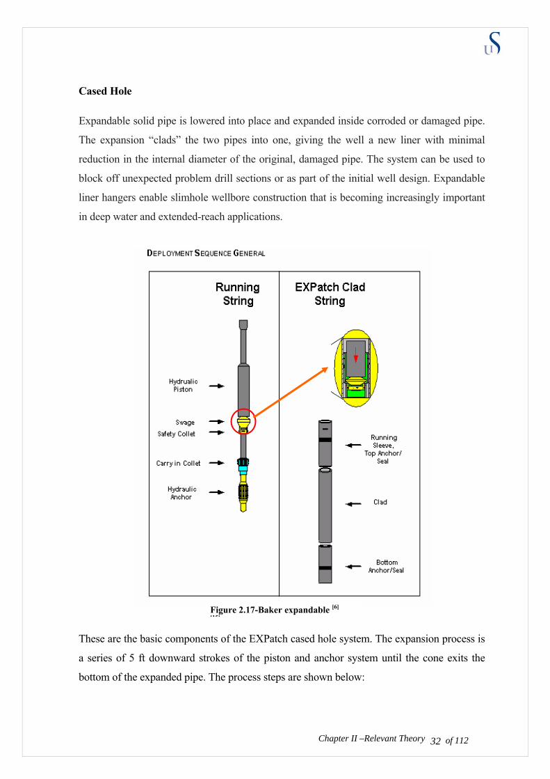
Cased Hole Expandable solid pipe is lowered into place and expanded inside corroded or damaged pipe.
The expansion “clads” the two pipes into one, giving the well a new liner with minimal
reduction in the internal diameter of the original, damaged pipe. The system can be used to
block off unexpected problem drill sections or as part of the initial well design. Expandable
liner hangers enable slimhole wellbore construction that is becoming increasingly important
in deep water and extended-reach applications.
These are the basic components of the EXPatch cased hole system. The expansion process is
a series of 5 ft downward strokes of the piston and anchor system until the cone exits the
bottom of the expanded pipe. The process steps are shown below:
Chapter II –Relevant Theory of 112 32
Figure 2.17-Baker expandable [6] [15]
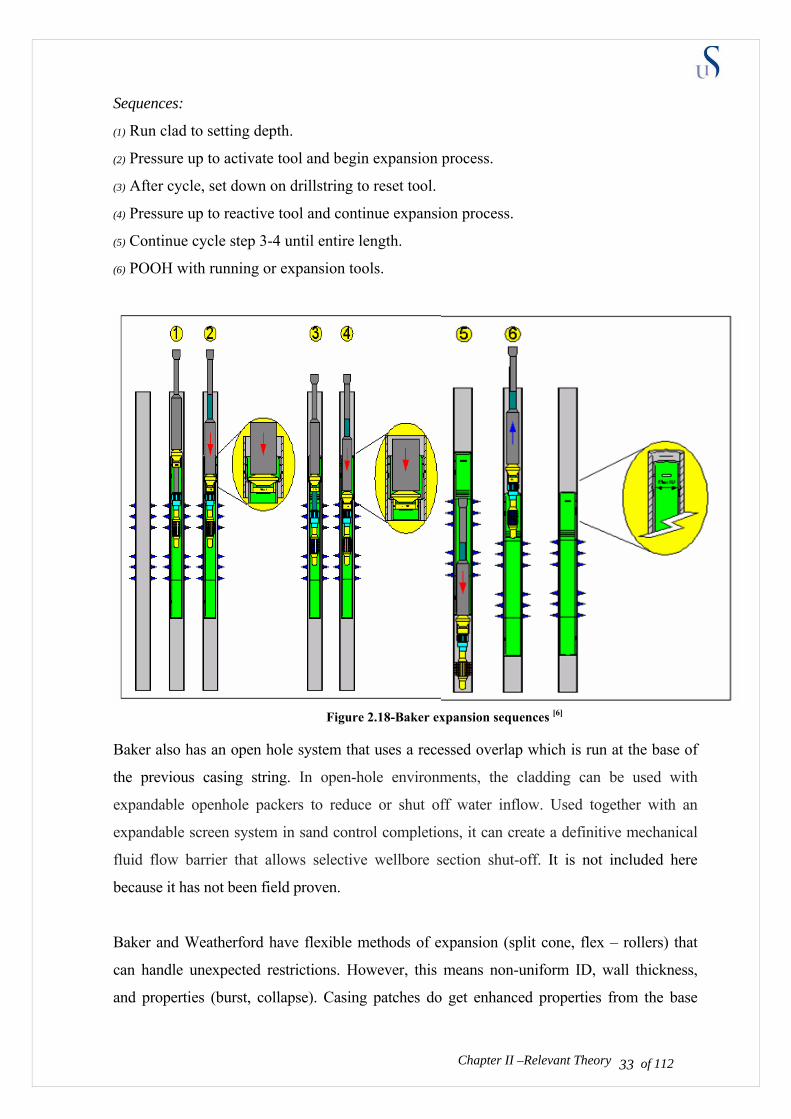
Sequences:
(1) Run clad to setting depth.
(2) Pressure up to activate tool and begin expansion process.
(3) After cycle, set down on drillstring to reset tool.
(4) Pressure up to reactive tool and continue expansion process.
(5) Continue cycle step 3-4 until entire length.
(6) POOH with running or expansion tools.
Baker also has an open hole system that uses a recessed overlap which is run at the base of
the previous casing string. In open-hole environments, the cladding can be used with
expandable openhole packers to reduce or shut off water inflow. Used together with an
expandable screen system in sand control completions, it can create a definitive mechanical
fluid flow barrier that allows selective wellbore section shut-off. It is not included here
because it has not been field proven.
Baker and Weatherford have flexible methods of expansion (split cone, flex – rollers) that
can handle unexpected restrictions. However, this means non-uniform ID, wall thickness,
and properties (burst, collapse). Casing patches do get enhanced properties from the base
Chapter II –Relevant Theory of 112 33
Figure 2.18-Baker expansion sequences [6]
pipe. The burst is almost additive if the base casing is only perforated. The collapse is
enhanced because the patch is constrained from becoming oval which is an early stage of
collapse. Testing could be done to quantify the additional strength gained if needed for a
specific application.
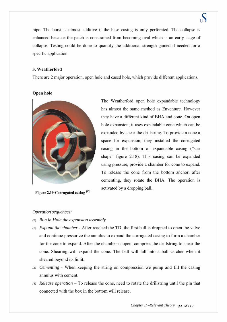
3. Weatherford
There are 2 major operation, open hole and cased hole, which provide different applications.
Open hole
The Weatherford open hole expandable technology
has almost the same method as Enventure. However
they have a different kind of BHA and cone. On open
hole expansion, it uses expandable cone which can be
expanded by shear the drillstring. To provide a cone a
space for expansion, they installed the corrugated
casing in the bottom of expandable casing (”star
shape” figure 2.18). This casing can be expanded
using pressure, provide a chamber for cone to expand.
To release the cone from the bottom anchor, after
cementing, they rotate the BHA. The operation is
activated by a dropping ball.
Operation sequences:
(1) Run in Hole the expansion assembly
(2) Expand the chamber - After reached the TD, the first ball is dropped to open the valve
and continue pressurize the annulus to expand the corrugated casing to form a chamber
for the cone to expand. After the chamber is open, compress the drillstring to shear the
cone. Shearing will expand the cone. The ball will fall into a ball catcher when it
sheared beyond its limit.
(3) Cementing - When keeping the string on compression we pump and fill the casing
annulus with cement.
(4) Release operation – To release the cone, need to rotate the drillstring until the pin that
connected with the box in the bottom will release.
Chapter II –Relevant Theory of 112 34
Figure 2.19-Corrugated casing [17]

(5) Expansion process – By pulling the drillstring out the hole the expansion will start
from bottom to top. However we need to keep pressurize the pipe to keep the drillstring
in compression and the cone in expansion form.
(6) Drill out or milling job – After the liner hanger had been expanded, then we need to
run the bit or the mill assembly to drill out the shoe.
Cased hole
The cased hole expansion is used to repair the casing system. Weatherford has a rotary
expansion cone. This tool has circumferentially mounted rollers in pressure-activated
pistons. The expansion of the solid tubing is carried out by a combination of backpressure,
created by circulating fluid through a nozzle in the tool and drillstring rotation. Each roller
acts independently, expanding the solid tubular to fit any anomalies of the parent casing.
Benefit of using this cone is low axial loads, has durable components (mean cheap) and fit
through unexpanded tubular for easy retrieval. However the disadvantages of this cone are
the expanded casing could have varied inside diameter. In other word, Weatherford fits
tighter to the base casing but may not have uniform wall thickness.
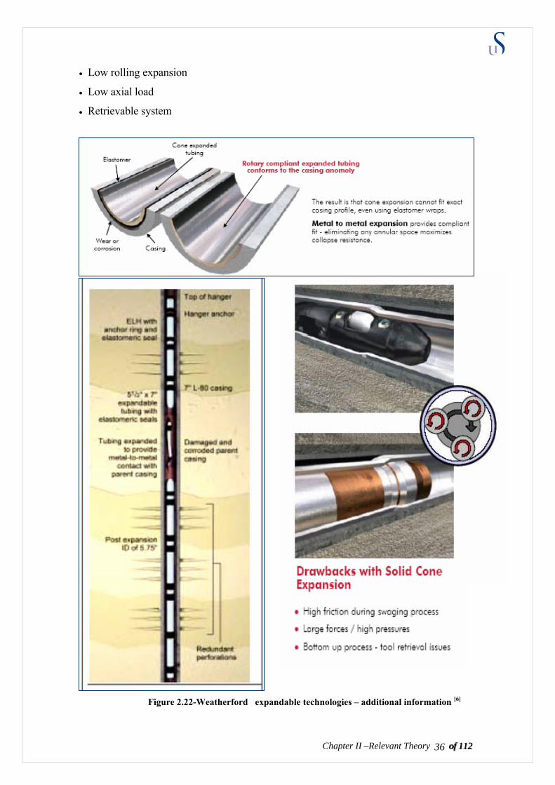
Rotary compliant expansion:
• Metal to metal contact
• Maximum casing collapse and burst
• Tolerant to casing anomalies
• Top-down expansion
Chapter II –Relevant Theory of 112 35
Figure 2.20-Weatherford open hole, expansion sequence[17]
Figure 2.21-Weatherford compliant cone [6]
of 112 36Chapter II –Relevant Theory of 112
• Low rolling expansion
• Low axial load
• Retrievable system
Figure 2.22-Weatherford expandable technologies – additional information [6]
2.3 COMBINATION OF DRILLING WITH EXPANDABLE CASING THEORY
There has not been any significant advancement of this technology. More issues and
technical challenges have been raised that cast even more doubt on the feasibility of a
commercially attractive product ever being developed. There are two areas that are causing
the greatest concern; technically how to combine both technology and poor post expansion
properties.
There are no case studies from this combine technology. Since both technology consists of
almost the same operation procedures therefore we could combine it. Practically, our concept
is tried to drill and case the hole with the expandable casing. Based on this concept, one first
drill through unstable zone (lost circulation) with the expandable casing, then change the
drilling BHA into expandable BHA, pump the cement and continue to expand the casing to
get bigger diameter. Ideally the operation is done in one or two times trips.
Both advantages which are to obtain a bigger production casing size and to solve the lost
circulation could be achieved in the same time. Bigger production casing size will let a
higher production rate which will compensate the operation cost. Problem due to lost
circulation can also be cut off. In the future, by increasing crew experiences, we expect
saving on rig time aslo can be achived.
However there are many technical challenges such as dillema of having weak connection for
drilling with casing and weak post expansion casing properties are becoming our main
concern. In expandable casing we need to have weak connections, in order to expand the
casing with the lower forces and in the mean time, we also need strong connections for
drilling purposes to avoid failure. The weak post expansion casing properties make the
operation limited just on special cases. It is important to understand that combine both
technologies mean combines its disadvantages and limitation as well. The cost and operation
risk are the most crucial and the most reasonable issue since the cost and risk of each
technologies already high.
of 112 37Chapter II –Relevant Theory of 112
The visibility and technical studies is being done by service companies however it has not
been commercialized yet. The progress to find the best solution is on going. The
possibilities of the best drill-expand performance methodology is still on-study.

CHAPTER III
ANALYSIS AND RESULT
There are a few questions that the author will investigate. Answering those questions could
help us conclude the feasibility study of this combine technology. The questions consist of
mostly technical part and one economic part. These are the questions:
• How can this combined method works?
• Are the expandable casing connections strong enough for drilling with casing?
• How does the expandable casing perform after being used for drilling?
• What are the expandable casing properties that need to be considered?
• Is the cost competitive?
• Are there any limitations on this process?
To answer these questions the author needs to discuss with the expandable technology and
drilling with casing experts.
3.1 ANALYSIS OF THE “DRILLING – EXPANSION” METHODOLOGY
Question: How can this combined method works?
Analysis:
To find mechanical and technical possible methods that could be implemented with the
current technologies, the author visited the companies and gathered the information. After
learning and observing, we believe there could be two methods that can be proposed. Here
we presented a conceptual method and in the discussion part we will preview the industry
product supporting this concept. The two methods that being conceptually considered
feasible are:
Method 1: drill and expand method
of 112 38
In this method, first drill the formation with the casing until the casing shoe reaches the
expected depth. Then change the drilling bottom hole assembly with the expansion bottom
hole assembly. The expansion cone is run into the hole with the drillpipe to bottom of the
casing. Before expansion process, pump cement through the drillpipe out to annulus of
casing and afterward start expansion from bottom to top.
Another alternative that could be possible for saving tripping time is to run the top-bottom
expansion method. However one has to mill the cement out and clean the well before
continues with the expansion process. The top-bottom expansion method has more
challenges on additional cleaning operation than bottom-top method; therefore the top-
bottom method prefers to be run on the clad system where the cement does not need to be
pumped through the expandable casing. Isolating the leak casing and trouble zone is the
suitable jobs for top-bottom expansion method. There are two different operations that need
to be considered on changing the drilling to expandable bottom hole assembly which actually
depend on the BHA types. If the BHA is:
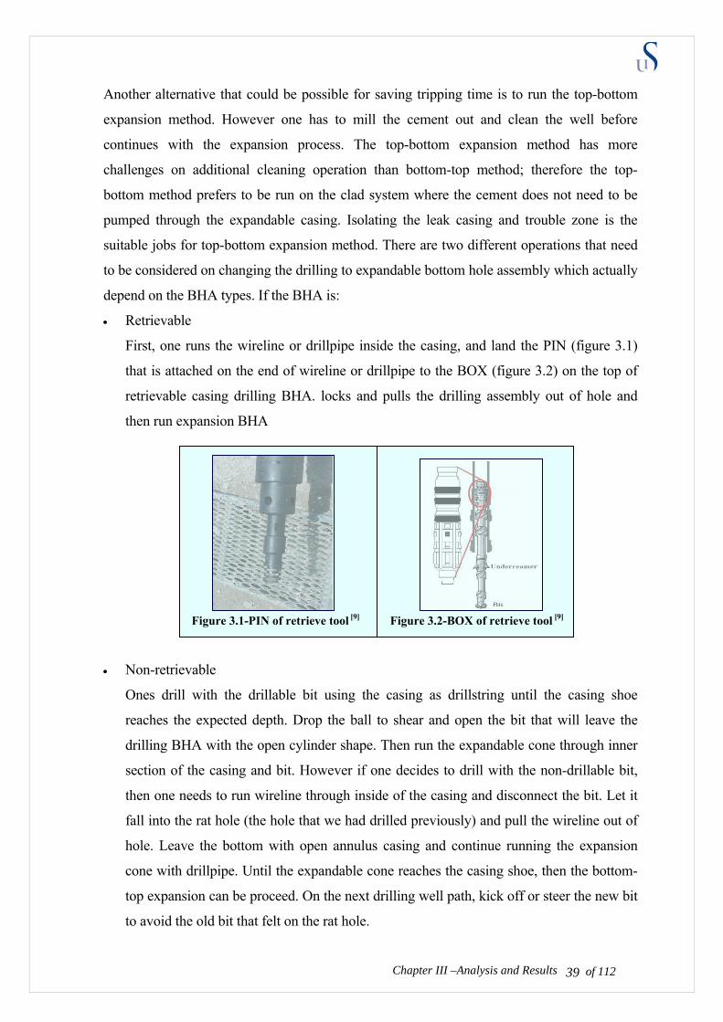
• Retrievable
First, one runs the wireline or drillpipe inside the casing, and land the PIN (figure 3.1)
that is attached on the end of wireline or drillpipe to the BOX (figure 3.2) on the top of
retrievable casing drilling BHA. locks and pulls the drilling assembly out of hole and
then run expansion BHA
Figure 3.1-PIN of retrieve tool [9] Figure 3.2-BOX of retrieve tool [9] • Non-retrievable
Ones drill with the drillable bit using the casing as drillstring until the casing shoe
reaches the expected depth. Drop the ball to shear and open the bit that will leave the
drilling BHA with the open cylinder shape. Then run the expandable cone through inner
section of the casing and bit. However if one decides to drill with the non-drillable bit,
then one needs to run wireline through inside of the casing and disconnect the bit. Let it
fall into the rat hole (the hole that we had drilled previously) and pull the wireline out of
hole. Leave the bottom with open annulus casing and continue running the expansion
cone with drillpipe. Until the expandable cone reaches the casing shoe, then the bottom-
top expansion can be proceed. On the next drilling well path, kick off or steer the new bit
to avoid the old bit that felt on the rat hole.
Chapter III –Analysis and Results of 112 39
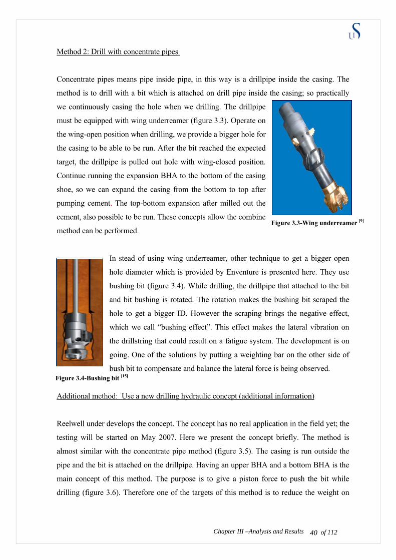
Method 2: Drill with concentrate pipes
Concentrate pipes means pipe inside pipe, in this way is a drillpipe inside the casing. The
method is to drill with a bit which is attached on drill pipe inside the casing; so practically
we continuously casing the hole when we drilling. The drillpipe
must be equipped with wing underreamer (figure 3.3). Operate on
the wing-open position when drilling, we provide a bigger hole for
the casing to be able to be run. After the bit reached the expected
target, the drillpipe is pulled out hole with wing-closed position.
Continue running the expansion BHA to the bottom of the casing
shoe, so we can expand the casing from the bottom to top after
pumping cement. The top-bottom expansion after milled out the
cement, also possible to be run. These concepts allow the combine
method can be performed.
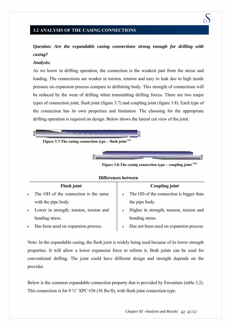
In stead of using wing underreamer, other technique to get a bigger open
hole diameter which is provided by Enventure is presented here. They use
bushing bit (figure 3.4). While drilling, the drillpipe that attached to the bit
and bit bushing is rotated. The rotation makes the bushing bit scraped the
hole to get a bigger ID. However the scraping brings the negative effect,
which we call “bushing effect”. This effect makes the lateral vibration on
the drillstring that could result on a fatigue system. The development is on
going. One of the solutions by putting a weighting bar on the other side of
bush bit to compensate and balance the lateral force is being observed.
Additional method: Use a new drilling hydraulic concept (additional information)
Reelwell under develops the concept. The concept has no real application in the field yet; the
testing will be started on May 2007. Here we present the concept briefly. The method is
almost similar with the concentrate pipe method (figure 3.5). The casing is run outside the
pipe and the bit is attached on the drillpipe. Having an upper BHA and a bottom BHA is the
main concept of this method. The purpose is to give a piston force to push the bit while
drilling (figure 3.6). Therefore one of the targets of this method is to reduce the weight on
Chapter III –Analysis and Results of 112 40
Figure 3.3-Wing underreamer [9]
Figure 3.4-Bushing bit [15]

bit. Therefore, a smaller surface equipment and facility could be used to drill a long
horizontal section. For the system specification we can see on table 3.1.
The unique method about this concept is the fluid circulation flow on the system. The system
has two BHA (upper and lower), which is attached on the drillpipe. Besides pumping the
fluid like on a conventional drilling, we also pump the drilling fluid into the casing annulus
to push the upper BHA for providing piston axial force on drill bit. However this method still
has a lot of consideration on well control, flow insurance and cutting transport because
plugging on the regulator (bottom BHA) could risk the whole operation.
Table 3.1-Rellwell Specification [18]
Figure 3.5-Reelwell system configuration [18]
Figure 3.6-Reelwell concept drawing [18]
Form these 3 conceptual methods, which are described briefly; we can see that there are
possibilities that the drilling with expandable casing method could be implemented.
Successful similar test has been achieved and plenty of money has been financed for the
researches. Therefore the temporary answer from this question can be drawn as below:
Result:
• Conceptually with present technology, drilling with expandable casing is possible.
• Since we do not need to mill out the cement and clean the inside wall interface of casing,
the bottom to top expansion is recommended for drilling with expandable casing method.
Chapter III –Analysis and Results of 112 41
3.2 ANALYSIS OF THE CASING CONNECTIONS
Question: Are the expandable casing connections strong enough for drilling with
casing?
Analysis:
As we know in drilling operation, the connection is the weakest part from the stress and
loading. The connections are weaker in torsion, tension and easy to leak due to high inside
pressure on expansion process compare to drillstring body. This strength of connections will
be reduced by the wear of drilling when transmitting drilling forces. There are two major
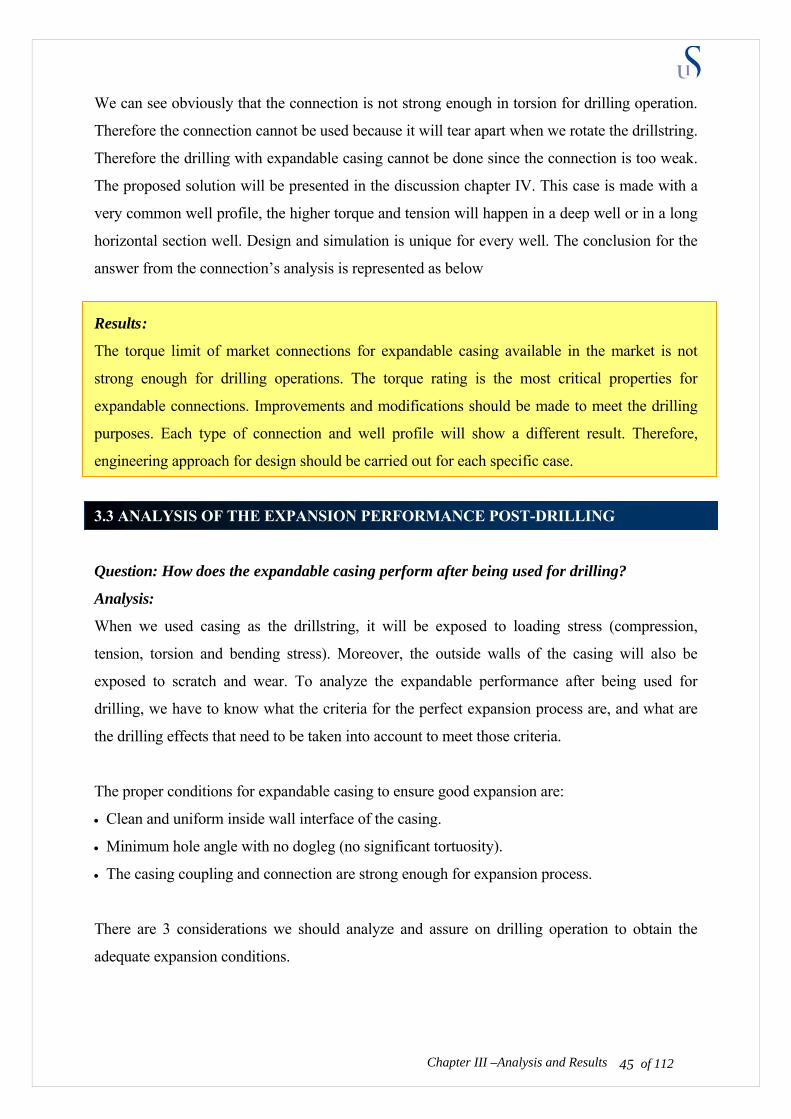
types of connection joint, flush joint (figure 3.7) and coupling joint (figure 3.8). Each type of
the connection has its own properties and limitation. The choosing for the appropriate
drilling operation is required on design. Below shows the lateral cut view of the joint.
Figure 3.7-The casing connection type – flush joint [16
Figure 3.8-The casing connection type – coupling joint [16]
Differences between
Flush joint Coupling joint
• The OD of the connection is the same
with the pipe body.
• Lower in strength; tension, torsion and
bending stress.
• Has been used on expansion process.
Chapter III –Analysis and Results
• The OD of the connection is bigger than
the pipe body.
• Higher in strength; tension, torsion and
bending stress.
• Has not been used on expansion process
Note: In the expandable casing, the flush joint is widely being used because of its lower strength
properties. It will allow a lower expansion force to reform it. Both joints can be used for
conventional drilling. The joint could have different design and strength depends on the
provider.
Below is the common expandable connection property that is provided by Enventure (table 3.2).
This connection is for 9 ⅝” XPC #36 (36 lbs/ft), with flush joint connection type.
of 112 42

Table 3.2-Enventure Connection properties [15]
9 ⅝ XPC #36, N-80 flush joint (enventure)-CONNECTION • Connection joint strength • Compressive load rating • Min parting load • Max pure bend rating • Torque
Mimimum final torque Optimum final torque Maximum final torque Maximum Yield torque
533,900 lbf (2375 KN) 427,100 lbf (1900 KN) 634,000 lbf (2820 KN) 19,80/100 ft 2500 ft.lbf (3.4 KN.m) 2800 ft.lbf (3.8 KN.m) 3100 ft.lbf (4.2 KN.m) 6200 ft.lbf (8.5 KN.m)
Our challenge is to analyse if this connection can be used for a simple drilling operation.
Therefore we have to make a simple-general well plan and calculate the stress; tension and
torque, which we will compare it with the connection properties. If the connection has a
stronger strength than the drilling stress, then we can conclude that it is adequate to be used in
this specific drilling case. Since different case will show different stresses, the acceptance
determination of this connection will vary.
It is important to make a general-representative case. Here, we present a simple model of torque
and tension on drilling with casing operation, compare with the connection properties. Case
example: Table 3.3-Case well parameter
Input parameters Kick-off-depth 1500.00 m Inclination of sail/hold section 60.00 deg Build radius 500.0 m Length of Bottom-hole-assembly (BHA) 200.00 m Mud weight 1.56 s.g. Length of sail/hold section 2200.00 m Tool joint radius (select meters or inches) 0.251 m Friction coefficient 0.30 Bit force (kN or tonnes) 2.00 tonnes Bit torque 6 kN/m Unit weight of drill pipe (in air) 0.30 kN/m Unit weight of BHA (in air) 3.00 kN/m Output values Buoyancy factor 0.8 Horizontal reach of well 2155 m Vertical depth of well 3033 mTVD Measured well depth 4224 mMD Dogleg severity of build section 3.4 deg/30m
Chapter III –Analysis and Results of 112 43
Figure 3.9 Case well profile

Tension and drag profile for case example.
Figure 3.10-Hook load profile for case example
As we see in the connection properties (table 3.2), this expandable connection has a tension
limit of 2375 KN and a compression limit of 1900 KN. If we plot it on the figure 3.10 we will
be in a safe operation area (bigger than the forces) where operation maximum tension is 1500
KN. Therefore practical speaking, the connections tension and compression are adequate to be
used for this case. The next figure 3.11 shows the torsion strength of the drilling compare with
the torque limit of the connection.
Chapter III –Analysis and Results
Torque diff 5.8 -6 KN.m
Torque yield at 8.5 KN.m
Figure 3.11-Torque profile for case example
of 112 44
Max Yield at 4.2 KN.m
(KN.m)
: is Operating area
Operating area
We can see obviously that the connection is not strong enough in torsion for drilling operation.
Therefore the connection cannot be used because it will tear apart when we rotate the drillstring.
Therefore the drilling with expandable casing cannot be done since the connection is too weak.
The proposed solution will be presented in the discussion chapter IV. This case is made with a
very common well profile, the higher torque and tension will happen in a deep well or in a long
horizontal section well. Design and simulation is unique for every well. The conclusion for the
answer from the connection’s analysis is represented as below
Results :
The torque limit of market connections for expandable casing available in the market is not
strong enough for drilling operations. The torque rating is the most critical properties for
expandable connections. Improvements and modifications should be made to meet the drilling
purposes. Each type of connection and well profile will show a different result. Therefore,
engineering approach for design should be carried out for each specific case.
3.3 ANALYSIS OF THE EXPANSION PERFORMANCE POST-DRILLING
Question: How does the expandable casing perform after being used for drilling?
Analysis:
When we used casing as the drillstring, it will be exposed to loading stress (compression,
tension, torsion and bending stress). Moreover, the outside walls of the casing will also be
exposed to scratch and wear. To analyze the expandable performance after being used for
drilling, we have to know what the criteria for the perfect expansion process are, and what are
the drilling effects that need to be taken into account to meet those criteria.
The proper conditions for expandable casing to ensure good expansion are:
• Clean and uniform inside wall interface of the casing.
• Minimum hole angle with no dogleg (no significant tortuosity).
• The casing coupling and connection are strong enough for expansion process.
There are 3 considerations we should analyze and assure on drilling operation to obtain the
adequate expansion conditions.
Chapter III –Analysis and Results of 112 45

of 112 46Chapter III –Analysis and Results of 112
The effects on drilling which are considered important to achieve a proper expansion are:
• The well can not suffer from any debris and junks after drilling operation.
• The casing has no big dogleg and tortuosity profiles.
• The well has no lateral vibration and whirl during the drilling operation.
Analysis 1: The well can not suffer from any debris and junks after drilling operation.
Before, this consideration was not taken into account for the expandable casing, because the
casing was run on a separate operation from drilling operation. The
cleanness and the uniformity of the casing inside wall pre-expansion are
assured. However, if we used the expandable casing for drilling, after
cementing, cements could stick on the inside wall of the expandable
casing. Besides when we use a retrievable bit, pulling the bit out the hole
could scratch the casing inside wall. These are risky for the expansion
cone to pass and also for expansion pressuring process. Therefore the
additional operation for well cleaning with brush and scraper is
recommended (figure 3.12).
To assure we have the uniform inside diameter of expandable casing, we can make up a mill bit
on the end of drillstring when we run cleaning operation. The mill bit should have an outside
diameter (gauge diameter) as big as the inside diameter (drift diameter) of casing. This mill bit
will mill any substandard casing wall thickness to the size of mill OD. Therefore we can obtain
a uniform ID wall.
Analysis 2: The well has no big dogleg and tortuosity.
The well path is specified by directional surveys from either a real or planned well. The
inclination and azimuth at discrete points along the path define the survey stations and a
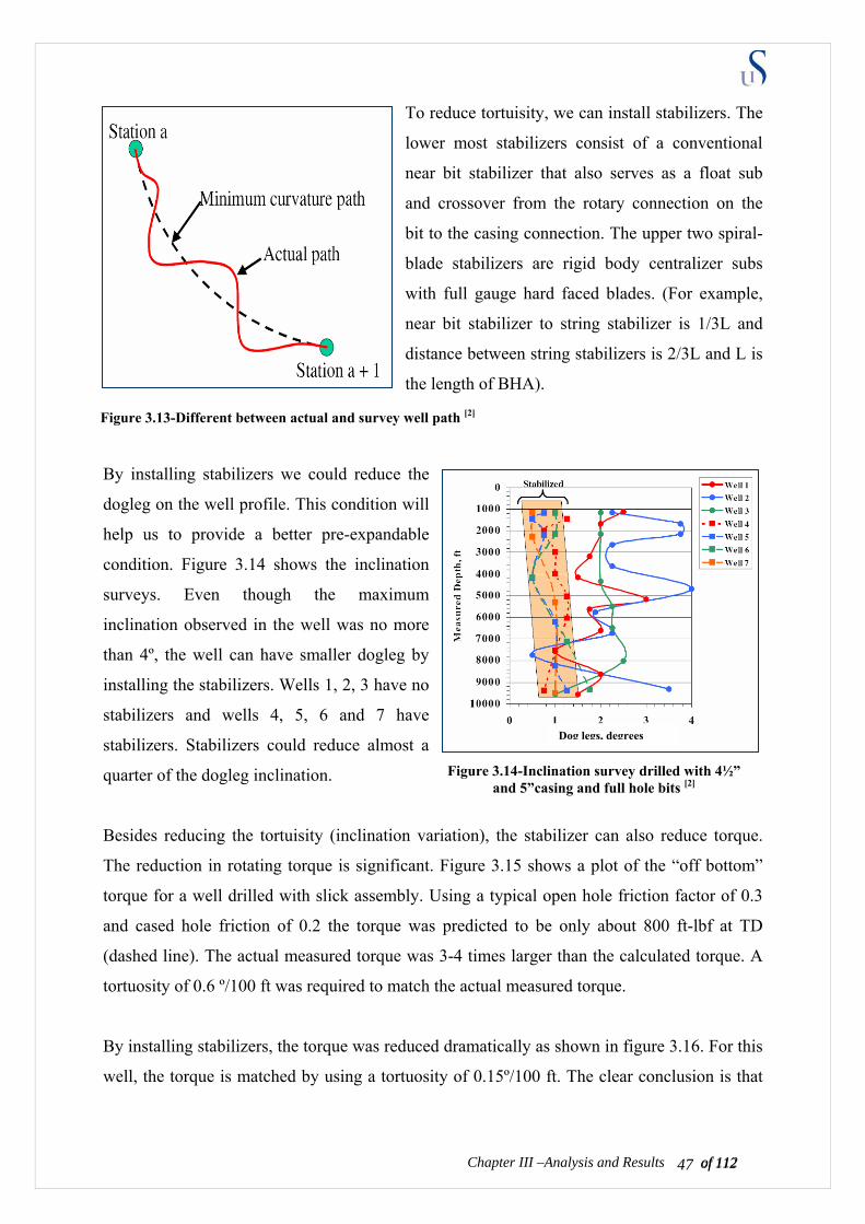
smooth cylinder are delineates the well path between survey points (see figure 3.13). A
Tortuosity is defined as the amount of curvature between stations, typically shown as
deg/100ft. The dogleg and tortuosity will make casing on bending and waving shape. This
shape will make the expansion cone could not distribute the lateral expansion force uniformly.
The un-uniform casing thickness will provide a spot, which will become the weakest part of
the casing due to the stress.
Figure 3.12-Casing scraper and brush [19]
of 112 47Chapter III –Analysis and Results of 112
To reduce tortuisity, we can install stabilizers. The
lower most stabilizers consist of a conventional
near bit stabilizer that also serves as a float sub
and crossover from the rotary connection on the
bit to the casing connection. The upper two spiral-
blade stabilizers are rigid body centralizer subs
with full gauge hard faced blades. (For example,
near bit stabilizer to string stabilizer is 1/3L and
distance between string stabilizers is 2/3L and L is
the length of BHA).
By installing stabilizers we could reduce the
dogleg on the well profile. This condition will
help us to provide a better pre-expandable
condition. Figure 3.14 shows the inclination
surveys. Even though the maximum
inclination observed in the well was no more
than 4º, the well can have smaller dogleg by
installing the stabilizers. Wells 1, 2, 3 have no
stabilizers and wells 4, 5, 6 and 7 have
stabilizers. Stabilizers could reduce almost a
quarter of the dogleg inclination.
Besides reducing the tortuisity (inclination variation), the stabilizer can also reduce torque.
The reduction in rotating torque is significant. Figure 3.15 shows a plot of the “off bottom”
torque for a well drilled with slick assembly. Using a typical open hole friction factor of 0.3
and cased hole friction of 0.2 the torque was predicted to be only about 800 ft-lbf at TD
(dashed line). The actual measured torque was 3-4 times larger than the calculated torque. A
tortuosity of 0.6 º/100 ft was required to match the actual measured torque.
By installing stabilizers, the torque was reduced dramatically as shown in figure 3.16. For this
well, the torque is matched by using a tortuosity of 0.15º/100 ft. The clear conclusion is that
Figure 3.13-Different between actual and survey well path [2]
Figure 3.14-Inclination survey drilled with 4½” and 5”casing and full hole bits [2]
Dog legs, degrees

the stabilizer assembly drilled a straighter and smoother hole, thus the torque was
significantly less.
Figure 3.15-Off bottom torque without stabilizer [2]
Installing the stabilizers, one will make the expandable connection lose a lot of torque burdens.
As we discuss before, the expandable casing connection has low torque strength, therefore
besides reducing dogleg, stabilizers could make it more feasible to be accepted in drilling
operation. The additional calculation and design should be run to determine the acceptance
criteria.
Analysis 3: The well has no lateral vibration and whirl during the drilling operation.
Lateral vibration or whirl is the most damaging vibration in DwC. The vibration can lead to
failure in casing coupling. The destructive lateral vibration can occur at any point along the
drillstring. The vibration most often displays an interaction with the drillstring rotation as
lateral displacement that orbits the borehole center (figure 3.17). This vibration often happens
in smaller ID casing. As the drillstring rotates, the initially small lateral force causes friction,
which produces a traction force that tends to cause the contact point to walk around the hole.
Lateral vibration and whirl can increase the torque on the system resulting in the connection
not being sufficiently strong to be expanded. On the expansion process when the cone runs
through the connection, the connection can leak due to de-rate strength.
Chapter III –Analysis and Results of 112 48
Figure 3.16-Off bottom torque with stabilizer [2]
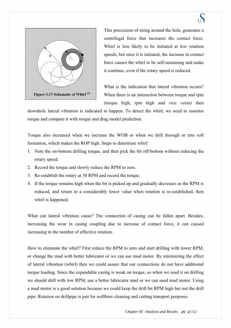
This precession of string around the hole, generates a
centrifugal force that increases the contact force.
Whirl is less likely to be initiated at low rotation
speeds, but once it is initiated, the increase in contact
force causes the whirl to be self-sustaining and make
it continue, even if the rotary speed is reduced.
What is the indication that lateral vibration occurs?
When there is an interaction between torque and rpm
(torque high, rpm high and vice versa) then
downhole lateral vibration is indicated to happen. To detect the whirl, we need to monitor
torque and compare it with torque and drag model prediction.
Torque also increased when we increase the WOB or when we drill through or into soft
formation, which makes the ROP high. Steps to determine whirl:
1. Note the on-bottom drilling torque, and then pick the bit off-bottom without reducing the
rotary speed.
2. Record the torque and slowly reduce the RPM to zero.
3. Re-establish the rotary at 30 RPM and record the torque.
4. If the torque remains high when the bit is picked up and gradually decreases as the RPM is
reduced, and return to a considerably lower value when rotation is re-established, then
whirl is happened.
What can lateral vibration cause? The connection of casing can be fallen apart. Besides,
increasing the wear in casing coupling due to increase of contact force, it can caused
increasing in the number of effective rotation.
How to eliminate the whirl? First reduce the RPM to zero and start drilling with lower RPM,
or change the mud with better lubricator or we can use mud motor. By minimizing the effect
of lateral vibration (whirl) then we could assure that our connections do not have additional
torque loading. Since the expandable casing is weak on torque, so when we used it on drilling
we should drill with low RPM, use a better lubricator mud or we can used mud motor. Using
a mud motor is a good solution because we could keep the drill bit RPM high but not the drill
pipe. Rotation on drillpipe is just for wellbore cleaning and cutting transport purposes.
Chapter III –Analysis and Results of 112 49
Figure 3.17-Schematic of Whirl [2]
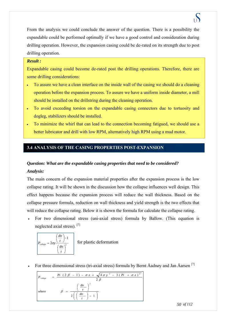
From the analysis we could conclude the answer of the question. There is a possibility the
expandable could be performed optimally if we have a good control and consideration during
drilling operation. However, the expansion casing could be de-rated on its strength due to post
drilling operation.
Result :
Expandable casing could become de-rated post the drilling operations. Therefore, there are
some drilling considerations:
• To assure we have a clean interface on the inside wall of the casing we should do a cleaning
operation before the expansion process. To assure we have a uniform inside diameter, a mill
should be installed on the drillstring during the cleaning operation.
• To avoid exceeding torsion on the expandable casing connectors due to tortuosity and
dogleg, stabilizers should be installed.
• To minimize the whirl that can lead to the connection becoming fatigued, we should use a
better lubricator and drill with low RPM, alternatively high RPM using a mud motor.
3.4 ANALYSIS OF THE CASING PROPERTIES POST-EXPANSION
Question: What are the expandable casing properties that need to be considered?
Analysis:
The main concern of the expansion material properties after the expansion process is the low
collapse rating. It will be shown in the discussion how the collapse influences well design. This
effect happens because the expansion process will reduce the wall thickness. Based on the
collapse pressure formula, reduction on wall thickness and yield strength is the two effects that
will reduce the collapse rating. Below it is shown the formula for calculate the collapse rating.
• For two dimensional stress (uni-axial stress) formula by Ballow. (This equation is
neglected axial stress). [7]
2
12
⎟⎠⎞
⎜⎝⎛
−⎟⎠⎞
⎜⎝⎛
=
tdot
do
yPcollape σ for plastic deformation
• For three dimensional stress (tri-axial stress) formula by Bernt Åadnøy and Jan Åarsen [7]
⎟⎟⎠
⎜⎜⎝
−⎟⎠
⎜⎝
12t
⎞⎛ ⎞⎛
⎟⎠⎞
⎜⎝⎛
=
+−+−−=
2)(34)12(
2
22
dot
do
where
zPiyzPiP collape
β
βσσσβ
of 112 50
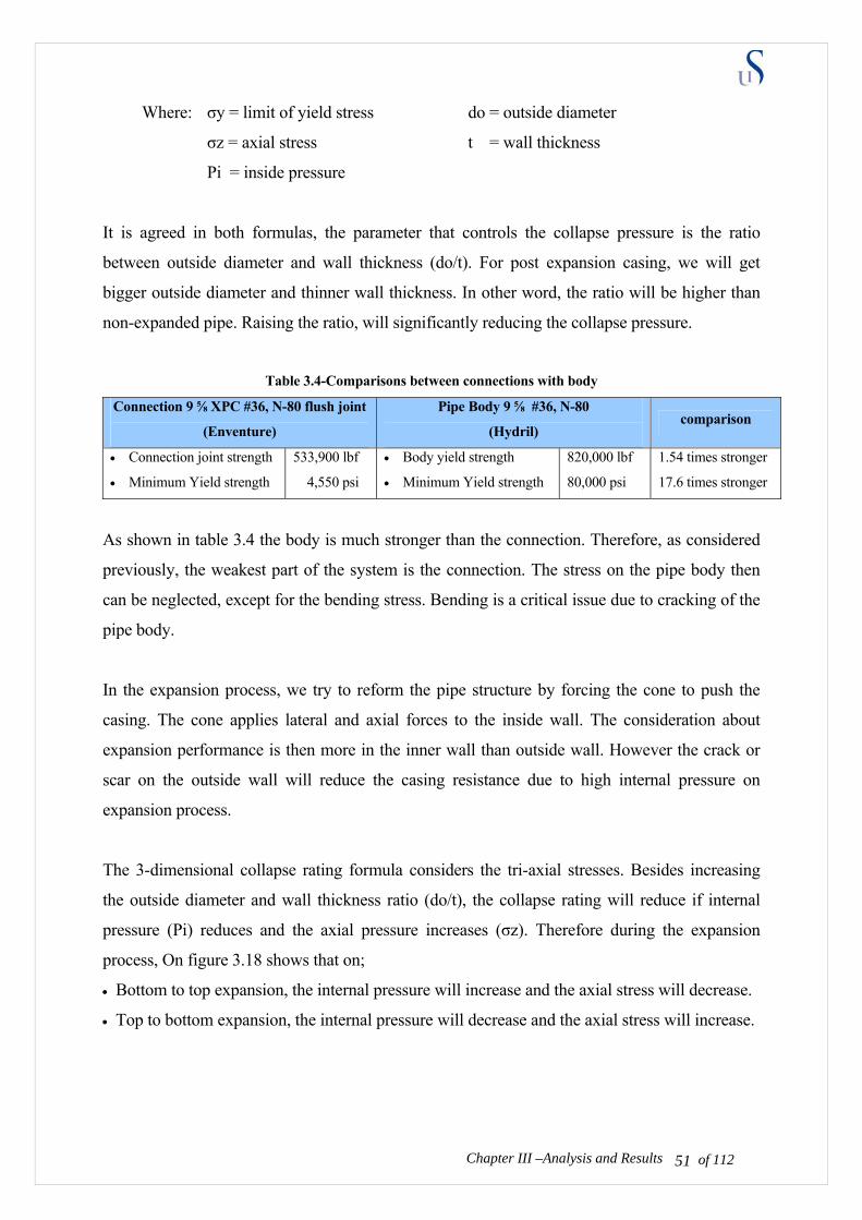
Where: σy = limit of yield stress do = outside diameter
σz = axial stress t = wall thickness
Pi = inside pressure
It is agreed in both formulas, the parameter that controls the collapse pressure is the ratio
between outside diameter and wall thickness (do/t). For post expansion casing, we will get
bigger outside diameter and thinner wall thickness. In other word, the ratio will be higher than
non-expanded pipe. Raising the ratio, will significantly reducing the collapse pressure.
Table 3.4-Comparisons between connections with body
Connection 9 ⅝ XPC #36, N-80 flush joint
(Enventure)
Pipe Body 9 ⅝ #36, N-80
(Hydril) comparison
• Connection joint strength
• Minimum Yield strength
533,900 lbf
4,550 psi
• Body yield strength
• Minimum Yield strength
820,000 lbf
80,000 psi
1.54 times stronger
17.6 times stronger
As shown in table 3.4 the body is much stronger than the connection. Therefore, as considered
previously, the weakest part of the system is the connection. The stress on the pipe body then
can be neglected, except for the bending stress. Bending is a critical issue due to cracking of the
pipe body.
In the expansion process, we try to reform the pipe structure by forcing the cone to push the
casing. The cone applies lateral and axial forces to the inside wall. The consideration about
expansion performance is then more in the inner wall than outside wall. However the crack or
scar on the outside wall will reduce the casing resistance due to high internal pressure on
expansion process.
The 3-dimensional collapse rating formula considers the tri-axial stresses. Besides increasing
the outside diameter and wall thickness ratio (do/t), the collapse rating will reduce if internal
pressure (Pi) reduces and the axial pressure increases (σz). Therefore during the expansion
process, On figure 3.18 shows that on;
• Bottom to top expansion, the internal pressure will increase and the axial stress will decrease.
Chapter III –Analysis and Results of 112 51
• Top to bottom expansion, the internal pressure will decrease and the axial stress will increase.

The table 3.5 below will show us the properties of expandable casing pre and post expansion.
Data is provided by Enventure. It is shown obviously that the post expansion collapse rating is
very low.
Chapter III –Analysis and Results of 112 52
Figure 3.18-Comparison of expansion methods
Pi < σz >
Pi > σz <
Having a low internal pressure
and high axial stress according to
triaxial collapse pressure formula
is the worst combination.
Therefore the proper expansion
should be from bottom to top to
avoid low collapse rating slightly
after expansion

Chapter III –Analysis and Results
of 112 53
Tabl
e 3.
5-Pr
e an
d Po
st e
xpan
sion-
casin
g pr
oper
ties (
Dat
a is
prov
ided
by
Enve
ntur
e) [1
5]
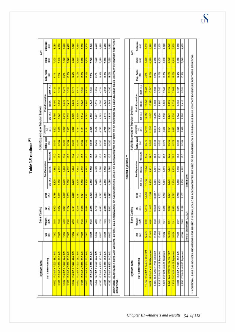
of 112 54
Tabl
e 3.
5-co
ntin
ue
Chapter III –Analysis and Results
[15]
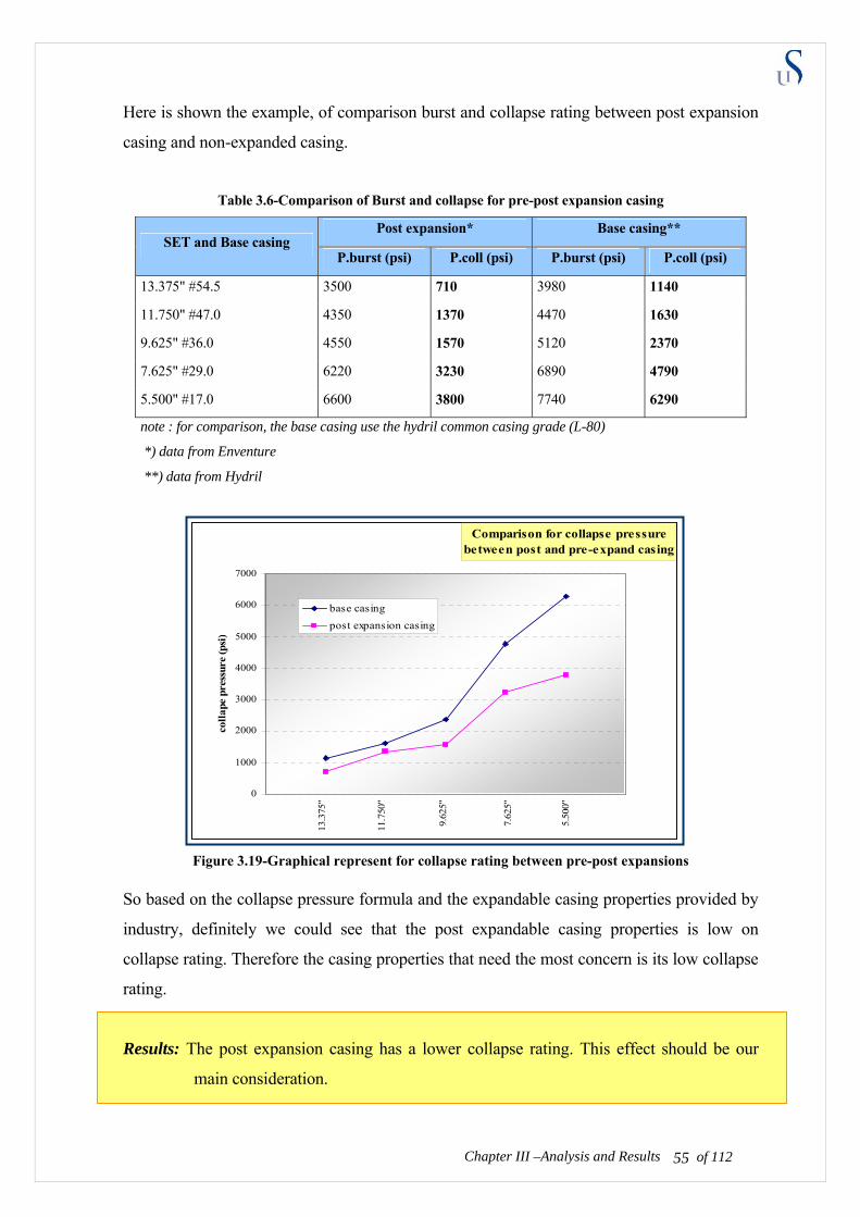
Here is shown the example, of comparison burst and collapse rating between post expansion
casing and non-expanded casing.
Table 3.6-Comparison of Burst and collapse for pre-post expansion casing
Post expansion* Base casing** SET and Base casing
P.burst (psi) P.coll (psi) P.burst (psi) P.coll (psi)
13.375" #54.5 3500 710 3980 1140
11.750" #47.0 4350 1370 4470 1630
9.625" #36.0 4550 1570 5120 2370
7.625" #29.0 6220 3230 6890 4790
5.500" #17.0 6600 3800 7740 6290
note : for comparison, the base casing use the hydril common casing grade (L-80)
*) data from Enventure
**) data from Hydril
Figure 3.19-Graphical represent for collapse rating between pre-post expansions
So based on the collapse pressure formula and the expandable casing properties provided by
industry, definitely we could see that the post expandable casing properties is low on
collapse rating. Therefore the casing properties that need the most concern is its low collapse
rating.
Results: The post expansion casing has a lower collapse rating. This effect should be our
main consideration.
Chapter III –Analysis and Results of 112 55
Comparison for collapse pressure between post and pre-expand casing
0
1000
2000
3000
4000
5000
6000
7000
colla
pe p
ress
ure
(psi
)
base casingpost expansion casing
13.3
75"
11.7
50"
9.62
5"
7.62
5"
5.50
0"
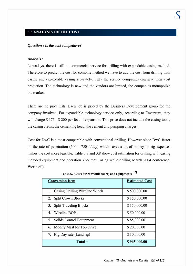
3.5 ANALYSIS OF THE COST
Question : Is the cost competitive?
Analysis :
Nowadays, there is still no commercial service for drilling with expandable casing method.
Therefore to predict the cost for combine method we have to add the cost from drilling with
casing and expandable casing separately. Only the service companies can give their cost
prediction. The technology is new and the vendors are limited, the companies monopolize
the market.
There are no price lists. Each job is priced by the Business Development group for the
company involved. For expandable technology service only, according to Enventure, they
will charge $ 175 - $ 200 per feet of expansion. This price does not include the casing tools,
the casing crews, the cementing head, the cement and pumping charges.
Cost for DwC is almost comparable with conventional drilling. However since DwC faster
on the rate of penetration (500 – 750 ft/day) which saves a lot of money on rig expenses
makes the cost more feasible. Table 3.7 and 3.8 show cost estimation for drilling with casing
included equipment and operation. (Source: Casing while drilling March 2004 conference,
World oil)
Table 3.7-Costs for conventional rig and equipments [12]
of 112 56Chapter III –Analysis and Results of 112
Conversion Item Estimated Cost
1. Casing Drilling Wireline Winch $ 500,000.00
2. Split Crown Blocks $ 150,000.00
3. Split Traveling Blocks $ 150,000.00
4. Wireline BOPs $ 50,000.00
5. Solids Control Equipment $ 85,000.00
6. Modify Mast for Top Drive $ 20,000.00
7. Rig Day rate (Land rig) $ 10,000.00
Total = $ 965,000.00
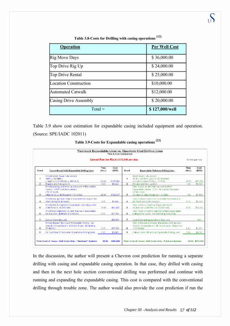
of 112 57Chapter III –Analysis and Results of 112
Table 3.8-Costs for Drilling with casing operations [12]
Operation Per Well Cost
Rig Move Days $ 36,000.00
Top Drive Rig Up $ 24,000.00
Top Drive Rental $ 25,000.00
Location Construction $10,000.00
Automated Catwalk $12,000.00
Casing Drive Assembly $ 20,000.00
Total = $ 127,000/well
Table 3.9 show cost estimation for expandable casing included equipment and operation.
(Source: SPE/IADC 102011)
Table 3.9-Costs for Expandable casing operations [22]
In the discussion, the author will present a Chevron cost prediction for running a separate
drilling with casing and expandable casing operation. In that case, they drilled with casing
and then in the next hole section conventional drilling was performed and continue with
running and expanding the expandable casing. This cost is compared with the conventional
drilling through trouble zone. The author would also provide the cost prediction if run the
9-5/8” monobore hole from top to bottom as the comparison case. However this cost
predictions neglect the additional cost because of failure and risks.
The well candidate that could have a reasonable cost to run this combine method is the wells
with:
• No acceptable conventional alternative.
• There is a significant drill through trouble zone – losses, gains, ledges, or sloughing.
• A tolerance for higher operational risk and possible failure wells.
• No requirement for high burst or collapse rating.
• Minimum hole angle with no doglegs
• The additional ID gained from using SET will yield a major economic benefit to offset
the additional rig time and high cost of the service.
Because of very limited information about the costs for the combined technology, the author
will predict the cost based on each support technologies. Using this case study, the author
will try to provide cost estimation for combine method that will be shown in next chapter.
The answer for the cost of this combine method, temporary can be concluded as below.
Result:
It is possible to save costs because running this combined method will reduce the rig time
used. However, well candidates should be carefully considered prior to using this method.
3.6 ANALYSIS OF THE OPERATIONAL LIMITATIONS AND RISKS
Question : Are there any limitations and risks on this process?
Analysis :
Combining those technologies means we also combine both technologies limitations.
The limitations of drilling with casing
Chapter III –Analysis and Results of 112 58
One of the challenging operations, which could become a limitation in drilling with casing, is
to land the casing hanger into the wellhead. The casing hanger should not be rotated when
seated on the wellhead, because the sealing and landing profile is weak due to deformation.
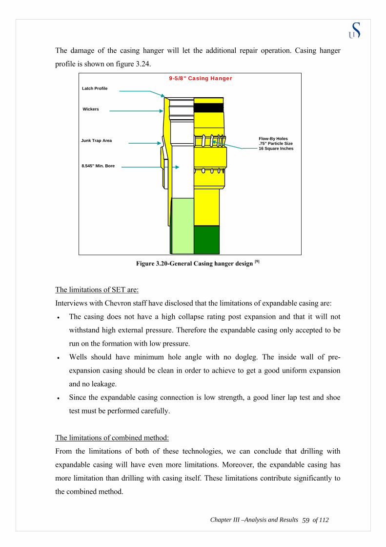
The damage of the casing hanger will let the additional repair operation. Casing hanger
profile is shown on figure 3.24.
Chapter III –Analysis and Results
9-5/8" Casing Hanger
Figure 3.20-General Casing hanger design [9]
The limitations of SET are:
Interviews with Chevron staff have disclosed that the limitations of expandable casing are:
• The casing does not have a high collapse rating post expansion and that it will not
withstand high external pressure. Therefore the expandable casing only accepted to be
run on the formation with low pressure.
• Wells should have minimum hole angle with no dogleg. The inside wall of pre-
expansion casing should be clean in order to achieve to get a good uniform expansion
and no leakage.
• Since the expandable casing connection is low strength, a good liner lap test and shoe
test must be performed carefully.
The limitations of combined method:
From the limitations of both of these technologies, we can conclude that drilling with
expandable casing will have even more limitations. Moreover, the expandable casing has
more limitation than drilling with casing itself. These limitations contribute significantly to
the combined method.
of 112 59
Latch Profile
Wickers
Junk Trap Area Flow-By Holes .75” Particle Size 16 Square Inches
8.545” Min. Bore

After analyzed, technically, there are two major limitations within this method, which are:
• The expandable casing connection has a low torque rating. Minimum hole angle and
whirl with no big torsion should be achieved to avoid the expandable connection falling
apart when drilling or expanding.
• The casing is very low on the collapse rating. Tendency to collapse is high especially
when the formation pressure is high and the pipe on tension.
Risk analysis of combined method
In order to do risk analysis, there are two outcomes of this technology that become our
concern:
• Health, Safety and Environment (HSE) outcomes
• Time delay and economical outcomes
These two outcomes will be applied and analyzed as the impact when the combined method
fails. The results of the analysis will be presented both in its probability (frequency it occurs)
and consequence (impact if it happens). The probability will be arranged and valued from
very low probable, less probable, probable, high probability to very high probability. The
consequences will be arranged and valued from minor, significant, severe, and major to
catastrophic. This value will be assessed by author belief and will be plotted on risk matrix.
Based on its limitations, the boundaries are;
1. The expandable casing connection has a low torque rating. Minimum hole angle and
whirl with no big torsion should be achieved to avoid the expandable connection falling
apart when drilling or expanding. The impact on:
of 112 60Chapter III –Analysis and Results
a. Health, Safety and Environment (HSE) are:
If the connection fails when drilling or expanding, the drillstring will disconnect. The
lost circulation or the kick could happen depend on how high the formation pressure
compares to pipe internal pressure.
Kick could blow out to the surface if the barriers fail. The integrity of the rig and the
safety and lives of the crews will be in danger. Besides, the kick could bring
uncontrolled volumes of formation fluid up to the surface, which will contaminate
the environment around the rig site.

In the event of the lost circulation, there will not be a high risk to the crews’ lives and
surface environment.
The author’s assessment is High probability and Major consequence
b. Time delay and economical outcomes are:
If the drillstring disconnects, the kick or the lost circulation will have significant
effects on additional operation time which will impact on the cost.
Since the well control technology quite advances now, we could detect the kick faster
or solve it safer. However a kick may not so severe, but an extreme kick is a blowout
which will indeed lead to a long time delay.
The lost circulation needs time to be solved. One has to stop the whole operation and
make a new fluid which will add to a lot of time delay. Besides, the fluid which is
lost into the formation will increase the operational cost.
The author’s assessment is High probability and Severe consequence.
2. The casing is very low on the collapse rating. Tendency to collapse is high especially
when the formation pressure is high and the pipe is on tension. The impact on:
a. Health, Safety and Environment (HSE) are:
If collapse happens, the casing will reduce in size (the inside diameter gets smaller).
It prevents the next string of casing to be run. Therefore the operation may have to be
stopped. If there is no leaking, the pressure will be in a static condition. The safety
and the environment will be ensured.
However if there is a leak, lost circulation or kick could happen. The risk could be
significant. However from a collapse to the leak phase, it is a progressive process
therefore it will be detected and handled earlier. Barriers will be activated to prevent
the blow out.
The author’s assessment is Probable and Significant consequence.
Chapter III –Analysis and Results of 112 61
b. Time delay and economical outcomes are:
If collapse occurs, the casing ID will significantly reduce in size (its inside diameter
gets smaller). To be able to run the next casing or drillpipe, further analysis should be
conducted. We may run a log to map the ID geometry; we also may run a mill to
make the size uniform. Many alternative operations could be studied before the final
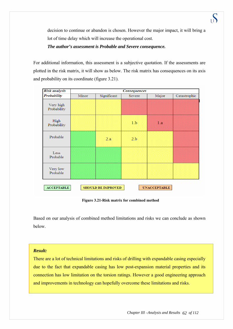
decision to continue or abandon is chosen. However the major impact, it will bring a
lot of time delay which will increase the operational cost.
The author’s assessment is Probable and Severe consequence.
For additional information, this assessment is a subjective quotation. If the assessments are
plotted in the risk matrix, it will show as below. The risk matrix has consequences on its axis
and probability on its coordinate (figure 3.21).
Based on our analysis of combined method limitations and risks we can conclude as shown
below.
Result:
There are a lot of technical limitations and risks of drilling with expandable casing especially
due to the fact that expandable casing has low post-expansion material properties and its
connection has low limitation on the torsion ratings. However a good engineering approach
and improvements in technology can hopefully overcome these limitations and risks.
Chapter III –Analysis and Results of 112 62
Figure 3.21-Risk matrix for combined method

CHAPTER IV
DISCUSSION
Here we will discuss our analysis from chapter 3. To simplify, before the discussion we will
refresh the results from our analysis on each sub-chapter. This chapter will present the
challenge, proposed solution or discussion.
4.1 DISCUSSION OF THE DRILLING – EXPANSION METHODOLOGY
Challenge: How can this combined method works?
Result:
• Conceptually with present technology, drilling with expandable casing is possible.
• Since we do not need to mill out the cement and clean the inside wall interface of casing,
the bottom to top expansion is recommended for drilling with expandable casing method.
Discussion
Discussion 1: Conceptually with present technology, drilling with expandable casing is
possible.
We first use drilling with casing system, which is provided by Tesco Corp, the expandable
casing is used as the drillstring for transmitting the drilling forces. The expandable casing
could be provided by Enventure or Weatherford, depending on which expansion method we
are going to use.
The drilling with casing could use non-retrievable or retrievable bottom hole assembly. For
example, if we use:
• Non-retrievable BHA with drillable bit.
of 112 63
When the drill bit reached the expected depth, drop a ball to stop the circulation, pump
the cement and pressurize the cylinder to shear the bit. After the bit is sheared, with
annulus remaining open, run the “modified” expandable casing BHA to the casing shoe

and start expansion from bottom to top. Modified expandable BHA supposedly has an
expandable cone and uses the same expansion method. The chamber for the cone to
expand should be provided and can be attached to the open cylinder annulus.
• Non-retrievable BHA with non-drillable bit
When the drill bit reaches the expected depth, disconnect and drop the bit using wireline.
The bit will fall into the rat hole that had been previously drilled. With open annulus
remaining open, then we run the “modified” expandable casing BHA to the casing shoe
and start expansion from bottom to top. On the next drilling operation, the bit should be
steered to avoid the rat hole.
• Retrievable BHA and bit
When the drill bit reaches the expected depth, run the wireline to retrieve the BHA and
bit. When the wireline retrievable pin sits on the wireline retrievable box and latch, we
can disconnect the bit and BHA from the drillstring. By tripping out the wireline we can
receive our bit. On the casing shoe that remains an open annulus, then we run the
“modified” expandable casing BHA to the casing shoe and start expansion from bottom
to top.
If we would like to use top to bottom expansion, after the drill bit reached the expected
depth, drop the ball to stop the circulation, pump the cement and pressurize the cylinder to
shear the bit. After the bit is sheared, remaining with the drilling assembly, we then run mill
bit, brush and scraper to clean the inside interface wall of expandable casing. After this
requirement is met, we continue to drop the plug to close the open annulus. Then the
Modified Baker or Weatherford top-bottom expansion cone can be run to expand the casing.
Chapter IV – Discussion of 112 64
There is an additional conceptual plan that combines drilling and expanding bottom hole
assembly into one package drilling-expanding BHA. The purpose of installing this BHA is to
reduce additional operation for changing the BHA. The BHA conceptually might look like
the expandable BHA attached on the top of drilling BHA. When the drilling reaches the
expected depth we drop a ball to close the annulus in the bit. Then we can start the expansion
process from bottom to top (Enventure or Weatherford). Then the remaining drilling BHA
can be handled many different ways depending on whether a retrievable or non-retrievable
system had been used. This combined BHA can reduce the wireline tripping or BHA
changing times. In other word, it can save costs due to operation and rig times. However the
reliability of expansion assembly after being used for drilling operation should be studied

further. The conceptual design presented on above just shown as the overview to convince
that there are technical possibilities to combine both methods. Additional each technology is
discussed below:
Drilling with casing Technology
Tesco is a company that specializes in drilling with casing technology. Besides having
drilled a test well with 29,000 ft, they have drilled 125 commercial wells. Figure 4.1 shows
the Tesco drilling footage activities. In this figure you can see there is a significant increase
in the drilling depth using casing. Besides providing drilling with casing services, Tesco and
Weatherford also provide drilling with casing rig and support equipment.
Drilling with casing justification:
• Faster process
• Reduces trouble time
• Increased reserves
- More wells
- Better production rate
• Integrated rig solution
of 112 65
Lost circulation
Stuck Pipe
Kick
Sloughing Shale
Other
24% of time from spud to TD (Jan 2004 Offshore magazine)
Fig 4.1 Casing drilling footage
Figure 4.2-Comparison of trouble zone on DwC [14]
0
50 000
100 000
150 000
Qua
rter
ly C
asin
g D
rille
d Fo
otag
e
Q199
Q299
Q399
Q499
Q100
Q200
Q300
Q400
Q101
Q201
Q301
Q401
Q102
Q202
Q302
Q402
Q103
Q203
Q303
Q403
Q104
Figure 4.1-Casing drilling footage [14]

In some cases it is difficult to run the casing after the conventional drillstring is tripped out
because of poor borehole quality. Some of these difficulties can be reduced by using casing
for drilling. There is no full explanation for this, but the well stability could be improved
with casing drilling operations. Not knowing about the smear effect at the time, during DwC
operation, the operator raised the mud weight as needed on the first few wells and noted that
they could TD a hole section with ½ to 1 ppg less mud weight without experiencing the
losses they had worried about. It is predicted that this happened because they drilled with the
bigger OD and therefore they had bigger surface area between rock and the metal. Figure 4.3
shows the smear effect. Below the Smear effect experiment and analysis by drilling with
casing experts is presented. (Source information: World oil conference for DwC) [13]
They also noted the difference in the cuttings that came from the well (figure 4.4) compared
with conventional drilling. The time they hypothesized that they were smearing or plastering
of 112 66Chapter IV –Discussion of 112
Mud Weights (ppg)
Casing Drillpipe 9.6 10.2
9.5 10 – 10.3 9.7 10.2 – 10.8 10.1 10.9 – 11.0
Figure 4.3-Smear effect profiles [13]
Figure 4.4-Cutting comparison between DwC and conventional drilling [13]
DwC
Conventional

of 112 67Chapter IV –Discussion of 112
the wellbore wall with cuttings and creating a super touch filter super impermeable filter
cake. This phenomenon is termed the smear effect.
They tested this theory by drilling a well in an area near three wellbores which had all
suffered from severe lost returns problems. Two of the wells required not only cement plugs
to stop the losses but eventually a liner as well. The third well was stuck and sidetracked due
to open hole problems including losses. The casing drilling well was drilled in the middle of
these three wells and did not experience any losses or stuck pipe trouble.
Following this success they moved to a well that had been conventionally drilled with severe
losses. After three attempts to stop the losses with cement plugs the well was abandoned.
They moved one of the casing drilling rigs on to this wellhead and successfully drilled the
well down with little trouble.
They did have losses when they reamed out the cement plugs however after drilling 100 ft of
new hole the losses slowed significantly and were minimal after 500 feet. This proved that
the smear effect did indeed exist and was extremely beneficial in preventing losses in weak
or fractured formation.
Spud to Cementing of Intermediate
200 - 300 sack balanced cement plug
7” Csg.
May 2002 10 days
8,103’
Casing Drilled
9 5/8” Csg.
4 1/2” Csg.
5 1/2”Liner
5,145’
7” Csg.
9,400’
Offset 2
9 5/8”Csg.
3 1/2” Csg.
Sept 2001 19 days
5 1/2” Liner
7” Csg.
6,917’
8,162’
Offset 1
9 5/8” Csg.
7” Csg.
7,985’
5,272’
8,185’
Offset 3
9 5/8”Csg.
4 1/2”Csg.
3 1/2” Csg.
Figure 4.5-Smear effect experiment on testing wells [13]
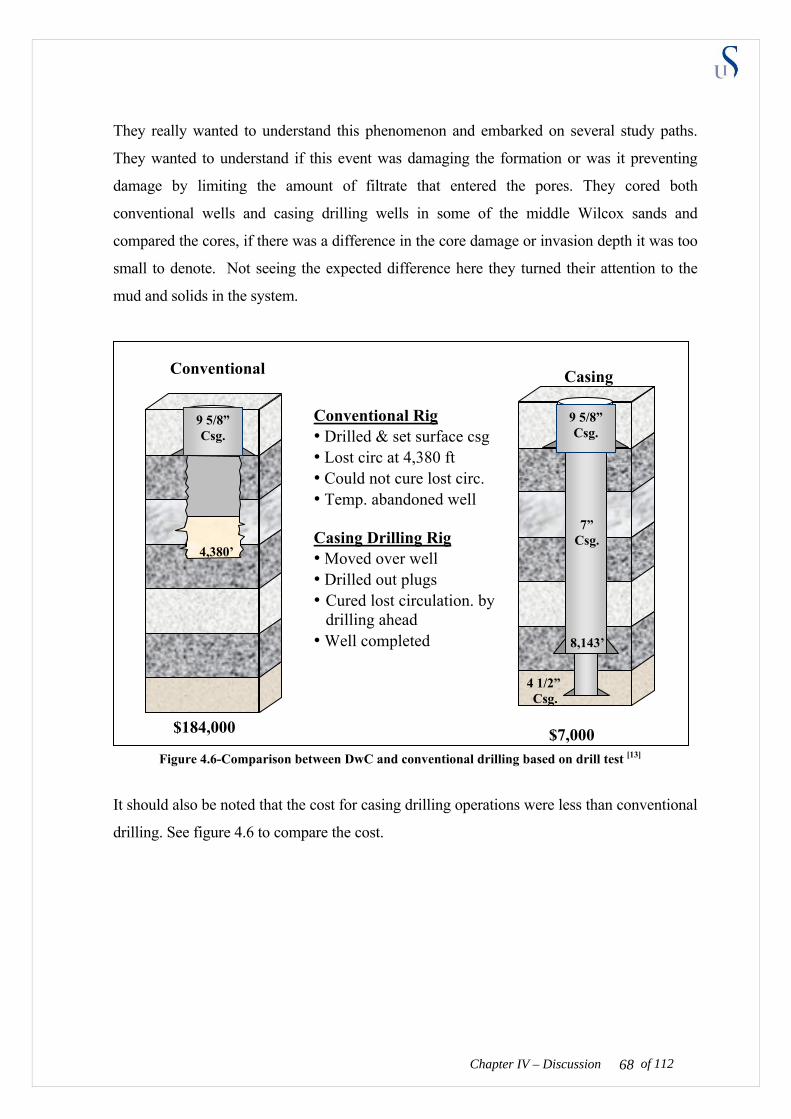
They really wanted to understand this phenomenon and embarked on several study paths.
They wanted to understand if this event was damaging the formation or was it preventing
damage by limiting the amount of filtrate that entered the pores. They cored both
conventional wells and casing drilling wells in some of the middle Wilcox sands and
compared the cores, if there was a difference in the core damage or invasion depth it was too
small to denote. Not seeing the expected difference here they turned their attention to the
mud and solids in the system.
It should also be noted that the cost for casing drilling operations were less than conventional
drilling. See figure 4.6 to compare the cost.
of 112 68Chapter IV – Discussion
7” Csg.
$7,000
8,143’
Casing
9 5/8” Csg.
4 1/2” Csg.
Conventional
9 5/8” Csg.
$184,000
4,380’
Conventional Rig • Drilled & set surface csg • Lost circ at 4,380 ft • Could not cure lost circ. • Temp. abandoned well Casing Drilling Rig • Moved over well • Drilled out plugs • Cured lost circulation. by
drilling ahead • Well completed
Figure 4.6-Comparison between DwC and conventional drilling based on drill test [13]
Expandable technology [6]
In open hole applications, Enventure is the only field proven technology at this time
according to Chevron expandable expert (REF). However, on cased hole applications, Baker
and Weatherford may be a better alternative. On a cased hole application, Baker is available
for 5 ½”, 7”, and 7 5/8” base casing repairs only. The Weatherford system is only available
for 6 5/8” and 7” (9 5/8” also designed). There are no price lists. Each job is priced by the
Business Development group for the company involved. This service is expensive –The pipe
is listed in the range of $150 - 200 / foot on the quotes.
Weatherford and Baker have re-usable tools which means they could be cheaper and do not
require drilling out at the end of the expansion. Enventure does a pressure test on the liner as
it is placed, but the aluminum shoe must be drilled out at the end of the expansion with a full
gauge bit or mill. The wall thickness on most Enventure pipe is ± 0.375” where Baker uses ±
0.25” wall. Clearance and strength vary accordingly. The Weatherford rotary technique uses
a metal-to-metal contact which can cause variation in wall thickness. Burst and collapse
properties of the patch are enhanced by the base pipe. Burst can be calculated and estimated,
but collapse if critical may require testing.
The Baker and Weatherford tools are “compliant” and will pass through a restriction in the
casing. The Enventure tool is solid and will assure a full gauge, round hole. The Enventure
system will not tolerate any debris between the patch and the base casing.
The top down expansion systems of Baker and Weatherford allow easy access and
replacement of the expansion mandrel, if a problem occurs. The bottom up Enventure system
requires backing out of the safety joint, pulling the inner drill pipe string, cutting and
recovering the unexpanded patch, and finally, recovering the solid mandrel. The lower
section of expanded patch must then be milled up unless there is room to start again above
that point.
The correct system to be used in a cased hole operation will depend on the specific
objectives of the application (pressure integrity, clearance, cost, size, operability, availability,
deliverability, etc.). All three systems should be evaluated.
Chapter IV – Discussion of 112 69
The generic cost estimate for a short 40’ patch for 5 ½” casing from Baker is approximately
$44,000. This estimate shows that the costs are very reasonable. This could be a solution to
shallow casing leaks where squeezes are often repeated without success. The cost is lower
because of the re-useable expansion tools. An additional benefit is that no drill out would be
required after expansion. However, note that the cost for additional length is between $150
and $175 per foot.
The Weatherford rotary system and the Baker drill pipe piston system do not require drill out
like the Enventure pressure expansion system does. The expansion tools are also re-useable
unlike the Enventure fixed cone. The Weatherford rotary system is dependant on bearing life
which is 300 ft. Sizes are also very limited for Baker and Weatherford.
Weatherford has also obtained the patent right to solid cone pressure expansion from Shell
but they do not have a commercial product at this time. They also offer the original Homco
patch and own that technology as well. Weatherford is in the development stage on multiple
SET concepts.
An industry SET users group was formed in April of 2003 in Houston. The group was
organized by Unocal with strong BP support. Early in 2004 several service companies
sponsored an industry survey of the operators to evaluate the potential market demand for
expandable tubular products. The Rock Mechanic consulting group conducted the survey
and shared the results with those that participated. The survey is an objective, non-technical,
optimistic view of the expandable market. Some of the study conclusions were:
• The very high reliability of expandable sand screens and solid expandable tubular
technology
• That the future of Slim Well-type wells is finally here (i.e. the use of multiple
expendables to reduce or slim the casing profile of a well
• That the future of monodiameter wells is soon.
Chapter IV – Discussion of 112 70
In this business, there are many things involved such as patent right, economy strategy and
companies political issues. Regarding the industry overview showed above, to be able to
apply drilling and expanding method, we will study the application of the conceptual
example using industry practice. Here we present our conceptual plan application using
industry technology.
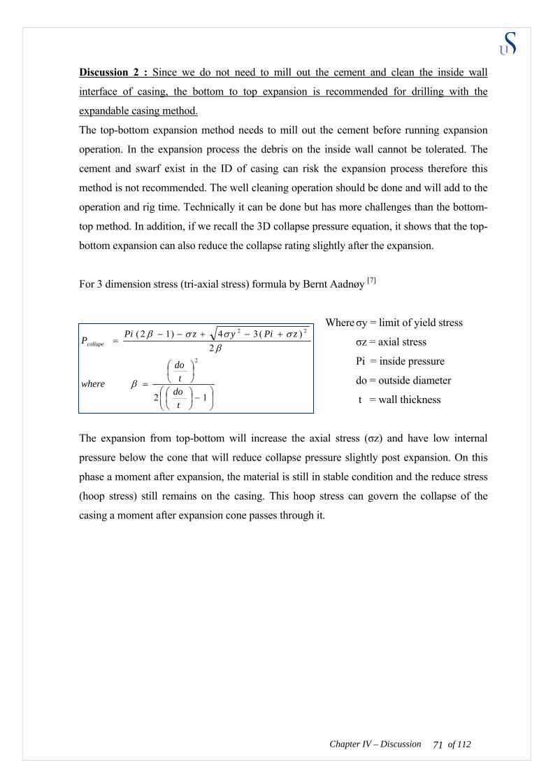
Discussion 2 : Since we do not need to mill out the cement and clean the inside wall
interface of casing, the bottom to top expansion is recommended for drilling with the
expandable casing method.
The top-bottom expansion method needs to mill out the cement before running expansion
operation. In the expansion process the debris on the inside wall cannot be tolerated. The
cement and swarf exist in the ID of casing can risk the expansion process therefore this
method is not recommended. The well cleaning operation should be done and will add to the
operation and rig time. Technically it can be done but has more challenges than the bottom-
top method. In addition, if we recall the 3D collapse pressure equation, it shows that the top-
bottom expansion can also reduce the collapse rating slightly after the expansion.
For 3 dimension stress (tri-axial stress) formula by Bernt Aadnøy [7]
Where σy = limit of yield stress
σz = axial stress
Pi = inside pressure
do = outside diameter
t = wall thickness
The expansion from top-bottom will increase the axial stress (σz) and have low internal
pressure below the cone that will reduce collapse pressure slightly post expansion. On this
phase a moment after expansion, the material is still in stable condition and the reduce stress
(hoop stress) still remains on the casing. This hoop stress can govern the collapse of the
casing a moment after expansion cone passes through it.
Chapter IV – Discussion of 112 71
⎟⎠
⎞⎜⎝
⎛−⎟
⎠⎞
⎜⎝⎛
⎟⎠⎞
⎜⎝⎛
=
+−+−−=
12
2)(34)12(
2
22
tdo
tdo
where
zPiyzPiPcollape
β
βσσσβ
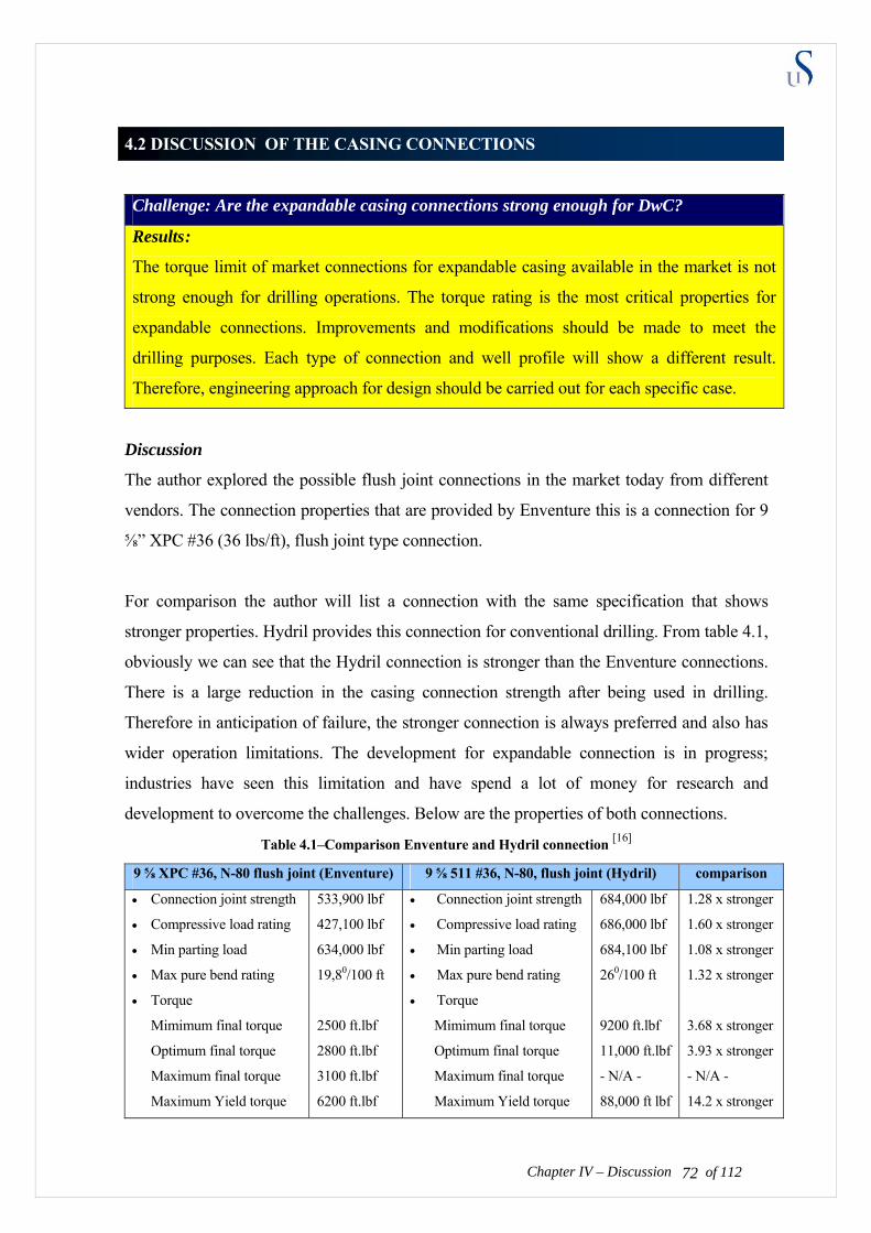
4.2 DISCUSSION OF THE CASING CONNECTIONS
Challenge: Are the expandable casing connections strong enough for DwC?
Results :
The torque limit of market connections for expandable casing available in the market is not
strong enough for drilling operations. The torque rating is the most critical properties for
expandable connections. Improvements and modifications should be made to meet the
drilling purposes. Each type of connection and well profile will show a different result.
Therefore, engineering approach for design should be carried out for each specific case.
Discussion
The author explored the possible flush joint connections in the market today from different
vendors. The connection properties that are provided by Enventure this is a connection for 9
⅝” XPC #36 (36 lbs/ft), flush joint type connection.
For comparison the author will list a connection with the same specification that shows
stronger properties. Hydril provides this connection for conventional drilling. From table 4.1,
obviously we can see that the Hydril connection is stronger than the Enventure connections.
There is a large reduction in the casing connection strength after being used in drilling.
Therefore in anticipation of failure, the stronger connection is always preferred and also has
wider operation limitations. The development for expandable connection is in progress;
industries have seen this limitation and have spend a lot of money for research and
development to overcome the challenges. Below are the properties of both connections.
Table 4.1–Comparison Enventure and Hydril connection [16]
Chapter IV – Discussion of 112 72
9 ⅝ XPC #36, N-80 flush joint (Enventure) 9 ⅝ 511 #36, N-80, flush joint (Hydril) comparison
• Connection joint strength
• Compressive load rating
• Min parting load
• Max pure bend rating
• Torque
Mimimum final torque
Optimum final torque
Maximum final torque
Maximum Yield torque
533,900 lbf
427,100 lbf
634,000 lbf
19,80/100 ft
2500 ft.lbf
2800 ft.lbf
3100 ft.lbf
6200 ft.lbf
• Connection joint strength
• Compressive load rating
• Min parting load
• Max pure bend rating
• Torque
Mimimum final torque
Optimum final torque
Maximum final torque
Maximum Yield torque
684,000 lbf
686,000 lbf
684,100 lbf
260/100 ft
9200 ft.lbf
11,000 ft.lbf
- N/A -
88,000 ft lbf
1.28 x stronger
1.60 x stronger
1.08 x stronger
1.32 x stronger
3.68 x stronger
3.93 x stronger
- N/A -
14.2 x stronger
The criteria for connection properties to assure the successful operation are:
• Make up torque of connection must be bigger than torsion in drilling operation
• Connection joint strength must be higher than tension or hook load in drilling operation.
• Compressive load rating must be bigger than string weight in the mud.
• Maximum bending rating must be bigger than the dogleg in well profile.
The connector provides discontinuities that may be the weakest point for fatigue. The
main fatigue in connection is because the casing connector geometry may create stress
riser where local stresses are higher than expected. Alternating stress is higher in the
connection than the body which means the connection is weaker.
When the connector is made up on the surface, the torque is acting through the threads to
produce a screw jack effect. This effect places compression on the torque shoulder and
high tension in the coupling wall. The magnitude of this tensile stress depends on the make
up torque, the thread design, coupling wall thickness, joint compound friction coefficient
and the amount of interference from the thread. The fatigue life and ultimate torque rating
must be balanced.
Expandable joint yield torque is approximately 93 % lower than usual casing connection. In
other words, the expandable connection is 14 times weaker than usual connections. This
property is unacceptable for drilling operation. It is not strong enough on torsion for drilling
operation as proved in the chapter three.
Since it is stronger, the Hydrill connection could be used for expandable and DwC
applications. However, according to the expandable designer and developer for Weatherford,
modification of Hydril 511 connection should be made. The groove should be cut and an
elastomer that allows the connection to seal during expansion and post-expansion process
needs to be added. It should be kept in mind that the stronger connection needs more lateral
expansion force to be able to expand properly.
Chapter IV – Discussion of 112 73
We also can use bottom hole motor; so the upper string doesn’t suffer from big torsion. The
rotation in the upper string is for hole cleaning purposes. Below the industry updates about
casing connection technology are shown in order to show that improvements are on going
and show promising results.

Additional information 1 [8]
A paper was presented this year about Connection Qualification for casing-Drilling
application (SPE/IADC 105432). In this paper they presented the method for testing and
inspecting the connection of 9 5/8”, 53.5lb, P-110 DWC/C-SR connection.
This coupled connection utilizes a thread seal and resilient seal ring to enhance the pressure
containability (see figure 4.1). The design employs an API buttress thread with abutting pin
noses as the torque shoulder to improve the torque capacity and fatigue performance.
Depending on application, there are two options for the seal rings (100% virgin Teflon or
25% glass filled Teflon). The glass filled version was used for this project.
Figure 4-1 DWC/C-SR connection
The result of this test confirms that the connection has passed the test without leaking or
mechanical failure. The test for qualification is accepted. Chevron and Grantprideco
cooperated together on this project. In the future this qualification tests should be run for the
modified connection for DwC and expandable purposes, such as a modified Hydril 511
connection.
Additional information 2 [4]
Here is the updated information from the service company about the Join Industry Project
(JIP) coordinates by Noble. This project is focusing on technologies exchange between
services companies and also field testing in Houston. One of the purposes is to test and
modify the Hydril’s connection that has also included as a participant of JIP.
Hydril’s task is to cut 723 expandable wedge threads at its normal premium thread prices.
Hydril will provide these connections at its normal premium connection prices and will assist
in running the expandable casing in the field to ensure that the threaded connections are
inspected and run properly.
Chapter IV – Discussion of 112 74
Problems with existing weak connections are:
1. Major cause of solid expandable failures
2. Limit ability to expand strong casing (P110)
3. Limit amount that casing can be expanded
4. Reduce burst and collapse strength
5. Pull apart during expansion
6. Require special “drawn-over-mandrel” casing
7. Cannot tolerate casing “dings” and blemishes
8. Require outer sleeve reinforcement
9. Thread leakage prevents expansion
10. Prevent expanding Monobore overlaps in one step
Hydril 723 Expandable Wedge Thread is:
1. Stronger threads critical to SET success
2. Hydril 723 wedge thread 30 to 60% stronger
3. Wedge design holds threads together during expansion
4. Use off-the-shelf casing with normal “dings” and defects
5. Eliminates special handling of casing
6. Increases reliability & reduces cost
7. Gives Noble a major competitive advantage
Kind of Hydril 723 Expandable Wedge Thread testing
New or modified expandable tools and new threaded connectors will be tested at TIW’s
Houston facility prior to being run in Participant monobore wells. These tests will be
conducted in TIW’s test frame pump facility, test laboratory and shallow test well in
Houston. These tests will include:
1. Cone force measurements
2. Threaded connection tests
3. Burst and collapse tests
4. Pumping tests
5. Shallow well tests
6. Monobore overlap expansion tests
7. Liner hanger tests
of 112 75Chapter IV – Discussion
8. Packer expansion tests
The conclusion of JIP is confidential to the sponsor and service companies. All intellectual
property (IP) developed during this JIP will belong to the companies that develop it (e.g.,
Noble Drilling, TIW, Hydril, TAM, Smith International, Houston Engineers, CSI
Technologies, CCSI, etc.) since these service companies are paying for the development of
the tools used on this project and need to own the IP to successfully market their tools and
services.
No IP rights will be granted to JIP Participants since Participants will receive their benefit
from this JIP by using ET wells in their fields to reduce drilling costs and having first call on
the use of Noble’s ET tools for two years after Phase I is completed.
Both industry examples show the high-torque and no leaking due to expansion connection
research and development is still on going. The development shows promising result for
further operations.
4.3 DISCUSSION OF THE EXPANSION PERFORMANCE POST-DRILLING
Challenge : How does the expandable casing perform after being used for drilling?
Result :
Expandable casing could become de-rated post the drilling operations. Therefore, there are
some drilling considerations:
• To assure we have a clean interface on the inside wall of the casing we should do a
cleaning operation before the expansion process. To assure we have a uniform inside
diameter, a mill should be installed on the drillstring during the cleaning operation.
• To avoid exceeding torsion on the expandable casing connectors due to tortuosity and
dogleg, stabilizers should be installed.
• To minimize the whirl that can lead to the connection becoming fatigued, we should use
a better lubricator and drill with low RPM, alternatively high RPM using a mud motor.
Discussion:
of 112 76Chapter IV –Discussion of 112
of 112 77Chapter IV –Discussion of 112
Discussion 1: To assure we have a clean interface on the inside wall of the casing we should
do a cleaning operation before the expansion process. To assure we have a uniform inside
diameter, a mill should be installed on the drillstring during the cleaning operation.
Based on the dynamics of the well debris can stay in the bottom of hole, in the drillstring
wall and suspended in drilling fluid in annulus. Debris can be classified as “Solid”, “Gunk”
or “Junk”: [19]
• Solids includes
- Mill scale rust from poorly prepared tubular
- Swarf from milling operation
- Solid fallout from drilling fluids e.g. Barite
- Cutting formation and cement
• Gunk includes
- Viscous drilling fluid such as synthetic mud at low temperature
- Gelling of OBM on contact with water
- Thread compound (pipe drop)
• Junk includes
- Materials generated during cement plug or float equipment drill out
- Metal generated after float or completion equipment drill out
- Elastomers/seal remain after milling as packer
- Debris by product of perforation operation
- Any other foreign material introduced from surface
Source of debris [19]
• Drill pipe & casing wear due to tripping in & out of hole
• P&A plugs (cement & drillable packers)
• Tie-back float equipment (wiper plug, collar & cement)
• Failure to bump the plug while cementing (cement, wiper plugs)
• Unconditioned mud (barite/solids fall-out due to poor/reduced suspension properties)
• Surface equipment (drill floor, hydraulics & hoisting systems)
• Mud emulsions
• Any tool run through the rotary
• Miscellaneous unknown
Determination of Well Cleanliness
• Nephelometric Turbidity Units (NTU)
The determination of well cleanliness is usually based on the cleanliness of fluid returning
from the wellbore. The most common measures are Nephelometric Turbidity Units (NTU)
and solids content. The higher the NTU number, the lower the well cleanness. Usually if
the NTU < 100 the well is defined as a clean well, however this is also depend on company
demand.
• Drag and Toque (additional)
Other indicators of a clean well are torque and drag (related to the friction coefficient of
fluid coating the casing walls) and cleanliness of the string when was pulled back.
Mechanical Wellbore Cleaning Tools
Basically, based on the working method and which debris are being cleaned, we can group
the tools into:
• Casing scrapers to remove cement and casing burrs
• Casing brushes to remove gunk, cement and scale
• Magnetic tools to retrieve ferrous debris
Best wellbore cleaning conditions are:
• High annular velocity
The higher the annular velocity, the cleaner the well will be. In a highly deviated well, flow
rate is the most critical parameter affecting hole cleaning efficiency. An increase in annular
velocity improves hole cleaning, regardless of the flow regime. Therefore, we need a
circulating device to boost the low annular velocity.
• Turbulent flow
Turbulent flow is a chaotic flow characterised by intense mixing caused by eddies.
Turbulence is deliberately initiated to help displace the mud cake from the walls to the
hole.
• Good concentric flow profile
The best carrying capacity is produced when the drillpipe is concentric within the annulus.
This provides a uniform annular profile throughout the annular cross section. In horizontal
wells the concentric profile can be achieved by introducing a stabilizer. As additional
information the casing scraper can also acts as a stabilizer.
Chapter IV – Discussion of 112 78

• Mud Rheology
The relationships between mud rheology and hole cleaning vary, depending on the annular
flow regime. Viscosity provides the mechanism by which fluid energy is transferred to the
cutting. Gel strength also provides suspension under static conditions, such as when the
flow stops due to the pumps being turned off.
Therefore to assure the casing inside diameter is clean and uniform before expansion
operation, it is recommended for the well cleaning operation to be run before the expansion
process. The debris can be accumulated on the inside wall of the casing when casing is used
for drilling operation. Mud, cement, chemicals substances and fluids are circulated through
the inside of the casing. All of these effects should be taken into account. We do not want to
take a risk of casing failure or casing leak during the expansion process. Any cement junk
and swarf that stacked on the wall and scar on the interface of the wall could jeopardize the
expansion process. The cone could be stuck and cannot pull out of hole or the wall could not
expand properly due to un-uniform diameter size.
Discussion 2: To avoid exceeding torsion on the expandable casing connectors due to
tortuosity and dogleg, stabilizers should be installed.
Drillstring fatigue failures generally result from oscillating bending stress rather than axial or
torsional loads. Fatigue is predominantly located in the lower portion of the drillstring, rather
than the top where the static point is highest. In many cases, fatigue crack will result in a leak
before the final rupture. The majority of wash outs that are found in drillstring are actually
caused by the fatigue cracks. In order to fatigue, the part must be exposed to an alternating
tensile stress. There are 2 common sources of cyclical tensile stresses, Bending stress that
result from rotating the pipe and the vibration.
hen the pipe is elastically deflected, the
than the inside (see figure 4.8).
Figure 4.8-Bending stress from pipe curvature [2]
W
PP
outside is tension and the inside is
compression. Since the wall thickness is thin,
the entire wall will suffer the same stresses.
The outer fiber will be stressed slightly more
of 112 79Chapter IV – Discussion

Chapter IV – Discussion
e diameter and
he bending will lead to the cone not giving uniform lateral expansion force. This effect
uce the bending stress we could do:
voiding pipe body from big dogleg
his stress concentration factor is multiplied by the bending stress to obtain the alternating
he maximum allowable operating stress for CwD
bigger the alter
The magnitude of the alternating bending stress is proportional to the pip
dogleg severity. This dictates that the larger casing must be limited to smaller curvature in
order to prevent fatigue failures.
T
results in the post expansion casing having an eclipse shape rather than a smooth circular
shape. The eclipse shape of the post expansion casing will make the casing easier to collapse.
The example of this case is on coiled tubing drilling, where it easy to collapse due to its
eclipse shape.
To solve and red
• Put more stabilizers on the casing, therefore the a
• Increase the care of the pipe handling
T
stress*) for fatigue life calculation. The higher the alternating stress, the lower the casing
strength. The magnitude of the alternating bending stress is proportional to the pipe diameter
and dog-leg severity. This dictates that the larger casing must be limited to smaller curvature
in order to prevent fatigue failures. If curvature and the outside diameter are big the
alternating stress will increase. In addition, the casing is subjected to axial stresses from the
hanging weight and from internal pressure that can increase the mean stress level and also
reduce the alternating stress 20-30% or more.
T
situation depends on the number of the alternating
stress cycles expected. The casing is likely to be
subjected to a higher alternating stress than
drillpipe in drilling the same hole size and
inclination. This means the casing maximum
allowable operating stress is higher than drillpipe.
An example of alternating stress relationship with
dogleg can be seen in figure 4.9.
The bigger the OD of casing the
Fi
nating stress worked on the same dogleg
gure 4.9-Alternating stress for curve drillstring [2]
tress: A stress produced in a material by forces that are such that each force alternately acts in opposite directions.
angle.
of 112 80
Alternating s

Discussion 3: To minimize the whirl that can lead to the connection becoming fatigued, we
should use a better lubricator and drill with low RPM, alternatively high RPM using a mud
motor.
Fatigue failures are caused by cyclical loading at stresses well below the elastic strength of
he friction factor used is generally assumed to be independent of velocity and the rotating
enerally the curved section high in the well contributes more to torque and drag than the
e main points relating to casing whirl are listed below:
is often indicative of whirl
) but
-
tion and abrasive
cies; RPM should not pass the
- poor lubrication fluid
ooth
the part. Under repeated loading, a crack develops at a point of localized high stress and
propagates through the body until the remaining cross sectional area is insufficient to support
the static load.
T
torque (whirl) should be independent of rotary speed. Differences between DwC and
conventional drilling are in average weight and diameter. Casing is much heavier than drill
string with almost the same properties. Casing coupling is also bigger than DP tool joints.
High inclination makes the torque and drag bigger.
G
same curvature located deeper in the well. Tension is maximal in the vertical section and
drag is maximal in the horizontal section. Therefore when drilling with casing, the casing
OD is bigger, the OH is smaller and the RPM is high. Those are the best combination for
whirl to occur.
Th
- Torque that increases when the rotary speed increases
- Torque that remains high when the bit is picked up off bottom (at constant RPM
returns to normal when the RPM is reduced to zero and restarted is proof of whirl
Threshold WOB and rpm to initiate drillstring whirl
- Whirl can be reduced by reducing the RPM and WOB
- Whirl tends to happen when drilled through hard forma
- Drillstring whirl is sometimes associated with buckling
- Whirl may also associate with lateral resonant frequen
limit of this frequency
Whirl is more likely in
- Centralizer can increase the whirl if it is not sm
of 112 81Chapter IV – Discussion
- Design of Bit also can initiate whirl
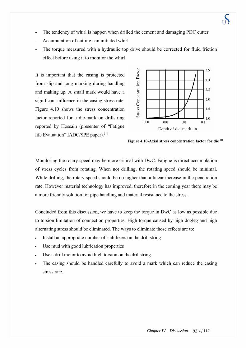
- The tendency of whirl is happen when drilled the cement and damaging PDC cutter
rive sh fluid friction
is important that the casing is protected
onitoring the rotary speed may be more critical with DwC. Fatigue is direct accumulation
oncluded from this discussion, we have to keep the torque in DwC as low as possible due
he drillstring
rk which can reduce the casing
- Accumulation of cutting can initiated whirl
- The torque measured with a hydraulic top d ould be corrected for
effect before using it to monitor the whirl
It
from slip and tong marking during handling
and making up. A small mark would have a
significant influence in the casing stress rate.
Figure 4.10 shows the stress concentration
factor reported for a die-mark on drillstring
reported by Hossain (presenter of “Fatigue
life Evaluation” IADC/SPE paper).[3]
Figure 4.10-Axial stress concentration factor for die [2]
M
of stress cycles from rotating. When not drilling, the rotating speed should be minimal.
While drilling, the rotary speed should be no higher than a linear increase in the penetration
rate. However material technology has improved, therefore in the coming year there may be
a more friendly solution for pipe handling and material resistance to the stress.
C
to torsion limitation of connection properties. High torque caused by high dogleg and high
alternating stress should be eliminated. The ways to eliminate those effects are to:
• Install an appropriate number of stabilizers on the drill string
• Use mud with good lubrication properties
• Use a drill motor to avoid high torsion on t
• The casing should be handled carefully to avoid a ma
stress rate.
of 112 82Chapter IV – Discussion
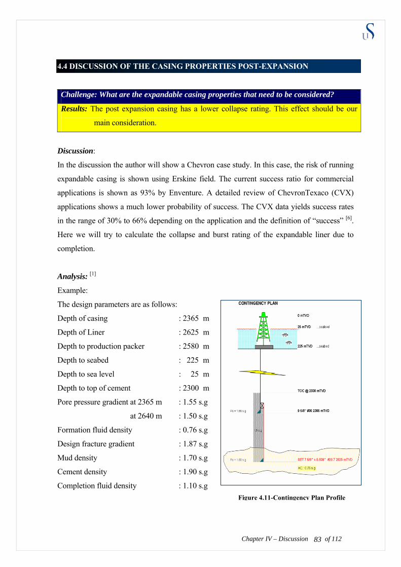
Chapter IV – Discussion
.4 DISCUSSION OF THE CASING PROPERTIES POST-EXPANSION 4
Challenge: What are the expandable casing properties that need to be considered?
Results: The post expansion casing has a lower collapse rating. This effect should be our
main consideration.
iscussion:
ion the author will show a Chevron case study. In this case, the risk of running
nalysis: [1]
parameters are as follows:
m
l
en
t 2365
density
D
In the discuss
expandable casing is shown using Erskine field. The current success ratio for commercial
applications is shown as 93% by Enventure. A detailed review of ChevronTexaco (CVX)
applications shows a much lower probability of success. The CVX data yields success rates
in the range of 30% to 66% depending on the application and the definition of “success” [6].
Here we will try to calculate the collapse and burst rating of the expandable liner due to
completion.
A
Example:
The design
Depth of casing : 2365
Depth of Liner : 2625 m
Depth to production packer : 2580 m
Depth to seabed : 225 m
Depth to sea leve : 25 m
Depth to top of cem t : 2300 m
Pore pressure gradient a m : 1.55 s.g
at 2640 m : 1.50 s.g
Formation fluid density : 0.76 s.g
Design fracture gradient : 1.87 s.g
Mud density : 1.70 s.g
Cement density : 1.90 s.g
Completion fluid : 1.10 s.g Figure 4.11-Contingency Plan Profile
of 112 83
The casing (expandable liner) data are:
Pre-expansion
OD1 : 7.625”
: 6.875” ID1
Wall thickness (t1) : 0.375”
Weight : 29.7 lbm/ft
Post-expansion
OD2 : 8.609”
ID2 : 7.900”
th ia = 405 bars
00 bars
ad t plugged
Wall thickness (t2) : 0.3545”
Burst streng : 5940 ps
Collapse resistance : 2950 psia = 2
Case 1 – Collapse lo ing if the perforations ge [1]
ure as external loading in the
servoir interval and formation fluid density inside.
t casing shoe is : 0.098 x 1.55 x 2365 = 359 bar
= 386 bar
t casing shoe is : 0.098 x 0.76 x 2365 = 176 bar
6 bar
t casing shoe is : (359 – 176) bar = 183 bar @ 2365 mTVD
96) bar = 190 bar @ 2625 mTVD
This post-drilling scenario assumes the formation press
re
The external pressure
a
at liner shoe is : 0.098 x 1.50 x 2625
The internal pressure of formation fluid
a
at liner shoe is : 0.098 x 0.76 x 2625 = 19
The resultant pressure
a
at liner shoe is : (386 – 1
*) Design factor (Norsok D-010): ratio between the rated strength of the mate
of 112 84Chapter IV – Discussion
rial over the estimate load

Note: This calculation applies only at the
reservoir level. There is no need to derate
we have to consider 10% for corrosion. So
the de in t is case becomes (200x0.9)/190 = 0.95
r is considered unacceptable. As comparison the Norwegian sector uses
ORSOK D-010 as the standard,where the design factor for the collapse rating should be
ring bull heading
Collapse due to perforation plug
2350100 150 200 250 300 350 400
2400
2450
2500
2550
2600
2650
450
Pressure (bar)
Dept
h (m
TVD
)
the collapse rating for biaxial stresses, as
the axial load is small and the liner is
cemented along its full length providing
mechanical support. Also, there will be
no drilling below the liner, so it is not
necessary to adjust the collapse pressure
for wear.
P internalP external
P resultant
collapse limit
Figure 4.12 Comparison of collapse rating
However since the liner is used for production,
sign factor*) using expandable casing h
(unacceptable).
This design facto
N
bigger than 1.0.
Case 2 – Burst du [1]
hen pumping fluids into the formation, the perforation may plug off, resulting in a build-up
e assume that the production packer is set above the
oe is : 0.098 x 1.87 x 2365 = 433 bar
= 481 bar
assumption that a sea water gradient exists
ehind the casing, giving a pressure of:
65 bar
W
of pressure across the casing wall. W
liner. Furthermore we assume that the bull heading fluid is formation fluid. The maximum
pressure inside the liner is defined equal to the fracturing pressure of the formation behind
the casing.
The internal pressure then becomes:
At casing sh
At liner shoe is : 0.098 x 1.87 x 2625
On the outside, we use the very conservative
b
At casing shoe is : 0.098 x 1.03 x 2365 = 239 bar
At liner shoe is : 0.098 x 1.03 x 2625 = 2
of 112 85Chapter IV – Discussion
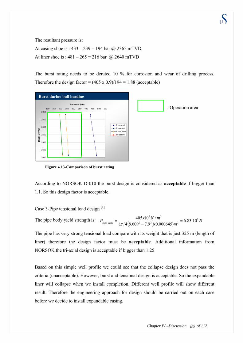
The resultant pressure is:
of 112
t casing shoe is : 433 – 239 = 194 bar @ 2365 mTVD
= 216 bar @ 2640 mTVD
osion and wear of drilling process.
herefore the design factor = (405 x 0.9)/194 = 1.88 (acceptable)
: Operation area
Acco design is considered as acceptable if bigger than
1.1. So this design factor is acceptable.
A
At liner shoe is : 481 – 265
The burst rating needs to be derated 10 % for corr
T
Burst during bull heading
2350
2400
2500
2550
2600
2650
100 150 200 250 300 350 400 450 500 550
Pressure (bar)
Dep
th (m
TVD
2450)
P internal
P external
rding to NORSOK D-010 the burst
Case 3-Pipe tensional load design [1]
The pipe body yield strength is: ( ) Nmx
mNxPyieldpipe
9222
25
10.83.6)000645.09.7609.84(
/10405=
−=
π
d compare with its weight that is just 325 m (length of
liner) therefore the design factor must be acceptable. Additional information from
pse design does not pass the
riteria (unacceptable). However, burst and tensional design is acceptable. So the expandable
The pipe has very strong tensional loa
NORSOK the tri-axial design is acceptable if bigger than 1.25
Based on this simple well profile we could see that the colla
c
liner will collapse when we install completion. Different well profile will show different
result. Therefore the engineering approach for design should be carried out on each case
before we decide to install expandable casing.
P resultant
burst limit
Figure 4.13-Comparison of burst rating
of 112 86Chapter IV –Discussion
To avoid collapse when installing the completion we need to ensure that the differential
pressure between the reservoir and completion fluid does not exceed the collapse rating of
xpandable casing. Technically said, we must design the completion fluid specific gravity to
hevron Energy Technology Company (ETC) was asked to evaluate the feasibility of using
ling of the several depleted
PHT sands in the Erskine field (North Sea, UK sector). The request stated:
eview geology
nd quantify risks of this approach in achieving successful coverage of virgin pressured
at around 15500 feet. This is 400 feet above the Erskine sandstone reservoir. The
ud weight was increased from 12.5 ppg in the intermediate hole to17.6 ppg in the shales
e
maintain high internal pressure. Upon the installation, we need to consider the collapse
failure more than the burst failure and the tension failure. The design should be carried out
for each specific installation.
Case study: ERSKINE High Collapse of expandable casing [5]
C
a high collapse rating expandable casing in the upcoming dril
H
“Evaluate expandable liners as means of casing off virgin pressure shales above the reservoir
to enable mud weight to be lowered to drill the depleted reservoir section. R
a
shales.”
In the development drilling of the Erskine wells the intermediate casing was set in the
limestone
m
of 112 87Chapter IV –Discussion of 112
above the reservoir. Currently, the Erskine reservoir has been significantly depleted but the
shales above the reservoir still require virgin mud weights. The proposed re-drill plan would
be to use expandable casing to case off the high-pressure shales to allow a reduction in mud
weight before drilling the depleted sand. The Erskine Field W-1 mud log is shown below on
figure 4.14:

Chapter IV – Discussion Chapter IV – Discussion of 112 88
of 112 88

Figure 4.14-Erskine Field W-1 mud log [5]
Chapter IV – Discussion of 112 89
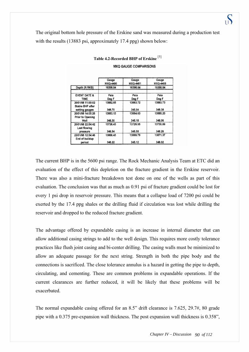
The original bottom hole pressure of the Erskine sand was measured during a production test
with the results (13883 psi, approximately 17.4 ppg) shown below:
Table 4.2-Recorded BHP of Erskine [5]
The current BHP is in the 5600 psi range. The Rock Mechanic Analysis Team at ETC did an
evaluation of the effect of this depletion on the fracture gradient in the Erskine reservoir.
There was also a mini-fracture breakdown test done on one of the wells as part of this
evaluation. The conclusion was that as much as 0.91 psi of fracture gradient could be lost for
every 1 psi drop in reservoir pressure. This means that a collapse load of 7200 psi could be
exerted by the 17.4 ppg shales or the drilling fluid if circulation was lost while drilling the
reservoir and dropped to the reduced fracture gradient.
The advantage offered by expandable casing is an increase in internal diameter that can
allow additional casing strings to add to the well design. This requires more costly tolerance
practices like flush joint casing and bi-center drilling. The casing walls must be minimized to
allow an adequate passage for the next string. Strength in both the pipe body and the
connections is sacrificed. The close tolerance annulus is a hazard in getting the pipe to depth,
circulating, and cementing. These are common problems in expandable operations. If the
current clearances are further reduced, it will be likely that these problems will be
exacerbated.
Chapter IV – Discussion of 112 90
The normal expandable casing offered for an 8.5” drift clearance is 7.625, 29.7#, 80 grade
pipe with a 0.375 pre-expansion wall thickness. The post expansion wall thickness is 0.358”,
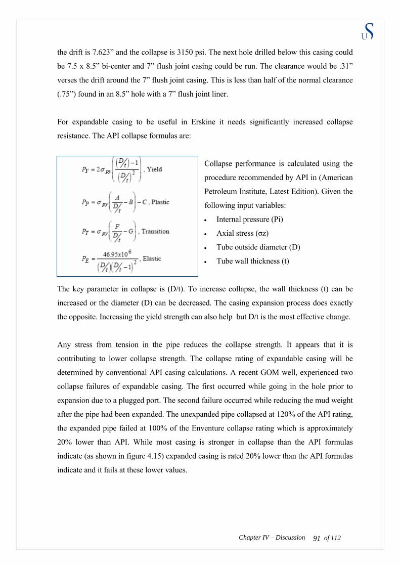
the drift is 7.623” and the collapse is 3150 psi. The next hole drilled below this casing could
be 7.5 x 8.5” bi-center and 7” flush joint casing could be run. The clearance would be .31”
verses the drift around the 7” flush joint casing. This is less than half of the normal clearance
(.75”) found in an 8.5” hole with a 7” flush joint liner.
For expandable casing to be useful in Erskine it needs significantly increased collapse
resistance. The API collapse formulas are:
Collapse performance is calculated using the
procedure recommended by API in (American
Petroleum Institute, Latest Edition). Given the
following input variables:
• Internal pressure (Pi)
• Axial stress (σz)
• Tube outside diameter (D)
• Tube wall thickness (t)
The key parameter in collapse is (D/t). To increase collapse, the wall thickness (t) can be
increased or the diameter (D) can be decreased. The casing expansion process does exactly
the opposite. Increasing the yield strength can also help but D/t is the most effective change.
Any stress from tension in the pipe reduces the collapse strength. It appears that it is
contributing to lower collapse strength. The collapse rating of expandable casing will be
determined by conventional API casing calculations. A recent GOM well, experienced two
collapse failures of expandable casing. The first occurred while going in the hole prior to
expansion due to a plugged port. The second failure occurred while reducing the mud weight
after the pipe had been expanded. The unexpanded pipe collapsed at 120% of the API rating,
the expanded pipe failed at 100% of the Enventure collapse rating which is approximately
20% lower than API. While most casing is stronger in collapse than the API formulas
indicate (as shown in figure 4.15) expanded casing is rated 20% lower than the API formulas
indicate and it fails at these lower values.
Chapter IV – Discussion of 112 91
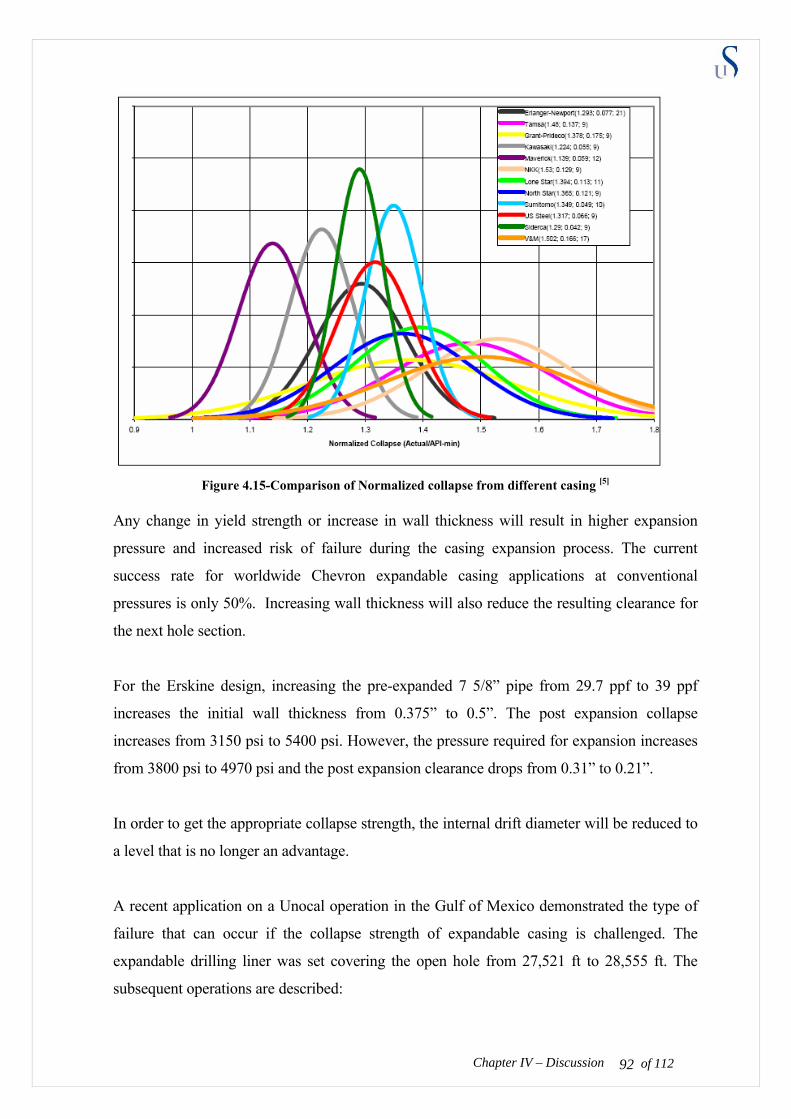
Figure 4.15-Comparison of Normalized collapse from different casing [5]
Any change in yield strength or increase in wall thickness will result in higher expansion
pressure and increased risk of failure during the casing expansion process. The current
success rate for worldwide Chevron expandable casing applications at conventional
pressures is only 50%. Increasing wall thickness will also reduce the resulting clearance for
the next hole section.
For the Erskine design, increasing the pre-expanded 7 5/8” pipe from 29.7 ppf to 39 ppf
increases the initial wall thickness from 0.375” to 0.5”. The post expansion collapse
increases from 3150 psi to 5400 psi. However, the pressure required for expansion increases
from 3800 psi to 4970 psi and the post expansion clearance drops from 0.31” to 0.21”.
In order to get the appropriate collapse strength, the internal drift diameter will be reduced to
a level that is no longer an advantage.
Chapter IV – Discussion of 112 92
A recent application on a Unocal operation in the Gulf of Mexico demonstrated the type of
failure that can occur if the collapse strength of expandable casing is challenged. The
expandable drilling liner was set covering the open hole from 27,521 ft to 28,555 ft. The
subsequent operations are described:

• TIH with 9 7/8”bit and 11” Rhino Reamer (3rd Bit)
• Started cutting mud weight to 12.0 ppg to reduce differential (over-balance)
- Mud weight SET set in – 13.0 ppg
- Collapse rating of SET – 1,580 psi (which is about equal 1 ppg differential @
29,600’ – mud cut to 12.0 ppg)
- Looked at differential – Wrong assumption made that some bleed off to formation
pressure (11.1 ppg) would have occurred
• Drilled from 29,623’ to 29,639’. Cutting mud weight
• Pipe stuck. (Expandable casing collapse)
• Raised mud weight to 12.5, then 13.0 ppg. Pipe free
• Continued drilling to 29,671’ – high torque. POOH to check bit
• Found problems in expandable. Could not pull out of hole past 27,654ft (with 350K#
overpull)
• TIH and attempted blind backoff at 28,760’. Unsuccessful
• Rigged Up TEAS System and severed BHA at 29,501’
• Ran Electric Line Log through collapse casing with fish in hole (MDT’s and caliper log)
Figure 4.16-3D image from simulation result of caliper log [5]
The expandable liner collapsed when the mud density was reduced one ppg which was
equivalent to the Enventure collapse rating of the expanded casing. The BHA was severed
and left in the hole. The well was logged and plugged.
High collapse expandable casing is NOT RECOMMENDED for Erskine case.
Chapter IV – Discussion of 112 93
Challenge 4+ : How to avoid post-expansion casing collapse when completions?
Result :
Upon the installation, we need to consider the collapse failure more than the burst failure and
the tension failure. The design should be carried out for each specific installation.
Discussion : [7]
As shown in the collapse equation, the low collapse rating can be avoided in three ways:
1. Increase the yield strength (use a good steel material)
2. Increase the internal pressure (increase Pi)
3. Decrease the axial stress (avoid compressive force)
The most appropriate technical action in post expansion casing to assure there is no collapse
is to maintain the internal pressure. Maintaining internal pressure could be done by:
• Increasing the specific gravity of completion fluid or drilling fluid. Completion fluid is
used when we expand the liner and production casing. Drilling fluid is used when we
drill with casing for a surface or intermediate casing.
• Building up the hydrostatic pressure inside the casing by pumping the fluid in the closed
casing system.
By maintaining the internal pressure, we can avoid collapse in the post expansion casing.
The yield strength of the material is limited to its properties. The metal ions which bond to
each other should remain strong for pre and post expansion conditions. This is challenges for
material engineering to develop a strong-thin-metal material that can be used as casing. In
additional, decreasing the axial stress can be avoided by using bottom-top expansion instead
of top-bottom expansion.
Chapter IV – Discussion of 112 94
⎟⎟⎠
⎞⎜⎜⎝
⎛−⎟
⎠⎞
⎜⎝⎛
⎟⎠⎞
⎜⎝⎛
=
+−+−−=
12
2)(34)12(
2
22
tdo
tdo
where
zPiyzPiPcollape
β
βσσσβ
4.5 DISCUSSION OF THE COST
Challenge : Is the cost competitive?
Result :
It is possible to save costs because running this combined method will reduce the rig time
used. However, well candidates should be carefully considered prior to using this method.
Discussion:
There are no exact cost calculations for drilling with expandable casing. However, there are a
few cases that we can use as the reference for cost prediction. The cases presented below are
a cost prediction by Chevron external presentation[11] for the Lobo field in the Gulf of
Mexico. This field is a 2 km water depth field with a potential for shallow water flow and
hydrates. The salt dome which is showed in figures 4.17 to 4.19 is defined as a trouble zone.
There are 3 cases that are used as an overview for analyzing the cost. The cases are based on
the same well conditions, but operated using different approaches:
1. Case example 1: Run DwC and expandable casing separately
The Drilling with casing method is used to drill and case the hole for all sections until the
bottom of the trouble zone. Then drill with conventional method to the top of the
reservoir section, run and expand the expandable casing in the bottom of the trouble zone
until the top of reservoir, finally drilling the reservoir section with open hole.
2. Case example 2: Run the combined method: Drilling with expandable casing.
One used drilling with casing method to drill and case the hole for all sections from
mudline to the top of the trouble zone. Then used the combined method to drill and
expand the casing until the bottom of the trouble zone. The hole from the bottom of
trouble zone to the reservoir section drilled with conventional method.
3. Case example 3: Drill with conventional method and expand the casing into a 9.5/8”
monobore feature.
Chapter IV – Discussion of 112 95
One drilled the entire hole with conventional method and underreamed it. Then run
expandable casing all the way down to reservoir section through the trouble zone and then
expanded the casing.
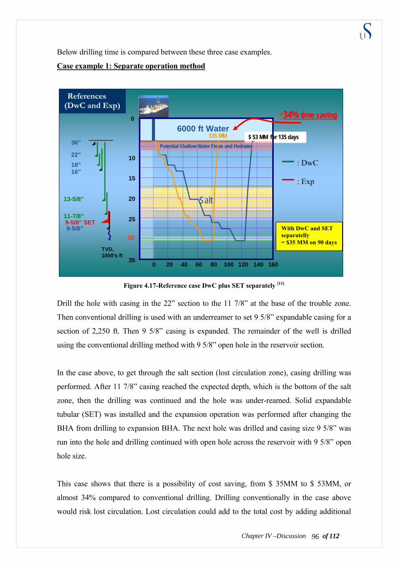
of 112 96Chapter IV –Discussion of 112
Below drilling time is compared between these three case examples.
Case example 1: Separate operation method
Salt
10
15
20
25
35
0
6000 ft Water
1600 20 40 60 80 100 120 140
$ 53 MM for 135 days Potential Shallow Water Flows and Hydrates
$35 MM 36”
22” 18” 16”
Figure 4.17-Reference case DwC plus SET separately [11]
Drill the hole with casing in the 22” section to the 11 7/8” at the base of the trouble zone.
Then conventional drilling is used with an underreamer to set 9 5/8” expandable casing for a
section of 2,250 ft. Then 9 5/8” casing is expanded. The remainder of the well is drilled
using the conventional drilling method with 9 5/8” open hole in the reservoir section.
In the case above, to get through the salt section (lost circulation zone), casing drilling was
performed. After 11 7/8” casing reached the expected depth, which is the bottom of the salt
zone, then the drilling was continued and the hole was under-reamed. Solid expandable
tubular (SET) was installed and the expansion operation was performed after changing the
BHA from drilling to expansion BHA. The next hole was drilled and casing size 9 5/8” was
run into the hole and drilling continued with open hole across the reservoir with 9 5/8” open
hole size.
This case shows that there is a possibility of cost saving, from $ 35MM to $ 53MM, or
almost 34% compared to conventional drilling. Drilling conventionally in the case above
would risk lost circulation. Lost circulation could add to the total cost by adding additional
13-5/8”
11-7/8” 9-5/8” SET
30
TVD, 1000's ft
With DwC and SET separatelly = $35 MM on 90 days
: DwC : Exp
9-5/8”
References (DwC and Exp)
+34% time saving
of 112 97Chapter IV –Discussion of 112
rig time and other costs related to hole problems. Since casing failure could happen, the risk
of having smaller hole diameter of the reservoir section exists.
Case example 2: Combined method
In this case, one drills with casing from the mudline to 17,000 ft in sections of 22” casing to
13 5/8” casing. From the top of trouble zone to the bottom of the trouble zone at 25,000 ft the
hole is drilled with 11 7/8” casing with underreamer. Then the 11 7/8” casing is expanded
giving 12.14” OD and 11.4” ID casing across almost 5,000 ft. Then below the trouble zone,
drilling is continued with 10 3/4” open hole across the reservoir section.
If we use the case one as the reference, we can predict the rough expenses from drilling with
expandable casing case. With information provide by Enventure based on their experiences
the cost estimate is shown below:
- Rate of Expansion = ± 20 – 30 ft /min = 72000 – 108000 ft/day
- Rate of Penetration = ± 30 ft/hr (normal assumption)
- Cost per feet for expansion = ± $175/ft - $200 /ft
From 18,000 ft to 25,000 ft, which is 5,000 ft, we run drilling with expandable casing. So we
will have:
Time consumption
- Drilling time = (5,000ft / 30 ft/hr) = 167 hr = 7 days
- Changing BHA = 4 days (drilling BHA to expansion)
- Expansion time = (7,000ft / 100,000 ft/day) = 0.07 day = 2 hour
- Changing BHA = 4 day (expansion BHA to drilling)
Total time consumption = (7 + 2 + 0.07 + 3) days = ±16 days
A more detailed of cost study should be done for real cases.
Cost consumption
If we assume for a deepwater well, the rig and surface equipment for DwC and expandable
will cost you $ 0.5 Million/day, therefore
- For 16 days operation = 16 days x $ 0.3 Million/day = $ 3,2 Million
- For expansion process = 7,000 ft x $ 200 /ft = $ 1.4 Million
- For DwC process = $ 1.09 Million (see table 3.7 and 3.8)
Total cost for SET operation and equipments is = $ 5.5 Million
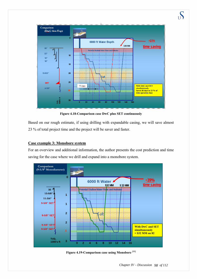
Figure 4.18-Comparison case DwC plus SET continuously
Based on our rough estimate, if using drilling with expandable casing, we will save almost
23 % of total project time and the project will be saver and faster.
Case example 3: Monobore system
For an overview and additional information, the author presents the cost prediction and time
saving for the case where we drill and expand into a monobore system.
Salt
1
1
2
2
3
0
6000 ft Water
160 2 4 6 8 10 12 14
$ 53 MM Potential Shallow Water Flows and Hydrates
$32 MM
Comparison (9-5/8” Monodiameter)
+39%
Chapter IV – Discussion
Figure 4.19-Comparison case using Monobore [11]
3
TVD, 1000's ft
3013-5/8”
11-3/4”
9-5/8” SET
9-5/8” SET
9-5/8” SET9-5/8” SET
With DwC and SET simultaneously = $32 MM on 82 d
of 112 98
time saving
time saving
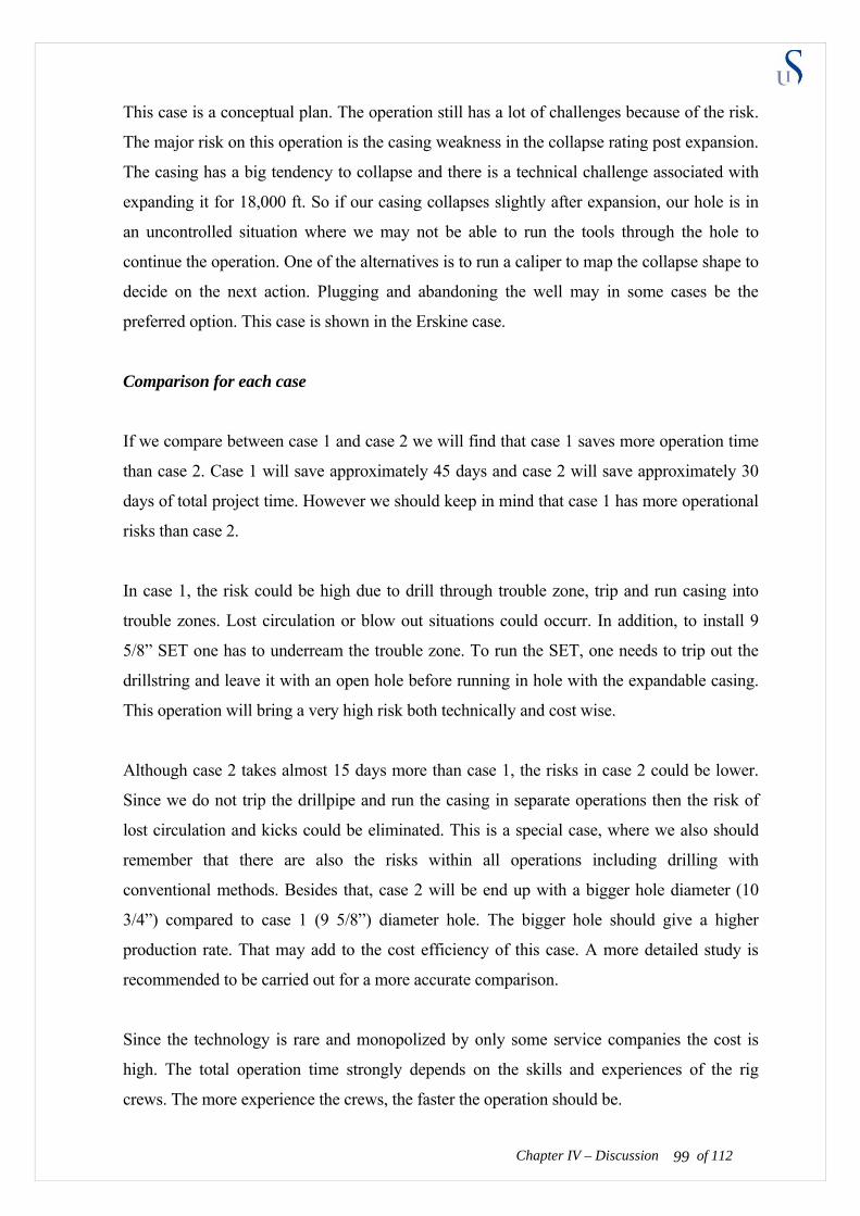
This case is a conceptual plan. The operation still has a lot of challenges because of the risk.
The major risk on this operation is the casing weakness in the collapse rating post expansion.
The casing has a big tendency to collapse and there is a technical challenge associated with
expanding it for 18,000 ft. So if our casing collapses slightly after expansion, our hole is in
an uncontrolled situation where we may not be able to run the tools through the hole to
continue the operation. One of the alternatives is to run a caliper to map the collapse shape to
decide on the next action. Plugging and abandoning the well may in some cases be the
preferred option. This case is shown in the Erskine case.
Comparison for each case
If we compare between case 1 and case 2 we will find that case 1 saves more operation time
than case 2. Case 1 will save approximately 45 days and case 2 will save approximately 30
days of total project time. However we should keep in mind that case 1 has more operational
risks than case 2.
In case 1, the risk could be high due to drill through trouble zone, trip and run casing into
trouble zones. Lost circulation or blow out situations could occurr. In addition, to install 9
5/8” SET one has to underream the trouble zone. To run the SET, one needs to trip out the
drillstring and leave it with an open hole before running in hole with the expandable casing.
This operation will bring a very high risk both technically and cost wise.
Although case 2 takes almost 15 days more than case 1, the risks in case 2 could be lower.
Since we do not trip the drillpipe and run the casing in separate operations then the risk of
lost circulation and kicks could be eliminated. This is a special case, where we also should
remember that there are also the risks within all operations including drilling with
conventional methods. Besides that, case 2 will be end up with a bigger hole diameter (10
3/4”) compared to case 1 (9 5/8”) diameter hole. The bigger hole should give a higher
production rate. That may add to the cost efficiency of this case. A more detailed study is
recommended to be carried out for a more accurate comparison.
Chapter IV – Discussion of 112 99
Since the technology is rare and monopolized by only some service companies the cost is
high. The total operation time strongly depends on the skills and experiences of the rig
crews. The more experience the crews, the faster the operation should be.
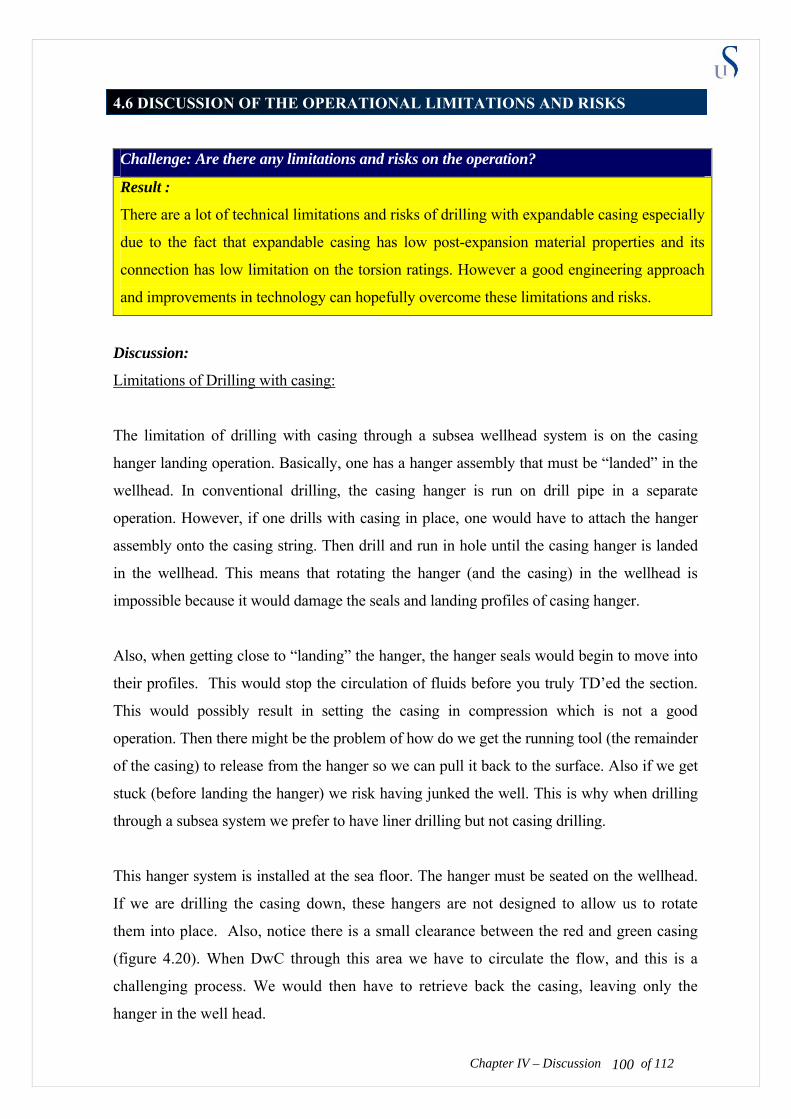
4.6 DISCUSSION OF THE OPERATIONAL LIMITATIONS AND RISKS
Challenge: Are there any limitations and risks on the operation?
Result :
There are a lot of technical limitations and risks of drilling with expandable casing especially
due to the fact that expandable casing has low post-expansion material properties and its
connection has low limitation on the torsion ratings. However a good engineering approach
and improvements in technology can hopefully overcome these limitations and risks.
Discussion:
Limitations of Drilling with casing:
The limitation of drilling with casing through a subsea wellhead system is on the casing
hanger landing operation. Basically, one has a hanger assembly that must be “landed” in the
wellhead. In conventional drilling, the casing hanger is run on drill pipe in a separate
operation. However, if one drills with casing in place, one would have to attach the hanger
assembly onto the casing string. Then drill and run in hole until the casing hanger is landed
in the wellhead. This means that rotating the hanger (and the casing) in the wellhead is
impossible because it would damage the seals and landing profiles of casing hanger.
Also, when getting close to “landing” the hanger, the hanger seals would begin to move into
their profiles. This would stop the circulation of fluids before you truly TD’ed the section.
This would possibly result in setting the casing in compression which is not a good
operation. Then there might be the problem of how do we get the running tool (the remainder
of the casing) to release from the hanger so we can pull it back to the surface. Also if we get
stuck (before landing the hanger) we risk having junked the well. This is why when drilling
through a subsea system we prefer to have liner drilling but not casing drilling.
Chapter IV – Discussion of 112 100
This hanger system is installed at the sea floor. The hanger must be seated on the wellhead.
If we are drilling the casing down, these hangers are not designed to allow us to rotate
them into place. Also, notice there is a small clearance between the red and green casing
(figure 4.20). When DwC through this area we have to circulate the flow, and this is a
challenging process. We would then have to retrieve back the casing, leaving only the
hanger in the well head.
There is operationally possible to land the casing
into the wellhead in DwC. First, drill deeper than the
target depth of the casing shoe, so when one pulls
out of the hole the trouble zone is still cased. On the
rig floor, the casing hanger is installed on top of the
casing and run in hole until it rests on the wellhead.
No rotation is allowed in this operation. The length
of extra hole and the length of the casing that needs
to pull should be designed carefully.
Fi
In a deepwater well that could mean we need to pull 4,000 to 8,000 ft of pipe back to the
surface and run it back to the mudline. This operation would take time. The new overdrive
system may help in handling the pipe. Casing cannot be handled in the derrick in the same
manner that drillpipe is handled. The benefits would have to be larger to justify the cost of
doing this. We would also have a problem of having the casing shear rams in the Blow Out
Preventer (BOP) stack during such an exercise.
We probably cannot shear anything larger than about 7” because of the BOP limitations. In
general, many operational issues that would require specialized tools that don’t exist are
needed. As we would have to recover the casing from the mudline, we probably wouldn’t
save any time. Therefore, a good engineering approach should be applied because this
operation is high risk and cost expensive.
The author believes if there is a demand for the solution, the development or modification of
a subsea wellhead could be done by its provider. Due to deep water and a harsh working
environment, some of the companies in Norway are now developing the subsea wellhead to
meet the costumers demand.
Chapter IV – Discussion of 112 101
gure 4.20-Hanger system on subsea wellhead [6]
Limitation of Expandable casing:
The biggest limitation on expandable casing is the low material properties due to collapse
limitation. There is a challenge for material engineers to find a metal that strong enough in
properties and economical enough to be used as casing. With today’s technology we can try
to maintain the internal pressure to balance the formation pressure.
As long as the resultant pressure in and outside the casing does not exceed the casing
strength, collapse can be avoided. However, maintaining or increasing the internal pressure
also brings a lot of engineering challenges. The completion fluid has its limitation on
properties and there are a lot of other operations on the completion that need to be operated
in low borehole pressure.
Limitation of Combined method:
Limitation of combined method practically is a combination of both limitations from drilling
with casing and expandable casing. The major limitations are the low collapse rating of post
expansion casing and the low torque limit of the expandable casing connector. The
consequences of its limitations and mitigate plans will be presented on below.
Risk Analysis
The figure 3.21 shows that the risk assessment falls in the “yellow” area on the risks matrix.
This means that the combined method operationally is possible to be accepted or rejected,
depends on the design. The yellow colour means that improvements are needed in order to
make this technology more acceptable.
Refer to figure 3.21, to make this technology more acceptable, we have to bring the risk
assessment to the green area. There are two things that we could do to avoid or reduce the
risks:
− Reduce the probability, which means reduced the frequencies it happens (In other
words, take prior actions to eliminate the failure).
− Reduce the consequence, which means reduced the impact of the outcome (In other
words, take action during and post the failure).
Chapter IV – Discussion of 112 102
The prior, during and post actions to reduce the risks of
1. The expandable connection falling apart when drilling or expanding. The actions are:
• Reducing the probability (prior the failure) can be done by:
- Installing appropriate number of stabilizer to reduce the drillstring torque
- Use a better lubricator and drill with low RPM, or high RPM using a mud motor
- Improve and use a stronger expandable casing connector
- Improve the well control skills and equipments (barriers)
- Test the barriers frequently
- Improve the understanding of safety and schedule the emergency exercise
• Reducing the consequence (during or post failure) can be done by:
- Gradually reduce the pipe rotation until it stops
- Stop the drilling operation and decrease the pump rate
- Run caliper log to map the connection geometry
- Reduce the tension on the drillstring
- Run an expandable casing to clad as the connections coupling or,
- Do the squeeze cementing on the leaking spots
- After the impact is dismissed, run and continue drilling with smaller casing
- Prepare for abandonment and worker allocation if the well is on un-control condition
2. The expandable casing collapse post expansion. The actions are;
• Reducing the probability (prior the failure) can be done by:
- Use a stronger casing on collapse rating.
- Use a good expansion method.
- Adjust the drilling or completion fluid to maintain internal hydraulic pressure.
• Reducing the consequence (during or post failure) can be done by:
- Run logging to map the collapse hole geometry
- Reduce the tension on the drillstring
- Run a mill into the collapse hole
- Run an expandable casing to clad and cover the leaking spots
- Do the squeeze cementing on the leaking spots
of 112 103Chapter IV – Discussion
- Prepare for abandonment and worker allocation if needed
CHAPTER V
APPLICATIONS OF TECHNOLOGY
Although the market for emergency/contingency use of drilling with expandable tubular in
drilling will always exist, it is vital that operators are convinced of the need to develop the
right mind-set where drilling with expandable becomes an integrated part of the well
planning. Among some operators right now, drilling with casing and expandable casing are
only used when “all else fails”. The goal should be that drilling with expandable casing
becomes the first alternative not the last. It is believed that through the diligence and
discipline being exercised by the service providers, and with the recommendations provided
here, the large market potential existing for drilling with expandable casing will become a
reality.
Proposing criteria field applications of this combined technology is quite challenging. Each
application already has limited technical applications and high cost. If we neglect the budget
and the risk, the boundary conditions for this application are:
5.1 Wells which drill through trouble zones.
With conventional drilling through trouble zones, lost circulation and kicks could happen.
This could impact on the environment, safety and the lives of the crew who work on the site.
Since this combined method can dismiss these risks, it is recommended to be applied on
drilling when dealing with these trouble zones.
This method could also be recommended on exploration wells, as the formations we drill
through have a lot of unknowns and uncertainties.
Weatherford for example, describes the following application of their expandable
technology. If we combine with our proposed method then it will reduce the risk of drilling
the trouble zone (figure 5.1).
of 112 104
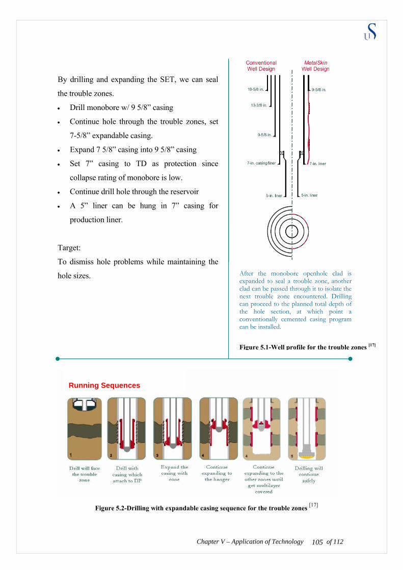
Chapter V – Application of Technology
y drilling and expanding the SET, we can seal
liner can be hung in 7” casing for
production liner.
ole sizes.
B
the trouble zones.
• Drill monobore w/ 9 5/8” casing
• Continue hole through the trouble zones, set
7-5/8” expandable casing.
• Expand 7 5/8” casing into 9 5/8” casing
• Set 7” casing to TD as protection since
collapse rating of monobore is low.
• Continue drill hole through the reservoir
• A 5”
Target:
To dismiss hole problems while maintaining the
h
After the monobore openhole clad is expanded to seal a trouble zone, another
can proceed to the planned total depth of the hole section, at which point a
clad can be passed through it to isolate the next trouble zone encountered. Drilling
conventionally cemented casing program can be installed.
Figure 5.1-Well profile for the trouble zon
Running Sequences
Figure 5.2-Drilling with expandable casing sequence for the trouble zones [17]
of 112 105
es [17]

5.2 Wells which have low formation pressure
Chapter V – Application of Technology of 112
s tation on ex
he well with low formation
pre ncluding all the possible considerations should be performed
hod.
It i ell, that the design of expandable casing is not
takes in design will have high impacts. Besides
o be threatened.
igh-pressure reservoir could possibly become a good well candidate for this combined
y If we drilled and expanded the casing just limited to the trouble zone, larger
can be obtained. The non-expandable
casing or liner casing could be run and it
ressure.
.3 Well where higher production rates are needed
arger
incremental cost of this method. Having a larger casing ID makes
it possible to install larger ID of completion string. This will bring more significant effects on
gas production rates rather than oil, because of the flow phase properties.
Weatherford, for example, describes the following application for their expandable
technology. If we combine with our proposed method then it will solve the trouble zone risk
and also attain bigger final ID (figure 5.3).
A discussed before, the biggest limi pandable casing is the low collapse rating.
Having a low collapse rating makes it only possible to be run on t
ssure. Engineering design i
before we decide to apply this combined met
s shown in Erskine field HPHT w
acceptable to be run in these conditions. Mis
costing a lot of money, the lives of the rig crew can als
H
technolog
diameter casing in the high-pressure reservoir
production could withstand the high reservoir
p
5
In evaluating whether to use this combined technology, the economic analysis of the well
should be done through the entire field life. The higher production rate because of the l
ID
of 112 106
could be able to pay the

Chapter V – Application of Technology of 112
y drilling and expanding the SET, we can
omplete the final production liner in a larger
his operation is done by:
Expand 13 5/8” casing to get 14 1/2” oversized
Expand 11 3/4” casing to 13 3/8”.
iner can be hung in 9 5/8” casing for a
production liner.
B
c Conventional well design
New method well design
diameter than by using a conventional drilling.
T
• Drill w/ conventionally and set 18 5/8” casing
to section of TD
• Continue drilling w/ 13 3/8” casing to its TD
with expandable casing.
•
shoe.
• Drill with expandable 11 3/4” casing until
section TD is reached.
•
• Drill and set 9 5/8” casing conventionally to its
TD as protection since collapse rating of
monobore is low.
• Continue drill hole to the reservoir
• A 7” l
The system improves well productivity and reservoir recovery. You can complete the reservoir section in a larger hole size and with one casing string fewer to surface.
Target: to optimize the size of production liner
ID size [17]Figure 5.3-Well profile for optimizing
Drill w/ combine method through
the trouble zone
Change drilling BHA to
expansion BHA
Cement the
requAs
well (if ired).
semble cone and initiate
expansion
Expand monobore
shoe extension
system
Expand liner
hanger
Drilled out the shoe
Drill will face the trouble
zone
ID size [17] Figure 5.4-Drilling with expandable casing sequence for optimizing
of 112 107

5.4 Wells which are drilled on land or in shallow w
ater
of 112 108Ch
e have a lower rig and operation cost and
less technical challenges than deep-water wells. As we discussed before, it will be a technical
d. Besides, land and shallow
water rigs being cheaper than deep-water rigs, the risk of failure in drilling the hole is more
ing application for their expandable
tech with our proposed method then it will need a smaller surface
aving and will provide the same performance (figure
We side diameter will make the modifica
etrack easier, with less challenges. Therefore the
hould
wel
W lls that are drilled on land or in shallow water will
challenge to seat the casing hanger on the deep-water wellhea
tolerable and easier handled.
For example, Weatherford describes the follow
nology. If we combine
equipment which mean a lot of cost s
5.4).
lls with a bigger in tion of completion and the option
be evaluated for each specific
of drilling a multilateral well or sid
engineering, economical and safety considerations s
l.
apter V – Application of Technology

Chapter V – Application of Technology
smaller rig and surface equipments because we can
ection TD, one can
drill and set accordingly 13 3/8”, 11 3/4” and 9
maintain large production liner sizes, we
can use the combined method to drill and
ill and set 7” casing conventionally from
surface to reservoir section as protection.
Target: to start with as small as possible surface
equipments
Figure 5.6-Drilling with expandable casing sequence on smaller rig size [17]
By installing and expanding the SET, we can use a
start drilling with a smaller diameter and lighter
casing.
• Drilling starts w/ 16” casing instead of 20”
casing.
• After 16” casing reach the s
5/8” casing using the conventional method.
• Where 11 3/4” casing hangs on 13 5/8” casing
and 9 5/8” casing hangs on 11 3/4” casing.
• To
expand 7 5/8” casing into 9 5/8”.
• This expandable casing clad inside its 9 5/8”
casing.
• Dr
New method well design
Change drilling BHA to
expansion BHA
Conventional well design
The system cuts well construction costs by reducing the need to telescope down to smaller and smaller casing sizes. You can start drilling with smaller-diameter upper-hole sections and finish with the same size or larger hole sections for optimal production string size
Figure 5.5-Well profile using smaller rig
Drill w/ combine method through
the trouble zone
Cement the well (if
required)
Close seal valve and expand
liner
Expand liner
hanger
Drilled out the shoe
of 112 109
[17]

CHAPTER VI
CONCLUSIONS
The two main purposes of this thesis are:
1 To study the feasibility of combining drilling
meth
wo main purposes of this thesis are:
1 To study the feasibility of combining drilling
meth
with casing and expandable casing
ods. The feasibility study will be done on technical and cost effective point of view.
e hod.
sing as a drillstring during the drilling
ope rget depth is reached. The conclusion of
my concept is possible. Table 6.1 shows and
logy. the combined technology
with casing and expandable casing
ods. The feasibility study will be done on technical and cost effective point of view.
ethod.
sing as a drillstring during the drilling
ope rget depth is reached. The conclusion of
my concept is possible. Table 6.1 shows and
logy. the combined technology
2 To propose the appropriate applications for this m2 To propose the appropriate applications for this m t
The concept of this thesis is to use expandable ca
ration, which will then be expanded when the ta
study is that the drilling with expandable
The concept of this thesis is to use expandable ca
ration, which will then be expanded when the ta
study is that the drilling with expandable
concludes the pros and cons of this combined technoTable 6.1-Pros and cons of
concludes the pros and cons of this combined technoTable 6.1-Pros and cons of
PROS CONS
• C ough an mitigate risks when drilling thr • Considered as a new technology, therefore
troubled zones. high risks because of lack of procedures
and experiences.
• Can obtain bigger ID of the completion • Need a tool improvement on drilling-
string, which will impact on a higher expansi ottom hole assembly (BHA). on b
production rate.
Can save rig time which will impact on • Risk of weakened material properties •
especially low collapse rating of post cost saving. (Showed on case study, ±
expansion casing and low on torque rating 23% of saving rig time can be achieved
of casing connections. if this technology is applied).
This combined technology shows a huge potential for cost savings, higher production and
etter ntrol. T re, it is recommended to continue studying and dev this
ma nology oal should be the drilling with expandable casing becomes the
rst alternative not the last.
b well co
ture tech
herefo
. The g
eloping
im
of 112 110
fi

REFERENCES
.A Balkema, Rotterdam, Netherlands, 1999, page
2.
. Hossain, M.M., et al, Fatigue Life evaluation: a key to avoid drillpipe Failure due to die-
5. Lofton, J., Erskine ion, Chevron internal
report, Chevron Energy Technology Company, Houston, Texa
6. Lofton, J., Update on Solid Expandable Tubular (SET), Chevron internal report, Chevron
Te
7. dnøy, B.S., Three Dimensiona in
the Critical Wells, University of Stavang 6. (available online at
www.sciencedirect.com)
n Qu ation,
/IADC C
9. rilling with Casing Overview, Chevron internal report, Chevron Energy
Technology Company, Houston, Texas, 2007.
ham Step
xternal
11 rillin
12 ion Process fo Chevron external
presentation, Casing Drilling Technical Conference, hosted by World Oil, March 2004.
3. Improved Wellbore Stability achieved with casing drilling operation through drilling
l Conference, hosted by World Oil, March 2004.
15. Enventure external tool data and document (available at www.enventure.com
1. Aadnøy, B.S., Modern Well Design, A
148-152.
Warren, M.T., Casing While Drilling Chapter, SPE Advanced Drilling Engineering
Textbook, Tescocorp, Houston, Texas, 2004.
3
marks, IADC/SPE 47789, presented at the 1998 IADC/SPE Asia Pacific Drilling
Conferences, Jakarta, September 7-9, 1998.
4. Maurer, W.C., King, C.H., Manz, S.A., Joint Industry Project Proposal on Expandable
Tubular Technology, Noble, Houston, Texas, 2004.
High Collapse Expandable Casing Evaluat
s, 2006.
Energy Technology Company, Houston,
Aasen, J.A., Aa
xas, 2004.
l Well Tubular Design Improves Margin
er, Norway, 200
8. Q.Lu., D.Hannahs., J.Wu., Connectio
SPE/IADC 105432, presented in SPE
Dowell, J.D., D
alification for Casing Drilling Applic
onference, Amterdam, Netherlands, 2007.
10. Sinor, A., Mcland. E., Laing, B., Old
Change, Baker Hughes Christensen, E
. Chevron external presentation, Casing D
. Casing Drilling Rig Select
, J., BHI Update-Insight into Potential
presentation, 2004.
g Technical Conference, World oil, 2003.
r the Stratton Field,
1
fluids “Smear effect”, Chevron external presentation, Casing Drilling Technical
Conference, hosted by World Oil, March 2004.
14. Warren, T., Tessari, B., Houtchens, B., Directional Casing While Drilling by Tescocorp,
Casing Drilling Technica
).
of 112 111
seal a trouble
16. Hydril external tool data and document (available at www.hydril.com).
presentation, 2007 (available at www.weatherford.com
17. MetalSkin, Solid Expandable System for opened and closed hole, Weatherford external
).
at the Offshore Europe 2005, Aberdeen, Scotland, U.K, 6-9 September 2005.
18. Vestavik, O.M., New Concept for Drilling Hydraulic, SPE 96412, Reelwell A.S,
presented
(Brochure available on www.reelwell.com).
MI-Swaco Specialized tools Best practices, E19. xternal SPS International company report,
2007 updated. (Brochure available on www.spsinternational.com).
Smith, K., Deepwater Wish-List and New Application, Chevron external presentation,
Casing Drilling Technical Conference, hosted
20.
by World Oil, 31 March 2004.
21. http://en.wikipedia.org/wiki/Deformation.
Mawford, N., Stephenson, D., York, P., et. al., SPE/22. IADC 102011, Beyond the limits of
Drilling and Completion–Expendables, presented on Indian Drilling Technology
Conference and Exhibition, Mumbai, India, October 2006
where βwhereExp)82 days
of 112 112