shear performance of frcc beam-column joints …kanakubo/jcea-mu.pdfshear performance of frcc...
TRANSCRIPT

Journal of Civil Engineering and Architecture 13 (2019) 562-571 doi: 10.17265/1934-7359/2019.09.003
Shear Performance of FRCC Beam-Column Joints Using
Various Polymer Fibers
Yu Mu, Akira Yasojima and Toshiyuki Kanakubo
Department of Engineering Mechanics and Energy, University of Tsukuba, Tsukuba-City, Ibaraki 305-8573, Japan
Abstract: Brittle shear failure should be avoided in beam-column joint of a reinforced concrete (RC) frame during the earthquake. Fiber-reinforced cementitious composite (FRCC) which presents a remarkable deformability especially under tensile and bending load with a large energy absorption capacity is expected to be used in the crucial part of a RC frame. With the development of polymer material, various synthetic fibers have become the best selection to improve concrete capacity and failure resistance without the corrosion of fibers. The objective of this study is to investigate the influence of fiber bridging effect on the shear capacity of FRCC beam-column joint. The main parameter of the test in the present study is the fiber types: aramid, polypropylene (PP) and polyvinyl alcohol (PVA) fiber. To evaluate shear capacity quantitatively, a new calculation method using FRCC tensile characteristics confirmed by the uniaxial tension test is newly proposed. The difference of below 7% between calculated value and experimental value demonstrates that the calculation method is feasible.
Key words: Shear, uniaxial tension test, aramid, PP, PVA.
1. Introduction
Beam-column joint is the crucial part of a
reinforced concrete (RC) frame, which is to ensure the
ductility of the whole structure especially when the
frame is subjected to huge earthquake. Under seismic
response, major damage should be avoided in the
beam-column joint. Even the beam and column step
into inelastic state, the joint has to remain the ability
to transfer actions. The reasons to avoid large damage
in beam-column joint under seismic response are to
keep transferring capacity of the gravity load in the
panel zone, to accomplish large ductility and energy
dissipation by other elements such as beam, and
difficulty of repairing the joint after earthquake [1].
Shear failure in the panel zone causes a typical
brittle damage in beam-column joint, so its shear
capacity should be given gratifyingly. Shear capacity
of beam-column joint is mainly supplied by the
dimensions of the panel zone and concrete strength.
An adequate amount of lateral confining
Corresponding author: Yu Mu, Ph.D. candidate, research fields: concrete structures, fiber-reinforced cementitious composites.
reinforcement in the panel zone also provides
non-shear failure. In general, however, the dimensions
of the panel zone are limited by the dimensions of
connecting columns and beams. In addition,
increasing confining reinforcements will cause great
construction difficulties in reinforcement cage and
casting.
Using fiber-reinforced concrete into panel zone of
beam-column joint to increase shear capacity is not a
new attempt [2-12]. By the introduction of steel fibers
in beam-column joints, steel fiber-reinforced concrete
(SFRC) is an attractive alternative to inhibit the
damage of joint panel and increase maximum load.
However, decreased stress caused by steel fiber
corrosion [13, 14] is a severe problem that has to be
faced. With the development of polymer material,
various synthetic fibers have become the best
selection to improve concrete capacity and failure
resistance without the corrosion of fibers [15, 16].
A newly cementitious-composite-based material
named fiber-reinforced cementitious composite
(FRCC) is cement composite with the mixture of short
fibers to increase ductility of cement composite.
D DAVID PUBLISHING
Shear Performance of FRCC Beam-Column Joints Using Various Polymer Fibers
563
Comparing to the conventional concrete, FRCC has a
remarkable deformability especially under tensile and
bending load with a large energy absorption capacity
due to the fiber bridging effect. After first cracking,
fiber can transfer tensile force through crack which
strongly affects the tensile performance of FRCC [17].
This remarkable bridging capacity makes it an
appropriate choice for application in beam-column
joint of RC structures to resist inelastic deformation.
Until now, FRCCs can be constituted with a category
of fibers, such as carbon [18], steel [19] and polymer
fibers [20]. Whereas, most research in materials field
has been focused on FRCC with a high modulus
polyethylene (PE) fiber, and has been conducted by
bending and tensile test [21]. Structural performance
of beam-column joints using polyvinyl alcohol (PVA)
[22, 23] and steel fiber [24] in panel zone with a fiber
volume fraction of 1% has been confirmed. Fibers can
restrain expansion of crack width, increase shear
capacity and improve structural performance rather
than the specimen without fiber. The previous
research [25] has also revealed that PP-ECC (a sort of
polypropylene fiber-reinforced cementitious
composite) can serve as transverse reinforcements to
carry the applied load.
Precast construction method which is widely used
in RC buildings especially in high skyscraper in Japan
becomes more and more popular by ensuring better
quality, simplified install procedure and shorter
duration. Until now, a new precast system which casts
the joint panel combining with beam and separating
column into two parts has been proposed. Even
though the FRCC constructability is tough, by
adopting this precast method, FRCCs can be used in
practical engineering easily. Therefore, it is a smart
way of enabling FRCC to play a better role in a
beam-column joint.
In this research, various polymer fibers have been
utilized in the FRCCs beam-column joint to increase
shear capacity and reduce the damage of the panel
zone. Compared with steel fiber, polymer fibers have
a better durability in cement matrix. The loading test
of FRCCs beam-column joints with a fiber volume
fraction of 1% is conducted to make clear the
influence of fiber type on shear capacity of panel zone.
Tensile performance of FRCCs characterized from
uniaxial tension test is also discussed. A new
calculation method for evaluating shear capacity of
FRCCs beam-column joint is proposed based on the
standard of Architectural Institute of Japan (AIJ) [26].
2. Outline of Test
2.1 Material Properties
The target compressive strength of the FRCCs was
set to 50 MPa. As listed in Table 1, water-cement ratio
of 0.56 was adopted, which is based on the previous
study [17], fiber volume fraction for each specimen
was 1%. The mechanical properties of each polymer
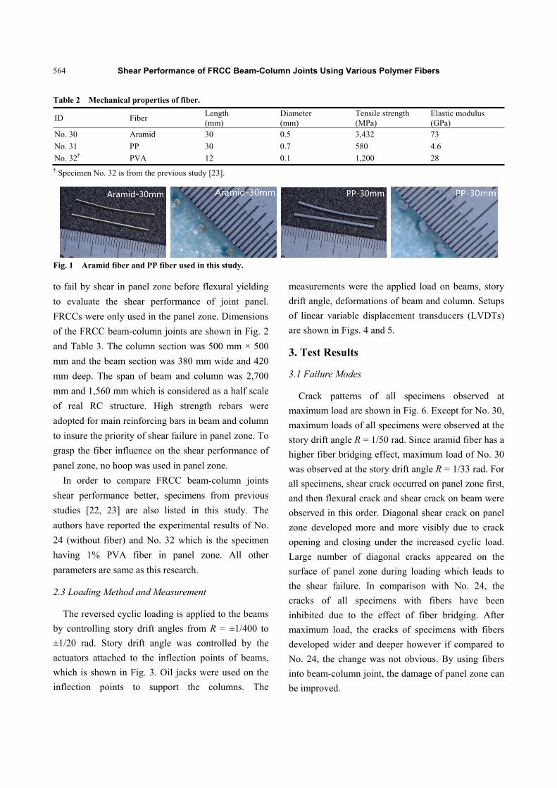
fiber are shown in Table 2 and Fig. 1. Aramid fiber
and PP fiber are fibrillated with a same length of 30
mm, while 12 mm for PVA fiber. Diameter for aramid,
PP and PVA is 0.5 mm, 0.7 mm and 0.1 mm
independently. Aramid fibers having an extraordinary
tensile strength of 3,432 MPa have been used in
aircraft, military vehicles, bullet proof vests and many
others. The used aramid was stranded from single
fibers. Surface roughness embossing has been made
on the PP fiber to improve the bond property.
2.2 Test Specimens
Two specimens (No. 30 and No. 31) were designed
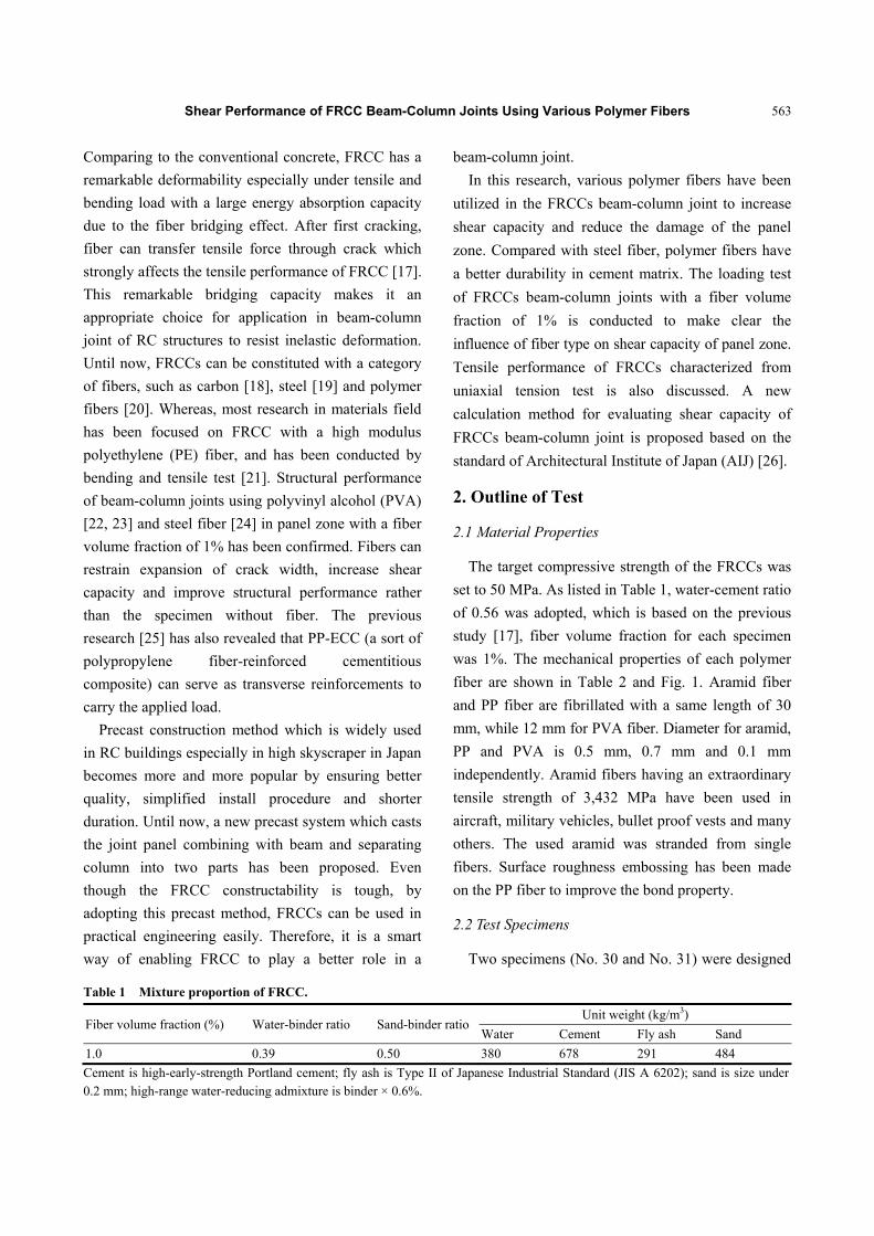
Table 1 Mixture proportion of FRCC.
Fiber volume fraction (%) Water-binder ratio Sand-binder ratioUnit weight (kg/m3)
Water Cement Fly ash Sand
1.0 0.39 0.50 380 678 291 484
Cement is high-early-strength Portland cement; fly ash is Type II of Japanese Industrial Standard (JIS A 6202); sand is size under 0.2 mm; high-range water-reducing admixture is binder × 0.6%.
Shear Performance of FRCC Beam-Column Joints Using Various Polymer Fibers
564
Table 2 Mechanical properties of fiber.
ID Fiber Length (mm)
Diameter (mm)
Tensile strength (MPa)
Elastic modulus (GPa)
No. 30 Aramid 30 0.5 3,432 73
No. 31 PP 30 0.7 580 4.6
No. 32† PVA 12 0.1 1,200 28 † Specimen No. 32 is from the previous study [23].
Fig. 1 Aramid fiber and PP fiber used in this study.
to fail by shear in panel zone before flexural yielding
to evaluate the shear performance of joint panel.
FRCCs were only used in the panel zone. Dimensions
of the FRCC beam-column joints are shown in Fig. 2
and Table 3. The column section was 500 mm × 500
mm and the beam section was 380 mm wide and 420
mm deep. The span of beam and column was 2,700
mm and 1,560 mm which is considered as a half scale
of real RC structure. High strength rebars were
adopted for main reinforcing bars in beam and column
to insure the priority of shear failure in panel zone. To
grasp the fiber influence on the shear performance of
panel zone, no hoop was used in panel zone.
In order to compare FRCC beam-column joints
shear performance better, specimens from previous
studies [22, 23] are also listed in this study. The
authors have reported the experimental results of No.
24 (without fiber) and No. 32 which is the specimen
having 1% PVA fiber in panel zone. All other
parameters are same as this research.
2.3 Loading Method and Measurement
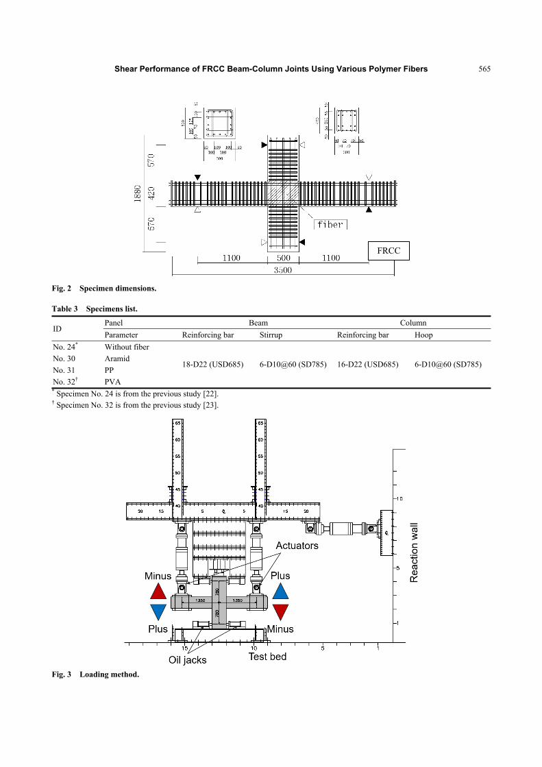
The reversed cyclic loading is applied to the beams
by controlling story drift angles from R = ±1/400 to
±1/20 rad. Story drift angle was controlled by the
actuators attached to the inflection points of beams,
which is shown in Fig. 3. Oil jacks were used on the
inflection points to support the columns. The
measurements were the applied load on beams, story
drift angle, deformations of beam and column. Setups
of linear variable displacement transducers (LVDTs)
are shown in Figs. 4 and 5.
3. Test Results
3.1 Failure Modes
Crack patterns of all specimens observed at
maximum load are shown in Fig. 6. Except for No. 30,
maximum loads of all specimens were observed at the
story drift angle R = 1/50 rad. Since aramid fiber has a
higher fiber bridging effect, maximum load of No. 30
was observed at the story drift angle R = 1/33 rad. For
all specimens, shear crack occurred on panel zone first,
and then flexural crack and shear crack on beam were
observed in this order. Diagonal shear crack on panel
zone developed more and more visibly due to crack
opening and closing under the increased cyclic load.
Large number of diagonal cracks appeared on the
surface of panel zone during loading which leads to
the shear failure. In comparison with No. 24, the
cracks of all specimens with fibers have been
inhibited due to the effect of fiber bridging. After
maximum load, the cracks of specimens with fibers
developed wider and deeper however if compared to
No. 24, the change was not obvious. By using fibers
into beam-column joint, the damage of panel zone can
be improved.
Shear Performance of FRCC Beam-Column Joints Using Various Polymer Fibers
565
Fig. 2 Specimen dimensions.
Table 3 Specimens list.
ID Panel Beam Column
Parameter Reinforcing bar Stirrup Reinforcing bar Hoop
No. 24* Without fiber
18-D22 (USD685) 6-D10@60 (SD785) 16-D22 (USD685) 6-D10@60 (SD785) No. 30 Aramid
No. 31 PP
No. 32† PVA * Specimen No. 24 is from the previous study [22]. † Specimen No. 32 is from the previous study [23].
Fig. 3 Loading method.
FRCC

Shear Performance of FRCC Beam-Column Joints Using Various Polymer Fibers
566
Pin
Roller(Linear Bush)
LVDT
LVDT
1100 1100500
570
570
420
Plus
Minus Plus
Minus
Fig. 4 Measurement of story drift angle.
LVDT
LVDT
1190 1190320
645
645
270
Plus
MinusPlus
Minus
Jigs fixed points
Fig. 5 Measurement of local deformation.

Shear Performance of FRCC Beam-Column Joints Using Various Polymer Fibers
567
No. 24 (no fiber)* No. 30 (aramid) No. 31 (PP) No. 32 (PVA)†
Fig. 6 Crack patterns at maximum load.
3.2 Load-Story Drift Angle Curve
Fig. 7 shows the relationships of load and story drift
angle obtained from the cyclic loading test. The peak
loads are listed in Table 4. Specimen No. 30 has the
highest value of 544 kN, which was mainly attributed
by its higher fiber bridging effect. Since all the
specimens were designed by failure of panel zone,
peak loads of specimens with fibers were increased
significantly compared to No. 24 due to the
effectiveness of fiber bridging.
4. Evaluation of Shear Capacity
4.1 Outline of Tension Test
To grasp the tensile characteristics of FRCC, the
uniaxial tension test was conducted. Aramid fiber, PP
fiber and PVA fiber were used to test the tensile
property. The fibers used for the tension test are the
same as those used in the beam-column joint
experiment. The mixture proportion of mortar matrix
has already been presented in Table 1. The fiber
volume fraction is 1%.
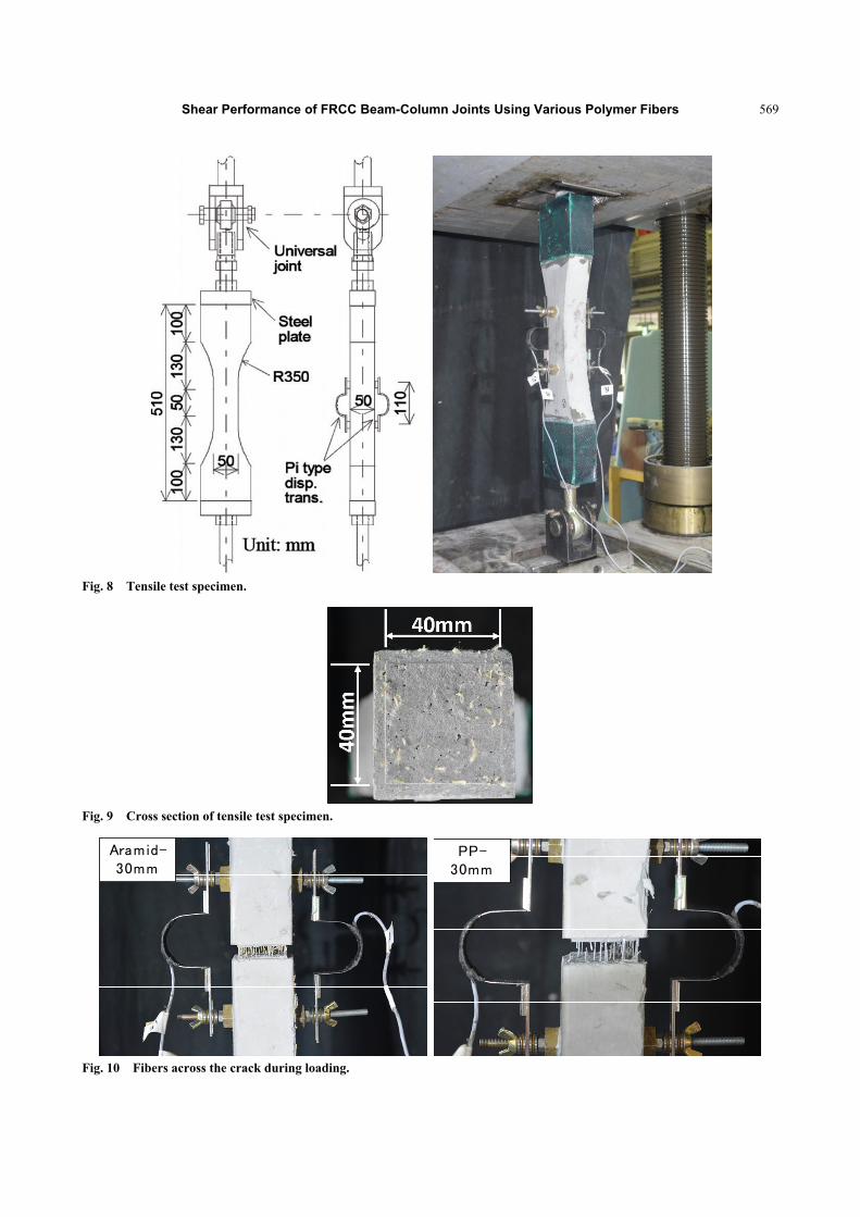
The details of the specimen and the loading method
are shown in Fig. 8. The total length of the specimen
is 510 mm with carbon fiber sheets attached at both
ends to avoid peel-off of the steel plate. Since the
increasing external moment caused by setup
irregularity and local fracture caused by secondary
moment will be an inevitable factor to the experiment,
pin-fix ends were applied at the boundaries to
minimize possible effects to the results. As shown in
Fig. 9, a notch was being made in the middle of the
specimen. The sectional area at ligament is 40 mm ×
40 mm. Tensile load and deformation in the test
region were obtained directly from the experiment.
The crack width is the average value of two pi-type
LVDTs.
4.2 Results of Tension Test
All specimens fractured at the ligament. Tensile
stress is calculated by tensile load divided by sectional
area at the ligament. Fig. 10 shows the example
photographs of the fibers across the crack during
loading. The relationships of tensile stress versus
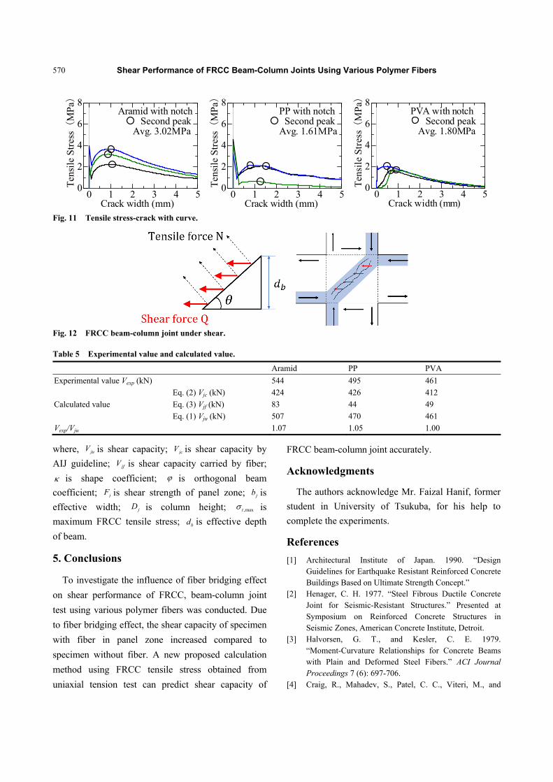
crack width are shown in Fig. 11. The tensile stress
showed a significant drop after first cracking. Due to
the fiber bridging effect, the tensile stress increased
until to the second peak and then decreased gradually.
The average tensile stresses of Aramid, PP and PVA
specimens at the second peak are 3.31 MPa (crack
width at 0.995 mm), 1.61 MPa (crack width at 1.199
mm) and 1.80 MPa (crack width at 0.680 mm),
respectively.
4.3 Evaluation of Shear Capacity
By assuming that the shear stress in the panel zone
is also carried by fiber bridging effect, shear capacity
of beam-column joint is evaluated through the tensile
characteristics of FRCC.
It is considered that the strut mechanism in FRCC
beam-column joint keeps until to story drift angle of R
= 1/50 rad due to the bridging effect of fibers which
are across the diagonal crack on the surface of panel
zone. After that, diagonal cracks start to move to shear
sliding direction which leads to the maximum load. At
the maximum load, by assuming failure of strut
mechanism and disappearance of fiber bridging effect
are occurred simultaneously, calculation method for

Shear Performance of FRCC Beam-Column Joints Using Various Polymer Fibers
568
-0.06 -0.03 0.03 0.06
-500
500
0Story drift angle R (rad)
Load Q (kN)
No.24No fiber
Qmax=385kNQmin=-389kN
-0.06 -0.03 0.03 0.06
-500
500
0Story drift angle R (rad)
Load Q (kN)
No.30Aramid 1%
Qmax=544kNQmin=-531kN
-0.06 -0.03 0.03 0.06
-500
500
0Story drift angle R (rad)
Load Q (kN)
No.31PP 1%
Qmax=495kNQmin=-488kN
-0.06 -0.03 0.03 0.06
-500
500
0Story drift angle R (rad)
Load Q (kN)
No.32PVA 1%
Qmax=461kNQmin=-461kN
Fig. 7 Load-story drift angle curve. * Specimen No. 24 is from the previous study [22]. † Specimen No. 32 is from the previous study [23].
Table 4 Peak load and story drift angle at peak load.
Peak load Story drift angle
No. 24 (no fiber) 389 kN 1/50 rad
No. 30 (aramid) 544 kN 1/33 rad
No. 31 (PP) 495 kN 1/50 rad
No. 32 (PVA) 461 kN 1/50 rad
shear capacity of FRCC beam-column joint in Eq. (1)
can be proposed. Eq. (1) is derived as the summation
of the Eq. (2) given by “Design Guidelines for
Earthquake Resistant Reinforced Concrete Buildings
Based on Inelastic Displacement Concept” [26] to
shear force carried by FRCC expressed by Eq. (3). As
shown in Fig. 12, shear force is derived from tension
force carried by fibers. The crack angle is observed
directly from the surface of panel zone. The second
peak load in uniaxial tension test is adopted for
maximum tensile stress in each type of fibers.
Experimental and calculated values of shear
capacity are converted to the shear force which is
applied to beam. As listed in Table 5, the difference of
below 7% between calculated value and experimental
value demonstrates that the calculation method is
feasible. By adopting this method, shear capacity of
FRCC beam-column joint can be calculated from
uniaxial tension test.
ju jc jfV V V (1)
= jc j j jV F b D (2)
,maxjf t b jV d b (3)
Shear Performance of FRCC Beam-Column Joints Using Various Polymer Fibers
569
Fig. 8 Tensile test specimen.
Fig. 9 Cross section of tensile test specimen.
Aramid-30mm
PP-30mm
Fig. 10 Fibers across the crack during loading.
Shear Performance of FRCC Beam-Column Joints Using Various Polymer Fibers
570
0 1 2 3 4 50
2
4
6
8
Crack width (mm)
Aramid with notch Second peak Avg. 3.02MPa
Ten
sile
Str
ess(
MP
a)
0 1 2 3 4 50
2
4
6
8
Crack width (mm)
PP with notch Second peak Avg. 1.61MPa
Ten
sile
Str
ess(
MP
a)
0 1 2 3 4 50
2
4
6
8
Crack width (mm)
PVA with notchSecond peak
Avg. 1.80MPa
Ten
sile
Str
ess(
MPa)
Fig. 11 Tensile stress-crack with curve.
Fig. 12 FRCC beam-column joint under shear.
Table 5 Experimental value and calculated value.
Aramid PP PVA
Experimental value Vexp (kN) 544 495 461
Calculated value
Eq. (2) Vjc (kN) 424 426 412
Eq. (3) Vjf (kN) 83 44 49
Eq. (1) Vju (kN) 507 470 461
Vexp/Vju 1.07 1.05 1.00
where, juV is shear capacity; jcV is shear capacity by
AIJ guideline; jfV is shear capacity carried by fiber;
is shape coefficient; is orthogonal beam
coefficient; jF is shear strength of panel zone; jb is
effective width; jD is column height; ,maxt is
maximum FRCC tensile stress; bd is effective depth
of beam.
5. Conclusions
To investigate the influence of fiber bridging effect
on shear performance of FRCC, beam-column joint
test using various polymer fibers was conducted. Due
to fiber bridging effect, the shear capacity of specimen
with fiber in panel zone increased compared to
specimen without fiber. A new proposed calculation
method using FRCC tensile stress obtained from
uniaxial tension test can predict shear capacity of
FRCC beam-column joint accurately.
Acknowledgments
The authors acknowledge Mr. Faizal Hanif, former
student in University of Tsukuba, for his help to
complete the experiments.
References
[1] Architectural Institute of Japan. 1990. “Design Guidelines for Earthquake Resistant Reinforced Concrete Buildings Based on Ultimate Strength Concept.”
[2] Henager, C. H. 1977. “Steel Fibrous Ductile Concrete Joint for Seismic-Resistant Structures.” Presented at Symposium on Reinforced Concrete Structures in Seismic Zones, American Concrete Institute, Detroit.
[3] Halvorsen, G. T., and Kesler, C. E. 1979. “Moment-Curvature Relationships for Concrete Beams with Plain and Deformed Steel Fibers.” ACI Journal Proceedings 7 (6): 697-706.
[4] Craig, R., Mahadev, S., Patel, C. C., Viteri, M., and

Shear Performance of FRCC Beam-Column Joints Using Various Polymer Fibers
571
Kertesz, C. 1984. “Behavior of Joints Using Reinforced Fibrous Concrete.” Presented at Fiber Reinforced Concrete—International Symposium, American Concrete Institute, Detroit.
[5] Naaman, A. E., Wight, J. K., and Abdou, H. 1987. “SIFCON Connections for Seismic Resistant Frames.” Concrete International: Design & Construction 9 (11): 34-9.
[6] Olario, I., Ioani, A., and Poienar, N. 1988. “Steel Fiber Reinforced Ductile Joints.” Presented at Ninth World Conference on Earthquake Engineering, Tokyo-Kyoto.
[7] Gefken, P. R., and Ramey, M. R. 1989. “Increased Joint Hoop Spacing in Type 2 Seismic Joints Using Fiber Reinforced Concrete.” ACI Structural Journal 86 (2): 168-72.
[8] Jiuru, T., Chaobin, H., Kaijian, Y., and Yongcheng, Y. 1992. “Seismic Behavior and Shear Strength of Frames Joint Using Steel-Fiber Reinforced Concrete.” Journal of Structural Engineering 118 (2): 341-58.
[9] Katzensteiner, B., Filiatrault, A., Mindess, S., and Banthia, N. 1992. “Use of Steel Fibrous Concrete in Seismic Design.” Presented at Fourth RILEM International Symposium on Fibre Reinforced Cement and Concrete, Sheffield.
[10] Durrani, A. J., and Diaz, A. J. 1992. “Seismic Resistance of Fiber-Reinforced Slab-Column Connections.” Presented at Tenth World Conference on Earthquake Engineering, Madrid.
[11] Olariu, I., Ioani, A. M., and Poienar, N. 1992. “Seismic Behaviour of Steel Fiber Concrete Beam-Column.” Presented at Tenth World Conference on Earthquake Engineering, Madrid.
[12] Filiatrault, A., Pineau, S., and Houde, J. 1995. “Seismic Behavior of Steel-Fiber Reinforced Concrete Interior Beam-Column Joints.” ACI Structural Journal 92 (5): 543-52.
[13] Kosa, K., and Naaman, A. E. 1990. “Corrosion of Steel Fiber Reinforced Concrete.” ACI Materials Journal 87 (1): 27-37.
[14] Kosa, K., Naaman, A. E., and Hanse, W. 1991. “Durability of Fiber Reinforced Mortar.” ACI Materials Journal 88 (3): 310-9.
[15] ACI Committee 544. 1996. 1R-96, State-of-the-Art Report on Fiber Reinforced Concrete. pp. 39-57.
[16] Mu, Y., and Kanakubo, T. 2015. “Bending Test of FRC Notched Beam with Various Polymer Fibers.” Summaries of Technical Papers of Annual Meeting Architectural
Institute of Japan (TOHKAI), Material Construction, pp. 511-2.
[17] Kanakubo, T., Miyaguchi, M., and Asano, K. 2016. “Influence of Fiber Orientation on Bridging Performance of Polyvinyl Alcohol Fiber-Reinforced Cementitious Composite.” American Concrete Institute Materials Journal 113 (2): 131-41.
[18] Li, V. C., and Obla, K. H. 1994. “Effect of Fiber Length Variation on Tensile Properties of Carbon Fiber Cement Composites.” Int’l J. of Composites Engineering 4 (9): 947-64.
[19] Li, V. C., Wu, H. C., Maalej, M., Mishra, D. K., and Hashida, T. 1996. “Tensile Behavior of Cement Based Composites with Random Discontinuous Steel Fibers.” J. Amer. Ceramics Soc. 79 (1): 74-8.
[20] Li, V. C., and Wu, H. C. 1992. “Conditions for Pseudo Strain-Hardening in Fiber Reinforced Brittle Matrix Composites.” J. Applied Mechanics Review 45 (8): 390-8.
[21] Li, V. C. 1998. “Engineered Cementitious Composites (ECC)—Tailored Composites through Micromechanical Modeling.” In Fiber Reinforced Concrete: Present and the Future, edited by Banthia, N., Bentur, A., and Mufti, A. A. Montreal: Canadian Society for Civil Engineering, pp. 64-97.
[22] Sano, N., Yamada, H., Miyaguchi, M., Yasojima, A., and Kanakubo, T. 2015. “Structural Performance of Beam-Column Joint Using DFRCC.” Presented at 11th Canadian Conference on Earthquake Engineering—Facing Seismic Risk, Paper ID 94163.
[23] Mu, Y., Ando, M., Yasojima, A., and Kanakubo, T. 2017. “Influence of Fiber Orientation on Structural Performance of Beam-Column Joints Using PVA FRCC.” In RILEM Book Series of Strain-Hardening Cement-Based Composites, SHCC4, pp. 465-72.
[24] Yamada, H., Ando, M., Yasojima, A., and Kanakubo, T. 2016. “Effect of Fiber Types on Shear Performance of Precast Concrete Beam-Column Joints Using DFRCC.” Presented at 7th International Conference of Asian Concrete Federation, Vietnam.
[25] Zhang, R., Matsumoto, K., Hirata, T., Ishizeki, Y., and Niwa, J. 2015. “Application of PP-ECC in Beam-Column Joint Connections of Rigid-Framed Railway Bridges to Reduce Transverse Reinforcements.” Engineering Structures 86: 146-56.
[26] Architectural Institute of Japan. 1999. “Design Guidelines for Earthquake Resistant Reinforced Concrete Buildings Based on Inelastic Displacement Concept.”