shared use path roadway intersections guidelines … studies/10_a_trail guidelines... · shared use...
TRANSCRIPT
Crossing Treatments Methodology Page 1 of 22
C:\Users\plndf20\AppData\Local\Microsoft\Windows\Temporary Internet Files\Content.Outlook\H4J5U3C9\Pinellas
Pathway Crossing Guidelines 20140827.docx
Shared Use Path – Roadway Intersections
Guidelines for Assigning Priority and Determining Traffic Control at Shared Use Path/Roadway Intersections Pinellas County, FL
August 2014 Report
Prepared by: Theodore A. Petritsch Christopher B. Fellerhoff
18115 U.S. Highway 41, Suite 600 Lutz, Florida 33549 Certificate of Authorization # 4548
Crossing Treatments Methodology Page 2 of 22
C:\Users\plndf20\AppData\Local\Microsoft\Windows\Temporary Internet Files\Content.Outlook\H4J5U3C9\Pinellas
Pathway Crossing Guidelines 20140827.docx
Introduction In Pinellas County and across the country, there is an increasing concern that the priority assigned
to trail and roadway traffic at intersections and corresponding controls are not being implemented
consistently or with due consideration of the intersection traffic conditions. This lack of a
consistent methodology results in pathway and roadway users behaving unpredictably at
intersections. This, in turn, can cause conflicts which may lead to crashes.
The Manual on Uniform Traffic Control Device (MUTCD) does not provide specific guidance on
how to sign and stripe pathway/roadway intersections. The AASHTO Guide for the Development
of Bicycle Facilities1 states only that intersection striping should be placed as warranted by the
MUTCD. Florida DOT design guidance2 reiterates what is in the MUTCD. This lack of guidance
contributes to the inconsistent and, in some cases, inappropriate, application of traffic control
devices at these intersections, which, in turn, results in unpredictable and potentially dangerous
behaviors on the part of motorists and path users.
The purpose of this project is to provide guidance for identifying specific traffic control packages
that can be used at intersections of shared use paths with roadways with given traffic conditions. It
primarily addresses midblock crossings of shared use paths with roadways. Each crossing will
have its own set of geometric and operation parameters that must be addressed. Thus, this
document should not be considered a standard. Engineering judgment is required when
implementing these guidelines.
What does midblock mean?
This document refers frequently to midblock crossings. A midblock crossing is an intersection of a
shared use path with a roadway that is located separate from a roadway/roadway intersection.
Methodology This project is not a research project; rather the guidance developed for this project was based
upon consensus from transportation professionals who work in Pinellas County. The process for
developing the consensus involved the following steps:
1. Workshop with transportation professionals – The workshop was held October 3, 2013.
Representatives from Pinellas County and FDOT participated. At this workshop,
intersections of paths with roadways of varying volumes, speeds, and lanes were reviewed
by the participants. For each intersection, the participants identified traffic control devices
they felt would be appropriate given the traffic conditions.
2. Based upon the input received at the workshop, design guidance was developed for the
identification traffic control devices to be used at path/roadway intersections. This
guidance is in the form of three tables – one for low-volume roadways, one for medium-
volume roadways, and one for high-volume roadways. The scenarios discussed at the
workshop are highlighted on the tables.
3. The draft guidance was sent to workshop participants for their review and comment.
1 AASHTO, Guide for the Development of Bicycle Facilities, AASHTO, Washington, D.C., 2012.
2 FDOT, Traffic Engineering Manual, FDOT, Tallahassee, FL, 2013.

Crossing Treatments Methodology Page 3 of 22
C:\Users\plndf20\AppData\Local\Microsoft\Windows\Temporary Internet Files\Content.Outlook\H4J5U3C9\Pinellas
Pathway Crossing Guidelines 20140827.docx
4. Met with stakeholders to review recommendations. At this meeting identify locations for
field testing recommendations.
5. A field review was conducted to evaluate field testing locations and recommend changes to
the draft technical memorandum describing results and proposed modifications to
guidance.
6. Two additional tasks are yet to be completed:
a. Meet to discuss field testing results and recommendations with stakeholders.
b. Prepare draft final guidance report and submit.
DRAFT Path/Roadway Traffic Control Guidance
Determination of appropriate traffic control should be considered in three steps:
1. Should a grade separated crossing be provided?
This decision should be based upon the volume of users on the path, types of users, and the
character of the roadway being crossed. This guidance is not intended to address under
what conditions a grade separated crossing should be provided.
2. Is a traffic signal warranted?
If traffic volumes are not high enough to warrant a grade separation, then it should be
determined if the roadway and path volumes are high enough to warrant a signal using the
MUTCD signal warrants. For the pedestrian and school warrants, bicyclists may be
counted as pedestrians. For vehicular warrants, only bicyclists can be considered.
3. What specific measures should be installed?
The specific traffic control devices that should be installed at particular crossings will vary
with the traffic and roadway conditions. The methodology should help determine who
should be given priority at intersections and what devices, or combinations thereof, should
be installed at the intersection.
The proposed crossing methodology is discussed in the following sections.
Grade Separated Crossings
Grade separated crossings are generally seen as the most desirable way to address conflicts
between pathway and roadway users. Those provided along the Pinellas Trail are generally safe,
convenient, and comfortable for all users.
In a case where a separate underpass or overpass is being considered, a quantitative method may
be needed to justify a grade separated crossing. In 1984, FHWA developed warrants for grade
separated crossings. According to these warrants, a grade separated crossing is justified if
• Hourly pedestrian volume >300 in four highest continuous hour periods (speed >40 mph)
and inside urban area;

Crossing Treatments Methodology Page 4 of 22
C:\Users\plndf20\AppData\Local\Microsoft\Windows\Temporary Internet Files\Content.Outlook\H4J5U3C9\Pinellas
Pathway Crossing Guidelines 20140827.docx
Figure 2 Pedestrian Signal Warrant
Figure 1 FHWA Axler Grade Separation Warrant
• Vehicle volume
>10,000 during same
period or ADT
>35,000 (speed >40
mph) and inside an
urban area; and,
• The crossing site is at
least 183 m (600 ft)
from nearest
alternative safe
crossing.
This warrant is graphically
illustrated in Figure 1. If this
warrant is met, a grade
separated roadway crossing
should be considered to
accommodate the pathway
users.
Signalized Crossings
The MUTCD provides warrants for the installation of traffic signals.3 Any of the warrants
described in the MUTCD can be used for pathway/roadway intersections. When using the
vehicular warrants, however, only bicyclists should be considered as volume on the path.
Alternatively, bicyclists can be
counted as pedestrians for the
application of the Pedestrian
Volumes warrant.
The most common signal
warrant used for the installation
of traffic signals at pathway
crossings is Warrant 4,
Pedestrian Volumes, shown in
Figure 2.
The MUTCD goes on to say
that the Pedestrian Volume
signal warrant shall not be
applied at locations where the
distance to the nearest traffic control signal along the major street is less than 300 ft, unless the
proposed traffic control signal will not restrict the progressive movement of [roadway] traffic.
3 Manual oN Uniform Traffic Control Devices, Chapter 4C, FHWA, 2009.
Crossing Treatments Methodology Page 5 of 22
C:\Users\plndf20\AppData\Local\Microsoft\Windows\Temporary Internet Files\Content.Outlook\H4J5U3C9\Pinellas
Pathway Crossing Guidelines 20140827.docx
This warrant requires actual roadway traffic volume and pedestrian (or bicycle) counts for the
pathway and motor vehicle counts on the roadway. Additionally, to satisfy the pedestrian warrant
the number of adequate gaps in the roadway traffic stream must be counted. Unfortunately,
determining the demand for a potential midblock pathway crossing location is not something that
can be done by counting the existing number of individuals crossing the roadway. Some method
using a surrogate site, or perhaps latent demand, must be employed to estimate the number of
users that would cross at a new signalized crossing.
Unsignalized Crossings
When a pathway/roadway intersection does not meet the warrants for a signal, unsignalized
treatments should be considered. The following sections address three aspects concerning
designating and designing unsignalized midblock path roadway crossings. First, we discuss
geometric constraints which may make realigning the trail intersection to a near intersection a
more appropriate crossing treatment than a designated midblock crossing. The next section
discusses how to assign priority at a midblock path/roadway intersection. Then we provide
guidance on the selection of traffic control devices for path/roadway intersections.
Roadway Geometric Constraints
Roadway geometrics are an important factor because they dictate if the midblock pathway
crossing can be designed safely. Two primary factors need to be considered: sight distance and
proximity to intersections.
The sight distances available to motorists and path users must be adequate to allow for a safe
crossing. Sight distance provided for motorists should be at least equal to the stopping sight
distance for the design
speed of the roadway. For
these values refer to A
Policy on the Geometric
Design of Streets and
Highways.4 While
motorists are required to
yield the right of way to
pedestrians, pedestrians
are more comfortable
crossing the street when
they have adequate sight
distance for them to see
far enough up the
approach roadway to
identify an adequate gap
in traffic. Required gap
lengths for path users to complete street crossings are discussed below. Vehicles should be
assumed as traveling at the roadway’s design speed.
4 AASHTO, A Policy on the Geometric Design of Streets and Highways, AASHTO, Washington, D.C., 2005.
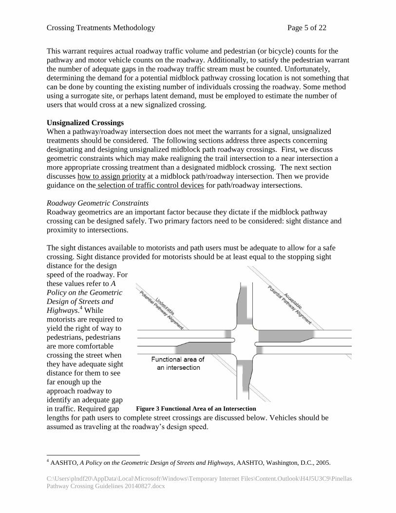
Figure 3 Functional Area of an Intersection

Crossing Treatments Methodology Page 6 of 22
C:\Users\plndf20\AppData\Local\Microsoft\Windows\Temporary Internet Files\Content.Outlook\H4J5U3C9\Pinellas
Pathway Crossing Guidelines 20140827.docx
The proximity to intersections is an important consideration because of the complexity of motor
vehicle movements on the approach to intersections. Essentially, if it can be avoided, midblock
pathway crossings should not be placed within the functional area of an intersection. The
functional area of an intersection includes both the approaches to and departures from the
intersection and the longitudinal limits of the auxiliary lanes (see Figure 3).5 If a crossing within
the functional area of an intersection is unavoidable, it is recommended that the crossing be moved
to the intersection.
Assigning Priority at Unsignalized Pathway Crossings
If a midblock crossing is to be designated, the first step is to determine which facility, the path or
the roadway, should receive priority at the crossing. Assigning priority to the “wrong” facility will
result in unpredictable and often inappropriate path user and motorist behaviors. For unsignalized
crossings, the MUTCD provides guidance for assigning priority at path roadway intersections. It
states,
When placement of STOP or YIELD signs is considered, priority at a shared-use
path/roadway intersection should be assigned with consideration of the following:
A. Relative speeds of shared-use path and roadway users;
B. Relative volumes of shared-use path and roadway traffic; and
C. Relative importance of shared-use path and roadway.
Speed should not be the sole factor used to determine priority, as it is sometimes
appropriate to give priority to a high-volume shared-use path crossing a low-volume
street, or to a regional shared-use path crossing a minor collector street.
When priority is assigned, the least restrictive control that is appropriate should be placed
on the lower priority approaches. STOP signs should not be used where YIELD signs
would be acceptable.6
It should not be a forgone conclusion that the roadway’s speeds will be higher than the pathway’s.
On sidepath type facilities (where the path is within the right of way of a parallel street) the
motorists on the roadways intersecting the path frequently are reducing speeds to negotiate the
adjacent roadway/side street intersection. Additionally, consideration given to the roadway having
higher speeds might be offset by the volume of the pathway being much higher than that of the
roadway. A local roadway might also be considered a lower priority than a regional pathway (such
as the Pinellas Trail). The Pinellas Trail (existing and proposed extension) has a higher volume
than the local roadways it crosses. However, on future extensions, or on other trails, it may be a
factor to consider when assigning priority.
For assigning priority at pathway intersections with two-lane roadways, we propose comparing the
volumes and speeds of the Pinellas Trail and intersecting roadways to determine which facility
should get priority. Figure 4 shows how this could be applied. Essentially the slope of each line
has been adjusted to reflect the proportionate speeds of the intersecting facilities (a 20 mph design
5 AASHTO, A Policy on the Geometric Design of Streets and Highways, AASHTO, Washington, D.C., 2005.
6 FHWA, Manual on Uniform Traffic Control Devices, pg. 9B-2, FHWA, Washington, D.C., 2003.

Crossing Treatments Methodology Page 7 of 22
C:\Users\plndf20\AppData\Local\Microsoft\Windows\Temporary Internet Files\Content.Outlook\H4J5U3C9\Pinellas
Pathway Crossing Guidelines 20140827.docx
speed was used for the Pinellas Trail). For instance, based upon Pinellas County Pinellas Trail user
counts there are about 1,600 users per day on the Pinellas Trail. Therefore, if the trail intersects a
roadway with a daily traffic of 900 vpd, and a speed limit of 30 mph, the trail would receive
priority over the roadway. If, however, the roadway had a speed limit of 45 mph, the roadway
would receive the priority.
On four-lane roadways, the priority is automatically assigned to the roadway. This was done for a
number of reasons. Multi-lane roadways are typically higher priority roadways; speeds are
typically higher on multilane roadways; and with multiple lanes in each direction, there is a
potential for multiple threat crashes.
The Apparent Paradox of Roadway Priority
There is an apparent paradox with assigning the priority to the roadway at a shared-use path
crossing. For example, on a multi-lane roadway the priority would be assigned to the roadway.
Therefore, the traffic control on the approaches to the intersections – signing, markings, flashing
beacons – are all placed to ensure the approaching path users know that they are required to yield
the right of way to the roadway users.
Roadway Speed Limit
Intersection Priority, intersecting a 2 lane street
as a function of roadway speed limit
0
500
1000
1500
2000
2500
3000
0 200 400 600 800 1000 1200 1400 1600 1800 2000Path Volume, daily counts
(2 x user counts, approximately)
Ro
ad
way
Vo
lum
e,
AD
T 15 mph
20 mph
25 mph
30 mph
35 mph
45 mph
55 mph
Roadway Priority
Pathway Priority
900 vpd
1600users per day
Figure 4 Proposed priority based upon facility speeds.

Crossing Treatments Methodology Page 8 of 22
C:\Users\plndf20\AppData\Local\Microsoft\Windows\Temporary Internet Files\Content.Outlook\H4J5U3C9\Pinellas
Pathway Crossing Guidelines 20140827.docx
The conundrum becomes apparent when one realizes that a shared use path is a pedestrian facility
(sidewalk) as well as a vehicular way. At every crossing of a shared use path and a roadway, there
is a legal crosswalk, whether marked or not. According to Florida Statutes (Section 316.130(7)),
“…the driver of a vehicle shall yield the right-of-way, slowing down or stopping if need be
to so yield, to a pedestrian crossing the roadway within a crosswalk when the pedestrian is
upon the half of the roadway upon which the vehicle is traveling or when the pedestrian is
approaching so closely from the opposite half of the roadway as to be in danger.”
Moreover, with regard to bicyclists, the law states (Section 316.2065(10)),
“A person propelling a vehicle by human power upon and along a sidewalk, or across a
roadway upon and along a crosswalk, has all the rights and duties applicable to a
pedestrian under the same circumstances.”
Consequently, when priority is assigned to the roadway, we are apparently requiring pathway
users to yield to traffic that is required by law to yield to pathway users. In actuality, when we
assign priority at an intersection we are requiring traffic approaching the intersection to yield to
traffic on the other approaches. However, this assignment of priority does not exempt path users or
motorists from their obligation to yield to users already within the intersection.7 This conundrum
is not merely academic – it underscores the importance of careful design and selection of traffic
control at path roadway intersections. Improper or incomplete design, and/or maintenance of
pathway/roadway intersections, have contributed and will continue to contribute to crashes,
injuries and deaths.
Driveways
Shared use path crossings of driveways are a special case path /roadway intersection. How they
are addressed is dependent upon the location of path with regard to parallel roadways. Where
shared use paths that are along independent alignments (not adjacent to a roadway) cross
driveways, priority should be assigned just as with any other path/roadway intersection. The
relative speeds and volumes should be considered and priority set as described above.
If the path is parallel and relatively close to an adjacent roadway, there are two options for
assigning priority. Ideally, at unsignalized crossings, the path would be realigned to cross the
driveway far enough away from the roadway paralleling the path to act as an independent
intersection. If this can be done, then priority should be determined using the relative speeds and
volumes of the driveway and the path. If, however, the path must remain close to the parallel
roadway, then the path should be given the same priority over entering driveways as the parallel
roadway.
Appropriate Traffic Control for the Crossing
Once the priority has been assigned at the intersection, appropriate traffic control treatments must
be selected. The traffic control used at pathway/roadway intersections must accomplish several
objectives:
1. Make pathway users and roadway users aware of the crossing conflict;
7 Section 316.121(1), F.S. and Section 316.130(8)

Crossing Treatments Methodology Page 9 of 22
C:\Users\plndf20\AppData\Local\Microsoft\Windows\Temporary Internet Files\Content.Outlook\H4J5U3C9\Pinellas
Pathway Crossing Guidelines 20140827.docx
2. Make users understand their obligations with regard to yielding on the approach to the
crossing; and,
3. Clarify the motorists’ obligations to path users within the crosswalk itself.
The method for determining traffic control for pathway/roadway intersections described below
addresses these three objectives.
The width of the roadway being crossed by the trail users and the motor vehicle volumes are the
determining factors for making this decision. This methodology uses these factors in combination
to stratify roadways by volume for application of different traffic control device packages.
For these guidelines, roadways are stratified into low-, medium-, and high-volume. The threshold
volume for low- to medium-volume was determined using the amount of time a pedestrian can
expect to wait for an adequate gap in traffic to cross the street. The medium- to high-volume
threshold is based upon the midblock crossing study previously referenced.
Low- to Medium-Volume Threshold. Low-volume roadways are those on which a path user
could expect to obtain an adequate gap to cross the street safely within 10 seconds of arriving at
the pathway/roadway intersection. The 90 percentile delay time was used to determine the upper
threshold for this roadway volume range; that is, 90 percent of the path users would be able to
begin crossing in a safe gap within 10 seconds of arriving at the intersection.
To calculate the required gaps, several assumptions about the users and the roadways were
required. The lengths of adequate gaps were calculated assuming 12-foot lanes, a startup time of 2
seconds, and a crossing speed of 2.8 ft/sec.8 Table 1 below shows the gap lengths for different
numbers of lanes. For roadways with a minimum 6-foot median, a pedestrian can select an
adequate gap to cross one direction of traffic, cross to the median, wait for an adequate gap to
cross the opposite direction of traffic, and cross to the far side of the roadway. For roadways
without a minimum 6-foot median, the pathway user must select a gap that is adequate to cross the
entire roadway.
Table 1. Required Gap for a to Cross
Number of lanes Gap length (sec)
1 6.29
2 10.57
3 14.86
Gap length is the time interval from when the rear of the first vehicle passes the observer to when
the front of the second vehicle passes the observer and represents the time when the lane is clear of
vehicles. Average gap length was calculated using the number of vehicles per hour per lane, a
speed of 44 ft/sec (30 mi/h), and a vehicle length of 20 ft. Thus
Average gap length (sec) = 3600 seconds/vehicles per hour – 20 feet/speed
8 This 2.8 ft per second speed was recommended in comments to an early draft of the methodology. It was discussed
at the January meeting and adopted for this revision.

Crossing Treatments Methodology Page 10 of 22
C:\Users\plndf20\AppData\Local\Microsoft\Windows\Temporary Internet Files\Content.Outlook\H4J5U3C9\Pinellas
Pathway Crossing Guidelines 20140827.docx
where
3600/vehicles per hour = number of seconds from when the front of the first vehicle
passes a waiting pathway user to when the front of the
second vehicle passes the pathway user
20/speed = the length of time for a vehicle to travel its own length
Gap lengths were assumed to be normally distributed, with a mean of the average gap length and a
standard deviation of 0.37 times the average gap length. That is, vehicles were assumed to pass
the midblock crossing location randomly rather than in platoons.
Using the NORMDIST function in Microsoft Excel, it is possible to calculate the proportion of
gaps that are of any specified minimum duration for any traffic volume. Figure 5 shows gap
lengths for 200 (top line), 400 (middle line), and 600 (bottom line) vehicles per hour in one lane.
With 200 vph, nearly 96 percent of gaps are a minimum of 6.29 seconds (the gap length required
to cross one lane of traffic). As traffic volumes increase, average gap lengths are shorter and
fewer gaps will meet the same specified duration. Figure 5 also shows that with 400 vph, about 76
percent of gaps are a minimum of 6.29 seconds. With 600 vph, only 36 percent of gaps are a
minimum of 6.29 seconds.
Figure 5 Sample Probability curves for Gap Lengths
As can be seen, as traffic volumes increase, crossing opportunities (i.e., adequate gaps) become
fewer. As a result, the probability that a path user will find an adequate gap to cross within a
reasonable time period (such as 10 seconds or 30 seconds) diminishes. Figure 6 shows the
probabilities of finding an adequate gap (i.e., 6.29 sec) within 10 seconds for different volumes on
a one-lane crossing. For example, with 475 vph, there is a 90 percent probability that a pathway

Crossing Treatments Methodology Page 11 of 22
C:\Users\plndf20\AppData\Local\Microsoft\Windows\Temporary Internet Files\Content.Outlook\H4J5U3C9\Pinellas
Pathway Crossing Guidelines 20140827.docx
user will experience a delay no longer than 10 seconds (that is, find an adequate gap within 10
seconds). At 800 vph, this probability drops to 20 percent.
Vehicles in one lane were also assumed to pass the observer independently of vehicles in another
lane. Thus, the probability of encountering a 10-second gap in two lanes is simply the probability
of a 10-second gap in Lane 1 times the probability of a 10-second gap in Lane 2.
P(2 lanes) = P (Lane 1) X P (Lane 2). With this assumption in mind, the same reasoning can be
extended to crossings involving 2-lanes, 3-lanes, and wider roadways.
The number of acceptable gaps in traffic is also influenced by the speed of the vehicles on the
roadway. Because a faster car takes less time to cross a point, for a given flow rate, higher speed
vehicles actually increase the number of (theoretically) acceptable gaps in a traffic stream.
Because this is a method for estimating the number of gaps, a conservative speed of 30 mph was
chosen as the assumed speed for developing this methodology. If the user wishes to confirm the
actual number of gaps, a pedestrian gap study could be performed.
Figure 6 Probability of a Pedestrian Getting an Adequate Gap
Based upon the above calculations, a low volume road is assumed to be a road where a pedestrian
would not have to wait more than 10 seconds to encounter an adequate gap for crossing the street.
This equates to approximately 4,500 vpd.9
Medium- to High-Volume Threshold. The medium- to high-volume threshold was chosen as
12,000 vpd. This volume was chosen as based upon a recent FHWA report10
which concluded,
9 Assumes K=0.097 and d=0.55.
10 Zegeer, Charles V., J. Richard Stewart, Herman F. Huang, Peter A. Lagerwey, John Feaganes, and B.J. Campbell.
Safety Effects of Marked vs. Unmarked Crosswalks at Uncontrolled Locations – Final Report and Recommended
Guidelines. Report No. FHWA-HRT-04-100. Federal Highway Administration, McLean, VA, February 2005.

Crossing Treatments Methodology Page 12 of 22
C:\Users\plndf20\AppData\Local\Microsoft\Windows\Temporary Internet Files\Content.Outlook\H4J5U3C9\Pinellas
Pathway Crossing Guidelines 20140827.docx
“Marked crosswalks alone (i.e., without traffic-calming treatments, traffic signals with
pedestrian signals when warranted, or other substantial improvement) are not
recommended at uncontrolled crossing locations on multilane roads (i.e., four or more
lanes) where traffic volume exceeds approximately 12,000…”
The referenced study distinguishes between roadways with and without medians, raising the
threshold to 15,000 vpd for roadways with raised medians. To minimize the volume categories in
the crossing guidelines, we chose to not differentiate between roadways with refuges and those
without with regard to this guideline. Consequently, we have decided to use 12,000 vpd as the
minimum value for high-volume roadways.
The calculated and final threshold volumes are provided in Table 2. The hourly volume of 1,150
vph shown in Table 2 represents the application of an assumed daily peak-to-daily factor (k factor)
of 0.097 and directional (d) factor of 0.55. These thresholds pertain to an undivided roadway or a
divided roadway with less than 6 ft of raised median. For a divided roadway with a minimum 6-
foot raised median, these thresholds pertain to each direction of traffic. The Guidelines Total
Traffic Volume column of Table 2 contains generalized values based upon the calculated volumes.
Table 2. Volume Thresholds for Pathway User Delay for Various Roadway Crossings Calculated Volume
Thresholds, vplph (vph for crossing)
Guidelines Total
Traffic Volume for
Lanes Crossed , vph
1 lane 2 lane 3 lane
Low volume
(delay <=10 sec)
< 475 < 230
(< 460)
< 139
(< 417)
< 475
Medium volume
475-1,150
343-575
(460 – 1,150)
139-384
(417 - 816)
475 to 1,150
High-volume
>1,150
> 575
(>1,150)
> 384
(>1,150)
>1,150
vplph = vehicles per lane per hour
vph = vehicles per hour
The above table has been simplified for the actual crossing guidelines application. In the
application, one would determine the volume of traffic in the lanes being crossed and use Table 3
to determine which table in the traffic control matrices to use. The proposed traffic control
matrices are provided later in the “Crossing Treatments Matrices” section of this document.
Table 3. Volume Thresholds for the Crossing Treatments Guidelines
Traffic Volume in Lanes Being
Crossed
< 4,500 vpd Table 5
4,500 – 12,000 vpd Table 6
>12,000 vpd Table 7
vpd = vehicles per day

Crossing Treatments Methodology Page 13 of 22
C:\Users\plndf20\AppData\Local\Microsoft\Windows\Temporary Internet Files\Content.Outlook\H4J5U3C9\Pinellas
Pathway Crossing Guidelines 20140827.docx
A summary of the treatments selected for each intersection is provided below.
Crossing Treatment Matrices
Three tiers of traffic control device packages were identified for these guidelines: static signs,
activated signs, and hybrid beacons. The components of each of these packages are provided in the
table below:
Table 4. Traffic Control Devices Tiers
Traffic Control Devices Tier
Traffic Control Device Static Signs Activated Signs Hybrid Beacon Marked Crosswalks Trail Xing Sign
(W11-15) w/
Arrow (W16-7p)2
Advance Stop Lines5
Trail Xing Sign (advance) and TRAIL
XING Pavement Marking
Stop Here to Ped Signs
(R1-5)3,4
RRFB crossing:
Ped Xing Signs
(W11-2) with rapid rectangular
flashing beacons, and supplemental
striping
Pedestrian Hybrid Beacon7
The matrices on the following pages present packages of traffic control devices recommended for
specific roadway conditions. While providing guidance, there are sometimes field conditions
which make the strict adherence to any typical signing and marking scheme impractical.
Therefore, when applied at new locations, each location should be reviewed in the field to ensure
the proposed treatments are appropriate.
If sight distance is limited, additional traffic control may be appropriate.
Additional traffic control may be appropriate in areas where expected path users are
predominately school children or individuals with mobility impairments.

Crossing Treatments Methodology Page 14 of 22
C:\Users\plndf20\AppData\Local\Microsoft\Windows\Temporary Internet Files\Content.Outlook\H4J5U3C9\Pinellas
Pathway Crossing Guidelines 20140827.docx
The matrices assume that the roadway is given priority. If the pathway is to be given priority, then
STOP or YIELD signs as appropriate should be installed on the roadway along with the applicable
pavement markings (stop lines or yield markings).
The following general notes apply to the crossing treatment matrices:
General Notes for Applying the Crossing Treatment Methodology Matrices
1. Volumes in the title cells assume a daily to peak hour volume factor of 0.97.
2. Each column in the table represents a package of traffic control devices recommended for the
specific crossing condition.
3. The designation of “YES” for the median assumes there is potential for installing a raised
median at the crossing location and that one will be installed. Raised medians that can be used
as refuges (6 feet wide minimum for pedestrians, greater than 8 feet recommended for shared
use paths) will allow for less restrictive motor vehicle traffic controls to be used in conjunction
with the midblock crossings.
4. On roadways with two-way left turn lanes, refuge islands should be installed at crossing
locations.
5. On multi-lane roadways with medians on the approach, crossing signs should be placed in the
medians as well as on the side of the roadway.
6. When advance stop lines are used on the approach roadways they should be used in
conjunction with solid lane lines extending back the stopping sight distance from stop lines.
This is to enable law enforcement officers to determine when a motorist fails to yield when he
could have done so.
7. On six-lane, undivided roadways, strong consideration should be given to providing a grade-
separated crossing of the roadway for pedestrians/trail users. Until such time as this can be
achieved, aggressive channelization should be used to divert pedestrians/trail users to the
nearest safe crossing.
8. This guidance assumes that lighting will be considered and provided where needed for
crossings that are used at night.

Crossing Treatments Methodology Page 15 of 22
C:\Users\plndf20\AppData\Local\Microsoft\Windows\Temporary Internet Files\Content.Outlook\H4J5U3C9\Pinellas Pathway Crossing Guidelines
20140827.docx
s
Table 5: Roadway Volume less than 475 vehicles per hour, vph (4,500 vehicles per day1,
vpd) Lanes 2 lanes 4 lanes
Median No Yes
No Yes
Speed ≤ 30
mph
35–
40
mph
≥ 45
mph
≤ 30
mph
35–
40
mph
≥ 45
mph
≤ 30
mph
35–
40
mph
≥ 45
mph
≤ 30
mph
35–
40
mph
≥ 45
mph
Taf
fic
Co
ntr
ol
Dev
ises
Pac
kag
e
Static Signs
Rectangular Rapid Flashing
Beacon
Hybrid Beacon

Crossing Treatments Methodology Page 16 of 22
C:\Users\plndf20\AppData\Local\Microsoft\Windows\Temporary Internet Files\Content.Outlook\H4J5U3C9\Pinellas Pathway Crossing Guidelines
20140827.docx
Table 6 : Roadway Volume > than 4751 vph (4,500 vpd) and < than 1,150 vph (12,000vpd)
Lanes 2 lanes 4 lanes 6 lanes
Median No Yes
No Yes No Yes
Speed ≤
30
mph
35–
40
mph
≥
45
mph
≤
30
mph
35–
40
mph
≥
45
mph
≤
30
mph
35–
40
mph
≥
45
mph
≤
30
mph
35–
40
mph
≥
45
mph
≤ 30
mph
35–40
mph
≥ 45
mph
≤ 30
mph
35–40
mph
≥ 45
mph
Taf
fic
Co
ntr
ol
Dev
ises
Pac
kag
e
Static Signs
Rectangular
Rapid
Flashing
Beacon
Hybrid
Beacon

Crossing Treatments Methodology Page 17 of 22
C:\Users\plndf20\AppData\Local\Microsoft\Windows\Temporary Internet Files\Content.Outlook\H4J5U3C9\Pinellas Pathway Crossing Guidelines
20140827.docx
Table 7 : Roadway Volume > than 1,150 vph (12,000vpd) Lanes 2 lanes 4 lanes 6 lanes
Median No Yes
No Yes No Yes
Speed ≤
30
mph
35–
40
mph
≥
45
mph
≤
30
mph
35–
40
mph
≥
45
mph
≤
30
mph
35–
40
mph
≥
45
mph
≤
30
mph
35–
40
mph
≥
45
mph
≤ 30
mph
35–40
mph
≥ 45
mph
≤ 30
mph
35–40
mph
≥ 45
mph
Taf
fic
Co
ntr
ol
Dev
ises
Pac
kag
e
Static Signs
Rectangular
Rapid
Flashing
Beacon
Hybrid
Beacon

Crossing Treatments Methodology Page 18 of 22
C:\Users\plndf20\AppData\Local\Microsoft\Windows\Temporary Internet
Files\Content.Outlook\H4J5U3C9\Pinellas Pathway Crossing Guidelines 20140827.docx
Rapid Rectangular Flashing Beacon (RRFB) Crossing Treatment
The RRFB (Figure 7) treatment is a combination of signing, markings and pedestrian activated
strobe and feedback devices. Signing for the RRFB includes advance warning signs (W11-2) with
AHEAD supplemental plaques (W16-9p), and YIELD HERE TO PEDS signs (R1-5). Pavement
markings include solid white lane lines (on divided multi-lane roads); the length of these lines is
dependent upon the design stopping sight distance for the roadway. The pedestrian activated
treatments are W11-2 signs with built in rectangular rapid flashing beacons. Additionally,
pedestrian visible strobes inform pedestrians of when the crossing is activated. Signs should
instruct pedestrians to wait for motorists to yield before crossing the road. This may be
supplemented with an audible message.
TRAIL XING (Figure 8) pavement messages should be placed on the pavement in advance of the
crossing. W11-15 signs may be used in place of W11-2 signs.
The Rapid Rectangular Flashing Beacon is the subject of an Interim Approval from FHWA.
Figure 7 Rapid Rectangular Flashing Beacon Installation

Crossing Treatments Methodology Page 19 of 22
C:\Users\plndf20\AppData\Local\Microsoft\Windows\Temporary Internet
Files\Content.Outlook\H4J5U3C9\Pinellas Pathway Crossing Guidelines 20140827.docx
Figure 8 TRAIL XING Pavement Marking

Crossing Treatments Methodology Page 20 of 22
C:\Users\plndf20\AppData\Local\Microsoft\Windows\Temporary Internet
Files\Content.Outlook\H4J5U3C9\Pinellas Pathway Crossing Guidelines 20140827.docx
Shared Use Paths Crossings of Side Streets at Intersections
Where a shared use path crosses a side street within the functional area of an intersection, the path
should be brought to the intersection and cross the side street within the crosswalk.
Intersections of side streets and paths parallel to a roadway are to be given the same priority as the
parallel roadway. Installing STOP or YIELD signs at these locations is not an effective method of
slowing or stopping path users at side streets and driveways. If path users perceive the signs as
overly restrictive, they will not comply with them. Furthermore, motorists may yield to path users
and wave them through in conflict with the sign priority at the intersection. The overuse of these
signs may decrease their effectiveness at locations where compliance with STOP or YIELD signs is
critical to the path users’ safety.
Where possible, reduce the speeds of shared use path users on the sidepath. Users of intersections
must be able to perceive conflicts at intersections, understand their obligations to yield or stop, and
be able to fulfill their obligations to yield. Slowing drivers and path users down on the approach to
intersections can provide more time for users to perceive and understand their obligations. Traffic
calming features are beyond the scope of this document. However, slowing the path user on the
approach to the intersection will also support these fundamental concepts.
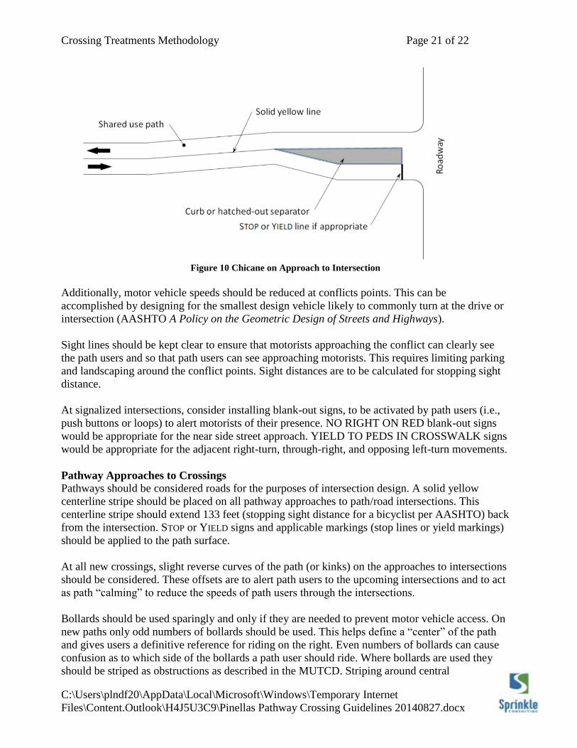
Horizontal deflection, either through a series of low design speed curves or a chicane, on the
approach to an intersection is an effective technique in reducing bicycle speeds on the approach to
intersections. Examples of these geometric design techniques are provided in Figures 9 and 10.
Figure 9 Geometric Design to Slow Bicyclists on Intersection Approaches
Crossing Treatments Methodology Page 21 of 22
C:\Users\plndf20\AppData\Local\Microsoft\Windows\Temporary Internet
Files\Content.Outlook\H4J5U3C9\Pinellas Pathway Crossing Guidelines 20140827.docx
Figure 10 Chicane on Approach to Intersection
Additionally, motor vehicle speeds should be reduced at conflicts points. This can be
accomplished by designing for the smallest design vehicle likely to commonly turn at the drive or
intersection (AASHTO A Policy on the Geometric Design of Streets and Highways).
Sight lines should be kept clear to ensure that motorists approaching the conflict can clearly see
the path users and so that path users can see approaching motorists. This requires limiting parking
and landscaping around the conflict points. Sight distances are to be calculated for stopping sight
distance.
At signalized intersections, consider installing blank-out signs, to be activated by path users (i.e.,
push buttons or loops) to alert motorists of their presence. NO RIGHT ON RED blank-out signs
would be appropriate for the near side street approach. YIELD TO PEDS IN CROSSWALK signs
would be appropriate for the adjacent right-turn, through-right, and opposing left-turn movements.
Pathway Approaches to Crossings
Pathways should be considered roads for the purposes of intersection design. A solid yellow
centerline stripe should be placed on all pathway approaches to path/road intersections. This
centerline stripe should extend 133 feet (stopping sight distance for a bicyclist per AASHTO) back
from the intersection. STOP or YIELD signs and applicable markings (stop lines or yield markings)
should be applied to the path surface.
At all new crossings, slight reverse curves of the path (or kinks) on the approaches to intersections
should be considered. These offsets are to alert path users to the upcoming intersections and to act
as path “calming” to reduce the speeds of path users through the intersections.
Bollards should be used sparingly and only if they are needed to prevent motor vehicle access. On
new paths only odd numbers of bollards should be used. This helps define a “center” of the path
and gives users a definitive reference for riding on the right. Even numbers of bollards can cause
confusion as to which side of the bollards a path user should ride. Where bollards are used they
should be striped as obstructions as described in the MUTCD. Striping around central

Crossing Treatments Methodology Page 22 of 22
C:\Users\plndf20\AppData\Local\Microsoft\Windows\Temporary Internet
Files\Content.Outlook\H4J5U3C9\Pinellas Pathway Crossing Guidelines 20140827.docx
bollards, those separating path users traveling in opposite directions, should be yellow.
Supplemental bollards separating users traveling in the same direction should be white.
Where an intersection is not clearly visible to an approaching bicyclist or where the traffic control
is not visible for a sufficient distance to permit the bicyclist to respond to the traffic control, an
Intersection Warning (W2-1), Stop Ahead (W3-1), Yield Ahead (W3-2), or Signal Ahead (W3-3)
sign should be used on the path approach to the intersection.
Existing Trail Approaches
It is likely that the basic existing Pinellas Trail approach configurations – separated bikes and
pedestrians, two bollards per approach - will be maintained at many locations. As these sections
undergo maintenance the striping should be modified to better represent the desired operations for
the approach and departure movements.
Figure 11 Approach Striping for Two-Bollard Approaches
The striping on the approach to the bollards should be modified to be consistent with Figure 11.
The stripe between opposing bike flows should be yellow to indicate that bikes on the opposite
side of the stripe are traveling in the opposite direction. The bicycle and directional symbols on the
path should be placed in advance of the bollards for approaching bicyclists. The line separating the
pedestrians from the bicyclists should be white as it essentially represents an edgeline for the (non-
motorized) vehicular way of the path. Again, directional arrows should be placed on the approach
side of the bollards. The solid lines on the approach to the intersections should be of a length
approximating the stopping sight distance (S.S.D.) for bicyclists. Striping around the bollards
should provide 1 foot clear to bicyclists and pedestrians. Stop lines should be placed for bicyclists
approaching the roadway intersection.