shared memory mimd architectures 18.1 introduction - … · chapter 18 - shared memory mimd...
TRANSCRIPT

D. Sima, T. J. Fountain, P. Kacsuk Advanced Computer Architectures
Chapter 18 - Shared Memory MIMD Architectures
18.1 Introduction
The three main design issues to increasing the scalability of shared memory systems
are:
1. Organisation of memory
2. Design of interconnection networks
3. Design of cache coherent protocols
As it was shown in Chapter 15, shared memory systems are basically classified
according to the organisation of their memory since this is the most fundamental design
issue. Accordingly, shared memory systems can be divided into four main classes:
1. Uniform-Memory-Access (UMA) machines
2. Non-Uniform-Memory-Access (NUMA) machines
3. Cache-Coherent Non-Uniform-Memory-Architecture (CC-NUMA) machines
4. Cache-Only Memory Architecture (COMA) machines
UMA machines belong to the physically shared memory architecture class, while
NUMA, CC-NUMA and COMA machines form the class of distributed shared memory
architectures. The four classes cover the three generations of shared memory systems.
Their first generation contains the UMA machines where the interconnection network
was based either on the concept of shared bus in order to construct low-price parallel
computers or on multistage networks in order to build massively parallel shared memory
systems. Meanwhile the small size bus based shared memory systems became
commercially available in the mid-eighties, the massively parallel shared memory
machines remained prototypes.
Contention is an inherent consequence of sharing and, by introducing an additional
shared hardware resource - the shared bus - it became a critical architectural bottleneck.
The whole history of shared memory systems is about struggling against contention.
Even in the first generation of shared memory systems, local cache memories were
introduced as a remedy to reduce contention. However, despite of the use of sophisticated
cache systems, the scalability of first generation shared memory systems was strongly
limited. The number of effectively exploitable processors was in the range of 20-30 in
shared bus based machines and 100-200 in multistage network based machines.
The second generation shared memory systems tried to physically distribute the
shared memory among the processors in order to reduce the traffic and consequently, the

D. Sima, T. J. Fountain, P. Kacsuk Advanced Computer Architectures
2
contention on the interconnection network. A further improvement was the replacement
of the single shared bus by a more complex multibus or multistage network. As a
consequence, in the second generation shared memory systems hundreds of processors
were accommodated even in commercially available machines. For example, in the BBN
Butterfly machine 256 processors worked together. However, in order to keep all the
processors busy, highly sophisticated software techniques were needed both at the level
of operating systems, compilers and user written application programs.
The third generation shared memory systems combine the advantages of the first two
generations. CC-NUMA and COMA machines are highly scalable, massively parallel
systems where contention is dramatically reduced by introducing large local cache
memories. Because of the underlying cache coherence protocols, programming these
machines is not more difficult than programming the first generation. Current CC-
NUMA and COMA machines can be upgraded in the range of thousand processors.
Similarly to the multicomputers, the quality of the interconnection network has a
decisive impact on the speed, size and cost of the whole machine. Since in
multiprocessors any processor should access any memory location, even if it physically
belongs to another processor, usually, dynamic interconnection schemes are employed.
Dynamic networks can be divided into two main classes according to their working
mode. Those networks that provide continuous connection among the processors and
memory blocks are called shared path networks. In these networks the continuous
connection is shared among the processors which have to compete for its use. The shared
path was typically a single bus in the first generation multiprocessors. In recent third
generation machines hierarchical bus-systems are introduced.
The other type of dynamic networks does not provide a continuous connection
among the processors and memory blocks, rather a switching mechanism enables to
temporarily connect processors to memory blocks. The two most popular classes of these
switching networks are the crossbar and multistage networks. The latter can be further
divided according to the structure of the employed switching elements and their
interconnection topology.
The dynamic networks have some drawbacks comparing them to the static networks
applied in multicomputers. Dynamic networks are either too expensive (switching
networks) or they can support only a limited number of processors (bus connection).
Recently, hierarchical multibus systems have been proposed in order to make a
compromise between the price and scalability of the network. Another recent approach
combines the static and dynamic network components in hierarchy.
Uniprocessors have successfully demonstrated the benefits of cache memories in
order to increase memory bandwidth. Accordingly, most of the shared memory systems

D. Sima, T. J. Fountain, P. Kacsuk Advanced Computer Architectures
3
employ cache memories, too. However, the application of caches in a multiprocessor
environment gives rise to the so-called cache consistency problem. In order to solve
these problems of maintaining data consistency in the caches, the cache-coherence
protocol should be added to the traffic of the network. The extra traffic deriving from
the cache coherence protocol reduces the benefits of the caches and hence, careful design
is necessary to introduce the minimal complexity protocol.
Cache coherence protocols are basically divided into two classes: hardware based
protocols and software based protocols. The hardware based protocols are strongly
related with the type of the employed interconnection network. The snoopy cache
protocol is employed in single bus based multiprocessors, while directory based cache
coherence protocols are the most popular in multistage networks. Finally, hierarchical
cache coherence protocols are applied in hierarchical multibus systems.
The design space and classification of shared memory architectures is shown in
Figure 1.

D. Sima, T. J. Fountain, P. Kacsuk Advanced Computer Architectures
4
Sing
le a
ddre
ss s
pace
mem
ory
acce
ss
Phy
sica
lV
irtu
al (
dist
ribu
ted)
shar
ed m
emor
ysh
ared
mem
ory
UM
A NU
MA
CC
-NU
MA
CO
MA
Inte
rcon
nect
ion
sche
me
Shar
ed p
ath
Sing
le b
usba
sed
Mul
tipl
e bu
sba
sed
Bus
mul
tipl
icat
ion
Gri
d of
buss
esH
iera
rchi
cal
(clu
ster
) sys
tem
Swit
chin
g ne
twor
k
Cro
ssba
rM
ulti
stag
ene
twor
k
Om
ega
Ban
yan
Ben
es
Cac
he c
oher
ency
Har
dwar
eSo
ftw
are
base
dba
sed
Shar
ed m
emor
y co
mpu
ters
Figure 1. Design space and classification of shared memory computers

D. Sima, T. J. Fountain, P. Kacsuk Advanced Computer Architectures
5
18.2 Dynamic interconnection networks
Dynamic interconnection networks enable the temporary connection of any two
components of a multiprocessor. This possibility is provided either by a shared path
network that can be allocated to any active component of the machine on a competitive
basis or by a number of switches that can be set in different ways according to the
connection requirements. The former networks are called shared path networks, while the
latter ones are called switching networks. Both dynamic network types can be further
classified. Shared path networks can be either single bus or multiply bus systems
depending on the number of buses providing interconnection among the components of
the multiprocessor. Switching networks are either crossbars or multistage networks. The
classification of dynamic interconnection networks is shown in Figure 2.
Dynamicinterconnection networks
Shared pathnetworks
single bus multiple buses
Switching
Crossbar Multistagenetworks
networks
Figure 2. Classification of dynamic interconnections networks
18.2.1 Shared path networks
Single shared bus
One of the most popular interconnection network is the single shared bus which has
several advantageous features. Firstly, its organisation is simply a generalisation and
extension of the buses employed in uniprocessor systems. It contains the same bus lines
(address, data, control, interrupt) as uniprocessors and some additional ones to solve the
contention on the bus when several processor simultaneously want to use the shared bus.
These lines are called arbitration lines and play crucial role in the implementation of
shared buses. Secondly, the shared bus is a very cost-effective interconnection scheme.
Increasing the number of processors does not increase the price of the shared bus.
However, the contention on the shared bus represents a strong limitation concerning the
number of applicable processors. Obviously, as the number of processors increases on the
bus, the probability of contention also increases proportionally, reaching a point when the
D. Sima, T. J. Fountain, P. Kacsuk Advanced Computer Architectures
6
whole bandwidth of the bus is exhausted by the processors and hence, adding a new
processor will not cause any potential speed-up in the multiprocessor. One of the main
design issues in shared bus multiprocessors is the enhancement of the number of
applicable processors by different methods. The three most important techniques are as
follows:
1. Introducing private memory
2. Introducing coherent cache memory
3. Introducing multiple buses
Without these improvements the applicable number of processors is in the range of
3-5. By introducing private memory and coherent cache memory, the number of
processors can be increased by an order of magnitude up to 30 processors. Bus
hierarchies open the way to construct scalable shared memory systems based on bus
interconnection. However, the employment of coherent cache memories as well as
multiple buses will significantly increase the expenses of building such multiprocessors.
Section 18.3 deals with the problem of coherent caches while Sections 18.7.1 shows an
example of scalable multiprocessors with multiple buses.
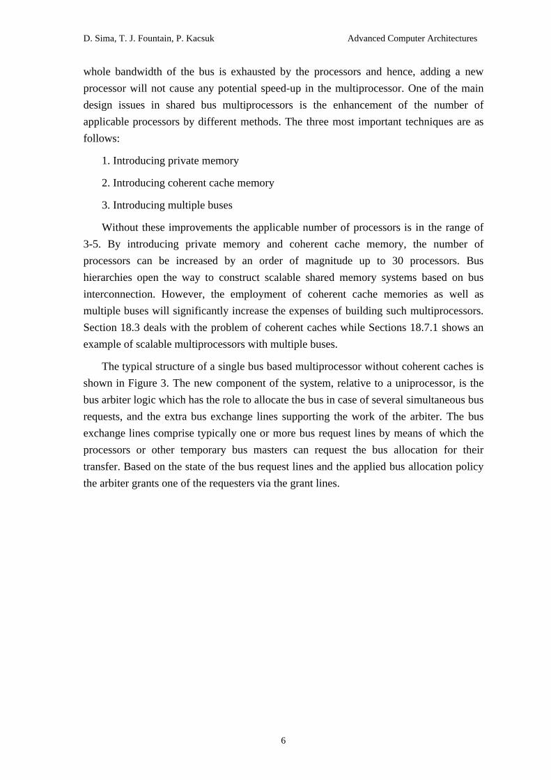
The typical structure of a single bus based multiprocessor without coherent caches is
shown in Figure 3. The new component of the system, relative to a uniprocessor, is the
bus arbiter logic which has the role to allocate the bus in case of several simultaneous bus
requests, and the extra bus exchange lines supporting the work of the arbiter. The bus
exchange lines comprise typically one or more bus request lines by means of which the
processors or other temporary bus masters can request the bus allocation for their
transfer. Based on the state of the bus request lines and the applied bus allocation policy
the arbiter grants one of the requesters via the grant lines.
D. Sima, T. J. Fountain, P. Kacsuk Advanced Computer Architectures
7
Busarbiterandcontrollogic
P1 ... Pk M1 Mn...
I/O I/O...1 m
address
data
control
interrupt
busexchangelines
Figure 3. Structure of a single bus based multiprocessor without caches
Though, in principle, the uniprocessor and multiprocessor buses are very similar,
there is a significant difference in their working mode. Uniprocessors and first generation
multiprocessors employ the so-called locked buses like the Multibus, VMEbus, etc.
Second generation multiprocessors apply pended buses. The difference comes from the
way how memory accesses are handled on the bus. A memory write access needs two
phases:
Phase 1. Transferring address and data on the bus to the memory controller.
Phase 2. Executing the memory write operation (including parity check, error
correction, etc.) by the memory controller.
The first phase is typically 3-4 times faster than the second one. In a uniprocessor
system the two phases are executed sequentially, the bus is locked until the complete
memory operation is finished. However, locking the bus in a multiprocessor system is
unnecessary and leads to low exploitation of the fast bus. If several processors and
several memory units are connected by the bus (and this is the case in single bus based
multiprocessors), then bus transfers and memory controller operations can be overlapped.
After finishing the bus transfer phase for a memory unit, another processor can start a
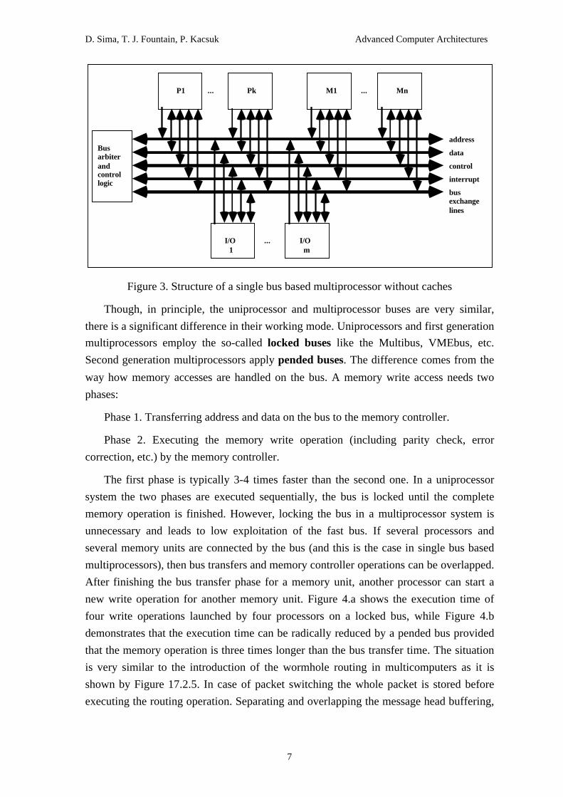
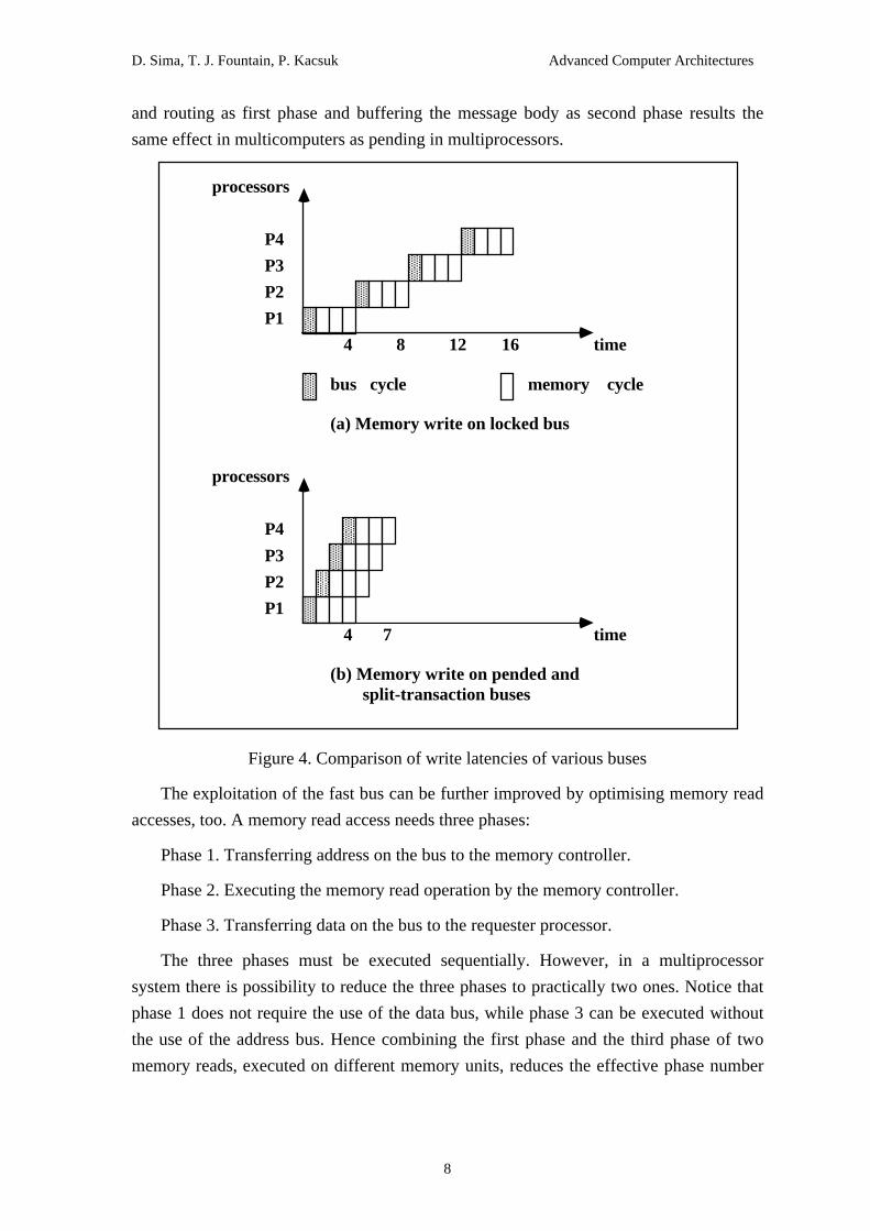
new write operation for another memory unit. Figure 4.a shows the execution time of
four write operations launched by four processors on a locked bus, while Figure 4.b
demonstrates that the execution time can be radically reduced by a pended bus provided
that the memory operation is three times longer than the bus transfer time. The situation
is very similar to the introduction of the wormhole routing in multicomputers as it is
shown by Figure 17.2.5. In case of packet switching the whole packet is stored before
executing the routing operation. Separating and overlapping the message head buffering,
D. Sima, T. J. Fountain, P. Kacsuk Advanced Computer Architectures
8
and routing as first phase and buffering the message body as second phase results the
same effect in multicomputers as pending in multiprocessors.
AAAAAAAAAAAAAAA
processors
P1
P2
P3
P4
(a) Memory write on locked bus
AAAAAAAAAAAAAAAAAAAAAAAA AAA
AAAAAAAAAAAAAAA AAA
AAAAAAAAAAAAAAA
time4 8 12 16
bus cycle memory cycleAAAAAAAAAAAAAAAAAA
AAAAAAAAAAAAAAAAAA
processors
P1
P2
P3
P4
(b) Memory write on pended and
AAAAAAAAAAAAAAAAAAAAAA
AAAAAAAAAAAAAAAAAAA
AAAAAAAAAAAAAAA
time4 7
split-transaction buses
Figure 4. Comparison of write latencies of various buses
The exploitation of the fast bus can be further improved by optimising memory read
accesses, too. A memory read access needs three phases:
Phase 1. Transferring address on the bus to the memory controller.
Phase 2. Executing the memory read operation by the memory controller.
Phase 3. Transferring data on the bus to the requester processor.
The three phases must be executed sequentially. However, in a multiprocessor
system there is possibility to reduce the three phases to practically two ones. Notice that
phase 1 does not require the use of the data bus, while phase 3 can be executed without
the use of the address bus. Hence combining the first phase and the third phase of two
memory reads, executed on different memory units, reduces the effective phase number

D. Sima, T. J. Fountain, P. Kacsuk Advanced Computer Architectures
9
to two. The comparison of the locked bus and the pended bus for memory read
operations is shown in Figure 5.a and b.
AAAAAAAAAAAAAAA
processors
P1
P2
P3
P4
(a) Memory read on locked bus
AAAAAAAAAAAAAAAAAA AAA
AAAAAAAAAAAA AAA
AAAAAAAAAAAA
timeAAAAAAAAAAAAAAA AAA
AAAAAAAAAAAAAAA AAA
AAAAAAAAAAAA AAAA
AAAAAAAAAAAAAAAA
AAAAAAAAAAAAAAA
processors
P1
P2
P3
P4
(d) Memory read on split-transaction bus
AAAAAAAAAAAAAAAAAAAAAAAAAAAAAAAAAAAAAAAAAA
AAAAAAAAAAAA
timeAAAAAAAAAAAAAAA AAAA
AAAAAAAAAAAAAAAAAAA
AAAAAAAAAAAAAAAAAAAAAAAAAAAAAA
85
5 10 15 20
AAAAAAAAAAAAAAA
AAAAAAAAAAAAAAA
AAAAAAAAAAAAAAA
AAAAAAAAAAAAAAA
AAAAAAAAAAAAAAAAAA
AAAAAAAAAAAAAAAAAAAAAAAA
P5
AAAAAAAAAAAAAAAAAA
processors
P1
P2
P3
P4
(d) Memory read on pended bus
AAAAAAAAAAAAAAAAAAAAAAAAAAAAAAAAAAAAAA
AAAAAAAAAAAAAAA
timeAAAAAAAAAAAAAAAAAAAAAAAAAAAAAAAAAAAAAAAAAAAAAAAAAAAAAAAAAAAAAAAAAA
5AAAAAAAAAAAAAAAAAA
AAAAAAAAAAAAAAAAAAAAAAAA
AAAAAAAAAAAAAAAAAAAA
AAAAAAAAAAAAAAA
AAAAAAAAAAAAAAA
AAAAAAAAAAAAAAA
25 30
14
11
108
P5
P5
Figure 5. Comparison of read latencies of various buses
From the implementation point of view of pended buses, memory controllers should
contain an input buffer where the contents of the address and data bus can be temporarily
stored from the bus, and an output buffer where the result of the memory read can be
stored until the bus accepts the memory request to transfer the data. Obviously, the
address and data buses should be separated in order to combine the first and third stages
of memory reads. A further requirement is that similarly to the processors, the memory

D. Sima, T. J. Fountain, P. Kacsuk Advanced Computer Architectures
10
controllers should be able to request bus transactions and arbiter logics should be able to
service their requests, too. The bus is not allocated for a complete memory read or write.
Rather it is allocated only either for the first phase of a memory write or read or for the
third phase of a memory read.
Third generation buses progress further. They enable the requester processor to issue
a new memory read access before completing the previous one. Data from different
memory reads can be returned in arbitrary order. The first phase and the third phase of a
memory read is totally separated or split and hence these buses are called split-
transaction buses. Using optimising arbiter logics two bus transaction phases (phase 1
and phase 3 of different memory reads) can be executed simultaneously. The
improvement of read latency by split-transaction buses is illustrated in Figure 5.c. On the
implementation side they employ special small size associative memories to link the
address of a pending read to a data response. When a memory read is issued, it occupies
the first available location in the associative memory and holds it until the memory
returns the requested data on the bus. When the associative memory is full, further
memory requests should be delayed until a location will be free again.
Arbiter logics play a crucial role in the implementation of pended and split-
transaction buses. These are the so-called 1-of-N arbiters since they grant the requested
resource (the shared bus) only to one of the requesters. The design space of arbiter logics
is very rich. There are basically two main possibilities to organise the arbitration logic
according to the distribution of its components in the multiprocessor system:
1. Centralised arbiter
2. Decentralised arbiter
Bus requests can be sent to the arbiter either by a single shared request line or by
independent request lines. Similarly, the granted requester can be notified either by one
of the independent grant lines or by using a daisy-chained grant line. The typical bus
allocation policies belong to one of the following schemes:
1. fixed priority
2. rotating priority
3. round robin
4. least recently used policy
5. first come first served scheme
The implementation of the fixed priority policy is very simple but it can not provide
fair allocation of the bus. The highest priority can be dynamically changed in the rotating
priority scheme providing a fair bus allocation strategy but with increased hardware

D. Sima, T. J. Fountain, P. Kacsuk Advanced Computer Architectures
11
complexity. In the round robin arbiter policy, fixed-length time slices of bus time are
allocated sequentially to each bus master in a round robin fashion. In the least recently
used policy, the bus master that has not used the bus for the longest time receives the
highest priority at every bus cycle. Both schemes provide good load balancing but the
latter requires less waiting time than the former one. In the first come first served
scheme, the bus is granted in the order of requests. This approach provides the best
performance but it requires the most complicated hardware to implement.
The design space of arbiter logics is depicted in Figure 6. Based on this rich design
space a large number of different bus arbiter logics have been proposed and built so far.
Here only the three most typical arbiter structures are explained.

D. Sima, T. J. Fountain, P. Kacsuk Advanced Computer Architectures
12
Arb
iter
logi
cs
Org
aniz
atio
n
Cen
tral
ized
Dis
trib
uted
Han
dlin
g of
requ
ests
Shar
edre
ques
tsIn
depe
nden
tre
ques
ts
Han
dlin
g of
gran
ts
Dai
sy-
chai
ned
Inde
pend
ent
gran
tsfi
xed
prio
rity
rota
ting
roun
dro
bin
leas
tre
cent
lyus
ed
firs
tco
me
firs
tse
rved
bus
allo
cati
on p
olic
y
Figure 6. Design space of arbiter logics

D. Sima, T. J. Fountain, P. Kacsuk Advanced Computer Architectures
13
The centralised arbitration with independent requests and grants is shown in Figure
7. Each potential bus master has an independent request line connected to the centralised
arbiter. Similarly, the arbiter uses separate grant lines for each bus master. Finally, a
shared bus busy line makes the set of bus exchange lines complete. The protocol of
allocating the bus is as follows:
AAAAAAAAAAAAAAAAAAAAAAAAAAAAAAAAAAAAAAAAAAAAAAAAAAAAAAAA
AAAAAAAAAAAAAAAAAAAAAAAAAAAAAAAAAAAAAAAAAAAAAAAAAAAAAAAA
AAAAAAAAAAAAAAAAAAAAAAAAAAAAAAAAAAAAAAAAAAAAAAAAAAAAAAAA
AAAAAAAAAAAAAAAAAAAAAAAAAAAAAAAAAAAAAAAAAA
AAAAAAAAAAAAAAAAAAAAAAAAAAAAAAAAAAAAAAAAAAAAAAAAAAAAAAAA
AAAAAAAAAAAAAAAAAAAAAAAAAAAAAAAAAAAAAAAAAAAAAAAAAAAAAAAA
AAAAAAAAAAAAAAAAAAAAAAAAAAAAAAAAAAAAAAAAAAAAAAAAAAAAAAAA
AAAAAAAAAAAAAAAAAAAAAAAAAAAAAAAAAAAAAAAAAA
AAAAAAAAAAAAAAAAAAAAAAAAAAAAAAAAAAAAAAAAAAAAAAAAAAAAAAAA
AAAAAAAAAAAAAAAAAAAAAAAAAAAAAAAAAAAAAAAAAAAAAAAAAAAAAAAA
AAAAAAAAAAAAAAAAAAAAAAAAAAAAAAAAAAAAAAAAAAAAAAAAAAAAAAAA
AAAAAAAAAAAAAAAAAAAAAAAAAAAAAAAAAAAAAAAAAA
...Master1 Master2 MasterN
AAAAAAAAAAAAAAAAAAAAAAAAAAAAAAAAAAAAAAAAAAAAAAAAAAAAAAAAAAAAAAAAAAAAAAAAAAAAAAAAAAAAAAAAAAAAAAAAAAAAAAAA
AAAAAAAAAAAAAAAAAAAAAAAAAAAAAAAAAAAAAAAAAAAAAAAAAAAAAAAAAAAAAAAAAAAAAAAAAAAAAAAAAAAAAAAAAAAAAAAAAAAAAAAA
AAAAAAAAAAAAAAAAAAAAAAAAAAAAAAAAAAAAAAAAAAAAAAAAAAAAAAAAAAAAAAAAAAAAAAAAAAAAAAAAAAAAAAAAAAAAAAAAAAAAAAAA
AAAAAAAAAAAAAAAAAAAAAAAAAAAAAAAAAAAAAAAAAAAAAAAAAAAA
R1G1R2G2
RNGN
Bus busy
Bus lines
R: Request G: Grant
CentralBus
Arbiter
Figure 7. Centralized arbitration with independent requests and grants
1. Masteri requests the bus by activating its dedicated bus request line.
2. If the bus busy line is passive, i.e., no other master uses the bus, the arbiterimmediately allocates the bus to the requester by activating the granti line. The requester
deactivates its request line and activates the bus busy line prohibiting the allocation of the
bus for other requesters. After completing the bus transaction, the requester deactivates
the bus busy line.
3. When the bus busy line is active, the arbiter does not accept any bus requests.
4. When several request lines are active by the time the bus busy line becomes
passive, the arbiter can use any bus allocation policies described above.
The centralised arbiter with independent request and grant lines has two major
advantages. Firstly, it can realise any bus allocation policy and secondly, it has faster
arbitration time compared with the daisy-chained arbiters. However, it requires a large
number of bus exchange lines, which is an obvious drawback.
One of the most popular organisation of arbiter logics is daisy-chaining. The
centralised version with fixed priority policy is illustrated in Figure 8. There is only a
single shared bus request line in the daisy-chained bus arbitration scheme. All the masters

D. Sima, T. J. Fountain, P. Kacsuk Advanced Computer Architectures
14
use this line to indicate their need to access the shared bus. The arbiter passes the bus
grant line to the first master and then it is passed from master to master creating a chain
of the masters. The priority of a master is determined by its position in the grant chain.
The closer position to the arbiter represents a higher priority. A master can access the
shared bus if the bus busy line is passive and its input grant line is active. When the
master does not require the bus and receives an active grant line, it activates its output
grant line enabling the next master to use the bus.
AAAAAAAAAAAAAAAAAAAAAAAAAAAAAAAAAAAAAAAAAAAAAAAAAAAAAAAAAAAAAAAA
AAAAAAAAAAAAAAAAAAAAAAAAAAAAAAAAAAAAAAAAAAAAAAAAAAAAAAAAAAAAAAAA
AAAAAAAAAAAAAAAAAAAAAAAAAAAAAAAAAAAAAAAAAAAAAAAAAAAAAAAAAAAAAAAA
AAAAAAAAAAAAAAAAAAAAAAAAAAAAAAAAAAAAAAAAAAAAAAAAAAAAAAAAAAAAAAAA
AAAAAAAAAAAAAAAAAAAAAAAAAAAAAAAAAAAAAAAAAAAAAAAAAAAAAAAAAAAAAAAA
AAAAAAAAAAAAAAAAAAAAAAAAAAAAAAAAAAAAAAAAAAAAAAAAAAAAAAAAAAAAAAAA
AAAAAAAAAAAAAAAAAAAAAAAAAAAAAAAAAAAAAAAAAAAAAAAAAAAAAAAAAAAAAAAA
AAAAAAAAAAAAAAAAAAAAAAAAAAAAAAAAAAAAAAAAAAAAAAAAAAAAAAAAAAAAAAAA
AAAAAAAAAAAAAAAAAAAAAAAAAAAAAAAAAAAAAAAAAAAAAAAAAAAAAAAAAAAAAAAA
AAAAAAAAAAAAAAAAAAAAAAAAAAAAAAAAAAAAAAAAAAAAAAAAAAAAAAAAAAAAAAAA
AAAAAAAAAAAAAAAAAAAAAAAAAAAAAAAAAAAAAAAAAAAAAAAAAAAAAAAAAAAAAAAA
AAAAAAAAAAAAAAAAAAAAAAAAAAAAAAAAAAAAAAAAAAAAAAAAAAAAAAAAAAAAAAAA
...Master1 Master2 MasterN
AAAAAAAAAAAAAAAAAAAAAAAAAAAAAAAAAAAAAAAAAAAAAAAAAAAAAAAAAAAAAAAAAAAAAAAAAAAAAAAAAAAAAAAAAAAAAAAAAAAAAAAAAAAAAAAAAAAAAAAA
AAAAAAAAAAAAAAAAAAAAAAAAAAAAAAAAAAAAAAAAAAAAAAAAAAAAAAAAAAAAAAAAAAAAAAAAAAAAAAAAAAAAAAAAAAAAAAAAAAAAAAAAAAAAAAAAAAAAAAAA
AAAAAAAAAAAAAAAAAAAAAAAAAAAAAAAAAAAAAAAAAAAAAAAAAAAAAAAAAAAAAAAAAAAAAAAAAAAAAAAAAAAAAAAAAAAAAAAAAAAAAAAAAAAAAAAAAAAAAAAA
AAAAAAAAAAAAAAAAAAAAAAAAAAAAAAAAAAAAAAAAAAAAAAAAAAAAAAAAAAAAAAAAAAAAAAAAAAAAAAAAAAAAAAAAAA
Bus lines
CentralBus
Arbiter
Bus
Grant1 G2 GN
Bus request
Bus busy
Figure 8. Daisy-chained bus arbitration scheme
The implementation of the daisy-chained arbitration scheme is very cost-effective.
Adding a new processor module does not require any extension of the existing bus
exchange lines. However, the relatively slow propagation of the grant signal on the grant
chain is a drawback of the scheme. Another obvious disadvantage is the lack of fairness
in the allocation scheme.
In order to eliminate this drawback a modified version, called the rotating arbiter,
can be employed in shared bus based multiprocessors. The structure of a decentralised,
rotating arbiter with independent request and grant lines is shown in Figure 9. The
priority loop of the rotating arbiter works similarly to the grant chain of the daisy-chained arbiter. Arbiteri is allowed to grant its coupled master unit if masteri has
activated its bus request line, the bus busy line is passive and the priority(i-1) input line is
active. If masteri has not activated its bus request line, arbiteri activates its output
priorityi line. The main difference comparing to the daisy-chained scheme appears in the
way how the lowest priority unit is selected. While in the daisy-chained arbiter the lowest
priority unit is always the farthest master, in the rotating scheme, it is always the master
that releases the bus.

D. Sima, T. J. Fountain, P. Kacsuk Advanced Computer Architectures
15
AAAAAAAAAAAAAAAAAAAAAAAAAAAAAAAAAAAAAAAAAAAAAAAAAAAAAAAAAAAAAAAA
AAAAAAAAAAAAAAAAAAAAAAAAAAAAAAAAAAAAAAAAAAAAAAAAAAAAAAAAAAAAAAAA
AAAAAAAAAAAAAAAAAAAAAAAAAAAAAAAAAAAAAAAAAAAAAAAAAAAAAAAAAAAAAAAA
AAAAAAAAAAAAAAAAAAAAAAAAAAAAAAAAAAAAAAAAAAAAAAAAAAAAAAAAAAAAAAAA
AAAAAAAAAAAAAAAAAAAAAAAAAAAAAAAAAAAAAAAAAAAAAAAAAAAAAAAAAAAAAAAA
AAAAAAAAAAAAAAAAAAAAAAAAAAAAAAAAAAAAAAAAAAAAAAAAAAAAAAAAAAAAAAAA
AAAAAAAAAAAAAAAAAAAAAAAAAAAAAAAAAAAAAAAAAAAAAAAAAAAAAAAAAAAAAAAA
AAAAAAAAAAAAAAAAAAAAAAAAAAAAAAAAAAAAAAAAAAAAAAAAAAAAAAAAAAAAAAAA
AAAAAAAAAAAAAAAAAAAAAAAAAAAAAAAAAAAAAAAAAAAAAAAAAAAAAAAAAAAAAAAA
AAAAAAAAAAAAAAAAAAAAAAAAAAAAAAAAAAAAAAAAAAAAAAAAAAAAAAAAAAAAAAAA
AAAAAAAAAAAAAAAAAAAAAAAAAAAAAAAAAAAAAAAAAAAAAAAAAAAAAAAAAAAAAAAA
AAAAAAAAAAAAAAAAAAAAAAAAAAAAAAAAAAAAAAAAAAAAAAAAAAAAAAAAAAAAAAAA
...Master1 Master2 MasterN
Bus lines
AAAAAAAAAAAAAAAAAAAAAAAAAAAAAAAAAAAAAAAAAAAA
AAAAAAAAAAAAAAAAAAAAAAAAAAAAAAAAAAAAAAAAAAAA
AAAAAAAAAAAAAAAAAAAAAAAAAAAAAAAAAAAAAAAAAAAA
AAAAAAAAAAAAAAAAAAAAAAAAAAAAAAAAAAAAAAAAAAAA
Arbiter1
AAAAAAAAAAAAAAAAAAAAAAAAAAAAAAAAAAAAAAAAAAAA
AAAAAAAAAAAAAAAAAAAAAAAAAAAAAAAAAAAAAAAAAAAA
AAAAAAAAAAAAAAAAAAAAAAAAAAAAAAAAAAAAAAAAAAAA
AAAAAAAAAAAAAAAAAAAAAAAAAAAAAAAAAAAAAAAAAAAA
Arbiter2
AAAAAAAAAAAAAAAAAAAAAAAAAAAAAAAAAAAAAAAAAAAA
AAAAAAAAAAAAAAAAAAAAAAAAAAAAAAAAAAAAAAAAAAAA
AAAAAAAAAAAAAAAAAAAAAAAAAAAAAAAAAAAAAAAAAAAA
AAAAAAAAAAAAAAAAAAAAAAAAAAAAAAAAAAAAAAAAAAAA
ArbiterN...
R1 R2 R3G1 G2 G3
Bus busy
P1 P2
R: Request G: Grant P: Priority
PN
Figure 9. Structure of a decentralized rotating arbiter with independent requests and
grants
Multiple shared bus
The limited bandwidth of the single shared bus represents a major limitation for
building scalable multiprocessors. There are several ways to increase the bandwidth of
the interconnection network. A natural idea is to multiply the number of employed buses
similarly to the processors and memory units. Four different ways have been proposed
for connecting buses to the processors, memory units, and other buses:
1. 1-dimension multiple bus system
2. 2- or 3-dimension bus systems
3. cluster bus system
4. hierarchical bus system
The simplest generalisation of the single bus system towards a multiple bus system is
the 1-dimension multiple bus system shown in Figure 10. This approach leads to a
typical uniform memory access (UMA) machine where any processor can access any
memory unit through any of the buses. The employment of the 1-of-N arbiters described
in the previous section is not sufficient in such systems. The arbitration is a two stage-
process in 1-dimension multiple bus systems. First, the 1-of-N arbiters (one per memory
unit) can resolve the conflict when several processors require exclusive access to the

D. Sima, T. J. Fountain, P. Kacsuk Advanced Computer Architectures
16
same shared memory unit. After the first stage m (out of n) processors can obtain access
to one of the memory units. However, when the number of buses (b) is less than that of
the memory units (m), a second stage of arbitration is needed where an additional b-of-m
arbiter is employed to allocate buses to those processors that successfully obtained access
to a memory unit.
.
.
.
... ...P1 P2 Pn M1 M2 Mm
B1B2
Bb
Figure 10. Structure of a 1-dimension multiple bus multiprocessor
Here a b-of-m arbiter described in (Mudge & al. 1987) is shown as an example. The
structure of the b-of-m arbiter is depicted in Figure 11. It contains a state register and marbiter modules (A1, A2, ... , Am) for each memory unit. The state register realises a
round-robin arbitration policy, i.e. it ensures that the highest priority will be given in the
next arbitration cycle to the arbiter module immediately following the last one serviced.The highest priority module Ai is selected by activating its ei input. If the memory unit
Mi was selected in the first stage of the arbitration cycle, it activates its request line Ri. If
both ei and Ri are active, the first available bus is allocated for the memory unit Mi (and
for the processor that obtained access to Mi in the first stage of the arbitration cycle) by
activating the grant line Gi and setting BAi as the address of the first available bus. The
arbiter module Ai passes the right of bus allocation to the next module by activating the
Ci line. The bus allocation proceeds sequentially from left to right in the ring of arbiter
modules as long as there is free bus in the system. When the last bus is allocated, thecorresponding arbiter module Aj activates the sj line of the state register. Accordingly, in
the next arbitration cycle Aj+1 will have the highest priority. If an arbiter module has no
active request from the associated memory unit, it immediately activates its C output and
copies the input BA value (address of the next available bus) to its output.

D. Sima, T. J. Fountain, P. Kacsuk Advanced Computer Architectures
17
AAAAAAAAAAAAAAAAAAAAAAAAAAAAAAAAAAAAAAAAAAAAAAAAAAAAAAAAAAAAAAAA
AAAAAAAAAAAAAAAAAAAAAAAAAAAAAAAAAAAAAAAAAAAAAAAAAAAAAAAAAAAAAAAA
AAAAAAAAAAAAAAAAAAAAAAAAAAAAAAAAAAAAAAAAAAAAAAAAAAAAAAAAAAAAAAAA
AAAAAAAAAAAAAAAAAAAAAAAAAAAAAAAAAAAAAAAAAAAAAAAA
Arbiter1
AAAAAAAAAAAAAAAAAAAAAAAAAAAAAAAAAAAAAAAAAAAAAAAAAAAAAAAAAAAAAAAA
AAAAAAAAAAAAAAAAAAAAAAAAAAAAAAAAAAAAAAAAAAAAAAAAAAAAAAAAAAAAAAAA
AAAAAAAAAAAAAAAAAAAAAAAAAAAAAAAAAAAAAAAAAAAAAAAAAAAAAAAAAAAAAAAA
AAAAAAAAAAAAAAAAAAAAAAAAAAAAAAAAAAAAAAAAAAAAAAAA
Arbiter2
AAAAAAAAAAAAAAAAAAAAAAAAAAAAAAAAAAAAAAAAAAAAAAAAAAAAAAAAAAAAAAAA
AAAAAAAAAAAAAAAAAAAAAAAAAAAAAAAAAAAAAAAAAAAAAAAAAAAAAAAAAAAAAAAA
AAAAAAAAAAAAAAAAAAAAAAAAAAAAAAAAAAAAAAAAAAAAAAAAAAAAAAAAAAAAAAAA
AAAAAAAAAAAAAAAAAAAAAAAAAAAAAAAAAAAAAAAAAAAAAAAA
Arbiterm
s1 e1 s2 e2 sm em
State register
C1 C2 Cm
R1 G1 BA1 R2 G2 BA2 Rm Gm BAm
Figure 11. Structure of a B-of-M arbiter (Mudge & al. 1987)
A further generalisation of the 1-dimension multiple buses is the introduction of the
second and third dimensions. 2-dimension multiple buses are employed in the Aquarius
Multi-Multi architecture (Carlton and Despain 1990), while the use of a 3-dimension
multiple bus system was proposed in the Wisconsin Multicube machine (Goodman and
Woest 1988). In these systems, multiple buses compose a grid interconnection network.
Each processor node is connected to a row bus and to a column bus. Processors along a
row or column constitute a conventional single bus based multiprocessor. The memory
can be distributed in several ways. The most traditional approach is to attach memory
units to each bus. In the Wisconsin Multicube machine, only the column buses are
supplied with memory units (see Figure 39). In the Aquarius Multi-Multi architecture the
memory units are allocated to processor nodes rather than to buses. The main problem of
these architectures is the maintenance of cache coherency. The cache coherence
techniques applied in the Wisconsin Multicube is described in Section 18.7.1.
The third alternative to introduce several buses into the multiprocessor is the cluster
architecture which represents a NUMA machine concept. The main idea of cluster
architectures is that single bus based multiprocessors, called clusters, are connected by a
higher level bus. Each cluster has its own local memory. The access time of a local
cluster memory is much less than the access time of a remote cluster memory. Keeping
the code and stacks in the cluster memory can significantly reduce the need of accessing
remote cluster memory. However, it turned out that without cache support this structure
can not avoid traffic jam on higher level buses. Such an early system was the Cm* (Swan
& al. 1977) that was designed as a scalable multiprocessor. Though its performance was
significantly better than that of a single bus based system, mathematical and simulation

D. Sima, T. J. Fountain, P. Kacsuk Advanced Computer Architectures
18
analyses have shown that the Cm* structure was unsuitable for massive parallelism due
to the lack of cache.
Memory latency of remote cluster memories can be improved by introducing cluster
caches like in the GigaMax system of (Encore Computer Corporation 1987). The
structure of the GigaMax is depicted in Figure 12. It connects up to 8 single bus based
Multimax multiprocessor systems of Encore into a cluster architecture. The Multimax
can contain up to 20 processors and 16 memory banks connected by the Nanobus. It
behaves as a cluster inside the GigaMax. In order to extend the Multimax into a cluster
architecture two new cards were introduced. The Uniform cluster cache is a second-level
cache card which stores remote cluster memory blocks that were recently accessed by the
local processors. The Uniform interconnection card provides high speed connection
between the Nanobuses used at the cluster and global level. It also snoops on the bus to
support cluster level cache coherence.
AAAAAAAAAAAAAAAAAAAAAAAAAAAAAAAAAAAAAAAAAAAAAAAAAAAAAAAAAAAAAAAAAAAAAAAAAAAAAAAAAAAAAAAAAAAAAAAAAAAAAAAAAAAA
AAAAAAAAAAAAAAAAAAAAAAAAAAAAAAAAAAAAAAAAAAAAAAAAAAAAAAAAAAAAAAAAAAAAAAAAAAAAAAAAAAAAAAAAAAAAAAAAAAAAAAAAAAAA
AAAAAAAAAAAAAAAAAAAAAAAAAAAAAAAAAAAAAAAAAAAAAAAAAAAAAAAAAAAAAAAAAAAAAAAAAAAAAAAAAAAAAAAAAAAAAAAAAAAAAAAAAAAA
AAAAAAAAAAAAAAAAAAAAAAAAAAAAAAAAAAAAAAAAAAAAAAAAAAAAAAAAAAAAAAAAAAAAAAAAAAAAAAAAAAAAAAAAAAAAAAAAAAAAAAAAAAAA
AAAAAAAAAAAAAAAAAAAAAAAAAAAAAAAAAAAAAAAAAAAAAAAAAAAAAAAAAAAAAAAAAAAAAAAAAAAAAAAAAAAAAAAAAAAAAAAAAAAAAAAAAAAA
AAAAAAAAAAAAAAAAAAAAAAAAAAAAAAAAAAAAAAAAAAAAAAAAAAAAAAAAAAAAAAAAAAAAAAAAAAAAAAAAAAAAAAAAAAAAAAAAAAAAAAAAAAAA
AAAAAAAAAAAAAAAAAAAAAAAAAAAAAAAAAAAAAAAAAAAAAAAAAAAAAAAAAAAAAAAAAAAAAAAAAAAAAAAAAAAAAAAAAAAAAAAAAAAAAAAAAAAA
AAAAAAAAAAAAAAAAAAAAAAAAAAAAAAAAAAAAAAAAAAAAAAAAAAAAAAAAAAAAAAAAAAAAAAAAAAAAAAAAAAAAAAAAAAAAAAAAAAAAAAAAAAAA
AAAAAAAAAAAAAAAAAAAAAAAAAAAAAAAAAAAAAAAAAAAAAAAAAAAAAAAAAAAAAAAAAAAAAAAAAAAAAAAAAAAAAAAAAAAAAAAAAAAAAAAAAAAA
AAAAAAAAAAAAAAAAAAAAAAAAAAAAAAAAAAAAAAAAAAAAAAAAAAAAAAAAAAAAAAAAAAAAAAAAAAAAAAAAAAAAAAAAAAAAAAAAAAAAAAAAAAAA
AAAAAAAAAAAAAAAAAAAAAAAAAAAAAAAAAAAAAAAAAAAAAAAAAAAAAAAAAAAAAAAAAAAAAAAAAAAAAAAAAAAAAAAAAAAAAAAAAAAAAAAAAAAA
AAAAAAAAAAAAAAAAAAAAAAAAAAAAAAAAAAAAAAAAAAAAAAAAAAAAAAAAAAAAAAAAAAAAAAAAAAAAAAAAAAAAAAAAAAAAAAAAAAAAAAAAAAAA
AAAAAAAAAAAAAAAAAAAAAAAAAAAAAAAAAAAAAAAAAAAAAAAAAAAAAA
Cluster bus (Nanobus)
MultimaxUniforminterconn.
card
Uniformclustercache
Cluster1
AAAAAAAAAAAAAAAAAAAAAAAAAAAAAAAAAAAAAAAAAAAAAAAAAAAAAAAAAAAAAAAAAAAAAAAAAAAAAAAAAAAAAAAAAAAAAAAAAAAAAAAAAAAA
AAAAAAAAAAAAAAAAAAAAAAAAAAAAAAAAAAAAAAAAAAAAAAAAAAAAAAAAAAAAAAAAAAAAAAAAAAAAAAAAAAAAAAAAAAAAAAAAAAAAAAAAAAAA
AAAAAAAAAAAAAAAAAAAAAAAAAAAAAAAAAAAAAAAAAAAAAAAAAAAAAAAAAAAAAAAAAAAAAAAAAAAAAAAAAAAAAAAAAAAAAAAAAAAAAAAAAAAA
AAAAAAAAAAAAAAAAAAAAAAAAAAAAAAAAAAAAAAAAAAAAAAAAAAAAAAAAAAAAAAAAAAAAAAAAAAAAAAAAAAAAAAAAAAAAAAAAAAAAAAAAAAAA
AAAAAAAAAAAAAAAAAAAAAAAAAAAAAAAAAAAAAAAAAAAAAAAAAAAAAAAAAAAAAAAAAAAAAAAAAAAAAAAAAAAAAAAAAAAAAAAAAAAAAAAAAAAA
AAAAAAAAAAAAAAAAAAAAAAAAAAAAAAAAAAAAAAAAAAAAAAAAAAAAAAAAAAAAAAAAAAAAAAAAAAAAAAAAAAAAAAAAAAAAAAAAAAAAAAAAAAAA
AAAAAAAAAAAAAAAAAAAAAAAAAAAAAAAAAAAAAAAAAAAAAAAAAAAAAAAAAAAAAAAAAAAAAAAAAAAAAAAAAAAAAAAAAAAAAAAAAAAAAAAAAAAA
AAAAAAAAAAAAAAAAAAAAAAAAAAAAAAAAAAAAAAAAAAAAAAAAAAAAAAAAAAAAAAAAAAAAAAAAAAAAAAAAAAAAAAAAAAAAAAAAAAAAAAAAAAAA
AAAAAAAAAAAAAAAAAAAAAAAAAAAAAAAAAAAAAAAAAAAAAAAAAAAAAAAAAAAAAAAAAAAAAAAAAAAAAAAAAAAAAAAAAAAAAAAAAAAAAAAAAAAA
AAAAAAAAAAAAAAAAAAAAAAAAAAAAAAAAAAAAAAAAAAAAAAAAAAAAAAAAAAAAAAAAAAAAAAAAAAAAAAAAAAAAAAAAAAAAAAAAAAAAAAAAAAAA
AAAAAAAAAAAAAAAAAAAAAAAAAAAAAAAAAAAAAAAAAAAAAAAAAAAAAAAAAAAAAAAAAAAAAAAAAAAAAAAAAAAAAAAAAAAAAAAAAAAAAAAAAAAA
AAAAAAAAAAAAAAAAAAAAAAAAAAAAAAAAAAAAAAAAAAAAAAAAAAAAAAAAAAAAAAAAAAAAAAAAAAAAAAAAAAAAAAAAAAAAAAAAAAAAAAAAAAAA
AAAAAAAAAAAAAAAAAAAAAAAAAAAAAAAAAAAAAAAAAAAAAAAAAAAAAA
Cluster bus (Nanobus)
MultimaxUniforminterconn.
card
Uniformclustercache
Cluster8
Uniforminterconn.
card
Uniforminterconn.
card
Global bus (Nanobus)
...
...
Figure 12. The GigaMax cluster architecture
Another natural generalisation of the single bus system is the hierarchical bus
system where single bus based 'supernodes' are connected to a higher level bus via a
higher level cache or 'supercache' (see Figure 18.3.12). Recursively applying these
construction techniques, arbitrarily large networks can be built. The main advantage of
this approach is that each bus level can work as a single bus system. However, it raises
the problem of maintaining cache consistency in a hierarchical system. This problem is
addressed later in Section 18.3.2. The hierarchical bus system can also be used without
main memory, employing only caches. Such a COMA machine is the Data Diffusion
Machine described in Section 18.8.1.

D. Sima, T. J. Fountain, P. Kacsuk Advanced Computer Architectures
19
18.2.2 Switching networks
Crossbar
The crossbar is the most powerful network type since it provides simultaneous access
among all the inputs and outputs of the network providing that all the requested outputs
are different. This great flexibility and parallel capability stem from the large number of
individual switches which are associated with any pair of input and output of the network
as it is shown by the schematic structure of the crossbar network in Figure 13. A detailed
view of the structure of switches in the crossbar reveals the enormous price to be paid for
these benefits. All the switches should contain an arbiter logic to allocate the memory
block in the case of conflicting requests and a multiplexer module to enable the
connection between the buses of the winner processor and the memory buses as depicted
in Figure 14. It means that both the wiring and logic complexity of the crossbar is
dramatically increased comparing to the single bus interconnection.
AAAAAAAAAAAAAAAAAAAAAAAAAAAAAAAAAAAA
AAAAAAAAAAAAAAAAAAAAAAAAAAAAAAAAAAAA
AAAAAAAAA
AAAAAAAAAAAAAAAAAAAAAAAAAAAAAAAA
AAAAAAAAAAAAAAAAAAAAAAAAAAAAAAAA
AAAAAAAAAAAAAAAA
AAAAAAAAAAAAAAAAAAAAAAAAAAAAAAAA
AAAAAAAAAAAAAAAAAAAAAAAAAAAAAAAA
AAAAAAAAAAAAAAAA
AAAAAAAAAAAAAAAAAAAAAAAAAAAAAAAA
AAAAAAAAAAAAAAAAAAAAAAAAAAAAAAAA
AAAAAAAAAAAAAAAA
S S S
S S S
S S S
AAAAAAAAAAAAAAAA
AAAAAAAAP1
AAAAAAAAAAAAAAAA
AAAAAAAA
P2
AAAAAAAAAAAAAAAA
AAAAAAAA
Pn
AAAAAAAAAAAAAAAA
AAAAAAAAAAAA
M1AAAAAAAAAAAAAAAA
AAAAAAAA
M2AAAAAAAAAAAAAAAA
AAAAAAAA
Mn...
.
.
.
AAAAAAAAAAAAAAAAAAAAAAAAAAAAAAAAAAAA
AAAAAAAAAAAAAAAAAAAAAAAAAAAAAAAAAAAA
AAAAAAAAA
AAAAAAAAAAAAAAAAAAAAAAAAAAAAAAAAAAAAAAAA
AAAAAAAAAAAAAAAAAAAAAAAAAAAAAAAAAAAAAAAA
AAAAAAAAAA
AAAAAAAAAAAAAAAA
AAAAAAAA
P2
Pn
S: Switch
Figure 13. Schematic view of a crossbar network

D. Sima, T. J. Fountain, P. Kacsuk Advanced Computer Architectures
20
AAAAAAAAAAAAAAAAAAAAAAAAAAAAAAAAAAAAAAAAAAAAAAAAAAAAAAAAAAAAAAAAAAAAAAAAAAAAAAAAAAAAAAAAAAAAAAAAAAAAAAAAAAAAAAAAAAAAAAAAAAAAAAAAAAAAAAAAAAAAAAAAAAAAAAAA
AAAAAAAAAAAAAAAAAAAAAAAAAAAAAAAAAAAAAAAAAAAAAAAAAAAAAAAAAAAAAAAAAAAAAAAAAAAAAAAAAAAAAAAAAAAAAAAAAAAAAAAAAAAAAAAAAAAAAAAAAAAAAAAAAAAAAAAAAAAAAAAAAAAAAAAA
AAAAAAAAAAAAAAAAAAAAAAAAAAAAAAAAAAAAAAAAAAAAAAAAAAAAAAAAAAAAAAAAAAAAAAAAAAAAAAAAAAAAAAAAAAAAAAAAAAAAAAAAAAAAAAAAAAAAAAAAAAAAAAAAAAAAAAAAAAAAAAAAAAAAAAAA
AAAAAAAAAAAAAAAAAAAAAAAAAAAAAAAAAAAAAAAAAAAAAAAAAAAAAAAAAAAAAAAAAAAAAAAAAAAAAAAAAAAAAAAAAAAAAAAAAAAAAAAAAAAAAAAAAAAAAAAAAAAAAAAAAAAAAAAAAAAAAAAAAAAAAAAA
AAAAAAAAAAAAAAAAAAAAAAAAAAAAAAAAAAAAAAAAAAAAAAAAAAAAAAAAAAAAAAAAAAAAAAAAAAAAAAAAAAAAAAAAAAAAAAAAAAAAAAAAAAAAAAAAAAAAAAAAAAAAAAAAAAAAAAAAAAAAAAAAAAAAAAAA
AAAAAAAAAAAAAAAAAAAAAAAAAAAAAAAAAAAAAAAAAAAAAAAAAAAAAAAAAAAAAAAAAAAAAAAAAAAAAAAAAAAAAAAAAAAAAAAAAAAAAAAAAAAAAAAAAAAAAAAAAAAAAAAAAAAAAAAAAAAAAAAAAAAAAAAA
AAAAAAAAAAAAAAAAAAAAAAAAAAAAAAAAAAAAAA
P1
Multiplexer
Arbiter
Switch
AAAAAAAAAAAAAAAAAAAAAAAAAAAAAAAAAAAAAAAAAAAAAAAAAAAAAAAAAAAAAAAAAAAAAAAAAAAAAAAAAAAAAAAAAAAAAAAAAAAAAAAAAAAAAAAAAAAAAAAAAAAAAAAAAAAAAAAAAAAAAAAAAAAAAAAA
AAAAAAAAAAAAAAAAAAAAAAAAAAAAAAAAAAAAAAAAAAAAAAAAAAAAAAAAAAAAAAAAAAAAAAAAAAAAAAAAAAAAAAAAAAAAAAAAAAAAAAAAAAAAAAAAAAAAAAAAAAAAAAAAAAAAAAAAAAAAAAAAAAAAAAAA
AAAAAAAAAAAAAAAAAAAAAAAAAAAAAAAAAAAAAAAAAAAAAAAAAAAAAAAAAAAAAAAAAAAAAAAAAAAAAAAAAAAAAAAAAAAAAAAAAAAAAAAAAAAAAAAAAAAAAAAAAAAAAAAAAAAAAAAAAAAAAAAAAAAAAAAA
AAAAAAAAAAAAAAAAAAAAAAAAAAAAAAAAAAAAAAAAAAAAAAAAAAAAAAAAAAAAAAAAAAAAAAAAAAAAAAAAAAAAAAAAAAAAAAAAAAAAAAAAAAAAAAAAAAAAAAAAAAAAAAAAAAAAAAAAAAAAAAAAAAAAAAAA
AAAAAAAAAAAAAAAAAAAAAAAAAAAAAAAAAAAAAAAAAAAAAAAAAAAAAAAAAAAAAAAAAAAAAAAAAAAAAAAAAAAAAAAAAAAAAAAAAAAAAAAAAAAAAAAAAAAAAAAAAAAAAAAAAAAAAAAAAAAAAAAAAAAAAAAA
AAAAAAAAAAAAAAAAAAAAAAAAAAAAAAAAAAAAAAAAAAAAAAAAAAAAAAAAAAAAAAAAAAAAAAAAAAAAAAAAAAAAAAAAAAAAAAAAAAAAAAAAAAAAAAAAAAAAAAAAAAAAAAAAAAAAAAAAAAAAAAAAAAAAAAAA
Pn
Multiplexer
Arbiter
Switch
...
...
Mi
Data busAddressControl
Data busAddressControl
Figure 14. Detailed structure of a crossbar network
The single bus system is unable to serve as an interconnection network for scalable
multiprocessors due to the limited bandwidth of the single bus. Though the crossbar
provides a scalable bandwidth, yet it is not appropriate to construct large scale
multiprocessors because of the large complexity and high cost of the switches. In
addition, the number of switches increases with the square of the number of processors in
the crossbar.

D. Sima, T. J. Fountain, P. Kacsuk Advanced Computer Architectures
21
Multistage networks
Multistage networks represent a compromise between the single bus and the crossbar
switch interconnections from the point of view of implementation complexity, cost,
connectivity, and bandwidth. A multistage network consists of alternating stages of links
and switches. Many kinds of multistage networks have been proposed and built so far.
They can be categorised based on the number of stages, the number of switches at a
stage, the topology of links connecting subsequent stages, and the type of switches
employed at the stages. The complete design space of multistage networks is shown in
Figure 15.
Multistage networks
Number of Number ofswitchesat a stage
Topology of linksamong stages
Switch type Operationmode
Operationmode
Number ofinput and
output links
Queueingswitch
Combiningswitch
Normalswitch
stages
Figure 15. Design space of multistage networks
The simplest multistage network is the omega network shown in Figure 16.a. It haslog2N stages with N/2 switches at each stage. The topology of links connecting
subsequent stages is a perfect shuffle named after the way shuffling a deck of cards,
whereby the top half of the deck is perfectly interleaved with the bottom half. All the
switches has two input and two output links. Four different switch positions are possible
as shown in Figure 16.b: upper broadcast, lower broadcast, straight through, and switch.
Since the switches can be independently configured, any single input can be connected to
any output. Figure 16.a illustrates a state of the switches where inputs and outputs are
connected in reversed order. These networks are suitable for broadcasting information
from a single input to all the outputs due to the upper broadcast and lower broadcast
switch positions. Figure 16.c illustrates the state of the switches when P2 sends a
broadcast message.

D. Sima, T. J. Fountain, P. Kacsuk Advanced Computer Architectures
22
AAAAAAAAAAAAAAAAAAAA
AAAAAAAAAAAAAAAAAAAA
AAAAAAAAAAAAAAAAAAAA
AAAAA
AAAAAAAAAAAAAAAAAAAA
AAAAAAAAAAAAAAAAAAAA
AAAAAAAAAAAAAAAAAAAA
AAAAA
AAAAAAAAAAAAAAAAAAAAAAAA
AAAAAAAAAAAAAAAAAAAAAAAA
AAAAAAAAAAAAAAAAAAAAAAAA
AAAAAA
AAAAAAAAAAAAAAAAAAAAAAAA
AAAAAAAAAAAAAAAAAAAAAAAA
AAAAAAAAAAAAAAAAAAAAAAAA
AAAAAA
AAAAAAAAAAAAAAAAAAAAAAAA
AAAAAAAAAAAAAAAAAAAAAAAA
AAAAAAAAAAAAAAAAAAAAAAAA
AAAAAA
AAAAAAAAAAAAAAAAAAAAAAAA
AAAAAAAAAAAAAAAAAAAAAAAA
AAAAAAAAAAAAAAAAAAAAAAAA
AAAAAA
AAAAAAAAAAAAAAAAAAAAAAAA
AAAAAAAAAAAAAAAAAAAAAAAA
AAAAAAAAAAAAAAAAAAAAAAAA
AAAAAA
AAAAAAAAAAAAAAAAAAAAAAAA
AAAAAAAAAAAAAAAAAAAAAAAA
AAAAAAAAAAAAAAAAAAAAAAAA
AAAAAA
AAAAAAAAAAAAAAAAAAAA
AAAAAAAAAAAAAAAAAAAA
AAAAAAAAAAAAAAAAAAAA
AAAAA
AAAAAAAAAAAAAAAAAAAA
AAAAAAAAAAAAAAAAAAAA
AAAAAAAAAAAAAAAAAAAA
AAAAA
AAAAAAAAAAAAAAAAAAAAAAAA
AAAAAAAAAAAAAAAAAAAAAAAA
AAAAAAAAAAAAAAAAAAAAAAAA
AAAAAA
AAAAAAAAAAAAAAAAAAAAAAAA
AAAAAAAAAAAAAAAAAAAAAAAA
AAAAAAAAAAAAAAAAAAAAAAAA
AAAAAA
AAAAAAAAAAAAAAAAAAAAAAAA
AAAAAAAAAAAAAAAAAAAAAAAA
AAAAAAAAAAAAAAAAAAAAAAAA
AAAAAA
AAAAAAAAAAAAAAAAAAAAAAAA
AAAAAAAAAAAAAAAAAAAAAAAA
AAAAAAAAAAAAAAAAAAAAAAAA
AAAAAA
AAAAAAAAAAAAAAAAAAAAAAAA
AAAAAAAAAAAAAAAAAAAAAAAA
AAAAAAAAAAAAAAAAAAAAAAAA
AAAAAA
AAAAAAAAAAAAAAAAAAAAAAAA
AAAAAAAAAAAAAAAAAAAAAAAA
AAAAAAAAAAAAAAAAAAAAAAAA
AAAAAA
AAAAAAAAAAAAAAAAAAAA
AAAAAAAAAAAAAAAAAAAA
AAAAAAAAAAAAAAAAAAAA
AAAAA
AAAAAAAAAAAAAAAAAAAA
AAAAAAAAAAAAAAAAAAAA
AAAAAAAAAAAAAAAAAAAA
AAAAA
AAAAAAAAAAAAAAAAAAAAAAAA
AAAAAAAAAAAAAAAAAAAAAAAA
AAAAAAAAAAAAAAAAAAAAAAAA
AAAAAA
AAAAAAAAAAAAAAAAAAAAAAAA
AAAAAAAAAAAAAAAAAAAAAAAA
AAAAAAAAAAAAAAAAAAAAAAAA
AAAAAA
AAAAAAAAAAAAAAAAAAAAAAAA
AAAAAAAAAAAAAAAAAAAAAAAA
AAAAAAAAAAAAAAAAAAAAAAAA
AAAAAA
AAAAAAAAAAAAAAAAAAAAAAAA
AAAAAAAAAAAAAAAAAAAAAAAA
AAAAAAAAAAAAAAAAAAAAAAAA
AAAAAA
AAAAAAAAAAAAAAAAAAAAAAAA
AAAAAAAAAAAAAAAAAAAAAAAA
AAAAAAAAAAAAAAAAAAAAAAAA
AAAAAA
AAAAAAAAAAAAAAAAAAAAAAAA
AAAAAAAAAAAAAAAAAAAAAAAA
AAAAAAAAAAAAAAAAAAAAAAAA
AAAAAA
000
001
010
011
100
101
110
111
000
001
010
011
100
101
110
111
0->7, 1->6, 2->5, 3->4, 4->3, 5->2, 6->1, 7->0
(a) Omega network topology and set of switches to reverse order
AAAAAAAAAAAAAAAAAAAAAAAA
AAAAAAAAAAAAAAAAAAAAAAAA
AAAAAAAAAAAAAAAAAAAAAAAA
AAAAAA
AAAAAAAAAAAAAAAAAAAAAAAA
AAAAAAAAAAAAAAAAAAAAAAAA
AAAAAAAAAAAAAAAAAAAAAAAA
AAAAAA
AAAAAAAAAAAAAAAAAAAAAAAA
AAAAAAAAAAAAAAAAAAAAAAAA
AAAAAAAAAAAAAAAAAAAAAAAA
AAAAAA
AAAAAAAAAAAAAAAAAAAAAAAA
AAAAAAAAAAAAAAAAAAAAAAAA
AAAAAAAAAAAAAAAAAAAAAAAA
AAAAAAAAAAAAAAAAAAA
AAAAAAAA
AAAAAAAA
AAAAAAAA
AA
AAAAAAAA
AAAAAAAA
AAAAAAAA
AA
AAAAAAAAAAAAA
upperbroadcast
lower straightthrough
switch
(b) Possible switch positions
AAAAAAAAAAAAAAAAAAAAAAAA
AAAAAAAAAAAAAAAAAAAAAAAA
AAAAAAAAAAAAAAAAAAAAAAAA
AAAAAA
AAAAAAAAAAAAAAAAAAAAAAAA
AAAAAAAAAAAAAAAAAAAAAAAA
AAAAAAAAAAAAAAAAAAAAAAAA
AAAAAA
AAAAAAAAAAAAAAAAAAAAAAAA
AAAAAAAAAAAAAAAAAAAAAAAA
AAAAAAAAAAAAAAAAAAAAAAAA
AAAAAA
AAAAAAAAAAAAAAAAAAAAAAAA
AAAAAAAAAAAAAAAAAAAAAAAA
AAAAAAAAAAAAAAAAAAAAAAAA
AAAAAA
AAAAAAAAAAAAAAAAAAAAAAAA
AAAAAAAAAAAAAAAAAAAAAAAA
AAAAAAAAAAAAAAAAAAAAAAAA
AAAAAA
AAAAAAAAAAAAAAAAAAAAAAAA
AAAAAAAAAAAAAAAAAAAAAAAA
AAAAAAAAAAAAAAAAAAAAAAAA
AAAAAA
AAAAAAAAAAAAAAAAAAAAAAAA
AAAAAAAAAAAAAAAAAAAAAAAA
AAAAAAAAAAAAAAAAAAAAAAAA
AAAAAA
000
001
010
011
100
101
110
111
000
001
010
011
100
101
110
111
AAAAAAAA
AAAAAAAA
AAAAAAAA
AA
AAAAAAAA
AAAAAAAA
AAAAAAAA
AAAA
AAAAAAAAAAAAAA
AAAAAAAAAAAAA
AAAAAAAAAAAAAA
AAAAAAAAAAAAAA
AAAAAAAAAAAAA
(c) Broadcast in the omega network
Figure 16. Omega network
One can get the butterfly network by replacing the 2 x 2 switches of the omega
network with 8 x 8 crossbar switches. As a result of the increased complexity of

D. Sima, T. J. Fountain, P. Kacsuk Advanced Computer Architectures
23
individual switches, the number of necessary stages (log8N) and the number of switches
per stages (N/8) are less than that in the omega network. The butterfly network has the
same properties as those of the omega network.
The generalised-cube network is very similar to the omega network. The only
difference between them appears in the topology of links connecting stages after stage 1.
In the generalised-cube network the topology of these links is based on a pairwise
exchange instead of the perfect shuffle.
All of the multistage networks introduced so far belong to the class of blocking
networks. Though any output can be accessed from any input in these networks by
setting the switches, the simultaneous access of all the outputs from different inputs is not
always possible. The possible sets of transformations mapping all inputs to a different
output are called permutations. In blocking networks there are permutations that can not
be realised by any program of the switches. Consider the (0->5, ..., 6->4, ...)
permutations. Figure 17. shows that no matter how the other inputs are mapped to the
outputs, a conflict appears at switch A, resulting the blocking of either 0->5 or the 6->4
message.
AAAAAAAAAAAAAAAAAAAAAAAA
AAAAAAAAAAAAAAAAAAAAAAAA
AAAAAAAAAAAAAAAAAAAAAAAA
AAAAAA
AAAAAAAAAAAAAAAAAAAAAAAAAAAA
AAAAAAAAAAAAAAAAAAAAAAAAAAAA
AAAAAAAAAAAAAAAAAAAAAAAAAAAA
AAAAAAAAAAAAAA
AAAAAAAAAAAAAAAAAAAAAAAA
AAAAAAAAAAAAAAAAAAAAAAAA
AAAAAAAAAAAAAAAAAAAAAAAA
AAAAAA
000
001
010
011
100
101
110
111
( 0->5, ..., 6->4, ...)
AAAAAAAAAAAA
AAAAAAAA
AAAAAAAA
AAAAAAAA
AA
AAAAAAAA
AAAAAAAA
AAAAAAAA
AAAA
000
001
010
011
100
101
110
111
Figure 17. Blocking in an Omega network
The relevant difference between these multistage networks and the crossbar
inteconnection is that the crossbar is a nonblocking network. For any permutation there
exists a configuration of switches in the crossbar that satisfies the permutation, i.e., any
simultaneous input-output combination is possible. Though this flexibility can not be
achieved in multistage networks there are remedies that can significantly improve the
parallel access mechanism of these networks. For example, the Benes network contains

D. Sima, T. J. Fountain, P. Kacsuk Advanced Computer Architectures
24
additional stages to introduce redundant paths in the interconnection scheme. The
resulted network is a rearrangeable nonblocking network. It means that nonblocking
configuration of the switches is possible for any permutation but only if the permutation
is known before any switch is configured. The price for this improved parallel
connectivity is the increased size, latency, and cost of the network.
The summary of properties of multistage networks discussed in the current section is
shown by Table 1. A detailed study of multistage networks can be found in (Siegel
1989). Multistage networks were quite popular in early large-scale shared memory
systems like the NYU Ultracomputer, CEDAR, HEP, etc. Recent scalable
multiprocessors are rather based on direct interconnection networks that are described in
Chapter 17.
network type number ofstages
number ofswitches at a
stage
topology oflinks between
stages
switch size operationmode
omega log2N N/2 2-way shuffle 2x2 blocking
butterfly log8N N/8 8-way shuffle 8x8 blocking
generalised-cube
S=log2N N/2 [0,1]: shuffle[1,S]:exchange
2x2 blocking
Benes S=2*log2N-1 N/2 [2,S-1]:exchange
2x2 rearrangeablenonblocking
Table 1. Summary of multistage networks
Techniques to avoid hot spots
In multistage network based shared memory systems hundreds of processors can
compete for the same memory location. This place of the memory is called hot spot and
can significantly enlarge latency in the interconnection network. When two processors
attempt to access the same memory location, their messages will conflict in one of the
switches no matter which interconnection network is used (crossbar or multistage). They
enter at two different inputs to the switch but want to exit at the same output. Obviously,
only one of the messages can be forwarded on the required output. According to the way
the other message is handled, two kinds of networks are distinguished: queuing networks
and nonqueuing networks.
Queuing networks temporarily hold the second message in the switch applying a
queue store being able to accommodate a small number of messages. Despite of the
switch queues queuing networks are quite vulnerable to network saturation. Experiments
showed that concentrating even only a very small percentage of all the accesses to a
particular memory location, the presence of the hot spot will affect not only the
processors requesting access to the hot spot but also the other processors trying to use the

D. Sima, T. J. Fountain, P. Kacsuk Advanced Computer Architectures
25
network. Waiting messages hold switch resources restricting the availability of such
resources for messages coming from other processors. As a consequence, additional
messages are blocked holding more resources and hot spot saturation propagates back
through the network in a treelike fashion as illustrated in Figure 18.
AAAAAAAAAAAAAAAAAAAA
AAAAAAAAAAAAAAAAAAAA
AAAAAAAAAAAAAAAAAAAA
AAAAA
M0
M1
M2
M3
M4
M5
M6
M7
AAAAAAAAAAAAAA
P0
P1
P2
P3
P4
P5
P6
P7
AAAAAAAAAAAAAAAAAAAA
AAAAAAAAAAAAAAAAAAAA
AAAAAAAAAAAAAAAAAAAA
AAAAA
AAAAAAAAAAAAA
AAAAAAAAAAAAAAAAAAAA
AAAAAAAAAAAAAAAAAAAA
AAAAAAAAAAAAAAAAAAAA
AAAAA
active
AAAAAAAAAAAAAAAAAAAAAAAAAAAAAAAAAAAAA
AAAAAAAAAAAAAAAAAAAAAAAA
AAAAAAAAAAAAAAAAAAAAAAAA
AAAAAA
AAAAAAAAAAAAAAAAAAAA
AAAAAAAAAAAAAAAAAAAA
AAAAAAAAAAAAAAAAAAAA
AAAAA
blockedblocked
AAAAAAAAAAAAAA
blocked
P2->M4 active => P7->M4 blocked => P1->M5 blocked => P5->M7 blocked
P2->M4
P7->M4P1->M5
P5->M7
Figure 18. Hot spot saturation in a blocking Omega network
Nonqueuing networks reject the second message so that unsuccessful messages
retreat and leave the network free. It gives a chance to other messages requiring different
paths to get through the network. However, the rejection of conflicting messages
decreases the network bandwidth to O(N/logN).
To compare the effect of hot spot problem in queuing and nonqueuing networks,
consider the case in Figure 18. In a queuing network message P7->M4 is blocked and
hence message P1->M5 is prevented from getting through. This results in the blocking of
message P5->M7, too. This case demonstrates that processors attempting to access
different memory modules are delayed by the hot spot. In a nonqueuing network the P5-
>M7 message has no obstacle since P1->M5 would be rejected by the network.
Another way of reducing the effect of hot spots in a switching network is the
introduction of combining switches. These are able to recognise that two messages are
directed to the same memory module and in such cases they can combine the two
messages into a single one. This technique is particularly advantageous in the
implementation of synchronisation tools like semaphores and barriers which are
frequently accessed by many processes running on distinct processors. Switching

D. Sima, T. J. Fountain, P. Kacsuk Advanced Computer Architectures
26
networks that employ combining switches are called combining networks. Section
18.4.2 explains in detail how the fetch_and_add primitive can be used in a combining
network to implement various synchronisation tools.
The structure of the combining switch used in the NYU Ultracomputer is depicted in
Figure 19. The memory requests from Pi and Pj enter two combining queues, one for the
Mk and one for the Ml memory block. If the two requests refer to the same memory
address the corresponding combining queue forwards one request to the memory block
and places the second request in the associated wait buffer. Replies from memory are
directed both to the noncombining queue of the requester processor and to the associated
wait buffer which tries to match the incoming reply with the stored requests. If a match is
found, the wait buffer generates a second reply for the other requester processor, too.
AAAAAAAAAAAAAAAAAAAAAAAAAAAAAAAAAAAAAAAAAAAAAAAAAAAAAAAAAAAAAAAAAAAAAAAAAAAAAAAAAAAAAAAAAAAAAAAAAAAAAAAAAAAAAAAAAAAAAAAAAAAAAAAAAAAAAAAAAAAAAAAAAAAAAAAAAAAAAAAAAAAAAAAAAAAAAAAAAAAAAAAAAAAAAAAAAAAAAAAAAAAAAAAAAAAA
AAAAAAAAAAAAAAAAAAAAAAAAAAAAAAAAAAAAAAAAAAAAAAAAAAAAAAAAAAAAAAAAAAAAAAAAAAAAAAAAAAAAAAAAAAAAAAAAAAAAAAAAAAAAAAAAAAAAAAAAAAAAAAAAAAAAAAAAAAAAAAAAAAAAAAAAAAAAAAAAAAAAAAAAAAAAAAAAAAAAAAAAAAAAAAAAAAAAAAAAAAAAAAAAAAAA
AAAAAAAAAAAAAAAAAAAAAAAAAAAAAAAAAAAAAAAAAAAAAAAAAAAAAAAAAAAAAAAAAAAAAAAAAAAAAAAAAAAAAAAAAAAAAAAAAAAAAAAAAAAAAAAAAAAAAAAAAAAAAAAAAAAAAAAAAAAAAAAAAAAAAAAAAAAAAAAAAAAAAAAAAAAAAAAAAAAAAAAAAAAAAAAAAAAAAAAAAAAAAAAAAAAA
AAAAAAAAAAAAAAAAAAAAAAAAAAAAAAAAAAAAAAAAAAAAAAAAAAAAAAAAAAAAAAAAAAAAAAAAAAAAAAAAAAAAAAAAAAAAAAAAAAAAAAAAAAAAAAAAAAAAAAAAAAAAAAAAAAAAAAAAAAAAAAAAAAAAAAAAAAAAAAAAAAAAAAAAAAAAAAAAAAAAAAAAAAAAAAAAAAAAAAAAAAAAAAAAAAAA
AAAAAAAAAAAAAAAAAAAAAAAAAAAAAAAAAAAAAAAAAAAAAAAAAAAAAAAAAAAAAAAAAAAAAAAAAAAAAAAAAAAAAAAAAAAAAAAAAAAAAAAAAAAAAAAAAAAAAAAAAAAAAAAAAAAAAAAAAAAAAAAAAAAAAAAAAAAAAAAAAAAAAAAAAAAAAAAAAAAAAAAAAAAAAAAAAAAAAAAAAAAAAAAAAAAA
AAAAAAAAAAAAAAAAAAAAAAAAAAAAAAAAAAAAAAAAAAAAAAAAAAAAAAAAAAAAAAAAAAAAAAAAAAAAAAAAAAAAAAAAAAAAAAAAAAAAAAAAAAAAAAAAAAAAAAAAAAAAAAAAAAAAAAAAAAAAAAAAAAAAAAAAAAAAAAAAAAAAAAAAAAAAAAAAAAAAAAAAAAAAAAAAAAAAAAAAAAAAAAAAAAAA
AAAAAAAAAAAAAAAAAAAAAAAAAAAAAAAAAAAAAAAAAAAAAAAAAAAAAAAAAAAAAAAAAAAAAAAAAAAAAAAAAAAAAAAAAAAAAAAAAAAAAAAAAAAAAAAAAAAAAAAAAAAAAAAAAAAAAAAAAAAAAAAAAAAAAAAAAAAAAAAAAAAAAAAAAAAAAAAAAAAAAAAAAAAAAAAAAAAAAAAAAAAAAAAAAAAA
AAAAAAAAAAAAAAAAAAAAAAAAAAAAAAAAAAAAAAAAAAAAAAAAAAAAAAAAAAAAAAAAAAAAAAAAAAAAAAAAAAAAAAAAAAAAAAAAAAAAAAAAAAAAAAAAAAAAAAAAAAAAAAAAAAAAAAAAAAAAAAAAAAAAAAAAAAAAAAAAAAAAAAAAAAAAAAAAAAAAAAAAAAAAAAAAAAAAAAAAAAAAAAAAAAAA
AAAAAAAAAAAAAAAAAAAAAAAAAAAAAAAAAAAAAAAAAAAAAAAAAAAAAAAAAAAAAAAAAAAAAAAAAAAAAAAAAAAAAAAAAAAAAAAAAAAAAAAAAAAAAAAAAAAAAAAAAAAAAAAAAAAAAAAAAAAAAAAAAAAAAAAAAAAAAAAAAAAAAAAAAAAAAAAAAAAAAAAAAAAAAAAAAAAAAAAAAAAAAAAAAAAA
AAAAAAAAAAAAAAAAAAAAAAAAAAAAAAAAAAAAAAAAAAAAAAAAAAAAAAAAAAAAAAAAAAAAAAAAAAAAAAAAAAAAAAAAAAAAAAAAAAAAAAAAAAAAAAAAAAAAAAAAAAAAAAAAAAAAAAAAAAAAAAAAAAAAAAAAAAAAAAAAAAAAAAAAAAAAAAAAAAAAAAAAAAAAAAAAAAAAAAAAAAAAAAAAAAAA
AAAAAAAAAAAAAAAAAAAAAAAAAAAAAAAAAAAAAAAAAAAAAAAAAAAAAAAAAAAAAAAAAAAAAAAAAAAAAAAAAAAAAAAAAAAAAAAAAAAAAAAAAAAAAAAAAAAAAAAAAAAAAAAAAAAAAAAAAAAAAAAAAAAAAAAAAAAAAAAAAAAAAAAAAAAAAAAAAAAAAAAAAAAAAAAAAAAAAAAAAAAAAAAAAAAA
AAAAAAAAAAAAAAAAAAAAAAAAAAAAAAAAAAAAAAAAAAAAAAAAAAAAAAAAAAAAAAAAAAAAAAAAAAAAAAAAAAAAAAAAAAAAAAAAAAAAAAAAAAAAAAAAAAAAAAAAAAAAAAAAAAAAAAAAAAAAAAAAAAAAAAAAAAAAAAAAAAAAAAAAAAAAAAAAAAAAAAAAAAAAAAAAAAAAAAAAAAAAAAAAAAAA
AAAAAAAAAAAAAAAAAAAAAAAAAAAAAAAAAAAAAAAAAAAAAAAAAAAAAAAAAAAAAAAAAAAAAAAAAAAAAAAAAAAAAAAAAAAAAAAAAAAAAAAAAAAAAAAAAAAAAAAAAAAAAAAAAAAAAAAAAAAAAAAAAAAAAAAAAAAAAAAAAAAAAAAAAAAAAAAAAAAAAAAAAAAAAAAAAAAAAAAAAAAAAAAAAAAA
AAAAAAAAAAAAAAAAAAAAAAAAAAAAAAAAAAAAAAAAAAAAAAAAAAAAAAAAAAAAAAAAAAAAAAAAAAAAAAAAAAAAAAAAAAAAAAAAAAAAAAAAAAAAAAAAAAAAAAAAAAAAAAAAAAAAAAAAAAAAAAAAAAAAAAAAAAAAAAAAAAAAAAAAAAAAAAAAAAAAAAAAAAAAAAAAAAAAAAAAAAAAAAAAAAAA
AAAAAAAAAAAAAAAAAAAAAAAAAAAAAAAAAAAAAAAAAAAAAAAAAAAAAAAAAAAAAAAAAAAAAAAAAAAAAAAAAAAAAAAAAAAAAAAAAAAAAAAAAAAAAAAAAAAAAAAAAAAAAAAAAAAAAAAAAAAAAAAAAAAAAAAAAAAAAAAAAAAAAAAAAAAAAAAAAAAAAAAAAAAAAAAAAAAAAAAAAAAAAAAAAAAAAAAAAAAAAAAAAAAAAAAAAAAAAAAAAAAAAAAAAAAAAAAAAAAAAAAAAAAAAAAAAAAAAAAAAAAAAAAAAAAAAAAAAAAAAAAAAAAAAAAAAAAAAAAAAAAAAAAAAAAAAAAAAAAAAAAAAAAAAAAAAAAAAAAAAAAAAAAAAAAAAAAAAAAAAAAAAAAAAAAAAAAAAAAAAAAAAAAAAAAAAAAAAAAAAAAAAAAAAAAAAAAAAAAAAAAAAAAAAAAAA AA AA AA AA AA AA AA AA A
AA
AA
A AA AA AA AA AA AA AA AA AA AA AA AA AA AA AAA
AA
A AA AA AA AA AA AA AA AA AA AA AA AA AA AA AAA
AA
A AA AA AA AA AA AA AA AA AA AA AA AA AA AA AAA
AA
A AA AA AA AA AA AA AA AA AA AA AA AA AA AA AAA
AA
A AA AA AA AA AA AA AA AA AA AA AA AA AA AA AAA
AA
A AA AA AA AA AA AA AA AA AA AA AA AA AA AA AAA
AA
A AA AA AA AA AA AA AA AA AA AA AA AA AA AA AAA
AA
A AA AA AA AA AA AA AA AA AA AA AA AA AA AA AAA
AA
A AA AA AA AA AA AA AA AA AA AA AA AA AA AA AAA
AA
A AA AA AA AA AA AA AA AA AA AA AA AA AA AA AAA
AA
A AA AA AA AA AA AA AA AA AA AA AA AA AA AA AAA
AA
A AA AA AA AA AA AA AA AA AA AA AA AA AA AA AAA
AA
A AA AA AA AA AA AA AA AA AA AA AA AA AA AA AAA
AA
A AA AA AA AA AA AA AA AA AA AA AA AA AA AA AAA
AA
A AA AA AA AA AA AA AA AA AA AA AA AA AA AA AAA
AA
A AA AA AA AA AA AA AA AA AA AA AA AA AA AA AAA
AA
A AA AA AA AA AA AA AA AA AA AA AA AA AA AA AAA
AA
A AA AA AA AA AA AA AA AA AA AA AA AA AA AA AAA
AA
A AA AA AA AA AA AA AA AA AA AA AA AA AA AA AAA
AA
A AA AA AA AA AA AA AA AA AA AA AA AA AA AA AAA
AA
A AA AA AA AA AA AA AA AA AA AA AA AA AA AA AAA
AA
A AA AA AA AA AA AA AA AA AA AA AA AA AA AA AAA
AA
A AA AA AA AA AA AA AA AA AA AA AA AA AA AA AAA
AA
A AA AA AA AA AA AA AA AA AA AA AA AA AA AA AAA
AA
A AA AA AA AA AA AA AA AA AA AA AA AA AA AA AAA
AA
A AA AA AA AA AA AA AA AA AA AA AA AA AA AA AAA
AA
A AA AA AA AA AA AA AA AA AA AA AA AA AA AA AAA
AA
A AA AA AA AA AA AA AA AA AA AA AA AA AA AA AAA
AA
A AA AA AA AA AA AA AA AA AA AA AA AA AA AA AAA
AA
A AA AA AA AA AA AA AA AA AA AA AA AA AA AA AAA
AA
A AA AA AA AA AA AA AA AA AA AA AA AA AA AA AAA
AA
A AA AA AA AA AA AA AA AA AA AA AA AA AA AA AAA
AA
A AA AA AA AA AA AA AA AA AA AA AA AA AA AA AAA
AA
A AA AA AA AA AA AA AA AA AA AA AA AA AA AA AAA
AA
A AA AA AA AA AA AA AA AA AA AA AA AA AA AA AAA
AA
A AA AA AA AA AA AA AA AA AA AA AA AA AA AA AAA
AA
A AA AA AA AA AA AA AA AA AA AA AA AA AA AA AAA
AA
A AA AA AA AA AA AA AA AA AA AA AA AA AA AA AAA
AA
A AA AA AA AA AA AA AA AA AA AA AA AA AA AA AAA
AA
A AA AA AA AA AA AA AA AA AA AA AA AA AA AA AAA
AA
A AA AA AA AA AA AA AA AA AA AA AA AA AA AA AAA
AA
A AA AA AA AA AA AA AA AA AA AA AA AA AA AA AAA
AA
A AA AA AA AA AA AA AA AA AA AA AA AA AA AA AAA
AA
A AA AA AA AA AA AA AA AA AA AA AA AA AA AA AAA
AA
A AA AA AA AA AA AA AA AA AA AA AA AA AA AA AAA
AA
A AA AA AA AA AA AA AA AA AA AA AA AA AA AA AAA
AA
A AA AA AA AA AA AA AA AA AA AA AA AA AA AA AAA
AA
A AA AA AA AA AA AA AA AA AA AA AA AA AA AA AAA
AA
A AA AA AA AA AA AA AA AA AA AA AA AA AA AA AAA
AA
A AA AA AA AA AA AA AA AA AA AA AA AA AA AA AAA
AA
A AA AA AA AA AA AA AA AA AA AA AA AA AA AA AAA
AA
AAAAAAAAAAAAAAAAAAAAAAAAAAAAAAAAAAAAAAAAAAAAAAAAAAAAAAAAAAAAAAAAAAAAAAAAAAAAAAAAAAAAAAAAAAAAAAAAAAAAAAAAAAAAAAAAAAAAAAAAAAAAAAAAAAAAAAAAAAAAAAAAAAAAAAAAAAAAAAAAAAAAAAAAAAAAAAAAAAAAAAAAAAAAAAAAAAAAAAAAAAAAAAAAAAAAAAAAAAAAAAAAAAAAAAAAAAAAAAAA
Combiningqueue
Noncomb.queue
Waitbuffer
Combiningqueue
Noncomb.queue
Waitbuffer
Proc(i)Mem(k)
Mem(l)Proc(j)
Figure 19. Structure of a combining switch
18.3 Cache coherence
18.3.1 Cache coherence problems
Cache memories are introduced into computers in order to bring data closer to the
processor and hence to reduce memory latency. Caches are widely accepted and
employed in uniprocessor systems. However, in multiprocessor machines where several
processors require a copy of the same memory block, the maintenance of consistency
among these copies raise the so-called cache coherence problem that can arise from three
reasons:

D. Sima, T. J. Fountain, P. Kacsuk Advanced Computer Architectures
27
1. Sharing of writable data
2. Process migration
3. I/O activity
Assume that data structure D is a shared writable one and processes on processors Pi
and Pj read the value of D. As a result, D is loaded into the cache Ci and Cj and hence
both caches contain a consistent value of D. If a process on processor Pi updates D to D',
cache Ci will contain D' while the other cache Cj still contain the original D value, i.e.
the copies of D become inconsistent. A read from Cj will not return the latest value of D.
Assume now that D is a private writable data structure owned by process A running
on processor Pi. If A writes D into D', Ci will contain D' while the main memory still
contains the original D value. If afterwards A migrates to processor Pj (j<>i) and
performs a read operation on the data structure, the original value D will be fetched from
the main memory to Cj instead of the updated value D'.
Inconsistency from I/O activity can arise in case of any writable data structure if the
I/O processor is working directly from the main memory. Obviously, if the data structure
D is written into D' by any processor, the I/O system is not able to observe this change of
value for D since the main memory contains the stale value of D.
From the point of view of cache coherence data structures can be divided into three
classes:
1. Read-only data structures which never cause any cache coherence problem.
They can be replicated and placed in any number of cache memory blocks without any
problem.
2. Shared writable data structures are the main resources of cache coherence
problems.
3. Private writable data structures pose cache coherence problems only in the case
of process migration.
There are several techniques to maintain cache coherence for the critical case, i.e. for
shared writable data structures. The applied methods can be divided basically into two
classes:
1. hardware-based protocols
2. software-based schemes
Software-based schemes usually introduce some restrictions in the cachability of data
in order to prevent the rise of cache coherence problems. First the hardware-based

D. Sima, T. J. Fountain, P. Kacsuk Advanced Computer Architectures
28
protocols are described in detail, then a short introduction to the software-based schemes
is given.
18.3.2 Hardware-based protocols
Hardware-based protocols provide general solutions to the problems of cache
coherence without any restrictions concerning the cachability of data. The price for this
approach is that shared memory systems should be extended with sophisticated hardware
mechanisms to support cache coherence. Hardware based protocols can be classified
according to:
1. memory update policy
2. cache coherence policy
3. interconnection scheme
Two types of memory update policies are applied in multiprocessors. The write-
through policy maintains consistency between the main memory and caches, i.e., when a
block is updated in one of the caches it is immediately updated in the memory, too. The
write-back policy permits that the memory can be temporarily inconsistent with the
lastly updated cached block. Memory is updated eventually when the modified block in
the cache is replaced or invalidated. Figure 20.a shows the effect of the write-back policy
while Figure 20.b illustrates the same cache operation but with write-through policy. The
application of write-through policy leads to unnecessary traffic on the interconnection
network in case of private data, and infrequently used shared data. On the other hand, it
is more reliable than the write-back scheme since error detection and recovery features
are available only at the main memory. The write-back policy is able to avoid useless
interconnection traffic however, it requires more complex cache controllers since read
references to memory locations, that are not updated yet, should be redirected to the
appropriate cache.

D. Sima, T. J. Fountain, P. Kacsuk Advanced Computer Architectures
29
AAAAAAAAAAAAAAAAAAAAAAAAAAAAAAAAAAAAAAAAAAAAAAAAAAAAAAAAAAAAAAAAAAAAAAAAAAAAAAAAAAAAAAAAAAAAAAAA
AAAAAAAAAAAAAAAAAAAAAAAAAAAAAAAAAAAAAAAAAAAAAAAAAAAAAAAAAAAAAAAAAAAAAAAAAAAAAAAAAAAAAAAAAAAAAAAA
AAAAAAAAAAAAAAAAAAAAAAAAAAAAAAAAAAAAAAAAAAAAAAAAAAAAAAAAAAAAAAAAAAAAAAAAAAAAAAAAAAAAAAAAAAAAAAAA
AAAAAAAAAAAAAAAAAAAAAAAAAAAAAAAAAAAAAAAAAAAAAAAAAAAAAAAAAAAAAAAAAAAAAAAAAAAAAAAAAAAAAAAAAAAAAAAA
Pi
AAAAAAAAAAAAAAAAAAAAAAAAAAAAAAAAAAAAAAAAAAAAAAAAAAAAAAAAAAAAAAAAAAAAAAAAAAAAAAAAAAAAAAAAAAAAAAAA
AAAAAAAAAAAAAAAAAAAAAAAAAAAAAAAAAAAAAAAAAAAAAAAAAAAAAAAAAAAAAAAAAAAAAAAAAAAAAAAAAAAAAAAAAAAAAAAA
AAAAAAAAAAAAAAAAAAAAAAAAAAAAAAAAAAAAAAAAAAAAAAAAAAAAAAAAAAAAAAAAAAAAAAAAAAAAAAAAAAAAAAAAAAAAAAAA
AAAAAAAAAAAAAAAAAAAAAAAAAAAAAAAAAAAAAAAAAAAAAAAAAAAAAAAAAAAAAAAAAAAAAAAAAAAAAAAAAAAAAAAAAAAAAAAA
D
Pj
D
Memory
...
Processor
Cache
(a) write-back memory update policy
AAAAAAAAAAAAAAAA
AAAAAAAAAAAAAAAA
AAAAAAAA
D'
Store D'
AAAAAAAAAAAAAAAAAAAAAAAAAAAAAAAAAAAAAAAAAAAAAAAAAAAAAAAAAAAAAAAAAAAAAAAAAAAAAAAAAAAAAAAAAAAAAAAAAAAA
AAAAAAAAAAAAAAAAAAAAAAAAAAAAAAAAAAAAAAAAAAAAAAAAAAAAAAAAAAAAAAAAAAAAAAAAAAAAAAAAAAAAAAAAAAAAAAAAAAAA
AAAAAAAAAAAAAAAAAAAAAAAAAAAAAAAAAAAAAAAAAAAAAAAAAAAAAAAAAAAAAAAAAAAAAAAAAAAAAAAAAAAAAAAAAAAAAAAAAAAA
AAAAAAAAAAAAAAAAAAAAAAAAAAAAAAAAAAAAAAAAAAAAAAAAAAAAAAAAAAAAAAAAAAAAAAAAAAAAAAAAAAAAAAAAAAAAAAAAAAAA
Pi
AAAAAAAAAAAAAAAAAAAAAAAAAAAAAAAAAAAAAAAAAAAAAAAAAAAAAAAAAAAAAAAAAAAAAAAAAAAAAAAAAAAAAAAAAAAAAAAAAAAA
AAAAAAAAAAAAAAAAAAAAAAAAAAAAAAAAAAAAAAAAAAAAAAAAAAAAAAAAAAAAAAAAAAAAAAAAAAAAAAAAAAAAAAAAAAAAAAAAAAAA
AAAAAAAAAAAAAAAAAAAAAAAAAAAAAAAAAAAAAAAAAAAAAAAAAAAAAAAAAAAAAAAAAAAAAAAAAAAAAAAAAAAAAAAAAAAAAAAAAAAA
AAAAAAAAAAAAAAAAAAAAAAAAAAAAAAAAAAAAAAAAAAAAAAAAAAAAAAAAAAAAAAAAAAAAAAAAAAAAAAAAAAAAAAAAAAAAAAAAAAAA
D
Pj
AAAAAAAAAAAAAAAA
AAAAAAAAAAAAAAAA
AAAAAAAAAAAAAAAA
AAAAAAAAAAAA
D'
Memory
...
Processor
Cache
(b) write-through memory update policy
AAAAAAAAAAAAAAAA
AAAAAAAAAAAAAAAA
AAAAAAAA
D'
Store D'
D'
Figure 20. Memory update policies in writing shared data structures
The write-through policy is a greedy policy to update the memory copy immediately,
while the write-back policy is a lazy one with postponed memory update. Similarly, a
greedy and a lazy cache coherence policy have been introduced for updating cache copies
of a data structure:
1. write-update policy (a greedy policy)
2. write-invalidate policy (a lazy policy)
The key idea of the write-update policy is that whenever a processor updates a
cached data structure, it updates immediately all the other cached copies as well. It
depends on the memory update policy whether the shared memory copy is updated or
not. The mechanism of the write-update policy is illustrated in Figure 21.a. The
immediate data migration can cause saturation in the interconnection network. Moreover,
this traffic is unnecessary in case of infrequently used shared data. Cache controllers
should be able to accept requests not only from their own processor but also from other
cache controllers.

D. Sima, T. J. Fountain, P. Kacsuk Advanced Computer Architectures
30
AAAAAAAAAAAAAAAAAAAAAAAAAAAAAAAAAAAAAAAAAAAAAAAAAAAAAAAAAAAAAAAAAAAAAAAAAAAAAAAAAAAAAAAAAAAAAAAAAAAA
AAAAAAAAAAAAAAAAAAAAAAAAAAAAAAAAAAAAAAAAAAAAAAAAAAAAAAAAAAAAAAAAAAAAAAAAAAAAAAAAAAAAAAAAAAAAAAAAAAAA
AAAAAAAAAAAAAAAAAAAAAAAAAAAAAAAAAAAAAAAAAAAAAAAAAAAAAAAAAAAAAAAAAAAAAAAAAAAAAAAAAAAAAAAAAAAAAAAAAAAA
AAAAAAAAAAAAAAAAAAAAAAAAAAAAAAAAAAAAAAAAAAAAAAAAAAAAAAAAAAAAAAAAAAAAAAAAAAA
Pj
AAAAAAAAAAAAAAAAAAAAAAAAAAAAAAAAAAAAAAAAAAAAAAAAAAAAAAAAAAAAAAAAAAAAAAAAAAAAAAAAAAAAAAAAAAAAAAAAAAAA
AAAAAAAAAAAAAAAAAAAAAAAAAAAAAAAAAAAAAAAAAAAAAAAAAAAAAAAAAAAAAAAAAAAAAAAAAAAAAAAAAAAAAAAAAAAAAAAAAAAA
AAAAAAAAAAAAAAAAAAAAAAAAAAAAAAAAAAAAAAAAAAAAAAAAAAAAAAAAAAAAAAAAAAAAAAAAAAAAAAAAAAAAAAAAAAAAAAAAAAAA
AAAAAAAAAAAAAAAAAAAAAAAAAAAAAAAAAAAAAAAAAAAAAAAAAAAAAAAAAAAAAAAAAAAAAAAAAAAAAAAAAAAAAAAAAAAAAAAAAAAA
D
Pk
...
Processor
Cache
(b) write-invalidate cache coherence policy
AAAAAAAAAAAAAAAA
AAAAAAAAAAAAAAAA
AAAA
D'
Store D'
AAAAAAAAAAAAAAAAAAAAAAAAAAAAAAAAAAAAAAAAAAAAAAAAAAAAAAAAAAAAAAAAAAAAAAAAAAAAAAAAAAAAAAAAAAAAAAAAAAAA
AAAAAAAAAAAAAAAAAAAAAAAAAAAAAAAAAAAAAAAAAAAAAAAAAAAAAAAAAAAAAAAAAAAAAAAAAAAAAAAAAAAAAAAAAAAAAAAAAAAA
AAAAAAAAAAAAAAAAAAAAAAAAAAAAAAAAAAAAAAAAAAAAAAAAAAAAAAAAAAAAAAAAAAAAAAAAAAAAAAAAAAAAAAAAAAAAAAAAAAAA
AAAAAAAAAAAAAAAAAAAAAAAAAAAAAAAAAAAAAAAAAAAAAAAAAAAAAAAAAAAAAAAAAAAAAAAAAAAAAAAAAAAAAAAAAAAAAAAAAAAA
Pi
AAAAAAAAAAAAAAAA
AAAAAAAAAAAAAAAA
AAAAAAAA
AAAAAAAAAAAAAAAA
AAAAAAAAAAAAAAAA
AAAAAAAA
AAAAAAAAAAAAAAAAAAAAAAAAAAAAAAAAAAAAAAAAAAAAAAAAAAAAAAAAAAAAAAAAAAAAAAAAAAAAAAAAAAAAAAAAAAAAAAAAAAAA
AAAAAAAAAAAAAAAAAAAAAAAAAAAAAAAAAAAAAAAAAAAAAAAAAAAAAAAAAAAAAAAAAAAAAAAAAAAAAAAAAAAAAAAAAAAAAAAAAAAA
AAAAAAAAAAAAAAAAAAAAAAAAAAAAAAAAAAAAAAAAAAAAAAAAAAAAAAAAAAAAAAAAAAAAAAAAAAAAAAAAAAAAAAAAAAAAAAAAAAAA
AAAAAAAAAAAAAAAAAAAAAAAAAAAAAAAAAAAAAAAAAAAAAAAAAAAAAAAAAAAAAAAAAAAAAAAAAAA
Pj
AAAAAAAAAAAAAAAAAAAAAAAAAAAAAAAAAAAAAAAAAAAAAAAAAAAAAAAAAAAAAAAAAAAAAAAAAAAAAAAAAAAAAAAAAAAAAAAAAAAA
AAAAAAAAAAAAAAAAAAAAAAAAAAAAAAAAAAAAAAAAAAAAAAAAAAAAAAAAAAAAAAAAAAAAAAAAAAAAAAAAAAAAAAAAAAAAAAAAAAAA
AAAAAAAAAAAAAAAAAAAAAAAAAAAAAAAAAAAAAAAAAAAAAAAAAAAAAAAAAAAAAAAAAAAAAAAAAAAAAAAAAAAAAAAAAAAAAAAAAAAA
AAAAAAAAAAAAAAAAAAAAAAAAAAAAAAAAAAAAAAAAAAAAAAAAAAAAAAAAAAAAAAAAAAAAAAAAAAAAAAAAAAAAAAAAAAAAAAAAAAAA
D
Pk
...
Processor
Cache
(a) write-update cache coherence policy
AAAAAAAAAAAAAAAAAAAA
AAAAAAAAAAAAAAAAAAAA
AAAAA
D'
Store D'
update(D')
AAAAAAAAAAAAAAAAAAAAAAAAAAAAAAAAAAAAAAAAAAAAAAAAAAAAAAAAAAAAAAAAAAAAAAAAAAAAAAAAAAAAAAAAAAAAAAAAAAAA
AAAAAAAAAAAAAAAAAAAAAAAAAAAAAAAAAAAAAAAAAAAAAAAAAAAAAAAAAAAAAAAAAAAAAAAAAAAAAAAAAAAAAAAAAAAAAAAAAAAA
AAAAAAAAAAAAAAAAAAAAAAAAAAAAAAAAAAAAAAAAAAAAAAAAAAAAAAAAAAAAAAAAAAAAAAAAAAAAAAAAAAAAAAAAAAAAAAAAAAAA
AAAAAAAAAAAAAAAAAAAAAAAAAAAAAAAAAAAAAAAAAAAAAAAAAAAAAAAAAAAAAAAAAAAAAAAAAAAAAAAAAAAAAAAAAAAAAAAAAAAA
Pi
AAAAAAAAAAAAAAAAAAAA
AAAAAAAAAAAAAAAAAAAA
AAAAAAAAAA
D'AAAAAAAAAAAAAAAAAAAA
AAAAAAAAAAAAAAAAAAAA
AAAAAAAAAA
D'
invalidate(D)
AAAAAAAAAAAAAAAA
AAAAAAAAAAAAAAAA
AAAA Invalid data
Figure 21. Cache coherence policies in writing shared data structures
In case of the write-invalidate policy, the updated cache block is not sent
immediately to other caches for updating their copy, rather a simple invalidate command
is sent to all other cached copies and the original version in the shared memory in order
to become invalidated. If later another processor wants to read the data structure, it is
provided by the updating processor. The mechanism of the write-invalidate policy is
shown in Figure 21.b. The traffic on the interconnection network is significantly reduced
compared to the write-update policy since the invalidate command requires much less
time than sending the updated data structure. Furthermore, cache controllers have to
accept only the invalidate command from other controllers.
Hardware-based protocols can be further classified into three basic classes depending
on the nature of the interconnection network applied in the shared memory system. If the
network efficiently supports broadcasting, the so-called snoopy cache protocol can be
advantageously exploited. This scheme is typically used in single bus based shared
memory systems where consistency commands (invalidate or update commands) are

D. Sima, T. J. Fountain, P. Kacsuk Advanced Computer Architectures
31
broadcasted via the bus and each cache 'snoops' on the bus for incoming consistency
commands.
Large multistage networks are not able to efficiently support broadcasting and
therefore, such a mechanism is needed that can directly forward consistency commands
to those caches that contain a copy of the updated data structure. For this purpose a
directory should be maintained for each block of the shared memory to define the
location of blocks in the possible caches. This approach is called the directory scheme.
The third approach tries to avoid the application of the costly directory scheme and
still to provide high scalability. In order to implement that approach, multiple-bus
networks are proposed with the application of hierarchical cache coherence protocols
that are generalised or extended versions of the single bus based snoopy cache protocol.
The design space and classification of hardware-based protocols is shown in Figure
22. Notice that the three branches of the design space are orthogonal, i.e., for any
hardware-based protocols these three choices can be used in any combination. When a
processor wants to read or write a data block the following cases can occur:
1. Read/write hit: There is a copy of the block in the processor's cache.
2. Read/write miss: The required block is missing from the processor's cache.
Hardware basedcache coherence protocols
Cache coherencypolicy
write- invalidate
write- update
Interconnectionscheme
single bus multistage multiple bus
snoopy cacheprotocols
directoryschemes
hierachicalcache coherence
protocols
full-mapdirectories
limited chaineddirectories directories
centralized distributed
Memory updatepolicy
write- through
write- back
Figure 22. Design space and classification of hardware based cache coherence protocols
In describing a cache coherence protocol the following definitions should be given:
1. Definition of possible states of blocks in caches, memories, and directories.

D. Sima, T. J. Fountain, P. Kacsuk Advanced Computer Architectures
32
2. Definition of commands to be performed at various read/write hit/miss actions.
3. Definition of state transitions in caches, memories, and directories according to the
commands.
4. Definition of transmission routes of commands among processors, caches,
memories, and directories.
In the next sections a detailed description of the cache coherence protocols related
with the interconnection networks is given. The description of protocols is based on the
definitions enumerated above.
Snoopy cache protocols
Snoopy cache protocols are very popular in shared bus based multiprocessors due to
their relative simplicity. They have both write-update and write-invalidate policy based
versions. Here only a write-update snoopy cache protocol will be explained in detail.
Write-invalidate snoopy cache protocols resemble in many ways and therefore, those
protocols are also easy to understand after studying a write-update protocol. A good
survey of several snoopy cache protocols can be found in (Archibald and Baer 1986).
In describing a snoopy cache protocol the following definitions should be given:
1. Definition of possible states of blocks in caches.
2. Definition of commands to be performed at various read/write hit/miss actions.
3. Definition of state transitions in caches, and memories according to the
commands.
Notice that the definition of transmission routes of commands can be omitted in
snoopy cache protocols since the commands are uniformly broadcasted on the shared
bus. The example protocol is similar to that applied in the DEC Firefly multiprocessor
workstation (Thacker & al. 1988). The protocol applies both the write-back and the
write-through update policies. The former is used for private blocks, while the latter one
is applied for shared blocks.
1. Definition of possible states of blocks in caches.
a. Valid-exclusive: The block is the only copy of the memory block. The cache
and memory blocks are consistent.
b. Shared: There are several cached copies of the memory block and all of them
are consistent.
c. Dirty: It is the only copy of the memory block and the memory block is
inconsistent.

D. Sima, T. J. Fountain, P. Kacsuk Advanced Computer Architectures
33
2. Definition of commands to be performed at various read/write hit/miss actions.
a. Read hit: The read operation can be performed locally without any bus
interaction.
b. Read miss: If there are shared copies of the data block (indicated by an extra bus
line called the "shared line"), the containing caches deliver the required copy as
shown in Figure 23.a where Pj has a read miss. If a dirty copy exists, it supplies the
necessary copy and updates the main memory, too. All the copies become shared.
The mechanism is illustrated in Figure 23.b. If there is no cached copy of the
block, the memory sends the block which becomes valid-exclusive.
AAAAAAAAAAAAAAAAAAAAAAAAAAAAAAAAAAAAAAAAAAAAAAAAAAAAAAAAAAAAAAAAAAAAAAAAAAAAAAAAAAAAAAAAAAAAAAAAAAAA
AAAAAAAAAAAAAAAAAAAAAAAAAAAAAAAAAAAAAAAAAAAAAAAAAAAAAAAAAAAAAAAAAAAAAAAAAAAAAAAAAAAAAAAAAAAAAAAAAAAA
AAAAAAAAAAAAAAAAAAAAAAAAAAAAAAAAAAAAAAAAAAAAAAAAAAAAAAAAAAAAAAAAAAAAAAAAAAAAAAAAAAAAAAAAAAAAAAAAAAAA
AAAAAAAAAAAAAAAAAAAAAAAAAAAAAAAAAAAAAAAAAAAAAAAAAAAAAAAAAAAAAAAAAAAAAAAAAAA
D
Pi
AAAAAAAAAAAAAAAAAAAAAAAAAAAAAAAAAAAAAAAAAAAAAAAAAAAAAAAAAAAAAAAAAAAAAAAAAAAAAAAAAAAAAAAAAAAAAAAAAAAA
AAAAAAAAAAAAAAAAAAAAAAAAAAAAAAAAAAAAAAAAAAAAAAAAAAAAAAAAAAAAAAAAAAAAAAAAAAAAAAAAAAAAAAAAAAAAAAAAAAAA
AAAAAAAAAAAAAAAAAAAAAAAAAAAAAAAAAAAAAAAAAAAAAAAAAAAAAAAAAAAAAAAAAAAAAAAAAAAAAAAAAAAAAAAAAAAAAAAAAAAA
AAAAAAAAAAAAAAAAAAAAAAAAAAAAAAAAAAAAAAAAAAAAAAAAAAAAAAAAAAAAAAAAAAAAAAAAAAAAAAAAAAAAAAAAAAAAAAAAAAAA
Pj
D
Memory
Processor
Cache
Load D
...
Read-Blk
Block(D)
1
2
(a)
AAAAAAAAAAAAAAAAAAAAAAAAAAAAAAAAAAAAAAAAAAAAAAAAAAAAAAAAAAAAAAAAAAAAAAAAAAAAAAAAAAAAAAAAAAAAAAAAAAAA
AAAAAAAAAAAAAAAAAAAAAAAAAAAAAAAAAAAAAAAAAAAAAAAAAAAAAAAAAAAAAAAAAAAAAAAAAAAAAAAAAAAAAAAAAAAAAAAAAAAA
AAAAAAAAAAAAAAAAAAAAAAAAAAAAAAAAAAAAAAAAAAAAAAAAAAAAAAAAAAAAAAAAAAAAAAAAAAAAAAAAAAAAAAAAAAAAAAAAAAAA
AAAAAAAAAAAAAAAAAAAAAAAAAAAAAAAAAAAAAAAAAAAAAAAAAAAAAAAAAAAAAAAAAAAAAAAAAAA
Pi
AAAAAAAAAAAAAAAAAAAAAAAAAAAAAAAAAAAAAAAAAAAAAAAAAAAAAAAAAAAAAAAAAAAAAAAAAAAAAAAAAAAAAAAAAAAAAAAAAAAA
AAAAAAAAAAAAAAAAAAAAAAAAAAAAAAAAAAAAAAAAAAAAAAAAAAAAAAAAAAAAAAAAAAAAAAAAAAAAAAAAAAAAAAAAAAAAAAAAAAAA
AAAAAAAAAAAAAAAAAAAAAAAAAAAAAAAAAAAAAAAAAAAAAAAAAAAAAAAAAAAAAAAAAAAAAAAAAAAAAAAAAAAAAAAAAAAAAAAAAAAA
AAAAAAAAAAAAAAAAAAAAAAAAAAAAAAAAAAAAAAAAAAAAAAAAAAAAAAAAAAAAAAAAAAAAAAAAAAAAAAAAAAAAAAAAAAAAAAAAAAAA
Pj
Memory
Processor
Cache
Load D
...
Read-Blk
Block(D)
1
2
(b)
SharedAAAAAAAAAAAAAAAA
AAAAAAAAAAAAAAAA
AAAAAAAAAAAAAAAA
AAAAAAAAAAAAAAAA
AAAAAAAA
D
Dirty
Figure 23. Read miss in the example protocol
c. Write hit: If the state of the block is valid-exclusive or dirty, the write operation
can be performed locally and the new state will be dirty. If the block is shared, all
copies, including the memory one, will be updated (write-update, write-through

D. Sima, T. J. Fountain, P. Kacsuk Advanced Computer Architectures
34
policy) as shown in Figure 21.a. If sharing has ceased (indicated by the shared
line), the block becomes valid-exclusive.
d. Write miss: If only the memory contains the block, it should supply a copy
which will be updated at the requester processor and after that it becomes dirty (see
Figure 24.a). If shared copies are available, all copies, including the memory one,
will be updated and the updated block is sent to the requester processor as shown in
Figure 24.b. The resulting state of all copies will be shared.
AAAAAAAAAAAAAAAAAAAAAAAAAAAAAAAAAAAAAAAAAAAAAAAAAAAAAAAAAAAAAAAAAAAAAAAAAAAAAAAAAAAAAAAAAAAAAAAAAAAA
AAAAAAAAAAAAAAAAAAAAAAAAAAAAAAAAAAAAAAAAAAAAAAAAAAAAAAAAAAAAAAAAAAAAAAAAAAAAAAAAAAAAAAAAAAAAAAAAAAAA
AAAAAAAAAAAAAAAAAAAAAAAAAAAAAAAAAAAAAAAAAAAAAAAAAAAAAAAAAAAAAAAAAAAAAAAAAAAAAAAAAAAAAAAAAAAAAAAAAAAA
AAAAAAAAAAAAAAAAAAAAAAAAAAAAAAAAAAAAAAAAAAAAAAAAAAAAAAAAAAAAAAAAAAAAAAAAAAAAAAAAAAAAAAAAAAAAAAAAAAAA
D
Pi
AAAAAAAAAAAAAAAAAAAAAAAAAAAAAAAAAAAAAAAAAAAAAAAAAAAAAAAAAAAAAAAAAAAAAAAAAAAAAAAAAAAAAAAAAAAAAAAAAAAA
AAAAAAAAAAAAAAAAAAAAAAAAAAAAAAAAAAAAAAAAAAAAAAAAAAAAAAAAAAAAAAAAAAAAAAAAAAAAAAAAAAAAAAAAAAAAAAAAAAAA
AAAAAAAAAAAAAAAAAAAAAAAAAAAAAAAAAAAAAAAAAAAAAAAAAAAAAAAAAAAAAAAAAAAAAAAAAAAAAAAAAAAAAAAAAAAAAAAAAAAA
AAAAAAAAAAAAAAAAAAAAAAAAAAAAAAAAAAAAAAAAAAAAAAAAAAAAAAAAAAAAAAAAAAAAAAAAAAAAAAAAAAAAAAAAAAAAAAAAAAAA
Pj
D
Memory
Processor
Cache
Store D'
...
Write(addr(D))
Block(D)
1
2
(b)
AAAAAAAAAAAAAAAAAAAAAAAAAAAAAAAAAAAAAAAAAAAAAAAAAAAAAAAAAAAAAAAAAAAAAAAAAAAAAAAAAAAAAAAAAAAAAAAA
AAAAAAAAAAAAAAAAAAAAAAAAAAAAAAAAAAAAAAAAAAAAAAAAAAAAAAAAAAAAAAAAAAAAAAAAAAAAAAAAAAAAAAAAAAAAAAAA
AAAAAAAAAAAAAAAAAAAAAAAAAAAAAAAAAAAAAAAAAAAAAAAAAAAAAAAAAAAAAAAAAAAAAAAAAAAAAAAAAAAAAAAAAAAAAAAA
AAAAAAAAAAAAAAAAAAAAAAAAAAAAAAAAAAAAAAAAAAAAAAAAAAAAAAAAAAAAAAAAAAAAAAAAAAAAAAAAAAAAAAAAAAAAAAAA
Pi
AAAAAAAAAAAAAAAAAAAAAAAAAAAAAAAAAAAAAAAAAAAAAAAAAAAAAAAAAAAAAAAAAAAAAAAAAAAAAAAAAAAAAAAAAAAAAAAA
AAAAAAAAAAAAAAAAAAAAAAAAAAAAAAAAAAAAAAAAAAAAAAAAAAAAAAAAAAAAAAAAAAAAAAAAAAAAAAAAAAAAAAAAAAAAAAAA
AAAAAAAAAAAAAAAAAAAAAAAAAAAAAAAAAAAAAAAAAAAAAAAAAAAAAAAAAAAAAAAAAAAAAAAAAAAAAAAAAAAAAAAAAAAAAAAA
AAAAAAAAAAAAAAAAAAAAAAAAAAAAAAAAAAAAAAAAAAAAAAAAAAAAAAAAAAAAAAAAAAAAAAAAAAAAAAAAAAAAAAAAAAAAAAAA
Pj
Memory
Processor
Cache
...
Block(D)
1
2
(a)
D Store D'
Write(addr(D))
Figure 24. Write miss in the example protocol
3. Definition of state transitions in caches, and memories according to the
commands.
The state transition diagram of the example protocol is shown in Figure 25.
where P-Read and P-Write are commands (actions) initiated by the associated
processor, while Read-Blk is a consistency command arriving from the bus and
initiated by other caches. The state transition diagram defines how the cache
controller should work when a request is given by the associated processor or by

D. Sima, T. J. Fountain, P. Kacsuk Advanced Computer Architectures
35
other caches through the bus. For example, when a Read-Blk command arrives to a
cache block in state Dirty, the cache controller should modify the state of the block
to Shared.
SharedValid-Exclusive
AAAAAAAAAAAA
AAAAAAAA
AAAAAAAA
AAAAAAAA
AAAAAAAA
AAAAAAAA
AAAAAAAA
AAAAAAAA
AAAA
AAAAAAAAA
AAAAAAAAAAAAAAAAAAAAAAAAAAAAAAAAAAAAAAAAAAAAAAAAAAAAAAAA
AAAAAAAAAAAAAAAAAAAAAAAAAAAAAAAAAAAAAAAAAAAAAAAAAAAAAAAA
AAAAAAAAAAAAAAAAAAAAAAAAAAAAAAAAAAAAAAAAAAAAAAAAAAAAAAAA
AAAAAAAAAAAAAAAAAAAAAAAAAAAA
Read-Blk
P-Write
P-Write
P-Read
Read-Blk
P-Read/P-Write
P-Read/P-WriteDirty
Read-Blk
Figure 25. State transition graph of the example protocol
The typical structure of a snoopy cache controller is depicted in Figure 26. It is
constructed as a finite state machine which realises the state transition diagram of the
snoopy cache protocol. It comprises three main parts. The snoopy controller implements
the snoopy cache protocol by continuously monitoring bus operations through the bus
interface. The cache directory contains the state for each block (2 bits/block in the case of
the example protocol). The directory is often duplicated in order to avoid contention
among commands arriving from the associated processor and from the bus. The cache
controller is similar to those employed in uniprocessor systems but it is extended with
handling the cache directory, too. It realises those parts of the state transition diagram of
the snoopy cache protocol that are related with the processor activity. For example, in
case of a load instruction the cache controllers checks if the requested block is in the
cache. If yes, it services the request locally. If not, it passes the request to the snoopy
controller which generates a Read-Blk command on the system bus. When the requested
block arrives, the snoopy controller updates the cache and the directory and notifies the
cache controller to service the load instruction. When a Read-Blk command arrives on
the bus, the snoopy controller checks if the block is available in the cache. If not, there is
no further action. If yes, the snoopy controller reads the state of the block. In case of a
shared block, it simply places the cache block to the bus. If the requested block is in state
Valid-exclusive or Dirty, it changes the state to Shared after placing the block on the bus.

D. Sima, T. J. Fountain, P. Kacsuk Advanced Computer Architectures
36
AAAAAAAAAAAAAAAAAAAAAAAAAAAAAAAAAAAAAAAAAAAAAAAAAAAAAAAAAAAAAAAAAAAAAAAAAAAAAAAAAAAAAAAAAAAAAAAAAAAAAAAAAAAAAAAAAAAAAAAAAAAAAAAAAAAAAAAAAAAAAAAAAAAAAAAAAAAAAAAAAAAAAAAAAAAAAAAAAAAA
AAAAAAAAAAAAAAAAAAAAAAAAAAAAAAAAAAAAAAAAAAAAAAAAAAAAAAAAAAAAAAAAAAAAAAAAAAAAAAAAAAAAAAAAAAAAAAAAAAAAAAAAAAAAAAAAAAAAAAAAAAAAAAAAAAAAAAAAAAAAAAAAAAAAAAAAAAAAAAAAAAAAAAAAAAAAAAAAAAAA
AAAAAAAAAAAAAAAAAAAAAAAAAAAAAAAAAAAAAAAAAAAAAAAAAAAAAAAAAAAAAAAAAAAAAAAAAAAAAAAAAAAAAAAAAAAAAAAAAAAAAAAAAAAAAAAAAAAAAAAAAAAAAAAAAAAAAAAAAAAAAAAAAAAAAAAAAAAAAAAAAAAAAAAAAAAAAAAAAAAA
AAAAAAAAAAAAAAAAAAAAAAAAAAAAAAAAAAAAAAAAAAAAAAAAAAAAAAAAAAAAAAAAAAAAAAAAAAAAAAAAAAAAAAAAAAAAAAAAAAAAAAAAAAAAAAAAAAAAAAAAAAAAAAAAAAAAAAAAAAAAAAAAAAAAAAAAAAAAAAAAAAAAAAAAAAAAAAAAAAAA
AAAAAAAAAAAAAAAAAAAAAAAAAAAAAAAAAAAAAAAAAAAAAAAAAAAAAAAAAAAAAAAAAAAAAAAAAAAAAAAAAAAAAAAAAAAAAAAAAAAAAAAAAAAAAAAAAAAAAAAAAAAAAAAAAAAAAAAAAAAAAAAAAAAAAAAAAAAAAAAAAAAAAAAAAAAAAAAAAAAA
AAAAAAAAAAAAAAAAAAAAAAAAAAAAAAAAAAAAAAAAAAAAAAAAAAAAAAAAAAAAAAAAAAAAAAAAAAAAAAAAAAAAAAAAAAAAAAAAAAAAAAAAAAAAAAAAAAAAAAAAAAAAAAAAAAAAAAAAAAAAAAAAAAAAAAAAAAAAAAAAAAAAAAAAAAAAAAAAAAAA
AAAAAAAAAAAAAAAAAAAAAAAAAAAAAAAAAAAAAAAAAAAAAAAAAAAAAAAAAAAAAAAAAAAAAAAAAAAAAAAAAAAAAAAAAAAAAAAAAAAAAAAAAAAAAAAAAAAAAAAAAAAAAAAAAAAAAAAAAAAAAAAAAAAAAAAAAAAAAAAAAAAAAAAAAAAAAAAAAAAA
AAAAAAAAAAAAAAAAAAAAAAAAAAAAAAAAAAAAAAAAAAAAAAAAAAAAAAAAAAAAAAAAAAAAAAAAAAAAAAAAAAAAAAAAAAAAAAAAAAAAAAAAAAAAAAAAAAAAAAAAAAAAAAAAAAAAAAAAAAAAAAAAAAAAAAAAAAAAAAAAAAAAAAAAAAAAAAAAAAAA
AAAAAAAAAAAAAAAAAAAAAAAAAAAAAAAAAAAAAAAAAAAAAAAAAAAAAAAAAAAAAAAAAAAAAAAAAAAAAAAAAAAAAAAAAAAAAAAAAAAAAAAAAAAAAAAAAAAAAAAAAAAAAAAAAAAAAAAAAAAAAAAAAAAAAAAAAAAAAAAAAAAAAAAAAAAAAAAAAAAA
AAAAAAAAAAAAAAAAAAAAAAAAAAAAAAAAAAAAAAAAAAAAAAAAAAAAAAAAAAAAAAAAAAAAAAAAAAAAAAAAAAAAAAAAAAAAAAAAAAAAAAAAAAAAAAAAAAAAAAAAAAAAAAAAAAAAAAAAAAAAAAAAAAAAAAAAAAAAAAAAAAAAAAAAAAAAAAAAAAAA
AAAAAAAAAAAAAAAAAAAAAAAAAAAAAAAAAAAAAAAAAAAAAAAAAAAAAAAAAAAAAAAAAAAAAAAAAAAAAAAAAAAAAAAAAAAAAAAAAAAAAAAAAAAAAAAAAAAAAAAAAAAAAAAAAAAAAAAAAAAAAAAAAAAAAAAAAAAAAAAAAAAAAAAAAAAAAAAAAAAA
AAAAAAAAAAAAAAAAAAAAAAAAAAAAAAAAAAAAAAAAAAAAAAAAAAAAAAAAAAAAAAAAAAAAAAAAAAAAAAAAAAAAAAAAAAAAAAAAAAAAAAAAAAAAAAAAAAAAAAAAAAAAAAAAAAAAAAAAAAAAAAAAAAAAAAAAAAAAAAAAAAAAAAAAAAAAAAAAAAAA
AAAAAAAAAAAAAAAAAAAAAAAAAAAAAAAAAAAAAAAAAAAAAAAAAAAAAAAAAAAAAAAAAAAAAAAAAAAAAAAAAAAAAAAAAAAAAAAAAAAAAAAAAAAAAAAAAAAAAAAAAAAAAAAAAAAAAAAAAAAAAAAAAAAAAAAAAAAAAAAAAAAAAAAAAAAAAAAAAAAA
AAAAAAAAAAAAAAAAAAAAAAAAAAAAAAAAAAAAAAAAAAAAAAAAAAAAAAAAAAAAAAAAAAAAAAAAAAAAAAAAAAAAAAAAAAAAAAAAAAAAAAAAAAAAAAAAAAAAAAAAAAAAAAAAAAAAAAAAAAAAAAAAAAAAAAAAAAAAAAAAAAAAAAAAAAAAAAAAAAAA
AAAAAAAAAAAAAAAAAAAAAAAAAAAAAAAAAAAAAAAAAAAAAAAAAAAAAAAAAAAAAAAAAAAAAAAAAAAAAAAAAAAAAAAAAAAAAAAAAAAAAAAAAAAAAAAAAAAAAAAAAAAA
AAAAAAAAAAAAAAAAAAAAAAAAAAAAAAAAAAAAAAAAAAAAAAAAAAAAAAAAAAAAAAAAAAAAAAAAAAAAAAAAAAAAAAAAAAAAAAAAAAAAAAAAAAAAAAAAAAAAAAAAAAAA
AAAAAAAAAAAAAAAAAAAAAAAAAAAAAAAAAAAAAAAAAAAAAAAAAAAAAAAAAAAAAAAAAAAAAAAAAAAAAAAAAAAAAAAAAAAAAAAAAAAAAAAAAAAAAAAAAAAAAAAAAAAA
AAAAAAAAAAAAAAAAAAAAAAAAAAAAAAAAAAAAAAAAAAAAAAAAAAAAAAAAAAAAAAAAAAAAAAAAAAAAAAAAAAAAAAAAAAAAAAAAAAAAAAAAAAAAAAAAAAAAAAAAAAAA
AAAAAAAAAAAAAAAAAAAAAAAAAAAAAAAAAAAAAAAAAAAAAAAAAAAAAAAAAAAAAAAAAAAAAAAAAAAAAAAAAAAAAAAAAAAAAAAAAAAAAAAAAAAAAAAAAAAAAAAAAAAA
AAAAAAAAAAAAAAAAAAAAAAAAAAAAAAAAAAAAAAAAAAAAAAAAAAAAAAAAAAAAAAAAAAAAAAAAAAAAAAAAAAAAAAAAAAAAAAAAAAAAAAAAAAAAAAAAAAAAAAAAAAAA
AAAAAAAAAAAAAAAAAAAAAAAAAAAAAAAAAAAAAAAAAAAAAAAAAAAAAAAAAAAAAAAAAAAAAAAAAAAAAAAAAAAAAAAAAAAAAAAAAAAAAAAAAAAAAAAAAAAAAAAAAAAA
AAAAAAAAAAAAAAAAAAAAAAAAAAAAAAAAAAAAAAAAAAAAAAAAAAAAAAAAAAAAAAAAAAAAAAAAAAAAAAAAAAAAAAAAAAAAAAAAAAAAAAAAAAAAAAAAAAAAAAAAAAAA
AAAAAAAAAAAAAAAAAAAAAAAAAAAAAAAAAAAAAAAAAAAAAAAAAAAAAAAAAAAAAAAAAAAAAAAAAAAAAAAAAAAAAAAAAAAAAAAAAAAAAAAAAAAAAAAAAAAAAAAAAAAAAAAAAAAAAAAAAAAAAAAAAAAAAAAAAAAAAAAAAAAAAAAAAAAAAAAAAAAAAAAAAAAAAAAAAAAAAAAAAAAAAAAAAAAAAAAAAAAAAAAAAAAAAAAAAA AAA AAA AAA AAA AAA AAA AAA A
AAAA
AA
AA AAA AAA AAA AAA AAA AAA AAA AAA AAA AAA AAA AAA AAA AAA AAAAA
AA
AA AAA AAA AAA AAA AAA AAA AAA AAA AAA AAA AAA AAA AAA AAA AAAAA
AA
AA AAA AAA AAA AAA AAA AAA AAA AAA AAA AAA AAA AAA AAA AAA AAAAA
AA
AA AAA AAA AAA AAA AAA AAA AAA AAA AAA AAA AAA AAA AAA AAA AAAAA
AA
AA AAA AAA AAA AAA AAA AAA AAA AAA AAA AAA AAA AAA AAA AAA AAAAA
AA
AA AAA AAA AAA AAA AAA AAA AAA AAA AAA AAA AAA AAA AAA AAA AAAAA
AA
AA AAA AAA AAA AAA AAA AAA AAA AAA AAA AAA AAA AAA AAA AAA AAAAA
AA
AA AAA AAA AAA AAA AAA AAA AAA AAA AAA AAA AAA AAA AAA AAA AAAAA
AA
AA AAA AAA AAA AAA AAA AAA AAA AAA AAA AAA AAA AAA AAA AAA AAAAA
AA
AA AAA AAA AAA AAA AAA AAA AAA AAA AAA AAA AAA AAA AAA AAA AAAAA
AA
AA AAA AAA AAA AAA AAA AAA AAA AAA AAA AAA AAA AAA AAA AAA AAAAA
AA
AA AAA AAA AAA AAA AAA AAA AAA AAA AAA AAA AAA AAA AAA AAA AAAAA
AA
AA AAA AAA AAA AAA AAA AAA AAA AAA AAA AAA AAA AAA AAA AAA AAAAA
AA
AA AAA AAA AAA AAA AAA AAA AAA AAA AAA AAA AAA AAA AAA AAA AAAAA
AA
AA AAA AAA AAA AAA AAA AAA AAA AAA AAA AAA AAA AAA AAA AAA AAAAA
AA
AA AAA AAA AAA AAA AAA AAA AAA AAA AAA AAA AAA AAA AAA AAA AAAAA
AA
AA AAA AAA AAA AAA AAA AAA AAA AAA AAA AAA AAA AAA AAA AAA AAAAA
AA
AA AAA AAA AAA AAA AAA AAA AAA AAA AAA AAA AAA AAA AAA AAA AAAAA
AA
AA AAA AAA AAA AAA AAA AAA AAA AAA AAA AAA AAA AAA AAA AAA AAAAA
AA
AA AAA AAA AAA AAA AAA AAA AAA AAA AAA AAA AAA AAA AAA AAA AAAAA
AA
AA AAA AAA AAA AAA AAA AAA AAA AAA AAA AAA AAA AAA AAA AAA AAAAA
AA
AA AAA AAA AAA AAA AAA AAA AAA AAA AAA AAA AAA AAA AAA AAA AAAAA
AA
AA AAA AAA AAA AAA AAA AAA AAA AAA AAA AAA AAA AAA AAA AAA AAAAA
AA
AA AAA AAA AAA AAA AAA AAA AAA AAA AAA AAA AAA AAA AAA AAA AAAAA
AA
AA AAA AAA AAA AAA AAA AAA AAA AAA AAA AAA AAA AAA AAA AAA AAAAA
AA
AA AAA AAA AAA AAA AAA AAA AAA AAA AAA AAA AAA AAA AAA AAA AAAAA
AA
AA AAA AAA AAA AAA AAA AAA AAA AAA AAA AAA AAA AAA AAA AAA AAAAA
AA
AA AAA AAA AAA AAA AAA AAA AAA AAA AAA AAA AAA AAA AAA AAA AAAAA
AA
AA AAA AAA AAA AAA AAA AAA AAA AAA AAA AAA AAA AAA AAA AAA AAAAA
AA
AA AAA AAA AAA AAA AAA AAA AAA AAA AAAAAAAAAAAAAAAAAAAAAAAAAAAAAAAAAAAAAAAAAAAAAAAAAAAAAAAAAAAAAAAAAAAAAAAAAAAAAAAAAAAAAAAAAAAAAAAAAAAAAAAAAAAAAAAAAAAAAAAAAAAAAAAAAAAAAAAAAAAAAAAAA
Cachecontroller
Snoopycontroller
Cachedirectory
A D
Cache
Processor
Interface
Interface
Snoopy cache controller
Memory
DA
AAAAAAAAAAAAAAAAAAAAAAAAAAAAAAAAAAAAAAAAAAAAAAAAAAAAAAAAAAAAAAAAAAAAAAAAAAAAAAAAAAAAAAAAAAAAAAAAAAAAAAAAAAAA
AAAAAAAAAAAAAAAAAAAAAAAAAAAAAAAAAAAAAAAAAAAAAAAAAAAAAAAAAAAAAAAAAAAAAAAAAAAAAAAAAAAAAAAAAAAAAAAAAAAAAAAAAAAA
AAAAAAAAAAAAAAAAAAAAAAAAAAAAAAAAAAAAAAAAAAAAAAAAAAAAAAAAAAAAAAAAAAAAAAAAAAAAAAAAAAAAAAAAAAAAAAAAAAAAAAAAAAAA
AAAAAAAAAAAAAAAAAAAAAAAAAAAAAAAAAAAAAAAAAAAAAAAAAAAAAAAAAAAAAAAAAAAAAAAAAAAAAAAAAAAAAAAAAAAAAAAAAAAAAAAAAAAA
AAAAAAAAAAAAAAAAAAAAAAAAAAA
Proc.
A D
...
PEn
PEi
Figure 26. Structure of the snoopy cache controller
Directory schemes
Directory schemes selectively send consistency commands only to those caches
where the valid copy of the shared data block is stored. In order to do that, a directory
entry should be associated with each data block. The directory entry consists of a set of
pointers to the caches holding valid copy of the block. Additionally, a dirty bit specifies
if any of the holding caches has right to update the associated block of data.
Basically, three main approaches can be distinguished in the realisation of directory
schemes:
1. Full-map directory
2. Limited directory
3. Chained directory
These schemes differ in the way of organising the structure of the directories. There
are two metrics which should be considered in comparing the three approaches:
1. Memory requirement for maintaining the directory
2. Number of consistency commands in the protocols
D. Sima, T. J. Fountain, P. Kacsuk Advanced Computer Architectures
37
Obviously, a directory scheme is favourable if it requires less memory space and
consistency commands. In the following sections the three main directory schemes are
described in detail.
Full-map directory scheme
In the full-map directory scheme each directory entry consists of as many pointers as
many caches are in the system. If cache Ci contains a copy of the data block, the pointer
Pi points to Ci, otherwise, Pi points to itself. If there is a one-to-one correspondence
among the pointers and the caches, a simply flag Fi (implemented as a single bit) is
enough to replace a pointer. In this implementation structure, called the presence flag
vector, a flag Fi is set if Ci contains a valid copy, otherwise, Fi is idle. Additionally to
the presence flags, there is an extra flag called the dirty flag which is set when one and
only one presence bit is set indicating that the associated cache has permission to update
the data block.
Besides the presence flag vector stored in the shared memory, two state flags (valid
and write-permission) are maintained in each cache for each data block. The first one is
set if the block is valid, while the second one is set if the cache has permission to write
into the block. The cache coherence protocol is complemented by means of these flags
and the presence flag vector. Stenström has proposed a modified version of the full-map
directory scheme, where the presence flag vector is associated with the cached copy
instead of the memory copy (Stenström 1989). This scheme has the advantage of both
reducing the number of protocol messages via the interconnection network and reducing
the necessary bit overhead of maintaining presence flag vectors.
Limited directory scheme
The objective of introducing the limited directory scheme was to radically reduce the
bit overhead comparing to the full-map directory scheme. The observed feature of cache
based shared memory system showed that in the vast majority of cases only a limited
number of caches contained valid copies of the same data block. It means that
maintaining a presence flag vector which contains a flag for each cache is superfluous in
most of the cases and particularly in highly scalable shared memory systems where
hundreds of processors (and therefore caches) are applied. According to this recognition
Agarwal proposed the use of limited directories (Agarwal & al. 1988).
From logical point of view, the structure of the directory entries in the shared
memory is very similar to those of the full-map scheme. There are two main differences.
The number of pointers (k) in a directory entry is much less than the number of
processors (n) in the shared memory system and these pointers are dynamically allocated

D. Sima, T. J. Fountain, P. Kacsuk Advanced Computer Architectures
38
for those caches that contain a copy of the associated data block. As a consequence,simple bits are not enough to represent pointers. In an n-processor system log2n bits are
needed for defining a presence pointer and therefore, the bit overhead of the limiteddirectory is klog2n/block, while in the full-map scheme, it is n/block. The bit overhead of
the limited directory scheme is less than the full-map scheme if
klog2n < n
or
nk < ----- log2n
As far as the number of valid copies of a data block does not exceed k, the limited
directory based cache coherence protocol is very similar to the full-map scheme.
Difference appears when more than k caches require read access to a data block. When
cache Cn sends read request to the shared memory and all available pointer places in the
limited directory entry are filled in with valid pointers, one of the copies of X in the
caches should be invalidated and then the corresponding pointer could be replaced with a
pointer to the requesting cache. This action of pointer replacement is called eviction and
obviously needs a selection policy, which can be as simple as a pseudo random eviction
policy.
Chained directory scheme
The chained directory scheme is a good compromise between the previous two
schemes. It preserves the limited nature of the central directory frames and even further
restricts the number of presence pointers to one. The dynamic extension of the number of
presence pointers is achieved by distributing the extra presence pointers among the
caches. Each data block in each cache is extended with a pointer that is used to chain the
valid copies of a data block. The positive characteristics of this scheme is that it requires
exactly as many presence pointers as many valid copies of the data block are created.
There is no superfluous presence pointers in the directory entries of the shared memory.
The creation of chained cached copies of shared data blocks are explained by means
of Figure 27. When the first processor (currently P0) wants to read data block X, the
memory sends a copy of X to C0, along with a special chain termination (CT) pointer
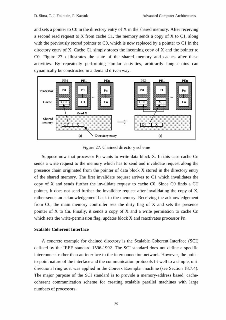
D. Sima, T. J. Fountain, P. Kacsuk Advanced Computer Architectures
39
and sets a pointer to C0 in the directory entry of X in the shared memory. After receiving
a second read request to X from cache C1, the memory sends a copy of X to C1, along
with the previously stored pointer to C0, which is now replaced by a pointer to C1 in the
directory entry of X. Cache C1 simply stores the incoming copy of X and the pointer to
C0. Figure 27.b illustrates the state of the shared memory and caches after these
activities. By repeatedly performing similar activities, arbitrarily long chains can
dynamically be constructed in a demand driven way.
AAAAAAAAAAAAAAAAAAAAAAAAAAAAAAAAAAAAAAAAAAAA
AAAAAAAAAAAAAAAAAAAAAAAAAAAAAAAAAAAAAAAAAAAA
AAAAAAAAAAAAAAAAAAAAAAAAAAAAAAAAAAAAAAAAAAAA
AAAAAAAAAAAAAAAAAAAAAAAAAAAAAAAAAAAAAAAAAAAA
AAAAAAAAAAAAAAAAAAAAAAAAAAAAAAAAAAAAAAAAAAAA
AAAAAAAAAAAAAAAAAAAAAAAAAAAAAAAAAAAAAAAAAAAA
AAAAAAAAAAAAAAAAAAAAAAAAAAAAAAAAAAAAAAAAAAAA
AAAAAAAAAAAAAAAAAAAAAAAAAAAAAAAAAAAAAAAAAAAA
AAAAAAAAAAAAAAAAAAAAAAAAAAAAAAAAAAAAAAAAAAAA
AAAAAAAAAAAAAAAAAAAAAAAAAAAAAAAAA
AAAAAAAAAAAAAAAAAAAAAAAAAAAAAAAAAAAAAAAAAAAAAAAAAAAAAAAAAAAAAAAAAAAAAAAAAAAAAAAA
AAAAAAAAAAAAAAAAAAAAAAAAAAAAAAAAAAAAAAAAAAAAAAAAAAAAAAAAAAAAAAAAAAAAAAAAAAAAAAAA
AAAAAAAAAAAAAAAAAAAAAAAAAAAAAAAAAAAAAAAAAAAAAAAAAAAAAAAAAAAAAAAAAAAAAAAAAAAAAAAA
PE0
P0
AAAAAAAAAAAAAAAAAAAAAAAAAAAAAAAAAAAAAAAAAAAAAAAAAAAAAAAAAAAAAAAAAAAAAAAAAAAAAAAA
AAAAAAAAAAAAAAAAAAAAAAAAAAAAAAAAAAAAAAAAAAAAAAAAAAAAAAAAAAAAAAAAAAAAAAAAAAAAAAAA
AAAAAAAAAAAAAAAAAAAAAAAAAAAAAAAAAAAAAAAAAAAAAAAAAAAAAAAAAAAAAAAAAAAAAAAAAAAAAAAA
PE1
P1
AAAAAAAAAAAAAAAAAAAAAAAAAAAAAAAAAAAAAAAAAAAAAAAAAAAAAAAAAAAAAAAAAAAAAAAAAAAAAAAA
AAAAAAAAAAAAAAAAAAAAAAAAAAAAAAAAAAAAAAAAAAAAAAAAAAAAAAAAAAAAAAAAAAAAAAAAAAAAAAAA
AAAAAAAAAAAAAAAAAAAAAAAAAAAAAAAAAAAAAAAAAAAAAAAAAAAAAAAAAAAAAAAAAAAAAAAAAAAAAAAA
PEn
Pn
...
AAAAAAAAAAAAAAAAAAAAAAAAAAAAAAAAAAAAAAAAAAAAAAAAAAAAAAAAAAAAAAAAAAAAAAAAAAAAAAAA
AAAAAAAAAAAAAAAAAAAAAAAAAAAAAAAAAAAAAAAAAAAAAAAAAAAAAAAAAAAAAAAAAAAAAAAAAAAAAAAA
AAAAAAAAAAAAAAAAAAAAAAAAAAAAAAAAAAAAAAAAAAAAAAAAAAAAAAAAAAAAAAAAAAAAAAAAAAAAAAAA
PE0
P0
AAAAAAAAAAAAAAAAAAAAAAAAAAAAAAAAAAAAAAAAAAAAAAAAAAAAAAAAAAAAAAAAAAAAAAAAAAAAAAAA
AAAAAAAAAAAAAAAAAAAAAAAAAAAAAAAAAAAAAAAAAAAAAAAAAAAAAAAAAAAAAAAAAAAAAAAAAAAAAAAA
AAAAAAAAAAAAAAAAAAAAAAAAAAAAAAAAAAAAAAAAAAAAAAAAAAAAAAAAAAAAAAAAAAAAAAAAAAAAAAAA
PE1
P1
AAAAAAAAAAAAAAAAAAAAAAAAAAAAAAAAAAAAAAAAAAAAAAAAAAAAAAAAAAAAAAAAAAAAAAAAAAAAAAAA
AAAAAAAAAAAAAAAAAAAAAAAAAAAAAAAAAAAAAAAAAAAAAAAAAAAAAAAAAAAAAAAAAAAAAAAAAAAAAAAA
AAAAAAAAAAAAAAAAAAAAAAAAAAAAAAAAAAAAAAAAAAAAAAAAAAAAAAAAAAAAAAAAAAAAAAAAAAAAAAAA
PEn
Pn
...
Cn
C X
Sharedmemory
Cache
Processor
Directory entry
AAAAAAAAAAAAAAAAAAAAAAAAAAAAAAAAAAAAAAAAAAAA
AAAAAAAAAAAAAAAAAAAAAAAAAAAAAAAAAAAAAAAAAAAA
AAAAAAAAAAAAAAAAAAAAAAAAAAAAAAAAAAAAAAAAAAAA
AAAAAAAAAAAAAAAAAAAAAAAAAAAAAAAAAAAAAAAAAAAA
AAAAAAAAAAAAAAAAAAAAAAAAAAAAAAAAAAAAAAAAAAAA
AAAAAAAAAAAAAAAAAAAAAAAAAAAAAAAAAAAAAAAAAAAA
AAAAAAAAAAAAAAAAAAAAAAAAAAAAAAAAAAAAAAAAAAAA
AAAAAAAAAAAAAAAAAAAAAAAAAAAAAAAAAAAAAAAAAAAA
AAAAAAAAAAAAAAAAAAAAAAAAAAAAAAAAAAAAAAAAAAAA
AAAAAAAAAAAAAAAAAAAAAAAAAAAAAAAAA
D X
C1
Read X
X,CT X,CT CnX,
(a) (b)
Figure 27. Chained directory scheme
Suppose now that processor Pn wants to write data block X. In this case cache Cn
sends a write request to the memory which has to send and invalidate request along the
presence chain originated from the pointer of data block X stored in the directory entry
of the shared memory. The first invalidate request arrives to C1 which invalidates the
copy of X and sends further the invalidate request to cache C0. Since C0 finds a CT
pointer, it does not send further the invalidate request after invalidating the copy of X,
rather sends an acknowledgement back to the memory. Receiving the acknowledgement
from C0, the main memory controller sets the dirty flag of X and sets the presence
pointer of X to Cn. Finally, it sends a copy of X and a write permission to cache Cn
which sets the write-permission flag, updates block X and reactivates processor Pn.
Scalable Coherent Interface
A concrete example for chained directory is the Scalable Coherent Interface (SCI)
defined by the IEEE standard 1596-1992. The SCI standard does not define a specific
interconnect rather than an interface to the interconnection network. However, the point-
to-point nature of the interface and the communication protocols fit well to a simple, uni-
directional ring as it was applied in the Convex Exemplar machine (see Section 18.7.4).
The major purpose of the SCI standard is to provide a memory-address based, cache-
coherent communication scheme for creating scalable parallel machines with large
numbers of processors.
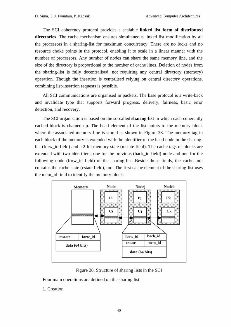
D. Sima, T. J. Fountain, P. Kacsuk Advanced Computer Architectures
40
The SCI coherency protocol provides a scalable linked list form of distributed
directories. The cache mechanism ensures simultaneous linked list modification by all
the processors in a sharing-list for maximum concurrency. There are no locks and no
resource choke points in the protocol, enabling it to scale in a linear manner with the
number of processors. Any number of nodes can share the same memory line, and the
size of the directory is proportional to the number of cache lines. Deletion of nodes from
the sharing-list is fully decentralised, not requiring any central directory (memory)
operation. Though the insertion is centralised relying on central directory operations,
combining list-insertion requests is possible.
All SCI communications are organised in packets. The base protocol is a write-back
and invalidate type that supports forward progress, delivery, fairness, basic error
detection, and recovery.
The SCI organisation is based on the so-called sharing-list in which each coherently
cached block is chained up. The head element of the list points to the memory block
where the associated memory line is stored as shown in Figure 28. The memory tag in
each block of the memory is extended with the identifier of the head node in the sharing-
list (forw_id field) and a 2-bit memory state (mstate field). The cache tags of blocks are
extended with two identifiers; one for the previous (back_id field) node and one for the
following node (forw_id field) of the sharing-list. Beside those fields, the cache unit
contains the cache state (cstate field), too. The first cache element of the sharing-list uses
the mem_id field to identify the memory block.
AAAAAAAAAAAAAAAAAAAAAAAAAAAAAAAAAAAAAAAAAAAAAAAAAAAAAAAAAAAAAAAAAAAAAAAAAAAAAAAAAAAAAAAAAAAAAAAA
AAAAAAAAAAAAAAAAAAAAAAAAAAAAAAAAAAAAAAAAAAAAAAAAAAAAAAAAAAAAAAAAAAAAAAAAAAAAAAAAAAAAAAAAAAAAAAAA
AAAAAAAAAAAAAAAAAAAAAAAAAAAAAAAAAAAAAAAAAAAAAAAAAAAAAAAAAAAAAAAAAAAAAAAAAAAAAAAAAAAAAAAAAAAAAAAA
AAAAAAAAAAAAAAAAAAAAAAAAAAAAAAAAAAAAAAAAAAAAAAAAAAAAAAAAAAAAAAAAAAAAAAAAAAAAAAAAAAAAAAAAAAAAAAAA
Pi
AAAAAAAAAAAA
AAAAAAAAAAAA
AAAAAAAAAAAA
AAAAAAAAAAAA
Memory Nodei
AAAAAAAA
AAAAAAAA
AAAA
AAAAAAAAAAAAAAAAAAAAAAAAAAAAAAAAAAAAAAAAAAAAAAAAAAAAAAAAAAAAAAAAAAAAAAAAAAAAAAAAAAAAAAAAAAAAAAAA
AAAAAAAAAAAAAAAAAAAAAAAAAAAAAAAAAAAAAAAAAAAAAAAAAAAAAAAAAAAAAAAAAAAAAAAAAAAAAAAAAAAAAAAAAAAAAAAA
AAAAAAAAAAAAAAAAAAAAAAAAAAAAAAAAAAAAAAAAAAAAAAAAAAAAAAAAAAAAAAAAAAAAAAAAAAAAAAAAAAAAAAAAAAAAAAAA
AAAAAAAAAAAAAAAAAAAAAAAAAAAAAAAAAAAAAAAAAAAAAAAAAAAAAAAAAAAAAAAAAAAAAAAAAAAAAAAAAAAAAAAAAAAAAAAA
Pj
Nodej
AAAAAAAA
AAAAAAAA
AAAA
AAAAAAAAAAAAAAAAAAAAAAAAAAAAAAAAAAAAAAAAAAAAAAAAAAAAAAAAAAAAAAAAAAAAAAAAAAAAAAAAAAAAAAAAAAAAAAAA
AAAAAAAAAAAAAAAAAAAAAAAAAAAAAAAAAAAAAAAAAAAAAAAAAAAAAAAAAAAAAAAAAAAAAAAAAAAAAAAAAAAAAAAAAAAAAAAA
AAAAAAAAAAAAAAAAAAAAAAAAAAAAAAAAAAAAAAAAAAAAAAAAAAAAAAAAAAAAAAAAAAAAAAAAAAAAAAAAAAAAAAAAAAAAAAAA
AAAAAAAAAAAAAAAAAAAAAAAAAAAAAAAAAAAAAAAAAAAAAAAAAAAAAAAAAAAAAAAAAAAAAAAAAAAAAAAAAAAAAAAAAAAAAAAA
Pk
Nodek
AAAAAAAA
AAAAAAAA
AAAA
mstate forw_id
data (64 bits)
forw_id back_id
cstate mem_id
data (64 bits)
Ci Cj Ck
Figure 28. Structure of sharing lists in the SCI
Four main operations are defined on the sharing list:
1. Creation

D. Sima, T. J. Fountain, P. Kacsuk Advanced Computer Architectures
41
2. Insertion
3. Deletion
4. Reduction to a single-node
Creation is a simplified version of the insertion operation when the associated
sharing-list is empty.
Insertion. When a cache miss occurs (at Ck in Figure 29), the node sends a prepend
request to the memory that responds with the pointer of the old head node and refreshes
its head node pointer by the address of the requester. After receiving the response from
the memory, the new head (if the sharing-list was not empty) notifies the old head node
by sending a new-head request. The old head updates its backward pointer and returns
its data. The two transactions are illustrated in Figure 29.
AAAAAAAAAAAAAAAAAAAAAAAAAAAAAAAAAAAAAAAAAAAAAAAAAAAAAAAAAAAAAAAAAAAAAAAAAAAAAAAAAAAAAAAAAAAAAAAAAAAA
AAAAAAAAAAAAAAAAAAAAAAAAAAAAAAAAAAAAAAAAAAAAAAAAAAAAAAAAAAAAAAAAAAAAAAAAAAAAAAAAAAAAAAAAAAAAAAAAAAAA
AAAAAAAAAAAAAAAAAAAAAAAAAAAAAAAAAAAAAAAAAAAAAAAAAAAAAAAAAAAAAAAAAAAAAAAAAAAAAAAAAAAAAAAAAAAAAAAAAAAA
AAAAAAAAAAAAAAAAAAAAAAAAAAAAAAAAAAAAAAAAAAAAAAAAAAAAAAAAAAAAAAAAAAAAAAAAAAAAAAAAAAAAAAAAAAAAAAAAAAAA
Pi
AAAAAAAAAAAA
AAAAAAAAAAAA
AAAAAAAAAAAA
AAAAAAAAAAAA
MemoryNodei
AAAAAAAA
AAAAAAAA
AAAA
AAAAAAAAAAAAAAAAAAAAAAAAAAAAAAAAAAAAAAAAAAAAAAAAAAAAAAAAAAAAAAAAAAAAAAAAAAAAAAAAAAAAAAAAAAAAAAAAAAAA
AAAAAAAAAAAAAAAAAAAAAAAAAAAAAAAAAAAAAAAAAAAAAAAAAAAAAAAAAAAAAAAAAAAAAAAAAAAAAAAAAAAAAAAAAAAAAAAAAAAA
AAAAAAAAAAAAAAAAAAAAAAAAAAAAAAAAAAAAAAAAAAAAAAAAAAAAAAAAAAAAAAAAAAAAAAAAAAAAAAAAAAAAAAAAAAAAAAAAAAAA
AAAAAAAAAAAAAAAAAAAAAAAAAAAAAAAAAAAAAAAAAAAAAAAAAAAAAAAAAAAAAAAAAAAAAAAAAAAAAAAAAAAAAAAAAAAAAAAAAAAA
Pj
Nodej
AAAAAAAA
AAAAAAAA
AAAA
AAAAAAAAAAAAAAAAAAAAAAAAAAAAAAAAAAAAAAAAAAAAAAAAAAAAAAAAAAAAAAAAAAAAAAAAAAAAAAAAAAAAAAAAAAAAAAAAAAAA
AAAAAAAAAAAAAAAAAAAAAAAAAAAAAAAAAAAAAAAAAAAAAAAAAAAAAAAAAAAAAAAAAAAAAAAAAAAAAAAAAAAAAAAAAAAAAAAAAAAA
AAAAAAAAAAAAAAAAAAAAAAAAAAAAAAAAAAAAAAAAAAAAAAAAAAAAAAAAAAAAAAAAAAAAAAAAAAAAAAAAAAAAAAAAAAAAAAAAAAAA
AAAAAAAAAAAAAAAAAAAAAAAAAAAAAAAAAAAAAAAAAAAAAAAAAAAAAAAAAAAAAAAAAAAAAAAAAAAAAAAAAAAAAAAAAAAAAAAAAAAA
Pk
Nodek
AAAAAAAA
AAAAAAAA
AAAA
AAAAAAAAAAAA
AAAAAAAAAAAAAAAAAA
AAAAAAAAAAAAAAAAAAAAAAAAAAAAAA
AAAAAAAAAAAAAAAAAAAAAAAAAAAAAAAAAAAAAAAAAAAAAAAAAAAAAAAAAAAA
AAAAAAAAAAAAAAAAAAAAAAAAAAAAAAAAAAAAAAAAAAAA
AAAAAAAAAAAAAAAAAAAAAAAAAAAAAAAAAAAAAAAAAAAA
AAAAAAAAAAAAAAAA
AAAAAAAAAAAAAAAAAAAAAAAAAAAAAAAAAAAAAAAAAAAAAAAAAAAAAAAAAAAAAAAAAAAAAAAA
AAAAAAAAAAAAAAAAAAAAAAAAAAAAAAAAAAAAAAAAAAAAAAAAAAAAAAAAAAAAAAAAAAAAAAAA
AAAAAAAAAAAAAAAAAAAAAAAAAAAAAAAAAAAAAAAAAAAAAAAAAAAAAAAAAAAAAAAAAAAAAAAA
AAAAAAAAAAAAAAAAAAAAAAAAAAAAAAAAAAAAAAAAAAAAAAAAAAAAAAAAAAAAAAAAAAAAAAAA
AAAAAAAAAAAAAAAAAA
new-head responses
prepend
Ci Cj
Ck
Figure 29. Insertion in a sharing list
Deletion. When a node wants to remove its cache line from the sharing-list, it sends
two messages. First, it sends an update backward request containing its backward pointer
(Pb) to its successor. The successor will update its backward pointer by the value
received in the request. The second message, an update forward request, is sent to the
predecessor. This message contains the forward pointer of the requester and is used by
the predecessor to update its forward pointer. The transactions and their result are
illustrated in Figure 30.

D. Sima, T. J. Fountain, P. Kacsuk Advanced Computer Architectures
42
AAAAAAAAAAAAAAAAAAAAAAAAAAAAAAAAAAAAAAAAAAAAAAAAAAAAAAAAAAAAAAAAAAAAAAAAAAAAAAAAAAAAAAAAAAAAAAAAAAAA
AAAAAAAAAAAAAAAAAAAAAAAAAAAAAAAAAAAAAAAAAAAAAAAAAAAAAAAAAAAAAAAAAAAAAAAAAAAAAAAAAAAAAAAAAAAAAAAAAAAA
AAAAAAAAAAAAAAAAAAAAAAAAAAAAAAAAAAAAAAAAAAAAAAAAAAAAAAAAAAAAAAAAAAAAAAAAAAAAAAAAAAAAAAAAAAAAAAAAAAAA
AAAAAAAAAAAAAAAAAAAAAAAAAAAAAAAAAAAAAAAAAAAAAAAAAAAAAAAAAAAAAAAAAAAAAAAAAAAAAAAAAAAAAAAAAAAAAAAAAAAA
Pi
AAAAAAAA
AAAAAAAA
AAAAAAAA
AAAAAAAA
Memory Nodei
AAAAAAAA
AAAAAAAA
AAAA
AAAAAAAAAAAAAAAAAAAAAAAAAAAAAAAAAAAAAAAAAAAAAAAAAAAAAAAAAAAAAAAAAAAAAAAAAAAAAAAAAAAAAAAAAAAAAAAAAAAA
AAAAAAAAAAAAAAAAAAAAAAAAAAAAAAAAAAAAAAAAAAAAAAAAAAAAAAAAAAAAAAAAAAAAAAAAAAAAAAAAAAAAAAAAAAAAAAAAAAAA
AAAAAAAAAAAAAAAAAAAAAAAAAAAAAAAAAAAAAAAAAAAAAAAAAAAAAAAAAAAAAAAAAAAAAAAAAAAAAAAAAAAAAAAAAAAAAAAAAAAA
AAAAAAAAAAAAAAAAAAAAAAAAAAAAAAAAAAAAAAAAAAAAAAAAAAAAAAAAAAAAAAAAAAAAAAAAAAAAAAAAAAAAAAAAAAAAAAAAAAAA
Pj
Nodej
AAAAAAAA
AAAAAAAA
AAAA
AAAAAAAAAAAAAAAAAAAAAAAAAAAAAAAAAAAAAAAAAAAAAAAAAAAAAAAAAAAAAAAAAAAAAAAAAAAAAAAAAAAAAAAAAAAAAAAAAAAA
AAAAAAAAAAAAAAAAAAAAAAAAAAAAAAAAAAAAAAAAAAAAAAAAAAAAAAAAAAAAAAAAAAAAAAAAAAAAAAAAAAAAAAAAAAAAAAAAAAAA
AAAAAAAAAAAAAAAAAAAAAAAAAAAAAAAAAAAAAAAAAAAAAAAAAAAAAAAAAAAAAAAAAAAAAAAAAAAAAAAAAAAAAAAAAAAAAAAAAAAA
AAAAAAAAAAAAAAAAAAAAAAAAAAAAAAAAAAAAAAAAAAAAAAAAAAAAAAAAAAAAAAAAAAAAAAAAAAAAAAAAAAAAAAAAAAAAAAAAAAAA
Pk
Nodek
AAAAAAAA
AAAAAAAA
AAAA
AAAAAAAA
AAAAAAAAAAAAAAAAA
AAAAAAAAA
AAAAAA
AAAAAAAA
AAAAAAAAAAAAAAAAAAA
AAAAAAAAA
AAAAAAAAAAAA
update backwardupdate forward
12
(a) Messages for deletion
AAAAAAAAAAAAAAAAAAAAAAAAAAAAAAAAAAAAAAAAAAAAAAAAAAAAAAAAAAAAAAAAAAAAAAAAAAAAAAAAAAAAAAAAAAAAAAAAAAAA
AAAAAAAAAAAAAAAAAAAAAAAAAAAAAAAAAAAAAAAAAAAAAAAAAAAAAAAAAAAAAAAAAAAAAAAAAAAAAAAAAAAAAAAAAAAAAAAAAAAA
AAAAAAAAAAAAAAAAAAAAAAAAAAAAAAAAAAAAAAAAAAAAAAAAAAAAAAAAAAAAAAAAAAAAAAAAAAAAAAAAAAAAAAAAAAAAAAAAAAAA
AAAAAAAAAAAAAAAAAAAAAAAAAAAAAAAAAAAAAAAAAAAAAAAAAAAAAAAAAAAAAAAAAAAAAAAAAAAAAAAAAAAAAAAAAAAAAAAAAAAA
Pi
AAAAAAAAAAAA
AAAAAAAAAAAA
AAAAAAAAAAAA
AAAAAAAAAAAA
Memory Nodei
AAAAAAAA
AAAAAAAA
AAAA
AAAAAAAAAAAAAAAAAAAAAAAAAAAAAAAAAAAAAAAAAAAAAAAAAAAAAAAAAAAAAAAAAAAAAAAAAAAAAAAAAAAAAAAAAAAAAAAAAAAA
AAAAAAAAAAAAAAAAAAAAAAAAAAAAAAAAAAAAAAAAAAAAAAAAAAAAAAAAAAAAAAAAAAAAAAAAAAAAAAAAAAAAAAAAAAAAAAAAAAAA
AAAAAAAAAAAAAAAAAAAAAAAAAAAAAAAAAAAAAAAAAAAAAAAAAAAAAAAAAAAAAAAAAAAAAAAAAAAAAAAAAAAAAAAAAAAAAAAAAAAA
AAAAAAAAAAAAAAAAAAAAAAAAAAAAAAAAAAAAAAAAAAAAAAAAAAAAAAAAAAAAAAAAAAAAAAAAAAAAAAAAAAAAAAAAAAAAAAAAAAAA
Pk
Nodek
AAAAAAAA
AAAAAAAA
AAAA
(b) Structure of the sharing list after deletion
Figure 30. Deletion from a sharing list
Reduction to a single-node. When a cache line is written, all the other elements of
the sharing-list must be invalidated. Only the head node has the right to update a cache
line and to remove the other elements from the sharing list. This is the reduction process
and it is performed sequentially. The head sends a purge request to the second node of
the list. This node returns its forward pointer, i.e., the address of the next node in the list.
Then, the head node sends a purge request to the third node and so on, until the last node
receives the purge request. If a node different from the head wants to execute a write on a
shared cache line, it has first to remove its cache line from the sharing-list and then to
insert it. As a result the node becomes the head of the sharing-list having the right to
update its cache line.
Notice that several insertion and deletion actions can be executed simultaneously on
the same sharing-list. In case of simultaneous prepend requests, the memory immediately
responds in the order the requests arrive. However, the new head that won the
competition will delay the other new heads until it has prepended itself to the sharing-list.
Special precedence rules are applied in case of simultaneous deletions among adjacent
nodes. the node closer to the tail has always priority and is deleted first. A useful feature
of simultaneous insertions is that they can be combined and as a result, hot spots can be

D. Sima, T. J. Fountain, P. Kacsuk Advanced Computer Architectures
43
avoided. An optional extension of the SCI base protocol can optimise the sequential
purge operation by replacing it with a parallel one (Gjessing & al. 1992).
Hierarchical cache coherent protocols
Hierarchical cache coherent protocols are applied in multiple bus based
multiprocessors which were introduced in Section 18.2.1. One of the natural
generalisations of the single bus system is the hierarchical bus system where single bus
based clusters or 'supernodes' are connected to a higher level bus via a higher level cache
or 'supercache'. Recursively applying these construction technique, arbitrarily large
networks can be built. The only operational extension is that second and higher levels of
caches should maintain system wide multicache coherency. In order to fulfil this
requirement, any memory locations, for which there are copies in the lower level caches,
should also have copies in the higher level cache. As a consequence, 'supercaches' should
be an order of magnitude larger than the next lower level caches. However, since they
can be implemented with slower, denser dynamic RAMs, identical to those applied for
the main memory, this size requirement is not a problem.
The first hierarchical bus system with cache coherency was proposed by Wilson
(Wilson 1987) who generalised Goodman's 'write-once' cache coherency protocol for the
multi-level cache system. To understand how multicache coherency control is achieved
in hierarchical bus multiprocessors, consider the operations of a two level structure
shown in Figure 31. Assume that processor P2 issues a write command to a data block X
which has four copies in caches C11, C12, C16 and C17. As it was shown, copies should
be available in the higher level caches C20 and C22, too. Goodman's 'write-once'
protocol is based on the write-invalidate policy and therefore, after writing X in C12 and
C20, all the other copies of X should be invalidated. It is achieved by broadcasting the
write command first on low level bus B10 and then on the higher level bus B20. The
copy of X in C11 is invalidated by the write command on bus B10. When the write
command appears on bus B20 second level caches check if they have a copy of X. When
C22 detects a write command to X and finds a copy of X, it must invalidate its own copy
and send down an invalidate command to bus B12 where copies of X in C16 and C17
should be invalidated. The final result is that only the first and second level caches
associated with the updating processor (C12 and C20) have copies of X. A subsequent
read request issued by another processor (for example P5) should be broadcasted at the
lower level and since, there is no copy at that level it should be propagated up the
hierarchy. When C20 detects the read request for X and finds that it has a dirty copy of
X, it issues a flush request down to bus B10 where cache C12 will relinquish exclusive
access and supplies the dirty copy of X to cache C15.

D. Sima, T. J. Fountain, P. Kacsuk Advanced Computer Architectures
44
AAAAAAAAAAAAAAAAAAAAAAAAAAAAAAAAAAAAAAAAAAAAAAAAAAAAAAAAAAAAAAAAAAAAAAAAAAAA
AAAAAAAAAAAAAAAAAAAAAAAAAAAAAAAAAAAAAAAAAAAAAAAAAAAAAAAAAAAAAAAAAAAAAAAAAAAA
AAAAAAAAAAAAAAAAAAAAAAAAAAAAAAAAAAAAAA
AAAAAAAAAAAAAAAAAAAAAAAAAAAAAAAAAAAAAAAAAAAAAAAAAAAAAAAAAAAAAAAAAAAAAAAAAAAA
AAAAAAAAAAAAAAAAAAAAAAAAAAAAAAAAAAAAAAAAAAAAAAAAAAAAAAAAAAAAAAAAAAAAAAAAAAAA
AAAAAAAAAAAAAAAAAAAAAAAAAAAAAAAAAAAAAA
C15
P5
C17
P7
Mainmemory
AAAAAAAAAAAAAAAAAAAAAAAAAAAAAAAAAAAAAAAAAAAAAAAAAAAAAAAAAAAAAAAAAAAAAAAAAAAA
AAAAAAAAAAAAAAAAAAAAAAAAAAAAAAAAAAAAAAAAAAAAAAAAAAAAAAAAAAAAAAAAAAAAAAAAAAAA
AAAAAAAAAAAAAAAAAAAAAAAAAAAAAAAAAAAAAA
C16
P6
AAAAAAAAAAAAAAAAAAAAAAAAAAAAAAAAAAAAAAAAAAAAAAAAAAAAAAAAAAAAAAAAAAAAAAAAAAAA
AAAAAAAAAAAAAAAAAAAAAAAAAAAAAAAAAAAAAAAAAAAAAAAAAAAAAAAAAAAAAAAAAAAAAAAAAAAA
AAAAAAAAAAAAAAAAAAAAAAAAAAAAAAAAAAAAAA
AAAAAAAAAAAAAAAAAAAAAAAAAAAAAAAAAAAAAAAAAAAAAAAAAAAAAAAAAAAAAAAAAAAAAAAAAAAA
AAAAAAAAAAAAAAAAAAAAAAAAAAAAAAAAAAAAAAAAAAAAAAAAAAAAAAAAAAAAAAAAAAAAAAAAAAAA
AAAAAAAAAAAAAAAAAAA
C13
P3
C14
P4
AAAAAAAA
AAAAAA
AAAAAAAA
AAAAAA
AAAAAAAAAAAAAAAAAAAAAAAAAAAAAAAAAAAAAAAAAAAAAAAAAAAAAAAAAAAAAAAAAAAAAAAAAAAA
AAAAAAAAAAAAAAAAAAAAAAAAAAAAAAAAAAAAAAAAAAAAAAAAAAAAAAAAAAAAAAAAAAAAAAAAAAAA
AAAAAAAAAAAAAAAAAAAAAAAAAAAAAAAAAAAAAA
AAAAAAAAAAAAAAAAAAAAAAAAAAAAAAAAAAAAAAAAAAAAAAAAAAAAAAAAAAAAAAAAAAAAAAAAAAAA
AAAAAAAAAAAAAAAAAAAAAAAAAAAAAAAAAAAAAAAAAAAAAAAAAAAAAAAAAAAAAAAAAAAAAAAAAAAA
AAAAAAAAAAAAAAAAAAAAAAAAAAAAAAAAAAAAAA
C10
P0
C12
P2
AAAAAAAAAAAAAAAAAAAAAAAAAAAAAAAAAAAAAAAAAAAAAAAAAAAAAAAAAAAAAAAAAAAAAAAAAAAA
AAAAAAAAAAAAAAAAAAAAAAAAAAAAAAAAAAAAAAAAAAAAAAAAAAAAAAAAAAAAAAAAAAAAAAAAAAAA
AAAAAAAAAAAAAAAAAAAAAAAAAAAAAAAAAAAAAA
C11
P1
AAAAAAAA
AAAAAA
AAAAAAAA
AAAAAA
B10 B11 B12
B20
C20 C21 C22
AAAAAAAAAAAA
AAAAAAAAAAAA
AAAAAAAAAAAA
AAAAAA
AAAAAAAAAAAA
AAAAAAAAAAAA
AAAAAAAAAAAA
AAA
Write
Write
Invalidate
Figure 31. Hierarchical cache coherence
Notice that those second level caches that have no copies of the written data block
work as filters during the invalidate or read operations. In the current example cache C21
did not send any command to bus B11. As a result, clusters where there is no copy of the
updated data block are not affected at all by the hierarchical cache coherence protocol.
18.3.3 Software-based protocols
Though hardware-based protocols offer the fastest mechanism of maintaining cache
consistence they introduce a significant extra hardware complexity particularly in
scalable multiprocessors. Software-based approaches represent a good and competitive
compromise since they require nearly negligible hardware support and they can lead to
the same small number of invalidation misses as the hardware-based protocols. All the
software-based protocols rely on compiler assistance. The compiler analysis the program
and classifies the variables according to their use into one of the four classes:
1. Read-only
2. Read-only for any number of processes and read-write for one process
3. Read-write for one process
4. Read-write for any number of processes

D. Sima, T. J. Fountain, P. Kacsuk Advanced Computer Architectures
45
Read-only variables can be cached without restrictions. Type 2 variables can be
cached only for that processor where the read-write process runs. Since only one process
uses type 3 variables it is sufficient to cache them only for that process. Type 4 variables
must not be cached in software-based schemes.
Variables demonstrate different behaviour in different program sections and hence
the program is usually divided into sections by the compiler and the variables are
categorised independently in each section. For example, a parallel for-loop is a typical
program section. More than that the compiler generates instructions that control the cache
or the access of cache explicitly based on the classification of variables and code
segmentation. Typically at the end of each program section, the caches must be
invalidated to ensure a consistent state of variables before starting a new section.
According to the way the invalidation is realised, two main schemes can be
distinguished:
1. Indiscriminate invalidation
2. Selective invalidation
The simplest approach is the indiscriminate invalidation in which the complete cache
is invalidated at the end of each program section. This scheme requires a single hardware
mechanism for turning on or off and invalidating the cache. However, it is very
conservative, it invalidates variables that could be used in the same cache in the next
program section.
Selective invalidation schemes can be further categorised according to the generation
of program sections:
1. Critical section based scheme
2. Parallel for-loop based scheme
The critical section based scheme relies on the assumption that shared read-write
variables are always accessed in critical sections guarded by software synchronisation
tools. These variables are selectively invalidated when the critical section is completed.
In order to do that shared variables, belonging to the same critical section, are placed on
the same page and each page is associated with a one-time identifier. Loading a cache
line will also place the associated one-time identifier in the cache. Invalidation is realised
based on the one-time identifiers.
Three parallel for-loop based selective invalidation schemes were proposed to
eliminate the drawback of the indiscriminate invalidation:
1. Fast selective invalidation
2. Timestamp scheme

D. Sima, T. J. Fountain, P. Kacsuk Advanced Computer Architectures
46
3. Version control scheme
The fast selective invalidation scheme (Cheong and Veidenbaum 1988) relies on a
write-through cache policy and introduces three instructions to control cache accesses:
Memory-Read, Cache-Read, and Cache-Invalidate. Cache-Read is applied to access a
variable when it is guaranteed that the variable is stable in the cache, otherwise the
Memory-Read command is used. An extra bit, called the change bit, is added to each
cache line. The Cache-Invalidate command sets all change bits true. An attempt to read a
variable with its change bit set true will lead to a read from the memory. As a second
effect the change bit is modified to false and hence forthcoming accesses can be satisfied
by the cache.
The timestamp scheme (Min and Baer 1989) allocates a clock to each data structure
and a timestamp entry to each cache line. The clock associated with a data structure is
updated at the end of each program section when the data structure was updated. The
timestamps in the cache directory are set to the value of the corresponding clock+1 when
the block is updated in the cache. Comparing the timestamp and the associated clock
value it can be decided if the variable is valid in the cache (timestamp>clock) or it should
be loaded from the memory. Notice that in the timestamp scheme, invalidations for
variables that are local to a processor in two subsequent program sections are omittable
since the timestamp value of these variables exceeds their clock value.
A similar method, called the version control scheme was proposed in (Cheong and
Veidenbaum 1990) in order to avoid unnecessary invalidations. The main idea of this
method is that writing a variable is permitted only to one process in a program section
and this writing generates a new version of the variable. When the writing process exits
its program section, the new version becomes the current version that can be used by
other processors, too. In order to recognise whether a variable is valid in the cache of a
processor, two new data structures are introduced. First, each processor maintains a
counter, called the current version number (CVN), for each variable it can use. Second,
each cache line is extended with a tag, called the birth version number (BVN). The CVN
represents the version of the variable that the processor must use, while the BVN
represents a particular version to which the cache copy belongs. A cache miss occurs
when the CVN is greater than the BVN otherwise, the variable can be accessed from the
cache.
The categorisation of software-based cache coherent protocols is shown in Figure 32.
The software support to reduce the complexity of hardware, necessary to maintain cache
coherency, is an important active research area in order to reduce the hardware cost of
scalable parallel computers.

D. Sima, T. J. Fountain, P. Kacsuk Advanced Computer Architectures
47
Software-based protocols
Indisciminateinvalidation
Selectinginvalidation
Criticalsectionbased
Parallelfor-loopbased
Fastselectiveinvalidation
Versioncontrolscheme
Timestampscheme
Figure 32. Classification of software-based cache coherence protocols
18.4 Synchronisation and event ordering in multiprocessors
There are two levels of exploiting parallelism in a multiprocessor. At the higher
level, the program is partitioned into processes that are executed on different processors.
This technique is called concurrent processing. At the lower level, memory accesses
within a process could be executed in an overlapped way with other accesses in order to
reduce load/store latency stemming from cache miss. This technique of hiding latency is
known as access pipelining. Another form of hiding latency, called as access buffering,
is when the memory accesses within a process are overlapped with other computations.
In order to synchronise concurrent processes special synchronising software tools are
used that are usually supported by hardware mechanisms. The lowest level of these
structures is the lock mechanism, the hardware/software implementation of which gives
rise to special problems in cache coherent multiprocessors. These implementation
techniques are examined in the next two sections.
Access buffering and access pipelining also require special attention in cache
coherent shared memory systems. Ordering of load/store events and maintaining the
correct order require new memory models that are the subject of Section 18.4.2.
18.4.1 Synchronisation mechanisms in multiprocessors
Mutual exclusion and other synchronisation problems can be solved by high level
synchronisation language constructs like semaphores, conditional critical regions,

D. Sima, T. J. Fountain, P. Kacsuk Advanced Computer Architectures
48
monitors, etc. All of these high level schemes are based on some low level
synchronisations tools realised or supported by hardware. In cache coherent architectures,
the atomic test&set operation is usually replaced with a cached test-and-test&set
scheme for spin waiting that has to meet the following criteria:
1. minimum amount of traffic generated while waiting
2. low latency release of a waiting processor
3. low latency acquisition of a free lock
These schemes are moderately successful in small cache based systems like shared
bus based multiprocessors but usually fail in scalable multiprocessors where high-
contention locks are frequent. In the current section low level synchronisations tools that
can efficiently be implemented either in small-size or scalable shared memory systems
are studied.
Lock implementations in shared bus systems
In shared bus multiprocessors the test&set synchronisation operation is widely
accepted to support the implementation of high level language constructs. In its simplest
form the test&set operation is based on a simple variable called 'lock' which can have
two states: CLOSED and OPEN. test&set is an indivisible, atomic operation on the lock
variable defined by the following C program:
char *lock;
while (exchange(lock, CLOSED) == CLOSED);
Exchange(value1,value2) is usually a CPU instruction meaning that the value of the
second parameter (value2) should be exchanged with the value of the memory location
given by the first argument (value1) and the latter value should be returned as a result of
the instruction. The instruction exchange requires two memory cycles: the first for
reading value1 and the second for writing value2. The atomic operation means that
during the execution of these two memory cycles the shared bus must not be granted to
any other processor in the system. Since in shared bus based systems the bus arbiter logic
is responsible for bus allocation, the realisation of the atomic exchange operation also
belongs to the tasks of the bus arbiter. For example, in the Intel 80386 family a special
LOCK control line serves to force the arbiter logic to suspend the bus arbitration for the
second cycle of the exchange instruction. After finishing the exchange instruction, the

D. Sima, T. J. Fountain, P. Kacsuk Advanced Computer Architectures
49
LOCK control line enables again the bus arbiter that can now allocate the shared bus to
another processor.
One of the main problems of implementing synchronisation schemes in cache
coherent architectures appears in deciding what happens if the test&set operation was
failed, i.e. the lock was in the state CLOSED. Obviously, as the definition of the test&set
operation shows, the processor should repeat the operation as long as the lock is
CLOSED. This is a form of busy waiting which ties up the processor in an idle loop and
increases the shared bus traffic and contention. This type of lock that relies on busy
waiting is called spin-lock and considered as a significant cause of performance
degradation when a large number of processes simultaneously use it.
Application of spin-locks in cache based multiprocessors gives rise to a new
problem, called thrashing. Assume that processor Pi successfully executes a test&set
operation on lock. As a result, a dirty copy of lock remains in the cache Ci (Figure 33.a).
Subsequent test&set operation on lock by Pj causes cache Ci to send a copy of lock to Cj
and both copies become shared. Notice that fetching a block from a remote cache
requires much longer time than fetching a single byte from the main memory. Moreover,
the second phase of test&set should write lock, which entails sending an invalidate
command on the shared bus and makes the copy of lock in Cj dirty (Figure 33.b). When
Pj finishes the test&set operation, a fair bus arbitration policy allocates the shared bus to
another processor Pk, which wants to perform test&set on lock, too. Obviously, the same
bus operations are required and performed again and finally, Ck contains a dirty copy of
lock (Figure 33.c). Since the test&set operation of Pj was failed, Pj attempts again to
execute test&set. As a result, the block of lock is copied back to Cj, and so on. Cj and Ck
play ping-pong with the block of lock as long as Pi remains in state CLOSED.
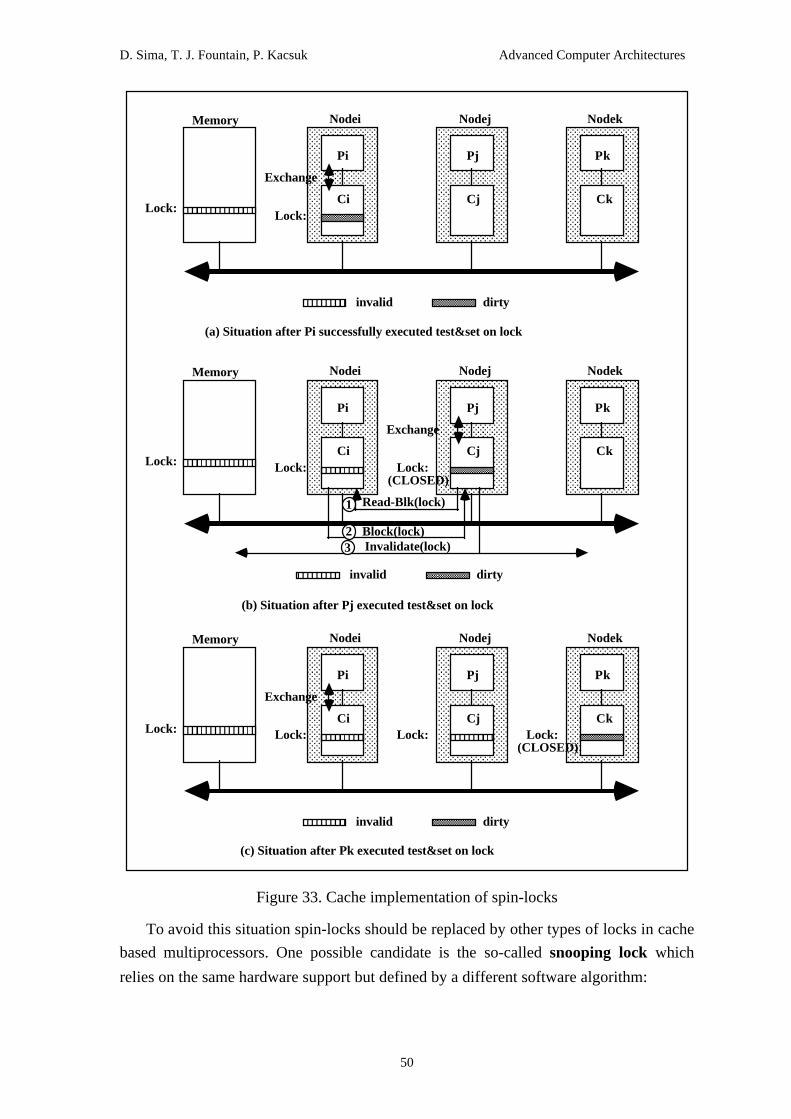
D. Sima, T. J. Fountain, P. Kacsuk Advanced Computer Architectures
50
AAAAAAAAAAAAAAAAAAAAAAAAAAAAAAAAAAAAAAAAAAAAAAAAAAAAAAAAAAAAAAAAAAAAAAAAAAAAAAAAAAAAAAAAAAAA
AAAAAAAAAAAAAAAAAAAAAAAAAAAAAAAAAAAAAAAAAAAAAAAAAAAAAAAAAAAAAAAAAAAAAAAAAAAAAAAAAAAAAAAAAAAA
AAAAAAAAAAAAAAAAAAAAAAAAAAAAAAAAAAAAAAAAAAAAAAAAAAAAAAAAAAAAAAAAAAAAAAAAAAAAAAAAAAAAAAAAAAAA
AAAAAAAAAAAAAAAAAAAAAAAAAAAAAAAAAAAAAAAAAAAAAAAAAAAAAAAAAAAAAAAAAAAAA
Pi
AAAAAAAAAAAA
AAAAAAAAAAAA
AAAAAAAAAAAA
AAAAAAAAA
Memory Nodei
AAAAAAAA
AAAAAAAA
AA
AAAAAAAAAAAAAAAAAAAAAAAAAAAAAAAAAAAAAAAAAAAAAAAAAAAAAAAAAAAAAAAAAAAAAAAAAAAAAAAAAAAAAAAAAAAA
AAAAAAAAAAAAAAAAAAAAAAAAAAAAAAAAAAAAAAAAAAAAAAAAAAAAAAAAAAAAAAAAAAAAAAAAAAAAAAAAAAAAAAAAAAAA
AAAAAAAAAAAAAAAAAAAAAAAAAAAAAAAAAAAAAAAAAAAAAAAAAAAAAAAAAAAAAAAAAAAAAAAAAAAAAAAAAAAAAAAAAAAA
AAAAAAAAAAAAAAAAAAAAAAAAAAAAAAAAAAAAAAAAAAAAAAAAAAAAAAAAAAAAAAAAAAAAA
Pj
Nodej
AAAAAAAAAAAAAAAAAAAAAAAAAAAAAAAAAAAAAAAAAAAAAAAAAAAAAAAAAAAAAAAAAAAAAAAAAAAAAAAAAAAAAAAAAAAA
AAAAAAAAAAAAAAAAAAAAAAAAAAAAAAAAAAAAAAAAAAAAAAAAAAAAAAAAAAAAAAAAAAAAAAAAAAAAAAAAAAAAAAAAAAAA
AAAAAAAAAAAAAAAAAAAAAAAAAAAAAAAAAAAAAAAAAAAAAAAAAAAAAAAAAAAAAAAAAAAAAAAAAAAAAAAAAAAAAAAAAAAA
AAAAAAAAAAAAAAAAAAAAAAAAAAAAAAAAAAAAAAAAAAAAAAAAAAAAAAAAAAAAAAAAAAAAA
Pk
Nodek
Ci Cj CkLock:
Exchange
Lock:
invalidAAAAAAAAAAAA
AAAAAAAAAAAA
AAA dirty
AAAAAAAAAAAA
AAAAAAAAAAAA
AAAAAA
(a) Situation after Pi successfully executed test&set on lock
AAAAAAAAAAAAAAAAAAAAAAAAAAAAAAAAAAAAAAAAAAAAAAAAAAAAAAAAAAAAAAAAAAAAAAAAAAAAAAAAAAAAAAAAAAAAAAAA
AAAAAAAAAAAAAAAAAAAAAAAAAAAAAAAAAAAAAAAAAAAAAAAAAAAAAAAAAAAAAAAAAAAAAAAAAAAAAAAAAAAAAAAAAAAAAAAA
AAAAAAAAAAAAAAAAAAAAAAAAAAAAAAAAAAAAAAAAAAAAAAAAAAAAAAAAAAAAAAAAAAAAAAAAAAAAAAAAAAAAAAAAAAAAAAAA
AAAAAAAAAAAAAAAAAAAAAAAAAAAAAAAAAAAAAAAAAAAAAAAAAAAAAAAAAAAAAAAAAAAAAAAA
Pi
AAAAAAAA
AAAAAAAA
AAAAAAAA
AAAAAA
Memory Nodei
AAAAAAAAAAAA
AAAAAAAAAAAA
AAA
AAAAAAAAAAAAAAAAAAAAAAAAAAAAAAAAAAAAAAAAAAAAAAAAAAAAAAAAAAAAAAAAAAAAAAAAAAAAAAAAAAAAAAAAAAAAAAAA
AAAAAAAAAAAAAAAAAAAAAAAAAAAAAAAAAAAAAAAAAAAAAAAAAAAAAAAAAAAAAAAAAAAAAAAAAAAAAAAAAAAAAAAAAAAAAAAA
AAAAAAAAAAAAAAAAAAAAAAAAAAAAAAAAAAAAAAAAAAAAAAAAAAAAAAAAAAAAAAAAAAAAAAAAAAAAAAAAAAAAAAAAAAAAAAAA
AAAAAAAAAAAAAAAAAAAAAAAAAAAAAAAAAAAAAAAAAAAAAAAAAAAAAAAAAAAAAAAAAAAAAAAA
Pj
Nodej
AAAAAAAAAAAAAAAAAAAAAAAAAAAAAAAAAAAAAAAAAAAAAAAAAAAAAAAAAAAAAAAAAAAAAAAAAAAAAAAAAAAAAAAAAAAAAAAA
AAAAAAAAAAAAAAAAAAAAAAAAAAAAAAAAAAAAAAAAAAAAAAAAAAAAAAAAAAAAAAAAAAAAAAAAAAAAAAAAAAAAAAAAAAAAAAAA
AAAAAAAAAAAAAAAAAAAAAAAAAAAAAAAAAAAAAAAAAAAAAAAAAAAAAAAAAAAAAAAAAAAAAAAAAAAAAAAAAAAAAAAAAAAAAAAA
AAAAAAAAAAAAAAAAAAAAAAAAAAAAAAAAAAAAAAAAAAAAAAAAAAAAAAAAAAAAAAAAAAAAAAAA
Pk
Nodek
Ci Cj CkLock:
Exchange
Lock:
invalid AAAAAAAA
AAAAAAAA
AAAA dirtyAAAA
AAAAAAAAAAAA
AA
(b) Situation after Pj executed test&set on lock
Lock:(CLOSED)AAAA
AAAAAAAA
AAAAAAAAAAAA
AAA
Read-Blk(lock)
Block(lock)Invalidate(lock)
23
1
AAAAAAAAAAAAAAAAAAAAAAAAAAAAAAAAAAAAAAAAAAAAAAAAAAAAAAAAAAAAAAAAAAAAAAAAAAAAAAAAAAAAAAAAAAAA
AAAAAAAAAAAAAAAAAAAAAAAAAAAAAAAAAAAAAAAAAAAAAAAAAAAAAAAAAAAAAAAAAAAAAAAAAAAAAAAAAAAAAAAAAAAA
AAAAAAAAAAAAAAAAAAAAAAAAAAAAAAAAAAAAAAAAAAAAAAAAAAAAAAAAAAAAAAAAAAAAAAAAAAAAAAAAAAAAAAAAAAAA
AAAAAAAAAAAAAAAAAAAAAAAAAAAAAAAAAAAAAAAAAAAAAAAAAAAAAAAAAAAAAAAAAAAAA
Pi
AAAAAAAAAAAA
AAAAAAAAAAAA
AAAAAAAAAAAA
AAAAAAAAA
Memory Nodei
AAAAAAAAAAAAAAAAAAAAAAAAAAAAAAAAAAAAAAAAAAAAAAAAAAAAAAAAAAAAAAAAAAAAAAAAAAAAAAAAAAAAAAAAAAAA
AAAAAAAAAAAAAAAAAAAAAAAAAAAAAAAAAAAAAAAAAAAAAAAAAAAAAAAAAAAAAAAAAAAAAAAAAAAAAAAAAAAAAAAAAAAA
AAAAAAAAAAAAAAAAAAAAAAAAAAAAAAAAAAAAAAAAAAAAAAAAAAAAAAAAAAAAAAAAAAAAAAAAAAAAAAAAAAAAAAAAAAAA
AAAAAAAAAAAAAAAAAAAAAAAAAAAAAAAAAAAAAAAAAAAAAAAAAAAAAAAAAAAAAAAAAAAAA
Pj
Nodej
AAAAAAAAAAAAAAAAAAAAAAAAAAAAAAAAAAAAAAAAAAAAAAAAAAAAAAAAAAAAAAAAAAAAAAAAAAAAAAAAAAAAAAAAAAAA
AAAAAAAAAAAAAAAAAAAAAAAAAAAAAAAAAAAAAAAAAAAAAAAAAAAAAAAAAAAAAAAAAAAAAAAAAAAAAAAAAAAAAAAAAAAA
AAAAAAAAAAAAAAAAAAAAAAAAAAAAAAAAAAAAAAAAAAAAAAAAAAAAAAAAAAAAAAAAAAAAAAAAAAAAAAAAAAAAAAAAAAAA
AAAAAAAAAAAAAAAAAAAAAAAAAAAAAAAAAAAAAAAAAAAAAAAAAAAAAAAAAAAAAAAAAAAAA
Pk
Nodek
Ci Cj CkLock:
Exchange
Lock:
invalidAAAAAAAAAAAA
AAAAAAAAAAAA
AAA dirty
AAAAAAAAAAAA
AAAAAAAAAAAA
AAAAAA
(c) Situation after Pk executed test&set on lock
AAAAAAAA
AAAAAAAA
AAAA
AAAAAAAA
AAAAAAAA
AA
AAAAAAAA
AAAAAAAA
AA Lock: Lock:
(CLOSED)
Figure 33. Cache implementation of spin-locks
To avoid this situation spin-locks should be replaced by other types of locks in cache
based multiprocessors. One possible candidate is the so-called snooping lock which
relies on the same hardware support but defined by a different software algorithm:

D. Sima, T. J. Fountain, P. Kacsuk Advanced Computer Architectures
51
while (exchange(lock, CLOSED) == CLOSED)
while (*lock == CLOSED);
The advantage of this approach comes from the introduction of the simplified second
while loop which can be executed on the cached copy of lock without accessing the
shared bus since it only reads the lock. The situation after executing the exchange
operations by Pj and Pk is identical to that of the spin-lock implementation shown in
Figure 33.c. However, the continuation is different. When Pj executes the
*lock==CLOSED test instruction, the dirty block of lock from Ck is copied to Cj and
both blocks become shared. Afterwards the two copies can be read independently and in
parallel by Pj and Pk without any access to the common bus. This simple modification of
the test&set algorithm eliminates the ping-pong effect but does not solve every problem.
When the locking processor releases the lock, the waiting processors compete for
executing their exchange operations which results in a temporary bus saturation. The
problem is not too serious if large critical sections are applied in the program. However,
in the case of short critical sections the bus saturation can become continuous due to the
frequent exchange operations.
The solution can be further improved by exchanging the order of the test loop and
exchange instruction:
for (;;) {
while (*lock == CLOSED);
if (exchange(lock, CLOSED) != CLOSED)
break;
}
This variation, called the test-and-test&set scheme, has the advantage that a
newcomer processor does not disturb the waiting processors. Assume that Pj starts its
synchronisation action when Pi is already engaged in its critical section and Pk
continuously executes its synchronisation action in order to enter its critical section. Pj
(like Pk) receives a shared copy of the lock on which it can test the state of the lock
independently from the other processors.
However, the simple solution shown above introduces extra latency for unused locks
and cannot prevent bus saturation when the lock is released. There are several approaches

D. Sima, T. J. Fountain, P. Kacsuk Advanced Computer Architectures
52
to remedy the bus saturation situation at lock release. Anderson proposed collision
avoidance locks (Anderson 1990) which enable the waiting processes to restart the
exchange operation after a lock release with different delay time. Another approach
applies a tree of locks in which the root lock protects the critical section. The tree forms a
tournament for competitive processes. The winner of a contest at a lower level becomes a
contestant at the next level. When finally a process reaches the root lock and wins the
contest it has the permission to enter its critical session. This kind of aggregate of locks is
called tournament locks. The individual locks of the tournament ones are constructed as
snooping locks.
The most effective lock type, the queue lock was proposed in (Graunke and Thakkar
1990). The structure of a queue lock is more complicated than a single byte representing
CLOSED or OPEN state. It actually contains in an array as many such bytes as many
processes use the lock for synchronisation. More than that each process can define in the
array what it specifies as locking state. The main idea of the queue lock is that processes
are waiting for the lock in a queue (represented by the lock array) from which they are
served in a first-in-first-out way. Accordingly, there is no competition after an unlock
operation, only the "next" process can relock the lock. Moreover, relocking does not need
any write operation and hence, the relocking process enters into the critical section
without requiring any shared bus operation for accessing the queue lock.
Lock implementations in scalable multiprocessors
The collision problem on a lock is even more serious in scalable multiprocessors
where hundreds of processors can compete for the same lock. The memory location of
lock becomes a hot spot which can significantly enlarge latency in the interconnection
network.
In order to reduce the hot spot problem in the NYU Ultracomputer and in the IBM
RP3 multiprocessor a new read-modify-write type primitive, called the fetch&add, was
introduced. The definition of the fetch&add primitive is as follows:

D. Sima, T. J. Fountain, P. Kacsuk Advanced Computer Architectures
53
fetch&add( x, a )
int *x, a;
{ int temp;
temp = *x;
*x = *x + a;
return( temp );
}
The fetch&add primitive is by definition atomic, just like the test&set primitive. For
the efficient implementation of the fetch&add all the memory modules are augmented
with an adder circuit. In this way it is sufficient to lock the variable x only for two
memory cycles, which otherwise would have required 10-20 cycles. Moreover, to avoid
the hot spot problem the fetch&add operation can also be combined by the applied
omega network in which all switches are enhanced with adder circuits.
Consider the implementation of DOALL loops by means of the fetch&add primitive.
The original DOALL loop is as follows:
DOALL N=1 to 1000
<loop body using N>
ENDDO
The equivalent implementation by the fetch&add primitive is the following:
i = fetch&add(N,1);
while (i <= 1000) {
loop_body(i);
i = fetch&add(N,1);
}
After initialising N to 1 each processor executes a fetch&add operation on N before
entering the loop. The fetch&add returns with different values that are used by the

D. Sima, T. J. Fountain, P. Kacsuk Advanced Computer Architectures
54
processors as index in the loop_body procedure. The work of the combining network in
realising the distributed fetch&add operation for 8 processors is depicted in Figure 34.
For simplicity, only those arcs are drawn in the figure that are active during the
fetch&add operation. Figure 34.a shows how the combining switches propagate the
fetch&add messages towards the memory module. One of the incoming messages is
stored in the switch while the other one is forwarded with an increment which is the sum
of the original increments. When the last fetch&add message arrives to the memory
module it contains the sum of all the increments. Notice that the switches operate as a
distributed parallel adder. The back propagation of the result can be followed on Figure
34.b. The result arriving back on the output arc of a switch is copied to one of the input
arcs. On the other input arc the sum of the incoming result and the stored increment is
forwarded back. Finally, each processor receives a unique value in the range of 1-8.

D. Sima, T. J. Fountain, P. Kacsuk Advanced Computer Architectures
55
AAAAAAAAAAAAAAAAAAAA
AAAAAAAAAAAAAAAAAAAA
AAAAAAAAAAAAAAAAAAAA
AAAAAAAAAAAAAAAAAAAA
AAAAAAAAAAAAAAAAAAAA
AAAAAAAAAAAAAAAAAAAA
AAAAAAAAAAAAAAAAAAAAAAAA
AAAAAAAAAAAAAAAAAAAAAAAA
AAAAAAAAAAAAAAAAAAAAAAAA
AAAAAAAAAAAAAAAAAAAA
AAAAAAAAAAAAAAAAAAAA
AAAAAAAAAAAAAAAAAAAA
AAAAAAAAAAAAAAAAAAAA
AAAAAAAAAAAAAAAAAAAA
AAAAAAAAAAAAAAAAAAAA
AAAAAAAAAAAAAAAAAAAA
AAAAAAAAAAAAAAAAAAAA
AAAAAAAAAAAAAAAAAAAA
AAAAAAAAAAAAAAAAAAAA
AAAAAAAAAAAAAAAAAAAA
AAAAAAAAAAAAAAAAAAAA
(a) Propagation of fetch&add operation through combining switches
AAAAAAAAAAAA
AAAAAAAAAAAAA
AAAAAAAA
AAAAAAAA
AAAAAAAA
AA
AAAAAAAA
AAAAAAAA
AAAAAAAA
AAAAAAAAAAAAA AAAAAAAAAAAA
AAAAAAAAAAAA
F&A(N,1)
F&A(N,1)
F&A(N,1)
F&A(N,1)
F&A(N,1)
F&A(N,1)
F&A(N,1)
F&A(N,1)
F&A(N,2)
F&A(N,2)
F&A(N,2)
F&A(N,2)
F&A(N,4)
F&A(N,4)
F&A(N,8)
1
1
1
1
2
2 4
AAAAAAAAAAAAAAAAAAAA
AAAAAAAAAAAAAAAAAAAA
AAAAAAAAAAAAAAAAAAAA
AAAAAAAAAAAAAAAAAAAA
AAAAAAAAAAAAAAAAAAAA
AAAAAAAAAAAAAAAAAAAA
AAAAAAAAAAAAAAAAAAAA
AAAAAAAAAAAAAAAAAAAA
AAAAAAAAAAAAAAAAAAAA
AAAAAAAAAAAAAAAAAAAA
AAAAAAAAAAAAAAAAAAAA
AAAAAAAAAAAAAAAAAAAA
AAAAAAAAAAAAAAAAAAAA
AAAAAAAAAAAAAAAAAAAA
AAAAAAAAAAAAAAAAAAAA
AAAAAAAAAAAAAAAAAAAA
AAAAAAAAAAAAAAAAAAAA
AAAAAAAAAAAAAAAAAAAA
AAAAAAAAAAAAAAAAAAAA
AAAAAAAAAAAAAAAAAAAA
AAAAAAAAAAAAAAAAAAAA
AAAAA
AAAAAAAAAAAA
AAAAAAAAAAAA
AAAAAAAAAAAA
AAAAAAAAAAAA
AAAAAAAAAAAA AAAAAAAAAAAA
AAAAAAAAAAAA
5
1+1
5+1
3+1
7+1
1+2
5+21+4
1
1
1
1
5
1
3
5
7
5
1
5
2
6
3
3
47
7
8
M6 returnsN=1
N becomes 9
to M6 containing the value N=1
(b) Back propagation of results
Figure 34. Distributed execution of fetch&add in a combining omega network
One can conclude that when N processors attempt to perform fetch&add operations
at the same memory location (potential hot spot), the memory is updated only once (no
hot spot) by the sum of the N increments. The returned values are unique and correspond
to an arbitrary sequential execution of the N fetch&add but they are performed in one
operation.
Additionally to the fetch&add operation, in the Dash architecture the so-called
queue-based locks are introduced to support synchronisation on high-contention locks.
Dash applies a directory based cache coherent scheme (see in Section 18.7.2 in detail)
which is extended with the support of queue-based locks indicating which processors are
spinning on the lock. When the lock is released, only one node (which is actually a four-

D. Sima, T. J. Fountain, P. Kacsuk Advanced Computer Architectures
56
processor cluster) is chosen at random and informed by the directory. This solution
eliminates unnecessary traffic and latency among the nodes. The grant request invalidates
only the selected node's caches and enables one of the waiting processors in that node to
acquire the lock. A time-out mechanism on the lock grant permits the grant to be sent to
another node if the spinning process has been migrated or swapped out.
18.4.2 Event ordering in cache coherent systems
Coherent caches have been introduced to multiprocessors in order to reduce memory
latency. However, read and write misses on caches reduce the achievable benefits of
caches. In order to reduce this effect access pipelining and access buffering techniques
should be employed. However, scalable multiprocessors could cause incorrect program
behaviour when these techniques are applied. In the current section conditions and
techniques are studied that ensure correct access pipelining and access buffering even in
scalable multiprocessors.
Strong ordering of events
In order to understand what correct parallel program execution means in a cache
coherent multiprocessor environment it should be discussed what requirements a correct
solution should satisfy. The generally accepted requirement, that is expected by every
programmer, is sequential consistency. The first definition of sequential consistency
was given by Lamport as follows (Lamport 1979). "A system is sequentially consistent if
the result of any execution is the same as if the operations of all the processors were
executed in some sequential order, and the operations of each individual processor appear
in the order specified by its program." In other words, a parallel program execution is
sequentially consistent if its any execution is equivalent with an interleaved execution on
a uniprocessor system.
It was shown in (Dubois and Scheurich 1986) that a necessary and sufficient
condition for a system with atomic memory accesses to be sequentially consistent is that
memory accesses should be performed in program order. Systems for which such a
condition holds are called strongly ordered systems. A memory access is atomic if its
affect is observable for each processor of the parallel computer at the same time. It can
be shown that memory accesses in parallel systems without caches are always atomic and
hence, for them it is sufficient to be strongly ordered for maintaining sequentially
consistency.
In case of adding caches to the processors, the memory access can become non-
atomic. Fortunately, memory accesses remain atomic in shared bus multiprocessors
because of the simultaneous broadcast capability of the buses. In such systems the

D. Sima, T. J. Fountain, P. Kacsuk Advanced Computer Architectures
57
invalidations are latched simultaneously by all the cache and memory controllers.
However, application of coherent caches in multiprocessors with scalable interconnection
networks (for example, packet-switched networks) gave rise to a new problem that did
not occur in previous parallel computers. This is the problem of non-atomic memory
accesses, where the effect of memory accesses spread in the system at different speeds to
different processors, i.e. processors can observe the same memory access at distinct time.
It has been shown that for such systems it is not sufficient to be strongly ordered for
ensuring sequentially consistency.
To illustrate the problem consider a simple example (Dubois, Scheurich and Briggs
1988) where three processors want to access the memory cells A and B in the following
order:
P1: ..., store A, ...
P2: ..., load A, store B, ...
P3: ..., load B, load A, ...
Assume that each processor executes the memory accesses in the order specified by
the program and each starts a new access when the previously issued one is completely
finished with respect to all the processors. Yet, it can happen that a processor Pi can
observe an out-of-date memory value though the indirect effect of the new updated value
has already reached Pi. This is an unexpected behaviour contradicting to the sequential
consistency model upon which current programs are written.
First of all examine how this unexpected behaviour can occur in a packet-switched
network where processors are equipped with coherent caches that work according to the
write-invalidate protocol. Assume that initially each processor has a read-only copy of A
and B in its cache.
Step 1. P1 issues a store operation on A that invalidates the other copies.
Step 2. P2 performs a read operation to get the new value of A since the invalidation
message has already arrived to its cache. As a result of the read operation, P1 writes back
the new value of A into the memory and sends a copy to P2. Since the load operation
successfully finished, Processor 2 executes a store operation on B that invalidates the
copy of B in the cache of P3.
Step 3. P3 reads the new value of B as it was updated by P2 because the invalidation
message of B has already arrived. However, P3 reads the old value of A since the
associated invalidation message has not yet reached P3.
Notice that the reason of not satisfying sequential consistency in the example above
is the unequal speed of invalidation messages, i.e., the presence of non-atomic memory

D. Sima, T. J. Fountain, P. Kacsuk Advanced Computer Architectures
58
accesses. If a hardware mechanism could support to restore the atomicity of memory
accesses, sequential consistency could be satisfied in scalable multiprocessors, too.
However, the question arises: do we really need sequential consistency? Before
answering the question let us examine what kind of event ordering is necessary to ensure
sequential consistency. It has been shown that the following event ordering is sufficient
to maintain sequential consistency:
All previous loads must be globally performed and all previous store accesses must
be performed before a load or store is allowed to perform with respect to any other
processor.
A load is globally performed if it is performed and if the store that is the source of
its returned value has been performed. An access (load or store) is performed if it isperformed with respect to all processors. A load by Pi is performed with respect to Pkwhen the issuing of a store by Pk cannot affect the value returned by the load. A store by
Pi is performed with respect to Pk when an issued load to the same address by Pk
returns the value defined by this store.
Sequential consistency is the strongest possible requirement for the logical behaviour
of parallel systems and its strict implementation significantly restricts the achievable
parallelism. Fortunately, the condition of strong ordering can be relaxed in order to
improve the performance of multiprocessors. A slightly relaxed version of sequential
consistency, called as processor consistency, has been proposed by Goodman (Goodman
1989). The following event orderings should hold to satisfy processor consistency:
1. All previous loads must be performed before a load is allowed to perform with
respect to any other processor.
2. All previous loads and stores must be performed before a store is allowed to
perform with respect to any other processor.
Weak ordering of events
Those systems that are able to further relax the conditions of event ordering by
relating memory request ordering to synchronising points of the program are called
weakly ordered systems. Two consistency models have been proposed to build weakly
ordered systems. The first one was introduced in (Dubois, Scheurich and Briggs 1986)
and is called the weak consistency model, the second one, called the release
consistency model is described in (Gharachorloo & al. 1990). Before the models are
explained in detail some definitions and concepts should be described.
First of all shared writable accesses should be classified according to their
relationships. They can be either competing or ordinary accesses. An access is

D. Sima, T. J. Fountain, P. Kacsuk Advanced Computer Architectures
59
competing if it includes a pair of conflicting accesses that are not ordered and are
executed by different processors. Two accesses are conflicting if they refer the same
memory location and at least one of them is a store operation. Competing accesses can be
either synchronisation accesses or non-synchronisation accesses. Synchronisation
accesses have two distinctive features: (1) they consist of one read and one write access
to the same variable; and (2) they serve for ordering conflicting accesses, i.e., making
them non-competing. Typical examples are the lock and unlock operations.
Synchronisation accesses can be further divided into request and release accesses. A
request is always considered as a read synchronisation access, while release as a write
access.
The memory consistency models can be categorised according to how deeply they
exploit the classification tree of shared writable accesses. The sequential and processor
consistency models cannot distinguish shared writable accesses at all. They handle all
such accesses in a uniform way. The week consistency model can exploit all the
categories except for the request and release types. Accordingly, the conditions to ensure
week consistency are as follows:
1. All previous synchronisation accesses must be performed before an ordinary
load or store access is allowed to perform with respect to any other processor.
2. All previous ordinary load and store accesses must be performed before a
synchronisation access is allowed to perform with respect to any other processor.
3. Synchronisation accesses are sequentially consistent with respect to one another.
Notice that week consistency enables that ordinary accesses can be executed in any
order that means a significant improvement in exploiting access pipelining and access
buffering. The release consistency model further improves the week consistency model
by distinguishing request and release accesses. The conditions to ensure release
consistency are as follows:
1. All previous request accesses must be performed before an ordinary load or store
access is allowed to perform with respect to any other processor.
2. All previous ordinary load and store accesses must be performed before a release
access is allowed to perform with respect to any other processor.
3. Competing accesses are processor consistent with respect to one another.
Figure 35. compares the week and release consistency models concerning the
possible overlapping activities during execution. When a node of the graphs becomes
executable, ordinary memory accesses (load/store) inside the nodes can be executed in
any order without restrictions in both models. Notice that all of those ordinary memory
accesses must be executed in an ordered way in the sequential and processor consistency
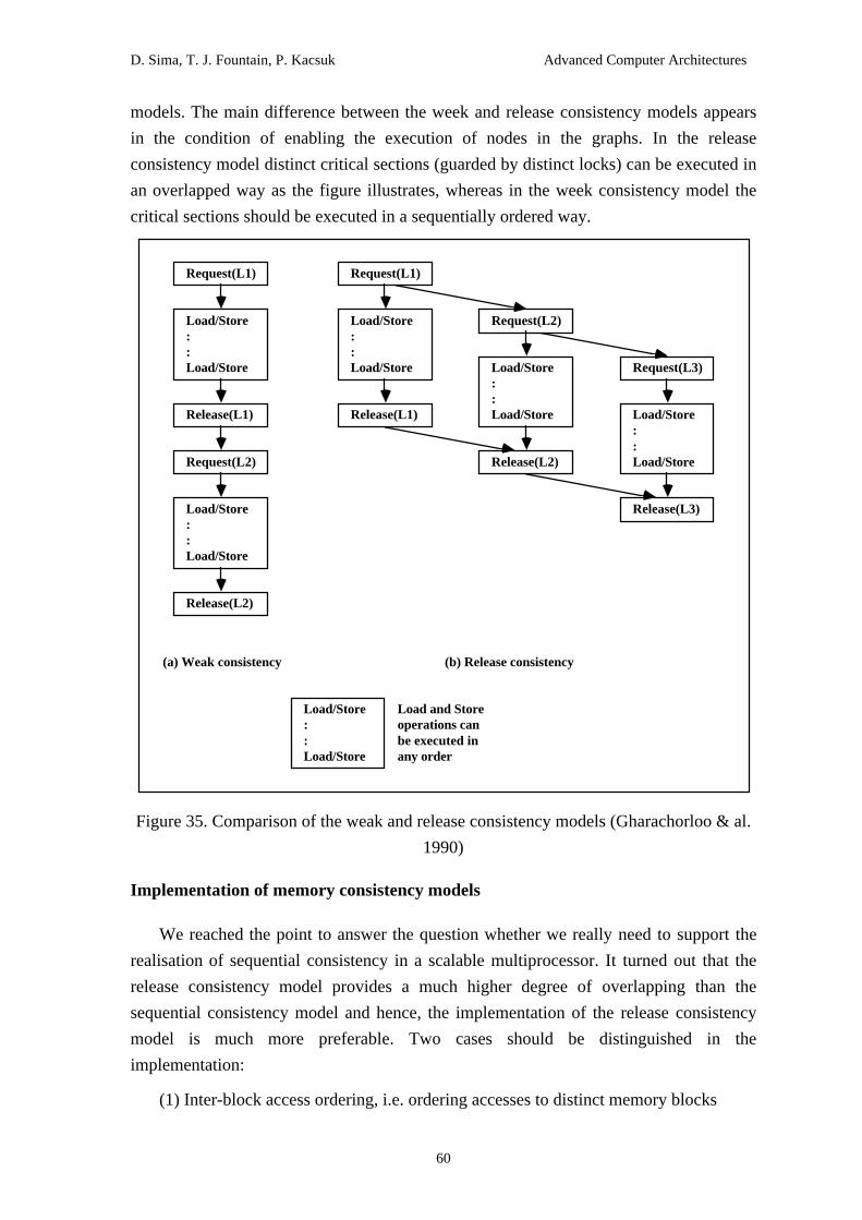
D. Sima, T. J. Fountain, P. Kacsuk Advanced Computer Architectures
60
models. The main difference between the week and release consistency models appears
in the condition of enabling the execution of nodes in the graphs. In the release
consistency model distinct critical sections (guarded by distinct locks) can be executed in
an overlapped way as the figure illustrates, whereas in the week consistency model the
critical sections should be executed in a sequentially ordered way.
Request(L1)
Load/Store : : Load/Store
Release(L1)
(a) Weak consistency (b) Release consistency
Load/Store : : Load/Store
Load and Store operations can be executed in any order
Request(L2)
Load/Store : : Load/Store
Release(L2)
Request(L1)
Load/Store : : Load/Store
Release(L1)
Request(L2)
Load/Store : : Load/Store
Release(L2)
Request(L3)
Load/Store : : Load/Store
Release(L3)
Figure 35. Comparison of the weak and release consistency models (Gharachorloo & al.
1990)
Implementation of memory consistency models
We reached the point to answer the question whether we really need to support the
realisation of sequential consistency in a scalable multiprocessor. It turned out that the
release consistency model provides a much higher degree of overlapping than the
sequential consistency model and hence, the implementation of the release consistency
model is much more preferable. Two cases should be distinguished in the
implementation:
(1) Inter-block access ordering, i.e. ordering accesses to distinct memory blocks
D. Sima, T. J. Fountain, P. Kacsuk Advanced Computer Architectures
61
(2) Intra-block access ordering, i.e. ordering accesses to the same memory block
Multiprocessors with scalable interconnection networks should be provided with a
special hardware mechanism called fence in order to ensure appropriate inter-block
access ordering for release consistency. Several fence operations were introduced in
(Gharachorloo & al. 1990) according to the operations they delay and the operations they
wait upon. The full fence delays all future read and write accesses, the write fence
delays all future write accesses, and immediate fence delays only the access immediately
following the fence.
To implement fences acknowledge messages from target memories and caches
should be introduced. The processor should administrate the outstanding accesses by
handling as many counters as many different kinds of accesses must be distinguished. A
counter is incremented when an access is issued and decremented when the associated
acknowledgements come back. The full fence is implemented by stalling the processor
until the necessary counters become zero, the write fence is implemented by stalling the
write buffer. The immediate fence requires the most complicated hardware support. The
fence operations have been first implemented in the Dash architecture and hence, their
realisation is shown in Section 18.7.2 where the Dash machine is described in detail. It
was shown in (Gharachorloo & al. 1990) that the same fence operations are suitable to
realise the other three memory consistency models, too.
Intra-block ordering of accesses is necessary in an invalidation based cache coherent
multiprocessor where invalidations may reach different processors at different times and
acknowledge messages are necessary to indicate that the write operation has been
finished. There are two options to handle read and ownership requests to a block with
pending invalidates:
(1) The request is delayed until the invalidations are complete. This solution results
in an atomic store operation.
(2) The request is serviced but the requesting processor is notified that the
acknowledge messages of the pending invalidates should be collected. Though this
alternative does not guarantee atomicity of the store access, at least informs the
requesting processor when the store has performed with respect to all processors.
The SCI cache coherence protocol (see Section 18.3.2) supports both strong and
weak ordering. Since invalidation is realised by the purge operation in the SCI standard,
the implementation of strong ordering means that the processor cannot proceed before
the purge operation is complete. On the contrary, the processor can proceed without
waiting for the completion of the purge operation in order to realise weak ordering.

D. Sima, T. J. Fountain, P. Kacsuk Advanced Computer Architectures
62
18.5 Uniform Memory Access (UMA) Machines
Contemporary uniform memory access machines are small size single bus based
multiprocessors. Large UMA machines with hundreds of processors and a switching
network were typical in the early design of scalable shared memory systems. Famous
representatives of that class of multiprocessors are the Denelcor HEP and the NYU
Ultracomputer. They introduced many innovative features in their design some of which
even today represent a significant milestone in parallel computer architectures. For
example, HEP is the starting point for each multithreaded architecture as shown in
Chapter 16. The combining switch approach of the NYU Ultracomputer and the
realisation of synchronisation primitives based on it was a significant step towards
scalable shared memory systems (see Section 18.4.1). However, these early systems do
not contain either cache memory or local main memory which turned out to be necessary
to achieve high performance in scalable shared memory systems.
Though the UMA architecture is not suitable to build scalable parallel computers. it
is excellent to construct small size single bus based multiprocessors. Two such machines
are the Encore Multimax of Encore Computer Corporation representing the technology
of the late eighties and the Power Challenge of Silicon Graphics Computing Systems
representing the technology of early nineties. In the next two sections these two
representative machines are described based on the design space of single bus based
multiprocessors shown in Figure 36. The figure also illustrates the main design
differences between the two multiprocessors.

D. Sima, T. J. Fountain, P. Kacsuk Advanced Computer Architectures
63
Cache coherencypolicy
Write- invalidate
Write- update
Memory updatepolicy
Write- through
Write- back
Bus workingmode
Lockedbus
Pendingbus
Split-transactionbus
(Multimax) (PowerChallenge)
Organization
Centralized Distributed Fixedpriority
Rotating Roundrobin
Leastrecently
used
Firstcomefirstserved
Bus allocation policy
(Multimax) (PowerChallenge) (Multimax
data bus)(Multimaxaddress bus)(PowerChallenge)
Single bus based multiprocessors
Arbiterlogic
(Multimax) (PowerChallenge)
(Multimax)(PowerChallenge)
Figure 36. Design space of single bus based multiprocessors
18.5.1 Encore Multimax
The most advanced feature of the Encore Multimax, when it appeared on the market,
was the Nanobus which was one of the first commercial applications of a pended bus.
The overall structure of the Nanobus is very similar to the one shown in Figure 3. Unlike
in many locked buses, the address and data buses are separated in the Nanobus. The
address bus initiates both memory read and memory write transfers on the Nanobus. In
case of write transactions the data bus is used together with the address bus, while in a
read transaction the data bus can be used by a memory unit to transfer the result of a
previous read access.
Separate but co-operating arbiter logics are employed to allocate the address and data
bus among the 20 processors and 16 memory banks. A centralised arbiter serves for
realising a fair round-robin arbitration policy for the address bus. However, the work of
the centralised address bus arbiter can be influenced by distributed access control
mechanisms under certain conditions. If a processor or memory controller cannot gain
control over the address bus for a certain number of bus cycles, they can use special bus
selection lines to force the central arbiter to deny access to the address bus for other bus
masters.

D. Sima, T. J. Fountain, P. Kacsuk Advanced Computer Architectures
64
The data bus arbiter is also divided into a central arbiter and a distributed access
control. The main difference between the address bus arbitration and the data bus
arbitration appears in the applied arbitration policy and the scope of users. The data
arbitration scheme is used only by the memory controllers since, the processors can
obtain access to the data bus implicitly when the address bus is allocated for them in case
of a memory write. Under such conditions the granted memory controller should ignore
its grant line. This situation can be detected by observing a special field of the address
bus. The data bus arbiter applies a fixed priority arbitration policy among the memory
controllers. The priority of a memory controller depends on its physical location on the
Nanobus. This fix priority scheme can lead to the starvation of low priority memory
controllers. In order to avoid this situation, the distributed access control can activate
special bus selection lines to temporarily lock out other bus masters from the arbitration
cycle.
The Encore Multimax employs a 256 Kbyte cache with a bus watcher (snoopy
controller) logic for each processor unit. The bus watcher implements write-through
memory update policy and write-invalidate cache coherence policy. A special ownership
scheme is applied to maintain cache coherency. Before writing a cache block the
ownership should be attained which causes the invalidation of other cache copies.
Similarly, when any other cache requests ownership, the snoopy controller should
invalidate its copy. For each cache line, two cache tag stores contain the physical address
information that is used by the processor and by the bus watcher to realise the cache
coherence policy. One cache tag store would not be sufficient since the bus watcher
should access it so frequently that the processor would be blocked on the single cache tag
store. The bus watcher should compare the contents of the address bus and the cache tag
store at each write cycle of the Nanobus. If the address bus holds an address stored in the
cache tag store, the bus watcher invalidates the corresponding cache location. When the
processor issues a read request, it checks the cache tag store. If it contains the requested
data in valid form, the read operation can be executed without using the Nanobus. In case
of a write request the processor also checks the tag store. If it contains the address, the
location is invalidated through the nanobus and written into the main memory.
Another advantageous feature of the Encore Multimax is the application of
pipelining both on the processor board and on the memory boards. Pipelining enables the
processor to start a new bus cycle before finishing the previous one, and for the memory
controller to receive a new memory access request before completing the service of the
previous one. Pipelining is implemented by applying buffer registers on both the
processor board and the memory board.

D. Sima, T. J. Fountain, P. Kacsuk Advanced Computer Architectures
65
18.5.2 Power Challenge
The Power Challenge has two versions: a deskside configuration, supporting up to
six processors, or a rack configuration, supporting up to 19 processors and very large
memory. The employed processor is the MIPS R8000 RISC processor in both cases.
Since the Power Challenge is a top multiprocessor, the parameters of its maximum
system configuration are given by Table 2.
Component DescriptionProcessor 19 MIPS R8000, 5.4 Gflops peakMain memory 16 Gbytes, 8-way interleavingI/O bus 4 POWERchannel-2, each 320 Mbytes/secSCSI channels 32 fast-wide independent SCSI-2 channelsDisk 3.0 TByte disk (RAID) or 960 Gbyte diskConnectivity 4 HIPPI channels, 8 ethernet channelsVME slots 5 VME64 expansion buses provide 25 VME64 slots
Table 2. Power Challenge maximum system configuration
The heart of the Power Challenge multiprocessor is the POWERpath-2 split-
transaction shared bus. The associative memory employed for splitting read transactions
is constructed from eight so-called read resources, i.e. up to eight reads can be
outstanding at any time. The POWERpath-2 bus was designed on the base of the RISC
philosophy. The types and variations of bus transactions are small, and each transaction
requires exactly the same five bus cycles: arbitration, resolution, address, decode,
acknowledge.
The 40-bit address bus and the 256-bit data bus are arbitrated separately. The only
bus transaction which requires simultaneous arbitration for the same processor is the
write request as shown by Table 3. Read and invalidate requests need only the address
bus therefore, they can be combined with a simultaneous read response.
Bus transaction Address bus Data buswrite request + +read request + -invalidate request + -read response - +
Table 3. POWERpath-2 bus transactions
Bus transactions are divided into three groups of priority in descending order:
1. read responses
2. address operations (read requests, invalidate requests, and interrupts)

D. Sima, T. J. Fountain, P. Kacsuk Advanced Computer Architectures
66
3. write requests
Within each group a fair, round-robin arbiter policy is applied. Although distributed
arbitration needs more logic to implement, POWERpath-2 employs a distributed
arbitration scheme since, it requires less transactions on the bus and hence reduces
latency. To prevent starvation a programmable urgent timer is provided for each
processor node. When a node is unable to issue requests on the bus for a specified
amount of time, its arbiter automatically raises its priority to urgent.
The POWERpath-2 maintains write-invalidate cache coherence by snoopy hardware.
The applied cache coherence policy is a slightly modified version of the Illinois Protocol
[Papamarcos, and Patel, 1984]. Each cache line has four states: Invalid, Exclusive, Dirty
exclusive, Shared. The memory update policy is write-back. Whenever a read request is
satisfied from another processor's cache, the cache read response is used to update the
memory as a writeback. Similarly to the Encore Multimax, the processor-bus interface
maintains a duplicate set of cache tags to reduce contention between the processor and
the snoopy controller.
Barrier synchronisation consists of two synchronisation activities. First N processes
are started by a fork operation and at the end of the parallel activity the N participating
process should wait for each other in a join operation. Special hardware mechanism and
compiler technique supports both synchronisation steps in the Power Challenge. SGI's
parallel compilers realise process forking necessary for barrier synchronisation by using a
master/slave role distribution among processes. The master prepares a parameter block
and sets a start bit in this block. When a fork occurs, slaves can start their work if they
find an activated start bit, and hence all the processors simultaneously attempt to read the
start bit. To avoid N read accesses to the start bit the POWERpath-2 bus provides a
piggyback read. This means that any number of processors can participate in a single
read transaction by accepting the read response as their own and indicating that the
corresponding cache block is shared.
The join operation is implemented by a counter initialised to N at forking. Any time
a processor finishes its activity, it decrements the counter. The join operation is
completed when the counter reaches 0. Without hardware support the join operation
would require approximately N2 bus transactions since each processor should exclusively
read the cache line containing the counter to decrement it, and should reread it anytime
another processor writes it (due to cache coherence maintenance). To reduce the bus
traffic to only N bus transfers, the join mechanism is supported by a special count
register at each processor interface. Since the synchronisation counter is not in the cache,
the extra reads stemming from cache coherence maintenance can be eliminated. When a
processor reaches the barrier it issues a single broadcast transaction on the address bus,

D. Sima, T. J. Fountain, P. Kacsuk Advanced Computer Architectures
67
which increments all of the counters in the system. It then begins reading its own counter
until it reaches N, which means all the processors reached their barrier point and hence,
the join is completed.
18.6 Non-Uniform Memory Access (NUMA) Machines
Non-Uniform Memory Access (NUMA) Machines were designed to avoid the
memory access bottleneck of UMA machines. The logically shared memory is physically
distributed among the processing nodes of NUMA machines leading to distributed shared
memory architectures. On one hand these parallel computers became highly scalable, but
on the other hand they are very sensitive of data allocation in local memories. Accessing
a local memory segment of a node is much faster than accessing a remote memory
segment. Not by chance, the structure and design of these machines resemble in many
ways to that of the distributed memory multicomputers. The main difference appears in
the organisation of the address space. In multiprocessors, a global address space is
applied that is uniformly visible from each processor, i.e., all processors can
transparently access all memory locations. In multicomputers, the address space is
replicated in the local memories of the processing elements (PEs). No PE is allowed to
directly access the local memory of another PE. This difference in the address space of
the memory is also reflected at the software level: distributed memory multicomputers
are programmed on the basis of the message passing paradigm, while NUMA machines
are programmed on the base of the global address space (shared memory) principle.
However, distinguishing these machines becomes more and more difficult in recent
parallel computers, like the Cray T3D, where both programming paradigms are provided
to the user in the form of library packages. A further aspect that makes the difference
even smaller comes from the fact that the actual form of accessing remote memory
modules is the same in both classes of MIMD computers. Remote memory accesses are
realised by messages even in the NUMA machines similarly to the message-passing
multicomputers.
The problem of cache coherency does not appear in distributed memory
multicomputers since the message passing paradigm explicitly handles different copies of
the same data structure in the form of independent messages. In the shared memory
paradigm, multiple accesses to the same global data structure are possible and can be
accelerated if local copies of the global data structure are maintained in local caches.
However, the hardware supported cache consistency schemes are not introduced into the
NUMA machines. These systems cache read-only code and data, as well as local data,
but not shared modifiable data. This is the distinguishing feature between NUMA and
CC-NUMA multiprocessors. Accordingly, NUMA machines are closer to the

D. Sima, T. J. Fountain, P. Kacsuk Advanced Computer Architectures
68
multicomputers than to other shared memory multiprocessors, while CC-NUMA
machines look like real shared memory systems.
In NUMA machines, like in multicomputers, the main design issues are the
organisation of processor nodes, the interconnection network, and the possible techniques
to reduce remote memory accesses. Typical NUMA machines are the BBN TC2000, the
IBM RP3, the Cray T3D and the Hector multiprocessor. Here only the two last ones are
described as examples to illustrate the realisation possibilities of NUMA architectures.
18.6.1 Hector
Hector is a hierarchical NUMA machine consisting of stations connected by a
hierarchy of ring networks. Stations are symmetric multiprocessors where the processing
modules (nodes) are connected by a single bus. Nodes comprise three main units. A
processor/cache unit, a memory unit and the station bus interface which connects the
otherwise separated processor and memory buses as it is shown in Figure 37. The
separation of the two buses enables other processors to access this memory while the
processor performs memory access operation in off-node memory. The processing
modules of the machine are grouped into shared bus based symmetric multiprocessors,
called stations. These are connected by bit-parallel local rings which are, in turn,
interconnected by a single global ring. Hector provides a flat, global address space,
where each processing module is assigned a range of addresses. The addressing scheme
uses r+s+p bits where r identifies the ring, s points to the station, and p addresses the slot
inside the station. Though global cache consistency cannot be maintained in Hector, a
snoopy protocol provides cache consistency among the nodes inside a station.

D. Sima, T. J. Fountain, P. Kacsuk Advanced Computer Architectures
69
AAAAAAAAAAAAAAAAAAAAAAAAAAAA
AAAAAAAAAAAAAAAAAAAAA
AAAAAAAAAAAAAAAAAAAAAAAAAAAA
AAAAAAAAAAAAAAAAAAAAA
AAAAAAAAAAAAAAAAAAAAAAAAAAAA
AAAAAAAAAAAAAAAAAAAAAAAAAAAA
AAAAAAAAAAAAAAAAAAAAAAAAAAAA
AAAAAAAAAAAAAAAAAAAAAAAAAAAA
AAAAAAAAAAAAAAAAAAAAAAAAAAAA
AAAAAAAAAAAAAAAAAAAAAAAAAAAA
AAAAAAAAAAAAAAAAAAAAAAAAAAAA
AAAAAAAAAAAAAAAAAAAAAAAAAAAA
AAAAAAAAAAAAAAAAAAAAAAAAAAAA
AAAAAAAAAAAAAAAAAAAAAAAAAAAA
AAAAAAAAAAAAAAAAAAAAAAAAAAAA
AAAAAAAAAAAAAAAAAAAAAAAAAAAA
AAAAAAAAAAAAAAAAAAAAAAAAAAAA
AAAAAAAAAAAAAAAAAAAAAAAAAAAA
AAAAAAAAAAAAAAAAAAAAAAAAAAAA
AAAAAAAAAAAAAAAAAAAAAAAAAAAA
AAAAAAAAAAAAAAAAAAAAAAAAAAAA
AAAAAAAAAAAAAAAAAAAAA
AAAAAAAAAAAAAAAAAAAAAAAAAAAA
AAAAAAAAAAAAAAAAAAAAA
AAAAAAAAAAAAAAAAAAAAAAAAAAAA
AAAAAAAAAAAAAAAAAAAAAAAAAAAA
AAAAAAAAAAAAAAAAAAAAAAAAAAAA
AAAAAAAAAAAAAAAAAAAAAAAAAAAA
AAAAAAAAAAAAAAAAAAAAAAAAAAAA
AAAAAAAAAAAAAAAAAAAAAAAAAAAA
AAAAAAAAAAAAAAAAAAAAAAAAAAAA
AAAAAAAAAAAAAAAAAAAAAAAAAAAA
AAAAAAAAAAAAAAAAAAAAAAAAAAAA
AAAAAAAAAAAAAAAAAAAAAAAAAAAA
AAAAAAAAAAAAAAAAAAAAAAAAAAAA
AAAAAAAAAAAAAAAAAAAAAAAAAAAA
AAAAAAAAAAAAAAAAAAAAAAAAAAAA
AAAAAAAAAAAAAAAAAAAAAAAAAAAA
AAAAAAAAAAAAAAAAAAAAAAAAAAAA
AAAAAAAAAAAAAAAAAAAAAAAAAAAA
AAAAAAAAAAAAAAAAAAAAAAAAAAAA
AAAAAAAAAAAAAAAAAAAAA
AAAAAAAAAAAAAAAAAAAAAAAAAAAA
Station
AAAAAAAAAAAAAAAAAAAAAAAAAAAA
Station
AAAAAAAAAAAAAAAAAAAAAAAAAAAA
Station
AAAAAAAAAAAAAAAAAAAAAAAAAAAA
AAAAAAAAAAAAAAAAAAAAA
AAAAAAAAAAAAAAAAAAAAAAAAAAAA
AAAAAAAAAAAAAAAAAAAAA
AAAAAAAAAAAAAAAAAAAAAAAAAAAAAAAA
AAAAAAAAAAAAAAAAAAAAAAAAAAAAAAAA
AAAAAAAAAAAAAAAAAAAAAAAAAAAAAAAA
AAAAAAAAAAAAAAAAAAAAAAAAAAAAAAAA
AAAAAAAAAAAAAAAAAAAAAAAAAAAAAAAA
AAAAAAAAAAAAAAAAAAAAAAAAAAAAAAAA
AAAAAAAAAAAAAAAAAAAAAAAAAAAAAAAA
AAAAAAAAAAAAAAAAAAAAAAAAAAAAAAAA
AAAAAAAAAAAAAAAAAAAAAAAAAAAAAAAA
AAAAAAAAAAAAAAAAAAAAAAAAAAAAAAAA
AAAAAAAAAAAAAAAAAAAAAAAAAAAAAAAA
AAAAAAAAAAAAAAAAAAAAAAAAAAAAAAAA
AAAAAAAAAAAAAAAAAAAAAAAAAAAAAAAA
AAAAAAAAAAAAAAAAAAAAAAAAAAAAAAAA
AAAAAAAAAAAAAAAAAAAAAAAAAAAAAAAA
AAAAAAAAAAAAAAAAAAAAAAAAAAAAAAAA
AAAAAAAAAAAAAAAAAAAAAAAAAAAA
AAAAAAAAAAAAAAAAAAAAAAAAAAAA
AAAAAAAAAAAAAAAAAAAAAAAAAAAA
AAAAAAAAAAAAAAAAAAAAAAAAAAAA
AAAAAAAAAAAAAAAAAAAAA
Station Station Station
Local ring
Global ring
Local ring
Inter-ring interfaces
Station controller
Proc.Module
Proc.Module
Proc.Module
I/OModule
AAAAAAAAAAAAAAAAAAAAAAAAAAAAAAAAAAAAAAAA
AAAAAAAAAAAAAAAAAAAAAAAAAAAAAAAAAAAAAAAA
AAAAAAAAAAAAAAAAAAAAAAAAAAAAAAAAAAAAAAAA
AAAAAAAAAAAAAAAAAAAAAAAAAAAAAAAAAAAAAAAA
AAAAAAAAAA
Station controller
Station bus
AAAAAAAAAAAAAAAAAAAAAAAAAAAAAAAAAAAAAAAAAAAAAAAA
AAAAAAAAAAAAAAAAAAAAAAAAAAAAAAAAAAAAAAAAAAAAAAAA
AAAAAAAAAAAAAAAAAAAAAAAAAAAAAAAAAAAAAAAAAAAAAAAA
AAAAAAAAAAAAAAAAAAAAAAAAAAAAAAAAAAAAAAAAAAAAAAAA
AAAAAAAAAAAAAAAAAAAAAAAAAAAAAAAAAAAAAAAAAAAAAAAA
AAAAAAAAAAAAAAAAAAAAAAAAAAAAAAAAAAAAAAAAAAAAAAAA
AAAAAAAAAAAAAAAAAAAAAAAAAAAAAAAAAAAAAAAAAAAAAAAA
AAAAAAAAAAAAAAAAAAAAAAAAAAAAAAAAAAAAAAAAAAAAAAAA
AAAAAAAAAAAAAAAAAAAAAAAAAAAAAAAAAAAAAAAAAAAAAAAA
AAAAAAAAAAAAAAAAAAAAAAAAAAAAAAAAAAAAAAAAAAAAAAAA
AAAAAAAAAAAAAAAAAAAAAAAAAAAAAAAAAAAAAAAAAAAAAAAA
AAAAAAAAAAAAAAAAAAAAAAAAAAAAAAAAAAAAAAAAAAAAAAAA
AAAAAAAAAAAAAAAAAAAAAAAAAAAAAAAAAAAA
Station bus
Station bus interface
Proc.+cache Memory
AAAAAAAAAAAAAAAAAAAAAAAAAAAAAAAA
AAAAAAAAAAAAAAAAAAAAAAAAAAAAAAAA
AAAAAAAAAAAAAAAAAAAAAAAAAAAAAAAA
AAAAAAAA
AAAAAAAAAAAAAAAAAAAAAAAAAAAAAAAA
AAAAAAAAAAAAAAAAAAAAAAAAAAAAAAAA
AAAAAAAAAAAAAAAAAAAAAAAAAAAAAAAA
AAAAAAAA
Station bus
I/O
AAAAAAAAAAAAAAAAAAAAAAAAAAAAAAAA
AAAAAAAAAAAAAAAAAAAAAAAAAAAAAAAA
AAAAAAAAAAAAAAAAAAAAAAAAAAAAAAAA
AAAAAAAA
AAAAAAAAAAAAAAAAAAAAAAAAAAAAAAAA
AAAAAAAAAAAAAAAAAAAAAAAAAAAAAAAA
AAAAAAAAAAAAAAAAAAAAAAAAAAAAAAAA
AAAAAAAA
adapter
display ethernet disk
Figure 37. Structure of the Hector machine
Memory accesses take place in a synchronised packet-transfer scheme controlled by
a hierarchy of interface circuits:
1. Station bus interface
2. Station controller (local ring interface)

D. Sima, T. J. Fountain, P. Kacsuk Advanced Computer Architectures
70
3. Inter-ring interface
The station bus interface serves for connecting processing modules to the station bus
by forwarding station bus requests to the station controller. When a processor requests
on-board memory access, it is the station bus interface that connects the processor bus to
the memory bus. Off-board memory requests are transformed to request packets and
passed by the station bus interface to the station controller. Incoming memory requests
are temporarily stored in a two-deep FIFO by the station bus interface until the memory
bus becomes free. If the FIFO is full, the station bus interface sends back to the requester
a negative acknowledgement.
The station controller has a two-fold role. First, it controls the allocation of the
station bus between on-station requests, and second, it realises the local ring interface for
the station. When a processing module requests the station bus and there is no contention
on the bus, the station controller grants the bus at the beginning of the next cycle. The
processor module places the data packet to the bus in the same cycle. If the destination
module belongs to the station, it acknowledges the reception of the packet in the next
cycle. If the acknowledgement is not given, the source module automatically retransmits
the request. An on-station transfer requires 3 cycles but only one of them ties up the bus
and hence, by independent requests, the full bus bandwidth can be exploited.
The station controller is responsible for connecting the station to a local ring, as well.
The station controller handles three kinds of requests listed in increasing priority: 1. on-
station requests (explained above), 2. off-station requests and 3. arriving packets from the
ring. Communication on the local ring is performed on a slot by slot basis. When the
arriving slot on the ring addresses the station, the packet is transmitted to the station bus.
When the slot is empty the station controller can fill it with an off-station message. When
the arriving slot addresses another station, it is forwarded in the local ring and the station
bus is granted to an on-station request.
The inter-ring interface is realised as a two-deep FIFO buffer that gives priority to
packets moving in the global ring. It means that whenever a packet travels on the global
ring it will reach its destination without delay.
The heart of the Hector design is the realisation of memory accesses as packet
transfer operations. As it was shown, nonlocal memory requests are transformed to
request packets by the station bus interface. The request packet contains a 32-bit
destination memory address, a source node address, and 32 bits of data in case of write
access. Packets move on the station bus and in the ring networks. When the request
packet reaches the destination node the corresponding station bus interface performs the
request and sends back a response packet that can be a simple acknowledgement for a
write access or it can contain up to 64 bits of data for read accesses. If the request can not
D. Sima, T. J. Fountain, P. Kacsuk Advanced Computer Architectures
71
be serviced a negative acknowledgement is sent back to the source node. If either a
negative acknowledgement or no acknowledgement arrives during a time-out period, the
source node retransmits the memory request. The latter case can occur, for example,
when transmission error is detected (by parity bits) and the packet is simply dropped.
This simple time-out based request-response protocol works well for ordinary read
and write operations. However, it can cause serious problem in case of read-and-write
operations like test&set. Assume that no answer arrives in the time-out period after
issuing a test&set operation. Two possible scenario could cause the lost of
acknowledgement. First, if the test&set request packet was dropped before it could reach
the destination. In this case the retransmission of the request does not cause any problem.
Second, the request arrived at the destination, the semaphore was closed due to the
request, but the acknowledgement packet has been dropped. In this case the
retransmission can not help, the semaphore remains locked for ever. Obviously, the two
scenarios should be visible for the source node in order to react correctly. In Hector the
read-and-write operations are handled in two stages by sending two distinct request
packets.
In the first stage, a read-and-lock packet is sent to the destination node that reads the
memory cell and sends its value back to the requester. The station bus interface of the
destination node maintains a <proc, addr> table to record that the given address is locked
for the associated processor and rejects access requests from other processors. In the
second stage, when the source node receives the result of the read-and-lock packet, it
generates a write-and-unlock packet that makes the destination node write the given
memory location and also remove the <proc, addr> pair from its table, unlocking the
access of the memory cell. By this time the test&set has finished so other processors can
access the semaphore without restriction. If the acknowledgement of the first stage
request can not reach the source node within the time-out period, the retransmission of
the read-and-lock does not cause problem even if the previous one reached the
destination node due to the presence of the <proc, addr> pair. If the write-and-unlock
packet is not acknowledged, its retranmission can be handled correctly based on the
absence or presence of the <proc, addr> pair.
Three main advantages can be stated assessing the Hector machine:
1. The hierarchical structure enables short transmission lines and good scalability.
2. The cost and the overall bandwidth of the structure grow linearly with the number
of nodes.
3. The cost of a memory access grows incrementally with the distance between the
processor and memory location.

D. Sima, T. J. Fountain, P. Kacsuk Advanced Computer Architectures
72
The main drawbacks of Hector are typical for all the NUMA machines, i.e., the lack
of global cache consistency and the nonuniform memory access time which require
careful software design.
18.6.2 Cray T3D
Cray T3D is the most recent NUMA machine that was designed with the intention to
provide a highly scalable parallel supercomputer that can incorporate both the shared
memory and the message passing programming paradigms. Like in other NUMA
machines, the shared memory is distributed among the processing elements in order to
avoid the memory access bottleneck and there is no hardware support for cache
coherency. However, a special software package and programming model, called the
CRAFT, manages coherence and guarantees the integrity of the data.
The Cray T3D hardware structure is divided into two parts:
1. Microarchitecture
2. Macroarchitecture
The microarchitecture is based on Digital's 21064 Alpha AXP
1. Limited address space
2. Little or no latency-hiding capability
3. Few or no synchronisation primitives
Cray research has designed a shell of circuitry around the core microprocessor to
extend its capabilities in the three areas. The Cray T3D system has up to 128 gigabytes
distributed shared memory that requires at least 37 bits of physical address. In order to
extend the number of address bits beyond the 34 provided by the Alpha chip, the Cray
T3D employs a 32-entry register set. It is the task of the shell circuitry to check the
virtual PE number. If it refers to the local PE, the shell performs a local memory
reference.
To improve the latency hiding mechanism of the Alpha chip, Cray introduces a 16
word length FIFO, called the prefetch queue, that permits to perform 16 prefetch
instructions without executing any load from the queue. The effect of a prefetch for a
remote node is that the next free location of the prefetch queue is reserved for the data
and a remote load operation is started for the requested data. When the processor needs
the prefetched data a load operation on the prefetch queue delivers the requested slot of
the queue. If the data has not returned yet from the remote node, the processor is stalled.
The Cray T3D supports 4 synchronisation mechanisms by hardware. The barrier
hardware comprises 16 parallel logical AND trees that enable multiple barriers to be

D. Sima, T. J. Fountain, P. Kacsuk Advanced Computer Architectures
73
pipelined. When a processor reaches the barrier it should set the associated barrier bit to a
one. When all the processors have reached the barrier, the AND function is satisfied and
clears by hardware the barrier bit of each participating processor, signalling them to
continue.
The Cray T3D provides a specialised register set to realise fetch-and-increment
hardware. The contents of these registers are automatically incremented whenever they
are read. Messaging is supported by a predefined queue area in the memory of each
processing node. Sending a message means a special cache-line-size write to the queue
area of the destination node. The shell circuitry interrupts the destination processor when
the message is stored in the queue. Atomic swap registers are provided to exchange data
between a register and a remote memory cell as an indivisible operation. Latency of
atomic swap can be hidden by using the prefetch technique.
The macroarchitecture defines how to connect and integrate the nodes of the
parallel computer, while the microarchitecture specifies the node organisation. One of the
main design objectives was to maintain the same macroarchitecture even for varying
microarchitectures which will always be designed around state-of-the-art commodity
microprocessors.
The two parts of the macroarchitecture are the memory system and the
interconnection network. The memory system realises a distributed shared memory
where any PE can directly address any other PE's memory. The physical address has two
components: a PE number and an offset within the PE. Each PE contains 16 or 64
Mbytes of local DRAM. Access time of the local memory is between 13 and 38 clock
cycles (87 to 253 nsec). The latency for accessing remote memory varies between 1 and
2 microseconds. The data cache is resident on Digital's 21064 Alpha AXP
microprocessor which applies a write-through, direct-mapped, read-allocate cache
technique. Recall that the Cray T3D has no hardware support for ensuring cache
coherency, rather the CRAFT programming model guarantees it.
The topology of the Cray T3D machine is a 3D torus that was selected on the base of
measurements on global latency and global bandwidth of real-world packages. The router
logic implements a dimension-order, wormhole routing algorithm with four virtual
channels (see Chapter 17). The network moves data in one or four 64-bit word length of
packets. Each hop through the network requires 1 clock cycle (6.67 nsec at 150 MHz) for
the switch and an additional 1 or 1.5 clock cycle for the physical wire. Every node
comprises two processing elements. The PEs are independent, supplied with separate
memories and data paths. They share only the bandwidth of the network and the block
transfer engine which is an asynchronous direct memory access controller.

D. Sima, T. J. Fountain, P. Kacsuk Advanced Computer Architectures
74
18.7 Cache-Coherent Non-Uniform Memory Access (CC-NUMA) Machines
All the CC-NUMA machines share the common goal of building a scalable shared
memory multiprocessor. The main difference among them appears in the way the
memory and cache coherence mechanism are distributed among the processing nodes.
Another distinguishing design issue is the selection of the interconnection network
among the nodes. They demonstrate a progress from the bus based networks towards a
more general interconnection network and from the snoopy cache coherency protocol
towards a directory scheme.
The Wisconsin multicube architecture (Goodman and Woest 1988) is the closest
generalisation of a single bus based multiprocessor. It completely relies on the snoopy
cache protocol but in a hierarchical way. The Aquarius Multi-Multi architecture (Carlton
and Despain 1990) combines the snoopy cache protocol with a directory scheme, but the
interconnection network strictly relies on the shared multibus concept. Both the
Wisconsin multicube and the Aquarius Multi-Multi have single processor nodes. The
nodes of the Stanford Dash architecture (Lenoski & al. 1992) are more complex, they are
realised as single bus based multiprocessors called clusters. The Dash architecture also
combines the snoopy cache protocol and the directory scheme. A snooping scheme
ensures the consistency of caches inside the clusters, while across clusters, the directory
scheme maintains consistency. In the Dash, the directory protocol is independent of the
type of interconnection network and hence, any of the low-latency networks that were
originally developed for multicomputers such as the mesh can be employed. The
Stanford FLASH architecture is a further development of the Dash machine by the same
research group. The main goal of the FLASH design was the efficient integration of
cache-coherent shared memory with high-performance message passing. Since the cluster
concept of the Dash is replaced with one-processor nodes, FLASH applies only directory
scheme for maintaining cache coherence. Finally, the Convex Exemplar is a
commercially available CC-NUMA machine which applies the Scalable Coherent
Interface to realise directory scheme based global cache coherence. Figure 38 shows the
design space of the CC-NUMA machines and Table 4 summarises the main features of
the five CC-NUMA architectures mentioned above.

D. Sima, T. J. Fountain, P. Kacsuk Advanced Computer Architectures
75
Mai
n m
emor
ydi
stri
buti
onC
ompl
exit
yof
nod
es
Sing
le
proc
esso
r no
de
Clu
ster
Sing
le
bus
base
dC
ross
bar
base
dPer
co
lum
n bu
s
Per
no
decl
uste
r
Cac
he c
onsi
sten
cysc
hem
e
Per
Snoo
py
cach
eSn
oopy
ca
che
+ di
rect
ory
Dir
ecto
ry
Inte
rcon
nect
ion
netw
ork
Gri
dof
bus
esM
esh
Rin
g
CC
-NU
MA
mac
hine
s
Figure 38. Design space of CC-NUMA machines

D. Sima, T. J. Fountain, P. Kacsuk Advanced Computer Architectures
76
Machine Complexity ofnodes
Memorydistribution
Cacheconsistencyscheme
Interconnectionnetwork
WisconsinMulticube
single processor per column bus snoopy cache grid of buses
Aquarius Multi-Multi
single processor per node snoopy cache +directory scheme
grid of buses
Stanford Dash bus basedmultiprocessor(cluster)
per cluster snoopy cache +directory scheme
-bus inside cluster-pair of meshesamong clusters
Stanford FLASH single processor per node directory scheme 2D meshConvex Exemplar hypernode (8
processors)per hypernode directory scheme
(Scalable CoherentInterface)
- crossbar insidehypernode- multipleunidirectionalrings amonghypernodes
Table 4. Main features of CC-NUMA machines
18.7.1 Wisconsin multicube
The Wisconsin multicube architecture employs row and column buses forming a
two-dimensional grid architecture as shown in Figure 39. The three-dimensional
generalisation will result in a cube architecture. The main memory is distributed along
the column buses, each data block of memory has a home column. Each row of
processors works similarly to single bus based multiprocessors. Each processing element
contains a processor, a conventional cache memory to reduce memory latency and a
snoopy cache that monitors a row bus and a column bus in order to realise a write-back,
write-invalidate cache coherence protocol. In order to describe the cache coherence
protocol of the Wisconsin multicube architecture, the following definitions should be
given:
1. Definition of possible states of blocks in caches, and memories.
2. Definition of commands to be performed at various read/write hit/miss actions.
3. Definition of state transitions in caches, and memories according to the
commands.
4. Definition of transmission routes of commands among processors, caches, and
memories.

D. Sima, T. J. Fountain, P. Kacsuk Advanced Computer Architectures
77
AAAAAAAAAAAAAAAAAAAA
AAAAAAAAAAAAAAAAAAAA
AAAAA
AAAAAAAAAAAAAAAAAAAAAAAA
AAAAAAAAAAAAAAAAAAAAAAAA
AAAAAAAAAA
AAAAAAAAAAAA
AAAA
P
AAAAAAAAAAAAAAAA
AAAA
CAAAAAAAAAAAAAAAAAAAA
AAAAAAAAAAAAAAAAAAAA
AAAAAAAAAAAAAAAAAAAAAAAA
AAAAAAAAAAAAAAAAAAAAAAAAAAAA
AAAAAAAAAAAA
AAAA
P
AAAAAAAAAAAAAAAA
AAAA
CAAAAAAAAAAAAAAAAAAAA
AAAAAAAAAAAAAAAAAAAA
AAAAAAAAAAAAAAAAAAAAAAAA
AAAAAAAAAAAAAAAAAAAAAAAAAAAA
AAAAAAAAAAAA
AAAA
P
AAAAAAAAAAAAAAAA
AAAA
CAAAAAAAAAAAAAAAAAAAA
AAAAAAAAAAAAAAAAAAAA
AAAAA
AAAAAAAAAAAAAAAAAAAAAAAA
AAAAAAAAAAAAAAAAAAAAAAAA
AAAAAAAAAA
AAAAAAAAAAAA
AAAA
P
AAAAAAAAAAAAAAAA
AAAA
C
AAAAAAAAAAAAAAAAAAAA
AAAAAAAAAAAAAAAAAAAA
AAAAA
AAAAAAAAAAAAAAAAAAAA
AAAAAAAAAAAAAAAAAAAA
AAAAAAAAA
AAAAAAAAAAAA
AAAA
P
AAAAAAAAAAAAAAAA
AAAAC
AAAAAAAAAAAAAAAAAAAA
AAAAAAAAAAAAAAAAAAAA
AAAAAAAAAAAAAAAAAAAA
AAAAAAAAAAAAAAAAAAAAAAAA
AAAAAAAAAAAA
AAAA
P
AAAAAAAAAAAAAAAA
AAAAC
AAAAAAAAAAAAAAAAAAAA
AAAAAAAAAAAAAAAAAAAA
AAAAAAAAAAAAAAAAAAAA
AAAAAAAAAAAAAAAAAAAAAAAA
AAAAAAAAAAAA
AAAA
P
AAAAAAAAAAAAAAAA
AAAAC
AAAAAAAAAAAAAAAAAAAA
AAAAAAAAAAAAAAAAAAAA
AAAAA
AAAAAAAAAAAAAAAAAAAA
AAAAAAAAAAAAAAAAAAAA
AAAAAAAAA
AAAAAAAAAAAA
AAAA
P
AAAAAAAAAAAAAAAA
AAAAC
AAAAAAAAAAAAAAAAAAAAAAAA
AAAAAAAAAAAAAAAAAAAAAAAA
AAAAAA
AAAAAAAAAAAAAAAAAAAA
AAAAAAAAAAAAAAAAAAAA
AAAAAAAAA
AAAAAAAAAAAA
AAAAP
AAAAAAAAAAAAAAAAAAAA
AAAAA
CAAAAAAAAAAAAAAAAAAAAAAAA
AAAAAAAAAAAAAAAAAAAAAAAA
AAAAAAAAAAAAAAAAAAAA
AAAAAAAAAAAAAAAAAAAAAAAA
AAAAAAAAAAAA
AAAAP
AAAAAAAAAAAAAAAAAAAA
AAAAA
CAAAAAAAAAAAAAAAAAAAAAAAA
AAAAAAAAAAAAAAAAAAAAAAAA
AAAAAAAAAAAAAAAAAAAA
AAAAAAAAAAAAAAAAAAAAAAAA
AAAAAAAAAAAA
AAAAP
AAAAAAAAAAAAAAAAAAAA
AAAAA
CAAAAAAAAAAAAAAAAAAAAAAAA
AAAAAAAAAAAAAAAAAAAAAAAA
AAAAAA
AAAAAAAAAAAAAAAAAAAA
AAAAAAAAAAAAAAAAAAAA
AAAAAAAAA
AAAAAAAAAAAA
AAAAP
AAAAAAAAAAAAAAAAAAAA
AAAAA
C
AAAAAAAAAAAAAAAAAAAA
AAAAAAAAAAAAAAAAAAAA
AAAAA
AAAAAAAAAAAAAAAAAAAAAAAA
AAAAAAAAAAAAAAAAAAAAAAAA
AAAAAA
AAAAAAAAAAAAAAAAAAAA
AAAAA
P
AAAAAAAAAAAAAAAA
AAAA
CAAAAAAAAAAAAAAAAAAAA
AAAAAAAAAAAAAAAAAAAA
AAAAAAAAAAAAAAAAAAAAAAAA
AAAAAAAAAAAAAAAAAAAAAAAA
AAAAAAAAAAAAAAAAAAAA
AAAAA
P
AAAAAAAAAAAAAAAA
AAAA
CAAAAAAAAAAAAAAAAAAAA
AAAAAAAAAAAAAAAAAAAA
AAAAAAAAAAAAAAAAAAAAAAAA
AAAAAAAAAAAAAAAAAAAAAAAA
AAAAAAAAAAAAAAAAAAAA
AAAAA
P
AAAAAAAAAAAAAAAA
AAAA
CAAAAAAAAAAAAAAAAAAAA
AAAAAAAAAAAAAAAAAAAA
AAAAA
AAAAAAAAAAAAAAAAAAAAAAAA
AAAAAAAAAAAAAAAAAAAAAAAA
AAAAAA
AAAAAAAAAAAAAAAAAAAA
AAAAA
P
AAAAAAAAAAAAAAAA
AAAA
C
AAAAAAAAAAAAAAAAAAAAAAAAAAAAAAAA
AAAAAAAAAAAAAAAAAAAAAAAAAAAAAAAA
AAAAAAAAAAAAAAAA
AAAA
MAAAAAAAAAAAAAAAAAAAAAAAAAAAAAAAA
AAAAAAAAAAAAAAAAAAAAAAAAAAAAAAAA
AAAAAAAAAAAAAAAA
AAAA
MAAAAAAAAAAAAAAAAAAAAAAAAAAAAAAAA
AAAAAAAAAAAAAAAAAAAAAAAAAAAAAAAA
AAAAAAAA
AAAAAAAAAAAAAAAA
AAAA
MAAAAAAAAAAAAAAAAAAAAAAAAAAAAAAAA
AAAAAAAAAAAAAAAAAAAAAAAAAAAAAAAA
AAAAAAAA
AAAAAAAAAAAAAAAA
AAAA
M
P: Processor C: Cache M: Memory
Figure 39. Structure of the Wisconsin multicube machine
1.a Possible states of blocks in memories:
1. unmodified: the value in the main memory is correct and it can have several
correct cached copies, too.
2. modified: the value in the main memory is stale and exists exactly one correct
cached copy.
1.b Possible states of blocks in caches:
Data blocks in a particular cache can have three different local states: shared (its
copy in the main memory is in global unmodified state), modified (its copy in the
main memory is in global modified state), invalid. Each cache controller contains a
special data structure called the modified line table. This table stores addresses of
all modified data blocks residing in caches in that column. Notice that all the
modified line tables in a given column should be identical.
2. A cache controller can issue four types of consistency commands:
1. READ: the associated processor wishes to read a data block that is not present in
its cache.
2. READ-MOD: the associated processor wishes to write a data block that is not in
modified state in its cache.

D. Sima, T. J. Fountain, P. Kacsuk Advanced Computer Architectures
78
3. ALLOCATE: an entire block is to be written regardless of its current contents.
4. WRITE-BACK: the data block in the main memory should be updated and set
into unmodified state.
3. and 4. Definition of state transitions in caches and memories, and definition of
transmission routes of commands. Here only the execution mechanisms of READ and
READ-MOD commands are explained. Interested readers can consult (Goodman and
Woest 1988) for details of the other consistency transactions.
1.a READ request for a data block X which is in state modified. The READ
request is issued on the row bus and accepted by the controller whose modified line
table contains the address of X. Assume the requester is C00, the modified copy of
X is held by C11 and the home column of X is the column 2 as shown in Figure 40.
In this case C01 accepts the request and broadcasts it on the column bus where all
controllers change the state of X into unmodified. In parallel, C11 picks up the
request and fetches X. Finally, C11 transmits X back on the column bus where C01
accepts the data block and broadcasts it on the row bus. The requesting cache C00
picks up X along with the home column controller C02 which writes X back to the
memory in unmodified state.

D. Sima, T. J. Fountain, P. Kacsuk Advanced Computer Architectures
79
AAAAAAAAAAAAAAAAAAAAAAAAAAAAAAAAAAAAAAAAAAAAAAAAAAAAAAAAAAAAAAAAAAAAAAAAAAAAAAAAAAAAAAAAAAAAAAAAAAAAAAAA
AAAAAAAAAAAAAAAAAAAAAAAAAAAAAAAAAAAAAAAAAAAAAAAAAAAAAAAAAAAAAAAAAAAAAAAAAAAAAAAAAAAAAAAAAAAAAAAAAAAAAAAA
AAAAAAAAAAAAAAAAAAAAAAAAAAAAAAAAAAAAAAAAAAAAAAAAAAAAAAAAAAAAAAAAAAAAAAAAAAAAAAAAAAAAAAAAAAAAAAAAAAAAAAAA
AAAAAAAAAAAAAAAAAAAAAAAAAAAAAAAAAAAAAAAAAAAAAAAAAAAA
Read X
P00
C00
AAAAAAAAAAAAAAAAAAAAAAAAAAAAAAAAAAAAAAAAAAAAAAAAAAAAAAAAAAAAAAAAAAAAAAAAAAAAAAAAAAAAAAAAAAAAAAAAAAAAAAAA
AAAAAAAAAAAAAAAAAAAAAAAAAAAAAAAAAAAAAAAAAAAAAAAAAAAAAAAAAAAAAAAAAAAAAAAAAAAAAAAAAAAAAAAAAAAAAAAAAAAAAAAA
AAAAAAAAAAAAAAAAAAAAAAAAAAAAAAAAAAAAAAAAAAAAAAAAAAAAAAAAAAAAAAAAAAAAAAAAAAAAAAAAAAAAAAAAAAAAAAAAAAAAAAAA
AAAAAAAAAAAAAAAAAAAAAAAAAAAAAAAAAAAAAAAAAAAAAAAAAAAA
P01
C01
AAAAAAAAAAAAAAAAAAAAAAAAAAAAAAAAAAAAAAAAAAAAAAAAAAAAAAAAAAAAAAAAAAAAAAAAAAAAAAAAAAAAAAAAAAAAAAAAAAAAAAAA
AAAAAAAAAAAAAAAAAAAAAAAAAAAAAAAAAAAAAAAAAAAAAAAAAAAAAAAAAAAAAAAAAAAAAAAAAAAAAAAAAAAAAAAAAAAAAAAAAAAAAAAA
AAAAAAAAAAAAAAAAAAAAAAAAAAAAAAAAAAAAAAAAAAAAAAAAAAAAAAAAAAAAAAAAAAAAAAAAAAAAAAAAAAAAAAAAAAAAAAAAAAAAAAAA
AAAAAAAAAAAAAAAAAAAAAAAAAAAAAAAAAAAAAAAAAAAAAAAAAAAA
P02
C02
AAAAAAAAAAAAAAAAAAAAAAAAAAAAAAAAAAAAAAAAAAAAAAAAAAAAAAAAAAAAAAAAAAAAAAAAAAAAAAAAAAAAAAAAAAAAAAAAAAAAAAAA
AAAAAAAAAAAAAAAAAAAAAAAAAAAAAAAAAAAAAAAAAAAAAAAAAAAAAAAAAAAAAAAAAAAAAAAAAAAAAAAAAAAAAAAAAAAAAAAAAAAAAAAA
AAAAAAAAAAAAAAAAAAAAAAAAAAAAAAAAAAAAAAAAAAAAAAAAAAAAAAAAAAAAAAAAAAAAAAAAAAAAAAAAAAAAAAAAAAAAAAAAAAAAAAAA
AAAAAAAAAAAAAAAAAAAAAAAAAAAAAAAAAAAAAAAAAAAAAAAAAAAA
P10
C10
AAAAAAAAAAAAAAAAAAAAAAAAAAAAAAAAAAAAAAAAAAAAAAAAAAAAAAAAAAAAAAAAAAAAAAAAAAAAAAAAAAAAAAAAAAAAAAAAAAAAAAAA
AAAAAAAAAAAAAAAAAAAAAAAAAAAAAAAAAAAAAAAAAAAAAAAAAAAAAAAAAAAAAAAAAAAAAAAAAAAAAAAAAAAAAAAAAAAAAAAAAAAAAAAA
AAAAAAAAAAAAAAAAAAAAAAAAAAAAAAAAAAAAAAAAAAAAAAAAAAAAAAAAAAAAAAAAAAAAAAAAAAAAAAAAAAAAAAAAAAAAAAAAAAAAAAAA
AAAAAAAAAAAAAAAAAAAAAAAAAAAAAAAAAAAAAAAAAAAAAAAAAAAA
P11
AAAAAAAAAAAAAAAAAAAAAAAAAAAAAAAAAAAAAAAAAAAAAAAAAAAAAAAAAAAAAAAAAAAAAAAAAAAAAAAAAAAAAAAAAAAAAAAAAAAAAAAA
AAAAAAAAAAAAAAAAAAAAAAAAAAAAAAAAAAAAAAAAAAAAAAAAAAAAAAAAAAAAAAAAAAAAAAAAAAAAAAAAAAAAAAAAAAAAAAAAAAAAAAAA
AAAAAAAAAAAAAAAAAAAAAAAAAAAAAAAAAAAAAAAAAAAAAAAAAAAAAAAAAAAAAAAAAAAAAAAAAAAAAAAAAAAAAAAAAAAAAAAAAAAAAAAA
AAAAAAAAAAAAAAAAAAAAAAAAAAAAAAAAAAAAAAAAAAAAAAAAAAAA
P12
C12AAAAAAAAAAAA
AAAAAAAAAAAA
AAA
X
read(X)
read(X)
AAAAAAAAAAAAAAA
AAAAAAAAA
AAAAAAAAAAAAAAAAAAAAAAAAAAAAAAAAAAAAAAAAAAAAAAAAAAAAAAAAAAAAAAAA
AAAAAAAAAAAAAAAAAAA
AAAAAAAAAAAAAAAAA
AAAAAAAAAAAA
AAAAAAAAA
AAAAAAAAAAAAAAAAAAAAAAAAAAAAAAAAAAAAAAAAAAAAAAAAAAAAAAAAAAAAAAAAAAAAAAAAA
AAAAAAAAAAAA
AAAAAAAAAAAAAAAAAAAAAA
value(X)AAAAAAAAAAAAAAAAAAAAAAAAAAAAAAAAAAAAAAA
AAAAAAAAAAAAAAAAAAAAAAAAAAAAAAAAAAAAAAAAAAAAAAAAAAAAAAAAAAAAAAAAAAAAAAAAAAAAAAAAAAAAAAAAAAAAAAAAAAAAAAAAAAAAAAAAAAAAAA
Mem-write(X,unmodified)
X: modified
value(X)
C11
M0 M1 M2
Figure 40. The mechanism of reading block X in state modified
1.b READ request for a data block X which is in state unmodified. In this case
the home column controller C02 accepts the request. If X has a copy in C02, it is
directly sent back to C00 on the row bus. Otherwise, C02 transmits the request to
the memory on the column bus. Receiving X from the memory on the column bus,
C02 transmits X to C00 via the row bus.
2.a READ-MOD request for a data block X which is in state modified. After
the first two bus operations (same as in READ request) C11 picks up the request,
invalidates the copy of X and transmits it on the row bus. Here, controller C10
accepts the data block and broadcasts it on the columns bus. Finally, C00 picks up
X, updates and stores it in modified state. As a side effect of the last column
operations, all the Cx0 controllers add the address of X to their modified line
tables. Note that the main memory is not updated (write-back policy).
2.b READ-MOD request for a data block X which is in state unmodified. In
this case the home column controller C02 accepts the request and forwards it to the
main memory which sends back an invalidate request along with a copy of X. Each

D. Sima, T. J. Fountain, P. Kacsuk Advanced Computer Architectures
80
controller on the column bus accepts the invalidate request and broadcasts it on the
associated row bus. C02 broadcasts the invalidate request along with the copy of
the block containing X on its row bus. Finally, C00 picks up the copy of X and
broadcasts a consistency command on its column bus to force the other caches to
insert the address of X to their modified line tables.
Notice that the symmetry of the multicube's organisation distributes bus traffic
uniformly among the row and column buses. This symmetry greatly reduces the
possibility of communication bottlenecks. Due to the grid organisation, a memory
request that results in a cache miss requires, at most, twice the number of bus operations
as that of a single bus based multiprocessor.
18.7.2 Stanford DASH
The nodes of the Dash architecture are single bus based multiprocessors, called
clusters. Each cluster comprises four processor pairs (MIPS R3000 processor and R3010
floating-point coprocessor), I/O interface, first- and second-level caches, a partition of
the main memory, and a directory and intercluster interface logic. Notice that the
memory is distributed among the nodes of the Dash reducing the bandwidth demands on
the global interconnect. The second level write-back caches are responsible for
maintaining cache coherency inside the cluster by applying a snoopy cache protocol. The
directory memory realises a cache coherent directory scheme across the clusters. The
interconnection network can be any low-latency direct network developed for message-
passing architectures. In the concrete Dash prototype a pair of wormhole routed meshes
is employed as shown in Figure 41. One mesh is used for transmitting request, the other
serves for reply messages. Notice that except for the directory memory, the Dash
architecture is similar to many message-passing systems (see Chapter 17).

D. Sima, T. J. Fountain, P. Kacsuk Advanced Computer Architectures
81
Cluster
AAAAAAAAAAAAAAAAAAAAAAAAAAAAAAAAAAAAAAAAAAAAAAAAAAAAAAAAAAAAAAAAAAAAAAAAAAAAAAAAAAAAAAAA
AAAAAAAAAAAAAAAAAAAAAAAAAAAAAAAAAAAAAAAAAAAAAAAAAAAAAAAAAAAAAAAAAAAAAAAAAAAAAAAAAAAAAAAA
AAAAAAAAAAAAAAAAAAAAAAAAAAAAAAAAAAAAAAAAAAAAAAAAAAAAAAAAAAAAAAAAAAAAAAAAAAAAAAAAAAAAAAAA
AAAAAAAAAAAAAAAAAAAAAA
C1
P1
AAAAAAAAAAAAAAAAAAAAAAAAAAAAAAAAAAAAAAAAAAAAAAAAAAAAAAAAAAAAAAAAAAAAAAAAAAAAAAAAAAAAAAAAAAAA
AAAAAAAAAAAAAAAAAAAAAAAAAAAAAAAAAAAAAAAAAAAAAAAAAAAAAAAAAAAAAAAAAAAAAAAAAAAAAAAAAAAAAAAAAAAA
AAAAAAAAAAAAAAAAAAAAAAAAAAAAAAAAAAAAAAAAAAAAAAAAAAAAAAAAAAAAAAAAAAAAAAAAAAAAAAAAAAAAAAAAAAAA
AAAAAAAAAAAAAAAAAAAAAAA
C1
P1
AAAAAAAAAAAAAAAAAAAAAAAAAAAAAAAAAAAAAAAAAAAAAAAAAAAAAAAAAAAAAAAAAAAAAAAAAAAAAAAAAAAAAAAA
AAAAAAAAAAAAAAAAAAAAAAAAAAAAAAAAAAAAAAAAAAAAAAAAAAAAAAAAAAAAAAAAAAAAAAAAAAAAAAAAAAAAAAAA
AAAAAAAAAAAAAAAAAAAAAAAAAAAAAAAAAAAAAAAAAAAAAAAAAAAAAAAAAAAAAAAAAAAAAAAAAAAAAAAAAAAAAAAA
AAAAAAAAAAAAAAAAAAAAAA
AAAAAAAAAAAAAAAAAAAAAAAAAAAAAAAAAAAAAAAAAAAAAAAAAAAAAAAAAAAAAAAAAAAAAAAAAAAAAAAAAAAAAAAAAAAA
AAAAAAAAAAAAAAAAAAAAAAAAAAAAAAAAAAAAAAAAAAAAAAAAAAAAAAAAAAAAAAAAAAAAAAAAAAAAAAAAAAAAAAAAAAAA
AAAAAAAAAAAAAAAAAAAAAAAAAAAAAAAAAAAAAAAAAAAAAAAAAAAAAAAAAAAAAAAAAAAAAAAAAAAAAAAAAAAAAAAAAAAA
AAAAAAAAAAAAAAAAAAAAAAA
Pi1
Ci1
Memory
Directory&
InterclusterInterface
I/OInterface
11Cluster Cluster
12 13
Cluster Cluster Cluster21 22 23
(a) Structure of the Dash system
(b) Structure of a cluster in the Dash
Figure 41. Structure of the Dash machine
The innovative feature of the Dash architecture is the distributed implementation of
the directory based cache coherence scheme. The memory system of the Dash is
partitioned into four levels as it is explained by Figures 42.a-d. The processor level can

D. Sima, T. J. Fountain, P. Kacsuk Advanced Computer Architectures
82
be exploited if the request can be serviced from the requester processor's cache (see
Figure 42.a). The next level, the local cluster level is applied when the request can be
serviced from a cache inside the cluster (see Figure 42.b). If the request cannot be
serviced from the local cluster it is forwarded to the home cluster where the physical
memory and directory of the given address is stored. This is the home cluster level
(Figure 42.c). If even the home cluster is unable to service the request, the remote
cluster level is used. This level consists of the caches of clusters marked by the home
directory as holding a copy of the requested block. Figure 42 also illustrates the way how
the read requests are serviced in the Dash at the different levels.
AAAAAAAAAAAAAAAAAAAAAAAAAAAAAAAAAAAAAAAAAAAAAAAAAAAAAAAAAAAAAAAAAAAAAAAAAAAAAAAA
AAAAAAAAAAAAAAAAAAAAAAAAAAAAAAAAAAAAAAAAAAAAAAAAAAAAAAAAAAAAAAAAAAAAAAAAAAAAAAAA
AAAAAAAAAAAAAAAAAAAAAAAAAAAAAAAAAAAAAAAAAAAAAAAAAAAAAAAAAAAAAAAAAAAAAAAAAAAAAAAA
AAAAAAAAAAAAAAAAAAAAAAAAAAAAAAAAAAAAAAAAAAAAAAAAAAAAAAAAAAAAAAAAAAAAAAAAAAAAAAAA
AAAAAAAAAAAAAAAAAAAAAAAAAAAAAAAAAAAAAAAAAAAAAAAAAAAAAAAAAAAAAAAAAAAAAAAAAAAAAAAA
AAAAAAAAAAAAAAAAAAAAAAAAAAAAAAAAAAAAAAAAAAAAAAAAAAAAAAAAAAAAAAAAAAAAAAAAAAAAAAAA
C1
P1
AAAAAAAAAAAAAAAAAAAAAAAAAAAAAAAAAAAAAAAAAAAAAAAAAAAAAAAAAAAAAAAAAAAAAAAAAAAAAAAA
AAAAAAAAAAAAAAAAAAAAAAAAAAAAAAAAAAAAAAAAAAAAAAAAAAAAAAAAAAAAAAAAAAAAAAAAAAAAAAAA
AAAAAAAAAAAAAAAAAAAAAAAAAAAAAAAAAAAAAAAAAAAAAAAAAAAAAAAAAAAAAAAAAAAAAAAAAAAAAAAA
C1
P1
AAAAAAAAAAAAAAAAAAAAAAAAAAAAAAAAAAAAAAAAAAAAAAAAAAAAAAAAAAAAAAAAAAAAAAAAAAAAAAAA
AAAAAAAAAAAAAAAAAAAAAAAAAAAAAAAAAAAAAAAAAAAAAAAAAAAAAAAAAAAAAAAAAAAAAAAAAAAAAAAA
AAAAAAAAAAAAAAAAAAAAAAAAAAAAAAAAAAAAAAAAAAAAAAAAAAAAAAAAAAAAAAAAAAAAAAAAAAAAAAAA
AAAAAAAAAAAAAAAAAAAAAAAAAAAAAAAAAAAAAAAAAAAAAAAAAAAAAAAAAAAAAAAAAAAAAAAAAAAAAAAA
AAAAAAAAAAAAAAAAAAAAAAAAAAAAAAAAAAAAAAAAAAAAAAAAAAAAAAAAAAAAAAAAAAAAAAAAAAAAAAAA
AAAAAAAAAAAAAAAAAAAAAAAAAAAAAAAAAAAAAAAAAAAAAAAAAAAAAAAAAAAAAAAAAAAAAAAAAAAAAAAA
AAAAAAAAAAAAAAAAAAAA
Pi1
Ci1C1
P1
AAAAAAAAAAAAAAAAAAAAAAAAAAAAAAAAAAAAAAAAAAAAAAAAAAAAAAAAAAAAAAAAAAAAAAAAAAAAAAAA
AAAAAAAAAAAAAAAAAAAAAAAAAAAAAAAAAAAAAAAAAAAAAAAAAAAAAAAAAAAAAAAAAAAAAAAAAAAAAAAA
AAAAAAAAAAAAAAAAAAAAAAAAAAAAAAAAAAAAAAAAAAAAAAAAAAAAAAAAAAAAAAAAAAAAAAAAAAAAAAAA
C1
P1
AAAAAAAAAAAAAAAAAAAAAAAAAAAAAAAAAAAAAAAAAAAAAAAAAAAAAAAAAAAAAAAAAAAAAAAAAAAAAAAA
AAAAAAAAAAAAAAAAAAAAAAAAAAAAAAAAAAAAAAAAAAAAAAAAAAAAAAAAAAAAAAAAAAAAAAAAAAAAAAAA
AAAAAAAAAAAAAAAAAAAAAAAAAAAAAAAAAAAAAAAAAAAAAAAAAAAAAAAAAAAAAAAAAAAAAAAAAAAAAAAA
AAAAAAAAAAAAAAAAAAAAAAAAAAAAAAAAAAAAAAAAAAAAAAAAAAAAAAAAAAAAAAAAAAAAAAAAAAAAAAAA
AAAAAAAAAAAAAAAAAAAAAAAAAAAAAAAAAAAAAAAAAAAAAAAAAAAAAAAAAAAAAAAAAAAAAAAAAAAAAAAA
AAAAAAAAAAAAAAAAAAAAAAAAAAAAAAAAAAAAAAAAAAAAAAAAAAAAAAAAAAAAAAAAAAAAAAAAAAAAAAAA
Pj1
Cj1
AAAAAAAAA
AAAA
Memory Memory
Cluster Cli (local cluster) Cluster Clj (home cluster)
load X
(c) Home cluster level
C1
P1
C1
P1
AAAAAAAAAAAAAAAAAAAAAAAAAAAAAAAAAAAAAAAAAAAAAAAAAAAAAAAAAAAAAAAAAAAAAAAAAAAAAAAA
AAAAAAAAAAAAAAAAAAAAAAAAAAAAAAAAAAAAAAAAAAAAAAAAAAAAAAAAAAAAAAAAAAAAAAAAAAAAAAAA
AAAAAAAAAAAAAAAAAAAAAAAAAAAAAAAAAAAAAAAAAAAAAAAAAAAAAAAAAAAAAAAAAAAAAAAAAAAAAAAA
Pi1
Ci1
load X
X
(a) Processor level
C1
P1
C1
P1
AAAAAAAAAAAAAAAAAAAAAAAAAAAAAAAAAAAAAAAAAAAAAAAAAAAAAAAAAAAAAAAAAAAAAAAAAAAAAAAA
AAAAAAAAAAAAAAAAAAAAAAAAAAAAAAAAAAAAAAAAAAAAAAAAAAAAAAAAAAAAAAAAAAAAAAAAAAAAAAAA
AAAAAAAAAAAAAAAAAAAAAAAAAAAAAAAAAAAAAAAAAAAAAAAAAAAAAAAAAAAAAAAAAAAAAAAAAAAAAAAA
Pi1
Ci1
AAAAAAAAAAAA
AAAA
Memory
load XC1
P1
C1
P1
AAAAAAAAAAAAAAAAAAAAAAAAAAAAAAAAAAAAAAAAAAAAAAAAAAAAAAAAAAAAAAAAAAAAAAAAAAAAAAAA
AAAAAAAAAAAAAAAAAAAAAAAAAAAAAAAAAAAAAAAAAAAAAAAAAAAAAAAAAAAAAAAAAAAAAAAAAAAAAAAA
AAAAAAAAAAAAAAAAAAAAAAAAAAAAAAAAAAAAAAAAAAAAAAAAAAAAAAAAAAAAAAAAAAAAAAAAAAAAAAAA
Pij
Cij
AAAAAAAAAAAAAA
AAAAAAAAAAAAAAA
X
X
AAAAAA
AAAAAAAAAAAAAAAAAAAAAAAAAAAAAAAAAAAAAAAAAAAAAAAAAAAAAAAAAAAAAAAAAAAAAAAAAAAAAAAAAAAA
AAAAAAAAAAAAAAAAAAAAAAAAAAAAAAAAAAAAAAAAAA
Interconnection network
AAAAAAAAAAAAAAAAAAAAAAAAAAAAAAAAAAAAAAAAAAAAAAAAAAAAAAAAAAAAAAAAAAA
(b) Local cluster level

D. Sima, T. J. Fountain, P. Kacsuk Advanced Computer Architectures
83
AAAAAAAAAAAAAAAAAAAAAAAAAAAAAAAAAAAAAAAAAAAAAAAAAAAAAAAAAAAAAAAAAAAAAAAAAAAAAAAAAAAA
AAAAAAAAAAAAAAAAAAAAAAAAAAAAAAAAAAAAAAAAAAAAAAAAAAAAAAAAAAAAAAAAAAAAAAAAAAAAAAAAAAAA
AAAAAAAAAAAAAAAAAAAAAAAAAAAAAAAAAAAAAAAAAAAAAAAAAAAAAAAAAAAAAAAAAAAAAAAAAAAAAAAAAAAA
AAAAAAAAAAAAAAAAAAAAA
AAAAAAAAAAAAAAAAAAAAAAAAAAAAAAAAAAAAAAAAAAAAAAAAAAAAAAAAAAAAAAAAAAAAAAAAAAAAAAAAAAAA
AAAAAAAAAAAAAAAAAAAAAAAAAAAAAAAAAAAAAAAAAAAAAAAAAAAAAAAAAAAAAAAAAAAAAAAAAAAAAAAAAAAA
AAAAAAAAAAAAAAAAAAAAAAAAAAAAAAAAAAAAAAAAAAAAAAAAAAAAAAAAAAAAAAAAAAAAAAAAAAAAAAAAAAAA
AAAAAAAAAAAAAAAAAAAAAAAAAAAAAAAAAAAAAAAAAAAAAAAAAAAAAAAAAAAAAAAAAAAAAAAAAAAAAAAAAAAA
AAAAAAAAAAAAAAAAAAAAAAAAAAAAAAAAAAAAAAAAAAAAAAAAAAAAAAAAAAAAAAAAAAAAAAAAAAAAAAAAAAAA
AAAAAAAAAAAAAAAAAAAAAAAAAAAAAAAAAAAAAAAAAAAAAAAAAAAAAAAAAAAAAAAAAAAAAAAAAAAAAAAAAAAA
AAAAAAAAAAAAAAAAAAAAAAAAAAAAAAAAAAAAAAAAAAAAAAAAAAAAAAAAAAAAAAAAAAAAAAAAAAAAAAAAAAAA
AAAAAAAAAAAAAAAAAAAAAAAAAAAAAAAAAAAAAAAAAAAAAAAAAAAAAAAAAAAAAAAAAAAAAAAAAAAAAAAAAAAA
AAAAAAAAAAAAAAAAAAAAAAAAAAAAAAAAAAAAAAAAAAAAAAAAAAAAAAAAAAAAAAAAAAAAAAAAAAAAAAAAAAAA
C1
P1
AAAAAAAAAAAAAAAAAAAAAAAAAAAAAAAAAAAAAAAAAAAAAAAAAAAAAAAAAAAAAAAAAAAAAAAAAAAAAAAA
AAAAAAAAAAAAAAAAAAAAAAAAAAAAAAAAAAAAAAAAAAAAAAAAAAAAAAAAAAAAAAAAAAAAAAAAAAAAAAAA
AAAAAAAAAAAAAAAAAAAAAAAAAAAAAAAAAAAAAAAAAAAAAAAAAAAAAAAAAAAAAAAAAAAAAAAAAAAAAAAA
C1
P1
AAAAAAAAAAAAAAAAAAAAAAAAAAAAAAAAAAAAAAAAAAAAAAAAAAAAAAAAAAAAAAAAAAAAAAAAAAAAAAAA
AAAAAAAAAAAAAAAAAAAAAAAAAAAAAAAAAAAAAAAAAAAAAAAAAAAAAAAAAAAAAAAAAAAAAAAAAAAAAAAA
AAAAAAAAAAAAAAAAAAAAAAAAAAAAAAAAAAAAAAAAAAAAAAAAAAAAAAAAAAAAAAAAAAAAAAAAAAAAAAAA
AAAAAAAAAAAAAAAAAAAAAAAAAAAAAAAAAAAAAAAAAAAAAAAAAAAAAAAAAAAAAAAAAAAAAAAAAAAAAAAAAAAA
AAAAAAAAAAAAAAAAAAAAAAAAAAAAAAAAAAAAAAAAAAAAAAAAAAAAAAAAAAAAAAAAAAAAAAAAAAAAAAAAAAAA
AAAAAAAAAAAAAAAAAAAAAAAAAAAAAAAAAAAAAAAAAAAAAAAAAAAAAAAAAAAAAAAAAAAAAAAAAAAAAAAAAAAA
AAAAAAAAAAAAAAAAAAAAA
Pi1
Ci1
1
C1
P1
AAAAAAAAAAAAAAAAAAAAAAAAAAAAAAAAAAAAAAAAAAAAAAAAAAAAAAAAAAAAAAAAAAAAAAAAAAAAAAAA
AAAAAAAAAAAAAAAAAAAAAAAAAAAAAAAAAAAAAAAAAAAAAAAAAAAAAAAAAAAAAAAAAAAAAAAAAAAAAAAA
AAAAAAAAAAAAAAAAAAAAAAAAAAAAAAAAAAAAAAAAAAAAAAAAAAAAAAAAAAAAAAAAAAAAAAAAAAAAAAAA
C1
P1
AAAAAAAAAAAAAAAAAAAAAAAAAAAAAAAAAAAAAAAAAAAAAAAAAAAAAAAAAAAAAAAAAAAAAAAAAAAAAAAAAAAA
AAAAAAAAAAAAAAAAAAAAAAAAAAAAAAAAAAAAAAAAAAAAAAAAAAAAAAAAAAAAAAAAAAAAAAAAAAAAAAAAAAAA
AAAAAAAAAAAAAAAAAAAAAAAAAAAAAAAAAAAAAAAAAAAAAAAAAAAAAAAAAAAAAAAAAAAAAAAAAAAAAAAAAAAA
AAAAAAAAAAAAAAAAAAAAAAAAAAAAAAAAAAAAAAAAAAAAAAAAAAAAAAAAAAAAAAAAAAAAAAAAAAAAAAAAAAAA
AAAAAAAAAAAAAAAAAAAAAAAAAAAAAAAAAAAAAAAAAAAAAAAAAAAAAAAAAAAAAAAAAAAAAAAAAAAAAAAAAAAA
AAAAAAAAAAAAAAAAAAAAAAAAAAAAAAAAAAAAAAAAAAAAAAAAAAAAAAAAAAAAAAAAAAAAAAAAAAAAAAAAAAAA
AAAAAAAAAAAAAAAAAAAAA
Pm1
Cm1C1
P1
AAAAAAAAAAAAAAAAAAAAAAAAAAAAAAAAAAAAAAAAAAAAAAAAAAAAAAAAAAAAAAAAAAAAAAAAAAAAAAAA
AAAAAAAAAAAAAAAAAAAAAAAAAAAAAAAAAAAAAAAAAAAAAAAAAAAAAAAAAAAAAAAAAAAAAAAAAAAAAAAA
AAAAAAAAAAAAAAAAAAAAAAAAAAAAAAAAAAAAAAAAAAAAAAAAAAAAAAAAAAAAAAAAAAAAAAAAAAAAAAAA
AAAAAAAAAAAAAAAAAAAA
C1
P1
AAAAAAAAAAAAAAAAAAAAAAAAAAAAAAAAAAAAAAAAAAAAAAAAAAAAAAAAAAAAAAAAAAAAAAAAAAAAAAAAAAAA
AAAAAAAAAAAAAAAAAAAAAAAAAAAAAAAAAAAAAAAAAAAAAAAAAAAAAAAAAAAAAAAAAAAAAAAAAAAAAAAAAAAA
AAAAAAAAAAAAAAAAAAAAAAAAAAAAAAAAAAAAAAAAAAAAAAAAAAAAAAAAAAAAAAAAAAAAAAAAAAAAAAAAAAAA
AAAAAAAAAAAAAAAAAAAAAAAAAAAAAAAAAAAAAAAAAAAAAAAAAAAAAAAAAAAAAAAAAAAAAAAAAAAAAAAAAAAA
AAAAAAAAAAAAAAAAAAAAAAAAAAAAAAAAAAAAAAAAAAAAAAAAAAAAAAAAAAAAAAAAAAAAAAAAAAAAAAAAAAAA
AAAAAAAAAAAAAAAAAAAAAAAAAAAAAAAAAAAAAAAAAAAAAAAAAAAAAAAAAAAAAAAAAAAAAAAAAAAAAAAAAAAA
Pk1
Ck1
C1
P1
AAAAAAAAAAAAAAAAAAAAAAAAAAAAAAAAAAAAAAAAAAAAAAAAAAAAAAAAAAAAAAAAAAAAAAAAAAAAAAAA
AAAAAAAAAAAAAAAAAAAAAAAAAAAAAAAAAAAAAAAAAAAAAAAAAAAAAAAAAAAAAAAAAAAAAAAAAAAAAAAA
AAAAAAAAAAAAAAAAAAAAAAAAAAAAAAAAAAAAAAAAAAAAAAAAAAAAAAAAAAAAAAAAAAAAAAAAAAAAAAAA
AAAAAAAAAAAAAAAAAAAA
C1
P1
AAAAAAAAAAAAAAAAAAAAAAAAAAAAAAAAAAAAAAAAAAAAAAAAAAAAAAAAAAAAAAAAAAAAAAAAAAAAAAAA
AAAAAAAAAAAAAAAAAAAAAAAAAAAAAAAAAAAAAAAAAAAAAAAAAAAAAAAAAAAAAAAAAAAAAAAAAAAAAAAA
AAAAAAAAAAAAAAAAAAAAAAAAAAAAAAAAAAAAAAAAAAAAAAAAAAAAAAAAAAAAAAAAAAAAAAAAAAAAAAAA
AAAAAAAAAAAAAAAAAAAAAAAAAAAAAAAAAAAAAAAAAAAAAAAAAAAAAAAAAAAAAAAAAAAAAAAAAAAAAAAAAAAA
AAAAAAAAAAAAAAAAAAAAAAAAAAAAAAAAAAAAAAAAAAAAAAAAAAAAAAAAAAAAAAAAAAAAAAAAAAAAAAAAAAAA
AAAAAAAAAAAAAAAAAAAAAAAAAAAAAAAAAAAAAAAAAAAAAAAAAAAAAAAAAAAAAAAAAAAAAAAAAAAAAAAAAAAA
Pj1
Cj1
AAAAAAAAAAAAAAAAAAAAAAAAAAA
AAAAAAAAA
AAAA AAA
AAAAAA
AAAA
5
Read-Req
D ClkX:
Memory
Memory
Memory
Memory
Read
AAAAAAAAAAAAAAAAAAAAAAAA
Read-Req
Read-Rply
2 3
Cluster Cli (local cluster) Cluster Clj
Cluster Clk (remote cluster)Cluster Clm (home cluster)
load X
D=Dirty
Sharing-Writeback
AAAAAAAAAAAAAAAAAAAAAAAAAAA
AAAAAAAAA
AAAA AAA
AAAAAA
AAAAAAAA
6
Read
AAAAA
AAAAAAAAAAAAAAAAAAA
AAAAAAAAAAAAAAAAAAAAAAAAAAAAAAAAAAAAAAA
AAAAAAAAAAAAA
AAAAAAAAAAAAAAAAAAAAAAAAAAAAAAAAA
4
(d) Remote cluster level
Figure 42. Cache levels of Dash
The Dash directory logic is divided into an inbound and outbound part to support
intercluster transactions. The outbound part is the directory controller (DC) including
the directory memory. The DC is responsible for forwarding local requests to remote
clusters, replying to remote requests, responding to cluster bus with directory information
and storing locks and lock queues. It also includes a. performance monitor for tracing a
variety of intra- and intercluster events, and the request and reply outbound network
logic handling the X-dimension of the interconnection network. The directory memory is
realised as a full-bit vector with one bit for each cluster. Additionally, for each entry, a
single state bit shows if the clusters have a dirty or shared copy of the block as it is
shown in Section 18.3.2.
The reply controller (RC), the inbound part of the directory logic, also contains
three major units. The remote access cache (RAC) is used for storing state of ongoing
memory requests and remote replies, and snooping on the bus. It is supplemented with
invalidation counters for each processor. The pseudo-CPU (PCPU) is responsible for
forwarding remote requests to the cluster bus and issuing cache line invalidations and
lock grants. The third part is the inbound network logic which handles the Y-dimension

D. Sima, T. J. Fountain, P. Kacsuk Advanced Computer Architectures
84
of the interconnection network. The RAC is implemented as a 128-Kbyte direct-mapped
snoopy cache with 16-byte cache lines. It realises the release consistency in the Dash and
performs operations such as prefetch. The RAC can handle several outstanding remote
requests from each of the cluster processors and is able to merge requests made to the
same cache block by different processors.
Figure 42.d assists in describing the main functions of the directory logic during a
read request. The circled numbers of the figure represent the actions of the directory that
are described here:
1. Local cluster: An RAC entry is allocated and DC sends a Read-Req message to
the home cluster.
2. Home cluster: PCPU issues a read on the cluster bus. Since the directory entry is
in dirty state, DC forwards the Read-Req message to the dirty remote cluster.
3. Remote cluster: PCPU issues a read on the cluster bus.
4. Remote cluster: The cache data is placed on the cluster bus by the dirty cache.
DC sends a Read-Rply message to the local cluster and a Sharing-Writeback to the home
cluster.
5. Local cluster: RC gets reply and releases CPU's arbitration. CPU retries read and
RAC responds with data.
6. Home cluster: PCPU issues Sharing-Writeback on the cluster bus. DC updates
directory entry to shared state.
Figure 43 shows the corresponding sequence for a store operation that requires
remote service. The task of the directory logic in the different clusters is as follows:

D. Sima, T. J. Fountain, P. Kacsuk Advanced Computer Architectures
85
AAAAAAAAAAAAAAAAAAAAAAAAAAAAAAAAAAAAAAAAAAAAAAAAAAAAAAAAAAAAAAAAAAAAAAAAAAAAAAAAAAAAAAAA
AAAAAAAAAAAAAAAAAAAAAAAAAAAAAAAAAAAAAAAAAAAAAAAAAAAAAAAAAAAAAAAAAAAAAAAAAAAAAAAAAAAAAAAA
AAAAAAAAAAAAAAAAAAAAAAAAAAAAAAAAAAAAAAAAAAAAAAAAAAAAAAAAAAAAAAAAAAAAAAAAAAAAAAAAAAAAAAAA
AAAAAAAAAAAAAAAAAAAAAA
AAAAAAAAAAAAAAAAAAAAAAAAAAAAAAAAAAAAAAAAAAAAAAAAAAAAAAAAAAAAAAAAAAAAAAAAAAAAAAAAAAAA
AAAAAAAAAAAAAAAAAAAAAAAAAAAAAAAAAAAAAAAAAAAAAAAAAAAAAAAAAAAAAAAAAAAAAAAAAAAAAAAAAAAA
AAAAAAAAAAAAAAAAAAAAAAAAAAAAAAAAAAAAAAAAAAAAAAAAAAAAAAAAAAAAAAAAAAAAAAAAAAAAAAAAAAAA
AAAAAAAAAAAAAAAAAAAAA
AAAAAAAAAAAAAAAAAAAAAAAAAAAAAAAAAAAAAAAAAAAAAAAAAAAAAAAAAAAAAAAAAAAAAAAAAAAAAAAAAAAA
AAAAAAAAAAAAAAAAAAAAAAAAAAAAAAAAAAAAAAAAAAAAAAAAAAAAAAAAAAAAAAAAAAAAAAAAAAAAAAAAAAAA
AAAAAAAAAAAAAAAAAAAAAAAAAAAAAAAAAAAAAAAAAAAAAAAAAAAAAAAAAAAAAAAAAAAAAAAAAAAAAAAAAAAA
AAAAAAAAAAAAAAAAAAAAA
AAAAAAAAAAAAAAAAAAAAAAAAAAAAAAAAAAAAAAAAAAAAAAAAAAAAAAAAAAAAAAAAAAAAAAAAAAAAAAAAAAAA
AAAAAAAAAAAAAAAAAAAAAAAAAAAAAAAAAAAAAAAAAAAAAAAAAAAAAAAAAAAAAAAAAAAAAAAAAAAAAAAAAAAA
AAAAAAAAAAAAAAAAAAAAAAAAAAAAAAAAAAAAAAAAAAAAAAAAAAAAAAAAAAAAAAAAAAAAAAAAAAAAAAAAAAAA
C1
P1
AAAAAAAAAAAAAAAAAAAAAAAAAAAAAAAAAAAAAAAAAAAAAAAAAAAAAAAAAAAAAAAAAAAAAAAAAAAAAAAAAAAA
AAAAAAAAAAAAAAAAAAAAAAAAAAAAAAAAAAAAAAAAAAAAAAAAAAAAAAAAAAAAAAAAAAAAAAAAAAAAAAAAAAAA
AAAAAAAAAAAAAAAAAAAAAAAAAAAAAAAAAAAAAAAAAAAAAAAAAAAAAAAAAAAAAAAAAAAAAAAAAAAAAAAAAAAA
C1
P1
AAAAAAAAAAAAAAAAAAAAAAAAAAAAAAAAAAAAAAAAAAAAAAAAAAAAAAAAAAAAAAAAAAAAAAAAAAAAAAAAAAAA
AAAAAAAAAAAAAAAAAAAAAAAAAAAAAAAAAAAAAAAAAAAAAAAAAAAAAAAAAAAAAAAAAAAAAAAAAAAAAAAAAAAA
AAAAAAAAAAAAAAAAAAAAAAAAAAAAAAAAAAAAAAAAAAAAAAAAAAAAAAAAAAAAAAAAAAAAAAAAAAAAAAAAAAAA
AAAAAAAAAAAAAAAAAAAAAAAAAAAAAAAAAAAAAAAAAAAAAAAAAAAAAAAAAAAAAAAAAAAAAAAAAAAAAAAA
AAAAAAAAAAAAAAAAAAAAAAAAAAAAAAAAAAAAAAAAAAAAAAAAAAAAAAAAAAAAAAAAAAAAAAAAAAAAAAAA
AAAAAAAAAAAAAAAAAAAAAAAAAAAAAAAAAAAAAAAAAAAAAAAAAAAAAAAAAAAAAAAAAAAAAAAAAAAAAAAA
AAAAAAAAAAAAAAAAAAAA
Pi1
Ci1
1
C1
P1
AAAAAAAAAAAAAAAAAAAAAAAAAAAAAAAAAAAAAAAAAAAAAAAAAAAAAAAAAAAAAAAAAAAAAAAAAAAAAAAAAAAA
AAAAAAAAAAAAAAAAAAAAAAAAAAAAAAAAAAAAAAAAAAAAAAAAAAAAAAAAAAAAAAAAAAAAAAAAAAAAAAAAAAAA
AAAAAAAAAAAAAAAAAAAAAAAAAAAAAAAAAAAAAAAAAAAAAAAAAAAAAAAAAAAAAAAAAAAAAAAAAAAAAAAAAAAA
C1
P1
AAAAAAAAAAAAAAAAAAAAAAAAAAAAAAAAAAAAAAAAAAAAAAAAAAAAAAAAAAAAAAAAAAAAAAAAAAAAAAAA
AAAAAAAAAAAAAAAAAAAAAAAAAAAAAAAAAAAAAAAAAAAAAAAAAAAAAAAAAAAAAAAAAAAAAAAAAAAAAAAA
AAAAAAAAAAAAAAAAAAAAAAAAAAAAAAAAAAAAAAAAAAAAAAAAAAAAAAAAAAAAAAAAAAAAAAAAAAAAAAAA
AAAAAAAAAAAAAAAAAAAAAAAAAAAAAAAAAAAAAAAAAAAAAAAAAAAAAAAAAAAAAAAAAAAAAAAAAAAAAAAAAAAA
AAAAAAAAAAAAAAAAAAAAAAAAAAAAAAAAAAAAAAAAAAAAAAAAAAAAAAAAAAAAAAAAAAAAAAAAAAAAAAAAAAAA
AAAAAAAAAAAAAAAAAAAAAAAAAAAAAAAAAAAAAAAAAAAAAAAAAAAAAAAAAAAAAAAAAAAAAAAAAAAAAAAAAAAA
AAAAAAAAAAAAAAAAAAAAA
Pm1
Cm1C1
P1
AAAAAAAAAAAAAAAAAAAAAAAAAAAAAAAAAAAAAAAAAAAAAAAAAAAAAAAAAAAAAAAAAAAAAAAAAAAAAAAAAAAA
AAAAAAAAAAAAAAAAAAAAAAAAAAAAAAAAAAAAAAAAAAAAAAAAAAAAAAAAAAAAAAAAAAAAAAAAAAAAAAAAAAAA
AAAAAAAAAAAAAAAAAAAAAAAAAAAAAAAAAAAAAAAAAAAAAAAAAAAAAAAAAAAAAAAAAAAAAAAAAAAAAAAAAAAA
C1
P1
AAAAAAAAAAAAAAAAAAAAAAAAAAAAAAAAAAAAAAAAAAAAAAAAAAAAAAAAAAAAAAAAAAAAAAAAAAAAAAAA
AAAAAAAAAAAAAAAAAAAAAAAAAAAAAAAAAAAAAAAAAAAAAAAAAAAAAAAAAAAAAAAAAAAAAAAAAAAAAAAA
AAAAAAAAAAAAAAAAAAAAAAAAAAAAAAAAAAAAAAAAAAAAAAAAAAAAAAAAAAAAAAAAAAAAAAAAAAAAAAAA
AAAAAAAAAAAAAAAAAAAA
AAAAAAAAAAAAAAAAAAAAAAAAAAAAAAAAAAAAAAAAAAAAAAAAAAAAAAAAAAAAAAAAAAAAAAAAAAAAAAAAAAAA
AAAAAAAAAAAAAAAAAAAAAAAAAAAAAAAAAAAAAAAAAAAAAAAAAAAAAAAAAAAAAAAAAAAAAAAAAAAAAAAAAAAA
AAAAAAAAAAAAAAAAAAAAAAAAAAAAAAAAAAAAAAAAAAAAAAAAAAAAAAAAAAAAAAAAAAAAAAAAAAAAAAAAAAAA
AAAAAAAAAAAAAAAAAAAAA
Pk1
Ck1
C1
P1
AAAAAAAAAAAAAAAAAAAAAAAAAAAAAAAAAAAAAAAAAAAAAAAAAAAAAAAAAAAAAAAAAAAAAAAAAAAAAAAAAAAA
AAAAAAAAAAAAAAAAAAAAAAAAAAAAAAAAAAAAAAAAAAAAAAAAAAAAAAAAAAAAAAAAAAAAAAAAAAAAAAAAAAAA
AAAAAAAAAAAAAAAAAAAAAAAAAAAAAAAAAAAAAAAAAAAAAAAAAAAAAAAAAAAAAAAAAAAAAAAAAAAAAAAAAAAA
C1
P1
AAAAAAAAAAAAAAAAAAAAAAAAAAAAAAAAAAAAAAAAAAAAAAAAAAAAAAAAAAAAAAAAAAAAAAAAAAAAAAAAAAAA
AAAAAAAAAAAAAAAAAAAAAAAAAAAAAAAAAAAAAAAAAAAAAAAAAAAAAAAAAAAAAAAAAAAAAAAAAAAAAAAAAAAA
AAAAAAAAAAAAAAAAAAAAAAAAAAAAAAAAAAAAAAAAAAAAAAAAAAAAAAAAAAAAAAAAAAAAAAAAAAAAAAAAAAAA
AAAAAAAAAAAAAAAAAAAAA
AAAAAAAAAAAAAAAAAAAAAAAAAAAAAAAAAAAAAAAAAAAAAAAAAAAAAAAAAAAAAAAAAAAAAAAAAAAAAAAA
AAAAAAAAAAAAAAAAAAAAAAAAAAAAAAAAAAAAAAAAAAAAAAAAAAAAAAAAAAAAAAAAAAAAAAAAAAAAAAAA
AAAAAAAAAAAAAAAAAAAAAAAAAAAAAAAAAAAAAAAAAAAAAAAAAAAAAAAAAAAAAAAAAAAAAAAAAAAAAAAA
AAAAAAAAAAAAAAAAAAAA
Pj1
Cj1
Read-Ex Req
read-exclusiveAAAAAAAA
AAAAAAAA
AAAAAAAA
AAAAAAAA
AAAAAAAA
AAAAAAAA
AAAAAA
AAAAAAAAAAAA
AAAAAAAAAA
AAAAAAAAAAAA
AAAAA
Read-Ex Req4
5
Read-Ex Req
Read-Ex Req
S ClkCljX:
Memory
Memory
Memory
Memory
read-exclusive
read-exclusiveAAAAAAAAAAAAAAAAAAAAAAAAAAAA
AAAAAAAAA
AAAAAAAAAAAAAAAA AAA
AAAAAA
AAAAAAAA
AAAAAAAAAAAAAAAAAAAAAAAAAAAAAAAAAAAAAAAAAAAAAAAAAAAAAAAAAAAA
AAAAAAAAAAAA
AAAAAAAA
AAAAAAAA
AAAAAAAA
AAAAAAAAAAAAAAAAAAAAAAAAAAAAAAAAAAAAAAAAAAAAAAAAAAAAAAAAAAAA
AAAAAAAAA
AAAAAAAAAAAAAA
AAAAAAAAAAAA
Inv-Req
Read-Ex RplyAAAAAAAAAAAAAAAA
AAAAAAAAAAAAAAAA
AAAA
Inv-Req
Inv-Ack
2 3
3
Cluster Cli Cluster Clj
Cluster ClkCluster Clm
store X
S=Shared
Figure 43. Sequence of actions in a store operation requiring remote service
1. Local cluster: CPU's write buffer issues read-exclusive on cluster bus and is
forced to retry. An RAC entry is allocated and DC sends Read-Ex Req to the home
cluster.
2. Home cluster: PCPU issues read-exclusive on cluster bus. The directory entry is
in shared state, so DC sends Inv-Req message to all shared clusters and a Read-Ex Reply
with data and invalidate counter to local cluster. DC updates directory state to dirty.
3. Remote cluster(s): PCPU issues read-exclusive on cluster bus to invalidate shared
copies. DC sends Inv-Ack to requesting cluster.
4. Local cluster: RC receives Read-Ex Reply with data and invalidation counter. It
releases CPU's arbitration. Write buffer repeats read-exclusive and RAC responds with
data. Write buffer retries write.
5. Local cluster: The invalidate counter of the RAC entry is decremented by each
Inv-Ack. When the counter reaches 0, RAC entry is deallocated.
Notice that in the Dash protocol the requester processor can execute the store
operation before all the Inv-Ack messages arrive from the remote clusters. This
optimisation of the Dash protocol contradicts to the sequential consistency model

D. Sima, T. J. Fountain, P. Kacsuk Advanced Computer Architectures
86
assumed by the programmer. Indeed, Dash supports the use of the release consistency
model described in Section 18.4.2. In case of inter-cluster ordering fence operations are
realised by a per processor counter that indicates the number of outstanding requests. The
fence operation can be completed when the counter reaches zero which means that there
is no outstanding request. Two types of fence operations are realised in the Dash: full
fence and write fence. In order to reduce hardware complexity, the write fence replaces
the immediate fences described in Section 18.4.2.
The lock and unlock synchronisation operations are distinguished by their physical
address in the Dash. Each unlock operation realises an implicit write fence operation,
preventing the processor from issuing any other writes. It can be shown that this implicit
write fence provides a sufficient implementation of the release consistency memory
model.
Beside the realisation of the release consistency model, Dash implements several
other memory access optimisations. The prefetch operations of Dash are nonbinding
and software controlled. Not binding the value at the time of the prefetch is necessary for
realising the release consistency model. When a processor issues a prefetch operation, the
cache block containing the requested data is moved to the processor's cache. The cache
coherence protocol handles such blocks, too. If it is rewritten before the requester could
read it, the block is simply invalidated. Obviously, the prefetch becomes inefficient in
such cases, but correctness is maintained.
Another mechanism, called exclusive prefetch, is available in Dash for cases when
the requester process wants to write the data after reading it. In such cases the processor
receives an exclusive version of the block and thus, it is not enforced to rerequest an
exclusive copy of the already received shared block. Performance studies proved that the
prefetch mechanism of the Dash can result in a two times increase of processor
utilisation.
18.7.3 Stanford FLASH
The main design issue in the Stanford FLASH project is the efficient combination of
directory based cache coherent shared memory architectures and state-of-the-art
message-passing architectures in order to reduce the high hardware overhead of
distributed shared memory machines and the high software overhead of the
multicomputers (Kuskin & al. 1994). The general structure of FLASH and its node is
depicted in Figure 44. The FLASH node comprises a high-performance commodity
microprocessor (MIPS T5) with its caches, a portion of the main memory, and the
MAGIC chip.

D. Sima, T. J. Fountain, P. Kacsuk Advanced Computer Architectures
87
AAAAAAAAAAAAAAAAAAAAAAAAAAAAAAAAAAAAAAAAAAAAAAAAAAAAAAAAAAAAAAAAAAAAAAAAAAAAAAAAAAAAAAAAAAAAAAAAAAAAAAAAAAAAAAAAAAAAAAAAAAAAAAAAAAAAAAAAAAAA
AAAAAAAAAAAAAAAAAAAAAAAAAAAAAAAAAAAAAAAAAAAAAAAAAAAAAAAAAAAAAAAAAAAAAAAAAAAAAAAAAAAAAAAAAAAAAAAAAAAAAAAAAAAAAAAAAAAAAAAAAAAAAAAAAAAAAAAAAAAA
AAAAAAAAAAAAAAAAAAAAAAAAAAAAAAAAAAAAAAAAAAAAAAAAAAAAAAAAAAAAAAAAAAAAAAAAAAAAAAAAAAAAAAAAAAAAAAAAAAAAAAAAAAAAAAAAAAAAAAAAAAAAAAAAAAAAAAAAAAAA
AAAAAAAAAAAAAAAAAAAAAAAAAAAAAAAAAAAAAAAAAAAAAAAAAAAAAAAAAAAAAAAAAAAAAAAAAAAAAAAAAAAAAAAAAAAAAAAAAAAAAAAAAAAAAAAAAAAAAAAAAAAAAAAAAAAAAAAAAAAA
AAAAAAAAAAAAAAAAAAAAAAAAAAAAAAAAAAAAAAAAAAAAAAAAAAAAAAAAAAAAAAAAAAAAAAAAAAAAAAAAAAAAAAAAAAAAAAAAAAAAAAAAAAAAAAAAAAAAAAAAAAAAAAAAAAAAAAAAAAAA
AAAAAAAAAAAAAAAAAAAAAAAAAAAAAAAAAAAAAAAAAAAAAAAAAAAAAAAAAAAAAAAAAAAAAAAAAAAAAAAAAAAAAAAAAAAAAAAAAAAAAAAAAAAAAAAAAAAAAAAAAAAAAAAAAAAAAAAAAAAA
AAAAAAAAAAAAAAAAAAAAAAAAAAAAAAAAAAAAAAAAAAAAAAAAAAAAAAAAAAAAAAAAAAAAAAAAAAAAAAAAAAAAAAAAAAAAAAAAAAAAAAAAAAAAAAAAAAAAAAAAAAAAAAAAAAAAAAAAAAAA
AAAAAAAAAAAAAAAAAAAAAAAAAAAAAAAAAAAAAAAAAAAAAAAAAAAAAAAAAAAAAAAAAAAAAAAAAAAAAAAAAAAAAAAAAAAAAAAAAAAAAAAAAAAAAAAAAAAAAAAAAAAAAAAAAAAAAAAAAAAA
AAAAAAAAAAAAAAAAAAAAAAAAAAAAAAAAAAAAAAAAAAAAAAAAAAAAAAAAAAAAAAAAAAAAAAAAAAAAAAAAAAAAAAAAAAAAAAAAAAAAAAAAAAAAAAAAAAAAAAAAAAAAAAAAAAAAAAAAAAAA
AAAAAAAAAAAAAAAAAAAAAAAAAAAAAAAAAAAAAAAAAAAAAAAAAAAAAAAAAAAAAAAAAAAAAAAAAAAAAAAAAAAAAAAAAAAAAAAAAAAAAAAAAAAAAAAAAAAAAAAAAAAAAAAAAAAAAAAAAAAA
AAAAAAAAAAAAAAAAAAAAAAAAAAAAAAAAAAAAAAAAAAAAAAAAAAAAAAAAAAAAAAAAAAAAAA
AAAAAAAAAAAAAAAAAAAA
AAAAAAAAAAAAAAA
2nd-levelcache
DRAM Microproc.
MAGICNet I/O
Figure 44. Structure of the FLASH machine (Kuskin & al. 1994)
The heart of the FLASH design is the MAGIC chip that integrates the memory
controller, network interface, programmable protocol processor, and I/O controller. The
MAGIC chip contains an embedded processor to provide flexibility for various cache
coherence and message-passing protocols. The applied directory-based cache coherence
protocol has two components:
1. Directory data structure
2. Handlers to realise the cache coherent protocol
The directory data structure is built on a semi-dynamic pointer allocation scheme for
maintaining the list of sharing processors. The protocol is very similar to the Dash
protocol with the main difference of collecting invalidation acknowledgements. While in
the DASH each cluster collects its own invalidation acknowledgements, in FLASH they
are collected by the home node where the directory element of the corresponding block is
stored.
Concerning the message passing protocols of FLASH, it can support different
message types. To implement a protocol two components should be defined for the
embedded processor of MAGIC: the message type and the executing handler that realises
the necessary protocol. Messages are optimised to support cache operations and hence
they are cache line-sized. User messages are realised as long messages transferred in
three stages:
1. Initiation
2. Transfer
3. Reception
Besides long messages, FLASH supports short messages, too, in order to realise
synchronisation operations like fetch-and-op and tree barriers. These are implemented

D. Sima, T. J. Fountain, P. Kacsuk Advanced Computer Architectures
88
similarly to the concept of active messages (Eicken & al. 1992) but only at the system
level.
The MAGIC node controller separates data and control paths as it is shown in Figure
45. The Message Split Unit divides the incoming messages to header and data part. The
header is directed to the Control Macropipeline while the data part is handled by the Data
Transfer Logic. The latter contains sixteen data buffers each with the size of a cache line.
Copying the data part is avoided by keeping it in the same buffer as it was received until
the header is processed by the control pipeline. Then, the output header and the data part
are combined again to form an outgoing message.
MemoryData
TransferLogic
Message Split Unit
ControlPipeline
Message Combine Unit
Processor Net I/O
Processor Net I/O
Message data Message headers
Figure 45. Structure of the MAGIC node controller
The Control Macropipeline comprises three main units representing three stages of a
pipeline (Figure 46). At the first stage Inbox executes hardware dispatch for message
headers and initiates speculative memory operations to reduce data access time. After
preprocessing the message headers, Inbox passes them to the Protocol Processor where
the actual message handler is executed. In order to accelerate the work of the Protocol
Processor its instructions (the code of the message handlers) and data are stored in
instruction and data caches. In addition, the Protocol Processor has a specially designed
instruction set containing, for example, bitfield manipulation instructions. Finally,
Outbox directs message headers to the destination places either to the network or to the
processor or to the I/O subsystem.
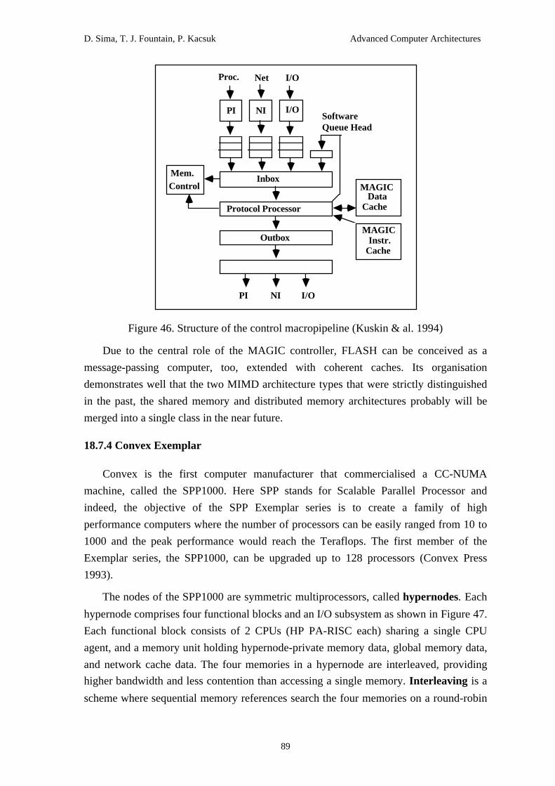
D. Sima, T. J. Fountain, P. Kacsuk Advanced Computer Architectures
89
Proc. Net I/O
PI NI I/O
Mem.Control
InboxMAGIC
DataCacheProtocol Processor
OutboxMAGIC
Instr.Cache
PI NI I/O
SoftwareQueue Head
Figure 46. Structure of the control macropipeline (Kuskin & al. 1994)
Due to the central role of the MAGIC controller, FLASH can be conceived as a
message-passing computer, too, extended with coherent caches. Its organisation
demonstrates well that the two MIMD architecture types that were strictly distinguished
in the past, the shared memory and distributed memory architectures probably will be
merged into a single class in the near future.
18.7.4 Convex Exemplar
Convex is the first computer manufacturer that commercialised a CC-NUMA
machine, called the SPP1000. Here SPP stands for Scalable Parallel Processor and
indeed, the objective of the SPP Exemplar series is to create a family of high
performance computers where the number of processors can be easily ranged from 10 to
1000 and the peak performance would reach the Teraflops. The first member of the
Exemplar series, the SPP1000, can be upgraded up to 128 processors (Convex Press
1993).
The nodes of the SPP1000 are symmetric multiprocessors, called hypernodes. Each
hypernode comprises four functional blocks and an I/O subsystem as shown in Figure 47.
Each functional block consists of 2 CPUs (HP PA-RISC each) sharing a single CPU
agent, and a memory unit holding hypernode-private memory data, global memory data,
and network cache data. The four memories in a hypernode are interleaved, providing
higher bandwidth and less contention than accessing a single memory. Interleaving is a
scheme where sequential memory references search the four memories on a round-robin

D. Sima, T. J. Fountain, P. Kacsuk Advanced Computer Architectures
90
basis. Each memory returns 64 bytes for sequential reads. A five-port crossbar serves for
interconnecting the four functional blocks and the I/O subsystem. Besides the network
cache that is included in the memory unit, each CPU is associated with 1 Mbyte data and
instruction caches. The cache/memory control unit realises cache coherency within the
hypernode and across the hypernodes only for the network cache units.
AAAAAAAAAAAAAAAAAAAAAAAAAAAAAAAA
AAAAAAAAAAAAAAAAAAAAAAAAAAAAAAAA
AAAAAAAAAAAAAAAAAAAAAAAAAAAAAAAA
AAAAAAAAAAAAAAAAAAAAAAAAAAAAAAAA
AAAAAAAAAAAAAAAAAAAAAAAAAAAAAAAA
AAAAAAAAAAAAAAAAAAAAAAAAAAAAAAAA
AAAAAAAAAAAAAAAAAAAAAAAAAAAAAAAA
AAAAAAAAAAAAAAAAAAAAAAAAAAAAAAAA
AAAAAAAAAAAAAAAAAAAAAAAAAAAAAAAA
AAAAAAAAAAAAAAAAAAAAAAAAAAAAAAAA
AAAAAAAAAAAAAAAAAAAAAAAAAAAAAAAA
AAAAAAAAAAAAAAAAAAAAAAAAAAAAAAAA
AAAAAAAAAAAAAAAAAAAAAAAAAAAAAAAA
AAAAAAAAAAAAAAAAAAAAAAAAAAAAAAAA
AAAAAAAAAAAAAAAAAAAAAAAAAAAAAAAA
AAAAAAAAAAAAAAAAAAAAAAAAAAAAAAAA
AAAAAAAAAAAAAAAAAAAAAAAAAAAAAAAA
AAAAAAAAAAAAAAAAAAAAAAAAAAAAAAAA
AAAAAAAAAAAAAAAAAAAAAAAAAAAAAAAA
AAAAAAAAAAAAAAAAAAAAAAAAAAAAAAAA
AAAAAAAAAAAAAAAAAAAAAAAAAAAAAAAA
AAAAAAAAAAAAAAAAAAAAAAAAAAAAAAAA
AAAAAAAAAAAAAAAAAAAAAAAAAAAAAAAA
AAAAAAAAAAAAAAAAAAAAAAAAAAAAAAAA
AAAAAAAAAAAAAAAAAAAAAAAAAAAAAAAA
AAAAAAAAAAAAAAAAAAAAAAAA
AAAAAAAAAAAAAAAAAAAAAAAAAAAA
AAAAAAAAAAAAAAAAAAAAAAAAAAAA
AAAAAAAAAAAAAAAAAAAAAAAAAAAA
AAAAAAAAAAAAAAAAAAAAAAAAAAAA
AAAAAAAAAAAAAAAAAAAAAAAAAAAA
AAAAAAAAAAAAAAAAAAAAAAAAAAAA
AAAAAAAAAAAAAAAAAAAAAAAAAAAA
AAAAAAAAAAAAAAAAAAAAAAAAAAAA
AAAAAAAAAAAAAAAAAAAAAAAAAAAA
AAAAAAAAAAAAAAAAAAAAAAAAAAAA
AAAAAAAAAAAAAAAAAAAAAAAAAAAA
AAAAAAAAAAAAAAAAAAAAAAAAAAAA
AAAAAAAAAAAAAAAAAAAAAAAAAAAA
AAAAAAAAAAAAAAAAAAAAAAAAAAAA
AAAAAAAAAAAAAAAAAAAAAAAAAAAA
AAAAAAAAAAAAAAAAAAAAAAAAAAAA
AAAAAAAAAAAAAAAAAAAAAAAAAAAA
AAAAAAAAAAAAAAAAAAAAAAAAAAAA
AAAAAAAAAAAAAAAAAAAAAAAAAAAA
AAAAAAAAAAAAAAAAAAAAAAAAAAAA
AAAAAAAAAAAAAAAAAAAAAAAAAAAA
AAAAAAAAAAAAAAAAAAAAAAAAAAAA
AAAAAAAAAAAAAAAAAAAAAAAAAAAA
AAAAAAAAAAAAAAAAAAAAAAAAAAAA
AAAAAAAAAAAAAAAAAAAAAAAAAAAA
AAAAAAAAAAAAAAAAAAAAA
AAAAAAAAAAAAAAAAAAAAAAAAAAAAAAAAAAAAAAAAAAAAAAAAAAAAAAAAAAAAAAAAAAAAAAAAAAAAAAAAAAAAAAAAAAAAAAAAAAAAAAAAAAAAAAAAAAAAAAAAAAAAAAAAAAAAAAAAAAAAAAAAAAAAAAAAAAAAAAAAAAAAAAAAAAAAAAAAAAAAAAAAAAAAAAAAAAAAAAAAAAAAAAAAAAAAAAAAAAAAAAAAAAAAAAAA
AAAAAAAAAAAAAAAAAAAAAAAAAAAAAAAAAAAAAAAAAAAAAAAAAAAAAAAAAAAAAAAAAAAAAAAAAAAAAAAAAAAAAAAAAAAAAAAAAAAAAAAAAAAAAAAAAAAAAAAAAAAAAAAAAAAAAAAAAAAAAAAAAAAAAAAAAAAAAAAAAAAAAAAAAAAAAAAAAAAAAAAAAAAAAAAAAAAAAAAAAAAAAAAAAAAAAAAAAAAAAAAAAAAAAAAA
AAAAAAAAAAAAAAAAAAAAAAAAAAAAAAAAAAAAAAAAAAAAAAAAAAAAAAAAAAAAAAAAAAAAAAAAAAAAAAAAAAAAAAAAAAAAAAAAAAAAAAAAAAAAAAAAAAAAAAAAAAAAAAAAAAAAAAAAAAAAAAAAAAAAAAAAAAAAAAAAAAAAAAAAAAAAAAAAAAAAAAAAAAAAAAAAAAAAAAAAAAAAAAAAAAAAAAAAAAAAAAAAAAAAAAAA
AAAAAAAAAAAAAAAAAAAAAAAAAAAAAAAAAAAAAAAAAAAAAAAAAAAAAAAAAAAAAAAAAAAAAAAAAAAAAAAAAAAAAAAAAAAAAAAAAAAAAAAAAAAAAAAAAAAAAAAAAAAAAAAAAAAAAAAAAAAAAAAAAAAAAAAAAAAAAAAAAAAAAAAAAAAAAAAAAAAAAAAAAAAAAAAAAAAAAAAAAAAAAAAAAAAAAAAAAAAAAAAAAAAAAAAA
AAAAAAAAAAAAAAAAAAAAAAAAAAAAAAAAAAAAAAAAAAAAAAAAAAAAAAAAAAAAAAAAAAAAAAAAAAAAAAAAAAAAAAAAAAAAAAAAAAAAAAAAAAAAAAAAAAAAAAAAAAAAAAAAAAAAAAAAAAAAAAAAAAAAAAAAAAAAAAAAAAAAAAAAAAAAAAAAAAAAAAAAAAAAAAAAAAAAAAAAAAAAAAAAAAAAAAAAAAAAAAAAAAAAAAAA
AAAAAAAAAAAAAAAAAAAAAAAAAAAAAAAAAAAAAAAAAAAAAAAAAAAAAAAAAAAAAAAAAAAAAAAAAAAAAAAAAAAAAAAAAAAAAAAAAAAAAAAAAAAAAAAAAAAAAAAAAAAAAAAAAAAAAAAAAAAAAAAAAAAAAAAAAAAAAAAAAAAAAAAAAAAAAAAAAAAAAAAAAAAAAAAAAAAAAAAAAAAAAAAAAAAAAAAAAAAAAAAAAAAAAAAA
AAAAAAAAAAAAAAAAAAAAAAAAAAAAAAAAAAAAAAAAAAAAAAAAAAAAAAAAAAAAAAAAAAAAAAAAAAAAAAAAAAAAAAAAAAAAAAAAAAAAAAAAAAAAAAAAAAAAAAAAAAAAAAAAAAAAAAAAAAAAAAAAAAAAAAAAAAAAAAAAAAAAAAAAAAAAAAAAAAAAAAAAAAAAAAAAAAAAAAAAAAAAAAAAAAAAAAAAAAAAAAAAAAAAAAAA
AAAAAAAAAAAAAAAAAAAAAAAAAAAAAAAAAAAAAAAAAAAAAAAAAAAAAAAAAAAAAAAAAAAAAAAAAAAAAAAAAAAAAAAAAAAAAAAAAAAAAAAAAAAAAAAAAAAAAAAAAAAAAAAAAAAAAAAAAAAAAAAAAAAAAAAAAAAAAAAAAAAAAAAAAAAAAAAAAAAAAAAAAAAAAAAAAAAAAAAAAAAAAAAAAAAAAAAAAAAAAAAAAAAAAAAA
AAAAAAAAAAAAAAAAAAAAAAAAAAAAAAAAAAAAAAAAAAAAAAAAAAAAAAAAAAAAAAAAAAAAAAAAAAAAAAAAAAAAAAAAAAAAAAAAAAAAAAAAAAAAAAAAAAAAAAAAAAAAAAAAAAAAAAAAAAAAAAAAAAAAAAAAAAAAAAAAAAAAAAAAAAAAAAAAAAAAAAAAAAAAAAAAAAAAAAAAAAAAAAAAAAAAAAAAAAAAAAAAAAAAAAAA
AAAAAAAAAAAAAAAAAAAAAAAAAAAAAAAAAAAAAAAAAAAAAAAAAAAAAAAAAAAAAAAAAAAAAAAAAAAAAAAAAAAAAAAAAAAAAAAAAAAAAAAAAAAAAAAAAAAAAAAAAAAAAAAAAAAAAAAAAAAAAAAAAAAAAAAAAAAAAAAAAAAAAAAAAAAAAAAAAAAAAAAAAAAAAAAAAAAAAAAAAAAAAAAAAAAAAAAAAAAAAAAAAAAAAAAA
AAAAAAAAAAAAAAAAAAAAAAAAAAAAAAAAAAAAAAAAAAAAAAAAAAAAAAAAAAAAAAAAAAAAAAAAAAAAAAAAAAAAAAAAAAAAAAAAAAAAAAAAAAAAAAAAAAAAAAAAAAAAAAAAAAAAAAAAAAAAAAAAAAAAAAAAAAAAAAAAAAAAAAAAAAAAAAAAAAAAAAAAAAAAAAAAAAAAAAAAAAAAAAAAAAAAAAAAAAAAAAAAAAAAAAAA
AAAAAAAAAAAAAAAAAAAAAAAAAAAAAAAAAAAAAAAAAAAAAAAAAAAAAAAAAAAAAAAAAAAAAAAAAAAAAAAAAAAAAAAAAAAAAAAAAAAAAAAAAAAAAAAAAAAAAAAAAAAAAAAAAAAAAAAAAAAAAAAAAAAAAAAAAAAAAAAAAAAAAAAAAAAAAAAAAAAAAAAAAAAAAAAAAAAAAAAAAAAAAAAAAAAAAAAAAAAAAAAAAAAAAAAA
AAAAAAAAAAAAAAAAAAAAAAAAAAAAAAAAAAAAAAAAAAAAAAAAAAAAAAAAAAAAAAAAAAAAAAAAAAAAAAAAAAAAAAAAAAAAAAAAAAAAAAAAAAAAAAAAAAAAAAAAAAAAAAAAAAAAAAAAAAAAAAAAAAAAAAAAAAAAAAAAAAAAAAAAAAAAAAAAAAAAAAAAAAAAAAAAAAAAAAAAAAAAAAAAAAAAAAAAAAAAAAAAAAAAAAAA
AAAAAAAAAAAAAAAAAAAAAAAAAAAAAAAAAAAAAAAAAAAAAAAAAAAAAAAAAAAAAAAAAAAAAAAAAAAAAAAAAAAAAAAAAAAAAAAAAAAAAAAAAAAAAAAAAAAAAAAAAAAAAAAAAAAAAAAAAAAAAAAAAAAAAAAAAAAAAAAAAAAAAAAAAAAAAAAAAAAAAAAAAAAAAAAAAAAAAAAAAAAAAAAAAAAAAAAAAAAAAAAAAAAAAAAA
AAAAAAAAAAAAAAAAAAAAAAAAAAAAAAAAAAAAAAAAAAAAAAAAAAAAAAAAAAAAAAAAAAAAAAAAAAAAAAAAAAAAAAAAAAAAAAAAAAAAAAAAAAAAAAAAAAAAAAAAAAAAAAAAAAAAAAAAAAAAAAAAAAAAAAAAAAAAAAAAAAAAAAAAAAAAAAAAAAAAAAAAAAAAAAAAAAAAAAAAAAAAAAAAAAAAAAAAAAAAAAAAAAAAAAAA
AAAAAAAAAAAAAAAAAAAAAAAAAAAAAAAAAAAAAAAAAAAAAAAAAAAAAAAAAAAAAAAAAAAAAAAAAAAAAAAAAAAAAAAAAAAAAAAAAAAAAAAAAAAAAAAAAAAAAAAAAAAAAAAAAAAAAAAAAAAAAAAAAAAAAAAAAAAAAAAAAAAAAAAAAAAAAAAAAAAAAAAAAAAAAAAAAAAAAAAAAAAAAAAAAAAAAAAAAAAAAAAAAAAAAAAA
AAAAAAAAAAAAAAAAAAAAAAAAAAAAAAAAAAAAAAAAAAAAAAAAAAAAAAAAAAAAAAAAAAAAAAAAAAAAAAAAAAAAAAAAAAAAAAAAAAAAAAAAAAAAAAAAAAAAAAAAAAAAAAAAAAAAAAAAAAAAAAAAAAAAAAAAAAAAAAAAAAAAAAAAAAAAAAAAAAAAAAAAAAAAAAAAAAAAAAAAAAAAAAAAAAAAAAAAAAAAAAAAAAAAAAAA
AAAAAAAAAAAAAAAAAAAAAAAAAAAAAAAAAAAAAAAAAAAAAAAAAAAAAAAAAAAAAAAAAAAAAAAAAAAAAAAAAAAAAAAAAAAAAAAAAAAAAAAAAAAAAAAAAAAAAAAAAAAAAAAAAAAAAAAAAAAAAAAAAAAAAAAAAAAAAAAAAAAAAAAAAAAAAAAAAAAAAAAAAAAAAAAAAAAAAAAAAAAAAAAAAAAAAAAAAAAAAAAAAAAAAAAA
AAAAAAAAAAAAAAAAAAAAAAAAAAAAAAAAAAAAAAAAAAAAAAAAAAAAAAAAAAAAAAAAAAAAAAAAAAAAAAAAAAAAAAAAAAAAAAAAAAAAAAAAAAAAAAAAAAAAAAAAAAAAAAAAAAAAAAAAAAAAAAAAAAAAAAAAAAAAAAAAAAAAAAAAAAAAAAAAAAAAAAAAAAAAAAAAAAAAAAAAAAAAAAAAAAAAAAAAAAAAAAAAAAAAAAAA
AAAAAAAAAAAAAAAAAAAAAAAAAAAAAAAAAAAAAAAAAAAAAAAAAAAAAAAAAAAAAAAAAAAAAAAAAAAAAAAAAAAAAAAAAAAAAAAAAAAAAAAAAAAAAAAAAAAAAAAAAAAAAAAAAAAAAAAAAAAAAAAAAAAAAAAAAAAAAAAAAAAAAAAAAAAAAAAAAAAAAAAAAAAAAAAAAAAAAAAAAAAAAAAAAAAAAAAAAAAAAAAAAAAAAAAA
AAAAAAAAAAAAAAAAAAAAAAAAAAAAAAAAAAAAAAAAAAAAAAAAAAAAAAAAAAAAAAAAAAAAAAAAAAAAAAAAAAAAAAAAAAAAAAAAAAAAAAAAAAAAAAAAAAAAAAAAAAAAAAAAAAAAAAAAAAAAAAAAAAAAAAAAAAAAAAAAAAAAAAAAAAAAAAAAAAAAAAAAAAAAAAAAAAAAAAAAAAAAAAAAAAAAAAAAAAAAAAAAAAAAAAAA
AAAAAAAAAAAAAAAAAAAAAAAAAAAAAAAAAAAAAAAAAAAAAAAAAAAAAAAAAAAAAAAAAAAAAAAAAAAAAAAAAAAAAAAAAAAAAAAAAAAAAAAAAAAAAAAAAAAAAAAAAAAAAAAAAAAAAAAAAAAAAAAAAAAAAAAAAAAAAAAAAAAAAAAAAAAAAAAAAAAAAAAAAAAAAAAAAAAAAAAAAAAAAAAAAAAAAAAAAAAAAAAAAAAAAAAA
AAAAAAAAAAAAAAAAAAAAAAAAAAAAAAAAAAAAAAAAAAAAAAAAAAAAAAAAAAAAAAAAAAAAAAAAAAAAAAAAAAAAAAAAAAAAAAAAAAAAAAAAAAAAAAAAAAAAAAAAAAAAAAAAAAAAAAAAAAAAAAAAAAAAAAAAAAAAAAAAAAAAAAAAAAAAAAAAAAAAAAAAAAAAAAAAAAAAAAAAAAAAAAAAAAAAAAAAAAAAAAAAAAAAAAAA
AAAAAAAAAAAAAAAAAAAAAAAAAAAAAAAAAAAAAAAAAAAAAAAAAAAAAAAAAAAAAAAAAAAAAAAAAAAAAAAAAAAAAAAAAAAAAAAAAAAAAAAAAAAAAAAAAAAAAAAAAAAAAAAAAAAAAAAAAAAAAAAAAAAAAAAAAAAAAAAAAAAAAAAAAAAAAAAAAAAAAAAAAAAAAAAAAAAAAAAAAAAAAAAAAAAAAAAAAAAAAAAAAAAAAAAA
AAAAAAAAAAAAAAAAAAAAAAAAAAAAAAAAAAAAAAAAAAAAAAAAAAAAAAAAAAAAAAAAAAAAAAAAAAAAAAAAAAAAAAAAAAAAAAAAAAAAAAAAAAAAAAAAAAAAAAAAAAAAAAAAAAAAAAAAAAAAAAAAAAAAAAAAAAAAAAAAAAAAAAAAAAAAAAAAAAAAAAAAAAAAAAAAAAAAAAAAAAAAAAAAAAAAAAAAAAAAAAAAAAAAAAAA
AAAAAAAAAAAAAAAAAAAAAAAAAAAAAAAAAAAAAAAAAAAAAAAAAAAAAAAAAAAAAAAAAAAAAAAAAAAAAAAAAAAAAAAAAAAAAAAAAAAAAAAAAAAAAAAAAAAAAAAAAAAAAAAAAAAAAAAAAAAAAAAAAAAAAAAAAAAAAAAAAAAAAAAAAAAAAA
AAAAAAAAAAAAAAAAAAAA
AAAAAAAAAAAAAAAAAAAA
AAAAAAAAAAAAAAA
AAAAAAAAAAAAAAAAAAAA
AAAAAAAAAAAA
AAAAAAAAAAAA
AAAAAAAAAAAAAAAAAA
AAAAAAAAAAAA
AAAAAAAAAAAA
AAAAAAAAAAAA
AAAAAAAAAAAA
AAAAAAAAAAAAAAAAAA
AAAAAAAAAAAAAAAAAAAA
AAAAAAAAAAAAAAAAAAAA
AAAAAAAAAAAAAAA
AAAAAAAAAAAAAAAAAAAA
AAAAAAAAAAAAAAAAAAAA
AAAAAAAAAAAAAAAAAAAA
AAAAAAAAAAAAAAA
AAAAAAAAAAAAAAAAAAAA
AAAAAAAA
AAAAAAAA
AAAA
AAAAAA
AAAA
AAAA
CPU CPU CPU CPU CPU CPU CPU CPU
Cache Cache
1 2 3 4 5 6 7 8Cache Cache Cache Cache Cache Cache
2MB 2MB 2MB 2MB 2MB 2MB 2MB 2MB
Agent Agent Agent Agent
5x5 Crossbar
Cache/MemControlControl Control Control
Cache/Mem Cache/Mem Cache/Mem
512 MB 512 MB 512 MB 512 MBMemory Memory Memory Memory
Hypernode 1
Hypernode 2
Hypernode 16
Scalable Coherent Interface Rings (600 MByte/sec each)
I/O
Subsystem(1.25 GByte/sec)
..
..
..
Figure 47. Convex Exemplar Architecture (Convex Press 1994)
The hypernodes are connected by four SCI (Scalable Coherent Interface) point-to-
point, unidirectional rings. As it was shown in Section 18.3.2, SCI can support several
kinds of interconnection networks, the unidirectional ring is one of those. Sequential
memory references to global memory are interleaved across the four rings. This is
accomplished using the ring in the same functional unit as the target memory, because
the memories are interleaved on a 64-byte basis. The four SCI rings are interleaved on
this basis as well; 64 bytes is the network cache line size.

D. Sima, T. J. Fountain, P. Kacsuk Advanced Computer Architectures
91
The global shared memory of the SPP1000 is distributed among the hypernodes. The
Convex Exemplar series is constructed using a hierarchical memory architecture
containing four types of allocable memory differentiated by the way data are allocated
and shared. The existence of four different memories in allocation, sharing or latency
does not imply that there must be four distinct physical memories. All four memories, as
well as the network cache, may be implemented by the same physical memory on each
hypernode. In the Exemplar the following types of memory are provided, listed in order
of increasing memory latency:
1. CPU-private memory serves for data accessed only by a single CPU. Notice that
the CPU-private memory is not physically implemented; it is the operating system that
partitions hypernode-private memory used as CPU-private memory for each of the CPUs.
2. Hypernode-private memory is provided for data shared only by CPUs within a
single Hypernode.
3. Near-shared memory is globally accessible from all hypernodes. This memory is
allocated from the global memory. Accessing a near-shared memory from the home
hypernode requires less latency than accessing it from other nodes.
4. Far-shared memory is globally accessible from all hypernodes with equal
latency. It is allocated from the global memories of several hypernodes. Coherent
memory that is designated far-shared (shared by and distributed across multiple
hypernodes) is interleaved across the hypernodes on a per-page basis (4 Kbytes) by
operating system software allocation of the table entries.
From cache coherence point of view two domains are distinguished in the Exemplar.
The intrahypernode domain implements coherency within a hypernode's processors and
their memories. The interhypernode domain implements coherency among the
hypernodes of the system. The two domains are bridged by a special network cache that
tracks coherency in both domains.
The SPP system applies the write-back, invalidate SCI coherency protocol (see
Section 18.3.2) to ensure cache coherence in the interhypernode domain. This is done by
maintaining a linked sharing list that contains a list of all the hypernodes sharing each
cache line, or the hypernode that exclusively owns the cache line. Within every
hypernode a record is kept of which CPUs have encached each line in the network cache
so that network coherency requests can be forwarded to the appropriate CPUs.
The cache coherence protocol of the intrahypernode domain satisfies the following
requirements:
1. Any number of read encachements of a cache line may be made at the same time.
The cache line may be read-shared in multiple caches.

D. Sima, T. J. Fountain, P. Kacsuk Advanced Computer Architectures
92
2. To write data into a cache line, the cache line must be owned exclusively. This
implies that any other copies must be deleted.
3. Modified cache lines must be written back to memory before being deleted, or the
contents can be forwarded directly to the new owner.
For illustrating what the rules above imply consider the following pseudo-code of a
simple matrix multiply. The algorithm calls spawn to fork nCPUs number of threads.
Each thread receives a unique thread identifier, itid. Each iteration of the outer do j...
loop is only executed by one CPU as determined by the following if statement. The
CPUs are allocated in cyclical fashion to the loop iterations. The first code (Figure 48)
works correctly for a cache-coherent machine. The second code (Figure 49) shows the
applications of those cache-handling and synchronising instructions that are necessary for
maintaining cache coherency in a noncache-coherent machine. The calls to flush on the a
and b arrays are required to ensure that the executing CPU gets an up-to-date copy of the
input arrays, because they may have been modified on a different CPU after being
encached on the current CPU. The call to flush on the c array is needed to write the
output array back to memory, so that subsequent operations will see the result of the
matrix multiply.
global c(idim,idim), a(idim,idim)
global b(idim,idim), nCPUs
private i, j, k, itid
call spawn( nCPUs )
do j = 1, idim
if ( jmod(j,nCPU).eq.itid ) then
do i = 1, idim
c(i,j) = 0.0
do k = 1, idim
c(i,j) = c(i,j) + a(i,k) * b(k,j)
enddo
enddo
endif
enddo
call join
Figure 48. Parallel matrix multiply code for cache-coherent machine (Convex Exemplar
Architecture 1993)
The flush on the c array should be done in a synchronised way in order to prevent two
processors from updating different c(i,j) elements in the same cache line at the same

D. Sima, T. J. Fountain, P. Kacsuk Advanced Computer Architectures
93
time. For that purpose, a semaphore is allocated to each element of the c array. Updating
and flushing a c(i,j) element can happen in a critical section that is guarded by the
associated semaphore. The lock and unlock functions are defined to compute the
corresponding cache line address for their first argument, and to lock or unlock the
semaphore in their second argument corresponding to that cache line. The second
algorithm is what the cache coherence hardware implements in the Exemplar's
intrahypernode domain.
global c(idim,idim), a(idim,idim)
global b(idim,idim), nCPUs
private i, j, k, itid, tmp
semaphore is(idim,idim)
call spawn( nCPUs )
do j = 1, idim
if ( jmod(j,nCPU).eq.itid ) then
do i = 1, idim
tmp = 0.0
do k = 1, idim
call flush(a(i,k))
call flush(b(k,j))
tmp = tmp + a(i,k) * b(k,j)
enddo
call lock(c(i,j), is(i,j))
c(i,j) = tmp
call flush(c(i,j))
call unlock(c(i,j), is(i,j))
enddo
endif
enddo
call join
Figure 49. Parallel matrix multiply code for noncache-coherent machine (Convex
Exemplar Architecture 1993)
18.8 Cache-Only Memory Architectures (COMA) Machines
COMA machines try to avoid the problems of static memory allocation of NUMA
and CC-NUMA machines by excluding main memory blocks from the local memory of
nodes and employing only large caches as node memories. In these architectures only
cache memories are present, no main memory is employed neither in the form of a

D. Sima, T. J. Fountain, P. Kacsuk Advanced Computer Architectures
94
central shared memory like in UMA machines nor in the form of a distributed main
memory like in NUMA and CC-NUMA computers. Similarly to the way how virtual
memory has eliminated the need of handling memory addresses explicitly, COMA
machines render static data allocation to local memories superfluous. In COMA
machines data allocation is demand driven, according to the cache coherence scheme,
data are always attracted to the local (cache) memory where they are needed.
In COMA machines similar cache coherence schemes can be applied than in other
shared memory systems. The only difference is that these techniques should be extended
with the capability of finding the datum on a cache read miss and of handling
replacement. Since COMA machines are scalable parallel architectures, only those cache
coherence protocols can be applied that support large scale parallel systems, i.e. directory
schemes and hierarchical cache coherent schemes. Two representative COMA
architectures are:
1. DDM (Data Diffusion Machine)
2. KSR1
DDM uses a hierarchical cache coherence scheme, while KSR1 applies a distributed
directory to maintain cache coherency. In the next section these machines and their cache
coherence schemes are explained.
18.8.1 Data Diffusion Machine (DDM)
DDM is a hierarchical, tree-like multiprocessor where the leaves of the tree represent
the basic DDM architecture (Hagersten & al. 1992). The basic DDM is a single-bus
based multiprocessor as illustrated in Figure 50. It contains a number of
processor/attraction memory pairs connected to the DDM bus. An attraction memory
consists of three main units:
1. State and data memory unit
2. Controller
3. Output buffer

D. Sima, T. J. Fountain, P. Kacsuk Advanced Computer Architectures
95
AAAAAAAAAAAAAAAAAAAAAAAAAAAAAAAAAAAAAAAAAAAAAAAAAAAAAAAAAAAAAAAAAAAAAAAAAAAAAAAAAAAAAAAAAAAAAAAAAAAAAAAAAAAAAAAAAAAA
AAAAAAAAAAAAAAAAAAAAAAAAAAAAAAAAAAAAAAAAAAAAAAAAAAAAAAAAAAAAAAAAAAAAAAAAAAAAAAAAAAAAAAAAAAAAAAAAAAAAAAAAAAAAAAAAAAAA
AAAAAAAAAAAAAAAAAAAAAAAAAAAAAAAAAAAAAAAAAAAAAAAAAAAAAAAAAAAAAAAAAAAAAAAAAAAAAAAAAAAAAAAAAAAAAAAAAAAAAAAAAAAAAAAAAAAA
AAAAAAAAAAAAAAAAAAAAAAAAAAAAAAAAAAAAAAAAAAAAAAAAAAAAAAAAAAAAAAAAAAAAAAAAAAAAAAAAAAAAAAAAAAAAAAAAAAAAAAAAAAAAAAAAAAAA
AAAAAAAAAAAAAAAAAAAAAAAAAAAAAAAAAAAAAAAAAAAAAAAAAAAAAAAAAAAAAAAAAAAAAAAAAAAAAAAAAAAAAAAAAAAAAAAAAAAAAAAAAAAAAAAAAAAA
AAAAAAAAAAAAAAAAAAAAAAAAAAAAAAAAAAAAAAAAAAAAAAAAAAAAAAAAAAAAAAAAAAAAAAAAAAAAAAAAAAAAAAAAAAAAAAAAAAAAAAAAAAAAAAAAAAAA
AAAAAAAAAAAAAAAAAAAAAAAAAAAAAAAAAAAAAAAAAAAAAAAAAAAAAAAAAAAAAAAAAAAAAAAAAAAAAAAAAAAAAAAAAAAAAAAAAAAAAAAAAAAAAAAAAAAA
AAAAAAAAAAAAAAAAAAAAAAAAAAAAAAAAAAAAAAAAAAAAAAAAAAAAAAAAAAAAAAAAAAAAAAAAAAAAAAAAAAAAAAAAAAAAAAAAAAAAAAAAAAAAAAAAAAAA
AAAAAAAAAAAAAAAAAAAAAAAAAAAAAAAAAAAAAAAAAAAAAAAAAAAAAAAAAAAAAAAAAAAAAAAAAAAAAAAAAAAAAAAAAAAAAAAAAAAAAAAAAAAAAAAAAAAA
AAAAAAAAAAAAAAAAAAAAAAAAAAAAAAAAAAAAAAAAAAAAAAAAAAAAAAAAAAAAAAAAAAAAAAAAAAAAAAAAAAAAAAAAAAAAAAAAAAAAAAAAAAAAAAAAAAAA
AAAAAAAAAAAAAAAAAAAAAAAAAAAAAAAAAAAAAAAAAAAAAAAAAAAAAAAAAAAAAAAAAAAAAAAAAAAAAAAAAAAAAAAAAAAAAAAAAAAAAAAAAAAAAAAAAAAA
AAAAAAAAAAAAAAAAAAAAAAAAAAAAAAAAAAAAAAAAAAAAAAAAAAAAAAAAAAAAAAAAAAAAAAAAAAAAAAAAAAAAAAAAAAAAAAAAAAAAAAAAAAAAAAAAAAAA
AAAAAAAAAAAAAAAAAAAAAAAAAAAAAAAAAAAAAAAAAAAAAAAAAAAAAAAAAAAAAAAAAAAAAAAAAAAAAAAAAAAAAAAAAAAAAAAAAAAAAAAAAAAAAAAAAAAA
AAAAAAAAAAAAAAAAAAAAAAAAAAAAAAAAAAAAAAAAAAAAAAAAAAAAAAAAAAAAAAAAAAAAAAAAAAAAAAAAAAAAAAAAAAAAAAAAAAAAAAAAAAAAAAAAAAAA
AAAAAAAAAAAAAAAAAAAAAAAAAAAAAAAAAAAAAAAAAAAAAAAAAAAAAAAAAAAAAAAAAAAAAAAAAAAAAAAAAAAAAAAAAAAAAAAAAAAAAAAAAAAAAAAAAAAAAAAAAAAAAAAAAAAAAAAAAAAAAAAAAAAAAAAAAAAAAAAAAAAAAAAAAAAAAAAAAAAAAAAAAAAAAAAAAAAAAAAAAAAAAAAAAAAAAAAAAAAAAAAAAAAAAAAAAAAAAAAAAAAAAAAAAAAAAAAAAAAAAAAAAAAAAAAAAAAAAAAAAAAAAAAAAAA AA AA AA AA AA AA A
AA
AA
A AA AA AA AA AA AA AA AA AA AA AA AA AA AA AAA
AA
A AA AA AA AA AA AA AA AA AA AA AA AA AA AA AAA
AA
A AA AA AA AA AA AA AA AA AA AA AA AA AA AA AAA
AA
A AA AA AA AA AA AA AA AA AA AA AA AA AA AA AAA
AA
A AA AA AA AA AA AA AA AA AA AA AA AA AA AA AAA
AA
A AA AA AA AA AA AA AA AA AA AA AA AA AA AA AAA
AA
A AA AA AA AA AA AA AA AA AA AA AA AA AA AA AAA
AA
A AA AA AA AA AA AA AA AA AA AA AA AA AA AA AAA
AA
A AA AA AA AA AA AA AA AA AA AA AA AA AA AA AAA
AA
A AA AA AA AA AA AA AA AA AA AA AA AA AA AA AAA
AA
A AA AA AA AA AA AA AA AA AA AA AA AA AA AA AAA
AA
A AA AA AA AA AA AA AA AA AA AA AA AA AA AA AAA
AA
A AA AA AA AA AA AA AA AA AA AA AA AA AA AA AAA
AA
A AA AA AA AA AA AA AA AA AA AA AA AA AA AA AAA
AA
A AA AA AA AA AA AA AA AA AA AA AA AA AA AA AAA
AA
A AA AA AA AA AA AA AA AA AA AA AA AA AA AA AAA
AA
A AA AA AA AA AA AA AA AA AA AA AA AA AA AA AAA
AA
A AA AA AA AA AA AA AA AA AA AA AA AA AA AA AAA
AA
A AA AA AA AA AA AA AA AA AA AA AA AA AA AA AAA
AA
A AA AA AA AA AA AA AA AA AA AA AA AA AA AA AAA
AA
A AA AA AA AA AA AA AA AA AA AA AA AA AA AA AAA
AA
A AA AA AA AA AA AA AA AA AA AA AA AA AA AA AAA
AA
A AA AA AA AA AA AA AA AA AA AA AA AA AA AA AAA
AA
A AA AA AA AA AA AA AA AA AA AA AA AA AA AA AAA
AA
A AA AA AA AA AA AA AA AA AA AA AA AA AA AA AAA
AA
A AA AA AA AA AA AA AA AA AA AA AA AA AA AA AAA
AA
A AA AA AA AA AA AA AA AA AA AA AA AA AA AA AAA
AA
A AA AA AA AA AA AAAAAAAAAAAAAAAAAAAAAAAAAAAAAAAAAAAAAAAAAAAAAAAAAAAAAAAAAAAAAAAAAAAAAAAAAAAAAAAAAAAAAAAAAAAAAAAAAAAAAAAAAAAAAAAAAAAAAAAAAAAAAAAAAAAAAAAAAAAAAAAAAAAAAAAAAAAAAAAAAAAAAAAAAAAAAAAAAAAAAAAAAAAAAAAAAAAAAAAAAAAAAAAAAAAAAAAAAAAAAAAAAAAAAAAAA
Above protocol
Below protocol
Topprotocol
Arbitration,selection
DDM bus
Output buffer
Attraction memory
State + datamemory
Attractionmemory
Processor Processor
Controller
Figure 50. Structure of the basic DDM machine (Hagersten & al. 1992)
There are two protocols applied in the controller. The snooping memory above
protocol provides the cache coherence scheme among the attraction memories, while the
memory below protocol realises the interface between the processor and the attraction
memory. Both protocols consider a cache line of the attraction memory as one unit and a
state field is stored in the attraction memory for each unit. The DDM employs an
asynchronous split-transaction bus, i.e. the bus is released between a requesting
transaction and its response. This delay time can be of arbitrarily length. Deadlock
avoidance on the DDM bus is guaranteed by the introduction of an arbitration/selection
logic that makes sure that only one responder will be selected for each bus request.
A write-invalidate snoopy-cache protocol is introduced which limits broadcast
requirements to a smaller subsystem and extends with support for replacement. A cache
line can occur in any of the following seven states:
1. I (Invalid): This attraction memory does not contain the cache line.
2. E (Exclusive): This attraction memory contains the cache line and there is no
other copy in the system.
3. S (Shared): There are several copies of the cache line and one of them is located
in this attraction memory.
4. R (Reading): This node started a read transaction and is waiting for the reply.
5. W (Waiting): This node started an erase transaction and waits for becoming
Exclusive.
D. Sima, T. J. Fountain, P. Kacsuk Advanced Computer Architectures
96
6. RW (Reading-and-Waiting): This node is waiting for a data value that becomes
Exclusive later.
7. A (Answering): This node is supposed to answer a read request.
The last four states are the so-called transient ones which are needed because of the
split-transaction bus where outstanding requests should be remembered. The following
transactions are permitted on the DDM bus:
1. Erase: Erases all copies of this cache line.
2. Exclusive: Acknowledges an erase request.
3. Read: Reads a copy of the cache line.
4. Data: Transfers data for an earlier read request.
5. Inject: Carries the only copy of a cache line and looks for an attraction memory to
place it. (Inject is initiated by a replacement.)
6. Out: Transfers the cache line out of the attraction memory. It will terminate when
another copy of the cache line is found. (Out is caused by a replacement.)
The state transition diagram of Figure 51 shows the possible transactions and their
relationship with the possible states of the attraction memories. Notice that transactions
can arrive either from the processor of a node or from the network. If the processor wants
to read an invalid cache line (I), the attraction memory initiates a Read transaction on the
network and rewrites the state into Reading (R). The bus selection logic will select one
attraction memory to service the request. The selected attraction memory places the
requested data on the bus and the requester attraction memory will grab it and place it as
a shared cache line in the local cache.
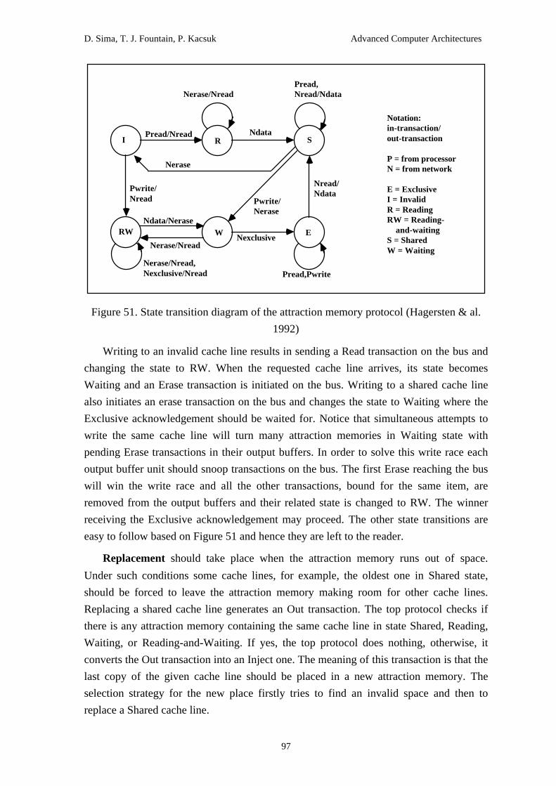
D. Sima, T. J. Fountain, P. Kacsuk Advanced Computer Architectures
97
I R S
RW W E
Pread/Nread
Nerase/NreadPread, Nread/Ndata
Ndata
Nerase
Pwrite/ Nread Pwrite/
Nerase
Nexclusive
Nread/ Ndata
Ndata/Nerase
Nerase/Nread
Nerase/Nread, Nexclusive/Nread Pread,Pwrite
Notation: in-transaction/ out-transaction P = from processor N = from network E = Exclusive I = Invalid R = Reading RW = Reading- and-waiting S = Shared W = Waiting
Figure 51. State transition diagram of the attraction memory protocol (Hagersten & al.
1992)
Writing to an invalid cache line results in sending a Read transaction on the bus and
changing the state to RW. When the requested cache line arrives, its state becomes
Waiting and an Erase transaction is initiated on the bus. Writing to a shared cache line
also initiates an erase transaction on the bus and changes the state to Waiting where the
Exclusive acknowledgement should be waited for. Notice that simultaneous attempts to
write the same cache line will turn many attraction memories in Waiting state with
pending Erase transactions in their output buffers. In order to solve this write race each
output buffer unit should snoop transactions on the bus. The first Erase reaching the bus
will win the write race and all the other transactions, bound for the same item, are
removed from the output buffers and their related state is changed to RW. The winner
receiving the Exclusive acknowledgement may proceed. The other state transitions are
easy to follow based on Figure 51 and hence they are left to the reader.
Replacement should take place when the attraction memory runs out of space.
Under such conditions some cache lines, for example, the oldest one in Shared state,
should be forced to leave the attraction memory making room for other cache lines.
Replacing a shared cache line generates an Out transaction. The top protocol checks if
there is any attraction memory containing the same cache line in state Shared, Reading,
Waiting, or Reading-and-Waiting. If yes, the top protocol does nothing, otherwise, it
converts the Out transaction into an Inject one. The meaning of this transaction is that the
last copy of the given cache line should be placed in a new attraction memory. The
selection strategy for the new place firstly tries to find an invalid space and then to
replace a Shared cache line.

D. Sima, T. J. Fountain, P. Kacsuk Advanced Computer Architectures
98
The single-bus based basic DDM architecture can be expanded to a hierarchical
multiprocessor system by simply replacing the top protocol with a directory unit which
connects the bus of the basic DDM architecture to a higher level bus. The directory unit
can be used to connect two higher level buses, resulting in a tree-like hierarchical
architecture where the leaves are basic DDM architectures, the root is the top and the
other nodes of the tree are directory units as illustrated in Figure 52.
P P Pi P P P P Pj P Pk P P
Top
W W
W I W S
I = Invalid W = Waiting S = Shared
I I W I I I I W I I I
Erase request (winner) Erase
S
Erase
Erase request (loser)
AAAAAAAAA
AAAAAAAAAAAAAAAAAAAA
AAAAAAAAAAAAAAAA
AAAAAAAAAAAAAAAAAA
Exclusive acknowledge
AM:
P:
D:
D:
P = Processor AM = Attraction Memory D = Directory
Figure 52. Write race in the hierarchical DDM (Hagersten & al. 1992)
The heart of the directory unit is a set-associative state memory containing
administrative information for each cache line residing in an attraction memory below it.
However, the state memory does not contain any data. The controller of the directory
units realises two protocols. The directory above protocol is a snooping one resembling
very much to the memory above protocol. The directory below protocol is compatible
with the top protocol for items in Exclusive state. The structure of the directory unit is
shown in Figure 53.
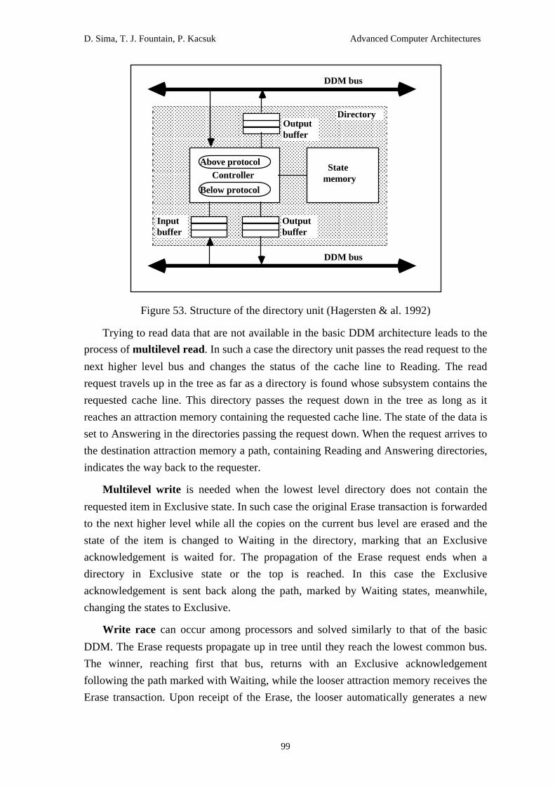
D. Sima, T. J. Fountain, P. Kacsuk Advanced Computer Architectures
99
AAAAAAAAAAAAAAAAAAAAAAAAAAAAAAAAAAAAAAAAAAAAAAAAAAAAAAAAAAAAAAAAAAAAAAAAAAAAAAAAAAAAAAAAAAAAAAAAAAAAAAAAAAAAAAAAAAAAAAAAAAAAAAAAAAAAAAAAAAAAAAAAAAAAAAAAAAAAAAAAAAAA
AAAAAAAAAAAAAAAAAAAAAAAAAAAAAAAAAAAAAAAAAAAAAAAAAAAAAAAAAAAAAAAAAAAAAAAAAAAAAAAAAAAAAAAAAAAAAAAAAAAAAAAAAAAAAAAAAAAAAAAAAAAAAAAAAAAAAAAAAAAAAAAAAAAAAAAAAAAAAAAAAAAA
AAAAAAAAAAAAAAAAAAAAAAAAAAAAAAAAAAAAAAAAAAAAAAAAAAAAAAAAAAAAAAAAAAAAAAAAAAAAAAAAAAAAAAAAAAAAAAAAAAAAAAAAAAAAAAAAAAAAAAAAAAAAAAAAAAAAAAAAAAAAAAAAAAAAAAAAAAAAAAAAAAAA
AAAAAAAAAAAAAAAAAAAAAAAAAAAAAAAAAAAAAAAAAAAAAAAAAAAAAAAAAAAAAAAAAAAAAAAAAAAAAAAAAAAAAAAAAAAAAAAAAAAAAAAAAAAAAAAAAAAAAAAAAAAAAAAAAAAAAAAAAAAAAAAAAAAAAAAAAAAAAAAAAAAA
AAAAAAAAAAAAAAAAAAAAAAAAAAAAAAAAAAAAAAAAAAAAAAAAAAAAAAAAAAAAAAAAAAAAAAAAAAAAAAAAAAAAAAAAAAAAAAAAAAAAAAAAAAAAAAAAAAAAAAAAAAAAAAAAAAAAAAAAAAAAAAAAAAAAAAAAAAAAAAAAAAAA
AAAAAAAAAAAAAAAAAAAAAAAAAAAAAAAAAAAAAAAAAAAAAAAAAAAAAAAAAAAAAAAAAAAAAAAAAAAAAAAAAAAAAAAAAAAAAAAAAAAAAAAAAAAAAAAAAAAAAAAAAAAAAAAAAAAAAAAAAAAAAAAAAAAAAAAAAAAAAAAAAAAA
AAAAAAAAAAAAAAAAAAAAAAAAAAAAAAAAAAAAAAAAAAAAAAAAAAAAAAAAAAAAAAAAAAAAAAAAAAAAAAAAAAAAAAAAAAAAAAAAAAAAAAAAAAAAAAAAAAAAAAAAAAAAAAAAAAAAAAAAAAAAAAAAAAAAAAAAAAAAAAAAAAAA
AAAAAAAAAAAAAAAAAAAAAAAAAAAAAAAAAAAAAAAAAAAAAAAAAAAAAAAAAAAAAAAAAAAAAAAAAAAAAAAAAAAAAAAAAAAAAAAAAAAAAAAAAAAAAAAAAAAAAAAAAAAAAAAAAAAAAAAAAAAAAAAAAAAAAAAAAAAAAAAAAAAA
AAAAAAAAAAAAAAAAAAAAAAAAAAAAAAAAAAAAAAAAAAAAAAAAAAAAAAAAAAAAAAAAAAAAAAAAAAAAAAAAAAAAAAAAAAAAAAAAAAAAAAAAAAAAAAAAAAAAAAAAAAAAAAAAAAAAAAAAAAAAAAAAAAAAAAAAAAAAAAAAAAAA
AAAAAAAAAAAAAAAAAAAAAAAAAAAAAAAAAAAAAAAAAAAAAAAAAAAAAAAAAAAAAAAAAAAAAAAAAAAAAAAAAAAAAAAAAAAAAAAAAAAAAAAAAAAAAAAAAAAAAAAAAAAAAAAAAAAAAAAAAAAAAAAAAAAAAAAAAAAAAAAAAAAA
AAAAAAAAAAAAAAAAAAAAAAAAAAAAAAAAAAAAAAAAAAAAAAAAAAAAAAAAAAAAAAAAAAAAAAAAAAAAAAAAAAAAAAAAAAAAAAAAAAAAAAAAAAAAAAAAAAAAAAAAAAAAAAAAAAAAAAAAAAAAAAAAAAAAAAAAAAAAAAAAAAAA
AAAAAAAAAAAAAAAAAAAAAAAAAAAAAAAAAAAAAAAAAAAAAAAAAAAAAAAAAAAAAAAAAAAAAAAAAAAAAAAAAAAAAAAAAAAAAAAAAAAAAAAAAAAAAAAAAAAAAAAAAAAAAAAAAAAAAAAAAAAAAAAAAAAAAAAAAAAAAAAAAAAA
AAAAAAAAAAAAAAAAAAAAAAAAAAAAAAAAAAAAAAAAAAAAAAAAAAAAAAAAAAAAAAAAAAAAAAAAAAAAAAAAAAAAAAAAAAAAAAAAAAAAAAAAAAAAAAAAAAAAAAAAAAAAAAAAAAAAAAAAAAAAAAAAAAAAAAAAAAAAAAAAAAAA
AAAAAAAAAAAAAAAAAAAAAAAAAAAAAAAAAAAAAAAAAAAAAAAAAAAAAAAAAAAAAAAAAAAAAAAAAAAAAAAAAAAAAAAAAAAAAAAAAAAAAAAAAAAAAAAAAAAAAAAAAAAAAAAAAAAAAAAAAAAAAAAAAAAAAAAAAAAAAAAAAAAA
AAAAAAAAAAAAAAAAAAAAAAAAAAAAAAAAAAAAAAAAAAAAAAAAAAAAAAAAAAAAAAAAAAAAAAAAAAAAAAAAAAAAAAAAAAAAAAAAAAAAAAAAAAAAAAAAAAAAAAAAAAAAAAAAAAAAAAAAAAAAAAAAAAAAAAAAAAAAAAAAAAAA
AAAAAAAAAAAAAAAAAAAAAAAAAAAAAAAAAAAAAAAAAAAAAAAAAAAAAAAAAAAAAAAAAAAAAAAAAAAAAAAAAAAAAAAAAAAAAAAAAAAAAAAAAAAAAAAAAAAAAAAAAAAAAAAAAAAAAAAAAAAAAAAAAAAAAAAAAAAAAAAAAAAA
AAAAAAAAAAAAAAAAAAAAAAAAAAAAAAAAAAAAAAAAAAAAAAAAAAAAAAAAAAAAAAAAAAAAAAAAAAAAAAAAAAAAAAAAAAAAAAAAAAAAAAAAAAAAAAAAAAAAAAAAAAAAAAAAAAAAAAAAAAAAAAAAAAAAAAAAAAAAAAAAAAAAAAAAAAAAAAAAAAAAAAAAAAAAAA
AAAAAAAA
AAAAAAAA
AAAAAAAA
AAAAAAAA
AAAAAAAA
AAAAAAAA
AAAAAAAA
AAAAAAAA
AAAAAAAA
AAAAAAAA
AAAAAAAA
AAAAAAAA
AAAAAAAA
AAAAAAAA
AAAAAAAA
AAAAAAAA
AAAAAA
AAAAAAAAAAAAAAAAAAAAAAAAAAAAAAAAAAAAAAAAAAAAAAAAAAAAAAAAAAAAAAAAAAAAAAAAAAAAAAAAAAAAAAAAAAAAAAAAAAAAAAAAAAAAAAAAAAAAAAAAAAAAAAAAAAAAAAAA AAA AAA AAA AAA AAA AAA AAA AAA AAA AAA AAA AAA AAAAA
AA
AA AAA AAA AAA AAA AAA AAA AAA AAA AAA AAA AAA AAA AAA AAA AAAAA
AA
AA AAA AAA AAA AAA AAA AAA AAA AAA AAA AAA AAA AAA AAA AAA AAAAA
AA
AA AAA AAA AAA AAA AAA AAA AAA AAA AAA AAA AAA AAA AAA AAA AAAAA
AA
AA AAA AAA AAA AAA AAA AAA AAA AAA AAA AAA AAA AAA AAA AAA AAAAA
AA
AA AAA AAA AAA AAA AAA AAA AAA AAA AAA AAA AAA AAA AAA AAA AAAAA
AA
AA AAA AAA AAA AAA AAA AAA AAA AAA AAA AAA AAA AAA AAA AAA AAAAA
AA
AA AAA AAA AAA AAA AAA AAA AAA AAA AAA AAA AAA AAA AAA AAA AAAAA
AA
AA AAA AAA AAA AAA AAA AAA AAA AAA AAA AAA AAA AAA AAA AAA AAAAA
AA
AA AAA AAA AAA AAA AAA AAA AAA AAA AAA AAA AAA AAA AAA AAA AAAAA
AA
AA AAA AAA AAA AAA AAA AAA AAA AAA AAA AAA AAA AAA AAA AAA AAAAA
AA
AA AAA AAA AAA AAA AAA AAA AAA AAA AAA AAA AAA AAA AAA AAA AAAAA
AA
AA AAA AAA AAA AAA AAA AAA AAA AAA AAA AAA AAA AAA AAA AAA AAAAA
AA
AA AAA AAA AAA AAA AAA AAA AAA AAA AAA AAA AAA AAA AAA AAA AAAAA
AA
AA AAA AAA AAA AAA AAA AAA AAA AAA AAA AAA AAA AAA AAA AAA AAAAA
AA
AA AAA AAA AAA AAA AAA AAA AAA AAA AAA AAA AAA AAA AAA AAA AAAAA
AA
AA AAA AAA AAA AAA AAA AAA AAA AAA AAA AAA AAA AAA AAA AAA AAAAA
AA
AA AAA AAA AAA AAA AAA AAA AAA AAA AAA AAA AAA AAA AAA AAA AAAAA
AA
AA AAA AAA AAA AAA AAA AAA AAA AAA AAA AAA AAA AAA AAA AAA AAAAA
AA
AA AAA AAA AAA AAA AAA AAA AAA AAA AAA AAA AAA AAA AAA AAA AAAAA
AA
AA AAA AAA AAA AAA AAA AAA AAA AAA AAA AAA AAA AAA AAA AAA AAAAA
AA
AA AAA AAA AAA AAA AAA AAA AAA AAA AAA AAA AAA AAA AAA AAA AAAAA
AA
AA AAA AAA AAA AAA AAA AAA AAA AAA AAA AAA AAA AAA AAA AAA AAAAA
AA
AA AAA AAA AAA AAA AAA AAA AAA AAA AAA AAA AAA AAA AAA AAA AAAAA
AA
AA AAA AAA AAA AAA AAA AAA AAA AAA AAA AAA AAA AAA AAA AAA AAAAA
AA
AA AAA AAA AAA AAA AAA AAA AAA AAA AAA AAA AAA AAA AAA AAA AAAAA
AA
AA AAA AAA AAA AAA AAA AAA AAA AAA AAA AAA AAA AAA AAA AAA AAAAA
AA
AA AAA AAA AAA AAA AAA AAA AAA AAA AAA AAA AAA AAA AAA AAA AAAAA
AA
AA AAA AAA AAA AAA AAA AAA AAA AAA AAA AAA AAA AAA AAA AAA AAAAA
AA
AA AAA AAA AAA AAA AAA AAA AAA AAA AAA AAA AAA AAA AAA AAA AAAAA
AA
AA AAA AAA AAA AAA AAA AAA AAA AAA AAA AAA AAA AAA AAA AAA AAAAA
AA
AA AAA AAA AAA AAA AAA AAA AAA AAA AAA AAA AAA AAA AAA AAA AAAAA
AA
AA AAA AAA AAA AAA AAA AAA AAA AAA AAA AAA AAA AAA AAA AAA AAAAA
AA
AA AAA AAA AAA AAA AAA AAA AAA AAA AAA AAA AAA AAA AAA AAA AAAAA
AA
AA AAA AAA AAA AAA AAA AAA AAA AAA AAA AAA AAA AAA AAA AAA AAAAA
AA
AA AAA AAA AAA AAA AAA AAA AAA AAA AAA AAA AAA AAA AAA AAA AAAAA
AA
AA AAA AAA AAA AAA AAA AAA AAA AAA AAA AAA AAA AAA AAA AAA AAAAA
AA
AA AAA AAA AAA AAA AAA AAA AAA AAA AAA AAA AAA AAA AAA AAA AAAAA
AA
AA AAA AAA AAA AAA AAA AAA AAA AAA AAA AAA AAAAAAAAAAAAAAAAAAAAAAAAAAAAAAAAAAAAAAAAAAAAAAAAAAAAAAAAAAAAAAAAAAAAAAAAAAAAAAAAAAAAAAAAAAAAAAAAAAAAAAAAAAAAAAAAAAAAAAAAAAAAAAAAAAAAAAAAAAAAAAAAAAAAAAAAAAAAAAAAAAAAAAAAAAAAAAAAAAAAAAAAAAAAAAAAAAAAAAAAAAAAAAAAAAAAAAAAAAAAAAAAAAAAAAAAAAAAAAAAAAAAAAAAAAAAAAAAAAAAAAAAAAAAA
Above protocol
Below protocol
Output buffer
Directory
StatememoryController
Output buffer
Input buffer
DDM bus
DDM bus
Figure 53. Structure of the directory unit (Hagersten & al. 1992)
Trying to read data that are not available in the basic DDM architecture leads to the
process of multilevel read. In such a case the directory unit passes the read request to the
next higher level bus and changes the status of the cache line to Reading. The read
request travels up in the tree as far as a directory is found whose subsystem contains the
requested cache line. This directory passes the request down in the tree as long as it
reaches an attraction memory containing the requested cache line. The state of the data is
set to Answering in the directories passing the request down. When the request arrives to
the destination attraction memory a path, containing Reading and Answering directories,
indicates the way back to the requester.
Multilevel write is needed when the lowest level directory does not contain the
requested item in Exclusive state. In such case the original Erase transaction is forwarded
to the next higher level while all the copies on the current bus level are erased and the
state of the item is changed to Waiting in the directory, marking that an Exclusive
acknowledgement is waited for. The propagation of the Erase request ends when a
directory in Exclusive state or the top is reached. In this case the Exclusive
acknowledgement is sent back along the path, marked by Waiting states, meanwhile,
changing the states to Exclusive.
Write race can occur among processors and solved similarly to that of the basic
DDM. The Erase requests propagate up in tree until they reach the lowest common bus.
The winner, reaching first that bus, returns with an Exclusive acknowledgement
following the path marked with Waiting, while the looser attraction memory receives the
Erase transaction. Upon receipt of the Erase, the looser automatically generates a new

D. Sima, T. J. Fountain, P. Kacsuk Advanced Computer Architectures
100
write action. A write race between processors Pi and Pj is shown in Figure 52. The
Exclusive acknowledgement, sent by the top to the winner Pj, modifies the states to
Exclusive along the path. The Erase removes data from the attraction memories of Pi and
Pk, and forces Pi to restart its write attempt.
The protocol described above shows many similarities with those proposed by
(Wilson 1987) and by (Goodman and Woest 1988). However, there are important
differences in the use of transient states, and in the organisation of the memory hierarchy.
In the DDM, there is no physically shared memory and higher level cashes in directory
units do not store any data, only state information. The DDM protocol guarantees
sequential consistency which means that the processor should wait for the
acknowledgement before performing the write. The hierarchical structure of the DDM
can accelerate the execution of the write action, even in the case of sequential
consistency, in two ways:
1. Instead of sending back the acknowledgement by the individual attraction
memories containing a copy of the requested cache line, it is the topmost node of the
subsystem that should send back the acknowledgement. It is possible since the top
contains information about each cache line.
2. Upon receiving the acknowledgement, write can take place before the other copies
of the cache line are actually erased.
18.8.2 KSR1
The KSR1 machine was the first commercially available COMA machine in which
the logically single address space is realised by a collection of local caches and by the so-
called ALLCACHE Engine (Frank & al. 1993). The ALLCACHE Engine realises a
sequentially consistent cache coherence algorithm based on a distributed directory
scheme. ALLCACHE stores data in pages and subpages. The unit of memory allocation
in local caches is the page containing 16 Kbytes. The unit of transferring data among
local caches is the subpage consisting of 128 bytes.
The distributed directory is a matrix in which a row is allocated for each subpage and
a column for each local cache as shown in Figure 54. A matrix element is empty if the
corresponding local cache does not contain any copy of the subpage. Since it is the
general case, the matrix is very sparse and therefore stored in a condensed way excluding
those elements that are empty. Nonempty elements can represent any of the following
four states:
EO (Exclusive Owner): This is the only valid copy in the whole machine.
C (Copy): At least two valid copies of the subpage exist in the machine.

D. Sima, T. J. Fountain, P. Kacsuk Advanced Computer Architectures
101
NO (Non-exclusive Owner): When several copies of the subpage exist, one of them
is marked as the non-exclusive owner.
I (Invalid): Though a copy of the subpage exists in the local cache, it is invalid and
will not be used.
A B C m
EO
0
C C NO
EO
C CAAAAAAAAAAAAAAAA
AAAA
C
C
EONO
NO
NO
0
n
...
...
Column for each local cache
Row
for
eac
h ca
che
subp
age
Notation: EO: Exclusive Owner C: Copy NO: Non-Exclusive Owner I: Invalid
(a) Read operations by processor B
AAAAAAAAAAAAAAAAAAAA
AAAAA
AAAAAAAAAAAAAAAAAAAA
AAAAA
A B C m
EO
0
C C NO
EO
C C
C
EO
NO
NO
0
n
...
...
EO
AAAAAAAAAAAAAAAA
AAAA
C
I I I
EOI
(b) Write operations by processor C
Figure 54. ALLCACHE Engine operations in the KSR1 (Frank & al. 1993)
A read miss will result in sending a request packet to the ALLCACHE Engine that
sends back a copy of the requested data from the local cache where the exclusive owner
is currently situated. At the same time the state of the owner is changed to Non-exclusive
Owner. If there is no exclusive owner, the copy of the requested data is taken from any
local cache where a valid copy exists as illustrated in Figure 54.a.
Writing a nonexisting or invalid subpage leads again to the activation of the
ALLCACHE Engine. If an exclusive owner exists, the subpage is copied from there to
the requester, while the requester becomes the new exclusive owner and the original

D. Sima, T. J. Fountain, P. Kacsuk Advanced Computer Architectures
102
owner is invalidated. If several copies exist, the exclusive ownership is transferred to the
requester while the other copies are invalidated as shown in Figure 54.b.
Similarly to the Data Diffusion Machine, the KSR1 has a hierarchical, organisation
based on rings (see Figure 55). At the lowest level of this hierarchy ALLCACHE
Group:0s can be found. Each group at this level consists of an ALLCACHE Engine:0
and a set of local caches. At the next level ALLCACHE Group:0s are combined with an
ALLCACHE Engine:1 composing an ALLCACHE Group:1 and, so on. ALLCACHE
Engine:i contains directory information about all the cache lines belonging to
ALLCACHE Group:i. Notice that the ALLCACHE Engines contain only directory
information about the cache lines but they do not contain any data. Figure 55 illustrates
how the directory information is expanded level by level and how hierarchical locality of
references is exploited by the hierarchical organisation of the ALLCACHE Engine.
AAAAAAAAAAAAAAAAAAAAAAAAAAAA
AAAAAAAAAAAAAAAAAAAAAAAAAAAA
AAAAAAAAAAAAAAAAAAAAAAAAAAAA
AAAAAAAAAAAAAAAAAAAAAAAAAAAA
AAAAAAAAAAAAAAAAAAAAAAAAAAAA
AAAAAAAAAAAAAAAAAAAAAAAAAAAA
AAAAAAAAAAAAAAAAAAAAA
AAAAAAAAAAAAAAAAAAAAAAAAAAAAAAAAAAAAAAAAAAAAAAAA
AAAAAAAAAAAAAAAAAAAAAAAAAAAAAAAAAAAAAAAAAAAAAAAA
AAAAAAAAAAAAAAAAAAAAAAAAAAAAAAAAAAAAAAAAAAAAAAAA
AAAAAAAAAAAAAAAAAAAAAAAAAAAAAAAAAAAAAAAAAAAAAAAA
AAAAAAAAAAAAAAAAAAAAAAAAAAAAAAAAAAAAAAAAAAAAAAAA
AAAAAAAAAAAAAAAAAAAAAAAAAAAAAAAAAAAAAAAAAAAAAAAA
AAAAAAAAAAAAAAAAAAAAAAAAAAAAAAAAAAAAAAAAAAAAAAAA
AAAAAAAAAAAAAAAAAAAAAAAAAAAAAAAAAAAAAAAAAAAAAAAA
AAAAAAAAAAAAAAAAAAAAAAAAAAAAAAAAAAAAAAAAAAAAAAAA
AAAAAAAAAAAAAAAAAAAAAAAAAAAAAAAAAAAAAAAAAAAAAAAA
AAAAAAAAAAAAAAAAAAAAAAAAAAAAAAAAAAAAAAAAAAAAAAAA
AAAAAAAAAAAAAAAAAAAAAAAAAAAAAAAAAAAAAAAAAAAAAAAA
AAAAAAAAAAAAAAAAAAAAAAAAAAAAAAAAAAAAAAAAAAAAAAAA
LocalCache
Directory
LocalCache
Processor
LocalCache
Directory
LocalCache
Processor
LocalCache
Directory
LocalCache
Processor
AAAAAAAAAAAAAAAAAAAAAAAAAAAAAAAAAAAA
AAAAAAAAAAAAAAAAAAAAAAAAAAAAAAAAAAAA
AAAAAAAAAAAAAAAAAAAAAAAAAAAAAAAAAAAA
AAAAAAAAAAAAAAAAAAAAAAAAAAAAAAAAAAAA
AAAAAAAAAAAAAAAAAAAAAAAAAAAAAAAAAAAA
AAAAAAAAAAAAAAAAAAAAAAAAAAAAAAAAAAAA
AAAAAAAAAAAAAAAAAAAAAAAAAAAAAAAAAAAA
AAAAAAAAAAAAAAAAAAAAAAAAAAAAAAAAAAAA
AAAAAAAAAAAAAAAAAAAAAAAAAAAAAAAAAAAA
AAAAAAAAAAAAAAAAAAAAAAAAAAAAAAAAAAAA
AAAAAAAAAAAAAAAAAAAAAAAAAAAAAAAAAAAA
AAAAAAAAAAAAAAAAAAAAAAAAAAAAAAAAAAAA
AAAAAAAAAAAAAAAAAAAAAAAAAAAAAAAAAAAA
AAAAAAAAAAAAAAAAAAAAAAAAAAAAAAAAAAAA
AAAAAAAAAAAAAAAAAAAAAAAAAAAAAAAAAAAA
AAAAAAAAAAAAAAAAAAAAAAAAAAAAAAAAAAAA
AAAAAAAAAAAAAAAAAAAAAAAAAAAAAAAAAAAA
AAAAAAAAAAAAAAAAAAAAAAAAAAAAAAAAAAAA
AAAAAAAAAAAAAAAAAAAAAAAAAAAAAAAAAAAA
AAAAAAAAAAAAAAAAAAAAAAAAAAAAAAAAAAAA
AAAAAAAAAAAAAAAAAAAAAAAAAAAAAAAAAAAA
AAAAAAAAAAAAAAAAAAAAAAAAAAAAAAAAAAAA
AAAAAAAAAAAAAAAAAAAAAAAAAAAAAAAAAAAA
AAAAAAAAAAAAAAAAAAAAAAAAAAAAAAAAAAAA
Ring:0
AAAAAAAAAAAAAAAAAAAAAAAAAAAA
AAAAAAAAAAAAAAAAAAAAAAAAAAAA
AAAAAAAAAAAAAAAAAAAAAAAAAAAA
AAAAAAAAAAAAAAAAAAAAAAAAAAAA
AAAAAAAAAAAAAAAAAAAAAAAAAAAA
AAAAAAAAAAAAAAAAAAAAAAAAAAAA
AAAAAAAAAAAAAAAAAAAAA
Ring:0
Ring:0 (AllCACHE Group:0)
Ring:1 (AllCACHE Group:1)
Ring:0Directory
Ring:0Directory
...
...
... AAAAAAAAAAAAAAAAAAAA
AAAAAAAAAAA
AAAAAAAAAAAA
AAAAAAAA
AAAAAAAA
AAAAAAAA
AAAAAAAA
AAAAAAAA
AAAAAAAA
AAAA
AAAAAAAAAAAAAA
AAAAAAAAAAAAAAAAA
AAAAAAAAAAAAAAAAAAAAAAAAAAAAAAAAAAAAA
Requester1 Requester2Responder1
Responder2
Figure 55. The hierarchical structure of the KSR1 machine
18.9 Summary
1. Assessment of interconnection networks
Two main tendencies can be witnessed in the application of interconnection
networks. First and second generation multiprocessors have employed the three main
types of dynamic interconnection networks: buses, crossbars and multistage networks.
Buses were used for relatively inexpensive small size multiprocessors like the Sequent
Balance, Sequent Symmetry, and Encore Multimax. Crossbars were also used in small
size systems where high performance was a main design issue like in C.MMP and Alliant
FX/8. In the first and second generation multiprocessors, the multistage network was the
most popular interconnection for building scalable multiprocessors with hundreds of

D. Sima, T. J. Fountain, P. Kacsuk Advanced Computer Architectures
103
processors since this network had relatively good price and performance properties in
that range of number of processors. The bandwidth of the bus was unsatisfactory while
the price and complexity of crossbar was intolerable for hundreds of processors.
Representative multiprocessors built on multistage networks are the NYU Ultracomputer,
Cedar, IBM RP3 and BBN TC-2000.
The significant progress of static interconnection networks of message passing
architectures caused that recent, third generation scalable multiprocessors employ mesh
or ring interconnections instead of multistage networks. Cray T3D, Stanford Dash, and
Stanford Flash apply 3- or 2-dimensional meshes, while Convex Exemplar, Hector and
KSR1 use rings to connect nodes in the multiprocessor. This shift from multistage
networks to static interconnection networks is easily explicable using Table 5 that
summarises the main properties of the most important dynamic and static network types.
Network Bus Crossbar Multistage Tree Hypercube Mesh
Minimumlatency
const. const. log(N) log(N) log(N) N1/2
Bandwidthperprocessor
1/N const. const. const. const. const.
Wiring cost w (width ofbus)
N Nlog(N) N Nlog(N) N
Switchingcost
N N2 Nlog(N) --- --- ---
Connectivity any to anybut only oneto one at atime
allpermutations, one at atime
somepermutations, if thenetwork isunblocked
3 nearestneighbours
log(N)nearestneighbours
4 nearestneighbours
Table 5. Comparing the dynamic and static network characteristics
While multistage networks seem to die out, buses and crossbars still survive as
internal connection of processors within clusters of scalable multiprocessors. Stanford
Dash and Hector apply buses inside their clusters, while Convex Exemplar introduces
crossbar for the hypernode. Current workstations are built as small-size multiprocessors
and hence, they employ buses to connect their RISC processors. A typical example is the
Power Challenge of Silicon Graphics. As chip fabrication technology advances, future
RISC chips will be built as multiprocessors and will use buses to connect their multiple
CPUs inside the chip (Gwennap 1994). Crossbars found new application area in recent
vector supercomputers like Cray Y-MP/816 and Fujitsu VPP500 to connect their
powerful but small number of vectorprocessors.

D. Sima, T. J. Fountain, P. Kacsuk Advanced Computer Architectures
104
2. Assessment of cache coherence schemes
The only matured cache coherence scheme is the snoopy cache technique which has
been intensively used in single bus based commercial multiprocessors. Directory based
and hierarchical cache coherence protocols are still under active research. Only two
commercial scalable multiprocessors have been supplied with hardware supported cache
coherency as shown by Table 6: KSR-1 and Convex Exemplar. Other supercomputer
vendors consider the directory based and hierarchical cache coherence protocols too risky
to use. Even the most carefully designed Scalable Coherent Interface lacks any
mathematical proof of correctness. However, such a complex protocol can not be
considered reliable without exhaustive verification. Under these circumstances it is
conceivable why supercomputer vendors recently turned their attention to the more tiring
but more reliable message passing paradigm instead of the shared memory programming
model. Table 6, which compares the main features of six representative commercial
supercomputers, justifies this statement. No matter what hardware concept these
machines follow (distributed memory or distributed shared memory) all of them provide
explicit message passing interface to the user.
ConvexExemplar
Cray T3D IBM SP-1/2 IntelParagon
KSR-1 TMC CM5
CommodityRISCprocessor
yes yes yes --- --- yes
64-bitaddressing
yes yes --- --- yes ---
all 64-bitdata
yes yes yes --- yes ---
cachecoherence
yes --- --- --- yes ---
Virtualsharedmemory
yes yes --- --- yes ---
ExplicitMessagePassing
yes yes yes yes yes yes
Standalonesingle OS
yes --- --- yes yes yes
Table 6. Comparison of six representative commercial supercomputers
3. The trend of merging the three main classes of MIMD architectures
It can be observed quite clearly that the three main directions of the MIMD
architectures are convergent and the fourth generation scalable MIMD computer will
demonstrate the most characteristic features of each type in the very close future.

D. Sima, T. J. Fountain, P. Kacsuk Advanced Computer Architectures
105
Multithreaded architectures will dominate the processor design and the computation
processor certainly will be a multithreaded superscalar processor. The computation
processor will be supported by some specialised processors like communication
processor and router inherited from distributed memory computers and by some
coprocessors for reducing memory latency like the remote memory request and
synchronisation coprocessors of the *T node (see Chapter 16). As a result of the shared
memory technology, processor nodes will be equipped by coherent caches and directory
logics. Such nodes could be extended to a supernode (or cluster) by connecting several
multithreaded computation processors via a shared bus. The FLASH and April machines
well represent the first steps towards this direction. FLASH tries to combine directory
based cache coherency with message passing, while April integrates multithreading with
cache coherency. Figure 56 illustrates how the three generations of different MIMD
computers converge to the envisaged fourth generation scalable parallel computer.
DISTRIBUTED
MEMORY
1st generation
SHARED
MEMORY
COMPUTERS COMPUTERS
Scalable Small sixeScalable
Hypercube
(Store&forward)
Multistage
(No cache consistency)
Shared bus
(snoopy cache)
2nd generation Mesh
(Wormhole routing)
NUMA
(No cache consistency)
3rd generation Processor + comm. proc. + router
CC-NUMA COMA
(Cluster concept)
4th generation Multithreaded processor + communication processor + router + cache + directory
Multithreaded machines
Figure 56. The convergency of scalable MIMD computers