shape memory alloy honeycombs: experiments & simulation
TRANSCRIPT

Shape memory alloy honeycombs: experiments &
simulation
John A. Shaw∗†, Chris Churchill§, David Grummon‡
Nicolas Triantafyllidis†, Petros Michailidis§ John Foltz¶
Aerospace Engineering Chemical Engin. & Materials Science
The University of Michigan Michigan State University
Metallic foams and honeycombs, with their light-weight, high specific stiffness, andwell-developed energy absorption characteristics, are of obvious utility in engineering ap-plications. However, these structures, often made of aluminum, suffer permanent defor-mation after crushing. Cellular structures made from shape-memory alloys (SMAs) areparticularly intriguing for their potential to deliver shape memory and/or superelasticityin a light-weight material. Realization of open-celled Nitinol has recently become possiblevia a (newly discovered by Profs. D. Grummon at Michigan State Univ. and J. Shawat Univ. of Michigan) transient-liquid reactive brazing system for creating robust metal-lurgical Nitinol-Nitinol bonds. With this technique, prototype sparse cellular honeycombstructures have been made and tested, showing up to 50% repeatedly recoverable strains.
Two different microgeometry NiTi honeycombs have been tested, a hexagonal for isother-mal conditions and a corrugated for thermal cycling. Moreover, the isothermal experimentsare simulated using a model that accounts for finite rotations and hysteretic responce ofthe ligaments and geometric imperfections of the finite size samples.
Nomenclature
ρ Material’s densityε Strainσ StressE Young’s modulusAs Initiation temperature of transformation to austeniteAf Completion temperature of transformation to austeniteMs Initiation temperature of transformation to martensiteMf Initiation temperature of transformation to martensiteδ downward displacementL Initial vertical length of honeycombP Compressive loadAo Footprint area of honeycombx Spatial x-coordinatez Thickness coordinatet Ligament thicknessd Cell size
∗Corresponding author, [email protected]†Professor,Aerospace Engineering Department,The University of Michigan, Ann Arbor, MI 48109-2140‡Professor, Chemical Engineering and Materials Science Department, Michigan State University, East Lansing, MI 48824-
1226§Graduate Student, Aerospace Engineering Department, University of Michigan, Ann Arbor, MI 48109-2140¶Graduate Student, Chemical Engineering and Materials Science Department, Michigan State University, East Lansing, MI
48824-1226
1 of 9
American Institute of Aeronautics and Astronautics
48th AIAA/ASME/ASCE/AHS/ASC Structures, Structural Dynamics, and Materials Conference<br> 15th23 - 26 April 2007, Honolulu, Hawaii
AIAA 2007-1739
Copyright © 2007 by the American Institute of Aeronautics and Astronautics, Inc. All rights reserved.

e Axial strain of beam’s centroidal axisλ Stretch ratio of beam’s centroidal axisκ Curvature of beam’s centroidal axisv(x) x-displacement of point on centroidal axis, initially at xw(x) z-displacement of point on centroidal axis, initially at xN Axial forceM Bending momentξ Internal variable of the material modelβ Material parameterσu Upper yield surface stressσl Lower yield surface stressEt Modulus during phase transformationε1u Nucleation strain during loadingε2l Nucleation strain during unloadingf Rate of change of parameter fSubscripts Property of solid materialSuperscript∗ Effective property of honeycomb
I. Introduction
Metallic foams and honeycombs, with their light-weight, high specific stiffness, and well-developed energyabsorption characteristics, are of obvious utility in engineering applications.1,2 However, these structures,often made of aluminum, suffer permanent deformation after crushing. Cellular structures made from shape-memory alloys (SMAs) are particularly intriguing for their potential to deliver shape memory and/or su-perelasticity in a light-weight material. While porous forms of NiTi have been made near 50% dense3 usingpowder metallurgy techniques, the difficulty of joining Nitinol to itself, while preserving robust adaptiveproperties, has hampered the realization of built-up, very low-density, cellular honeycombs from NiTi-basedSMAs.
The maximum tensile strain recovery obtainable from a monolithic Nitinol polycrystal is in the rangeof 5 to 8%, in the low-cycle limit, and is less than 2.5% when high cycle fatigue is a factor. These limitscan, however, be substantially exceeded by exploiting bending of thin ligaments during in-plane loading ofopen-cell structures. During deformation, open structures also cope more effectively with latent heat effectsassociated with the underlying displacive transformations in SMAs. Thermal inertia tends to dominatethe response time of SMA actuators, and furthermore, can cause hypersensitive rate dependencies.4–6 Thethermal time constant scales with the structure’s volume-to-surface area ratio, which is potentially greatlyreduced with sparse cellular materials. Furthermore, one reason that Nitinol is most commonly availablein wire or thin strip form is that larger sections have poorer properties due to inhomogeneous quenchingrates after annealing. By contrast, open cell structures, even those with substantial mass, can be effectivelyquenched during heat treatment to develop optimal properties, since the surface area/volume ratio scalesmore favorably.
Effective properties can be achieved with SMA honeycombs that are not possible with conventionalaluminum honeycombs as described in Table 1. Consider a honeycomb structure with the same cell size andtopology made from high strength aluminum with a modulus E = 70 GPa (the same modulus as austeniticNitinol) and yield strength of 350 GPa. Yielding can be avoided by designing the honeycomb such thatthe maximum strain does not exceed ≈ 0.5% during crushing. Large-displacement lateral compression ofa honeycomb (with ligament thickness, t, and cell size, d) relies primarily on bending of the ligaments ascell rows are flattened.7 The local extreme fiber strain is of order t/d, since d is a measure of the radius ofcurvature of the initial cell. Because aluminum must remain within 0.5% strain to avoid yielding, but theSMA can be strained to about 5%, the ligament thickness in the aluminum honeycomb must be thinner thanthe corresponding SMA thickness by a factor of 10. The initial effective elastic modulus of the honeycombscales with (t/d)3, so the thinner ligament in the aluminum honeycomb reduces its effective modulus by afactor of 1000 compared to the SMA honeycomb. In addition, the effective crushing stress scales as (t/d)2,
2 of 9
American Institute of Aeronautics and Astronautics

so the effective crushing stress in the aluminum honeycomb would be roughly 1/100 to that of the Nitinolhoneycomb with the same macroscopic dimensions and cell topology.
Table 1. Expected scaling laws and comparison between conventional aluminum honeycomb and Nitinol honeycombfor the same recovery strain. Subscript ‘s’ denotes properties of the solid material, and superscript * denotes effectiveproperties of the honeycomb. Numerical values shown are order of magnitude estimates.
Property Scaling Aluminum honeycomb NiTi honeycombrelative density ρ∗
ρs∼ t
d 10−3 10−2
max bending strain εs,max ∼ td 10−3 10−2
effective plateau stress |σ∗|σs
∼ (td
)2 10−6 10−4
effective modulus E∗Es∼ (
td
)3 10−9 10−6
Besides the individual advantages of these two classes of materials, the combination can provide adaptiveproperties beyond those of a conventional monolithic SMA in terms of amplified strain recovery and thermalresponse time. Both attributes, isothermal recovery (superelasticity) and thermal shape recovery, are ofobvious utility in the context of active structures. Furthermore, if Nitinol honeycombs could be realizedas open-cell, layered structures by simply building them up from wrought SMA sheet, strip, tube, or wire(pre-engineered and acquired off-the-shelf), such materials might become economically attractive. Our goal,therefore, is to design and fabricate shape-memory and superelastic metal honeycombs that combine ampli-fied shape recovery with high specific stiffness, excellent fatigue-resistance, low density, good thermal andchemical stability, and even biocompatibility. SMA honeycombs could prove useful in defense and aerospaceapplications as thermally-active multifunctional materials, highly resilient structures, lightweight armor, orin novel vibration damping systems.
II. A New Fabrication Method for Cellular Nitinol Structures
Honeycomb structures built up from wrought SMAs are a viable alternative to foamed or porous metals ifa method can be found to join individual corrugated or dimpled sheets or strips. The joining method used tocreate an open topology must not only provide a robust metallurgical bond, but must also be derivable froma simple, clean, and cost-effective batch process. While a few specialized techniques for soldering and weldingNitinol have been developed over the years, until now no low-cost joining method capable of producing toughmetallurgical bonds in complex multiple-contact structures, such as honeycombs or spaceframes, has beenavailable.
We have recently discovered a solution in the form of a niobium-based braze that has promising metallur-gical characteristics. When niobium is brought into contact with conventional wrought Nitinol at elevatedtemperature, the existence of a quasibinary eutectic minimum in the liquidus temperature drives local melt-
Figure 1. A superelastic Nitinol honeycomb structure with relative density of < 5%, fabricated by joining individualcorrugated Nitinol strips using the newly developed brazing system. The approximate ligament thickness is t = 0.1 mm(except at the double layered joints), and the approximate cell diameter is d = 5.4 mm.
3 of 9
American Institute of Aeronautics and Astronautics
ing. The liquid produced has a composition near the quasibinary TiNi - Nb eutectic at Ni38Ti36Nb26. Itaggressively wets both pure niobium and NiTi, and is therefore self-fluxing in the sense that it can dissolveoxide scales. Both solid phases that appear on eutectic freezing (B2-NiTi and bcc-Nb) are ductile, leading tobraze joints that are strong, tough, corrosion resistant, and thermally stable. None of the alloy constituentsis exotic or unreasonably expensive, and the end product is probably biocompatible.
Honeycomb specimens, such as the one shown in Fig. 1, were fabricated at Michigan State Universityfrom 5.2 mm wide rolled, superelastic, nickel-rich Nitinol strip obtained from Memry Corporation, BrookfieldCT. Strip thickness 0.1 mm was used for the hexagonal microgeometry specimen and 0.2 mm for the cor-rugated one. Based on differential scanning calorimetry the strip material had the following transformationtemperatures: As = 25 oC, Af = 7 oC, Ms = −54 oC, and Mf = −75 oC. The strips were first shape-setinto corrugated form at 500 oC for 10 to 30 minutes using stainless steel dies. After shape-setting, thecorrugated strips were etched in a solution containing 50mL HNO3, 38 mL HCl, and 17 mL HF to removesurface oxides. The honeycomb layup was assembled with small 50.8 micron thick square pieces (3mm x3mm) of 99.7% pure niobium foil placed between the contacting faces.
The assembled layup was lightly secured in TZ-molybdenum support fixtures with no fluxing agent andwashed in acetone and ethanol. Brazing was conducted in a Centorr M60 tungsten-element diffusion-pumpedvacuum furnace evacuated to a base pressure of 7 × 10⁻⁶ Torr and then heated quickly to between 1175and 1200 oC, held for a brief period, and then furnace cooled. After removal from the vacuum furnace, theas-brazed honeycombs were given an aging treatment near 500 oC prior to compression testing.
III. Experiments
Experiments were performed on prototype Nitinol honeycombs that exhibit an amplified form of supere-lasticity and shape memory recovery. An example of each is discussed below.
III.A. Isothermal Superelastic Experiment
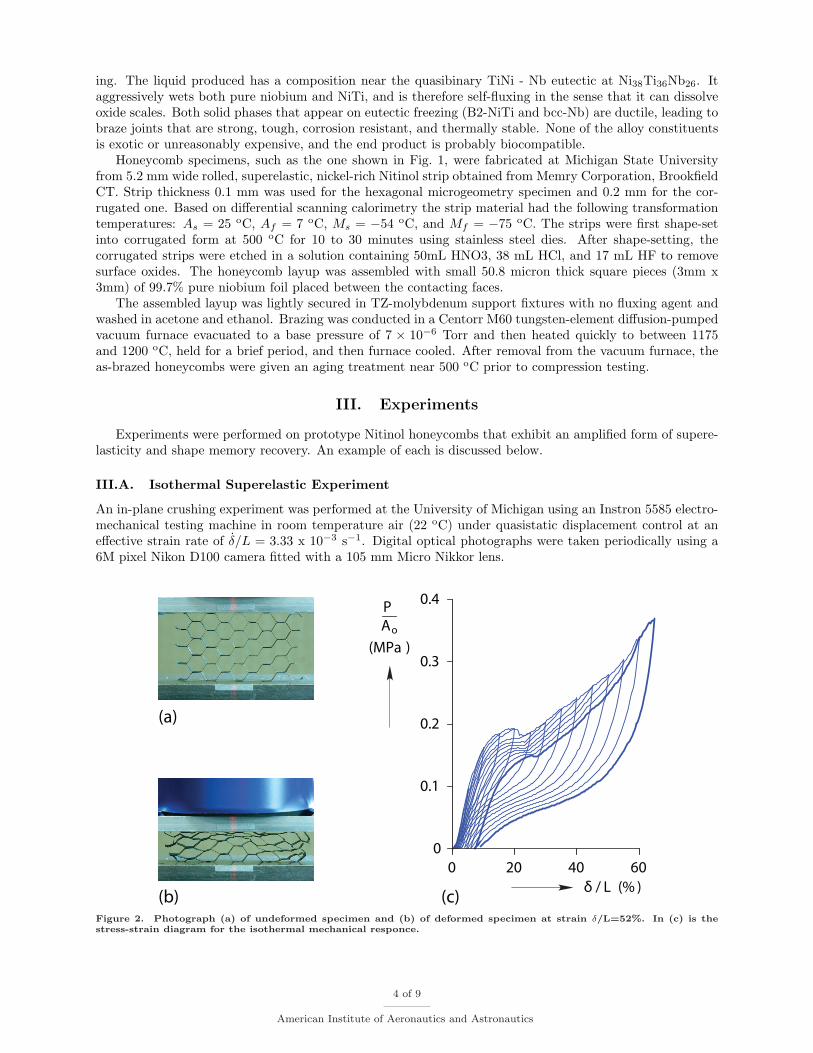
An in-plane crushing experiment was performed at the University of Michigan using an Instron 5585 electro-mechanical testing machine in room temperature air (22 oC) under quasistatic displacement control at aneffective strain rate of δ/L = 3.33 x 10⁻³ s−1. Digital optical photographs were taken periodically using a6M pixel Nikon D100 camera fitted with a 105 mm Micro Nikkor lens.
0
0 20 40 60
0.1
0.2
0.3
0.4
δ / L (% )
P
Ao
(MPa )
(a)
(c)(b)
Figure 2. Photograph (a) of undeformed specimen and (b) of deformed specimen at strain δ/L=52%. In (c) is thestress-strain diagram for the isothermal mechanical responce.
4 of 9
American Institute of Aeronautics and Astronautics

Figure 2a shows an image of a Nitinol honeycomb specimen (4-1/2 cells high by about 7 cells wide)at the start of the experiment, and Fig. 2b shows a deformed configuration. In the same figures we alsoshow the initial vertical length (L) between compression platens and the downward displacement (δ) of theupper platen. The silver strips seen on the front of the platens are reflective tags used with an EIR modelLE-05 laser extensometer to accurately measure platen displacement and to serve as a cross-check on thestrain measurement derived from the crosshead displacement. The mechanical response shown in Fig. 2c isreported as the compressive load (P ) divided by the projected cross-sectional area, Ao, (the total footprintarea, including the area of the incomplete cells at the edges) perpendicular to the loading direction, to give amacroscopic measure of compressive stress. An incremental strain history with load-unload cycles in 5% stepswere imposed to probe the effective superelastic strain recovery properties and residual strain. A limit loadis seen in the response on the fifth cycle, near 22% strain, when a local band of highly deformed cells formed,yet the honeycomb recovers to a nearly uniform configuration upon unloading. The final load-unload cycle,taken to 65% compressive strain, is shown by the bold line in the figure. Although the closure of the loop isnot perfect (leaving about 1.3% relative unrecovered strain), it clearly shows a wide hysteresis and nonlinearbehavior typical of a superelastic material undergoing bending deformation. The absolute residual strainwas < 10% demonstrating a strain recovery of over 55%. Subsequent cycles (not shown) show shakedown toa relatively stable hysteresis loop. Other similar superelastic experiments on corrugated Nitinol structuresare reported in 8.
III.B. Shape Memory Experiment
A second experiment was performed on a wavy-corrugated honeycomb specimen as shown in Fig. 3a todemonstrate shape memory behavior. The ligament thickness in this case was t = 0.2 mm (twice as thickas before), yet the initial radius curvature, 1/d, was similar to the average 1/d of the previous hexagonalhoneycomb. Figure 3b shows the stress-strain-temperature measurements conducted in an oil-chilled bath.First, the specimen was heated to 40 oC to ensure the specimen started in the austenite phase, and thenit was then cooled (magenta line) nearly stress-free to about -20 oC, resulting in only a small change ofabout 2% compressive strain. We suspect this small strain was due to either the crystallographic texturein the original strip material or some small residual stresses that resulting from the fabrication process.The temperature was then held at -20 oC, and a load-unload displacement cycle was performed (blue line).The maximum compressive strain was about 37% during loading, and the residual strain upon unloading
5
T (°C)
δ / L ( %)
0 10 20 30 40-2
0
25
50
0
0.5
1
1.5P
Ao
(MPa )
0
(a) (b)
Figure 3. Results of shape memory experiment on a corrugated Nitinol honeycomb: (a) initial photograph of thespecimen before the experiment, (b) thermomechanical response showing the shape memory effect with stress-freecooling (magenta line), isothermal load-unload (blue), then stress-free heating (magenta). A subsequent superelasticresponse is also shown (black line) for reference.
5 of 9
American Institute of Aeronautics and Astronautics

was about 17%, showing significant spring back even during the martensite response. Next, the load wasremoved and the bath was heated to 40 oC, and the strain was recovered to within 1% of the originalconfiguration. This demonstrates a significantly larger strain recovery than can be obtained with monolithicNitinol. Although not done here, we expect to recover even larger strains by loading further during themartensitic (cold) loading segment. A superelastic load-unload cycle was then performed at 40 oC. Notethat the effective stress levels are accordingly higher than the results of the previous hexagonal honeycombdue to the two-fold larger t/d ratio and the different cell topology.
IV. Modelling & Simulation of Isothermal Experiment
Simulations have been done for the case of isothermal experiments on the 4-1/2 x 7 cell with hexagonalgeometry shown in Fig. 2a, using small-strain, finite displacement and rotation nonlinear beam kinematicsfor the ligaments. Although a detailed presentation of the corresponding theory is given in Ref. 9, a briefdescription of the model is given here for completeness.
Adopting the classic Bernulli-Navier-Euler hypothesis for the kinematics of the beam (planarity of de-formed sections perpendicular to centroidal axis and their normality to the deformed centroidal axis) theaxial strain ε(x, z) at a point with initial coordinates (x, z) in the local frame of each beam is taken to be(see Fig. 4)
ε = e + zκ (1)
Here e is the axial strain of the beam’s centroidal axis
e = λ− 1 λ = [(1 + v,x)2 + (w,x)2]1/2 (2)
where λ is the stretch ratio of the beam’s centroidal axis expressed in terms of the x and z displacementsv(x) and w(x) of a point on this axis initially at x. The bending strain κ is given in terms of the samedisplacements by
κ = [(1 + v,x)w,xx − w,xv,xx]/λ2 (3)
The work-conjugate quantities associated to the axial (e) and bending (κ) strains are the axial force (N)and bending moment (M) given by
N =∫ t
2
− t2
σ dz M =∫ t
2
− t2
σ z dz (4)
where t is the beam thickness.The variational form use to obtain the displacement field for each ligament is (in view of absence of
distributed external loads) ∫ L
0
(N δe + M δκ) dx = 0 (5)
tx
z
u(x)
v(x)
w(x)A
B
BA
Figure 4. Undeformed and deformed configuration for beam element of thickness t.
6 of 9
American Institute of Aeronautics and Astronautics

It should be pointed out here that the particular choice, made in Eq. (2) and (3) for the kinematics ofthe beam leads to a consistent theory, i.e. the Euler-Lagrange equations derived from Eq. (5) coincide withthe exact equilibrium equations of the beam in the current configuration. These latter set of equations canbe obtained directly from equilibrium considerations of a beam segment with no distributed load.
The last element required to complete the description of the behavior of the cell walls is the constitutivelaw for the cell wall material. To this end the constitutive equation for the tensile region σ > 0 for the stress(σ(x, z)) - strain (ε(x, z)) response at a material point with reference coordinates (x, z) in each ligament isgiven by
σ = E(e− β ξ) (6)
where 0 ≤ ξ ≤ 1 is the hysteretic model’s internal variable and β a material parameter. The material’sincremental response is given by the rate form Eq. (6) where in the elastic range
σu(ξ) < σ < σl(ξ) ξ = 0 (7)
while for stress states on the upper σu(ξ) or lower σl(ξ) yield surfaces
σu(ξ) = σ ξ =
E − Et
βε ε > 0 loading
0 ε < 0 unloading
σl(ξ) = σ ξ =
E − Et
βε ε < 0 loading
0 ε > 0 unloading(8)
A schematic representation of the various parameters of this hysteretic model is given in Fig. 5. By pre-scribing E,Et,β,ε1u and ε2l the tensile behavior of the model is fully determined. An analogous constructionis also adopted for the compressive region σ > 0 of the SMA’s response. Notice that there is no need to havetension/compression symmetry for the material response of the cell walls, a feature adopted in our numericalsimulations to better match the calculations with experimental results.
-0.02 0 0.02 0.04
-1
-0.5
0
0.5
d2t
L
P
(b)
δ
(c)
stress
(GPa)
strain
(a)
E
E t
ε 1u ε 2lβ
slope
t
ξ=const.
σ (ξ)u
σ (ξ)l
Figure 5. Modelling of isothermal experiment: (a) Hysteretic stress - strain law used in numerical calculations, (b)Idealized perfect geometry with definition of parameters, (c) Imperfect geometry (created from a digitized picture ofthe actual specimen) .
7 of 9
American Institute of Aeronautics and Astronautics

0.05 0.15 0.25 0.35
0
0.05
0.10
0.15
0.20
1
2
3
1
2
3
δ / L (%)
P
Ao
(MPa)
Figure 6. Results from numerical calculations: Response of finite element model for various loadings-unloadings to10%,20%,30% and 35%, superimposed on the data from the actual experiment, and on the right configurations of modelfor the specific points depicted in the response curve.
An incremental Newton-Raphson method is adopted for the numerical calculations reported here whereeach beam ligament is discretized in 10 elements in the x-direction with 4 d.o.f per node (v, v,x, w, w,x) andHermitian cubic interpolation for v(x) and w(x). A 4 point Gauss integration is used in each elements andat each integration station 51 equidistant z points are used for the required thickness integrations. For eachmaterial point (x, z) used in the calculations it’s internal variable ξ is also stored.
The accuracy of the code has been verified by analytical calculations on single ligaments and by comparingresults in the loading regime of the honeycomb’s response with previous calculations reported in Ref. 9.
The results of our calculations are shown in Fig. 6. Prior to their discussion and comparison withthe experiments, two points should be made. The first concerns the selection of the ligament’s constitutiveresponse which is depicted in Fig. 5a. The numerical values for E, Et, ε1u, ε2l, β for the tensile and compressiveregimes have been selected so as to provide a reasonable match between theory and experiment as depictedin Fig. 6. The second point is that the imperfect geometry of the specimen has been accurately representedin our calculations by taking into account the actual shape of each ligament.
Notice from the comparison between theory and experiment Fig. 6 that the macroscopic stress-strainresponse of the specimen is followed reasonably well for the loading phase. Moreover our simulation capturesthe transition of a relatively uniform strain (Fig. 6-1 at δ/L = 10%) to a highly nonuniform deformation mode(Fig. 6-2 at δ/L = 35%). Observe that the large macroscopic strain mode is similar to the experimentallyobserved mode in Fig. 2b and captures the trend of strain distribution in vertical direction (although theexperimental result depicted is for a larger macroscopic strain δ/L = 52%). Upon unloading the more-or-lessuniform deformation pattern is observed again in Fig. 6-3 which is similar to Fig. 6-1.
There is a rather important discrepancy between the numerically calculated and experimentally observedunloading paths, which can be explained by the presence of friction at the boundaries, a feature thatis presently under investigation. On the overall the simulations show a reasonably good agreement withexperiments.
V. Conclusions
It is shown for the first time that built-up honeycomb structures with < 5% relative density, fabricatedfrom conventional wrought Nitinol material, exhibit an amplified form of superelasticity and shape memory
8 of 9
American Institute of Aeronautics and Astronautics

when subjected to in-plane compressive loading. Long-standing difficulties with bonding Nitinol to itselfwere resolved with a newly developed brazing technique using niobium. We expect that a ten-fold improve-ment in thermal response rate can also be shown in the future due to the favorable scaling of materialsurface area/volume ratio. The findings so far have broad potential implications for lightweight armor,general energy absorption materials, compliance-matched biomedical implants, high-displacement actuators,and smart/adaptive structures. The design opportunities and thermo-mechanical behavior of light-weightcellular Nitinol structures are relatively unexplored, and there exist many interesting scientific questionsand engineering challenges that will be pursued. Furthermore, now that Nitinol can be realized as open-cell,layered structures by simply building them up from off-the-shelf wrought SMA sheets, strips, tubes, or wires,such materials could be economically attractive.
Acknowledgments
J. Shaw and C. Churchill acknowledge the financial support of the Office of Naval Research (ONR younginvestigator grant, N00014-01-1-0581), the National Science Foundation (CAREER grant, CMS-9984189,grant CMS-0409172, and grant CMS-0409084), and the General Motors/University of Michigan Collabora-tive Research Laboratory for Smart Materials and Structures with sincere thanks. N. Triantafyllidis andP. Michailidis acknowledge support of National Science Foundation (grant CMS-0409084). D. Grummon andJ. Foltz acknowledge the support of the Materials and Processes Laboratory at General Motors Researchand Development.
References
1Gibson, L. J. and Ashby, M. F., Cellular Solids: Structure and Properties, Cambridge Solid State Series, CambridgeUniversity Press, Cambridge, UK, 2nd ed., 1997.
2Ashby, M., Evans, A., Fleck, N., Gibson, L., Hutchinson, J., and Wadley, H., Metals Foams: A Design Guide, Butterworth–Heinemann, Boston, MA, 1st ed., 2000.
3Lagoudas, D., Entchev, P., Vandygriff, E., Qidwai, M., and DeGiorgi, V., “Modeling of Thermomechanical Response ofPorous Shape Memory Alloys,” Proceedings of the Adaptive Structures and Material Systems Symposium, ASME InternationalMechanical Engineering Congress and Exposition, 2001.
4Shaw, J. A. and Kyriakides, S., “Thermomechanical Aspects of NiTi,” Journal of the Mechanics and Physics of Solids,Vol. 43, No. 8, 1995, pp. 1243–1281.
5Shaw, J. A. and Kyriakides, S., “On the Nucleation and Propagation of Phase Transformation Fronts in a NiTi Alloy,”Acta Materialia, Vol. 45, No. 2, 1997, pp. 683–700.
6Iadicola, M. A. and Shaw, J. A., “Rate and Thermal Sensitivities of Unstable Transformation Behavior in a Shape MemoryAlloy,” International Journal of Plasticity, Vol. 20, 2004, pp. 577–605.
7Papka, S. and Kyriakides, S., “In–plane Compressive Response of Crushing of Honeycomb,” Journal of the Mechanicsand Physics of Solids, Vol. 42, 1994, pp. 1499–532.
8Shaw, J. A., Grummon, D. S., and Foltz, J., “Superelastic NiTi Honeycombs: Fabrication and Experiments,” SmartMaterials and Structures, Vol. (to appear), 2006.
9Triantafyllidis, N. and Schraad, M., “Onset of Failure in Aluminum Honeycombs Under Arbitrary In-Plane Loading,”Journal of the Mechanics and Physics of Solids, Vol. 46, 1998, pp. 1089–1124.
9 of 9
American Institute of Aeronautics and Astronautics