sgp / space geodesy project · 2016-08-07 · the shelter provides the other subsystems with power,...
TRANSCRIPT
SGP / SPACE GEODESY PROJECT
Space Geodesy Satellite Laser Ranging System Requirements
Document Public Version
Jan McGarry Levels 3 & 4 08/07/2016

4. Subsystems
4.1. Telescope and Gimbal Subsystem
The telescope is designed as a monostatic system to both transmit laser energy and receive
light from targeted objects through common optics and a common optical path. The gimbal
drives the telescope to track Earth orbiting satellites, stars and fixed ground targets. This
subsystem includes the telescope and Coudé path through the tracking subsystem, two
cameras mounted on the telescope (one low light camera for viewing dim targets and one wide
field of view camera for visual tracking), and all associated environmental monitoring and
control devices such as temperature sensors, accelerometers, etc. It also includes the gimbal,
encoders, servo electronics, and additional hardware/software to monitor/maintain
environmental limits. The gimbal portion of the telescope and gimbal subsystem is attached to
a riser which is mounted on a concrete pier and maintains vibrational isolation from other
components of the shelter and dome to minimize disturbances to the gimbal pointing and
tracking. This subsystem has components in both the dome and the shelter.
4.2. Optical Bench
The optical bench (OB) subsystem is designed to allow the laser subsystem, receiver subsystem,
and star camera to reside in an environmentally controlled environment, while supporting laser
divergence changes for different satellites, point‐ahead of the laser beam for satellites, beam
blocking and beam attenuation for laser safety, system configuration changes for the various
modes (star calibration, ground target ranging and satellite tracking), and reduction in the
background light that the detector is exposed to (ND wheel, spatial and spectral filters). Laser
light is directed along a path on the optical bench that is aligned to the telescope optical axis.
The transmitted light goes from the laser to the pit mirror (which is part of the OB subsystem),
along the Coudé path, and eventually out through the telescope. Receive light captured by the
telescope is directed to the receive path on the optical bench which is also aligned to the
telescope optical axis. Finally, this subsystem includes diagnostic components to monitor the
laser characteristics and to support alignment. The star camera is part of the optical bench
subsystem. The optical bench is contained within the shelter.
4.3. Range Receiver
The range receiver subsystem consists of the detector and associated electronics to detect and
measure the start and stop event times, support the software’s determination of the signal
from the background noise and the range to the target, and provide angular offset information
to allow for closed loop tracking. The range receiver subsystem also includes the RCE (Range
Control Electronics) which provides the software with control of the laser fire frequency,
provides the software range gate control for the detector during satellite tracking, and provides
fixed ground target range gate control. In addition the range receiver subsystem includes a
wide field of view low light Acquisition Camera for use in acquiring targets with poor
predictions. Part of this subsystem sits on the optical bench, the rest is in the electronics rack.
All are contained within the shelter.

4.4. Laser Subsystem
The laser subsystem consists of the laser, associated control electronics, a chiller to maintain
the laser’s internal temperature and additional hardware/software to monitor/maintain
environmental variables and control power output of the laser. The laser subsystem is
contained within the shelter with the laser itself on the optical bench, the associated
electronics in the electronics racks, and the chiller rack mounted in the optical bench area.
4.5. Laser Safety Subsystem
The laser safety subsystem is designed to meet all NASA, ANSI, FAA, and local safety standards
for outdoor laser use as well as to protect SGSLR and other ground personnel. It includes an
instrument for aircraft detection which is co‐aligned with the laser beam, support electronics,
beam blocks and ND filters for eye‐safety external to the system, and sensors to inhibit the
laser should a subsystem fault occur or should someone access an area in the system where the
laser light can cause damage, such as the roof of the shelter or the dome. The aircraft
detection components reside on their own stand outside of the shelter, the beam blocks and
ND filters are on the optical bench, and the support electronics and computer interface are in
the electronics racks. Some of the sensors are outside of the shelter and some (such as the
door to the optical bench room) are inside the shelter.
4.6. Time and Frequency
The Time and Frequency subsystem generates and regulates the various timing signals used by
other subsystems as well as the time of day used by the software. It acquires a GPS time and
ensures that the timing signal remains stable, and outputs the 1 PPS from an oscillator
disciplined by GPS and the 10 MHz signal that is synchronized to that 1 PPS. The system also
includes a monitoring subsystem that uses a secondary GPS timing source to compare the GPS
1 PPS outputs and provide the data to the computer subsystem to assess the accuracy of the
Timing and Frequency subsystem. Most of this system is contained within the shelter. The GPS
antenna(s) are mounted outside of the shelter.
4.7. Meteorological
The Meteorological subsystem is designed to measure outside environmental conditions to
provide information for precise ranging and health and safety of the system. This subsystem
consists of a variety of measurement devices all located roughly together outside the shelter
and dome. The most important of these measurements for ranging accuracy are the
barometric pressure, temperature, and humidity. The system also includes stands and
associated hardware for the system.
4.8. Dome, Shelter, and Pier/Riser
This subsystem includes the components which enclose, protect and support the SLR operation.
They are divided into three major components, the dome, the shelter and the pier with the
riser. These are primarily the structure, but may also contain additional components as
described below.
4.8.1. Dome
The dome is designed to contain and protect the telescope and the gimbal (part of the tracking
subsystem) and associated hardware while allowing transmission and reception of light while
operating. This component includes the dome structure with an opening, the shutter over the
opening, motors to open the shutter, motors to rotate the dome with the telescope, a structure
to allow the rotation, and any additional hardware needed to measure/maintain the
environment within the dome.
4.8.2. Shelter
The shelter is designed to contain and protect the optical bench, laser and all the electronics, as
well as provide work space for support personnel. In addition to the structure, it includes HVAC,
humidity control, lighting and all necessary additional hardware for monitoring the interior
environment. The shelter provides the other subsystems with power, UPS, and surge protection,
including protection from lightning. It also provides a pass‐through for internet and
telecommunications.
4.8.3. Pier and Riser
The pier provides physical support for the telescope and gimbal and vibrational isolation from
the shelter. The riser is designed to mate the tracking subsystem to the pier.
4.9. Computer and Software
The computer and software subsystem contains all the computers and the software to control,
calibrate, and maintain the system as a whole, and to communicate with the control center.
The software is designed to support local, remote, and fully automated operations. This
subsystem links all other subsystems together, transfers and stores data, processes the ranging
data, and communicates with the IGSOC. It is contained within the shelter.
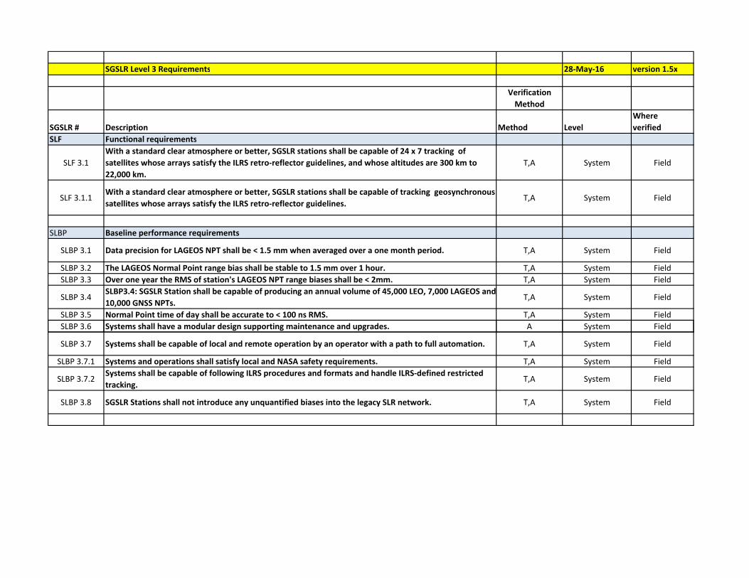
SGSLR Level 3 Requirements 28‐May‐16 version 1.5x
Verification
Method
SGSLR # Description Method Level
Where
verified
SLF Functional requirements
SLF 3.1
With a standard clear atmosphere or better, SGSLR stations shall be capable of 24 x 7 tracking of
satellites whose arrays satisfy the ILRS retro‐reflector guidelines, and whose altitudes are 300 km to
22,000 km.
T,A System Field
SLF 3.1.1With a standard clear atmosphere or better, SGSLR stations shall be capable of tracking geosynchronous
satellites whose arrays satisfy the ILRS retro‐reflector guidelines.T,A System Field
SLBP Baseline performance requirements
SLBP 3.1 Data precision for LAGEOS NPT shall be < 1.5 mm when averaged over a one month period. T,A System Field
SLBP 3.2 The LAGEOS Normal Point range bias shall be stable to 1.5 mm over 1 hour. T,A System Field
SLBP 3.3 Over one year the RMS of station's LAGEOS NPT range biases shall be < 2mm. T,A System Field
SLBP 3.4SLBP3.4: SGSLR Station shall be capable of producing an annual volume of 45,000 LEO, 7,000 LAGEOS and
10,000 GNSS NPTs.T,A System Field
SLBP 3.5 Normal Point time of day shall be accurate to < 100 ns RMS. T,A System Field
SLBP 3.6 Systems shall have a modular design supporting maintenance and upgrades. A System Field
SLBP 3.7 Systems shall be capable of local and remote operation by an operator with a path to full automation. T,A System Field
SLBP 3.7.1 Systems and operations shall satisfy local and NASA safety requirements. T,A System Field
SLBP 3.7.2Systems shall be capable of following ILRS procedures and formats and handle ILRS‐defined restricted
tracking.T,A System Field
SLBP 3.8 SGSLR Stations shall not introduce any unquantified biases into the legacy SLR network. T,A System Field

Controlled by: Jan McGarry SGSLR Level 4 Requirements Developed by Mark Shappirio
7‐Aug‐16
Version 2.0
SGSLR # Parent Description Rationale for requirement
4.1 Telescope and Gimbal (GTA)
4.1.1 Telescope
4.1.1.1SLF 3.1
SLF 3.1.1
The telescope subsystem shall be designed to transmit
from the optical bench subsystem and return receive light
from the satellite to the optical bench subsystem
Overall description of subsystem purpose
4.1.1.2 SLBP 3.4The telescope shall be capable of operation within
‐40oC to +50oC and wind speeds up to 18 m/s.
Telescope must be able to operate without issue in a wide
range of environments.
4.1.1.3SLBP 3.7
SLBP 3.4
The telescope shall be capable of survival at temperatures
ranging from ‐50oC to +55oC.
The telescope must be robust enough to maintain stability
of the optical components.
4.1.1.4SLBP 3.4
SLBP 3.6
The telescope optical paths shall be sealed against dust
and contamination.
A sealed telescope will keep the optical components clean
longer, and require less maintenance.
4.1.1.5SLP3.7
SLBP 3.7.1
The telescope shall support the mounting of system
support equipment.
The telescope must be robust enough to hold additional
payloads while maintaining stability of the optical
components.
4.1.1.6SLBP 3.4
SLBP 3.6
The telescope optical elements shall be designed to meet
MIL‐SPEC‐C‐675 sections 3.8.2, 3.8.3, and 3.8.4.1
Reduced downtime results in reduced operational costs,
increased data volume and longer telescope life.
4.1.1.7SLBP 3.4
SLBP 3.7The telescope shall be capable of maintaining alignment.
Reduced downtime results in reduced operational costs,
increased data volume and longer telescope life.
4.1.1.8SLF 3.1
SLF 3.1.1
The rotation caused by the optical Coude path with
respect to gimbal angular space shall be defined by a fixed
model.
Coude path rotation must be known to convert angular
measurements on the optical bench to the gimbal's angular
space.
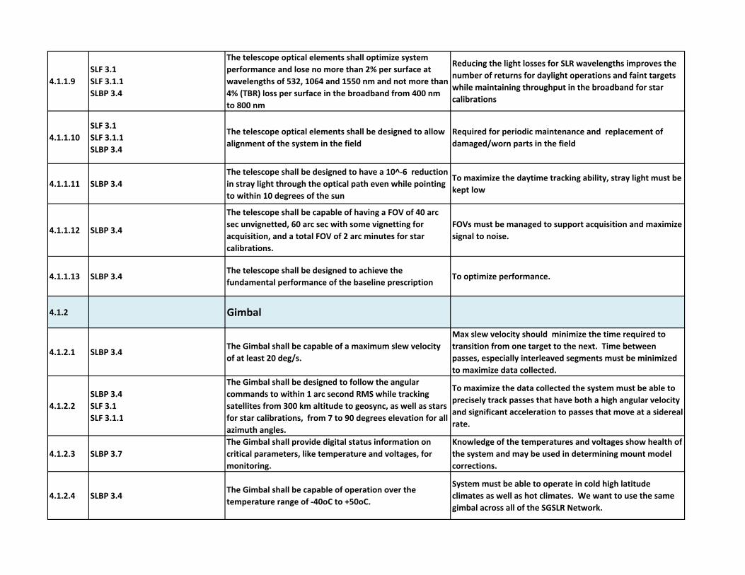
4.1.1.9
SLF 3.1
SLF 3.1.1
SLBP 3.4
The telescope optical elements shall optimize system
performance and lose no more than 2% per surface at
wavelengths of 532, 1064 and 1550 nm and not more than
4% (TBR) loss per surface in the broadband from 400 nm
to 800 nm
Reducing the light losses for SLR wavelengths improves the
number of returns for daylight operations and faint targets
while maintaining throughput in the broadband for star
calibrations
4.1.1.10
SLF 3.1
SLF 3.1.1
SLBP 3.4
The telescope optical elements shall be designed to allow
alignment of the system in the field
Required for periodic maintenance and replacement of
damaged/worn parts in the field
4.1.1.11 SLBP 3.4
The telescope shall be designed to have a 10^‐6 reduction
in stray light through the optical path even while pointing
to within 10 degrees of the sun
To maximize the daytime tracking ability, stray light must be
kept low
4.1.1.12 SLBP 3.4
The telescope shall be capable of having a FOV of 40 arc
sec unvignetted, 60 arc sec with some vignetting for
acquisition, and a total FOV of 2 arc minutes for star
calibrations.
FOVs must be managed to support acquisition and maximize
signal to noise.
4.1.1.13 SLBP 3.4The telescope shall be designed to achieve the
fundamental performance of the baseline prescriptionTo optimize performance.
4.1.2 Gimbal
4.1.2.1 SLBP 3.4The Gimbal shall be capable of a maximum slew velocity
of at least 20 deg/s.
Max slew velocity should minimize the time required to
transition from one target to the next. Time between
passes, especially interleaved segments must be minimized
to maximize data collected.
4.1.2.2
SLBP 3.4
SLF 3.1
SLF 3.1.1
The Gimbal shall be designed to follow the angular
commands to within 1 arc second RMS while tracking
satellites from 300 km altitude to geosync, as well as stars
for star calibrations, from 7 to 90 degrees elevation for all
azimuth angles.
To maximize the data collected the system must be able to
precisely track passes that have both a high angular velocity
and significant acceleration to passes that move at a sidereal
rate.
4.1.2.3 SLBP 3.7
The Gimbal shall provide digital status information on
critical parameters, like temperature and voltages, for
monitoring.
Knowledge of the temperatures and voltages show health of
the system and may be used in determining mount model
corrections.
4.1.2.4 SLBP 3.4The Gimbal shall be capable of operation over the
temperature range of ‐40oC to +50oC.
System must be able to operate in cold high latitude
climates as well as hot climates. We want to use the same
gimbal across all of the SGSLR Network.
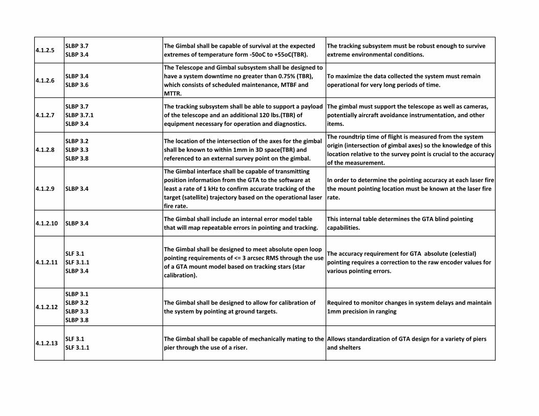
4.1.2.5SLBP 3.7
SLBP 3.4
The Gimbal shall be capable of survival at the expected
extremes of temperature form ‐50oC to +55oC(TBR).
The tracking subsystem must be robust enough to survive
extreme environmental conditions.
4.1.2.6SLBP 3.4
SLBP 3.6
The Telescope and Gimbal subsystem shall be designed to
have a system downtime no greater than 0.75% (TBR),
which consists of scheduled maintenance, MTBF and
MTTR.
To maximize the data collected the system must remain
operational for very long periods of time.
4.1.2.7
SLBP 3.7
SLBP 3.7.1
SLBP 3.4
The tracking subsystem shall be able to support a payload
of the telescope and an additional 120 lbs.(TBR) of
equipment necessary for operation and diagnostics.
The gimbal must support the telescope as well as cameras,
potentially aircraft avoidance instrumentation, and other
items.
4.1.2.8
SLBP 3.2
SLBP 3.3
SLBP 3.8
The location of the intersection of the axes for the gimbal
shall be known to within 1mm in 3D space(TBR) and
referenced to an external survey point on the gimbal.
The roundtrip time of flight is measured from the system
origin (intersection of gimbal axes) so the knowledge of this
location relative to the survey point is crucial to the accuracy
of the measurement.
4.1.2.9 SLBP 3.4
The Gimbal interface shall be capable of transmitting
position information from the GTA to the software at
least a rate of 1 kHz to confirm accurate tracking of the
target (satellite) trajectory based on the operational laser
fire rate.
In order to determine the pointing accuracy at each laser fire
the mount pointing location must be known at the laser fire
rate.
4.1.2.10 SLBP 3.4The Gimbal shall include an internal error model table
that will map repeatable errors in pointing and tracking.
This internal table determines the GTA blind pointing
capabilities.
4.1.2.11
SLF 3.1
SLF 3.1.1
SLBP 3.4
The Gimbal shall be designed to meet absolute open loop
pointing requirements of <= 3 arcsec RMS through the use
of a GTA mount model based on tracking stars (star
calibration).
The accuracy requirement for GTA absolute (celestial)
pointing requires a correction to the raw encoder values for
various pointing errors.
4.1.2.12
SLBP 3.1
SLBP 3.2
SLBP 3.3
SLBP 3.8
The Gimbal shall be designed to allow for calibration of
the system by pointing at ground targets.
Required to monitor changes in system delays and maintain
1mm precision in ranging
4.1.2.13SLF 3.1
SLF 3.1.1
The Gimbal shall be capable of mechanically mating to the
pier through the use of a riser.
Allows standardization of GTA design for a variety of piers
and shelters

4.1.2.14 SLBP 3.6 The Gimbal shall be capable of being reshipped.
To allow for redeployment. In particular one of the GTA
subsystems must be at GGAO in support of the collocations.
It will then need to be redeployed.
4.1.2.15 SLBP 3.7.1The Gimbal shall be designed to meet all of the NASA,
GSFC and local safety standards.required for safety
4.1.2.16 SLBP 3.4
The Tracking subsystem shall be capable of a tracking
azimuth velocity of 0°– 10°/sec with an azimuth
acceleration of 0°‐2°/sec2; a tracking elevation velocity of
0°‐2° deg/sec with an elevation acceleration of 0°‐
0.5°/sec2
To maximize the data collected the system must minimize
any keyhole area and must be able to precisely track passes
that have both a high angular velocity and significant
acceleration as well as passes that move at a sidereal rate.
4.1.2.17 SLBP 3.7
The Tracking Subsystem shall be capable of full control by
the SGSLR system software, and provide all relevant data
to the system software.
Required for remote/automated operations and for
monitoring, decision making, and transfer to IGSOC.
4.1.2.18 SLBP 3.7The Tracking Subsystem shall be designed to support local,
remote, and fully automated operations
Required for remote/automated operations and for
monitoring, decision making, and transfer to IGSOC.
4.2 Optical Bench
4.2.1SLF 3.1
SLF 3.1.1
The optical bench subsystem shall serve as the optical
interface between the laser transmitter, receiver, GTA,
and star camera.
Requirement on the functionality of the optical bench
4.2.2SLBP 3.4
SLBP 3.6
The optical bench subsystem shall be designed to have a
system downtime no greater than 1.65% (TBR), which
consists of scheduled maintenance, MTBF and MTTR.
In order to ensure required data volume the system must
minimize down time.
4.2.3 SLBP 3.7
The optical bench subsystem shall be capable of full
control by the SGSLR system software, and provide all
relevant data to the system software.
Control and knowledge of the settings required for health
and safety of the system and for monitoring, decision
making, support remote and automated operations, and
transferring information.

4.2.4 SLBP 3.7
The optical bench subsystem shall be capable of being
automatically placed into all operational configurations by
the software.
Requirement for remote/autonomous operation of the
system
4.2.5
SLBP 3.4
SLF 3.1
SLF 3.1.1
The components on the optical bench shall be compatible
with all laser output characteristics.
The bench must be able to handle the output characteristics
of the laser including divergence, wavelength and the energy
density from the laser at full power.
4.2.6
SLBP 3.4
SLF 3.1
SLF 3.1.1
The optical bench subsystem design shall optimize system
ranging performance at 532 nm, 1064 nm, and 1550 nm,
and star imaging performance from 400 nm to 800 nm.
Light throughput needs to be optimized to maximize signal.
4.2.7
SLBP 3.1
SLBP 3.2
SLBP 3.3
SLBP 3.4
The optical bench subsystem shall be designed to
minimize backscatter across all operational wavelengths.To maximize signal to noise ratio.
4.2.8SLBP 3.6
SLBP 3.7.1
The optical bench subsystem shall be capable of manual
configuration for testing, troubleshooting, and special
calibrations of the system.
Required for testing and diagnostics with engineer present.
4.2.9
SLF 3.1
SLF 3.1.1
SLBP 3.4
The optical bench subsystem shall be capable of directing
the transmit laser beam along a path angularly different
from the telescope optical axis for point ahead capability.
To increase signal to noise by minimizing laser divergence
and telescope FOV

4.2.10 SLBP 3.7.1
The optical bench subsystem design shall provide space
for the required optical attenuators and beam blocks to
address laser safety.
Required for laser safety.
4.2.11 SLBP 3.4
The optical bench subsystem shall be isolated from
vibrations from the shelter that are greater than the
equivalent to Vibration Criterion Curve A (VC‐A) 50
micrometers/sec RMS (TBR).
The optical bench must be isolated from the shelter and the
system pad to maintain optical stability.
4.2.12
SLBP 3.4
SLF 3.1
SLF 3.1.1
The optical bench subsystem design shall support
alignment to within 1 arc seconds (TBR) of the
transmit, receive, and star camera optical paths to the
telescope optical axis.
To ensure pointing accuracy.
4.2.13SLBP 3.7
SLBP 3.7.1
The optical bench subsystem shall be capable of being
placed into a "safe mode" in the event of an unexpected
power failure.
Required for safety of the equipment.
4.2.14
SLBP 3.1
SLBP 3.2
SLBP 3.3SLBP 3.6
SLF 3.1
SLF 3.1.1
The optical bench subsystem design shall include sufficient
space for the laser head of the laser subsystem.To accommodate the laser on the optical bench.
4.2.15
SLBP 3.1
SLBP 3.2
SLBP 3.3
SLBP 3.6
SLF 3.1
SLF 3.1.1
The optical bench subsystem design shall include sufficient
space for the receiver subsystem.To accommodate the receiver on the optical bench.
4.2.16 SLRBP 3.7The optical bench subsystem shall be designed to support
local, remote, and fully automated operations.
Requirement for remote/autonomous operation of the
system
4.2.17
SLBP 3.1
SLBP 3.2
SLBP 3.3
SLBP 3.8
The optical bench subsystem shall be designed and
optimized to support the required range measurement
precision and stability.
To support the system performance requirements.

4.2.18
SLF 3.1
SLF 3.1.1
SLBP 3.4
The optical bench subsystem shall capture usable
nighttime images of stars down to magnitude 6 (TBR).To provide enough stars for mount pointing calibration.
4.2.19
SLF 3.1
SLF 3.1.1
SLBP 3.7
SLBP 3.4
The optical bench subsystem shall be designed to support
the 2 arcmin FOV for star imaging and 60 arcsec FOV for
satellite acquisition.
The FOV must be wide enough to allow for the expected
nominal errors in the system pointing to stars and satellites.
4.2.20 SLBP 3.4The optical bench subsystem shall provide stray light
protection for the detector and all cameras on the bench.
Required for the system performance and safety of the
components.
4.2.21SLBP 3.6
SLBP 3.4
The optical bench shall support local and remote
diagnostic capability.
To allow for trouble‐shooting in the field, either locally or
remotely.
4.3 Range Receiver
4.3.1
SLBP 3.1
SLBP 3.2
SLBP 3.3
SLBP 3.8
The range receiver subsystem shall make all timing
measurements relative to the system base frequency with
< 5 ps (TBR) precision and < 10 ps (TBR) stability over an
hour.
To meet operational performance requirements
4.3.2
SLBP 3.1
SLBP 3.2
SLBP 3.3
SLBP 3.8
The components of the range receiver subsystem shall
each have a known error which collectively do not exceed
the subsystem's ranging error budget.
All errors contributing to system error must be controlled to
maintain overall error budget
4.3.3SLF 3.1
SLF 3.1.1
The range receiver subsystem shall be designed to detect
photons from the laser pulse in the transmit optical path.Functional performance requirement.
4.3.4
SLBP 3.1
SLBP 3.2
SLBP 3.3
The range receiver subsystem shall be designed to detect
single photons from the receive optical path.
To meet science (ITRF) requirements for range
measurements

4.3.5
SLBP 3.1
SLBP 3.2
SLBP 3.3
SLBP 3.8
The range receiver subsystem shall be designed to operate
in three modes: internal calibration, external calibration,
and satellite ranging.
Different time of flight ranges require different gating and
protection for stray light into the detector. Calibrations are
required to meet performance.
4.3.6 SLBP 3.4The range receiver subsystem shall have a system dead
time that is less than 10 ns (TBR).
Measurements cannot be made during detector or timer
dead time. Minimizing this dead time means reduced data
loss which maintains normal point data volumes.
4.3.7 SLBP 3.4
The range receiver subsystem shall be capable of avoiding
> 90% (TBR) of collisions between the transmit and receive
events.
Timing measurements of the return pulses from satellite
cannot be made when the receive events occur around the
same time as the fire.
4.3.8 SLBP 3.4The range receiver subsystem shall be capable of blanking
the detector during laser energy transmission.Needed to protect the detector from scattered laser light
4.3.9
SLBP 3.4
SLBP 3.7
SLF 3.1
SLF 3.1.1
The range receiver shall provide timing and spatial
information from transmit and receive events needed for
closed loop tracking.
The system needs information from the receiver to calculate
the biases needed for closed loop tracking and to form the
science product.
4.3.10
SLBP 3.4
SLF 3.1
SLF 3.1.1
The range receiver subsystem shall be able to correctly
distinguish and accurately process satellite range returns
with (1) background noise rates up to 13 MHz (TBR) with
a return signal rates of between 0.05 and 0.2 pes/fire
(TBR), and (2) background noise rates up to 5 MHz (TBR)
for return signal rates between 0.001 and 0.05 pes/fire
(TBR)
The system must be able to make range measurements with
daylight background noise rates, and with very low return
rates from satellites.
4.3.11
SLBP 3.4
SLF 3.1
SLF 3.1.1
The range receiver system shall be able to survive and
recover from 30 MHz (TBR) background rates.
The design of the detector, receiver optics and electronics
must allow the system to recover from high background
rates.
4.3.12
SLF 3.1
SLF 3.1.1
SLBP 3.1
SLBP 3.2
SLBP 3.4
The range receiver subsystem shall provide gating to the
detector for internal and external calibrations, and
satellite ranging.
The detector must be protected and the background noise
reduced temporally.
4.3.13 SLBP 3.4
SLBP 3.7
The range receiver shall be capable of full control by the
SGSLR system software, and provide all relevant data to
the system software.
To support remote/automated operations and for
monitoring, decision making, and transfer to IGSOC.

4.3.14 SLBP 3.4
SLBP 3.6
The range receiver subsystem shall be designed to have a
system downtime no greater than 1.8% (TBR), which
consists of scheduled maintenance, MTBF and MTTR.
To achieve the data volumes required the system can only
be down for short periods.
4.3.15SLBP 3.7
SLBP 3.7.1
The range receiver subsystem shall be capable of being
placed into a "safe mode" in the event of an unexpected
power failure.
Required for safety of the equipment
4.3.16SLBP 3.7 The receiver subsystem shall be designed to support local,
remote and fully automated operations.
Subsystem must function properly during all modes of
operation.
4.3.17
SLBP 3.7
SLBP 3.4The range receiver subsystem shall provide spatial
information to =< 2 arc second accuracy (TBR).
Subsystem must function properly during automated
operation. Spatial information is needed for closed loop
tracking.
4.3.18
SLBP 3.7
SLBP 3.4
The range receiver subsystem shall provide signal
processing information in the form of a spatial histogram
across the tracking FOV to the system software at 20 Hz
(TBR) rate.
Needed to support automated closed loop tracking for
automated operation. Signal processing by the hardware
allows the software to make faster decisions.
4.4 Laser SUBSYSTEM
4.4.1
SLBP 3.4
SLF 3.1
SLF 3.1.1
The laser subsystem shall generate optical pulses for
ranging with an adjustable power output and repetition
rate for a set wavelength, pulse width and enough energy
to successfully range to the highest required satellites.
To allow for adjustments in output for different
configurations of the telescope from station to station and
to allow for collision avoidance between outgoing and
incoming laser pulses.
4.4.2SLBP 3.4
SLBP 3.6
The laser subsystem shall be designed to have a system
downtime no greater than 2.85% , which consists of
scheduled maintenance, MTBF and MTTR.
To maintain the required annual normal point data volume.
4.4.3 SLBP 3.7
The laser subsystem shall be capable of full control by the
SGSLR system software, and provide all relevant data to
the system software.
Required for remote/automated operations and for
monitoring, decision making, and transfer to IGSOC.
4.4.4SLBP 3.2
SLBP 3.4
The laser output shall be stable over defined periods of
time.
Stability of the laser is needed for millimeter level system
performance.

4.4.5 SLBP 3.4The laser subsystem shall be capable of firing continuously
for one month between scheduled maintenance periods.
Operational parameters will require firing continuously for
hours.
4.4.6 SLBP 3.4
The laser subsystem shall be able to resume firing at
nominal output parameters after defined periods of
interruption.
To maintain the required annual normal point data volume.
4.4.7SLBP 3.7
SLBP 3.7.1
The laser subsystem shall be capable of being placed into
a "safe mode" in the event of an unexpected power
failure.
Required for safety of the equipment.
4.4.8 SLBP 3.7The laser subsystem shall support local, remote, and fully
automated operations.
Required for remote/automated operations and for
monitoring, decision making, and transfer to IGSOC.
4.4.9 SLBP 3.6The laser head of the laser subsystem shall be mountable
on the optical bench subsystem.
Required for modularity and resources impacts and to
maintain the relative stability between the laser, receiver
and other optics.
4.4.10 SLBP 3.4The laser subsystem shall support external firing using
input from the RCE.
Needed to allow PRF changes by the software to avoid
collisions between outgoing and incoming pulses
4.5 Laser Safety SUBSYSTEM
4.5.1 SLBP 3.7.1
The laser safety subsystem shall ensure that no one is
exposed to non eye safe laser light during normal
operations.
NASA and FAA safety regulations and laws.
4.5.2 SLBP 3.7.1
The laser safety subsystem shall ensure that no one is
exposed to non eye safe laser light outside of the laser
operations area and dome during non operational
periods.
NASA and FAA safety regulations and laws.
4.5.3SLBP 3.4
SLBP 3.6
The laser safety subsystem shall be designed to have a
system downtime no greater than 1.5% (TBR), which
consists of scheduled maintenance, MTBF and MTTR.
Reliability is important to meet data volume requirements
and to keep operations costs under control.
4.5.4 SLBP 3.4Outdoor components of the laser safety subsystem shall
be capable of operation within ‐40 deg C and +50 deg C.
The laser safety subsystem must be able to be located in and
operate at sites with wide temperature ranges.

4.5.5SLBP 3.7
SLBP 3.4
Outdoor components of the laser safety subsystem shall
be capable of survival at ‐50 deg C and +55 deg C.
The laser safety subsystem must be able to be located in and
survive in a wide variety of climates.
4.5.6SLBP 3.7 The laser safety subsystem shall be capable of automated
and manual reset. Required for automated/remote operations.
4.5.7 SLBP 3.7.1
The laser safety subsystem shall be capable of detecting
aircraft and ensuring that aircraft are not exposed to laser
light.
NASA and FAA safety regulations and laws.
4.5.8 SLBP 3.7.1
The laser safety subsystem shall not allow transmission of
non eye safe laser radiation below the minimum tracking
elevation angle 10 deg (TBR)
NASA and FAA safety regulations and laws.
4.5.9 SLBP 3.7.1
The laser safety subsystem shall allow for full power
operation, 5 Watts (TBR), of the laser for alignment
purposes without exposing persons outside of the laser
operations area (nominal hazard zone).
Different configurations may be required for various
alignments/testing.
4.5.10SLBP 3.7 The laser safety subsystem shall provide status and
configuration information to the system software.
To support remote and/or automated operations and NASA
safety requirements
4.5.11
SLBP 3.7
SLBP 3.7.1
The laser safety subsystem shall be capable of
commanding by the system software without allowing the
software to override safety settings.
To support remote and/or automated operations and NASA
safety requirements
4.5.12
SLBP 3.4
SLBP 3.7The laser safety subsystem shall be designed to support
local, remote and fully automated operations.To support remote and/or automated operations

4.5.13 SLBP 3.6
Applicable laser safety subsystem components shall be
designed to occupy a minimal footprint on the optical
bench.
Reduce impact on other subsystems
4.5.14SLBP 3.7
SLBP 3.7.1
The laser safety subsystem shall be capable of being
placed into a "safe mode" in the event of an unexpected
power failure.
To support remote and/or automated operations
4.5.15SLBP 3.7.1
SLBP 3.7
The laser safety subsystem shall default to a fail safe
mode in case of a subsystem failure.NASA safety regulations.
4.5.16 SLBP 3.7.1Laser safety system shall be fully compliant with NASA
safety standards.NASA safety regulations.
4.6 Time and Frequency
4.6.1
SLBP 3.1
SLBP 3.2
SLBP 3.3
SLBP 3.5
The time and frequency subsystem shall provide stable
and accurate date/time and frequency signals relative to
GPS.
To maintain the required accuracy of the normal points the
timing subsystem must be stable and accurate
4.6.2SLBP 3.4
SLBP 3.6
The time and frequency subsystem shall be designed to
have a system downtime no greater than 0.3% , which
consists of scheduled maintenance, MTBF and MTTR.
In order to maximize tracking data, the system downtime
must be minimized.
4.6.3
SLF 3.1
SLF 3.1.1
SLBP 3.4
The outdoor components of the time and frequency
subsystem shall be capable of operation from ‐40 deg C to
+50 deg C.
In order to maximize tracking data, the system should be
capable of full operation within the local environmental
conditions.
4.6.4
SLBP 3.7
SLBP 3.4
The outdoor components of the time and frequency
subsystem shall be capable of survival from ‐50 deg C to
+55 deg C.
Survivability ensures that the system will recover from
downtime outside of operational range of environmental
conditions and can reduce the need to replace components.
4.6.5
SLF 3.1
SLF3.1.1
SLBP 3.1
SLBP 3.2
SLBP 3.3
SLBP 3.5
The time and frequency subsystem shall provide the
timing signals (analog and digital) required by the SGSLR
subsystems.
Functional performance requirement. All subsystems must
have a common time & frequency source.

4.6.6 SLBP 3.7
The timing and frequency subsystem shall be capable of
full control by the computer and software subsystem, and
shall provide all relevant data to the computer and
software system.
Required for remote/automated operations and for
monitoring, decision making and transfer to the IGSOC.
4.6.7
SLBP 3.5
SLBP 3.6
SLBP 3.7
The time and frequency subsystem shall be able to accept
external time and frequency sources. Maintain ability to supply timing signals and check that
timing is remaining accurate and for the ability to use
centralized SGP site timing if available.
4.6.8
SLBP 3.1
SLBP 3.2
SLBP 3.3
SLBP 3.4
SLBP 3.5
SLBP 3.7
The time and frequency subsystem shall be capable of self‐
monitoring its frequency and timing pulses by comparison
to an included independent GPS source.
Required to detect frequency and timing anomalies that
would corrupt the accuracy of the normal point data and
report them to the computer and software subsystem.
4.6.9 SLBP 3.7The time and frequency subsystem shall be designed to
support local, remote and fully automated operations.Required for remote/automated operations
4.6.10SLBP 3.7
SLBP 3.7.1
The time and frequency subsystem shall be capable of
being placed into a "safe mode" in the event of an
unexpected power failure.
Required for safety of the equipment
4.6.11
SLBP 3.1
SLBP 3.2
SLBP 3.3
SLBP 3.4
SLBP 3.5
The time and frequency subsystem shall meet its required
performance within a 24 hour period of time from power
on.
In order to maximize tracking data, the system warmup
period must be minimized and predictable.
4.7 Meteorological
4.7.1
SLBP 3.1
SLBP 3.2
SLBP 3.3
SLBP 3.7
SLBP 3.8
The meteorological subsystem shall measure wind speed
and direction (average and gust), atmospheric pressure,
temperature, relative humidity, visibility, precipitation,
and cloud cover.
Meteorological information is necessary for accurate
calibration of satellite ranging and is necessary to support
automated decision making on weather parameters.
4.7.2SLBP 3.4
SLBP 3.6
The Meteorological subsystem shall be designed to have a
system downtime no greater than 0.6%, which consists of
scheduled maintenance, MTBF and MTTR.
In order to support data volume requirements the system
must minimize downtime

4.7.3
SLBP 3.1
SLBP 3.2
SLBP 3.3
SLBP 3.7
SLBP 3.8
The meteorological subsystem shall be capable of
producing consistently accurate data within the
operational range of ‐40 deg C to +50 deg C.
Must be able to support operations in a wide range of
environmental extremes for both the safety of the system
and accurate correction of the ranging measurements.
4.7.4SLBP 3.4
SLBP 3.7
The meteorological subsystem shall be capable of survival
between ‐50 deg C and +55 deg C.
Must be able to support operations and survive in a wide
range of environmental extremes for the protection of the
system.
4.7.5 SLBP 3.7
The meteorological subsystem shall provide
environmental data when requested by the system
software within a 60 s response time for all except
precipitation and wind which require a 10 s response time.
Required to support automated decision making for ranging
and the safety of the system.
4.7.6 SLBP 3.7
The meteorological subsystem shall be capable of full
control by the SGSLR system software, and provide all
relevant data to the system software.
To support remote/automated operations and for
monitoring, decision making, and transfer to IGSOC.
4.7.7 SLBP 3.7The meteorological subsystem shall be designed to
support local, remote, and fully automated operations.
To support remote/automated operations and for
monitoring, decision making, and transfer to IGSOC.
4.7.8SLBP 3.7
SLBP 3.7.1
The meteorological subsystem shall be capable of being
placed into a "safe mode" in the event of an unexpected
power failure.
Required to support remote and automated operations, and
decision making for system safety.
4.8 Dome, Shelter, and Pier4.8.1 Dome
4.8.1.1SLBP 3.4
SLBP 3.7.1
The dome and shutter shall protect the GTA and
associated components from the elements and support
system performance.
Required for safety of system and to support system
performance.
4.8.1.2SLBP 3.4
SLBP 3.6
The dome subsystem shall be designed to have a system
downtime no greater than 2.1% (TBR), which consists of
scheduled maintenance, MTBF and MTTR.
Reduced MTBF to maintain required normal point
production and maintenance costs improve operational
costs to the project.

4.8.1.3
SLBP 3.4
SLBP 3.7
SLF 3.1
SLF3.1.1
The dome subsystem shall be able to support operations
in temperature between ‐40 deg C and +50 deg C, and
wind speed of up to 18 m/s.
The SGSLR Network will be deployed all over the world using
a common architecture. The dome must be able to handle
conditions at the locations it is deployed to.
4.8.1.4SLBP 3.7
SLBP 3.4
The dome subsystem shall be capable of survival at
‐50 deg C to +55 deg C and wind speeds up to 60 m/s.
The SGSLR Network will be deployed all over the world using
a common architecture. The dome must be able to survive
conditions at the locations it is deployed to.
4.8.1.5SLBP 3.4
SLBP 3.7
The dome subsystem shall be designed to mitigate the
effects of condensation.
Condensation may lead to leaking onto the telescope optics
or onto/into the gimbal
4.8.1.6
SLBP 3.4
SLBP 3.7
SLBP 3.7.1
The dome subsystem shall keep precipitation from
entering the interior of the dome with the shutter fully
closed.
To protect the telescope and gimbal from moisture and
particulates
4.8.1.7 SLBP 3.7Environmental conditions inside the dome shall be
available for monitoring by software.
System must have capability for remote monitoring and
later control. Knowledge of environmental conditions
within the dome is key to the identification of potential
system problems before they occur or before they cause
system failure.
4.8.1.8SLBP 3.4
SLBP 3.7
The dome and shutter shall be capable of closed loop
position control by the computer subsystem to an
accuracy of 5 degrees (TBR).
To support remote/automated operations
4.8.1.9 SLBP 3.7
The dome subsystem shall be capable of full control by the
SGSLR system software, and provide all relevant data to
the system software.
Required for remote/automated operations and for
monitoring, decision making, and transfer to IGSOC.
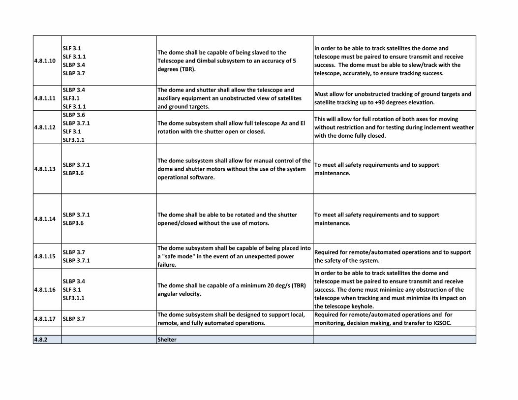
4.8.1.10
SLF 3.1
SLF 3.1.1
SLBP 3.4
SLBP 3.7
The dome shall be capable of being slaved to the
Telescope and Gimbal subsystem to an accuracy of 5
degrees (TBR).
In order to be able to track satellites the dome and
telescope must be paired to ensure transmit and receive
success. The dome must be able to slew/track with the
telescope, accurately, to ensure tracking success.
4.8.1.11
SLBP 3.4
SLF3.1
SLF 3.1.1
The dome and shutter shall allow the telescope and
auxiliary equipment an unobstructed view of satellites
and ground targets.
Must allow for unobstructed tracking of ground targets and
satellite tracking up to +90 degrees elevation.
4.8.1.12
SLBP 3.6
SLBP 3.7.1
SLF 3.1
SLF3.1.1
The dome subsystem shall allow full telescope Az and El
rotation with the shutter open or closed.
This will allow for full rotation of both axes for moving
without restriction and for testing during inclement weather
with the dome fully closed.
4.8.1.13SLBP 3.7.1
SLBP3.6
The dome subsystem shall allow for manual control of the
dome and shutter motors without the use of the system
operational software.
To meet all safety requirements and to support
maintenance.
4.8.1.14SLBP 3.7.1
SLBP3.6
The dome shall be able to be rotated and the shutter
opened/closed without the use of motors.
To meet all safety requirements and to support
maintenance.
4.8.1.15SLBP 3.7
SLBP 3.7.1
The dome subsystem shall be capable of being placed into
a "safe mode" in the event of an unexpected power
failure.
Required for remote/automated operations and to support
the safety of the system.
4.8.1.16
SLBP 3.4
SLF 3.1
SLF3.1.1
The dome shall be capable of a minimum 20 deg/s (TBR)
angular velocity.
In order to be able to track satellites the dome and
telescope must be paired to ensure transmit and receive
success. The dome must minimize any obstruction of the
telescope when tracking and must minimize its impact on
the telescope keyhole.
4.8.1.17 SLBP 3.7The dome subsystem shall be designed to support local,
remote, and fully automated operations.
Required for remote/automated operations and for
monitoring, decision making, and transfer to IGSOC.
4.8.2 Shelter
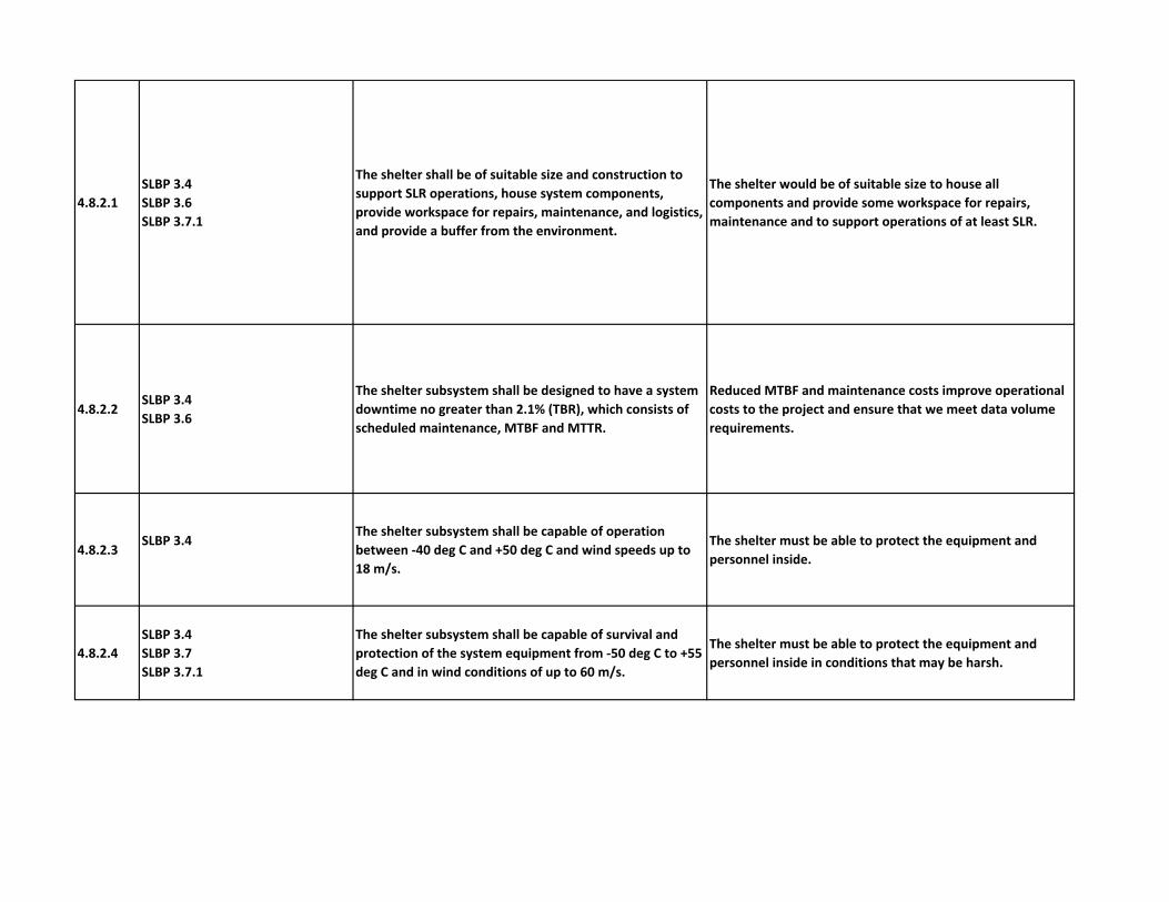
4.8.2.1
SLBP 3.4
SLBP 3.6
SLBP 3.7.1
The shelter shall be of suitable size and construction to
support SLR operations, house system components,
provide workspace for repairs, maintenance, and logistics,
and provide a buffer from the environment.
The shelter would be of suitable size to house all
components and provide some workspace for repairs,
maintenance and to support operations of at least SLR.
4.8.2.2SLBP 3.4
SLBP 3.6
The shelter subsystem shall be designed to have a system
downtime no greater than 2.1% (TBR), which consists of
scheduled maintenance, MTBF and MTTR.
Reduced MTBF and maintenance costs improve operational
costs to the project and ensure that we meet data volume
requirements.
4.8.2.3SLBP 3.4
The shelter subsystem shall be capable of operation
between ‐40 deg C and +50 deg C and wind speeds up to
18 m/s.
The shelter must be able to protect the equipment and
personnel inside.
4.8.2.4
SLBP 3.4
SLBP 3.7
SLBP 3.7.1
The shelter subsystem shall be capable of survival and
protection of the system equipment from ‐50 deg C to +55
deg C and in wind conditions of up to 60 m/s.
The shelter must be able to protect the equipment and
personnel inside in conditions that may be harsh.

4.8.2.5
SLBP 3.4
SLBP 3.7Environmental conditions inside the shelter shall be
capable of being monitored and controlled by software.
System must have capability for remote monitoring and
later control. Knowledge of key voltage, and meteorological
conditions within the shelter is key to the identification of
potential system problems before they occur or before they
cause system failure.
4.8.2.6 SLBP 3.7
The lights, cameras, communications, and power of the
shelter shall be capable of being monitored and controlled
by software.
Required for remote/automated operations and for
monitoring, decision making, and transfer to IGSOC.
4.8.2.7 SLBP 3.7.1
The shelter roof shall be capable of supporting the dome
dead load of 3000 pounds; a
uniform live load of 50 pounds per square feet (psf) (TBR)
or a concentrated live load of 1000
pounds over 12 inch x 12 inch area (TBR)
To ensure operations and maintenance, the shelter must be
able to support the weight of the dome, any equipment, and
personnel on the roof without sagging/breaking/failure.
Failure to support these could result in damage to the
equipment below and or the safety of those within the
shelter
4.8.2.8
SLBP 3.1
SLBP 3.2
SLBP 3.3
SLBP 3.7.1
The shelter shall be partitioned to allow for separate
environmental conditions and safety considerations.
To keep sensitive components/subsystems clean and at a
highly controlled temperature which will support the data
stability and quality.
4.8.2.9
SLBP 3.7
SLBP 3.7.1
SLBP 3.6
SLBP 3.1
SLBP 3.2
SLBP 3.3
The shelter shall be sealed to prevent contamination to
the shelter interior.
To keep sensitive components/subsystems clean and at a
highly controlled temperature which will support the data
stability and quality.
4.8.2.10SLF 3.1
SLF 3.1.1
The shelter floor and roof shall provide openings for the
telescope and telescope support structure.
Functional requirement to allow the telescope to reside on
the roof of the shelter and the pier to go into the ground
through the shelter floor without being vibrationally
attached to floor.
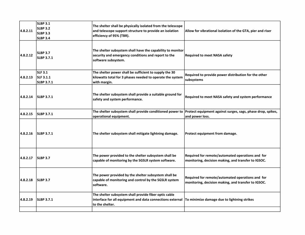
4.8.2.11
SLBP 3.1
SLBP 3.2
SLBP 3.3
SLBP 3.4
The shelter shall be physically isolated from the telescope
and telescope support structure to provide an isolation
efficiency of 95% (TBR).
Allow for vibrational isolation of the GTA, pier and riser
4.8.2.12SLBP 3.7
SLBP 3.7.1
The shelter subsystem shall have the capability to monitor
security and emergency conditions and report to the
software subsystem.
Required to meet NASA safety
4.8.2.13
SLF 3.1
SLF 3.1.1
SLBP 3.7.1
The shelter power shall be sufficient to supply the 30
kilowatts total for 3 phases needed to operate the system
with margin.
Required to provide power distribution for the other
subsystems
4.8.2.14 SLBP 3.7.1The shelter subsystem shall provide a suitable ground for
safety and system performance.Required to meet NASA safety and system performance
4.8.2.15 SLBP 3.7.1The shelter subsystem shall provide conditioned power to
operational equipment.
Protect equipment against surges, sags, phase drop, spikes,
and power loss.
4.8.2.16 SLBP 3.7.1 The shelter subsystem shall mitigate lightning damage. Protect equipment from damage.
4.8.2.17 SLBP 3.7The power provided to the shelter subsystem shall be
capable of monitoring by the SGSLR system software.
Required for remote/automated operations and for
monitoring, decision making, and transfer to IGSOC.
4.8.2.18 SLBP 3.7
The power provided by the shelter subsystem shall be
capable of monitoring and control by the SGSLR system
software.
Required for remote/automated operations and for
monitoring, decision making, and transfer to IGSOC.
4.8.2.19 SLBP 3.7.1
The shelter subsystem shall provide fiber optic cable
interface for all equipment and data connections external
to the shelter.
To minimize damage due to lightning strikes

4.8.3 Pier and Riser
4.8.3.1
SLBP 3.1
SLBP 3.2
SLBP 3.3
SLBP 3.4
SLBP 3.7.1
SLBP 3.8
SLF 3.1
SLF3.1.1
The pier and riser shall be constructed to rigidly support
the GTA while maintaining the optimum performance of
the GTA. Fundamental frequency is greater than or equal
to 80 Hz (TBR).
The pier and riser must be able to support the telescope and
gimbal and maintain stability.
4.8.3.2 SLF 3.1
SLF 3.1.1
The pier and riser shall be constructed to support the
Coude path to the optical bench.Light needs to get to the optical bench from the telescope.
4.8.3.3
SLBP 3.1
SLBP 3.2
SLBP 3.3
SLBP 3.4
SLBP 3.8
SLF 3.1
SLF 3.1.1
The pier shall have > 95% (TBR) vibration isolation
efficiency from the shelter and its pad.
The telescope and gimbal must be vibrationally isolated
from the shelter and the system pad to maintain optical
stability.
4.8.3.4SLF 3.1
SLF 3.1.1
The riser shall be designed to include a leveling
mechanism for the GTA with a +/‐ 2 arc seconds accuracy.To allow the GTA azimuth rotation to match horizontal.
4.9 Computer and Software
4.9.1 SLBP 3.7
The computer and software subsystem shall be designed
to support (a) local operations, (b) remote operations, and
(c) fully automatic operations with no human present on
site but with remote monitoring of the system.
Future SGP budgets will require much lower operating costs
than now. To do this will require more automation,
however, an operator must always be able to take control of
the system.
4.9.2 SLBP 3.7
Remote Access Terminal (RAT) shall include a user
interface to allow both local and remote access to the
data generated by the system.
RAT is the human interface to the system both for control
and for system monitoring. This should be possible for
operators at the station as well as across the world.
RAT Operations

4.9.3 SLBP 3.7
RAT shall maintain a display of critical subsystem and
operational parameters accessible to both local and
remote users.
The operator needs to have easy access to viewing critical
parameters when operating the system.
4.9.4 SLBP 3.7
Remote Access Terminal (RAT) client and server software
shall be able to manage at least two (TBR) internet
connections.
Multiple RAT GUIs need to be able to connect to the system
for viewing, although only one can have control at a time. A
single laptop in the IGSOC will need to control multiple
SGSLR stations at the same time.
4.9.5SLBP 3.7
SLBP 3.7.1
Remote Access Terminal (RAT) software shall allow
remote and local control of operations and of operating
parameters such that there is no effect on the health and
safety of the system or surrounding environment (e.g.,
aircraft avoidance).
The system health and safety, including all human and
equipment safety inside and outside of the shelter, must be
maintained during all modes of operations. The software
will not override any hardware safety function.
4.9.6 SLBP 3.4
Any computers requiring deterministic timing shall have a
real‐time operating system with a known latency that is <
100 microseconds.
Because of hard real‐time hardware interfaces the OS must
be deterministic.
4.9.7SLBP 3.4
SLBP 3.6
The computers selected shall have backplanes that can
support the types of interfaces (serial, USB, Ethernet,
parallel) and number of cards required for the SGSLR
subsystems.
Subsystem must be able to interface to all of the SGSLR
hardware.
4.9.8 SLBP 3.4
The computer subsystem shall have > 4 GB (TBR) memory,
> 2 GHz (TBR) CPU, and > 500 GB (TBR) drive space
capacity.
Subsystem must be sized to handle the tracking, data
processing, and data volume.
4.9.9SLBP 3.4
SLBP 3.6
The computer subsystem shall be designed to keep down
time to less than 2.55% (TBR) on average over a year.
Data collection must be maximized. Down time includes
scheduled maintenance, MTBF, MTTR and required reboot.
4.9.10SLBP 3.7
SLBP 3.4
The software shall be capable of running successfully in an
independent operational state for > 7 days (TBR) .
System will eventually be fully automated and must operate
for days with no human intervention.
Computer Hardware
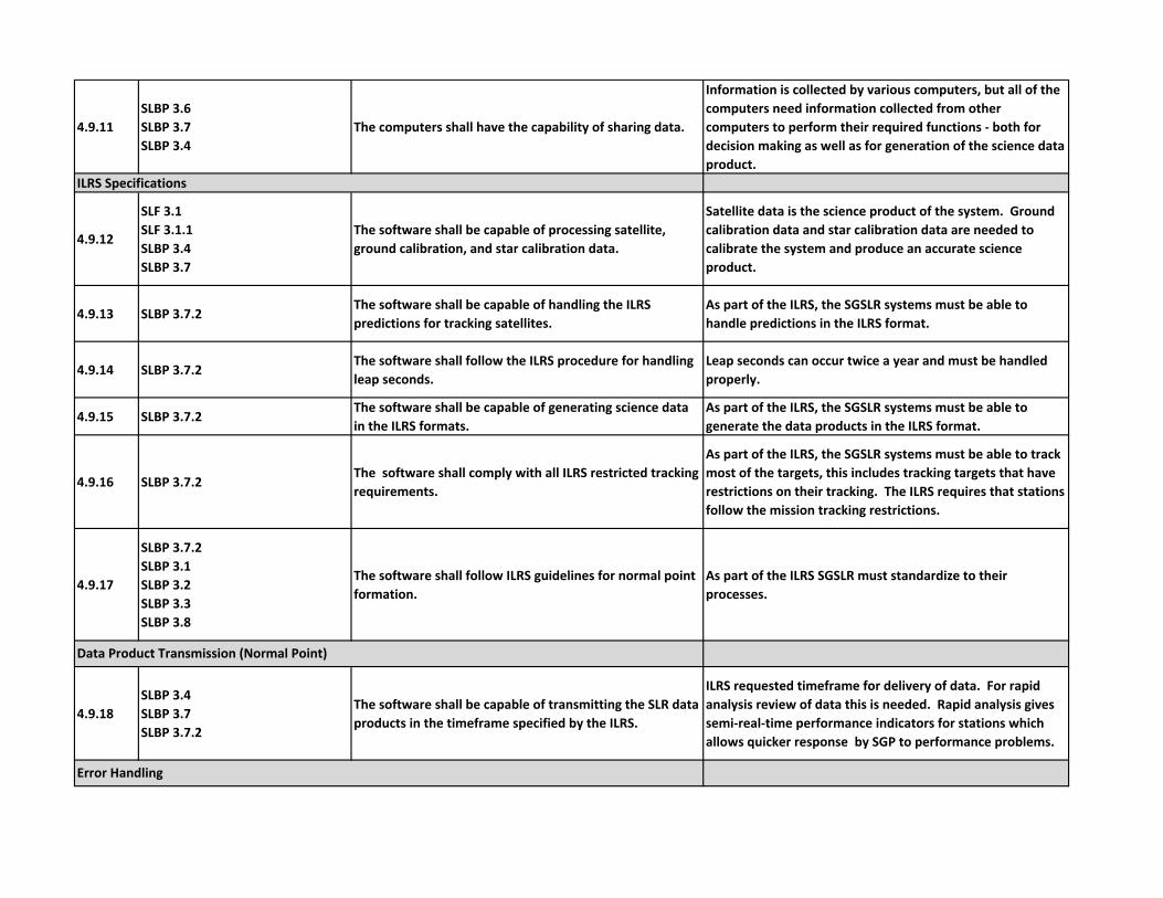
4.9.11
SLBP 3.6
SLBP 3.7
SLBP 3.4
The computers shall have the capability of sharing data.
Information is collected by various computers, but all of the
computers need information collected from other
computers to perform their required functions ‐ both for
decision making as well as for generation of the science data
product.
4.9.12
SLF 3.1
SLF 3.1.1
SLBP 3.4
SLBP 3.7
The software shall be capable of processing satellite,
ground calibration, and star calibration data.
Satellite data is the science product of the system. Ground
calibration data and star calibration data are needed to
calibrate the system and produce an accurate science
product.
4.9.13 SLBP 3.7.2The software shall be capable of handling the ILRS
predictions for tracking satellites.
As part of the ILRS, the SGSLR systems must be able to
handle predictions in the ILRS format.
4.9.14 SLBP 3.7.2The software shall follow the ILRS procedure for handling
leap seconds.
Leap seconds can occur twice a year and must be handled
properly.
4.9.15 SLBP 3.7.2The software shall be capable of generating science data
in the ILRS formats.
As part of the ILRS, the SGSLR systems must be able to
generate the data products in the ILRS format.
4.9.16 SLBP 3.7.2The software shall comply with all ILRS restricted tracking
requirements.
As part of the ILRS, the SGSLR systems must be able to track
most of the targets, this includes tracking targets that have
restrictions on their tracking. The ILRS requires that stations
follow the mission tracking restrictions.
4.9.17
SLBP 3.7.2
SLBP 3.1
SLBP 3.2
SLBP 3.3
SLBP 3.8
The software shall follow ILRS guidelines for normal point
formation.
As part of the ILRS SGSLR must standardize to their
processes.
4.9.18
SLBP 3.4
SLBP 3.7
SLBP 3.7.2
The software shall be capable of transmitting the SLR data
products in the timeframe specified by the ILRS.
ILRS requested timeframe for delivery of data. For rapid
analysis review of data this is needed. Rapid analysis gives
semi‐real‐time performance indicators for stations which
allows quicker response by SGP to performance problems.
ILRS Specifications
Data Product Transmission (Normal Point)
Error Handling
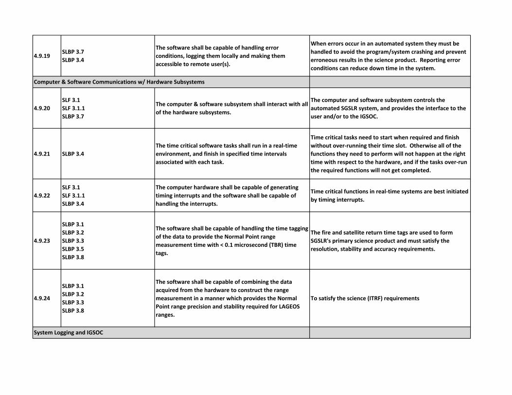
4.9.19SLBP 3.7
SLBP 3.4
The software shall be capable of handling error
conditions, logging them locally and making them
accessible to remote user(s).
When errors occur in an automated system they must be
handled to avoid the program/system crashing and prevent
erroneous results in the science product. Reporting error
conditions can reduce down time in the system.
4.9.20
SLF 3.1
SLF 3.1.1
SLBP 3.7
The computer & software subsystem shall interact with all
of the hardware subsystems.
The computer and software subsystem controls the
automated SGSLR system, and provides the interface to the
user and/or to the IGSOC.
4.9.21 SLBP 3.4
The time critical software tasks shall run in a real‐time
environment, and finish in specified time intervals
associated with each task.
Time critical tasks need to start when required and finish
without over‐running their time slot. Otherwise all of the
functions they need to perform will not happen at the right
time with respect to the hardware, and if the tasks over‐run
the required functions will not get completed.
4.9.22
SLF 3.1
SLF 3.1.1
SLBP 3.4
The computer hardware shall be capable of generating
timing interrupts and the software shall be capable of
handling the interrupts.
Time critical functions in real‐time systems are best initiated
by timing interrupts.
4.9.23
SLBP 3.1
SLBP 3.2
SLBP 3.3
SLBP 3.5
SLBP 3.8
The software shall be capable of handling the time tagging
of the data to provide the Normal Point range
measurement time with < 0.1 microsecond (TBR) time
tags.
The fire and satellite return time tags are used to form
SGSLR's primary science product and must satisfy the
resolution, stability and accuracy requirements.
4.9.24
SLBP 3.1
SLBP 3.2
SLBP 3.3
SLBP 3.8
The software shall be capable of combining the data
acquired from the hardware to construct the range
measurement in a manner which provides the Normal
Point range precision and stability required for LAGEOS
ranges.
To satisfy the science (ITRF) requirements
Computer & Software Communications w/ Hardware Subsystems
System Logging and IGSOC

4.9.25 SLBP 3.7
The software shall record data, activities, events and
report status and error information to the IGSOC on
defined intervals.
Automated and remotely controlled systems need feedback
to remote monitors
4.9.26 SLBP 3.7
The software shall be capable of sending alerts and
warnings immediately to the IGSOC and selected
personnel.
Automated and remotely controlled systems need to alert
humans when the system has issues (errors or alarms).
4.9.27SLBP 3.7.1
SLBP 3.4
The computers and software shall adhere to NASA’s IT
Security policy (NPR 2810.1a Security of Information
Technology).
All NASA computer systems must adhere to NASA IT Security
policy.
4.9.28
SLBP 3.7
SLF 3.1
SLF 3.1.1
The software shall be capable of receiving star and sky
image data from the camera systems and transferring
them to the IGSOC.
Star images are needed to perform star calibrations. Mount
camera is needed to monitor where telescope is pointing.
4.9.29
SLBP 3.7
SLF 3.1
SLF 3.1.1
The software shall be capable of processing star images to
generate star centroids for star calibrations, and sky
images to generate cloud cover for sky clarity
determination.
Star and Sky images need to be analyzed (processed) before
their information can be used.
4.9.30 SLBP 3.7The computers shall be capable of receiving and
monitoring status information from the subsystems.
An automated system needs the software to monitor all
subsystems.
4.9.31SLBP 3.7
SLBP 3.4
The software shall be capable of determining each
subsystem's status and determining the overall system
status.
The software must get enough information from each
subsystem and it must be able to interpret the information
to determine the subsystem status.
4.9.32 SLBP 3.4The software shall have an automatic backup procedure
for system and data recovery.
The system state needs to be captured at regular periodical
intervals. Included in the backups should be the software
and the input databases and recent output data.
NASA IT Security
Computer Receiving Star and Sky Images
Monitoring
Backups

4.9.33
SLF 3.1
SLF 3.1.1
SLBP 3.4
SLBP 3.7
SLBP 3.7.2
The software shall be capable of command and control of
the system 24/7, to perform satellite tracking and ranging,
for a majority of the ILRS list of active satellites, when
conditions permit.
The software must be able to operate the system in a fully
automated manner but also handle commands from the
IGSOC whenever they are sent.
4.9.34
SLF 3.1
SLF 3.1.1
SLBP 3.2
SLBP 3.3
SLBP 3.4
SLBP 3.7
SLBP 3.8
The software shall be capable of performing ground
calibrations 24/7 when conditions permit.Same rationale as above.
4.9.35
SLF 3.1
SLF 3.1.1
SLBP 3.4
SLBP 3.7
The software shall be capable of performing star
calibration 24/7 when conditions permit.Same rationale as above.
4.9.36
SLF 3.1
SLF 3.1.1
SLBP3.4
SLBP 3.7
The software shall be capable of performing star
assessments 24/7 when conditions permit.Same rationale as above.
4.9.37SLBP 3.7
SLBP 3.4
The software shall be able to control operations by
making decisions based on weather, sky clarity, pointing
bias, and system and subsystem monitoring.
An automated SLR system must be able to change its targets
based on the sky clarity, its pointing based on receiver
inputs, and must be able to protect itself from harmful
weather.
Automation
Tracking, Star Cals, Ground Cals, Star Assessment

4.9.38
SLBP 3.7
SLBP 3.7.2
SLBP 3.4
The software shall be capable of automatically following
the daily SGSLR schedule, including satellite passes,
scheduled ground calibration, scheduled star calibration,
and routine maintenance.
In order to ensure that all ILRS satellites get tracked as
needed, the ILRS priority list is used to generate an SLR
schedule for each station. The schedule also includes
required calibrations and routine maintenance.
4.9.39SLBP 3.7
SLBP 3.4
The software shall be capable of making real‐time changes
to the tracking schedule based on system information,
real‐time information from the VLBI antenna and external
input from the IGSOC.
A fully automated SLR system must be able to compensate
for issues that arise, continually working toward maximizing
the data collection.
4.9.40SLBP 3.7
SLBP 3.6
The computer and software subsystem shall allow for
diagnostic control and simulation both locally and
remotely.
Because these systems will be remote from the more expert
engineering support, simulations and diagnostic tools will be
needed to support diagnosing and determining the source of
problems.
4.9.41 SLBP 3.7.1The software shall not be able to override the laser safety
subsystem.The hardware must have control of the laser safety.
4.9.42SLBP 3.7
SLBP 3.7.1
The software shall check that all conditions are nominal
before requesting the laser to fire.This adds one final layer of checking before firing.
4.9.43SLBP 3.7
SLBP 3.7.1
The software shall operate in a manner to protect any
nearby VLBI antenna from the SLR radar.
VLBI can be damaged by the SLR radar. There will be
handshaking that will take place between then two systems
to ensure that the VLBI signal chain does not get damaged.
4.9.44
SLBP 3.7
SLBP 3.7.1
SLBP 3.4
The software shall be capable of making decisions and
taking action to protect the system.
With no human on site the software must take the action to
protect the system from damage.
4.9.45SLBP 3.7
SLBP 3.7.1
The software shall be capable of restricting lasing in
certain exclusion areas at, or near, the ground, through
the use of a mask.
A mask is often used in SLR systems to keep the laser from
firing at objects near the ground (buildings, towers, etc.).
Diagnostics/Simulations
System Protection

4.9.46
SLBP 3.7
SLBP 3.7.1
SLBP 3.4
The software shall be capable of protecting the system
from erroneous user input.
The system must be capable of protecting itself by rejecting
inputs from the user via RAT, or commands from the IGSOC
that cause error conditions, that may cause the system
damage, or that could compromise safety.
4.9.47 SLBP 3.7
The software shall be capable of accepting a schedule
generated by the IGSOC or generating a satellite
prioritized schedule onsite.
SGSLR requires a daily schedule in order to operate.
4.9.48SLBP 3.7
SLBP 3.4
The software shall be capable of site specific and target
specific configurations.
Each site will be unique and each target could have unique
characteristics.
4.9.49SLBP 3.7
SLBP 3.4
The software shall be capable of setting system
configurations for optimum return rates, including
blanking, PRF, ND wheels, time & pointing bias, beam
divergence and TBD.
A fully automated SLR system must be able to perform
optimization in order to get the data quality and quantity
required.
Schedule
Configuration