sga series dc power supplies - vacequip
TRANSCRIPT

SGA Series DC Power Supplies
Operation Manual
SORENSEN Power Supplies Elgar Electronics Corporation 9250 Brown Deer Road San Diego, CA 92121-2294 1-800-73ELGAR (1-800-733-5427)Tel: (858) 450-0085 Fax: (858) 458-0267 Email: [email protected] www.elgar.com
©2004 bThis document contains information proprietary tnot to be duplicated or transferred in any manner
September 17, 2004
y Elgar Electronics Corporation o Elgar Electronics Corporation. The information contained herein is without prior written permission from Elgar Electronics Corporation.
Document No. M550129-01 Rev D

ELGAR FIVE–YEAR WARRANTY Sorensen products are warranted by Elgar Electronics Corporation to be free from defects in material and workmanship. This warranty is effective for five years from the date of shipment of the product to the original purchaser. Liability of Elgar under this warranty shall exist provided that:
• the Buyer exposes the product to normal use and service and provides normal maintenance on the product;
• Elgar is promptly notified of defects by the Buyer and that notification occurs within the warranty period;
• the Buyer receives a Return Material Authorization (RMA) number from Elgar’s Repair Department prior to the return of the product to Elgar for repair, phone 800-73ELGAR (800-733-5427);
• the Buyer returns the defective product in the original, or equivalent, shipping container;
• if, upon examination of such product by Elgar it is disclosed that, in fact, a defect in materials and/or workmanship does exist, that the defect in the product was not caused by improper conditions, misuse, or negligence; and,
• that QA seal and nameplates have not been altered or removed and the equipment has not been repaired or modified by anyone other than Elgar authorized personnel. After a product is evaluated and a consultation performed with the Buyer, if no failure exists, then the product may be subject to an evaluation fee.
This warranty is exclusive and in lieu of all other warranties, expressed or implied, including, but not limited to, implied warranties of merchantability and fitness of the product to a particular purpose. Elgar, its agents, or representatives shall in no circumstance be liable for any direct, indirect, special, penal, or consequential loss or damage of any nature resulting from the malfunction of the product. Remedies under this warranty are expressly limited to repair or replacement of the product.
CONDITIONS OF WARRANTY
• To return a defective product, contact an Elgar representative or the Elgar factory for an RMA number. Unauthorized returns will not be accepted and will be returned at the shipper’s expense.
• For Sorensen products found to be defective within thirty days of receipt by the original purchaser, Elgar will absorb all ground freight charges for the repair. Products found defective within the warranty period, but beyond the initial thirty-day period, should be returned prepaid to Elgar for repair. Elgar will repair the unit and return it by ground freight pre-paid.
• Normal warranty service is performed at Elgar during the weekday hours of 7:00 am to 4:00 pm Pacific time. Warranty repair work requested to be accomplished outside of normal working hours will be subject to Elgar non-warranty service rates.
• Warranty field service is available on an emergency basis. Travel expenses (travel time, per diem expense, and related air fare) are the responsibility of the Buyer. A Buyer purchase order is required by Elgar prior to scheduling.
• A returned product found, upon inspection by Elgar, to be in specification is subject to an inspection fee and applicable freight charges.
• Equipment purchased in the United States carries only a United States warranty for which repair must be accomplished at the Elgar factory.
Committed to Quality...Striving for Excellence
M550129-01 (Operation) Rev D i
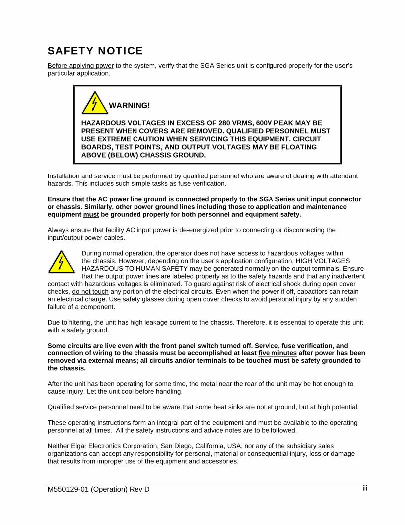
SAFETY NOTICE Before applying power to the system, verify that the SGA Series unit is configured properly for the user’s particular application.
WARNING!
HAZARDOUS VOLTAGES IN EXCESS OF 280 VRMS, 600V PEAK MAY BE PRESENT WHEN COVERS ARE REMOVED. QUALIFIED PERSONNEL MUST USE EXTREME CAUTION WHEN SERVICING THIS EQUIPMENT. CIRCUIT BOARDS, TEST POINTS, AND OUTPUT VOLTAGES MAY BE FLOATING ABOVE (BELOW) CHASSIS GROUND.
Installation and service must be performed by qualified personnel who are aware of dealing with attendant hazards. This includes such simple tasks as fuse verification.
Ensure that the AC power line ground is connected properly to the SGA Series unit input connector or chassis. Similarly, other power ground lines including those to application and maintenance equipment must be grounded properly for both personnel and equipment safety.
Always ensure that facility AC input power is de-energized prior to connecting or disconnecting the input/output power cables.
During normal operation, the operator does not have access to hazardous voltages within the chassis. However, depending on the user’s application configuration, HIGH VOLTAGES HAZARDOUS TO HUMAN SAFETY may be generated normally on the output terminals. Ensure that the output power lines are labeled properly as to the safety hazards and that any inadvertent
contact with hazardous voltages is eliminated. To guard against risk of electrical shock during open cover checks, do not touch any portion of the electrical circuits. Even when the power if off, capacitors can retain an electrical charge. Use safety glasses during open cover checks to avoid personal injury by any sudden failure of a component.
Due to filtering, the unit has high leakage current to the chassis. Therefore, it is essential to operate this unit with a safety ground.
Some circuits are live even with the front panel switch turned off. Service, fuse verification, and connection of wiring to the chassis must be accomplished at least five minutes after power has been removed via external means; all circuits and/or terminals to be touched must be safety grounded to the chassis.
After the unit has been operating for some time, the metal near the rear of the unit may be hot enough to cause injury. Let the unit cool before handling.
Qualified service personnel need to be aware that some heat sinks are not at ground, but at high potential.
These operating instructions form an integral part of the equipment and must be available to the operating personnel at all times. All the safety instructions and advice notes are to be followed.
Neither Elgar Electronics Corporation, San Diego, California, USA, nor any of the subsidiary sales organizations can accept any responsibility for personal, material or consequential injury, loss or damage that results from improper use of the equipment and accessories.
M550129-01 (Operation) Rev D iii

SAFETY SYMBOLS
M550129-01 (Operation) Rev D iv

FCC NOTICE This equipment has been tested and found to comply with the limits for a Class A digital device, pursuant to part 15 of the FCC Rules. These limits are designed to provide reasonable protection against harmful interference when the equipment is operated in a commercial environment. This equipment generates, uses, and can radiate radio frequency energy and, if not installed and used in accordance with the instruction manual, may cause harmful interference to radio communications. Operation of this equipment in a residential area is likely to cause harmful interference in which case the user will be required to correct the interference at his own expense
M550129-01 (Operation) Rev D v
ABOUT THIS MANUAL This manual has been written expressly for the Sorensen SGA Series of power supplies that have been designed and certified to meet the Low Voltage and Electromagnetic Compatibility Directive Requirements of the European Community.
Since the Low Voltage Directive is to ensure the safety of the equipment operator, universal graphic symbols have been used both on the unit itself and in this manual to warn the operator of potentially hazardous situations (see Safety Symbols on page iv).
M550129-01 (Operation) Rev D vi

CONTENTS
SECTION 1 OVERVIEW........................................................................ 1-1
1.1 General Description ......................................................................................... 1-1 1.2 Technical Specifications .................................................................................. 1-1
1.2.1 Environmental Characteristics ............................................................. 1-1 1.2.2 Electrical Characteristics ..................................................................... 1-2 1.2.3 SGA Series Voltage and Current Specifications.................................. 1-4 1.2.4 Physical Characteristics....................................................................... 1-4
SECTION 2 INSTALLATION................................................................. 2-1
2.1 Inspection ........................................................................................................ 2-1 2.2 Contents of Shipment ...................................................................................... 2-1 2.3 Input/Output Connections ................................................................................ 2-2 2.4 Location and Mounting .................................................................................... 2-2
2.4.1 6U Chassis Removal from Rack.......................................................... 2-3 2.5 Wire Size ......................................................................................................... 2-4 2.6 Wire Gauge Selection...................................................................................... 2-5 2.7 Load Considerations........................................................................................ 2-7
2.7.1 Inductive Loads.................................................................................... 2-7 2.8 Outline Drawings ............................................................................................. 2-7
SECTION 3 OPERATION...................................................................... 3-1
3.1 Controls and Indicators.................................................................................... 3-1 3.1.1 Shaft Lock (Option) .............................................................................. 3-3
3.2 Local Operation ............................................................................................... 3-4 3.2.1 Initial Setup .......................................................................................... 3-4
M550129-01 (Operation) Rev D vii
3.2.2 Voltage Mode Operation ......................................................................3-4 3.2.3 Current Mode Operation ......................................................................3-5 3.2.4 Overvoltage Protection.........................................................................3-5 3.2.5 Analog Control Connector (J1).............................................................3-6
3.3 Remote Current Programming .......................................................................3-10 3.4 Remote Voltage Programming.......................................................................3-11 3.5 Remote Sensing.............................................................................................3-12 3.6 Remote Output On/Off Control.......................................................................3-14 3.7 Remote Overvoltage Setpoint ........................................................................3-15 3.8 Remote Shutdown (S/D) ................................................................................3-16 3.9 Master/Slave Operation .................................................................................3-16
3.9.1 Parallel Operation ..............................................................................3-16 3.9.2 Series Operation ................................................................................3-17
SECTION 4 VERIFICATION AND CALIBRATION................................. 4-1
4.1 Introduction ......................................................................................................4-1 4.1.1 Verification and Calibration Cycle ........................................................4-1 4.1.2 Preparation...........................................................................................4-1
4.2 Standard Verification and Calibration Procedure .............................................4-2 4.2.1 Current Mode .......................................................................................4-2 4.2.2 Voltage Mode .......................................................................................4-3 4.2.3 Resistor Programming Current Sources ..............................................4-4
4.3 Isolated Analog (Option) Verification and Calibration Procedure.....................4-4 4.3.1 Current Mode .......................................................................................4-5 4.3.2 Voltage Mode .......................................................................................4-5
SECTION 5 MAINTENANCE................................................................. 5-1
5.1 Introduction ......................................................................................................5-1 5.2 Preventive Maintenance...................................................................................5-1 5.3 Fuses ...............................................................................................................5-3
LIST OF TABLES Table 2–1. 5kW to 15kW and 20kW to 30kW Series Input/Output Connectors............2-3 Table 2–2. Input Connections .......................................................................................2-4 Table 2–3. Output Connections ....................................................................................2-4 Table 2–4. Minimum Wire Size .....................................................................................2-5
M550129-01 (Operation) Rev D viii
Sorensen SGA Series Contents
Table 2–5 Recommended Wire Gauge Selection Guide.............................................. 2-6 Table 2–6 Maximum AC Current Ratings..................................................................... 2-6 Table 2–7 Recommended Lugs ................................................................................... 2-6 Table 2–8. Recommended Sense Connector Tools..................................................... 2-7 Table 3–1. ANALOG CONTROL Connector (J1), Designations and Functions........... 3-9 Table 5–1. Recommended Annual Inspection.............................................................. 5-2 Table 5–2. Fuse Values................................................................................................ 5-3
LIST OF FIGURES Figure 2–1. SGA Series Outline Drawing, 3U Models, 5kW to 15kW .......................... 2-8 Figure 2–2. SGA Series Outline Drawing, 6U Models, 20kW to 30kW ........................ 2-9 Figure 3–1. Front Panel Controls and Indicators (3U model shown)............................ 3-1 Figure 3–2. Rear Panel Connectors (3U model shown)............................................... 3-2 Figure 3–3. Shaft Lock ................................................................................................. 3-3 Figure 3–4. ANALOG CONTROL Connector (J1) Pin-out............................................ 3-7 Figure 3–5. Remote Current Programming Using Resistance ................................... 3-10 Figure 3–6. Remote Current Programming Using 0-5 VDC or 0-10 VDC Voltage Source..................................................................................................................................... 3-11 Figure 3–7. Remote Voltage Programming Using Resistance ................................... 3-12 Figure 3–8. Remote Voltage Programming Using 0-5 VDC or 0-10 VDC Voltage Source..................................................................................................................................... 3-12 Figure 3–9. Remote Sensing Operation at the Load .................................................. 3-13 Figure 3–10. Remote On/Off Control by Contact Closure .......................................... 3-14 Figure 3–11. Remote On/Off Using Isolated AC or DC Voltage Source .................... 3-14 Figure 3–12. Remote On/Off Using Isolated TTL/CMOS Voltage Supply .................. 3-15 Figure 3–13. Remote Overvoltage Set Using DC Voltage Source ............................. 3-15 Figure 3–14. Remote Shutdown Using DC Voltage Source....................................... 3-16 Figure 3–15. Master/Slave Connection ...................................................................... 3-16 Figure 4–1. Precision Current Shunt ............................................................................ 4-2 Figure 4–2. Potentiometer Locations............................................................................ 4-7
M550129-01 (Operation) Rev D ix

SECTION 1
1.1
1.2
1.2.1
OVERVIEW
General Description The Sorensen SGA Series power supplies are general–purpose power supplies designed specifically for laboratory test and systems applications requiring variable DC sources with good ripple and regulation characteristics. These power supplies are constant current/constant voltage supplies with an automatic crossover feature.
A variety of user interfaces are available, ranging from manual front–panel control and standard non–isolated remote analog control, to optional GPIB or isolated remote analog control.
Technical Specifications The following sections provide environmental, electrical, and physical characteristics for the SGA Series power supplies.
Environmental Characteristics
Note: The SGA Series power supplies are intended for indoor use only. Parameter Specification
Temperature Coefficient 0.02%/°C of maximum output voltage rating for voltage set point. 0.03%/°C of maximum output current rating for current set point.
Ambient Temperature Operating 0 to 50°C Storage -25° to 65°C
Cooling Internal fans. Units may be stacked without clearance. Humidity 0 to 90% at 40°C, derate to 50% at 25°C (non-condensing)
Altitude Operating full power available up to 5,000 feet (1,524m), derate 10% of full power for every 1,000 feet higher non-operating to 40,000 feet (12,192m)
Agency Approvals CE Mark to EN61010 and EN61326 UL recognized to UL1012
M550129-01 (Operation) Rev D 1-1

Sorensen SGA Series Overview
1.2.2 Electrical Characteristics
Parameter Specification
Input Power
Voltage (Standard) 208/220 VAC±10% (tested to 187-242 VAC)
Voltage (Options) 380/400 VAC±10% (tested to 342-440 VAC) 440/480 VAC±10% (tested to 396-528 VAC)
Frequency 47 to 63 Hz
Phases 3–phase, 3–wire plus ground. Not phase rotation sensitive. Neutral not used.
Front Panel Meter Accuracy
Voltage ±0.5% of full-scale + 1 digit
Current ±0.5% of full-scale + 1 digit
Load Regulation (Specified at no load to full load, nominal AC input)
Voltage 0.02% of maximum output voltage
Current 0.1% of maximum output current
Line Regulation (Specified ±10% of nominal AC input, constant load)
Voltage 0.01% of maximum output voltage
Current 0.05% of maximum output current
Transient Response A 50% step load will recover to within 0.75% of original value within 1 ms.
Down Programming With no load the output will program from 100 to 10% in less than 1.5 seconds
Stability ±0.05% of set point after 8–hr. warm-up at fixed line, load, and temperature using remote sense
Remote Control/Monitor On/Off control via contact closure, 6-120 VDC or 12-240 VAC, and TTL or CMOS switch, output voltage and current monitor, OVP limit set, summary fault status
Power Factor >0.9 typical for 208/220VAC input >0.78 typical for 380/400VAC input >0.7 typical for 440/480VAC input
Efficiency 87% typical at full load, nominal line
Remote Programming
Accuracy
Constant Voltage ±0.25% of full-scale output (Vp5 input)
M550129-01 (Operation) Rev D 1-2

Sorensen SGA Series Overview
M550129-01 (Operation) Rev D 1-3
Parameter Specification
Constant Current ±0.8% of full-scale output
Overvoltage Protection (OVP)
±1% of full-scale output
Resistive
Constant Voltage (0-100%) 0–5 kΩ
Constant Current (0-100%) 0–5 kΩ
Voltage
Constant Voltage (0-100%) 0–5 VDC or 0–10 VDC
Constant Current (0-100%) 0–5 VDC or 0–10 VDC
Overvoltage Protection (OVP) (0-110%)
0–5.5 VDC
Remote Sensing
Terminals are provided to sense output voltage at point of load. Maximum line drop 5% of rated voltage per line for 60-100V models, 2% of rated voltage per line for models 160V and greater.
ISOLATED ANALOG CONTROL (OPTION)
Input to Output Isolation 500 V
Compliant with maximum terminal float voltage. Recommended operation under SELV normal conditions.

Sorensen SGA Series Overview
1.2.3 SGA Series Voltage and Current Specifications
Amperage
Voltage 5 kW 10 kW 15 kW 20 kW 25 kW 30 kW Ripple*
RMS Noise*
P–P
0-60V 0-83A 0-167A 0-250A 0-333A 0-417A 0-500A 20 mV 75 mV
0-80V 0-63A 0-125A 0-188A 0-250A 0-313A 0-375A 20 mV 100 mV
0-100V 0-50A 0-100A 0-150A 0-200A 0-250A 0-300A 20 mV 100 mV
0-160V 0-31A 0-63A 0-94A 0-125A 0-156A 0-188A 25 mV 150 mV
0-200V 0-25A 0-50A 0-75A 0-100A 0-125A 0-150A 25 mV 175 mV
0-250V 0-20A 0-40A 0-60A 0-80A 0-100A 0-120A 30 mV 200 mV
0-330V 0-15A 0-30A 0-45A 0-61A 0-76A 0-91A 30 mV 200 mV
0-400V 0-12A 0-25A 0-38A 0-50A 0-63A 0-75A 30 mV 300 mV
0-600V 0-8A 0-17A 0-25A 0-33A 0-42A 0-50A 40 mV 350 mV
* Ripple and noise specified at full load, nominal AC input
1.2.4 Physical Characteristics
Dimension 3U Models 6U Models Width 19.00 in (48.3 cm) 19.00 in (48.3 cm)
Depth 25.12 in (63.8 cm) 25.12 in (63.8 cm)
Height 5.25 in (13.3 cm) 10.5 in (26.7 cm)
Weight 80 lbs (36 kg) maximum 160 lbs (73 kg) maximum Note: Specifications are subject to change without notice.
M550129-01 (Operation) Rev D 1-4

SECTION 2
2.1 Inspection
2.2
INSTALLATION
Inspect the shipping carton for possible damage before unpacking the unit. Carefully unpack the equipment. Save all packing materials until inspection is complete. Verify that all items listed on the packing slips have been received. Visually inspect all exterior surfaces for broken knobs, connectors, or meters. Inspect for dented or damaged exterior surfaces. External damage may be an indication of internal damage. If any damage is evident, immediately contact the carrier that delivered the unit and submit a damage report. Failure to do so could invalidate future claims. Direct repair issues to Elgar Customer Service at 1-800-73ELGAR (1-800-733-5427).
Contents of Shipment Depending on the model, configuration, and options available for your SGA Series power supply, the ship kit may include additional parts and accessories. At a minimum, the ship kit that accompanies your SGA Series power supply includes the following items:
• SGA Series DC Power Supplies Operation Manual (Elgar Document No. M550129-01)
• Sense mating connector (Molex P/N 39-01-4031) with loose contacts (Molex P/N 39-00-0182)
• J1 mating connector (Cinch P/N DB25P or equivalent) normally shipped attached to rear panel J1
• Back shell for J1 (DB25) mating connector (Cinch P/N DCH-B-001 or equivalent)
• Screw, lock washer, and nut for AC input and DC output connections: 5–15 kW: ¼-20UNC-2B x ½", 4 ea AC input only 20–30 kW: 3/8-16UNC-2B x 7/8", 6 ea
• Black screw, 10-32UNC-2B x ½", front panel rack fastener: 5–15 kW: 4 ea 20–30 kW: 8 ea
If any of these parts are missing, please contact Elgar Customer Service at 1-800-73ELGAR (1-800-733-5427).
M550129-01 (Operation) Rev D 2-1
Installation Sorensen SGA Series
2.3 Input/Output Connections
WARNING! High voltage present! Risk of electrical shock. Do not remove cover. Refer to qualified service personnel.
Table 2–1 lists all external connections for the SGA Series models. Table 2–2 and Table 2–3 provide input and output connection descriptions by power supply type.
For permanently connected equipment, a readily accessible disconnect device shall be incorporated in the fixed wiring. For pluggable equipment, the socket outlet shall be installed near the equipment and shall be easily accessible.
Take precautions to ensure that the concentration of ozone is limited to a safe value. The recommended long-term exposure limit for ozone is 0.1 PPM (0.2 mg/m3).
CAUTION! For proper connection to the mains, a 100–amp circuit breaker or fuse for 3U units and a 200–amp circuit breaker or fuse for 6U units is required.
WARNING! Under no condition should the negative output terminal exceed 150V to earth ground.
2.4 Location and Mounting
WARNING! To reduce the risk of fire or electrical shock, install the SGA Series unit in a temperature and humidity controlled indoor area, free of conductive contaminants.
CAUTION! The unit should be provided with proper ventilation. The rear and both sides of the unit should be free of obstructions. To ensure proper airflow, a minimum 4" clearance from the rear air outlet is required. The unit should not be installed in a raised ambient temperature greater than 50°C.
CAUTION! This unit is intended for installation in a protected environment. No user serviceable parts inside. Service to be performed by qualified personnel only.
The SGA Series models are designed to be mounted in a standard 19-inch equipment rack. If additional instrumentation is mounted in the rack, no additional clearance is required between the SGA series and other power supplies or instruments.
1. Support the unit using rack mount slides or appropriate L brackets (suggested parts are listed below).
M550129-01 (Operation) Rev D 2-2
Sorensen SGA Series Installation
M550129-01 (Operation) Rev D 2-3
Rack Mount Slide Kit:
5–15kW units Elgar P/N K550212-01 20–30kW units Elgar P/N K550213-01
2. Secure the unit in place using the screws provided.
2.4.1 6U Chassis Removal from Rack
The slides have a Front Disconnect Feature and lock at full extension.
To return the chassis back into the rack from full extension, depress the flat steel spring inward (located on the slides) and push the chassis back.
To disconnect and remove the chassis from the rack, depress the flat steel spring inward (located on the slides) and pull the chassis forward.
WARNING! The 6U SGA Series unit weighs up to 160 lbs (73kg) depending on the model. A minimum three-person lift is required!
When the chassis is at full extension, the flat springs are located approximately one (1) inch behind the front EIA RETMA rails. Access the springs with a flat blade screwdriver or similar device to release from lock-out or to remove the chassis from the rack.
The slides can be mounted to the chassis with this spring oriented on the top or the bottom of the slide.
Table 2–1 provides details of the SGA Series input and output connectors and their functions. Connector Function Connects To
FL1 – AC FL1 – AC FL1 – AC Chassis - GND
Prime AC Power Input See Table 2–2. Not phase rotation sensitive. Neutral not used.
208/220 VAC (Std) 380/400 VAC (Option) 440/480 VAC (Option) 47-63 Hz
Pos. Threaded Stud Neg. Threaded Stud Pos. Bus Bar Neg. Bus Bar
Output Power: 3U models (see Table 2–3) 6U models (see Table 2–3)
User load(s)
ANALOG CONTROL Connector (J1) Control Interface See Table 3–1 for
description Sense Connector Used for remote sense Refer to Section 3.5 Parallel In-Out Used for parallel operation Refer to Section 3.9
Table 2–1. 5kW to 15kW and 20kW to 30kW Series Input/Output Connectors
Installation Sorensen SGA Series
Power Supply Type Connection Description 5 kW to 15 kW Bus Bar with holes for 1/4"–20 bolts 20 kW to 30 kW Bus Bar with holes for 3/8"–16 bolts
Table 2–2. Input Connections
Power Supply Type Connection Description
5 kW to 15 kW ≥60V 3/8" Threaded Studs 20 kW to 30 kW ≥60V Bus Bar with holes for 3/8" bolts
Table 2–3. Output Connections
Note: Failure to observe the maximum torque specification indicated in the housing will void the warranty on the SGA Series unit.
2.5 Wire Size Care must be taken to properly size all conductors for the input and output of the power supply. The tables below will assist in determining the appropriate wire size for both the input and output connections Table 2–4 below gives minimum recommended wire size. This table is derived from the National Electrical Code; it is for reference only. Local laws and conditions may have different requirements. Note that these recommendations are for copper wire only. For higher ratings, wires can be paralleled; refer to the National Electrical Code.
Size Temperature Rating of Copper Conductor 60°C 75°C 85°C 90°C
Types: RUW, T, TW, UF
Types: FEPW, RHW, RH, RUH,
THW, THWN, XHHW, USE, ZW
Types: V, MI Types: TA, TBS, SA, AVB, SIS,
FEP, FEPB, RHH, THHN, XHHW
AWG MCM
Current Rating
14 20 20 25 25
12 25 25 30 30
10 30 35 40 40
8 40 50 55 55
6 55 65 70 75
4 70 85 95 95
3 85 100 110 110
2 95 115 125 130
1 110 130 145 150
0 125 150 165 170
M550129-01 (Operation) Rev D 2-4

Sorensen SGA Series Installation
M550129-01 (Operation) Rev D 2-5
Size Temperature Rating of Copper Conductor 60°C 75°C 85°C 90°C
Types: RUW, T, TW, UF
Types: FEPW, RHW, RH, RUH,
THW, THWN, XHHW, USE, ZW
Types: V, MI Types: TA, TBS, SA, AVB, SIS,
FEP, FEPB, RHH, THHN, XHHW
AWG MCM
Current Rating
00 145 175 190 195
000 165 200 215 225
0000 195 230 250 260
Table 2–4. Minimum Wire Size
2.6 Wire Gauge Selection The following guidelines assist in determining the optimum cable specification for your power applications. The same engineering rules apply whether going into or out of an electrical device. Thus, this guide applies equally to the input cable and output cable for this Sorensen instrument and application loads.
Power cables must be able to safely carry maximum load current without overheating or causing insulation destruction. It is important to everyday performance to minimize IR (voltage drop) loss within the cable. These losses have a direct effect on the quality of power delivered to and from instruments and corresponding loads.
When specifying wire gauge, consider the operating temperature. Wire gauge current capability and insulation performance drops with the increased temperature developed within a cable bundle and with increased environmental temperature. Thus, short cables with generously derated gauge and insulation properties are recommended for power source applications.
Avoid using published commercial utility wiring codes. These codes are designed for the internal wiring of homes and buildings and accommodate the safety factors of wiring loss, heat, breakdown insulation, aging, etc. However, these codes consider that up to 5% voltage drop is acceptable.
Such a loss directly detracts from the quality performance specifications of this Sorensen instrument. Frequently, these codes do not consider bundles of wire within a cable arrangement.
In high performance applications, as in motor start-up and associated inrush/ transient currents, additional consideration is required. The cable wire gauge must consider peak voltages and currents, which may be up to ten times the average values. An underrated wire gauge adds losses, which alter the inrush characteristics of the application and thus the expected performance.
Table 2–5 identifies popular ratings for DC power source cable wire gauges.

Installation Sorensen SGA Series
Column 1 Column 2 Column 3 Column 4 Size
(AWG) Amperes
(Maximum) Ohms/100 Feet
(One Way) IR Drop/100 Feet
(Column 2 x Column 3) 14 15 0.257 3.85 12 20 0.162 3.24 10 30 0.102 3.06 8 40 0.064 2.56 6 55 0.043 2.36 4 70 0.025 1.75 2 95 0.015 1.42
1/0 125 0.010 1.25 3/0 165 0.006 1.04
Table 2–5 Recommended Wire Gauge Selection Guide
Refer to Table 2–6 for AC input current requirements and Section 1.2.3 for output current requirements.
Input Line Current Input V
5 kW 10 kW 15 kW 20 kW 25 kW 30kW Unit of
Measure
208/220VAC 21 41 62 83 103 124
380/400VAC 14 27 40 54 67 80
440/480VAC 13 26 39 52 65 78
Amps AC per phase
Table 2–6 Maximum AC Current Ratings
Refer to Table 2–7 for input/output lug recommendations.
Lug Manufacturer 3U Models Input/Output 6U Models Input/Output
Panduit “PN” Series or equivalent “LCA” Series or equivalent
Table 2–7 Recommended Lugs
The recommended tools for installation and extraction of the sense connector are listed below in Table 2–8.
M550129-01 (Operation) Rev D 2-6
Sorensen SGA Series Installation
M550129-01 (Operation) Rev D 2-7
Tool Manufacturer Manufacturer P/N
Crimping Device Molex 11-01-0197
Extracting Device Molex 11-03-0044
Table 2–8. Recommended Sense Connector Tools
2.7
2.7.1
2.8
Load Considerations
Inductive Loads
To prevent damage to the power supply from inductive kickback, connect a diode (rated at greater than the supply’s output voltage and current) across the output. Connect the cathode to the positive output and the anode to return. Where positive load transients such as back EMF from a motor may occur, a second diode in series with the output is recommended to protect the power supply.
Outline Drawings Figure 2–1 and Figure 2–2, next, show the outlines and overall dimensions of the 3U and 6U models of the SGA Series product line.
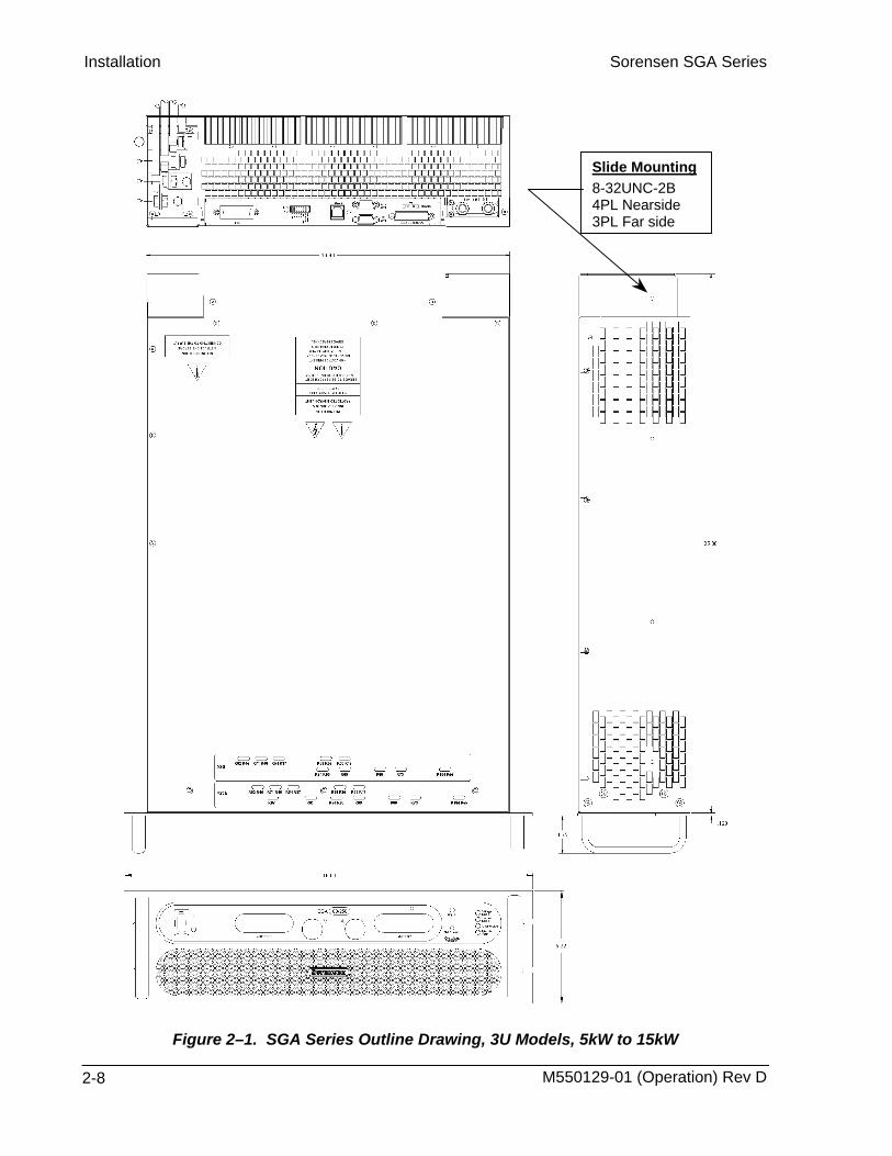
Installation Sorensen SGA Series
Slide Mounting 8-32UNC-2B 4PL Nearside 3PL Far side
Figure 2–1. SGA Series Outline Drawing, 3U Models, 5kW to 15kW
M550129-01 (Operation) Rev D 2-8

Sorensen SGA Series Installation
M550129-01 (Operation) Rev D 2-9
Slide Mounting 8-32UNC-2B 6PL Nearside 7PL Far side
Figure 2–2. SGA Series Outline Drawing, 6U Models, 20kW to 30kW

SECTION 3
3.1
OPERATION
Controls and Indicators Refer to Figure 3–1 and the corresponding descriptions below for an explanation of front panel controls and indicators on the SGA Series power supply.
Figure 3–1. Front Panel Controls and Indicators (3U model shown)
Voltage Display: 3½ digit green LED display indicates the DC output voltage of the supply. Display indicates the OVP setting when the SET/RESET OVERVOLTAGE PROTECTION button is pushed.
Current Display: 3½ digit green LED display indicates the DC output current of the supply.
ADJUST Overvoltage Potentiometer: Adjusts the overvoltage trip level.
M550129-01 (Operation) Rev D 3-1

Operation Sorensen SGA Series
VOLTAGE MODE Indicator: Green LED lights when in the constant–voltage mode of operation. When in the constant–voltage mode, the output voltage will regulate to the set value and the current value will vary with the load.
CURRENT MODE Indicator: Green LED lights when in the constant–current mode of operation. When in the constant–current mode, the output current will regulate to the set value and the output voltage will vary with the load.
OVERVOLTAGE FAULT Indicator: Red LED indicates output voltage has exceeded preset level, and power supply output is turned off. MODULE FAULT Indicator: Yellow LED indicates an internal fault such as bias supply,
thermal, or converter failure. SET/RESET OVERVOLTAGE PROTECTION Pushbutton: Depress button to view OVP
level. Push and hold for 4 seconds to reset OVP condition. CURRENT knob: 10–turn adjustment sets the output current. (Optional shaft locks not
shown. Please see Section 3.1.1). VOLTAGE knob: 10–turn adjustment sets the output voltage. (Optional shaft locks not
shown. Please see Section 3.1.1). ON/OFF Switch: Two–position switch enables or disables the power supply.
WARNING! The OFF position of the power switch does not remove voltage from the input terminal blocks. Remove all external power before servicing the unit.
Refer to Figure 3–2 and the corresponding descriptions below for an explanation of rear panel connectors.
Figure 3–2. Rear Panel Connectors (3U model shown)
DC OUTPUT: Positive (+) and negative (–) outputs. Threaded studs for 5-15kW models; bus bars for 20-30kW models.
M550129-01 (Operation) Rev D 3-2
Sorensen SGA Series Operation
ANALOG CONTROL Connector (J1): I/O connector for input programming and analog output monitoring signals as well as status indication and remote shutdown signals. See Table 3–1 for individual pin descriptions.
SENSE Connector (J3): Input connector for load voltage sensing to correct for line drops in the load cables (see Section 3.5).
PARALLEL IN Connector: Allows master/slave configuration of up to five units when connected to another unit’s PARALLEL OUT connector (see Section 3.9).
PARALLEL OUT Connector: Allows master/slave configuration of up to five units when connected to another unit's PARALLEL IN connector (see Section 3.9).
RS232 Connector: Optional RJ-11 connector for remote control.
Dipswitch: Eight–position dipswitch to configure an SGA Series unit with an IEEE option.
GPIB Connector: Optional connector for remote control.
AC Input Bus Bars: Connection for 3-phase AC and Ground.
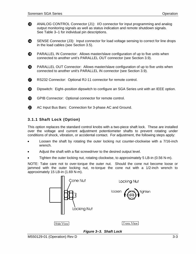
3.1.1 Shaft Lock (Option)
This option replaces the standard control knobs with a two-piece shaft lock. These are installed over the voltage and current adjustment potentiometer shafts to prevent rotating under conditions of shock, vibration, or accidental contact. For adjustment, the following steps apply:
• Loosen the shaft by rotating the outer locking nut counter-clockwise with a 7/16-inch wrench.
• Adjust the shaft with a flat screwdriver to the desired output level.
• Tighten the outer locking nut, rotating clockwise, to approximately 5 LB-in (0.56 N-m). NOTE: Take care not to over-torque the outer nut. Should the cone nut become loose or jammed with the outer locking nut, re-torque the cone nut with a 1/2-inch wrench to approximately 15 LB-in (1.69 N-m).
M550129-01 (Operation) Rev D 3-3 Figure 3–3. Shaft Lock
Operation Sorensen SGA Series
CAUTION! Never completely loosen the cone nut, or remove the shaft lock from the chassis.
3.2
3.2.1
3.2.2
Local Operation The SGA Series power supply is shipped from the factory configured for local voltage/current control and local voltage sensing. The ANALOG CONTROL connector is supplied with a mating connector with remote ON/OFF jumpered for ON (terminal 5 shorted to terminal 6).
Prior to turning the unit on, rotate the voltage and current potentiometers fully counterclockwise (minimum output). Then, turn the power ON and adjust the voltage and current to the desired output.
This section provides an overview of front panel operation and initial functional tests of the power supply.
Initial Setup Before connecting the unit to an AC outlet, ensure that the front panel ON/OFF power switch is in the off position and that the voltage and current control knobs are fully counterclockwise. Check the ANALOG CONTROL (J1) mating connector on the rear panel to verify that pins 5 and 6 (Remote Output On/Off) are shorted together to enable the output of the supply (see Section 3.6). This is the default configuration installed from the factory. Apply power to the AC mains input.
Voltage Mode Operation
When the supply is in the Voltage mode, the output voltage of the supply is controlled by the voltage knob on the front panel or by the remote voltage input. See Section 3.4. The Current knob (or remote current input) operates as a current limit. The output voltage is regulated at the selected value while the output current varies with the load requirements. To verify operation in voltage mode, follow the steps below:
• Connect a digital voltmeter (DVM) across the rear panel positive and negative output terminals, observing the correct polarity. Make sure the DVM is in the dc voltage mode and the range is adequate to handle the full-scale voltage of the power supply.
• Rotate the Current control knob about ½ turn clockwise (this sets the current limit at a nominal setting above 0 Amps)
• Turn on the power supply.
• Slowly rotate the Voltage knob clockwise and observe both the front panel voltage display and the output of the DVM. The minimum range should be from 0V to the maximum rated voltage output of the supply. The front panel display and DVM readings should track within the accuracies of the meter and the front panel display.
• Check that the green Voltage Mode indicator is on.
M550129-01 (Operation) Rev D 3-4
Sorensen SGA Series Operation
• Turn the Voltage knob and Current knob fully counterclockwise.
• Turn the power supply off.
If Voltage mode operation did not function as indicated above, recheck your setup and perform the check again. If the function continues to fail, contact the factory for assistance.
3.2.3
3.2.4
Current Mode Operation
When the supply is in the Current Mode, the output current of the supply is controlled by the Current knob on the front panel or by the remote current input (see Section 3.3). The Voltage control knob (or remote voltage input) operates as a voltage limit. To verify operation in current mode, follow the steps below: • Connect a high current DC ammeter across the rear panel positive and negative output
terminals, observing the correct polarity. Select wire leads of sufficient current carrying capacity and an ammeter range compatible with the units maximum rated output current. NOTE: If a high current ammeter is not available, you may simply short the output terminals together. This will not harm the supply.
• Rotate the Voltage control knob about ½ turn clockwise (this sets the Voltage limit at a
nominal setting above 0 Volts and forces the supply into current mode).
• Turn on the power supply.
• Slowly rotate the Current knob clockwise and observe both the front panel current display and the output of the ammeter. The minimum range should be from 0A to the maximum rated current output of the supply. The front panel display and ammeter readings should track within the accuracies of the meter and the front panel display.
• Check that the green Current Mode indicator is on.
• Turn the Voltage knob and Current knob fully counterclockwise.
• Turn the power supply off.
• Disconnect the ammeter or short from the output terminals.
If Current mode operation did not function as indicated above, recheck your setup and perform the check again. If the function continues to fail, contact the factory for assistance.
Overvoltage Protection
The Overvoltage Protection (OVP) function allows the supply to shutdown the output when it exceeds a preset voltage. This may be used to protect sensitive circuits or loads from damage caused by an excessive voltage on the output of the supply. To verify OVP operation, follow the steps below: • Make sure there is nothing connected across the output terminals.
M550129-01 (Operation) Rev D 3-5

Operation Sorensen SGA Series
• Rotate the Current control knob about ½ turn clockwise (this sets the current limit at a nominal setting above 0 Amps)
• Turn on the power supply.
• Press and hold the Set/Reset Overvoltage Protection pushbutton on the front panel and observe the reading on the voltage display. This is the present setting of the OVP limit. The factory default setting is approximately 110% of the maximum rated output of the supply.
• While holding down the Set/Reset button, use a small adjustment screwdriver to adjust the OVP setting by turning the 4-turn recessed adjust potentiometer counterclockwise. As you adjust the potentiometer the reading on the voltage display should decrease (increase as you adjust in a clockwise direction).
• Set the OVP to about 80-90% of the maximum rated output voltage and note the OVP voltage value. Release the Set/Reset pushbutton.
• Rotate the Voltage knob clockwise until the voltage display indicates you are about 2-3% below the OVP voltage value noted above.
• Slowly continue to increase the output of the supply until you exceed the value of the OVP setting. At this point the OVP light should turn on and the output of the supply will turn off causing the output to go to 0 volts (as indicated on the voltage display).
• Turn the Voltage knob fully counterclockwise, then press and hold the Set/Reset pushbutton until the OVP light turns off.
• Reset the OVP setting as appropriate for your application per steps 4 and 5 above. If you do not chose to use OVP, then the OVP adjust may be set fully clockwise to approximately 110% of the rated output voltage of the supply.
If OVP mode did not function as indicated above, recheck your setup and perform the check again. If the function continues to fail, contact the factory for assistance.
3.2.5 Analog Control Connector (J1)
The ANALOG CONTROL connector on the rear panel allows the unit to be configured for different operating configurations: local and remote current programming, local and remote voltage programming, current and voltage output monitoring, output enable/disable, etc. The setup and operating requirements of each configuration are provided in Sections 3.3 through 3.8.
3.2.5.1 Isolated Analog Control (Option)
The Isolated Analog Control uses the same Analog Control connector (J1). This option fully isolates remote control signals and allows control of units not connected to a common ground. Control ground is isolated from power ground, which protects against potential damage from systems with high electrical noise or large ground loop currents. Note: Some standard analog programming signals may not be available with this option. See Table 1.2.2 for details.
M550129-01 (Operation) Rev D 3-6
Sorensen SGA Series Operation
CAUTION! This option is not intended to allow operation of the power supply at excessive voltages. Refer to Section 2 INSTALLATION for maximum terminal voltages.
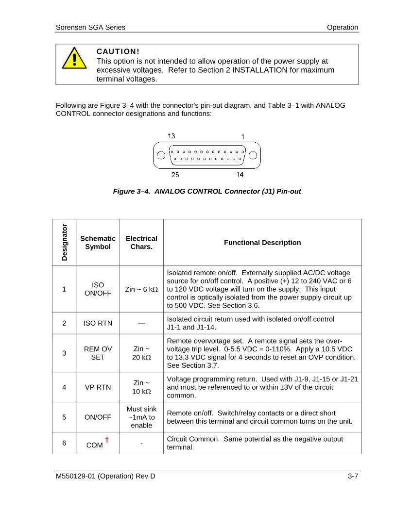
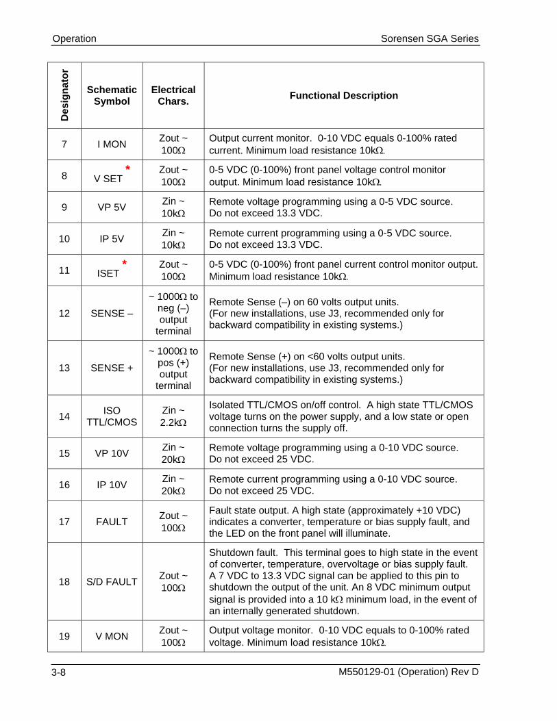
Following are Figure 3–4 with the connector's pin-out diagram, and Table 3–1 with ANALOG CONTROL connector designations and functions:
Figure 3–4. ANALOG CONTROL Connector (J1) Pin-out
Des
igna
tor
Schematic Symbol
Electrical Chars. Functional Description
1 ISO ON/OFF Zin ~ 6 kΩ
Isolated remote on/off. Externally supplied AC/DC voltage source for on/off control. A positive (+) 12 to 240 VAC or 6 to 120 VDC voltage will turn on the supply. This input control is optically isolated from the power supply circuit up to 500 VDC. See Section 3.6.
2 ISO RTN — Isolated circuit return used with isolated on/off control J1-1 and J1-14.
3 REM OV SET
Zin ~ 20 kΩ
Remote overvoltage set. A remote signal sets the over-voltage trip level. 0-5.5 VDC = 0-110%. Apply a 10.5 VDC to 13.3 VDC signal for 4 seconds to reset an OVP condition. See Section 3.7.
4 VP RTN Zin ~ 10 kΩ
Voltage programming return. Used with J1-9, J1-15 or J1-21 and must be referenced to or within ±3V of the circuit common.
5 ON/OFF Must sink ~1mA to enable
Remote on/off. Switch/relay contacts or a direct short between this terminal and circuit common turns on the unit.
6 COM †
- Circuit Common. Same potential as the negative output terminal.
M550129-01 (Operation) Rev D 3-7
Operation Sorensen SGA Series
Des
igna
tor
Schematic Symbol
Electrical Chars. Functional Description
7 I MON Zout ~ 100Ω
Output current monitor. 0-10 VDC equals 0-100% rated current. Minimum load resistance 10kΩ.
8 V SET *
Zout ~ 100Ω
0-5 VDC (0-100%) front panel voltage control monitor output. Minimum load resistance 10kΩ.
9 VP 5V Zin ~ 10kΩ
Remote voltage programming using a 0-5 VDC source. Do not exceed 13.3 VDC.
10 IP 5V Zin ~ 10kΩ
Remote current programming using a 0-5 VDC source. Do not exceed 13.3 VDC.
11 ISET *
Zout ~ 100Ω
0-5 VDC (0-100%) front panel current control monitor output. Minimum load resistance 10kΩ.
12 SENSE – ~ 1000Ω to
neg (–) output
terminal
Remote Sense (–) on 60 volts output units. (For new installations, use J3, recommended only for backward compatibility in existing systems.)
13 SENSE + ~ 1000Ω to
pos (+) output
terminal
Remote Sense (+) on <60 volts output units. (For new installations, use J3, recommended only for backward compatibility in existing systems.)
14 ISO TTL/CMOS
Zin ~ 2.2kΩ
Isolated TTL/CMOS on/off control. A high state TTL/CMOS voltage turns on the power supply, and a low state or open connection turns the supply off.
15 VP 10V Zin ~ 20kΩ
Remote voltage programming using a 0-10 VDC source. Do not exceed 25 VDC.
16 IP 10V Zin ~ 20kΩ
Remote current programming using a 0-10 VDC source. Do not exceed 25 VDC.
17 FAULT Zout ~ 100Ω
Fault state output. A high state (approximately +10 VDC) indicates a converter, temperature or bias supply fault, and the LED on the front panel will illuminate.
18 S/D FAULT Zout ~ 100Ω
Shutdown fault. This terminal goes to high state in the event of converter, temperature, overvoltage or bias supply fault. A 7 VDC to 13.3 VDC signal can be applied to this pin to shutdown the output of the unit. An 8 VDC minimum output signal is provided into a 10 kΩ minimum load, in the event of an internally generated shutdown.
19 V MON Zout ~ 100Ω
Output voltage monitor. 0-10 VDC equals to 0-100% rated voltage. Minimum load resistance 10kΩ.
M550129-01 (Operation) Rev D 3-8

Sorensen SGA Series Operation
Des
igna
tor
Schematic Symbol
Electrical Chars. Functional Description
20 VP RTN Zin ~ 10Ω
Voltage programming return. Used with J1-9, J1-15 or J1-21 and must be referenced to or within ±3V of the circuit common.
21 VP RES *
~ 10.8V compliance
1 milliamp current source for remote voltage programming using resistance. 0-5k ohm resistor referenced to common will program the output voltage from 0-100%.
22 IP RES *
~ 10.8V compliance
1 milliamp current source for remote current programming using resistance. 0-5k ohm resistor referenced to common will program the output from 0-100%.
23 IP RTN Zin ~ 10kΩ
Current programming return. Used with J1-10, J1-16 or J1-22 and must be referenced to or within ±3V of the circuit common.
24 COM †
- Circuit common. Same potential as the negative output terminal.
25 IP RTN Zin ~ 10kΩ
Current programming return. Used with J1-10, J1-16 or J1-22 for remote current programming and must be referenced to or within ±3V of the circuit common.
Table 3–1. ANALOG CONTROL Connector (J1), Designations and Functions † Control ground is isolated from power ground with the isolated analog control
(option). See Section 3.2.5.1 * Signals not available with isolated analog control (option).
CAUTION! If standard analog programming is used, note the programming return (J1-6 & J1-24) is at the same potential as the negative output terminal of the power supply. Observance of return connections should be made with respect to input programming signal equipment. Improper connection may result in ground loops and as a result internal power supply damage may occur. (Output current then flows to chassis by means of external connection to the J1 common (J1-6 & J1-24)).
M550129-01 (Operation) Rev D 3-9

Operation Sorensen SGA Series
3.3 Remote Current Programming Remote current programming is used for applications that require the output current be programmed (controlled) from a remote source. An external resistance or external voltage source may be used as a programming device. When using remote current programming, a shielded, twisted-pair, hookup wire is recommended to prevent noise interference with programming signals.
1. Remote Current Programming Using Resistance: The resistance coefficient for remote current programming is 5k ohms/100% rated output with respect to terminal J1-23 (IP RTN). The programming current from terminal J1-22 (IP RES) is factory set for 1 milliampere. This yields a coefficient of 1.0% of rated output current for each 50 ohms. If multiple switches or relays are used to program different levels, make-before-break contacts are recommended. Note that if an external resistance is used for remote programming, the current programming return (IP RTN), terminal J1-23, must be connected directly to or within ±3 volts (see note) of the power supply common terminal, J1-24. See Figure 3–5 for connection requirements.
Figure 3–5. Remote Current Programming Using Resistance
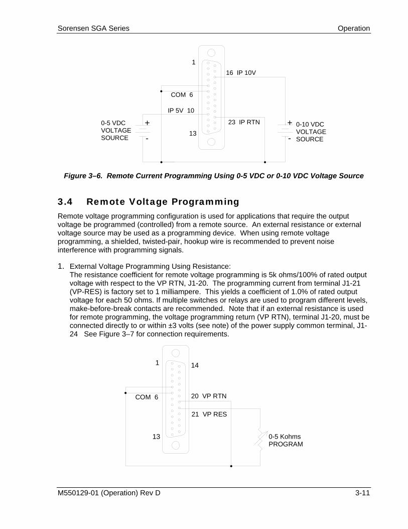
2. Remote Current Programming Using a 0-5 VDC or 0-10 VDC Voltage Source: A DC voltage source for remote current programming is connected between J1-10 (IP 5V) or J1-16 (IP 10V) and the return terminal J1-23 (IP RTN). Note that the return terminal J1-23 (IP RTN) must be referenced directly to or within ±3V (see note) of the power supply common, J1-24. The voltage coefficient for 5V remote current programming is 50 millivolts = 1% of rated output, i.e., for a 300 amp model, each 50 millivolts of programming voltage equals 3 amps of output current. The voltage coefficient for 10V remote current programming is 100 millivolts = 1% of rated output, i.e., for a 300 amp model, each 100 millivolts of programming voltage equals 3 amps of output current. See Figure 3–6 for connection requirements.
M550129-01 (Operation) Rev D 3-10
Sorensen SGA Series Operation
+
-
1
1323 IP RTN
COM 6
+
-
16 IP 10V
IP 5V 10
0-5 VDCVOLTAGESOURCE
0-10 VDCVOLTAGESOURCE
Figure 3–6. Remote Current Programming Using 0-5 VDC or 0-10 VDC Voltage Source
3.4 Remote Voltage Programming Remote voltage programming configuration is used for applications that require the output voltage be programmed (controlled) from a remote source. An external resistance or external voltage source may be used as a programming device. When using remote voltage programming, a shielded, twisted-pair, hookup wire is recommended to prevent noise interference with programming signals.
1. External Voltage Programming Using Resistance: The resistance coefficient for remote voltage programming is 5k ohms/100% of rated output voltage with respect to the VP RTN, J1-20. The programming current from terminal J1-21 (VP-RES) is factory set to 1 milliampere. This yields a coefficient of 1.0% of rated output voltage for each 50 ohms. If multiple switches or relays are used to program different levels, make-before-break contacts are recommended. Note that if an external resistance is used for remote programming, the voltage programming return (VP RTN), terminal J1-20, must be connected directly to or within ±3 volts (see note) of the power supply common terminal, J1-24 See Figure 3–7 for connection requirements.
1
13
14
20 VP RTN
21 VP RES
COM 6
0-5 KohmsPROGRAM
M550129-01 (Operation) Rev D 3-11
Operation Sorensen SGA Series
Figure 3–7. Remote Voltage Programming Using Resistance
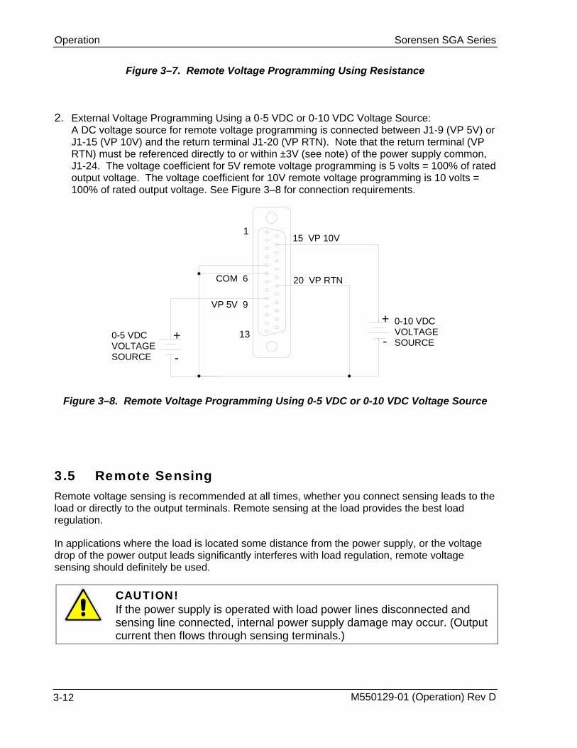
2. External Voltage Programming Using a 0-5 VDC or 0-10 VDC Voltage Source: A DC voltage source for remote voltage programming is connected between J1-9 (VP 5V) or J1-15 (VP 10V) and the return terminal J1-20 (VP RTN). Note that the return terminal (VP RTN) must be referenced directly to or within ±3V (see note) of the power supply common, J1-24. The voltage coefficient for 5V remote voltage programming is 5 volts = 100% of rated output voltage. The voltage coefficient for 10V remote voltage programming is 10 volts = 100% of rated output voltage. See Figure 3–8 for connection requirements.
115 VP 10V
+
-
13
20 VP RTNCOM 6
+
-
VP 5V 9
0-5 VDCVOLTAGESOURCE
0-10 VDCVOLTAGESOURCE
Figure 3–8. Remote Voltage Programming Using 0-5 VDC or 0-10 VDC Voltage Source
3.5 Remote Sensing Remote voltage sensing is recommended at all times, whether you connect sensing leads to the load or directly to the output terminals. Remote sensing at the load provides the best load regulation.
In applications where the load is located some distance from the power supply, or the voltage drop of the power output leads significantly interferes with load regulation, remote voltage sensing should definitely be used.
CAUTION! If the power supply is operated with load power lines disconnected and sensing line connected, internal power supply damage may occur. (Output current then flows through sensing terminals.)
M550129-01 (Operation) Rev D 3-12

Sorensen SGA Series Operation
To use remote voltage sensing, connect the power supply as described below. See Figure 3–9 for connection requirements.
Connect sensing leads from the load positive to J3-1 and the load negative to J3-2. A shielded, twisted-pair, hookup wire is recommended to avoid potential noise interference.
Figure 3–9. Remote Sensing Operation at the Load
M550129-01 (Operation) Rev D 3-13

Operation Sorensen SGA Series
3.6 Remote Output On/Off Control Remote on/off control may be accomplished by contact closure or by an isolated external AC/DC or TTL/CMOS voltage source. 1. Remote on/off by contact closure. Output is on when contacts (J1-5 and J1-6) are closed.
See Figure 3–10 for connection requirements.
1 14
25
6
ON/OFF 5
Figure 3–10. Remote On/Off Control by Contact Closure
2. Remote on/off control may be accomplished by an external 12 to 240 VAC or 6 to 120 VDC or TTL/CMOS source. Application of AC/DC or high state TTL/CMOS voltage will turn on the power supply. See Figure 3–11 and Figure 3–12 for connection requirements.
25
14
-AC OR DCSOURCE
ISO RTN 2
ISO ON/OFF 1+
Figure 3–11. Remote On/Off Using Isolated AC or DC Voltage Source
M550129-01 (Operation) Rev D 3-14

Sorensen SGA Series Operation
25
14 ISO TTL/CMOS1
ISO RTN 2
Figure 3–12. Remote On/Off Using Isolated TTL/CMOS Voltage Supply
3.7 Remote Overvoltage Setpoint
CAUTION! Do not program the remote overvoltage set point greater than 10% (5.5V) above the power supply rated voltage (except as noted) as internal power supply damage may occur.
A remote DC voltage source can be connected externally between terminals J1-6 (COM) and J1-3 (REM OV SET) to set the output overvoltage trip level. A 0-5.5 VDC signal equals 0-110% of rated output voltage. See Figure 3–13 for connection requirements.
+
-
1
13
COM 6
REM OV SET 3
0-5.5 VDCVOLTAGESOURCE
Figure 3–13. Remote Overvoltage Set Using DC Voltage Source
Note: The Remote OVP trip level will ALWAYS take precedence over the local trip level, even if the local OVP trip level is set to a lower value. To reset an OVP externally, apply a 10.5–13.3 VDC signal to J1-3 for a minimum of four (4) seconds.
M550129-01 (Operation) Rev D 3-15
Operation Sorensen SGA Series
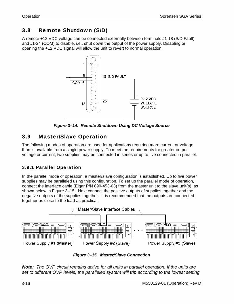
3.8 Remote Shutdown (S/D) A remote +12 VDC voltage can be connected externally between terminals J1-18 (S/D Fault) and J1-24 (COM) to disable, i.e., shut down the output of the power supply. Disabling or opening the +12 VDC signal will allow the unit to revert to normal operation.
Figure 3–14. Remote Shutdown Using DC Voltage Source
3.9
3.9.1
Master/Slave Operation The following modes of operation are used for applications requiring more current or voltage than is available from a single power supply. To meet the requirements for greater output voltage or current, two supplies may be connected in series or up to five connected in parallel.
Parallel Operation
In the parallel mode of operation, a master/slave configuration is established. Up to five power supplies may be paralleled using this configuration. To set up the parallel mode of operation, connect the interface cable (Elgar P/N 890-453-03) from the master unit to the slave unit(s), as shown below in Figure 3–15. Next connect the positive outputs of supplies together and the negative outputs of the supplies together. It is recommended that the outputs are connected together as close to the load as practical.
Figure 3–15. Master/Slave Connection
Note: The OVP circuit remains active for all units in parallel operation. If the units are set to different OVP levels, the paralleled system will trip according to the lowest setting.
M550129-01 (Operation) Rev D 3-16

Sorensen SGA Series Operation
For ease of use, adjust the OVP levels for the slaves to maximum and adjust the master OVP level to the desired setting.
3.9.2 Series Operation
Series operation is used to obtain a higher voltage single output supply using two units. Connect the negative terminal (–) of one supply to the positive terminal (+) of the next supply of the same model. The total voltage available is the sum of the maximum voltages of each supply (add voltmeter readings). Notes:
1. Under no condition should the negative (–) output terminal of any power supply exceed 150V to Earth ground. This is limited by the creepage/clearance distances internal to the construction of the metal shell 25-pin ‘D’ connector mated to J3. If a higher output voltage range is required, contact the Sorensen Sales Department or Customer Service for availability.
2. The maximum allowable current for a series string of power supplies is the rated output current of a single supply in the string.
3. Remote sensing should not be used during series operation.
M550129-01 (Operation) Rev D 3-17

SECTION 4
4.1
4.1.1
4.1.2
VERIFICATION AND CALIBRATION
Introduction This section provides verification and calibration procedures for the standard SGA Series power supplies and isolated analog control (option).
Verification and Calibration Cycle
It is recommended that the power supply be calibrated and/or verified once each year of operation.
Preparation
WARNING! Hazardous voltages exist on the rear of the supply. Great care must be taken to avoid both the input terminals, and while the supply is enabled, the output terminals. Only authorized personnel should perform this procedure.
Due to the importance of accurate readings to performance, only technically trained personnel should perform calibration procedures.
The calibration and adjustment procedures require two digital multimeters. To set up for the calibration procedures, first perform the following:
• Remove prime AC power.
• Connect the power supply to a precision current shunt (as shown in Figure 4–1 below) capable of a minimum of 10% above full rated output. A fan may be required to cool the shunt.
M550129-01 (Operation) Rev D 4-1

Verification and Calibration Sorensen SGA Series
SHUNT
Figure 4–1. Precision Current Shunt
4.2
4.2.1
Standard Verification and Calibration Procedure All calibration potentiometers can be adjusted through access holes in the top cover of the SGA Series unit. It is not necessary to remove the top cover to perform the calibration procedures.
Current Mode
1. Set the SGA Series unit to operate in remote current programming mode using an external 0-5 Vdc voltage source as shown in Figure 3–6 in Section 3.3 Remote Current Programming.
2. Attach a precision meter across the shunt Kelvin terminals.
3. Attach a precision meter in parallel with the voltage programming source.
4. Set the voltage source to 0.0V ± 1mV.
5. Apply AC power and turn the front panel voltage set potentiometer fully clockwise and verify the current mode indicator is illuminated.
6. Verify the unit is set to 0A ± 0.8% of full-scale output. If necessary, adjust R55 for zero current through the shunt. (See Figure 4–2.)
7. Set the programming voltage to 5.0V ± 1mV.
8. Verify the unit is set to 100% ± 0.8% of full-scale output current. If necessary, adjust R69 for 100% of full-scale current on the shunt.
9. Set the programming source for 0.5V ± 1mV.
M550129-01 (Operation) Rev D 4-2

Sorensen SGA Series Verification and Calibration
10. Verify the unit is set to 10% ± 0.8% of full-scale output current. If necessary, adjust R55 for 10% of full-scale current on the shunt.
11. Repeat the steps above as required to obtain the required accuracy.
12. Set the programming source to obtain 100% output current on the shunt. Verify that the front panel meter displays 100% ± 1% of full-scale output current. If necessary adjust R85 such that the current display reads 100% current.
4.2.2 Voltage Mode
1. Disable AC power to the unit. Remove the current shunt from the output and verify that there is no load attached.
2. Remove the precision meter leads from the current shunt and apply them across the output terminals.
3. Set the SGA series unit to operate in remote voltage programming mode using an external 0-5 Vdc voltage source as shown in Figure 3–8. in Section 3.4 Remote Voltage Programming.
4. Apply AC power and turn the front panel current set potentiometer fully clockwise and verify that the voltage mode indicator is illuminated.
5. Verify that the unit is set to 0V ± 0.25% of full-scale output voltage. If necessary adjust R90 to obtain zero output volts. (See Figure 4–2.)
6. Set the programming source to 5.0V ±1mV.
7. Verify that the unit is set to 100% ± 0.25% of full-scale output voltage. If necessary adjust R74 for 100% output voltage.
8. Set the programming source to 0.5V ±1mV.
9. Verify that the unit is set to 10% ± 0.25% of full-scale output voltage. If necessary adjust R90 for 10% output voltage.
10. Repeat the steps above as required to obtain the required accuracy.
11. Set the programming source to obtain 100% output voltage. Verify the front panel meter displays 100% ± 1% of full-scale output voltage. If necessary adjust R73 such that the front panel voltage meter reads 100% output voltage.
12. Remove all connections to the remote analog control connector (J1), except the jumper between pins 5 and 6. This reverts the SGA series unit back to local, front panel control.
13. Turn the front panel voltage pot fully clockwise.
14. Verify that the front panel meter displays a minimum of 100.5% of full-scale output voltage. If necessary, adjust R74 such that the output voltage is 100.5% of rating.
M550129-01 (Operation) Rev D 4-3
Verification and Calibration Sorensen SGA Series
CAUTION! Hazardous voltages may be present on the output after the output is disabled due to stored capacitive charge. Allow 5 minutes to drain the output capacitive charge to safe levels before connecting or removing output wiring.
4.2.3
4.3
Resistor Programming Current Sources
1. Disable AC power to the unit. Turn the front panel Voltage and Current knobs fully counterclockwise.
2. Connect the power supply to a precision current shunt (see Figure 4–1, Section 4.1.2 Preparation).
3. Set the SGA series unit to operate in remote current programming mode using resistance by connecting a 5K ohm (1% or better tolerance) resistor as shown in Figure 3–5 in Section 3.3 Remote Current Programming.
4. Attach a precision meter across the shunt Kelvin terminals.
5. Apply AC power and enable the unit via the front panel On/Off switch.
6. Verify there is 5V ±1% across the resistor. If necessary, adjust R45 to measure 5.00V read back on the voltmeter.
7. Disable AC power to the unit.
8. Set the SGA series unit to operate in remote voltage programming mode using resistance by connecting a 5K ohm (1% or better tolerance) resistor as shown in Figure 3–7 in Section 3.4 Remote Voltage Programming.
9. Apply AC power and enable the unit via the front panel On/Off switch.
10. Verify that there is 5V ± 1% across the resistor. If necessary, adjust R71 to measure 5.00V read back on the voltmeter.
11. Disable AC power and remove all connections to the remote analog control connector (J1), except the jumper between pins 5 and 6.
Isolated Analog (Option) Verification and Calibration Procedure
All calibration potentiometers can be adjusted through access holes in the top cover of the SGA Series unit. It is not necessary to remove the top cover to perform the calibration procedures.
M550129-01 (Operation) Rev D 4-4
Sorensen SGA Series Verification and Calibration
4.3.1
4.3.2
Current Mode
1. Set the SGA series unit to operate in remote current programming mode using an external 0-5 Vdc voltage source as shown in Figure 3–6 in Section 3.3 Remote Current Programming.
2. Attach a precision meter across the shunt Kelvin terminals.
3. Attach a precision meter in parallel with the voltage programming source.
4. Set the voltage source to 0.0V ± 1mV.
5. Apply AC power and turn the front panel voltage set potentiometer fully clockwise and verify the current mode indicator is illuminated.
6. Verify that the unit is set to 0A ± 0.8% of full-scale output. If necessary, adjust R47 for zero current through the shunt (see Figure 4–1 in Section 4.1.2 Preparation).
7. Set the programming voltage to 5.0V ± 1mV.
8. Verify that the unit is set to 100% ± 0.8% of full scale output current. If necessary, adjust R33 for 100% of full scale current on the shunt.
9. Set the programming source for 0.5V ± 1mV.
10. Verify that the unit is set to 10% ± 0.8% of full scale output current. If necessary, adjust R47 for 10% of full scale current on the shunt.
11. Repeat the steps above as required to obtain the required accuracy.
12. Set the programming source to obtain 100% output current on the shunt. Verify that the front panel meter displays 100% ± 1% of full-scale output current. If necessary adjust R85 such that the current display reads 100% current.
Voltage Mode
1. Disable AC power to the unit. Remove the current shunt from the output and verify that there is no load attached.
2. Remove the precision meter leads from the current shunt and apply them across the output terminals.
3. Set the SGA series unit to operate in remote voltage programming mode using an external 0-5 Vdc voltage source as shown in Figure 3–8. in Section 3.4 Remote Voltage Programming.
4. Apply AC power and turn the front panel current set potentiometer fully clockwise and verify that the voltage mode indicator is illuminated.
5. Verify that the unit is set to 0V ± 0.25% of full-scale output voltage. If necessary adjust R35 to obtain zero output volts. (See Figure 4–2.)
6. Set the programming source to 5.0V ±1mV.
M550129-01 (Operation) Rev D 4-5

Verification and Calibration Sorensen SGA Series
7. Verify that the unit is set to 100% ± 0.25% of full-scale output voltage. If necessary adjust R39 for 100% output voltage.
8. Set the programming source to 0.5V ±1mV.
9. Verify that the unit is set to 10% ± 0.25% of full-scale output voltage. If necessary adjust R35 for 10% output voltage.
10. Repeat the steps above as required to obtain the required accuracy.
11. Set the programming source to obtain 100% output voltage. Verify the front panel meter displays 100% ± 1% of full-scale output voltage. If necessary adjust R73 such that the front panel voltage meter reads 100% output voltage.
12. Remove all connections to the remote analog control connector (J1), except the jumper between pins 5 and 6. This reverts the SGA series unit back to local, front panel control.
13. Turn the front panel voltage pot fully clockwise.
13. Verify that the front panel meter displays a minimum of 100.5% of full-scale output voltage If necessary, adjust R74 such that the output voltage is 100.5% of rating.
CAUTION! Hazardous voltages may be present on the output after the output is disabled due to stored capacitive charge. Allow 5 minutes to drain the output capacitive charge to safe levels before connecting or removing output wiring.
M550129-01 (Operation) Rev D 4-6
Sorensen SGA Series Verification and Calibration
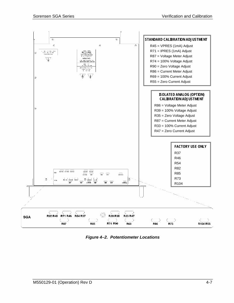
STANDARD CALIBRATION ADJUSTMENT R45 = VPRES (1mA) Adjust R71 = IPRES (1mA) Adjust R87 = Voltage Meter Adjust R74 = 100% Voltage Adjust R90 = Zero Voltage Adjust R86 = Current Meter Adjust R69 = 100% Current Adjust R55 = Zero Current Adjust
ISOLATED ANALOG (OPTION) CALIBRATION ADJUSTMENT
R86 = Voltage Meter Adjust R39 = 100% Voltage Adjust R35 = Zero Voltage Adjust R87 = Current Meter Adjust R33 = 100% Current Adjust R47 = Zero Current Adjust
FACTORY USE ONLY R37 R46 R54 R82
Figure 4–2. Po
M550129-01 (Operation) Rev D
R85 R73 R104
tentiometer Locations
4-7

SECTION 5
5.1
MAINTENANCE
Introduction This chapter contains preventive maintenance information for the SGA Series power supplies.
WARNING! All maintenance that requires removal of the cover of the unit should only be done by properly trained and qualified personnel. Hazardous voltages exist inside the unit. Disconnect the supply from the input power before performing any maintenance. Service, fuse verification, and connection of wiring to the chassis must be accomplished at least five minutes after power has been removed via external means; all circuits and/or terminals to be touched must be safety grounded to the chassis.
5.2 Preventive Maintenance
No routine maintenance on the SGA Series is required, aside from periodic cleaning of the unit when needed:
• Once a unit is removed from service, vacuum all air vents, including the front panel grill. Clean the exterior with a mild solution of detergent and water. Apply the solution onto a soft cloth, not directly to the surface of the unit. To prevent damage to materials, do not use aromatic hydrocarbons or chlorinated solvents for cleaning.
• Low–pressure compressed air may be used to remove dust from in and around components on the printed circuit boards.
WARNING! The OFF position of the power switch does not remove voltage from the input terminal blocks. Remove all external power before performing any service.
M550129-01 (Operation) Rev D 5-1
Maintenance Sorensen SGA Series
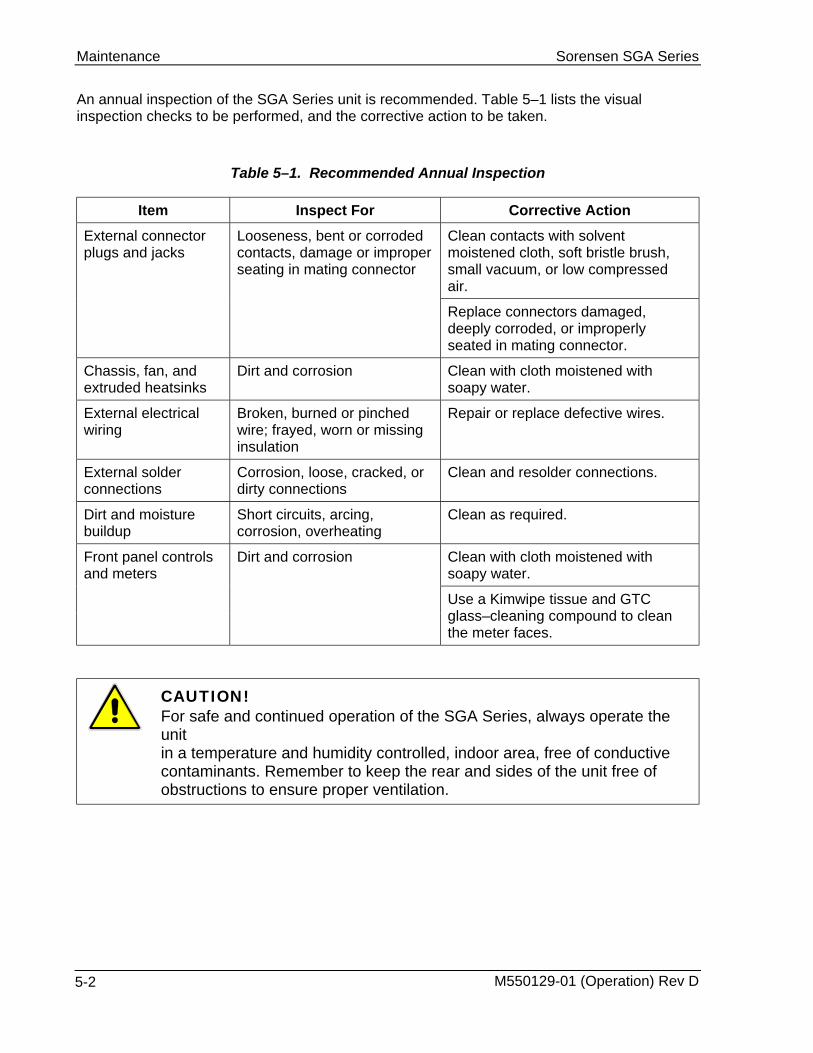
An annual inspection of the SGA Series unit is recommended. Table 5–1 lists the visual inspection checks to be performed, and the corrective action to be taken.
Table 5–1. Recommended Annual Inspection
Item Inspect For Corrective Action Clean contacts with solvent moistened cloth, soft bristle brush, small vacuum, or low compressed air.
External connector plugs and jacks
Looseness, bent or corroded contacts, damage or improper seating in mating connector
Replace connectors damaged, deeply corroded, or improperly seated in mating connector.
Chassis, fan, and extruded heatsinks
Dirt and corrosion Clean with cloth moistened with soapy water.
External electrical wiring
Broken, burned or pinched wire; frayed, worn or missing insulation
Repair or replace defective wires.
External solder connections
Corrosion, loose, cracked, or dirty connections
Clean and resolder connections.
Dirt and moisture buildup
Short circuits, arcing, corrosion, overheating
Clean as required.
Clean with cloth moistened with soapy water.
Front panel controls and meters
Dirt and corrosion
Use a Kimwipe tissue and GTC glass–cleaning compound to clean the meter faces.
CAUTION! For safe and continued operation of the SGA Series, always operate the unit in a temperature and humidity controlled, indoor area, free of conductive contaminants. Remember to keep the rear and sides of the unit free of obstructions to ensure proper ventilation.
M550129-01 (Operation) Rev D 5-2

Sorensen SGA Series Maintenance
5.3 Fuses There are no user replaceable components in the power supply.
WARNING! Only properly trained and qualified personnel should remove the cover from the power supply. Service, fuse verification, and connection of wiring to the chassis must be accomplished at least five minutes after power has been removed via external means; all circuits and/or terminals to be touched must be safety grounded to the chassis.
CAUTION! To reduce the risk of fire or electrical shock, replace fuses only with the same type and rating.
Internal fuses are listed in Table 5–2. Note, however, that failure of one of these fuses indicates a more serious problem has occurred. Please contact the factory for further assistance.
PCB Part No. Reference Value Manufacturer Part No.
Bias Supply 5546335 F1, F2, F3 600 Volt, 5 Amp Littelfuse KLK-5
Module Controller 5556210 F1 600 Volt, 30 Amp Littelfuse KLKD30
Table 5–2. Fuse Values
M550129-01 (Operation) Rev D 5-3

INDEX
C
Circuit Breaker Requirements, 2-2 Controls and Indicators, 3-1
Analog Control (J1), 3-6 Current Mode
Operation, 3-5 Verification and Calibration, 4-2
F
Fuses, 5-3
I
Inductive Loads, 2-7 Input/Output Connections, 2-2
Connector Functions, 2-3 Isolated Analog Control, 3-6
J
J1 Connector, 3-6
L
Loads Inductive, 2-7
Location and Mounting, 2-2
M
Maintenance Annual Inspection, 5-2 Fuses, 5-3 Preventive, 5-1
Master/Slave Operation, 3-16 Mounting Hardware, 2-2
N
Noise, 1-4
O
Operation Current Mode, 3-5 Local, 3-4 Master/Slave, 3-16 Parallel, 3-16 Remote Current Programming, 3-10 Remote Output On/Off Control, 3-14 Remote Overvoltage Setpoint, 3-15 Remote Sensing, 3-12 Remote Shutdown, 3-16 Remote Voltage Programming, 3-11 Series, 3-17 Voltage Mode, 3-4
Overvoltage Protection, 3-5 Ozone Precaution, 2-2
P
Parallel Operation, 3-16 Potentiometer Locations, 4-7
R
Rack slides, 2-2 Remote Current Programming, 3-10 Remote Output On/Off Control, 3-14 Remote Overvoltage Setpoint, 3-15 Remote Sensing, 3-12 Remote Shutdown, 3-16 Remote Voltage Programming, 3-11 Ripple, 1-4
M550129-01 (Operation) Rev D Index 1

Index Sorensen SGA Series
S
Safety Symbols, iv Series Operation, 3-17 Setup, 3-4 Shaft Lock, 3-3 Specifications, 1-1
Current, 1-4 Electrical Characteristics, 1-2 Environmental Characteristics, 1-1 Noise, 1-4 Physical Characteristics, 1-4 Ripple, 1-4
Voltage, 1-4
V
Ventilation, 2-2 Verification and Calibration, 4-2
Current Mode, 4-2 Voltage Mode
Operation, 3-4
W
Wire Gauge Selection, 2-5 Wire Size, 2-4
Index 2 M550129-01 (Operation) Rev D