sfd-oldercodes
TRANSCRIPT

8/13/2019 SFD-OlderCodes
http://slidepdf.com/reader/full/sfd-oldercodes 1/105
Steel Frame Design Manual AIS ASD-1989, AISC LRFD-1993, & BS 5950-2000

8/13/2019 SFD-OlderCodes
http://slidepdf.com/reader/full/sfd-oldercodes 2/105
ISO ETA032913M6 Rev 0Berkeley, California, USA March 2013
Steel FrameDesign Manual
AISC ASD-1989, AISC LRFD-1993 and BS 5950-2000
For ETABS ® 2013

8/13/2019 SFD-OlderCodes
http://slidepdf.com/reader/full/sfd-oldercodes 3/105

8/13/2019 SFD-OlderCodes
http://slidepdf.com/reader/full/sfd-oldercodes 4/105
DISCLAIMER
CONSIDERABLE TIME, EFFORT AND EXPENSE HAVE GONE INTO THEDEVELOPMENT AND DOCUMENTATION OF THIS SOFTWARE. HOWEVER,THE USER ACCEPTS AND UNDERSTANDS THAT NO WARRANTY ISEXPRESSED OR IMPLIED BY THE DEVELOPERS OR THE DISTRIBUTORS ONTHE ACCURACY OR THE RELIABILITY OF THIS PRODUCT.
THIS PRODUCT IS A PRACTICAL AND POWERFUL TOOL FOR STRUCTURAL
DESIGN. HOWEVER, THE USER MUST EXPLICITLY UNDERSTAND THE BASICASSUMPTIONS OF THE SOFTWARE MODELING, ANALYSIS, AND DESIGNALGORITHMS AND COMPENSATE FOR THE ASPECTS THAT ARE NOTADDRESSED.
THE INFORMATION PRODUCED BY THE SOFTWARE MUST BE CHECKED BYA QUALIFIED AND EXPERIENCED ENGINEER. THE ENGINEER MUSTINDEPENDENTLY VERIFY THE RESULTS AND TAKE PROFESSIONALRESPONSIBILITY FOR THE INFORMATION THAT IS USED.

8/13/2019 SFD-OlderCodes
http://slidepdf.com/reader/full/sfd-oldercodes 5/105
Table of Contents
CHAPTER I Introduction 1Over view . . . . . . . . . . . . . . . . . . . . . . . . . . . . . . . . . 1Organization . . . . . . . . . . . . . . . . . . . . . . . . . . . . . . . 3Rec ommended Read ing . . . . . . . . . . . . . . . . . . . . . . . . . 3
CHAPTER II Design Algorithms 5Design Load Com binations. . . . . . . . . . . . . . . . . . . . . . . . 6Design and Check Sta tions . . . . . . . . . . . . . . . . . . . . . . . . 7P- Effects . . . . . . . . . . . . . . . . . . . . . . . . . . . . . . . . 8Element Un sup ported Lengths . . . . . . . . . . . . . . . . . . . . . . 8Effec tive Length Fac tor ( K ) . . . . . . . . . . . . . . . . . . . . . . . 10Choice of In put Units . . . . . . . . . . . . . . . . . . . . . . . . . . 13
CHAPTER III Check/Design for AISC-ASD89 15Design Load ing Com binations . . . . . . . . . . . . . . . . . . . . . 18Clas sification of Sec tions . . . . . . . . . . . . . . . . . . . . . . . . 18Calculation of Stresses . . . . . . . . . . . . . . . . . . . . . . . . . 22Calculation of Al low able Stresses . . . . . . . . . . . . . . . . . . . 23
Al low able Stress in Ten sion . . . . . . . . . . . . . . . . . . . . 23
Allow able Stress in Com pres sion . . . . . . . . . . . . . . . . . 23Flex ural Buck ling . . . . . . . . . . . . . . . . . . . . . . . 23Flex ural-Tor sional Buck ling. . . . . . . . . . . . . . . . . . 25
Al low able Stress in Bend ing . . . . . . . . . . . . . . . . . . . . 30I-sec tions. . . . . . . . . . . . . . . . . . . . . . . . . . . . 30Chan nel sec tions . . . . . . . . . . . . . . . . . . . . . . . . 33T-sec tions and Dou ble an gles . . . . . . . . . . . . . . . . . 34Box Sec tions and Rect angular Tubes . . . . . . . . . . . . . 35Pipe Sec tions. . . . . . . . . . . . . . . . . . . . . . . . . . 36Round Bars . . . . . . . . . . . . . . . . . . . . . . . . . . 36
i

8/13/2019 SFD-OlderCodes
http://slidepdf.com/reader/full/sfd-oldercodes 6/105
Rect angular and Square Bars . . . . . . . . . . . . . . . . . 36Single-An gle Sec tions. . . . . . . . . . . . . . . . . . . . . 37Gen eral Sec tions . . . . . . . . . . . . . . . . . . . . . . . . 39
Allow able Stress in Shear . . . . . . . . . . . . . . . . . . . . . 39Cal culation of Stress Ra tios . . . . . . . . . . . . . . . . . . . . . . . 41
Axial and Bend ing Stresses. . . . . . . . . . . . . . . . . . . . . 41Shear Stresses. . . . . . . . . . . . . . . . . . . . . . . . . . . . 43
CHAPTER IV Check/Design for AISC-LRFD93 45Design Load ing Com binations . . . . . . . . . . . . . . . . . . . . . 48Clas sification of Sec tions . . . . . . . . . . . . . . . . . . . . . . . . 48Calculation of Fac tored Forces . . . . . . . . . . . . . . . . . . . . . 52Cal culation of Nom inal Strengths . . . . . . . . . . . . . . . . . . . . 54
Com pres sion Ca pac ity . . . . . . . . . . . . . . . . . . . . . . . 54Flex ural Buck ling . . . . . . . . . . . . . . . . . . . . . . . 54
Flex ural-Tor sional Buck ling. . . . . . . . . . . . . . . . . . 58Tor sional and Flex ural-Tor sional Buck ling . . . . . . . . . . 58Ten sion Ca pac ity . . . . . . . . . . . . . . . . . . . . . . . . . . 60Nom inal Strength in Bend ing . . . . . . . . . . . . . . . . . . . 61
Yield ing . . . . . . . . . . . . . . . . . . . . . . . . . . . . 61Lat eral-Tor sional Buck ling . . . . . . . . . . . . . . . . . . 61Flange Lo cal Buck ling. . . . . . . . . . . . . . . . . . . . . 65Web Lo cal Buck ling . . . . . . . . . . . . . . . . . . . . . . 69
Shear Ca pac ities . . . . . . . . . . . . . . . . . . . . . . . . . . 72Cal culation of Ca pac ity Ra tios . . . . . . . . . . . . . . . . . . . . . 73
Axial and Bend ing Stresses. . . . . . . . . . . . . . . . . . . . . 74Shear Stresses. . . . . . . . . . . . . . . . . . . . . . . . . . . . 74
CHAPTER V Check/Design for BS 5950-2000 77Design Load ing Com binations . . . . . . . . . . . . . . . . . . . . . 80Clas sification of Sec tions . . . . . . . . . . . . . . . . . . . . . . . . 81Calculation of Fac tored Forces . . . . . . . . . . . . . . . . . . . . . 81Cal culation of Sec tion Ca pac ities . . . . . . . . . . . . . . . . . . . . 85
Com pres sion Re sistance . . . . . . . . . . . . . . . . . . . . . . 85Ten sion Ca pac ity . . . . . . . . . . . . . . . . . . . . . . . . . . 87Moment Ca pac ity. . . . . . . . . . . . . . . . . . . . . . . . . . 87
Plas tic and Com pact Sec tions . . . . . . . . . . . . . . . . . 87Semi-com pact Sec tions . . . . . . . . . . . . . . . . . . . . 89
Lat eral-Tor sional Buck ling Mo ment Ca pac ity . . . . . . . . . . . 89Shear Ca pac ities . . . . . . . . . . . . . . . . . . . . . . . . . . 91
Cal culation of Ca pac ity Ra tios . . . . . . . . . . . . . . . . . . . . . 93Local Ca pac ity Check . . . . . . . . . . . . . . . . . . . . . . . 93
Under Ax ial Ten sion. . . . . . . . . . . . . . . . . . . . . . 93Under Ax ial Com pres sion . . . . . . . . . . . . . . . . . . . 93
ii
CSI Steel Design Manual

8/13/2019 SFD-OlderCodes
http://slidepdf.com/reader/full/sfd-oldercodes 7/105
Over all Buck ling Check . . . . . . . . . . . . . . . . . . . . . . 94Shear Ca pac ity Check . . . . . . . . . . . . . . . . . . . . . . . 94
CHAPTER VI Design Output 95Over view . . . . . . . . . . . . . . . . . . . . . . . . . . . . . . . . 95
Graph ical Dis play of De sign Out put . . . . . . . . . . . . . . . . . . 96Tab ular Dis play of De sign Out put . . . . . . . . . . . . . . . . . . . 97Mem ber Spe cific In formation . . . . . . . . . . . . . . . . . . . . . . 98
References 101Index 103
iii
Table of Contents

8/13/2019 SFD-OlderCodes
http://slidepdf.com/reader/full/sfd-oldercodes 8/105
C h a p t e r I
Introduction
OverviewETABS fea ture pow erful and com pletely in tegrated mod ules for de sign of bothsteel and re inforced con crete struc tures. The pro gram pro vides the user with op -
tions to cre ate, mod ify, ana lyze and de sign struc tural mod els, all from within thesame user in ter face. The pro gram is ca pa ble of per form ing ini tial mem ber siz ingand op timization from within the same in terface.
The pro gram pro vides an in teractive en viron ment in which the user can study thestress con ditions, make ap pro pri ate changes, such as re vis ing mem ber prop erties,and re- examine the re sults with out the need to re- run the analy sis. A sin gle mouseclick on an ele ment brings up de tailed de sign in formation. Mem bers can begrouped to gether for de sign pur poses. The out put in both graphi cal and tabu latedformats can be read ily printed.
The pro gram is struc tured to sup port a wide va riety of the lat est na tional and in ter-national de sign codes for the auto mated de sign and check of con crete and steelframe mem bers. The steel de sign codes sup ported in pro gram can be found inDesing > Steel Frame De sign > Pref er ences menu.
The de sign is based upon a set of user- specified load ing com binations. How ever,the pro gram pro vides a set of de fault load com binations for each de sign code sup -
Overview 1

8/13/2019 SFD-OlderCodes
http://slidepdf.com/reader/full/sfd-oldercodes 9/105
ported in the program. If the de fault load com binations are ac cept able, no defi nitionof ad ditional load com bination is re quired.
In the de sign pro cess the pro gram picks the least weight sec tion re quired forstrength for each ele ment to be de signed, from a set of user speci fied sec tions. Dif -
ferent sets of avail able sec tions can be speci fied for dif ferent groups of ele ments.Also sev eral ele ments can be grouped to be de signed to have the same sec tion.
In the check pro cess the pro gram pro duces de mand/ca pac ity ra tios for ax ial loadand bi axial mo ment in teractions and shear. The de mand/ca pac ity ra tios are basedon ele ment stress and al low able stress for al low able stress de sign, and on fac toredloads (ac tions) and fac tored ca paci ties (re sis tances) for limit state de sign.
The checks are made for each user speci fied (or pro gram de faulted) load com bina-tion and at sev eral user con trolled sta tions along the length of the ele ment. Maxi -mum de mand/ca pac ity ra tios are then re ported and/or used for de sign op timization.
All al low able stress val ues or de sign ca pac ity val ues for ax ial, bend ing and shearactions are cal culated by the pro gram. Te dious cal culations as sociated with evalu -ating ef fec tive length fac tors for col umns in mo ment frame type struc tures are auto -mated in the al go rithms.
The pres entation of the out put is clear and con cise. The in formation is in a form thatallows the designer to take ap pro pri ate re medial meas ures if there is mem ber over -stress. Backup de sign in formation pro duced by the pro gram is also pro vided forcon ven ient veri fication of the re sults.
When us ing AISC-LRFD de sign codes, re quire ments for con tinuity plates at thebeam to col umn con nec tions are eval uated. The pro gram per forms a joint shearanal y sis to de termine if doubler plates are re quired in any of the joint panel zones.Max imum beam shears re quired for the beam shear con nec tion de sign are re ported.Also max imum ax ial ten sion or com pres sion val ues that are gen erated in the mem -ber are re ported.
Spe cial 1989AISC-ASD and 1993 AISC--LRFD seis mic de sign pro visions are im -plemented in the cur rent ver sion of the pro gram. The ra tio of the beam flex ural ca -pac ities with re spect to the col umn re duced flex ural ca pac ities (re duced for ax ialforce ef fect) as so ci ated with the weak beam-strong col umn as pect of any beam/col -umn in tersec tion, are re ported for spe cial mo ment re sist ing frames. Ca pac ity re -quire ments as sociated with seis mic fram ing sys tems that re quire duc til ity arechecked.
Eng lish as well as SI and MKS met ric units can be used to de fine the model ge ome -try and to spec ify de sign pa rame ters.
2 Overview
CSI Steel Design Manual

8/13/2019 SFD-OlderCodes
http://slidepdf.com/reader/full/sfd-oldercodes 10/105
OrganizationThis man ual is or gan ized in the fol low ing way:
Chap ter II out lines vari ous as pects of the steel de sign pro cedures of the pro gram.
This chap ter de scribes the com mon ter minol ogy of steel de sign as im plemented inthe program.
Each of eleven sub sequent chap ters gives a de tailed de scrip tion of a spe cific codeof prac tice as in terpreted by and im plemented in the program. Each chap ter de -scribes the de sign load ing com binations to be con sidered; al low able stress or ca -pac ity cal culations for ten sion, com pres sion, bend ing, and shear; cal culations of demand/ca pac ity ra tios; and other spe cial con sidera tions re quired by the code.
• Chap ter III gives a de tailed de scrip tion of the AISC ASD steel code (AISC
1989) as im plemented in the pro gram.• Chap ter IV gives a de tailed de scrip tion of the AISC LRFD steel code (AISC
1993) as im plemented in the pro gram.
• Chap ter V gives a de tailed de scrip tion of the Brit ish code BS 5950 (BSI 2000)as im plemented in the pro gram.
Chap ter VI out lines vari ous as pects of the tabu lar and graphi cal out put from theprogram re lated to steel de sign.
Recommended ReadingIt is rec ommended that the user read Chap ter II “De sign Al gorithms” and one of eleven sub sequent chap ters cor respond ing to the code of in terest to the user. Fi nallythe user should read “De sign Out put” in Chap ter VI for un der stand ing and in ter-pret ing the program out put re lated to steel de sign.
Organization 3
Chapter I Introduction

8/13/2019 SFD-OlderCodes
http://slidepdf.com/reader/full/sfd-oldercodes 11/105
C h a p t e r II
Design Algorithms
This chap ter out lines vari ous as pects of the steel check and de sign pro cedures thatare used by the pro gram. The steel de sign and check may be per formed ac cord ingto one of the fol low ing codes of prac tice.
• Amer ican In sti tute of Steel Con struc tion’s “Al low able Stress De sign and Plas -tic De sign Spec ification for Struc tural Steel Build ings”, AISC-ASD (AISC1989).
• Ameri can In sti tute of Steel Con struc tion’s “Load and Re sis tance Fac tor De -sign Speci fication for Struc tural Steel Build ings”, AISC- LRFD (AISC 1994) .
• Brit ish Stan dards In sti tution’s “Struc tural Use of Steel work in Build ing”, BS5950 (BSI 2000).
Details of the al go rithms as so ci ated with each of these codes as im ple mented andinterpreted in the pro gram are de scribed in sub sequent chap ters. How ever, thischap ter pro vides a back ground which is com mon to all the de sign codes.
It is as sumed that the user has an en gineer ing back ground in the gen eral area of struc tural steel de sign and fa mili arity with at least one of the above men tioned de -sign codes.
5

8/13/2019 SFD-OlderCodes
http://slidepdf.com/reader/full/sfd-oldercodes 12/105
For re ferring to per tinent sec tions of the cor respond ing code, a unique pre fix is as -signed for each code. For ex ample, all ref er ences to the AISC-LRFD code carry thepre fix of “ LRFD ”. Sim ilarly,
– Ref erences to the AISC-ASD code carry the pre fix of “ ASD ”
– Ref erences to the Brit ish code carry the pre fix of “ BS ”
Design Load CombinationsThe de sign load com binations are used for de termin ing the vari ous com binations ofthe load cases for which the struc ture needs to be de signed/checked. The load com -bination fac tors to be used vary with the se lected de sign code. The load com bina-tion fac tors are ap plied to the forces and mo ments ob tained from the as sociatedload cases and the re sults are then summed to ob tain the fac tored de sign forces andmoments for the load com bination.
For multi- valued load com binations in volv ing re sponse spec trum, time his tory,mov ing loads and multi- valued com binations (of type en vel oping, square- root of the sum of the squares or ab solute) where any cor respon dence be tween in teract ingquan tities is lost, the pro gram auto mati cally pro duces mul tiple sub com binationsusing maxima/min ima per mutations of in teract ing quan tities. Sepa rate com bina-tions with nega tive fac tors for re sponse spec trum cases are not re quired be cause thepro gram auto mati cally takes the min ima to be the nega tive of the maxima for re -sponse spec trum cases and the above de scribed per mutations gen erate the re quiredsub com binations.
When a de sign com bination in volves only a sin gle multi- valued case of time his -tory or mov ing load, fur ther op tions are avail able. The pro gram has an op tion to re -quest that time his tory com binations pro duce sub com binations for each time stepof the time his tory. Also an op tion is avail able to re quest that mov ing load com bi-nations pro duce sub com binations us ing maxima and min ima of each de sign quan -tity but with cor respond ing val ues of in teract ing quan tities.
For nor mal load ing con ditions in volv ing static dead load, live load, wind load, andearth quake load, and/or dy namic re sponse spec trum earth quake load, the pro gramhas built- in de fault load ing com binations for each de sign code. These are based onthe code rec ommen dations and are docu mented for each code in the cor respond ingchap ters.
For other load ing con ditions in volv ing mov ing load, time his tory, pat tern liveloads, sepa rate con sidera tion of roof live load, snow load, etc., the user must de fine
6 Design Load Combinations
CSI Steel Design Manual

8/13/2019 SFD-OlderCodes
http://slidepdf.com/reader/full/sfd-oldercodes 13/105
design load ing com binations ei ther in lieu of or in ad dition to the de fault de signload ing com binations.
The de fault load com bi na tions as sume all static load cases de clared as dead load tobe ad di tive. Simi larly, all cases de clared as live load are as sumed ad ditive. How -
ever, each static load case de clared as wind or earth quake, or re sponse spec trumcases, is as sumed to be non ad ditive with each other and pro duces mul tiple lat eralload com binations. Also wind and static earth quake cases pro duce sepa rate load ingcom binations with the sense (posi tive or nega tive) re versed. If these con ditions arenot cor rect, the user must pro vide the ap pro priate de sign com binations.
The de fault load com binations are in cluded in de sign if the user re quests them to beincluded or if no other user de fined com bination is avail able for con crete de sign. If any de fault com bination is in cluded in de sign, then all de fault com binations willauto mati cally be up dated by the pro gram any time the user changes to a dif ferent
design code or if static or re sponse spec trum load cases are modi fied.Live load re duc tion fac tors can be ap plied to the mem ber forces of the live load caseon an element- by- element ba sis to re duce the con tribution of the live load to thefac tored load ing.
The user is cau tioned that if mov ing load or time his tory re sults are not re quested tobe re cov ered in the analy sis for some or all the frame mem bers, then the ef fects of these loads will be as sumed to be zero in any com bination that in cludes them.
Design and Check StationsFor each load com bination, each el ement is de signed or checked at a num ber of lo -cations along the length of the el ement. The lo cations are based on equally spacedseg ments along the clear length of the el ement. The num ber of seg ments in an el e-ment is re quested by the user be fore the anal y sis is made. The user can re fine thedesign along the length of an el ement by re quest ing more seg ments.
The ax ial-flexure interaction ra tios as well as shear stress ra tios are cal culated foreach sta tion along the length of the mem ber for each load com bination. The ac tualmem ber stress com ponents and cor respond ing al low able stresses are cal culated.Then, the stress ra tios are evalu ated ac cord ing to the code. The con trol ling com -pres sion and/or ten sion stress ra tio is then ob tained, along with the cor respond ingiden tification of the sta tion, load com bination, and code- equation. A stress ra tiogreater than 1.0 in dicates an over stress or ex ceed ing a limit state.
Design and Check Stations 7
Chapter II Design Algorithms

8/13/2019 SFD-OlderCodes
http://slidepdf.com/reader/full/sfd-oldercodes 14/105
P- EffectsThe program de sign al gorithms re quire that the analy sis re sults in clude the P- ef-fects. The P- effects are con sid ered dif ferently for “braced” or “non sway” and“un braced” or “sway” com ponents of mo ments in frames. For the braced mo mentsin frames, the ef fect of P- is lim ited to “in divid ual mem ber sta bil ity”. For un -braced com ponents, “lat eral drift ef fects” should be con sidered in ad dition to in di-vid ual mem ber sta bil ity ef fect. In the program, it is as sumed that “braced” or “non -sway” mo ments are con trib uted from the “dead” or “live” loads. Whereas, “un -braced” or “sway” mo ments are con trib uted from all other types of loads.
For the in divid ual mem ber sta bil ity ef fects, the mo ments are mag nified with mo -ment mag nification fac tors as in the AISC-LRFD code is con sidered di rectly in thedesign equa tions as in the Ca nadian, Brit ish, and Eu ropean codes. No mo mentmag nification is ap plied to the AISC-ASD code.
For lat eral drift ef fects of un braced or sway frames, the program as sumes that theampli fication is al ready in cluded in the re sults be cause P- effects are con sid eredfor all but AISC- ASD code.
The us ers of the pro gram should be aware that the de fault anal ysis op tion in theprogram is turned OFF for P- effect. The de fault number of it era tions for P-analy sis is 1. The user should turn the P- analy sis ON and set the maxi mumnumber of it era tions for the analy sis. No P- analy sis is re quired for the AISC- ASD code. For fur ther ref erence, the user is re ferred to CSI Analy sis Ref er enceMan ual (CSI 2005).
Element Unsupported LengthsTo ac count for col umn slen derness ef fects, the col umn un sup ported lengths are re -quired. The two un sup ported lengths are l 33 and l 22 . See Figure II-1 . These are thelengths be tween sup port points of the ele ment in the cor respond ing di rec tions. Thelength l 33 cor responds to in stabil ity about the 3-3 axis (ma jor axis), and l 22 cor re-sponds to in stabil ity about the 2-2 axis (mi nor axis). The length l 22 is also used forlateral- torsional buck ling caused by ma jor di rec tion bend ing (i.e., about the 3-3axis). See Figure II-2 for cor respon dence be tween the program axes and the axes inthe de sign codes.
Normally, the un sup ported el ement length is equal to the length of the el ement, i.e.,the dis tance be tween END-I and END-J of the el ement. See Figure II-1 . The pro -gram, how ever, al lows us ers to as sign sev eral el e ments to be treated as a sin glemem ber for de sign. This can be done dif ferently for ma jor and mi nor bend ing.
8 P- Effects
CSI Steel Design Manual

8/13/2019 SFD-OlderCodes
http://slidepdf.com/reader/full/sfd-oldercodes 15/105
There fore, ex traneous joints, as shown in Figure II-3 , that af fect the un sup portedlength of an el ement are au tomat ically taken into con sid eration.
In de termin ing the val ues for l 22 and l 33 of the el ements, the pro gram rec ognizesvar ious as pects of the struc ture that have an ef fect on these lengths, such as mem bercon nec tiv ity, di aphragm con straints and sup port points. The pro gram au tomat i-cally lo cates the el ement sup port points and eval uates the cor respond ing un sup -ported el ement length.
There fore, the un sup ported length of a col umn may ac tually be eval uated as be inggreater than the cor respond ing el ement length. If the beam frames into only one di -rec tion of the col umn, the beam is as sumed to give lat eral sup port only in that di rec-tion. The user has op tions to spec ify the un sup ported lengths of the el ements on anelement-by-el ement ba sis.
Element Unsupported Lengths 9
Chapter II Design Algorithms
l33
l 22
Axis 1
Axis 3
Axis 2
End I
End j
Figure II-1 Major and Minor Axes of Bending

8/13/2019 SFD-OlderCodes
http://slidepdf.com/reader/full/sfd-oldercodes 16/105
Effective Length Factor (K )The col umn K -factor al gorithm has been de veloped for building- type struc tures,where the col umns are ver tical and the beams are hori zon tal, and the be hav ior is ba -sically that of a moment- resisting na ture for which the K -factor cal culation is rela -tively com plex. For the pur pose of cal culating K -factors, the ele ments are iden ti -fied as col umns, beams and braces. All ele ments par allel to the Z- axis are clas sifiedas col umns. All ele ments par allel to the X-Y plane are clas sified as beams. The restare braces.
10 Effective Length Factor (K )
CSI Steel Design Manual
2
33
2SAP2000
EUROCODE 3
z
z
y y
ASD89, LRFD95 & AASHTO
y
y
x x
CISC95
y
y
x x
y
y
x x
BS5950
Figure II-2Correspondence between the program Axes and Code Axes

8/13/2019 SFD-OlderCodes
http://slidepdf.com/reader/full/sfd-oldercodes 17/105
The beams and braces are as signed K -fac tors of unity. In the cal culation of theK -fac tors for a col umn el ement, the pro gram first makes the fol low ing four stiff -ness sum mations for each joint in the struc tural model:
S =E I
Lcx
c c
c x
÷÷ S =
E I
Lbx
b b
b x
÷÷
S =E I
Lcy
c c
c y
÷÷ S =
E I
Lby
b b
b y
÷÷
where the x and y sub scripts cor respond to the global X and Y di rec tions and the cand b sub scripts re fer to col umn and beam. The lo cal 2-2 and 3-3 terms EI l22 22
and EI l33 33 are ro tated to give com ponents along the global X and Y direc tions to
form the ( / )EI l x and ( / )EI l y val ues. Then for each col umn, the joint sum mationsat END-I and the END-J of the mem ber are trans formed back to the col umn lo cal1-2-3 co ordinate sys tem and the G-val ues for END-I and the END-J of the mem berare cal culated about the 2-2 and 3-3 di rec tions as fol lows:
Effective Length Factor (K ) 11
Chapter II Design Algorithms
Figure II-3Unsupported Lengths are Affected by Intermediate Nodal Points

8/13/2019 SFD-OlderCodes
http://slidepdf.com/reader/full/sfd-oldercodes 18/105
G =S
S I
I c
I b
2222
22
G =S
S J
J c
J b
2222
22
G =S
S I
I c
I b
3333
33
G =S
S J
J c
J b
3333
33
If a ro ta tional re lease ex ists at a par tic u lar end (and di rec tion) of an el ement, thecor respond ing value is set to 10.0. If all de grees of free dom for a par ticular joint aredeleted, the G-val ues for all mem bers con nect ing to that joint will be set to 1.0 forthe end of the mem ber con nect ing to that joint. Finally, if G I and G J are known fora par ticular di rec tion, the col umn K -fac tor for the cor respond ing di rec tion is cal cu-lated by solv ing the fol low ing re lation ship for :
2 I J
I J
36
6 ( + )=
tanG G
G G
from which K = / . This re lation ship is the mathe mati cal formulation for theevalua tion of K fac tors for moment- resisting frames as sum ing sidesway to be un in-hibi ted. For other struc tures, such as braced frame struc tures, trusses, space frames,trans mis sion tow ers, etc., the K -factors for all mem bers are usu ally unity andshould be set so by the user. The fol low ing are some im por tant as pects as sociatedwith the col umn K -factor al gorithm:
• An ele ment that has a pin at the joint un der con sid era tion will not en ter the stiff -ness sum mations cal culated above. An ele ment that has a pin at the far end
from the joint un der con sidera tion will con trib ute only 50% of the cal culatedEI value. Also, beam ele ments that have no col umn mem ber at the far end fromthe joint un der con sidera tion, such as can tilevers, will not en ter the stiff nesssum mation.
• If there are no beams fram ing into a par ticu lar di rec tion of a col umn ele ment,the as sociated G-value will be in fin ity. If the G-value at any one end of a col -umn for a par ticu lar di rec tion is in fin ity, the K -factor cor respond ing to that di -rec tion is set equal to unity.
• If ro tational re leases ex ist at both ends of an ele ment for a par ticu lar di rec tion,
the cor respond ing K -factor is set to unity.• The auto mated K -factor cal culation pro cedure can oc casion ally gen erate ar tifi-
cially high K -factors, spe cifi cally un der cir cum stances in volv ing skewedbeams, fixed sup port con ditions, and un der other con ditions where the pro -gram may have dif ficulty rec ogniz ing that the mem bers are lat erally sup portedand K -factors of unity are to be used.
12 Effective Length Factor (K )
CSI Steel Design Manual

8/13/2019 SFD-OlderCodes
http://slidepdf.com/reader/full/sfd-oldercodes 19/105

8/13/2019 SFD-OlderCodes
http://slidepdf.com/reader/full/sfd-oldercodes 20/105
C h a p t e r III
Check/Design for AISC-ASD89
This chap ter de scribes the de tails of the struc tural steel de sign and stress check al -gorithms that are used by the pro gram when the user se lects the AISC- ASD89 de -sign code (AISC 1989). Vari ous no tations used in this chap ter are de scribed inTable V-1 .
For re ferring to per tinent sec tions and equa tions of the origi nal ASD code, a uniquepre fix “ASD” is as signed. However, all ref er ences to the “Speci fi ca tions for Al -low able Stress De sign of Single- Angle Mem bers” carry the pre fix of “ASD SAM”.
The de sign is based on user- specified load ing com binations. But the pro gram pro -vides a set of de fault load com binations that should sat isfy re quire ments for the de -sign of most build ing type struc tures.
In the evalua tion of the ax ial force/bi ax ial mo ment ca pac ity ra tios at a sta tion along
the length of the mem ber, first the ac tual mem ber force/mo ment com ponents andthe cor respond ing ca paci ties are cal cu lated for each load com bi na tion. Then the ca -pac ity ra tios are evalu ated at each sta tion un der the in flu ence of all load com bi na -tions us ing the cor respond ing equa tions that are de fined in this chapter. The con -trol ling ca pac ity ra tio is then ob tained. A ca pac ity ra tio greater than 1.0 in dicatesover stress. Simi larly, a shear ca pac ity ra tio is also cal cu lated sepa rately.
15

8/13/2019 SFD-OlderCodes
http://slidepdf.com/reader/full/sfd-oldercodes 21/10516
CSI Steel Design Manual
A = Cross- sectional area, in 2
A e = Effective cross- sectional area for slen der sections, in 2
A f = Area of flange , in 2
A g = Gross cross- sectional area, in 2
A Av v2 3, = Ma jor and mi nor shear ar eas, in 2
A w = Web shear area, dt w , in 2
C b = Bend ing Co efficientC m = Mo ment Co efficientC w = Warp ing con stant, in 6
D = Out side di ame ter of pipes, inE = Modu lus of elas ticity, ksiF
a= Al low able ax ial stress, ksi
F b = Al low able bending stress, ksiF F b b33 22, = Al low able ma jor and mi nor bend ing stresses, ksiF cr = Criti cal com pres sive stress, ksi
F e 33 =( )
12
23
2
33 33 33
2
E
K l r
F e 22 =( )
12
23
2
22 22 22
2
E
K l r
F v = Al low able shear stress, ksiF y = Yield stress of ma terial, ksiK = Ef fec tive length fac torK K 33 22, = Ef fec tive length K -factors in the ma jor and mi nor directions
M M 33 22, = Major and mi nor bend ing mo ments in mem ber, kip- in M ob = Lateral- torsional mo ment for an gle sections, kip- inP = Axial force in mem ber, kipsPe = Euler buck ling load, kipsQ = Re duc tion fac tor for slen der sec tion, = Q Qa s
Q a = Re duc tion fac tor for stiff ened slen der elementsQ s = Re duc tion fac tor for unstiff ened slen der elementsS = Sec tion modu lus, in 3
S S 33 22, = Ma jor and mi nor sec tion moduli, in 3
Table III-1 AISC-ASD Notations

8/13/2019 SFD-OlderCodes
http://slidepdf.com/reader/full/sfd-oldercodes 22/105 17
Chapter III Check/Design for AISC-ASD89
S S eff eff , ,,33 22 = Ef fec tive major and mi nor sec tion moduli for slen der sections, in 3
S c
= Sec tion modu lus for com pres sion in an an gle section, in 3
V V 2 3, = Shear forces in major and mi nor directions, kipsb = Nomi nal di men sion of plate in a sec tion, in
longer leg of an gle sections,b t f w2 for welded and b t f w3 for rolled box sec tions, etc.
b e = Ef fec tive width of flange, inb f = Flange width, ind = Over all depth of mem ber, in
f a = Axial stress ei ther in com pres sion or in tension, ksi f b = Nor mal stress in bend ing, ksi
f f b b33 22, = Nor mal stress in ma jor and minor di rec tion bending, ksi f v = Shear stress, ksi f f v v2 3, = Shear stress in ma jor and minor di rec tion bending, ksih = Clear dis tance be tween flanges for I shaped sec tions ( )d t f 2 , inh e = Ef fec tive dis tance be tween flanges less fil lets, ink = Dis tance from outer face of flange to web toe of fil let , ink c = Pa rame ter used for clas sification of sec tions,
[ ]4.05
0.46h t w
if h t w > 70 ,
1 if h t w 70 .l l33 22, = Ma jor and mi nor di rec tion un braced mem ber lengths, inlc = Criti cal length, inr = Ra dius of gy ration, inr r 33 22, = Ra dii of gy ration in the ma jor and mi nor di rec tions, inr z = Mini mum Ra dius of gy ration for an gles, int = Thick ness of a plate in I, box, chan nel, an gle, and T sections, int f = Flange thick ness, int w = Web thick ness, in
w = Spe cial sec tion prop erty for an gles, in
Table III-1 AISC-ASD Notations (cont.)

8/13/2019 SFD-OlderCodes
http://slidepdf.com/reader/full/sfd-oldercodes 23/105

8/13/2019 SFD-OlderCodes
http://slidepdf.com/reader/full/sfd-oldercodes 24/105Classification of Sections 19
Chapter III Check/Design for AISC-ASD89
Figure III-1 AISC-ASD Definition of Geometric Properties

8/13/2019 SFD-OlderCodes
http://slidepdf.com/reader/full/sfd-oldercodes 25/10520 Classification of Sections
CSI Steel Design Manual
SectionDescription
RatioChecked
CompactSection
NoncompactSection
SlenderSection
I-SHAPE
b t f
f 2( rolled)
F y65 F y95 No limit
b t f
f 2(welded)
F y65 95 F k y c / No limit
d t w
For f Fa
y 0.16
6401
F
f F y
a
y
( )3.74 ,
For f F a y / > 0.16 257 / F y .
No limit No limit
h t w No limit
If compression only, F y253
otherwise F b760
( )+14000
16.5
260
F F y y
BOX
b t f F y190 F y238 No limit
d t w As for I-shapes No limit No limit
h t w No limit As for I-shapes As for I-shapes
Other t t w f 2 , d bw f 6 None None
CHANNEL
b t f As for I-shapes As for I-shapes No limit
d t w As for I-shapes No limit No limit
h t w No limit As for I-shapes As for I-shapes
Other No limit No limit
If weldedb d f w 0.25,t t
f w 3.0
If rolledb d f w 0.5,t t f w 2.0
Table III-2 Limiting Width-Thickness Ratios for
Classification of Sections Based on AISC-ASD

8/13/2019 SFD-OlderCodes
http://slidepdf.com/reader/full/sfd-oldercodes 26/105
If the sec tion di men sions sat isfy the lim its shown in the ta ble, the sec tion is clas si-fied as ei ther Com pact, Non com pact, or Slen der. If the sec tion sat is fies the cri teriafor Com pact sec tions, then the sec tion is clas sified as Com pact sec tion. If the sec -tion does not sat isfy the cri teria for Com pact sec tions but sat isfies the cri teria forNon com pact sec tions, the sec tion is clas si fied as Noncom pact sec tion. If the sec -tion does not satisfy the cri teria for Com pact and Non com pact sec tions but sat isfies
Classification of Sections 21
Chapter III Check/Design for AISC-ASD89
SectionDescription
RatioChecked
CompactSection
NoncompactSection
SlenderSection
T-SHAPE
b t f
f 2 F y65 F y95 No limit
d t w Not applicable F y127 No limit
Other No limit No limit
If weldedb d f w 0.5,t t f w 1.25
If rolledb d f w 0.5,t t f w 1.10
DOUBLEANGLES
b t Not applicable F y76 No limit
ANGLE b t Not applicable F y76 No limit
PIPE D t F y3 300, F y3300, F y13,000
(Compression only)No limit for flexure
ROUND BAR Assumed Compact
RECTANGLE Assumed Noncompact
GENERAL Assumed Noncompact
Table III-2 Limiting Width-Thickness Ratios for
Classification of Sections Based on AISC-ASD (Cont.)

8/13/2019 SFD-OlderCodes
http://slidepdf.com/reader/full/sfd-oldercodes 27/105
the cri teria for Slen der sec tions, the sec tion is clas si fied as Slender sec tion. If thelim its for Slen der sec tions are not met, the sec tion is clas sified as Too Slen der.Stress check of Too Slen der sec tions is be yond the scope of SAP2000.
In clas sifying web slen derness of I-shapes, Box, and Chan nel sec tions, it is as -
sumed that there are no in termediate stiff eners (ASD F5, G1). Dou ble an gles arecon servatively as sumed to be sepa rated.
Calculation of StressesThe stresses are cal culated at each of the pre viously de fined sta tions. The mem berstresses for non- slender sec tions that are cal cu lated for each load com bi na tion are,in gen eral, based on the gross cross- sectional prop erties.:
f = P/Aa f = M /S b 33 33 33
f = M /S b 22 22 22
f = V /Av v2 2 2
f = V /Av v3 3 3
If the sec tion is slen der with slen der stiff ened ele ments, like slen der web in I, Chan -nel, and Box sec tions or slen der flanges in Box, ef fec tive sec tion moduli based onreduced web and re duced flange di men sions are used in cal culating stresses.
f = P/Aa
(ASD A-B5.2d) f = M /S b eff 33 33 33, (ASD A-B5.2d) f = M /S b eff 22 22 22, (ASD A-B5.2d) f = V /Av v2 2 2 (ASD A-B5.2d) f = V /Av v3 3 3 (ASD A-B5.2d)
The flexural stresses are cal cu lated based on the prop erties about the principal axes.For I, Box, Chan nel, T, Dou ble-an gle, Pipe, Cir cular and Rec tangular sec tions, theprin cipal axes co incide with the geo met ric axes. For Single- angle sec tions, the de -sign con sid ers the prin ci pal properties. For gen eral sec tions it is as sumed that all
sec tion prop erties are given in terms of the prin cipal di rec tions.For Single- angle sec tions, the shear stresses are cal cu lated for di rec tions along thegeo met ric axes. For all other sec tions the shear stresses are cal cu lated along thegeo met ric and prin ciple axes.
22 Calculation of Stresses
CSI Steel Design Manual

8/13/2019 SFD-OlderCodes
http://slidepdf.com/reader/full/sfd-oldercodes 28/105
Calculation of Allowable StressesThe al low able stresses in com pres sion, ten sion, bend ing, and shear are com putedfor Com pact, Non com pact, and Slen der sec tions ac cord ing to the fol low ing sub -sec tions. The al low able flexural stresses for all shapes of sec tions are cal culatedbased on their prin cipal axes of bend ing. For the I, Box, Chan nel, Cir cular, Pipe, T,Dou ble-an gle and Rec tangular sec tions, the prin cipal axes co incide with their geo -met ric axes. For the An gle sec tions, the prin cipal axes are de termined and all com -putations re lated to flex ural stresses are based on that.
If the user speci fies nonz ero al low able stresses for one or more ele ments in the pro -gram “Overwrites Ele ment De sign Data” form, these val ues will over ride the
above men tioned cal cu lated val ues for those ele ments as de fined in the fol low ingsub sec tions. The speci fied al lowable stresses should be based on the prin ci pal axes
of bend ing.
Allowable Stress in Tension
The al low able ax ial ten sile stress value F a is as sumed to be 0.60 F y .
F = F a y0.6 (ASD D1, ASD SAM 2)
It should be noted that net sec tion checks are not made. For mem bers in ten sion,if l r is greater than 300, a mes sage to that ef fect is printed (ASD B7, ASD SAM 2).
For sin gle an gles, the mini mum radius of gy ration, r z , is used in stead of r 22 and r 33in com put ing l r .
Allowable Stress in Compression
The al low able ax ial com pres sive stress is the minimum value ob tained from flex -ural buck ling and flexural- torsional buck ling. The al low able com pres sive stressesare de termined ac cord ing to the fol low ing sub sec tions.
For mem bers in com pres sion, if Kl r is greater than 200, a warn ing mes sage is
printed (ASD B7, ASD SAM 4). For sin gle an gles, the mini mum radius of gy ra-tion, r z , is used in stead of r 22 and r 33 in com put ing Kl r .
Flexural Buckling
The al low able ax ial com pres sive stress value, F a , de pends on the slen derness ra tioKl r based on gross sec tion prop erties and a cor respond ing criti cal value, C c ,where
Calculation of Allowable Stresses 23
Chapter III Check/Design for AISC-ASD89

8/13/2019 SFD-OlderCodes
http://slidepdf.com/reader/full/sfd-oldercodes 29/105
Klr
K l
r
K l
r =
max ,33 33
33
22 22
22
, and
C c = 2 2 E
F y . (ASD E2, ASD SAM 4)
For sin gle an gles, the mini mum radius of gy ration, r z , is used in stead of r 22 and r 33
in com put ing Kl r .
For Com pact or Non com pact sec tions F a is evalu ated as fol lows:
( )
F =
Kl/r
C F
+ Kl/r C
K
ac
y
c
1.0 ( ) 2
22
53
38 ( )l/r
C
c
3
38
, ifKlr
C c , (ASD E2-1, SAM 4-1)
F =E
Kl r a
12
23
2
2( ) , if
Klr
C c> . (ASD E2-2, SAM 4-2)
If Kl r is greater than 200, then the cal culated value of F a is taken not to ex ceed thevalue of F a cal culated by us ing the equa tion ASD E2-2 for Com pact and Non com -pact sec tions (ASD E1, B7).
For Slender sec tions, ex cept slen der Pipe sec tions, F a is evalu ated as fol lows:
( )F = Q
Kl/r
C F
+Kl/r
C
ac
y1.0( ) 2
22
53
3
8
( )c
c
Kl/r
C
3
38
, ifKlr
C c , (ASD A-B5-11, SAM 4-1)
F =E
Kl r a
12
23
2
2( ) , ifKlr C c>
. (ASD A-B5-12, SAM 4-2)
where,
C E
Q F c
y
= 2 2
. (ASD A-B5.2c, ASD SAM 4)
24 Calculation of Allowable Stresses
CSI Steel Design Manual

8/13/2019 SFD-OlderCodes
http://slidepdf.com/reader/full/sfd-oldercodes 30/105
For slen der sec tions, if Kl r is greater than 200, then the cal culated value of F a istaken not to ex ceed its value cal culated by us ing the equa tion ASD A-B5-12 (ASDB7, E1).
For slen der Pipe sec tions F a is evalu ated as fol lows:
F = D t
F a y662
0.40+ (ASD A- B5-9)
The re duc tion fac tor, Q , for all com pact and non com pact sec tions is taken as 1. Forslen der sec tions, Q is com puted as fol lows:
Q Q Qs a= , where (ASD A-B5.2.c, SAM 4)
Q s = re duc tion fac tor for un stiff ened slen der ele ments, and (ASD A-B5.2.a)
Q a = re duc tion fac tor for stiff ened slen der ele ments. (ASD A-B5.2.c)
The Q s fac tors for slen der sec tions are cal culated as de scribed in Table III-3 (ASDA-B5.2a, ASD SAM 4). The Q a fac tors for slen der sec tions are cal culated as theratio of ef fec tive cross- sectional area and the gross cross- sectional area.
Q A
Aa
e
g
= (ASD A- B5-10)
The ef fec tive cross- sectional area is com puted based on ef fec tive width as fol lows:
( ) A A b b t e g e=
b e for un stiff ened el ements is taken equal to b, and b e for stiff ened el ements istaken equal to or less than b as given in Table III-4 (ASD A-B5.2b). For webs in I,box, and Chan nel sec tions, h e is used as b e and h is used as b in the above equa tion.
Flexural-Torsional Buckling
The al low able ax ial com pres sive stress value, F a , de termined by the limit states of torsional and flexural- torsional buck ling is de termined as fol lows (ASD E3, C-E3):
( )
( )F = Q
Kl/r
C F
+Kl/r
C
a
e
c
y
e
1.0
2
22
53
3
8
( )c
e
c
Kl/r
C
3
38
, if ( )Kl/r C e c
, (E2-1, A- B5- 11)
Calculation of Allowable Stresses 25
Chapter III Check/Design for AISC-ASD89

8/13/2019 SFD-OlderCodes
http://slidepdf.com/reader/full/sfd-oldercodes 31/10526 Calculation of Allowable Stresses
CSI Steel Design Manual
SectionType
Re duc tion Fac tor for Un stiff ened Slen der Ele ments(Q s)
EquationReference
I-SHAPE [ ]Q
if b t F k
b t F k if F s
f f y c
f f y c y=
1.0 95
1.293 0.00309 95
2
2
,
[ ]{ }k b t F k
k b t F if b t F k
c f f y c
c f f y f f y c
< <2
2 22
195
26,200 195
,
.
ASD A-B5-3,ASD A-B5-4
BOX Q s = 1 ASD A-B5.2c
CHANNEL As for I-shapes with b t f f 2 replaced by b t f f .ASD A-B5-3,ASD A-B5-4
T-SHAPE
For flanges, as for flanges in I-shapes. For web see below.
[ ]Q
if d t F
d t F if F d t s
w y
w y y w <
1.0 , 127
1.908 0.00715 127
,
,
[ ]{ }
< 176
20,000 176
F
d t F if d t F
y
w y w y
,
, .2
ASD A-B5-3,ASD A-B5-4,ASD A-B5-5,
ASD A-B5-6
DOUBLE-ANGLE
[ ]Q
if b t F
b t F if F b t s
y
y y= < <
1.0 , 76
1.340 0.00447 76 155
,
,
[ ]{ }F
b t F if b t F
y
y y
,
, .15,500 1552
ASD A-B5-1,ASD A-B5-2,
SAM 4-3
ANGLE [ ]Q
if b t F
b t F if F b t s
y
y y= < <
1.0 , 76
1.340 0.00447 76 155
,
,
[ ]{ }F
b t F if b t F
y
y y
,
, .15,500 1552
ASD A-B5-1,ASD A-B5-2,
SAM 4-3
PIPE Q s = 1 ASD A-B5.2c
ROUNDBAR
Q s = 1 ASD A-B5.2c
RECTAN-GULAR
Q s = 1 ASD A-B5.2c
GENERAL Q s = 1 ASD A-B5.2c
Table III-3 Reduc tion Fac tor for Un stiffened Slen der Ele ments, Q s

8/13/2019 SFD-OlderCodes
http://slidepdf.com/reader/full/sfd-oldercodes 32/105Calculation of Allowable Stresses 27
Chapter III Check/Design for AISC-ASD89
SectionType
Effective Width for Stiffened Sections EquationReference
I-SHAPE h
h if h
t f t
f h t f if
h
t
e
w
w
w w
=
>
, ,
( ),
195.74
253 44.31
195.74
f . (compression only, f
P A g
= ) ASD A-B5-8
BOX
h
h if h
t f
t
f h t f if
h
t
e
w
w
w w
=
>
, ,
( ),
195.74
253 44.31
195.74
f . (compression only, f
P
A g
= )
b
b if b
t f
t
f h t f if
b
t
e
f
f
f
=
, ,
( ),
183.74
253 50.31 >
183.74
f . (compr., flexure, f F y= 0.6 )
ASD A-B5-8
ASD A-B5-7
CHANNEL h
h if h
t f
t
f h t f if
h
t
e
w
w
w w
=
>
, ,
( ),
195.74
253 44.31
195.74
f . (compression only, f
P
A g
= ) ASD A-B5-8
T-SHAPE b be = ASD A-B5.2c
DOUBLE-ANGLE
b be = ASD A-B5.2c
ANGLE b be = ASD A-B5.2c
PIPE Q a = 1, (However, special expression for allowable axial stress is given.) ASD A-B5-9
ROUNDBAR
Not applicable
RECTAN-GULAR
b be = ASD A-B5.2c
GENERAL Not applicable
Table III-4Effective Width for Stiffened Sections

8/13/2019 SFD-OlderCodes
http://slidepdf.com/reader/full/sfd-oldercodes 33/105
( )F =
E
Kl/r a
e
12
23
2
2 , if ( )Kl/r C
e c> . (E2-2, A- B5- 12)
where,
C E
Q F c
y
= 2 2
, and (ASD E2, A-B5.2c, SAM 4)
( )Kl/r E
F ee
= 2
. (ASD C- E2-2, SAM 4-4)
ASD Com men tary (ASD C-E3) re fers to the 1986 ver sion of the AISC-LRFD codefor the cal culation of F e . The 1993 ver sion of the AISC-LRFD code is the same as
the 1986 ver sion in this respect. F e is cal culated in the pro gram as fol lows:• For Rec tangular, I, Box, and Pipe sec tions:
( )F
EC
K lGJ
I I e
w
z z
= + +
2
222 33
1 (LRFD A- E3-5)
• For T-sections and Dou ble-angles:
F =F F
H F F H
F F e e ez e ez
e ez
22 22
2222 1 1
4+
÷÷ +( ) (LRFD A- E3-6)
• For Channels:
F =F F
H
F F H
F F e
e ez e ez
e ez
33 33
3322
1 14+
÷÷
+( ) (LRFD A- E3-6)
• For Sin gle-angle sec tions with equal legs:
F =F F
H
F F H
F F e
e ez e ez
e ez
33 33
3322
1 14+
÷÷
+( ) (ASD SAM C- C4-1)
• For Single- angle sec tions with une qual legs, F e is cal culated as the mini mumreal root of the fol low ing cu bic equa tion (ASD SAM C- C4-2, LRFD A- E3-7):
28 Calculation of Allowable Stresses
CSI Steel Design Manual

8/13/2019 SFD-OlderCodes
http://slidepdf.com/reader/full/sfd-oldercodes 34/105
( )( )( ) ( ) (F F F F F F F F F x
r F e e e e e ez e e e e 33 22
222
02
02
2 F F y
r e e =33
02
02
0) ,
where,
x y0 0, are the co or di nates of the shear cen ter with re spect to the cen troid, x 0 0= for double- angle and T- shaped mem bers ( y-axis of sym me-
try),
r x y I I
A g0 0
202 22 33= + +
+ = po lar ra dius of gy ration about the shear center,
H x y
r = +
÷÷1 0
202
02
, (LRFD A- E3-9)
( )F
E
K l r e33
2
33 33 33
2=
, (LRFD A- E3-10)
( )F
E
K l r e22
2
22 22 22
2=
, (LRFD A- E3-11)
( )F
EC
K lGJ
Ar ez
w
z z
= +2
202
1 , (LRFD A- E3-12)
K K 22 33, are ef fec tive length fac tors in mi nor and ma jor di rec tions,
K z is the ef fec tive length fac tor for tor sional buck ling, and it is taken equal toK 22 in the pro gram,
l l22 33, are ef fec tive lengths in the mi nor and ma jor di rec tions,
l z is the ef fec tive length for tor sional buck ling, and it is taken equal to l 22 .
For an gle sec tions, the prin cipal mo ment of in ertia and ra dii of gy ration are used forcom put ing F e (ASD SAM 4). Also, the maxi mum value of Kl, i .e,max( , )K l K l22 22 33 33 , is used in place of K l22 22 or K l33 33 in cal culat ing F e22 and F e33
in this case.
Calculation of Allowable Stresses 29
Chapter III Check/Design for AISC-ASD89

8/13/2019 SFD-OlderCodes
http://slidepdf.com/reader/full/sfd-oldercodes 35/105
Allowable Stress in Bending
The al low able bend ing stress de pends on the fol low ing cri teria: the geo met ricshape of the cross- section, the axis of bend ing, the com pact ness of the sec tion, anda length pa rame ter.
I-sections
For I- sections the length pa rame ter is taken as the lat er ally un braced length, l 22 ,which is com pared to a criti cal length, l c . The criti cal length is de fined as
lb
F
A
d F c
f
y
f
y
= min ,,76 20 000
, where (ASD F1-2)
A f is the area of com pres sion flange,
Major Axis of Bending
If l 22 is less than l c , the ma jor al low able bend ing stress for Com pact andNoncom pact sec tions is taken de pend ing on whether the sec tion is welded orrolled and whether f y is greater than 65 ksi or not.
For Com pact sec tions:
F = F b y33
0.66 if f y 65 ksi , (ASD F1-1)
F = F b y33 0.60 if f y > 65 ksi , (ASD F1-5)
For Non com pact sec tions:
F =b
t F F b
f
f
y y332
0.79 0.002
÷÷ , if rolled and f y 65 ksi , (ASD F1-3)
F =b
t
F
k F b
f
f
y
c
y33
20.79 0.002
÷
÷, if welded and f y 65 ksi , (ASDF1-4)
F = F b y33 0.60 if f y > 65 ksi .. (ASD F1-5)
If the un braced length l 22 is greater than l c , then for both Com pact and Non -com pact I- sections the al low able bend ing stress de pends on the l r T 22 ra tio.
30 Calculation of Allowable Stresses
CSI Steel Design Manual

8/13/2019 SFD-OlderCodes
http://slidepdf.com/reader/full/sfd-oldercodes 36/105
Forl
r
C
F T
b
y
22 102 000, ,
F F b y33 = 0.60 , (ASD F1-6)
for102 000 510 00022, ,C
F
l
r
C
F b
y T
b
y
< ,
F F l r
C F F b
y T
b
y y3322
223 1530 000
= ( / )
,0.60 , and (ASD F1-6)
forl
r
C
F T
b
y
22510 000
>,
,
F C
l r F b
b
T
y33
222
170 0000=
,
( / )0.6 , (ASD F1-7)
and F b 33 is taken not to be less than that given by the fol low ing for mula:
( )
F C
l d AF b
b
f
y33
22
12 000= 0.6
,
/ (ASD F1-8)
where,
r T is the ra dius of gy ration of a sec tion com pris ing the com pres sion flange and1 3 the com pres sion web taken about an axis in the plane of the web,
C = + M
M +
M
M b
a
b
a
b
1.75 1.05 0.3
÷÷
÷÷
2
2.3, where (ASD F1.3)
M M a band are the end mo ments of any un braced seg ment of the mem ber and M a is nu mer ically less than M b ; M M a b be ing pos itive for dou ble cur vaturebend ing and neg ative for sin gle cur vature bend ing. Also, if any mo ment withinthe seg ment is greater than M b , C b is taken as 1.0. Also, C b is taken as 1.0 forcan tilevers and frames braced against joint trans lation (ASD F1.3). The pro -gram de faults C b to 1.0 if the un braced length, l 22 , of the mem ber is re definedby the user (i.e. it is not equal to the length of the mem ber). The user can over -write the value of C b for any mem ber by spec ifying it.
Calculation of Allowable Stresses 31
Chapter III Check/Design for AISC-ASD89

8/13/2019 SFD-OlderCodes
http://slidepdf.com/reader/full/sfd-oldercodes 37/105
The al low able bend ing stress for Slen der sec tions bent about their ma jor axis isdetermined in the same way as for a Non com pact sec tion. Then the fol low ingadditional con sid era tions are taken into ac count.
If the web is slen der, then the pre viously com puted al low able bend ing stress is
reduced as fol lows:
F R R F b PG e b33 33= , where (ASD G2-1)
R A
Aht F
PGw
f b
= 1.0 0.0005 1.0760
33
, (ASD G2)
( ) R
A
A
A A
e
w
f
w
f
=
+
+
12
12 21.0
3 3 , (hy brid gird ers) (ASD G2)
R e = 1.0 , (non- hybrid gird ers) (ASD G2)
A w = Area of web, in 2 ,
A f = Area of com pres sion flange, in 2 ,
= 0.6
1.0F
F y
b 33 (ASD G2)
F b 33 = Al low able bend ing stress as sum ing the sec tion is non- compact, and
F b 33 = Al low able bend ing stress af ter con sidering web slenderness.
In the above ex pres sions, R e is taken as 1, be cause cur rently the pro gram dealswith only non-hy brid gird ers.
If the flange is slen der, then the pre viously com puted al low able bend ing stressis taken to be lim ited as follows.
( )F Q F b s y33 0.6 , where (ASD A-B5.2a, A-B5.2d)
Q s is de fined ear lier.
32 Calculation of Allowable Stresses
CSI Steel Design Manual

8/13/2019 SFD-OlderCodes
http://slidepdf.com/reader/full/sfd-oldercodes 38/105
Minor Axis of Bending
The mi nor di rec tion al low able bend ing stress F b 22 is taken as fol lows:
For Com pact sec tions:
F = F b y22 0.75 if f y 65 ksi , (ASD F2-1)
F = F b y22 0.60 if f y > 65 ksi , (ASD F2-2)
For Non com pact and Slen der sec tions:
F =b
t F F b
f
f
y y222
1.075 0.005
÷÷ , if f y 65 ksi , (ASD F2-3)
F = F b y22 0.60 if f y > 65 ksi .. (ASD F2-2)
Channel sections
For Chan nel sec tions the length pa rame ter is taken as the lat erally un bracedlength, l 22 , which is com pared to a criti cal length, l c . The criti cal length is de -fined as
lb
F
A
d F c
f
y
f
y
= min ,,76 20 000
, where (ASD F1-2)
A f is the area of com pres sion flange,
Major Axis of Bending
If l 22 is less than l c , the ma jor al low able bend ing stress for Com pact andNoncom pact sec tions is taken de pend ing on whether the sec tion is welded orrolled and whether f y is greater than 65 ksi or not.
For Com pact sec tions:
F = F b y33 0.66 if f y 65 ksi , (ASD F1-1)
F = F b y33 0.60 if f y > 65 ksi , (ASD F1-5)
For Non com pact sec tions:
F =b
t F F b
f
f
y y33 0.79 0.002
÷÷ , if rolled and f y 65 ksi , (ASD F1-3)
Calculation of Allowable Stresses 33
Chapter III Check/Design for AISC-ASD89

8/13/2019 SFD-OlderCodes
http://slidepdf.com/reader/full/sfd-oldercodes 39/105
F =b
t
F
k F b
f
f
y
c
y33 0.79 0.002
÷÷
, if welded and f y 65 ksi , (ASD F1-4)
F = F b y33 0.60 if f y > 65 ksi .. (ASD F1-5)
If the un braced length l 22 is greater than l c , then for both Com pact andNoncom pact Chan nel sections the al low able bend ing stress is taken as follows:
( )F
C
l d AF b
b
f
y33
22
12 000= 0.6
,
/ (ASD F1-8)
The al low able bend ing stress for Slen der sec tions bent about their ma jor axis isdetermined in the same way as for a Non com pact sec tion. Then the fol low ingadditional con sid era tions are taken into ac count.
If the web is slen der, then the pre viously com puted al low able bend ing stress isreduced as fol lows:
F R R F b e PG b33 33= (ASD G2-1)
If the flange is slen der, the pre viously com puted al low able bend ing stress istaken to be lim ited as follows:
( )F Q F b s y33 0.6 (ASD A-B5.2a, A-B5.2d)
The defi nition for r T , C b , A f , A w , R e , R PG , Q s , F b 33 , and F b 33 are given ear lier.
Minor Axis of Bending
The mi nor di rec tion al low able bend ing stress F b 22 is taken as fol lows:
F = F b y22 0.60 (ASD F2-2)
T-sections and Double angles
For T sec tions and Dou ble an gles, the al low able bend ing stress for both ma jorand mi nor axes bending is taken as,
F = Q F b s y0.60 .
34 Calculation of Allowable Stresses
CSI Steel Design Manual

8/13/2019 SFD-OlderCodes
http://slidepdf.com/reader/full/sfd-oldercodes 40/105
Box Sections and Rectangular Tubes
For all Box sec tions and Rec tangular tubes, the length pa rame ter is taken as thelaterally un braced length, l 22 , meas ured com pared to a criti cal length, l c . Thecriti cal length is de fined as
l M /M b
F ,
bF
c a b
y y
= +max ( )1950 12001200 (ASD F3-2)
where M a and M b have the same defi nition as noted ear lier in the for mula for
C b . If l 22 is speci fied by the user, l c is taken as 1200 bF y
in the pro gram.
Major Axis of Bending
If l 22 is less than l c , the al low able bend ing stress in the ma jor di rec tion of bend ing is taken as:
F = F b y33 0.66 (for Com pact sec tions) (ASD F3-1)
F = F b y33 0.60 (for Non com pact sec tions) (ASD F3-3)
If l 22 exceeds l c , the al low able bend ing stress in the ma jor di rec tion of bend -ing for both Com pact and Non com pact sec tions is taken as:
F = F b y33 0.60 (ASD F3-3)The ma jor di rec tion al low able bend ing stress for Slen der sec tions is de ter-mined in the same way as for a Non com pact sec tion. Then the fol low ing ad di-tional con sidera tion is taken into ac count. If the web is slen der, then the pre vi-ously com puted al low able bend ing stress is re duced as fol lows:
F R R F b e PG b33 33= (ASD G2-1)
The defi nition for R e , R PG , F b 33 , and F b 33 are given ear lier.
If the flange is slen der, no ad ditional con sid eration is needed in com put ing al -low able bend ing stress. How ever, ef fec tive sec tion di men sions are cal culatedand the sec tion modu lus is modi fied ac cord ing to its slen derness.
Minor Axis of Bending
If l 22 is less than l c , the al low able bend ing stress in the minor di rec tion of bend -ing is taken as:
Calculation of Allowable Stresses 35
Chapter III Check/Design for AISC-ASD89

8/13/2019 SFD-OlderCodes
http://slidepdf.com/reader/full/sfd-oldercodes 41/105

8/13/2019 SFD-OlderCodes
http://slidepdf.com/reader/full/sfd-oldercodes 42/105
Single-Angle Sections
The al low able flex ural stresses for Single- angles are cal culated based on their prin -cipal axes of bend ing (ASD SAM 5.3).
Major Axis of Bending
The al low able stress for ma jor axis bend ing is the mini mum con sidering the limitstate of lateral- torsional buck ling and lo cal buck ling (ASD SAM 5.1).
The al low able ma jor bend ing stress for Single- angles for the limit state of lateral- torsional buck ling is given as fol lows (ASD SAM 5.1.3):
F =F
F F b major
ob
y
ob, 0.55 0.10 , if F F ob y (ASD SAM 5-3a)
F =F
F F F b major
y
ob
y y, 0.95 0.50 0.66 , if F F ob y> (ASD SAM 5-3b)
where, F ob is the elas tic lateral- torsional buck ling stress as cal culated be low.
The elas tic lateral- torsional buck ling stress, F ob , for equal- leg an gles is taken as
F C l t
ob b=28,250
, (ASD SAM 5-5)
and for unequal- leg an gles F ob is cal culated as
F C I
S llt r ob b
major
w w= + +143,100 0.052minmin2
2 2 ( ) , (ASD SAM 5-6)
where,
( )t t t w f = min , ,
( )l l l= max ,22 33 ,
I min = mi nor prin cipal mo ment of in ertia,
I max = major prin cipal mo ment of in ertia,
S major = ma jor sec tion modu lus for com pres sion at the tip of one leg,
Calculation of Allowable Stresses 37
Chapter III Check/Design for AISC-ASD89

8/13/2019 SFD-OlderCodes
http://slidepdf.com/reader/full/sfd-oldercodes 43/105
r min = ra dius of gy ration for mi nor prin cipal axis,
w A I z w z dA z= + 1
22 20
max
( ) , (ASD SAM 5.3.2)
z = co ordinate along the ma jor prin cipal axis,
w = co ordinate along the mi nor prin cipal axis, and
z0 = co ordinate of the shear cen ter along the ma jor prin cipal axis with re spectto the cen troid.
w is a spe cial sec tion prop erty for an gles. It is posi tive for short leg in com pres -sion, nega tive for long leg in com pres sion, and zero for equal- leg an gles (ASDSAM 5.3.2). How ever, for con servative de sign in the pro gram, it is al ways taken as
nega tive for unequal- leg an gles.In the above ex pres sions C b is cal culated in the same way as is done for I sec tionswith the ex cep tion that the up per limit of C b is taken here as 1.5 in stead of 2.3.
C = + M
M +
M
M b
a
b
a
b
1.75 1.05 0.3
÷÷
÷÷
2
1.5 (ASD F1.3, SAM 5.2.2)
The al low able ma jor bend ing stress for Single- angles for the limit state of lo calbuck ling is given as fol lows (ASD SAM 5.1.1):
F = F b major y, 0.66 , ifbt F y
65 , (ASD SAM 5-1a)
F = F b major y, 0.60 , if65 76
F
bt F y y
< , (ASD SAM 5-1b)
( )F = Q F b major y, 0.60 , ifbt F y
>76
, (ASD SAM 5-1c)
where,
t = thick ness of the leg un der consideration,
b = length of the leg un der con sidera tion, and
Q = slen derness re duc tion fac tor for lo cal buck ling. (ASD A- B5-2, SAM 4)
38 Calculation of Allowable Stresses
CSI Steel Design Manual

8/13/2019 SFD-OlderCodes
http://slidepdf.com/reader/full/sfd-oldercodes 44/105
In cal culat ing the al low able bend ing stress for Single- angles for the limit state of local buck ling, the al low able stresses are cal cu lated con sid er ing the fact that ei therof the two tips can be un der com pres sion. The mini mum al low able stress is con sid-ered.
Minor Axis of Bending
The al low able minor bend ing stress for Single- angles is given as fol lows (ASDSAM 5.1.1, 5.3.1b, 5.3.2b):
F = F yb,minor 0.66 , ifbt F y
65 , (ASD SAM 5-1a)
F = F yb,minor 0.60 , if65 76
F
bt
F y y
< , (ASD SAM 5-1b)
( )F = Q F yb,minor 0.60 , ifbt F y
>76
, (ASD SAM 5-1c)
In cal culat ing the al low able bend ing stress for Single- angles it is as sumed that thesign of the mo ment is such that both the tips are un der com pres sion. The mini mumallow able stress is con sidered.
General SectionsFor Gen eral sec tions the al low able bend ing stress for both ma jor and mi noraxes bending is taken as,
F = F b y0.60 .
Allowable Stress in Shear
The shear stress is cal culated along the geo met ric axes for all sec tions. For I, Box,
Chan nel, T, Dou ble an gle, Pipe, Cir cular and Rec tangular sec tions, the prin cipalaxes co incide with their geo met ric axes. For Single- angle sec tions, prin cipal axesdo not co incide with the geometric axes.
Major Axis of Bending
The al low able shear stress for all sec tions ex cept I, Box and Chan nel sec tions istaken in the pro gram as:
Calculation of Allowable Stresses 39
Chapter III Check/Design for AISC-ASD89

8/13/2019 SFD-OlderCodes
http://slidepdf.com/reader/full/sfd-oldercodes 45/105
F F v y= 0.40 (ASD F4-1, SAM 3-1)
The al low able shear stress for ma jor di rec tion shears in I- shapes, boxes and chan -nels is evalu ated as fol lows:
F F v y= 0.40 , ifh
t F w y
380 , and (ASD F4-1)
F C
F F vv
y y= 2.89
0.40 , if380
260F
ht
y w
< . (ASD F4-2)
where,
( )C
k
F h t
if h
t
k
F
h t
k
F if
ht
v
v
y w w
v
y
w
v
y
=
45 0002
,, ,
,
56,250
190
w
v
y
k
F < 56,250 ,
(ASD F4)
( )
( )
k a h
if ah
a hif
ah
v =
+
+ >
4.005.34
5.344.00
2
2
1
1
, ,
, ,(ASD F4)
t w = Thick ness of the web,
a = Clear dis tance be tween trans verse stiff en ers, in. Cur rently it is takencon servatively as the length, l 22 , of the mem ber in the pro -
gram,
h = Clear dis tance be tween flanges at the sec tion, in.
Minor Axis of Bending
The al low able shear stress for mi nor di rec tion shears is taken as:
F F v y= 0.40 (ASD F4-1, SAM 3-1)
40 Calculation of Allowable Stresses
CSI Steel Design Manual

8/13/2019 SFD-OlderCodes
http://slidepdf.com/reader/full/sfd-oldercodes 46/105
Calculation of Stress RatiosIn the calculation of the ax ial and bend ing stress ca pac ity ra tios, first, for each sta -tion along the length of the mem ber, the ac tual stresses are cal cu lated for each loadcom bination. Then the cor respond ing al low able stresses are calculated. Then, thecapac ity ra tios are calculated at each sta tion for each mem ber un der the in flu ence ofeach of the de sign load com binations. The con trol ling ca pac ity ra tio is then ob -tained, along with the as sociated sta tion and load com bination. A ca pac ity ra tiogreater than 1.0 in dicates an overstress.
Dur ing the de sign, the ef fect of the pres ence of bolts or welds is not con sid ered.Also, the joints are not de signed.
Ax ial and Bending Stresses
With the com puted al low able ax ial and bend ing stress val ues and the fac tored ax ialand bend ing mem ber stresses at each sta tion, an in teraction stress ra tio is pro ducedfor each of the load com binations as fol lows (ASD H1, H2, SAM 6):
• If f a is com pres sive and f F a a > 0.15, the com bined stress ra tio is given bythe larger of
f
F +
C f
f
F' F
+C f a
a
m b
a
e
b
m b33 33
3333
22 22
1 1
÷÷
f
F' F a
e
b
÷÷22
22
, and (ASD H1-1, SAM 6.1)
( )
f
F
f
F
f
F a
y
b
b
b
bQ 0.60+ +33
33
22
22
, where (ASD H1-2, SAM 6.1)
f a , f b 33 , f b 22 , F a , F b 33 , and F b 22 are de fined ear lier in this chapter,
C m 33 and C m 22 are co efficients rep resent ing dis tribution of mo ment along themem ber length.
Calculation of Stress Ratios 41
Chapter III Check/Design for AISC-ASD89
8/13/2019 SFD-OlderCodes
http://slidepdf.com/reader/full/sfd-oldercodes 47/105
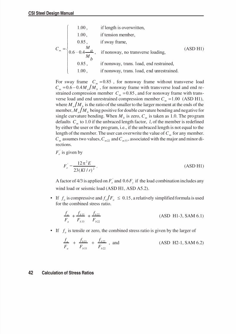
C m =
1.00 , if length is overwritten,
1.00 , if tension member,
0.85 , if sway frame,
0.6 0.4 if
M a
M b , nonsway, no transverse loading,
0.85 , if nonsway, trans. load, end restrained,
1.00 , if nonsway, trans. load, end unrestrained.
(ASD H1)
For sway frame C m = 0.85 , for nonsway frame with out trans verse loadC M M m a b= 0.6 0.4 , for nonsway frame with trans verse load and end re -strained com pres sion mem ber C m = 0.85 , and for nonsway frame with trans -verse load and end un restrained com pres sion mem ber C m = 1.00 (ASD H1),where M M a b is the ra tio of the smaller to the larger mo ment at the ends of themem ber, M M a b be ing pos itive for dou ble cur vature bend ing and neg ative forsingle cur vature bend ing. When M b is zero, C m is taken as 1.0. The pro gramdefaults C m to 1.0 if the un braced length fac tor, l, of the mem ber is re de finedby ei ther the user or the pro gram, i.e., if the un braced length is not equal to thelength of the mem ber. The user can over write the value of C m for any mem ber.C m assumes two val ues, C m 22 and C m 33 , as sociated with the ma jor and mi nor di -rec tions.
F e is given by
F E Kl r
e = 1223
2
2( / ) . (ASD H1)
A fac tor of 4/3 is ap plied on F e and 0.6 F y if the load com bination in cludes any
wind load or seis mic load (ASD H1, ASD A5.2).
• If f a is com pres sive and f F a a 0.15 , a rela tively sim pli fied for mula is usedfor the com bined stress ra tio.
f
F +
f
F +
f
F a
a
b
b
b
b
33
33
22
22 (ASD H1-3, SAM 6.1)
• If f a is ten sile or zero, the com bined stress ra tio is given by the larger of
f
F
f
F
f
F a
a
b
b
b
b
+ +33
33
22
22
, and (ASD H2-1, SAM 6.2)
42 Calculation of Stress Ratios
CSI Steel Design Manual

8/13/2019 SFD-OlderCodes
http://slidepdf.com/reader/full/sfd-oldercodes 48/105
f
F
f
F b
b
b
b
33
33
22
22
+ , where
f a , f b 33 , f b 22 , F a , F b 33 , and F b 22 are de fined ear lier in this chap ter. How ever, ei -ther F b 33 or F b 22 need not be less than 0.6 F y in the first equa tion (ASD H2-1).The sec ond equa tion con sid ers flex ural buck ling with out any be nefi cial ef fectfrom ax ial com pres sion.
For cir cular and pipe sec tions, an SRSS com bination is first made of the two bend -ing com ponents be fore add ing the ax ial load com ponent, in stead of the sim ple ad -dition im plied by the above for mulae.
For Single- angle sec tions, the com bined stress ra tio is cal culated based on the prop -erties about the principal axis (ASD SAM 5.3, 6.1.5). For I, Box, Chan nel, T, Dou -ble-an gle, Pipe, Cir cular and Rec tan gular sec tions, the prin cipal axes co incide withtheir geo met ric axes. For Single- angle sec tions, prin ci pal axes are de termined inthe pro gram. For gen eral sec tions no ef fort is made to de termine the prin cipal di rec-tions.
When de sign ing for com binations in volv ing earth quake and wind loads, al low ablestresses are in creased by a fac tor of 4/3 of the regu lar al low able value (ASD A5.2).
Shear Stresses
From the al low able shear stress val ues and the fac tored shear stress val ues at eachsta tion, shear stress ra tios for ma jor and minor di rec tions are computed for each of the load com binations as fol lows:
f
F v
v
2 , and
f
F v
v
3 .
For Sin gle-an gle sec tions, the shear stress ra tio is cal culated for di rec tions alongthe geo met ric axis. For all other sec tions the shear stress is cal culated along theprin ciple axes which co incide with the geo met ric axes.
When de sign ing for com binations in volv ing earth quake and wind loads, al low ableshear stresses are in creased by a fac tor of 4/3 of the regular al low able value (ASDA5.2).
Calculation of Stress Ratios 43
Chapter III Check/Design for AISC-ASD89

8/13/2019 SFD-OlderCodes
http://slidepdf.com/reader/full/sfd-oldercodes 49/105
C h a p t e r IV
Check/Design for AISC-LRFD93
This chap ter de scribes the de tails of the struc tural steel de sign and stress check al -gorithms that are used by the pro gram when the user se lects the AISC- LRFD93 de -sign code (AISC 1994). Vari ous no tations used in this chap ter are de scribed inTable VI-1 .
For re ferring to per tinent sec tions and equa tions of the origi nal LRFD code, aunique pre fix “LRFD” is as signed. However, all ref erences to the “Speci fi ca tionsfor Load and Resistance Fac tored De sign of Single- Angle Mem bers” carry the pre -fix of “LRFD SAM”.
The de sign is based on user- specified load ing com binations. But the pro gram pro -vides a set of de fault load com binations that should sat isfy re quire ments for the de -sign of most build ing type struc tures.
In the evalua tion of the ax ial force/bi ax ial mo ment ca pac ity ra tios at a sta tion alongthe length of the mem ber, first the ac tual mem ber force/mo ment com ponents andthe cor respond ing ca paci ties are cal cu lated for each load com bi na tion. Then the ca -pac ity ra tios are evalu ated at each sta tion un der the in flu ence of all load com bi na -tions us ing the cor respond ing equa tions that are de fined in this chapter. The con -trol ling ca pac ity ra tio is then ob tained. A ca pac ity ra tio greater than 1.0 in dicatesexceed ing a limit state. Simi larly, a shear ca pac ity ra tio is also cal cu lated sepa -rately.
45

8/13/2019 SFD-OlderCodes
http://slidepdf.com/reader/full/sfd-oldercodes 50/105

8/13/2019 SFD-OlderCodes
http://slidepdf.com/reader/full/sfd-oldercodes 51/105 47
Chapter IV Check/Design for AISC-LRFD93
Q a = Re duc tion fac tor for stiff ened slen der elementsQ s = Re duc tion fac tor for unstiff ened slen der elementsS = Sec tion modu lus, in 3
S S 33 22, = Ma jor and mi nor sec tion moduli, in 3
S S eff eff , ,,33 22 = Ef fec tive major and mi nor sec tion moduli for slen der sections, in 3
S c = Sec tion modu lus for com pres sion in an an gle section, in3
V V n n2 3, = Nomi nal ma jor and mi nor shear strengths, kipsV V u u2 3, = Fac tored ma jor and mi nor shear loads, kips Z = Plas tic modu lus, in 3
Z Z 33 22, = Ma jor and mi nor plas tic moduli, in 3
b = Nomi nal di men sion of plate in a sec tion, inlonger leg of an gle sections,b t f w2 for welded and b t f w3 for rolled box sec tions, etc.
b e = Ef fec tive width of flange, inb f = Flange width, in
d = Over all depth of mem ber, ind e = Ef fec tive depth of web, inh c = Clear dis tance be tween flanges less fil lets, in
assumed d k 2 for rolled sec tions, and d t f 2 for welded sec tionsk = Dis tance from outer face of flange to web toe of fil let, ink c = Pa rame ter used for sec tion clas sification,
4 h t w , 0.35 0.763 k c
l l33 22, = Ma jor and mi nor di rec tion un braced mem ber lengths, inr = Ra dius of gy ration, in
r r 33 22, = Ra dii of gy ration in the ma jor and mi nor di rec tions, int = Thick ness, int f = Flange thick ness, int w = Thick ness of web, in
w = Spe cial sec tion prop erty for an gles, in= Slen der ness pa rame ter
c e, = Col umn slen der ness pa rame ters
p = Lim iting slen derness pa rame ter for com pact ele ment
r = Lim iting slen derness pa rame ter for non- compact ele ment
s = Lim iting slen derness pa rame ter for seismic ele mentslender = Lim iting slen derness pa rame ter for slender ele ment
b = Re sistance fac tor for bend ing, 0.9
c = Re sistance fac tor for com pres sion, 0.85
t = Re sis tance fac tor for ten sion, 0.9
v = Re sis tance fac tor for shear, 0.9
Table IV-1 AISC-LRFD Notations (cont.)

8/13/2019 SFD-OlderCodes
http://slidepdf.com/reader/full/sfd-oldercodes 52/105
Eng lish as well as SI and MKS met ric units can be used for in put. But the code isbased on Kip- Inch- Second units. For sim plic ity, all equa tions and de scrip tions pre -sented in this chap ter cor respond to Kip- Inch- Second units un less oth erwisenoted.
Design Loading CombinationsThe de sign load com binations are the vari ous com binations of the load cases forwhich the struc ture needs to be checked. For the AISC- LRFD93 code, if a struc tureis sub jected to dead load (DL), live load (LL), wind load (WL), and earth quake in -duced load (EL), and con sidering that wind and earth quake forces are re versi ble,then the fol low ing load com binations may have to be de fined (LRFD A4.1):
1.4 DL (LRFD A4-1)
1.2 DL + 1.6 LL (LRFD A4-2)0.9 DL ± 1.3 WL (LRFD A4-6)1.2 DL ± 1.3 WL (LRFD A4-4)1.2 DL + 0.5 LL ± 1.3 WL (LRFD A4-4)
0.9 DL ± 1.0 EL (LRFD A4-6)1.2 DL ± 1.0 EL (LRFD A4-4)1.2 DL + 0.5 LL ± 1.0 EL (LRFD A4-4)
These are also the de fault de sign load com binations in the pro gram when ever theAISC- LRFD93 code is used. The user should use other ap pro priate load ing com bi-nations if roof live load is sepa rately treated, if other types of loads are pres ent, or ifpat tern live loads are to be con sid ered.
Live load re duc tion fac tors can be ap plied to the mem ber forces of the live load caseon an element- by- element ba sis to re duce the con tribution of the live load to thefac tored load ing.
When us ing the AISC- LRFD93 code, the pro gram design as sumes that a P-analy sis has been per formed so that mo ment mag nification fac tors for mo ments
caus ing sidesway can be taken as unity. It is recommended that the P- analy sis bedone at the fac tored load level of 1.2 DL plus 0.5 LL (White and Hajjar 1991).
Classification of SectionsThe nom inal strengths for ax ial com pres sion and flex ure are de pend ent on the clas -sification of the sec tion as Com pact, Noncompact, Slen der or Too Slen der. The
48 Design Loading Combinations
CSI Steel Design Manual

8/13/2019 SFD-OlderCodes
http://slidepdf.com/reader/full/sfd-oldercodes 53/105Classification of Sections 49
Chapter IV Check/Design for AISC-LRFD93
tw
t w tw
tw
tw
t f tf
t f
t
t f
t f
d
t = t = tw f
t t
z
2, y
2, y
3, x 3, x
AISC-LRFD93 : Axes Conventions
2-2 is the cross-section axis parallel to the webs,the longer dimension of tubes,
the longer leg of single angles, or the side by side legs of double-angles.This is the same as the y-y axis.
3-3 is orthogonal to 2-2. This is the same as the x-x axis.
b f
b f b f b f
b f
b f
b b
dh d
b
b
b b = b - 3tf f
D
hc hchc
k
b b
K
Figure IV-1 AISC-LRFD Definition of Geometric Properties

8/13/2019 SFD-OlderCodes
http://slidepdf.com/reader/full/sfd-oldercodes 54/105

8/13/2019 SFD-OlderCodes
http://slidepdf.com/reader/full/sfd-oldercodes 55/105Classification of Sections 51
Chapter IV Check/Design for AISC-LRFD93
Descriptionof Section
Width-Thickness
Ratio( )
COMPACT(SEISMIC ZONE)
( s)
NONCOMPACT(Uniform Compression)
( M M 22 33 0 )( r )
I-SHAPE
b t f
f 2 (rolled) F y52 F y95
b t f
f 2 (welded)
F y52 F y95
h t c
w
For P Pu
b y 0.125,
÷÷
5201
F -
PP y
u
b y
1.54
For P Pu
b y > 0.125
÷÷ 191 253
F -
PP F
y
u
b y y
2.33
F y253
BOXb t f
h t c
w
Not applicableNot applicable
F y238
F y253
CHANNELb t f
f
h t c
w
As for I-shapesAs for I-shapes
As for I-shapesAs for I-shapes
T-SHAPEb t f
f 2
d t w
Not applicableNot applicable
As for I-shapes F y127
ANGLE b t Not applicable F y76
DOUBLE-ANGLE(Separated)
b t Not applicable F y76
PIPE D t Not applicable F y3300
ROUND BAR Assumed Compact
RECTANGULAR Assumed Noncompact
GENERAL Assumed Noncompact
Table IV-3 Limiting Width-Thickness Ratios for
Classification of Sections (Special Cases) based on AISC-LRFD

8/13/2019 SFD-OlderCodes
http://slidepdf.com/reader/full/sfd-oldercodes 56/105

8/13/2019 SFD-OlderCodes
http://slidepdf.com/reader/full/sfd-oldercodes 57/105
C m 33 and C m 22 are co efficients rep resent ing dis tribution of mo ment along themem ber length.
C m =
1.00 , if length is overwritten,
1.00 , if tension member,
1.00 , if end unrestrained,
0.6 0.4 if no trans M
M a
b
, verse loading,
0.85 , if trans. load, end restrained,
1.00 , if trans. load, end unrestrained,
(LRFD C1-3)
M M a b is the ra tio of the smaller to the larger mo ment at the ends of the mem -ber, M M a b being posi tive for dou ble cur vature bend ing and nega tive for sin -gle cur vature bend ing. For tension mem bers C m is as sumed as 1.0. For com -
pres sion mem bers with trans verse load on the mem ber, C m is as sumed as 1.0for mem bers with any un restrained end and as 0.85 for mem bers with two un re-strained ends. When M b is zero, C m is taken as 1.0. The pro gram de faults C m to1.0 if the un braced length factor, l, of the mem ber is re defined by ei ther theuser or the pro gram, i.e., if the un braced length is not equal to the length of themem ber. The user can over write the value of C m for any mem ber. C m assumestwo val ues, C m 22 and C m 33 , as sociated with the ma jor and mi nor di rec tions.
The mag nification fac tor B1 , must be a posi tive number. There fore Pu must be lessthan Pe . If Pu is found to be greater than or equal to Pe , a fail ure con dition is de -clared.
The pro gram de sign as sumes the anal ysis in cludes P- ef fects, there fore B 2 istaken as unity for bend ing in both di rec tions. It is sug gested that the P- anal ysis bedone at the fac tored load level of 1.2 DL plus 0.5 LL (LRFD C2.2). See also Whiteand Hajjar (1991).
For sin gle an gles, where the prin cipal axes of bend ing are not co incident with thegeo met ric axes (2-2 and 3-3), the pro gram con servatively uses the maxi mum ofK l22 22 and K l33 33 for de termin ing the ma jor and mi nor di rec tion Euler buck ling ca -
pac ity.
If the pro gram as sump tions are not satisfactory for a par ticu lar struc tural model ormem ber, the user has a choice of ex plic itly speci fying the val ues of B1 and B 2 forany mem ber.
Calculation of Factored Forces 53
Chapter IV Check/Design for AISC-LRFD93

8/13/2019 SFD-OlderCodes
http://slidepdf.com/reader/full/sfd-oldercodes 58/105
Calculation of Nominal StrengthsThe nomi nal strengths in com pres sion, ten sion, bend ing, and shear are com putedfor Com pact, Non com pact, and Slen der sec tions ac cord ing to the fol low ing sub -sec tions. The nomi nal flex ural strengths for all shapes of sec tions are cal cu latedbased on their prin cipal axes of bend ing. For the Rec tangular, I, Box, Chan nel, Cir -cular, Pipe, T, and Double- angle sec tions, the prin cipal axes co incide with theirgeo met ric axes. For the An gle sec tions, the prin cipal axes are de ter mined and allcom putations ex cept shear are based on that.
For Single- angle sec tions, the shear stresses are cal cu lated for di rec tions along thegeo met ric axes. For all other sec tions the shear stresses are cal culated along theirgeo met ric and prin ciple axes.
The strength re duc tion fac tor, , is taken as fol lows (LRFD A5.3):
t = Re sis tance fac tor for ten sion, 0.9 (LRFD D1, H1, SAM 2, 6)c = Re sis tance fac tor for com pres sion, 0.85 (LRFD E2, E3, H1)c = Re sis tance fac tor for com pres sion in angles, 0.90 (LRFD SAM 4, 6)b = Re sis tance fac tor for bend ing, 0.9 (LRFD F1, H1, A-F1, A-G2, SAM 5)v = Re sis tance fac tor for shear, 0.9 (LRFD F2, A-F2, A-G3, SAM 3)
If the user speci fies nomi nal strengths for one or more ele ments in the“Overwrites” form, these val ues will over ride the above men tioned cal cu lated val ues for those ele ments as de fined in the fol lowing sub sec tions. The speci fied
nomi nal strengths should be based on the prin ci pal axes of bending.
Compression Capacity
The nomi nal compression strength is the minimum value ob tained from flex uralbuck ling, tor sional buckling and flexural- torsional buck ling. The strengths are de -termined ac cord ing to the fol low ing sub sec tions.
For mem bers in com pres sion, if Kl r is greater than 200, a mes sage to that ef fect isprinted (LRFD B7, SAM 4). For sin gle an gles, the mini mum radius of gy ration, r z ,is used in stead of r 22 and r 33 in com put ing Kl r .
Flexural Buckling
The nomi nal ax ial com pres sive strength, Pn , de pends on the slen derness ra tio, Kl r ,and its criti cal value, c , where
54 Calculation of Nominal Strengths
CSI Steel Design Manual

8/13/2019 SFD-OlderCodes
http://slidepdf.com/reader/full/sfd-oldercodes 59/105
Klr
K l
r
K l
r =
max ,33 33
33
22 22
22
, and
c =Kl
r
F
E
y . (LRFD E2-4, SAM 4)
For sin gle an gles, the mini mum radius of gy ration, r z , is used in stead of r 22 and r 33
in com put ing Kl r .
Pn for Com pact or Non com pact sec tions is evalu ated for flex ural buck ling as fol -lows:
P = A F n g cr , where (LRFD E2-1)
( )F = F cr yc0.6582
, for c 1.5, and (LRFD E2-2)
F = F cr y0.877
c2
, for c > 1.5. (LRFD E2-3)
Pn for Slender sec tions is evalu ated for flex ural buck ling as fol lows:
P = A F n g cr , where (LRFD A-B3d, SAM 4)
( )F = Q F cr yc0.658 Q 2
, for c 1.5Q , and (LRFD A-B5-15, SAM 4-1)
F = F cr y0.877c
2 , for c > 1.5Q . (LRFD A-B5-16, SAM 4-2)
The re duc tion fac tor, Q , for all com pact and non com pact sec tions is taken as 1. Forslen der sec tions, Q is com puted as fol lows:
Q Q Qs a= , where (LRFD A- B5-17, SAM 4)
Q s = re duc tion fac tor for un stiff ened slen der ele ments, and (LRFD A-B5.3a)
Q a = re duc tion fac tor for stiff ened slen der ele ments. (LRFD A-B5.3c)
The Q s fac tors for slen der sec tions are cal cu lated as de scribed in Table IV-4 (LRFDA-B5.3a). The Q a fac tors for slen der sec tions are cal cu lated as the ra tio of ef fec tivecross- sectional area and the gross cross- sectional area (LRFD A-B5.3c).
Q A
Aa
e
g
= (LRFD A- B5- 14)
Calculation of Nominal Strengths 55
Chapter IV Check/Design for AISC-LRFD93

8/13/2019 SFD-OlderCodes
http://slidepdf.com/reader/full/sfd-oldercodes 60/10556 Calculation of Nominal Strengths
CSI Steel Design Manual
SectionType
Re duc tion Fac tor for Un stiff ened Slen der Ele ments(Q s)
EquationReference
I-SHAPE
[ ]Q
if b t F
b t F if F s
f f y
f f y y= <
1.0 , 95
1.415 0.00437 95
2
2
,
,[ ]{ }
b t F b t F if b t F
f f y
f f y f f y
22 2
2< 176
20,000 176,
, .
(rolled)
LRFD A-B5-5,LRFD A-B5-6
[ ]Q
if b t F k
b t F k if F s
f f y c
f f y c=
1.0 109
1.415 0.00381 109
2
2
,
[ ]{ } y c f f y c
c f f y f f y c
k b t F k
k b t F if b t F k
< <2
2 22
200
26,200 200
,
.
(welded)
LRFD A-B5-7,LRFD A-B5-8
BOX Q s = 1 LRFD A-B5.3d
CHANNEL As for I-shapes with b t f f 2 replaced by b t f f .LRFD A-B5-5,LRFD A-B5-6,LRFD A-B5-7,LRFD A-B5-8
T-SHAPE
For flanges, as for flanges in I-shapes. For web see below.
[ ]Q
if d t F
d t F if F d t s
w y
w y y w <
1.0 , 127
1.908 0.00715 127
,
,
[ ]{ }< 176
20,000 176
F
d t F if d t F
y
w y w y
,
, .2
LRFD A-B5-5,LRFD A-B5-6,LRFD A-B5-7,LRFD A-B5-8,LRFD A-B5-9,LRFDA-B5-10
DOUBLE-ANGLE
(Separated)[ ]Q
if b t F b t F if F b t s
y
y y= < <1.0 , 76
1.340 0.00447 76 155,
,
[ ]{ }F
b t F if b t F
y
y y
,
, .15,500 1552
LRFD A-B5-3,LRFD A-B5-4
ANGLE [ ]Q
if b t F E
b t F E if F E bs
y
y y= <
1.0 , 0.446
1.34 0.761 0.446
,
,
[ ] [ ]{ }t F E
b t F E if b t F E
y
y y
< 0.910
0.534 0.910
,
, .2
LRFD SAM4-3
PIPE Q s = 1 LRFD A-B5.3d
ROUND
BARQ
s = 1
LRFD A-B5.3d
RECTAN-GULAR
Q s = 1 LRFD A-B5.3d
GENERAL Q s = 1 LRFD A-B5.3d
Table IV-4 Reduc tion Fac tor for Un stiffened Slen der Ele ments, Q s

8/13/2019 SFD-OlderCodes
http://slidepdf.com/reader/full/sfd-oldercodes 61/105Calculation of Nominal Strengths 57
Chapter IV Check/Design for AISC-LRFD93
SectionType
Effective Width for Stiffened Sections EquationReference
I-SHAPE h
h if h
t f
t
f h t f if
h
t
e
w
w
w w
= >
, ,
( ),
253
326 57.2 2531
f . (compression only, f P
A g
= ) LRFD A-B5-12
BOX
h
h if h
t f
t
f h t f if
h
t
e
w
w
w w
=
>
, ,
( ),
253
326 57.2 2531
f . (compression only, f
P
A g
= )
b
b if b
t f
t f b t f
if bt
e
f
f
f f
=
>
, ,
( ),
238
326 64.9 21 38 f
.
(compr. or flexure, f F y= )
LRFD A-B5-12
LRFD A-B5-11
CHANNEL h
h if h
t f
t
f h t f if
h
t
e
w
w
w w
=
>
, ,
( ),
253
326 57.2 2531
f . (compression only, f
P
A g
= ) LRFD A-B5-12
T-SHAPE b be = LRFD A-B5.3b
DOUBLE-ANGLE
(Separated)
b be = LRFD A-B5.3b
ANGLE b be = LRFD A-B5.3b
PIPE
( )
Q
if D
t F
D t F if
D
t F
a y
y y
=+ >
1, ,
, .
3,300
1,100 23
3,300 (compression only) LRFD A-B5-13
ROUNDBAR
Not applicable
RECTAN-GULAR b be = LRFD A-B5.3b
GENERAL Not applicable
Table IV-5Effective Width for Stiffened Sections

8/13/2019 SFD-OlderCodes
http://slidepdf.com/reader/full/sfd-oldercodes 62/105
The ef fec tive cross- sectional area is com puted based on ef fec tive width as fol lows:
( ) A A b b t e g e=
b e for un stiff ened el ements is taken equal to b, and b e for stiff ened el ements is
taken equal to or less than b as given in Table IV-5 (LRFD A-B5.3b). For webs in I,box, and Chan nel sec tions, h e is used as b e and h is used as b in the above equa tion.
Flexural-Torsional Buckling
Pn for flexural- torsional buck ling of Double- angle and T- shaped com pres sionmem bers whose ele ments have width- thickness ra tios less than r is given by
P = A F n g crft , where (LRFD E3-1)
F = F F H
F F H F F
crft cr crz cr crz
cr
2 2
221 1 4+
÷÷ +( crz ) 2 , where (LRFD E3-1)
F GJ
Ar crz =
02
,
H x y
r = +
÷÷1 0
202
02
,
r 0 = Po lar ra dius of gy ration about the shear cen ter,
x y0 0, are the coor dinates of the shear cen ter with re spect to the cen troid, x 0 0= for double- angle and T- shaped mem bers ( y-axis of sym me-
try),
F cr 2 is de ter mined ac cord ing to the equa tion LRFD E2-1 for flex ural
buck ling about the mi nor axis of sym metry for
c yKl
r
F
E =
22
.
Torsional and Flexural-Torsional Buck lingThe strength of a com pres sion mem ber, Pn , de termined by the limit states of tor -sional and flexural- torsional buck ling is de termined as fol lows:
P = A F n g cr , where (LRFD A- E3-1)
58 Calculation of Nominal Strengths
CSI Steel Design Manual

8/13/2019 SFD-OlderCodes
http://slidepdf.com/reader/full/sfd-oldercodes 63/105
( )F = Q F cr ye0.658 Q 2
, for e 1.5Q , and (LRFD A-E3-2)
F = F cr y0.877
e2
, for e > 1.5Q . (LRFD A-E3-3)
In the above equa tions, the slen derness pa rame ter e is cal culated as
e =F
F y
e
, (LRFD A-E3-4)
where F e is cal culated as fol lows:
• For Rec tangular, I, Box, and Pipe sec tions:
( )F
EC
K lGJ I I
e w
z z
= + +
2
222 33
1 (LRFD A- E3-5)
• For T-sections and Dou ble-angles:
F =F F
H
F F H
F F e
e ez e ez
e ez
22 22
2222
1 14+
÷÷
+( ) (LRFD A- E3-6)
• For Channels:
F =F F
H
F F H
F F e
e ez e ez
e ez
33 33
3322
1 14+
÷÷
+( ) (LRFD A- E3-6)
• For Sin gle-angles sec tions with equal legs:
F =F F
H
F F H
F F e
e ez e ez
e ez
33 33
3322
1 14+
÷÷
+( ) (LRFD A- E3-6)
• For Single- angle sec tions with une qual legs, F e is cal cu lated as the mini mumreal root of the fol low ing cu bic equa tion (LRFD A- E3-7):
( )( )( ) ( ) (F F F F F F F F F x
r F e e e e e ez e e e e 33 22
222
02
02
2 F F y
r e e =33
02
02
0) ,
where,
Calculation of Nominal Strengths 59
Chapter IV Check/Design for AISC-LRFD93

8/13/2019 SFD-OlderCodes
http://slidepdf.com/reader/full/sfd-oldercodes 64/105
x y0 0, are the co ordinates of the shear cen ter with re spect to the cen troid, x 0 0= for double- angle and T- shaped mem bers ( y-axis of sym me-
try),
r x y I I
A g0 0
202 22 33= + +
+ = po lar ra dius of gy ration about the shear center,
H x y
r = +
÷÷1 0
202
02
, (LRFD A- E3-9)
( )F
E
K l r e33
2
33 33 33
2=
, (LRFD A- E3-10)
( )F E
K l r e22
2
22 22 22
2=
, (LRFD A- E3-11)
( )F
EC
K lGJ
Ar ez
w
z z
= +2
202
1 , (LRFD A- E3-12)
K K 22 33, are ef fec tive length fac tors in mi nor and ma jor di rec tions,
K z is the ef fec tive length fac tor for tor sional buck ling, and it is taken equal toK 22 in the pro gram,
l l22 33, are ef fec tive lengths in the mi nor and ma jor di rec tions,
l z is the ef fec tive length for tor sional buck ling, and it is taken equal to l 22 .
For an gle sec tions, the prin cipal mo ment of in ertia and ra dii of gy ration are used forcom put ing F e . Also, the maxi mum value of Kl, i.e, max( , )K l K l22 22 33 33 , is used inplace of K l22 22 or K l33 33 in cal culat ing F e22 and F e33 in this case.
Tension CapacityThe nomi nal ax ial ten sile strength value Pn is based on the gross cross- sectionalarea and the yield stress.
P A F n g y= (LRFD D1-1)
60 Calculation of Nominal Strengths
CSI Steel Design Manual

8/13/2019 SFD-OlderCodes
http://slidepdf.com/reader/full/sfd-oldercodes 65/105
It should be noted that no net sec tion checks are made. For mem bers in ten sion,if l r is greater than 300, a mes sage to that ef fect is printed (LRFD B7, SAM 2). Forsingle an gles, the min imum ra dius of gy ration, r z , is used in stead of r 22 and r 33 incom put ing Kl r .
Nominal Strength in Bending
The nominal bend ing strength de pends on the fol low ing cri teria: the geo met ricshape of the cross- section, the axis of bend ing, the com pact ness of the sec tion, anda slen derness pa rame ter for lateral- torsional buck ling. The nomi nal strengths for allshapes of sec tions are cal culated based on their prin cipal axes of bend ing. For theRec tangular, I, Box, Chan nel, Cir cular, Pipe, T, and Double- angle sec tions, theprin cipal axes co incide with their geo met ric axes. For the Sin gle An gle sec tions,the prin cipal axes are de termined and all com putations re lated to flex ural strengths
are based on that. The nomi nal bend ing strength is the minimum value ob tained ac -cord ing to the limit states of yield ing, lateral- torsional buck ling, flange lo cal buck -ling, and web lo cal buck ling, as fol lows:
Yielding
The flex ural de sign strength of beams, de termined by the limit state of yield ing is:
M Z F S F p y y= 1.5 (LRFD F1-1)
Lateral-Torsional Buckling
Doubly Symmetric Shapes and Channels
For I, Chan nel, Box, and Rec tangular shaped members bent about the ma jor axis,the mo ment ca pac ity is given by the fol low ing equa tion (LRFD F1):
M =
M if L L
C M - M - M L - L
L -n
p b p
b p p r
b p
r 33
33
33 33 33
, ,
( ) L M if L L L
M M if L
p p p b r
cr p
÷÷ < 33
33 33
, ,
, b r L> .
(LRFD F1-1, F1-2, F1- 12)
where,
Calculation of Nominal Strengths 61
Chapter IV Check/Design for AISC-LRFD93

8/13/2019 SFD-OlderCodes
http://slidepdf.com/reader/full/sfd-oldercodes 66/105
M n 33 = Nomi nal ma jor bend ing strength, M p 33 = Ma jor plas tic mo ment, Z F S F y y33 331.5 , (LRFD F1.1) M r 33 = Ma jor lim iting buck ling mo ment,
( )F F S y r 33 for I- shapes and chan nels, (LRFD F1-7)and F S y eff , 33 for rec tangular bars and boxes, (LRFD F1- 11)
M cr 33 = Criti cal elas tic mo ment,C
LEI GJ +
E L
I C b
b b
w
22
2
22
÷÷
for I- shapes and chan nels, and (LRFD F1- 13)57 000
22
C JA
L r b
b
for boxes and rec tangular bars, (LRFD F1- 14)
L b = Lat erally un braced length, l 22 ,
L p = Lim iting lat erally un braced length for full plas tic ca pac ity,300 22r
F y for I- shapes and chan nels, and (LRFD F1-4)
3750 22
33
r
M JA
p
for boxes and rec tangular bars, (LRFD F1-5)
L r = Lim iting lat erally un braced length forine las tic lateral- torsional buck ling,
[ ]r X
F F + X F - F y r y r
22 1
211+ ( )2
12
12
for I- shapes and chan nels, and (LRFD F1-6)
57 000 22
33
r JA
M r for boxes and rec tangular bars, (LRFD F1- 10)
X 1 =
S EGJA
33 2 , (LRFD F1-8)
X 2 = 422
33
2C
I
S
GJ w
÷ , (LRFD F1-9)
C b =12.5
2.5 M
M + M + M + M A B C
max
max 3 4 3 , and (LRFD F1-3)
M max , M M M A B C , ,and are ab solute val ues of max imum mo ment, ¼ point, cen terof span and ¾ point ma jor mo ments re spec tively, in the mem ber. C b should betaken as 1.0 for can tilevers. How ever, the pro gram is un able to de tect whether the
62 Calculation of Nominal Strengths
CSI Steel Design Manual

8/13/2019 SFD-OlderCodes
http://slidepdf.com/reader/full/sfd-oldercodes 67/105
mem ber is a can tilever. The user should over write C b for can ti levers . The pro -gram also de faults C b to 1.0 if the mi nor un braced length, l 22 , of the mem ber is re -defined by the user (i.e. it is not equal to the length of the mem ber). The user canover write the value of C b for any mem ber.
For I, Chan nel, Box, and Rec tangular shaped members bent about the minor axis,the mo ment ca pac ity is given by the fol low ing equa tion:
M = M = Z F S F n p y y22 22 22 221.5 (LRFD F1)
For pipes and cir cular bars bent about any axis,
M = M = Z F S F n p y y1.5 . (LRFD F1)
T-sections and Double Angles
For T- shapes and Dou ble-an gles the nomi nal ma jor bend ing strength is given as,
M =EI GJ
L B + + Bn
b33
22 21 , where (LRFD F1- 15)
M F S n y33 331.5 , for posi tive mo ment, stem in tension (LRFD F1.2c)
M F S n y33 33 , for negative mo ment, stem in com pres sion (LRFD F1.2c)
Bd
L
I
J b
= ± 2.3 22 . (LRFD F1- 16)
The pos itive sign for B applies for ten sion in the stem of T-sec tions or the out -stand ing legs of dou ble an gles (pos itive mo ments) and the neg ative sign ap plies forcom pres sion in stem or legs (neg ative mo ments).
For T- shapes and dou ble an gles the nomi nal mi nor bend ing strength is as sumed as,
M = S F n y22 22 .
Single AnglesThe nomi nal strengths for Single- angles are cal culated based on their prin cipalaxes of bend ing. The nomi nal ma jor bend ing strength for Single- angles for thelimit state of lat eral-tor sional buck ling is given as fol lows (LRFD SAM 5.1.3):
Calculation of Nominal Strengths 63
Chapter IV Check/Design for AISC-LRFD93

8/13/2019 SFD-OlderCodes
http://slidepdf.com/reader/full/sfd-oldercodes 68/105
M = M
M M M n major
ob
y major
ob y,,
,0.92 0.17 1.25 major ob y major if M M , ,,
M = M
M M n major
y major
ob
y major ,,
,1.58 0.83 1.2 5 M if M M y major ob y major , ,, ,>
where,
M y major , = yield mo ment about the ma jor prin cipal axis of bend ing,con sid ering the pos sibil ity of yield ing at the heel and both of theleg tips,
M ob = elas tic l ateral-tor sional buck ling mo ment as cal culated be low.
The elas tic lat eral-tor sional buck ling mo ment, M ob , for equal- leg an gles is taken as
M C E b t l
ob b=0.46 2 2
, (LRFD SAM 5-5)
and for unequal- leg an gles the M ob is cal culated as
M EC I
llt r ob b w w= + +4.9 0.052min
min2
2 2 ( ) , (LRFD SAM 5-6)
where,
( )t t t w f = min , ,
( )l l l= max ,22 33 ,
I min = mi nor prin cipal axis mo ment of in ertia,
I max = major prin cipal axis mo ment of in ertia,
r min = ra dius of gy ration for mi nor prin cipal axis,
w A I z w z dA z= + 1 22 2
0max
( ) , (LRFD SAM 5.3.2)
z = co ordinate along the ma jor prin cipal axis,
w = co ordinate along the mi nor prin cipal axis, and
64 Calculation of Nominal Strengths
CSI Steel Design Manual

8/13/2019 SFD-OlderCodes
http://slidepdf.com/reader/full/sfd-oldercodes 69/105
z0 = co ordinate of the shear cen ter along the ma jor prin cipal axis with re spectto the cen troid.
w is a spe cial sec tion prop erty for an gles. It is posi tive for short leg in com pres -sion, nega tive for long leg in com pres sion, and zero for equal- leg an gles (LRFD
SAM 5.3.2). How ever, for con servative de sign in the pro gram, it is al ways taken asnega tive for unequal- leg an gles.
General Sections
For General sec tions the nomi nal ma jor and mi nor di rec tion bend ing strengths areassumed as,
M = S F n y .
Flange Local BucklingThe flex ural de sign strength, M n , of Non com pact and Slender beams for the limitstate of Flange Lo cal Buck ling is cal culated as fol lows (LRFD A-F1):
For major di rec tion bend ing,
M =
M if
M M M n
p p
p p r p
r p33
33
33 33 33
, ,
( )
÷
÷ <
>
, ,
, .
if
M M if
p r
cr p r
33 33
(A-F1-3)
and for mi nor di rec tion bend ing,
M =
M if
M M M n
p p
p p r
p
r p22
22
22 22 22
, ,
( )
÷÷
<
>
, ,
, .
if
M M if
p r
cr p r
22 22
(A-F1-3)
where,
Calculation of Nominal Strengths 65
Chapter IV Check/Design for AISC-LRFD93

8/13/2019 SFD-OlderCodes
http://slidepdf.com/reader/full/sfd-oldercodes 70/105
M n 33 = Nomi nal ma jor bend ing strength, M n 22 = Nomi nal mi nor bend ing strength, M p 33 = Ma jor plas tic mo ment, Z F S F y y33 331.5 , M p 22 = Mi nor plas tic mo ment, Z F S F y y22 221.5 , M r 33 = Ma jor lim iting buck ling mo ment,
M r 22 = Mi nor lim iting buck ling mo ment, M cr 33 = Ma jor buck ling mo ment, M cr 22 = Mi nor buck ling mo ment,
= Con trol ling slen der ness pa rame ter, p = Larg est value of for which M M n p= , andr = Larg est value of for which buck ling is ine las tic.
The pa rame ters , p , r , M r 33 , M r 22 , M cr 33 , and M cr 22 for flange lo cal buck ling fordif ferent types of shapes are given be low:
I Shapes, Channels
=b
t f
f 2 , (for I sec tions) (LRFD B5.1, Ta ble A-F1.1)
=b
t f
f
, (for Chan nel sec tions) (LRFD B5.1, Ta ble A-F1.1)
p
yF =65
, (LRFD B5.1, Ta ble A-F1.1)
( )
r
y r
y r c
F F
F F k
=
141For rolled shape,
162 For wel
,
, ded shape, (LRFD Ta ble A-F1.1)
M F F S r y r 33 33= ( ) , (LRFD Ta ble A-F1.1)
M F S r y22 22= , (LRFD Ta ble A-F1.1)
M S
k S
cr c
33
2 33
2 33
=
20,000For rolled shape,
26,200
,
, For welded shape,(LRFD Ta ble A-F1.1)
66 Calculation of Nominal Strengths
CSI Steel Design Manual

8/13/2019 SFD-OlderCodes
http://slidepdf.com/reader/full/sfd-oldercodes 71/105
M S
k S
cr c
22
2 22
2 22
=
20,000For rolled shape,
26,200
,
, For welded shape,(LRFD Ta ble A-F1.1)
F r =10 ksi, For rolled shpae,16.5 ksi, For welded shape.
(LRFD A-F1)
Boxes
=
b t
t b t
t
f w
f
f w
f
3
2
,
,
For rolled shape,
For welded shape, (LRFD B5.1, Ta ble A-F1.1)
p
yF =
190 , (LRFD B5.1, Ta ble A-F1.1)
r
yF =
238 , (LRFD B5.1, Ta ble A-F1.1)
M F F S r y r eff 33 33= ( ) , , (LRFD Ta ble A-F1.1)
M F F S r y r eff 22 22= ( ) , , (LRFD Ta ble A-F1.1)
( ) M F S S S cr y eff eff 33 33 33 33= , , , (LRFD Ta ble A-F1.1)
M F S cr y eff 22 22= , , (LRFD Ta ble A-F1.1)
F r =10 ksi, For rolled shpae,
16.5 ksi, For welded shape,(LRFD A-F1)
S eff , 33 = ef fec tive ma jor sec tion modu lus con sid ering slen derness, and
S eff , 22 = ef fec tive minor sec tion modu lus con sid ering slen derness.
T-sections and Double Angles
No lo cal buck ling is con sidered for T sec tions and Dou ble an gles in the pro gram. If spe cial con sid era tion is re quired, the user is ex pected to ana lyze this sepa rately.
Calculation of Nominal Strengths 67
Chapter IV Check/Design for AISC-LRFD93
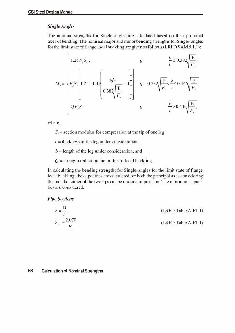
8/13/2019 SFD-OlderCodes
http://slidepdf.com/reader/full/sfd-oldercodes 72/105
Single Angles
The nomi nal strengths for Single- angles are cal culated based on their prin cipalaxes of bend ing. The nomi nal ma jor and mi nor bend ing strengths for Single- anglesfor the limit state of flange lo cal buck ling are given as fol lows (LRFD SAM 5.1.1):
M =
F S if bt F
F S
F
n
y c
y
y c
1.25 0.382E
1.25 1.49 b t
0.382E
, ,
y
y
if F
bt
÷÷÷÷÷
< 1 , 0.382 E 0.446 E
Q 0.446E
F
F S if
b
t F
y
y c y
,
, ,>
where,
S c = sec tion modu lus for com pres sion at the tip of one leg,
t = thick ness of the leg un der consideration,
b = length of the leg un der con sidera tion, and
Q = strength re duc tion fac tor due to lo cal buck ling.
In cal culat ing the bend ing strengths for Single- angles for the limit state of flangelo cal buck ling, the ca paci ties are cal cu lated for both the prin ci pal axes con sid er ingthe fact that ei ther of the two tips can be un der com pres sion. The mini mum ca paci -ties are con sid ered.
Pipe Sections
=Dt
, (LRFD Ta ble A-F1.1)
p
yF =
2,070 , (LRFD Ta ble A-F1.1)
68 Calculation of Nominal Strengths
CSI Steel Design Manual

8/13/2019 SFD-OlderCodes
http://slidepdf.com/reader/full/sfd-oldercodes 73/105
r yF
=8,970
(LRFD Ta ble A-F1.1)
M = M = D t
+ F S r r y33 22600
÷÷ , (LRFD Ta ble A-F1.1)
M = M = D t
S cr cr 33 229,570
÷÷ , (LRFD Ta ble A-F1.1)
Circular, Rectangular, and General Sections
No con sideration of lo cal buck ling is re quired for solid cir cular shapes, rec tangularplates (LRFD Ta ble A-F1.1). No lo cal buck ling is con sidered in the pro gram forcircular, rec tan gular, and gen eral shapes. If spe cial con sidera tion is re quired, the
user is ex pected to ana lyze this sepa rately.
Web Local Buckling
The flex ural de sign strengths are considered in the pro gram for only the ma jor axisbend ing (LRFD Ta ble A-F1.1).
I Shapes, Channels, and Boxes
The flex ural de sign strength for the ma jor axis bending, M n , of Non com pact and
Slender beams for the limit state of Web Lo cal Buck ling is cal cu lated as fol lows(LRFD A- F1-1, A- F1-3, A-G2-2):
M =
M if
M M M n
p p
p p r p
r p33
33
33 33 33
, ,
( )
÷÷
<
>
, ,
, ,
if
S R R F if
p r
PG e cr r
33
(A-F1,A-G1)
where,
M n 33 = Nomi nal ma jor bend ing strength, M p 33 = Ma jor plas tic mo ment, Z F S F y y33 331.5 , (LRFD F1.1) M r 33 = Ma jor lim iting buck ling mo ment, R S F e y33 ,(LRFD TableA- F1.1)
= Web slen derness pa rame ter, p = Larg est value of for which M M n p= ,
Calculation of Nominal Strengths 69
Chapter IV Check/Design for AISC-LRFD93

8/13/2019 SFD-OlderCodes
http://slidepdf.com/reader/full/sfd-oldercodes 74/105
r = Larg est value of for which buck ling is ine las tic, R PG = Plate girder bend ing strength re duc tion factor, R e = Hy brid girder fac tor, andF cr = Criti cal com pres sion flange stress, ksi.
The web slen der ness pa rame ters are com puted as fol lows, where the value of Pu istaken as posi tive for com pres sion and zero for tension:
=h
t c
w
,
p
y
u
b y
u
b yF -
P
P
P
P
=
÷÷
6402.75 for 0.11 , 25,
1912.33 for
F -
P
P F
P
P
y
u
b y y
u
b y
÷÷
253, > 0.125, and
r
y
u
b yF -
P
P=
÷÷
9700.741 .
The pa rame ters R PG , R e , and F cr for slen der web sec tions are cal culated in the pro -gram as fol lows:
Ra
a
h
t F PG
r
r
c
w cr = +
÷÷1 1,200 300970
1.0 , (LRFD A- G2-3)
( ) R
a m m
ae
r
r
=+
+
12 2
12 21.0
3
(for hy brid sec tions), (LRFD A- G2)
R e = 1.0 , (for non-hy brid sec tion), where (LRFD A- G2)
a r = web areacompression flange area
1.0 , and (LRFD A- G2)
mF
F F y
cr y
=min( , )
, taken as 1.0. (LRFD A- G2)
In the above ex pres sions, R e is taken as 1, be cause cur rently the pro gram dealswith only non-hy brid gird ers.
70 Calculation of Nominal Strengths
CSI Steel Design Manual

8/13/2019 SFD-OlderCodes
http://slidepdf.com/reader/full/sfd-oldercodes 75/105
The criti cal com pres sion flange stress, F cr , for slen der web sec tions is cal culatedfor limit states of lateral- torsional buck ling and flange lo cal buck ling for the cor re-spond ing slen der ness pa rame ter in the pro gram as fol lows:
F =
F if
C F F if cr
y p
b y p
r p
y p
, ,
,
<112
C if
r
PGr >
,
, ,2
(LRFD A- G2-4, 5, 6)
The pa rame ters , p , r , and C PG for lateral-torsional buck ling for slen der web I,Chan nel and Box sec tions are given be low:
= L
r b
T
, (LRFD A- G2-7)
p
yF =
300 , (LRFD A- G2-8)
r
yF =
756 , (LRFD A- G2-9)
C C PG b= 286,000 , and (LRFD A- G2-10)r T = ra dius of gy ration of the com pres sion flange plus one- third of the
com pres sion por tion of the web, and it is taken as b f 12 in the pro -
gram.
C b = a fac tor which de pends on span mo ment. It is cal culated us ingthe equa tion given in page 62.
The pa rame ters , p , r , and C PG for flange local buck ling for slen der web I,Chan nel and Box sec tions are given be low:
=bt
, (LRFD A- G2- 11)
p
yF =
65 , (LRFD A- G2- 12)
Calculation of Nominal Strengths 71
Chapter IV Check/Design for AISC-LRFD93

8/13/2019 SFD-OlderCodes
http://slidepdf.com/reader/full/sfd-oldercodes 76/105
r
y cF k =
230 , (LRFD A- G2- 13)
C k PG c= 26,200 , and (LRFD A- G2-14)
C b = 1 . (LRFD A- G2- 15)
T-sections and Double Angles
No lo cal buck ling is con sid ered for T- sections and Dou ble-an gles in the pro gram.If spe cial con sid era tion is re quired, the user is ex pected to ana lyze this sepa rately.
Single Angles
The nomi nal ma jor and mi nor bend ing strengths for Single- angles for the limit stateof web lo cal buck ling are the same as those given for flange lo cal buckling (LRFDSAM 5.1.1). No ad ditional check is con sid ered in the pro gram.
Pipe Sections
The nomi nal ma jor and mi nor bend ing strengths for Pipe sections for the limit stateof web lo cal buck ling are the same as those given for flange lo cal buck ling (LRFDTa ble A-F1.1). No ad ditional check is con sidered in the pro gram.
Circular, Rectangular, and General Sections
No web lo cal buck ling is re quired for solid cir cular shapes and rec tangular plates(LRFD Ta ble A-F1.1). No web lo cal buck ling is con sid ered in the pro gram for cir -cular, rec tan gu lar, and gen eral shapes. If spe cial con sid era tion is re quired, the useris ex pected to ana lyze them sepa rately.
Shear Capacities
The nomi nal shear strengths are cal culated for shears along the geo met ric axes forall sec tions. For I, Box, Chan nel, T, Dou ble an gle, Pipe, Cir cular and Rec tangular
sec tions, the prin ci pal axes co incide with their geo met ric axes. For Single- anglesec tions, prin cipal axes do not co incide with their geo met ric axes.
Major Axis of Bending
The nomi nal shear strength, V n 2 , for ma jor di rec tion shears in I- shapes, boxes andchan nels is evalu ated as fol lows:
72 Calculation of Nominal Strengths
CSI Steel Design Manual

8/13/2019 SFD-OlderCodes
http://slidepdf.com/reader/full/sfd-oldercodes 77/105
Forh
t
F w y
418 ,
V = F An y w2 0.6 , (LRFD F2-1)
for 418 523F
< ht
F y w y
,
V = F AF
ht
n y w
y w2 0.6
418 , and (LRFD F2-2)
for523
260F
<h
t y w
,
[ ]V =
A
h t n
w
w
2 2132000 . (LRFD F2-3 and A- F2-3)
The nomi nal shear strength for all other sec tions is taken as:
V = F An y v2 20.6 .
Minor Axis of Bending
The nomi nal shear strength for mi nor di rec tion shears is as sumed as:V = F An y v3 30.6
Calculation of Capacity RatiosIn the calculation of the ax ial force/bi axial mo ment ca pac ity ra tios, first, for eachsta tion along the length of the mem ber, the ac tual mem ber force/mo ment com po-nents are cal culated for each load com bination. Then the cor respond ing ca paci tiesare calculated. Then, the ca pac ity ra tios are calculated at each sta tion for eachmem ber un der the in fluence of each of the de sign load com binations. The con trol -ling com pres sion and/or ten sion ca pac ity ra tio is then ob tained, along with the as -sociated sta tion and load com bination. A ca pac ity ra tio greater than 1.0 in dicatesexceed ing a limit state.
Dur ing the de sign, the ef fect of the pres ence of bolts or welds is not con sid ered.Also, the joints are not de signed.
Calculation of Capacity Ratios 73
Chapter IV Check/Design for AISC-LRFD93

8/13/2019 SFD-OlderCodes
http://slidepdf.com/reader/full/sfd-oldercodes 78/105

8/13/2019 SFD-OlderCodes
http://slidepdf.com/reader/full/sfd-oldercodes 79/105

8/13/2019 SFD-OlderCodes
http://slidepdf.com/reader/full/sfd-oldercodes 80/105

8/13/2019 SFD-OlderCodes
http://slidepdf.com/reader/full/sfd-oldercodes 81/10578
CSI Steel Design Manual
A = Cross- sectional area, mm 2
A g = Gross cross- sectional area, mm 2
A Av v2 3, = Ma jor and mi nor shear ar eas, mm 2
B = Breadth, mm D = Depth of sec tion, mm
or out side di ame ter of pipes, mmE = Modu lus of elas ticity, MPaF c = Ax ial com pres sion, NF t = Ax ial ten sion, NF F v v2 3, = Ma jor and mi nor shear loads, NG = Shear modu lus, MPa H = Warp ing con stant, mm 6
I 33 = Ma jor mo ment of in ertia, mm 4
I 22 = Mi nor mo ment of in ertia, mm 4 J = Tor sional con stant for the sec tion, mm 4 K = Ef fec tive length fac torK K 33 22, = Ma jor and mi nor ef fec tive length fac tors
M = Ap plied mo ment, N-mm M 33 = Ap plied mo ment about ma jor axis, N-mm M 22 = Ap plied mo ment about mi nor axis, N-mm M a 33 = Ma jor maxi mum bend ing mo ment, N-mm M a 22 = Mi nor maxi mum bend ing mo ment, N-mm
M b = Buck ling re sistance mo ment, N-mm M c = Mo ment ca pac ity, N-mm M c 33 = Ma jor mo ment ca pac ity, N-mm M c 22 = Mi nor mo ment ca pac ity, N-mm M E = Elas tic criti cal mo ment, N-mmPc = Com pres sion re sistance, NP Pc c33 22, = Ma jor and mi nor com pres sion re sistance, NP t = Ten sion ca pac ity, NP Pv v2 3, = Ma jor and mi nor shear ca paci ties, N
S S 33 22, = Ma jor and mi nor plas tic sec tion moduli, mm 3
T = Thick ness of flange or leg, mmY s = Speci fied yield strength, MPa Z Z 33 22, = Ma jor and mi nor elas tic sec tion moduli, mm 3
Table V-1 BS 5950-2000 Notations

8/13/2019 SFD-OlderCodes
http://slidepdf.com/reader/full/sfd-oldercodes 82/105 79
Chapter V Check/Design for BS 5950-2000
a = Rob ert son con stantb = Out stand width, mmd = Depth of web, mmh = Story height, mmk = Dis tance from outer face of flange to web toe of fil let , mml = Un braced length of mem ber, mml l33 22, = Ma jor and mi nor di rec tion un braced mem ber lengths, mml le e33 22, = Ma jor and mi nor ef fec tive lengths, mm ( , )K l K l33 33 22 22
m = Equiva lent uni form mo ment fac torn = Slen der ness correction fac torq e = Elas tic criti cal shear strength of web panel, MPaq cr = Criti cal shear strength of web panel, MPar r 33 22, = Ma jor and mi nor ra dii of gy ration, mmr z = Mini mum ra dius of gy ration for an gles, mmt = Thick ness, mmt f = Flange thick ness, mmt w = Thick ness of web, mmu = Buck ling pa rame terv = Slen der ness fac tor
= Ra tio of smaller to larger end mo ments
= Con stant275
12
y
÷÷
= Slen der ness pa rame ter
o = Lim iting slen der ness
LT = Equiva lent slen der ness
Lo = Lim iting equiva lent slen der ness= Perry fac tor
LT = Perry co efficient
c = Com pres sive strength, MPa
E = Euler strength, MPa
y = Yield strength, MPa= Mono sym metry in dex
Table V-1 BS 5950-2000 Notations (cont.)

8/13/2019 SFD-OlderCodes
http://slidepdf.com/reader/full/sfd-oldercodes 83/105
Design Loading CombinationsThe de sign load com binations are the vari ous com binations of the load cases forwhich the struc ture needs to be checked. Ac cord ing to the BS 5950-00 code, if astruc ture is sub jected to dead load (DL), live load (LL), wind load (WL), and earth -quake load (EL), and con sidering that wind and earth quake forces are re versi ble,then the fol low ing load com binations may have to be con sid ered (BS 2.4):
1.4 DL1.4 DL + 1.6 LL (BS 2.4.1.1)
1.0 DL ± 1.4 WL1.4 DL ± 1.4 WL1.2 DL + 1.2 LL ± 1.2 WL (BS 2.4.1.1)
1.0 DL ± 1.4 EL1.4 DL ± 1.4 EL1.2 DL + 1.2 LL ± 1.2 EL
These are also the de fault de sign load com binations when ever BS 5950-00 Code isused. The user should use other ap pro priate load ing com binations if roof live loadis sepa rately treated, other types of loads are pres ent, or if pat tern live loads are tobe con sidered.
Live load re duc tion fac tors can be ap plied to the mem ber forces of the live load case
on an element- by- element ba sis to re duce the con tribution of the live load to thefac tored load ing.
In ad dition to the above load com binations, the code re quires that all build ingsshould be ca pable of re sist ing a no tional de sign hori zon tal load ap plied at eachfloor or roof level. The no tional load should be equal to the maxi mum of 0.01 timesthe fac tored dead load and 0.005 times the fac tored dead plus live loads (BS 2.4.2.3and 2.3.2.4). The no tional forces should be as sumed to act in any one di rec tion at atime and should be taken as act ing si mul taneously with the fac tored dead plus ver ti-cal im posed live loads. They should not be com bined with any other hori zon tal load
cases (BS 5.1.2.4). It is rec ommended that the user should de fine ad ditional loadcases for con sidering the no tional load in the pro gram and de fine the ap pro priatedesign com binations.
When us ing the BS 5950-00 code, the pro gram de sign as sumes that a P- analy sishas al ready been per formed, so that mo ment mag nification fac tors for the mo mentscausing side- sway can be taken as unity. It is suggested that the P- analy sis be
80 Design Loading Combinations
CSI Steel Design Manual

8/13/2019 SFD-OlderCodes
http://slidepdf.com/reader/full/sfd-oldercodes 84/105
done at the fac tored load level cor responding to 1.2 dead load plus 1.2 live load.See also White and Hajjar (1991).
Classification of SectionsThe nom inal strengths for ax ial com pres sion and flex ure are de pend ent on the clas -sification of the sec tion as Plas tic, Com pact, Semi-com pact, or Slen der. Pro gramchecks the sec tions ac cord ing to Table V-2 (BS 3.5.2). The pa ram e ters r r 1 2, andalong with the slen der ness ra tios are the ma jor fac tors in clas si fi ca tion of sec tion.
• r 1 and r 2 is the ra tio of mean lon gitudinal stress in the web to y in a sec tion.This im plies that for a sec tion in pure bend ing r 1 and r 2 are zero. In cal cu lat ingr 1 and r 2 , com pres sion is taken as pos itive and ten sion is taken as neg ative. ForI, H, RHS and welded box sec tions with equal flanges, r 1 and r 2 are cal culated
as fol lows:
r P
dt where r
r P
A
y
g y
1 1
2
1 1= <
=
• is de fined as fol lows:
=
÷÷
2751 2
y
/
The sec tion is clas si fied as ei ther Class 1 (Plas tic), Class 2 (Com pact), or Class 3(Semi- compact) as ap plicable. If a sec tion fails to sat isfy the lim its for Class 3(Semi- compact) sec tions, the sec tion is clas si fied as Class 4 (Slen der). Cur -rently program does not check stresses for Slen der sections.
Calculation of Factored ForcesThe fac tored mem ber loads that are cal culated for each load com bination are F t orF c , M 33 , M 22 , F v 2 , and F v 3 cor respond ing to fac tored val ues of the ten sile or com -pres sive ax ial load, the ma jor mo ment, the mi nor mo ment, the ma jor di rec tionshear load, and the mi nor di rec tion shear load, re spec tively. These fac tored loadsare cal cu lated at each of the pre vi ously de fined sta tions.
Classification of Sections 81
Chapter V Check/Design for BS 5950-2000

8/13/2019 SFD-OlderCodes
http://slidepdf.com/reader/full/sfd-oldercodes 85/105
CSI Steel Design Manual
82 Calculation of Factored Forces
Description of Section
RatioChecked
Class 1(Plastic)
Class 2(Compact)
Class 3(Semi-compact)
I-SHAPE
b T (Rolled) 9 10 15
b T (welded) 8 9 13 b T (Compression
due to bending)28 32 40
b T (Axialcompression)
Not Applicable Not applicable 40
d t
(Neutral axis atmid-depth)
80 100 120
d t
(r 1 is negative)+
801 1r
40
+100 1 1r
40
1201 + 2 2r
40
d t
(r 2 is positive)+
801 1r
40
+
100 1 15 1. r
40
1201 + 2 2r
40
d t
(Axial compression)Not applicable Not applicable
1201 + 2 2r
40
BOX
b T (Flangecompression due to
bending)
28 80 d t /
32 80 d t /
40
b T
(Flange axialcompression)
Not applicable Not applicable 40
d t
(Web neutral axis atmid-depth)
64 80 120
Table V-2 Limiting Width-Thickness Ratios for
Classification of Sections based on BS 5950-2000

8/13/2019 SFD-OlderCodes
http://slidepdf.com/reader/full/sfd-oldercodes 86/105Calculation of Factored Forces 83
Chapter V Check/Design for BS 5950-2000
Description of Section
RatioChecked
Class 1(Plastic)
Class 2(Compact)
Class 3(Semi-compact
)
BOX
d t
(Generally)
+
641 0 6 1. r
40
+
801 1r
40
+
1201 2 2r
40
d t
(web axialcompression)
Not applicable Not applicable 40
CHANNEL d t
40 40 40
T-SHAPE d t 8 9 18
ANGLE, DOUBLEANGLE
(separated)
(Ax ial compression)
d t
d t
( )b + d t
Not applicable Not applicable151524
ANGLE
(com pres sion due tobend ing)
b t
d t
9
9
10
10
15
15
PIPE
(compression due tobending)
(Ax ial com pres sion)
D t
D t
40 2
Not ap plicable
50 2
Not ap plicable
140 2
80 2
SOLIDCIRCLE
Assumed Compact
SOLIDRECTANGLE
Assumed Compact
Table V-2 (cont.) Limiting Width-Thickness Ratios for
Classification of Sections based on BS 5950-2000

8/13/2019 SFD-OlderCodes
http://slidepdf.com/reader/full/sfd-oldercodes 87/10584 Calculation of Factored Forces
CSI Steel Design Manual
b
b
b
bb
b
t
d
d
d
r
d
d = D - 3t
t t
T
T
T
T T
t
t
t
t
tD
D
b b b
td
b = B - 3t
B
Dd d
z2, y
2, yBS 5950 : Axes Conventions
2-2 is the cross-section axis parallel to the webs,the longer dimension of tubes,the longer leg of single angles, or the side by side legs of double-angles.This is the same as the y-y axis.
3-3 is orthogonal to 2-2. This is the same as the x-x axis.
3, x 3, x
Figure V-1 BS 5950-2000 Definition of Geometric Properties

8/13/2019 SFD-OlderCodes
http://slidepdf.com/reader/full/sfd-oldercodes 88/105
The mo ment mag nification for non-sidesway mo ments is in cluded in the over allbuck ling in teraction equa tions.
M = M + M g s1
1 200 s,max
, where (BS 5.6.6, Ap pen dix E)
s,max = Maxi mum story- drift di vided by the story- height, M g = Fac tored mo ments not caus ing trans lation, and M s = Fac tored mo ments caus ing side sway.
The mo ment mag nification fac tor for mo ments caus ing sidesway can be taken asunity if a P- anal ysis is car ried out. the pro gram de sign as sumes a P- anal ysis hasbeen done and, there fore, s max , for both ma jor and mi nor di rec tion bend ing istaken as 0. It is sug gested that the P- anal y sis be done at the fac tored load level of 1.2 DL plus 1.2 LL. See also White and Hajjar (1991).
Calculation of Section CapacitiesThe nomi nal strengths in com pres sion, ten sion, bend ing, and shear are com putedfor Class 1, 2, and 3 sec tions ac cord ing to the fol low ing sub sec tions. By de fault,program takes the de sign strength, y , to be 1.0 times the mini mum yield strengthof steel, Y s , as speci fied by the user. In in put ting val ues of the yield strength, theuser should en sure that the thick ness and the ul timate strength limi tations given inthe code are sat isfied (BS 3.1.1).
y sY = 1.0 (BS 3.1.1)
For Class 4 (Slen der) sec tions and any sin gly symmetric and un symmet ric sec tionsre quir ing spe cial treat ment, such as the con sid era tion of lo cal buck ling, flexural- torsional and tor sional buck ling, or web buck ling, re duced sec tion ca paci ties maybe ap pli ca ble. The user must sepa rately in vestigate this re duc tion if such ele mentsare used.
If the user speci fies nominal strengths for one or more ele ments in the
“Overwrites”, these val ues will over ride all above the men tioned cal cu lated val -ues for those ele ments as de fined in the fol lowing sub sec tions.
Compression Resistance
The com pres sion re sis tance for plas tic, com pact, or semi- compact sec tions isevalu ated as fol lows:
Calculation of Section Capacities 85
Chapter V Check/Design for BS 5950-2000

8/13/2019 SFD-OlderCodes
http://slidepdf.com/reader/full/sfd-oldercodes 89/105
P = Ac g c , (BS 4.7.4)
where c is the com pres sive strength given by
cE y
E y
=+( )2 -
12 , where (BS C.1)
=
+( +1)
2 y E , (BS C.1)
86 Calculation of Section Capacities
CSI Steel Design Manual
Descriptionof Section
Thickness (mm)Axis of Bending
Major Minor
I-SHAPE (rolled)
40> 40
2.03.5
3.55.5
H-SHAPE(rolled)
40> 40
3.55.5
5.58.0
I or H-SHAPE(welded)
40> 40
3.53.5
5.58.0
BOX or Pipe(Rolled)
any 2.0 2.0
BOX(welded)
40> 40
3.55.5
3.55.5
CHANNEL,T-SHAPE, ANGLE
any 5.5 5.5
RECTANGULARor CIRCLE
40> 40
3.55.5
3.55.5
GENERAL any 5.5 5.5
Table V-3 Robertson Constant in BS 5950-2000

8/13/2019 SFD-OlderCodes
http://slidepdf.com/reader/full/sfd-oldercodes 90/105
E = Eu ler strength, 2 2E ,
= Perry fac tor, 0.001 ( - 0a ) 0 , (BS C.2)a = Rob ertson con stant from Table V-3 , (BS C2, BS Ta ble 25) 0 =
Lim iting slen derness, 0.22
12
E
y
÷÷
, and (BS C.2)
= the slen der ness ra tio in ei ther the ma jor, 33 = /l r e33 33 , orin the mi nor, 22 = /l r e22 22 di rec tion (BS 4.7.2).
The larger of the two val ues is used in the above equa tionsto cal cu late Pc .
For sin gle an gles r z is used in stead of r 33 and r 22 . For mem bers in com pres sion,if is greater than 180, a mes sage to that ef fect is printed al though there is nosuch lim itation ex ists in BS 5950-2000 code.
Tension Capacity
The ten sion ca pac ity of a mem ber is given by
P = At g y . (BS 4.6.1)
It should be noted that no net sec tion checks are made. If is greater than 250, ames sage is dis played al though there is no such lim itation ex ists in BS 5950-2000code.
The user may have to sepa rately in ves ti gate the mem bers which are con nected ec -cen tri cally to the axis of the mem ber, for ex ample an gle sections.
Moment Capacity
The mo ment ca paci ties in the ma jor and mi nor di rec tions, M M c c33 22and are basedon the de sign strength and the sec tion modu lus, the co -ex istent shear and the pos si-bil ity of lo cal buck ling of the cross- section. Lo cal buck ling is avoided by ap ply ing
a limi tation to the width/thick ness ra tios of ele ments of the cross- section. The mo -ment ca paci ties are cal cu lated as fol lows:
Plastic and Compact Sections
For plas tic and com pact sec tions, the mo ment ca paci ties about the ma jor and theminor axes of bend ing de pend on the shear force, F v , and the shear ca pac ity, Pv .
Calculation of Section Capacities 87
Chapter V Check/Design for BS 5950-2000

8/13/2019 SFD-OlderCodes
http://slidepdf.com/reader/full/sfd-oldercodes 91/105
For I, Box, Chan nel, and Dou ble-Chan nel sec tions bend ing about the 3-3 axis themo ment ca pac i ties con sid er ing the ef fects of shear force are com puted as
M = S Z , F Pc y y v v 1.5 for 0.6 , (BS 4.2.5.2)
M = S S Z , F Pc y v y v v ( ) >1.5 for 0.6 , (BS 4.2.5.3)except for sim ply sup ported and can tilever beams, the bend ing about the 3-3axis the mo ment ca pac i ties con sid ering the ef fects of shear force are com -puted as
M = S Z , F Pc y y v v 1.2 for 0.6 , (BS 4.2.5.2)
M = S S Z , F Pc y v y v v ( ) >1.2 for 0.6 , (BS 4.2.5.3)
where
S = Plas tic modu lus of the gross sec tion about the relev ant axis,
Z = Elastic modu lus of the gross sec tion about the relev ant axis,
S v = Plas tic modu lus of the gross sec tion about the rel evant axisless the plas tic modu lus of that part of the sec tion re main ingafter de duc tion of shear area i.e. plas tic modu lus of shear area.For ex ample, for rolled I-shapes S v 2 is taken to be tD 2 4 and
for welded I-shapes it is taken as td 2 4 ,
Pv = The shear ca pac ity de scribed later in this chap ter,
=2
1F
P v
v
2
.
The com bined ef fect of shear and ax ial forces is not be ing con sidered be cause prac -tical situa tions do not war rant this. In rare cases, how ever, the user may have to in -ves tigate this in depend ently, and if nec essary, over write val ues of the sec tion
moduli.
For all other cases, the re duc tion of mo ment ca pac ities for the pres ence of shearforce is not con sidered. The user should in ves tigate the re duced mo ment ca pac itysep arately. The mo ment ca pac ity for these cases is com puted in program as
M = S Z c y y 12. . , for sim ply sup ported/cantilevered beam (BS 4.2.5.2)
M = S Z c y y 15. . , for sim ply sup ported/can tilevered beam (BS 4.2.5.2)
88 Calculation of Section Capacities
CSI Steel Design Manual

8/13/2019 SFD-OlderCodes
http://slidepdf.com/reader/full/sfd-oldercodes 92/105
Semi-compact Sections
For semi-com pact sec tions, the mo ment ca pac ities about the ma jor and the mi noraxes of bend ing de pend on the shear force, F v , and the shear ca pac ity, Pv .
For I, Box, Chan nel, and Dou ble-Chan nel sec tions bend ing about the 3-3 axis themoment ca pac i ties con sid er ing the ef fects of shear force are com puted as:
M = Z , F Pc y v vfor 0.6 , (BS 4.2.5.2)
M = Z S , F Pc y v v v ( / . ) >15 for 0.6 , (BS 4.2.5.3)
Lateral-Torsional Buckling Moment Capacity
The lat eral tor sional buck ling strength, b , of a mem ber is cal cu lated from the fol -
low ing equa tions. The pro gram as sumes the mem bers to be uni form (of con stantprop erties) through out their lengths. Fur ther more mem bers are as sumed to be sym -met rical about at least one axis.
For I, Box, T, Chan nel, and Dou ble-Chan nel sec tions M b is ob tained from
bE y
L L E y
=+( -
2) / 1 2
, where (BS B2.1)
L
y LT E
=+( +1)
2 ,
E = The elas tic crit ical stress,2 E
LT
2 , and (BS B2.3)
LT = The Perry co efficient.
The Perry co efficient, LT , for rolled and welded sec tions is taken as fol lows:
For rolled sec tions
{ } LT LT L L= 0 0 , and (BS B2.3)
for welded sec tions
LT LT L= 02 0 ,
with LT LT L LT L LT L( ) ( ) 0 02 . (BS B2.2)
Calculation of Section Capacities 89
Chapter V Check/Design for BS 5950-2000

8/13/2019 SFD-OlderCodes
http://slidepdf.com/reader/full/sfd-oldercodes 93/105
In the above defi nition of LT , L 0 and LT are the lim iting equiva lent slen dernessand the equiva lent slen derness, re spec tively, and b is a con stant. LT is taken as0.007 (BS 2.3). For flanged mem bers sym met rical about at least one axis and uni -form throughout their length, L 0 is de fined as fol lows:
L
y
E 0
2= 0.4 , (BS B2.29b)
For I, Chan nel, Dou ble-Chan nel, and T sections LT is de fined as
LT b= 2 25. , (BS B2.3)
and for Box sec tions LT is de fined as
( )
LT bn= 2.25
1 2 , where (BS B2.6)
• is the slen derness and is equiv alent to l r e22 22 . (BS B4.3.6.7)
• The ra tio w should be taken as follows.
for class 1 plas tic or class 2 com pact cross-sec tion:
w = 1.0
for class 3 semi-com pact cross-sec tion:
if M Z b b x = then w x
x
Z S
= , and
if M S b b x ef = then w x eff
x
S
S =
• u is the buck ling pa ram eter. It is con servatively taken as 0.9 for rolled I-shapesand chan nels. For any other sec tion, u is taken as 1.0 (BS 4.3.7.5). For I, Chan -nel, and Dou ble-Chan nel sec tions,
uS
A D T =
4 332
2 2
1 4
( )
÷÷ , for I, Chan nel, and Dou ble-Chan nel, (BS B2.5b)
uS
A D T =
4
2332
2 2
1 4
( / )
÷÷ , for T sec tion, where (BS B2.5b)
CSI Steel Design Manual
90 Calculation of Section Capacities

8/13/2019 SFD-OlderCodes
http://slidepdf.com/reader/full/sfd-oldercodes 94/105
=
÷÷1 22
33
I
I . (BS B2.5b)
• v is the slen derness fac tor. For I, Chan nel, Dou ble-Chan nel, and T sec tions, itis given by the fol low ing for mula.
v
N N + x
=1
12
4 11
20
22( ) + +
12
, where (BS B2.4)
N =
0.5 , for I, Channel, Double - Channel sections,
1.0 , for T sections with flange in compression,
0.0 , for T sections with flange in tension, and
(BS B2.4)
=
0.0 , for I, Channel, Double - Channel sections,
0.8 , for T sections with flange in compression, and
-1.0 , for T sections with flange in tension.
(BS B2.4)
• b is the buck ling in dex for box section fac tor. It is given by the fol low ing for -mula. (BS B2.6.1).
b S AJ
= 332 1 2
÷÷ , where (BS B2.6.1)
=
÷÷
÷÷1 122
33 33
I
I J I 2.6
. (BS B2.6.1)
For all other sections , lat eral tor sional buck ling is not considered. The user shouldinves tigate mo ment ca pac ity con sid ering lateral- torsional buck ling sepa rately.
Shear CapacitiesThe shear ca paci ties for both the ma jor and mi nor di rec tion shears in I- shapes,boxes or chan nels are evalu ated as fol lows:
P = Av y v2 20.6 , and (BS 4.2.3)
P = Av y v3 30.6 . (BS 4.2.3)
Calculation of Section Capacities 91
Chapter V Check/Design for BS 5950-2000

8/13/2019 SFD-OlderCodes
http://slidepdf.com/reader/full/sfd-oldercodes 95/10592 Calculation of Section Capacities
CSI Steel Design Manual
Descriptionof Section
ConditionAxis of Bending
Major Minor
I-SHAPE RolledWelded
tDtd ( )0.9 4bT
( )0.9 4bT
CHANNELRolledWelded
tDtd
( )0.9 2bT ( )0.9 2bT
DOUBLE CHANNELRolledWelded
2.0 tD2.0 td
( )2.0 0.9* 2bT ( )2.0 0.9* 2bT
BOX D
D B A
+
B D B
A+
T-SHAPERolledWelded
td ( )t d T
( )0.9 2bT ( )0.9 2bT
DOUBLE ANGLE 2td 2 bt
ANGLE td bt
RECTANGULAR 0.9 A 0.9 A
CIRCLE 0.9 A 0.9 A
PIPE 0.6 A 0.6 A
GENERAL 0.9 A 0.9 A
Table V-4Shear Area in BS 5950-2000

8/13/2019 SFD-OlderCodes
http://slidepdf.com/reader/full/sfd-oldercodes 96/105
The shear ar eas A v 3 and A v 2 are given in Ta ble V-4.
More over, the shear ca pac ity com puted above is valid only if d t 70 for rolledsec tion and d t 62 for welded sec tion. For d t 70 for rolled sec tion andd t 62 for welded sec tion, the shear buck ling of the thin mem bers should be
checked in depend ently by the user in ac cor dance with the code (BS 4.4.5).
Calculation of Capacity RatiosIn the calculation of the ax ial force/bi axial mo ment ca pac ity ra tios, first, for eachsta tion along the length of the mem ber, for each load com bination, the ac tual mem -ber force/mo ment com ponents are cal culated. Then the cor respond ing ca paci tiesare calculated. Then, the ca pac ity ra tios are calculated at each sta tion for eachmem ber un der the in fluence of each of the de sign load com binations. The con trol -
ling com pres sion and/or ten sion ca pac ity ra tio is then ob tained, along with the as -sociated sta tion and load com bination. A ca pac ity ra tio greater than 1.0 in dicatesexceed ing a limit state.
Dur ing the de sign, the ef fect of the pres ence of bolts or welds is not con sid ered.Also, the joints are not de signed.
Local Capacity Check
For mem bers un der ax ial load and mo ments, lo cal ca pac ity ra tios are cal cu lated asfol lows:
Under Axial Tension
A sim pli fied ap proach al lowed by the code is used to check the lo cal ca pac ity forplas tic and com pact sec tions.
F
A +
M
M +
M
M t
g y c c
33
33
22
22
(BS 4.8.2)
Under Axial Compression
Simi larly, the same sim pli fied ap proach is used for ax ial com pres sion.
F
A +
M
M +
M
M c
g y c c
33
33
22
22
(BS 4.8.3.2)
Calculation of Capacity Ratios 93
Chapter V Check/Design for BS 5950-2000

8/13/2019 SFD-OlderCodes
http://slidepdf.com/reader/full/sfd-oldercodes 97/105
Overall Buckling Check
In ad dition to lo cal ca pac ity checks, which are car ried out at sec tion level, a com -pres sion mem ber with bend ing mo ments is also checked for over all buck ling in ac -cordance with the fol low ing in teraction ra tio:
F
A
m M
M +
m M
Z c
g c b y + 33 33 22 22
22
(BS 4.8.3.3.1)
The equiva lent uni form mo ment fac tor, m, for mem bers of uni form sec tion andwith flanges, not loaded be tween ad jacent lat eral re straints, is de fined as
m = + M M M
M M 0.2
0.8M 240 1 0 6 0 12 3 4. . .
max max
+ + . (BS Ta ble 26)
For other mem bers, the value of m is taken as 1.0. The pro gram de faults m to 1.0 ifthe un braced length, l, of the mem ber is over writ ten by the user (i.e. if it is not equalto the length of the mem ber). The user can over write the value of m for any mem -ber by spec ifying it. The mo ment M 2 and M 4 are the val ues at the quar ter points andthe mo ment M 3 is the value at mid-length. If M 2 , M 3 and M 4 all lie on the same sideof the axis, their val ues are taken as pos itive. If they lie both sides of the axis, theside lead ing to the larger value is taken as the pos itive side. The val ues M max and
M 24 are al ways taken as pos i tive. M max is the mo ment in the seg ment and the M 24 isthe max imum mo ment in the cen tral half of the seg ment.
Shear Capacity Check
From the fac tored shear force val ues and the shear ca pac ity val ues at each sta tion,shear ca pac ity ra tios for ma jor and minor di rec tions are pro duced for each of theload com binations as fol lows:
F
Pv
v
2
2
, and
F P
v
v
3
3
.
94 Calculation of Capacity Ratios
CSI Steel Design Manual

8/13/2019 SFD-OlderCodes
http://slidepdf.com/reader/full/sfd-oldercodes 98/105
C h a p t e r VI
Design Output
OverviewThe pro gram cre ates de sign out put in three dif ferent ma jor for mats: graph ical dis -play, tab ular out put, and mem ber spe cific de tailed de sign in formation.
The graphi cal dis play of steel de sign out put in cludes in put and out put de sign in for -ma tion. In put de sign in formation in cludes de sign sec tion la bels, K -factors, liveload re duc tion fac tors, and other de sign pa rame ters. The out put de sign in formationincludes ax ial and bend ing in teraction ra tios and shear stress ra tios. All graphi calout put can be printed.
The tabu lar out put can be saved in a file or printed. The tabu lar out put in cludesmost of the in formation which can be dis played. This is gen erated for added con -ven ience to the de signer.
The mem ber-spe cific de tailed de sign in formation shows de tails of the cal culationfrom the de sign er’s point of view. It shows the de sign sec tion di men sions, ma terialprop erties, de sign and al low able stresses or fac tored and nomi nal strengths, andsome in termediate re sults for all the load com bina tions at all the de sign sec tions of a spe cific frame mem ber.
Overview 95

8/13/2019 SFD-OlderCodes
http://slidepdf.com/reader/full/sfd-oldercodes 99/105

8/13/2019 SFD-OlderCodes
http://slidepdf.com/reader/full/sfd-oldercodes 100/105
The graph ics can be dis played in ei ther 3D or 2D mode. The pro gram stan dard viewtrans formations are avail able for all steel de sign in put and out put dis plays. Forswitch ing be tween 3D or 2D view of graphi cal dis plays, there are sev eral but tonson the main tool bar. Al ternatively, the view can be set by choos ing Set 3D View...from the View menu.
The graphi cal dis play in an ac tive win dow can be printed in gray scaled black andwhite from the pro gram pro gram. To send the graphi cal out put di rectly to theprinter, click on the Print Graph ics but ton in the File menu. A screen cap ture of the ac tive win dow can also be made by fol low ing the stan dard pro cedure pro videdby the Win dows op erating sys tem.
Tabular Display of Design OutputThe tabu lar de sign out put can be sent di rectly ei ther to a printer or to a file. Theprinted form of tabu lar out put is the same as that pro duced for the file out put withthe ex cep tion that for the printed out put font size is ad justed.
The tabu lar de sign out put in cludes in put and out put de sign in formation which de -pends on the de sign code of choice. For the AISC- ASD89 code, the tabu lar out putincludes the fol low ing. All ta bles have for mal head ings and are self- explanatory, sofur ther de scrip tion of these ta bles is not given.
Input de sign in formation in cludes the fol low ing:
• Load Com bination Mul tipli ers
– Com bination name,
– Load types, and
– Load fac tors.
• Steel Stress Check Ele ment In formation (code de pend ent)
– Frame ID,
– De sign Sec tion ID,
– K -factors for ma jor and mi nor di rec tion of buck ling,
– Unbraced Length Ra tios,
– C m -factors,
– C b -factors, and
– Live Load Re duc tion Fac tors.
Tabular Display of Design Output 97
Chapter VI Design Output

8/13/2019 SFD-OlderCodes
http://slidepdf.com/reader/full/sfd-oldercodes 101/105
• Steel Mo ment Mag nification Fac tors (code de pend ent)
– Frame ID,
– Sec tion ID,
– Fram ing Type,
– b -factors, and
– s -factors.
The out put de sign in formation in cludes the fol low ing:
• Steel Stress Check Out put (code de pend ent)
– Frame ID,
– Sec tion location,
– Con trol ling load com bination ID for P-M in teraction,– Ten sion or com pres sion in dication,
– Ax ial and bend ing in teraction ra tio,
– Con trol ling load com bination ID for ma jor and mi nor shear forces, and
– Shear stress ra tios.
The tab ular out put can be ac cessed by se lect ing Print De sign Ta bles... from theFile menu. This will pop up a di alog box. Then the user can spec ify the de signquan tities for which the re sults are to be tab ulated. By de fault, the out put will besent to the printer. If the user wants the out put stream to be re directed to a file,he/she can check the Print to File box. This will pro vide a de fault file name. Thedefault file name can be ed ited. Al ter na tively, a file list can be ob tained by click ingthe File Name but ton to chose a file from. Then click ing the OK but ton will di rectthe tab ular out put to the re quested stream the file or the printer.
Member Specific InformationThe mem ber spe cific de sign in formation shows the de tails of the cal culation fromthe de sign er’s point of view. It pro vides an ac cess to the ge ome try and ma terialdata, other in put data, de sign sec tion di men sions, de sign and al low able stresses, re -in force ment de tails, and some of the in ter me di ate re sults for a mem ber. The de signdetail in formation can be dis played for a spe cific load com bination and for a spe -cific sta tion of a frame mem ber.
98 Member Specific Information
CSI Steel Design Manual

8/13/2019 SFD-OlderCodes
http://slidepdf.com/reader/full/sfd-oldercodes 102/105
The de tailed de sign in formation can be ac cessed by right click ing on the de siredframe mem ber. This will pop up a dia log box called Steel Stress Check In for ma -tion which in cludes the fol low ing tabu lated in formation for the spe cific mem ber.
– Frame ID,
– Sec tion ID,
– Load com bination ID,
– Sta tion location,
– Ax ial and bend ing in teraction ra tio, and
– Shear stress ra tio along two axes.
Additional in formation can be ac cessed by click ing on the Re Des ign and De tailsbut tons in the dia log box. Ad ditional in formation that is avail able by click ing on
the Re Des ign but ton is as fol lows:
• De sign Fac tors (code de pend ent)
– Ef fec tive length fac tors, K , for ma jor and mi nor di rec tion of buck ling,
– Unbraced Length Ra tios,
– C m -factors,
– C b -factors,
– Live Load Re duc tion Fac tors,
– s -factors, and– b -factors.
• Ele ment Sec tion ID
• Ele ment Fram ing Type
• Over writ ing al low able stresses
Additional in formation that is avail able by click ing on the De tails but ton is givenbelow.
• Frame, Sec tion, Sta tion, and Load Com bination IDs,
• Sec tion geo met ric in formation and graphi cal rep resen tation,
• Ma terial prop erties of steel,
• Mo ment fac tors,
• De sign and al low able stresses for ax ial force and bi axial mo ments, and
• De sign and al low able stresses for shear.
Member Specific Information 99
Chapter VI Design Output

8/13/2019 SFD-OlderCodes
http://slidepdf.com/reader/full/sfd-oldercodes 103/105
References
AISC, 1989
Man ual of Steel Con struc tion, Al low able Stress De sign , 9th Edi tion, Ameri canInsti tute of Steel Con struc tion, Chi cago, Ill, 1989.
AISC, 1994
Man ual of Steel Con struc tion, Load & Re sis tance Fac tor De sign , 2nd Edi tion,Ameri can In sti tute of Steel Con struc tion, Chi cago, Ill, 1994.
BSI, 2000
Struc tural Use of Steel work in Build ing, Part 1, Code of Prac tice for De sign inSim ple and Con tinuous Con struc tion: Hot Rolled Sec tions, BS 5950 : Part 1 :2000 , Brit ish Stan dards In sti tution, Lon don, UK, 2000.
CSI, 20012a
Wel come to ETABS,, Com put ers and Struc tures, Inc., Berke ley, Cal ifornia,2012.
CSI, 2012b
CSI Anal ysis Ref er ence Man ual , Com put ers and Struc tures, Inc., Berke ley,Cal ifornia, 2012.
D. W. White and J. F. Hajjar, 1991
“Ap pli ca tion of Second- Order Elas tic Analy sis in LRFD: Re search to Prac -tice,” En gineer ing Jour nal, Ameri can In sti tute of Steel Con struc tion, Inc. , Vol.28, No. 4, 1991.
101

8/13/2019 SFD-OlderCodes
http://slidepdf.com/reader/full/sfd-oldercodes 104/105
Index
Bend ing strengthASD (al low able), 30BS, 87LRFD, 61
Braced frames, 8BS, 85LRFD, 52
Capac ity ra tio , 2, 7ASD, 15 , 41
BS, 77 , 93LRFD, 45 , 73
Check sta tions, 7
Clas sification of sec tionsASD, 18BS, 81LRFD, 48
Com pact sec tionSee Clas sification of sec tions
Com pres sive strengthASD, 23ASD (al low able), 23BS, 85LRFD, 54
Design codes, 1See Also "Sup ported de sign codes"
Design load com binations, 6
Design out put, 95graph ical, 96mem ber spe cific, 98tabular, 97
Design sta tions, 7
Effec tive length fac tor, 10
Euler buck ling loadASD, 24BS, 85LRFD, 52
Fac tored forces and mo mentsBS, 81LRFD, 52
Flex ural buck lingASD, 23BS, 85
LRFD, 23 , 54Graph ical out put, 96
Interaction equa tionsSee Ca pac ity ra tio
Interactive en viron ment, 1
Lat eral drift ef fect, 8See Also P-Delta anal y sis
103

8/13/2019 SFD-OlderCodes
http://slidepdf.com/reader/full/sfd-oldercodes 105/105
Lat eral-tor sional buck lingASD, 30BS, 89LRFD, 61 , 66, 69
Live load re duc tion fac tor , 7, 18, 48, 80
Load ing com binations, 1ASD, 18BS, 80LRFD, 48
Mem ber spe cific out put, 98
Mem ber sta bil ity ef fect, 8See Also P-Delta anal y sis
Mo ment mag nificationBS, 81LRFD, 52
Noncompact sec tionSee Clas sification of sec tions
Nonsway, 8BS, 85LRFD, 52
Notional load
BS, 80Out put, 2
details, 99graph ical, 95tab ular 95
Redesign, 99
Rob ertson con stant, 85
Sec ond or der ef fectsSee P-Delta ef fects
Shear strengthASD (al low able), 39BS, 91LRFD, 72
Slen der sec tionSee Clas sification of sec tions
Strength re duc tion fac torsBS (par tial fac tors), 85LRFD, 54
Sup ported de sign codes, 1ASD, 15BS, 77LRFD, 5 , 45
Sway, 8BS, 85LRFD, 52
Tab ular out put, 97
Ten sile strengthASD (al low able), 23BS, 87LRFD, 60
U b d f 8
CSI Steel Design Manual