sewer construction, operation, and maintenance
TRANSCRIPT

1
بسم الله الرحمن الرحيم
Sewer Construction, Operation, and Maintenance
3rd - )ألآوشاء ، التشغيل ، الصياوح( Class
Sataa A. Al-Bayati (10-11)
Fig.(1) The Street
Fig.(2) The utility Locations

2
Fig.(3) The trench patch
1. Classification of excavation:
1. hand excavation
It is held to an absolute minimum in sewer construction. It is limited
to intersections with existing structures, pipes, cables & minor
excavation at pipe joints.
2. Machine excavation
Trenches are excavated using specialized equipment such as back
hoes, clamshells, or draglines see Figs.(4, 5, & 6).
Fig.(4) backhoe-loader sideview

3
Fig.(5) Clamshell
Fig.(6) Dragline excavator
2. Sheeting & bracing)أسىاد جذران الحفر(
It is required in unstable materials to prevent walls collapse.
It may be made from wood or steel.
It is used when the sides of trenches > 1.5m deep
≥ 2.5m length

4
Fig.(7) Sheeting & bracing
3. Dewatering of trenches)سحة المياي مه الحفر(
If the groundwater table is above the trench bottom, water will flow into it.
This required removal of water by pumping.
Well points, Fig.(8): These are pipes 50 to 75mm in diameter, pointed at
lower ends.
Fig.(8) Well points
5
Fig. (9) Typical arrangements for dewatering operations
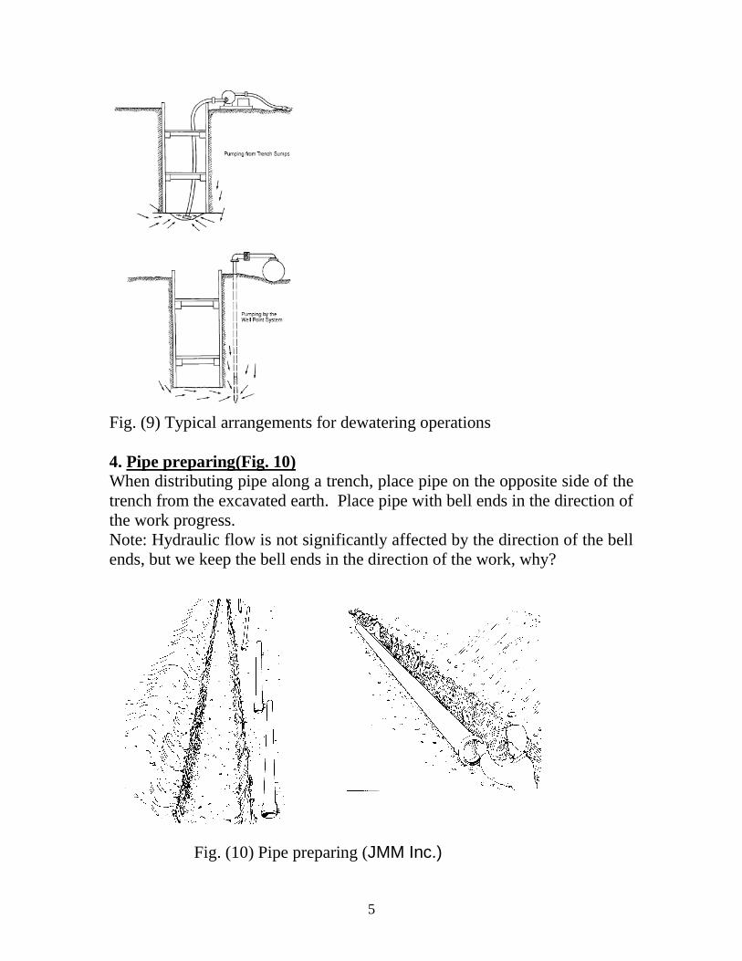
4. Pipe preparing(Fig. 10)
When distributing pipe along a trench, place pipe on the opposite side of the
trench from the excavated earth. Place pipe with bell ends in the direction of
the work progress.
Note: Hydraulic flow is not significantly affected by the direction of the bell
ends, but we keep the bell ends in the direction of the work, why?
Fig. (10) Pipe preparing (JMM Inc.)

6
5. Bedding)التوسيذ( (Fig. 11 & 12)
Bedding is required primarily to bring the trench bottom up to grade.
Bedding materials should be placed to provide uniform longitudinal support
under the pipe to prevent low spots بقع واطئة() .
Under normal circumstances a bedding of 100 to 150mm compacted is of
sufficient thickness for the bedding.
Fig.(11) Bedding methods of PVC pipe (City of Perry, Georgia, US, 2004).
Fig.(12) Bedding methods of ductile iron pipe (City of Perry, Georgia, US, 2004).
6. Pipe lying
- Check the level of trench bottom. The grade may be held within
10mm of that on drawings.
7
- Inspect the pipe for cracks or defects, with particular attention to the
joints.
- Pipe lengths are placed on line & grade.
Fig. (13) Pipe handling
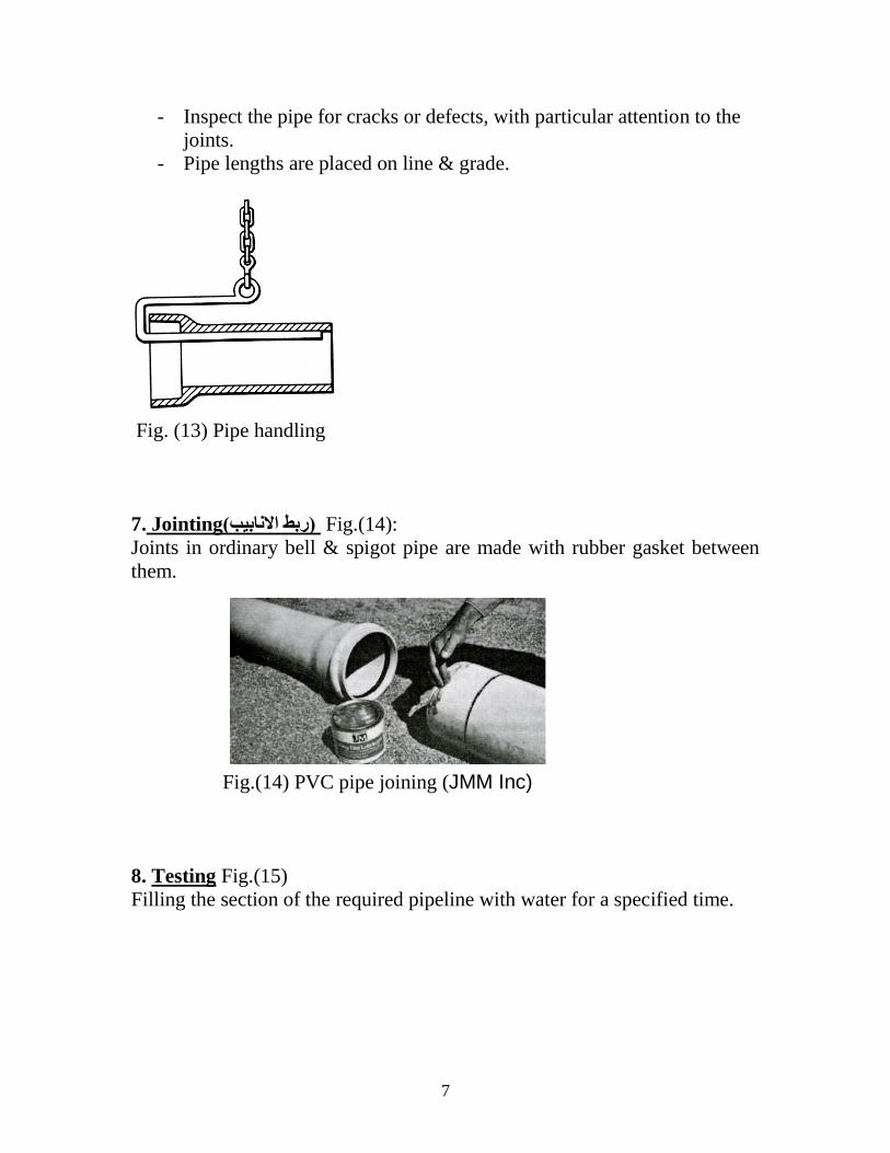
7. Jointing)رتط الاواتية( Fig.(14):
Joints in ordinary bell & spigot pipe are made with rubber gasket between
them.
Fig.(14) PVC pipe joining (JMM Inc)
8. Testing Fig.(15)
Filling the section of the required pipeline with water for a specified time.

8
Fig.(15) Section under leakage test
9. Backfilling)الردم(
Trenches should be backfilled immediately after the pipe is laid unless
Class-A bedding is used, where the concrete must set up sufficiently to
support the backfill. This quick backfilling protects the pipe:
a) from falling rocks
b) eliminates possibility of lifting the pipe from grade due to flooding of
an open trench
c) avoids shifting pipe out of line by cave-ins)ألانهيبرات(
Process:
Fill should be free of debris, & large rocks.
Fill should be tamped)يحدل( in layers 150mm deep around, under, & over the
pipe to a depth of 600mm. Earth should be dropped into the trench carefully
until 600mm of cover is in place.
Fill beneath streets & other surface construction must be bedding material,
sand or tamped earth placed in uniform layers at a moisture content
assuming maximum density.
Some times partial backfilling (joints not covered with soil) is used so it
possible to check the leak visually.
10. Strength & loading
The static load produced on buried pipe can be calculated using,
W = C w B2
Where:
W = load on pipe / unit length
w = weight of fill / unit volume = fill density
B = width of trench below top of pipe

9
≥ 1.5D + 300mm
D = pipe diameter
C = coefficient depends on trench depth, construction character, & fill
material
Bc = outside pipe diameter
1.Min.= ¼ inside diam. 1. 0.6 Bc
2. Min. = Bc/4
Concrete strength ≥ 2000psi (13.8MPa)
Fig.(16) Bedding methods of concrete pipe.
Example:
A 610mm sewer is to be placed in an ordinary trench 1.22m wide which will
be backfilled with wet clay weighing 1920kg/m3. Determine the load upon
the pipe. Take C = 2.20.
Solution:
W = C w B2
W = 2.2 × 1920 × (1.22)2
= 6290kg/m
If the standard strength pipe has a minimum crushing strength of 3870kg/m
& the safety factor = 1.5, then
Allowable load = 3870/1.5 = 2580kg/m
Load factor = 6290/2580 = 2.44
From the Fig. → choose class A
Class A
Concrete bedding
Load factor =2.2-3.4
Class B
First class bedding
Load factor = 1.9

10
11. Sewer built in place
For large size, cast in place sewer is used.
12. Jacking & boring
Sewers under highways, railroads, etc. are installed by jacking & boring.
Pipes are driven by hydraulic jacks mounted in a jacking pit at the point of
beginning.
13. Other construction Techniques
Fig. (17) Below grade stream crossing (City of Perry, Georgia, US, 2004)

11
Fig. (18) Aerial stream crossing (City of Perry, Georgia, US, 2004)
Fig. (19) Pavement replacement (City of Perry, Georgia, US, 2004)

12
Fig.(20) Principles of ground-probing radar.

13
Operation and Maintenance Sanitary sewer tests Infiltration/inflow (I/I)
Inspection = test فحص()
1. Smoke Testing)فحص الذخان(
Fig. (21) smoke testing
The purpose of smoke testing is to locate rainfall-dependent I/I sources,
which could lead to an overflow )فيض( during a storm event.
Specific sources detected include inlets, area drains, and broken main and
service lines.
Process:
A non-toxic, non-staining غير ملطخّ() low-pressure smoke is pumped through
a manhole into the sewer pipe for distances up to 180 m.
Smoke emissions ينبعث() from manholes and from the ground indicate
defects in manholes, sewer lines, and sewer laterals through which I/I may
enter the sewer.
2. Line Lamping (Visual Inspection))فحص تصري( Fig. (22)

14
It is performed in conjunction with manhole inspection. Lamping consists of
visually inspecting the interior of the sewer lines connected to the manhole
by using a powerful flashlight and mirror while standing above or in the
manhole.
Line lamping is used to obtain information on pipe condition and to
determine if a section of pipe is straight and clean.
3. Closed Circuit Television Inspection, CCTV (فحص تلفار الذائرج المغلقح(
Small diameters can only be inspected by CCTV.
CCTV is often performed on selected defective sewer lines identified
through other less costly preliminary inspection techniques such as lamping,
& smoke testing.
The CCTV unit can traverse up to 1800 ft (540m) each way from a given
access point.
Process:
CCTV inspection is performed by pulling the camera through the sewer line.
The images from the camera are observed on a monitor.
The videotape provides a visual and audio record of problem areas of the
sewer line.
The evaluation of the CCTV records will help identify structural problems of
the sewer line, locate leaking joints and non-structural cracks, blockages,
dropped joints, and identify areas of root intrusion أختراق() .
4. Pipe profiling sonar, PPS)سووار تشخيص الاوثوب(
Fig. (23) The display screen
The technology can provide information on structural damage, blockages,
sediments رسىبيبت() , large cracks, and the location of incoming lateral lines.

15
Limitation:
PPS can be used for inspecting pipes from 3-in through 144-in diameter and
has a maximum cable length of 2500ft (750m).
Process:
The sonar unit transmits an acoustic signal radially toward the pipe walls,
using a rotating transducer. The time delay between transmission and
reception of reflected pulse echo is used to determine the distance from the
transducer to the surface which reflected the pulse.
The device communicates via cable with an acoustic processor unit fitted
with a CD read-writer for storing still-frame images from the display screen
at full resolution. The stored images can be loaded back into the system,
cursors positioned, and measurements taken of pipe diameter, objects, and
large defects.
Actual application:
In 2000, under ideal conditions in a 96-in diameter sewer using extremely
slow forward advancement, the device can indicate openings or cracks of
about 0.2-in (5mm).
5. Man-entry inspection)فحص الاواتية الكثيرج القطر(
It may be performed on large-diameter sewer lines.
During inspection, the crew مجمىعة الفحص() should observe the appearance
مظهر() of the sewer line walls, signs of flow disturbances أضطراة() , extent of
corrosion, and the structural condition of the sewer line.
Sounding tests may be performed by striking ضرة() the crown, sidewalls,
and invert of the sewer line with a hammer and noting whether the generated
sound is dull or solid.
6. Manhole Inspection
Manhole inspections are performed to confirm the physical layout and
mapping of the sewer system, determine the physical condition of the
sanitary sewer manholes and to locate sources of I/I.
Proactive Maintenance)صيانة وقائية( Cleaning such as sediment, grease, debris and roots, is the most important maintenance tool. This needs a good schualing; daily, weekly, monthly, yearly, and more.

16
Collection System Maintenance Techniques The Sewer Maintenance Division must have maintenance and cleaning program to keep the sanitary sewer system operating efficiently and to minimize the number of calls for service. The following are the common techniques.
1. Hydraulic Cleaning)التنظيف المائي( Jetting removes grease buildup and debris by directing high velocities of water against the pipe walls at various angles. The basic jetting machine equipment is usually mounted on a truck or trailer. It consists of water supply tank of at least 3.8 m3 (1000 gallons), a high pressure water pump, a powered drum reel holding at least 152 m (500 ft) of one inch hose on a reel having speed and direction controls and a variety of nozzles. Jetting is efficient for routine cleaning of small diameter, low flow sewers. Balling Balling is a hydraulic cleaning method in which the pressure of a water head creates high velocity water flow around an inflated rubber cleaning ball. The ball is a hollow neoprene & it has an outside spiral thread and swivel connection that causes it to spin, resulting in a scrubbing action of the water along the pipe. To clean sewer lines, the ball is tied to a rope & air-inflated to fit inside the pipe. The ball is then inserted into the line at a manhole producing a movable dam سد() in the pipe. As the sewage backs up, the ball is allowed to move slowly downstream, while being controlled by the rope. When the head of water exceeds the air pressure in the ball, a jet of water is released under the ball, sweeping sediment ahead. At the same time the ribs on the surface of the ball scrape slime from the pipe wall. Only when there is a complete stoppage is it necessary to use sewer rods to open the line. The transported sediment is removed at the downstream manhole. One city in USA, reports that at least 75% of the sewer system is balled each year. Daily runs of 1 to 3 miles are not unusual.

17
Approximately 855 miles of sewer have been cleaned at a cost of $90 to $95 per mile.
2. Mechanical Cleaning)التنظيف الميكانيكي( Mechanical cleaning techniques include the rodding machine and cable drag machine. 2.1 Sewer Rodding Today’s rodding machines utilize a continuous steel rod, rotated by a gasoline engine-powered shaft, played out along the length of the sewer with a variety of attachments to match the cleaning requirement and the diameter.
Fig. (24) Variety of attachments
2.2 Cable or Bucket Machines These techniques use a steel cable attached to both ends of buckets to “drag” the sewer and remove larger or harder deposits than a rodder is capable of addressing.

18
Fig. (25) Bucket Combined cleaning:
Fig. (25) Procedure of combined cleaning Reference: City of Perry, Georgia, US, 2004, "Water and Sanitary Sewer Standard Specifications" JMM Company Inc., Gravity Sewer Installation Guide,