sewage sludge management in germany - · pdf filecurrent status of sewage sludge management...
TRANSCRIPT
in Germany
Sewage sludge management
Order brochures address:
Umweltbundesamt c/o GVP
Postfach 30 03 61 | 53183 Bonn | Germany
The brochure is free.
Telephone service: +49 (0)3 40 21 03-66 88 Fax service: +49 (0)3 40 21 04-66 88
w w w.umwel t bunde s amt .de
Authors:
Dipl.-Ing. Benjamin Wiechmann
Dipl.-Ing. Claudia Dienemann
Dr. Christian Kabbe
M. Sc. Simone Brandt
Dr. Ines Vogel
Dr. Andrea Roskosch

Publisher: Umweltbundesamt (UBA) | Postfach 1406 | 06844 Dessau-Roßlau | Germany
in Germany
Sewage sludge management

Contents
Preface 3
1 Introduction 4What is sewage sludge? 4Where does sewage sludge occur? 5
2 Composition of sewage sludge 7Heavy metals in sewage sludge 9Organic compounds in sewage sludge 11Pathogens and health hazards arising from e.g. EHEC
12
Pharmaceutical drug residues in sewage sludge
14
3 Sludge treatment 16
4 Thermal sludge treatment 23Mono-incineration 23Co-incineration 25
5 Sewage sludge use in the agricultural sector
29
Nutrients in sewage sludge 30Sewage sludge pollutants 31Pros and cons of using sewage sludge as a fertilizer
34
6 Phosphorous recovery 34Phosphorous recovery potential and processes
36
Cost efficient phosphorous recycling in Germany
38
7 Sewage sludge quantities, management and recycling
42
8 Footing the bill for sewage sludge management
50
9 The way forward 52
10 Illustrations 58
11 Tabels 58
12 Abbreviations 60
13 Acknowledgements 62
14 Bibliography 62
15 Appendix I 68
16 Appendix II 82Sewage sludge management legislation 82
17 Appendix III 87Heavy metals in sewage sludge 87
18 Appendix IV 88
2
Contents
Preface
Germany’s municipal sewage treatment plants generate some two million tons of dry sewage sludge annually, with the proportion of ther-mally treated sewage sludge increasing from 31.5 per cent in 2004 to more than 54 % in 2011.
Sludge, which is usually incinerated or used as agricultural fertilizer, contains a whole series of harmful substances that complicate the task of sludge management. But sludge also contains a number of nutrients such as phosphorus, nitrogen and potassium. Hence the goal of sewage sludge management is to remove sludge pollutants while retaining sludge nutrients. Sewage sludge undergoes thermal recycling at facilities such as sewage sludge mono-incineration plants, cement plants and coal fired power plants.
Sewage sludge utilization for farming pur-poses has plateaued of late (2006 to 2011) at around 29 %, an evolution attributable to more stringent quality standards for sewage sludge.
However, sewage sludge is set to take on grea-ter importance as a raw material, mainly due to the increased concentrations of phospho-rous it contains.
This pamphlet discusses the potential offered by sewage sludge and the ways it can be used sustainably. The pamphlet also describes the current status of sewage sludge management in Germany, with particular emphasis on the extent to which sludge use as a fertilizer can be reduced without foregoing phosphorous and other sludge nutrients. Over the next one to two decades, Germany needs to wean itself away from using sewage sludge for farming and at the same time efficiently leveraging the potential for using sewage sludge as a low cost fertilizer.
3
Preface
What is sewage sludge?In Germany, daily water use now reaches 120 litres per person. All of this water ulti-mately ends up in the sewage system, and from there is channelled to sewage treatment plants. At such plants, the sewage passes through screens and sieves and undergoes mechanical and biological purification, the goal being to remove impurities from the sewage and to then channel the re-sulting purified water into waterbodies. The residue of this process is known as sewage sludge, which can occur in anhy-drous, dried or other processed forms.
Raw sludge is sewage sludge that is remo-ved from sewage treatment plants without being treated. Sewage sludge is generated by both municipal and industrial sewage treatment plants. When it comes to material recycling within the meaning of the Sewage Sludge Ordinance (Klärschlammverordnung, AbfKlärV), only sewage sludge from mu-nicipal sewage treatment plants is usually suitable. Under the said ordinance, sewage sludge compost and mixtures also qualify as sewage sludge. Sewage sludge mixtures are mixtures of sewage sludge and other conformant substances, in accordance with Appendix 2 tables 11 and 12 of the Fertilizer
Ordinance (Düngemittelverordnung, DüMV). Sewage sludge compost comprises compos-ted sewage sludge mixtures [ABFKLÄRV].
Sewage sludge can be characterized based on various physical, chemical and micro-biological parameters, using the characte-ristic values listed in table 1. It should also be noted that apart from these parameters, there are others such as the sludge volu-me index and digestion time that are also used to characterize sewage sludge.
For example, elevated loss on ignition indicates a high organic substance con-centration in sewage sludge. One of the purposes of sewage sludge incineration is to expunge the organic substances from the sludge. Hence loss on ignition is one of the key parameters when it comes to characteri-zing sewage sludge combustibility, whereby water content is also an important factor, since unduly high water content reduces the calorific value of fuel. And finally, sewage sludge should never be characterized on the basis of only a single parameter, because the parameters are always interrelated.
Introduction01
4
01 · Introduction

Table 1: Sludge parameters and their significance [Kopp; Räbiger]
Parameter Unit of measure Explanation
Dry solids (DS) e. g. kg, g, mgThe drying process results in a dry-mass/-solids residue in dry sludge. Determined by subtracting water content.
Total solids (TS) e. g. kg/m3, g/l The dry mass content in a given volume.
Dry residue (DR) %Unit of measure for the solid content of a non-filtrated sludge sample; dry mass portion of given volume of sludge. Determi-ned by vapourizing water content.
Water content (WC) %Unit of measure for the water content of a given volume of sludge. Determined via vapourizing water content.
Residue on ignition (ROI) %Unit of measure for the inorganic or mineral content of dry solids in sewage sludge. Determined by burning up the dry solids.
Loss on ignition (LOI) %Organic substance content of a given volume of sewage sludge dry solids. Determined by burning up the dry solids.
pH - Negative decimal logarithm for hydrogen ion activity.
Sludge type -Operational data. Classifying sewage sludge according to where it occurs.
Sludge age -Operational data. Determined by the ratio between the bac-teria mass in the basin and the daily bacteria mass removed from excess sludge.
Where does sewage sludge occur?Sewage sludge is a generic term that provides no indication as to the origin and/or type of sludge involved; and thus even dried or dewatered sludge qualifies as sewage sludge under Germany’s Sewage Sludge Ordinance (AbfKlärV). Each of the various types of raw sludge has a specific designation, depen-
ding on the juncture in the purification process at which the sludge is generated.
Figure 1 shows the juncture in a sewage treat-ment plant’s purification process at which the various types of sludge are generated.
5
Introduction · 01
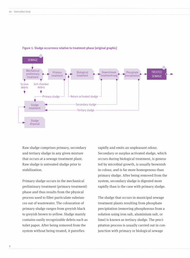
Raw sludge comprises primary, secondary and tertiary sludge in any given mixture that occurs at a sewage treatment plant. Raw sludge is untreated sludge prior to stabilization.
Primary sludge occurs in the mechanical preliminary treatment (primary treatment) phase and thus results from the physical process used to filter particulate substan-ces out of wastewater. The colouration of primary sludge ranges from greyish black to greyish brown to yellow. Sludge mainly contains easily recognizable debris such as toilet paper. After being removed from the system without being treated, it putrefies
rapidly and emits an unpleasant odour. Secondary or surplus activated sludge, which occurs during biological treatment, is genera-ted by microbial growth, is usually brownish in colour, and is far more homogenous than primary sludge. After being removed from the system, secondary sludge is digested more rapidly than is the case with primary sludge.
The sludge that occurs in municipal sewage treatment plants resulting from phosphate precipitation (removing phosphorous from a solution using iron salt, aluminium salt, or lime) is known as tertiary sludge. The preci-pitation process is usually carried out in con-junction with primary or biological sewage
Figure 1: Sludge occurrence relative to treatment phase [original graphic]
Mechanical preliminary treatment
Primary treatment
Biological treatment
Downstream treatmentrung
Phosphate precipitation
TREATED SEWAGE
Sludge treatment
SEWAGE
Screen debris
Grit chamber debris
Primary sludge Return activated sludge
Tertiary sludge
Sludge disposal
Secondary sludge
6
01 · Introduction

Sewage sludge can be regarded as a multi-substance mixture. Because of the inhomo-geneity and tremendous differences in the concentrations of its components, it is difficult to determine or define a standard composition for sewage sludge, which is mainly compo-sed of organic substances. Sewage sludge (i. e. stabilized primary, secondary or tertiary sludge that occurs in a mixture at the end of the treatment process) contains plant nutrients such as nitrogen and phosphorous, as well as harmful substances such as pathogens, endocrine disrupters and heavy metals.
Table 2 below list the attributes that are used to characterize municipal sewage sludge. The data in this table is derived from a German Association for Water, Wastewater and Waste (Deutsche Vereinigung für Wasserwirtschaft, Abwasser und Abfall e. V., DWA) publica-tion [DWA]. At the time of publication of this pamphlet, the only other available relevant data was a study by Environmental Agency Austria. This data was incorporated into the table in the interest of completeness.
treatment, rather than in a structurally separate treatment system. Hence tertiary sludge often occurs not separately, but rather mixed in with primary or secondary sludge. The colouration of tertiary sludge is deter-mined by the substance reactions that come into play, whereby the chemical properties of tertiary sludge differ considerably from those of primary and secondary sludge. Tertia-ry sludge is normally stable and does not
emit an unpleasant odour. The other sludge designations are digested sludge (sludge that undergoes an anaerobic sludge stabilization process) and stabilized sludge (sludge that un-dergoes a chemical or biological sludge stabi-lization process) [BISCHOFSBERGER ET AL.].
A list and brief description of all sewage treat-ment legislation can be found in Appendix II.
Composition of sewage sludge
02
7
Composition of sewage sludge · 02

Table 2: Sewage sludge composition [dwa; oliva et al.]
* Werte stammen aus [Oliva et. al.]; Median** Werte stammen aus [Oliva et. al.]
Substance Unit of measure Value range according to DWApH value – 7.7*Dry solids (DS) wt % 30.5*Loss on ignition (LOI) % 45–80**Water wt % 65–75Volatile matter wt % 30Net calorific value (NCV) MJ/kg DM 10–12Carbon (C) % 33–50
Oxygen (O2) % 10–20
Hydrogen (H2) % 3–4Nitrogen (N2) % 2–6Sulphur (S) % 0.5–1.5Fluorine (F2) wt % <0.01Chlorine (Cl2) % 0.05–0.5Phosphorous (P) g/kg 2–55Antimony (Sb) mg/kg DS 5–30Arsenic (As) mg/kg DS 4–30Lead (Pb) mg/kg DS 70–100Cadmium (Cd) mg/kg DS 1.5–4.5Chrome (Cr) mg/kg DS 50–80Copper (Cu) mg/kg DS 300–350Manganese (Mn) mg/kg DS 600–1,500Nickel (Ni) mg/kg DS 30–35Selenium (Se) mg/kg TS 1–5Thallium (Th) mg/kg TS 0.2–0.5Vanadium (V) mg/kg TS 10–100Mercury (Hg) mg/kg TS 0.3–2.5Zinc (Zn) mg/kg TS 100–300Tin (Sn) mg/kg TS 30–80AOX mg/kg TS 350PCDD/F mg/kg TS 0.000035Molybdenum (Mo) g/kg TS 3.9*Cobalt (Co) g/kg TS 6.53*Calcium (Ca) g/kg TS 71*Potassium (K) g/kg TS 2.63*Magnesium (Mg) g/kg TS 9.17*
8
02 · Composition of sewage sludge

Heavy metals in sewage sludgeMost of the heavy metals found in muni-cipal wastewater treatment plant sludge are attributable to inputs from the surfaces of man-made urban elements. Thus for example, substances such as lead, cadmium and copper end up in the sewage system and thus in sludge, via building surfaces,
pipes, brake linings and electric lines [OLIVA ET AL.]. Table 3 lists the concentrations of heavy metals in sewage sludge in recent years (data available up to 2006 only). The heavy metals that fall within the scope of the Sewage Sludge Ordinance (AbfKlärV) are expressed in mg per kg of dry solids.
mg/kg of dry solids
1977 19821986–1990
1998 2001 2002 2003 2004 2005 2006
Change between
1977 (=100%)
and 2006
Change between
2001 (=100%)
and 2006
Lead 220 190 113 63 53 50 48 44.3 40.4 37.2 -83.09 -29.81
Cadmi-um
21 4.1 2.5 1.4 1.2 1.1 1.1 1.02 0.97 0.96 -95.43 -20.00
Chrome 630 80 62 49 45 45 42 40.7 37.1 36.7 -94.17 -18.44
Copper 378 370 322 289 304 306 305 306.3 306.4 300.4 -20.53 -1.18
Nickel 131 48 34 27 27 27 27 25.8 25.2 24.9 -80.99 -7.78
Mercury 4.8 2.3 2.3 1 0.8 0.7 0.7 0.62 0.59 0.59 -87.71 -26.25
Zinc 2,140 1,480 1,045 835 794 750 746 756.7 738.2 713.5 -66.66 -10.14
Total nitrogen
n/a n/a n/a n/a 39,357 38,846 40,328 42,025 42,457 43,943 ns +11.65
Total phos-phorous
n/a n/a n/a n/a 27,337 22,019 22,559 23,581 24,312 24,531 ns -10.26
Table 3: Sludge concentrations of selected heavy metals and of nitrogen and phosphorus between 1977 and 2006.
9
Composition of sewage sludge · 02
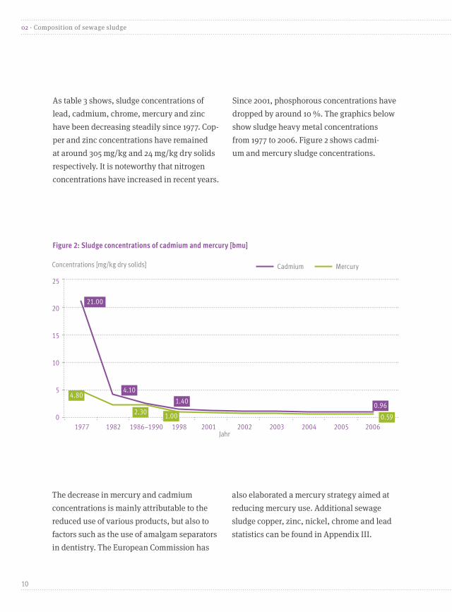
As table 3 shows, sludge concentrations of lead, cadmium, chrome, mercury and zinc have been decreasing steadily since 1977. Cop-per and zinc concentrations have remained at around 305 mg/kg and 24 mg/kg dry solids respectively. It is noteworthy that nitrogen concentrations have increased in recent years.
Since 2001, phosphorous concentrations have dropped by around 10 %. The graphics below show sludge heavy metal concentrations from 1977 to 2006. Figure 2 shows cadmi-um and mercury sludge concentrations.
The decrease in mercury and cadmium concentrations is mainly attributable to the reduced use of various products, but also to factors such as the use of amalgam separators in dentistry. The European Commission has
also elaborated a mercury strategy aimed at reducing mercury use. Additional sewage sludge copper, zinc, nickel, chrome and lead statistics can be found in Appendix III.
Figure 2: Sludge concentrations of cadmium and mercury [bmu]
25
20
15
10
5
0
Concentrations [mg/kg dry solids] Cadmium Mercury
21.00
4.10
1.400.96
4.80
2.30 1.00 0.59
Jahr1977 1982 1986–1990 1998 2001 2002 2003 2004 2005 2006
10
02 · Composition of sewage sludge
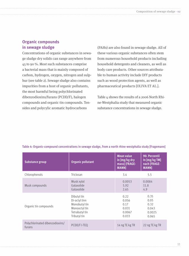
Table 4: Organic-compound concentrations in sewage sludge, from a north rhine-westphalia study [Fragemann]
Organic compounds in sewage sludgeConcentrations of organic substances in sewa-ge sludge dry solids can range anywhere from 45 to 90 %. Most such substances comprise a bacterial mass that is mainly composed of carbon, hydrogen, oxygen, nitrogen and sulp-hur (see table 2). Sewage sludge also contains impurities from a host of organic pollutants, the most harmful being polychlorinated dibenzodioxins/furans (PCDD/F), halogen compounds and organic tin compounds. Ten-sides and polycylic aromatic hydrocarbons
(PAHs) are also found in sewage sludge. All of these various organic substances often stem from numerous household products including household detergents and cleaners, as well as body care products. Other sources attributa-ble to human activity include DIY products such as wood protection agents, as well as pharmaceutical products [OLIVA ET AL.].
Table 4 shows the results of a 2006 North Rhi-ne-Westphalia study that measured organic substance concentrations in sewage sludge.
Substance group Organic pollutant
Mean value in [mg/kg dry mass] [FRAGE-MANN]
90. Perzentil In [mg/kg TM] nach [FRAGE-MANN]
Chlorophenols Triclosan 3.4 5.5
Musk compoundsMusk xylolGalaxolideGalaxolide
0.00535.922.65
0.008411.84.9
Organic tin compounds
Dibutyl tinDi-octyl tinnMonobutyl tinMonooctyl tin Tetrabutyl tin Tributyl tin
0.220.0560.170.0310.00670.033
0.350.050.320.0430.00250.065
Polychlorinated dibenzodioxins/furans
PCDD/F I-TEQ 14 ng TE kg TR 22 ng TE kg TR
11
Composition of sewage sludge · 02

Substance group Organic pollutant
Mean value in [mg/kg dry mass] [FRAGE-MANN]
90. Perzentil In [mg/kg TM] nach [FRAGE-MANN]
Polybrominated diphenyl ethers
Tetrabromodiphenyl ether Pentabromodiphenyl ether Hexabrominated diphenyl ether Heptabrominated diphenyl ether
0.0260.0480.0110.013
0.0370.0630.0110.0058
PAC
Decabrominated diphenyl etherBenzo(a)pyreneChryseneEPA PAC (excluding acenaphty-lene
0.570.470.646.64
1.060.731.119.52
PCB (polychlorinated biphenyls) Total PCB 6 0.091 0.17
PhthalatesDEHPDibutyl phthalate
27.50.55
57.51
TensideLinear alkyl benzene sulfonate (LAS)Nonylphenol
1,723
21.5
4,000
44.2
The aforementioned pollutants and the concentrations thereof were mainly de-termined in accordance with their catch-
ment areas, as well as population size and numbers of businesses [OLIVA ET AL.].
Pathogens and health hazards arising e. g. from EHECPathogens such as bacteria, viruses, pa-rasites and worm eggs are also found in sewage sludge. If such sludge is used as fertilizer, the pathogens in it can enter the human and animal food chain, thus endangering the health of both [GUJER].
This potential health hazard is the subject of an ongoing debate concerning the possible transmission of EHEC to humans as the result
of the utilization of sewage sludge and other organic substances as fertilizer. The 2011 EHEC epidemic, which was provoked by the EHEC pathogen O104:H4, raised public awareness of the importance of such risk assessments. Two requirements need to be met in order to conduct such assessments: (a) the survival ca-pability of the pathogen must be known; and (b) it must be possible to determine the proba-bility that humans and livestock will come into contact with sewage sludge. The pathogens
12
02 · Composition of sewage sludge

with the greatest survival capability are (a) spore producing bacteria such as clostrida; (b) parasites that form a long term phase or that produce spores (e. g. giardia and cryptospo-ridia); (c) plus worm eggs. Bacteria that do not produce spores normally survive for only anywhere from a few weeks to a few months.
Very little is known about the ability of the EHEC pathogen O104:H4 to survive in the environment. Inasmuch as the epidemic strain contains two E. coli pathogens (EHEC and EAggEC), the relevant risk can at present only be assessed based on the characteristics of these E. coli pathogens, and of apatho-genic E. coli . Inasmuch as EAggEC bacteria tend to exhibit bacterial cell aggregation and form biofilms, the E. coli epidemic strain O104:H4 could potentially persist in environmental biofilms. Moreover, it is safe to assume that the E. coli epidemic strain O157:H7 can potentially survive for months in the ground, as it has been shown to possess the capacity to survive over a period of many months in various types of soil and under various sets of experimental conditions.
In view of the fact that the EHEC pathogen O104:H4 exhibits a high level of survival capability, it is essential that humans and animals not be exposed to it. Hence in drafting the Sewage Sludge Ordinance’s (AbfKlärV) health and safety provisions, minimizing pos-sible risk for humans and livestock was a top priority. Another way to avoid such exposure
would be through hygienization of sewage sludge by reducing pathogen concentrations before sludge is used as fertilizer. But as the Sewage Sludge Ordinance (AbfKlärV) takes a different approach to this problem, it contains restrictive regulations concerning sewage sludge application on land. Hence section 4 of this ordinance contains application restric-tions such as that sewage sludge cannot be used as fertilizer for fruit and vegetable growing, or on permanent grassland. The ordinance also sets forth sludge application limitations for fields that are used to grow forage or cultivate sugar beets (in cases where the beet leaves are used as forage). Thus sewage sludge cannot be used as fertilizer for food or animal feed that is eaten raw.
Hence the Sewage Sludge Ordinance (AbfKlärV) is in effect predicated on the assumption that insofar as sewage sludge is utilized properly, neither fruit/vegetable crops nor forage will be contaminated.
Sewage sludge utilization is also prohibited in zone I and II protected drinking water areas (containment facilities and protected areas per se), and in up to ten meter wide buffer strips. The presence of sewage sludge and the utilization thereof as fertilizer in zone III water protection areas (i.e. the catchment area of a protected containment facility) are banned in certain cases at the regional level.
13
Composition of sewage sludge · 02
Pharmaceutical drug residues in sewage sludgeMore than 30,000 tons of pharmaceuti-cal drugs are used in Germany annually [RÖNNEFAHRT]. After being used for therapeutic purposes or being disposed of improperly (in toilets), residues of these drugs end up in municipal sewage systems.
Depending on the sewage treatment me-thods used, a greater or lesser portion of the pharmaceutical drug residues removed from sewage are deposited in sewage sludge. The downside of more efficient removal of such residues from sewage (thanks to the use of advanced treatment technologies) is rising concentrations of pharmaceutical drug residues in sewage sludge. And when such sludge is used as fertilizer, the phar-maceutical drug residues contained in it are applied to the ground, along with the sludge’s nutrient load. Such substances can then seep into the soil (where they accumulate) and groundwater, or can be directly incorporated into waterbodies through surface runoff. While extensive research has been done on pharmaceutical drug residues in sewage treat-ment plant runoff and surface waterbodies,
little in the way of scientific data is available on drug residue concentrations in sewage sludge and the behaviour of these concentra-tions in the soil. Apparently, this is because scientifically demonstrating the presence of pharmaceutical compounds in soil is compli-cated by the fact that many of these substan-ces are fixed to the organic soil matrix (i.e. the various solids in soil) and can only be remo-ved through lengthy extraction processes.
The elimination rates of pharmaceutical drug residues in sewage sludge via breakdown, as well as sorption (i.e. input into or adhe-sion to the organic components of sewage sludge) vary greatly. According to one study [BOXALL ET AL.] pharmaceutical drugs (e.g. certain antibiotics) that are non-polar and have a high molecular weight tend to exhibit elevated sorption. Another study [GOLET ET AL.] observed an 88 to 92 % elimination rate, mainly through input into sewage sludge, and demonstrated up to a 3.5 mg/kg sewage sludge concentration of the fluoroquinolone antibiotics ciprofloxacin and norfloxacin. Ac-cording to the study authors, the soil in fields fertilized with sewage sludge contains up to
Experts believe that the existing ordinances are sufficient to prevent EHEC from entering the food chain, groundwater or surface water-bodies via sewage sludge application on land,
provided that sludge is used in accordance with the Sewage Sludge Ordinance (AbfKlärV). However, this belief in turn presupposes that sludge monitoring will be 100 % effective.
14
02 · Composition of sewage sludge

0.45 mg per kilogram of the relevant substan-ces that are also highly persistent, i.e. remain in the environment for a lengthy period.
According to an IWW literature review (commissioned by the UBA) of the monito-ring data for pharmaceutical drugs in the environment [BERGMANN ET AL.], apart from the aforementioned antibiotics cipro-floxacin and norfloxacin, the antibiotics doxycyclin, clarithromycin, roxithromy-cin and trimethoprim, the anticonvulsant carbamazepine, the hyperlipidemia drugs bezafibrate, fenofibrate and gemfibrozil, and the beta blocker metroprolol occur in sewage sludge in concentrations exceeding 100 μg/kg. Oestrogens such as 17-beta-estradiol and 17-alpha- ethinylestradiol have also been detected in sewage sludge samples.
Another study [STUMPE] concerning the soil breakdown and mineralization of stero-id hormones that end up in fields as the result of sewage sludge fertilization (among other applications) found that oestrogen is a stable compound in the soil. The study’s lab experiments showed that oestrogen in soil is subject to vertical displacement and should thus be factored into risk assessments concerning groundwater as well as surface waterbodies that are affected by groundwater.
Another subject of debate among scientists concerning sewage sludge application on land is the spread of pathogens that are resistant
to antibiotics. There is evidence that in part owing to the elevated bacterial concentrations found in sewage treatment plants, antibiotic resistance can be exchanged between bacte-ria that are input with sewage from facilities such as hospitals [UBA]. This phenomenon could potentially give rise to new constellati-ons of antibiotic resistance being transmitted to heretofore nonresistant bacteria. According to another study [EIBISCH], the continuous input of antibiotics into soil over a prolonged period can result in elevated concentra-tions of bacteria that promote the growth of antibiotic-resistant bacteria, resulting in the possibility of gene transfers of the resistance genes of such antibiotics. Expert reports issued by the German Advisory Council on the Environment (SRU) concerning phar-maceutical drugs in the environment indicate that the spread of antibiotic resistance in the environment resulting from resistant-bacteria inputs poses a greater public health hazard than antibiotic inputs per se [SRU].
Antibiotics can be absorbed in the soil by plant roots and can be absorbed by plant tissues down to the seed level [GROTE ET AL.]. However the concentrations that have been detected in such settings are lower than the health reference values that apply to products such as food of animal origin. There are various indications that phar-maceutical drugs remain and accumulate in the soil as the result of sewage sludge
15
Composition of sewage sludge · 02
fertilization. Although generally speaking such inputs are not currently regarded as serious hazard for soil, soil organisms or human health, the data concerning the long term impact of these inputs on soil orga-nisms, the environment as a whole, and on human health is currently insufficient. According to a German Advisory Council on
the Environment (Sachverständigenrat für Umweltfragen, SRU) report on pharmaceuti-cal drugs in the environment, although only a handful of pharmaceutical drugs accumulate in sewage sludge, it would be advisable to gradually phase out the use of sewage sludge as a fertilizer so as to avoid diffuse loads of potentially harmful substances in soil [SRU].
The term sludge treatment encompasses all processes that improve the suitability for use, transport or storage of sewage sludge. Sludge treatment methods include thicke-ning, hygienization, biological stabiliza-tion, dewatering, drying and incineration [GUJER; BRANDT]. The latter process will be discussed in a separate chapter.
Thickening The purpose of sludge thickening is to reduce sludge volume by removing as much water as possible from the sludge. In thickeners (which are very similar to sedimentation tanks in terms of their design and proces-ses), sludge particles naturally sink to and are deposited on the bottom. In addition, a mixer expedites particle flocking so as to enable the particles to be deposited more rapidly. The sludge is removed from the
bottom of the thickener, and is discharged to the surface of the excess water [GUJER].
Hygienization Hygienization reduces the concentrations of pathogens such as viruses and worm eggs in sewage sludge, the goal being to minimize the risk of human and animal contamination when sludge is used as a fertilizer. A draft of a proposed amended version of the Sewage Sludge Ordinance (AbfKlärV) stipulates that sewage sludge may only be discharged or applied insofar as it has been hygienized. Ap-pendix 2 of this draft bill contains a list of the allowable hygienization methods that allow for compliance with the mandated physical and chemical parameters for sewage sludge hygienization [BRANDT] (see table below).
Sludge treatment03
16
03 · Sludge treatment
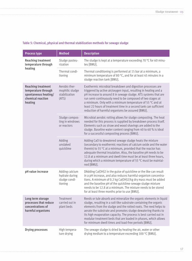
Table 5: Chemical, physical and thermal stabilization methods for sewage sludge
Process type Method Description
Reaching treatment temperature through heating
Sludge pasteu-rization
The sludge is kept at a temperature exceeding 70 °C for 60 minu-tes [BMU].
Thermal condi-tioning
Thermal conditioning is performed at 15 bar at a minimum, a minimum temperature of 80 °C, and for at least 45 minutes in a sludge reaction tank [BMU].
Reaching treatment temperature through spontaneous heating/chemical reaction heating
Aerobic-ther-mophilic sludge stabilization (ATS)
Exothermic microbial breakdown and digestion processes are triggered by active air/oxygen input, resulting in heating and a pH increase to around 8 in sewage sludge. ATS systems that are run semi-continuously need to be composed of two stages at a minimum. Only with a minimum temperature of 55 °C and at least 22 hours of treatment time in a second tank can sufficient reduction of harmful organisms be assured [BMU].
Sludge compos-ting in windrows or reactors
Microbial aerobic rotting allows for sludge composting. The heat needed for this process is supplied by breakdown process itself. Elements such as straw and wood shavings are added to the sludge. Baseline water content ranging from 40 to 60 % is ideal for a successful composting process [BMU].
Adding unslaked quicklime
Adding CaO to dewatered sewage sludge heats the mixture (secondary to exothermic reactions of calcium oxide and the water therein) to 55 °C at a minimum, provided that the reactor has adequate thermal insulation. Also, the baseline pH needs to be 12.8 at a minimum and dwell time must be at least three hours, during which a minimum temperature of 55 °C must be maintai-ned [BMU].
pH value increase Adding calcium hydrate during sludge condi-tioning
DAdding Ca(OH)2 in the guise of quicklime or the like can result in a pH increase, and also reduces harmful-organism concentra-tions. A minimum of 0.2 kg Ca(OH)2/kg dry mass must be added and the baseline pH of the quicklime-sewage sludge mixture needs to be 12.8 at a minimum. The mixture needs to be stored for at least three months prior to use [BMU].
Long term storage processes that reduce concentrations of harmful organisms
Treatment carried out in plant beds
Reeds or tule absorb and mineralize the organic elements in liquid sludge, resulting in a soil-like substrate containing the organic elements from the sludge and the rotted roots. The reed helps to aerate the substrate and promotes sludge dewatering thanks to its high evaporation capacity. The process is best carried out in modular treatment beds that are loaded in phases, which allows for minimum dwell times and load-free periods [BMU].
Drying processes High tempera-ture drying
The sewage sludge is dried by heating the air, water or other drying medium to a temperature exceeding 100 °C [BMU].
17
Sludge treatment · 03

Biological sludge stabilization Biological sludge stabilization reduces con-centrations of organic substances that break down rapidly, so as to avoid the unpleasant odours associated with such substances. A di-stinction is usually made between anaerobic biological sludge stabilization (digestion) and its aerobic counterpart. These processes are normally carried out in the psychrophilic, me-sophilic or thermophilic temperature ranges.
Large-scale biological sludge stabilizati-on facilities in Germany normally use the anaerobic process, which is done in what are known as digesters. Sewage sludge digestion allows for sludge stabilization, i.e. reduced odour emissions and biological activity. It is also essential that digestion improve sewage sludge dewatering capaci-ty, among other things. Another advantage of anaerobic treatment is that it produces a gas that can be used to generate energy. Other biological sludge stabilization me-thods are compostation and soilification.
The dewatering induced by digestion is ad-vantageous for subsequent thermal recycling in that digestion raises the heat value of the sludge. However, this is also a drawback in that the anaerobic breakdown process reduces organic-substance concentration and thus the calorific value of the sludge.
Sludge dewatering Mechanical sludge dewatering, which reduces the volume of the sludge mixture by reducing
its water content, is particularly important in settings where sewage sludge is transpor-ted to another site for treatment or disposal. Dewatering reduces the volume of sewage sludge that needs to be transported. What’s more, sludge cake (solid sludge) is far easier to process than liquid sludge. Dewatering also makes sludge combustion more cost effective by increasing the calorific value of the sludge.
Mechanical dewatering of sewage sludge in decanters, centrifuges, or belt or chamber filter presses results in solids concentrations amounting to 20 to 45 %, measured as dry residue. The success of mechanical dewate-ring mainly hinges on the machinery used, the nature and properties of the sludge, as well as any conditioning it may undergo.
Upstream sludge conditioning improves sludge dewatering capacity, through the use of flocking and flocking agent additives, whe-reby a distinction is made between inorganic flocking agents such as iron or aluminium salt, lime, and coal on one hand, and organic flocking agents (organic polymers) on the other. Iron and aluminium salts are often used as dewatering precipitates for phos-phate removal. As these salts substantially increase the noncombustible material (i.e. ash) content of dewatered sludge, organic conditioning agents are normally used prior to thermal sewage sludge treatment.
Sewage sludge dryingDried sewage sludge has a number of
18
03 · Sludge treatment
advantages over wet sludge that stems directly from the treatment process. Sludge dewatering and subsequent drying are preferable for the following reasons:
• Reduced sewage sludge volume• More conducive to storage and transport• More amenable to conveyance and dosing • Microbiological stabilization & health safety • Increased calorific value
The main drawback of drying is the additional energy needed for drying and dewatering.
Mechanical dewatering is only the first step in the drying process, during which vari-ous methods are used in order to increase sewage sludge solids content to more than 50 %. There are basically two types of sludge drying: partial drying to around 85 % dry residue; and complete drying to around 95 % dry residue. Sewage sludge is deemed partly dry insofar as it has undergone the paste phase, i.e. its solids content equa-tes to more than 50 to 55 % dry residue.
The key factor for subsequent thermal treatment is increasing the calorific value. In many cases the level of total solids achieved through mechanical dewatering does not allow for self-sustaining sludge incineration; or for technical reasons additional drying is necessary for sludge incineration. The most energy efficient method in this regard is to dry the sludge at the incineration site using a method such as waste heat recovery
[Beckmann]. Sewage sludge drying uses a tremendous amount of energy, as residual sludge water is evaporated using thermal energy. In this process, the drying gradient is determined by the intended use of the sludge.
For spontaneous incineration (without an au-xiliary combustion system) in sewage sludge mono-incineration plants, dewatering and drying of raw sludge to a total solids of 35 % dry residue are normally sufficient. The coun-terpart minimum value for digested sludge is 45 to 55 % dry residue, since digestion leaves behind a lesser amount of organic material for incineration. Waste incineration plants hand-le dewatered, partly dried and fully dried se-wage sludge. For power plants, sewage sludge with a solids content ranging from 20 to 35 % dry residue is normally used for incineration purposes. Such plants have coal grinding sys-tems that allow for integrated sewage sludge drying. Fully dried sludge can also be used in power plants. Sewage sludge in cement plants needs to be both dewatered and fully dried.
Sewage sludge combusts spontaneously at a heat value of around 4,500 to 5,000 kJ/kg; or if hot exhaust air from the boiler is used to prewarm the combustion air, spontaneous combustion can occur at 4,000 kJ/kg. Drying increases sewage sludge calorific value to 13,000 kJ/kg; thus the calorific value of dried sewage sludge is on a par with that of dry wood or lignite. Various heating media can be used for sludge dryers. Table 6 lists the hea-ting media and drying systems that are used.
19
Sludge treatment · 03
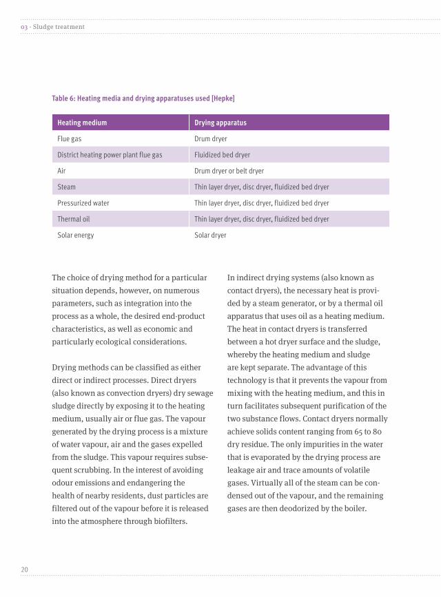
The choice of drying method for a particular situation depends, however, on numerous parameters, such as integration into the process as a whole, the desired end-product characteristics, as well as economic and particularly ecological considerations.
Drying methods can be classified as either direct or indirect processes. Direct dryers (also known as convection dryers) dry sewage sludge directly by exposing it to the heating medium, usually air or flue gas. The vapour generated by the drying process is a mixture of water vapour, air and the gases expelled from the sludge. This vapour requires subse-quent scrubbing. In the interest of avoiding odour emissions and endangering the health of nearby residents, dust particles are filtered out of the vapour before it is released into the atmosphere through biofilters.
In indirect drying systems (also known as contact dryers), the necessary heat is provi-ded by a steam generator, or by a thermal oil apparatus that uses oil as a heating medium. The heat in contact dryers is transferred between a hot dryer surface and the sludge, whereby the heating medium and sludge are kept separate. The advantage of this technology is that it prevents the vapour from mixing with the heating medium, and this in turn facilitates subsequent purification of the two substance flows. Contact dryers normally achieve solids content ranging from 65 to 80 dry residue. The only impurities in the water that is evaporated by the drying process are leakage air and trace amounts of volatile gases. Virtually all of the steam can be con-densed out of the vapour, and the remaining gases are then deodorized by the boiler.
Table 6: Heating media and drying apparatuses used [Hepke]
Heating medium Drying apparatus
Flue gas Drum dryer
District heating power plant flue gas Fluidized bed dryer
Air Drum dryer or belt dryer
Steam Thin layer dryer, disc dryer, fluidized bed dryer
Pressurized water Thin layer dryer, disc dryer, fluidized bed dryer
Thermal oil Thin layer dryer, disc dryer, fluidized bed dryer
Solar energy Solar dryer
20
03 · Sludge treatment

Solar drying, which as the name suggests dries sewage sludge using solar energy, has come into greater use in recent years. This process entails heating the sludge and then drying it in a greenhouse-like const-ruction. In order for evaporation and thus drying of the sewage sludge to proceed in an optimal manner, the sludge needs to be well aerated and turned repeatedly [Felber and Fischer]. Solar drying can be expedited through the use of floor radiation heating
or radiators or the like, so as to allow for the use of waste heat from power plants or waste incineration plants [Lehrmann 2010].
As of 2012, some 114 sludge drying facili-ties were in operation in Germany. Figure 3 contains a list of some of the sewage sludge dryers that are used, whereby in Germany numerous other systems also exist, some of which were decommissioned in 2011.
Source: proprietary data
21
Sludge treatment · 03
Figure 3: germany’s sewage sludge dryer fleet, broken down by type
53 solar dryers that do not use waste heat
13 disc dryers
5 cold-air dryers
4 thin layer dryers
19 solar dryers that use waste heat
10 drum dryers
5 fluidized bed dryers
10 belt dryers 1 screw dryer

The number of solar dryers in operation rose by more than 60 installations between 2004 and 2010. Apart from the drying methods used, sludge dryers are classified according
to their mean throughput (see Figure 4). A detailed list with technical details concer-ning all types of sludge dryers used in Ger-many can be found in Appendix IV, table 23.
Sludge drying capacity has not kept pace with the percentage rise in sewage sludge drying facilities. The throughput of solar sewage sludge dryers is considerably lower than that of disc or thin layer dryers, and is generally lower than that of thermal methods, regard-less of whether waste-heat recovery capability
is available. Despite this drawback, solar se-wage sludge dryer use is definitely on the rise. Use of these apparatuses is mainly advantage-ous in settings where no waste heat is availa-ble and the nearest mono-incineration plant is too far away. However, as noted, the choice of dryer hinges on many different factors.
22
03 · Sludge treatment
Source: proprietary dataFigure 4: Mean sludge dryer throughput
30,000
4,6004,9251,288353.12
14,007
1,317
10,246
3,034
Throughput [tons dry substance/a]
35,000
30,000
25,000
20,000
15,000
10,000
5,000
0
Belt drye
rs
Thin laye
r drye
rs
Cold air drye
rs
Solar drye
rs
Drum dryers
Solar drye
rs that
use w
aste heat
Fluidize
d bed dryers
Screw drye
rs
Disc drye
rs

Thermal sewage sludge treatment
04
The term “thermal disposal” in connection with sewage sludge pertains to incinerati-on at mono-incineration plants (including gasification installations), at coal fired power
Mono-incinerationSewage sludge mono-incineration facilities are operated at temperatures ranging from 850 to 950 °C; temperatures below 850 °C can result in odour emissions, and at temperatu-res above 950 °C ash sintering can occur. The temperature that is reached during incinerati-on depends on the energy content and quan-tity of the sewage sludge being used, as well as by the amount of available combustion air. By law (Federal Imission Control Ordinance – 17. Bundes-Immissionsschutzverordnung, 17. BImSchV), a minimum of 6 volume percent oxygen content must be maintained, afterburning must be carried out at 850 °C at a minimum, and at least two seconds of waste gas dwell time must be allowed in the afterburning chamber so as to allow for effici-ent combustion. Germany currently has (a) around 20 sewage sludge mono-incineration plants with aggregate combustion capacity of 580,000 tons dry solids annually; and (b) seven private sector sewage sludge mono-in-
plants and cement plants, and at certain waste incineration facilities. Moreover, the search for alternative sewage sludge treat-ment methods has intensified in recent years.
cineration plants with aggregate combustion capacity of 830,000 tons of original sewage sludge substance annually. These facilities use either raw sludge or digested sludge, which can be provided in a dewatered, partly dried or completely dried state. Further infor-mation in this regard can be found in table 22.
Combustion systems The following types of combus-tion systems are used for sewage sludge mono-incineration plants:
• Fluidized bed furnaces• Multiple-hearth furnaces• Multiple-hearth fluidized bed furnaces• Cycloid furnaces
The following table lists the particulari-ties of these various types of furnaces:
23
Thermal sewage sludge treatment · 04

Table 7: Comparison of the various combustion systems
Fluidized bed Multiple-hearth Multiple-hearth fluidized bed
Cycloid
Attributes No moving parts and minimal wear and tear
No separate pre-drying phase nee-ded; more complex design with moving parts and cooled hollow shafts
No separate pre-drying phase nee-ded; moving hollow shafts; low fluidized bed volumes
No moving parts and minimal wear and tear; needs no flui-dized bed material
Operating performance
Rapid startup and shutdown thanks to short heating-up and cooling cycles; can be operated intermittently
Lengthy heating-up times; needs to be operated conti-nuously
Medium heating-up and cooling times
Similar to fluidized bed; compatible with a broad range of fuels
Combustion Only minimal excess air needed; complete burn-up only occurs above the fluidized bed
Burn-up difficult to control; impervious to fluctuations in load volumes and to large elements
Requires minimal excess air; burn-out readily manageable; most combustion oc-curs in the fluidized bed; as compared to fluidized bed furnace, impervious to sludge quality fluctuations.
Solids content, long and gaseous ele-ments, short dwell times, variable pri-mary and secondary air intake at various levels
Waste gas ash content
High Low High High
Ash dischar-ge
Via waste gas flow and sand removal
At the bottommost hearth
Via waste gas flow and sand removal
Via waste gas flow; large ash particles on the bottom
Residues Ash, fluidized bed material
Ash Ash, fluidized bed material
Ash; in some cases large ash particles
Sewage sludge incineration plant emissionsSewage sludge incineration in sewage sludge mono-incineration plants and co-incineration combustion plants is governed by the Federal Imission Control Ordinance (17. BImSchV),
which promulgates a number of air emissi-on limit values. In the interest of adhering to these values through emission abate-ment, all sewage sludge mono-incineration plants have flue gas leaning systems.
24
04 · Thermal sewage sludge treatment

The Federal Imission Control Ordinance (17. BImSchV) contains provisions concer-ning various types of emissions such as dust, NOX, and mercury. All incineration processes and all types of incineration plants generate dust. All such plants are equipped with a filtering dust collector that efficiently reduces dust emissions. The mean dust content of cleaned flue gas ranges from 0.2 to 2.5 mg/m3; the statutory limit for this parameter is currently 10 mg/m3. NOX formation in sewage sludge mono-incineration plants is mainly attributable to two sources. First, sewage sludge contains substances such as ammonium. NOX can be formed through ammonium oxidation, as well as through ammonium input via incineration air in the form of oxygen and nitrogen, which at high temperatures can react with each other to form NOX. The mean value of the emissions is around 80 mg/m3, although values ranging up to 180 mg/m3 have been measured on rare occasions. The limit value for nitrogen is
200 mg/m3. Apart from the two aforementioned emissions, mercury plays a key role in environmental policy. According to UBA figures, the total mer-cury load from all sewage sludge mono-incine-ration plants for 2010 was around 39 kg, which is negligible compared to the around 5.5 ton figure for German coal fired power plants.
Other processes Apart from the aforementioned incinerati-on methods, a sewage sludge gasification plant has been in continuous operation in Balingen since 2004. This plant, whose annual incineration capacity is 1,250 tons of dry mass, converts dried sewage sludge into syngas, which is used for fuel by a district heating power plant and thus allows for co-generation of heat and electricity. There is also a gasification plant in Dinkelsbühl, which is currently shut down, as well as one in Mannheim that is slated to go into continuous operation in the near future.
Co-incinerationApart from incineration in sewage sludge mono-incineration plants, sewage sludge can also be incinerated at power plants. Known as co-incineration, this process is mainly carried out at coal fired power plants, waste incinera-tion plants and cement plants. One advantage of cement plants over sewage sludge mono-incineration plants is that they reduce fuel and additive use for the cement industry.
Coal fired power plant co-incineration Sewage sludge incineration in power plants has accounted for an ever growing proportion of sewage sludge disposal in recent years, whereby licensed available capacity in this regard is currently around 716,000 tons dry mass/a – the equivalent of 26 German power plants. Sewage sludge can be co-incinerated at both coal and lignite fired power plants.
25
Thermal sewage sludge treatment · 04

The main combustion methods currently used are dust and fluidized bed combustion.
As a rule, only stabilized (i.e. digested) sewage sludge is incinerated. The use of raw sludge entails too many handling and storage problems, particularly owing to its low dewatering capacity, as well as gas formation and odour emissions. As it is technically feasi-ble to incinerate both dried and dewatered sewage sludge, most co-incineration power plants currently incinerate dewatered sewage sludge with total solids ranging from 25 to 35 % dry residue. Some power plants only incinerate fully dried sewage sludge, while others burn this type of sludge in a mixture.
Before dewatered sewage sludge is incinera-ted, an integrated sewage sludge drying pro-cess is carried out. For pulverized-coal firing, the sewage sludge is normally incorporated into the process via a coal grinding system that dries and pulverizes the sludge along with the coal. Only one German power plant currently uses a separate disc dryer. Often-times coal grinder drying capacity is limited owing to the fact that only a relatively low percentage of dewatered sewage sludge can be used in such apparatuses. This holds true in particular for coal-fired power plants, whe-re the low coal water content severely limits dryer capacity. Figure 8 contains an overview of coal-fired power plant co-incineration.
Table 8: Coal fired power plant co-incineration
Fuel properties Combustion mode Sewage sludge co-incineration
Coal-fired power plants
Coal water content: 7–11 %. Calorific value: 27–30 MJ/kg
Pulverized-coal firing, cyclone melting chamber, circulating fluidized bed firing
The extent to which dewatered sewage sludge can be used is limited owing to low coal grinder drying capacity
Lignite fired power plants
Lignite water content: 46–60 %. Calorific value: 8.5–12.5 MJ/kg
Pulverized-coal firing, circulating fluidized bed firing
Sewage sludge use is limited owing to sludge heavy-metal content
and the total dry mass calorific value is accor-dingly lower. The calorific value of fully dried sewage sludge ranges from 9 to 12 MJ/kg, which is similar to that of lignite on delivery
The mineral content of sewage sludge is, as compared to coal, relatively high (around 40 to 50 % higher). Hence the amount of ash that needs to be disposed of is accordingly higher,
26
04 · Thermal sewage sludge treatment
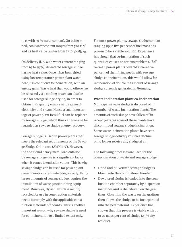
(i. e. with 50 % water content). On being mi-ned, coal water content ranges from 7 to 11 % and its heat value ranges from 27 to 30 MJ/kg.
On delivery (i. e. with water content ranging from 65 to 75 %), dewatered sewage sludge has no heat value. Once it has been dried using low temperature power plant waste heat, it is conducive to incineration, with an energy gain. Waste heat that would otherwise be released via a cooling tower can also be used for sewage sludge drying, in order to obtain high quality energy in the guise of electricity and steam. Hence a small percen-tage of power plant fossil fuel can be replaced by sewage sludge, which thus can likewise be regarded as sewage sludge energy recovery.
Sewage sludge is used in power plants that meets the relevant requirements of the Sewa-ge Sludge Ordinance (AbfKlärV). However, the additional heavy-metal load entailed by sewage sludge use is a significant factor when it comes to emission values. This is why sewage sludge can be used for power plant co-incineration to a limited degree only. Using larger amounts of sewage sludge requires the installation of waste gas scrubbing equip-ment. Moreover, fly ash, which is mainly recycled for use in construction materials, needs to comply with the applicable const-ruction materials standards. This is another important reason why sewage sludge is used for co-incineration to a limited extent only.
For most power plants, sewage sludge content ranging up to five per cent of fuel mass has proven to be a viable solution. Experience has shown that co-incineration of such quantities causes no serious problems. If all German power plants covered a mere five per cent of their firing needs with sewage sludge co-incineration, this would allow for incineration of double the amount of sewage sludge currently generated in Germany.
Waste incineration plant co-incineration Municipal sewage sludge is disposed of in a number of waste incineration plants. The amounts of such sludge have fallen off in recent years, as some of these plants have discontinued sewage sludge incineration. Some waste incineration plants have seen sewage sludge delivery volumes decline or no longer receive any sludge at all.
The following processes are used for the co-incineration of waste and sewage sludge:
• Dried and pulverized sewage sludge is blown into the combustion chamber.
• Dewatered sludge is loaded into the com-bustion chamber separately by dispersion machines and is distributed on the gra-tings. Churning the waste on the gratings then allows the sludge to be incorporated into the bed material. Experience has shown that this process is viable with up to 20 mass per cent of sludge (25 % dry residue).
27
Thermal sewage sludge treatment · 04

• Dewatered or dried sewage sludge ismixed with the residual waste and isthen incinerated with it. This can bedone through homogenization in aseparate apparatus, in a waste bun-ker via targeted dosing by the craneoperator, or can be carried out in acontrolled manner in a feed hopper.
Cement plant co-incineration For decades, cement manufacturers have been using alternative fuels derived from waste in order to save energy, since cement manufacturing is extremely energy intensive. Cement plants use dried sewage sludge as a substitute for fossil fuel. Moreover, the minerals contained in sewage sludge can be used as a substitute for mineral raw
materials such as sand and iron ore that are needed for cement manufacturing. Sewage sludge co-incineration in cement plants contributes to climate protection and resource conservation in that it saves fuel and reduces carbon emissions since sewage sludge co-incineration counts as a climate neutral process. Under the amended version of the Federal Imission Control Ordinance (17. BImSchV) of 14 Au-gust 2003, the heavy-metal limit values for waste management also apply to sewage sludge co-incineration in cement plants.
Table 9 show the quantities of sewage sludge that are incinerated in cement plants, according to statistics in Bun-desverband der Deutschen Zementin-dustrie e. V. environmental reports.
Year 2003 2004 2005 2006 2007 2008 2009 2010
Use 4 48 157 238 254 267 263 276 kt/a
Heat value 11 4 3 4 4 4 4 4 MJ/kg
Table 9: Amounts of sewage sludge incinerated in cement plants, 2003–2010
Co-incineration in cement plants increased forty-fold between 2003 and 2005, and has continued to rise steadily ever since. This momentous increase is mainly attributable to the ban on using all types of raw was-te as landfill, pursuant to the Technical
Instruction on Municipal Waste (Tech-nische Anleitung Siedlungsabfall, TASi) that was in force during the said period.
Despite the increase in cement plant co-incineration, only a negligible amount of
28
04 · Thermal sewage sludge treatment

sewage sludge is co-incinerated at cement plants and waste incineration plants.
Pros and cons of sewage sludge co-incineration Sewage sludge co-incineration saves fossil fuel and thus reduces costs. Substituting sewage sludge for fossil fuel reduces car-bon emissions, as sewage sludge can be regarded as a climate neutral material.
The cement industry also uses sewage sludge as an aggregate, thus allowing for cost savings and contributing to resource conservation.
A downside to co-incineration, however, is that the phosphorous content of the sewage sludge becomes irrecoverable, by virtue of the fact that the phosphorous is either incorporated into the cement or is
highly diluted in slag and other incinera-tion residues. Phosphorous recovery and its significance for sewage sludge disposal going forward is discussed in section 6.
A complete list of all German installations that incinerate or co-incinerate sewage sludge can be found in Appendix I.
Alternative sewage sludge treatment methods Processes such as wet oxidation, hydrolysis, hydrothermal carbonization (HTC), low tem-perature conversion and supercritical water oxidation are regarded as possible alternati-ves to thermal sewage sludge treatment me-thods. Various sewage sludge gasification and pyrolysis processes are in the development phase, or only a handful of these processes have been used on a large scale thus far.
Sewage sludge use in the agricultural sector
05
Sewage sludge is one of the most commonly used and regularly controlled secondary raw material fertilizers, that has the capacity to meet part of the nutrient requirements of crops. Sewage sludge can also improve the humus balance, particularly for farms that
do not generate their own manure. However, sewage sludge fertilizer is also a pollution sink for harmful sewage components from households, businesses and diffuse sources, concerning whose environmental impact too little is known. The extent of the possible soil,
29
Sewage sludge use in the agricultural sector · 05

plant, groundwater, and surface-water pollu-tion resulting from these sources is difficult to determine, even in cases where relatively small amounts of sewage sludge are used.
Only sewage sludge from municipal sewage treatment plants can be used as fertilizer for conventional farm crops. In the interest of completely ruling out the transmission of infectious agents, the use of sludge as ferti-lizer has been banned for organic farming, in forests, in grassland, and for fruit and vegetable cultivation. Sewage sludge use as a fertilizer for forage cultivation is limited (seeding followed by deep tilling; see the Sewage Sludge Ordinance (AbfKlärV)).
Also, new breakdown products of pharmaceu-tical drugs are discovered in sewage sludge all the time. These breakdown products are incorporated into sewage sludge via human excretion and in other ways. It is simply not humanly possible for scientists to develop specific detection processes for and assess the environmental impact of all of these substances, whose combined impact is particularly difficult to characterize and assess. Scientists can merely estimate the theoretical hazards posed by these subs-tances; and unfortunately, by the time the relevant hard facts become available, the pollutants in question will already have found their way into the biosphere [BRANDT].
Nutrients in sewage sludge Depending on its origin and dewatering gradi-ent, sewage sludge contains varying amounts of nutrients such as nitrogen, phosphorous and potassium. For instance, 100 tons of wet sludge with 5 % dry substance contains an average of around 190 kg of nitrogen, 55 kg of which is ammonium-N; plus 195 kg of phosphate and 30 kg of potassium [LfL].
The bonding structure of the phosphorous contained in sewage sludge depends on fac-tors such as the phosphorus precipitation me-thod used by the sewage treatment plant. De-pending on whether a chemical or biological phosphorous precipitation method is used,
anywhere from 60 to 80 % of phosphorous occurs in an inorganic form, and around 1 to 38 % of it is water soluble [KRATZ/SCHNUG].
The actual phytoavailability of phospho-rous is determined by various factors such as soil and fertilizer pH and sewage sludge iron and aluminium content. Inasmuch as an unfavourable phosphorous-iron ratio can greatly reduce phytoavailability [ABD EL-SAMIE], during the treatment process biological phosphorous precipitation rather than chemical phosphorous precipitation should be used for sewage sludge destined for use as fertilizer. When sewage sludge is used
30
05 · Sewage sludge use in the agricultural sector

as fertilizer, its actual nutrient content (which often deviates greatly from mean content data) should be taken into consideration and factored into nutrient balance assess-ments. Actual weights and nutrient contents attributable to a given lot can be found in the documents which are to accompany each lot (Düngemittelrechtliche Begleitpapiere).
The Sewage Sludge Ordinance (AbfKlärV) stipulates that up to five tons of dry sewa-ge sludge may be used for each hectare of land over a given three year period. This represents, for instance, 100 m3 of sewage sludge with 5 % dry solids (wet sludge).
Users are required to indicate on the delivery note the amount of sludge fertilizer used, whereby the volume limit and ban on com-binations must be observed. During the said three year period, no fertilizer containing organic waste may be applied in addition to sewage sludge fertilizer. A copy of the delivery note is given to the grower, to the carrier and to the district administrative authority (Kreis-verwaltungsbehörde), whereby the sewage
treatment plant operator keeps the original and is required to archive it for 30 years.
Sewage sludge from various sewage treatment plants is not to be admixed. Mixing sewage sludge with liquid manure or the like is allo-wable, although the amount of such mixture that is used may not result in the sewage sludge component exceeding five tons dry so-lids over a three year period (see the Sewage Sludge Ordinance, AbfKlärV). In cases where sewage sludge is placed in liquid-manure pits, the liquid manure-sewage sludge mixture is subject to the restrictions and all other provisions of the Sewage Sludge Ordinance (as is the case with all other sewage sludge mixtures), and its use is subject to prior soil and mixture analysis. Insofar as in addition to sewage sludge nutrient and pollutant content, aggregates content is also known and the composition of a given mixture can be deter-mined with certainty, mixture analysis can be foregone. Using such mixtures for grassland and other aforementioned areas subject to sewage sludge utilization bans is prohibited.
Sewage sludge pollutantsThe heavy-metal load in sewage sludge has by and large remained relatively low over the past 15 to 20 years. On the other hand, considerable attention has been focused on organic pollutants in sewage sludge of late, whereby sewage sludge analyses are required
for a relatively limited number of substances. In elaborating the amended version of the Sewage Sludge Ordinance (AbfKlärV), new recommended limit values were investiga-ted, resulting in the pollutants in question being classified into four categories [Bergs].
31
Sewage sludge use in the agricultural sector · 05

Category Pollutant/statutory requirement
1 Previously regulated pollutants that are still relevant to some extent (e. g. PCDD/-F, PCB, AOX); limit values unchanged
2 Pollutants that still exhibit relatively high wastewater or sewage sludge loads; new limit values (e. g. PACs)
3 Pollutants with a high level of ecotoxicological relevance, but that have decreased considerably in recent years (e. g. TBT, DEHP), or whose concentrations are extremely high; monitoring only
4 No limit value or monitoring (e. g. LAS, nanoparticles)
Table 10: Sewage sludge pollutant classifications that were used to elaborate recommended limit values [Bergs]
Perfluorinated tensides (PFTs) are an example of a substance group that only recently was recognized as a relevant sewage sludge component from a public health standpoint. Given the fact that, owing to its properties, it is widely used in many different ways, a limit value for PFTs was incorporated into the amended version of the Sewage Sludge Ordinance (AbfKlärV).
Using cadmium as an example, it will now be explained why the Sewage Sludge Ordinance (AbfKlärV) limit values need to be revised and why this revision should be taken into consideration for the amended ordinance. Cadmium, along with zinc, is the only heavy metal whose transmission from the soil to grain seeds can be detected to a relevant degree. As the result of a toxici-ty assessment revision, the EFSA reduced the weekly tolerable intake of cadmium from 7 μg/kg of body weight to 2.5 μg/kg of body weight, with the goal of minimizing
overall cadmium intake. This also applies to the use of sewage sludge as fertilizer. The current allowable cadmium loads for sewage sludge fertilizing can be found in Figure 5.
A maximum of 5 mg of cadmium per kilo-gram of dry solids is currently allowable in sewage sludge that is applied to so called light soils (Figure 5, first line). For a maxi-mum usage volume of 5 tons dry solids over a three period, this equates to a maximum allowable load (Figure 5, line 2) of 8.3 g of cadmium per hectare and year. The allowable amount for “other soils” is currently 16.7 mg of cadmium input per hectare and year.
The allowable total load greatly exceeds the actual load amounting to around 1.7 g of cadmium per hectare and year (bar at bottom of graphic). Hence leaving the current limit values unchanged would allow for a sizeable sewage sludge quality range. Establishment of quality assurance instruments (as called for
32
05 · Sewage sludge use in the agricultural sector

by the amended version of the Sewage Sludge Ordinance, AbfKlärV), together with revision of the limit values, would go a long way toward achieving greater quality uniformity for sewage sludge. The precautionary values
pursuant to the Federal Soil Protection and Contaminated Sites Ordinance (Bundesbo-denschutzverordnung, BBodSchV) are shown in purple, for purposes of comparison.
Figure 5: Allowable total cadmium load for maximum usage amounts pursuant to the sewage sludge ordinance (AbfKlärV), compared with actual mean cadmium loads [Ruppe et al.]
Maximum allowable usage amount: five tons dry solids per three year period
Light soils
Heavy soils
5 mg Cd/kg DSSewage sludge limit value pursu-ant to AbfKlärV 10 mg Cd/kg DS
8.3 g Cd/ha*a 16.7 g Cd/ha*a
0.4 mg Cd/kg TS
Sand
1.0 mg Cd/kg TS
Lehm/Schluff
1.5 mg Cd/kg TS
Ton
Allowable total cadmium load
Precautionary value pursuant to BBodSchV
SEWAGE SLUDGE
Mean total cadmium load with mean content of 1.1 mg cad-mium/kg dry substance in sewage sludge: 1.7 g/ha*a
Source: Proprietary data; mean cadmium content and total cadmium load 1.1 mg cadmium/kg dry substance (Ruppe et al. 2009)
33
Sewage sludge use in the agricultural sector · 05

Pros and cons of using sewage sludge as a fertilizerThe importance of phosphorous and the state of the art of phosphorous recovery, which are discussed below, can be better
understood in light of the pros and cons of using sewage sludge, as exhibited in table 11. The problem with the handling and dis-posal of sewage sludge lies in its role as a pollutant sink and nutrient point source.
Table 11: Pros and cons of using sewage sludge as a fertilizer
Pros Cons
Exhaustive sewage sludge pollutant tests are carried out; the Sewage Sludge Ordinance (AbfKlärV) sets limits values for heavy metals and organic pollutants in sewage sludge.
The Sewage Sludge Ordinance (AbfKlärV) contains no provisions concerning what are to date presumably unknown or non-regulated sewage sludge pollutants such as nanoparticles, thallium, tributyl tin (TBT), mineral hydrocarbons, and various pathogens.
Sludge contains high concentrations of organic subs-tances, which promote humus formation.
Humus formation can be promoted using other methods such as crop rotation.
Low cost source of necessary nutrients Low cost nutrients can be obtained using other manu-re and other fertilizers.
Low cost phosphorous fertilizer, no import depen-dence
The direct phytoavailability of phosphates is mainly determined by the precipitation method used.
Soil testing prior to the use of sewage sludge as a fer-tilizer. However, such tests are carried out on request from and at the cost and expense of sewage treatment plant operators.
Phosphorous recovery06
the quality of this phosphorous is decli-ning, particularly for raw phosphate that is obtained from sediment reserves, owing to increasing contamination from toxic heavy
Sufficient phosphorous remains in currently exploited continental phosphorous reser-ves for worldwide use for around 360 years [U. S. GEOLOGICAL SURVEY]. However,
34
06 · Phosphorous recovery

metals (mainly cadmium: up to 147 mg per kg of phosphorous) [SCHEIDIG] and radionuclei (mainly uranium: up to 687 mg/kg of phos-phorous) [RÖMER ET AL.] and the consequent environmental and health risks. According to a recent study, the phosphorous peak is likely to be reached in 2033 [CORDELL ET AL.].
Worldwide phosphate fertilizer demand is set to increase by two per cent annually (i. e. around four million tons a year), with around 90 % of this demand stemming from Asia and North America [FAO]. The most important drivers of this trend are world population growth and efforts on the part of developing nations to achieve a high standard of living. The consequent increase in meat consumpti-on will be the major driver of increased phos-phorous use, since livestock raising entails
considerably more energy use for feed than livestock provides after being slaughtered.
Around 90 % of phosphorous reserves are controlled by only five nations, and nearly half of the world’s proven continental phos-phorous reserves are located in Africa (see Fi-gure 6). The fact that Morocco’s phosphorous reserves are attributable to the country having annexed Western Sahara (an action not recog-nized by the UN) is already a conflict waiting to happen and is a matter of concern for Germany’s raw materials security situation.
An additional 35 % of proven phosphorous re-serves are located in China and the US, which themselves need a large amount of phospho-rous; and thus these reserves are available for global trading to only a limited extent.
35
Phosphorous recovery · 06
Figure 6: Global distribution of explored raw phosphate reserves as of 2013 [U.S. geological survey]
Morocco 78.9 %
South Africa 2.4 %
China 5.8 %
USA 2.2 %
Jordan 2.4 %
Algeria 3.5 %
Russia 2.1 %
Syria 2.8 %

German imports all of its raw rock phos-phate and the mineral fertilizers obtained therefrom. Hence phosphorous, parti-cularly in its capacity as a crop nutrient,
is a strategic resource, 138,000 tons of which were used as phosphate fertili-zer in fiscal year 2007/2008 [IWMI].
Phosphorous recovery potential and processesIn view of population growth and the con-sequent rising demand for phosphate [FAO], recovery technologies are set to take on considerably greater importance for resource supply security, human health and natural resource conservation. In keeping with the government’s resource conservation initia-tive, the Federal Ministry of Education and Research (BMBF) and the Federal Ministry for the Environment (BMU) promoted the development and use of new methods that
allow for large scale recycling of phosphorous from municipal sewage sludge and sewage, excess liquid manure, animal meal, and other phosphorous containing organic materials. The table below exhibits the recycling poten-tial of selected substance flows in Germany.
According to studies comparing the phytoavai-lability of various recycled products with that of commercial fertilizers, elevated iron content secondary to the use of iron salt as a precipita-te has a negative impact on phytoavailability.
Table 12: Estimated phosphorous recycling potential for various substance flows in germany [proprietary compilation]
* These potentials do not lend themselves to tallying, as they represent various competing recovery paths within the sewage treatment cycle.
Substance flowEstimated recoverable phosphorous, expressed in tons per year
Municipal sewage *54,000
Industrial sewage 15,000
Municipal sewage sludge *50,000
Sewage sludge ash *66,000
Manure 444,000
Animal byproducts: (classes 1 through 3, excluding animal fat) (up to 6 % phosphorous)
20,000
Estimated phosphorous demand in Germany 170.000
36
06 · Phosphorous recovery

When it comes to substance recycling for elec-trothermal phosphorous manufacturing pur-poses (Thermophos, NL), the molar Fe:P ratio needs to be lower than 0.2. On the other hand, recycling substances from sewage treatment plants that use biological phosphorous preci-pitation has proven to be very cost effective. Further research in this domain is currently ongoing via various research projects.
Wet chemical processes using magnesium ammonium phosphate (MAP) as a precipitate, as well as thermal metallurgical processes, are regarded as being particularly promising. The MAP process allows for the recovery of around 40 to 70 % of the phosphorous contained in wastewater treatment plant sewage input, and allows for production of a low pollution nitrogen phosphate fertili-zer, as well as a highly suitable raw mate-rial for fertilizer manufacturing – both of which are outstanding particularly owing to their good phytoavailability. However, the residual organic content of MAP fertilizers is relatively high, depending on the gradient of the subsequent purification process. Although thermal-metallurgical processes are more technically complex than MAP precipi-tation, they allow for the following: (a) reco-very of more than 90 % of the phosphorous in wastewater treatment plant sewage input;
(b) concurrent use of the thermal energy in se-wage sludge; and (c) elimination of the orga-nic pollutants in sludge during incineration. In order for thermal-metallurgical phospho-rous recovery from sewage sludge and sewage sludge ash to be efficient, sewage sludge needs to be incinerated separately owing to the fact that it contains relatively high phos-phorous concentrations, as well as managea-ble levels of pollutants such as heavy metals.
The main drawback of co-incineration is that it precludes recovery of the phosphorous in sewage sludge. But if, on the other hand, all of Germany’s sewage sludge were incinerated separately (around 2 million tons of dry mass annually), i. e. solely via mono-incineration, around 66,000 tons of phosphorous could potentially be recovered from the residual ash. This represents around 55 % of agri-cultural use of mineral phosphorous. Table 13 provides an overview of the world-wide and in some cases already established phosphorus recovery methods, the majo-rity of which were developed in Germany. However, only a handful of these methods has been implemented thus far as either pilot installations or on a large scale.
For further information visit www.phosphorrecycling.de
37
Phosphorous recovery · 06

Table 13: Methods for recovering phosphorous from sewage flows [Montag et al. and proprietary data]
Aqueous phase Sewage sludge Sewage sludge ashAdsorption method Air Prex/MAP method Ash Dec (SUSAN)CSIR fluidized bed reactor Aqua Reci BioConDHV Crystalactor® CAMBI ATZ iron bed reactor Kurita fixed bed KEMIKOND EPHOS Magnetic separator KREPRO PASCHSecondary precipitation/flocking filtration LOPROX SESAL(-Phos)NuReBas process Mephrec SEPHOSOstara PEARL™ Peco Bioleaching Phosiedi Phostrip Mephrec P-RoC (Prophos) PRISA ThermphosRECYPHOS Seaborne PhosRec (Koop Schiefer)REPHOS Stuttgart method RECOPHOS RIM NUT ion exchanger Unitika-Phosnix® LEACHPHOSSydney Water Board reactor FIX-Phos Eberhard method Phostrip Gifhorner method RecoPhos (Germany)Phosnix PROXNAN EPHOS
Kemira-KREPRO InocrePRISA POPROX method NuReSys Aqua ReciEbara MEPHRECMAP crystallization Treviso ATZ iron bed reactorRECYPHOS RecoPhos (AT)
Cost efficient phosphorous recycling in Germany Table 14 lists the phosphorous recovery installations that have been completed or that are in the pipeline, along with their key parameters.
Current R&D activities reflect the increased interest in technologies that would allow for recovery and recycling of the phospho-rus contained in various wastewater flows. As the May 2009 International Conference
on Nutrient Recovery from Waste Water Streams conference showed, Germany is in the forefront of R&D in this field – although Canada, Japan and the US are in the van-guard when it comes to bringing large scale projects to fruition. Legislation is pending in Switzerland requiring that phosphorus be recovered from waste water flows and animal meal, the goal being for Switzer-land, which now imports phosphorous, to become a phosphorous exporting nation.
38
06 · Phosphorous recovery

This requirement was slated to take effect in 2011/2012. The bill calls for a phosphorous recovery rate ranging from 50 to 100 % by 2015. The use of sewage sludge as fertilizer has been banned in Switzerland since 2008.
Sweden aims to recover a minimum of 60 % of wastewater phosphorous by 2015 and use it for farming [SWEDISH EPA].
Numerous methods have already been developed in Germany that are still in the experimental stage. But intensive efforts are underway to implement one or more of these methods on a large scale, for the purpose of establishing legal and economic frameworks that will enable these new methods to become economically viable.
Such projects can potentially be funded through subsidies and/or via sewage char-ges. Inasmuch as the greatest phosphorous recovery potential lies in recovery from waste water and sewage sludge, the Sewage Sludge Ordinance (AbfKlärV) should stipulate that phosphorus is to be recycled through phos-phorus recovery, as an incentive to sewage treatment plant operators to install suitable recovery equipment. In the interest of promo-ting even more efficient use of the phos-phorous in sewage sludge, the capacity of mono-incineration plants should be increased from their current level of 500 tons dry solids/year to around 2 million tons dry solids/year. Recognition of exclusive mono-incineration
of sewage sludge as a source of renewa-ble energy, together with funding of this technology under the Renewable Energy Act (Erneuerbare-Energien-Gesetz, EEG), would presumably expedite this capacity increase.
In the interest of promoting even more efficient use of the raw materials in sewage sludge (phosphorous, plus the important metals), phosphorous recovery-enabled landfill sites and facilities at such sites that are specifically designed for phosphorous re-covery should be established, until sufficient capacity is available to process the volumes of sewage sludge ash that are generated.
All of the processes described here generate products that can be used as fertilizer that is less polluting than conventional mineral fertilizers made from raw phosphate of sedi-mentary origin. This is attributable to the fact that the cadmium and uranium levels of their recycled products are considerably lower than those in raw phosphate of sedimentary origin [RÖMER ET AL.]. All products provide the re-quisite phytoavailability, i. e. they fertilize the plants to a satisfactory degree. MAP products tend to exhibit greater phytoavailability than ash products. Table 15 lists the pros and cons of the MAP process versus thermal recovery.
Inasmuch as only two such processes are cur-rently in use at large scale installations, no va-lid conclusions concerning the economic effici-ency of the various processes can be reached.
39
Phosphorous recovery · 06

Operator/location Method Input Output
Phos-phorous volume, in litres/year
Status/com-ments
Seaborne EPM AG/ KA Gifhorn
Seaborne (MAP precipi-tation)
120 m3/d fermentati-on substrate
In operation since 2007
Remondis Aqua/ Altentreptow (MV)
Rephos® MAP precipitation
Dairy waste water (80 mg P/l)
In operation since 2007
Berliner Wasserbetrie-be/KW Waßmannsdorf and ABA Neuwerk-Mönchengladbach
AirPrex® Com-mercial name: Berliner Pflanze MAP precipitation
Digested sludge
(100 m3/h)
2.5 tons
MAP/d
As at 2013
KW Neuwerk-Mön-chengladbach
AirPrex® MAP precipitation
Digested sludge (50 m3/h)
MAP As at 2013
Braunschweig- Stein-hof
AirPrex® MAP precipitation (prospective)
MAP As at 2013
Lingen AirPrex® MAP As at 2013
Hildesheim FIX-Phos CaP As at 2013
Mainz Budenheim process
CaP Experimen-tal phase. As at 2013
KA Offenburg (Baden-Württemberg)
Stuttgart process (MAP precipitation)
Digested sludge 50 kg MAP/d
As at 2011
Ash Dec, now Outotec (RETERRA) (Branden-burg)
SUSAN
Thermoche-mical
Sewage sludge ash | (around 9 % phosphorous) | (12,000 t/a)
Around 10,000 t/a phosphorus fertilizer
Around 1,000 tons planned
Rollout set for 2014 or 2015
Ingitec (Nuremberg) Mephrec® (metallurgical method)
Sewage sludge (25 % dry subs-tance), 60,000 tons/year (or sewage sludge ash)
Phospho-rus slag, 12,000 tons/year
Around 500 tons planned
Rollout set for 2014
RecoPhos (Schöne-beck)
Thermoche-mical
Sewage sludge ash Phosphorus fertilizer
Unknown Rollout set for 2014
P-RoC (Neuburg) Crystalliza-tion
Sludge CaP Around 20 tons
As at 2012
Table 14: Large scale german installations that have been realized or are in the pipeline, as at 2010 [proprietary compilation]
Conversion of the following phosphorous content: P2O5 = 43.64 % and MAP (MgNH4P4 · 6H2O) = 12.62 %40
06 · Phosphorous recovery

Table 15: Comparison of wet-chemical map processes and map thermal processes
MAP Thermal
Advantages • Less cost intensive
• More conducive to retrofitting
• Superior phytoavailability
• Higher recovery rate (90 %)
• Simultaneous material and energy use of sewage sludge
• More versatile, i. e. suitable for all types of sewage sludge and other substances
• All organic pollutants are expunged
• Considerably lower volumes of waste (residual substances)
Drawbacks • Only up to 40 % recovery at present
• Only compatible with biologi-cal phosphorous installations
• Higher investment costs
• More cost intensive process
Remondis Aqua’s Rephos process and the Air-Prex® process have proven to be economic-ally efficient at a number of sewage treatment plants. According to their developers and potential users, on paper the Ulophons®, Mephrec® and ReceoPhos® processes are economically efficient under the required operating conditions, including in cases in-volving low product sales revenues. However, none of these processes has ever been used in a large scale installation, although such applications are in the pipeline in certain cases such as for Mephrec®. Hence phospho-rous recycling processes that are currently not economically efficient may become so in three to 20 years, at the currently projec-ted world market prices and assuming that systematic implementation of phosphorous recycling gets underway in 2012 [SARTORIUS]. Application of an admixture level would not
promote phosphorous recovery using current state of the art technologies. Nonetheless, in the interest of promoting technological advan-ces in this sphere and achieving high phos-phorus recovery levels, a report titled Eva-luation of Options for the Sustainable Use of Secondary Phosphorus Reserves issued by the Länder Workgroup for Waste (Länderarbeits-gemeinschaft Abfall) recommends a number of instruments such as voluntary measures and establishment of a fund or the like.
Sewage sludge ash recycling pathsAs noted, industry experts are currently discussing the possibility of storing sewa-ge sludge ash in dedicated facilities from which it would be readily recoverable.
Unfortunately, current ash management methods preclude ash recovery, and
http://www.laga-online.de/servlet/is/23875/Bericht_Phosphorr%C3%BCckgewinnung_engl.pdf?command=down loadContent&filename=Bericht_Phosphorr%FCckgewinnung_engl.pdf
41
Phosphorous recovery · 06

thus in turn phosphorous recovery. Figure 7 shows that the vast majority of landfill ash is recovered or is used as mine sealing (underground mine backfilling).
Lesser amounts of this ash are used as agricultural fertilizer, as ash meets the statutory requirements for this application.
Sewage sludge quantities, management and recycling
07
Around two million tons of sewage sludge dry mass (TDM) were disposed of in Germany in 2010. Around 50 % of this sludge under-went thermal disposal, while 883,659 TDM
were used for farming, landscaping and other purposes such as composting and recultivati-on (see table 16 and Figure 8 for the regional states’ disposal pathways and methods).
Figure 7: Disposal paths of sewage sludge ash from 18 mono-incineration plants in 2009 [proprietary data]
91,867 for landfill
49,234 for asphalt plants/copper refineries
58,468 for mine sealing
8,500 for farming
42
07 · Sewage sludge quantities, management and recycling
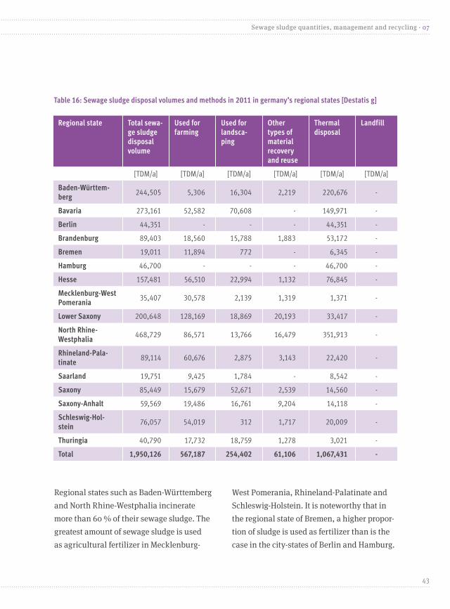
Regional states such as Baden-Württemberg and North Rhine-Westphalia incinerate more than 60 % of their sewage sludge. The greatest amount of sewage sludge is used as agricultural fertilizer in Mecklenburg-
West Pomerania, Rhineland-Palatinate and Schleswig-Holstein. It is noteworthy that in the regional state of Bremen, a higher propor-tion of sludge is used as fertilizer than is the case in the city-states of Berlin and Hamburg.
Regional state Total sewa-ge sludge disposal volume
Used for farming
Used for landsca-ping
Other types of material recovery and reuse
Thermal disposal
Landfill
[TDM/a] [TDM/a] [TDM/a] [TDM/a] [TDM/a] [TDM/a]
Baden-Württem-berg
244,505 5,306 16,304 2,219 220,676 -
Bavaria 273,161 52,582 70,608 - 149,971 -
Berlin 44,351 - - - 44,351 -
Brandenburg 89,403 18,560 15,788 1,883 53,172 -
Bremen 19,011 11,894 772 - 6,345 -
Hamburg 46,700 - - - 46,700 -
Hesse 157,481 56,510 22,994 1,132 76,845 -
Mecklenburg-West Pomerania
35,407 30,578 2,139 1,319 1,371 -
Lower Saxony 200,648 128,169 18,869 20,193 33,417 -
North Rhine-Westphalia
468,729 86,571 13,766 16,479 351,913 -
Rhineland-Pala-tinate
89,114 60,676 2,875 3,143 22,420 -
Saarland 19,751 9,425 1,784 - 8,542 -
Saxony 85,449 15,679 52,671 2,539 14,560 -
Saxony-Anhalt 59,569 19,486 16,761 9,204 14,118 -
Schleswig-Hol-stein
76,057 54,019 312 1,717 20,009 -
Thuringia 40,790 17,732 18,759 1,278 3,021 -
Total 1,950,126 567,187 254,402 61,106 1,067,431 -
Table 16: Sewage sludge disposal volumes and methods in 2011 in germany’s regional states [Destatis g]
43
Sewage sludge quantities, management and recycling · 07

Sewage sludge volumes in selected years since 1998 Around 2.2 million TDM were disposed of in 1998, since which time sludge volumes have declined continuously. By 2009, the figure was just under 2 million TDM, and only in 2004 was a slight increase of a few 10,000 TDM registered. This evolution is mainly attributable to the increased use of anaerobic sludge treatment methods, which reduce sewage sludge volumes. The graphic below illustrates this evolution.
These sewage sludge statistics are based on Federal Statistical Office (Statistisches Bundesamt) figures concerning biological sewage treatment [DESTATIS A, B, C, D, E]. In the interest of allowing for statisti-cal comparisons, the amounts of sewage sludge that were transferred to other sewage treatment plants were subtracted from the respective tallies for 1998, 2001 and 2004, because the statistics below do not take these volumes into account. Moreover the “Interim storage” rubric no longer appears in statis-
44
07 · Sewage sludge quantities, management and recycling
Figure 8: Percentage distribution of disposal methods in germany’s regional states for 2011 [Destatis g]
Other types of material recovery and reuse
Landscaping
Farming
Thermal disposal
Baden-Württ
emberg
Brandenburg
Bremen
Hamburg
Bavaria
Hesse
Lower S
axony
North Rhine-W
estphalia
Rhineland-Palatinate
Mecklenburg-W
est Pomerania
Saarland
Saxony-A
nhalt
Schleswig-H
olstein
Thuringia
Saxony
Berlin
100
90
80
70
60
50
40
30
20
10
0
Percentage distribution
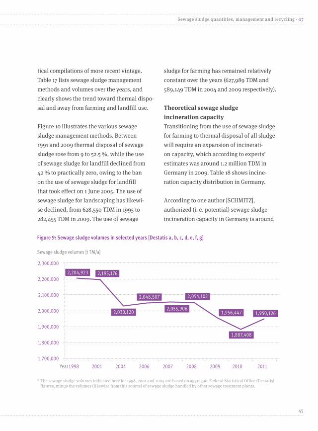
tical compilations of more recent vintage. Table 17 lists sewage sludge management methods and volumes over the years, and clearly shows the trend toward thermal dispo-sal and away from farming and landfill use.
Figure 10 illustrates the various sewage sludge management methods. Between 1991 and 2009 thermal disposal of sewage sludge rose from 9 to 52.5 %, while the use of sewage sludge for landfill declined from 42 % to practically zero, owing to the ban on the use of sewage sludge for landfill that took effect on 1 June 2005. The use of sewage sludge for landscaping has likewi-se declined, from 628,550 TDM in 1995 to 282,455 TDM in 2009. The use of sewage
sludge for farming has remained relatively constant over the years (627,989 TDM and 589,149 TDM in 2004 and 2009 respectively).
Theoretical sewage sludge incineration capacityTransitioning from the use of sewage sludge for farming to thermal disposal of all sludge will require an expansion of incinerati-on capacity, which according to experts’ estimates was around 1.2 million TDM in Germany in 2009. Table 18 shows incine-ration capacity distribution in Germany.
According to one author [SCHMITZ], authorized (i. e. potential) sewage sludge incineration capacity in Germany is around
45
Sewage sludge quantities, management and recycling · 07
2,300,000
2,200,000
2,100,000
2,000,000
1,900,000
1,800,000
1,700,000
2,048,507
2,055,906
2,054,102
1,956,447 1,950,126
1,887,408
2006 2007 2008 2010 20112009
* The sewage sludge volumes indicated here for 1998, 2001 and 2004 are based on aggregate Federal Statistical Office (Destatis) figures, minus the volumes (likewise from this source) of sewage sludge handled by other sewage treatment plants.
Figure 9: Sewage sludge volumes in selected years [Destatis a, b, c, d, e, f, g]
Sewage sludge volumes [t TM/a]
2,204,923 2,195,176
2,030,120
Year1998 2001 2004

1) Including management carried out by other sewage treatment plants, but excluding sludge transferred to other such plants. 2) Excluding sludge transferred to other sewage treatment plants 3) Composting and farming uses have been combined.
Table 17: Sewage sludge volumes and management methods, for selected years [Destatis a, b, c, d, e, f, g]
Total sewage sludge volume
Recycling Thermal disposal LandfillAbgabe an andere Abwas-serbehandlungsanlagen
Interim storage
Total Farming Landscaping Other types of material recoveryand reuse
Year TDM TDM TDM % TDM % TDM % TDM % TDM % TDM TDM
2011 1,950,126 1) 882,695 567,187 29.0 254,402 13.0 61,106 3.0 1,067,431 55.0 0 0
2010 1,887,408 1) 883,659 566,295 30.0 259,312 13.7 58,052 3.1 1,003,749 53.2 0 0 - -
2009 1,956,447 1) 927,516 589,149 30.1 282,455 14.4 55,912 2.9 1,028,034 52.5 897 0 - -
2008 2,054,102 2) 973,997 587,832 29.0 331,556 16.0 54,609 3.0 1,077,624 53.0 2,481 0 - -
2007 2,055,906 2) 1,036,844 592,561 29.0 368,912 18.0 75,371 4.0 1,015,014 49.0 4,048 0 - -
2006 2,048,507 2) 1,078,264 611,598 30.0 399,712 20.0 66,954 3.0 965,115 47.0 5,128 0 - -
2004 2,260,846 1,175,694 627,989 - 492,768 3) - 54,937 - 711,170 - 79,052 - 230,726 64,204
2001 2,429,403 1,399,456 754,837 - 583,269 3) - 61,350 - 554,924 - 159,673 - 234,227 81,123
1998 2,459,177 1,490,074 783,662 - 628,550 3) - 77,862 - 395,859 - 205,140 - 254,254 113,850
Table 18: Incineration capacity in germany, 2009 [Schmitz]
Installations Authorized capacity [in TDM/a]
Availability [in %]
Capacity use [in TDM]
EnBW power plants 69,375
E.ON power plants 170,475
RWE power plants 213,700
Vattenfall power plants 126,750
Other operators’ power plants 136,200
Total power plant capacity 716,500 70 501,550
Sewage sludge mono-incineration plants 554,750 90 499,275
Cement plants 89,000 95 84,550
Waste incineration plants 119,300 80 95,440
Total sewage sludge incineration capacity in Germany 1,479,550 1,180,815
Thermally treated sewage sludge volumes, 2009 1,028,034
Authorized sewage sludge volumes, 2009 1,956,447
46
07 · Sewage sludge quantities, management and recycling

Table 17: Sewage sludge volumes and management methods, for selected years [Destatis a, b, c, d, e, f, g]
Total sewage sludge volume
Recycling Thermal disposal Landfill Abgabe an andere Abwas-serbehandlungsanlagen
Interim storage
Total Farming Landscaping Other types of material recovery and reuse
Year TDM TDM TDM % TDM % TDM % TDM % TDM % TDM TDM
2011 1,950,126 1) 882,695 567,187 29.0 254,402 13.0 61,106 3.0 1,067,431 55.0 0 0
2010 1,887,408 1) 883,659 566,295 30.0 259,312 13.7 58,052 3.1 1,003,749 53.2 0 0 - -
2009 1,956,447 1) 927,516 589,149 30.1 282,455 14.4 55,912 2.9 1,028,034 52.5 897 0 - -
2008 2,054,102 2) 973,997 587,832 29.0 331,556 16.0 54,609 3.0 1,077,624 53.0 2,481 0 - -
2007 2,055,906 2) 1,036,844 592,561 29.0 368,912 18.0 75,371 4.0 1,015,014 49.0 4,048 0 - -
2006 2,048,507 2) 1,078,264 611,598 30.0 399,712 20.0 66,954 3.0 965,115 47.0 5,128 0 - -
2004 2,260,846 1,175,694 627,989 - 492,768 3) - 54,937 - 711,170 - 79,052 - 230,726 64,204
2001 2,429,403 1,399,456 754,837 - 583,269 3) - 61,350 - 554,924 - 159,673 - 234,227 81,123
1998 2,459,177 1,490,074 783,662 - 628,550 3) - 77,862 - 395,859 - 205,140 - 254,254 113,850
Figure 10: Sewage sludge management, 1991–2010 [uba, Destatis f]
* No 100 % tallies available prior to 2007 owing to a change in statistical gathering methodology;
1991
1995
1998
2001
2004
2007
2008
2009 2011
2010
Landfill Farming Landscaping, composting and other types of material
recovery and reuse
Incineration
Dry solids use (in %)
42.0
28.0
39.0
31.7
31.1
27.8
28.8
28.6 30
.130
.029
.1
16.0
8.3
6.6
3.5
0.2
0.1
0.0
0.0
0.0 2.
715
.528
.926
.524
.121
.618
.817
.316
.816
.2
9.0
9.0
16.0
22.8
31.5
49.4 52
.252
.253
.2 54.760
50
40
30
20
10
0
47
Sewage sludge quantities, management and recycling · 07

Table 19: eu sewage sludge output and management methods in eu member states as at 2010 [eurostat; milieu; wrc; rpa]
Member state Proportion of the populati-on with access to municipal sewage treatment plants
Total sewage sludge volume in EU member states
Proportion of total EU volume
Farming Incineration Landfill Other
[%] [mio. kg dry solids/a] [%] [%] [%] [%] [%]
Bulgaria 45.0 47.0 0.4 50.0 0.0 30.0 20.0
Cyprus 30.0 10.8 0.1 50.0 0.0 40.0 10.0
Czech Republic 76.0 260.0 2.3 55.0 25.0 10.0 25.0
Estonia 80.0 33.0 0.3 15.0 - - 85.0
Hungary 57.0 175.0 1.5 75.0 5.0 10.0 5.0
Latvia 65.0 30.0 0.3 30.0 40.0 30.0
Lithuania 71.0 80.0 0.7 30.0 0.0 5.0 65.0
Malta 48.0 10.0 0.1 - - 100.0 -
Poland 64.0 520.0 4.5 40.0 5.0 45.0 10.0
Romania 29.0 165.0 1.4 0.0 5.0 95.0
Slovakia 52.0 55.0 0.5 50.0 5.0 5.0 10.0
Slovenia 57.0 25.0 0.2 5.0 25.0 40.0 30.0
Austria 93.0 273.0 2.4 15.0 40.0 1.0 45.0
Belgium 69.0 170.0 1.5 10.0 90.0 - -
Denmark ns 140.0 1.2 50.0 45.0 - -
Finland 81.0 155.0 1.3 5.0 - - 95.0
France 80.0 1,300.0 11.3 65.0 15.0 5.0 15.0
Germany 95.0 2,000.0 17.4 30.0 50.0 0.0 20.0
Greece 87.0 260.0 2.3 5.0 95.0
Ireland 84.0 135.0 1.2 75.0 15.0 10.0
Italy ns 1,500.0 13.0 25.0 20.0 25.0 30.0
Luxembourg 95.0 10.0 0.1 90.0 5.0 5.0
The Netherlands 99.0 560.0 4.9 0.0 100.0
Portugal 70.0 420.0 3.7 50.0 30.0 20.0
Spain 92.0 1,280.0 11.1 65.0 10.0 20.0
Sweden 86.0 250.0 2.2 15.0 5.0 1.0 75.0
United Kingdom ns 1,640.0 14.3 70.0 20.0 1.0 10.0
Total EU 15 85.9 10,093.0 87.7 *38.0 *35.8 *18.3 *33.9
Total EU 27 71.0 11,503.8 - *37.3 *23.8 *28.7 *31.3
* Mean values
48
07 · Sewage sludge quantities, management and recycling

716,000 TDM/a, whereas from a technical standpoint only 500,000 TDM/a of this capacity is usable. Mono-incineration plant capacity in 2009 was around 500,000 TDM/a, but has grown since then due to factors such as the construction of new facilities. Hence in 2009 available capacity was around 1.2 million TDM/a (see table 18). Creating adequate incineration capacity by building new incineration facilities would go a long way toward phasing out the use of sewage sludge as fertilizer.
Sewage sludge management in EU member states Around 11.5 million TDM is generated in the EU each year. Table 19 shows the volumes of sewage sludge requiring ma-nagement in the EU member states, as well as the extent to which they use the various available management methods.
Germany generates the largest amount of sewage sludge in the EU (18 %), owing to its large population and the high proportion of households that are integrated into their local municipal sewage system. The UK also generates a large amount of sewage sludge each year. The volume of sewage sludge requiring management is likely to increase, presuming that the proportion of households incorporated into public sewage systems grows. This in turn will pose a new challenge for sewage sludge management in the EU.
Member state Proportion of the populati-on with access to municipal sewage treatment plants
Total sewage sludge volume in EU member states
Proportion of total EU volume
Farming Incineration Landfill Other
[%] [mio. kg dry solids/a] [%] [%] [%] [%] [%]
Bulgaria 45.0 47.0 0.4 50.0 0.0 30.0 20.0
Cyprus 30.0 10.8 0.1 50.0 0.0 40.0 10.0
Czech Republic 76.0 260.0 2.3 55.0 25.0 10.0 25.0
Estonia 80.0 33.0 0.3 15.0 - - 85.0
Hungary 57.0 175.0 1.5 75.0 5.0 10.0 5.0
Latvia 65.0 30.0 0.3 30.0 40.0 30.0
Lithuania 71.0 80.0 0.7 30.0 0.0 5.0 65.0
Malta 48.0 10.0 0.1 - - 100.0 -
Poland 64.0 520.0 4.5 40.0 5.0 45.0 10.0
Romania 29.0 165.0 1.4 0.0 5.0 95.0
Slovakia 52.0 55.0 0.5 50.0 5.0 5.0 10.0
Slovenia 57.0 25.0 0.2 5.0 25.0 40.0 30.0
Austria 93.0 273.0 2.4 15.0 40.0 1.0 45.0
Belgium 69.0 170.0 1.5 10.0 90.0 - -
Denmark ns 140.0 1.2 50.0 45.0 - -
Finland 81.0 155.0 1.3 5.0 - - 95.0
France 80.0 1,300.0 11.3 65.0 15.0 5.0 15.0
Germany 95.0 2,000.0 17.4 30.0 50.0 0.0 20.0
Greece 87.0 260.0 2.3 5.0 95.0
Ireland 84.0 135.0 1.2 75.0 15.0 10.0
Italy ns 1,500.0 13.0 25.0 20.0 25.0 30.0
Luxembourg 95.0 10.0 0.1 90.0 5.0 5.0
The Netherlands 99.0 560.0 4.9 0.0 100.0
Portugal 70.0 420.0 3.7 50.0 30.0 20.0
Spain 92.0 1,280.0 11.1 65.0 10.0 20.0
Sweden 86.0 250.0 2.2 15.0 5.0 1.0 75.0
United Kingdom ns 1,640.0 14.3 70.0 20.0 1.0 10.0
Total EU 15 85.9 10,093.0 87.7 *38.0 *35.8 *18.3 *33.9
Total EU 27 71.0 11,503.8 - *37.3 *23.8 *28.7 *31.3
49
Sewage sludge quantities, management and recycling · 07
Phasing out the agricultural use of sewage sludge would mainly affect sewage sludge producers, in that they would need to trans-port sewage sludge over longer distances than is currently the case. The presumably higher management costs resulting from this change would probably prompt an increase in taxpayers’ sewage charges [FELS ET AL.].1)
To analyze the extent to which such higher charges would be a burden on taxpayers, in the following a somewhat simplified approach to the issue will be taken.
Wastewater management costs are current-ly determined by the following factors:
• Sewage treatment plant capacity use and size • Tourism and other seasonal factors• Management method• Structural characteristics such as hills in
the terrain along haulage routes• Population density per meter of channel• Subsidies [FELS ET AL.]
According to one analysis [FELS ET AL.], sewage treatment plant and channel capital investment costs have an extremely long term impact on wastewater management
costs, some 75 to 85 % of which are not determined by water consumption levels. The second highest wastewater related costs are attributable to writedowns and inte-rest, while personnel costs are estimated to account for around 14 % of total wastewater management costs. An additional 10 % of these costs is attributable to materials and energy, while treatment and disposal account for only 3 %. Hence downstream disposal has a relatively minor impact on costs, relative to other cost factors, which in turn means that adopting new wastewater manage-ment methods or tweaking new ones would have little effect on total costs and would thus result in only a negligible increase in taxpayers’ sewage charges [FELS ET AL.].
As can be seen in Figure 11, at € 120 to € 375 per ton of dry solids, using sewage sludge as fertilizer is currently the most cost effective sewage management method, whereas the figure for thermal mono-incineration is € 180 to € 400. According to another analysis, was-tewater management costs range from € 8 to € 130 per ton of wet substance (see Figure 20).
Footing the bill for sewage sludge management
08
1) Cf. coalition agreement between CDU, CSU and SPD, 18th legislative period, p. 120: “We will phase out sewage sludge use as fertilizer and will recover phosphorous and other nutri-ents.”
50
08 · Footing the bill for sewage sludge management

Table 20: Sewage sludge management costs [Schumacher; Nebocat]
Sewage sludge management method
Sewage sludge manage-ment costs [EUR/t of wet substance]
Sludge type
Min. Max.
Co-incineration at coal fired power plants 80 130 Dry: greater than 85 %
Cement plant co-incineration 90 100 Dry: greater than 85 %
Mono-incineration 80 120 Mechanically dewatered: 20–45 % dry substance
Waste incineration plant co-incineration
80 100 Mechanically dewatered: 20–45 % dry substance
Co-incineration at coal fired power plants
75 100 Mechanically dewatered: 20–45 % dry substance
Co-incineration at lignite fired power plants
50 75 Mechanically dewatered: 20–45 % dry substance
Recultivation 30 45 Mechanically dewatered: 20–45 % dry substance
Farming, trans-regional 33 45 Mechanically dewatered: 20–45 % dry substance
Farming, regional 25 30 Mechanically dewatered: 20–45 % dry substance
Farming, liquid 8 12 Mechanically dewatered: 20–45 % dry substance
Figure 11: Sewage sludge management costs, including dewatering and haulage costs (in euros per ton of dry residue) [dwa a, b]
Euro/ton of dry residue
450
400
350
300
250
200
150
100
50
0
Farm
ing
(wet, 4
% dry
residue)
Farm
ing (mech
anically
dewatered, 25 %
dry resid
ue)
Recultiv
ation (m
echanica
lly
dewatered, 25 %
dry resid
ue)
Co-incin
eration (m
echanica
lly
dewatererd, 25 %
dry resid
ue)
Mono-incin
eration (m
echanica
lly
dewatered, 25 %
dry resid
ue)
Cement plant c
o-incin
eration
(greater than 90 %
dry resid
ue)
51
Footing the bill for sewage sludge management · 08
According to a study commissioned by Schleswig-Holstein’s environmental ministry [FELS ET AL.], the total economic cost of using sewage sludge for agricultural use is € 7.3 mil-lion, and for thermal disposal, € 13.5 million.
According to the study [FELS ET AL.], the impact of a ban on using sewage sludge as fertilizer would be as follows: The study notes that only three per cent of total wastewater management costs are attributable to sewage sludge disposal, with the remainder stem-ming from plant equipment, interest and wri-tedowns. Wastewater costs currently average around € 2 per cubic meter, and according to the study would rise by three eurocents per cubic meter. For a four-person household, this would result in an increase from € 448 to € 454 annually, i. e. € 6 per year. The increase for sewage treatment plants that do not dewater their sludge would amount to four eurocents per cubic meter. These figures
were computed using a model whose results are determined by the wastewater manage-ment costs and water consumption levels that are input into the model [FELS ET AL.].
As yet unclear is the extent to which these results might apply to Germany as a who-le. Phasing out agricultural use of sewage sludge would of course have advantages and disadvantages for the various actors affected. There would be an impact on sewage charges, but only a negligible one. Farmers would need to use industrial fertilizer in lieu of sewage sludge fertilizer, and this would constitute a cost disadvantage, but would reduce pollutant inputs. One of the main advantages of phosphorous recove-ry is that, unlike sewage sludge nutrients, those found in both mineral and recycled fertilizers have a defined composition and phytoavailability. This would promote sound, needs-oriented fertilizing practices.
Owing to its extreme inhomogeneity, the quality of sewage sludge is difficult to cha-racterize. Sewage sludge fertilizer contains the following elements, all of which are potential ecosystem pollutants: various organic substances that exert hormonal effects; various infectious agents; heavy
metals; residues of pharmaceutical drugs. Sewage sludge is probably the least cost intensive source of phosphorus and nut-rients of any currently available fertilizer, and also contains a high concentration of humus forming organic substances. Hence the phytoavailability of the phosphorous
The way forward09
52
09 · The way forward

content of sewage sludge is mainly deter-mined by the precipitation method used for sewage treatment. And yet, humus formation can also be attained through alternative methods such as crop rotation.
But sewage sludge fertilizer is also a pollution sink for harmful sewage components from households, businesses and diffuse sources, concerning whose environmental relevance too little is known. Notwithstanding tighter controls and stricter limit values for certain sewage sludge pollutants, uncontrolled pollutants such as hydrocarbons inevitably find their way into the soil. Incorporation of certain pollutants into the food chain cannot always be avoided, despite the fact that, for example, plants normally do not absorb organic pollutants. Nonetheless, new break-down products of pharmaceutical drugs are discovered in sewage sludge all the time, and they are incorporated into sewage sludge via human excretion carried by the wastewater that is treated by sewage treatment plants.
Moreover, as agricultural use of sewage sludge can potentially result in the spread of pathogens to humans, animals and plants, Germany has imposed strict legal restric-tions on this activity. For example, the use of sewage sludge fertilizer for fruit and vegetable crops and on permanent grassland is banned, and is subject to statutory waiting periods for use on vegetable crops, as well as for forage cultivation. The proposed amended version of the Sewage Sludge Ordinance (AbfKlärV)
contains a number of new measures aimed at reducing sewage sludge related risk, such as a quality assurance system and requiring that sludge be hygienized so as to reduce pathogen concentrations. These additional sludge treatment processes will also entail additional costs that are prohibitive for smal-ler sewage treatment plants. In the interest of minimizing the risk that agricultural use of sewage sludge will occasion pathogen transfer, it is crucial that the new ordinance retain these tight restrictions on the agricul-tural use of sewage sludge. In keeping with the precautionary principle and in light of the pollutants and pathogens found in sewage sludge, the UBA deems the agricultural use of sewage sludge to be a serious public health and environmental hazard and advocates that this practice be phased out. But as sewage sludge use is an important source of phos-phorous, and since use of the latter as a crop fertilizer should be intensified going forward, in tandem with the phase-out of sewage sludge as a fertilizer, the use of methods for recovering phosphorous and possibly other substances from sewage sludge needs to be stepped up. In the UBA’s view, this can be achieved through direct nutrient recovery from wastewater or sewage sludge, and parti-cularly through thermal methods that allow for the use of fly ash as fertilizer. To achieve this goal, the relevant technologies need to be optimized. In the UBA’s view, there is no reason why such a recovery process could not be instituted within the next two decades.
53
The way forward · 09

Phasing out agricultural use of sewage sludge would mean that the organic, humus-forming substances in sewage sludge would no longer be available. In order to make up for the lack of such substances and a possible negative humus balance, it will be necessa-ry to use substitute methods that meet the good professional practice requirements of the Federal Soil Protection Act (Bundesbo-denschutzgesetz, BBodSchG). The UBA sees no reason why intelligent humus manage-ment based on crop rotation and the like, in conjunction with the planned build-out of biowaste collection and recycling, could not contribute to filling the current gaps.
Germany currently imports phosphorous, whose quality is steadily declining, however, by virtue of its high concentrations of radio-nucleides and heavy metals. But as phospho-rous is a finite resource that is essential for human life, it must be kept in the food chain as much as possible. The current policy goal is for at least 20 % of Germany’s raw phosphate to be obtained from sewage sludge or sewage sludge ash in the coming years. To this end, for many years now scientists have been de-veloping processes that allow phosphorous to be recovered from sewage sludge and sewage sludge ash, while other processes produce ash containing phytoavailable phosphorous. But as these processes have thus far been used in only a handful of large scale installations, extensive government funding is needed in order to implement them on a large scale so as to establish them as viable solutions.
It’s impossible to say which phosphorous recovery process is the “best,” since the choice of the right process for a particular setting depends on myriad factors (e. g. sewa-ge sludge ash heavy metal content; sewage treatment plant and/or mono-incineration plant operating modality and size; plant proximity to incineration and co-incineration facilities; haulage costs; phosphorous prices on world markets). That said, emphasis should be placed on the development and use of processes that pay for themselves by virtue of their high phosphorous yields.
There is no way that the currently authorized capacity of Germany’s incineration facilities can compensate for the volumes of sewage sludge that are being recycled using cur-rent sewage sludge management methods. Hence the government should be working toward the construction of new incineration facilities, preferably mono-incineration plants with phosphorous recovery capacities.
Sewage sludge co-incineration has numerous relative advantages: it reduces fossil fuel use and thus carbon emissions; it is more cost effective than mono-incineration; and sewage sludge ash reduces resour-ce use, as this material can also be used as an aggregate in cement production.
But co-incineration also removes valuable phosphorous from the food chain, because the phosphorus is either incorporated into the cement, or is irrecoverably distributed
54
09 · The way forward
in slag and other incineration residues. Hence, wherever possible mono-incineration should be used rather than co-incineration.
A preliminary rough estimate reveals that transitioning from agricultural use of sewage sludge to the exclusive use of mono-incinera-tion in conjunction with phosphorous recove-ry would engender only a minor sewage char-ge bump. Such a changeover would avoid soil substance and contamination risks. It would also eliminate Germany’s dependence on im-ported phosphorous, whose quality is bound to decline, whose price will likely rise in the future, and whose contaminants need to be removed before the phosphorous can be used. And finally, such a transition would open up a new market that would very likely have a positive impact on technology transfer, whe-reby the requisite recovery installations and incineration capacities would also create jobs.
The main advantage of solar sewage sludge drying, which has come into increasing use in recent years, is that it entails lower capital investment and operating costs. However, drum and disc dryers currently have the largest aggregate throughput, despite the fact that the most energy saving drying method is right at the incineration site, using a process such as waste heat recovery.
Table 21 provides an overview of the pros and cons of current sewage sludge management methods. In the UBA’s view, the following measures
need to be taken in order to phase out the agricultural use of sewage sludge:
• Mono-incineration capacity will need to be increased, through the construction of mo-no-incineration plants, which should also integrate phosphorous recovery systems. Co-incineration should only be per-mitted until mono-incineration ca-pacity can be expanded to the point where green, reliable sewage sludge management is assured. Hence we regard co-incineration as a stepping stone to the exclusive use of mono-incineration.
• In creating incineration capacity, the shortest possible haulage routes should be used for sewage sludge management, so as to avoid deleterious effects on human health and the ecosphere.
• Insofar as co-incineration is preferable to mono-incineration due to the economic or logistical unfeasibility of implementing mono-incineration with a downstream phosphorus recovery system, it will be necessary to institute alternative phos-phorous recovery methods such as those involving recovery not from sewage sludge ash, but rather directly from wastewater or sewage sludge. However, the phosphorus recovery potential of these methods is lower than that of phosphorous recovery from incineration ash. The low-phos-phorous sewage sludge obtained using these various methods can be disposed
55
The way forward · 09
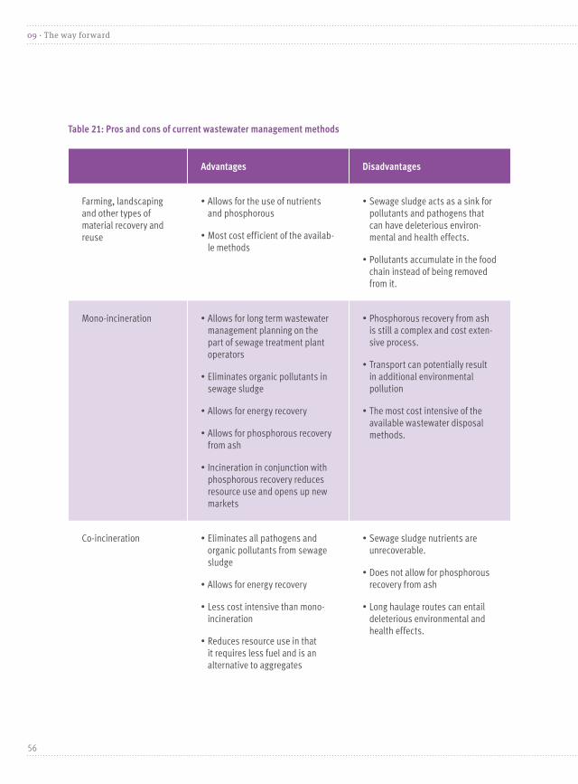
Table 21: Pros and cons of current wastewater management methods
Advantages Disadvantages
Farming, landscaping and other types of material recovery and reuse
• Allows for the use of nutrients and phosphorous
• Most cost efficient of the availab-le methods
• Sewage sludge acts as a sink for pollutants and pathogens that can have deleterious environ-mental and health effects.
• Pollutants accumulate in the food chain instead of being removed from it.
Mono-incineration • Allows for long term wastewater management planning on the part of sewage treatment plant operators
• Eliminates organic pollutants in sewage sludge
• Allows for energy recovery
• Allows for phosphorous recovery from ash
• Incineration in conjunction with phosphorous recovery reduces resource use and opens up new markets
• Phosphorous recovery from ash is still a complex and cost exten-sive process.
• Transport can potentially result in additional environmental pollution
• The most cost intensive of the available wastewater disposal methods.
Co-incineration • Eliminates all pathogens and organic pollutants from sewage sludge
• Allows for energy recovery
• Less cost intensive than mono-incineration
• Reduces resource use in that it requires less fuel and is an alternative to aggregates
• Sewage sludge nutrients are unrecoverable.
• Does not allow for phosphorous recovery from ash
• Long haulage routes can entail deleterious environmental and health effects.
56
09 · The way forward

of through co-incineration. Methods that allow for phosphorous recovery from was-tewater, sewage sludge and sewage sludge ash should be optimized and expanded. To this end, financial support for recovery technologies should be provided, via inst-ruments such as subsidy programs, sewa-ge charge revenues, sewage sludge funds, and sewage sludge compensation funds.
• The Sewage Sludge Ordinance (AbfKlärV) limit values for the transitional period in the runup to complete phase-out of agricultural sewage sludge use should be reviewed. The government also needs to determine whether, for reasons of precautionary soil and health protection, limits should be imposed on pollutants that are not currently regulated.
• The health requirements concerning sewage sludge that is used for agriculture or landscaping should be reviewed and if necessary tightened. The risk of infecting humans and livestock could be minimized through implementation of a quality ma-nagement system, or alternatively through sewage sludge treatment. The current usage restrictions should be retained, at a minimum, in the new version of the Sewage Sludge Ordinance (AbfKlärV).
• Current legal requirements need to be tightened so as to ensure high yields of recovered phosphorus from the relevant
substance flows such as wastewater and sewage sludge. Sewage sludge ash with a phosphorous content exceeding two per cent should be stored separately and reco-verably for possible recovery, at least until adequate phosphorous recovery plants are created. To this end, additional storage capacity for this type of sewage sludge ash should be created.
• Wherever possible, processes should be used that allow for phosphorous recovery. This could be achieved, for example, by switching to a biological phosphorus elimi-nation process, followed by reduced iron precipitation from sewage treatment plants in view of the fact that iron content deter-mines the quality and above all the phy-toavailability of recovered phosphorous.
• Sewage sludge dewatering, drying and hauling uses energy, some of which could potentially be recovered through an incineration process. Solar drying in conjunction with waste heat recove-ry is a sensible solution in this regard, thanks to its positive energy balance.
Ecofriendly sewage sludge management can only be achieved through intermeshing of the aforesaid measures, as this is the only way to transition to resource efficient phosphorous recovery that will also eliminate Germany’s dependence on imported phosphorous. To this end, the correct course must be set now.
57
The way forward · 09

Figure 1 Sludge occurrence broken down by treatment phase [original graphic] 6
Figure 2 Sewage sludge cadmium and mercury concentrations [BMU] 10
Figure 3 Sewage sludge dryer fleet, broken down by type 21
Figure 4 Mean sludge dryer throughput 22
Figure 5 Allowable total cadmium load for maximum usage amounts pursuant to the Sewage Sludge Ordinance (AbfKlärV) [RUPPE ET AL.]
33
Figure 6 Global distribution of explored raw rock phosphate reserves as of 2008 [U.S. GEOLOGICAL SURVEY]
35
Figure 7 Disposal paths of sewage sludge ash for 18 mono-incineration plants in 2009 [Proprie-tary data]
42
Figure 8 Percentage distribution of disposal methods in Germany’s regional states [DESTATIS F] 44
Figure 9 Sewage sludge volumes and management methods for selected years [DESTATIS A, B, C, D, E, F, G]
45
Figure 10 Sewage sludge disposal, 1991–2010 [UBA, DESTATIS F] 47
Figure 11 Sewage sludge management costs, including dewatering and haulage costs (in euros per ton of dry residue) [DWA A, B]
51
Figure 12 Sewage sludge copper concentrations [BMU] 87
Figure 13 Sewage sludge zinc concentrations [BMU] 88
Figure 14 Sewage sludge nickel, chrome and lead concentrations [BMU] 89
Illustrations10
Tables11
Table 1 Sludge parameters and their significance [KOPP; RÄBIGER] 5
Table 2 Sewage sludge composition [DWA; OLIVIA ET AL.] 8
Table 3 Sludge concentrations of selected heavy metals, as well as nitrogen and phosphorous, between 1977 and 2006. [BMU]
9
58
10 · Illustrations
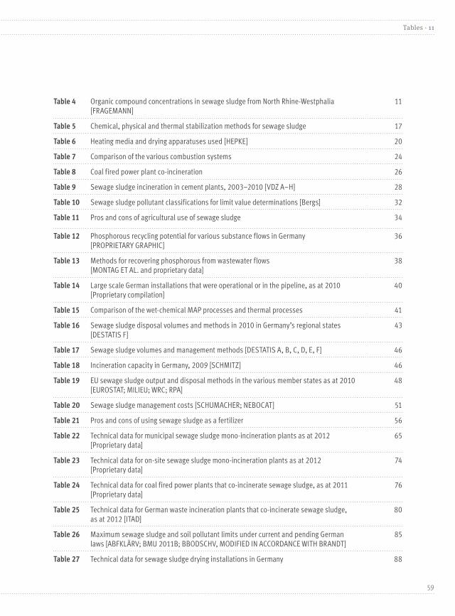
Table 4 Organic compound concentrations in sewage sludge from North Rhine-Westphalia [FRAGEMANN]
11
Table 5 Chemical, physical and thermal stabilization methods for sewage sludge 17
Table 6 Heating media and drying apparatuses used [HEPKE] 20
Table 7 Comparison of the various combustion systems 24
Table 8 Coal fired power plant co-incineration 26
Table 9 Sewage sludge incineration in cement plants, 2003–2010 [VDZ A–H] 28
Table 10 Sewage sludge pollutant classifications for limit value determinations [Bergs] 32
Table 11 Pros and cons of agricultural use of sewage sludge 34
Table 12 Phosphorous recycling potential for various substance flows in Germany [PROPRIETARY GRAPHIC]
36
Table 13 Methods for recovering phosphorous from wastewater flows [MONTAG ET AL. and proprietary data]
38
Table 14 Large scale German installations that were operational or in the pipeline, as at 2010 [Proprietary compilation]
40
Table 15 Comparison of the wet-chemical MAP processes and thermal processes 41
Table 16 Sewage sludge disposal volumes and methods in 2010 in Germany’s regional states [DESTATIS F]
43
Table 17 Sewage sludge volumes and management methods [DESTATIS A, B, C, D, E, F] 46
Table 18 Incineration capacity in Germany, 2009 [SCHMITZ] 46
Table 19 EU sewage sludge output and disposal methods in the various member states as at 2010 [EUROSTAT; MILIEU; WRC; RPA]
48
Table 20 Sewage sludge management costs [SCHUMACHER; NEBOCAT] 51
Table 21 Pros and cons of using sewage sludge as a fertilizer 56
Table 22 Technical data for municipal sewage sludge mono-incineration plants as at 2012 [Proprietary data]
65
Table 23 Technical data for on-site sewage sludge mono-incineration plants as at 2012 [Proprietary data]
74
Table 24 Technical data for coal fired power plants that co-incinerate sewage sludge, as at 2011 [Proprietary data]
76
Table 25 Technical data for German waste incineration plants that co-incinerate sewage sludge, as at 2012 [ITAD]
80
Table 26 Maximum sewage sludge and soil pollutant limits under current and pending German laws [ABFKLÄRV; BMU 2011B; BBODSCHV, MODIFIED IN ACCORDANCE WITH BRANDT]
85
Table 27 Technical data for sewage sludge drying installations in Germany 88
59
Tables · 11
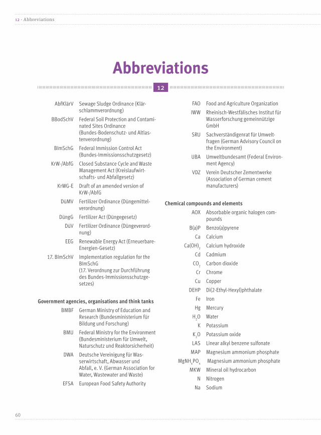
Abbreviations12
AbfKlärV Sewage Sludge Ordinance (Klär-schlammverordnung)
BBodSchV Federal Soil Protection and Contami-nated Sites Ordinance (Bundes-Bodenschutz- und Altlas-tenverordnung)
BImSchG Federal Immission Control Act (Bundes-Immissionsschutzgesetz)
KrW-/AbfG Closed Substance Cycle and Waste Management Act (Kreislaufwirt-schafts- und Abfallgesetz)
KrWG-E Draft of an amended version of KrW-/AbfG
DüMV Fertilizer Ordinance (Düngemittel-verordnung)
DüngG Fertilizer Act (Düngegesetz)
DüV Fertilizer Ordinance (Düngeverord-nung)
EEG Renewable Energy Act (Erneuerbare-Energien-Gesetz)
17. BImSchV Implementation regulation for the BImSchG (17. Verordnung zur Durchführung des Bundes-Immissionsschutzge-setzes)
Government agencies, organisations and think tanks
BMBF German Ministry of Education and Research (Bundesministerium für Bildung und Forschung)
BMU Federal Ministry for the Environment (Bundesministerium für Umwelt, Naturschutz und Reaktorsicherheit)
DWA Deutsche Vereinigung für Was-serwirtschaft, Abwasser und Abfall, e. V. (German Association for Water, Wastewater and Waste)
EFSA European Food Safety Authority
FAO Food and Agriculture Organization
IWW Rheinisch-Westfälisches Institut für Wasserforschung gemeinnützige GmbH
SRU Sachverständigenrat für Umwelt-fragen (German Advisory Council on the Environment)
UBA Umweltbundesamt (Federal Environ-ment Agency)
VDZ Verein Deutscher Zementwerke (Association of German cement manufacturers)
Chemical compounds and elements
AOX Absorbable organic halogen com-pounds
B(a)P Benzo(a)pyrene
Ca Calcium
Ca(OH)2 Calcium hydroxide
Cd Cadmium
CO2 Carbon dioxide
Cr Chrome
Cu Copper
DEHP Di(2-Ethyl-Hexyl)phthalate
Fe Iron
Hg Mercury
H2O Water
K Potassium
K2O Potassium oxide
LAS Linear alkyl benzene sulfonate
MAP Magnesium ammonium phosphate
MgNH4PO
4 Magnesium ammonium phosphate
MKW Mineral oil hydrocarbon
N Nitrogen
Na Sodium
60
12 · Abbreviations

Ni Nickel
P Phosphorus
PAC Polycyclic aromatic hydrocarbon
Pb Lead
PBDE Bromated diphenylether
PCB Polychlorinated biphenyl
PCDD/PCDF Polychlorinated dibenzo-p-dioxin and dibenzo-furan
PFC Perfluorocarbon
P2O
5 Phosphorous pentoxide
TBT Tributyl tin
Zn Zinc
Parameters
ROI Residue on ignition [%]
LOI Loss on ignition [%]
NCV Net calorific value [kJ/kg, MJ/kg]
TEQ/TE Toxicity equivalent
DM Dry mass [mg, g, kg]
DR Dry residue [%]
DS Dry solids [mg, g, kg]
TS Total solids [kg/m3, g/L]
WC Water content [%]
Units of measurement
a Year
kJ Kilojoule (103 joules)
mg Milligram (106 kg)
MJ Megajoule (106 joules)
m3 Cubic meters
t Ton (103 kg)
% Per cent
Other abbreviations
ATS Aerobic-thermophilic sludge stabi-lization
AVA Waste incineration plant
BHKW Cogeneration power plant
EU European Union
EU-27 27 member states of the EU
EHEC Enterohaemorrhagic Escherichia coli (E. coli)
EAggEC Enteroaggrative Escherichia coli (E. coli)
HTC Hydrothermal carbonization
ns Not specified
61
Abbreviations · 12

Bibliography14
Bibliography for the section titled “What is sewage sludge?”[ABFKLÄRV] Klärschlammverordnung (AbfKlärV); Aus-fertigungsdatum: 15.04.1992; Zuletzt durch Artikel 9 der Verordnung vom 9. November 2010 (BGBl. I S. 1504) geändert
Bibliography for the section titled “Where does sewage sludge occur?”[BISCHOFSBERGER ET.AL.] Wolfgang Bischofsberger, Norbert Dichtl, Karl-Heinz Rosenwinkel, Carl Franz Seyfried, Botho Böhnke (Hrsg.): Anaerobtechnik, 2. Auf-lage; Springer-Verlag Berlin Heidelberg, 2005
Bibliography for the following sections: “Composi-tion of sewage sludge;” “Heavy metals in sewage sludge;” “Organic compounds;” “Pathogens and health requirements”[KOPP] Dr.-Ing Julia Kopp: Eigenschaften von Klär-schlamm; Tagungsbeitrag VDI-Fachkonferenz Klär-schlammbehandlung; 27–28.Oktober 2010, Offenbach
[RÄBIGER] Prof. Dr.-Ing. N. Räbiger: Projekt wasser-wissen. Institut für Umweltverfahrenstechnik; Online abgerufen am/unter: 25.02.2011 http://www.wasser-wissen.de/
[GUJER] Prof. Dr. Willi Gujer; Siedlungswirtschaft; Institut für Umweltingenieurwissenschaften ETH Zürich, Springer-Verlag Berlin Heidelberg 1999, 2002 und 2007
[OLIVA ET.AL.] Judith Oliva, Antonia Bernhardt, Hubert Reisinger, Manfred Domenig, Hans-Jörg Krammer; Klärschlamm-Materialien zur Abfallwirtschaft; Umwelt-bundesamt AT; Report; Klagenfurt 2009
[DWA] Deutsche Vereinigung für Wasserwirtschaft, Abwasser und Abfall e. V.; Entwurf zum Merkblatt DWA-M 387 Thermische Behandlung von Klärschläm-men: Mitverbrennung; Hennef; 2009
[FRAGEMANN] Hans-Jürgen Fragemann, Dr. Dietmar Barkowski; Klärschlammbelastungen mit organi-schen Schadstoffen – Ergebnisse der landesweiten Untersuchungen in Nordrhein-Westfalen; Vortrag auf Expertentagung in Bonn am 6. Dezember 2006[BMU] Bundesministerium für Umwelt, Naturschutz und Reaktorsicherheit; Klärschlammverwertung in der Landwirtschaft; Internetseite; Online abgerufen am/unter: 16.02.2011 http://www.bmu.de/abfallwirtschaft/doc/40230.php
Acknowledgements13
We would like to extend our particularly heartfelt gratitude to all installation operators who provided us with data concerning their installations, and to the DWA for its support. We would also like to thank Ulrich Jacobs from EcoSystemsInternational GmbH and Matthias Jasper from IAA Ingenieurgesellschaft für Abfall und Abwasser mbH & Co. KG for their invaluable help.
62
13 · Acknowledgements

Bibliography for the section titled “Pharmaceutical drug residues in sewage sludge”[EIBISCH], Eibisch, Nina: Einträge und Verhalten von Arzneimittelrückständen in Böden. Technische Universi-tät Freiberg 11.01.2006
[GOLET ET.AL.] Golet, E. M.; Xifra, I.; Siegrist, H.; Alder, A. C. und W. Giger: Environmental Exposure of Fluor-quinolone Antibacterial Agents form Sewage to Soil. Environmental Science & Technology Vol. 37, No. 15, p. 3243-3249
[GROTE ET. AL] Grote, M.; Didem, H. Y. und R. Michel: Antibiotikaspuren im Getreide? – Analytik, Befunde, Bewertung. Vortrag 59. Tagung der Getreidechemie 18.–19.06.2008
[BERGMANN ET. AL.] Bergmann, A.; Fohrmann, R. und F.-A. Weber: Zusammenstellung von Monitoringdaten zu Umweltkonzentrationen von Arzneimitteln. Gutachten im Auftrag des Umweltbundesamtes FKZ 360 14 013; 2010
[RÖNNEFAHRT] Rönnefahrt, Ines: Humanarzneimittel in der Umwelt – Neue Ansätze in der Risikobewertung in der EU. Jahrestagung 2002 Umweltchemie und Ökotoxi-kologie, Tagungsband, 189.
[SRU] Sachverständigenrat für Umweltfragen: Arznei-mittel in der Umwelt. Stellungnahme Nr. 12. April 2007
[STUMPE] Stumpe, B: Mineralization and sorption of the steroid hormones 17b-estradiol, estrone, 17a-ethinylestradiol and testosterone in natural and organic waste amended agricultural soils. Dissertation Ruhr Universität Bochum. 2010
[UBA] Umweltbundesamt: Hygienische Fragen der Um-welttechnik – Abwasserhygiene; in: Jahresbericht 1997 Umweltbundesamt S. 100–101
Bibliography for the section titled “Sewage sludge treatment”[GUJER] Prof. Dr. Willi Gujer: Siedlungswirtschaft; Institut für Umweltingenieurwissenschaften ETH Zürich, Springer-Verlag Berlin Heidelberg 1999, 2002 und 2007
[BRANDT] Brandt, Simone; Nutzung von Klärschlamm als Rohstoffquelle – Akuteller Stand in Deutschland und in der Europäischen Union sowie Perspektiven für die Zukunft; Masterarbeit, 23. Februar 2011; Berlinhttp://www.andrakar.com/brandt/Rohstoffquelle_Klaer schlamm_Perspektiven_Br0211.pdf
[BMU] Bundesministerium für Umwelt, Naturschutz und Reaktorsicherheit; Klärschlammverordnung (AbfKlärV) – Zweiter Arbeitsentwurf für eine Novelle der Klär-schlammverordnung vom 20.08.2010; Online abgerufen am/unter: 12.02.2011 http://www.bmu.de/abfallwirtschaft/downloads/doc/46373.php
Bibliography for the section titled “Sewage sludge drying”[LEHRMANN] Lehrmann, Falko: Stand und Perspektiven der thermischen Klärschlammentsorgung. Vortrag zur VDI-Fachkonferenz Klärschlammbehandlung; Offen-bach; 27 und 28. Oktober 2010
[Beckmann] Prof. Dr.-Ing. Beckmann, Michael: Stoff- und Energiebilanzen bei der Verbrennung von Klärschlamm; In: Sammelband zur VDI-Fachkonferenz “Klärschlamm-behandlung – Technologie, Wertstoffrückgewinnung, Entwicklung” (Hrsg. VDI); Oktober 2010
[Hepke] Dr.-Ing. Hepke, Hans-Jörg: Thermische Verfah-ren der Klärschlammtrocknung; Tagungsbeitrag zur VDI-Fachkonferenz Klärschlammbehandlung am 27. und 28. Oktober 2010 in Offenbach
[Felber/Fischer]. Felber, H., Fischer, M.: Klärwärter-Ta-schenbuch. Deutsche Vereinigung für Wasserwirtschaft, Abwasser und Abfall e. V. 16. Auflage 2010. 2. F. Hirt-hammer Verlag München/Oberhaching.
Bibliography for the section titled “Cement plant co-incineration”[VDZ A] Verein Deutscher Zementwerke e. V.: Environ-mental Data of the German Cement Industry 2009; Düsseldorf August 2011
[VDZ B] Verein Deutscher Zementwerke e. V.: Environ-mental Data of the German Cement Industry 2009; Düsseldorf Juli 2010
63
Bibliography · 14

[VDZ C] Verein Deutscher Zementwerke e. V.: Umweltda-ten der deutschen Zementindustrie 2008; Düsseldorf August 2009
[VDZ D] Verein Deutscher Zementwerke e. V.: Umwelt-daten der deutschen Zementindustrie 2007; Düsseldorf September 2008
[VDZ E] Verein Deutscher Zementwerke e. V.: Umweltda-ten der deutschen Zementindustrie 2006; Düsseldorf September 2007
[VDZ F] Verein Deutscher Zementwerke e. V.: Umweltda-ten der deutschen Zementindustrie 2005; Düsseldorf September 2006
[VDZ G] Verein Deutscher Zementwerke e. V.: Umwelt-daten der deutschen Zementindustrie 2004; Düsseldorf September 2005
[VDZ H] Verein Deutscher Zementwerke e. V.: Umwelt-daten der deutschen Zementindustrie 2003; Düsseldorf November 2004
Bibliography for the section titled “Agricultural use of sewage sludge”[ABD EL-SAMIE] Abd El-Samie IMF: Phosphordün-gewirkung von Klärschlämmen aus Klärwerken mit Phosphateliminierung durch Eisensalze. Dissertation, Georg-August-Universität Göttingen
[BRANDT] Brandt, Simone; Nutzung von Klärschlamm als Rohstoffquelle – Akuteller Stand in Deutschland und in der Europäischen Union sowie Perspektiven für die Zukunft; Masterarbeit, 23. Februar 2011; Berlinhttp://www.andrakar.com/brandt/Rohstoffquelle_Klaer schlamm_Perspektiven_Br0211.pdf
[LFL] Bayerische Landesanstalt für Landwirtschaft (LfL): Landwirtschaftliche Verwertung von Klärschlamm. 2006; http://www.LfL.bayern.de
[BERGS] Dr. Bergs, Claus-Gerhard: Neuerungen im Abfall- und Düngerecht – Auswirkungen auf die Ver-wertung und Beseitigung von Klärschlämmen, Vortrag VDI-Fachkonferenz Offenbach, 27.10.2010
[KRATZ S, SCHNUG] Kratz, Sylvia; Schnug, Ewald: Agronomische Bewertung von Phosphatdüngern, Vortrag bei Symposium: Ressourcen schonender Einsatz von Phosphor in der Landwirtschaft, Braunschweig, 10./11.11.2008, www.jki.de
[RUPPE ET. AL.] Ruppe A, Bahr C, Pohl A: Fortschreibung von Beurteilungsmaßstäben für den Wirkungspfad Boden-Pflanze: Methodik zur flächenrepräsentativen Erfassung pflanzenverfügbarer Stoffgehalte in unbe-lasteten Böden und Stoffgehalten in Nahrungs-und Fut-termittelpflanzen. Forschungsbericht; FKZ 206 74 200, Umweltbundesamt, Dessau (Veröffentlichung in Vorbereitung), 2009.
Bibliography for the section titled “Sewage sludge quantities, management and recycling”[SCHMITZ] Erich Schmitz: Perspektiven der Mitverbren-nung von Klärschlämmen; 6. Klärschlammtage der DWA; Fulda, 12 Mai 2009
[DESTATIS A] Statistisches Bundesamt: Klärschlam-mentsorgung aus der biologischen Abwasserbehand-lung 2006; online abgerufen am/unter: 24.02.2011http://www.destatis.de/jetspeed/portal/cms/Sites/destatis/Internet/DE/Content/Statistiken/Umwelt/UmweltstatistischeErhebungen/Wasserwirtschaft/Tabellen/Content100/Klaerschlamm,templateId=renderPrint.psml
[DESTATIS B] Statistisches Bundesamt: Klärschlam-mentsorgung aus der biologischen Abwasserbehand-lung 2007; online abgerufen am/unter: 24.02.2011 http://www.destatis.de/jetspeed/portal/cms/Sites/destatis/Internet/DE/Content/Statistiken/ Umwelt/UmweltstatistischeErhebungen/ Wasserwirtschaft/Tabellen/Content100/Klaerschlamm 2007,templateId=renderPrint.psml
[DESTATIS C] Statistisches Bundesamt: Klärschlam-mentsorgung aus der biologischen Abwasserbehand-lung 2008; online abgerufen am/unter: 24.02.2011 http://www.destatis.de/jetspeed/portal/cms/Sites/destatis/Internet/DE/Content/Statistiken/ Umwelt/UmweltstatistischeErhebungen/ Wasserwirtschaft/Tabellen/Content100/Klaerschlamm 2008,templateId=renderPrint.psml
64
14 · Bibliography

[DESTATIS D] Statistisches Bundesamt: Klärschlam-mentsorgung aus der biologischen Abwasserbehand-lung 2009; online abgerufen am/unter: 24.02.2011 http://www.destatis.de/jetspeed/portal/cms/Sites/destatis/Internet/DE/Content/Statistiken/Umwelt/UmweltstatistischeErhebungen/Wasserwirtschaft/ Tabellen/Content100/Klaerschlamm2009,templateId =renderPrint.psml
[DESTATIS E] Statistisches Bundesamt: öffentliche Was-serversorgung und Abwasserbeseitigung; Fachserie 19, Reihe 2.1, Umwelt; 2004
[DESTATIS F] Statistisches Bundesamt: Klärschlam-mentsorgung aus der biologischen Abwasserbehand-lung 2010; online abgerufen am/unter: 01.02.2012 http://www.destatis.de/jetspeed/portal/cms/Sites/destatis/Internet/DE/Content/Statistiken/ Umwelt/UmweltstatistischeErhebungen/ Wasserwirtschaft/Tabellen/Content100/Klaerschlamm VerwertArt2010,templateId=renderPrint.psml#Fussnote5
[DESTATIS G] Statitisches Bundesamt: Klärschlamm-verwertung aus der biologischen Abwasserbehand-lung 2011, online abgerufen am/unter: 14.08.2013 https://www.destatis.de/DE/ZahlenFakten/ GesamtwirtschaftUmwelt/Umwelt/ UmweltstatistischeErhebungen/Wasserwirtschaft/Tabellen/KlaerschlammVerwertArt2011.html;jsessionid=404E90E0D27330D202F7A246B409731C.cae3
[UBA] Umweltbundesamt: Daten zur Umwelt; Klär-schlammentsorgung; Online abgerufen am/unter: 24.02.2011 http://www.umweltbundesamt-daten-zur-umwelt.de/umweltdaten/public/document/downloadImage.do?ident=19543
Bibliography for the section titled “Sewage sludge management in EU member states”[MILIEU; WRC; RPA] Milieu Ltd, WRc and RPA Environ-mental, economic and social impacts of the use of sewage sludge on land; Final Report for the European Commission; Part I: Overview Report;
[EUROSTAT] Gesamtklärschlammaufkommen aus der öf-fentlichen Abwasserbehandlung. Online abgerufen am/unter: 01. März 2011, http://epp.eurostat.ec.europa.eu/tgm/refreshTableAction.do?tab=table&plugin=1&pcode=ten00030&language=de
Bibliography for the section titled “Phosphorous recover”[SCHNUG/PINNEKAMP] Schnug, Ewald und Pinne-kamp, Johannes (TV Beitrag 2008); online abrufbar unter: http://www.3sat.de/mediathek/mediathek.php?obj=10256
[VACCARI] Vaccari, David A.: Phosphorus: A Looming Crisis, Scientific American, 2009 Nr. 6, S. 54–59 Droht ein Mangel an Phosphor? Spektrum der Wissenschaft, 2009 Nr. 11, S. 78–83
[SCHEIDIG] Dr.-Ing Scheidig,. Klaus: Wirtschaftliche und energetische Aspekte des Phosphor-Recyclings aus Klärschlamm, KA Korrespondenz Abwasser, Abfall, 2009 (56) Nr. 11 S. 1,138–1,146
[RÖMER ET.AL.] Römer, Wilhelm; Gründel, Michael; Friedrich Güthoff, Friedrich: U-238, U-235, Th-232 und Ra-226 in einigen ausgewählten Rohphosphaten, Phosphatdüngern, Boden- sowie Pflanzenproben aus einem P-Düngungsversuch, Journal für Kulturpflanzen, 2010 (62) Nr. 6 S. 200–210
[CORDELL ET. AL.] Cordell, Dana; Neset, Tina; White, Stuart; Drangert, Jan – Olof; Mavinic, D., Ashley, K.; Koch, F.: Preferred future phosphorus scenarios: A framework for meeting longterm phosphorus needs for global food demand, International Conference on Nu-trient Recovery from Waste Water Streams, Vancouver May 10th–13th , 2009, IWA Publishing, London, New York (ISBN 1843392321)
[FAO] Food and Agriculture Organization of the United Nations; Current world fertilizer trends and outlook to 2011/12
[U.S. GEOLOGICAL SURVEY] U.S. Geological Survey, Mineral Commodity Summaries (Januar 2013)
65
Bibliography · 14
[IWMI] International Water Management Institute: Comprehensive Assessment of water management in agriculture,2006; online abrufbar unter www.iwmi.cgiar.org\assessment
[WRAP] Waste & Resources Action Programme: The food we waste, Food waste report v2, 2008
[FRAITURE] Fraiture, Charlotte de: Future Water Require-ments for Food – Three Scenarios, International Water Management Institute (IWMI), SIWI Seminar: Water for Food, Bio-fuels or Ecosystems? in World Water Week 2007, Stockholm August 12th–18th 2007
[LUNDQVIST ET. AL.] Lundqvist, J., C. de Fraiture and D. Molden: Saving Water: From Field to Fork – Curbing Losses and Wastage in the Food Chain, SIWI Policy Brief, Stockholm Inter national Water Institute
[WHO] World Health Organization: Obesity and overweight, Fact sheet number 311, World Health Organisation Global Strategy on Diet, Physical Activity and Health, Genf
[Kabbe/Jakob] Kabbe, Christian und Dr. Jakob, Wolfgang, Process to recover phosphate from meat and bone meal with utilisation of waste heat, International Conference on Nutrient Recovery from Waste Water Streams, Van-couver May 10–13, 2009, IWA Publishing, London, New York (ISBN 1843392321)
[Sartorius] Sartorius, Christian; Technologievorausschau und Zukunftschancen durch die Entwicklung von Phos-phorrecyclingtechnologien in Deutschland; Tagungsbei-trag zur Abschlusspräsentation im Zuge der Förderin-itiative “Kreislaufwirtschaft für Pflanzennährstoffe, insbesondere Phosphor”; September 2011; Berlin
[SWEDISH EPA] Swedish Environmental Protection Agency, A Strategy for Sustainable Waste Management – Sweden’s Waste Plan, Stockholm 2005 (ISBN: 91-620-1249-5)[von HORN ET.AL.] Dr. von Horn, Jana; Dr. Dr. Sartorius, Christian; Tettenborn, Felix:
Technologievorausschau für Phosphorrecyclingtech-nologien (Arbeitspaket 6) Im Rahmen des Projektes „Phosphorrecycling – Ökologische und wirtschaftliche Bewertung verschiedener Verfahren und Entwicklung eines strategischen Verwertungskonzeptes für Deutsch-land“ (PhoBe) im Auftrag des Bundesministeriums für Bildung und Forschung (FKZ 02WA0807);2010
Bibliography for the section titled “Who foots the bill for sewage sludge management?”[FELS ET.AL] Dr. Fels, Thomas; Dr. Heid, Markus und Dr. Kersten, Malte: Ermittlung der Kosten, die mit einem Ausstieg/Teilausstieg aus der landwirtschaftlichen Klärschlammverwertung verbunden wären; Studie für das Ministerium für Umwelt, Naturschutz und Landwirt-schaft des Landes Schleswig-Holstein; witra-kiel GbR; Universität Kiel; 2005
[SCHUMACHER; NEBOCAT] Werner Schumacher und Günter Nebocat: Kosten der Ersatzbrennstoffverbren-nung in Monoverbrennungsanlagen; Tagungsbeitrag; Energie aus Abfall Band 6; TK Verlag, Neuruppin; 2009
[DWA A] Deutsche Vereinigung für Wasserwirtschaft, Abwasser und Abfall e. V.; Arbeitsgruppe AK-13.4: Klärschlammentsorgungskonzepte; Fachbeitrag für Kor-respondenz Abwasser, Abfall; Heft 3/10; Hennef; 2010
[DWA B] Deutsche Vereinigung für Wasserwirtschaft, Abwasser und Abfall e. V.; DWA-Positionen; Position zur Klärschlammentsorgung; Hennef; 2010
[DESTATIS A] Statistisches Bundesamt Deutschland: Durchschnittliche Kosten für die Entsorgung von Ab-wasser aus privaten Haushalten 2005 bis 2007; online abgerufen am/unter: 14.02.2011, http://www.destatis.de/jetspeed/portal/cms/Sites/destatis/Internet/DE/Content/Statistiken/Umwelt/ UmweltstatistischeErhebungen/Wasserwirtschaft/Tabellen/Content75/ Durchschnittskosten__ Abwasser__Haushalte.psml
[DESTATIS B] Statistisches Bundesamt Deutschland: Ge-biet und Bevölkerung – Fläche und Bevölkerung. online abgerufen am/unter: 14.02.2011 http://www.statistik-portal.de/Statistik-Portal/de_jb01_jahrtab1.asp
66
14 · Bibliography

[DESTATIS C] Statistisches Bundesamt Deutschland: Klärschlammentsorgung aus der biologischen Ab-wasserbehandlung 2007. online abgerufen am/unter: 14.02.2011http://www.destatis.de/jetspeed/portal/cms/Sites/destatis/Internet/DE/Content/Statistiken/Umwelt/UmweltstatistischeErhebungen/Wasserwirtschaft/Tabellen/Content100/Klaerschlamm2007,templateId=renderPrint.psml
Bibliography for Appendix II (Sewage sludge management legislation) für die Klärschlammentsorgung“: [17.BIMSCHV] Siebzehnte Verordnung zur Durchführung des Bundes-Immissionsschutzgesetzes (Verordnung über die Verbrennung und die Mitverbrennung von Abfällen – 17. BImSchV); Ausfertigungsdatum: 23.11.1990; In der Fassung der Bekanntmachung vom 14. August 2003 (BGBl. I S. 1633), die durch Artikel 2 der Verordnung vom 27. Januar 2009 (BGBl. I S. 129) geändert worden ist.
[ABFKLÄRV] Klärschlammverordnung (AbfKlärV); Ausfertigungsdatum: 15.04.1992; zuletzt geändert durch Artikel 9 der Verordnung vom 9. November 2010 (BGBl. I S. 1504)
[BBODSCHV] Bundes-Bodenschutz- und Altlastenver-ordnung (BBodSchV); Ausfertigungsdatum: 12.07.1999; zuletzt geändert durch Artikel 16 des Gesetzes vom 31. Juli 2009 (BGBl. I S. 2585)
[BMU 2011B] Bundesministerium für Umwelt, Natur-schutz und Reaktorsicherheit; Klärschlammverordnung (AbfKlärV) – Arbeitsentwurf für einen Referentenent-wurf; Einer Verordnung zur Neuordnung der Klär-schlammverwertung auf Böden; Stand 01.06.2011
[BRANDT] Brandt, Simone; Nutzung von Klärschlamm als Rohstoffquelle – Akuteller Stand in Deutschland und in der Europäischen Union sowie Perspektiven für die Zukunft; Masterarbeit, 23. Februar 2011; Berlinhttp://www.andrakar.com/brandt/Rohstoffquelle_ Klaerschlamm_Perspektiven_Br0211.pdf
[DÜMV] Verordnung über das Inverkehrbringen von Düngemitteln, Bodenhilfsstoffen, Kultursubstraten und Pflanzenhilfsmitteln (Düngemittelverordnung – DüMV); Ausfertigungsdatum: 16.12.2008; zuletzt geändert durch Artikel 1 der Verordnung vom 14. Dezember 2009 (BGBl. I S. 3905)
[DÜNGG] Düngegesetz (DüngG); Ausfertigungsdatum: 09.01.2009; zuletzt geändert durch Artikel 10 des Gesetzes vom 9. Dezember 2010 (BGBl. I S. 1934)
er die Anwendung von Düngemitteln, Bodenhilfsstof-fen, Kultursubstraten und Pflanzenhilfsmitteln nach den Grundsätzen der guten fachlichen Praxis beim Düngen (Düngeverordnung – DüV); Ausfertigungsda-tum: 10.01.2006; In der Fassung der Bekanntmachung vom 27. Februar 2007 (BGBl. I S.221), zuletzt geändert durch Artikel 18 des Gesetzes vom 31. Juli 2009 (BGBl. I S. 2585)
[EWG] Richtlinie 86/278/EWG des Rates vom 12. Juni 1986 über den Schutz der Umwelt und ins besondere der Böden bei der Verwendung von Klärschlamm in der Landwirtschaft
[KRW/ABFG] Gesetz zur Förderung der Kreislauf-wirtschaft und Sicherung der umweltverträglichen Beseitigung von Abfällen (Kreislaufwirtschafts- und Abfallgesetz – KrW-/AbfG) vom 27. September 1994 (BGB. I S. 2705); zuletzt geändert durch Artikel 8 des Gesetzes vom 11. August 2010 (BGBl. I S. 1163)
[KRWG] Gesetz zur Förderung der Kreislaufwirtschaft und Sicherung der umweltverträglichen Bewirtschaf-tung von Abfällen (Kreislaufwirtschaftsgesetz – KrWG); Bundesgesetzblatt Jahrgang 2012 Teil I Nr. 10, ausgege-ben zu Bonn am 29. Februar 2012.
67
Bibliography · 14
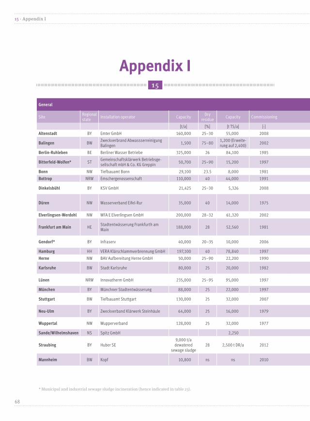
Appendix I15
General Input Sludge dewatering
SiteRegional state
Installation operator CapacityDry
residueCapacity Commissioning Operating hours, 2009
Sludge makeup (raw sludge/digested sludge)
Sludge typeDewatering installation
Total (mean) residual water content
[t/a] [%] [t TS/a] [-] [h/a] [-] [-] [-] [%]
Altenstadt BY Emter GmbH 160,000 25–30 55,000 2008 7,000 ns Municipal sewage sludge Decanter -
Balingen BWZweckverbrand Abwassserreinigung Balingen
1,500 75–801,200 (Erweite-rung auf 2,400)
2002 ns Digested sludge Sewage sludge Chamber filter press 69
Berlin-Ruhleben BE Berliner Wasser Betriebe 325,000 26 84,100 1985 8,760 Raw sludge, 3.5 % dry solids Sewage sludge Centrifuge 74
Bitterfeld-Wolfen* STGemeinschaftsklärwerk Betriebsge-sellschaft mbH & Co. KG Greppin
50,700 25–90 15,200 1997 7,738 Raw sludgeIndustrial and municipal sewage sludge
Centrifuge 74
Bonn NW Tiefbauamt Bonn 29,100 23.5 8,000 1981 6,854 Digested sludge Sewage sludge, floating sludge Centrifuge 76.5
Bottrop NRW Emschergenossenschaft 110,000 40 44,000 1991 7,800 Digested sludge Sewage sludge Membrane filter press 60
Dinkelsbühl BY KSV GmbH 21,425 25–30 5,326 20084,309
(shut down since 2010)gefault Municipal sewage sludge ns 72
Düren NW Wasserverband Eifel-Rur 35,000 40 14,000 1975 8,4002009: digested sludge (including digested sludge as from 2010)
Sewage sludge Centrifuge 74.00
Elverlingsen-Werdohl NW WFA E Elverlingsen GmbH 200,000 28–32 61,320 2002 7,313 Digested sludge Sewage sludge KFP ZF 68–72
Frankfurt am Main HEStadtentwässerung Frankfurth am Main
188,000 28 52,560 1981Average 6,851 per line, total of 20,552.5 for three lines in opera-tion simultaneously
Raw sludge Sewage sludge Centrifuge 71
Gendorf* BY Infraserv 40,000 20–35 10,000 2006 ns Raw sludgeIndustrial and municipal sewage sludge
Decanter 26
Hamburg HH VERA Klärschlammverbrennung GmbH 197,100 40 78,840 1997 23,463 h=3 lines = 7,821 per line Digested sludge Sewage sludge Centrifuge 78
Herne NW BAV Aufbereitung Herne GmbH 50,000 25–90 22,200 1990 ns Digested sludge Sewage sludge - 10–75
Karlsruhe BW Stadt Karlsruhe 80,000 25 20,000 1982 6,500 RohschlammSewage sludge, screen debris, trapped grease
Centrifuge 75
Lünen NRW Innovatherm GmbH 235,000 25–95 95,000 1997 7,850 Digested sludge Sewage sludge, Filter cakeCentrifuge, Membranefilter press
60
München BY Münchner Stadtentwässerung 88,000 25 22,000 1997 8,430 Digested sludge Sewage sludge Centrifuge 72
Stuttgart BW Tiefbauamt Stuttgart 130,000 25 32,000 20074,809(Linie 3)
Raw sludge, excess sludge,digested sludge
Sewage sludge, screen debris, trapped grease
Centrifuge 75
Neu-Ulm BY Zweckverband Klärwerk Steinhäule 64,000 25 16,000 1979 ns Raw sludge/Digested sludgeSewage sludge, screen debris, trapped grease
Centrifuge 75
Wuppertal NW Wupperverband 128,000 25 32,000 1977 8,586 Digested sludge Sewage sludgeCentrifuge, Membranefilter press
75
Sande/Wilhelmshaven NS Spitz GmbH 2,250 Shut down Digested sludge Sewage sludge External -
Straubing BY Huber SE9,000 t/a
dewatered sewage sludge
28 2,500 t DR/a 20127,500
(Design capacity)Digested sludge Sewage sludge, Screen debris Centrifuge 72
Mannheim BW Kopf 10,800 ns ns 20107,000
(planned)Digested sludge Sewage sludge, Screen debris
* Municipal and industrial sewage sludge incineration (hence indicated in table 23).
68
15 · Appendix I

Table 22: Technical data for municipal sewage sludge mono-incineration plants as at 2012 [proprietary data]
General Input Sludge dewatering
SiteRegional state
Installation operator CapacityDry
residueCapacity Commissioning Operating hours, 2009
Sludge makeup (raw sludge/digested sludge)
Sludge typeDewatering installation
Total (mean) residual water content
[t/a] [%] [t TS/a] [-] [h/a] [-] [-] [-] [%]
Altenstadt BY Emter GmbH 160,000 25–30 55,000 2008 7,000 ns Municipal sewage sludge Decanter -
Balingen BWZweckverbrand Abwassserreinigung Balingen
1,500 75–801,200 (Erweite-rung auf 2,400)
2002 ns Digested sludge Sewage sludge Chamber filter press 69
Berlin-Ruhleben BE Berliner Wasser Betriebe 325,000 26 84,100 1985 8,760 Raw sludge, 3.5 % dry solids Sewage sludge Centrifuge 74
Bitterfeld-Wolfen* STGemeinschaftsklärwerk Betriebsge-sellschaft mbH & Co. KG Greppin
50,700 25–90 15,200 1997 7,738 Raw sludgeIndustrial and municipal sewage sludge
Centrifuge 74
Bonn NW Tiefbauamt Bonn 29,100 23.5 8,000 1981 6,854 Digested sludge Sewage sludge, floating sludge Centrifuge 76.5
Bottrop NRW Emschergenossenschaft 110,000 40 44,000 1991 7,800 Digested sludge Sewage sludge Membrane filter press 60
Dinkelsbühl BY KSV GmbH 21,425 25–30 5,326 20084,309
(shut down since 2010)gefault Municipal sewage sludge ns 72
Düren NW Wasserverband Eifel-Rur 35,000 40 14,000 1975 8,4002009: digested sludge (including digested sludge as from 2010)
Sewage sludge Centrifuge 74.00
Elverlingsen-Werdohl NW WFA E Elverlingsen GmbH 200,000 28–32 61,320 2002 7,313 Digested sludge Sewage sludge KFP ZF 68–72
Frankfurt am Main HEStadtentwässerung Frankfurth am Main
188,000 28 52,560 1981Average 6,851 per line, total of 20,552.5 for three lines in opera-tion simultaneously
Raw sludge Sewage sludge Centrifuge 71
Gendorf* BY Infraserv 40,000 20–35 10,000 2006 ns Raw sludgeIndustrial and municipal sewage sludge
Decanter 26
Hamburg HH VERA Klärschlammverbrennung GmbH 197,100 40 78,840 1997 23,463 h=3 lines = 7,821 per line Digested sludge Sewage sludge Centrifuge 78
Herne NW BAV Aufbereitung Herne GmbH 50,000 25–90 22,200 1990 ns Digested sludge Sewage sludge - 10–75
Karlsruhe BW Stadt Karlsruhe 80,000 25 20,000 1982 6,500 RohschlammSewage sludge, screen debris, trapped grease
Centrifuge 75
Lünen NRW Innovatherm GmbH 235,000 25–95 95,000 1997 7,850 Digested sludge Sewage sludge, Filter cakeCentrifuge, Membrane filter press
60
München BY Münchner Stadtentwässerung 88,000 25 22,000 1997 8,430 Digested sludge Sewage sludge Centrifuge 72
Stuttgart BW Tiefbauamt Stuttgart 130,000 25 32,000 20074,809(Linie 3)
Raw sludge, excess sludge, digested sludge
Sewage sludge, screen debris, trapped grease
Centrifuge 75
Neu-Ulm BY Zweckverband Klärwerk Steinhäule 64,000 25 16,000 1979 ns Raw sludge/Digested sludgeSewage sludge, screen debris, trapped grease
Centrifuge 75
Wuppertal NW Wupperverband 128,000 25 32,000 1977 8,586 Digested sludge Sewage sludgeCentrifuge, Membrane filter press
75
Sande/Wilhelmshaven NS Spitz GmbH 2,250 Shut down Digested sludge Sewage sludge External -
Straubing BY Huber SE9,000 t/a
dewatered sewage sludge
28 2,500 t DR/a 20127,500
(Design capacity)Digested sludge Sewage sludge, Screen debris Centrifuge 72
Mannheim BW Kopf 10,800 ns ns 20107,000
(planned)Digested sludge Sewage sludge, Screen debris
69
Appendix I · 15

General Drying Incineration
Site UnitResidual water content
after dryingIncineration technology Incineration units
Mean annual sewage sludge calorific value
Mean theoretical capacity per unit
Amount incinerated in 2009
Incinerator manufacturer Additional fuel
[-] [%] [-] [-] [kJ/kg] [t TS/h] [t TS/a] [-] [-]
Altenstadt Thermal oil circuit 25–30 Grate firing 2 furnaces 8,000 je 2,5 t TM/h 23,000
Balingen Solar drying 20–25 Fluidized bed gasification 1 gasification 0.18 Kopf Digester gas
Berlin-Ruhleben - - Stationary fluidized bed 3 ca. 17 MJ/kg TR 3.20 41,128 Uhde Fuel oil
Bitterfeld-Wolfen* Disc dryer 55 Stationary fluidized bed 1 5,950 or 10,200 kj/kg dry solids 2.00 10,262 Uhde Natural gas
Bonn - - Stationary fluidized bed 2 1.42 6,600 Raschka Digester gas, Fuel oil
Bottrop - - Stationary fluidized bed 2 4,500 3.00 46,000 Raschka Fuel oil
Dinkelsbühl Belt dryer <10 Pyrobuster technology 1 10.9/11.8 0.60 1,290 Eisenmann AG Fuel oil/Propane
Düren Disc dryer 60 Stationary fluidized bed 1
2009: 14,604 KJ/kg dry solids, only raw sludge incinerated (2010: raw sludge volume 12,820, digested sludge 3,700 KJ/kg dry solids)
1.75 10,924 Lurgi Natural gas
Elverlingsen-Werdohl - - Stationary fluidized bed 11,000 in OS; 10,000 – 13,000 kJ/kg dry solids
7.00 185,421 t/a TKECCoal/natural gas/
fuel oil/SBS
Frankfurt am Main Fluidized bedca. 30
(Eintritt in Wirbelschicht)Fluidized bed 4 17,000 kJ/kg TS; 3,100 kJ/kg damp 2.00 33,946 Lurgi Fuel oil (Light oil)
Gendorf* Disc dryer 50 Fluidized bed 1 1.25 Natural gas
Hamburg Disc dryer 58 Stationary fluidized bed 33,650, or 13 MJ/kg dry residue in 2009; the figure for 2010 was 13.6 MJ/kg dry residue
3.40 60,256 AE & E Fuel oil, Digester gas
Herne - - Stationary fluidized bed 1 8.00 Raschka Fuel oil
Karlsruhe Disc dryer 55 Stationary fluidized bed 2 (1+1) 14,000–15,000 1.90/2.70 13,000 Raschka Fuel oil
Lünen - - Fluidized bed 1 4,000 13.00 89,000 Raschka Fuel oil
München Contact disc dryer 55 Stationary fluidized bed 2 4,500/10,000 3.00 21,421 Raschka Faulgas
Stuttgart Disc dryer 55 Stationary fluidized bed 2 13.8 MJ/kg TS 4.00 22,700 Bamag Digester gas, Fuel oil
Neu-Ulm Thin layer dryer 60 Stationary fluidized bed 2 ns 2.00 16,389 Thyssen Fuel oil
Wuppertal Thin layer dryer 55 Stationary fluidized bed 2Mean annual (weighted) calorific va-lue: 12,100 kJ/kg dry solids; range: 9,300 to 14,370 kJ/kg dry solids
4.60 29,557 Thyssen Fuel oil
Sande/Wilhelmshaven Fluidized bed dryer 15 Cycloid combustion chamber 1 0.30 0,00 Steinmüller Natural gas
Straubing Belt dryer 35 Ash incineration 1 7,000 kJ/kg 530 kg/h 3,500 t/a Fa. Zauner
Mannheim Drum dryer Fluidized bed gasification 1 Kopf
* Municipal and industrial sewage sludge incineration (hence indicated in table 23).
70
15 · Appendix I
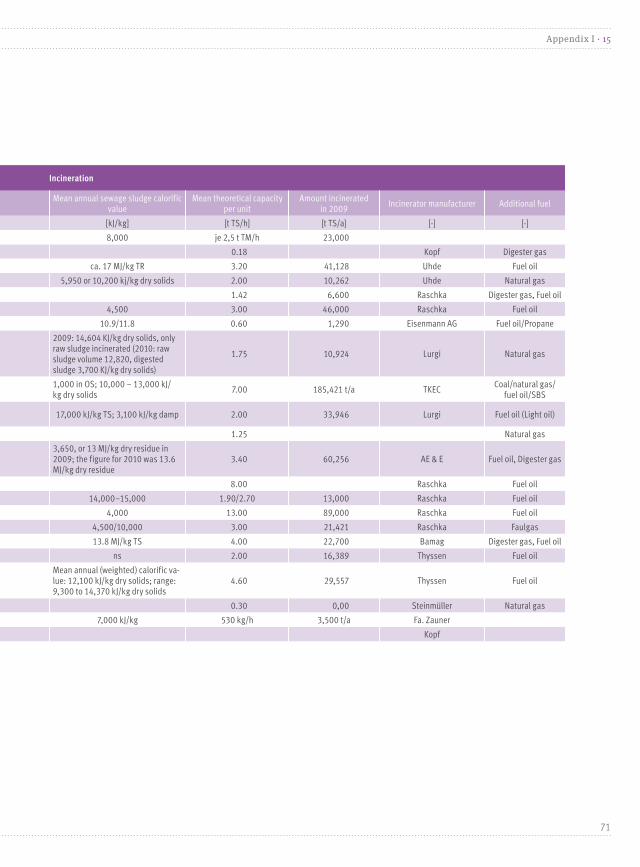
General Drying Incineration
Site UnitResidual water content
after dryingIncineration technology Incineration units
Mean annual sewage sludge calorific value
Mean theoretical capacity per unit
Amount incinerated in 2009
Incinerator manufacturer Additional fuel
[-] [%] [-] [-] [kJ/kg] [t TS/h] [t TS/a] [-] [-]
Altenstadt Thermal oil circuit 25–30 Grate firing 2 furnaces 8,000 je 2,5 t TM/h 23,000
Balingen Solar drying 20–25 Fluidized bed gasification 1 gasification 0.18 Kopf Digester gas
Berlin-Ruhleben - - Stationary fluidized bed 3 ca. 17 MJ/kg TR 3.20 41,128 Uhde Fuel oil
Bitterfeld-Wolfen* Disc dryer 55 Stationary fluidized bed 1 5,950 or 10,200 kj/kg dry solids 2.00 10,262 Uhde Natural gas
Bonn - - Stationary fluidized bed 2 1.42 6,600 Raschka Digester gas, Fuel oil
Bottrop - - Stationary fluidized bed 2 4,500 3.00 46,000 Raschka Fuel oil
Dinkelsbühl Belt dryer <10 Pyrobuster technology 1 10.9/11.8 0.60 1,290 Eisenmann AG Fuel oil/Propane
Düren Disc dryer 60 Stationary fluidized bed 1
2009: 14,604 KJ/kg dry solids, only raw sludge incinerated (2010: raw sludge volume 12,820, digested sludge 3,700 KJ/kg dry solids)
1.75 10,924 Lurgi Natural gas
Elverlingsen-Werdohl - - Stationary fluidized bed 11,000 in OS; 10,000 – 13,000 kJ/kg dry solids
7.00 185,421 t/a TKECCoal/natural gas/
fuel oil/SBS
Frankfurt am Main Fluidized bedca. 30
(Eintritt in Wirbelschicht)Fluidized bed 4 17,000 kJ/kg TS; 3,100 kJ/kg damp 2.00 33,946 Lurgi Fuel oil (Light oil)
Gendorf* Disc dryer 50 Fluidized bed 1 1.25 Natural gas
Hamburg Disc dryer 58 Stationary fluidized bed 33,650, or 13 MJ/kg dry residue in 2009; the figure for 2010 was 13.6 MJ/kg dry residue
3.40 60,256 AE & E Fuel oil, Digester gas
Herne - - Stationary fluidized bed 1 8.00 Raschka Fuel oil
Karlsruhe Disc dryer 55 Stationary fluidized bed 2 (1+1) 14,000–15,000 1.90/2.70 13,000 Raschka Fuel oil
Lünen - - Fluidized bed 1 4,000 13.00 89,000 Raschka Fuel oil
München Contact disc dryer 55 Stationary fluidized bed 2 4,500/10,000 3.00 21,421 Raschka Faulgas
Stuttgart Disc dryer 55 Stationary fluidized bed 2 13.8 MJ/kg TS 4.00 22,700 Bamag Digester gas, Fuel oil
Neu-Ulm Thin layer dryer 60 Stationary fluidized bed 2 ns 2.00 16,389 Thyssen Fuel oil
Wuppertal Thin layer dryer 55 Stationary fluidized bed 2Mean annual (weighted) calorific va-lue: 12,100 kJ/kg dry solids; range: 9,300 to 14,370 kJ/kg dry solids
4.60 29,557 Thyssen Fuel oil
Sande/Wilhelmshaven Fluidized bed dryer 15 Cycloid combustion chamber 1 0.30 0,00 Steinmüller Natural gas
Straubing Belt dryer 35 Ash incineration 1 7,000 kJ/kg 530 kg/h 3,500 t/a Fa. Zauner
Mannheim Drum dryer Fluidized bed gasification 1 Kopf
71
Appendix I · 15

* Municipal and industrial sewage sludge incineration (hence indicated in table 23).
General Waste heat recovery Waste gas scrubbing Slag and ash recycling and management
Site Aggregat ManufacturerMean steam parameter
Raw electrical output
Energy useFlue gas cleaning
linesDust collector Additional waste gas scrubbing
Recycling/elimina-tion in
Volume
[-] [-] [bar/°C] [MW] [-] [-] [-] [-] [-] [-] [-] [t/a]
Altenstadt Boiler with thermal oil - Heat for drying 1Cyclone and cloth filter downstream from entrai-ned flow adsorber
Denitrogenation (SNCR) Entrained flow adsorberTwo-phasescrubber
Mainly used for farming, and to a lesser extent in asphalt plants
8,500
Balingen CHP plant Kopf/EAG - Heat, Electricity 1 Cyclone and ceramic filter Wet scrubbing Tar condensation Asphalt plant 500
Berlin-Ruhleben Water-tube boiler (Natu-ral circulation)
L. & C. Stein-müller
46/4601 × 2.8/ 2 × 2.0
Electricity, Heat 3 Electrofilter Wet absorber - Mine sealing 14,400
Bitterfeld-Wolfen* Natural circulation Bertsch 10/180 - Heat 1 Electrofilter, Cloth filter Wet two-stage scrubber Entrained flow adsorber - Mine sealing 5,233
Bonn Forced-circulation waste heat boiler
Stahl 10/180 Heat, Electricity 2 Electrofilter Semi-dry absorber Entrained flow adsorber Landfill covering 3,200
Bottrop Forced-circulation boiler Raschka 35/400 3.5 Heat, Electricity 2 Electrofilter Wet two-stage NaOH scrubber - - Asphalt plant 18,000
Dinkelsbühl Waste heat steam boiler HTA GmbH 10/184 ns Drying 1 Cyclone Sorption agent Dust filter
Tested for use as a construction aggrega-te, currently used as landfill
bis 1,700 (442 in 2009)
Düren Heat transfer oil waste-heat boiler
Ohl - Heat 1 Wet scrubber SO2 scrubber
Stationary bed filter for mercury removal
SNCR systemLandfill; landfillconstruction
3,467
Elverlingsen-Werdohl Steam boiler Bertsch 17/320Auxiliary steam for power plant use
1 ElectrofilterSpray dryer, acid scrubber, SO
2scrubber
Hearth furnace and cloth filter
Landfill; landfillconstruction
35,000
Frankfurt am Main Steam boiler Lentjes 38/380 3 Heat, Electricity 4 Electrofilter Wet four-stage scrubberFestbettadsorber (ActWi-vated carbon)
Mine sealing 6,803
Gendorf* 20/215
Hamburg Natural-circulation boiler AE & E 40/40032 ST and
HRSGHeat, Electricity 3 Electrofilter
Wet pipe quencher, counter-flow scrubber
Entrained flow adsorber Copper refinery fly ash 21,834
Herne Coal slurry rotary drier Hoffmeyer - Heat 2 Cloth filter Dry sorption Primary additive Asphalt plant 8,900
Karlsruhe Natural-circulation boiler Raschka, Oschatz 25/300 25/300 Heat, Electricity 2 ElectrofilterWet oxidation Venturi scrubber, three-stage
- Mine sealing 4,000
Lünen Natural-circulation boiler Noell-KRC 40/400 8.5 Electricity 1 Electrofilter, Cloth filter Semi-dry, two-stage scrubber Entrained flow adsorberLandfill; landfillconstruction
40,000
München Waste-heat boiler Wamser 40/400 0.269869514Heat for plant use, Electricity
4 Electrofilter Cloth filter Two-stage scrubberWet electro-filter
Landfill; landfillconstruction
8,500
Stuttgart Waste-heat boiler Bertsch 63/410 1.2 MW Heat, Electricity 2 ElectrofilterSemi-dry jet scrubber, packed-bedscrubber
Entrained flow adsorber + HOK
Electrofilter 2 Mine sealing8,220
(2009)
Neu-Ulm Water-tube boilerUMAG, Baum-
garte24/250 40/400 ns Heat, Electricity 4 Electrofilter, Cloth filter Wet jet scrubber, packed-bed scrubber
Dry additive, cloth filter, entrained flow adsorber
Mine sealing 7,400
Wuppertal Natural-circulation waste heat boiler
Blohm + Voss 31/355 --- Heat, Electricity 2 ElectrofilterWet two-stage scrubber: acid stage, no internals; base stage with packingsr
Activated coke adsorber/cloth filter
- Mine sealing 12,412
Sande/Wilhelmshaven Natural-circulation waste heat boiler
Wulff 19/210 Heat 4Cloth filter, Hot-gas cyclone
Dry/evaporative cooler Hearth furnace coke filer
Straubing Micro-gas turbine heat exchanger
Turbine: Turbec 80 kW el. 800 kW therm. 1 Hydrocyclone Cloth filter SNCR Lime injectionPhosphorous recyclingplanned
1,400
Mannheim CHP plant 3.6 MW Heat 1 Keramikfilter Dryer Two-step stage gas scrubbing
-
72
15 · Appendix I
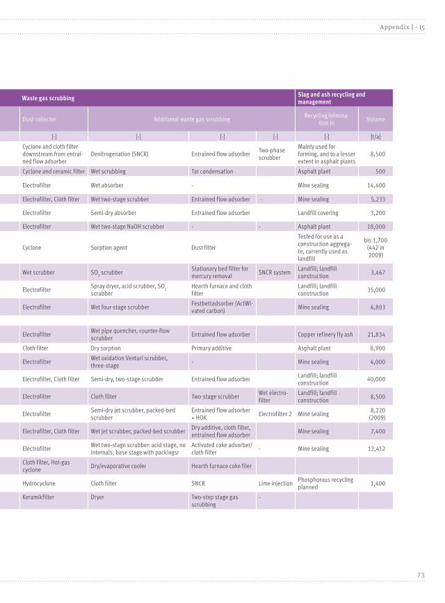
General Waste heat recovery Waste gas scrubbing Slag and ash recycling and management
Site Aggregat ManufacturerMean steam parameter
Raw electrical output
Energy useFlue gas cleaning
linesDust collector Additional waste gas scrubbing
Recycling/elimina-tion in
Volume
[-] [-] [bar/°C] [MW] [-] [-] [-] [-] [-] [-] [-] [t/a]
Altenstadt Boiler with thermal oil - Heat for drying 1Cyclone and cloth filter downstream from entrai-ned flow adsorber
Denitrogenation (SNCR) Entrained flow adsorberTwo-phase scrubber
Mainly used for farming, and to a lesser extent in asphalt plants
8,500
Balingen CHP plant Kopf/EAG - Heat, Electricity 1 Cyclone and ceramic filter Wet scrubbing Tar condensation Asphalt plant 500
Berlin-Ruhleben Water-tube boiler (Natu-ral circulation)
L. & C. Stein-müller
46/4601 × 2.8/ 2 × 2.0
Electricity, Heat 3 Electrofilter Wet absorber - Mine sealing 14,400
Bitterfeld-Wolfen* Natural circulation Bertsch 10/180 - Heat 1 Electrofilter, Cloth filter Wet two-stage scrubber Entrained flow adsorber - Mine sealing 5,233
Bonn Forced-circulation waste heat boiler
Stahl 10/180 Heat, Electricity 2 Electrofilter Semi-dry absorber Entrained flow adsorber Landfill covering 3,200
Bottrop Forced-circulation boiler Raschka 35/400 3.5 Heat, Electricity 2 Electrofilter Wet two-stage NaOH scrubber - - Asphalt plant 18,000
Dinkelsbühl Waste heat steam boiler HTA GmbH 10/184 ns Drying 1 Cyclone Sorption agent Dust filter
Tested for use as a construction aggrega-te, currently used as landfill
bis 1,700 (442 in 2009)
Düren Heat transfer oil waste-heat boiler
Ohl - Heat 1 Wet scrubber SO2 scrubber
Stationary bed filter for mercury removal
SNCR systemLandfill; landfill construction
3,467
Elverlingsen-Werdohl Steam boiler Bertsch 17/320Auxiliary steam for power plant use
1 ElectrofilterSpray dryer, acid scrubber, SO
2
scrubberHearth furnace and cloth filter
Landfill; landfill construction
35,000
Frankfurt am Main Steam boiler Lentjes 38/380 3 Heat, Electricity 4 Electrofilter Wet four-stage scrubberFestbettadsorber (ActWi-vated carbon)
Mine sealing 6,803
Gendorf* 20/215
Hamburg Natural-circulation boiler AE & E 40/40032 ST and
HRSGHeat, Electricity 3 Electrofilter
Wet pipe quencher, counter-flow scrubber
Entrained flow adsorber Copper refinery fly ash 21,834
Herne Coal slurry rotary drier Hoffmeyer - Heat 2 Cloth filter Dry sorption Primary additive Asphalt plant 8,900
Karlsruhe Natural-circulation boiler Raschka, Oschatz 25/300 25/300 Heat, Electricity 2 ElectrofilterWet oxidation Venturi scrubber, three-stage
- Mine sealing 4,000
Lünen Natural-circulation boiler Noell-KRC 40/400 8.5 Electricity 1 Electrofilter, Cloth filter Semi-dry, two-stage scrubber Entrained flow adsorberLandfill; landfill construction
40,000
München Waste-heat boiler Wamser 40/400 0.269869514Heat for plant use, Electricity
4 Electrofilter Cloth filter Two-stage scrubberWet electro-filter
Landfill; landfill construction
8,500
Stuttgart Waste-heat boiler Bertsch 63/410 1.2 MW Heat, Electricity 2 ElectrofilterSemi-dry jet scrubber, packed-bed scrubber
Entrained flow adsorber + HOK
Electrofilter 2 Mine sealing8,220
(2009)
Neu-Ulm Water-tube boilerUMAG, Baum-
garte24/250 40/400 ns Heat, Electricity 4 Electrofilter, Cloth filter Wet jet scrubber, packed-bed scrubber
Dry additive, cloth filter, entrained flow adsorber
Mine sealing 7,400
Wuppertal Natural-circulation waste heat boiler
Blohm + Voss 31/355 --- Heat, Electricity 2 ElectrofilterWet two-stage scrubber: acid stage, no internals; base stage with packingsr
Activated coke adsorber/cloth filter
- Mine sealing 12,412
Sande/Wilhelmshaven Natural-circulation waste heat boiler
Wulff 19/210 Heat 4Cloth filter, Hot-gas cyclone
Dry/evaporative cooler Hearth furnace coke filer
Straubing Micro-gas turbine heat exchanger
Turbine: Turbec 80 kW el. 800 kW therm. 1 Hydrocyclone Cloth filter SNCR Lime injectionPhosphorous recycling planned
1,400
Mannheim CHP plant 3.6 MW Heat 1 Keramikfilter Dryer Two-step stage gas scrubbing
-
73
Appendix I · 15

Table 23: Technical data for on-site sewage sludge mono-incineration plants as at 2012 [proprietary data]
General Incineration Waste heat recovery
SiteResidual water
content after dryingIncineration technology
Incineration units
Mean annual sewage sludge calorific value
Mean theoretical capacity per unit
Amount incine-rated in 2009
Incinerator manufacturer
Additional fuel UnitManufac-
turerMean steam parameter
Raw electrical output
[%] [-] [-] [kJ/kg] [t TS/h] [t TS/a] [-] [-] [-] [-] [bar/°C] [MW]
Burghausen 60 SW 1 0.6 Lurgi Natural gas Waste-heat boiler Wehrle 16,5/200
Frankenthal-Mörsch - SW 2 2,000 7 t TR 110,000Rheinstahl/MAB-Lentjes
Coal, refuse-derived fuel, light fuel oil
Natural circulation Lentjes 63/420max. 13 MW (2009: 60,190 MWh (gross output))
Frankfurt Hoechst - SW 2 3,500 4.2 70,000 Uhde Coal, natural gas, fuel oilNatural-circulation waste heat boiler
MAN/GHH 16/280
Leverkusen EO 1 4,200 4.5 23,387 LurgiNatural gas, fuel-oil substitu-te for secondary combustionchamber
Radiation pass, superhe-ater, ECO
Lentjes 41/360
Marl SW 1 3 Raschka Natural gas, On-site fuel gas Waste-heat boiler Wehrle 25/220
Bitterfeld-Wolfen Technical data in table 22
Gendorf/Burgkirchen Technical data in table 22
General Waste gas scrubbing Slag recycling and disposal
Site Energy useWaste gas
scrubbing linesDust
collectorAdditional waste gas scrubbing
Additional waste gas scrubbing
Additional waste gas scrubbing
Recycling/elimination in Volume
[-] [-] [-] [-] [-] [-] [-] t/a
Burghausen Steam for drying 1 Cyclone Pre-soaker and Venturi scrubber Aerosol separator Adsorption scrubber ns ns
Frankenthal-Mörsch Heat, Electricity 2 Electrofilter Wet/packed-bed tower Avoidance, mine sealing in salt mines42,736
(sewage sludge, coal, refuse-derived fuel)
Frankfurt Hoechst Heat, Steam 2 Electrofilter Wet/two-stage wet scrubbing none none Landfill/mine sealing 33,000
Leverkusen Heat, Steam 1 Scrubber Wet/single-jet cooler, two-stage rotary scrubber, jet scrubber Entrained flow reactor Elimination, HWD Leverkusen 16,992
Marl Steam 4 Cloth filter Wet and dry SCR, stationary bed adsorber ns ns
Bitterfeld-Wolfen Technical data in table 22
Gendorf/Burgkirchen Technical data in table 22
General Input Dewatering Drying
SiteRegional
stateOperator Technology Went live on Operating hours Capacity
Dry residue
CapacitySludge makeup (raw/
digested sludge)Sludge type Dewatering installation
Total (mean) resi-dual water content
Unit
[-] [-] [-] [-] [h/a] [t/a] [%] [t TM/a] [-] [-] [-] [%] [-]
Burghausen BY Wacker Chemie 1 Fluidized bed 1976 20,000 21 4,125 Raw sludgeMunicipal and industrial sewage sludge
Belt filter press 80Thin layer dryer
Frankenthal-Mörsch RP BASF AG 2 Fluidized beds 1992Furnace 1: 7,158 Furnace 2: 6,445
420,000 40 110,000 Raw sludge industrial sewage sludge Chamber/membrane filter press 57 -
Frankfurt Hoechst HE Infraserv GmbH 2 Fluidized beds 1994Str I: 8,164 h; Str II: 8,055 h
205,000 35 80,000 Raw sludgeMunicipal and industrial sewage sludge
Membrane filter press 65–70 -
Leverkusen NW Currenta GmbH 1 Multiple-hearth 1988 8,000 120,000 27–40 36,000 Raw sludge industrial sewage sludge Membrane filter press 60
Marl NW Infracor GmbH 1 Fluidized bed 1980 40,000 25 10,000 Raw sludgeMunicipal and industrial sewage sludge
Concentrator; belt-type filter press 75
Bitterfeld-Wolfen SH GKW Technical data in table 22
Gendorf/Burgkirchen BY Infraserv GmbH Technical data in table 22
74
15 · Appendix I
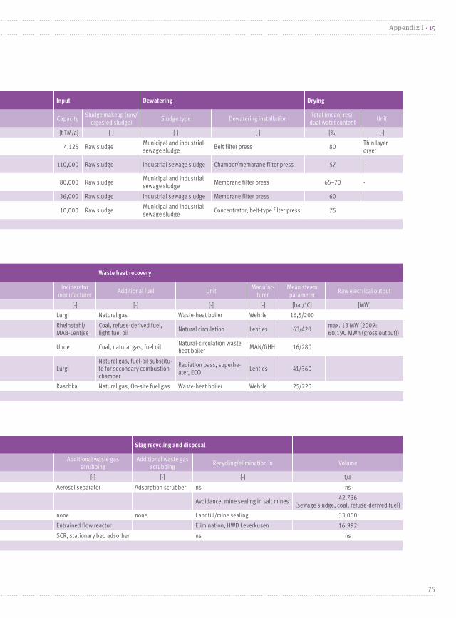
General Incineration Waste heat recovery
SiteResidual water
content after dryingIncineration technology
Incineration units
Mean annual sewage sludge calorific value
Mean theoretical capacity per unit
Amount incine-rated in 2009
Incinerator manufacturer
Additional fuel UnitManufac-
turerMean steam parameter
Raw electrical output
[%] [-] [-] [kJ/kg] [t TS/h] [t TS/a] [-] [-] [-] [-] [bar/°C] [MW]
Burghausen 60 SW 1 0.6 Lurgi Natural gas Waste-heat boiler Wehrle 16,5/200
Frankenthal-Mörsch - SW 2 2,000 7 t TR 110,000Rheinstahl/MAB-Lentjes
Coal, refuse-derived fuel, light fuel oil
Natural circulation Lentjes 63/420max. 13 MW (2009: 60,190 MWh (gross output))
Frankfurt Hoechst - SW 2 3,500 4.2 70,000 Uhde Coal, natural gas, fuel oilNatural-circulation waste heat boiler
MAN/GHH 16/280
Leverkusen EO 1 4,200 4.5 23,387 LurgiNatural gas, fuel-oil substitu-te for secondary combustion chamber
Radiation pass, superhe-ater, ECO
Lentjes 41/360
Marl SW 1 3 Raschka Natural gas, On-site fuel gas Waste-heat boiler Wehrle 25/220
Bitterfeld-Wolfen Technical data in table 22
Gendorf/Burgkirchen Technical data in table 22
General Waste gas scrubbing Slag recycling and disposal
Site Energy useWaste gas
scrubbing linesDust
collectorAdditional waste gas scrubbing
Additional waste gas scrubbing
Additional waste gas scrubbing
Recycling/elimination in Volume
[-] [-] [-] [-] [-] [-] [-] t/a
Burghausen Steam for drying 1 Cyclone Pre-soaker and Venturi scrubber Aerosol separator Adsorption scrubber ns ns
Frankenthal-Mörsch Heat, Electricity 2 Electrofilter Wet/packed-bed tower Avoidance, mine sealing in salt mines42,736
(sewage sludge, coal, refuse-derived fuel)
Frankfurt Hoechst Heat, Steam 2 Electrofilter Wet/two-stage wet scrubbing none none Landfill/mine sealing 33,000
Leverkusen Heat, Steam 1 Scrubber Wet/single-jet cooler, two-stage rotary scrubber, jet scrubber Entrained flow reactor Elimination, HWD Leverkusen 16,992
Marl Steam 4 Cloth filter Wet and dry SCR, stationary bed adsorber ns ns
Bitterfeld-Wolfen Technical data in table 22
Gendorf/Burgkirchen Technical data in table 22
General Input Dewatering Drying
SiteRegional
stateOperator Technology Went live on Operating hours Capacity
Dry residue
CapacitySludge makeup (raw/
digested sludge)Sludge type Dewatering installation
Total (mean) resi-dual water content
Unit
[-] [-] [-] [-] [h/a] [t/a] [%] [t TM/a] [-] [-] [-] [%] [-]
Burghausen BY Wacker Chemie 1 Fluidized bed 1976 20,000 21 4,125 Raw sludgeMunicipal and industrial sewage sludge
Belt filter press 80Thin layer dryer
Frankenthal-Mörsch RP BASF AG 2 Fluidized beds 1992Furnace 1: 7,158 Furnace 2: 6,445
420,000 40 110,000 Raw sludge industrial sewage sludge Chamber/membrane filter press 57 -
Frankfurt Hoechst HE Infraserv GmbH 2 Fluidized beds 1994Str I: 8,164 h; Str II: 8,055 h
205,000 35 80,000 Raw sludgeMunicipal and industrial sewage sludge
Membrane filter press 65–70 -
Leverkusen NW Currenta GmbH 1 Multiple-hearth 1988 8,000 120,000 27–40 36,000 Raw sludge industrial sewage sludge Membrane filter press 60
Marl NW Infracor GmbH 1 Fluidized bed 1980 40,000 25 10,000 Raw sludgeMunicipal and industrial sewage sludge
Concentrator; belt-type filter press 75
Bitterfeld-Wolfen SH GKW Technical data in table 22
Gendorf/Burgkirchen BY Infraserv GmbH Technical data in table 22
75
Appendix I · 15
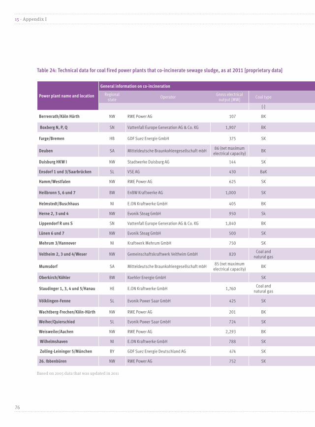
Table 24: Technical data for coal fired power plants that co-incinerate sewage sludge, as at 2011 [proprietary data]
Based on 2005 data that was updated in 2011
Power plant name and location
General information on co-incineration
Regional state
OperatorGross electrical
output [MW]Coal type Firing
Coal water content
Coal throughput Sewage sludge fired sinceNo. of lines that co-
incinerate sewage sludge
[-] [-] [%] [t/h] [-] [-]
Berrenrath/Köln Hürth NW RWE Power AG 107 BK ZWS 51–61 30Co-incineration in both boilers since 1994; continuous operation since 2000
2
Boxberg N, P, Q SN Vattenfall Europe Generation AG & Co. KG 1,907 BK SF 56 - Feb. 1999 2 Boilers
Farge/Bremen HB GDF Suez Energie GmbH 375 SK SF 10.5 1002001 2003
1
Deuben SA Mitteldeutsche Braunkohlengesellschaft mbH86 (net maximum
electrical capacity)BK SF 48–56 102 2002 5 Boilers
Duisburg HKW I NW Stadtwerke Duisburg AG 144 SK ZWS 10–20 30 2002/1995 1
Ensdorf 1 und 3/Saarbrücken SL VSE AG 430 BaK SF 5–17 200 2001 2 Blocks
Hamm/Westfalen NW RWE Power AG 625 SK SF 8–16 100 2002 1
Heilbronn 5, 6 und 7 BW EnBW Kraftwerke AG 1,000 SK SF 9 280Apr. 1999 Aug. 1998
1
Helmstedt/Buschhaus NI E.ON Kraftwerke GmbH 405 BK SF 45 300 1997 1
Herne 2, 3 und 4 NW Evonik Steag GmbH 950 Sk SF 11 110 2005 1
Lippendorf R uns S SN Vattenfall Europe Generation AG & Co. KG 1,840 BK SF 52–54 - 2004 2 Blocks
Lünen 6 und 7 NW Evonik Steag GmbH 500 SK SF 11 160 2005 1
Mehrum 3/Hannover NI Kraftwerk Mehrum GmbH 750 SK SF 6–8 240 2002 1
Veltheim 2, 3 und 4/Weser NW Gemeinschaftskraftwerk Veltheim GmbH 820Coal and
natural gasSF 8–12 113 2003 1
Mumsdorf SA Mitteldeutsche Braunkohlengesellschaft mbH85 (net maximum
electrical capacity)BK SF 48–56 128 2000 4 Boilers
Oberkirch/Köhler BW Koehler Energie GmbH SK ZWS 6–9 10 2003 1
Staudinger 1, 3, 4 und 5/Hanau HE E.ON Kraftwerke GmbH 1,760Coal and
natural gasSF 8–12 120 2004 1
Völklingen-Fenne SL Evonik Power Saar GmbH 425 SK SF 20 93 2001One of two blocks with
co-incineration
Wachtberg-Frechen/Köln-Hürth NW RWE Power AG 201 BK ZWS 51–61 50 Co-incineration in both fluidized bed boilers since 2003 2
Weiher/Quierschied SL Evonik Power Saar GmbH 724 SK SF 9 250 April 1999/1996 1
Weisweiler/Aachen NW RWE Power AG 2,293 BK SF 55–60 200 Co-incineration in two of eight blocks since August 2008 2
Wilhelmshaven NI E.ON Kraftwerke GmbH 788 SK SF 8.5 250 2004/2003 1
Zolling-Leininger 5/München BY GDF Suez Energie Deutschland AG 474 SK SF 6–12 136 1999 1
26. Ibbenbüren NW RWE Power AG 752 SK SF Co-incineration since 2001 1
76
15 · Appendix I

Power plant name and location
General information on co-incineration
Regional state
OperatorGross electrical
output [MW]Coal type Firing
Coal water content
Coal throughput Sewage sludge fired sinceNo. of lines that co-
incinerate sewage sludge
[-] [-] [%] [t/h] [-] [-]
Berrenrath/Köln Hürth NW RWE Power AG 107 BK ZWS 51–61 30Co-incineration in both boilers since 1994; continuous operation since 2000
2
Boxberg N, P, Q SN Vattenfall Europe Generation AG & Co. KG 1,907 BK SF 56 - Feb. 1999 2 Boilers
Farge/Bremen HB GDF Suez Energie GmbH 375 SK SF 10.5 1002001 2003
1
Deuben SA Mitteldeutsche Braunkohlengesellschaft mbH86 (net maximum
electrical capacity)BK SF 48–56 102 2002 5 Boilers
Duisburg HKW I NW Stadtwerke Duisburg AG 144 SK ZWS 10–20 30 2002/1995 1
Ensdorf 1 und 3/Saarbrücken SL VSE AG 430 BaK SF 5–17 200 2001 2 Blocks
Hamm/Westfalen NW RWE Power AG 625 SK SF 8–16 100 2002 1
Heilbronn 5, 6 und 7 BW EnBW Kraftwerke AG 1,000 SK SF 9 280Apr. 1999 Aug. 1998
1
Helmstedt/Buschhaus NI E.ON Kraftwerke GmbH 405 BK SF 45 300 1997 1
Herne 2, 3 und 4 NW Evonik Steag GmbH 950 Sk SF 11 110 2005 1
Lippendorf R uns S SN Vattenfall Europe Generation AG & Co. KG 1,840 BK SF 52–54 - 2004 2 Blocks
Lünen 6 und 7 NW Evonik Steag GmbH 500 SK SF 11 160 2005 1
Mehrum 3/Hannover NI Kraftwerk Mehrum GmbH 750 SK SF 6–8 240 2002 1
Veltheim 2, 3 und 4/Weser NW Gemeinschaftskraftwerk Veltheim GmbH 820Coal and
natural gasSF 8–12 113 2003 1
Mumsdorf SA Mitteldeutsche Braunkohlengesellschaft mbH85 (net maximum
electrical capacity)BK SF 48–56 128 2000 4 Boilers
Oberkirch/Köhler BW Koehler Energie GmbH SK ZWS 6–9 10 2003 1
Staudinger 1, 3, 4 und 5/Hanau HE E.ON Kraftwerke GmbH 1,760Coal and
natural gasSF 8–12 120 2004 1
Völklingen-Fenne SL Evonik Power Saar GmbH 425 SK SF 20 93 2001One of two blocks with
co-incineration
Wachtberg-Frechen/Köln-Hürth NW RWE Power AG 201 BK ZWS 51–61 50 Co-incineration in both fluidized bed boilers since 2003 2
Weiher/Quierschied SL Evonik Power Saar GmbH 724 SK SF 9 250 April 1999/1996 1
Weisweiler/Aachen NW RWE Power AG 2,293 BK SF 55–60 200 Co-incineration in two of eight blocks since August 2008 2
Wilhelmshaven NI E.ON Kraftwerke GmbH 788 SK SF 8.5 250 2004/2003 1
Zolling-Leininger 5/München BY GDF Suez Energie Deutschland AG 474 SK SF 6–12 136 1999 1
26. Ibbenbüren NW RWE Power AG 752 SK SF Co-incineration since 2001 1
77
Appendix I · 15

Based on 2005 data that was updated in 2011
Power plant name and location
Sewage sludge Waste gas scrubbing
Shunting to combustion process
Sewage sludge through-put in as-delivered state
Sewage sludge throughput for dry mass
Solids content in as deli-vered state
OriginSSewage sludge pollutant content
Dust separation DeNOx
SOX
Miscellaneous
[-] [1,000 t OS/a] [1,000 t TM/a] [% TR] [-] [-] [-] [-] [-] [-]
Berrenrath/Köln Hürth Circulating fluidized bed 215 65Mechanically dewatered se-wage sludge with less than 35 % dry solids content
municipal/industrialRequirements exceed AbfKlärV
Electrofilter Primary CFB pZWSEntrained flow absor-
ber with lignite
Boxberg N, P, Q Coal downcomer 140 42 30 municipalMunicipal sewage sludge
Electrofilter, Scrubber Primary measures WGC -
Farge/Bremen Coal downcomer distri-butor
20 15
1822
> 90 %municipal Lower than AbfKlärV Electrofilter SCR high dust WGC -
Deuben In front of coal grinder 84 25 20–37 municipal Lower than AbfKlärV Electrofilter - WGC -
Duisburg HKW I Circulating fluidized bed 18 5.4 25–35 municipalMunicipal sewage sludge
Electrofilter Primary CFB pZWS -
Ensdorf 1 und 3/Saarbrücken Grinder with coal dust 81 24 25–45 municipal Lower than AbfKlärV Electrofilter SCR low dust SAS -
Hamm/Westfalen Coal conveyor, grinder 10 9 25–95 municipalMunicipal sewage sludge
Electrofilter SCR low dust WGC Alkaline scrubber
Heilbronn 5, 6 und 7 Coal downcomer
60 mechanically dewa-tered sludge and 25–20 thermally separated sludge
4025–35
> 95municipal Lower than AbfKlärV Electrofilter SCR high dust WGC -
Helmstedt/Buschhaus Coal conveyor, grinder 100 50 25–95 municipal/industrial Higher than AbfKlärV Electrofilter Primary measures WGC -
Herne 2, 3 und 4 Coal downcomer 30 25 > 69 municipal/industrial Lower than AbfKlärV Electrofilter SCR low dust WGC -
Lippendorf R uns S Coal downcomer 380 93 25–35 municipal/industrial Higher than AbfKlärV Electrofilter, Scrubber SNCR WGC -
Lünen 6 und 7 directly to the combustion process
30 25 > 69 municipal/industrial Lower than AbfKlärV Electrofilter SCR low dust WGC -
Mehrum 3/Hannover Coal downcomer 35 11 25–35 municipal/industrial Lower than AbfKlärV Electrofilter SCR high dust WGC -
Veltheim 2, 3 und 4/Weser with steam guns directly to the combustion process
45 13.5 25–35 municipal/industrial Higher than AbfKlärV Electrofilter SCR high dust WGC -
Mumsdorf In front of coal grinder 100 28 20–37 municipal Lower than AbfKlärV Electrofilter - WGC -
Oberkirch/Köhler Ash return 20 5 18–32 municipal Lower than AbfKlärV Cloth filter - - -
Staudinger 1, 3, 4 und 5/Hanau Coal downcomer 60 18 25–35 municipal/industrial Lower than AbfKlärV Electrofilter SCR high dust WGC -
Völklingen-Fenne In front of coal grinder 14 4.2 25–35 municipal Lower than AbfKlärV Electrofilter Firing side WGC
Wachtberg-Frechen/Köln-Hürth Circulating fluidized bed 280/260 85Mechanically dewatered se-wage sludge with less than 35 % dry solids content
municipal/industrialRequirements exceed AbfKlärV
Electrofilter Primary CFB pZWSEntrained flow absor-ber with lignite coke
Weiher/Quierschied Grinder with coal dust 6–10 5.5–9 90–95 * municipal Lower than AbfKlärV Electrofilter SCR high dust WGC -
Weisweiler/Aachen Coal downcomer 140 35 22–33 max. 35 % dry solids municipalLower than AbfKlärV, but Hg less than 5mg/kg dry solids
Electrofilter Firing side SNCR WGC (FGDP) -
Wilhelmshaven Coal downcomer 50 12.5 25 municipal Lower than AbfKlärV Electrofilter SCR high dust WGC -
Zolling-Leininger 5/München Coal downcomer 35 9.5 25–35 municipal/industrial Lower than AbfKlärV Electrofilter SCR high dust WGC -
26. Ibbenbüren 90 35 (10 t/h) 20–40 % TS municipal
78
15 · Appendix I

Power plant name and location
Sewage sludge Waste gas scrubbing
Shunting to combustion process
Sewage sludge through-put in as-delivered state
Sewage sludge throughput for dry mass
Solids content in as deli-vered state
OriginSSewage sludge pollutant content
Dust separation DeNOx
SOX
Miscellaneous
[-] [1,000 t OS/a] [1,000 t TM/a] [% TR] [-] [-] [-] [-] [-] [-]
Berrenrath/Köln Hürth Circulating fluidized bed 215 65Mechanically dewatered se-wage sludge with less than 35 % dry solids content
municipal/industrialRequirements exceed AbfKlärV
Electrofilter Primary CFB pZWSEntrained flow absor-
ber with lignite
Boxberg N, P, Q Coal downcomer 140 42 30 municipalMunicipal sewage sludge
Electrofilter, Scrubber Primary measures WGC -
Farge/Bremen Coal downcomer distri-butor
20 15
1822
> 90 %municipal Lower than AbfKlärV Electrofilter SCR high dust WGC -
Deuben In front of coal grinder 84 25 20–37 municipal Lower than AbfKlärV Electrofilter - WGC -
Duisburg HKW I Circulating fluidized bed 18 5.4 25–35 municipalMunicipal sewage sludge
Electrofilter Primary CFB pZWS -
Ensdorf 1 und 3/Saarbrücken Grinder with coal dust 81 24 25–45 municipal Lower than AbfKlärV Electrofilter SCR low dust SAS -
Hamm/Westfalen Coal conveyor, grinder 10 9 25–95 municipalMunicipal sewage sludge
Electrofilter SCR low dust WGC Alkaline scrubber
Heilbronn 5, 6 und 7 Coal downcomer
60 mechanically dewa-tered sludge and 25–20 thermally separated sludge
4025–35
> 95municipal Lower than AbfKlärV Electrofilter SCR high dust WGC -
Helmstedt/Buschhaus Coal conveyor, grinder 100 50 25–95 municipal/industrial Higher than AbfKlärV Electrofilter Primary measures WGC -
Herne 2, 3 und 4 Coal downcomer 30 25 > 69 municipal/industrial Lower than AbfKlärV Electrofilter SCR low dust WGC -
Lippendorf R uns S Coal downcomer 380 93 25–35 municipal/industrial Higher than AbfKlärV Electrofilter, Scrubber SNCR WGC -
Lünen 6 und 7 directly to the combustion process
30 25 > 69 municipal/industrial Lower than AbfKlärV Electrofilter SCR low dust WGC -
Mehrum 3/Hannover Coal downcomer 35 11 25–35 municipal/industrial Lower than AbfKlärV Electrofilter SCR high dust WGC -
Veltheim 2, 3 und 4/Weser with steam guns directly to the combustion process
45 13.5 25–35 municipal/industrial Higher than AbfKlärV Electrofilter SCR high dust WGC -
Mumsdorf In front of coal grinder 100 28 20–37 municipal Lower than AbfKlärV Electrofilter - WGC -
Oberkirch/Köhler Ash return 20 5 18–32 municipal Lower than AbfKlärV Cloth filter - - -
Staudinger 1, 3, 4 und 5/Hanau Coal downcomer 60 18 25–35 municipal/industrial Lower than AbfKlärV Electrofilter SCR high dust WGC -
Völklingen-Fenne In front of coal grinder 14 4.2 25–35 municipal Lower than AbfKlärV Electrofilter Firing side WGC
Wachtberg-Frechen/Köln-Hürth Circulating fluidized bed 280/260 85Mechanically dewatered se-wage sludge with less than 35 % dry solids content
municipal/industrialRequirements exceed AbfKlärV
Electrofilter Primary CFB pZWSEntrained flow absor-ber with lignite coke
Weiher/Quierschied Grinder with coal dust 6–10 5.5–9 90–95 * municipal Lower than AbfKlärV Electrofilter SCR high dust WGC -
Weisweiler/Aachen Coal downcomer 140 35 22–33 max. 35 % dry solids municipalLower than AbfKlärV, but Hg less than 5mg/kg dry solids
Electrofilter Firing side SNCR WGC (FGDP) -
Wilhelmshaven Coal downcomer 50 12.5 25 municipal Lower than AbfKlärV Electrofilter SCR high dust WGC -
Zolling-Leininger 5/München Coal downcomer 35 9.5 25–35 municipal/industrial Lower than AbfKlärV Electrofilter SCR high dust WGC -
26. Ibbenbüren 90 35 (10 t/h) 20–40 % TS municipal
79
Appendix I · 15

Table 25: Technical data for german waste incineration plants that co-incinerate sewage sludge, as at 2012 [itad]
Site Regional state
Installation operator Incinerated sludge output from municipal sewage treatment plants (Waste Incineration Ordinance, AVV 190805 only)
Sludge from municipal water treatment plants (AVV 190805 only)
Sludge from industrial wastewa-ter treatment plants
Dried separately prior to incineration
Max. capacity
[Mg/a] TS-Gehalt [%] [Mg/a] [Mg/a]
Bamberg BY Zweckverband Müllheizkraftwerk Stadt und Landkreis Bamberg
14,032 30 % nach Entwässerung Not applicable No Not applicable
Coburg BY Zweckverband für Abfallwirtschaft in Nordwest-Oberfranken
3,314 25 - No -
Hamburg, Borsigstr. HH MVB GmbH 2,642 - - - -
Hamburg, Rugenb. HH MVR Müllverwertung Rugenberger Damm GmbH & Co. KG
3,226 28 - - -
Hamburg, Stellingen HH Stadtreinigung Hamburg 12,150 25 - - -
Ingolstadt BY Zweckverband Müllverwertungs-anlage Ingolstadt
628 80 - - -
Kamp-Lintfort NRW Kreis Weseler Abfallgesellschaft mbH & Co. KG
3,700 25 - Fluidized be 34
Köln NRW AVG Köln mbH 10,381 No -
Krefeld NRW EGK Entsorgungsgesellschaft Krefeld GmbH & Co. KG
1,281/11,872 30 %/90 % - - -
München BY AWM – Abfallwirtschaftsbetrieb München
9,730 - - Centrifuge only -
Velsen SL AVA Velsen GmbH 125 25 - -
Würzburg BW Zweckverband Abfallwirtschaft Raum Würzburg
8,445 40 - Flash dry system 24,000
Zella-Mehlis TH Zweckverband für Abfallwirtschaft Südwestthüringen (ZASt)
2,848.76 - - No -
Burgau BY Landkreis Günzburg Kreisabfall-wirtschaftsbetrieb
- - 85 - -
Seven additional unspecified plants
4,250 23 1.789 No 140,040
Four values Two values Three values 3 × no, 3 × n/a Three values
Mean value 5,424 34 4,085 54,691
Total 65,091 12,255 164,074
80
15 · Appendix I

Site Regional state
Installation operator Incinerated sludge output from municipal sewage treatment plants (Waste Incineration Ordinance, AVV 190805 only)
Sludge from municipal water treatment plants (AVV 190805 only)
Sludge from industrial wastewa-ter treatment plants
Dried separately prior to incineration
Max. capacity
[Mg/a] TS-Gehalt [%] [Mg/a] [Mg/a]
Bamberg BY Zweckverband Müllheizkraftwerk Stadt und Landkreis Bamberg
14,032 30 % nach Entwässerung Not applicable No Not applicable
Coburg BY Zweckverband für Abfallwirtschaft in Nordwest-Oberfranken
3,314 25 - No -
Hamburg, Borsigstr. HH MVB GmbH 2,642 - - - -
Hamburg, Rugenb. HH MVR Müllverwertung Rugenberger Damm GmbH & Co. KG
3,226 28 - - -
Hamburg, Stellingen HH Stadtreinigung Hamburg 12,150 25 - - -
Ingolstadt BY Zweckverband Müllverwertungs-anlage Ingolstadt
628 80 - - -
Kamp-Lintfort NRW Kreis Weseler Abfallgesellschaft mbH & Co. KG
3,700 25 - Fluidized be 34
Köln NRW AVG Köln mbH 10,381 No -
Krefeld NRW EGK Entsorgungsgesellschaft Krefeld GmbH & Co. KG
1,281/11,872 30 %/90 % - - -
München BY AWM – Abfallwirtschaftsbetrieb München
9,730 - - Centrifuge only -
Velsen SL AVA Velsen GmbH 125 25 - -
Würzburg BW Zweckverband Abfallwirtschaft Raum Würzburg
8,445 40 - Flash dry system 24,000
Zella-Mehlis TH Zweckverband für Abfallwirtschaft Südwestthüringen (ZASt)
2,848.76 - - No -
Burgau BY Landkreis Günzburg Kreisabfall-wirtschaftsbetrieb
- - 85 - -
Seven additional unspecified plants
4,250 23 1.789 No 140,040
Four values Two values Three values 3 × no, 3 × n/a Three values
Mean value 5,424 34 4,085 54,691
Total 65,091 12,255 164,074
81
Appendix I · 15
Appendix II
Sewage sludge management legislationThe legislation discussed governing sewage sludge management comprise the Bun-desgesetze (federal statutes) and Bundes-verordnungen (federal ordinances) that apply to sewage sludge incineration and to agricultural use of sewage sludge.
Closed Substance Cycle and Waste Management ActClosed Substance Cycle and Waste Ma-nagement Act (Kreislaufwirtschaftsgesetz, KrWG governs waste management and thus sewage sludge as well. The new KrWG was published in the 29 February 2012 issue of the Bundesgesetzblatt (BGBl. I p. 212) and took effect on 1 June 2012. The new law aims to sustainably improve environmental and climate protection and resource efficiency for waste management through optimized waste prevention and recycling. The law stipulates a five-level hierarchy comprising the following: prevention; preparations for recycling; recyc-ling; other uses (e. g. energy); disposal/elimi-nation. Enactment of this five-level hierarchy transposed Directive 2008/98/EC (Waste Framework Directive) into German law.
In cases involving the agricultural use of sewage sludge, Article 11 of the KrWg law
stipulates that, in the interest of assuring proper and harmless usage, detailed usage provisions are to be governed by specific regulations known as Rechtsverordnungen (statutory instruments). This in turn will form the legal basis for the Sewage Sludge Ordinance (AbfKlärV), going forward.
For cases involving thermal disposal of sewa-ge sludge, Article 13 of the KrWG law stipula-tes that operator obligations are to be gover-ned by the Federal Immission Control Act (Bundes-Immissionsschutzgesetz, BImSchG).
Sewage sludge that is used as fertili-zer is governed by fertilizer law.
Klärschlammverordnung (AbfKlärV) (Sewage Sludge Ordinance) This ordinance governs the use of sewa-ge sludge as agricultural or horticultural fertilizer and is without prejudice to the provisions of fertilizer law. The limit values defined in the ordinance are to be undercut wherever possible. Sewage sludge that is used as agricultural and horticultural ferti-lizer is not to be deleterious to the common good; such sludge is to be use only insofar as allowed by site conditions, cultivation conditions, and plant nutrient requirements.
16
82
16 · Appendix II

Article 3(5) of the ordinance stipulates that se-wage treatment plant operators are required to conduct the following tests of sewage sludge samples at six month intervals at a minimum:
1. Nutrient content: total nitrogen content, as well as ammonia nitrogen, phosphate, potassium and magnesium content.
2. Total organic halogen compounds, expressed as adsorbed AOX.
3. Heavy metals: lead, cadmium, chrome, copper, zinc, nickel and mercury.
4. pH, dry residue, organic substances and alkaline active ingredients.
Prior to initial use and at a maximum of two year intervals thereafter, sewa-ge sludge is to be tested for PCB, dioxins and furans [Article 3 ABFKLÄRV].
Article 3 stipulates that wastewater treat-ment plant operators are also required to test soil that is to be fertilized with sewa-ge sludge, prior to initial use and at ten year intervals thereafter. The following tests are to be conducted in such cases:
• pH value • Nutrients: phytoavailable phospha-
te, potassium and magnesium • Heavy metals: lead, cadmium, chrome,
copper, zinc, nickel and mercury.
Wastewater treatment plant opera-tors are required to defray the costs of soil and sewage sludge tests.
The use of raw sludge, industrial sludge and sewage sludge as fertilizer is strict-ly prohibited. Likewise prohibited is the use of sewage sludge for the following:
• Fruit and vegetable crops • Permanent grassland and forests • Animal forage cultivation • Nature conservation areas, natural monu-
ments and national parks • Zone I and II water protection areas • In cases where the sludge and soil limit valu-
es set forth in Article 4 cannot be adhered to.
No more than five tons of dry solids per hectare are to be applied over any given three year period. Sewage sludge compost use is limited to ten tons per hectare every three years, provided that pollutant content does not exceed one half of permissible heavy metal content [Article 6 ABFKLÄRV]. The current version of the ordinance dates back to 1992, and the Federal Ministry for the Environment (BMU) spent years elaborating the new version. A second draft of the bill was completed in October 2010. Table 26 shows the sewage sludge and soil related differences between the provisions of the current law and those of the proposed bill.
83
Appendix II · 16
The EU sewage sludge directive Directive 86/278/EEC aims to (a) regulate the agricultural use of sewage sludge by avoiding deleterious effects on soil, vegetation, plants and livestock, and at the same time (b) promo-te sound sludge use practices. The directive contains limit values for heavy metals in soil and sludge, and for the amounts of heavy metals that may be applied to soil annually. Sewage sludge use is prohibited insofar as the soil concentration of one or more heavy me-tals exceeds the limit values set by the directi-ve. The member states are required to institute measures ensuring that these limit values are not exceeded for sewage sludge use.
The directive stipulates that sewage sludge must be treated before being used as ferti-lizer. However, the use of untreated sewage sludge is permitted insofar as the sludge is washed down or buried in the soil.
The directive furthermore stipulates that on pastures and fields used for fo-rage cultivation, as well as during the vegetation period of fruit and vegetable crops, a waiting period must be obser-ved prior to sewage sludge application. The directive also requires the member states to maintain a register that regu-larly reports on the amounts of sewage sludge produced and used for agricultu-ral purposes, as well as the composition and characteristics of this sludge [EEC].
Fertilizer legislationGermany’s main fertilizer regulations comprise the Fertilizer Act (DüngG) and the Fertilizer Ordinances (DüV and DüMV), whose main sewage sludge pro-visions will now be briefly described.
Fertilizer Act (Düngegesetz, DüngG) This law aims to achieve the following: ensure that crop plants receive adequate nutriti-on; preserve or improve soil fertility; avoid subjecting humans and livestock to hazards attributable to fertilizers and other substrates, within the meaning of the law. To this end, Article 11 of the law requires that a sewage sludge compensation fund be established for personal injury and property damage attri-butable to legally compliant agricultural use of sewage sludge. Under the law, the fund is to be financed by sewage sludge producers or owners who dispose of their sludge by making it available for agricultural use. Fertilizing is to be carried out in accordance with good professional practice that is, as regards type, amount and timing of application, com-mensurate with plant requirements and soil nutrient content [see Article 3(2) DÜNGG].
Fertilizer Ordinance (Düngeverordnung, DüV) The Fertilizer Ordinance (DüV) sets forth the requirements for (a) good professio-nal practice for fertilizer use; and (b) the avoidance of substance risk attributable to agricultural use of sewage sludge.
84
16 · Appendix II

Table 26: Maximum sewage sludge and soil pollutant limits under current and pending german laws [abfklärv; bmu 2011b; bbodschv, modified in accordance with brandt]
* Maximum allowable heavy metal content is not to exceed the precautionary values pursuant to section 4.1 Appendix 2 of the current version of the Federal Soil Protection and Contaminated Sites Ordinance (BBodSchV). The allowable content, which is determined by soil type, is lowest for sand and highest for clay, with lime/silt falling between the two.
** The current limit values (as at November 2013) for arsenic, lead, cadmium, chrome, copper, nickel, mercury, thallium, zinc and perfluorinated compounds will expire on 31 December 2014. As from 1 January 2015, the limit values set forth in Appendix 2, table 1, no. 1.4 of the Fertilizer Ordinance (DüMV) will apply.
AbfKlärV 1992 Draft version of AbfKlärV 2010
Pollutant Maximum allowable content in mg/kg dry solids
Soil Sewage sludge Soil* Sewage sludge**
Heavy metalsAsPbCdCr CuNiHgThZn
1001.5
1006050
1
200
90010
900800200
8
2.500
40–1000.4–1.530–10020–6015–700.1–1
60–200
18150
3120800100
21.5
1,800
Persistent organic pollutantsPCBPCDD/PCDFB(a)PPFC (PFOA and PFOS)
0.2 per congener 100 ng/kg dry solids
0.1 per congener 30 ng TEQ/kg dry solids
10,1
AOX 500 400
Salmonella spp.No microbes per 50 g wet substance
Sewage sludge fertilizer is to be applied at intervals and in amounts that are com-mensurate with plant nutrition needs and that promote minimum nutrient loss.
The fertilizer needs of the crops in ques-tion are to be determined prior to appli-cation of substantial amounts of nitrogen
or phosphate in sewage sludge fertilizer and other substrates, within the meaning of the Fertilizer Ordinance (DüV).
The following factors that can potentially affect nutrient conditions (e. g. crop type, previous crop, tilling, and watering) are to be taken into account in this regard: crop
85
Appendix II · 16

nutrition needs; nutrient phytoavailability in the soil and during the growth phase; lime content; soil reaction (pH); soil hu-mus content; cultivation conditions. From 1 November to 31 January, the use of sewa-ge sludge fertilizer on crops is prohibited, owing to the ban on the use of fertilizers with high phosphorous concentrations [DÜV].
Fertilizer Ordinance (Düngemittelverord-nung, DüMV) This ordinance governs the placing on the market of (a) fertilizer that is not designa-ted as EU fertilizer; and (b) soil improvers, culture media and plant aids. The Fertili-zer Ordinance (DüMV) classifies sewage sludge as an organic fertilizer or an organic mineral fertilizer whose use is allowed as an NPC (nitrogen phosphate, nitrogen phosphate and potassium) fertilizer.
Under Article 10(3) of the current version of the Fertilizer Ordinance (DüMV) ordinance, sewage sludge whose limit values exceed those of the ordinance’s Appendix 2 table 1.4 but comply with those set forth in the sewage sludge ordinance for the same pollutant may be placed on the market until the end of 2014. Thereafter, only sewage sludge whose limit values comply with the Fertilizer Ordinance (DüMV) can be placed on the market. Se-wage sludge may only be used as fertilizer via direct application in a non-mixed state [DÜMV APPENDIX 2, TABLE 7, ROW 7.4.3].
Federal Immission Control Ordinance (17. Bundes-Immissionsschutzverordnung, 17. BImSchV)
This ordinance governs the construction, characteristics, and operation of incinera-tion and co-incineration plants that inci-nerate waste and that are subject to permit requirements under Article 4 of the Federal Immission Control Act (BImSchG) [Article 1, 17. BIMSCHV], which stipulates that theordinance also applies to sewage sludge incineration and co-incineration plants.
In the interest of curbing emissions, the law sets limit values for total dust, sulphur dioxide, nitrogen oxides, mercury, carbon monoxide and heavy metals.
The ordinance lays down incineration plant construction and operation requirement con-cerning the following:
• Air quality measures• Fire safety measures• Waste management• Heat recovery
The ordinance’s key requirements are that (a) a combustion air afterburning temperature of 850 °C must be maintained for two seconds; and (b) the operator must continuously monitor emission levels and report them to the competent authorities [17.BIMSCHV].
86
16 · Appendix II

Heavy metals in sewage sludge Figure 12 contains data concerning copper concentrations in sewage sludge. Figure 13 contains data concerning zinc concentrations in sewage sludge. Figure 14 contains data concerning nickel, chrome and iron concentrations in sewage sludge.
Appendix III17
Figure 12: Sewage sludge copper concentrations [bmu]
400
350
300
250
200
150
100
50
0
378.0 370.0
289.0
300.4
1977 1982 1986–1990 1998 2001 2002 2003 2004 2005 2006
Concentration [mg/kg dry solids] Copper
Year
87
Appendix III · 17
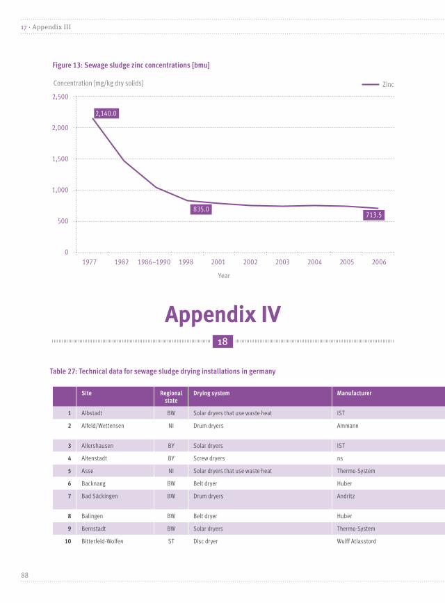
Appendix IV
Table 27: Technical data for sewage sludge drying installations in germany
18
Site Regional state
Drying system Manufacturer Throughput [tons dry solids/a] Dry residue (% of dry residue), after drying
Substrate use
1 Albstadt BW Solar dryers that use waste heat IST 1,000 40–70 ns
2 Alfeld/Wettensen NI Drum dryers Ammann Currently shut down (previously 2,000)
95 Composting/recultivation
3 Allershausen BY Solar dryers IST 200 60–70 ns
4 Altenstadt BY Screw dryers ns 30,000 90 Incineration
5 Asse NI Solar dryers that use waste heat Thermo-System 88 70 ns
6 Backnang BW Belt dryer Huber 4,640 92–95 Co-incineration at Heilbronn power plant
7 Bad Säckingen BW Drum dryers Andritz Currently shut down (previously 3,800–4,000)
92 Incineration
8 Balingen BW Belt dryer Huber 2,000 85 Proprietary thermal recycling
9 Bernstadt BW Solar dryers Thermo-System 220 70–90 Thermal recycling (co-incineration)
10 Bitterfeld-Wolfen ST Disc dryer Wulff Atlasstord 15,167 45–50 Incineration (proprietary fluidized bed)
Figure 13: Sewage sludge zinc concentrations [bmu]
Concentration [mg/kg dry solids] Zinc
2,500
2,000
1,500
1,000
500
0
2,140.0
835.0 713.5
Year
1977 1982 1986–1990 1998 2001 2002 2003 2004 2005 2006
88
17 · Appendix III

Site Regional state
Drying system Manufacturer Throughput [tons dry solids/a] Dry residue (% of dry residue), after drying
Substrate use
1 Albstadt BW Solar dryers that use waste heat IST 1,000 40–70 ns
2 Alfeld/Wettensen NI Drum dryers Ammann Currently shut down (previously 2,000)
95 Composting/recultivation
3 Allershausen BY Solar dryers IST 200 60–70 ns
4 Altenstadt BY Screw dryers ns 30,000 90 Incineration
5 Asse NI Solar dryers that use waste heat Thermo-System 88 70 ns
6 Backnang BW Belt dryer Huber 4,640 92–95 Co-incineration at Heilbronn power plant
7 Bad Säckingen BW Drum dryers Andritz Currently shut down (previously 3,800–4,000)
92 Incineration
8 Balingen BW Belt dryer Huber 2,000 85 Proprietary thermal recycling
9 Bernstadt BW Solar dryers Thermo-System 220 70–90 Thermal recycling (co-incineration)
10 Bitterfeld-Wolfen ST Disc dryer Wulff Atlasstord 15,167 45–50 Incineration (proprietary fluidized bed)
Figure 14: Sewage sludge nickel, chrome and lead concentrations [bmu]
700
600
500
400
300
200
100
0
Concentration [mg/kg dry solids] Nickel Chrome Lead
630.0
80.0 63.0 37.2
190.0220.0
131.0
48.0 34.0 24.9
36.7
Year
1977 1982 1986–1990 1998 2001 2002 2003 2004 2005 2006
89
Appendix IV · 18
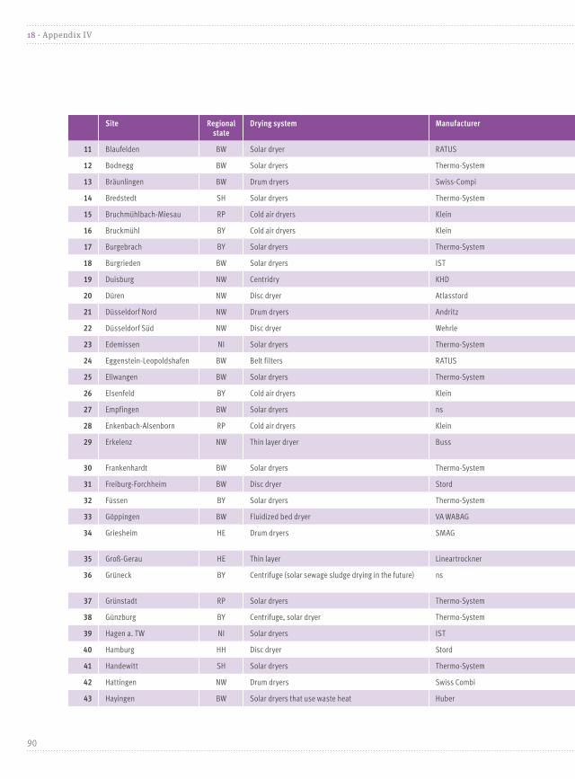
Site Regional state
Drying system Manufacturer Throughput [tons dry solids/a] Dry residue (% of dry residue), after drying
Substrate use
11 Blaufelden BW Solar dryer RATUS 200 50 Agriculture
12 Bodnegg BW Solar dryers Thermo-System 90 90 Thermal recycling (co-incineration)
13 Bräunlingen BW Drum dryers Swiss-Compi 5,000–6,000 92 Co-incineration at Heilbronn power plant
14 Bredstedt SH Solar dryers Thermo-System 108 70 Agricultural use
15 Bruchmühlbach-Miesau RP Cold air dryers Klein 600 88 Recultivation, landscaping
16 Bruckmühl BY Cold air dryers Klein 266 76 Recultivation
17 Burgebrach BY Solar dryers Thermo-System 190 70 ns
18 Burgrieden BW Solar dryers IST 100–300 50–90 Composting, recultivation
19 Duisburg NW Centridry KHD Currently not in use 68–70 Incineration
20 Düren NW Disc dryer Atlasstord 11,000 40 (partial drying) Incineration (proprietary fluidized bed)
21 Düsseldorf Nord NW Drum dryers Andritz 5,000 92 Thermal recycling
22 Düsseldorf Süd NW Disc dryer Wehrle 7,000 94 Thermal recycling
23 Edemissen NI Solar dryers Thermo-System 288 75 ns
24 Eggenstein-Leopoldshafen BW Belt filters RATUS 600 75 Recultivation, incineration
25 Ellwangen BW Solar dryers Thermo-System 700 70 Thermal recycling (co-incineration)
26 Elsenfeld BY Cold air dryers Klein 5,300 80–90 Incineration
27 Empfingen BW Solar dryers ns ns ns ns
28 Enkenbach-Alsenborn RP Cold air dryers Klein 220 85 Agriculture, landscaping, composting
29 Erkelenz NW Thin layer dryer Buss Currently not in use 90 Agricultural wet sludge; or alternatively, dewatering using decanters for subsequent use in composting installations
30 Frankenhardt BW Solar dryers Thermo-System 143 75 Thermal recycling (co-incineration)
31 Freiburg-Forchheim BW Disc dryer Stord 8,000 92 Thermal recycling, landfill
32 Füssen BY Solar dryers Thermo-System 625 70 Thermal recycling (mono-incineration)
33 Göppingen BW Fluidized bed dryer VA WABAG 2,500 93 Power plant incineration
34 Griesheim HE Drum dryers SMAG Used solely during peak demand periods
95 Composting (wet sludge)
35 Groß-Gerau HE Thin layer Lineartrockner 600 80–90 Agriculture
36 Grüneck BY Centrifuge (solar sewage sludge drying in the future) ns 20 m3/h for 8 hours of operation 27(70–80 % in the future)
Co-incineration at coal fired power plants
37 Grünstadt RP Solar dryers Thermo-System 363 50–70 ns
38 Günzburg BY Centrifuge, solar dryer Thermo-System 1,400 50–60 Agriculture, composting, thermal disposal
39 Hagen a. TW NI Solar dryers IST 180 70 ns
40 Hamburg HH Disc dryer Stord 45,000 42 Proprietary incineration
41 Handewitt SH Solar dryers Thermo-System 220 75 Agricultural use
42 Hattingen NW Drum dryers Swiss Combi 5,000 93 Thermal recycling
43 Hayingen BW Solar dryers that use waste heat Huber 88 80–90 Agriculture
90
18 · Appendix IV

Site Regional state
Drying system Manufacturer Throughput [tons dry solids/a] Dry residue (% of dry residue), after drying
Substrate use
11 Blaufelden BW Solar dryer RATUS 200 50 Agriculture
12 Bodnegg BW Solar dryers Thermo-System 90 90 Thermal recycling (co-incineration)
13 Bräunlingen BW Drum dryers Swiss-Compi 5,000–6,000 92 Co-incineration at Heilbronn power plant
14 Bredstedt SH Solar dryers Thermo-System 108 70 Agricultural use
15 Bruchmühlbach-Miesau RP Cold air dryers Klein 600 88 Recultivation, landscaping
16 Bruckmühl BY Cold air dryers Klein 266 76 Recultivation
17 Burgebrach BY Solar dryers Thermo-System 190 70 ns
18 Burgrieden BW Solar dryers IST 100–300 50–90 Composting, recultivation
19 Duisburg NW Centridry KHD Currently not in use 68–70 Incineration
20 Düren NW Disc dryer Atlasstord 11,000 40 (partial drying) Incineration (proprietary fluidized bed)
21 Düsseldorf Nord NW Drum dryers Andritz 5,000 92 Thermal recycling
22 Düsseldorf Süd NW Disc dryer Wehrle 7,000 94 Thermal recycling
23 Edemissen NI Solar dryers Thermo-System 288 75 ns
24 Eggenstein-Leopoldshafen BW Belt filters RATUS 600 75 Recultivation, incineration
25 Ellwangen BW Solar dryers Thermo-System 700 70 Thermal recycling (co-incineration)
26 Elsenfeld BY Cold air dryers Klein 5,300 80–90 Incineration
27 Empfingen BW Solar dryers ns ns ns ns
28 Enkenbach-Alsenborn RP Cold air dryers Klein 220 85 Agriculture, landscaping, composting
29 Erkelenz NW Thin layer dryer Buss Currently not in use 90 Agricultural wet sludge; or alternatively, dewatering using decanters for subsequent use in composting installations
30 Frankenhardt BW Solar dryers Thermo-System 143 75 Thermal recycling (co-incineration)
31 Freiburg-Forchheim BW Disc dryer Stord 8,000 92 Thermal recycling, landfill
32 Füssen BY Solar dryers Thermo-System 625 70 Thermal recycling (mono-incineration)
33 Göppingen BW Fluidized bed dryer VA WABAG 2,500 93 Power plant incineration
34 Griesheim HE Drum dryers SMAG Used solely during peak demand periods
95 Composting (wet sludge)
35 Groß-Gerau HE Thin layer Lineartrockner 600 80–90 Agriculture
36 Grüneck BY Centrifuge (solar sewage sludge drying in the future) ns 20 m3/h for 8 hours of operation 27 (70–80 % in the future)
Co-incineration at coal fired power plants
37 Grünstadt RP Solar dryers Thermo-System 363 50–70 ns
38 Günzburg BY Centrifuge, solar dryer Thermo-System 1,400 50–60 Agriculture, composting, thermal disposal
39 Hagen a. TW NI Solar dryers IST 180 70 ns
40 Hamburg HH Disc dryer Stord 45,000 42 Proprietary incineration
41 Handewitt SH Solar dryers Thermo-System 220 75 Agricultural use
42 Hattingen NW Drum dryers Swiss Combi 5,000 93 Thermal recycling
43 Hayingen BW Solar dryers that use waste heat Huber 88 80–90 Agriculture
91
Appendix IV · 18

Site Regional state
Drying system Manufacturer Throughput [tons dry solids/a] Dry residue (% of dry residue), after drying
Substrate use
44 Herdwangen BW Solar dryers Thermo-System 69 90 Thermal recycling (co-incineration)
45 Herzebrock-Clarholz NW Screen belt dryer Dornier Not in operation (previously 900) 85–90 Incineration (power plants or waste incineration plants)
46 Hetlingen SH Drum dryers SCT 6,600 90 Substance or thermal recycling
47 Hiddenhausen NW Centrifuge ns ns 23 % Incineration in various power plants
48 Hochdorf Assenheim RP Solar dryers that use waste heat Roediger Bioenergie 1,250 90 Cement plants
49 Höhr-Grenzhausen RP Cold air dryers Klein Currently not in use 80 Recultivation (wet sludge)
50 Holzminden NI Thin layer, drum dryers Buss Not in operation (previously 1,500)
90 Recultivation; incineration at Buschhaus power plant
51 Huglfing BY Solar dryers IST 120 60–70 ns
52 Iffezheim BW Solar dryer IST 100–120 70–85 Agriculture, recultivation
53 Ingolstadt BY Belt dryer with waste incineration waste heat Huber 3,500with 85 % dry residue
85 ns
54 Jerxheim NI Solar dryers that use waste heat Thermo-System 200 80 ns
55 Juist NI Solar dryers Thermo-System 120 55 ns
56 Kamp-Lintford NW Steam fluidized bed drying 12,000 95 Co-incineration in proprietary waste incineration plant
57 Kandern-Hammerstein BW Solar dryer IST 80–100 70–90 Incineration at Helmstedt lignite fired power plant
58 Karlsfeld BY Solar dryers IST 400 60–70 ns
59 Karlsruhe BW Disc dryer Stord 10,000 40 Incineration (proprietary)
60 Karlstadt BY Belt dryer ns 5,100 t/a ns Thermal recycling at cement plant
61 Kassel HE Drum dryers Bird Humboldt 5,500 98 Recultivation, tendency toward thermal recycling
62 Kempten BY Belt dryer ns 14,000 87 ns
63 Krefeld NW Disc dryer Wehrle 13,720 92 Incineration at waste incineration plant
64 Kreßberg BW Solar dryers Thermo-System 90 75 Thermal recycling (co-incineration)
65 Lahr BW Fluidized bed dryer Sulzer Not in operation 85 Currently landfill
66 Lambsheim RP Solar dryers Thermo-System 230 70 Agricultural use
67 Landstuhl RP Cold air dryers Klein Currently not in use 80–90 Agriculture
68 Lauterstein-Albhof BW Solar dryers that use waste heat Roediger Bioenergie 1,000 90 Cement plants
69 Leintal-Göggingen BW Solar dryers Thermo-System 182 75 ns
70 Lepoldshafen BW Solar dryers ns ns ns ns
71 Leutershausen-Sachsen BY Solar dryers that use waste heat Roediger Bioenergie 2,000 90 Cement plants
72 Leutkirch BW Fluidized bed dryer Vtech 1,500 96 Recultivation; landfill site shut down
73 Lichtenfels BY Belt dryer Innoplana 1,000 93 Agriculture/incineration
74 Main-Mud BY Solar dryers that use waste heat IST 1,000 60–70 ns
75 Mainz-Mombach BW Belt dryer Sevar 5,200 77 Co-incineration at power plant
76 Mannheim BW Drum dryers Bird Humboldt 10,000 95 Currently landfill
92
18 · Appendix IV

Site Regional state
Drying system Manufacturer Throughput [tons dry solids/a] Dry residue (% of dry residue), after drying
Substrate use
44 Herdwangen BW Solar dryers Thermo-System 69 90 Thermal recycling (co-incineration)
45 Herzebrock-Clarholz NW Screen belt dryer Dornier Not in operation (previously 900) 85–90 Incineration (power plants or waste incineration plants)
46 Hetlingen SH Drum dryers SCT 6,600 90 Substance or thermal recycling
47 Hiddenhausen NW Centrifuge ns ns 23 % Incineration in various power plants
48 Hochdorf Assenheim RP Solar dryers that use waste heat Roediger Bioenergie 1,250 90 Cement plants
49 Höhr-Grenzhausen RP Cold air dryers Klein Currently not in use 80 Recultivation (wet sludge)
50 Holzminden NI Thin layer, drum dryers Buss Not in operation (previously 1,500)
90 Recultivation; incineration at Buschhaus power plant
51 Huglfing BY Solar dryers IST 120 60–70 ns
52 Iffezheim BW Solar dryer IST 100–120 70–85 Agriculture, recultivation
53 Ingolstadt BY Belt dryer with waste incineration waste heat Huber 3,500 with 85 % dry residue
85 ns
54 Jerxheim NI Solar dryers that use waste heat Thermo-System 200 80 ns
55 Juist NI Solar dryers Thermo-System 120 55 ns
56 Kamp-Lintford NW Steam fluidized bed drying 12,000 95 Co-incineration in proprietary waste incineration plant
57 Kandern-Hammerstein BW Solar dryer IST 80–100 70–90 Incineration at Helmstedt lignite fired power plant
58 Karlsfeld BY Solar dryers IST 400 60–70 ns
59 Karlsruhe BW Disc dryer Stord 10,000 40 Incineration (proprietary)
60 Karlstadt BY Belt dryer ns 5,100 t/a ns Thermal recycling at cement plant
61 Kassel HE Drum dryers Bird Humboldt 5,500 98 Recultivation, tendency toward thermal recycling
62 Kempten BY Belt dryer ns 14,000 87 ns
63 Krefeld NW Disc dryer Wehrle 13,720 92 Incineration at waste incineration plant
64 Kreßberg BW Solar dryers Thermo-System 90 75 Thermal recycling (co-incineration)
65 Lahr BW Fluidized bed dryer Sulzer Not in operation 85 Currently landfill
66 Lambsheim RP Solar dryers Thermo-System 230 70 Agricultural use
67 Landstuhl RP Cold air dryers Klein Currently not in use 80–90 Agriculture
68 Lauterstein-Albhof BW Solar dryers that use waste heat Roediger Bioenergie 1,000 90 Cement plants
69 Leintal-Göggingen BW Solar dryers Thermo-System 182 75 ns
70 Lepoldshafen BW Solar dryers ns ns ns ns
71 Leutershausen-Sachsen BY Solar dryers that use waste heat Roediger Bioenergie 2,000 90 Cement plants
72 Leutkirch BW Fluidized bed dryer Vtech 1,500 96 Recultivation; landfill site shut down
73 Lichtenfels BY Belt dryer Innoplana 1,000 93 Agriculture/incineration
74 Main-Mud BY Solar dryers that use waste heat IST 1,000 60–70 ns
75 Mainz-Mombach BW Belt dryer Sevar 5,200 77 Co-incineration at power plant
76 Mannheim BW Drum dryers Bird Humboldt 10,000 95 Currently landfill
93
Appendix IV · 18

Site Regional state
Drying system Manufacturer Throughput [tons dry solids/a] Dry residue (% of dry residue), after drying
Substrate use
77 Markt Au BY Solar dryer Thermo-System 130 70–80 1/4 Agriculture, 3/4 Recultivation
78 Markt Essenbach BY Solar dryers Thermo-System 216 70 ns
79 Marktbergel BY Solar dryers that use waste heat Huber 80–90 ns
80 Memmingen BY Fluidized bed dryer VA WABAG 2,500–3,500 90 Currently recultivation,but incineration in the future
81 Miltenberg BY Solar dryers ns 4,000 t/a 75
82 Mintaching BY Belt dryer HUBER SE 2,000 90 Co-incineration at power plant
83 Mönchengladbach NW Drum dryers Swiss-Combi Not in operation (previously 8,000–12,000)
90–95 Incineration (mixed with wet sludge)
84 München-Nord BY Disc dryer Wulff 15,000 50 (Partial drying) Co-incineration at waste incineration plant
85 Murnau BY Solar dryers that use waste heat IST 476 60–70 ns
86 Neckarsulm BW Solar dryers that use waste heat Roediger Bioenergie 2,000 90 Cement plant
87 Neufahrn BY Solar dryers IST 280 60–70 ns
88 Neu-Ulm BY Thin layer dryer 10,000 40 Incineration in proprietary facility
89 Niederkrüchten NW Thin layer dryer Buss 382 68 Processing and recycling by RWE in Herten
90 Nordstemmen NI Solar dryers that use waste heat Thermo-System 376 70 ns
91 Nürnberg BY Disc dryer Buss Not in operation (previously 12,000)
90 Co-incineration at coal fired power plant and cement plant, plus recultivation
92 Oyten NI Drum dryers Andritz 750 92 Power plant co-incineration; minor amount of landfill
93 Oldenburg NI Solar dryers that use waste heat Thermo-System 10,000 65 Thermal recycling
94 Pocking BY Solar dryers Thermo-System 360 70 ns
95 Quierschied SL Disc dryer Wehrle 30,000 95 Incineration
96 Rastatt BW Fluidized bed dryer CT Umwelttechnik 3,500 90 Incineration at Heilbronn power plant discontinued
97 Raubling BY Solar dryers Thermo-System 250 60 ns
98 Renningen BW Solar dryers Thermo-System 288 70 Thermal recycling (co-incineration)
99 Renquishausen BW Solar dryers Thermo-System 21 90 ns
100 Riepe NI Solar dryers that use waste heat Thermo-System 600 80 Agricultural use
101 Rödental BY Solar dryers Thermo-System 400 75 ns
102 Röthenbach BY Solar dryers IST 400 40–70 ns
103 Rudersberg BW Solar dryers that use waste heat Huber 250 80–90 ns
104 Salzkotten NW Belt dryer Stela-Laxhuber Not in operation (previously 500)
80 Incineration
105 Scheßlitz BY Solar dryers Thermo-System 110 75 ns
106 Schlitz-Hutzdorf HE Solar dryers Thermo-System 280 70 ns
107 Schlüsselfeld BY Solar dryers Thermo-System 300 75 ns
108 Schönaich BW Solar dryers Thermo-System 1,000 70 Thermal recycling (co-incineration)
94
18 · Appendix IV

Site Regional state
Drying system Manufacturer Throughput [tons dry solids/a] Dry residue (% of dry residue), after drying
Substrate use
77 Markt Au BY Solar dryer Thermo-System 130 70–80 1/4 Agriculture, 3/4 Recultivation
78 Markt Essenbach BY Solar dryers Thermo-System 216 70 ns
79 Marktbergel BY Solar dryers that use waste heat Huber 80–90 ns
80 Memmingen BY Fluidized bed dryer VA WABAG 2,500–3,500 90 Currently recultivation, but incineration in the future
81 Miltenberg BY Solar dryers ns 4,000 t/a 75
82 Mintaching BY Belt dryer HUBER SE 2,000 90 Co-incineration at power plant
83 Mönchengladbach NW Drum dryers Swiss-Combi Not in operation (previously 8,000–12,000)
90–95 Incineration (mixed with wet sludge)
84 München-Nord BY Disc dryer Wulff 15,000 50 (Partial drying) Co-incineration at waste incineration plant
85 Murnau BY Solar dryers that use waste heat IST 476 60–70 ns
86 Neckarsulm BW Solar dryers that use waste heat Roediger Bioenergie 2,000 90 Cement plant
87 Neufahrn BY Solar dryers IST 280 60–70 ns
88 Neu-Ulm BY Thin layer dryer 10,000 40 Incineration in proprietary facility
89 Niederkrüchten NW Thin layer dryer Buss 382 68 Processing and recycling by RWE in Herten
90 Nordstemmen NI Solar dryers that use waste heat Thermo-System 376 70 ns
91 Nürnberg BY Disc dryer Buss Not in operation (previously 12,000)
90 Co-incineration at coal fired power plant and cement plant, plus recultivation
92 Oyten NI Drum dryers Andritz 750 92 Power plant co-incineration; minor amount of landfill
93 Oldenburg NI Solar dryers that use waste heat Thermo-System 10,000 65 Thermal recycling
94 Pocking BY Solar dryers Thermo-System 360 70 ns
95 Quierschied SL Disc dryer Wehrle 30,000 95 Incineration
96 Rastatt BW Fluidized bed dryer CT Umwelttechnik 3,500 90 Incineration at Heilbronn power plant discontinued
97 Raubling BY Solar dryers Thermo-System 250 60 ns
98 Renningen BW Solar dryers Thermo-System 288 70 Thermal recycling (co-incineration)
99 Renquishausen BW Solar dryers Thermo-System 21 90 ns
100 Riepe NI Solar dryers that use waste heat Thermo-System 600 80 Agricultural use
101 Rödental BY Solar dryers Thermo-System 400 75 ns
102 Röthenbach BY Solar dryers IST 400 40–70 ns
103 Rudersberg BW Solar dryers that use waste heat Huber 250 80–90 ns
104 Salzkotten NW Belt dryer Stela-Laxhuber Not in operation (previously 500)
80 Incineration
105 Scheßlitz BY Solar dryers Thermo-System 110 75 ns
106 Schlitz-Hutzdorf HE Solar dryers Thermo-System 280 70 ns
107 Schlüsselfeld BY Solar dryers Thermo-System 300 75 ns
108 Schönaich BW Solar dryers Thermo-System 1,000 70 Thermal recycling (co-incineration)
95
Appendix IV · 18

Site Regional state
Drying system Manufacturer Throughput [tons dry solids/a] Dry residue (% of dry residue), after drying
Substrate use
109 Schönerlinde BE/BB Drum dryers Bird Humboldt 8,000 95 Incineration
110 Schongau BY Solar dryers Thermo-System 496 40 Thermal recycling (mono-incineration)
111 Schwarzenbruck BY Drum dryers Rödiger (Mozer) Not in operation (previously 650) 90 Composting or thermal recycling
112 Sigmaringen BW Solar dryers IST 450 40–70 Thermal recycling (co-incineration)
113 Sinzig RP Disc dryer KHD 350 95 Currently landfill
114 St. Peter-Ording SH Solar dryers Thermo-System 160 75 Agriculture
115 Starnberg BY Belt dryer Sevar Currently not in use 95–98 Currently used as landfill covering (on around 30% dewatered dry residue)
116 Steinbrück NI Solar dryers that use waste heat Thermo-System 240 75 ns
117 Steinen BW Disc dryer Stord 800 90 Co-incineration at coal fired power plant
118 Stockach BW Solar dryers Thermo-System 750 70 Thermal recycling (co-incineration)
119 Stuttgart-Mühlhausen BW Disc dryer Wulff/Atlas Stord 20,000–25,000 48 Incineration
120 Sulz / Vöhringen BW Solar dryers that use waste heat Roediger Bioenergie 470 90 Cement plants
121 Tübingen BW Drum dryers Andritz 2,000 93 Incineration
122 Ühlingen-Birkendorf BW Solar dryers ns ns ns ns
123 Unterpleichfeld BY Solar dryers that use waste heat (powered by a biogas facility)
Roediger Bioenergie 700 90 Thermal recycling in cement plants
124 Unterschneidheim BW Solar dryers Thermo-System 128 80 Thermal recycling (co-incineration)
125 Vlotho NW Drum dryers Andritz 400 70 Incineration
126 Waibstadt BW Solar dryers Thermo-System 275 70 Thermal recycling (co-incineration)
127 Waldenburg BW Solar dryers Thermo-System 150 75 ns
128 Waldenburg RP Solar dryer, Belt filters Thermo-System 100–130 75 Co-incineration at lignite fired power plant
129 Wallmerod RP Cold air dryers Klein Currently not in use 85 Agriculture
130 Wangen BY Belt dryer Klein 1,500 t TS/a 90 Thermal recycling
131 Wassmannsdorf BE/BB Centrifuge ns 25,500 t/a 26,5 ns
132 Weddel-Lehre NI Solar dryers Thermo-System 180 55 ns
133 Wegscheid BY Solar dryers Thermo-System 50 75 ns
134 Weil am Rhein BW Solar dryers that use waste heat IST 1,440 60–80 Thermal recycling (co-incineration)
135 Weißenhorn BY Cold air dryers Klein 200 80 Recultivation
136 Wilhelmsdorf BW Solar dryers Thermo-System 264 75 Thermal recycling (co-incineration)
137 Winterhausen BY Solar dryers Thermo-System 1,100 60 ns
138 Wittlich-Platten RP Solar dryers that use waste heat Roediger Bioenergie Shut down (previously 1,600) 90 Cement plants
139 Wolfratshausen BY Disc dryer Stord 1,050 90 Recultivation
140 Wuppertal NW Thin layer dryer Buss 30,000 45 Incineration
141 Wyk auf Föhr SH Solar dryers Thermo-System 230 75 ns
96
18 · Appendix IV
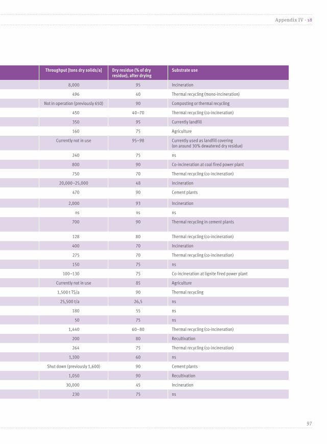
Site Regional state
Drying system Manufacturer Throughput [tons dry solids/a] Dry residue (% of dry residue), after drying
Substrate use
109 Schönerlinde BE/BB Drum dryers Bird Humboldt 8,000 95 Incineration
110 Schongau BY Solar dryers Thermo-System 496 40 Thermal recycling (mono-incineration)
111 Schwarzenbruck BY Drum dryers Rödiger (Mozer) Not in operation (previously 650) 90 Composting or thermal recycling
112 Sigmaringen BW Solar dryers IST 450 40–70 Thermal recycling (co-incineration)
113 Sinzig RP Disc dryer KHD 350 95 Currently landfill
114 St. Peter-Ording SH Solar dryers Thermo-System 160 75 Agriculture
115 Starnberg BY Belt dryer Sevar Currently not in use 95–98 Currently used as landfill covering (on around 30% dewatered dry residue)
116 Steinbrück NI Solar dryers that use waste heat Thermo-System 240 75 ns
117 Steinen BW Disc dryer Stord 800 90 Co-incineration at coal fired power plant
118 Stockach BW Solar dryers Thermo-System 750 70 Thermal recycling (co-incineration)
119 Stuttgart-Mühlhausen BW Disc dryer Wulff/Atlas Stord 20,000–25,000 48 Incineration
120 Sulz / Vöhringen BW Solar dryers that use waste heat Roediger Bioenergie 470 90 Cement plants
121 Tübingen BW Drum dryers Andritz 2,000 93 Incineration
122 Ühlingen-Birkendorf BW Solar dryers ns ns ns ns
123 Unterpleichfeld BY Solar dryers that use waste heat (powered by a biogas facility)
Roediger Bioenergie 700 90 Thermal recycling in cement plants
124 Unterschneidheim BW Solar dryers Thermo-System 128 80 Thermal recycling (co-incineration)
125 Vlotho NW Drum dryers Andritz 400 70 Incineration
126 Waibstadt BW Solar dryers Thermo-System 275 70 Thermal recycling (co-incineration)
127 Waldenburg BW Solar dryers Thermo-System 150 75 ns
128 Waldenburg RP Solar dryer, Belt filters Thermo-System 100–130 75 Co-incineration at lignite fired power plant
129 Wallmerod RP Cold air dryers Klein Currently not in use 85 Agriculture
130 Wangen BY Belt dryer Klein 1,500 t TS/a 90 Thermal recycling
131 Wassmannsdorf BE/BB Centrifuge ns 25,500 t/a 26,5 ns
132 Weddel-Lehre NI Solar dryers Thermo-System 180 55 ns
133 Wegscheid BY Solar dryers Thermo-System 50 75 ns
134 Weil am Rhein BW Solar dryers that use waste heat IST 1,440 60–80 Thermal recycling (co-incineration)
135 Weißenhorn BY Cold air dryers Klein 200 80 Recultivation
136 Wilhelmsdorf BW Solar dryers Thermo-System 264 75 Thermal recycling (co-incineration)
137 Winterhausen BY Solar dryers Thermo-System 1,100 60 ns
138 Wittlich-Platten RP Solar dryers that use waste heat Roediger Bioenergie Shut down (previously 1,600) 90 Cement plants
139 Wolfratshausen BY Disc dryer Stord 1,050 90 Recultivation
140 Wuppertal NW Thin layer dryer Buss 30,000 45 Incineration
141 Wyk auf Föhr SH Solar dryers Thermo-System 230 75 ns
97
Appendix IV · 18

Notes
98
Notes

99

100

Publisher:
Umweltbundesamt (UBA)
Postfach 1406
06844 Dessau-Roßlau | Germany
Telefax: +49 (0)3 40 21 03-22 85
w w w.umwel t bunde s amt .de
01.09.2013
Design: www.publicgarden.de
DTP and typesetting: Team VIERZIG A, Dessau, www.vierzig-a.de
Printed on 100 % recycled paper.
Imprint