seven2go™ pro conductivity meter s7 - hogentogler.com · 6 conductivity settings 31 6.1...
TRANSCRIPT

METTLER T
OLEDO
Seve
n2Go
pro
Cal
S7O
pera
ting
Inst
ruct
ions Seven2Go™ pro Conductivity Meter


Table of Contents
Introduction1 7
Safety Measures2 8
Definition of signal warnings and symbols2.1 8Product specific safety notes2.2 8
Design and Function3 11
Overview3.1 11Sensor connection3.2 11T-Pad and hard keys3.3 11Interface connection3.4 13Display icons3.5 13LED3.6 15Acoustic signal3.7 15
Putting into Operation4 16
Scope of Delivery4.1 16Installing the batteries4.2 17Installing power supply4.3 18Connecting sensors4.4 19Installing optional equipment4.5 20Electrode holder4.5.1 20Meter base stabilizing unit4.5.2 20Wrist strap4.5.3 21Switching the instrument on and off4.6 22Instrument Setup4.7 22Data storage4.7.1 23Storage mode4.7.1.1 23Storage destination4.7.1.2 23System settings4.7.2 24Language4.7.2.1 24Time and date4.7.2.2 24Access control4.7.2.3 24Sounds and visuals4.7.2.4 25User modes4.7.2.5 25Power management4.7.2.6 26Factory reset4.7.3 26Instrument self-test4.7.4 26
Instrument Setup5 27
Data storage5.1 27Storage mode5.1.1 27Storage destination5.1.2 27System settings5.2 28Language5.2.1 28Time and date5.2.2 28Access control5.2.3 28Sounds and visuals5.2.4 29User modes5.2.5 29Power management5.2.6 30Factory reset5.3 30Instrument self-test5.4 30
Table of Contents 3
Conductivity Settings6 31
Calibration settings6.1 32Select a pre-defined conductivity standard6.1.1 32Enter a customized conductivity standard6.1.2 33Enter a cell constant6.1.3 33Calibration reminder6.1.4 33Measurement settings6.2 35Reference Temperature6.2.1 35Temperature Correction6.2.2 35TDS factor6.2.3 36Conductivity unit6.2.4 36Conductivity Ash6.2.5 37Endpoint type6.3 38Interval readings6.4 38Temperature settings6.5 39Measurement limits6.6 39
IDs7 40
Sample ID7.1 40User ID7.2 40Sensor ID7.3 41
Sensor Calibration8 42
Sample Measurement9 43
Selecting a measurement unit9.1 43Performing a conductivity measurement9.2 43Performing a TDS measurement9.3 44Performing a salinity measurement9.4 45Performing a resistivity measurement9.5 46Performing a conductivity ash measurement9.6 47Performing a measurement with interval reading9.7 48
Data Management10 49
Data menu structure10.1 49Measurement data10.2 49Calibration data10.3 50ISM data10.4 50Data export to PC10.5 51
Maintenance11 52
Software update11.1 52Repair of the instrument11.2 52Disposal11.3 52
Product Portfolio12 53
Meter and kit versions12.1 53Accessories12.2 54
Technical Data13 55
Table of Contents4
Appendix14 57
Conductivity standards14.1 57Temperature correction factors14.2 58Temperature coefficients (alpha-values)14.3 59Practical salinity scale (UNESCO 1978)14.4 59Conductivity to TDS conversion factors14.5 59USP/EP tables14.6 60Conductivity ash methods14.7 60Refined sugar (28 g/100 g solution) ICUMSA GS2/3-1714.7.1 60Raw sugar or melasses (5 g / 100 mL solution) ICUMSA GS1/3/4/7/8-13
14.7.2 60
Table of Contents 5

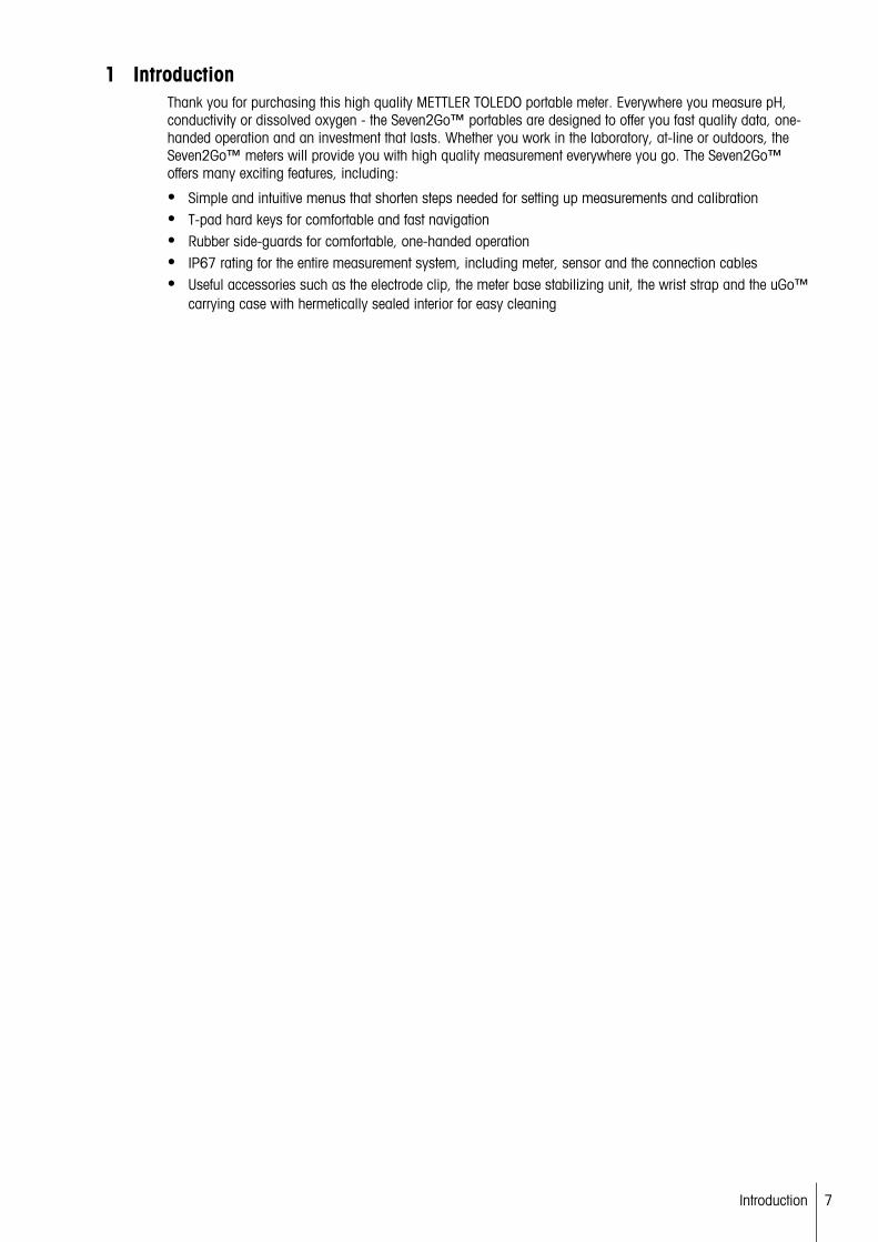
1 IntroductionThank you for purchasing this high quality METTLER TOLEDO portable meter. Everywhere you measure pH,conductivity or dissolved oxygen - the Seven2Go™ portables are designed to offer you fast quality data, one-handed operation and an investment that lasts. Whether you work in the laboratory, at-line or outdoors, theSeven2Go™ meters will provide you with high quality measurement everywhere you go. The Seven2Go™offers many exciting features, including:
● Simple and intuitive menus that shorten steps needed for setting up measurements and calibration● T-pad hard keys for comfortable and fast navigation● Rubber side-guards for comfortable, one-handed operation● IP67 rating for the entire measurement system, including meter, sensor and the connection cables● Useful accessories such as the electrode clip, the meter base stabilizing unit, the wrist strap and the uGo™
carrying case with hermetically sealed interior for easy cleaning
7Introduction
2 Safety Measures
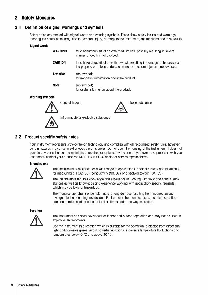
2.1 Definition of signal warnings and symbolsSafety notes are marked with signal words and warning symbols. These show safety issues and warnings.Ignoring the safety notes may lead to personal injury, damage to the instrument, malfunctions and false results.
Signal words
WARNING for a hazardous situation with medium risk, possibly resulting in severeinjuries or death if not avoided.
CAUTION for a hazardous situation with low risk, resulting in damage to the device orthe property or in loss of data, or minor or medium injuries if not avoided.
Attention (no symbol)for important information about the product.
Note (no symbol)for useful information about the product.
Warning symbols
General hazard Toxic substance
Inflammable or explosive substance
2.2 Product specific safety notesYour instrument represents state-of-the-art technology and complies with all recognized safety rules, however,certain hazards may arise in extraneous circumstances. Do not open the housing of the instrument; it does notcontain any parts that can be maintained, repaired or replaced by the user. If you ever have problems with yourinstrument, contact your authorized METTLER TOLEDO dealer or service representative.
Intended use
This instrument is designed for a wide range of applications in various areas and is suitablefor measuring pH (S2, S8), conductivity (S3, S7) or dissolved oxygen (S4, S9).
The use therefore requires knowledge and experience in working with toxic and caustic substances as well as knowledge and experience working with application-specific reagents,which may be toxic or hazardous.
The manufacturer shall not be held liable for any damage resulting from incorrect usagedivergent to the operating instructions. Furthermore, the manufacturer`s technical specifications and limits must be adhered to at all times and in no way exceeded.
Location
The instrument has been developed for indoor and outdoor operation and may not be used inexplosive environments.
Use the instrument in a location which is suitable for the operation, protected from direct sunlight and corrosive gases. Avoid powerful vibrations, excessive temperature fluctuations andtemperatures below 0 °C and above 40 °C.
8 Safety Measures
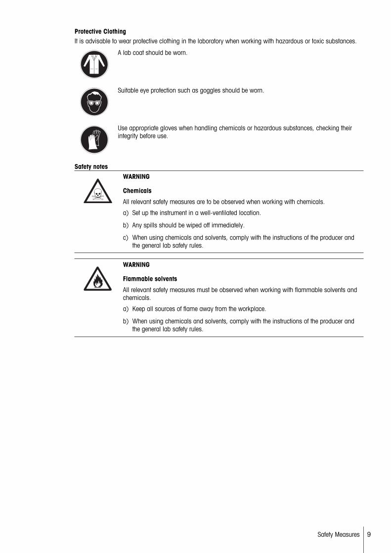
Protective ClothingIt is advisable to wear protective clothing in the laboratory when working with hazardous or toxic substances.
A lab coat should be worn.
Suitable eye protection such as goggles should be worn.
Use appropriate gloves when handling chemicals or hazardous substances, checking theirintegrity before use.
Safety notes WARNING
Chemicals
All relevant safety measures are to be observed when working with chemicals.
a) Set up the instrument in a well-ventilated location.
b) Any spills should be wiped off immediately.
c) When using chemicals and solvents, comply with the instructions of the producer andthe general lab safety rules.
WARNING
Flammable solvents
All relevant safety measures must be observed when working with flammable solvents andchemicals.
a) Keep all sources of flame away from the workplace.
b) When using chemicals and solvents, comply with the instructions of the producer andthe general lab safety rules.
9Safety Measures
FCC RulesThis device complies with Part 15 of the FCC Rules and Radio Interference Requirements of the CanadianDepartment of Communications. Operation is subject to the following conditions: (1) this device may not causeharmful interference, and (2) this device must accept any interference received, including interference that maycause undesired operation.
This equipment has been tested and found to comply with the limits for a Class A digital device, pursuant toPart 15 of the FCC rules. These limits are designed to provide reasonable protection against harmful interference when the equipment is operated in a commercial environment. This equipment generates, uses, and canradiate radio frequency energy and, if not installed and used in accordance with the instruction manual, maycause harmful interference to radio communications. Operation of this equipment in a residential area is likelyto cause harmful interference in which case the user will be required to correct the interference at his ownexpense.
10 Safety Measures

3 Design and Function
3.1 Overview
9
8
11
10
8
1 Status LED (only Pro-series) 7 Rubber feet2 Display 8 Fixing points for electrode holder3 Calibration key 9 Micro-USB port (only Pro-series)4 On/Off key 10 Battery compartment5 Read key 11 Slot for wrist strap6 T-Pad
3.2 Sensor connection
1 LTW socket for conductivityand temperature signal input
3.3 T-Pad and hard keys
Cal
5 3
4
216 7
11Design and Function

In standard screenKey Press and release Press and hold
1 Read Start and manually stop a measurement
Activate/Deactivate uFocus™
2 Settings / Up Open setup menu ---3 Store / Right Save last measurement data ---4 Mode / Down Switch measurement mode ---5 Recall / Left Recall measurement data ---6 Cal Enter calibration mode Recall last calibration result7 On / Off --- Switch instrument on (hold for 1 sec
ond) or off (hold for 3 seconds)
In calibration mode (indicated by )Key Press and release Press and hold
1 Read Start and manually stop calibrationSave calibration result
---
2 Settings / Up --- ---3 Store / Right --- ---4 Mode / Down --- ---5 Recall / Left Discard calibration result Exit calibration mode6 Cal ---7 On / Off --- ---
Settings and data menuKey Press and release Press and hold
1 Read Select submenuConfirm setting
Exit menu
2 Settings / Up Edit value (increase)Navigate between menu points
Fast value increase
3 Store / Right Navigate between menu tabs(only in top level per tab)
---
4 Mode / Down Edit value (decrease)Navigate between menu points
Fast value decrease
5 Recall / Left Navigate between menu tabs(only in top level per tab)One level up (if not in top level)Move left (in input fields)
One level up (if entering value intoinput field)
6 Cal --- ---7 On / Off --- ---
12 Design and Function
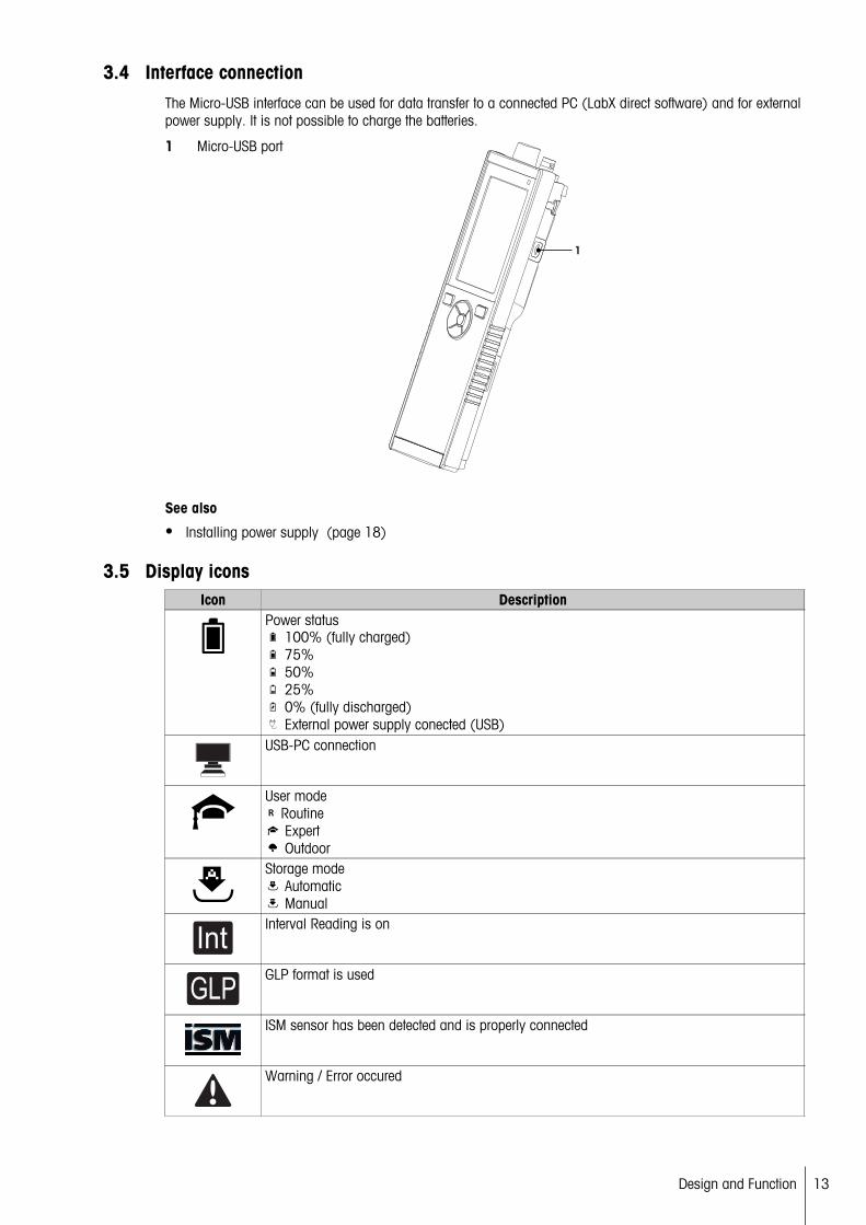
3.4 Interface connectionThe Micro-USB interface can be used for data transfer to a connected PC (LabX direct software) and for externalpower supply. It is not possible to charge the batteries.
1 Micro-USB port
See also
● Installing power supply (page 18)
3.5 Display iconsIcon Description
Power status 100% (fully charged) 75% 50% 25% 0% (fully discharged) External power supply conected (USB)
USB-PC connection
User modeR Routine
Expert Outdoor
Storage mode Automatic Manual
IntInterval Reading is on
GLPGLP format is used
ISM sensor has been detected and is properly connected
Warning / Error occured
13Design and Function

Icon DescriptionSample ID
Calibration standard
User ID
Sensor ID
AEndpoint typeA AutomaticT TimedM Manual
Wait icon
14 Design and Function

3.6 LEDTo use the LED, it has to be enabled in the instrument setup, see section Sounds and visuals (page 25). TheLED indicates different information of the device:
● Alarm Messages● Measurement endpoint● System Info
Instrument State LED green LED red LEDorange
Meaning
On for 5 s ● Instrument boot upInstrument turn ON
Blinking ● Instrument has failed to boot correctly or failure after booting
● Error message appears
Instrument runningwithout calibration ormeasurement inprogress
Blinking ● Calibration has expired and user has definedinstrument to be blocked if sensor expires -error message displayed
● Any other error occurred and is displayed
Pulsing ● Measurement in progress
Solid ● Measurement complete
Measurement Mode
Blinking ● Measurement outside limits● Error occured
Pulsing ● Calibration in progress
Solid ● Calibration complete
Calibration Mode
Blinking ● Calibration not successful● Error occured
Pulsing ● Data transfer in progress
Solid ● Data transfer complete
Data Transfer
Blinking ● Data transfer not successful● Error occured
Sleep Mode Solid ● Meter in Sleep Mode● Press On/Off to re-activate meter
3.7 Acoustic signalTo use the acoustic signals, they have to be enabled in the instrument setup (see section Sounds and visuals(page 25)). You can enable or disable the acoustic signal for the following features:
● Keypress● Alarm Messages● Measurement endpoint
15Design and Function

4 Putting into Operation
4.1 Scope of DeliveryCheck the completeness of the delivery. The following parts belong to the standard equipment of your newinstrument. Further parts may be included depending on the ordered kit versions.
METTLER T
OLEDO
Cal
S7 instrumentfor conductivity measurement
Battery LR3/AA 1.5V4 pcs.
Electrode holder
Meter base unit
USB-A to micro-USB cable for connection to PC,length = 1 m
Seven2GoOperating Instructions
Test Reportmany more
CD-ROM including operating instructions
16 Putting into Operation
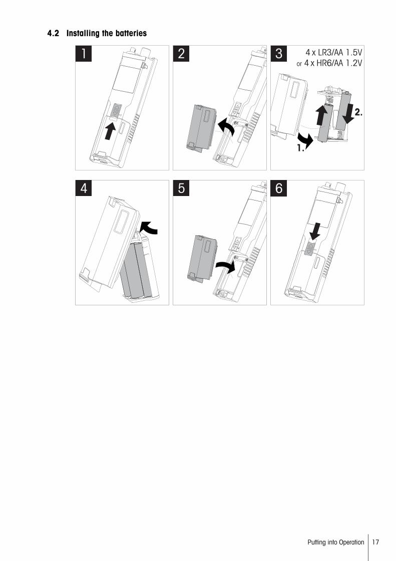
4.2 Installing the batteries
1 2
1.
2.
4 x LR3/AA 1.5V
or 4 x HR6/AA 1.2V3
4 5 6
17Putting into Operation

4.3 Installing power supplyThe instrument is not supplied with an AC adapter.
Alternatively, the instrument can be supplied by an external power supply unit (not included in the scope ofdelivery) via the Micro-USB socket. Use an AC adapter that is suitable for all line voltages in the range of 100 to240 V, 50/60 Hz and incorporates a USB socket. For connection, a suitable USB cable with an Micro-USB plugis required.
While the instrument is powered by the external power supply, the batteries are not being used. The icon isshown on the screen.
Attention● Take care that the AC adapter does not come into contact with liquids!● The power plug must be accessible at all times!
1 Connect the cable of the AC adapter with the Micro-USB socket of the instrument.
2 Plug the AC adapter into the wall socket.
18 Putting into Operation

4.4 Connecting sensors
ISM® sensorWhen connecting an ISM® sensor to the meter, one of the following conditions have to be met for the calibration data to be transferred automatically from the chip of the sensor into the meter and is used for further measurements. After attaching the ISM® sensor ...
● The meter must be switched on.● (If the meter is already switched on) the READ key is pressed.● (If the meter is already switched on) the CAL key is pressed.
We strongly recommend you to switch off the meter when disconnecting an ISM sensor. In doing so, you makesure that the sensor is not removed while the instrument is reading data from or writing data to the ISM-chip ofthe sensor.
The ISM icon appears on the display and the sensor ID of the sensor chip is registered and appears on thedisplay.
The calibration history, the initial certificate and the maximum temperature can be reviewed and printed in thedata memory.
19Putting into Operation

4.5 Installing optional equipment
4.5.1 Electrode holder
For a safe placing of the electrode you can mount an electrode holder on the side of the instrument. Theelctrode holder is part of delivery. You can mount it on either sides of the instrument for your personal handling.
1 Remove the protective clips (1).
1
2 Push the electrode holder (1) into the recess (2) of theinstrument.
1
2
4.5.2 Meter base stabilizing unit
The meter base stabilizing unit should be mounted when using the instrument on a desk. It ensures a more firmand secure stand when pressing the keys.
1 Remove the protective clips (1).
1
2 Push the meter base stabilizing unit (1) into the recesses (2) of the instrument.
1
2
20 Putting into Operation

4.5.3 Wrist strap
For better protection against damage caused by dropping, you can mount the wrist strap as shown in the following diagrams.
METTLER TOLEDO
METTLER TOLEDO
OLEDO
1
2
OLEDO METTLER TOLEDO
METTLER TOLED
O METTL
ER
ETTLER
METTLER TOLEDO
METTLER TOLEDO
OLEDO
3
ME
TT
LE
R TO
LE
DO
M
ETTLER
METTLER TOL
4
21Putting into Operation

4.6 Switching the instrument on and off
1 Press to switch on the instrument.
The firmware version, the serial number and the current date are displayed for about 5 seconds. Afterthat the instrument is ready for use.
2 Press for 3 seconds and release to switch off theinstrument.
EDO
Cal
Note
● By default after 10 minutes not in use, the instrument changes to sleep mode. This can be changed in thesetup.
● When starting the meter for the first time, the display for entering time and date appears automatically.These settings can be changed later again.
See also
● Power management (page 26)● Time and date (page 24)
4.7 Instrument Setup1 Press to enter the menu.
2 Go to .
Menu structure1. Data Storage1.1 Storage Mode1.1.1 Automatic Storage1.1.2 Manual Storage1.2 Storage Destination1.2.1 Memory1.2.2 LabX Direct1.2.3 Memory + LabX Direct2. System Settings2.1 Language2.2 Time and Date2.3 Access Control2.4 Sounds & Visuals2.5 User Mode2.6 Power Management3. Factory Reset4. Instrument Self-test
22 Putting into Operation
4.7.1 Data storage
4.7.1.1 Storage mode
● Automatic storage:In this storage mode, all measurement results are getting saved automatically to the selected storage destination.
● Manual storage:In this mode, the user has to save a measurement result manually by pressing . For this, the user gets amessage on the display after every measurement.
4.7.1.2 Storage destination
There are different possibilities to store the measurement results. The Seven2Go pro meter provides 2000 internal memory locations (M0001 - M2000).
● Memory:The measurement results are saved in the internal memory.
● LabX Direct:The measurement results are transferred only to LabX Direct. For this a PC connection via USB is required.The PC software LabX®direct must be setup accordingly.
● Memory + LabX Direct:The measurement results are saved in the internal memory and transferred to LabX®Direct. For this a PCconnection via USB is required. The PC software LabX®direct must be setup accordingly.
23Putting into Operation

4.7.2 System settings
4.7.2.1 Language
The following languages are available for the system:
● English● German● French● Spanish● Italian● Portuguese● Polish● Russian● Chinese● Japanese● Korean● Thai
4.7.2.2 Time and date
When starting the meter for the first time, the display for entering time and date appears automatically. In thesystem settings, two time and four date display formats are available:
● Time24-hour format (for example, 06:56 and 18:56) 12-hour format (for example, 06:56 AM and 06:56 PM)
● Date28-11-2013 (day-month-year)11-28-2013 (month-day-year)28-Nov-2013 (day-month-year)28/11/2013 (day-month-year)
4.7.2.3 Access control
PIN settings are available for:
● System Settings● Deletion of Data● Instrument Login
A maximum of 6 characters can be entered as PIN. When enabling an access control, the PIN must be definedand re-entered for verification.
Note
● Access control for system settings cannot be disabled as long as the instrument is operated in routinemode!
See also
● User modes (page 25,29)
24 Putting into Operation

4.7.2.4 Sounds and visuals
An acoustic signal can be switched on or off for the following three cases:
● Key is pressed● Alarm/warning message appears● Measurement is stable and has endpointed (stability signal appears)
The LED can be switched on or off for the following three cases:
● Alarm message● Measurement endpoint● System info
4.7.2.5 User modes
The meter has three user modes:
Routine Mode:Limited access rights. The user can only perform measurements, calibrations, review results and change basicsettings. The concept of the routine mode is a GLP feature which ensures that important settings and storeddata cannot be deleted or unintentionally changed. The following operations are blocked in routine mode:
● Deletion of data● Measurement and Calibration settings (except choosing reference temperature)● Create sensor ID● Factory reset● Instrument self-test● System settings can be accessed by entering PIN code (by default 000000)
Expert Mode:The factory default setting enables all functions of the meter.
Outdoor Mode:The user has full access rights (like in expert mode). The screen is always is uFocus view and the followingparameters are set to specific values to reduce battery consumption:
● Auto dimming after 20 s● Auto shutdown after 10 min● All LED signals off
25Putting into Operation

4.7.2.6 Power management
Screen Brightness:The screen brightness can be set from levels 1 to 16.
Auto Dimming:You can activate the auto dimming function for power saving. For this you can define a time period from 5 -300 s. This is the time when the period backlight is switched off after the instrument is not in use.
Energy Saving:You can activate either auto sleep or auto shutdown for saving energy.
Auto SleepThe instrument changes into the sleep modus (standby) after a defined time of not in use. The instrument doesnot shut down automatically. You can define a time period between 5 - 99 minutes. The orange LED light indicates that the instrument currently is in sleep mode. Press to activate the meter.
Auto ShutdownThe instrument shuuts down automatically after a defined time of not in use. You can define a time periodbetween 5 - 99 minutes.
4.7.3 Factory reset
Note
Loss of data!
With a factory reset all settings will be set to default values and all data memories will bedeleted.
1 Press to enter the setup menu.
2 Go to > Factory Reset.
3 Press Read to confirm the factory reset or press to cancel.
When confirmed, all settings have default values and the memory is fully cleared.
4 Press and hold to exit the setup menu.
4.7.4 Instrument self-test
The instrument self-test allows to check if display, LED, beep and keys are working correctly.
1 Press to enter the setup menu.
2 Go to > Instrument Self-test.
3 Press Read to start the self-test.
Display: All pixels of the display are shown black for 2 seconds, then white for 2 seconds.
LED: The LED changes color to green, orange and flashing red.
Beep and keys: The icons for the seven keys are shown on the screen, each keypress lets its icon disappear while a beep sounds. The keys must be pressed within 20 seconds.
If the self-test is successful, OK appears on the screen and the LED is green for 2 seconds. Otherwise Self-test failure appears and the LED flashes red. In both cases the instrument then goes back to normal mode.
26 Putting into Operation

5 Instrument Setup1 Press to enter the menu.
2 Go to .
Menu structure1. Data Storage1.1 Storage Mode1.1.1 Automatic Storage1.1.2 Manual Storage1.2 Storage Destination1.2.1 Memory1.2.2 LabX Direct1.2.3 Memory + LabX Direct2. System Settings2.1 Language2.2 Time and Date2.3 Access Control2.4 Sounds & Visuals2.5 User Mode2.6 Power Management3. Factory Reset4. Instrument Self-test
5.1 Data storage
5.1.1 Storage mode
● Automatic storage:In this storage mode, all measurement results are getting saved automatically to the selected storage destination.
● Manual storage:In this mode, the user has to save a measurement result manually by pressing . For this, the user gets amessage on the display after every measurement.
5.1.2 Storage destination
There are different possibilities to store the measurement results. The Seven2Go pro meter provides 2000 internal memory locations (M0001 - M2000).
● Memory:The measurement results are saved in the internal memory.
● LabX Direct:The measurement results are transferred only to LabX Direct. For this a PC connection via USB is required.The PC software LabX®direct must be setup accordingly.
● Memory + LabX Direct:The measurement results are saved in the internal memory and transferred to LabX®Direct. For this a PCconnection via USB is required. The PC software LabX®direct must be setup accordingly.
27Instrument Setup
5.2 System settings
5.2.1 Language
The following languages are available for the system:
● English● German● French● Spanish● Italian● Portuguese● Polish● Russian● Chinese● Japanese● Korean● Thai
5.2.2 Time and date
When starting the meter for the first time, the display for entering time and date appears automatically. In thesystem settings, two time and four date display formats are available:
● Time24-hour format (for example, 06:56 and 18:56) 12-hour format (for example, 06:56 AM and 06:56 PM)
● Date28-11-2013 (day-month-year)11-28-2013 (month-day-year)28-Nov-2013 (day-month-year)28/11/2013 (day-month-year)
5.2.3 Access control
PIN settings are available for:
● System Settings● Deletion of Data● Instrument Login
A maximum of 6 characters can be entered as PIN. When enabling an access control, the PIN must be definedand re-entered for verification.
Note
● Access control for system settings cannot be disabled as long as the instrument is operated in routinemode!
See also
● User modes (page 25)
28 Instrument Setup

5.2.4 Sounds and visuals
An acoustic signal can be switched on or off for the following three cases:
● Key is pressed● Alarm/warning message appears● Measurement is stable and has endpointed (stability signal appears)
The LED can be switched on or off for the following three cases:
● Alarm message● Measurement endpoint● System info
5.2.5 User modes
The meter has three user modes:
Routine Mode:Limited access rights. The user can only perform measurements, calibrations, review results and change basicsettings. The concept of the routine mode is a GLP feature which ensures that important settings and storeddata cannot be deleted or unintentionally changed. The following operations are blocked in routine mode:
● Deletion of data● Measurement and Calibration settings (except choosing reference temperature)● Create sensor ID● Factory reset● Instrument self-test● System settings can be accessed by entering PIN code (by default 000000)
Expert Mode:The factory default setting enables all functions of the meter.
Outdoor Mode:The user has full access rights (like in expert mode). The screen is always is uFocus view and the followingparameters are set to specific values to reduce battery consumption:
● Auto dimming after 20 s● Auto shutdown after 10 min● All LED signals off
29Instrument Setup

5.2.6 Power management
Screen Brightness:The screen brightness can be set from levels 1 to 16.
Auto Dimming:You can activate the auto dimming function for power saving. For this you can define a time period from 5 -300 s. This is the time when the period backlight is switched off after the instrument is not in use.
Energy Saving:You can activate either auto sleep or auto shutdown for saving energy.
Auto SleepThe instrument changes into the sleep modus (standby) after a defined time of not in use. The instrument doesnot shut down automatically. You can define a time period between 5 - 99 minutes. The orange LED light indicates that the instrument currently is in sleep mode. Press to activate the meter.
Auto ShutdownThe instrument shuuts down automatically after a defined time of not in use. You can define a time periodbetween 5 - 99 minutes.
5.3 Factory reset
Note
Loss of data!
With a factory reset all settings will be set to default values and all data memories will bedeleted.
1 Press to enter the setup menu.
2 Go to > Factory Reset.
3 Press Read to confirm the factory reset or press to cancel.
When confirmed, all settings have default values and the memory is fully cleared.
4 Press and hold to exit the setup menu.
5.4 Instrument self-testThe instrument self-test allows to check if display, LED, beep and keys are working correctly.
1 Press to enter the setup menu.
2 Go to > Instrument Self-test.
3 Press Read to start the self-test.
Display: All pixels of the display are shown black for 2 seconds, then white for 2 seconds.
LED: The LED changes color to green, orange and flashing red.
Beep and keys: The icons for the seven keys are shown on the screen, each keypress lets its icon disappear while a beep sounds. The keys must be pressed within 20 seconds.
If the self-test is successful, OK appears on the screen and the LED is green for 2 seconds. Otherwise Self-test failure appears and the LED flashes red. In both cases the instrument then goes back to normal mode.
30 Instrument Setup

6 Conductivity Settings1 Press to enter the menu.
2 Go to Conductivity.
Menu structure1. Calibration Settings1.1 Calibration Standard 1.1.1 Predefined Standard1.1.2 Customized Standard1.1.3 Enter Cell Constant1.2 Calibration Reminder 2. Measurement Settings2.1 Reference Temperature2.2 Temperature Correction2.3 TDS Factor2.4 Conductivity Unit2.5 Conductivity Ash2.5.1 ICUMSA Method2.5.2 Conductivity of Used Water3. Endpoint Type4. Interval Readings5. Temperature Settings5.1 Set MTC Temperature5.2 Temperature Unit6. Measurement Limits6.1 Conductivity Limit6.2 TDS Limit6.3 Salinity Limit6.4 Resistivity Limit6.5 Conductivity Ash Limit6.6 Temperature Limit
31Conductivity Settings

6.1 Calibration settings
6.1.1 Select a pre-defined conductivity standard
The following pre-defined international conductivity standards are available:
● 10 μS/cm● 84 μS/cm● 500 μS/cm● 1413 μS/cm● 12.88 mS/cm● Saturated NaCi
The following pre-defined chinese conductivity standards are available:
● 146.5 μS/cm● 1408 μS/cm● 12.85 mS/cm● 111.35 mS/cm
The following pre-defined japanese conductivity standards are available:
● 1330.00 μS/cm● 133.00 μS/cm● 26.6 μS/cm
Select a pre-defined standard:1 Press to enter the setup menu.
2 Go to Conductivity > Calibration Settings > Calibration Standard > Predefined Standard.
3 Select a standard using and .
4 Press Read to confirm.
5 Press to exit the calibration menu.
6 Press and hold to exit the setup menu.
32 Conductivity Settings
6.1.2 Enter a customized conductivity standard
This option is for users who would like to use their own conductivity standard for calibration of the conductivitysensor. Up to 5 temperature-dependent values (in mS/cm only) can be entered in the table. The lowest possibleconductivity value is 0.00005 mS/cm (0.05 μS/cm). This value corresponds to the conductivity of pure waterat 25 °C, exclusively caused by the autoprotolysis of water. The highest value that can be entered is200 mS/cm.
When switching from a predefined standard to customized standard, you should always save the table even ifno values have changed.
1 Press to enter the setup menu.
2 Go to Conductivity > Calibration Settings > Calibration Standard > Customized Standard.
There are pre-defined values of a standard in the table which are all changeable.
3 Select a temperature value by using and and press Read to edit it.
4 Change the selected temperature digit by digit using the TPad keys and press Read to confirm.
5 Press to navigate to the related calibration standard value and press Read to edit it.
6 Change the value digit by digit using the TPad keys and press Read to confirm.
7 Repeat steps 3 to 6 for all pairs of temperature and conductivity value.To delete any value, press and hold Read in that field of the table.Please note that the table must not have empty lines in-between but only at the end.
8 Go to Save and press Read to save your changes.
9 Press to exit the calibration menu.
10 Press and hold to exit the setup menu.
6.1.3 Enter a cell constant
If the cell constant of the conductivity cell being used is accurately known, it can be entered directly in themeter. A cell constant between 1.00000e-6 cm-1 and 2.00000e+2 cm-1 (corresponds to 0.000001 cm-1 and200 cm-1). can be entered. In the calibration settings you only set the calibration option to entering the cellconstant manually. The cell constant itself is entered during the normal calibration process instead of measuring in a calibration standard and it is saved per sensor ID.
1 Press to enter the setup menu.
2 Go to Conductivity > Calibration Settings > Calibration Standard > Enter Cell Constant and press Read.
3 Press to exit the calibration menu.
4 Press and hold to exit the setup menu.
5 Press Cal.
6 Enter the cell constant digit by digit. Increase or decrease each value by using the TPad keys and pressRead to confirm.
The entered cell constant is displayed on the screen.
6.1.4 Calibration reminder
When the calibration reminder is activated, the user is reminded to perform a new calibration after a certainuser-defined interval (maximum 9999 h) has elapsed.
1 Press to enter the setup menu.
2 Go to DO > Calibration Settings > Calibration Standard > Calibration Reminder .
3 Choose On or Off by using and .
4 Press Read to confirm.
Another screen appears to enter the interval time.
5 Enter the interval time by using the TPad keys and press Read to save.
Another screen appears to select calibration expiration date. Select as of when the sensor should beblocked for further measurements as soon as the entered interval has elapsed.
33Conductivity Settings

Immediately:The meter is immediately blocked for measurement when the predefined interval has elapsed.
Exp: Reminder + 1 h:The meter is blocked for measurement 1 hour after the predefined interval has elapsed.
Exp: Reminder + 2 h:The meter is blocked for measurement 2 hours after the predefined interval has elapsed.
Continue Reading:The user can continue measuring when the predefined interval has elapsed.
6 Press Read to confirm.
7 Press .
8 Press and hold to exit the setup menu.
34 Conductivity Settings

6.2 Measurement settings
6.2.1 Reference Temperature
The following reference temperatures are available:
● 20 °C (68 °F)● 25 °C (77 °F)
1 Press to enter the setup menu.
2 Go to Cond. > Measurement Settings > Reference Temperature.
3 Choose the reference temperature by using and and press Read.
4 Press to exit the measurement menu.
5 Press and hold to exit the setup menu.
6.2.2 Temperature Correction
There are four options for temperature correction available:
● linear● non-linear● pure water● off
With most solutions, a linear interrelationship between conductivity and temperature is given. In such cases,select the linear correction method. The conductivity of natural water shows strong non-linear temperaturebehavior. For this reason, use the non-linear correction for natural water. The option pure water should onlybe used for cases in which ultra-pure or pure water is measured.
In some cases, for example, when measuring according to USP/EP (United States/European Pharmacopoeia)you need to switch off the temperature correction.
LinearWhen selecting linear correction, the input field for the temperature correction coefficient - also called alphacoefficient - appears. Values from 0.000 to 10.000 %/°C can be entered. The measured conductivity is corrected and displayed using the following formula:
GTRef = GT / (1 + ( (T – TRef)) / 100 %)
● GT: conductivity measured at temperature T (mS/cm)● GTRef: conductivity (mS/cm) displayed by the instrument, calculated back to the reference temperature TRef
● : linear temperature correction coefficient (%/°C); = 0: no temperature correction● T: measured temperature (°C)● TRef: Reference temperature (20 °C or 25 °C)
Each sample has different temperature behavior. For pure salt solutions the correct coefficient can be found inliterature, otherwise you need to determine the -coefficient by measuring the conductivity of the sample at twotemperatures and calculate the coefficient by using the following formula:
= (GT1 - GT2) * 100% / (T1 - T2) / GT2
● T1: Typical sample temperature● T2: Reference temperature● GT1: Measured conductivity at typical sample temperature● GT2: Measured conductivity at reference temperature
To enter the linear temperature correction follow these steps:1 Press to enter the setup menu.
2 Go to Measurement Settings > Temperature Correction > Linear and press Read to confirm.
3 Enter the -coefficient (0.000 - 10.000) by using and and press Read.
4 Press to exit the measurement menu.
35Conductivity Settings

5 Press and hold to exit the setup menu.
Non-linearThe conductivity of natural water shows strong non-linear temperature behavior. For this reason, use the non-linear correction for natural water. The measured conductivity is multiplied by the factor f25 for the measuredtemperature (see appendix) and thus corrected to the reference temperature of 25 °C:
GT25 = GT * f25
If 20 °C is used as reference temperature, the conductivity corrected to 25 °C is divided by 1.116 (see f25 for20.0 °C):
GT20 = (GT · f25) / 1.116
Note
● Conductivity measurements of natural water can only be performed at temperatures ranging from 0 °C to36 °C. Otherwise, the warning message Temp. out of conductivity ash correction range appears.
Pure waterSimilar to non-linear correction for natural water a different type of non-linear correction is used for ultra-pureand pure water. The values are compensated in the range from 0.005 to 5.00 μS/cm at temperatures(0-50 °C) that differ from the reference temperature (25 °C). This could for example be when checking the pureor ultra-pure water production equipment, or when checking if the cleaning-in-progress procedure for whichultra-pure water has been used had led to the removal of all soluble substances. Due to the high influence ofCO2 from the air, we strongly recommend to use a flow-through-cell for this type of measurements.
Note
● Conductivity measurements using the pure water compensation mode can only be performed at temperatures ranging from 0 °C to 50 °C. Otherwise, the warning message "Temp. out of pure water range"appears.
● In case the conductivity reading exceeds the upper limit of 5.00 μS/cm in the mode pure warer, the compensation will resemble a linear compensation mode with = 2.00 %/°C.
6.2.3 TDS factor
TDS (Total dissolved solids) is calculated by multiplying the conductivity value in µS/cm with the TDS factor toget the concentration in mg/L or ppm. A factor between 0.40 and 1.00 can be entered. Please see appendix forsome typical values for the TDS factor.
1 Press to enter the setup menu.
2 Go to Measurement Settings > TDS Factor.
3 Enter the TDS factor (0.40 - 1.00) digit by digit using and and press Read.
4 Press to exit the measurement menu.
5 Press and hold to exit the setup menu.
6.2.4 Conductivity unit
Depending on your requirements to express the readings per centimeter or per meter, you can change the conductivity unit as follows:
● µS/cm and mS/cm● µS/m and mS/m
1 Press to enter the setup menu.
2 Go to Cond. > Measurement Settings > Conductivity Unit.
3 Choose the unit by using and and press Read.
4 Press to exit the measurement menu.
5 Press and hold to exit the setup menu.
36 Conductivity Settings
6.2.5 Conductivity Ash
Conductivity Ash (%) is an important parameter that reflects the content of soluble inorganic salts in refinedsugar or raw sugar/melasses. These soluble inorganic impurities directly affect the purity of the sugar. Thismeter can measure conductivity ash according to the following two ICUMSA methods.
● 28 g/100 g solution (refined sugar - ICUMSA GS2/3-17)● 5 g/100 mL solution (raw sugar – ICUMSA GS1/3/4/7/8-13)
The instrument will directly convert the measured conductivity to conductivity ash % according to the selectedmethod. The user has the possibility to enter the conductivity of the used water for preparing the sugar solutionsin μS/cm (0.0 to 100.0 μS/cm). This value is then used for correcting the measured conductivity ash valuesaccording to the formulae given in the appendix.
1 Press to enter the setup menu.
2 Go to Measurement Settings > Conductivity Ash > ICUMSA Method.
3 Use and to select the right method and confirm with Read.
4 Go to Cond. of Used Water Water.
5 Enter the conductivity of used water digit by digit using the TPad and press Read to save.
6 Press to exit the measurement menu.
7 Press and hold to exit the setup menu.
Note
● Conductivity ash measurements are only possible in the temperature range from 15 °C to 25 °C. Otherwise,the warning message ... appears.
37Conductivity Settings

6.3 Endpoint type
Auto EndpointWith the automatic endpoint the meter defines the end of an individual reading depending on programmed stability criterion for the signal. This ensures an easy, quick and precise measurement.
1 Press to enter the setup menu.
2 Go to DO > Endpoint Type.
3 Select Auto EP and press Read to confirm.
4 Press and hold to exit the setup menu.
Manual Endpoint
In this mode, the user is required to stop the measurement reading manually.
1 Press to enter the setup menu.
2 Go to DO > Endpoint Type.
3 Select Manual EP and press Read to confirm.
4 Press and hold to exit the setup menu.
Timed Endpoint
The measurement stops after the defined time, which can be set between 5 s and 3600 s.
1 Press to enter the setup menu.
2 Go to DO > Endpoint Type.
3 Select Timed EP and press Read to confirm.
4 Enter the measurement time digit by digit using the TPad keys and press Read to save.
5 Press and hold to exit the setup menu.
6.4 Interval readingsA reading is taken every time after a certain interval (1 – 2400 s) defined in the menu has elapsed. The measurement series stops according to the selected endpoint format or manually by pressing Read. When timed-interval reading is On, Int. appears on the screen.
Example:To measure the conductivity every 30 s during 5 min, set the interval time to 30 s and the endpoint type totimed with a measurement time of 5 min.
1 Press to enter the setup menu.
2 Go to DO > Interval Readings.
3 Select On and press Read to confirm.
4 If interval readings has been enabled, enter the interval time digit by digit using the TPad keys.
5 Press Read save.
6 Press and hold to exit the setup menu.
38 Conductivity Settings

6.5 Temperature settings
Setting the temperature unit:You can set the temperature unit to °C or °F.
1 Press to enter the setup menu.
2 Go to DO > Temperature Settings > Temperature Unit.
3 Select the temperature unit and press Read to save.
4 Press .
5 Press and hold to exit the setup menu.
6.6 Measurement limitsYou can define limits (max. and min.) for every kind of measurement:
● DO Limit● Temperature Limit
To set a measurement limit follow these steps:
1 Press to enter the setup menu.
2 Go to DO > Measurement Limits.
3 Choose the desired measurement type by using and and press Read to confirm.
4 Select Yes to activate the limit and press Read to confirm.
5 Press Read to activate or deactivate the max. Limit.
6 Press and then press Read to edit the max. limit value.
7 Change the max. limit value digit by digit using and and press Read to save.
8 Press to switch to the min. limit.
9 Press Read to activate or deactivate the min. Limit.
10 Press and then press Read to edit the min. limit value.
11 Change the min. limit value digit by digit using and and press Read to save.
12 Go to Save and press Read to save your settings.
13 Press .
14 Press and hold to exit the setup menu.
39Conductivity Settings

7 IDs1 Press to enter the menu.
2 Go to ID.
Menu structure1. Sample ID1.1 Enter Sample ID1.2 Auto Sequential1.3 Select Sample ID1.4 Delete Sample ID2. User ID2.1 Enter User ID2.2 Select User ID2.3 Delete User ID3. Sensor ID / SN3.1 Enter Sensor ID / SN3.2 Select Sensor ID
7.1 Sample ID1 Press to enter the setup menu.
2 Go to ID Settings > Sample ID.
Go to Enter Sample ID to enter a new sample ID. An alphanumeric sample ID with up to 12 characters can beentered.
Auto sequential:1. Auto Sequential = On
Using this setting will automatically increment the sample ID by 1 for each reading. If the last character ofthe sample ID is not a number, then the number 1 will be added to the sample ID with the second sample.This requires the sample ID to have less than 12 characters.
2. Auto Sequential = OffThe sample ID is not incremented automatically.
To select a sample ID out of a list of already entered sample IDs, go to Select Sample ID. A maximum of 10sample IDs are stored in memory and listed for selection. If the maximum of 10 has already been entered,either any sample ID is deleted manually or the oldest ID will automatically be overwritten by the new ID.
To delete an existing sample ID out of the list, go to Delete Sample ID. Choose the sample ID you want todelete and press Read.
7.2 User ID1 Press to enter the setup menu.
2 Go to ID Settings > User ID.
Select Enter User ID to enter a new user ID. An alphanumeric user ID with up to 12 characters can be entered.
To select a user ID out of the list, go to Select User ID. A maximum of 10 user IDs are stored in memory andlisted for selection. If the maximum of 10 has already been entered, either a user ID is deleted manually or theoldest ID will automatically be overwritten by the new ID.
To delete an existing user ID out of the list, go to Delete User ID. Choose the user ID you want to delete andpress Read.
40 IDs

7.3 Sensor ID1 Press to enter the setup menu.
2 Go to ID Settings > Sensor ID / SN.
Select Enter Sensor ID / SN to enter a new sensor ID and serial number (SN). An alphanumeric sensor ID andSN with up to 12 characters can be entered.
To select a sensor ID out of the list, go to Select Sensor ID. A maximum of 10 sensor IDs are stored in thememory and listed for selection. If the maximum of 10 has already been entered, the oldest ID will automatically be overwritten by the new ID.
Note
● To delete a sensor from the list, delete its calibration data, see section Calibration data (page 50).
41IDs

8 Sensor CalibrationThe following procedure only applies if a pre-defined or user-defined calibration standard is set. In case the cellconstant has to be entered manually, a separate section is required:
1 Press Cal.
An input field appears to enter the cell constant.
2 Increase or decrease the cell constant value digit by digit using the TPad keys and press Read to confirm.
Perform a sensor calibration:A sensor is connected to the instrument.
The correct calibration standard is defined in the settings (see section Calibration settings (page 32)).
1 Place the electrode in a calibration standard and press Cal to enter the calibration mode.
appears on the display.
2 Press Read to start the calibration.
Depending on the set endpoint format, the letter A (auto), T (timed) or M (manual) is blinking duringthe calibration.
When the endpoint is reached, the display freezes automatically. Independent on the set endpoint format, Read can be pressed to endpoint the calibration manually.
The calibration result is displayed.
3 Press Read to save the calibration data or press to cancel.
Note ● The second point required for the conductivity calibration curve is permanently programmed in the meter
and is 0 S/m for a specific resistivity moving toward infinity. To ensure the most accurate conductivity readings, verify the cell constant with a standard solution regularly and recalibrate if necessary.
42 Sensor Calibration
9 Sample Measurement
9.1 Selecting a measurement unitWith the S7 conductivity meter it is possible to measure the following parameters of a sample:
● Conductivity (µS/cm and mS/cm)The instrument will switch automatically to µS/m and mS/m depending on the measurement value (e.g.conductivity of ethanol according to the ABNT/ABR 10547 method).
● TDS (mg/L)● Salinity (psu)● Resistivity (Ohm.cm)● Conductivity ash (%)
To change the measurement mode, press as often as the desired appears.
9.2 Performing a conductivity measurementAn sensor is connected to the instrument.
The sensor is calibrated.
The following measurement settings are done:- Reference temperature- Temperature correction method- Conductivity unit- Endpoint type- Data storage mode and location
1 Press once or several times to switch between the measurement modes until a conductivity unit (µS/cm,mS/cm, µS/m, mS/m) is displayed.
2 Place the sensor into the sample and press Read to start the measurement.
The decimal point and - depending on the endpoint format setting - A (automatic), T (timed) or M(manual) are blinking during the measurement.
3 When the measurement has endpointed, the display freezes. Independent on the set endpoint format, Readcan be pressed to endpoint the measurement manually.
The measurement result is displayed.
If Data Storage Mode is set to Automatic Storage, the complete measurement data is automaticallytransferred to the set storage destination.
4 If Data Storage Mode is set to Manual Storage, press to transfer the data to the set storage location.
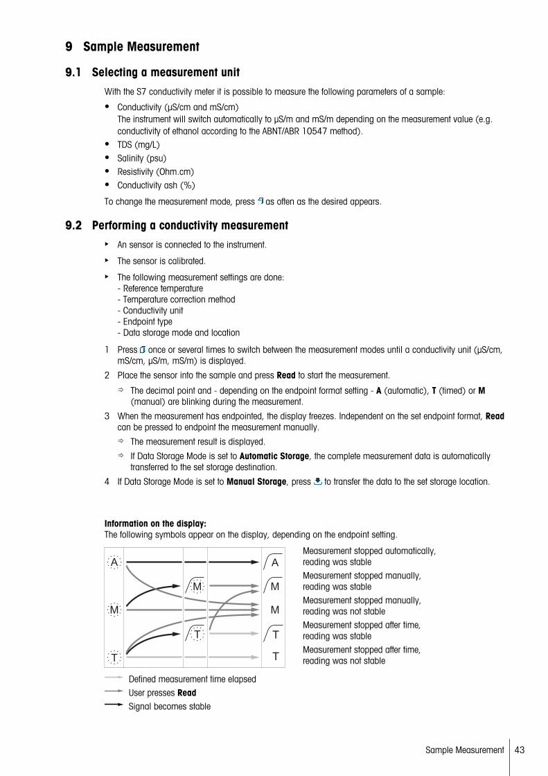
Information on the display:The following symbols appear on the display, depending on the endpoint setting.
Measurement stopped automatically,reading was stableMeasurement stopped manually,reading was stableMeasurement stopped manually,reading was not stableMeasurement stopped after time,reading was stable
A
M
T
M
T
A
M
T
M
TMeasurement stopped after time,reading was not stable
Defined measurement time elapsedUser presses ReadSignal becomes stable
43Sample Measurement

See also
● Measurement settings (page 35)
9.3 Performing a TDS measurementA sensor is connected to the instrument.
The sensor is calibrated.
The following measurement settings are done:- Reference temperature- Temperature correction method- TDS factor- Endpoint type- Data storage mode and location
1 Press once or several times to switch between the measurement modes until the unit mg/L or g/L is displayed.
2 Place the sensor into the sample and press Read to start the measurement.
The decimal point and - depending on the endpoint format setting - A (automatic), T (timed) or M(manual) are blinking during the measurement.
3 When the measurement has endpointed, the display freezes. Independent on the set endpoint format, Readcan be pressed to endpoint the measurement manually.
The measurement result is displayed.
If Data Storage Mode is set to Automatic Storage, the complete measurement data is automaticallytransferred to the set storage destination.
4 If Data Storage Mode is set to Manual Storage, press to transfer the data to the set storage location.
Information on the display:The following symbols appear on the display, depending on the endpoint setting.
Measurement stopped automatically,reading was stableMeasurement stopped manually,reading was stableMeasurement stopped manually,reading was not stableMeasurement stopped after time,reading was stable
A
M
T
M
T
A
M
T
M
TMeasurement stopped after time,reading was not stable
Defined measurement time elapsedUser presses ReadSignal becomes stable
See also
● Measurement settings (page 35)
44 Sample Measurement
9.4 Performing a salinity measurementA sensor is connected to the instrument.
The sensor is calibrated.
The following measurement settings are done:- Endpoint type- Data storage mode and location
1 Press once or several times to switch between the measurement modes the unit psu is displayed.
2 Place the sensor into the sample and press Read to start the measurement.
The decimal point and - depending on the endpoint format setting - A (automatic), T (timed) or M(manual) are blinking during the measurement.
3 When the measurement has endpointed, the display freezes. Independent on the set endpoint format, Readcan be pressed to endpoint the measurement manually.
The measurement result is displayed.
If Data Storage Mode is set to Automatic Storage, the complete measurement data is automaticallytransferred to the set storage destination.
4 If Data Storage Mode is set to Manual Storage, press to transfer the data to the set storage location.
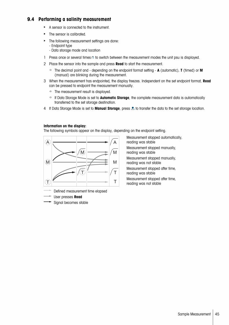
Information on the display:The following symbols appear on the display, depending on the endpoint setting.
Measurement stopped automatically,reading was stableMeasurement stopped manually,reading was stableMeasurement stopped manually,reading was not stableMeasurement stopped after time,reading was stable
A
M
T
M
T
A
M
T
M
TMeasurement stopped after time,reading was not stable
Defined measurement time elapsedUser presses ReadSignal becomes stable
45Sample Measurement
9.5 Performing a resistivity measurementA sensor is connected to the instrument.
The sensor is calibrated.
The following measurement settings are done:- Reference temperature- Temperature correction method- Endpoint type- Data storage mode and location
1 Press once or several times to switch between the measurement modes until a resistivity unit (Ω cm,kΩ cm, MΩ cm) is displayed.
2 Place the sensor into the sample and press Read to start the measurement.
The decimal point and - depending on the endpoint format setting - A (automatic), T (timed) or M(manual) are blinking during the measurement.
3 When the measurement has endpointed, the display freezes. Independent on the set endpoint format, Readcan be pressed to endpoint the measurement manually.
The measurement result is displayed.
If Data Storage Mode is set to Automatic Storage, the complete measurement data is automaticallytransferred to the set storage destination.
4 If Data Storage Mode is set to Manual Storage, press to transfer the data to the set storage location.
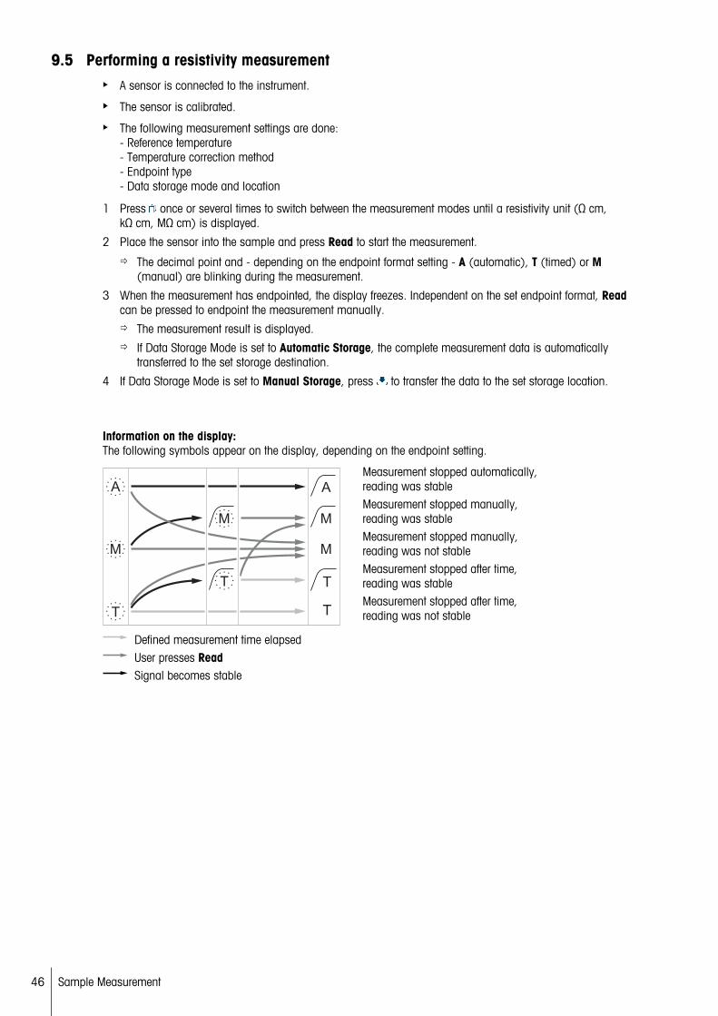
Information on the display:The following symbols appear on the display, depending on the endpoint setting.
Measurement stopped automatically,reading was stableMeasurement stopped manually,reading was stableMeasurement stopped manually,reading was not stableMeasurement stopped after time,reading was stable
A
M
T
M
T
A
M
T
M
TMeasurement stopped after time,reading was not stable
Defined measurement time elapsedUser presses ReadSignal becomes stable
46 Sample Measurement
9.6 Performing a conductivity ash measurementA sensor is connected to the instrument.
The sensor is calibrated.
The following measurement settings are done:- ICUMSA method- Conductivtiy of used water- Endpoint type- Data storage mode and location
1 Prepare the sugar sample according to the selected ICUMSA method (see appendix).
2 Press once or several times to switch between the measurement modes until the unit % is displayed.
3 Place the sensor into the sample and press Read to start the measurement.
The decimal point and - depending on the endpoint format setting - A (automatic), T (timed) or M(manual) are blinking during the measurement.
4 When the measurement has endpointed, the display freezes. Independent on the set endpoint format, Readcan be pressed to endpoint the measurement manually.
The measurement result is displayed.
If Data Storage Mode is set to Automatic Storage, the complete measurement data is automaticallytransferred to the set storage destination.
5 If Data Storage Mode is set to Manual Storage, press to transfer the data to the set storage location.
Note
● According to ICUMSA conductivity ash measurements must be performed in a temperature range of 15 to25 °C. If this requirement is not met, an error message is displayed.
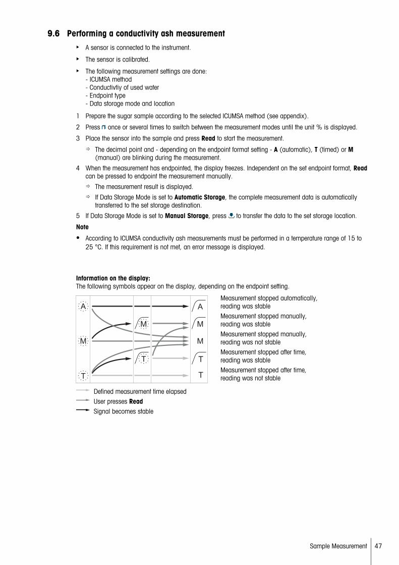
Information on the display:The following symbols appear on the display, depending on the endpoint setting.
Measurement stopped automatically,reading was stableMeasurement stopped manually,reading was stableMeasurement stopped manually,reading was not stableMeasurement stopped after time,reading was stable
A
M
T
M
T
A
M
T
M
TMeasurement stopped after time,reading was not stable
Defined measurement time elapsedUser presses ReadSignal becomes stable
47Sample Measurement
9.7 Performing a measurement with interval readingA sensor is connected to the instrument.
The sensor is calibrated.
Measurement settings were done (see previous chapters).
Timed interval reading is enabled (see chapter Interval readings (page 38)).
1 Press once or several times to switch between the measurement modes until the desired unit is displayed.
2 Place the sensor into the sample and press Read to start the measurement.
3 Press once or several times to switch between the measurement modes until the unit mg/L or g/L is displayed.
4 Place the sensor into the sample and press Read to start the measurement.
The decimal point and - depending on the endpoint format setting - A (automatic), T (timed) or M(manual) are blinking during the measurement.
After every defined time interval the result is automatically sent to the set data storage destination. Thishappens even if Data Storage Mode is set to Manual.
5 When the measurement has endpointed, the display freezes. The last measurement result is displayed.
48 Sample Measurement

10 Data Management
10.1 Data menu structurePress to enter and also to exit the setup menu.
1. Measurement Data1.1 Review1.2 Transfer1.3 Delete2. Calibration Data2.1 Review2.2 Transfer2.3 Delete3. ISM Data3.1 Initial Calibration Data3.2 Calibration History3.3 Electrode Records3.4 Reset ISM
10.2 Measurement data
Review > AllTransfer > AllDelete > All:All stored measurement data can be reviewed, transferred or deleted. The most recent data saved appears onthe display.
Review > PartialTransfer > PartialDelete > Partial:Partially selected measurement data can be reviewed, transferred or deleted. The measurement data can be filtered according to 4 criteria.
● Date/Time● Sample ID● Measurement mode● Memory number
Note
● When filtering by date/time, the date must always be entered. If the time 00:00 is used, all results from thewhole day are showed/transferred/deleted. Otherwise only the results exactly at the given date and time areaffected.
Delete > All After Transfer:All stored measurement data can be transferred to a PC with software LabX®direct. The measurement data willbe deleted automatically after transfer.
49Data Management

10.3 Calibration data
Review:The stored calibration data of the selected sensor can be reviewed.
Transfer:All stored calibration data of the selected sensor can be transferred to a PC with software LabX®direct.
Delete:The calibration data of the selected sensor is deleted. As the same time the sensor ID is deleted from the sensorID list.
Note
● It is not possible to delete the active sensor. Choose a different one from the sensor ID list first.
10.4 ISM dataSeven2Go meters incorporate Intelligent Sensor Management (ISM®) technology. This ingenious functionalityprovides extra security, safety and eliminates mistakes. The most important features are:
Extra security!
● After connecting the ISM® sensor, the sensor is automatically recognized and the sensor ID and serial number are transferred from the sensor chip to the meter. The data is also printed on the GLP printout.
● After calibration of the ISM® sensor, the calibration data is automatically stored from the meter to the sensorchip. The most recent data is always stored where it should be – on the sensor chip!
Extra safety!
After connecting the ISM® sensor, the five most recent calibrations are transferred to the meter. These can bereviewed to see the development of the sensor over time. This information provides an indication if the sensorshould be cleaned or renewed.
Eliminate mistakes!
After connecting an ISM® sensor, the last set of calibration data is automatically used for measurements.
Additional features are described below.
In the ISM data menu you have the following submenus:
Initial calibration dataWhen an ISM® sensor is connected, the initial calibration data in the sensor can be reviewed or transferred. Thefollowing data is included:
● Response time● Temperature tolerance● Cell constant● Cell constant tolerance● Type (and name) of electrode (for example, InLab Expert Pro ISM)● Serial number (SN) and ordering (ME) number● Production date
Calibration historyThe last 5 calibrations data stored in ISM® sensor including current calibration can be reviewed or transferred.
Electrode Records
Beside the inital electrode name and serial number, the maximum temperature the sensor measured and thedate when this happened can be reviewed.
Reset ISM®
The calibration history in this menu can be deleted. This menu is protected by a deletion PIN. Upon delivery, thePIN for deletion is set to 000000. Change the PIN to prevent unauthorized access.
50 Data Management

10.5 Data export to PCIt is possible to transfer either all data or a user-defined set of data from the memory to a PC by usingLabX®direct. The settings between the instrument and PC are adjusted automatically because USB connectionis plug-and-play.
The following section describes how to proceed with the different configurations.
Data transfer from the meter to LabX®direct1 Connect the instrument via USB-B to the PC.
appears on the display.
2 Press to enter the setup menu.
3 Go to > Data Storage > Storage Destination and select LabX Direct.
4 Press for 3 s to leave the setup menu.
5 Open the software LabX®direct pH and select the correct instrument.
6 Press to enter the data menu.
7 Go to Measurement Data > Transfer and select the data you want to transfer.
The transfer starts automatically after the data content is selected.
51Data Management

11 Maintenance
11.1 Software updateA software update can only be done by an authorized METTLER TOLEDO Service agent!
11.2 Repair of the instrumentSeven2Go meters can be repaired. Please ask the METTLER TOLEDO Service department for more information.
11.3 Disposal
In conformance with the European Directive 2002/96/EC on Waste Electrical and ElectronicEquipment (WEEE) this device may not be disposed of in domestic waste. This also appliesto countries outside the EU, per their specific requirements.
Please dispose of this product in accordance with local regulations at the collecting pointspecified for electrical and electronic equipment. If you have any questions, please contactthe responsible authority or the distributor from which you purchased this device. Should thisdevice be passed on to other parties (for private or professional use), the content of this regulation must also be related.
Thank you for your contribution to environmental protection.
52 Maintenance

12 Product Portfolio
12.1 Meter and kit versionsParts Order No.Seven2Go Conductivity meter S7 ONLY 1) 30207961S7-Standard Kitwith InLab 738-ISM
30207962
S7-Field Kitwith InLab 738-ISM and uGo carrying case
30207963
S7-USP/EP Kitwith InLab 742-ISM and uGo carrying case
30207873
1) Including:
● 1 x CD with operating instructions● 1 x QuickGuide● 1 x Declaration of conformity● 1 x Test certificate● 1 x Wrist strap● 1 x Electrode assembly● 1 x Micro-USB to USB-A cable● 1 x Meter base● 1 x LabX direct CD● 1 x Set of conductivity standards
53Product Portfolio

12.2 AccessoriesParts Order No.uGo™ carrying case 30122300Seven2Go meter benchtop stabilizing base 30122303Seven2Go electrode clip and electrode clip covers (4 pcs.) 30137805Seven2Go wrist strap 30122304Electrode arm uPlace™ (complete) 30019823Power adapter for USB cable(to operate instrument without batteries)
30207980
InLab 738-ISM-IP67,4 graphite poles, epoxy shaft, ATC, cell constant: 0.57cm-1
51344110
InLab 742-ISM-IP67,2 steel poles, steel V4A shaft, ATC, cell constant: 0.105 cm-1
51344116
InLab® 725,2 platinum poles, glass shaft, ATC, cell constant: 0.1 cm-1
Adapter for connection with the instrument required
30014160
Mini-DIN to LTW adapter to connect benchtop conductivity sensors(e.g. InLab 725) to Seven2Go Conductivity meters
51302329
Solutions Order No.1.3 µS/cm conductivity check solution, 250 mL 300908475 µS/cm conductivity calibration standard solution, 250 mL 3009461710 µS/cm conductivity calibration standard solution, 10 x 20 mL 3011114110 μS/cm conductivity standard solution, 250 mL 5130016984 µS/cm conductivity calibration standard solution, 10 x 20 mL 3011114084 μS/cm conductivity standard solution, 250 mL 51302153500 μS/cm conductivity standard solution, 250 mL 513001701413 μS/cm conductivity standard solution, 30 x 20 mL 513020491413 µS/cm conductivity calibration standard solution, 250 mL 513500921413 μS/cm conductivity standard solution, 6 x 250 mL 5135009612.88 mS/cm conductivity standard solution, 30 x 20 mL 5130205012.88 mS/cm conductivity calibration standard solution. 250 mL 535009412.88 mS/cm conductivity standard solution, 6 x 250 mL 51350098
Documents Order No.A Guide to Conductivity Measurement 3009912
Software Order No.LabX®direct pH PC software 51302876
54 Product Portfolio
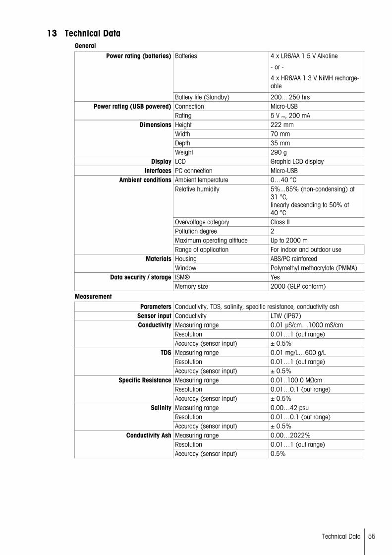
13 Technical DataGeneral
Batteries 4 x LR6/AA 1.5 V Alkaline
- or -
4 x HR6/AA 1.3 V NiMH rechargeable
Power rating (batteries)
Battery life (Standby) 200... 250 hrsConnection Micro-USBPower rating (USB powered)Rating 5 V , 200 mAHeight 222 mmWidth 70 mmDepth 35 mm
Dimensions
Weight 290 gDisplay LCD Graphic LCD display
Interfaces PC connection Micro-USBAmbient temperature 0…40 °CRelative humidity 5%...85% (non-condensing) at
31 °C,linearly descending to 50% at40 °C
Overvoltage category Class IIPollution degree 2Maximum operating altitude Up to 2000 m
Ambient conditions
Range of application For indoor and outdoor use Housing ABS/PC reinforcedMaterialsWindow Polymethyl methacrylate (PMMA)ISM® YesData security / storageMemory size 2000 (GLP conform)
MeasurementParameters Conductivity, TDS, salinity, specific resistance, conductivity ash
Sensor input Conductivity LTW (IP67)Measuring range 0.01 µS/cm…1000 mS/cmResolution 0.01…1 (out range)
Conductivity
Accuracy (sensor input) ± 0.5%Measuring range 0.01 mg/L…600 g/LResolution 0.01…1 (out range)
TDS
Accuracy (sensor input) ± 0.5%Measuring range 0.01..100.0 MΩcmResolution 0.01…0.1 (out range)
Specific Resistance
Accuracy (sensor input) ± 0.5%Measuring range 0.00…42 psuResolution 0.01…0.1 (out range)
Salinity
Accuracy (sensor input) ± 0.5%Measuring range 0.00…2022%Resolution 0.01…1 (out range)
Conductivity Ash
Accuracy (sensor input) 0.5%
55Technical Data
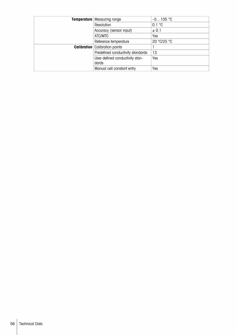
Measuring range –5…105 °CResolution 0.1 °CAccuracy (sensor input) ± 0.1ATC/MTC Yes
Temperature
Reference temperature 20 °C/25 °CCalibration points 1Predefined conductivity standards 13User-defined conductivity standards
Yes
Calibration
Manual cell constant entry Yes
56 Technical Data
14 Appendix
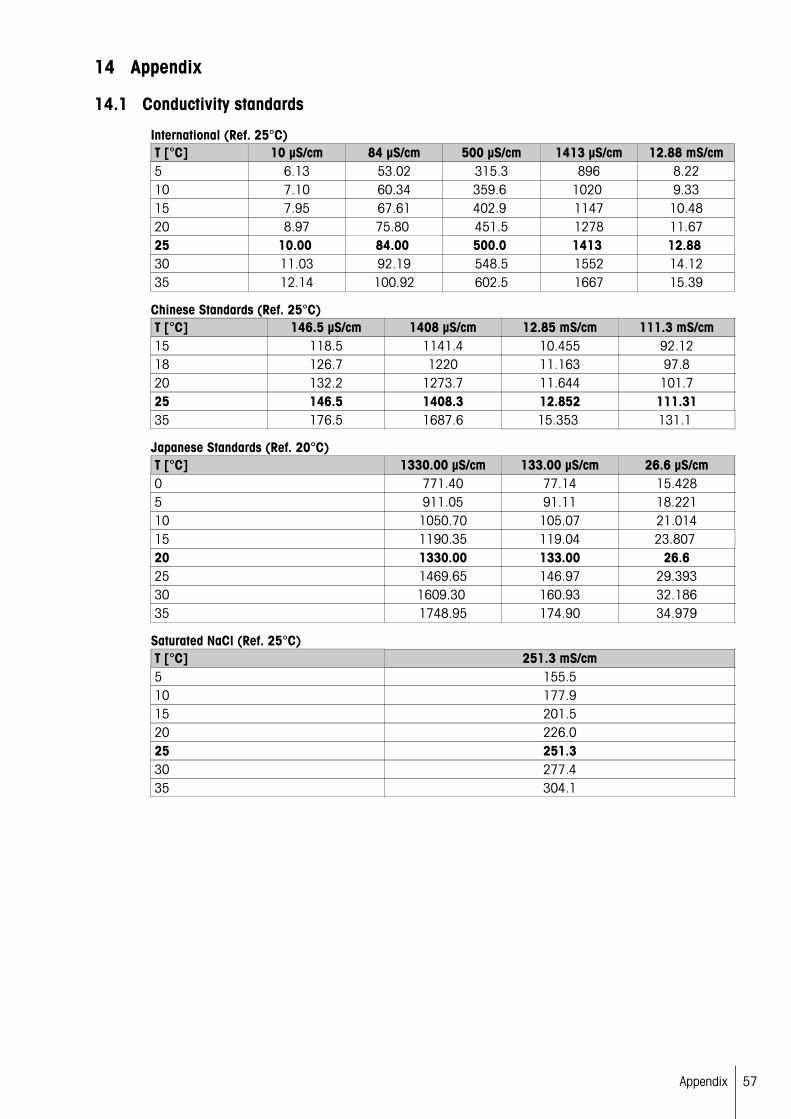
14.1 Conductivity standards
International (Ref. 25°C)T [°C] 10 µS/cm 84 µS/cm 500 µS/cm 1413 µS/cm 12.88 mS/cm5 6.13 53.02 315.3 896 8.2210 7.10 60.34 359.6 1020 9.3315 7.95 67.61 402.9 1147 10.4820 8.97 75.80 451.5 1278 11.6725 10.00 84.00 500.0 1413 12.88 30 11.03 92.19 548.5 1552 14.1235 12.14 100.92 602.5 1667 15.39
Chinese Standards (Ref. 25°C)T [°C] 146.5 µS/cm 1408 µS/cm 12.85 mS/cm 111.3 mS/cm15 118.5 1141.4 10.455 92.1218 126.7 1220 11.163 97.820 132.2 1273.7 11.644 101.725 146.5 1408.3 12.852 111.3135 176.5 1687.6 15.353 131.1
Japanese Standards (Ref. 20°C)T [°C] 1330.00 µS/cm 133.00 µS/cm 26.6 µS/cm0 771.40 77.14 15.4285 911.05 91.11 18.22110 1050.70 105.07 21.01415 1190.35 119.04 23.807 20 1330.00 133.00 26.625 1469.65 146.97 29.39330 1609.30 160.93 32.18635 1748.95 174.90 34.979
Saturated NaCl (Ref. 25°C)T [°C] 251.3 mS/cm5 155.510 177.915 201.520 226.025 251.330 277.435 304.1
57Appendix

14.2 Temperature correction factors
Temperature correction factors f25 for non-linear conductivity correction°C .0 .1 .2 .3 .4 .5 .6 .7 .8 .90 1.918 1.912 1.906 1.899 1.893 1.887 1.881 1.875 1.869 1.8631 1.857 1.851 1.845 1.840 1.834 1.829 1.822 1.817 1.811 1.8052 1.800 1.794 1.788 1.783 1.777 1.772 1.766 1.761 1.756 1.7503 1.745 1.740 1.734 1.729 1.724 1.719 1.713 1.708 1.703 1.6984 1.693 1.688 1.683 1.678 1.673 1.668 1.663 1.658 1.653 1.6485 1.643 1.638 1.634 1.629 1.624 1.619 1.615 1.610 1.605 1.6016 1.596 1.591 1.587 1.582 1.578 1.573 1.569 1.564 1.560 1.5557 1.551 1.547 1.542 1.538 1.534 1.529 1.525 1.521 1.516 1.5128 1.508 1.504 1.500 1.496 1.491 1.487 1.483 1.479 1.475 1.4719 1.467 1.463 1.459 1.455 1.451 1.447 1.443 1.439 1.436 1.43210 1.428 1.424 1.420 1.416 1.413 1.409 1.405 1.401 1.398 1.38411 1.390 1.387 1.383 1.379 1.376 1.372 1.369 1.365 1.362 1.35812 1.354 1.351 1.347 1.344 1.341 1.337 1.334 1.330 1.327 1.32313 1.320 1.317 1.313 1.310 1.307 1.303 1.300 1.297 1.294 1.29014 1.287 1.284 1.281 1.278 1.274 1.271 1.268 1.265 1.262 1.25915 1.256 1.253 1.249 1.246 1.243 1.240 1.237 1.234 1.231 1.22816 1.225 1.222 1.219 1.216 1.214 1.211 1.208 1.205 1.202 1.19917 1.196 1.193 1.191 1.188 1.185 1.182 1.179 1.177 1.174 1.17118 1.168 1.166 1.163 1.160 1.157 1.155 1.152 1.149 1.147 1.14419 1.141 1.139 1.136 1.134 1.131 1.128 1.126 1.123 1.121 1.11820 1.116 1.113 1.111 1.108 1.105 1.103 1.101 1.098 1.096 1.09321 1.091 1.088 1.086 1.083 1.081 1.079 1.076 1.074 1.071 1.06922 1.067 1.064 1.062 1.060 1.057 1.055 1.053 1.051 1.048 1.04623 1.044 1.041 1.039 1.037 1.035 1.032 1.030 1.028 1.026 1.02424 1.021 1.019 1.017 1.015 1.013 1.011 1.008 1.006 1.004 1.00225 1.000 0.998 0.996 0.994 0.992 0.990 0.987 0.985 0.983 0.98126 0.979 0.977 0.975 0.973 0.971 0.969 0.967 0.965 0.963 0.96127 0.959 0.957 0.955 0.953 0.952 0.950 0.948 0.946 0.944 0.94228 0.940 0.938 0.936 0.934 0.933 0.931 0.929 0.927 0.925 0.92329 0.921 0.920 0.918 0.916 0.914 0.912 0.911 0.909 0.907 0.90530 0.903 0.902 0.900 0.898 0.896 0.895 0.893 0.891 0.889 0.88831 0.886 0.884 0.883 0.881 0.879 0.877 0.876 0.874 0.872 0.87132 0.869 0.867 0.866 0.864 0.863 0.861 0.859 0.858 0.856 0.85433 0.853 0.851 0.850 0.848 0.846 0.845 0.843 0.842 0.840 0.83934 0.837 0.835 0.834 0.832 0.831 0.829 0.828 0.826 0.825 0.82335 0.822 0.820 0.819 0.817 0.816 0.814 0.813 0.811 0.810 0.808
58 Appendix
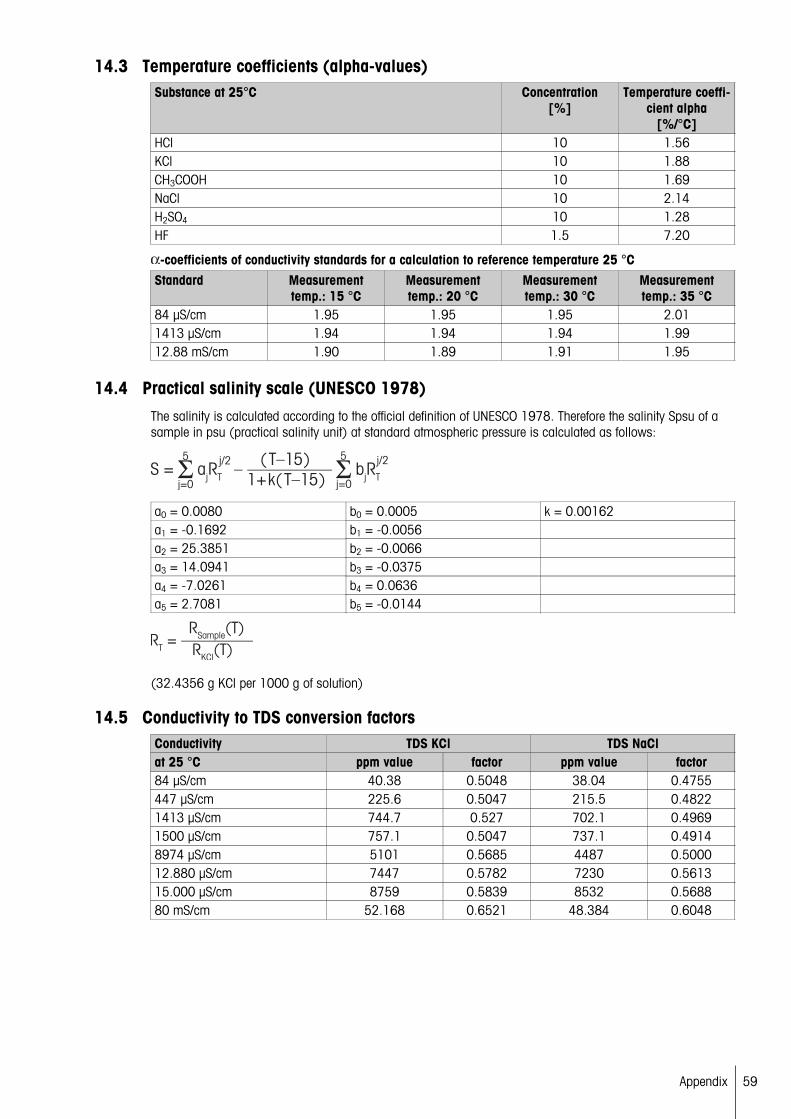
14.3 Temperature coefficients (alpha-values)Substance at 25°C Concentration
[%]Temperature coeffi
cient alpha[%/°C]
HCl 10 1.56KCl 10 1.88CH3COOH 10 1.69NaCl 10 2.14H2SO4 10 1.28HF 1.5 7.20
-coefficients of conductivity standards for a calculation to reference temperature 25 °CStandard Measurement
temp.: 15 °CMeasurementtemp.: 20 °C
Measurementtemp.: 30 °C
Measurementtemp.: 35 °C
84 µS/cm 1.95 1.95 1.95 2.011413 µS/cm 1.94 1.94 1.94 1.9912.88 mS/cm 1.90 1.89 1.91 1.95
14.4 Practical salinity scale (UNESCO 1978)The salinity is calculated according to the official definition of UNESCO 1978. Therefore the salinity Spsu of asample in psu (practical salinity unit) at standard atmospheric pressure is calculated as follows:
a0 = 0.0080 b0 = 0.0005 k = 0.00162a1 = -0.1692 b1 = -0.0056a2 = 25.3851 b2 = -0.0066a3 = 14.0941 b3 = -0.0375a4 = -7.0261 b4 = 0.0636a5 = 2.7081 b5 = -0.0144
(32.4356 g KCl per 1000 g of solution)
14.5 Conductivity to TDS conversion factorsConductivity TDS KCl TDS NaClat 25 °C ppm value factor ppm value factor84 µS/cm 40.38 0.5048 38.04 0.4755447 µS/cm 225.6 0.5047 215.5 0.48221413 µS/cm 744.7 0.527 702.1 0.49691500 µS/cm 757.1 0.5047 737.1 0.49148974 µS/cm 5101 0.5685 4487 0.500012.880 µS/cm 7447 0.5782 7230 0.561315.000 µS/cm 8759 0.5839 8532 0.568880 mS/cm 52.168 0.6521 48.384 0.6048
59Appendix

14.6 USP/EP tablesConductivity requirements (µS/cm) for USP / EP (highly purfied water) / EP (purfied water)
Temperature
[°C]
USP
[µS/cm]
EP(highly purfied water)
[µS/cm]
EP(purfied water)
[µS/cm]0 0.6 0.6 2.45 0.8 0.8 -10 0.9 0.9 3.615 1.0 1.0 -20 1.1 1.1 4.325 1.3 1.3 5.130 1.4 1.4 5.435 1.5 1.5 -40 1.7 1.7 6.545 1.8 1.8 -50 1.9 1.9 7.155 2.1 2.1 -60 2.2 2.2 8.165 2.42 2.42 -70 2.5 2.5 9.175 2.7 2.7 9.780 2.7 2.7 9.785 2.7 2.7 -90 2.7 2.7 9.795 2.9 2.9 -100 3.1 3.1 10.2
14.7 Conductivity ash methodsThe meter can measure the conductivity ash (%) according to the two ICUMSA methods:
14.7.1 Refined sugar (28 g/100 g solution) ICUMSA GS2/3-17
The formula that the instrument uses is:
%(m/m)=0,0006x((C1/(1+0,026x(T-20)))–0,35x(C2/(1+0,026x(T-20)))xK)
C1 = conductivity of the sugar solution in μS/cm with cell constant = 1 cm-1
C2 = conductivity of the water used in μS/cm to prepare the sugar solution with cell constant = 1 cm-1
T = temperature in °C between 15°C and 25°C
K = cell constant
14.7.2 Raw sugar or melasses (5 g / 100 mL solution) ICUMSA GS 1/3/4/7/8-13
The formula that the instrument uses is:
%(m/V)=0,0018x((C1/(1+0,023x(T-20))-C2/(1+0,023x(T-20)))xK)
C1 = conductivity of the sugar solution in μS/cm with cell constant = 1 cm-1
C2 = conductivity of the water used to prepare the sugar solution in μS/cm with cell constant = 1 cm-1
T = temperature in °C between 15°C and 25°C
K = cell constant of the used sensor
60 Appendix


*30219677*
For more informationwww.mt.com/ph
Mettler-Toledo AG, AnalyticalCH-8603 Schwerzenbach, SwitzerlandTel. +41 (0)44 806 77 11Fax +41 (0)44 806 73 50www.mt.com
Subject to technical changes.© Mettler-Toledo AG 08/201430219677A