sevee & maher map adapted from 7.5 min usgs topographic quadrangle lewiston, me - 1979 figure 1...
TRANSCRIPT


____________________ 1 SITE PLAN REVIEW APP TEXT.DOC Sevee & Maher Engineers, Inc. November 2018
TABLE OF CONTENTS
Section No. Title Page No.
1.0 PROJECT DESCRIPTION ................................................................................................... 1
2.0 SITE DESIGN CRITERIA ..................................................................................................... 3
LIST OF ATTACHMENTS
ATTACHMENT A TITLE, RIGHT OR INTEREST ATTACHMENT B FINANCIAL AND TECHNICAL CAPACITY ATTACHMENT C STORMWATER MANAGEMENT REPORT ATTACHMENT D CAPACITY TO SERVE LETTERS ATTACHMENT E EROSION AND SEDIMENTION CONTROL PLAN ATTACHMENT F MHPC MAP ATTACHMENT G FEMA FIRM MAP
_________________________ 1 SITE PLAN REVIEW APP TEXT.DOC Sevee & Maher Engineers, Inc. November 2018
CITY OF AUBURN DEVELOPMENT REVIEW APPLICATION
BANK BRANCH AND OFFICE BUILDING AUBURN, MAINE
1.0 PROJECT DESCRIPTION
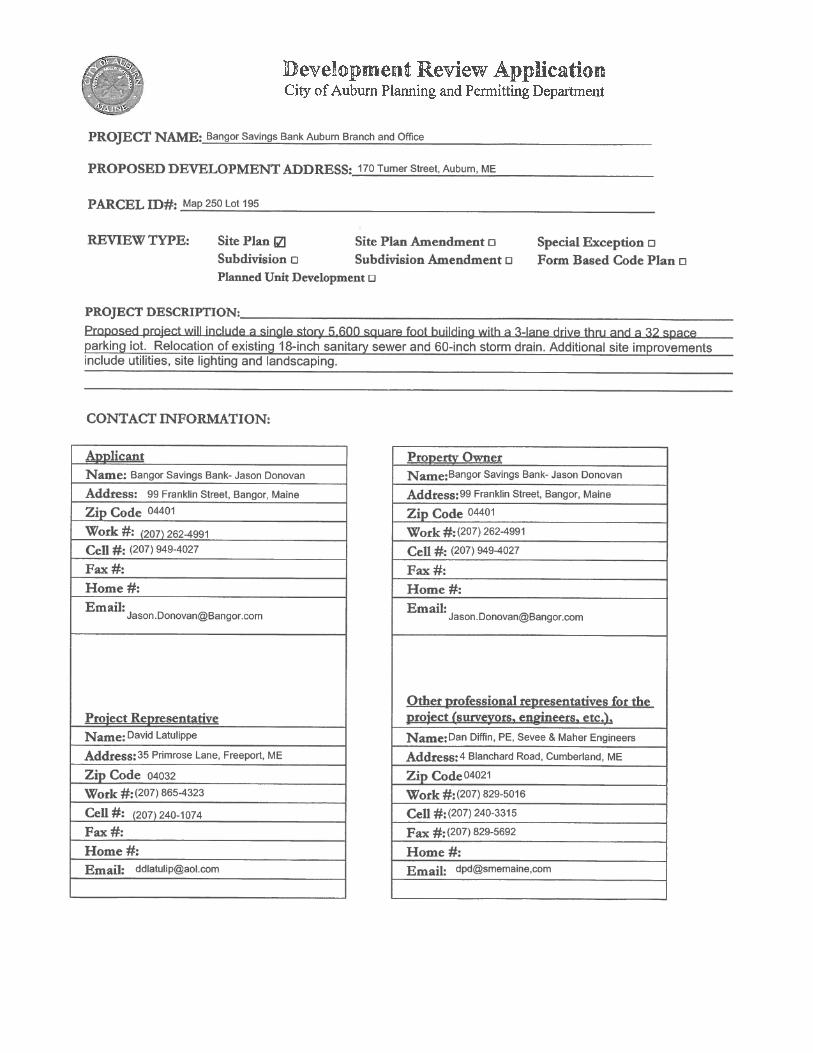
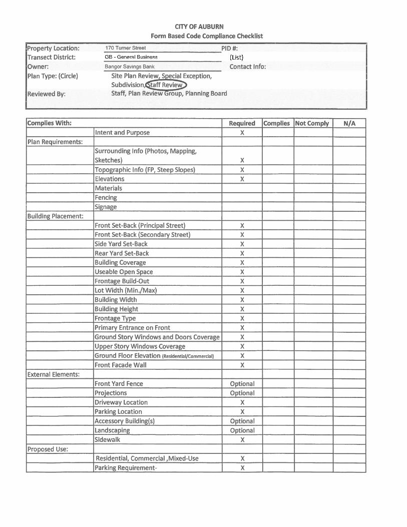
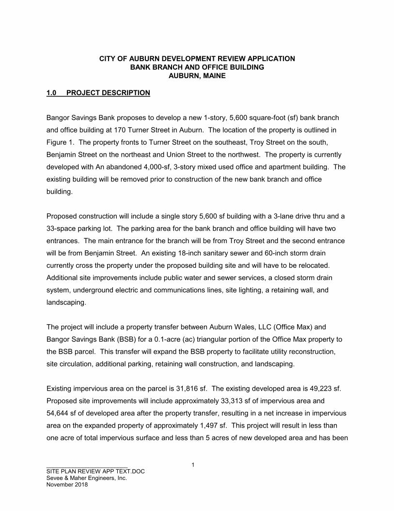
Bangor Savings Bank proposes to develop a new 1-story, 5,600 square-foot (sf) bank branch
and office building at 170 Turner Street in Auburn. The location of the property is outlined in
Figure 1. The property fronts to Turner Street on the southeast, Troy Street on the south,
Benjamin Street on the northeast and Union Street to the northwest. The property is currently
developed with An abandoned 4,000-sf, 3-story mixed used office and apartment building. The
existing building will be removed prior to construction of the new bank branch and office
building.
Proposed construction will include a single story 5,600 sf building with a 3-lane drive thru and a
33-space parking lot. The parking area for the bank branch and office building will have two
entrances. The main entrance for the branch will be from Troy Street and the second entrance
will be from Benjamin Street. An existing 18-inch sanitary sewer and 60-inch storm drain
currently cross the property under the proposed building site and will have to be relocated.
Additional site improvements include public water and sewer services, a closed storm drain
system, underground electric and communications lines, site lighting, a retaining wall, and
landscaping.
The project will include a property transfer between Auburn Wales, LLC (Office Max) and
Bangor Savings Bank (BSB) for a 0.1-acre (ac) triangular portion of the Office Max property to
the BSB parcel. This transfer will expand the BSB property to facilitate utility reconstruction,
site circulation, additional parking, retaining wall construction, and landscaping.
Existing impervious area on the parcel is 31,816 sf. The existing developed area is 49,223 sf.
Proposed site improvements will include approximately 33,313 sf of impervious area and
54,644 sf of developed area after the property transfer, resulting in a net increase in impervious
area on the expanded property of approximately 1,497 sf. This project will result in less than
one acre of total impervious surface and less than 5 acres of new developed area and has been

BASE MAP ADAPTED FROM 7.5 MIN
USGS TOPOGRAPHIC QUADRANGLE
LEWISTON, ME - 1979
FIGURE 1
SITE LOCATION MAP
BANGOR SAVINGS BANK
AUBURN BRANCH/OFFICE BUILDING
AUBURN, MAINE
6/22/2018SITELOC SME-STDDWG: REV:LMN: CTB:
SME
SEVEE & MAHER
ENGINEERS
01000 2000 FEET
SITE LOCATION
\\Nse
rver\c
fs\Ba
ngor
Sav
ings B
ank\A
ubur
n\Aca
d\Figu
res\S
ITEL
OC.dw
g, 6/2
2/201
8 9:12
:56 A
M, bw
b
_________________________ 3 SITE PLAN REVIEW APP TEXT.DOC Sevee & Maher Engineers, Inc. November 2018
designed to meet Basic Standards as outlined in Maine Department of Environmental
Protection (MEDEP) Chapter 500. The project will not require a MEDEP Stormwater
Management Permit.
Proposed site improvements and a schematic building design are outlined in the attached
drawing set. Conformance with the requirements of Chapter 60 of the City of Auburn Code of
Ordinances are outlined in the following sections of this application package.
2.0 SITE DESIGN CRITERIA
A. District Regulation (Chapter 60, Article IV, Division 12)
The project site is in the General Business District.
Use Regulation: The property will be developed as a bank branch and business
office. Both uses are permitted use in section 60-499(a), Article IV of the City of
Auburn Zoning Ordinance.
Setbacks: The proposed building has been designed to suit existing topography,
landscape, and subsurface conditions on the property. Building setbacks meet
the requirements of the zoning ordinance, including a 14-foot setback from
Turner Street (as amended by the City), and 25-foot setbacks from Benjamin
Street, Union Street and Troy Street. The rear building setback adjacent to the
Office Max property is 35 feet. Building setbacks and a table outlining additional
dimensional standards are included on Drawing C-102.
B. Off Street Parking and Loading: (Chapter 60, Article VI) Off Street Parking: Off-street parking space requirements for multi-use building
office and a branch are outlined in Section 60-608 of the City of Auburn Zoning
Ordinance. The ordinance outlines 1 space per 200 sf of office area and 1
space per 300 sf of bank branch area. The square footage of the bank branch is
2,960 square feet, resulting in a minimum of 10 parking spaces for this use. The
square footage of the office is 3,360 square feet, resulting in a minimum of 17
parking spaces required for office space use. Total required parking for the
_________________________ 4 SITE PLAN REVIEW APP TEXT.DOC Sevee & Maher Engineers, Inc. November 2018
proposed use is 27 spaces. Thirty-three parking spaces are proposed for this
project, which exceeds the standard requirement.
Off Street Loading: Off-street loading space requirements are outlined in
Section 60-609 of the City of Auburn Zoning Ordinance. Loading on the street is
not anticipated under normal building operations, and adequate space for
loading is provided on the property. The building will not require any additional
loading space in the public right of way.
C. Signs – (Chapter 60, Article VI)
Two signs are proposed as part of this project. One will be located on the
eastern portion of the property at the corner of Turner Street and Benjamin
Street. A second sign will be located on the western portion of the property
facing Union Street. Sign locations were designed to meet the standards of
Article VI Section 60.637 of the City Zoning Ordinance.
D. Access Management Standards (Chapter 60, Article X)
Site Access: Access Management Standards are outlined in Article X of the City
of Auburn Zoning Ordinance. Requirements include the following:
a) 60-799: Safe sight distance: Troy Street and Benjamin Street are a low
volume, 20 mile-per-hour (mph) streets. City Ordinance requires 200 feet
of sight distance for the 20-mph posted speed limit. More than 200 feet
of sight distance is available both directions on Troy and Benjamin
Streets, which meets the requirement of the ordinance.
b) 60-800: Curb cut and driveway spacing: City Ordinance requires a
minimum curb cut separation distance of 85 feet from the midpoint of a
proposed driveway to the intersection of two streets. The distance from
the midpoint of the proposed Benjamin Street access to Union Street is
approximately 89 feet, which meets the municipal separation distance.
The distance from the midpoint of the Troy Street access to Turner Street
is 85feet, which also meets the municipal standard.
c) 60-801: Number of driveways per lot: There are two driveways proposed
as part of this project. Site access includes one two-way access to Troy
_________________________ 5 SITE PLAN REVIEW APP TEXT.DOC Sevee & Maher Engineers, Inc. November 2018
Street and one two-way driveway to Benjamin Street. City ordinance
requires one two-way access per roadway. The proposed configuration
meets the requirement of the Ordinance.
d) 60-803: Corner lot access: The Ordinance requires that corner lot
access should be located on the minor road of the two adjacent streets.
Proposed access for the property is located on Benjamin Street and Troy
Street, which are minor roads. The proposed access meets the
requirement of the Ordinance.
Peak Hour for On-Site: A total of 15 employees are anticipated for the proposed
bank branch and office building. Seven employees will work at the bank branch,
and 8 employees will occupy the office space.
The anticipated maximum peak hour vehicle trip ends for the bank branch will be
83 for the PM peak hour on a weekday and 4 for the office space during the AM
peak hour on a weekday. The total combined trip ends for the site on a weekday
is 87. Since the proposed total does not exceed 100 trips, a Traffic Movement
Permit (TMP) will not be required from the Maine Department of Transportation
(MEDOT). Total trips for the property will be divided between the two proposed
site entrances, which will help reduce impact to adjacent streets.
Vehicle Movement and Pedestrian Circulation: The proposed parking area and
drive aisles were designed of meet the requirements for off-street parking
outlined in this Ordinance. The parking area will be paved and feature well
defined circulation routes, traffic control signage and pedestrian crossings to
minimize conflict between vehicles and pedestrians. The Site Layout Plan,
Drawing C-102, outlines design and construction for the proposed parking area.
Fire protection: The National Fire Protection Association (NFPA) requires
sprinkler systems for buildings that are greater than 10,000 square feet. The
proposed building 5,600 square feet and will not require a sprinkler system.
_________________________ 6 SITE PLAN REVIEW APP TEXT.DOC Sevee & Maher Engineers, Inc. November 2018
Parking and service areas have been designed to accommodate fire truck
access to the building. Concrete sidewalks are proposed on the south side of
the building to improve building egress from the south side of the structure.
E. Environmental Regulations (Chapter 60, Article XII)
The project site is not in the Environment Regulated District and not required to
meet the standards outlined in this section.
F. Environmental Performance Standard (Chapter 60, Article XIII)
The Environmental Performance Standard in Article XIII of the City of Auburn
Zoning Ordinance includes the following sections:
a) 60-1036: Noise: Construction will occur between 7:00 am and 7:00 pm,
in conformance with section 60-1036. Following construction, noise
levels are not anticipated to be excessive.
b) 60-1037: Vibration: Construction of the site and building will not result in
unnecessary vibration.
c) Phosphorus Control: The site is not in the Lake Auburn or Taylor Pond
watershed. Phosphorus control is not required for this project.
G. Historic and Archaeological Resources (Chapter 60, Article XIV)
This project is currently developed with a multi-story apartment building and retail
space. The Maine Historic Preservation Commission (MHPC) has not identified
any historic and archaeological resources on this site. A map from MHPC
outlining the historic and archaeological resources in the area is included in
Attachment F.

_________________________ 7 SITE PLAN REVIEW APP TEXT.DOC Sevee & Maher Engineers, Inc. November 2018
H. Utilities
Existing development on the property includes a 60-inch diameter storm drain
and an 18-inch diameter sanitary sewer main. Portions of these existing utilities
exist under the proposed building location and will require relocation to enhance
future maintenance and minimize settlement to the proposed structure. The
existing 60-inch diameter storm drain and 18-inch diameter sewer will be
relocated to the southwest portion of the property, approximately 20 feet away
from the proposed building. The proposed 6-inch sanitary sewer service for the
new building will connect to the relocated municipal 18-inch sewer on the
property.
The building will include a new 2-inch water service connecting to the existing 8”
water main in the Troy Street right-of-way, near the intersection of Troy Street
and Turner Street. The Auburn, Maine Water and Sewerage District (AWSD)
has verified they have capacity to serve the project. A copy of their letter is
included in Attachment D.
Natural gas service will be provided from the existing 2-inch diameter gas main
in the Benjamin Street right-of-way. Unitil has verified that capacity is available
for the building from the existing main. A copy of their letter is included in
Attachment D.
Electric and communications services will be provided to the site from the
existing utility pole on east side of Turner Street. Development will include
installation of a new riser pole and transformer adjacent to the project site on the
west side of Turner Street. The new service will run underground from the new
pole into the building.
I. Grading and Drainage
Attachment C includes a Stormwater Management Report describing the impacts
of proposed development on projected stormwater runoff from the property. The
property discharges directly to the municipal storm drain system. Our model
indicates the existing system has adequate capacity to accommodate the
_________________________ 8 SITE PLAN REVIEW APP TEXT.DOC Sevee & Maher Engineers, Inc. November 2018
proposed development. We do not anticipate any adverse impacts to
downstream properties or structures resulting from this project.
Attachment C also includes a Post-Construction Stormwater Management
Report for the project to assist the owner with future operations and maintenance
of stormwater management devices on the property.
Based on review of the flood hazard boundary maps, the site is not situated in a
federally designated flood hazard zone. A FEMA FIRM map for the project area
is included in Attachment G for reference.
J. Erosion Control
All grading, filling, and associated site construction will be conducted in
accordance with the Maine Erosion and Sediment Control Best Management
Practices (BMPs) latest edition, dated October 2016. This will be the minimum
standard for erosion and sedimentation control for the project, as adopted by the
City of Auburn from the MEDEP standards. A copy of the Erosion and
Sedimentation Control Plan is included in Attachment E. Erosion and
sedimentation control notes and details are included on Drawing C-103, Drawing
C-300, and Drawing C-301 in the project plan set.
K. Landscaping
Screening, buffering, and landscaping on the property were designed by a
registered landscape architect in accordance with the standards outlined in this
section. Buffer yards and screening are shown on the Site Planting Plan L-1
included in the project plan set.
L. Right of Title or Interest, Technical and Financial Capacity
As previously outlined, this project will include a property transfer between Office
Max and BSB for a 0.1-acre (ac) triangular portion of the Office Max property to
the BSB parcel. A copy of the quitclaim deed for the main parcel and draft
language for the parcel to be transferred to BSB from Auburn Wales, LLC, are
included in Attachment A.

_________________________ 9 SITE PLAN REVIEW APP TEXT.DOC Sevee & Maher Engineers, Inc. November 2018
A description outlining technical and financial capacity for the project are
included in Attachment B.

ATTACHMENT A
TITLE, RIGHT OR INTEREST

N O T N O T
A N A N
O F F I C I A L O F F I C I A L
C O P Y C O P Y
N O T N O T
A N A N
O F F I C I A L O F F I C I A L
C O P Y C O P Y
N O T N O T
A N A N
O F F I C I A L O F F I C I A L
C O P Y C O P Y
N O T N O T
A N A N
O F F I C I A L O F F I C I A L
C O P Y C O P Y
N O T N O T
A N A N
O F F I C I A L O F F I C I A L
C O P Y C O P Y
N O T N O T
A N A N
O F F I C I A L O F F I C I A L
C O P Y C O P Y

PROPERTY TRANSFER This project will include a property transfer between Auburn Wales, LLC (Office Max) and Bangor Savings Bank (BSB) for a 0.1-acre (ac) triangular portion of the Office Max property to the BSB parcel. The property transfer is in progress and final documentation of the transfer be submitted prior to the start of construction. The draft narrative for the property transfer is on the next page.

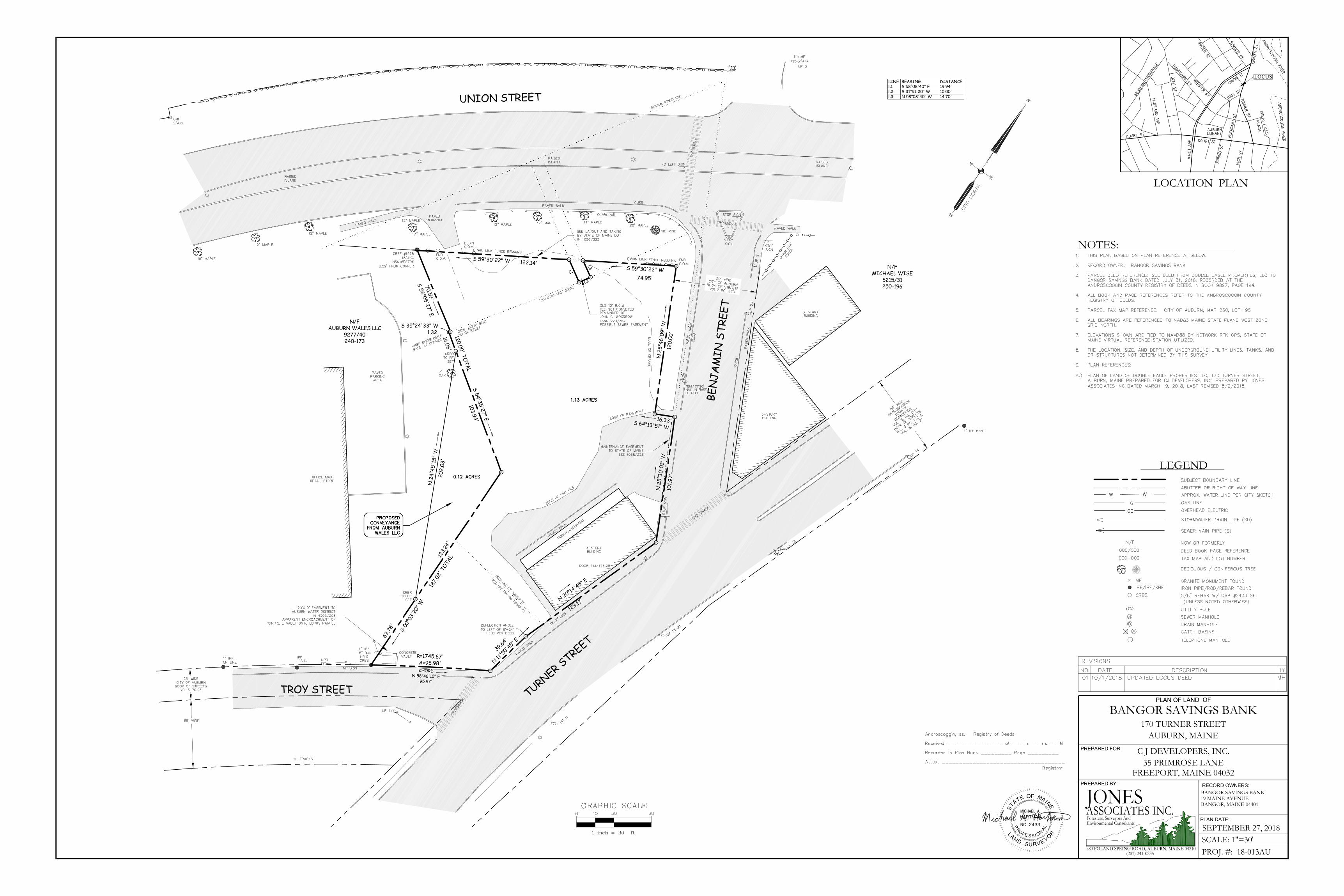
PARCEL TO BE CONVEYED FROM AUBURN WALES LLC A certain lot or parcel of land situated northwesterly but not adjacent to Troy Street and southeasterly of, but not adjacent to Union Street, in the City of Auburn, County of Androscoggin, State of Maine, being more particularly bounded and described as follows: Beginning at a 5/8” rebar with cap #2433 on the easterly line of land now or formerly of Auburn Wales LLC (Grantor) as described in a deed recorded at the Androscoggin County Registry of Deeds in Book 9277, Page 40, and on the westerly side of land now or formerly of Bangor Savings Bank, as described in a deed recorded at the said Registry of Deeds in Book 9897, Page 194, said point being located N 00°03'20" E a distance of 63.78 feet from a 1 inch iron pin found on the northwesterly sideline of Troy Street, at the southeast corner of said Grantor, and the southwest corner of said Bangor Savings Bank; thence N 24°45'15" W through land of the Grantor, a distance of 202.03 feet to a 5/8 inch rebar with cap #2433 set at land of said Bangor Savings Bank ; thence S 54°35'27" E along land of said Bangor Savings Bank, a distance of 103.94 feet to a 5/8 inch rebar with cap #2433 set ; thence S 00°03'20" W along land of said Bangor Savings Bank, a distance of 123.24 feet to the point of beginning. The above described parcel contains 0.12 acres. All bearings noted are referenced to NAD83 Maine State Plane West Zone Grid North. Meaning and intending to convey a portion of the premises conveyed to Auburn Wales LLC by a deed from JTS Management, LLC dated December 5, 2015, recorded at the said Registry of Deeds in Book 9277, Page 40. The above description is based on a boundary sketch by Jones Associates Inc., entitled “Proposed Conveyance Sketch of Portion of Tax Map 240 Lot 173” Bangor Savings Bank, 170 Turner Street, Auburn, Maine, dated September 27, 2018, revised October 1, 2018.

ATTACHMENT B
FINANCIAL AND TECHNICAL CAPACITY

FINANCIAL CAPACITY The Applicant is in the process of securing financing for the project and will provide a letter of Financial Capacity to the City prior to the start of construction. The Applicant requests that the letter be a condition of approval for the project. TECHNICAL CAPACITY A. PRIOR EXPERIENCE The Bangor Savings Bank has contracted with experienced, qualified firms to manage the facility’s design and construction. The following is a list of the firms and the roles for this project. Construction Manager: Landry French Construction 160 Pleasent Hill Road Scarborough, ME 04074
Website: http://landryfrenchconstruction.com/ Building Architect: TAC Architectural Group 40 Summer St, Suite 4 Bangor, ME 04401
Website: https://tac-arch.com/ Civil & Geotechnical Engineer:
Sevee & Maher Engineers, Inc. 4 Blanchard Road
Cumberland Center, ME 04021 Website: www.smemaine.com
Landscape Architect: Land Design Solutions 160 Longwoods Road’ Cumberland, ME 04021

ATTACHMENT C
STORMWATER MANAGEMENT REPORT
STORMWATER MANAGEMENT REPORT
Prepared for
BANGOR SAVINGS BANK AUBURN BRANCH/OFFICE BUILDING
AUBURN, MAINE
November 2018

____________________ i Stormwater Management Report Sevee & Maher Engineers, Inc. November 2018
TABLE OF CONTENTS
Section No. Title Page No. 1.0 INTRODUCTION.................................................................................................................. 1
2.0 PROJECT DESCRIPTION ................................................................................................... 1
3.0 SITE WATERSHED ............................................................................................................. 2
4.0 STORMWATER QUALITY ANALYSIS ................................................................................ 3
5.0 STORMWATER QUANTITY ANALYSIS ............................................................................. 4
6.0 SUMMARY .......................................................................................................................... 5 LIST OF APPENDICES APPENDIX A NRCS SOIL REPORT APPENDIX B PRE-DEVELOPMENT HYDROCAD CALCULATIONS APPENDIX C POST-DEVELOPMENT HYDROCAD CALCULATIONS APPENDIX D POST-CONSTRUCTION STORMWATER MANAGEMENT PLAN APPENDIX E PRE-, POST-DEVELOPMENT STORMWATER FIGURES

____________________ ii Stormwater Management Report Sevee & Maher Engineers, Inc. November 2018
LIST OF TABLES
Table No. Title Page No. 1 STORMWATER QUANTITY SUMMARY (CFS) .................................................................. 4
____________________ Stormwater Management Report Sevee & Maher Engineers, Inc. November 2018
1
STORMWATER MANAGEMENT REPORT
BANGOR SAVINGS BANK AUBURN, MAINE
1.0 INTRODUCTION
This stormwater management report has been prepared by Sevee & Maher Engineers, Inc.
(SME), to assess stormwater management design for proposed site development located at 170
Turner Street in Auburn, Maine. Stormwater design is based on the water quality and quantity
objectives identified in Chapter 500 of the Maine Department of Environmental Protection
(MEDEP) Stormwater Management Law and the City of Auburn Code of Ordinance.
2.0 PROJECT DESCRIPTION
Bangor Savings Bank proposes to develop a new 1-story, 5,600 square-foot (sf) bank branch
and office building at 170 Turner Street in Auburn. The property fronts to Turner Street on the
southeast, Troy Street on the south, Benjamin Street on the northeast and Union Street to the
northwest. The property is currently developed with An abandoned 4,000-sf, 3-story mixed
used office and apartment building. The existing building will be removed prior to construction
of the new bank branch and office building.
Proposed construction will include a single story 5,600 sf building with a 3-lane drive thru and a
33-space parking lot. The parking area for the bank branch and office building will have two
entrances. The main entrance for the branch will be from Troy Street and the second entrance
will be from Benjamin Street. An existing 18-inch sanitary sewer and 60-inch storm drain
currently cross the property under the proposed building site and will have to be relocated.
Additional site improvements include public water and sewer services, a closed storm drain
system, underground electric and communications lines, site lighting, a retaining wall, and
landscaping.
The project will include a property transfer between Auburn Wales, LLC (Office Max) and
Bangor Savings Bank (BSB) for a 0.1-acre (ac) triangular portion of the Office Max property to
____________________ Stormwater Management Report Sevee & Maher Engineers, Inc. November 2018
2
the BSB parcel. This transfer will expand the BSB property to facilitate utility reconstruction, site
circulation, additional parking, retaining wall construction, and landscaping.
Existing impervious area on the parcel is 31,816 sf. The existing developed area is 49,223 sf.
Proposed site improvements will include approximately 33,313 sf of impervious area and 54,644
sf of developed area after the property transfer, resulting in a net increase in impervious area on
the expanded property of approximately 1,497 sf. This project will result in less than one acre of
total impervious surface and less than 5 acres of new developed area and has been designed to
meet Basic Standards as outlined in Maine Department of Environmental Protection (MEDEP)
Chapter 500. The project will not require a MEDEP Stormwater Management Permit.
3.0 SITE WATERSHED
On-site soils were identified using the Natural Resources Conservation Service (NRCS) online
soil information for Androscoggin and Sagadahoc Counties, Maine. A copy of the custom Soil
Resource Report is included in Appendix A. The soil within the work area consists of made land
(Md) with slopes ranging from less than 1 percent to 35 percent. On-site soils are classified as
“moderately well drained” and designated as hydrologic soil group (HSG) C for this
investigation.
The project site is located in downtown Auburn across from Great Falls Plaza. The property
fronts to Turner Street on the southeast, Troy Street on the south, Benjamin Street on the
northeast and Union Street to the northwest. Boundary and topographic data for the attached
project plan set was obtained from a survey completed by Jones Associates (Jones), dated
August 2, 2018.
Under existing conditions, the site generally drains from northwest to southeast. Stormwater
runoff is collected by a series of catch basins and a culvert that convey stormwater runoff off site
to the City’s storm drain system.
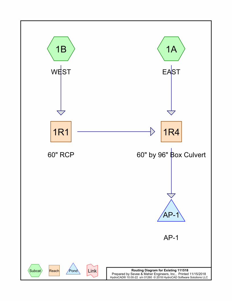
Stormwater flows were evaluated using two drainage subcatchments and a single Analysis
Point (AP). The northern subcatchment (SC-1B) drains to an existing 12-inch culvert connected
____________________ Stormwater Management Report Sevee & Maher Engineers, Inc. November 2018
3
to DMH-1, a drain manhole in the north central portion of the property that connects to an
existing 60-inch municipal storm drain pipe crossing the parcel. Surface runoff in the southern
drainage subcatchment (SC-1A) flows to an existing catch basin at the eastern end of the parcel
that connects to DMH-2, an existing drain manhole in the south-central portion of the property
connected to the existing 60-inch municipal storm drain pipe crossing the parcel. Runoff is
analyzed at Analysis Point 1 (AP-1), a catch basin at the southwest corner of Troy Street and
Turner Street. The existing catch basin as AP-1 is connected to the 60-inch municipal storm
drain pipe that crosses the project site. AP-1 was established to estimate the combined flows
from individual subcatchments and assess impact to the municipal storm drain system.
Under developed conditions, site drainage will be similar to existing conditions. Surface grading
and curbing will be used to direct stormwater runoff to a series of new catch basins connected
to DMH-201 and DMH-202, two replacement structures installed as part of the required storm
drain relocation. These new drain manholes will connect to the existing 60-inch diameter storm
drain crossing the property and discharge to existing DMH-2 and the existing municipal storm
drain system in Troy Street. Portions of the existing 60-inch drainage pipe and 12-inch culvert
will be bypassed and abandoned, and a new pipe will be installed to convey runoff to the
municipal system. Runoff previously collected by the 12-inch storm drain will be routed to CB-
105 and DMH-201.
Pre- and post-development stormwater management plans identify the on-site drainage patterns
before and after development. Figures D-100 and D-101 are included in Appendix E of this
report for reference. Appendices B and C provide pre- and post-development calculations using
TR-20 methodologies prepared with the HydroCAD Version 10.0 computer stormwater modeling
system by Applied Microcomputer Systems of Chocorua, New Hampshire.
4.0 STORMWATER QUALITY ANALYSIS
As previously outlined, stormwater treatment will not be required for this project based on Maine
Department of Environmental Protection (MEDEP) Chapter 500 standards. Based on the size
of the project and the scope of proposed development, we do not anticipate redevelopment of
the parcel will adversely impact the quality of stormwater runoff from the property. The site is
____________________ Stormwater Management Report Sevee & Maher Engineers, Inc. November 2018
4
located near the base of a large, urban watershed and currently discharges directly to a
municipal storm drain system. New construction will include clearing the site, replacement of
gravel parking surfaces with pavement, installation of landscaping, and construction of a closed
stormwater management system. This project is designed to meet Basic Standards outlined in
Maine Department of Environmental Protection (MEDEP) Chapter 500, and construction will
adhere to MEDEP Best Management Practices (BMP’s) for erosion and sedimentation control.
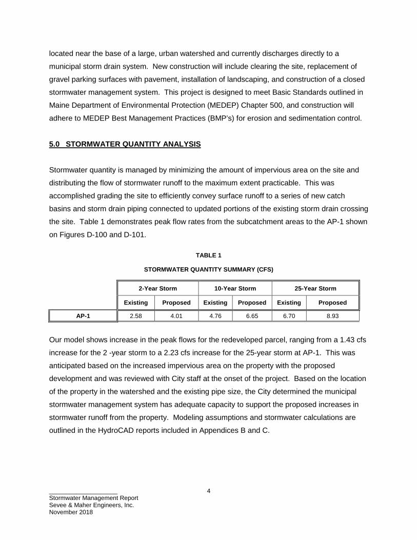
5.0 STORMWATER QUANTITY ANALYSIS Stormwater quantity is managed by minimizing the amount of impervious area on the site and
distributing the flow of stormwater runoff to the maximum extent practicable. This was
accomplished grading the site to efficiently convey surface runoff to a series of new catch
basins and storm drain piping connected to updated portions of the existing storm drain crossing
the site. Table 1 demonstrates peak flow rates from the subcatchment areas to the AP-1 shown
on Figures D-100 and D-101.
TABLE 1
STORMWATER QUANTITY SUMMARY (CFS)
2-Year Storm 10-Year Storm 25-Year Storm
Existing Proposed Existing Proposed Existing Proposed
AP-1 2.58 4.01 4.76 6.65 6.70 8.93
Our model shows increase in the peak flows for the redeveloped parcel, ranging from a 1.43 cfs
increase for the 2 -year storm to a 2.23 cfs increase for the 25-year storm at AP-1. This was
anticipated based on the increased impervious area on the property with the proposed
development and was reviewed with City staff at the onset of the project. Based on the location
of the property in the watershed and the existing pipe size, the City determined the municipal
stormwater management system has adequate capacity to support the proposed increases in
stormwater runoff from the property. Modeling assumptions and stormwater calculations are
outlined in the HydroCAD reports included in Appendices B and C.

____________________ Stormwater Management Report Sevee & Maher Engineers, Inc. November 2018
5
6.0 SUMMARY This project will not have an adverse impact to the abutting properties or downstream drainage
structures. The project discharges to an existing municipal storm drain system, located near the
bottom of a large, urban watershed. Based on review with City staff, anticipated increases
stormwater runoff from the property will not exceed the capacity the existing municipal storm
drain system.

APPENDIX A
NRCS SOIL REPORT
United StatesDepartment ofAgriculture
A product of the NationalCooperative Soil Survey,a joint effort of the UnitedStates Department ofAgriculture and otherFederal agencies, Stateagencies including theAgricultural ExperimentStations, and localparticipants
Custom Soil Resource Report forAndroscoggin and Sagadahoc Counties, Maine
NaturalResourcesConservationService
April 4, 2018

PrefaceSoil surveys contain information that affects land use planning in survey areas. They highlight soil limitations that affect various land uses and provide information about the properties of the soils in the survey areas. Soil surveys are designed for many different users, including farmers, ranchers, foresters, agronomists, urban planners, community officials, engineers, developers, builders, and home buyers. Also, conservationists, teachers, students, and specialists in recreation, waste disposal, and pollution control can use the surveys to help them understand, protect, or enhance the environment.
Various land use regulations of Federal, State, and local governments may impose special restrictions on land use or land treatment. Soil surveys identify soil properties that are used in making various land use or land treatment decisions. The information is intended to help the land users identify and reduce the effects of soil limitations on various land uses. The landowner or user is responsible for identifying and complying with existing laws and regulations.
Although soil survey information can be used for general farm, local, and wider area planning, onsite investigation is needed to supplement this information in some cases. Examples include soil quality assessments (http://www.nrcs.usda.gov/wps/portal/nrcs/main/soils/health/) and certain conservation and engineering applications. For more detailed information, contact your local USDA Service Center (https://offices.sc.egov.usda.gov/locator/app?agency=nrcs) or your NRCS State Soil Scientist (http://www.nrcs.usda.gov/wps/portal/nrcs/detail/soils/contactus/?cid=nrcs142p2_053951).
Great differences in soil properties can occur within short distances. Some soils are seasonally wet or subject to flooding. Some are too unstable to be used as a foundation for buildings or roads. Clayey or wet soils are poorly suited to use as septic tank absorption fields. A high water table makes a soil poorly suited to basements or underground installations.
The National Cooperative Soil Survey is a joint effort of the United States Department of Agriculture and other Federal agencies, State agencies including the Agricultural Experiment Stations, and local agencies. The Natural Resources Conservation Service (NRCS) has leadership for the Federal part of the National Cooperative Soil Survey.
Information about soils is updated periodically. Updated information is available through the NRCS Web Soil Survey, the site for official soil survey information.
The U.S. Department of Agriculture (USDA) prohibits discrimination in all its programs and activities on the basis of race, color, national origin, age, disability, and where applicable, sex, marital status, familial status, parental status, religion, sexual orientation, genetic information, political beliefs, reprisal, or because all or a part of an individual's income is derived from any public assistance program. (Not all prohibited bases apply to all programs.) Persons with disabilities who require
2

alternative means for communication of program information (Braille, large print, audiotape, etc.) should contact USDA's TARGET Center at (202) 720-2600 (voice and TDD). To file a complaint of discrimination, write to USDA, Director, Office of Civil Rights, 1400 Independence Avenue, S.W., Washington, D.C. 20250-9410 or call (800) 795-3272 (voice) or (202) 720-6382 (TDD). USDA is an equal opportunity provider and employer.
3

ContentsPreface.................................................................................................................... 2How Soil Surveys Are Made..................................................................................5Soil Map.................................................................................................................. 8
Soil Map................................................................................................................9Legend................................................................................................................10Map Unit Legend................................................................................................ 12Map Unit Descriptions........................................................................................ 12
Androscoggin and Sagadahoc Counties, Maine.............................................14HfB—Hartland very fine sandy loam, 2 to 8 percent slopes........................14HfD2—Hartland very fine sandy loam, 15 to 25 percent slopes, eroded.... 14Md—Made land, loamy materials................................................................15
References............................................................................................................16
4

How Soil Surveys Are MadeSoil surveys are made to provide information about the soils and miscellaneous areas in a specific area. They include a description of the soils and miscellaneous areas and their location on the landscape and tables that show soil properties and limitations affecting various uses. Soil scientists observed the steepness, length, and shape of the slopes; the general pattern of drainage; the kinds of crops and native plants; and the kinds of bedrock. They observed and described many soil profiles. A soil profile is the sequence of natural layers, or horizons, in a soil. The profile extends from the surface down into the unconsolidated material in which the soil formed or from the surface down to bedrock. The unconsolidated material is devoid of roots and other living organisms and has not been changed by other biological activity.
Currently, soils are mapped according to the boundaries of major land resource areas (MLRAs). MLRAs are geographically associated land resource units that share common characteristics related to physiography, geology, climate, water resources, soils, biological resources, and land uses (USDA, 2006). Soil survey areas typically consist of parts of one or more MLRA.
The soils and miscellaneous areas in a survey area occur in an orderly pattern that is related to the geology, landforms, relief, climate, and natural vegetation of the area. Each kind of soil and miscellaneous area is associated with a particular kind of landform or with a segment of the landform. By observing the soils and miscellaneous areas in the survey area and relating their position to specific segments of the landform, a soil scientist develops a concept, or model, of how they were formed. Thus, during mapping, this model enables the soil scientist to predict with a considerable degree of accuracy the kind of soil or miscellaneous area at a specific location on the landscape.
Commonly, individual soils on the landscape merge into one another as their characteristics gradually change. To construct an accurate soil map, however, soil scientists must determine the boundaries between the soils. They can observe only a limited number of soil profiles. Nevertheless, these observations, supplemented by an understanding of the soil-vegetation-landscape relationship, are sufficient to verify predictions of the kinds of soil in an area and to determine the boundaries.
Soil scientists recorded the characteristics of the soil profiles that they studied. They noted soil color, texture, size and shape of soil aggregates, kind and amount of rock fragments, distribution of plant roots, reaction, and other features that enable them to identify soils. After describing the soils in the survey area and determining their properties, the soil scientists assigned the soils to taxonomic classes (units). Taxonomic classes are concepts. Each taxonomic class has a set of soil characteristics with precisely defined limits. The classes are used as a basis for comparison to classify soils systematically. Soil taxonomy, the system of taxonomic classification used in the United States, is based mainly on the kind and character of soil properties and the arrangement of horizons within the profile. After the soil
5
scientists classified and named the soils in the survey area, they compared the individual soils with similar soils in the same taxonomic class in other areas so that they could confirm data and assemble additional data based on experience and research.
The objective of soil mapping is not to delineate pure map unit components; the objective is to separate the landscape into landforms or landform segments that have similar use and management requirements. Each map unit is defined by a unique combination of soil components and/or miscellaneous areas in predictable proportions. Some components may be highly contrasting to the other components of the map unit. The presence of minor components in a map unit in no way diminishes the usefulness or accuracy of the data. The delineation of such landforms and landform segments on the map provides sufficient information for the development of resource plans. If intensive use of small areas is planned, onsite investigation is needed to define and locate the soils and miscellaneous areas.
Soil scientists make many field observations in the process of producing a soil map. The frequency of observation is dependent upon several factors, including scale of mapping, intensity of mapping, design of map units, complexity of the landscape, and experience of the soil scientist. Observations are made to test and refine the soil-landscape model and predictions and to verify the classification of the soils at specific locations. Once the soil-landscape model is refined, a significantly smaller number of measurements of individual soil properties are made and recorded. These measurements may include field measurements, such as those for color, depth to bedrock, and texture, and laboratory measurements, such as those for content of sand, silt, clay, salt, and other components. Properties of each soil typically vary from one point to another across the landscape.
Observations for map unit components are aggregated to develop ranges of characteristics for the components. The aggregated values are presented. Direct measurements do not exist for every property presented for every map unit component. Values for some properties are estimated from combinations of other properties.
While a soil survey is in progress, samples of some of the soils in the area generally are collected for laboratory analyses and for engineering tests. Soil scientists interpret the data from these analyses and tests as well as the field-observed characteristics and the soil properties to determine the expected behavior of the soils under different uses. Interpretations for all of the soils are field tested through observation of the soils in different uses and under different levels of management. Some interpretations are modified to fit local conditions, and some new interpretations are developed to meet local needs. Data are assembled from other sources, such as research information, production records, and field experience of specialists. For example, data on crop yields under defined levels of management are assembled from farm records and from field or plot experiments on the same kinds of soil.
Predictions about soil behavior are based not only on soil properties but also on such variables as climate and biological activity. Soil conditions are predictable over long periods of time, but they are not predictable from year to year. For example, soil scientists can predict with a fairly high degree of accuracy that a given soil will have a high water table within certain depths in most years, but they cannot predict that a high water table will always be at a specific level in the soil on a specific date.
After soil scientists located and identified the significant natural bodies of soil in the survey area, they drew the boundaries of these bodies on aerial photographs and
Custom Soil Resource Report
6

identified each as a specific map unit. Aerial photographs show trees, buildings, fields, roads, and rivers, all of which help in locating boundaries accurately.
Custom Soil Resource Report
7

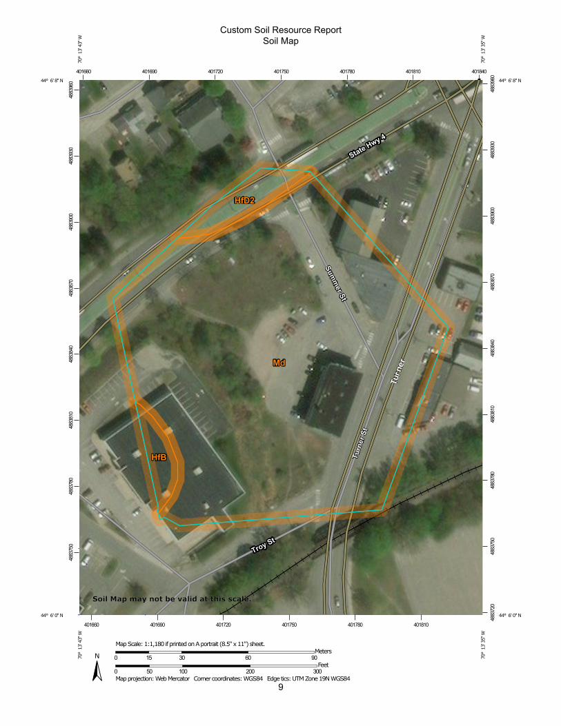
Soil MapThe soil map section includes the soil map for the defined area of interest, a list of soil map units on the map and extent of each map unit, and cartographic symbols displayed on the map. Also presented are various metadata about data used to produce the map, and a description of each soil map unit.
8
9
Custom Soil Resource ReportSoil Map
4883
750
4883
780
4883
810
4883
840
4883
870
4883
900
4883
930
4883
960
4883
720
4883
750
4883
780
4883
810
4883
840
4883
870
4883
900
4883
930
4883
960
401660 401690 401720 401750 401780 401810 401840
401660 401690 401720 401750 401780 401810
44° 6' 8'' N70
° 1
3' 4
3'' W
44° 6' 8'' N
70° 1
3' 3
5'' W
44° 6' 0'' N
70° 1
3' 4
3'' W
44° 6' 0'' N
70° 1
3' 3
5'' W
N
Map projection: Web Mercator Corner coordinates: WGS84 Edge tics: UTM Zone 19N WGS840 50 100 200 300
Feet0 15 30 60 90
MetersMap Scale: 1:1,180 if printed on A portrait (8.5" x 11") sheet.
Soil Map may not be valid at this scale.
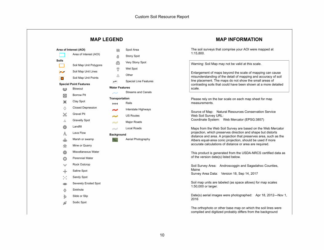
MAP LEGEND MAP INFORMATION
Area of Interest (AOI)Area of Interest (AOI)
SoilsSoil Map Unit Polygons
Soil Map Unit Lines
Soil Map Unit Points
Special Point FeaturesBlowout
Borrow Pit
Clay Spot
Closed Depression
Gravel Pit
Gravelly Spot
Landfill
Lava Flow
Marsh or swamp
Mine or Quarry
Miscellaneous Water
Perennial Water
Rock Outcrop
Saline Spot
Sandy Spot
Severely Eroded Spot
Sinkhole
Slide or Slip
Sodic Spot
Spoil Area
Stony Spot
Very Stony Spot
Wet Spot
Other
Special Line Features
Water FeaturesStreams and Canals
TransportationRails
Interstate Highways
US Routes
Major Roads
Local Roads
BackgroundAerial Photography
The soil surveys that comprise your AOI were mapped at 1:15,800.
Warning: Soil Map may not be valid at this scale.
Enlargement of maps beyond the scale of mapping can cause misunderstanding of the detail of mapping and accuracy of soil line placement. The maps do not show the small areas of contrasting soils that could have been shown at a more detailed scale.
Please rely on the bar scale on each map sheet for map measurements.
Source of Map: Natural Resources Conservation ServiceWeb Soil Survey URL: Coordinate System: Web Mercator (EPSG:3857)
Maps from the Web Soil Survey are based on the Web Mercator projection, which preserves direction and shape but distorts distance and area. A projection that preserves area, such as the Albers equal-area conic projection, should be used if more accurate calculations of distance or area are required.
This product is generated from the USDA-NRCS certified data as of the version date(s) listed below.
Soil Survey Area: Androscoggin and Sagadahoc Counties, MaineSurvey Area Data: Version 18, Sep 14, 2017
Soil map units are labeled (as space allows) for map scales 1:50,000 or larger.
Date(s) aerial images were photographed: Apr 18, 2012—Nov 1, 2016
The orthophoto or other base map on which the soil lines were compiled and digitized probably differs from the background
Custom Soil Resource Report
10
MAP LEGEND MAP INFORMATION
imagery displayed on these maps. As a result, some minor shifting of map unit boundaries may be evident.
Custom Soil Resource Report
11
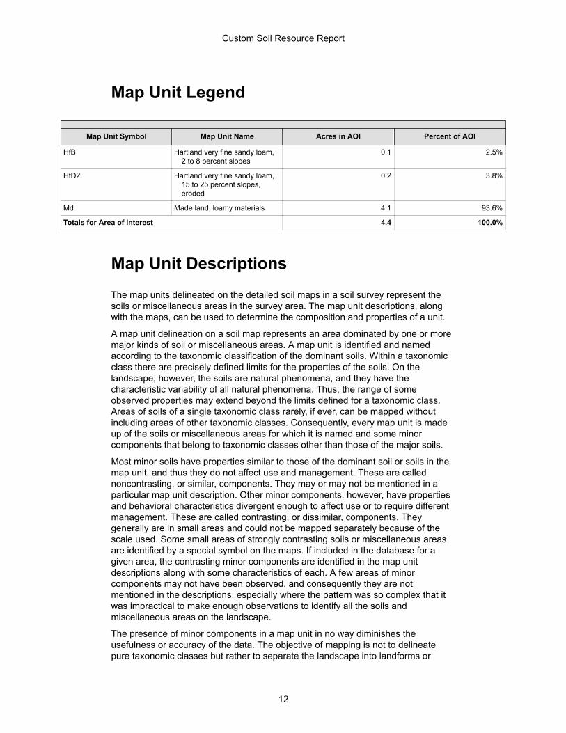
Map Unit Legend
Map Unit Symbol Map Unit Name Acres in AOI Percent of AOI
HfB Hartland very fine sandy loam, 2 to 8 percent slopes
0.1 2.5%
HfD2 Hartland very fine sandy loam, 15 to 25 percent slopes, eroded
0.2 3.8%
Md Made land, loamy materials 4.1 93.6%
Totals for Area of Interest 4.4 100.0%
Map Unit DescriptionsThe map units delineated on the detailed soil maps in a soil survey represent the soils or miscellaneous areas in the survey area. The map unit descriptions, along with the maps, can be used to determine the composition and properties of a unit.
A map unit delineation on a soil map represents an area dominated by one or more major kinds of soil or miscellaneous areas. A map unit is identified and named according to the taxonomic classification of the dominant soils. Within a taxonomic class there are precisely defined limits for the properties of the soils. On the landscape, however, the soils are natural phenomena, and they have the characteristic variability of all natural phenomena. Thus, the range of some observed properties may extend beyond the limits defined for a taxonomic class. Areas of soils of a single taxonomic class rarely, if ever, can be mapped without including areas of other taxonomic classes. Consequently, every map unit is made up of the soils or miscellaneous areas for which it is named and some minor components that belong to taxonomic classes other than those of the major soils.
Most minor soils have properties similar to those of the dominant soil or soils in the map unit, and thus they do not affect use and management. These are called noncontrasting, or similar, components. They may or may not be mentioned in a particular map unit description. Other minor components, however, have properties and behavioral characteristics divergent enough to affect use or to require different management. These are called contrasting, or dissimilar, components. They generally are in small areas and could not be mapped separately because of the scale used. Some small areas of strongly contrasting soils or miscellaneous areas are identified by a special symbol on the maps. If included in the database for a given area, the contrasting minor components are identified in the map unit descriptions along with some characteristics of each. A few areas of minor components may not have been observed, and consequently they are not mentioned in the descriptions, especially where the pattern was so complex that it was impractical to make enough observations to identify all the soils and miscellaneous areas on the landscape.
The presence of minor components in a map unit in no way diminishes the usefulness or accuracy of the data. The objective of mapping is not to delineate pure taxonomic classes but rather to separate the landscape into landforms or
Custom Soil Resource Report
12

landform segments that have similar use and management requirements. The delineation of such segments on the map provides sufficient information for the development of resource plans. If intensive use of small areas is planned, however, onsite investigation is needed to define and locate the soils and miscellaneous areas.
An identifying symbol precedes the map unit name in the map unit descriptions. Each description includes general facts about the unit and gives important soil properties and qualities.
Soils that have profiles that are almost alike make up a soil series. Except for differences in texture of the surface layer, all the soils of a series have major horizons that are similar in composition, thickness, and arrangement.
Soils of one series can differ in texture of the surface layer, slope, stoniness, salinity, degree of erosion, and other characteristics that affect their use. On the basis of such differences, a soil series is divided into soil phases. Most of the areas shown on the detailed soil maps are phases of soil series. The name of a soil phase commonly indicates a feature that affects use or management. For example, Alpha silt loam, 0 to 2 percent slopes, is a phase of the Alpha series.
Some map units are made up of two or more major soils or miscellaneous areas. These map units are complexes, associations, or undifferentiated groups.
A complex consists of two or more soils or miscellaneous areas in such an intricate pattern or in such small areas that they cannot be shown separately on the maps. The pattern and proportion of the soils or miscellaneous areas are somewhat similar in all areas. Alpha-Beta complex, 0 to 6 percent slopes, is an example.
An association is made up of two or more geographically associated soils or miscellaneous areas that are shown as one unit on the maps. Because of present or anticipated uses of the map units in the survey area, it was not considered practical or necessary to map the soils or miscellaneous areas separately. The pattern and relative proportion of the soils or miscellaneous areas are somewhat similar. Alpha-Beta association, 0 to 2 percent slopes, is an example.
An undifferentiated group is made up of two or more soils or miscellaneous areas that could be mapped individually but are mapped as one unit because similar interpretations can be made for use and management. The pattern and proportion of the soils or miscellaneous areas in a mapped area are not uniform. An area can be made up of only one of the major soils or miscellaneous areas, or it can be made up of all of them. Alpha and Beta soils, 0 to 2 percent slopes, is an example.
Some surveys include miscellaneous areas. Such areas have little or no soil material and support little or no vegetation. Rock outcrop is an example.
Custom Soil Resource Report
13
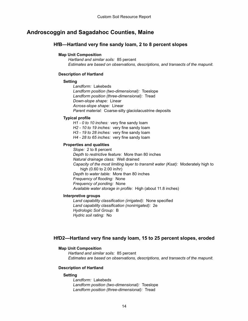
Androscoggin and Sagadahoc Counties, Maine
HfB—Hartland very fine sandy loam, 2 to 8 percent slopes
Map Unit CompositionHartland and similar soils: 85 percentEstimates are based on observations, descriptions, and transects of the mapunit.
Description of Hartland
SettingLandform: LakebedsLandform position (two-dimensional): ToeslopeLandform position (three-dimensional): TreadDown-slope shape: LinearAcross-slope shape: LinearParent material: Coarse-silty glaciolacustrine deposits
Typical profileH1 - 0 to 10 inches: very fine sandy loamH2 - 10 to 19 inches: very fine sandy loamH3 - 19 to 28 inches: very fine sandy loamH4 - 28 to 65 inches: very fine sandy loam
Properties and qualitiesSlope: 2 to 8 percentDepth to restrictive feature: More than 80 inchesNatural drainage class: Well drainedCapacity of the most limiting layer to transmit water (Ksat): Moderately high to
high (0.60 to 2.00 in/hr)Depth to water table: More than 80 inchesFrequency of flooding: NoneFrequency of ponding: NoneAvailable water storage in profile: High (about 11.8 inches)
Interpretive groupsLand capability classification (irrigated): None specifiedLand capability classification (nonirrigated): 2eHydrologic Soil Group: BHydric soil rating: No
HfD2—Hartland very fine sandy loam, 15 to 25 percent slopes, eroded
Map Unit CompositionHartland and similar soils: 85 percentEstimates are based on observations, descriptions, and transects of the mapunit.
Description of Hartland
SettingLandform: LakebedsLandform position (two-dimensional): ToeslopeLandform position (three-dimensional): Tread
Custom Soil Resource Report
14
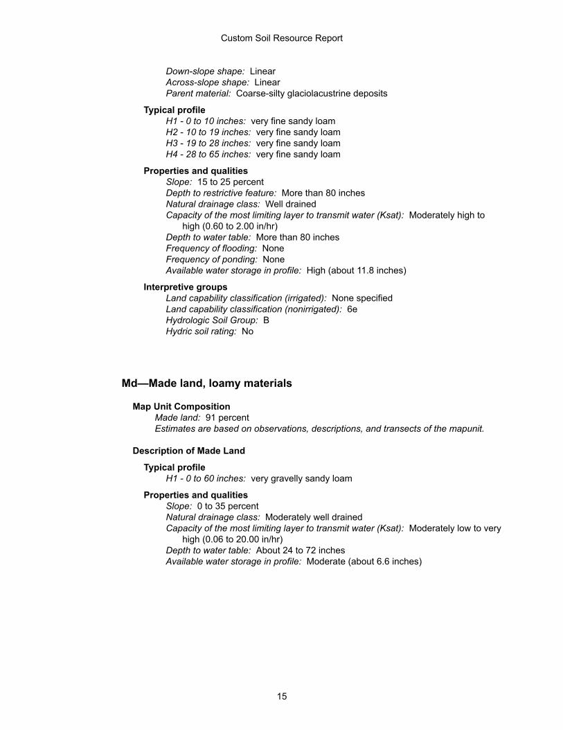
Down-slope shape: LinearAcross-slope shape: LinearParent material: Coarse-silty glaciolacustrine deposits
Typical profileH1 - 0 to 10 inches: very fine sandy loamH2 - 10 to 19 inches: very fine sandy loamH3 - 19 to 28 inches: very fine sandy loamH4 - 28 to 65 inches: very fine sandy loam
Properties and qualitiesSlope: 15 to 25 percentDepth to restrictive feature: More than 80 inchesNatural drainage class: Well drainedCapacity of the most limiting layer to transmit water (Ksat): Moderately high to
high (0.60 to 2.00 in/hr)Depth to water table: More than 80 inchesFrequency of flooding: NoneFrequency of ponding: NoneAvailable water storage in profile: High (about 11.8 inches)
Interpretive groupsLand capability classification (irrigated): None specifiedLand capability classification (nonirrigated): 6eHydrologic Soil Group: BHydric soil rating: No
Md—Made land, loamy materials
Map Unit CompositionMade land: 91 percentEstimates are based on observations, descriptions, and transects of the mapunit.
Description of Made Land
Typical profileH1 - 0 to 60 inches: very gravelly sandy loam
Properties and qualitiesSlope: 0 to 35 percentNatural drainage class: Moderately well drainedCapacity of the most limiting layer to transmit water (Ksat): Moderately low to very
high (0.06 to 20.00 in/hr)Depth to water table: About 24 to 72 inchesAvailable water storage in profile: Moderate (about 6.6 inches)
Custom Soil Resource Report
15
ReferencesAmerican Association of State Highway and Transportation Officials (AASHTO). 2004. Standard specifications for transportation materials and methods of sampling and testing. 24th edition.
American Society for Testing and Materials (ASTM). 2005. Standard classification of soils for engineering purposes. ASTM Standard D2487-00.
Cowardin, L.M., V. Carter, F.C. Golet, and E.T. LaRoe. 1979. Classification of wetlands and deep-water habitats of the United States. U.S. Fish and Wildlife Service FWS/OBS-79/31.
Federal Register. July 13, 1994. Changes in hydric soils of the United States.
Federal Register. September 18, 2002. Hydric soils of the United States.
Hurt, G.W., and L.M. Vasilas, editors. Version 6.0, 2006. Field indicators of hydric soils in the United States.
National Research Council. 1995. Wetlands: Characteristics and boundaries.
Soil Survey Division Staff. 1993. Soil survey manual. Soil Conservation Service. U.S. Department of Agriculture Handbook 18. http://www.nrcs.usda.gov/wps/portal/nrcs/detail/national/soils/?cid=nrcs142p2_054262
Soil Survey Staff. 1999. Soil taxonomy: A basic system of soil classification for making and interpreting soil surveys. 2nd edition. Natural Resources Conservation Service, U.S. Department of Agriculture Handbook 436. http://www.nrcs.usda.gov/wps/portal/nrcs/detail/national/soils/?cid=nrcs142p2_053577
Soil Survey Staff. 2010. Keys to soil taxonomy. 11th edition. U.S. Department of Agriculture, Natural Resources Conservation Service. http://www.nrcs.usda.gov/wps/portal/nrcs/detail/national/soils/?cid=nrcs142p2_053580
Tiner, R.W., Jr. 1985. Wetlands of Delaware. U.S. Fish and Wildlife Service and Delaware Department of Natural Resources and Environmental Control, Wetlands Section.
United States Army Corps of Engineers, Environmental Laboratory. 1987. Corps of Engineers wetlands delineation manual. Waterways Experiment Station Technical Report Y-87-1.
United States Department of Agriculture, Natural Resources Conservation Service. National forestry manual. http://www.nrcs.usda.gov/wps/portal/nrcs/detail/soils/home/?cid=nrcs142p2_053374
United States Department of Agriculture, Natural Resources Conservation Service. National range and pasture handbook. http://www.nrcs.usda.gov/wps/portal/nrcs/detail/national/landuse/rangepasture/?cid=stelprdb1043084
16

United States Department of Agriculture, Natural Resources Conservation Service. National soil survey handbook, title 430-VI. http://www.nrcs.usda.gov/wps/portal/nrcs/detail/soils/scientists/?cid=nrcs142p2_054242
United States Department of Agriculture, Natural Resources Conservation Service. 2006. Land resource regions and major land resource areas of the United States, the Caribbean, and the Pacific Basin. U.S. Department of Agriculture Handbook 296. http://www.nrcs.usda.gov/wps/portal/nrcs/detail/national/soils/?cid=nrcs142p2_053624
United States Department of Agriculture, Soil Conservation Service. 1961. Land capability classification. U.S. Department of Agriculture Handbook 210. http://www.nrcs.usda.gov/Internet/FSE_DOCUMENTS/nrcs142p2_052290.pdf
Custom Soil Resource Report
17

APPENDIX B
PRE-DEVELOPMENT HYDROCAD CALCULATIONS
1A
EAST
1B
WEST
1R1
60" RCP
1R4
60" by 96" Box Culvert
AP-1
AP-1
Routing Diagram for Existing 111518Prepared by Sevee & Maher Engineers, Inc., Printed 11/15/2018
HydroCAD® 10.00-22 s/n 01260 © 2018 HydroCAD Software Solutions LLC
Subcat Reach Pond Link

Type III 24-hr 2-yr Storm Rainfall=3.00"Existing 111518 Printed 11/15/2018Prepared by Sevee & Maher Engineers, Inc.
Page 2HydroCAD® 10.00-22 s/n 01260 © 2018 HydroCAD Software Solutions LLC
Time span=5.00-20.00 hrs, dt=0.05 hrs, 301 pointsRunoff by SCS TR-20 method, UH=SCS, Weighted-CN
Reach routing by Stor-Ind+Trans method - Pond routing by Stor-Ind method
Runoff Area=70,337 sf 40.77% Impervious Runoff Depth>1.34"Subcatchment 1A: EAST Flow Length=310' Tc=8.4 min CN=83 Runoff=2.47 cfs 0.180 af
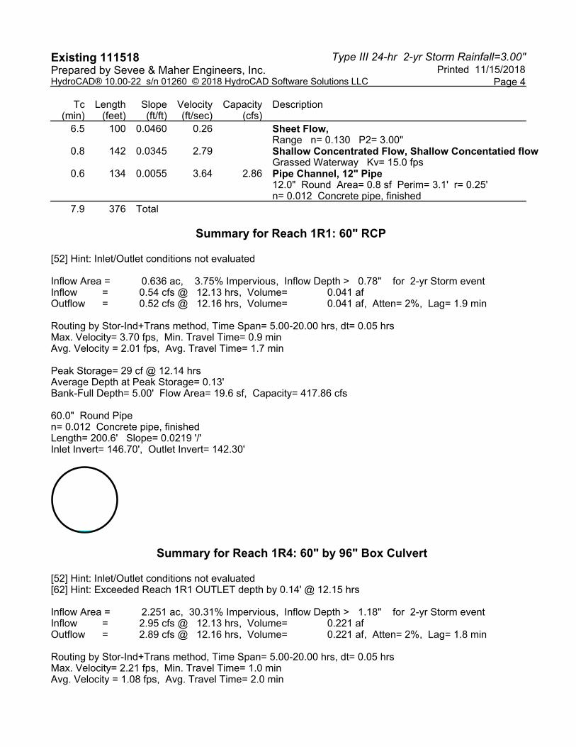
Runoff Area=27,712 sf 3.75% Impervious Runoff Depth>0.78"Subcatchment 1B: WEST Flow Length=376' Tc=7.9 min CN=73 Runoff=0.54 cfs 0.041 af
Avg. Flow Depth=0.13' Max Vel=3.70 fps Inflow=0.54 cfs 0.041 afReach 1R1: 60" RCP60.0" Round Pipe n=0.012 L=200.6' S=0.0219 '/' Capacity=417.86 cfs Outflow=0.52 cfs 0.041 af
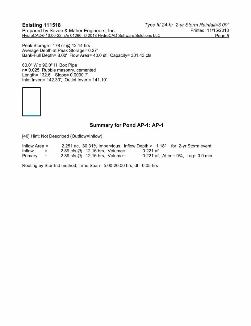
Avg. Flow Depth=0.27' Max Vel=2.21 fps Inflow=2.95 cfs 0.221 afReach 1R4: 60" by 96" Box Culvert60.0" x 96.0" Box Pipe n=0.025 L=132.6' S=0.0090 '/' Capacity=301.43 cfs Outflow=2.89 cfs 0.221 af
Inflow=2.89 cfs 0.221 afPond AP-1: AP-1 Primary=2.89 cfs 0.221 af

Type III 24-hr 2-yr Storm Rainfall=3.00"Existing 111518 Printed 11/15/2018Prepared by Sevee & Maher Engineers, Inc.
Page 3HydroCAD® 10.00-22 s/n 01260 © 2018 HydroCAD Software Solutions LLC
Summary for Subcatchment 1A: EAST
Runoff = 2.47 cfs @ 12.12 hrs, Volume= 0.180 af, Depth> 1.34"
Runoff by SCS TR-20 method, UH=SCS, Weighted-CN, Time Span= 5.00-20.00 hrs, dt= 0.05 hrsType III 24-hr 2-yr Storm Rainfall=3.00"
Area (sf) CN Description6,861 98 Paved parking, HSG C
16,872 98 Paved roads w/curbs & sewers, HSG C4,946 98 Roofs, HSG C
41,224 72 Woods/grass comb., Good, HSG C434 65 Brush, Good, HSG C
70,337 83 Weighted Average41,658 59.23% Pervious Area28,679 40.77% Impervious Area
Tc Length Slope Velocity Capacity Description(min) (feet) (ft/ft) (ft/sec) (cfs)
7.1 100 0.0360 0.23 Sheet Flow, Range n= 0.130 P2= 3.00"
1.2 181 0.0292 2.56 Shallow Concentrated Flow, Grassed Waterway Kv= 15.0 fps
0.1 29 0.0169 5.32 1.86 Pipe Channel, 8.0" Round Area= 0.3 sf Perim= 2.1' r= 0.17'n= 0.011 Concrete pipe, straight & clean
8.4 310 Total
Summary for Subcatchment 1B: WEST
Runoff = 0.54 cfs @ 12.13 hrs, Volume= 0.041 af, Depth> 0.78"
Runoff by SCS TR-20 method, UH=SCS, Weighted-CN, Time Span= 5.00-20.00 hrs, dt= 0.05 hrsType III 24-hr 2-yr Storm Rainfall=3.00"
Area (sf) CN Description469 98 Paved parking, HSG C569 98 Paved roads w/curbs & sewers, HSG C
26,674 72 Woods/grass comb., Good, HSG C27,712 73 Weighted Average26,674 96.25% Pervious Area
1,038 3.75% Impervious Area
Type III 24-hr 2-yr Storm Rainfall=3.00"Existing 111518 Printed 11/15/2018Prepared by Sevee & Maher Engineers, Inc.
Page 4HydroCAD® 10.00-22 s/n 01260 © 2018 HydroCAD Software Solutions LLC
Tc Length Slope Velocity Capacity Description(min) (feet) (ft/ft) (ft/sec) (cfs)
6.5 100 0.0460 0.26 Sheet Flow, Range n= 0.130 P2= 3.00"
0.8 142 0.0345 2.79 Shallow Concentrated Flow, Shallow Concentatied flowGrassed Waterway Kv= 15.0 fps
0.6 134 0.0055 3.64 2.86 Pipe Channel, 12" Pipe12.0" Round Area= 0.8 sf Perim= 3.1' r= 0.25'n= 0.012 Concrete pipe, finished
7.9 376 Total
Summary for Reach 1R1: 60" RCP
[52] Hint: Inlet/Outlet conditions not evaluated
Inflow Area = 0.636 ac, 3.75% Impervious, Inflow Depth > 0.78" for 2-yr Storm eventInflow = 0.54 cfs @ 12.13 hrs, Volume= 0.041 afOutflow = 0.52 cfs @ 12.16 hrs, Volume= 0.041 af, Atten= 2%, Lag= 1.9 min
Routing by Stor-Ind+Trans method, Time Span= 5.00-20.00 hrs, dt= 0.05 hrsMax. Velocity= 3.70 fps, Min. Travel Time= 0.9 minAvg. Velocity = 2.01 fps, Avg. Travel Time= 1.7 min
Peak Storage= 29 cf @ 12.14 hrsAverage Depth at Peak Storage= 0.13'Bank-Full Depth= 5.00' Flow Area= 19.6 sf, Capacity= 417.86 cfs
60.0" Round Pipen= 0.012 Concrete pipe, finishedLength= 200.6' Slope= 0.0219 '/'Inlet Invert= 146.70', Outlet Invert= 142.30'
Summary for Reach 1R4: 60" by 96" Box Culvert
[52] Hint: Inlet/Outlet conditions not evaluated[62] Hint: Exceeded Reach 1R1 OUTLET depth by 0.14' @ 12.15 hrs
Inflow Area = 2.251 ac, 30.31% Impervious, Inflow Depth > 1.18" for 2-yr Storm eventInflow = 2.95 cfs @ 12.13 hrs, Volume= 0.221 afOutflow = 2.89 cfs @ 12.16 hrs, Volume= 0.221 af, Atten= 2%, Lag= 1.8 min
Routing by Stor-Ind+Trans method, Time Span= 5.00-20.00 hrs, dt= 0.05 hrsMax. Velocity= 2.21 fps, Min. Travel Time= 1.0 minAvg. Velocity = 1.08 fps, Avg. Travel Time= 2.0 min
Type III 24-hr 2-yr Storm Rainfall=3.00"Existing 111518 Printed 11/15/2018Prepared by Sevee & Maher Engineers, Inc.
Page 5HydroCAD® 10.00-22 s/n 01260 © 2018 HydroCAD Software Solutions LLC
Peak Storage= 178 cf @ 12.14 hrsAverage Depth at Peak Storage= 0.27'Bank-Full Depth= 8.00' Flow Area= 40.0 sf, Capacity= 301.43 cfs
60.0" W x 96.0" H Box Pipen= 0.025 Rubble masonry, cementedLength= 132.6' Slope= 0.0090 '/'Inlet Invert= 142.30', Outlet Invert= 141.10'
Summary for Pond AP-1: AP-1
[40] Hint: Not Described (Outflow=Inflow)
Inflow Area = 2.251 ac, 30.31% Impervious, Inflow Depth > 1.18" for 2-yr Storm eventInflow = 2.89 cfs @ 12.16 hrs, Volume= 0.221 afPrimary = 2.89 cfs @ 12.16 hrs, Volume= 0.221 af, Atten= 0%, Lag= 0.0 min
Routing by Stor-Ind method, Time Span= 5.00-20.00 hrs, dt= 0.05 hrs
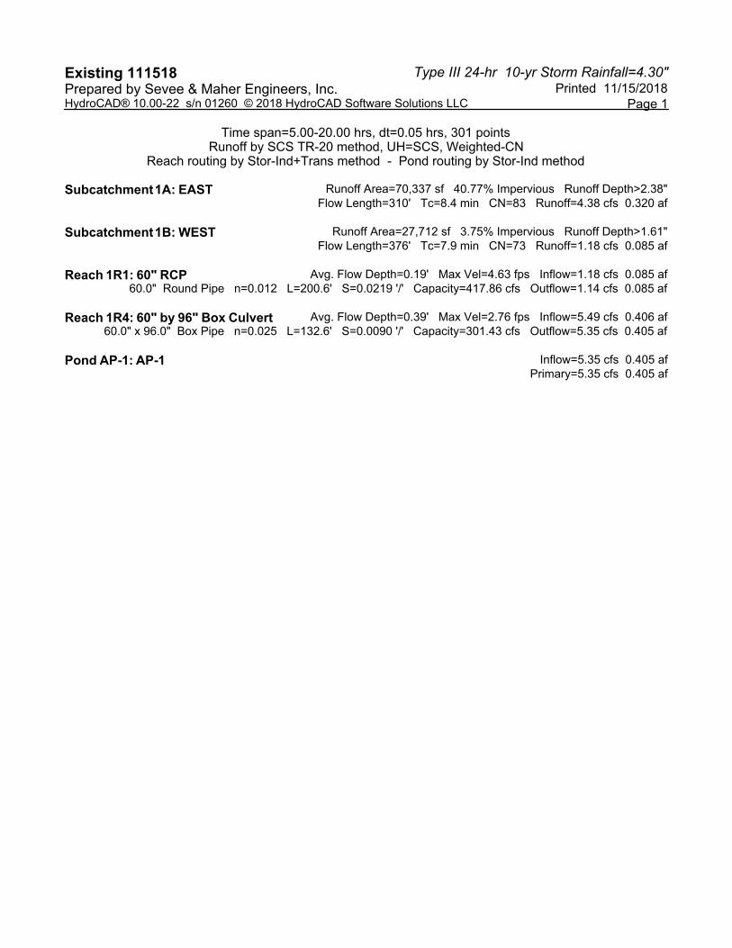
Type III 24-hr 10-yr Storm Rainfall=4.30"Existing 111518 Printed 11/15/2018Prepared by Sevee & Maher Engineers, Inc.
Page 1HydroCAD® 10.00-22 s/n 01260 © 2018 HydroCAD Software Solutions LLC
Time span=5.00-20.00 hrs, dt=0.05 hrs, 301 pointsRunoff by SCS TR-20 method, UH=SCS, Weighted-CN
Reach routing by Stor-Ind+Trans method - Pond routing by Stor-Ind method
Runoff Area=70,337 sf 40.77% Impervious Runoff Depth>2.38"Subcatchment 1A: EAST Flow Length=310' Tc=8.4 min CN=83 Runoff=4.38 cfs 0.320 af
Runoff Area=27,712 sf 3.75% Impervious Runoff Depth>1.61"Subcatchment 1B: WEST Flow Length=376' Tc=7.9 min CN=73 Runoff=1.18 cfs 0.085 af
Avg. Flow Depth=0.19' Max Vel=4.63 fps Inflow=1.18 cfs 0.085 afReach 1R1: 60" RCP60.0" Round Pipe n=0.012 L=200.6' S=0.0219 '/' Capacity=417.86 cfs Outflow=1.14 cfs 0.085 af
Avg. Flow Depth=0.39' Max Vel=2.76 fps Inflow=5.49 cfs 0.406 afReach 1R4: 60" by 96" Box Culvert60.0" x 96.0" Box Pipe n=0.025 L=132.6' S=0.0090 '/' Capacity=301.43 cfs Outflow=5.35 cfs 0.405 af
Inflow=5.35 cfs 0.405 afPond AP-1: AP-1 Primary=5.35 cfs 0.405 af

Type III 24-hr 25-yr Storm Rainfall=5.40"Existing 111518 Printed 11/15/2018Prepared by Sevee & Maher Engineers, Inc.
Page 2HydroCAD® 10.00-22 s/n 01260 © 2018 HydroCAD Software Solutions LLC
Time span=5.00-20.00 hrs, dt=0.05 hrs, 301 pointsRunoff by SCS TR-20 method, UH=SCS, Weighted-CN
Reach routing by Stor-Ind+Trans method - Pond routing by Stor-Ind method
Runoff Area=70,337 sf 40.77% Impervious Runoff Depth>3.32"Subcatchment 1A: EAST Flow Length=310' Tc=8.4 min CN=83 Runoff=6.04 cfs 0.447 af
Runoff Area=27,712 sf 3.75% Impervious Runoff Depth>2.41"Subcatchment 1B: WEST Flow Length=376' Tc=7.9 min CN=73 Runoff=1.78 cfs 0.128 af
Avg. Flow Depth=0.23' Max Vel=5.24 fps Inflow=1.78 cfs 0.128 afReach 1R1: 60" RCP60.0" Round Pipe n=0.012 L=200.6' S=0.0219 '/' Capacity=417.86 cfs Outflow=1.73 cfs 0.128 af
Avg. Flow Depth=0.49' Max Vel=3.12 fps Inflow=7.75 cfs 0.574 afReach 1R4: 60" by 96" Box Culvert60.0" x 96.0" Box Pipe n=0.025 L=132.6' S=0.0090 '/' Capacity=301.43 cfs Outflow=7.56 cfs 0.574 af
Inflow=7.56 cfs 0.574 afPond AP-1: AP-1 Primary=7.56 cfs 0.574 af

APPENDIX C
POST-DEVELOPMENT HYDROCAD CALCULATIONS
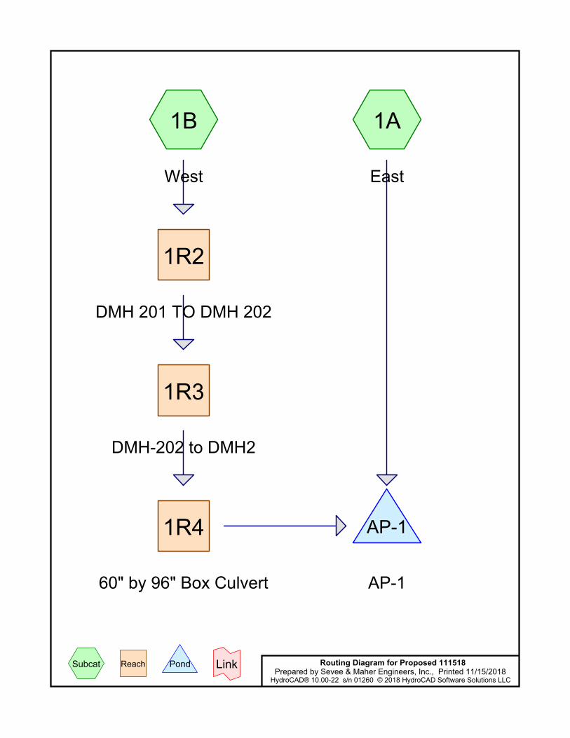
1A
East
1B
West
1R2
DMH 201 TO DMH 202
1R3
DMH-202 to DMH2
1R4
60" by 96" Box Culvert
AP-1
AP-1
Routing Diagram for Proposed 111518Prepared by Sevee & Maher Engineers, Inc., Printed 11/15/2018
HydroCAD® 10.00-22 s/n 01260 © 2018 HydroCAD Software Solutions LLC
Subcat Reach Pond Link
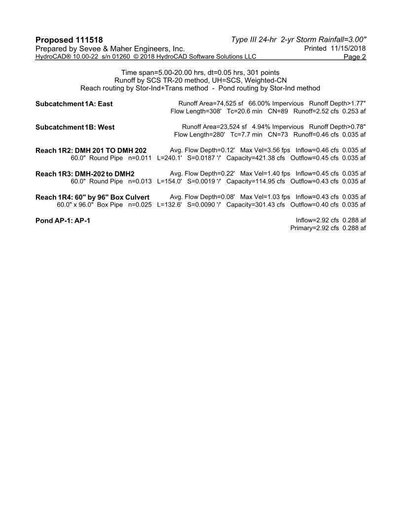
Type III 24-hr 2-yr Storm Rainfall=3.00"Proposed 111518 Printed 11/15/2018Prepared by Sevee & Maher Engineers, Inc.
Page 2HydroCAD® 10.00-22 s/n 01260 © 2018 HydroCAD Software Solutions LLC
Time span=5.00-20.00 hrs, dt=0.05 hrs, 301 pointsRunoff by SCS TR-20 method, UH=SCS, Weighted-CN
Reach routing by Stor-Ind+Trans method - Pond routing by Stor-Ind method
Runoff Area=74,525 sf 66.00% Impervious Runoff Depth>1.77"Subcatchment 1A: East Flow Length=308' Tc=20.6 min CN=89 Runoff=2.52 cfs 0.253 af
Runoff Area=23,524 sf 4.94% Impervious Runoff Depth>0.78"Subcatchment 1B: West Flow Length=280' Tc=7.7 min CN=73 Runoff=0.46 cfs 0.035 af
Avg. Flow Depth=0.12' Max Vel=3.56 fps Inflow=0.46 cfs 0.035 afReach 1R2: DMH 201 TO DMH 20260.0" Round Pipe n=0.011 L=240.1' S=0.0187 '/' Capacity=421.38 cfs Outflow=0.45 cfs 0.035 af
Avg. Flow Depth=0.22' Max Vel=1.40 fps Inflow=0.45 cfs 0.035 afReach 1R3: DMH-202 to DMH260.0" Round Pipe n=0.013 L=154.0' S=0.0019 '/' Capacity=114.95 cfs Outflow=0.43 cfs 0.035 af
Avg. Flow Depth=0.08' Max Vel=1.03 fps Inflow=0.43 cfs 0.035 afReach 1R4: 60" by 96" Box Culvert60.0" x 96.0" Box Pipe n=0.025 L=132.6' S=0.0090 '/' Capacity=301.43 cfs Outflow=0.40 cfs 0.035 af
Inflow=2.92 cfs 0.288 afPond AP-1: AP-1 Primary=2.92 cfs 0.288 af

Type III 24-hr 2-yr Storm Rainfall=3.00"Proposed 111518 Printed 11/15/2018Prepared by Sevee & Maher Engineers, Inc.
Page 3HydroCAD® 10.00-22 s/n 01260 © 2018 HydroCAD Software Solutions LLC
Summary for Subcatchment 1A: East
Runoff = 2.52 cfs @ 12.28 hrs, Volume= 0.253 af, Depth> 1.77"
Runoff by SCS TR-20 method, UH=SCS, Weighted-CN, Time Span= 5.00-20.00 hrs, dt= 0.05 hrsType III 24-hr 2-yr Storm Rainfall=3.00"
Area (sf) CN Description16,163 98 Paved roads w/curbs & sewers, HSG C
7,348 98 Roofs, HSG C25,672 98 Paved parking, HSG C25,342 72 Woods/grass comb., Good, HSG C74,525 89 Weighted Average25,342 34.00% Pervious Area49,183 66.00% Impervious Area
Tc Length Slope Velocity Capacity Description(min) (feet) (ft/ft) (ft/sec) (cfs)
0.3 23 0.0391 1.30 Sheet Flow, Sheet Flow pavementSmooth surfaces n= 0.011 P2= 3.00"
18.7 77 0.0065 0.07 Sheet Flow, Sheet flow GrassGrass: Dense n= 0.240 P2= 3.00"
1.2 167 0.0203 2.29 Shallow Concentrated Flow, Unpaved Kv= 16.1 fps
0.4 41 0.0071 1.71 Shallow Concentrated Flow, Paved Kv= 20.3 fps
20.6 308 Total
Summary for Subcatchment 1B: West
Runoff = 0.46 cfs @ 12.12 hrs, Volume= 0.035 af, Depth> 0.78"
Runoff by SCS TR-20 method, UH=SCS, Weighted-CN, Time Span= 5.00-20.00 hrs, dt= 0.05 hrsType III 24-hr 2-yr Storm Rainfall=3.00"
Area (sf) CN Description22,361 72 Woods/grass comb., Good, HSG C
1,163 98 Paved roads w/curbs & sewers, HSG C23,524 73 Weighted Average22,361 95.06% Pervious Area
1,163 4.94% Impervious Area
Tc Length Slope Velocity Capacity Description(min) (feet) (ft/ft) (ft/sec) (cfs)
6.7 100 0.0420 0.25 Sheet Flow, Range n= 0.130 P2= 3.00"
0.8 102 0.0225 2.25 Shallow Concentrated Flow, Grassed Waterway Kv= 15.0 fps
0.2 78 0.0100 5.36 4.21 Pipe Channel, 12" pipe12.0" Round Area= 0.8 sf Perim= 3.1' r= 0.25'n= 0.011 Concrete pipe, straight & clean
Type III 24-hr 2-yr Storm Rainfall=3.00"Proposed 111518 Printed 11/15/2018Prepared by Sevee & Maher Engineers, Inc.
Page 4HydroCAD® 10.00-22 s/n 01260 © 2018 HydroCAD Software Solutions LLC
7.7 280 Total
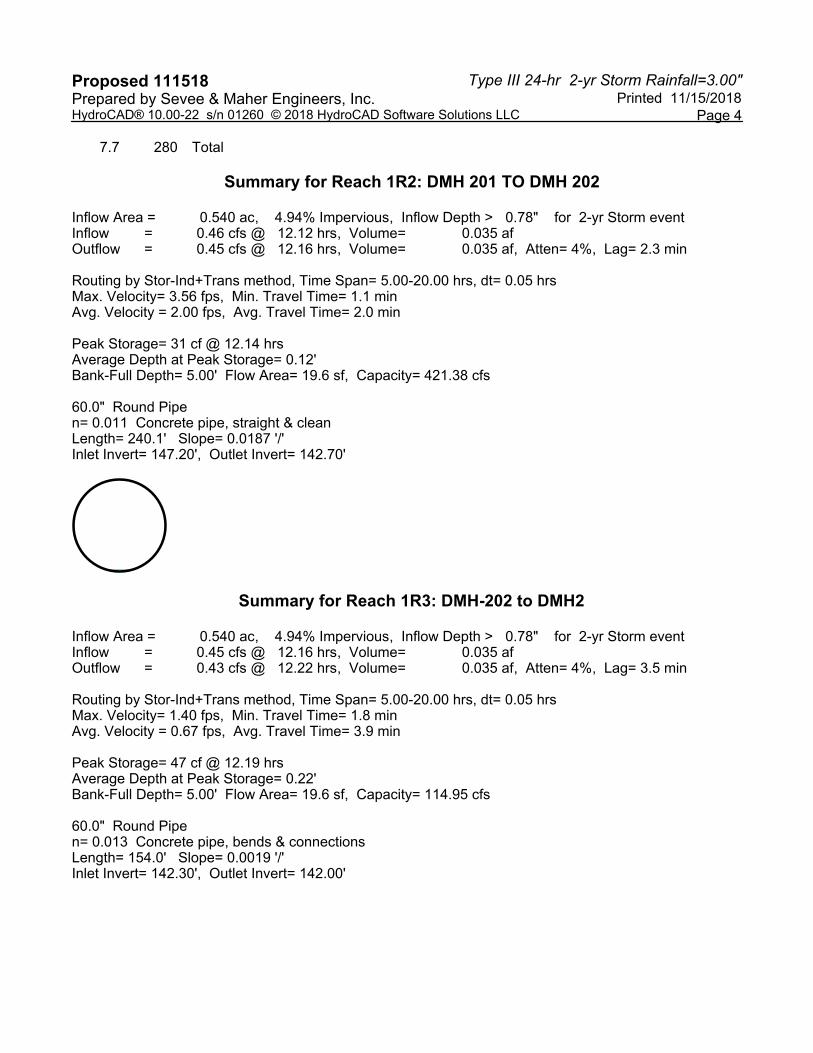
Summary for Reach 1R2: DMH 201 TO DMH 202
Inflow Area = 0.540 ac, 4.94% Impervious, Inflow Depth > 0.78" for 2-yr Storm eventInflow = 0.46 cfs @ 12.12 hrs, Volume= 0.035 afOutflow = 0.45 cfs @ 12.16 hrs, Volume= 0.035 af, Atten= 4%, Lag= 2.3 min
Routing by Stor-Ind+Trans method, Time Span= 5.00-20.00 hrs, dt= 0.05 hrsMax. Velocity= 3.56 fps, Min. Travel Time= 1.1 minAvg. Velocity = 2.00 fps, Avg. Travel Time= 2.0 min
Peak Storage= 31 cf @ 12.14 hrsAverage Depth at Peak Storage= 0.12'Bank-Full Depth= 5.00' Flow Area= 19.6 sf, Capacity= 421.38 cfs
60.0" Round Pipen= 0.011 Concrete pipe, straight & cleanLength= 240.1' Slope= 0.0187 '/'Inlet Invert= 147.20', Outlet Invert= 142.70'
Summary for Reach 1R3: DMH-202 to DMH2
Inflow Area = 0.540 ac, 4.94% Impervious, Inflow Depth > 0.78" for 2-yr Storm eventInflow = 0.45 cfs @ 12.16 hrs, Volume= 0.035 afOutflow = 0.43 cfs @ 12.22 hrs, Volume= 0.035 af, Atten= 4%, Lag= 3.5 min
Routing by Stor-Ind+Trans method, Time Span= 5.00-20.00 hrs, dt= 0.05 hrsMax. Velocity= 1.40 fps, Min. Travel Time= 1.8 minAvg. Velocity = 0.67 fps, Avg. Travel Time= 3.9 min
Peak Storage= 47 cf @ 12.19 hrsAverage Depth at Peak Storage= 0.22'Bank-Full Depth= 5.00' Flow Area= 19.6 sf, Capacity= 114.95 cfs
60.0" Round Pipen= 0.013 Concrete pipe, bends & connectionsLength= 154.0' Slope= 0.0019 '/'Inlet Invert= 142.30', Outlet Invert= 142.00'
Type III 24-hr 2-yr Storm Rainfall=3.00"Proposed 111518 Printed 11/15/2018Prepared by Sevee & Maher Engineers, Inc.
Page 5HydroCAD® 10.00-22 s/n 01260 © 2018 HydroCAD Software Solutions LLC
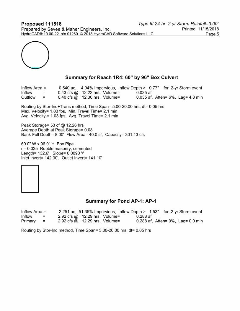
Summary for Reach 1R4: 60" by 96" Box Culvert
Inflow Area = 0.540 ac, 4.94% Impervious, Inflow Depth > 0.77" for 2-yr Storm eventInflow = 0.43 cfs @ 12.22 hrs, Volume= 0.035 afOutflow = 0.40 cfs @ 12.30 hrs, Volume= 0.035 af, Atten= 6%, Lag= 4.8 min
Routing by Stor-Ind+Trans method, Time Span= 5.00-20.00 hrs, dt= 0.05 hrsMax. Velocity= 1.03 fps, Min. Travel Time= 2.1 minAvg. Velocity = 1.03 fps, Avg. Travel Time= 2.1 min
Peak Storage= 53 cf @ 12.26 hrsAverage Depth at Peak Storage= 0.08'Bank-Full Depth= 8.00' Flow Area= 40.0 sf, Capacity= 301.43 cfs
60.0" W x 96.0" H Box Pipen= 0.025 Rubble masonry, cementedLength= 132.6' Slope= 0.0090 '/'Inlet Invert= 142.30', Outlet Invert= 141.10'
Summary for Pond AP-1: AP-1
Inflow Area = 2.251 ac, 51.35% Impervious, Inflow Depth > 1.53" for 2-yr Storm eventInflow = 2.92 cfs @ 12.29 hrs, Volume= 0.288 afPrimary = 2.92 cfs @ 12.29 hrs, Volume= 0.288 af, Atten= 0%, Lag= 0.0 min
Routing by Stor-Ind method, Time Span= 5.00-20.00 hrs, dt= 0.05 hrs

Type III 24-hr 10-yr Storm Rainfall=4.30"Proposed 111518 Printed 11/15/2018Prepared by Sevee & Maher Engineers, Inc.
Page 1HydroCAD® 10.00-22 s/n 01260 © 2018 HydroCAD Software Solutions LLC
Time span=5.00-20.00 hrs, dt=0.05 hrs, 301 pointsRunoff by SCS TR-20 method, UH=SCS, Weighted-CN
Reach routing by Stor-Ind+Trans method - Pond routing by Stor-Ind method
Runoff Area=74,525 sf 66.00% Impervious Runoff Depth>2.92"Subcatchment 1A: East Flow Length=308' Tc=20.6 min CN=89 Runoff=4.07 cfs 0.416 af
Runoff Area=23,524 sf 4.94% Impervious Runoff Depth>1.61"Subcatchment 1B: West Flow Length=280' Tc=7.7 min CN=73 Runoff=1.01 cfs 0.072 af
Avg. Flow Depth=0.18' Max Vel=4.46 fps Inflow=1.01 cfs 0.072 afReach 1R2: DMH 201 TO DMH 20260.0" Round Pipe n=0.011 L=240.1' S=0.0187 '/' Capacity=421.38 cfs Outflow=0.97 cfs 0.072 af
Avg. Flow Depth=0.32' Max Vel=1.78 fps Inflow=0.97 cfs 0.072 afReach 1R3: DMH-202 to DMH260.0" Round Pipe n=0.013 L=154.0' S=0.0019 '/' Capacity=114.95 cfs Outflow=0.93 cfs 0.072 af
Avg. Flow Depth=0.13' Max Vel=1.45 fps Inflow=0.93 cfs 0.072 afReach 1R4: 60" by 96" Box Culvert60.0" x 96.0" Box Pipe n=0.025 L=132.6' S=0.0090 '/' Capacity=301.43 cfs Outflow=0.90 cfs 0.072 af
Inflow=4.95 cfs 0.488 afPond AP-1: AP-1 Primary=4.95 cfs 0.488 af

Type III 24-hr 25-yr Storm Rainfall=5.40"Proposed 111518 Printed 11/15/2018Prepared by Sevee & Maher Engineers, Inc.
Page 2HydroCAD® 10.00-22 s/n 01260 © 2018 HydroCAD Software Solutions LLC
Time span=5.00-20.00 hrs, dt=0.05 hrs, 301 pointsRunoff by SCS TR-20 method, UH=SCS, Weighted-CN
Reach routing by Stor-Ind+Trans method - Pond routing by Stor-Ind method
Runoff Area=74,525 sf 66.00% Impervious Runoff Depth>3.91"Subcatchment 1A: East Flow Length=308' Tc=20.6 min CN=89 Runoff=5.39 cfs 0.558 af
Runoff Area=23,524 sf 4.94% Impervious Runoff Depth>2.41"Subcatchment 1B: West Flow Length=280' Tc=7.7 min CN=73 Runoff=1.53 cfs 0.108 af
Avg. Flow Depth=0.22' Max Vel=5.02 fps Inflow=1.53 cfs 0.108 afReach 1R2: DMH 201 TO DMH 20260.0" Round Pipe n=0.011 L=240.1' S=0.0187 '/' Capacity=421.38 cfs Outflow=1.47 cfs 0.108 af
Avg. Flow Depth=0.39' Max Vel=2.02 fps Inflow=1.47 cfs 0.108 afReach 1R3: DMH-202 to DMH260.0" Round Pipe n=0.013 L=154.0' S=0.0019 '/' Capacity=114.95 cfs Outflow=1.41 cfs 0.108 af
Avg. Flow Depth=0.17' Max Vel=1.67 fps Inflow=1.41 cfs 0.108 afReach 1R4: 60" by 96" Box Culvert60.0" x 96.0" Box Pipe n=0.025 L=132.6' S=0.0090 '/' Capacity=301.43 cfs Outflow=1.37 cfs 0.108 af
Inflow=6.68 cfs 0.666 afPond AP-1: AP-1 Primary=6.68 cfs 0.666 af

APPENDIX D
POST-CONSTRUCTION STORMWATER MANAGEMENT PLAN
POST-CONSTRUCTION STORMWATER MANAGEMENT PLAN
Prepared for
BANGOR SAVINGS BANK
AUBURN BRANCH/OFFICE BULDING AUBURN, MAINE
November 2018
____________________ i Appedix F Post Construction Stormwater Plan Sevee & Maher Engineers, Inc. November 2018
TABLE OF CONTENTS Section No. Title Page No. 1.0 SITE DESCRIPTION ...................................................................................................... 1
2.0 FACILITY CONTACTS .................................................................................................. 2
3.0 POST-CONSTRUCTION STORMWATER MANAGEMENT PLAN OVERVIEW AND OBJECTIVES ................................................................................................................. 2 3.1 Site Management Practices .................................................................................. 3 3.2 Inspections ........................................................................................................... 3 3.3 Routine Maintenance and Corrective Actions........................................................ 3 3.4 City of Auburn Annual Inspection Requirements ................................................... 5
LIST OF TABLES Table No. Title Page No. 1 SITE INSPECTION SCHEDULE ....................................................................................... 7
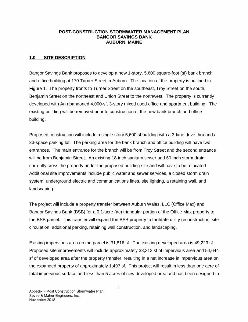
____________________ 1 Appedix F Post Construction Stormwater Plan Sevee & Maher Engineers, Inc. November 2018
POST-CONSTRUCTION STORMWATER MANAGEMENT PLAN BANGOR SAVINGS BANK
AUBURN, MAINE
1.0 SITE DESCRIPTION
Bangor Savings Bank proposes to develop a new 1-story, 5,600 square-foot (sf) bank branch
and office building at 170 Turner Street in Auburn. The location of the property is outlined in
Figure 1. The property fronts to Turner Street on the southeast, Troy Street on the south,
Benjamin Street on the northeast and Union Street to the northwest. The property is currently
developed with An abandoned 4,000-sf, 3-story mixed used office and apartment building. The
existing building will be removed prior to construction of the new bank branch and office
building.
Proposed construction will include a single story 5,600 sf building with a 3-lane drive thru and a
33-space parking lot. The parking area for the bank branch and office building will have two
entrances. The main entrance for the branch will be from Troy Street and the second entrance
will be from Benjamin Street. An existing 18-inch sanitary sewer and 60-inch storm drain
currently cross the property under the proposed building site and will have to be relocated.
Additional site improvements include public water and sewer services, a closed storm drain
system, underground electric and communications lines, site lighting, a retaining wall, and
landscaping.
The project will include a property transfer between Auburn Wales, LLC (Office Max) and
Bangor Savings Bank (BSB) for a 0.1-acre (ac) triangular portion of the Office Max property to
the BSB parcel. This transfer will expand the BSB property to facilitate utility reconstruction, site
circulation, additional parking, retaining wall construction, and landscaping.
Existing impervious area on the parcel is 31,816 sf. The existing developed area is 49,223 sf.
Proposed site improvements will include approximately 33,313 sf of impervious area and 54,644
sf of developed area after the property transfer, resulting in a net increase in impervious area on
the expanded property of approximately 1,497 sf. This project will result in less than one acre of
total impervious surface and less than 5 acres of new developed area and has been designed to
____________________ 2 Appedix F Post Construction Stormwater Plan Sevee & Maher Engineers, Inc. November 2018
meet Basic Standards as outlined in Maine Department of Environmental Protection (MEDEP)
Chapter 500. The project will not require a MEDEP Stormwater Management Permit.
2.0 FACILITY CONTACTS
Facility: Bangor Savings Bank Auburn Branch and Offices 170 Turner Street
Auburn, Maine 04210 Owner Representative: Jason Donovan VP Facilities Manager
Bangor Savings Bank Telephone: 207-262-4991 Maintenance Responsibility: Jason Donovan Telephone: 207-262-4991 Consultant/Designer: Sevee & Maher Engineers 4 Blanchard Road Cumberland, Maine 04021 Telephone: 207-829-5016 Daniel P. Diffin, P.E. [email protected] 3.0 POST-CONSTRUCTION STORMWATER MANAGEMENT PLAN OVERVIEW AND OBJECTIVES
The Post-Construction Stormwater Management Plan (PSWMP) is an important component of
the overall stormwater management system for the site. PSWMP addresses various
maintenance activities that should occur after construction and site stabilization. Proper
implementation of the PSWMP can minimize pollutant generation and transport and maintain
the stormwater treatment system to ensure proper operation. This PSWMP includes three
primary components:
1. Site Management Practices
2. Inspections
3. Routine Maintenance and Corrective Actions
____________________ 3 Appedix F Post Construction Stormwater Plan Sevee & Maher Engineers, Inc. November 2018
3.1 Site Management Practices
Site management practices are aimed at reducing pollutants by minimizing use of certain
materials, using alternative materials, or removing pollutants prior to discharge to the
stormwater treatment system. These practices shall include:
a. Use slow release sulfur or plastic coated ureaform fertilizers (e.g., Nutralene);
b. Do not fertilize vegetated swales once vegetation is established;
c. Minimize use of pesticides by using a sound integrated pest management (IPM)
approach to monitor and control the actual pests present;
d. Collect and remove autumn leaves to minimize transport to the stormwater
treatment system;
e. Minimize use of de-icing materials and sand;
f. Routine sweeping of parking areas and driveways;
g. Fertilizers, pesticides and other hazardous materials should be stored in
enclosed areas to avoid exposure to precipitation; and
h. Material handling should be conducted to minimize risk of spillage and release to
the stormwater treatment system.
3.2 Inspections
A series of routine inspections shall be completed to allow for the early identification of potential
problems and to guide routine maintenance activities. Inspections shall be carried out in
accordance with the attached Site Inspection Schedule (Table 1). Dates and observations shall
be recorded for each inspection on the attached Inspection Log.
3.3 Routine Maintenance and Corrective Actions
Routine maintenance activities are designed to ensure proper function of the stormwater
management system and minimize pollutant transport from the site. Routine maintenance
activities must be completed according to the schedule (Table 1) provided in this plan. This
schedule is the minimum amount of maintenance required; maintenance that is more frequent

____________________ 4 Appedix F Post Construction Stormwater Plan Sevee & Maher Engineers, Inc. November 2018
may be needed when indicated by the inspections. Corrective actions (supplemental
maintenance activities or repairs) should be completed within 7 days of the inspection
identifying the problem. Each maintenance activity will be recorded on the attached
Maintenance and Repair Log.
During construction, the Sitework Contractor shall be responsible for cleaning and maintaining
stormwater components on the schedule outlined in Table 1.
Following completion of construction, Bangor Savings Bank will be responsible for cleaning and
maintaining stormwater components on the schedule outlined in Table 1.
Place removed sediments in an area of low erosion potential, either on-site or off-site, and seed
with erosion control seed mix.
The following describes specific stormwater facilities maintenance requirements and minimum
schedule of inspection and maintenance.
1. Open swales and ditches need to be inspected in the spring and fall, or after a
major rainfall event, to assure that debris or sediments do not reduce the
effectiveness of the system. Debris needs to be removed at that time. Sign of
erosion or blockage shall be immediately repaired to assure a vigorous growth of
vegetation for the stability of the structure and proper functioning. Swales that
show newly formed channels or gullies will be immediately repaired by
reseeding/sodding of bare spots, removal of trash, leaves and/or accumulated
sediments, and the control of woody or other undesirable vegetation.
2. Vegetated ditches should be mowed at least once during the growing season.
Larger brush or trees must not be allowed to become established in the channel.
Any areas where the vegetation fails will be subject to erosion and should be
repaired and revegetated.
3. If sediment in culverts or piped drainage systems exceeds 20 percent of the
diameter of the pipe, it should be removed. This may be accomplished by
hydraulic flushing or other mechanical means; however, care should be taken to
____________________ 5 Appedix F Post Construction Stormwater Plan Sevee & Maher Engineers, Inc. November 2018
not flush the sediments into the wet pond or retention/detention pond as it will
reduce the pond's capacity and hasten the time when it must be cleaned. Storm
pipes should be inspected on an annual basis.
4. Paved surfaces shall be swept or vacuumed at least annually in the spring to
remove winter sand and periodically during the year on an as-needed basis to
minimize the transportation of sediment during rainfall events.
5. Pervious surfaces and pavement, whether asphalt, concrete or paving stones,
have the potential to become impervious if not properly maintained. The
following need to be planned for and be met:
• Frequent inspections are performed during the first few months following
construction. Then, the system is inspected routinely on an annual basis.
Inspections should be made after significant storm events to check for
surface ponding that could indicate failure due to clogging. Non-routine
maintenance may require reconstruction of the surface treatment, and
possibly the filter and reservoir layers, to relieve major clogging.
• Prevent sedimentation due to the erosion of areas upgradient the
pervious pavement structures.
• Prevent vehicles with muddy wheels from accessing onto areas intended
for pervious pavement.
• Sweep, vacuum and/or pressure wash pavement twice annually at a
minimum.
• Limit salt use for deicing, and do not use sand.
• Remove leaves and organic debris in the fall.
• Measures should be taken to ensure that an area designed to be porous
does not receive a future overlay of conventional non-porous paving.
3.4 City of Auburn Annual Inspection Requirements
Submit a certification of the following to the City before October 31 of each year on a form
provided by the City certifying that the stormwater management structures have been
adequately maintained and function as intended. The certification shall also describe any

____________________ 6 Appedix F Post Construction Stormwater Plan Sevee & Maher Engineers, Inc. November 2018
maintenance completed or changes made to the stormwater structures on the property. The
following are requirements of the annual certification:
1. The person or his or her designee shall, at least annually, inspect the stormwater
management structures in accordance with all municipal and state inspections,
cleaning and maintenance requirements, and any applicable post-construction
stormwater maintenance plan provisions;
2. A qualified post-construction stormwater inspector shall, at least once every five
years, inspect the stormwater management structures in accordance with all
municipal and state inspection, cleaning and maintenance requirements, and
any applicable post-construction stormwater maintenance plan provisions; and
3. If the stormwater management structures require maintenance and/or cleaning to
function as intended, the person shall take corrective action(s) to address any
deficiencies.
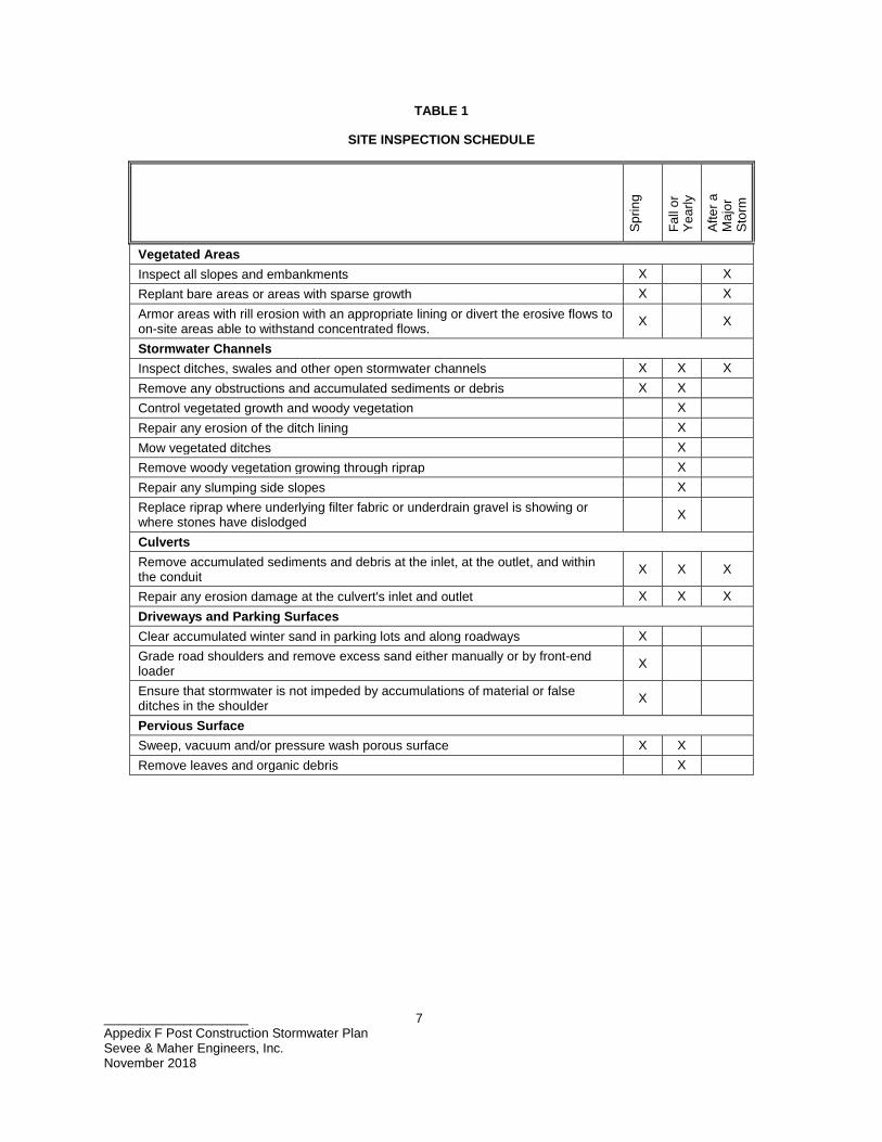
____________________ 7 Appedix F Post Construction Stormwater Plan Sevee & Maher Engineers, Inc. November 2018
TABLE 1
SITE INSPECTION SCHEDULE
Sprin
g
Fall
or
Year
ly
Afte
r a
Maj
or
Stor
m
Vegetated Areas Inspect all slopes and embankments X X Replant bare areas or areas with sparse growth X X Armor areas with rill erosion with an appropriate lining or divert the erosive flows to on-site areas able to withstand concentrated flows. X X
Stormwater Channels Inspect ditches, swales and other open stormwater channels X X X Remove any obstructions and accumulated sediments or debris X X Control vegetated growth and woody vegetation X Repair any erosion of the ditch lining X Mow vegetated ditches X Remove woody vegetation growing through riprap X Repair any slumping side slopes X Replace riprap where underlying filter fabric or underdrain gravel is showing or where stones have dislodged
X
Culverts Remove accumulated sediments and debris at the inlet, at the outlet, and within the conduit X X X
Repair any erosion damage at the culvert's inlet and outlet X X X Driveways and Parking Surfaces Clear accumulated winter sand in parking lots and along roadways X Grade road shoulders and remove excess sand either manually or by front-end loader X
Ensure that stormwater is not impeded by accumulations of material or false ditches in the shoulder X
Pervious Surface Sweep, vacuum and/or pressure wash porous surface X X Remove leaves and organic debris X

____________________ 8 Appedix F Post Construction Stormwater Plan Sevee & Maher Engineers, Inc. November 2018
INSPECTION LOG
Date
Device/Area Inspected
Inspected By
Observations, Deficiencies & Recommended Corrective Actions

____________________ 9 Appedix F Post Construction Stormwater Plan Sevee & Maher Engineers, Inc. November 2018
MAINTENANCE AND REPAIR LOG
Date
Device or
Area Maintained/ Repaired
Maintenance and/or Repair
Completed By
Maintenance Completed/Corrective Actions Taken

APPENDIX E
PRE-, POST-DEVELOPMENT STORMWATER FIGURES
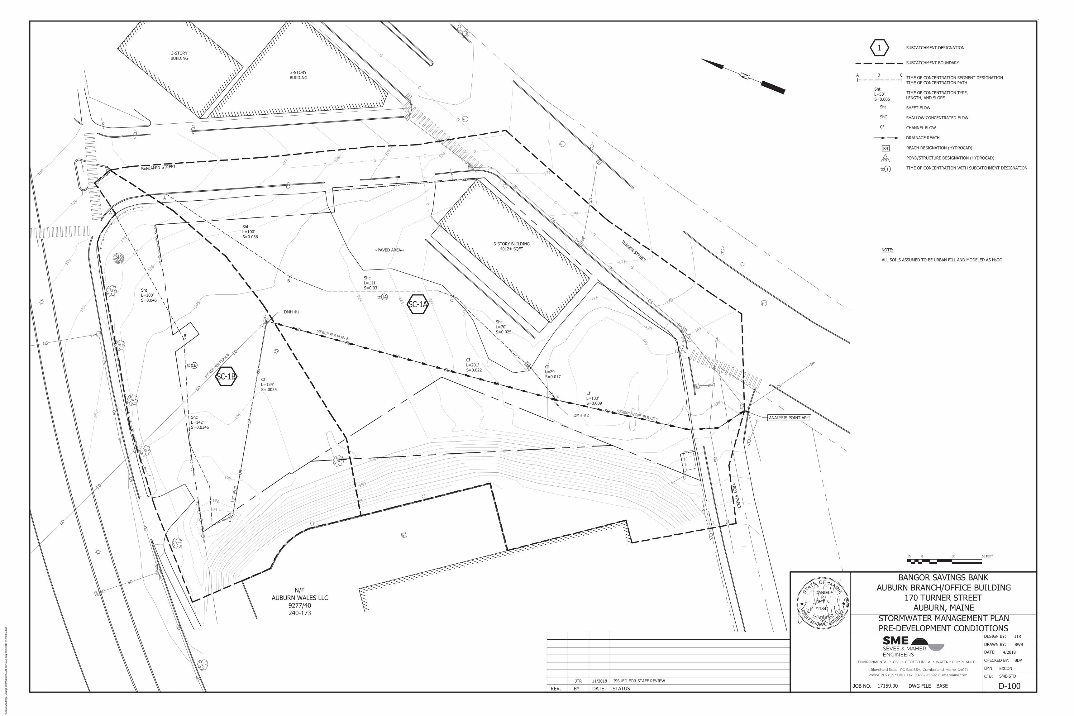
F
SMESEVEE & MAHERENGINEERS
ENVIRONMENTAL CIVIL GEOTECHNICAL WATER COMPLIANCE
4 Blanchard Road, PO Box 85A, Cumberland, Maine 04021Phone 207.829.5016 Fax 207.829.5692 smemaine.com
\\Nse
rver\c
fs\Ba
ngor
Sav
ings B
ank\A
ubur
n\Aca
d\Plan
s\BAS
E.dw
g, 11
/16/20
18 2:
52:58
PM,
bwb

ENVIRONMENTAL CIVIL GEOTECHNICAL WATER COMPLIANCE
4 Blanchard Road, PO Box 85A, Cumberland, Maine 04021Phone 207.829.5016 Fax 207.829.5692 smemaine.com
SMESEVEE & MAHERENGINEERS
\\Nse
rver\c
fs\Ba
ngor
Sav
ings B
ank\A
ubur
n\Aca
d\Plan
s\BAS
E.dw
g, 11
/16/20
18 3:
05:39
PM,
bwb

ATTACHMENT D
CAPACITY TO SERVE LETTERS
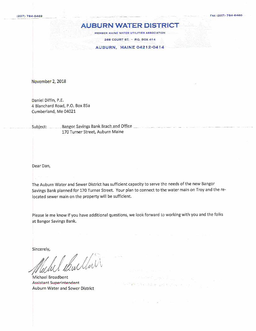
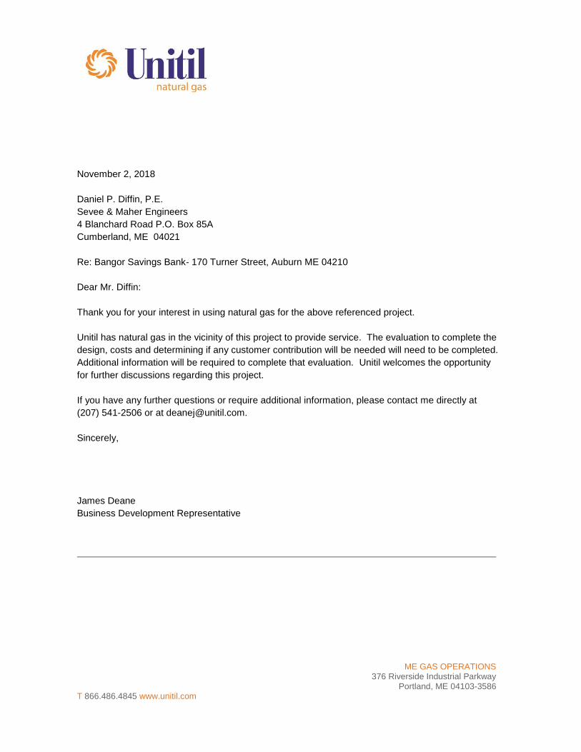
ME GAS OPERATIONS
376 Riverside Industrial Parkway Portland, ME 04103-3586
T 866.486.4845 www.unitil.com
November 2, 2018 Daniel P. Diffin, P.E. Sevee & Maher Engineers 4 Blanchard Road P.O. Box 85A Cumberland, ME 04021 Re: Bangor Savings Bank- 170 Turner Street, Auburn ME 04210 Dear Mr. Diffin: Thank you for your interest in using natural gas for the above referenced project. Unitil has natural gas in the vicinity of this project to provide service. The evaluation to complete the design, costs and determining if any customer contribution will be needed will need to be completed. Additional information will be required to complete that evaluation. Unitil welcomes the opportunity for further discussions regarding this project. If you have any further questions or require additional information, please contact me directly at (207) 541-2506 or at [email protected]. Sincerely, James Deane Business Development Representative

ATTACHMENT E
EROSION AND SEDIMENTION CONTROL PLAN

EROSION AND SEDIMENTATION CONTROL PLAN
Prepared for
BANGOR SAVINGS BANK AUBURN BRANCH/OFFICE BUILDING
AUBURN, MAINE
November 2018

____________________ E1-Erosion and Sedimentation Control Plan Sevee & Maher Engineers, Inc. November 2018
i
TABLE OF CONTENTS
Section No. Title Page No.
INTRODUCTION.................................................................................................................. 1
PROJECT DESCRIPTION ................................................................................................... 2
EROSION CONTROL MEASURES ..................................................................................... 3
SITE STABILIZATION ......................................................................................................... 3
IMPLEMENTATION SCHEDULE ........................................................................................ 4
DETAILS AND SPECIFICATIONS ...................................................................................... 5 6.1 Temporary Erosion Control ................................................................................. 6 6.2 Permanent Erosion Control ................................................................................. 6 6.3 Standard Erosion Control Procedures ................................................................. 7
MAINTENANCE................................................................................................................... 9 7.1 Routine Maintenance .......................................................................................... 9 7.2 Grassed Areas .................................................................................................... 9 7.3 Culverts and Gutters ........................................................................................... 9
EROSION CONTROL REMOVAL ......................................................................................10
CONCLUSION ....................................................................................................................10
LIST OF APPENDICES APPENDIX A DRAWING C-103: EROSION AND SEDIMENTATION CONTROL PLAN APPENDIX B DRAWING C-300: EROSION AND SEDIMENTATION CONTROL
NOTES AND DETAILS

____________________ E1-Erosion and Sedimentation Control Plan Sevee & Maher Engineers, Inc. November 2018
ii
LIST OF TABLES
Table No. Title Page No. 6-1 PERMANENT SEEDING RATES ....................................................................................... 6
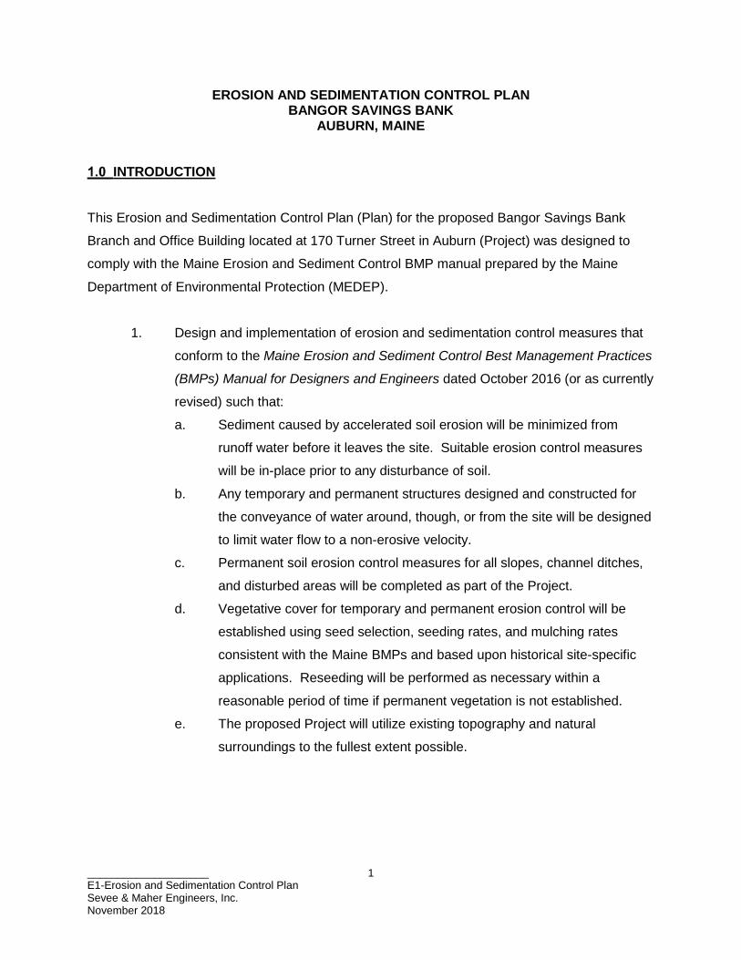
____________________ E1-Erosion and Sedimentation Control Plan Sevee & Maher Engineers, Inc. November 2018
1
EROSION AND SEDIMENTATION CONTROL PLAN BANGOR SAVINGS BANK
AUBURN, MAINE
INTRODUCTION
This Erosion and Sedimentation Control Plan (Plan) for the proposed Bangor Savings Bank
Branch and Office Building located at 170 Turner Street in Auburn (Project) was designed to
comply with the Maine Erosion and Sediment Control BMP manual prepared by the Maine
Department of Environmental Protection (MEDEP).
1. Design and implementation of erosion and sedimentation control measures that
conform to the Maine Erosion and Sediment Control Best Management Practices
(BMPs) Manual for Designers and Engineers dated October 2016 (or as currently
revised) such that:
a. Sediment caused by accelerated soil erosion will be minimized from
runoff water before it leaves the site. Suitable erosion control measures
will be in-place prior to any disturbance of soil.
b. Any temporary and permanent structures designed and constructed for
the conveyance of water around, though, or from the site will be designed
to limit water flow to a non-erosive velocity.
c. Permanent soil erosion control measures for all slopes, channel ditches,
and disturbed areas will be completed as part of the Project.
d. Vegetative cover for temporary and permanent erosion control will be
established using seed selection, seeding rates, and mulching rates
consistent with the Maine BMPs and based upon historical site-specific
applications. Reseeding will be performed as necessary within a
reasonable period of time if permanent vegetation is not established.
e. The proposed Project will utilize existing topography and natural
surroundings to the fullest extent possible.
____________________ E1-Erosion and Sedimentation Control Plan Sevee & Maher Engineers, Inc. November 2018
2
PROJECT DESCRIPTION
Bangor Savings Bank proposes to develop a new 1-story, 5,600 square-foot (sf) bank branch
and office building at 170 Turner Street in Auburn. The property fronts to Turner Street on the
southeast, Troy Street on the south, Benjamin Street on the northeast and Union Street to the
northwest. The property is currently developed with an abandoned 4,000-sf, 3-story mixed used
office and apartment building. The existing building will be removed prior to construction of the
new bank branch and office building.
Proposed construction will include a single story 5,600 sf building with a 3-lane drive thru and a
33-space parking lot. The parking area for the bank branch and office building will have two
entrances. The main entrance for the branch will be from Troy Street and the second entrance
will be from Benjamin Street. An existing 18-inch sanitary sewer and 60-inch storm drain
currently cross the property under the proposed building site and will have to be relocated.
Additional site improvements include public water and sewer services, a closed storm drain
system, underground electric and communications lines, site lighting, a retaining wall, and
landscaping.
The project will include a property transfer between Auburn Wales, LLC (Office Max) and
Bangor Savings Bank (BSB) for a 0.1-acre (ac) triangular portion of the Office Max property to
the BSB parcel. This transfer will expand the BSB property to facilitate utility reconstruction, site
circulation, additional parking, retaining wall construction, and landscaping.
Existing impervious area on the parcel is 31,816 sf. The existing developed area is 49,223 sf.
Proposed site improvements will include approximately 33,313 sf of impervious area and 54,644
sf of developed area after the property transfer, resulting in a net increase in impervious area on
the expanded property of approximately 1,497 sf. This project will result in less than one acre of
total impervious surface and less than 5 acres of new developed area and has been designed to
meet Basic Standards as outlined in Maine Department of Environmental Protection (MEDEP)
Chapter 500. The project will not require a MEDEP Stormwater Management Permit.

____________________ E1-Erosion and Sedimentation Control Plan Sevee & Maher Engineers, Inc. November 2018
3
EROSION CONTROL MEASURES
In developed conditions, the site will drain similar to existing conditions. The proposed
driveways and parking lot will be curbed to direct stormwater runoff to a new series of catch
basins connected to an existing manhole DMH#2 which drains into the existing municipal storm
drain in Troy Street.
Erosion and sedimentation control details and specifications associated with the driveways,
developed site areas, and treatment measures are shown on Drawings C-103 and C-300
(Appendix A and B, respectively) submitted with this application.
SITE STABILIZATION
All Erosion and Sedimentation Control Devices will be constructed in conformance with the
Maine Erosion and Sediment Control Best Management Practices (BMPs) Manual for Designers
and Engineers dated October 2016, as currently revised; the Erosion and Sedimentation Control
Plan as outlined herein and shown on the Construction Drawings; and any conditions of
approval as may be contained in the MEDEP Stormwater Law permit for this project.
Disturbed areas will be permanently stabilized within 7 days of final grading. Disturbed areas
not to be worked on within 14 days of disturbance will be temporarily stabilized within 7 days of
the disturbance. Temporary and permanent seeding and mulching requirements are presented
in Section 6.1 Temporary Measures, and Section 6.2, Permanent Measures, on Drawing C-300.
The following devices will be used to stabilize the site during and after construction. Details for
construction and maintenance of erosion and sedimentation control features are provided on
Drawing C-300.
• Siltation fence will be installed at locations shown on the Construction Drawings
and down slope of disturbed areas every 100 feet until the site is revegetated.

____________________ E1-Erosion and Sedimentation Control Plan Sevee & Maher Engineers, Inc. November 2018
4
• Mulch to provide cover for denuded or seeded areas until vegetation is
established. Hay/straw mulch will be available on site at all times to provide
immediate temporary stabilization when necessary.
• Revegetation of drainage channels with S75 erosion control blanket as
manufactured by North American Green or an approved equal.
• Stone check dams, hay bale barriers, and riprapped culvert inlet and outlet
aprons to reduce runoff velocities and protect denuded soil surfaces from
concentrated flows.
• Stabilized construction entrance(s)/exit(s) at all access points to the site to
prevent tracking of soil onto adjacent local roads.
• Loam, seed, and mulch to revegetate all denuded areas not stabilized by other
means, such as riprap, intended to be roof, or be a paved or gravel surfaced.
IMPLEMENTATION SCHEDULE
Bangor Savings Bank will establish the timing and sequencing of land disturbance. This work
will be subject to the limits set forth herein, as may be specified by the Maine Erosion, and
Sediment Control Best Management Practices (BMPs) Manual for Designers and Engineers
dated October 2016, as currently revised.
In general, construction is expected to begin in the fall of 2018.
The Erosion and Sedimentation Control features are presented on6.1 Drawings C-103 and C-
300 This plan includes the following elements:
• driveways,
• property boundaries,
• buildings,
• drainage channels,
• catch basins, and
• subsurface drainage pipes.
____________________ E1-Erosion and Sedimentation Control Plan Sevee & Maher Engineers, Inc. November 2018
5
The general construction sequence of the site is expected to be as follows:
• Site preparation through demolition of existing structures, concrete slabs, and
foundation materials as appropriate.
• Install temporary erosion control measures.
• Stockpile topsoil at designated areas on the property.
• Complete utility relocation for sanitary sewer and storm drain.
• Construct stormwater management facilities.
• Install utilities, and construct subgrade of driveways and parking areas.
• Prepare the building site and construct foundations.
• Perform site stabilization (complete roadway and parking area gravel and
bituminous pavement; loam, seed, and mulch) and other miscellaneous items
(plantings).
• Clean sediment from temporary collection structures; complete construction of
stormwater management structures.
• Remove temporary erosion control measures after all disturbed areas are
stabilized.
DETAILS AND SPECIFICATIONS
The details and specifications for all temporary and permanent erosion controls to be installed at
the site are provided in Drawing C-300, Erosion Control Notes and Details.
Temporary and permanent erosion control measures will be implemented to minimize erosion
during construction and cover placement. Temporary measures (i.e., silt barriers and silt socks)
and permanent measures (i.e., permanent seeding, and mulching) will be monitored on a
regular basis. The contractor will ensure that structures are functioning properly and will
perform necessary maintenance described in the Maine Construction General Permit and the
Maine BMPs. Erosion and Sedimentation Control Sections and Details (Drawing C-300)
specified for the Project are contained in Appendix B.
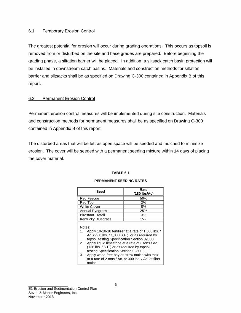
____________________ E1-Erosion and Sedimentation Control Plan Sevee & Maher Engineers, Inc. November 2018
6
6.1 Temporary Erosion Control
The greatest potential for erosion will occur during grading operations. This occurs as topsoil is
removed from or disturbed on the site and base grades are prepared. Before beginning the
grading phase, a siltation barrier will be placed. In addition, a siltsack catch basin protection will
be installed in downstream catch basins. Materials and construction methods for siltation
barrier and siltsacks shall be as specified on Drawing C-300 contained in Appendix B of this
report.
6.2 Permanent Erosion Control
Permanent erosion control measures will be implemented during site construction. Materials
and construction methods for permanent measures shall be as specified on Drawing C-300
contained in Appendix B of this report.
The disturbed areas that will be left as open space will be seeded and mulched to minimize
erosion. The cover will be seeded with a permanent seeding mixture within 14 days of placing
the cover material.
TABLE 6-1
PERMANENT SEEDING RATES
Seed Rate (180 lbs/Ac)
Red Fescue 50% Red Top 2% White Clover 5% Annual Ryegrass 25% Birdsfoot Trefoil 3% Kentucky Bluegrass 15% Notes: 1. Apply 10-10-10 fertilizer at a rate of 1,300 lbs. /
Ac. (29.8 lbs. / 1,000 S.F.), or as required by topsoil testing Specification Section 02800.
2. Apply liquid limestone at a rate of 3 tons / Ac. (138 lbs. / S.F.) or as required by topsoil testing Specification Section 02800.
3. Apply weed-free hay or straw mulch with tack at a rate of 2 tons / Ac. or 300 lbs. / Ac. of fiber mulch.

____________________ E1-Erosion and Sedimentation Control Plan Sevee & Maher Engineers, Inc. November 2018
7
Permanent seeding operations typically occur no later than October 1. After October 1,
disturbed soil shall be protected with mulch consisting of either hay or straw and the temporary
seed mixture. The mulch may be required to be secured with netting, twine, or other approved
methods. Seeding operations shall be done sequentially as the project development
progresses, to minimize, to the great practical extent, areas of the completed cover system
exposed to the elements. Problem areas and continually eroding areas shall be repaired
immediately with temporary erosion control blankets. The blankets shall conform and be
installed in accordance with the manufacturer’s recommendations.
6.3 Standard Erosion Control Procedures
In addition to these measures, the following erosion and sedimentation control procedures will
be implemented during construction and cover placement:
1. Soil erosion and sedimentation control measures will be performed in
accordance with procedures outlined in the Maine Erosion and Sediment Control
BMPs (Maine Department of Environmental Protection, October 2016) as
currently revised.
2. Removal of trees, brush, and other vegetation, as well as disturbance of soil, will
be kept to a minimum during site development.
3. Erosion and sedimentation control measures such as bark mulch sediment
barriers, siltsacks, and a siltation barrier will be installed at locations shown on
the Contract Drawings.
4. Siltation barriers will be inspected after each rainfall and at least daily during
prolonged rainfall. Required repairs will be made. Sediment deposits will be
removed periodically from the upstream side of the siltation barriers and will be
spread and stabilized in site areas not subject to erosion. Siltation barriers will
be replaced, as necessary, to provide proper filtering action.
____________________ E1-Erosion and Sedimentation Control Plan Sevee & Maher Engineers, Inc. November 2018
8
5. Riprap required at culverts and down spouts will consist of fieldstone or rough
unhewn quarry stone of approximately rectangular shape. Stones will be of a
size as noted on the construction drawings.
6. Following final grading, all graded or disturbed areas, not to be used as gravel
roadways or parking areas will be spread with a minimum compacted depth of 4
inches of topsoil and seeded to provide a permanent vegetative cover.
7. All areas receiving topsoil will be seeded. Seeding normally will occur between
April 1 and October 1. Surface water runoff control measures (i.e., drainage
ditches, berms, and culverts) will be constructed before seeding; all grading will
be performed before seeding. The top layer of soil will be loosened by raking,
discing, or other acceptable means before seeding. Application rates for the
lime, fertilizer, seed, and mulch are presented in Table 6-1. The seed will be
applied uniformly with a cyclone seeder, drill, cultipack seeder, or hydroseeder.
Seed will not be planted if there is danger of frost shortly after seed germination.
Maximum seeding depth is ¼ inch when using methods other than hydroseeding.
Wood fiber cellulose mulch or hay mulch will be spread uniformly upon
completion of the seedbed preparation, liming, fertilization, and seeding. The
mulch may be anchored in place by uniformly applying an acceptable mulch
binder such a Curasol or Terratac.
8. If germination is unsuccessful (i.e., less than 90-percent catch) within 30 days of
seeding or there is unsatisfactory growth in the next year, the area will be
reseeded in accordance with seeding specifications described herein.
____________________ E1-Erosion and Sedimentation Control Plan Sevee & Maher Engineers, Inc. November 2018
9
MAINTENANCE
7.1 Routine Maintenance
During construction, inspections will be undertaken by the contractor to assure that temporary
and permanent erosion and sedimentation controls are properly installed and correctly
functioning, and that additional erosion control measures are installed if needed. Such
inspections will occur bi-weekly and after each significant rainfall event (1 inch or more within a
24-hour period) during construction until permanent erosion control measures have been
properly installed and the site is stabilized. The contractor shall perform all inspections and
documentation required by the Maine General Construction Permit.
7.2 Grassed Areas
Fertilize and lime, as necessary, according to a soil test performed by University of Maine as
described in the Contract Specifications.
7.3 Culverts and Gutters
Culverts and gutters will be inspected in early spring, late fall, and after significant rain events.
All debris and sediment will be removed and any erosion of inlet or outlet channels repaired.
____________________ E1-Erosion and Sedimentation Control Plan Sevee & Maher Engineers, Inc. November 2018
10
EROSION CONTROL REMOVAL
Removal of temporary erosion control measures shall be the responsibility of the contractor.
Erosion controls shall remain in place and maintained by the contractor until all related
construction is complete and the area is stable. An area is considered stable if 90 percent cover
of grass has been established or riprap or other permanent measures are in place and
functioning properly.
Silt barriers shall be removed once the areas upstream are stable. The silt barriers shall be
disposed of legally and properly off-site. Sediment trapped behind these controls shall be
distributed to an area undergoing final grading and graded in an aesthetic manner to conform to
the topography and fertilized, seeded, and mulched in accordance with the rates listed in
Table 6-1. The sediment trapped by these devices shall not be regraded within the existing
drainage ways.
Once the trapped sediments have been removed from the temporary sedimentation devices, the
disturbed areas must be loamed (if necessary), fertilized, seeded, and mulched in accordance
with the rates listed in Table 6-1.
CONCLUSION
The proposed project has been designed with stormwater management and erosion controls to
manage surface water runoff from the site during construction and post-closure such that clean
stormwater is directed to downstream water bodies. The foregoing measures and controls will
help to assure that no unreasonable erosion of soil or sediment will occur as a result from
construction or operations.
All proposed structures to be used within this project have been designed using engineering
procedures commonly used in stormwater analyses.
To minimize erosion during and after construction, temporary and permanent erosion control
measures will be implemented. Temporary measures (i.e., silt barriers and siltsacks) and

____________________ E1-Erosion and Sedimentation Control Plan Sevee & Maher Engineers, Inc. November 2018
11
permanent measures (i.e., permanent seeding, mulching, and culvert inlet and outlet protection)
will be monitored on a regular basis. As part of the contractor’s scope of work to ensure that
devices are functioning properly, the contractor will perform necessary inspections and
maintenance for the erosion control systems.
During construction, the Contractor will be responsible for inspecting the silt fence, siltsacks and
other components of the erosion control system on a bi-weekly basis after each rainfall and at
least daily during prolonged rainfall. Any necessary repairs shall be made immediately.

APPENDIX A
EROSION AND SEDIMENTATION CONTROL PLAN

SMESEVEE & MAHERENGINEERS
ENVIRONMENTAL CIVIL GEOTECHNICAL WATER COMPLIANCE
4 Blanchard Road, PO Box 85A, Cumberland, Maine 04021Phone 207.829.5016 Fax 207.829.5692 smemaine.com
\\Nse
rver\c
fs\Ba
ngor
Sav
ings B
ank\A
ubur
n\Aca
d\Plan
s\BAS
E.dw
g, 11
/16/20
18 3:
07:41
PM,
bwb

APPENDIX B
EROSION AND SEDIMENTATION CONTROL NOTES AND DETAILS
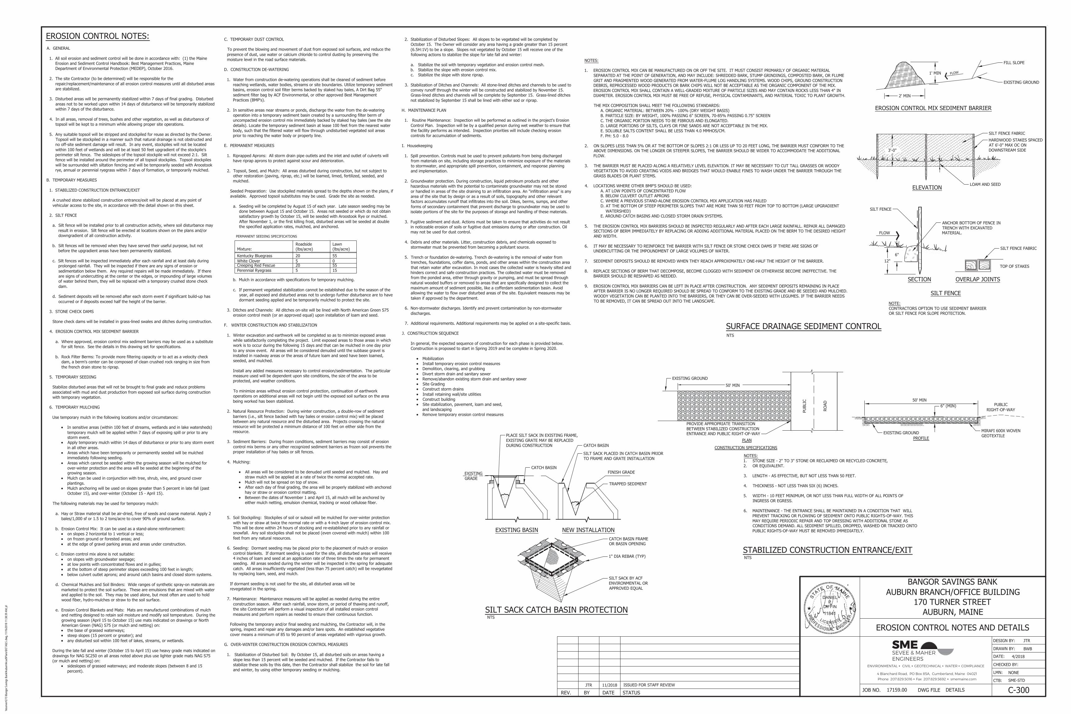
SMESEVEE & MAHERENGINEERS
ENVIRONMENTAL CIVIL GEOTECHNICAL WATER COMPLIANCE
4 Blanchard Road, PO Box 85A, Cumberland, Maine 04021Phone 207.829.5016 Fax 207.829.5692 smemaine.com
\\nse
rver\C
FS\B
ango
r Sav
ings B
ank\A
ubur
n\Aca
d\Plan
s\DET
AILS
.dwg,
11/16
/2018
11:38
:39 A
M, jrl

ATTACHMENT F
MHPC MAP
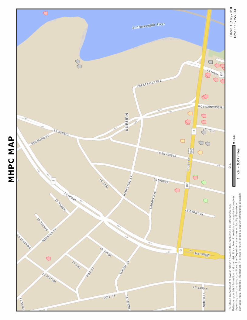
��������
����� ����� �� ������������������ ����
���!"#�$� % ����&'
()*�+,-.*�/*0,123*.2�45�(1,.60412,2-4.�014
7-8*6�2)-6�09:;-<,2-4.�541�-.5413,2-4.�4.;=>�
?*;-,.<*�904.�2)-6�-.5413,2-4.�-6�,2�96*1�1-6@>
�A2�-6�69:B*<2�24�1*7-6-4.�,.8�3,=�:*�-.<430;*
2*�8*0*.8-.C�904.�<),.C
-.C�<4.8-2-4.6>�()*�/*0,123*.2�,6693*6�.4�
;-,:-;-2=�-5�-.B91-*6�41�8,3,C*6�1*69;2�5143�2)
-6�-.5413,2-4.>�()-6�3,0�-6�.42�-.2*.8*8�24�69
00412�*3*1C*.<=�8-60,2<)>�

ATTACHMENT G
FEMA FIRM MAP

������������ ��������������������
�������������������� !�
��� ��"�����#$���%����"&'���
�(�� )��� )(�
��)����(�
"��*
!�+ ,-(.�//01�//+.- (�.(0��
!�+ ,- 2�3201� //+(-/3�2 0��455�674�859:8;�6:8�<5;=7>5<�>5?5@<�=@<�
7@<5A�B=9�6:8�678B�9=@5>�>=C:D;
495E7=>�6>::< F=G=8<�=85=4HIJKLMJ�NOPQ�6RLLS�5RQT
OJILU�VN65WXYZ[�\]�]�\__ HIJK�N65�L�<QaJKXYZ[�\
b]�\c]�\d]�b]�\e8QfMROJLg�6RLLShOg ijkl�=UUMOR�EKOUmQ�6RL
LS�FOnOSo�=QOPLp�ql�OUUMOR�mKOUmQ�pRL
LS�hIJK�OTQOfQSQaJK�RQPP�JKOU�LUQ�pLL
J�L�hIJK�SOIUOfQOQOP�Lp�RQPP�JKOU�LUQ�P
rMOQ�sIRQ��XYZ[�t6MJMQ�ELUSIJILUP�ql�=
UUMOREKOUmQ�6RLLS�FOnOSXY
Z[�t=QO�hIJK�8QSMmQS�6RLL
S�8IPu�SMQ�JL>QTQQj�4QQ�@LJQPjXYZ[�t =QO�hIJK�6RLLS�8IPu�SM
Q�JL�>QTQQXYZ[�v@:�4E855@ =QO�Lp�BIUIs
OR�6RLLS�FOnOSXYZ[�t =QO�Lp�DUSQJQsIUQS�6RLLS�FOnOSXYZ[�v
EKOUUQRo�EMRTQJo�L�4JLs�4QhQ
>QTQQo�<IuQo�L�6RLLShORR
ELPP�4QmJILUP�hIJK�ql�=UUMOR�EKOUmQ
wxyz HOJQ�4MpOmQ�5RQTOJILU ELOPJOR�;OUPQmJ ELOPJOR�;OUPQmJ�NOPQRI
UQ 9LpIRQ�NOPQRIUQ FgSLfOaKIm�6QOJMQNOPQ�6RLLS�5RQTOJILU�>IUQ�VN65W
5ppQmJITQ�>:B8P >IsIJ�Lp�4JMSg {MIPSImJILU�NLMUSOg <IfIJOR�<OJO�=TOIRO|RQ @L�<IfIJOR�<OJO�=TOIRO |RQ
DUsOaaQS;KIP�sOa�mLsaRIQP�hIJK
�65B=}P�PJOUSOSP�pL�J KQ�MPQ�Lp�
SIfIJOR�pRLLS�sOaP�Ip�IJ�IP�ULJ�TLIS�OP�SQPmI|QS�|
QRLhj�;KQ�|OPQsOa�PKLhU�mL
saRIQP�hIJK�65B=}P�|OPQsOa�
OmmMOmg�PJOUSOSP ;KQ�pRLLS�KOnOS�IUpLsOJILU�IP�SQITQS�SIQmJRg �
pLs�JKQOMJKLIJOJITQ�@6F>�hQ|
�PQTImQP�aLTISQS�|g�65B=j�;KIP�sOa
hOP�Q~aLJQS�LU�qi�kk�kiq��OJ�k�k���i�9B��O
US�SLQP�ULJQpRQmJ�mKOUfQP�L�OsQU
SsQUJP�PM|PQrMQUJ�JL�JKIP�SOJQ�OUS
JIsQj�;KQ�@6F>�OUS�QppQmJITQ�IUpLsOJILU�sOg�m
KOUfQ�L|QmLsQ�PMaQPQSQS�|g�
UQh�SOJO�LTQ�JIsQj;KIP�sOa�IsOfQ�IP�TLIS�
Ip�JKQ�LUQ�L�sLQ�Lp�JKQ�pLRRLhIUf�sOa
QRQsQUJP�SL�ULJ�OaaQO��|OPQsOa�IsOfQgo�pRLL
S�nLUQ�RO|QRPoRQfQUSo�PmORQ�|Oo�sOa�
mQOJILU�SOJQo�mLssMUIJg�ISQUJIpIQPo
678B�aOUQR�UMs|Qo�OUS�678B�QppQmJ ITQ�SOJQj�B
Oa�IsOfQP�pLMUsOaaQS�OUS�MUsLSQ
UInQS�OQOP�mOUULJ�|Q�MPQS�pL
QfMROJLg�aMaLPQPj������� :;F58�=85=4�:6 6>::<�F=G=8< :;F58�=85=4 ?5@58=> 4;8DE;D854 :;F58 65=;D854 B=9�9=@5>42
�.)���
���y� ;KQ�aIU�SIPaROgQS�LU�JKQ�sOa�IP�OU�OaaL~IsOJQ
�aLIUJ�PQRQmJQS�|g�JKQ�MP
Q�OUS�SLQP�ULJ�QaQPQUJ�
OU�OMJKLIJOJITQ�aLaQJg�RLmOJILUj