set-upinstructions - vending world · d~crane-national vendors. shoppertron ... vendors neither...
TRANSCRIPT

Set-Up Instructions
4300001 REV. L
Copyright©
d~ CRANE- National Vendors

SHOPPERTRON
1Zl.A••~.~!Jk,.{It.A..!Jt.A,A!Jl..!Jt.AA!tt."j.'t,A!Jt.AWARRANTY
th4':! Shopp@rtron· l'terchaod1sel' 1. If'arraflted for one (1) year again8tdefeetlve parts and ~orkmBnBhlp. Any part or parts which are proven tobe d~fec.t1ve w;l.thin one (1) year of t.he date of IiIhlplllent will berepaired or r@plsced fr@e of charge ~hen the d~f~ct1ve part is~etu~ned, wtth transport_tion chargee prepaid, to the destinationd~slgnat@d by the N3tlonal Ven4o~s Warranty Dep~rtment.
All r~fr!g~rAtion units and 1ce~~kers are warranted on the above basisfor a period of one (l) year of the date of Bhipcent.
Thh warrant.y applies only to th@ or1g;(,n.l pU'tchas,@r of theHel'ch-,ndiaer and is null and vo;ld 1£ the 'MerchGnd18eJ:' Is Bold duringthe period of wsrrsnty.
r"h warrRnty is also null and void fOJ;" all t:!1l:!,ctric:al cOl;llponents.""irint, or c:ir~l.ilts, .nd/or for all mt:!chaniMl p.rts or assemblit:!sdamag~d AS a result of ~pt:!rating the Merchandiser Bt other than 110-120volts, 60 Hertz current. The woll-rro\lnty is null and void in event ofvandalism, fir@, or negl1gence on the part of the operator.
No warrAnty is given OJ;" implied on incilndeacl!nt lamps, neon lollmpsifluore~eent lAmps, ballast, or starters, and other expendable items. Nownrranty will be gi~@n wh~n other manufactured ~omllonenta are installed1n National Vendors Merchsnd~ser~.
Furth~r, National Vendors 18 not J:'esponl;lib1e for any cost of l:iervl~e
rendered, or repairs made on m@:rchandiser or p8rts. .t othe.r thanNation~l Vendo~s: o~ by ~nyone other than an authorized fa~tory &@rvlc:e~epres~ntative of NatiOnal Vendors; unless .uthor1~3tlo" to in~ur suchexpense has been g1~en in writing by National ve.ndors prior toincurrin& ~uch ~xp~tt~~.
~1. ..rr.nty 1. l~ lieu of all otber w.rr.n~1eB ~~re8.ed O~ l-,lied.1ncludinS. v1tbout l1a1tatiou p _~r.ntie. of -.:r~b.ntab:l.llty••nd all
! otber obligation or l1abtlltiea OD N.tioGal Veado~. p.rt~ and NatioaalVendors neither aa8U_8, nor .uthQrlze* _tty person to aa.u-e for it,anJ other oblisatloD or liability in eO~D~etlon ~th the aale of ••1d
~ equlp~nt or any part tbereof... National Vendors
L12955 Enterprise WayBridgeton, MO 63044
'T.......~~~.~_II'i'Q'.~'tIII!:"1_-_...This machine has been engineered to
our own rigid safety and performancestandards. It has earned a -"Letter ofCoropliance" from NMIA indicating thatit complies with sanitation and healthguidelines recommended by the AutomaticHerchandising Health-Industry Council(MIHIC) and it conforms with all otherNAIIA safety recommendations.
To ~etatn the safety and performancebuilt into this machine, it is impor-
tant that installation and maintenancebe conducted So as to not alter theconstruction, or wiring, and thatreplacement parts are as specified inthe Parts Manual. Your investment inthis equipment will be protected byusing the Set-Up Instructions and PartsHanual in your operation and maintenance work. By following prescribedprocedure.s, machine performanc.e andsafety will be p.reserved.
4300001Copyi"ighteNational Vendors
A Division of UNIDYNAMICS, Corp. Rev. L

TABLE OF CONTENTS
SECTION I - GENERAL INFORMATION AND INSTALLATIONUnpacking and Inspecting .•••••••••........••• 1Electrical Supply at the Site •.•••••••••••••• 1Installation of the Merchandiser •••..•.•••••• 3Installation of the Coin Mechanism .•...•••••• 4Installation of the Door Lock •••.••.•.••••.•. 4Installation of the Money Box LOck •....••••.• 5Heal th Control 5Loading the Merchandiser ••••.•.....•••••••••• 6
SECTION 11 - PROGRAM OPERATIONSSupervisor Procedures ..............•••..•.•.• 7Configuration Procedures .................•••. geSetting the Vend Price .••••••••••.•.•.•.•.•.• l2aSetting the Oiscount 1 & 2 Prices •..•...••••• 12bsetting Section 3 Access ••.•...•••.••..•••••• 12cSetting Tamper Check •.•.••••••••.•.•.•.•.•••. l2cSetting Mach Load ..•.•.•.•••.••...••.•.••••.• 12dSetting the Free Vend .............•••...•.•.• 12dMaking a Test Vand •••••••••••. ~ ••••.•.•...... 12dsetting the Bill Validator •••.•..•......••... 13Testing the Payout Switches ••••.••••••••••.•. 13Reading the Internal Temperature ••.•••.•••••• 13Testing the Health Control ••••••••••••.•.•••. 13Retrieving Data From Machine Memory (RAM) •••• 13Clearing Data From Machine Memory (RAM) •••••• 15Checking the Diagnostics •.•.•.•.•.•.•.•.•.••• 16Checking the Controller PCB •••••••.••.••••••• l7b
SECTION 111 - ADJUSTMENT, REMOVAL AND REPLACEMENT PROCEDURESAdjusting Product Oividers ••••••.•.•...•...•. 18Adjusting the Delivery Door stops •••••••.•.•. 19Shelf Assembly Removal and Replacement ..••.•• 19Drum Assembly Removal and Replacement ...•••.• 19Door Side Trim Removal and Replacement ••..•.• 19
SECTION IV - ROUTINE SERVICE AND SANITATION
SECTION V
General III .. .. .. .. .. .. .. .. .. .. .. 22Daily Service 23Daily Sanitation .•.•.•.•.•.•....•.•.•.•.••••• 23Weekly Service .....•.•••.•..••.•..........•.. 23Weekly Sanitation •...••••••....•.•..•..••••.. 24Monthly Service ..•.••••••............•.•.•.•. 24Monthly Sanitation •••••••.•••••.•••..•.•.•.•. 24Semi-Annual Service •••.••••••...•.•.•.•.....• 24Semi-Annual Sanitation ••.•.....•..•••..•.•. ~. 24Cleaning the Coin Validator and Coin Chute ••• 24Cleaning the Bill Validator •••••••••••••••••. 25CIRCUITRY
Wiring Diagram .•••••.•...•.•••..•••.•..•••••• 26SChematic '" ••.•......... _ . . . . . . 27
Rev. J iii-d 4300001

SIZE:
WEIGHT:
POWERREQUIREMENTS:
CAPACITY:
REFRIGERATIONSYSTEM:
COINMECHANISM:
BILLVALIDATOR:
SHOPPERTRONSPECIFICATIONS
72" (182 em) high, 38" (96 cm) wide, 31.5"(80 cm) deep, 6" legs comply with U.S. PublicHealth Service and AMHIC of NAMA requirements
760 LBS. (347 kg)
110-120 volts, 60 HZ, 12 amps
9 levels, each level adjustable to 6, 12, 1Qor 24 items. Total capacity for 54-216 items
1/3 h.p compressor, 11.4 oz. (323 g)R-12 charge
OPTIONAL EQUIPMENT
COINTRON 3000MARS TRC 6000 (Drop shipped)
MAKA NB11B 400 (Bill capacity of 4~0)
(FACTORY OR FIELD INSTALLED)
Door Locks (Flex-Ace or yan Lock)Cabinet Base PlateMoney Box Lock
4300001
(Specifications SUbject to change without notice)
iv-d

SECTION IGENERAL INFORMATION AND INSTALLATION
This Set-Up Instructions provides theinformation required for properunpacking, inspection, installation,preparing for vending, adjustmentremoval-replacement procedures, routingservice and sanitation.
E. Instructionsoptional Basewith the Baseshipped.
for installing thePlate are included
Plate Assembly when
Read the following instructionsthoroughly before unpacking, inspecting, or installing the Merch9.ndiser.All references to left and right are asseen when looking at the front of theMerchandiser or the assembly beingdescribed. To determine the name andthe location of various components, seeFigure 1-1.
CAUTION
For Mel"Chandi8er in8tallation be sureto follow the 8equence 8S outlined inthis section.
Unpacking and Inspecting
A. CarefUlly remove the Merchandiserfrom its shipping carton and placeit on a level surface.
F. Inspect the merchandiser electricalconnectors and components.
The Location's Electrical Supply
The Shoppertron Merchandiser isequipped with a service cord thatterminates in a 3 pin connector. Thewall receptacle into which the servicecord connector is plugged must beproperly polarized and grounded, andsupply a constant 120 volts at 60hertz. The receptacle should beprotected by a 15 amp fuse or circuitbreaker.
A. Line Voltage
B. Inspect the outside of theMerchandiser for dents, scratches.or any damage resulting fromimproper handling.
C. Open the monetary compartment. Ifthe merchandiser is eqUipped withthe optional door lock, the key willbe in the coin return receptacle.
D. Inspect the inside of the cabinet.Observe the location and position ofthe packing material, should reusebecome necessary. Carefully removeall packing material.
If any damageunpacking thisclaim immedia tely
NOTE
was observed WhileMerchandiser, file awit h t he carrier.
1
Do not operate the Merchandiser onan electrical supply line over whichthe voltage may drop below 1l0-voltsduring the location's peak powerusage time. The warranty of theMerchandiser is null and void whenthe minimum electrical requirementsdescribed here are not met.
B. wan Receptacle Polarity
Check the polarity of the receptaclewith a neon indicator test lamp or avolt-ohmmeter. Measure 120 VAC. perFigure 1-2. If the test lamp doesnot glow when it is inserted intothe receptacle in the positionshown, or a voltage is not measuredon the meter, have the wallreceptacle rewired to conform to therequired polarity.
4300001

PLEASE PAY SPECIAL ATTENTION TO THIS PAGESection I
DRIVEMOTORASSEMBLY
HEALTH CONTROLTEMPERATURE:SENSOR
I
I:I.
I I:0'
j i'-,'I
I'
I;
STORAGEAREA
COiNBOX
DOORINTERLOCKSWITCH
ELECTRICALPANELCOVER
LINTSCREEN
MAINPOWERSWITCH
DOORDUCTFILTER
Blower MotorLube on regular basisSee motor for type of oil
4300001
Flgu~e 1-1. ComponenT Locato~ (1 of 2)
2

CABINETDOOR
/(REF)
====~~911
I~
,,I
, I
I
CONTROLPANEL
DATAACCESS
~~==:::::::t";':--- CONTROLLOCK(optional)
BILLVALIDATOR(optIonal)
.COINMECHANISM(optional)
MONETARYDOOR
Section I
--THREE WIREGROUNDING TYPEWALL OUTLET
Figure 1-2. Receptacle Grounding Test
CAUTION
Par Customer and Serviceman Safety.snd to Msure proper Merchandiseroperation. always be sure theMerchandiser is leveled properly on aflat. solid. stable Door or basefoundation •
A. Move the Merchandiaer to the desiredlocation. Position the Merchandiserin the desired location at least 6in. (15 cm) from any wall. Level thecabinet left-ta-right and front-torear; adjust the leg levelers asrequired and check with a spiritlevel. Securely support themerchandiser when tilting thecabinet.
Figure 1-'. CoMponent lOcaTor (2 of 2)
Installation of the Merchandiser
WARNING
This merchBndiaer is Intended forindoor use only.
3
B. For "Bank Style" inatallations ofmultiple Merchandisers:
1. Place the first machine inlocation or at the highest spotif the floor ;a not level.Ell:tend the leg levelers only asrequired.
2. Position and level the X'emainingmachines.
4300001

Sec"iOD 1
C. Set the main power switch to "OFF".
WARNING
B. Loosen the coin mechanism mountingscrews on the Merchandiser to standoff about 1/8" (0.3 cm).
The quarter tube must have at leastfour dollars in quarters for the billvalidator to work.
C. Place the coin mechanismwith key holes overmounting screws.
NOTE
E. Connect the coinpower-input plug withsupply connectorMerchandiser.
in locationthe three
mechanismthe powerin the
screws andvalldator
the mountingthe coin
D. Tightenreinstallassembly.
E. Move the MAIN Switch to the ONposition. Close Cabinet Door. TheDisplay Light will light, the VentFan Motor will be energized.
Instal1lltion of the Coin Mechanism
To install the coin mechanism, seeFigure 1-3 and do the below:
DO NOT plug the Merchandiser servicecord connector into a wall receptaclethat is impl"(lperly pOlarized andgl"(lUnded.
D. Connect the Merchandiser servicecord to the wall receptacle that hasbeen properly polarized.
Ffgure 1-3. Ooln Mechanism Jns~81 latlon
G. Turn the Main Power Switch to ON.
areare
door locks thatNational Vendors
The optionalavailable fromlisted below:
Installation of the Door Look
F. Fill the respective coin tubes tothe desired levels. Insert coins oneat a time and make certain that allcoins lie Oat in the coin tubes.
H. Payout about 6 coins to insurepl'oper loading.
I. Reload the dispensed Coins.
J. VisUally cheek the tubes forshingling of coins.
COINCHUTE
"OU~Tl"GPLATE
__~IU
--'. - I.." ..
COI~MECHA~lsM
CAUTION
Set the IIIlIin power switch to ·Opp·before installtng coin meclu1niBm.
FLEX-ACE (PIN 9992000)• corresponding key (PIN 9994000)
A. Refer to instructions provided withthe coin mechanism and remove thecoin validator sssembly.
VAN LOCK (PIN 3112163)• corresponding key (PIN 3112164)• kit-lock and key (PIN 3122165)
43000014

Section I
FIgur8 1~4. Loek Cyl Inder In~t8118tlon
O. Install the cam and secure with thescrew.
SCREW
CAM
condition wminitial set-up ,
~ONEYBOX
WASHER ~UT
LOCK
Health Control
FIgure 1-5. Mbney Box Lock In$t811e~lon
Should the temperature of therefrigerated cabinet not pUll down to45° (7°C) within 30 minutes after thedoor of the refrigerated cabinet isclosed, or if the temperature of thecabinet should rise above 45°F (7°C),the merchandiser will automatically gointo an out-of-service mode and foodwill not be vended. Should this occur,the display will show "Temporary Out OfService". When the monetal'Y door isopened, the message "Health Off" andthe date and time will be displayed.To reset the health control, therefrigerated cabinet door must beopened and closed again.
The Shoppertron merchandiser isequipped with an electronic healthcontrol. The health control preventsthe vending of merchandise underconditions which could have caused theproduct to become spoiled. A healthcontrol is required by most state and10co.1 health authorities. Thetemperature sensor for the healthcontrol is located on the inside of therefrigerated cabinet door, see Figure1-1.
The out-of-serviceusually occur at
the
thethe
SQUAREHOLE
frombox
opening onsecure with
LEVER
LOCK ~SPRI~G - ,:
'1LOCK IPIN
I
A. Remove moneymerchandiser.
Installation of the Money Box Lock
To install the optional money box lock.see Figure 1-5. and do the below:
e. Insert lock intomoney box. andwasher and nut.
B. Remove the screw, cam. nut. andwasher from the lock assembly.
E. Place money boX back in themerchandiser and test the lock withkey(s) provided.
To install an optional door lock, seeFigure 1-4. and do the below:
A. Remove lock spring.
B. Depress lock pin and push lockcylinder into lever until pin snapsinto place.
e. Test lock mechanism with key.
54300001

Section I
therefore. National Vendors recommendsthat the merchandiser operate withthe refrigel'8ted compartment emptyuntil the temperature reaches a levellow enough for the health control to besatisfied.
Should it be necessary to test thehealth control. see Testing the HealthControl. Section II.
Loading the Merchandiser
A. There are two types of loadingmodes; FUll Shop Mode which theentire drum is loaded and Limited
Shop Mode where only 1 or 2 zones ofthe drum are loaded. This mode isusually used on smaller locations. Toset the mode. see Setting Machine
Configuration Section II.
B. Adjust the Product Dividers. ifapplicable. See Adjusting ProductDividers. Section III.
C. Set new prices. if applicable. SeeSetting the Vend Price. Section II.
D. Set discount pricea. if applicable.See Setting the Discount 1 and 2Prices. Section II.
43000016
CAUTION
The J.ood switch overrides the LilDitedShop mode. enabling the unusedZones(s) of the drum to be loIlcled.
MOTE
If the drum is loaded with commoditieswhich are too large for the compartments. the drum will not rotateproperly.
E. Press and hold the load awitch - Thedrum will rotate.
F. Load the Food Dru m.
CAUTION
If Tamper Cheek is ON or the machine isconfigured to Prefer Max. the MACHLOAD button must be pressed afterclosing the refrigeration door. Thisprevents any compartment doors frombeing locked out.
G. Close refrigeration door.
H. Press and hold MACH LOADED fortwo seconds - The Credit Displaywill show "DRUM FULL".

SHOPPERTRONSECTION II
PROGRAM OPERATIONS
FIQu~e 2-1. Confrol pone I
Sorne set-up. test snd maintenanceoper"tions are computer controlled.These operations are regulated by thecontrol Panel switches (see figure 2-1)and the Selection Panel switches (seefigure 2-2).
L:j".' [1]'"'" If..I
n¥l~LJLrJ
w~1w~1crJ' [!"'IIU:au. tll;C1
• •
NOTE
All times are shown in 24 hour format.For example 7,30 P. M. is displayed as1930.
To leave a function, press anotherfunction but Ion On Ihe Con Irol Panel orclose Ihe monelary door.
Security Control Setting
• The security control featurelets you control access tostored data and to all ofthe Functions.
Security Control isaccomplished by assigninga SUPERVISOR Access Code.
• Access to the SUPERVISORmode is possible only torthose users who know theSUPERVISOR Access Code.
INSERT COINSOR DOLlAR Bill
•PRESS BUTTONS BELOW
TO PREVIEW ITEM•
MAKE YOUR SELECTION
ICHANGE RETURNED BELOW I
7
• With access to the SUPERVISORmode, the Supervisor can doany of the following:
* LOCK or UNLOCK any ofthe Functions
• SHOW or HIDE any ofthe Data Categories
* Assign a new supervisorAccess Code
• Users who know this codewill have access to allof the Functions and canrecall data from all of theData Categories.
• Users who do not know thiscode will only be able toaccess Functions that areUNLOCKED and Data Categoriesthat are coded for SHOW.
4300001

SECTION 11
SUPERVISOR PROCEDURE 1
SHOPPERTRON
IF YOU \lANT TO ... ENTER THIS KEYSTROKE ... AND THE DISPLAY INDIcATES COMMENTS
Assisn • New 1. Pres.s and Hold ENTER cOllEACCESS COllE INDEXfor theSupe.,.vhlor 2. Enter 0 0 0 0 UNLOCKED You now hav~ access to
all Functions and DataCategories
3. Pri:!sa and Hold SUPERVISOR You now have access toDIAC/5 the supervisor Function
4. --- SUPER 0000
5. Enter a new 4 digit SUPER XXXX ~xxx ~ the new accesSAccess Code c_
6. CONTINUE option.:1. Close monetary door
less than 5 se~onds toretain acCeSS to allFunctions end DataCategories.
2. Close monetary doormore than 5 seconds toleave the Supervisormode.
3. Repe.tedly pre••~unt(l display showsSUPERVISOR. You cancomplete anotherSupervisor Procedureby starting At Step 4of that procedure.
4300001 8 Rev. J

SHOPPERTRON
SUPERVISOR PROCEDURE 2: LOCK or UNLOCK Function Access
SECTION II
STEP ACTION REQUIRED ... RESULTS ClJIIMENTS
1 Press end hold INDEX CredIt olop loy sho~s: ENTER CODE
2 Enter your access cod~ Credit Display shows: UNLOCKED LOCKED ~i 11 b.d1splll.y.:!!d if YO~l enterth~ wrong Aocess,Code
3 Pre~$ and hold OIAG!S Credit Display shows~ SUPERVISOR You now have 8ccess tothe Sup~r~1~or Function
4 0 Pre:ss - Credit Display shows: SUPER xxxx Tht~ allows YOu toP limit data access fOrT all userS wlthout codes10 Repeatedly press - Cr~d1t Display shows: USER N /5XXX This ~l'ows you toN until the d~s1red l1mlt data access forS user 1~ shown us~rs with codes
5 Press the swlt~h for the Credit Display shows: l.2£Wfunction you want to orLock or Unlock UNLOCKED
6 0 Press the funct10n switch Credit Display shows: LOCKED Th1s allows you top again to change access or switch betw~~n lock~d
T UNLOCKED and Unloc'K.~d
10 Rl:!pe~t Step 5 for anotherN functionS
Conttnu~ Optl0ns:1. Close monetary door
less than 5 secondsr~tain acc~ss to allFunctions and DlltllCatego'ries.
2. Clos@ monetary doorfor more than 5seconds to leave theS.upervlsor Mode.
3. Press ---repeated 1y unt ncredIt dIsplayshows SUPERVISOR.You can eompl~te
another SupervisorProcedure bystartIng at Step 4of that procedure.
Rev. J 9a 4300001

SECTION II SHOPPERTRON
SUPERVISOR PROCEDURE 4: ASSIGNING ACCESS CODES FOR USERS OTHER THAN THESUPERVISOR
STEP ACTION REQUIRED .. _ RESULTS l:lJMHENTS
1 Pre•••nd hold INDEX Credit Display shows: ENTER CODE
2 Enter Sup~rvisor Access D Credit Display shows: UNLOCKEDCode P
T CrlE!!dtt Display .hows: lOCKED The correct acclE!!ss[ codlE!! w~s not enterlE!!dDNS
3 Pre•• and hold DIAG/S Credit Display .hows: SUPERVISOR You now have accessto the SupervisorFunction
4 Press • Credit Oisp14Y shows: USER 1 XX Xl( The suplE!!rvtsor andlE!!ach of the master
5 0 EntlE!!r ~n Access Code CrlE!!d1t Dlsplay shows: New Cod@ users should hav~p for User 1 uniqulE!! access code~
TI Go to Step 6 and keep0 the displayed codeN for Us~r 1S
6 Press Credit Disp1dY shows: USER 2 X)(XX
7 0 Enter an Access Code Credit Display shows: New Codep for User 2T1 Go to Step 8 and keep0 the di.played codeN for USt:!:1" 2S
8 Press Credit Display shows; USER 3 xX)(X
9 a Enter an Access Code Credit D'spl~y shows: New CodeP for U$l:!t 3T
I
1 Go to Step 10 and kl:!epa the d1spl~yed eod~
N for User 3S
10 Pr@ss Credit Display shows: USER 4 )()()()(
11 0 Enter a.n Acc@ss Code Credlt Display shows: New CodeP for User 4T[ Go to Step 12 and keep0 the di9pla.y@d code
12 Close the dcot ,witeh for This will exit thefivl:!' sl:!'conds Supervisor ModI:!' clear
the Superyisor~s codefrom the dl.play
13 Confirm the lOCK/UNlOCKsettlngs for users whodo not have codes
14 Enter the fou~ dtgit cod@for each user and confirmlOCK/UNlOCK .ettlng.
Rev. J9c
4300001

SECTION II SHOPPERTRON
The Data categories will be shownin the following order:
Each of these Data categories willbe explained under Retrieving DataFrom Machine Memory later in thissection.
VERSID THIS DATANR$ WILL ALWAYS BESLS$ DISPLAYED FDRVENDS AUTHORIZED USERS**************************
CONF XXXX
CATEGORY (lI'TIOHS
TYPE Of DUMB OR EXEClIDNETARY COIN MECMUIlIT
DUMB OEBlTOR
GIROV£NO DEBIT
APPLICATION ENGLISH (UK)
ENGLISH (US/CANADA)
GERMAN
FRENCH
SPECIAL USER SUPERVI SOR ONLYACCESS
SUPERVISOR &1 MASTER
SUPERVISOR .& 2 MASTERS
SUPERVISOR &3 MASTERS
SUPERVISOR &4 MASTERS
Press MACH CONF and the Credi t Di sp1ayshows:
The CONFIGURE CODE is used to setoptions for the following categories;
CONFIGURATION PROCEDURES
THIS DATAWILL ALWAYSBE DISPLAYEDFOR AUTHORIlfDUSERS
THIS DATA WILLONLY BE DISPLAYEDWHEN IT IS NOT ZERO
FV$FVTESTCBX$WIN$WINDSI$DS2$$1'S$5'S**************************HEALTHLAST P.LONGESTFULL C.PRICETIMECOLDWARM
Press the Right Arrow to advanceto the next SUPERVISOR function the credit display will scroll thefollowing message:
A new code must be programmedwhenever any of these options ischanged.
24 LETTER CUSTOM MESSAGE
The 24 LETTER CUSTOM MESSAGEprocedure is not supported at thistime. THIS IS NOT THE SAME ASCUSTOM MSGI and CUSTOM MSG2DISCUSSED BELOW.
If you used the Supervisor AccessCode, you must cTose the MonetaryDoor for Tess than five seconds ifyou want to access other functions.
Supplement Hge
4300001

SECTION II
'SETTING THE CONFIGURATION CODE
SHOPPERTRON
SITP Al:T10l1 REqUIRED RESILT CDMMENTS
I Press MACM CON CONF WXYZ The cur~ent machine configuratlonoode is displayed. (Se. step 3far code explanations.)
Software vers10ns ~ar1i~t than HQN maydisplay an unr@cognt%~d value in theYZ posH ion. When thiS happens. thecorrect cod~ must be entered.
2 Press and Hold Two "BEEPS' sound You may now enter a new ~chlne
MACH CON configuration cod~.
.... and -
All dhplay segmentslight
3 0 Enter a new The f1rst thril!4:! IIlMEP CONFIGURATION CODE digits of the IlONETARY SI/ VALUE PLACET n~ code areI dtsplay~d as you DUMB OR MECH 0 W0 enter them EXEC COINN MECH MAG BS WXY-
DUMB DEBIT MECH IWhi:!n you ente'r" DR GIROVENDthe fourth digit DEBIT MAG 9(Zl. the dhp loygoes b lank. and APPLICATlOll VALlIE PlACEthe standbyrnessl!Ige h ENGLISH 0 Xdhplayed (US and CANADA)
ENGLISH (UK) I
GERHAN 3
FRENCH 5
SPECIAL USERS VAlUE PLACE
NO CHANGE IN USERS 23 yz
SUPERVISOR ONLY 00
SUPERVISOR and 011 HASTER USER
SUPERVISOR and 022 MASTER USERS
SUPERVISOR and 033 MASTER USERS
SUPERVISOR and 044 HASTER USERS
Go to Step 4 andkeep d]aplayed oode
4 Contlnu. OptIons:1. Press MACH CON to iem8in in the
Conf1glJi@ Mode.2. Ent@j another function.3. c'os~ the monetary door.
4300001lOa
Rev. l

SHOPPERTRON
Press MACH CONF or the Right Arrowthe credit display will show:
CUSTOM-MSG 1
Thi s feature 1ets you programspecial messages for yourcustomers.You can have two differentmessages.You can set start and stop timesas well as days of the week thateach message will be displayed.When turned ON, the messageswill scroll across the creditdisplay when no otherinformation message is presentin the display. Informationmessages incl ude : CREDIT; COINSONLY; and TEMPORARILY OUT OFSERVICE.Upon leaving the factory, themessages will be:
FIRST 63 LETTER CUSTOM MESSAGEWITH TRAILING BLANKS
and
SECOND 63 LETTER CUSTOM MESSAGEWITH TRAILING BLANKS
If you want to review or changeCUSTOM-MSGI, go to the MessageControl and Editing Procedurebelow.If you don't want to review orchange CUSTOM-MSGI, press MACHCONF or the Right Arrow. Thecredit display will show:
CUSTOM-MSG2
If.you want to review or changeCUSTOM-MSG2, go to the MessageControl and Editing Procedurebelow.If you don't want to review orchange CUSTOM-MSG2, go to theCHANGE$l/NO CHANGE Procedure onthe next page.
CUSTOM MESSAGE CONTROL AND EDITING
MESSAGE EDITING
Supplement HlOb
SECTION I I
If you want to review or change theCustom Message, press INDEX or theLeft Arrow.- The scrolling will stop;
The beginning of the messagewill appear;
- The first character will beflashing.
If the flashing character iscorrect, press the Right Arrow andthe next character wi 11 be theflashing character.If you want to change the flashingcharacter, you can enter a letter,a number, a special character ora bl ank.- Repeatedly press the Left Arrow
to advance through the fo 11 owi ng1i st:
A K U 0B L V S 1C M W 20 N X + 3E Q y I 4F P 2 ( 5G 0 (blank) "' 6H R ,.. ) 7I S .'" ? 8'.'i!J
J T III 9
Press the INDEX key to backthrough the list.You can al so press the CLEAR keyto enter a blank.
- Numbers can also be entered byusing the alternate number keyson the Control Panel.
DeJDGJDODB
4300001

SECTlON I I
Repeat thi s procedure unt i 1 youhave edited the entire message.The total number of letters,numbers, special characters andblanks must be 63 or less.If your message is less than 63characters, you must do one of thefollowing:
Enter enough blanks at the endof your message to bri ng thetotal up to 63.Enter an End of Field Character)l
The message will resume scrollingif you press the Right Arrow whenthe End of Field Character isflashing or after the 63rdcharacter has been entered.If the scra 11 ;ng mes sage iscorrect, go on to Message Control,below.
MESSAGE CONTROL
Press MACH CONF 01' the Right Arrowand the display will indicate:
STRT X HH.MM
NOTE
X ~ 5 for CUSTOM-MSGIX ~ 6 for CUSTOM MSG2
Use the numeric keys on theContra1 Pane I to enter a newstart time if you wish.
Press MACH CONF or the Right Arrowand the display will indicate:
STOP X HH.MMUse the numeric keys on theCantro1 Pane1 to enter a newstop time if you wish.
Press MACH CONF or the Right Arrowand the display will indicate:
X SMTWTFSThe letters shown are the daysthe message will be shown.Press the numeric keys on theControl Panel to switch betweenmessage shown and message notshown. (];Sunday thru7=Saturday)
If the message is not to be shownon any days:
Press CLEAR if the message is
4300001IOc
SHOPPERTRON
not to be shown on any days.The display will indicate:
MESSAGE ALWAYS OFFSet STRT X and STOP Xto 00.00.Clear all days of the week.
To show the message at all times:Set STRT X and STOP X with oneminute between them. Thisshaul d be duri ng a low usagetime period.Set for showing on all days ofthe week.
CHANGE$I/NO CHANGE PROCEDURE
Press MACH CONF or the Right Arrowand the credit display willindicate:
CHANGE$l/NO CHANGE
CHANGESI permits the return offour Quarters by operating thescavenge lever after a $1 billhas been inserted.NO CHANGE requires that ase1ect i on be made after a $1bill has been inserted. If theselection is inoperative, fourquarters will be returned whenthe scavenge 1ever is act ivated.Press INDEX to switch betweenthese two options.
DECLINE $$/NO DECLINE PROCEDURE
Press MACH CONF or the Right Arrowand the credit displaY willindicate:
DECLINE $$/NO DECLINE
DECLINE $S permits the purchaseof more than one item after acredit has been established.Operat ing the scavenge 1everwill return change.NO DECLINE causes change to bereturned after a s i ngl eselection has been made.Press INDEX to swi tch betweenthese two options.
Supplement H

SHOPPERTRON
BILL VALIDATOR CONTROL PROCEDURE
SECTION II
.
STEP ACTION REQUIRED RESULT e-ENTS
INIT IAL OECLINE$$/NO DECLINECONDITION Option i. displayed
I Press MACH CONF current Validatcr Option Opt1ons:10 displayed 1. SERIAL OBV
- or - 2. PULSE DBV-- 3. NO VALOTR
2 Go to Step 7 ~nd keep thedisplayed validator option
3 0 Press INDEX to change NO VALOTRP from PULSE or SERIALT to NO VALDTR option. ThenT go to Step 70N Go to Step 4S
4 0 Press INDEX to change SERIAL DOVP from PULSE or NO VALOTRT to SERIAL option. ThenI go to Step 6.0N Go to Step 5S
5 Pres~ INDEX to ~hange PULSE DOVfrom SERIAL or NO VALOTRto PULSE option. Thengo to Step 7
6 Press MACM CONF Current Bi 11 The denomtnation isAcceptll.nG~ List displayed if the bill
will be aeeeptedOKS.1.2.5.10.20
7 0 Swtteh betw@en Aooept and New Bill List PRESS TO CHANGEP Net Accept for any btll you is displayed THIS STATUS OFT want to ch~nge on the list BUTTON TMIS OILLI0 I $ 1.00N Go to Step 8 and keep the5 curtent Bll1 List 2 S 2.00
8 Conttnue opt Ions:I. Pros. MAC~ CONF
to ~emain in theConfigure Mode
2. Enter anotherfunction
3. Close monetarydoor
Rev. K10d
4300001

SHOPPERTROfilTRAY - 0-4) - The trAy on everylevel CAn he configured for 1 to 4compArtments. The Price DisplllYshows whllt eAch level the trllYII lirepresently set for. To chAnge thetrAy configuration, see AdjustingProduct Dividers, Section III and dothe below:
A. Press the numeric Keys to enterthe desired configuration using1.2.3 or 4.
b. Slide the door to the right foreAch level to be set for thatconfi gu rA lion.
c. Repe"t steps a Bnd b until allleve:8 8re Get.
SHOP ALL/SHOP I/SHOP 1 + 2 see Figure 2-4 lind press INDEXfor desired mode:
• SHOP ALL - .hops entire drum.• SHOP 1 - Shops &one 1 only.• SHOP 1 + 2 - shops zone 1 + Z only.
(TOP VIEW)
"II.'. :r-•• IW".. IKf ....,
NO PREFER/PREFER lIPR£FER MAX"reSS INDEX for desired mode:
• NO PREFER - Drum centers topresent zone After A vend.PREFER I - Drum rotlltes to zone 1after a vend.
• PREFER MAX - Drum rotates to thefullest zone .fter a vend.
11
SECTlOII II
NOTB
The aellve rone of Ihe drum mUSI befully loaded for "rAIolJ'£R ON" and"PREFER MAX· 10 ,",orle properly.
VW DELAY XX -Press the numerlclteysto el~"1erthe llmount of seconds youwish to d:!l"y the drum from rotstingaftel' a .....,;ld ia made.
DR DELAY XX - Preas the numeriekeys to enter the "mount of secondsyou wish to keep the product doorunlocked dter a vend.
WIN/NO WINNER - Press INDEX fordesired mode. If in Vlinner mode:• Press the nUr:leI'ic keys to enter A
number between 50 and 9.999. Thewinning vend wlll occur randomlyonce in that many vends.
• Winner is now set by trsy level.When "WINNER" is ensbled. thedisplllY at eBch level willindicate "ON" when that ll!vel isdesignated as 1\ winner .,ale andwill indicate "OFF" when it is not60 designsted. Move the Vend Doorsto switch the associllted displsysbetween "ON" and "OFF". All Vendswm be counted to determine whena "WINNER" wl11 occur. However.the "WINNER" sale wl11 be delilyedwhen an "OFF" level trips thewinner vend total. The next vendfrom an "ON" level wm be thewinner.
AUTO ALIGN/NO ALIGN - aelect"NO ALION" and the merchandiseroperlltes liS with prior aoftwareversions. Sl!lect "AUTO ALION" lindthe ml!rchandiser will not unlock avend door when the compllrtml!nt isone Btep out of alignment. It wl11automaticlllly move the compartmentto the correct alignment and 1I1l0wthe customer to try agAin. When thernerchandiBer 1a unahle to determinethe desired compartment the displaywill indicate ·OFF-LINE. PUSHARROWS". liS would be the CBBehAd the "NO ALIGN" option beenselecied.
4300001
SECTION II
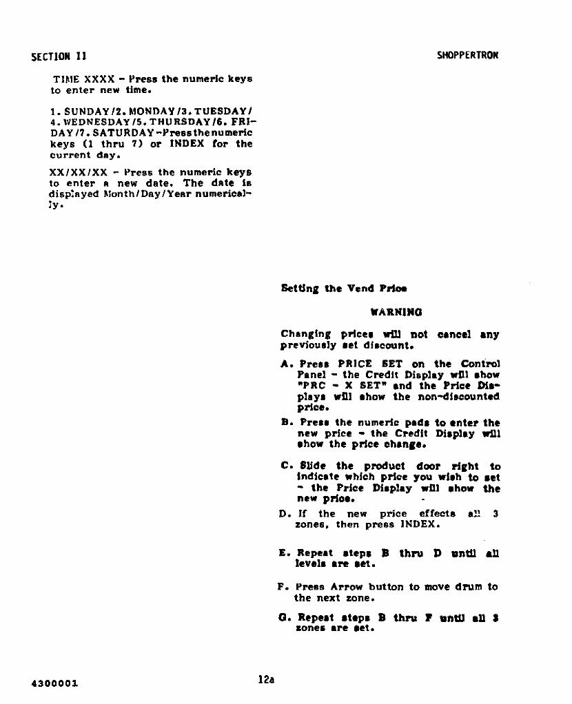
TIME XXX X - !'re8S the numeric keysto enter new time.
1.SUNDAY/2.MONDAY/3.TUESDAYI4. WEDNESDAY 15. THURSDAY 16. FRIDAY 17. SATURDAY-l'ressthenumerickeys (1 thru 7) or INDEX tor thecurrent day.
XX/XX/XX - I"ress the numeric keysto enter a new date. The date 18disp,ayed Month/Day/Year numerical!y.
4300001 12a
SHOPPERTRON
SetUng the Vend p~
WARNINO
Changing prlcu wil1 not cancel enypreviously aet dlacount.
A. Prua PRICE SET on the Control'anel - the Credit Display wUl ahow"PRC - X SET" and the Price maplsya wUI ahow the non-dlacounteC!price.
B. Pre.. the numeric pld. to enter thenew price - the Credit Dlapley .nl'how the price chenls.
C. IUde the pJ'Oduct door right toIndlcete which price you wlah to 8et- the Price Dilplay .m ahow thenew prloa.
D. If the new price effech a!1 3zones, then press INDEX.
E. Repeat atepa » thru D unUl 811levela are ,st.
F. Press Arrow button to move drum tothe next zone.
G. Repeat ,tepa B thl'U P .nUl .11 »zones are let.

Repeat lIteps B thru F \InW alldiscounting is set.
Press the numeric keya to enter afoul' digit number indicating thediscount percentages for discount 1• 2 (00 - 99t for each discount).
ZOllE 3ACCESSLIGHT
DISCLIGHT
Press DISC SET again and the CreditDisp!ay wUI indiCAte "STOP 2 XXXX".Press the nUr.1eric keys to enter thestop time.
SECTION II
PresS DISC SET IlgAin - the CreditDisplay wi!! show" SMTWTFS". Pressthe numeric keys to se!ect thedRy(S) that the discount is ineffect. (1 = Sunday thru 7 =Saturday) •
Press DISC SET agAin and the CreditDisp!ay wi!! indicate 8 variation of"SMTWTFS". The Display wi!! he blankwhen the merchandiser comes from thefactory. Otherwise. the Disp!ay wUlindicate the days during which thediscount is currently in effect. Thefollowing options Are aVIli1able forsetting effective discount days:
Press DISC ON /OFF - two beeps Ilrehellrd And the third LED on theController PCB wil! light indicatingthat the ciseount is on, see Figure2-5. To terminate discount, pressDISC ON/OFF again 1 beep· isheard.
doorthe
ellch
the current pricediscount 1 is lIetdiscount 2 is setdiscount 1 and 2 Are set
RepeAted!y slide each productto the right end observe(o!.'owing on the Price Displaytime:
X.XXdld2dld2
If the discount price effects all 3zones, then press INDEX.Repeat steps B thl"Y 0 tor eAchdiscount being Bet.
Press Arrow button to move the drumto the next zone.
To check t he difference between rhediscount and non-discounted price.,preu PRICE SET and DISC alternatel)'.
Press DISC 1 SET on the Cont!'OlPanel - the Credit Displey wnJ show~X.l = YY 2. = :l.Z· (X indicAtes thezone, YY indicates the % offdiscou nt I and ZZ indicates the %off discou nt 2) and the priceDisp!ay wU! show the !eve!s forwhich the discount is in effect.Wben YY=99 or 22=99 the % offwill be 100%.
SHOPPERTRON
Setting tbe DI8Count 1 and 2 Pricu
NOTB
Press DISC SET - the Credit Displaywil! show "START XXXX". Press thenUr.1eric keys to enter the stoptime.
fIB"r. 2·'. CDft,roll•• 'CB
Press DISC SET agAin - the CreditDisplay wi!! show "STOP XXXX".Press the numeric keys to enter thestop time.
12b4300001

SECTION 11
Zone 3 Access Functions
• You eRn ensure thRt your customers onthe second or third shift "Iso hRve "wide rRnge of foods to select from.
• \lhen Zone 3 Access is in the ONstRtuS. customers eRn purchRse fromZone 3 only during dRyS ond timesthRt you hRve se!ected.
NOTE
Pul ling Zone 3 Access in the ON statuswill override Shop ALL. Shop 1 and Shop1 l 2.
Setting Zone 3 Access Times:
A. Press ACCESS 3 SET on the ControlPAne! - the Credit Display wi!l showSTRT 3 XXXX. Press the numeric keysif you wish to enter R new starttir':1e. This will be the time whencustOr':1ers will first be able topurchAse from Zone 3. This is buedon R 24 hour clOCk - ie 7 :30 P.M. is1930 on the clock.
B. Press ACCESS 3 SET again - theCredit Display wi!! Show STOP 3XXXX. Press numeric keys if youwish to enter a new stop time. Thiswi!! be the time when customers wi!lno longer be sble to purchaae fromZone 3.
C. Press ACCESS 3 SET agBln - theCredit Display wi!l show 3 SMTWTFS.These sre the doys when purchasesfrom ZONE 3 wi!! be controlled.Press the numeric keys to select thedays you desire. 0. Sunday thru 7=SAturday) •
NOTE
You can set a different access lime fora second group of days - I.e. for theweekend.
4300001 12c
SHOPPERTROND. Press ACCESS 3 SET IIgain - the
Credit Dlspilly wi!l show STRT 4XXXX. Enter II new time ss done InStep A.
E. Press ACCESS 3 SET "gllin - theDisplay wi1l show STOP 4 XXXX.Enter a new time a8 done in Step B.
F. Press ACCESS 3 SET egRin - theCredit Disploy wi!l show 4 SMTWTFS ~
Select the doys for llccess os doneIn Step C.
Activoting ond Deactivating lone 3Access:
• The ototus of lone 3 Access is ONwhen the fourth LED on theContro!!er PCB is Ht. See Figure2-5.
• Press ACCESS 3 ON IOFF on the ControlPane! to switch between Access ONond Access OFF.
• Two beeps w111 be heard when youswitch to the ON atatus.
• One beep will be heerd when youswitch to the OFF statue.
Tamper Check Functlan
• The Temper Check feature keeps trllckof sales by zones. The SHOPPERTRONController uaes this information torotllte the drum fo!!owlng R so!e sothe fullest accessable zone 18 inview. (See preferllnce mode).
• If 0 product i8 removed and returnedto II compArtment before the door isclosed. it could hllve been tAmperedwith. The Tllmper Check fellture wi!!refuse to open thRt door 0 aecondtime.
A. Press TAMPER CHECK on the ControlP"nel - the Credit Dllpl"y wi1l showeither TAMPER ON or TAMPER OFF.
B. Press INDEX on the Control Pllnelto chllnge the .tatus of TAMPERCHECK.

, SIiOPPERTRONPress TAMl'ER CIIECK AgAin And the
credit displ"y win showZL XX LEFT
- 01' -ZR XX 1.EFT
where• Z is the Zone numher
L or R is t he rig ht or left ha!fof the Eone. .
• XX is the nu,.,her of conip~rtmelltsIn thAt h ..lf of the Zone whichhAve not heen sold i.e. the door,hllve not heen opened.
Any product In A compllrtment thatIndic.. tes AS sold mAy have beentAmpered with ..nd IIhould bedlscRrded.
Press the Right Arrow or the LeftArrow to rotAte the drum until eachhlllf of eRch zone has been checked.
NOTE
TAMPER CHECK will work properly onlyIf Ihe MA CHI N£ LOADE D procedure iscomplered each time the SHOPpERTRONis looded wit h product.
)f8chlne Loaded Function
Complete this procedure lifter you have10llded thl' SHOVI'ERTRON.
NOTE
The MACHINE LOADED procedure mustbe compleled when PREFER MAX OrTAAIf'ER CHECK fealures are used.
Press And hold MACH LOADED you wi!! heAT"'One beep - lind thecredit displAY wil! show
LOADING
Continue to hold MACH LOADED you wi!l heAr 2 beeps - lind theen'edlt displAy will show DRUMFULL.
If you do not hAve Any emptycompArtmentl:. you hllve completedthis procedure.
12d
SECTJON II
IMPORTANT
ALL COMPARTMENTS THAT ARE EMPTYAFTER LOAD1NC MUST BE VENDED.
If you do hAve empty cotnpBrtments.press FREE VEND on the ControlVAne!. (Thll: IIpplles 11 you are notAlreAdy on Free Vend StAtus.)
Complete II vend sequence for each ofthe empty r»rnpllrtments.
Press FREE VEND on the Control "lInelto cancel the Free Vend IItatuS.
Setting the Free Vend
To free vend selected items only. lletthe respective vend prices to tero. Tofree vend the entire merchAndiser,press FREE VEND on the Control Panel two beeps llre heard And the CreditDIl:play wm nuh "NO MONEYREQUIRED". Price .ettings are noteffected by thio function. To terlllinatefree vend. press FREE VEND again- one beep is heard. .
Malting • Teat Vend
Press INDEX on the Control Pllnel the Credit Display wil! show "TESTVEND" IndiCAting a single test vendcan be Illade.
With the refrigeration door Closed.Illy ae!ection can be made withoutusing money. If money is inserted.change will be paid out when creditexceeds the vend price. The price ofthe selection is then returned in IIfew .econds.
4300001

sectioll 11
Set ling the Bill VaUdator
If the merchandiser Il equippedthe optional bUI validator.Setting the Machine Configuration,.section.
wUhlee
thll
the Jest 30 mlnutea the Credit DlaplaywUl Ihow the tlmeremalnln, on theHealth Control and the temperature.The Internal temperature may alaa beread by pressing the two rotate button•together on the Selection Panal.
automaticallyrefrigerated
l. The Health Cont 1"'01reset. everylfme thecabinet door f. clo.ed.
NOT.
To test the operation of the electronieHealth Control. keep the refrigeratedcabinet door closed for a minimum of aominutes and then do the rollowln,:
A. Open the Monetary and RefrigeratedCabinet Door and aUow 2-3 minutesfor the cabinet temperture to riae.When the Health Control aenaortemperature haa risen above 45° F(7°C) the message "TEMPORARYOUT OF SERVICE" wUI appear onthe Credit Display.
B. Close the Monetary and RefrigeratedCabinet Door.
Teatlng the Health Contro1
2. The (nternal cabinet lemperaturedisplayed by pressing Ihe SHOWTEMP bullon on the Control Panel.The temperolure range dl.ployedt. 0° 1o 255°F.
HIGH QU~RT£R SWITCH
ON
D~D[1 2 3 •
The total "umber of dollar bills thathave been accepted will be atored Inthe computer's memory. To retrievestored data, Sl'e Retrieving Data fromMachine Memory. this section.
1f the changer Is a MARS TRC 6000 the"high quarter" switch must be set to1he OFF position. The switch Is locatedon the back of the housing portion ofthe unit (sel' Figure 2-6).
Teating the Payout Switcbea
Payout Rwitches on the Control PRnelfunction only with the Cointron andMars coin mechanisms. Preas 5•• 10•• or25. PA YOUT - nickels. dimes or quarterswill be dispensed one at a time.
:Rudlng Internal Temperatuft
Press SHOW TEMP on Control Panel the Credit Display wUl ahow the Umeand the temperature of Inllde thecabinet In degrees FarhenheU. If2'efrigeration door was opened within
C. Should the temperature not pull downbelow 45°F (7°e) within ao mlnutea.the "Temporary Out Of Service"llIeasage wUl be diaplayed and themerchandi.er vend circuit diaabled.
Retrieving Data FJ'OIII Machine lIelllOl"J(RAIl)
Sales and vend data for Individual&ones and levela. aa ahown In the pricediaplBya. can be ahown In the creditdisplay by opening the- "end door forthe level of intereat.
134300001

5ecUDD 11
After prE'ulng the DATA RECALL key toenter the Data Retrieval mode, theD'" TA RECA L1. key OR the Right ArrowkeyCan be used to scroll lorward throughthe data catagories.
The INDEX key OR the Lelt Arrow keyCAn be used to scroll through the datacategories In reverse.
The nAsh-times lor multi-word datamessages have been Increased to makethem euler to read.
NOTE
Preu J"'DEX on the Cont,.ol Panel toreverse .croll.
Preu DATA RECALL on the ControlPanel and observe the foUowing on theCredit Display alter eaeh time Itapressed:
VERS XXXXX - the software ver,lonnumber.
lD XXXXX - the machine In nUlllber;press and hold CLEAR untU 2beeps is heard ,nd the C!'edltDisplay shows .ix u!'o',. Then pre..liix numeric keys to aet the naw IDnumber.
NR S XXXX.XX - the total non-ranttable5ale$ amount.
SLS S XXXX. XX - the total ..Ie, ,mount.
VENDS XXXX - the total number ofvends.
FV S XXXX.XX - the total .••le, undertree vend.
TV XXXX - the total number or freevenda.
TEST XXXX - the total number of t ••tvenda (Teat Venda .re not Included Inl'otal Vend').
CBX S XXXX,XX - the total 11Ilount of.:lash in the money boz.
4300001
WIN $ XXXX.XX - the total 'ale' underwinner.WIN XXXX .. the total number 01wlnnel"••DSI $ XXXX.XX - the tot.1 ..I.. underdlaeount 1.
DSI XXXX - the tot.l number of vend.under dilleount 1.DS2 $ XXXX.XX - the total ..les underdiacount I.
DS2 XXXX - the total number of vendaunder diacount 2.
NO. 51 XXXX - the total number of onedonal' bill' aceepted by ·the billvalld.tor.
NO. 55 XXXX - the total number of nvedollar bills sceepted by the billvalidatol'.
HEALTH OFF - the MONTH/DAY andHOUaS/MXNUTES that the Hea1thcontrol was off followed by theMAX degrees F reached durinqthis ti•• period.
LAST POWER. - the l..t time the powerwent off· monthfday, hourafminutes andfor how long the power ••• off - FOR.day fhourllfminute.,
LONO'ST PWR. .. the 10n,,,t time thepower WBI off .. month/day. hour.fminute. and for how lon, the power .alloff - FOR. d.y/houl'./mlnut•••FULL CLEAR.. NM/DD BR..NN - thedate and time of the last run olear ofdata 'lain, the CLEAR key and theINDEX key toaether.
'RICE lET - the l..t time a price ...ehan,ed - month/day and hour.fminute••
TINE SET - the Ja.t time tb. oloek .aachanled - month/day and bour.,.lnut•••
MOT.
I' ,fthe" doo.. ,. op."ed lito... Ulan once'n a lIn minule Ine"''''lnl. " wRl onlylie ,..cO,.ded a. on. ,""••
14

SHOPPERTRON
COLD I XXXM - Indlo;:dlne the dur8llonjn IlIlnulu .nd the l..t Ullle therefrilterlltion door ""at opened· IllonthldRY and hour.almlnut•••
COLD 2 XXX~! - Indicating the duration:In minutes .nd the ucond to lut UlDeth~ • the ..eoI'd to lut isme therefrigerlltion door Wa& opened· monthlday t>ourslmlnutel.
COLD:' XXX},! - Indie8ting the .suraJonin minutes and the third to l..t timethe refrigention door wa' opened monthl day and hour.lmlnute••
COLD 4 XXXM - Indicating the duraUonjn minutes the fourth to I..t time therefrigeration door was opened - month'day .nd Ilounlminutu.
'II'ARM 1 XXXM - Indic.Une the durationIn minutes the last time the monetarydoor wn opened - mc:>nth/d.y .ndhourl/minutel.
\ti."RM 2 XXXM - indicating the durationin minutes the lecc:>nd to I..t time themonetary door was opened • month/day.nd hours/minute••
"W.'RM 3 XXXM • Indiclting the durationin minutes the third to )est Ume themonellry door WIS opened - 1lI0nthld.y_nd houn/minutes.
WARM 4 XXXM • indieatine the dur.tlon:In minl,lt es the lourth to lut time themonetny door wu opened - 1Il0nth/d.y.nd hOl,lnlmlnute••• Total S.les. Toul Vends. 'I'M Vand
Sales, Total Free Vend., WinnerSa!u, Tou! Winner Vend.,' DI.count 1Ind 2 Sales. Ind Tot.l Di.count 1 and2 Vends u'e now .hown by .lthn 1.v.1or by price .eetlon. The.e totalewll.! be Ihown In the Price DI.pll,.,The e.le and vend totlle anInItially .hown by level. The totaJaby price eection Cln be dl.played Inthe Price Dlaplay. by p1'8••1n, -1·.·2" or "," on the Control .anal.Preselne "OR will I'etul'n the dl.pl.y.to totaJ. by level. Ttle total In the1Il.1n di.play on the Selection .aneldoe. not ohlnee.
15
Beetl.. 11
• The colon In the Price 01,1"')' ta~aed I' a deehul potnt for .el••total. Je.. than 1100,00. fo....1a.'otal. of 1100,00 0" lllOre. the oo1onI. not ".ed and total. .... ~ndeddown to the ne.re.t doUar. Tilemaxllllum .mount dl.pl.)'ed .at be191111•
• The ...l.a end "end toW. b)' levelt,nd aG~t1on are be clear.d When thellIaln !J~.play d.ta I. Cleared.
Clcarlnl .ri.ta 1'l'OIII Maehlae lIelDOl7(R.AlIl
NOT.
'f a npn-renltoble Ilem fa GlIempted10 b. clear.d. Ih. Credit Djapla)' w(llahpw 'CANNOT CI.It".
Healill Off. Lut Power Clnd Long'atPowe" can 01'11)' b. clear.d fndlvfdually.
A. To clear a .elected Item only, pre••DATA ItECALL \lnUl you arrive It theUem .eleeted. Then pr....nd holdCLEAR until , beep. t. haa1'C1(."roz. , .econda).
B. To clear the enUre IlAM (reaettabledlta), preu DATA RECALL untilyou Irrive at .ny nutt.ble Item.Then pre.. CLEAR and INDEXtOllether until , beep. t. lIeard(Ipprox. , .econd.).
NOTE
fhe Nuttable data catego,;" "'cilldeth. group "arUng wltll SL.S , XXXX.XXlUld .rUling wflll LONG'ST P'WR..
c. 1'0 Yerlfy the data ••• O1••red.oomplete the "Retrlevinl D.ta 'romlIaehlne MellM)py", p!OC*dure In thi.aaction.
4300001

8,3,2,3
SHOPPERTRON
HOM! !.IITEII..SWITCH NUHBEIlS
KECIWIICAL 0,0,2,3
MAGNETIC 8,0,2,3
KECIWIICAL 0,1,2,3
MAGNETIC 8,1,2,3
KECllANlCAL 0,3,2,3
MARS EXEC rOllENGLISH COINS
UKAPPLICATION
)Wl.S EXEC roll.GERMAN COlliS
GERMANAPPLICATION MAGNETIC
COlli KECI
COUiTRON 3000OR SDlIUll.USA/CANADAAPPLI CATION
I. NO ERRORS - Appeara only tr theirare no diagnostic error••
Press CIAO on the Control Panel andobserve the following on the CreditDisplay after each time It Is preaaed:
SECTION IIChecking the Di.&gnOlltic.
This merchAndiser is constantlymonitoring itself. If A problem occurs.the Credit DisplAY will show "TEMPORARYOUT OF SERVICE" FAults 2 thru 14wi!! not A!low the unit to Accept moneyor vend until the prohlem is corrected.When the monetAry door is opened, theCredit DisplAY will show one of thesefR.u~ts.
NOTE
5. ROM ERROR - V14 ROM check.umfaU·ure.
Fa ult s 2 t h..u 24 ollly appea.. if alle ....o.. is p ..esent til the system.
6. HEALTH OFF - the month/day .ndhours/minutes that the HealthControl went of!•
2. STUCK KEYS - mere than one key isstuck on the Control Panel And/orthe Selection PAnel, disabling thekeyboard.
3. RAM ERROR - Ul3 RAM fsllure.
.,. COIN MECH/NO PWR UP - didn'treceive. power up message from thecoin unit.
8. COIN MECH/NO DATA· eommunications f.ilu!'e with eoin unit.
4. RAM DATA - un RAM battery faUure. 9. COIN MECH/SENSOR ERR - unsore!'ror meSSAge trom coin unit.
11. MOTOR ERR/SOLENOID - inputf.Uure from .witch actlv.ted by.olenoid.
14. MOTOR JAM - drum movement isohstructed. The controller wi!!periodiCAlly try to move the drumto leArn if the obstruction hilSbeen clellred.
12, MOTOR ERR/WHEEL - no inputfrom drive motor .Iotted wheel.
13. CAN'T HOME - 1Il0tor or home.witch f.llure.
NOTE
If any ve ..sion 05AXX .oftwa..s I.updated to ve ..ston 052AC 0 .. g ..eate.. 0 ..
if tile U13 Ram 0" t he main PC Boa"d i.replaced It may be neceua..y roreconfigure the Ram's cheek byre. lindoption registers for coin mech and typeofllome 'wiUh. Tu ..n rhe machine on lindpress tile "MACH CONF" key ro enter anyeonfigu"e step. Now p ..ess and hold rhe"MACH CONF" key until two beep• • oundan d all t he displays light. En te.. rhe 4digit code listed below for the option.that are applicable. Turn po""e,. off fo ..o few .ecl>nds to restarr the .oftwa"eand cain mechanillm. If Ram dara ."ror..eoceu..s ..eplace IT13,
10. TEMP XXF t,Uuretemper.ture.
temperature tensordlspl.Yll present
4300001 16

SHOPPERTRON
NOTE
Faults 15 thru 24 win not disab7e themerchandi ser.
15. MOTOR ERR/DIRECTION drumrotation in opposite direction ofintent.
16. LEFT KEY - left key on SelectionPanel is stuck.
17. RIGHT KEY - right key on SelectionPanel is stuck.
SECTION II
'~I:\Q):UI
Con,rol ,., p.c.e.
TO TURN COP ON
Turn rn~in power to OFF.Remove cover from the Controller.Connect a temporRry jumper to theController cirCUit board eX8ct!yliS Shown be!ow:
18.
19.
20.
21.
22.
INSIDE KEY - key on the ControlPanel is stuck.
CHECK DBV check the bi 11validator for jams in the billpath.
BILL DATA - no reply from serialval idator upon request to sendmessage; check J129.
STACK FULL bill val idatorstacker is full; this disablesonly the validator.
COP OFF COP is short forComputer Operating Properly. TheController does not have theoptimum protection from noisy 1inevoltages, electrostaticdischarges. electrical noise. etc.
• Turn mllin pOWiI!lO to ON.• Wlllt for dillplays to light.• bill gnolltlc mell81lge COP OFF ,tUl
IIppeAlOS.• Turn mAin power to OFF.
Turn mllin power to ON.Dillgnolltic me8S11ge COP OFF ahouldno longer appear.
• Turn main power to OFF.Remove the temporllry Jumper.
• Rep!ace the Controller Cover.Turn mllin power to ON.
23. TAMPER - lin attempt hIlS been madeto buy from an empty compartment.See setting the Tamper Check, thisaection.
24. CHK PRICES - prices may hsvechanged d\le to an electricalmillfunetion. The default price ill$12.1S. See Setting the V~nd Price,this .eetion.
25. TRAY CONFG - tray configurationprogram may have changed due to anelect rica! malfunction. See Settingthe Machine Configuration, thisaection. .
26. CHECK DISC ~ discount pricesmilY have changed due to anelectrical malfunction, aetting thediscount to 0\. See SettingDIscount 1 and 2 prices, thIsaectlon.
Z7. XX.X VOLTS a unregulRted voltagefor reference on!y.
Rev. K17a
4300001

SECTION IIChecking the COfItI'oUer PCB
Ohserve the green Rnd first redindiclItor !Ights on the controller PCB(see Figure 2-7) when door is open andpower is turned on.
• All lights orr indicAtes power cordIs disconnected or no voltAge at .allreceptAcle or (use under electricll!plIne! cover is open (see Figure 1-1).t-I).
• Red Light On - indiCAtes low voltageexists.
• Green Light ON indlcRtes thecontro~!er hAS power.
SHOPPERTRON
GR.£EIILIGIIT
nDLIGHT
4300001 17b

SBCTION IIIAD~USTMBNT.REMOVAL AND RBPLACEMENT PROCBDURBS
Adjusting the Product Divide,..
Produ"t dividers may be sdjusted to8""ommodate various sbe producta. ElIchlevel has thl' capadty range of e. 12.18 or 24 products.
NOTS
lI'hE'n adjusting p"oducl divide..'. moleeBurl' Ihal all .iz I..a)/. on eachporlieula,. level 0"1' lie! the .ame.
I. Remove the divider.
B. To relnataU the product divider.reverse Itep A.
C. Change the program operation to",ateh the new tray configuration.See Setllnr the Machine Configul'8·tlon. sectlon 11.
A. To remove the product dividers. seeFigure 3-1 and do the below:- .1. Firmly grasp the retainer and
sUdI' out towards you.
D. Change delivery door .topl to mltchthe new tray conriguration for eachlevel. See Adjusting Delivery DoorStops. this section.
WL
• • s
.IlKASS£KIILY
vl------seuw
on
~'1: I1 ~ "1H_--- I
...."
nELfASSEMBLY
DIVIDER JAIL
'I,
UIAINU
4300001

Section III
Adjusting the DeJive~ Door Stops
A. Disconnect temperature sensor fromdoor panel.
remove or install food drum withouthelp.
B. Remove the fluorescent light anddoor panel.
A. To remove drum assembly, see Figure3-3 and do the below:
C. Adjust the door stop(s)necessary, see figure 3-2.
9S1. Remove any food from drum
assembly.
Shelf Assembly Removsl and Replacement
A. To remove Shelf assembly, see figure3-1 and do the helow:
2. Loosen two screws and remove topbracket assembly.
B. To replace drum assembly. reverseprocedure.
D. Reinstallrescentsensor.
thelight
doorand
panel. fluotempera tu re
3. Lift drumclearingassembly.
assembly up and outthe drive motor
L Rotate drum assembly around untilthe shelf to be removed isdirectly in front. Door Side Trim Removal and Replacement
A. To remove the door trim. see Figure3-4 and do the below:
2. Remove dividers, if applicable.See Adjusting the ProductDiViders, this section.
3. Remove screws and the rails onboth sides of the shelf.
4. Slide out shelf assembly.
I. Starting at the top ofdoor, insert a straightscrewdriver between theframe and the door trim anda 1/4 turn.
theslot
doorturn
B. To replace shelf assembly, reversep raced u re.
2. Using a rubber mallet. tap thedoor trim off as shown.
isthedown
trim3. Move the screwdriver
door until the doorcompletely removed.
B. T? replace the door trim. align thetnm on the door and tap on with arubber mallet.
WARNING
Drum Assembly Removsl and Replacement
The food drum weight approximately 75Ib8. (34.0 kg). Do Not attempt to
194300001

I
Sedtlon III
SCREWS
BRACKETASSEMBLY
EXAMPLE SHOWSDOOR STOP SETFOR 24 PRODUCTS
Figure ~-2. ~oduct Ooo~ Stop Adjustment
Removed)
PRODUCT DOOR (REF)
DRUMASSEMBLY
II
II
4300001
Figure ,-,. Drum Assembly ReMoval and Repl8cement
20

Section III
Flgu~8 3-4. Door Side Tr'm ReMovAl end Replecement
21I.louno 1

SECTION IVROUTINE SERViCE AND SANITATION
This section contains information forroutine servicing and sanitation of theShoppertron.
SAnitation is an important phase ofMerchandiser operation:. The lack ofproper s'lrvice and sanitation can causeMerchandiser malfunction and loSS ofsales.
The periods and suggested proceduresfor service and sanitation are daily,weekly, monthly, and semi-annually.These periods and procedures are givenas guides only and are not to beconstrued "s "bsolute or invari"ble.Local conditions must a!w"ys beconsidered. Certain installationsrequire that some or all of the stepsunder Monthly Service and Sanitation beperformed weekly. E"ch Merch"ndisermust be maintained individually in>!Coord with its particular requirements. National Vendors, however,stresses "A CLEAN MERCHANDISERIS THE MOST PROFITABLEMERCHANDISER.
S"nitize shall me"n effectiveb"ctericidal treatment of cleansurfs.ces of equipment and utensils by aprocess which has been approved by theheRlth "uthority "s being effective indestroying microorganisms, includingpathogens.
b. at least 12.5 ppm of availableiodine in II solution having a pHnot higher than 5.0 and atemperature of not lower than24°C (75°F); or.
c. any othel" chemical-sanitizingagent which has been proved to beeffective and non-toxic unde.r useconditions, and for which asuitable field test isavailable.
The following warnings and cautions,are applicable to the service andsanitation procedures given in thissection.
WARNING
1. M1lk and other foods are perishableproducts. Follow local healthauthorities rules and l"egulstionsfol" stol"Sge and handling of theseitems.
2. All loose food particles or spillsgewhether wet or dry must be removedfrom the inside and outside of themerchandiser.
CAUTION
1. Do not get electrical connections orelectrical components dsmp Ol" wet.
2. Do not use 1JIIXes or lubricants whichcontsin silicone on or in themerchandiser. Silicone or siliconevapors can cauee electrical failure.
Genel'll1
least one-halfhot water at alower than 77°C
Sanitizing processes generally acceptedby the health authority are as follows:
1. Immersion for atminute in cleantemper"ture not( 170°F)
2. Immersion for a period of at leastone minute in a Sanitizing solutioncontaining:
a. at le"st 50 ppm of availablechlorine at a temperature notlower than 24°C (75°F) or,
Set the main power switch to "OFF"before cleaning or servicing themel"chandiser. Use aerosol spraycleaners or spray waxes only in well ventilated areas. NEVER use any sprayproduct containing silicone siliconesprays can coat electrical contactscausing a machine malfunction.
430000122

Section IV
WARNING
Before ulring any liquid cleaner. unplugthe merchandiser power cord or shut offpower to the won receptscle to avoidhazard of electrical shock. Makecertain on components are thoroughlydry and properly iJUJtsIIed beforerestoring power.
Refer to the Parts Manual foradditional service information andreplacement parts. For factoryassistance, contact the nearestNational Vendors l"epresentative.
1. PUSH UP LATCH
Contact the Local Health Authoritiesand obtain their acceptance of thesanitizer you intend to use whencleaning and sanitizing theMerchandiser.
When cleaning and sanitizing theMerchandiser, use CLEAN, DISPOSABLEPAPER WIPER rather than cloths.
Deily Service
A. Replace burned-out or discoloredbulbs.
• •
3.
B. Replenish coin tubes in the CoinMeChanism.
FIgure 4-1. 811 I vel Idetor - Doller 811 I Remove I
E. Clean the display glass on thecabinet door.
C. Empty the bill validator, See figure4-1.
D. Test vend the merchandiser. Seemaking a test vend, Section II.
F. Check the temperature of the cabinet.See Reading the Internal Temperature,Section III .
B. Check for liquid spillage on themerchandiser modules. If there isspillage, remove the modules shelfsand dividers affected and wash andsanitize them with a clean, dampdisposable paper wiper or a cleansoft-bristle brush. Rinse withclean hot water and dry thoroughly.
C. Wipe the exterior of themerchandiser with a damp disposablepaper wiper and dry thoroughly.
D. Fill the appropriate columns on therecord of cleaning card.
sanitationreload the
dailythen
G. Follow theprocedures andmerchandiser.
Daily Sanitstion Weekly Service
A. Remove all past-date merchandisefrom the merchandiser.
A. Follow theInstructions.
Daily Service
234300001

Section IV
CoinCointhis
Coin Chute andSee Cleaning the
and Coin Chute in
B. Clean theValidator.Validatol'section.
C. Inspect the refrigeration screen.remove 'loy accumulated dust.
B. Brush the Vent Screens.
D. Inspect the ExhaustHnd replace beforeclogged.
Filter. Cleanit becomes
C. Clean the Bill Validatol'. SeeCleaning the Bill Valida tor in thissection.
Eo Inspect the Coin Mechanism.Validator and Bill Validator.if necessary.
CoinClean
D. Remove the Vent Fan Filters. Cleanthe Screens with a dry cloth, Washwith a warm detergent solution.rinse. dl'y and l"e!lssemble.
Weekly SanitationMonthly Sanitation
A. Follow theInstructions.
Daily SanitationA. Follow the
In 8tl"l1ctions.Weekly Sanitation
13. Inspect the Merchandiser for oVerIll! cleanliness. especially thecorners.
B. Fill in the appropriate columns onthe reCOl"<i of cleaning card.
B. Inspect the MerchandiseI' for wornparts and l'eplace where necessary.
C. Wash and sanitize the merchandisershelfs and dividers with a clean.damp disposable paper wipe Or aclean soft-bristle brush. Thedividers may be removed for easiercleaning. see Adjusting ProductDividers, Section III. Rinse withhot water and dry thoroughly.
Seroi-Annual Service
A. Follow theInstructions.
Weekly Sel'v!ee
C. Lubricate the drive motor stop pin.(DO NOT OVER OIL).
D. Wash and sanitize the merchandiserfood compartment with a clean, dampdisposable paper wiper. Drythoroughly.
E. Fill in the appropriate columns ofthe record of cleaning card.
Do notSiliconefailures.
CAUTION
use Silicone lubricants.can cause electrical contact
Monthly Service D. Lubricate all moving parts that donot come in contact with food.
A. Follow theInstructions.
Weekly ServiceSemi-Annual Sanitation
WARNING Follow the Weekly Sel'vice Instructions.
1. Be sure the area is well ventilatedand no open fIa_ are pl"esentbefore using any ae:ftl801 spray cans.
2. Use protectiveshield if a:iPdrying.
g1ssse& O't' protectivehose is used tor
Cleaning the Coin Valid.tor and CoinChute
A. The Coin Validator and Coin ChuteshOUld be inspected at regulal"intervals and cleaned onapproximately a monthly schedule.
430000124

Section IV
B. Remove the Coin Validator Assemblyfrom the Merchandiser and clean theCoin Chute with a tube cleaningbrush to remoVe any accumulated dustand foreign matter.
C. Clean the Coin Validator thoroughlyor replace the assembly with a cleanunit from the shop. The CoinVslidator can be cleaned withdetergent and hot water, but it hasto be completely dry before it isreplaced in the Merchandiser.
VIEW A
VIEW B
Cleaning the Bill Validator
A. To clean(optionaD,the below:
the Bill Validatorsee Figure 4-2 and do
VIEW C
RUBBERROLLERS
MAGNETICHEADS
~WARNING
3. Wipe clean the rollers and belt.Remove any foreign matter.Inspect the latches and leversfor smooth operation (View C).
1. The bill insertion opening may becleaned with a mild detergent,(View A).
2. Periodically open the billvalidator and inspect themagnetic heads. Open the billvalidator by pulling down on thebottom latch. If the magneticheads appear dirty, apply a smallamount of denatured alcohol to acotton applicator, and clean(View B),
Never use water or spray lubricants toclean the bill vaJidator - disconnectmain power and unplug electrlcaJ.circuits.
4. Connect main power and test vendthe merchandiser for acceptanceof genuine dollar bills. FIgure 4-2. a'i I V~I ld~tor CleanIng
254300001