servovalves · 2015-08-06 · mts series 256 servovalves are electrohydraulic three-stage...
TRANSCRIPT
l
be certain.
ServovalvesDurable, reliable performance for precise servohydraulic control

MTS SERVOVALVES DEL IVER THE SPEED, PERFORMANCE AND
F IDEL ITY TEST PROFESSIONALS NEED TO ACHIEVE REPEATABLE,
REPRODUCIBLE AND HIGHLY ACCURATE RESULTS IN A WIDE RANGE OF
APPL ICATIONS. DESIGNED TO T IGHT TOLERANCES FOR EXCEPTIONAL
CONTROL, ALL OF THE SERVOVALVES IN OUR PORTFOL IO DEL IVER
REL IABLE PERFORMANCE AND OUTSTANDING DURABIL ITY.
3
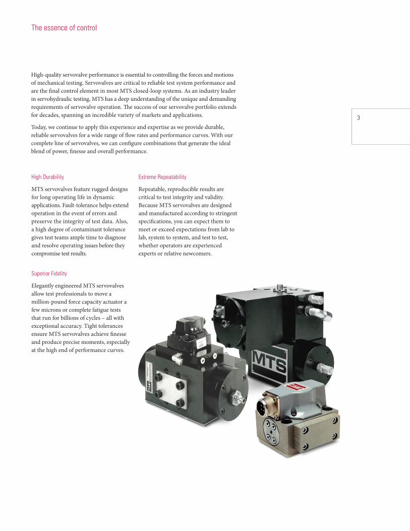
High-quality servovalve performance is essential to controlling the forces and motions of mechanical testing. Servovalves are critical to reliable test system performance and are the final control element in most MTS closed-loop systems. As an industry leader in servohydraulic testing, MTS has a deep understanding of the unique and demanding requirements of servovalve operation. The success of our servovalve portfolio extends for decades, spanning an incredible variety of markets and applications.
Today, we continue to apply this experience and expertise as we provide durable, reliable servovalves for a wide range of flow rates and performance curves. With our complete line of servovalves, we can configure combinations that generate the ideal blend of power, finesse and overall performance.
High Durability
MTS servovalves feature rugged designs for long operating life in dynamic applications. Fault-tolerance helps extend operation in the event of errors and preserve the integrity of test data. Also, a high degree of contaminant tolerance gives test teams ample time to diagnose and resolve operating issues before they compromise test results.
Superior Fidelity
Elegantly engineered MTS servovalves allow test professionals to move a million-pound force capacity actuator a few microns or complete fatigue tests that run for billions of cycles – all with exceptional accuracy. Tight tolerances ensure MTS servovalves achieve finesse and produce precise moments, especially at the high end of performance curves.
Extreme Repeatability
Repeatable, reproducible results are critical to test integrity and validity. Because MTS servovalves are designed and manufactured according to stringent specifications, you can expect them to meet or exceed expectations from lab to lab, system to system, and test to test, whether operators are experienced experts or relative newcomers.
The essence of control

Series 252 Servovalves
MTS Series 252 Servovalves are two-stage, four-way servovalves specifically designed for low to medium flow rates of 3.8 to 227 lpm (1 to 60 gpm*) in high-response servohydraulic systems. Depend on these workhorse components for solid, consistent performance.
Performance
Each Series 252 Servovalve includes a torque motor and two stages of hydraulic power regulation. The torque motor controls the first stage by positioning a flapper that controls hydraulic fluid flow from two nozzles in the first stage. Differential pressure positions the second stage spool, which controls the direction and rate of hydraulic fluid flow to the actuator.
These servovalves incorporate all the advantages of closed-loop control. As the second stage spool reacts, a feedback spring by the spool counters the action of the torque motor and flapper. By the time the spool reaches the commanded position, the motor and flapper are counteracted. Flow from both nozzles is equal and the spool stops. This design ensures precise control of spool position, a high hydraulic driving force on the spool and a high error-force gradient.
* 1/8, 1/4 and 1/2 gpm valves are also available upon request
Common Applications
Typical applications for Series 252 Servovalves include hydraulic power control and regulation in fatigue test systems, simulators, servohydraulic process controls and industrial controls. Applications that require higher flow rates can be accommodated with two
» Nozzle-flapper design with spool feedback provides positive internal closed-loop flow control
» Internal filtration protects nozzle orifices from contamination
» Standard mounting configurations make it simple to change flow ratings
» Unpeaked response over servo-system frequency range
» 31 MPa (4500 psi) operating pressure ensures optimal performance and reliability
» High spool-driving forces (over 100 pounds-force) provide low contamination sensitivity
» Can be configured with a fifth port, which separates pilot pressure from system pressure
Series 252 Servovalves connected in parallel, which doubles the flow rating. This dual configuration (which requires a special dual-valve manifold) not only costs less to operate than a larger valve, it offers higher availability and increased response rate in some applications.
Coil Magnets Upper Pole Piece
Flexure Tube
Lower Pole Piece
Flapper
Feedback Wire
Fixed Orifice
To/From Actuator
Return To Power Supply
Filter
Spool
Nozzle
Armature
First Stage
Second Stage
Pressure FromPower Supply

5
Series 252 Servovalves are ideal for low and medium flow applications.
Typical Performance Characteristics
Full Flow 90° point at
Model Rating* 10% command Null Flow†
L/min gpm L/min gpm
252.21C 4.0 1.0 240 Hz 1.10 0.29
252.22C 9.5 2.5 240 Hz 1.44 0.38
252.23C 19.0 5.0 240 Hz 2.27 0.60
252.24C 38.0 10.0 200 Hz 2.27 0.60
252.25C 57.0 15.0 150 Hz 2.27 0.60
252.31A‡ 93.0 25.0 80 Hz 5.56 1.47
252.32A‡ 151.0 40.0 60 Hz 5.56 1.47
252.33A‡ 227.0 60.0 50 Hz 8.33 2.20
252.41A 4.0 1.0 300 Hz 1.10 0.29
252.42A 9.5 2.5 280 Hz 1.44 0.38
252.43A 19.0 5.0 280 Hz 2.27 0.60
* Flow ratings are for 7 MPa (1000 psi) pressure drop across the servovalve. Higher flows are available at higher pressure drops.† The maximum internal null flow is specified at 21 MPa (3000 psi). The null flow at the first stage is 0.76 L/min (0.20 gpm) for all Series 252 Servovalves.‡ The 90° point is at 40% command. Specifications are subject to change without notice. Contact MTS for verification of specifications critical to your needs.
100
10
1
0.11 10 100 1000
Flow
in G
allo
ns p
er M
inut
e
Flow
in L
iters
per
Min
ute
Frequency in Hertz
378
37
3.7
0.37
100
10
1
0.11 10 100 1000
Flow
in G
allo
ns p
er M
inut
e
Flow
in L
iters
per
Min
ute
Frequency in Hertz
378
37
3.7
0.37
252.25
252.22
252.23
252.24
252.21
252.33
252.31
252.32
Note: Performance is with 21 MPa (3000 psi) pressure supplied and7 MPa (1000 psi) pressure drop across the servovalve
Note: Performance is with 21 MPa (3000 psi) pressure supplied and7 MPa (1000 psi) pressure drop across the servovalve
252.43
252.41
252.42
100
10
1
0.11 10 100 1000
Flow
in G
allo
ns p
er M
inut
e
Flow
in L
iters
per
Min
ute
Frequency in Hertz
378
37
3.7
0.37
Note: Performance is with 21 MPa (3000 psi) pressure supplied and7 MPa (1000 psi) pressure drop across the servovalve.
100
10
1
0.11 10 100 1000
Flow
in G
allo
ns p
er M
inut
e
Flow
in L
iters
per
Min
ute
Frequency in Hertz
378
37
3.7
0.37
100
10
1
0.11 10 100 1000
Flow
in G
allo
ns p
er M
inut
e
Flow
in L
iters
per
Min
ute
Frequency in Hertz
378
37
3.7
0.37
252.25
252.22
252.23
252.24
252.21
252.33
252.31
252.32
Note: Performance is with 21 MPa (3000 psi) pressure supplied and7 MPa (1000 psi) pressure drop across the servovalve
Note: Performance is with 21 MPa (3000 psi) pressure supplied and7 MPa (1000 psi) pressure drop across the servovalve
The flow vs. frequency response curves below show typical servovalve performance with sine wave control and ± 100% command.

Series 256 Servovalves
» 21 MPa (3000 psi) operating pressure ensures optimal performance and reliability
» Internal filtration protects nozzle orifices from contamination
» Electronic spool position feedback improves tuning and system performance with three-stage valve drivers
» Very low current threshold ensures high servovalve control resolution
» Matched, ground metering edges minimize crossover distortion
» High spool-driving forces and hardened tool-steel metering edges decrease erosive wear and reduce the risk of spools sticking due to dirty hydraulic fluid
MTS Series 256 Servovalves are electrohydraulic three-stage servovalves consisting of a high-flow, four-way spool valve and a smaller two-stage pilot valve. They are designed and engineered for the critical requirements of high-flow, high-response, closed-loop servohydraulic testing.
Performance
Series 256 Servovalves use a Series 252 Servovalve to drive a larger spool in a third stage. An internal linear variable differential transformer (LVDT) monitors the third-stage spool position and provides a signal to the servovalve controller on a three-stage valve driver. The valve controller compares the spool position with the DC error signal and alters the control signal to the torque motor in the first stage accordingly. When DC error reaches zero, servo action in the inner loop decreases and both spools return to their null positions, stopping the flow to the actuator.
Common Applications
Typical applications for Series 256 Servovalves include position, load, or velocity control of larger hydraulic actuators in highly dynamic applications, as well as pressure control in a dynamic pressurization system. Some models can be configured with different sizes of pilot stage servovalves for unique performance requirements. Be sure not to exceed performance requirements significantly, because systems can be difficult to control if servovalves are oversized for a specific application.
Coil Magnets Upper Pole Piece
Flexure Tube
Lower Pole Piece
Flapper
Feedback Wire
Fixed Orifice
Pilot Pressure
Third (Main)Stage Spool
Return
Core
LVDTTransformer
Pilot Return
Filter
Second (Pilot)Stage Spool
Nozzle
Armature
First Stage
Second Stage
Third Stage
Pressure

7
Series 256 Servovalves are engineered for high-flow, high-response applications.
Static Servovalve Performance
Nominal Null Null Null Flow-Pressure
Model* Rated Flow Flow Gain Pressure Gain Coefficient Null Flow
L/min gpm L/min/% stroke gpm/% stroke (% supply/ % stroke) cm5/kgf/sec in.3/sec/psi L/min gpm256.04 151 40 4.2 1.1 100 0.28 1.2 x 10⁻³ 7.0 2.0
256.09 340 90 6.0 1.6 150 0.56 2.4 x 10⁻³ 13.0 3.5
256.18 680 180 10.6 2.8 200 0.73 3.1 x 10⁻³ 21.0 5.5
256.25 950 250 16.0 4.2 160 1.38 5.9 x 10⁻³ 23.0 6.0
256.40 1500 400 29.0 7.7 250 1.61 6.9 x 10⁻³ 28.0 7.5
Dynamic Servovalve Performance
90° Phase Spool Stroke Rise Time (tr) 3
Model* Rated Flow1 Pilot Flow Full Flow Frequency 2, 3 Signal 3, 4 (milliseconds)
L/min gpm L/min gpm (Hz) (Hz) 90% open 10% open
256.04X-01 151 40 3.8 1 100 130 3 2.5
256.09X-01 340 90 3.8 1 30 90(A) 165(B) 9 3.5
256.09X-02 340 90 9.5 2.5 60 85(A) 165(B) 4.6 2.5
256.09X-05 340 90 19 5 100 265(B) 3.5 3.5
256.18X-01 680 180 3.8 1 20 120 7.6 3
256.18X-02 680 180 9.5 2.5 47 130 5 2.5
256.18X-03 680 180 19 5 65 110 4.5 2
256.25X-01 950 250 3.8 1 10 90 15 10
256.25X-02 950 250 9.5 2.5 18 125 <10 <10
256.25X-05 950 250 19 5 25 125 8 4
256.40X-01 1500 400 3.8 1 45 405 655 205
256.40X-02 1500 400 9.5 2.5 95 755 265 85
256.40X-05 1500 400 19 5 125 110 13 4
256.40X-10 1500 400 38 10 155 110 10 3.5
* All values are typical of Series 256 Servovalves operated at the recommended hydraulic fluid filtration levels.
1 With a 7 MPa (1000 psi ) pressure drop across the servovalve.2 The data is derived from typical Model 256 Servovalves driven with a valve controller with “rate” compensation. A constant sine wave was directed to the valve controller. The amplitude was ± the main-stage, full-stroke, LVDT voltage. The servovalve flow at the higher frequencies depends on many system characteristics that are unrelated to the Model 256 Servovalve (e.g., hydraulic fluid compressibility, supply and return line lengths, actuator characteristics and load or specimen characteristics).3 Unless otherwise specified, values given in this column are for Model 256.XXA/.XXC Servovalves. Contact MTS for Model 256.XXB/.XXD.4 At ±10% spool stroke.5 These are estimated values. All other values are typical.
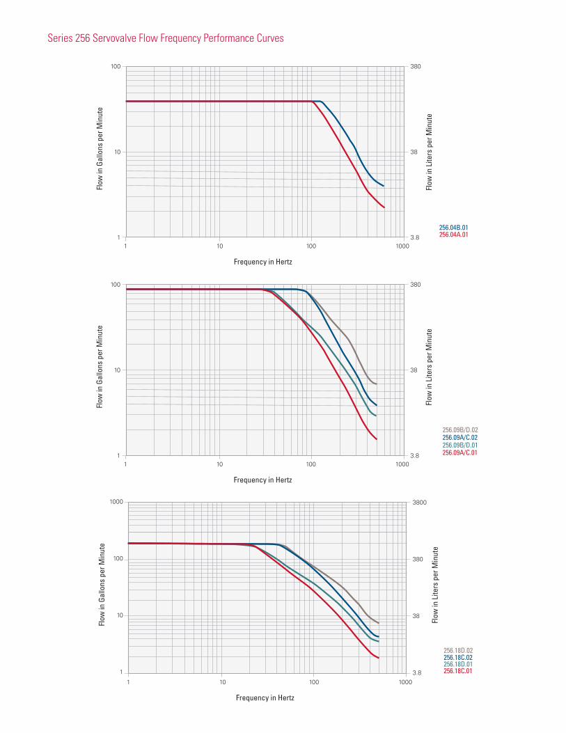
Series 256 Servovalve Flow Frequency Performance Curves
256.04A.01
100
10
1
380
38
3.81 10 100 1000
Frequency in Hertz
Flow
in G
allo
ns p
er M
inut
e
Flow
in L
iters
per
Min
ute
256.04B.01
100
10
1
380
38
3.81 10 100 1000
Flow
in G
allo
ns p
er M
inut
e
Flow
in L
iters
per
Min
ute
Frequency in Hertz
256.09A/C.01
256.09B/D.02
256.09B/D.01256.09A/C.02
1000
100
10
1
3800
380
38
3.81 10 100 1000
Flow
in G
allo
ns p
er M
inut
e
Flow
in L
iters
per
Min
ute
Frequency in Hertz
256.18C.01
256.18D.02
256.18D.01256.18C.02

9
1000
100
10
1
3800
380
38
3.81 10 100 1000
Flow
in G
allo
ns p
er M
inut
e
Flow
in L
iters
per
Min
ute
Frequency in Hertz
256.25B.05
256.25A.05
256.25A.01
256.25B.01
256.25A.02
256.25B.02
256.40A.01
256.40A.10
256.40A.02
256.40B.01
256.40B.05256.40B.02
256.40A.05
1000
100
10
1
3800
380
38
3.81 10 100 1000
Flow
in G
allo
ns p
er M
inut
e
Flow
in L
iters
per
Min
ute
Frequency in Hertz

Series 257 Servovalves
MTS Series 257 Servovalves are two-stage, four-way servovalves featuring an electrodynamic pilot stage for maximum performance. These valves accommodate very high-flow closed-loop servohydraulic testing applications that require extremely high precision.
» First natural resonant frequency of 650 to 700 Hz
» Flow ratings from 113 to 1514 lpm (30 to 400 gpm) with a 7 MPa (1000 psi) pressure drop
» Less than 0.05% hysteresis without dither
» Very low threshold (typically 0.02%) permits high servovalve resolution
Performance
Series 257 Servovalves consist of a high-response, voice coil-operated pilot stage (single-stage servovalve) that controls a high-flow, four-way main stage. Very stiff springs suspend the pilot, enabling a high first natural resonant frequency.
During operation, the valve controller compares the DC error to the main stage spool position indicated by the LVDT, in order to determine the magnitude and polarity of the valve command signal. This signal is sent to the power driver, which boosts it and adds damping factors to create the servovalve control signal. Then it is applied to the pilot stage voice coil to induce a magnetic field that interacts with the magnetic field of a DC-excited field coil. The difference in polarity causes the pilot spool to apply fluid to the main stage spool, which ports fluid to the actuator.
The main stage LVDT generates the servovalve feedback signal. Pilot spool movement causes the magnetic core in the linear velocity transducer to move, creating the pilot velocity feedback signal that combines with the valve command signal to allow higher inner-loop gain settings that expand system capabilities.
Common Applications
Series 257 Servovalves are typically used in high-frequency systems. Specifically engineered to handle very high flow rates with equally high precision, these valves tend to require a greater degree of care and attention. It is important to warm up
these valves before testing begins to avoid the risk of galling, and to check voice coil resistance every six months. Special compensation networks in the valve controller (available from MTS) help maximize dynamic performance.
PilotPressure
Field CoilConnector
Voice CoilConnector
Voice Coil
Pressure
To Actuator
Main Stage (second stage)
Return
Output Pressurefrom Pilot Stage
LVT
Pilot Return
Pilot Stage (first stage)
LVTConnector
LVT Locknut
Pilot Spool
Preload Adjustment(factory adjusted)
Main Stage Spool
LVDT (connector not shown)
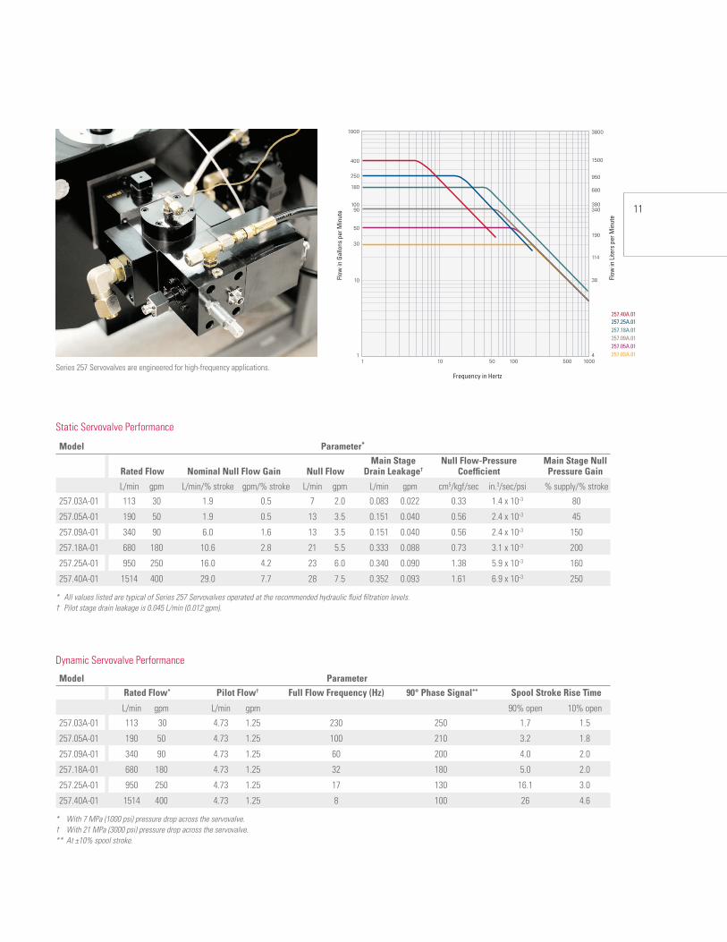
11
Series 257 Servovalves are engineered for high-frequency applications.
Static Servovalve Performance
Model Parameter*
Main Stage Null Flow-Pressure Main Stage Null Rated Flow Nominal Null Flow Gain Null Flow Drain Leakage† Coefficient Pressure Gain
L/min gpm L/min/% stroke gpm/% stroke L/min gpm L/min gpm cm5/kgf/sec in.3/sec/psi % supply/% stroke
257.03A-01 113 30 1.9 0.5 7 2.0 0.083 0.022 0.33 1.4 x 10⁻³ 80
257.05A-01 190 50 1.9 0.5 13 3.5 0.151 0.040 0.56 2.4 x 10⁻³ 45
257.09A-01 340 90 6.0 1.6 13 3.5 0.151 0.040 0.56 2.4 x 10⁻³ 150
257.18A-01 680 180 10.6 2.8 21 5.5 0.333 0.088 0.73 3.1 x 10⁻³ 200
257.25A-01 950 250 16.0 4.2 23 6.0 0.340 0.090 1.38 5.9 x 10⁻³ 160
257.40A-01 1514 400 29.0 7.7 28 7.5 0.352 0.093 1.61 6.9 x 10⁻³ 250
* All values listed are typical of Series 257 Servovalves operated at the recommended hydraulic fluid filtration levels.† Pilot stage drain leakage is 0.045 L/min (0.012 gpm).
Dynamic Servovalve Performance
Model Parameter Rated Flow* Pilot Flow† Full Flow Frequency (Hz) 90° Phase Signal** Spool Stroke Rise Time
L/min gpm L/min gpm 90% open 10% open
257.03A-01 113 30 4.73 1.25 230 250 1.7 1.5
257.05A-01 190 50 4.73 1.25 100 210 3.2 1.8
257.09A-01 340 90 4.73 1.25 60 200 4.0 2.0
257.18A-01 680 180 4.73 1.25 32 180 5.0 2.0
257.25A-01 950 250 4.73 1.25 17 130 16.1 3.0
257.40A-01 1514 400 4.73 1.25 8 100 26 4.6
* With 7 MPa (1000 psi) pressure drop across the servovalve.† With 21 MPa (3000 psi) pressure drop across the servovalve.** At ±10% spool stroke.
3800
1500
950
680
380340
190
114
38
4
1000
400
250
180
10090
50
30
10
11 10 50 100 500 1000
Flow
in G
allo
ns p
er M
inut
e
Flow
in L
iters
per
Min
ute
Frequency in Hertz
257.40A.01
257.09A.01257.18A.01257.25A.01
257.03A.01257.05A.01
Maintenance, Care and Service
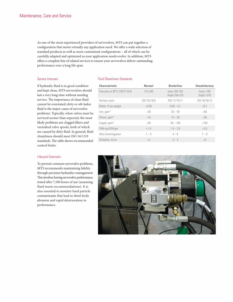
As one of the most experienced providers of servovalves, MTS can put together a configuration that meets virtually any application need. We offer a wide selection of standard products as well as more customized configurations – all of which can be carefully adapted and optimized as your application needs evolve. In addition, MTS offers a complete line of related services to ensure your servovalves deliver outstanding performance over a long life span.
Service Intervals
If hydraulic fluid is in good condition and kept clean, MTS servovalves should last a very long time without needing service. The importance of clean fluid cannot be overstated; dirty or silt-laden fluid is the major cause of servovalve problems. Typically, when valves must be serviced sooner than expected, the most likely problems are clogged filters and varnished valve spools, both of which are caused by dirty fluid. In general, fluid cleanliness should meet ISO 16/13/9 standards. The table shows recommended control limits.
Lifecycle Extension
To prevent common servovalve problems, MTS recommends maintaining fidelity through precision hydraulics management. This involves having servovalve performance tested after 7,500 hours of use (assuming fluid meets recommendations). It is also essential to monitor hard particle contaminants that lead to third-body abrasion and rapid deterioration in performance.
Fluid Cleanliness Standards
Characteristic Normal Borderline Unsatisfactory
Viscosity at 38°C (100°F) SUS 215-240 (low) 183-193 (low) <183 (high) 256-276 (high) >276
Particle count ISO 16/13/9 ISO 17/15/11 ISO 18/16/13
Water, % by weight <0.05 0.05 – 0.1 >0.1
Iron, ppm* <30 30 – 50 >50
Silicon, ppm* <15 15 – 30 >30
Copper, ppm* <40 40 – 100 >100
TAN mg KOH/gm <1.4 1.4 – 2.6 >2.6
Ultra Centrifugation 1 – 3 4 – 6 7 – 8
Oxidation, A/cm <3 3 – 4 >4
13
Common Problems and Solutions
» Whistling. This sound may occur when system pressure is on, the actuator is not moving and the system is under control. The high-pitched noise coming from the servovalve is caused by high-speed leakage flow through metering edges, which are intentionally made to zero lap. To eliminate the noise, simply increase the return line pressure.
» Squeaking. If squeaks are synchronized with actuator movement, it is likely that the spool is moving across the null position and fluid flow in the return line is unable to stop due to fluid inertia. To eliminate the noise, increase the return line pressure.
» Irregular movement. Irregular actuator or servovalve movement can be caused by dirty hydraulic fluid. Contaminants temporarily clog the gap between the servovalve’s flapper and nozzles, causing the servovalve and actuator to jerk. Poor system design may also be the cause. For example, hysteresis
and threshold will result if a small actuator is used with a high-flow servovalve, or if the pilot stage is too big for the output stage. In general, lowering pilot supply pressure, adding a small amount of dither, and retuning the system may help improve system disturbance rejection.
» Squealing. Occasionally, when a low-flow three-stage servovalve is used to control a large, long-stroke actuator, the valve will squeal when the main stage supply pressure is on; an oscilloscope shows spool oscillation, but tuning does not stop the noise. One possible source is mechanical or hydromechanical resonance. Rotating a Series 252 Servovalve 90° or 180° may cut off the mechanical feedback path. For a Series 256 Servovalve, decreasing the size of the pilot servovalve may help with squealing. Otherwise, you can eliminate squealing by adding a piece of hose to C1 or C2 port of pilot stage (-4 or -6 size, 1 to 2 feet long).
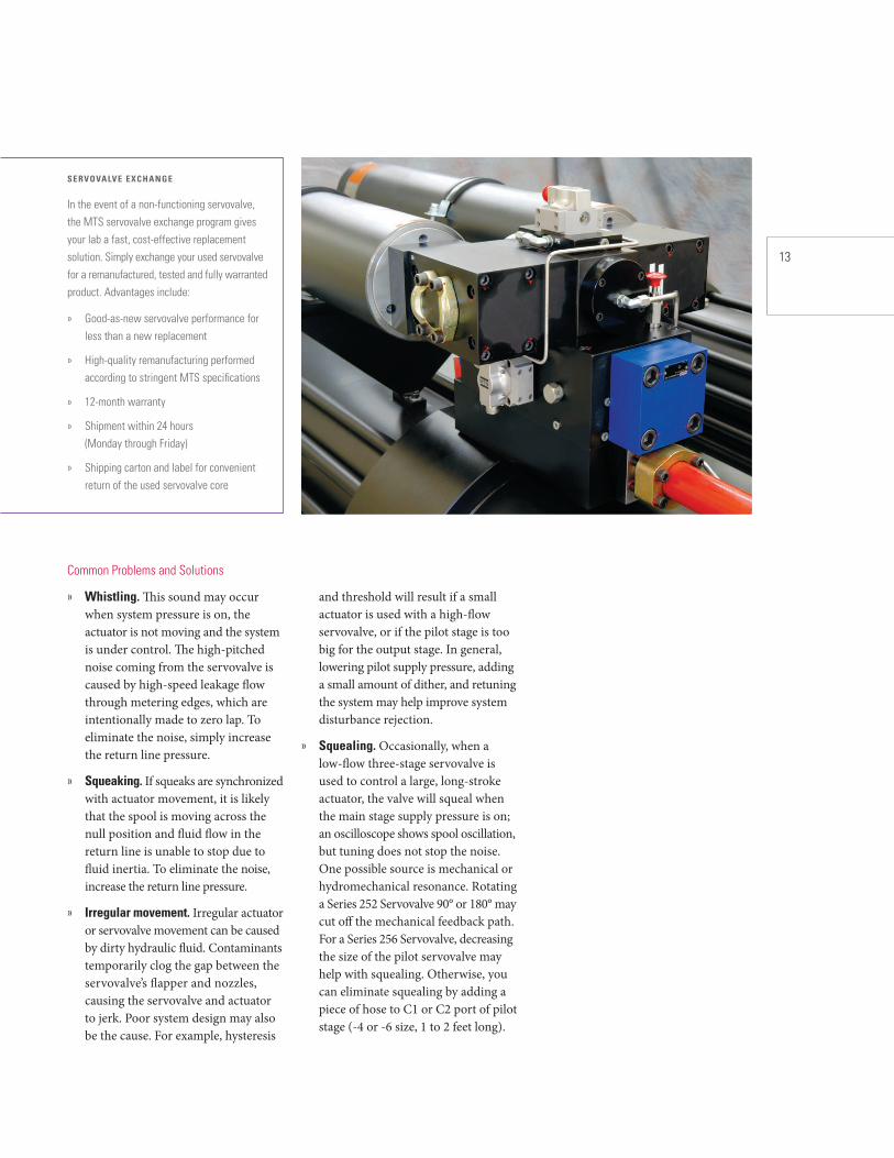
SERVOVALVE EXCHANGE
In the event of a non-functioning servovalve, the MTS servovalve exchange program gives your lab a fast, cost-effective replacement solution. Simply exchange your used servovalve for a remanufactured, tested and fully warranted product. Advantages include:
» Good-as-new servovalve performance for less than a new replacement
» High-quality remanufacturing performed according to stringent MTS specifications
» 12-month warranty
» Shipment within 24 hours (Monday through Friday)
» Shipping carton and label for convenient return of the used servovalve core

15
Series 252 Specifications
Maximum operating pressure 31 MPa (4500 psi)
Minimum operating pressure 1.4 MPa (200 psi)
Operating temperature range -40°C to 135°C (-40°F to 275°F)
Seals Viton
Rated full-flow input signal current‡ 25 mA (series) 50 mA (differential) 50 mA total (parallel)
Coil resistance 80Ω per coil
Weight 252.2x/.4x 1.03 kg (2.3 lb) 252.3x 3.5 kg (7.75 lb)
Recommended hydraulic fluid Mobil DTE 25 or Shell Tellus 46
Series 256 Specifications
Pilot stage mating connector MS 3106-A-14S-2S
Pilot stage full flow current 50 mA
Main stage mating connector PT06 A-8-4S (SR)
Main stage excitation 20 V p-p at 10 kHz
Main stage impedance 200 W minimum at 10 kHz
Main stage sensitivity 0.21 V/V per 2.54 mm (0.100 in.) stroke
Standard operating pressure 21 MPa (3000 psi)
Operating temperature range -54°C to 135°C (-65°F to 275°F)
Recommended filtration level 3-micron absolute (pilot stage) 12-micron absolute (main stage)
Recommended hydraulic fluid Mobil DTE 25 or Shell Tellus 46
Seals Buna-N
Series 257 Specifications
Field coil connector PT02H-8-3P
Field coil resistance 90Ω
Field coil working current 3.5 A
Voice coil connector PT02H-8-2P
Voice coil resistance 6Ω
Voice coil working current 3.5 A
First natural resonant frequency 650-700 Hz
LVT connector PT02H-8-4P
LVT electrical impedance 2kΩ
LVT sensitivity 12.7 mV/cm/sec. (50 mV/in./sec.) minimum
LVDT connector PT02H-8-4P
LVDT excitation 20 Vp-p at 10 kHz
LVDT sensitivity 0.21 V/V per 2.54 mm (0.100 in.) stroke
Standard operating pressure 21 MPa (3000 psi)
Hydraulic fluid temperature -40°C to 135°C (-40°F to 275°F)
Seals Buna-N
Recommended filtration level 3-micron absolute (pilot stage) 10-micron absolute (main stage)
Fluid Care
Choose the MTS Fluid Care Program to protect your investment, mitigate risk of downtime, improve servovalve performance and help reduce total cost of ownership. This program combines precise fluid assessment with expert field service engineering to identify and resolve fluid contamination issues before they compromise your lab’s productivity.
We work with you to design a sampling schedule that aligns with your usage and performance goals. An MTS field service engineer (FSE) then takes samples, reviews report results with you, and helps you determine if and when a maintenance intervention is required. Your FSE may also discuss results that are out of normal range, monitor trends and provide an annual summary of results, including fluid condition trend information and recommendations for future actions.
MTS is a registered trademark of MTS Systems Corporation in the United States. This trademark may be protected in other countries. RTM No. 211177.
©2014 MTS Systems Corporation 100-241-355 Servovalves Printed in U.S.A.10/14
MTS Systems Corporation14000 Technology Drive Eden Prairie, MN 55344-2290 USA
ISO 9001 Certified QMShttp://www.mts.com
l
Regional Business Centers
THE AMERICAS
MTS Systems Corporation
14000 Technology Drive
Eden Prairie, MN 55344-2290
USA
Telephone: 952-937-4000
Toll Free: 800-328-2255
Fax: 952-937-4515
E-mail: [email protected]
Internet: www.mts.com
EUROPE
MTS Systems France
BAT EXA 16
16/18 rue Eugène Dupuis
94046 Créteil Cedex
France
Telephone: +33-(0)1-58 43 90 00
Fax: +33-(0)1-58 43 90 01
E-mail: [email protected]
MTS Systems GmbH
Hohentwielsteig 3
14163 Berlin
Germany
Telephone: +49-(0)30 81002-0
Fax: +49-(0)30 81002-100
E-mail: [email protected]
MTS Systems S.R.L. a socio unico
Strada Pianezza 289
10151 Torino
Italy
Telephone: +39-(0)11 45175 11 sel. pass.
Fax: +39-(0)11 45175 00-01
E-mail: [email protected]
MTS Systems Norden AB
Datavägen 37
SE-436 32 Askim
Sweden
Telephone: +46-(0)31-68 69 99
Fax: +46-(0)31-68 69 80
E-mail: [email protected]
MTS Systems Ltd. UK
Unit 9, Cirencester Office Park
Tetbury Road
Cirencester
Gloucestershire
GL7 6JJ
United Kingdom
Telephone: +44-(0)1285-648800
Fax: +44-(0)1285-658052
E-mail: [email protected]
ASIA/PACIF IC
MTS Japan Ltd.
ArcaCentral Bldg. 8F
1-2-1 Kinshi, Sumida-ku
Tokyo 130-0013
Japan
Telephone: 81-3-6658-0901
Fax: 81-3-6658-0904
E-mail: [email protected]
MTS Korea, Inc.
4th F., ATEC Tower, 289,
Pankyo-ro, Bundang-gu
Seongnam-si
Gyeonggi-do 463-400,
Korea
Telephone: 82-31-728-1600
Fax: 82-31-728-1699
E-mail: [email protected]
MTS China Hechuan Office
Room 703 Building #B,
Venture International Park,
No. 2679 Hechuan Road,
Minhang District,
Shanghai 201103,
P.R.China
Telephone: +86-21-5427 1122
Fax: +86-21-6495 6330
E-mail: [email protected]