servo hoist operation manual€¦ · knight global recommends the use of demag chain grease. the...
TRANSCRIPT

Servo Hoist Operation Manual
THIS MANUAL CONTAINS IMPORTANT INFORMATION REGARDING INSTALLATION, SAFETY, MAINTENANCE, AND OPERATION OF THE KNIGHT GLOBAL SERVO HOIST AND SHOULD BE AVAILABLE TO ALL PERSONNEL. RESPONSIBLE FOR USING THE HOIST.
REV: 002-20200107

KNIGHT SERVO HOIST OPERATION MANUAL
This manual provides important information for all personnel involved in the installation, operation and maintenance of the Knight Global Servo Hoist. All personnel must read this document before operating the equipment. Every effort has been made to provide complete and accurate product information in this manual. However, due to product improvements and changes, discrepancies and omissions may be present. Visit our website at www.knightglobal.com for the updated information on all our products. It is the responsibility of the end user to exercise common sense and judgment when performing the tasks described in this manual. If any procedure seems inaccurate, incomplete or unsafe please put the equipment in a safe condition and contact Knight Global service department for assistance. Knight service department’s phone number is: (248) 375-7962. Throughout this manual there are steps and procedures that if not performed correctly can result in personal injury or equipment damage. The following signal words are used to identify the level of potential hazard.
WARNING Indicates a hazard which will cause severe injury, death or substantial
equipment damage.
CAUTION Indicates a hazard which can or will cause injury or equipment damage.
NOTE Notifies personnel of installation, operation or maintenance information
which is important but not hazard related.

KNIGHT SERVO HOIST OPERATION MANUAL
i TABLE OF CONTENTS
1. SAFETY ........................................................................................................................................................ 1 A. General Safety Precautions ................................................................................................................... 2 B. Safety Devices ....................................................................................................................................... 3 Motor Holding Brake ......................................................................................................................... 3 Overload Capacity Protection ........................................................................................................... 3 Run-Stop Push Button ...................................................................................................................... 3 Safety Drop Stop (SDS) Chain ......................................................................................................... 3
2. INSTALLATION ........................................................................................................................................... 5 A. Introduction ............................................................................................................................................. 6 B. Initial Setup ............................................................................................................................................. 7 Step 1: Unpacking ............................................................................................................................ 7 Step 2: System Assembly ................................................................................................................ 7 Step 2a) Servo Hoist Trolley Installation:...................................................................... 8 Step 2b) Safety Cable Installation: ............................................................................... 9 Step 2c) 19-pin Coil Cable Installation: ....................................................................... 10 Step 2d) 4mm and 5mm Chain Installation:................................................................ 11 Step 3: Power Supply to Servo Hoist ............................................................................................. 12 Step 4: Releasing the Run-Stop button ......................................................................................... 12 Step 5: Control Handle Set-up ....................................................................................................... 13 Step 5a) Inline Handle setup: ..................................................................................... 13 Step 5b) Fixture Handle setup: ................................................................................... 13 Step 5c) Discrete Up / Down Handle setup: ............................................................... 14 Step 5d) Digital Wireless Remote Up / Down Controller with Run-Stop: ................... 14 Step 6: Test Hoist Movement ......................................................................................................... 15 Step 7: Back-Up Software .............................................................................................................. 15 Step 8: Software Adjustments (If necessary) ................................................................................. 15
3. OPERATION............................................................................................................................................... 17 A. Principle of Operation ........................................................................................................................... 17 B. Model Number ...................................................................................................................................... 17 Servo Hoist Control Configurations ................................................................................................. 18 C. Servo Hoist Functionality Modes .......................................................................................................... 19 Run-Stop ......................................................................................................................................... 19 Shut Down ....................................................................................................................................... 19 Start Up ........................................................................................................................................... 19 No Mode .......................................................................................................................................... 19 Lift Mode ......................................................................................................................................... 19 Travel Limits .................................................................................................................................... 21 Fault Mode ...................................................................................................................................... 21
4. MAINTENANCE ......................................................................................................................................... 23 A. CHAIN INSPECTION ........................................................................................................................... 23 4.1 Inspection Overview .................................................................................................................. 23 4.2 Use of Chain Safely in Any Application .................................................................................... 24 4.3 Determining the Frequency of Chain Inspections ..................................................................... 25 4.3.1 Service Rating Load Criteria ....................................................................................... 25 4.3.2 Service Class (Duty Cycle) ......................................................................................... 25 4.4 Type of Inspections ................................................................................................................... 26 4.4.1 Frequent Inspection (Visual) ....................................................................................... 26 4.4.1.1 What to Look for During a Frequent Inspection .............................................. 26 4.4.2 Periodic Inspection (Documented) .............................................................................. 27 4.4.2.1 Recommendations for Periodic Inspections ................................................... 27 4.4.2.2 Recommended Record Keeping for Periodic Inspections .............................. 29 4.4.3 Chain Lubrication: ....................................................................................................... 30 4.4.4 Load Chain Replacement: .......................................................................................... 30 4.4.5 Double Roller Chain: ................................................................................................... 31 4.4.5.1 Chain Roller Chain Gauge Replacement Measurement ................................ 31 4.4.5.2 Lubricating the Servo Arm Roller Chain ......................................................... 32

KNIGHT SERVO HOIST OPERATION MANUAL
ii TABLE OF CONTENTS
B. PREVENTATIVE MAINTENANCE FOR KNIGHT SERVO HOIST ..................................................... 33 4.5 Servo Hoists Inspections .......................................................................................................... 33 4.5.1 Recommendations for Frequent Inspections for Servo Hoists (Visual) ...................... 33 4.5.2 Periodic Inspection (Documented) .............................................................................. 34 4.6 Load and Safety Drop Stop Chain Replacement (Normal Maintenance) ................................. 36 4.6.1 Resetting the Encoder Offset ...................................................................................... 41 4.7 Broken Chain Replacement ...................................................................................................... 42 4.7.1 Resetting the Encoder Offset ...................................................................................... 47
5. SOFTWARE ............................................................................................................................................... 49 A. Getting Started ..................................................................................................................................... 50 B. Connecting to a Servo Hoist ................................................................................................................ 51 C. Backing up the Knight Servo Hoist Software ....................................................................................... 54 D. Load a New Drive with Existing Software ............................................................................................ 58 E. Check or Change Setup Values ........................................................................................................... 62 F. Encoder Offset Setup Procedure ......................................................................................................... 64 G. Operating Test Mode ........................................................................................................................... 65 H. Accessing the Servo Hoist’s Fault Log................................................................................................. 66
6. PARAMETER DESCRIPTIONS ................................................................................................................. 67 A. iSTS Status Array ................................................................................................................................. 67 B. fSTS Status Array................................................................................................................................. 67 C. F8L1 Parameter Array .......................................................................................................................... 71 D. User Retained Variables Parameter Array ........................................................................................... 76 E. F8L2 Parameter Array .......................................................................................................................... 82 F. F8L3 Parameter Array .......................................................................................................................... 89
7. TROUBLESHOOTING ............................................................................................................................... 91 A. Troubleshooting Screens ..................................................................................................................... 91 B. System Activity screens including Faults, Warnings and Error Codes ............................................... 101 C: Troubleshooting Inputs and Outputs .................................................................................................. 108 D: Troubleshooting Chart ........................................................................................................................ 109
8. SPARE PARTS LIST ............................................................................................................................... 110
9. DECOMMISSIONING OF A SERVO HOIST ........................................................................................... 110
10. KNIGHT’S PERFORMANCE WARRANTY ............................................................................................. 111

KNIGHT SERVO HOIST OPERATION MANUAL
SECTION 1 SAFETY
1
1. SAFETY Knight Global cannot be aware of or provide for all the procedures by which the Servo Hoist operations or repairs may be conducted and the hazards which may result from each method. If operation or maintenance not specifically recommended by Knight Global is conducted, it must be ensured that product or personnel safety is not endangered by these actions. If not sure of an operation or maintenance procedure or step, personnel should place the Servo Hoist in a safe condition and contact a supervisor and/or Knight Global’s service department for technical support. Modifications to upgrade, re-rate or otherwise alter this equipment shall be authorized only by the original equipment manufacturer. If a below-the-hook lifting device or sling is used with the Servo Hoist, refer to ANSI/ASME B30.9 “Safety Standard for Slings”, or ANSI/ASME B30.20 “Safety Standard for Below-the-Hook Lifting Devices”. Electrical equipment described in this manual are designed and built in compliance with ANSI/NFPA 70, “National Electrical Code”. It is the responsibility of the system designer, system manufacturer, crane or rail manufacturer, installer, and user to ensure that the installation and associated wiring of the Servo Hoist and components are in compliance with ANSI/NFPA 70, and all applicable Federal, State and Local Codes. Hazardous voltages are present in the Servo Hoist and components. Only properly trained and competent personnel should perform inspections or repairs on the Servo Hoist or accessories. Prior to performing any maintenance (mechanical or electrical) on the Servo Hoist, de-energize (disconnect) the main switch supplying power to the Servo Hoist. Lock out the power supply following standard plant procedures. Ensure that the installation, inspection, testing, maintenance and operation are in compliance with ANSI/ASME B30.16 “Safety Standard for Overhead Hoists”, OSHA Regulations, ANSI/NFPA 70, National Electric Code, and applicable ANSI/ASME standards. This is the responsibility of the owner/operator. All personnel that will install, operate, inspect, test or maintain the hoist should read this manual and be familiar with all applicable portions of the referenced standards. If clarification of any information in this manual or additional information is required, contact Knight Global. Do not install, operate, inspect, test or maintain the hoist unless all information is understood.

KNIGHT SERVO HOIST OPERATION MANUAL
SECTION 1 SAFETY
2
A. General Safety Precautions
• Do not operate the Servo Hoist before reading this technical manual.
• Allow only personnel trained in safety and operation of this Servo Hoist to operate the Servo Hoist.
• If the Servo Hoist is locked out or a “DO NOT OPERATE” sign is on the Servo Hoist or controls, do not operate the Servo Hoist until the lock or sign is removed by designated personnel.
• Do not use the Servo Hoist if hook’s safety latch has been sprung or broken.
• If the Servo Hoist utilizes a hook, ensure the hook’s safety latch is engaged before operating the hoist.
• Before each shift or prior to use, inspect the Servo Hoist in accordance with the procedures defined in the Maintenance section of this manual.
• Never place your hand or fingers inside the throat area of a hook.
• Never operate a Servo Hoist with twisted, kinked or damaged chain.
• Only operate a Servo Hoist when the chain is centered over the hook. Do not “side pull” or “yard” the chain.
• Do not force the hook into place by hammering.
• Ensure the load is properly seated in the saddle of the hook.
• Never run the chain over a sharp edge.
• Pay attention to the load at all times when operating the Servo Hoist.
• Ensure no personnel are in the path of the load.
• Do not lift the load over personnel.
• Never use a Servo Hoist for lifting or lowering people.
• Do not allow anyone to stand on a suspended load.
• Do not swing a suspended load.
• Never leave a suspended load unattended.
• Never cut or weld a suspended load.
• Do not operate a Servo Hoist if the chain is jumping, jamming, overloading or binding.
• Do not operate a Servo Hoist if it is generating excessive noise.
• Avoid collisions or bumping of the Servo Hoist.
• Do not operate Servo Hoist when damaged or malfunctioning.
• Do not remove load or handling device until tension is released from the chain.
• Discontinue operation of Servo Hoist after multiple unresolved faults. A system fault would be signified by the Red light on the Run-Stop button continuously flashing or the Run-Stop button having to be repeatedly reset.

KNIGHT SERVO HOIST OPERATION MANUAL
SECTION 1 SAFETY
3
B. Safety Devices
Motor Holding Brake
A motor holding braking system engages and holds the vertical axis in place in the event of a power outage or when the Run-Stop button is pressed.
Overload Capacity Protection
Protects the equipment and prevents the operator from lifting or moving more weight than the system is rated for. If the load weight exceeds the programmed capacity, the hoist will not lift any further until the excess load is removed. Downward motion is permitted when overloaded to allow the user to safely set the weight back down on a stable surface.
Run-Stop Push Button
If an operator needs to shut down the system immediately, the operator pushes the Run-Stop button. The system will not function until it is reset. To reset the system from the Run-Stop condition, the operator turns the button clockwise to release it from the depressed position. All virtual limits and programs remain intact.
Safety Drop Stop (SDS) Chain
All Standard units have a Safety Drop Stop (SDS) chain included. The SDS Chain moves up and down the vertical axis with the load chain. It provides load stabilization in the event of a catastrophic load chain failure. This unique feature has a US Patent NO. 10,099,904 awarded as of 2018.

KNIGHT SERVO HOIST OPERATION MANUAL
SECTION 1 SAFETY
4

KNIGHT SERVO HOIST OPERATION MANUAL
SECTION 2 INSTALLATION 5
2. INSTALLATION Prior to installation, visually inspect the Servo Hoist for signs of damage or missing parts.
CAUTION Prior to installation, the chain must be lubed using a SAE 50 to 90 EP oil.
Follow the procedure detailed in section 4.4.3 “Chain Lubrication” of this manual. Knight Global recommends the use of Demag Chain Grease. The part number of the Demag Chain grease tube is 665 009 44.
CAUTION Prior to placing this unit into service, the owners and user are advised
to examine specific local and/or other regulations, including ANSI and OSHA regulations that may apply to the use of this product.
WARNING A falling load can cause injury or death. Before installing this hoist read
the “Safety” section of this manual.
Follow all procedures in this section for installation and set-up of the Servo Hoist. Retain all product information supplied with the Servo Hoist for future reference. Ensure that the supporting structure is able to support the weight of the system and load. The structure should be able to support 300 percent of the combined weight of the Servo Hoist and load. Do not use a supporting structure that tilts the Servo Hoist to one side or the other. For safe and proper installation into a rail system, refer to the installation manual provided by the rail system manufacturer. When installation is complete and prior to placing the Servo Hoist into operation, inspect the Servo Hoist following the instructions in section 4.4.2.1 “Recommendations for Periodic Inspections” of the “Maintenance” portion of this manual.
KNIGHT SERVO HOIST OPERATION MANUAL
SECTION 2 INSTALLATION
6
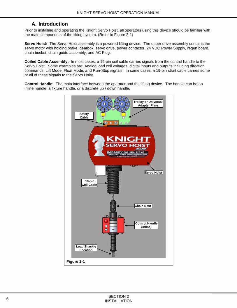
A. Introduction Prior to installing and operating the Knight Servo Hoist, all operators using this device should be familiar with the main components of the lifting system. (Refer to Figure 2-1) Servo Hoist: The Servo Hoist assembly is a powered lifting device. The upper drive assembly contains the servo motor with holding brake, gearbox, servo drive, power contactor, 24 VDC Power Supply, regen board, chain bucket, chain guide assembly, and AC Plug. Coiled Cable Assembly: In most cases, a 19-pin coil cable carries signals from the control handle to the Servo Hoist. Some examples are: Analog load cell voltages, digital inputs and outputs including direction commands, Lift Mode, Float Mode, and Run-Stop signals. In some cases, a 19-pin strait cable carries some or all of these signals to the Servo Hoist. Control Handle: The main interface between the operator and the lifting device. The handle can be an inline handle, a fixture handle, or a discrete up / down handle.
Figure 2-1
Trolley or Universal Adapter Plate
Safety Cable
Location
19-pin Coil Cable
Chain Nest
Control Handle (Inline)
Load Shackle Location
Servo Hoist

KNIGHT SERVO HOIST OPERATION MANUAL
SECTION 2 INSTALLATION 7
B. Initial Setup
Step 1: Unpacking
1) Unpack the Servo Hoist. Lift the hoist carefully out of packaging.
2) Keep the accompanying documents with the hoist or near the site of operation.
Step 2: System Assembly Knight Servo Hoists are typically delivered pre-assembled; if not, read the following sections.
2a) Servo Hoist Trolley Installation 2b) Safety Cable Installation 2c) 19-pin Coil Cable Installation 2d) 4mm and 5mm Chain Installation

KNIGHT SERVO HOIST OPERATION MANUAL
SECTION 2 INSTALLATION
8
Step 2a) Servo Hoist Trolley Installation:
Prior to installation visually inspect the trolley for signs of damage or missing parts.
1) Slide the trolley or adapter plate into the trolley mounting plate on top of the Servo Hoist. (Refer to Figure 2-2)
CAUTION Ensure that there is a (2) two-point connection when using the universal
adapter plate to hang the hoist from a structure. (Refer to Figure 2-3)
2) Insert the (2) two ½-13x1¾” (grade 8 or better) socket head cap screws (SHCS) and
(2) two washers.
NOTE The trolley should be mounted offset of the load distribution.
3) Secure the (2) two SHCS with (2) two ½-13 reverse lock nuts. As each bolt is tightened, the
reverse lock nut will get drawn into its slot and get trapped there.
4) Install the safety cable through the servo trolley or adapter and the trolley mounting plate. (Refer to Step 2b “Safety Cable Installation”)
5) Roll hoist into rail system.
Figure 2-2
Figure 2-3

KNIGHT SERVO HOIST OPERATION MANUAL
SECTION 2 INSTALLATION 9
Step 2b) Safety Cable Installation:
1) Slide thimbles together. (Refer to Figure 2-2) 2) Slide (2) two Crosby cable clamps onto the cable. 3) Loop the end of cable around thimble and run the end through the Crosby clamps.
The cable saddle (forged part) rests on the “live” (longer) end of the cable. The U-bolt rests on the “dead” (shorter) end of the cable. (Refer to Figure 2-3)
4) Tighten each nut on a single clamp, alternating sides. Repeat this procedure on the other clamp. Each nut should be tightened to a minimum of 15 ft-lbs.
5) Follow the steps below for trolley or adapter plate. 6) Insert cable through the center hole on the trolley bracket which is attached to the hoist and place
(2) two Crosby clamps on the other end of the cable. (Refer to Figure 2-4) 7) Secure the (2) two Crosby clamps snug to the thimble, repeating step 3. 8) Install the cable so that the Servo Hoist has a drop of not more than 1 in. [2.54 cm]. 9) Trim excess cable and tape ends of cable to prevent fraying. (Refer to Figure 2-4)
Figure 2-2
Figure 2-3
Figure 2-4
Figure 2-5
“U-Bolt”
“Cable Saddle”
Center Hole
Crosby Cable Clamp

KNIGHT SERVO HOIST OPERATION MANUAL
SECTION 2 INSTALLATION
10
Step 2c) 19-pin Coil Cable Installation:
1) Ensure power is removed from hoist. 2) Slide the 19-pin coil cable upward over the chain and into the clamping assembly. 3) Secure the (4) four M6 nuts onto the bolts that pass through the clamping assembly from the
bottom of the Servo Hoist. (Refer to Figure 2-6) 4) Connect the 19-pin connector to the bottom of the Servo Hoist. (Refer to Figure 2-7) 5) Seat both chains into the control handle’s chain nest. Secure both of the chain’s retaining bolts
through the provided holes in the chain nest. (Refer to Step 2d “4mm and 5mm Chain Installation”)
6) Loosen the (2) two M4 screws holding the 19-pin receptacle and slide it out of the control handle’s housing. (Refer to Figure 2-8)
7) Connect the 19-pin connector to the receptacle, slide it back into the control handle’s housing and secure the (2) two M4 screws. (Refer to Figure 2-9)
8) Secure the (2) two M6 bolts for each of the handle coil cable clamping rings located on top of the control handle. (Refer to Figure 2-9)
Figure 2-6
Figure 2-7
Figure 2-8
Figure 2-9
19-Pin Connector
19-Pin Connector
Clamping Rings
M6 Nuts
M4 Bolts (M3 Allen Wrench)
Clamping Assembly

KNIGHT SERVO HOIST OPERATION MANUAL
SECTION 2 INSTALLATION 11
Step 2d) 4mm and 5mm Chain Installation:
CAUTION DO NOT CUT CHAIN TO SHORTEN IT! The chain will be reeled into the
hoist in Section 2, Step 5 “Control Handle Set-up”.
1) Thread both chains through the coil cable. 2) Place the load chain into the top portion of the chain nest and insert the bolt provided thru chain
nest in front of load chain’s last link. A M4 allen wrench is required if the servo’s capacity is 250 or 500lbs. Otherwise both M4 and M5 allen wrenches will be required. (Refer to Figure 2-10)
3) Ensure that both chains are parallel with no twists from the gear box down to the chain nest. 4) Install the last link of the Safety Drop Stop (SDS) chain into the lower portion of the chain nest in
front of the load chain. Ensure that the SDS chain is kept parallel to the load chain. 5) Install the bolt provided into the bottom bolt hole in the chain nest and through the last link in the
SDS chain. (Refer to Figure 2-13) 6) Ensure that the large O-ring is fitted into the groove of the chain nest and the small O-ring is just
above the chain nest but below the safety chain ID tag. (Refer to Figure 2-14) 7) Figure 2-15 shows the completed installation of both chains into the chain nest.
Figure 2-10
Figure 2-11
Figure 2-12
Figure 2-13
Chain Nest
M4 or M5 Allen
Wrench
M4 or M5 Allen
Wrench
Small O-ring
Large O-ring
Load Chain Safety Chain
Safety Chain ID Tag

KNIGHT SERVO HOIST OPERATION MANUAL
SECTION 2 INSTALLATION
12
Step 3: Power Supply to Servo Hoist Prior to installation visually inspect the Servo Hoist for signs of damage or missing parts. Power Requirements: Call a Knight Representative to obtain the correct power requirements for your system. Standard: 240 VAC Single Phase 50/60 Hertz. Refer to system specific documentation for any special power requirements.
1) The Servo Hoist power is connected by a twist lock plug (Refer to Figure 2-16: Standard) or fed by a hard-wired circuit, provided by end user (Refer to Figure 2-17: CE Compliant).
2) The red light on the Run-Stop button will illuminate when power is provided to the Servo Hoist system.
Step 4: Releasing the Run-Stop button The Run-Stop button is engaged for shipping purposes.
1) Turn Run-Stop button a quarter of a turn clockwise to release the Run-Stop and wait for red light to turn off. (Refer to Figure 2-18)
2) Please, refer to the Run-Stop mode functionality in section 3.C. “Servo Hoist Functionality Modes” of this manual for more information.
Figure 2-18
Figure 2-16: Standard
Figure 2-17: CE Compliant
Twist Lock Plug

KNIGHT SERVO HOIST OPERATION MANUAL
SECTION 2 INSTALLATION 13
Step 5: Control Handle Set-up There are (4) four control handle configurations. This section discusses the correct setup of each of these.
5a) Inline Handle setup 5b) Fixture Handle setup 5c) Discrete Up / Down Handle setup 5d) Digital Wireless Remote Up / Down Controller with Run-Stop
Step 5a) Inline Handle setup:
1) Hold the inline handle and trigger with one hand, and hold the chain away from the inline handle with other hand. (Refer to Figure 2-19)
2) Apply upward pressure on inline handle until the green light flashes. 3) Once green light starts flashing, release the inline handle and the GREEN light will illuminate. 4) Grasp the inline handle and apply upward pressure until the chain starts feeding into the hoist.
Continue this until the inline handle is hanging vertically from the hoist at a comfortable height.
Figure 2-19
Step 5b) Fixture Handle setup:
1) Set-up the fixture handle into the orientation in which it will be used in the application. Refer to the layout drawings for the application to determine this. (Refer to Figure 2-20)
2) Apply upward pressure on fixture handle until the green light on the Operator Control Interface (OCI) flashes. (Refer to Figure 2-21)
3) Once green light starts flashing, release the fixture handle and the GREEN light will illuminate. 4) Grasp the fixture handle and apply upward pressure until the chain starts feeding into the hoist.
Continue this until the fixture is hanging from the hoist at a comfortable height.
Figure 2-20
Figure 2-21

KNIGHT SERVO HOIST OPERATION MANUAL
SECTION 2 INSTALLATION
14
Step 5c) Discrete Up / Down Handle setup:
1) Press the Up lever until the green light on the Operator Control Interface (OCI) starts to flash. (Refer to Figure 2-22)
2) Once the green light starts flashing, release the Up lever and the GREEN light will illuminate. 3) Press the Up lever again until the chain starts feeding into the hoist. Continue this until the fixture is hanging from the hoist at an acceptable height.
Figure 2-22
Step 5d) Digital Wireless Remote Up / Down Controller with Run-Stop:
1) Press the Up button until the green light on the Operator Control Interface (OCI) starts to flash. (Refer to Figure 2-23)
2) Once the green light starts to flash on the OCI, release the Up button until the green light illuminates.
3) Press the Up button again until the chain starts to feed into the hoist. Continue holding the Up button until the fixture is hanging from the hoist at an acceptable height.
Figure 2-23
NOTE
A continuously flashing GREEN light indicates a safe start activation fault. The system is sensing commanded motion during the Power-Up sequence.
Remedy Analog Handle: Release the handle and verify that the GREEN light
illuminates solid. If the GREEN light still flashes after the handle is released, refer to section 7. “Troubleshooting”.
Up/Down Pendent: Release both buttons and verify that the GREEN light illuminates solid. If the GREEN light still flashes after the button is released, refer to section 7. “Troubleshooting”.
Green Light
Up Button

KNIGHT SERVO HOIST OPERATION MANUAL
SECTION 2 INSTALLATION 15
Step 6: Test Hoist Movement Test the Servo Hoist movement by applying upward and downward pressure on the inline or fixture handle. If the system uses a discrete Up / Down handle, press the Up and Down levers to move the fixture up and down.
Step 7: Back-Up Software Knight Servo Hoists are pre-programmed prior to delivery. It is a good practice to back-up this software before initial operation. Refer to the section 5. ‘Software’ portion of this manual for instructions to connect to the Servo Hoist and to back-up the software.
Step 8: Software Adjustments (If necessary) After making a back-up of the software in step 7, it may be necessary to adjust certain parameters in the software to ensure that the servo performs correctly for a specific application. Refer to the following first-time adjustments in section 5. ‘Software’.
• Verify the hoist’s maximum weight. This is also known as the Up Stop weight of the hoist.
• Verify the hoist’s minimum weight. This is also known as the Down Stop or pay out weight of the hoist.
• Verify the hoist’s fixture weight.
• Verify that the analog handle is balanced.
• Verify that the encoder offset is correct.

KNIGHT SERVO HOIST OPERATION MANUAL
SECTION 2 INSTALLATION
16
KNIGHT SERVO HOIST OPERATION MANUAL
SECTION 3 OPERATION 17
3. OPERATION
A. Principle of Operation The Servo Hoist system receives a command to move up or down along the “Z” axis from any input force applied to the handles or by pressing the Up or Down levers.
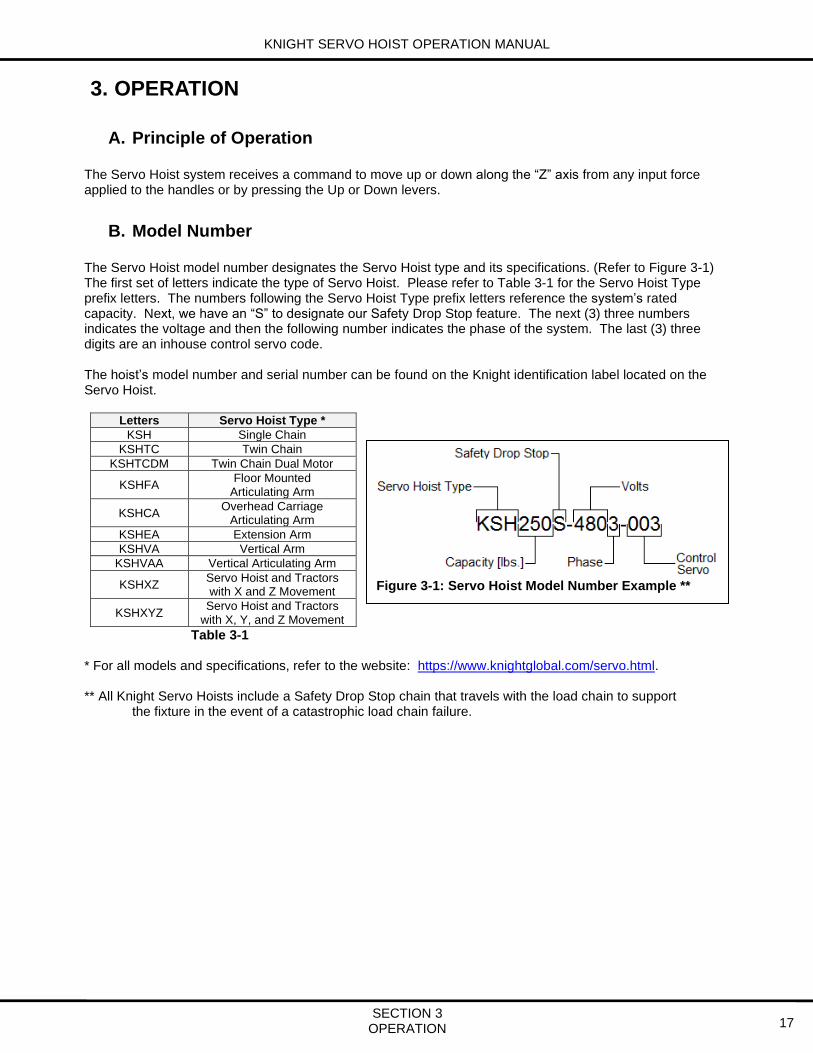
B. Model Number The Servo Hoist model number designates the Servo Hoist type and its specifications. (Refer to Figure 3-1) The first set of letters indicate the type of Servo Hoist. Please refer to Table 3-1 for the Servo Hoist Type prefix letters. The numbers following the Servo Hoist Type prefix letters reference the system’s rated capacity. Next, we have an “S” to designate our Safety Drop Stop feature. The next (3) three numbers indicates the voltage and then the following number indicates the phase of the system. The last (3) three digits are an inhouse control servo code. The hoist’s model number and serial number can be found on the Knight identification label located on the Servo Hoist.
Letters Servo Hoist Type *
KSH Single Chain
KSHTC Twin Chain
KSHTCDM Twin Chain Dual Motor
KSHFA Floor Mounted
Articulating Arm
KSHCA Overhead Carriage
Articulating Arm
KSHEA Extension Arm
KSHVA Vertical Arm
KSHVAA Vertical Articulating Arm
KSHXZ Servo Hoist and Tractors with X and Z Movement
KSHXYZ Servo Hoist and Tractors
with X, Y, and Z Movement
Table 3-1 * For all models and specifications, refer to the website: https://www.knightglobal.com/servo.html. ** All Knight Servo Hoists include a Safety Drop Stop chain that travels with the load chain to support the fixture in the event of a catastrophic load chain failure.
Figure 3-1: Servo Hoist Model Number Example **

KNIGHT SERVO HOIST OPERATION MANUAL
SECTION 3 OPERATION 18
Servo Hoist Control Configurations
Figure 3- 2
NUMBER DESCRIPTION
1 KNIGHT SERVO HOIST (xxxx = CAPACITY in LBS.)
2 KNIGHT 19-PIN COIL CABLE (xx = FT.)
3 KNIGHT 19-PIN STRAIGHT CABLE (xx = FT.)
4 KNIGHT LOAD MONITORING MODULE WITH OPERATOR CONTROL INTERFACE (OCI)
5 KNIGHT ANALOG INLINE HANDLE
6 KNIGHT LOAD MONITORING MODULE (LMM)
7 KNIGHT DUAL SPEED HANDLE PENDENT
8 KNIGHT FIXTURE HANDLE WITH INTERNAL LOAD CELL
9 KNIGHT OPERATOR CONTROL INTERFACE (OCI)
10 KNIGHT DUAL SPEED HANDLE WITH OPERATOR CONTROL INTERFACE (OCI)
-03 -04 -06 -08 -10 -15 -20
250 350 500 750 1000 1500 2000
1
2
6
5
4
3
3 3
3
7 8 7 9
3
7 8
10
2 & 3
1
2 2

KNIGHT SERVO HOIST OPERATION MANUAL
SECTION 3 OPERATION 19
C. Servo Hoist Functionality Modes
Run-Stop
Step 1. Press the RUN-STOP button, located on the Operator Control Interface (OCI) module.
• Drive power is removed from the system and the holding brake is set.
• The Run-Stop button will flash red. Recovery:
Step 1. Reset the RUN-STOP button by twisting it a quarter of a turn clockwise.
Shut Down
Step 1. Press the RUN-STOP button, located on the Operator Control Interface (OCI).
Step 2. Follow the warning labels on the Servo Hoist and disconnect the power supplied to the unit.
Start Up
Step 1. Connect the power supply to the unit.
Step 2. Reset the RUN-STOP button by twisting it a quarter of a turn clockwise.
• The hoist will power up and the OCI’s RED and GREEN indications will briefly flash when the system is ready to function.
• The unit will then default to No Mode: the OCI’s GREEN, BLUE, and RED indicators will turn off.
No Mode
When the Servo Hoist powers up or if it is inactive for a continuous time period, the unit will shift to this energy saving mode. The factory default time period is 15 minutes. The holding brake will engage and power will be removed from the motor while No Mode is active. When the unit is in No Mode, the OCI’s GREEN, BLUE, and RED indicators will be off.
Lift Mode
Press the GREEN (Lift) button to place the Servo Hoist into Lift Mode.
• The GREEN (Lift) indicator will illuminate.
NOTE
A continuously flashing GREEN light indicates a safe start activation fault. The system is sensing commanded motion during the Power-Up sequence.
Remedy Analog Handle: Release the handle and verify that the GREEN light
illuminates solid. If the GREEN light still flashes after the handle is released, refer to section 7. “Troubleshooting”.
Up/Down Pendent: Release both buttons and verify that the GREEN light illuminates solid. If the GREEN light still flashes after the button is released, refer to section 7. “Troubleshooting”.

KNIGHT SERVO HOIST OPERATION MANUAL
SECTION 3 OPERATION 20
Systems with In-line or Fixture Handle Style Lift Controls: Step 1. Apply force to the handle in the desired direction of travel (upward or downward).
The travel speed of the fixture is proportional to the force applied to the handle.
Systems with Discrete Up / Down Style Lift Controls: Step 1. Press the Up or Down button to move the hoist in the desired direction.
NOTE If the hoist is in No Mode and a lift command is given to the system, the
hoist will automatically go into Lift Mode.
Float Mode
Step 1. Press the BLUE (Float) button to place the Servo Hoist into Float Mode. When the BLUE button is pressed, a snapshot is taken of the load that is attached to the end of the hoist (i.e. the system records the weight suspended from the fixture). The BLUE (Float) indicator will illuminate.
Step 2. Apply pressure to the top of the part to move it down or lift up on the part to move it up. Do not use the lift controls to move the part as this will place the hoist back into Lift Mode.
WARNING An operator should never be able to release a load while in Float mode. The operator must switch to Lift mode in order to release a load.
NOTE If the Knight controls team programmed the hoist, it will never release or
unclamp a part while it is in Float mode. The hoist will have to be switched to Lift mode for a part to be released or unclamped.
To change from Float Mode to Lift Mode, follow any of the steps below:
• Operate the lift controls. The hoist will automatically change to Lift Mode and then it will move the fixture or handle up or down.
• Press the GREEN (Lift) push button and the unit will change into Lift Mode.
• Allow the Float Mode Timeout timer to expire. This timer is set at the factory to 5 minutes of non-use. To change this timer, refer to section 6. ‘Variable Descriptions’ in the Software section.
NOTE The part must be picked up while the hoist is in Lift Mode and then the
operator may place the Servo Hoist into Float Mode.
NOTE Do not rest your hand on the part when pressing the Float push button.
This can cause a bias or an incorrect zero value measurement to be processed and may cause unintended movement.
NOTE Use of the Lift Mode controls will prevent the unit from remaining in or
changing to Float Mode.

KNIGHT SERVO HOIST OPERATION MANUAL
SECTION 3 OPERATION 21
Travel Limits
NOTE During operation (Lift or Float Mode) the hoist will ramp down in speed as
the travel limits are approached.
NOTE The absolute upper and lower travel limits are factory set to the physical
limits of the Servo Hoist. Contact a Knight Global Representative for information regarding changes to these absolute limits.
Fault Mode
The Red light will flash. Step 1. Press the RUN-STOP button, located on the Operator Control Interface (OCI).
• Drive power is removed from the system and the holding brake is set.
• The RUN-STOP button will flash red. Recovery:
Step 1. Correct the situation that caused the fault. Refer to section 7.B. “System Activity screens including Faults, Warnings and Error Codes” for a list of common faults.
Step 2. Follow the Start Up procedure to restore power to the unit.

KNIGHT SERVO HOIST OPERATION MANUAL
SECTION 3 OPERATION 22

KNIGHT SERVO HOIST OPERATION MANUAL
SECTION 4 MAINTENANCE 23
4. MAINTENANCE
A. CHAIN INSPECTION
4.1 Inspection Overview The inspection procedures and recommendations in this manual are based on ANSI/ASME B30.16 “Overhead Underhung and Stationary Hoists” and ISO7592-1983 “Calibrated Round Steel Link Lifting Chains -- Guidelines to proper use and maintenance.” The following definitions and recommendations are from both specifications and pertain to the recommended inspection procedures in this manual. Qualified Person: A person who, by possession of a recognized degree in an applicable field, or certificate of professional standing, or who by extensive knowledge, training and experience, has successfully demonstrated the ability to solve or resolve problems relating to the subject matter at work. Designated Person: A person selected or assigned by the employer or the employer’s representative as being competent to perform specific duties. Abnormal Operating Conditions: Environmental conditions that are unfavorable, harmful, or detrimental to the operation of a hoist, such as excessively high or low ambient temperatures, exposure to weather, corrosive fumes, dust laden or moisture laden atmospheres, and hazardous locations.

KNIGHT SERVO HOIST OPERATION MANUAL
SECTION 4 MAINTENANCE 24
4.2 Use of Chain Safely in Any Application
Balance: Know the Load - determine the weight, center of gravity, angle and lift.
Overload: Never Overload the Chain - check the working load limit on the identification tag.
Knots, Twists and Kinks - Ensure chain is not twisted, knotted or kinked before lifting load. Chains should not be shortened with knots, bolts or other make-shift devices.
Sharp Edges - Protect chain with padding when lifting sharp edged loads.
Abrupt Movement - Lift and lower loads smoothly. Do not jerk.
Extreme Temperatures - Do not expose alloy chain to temperatures of 400°F or higher or -40°F or lower.

KNIGHT SERVO HOIST OPERATION MANUAL
SECTION 4 MAINTENANCE 25
4.3 Determining the Frequency of Chain Inspections Knight recommends utilizing load criteria and duty cycle data when determining the frequency of inspections. Inspection frequency should be identified by a qualified person and is based on factors such as the severity of the environment the hoist is being used in, percentage of capacity lifts, cycle time and shock loading. Each Servo Hoist should be rated individually and inspections performed in accordance with that rating. Proper maintenance depends on an evaluation of the severity of usage to which the hoist and the chains are subjected to in the specific application.
The overall determination of how often the hoist and chains should be inspected is a combination of its Service Rating Load Criteria (4.3.1) and its Service Class or Duty Cycle (4.3.2).
4.3.1 Service Rating Load Criteria
Light Service: Hoist and chains normally subjected to light loads and very rarely to maximum loads.
Moderate Service: Hoist and chains normally subjected to moderate loads but fairly frequently to maximum loads.
Heavy Service: Hoist and chains normally subjected to loads of heavy magnitude and frequently to maximum loads.
Very Heavy Service: Hoist and chains regularly subjected to maximum loads.
4.3.2 Service Class (Duty Cycle)
Service Class is determined by the total number of cycles the system has performed. (Table 4-1)
• Service Class 0: 0 to 20,000 loaded cycles.
• Service Class 1: 20,001 to 100,000 loaded cycles.
• Service Class 2: 100,001 to 500,000 loaded cycles.
• Service Class 3: 500,001 to 2,000,000 loaded cycles.
• Service Class 4: over 2,000,000 loaded cycles.
Cycles Per Day Desired Life (Years)
1 5 10 20 30
5 0 0 0 1 1
10 0 0 1 1 2
25 0 1 1 2 2
50 0 1 2 2 3
100 1 2 2 3 3
200 1 2 3 3 4
300 2 3 3 4 4
750 2 3 4 4 4
1,000 2 3 4 4 4
Table 4-1: Service Class Example: If the system is performing 100 cycles per day, it will progress though Service Classes
during its use: 1 year 26,000 cycles Service Class 1 5 years 130,000 cycles Service Class 2 10 years 260,000 cycles Service Class 2 20 years 520,000 cycles Service Class 3 30 years 780,000 cycles Service Class 3

KNIGHT SERVO HOIST OPERATION MANUAL
SECTION 4 MAINTENANCE 26
4.4 Type of Inspections The inspection procedure is divided into two general classifications based upon the intervals at which the inspections should be performed for the hoist and chains during regular use. The general classifications are herein designated as "frequent" and "periodic" with respective intervals between inspections as defined below.
In addition, visual observations shall be conducted during regular service for any damage or evidence of malfunction which might occur between regular inspections.
4.4.1 Frequent Inspection (Visual)
This is a visual examination of the hoist and its chains by the operator or other designated personnel, without requiring records to be made. This inspection should be carried out at the following intervals:
A. Light Service or Service Class 0 / 1 – Every Month
B. Moderate Service or Service Class 2 – Every Two Weeks
C. Heavy Service or Service Class 3 – Every Week
D. Very Heavy Service or Service Class 4 – Every Day
Additionally, the operator should check the system continually during operation to ensure that no malfunctions are occurring (such as abnormal noises or binding of the chain).
4.4.1.1 What to Look for During a Frequent Inspection
Operator should examine the chain throughout its working length to detect any evidence of wear, distortion or external damage. Equipment should be operated under a load as near as possible to the usual operating load, in both directions and observe the functioning of the chain. The chain should feed smoothly into and out of the servo. Additionally, the operator should check the system continually during operation to ensure that no malfunctions are occurring.
• Check for visual signs or abnormal noises (grinding etc.) which would indicate a potential problem.
• Ensure controls function properly and return to neutral when released.
• Ensure the load chain feeds through the hoist correctly.
• Ensure that the chain doesn’t bind, is excessively noisy or “clicks” as it leaves the bottom of the servo.
If any of these abnormal conditions are evident, the Servo Hoist should be taken out of service and a detailed inspection and corrective actions should be taken by qualified maintenance personnel.

KNIGHT SERVO HOIST OPERATION MANUAL
SECTION 4 MAINTENANCE 27
4.4.2 Periodic Inspection (Documented)
This is a thorough examination of the hoist and its chains conducted by a qualified person, making records of external conditions to provide a basis for the hoist’s continuing evaluation. This Inspection should be carried out at the following intervals:
A. Light Service or Service Class 0/1 – Yearly
(equipment remains in place).
B. Moderate Service or Service Class 2 – Every Six Months (equipment remains in place unless external conditions indicate that disassembly should be done to permit detailed inspection).
C. Heavy Service or Service Class 3 – Every Three Months (equipment remains in place unless external conditions indicate the disassembly should be done to permit detailed inspection).
D. Very Heavy Service or Service Class 4 – Every Six Weeks (equipment remains in place unless external conditions indicate that disassembly should be done to permit detailed inspection).
4.4.2.1 Recommendations for Periodic Inspections
Perform the inspection detailed under section 4.4.1.1 “Ideas Regarding What to Look for During a Frequent Inspection” of this manual. Next, the chains should be cleaned for inspection, using any cleaning method that will not cause damage. Adequate lighting should be provided for the person inspecting the chain. The chain should be examined link by link for cracks, gouges, nicks, distortion, corrosion, deposits of foreign material, and for interlink wear. To inspect for wear at the interlink contact points, slacken the chain and rotate adjacent links to expose the inner ends of the link. If wear is observed or if elongation is suspected, measure the chain using the supplied chain gauge shipped with the servo hoist.
A. Chain Link Thickness
If chain is worn to less than the minimum allowable thickness (T), remove the chain from service. (Refer to Figure 4-1)
Minimum Allowable Chain Link Thickness at Any Point
Nominal Chain Size Minimum Thickness “T”
Inches mm Inches mm
.157 4.0 .137 3.48
.196 5.0 .171 4.35 Figure 4-1
T

KNIGHT SERVO HOIST OPERATION MANUAL
SECTION 4 MAINTENANCE 28
B. Chain Gauge Replacement Measurement for 4mm and 5mm Load Chains
1. Determine which type of chain is being inspected, either 4mm or 5mm,
by placing a single link into the chain gauge where the arrows are located. (Refer to Figure 4-2)
2. Raise the hoist to the full up position and mark the chain.
3. Lower the hoist to the full down position.
4. Select 13 links starting with the link that was marked in step 2.
5. The 13-selected links should fit loosely onto gauge prongs as shown below. If links number 1 and 13 do not fit onto prongs or have to be forced into selection, replace the load chain. This length has stretched 2% or more and should be removed from service and replaced with new chain.
6. Perform this inspection in multiple sections of the chain working up to the sprocket.
Figure 4-2
C. If Chain Gauge is Not Available • Select an unworn, un-stretched length of the load chain.
• Suspend the chain vertically under tension. Use a caliper type gauge to measure the accumulated pitch of between 5 and 13 links.
• Measure the same number of links throughout the used chain and calculate the percentage increase in length.
• The chain should be replaced if the gauge length measured over any 5, 7, 9, 11, or 13 links as appropriate exceeds that of the unused chain by 2%.

KNIGHT SERVO HOIST OPERATION MANUAL
SECTION 4 MAINTENANCE 29
D. Rejection Criteria The chain should be rejected and replaced if any of the following conditions are observed: (Refer to Figure 4-3)
• Cracked or worn links
• Severe nicks or gouges
• Twisted or bent links
• Severe corrosion
• Deposits which cannot be removed
• Increase in gauge length which exceeds the manufacturer's recommendations. In the absence of manufacturer's recommendations, the chain should be replaced if the gauge length measured over any 5, 7, 9, 11, or 13 links as appropriate exceeds that of the unused chain by 2%.
Figure 4-3
4.4.2.2 Recommended Record Keeping for Periodic Inspections
Adequate records as a part of periodic inspection are essential for the proper use of calibrated chains. The chain record should include a complete description and identification of the new chain, the date and results of each inspection, the date and results of each test and the date and description of any maintenance.
The record is a continuous history of the chain and shows that it has been regularly inspected and maintained in good operating condition.
When the chain is removed from service, a new record should be prepared for the replacement chain.

KNIGHT SERVO HOIST OPERATION MANUAL
SECTION 4 MAINTENANCE 30
4.4.3 Chain Lubrication:
Keep chain well lubricated. Never operate a hoist when the load chain does not flow freely and smoothly into and out of the gear box assembly or when it makes noises indicative of binding or other malfunctions. Replace the chain if it is visibly damaged in any way. Clean, lubricate, and inspect the load chain based on the frequent inspection criteria described in section 4.4.1. In a corrosive environment, lubricate more frequently than normal. Failure to maintain a clean and well lubricated load chain will result in rapid load chain wear that can lead to chain failure which can cause severe injury, death or substantial property damage. If required, clean the chain with acid free solvent to remove rust or abrasive dust buildup before the chain is lubricated. Lubricate each link of the chain with a light coat of SAE 50 to 90 EP oil or equivalent machine/gear oil. Ensure that oil is applied to the bearing surfaces of the load chain links. Wipe off excess oil from the load chain surfaces. Substitute a dry lubricant for use in dusty environments. Knight recommends Demag Chain Grease: P/N 665 009 44. (Refer to Figure 4-4: Chain Lubrication) Lubricate hook and safety latch pivot points with same lubricant used on the load chain. Lubricate chain without load on chain. This will allow lube to penetrate between links.
WARNING Failure to maintain clean and lubricated load chain will void the
manufacturer’s warranty.
4.4.4 Load Chain Replacement:
Care should be taken to re-install the chain without any twists down the entire chain’s length between the gear box and its anchored end in the chain nest. Proper orientation of the entering link should be established since a twist cannot be corrected except by removing and re-installing the chain. Refer to 4.6 “Load and Safety Drop Stop Chain Replacement (Normal Maintenance)” for further instructions on how to replace load chain.
Figure 4-4: Chain Lubrication

KNIGHT SERVO HOIST OPERATION MANUAL
SECTION 4 MAINTENANCE 31
4.4.5 Double Roller Chain:
Over time the chain elongates as it wears leading to a significant increase in actual pitch and potential chain failure. When the normal pitch length has been extended by 2-3%, the service life of the chain is significantly reduced and the ultimate breaking strength is considerably lower. At 2% elongation a qualified service technician must set a safe time limit for replacement. At 3% the chain must be replaced immediately. Knight Global provides a Roller Chain Gauge with each roller chain hoist. The roller chain should be checked at intervals depending on the service and load conditions. (Refer to section 4.3)
4.4.5.1 Roller Chain Gauge Replacement Measurement
Roller Chains should be cleaned for inspection, using any cleaning method that will not cause damage.
1. Close gauge to confirm calibration: Check the calibration by closing the slide fully.
2. Read the ‘Percentage Wear’ window: When the gauge is fully closed, if the black arrow moves into the ‘+’ or ‘-‘ zones, the gauge will not give an accurate measurement and should not be used. Similarly, if the ‘V’ jaws are damaged the instrument may also not perform accurately.
3. Identify the pitch: Align the red arrows within the center of the pins on ONE of the OUTER link plates. Depending on ease of access, one pair of arrows will be more suitable than the others. The normal pitch will appear in the ‘Pitch’ window. The number of pins (n) that the chain is to be measured over will appear in the ‘Measure over pins’ window.
4. Select the Correct side of the gauge: Select the correct scale according to pitch size. Once the pitch is determined, the number of pins to measure is displayed.
Knight’s Roller Chain uses the “A Scale” side.
NOTE: “A Scale” side = 3/8”, ½”, 5/8”, ¾”, 1”, 1 ¼”, 1 ½”, 2 ½”, and 3”. “B Scale” side = 1 ¾” x 2”
Continued on next page
Pitch
Measure over pins
Red Arrows

KNIGHT SERVO HOIST OPERATION MANUAL
SECTION 4 MAINTENANCE 32
5. Measure the Chain: The chain should be cleaned and measured in its location while placed under approximately 1% of the minimum breaking load. If a set of check weights is not available, it is sufficient for the chain to be tensioned by the weight of the carriage and lift assist.
Identify the section of the chain that regularly runs over the pulley as this part of the chain is most susceptible to wear. Measurements must then be made in at least 3 separate locations on this section.
Place the ‘V’ jaw of the chain gauge over the first pin of one of the selected sections and then extend the slide until the other ‘V’ jaw reaches the final pin. The final pin will be the one that appeared in the ‘Measure over pins’ window as previously determined in step 3.
6. Read off the Percentage: Check the ‘Percentage Wear’ windows. A percentage will appear in 0.25% (¼%) increments. If the chain has elongated by 2% or more, the warning window will be filled with red and necessary action must be taken.
4.4.5.2 Lubricating the Servo Arm Roller Chain
After changing the roller chain, before a test load is lifted and before the hoist is put into operation as well as during normal operation when no load is attached, the chain link contact areas must be lubricated with Demag gear grease, part no. 665 009 44. The chain link contact areas must be re-lubricated appropriately – after being cleaned – at intervals depending on the service and load conditions. Knight recommends the roller chain be lubricated periodically in accordance with section 4.4.3 Chain Lubrication. Cut off the tip of the grease tube and inject grease into the chain’s links by compressing the tube while you run the chain to its end positions to ensure complete and even lubrication of the chain.
Warning Window

KNIGHT SERVO HOIST OPERATION MANUAL
SECTION 4 MAINTENANCE 33
B. PREVENTATIVE MAINTENANCE FOR KNIGHT SERVO HOIST
4.5 Servo Hoists Inspections
4.5.1 Recommendations for Frequent Inspections for Servo Hoists (Visual)
This is a visual examination by the operator or other designated personnel, without requiring records to be made. Inspection should be carried out at the following intervals recommended in section 4.4.1 ‘Frequent Inspection (Visual)’.
Additionally, the operator should check the system continually during operation to ensure that no malfunctions are occurring.
4.5.1.1 Servo Hoist: • Visually inspect the Servo Hoist and ensure that it is in good general working order.
Repair or replace any broken or missing parts.
• Cycle the Servo Hoist and listen for any abnormal noises (grinding, etc.). If any abnormal noises are evident, an inspection of the Servo Hoist must be performed.
• Inspect how the chain feeds through the Servo Hoist. If any binding is evident, clean and lubricate the chain (Refer to section 4.4.2 ‘Periodic Inspection (Documented)’. If the problem persists replace the chain.
• Cycle the Run-Stop button and ensure it functions correctly.
4.5.1.2 Load Shackle: • Check the shackle for signs of wear.
• Ensure the load shackle is not cracked, nicked or gouged. Replace the shackle as necessary.
• Confirm all cotter pins and / or keepers are in place.
If any of these abnormal conditions are evident, the Servo Hoist should be taken out of service and a detailed inspection and corrective actions should be taken by qualified maintenance personnel.
KNIGHT SERVO HOIST OPERATION MANUAL
SECTION 4 MAINTENANCE 34
4.5.2 Periodic Inspection (Documented) Perform the items listed in the section 4.4.1.1. ‘What to Look for During a Frequent Inspection’ in addition to the items listed below. All findings from this inspection should be recorded.
4.5.2.1 Supporting Structure: • Check for distortion, wear and continued ability to support the load. Refer to
manufacturers’ instructions for overhead rail systems.
4.5.2.2 Rail Trolley (if applicable): • Ensure wheels and side rollers run smoothly and are not excessively worn. Replace
the wheels and side rollers as necessary.
• Visually check the nylon at the bearing and along the face of the wheel for cracks.
4.5.2.3 Fasteners: • Check all fasteners and ensure they are not loose, missing or damaged.
4.5.2.4 Load Hook (if applicable): • Inspect for cracks, wear or damage.
• Inspect hook throat for spreading and proper safety latch engagement.
• Measure hook throat at wear points: greater than ten percent wear in any throat zone requires replacement. Refer to manufacturer's instructions for wear zone information.
• Inspect the hook eye or chain nest and sleeve for correct functionality. Also, each should rotate without binding and should not be damaged.
4.5.2.5 Valves, Timers, and Switches: • Check during an operation cycle to ensure the sequence is operating at optimum
efficiency. Repair or replace if needed.
4.5.2.6 Wiring:
• Check for broken, loose, missing, and worn wires. Check all electrical cables for signs of age, wear, or damage, and make sure all connections are tight and secure. Repair or replace if needed.
4.5.2.7 Electrical Enclosures, Disconnect Boxes, and Circuit Breakers:
• Check for obvious signs of damage and repair or replace if needed.
• Verify disconnect is operational. Check for loose, bent, or broken components. Repair or replace if needed.
• Inspect for loose or broken terminals. Check for the presence of contaminants like dirt, dust, grease, or rust. Repair or replace if needed.
If any of these abnormal conditions are evident, the Servo Hoist should be taken out of service and a detailed inspection and corrective actions should be taken by qualified maintenance personnel.

KNIGHT SERVO HOIST OPERATION MANUAL
SECTION 4 MAINTENANCE 35
4.5.2.8 Labels and Tags: • Ensure that all labels are intact and legible. Replace as necessary.
(Refer to Figure 4-5)
Figure 4-5
If any of the labels or warning tags listed above are missing, contact Knight Global at 248-377-4950 to order replacements.
CE Identification Identification
Enclosure Cover Label
Voltage Warning Tags

KNIGHT SERVO HOIST OPERATION MANUAL
SECTION 4 MAINTENANCE 36
4.6 Load and Safety Drop Stop Chain Replacement (Normal Maintenance)
The materials required for the chain replacement are shown in Figure 4-6:
Step 1. Raise the inline handle or Load Monitoring Module to its full up position.
Step 2. Measure the distance from the top of the inline handle or load cell assembly to the bottom of the servo hoist. (Refer to Figure 4-7)
Step 3. Record this measurement because it will be used in section 5.F. ‘Encoder Offset Setup Procedure’.
Figure 4-7
Step 4. Move the inline handle or load cell assembly down to a comfortable working height.
Step 5. Remove ALL of the load that is attached to the hoist under the inline handle or load cell assembly. This includes the part and the system’s fixture.
Figure 4-6
Date of Replacement Measurement in. in. in. in. in.
KNIGHT SERVO HOIST OPERATION MANUAL
SECTION 4 MAINTENANCE 37
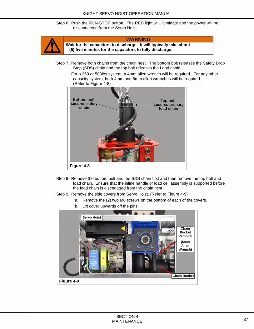
Step 6. Push the RUN-STOP button. The RED light will illuminate and the power will be disconnected from the Servo Hoist.
WARNING Wait for the capacitors to discharge. It will typically take about (5) five minutes for the capacitors to fully discharge.
Step 7. Remove both chains from the chain nest. The bottom bolt releases the Safety Drop Stop (SDS) chain and the top bolt releases the Load chain.
For a 250 or 500lbs system, a 4mm allen wrench will be required. For any other capacity system, both 4mm and 5mm allen wrenches will be required. (Refer to Figure 4-8)
Figure 4-8
Step 8. Remove the bottom bolt and the SDS chain first and then remove the top bolt and load chain. Ensure that the inline handle or load cell assembly is supported before the load chain is disengaged from the chain nest.
Step 9. Remove the side covers from Servo Hoist. (Refer to Figure 4-9)
a. Remove the (2) two M6 screws on the bottom of each of the covers.
b. Lift cover upwards off the pins.
Figure 4-9
Chain Bucket
Servo Hoist
Chain Bucket
Removal
(5mm Allen
Wrench)

KNIGHT SERVO HOIST OPERATION MANUAL
SECTION 4 MAINTENANCE 38
Step 10. While supporting the chain buckets, remove the (1) one M5 retainer bolt that secures both chain buckets inside of the Servo Hoist. (Refer to Figure 4-10)
Figure 4-10
Step 11. Remove both chain buckets through the bottom of the Servo Hoist.
Step 12. Remove both chains from their individual chain buckets.
Step 13. Remove both of the end-stop assemblies from the each of the old load and Safety Drop Stop (SDS) chains.
Step 14. Connect both of the old chains together with the both of new chains by using both of the yellow chain interface links. (Refer to Figure 4-11)
Figure 4-11
Step 15. To enable the chain pay-out sequence, using the Operator Control Interface (OCI), twist the Run-Stop button clockwise to enable the hoist. Within 3 seconds, press the Run-Stop button, press and release the Green Lift button and then the Blue Float button, twist the Run-Stop button clockwise and release. This will start the pay-out mode after three to ten seconds. If the direction is incorrect, press the Run-Stop button to stop the pay-out mode and repeat the above sequence to pay-out the chain in the opposite direction.
Step 16. Stop the pay-out mode by pressing the Run-Stop button when the yellow interface chain links have moved through the gear box and are at an acceptable height to reattach the inline handle or load cell assembly.
Step 17. Lubricate both the load and the Safety Drop Stop (SDS) chains per section 4.4.3 ‘Chain Lubrication’.
Chain Bucket retainer
bolt

KNIGHT SERVO HOIST OPERATION MANUAL
SECTION 4 MAINTENANCE 39
Step 18. Reinstall both chains into each of their correct chain buckets.
Step 19. Reinstall the chain buckets back into the servo hoist.
Step 20. Reinstall the servo hoist side covers.
Step 21. The SDS chain needs to be cut to the correct length so it has slack in it when the load chain is properly connected.
Step 22. Ensure that both chains are parallel with no twists from the gear box down to their respective ends.
Step 23. Count down seven links from the end of the load chain. Cut the seventh link so the SDS chain is six links longer than the load chain. (Refer to Figure 4-12)
Figure 4-12
Step 24. Install the safety chain identification sleeve on the SDS chain and then heat shrink it to the SDS chain on the eighth link up from the bottom of the SDS chain. (Refer to Figure 4-13)
Figure 4-13
Step 25. Reinstall the new small O-ring around both the load and SDS chains.
Step 26. Reinstall both chains back through the center of the coil cable.

KNIGHT SERVO HOIST OPERATION MANUAL
SECTION 4 MAINTENANCE 40
Step 27. Ensure that both chains are parallel to each other and have NO twists in them when they are installed into the chain nest. (Refer to Figure 4-14)
Figure 4-14
Step 28. First, the last link of the load chain is installed into the top slot of the chain nest. The chain must be kept parallel with no twists. The bolt is installed in front of the last link of the load chain and into the chain nest. (Refer to Figure 4-15)
Figure 4-15
Step 29. Next, the last link of the SDS chain is installed into the bottom slot of the chain nest. The chain must be kept parallel with no twists. The bolt is installed through the last link of the SDS and into the chain nest. (Refer to Figure 4-16)
Figure 4-16
Step 30. Reinstall the large O-ring into the groove located on the chain nest. (Refer to Figure 4-15)
Step 31. Move the small O-ring down so it is just above the top of the chain nest.
Step 32. The servo hoist may now be repowered and tested.

KNIGHT SERVO HOIST OPERATION MANUAL
SECTION 4 MAINTENANCE 41
4.6.1 Resetting the Encoder Offset
Please refer to section 5.F. ‘Encoder Offset Setup Procedure’ for the steps to reset the encoder offset for this system.
WARNING Do NOT raise the servo handle above the recorded measurement
obtained in Step 3 of section 4.6 ‘Load and Safety Drop Stop Chain Replacement (Normal Maintenance)’ or damage may be done to the servo.

KNIGHT SERVO HOIST OPERATION MANUAL
SECTION 4 MAINTENANCE 42
4.7 Broken Chain Replacement
The materials required for the chain replacement are shown in Figure 4-18:
.
Step 1. Raise the inline handle or Load Monitoring Module to its full up position.
Step 2. Measure the distance from the top of the inline handle or load cell assembly to the bottom of the servo hoist. (Refer to Figure 4-19)
Step 3. Record this measurement because it will be used in section 5.F. ‘Encoder Offset Setup Procedure’.
Figure 4-19
Step 4. Move the inline handle or load cell assembly down to a comfortable working height.
Step 5. Remove ALL of the load that is attached to the hoist under the inline handle or load cell assembly. This includes the part and the system’s fixture.
Figure 4-18
Date of Replacement Measurement in. in. in. in. in.

KNIGHT SERVO HOIST OPERATION MANUAL
SECTION 4 MAINTENANCE 43
Step 6. Push the RUN-STOP button. The RED light will illuminate and the power will be disconnected from the Servo Hoist.
WARNING Wait for the capacitors to discharge. It will typically take about (5) five minutes for the capacitors to fully discharge
Step 7. Remove both chains from the chain nest. The bottom bolt releases the Safety Drop Stop (SDS) chain and the top bolt releases the Load chain.
For a 250 or 500lbs system, a 4mm allen wrench will be required. For any other capacity system, both 4mm and 5mm allen wrenches will be required. (Refer to Figure 4-20)
Figure 4-20
Step 8. Remove the bottom bolt and the SDS chain first and then remove the top bolt and load chain. Ensure that the inline handle or load cell assembly is supported before the load chain is disengaged from the chain nest.
Step 9. Remove the side covers from Servo Hoist. (Refer to Figure 4-21)
a. Remove the (2) two M6 screws on the bottom of each of the covers.
b. Lift cover upwards off the pins.
Figure 4-21
Chain Bucket
Servo Hoist
Chain Bucket
Removal
(5mm Allen
Wrench)

KNIGHT SERVO HOIST OPERATION MANUAL
SECTION 4 MAINTENANCE 44
Step 10. While supporting the chain buckets, remove the (1) one M5 retainer bolt that secures both chain buckets inside of the Servo Hoist. (Refer to Figure 4-22)
Figure 4-22
Step 11. Remove the chain buckets through the bottom of the Servo Hoist.
Step 12. Remove both chains from the individual chain buckets.
Step 13. Remove both of the end-stop assemblies from the each of the old load and Safety Drop Stop (SDS) chains.
Step 14. Connect the old SDS chain to the new SDS chain using one of the yellow interface links. (Refer to Figure 4-23)
Figure 4-23
Step 15. To enable the chain pay-out sequence, using the Operator Control Interface (OCI), twist the Run-Stop button clockwise to enable the hoist. Within 3 seconds, press the Run-Stop button, press and release the Green Lift button and then the Blue Float button, twist the Run-Stop button clockwise and release. This will start the pay-out mode after three to ten seconds. If the direction is incorrect, press the Run-Stop button to stop the pay-out mode and repeat the above sequence to pay-out the chain in the opposite direction.
Step 16. When the yellow chain interface link reaches the gear box, stop the pay-out mode by pressing the Run-Stop button.
Chain Bucket retainer
bolt

KNIGHT SERVO HOIST OPERATION MANUAL
SECTION 4 MAINTENANCE 45
Step 17. Using the chain installation tool, locate the load chain pocket opening on the bottom of the gear box. (Refer to Figure 4-24)
Figure 4-24
Step 18. Using the chain installation tool, feed it completely through the gear box.
Step 19. Connect the new load chain to the chain installation tool.
Step 20. Pull the chain installation tool until the load chain just enters the gear box chain pocket opening.
Step 21. Ensure that the new load chain is aligned correctly so that it will enter the gear box properly.
Step 22. Ensure that there is tension on the chain replacement tool so that it is pulled into the gear box when the payout mode is started.
Step 23. Restart the pay-out mode by following the procedure listed in Step 15 above.
Step 24. This will feed the new load chain and SDS chain through the gear box.
Step 25. When the new load chain is long enough to attach to the chain nest, press the Run-Stop button to stop the pay-out mode.
Step 26. Lubricate both the load and the Safety Drop Stop (SDS) chains per section 4.4.3 ‘Chain Lubrication’.
Step 27. Reinstall both chains into each of their correct chain buckets.
Step 28. Reinstall the chain buckets back into the servo hoist.
Step 29. Reinstall the servo hoist side covers.
Step 30. The SDS chain needs to be cut to the correct length so it has slack in it when the load chain is properly connected.
Step 31. Ensure that both chains are parallel with no twists from the gear box down to their respective ends.
Chain Pocket

KNIGHT SERVO HOIST OPERATION MANUAL
SECTION 4 MAINTENANCE 46
Step 32. Count down seven links from the end of the load chain. Cut the seventh link so the SDS chain is six links longer than the load chain. (Refer to Figure 4-25)
Figure 4-25
Step 33. Install the safety chain identification sleeve on the SDS chain and then heat shrink it to the SDS chain on the eighth link up from the bottom of the SDS chain. (Refer to Figure 4-26)
Figure 4-26
Step 34. Reinstall the new small O-ring around both the load and SDS chains.
Step 35. Reinstall both chains back through the center of the coil cable.
Step 36. Ensure that both chains are parallel to each other and have NO twists in them when they are installed into the chain nest. (Refer to Figure 4-27)
Figure 4-27

KNIGHT SERVO HOIST OPERATION MANUAL
SECTION 4 MAINTENANCE 47
Step 37. First, the last link of the load chain is installed into the top slot of the chain nest. The chain must be kept parallel with no twists. The bolt is installed in front of the last link of the load chain and into the chain nest. (Refer to Figure 4-28)
Figure 4-28
Step 38. Next, the last link of the SDS chain is installed into the bottom slot of the chain nest. The chain must be kept parallel with no twists. The bolt is installed through the last link of the SDS and into the chain nest. (Refer to Figure 4-29)
Figure 4-29
Step 39. Reinstall the large O-ring into the groove located on the chain nest. (Refer to Figure 4-28)
Step 40. Move the small O-ring down so it is just above the top of the chain nest.
Step 41. The servo hoist may now be repowered and tested.
4.7.1 Resetting the Encoder Offset
Please refer to section 5.F. ‘Encoder Offset Setup Procedure’ for the steps to reset the encoder offset for this system.
WARNING Do NOT raise the servo handle above the recorded measurement
obtained in Step 3 of 4.7 ‘Broken Chain Replacement’ or damage may be done to the servo.

KNIGHT SERVO HOIST OPERATION MANUAL
SECTION 4 MAINTENANCE 48

KNIGHT SERVO HOIST OPERATION MANUAL
SECTION 5 SOFTWARE 49
5. SOFTWARE There are several subjects related to the Servo Hoist’s software that will be reviewed here: 5.A.) Getting Started 5.B.) Connecting to a Servo Hoist 5.C.) Backing up the Knight Servo Hoist Software 5.D.) Load a New Drive with Existing Software 5.E.) Check or Change Setup Values 5.F.) Encoder Offset Setup Procedure 5.G.) Operating Test Mode 5.H.) Accessing the Servo Hoist’s Fault Log In the next few sections of the manual a shorthand is used to point to a particular screen in the Knight Servo Studio (KSS) program. The shorthand that explains how to find each screen or parameter in the KSS is explained below:
KSS Workspace tree location (User Level= Advanced): Knight Work Order # \ Status \ System Status Bits This means that the Knight Servo Studio’s ‘User Level’ dropdown located on the top menu must be set to the ‘Advanced’ option. Next, in the ‘Workspace’ panel on the left-hand side of the screen, the ‘+’ sign next to the Knight Work Order number needs to be pressed. This will expand the selection tree. Mouse down and press the ‘+’ sign next to the ‘Status’ option and double-click on the ‘System Status Bits’ screen. This will open that screen and any specific parameters can be inspected.
KSS Home screen location: Quick View panel \ Row 6 (Lower right-hand portion of the screen) This means that on the Knight Servo Studio’s home screen there is a panel located in the lower right-hand portion of the screen labeled ‘Quick View’. The parameter in question is located on ‘Row 6’ of that panel.
If the Servo Hoist is being set up for the first-time, here is a list of functions to initially verify. The functions can be accessed from the ‘Quick Setup’ screen located here:
KSS Workspace tree location (User Level= Advanced): Knight Work Order # \ Setup \ Quick Setup 1) The hoist’s maximum allowed weight: This can be verified by following the instructions in section 5.E. ‘Check or Change Setup Values’ on ‘Row #6’. 2) The hoist’s set down weight: This can be verified by following the instructions in section 5.E. ‘Check or Change Setup Values’ on ‘Row #7’. 3) The hoist’s fixture weight is correct: This can be verified by following the instructions in section 5.E. ‘Check or Change Setup Values’ on ‘Row #4’. 4) The analog handle is balanced: This can be verified by following the instructions in section 5.E. ‘Check or Change Setup Values’ on ‘Row #9’. 5) The encoder offset procedure: This can be verified by following the instructions in section 5.F. ‘Encoder Offset Setup Procedure’.

KNIGHT SERVO HOIST OPERATION MANUAL
SECTION 5 SOFTWARE 50
A. Getting Started Listed below are the hardware and software items needed to connect to a Knight Servo Hoist: (Refer to Figure 5-1)
• Laptop running Microsoft Windows 7 or above. (Customer Supplied)
• Ethernet Cable with (1) RJ45 connector and (1) M12 4-pin connector.
• The Knight Servo Studio software package. Note: The Knight Servo Studio software and an Ethernet Cable can be ordered from Knight: P/N EBA1395.
Figure 5-1

KNIGHT SERVO HOIST OPERATION MANUAL
SECTION 5 SOFTWARE 51
B. Connecting to a Servo Hoist The Knight Servo Studio Servo software is used to configure and troubleshoot the Knight Servo Hoist. The following steps are required to initiate a connection between a computer running the Knight Servo Studio software and the Knight Servo Hoist:
Knight Servo Studio Software Package Setup:
Step 1. Setup the Ethernet communication settings for your laptop.
a. Using a Microsoft Windows based PC open the Network and Sharing Center. b. Right click on Local Area Connections. Select Properties. (Refer to Figure 5-2)
c. Select Internet Protocol Version 4 (TCP/IPv4). Select Properties. d. Select Use the following IP address:
In most cases the laptop’s IP Address should be: 196.168.2.250 Type the correct IP address and Subnet mask into the spaces provided and press the ‘OK’ button. (Refer to Figure 5-3)
Figure 5-3
Figure 5-2

KNIGHT SERVO HOIST OPERATION MANUAL
SECTION 5 SOFTWARE 52
Step 2. Insert the USB card that was supplied with Servo Hoist into the laptop.
Double-click on the “ksh_sm_user.exe” icon to launch the Knight Servo Studio installation software. (Refer to Figure 5-4)
Figure 5-4
Step 3. Double click on the blue Knight Servo Studio software icon located on the desktop and allow the Knight Servo Studio software to load. (Refer to Figure 5-5)
Figure 5-5
Step 4. When the software loads, choose the ‘Open Project from Device’ option. Input the correct IP Address into the Network Configuration box. The IP Address for the hoist will be located next to the M12 ENET receptacle located on the Load Monitoring Module or the Inline Handle, but in most cases is: 192.168.2.101 (Refer to Figure 5-5)
Knight Servo Studio

KNIGHT SERVO HOIST OPERATION MANUAL
SECTION 5 SOFTWARE 53
Step 5. Move the mouse to the right side of the screen and select the ‘Connect’ button. If the communications are operating correctly the red ‘Disconnected’ box will turn to a green ‘Connected’ box. (Refer to Figure 5-6)
If the Knight Servo Studio software does not connect to the hoist, recheck all of the connections and ensure that the hoist has its 240VAC power connected.
Figure 5-6

KNIGHT SERVO HOIST OPERATION MANUAL
SECTION 5 SOFTWARE 54
C. Backing up the Knight Servo Hoist Software The section will explain how to save a backup copy of the ‘Knight Servo Studio’ (a .KSP file) and the ‘Knight SD3 Program Editor’ (a .PRJ file).
Save a copy of the Knight Servo Studio’s .KSP file:
Step 1. Mouse up to the top menu bar located on the left-hand side of the screen and select ‘File’. Highlight the ‘Save To File’ option and select it. (Refer to Figure 5-7)
Figure 5-7
Step 2. Select the folder where to save the backup copy of the file. Ensure the Knight Work Order
number is included in the filename. (Refer to Figure 5-8) Knight suggests that a ‘Controls’ folder be created as well as subdirectories for each servo. The hoist’s Work Order number should be used as the name for these new subdirectories. i.e. \Controls\123748.
Figure 5-8
Step 3. Send a copy of the newly saved file to Knight’s Servo Team at [email protected].

KNIGHT SERVO HOIST OPERATION MANUAL
SECTION 5 SOFTWARE 55
Save a copy of the Knight SD3 Program Editor’s .PRJ file:
Step 1. Open the ‘Knight SD3 Program Editor’ by clicking on the appropriate Knight Icon. (Refer to Figure 5-9)
Figure 5-9
Step 2. After the program loads, mouse to the top menu, select the ‘Project’ Tab, then mouse down and select ‘Upload…’. (Refer to Figure 5-10)
Figure 5-10

KNIGHT SERVO HOIST OPERATION MANUAL
SECTION 5 SOFTWARE 56
Step 3. Input the IP Address into the selection box that appears. In most cases the IP Address will be: 192.168.2.101 (Refer to Figure 5-11)
Figure 5-11
Step 4. The program will examine the servo drive and display the programs that are held within it. Highlight the latest one and press the ‘Open’ button. (Refer to Figure 5-12)
Figure 5-12

KNIGHT SERVO HOIST OPERATION MANUAL
SECTION 5 SOFTWARE 57
Step 5. After the program data is downloaded to the laptop, the program will display this new information inside the ‘Knight SD3 Program Editor’ on the ‘Drive Info’ Tab. (Refer to Figure 5-13)
Figure 5-13
Step 6. The ‘Other Code’ Tab can be selected to review application specific code. (Refer to Figure 5-14)
Figure 5-14

KNIGHT SERVO HOIST OPERATION MANUAL
SECTION 5 SOFTWARE 58
D. Load a New Drive with Existing Software This section of the manual explains how to copy the Knight drive files from an old drive to a new drive.
Step 1. Lower the hoist’s support fixture and part so that no load is suspended from the hoist.
WARNING There can be NO load suspended from the hoist prior to replacing a drive.
Step 2. Press the Run-Stop button.
Step 3. Remove the 240VAC power from the system.
Step 4. In order to remove the old Drive from the Enclosure, remove the two #3 Phillips screws and then the cover from the top of the hoist’s enclosure. (Refer to Figure 5-15)
Figure 5-15
Step 5. Remove all of the connectors attached to the servo drive:
• X20: 24-pin connector.
• X18: Encoder cable.
• X21: D-sub connector.
• X14: Ethernet connector.
• X25: 24-pin connector.
Step 6. Remove the (2) two 10mm nuts that secure the servo to the bottom plate using a metric deep well socket wrench. The (2) two button head bolts that the nuts thread onto are 6mm and if they back out use a 4mm Allen wrench to secure them.
#3 Phillips Head Screws

KNIGHT SERVO HOIST OPERATION MANUAL
SECTION 5 SOFTWARE 59
Step 7. Remove the I/O Modules from both of the old and new drives. This is accomplished by loosening the thumbscrews (use a #1 Philips if necessary) and then carefully lifting the I/O Module up off the top of the servo. (Refer to Figures 5-16)
Step 8. The SD card is now accessible and can be seen in the old drive. (Refer to Figures 5-17)
Figure 5-16
Figure 5-17
Step 9. Place you finger on the circuit board in front of the SD card. When the SD card is released it will spring back with enough force to move several inches. See Note below. (Refer to Figure 5-18)
Step 10. Eject the SD card by pressing it in with your other index finger and then allowing it to spring back. (Refer to Figure 5-19)
Figure 5-18
Figure 5-19
NOTE When released, the SD card may spring out of the slot quickly. If there is
nothing in front of the SD card, it may be ejected with enough force to move several inches and possibly drop down inside the servo.
After the SD Card is released, if it doesn’t move forward far enough to be removed from the slot, you may need to move your finger off of the card more quickly.
Thumbscrews
SD Card
SD Card

KNIGHT SERVO HOIST OPERATION MANUAL
SECTION 5 SOFTWARE 60
Step 11. Label the SD card and keep it safe and accessible for replacement.
Step 12. Prepare the new Sieb and Meyer servo drive obtained from Knight Global for installation.
Step 13. Install the SD card into the new drive. This will guarantee that all of the parameters that depict the functionality of the system will be maintained.
Step 14. Re-install the I/O module into the new drive. Do not apply an excessive amount of force. The I/O module should easily slide into place if it is lined up correctly. Tighten the thumbscrews fully by hand, before using a #1 Philips screwdriver; Ensure the screws don’t strip when tightening.
Step 15. Re-secure the new drive to the bottom plate of the hoist’s enclosure and reattach all of the cable connectors:
• X20: 24-pin connector.
• X18: Encoder cable.
• X21: D-sub connector.
• X14: Ethernet connector.
• X25: 24-pin connector.
Step 16. Reinstall the cover on top of the hoist’s enclosure. (Refer to Figure 5-15)
Step 17. Re-connect the 240VAC power to the drive.
Step 18. The Run-Stop red light and the green light will flash on and off briefly when the Servo Hoist has reinitialized. This will take 1-2 minutes after the unit has been powered up.
Step 19. Connect to the Servo Hoist by following the 5.B. “Connecting to a Servo Hoist” procedure.
Step 20. Check for any Drive Faults. A fault will be designated by an illuminated red box next to the fault’s description on the Active Fault screen. See Chapter 7.B. for details. (Refer to Figure 5-20)
Figure 5-20
KSS Workspace tree location (User Level= Advanced): Knight Work Order # \ Status \ Active Faults

KNIGHT SERVO HOIST OPERATION MANUAL
SECTION 5 SOFTWARE 61
Step 21. Check for any Drive Warnings. A warning will be designated by an illuminated yellow box next to the warning’s description on the Active Warnings screen. See Chapter 7.B. for details. (Refer to Figure 5-21)
Figure 5-21
KSS Workspace tree location (User Level= Advanced): Knight Work Order # \ Status \ Active Warnings
Step 22. If the I/O devices connected to the I/O module are not working, verify that the green terminal block is correctly seated into the Remote I/O Module and that the module is installed properly into the servo drive.
Step 23. If the unit doesn’t work properly, follow the troubleshooting screens located inside the Knight Servo Studio under the Troubleshooting branch of Workspace directory tree. (Refer to Figure 5-22)
Refer to Chapter 7 for a complete description of each screen listed on the directory tree below.
Figure 5-22

KNIGHT SERVO HOIST OPERATION MANUAL
SECTION 5 SOFTWARE 62
E. Check or Change Setup Values The Knight Servo Studio Servo software can be used to setup the Knight servo drive. Follow these steps to configure the servo drive after a laptop has been connected to the system. Refer to section 5.B. “Connecting to a Servo Hoist”.
Step 1. Mouse up to the top menu bar located on the left-hand side of the screen and select ‘User Level’.
Highlight the ‘Advanced’ option and select it. Step 2. Just below the top menu bar is a window named ‘Workspace’.
There will be a ‘+’ sign next to the Job Number of the Knight servo you are doing maintenance on. Press this ‘+’ button and a selection tree will appear.
Step 3. Mouse down the selection tree to ‘Setup’. Press the ‘+’ sign next to the ‘Setup’ selection. Double-click on the ‘Quick Setup’ option.
Step 4. This will display a screen labeled ‘Quick Setup (Job Number: Setup)’.
Quick Setup screen: (Refer to Figure 5-23)
Row #1) Float Load Cell setup: The ‘Re-Zero Float LC’ button should only be pressed if there is nothing hanging from the bottom of the Load Monitoring Module (LMM). This button is usually only pressed when the LMM has been replaced.
Row #2) Encoder Offset set-up: Inputting a number into the ‘Home Position’ box and pressing the ‘Set Encoder Offset’ button will equate the ‘Current Position’ of the hoist to that number. The hoist is usually moved to its top position, a zero is entered into the ‘Home Position’ display, and the ‘Set Encoder Offset’ button is pressed equating this top position to zero inches.
Row #3) Upper / Lower limits: This Row displays the absolute Upper and Lower Limits of the Servo Hoist.
Row #4) Fixture Weight setup: If the weight of the fixture changes, ensure that the fixture is hanging free without a part or any extra weight hanging from it and press the ‘Set Fixture weight’ button to change the ‘Fixture Weight (lb)’ to the current ‘Total Weight (lb)’ displayed.
Row #5) Maximum rated capacity of the servo: This value should not be changed.
Row #6) Maximum allowed weight: This is the total amount of weight that the servo will lift. If this value is exceeded the servo will stop moving upward. I.e. an Up Stop Fault will be generated and processed.
Row #7) Minimum weight: This is the amount of weight that the servo will set down on a surface. This can be set to ensure that only a specific amount of weight is set down on a pallet or surface. Also, it ensures that the servo will not pay-out additional chain when the part is set down.
Row #8) Handle selection: This value should not be changed.
Row #9) Lift Load Cell setup: If the hoist has an analog handle this function is active. The ‘Re-Zero Lift LC’ button can be pressed to equate the ‘Lift LC Bias’ to the ‘Lift LC Voltage’. This function may also be used to stop the fixture from ‘drifting’ up or down. Ensure there is no external force affecting the handle and press the ‘Re-Zero Lift LC’ button.
Row #10) Commit Row: If ANY of the Rows above are changed, the ‘Commit’ button will turn yellow and must be pressed for that change to be processed by the servo.
NOTE: If any values are changed, Ensure that the Servo Hoist program is backed up to the PC. See Chapter 5.C. ‘Backing up the Knight Servo Hoist Software’ for details.

KNIGHT SERVO HOIST OPERATION MANUAL
SECTION 5 SOFTWARE 63
Figure 5-23
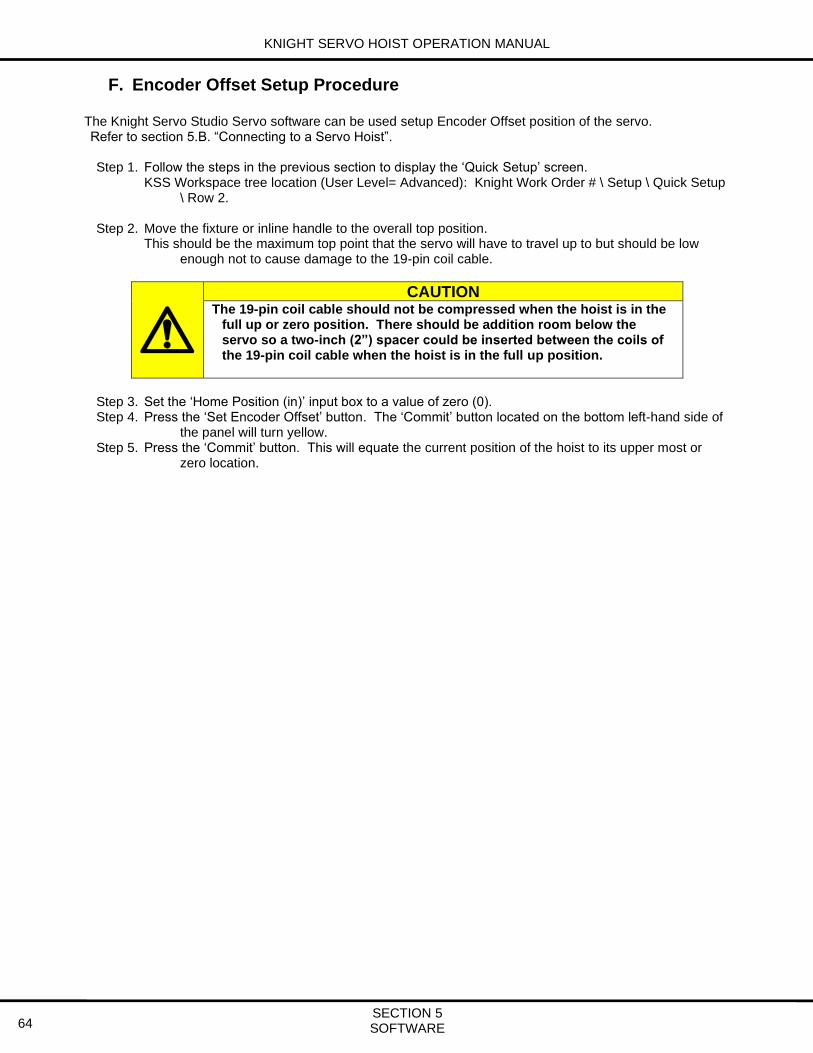
KNIGHT SERVO HOIST OPERATION MANUAL
SECTION 5 SOFTWARE 64
F. Encoder Offset Setup Procedure The Knight Servo Studio Servo software can be used setup Encoder Offset position of the servo. Refer to section 5.B. “Connecting to a Servo Hoist”.
Step 1. Follow the steps in the previous section to display the ‘Quick Setup’ screen.
KSS Workspace tree location (User Level= Advanced): Knight Work Order # \ Setup \ Quick Setup \ Row 2.
Step 2. Move the fixture or inline handle to the overall top position.
This should be the maximum top point that the servo will have to travel up to but should be low enough not to cause damage to the 19-pin coil cable.
CAUTION The 19-pin coil cable should not be compressed when the hoist is in the
full up or zero position. There should be addition room below the servo so a two-inch (2”) spacer could be inserted between the coils of the 19-pin coil cable when the hoist is in the full up position.
Step 3. Set the ‘Home Position (in)’ input box to a value of zero (0). Step 4. Press the ‘Set Encoder Offset’ button. The ‘Commit’ button located on the bottom left-hand side of
the panel will turn yellow. Step 5. Press the ‘Commit’ button. This will equate the current position of the hoist to its upper most or
zero location.

KNIGHT SERVO HOIST OPERATION MANUAL
SECTION 5 SOFTWARE 65
G. Operating Test Mode The ‘Test Mode’ can be initiated from the Knight Servo Software.
Step 1. Mouse to the ‘Workspace’ panel and select the ‘+’ next to the Knight Work Order Number. Step 2. Next, mouse to and select the ‘+’ next to ‘Motion’ and then double-click on ‘Test Mode’. Step 3. This will display a screen labeled ‘Test Mode (Job Number: Motion)’.
Test Mode screen: (Refer to Figure 5-24)
Row #1) Upper and Lower limit setup: The hoist’s movement in the reverse direction will stop at the upper limit and its forward movement will stop at the lower limit. Note: When the ‘Start’ button is pressed, the servo will move to the upper limit and then continue the test cycle.
Row #2) The ‘Velocity (ips)’ value should be set between 3 to 10. The ‘Accel (ips2)’ value should be set between 2 to 10. The ‘Decel (ips2)’ value should be set between 2 to 10.
Row #3) The ‘Delay (ms)’ value should equal the time it takes for the servo to move from the upper limit to the lower limit during the cycle. If using the settings on the screen below, the delay should be set to 6000ms or a six second delay. The ‘Max Moves’ box displays the total number of cycles that the servo will perform in test mode.
Row #4) The ‘Move Count’ box will display the current number of cycles the hoist has performed. Press the ‘Reset Counter’ button if the current number of cycles needs to be reset to zero.
Row #5) Press the ‘Start’ button once to start the test cycle. The button will turn green and the test will start within a few seconds. Press the ‘Start’ button again to stop the test cycle. The button will turn grey and the hoist’s movement will immediately stop.
Figure 5-24

KNIGHT SERVO HOIST OPERATION MANUAL
SECTION 5 SOFTWARE 66
H. Accessing the Servo Hoist’s Fault Log The servo drive’s Fault Log is accessible from its web page.
Step 1. Open your web browser and enter on the hoist’s IP Address in the address bar. This will be 192.168.2.101 in most cases.
Step 2. The web page will be similar to what is shown in Figure 5-24.
Figure 5-24
Step 3. Select the ‘Fault Logs’ button to see a list of all of the faults recorded by the servo.
Each fault will have a ‘Fault ID’, a ‘Description’, the time the fault occurred and the duration the fault lasted. (Refer to Figure 5-25)
Figure 5-25

KNIGHT SERVO HOIST OPERATION MANUAL
SECTION 6 PARAMETER DESCRIPTIONS
67
6. PARAMETER DESCRIPTIONS There are several parameter status arrays described in this section: 6.A.) iSTS Status Array 6.B.) fSTS Status Array 6.C.) F8L1 Parameter Array 6.D.) User Retained Variables Parameter Array 6.E.) F8L2 Parameter Array 6.F.) F8L3 Parameter Array
A. iSTS Status Array This complete array is reserved for internal use.
B. fSTS Status Array This Global Array is used as a status file to review the current state of the Servo Hoist. These parameters are listed in the fSTS array and can be displayed at: KSS Workspace tree location (User Level= Advanced): Knight Work Order # \ Parameters \ fSTS \ Row xx.
Many of these parameters have equivalent displays located on various Knight Servo Studio (KSS) screens. The location of these screens is listed at the end of each parameter’s description. See section 5. ‘Software’ for an explanation of the shorthand used.
fSTS:00 – Run-Stop Variable Units: Boolean (0=Off, 1=On) Description: This parameter displays a ‘1’ if the Run-Stop button is in the run position and the 19-pin coil cable is connected to the Servo Hoist. It will be a ‘0’ if the Run-Stop button is in the opened condition or if the 19-pin coil cable is disconnected.
KSS Workspace tree location (User Level= Advanced): Knight Work Order # \ Status \ System Status Bits fSTS:01 – Lowest Set Fault Number Variable Units: Fault # Description: This parameter displays the current drive fault if one exists. If the number is between 1 and 310 then a drive fault has occurred and will be displayed on the Knight Servo Studio Active Fault screen. A complete list of faults is listed in this manual in section 7 under the heading ‘Error Codes’.
KSS Home screen location: Quick View panel \ Row 1 (Lower right-hand portion of the screen). KSS Workspace tree location (User Level= Advanced): Knight Work Order # \ Status \ Active Faults fSTS:02 and fSTS:03 – Spare fSTS:04 – Current Mode (0=none, 1=Lift, 2=Float, 3=Position, 4=Payout) Variable Units: Choice (0 = No Mode/Sleep, 1=Lift Mode, 2=Float Mode, 3=Test Mode) Description: This parameter displays the current operating mode of the hoist. fSTS:05 – Current Motion Time (s) Variable Units: Seconds Description: This parameter displays the time it took to complete the last cycle. fSTS:06 through fSTS:09 – Spare fSTS:10 – Float Load Cell Raw Voltage Variable Units: Volts Description: This parameter displays the analog voltage from the float load cell.

KNIGHT SERVO HOIST OPERATION MANUAL
SECTION 6 PARAMETER DESCRIPTIONS
68
fSTS:11 – Float Load Cell Filtered Voltage Variable Units: Volts Description: This parameter displays an intermediate calculation of the force exerted on the float load cell. fSTS:12 – Float Load Cell Bias Voltage Variable Units: Volts Description: This parameter displays an intermediate calculation of the force exerted on the float load cell. fSTS:13 – Float Load Cell Raw Weight Reading (lb) Variable Units: Pounds Description: This parameter displays an intermediate calculation of the force exerted on the float load cell. fSTS:14 – Zeroed and Filtered Weight Reading (lb) Variable Units: Pounds Description: This parameter displays an intermediate calculation of the force exerted on the float load cell. fSTS:15 – Total Filtered and Compensated Weight (lb) Variable Units: Pounds Description: This parameter displays an intermediate calculation of the force exerted on the float load cell. fSTS:16 – Floating Weight (lb) Variable Units: Pounds Description: This parameter displays the weight used by the hoist while it is in Float Mode. fSTS:17 – Steady Part Weight (lb) Variable Units: Pounds Description: This parameter displays the weight of the part hanging from the fixture or inline handle. KSS Workspace tree location (User Level= Advanced): Knight Work Order # \ Setup \ Quick Setup \ Row 4. KSS Home screen location: Quick View panel \ Row 6 (Lower right-hand portion of the screen). fSTS:18 – Float Load Cell Weight - Fixture Weight (lb) Variable Units: Pounds Description: This parameter displays an intermediate calculation of the force exerted on the float load cell. fSTS:19 – Float Load Cell Scaled Value (lb) Variable Units: Pounds Description: This parameter displays an intermediate calculation of the force exerted on the float load cell. fSTS:20 – Lift Load Cell Raw Voltage Variable Units: Volts Description: Analog voltage from the lift load cell. fSTS:21 – Lift Load Cell Filtered Voltage Variable Units: Volts Description: This parameter displays an intermediate calculation of the force exerted on the lift load cell. fSTS:22 – Lift Load Cell Bias Voltage Variable Units: Volts Description: This parameter displays an intermediate calculation of the force exerted on the lift load cell. fSTS:23 – Lift Load Cell Raw Weight Reading (lb) Variable Units: Pounds Description: This parameter displays an intermediate calculation of the force exerted on the lift load cell. fSTS:24 – Lift Load Cell Adjusted Weight (lb) Variable Units: Pounds Description: This parameter displays an intermediate calculation of the force exerted on the lift load cell.

KNIGHT SERVO HOIST OPERATION MANUAL
SECTION 6 PARAMETER DESCRIPTIONS
69
fSTS:25 – Lift Load Cell Weight (lb) Variable Units: Pounds Description: This parameter displays an intermediate calculation of the force exerted on the lift load cell. fSTS:26 – Lift Load Cell Weight, Filtered (lb) Variable Units: Pounds Description: This parameter displays an intermediate calculation of the force exerted on the lift load cell. fSTS:27 – Lift Weight - Adjusted, Zeroed, Filtered (lb) Variable Units: Pounds Description: This parameter displays the force applied to the fixture or inline handle. fSTS:28 – Spare fSTS:29 – Motor Encoder Raw Position (in) Variable Units: Inches Description: This parameter displays the encoder information directly from the motor. fSTS:30 – Motor Encoder Real World Position (in) Variable Units: Inches Description: This parameter displays the normalized encoder information. KSS Workspace tree location (User Level= Advanced): Knight Work Order # \ Setup \ Quick Setup \ Row 2. KSS Home screen location: Quick View panel \ Row 5 (Lower right-hand portion of the screen). fSTS:31 – Command Velocity (ips) Variable Units: Inches per second Description: This parameter displays an intermediate calculation of the force exerted on the lift load cell. fSTS:32 – Feedback Velocity (ips) Variable Units: Inches per second Description: This parameter displays an intermediate calculation of the force exerted on the lift load cell. fSTS:33 – 2nd Float Load Cell Raw Voltage Variable Units: Volts Description: This parameter displays information relating to a second float load cell. fSTS:34 – 2nd Float Load Cell Filtered Voltage Variable Units: Volts Description: This parameter displays information relating to a second float load cell. fSTS:35 – 2nd Float Load Cell Bias Voltage Variable Units: Volts Description: This parameter displays information relating to a second float load cell. fSTS:36 – Feedback Acceleration (ips^2) Variable Units: Inches per second2 Description: This parameter displays the feedback acceleration of the hoist. fSTS:37 and fSTS:38 – Spare fSTS:39 – Lift Mode Max Speed (ips) Variable Units: Inches per second Description: This parameter sets the maximum speed of the hoist when in Lift Mode. fSTS:40 – Float Mode Max Speed (ips) Variable Units: Inches per second Description: This parameter sets the maximum speed of the hoist when in Float Mode.

KNIGHT SERVO HOIST OPERATION MANUAL
SECTION 6 PARAMETER DESCRIPTIONS
70
fSTS:41 – Max Motor Speed (ips) Variable Units: Inches per second Description: This parameter sets the maximum speed the hoist can move. fSTS:42 – Max Command Speed (ips) Variable Units: Inches per second Description: This parameter sets the maximum command speed the hoist will accept. fSTS:43 – Command Current Variable Units: Amps Description: This parameter displays the instantaneous command current of the hoist. fSTS:44 and fSTS:45 – Spare fSTS:46 – Total Distance (in) Variable Units: Inches Description: This parameter displays the overall distance the servo has traveled since delivery. fSTS:47 – Lift Mode Distance (in) Variable Units: Inches Description: This parameter displays the total distance the servo has traveled while in Lift Mode. fSTS:48 – Float Mode Distance (in) Variable Units: Inches Description: This parameter displays the total distance the servo has traveled while in Float Mode. fSTS:49 – Position Mode Distance (in) Variable Units: Inches Description: This parameter displays the total distance the servo has traveled while in position mode. fSTS:50 through fSTS:127 are reserved for User Program code located in the Knight SD3 Program Editor’s .PRJ file under the ‘Other Code’ Tab.

KNIGHT SERVO HOIST OPERATION MANUAL
SECTION 6 PARAMETER DESCRIPTIONS
71
C. F8L1 Parameter Array This array stores the parameters that are most frequently adjusted by the end user. This list contains parameters used to fine tune the hoist’s performance. It also contains configuration parameters that must be adjusted after maintenance to the servo, motor or gearbox or after modification of the fixture or lift handle.
These parameters are listed in the F8L1 array and can be displayed at: KSS Workspace tree location (User Level= Advanced): Knight Work Order # \ Parameters \ F8L1 \ Row xx.
Many of these parameters have equivalent displays located on various Knight Servo Studio (KSS) screens. The location of these screens is listed at the end of each parameter’s description. See section 5. ‘Software’ for an explanation of the shorthand used.
F8L1:00 – Initial Settings Variable Units: Various Description: Reserved for internal use only. F8L1:01 – Calibration Weight Variable Units: Pounds Description: Reserved for internal use only. F8L1:02 – Voltage Difference Variable Units: Volts Description: Reserved for internal use only. F8L1:03 and F8L1:04 – Spare F8L1:05 – Reverse/Upper Limit (in) Variable Units: Inches Description: This parameter sets the upper travel limit for the hoist. This value should be set to a number greater than or equal to zero. The home position or absolute physical top limit of the hoist’s movement is set to zero inches.
KSS Workspace tree location (User Level= Advanced): Knight Work Order # \ Setup \ Quick Setup \ Row 3. F8L1:06 – Forward/Lower Limit (in) Variable Units: Inches Description: This parameter sets the lower travel limit for the hoist. This value should be set to the physical lowest limit of the hoist.
NOTE: All measurements increase in value as the fixture moves downward towards the ground. KSS Workspace tree location (User Level= Advanced): Knight Work Order # \ Setup \ Quick Setup \ Row 3. F8L1:07 – Spare F8L1:08 – Handle Weight (lb) Variable Units: Pounds Description: This parameter is not currently used for software calculations. F8L1:09 – Fixture Weight (lb) Variable Units: Pounds Description: This parameter is used to show the static weight of all equipment hanging below the hoist’s Load Monitoring Module (LMM). This equipment includes the hook, shackle and fixture. This parameter must be adjusted if the fixture is modified or replaced.
See section 5.D. ‘Check or Change Setup Values’ to modify this parameter. KSS Workspace tree location (User Level= Advanced): Knight Work Order # \ Setup \ Quick Setup \ Row 4. F8L1:10 – Spare

KNIGHT SERVO HOIST OPERATION MANUAL
SECTION 6 PARAMETER DESCRIPTIONS
72
F8L1:11 – Encoder Offset (in) Variable Units: Inches Description: This parameter sets the offset that the hoist uses to compute its home position. It offsets the absolute encoder’s zero position so the hoist’s zero position becomes the position at the physical upper limit of its travel. A setting of zero indicates a non-absolute incremental motor and is only for compatibility with legacy systems. This parameter must be adjusted when the motor, gearbox or chain are replaced.
See section 5.D. ‘Check or Change Setup Values’ to modify this parameter. KSS Workspace tree location (User Level= Advanced): Knight Work Order # \ Setup \ Quick Setup \ Row 2. F8L1:12 – Decel Rate at Limits (ips^2) Variable Units: Inches per second2 Description: This parameter sets the rate of deceleration when the hoist reaches its top and bottom limits.
These limits are typically F8L1:5 ‘Reverse/Upper Limit (in)’ and F8L1:6 ‘Forward/Lower Limit (in)’. The greater the number the quicker the hoist slows down when it approaches a limit.
F8L1:13 through F8L1:20 – Spare F8L1:21 – Max Weight (lb) Variable Units: Pounds Description: This parameter sets the maximum load that the Servo Hoist will lift. This includes the weight of
the fixture and the part. NOTE: F8L2:21 ‘Max Weight Override (lb)’ also restricts the maximum load that the hoist will lift. F8L1:21 must be set to a value less than or equal to the value of F8L2:21. KSS Workspace tree location (User Level= Advanced): Knight Work Order # \ Setup \ Quick Setup \ Row 6. F8L1:22 – Min Weight (lb) Variable Units: Pounds Description: This parameter limits the load that the Servo Hoist will set down on a surface. In other words, once the weight supported by the hoist measures below this value, the Servo Hoist will not set down any more weight and hence will not pay out any more chain.
KSS Workspace tree location (User Level= Advanced): Knight Work Order # \ Setup \ Quick Setup \ Row 7. F8L1:23 – Lift Mode Timeout (minutes) Variable Units: Minutes Description: This parameter sets the length of time that the hoist will stay in Lift Mode unattended. When idle for longer than this specified time, the hoist will disable itself and revert to No Mode. If this variable is set to zero, the hoist will not switch from Lift Mode to No Mode.
KSS Workspace tree location (User Level= Advanced): Knight Work Order # \ Setup \ Lift Mode \ Row 1. F8L1:24 – Lift Mode Speed Limit (ips) Variable Units: Inches per second Description: This parameter sets the maximum lift velocity for the Servo Hoist while in Lift Mode. KSS Workspace tree location (User Level= Advanced): Knight Work Order # \ Setup \ Lift Mode \ Row 1. F8L1:25 through F8L1:28 – Spare F8L1:29 – Lift Handle Force Sense (Float) (lb) Variable Units: Pounds Description: Before the hoist switches from Float Mode to Lift Mode, this amount of force is required to be registered on a fixture or inline handle. This parameter only applies to systems that do not have a trigger that enables Lift Mode.
KSS Workspace tree location (User Level= Advanced): Knight Work Order # \ Setup \ Lift Mode \ Row 2.

KNIGHT SERVO HOIST OPERATION MANUAL
SECTION 6 PARAMETER DESCRIPTIONS
73
F8L1:30 – Lift Handle Force Sense (not Float) (lb) Variable Units: Pounds Description: Before the hoist switches from No Mode to Lift Mode, this amount of force is required to be registered on a fixture or inline handle. This parameter only applies to systems that do not have a trigger that enables Lift Mode.
KSS Workspace tree location (User Level= Advanced): Knight Work Order # \ Setup \ Lift Mode \ Row 2. F8L1:31 – Lift Handle Force Deadband (lb) Variable Units: Pounds Description: This parameter sets the amount of input force that is required to be registered on a fixture or
inline handle to start motion. KSS Workspace tree location (User Level= Advanced): Knight Work Order # \ Setup \ Lift Mode \ Row 3. F8L1:32 through F8L1:35 – Spare F8L1:36 – Digital Lift Fast Speed (ips) Variable Units: Inches per second Description: This parameter sets the maximum velocity for a hoist with discrete up/down controls. This
parameter is used by the software when a digital lever is fully depressed. Note: Applies to systems with up/down pendants or wireless transmitters only. KSS Workspace tree location (User Level= Advanced): Knight Work Order # \ Setup \ Lift Mode \ Row 4. F8L1:37 – Digital Lift Normal Speed (ips) Variable Units: Inches per second Description: This parameter sets the minimum velocity for a hoist with discrete up/down controls. This
parameter is used by the software when a digital lever is only depressed half way. Note: Applies to systems with up/down pendants or wireless transmitters only. KSS Workspace tree location (User Level= Advanced): Knight Work Order # \ Setup \ Lift Mode \ Row 4. F8L1:38 – Digital Lift Accel (ips^2) Variable Units: Inches per second2 Description: This parameter sets the acceleration for hoists with discrete up/down controls. Note: Applies to systems with up/down pendants or wireless transmitters only. KSS Workspace tree location (User Level= Advanced): Knight Work Order # \ Setup \ Lift Mode \ Row 5. F8L1:39 – Digital Lift Decel (ips^2) Variable Units: Inches per second2 Description: This parameter sets the deceleration for hoists with discrete up/down controls. Note: Applies to systems with up/down pendants or wireless transmitters only. KSS Workspace tree location (User Level= Advanced): Knight Work Order # \ Setup \ Lift Mode \ Row 5. F8L1:40 – Spare F8L1:41 – Float Mode Top Limit (in) Variable Units: Inches Description: This parameter sets the upper travel limit for the hoist when it is in Float Mode. This is used to restrict the Float Mode travel to a position greater than the overall upper limit set in F8L1:5 ‘Reverse/Upper Limit (in)’.
KSS Workspace tree location (User Level= Advanced): Knight Work Order # \ Setup \ Float Mode \ Row 2. F8L1:42 – Float Mode Bottom Limit (in) Variable Units: Inches Description: This parameter sets the lower travel limit for the hoist when it is in Float Mode. This is used to restrict the Float Mode travel to a position less than the overall lower limit set in F8L1:6 ‘Forward/Lower Limit (in)’.
KSS Workspace tree location (User Level= Advanced): Knight Work Order # \ Setup \ Float Mode \ Row 2.

KNIGHT SERVO HOIST OPERATION MANUAL
SECTION 6 PARAMETER DESCRIPTIONS
74
F8L1:43 – Float Mode Timeout (minutes) Variable Units: Minutes Description: This parameter sets the length of time that the hoist will stay in Float Mode unattended. When idle for longer than this specified time the hoist will disable and revert to No Mode. If this variable is set to zero, the hoist will not switch from Float Mode to No Mode.
KSS Workspace tree location (User Level= Advanced): Knight Work Order # \ Setup \ Float Mode \ Row 1. F8L1:44 – Float Mode Speed Limit (ips) Variable Units: Inches per second Description: This parameter sets the maximum velocity of the Servo Hoist when it is in Float Mode. KSS Workspace tree location (User Level= Advanced): Knight Work Order # \ Setup \ Float Mode \ Row 1. F8L1:45 – Float Force Deadband (lb) Variable Units: Pounds Description: This parameter sets the minimum amount of force that is required to be exerted on the fixture or part hanging from the bottom of the Load Monitoring Module to start motion while the hoist is in Float Mode.
KSS Workspace tree location (User Level= Advanced): Knight Work Order # \ Setup \ Float Mode \ Row 3. F8L1:46 through F8L1:77 – Spare F8L1:78 – Slow Zone Mode (0 = off, 1 = down, 2 = up, 3 = both) Variable Units: Choice (0=off, 1=down, 2=up, 3=up and down) Description: This parameter configures the hoist’s automatic slow zone. This parameter works with the variables F8L1:79 to F8L1:84 to configure the automatic slow zone.
0 = Slow Zone feature is disabled. 1 = Program will automatically decrease the speed of the hoist only when moving down. 2 = Program will automatically decrease the speed of the hoist only when moving up. 3 = Program will automatically decrease the speed of the hoist when moving up or down.
KSS Workspace tree location (User Level= Advanced): Knight Work Order # \ Setup \ Slow Zone \ Row 1. NOTE: If using this function, all parameters (F8L1:79 to F8L1:84) must be non-zero for the Slow Zone to function correctly.
F8L1:79 – Slow Zone Part Loaded Weight (lb) Variable Units: Pounds Description: This parameter sets the number of pounds that the hoist needs to register in order to indicate that a part is loaded on the fixture. This parameter is only processed if the Slow Zone is turned on. i.e. F8L1:78 ‘Slow Zone Mode’ is not zero.
KSS Workspace tree location (User Level= Advanced): Knight Work Order # \ Setup \ Slow Zone \ Row 2. F8L1:80 – Slow Zone Part Loaded Position (in) Variable Units: Inches Description: This parameter sets the height that the hoist will start to run at a reduced speed when a part is loaded. This parameter is only processed if the Slow Zone is turned on. i.e. F8L1:78 ‘Slow Zone Mode’ is not zero.
NOTE: The current position of the hoist is visible in fSTS: 30 “Real World Position” or on the KSS Home screen location: Quick View panel \ Row 5 (Lower right-hand portion of the screen). KSS Workspace tree location (User Level= Advanced): Knight Work Order # \ Setup \ Slow Zone \ Row 2. F8L1:81 – Slow Zone Part Loaded Speed (ips) Variable Units: Inches per second Description: This parameter sets the reduced speed that the hoist runs at when a part is loaded and it is below the F8L1:80 ‘Slow Zone Part Loaded Position’ parameter. This parameter is only processed if the Slow Zone is turned on. i.e. F8L1:78 ‘Slow Zone Mode’ is not zero.
KSS Workspace tree location (User Level= Advanced): Knight Work Order # \ Setup \ Slow Zone \ Row 2.

KNIGHT SERVO HOIST OPERATION MANUAL
SECTION 6 PARAMETER DESCRIPTIONS
75
F8L1:82 – Slow Zone Part Unloaded Position (in) Variable Units: Inches Description: This parameter sets the height that the hoist will start to run at a reduced speed when a part is not loaded. This is only valid if the Slow Zone is turned on. i.e. F8L1:78 ‘Slow Zone Mode’ is not zero.
KSS Workspace tree location (User Level= Advanced): Knight Work Order # \ Setup \ Slow Zone \ Row 3. F8L1:83 – Slow Zone Part Unloaded Speed (ips) Variable Units: Inches per second Description: This parameter sets the reduced speed that the hoist runs at when a part is not loaded and it is below the F8L1:82 ‘Slow Zone Part Unloaded Position’ parameter. This parameter is only processed if the Slow Zone is turned on. i.e. F8L1:78 ‘Slow Zone Mode’ is not zero.
KSS Workspace tree location (User Level= Advanced): Knight Work Order # \ Setup \ Slow Zone \ Row 3. F8L1:84 – Slow Zone Max Decel (ips^2) Variable Units: Inches per second2 Description: This parameter sets the deceleration constant when the hoist approaches the slow zone and transitions from the normal speed to the reduced speed. This parameter is only processed if the Slow Zone is turned on. i.e. F8L1:78 ‘Slow Zone Mode’ is not zero.
KSS Workspace tree location (User Level= Advanced): Knight Work Order # \ Setup \ Slow Zone \ Row 4. F8L1:85 – Slow Zone Invert Variable Units: Boolean (0=Off, 1=On) Description: The slow zone usually is only initiated when the hoist is Below the slow zone heights. This parameter changes the functionality of the slow zone so that it initiates when the hoist is Above the stated heights.
KSS Workspace tree location (User Level= Advanced): Knight Work Order # \ Setup \ Slow Zone \ Row 1. F8L1:86 through F8L1:255 – Spare

KNIGHT SERVO HOIST OPERATION MANUAL
SECTION 6 PARAMETER DESCRIPTIONS
76
D. User Retained Variables Parameter Array This array displays all of the user retained variables for the hoist. These parameters are listed in the User Retained Variables array and can be displayed at: KSS Workspace tree location (User Level= Advanced): Knight Work Order # \ User Program \ UserRetainVars \ Row xx
UserRetainVars:00 – Test Mode Upper Position Variable Units: Inches Description: This parameter sets the upper travel limit for the hoist while it is in Test Mode. This value should be set to a number greater than or equal to zero and should not be less than F8L1:05 ‘Reverse/Upper Limit (in)’.
KSS Workspace tree location (User Level= Advanced): Knight Work Order # \ Motion \ Test Mode \ Row 1 UserRetainVars:01 – Test Mode Lower Position Variable Units: Inches Description: This parameter sets the lower travel limit for the hoist while it is in Test Mode. This value should be set to a number greater than the UserRetainVars:00 ‘Test Mode Upper Position’ parameter.
KSS Workspace tree location (User Level= Advanced): Knight Work Order # \ Motion \ Test Mode \ Row 1 UserRetainVars:02 – Test Mode Target Velocity Variable Units: Inches per second Description: This parameter sets the speed of the hoist while it is in Test Mode. KSS Workspace tree location (User Level= Advanced): Knight Work Order # \ Motion \ Test Mode \ Row 2 UserRetainVars:03 – Test Mode Target Acceleration Variable Units: Inches per second2 Description: This parameter sets the acceleration of the hoist while it is in Test Mode. KSS Workspace tree location (User Level= Advanced): Knight Work Order # \ Motion \ Test Mode \ Row 2 UserRetainVars:04 – Test Mode Target Deceleration Variable Units: Inches per second2 Description: This parameter sets the deceleration of the hoist while it is in Test Mode. KSS Workspace tree location (User Level= Advanced): Knight Work Order # \ Motion \ Test Mode \ Row 2 UserRetainVars:05 – Test Mode Delay Between Moves Variable Units: Milliseconds Description: This parameter sets the time delay between upward and downward cycles of the hoist while it is in Test Mode. The hoist will move up, delay at its upper position, move down and then delay at its lower position.
KSS Workspace tree location (User Level= Advanced): Knight Work Order # \ Motion \ Test Mode \ Row 3 UserRetainVars:06 – Test Mode Target Move Count Variable Units: Count Description: This parameter sets number of movements the hoist will perform while it is in Test Mode. This count will be increased for every move up and move down the hoist completes. i.e. A complete up and down cycle of the hoist will count as TWO movements.
KSS Workspace tree location (User Level= Advanced): Knight Work Order # \ Motion \ Test Mode \ Row 3 UserRetainVars:07 – Test Mode Start Test Cycle Variable Units: Boolean (0=Off, 1=On) Description: This parameter starts the Test Mode if it is a One and stops Test Mode if it is a Zero. KSS Workspace tree location (User Level= Advanced): Knight Work Order # \ Motion \ Test Mode \ Row 5

KNIGHT SERVO HOIST OPERATION MANUAL
SECTION 6 PARAMETER DESCRIPTIONS
77
UserRetainVars:08 – Test Mode Current Movement Count Variable Units: Count Description: This parameter sets displays the current movement count of the hoist while it is in Test Mode. KSS Workspace tree location (User Level= Advanced): Knight Work Order # \ Motion \ Test Mode \ Row 4 UserRetainVars:09 through UserRetainVars:11 – Spare UserRetainVars:12 – Part Loaded Weight (lb) Variable Units: Pounds Description: This is a weight in pounds that triggers the part loaded bit On. If the current weight hanging from the fixture is greater than this parameter, then the part loaded bit is On. If the current weight hanging from the fixture is less than this parameter, then the part loaded bit is Off.
UserRetainVars:13 – Clear to Rotate Position (in) Variable Units: Inches Description: This parameter sets a height that the hoist must be above to allow the Rotate function to execute.
UserRetainVars:14 – Fixture Down Force (lb) Variable Units: Pounds Description: This parameter controls the amount of weight that the hoist has to set down before permitting the clamp open motion to execute. This Ensures that the operator places at least a portion of the part’s weight down on a surface before allowing the part clamp to open.
UserRetainVars:15 – Tilt Window Upper Position, Loaded (in) Variable Units: Inches Description: This parameter sets the upper limit of the window that allows the Tilt function to execute while the hoist is loaded. i.e. The Part Weight (fSTS:17 ‘Steady Part Weight’) is greater than the value in UserRetainVar:12 ‘Part Loaded Weight (lb)’.
UserRetainVars:16 – Tilt Window Lower Position, Loaded (in) Variable Units: Inches Description: This parameter sets the lower limit of the window that allows the Tilt function to execute while the hoist is loaded. i.e. The Part Weight (fSTS:17 ‘Steady Part Weight’) is greater than the value in UserRetainVar:12 ‘Part Loaded Weight (lb)’.
UserRetainVars:17 – Tilt Window Upper Position, Unloaded (in) Variable Units: Inches Description: This parameter sets the upper limit of the window that allows the Tilt function to execute while the hoist is unloaded. i.e. The Part Weight (fSTS:17 ‘Steady Part Weight’) is less than the value in UserRetainVar:12 ‘Part Loaded Weight (lb)’.
UserRetainVars:18 – Tilt Window Lower Position, Unloaded (in) Variable Units: Inches Description: This parameter sets the lower limit of the window that allows the Tilt function to execute while the hoist is unloaded. i.e. The Part Weight (fSTS:17 ‘Steady Part Weight’) is less than the value in UserRetainVar:12 ‘Part Loaded Weight (lb)’.
UserRetainVars:19 and UserRetainVars:20 – Spare UserRetainVars:21 – Fixture Disconnected Maximum Lift Weight (lb) Variable Units: Pounds Description: This parameter sets the maximum weight that the hoist is allowed to lift when the fixture is not connected to the Load Monitoring Module (LMM).

KNIGHT SERVO HOIST OPERATION MANUAL
SECTION 6 PARAMETER DESCRIPTIONS
78
UserRetainVars:22 – Parameter Set 1 Target Velocity (ips) Variable Units: Inches per second Description: This Parameter Set 1 variable must be enabled. If enabled, it sets the velocity during an automatic move function.
UserRetainVars:23 – Parameter Set 1 Target Acceleration (ips^2) Variable Units: Inches per second2 Description: This Parameter Set 1 variable must be enabled. If enabled, it sets the acceleration during an automatic move function.
UserRetainVars:24 – Parameter Set 1 Target Deceleration (ips^2) Variable Units: Inches per second2 Description: This Parameter Set 1 variable must be enabled. If enabled, it sets the deceleration during an automatic move function.
UserRetainVars:25 – Parameter Set 1 Target Position (in) Variable Units: Inches Description: This Parameter Set 1 variable must be enabled. If enabled, it sets the destination for an automatic move function.
UserRetainVars:26 – Parameter Set 1 Float Weight (lb) Variable Units: Pounds Description: This Parameter Set 1 variable must be enabled. If enabled, it sets the weight used by Float Mode instead of using the normal instantaneous weight obtained when Float Mode is initiated.
UserRetainVars:27 – Parameter Set 1 Forward/Lower Limit (in) Variable Units: Inches Description: This Parameter Set 1 variable must be enabled. If enabled, it sets the lower travel limit for the hoist.
UserRetainVars:28 – Parameter Set 1 Reverse/Upper Limit (in) Variable Units: Inches Description: This Parameter Set 1 variable must be enabled. If enabled, it sets the upper travel limit for the hoist.
UserRetainVars:29 – Parameter Set 1 Minimum Part Weight (lb) Variable Units: Pounds Description: This Parameter Set 1 variable must be enabled. If enabled, it limits the load that the Servo Hoist will set down on a surface.
UserRetainVars:30 – Parameter Set 1 Maximum Total Weight (lb) Variable Units: Pounds Description: This Parameter Set 1 variable must be enabled. If enabled, it sets the maximum load that the Servo Hoist will lift.
UserRetainVars:31 – Parameter Set 1 Maximum Torque (Nm) Variable Units: Newton meters Description: This Parameter Set 1 variable must be enabled. If enabled, it sets the maximum motor feedback torque allowed.
UserRetainVars:32 – Parameter Set 1 Maximum Motor Current (A) Variable Units: Amps Description: This Parameter Set 1 variable must be enabled. If enabled, it sets the maximum current sent to the motor.

KNIGHT SERVO HOIST OPERATION MANUAL
SECTION 6 PARAMETER DESCRIPTIONS
79
UserRetainVars:33 – Parameter Set 1 Maximum Velocity (ips) Variable Units: Inches per second Description: This Parameter Set 1 variable must be enabled. If enabled, it sets the maximum speed that the Servo Hoist may travel.
UserRetainVars:34 – Parameter Set 1 Fixture Weight (lb) Variable Units: Pounds Description: This Parameter Set 1 variable must be enabled. If enabled, it shows the static weight of all equipment hanging below the hoist’s Load Monitoring Module (LMM).
UserRetainVars:35 – Parameter Set 1 Invert Slow Zone Variable Units: Boolean (0=Off, 1=On) Description: The Parameter Set 1slow zone usually is only initiated when the hoist is Below the Parameter Set 1slow zone heights. This parameter changes the functionality of the Parameter Set 1slow zone so that it initiates when the hoist is Above the stated Parameter Set 1 heights.
This parameter is only processed if the Parameter Set 1 Slow Zone is turned on: i.e. UserRetainVar:36 ‘Parameter Set 1 Slow Zone Mode’ is not zero.
UserRetainVars:36 – Parameter Set 1 Slow Zone Mode Variable Units: Choice (0=off, 1=down, 2=up, 3=up and down) Description: This Parameter Set 1 variable must be enabled. If enabled, the hoist’s automatic slow zone will be active.
This parameter works with the User Retained Variables 37 - 42 to configure the Parameter Set 1 slow zone. 0 = Parameter Set 1 Slow Zone feature is disabled. 1 = Program will automatically decrease the speed of the hoist only when moving down. 2 = Program will automatically decrease the speed of the hoist only when moving up. 3 = Program will automatically decrease the speed of the hoist when moving up or down.
NOTE: If using this function, all parameters (37 to 42) must be non-zero for the Slow Zone to function correctly.
UserRetainVars:37 – Parameter Set 1 Slow Zone Part Loaded Sense Weight (lb) Variable Units: Pounds Description: This parameter sets the number of pounds that the hoist needs to register in order to indicate that a part is loaded on the fixture.
This parameter is only processed if the Parameter Set 1 Slow Zone is turned on: i.e. UserRetainVar:36 ‘Parameter Set 1 Slow Zone Mode’ is not zero.
UserRetainVars:38 – Parameter Set 1 Slow Zone Part Loaded Max Speed (ips) Variable Units: Inches per second Description: This parameter sets the reduced speed that the hoist moves at when a part is loaded and it is below the UserRetainVar:39 ‘Parameter Set 1 Slow Zone Part Loaded Position (in)’ parameter.
This parameter is only processed if the Parameter Set 1 Slow Zone is turned on: i.e. UserRetainVar:36 ‘Parameter Set 1 Slow Zone Mode’ is not zero.
UserRetainVars:39 – Parameter Set 1 Slow Zone Part Loaded Position (in) Variable Units: Inches Description: This parameter sets the height that the hoist will start to move at a reduced speed when a part is loaded.
This parameter is only processed if the Parameter Set 1 Slow Zone is turned on: i.e. UserRetainVar:36 ‘Parameter Set 1 Slow Zone Mode’ is not zero.
NOTE: The current position of the hoist is visible in fSTS: 30 “Real World Position” or on the KSS Home screen location: Quick View panel \ Row 5 (Lower right-hand portion of the screen).
KNIGHT SERVO HOIST OPERATION MANUAL
SECTION 6 PARAMETER DESCRIPTIONS
80
UserRetainVars:40 – Parameter Set 1 Slow Zone Part Unloaded Max Speed (ips) Variable Units: Inches per second Description: This parameter sets the reduced speed that the hoist moves at when a part is unloaded and it is below the UserRetainVar:41 ‘Parameter Set 1 Slow Zone Part Unloaded Position (in)’ parameter.
This parameter is only processed if the Parameter Set 1 Slow Zone is turned on: i.e. UserRetainVar:36 ‘Parameter Set 1 Slow Zone Mode’ is not zero.
UserRetainVars:41 – Parameter Set 1 Slow Zone Part Unloaded Position (in) Variable Units: Inches Description: This parameter sets the height that the hoist will start to move at a reduced speed when a part is unloaded.
This parameter is only processed if the Parameter Set 1 Slow Zone is turned on: i.e. UserRetainVar:36 ‘Parameter Set 1 Slow Zone Mode’ is not zero.
UserRetainVars:42 – Parameter Set 1 Slow Zone Entry Decel Rate Variable Units: Inches per second2 Description: This parameter sets the deceleration rate of the hoist as it transitions from its normal speed to its slow zone speed.
This parameter is only processed if the Parameter Set 1 Slow Zone is turned on: i.e. UserRetainVar:36 ‘Parameter Set 1 Slow Zone Mode’ is not zero.

KNIGHT SERVO HOIST OPERATION MANUAL
SECTION 6 PARAMETER DESCRIPTIONS
81
UserRetainVars:43 through UserRetainVars:63 – Parameter Set 2 Variable Units: See above Description: These parameters are described in the Parameter Set 1 section: UserRetainVars:22 to 42. UserRetainVars:64 through UserRetainVars:84 – Parameter Set 3 Variable Units: See above Description: These parameters are described in the Parameter Set 1 section: UserRetainVars:22 to 42. UserRetainVars:85 through UserRetainVars:105 – Parameter Set 4 Variable Units: See above Description: These parameters are described in the Parameter Set 1 section: UserRetainVars:22 to 42. UserRetainVars:106 through UserRetainVars:126 – Parameter Set 5 Variable Units: See above Description: These parameters are described in the Parameter Set 1 section: UserRetainVars:22 to 42. UserRetainVars:127 through UserRetainVars:147 – Parameter Set 6 Variable Units: See above Description: These parameters are described in the Parameter Set 1 section: UserRetainVars:22 to 42. UserRetainVars:148 through UserRetainVars:168 – Parameter Set 7 Variable Units: See above Description: These parameters are described in the Parameter Set 1 section: UserRetainVars:22 to 42. UserRetainVars:169 through UserRetainVars:189 – Parameter Set 8 Variable Units: See above Description: These parameters are described in the Parameter Set 1 section: UserRetainVars:22 to 42. UserRetainVars:190 through UserRetainVars:210 – Parameter Set 9 Variable Units: See above Description: These parameters are described in the Parameter Set 1 section: UserRetainVars:22 to 42. UserRetainVars:211 through UserRetainVars:231 – Parameter Set 10 Variable Units: See above Description: These parameters are described in the Parameter Set 1 section: UserRetainVars:22 to 42. UserRetainVars:232 through UserRetainVars:252 – Parameter Set 11 Variable Units: See above Description: These parameters are described in the Parameter Set 1 section: UserRetainVars:22 to 42. UserRetainVars:253 through UserRetainVars:273 – Parameter Set 12 Variable Units: See above Description: These parameters are described in the Parameter Set 1 section: UserRetainVars:22 to 42. UserRetainVars:274 through UserRetainVars:294 – Parameter Set 13 Variable Units: See above Description: These parameters are described in the Parameter Set 1 section: UserRetainVars:22 to 42. UserRetainVars:295 through UserRetainVars:315 – Parameter Set 14 Variable Units: See above Description: These parameters are described in the Parameter Set 1 section: UserRetainVars:22 to 42. UserRetainVars:316 through UserRetainVars:336 – Parameter Set 15 Variable Units: See above Description: These parameters are described in the Parameter Set 1 section: UserRetainVars:22 to 42.

KNIGHT SERVO HOIST OPERATION MANUAL
SECTION 6 PARAMETER DESCRIPTIONS
82
E. F8L2 Parameter Array This array stores advanced parameters that affect the performance of the hoist. These parameters should only be adjusted with the aid of a Knight Representative.
These parameters are listed in the F8L2 array and can be displayed at: KSS Workspace tree location (User Level= Advanced): Knight Work Order # \ Parameters \ F8L2 \ Row xx.
Many of these parameters have equivalent displays located on various Knight Servo Studio (KSS) screens. The location of these screens is listed at the end of each parameter’s description. See section 5. ‘Software’ for an explanation of the shorthand used.
WARNING ALL variables in the F8L2 parameter list should NOT be manipulated without the aid of a Knight representative.
F8L2:00 – Spare F8L2:01 – Inline Handle Trigger Bias (V) Variable Units: Volts Description: Reserved for internal use only. F8L2:02 – Spare F8L2:03 – Reverse Encoder Direction Variable Units: Boolean (0=Off, 1=On) Description: This parameter sets the forward direction of the encoder. This is a physical property and should
not be modified. KSS Workspace tree location (User Level= Advanced): Knight WO# \ Setup \ Motor and Gearbox \ Row 1½. F8L2:04 – Spare F8L2:05 – Gear Ratio Variable Units: Integer Description: This parameter states the gear ratio of the gear reducer. This is a physical property and should
not be modified. KSS Workspace tree location (User Level= Advanced): Knight WO# \ Setup \ Motor and Gearbox \ Row 4. F8L2:06 – Max Motor Speed (RPM) Variable Units: RPM Description: This parameter states the maximum revolutions per minute of the servo motor. This is a
physical property and should not be modified. KSS Workspace tree location (User Level= Advanced): Knight WO# \ Setup \ Motor and Gearbox \ Row 1. F8L2:07 – Lift Load Cell Gain (lb/V) Variable Units: Pounds per Volt Description: This parameter states the gain of the lift load cell. This is a physical property and should not be
modified. KSS Workspace tree location (User Level= Advanced): Knight WO# \ Tuning \ Analog Calibration \ Row 3.

KNIGHT SERVO HOIST OPERATION MANUAL
SECTION 6 PARAMETER DESCRIPTIONS
83
F8L2:08 – Float Load Cell Gain (lb/V) Variable Units: Pounds per Volt Description: This parameter states the gain of the float load cell. This is a physical property and should not
be modified. KSS Workspace tree location (User Level= Advanced): Knight WO# \ Tuning \ Analog Calibration \ Row 2. F8L2:09 – Lift Load Cell Bias (V) Variable Units: Volts Description: This parameter states the value of the lift load cell’s analog input when there is no external force exerted on the handle. This is a physical property and should not be modified unless the fixture or inline handle is replaced.
KSS Workspace tree location (User Level= Advanced): Knight WO# \ Tuning \ Analog Calibration \ Row 3. F8L2:10 – Float Load Cell Bias (V) Variable Units: Volts Description: This parameter states the value of the float load cell’s analog input when there is no external weight hanging from the Load Monitoring Module (LMM). This is a physical property and should not be modified unless the LMM is replaced.
KSS Workspace tree location (User Level= Advanced): Knight WO# \ Tuning \ Analog Calibration \ Row 2. F8L2:11 – Reverse Motor Direction Variable Units: Boolean (0=Off, 1=On) Description: This parameter sets the direction of the servo motor. This is a physical property of the servo motor and should not be modified.
KSS Workspace tree location (User Level= Advanced): Knight WO# \ Setup \ Motor and Gearbox \ Row 1. F8L2:12 – Spare F8L2:13 – Max Velocity Following Error (ips) Variable Units: Inches per second Description: This parameter sets the maximum acceptable amount of following error allowable by the hoist. This is used by the controller for detecting a velocity following error which generates a fault number of 104.
F8L2:14 – Chain Pitch (mm) Variable Units: Millimeters Description: This parameter states the pitch or length of each chain link. This is a physical property and
should not be modified. KSS Workspace tree location (User Level= Advanced): Knight WO# \ Setup \ Motor and Gearbox \ Row 2. F8L2:15 – Chain Links per Revolution Variable Units: Number of Chain Links Per Rev Description: This parameter states the size of the drive sprocket. This is a physical property and should not
be modified. KSS Workspace tree location (User Level= Advanced): Knight WO# \ Setup \ Motor and Gearbox \ Row 3. F8L2:16 – Fault Decel Rate (ips^2) Variable Units: Inches per second2 Description: This parameter sets the deceleration rate of the hoist when a fault occurs. The minimum setting for this is 50in/s2.
F8L2:17 – Lift Mode Allow Down Full Speed Variable Units: Boolean (0=Off, 1=On) Description: Setting this parameter to a 1 (or On) allows the hoist to travel at its maximum speed when lowering its load in Lift Mode. This speed is dynamically limited by the load weight when moving upwards in Lift Mode. Setting this to a 0 (or Off) dynamically limits the speed when lifting and lowering in Lift Mode.
KSS Workspace tree location (User Level= Advanced): Knight WO# \ Setup \ Lift Mode \ Row 4.

KNIGHT SERVO HOIST OPERATION MANUAL
SECTION 6 PARAMETER DESCRIPTIONS
84
F8L2:18 – Hard Stop Home Position (in) Variable Units: Inches Description: This parameter displays the “real world” position after accepting a value by pressing the
‘Set Encoder Offset’ button on the ‘Quick Setup’ screen. KSS Workspace tree location (User Level= Advanced): Knight WO# \ Setup \ Quick Setup \ Row 2. F8L2:19 – Spare F8L2:20 – Lift Mode Enable Variable Units: Boolean (0=Off, 1=On) Description: This parameter is used to enable or disable Lift Mode. KSS Workspace tree location (User Level= Advanced): Knight WO# \ Setup \ Lift Mode \ Row 1. F8L2:21 – Max Weight Override (lb) Variable Units: Pounds Description: This sets the maximum load that the Servo Hoist will lift. This includes the weight of the fixture
and the part. NOTE: Parameter F8L1:21 ‘Max Weight (lb.)’ also restricts the maximum load. F8L1:21 must be set to a value less than or equal to the value of F8L2:21. F8L2:22 – Up Stop Resume Bandwidth (lb) Variable Units: Pounds Description: Reserved for internal use only. F8L2:23 – Down Stop Resume Bandwidth (lb) Variable Units: Pounds Description: Reserved for internal use only. F8L2:24 – Up/Down Stop Resume Time (ms) Variable Units: Milliseconds Description: Reserved for internal use only. F8L2:25 – Lift Mode Max Speed Scale Factor Variable Units: Factor Description: This factor is multiplied by F8L1:24 ‘Lift Mode Speed Limit (ips)’ to obtain the maximum lift speed of the hoist. This value is normally a one. Any value above one will increase the hoist’s maximum speed and any value below one will reduce the hoist’s maximum speed.
F8L2:26 – Spare F8L2:27 – Impulse Limiting Enable Variable Units: Boolean (0=Off, 1=On) Description: This parameter is used to enable the hoist’s impulse limiting code. When this code is enabled, the hoist will sense an instantaneous increase in weight registered by the float load cell and slow the hoist to reduce the impact on the system. Instead of suddenly moving the load upwards, the hoist senses the impulse and automatically slows down to a controlled speed.
KSS Workspace tree location (User Level= Advanced): Knight WO# \ Tuning \ Impulse Limiting \ Row 1. F8L2:28 – Impulse Limiting Max Speed (ips) Variable Units: Inches per second Description: This parameter sets the speed that the hoist will slow to when impulse limiting is enabled and a sudden movement is detected.
KSS Workspace tree location (User Level= Advanced): Knight WO# \ Tuning \ Impulse Limiting \ Row 2.

KNIGHT SERVO HOIST OPERATION MANUAL
SECTION 6 PARAMETER DESCRIPTIONS
85
F8L2:29 – Impulse Limiting Max Speed Time (ms) Variable Units: Seconds Description: This parameter sets the duration that the slow speed will be active when impulse limiting is enabled and a sudden movement is detected.
KSS Workspace tree location (User Level= Advanced): Knight WO# \ Tuning \ Impulse Limiting \ Row 2. F8L2:30 – Lift Analog Handle Enable Variable Units: Boolean (0=Off, 1=On) Description: This parameter is used to enable an analog handle. This parameter is enabled for systems that have an inline or fixture handle.
KSS Workspace tree location (User Level= Advanced): Knight WO# \ Setup \ Lift Mode \ Row 2. F8L2:31 – Lift Filter Bandwidth Variable Units: Frequency Description: This parameter controls how quickly the hoist responds to force changes on the lift load cell. The larger the number the faster the hoist reacts to changes in force applied to the analog handle.
F8L2:32 – Lift Analog Decel on Trigger Release (ips^2) Variable Units: Inches per second2
Description: Reserved for internal use only. F8L2:33 – Lift Proportional Accel (ips^2) Variable Units: Inches per second2 Description: Reserved for internal use only. F8L2:34 – Lift Proportional Decel (ips^2) Variable Units: Inches per second2 Description: Reserved for internal use only. F8L2:35 – Lift Command Force Limit (lb) Variable Units: Pounds Description: This parameter sets the maximum lift command that can be given to the hoist via an analog handle without generating a fault. For example, if this parameter is set to 100lbs and a force of more than 100lbs is applied to the handle while the hoist is in Lift Mode then the software will generate a fault.
F8L2:36 – Lift Cancel Gain Variable Units: Real Number Description: This parameter controls how much of the force registered on the lift load cell is subtracted from
the force seen on the float load cell when using a fixture handle. F8L2:37 – Spare F8L2:38 – Lift Digital PB Enable Variable Units: Boolean (0=Off, 1=On) Description: This parameter is used to enable a digital handle. This parameter is enabled for systems that have a single-speed or two-speed pushbutton control handle or a wireless transmitter pendant.
KSS Workspace tree location (User Level= Advanced): Knight WO# \ Setup \ Lift Mode \ Row 3. F8L2:39 – Spare F8L2:40 – Float Mode Enable Variable Units: Boolean (0=Off, 1=On) Description: This parameter is used to enable or disable Float Mode. KSS Workspace tree location (User Level= Advanced): Knight WO# \ Setup \ Float Mode \ Row 1. F8L2:41 through F8L2:44 – Spare

KNIGHT SERVO HOIST OPERATION MANUAL
SECTION 6 PARAMETER DESCRIPTIONS
86
F8L2:45 – Float Mode Max Speed Scale Factor Variable Units: Factor Description: This factor is multiplied by F8L1:44 ‘Float Mode Speed Limit (ips)’ to obtain the maximum speed of the hoist while it is in Float Mode. This value is normally a one. Any value above one will increase the hoist’s maximum speed and any value below one will reduce the hoist’s maximum speed.
F8L2:46 through F8L2:50 – Spare F8L2:51 – "In Position" Velocity Window Variable Units: Inches Description: Reserved for internal use only. F8L2:52 – Spare F8L2:53 – Float Proportional Accel (ips^2) Variable Units: Inches per second2 Description: Reserved for internal use only. F8L2:54 – Float Proportional Decel (ips^2) Variable Units: Inches per second2 Description: Reserved for internal use only. F8L2:55 – Float Command Force Limit (lb) Variable Units: Pounds Description: This parameter sets the maximum float command that can be given to the hoist without
generating a fault. For example, if this parameter is set to 100lbs and a force of more than 100lbs is applied to the fixture or part while the hoist is in Float Mode then the software will generate a fault.
F8L2:56 through F8L2:59 – Spare F8L2:60 – Float Proportional Gain Variable Units: Real Number Description: This parameter sets the target velocity per unit of force exerted on the float load cell while the hoist is in Float Mode.
KSS Workspace tree location (User Level= Advanced): Knight WO# \ Setup \ Float Mode \ Row 4. F8L2:61 – Float Filter Scale Factor Variable Units: Real Number Description: This parameter sets how quickly the force applied to the load suspended from the Load Monitoring Module changes the float command velocity.
KSS Workspace tree location (User Level= Advanced): Knight WO# \ Setup \ Float Mode \ Row 4. F8L2:62 – Spare F8L2:63 – Float Force Filter Trim Scale Factor Variable Units: Real Number Description: This parameter allows the hoist to respond quicker to a float motion input command. The higher
the value, the easier it is to begin movement of the hoist while it is in Float Mode. KSS Workspace tree location (User Level= Advanced): Knight WO# \ Setup \ Float Mode \ Row 5. F8L2:64 – Max Speed for Jerk Limiting (ips) Variable Units: Inches per second Description: This parameter controls the maximum velocity the hoist can be travelling at and still reset the "Hit Ground" bit while it is in Float Mode.

KNIGHT SERVO HOIST OPERATION MANUAL
SECTION 6 PARAMETER DESCRIPTIONS
87
F8L2:65 – Disable Gear Unlock Code Variable Units: Real Number Description: When this parameter is enabled, it limits the initial maximum velocity of Float Mode. When the hoist slows below the speed listed in F8L3[68] ‘Gear Unlock Feedback Velocity (ips)’, then the software will prevent any increase in speed over F8L3[67] ‘Gear Unlock Command Velocity (ips)’ for the amount of time in F8L3[69] ‘Gear Unlock Time (ms)’. After this delay, the hoist is allowed to ramp up towards its commanded velocity.
F8L2:66 – Spare F8L2:67 – Enable Accelerometer Variable Units: Reserved for internal use only. Description: Reserved for internal use only. F8L2:68 – Accelerometer Gain (G/V) Variable Units: Reserved for internal use only. Description: Reserved for internal use only. F8L2:69 and F8L2:70 – Spare F8L2:71 – Enable Stress Relief Logic Variable Units: Reserved for internal use only. Description: Reserved for internal use only. F8L2:72 – Spare F8L2:73 – Polynomial Weight Correction Factor 6 Variable Units: Reserved for internal use only. Description: Reserved for internal use only. F8L2:74 – Polynomial Weight Correction Factor 5 Variable Units: Reserved for internal use only. Description: Reserved for internal use only. F8L2:75 – Polynomial Weight Correction Factor 4 Variable Units: Reserved for internal use only. Description: Reserved for internal use only. F8L2:76 – Polynomial Weight Correction Factor 3 Variable Units: Reserved for internal use only. Description: Reserved for internal use only. F8L2:77 – Polynomial Weight Correction Factor 2 Variable Units: Reserved for internal use only. Description: Reserved for internal use only. F8L2:78 – Polynomial Weight Correction Factor 1 Variable Units: Reserved for internal use only. Description: Reserved for internal use only. F8L2:79 – Polynomial Weight Correction Factor 0 Variable Units: Reserved for internal use only. Description: Reserved for internal use only. F8L2:80 – Touch Filter Bandwidth Variable Units: Real Number Description: This parameter controls how quickly the system triggers a Down Stop or Up Stop in response to exceeding the minimum or maximum weight. The larger the number the more quickly the hoist responds.

KNIGHT SERVO HOIST OPERATION MANUAL
SECTION 6 PARAMETER DESCRIPTIONS
88
F8L2:81 – Steady Weight Filter Constant Variable Units: Real Number Description: This parameter controls how quickly the "Steady Part Weight" value changes in response to changes in float load cell force. The larger the number the more quickly the hoist responds.
F8L2:82 – Spare F8L2:83 – Active Damping Filter Constant (LF) Variable Units: Real Number Description: This parameter is used in conjunction with F8L2:86 ‘Active Damping Gain (LF)’ to prevent low frequency oscillations occurring at the control handle.
KSS Workspace tree location (User Level= Advanced): Knight WO# \ Tuning \ Active Dampening Filters \ Row 1.
F8L2:84 – Spare F8L2:85 – Active Damping Filter Constant (HF) Variable Units: Real Number Description: This parameter is used in conjunction with F8L2:87 ‘Active Damping Gain (HF)’ to prevent high frequency oscillations occurring at the control handle.
KSS Workspace tree location (User Level= Advanced): Knight WO# \ Tuning \ Active Dampening Filters \ Row 2.
F8L2:86 – Active Damping Gain (LF) Variable Units: Real Number Description: This parameter is used in conjunction with F8L2:83 ‘Active Damping Filter Constant (LF)’ to prevent low frequency oscillations occurring at the control handle.
KSS Workspace tree location (User Level= Advanced): Knight WO# \ Tuning \ Active Dampening Filters \ Row 1.
F8L2:87 – Active Damping Gain (HF) Variable Units: Real Number Description: This parameter is used in conjunction with F8L2:85 ‘Active Damping Filter Constant (HF)’ to prevent high frequency oscillations occurring at the control handle.
KSS Workspace tree location (User Level= Advanced): Knight WO# \ Tuning \ Active Dampening Filters \ Row 2.
F8L2:88 and F8L2:89 – Spare F8L2:90 – Active Damping Min Gain (Lift) Variable Units: Real Number Description: This parameter sets the lowest point the velocity-based ramp-down multiplier can reach. This is only valid for Lift Mode.
KSS Workspace tree location (User Level= Advanced): Knight WO# \ Tuning \ Active Dampening Filters \ Row 3.
F8L2:91 – Active Damping Min Gain (Float) Variable Units: Real Number Description: This parameter sets the lowest point the velocity-based ramp-down multiplier can reach. This is only valid for Float Mode.
KSS Workspace tree location (User Level= Advanced): Knight WO# \ Tuning \ Active Dampening Filters \ Row 3.

KNIGHT SERVO HOIST OPERATION MANUAL
SECTION 6 PARAMETER DESCRIPTIONS
89
F8L2:92 – Active Damping Always On Variable Units: Boolean (0=Off, 1=On) Description: This parameter controls whether or not the low frequency Active Damping velocity is ramped down based on velocity. If the value is a one (or On), the hoist will only control the ramp function while it is moving down towards the ground. If the value is a zero (or Off), it will control the velocity in both directions.
F8L2:93 – Active Damping Ramp Down Start Position (in) Variable Units: Inches Description: This parameter sets the point at which the active damping velocity starts to ramp down based on position.
KSS Workspace tree location (User Level= Advanced): Knight WO# \ Tuning \ Active Dampening Filters \ Row 4.
F8L2:94 – Active Damping Ramp Down Min Gain Position (in) Variable Units: Inches Description: This parameter sets the point at which the position-based ramp reaches its minimum multiplier value.
KSS Workspace tree location (User Level= Advanced): Knight WO# \ Tuning \ Active Dampening Filters \ Row 4.
F8L2:95 – Active Damping Ramp Down Min Gain Variable Units: Real Number Description: This parameter sets the lowest point the position-based ramp-down multiplier can reach. KSS Workspace tree location (User Level= Advanced): Knight WO# \ Tuning \ Active Dampening Filters \
Row 4. F8L2:96 – Enable LF AD Notch Filter Variable Units: Reserved for internal use only. Description: Reserved for internal use only. F8L2:97 – Enable HF AD Notch Filter Variable Units: Reserved for internal use only. Description: Reserved for internal use only. F8L2:98 – 2nd Float LC Gain (lb/V) Variable Units: Reserved for internal use only. Description: Reserved for internal use only. F8L2:99 – 2nd Float LC Bias (V) Variable Units: Reserved for internal use only. Description: Reserved for internal use only. F8L2:100 through F8L2:255 – Spare
WARNING ALL variables in the F8L2 parameter list should NOT be manipulated without the aid of a Knight representative.
F. F8L3 Parameter Array This entire array is reserved for internal use.

KNIGHT SERVO HOIST OPERATION MANUAL
SECTION 6 PARAMETER DESCRIPTIONS
90

KNIGHT SERVO HOIST OPERATION MANUAL
SECTION 7 TROUBLESHOOTING 91
7. TROUBLESHOOTING There are several troubleshooting screens described in this section: 7.A.) Troubleshooting Screens 7.B.) System Activity screens including Faults, Warnings and Error Codes 7.C.) Troubleshooting Inputs and Outputs 7.D.) Troubleshooting Chart
A. Troubleshooting Screens There are several Troubleshooting screens covered in this section. Each of these screens is listed below and
can be accessed inside the Knight Servo Studio (KSS) software from: KSS Workspace tree location (User Level= Advanced): Knight Work Order # \ Troubleshooting \ … 7a) Motion Not Allowed screen 7b) Can't Enter Lift Mode screen 7c) Can't Enter Float Mode screen 7d) Can't Move Up/Reverse screen 7e) Can't Move Down/Forward screen 7f) Flashing Red Light screen 7g) Flashing Green Light screen 7h) Not Booting/Displays All Show 0 screen 7i) Drive Won't Enable screen 7j) Not Moving Correctly screen 7k) Velocity Following Error/Overspeed screen See section 5. ‘Software’ for an explanation of the shorthand used.

KNIGHT SERVO HOIST OPERATION MANUAL
SECTION 7 TROUBLESHOOTING 92
7a) Motion Not Allowed screen This screen lists the steps to trace down the reason why the hoist’s motion is not allowed. In section (I), if the indicator box is green then the hoist’s motion is allowed, but if the indicator box is red then
the hoist’s motion is restricted. If the hoist’s motion is restricted, follow the steps listed on the screen below. (Refer to Figure 7-1)
Figure 7-1
I

KNIGHT SERVO HOIST OPERATION MANUAL
SECTION 7 TROUBLESHOOTING 93
7b) Can't Enter Lift Mode screen This screen lists the steps to trace down the reason why the hoist will not enter Lift Mode. In section (I), if the indicator box is green then the function is on, but if the indicator box is red then the
function is off. In section (II), if the indicator box is green then the function is on, but if the indicator box is grey then the
function is off. In section (III), if the indicator box is green then the function is on, but if the indicator box is red then the
function is off. If the hoist will not enter Lift Mode, ensure all of the conditions listed on the screen below are met.
(Refer to Figure 7-2)
Figure 7-2
I
II
III

KNIGHT SERVO HOIST OPERATION MANUAL
SECTION 7 TROUBLESHOOTING 94
7c) Can't Enter Float Mode screen This screen lists the steps to trace down the reason why the hoist will not enter Float Mode. In section (I), if the indicator box is green then the function is on, but if the indicator box is red then the
function is off. In section (II), if the indicator box is green then the function is on, but if the indicator box is grey then the
function is off. In section (III), if the indicator box is green then the function is on, but if the indicator box is red then the
function is off. If the hoist will not enter Float Mode, ensure all of the conditions listed on the screen below are met.
(Refer to Figure 7-3)
Figure 7-3
I
II
III

KNIGHT SERVO HOIST OPERATION MANUAL
SECTION 7 TROUBLESHOOTING 95
7d) Can't Move Up/Reverse screen This screen lists the steps to trace down the reason why the hoist won’t move upwards towards the bottom of the servo. In section (I), if the indicator box is green then the function is on, but if the indicator box is grey then the
function is off. In section (II), the current measured weight is shown as well as the maximum weight the hoist will lift.
In section (III), the current position is shown as well as the upper limit of the hoist.
In section (IV), both of the load cell voltages are shown in real time. NOTE: If the hoist only has a digital up/down control handle, the ‘Lift LC Voltage’ will be zero. In section (V), if the indicator box is red then the hoist’s Up Stop is active, but if it is grey the hoist’s Up Stop is
off. If the Up Stop is active then the software is preventing the hoist from moving up. If the hoist won’t move up, ensure all of the conditions listed on the screen below are met.
(Refer to Figure 7-4)
Figure 7-4
I
II
III
V
IV

KNIGHT SERVO HOIST OPERATION MANUAL
SECTION 7 TROUBLESHOOTING 96
7e) Can't Move Down/Forward screen This screen lists the steps to trace down the reason why the hoist won’t move down towards the facilities’ floor. In section (I), if the indicator box is green then the function is on, but if the indicator box is grey then the
function is off. In section (II), the current measured weight is shown as well as the total weight that the hoist will set down on
a surface. In section (III), the current position is shown as well as the lower limit of the hoist.
In section (IV), both of the load cell voltages are shown in real time. NOTE: If the hoist only has a digital up/down control handle, the ‘Lift LC Voltage’ will be zero. In section (V), if the indicator box is red then the hoist’s Down Stop is active, but if it is grey the hoist’s
Down Stop is off. If the Down Stop is active then the software is preventing the hoist from moving down. If the hoist won’t move down ensure all of the conditions listed on the screen below are met.
(Refer to Figure 7-5)
Figure 7-5
I
II
III
IV
V

KNIGHT SERVO HOIST OPERATION MANUAL
SECTION 7 TROUBLESHOOTING 97
7f) Flashing Red Light screen This screen lists the steps to trace down the reason why the hoist’s red fault light is flashing. In section (I), if the indicator box is red then either a Fault or Warning is Active. If the hoist’s red light is flashing, check the ‘Code’ display to find out which Fault or Warning is Active. The ‘Code’ display is located in the left-middle portion of the screen below, and this error code can also be seen at: KSS Home screen location: Quick View panel \ Row 6 (Lower right-hand portion of the screen). (Refer to Figure 7-6)
Figure 7-6
I

KNIGHT SERVO HOIST OPERATION MANUAL
SECTION 7 TROUBLESHOOTING 98
7g) Flashing Green Light screen This screen lists the steps to trace down the reason why the hoist’s green light is flashing. This green light is customarily referred to as the ‘Lift Mode light’ because it is normally illuminated during Lift Mode. In section (I), if the indicator box is green then the function is on, but if the indicator box is grey then the
function is off. In section (II), if the indicator box is green then the function is on, but if the indicator box is grey then the
function is off. This screen lists information generated by both a digital and an analog handle. In section (III), if the green light is flashing, then usually one of two situations are occurring:
1) The analog handle is being activated with an excessive amount of force influencing the handle. 2) The hoist has application specific code communicating an event to the operator.
If the hoist’s green light is flashing, follow the steps listed on the screen below. (Refer to Figure 7-7)
Figure 7-7
I
II
III

KNIGHT SERVO HOIST OPERATION MANUAL
SECTION 7 TROUBLESHOOTING 99
7h) Not Booting/Displays All Show 0 screen This screen lists the steps to trace down the reason why the hoist’s Knight Servo Studio is displaying all Zeros on its displays. If the KSS displays are all showing Zeros, follow the steps listed on the screen below. (Refer to Figure 7-8)
Figure 7-8
7i) Drive Won't Enable screen This screen lists the steps to trace down the reason why the hoist won’t enable. If the hoist won’t enable, follow the steps listed on the screen below. (Refer to Figure 7-9)
Figure 7-9

KNIGHT SERVO HOIST OPERATION MANUAL
SECTION 7 TROUBLESHOOTING 100
7j) Not Moving Correctly screen This screen lists the steps to trace down the reason why the hoist won’t move up and down smoothly. If the hoist won’t move up and down easily, follow the steps listed on the screen below. (Refer to Figure 7-10)
Figure 7-10
7k) Velocity Following Error/Overspeed screen This screen lists the steps to trace down the reason why the hoist is experiencing multiple Velocity Following errors. The Velocity Follow error will generate a 104 Fault in the software. This fault will be listed on the: KSS Home screen location: Quick View panel \ Row 1 (Lower right-hand portion of the screen). If the hoist is experiencing an excessive number of Velocity Following errors, follow the steps listed on the
screen below. (Refer to Figure 7-11)
Figure 7-11

KNIGHT SERVO HOIST OPERATION MANUAL
SECTION 7 TROUBLESHOOTING 101
B. System Activity screens including Faults, Warnings and Error Codes There are several System Activity screens covered in this section. Each of these screens is listed below and
can be accessed inside the Knight Servo Studio (KSS) software from: KSS Workspace tree location (User Level= Advanced): Knight Work Order # \ Status \ 7l) System Status Bits screen 7m) Active Faults screen 7n) Active Warnings screen 7o) Knight Error Codes - These error codes are displayed in the Knight Servo Studio. 7p) Sieb & Meyer Error Codes - These codes are flashed on the servo’s 7-segment display. 7l) System Status Bits screen This screen shows many aspects of the hoist’s systems in real time. In section (I), if the indicator box is green then that particular hoist’s function is on, but if the indicator box is
grey then that particular hoist’s function is off. This screen gives an overview of the hoist’s readiness. (Refer to Figure 7-12)
Figure 7-12
I

KNIGHT SERVO HOIST OPERATION MANUAL
SECTION 7 TROUBLESHOOTING 102
7m) Active Faults screen This screen shows all faults that may be active on the hoist. In section (I), if the indicator box is red then that fault is active, but if the indicator box is grey then that
fault is off. This screen graphically shows if a fault is active. If a fault is active it will correspond to a particular fault code.
This fault code can be easily viewed at: KSS Home screen location: Quick View panel \ Row 1 (Lower right-hand portion of the screen). (Refer to Figure 7-13)
Figure 7-13
I

KNIGHT SERVO HOIST OPERATION MANUAL
SECTION 7 TROUBLESHOOTING 103
7n) Active Warnings screen This screen shows all warnings that may be active on the hoist. In section (I), if the indicator box is yellow then that warning is active, but if the indicator box is grey then that
warning is off. This screen graphically shows if a warning is active. If a warning is active it will correspond to a particular
warning code. This warning code can be easily viewed at: KSS Home screen location: Quick View panel \ Row 1 (Lower right-hand portion of the screen). (Refer to Figure 7-14)
Figure 7-14
I

KNIGHT SERVO HOIST OPERATION MANUAL
SECTION 7 TROUBLESHOOTING 104
7o) Knight Error Codes These are the error codes that can be generated by the Knight firmware and displayed in the
Knight Servo Studio.
Error Code
Description
100 Hardware Fault
101 Run-Stop button pressed
102 Bad Parameters
103 Bad Position Command
104 Velocity Following Error
105 Position Following Error
106 Axis Enable Failure
107 Float Load Cell Not Connected
109 Excessive Lift Force Fault
111 Overspeed Fault
140 User Program Fault
150 Heartbeat Lost Fault
152 Illegal Encoder State
153 Forward Overtravel
154 Reverse Overtravel
250 Position Out Of Range
252 Onboard I/O Fault
253 Addon I/O Fault
254 Payout Mode Active
255 Fatal Error
256 Output Stage Overcurrent Fault
257 Motor Overcurrent Fault
258 Output Overtemperature Fault
259 CPU Overtemperature Fault
260 Output Overtemperature U Fault
261 Output Overtemperature V Fault
262 Output Overtemperature W Fault
263 Output Stage Failure Fault
264 Output Stage Supply Fault
265 Output Stage Overload Fault
266 Output Stage Overload U Fault
267 Output Stage Overload V Fault
268 Output Stage Overload W Fault
Error Code
Description
269 Motor Temperature Fault
270 Feedback Fault
271 Chopper IIT Fault
272 Power IIT Fault
273 Power Lost Fault
274 Rintern IIT Fault
275 Rextern IIT Fault
276 Power Overload Fault
277 Power Undervoltage Fault
278 Power Overvoltage Fault
279 Chopper Overload Fault
280 Power Overcurrent Fault
281 Enable Lost Fault
282 LL EStop Fault
283 LL Error Fault
284 Onboard I/O #4 Fault
285 Onboard I/O #5 Fault
286 Onboard I/O #6 Fault 287 Onboard I/O #7 Fault
288 Onboard I/O #8 Fault
289 Onboard I/O #9 Fault
290 Onboard I/O #10 Fault
291 Onboard I/O #11 Fault
292 Onboard I/O #12 Fault
293 Onboard I/O #13 Fault
294 Onboard I/O #14 Fault
295 Onboard I/O #15 Fault
296 Addon I/O #36 Fault
297 Addon I/O #37 Fault
298 Addon I/O #38 Fault
299 Addon I/O #39 Fault
300 Addon I/O #40 Fault
301 Addon I/O #41 Fault
302 Addon I/O #42 Fault
303 Addon I/O #43 Fault
304 Addon I/O #44 Fault
305 Addon I/O #45 Fault
306 Addon I/O #46 Fault
307 Addon I/O #47 Fault

KNIGHT SERVO HOIST OPERATION MANUAL
SECTION 7 TROUBLESHOOTING 105
7p) Sieb & Meyer Error Codes The 7-segment display located on the front of the Sieb & Meyer SD3 servo drive displays internal error codes
programmed by the manufacturer. These error codes are flashed on the display one digit at a time and are preceded by an “E”. For instance, the error “Supply Voltage Too Low” equates to Error Code 0132. The 7-segment display would flash an “E”, then a “0”, then a “1”, then a “3”, then a “2.”. This code will repeat until the error is remedied.
The Knight fault codes displayed in Knight Servo Studio are the primary troubleshooting resource, but the Sieb & Meyer error codes are provided here for reference.
Error Code
Description
0002 Log File
0003 File Not Found
0004 Create XML File
0005 Real Time FIFO
0006 Install ISR
0007 Task Let
0008 ISR Install
0009 Shared Memory Not Found
0010 Undefined State
0011 Wrong Parameter Value
0012 Object Not Found
0013 Wrong Object Size
0014 Parameter File Not Found
0015 Type Plate File Not Found
0016 EEPROM Time Out
0017 EEPROM Check Sum
0018 No Valid Interrupt lD
0019 No Valid Serial Number
0020 Wrong Hardware ID Code
0021 Task Create
0022 Wrong Command
0023 Compensation File Not Found
0024 Command Canceled
0025 Machine Stop
0026 No PCle Device
0027 FPGA Done Time Out
0028 FPGA Initialization Time Out
0029 Wrong File Format
0030 Mapping
0031 No Shared Memory Block
0032 No Plugin Found
0033 Shared Memory Block Not Found
0034 Shared Memory Block Size
0035 No Response
0036 Buffer Full
0037 Wrong Curve Count
0038 FPGA Wrong Version
0039 Wrong Product Name
0040 Wrong Product ID
0041 Wrong Product Version
0042 Wrong Product ID ln Parameter File
0043 Create Object Dictionary File
0044 Create Device Configuration File
0045 Create Parameter Files
Error Code
Description
0046 Hardware File
0047 System Clock Not Set
0073 Quit Reboot
0074 Quit Create Object Dictionary
0075 Quit Create Default Parameter
0076 Quit Program
0077 Quit Restart
0078 Quit IP
0079 Parameter Not Found
0080 Script Execution Fault
0081 Hardware Not Available
0082 FPGA Package File Not Found
0112 IIT Power
0113 IIT Chopper Resistor
0114 Input Lost
0115 Undervoltage
0116 Overvoltage
0117 Chopper Overload
0118 DC-DC Converter Fault
0119 DC-DC Overload
0120 PFC Fault
0121 Preload Time
0122 Power Overload
0123 Preload
0124 Power Off
0125 DCO Voltage
0126 DC1 Voltage
0127 DC2 Voltage
0128 Safety
0129 Chopper Resistor Too Low
0130 Chopper Power Too High
0131 Chopper Resistor Power Too High
0132 Supply Voltage Too Low
0133 Chopper Voltage Too Low
0134 Unknown Supply Type
0135 Supply Voltage Too High
0136 IIT Chopper Resistor 90
0137 Restart Application
0138 Incompatible FPGA File
0139 FPGA File Does Not Exist
0140 Power User Fault
0141 Power Busy

KNIGHT SERVO HOIST OPERATION MANUAL
SECTION 7 TROUBLESHOOTING 106
Error Code
Description
0142 IIT Chopper Resistor Internal
0143 IIT Chopper Resistor External
0144 IIT Chopper
0145 Chopper Voltage Level
0146 Power Ok
0147 Module Chopper Temperature
0148 Module Rectifier Temperature
0160 Not Calibrated
0161 Profile
0162 Actual Position Not Destination Position
0163 SG Command Busy
0164 Not Operation Enabled
0165 Illegal Cal Method
0166 Illegal Drive Number
0167 Wrong Drive Type
0168 Not Ready To Switch On
0169 Wrong Start Condition
0170 Drive Parameter Fault
0171 Velocity Out Of Limits
0172 Simulated Error
0173 Change On The Fly
0174 Not ln Gantry Mode
0175 Wrong Master
0176 Emergency Stop
0177 Limit Switch P
0178 Limit Switch N
0179 Position Out Of Limits
0180 Parameter Out Of Limits
0181 Motor Temperature
0182 Heat Sink Temperature
0183 Drive Overload
0184 Drive Overvoltage
0185 Drive Undervoltage
0186 Power Stage Off
0187 Gantry Positions Not Equal
0188 Not ln Hold Mode
0189 Power Stage On
0190 Acceleration Out Of Limits
0191 Jerk Out Of Limits
0192 Bad Switching
0193 Overload U
0194 Overload V
0195 Overload W
0196 Overload
0197 No Valid Parameter
0198 Output Stage Off
0199 IIT Motor
0200 IIT Output Stage
0201 Module U Temperature
0202 Module V Temperature
0203 Module W Temperature
Error Code
Description
0204 Water Temperature
0205 Ambient Temperature
0206 Feedback
0207 Over Speed
0208 Output Stage Enabled
0209 Limit Switch Input Not Enabled
0210 Brake Output Not Enabled
0211 Function Disabled
0256 NR No Tool
0257 NR Time Out
0258 NR Angle Too Low
0259 NR Angle Too High
0260 NR Torque Out Of Range
0261 NR Friction Torque Too Low
0262 NR Friction Torque Too High
0263 NR Angle Max
0264 NR Current Too Low
0265 NR Current Too High
0266 NR Time Max
0267 NR Illegal Variant
0268 NR Illegal Section
0269 NR Unknown Tool
0270 NR No Transducer
0271 NR No Scanner
0272 NR Start Lost
0273 NR No Valid Section Type
0320 Network Invalid Telegram ID
0321 Network Zero Data
0322 Network CRC
0323 Network Synchronization
0324 Network Configuration
0325 Network NMT
0326 Network Addressing
0327 Network Node Guarding
0328 Network EEPROM
0329 Network Heartbeat
0337 Network Invalid AL Control
0338 Network Unknown AL Control error
0339 Network Boot Not Supported
0340 Network No Valid Firmware
0342 Network Invalid Mbx Configuration
0345 Network No Valid Outputs
0346 Network Sync Error
0347 Network SM Watchdog
0349 Network Invalid SM Out Configuration

KNIGHT SERVO HOIST OPERATION MANUAL
SECTION 7 TROUBLESHOOTING 107
Error Code
Description
0351 Network Invalid SM ln Configuration
0361 Network Free Run Needs 3 Buffer Mode
0365 Network Fatal Sync Error
0368 Network Invalid Sync Configuration
0374 Network Sync Zero Cycle Time
0377 Network EE Error
0496 OEM
0559 OEM End
0640 TI Base
0641 TI Wrong State
0642 TI Command Not Supported
0643 TI Break Command
0644 TI Wrong Address
0645 TI Config Com Port
0646 TI Device Not Supported
0647 TI No Connection
0650 TI UART Config COM Port
0651 TI UART RX Buffer 0 Overflow
0652 TI UART RX Buffer 1 Overflow
0653 TI UART TX Buffer 0 Overflow
0654 TI UART TX Buffer 1 Overflow
0655 TI UART CRC Error
0656 TI UART Telegram Counter
0660 TI IIC Timeout
0661 TI IIC Wrong Mode
0662 TI IIC Write Data
0663 TI IIC ACK
0664 TI IIC NACK
0665 TI IIC STOP
0666 TI IIC PSR
0667 TI IIC Device
0668 TI IIC res28
0669 TI IIC res29
0670 Tl ZMDI IIC
0671 TI ZMDI Measurement
0672 TI ZMDI CRC Error
0673 TI ZMDI Command Not Supported

KNIGHT SERVO HOIST OPERATION MANUAL
SECTION 7 TROUBLESHOOTING 108
C: Troubleshooting Inputs and Outputs This screen can be used to inspect the hoist’s Inputs and Outputs. This screen can be accessed inside the
Knight Servo Studio (KSS) software from: KSS Workspace tree location (User Level= Advanced): Knight Work Order # \ Motion \ I/O Control 7q) I/O Control screen 7q) I/O Control screen This screen shows each of the onboard inputs and outputs. In section (I), if the indicator box in the 3rd column is green then that I/O point is on, but if that indicator box is
grey then it is off. This screen graphically shows if an Input or Output is On, Forced On, or Forced Off.
In order to Force an I/O point On, mouse to and press the button in the 1st column (labeled ‘ON’) next to that point. A yellow box in the 1st column indicates that I/O point is Forced On.
NOTE: If the point being Forced On is an Output and that specific Output does not turn on within 25ms, then this will be reflected on the ‘I/O Fault’ screen. This screen is located at: KSS Workspace tree location (User Level= Advanced): Knight WO# \ Status \ I/O Fault In order to Force an I/O point Off, mouse to and press the button in the 2nd column (labeled ‘OFF’)
next to that point. A yellow box in the 2nd column indicates that I/O point is Forced Off. NOTE: All Forced On or Forced Off I/O points are RESET every time the Run-Stop button is cycled. (Refer to Figure 7-18)
Figure 7-18
I

KNIGHT SERVO HOIST OPERATION MANUAL
SECTION 7 TROUBLESHOOTING 109
D: Troubleshooting Chart The Servo Hoist operation may be affected by various factors. If your hoist is not performing as well as expected, follow the table below to diagnose the problem. If unable to resolve the issue, contact the Knight Service Department at 248-375-7962 or via e-mail at [email protected].
Problem Cause Solution
Hoist does not lift or lower
Power loss Check circuit breaker, switches, and connections of all power lines. Check Run-Stop button, reset if necessary.
Incorrect voltage Check supply voltage and frequency of power supply to ensure it is correct for the Servo Hoist.
Electrical fault Secure power to the hoist; check all wiring and connections on the Servo Hoist.
Hoist capacity exceeded Reduce the weight of the load to within the rated or programmed capacity of the Servo Hoist.
Servo Hoist lifts but does not lower
"Lower Travel Limit" set incorrectly
Check parameter F8L1:06 “Forward / Lower Limit (in)”.
Damaged pendent cord Check each conductor in the pendent cable for continuity.
Replace damaged cable as required.
Servo Hoist lowers but will not lift
"Upper Travel Limit" set incorrectly
Check parameter F8L1:05 “Reverse / Upper Limit (in)”.
Damaged pendent cord Check each conductor in the pendent cable for continuity.
Replace damaged cable as required.
Hoist capacity exceeded Reduce the weight of the load to within the rated or programmed capacity of the Servo Hoist.
Low voltage in power supply Determine the cause of low voltage and restore voltage back to within +/-10% of required voltage supply.
Servo Hoist does not lift at proper speed
Hoist capacity exceeded Reduce the weight of the load to within the rated or programmed capacity of the Servo Hoist.
Low voltage in power supply Determine the cause of low voltage and restore voltage back to within +/-10% of required voltage supply.
Servo Hoist operates intermittently
Open / Short circuit Check circuit for loose connections or broken conductors. Repair or replace as necessary.
Damaged pendent cord Check each conductor in the pendent cable for continuity. Replace damaged cable as required.
Damaged handle
Check each conductor in the pendent cable for continuity.
Replace damaged conductors as required. Check connections and replace if necessary.
Continuously flashing Green light using an Up/Down Pendent
Damaged pendent cord or switch
Check each conductor in the pendent cable for continuity.
Check switch for correct functionality. Replace damaged part as required.

KNIGHT SERVO HOIST OPERATION MANUAL
S ECTION 8 / SECTION 9 SPARE PARTS LIST / DECOMMISSIONING 110
8. SPARE PARTS LIST Because Knight is continuously improving and updating its products, all product drawings and spare parts lists for this Servo Hoist are provided as supporting documentation accompanying this manual and delivered with the system.
9. DECOMMISSIONING OF A SERVO HOIST Knight Servo Hoists contain various materials which, at the end of the service life, must be disposed of or recycled (where appropriate), in accordance with statutory regulations.
Decommissioning:
WARNING Knight Servo Hoists must be decommissioned by qualified personnel.
• Ensure there is not a load on the hoist.
• Remove power from hoist.
• Remove hoist from rail or support structure.
• If desired, Knight Global will properly dispose of the hoist. Contact a Knight Global representative to obtain a Return Material Authorization form.

KNIGHT SERVO HOIST OPERATION MANUAL
SECTION 10 WARRANTY
111
10. KNIGHT’S PERFORMANCE WARRANTY
Knight warrants that its products and parts shall meet all applicable specifications, performance requirements,
and be free from defects in material and workmanship for one year, (Servo Systems for (2) two years,
Pneumatic Lift Tables for (5) five years), from the date of invoice, unless otherwise noted.
Knight warrants the Servo Hoist, Arms, and Tractors to be free from defects in material or workmanship for a
period of two years or 6000 hours use from the date of shipment.
On design and build jobs, the customer is the owner of the equipment once they authorize shipment. The
purchased equipment cannot be returned for reimbursement or credit.
Exclusions
This warranty shall not cover the failure or defective operation caused by inadequate training provided by
customer regarding the operation and/ or maintenance of the tool, misuse, negligence, misadjustment, or any
alteration not approved by Knight Global. Knight’s obligation is limited to the replacement or repair of Knight’s
products at a location designated by Knight Global. Buyer is responsible for all associated internal removal
and reinstallation costs as well as freight charges to and from Knight Global. Knight’s maximum liability shall
not in any case exceed the contract price for the products claimed to be defective.
Any field modification made to Knight Products or Systems without the written authorization by Knight Global
shall void Knight’s warranty obligation.
Any purchased components not manufactured by Knight Global and their specific individual warranties are
not covered. Paint defects, scratches and marring from shipping are also excluded on all Knight Global
products and products not manufactured by Knight Global.
Knight Distributors/ Agents are not authorized to circumvent or change any of these terms and/ or conditions
of this warranty unless prior approval is received in writing by Knight Global Management. Verbal statements
made by Knight Distributors/ Agents do not constitute warranties.
Disclaimer
OTHER THAN AS SET FORTH HEREIN, NO OTHER EXPRESSED WARRANTIES, AND NO IMPLIED
WARRANTIES, ORAL AND WRITTEN, INCLUDING BUT NOT LIMITED TO THE WARRANTIES OF
MERCHANTABILITY OR FITNESS FOR A PARTICULAR PURPOSE, ARE MADE BY KNIGHT GLOBAL
WITH RESPECT TO ITS PRODUCTS AND ALL SUCH WARRANTIES ARE HEREBY SPECIFICALLY
DISCLAIMED.
KNIGHT GLOBAL SHALL NOT BE LIABLE UNDER ANY CIRCUMSTANCES FOR ANY INCIDENTAL,
SPECIAL AND/OR CONSEQUENTIAL DAMAGES WHATSOEVER, WHETHER OR NOT FORESEEABLE,
INCLUDING BUT NOT LIMITED TO DAMAGES FOR LOST PROFITS AND ALL SUCH INCIDENTAL,
SPECIAL AND/OR CONSEQUENTIAL DAMAGES ARE HEREBY ALSO SPECIFICALLY DISCLAIMED.
KNIGHT GLOBAL WILL NOT BE LIABLE FOR ANY LOSS, INJURY OR DAMAGE TO PERSONS OR PROPERTY, NOR FOR DAMAGES OF ANY KIND RESULTING FROM FAILURE OR DEFECTIVE OPERATION OF ANY MATERIALS OR EQUIPMENT FURNISHED HEREUNDER.

KNIGHT GLOBAL 2705 Commerce Parkway
Auburn Hills, MI 48326 Phone 248-377-4950 | Fax 248-377-2135
For additional copies of the literature contact: [email protected] For technical questions contact: [email protected] For service-related requests contact: [email protected]
www.knightglobal.com