servo and proportional valves - gpm...
TRANSCRIPT
Servo and Proportional Valves
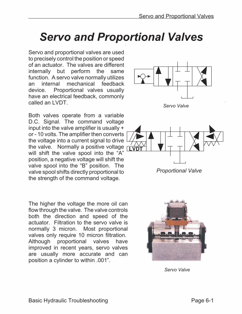
Servo and proportional valves are usedto precisely control the position or speedof an actuator. The valves are differentinternally but perform the samefunction. A servo valve normally utilizesan internal mechanical feedbackdevice. Proportional valves usuallyhave an electrical feedback, commonlycalled an LVDT.
Both valves operate from a variableD.C. Signal. The command voltageinput into the valve amplifier is usually +or - 10 volts. The amplifier then convertsthe voltage into a current signal to drivethe valve. Normally a positive voltagewill shift the valve spool into the “A”position, a negative voltage will shift thevalve spool into the “B” position. Thevalve spool shifts directly proportional tothe strength of the command voltage.
The higher the voltage the more oil canflow through the valve. The valve controlsboth the direction and speed of theactuator. Filtration to the servo valve isnormally 3 micron. Most proportionalvalves only require 10 micron filtration.Although proportional valves haveimproved in recent years, servo valvesare usually more accurate and canposition a cylinder to within .001”.
Basic Hydraulic Troubleshooting Page 6-1
Servo and Proportional Valves
Servo Valve
Proportional Valve
Servo Valve
Servo Valve Operation
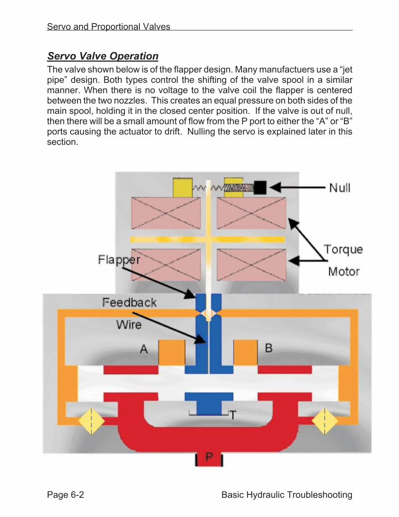
The valve shown below is of the flapper design. Many manufactuers use a “jetpipe” design. Both types control the shifting of the valve spool in a similarmanner. When there is no voltage to the valve coil the flapper is centeredbetween the two nozzles. This creates an equal pressure on both sides of themain spool, holding it in the closed center position. If the valve is out of null,then there will be a small amount of flow from the P port to either the “A” or “B”ports causing the actuator to drift. Nulling the servo is explained later in thissection.
Servo and Proportional Valves
Page 6-2 Basic Hydraulic Troubleshooting
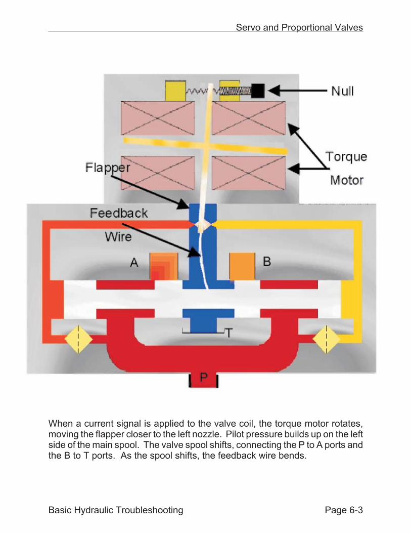
When a current signal is applied to the valve coil, the torque motor rotates,moving the flapper closer to the left nozzle. Pilot pressure builds up on the leftside of the main spool. The valve spool shifts, connecting the P to A ports andthe B to T ports. As the spool shifts, the feedback wire bends.
Servo and Proportional Valves
Basic Hydraulic Troubleshooting Page 6-3
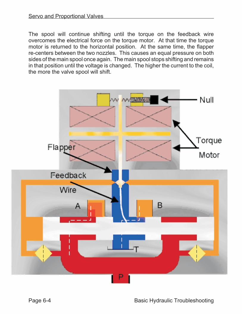
The spool will continue shifting until the torque on the feedback wireovercomes the electrical force on the torque motor. At that time the torquemotor is returned to the horizontal position. At the same time, the flapperre-centers between the two nozzles. This causes an equal pressure on bothsides of the main spool once again. The main spool stops shifting and remainsin that position until the voltage is changed. The higher the current to the coil,the more the valve spool will shift.
Servo and Proportional Valves
Page 6-4 Basic Hydraulic Troubleshooting
Direct Operated Valves
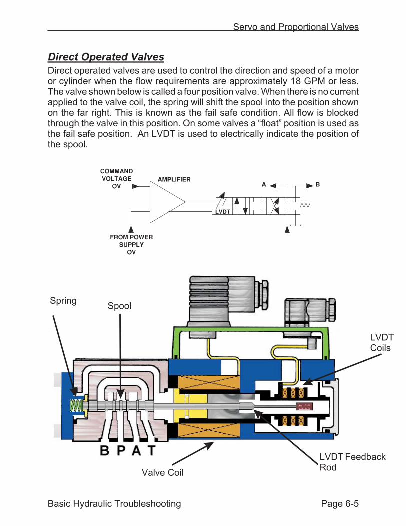
Direct operated valves are used to control the direction and speed of a motoror cylinder when the flow requirements are approximately 18 GPM or less.The valve shown below is called a four position valve. When there is no currentapplied to the valve coil, the spring will shift the spool into the position shownon the far right. This is known as the fail safe condition. All flow is blockedthrough the valve in this position. On some valves a “float” position is used asthe fail safe position. An LVDT is used to electrically indicate the position ofthe spool.
Servo and Proportional Valves
Basic Hydraulic Troubleshooting Page 6-5
SpringSpool
LVDTCoils
LVDT FeedbackRod
Valve Coil
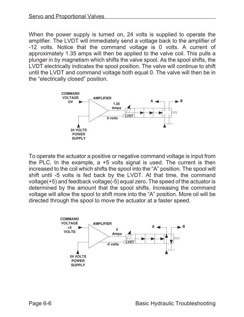
When the power supply is turned on, 24 volts is supplied to operate theamplifier. The LVDT will immediately send a voltage back to the amplifier of-12 volts. Notice that the command voltage is 0 volts. A current ofapproximately 1.35 amps will then be applied to the valve coil. This pulls aplunger in by magnetism which shifts the valve spool. As the spool shifts, theLVDT electrically indicates the spool position. The valve will continue to shiftuntil the LVDT and command voltage both equal 0. The valve will then be inthe “electrically closed” position.
To operate the actuator a positive or negative command voltage is input fromthe PLC. In the example, a +5 volts signal is used. The current is thenincreased to the coil which shifts the spool into the “A” position. The spool willshift until -5 volts is fed back by the LVDT. At that time, the commandvoltage(+5) and feedback voltage(-5) equal zero. The speed of the actuator isdetermined by the amount that the spool shifts. Increasing the commandvoltage will allow the spool to shift more into the “A” position. More oil will bedirected through the spool to move the actuator at a faster speed.
Servo and Proportional Valves
Page 6-6 Basic Hydraulic Troubleshooting
Two Stage Valves
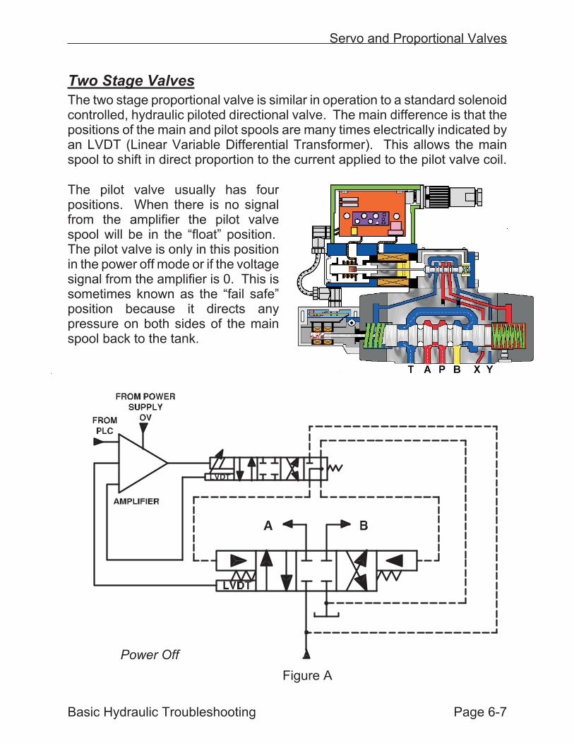
The two stage proportional valve is similar in operation to a standard solenoidcontrolled, hydraulic piloted directional valve. The main difference is that thepositions of the main and pilot spools are many times electrically indicated byan LVDT (Linear Variable Differential Transformer). This allows the mainspool to shift in direct proportion to the current applied to the pilot valve coil.
The pilot valve usually has fourpositions. When there is no signalfrom the amplifier the pilot valvespool will be in the “float” position.The pilot valve is only in this positionin the power off mode or if the voltagesignal from the amplifier is 0. This issometimes known as the “fail safe”position because it directs anypressure on both sides of the mainspool back to the tank.
Servo and Proportional Valves
Basic Hydraulic Troubleshooting Page 6-7
Power Off
Figure A
In Figure A, the main spool is spring centered to the closed position becausethe pilot valve spool is in the fail safe position. Flow from the pump andaccumulator is blocked to the cylinder or motor. Some systems will removethe current to the pilot valve if the main spool LVDT signal fails, a e-stop isactivated or there is no “enable” signal from the PLC. If the linear positionerdoes not move to the proper position or the transducer fails, the current to thepilot valve may also be removed.
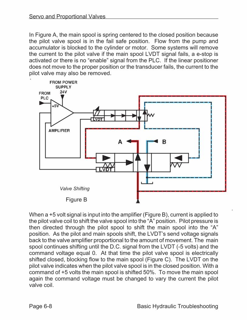
When a +5 volt signal is input into the amplifier (Figure B), current is applied tothe pilot valve coil to shift the valve spool into the “A” position. Pilot pressure isthen directed through the pilot spool to shift the main spool into the “A”position. As the pilot and main spools shift, the LVDT’s send voltage signalsback to the valve amplifier proportional to the amount of movement. The mainspool continues shifting until the D.C. signal from the LVDT (-5 volts) and thecommand voltage equal 0. At that time the pilot valve spool is electricallyshifted closed, blocking flow to the main spool (Figure C). The LVDT on thepilot valve indicates when the pilot valve spool is in the closed position. With acommand of +5 volts the main spool is shifted 50%. To move the main spoolagain the command voltage must be changed to vary the current the pilotvalve coil.
Servo and Proportional Valves
Page 6-8 Basic Hydraulic Troubleshooting
Valve Shifting
Figure B
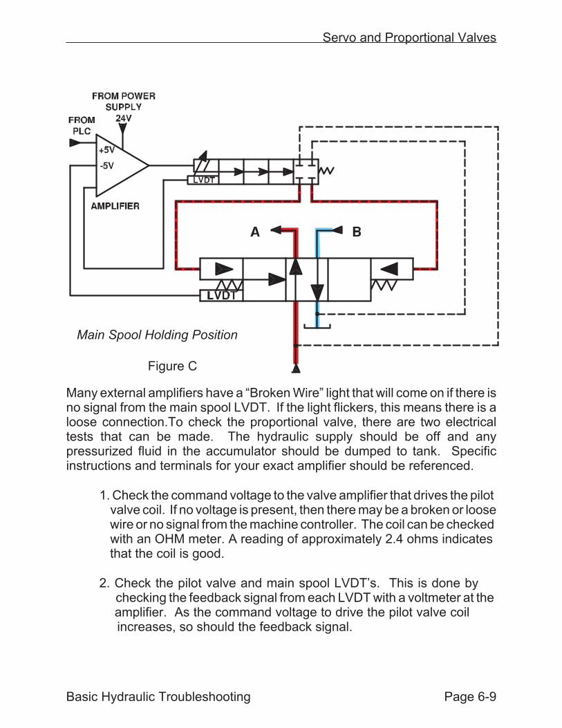
Many external amplifiers have a “Broken Wire” light that will come on if there isno signal from the main spool LVDT. If the light flickers, this means there is aloose connection.To check the proportional valve, there are two electricaltests that can be made. The hydraulic supply should be off and anypressurized fluid in the accumulator should be dumped to tank. Specificinstructions and terminals for your exact amplifier should be referenced.
1. Check the command voltage to the valve amplifier that drives the pilotvalve coil. If no voltage is present, then there may be a broken or loosewire or no signal from the machine controller. The coil can be checkedwith an OHM meter. A reading of approximately 2.4 ohms indicatesthat the coil is good.
2. Check the pilot valve and main spool LVDT’s. This is done bychecking the feedback signal from each LVDT with a voltmeter at theamplifier. As the command voltage to drive the pilot valve coilincreases, so should the feedback signal.
Basic Hydraulic Troubleshooting Page 6-9
Servo and Proportional Valves
Main Spool Holding Position
Figure C
On Board Amplifiers
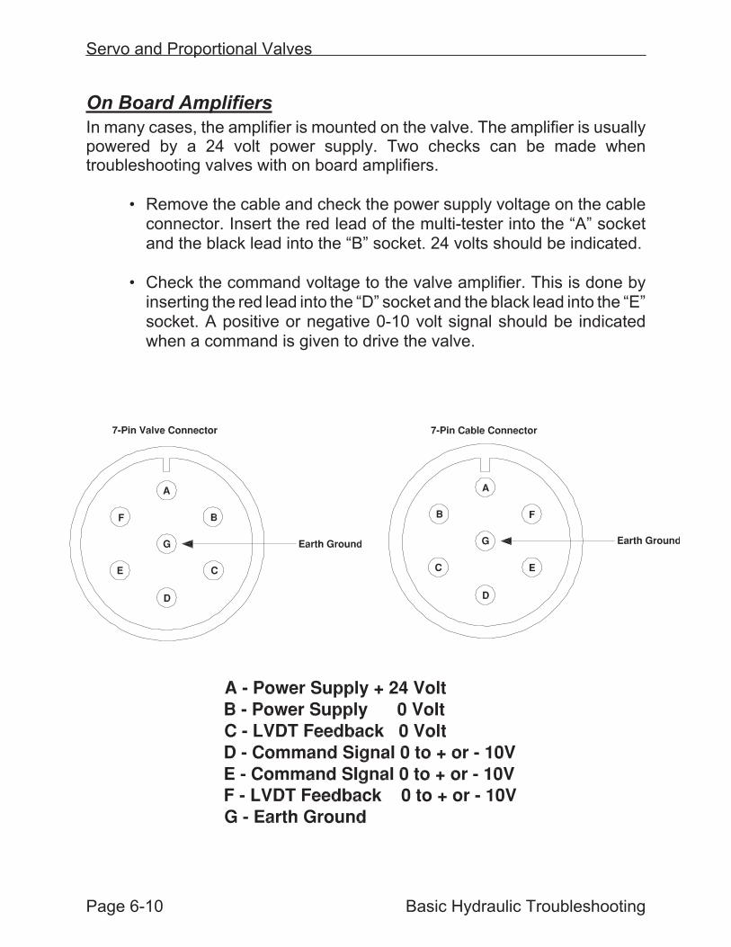
In many cases, the amplifier is mounted on the valve. The amplifier is usuallypowered by a 24 volt power supply. Two checks can be made whentroubleshooting valves with on board amplifiers.
• Remove the cable and check the power supply voltage on the cableconnector. Insert the red lead of the multi-tester into the “A” socketand the black lead into the “B” socket. 24 volts should be indicated.
• Check the command voltage to the valve amplifier. This is done byinserting the red lead into the “D” socket and the black lead into the “E”socket. A positive or negative 0-10 volt signal should be indicatedwhen a command is given to drive the valve.
Page 6-10 Basic Hydraulic Troubleshooting
Servo and Proportional Valves

Linear Positioner
Cylinders used with servo and proportionalvalves usually have a feedback devicesuch as a Temposonic transducer toindicate cylinder position. The transducertube fits down inside the hollow rod of thecylinder. A magnet is bolted onto thecylinder piston. Electrical current pulsesare sent through the transducer tube. Asthe cylinder piston moves, the magnetinteracts with the current pulses. Thismagnetic “strain” electrically indicates tothe transducer the position of the piston.The transducer then sends digital pulses back to the machine controllerindicating the precise position of the cylinder.
Servo and Proportional Valves
Basic Hydraulic Troubleshooting Page 6-11
Hydraulic Cylinder with a Temposonic Transducer
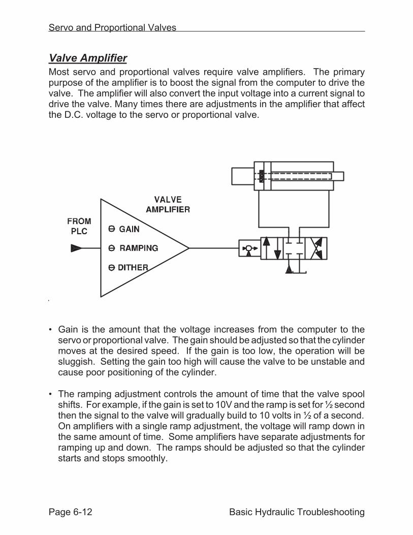
Valve Amplifier
Most servo and proportional valves require valve amplifiers. The primarypurpose of the amplifier is to boost the signal from the computer to drive thevalve. The amplifier will also convert the input voltage into a current signal todrive the valve. Many times there are adjustments in the amplifier that affectthe D.C. voltage to the servo or proportional valve.
• Gain is the amount that the voltage increases from the computer to theservo or proportional valve. The gain should be adjusted so that the cylindermoves at the desired speed. If the gain is too low, the operation will besluggish. Setting the gain too high will cause the valve to be unstable andcause poor positioning of the cylinder.
• The ramping adjustment controls the amount of time that the valve spoolshifts. For example, if the gain is set to 10V and the ramp is set for ½ secondthen the signal to the valve will gradually build to 10 volts in ½ of a second.On amplifiers with a single ramp adjustment, the voltage will ramp down inthe same amount of time. Some amplifiers have separate adjustments forramping up and down. The ramps should be adjusted so that the cylinderstarts and stops smoothly.
Servo and Proportional Valves
Page 6-12 Basic Hydraulic Troubleshooting
• Dither is a 60Hz – 100Hz cycle A.C. signal that is applied to the valve coil.The purpose of the dither is to maintain the valve spool in constant motion.This prevents contaminants from building up between the valve spool andhousing. Any contamination would cause friction as the valve spool shifts.The friction would affect the positioning of the spool. Many times the ditheris preset by the manufacturer and is non-adjustable. On systems where it isadjustable, if it is set too high it could cause the cylinder or motor to rapidlyoscillate. Setting the dither too low could result in poor positioning.
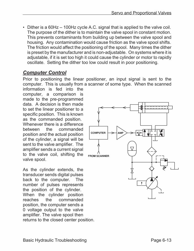
Computer Control
Prior to positioning the linear positioner, an input signal is sent to thecomputer. This is usually from a scanner of some type. When the scannedinformation is fed into thecomputer, a comparison ismade to the pre-programmeddata. A decision is then madeto set the linear positioner to aspecific position. This is knownas the commanded position.Whenever there is a differencebetween the commandedposition and the actual positionof the cylinder, a signal will besent to the valve amplifier. Theamplifier sends a current signalto the valve coil, shifting thevalve spool.
As the cylinder extends, thetransducer sends digital pulsesback to the computer. Thenumber of pulses representsthe position of the cylinder.When the cylinder positionreaches the commandedposition, the computer sends a0 voltage output to the valveamplifier. The valve spool thenreturns to the closed center position.
Servo and Proportional Valves
Basic Hydraulic Troubleshooting Page 6-13
Troubleshooting and Adjusting the System
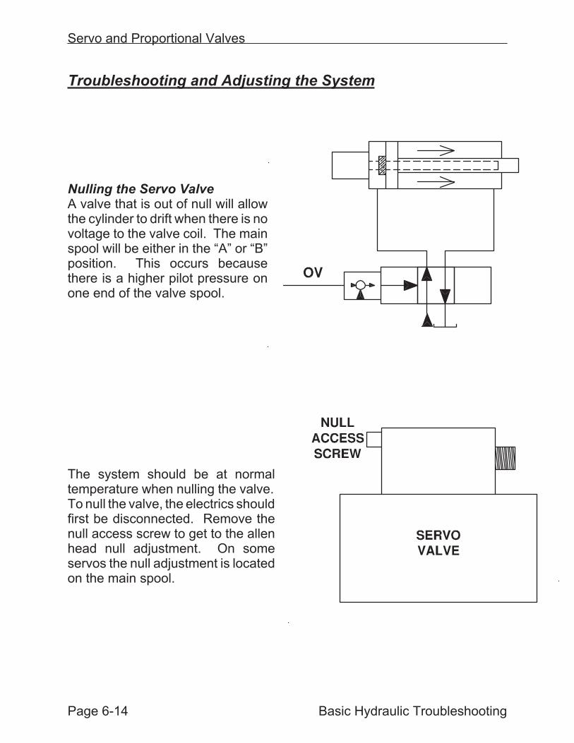
Nulling the Servo ValveA valve that is out of null will allowthe cylinder to drift when there is novoltage to the valve coil. The mainspool will be either in the “A” or “B”position. This occurs becausethere is a higher pilot pressure onone end of the valve spool.
The system should be at normaltemperature when nulling the valve.To null the valve, the electrics shouldfirst be disconnected. Remove thenull access screw to get to the allenhead null adjustment. On someservos the null adjustment is locatedon the main spool.
Servo and Proportional Valves
Page 6-14 Basic Hydraulic Troubleshooting
The null is usually a 1/8” or 3/16” allen head. If possible use a brass wrench asit won’t interfere with the magnetism in the coils. Observe the cylinder driftwhile nulling. The adjustment should not be turned more than 1 or 2 turnsmaximum. When the cylinder stops drifting, the valve is nulled.
The null should not have to be continually adjusted once set. The valve canget out of null if the temperature or pressure changes are more thanapproximately 5%. Coolers and heaters on the reservoir should be set to turnon and off to maintain a constant temperature.
Nulling the Proportional Valve
Depending on the type of valve that is used, the null or “bias” adjustment maybe in the amplifier or on the valve itself. On many valves made by Moog, thenull is located on the end of the LVDT housing. A threaded pan screw has tobe removed to access the allen head adjustment. The electrical cable shouldremain connected when nulling the valve. Whether on the valve or in theamplifier, the adjustment should be made in small increments until the driftingof the cylinder or motor stops.
Servo and Proportional Valve Troubleshooting
When a problem occurs in a system, the first thought many times is to changethe servo or proportional valve. There are two problems with indiscriminatelychanging these valves:
1. Servo and proportional valves are expensive! Of valves used inplants today, the starting price is $1500.00 and it goes up from there.
2. When a servo or proportional valve is removed, the hydraulic linesare immediately opened to airborne contaminates.
Basic Hydraulic Troubleshooting Page 6-15
Servo and Proportional Valves
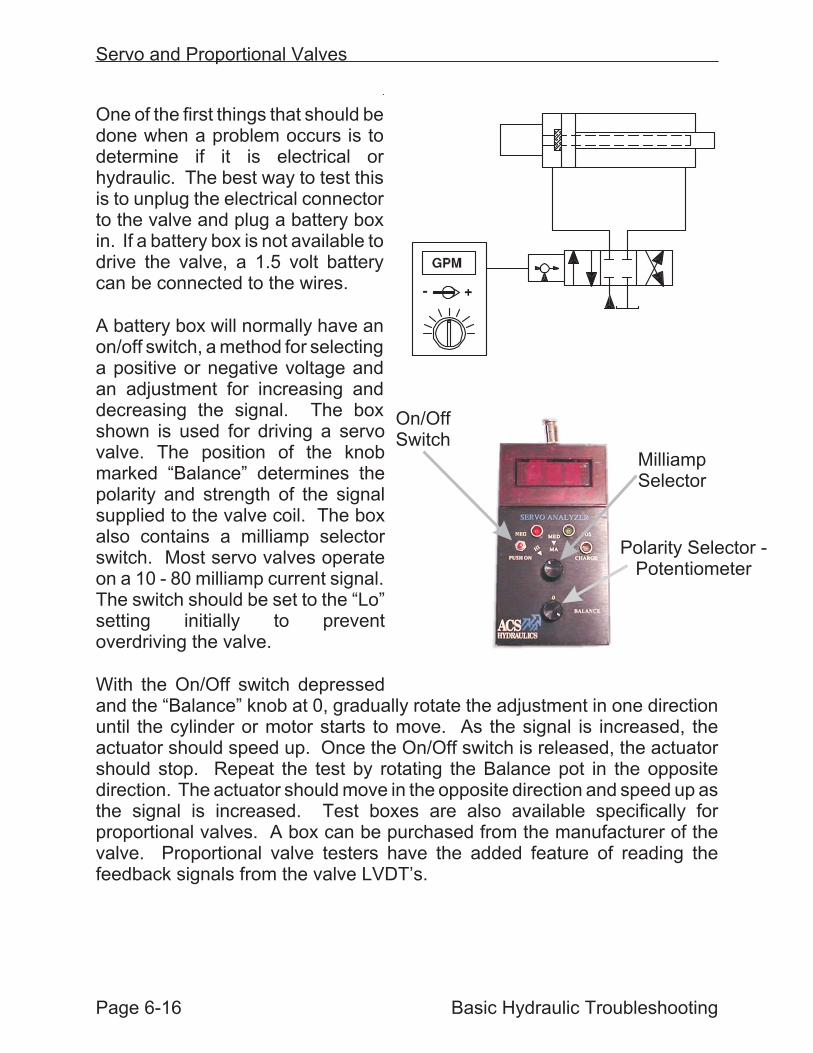
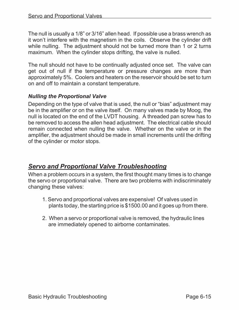
One of the first things that should bedone when a problem occurs is todetermine if it is electrical orhydraulic. The best way to test thisis to unplug the electrical connectorto the valve and plug a battery boxin. If a battery box is not available todrive the valve, a 1.5 volt batterycan be connected to the wires.
A battery box will normally have anon/off switch, a method for selectinga positive or negative voltage andan adjustment for increasing anddecreasing the signal. The boxshown is used for driving a servovalve. The position of the knobmarked “Balance” determines thepolarity and strength of the signalsupplied to the valve coil. The boxalso contains a milliamp selectorswitch. Most servo valves operateon a 10 - 80 milliamp current signal.The switch should be set to the “Lo”setting initially to preventoverdriving the valve.
With the On/Off switch depressedand the “Balance” knob at 0, gradually rotate the adjustment in one directionuntil the cylinder or motor starts to move. As the signal is increased, theactuator should speed up. Once the On/Off switch is released, the actuatorshould stop. Repeat the test by rotating the Balance pot in the oppositedirection. The actuator should move in the opposite direction and speed up asthe signal is increased. Test boxes are also available specifically forproportional valves. A box can be purchased from the manufacturer of thevalve. Proportional valve testers have the added feature of reading thefeedback signals from the valve LVDT’s.
Servo and Proportional Valves
Page 6-16 Basic Hydraulic Troubleshooting
On/OffSwitch
MilliampSelector
Polarity Selector -Potentiometer
If the cylinder operates correctly when driving the valve with the battery boxbut moved erratically or not at all when it was operated normally, then theproblem is probably electronic. Keep in mind that you have broken the closedelectrical loop, so the cylinder will not move to a specific position. If thecylinder operates OK when driving with the battery box, the linear positionershould then be checked.
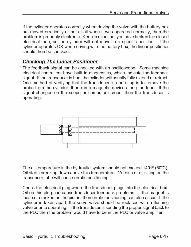
Checking The Linear Positioner
The feedback signal can be checked with an oscilloscope. Some machineelectrical controllers have built in diagnostics, which indicate the feedbacksignal. If the transducer is bad, the cylinder will usually fully extend or retract.One method of verifying that the transducer is operating is to remove theprobe from the cylinder, then run a magnetic device along the tube. If thesignal changes on the scope or computer screen, then the transducer isoperating.
The oil temperature in the hydraulic system should not exceed 1400F (600C).Oil starts breaking down above this temperature. Varnish or oil silting on thetransducer tube will cause erratic positioning.
Check the electrical plug where the transducer plugs into the electrical box.Oil on this plug can cause transducer feedback problems. If the magnet isloose or cracked on the piston, then erratic positioning can also occur. If thecylinder is taken apart, the servo valve should be replaced with a flushingvalve prior to operating. If the transducer is sending the proper signal back tothe PLC then the problem would have to be in the PLC or valve amplifier.
Servo and Proportional Valves
Basic Hydraulic Troubleshooting Page 6-17
If the problem still exists when driving with the battery box, then the problem isin the servo or proportional valve, the hydraulic system or the mechanicallinkage. To isolate the problem, remove the valve and place it in a clean,plastic bag. Do not put a new valve on at this time.
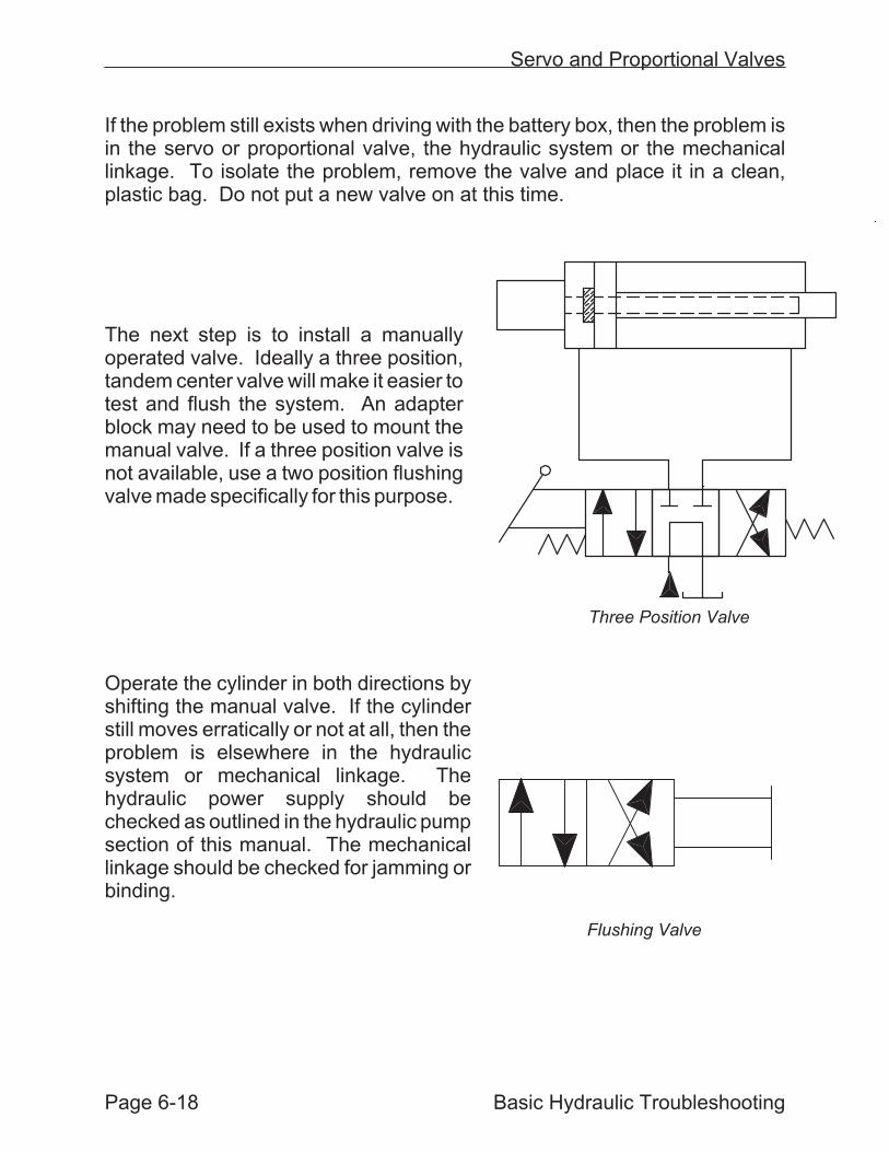
The next step is to install a manuallyoperated valve. Ideally a three position,tandem center valve will make it easier totest and flush the system. An adapterblock may need to be used to mount themanual valve. If a three position valve isnot available, use a two position flushingvalve made specifically for this purpose.
Operate the cylinder in both directions byshifting the manual valve. If the cylinderstill moves erratically or not at all, then theproblem is elsewhere in the hydraulicsystem or mechanical linkage. Thehydraulic power supply should bechecked as outlined in the hydraulic pumpsection of this manual. The mechanicallinkage should be checked for jamming orbinding.
Page 6-18 Basic Hydraulic Troubleshooting
Servo and Proportional Valves
Three Position Valve
Flushing Valve
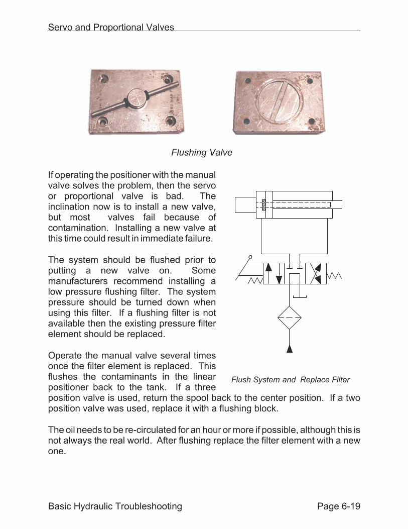
If operating the positioner with the manualvalve solves the problem, then the servoor proportional valve is bad. Theinclination now is to install a new valve,but most valves fail because ofcontamination. Installing a new valve atthis time could result in immediate failure.
The system should be flushed prior toputting a new valve on. Somemanufacturers recommend installing alow pressure flushing filter. The systempressure should be turned down whenusing this filter. If a flushing filter is notavailable then the existing pressure filterelement should be replaced.
Operate the manual valve several timesonce the filter element is replaced. Thisflushes the contaminants in the linearpositioner back to the tank. If a threeposition valve is used, return the spool back to the center position. If a twoposition valve was used, replace it with a flushing block.
The oil needs to be re-circulated for an hour or more if possible, although this isnot always the real world. After flushing replace the filter element with a newone.
Basic Hydraulic Troubleshooting Page 6-19
Servo and Proportional Valves
Flush System and Replace Filter
Flushing Valve