service virtualization user guide - hewlett packard … virtualization management...
TRANSCRIPT

Software Version: 3.83
User Guide
Service Virtualization
Document Release Date: January 16, 2018 | Software Release Date: January 2017
Go to HELP CENTER ONLINEhttp://admhelp.microfocus.com/sv/
Legal Notices
DisclaimerCertain versions of software and/or documents (“Material”) accessible here may contain branding from Hewlett-Packard
Company (now HP Inc.) and Hewlett Packard Enterprise Company. As of September 1, 2017, the Material is now offered by
HPE, a separately owned and operated company. Any reference to the HP and Hewlett Packard Enterprise/HPE marks is
historical in nature, and the HP and Hewlett Packard Enterprise/HPE marks are the property of their respective owners.
WarrantyThe only warranties for Seattle SpinCo, Inc. and its subsidiaries (“Seattle”) products and services are set forth in the express
warranty statements accompanying such products and services. Nothing herein should be construed as constituting an
additional warranty. Seattle shall not be liable for technical or editorial errors or omissions contained herein. The
information contained herein is subject to change without notice.
Restricted Rights LegendConfidential computer software. Except as specifically indicated, valid license from Seattle required for possession, use or
copying. Consistent with FAR 12.211 and 12.212, Commercial Computer Software, Computer Software Documentation, and
Technical Data for Commercial Items are licensed to the U.S. Government under vendor's standard commercial license.
Copyright Notice© Copyright 2011-2017 EntIT Software LLC
Trademark NoticesAdobe™ is a trademark of Adobe Systems Incorporated.
Microsoft® and Windows® are U.S. registered trademarks of Microsoft Corporation.
UNIX® is a registered trademark of The Open Group.
Oracle and Java are registered trademarks of Oracle and/or its affiliates.
User GuideService Virtualization
Service Virtualization (3.83) Page 2 of 474
Contents
Service Virtualization 1
What's New 11
Chapter 1: Service Virtualization at a Glance 13Introducing Service Virtualization 14
Service Virtualization Components 14
Installation and Licensing 15
Service Virtualization Editions 16
Functionality by Edition 16
Upgrading your edition 18
Start Service Virtualization 18
End-to-End Workflow 20
Manage Service Virtualization Servers 22
Access a Secured Service Virtualization Server 23
Secure the Designer's Embedded Server 24
Sharing Data 25
Service Virtualization User Interface 26
Start Page 27
Service Virtualization Designer Window 32
Service Virtualization Main Menus 33
Select License Type Page 37
License Installation Pages 39
Chapter 2: Service Virtualization Agents 44Service Virtualization Agents 45
Configure Agents 45
Configure the File System/File System FTP Agents 47
Configure the HTTP/HTTPS Gateway Agents 47
Configure the HTTP(S) Proxy Agent 49
Configure the IBM IMS TM Agent 49
Configure the Java Agent 50
Configure the JDBC Agent 52
JDBC type to Java type mapping 56
Configure the JMS Generic Agent 57
Configure the MSMQ Agent 58
Configure the Oracle AQ Agent 59
Configure the SAP Agent 60
User GuideService Virtualization
Service Virtualization (3.83) Page 3 of 474
Configure the TIBCO EMS Non Intrusive Agent 62
Configure the WebMethods SAP Agent 63
Configure the WebSphere MQ Non-Intrusive Agent 66
Configure the WebSphere MQ Agent 74
Forward HTTP Agent Communication Through an HTTP Proxy 76
Agents User Interface 76
Agents Page 77
File System Agent Settings 77
File System FTP Agent Settings 79
HTTP/HTTPS Gateway Agent Settings 81
HTTP(S) Proxy Agent Settings 84
IBM IMS TM Agent Settings 86
Java Agent Settings 88
JDBC Agent Settings 90
JMS Generic Agent Settings 92
MSMQ Agent Settings 95
ONC/RPC Agent 97
Oracle AQ Agent Settings 99
SAP Agent Settings 101
TCP Agent Settings 103
TIBCO EMS Agent Settings 105
WebMethods SAP Agent Settings 107
WebSphere MQ Non-Intrusive Agent Settings 109
WebSphere MQ Agent Settings 114
Proxy Settings Dialog Box 120
Chapter 3: Virtual Services 122Virtual Services 123
Virtualization Projects 123
Virtual Service Types 124
XML Services 125
Binary Services 125
SOAP Services 125
REST Services 125
IBM IMS TM Virtual Services 126
COBOL over IBM CICS TS HTTP Services 127
SQL Services 127
SAP IDoc and SAP RFC Services 127
ONC/RPC Services 128
Service Descriptions 128
Create a Virtual Service 130
User GuideService Virtualization
Service Virtualization (3.83) Page 4 of 474
Optional: Create a new project 130
Configure Virtual Services 132
HTTP Service Discovery 134
Manage Virtualization Projects 135
Edit a Service Description 136
Define the URI Space 140
Virtualize SAP IDoc Communication 142
Virtualize SAP RFC Communication 143
Virtualize Fixed-Length Communication 143
Virtualize fixed-length communication 144
Service description format 144
Supported data types 146
Creating the text file 146
Service description file naming 147
Message Logging 148
Log Files 150
Virtual Services User Interface 151
Summary of Virtualization Project Dialog Box 152
Create New Virtual Service Wizard 153
Import Real Service Description Page 154
Choose Service Protocol Page 155
Message Type Page 156
Service Properties Page 158
Browse Destinations Dialog Box 179
Summary of Virtualization Page 181
Create Multiple Virtual Services Wizard 183
Endpoint Validation Dialog Box 184
Virtualization Explorer 185
Virtual Service Editor 186
Edit Endpoints Dialog Box 192
Change Server Dialog Box 194
Projects and Solutions Page 196
Service Description Editor 197
Session ID Definition Wizard 200
Define Default Session IDs Page 200
Select Session ID Page 201
Define Operation Specific Session IDs Page 202
Define Data Format Session IDs Page 203
Define Session IDs Summary Page 204
Data Masking Dialog Box 205
Replace Algorithm Configuration Dialog Box 207
Edit Metadata Dialog Box 209
User GuideService Virtualization
Service Virtualization (3.83) Page 5 of 474

Add Data Format Dialog Box 211
Chapter 4: Simulation 213Simulation 214
Run Simulations 214
Service Locking 217
Simulation User Interface 217
Runtime View 218
Problem List 219
Service Administration 221
Chapter 5: Service Virtualization Management 224Service Virtualization Management 225
Get Started Using Service Virtualization Management 226
Chapter 6: Command Line Management 228Command Line Management 229
Manage Virtual Services from the Command Line 230
Deploy a Virtual Service on Multiple Service Virtualization Servers 244
Automation example 246
Chapter 7: Simulation Modeling 247Simulation Modeling 248
Manage Simulation Models 248
Chapter 8: Data Modeling 250Data Modeling 251
Rule Functions 254
Overview 254
Custom functions 257
Data Driving 257
Array Binding 257
Data Format Binding 258
Simulation Preview 258
The Simulation Process 259
Modify Virtual Service Behavior 261
Define Rule Functions 264
Configure Dynamic Data Functions 265
Configure the Sequential Number Generator Function 266
Configure the Random Number Generator Function 271
Configure the Date/Time Functions 275
User GuideService Virtualization
Service Virtualization (3.83) Page 6 of 474
Configure the Substring Function 279
Define Custom Functions 281
Configure Regular Expressions 282
Work With External Data Sources 283
Working with External Data Sources - Use-case Example 286
Call External Services 286
Create service call activity by importing a service description 287
Create service call activity by importing messages 287
Work with service call activity in the Data Model 288
Assess Change Impact 289
Data Model User Interface 290
Data Model Editor 291
Data Model Editor Context Menus 297
Data Model Editor Options Page 301
Simulation Preview Pane 302
Row Detail Dialog Box 303
Substring Dialog Box 305
Import Request/Response Message Dialog Box 307
Replace Request/Response Message Dialog Box 309
Learn Schema Dialog Box 310
Export Rows Dialog Box 311
Request/Response Pairing Dialog Box 312
New Data Driven Rule Dialog Box 313
Import/Export Data Dialog Box 314
External Data Properties Dialog Box 317
New/Edit Function Dialog Box 318
Change Columns Dialog Box 319
Edit Sheet Relations Dialog Box 321
Data Format/Response Type/Choice Binding Dialog Box 323
Select Service Operation Dialog Box 323
Service Properties for XML Service Call Activity 325
Activity Properties Dialog Box 326
FAQs: Data Model Editor 327
Chapter 9: Stateful Simulation 330Stateful Simulation 331
Simulate a Stateful Service 332
Reorder tracks 333
Stateful Layout View 334
Chapter 10: Performance Modeling 336
User GuideService Virtualization
Service Virtualization (3.83) Page 7 of 474

Performance Modeling 337
Modify Virtual Service Performance 338
Performance Model User Interface 340
Performance Model Editor 341
Chapter 11: Composite Application Topology 348Composite Application Topology 349
Model Composite Applications 349
Topology User Interface 351
Summary of New Topology Dialog Box 352
Topology Editor 352
Service Discovery Dialog Box 357
Chapter 12: Security 359Virtual Service Security 360
Set Security 361
Set Message Security 362
Set Transport Security 369
Password Encryption 371
Security User Interface 372
Edit Credential Store Dialog Box 373
Advanced Message Security Settings Dialog Box 374
Chapter 13: HPE Test Automation Tools Integration 376HPE Test Automation Tools Integration 377
User Authentication 377
Unified Functional Testing 377
Performance Center and LoadRunner 377
Performance Counters 378
Chapter 14: Continuous Integration 382
Chapter 15: HPE Application Lifecycle Management (ALM) Integration 388HPE Application Lifecycle Management ALM Integration 389
Work with HPE ALM 389
Troubleshoot lost connection to ALM 391
FAQs: ALM Integration 392
Chapter 16: Version Control Support 395Subversion (SVN) Version Control Support 396
User GuideService Virtualization
Service Virtualization (3.83) Page 8 of 474
Work with SVN 396
Chapter 17: Troubleshooting 399Runtime View Errors 400
Configuring HTTP Proxy on Clients 400
Setting HTTP Proxy in Designer 403
Slow Designer Responsiveness 405
Application Timeouts 406
Validation error during JMS Generic agent configuration 406
Chapter 18: Service Virtualization Labs 407Enable Lab Features 408
Scripted Rules 408
Scripted Rules 409
Create a Scripted Rule 409
Prerequisite: Enable the Scripting lab feature 409
Create a new scripted rule 409
Edit a script 410
Script guidelines 410
Configure logging for scripted rules 414
Set options for the scripted rule 416
Configure C# Security 416
Configure C# rule security 417
Disable C# rule security 418
Use a third-party library in a C# rule 418
Debug a C# scripted rule 419
Enable debugging 419
Debug the script 419
Changing data structure types in a C# scripted rule 420
Network Virtualization Integration 421
Network Virtualization Integration 422
Virtualize Network Conditions 422
PCAP File Import 423
Packet Capture (pcap) File Import 424
Import .pcap Files 424
WebSphere MQ Root Element Routing 424
ISO 8583 Support 425
Simulation Report 425
Simulation Report Use Cases 430
Simulation Report Scenario 1 431
Simulation Report Scenario 2 437
User GuideService Virtualization
Service Virtualization (3.83) Page 9 of 474

Preserve XML Namespace Prefixes 439
Content-Based Correlation 440
Overview 440
Implement content-based correlation 442
Chapter 19: Tutorials 443Learning a REST Service Tutorial 444
Interactive REST Authoring Tutorial 453
Send Us Feedback 474
User GuideService Virtualization
Service Virtualization (3.83) Page 10 of 474

What's NewThis What's New provides an overview of the features that are introduced or enhanced in ServiceVirtualization 3.83.
Protocols and virtualization enhancementsSFTP (FTP over SSH). Support added for FTP over SSH (SFTP), complementing the existingFTP/FTPS transports for file exchange simulation. For details, see "File System FTP AgentSettings" on page 79.
Fixed-length over FTP. Transfer fixed-length messages over FTP transport. For details, see"Virtualize Fixed-Length Communication" on page 143.
SAP RFC in WebMethods. Enhanced SAP IDOC virtualization, enabling the use of SAP RFC withSAG WebMethods middleware. For details, see "Virtualize SAP RFC Communication" on page 143.
Virtual service design and simulationenhancementsDuplicate rules. Copy existing Data Model rules. For details, see "Data Model Editor ContextMenus" on page 297.
Disable track creation. Disable creation of tracks during learning of stateless simulation, or whenthe data model contains tracks but simulation is not following them, and simulation accuracy isnegatively impacted. For details, see "Virtual Service Editor" on page 186.
Adjust track priority. Control and change the priority of a track. In previous versions, the trackpriority was derived from a timestamp of a call on the first position within the track. When youchanged the first position of the track, the priority also changed. You can now manually definetrack priority within the Stateful Layout view. For details, see "Simulate a Stateful Service" on page332.
Message routing to real service when no URI space matches. Define a message to forward to thereal service when there is no matching request. In previous versions, simulation returned a 404error when it handled a request for a known endpoint that did not match any URI space in thevirtual service. For details, see "HTTP/HTTPS Gateway Agent Settings" on page 81.
Service Call Activity (SCA) Enhancements. Improved Service Call Activity configuration andusability:
l SCA without Service Description. Create Service Call Activity without a service description byimporting sample messages, and without providing a service description of the target API.
l SCA with one-way operations. Support added for Service Call Activity with one-wayoperations.
User GuideWhat's New
Service Virtualization (3.83) Page 11 of 474
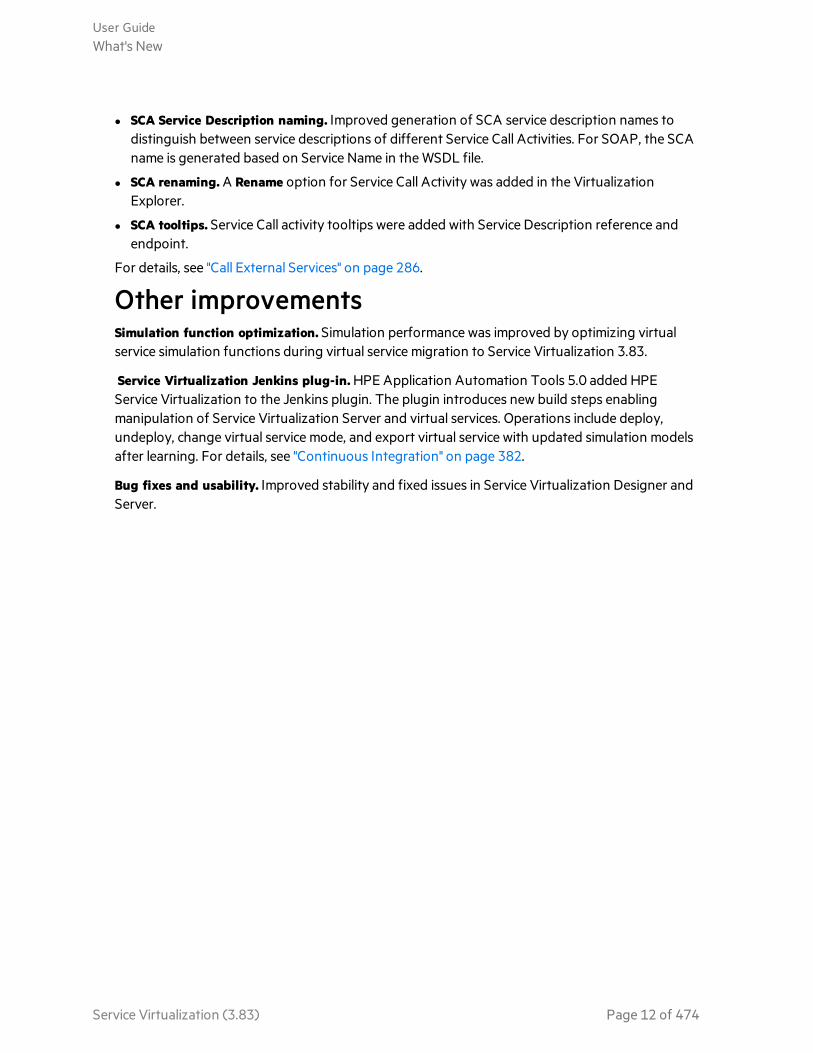
l SCA Service Description naming. Improved generation of SCA service description names todistinguish between service descriptions of different Service Call Activities. For SOAP, the SCAname is generated based on Service Name in the WSDL file.
l SCA renaming. A Rename option for Service Call Activity was added in the VirtualizationExplorer.
l SCA tooltips. Service Call activity tooltips were added with Service Description reference andendpoint.
For details, see "Call External Services" on page 286.
Other improvementsSimulation function optimization. Simulation performance was improved by optimizing virtualservice simulation functions during virtual service migration to Service Virtualization 3.83.
Service Virtualization Jenkins plug-in. HPE Application Automation Tools 5.0 added HPEService Virtualization to the Jenkins plugin. The plugin introduces new build steps enablingmanipulation of Service Virtualization Server and virtual services. Operations include deploy,undeploy, change virtual service mode, and export virtual service with updated simulation modelsafter learning. For details, see "Continuous Integration" on page 382.
Bug fixes and usability. Improved stability and fixed issues in Service Virtualization Designer andServer.
User GuideWhat's New
Service Virtualization (3.83) Page 12 of 474

Chapter 1: Service Virtualization at a GlanceThis chapter includes:
• Introducing Service Virtualization 14• Service Virtualization Components 14• Installation and Licensing 15• Service Virtualization Editions 16• Start Service Virtualization 18• End-to-End Workflow 20• Manage Service Virtualization Servers 22• Access a Secured Service Virtualization Server 23• Secure the Designer's Embedded Server 24• Sharing Data 25• Service Virtualization User Interface 26
Service Virtualization (3.83) Page 13 of 474

Introducing Service VirtualizationService Virtualization provides a framework for creating virtual services for use in testing yourapplications under development, allowing developers and testers access to limited or unavailableservices in a simulated environment.
How does it work?
Service Virtualization places a virtual service between the client application (application under test) andthe real service to which you require access. Once you create virtual services to simulate the real servicesthat you require, you reconfigure your client applications to use the virtual services, instead of the realservices.
How do I get started?
For more details, see "End-to-End Workflow" on page 20.
Service Virtualization ComponentsService Virtualization consists of the following applications:
Designer A client application enabling you to create virtual services, and run simulations ofreal service behavior. The Service Virtualization Designer is used for design andvalidation of virtual services within the same desktop environment, and includes anembedded server for hosting virtual services.
User GuideChapter 1: Service Virtualization at a Glance
Service Virtualization (3.83) Page 14 of 474

Server(Optional)
A standalone server application which hosts the running of virtual services. TheService Virtualization Server is optimized for performance, can contain many moreservices than the Designer, and can be accessed by multiple Designers.
For details on configuring the Service Virtualization Server, see the HPE ServiceVirtualization Installation Guide.
For details on working with the Service Virtualization Server, see "Manage ServiceVirtualization Servers" on page 22.
ManagementInterface(Optional)
A web application enabling you to view and manage all services from ServiceVirtualization configured servers, without opening the Designer or individualprojects. The Service Virtualization Management is installed by default when youinstall the Service Virtualization Server.
Installation and LicensingThe Service Virtualization Installation Guide, available from the Service Virtualization Help Center,describes system prerequisites, installation process, and configuration information.
The Service Virtualization Designer is installed with a 30-day trial license. To continue working with theDesigner, you must install a license from HPE.
After the evaluation period, the Designer will no longer work, but your data is preserved.
Note: For information on Service Virtualization Server licensing, see the Service VirtualizationInstallation Guide.
In this topic:
l "Get a license" below
l "Install a Designer license" below
l "Concurrent licensing" on the next page
Get a licenseYou can obtain HPE licenses through the HPE Software Licensing Portal.
In addition, if you want to later install Service Virtualization on a different machine, you need to migrateyour license. For more information, visit the Licensing Portal.
Install a Designer license1. From the Help menu, select License Management.
2. Select a license type. For user interface details, see "Select License Type Page" on page 37.
3. Install the license. For user interface details, see "License Installation Pages" on page 39.
User GuideChapter 1: Service Virtualization at a Glance
Service Virtualization (3.83) Page 15 of 474

Concurrent licensingConcurrent (floating) licenses can be shared dynamically between multiple users using HPE AutoPassLicense Server. AutoPass License Server is included in the Service Virtualization installation package.
You install concurrent licenses on the license server. When the Designer is started, the application takesa license from the license server, and returns it when the application is closed.
Define the license server in License Management.
See also:l "Service Virtualization Editions" below
Service Virtualization EditionsService Virtualization is available in several editions, which determine the functionality available to youin the application.
When you first install the Service Virtualization Designer or Server, a 30-day trial license is installed. Thislicense runs the Premium Edition.
SV Edition Description
PremiumEdition
Provides full Service Virtualization functionality.
Express Edition Provides a subset of the full Service Virtualization functionality, as describedbelow.
CommunityEdition
Provides a subset of product functionality, designed to introduce you to ServiceVirtualization.
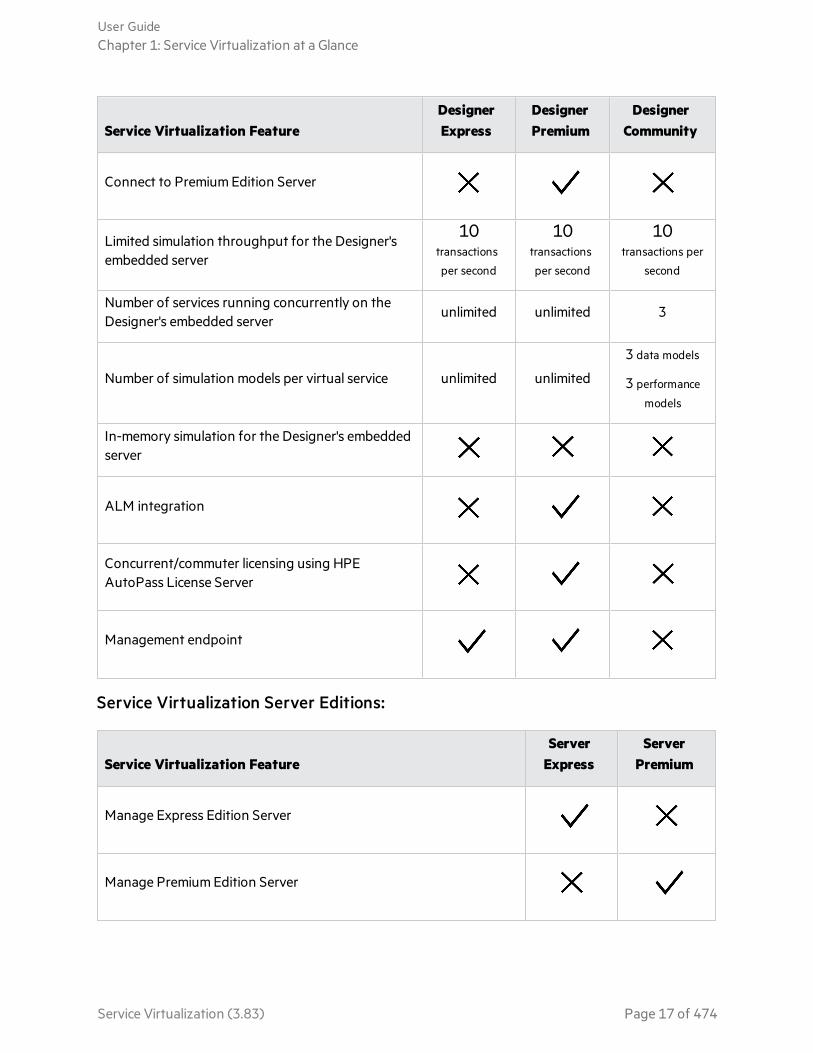
Functionality by EditionThe limits specified here are default settings for the editions. They may change according to yourlicense agreement.
Service Virtualization Designer Editions:
Service Virtualization FeatureDesignerExpress
DesignerPremium
DesignerCommunity
Connect to Express Edition Server
User GuideChapter 1: Service Virtualization at a Glance
Service Virtualization (3.83) Page 16 of 474
Service Virtualization FeatureDesignerExpress
DesignerPremium
DesignerCommunity
Connect to Premium Edition Server
Limited simulation throughput for the Designer'sembedded server
10transactions
per second
10transactions
per second
10transactions per
second
Number of services running concurrently on theDesigner's embedded server
unlimited unlimited 3
Number of simulation models per virtual service unlimited unlimited
3 data models
3 performance
models
In-memory simulation for the Designer's embeddedserver
ALM integration
Concurrent/commuter licensing using HPEAutoPass License Server
Management endpoint
Service Virtualization Server Editions:
Service Virtualization FeatureServer
ExpressServer
Premium
Manage Express Edition Server
Manage Premium Edition Server
User GuideChapter 1: Service Virtualization at a Glance
Service Virtualization (3.83) Page 17 of 474

Service Virtualization FeatureServer
ExpressServer
Premium
Maximum deployed services on the Service Virtualization Server 100Full
functionality
Maximum concurrent users connected to Service VirtualizationManagement
10Full
functionality
Maximum managed Service Virtualization Servers in ServiceVirtualization Management
1Full
functionality
Maximum CPU cores 8Full
functionality
In-memory simulation
ACL/Server access permission functionality
ALM integration
Upgrading your editionUpgrade your edition by adding the appropriate license. You can backup your server on one edition andrestore it on a different edition.
Note: The product edition has no impact on the server backup archive, project files containingvirtual services, or agent configuration files. You can apply a backup from a server of one editionto a server of a different edition, and use virtual services created by one edition in a server ordesigner of another edition.
For example, after you upgrade from Server Express to Server Premium, you can restore yourserver from a backup made on Server Express edition.
Start Service VirtualizationThis section explains how to start the Service Virtualization applications. For more details on eachcomponent, see "Introducing Service Virtualization" on page 14.
User GuideChapter 1: Service Virtualization at a Glance
Service Virtualization (3.83) Page 18 of 474
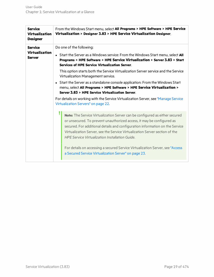
ServiceVirtualizationDesigner
From the Windows Start menu, select All Programs > HPE Software > HPE ServiceVirtualization > Designer 3.83 > HPE Service Virtualization Designer.
ServiceVirtualizationServer
Do one of the following:
l Start the Server as a Windows service: From the Windows Start menu, select AllPrograms > HPE Software > HPE Service Virtualization > Server 3.83 > StartServices of HPE Service Virtualization Server.
This option starts both the Service Virtualization Server service and the ServiceVirtualization Management service.
l Start the Server as a standalone console application: From the Windows Startmenu, select All Programs > HPE Software > HPE Service Virtualization >Server 3.83 > HPE Service Virtualization Server.
For details on working with the Service Virtualization Server, see "Manage ServiceVirtualization Servers" on page 22.
Note: The Service Virtualization Server can be configured as either securedor unsecured. To prevent unauthorized access, it may be configured assecured. For additional details and configuration information on the ServiceVirtualization Server, see the Service Virtualization Server section of theHPE Service Virtualization Installation Guide.
For details on accessing a secured Service Virtualization Server, see "Accessa Secured Service Virtualization Server" on page 23.
User GuideChapter 1: Service Virtualization at a Glance
Service Virtualization (3.83) Page 19 of 474

ServiceVirtualizationManagement
To start the Service Virtualization Management service:
On the Service Virtualization Server machine, from the Windows Start menu, selectAll Programs > HPE Software > HPE Service Virtualization > Server 3.83 > StartServices of HPE Service Virtualization Server.
This option starts both the Service Virtualization Server service and the ServiceVirtualization Management service.
To access the Service Virtualization Management interface:
Open a browser window and enter one of the following URLs:
l The Service Virtualization Management URL:
https://<Service Virtualization Server IP orhostname>:<Service Virtualization Management port>
By default, the Service Virtualization Management port is 6086.
l The Service Virtualization Server URL:
<Service Virtualization Server IP orhostname>:<HTTP/HTTPS port number>/management
For more details on Service Virtualization network ports, see the HPE ServiceVirtualization Installation Guide.
For more details on Service Virtualization Management, see "Service VirtualizationManagement" on page 225.
End-to-End WorkflowThis task describes the overall Service Virtualization workflow.
1. Start the Service Virtualization components
Service Virtualization includes a Designer with an embedded server, an optional standalone server,and a management interface.
For details on these components, see "Service Virtualization Components" on page 14.
For details on starting the components, see "Start Service Virtualization" on page 18.
2. Install a Service Virtualization Designer license
The Designer is installed with a 30-day evaluation license. To continue working with the Designer,you must obtain and install a valid license from HPE.
For details on installing the Designer license, see "Installation and Licensing" on page 15.
3. Configure Service Virtualization agents
User GuideChapter 1: Service Virtualization at a Glance
Service Virtualization (3.83) Page 20 of 474

Configure the protocol-specific agents that handle communication between clients and real orvirtual services. For task details, see "Configure Agents" on page 45.
4. Optional: Model composite applications
Create a visual map of the services in your composite applications, and the relationships betweenthem. Group services into larger composites, mark service types, and display the service callsbetween them. For task details, see "Model Composite Applications" on page 349.
5. Create virtual services
Create virtual services to simulate real services with limited access or that are unavailable. For taskdetails, see "Create a Virtual Service" on page 130.
6. Configure virtual services
Set up your virtual services to create a simulation for your testing purposes. Configure security,logging, protocol, and server settings to meet your needs. For task details, see "Configure VirtualServices" on page 132.
7. Configure clients
Reconfigure your client applications to use the virtual services instead of the real services. ServiceVirtualization enables you to manipulate virtual services to get different results.
8. Learn service behavior
Record the behavior of the real service in order to learn its requests and responses. For task details,see "Run Simulations" on page 214.
9. Run simulations
Use virtual services to simulate real services during your testing process. For task details, see "RunSimulations" on page 214.
10. Review and monitor services
Monitor services during learning and simulation sessions. For details, see "Run Simulations" onpage 214.
11. Design and configure simulation models
Create and customize data and performance models to meet your needs. Learn real servicebehavior, create customized rules for virtual service behavior, add service calls, and add externaldata sources. For task details, see "Manage Simulation Models" on page 248.
12. Optional: Integrate with HPE Test Automation tools
Integrate Service Virtualization with HPE test automation tools. For details, see "HPE TestAutomation Tools Integration" on page 377.
13. Manage virtual services
Deploy, undeploy, unlock, view, or change the runtime mode of virtual services on any Service
User GuideChapter 1: Service Virtualization at a Glance
Service Virtualization (3.83) Page 21 of 474

Virtualization Server.
For details, see:
l "Get Started Using Service Virtualization Management" on page 226
l "Manage Virtual Services from the Command Line" on page 230
Manage Service Virtualization ServersThis task describes how to use Service Virtualization Servers for your virtual services.
Note: For details on starting a Service Virtualization Server, see "Start Service Virtualization" onpage 18.
View, add, or delete ServersThe Servers page displays all Service Virtualization Servers that are configured for your Designer.
From the main menu, select Tools > Options. Click the Servers tab.
When you add a Server, it is added to the list of available Servers, enabling you to select this Serverwhen you create a new Service Virtualization project.
View Server statusThe Servers page displays status information for each Service Virtualization Server configured for yourDesigner.
From the main menu, select Tools > Options. Click the Servers tab.
Status indicators:
l Green - online.
l Red - not running.
l Yellow - indicates some connection problem, such as invalid credentials or a missing trustedcertificate.
Change ServersMove the virtual services in the open project to a different server.
From the main menu, select Project > Change Server.
Connect to a Server with a different userIf you are working with a secured Service Virtualization Server, your access may be limited based onpermissions assigned to your user. For details, see the "Access a Secured Service Virtualization Server"
User GuideChapter 1: Service Virtualization at a Glance
Service Virtualization (3.83) Page 22 of 474

on the next page.
To connect to a server with a different user, from the main menu, select Tools > Options, and click theServers tab. Right-click a server and select Connect using different credentials.
For details on server authentication and user access permissions, see the HPE Service VirtualizationInstallation Guide.
Configure Service Virtualization agentsService Virtualization agents handle communication between a client and a real or virtual service.Agents are protocol specific. You must configure agents for each protocol your services are using, oneach Service Virtualization Server or the Designer's embedded server on which the services aredeployed.
You can manage agents using both the Designer, and Service Virtualization Management.
In the Designer: Manage agents in the Agents page. For user-interface details, see "Agents Page" onpage 77.
Note: For details on managing agents in Service Virtualization Management, see the ServiceVirtualization Management help within the application.
See also:l "Secure the Designer's Embedded Server" on the next page
l "Access a Secured Service Virtualization Server" below
Access a Secured Service Virtualization ServerWhen the Service Virtualization Designer contacts a secured Service Virtualization Server for the firsttime, it requests user input in order to establish a secured communication channel.
You can determine whether the Service Virtualization Server is secured based on its URL. The URL ofan unsecured server begins with http, whereas the URL of the secured server begins with https. Forexample, the URL of a secured server might be https://mymachine.com:6085/management. In addition,the port of the secured server is different from that of the unsecured server.
Note:
l When you are working with a secured Service Virtualization Server, the actions available toyou and the information displayed in the Service Virtualization Designer vary, based on youruser access permissions. For example, a user who is not assigned to any of the ServiceVirtualization user groups cannot view any agent data or any services deployed on the server.
For details on the Service Virtualization user groups, see the HPE Service VirtualizationInstallation Guide.
User GuideChapter 1: Service Virtualization at a Glance
Service Virtualization (3.83) Page 23 of 474
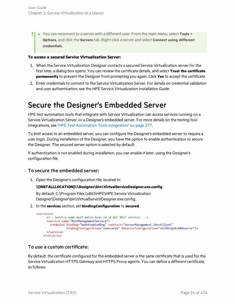
l You can reconnect to a server with a different user. From the main menu, select Tools >Options, and click the Servers tab. Right-click a server and select Connect using differentcredentials.
To access a secured Service Virtualization Server:
1. When the Service Virtualization Designer contacts a secured Service Virtualization server for thefirst time, a dialog box opens. You can review the certificate details, and select Trust the certificatepermanently to prevent the Designer from prompting you again. Click Yes to accept the certificate.
2. Enter credentials to connect to the Service Virtualization Server. For details on credential validationand user authentication, see the HPE Service Virtualization Installation Guide.
Secure the Designer's Embedded ServerHPE test automation tools that integrate with Service Virtualization can access services running on aService Virtualization Server, or a Designer's embedded server. For more details on the testing toolintegrations, see "HPE Test Automation Tools Integration" on page 377.
To limit access to an embedded server, you can configure the Designer's embedded server to require auser login. During installation of the Designer, you have the option to enable authentication to securethe Designer. The secured server option is selected by default.
If authentication is not enabled during installation, you can enable it later, using the Designer'sconfiguration file.
To secure the embedded server:
1. Open the Designer's configuration file, located in:
%[INSTALLLOCATION]%\Designer\bin\VirtualServiceDesigner.exe.config
By default, C:\Program Files (x86)\HPE\HPE Service VirtualizationDesigner\Designer\bin\VirtualServiceDesigner.exe.config.
2. In the services section, set bindingConfiguration to secured.
To use a custom certificate:
By default, the certificate configured for the embedded server is the same certificate that is used for theService Virtualization HTTPS Gateway and HTTPS Proxy agents. You can define a different certificate,as follows:
User GuideChapter 1: Service Virtualization at a Glance
Service Virtualization (3.83) Page 24 of 474
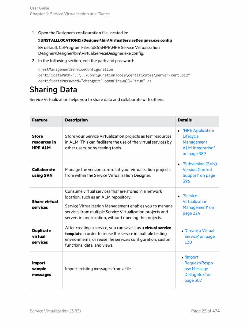
1. Open the Designer's configuration file, located in:
%[INSTALLLOCATION]%\Designer\bin\VirtualServiceDesigner.exe.config
By default, C:\Program Files (x86)\HPE\HPE Service VirtualizationDesigner\Designer\bin\VirtualServiceDesigner.exe.config.
2. In the following section, edit the path and password:
<restManagementServiceConfigurationcertificatePath="..\..\ConfigurationTools\certificates\server-cert.p12"certificatePassword="changeit" openFirewall="true" />
Sharing DataService Virtualization helps you to share data and collaborate with others.
Feature Description Details
Storeresources inHPE ALM
Store your Service Virtualization projects as test resourcesin ALM. This can facilitate the use of the virtual services byother users, or by testing tools.
l "HPE ApplicationLifecycleManagementALM Integration"on page 389
Collaborateusing SVN
Manage the version control of your virtualization projectsfrom within the Service Virtualization Designer.
l "Subversion (SVN)Version ControlSupport" on page396
Share virtualservices
Consume virtual services that are stored in a networklocation, such as an ALM repository.
Service Virtualization Management enables you to manageservices from multiple Service Virtualization projects andservers in one location, without opening the projects.
l "ServiceVirtualizationManagement" onpage 224
Duplicatevirtualservices
After creating a service, you can save it as a virtual servicetemplate in order to reuse the service in multiple testingenvironments, or reuse the service's configuration, customfunctions, data, and views.
l "Create a VirtualService" on page130
Importsamplemessages
Import existing messages from a file.
l "ImportRequest/Response MessageDialog Box" onpage 307
User GuideChapter 1: Service Virtualization at a Glance
Service Virtualization (3.83) Page 25 of 474
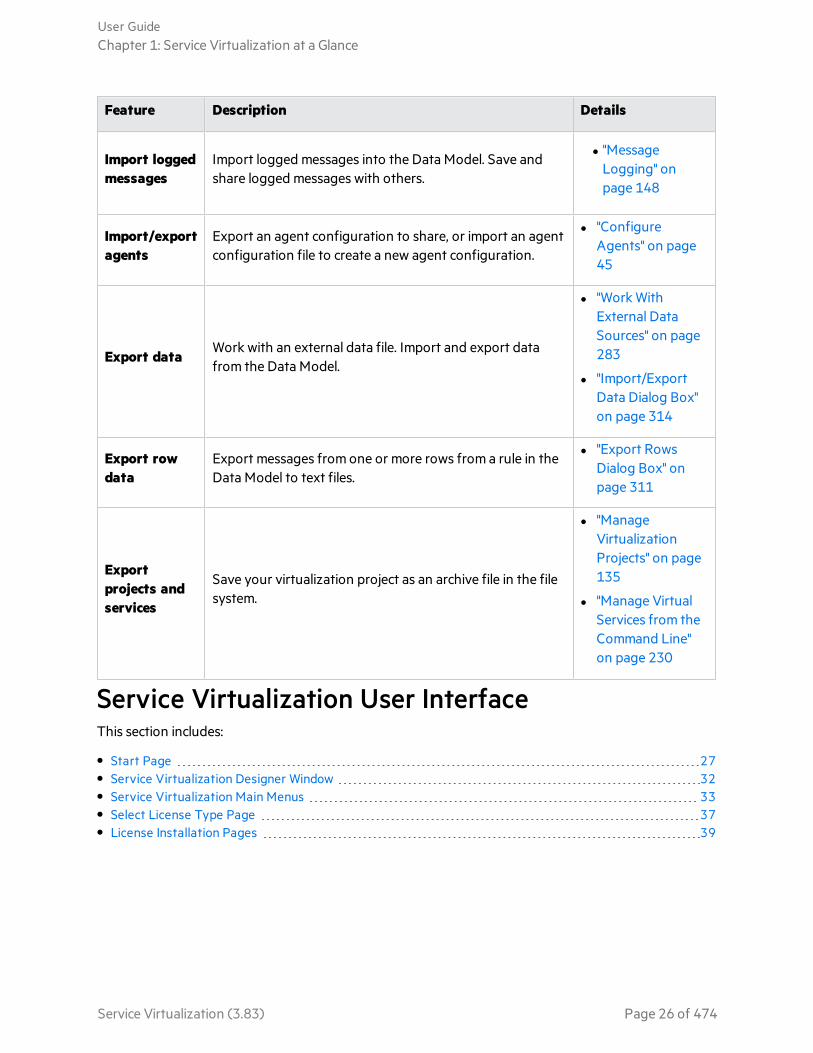
Feature Description Details
Import loggedmessages
Import logged messages into the Data Model. Save andshare logged messages with others.
l "MessageLogging" onpage 148
Import/exportagents
Export an agent configuration to share, or import an agentconfiguration file to create a new agent configuration.
l "ConfigureAgents" on page45
Export dataWork with an external data file. Import and export datafrom the Data Model.
l "Work WithExternal DataSources" on page283
l "Import/ExportData Dialog Box"on page 314
Export rowdata
Export messages from one or more rows from a rule in theData Model to text files.
l "Export RowsDialog Box" onpage 311
Exportprojects andservices
Save your virtualization project as an archive file in the filesystem.
l "ManageVirtualizationProjects" on page135
l "Manage VirtualServices from theCommand Line"on page 230
Service Virtualization User InterfaceThis section includes:
• Start Page 27• Service Virtualization Designer Window 32• Service Virtualization Main Menus 33• Select License Type Page 37• License Installation Pages 39
User GuideChapter 1: Service Virtualization at a Glance
Service Virtualization (3.83) Page 26 of 474
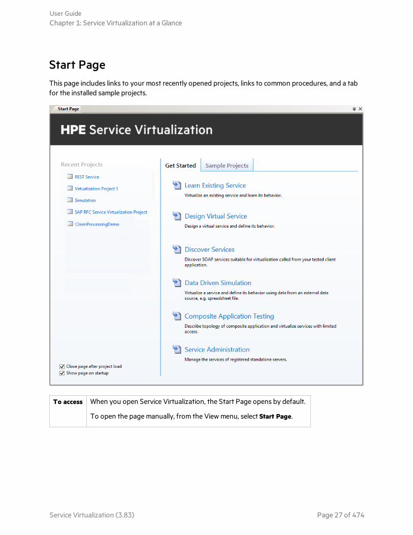
Start PageThis page includes links to your most recently opened projects, links to common procedures, and a tabfor the installed sample projects.
To access When you open Service Virtualization, the Start Page opens by default.
To open the page manually, from the View menu, select Start Page.
User GuideChapter 1: Service Virtualization at a Glance
Service Virtualization (3.83) Page 27 of 474

General
UI Element Description
Recent Projects Displays links to the most recently opened projects.
Get Started page Displays links to common procedures. For details, see Get Started Page below.
Sample Projectspage
Displays links to the demo projects, installed with Service Virtualization. Fordetails, see Sample Projects Page below.
Close page afterproject load
Closes the Start Page when you open a project.
Show page onstartup
Displays the Start Page each time you start Service Virtualization.
Get Started Page
This page provides links to several common procedures you perform in Service Virtualization.
UI Element Description
Learn ExistingService
Enables you to virtualize an existing service and learn its behavior.
Creates new virtualization project and a virtual service, and then places the newservice in Learning mode.
For user interface details, see "Virtual Service Editor" on page 186.
Design VirtualService
Enables you to design a virtual service and define its behavior.
Creates new virtualization project and a virtual service, and opens the DataModel Editor.
For user interface details, see "Data Model Editor" on page 291.
Discover Services Enables you to discover SOAP services suitable for virtualization in yourapplication under test.
Creates a new virtualization project, and opens the Service Discovery dialogbox, enabling you to find all services used by an application.
For user interface details, see "Service Discovery Dialog Box" on page 357.
Note: See also "HTTP Service Discovery" on page 134 for creatingREST services.
User GuideChapter 1: Service Virtualization at a Glance
Service Virtualization (3.83) Page 28 of 474
UI Element Description
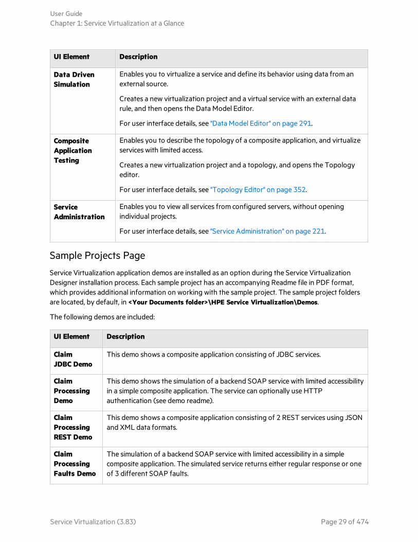
Data DrivenSimulation
Enables you to virtualize a service and define its behavior using data from anexternal source.
Creates a new virtualization project and a virtual service with an external datarule, and then opens the Data Model Editor.
For user interface details, see "Data Model Editor" on page 291.
CompositeApplicationTesting
Enables you to describe the topology of a composite application, and virtualizeservices with limited access.
Creates a new virtualization project and a topology, and opens the Topologyeditor.
For user interface details, see "Topology Editor" on page 352.
ServiceAdministration
Enables you to view all services from configured servers, without openingindividual projects.
For user interface details, see "Service Administration" on page 221.
Sample Projects Page
Service Virtualization application demos are installed as an option during the Service VirtualizationDesigner installation process. Each sample project has an accompanying Readme file in PDF format,which provides additional information on working with the sample project. The sample project foldersare located, by default, in <Your Documents folder>\HPE Service Virtualization\Demos.
The following demos are included:
UI Element Description
ClaimJDBC Demo
This demo shows a composite application consisting of JDBC services.
ClaimProcessingDemo
This demo shows the simulation of a backend SOAP service with limited accessibilityin a simple composite application. The service can optionally use HTTPauthentication (see demo readme).
ClaimProcessingREST Demo
This demo shows a composite application consisting of 2 REST services using JSONand XML data formats.
ClaimProcessingFaults Demo
The simulation of a backend SOAP service with limited accessibility in a simplecomposite application. The simulated service returns either regular response or oneof 3 different SOAP faults.
User GuideChapter 1: Service Virtualization at a Glance
Service Virtualization (3.83) Page 29 of 474

UI Element Description
ClaimProcessingSecurityDemo
This demo shows a composite application consisting of 2 SOAP services. It allowsdemonstrating how to record and simulate the behavior of one of the SOAPservices. Both services authenticate each other using X509 certificates.
ClaimProcessingStandaloneServer Demo
This demo shows a composite application consisting of 2 SOAP services. It allowsdemonstrating how to record and simulate the behavior of one of the SOAPservices on a standalone server.
ClaimApprovalJMS Demo
This demo shows a composite application consisting of 3 SOAP services. It allowsdemonstrating how to record and simulate the behavior of two SOAP services.Demo is similar to the Claim processing service simulation demo. One XML over JMSservice (TIBCO EMS approval service) has been added to the topology here and isbeing simulated, too.
ClaimApproval MSMQ Demo
This demo shows a composite application consisting of 3 SOAP services. It allowsdemonstrating how to record and simulate the behavior of two SOAP services. Thedemo is similar to the Claim Processing service virtualization demo. One XML overMS MQ service (MS MQ approval service) has been added to the topology here andis being simulated, too.
ClaimApprovalWebSphereMQ Demo
This demo shows a composite application consisting of 3 SOAP services. It allowsdemonstrating how to record and simulate the behavior of two SOAP services. Thedemo is similar to the Claim Processing service virtualization demo. One XML overWebSphere MQ service (WebSphere MQ approval service) has been added to thetopology here, and is being simulated, too.
IBM IMSTransactionManagerPhonebookDemo
This demo shows virtualization of the Phonebook IMS Transaction Managerapplication. The client is using IBM IMS Connect API to communicate with IMS TMover TCP/IP.
RequestTrackingServiceActivityDemo
This demo shows a composite application consisting of 4 SOAP services. It allowsdemonstrating how to record and simulate the behavior of two SOAP services. Inaddition, activity can be demonstrated by calling the third SOAP service from asimulated service.
SAP IDocDemo
This demo shows the virtualization of a service that uses the SAP IDoc protocol. Itenables you to record and simulate asynchronous IDoc message transfer.
SAP RFCDemo
This demo shows the virtualization of a service that uses the SAP RFC protocol. Itenables you to record and simulate a remote-enabled RFC function module.
User GuideChapter 1: Service Virtualization at a Glance
Service Virtualization (3.83) Page 30 of 474

UI Element Description
ShoppingCart- No SessionsDemo
This demo shows virtualization of stateful shopping cart service, where only oneclient is using the stateful service.
ShoppingCart- Sessions byClients Demo
This demo shows virtualization of stateful shopping cart service, where multipleconcurrent clients are using the stateful service and private session is generated foreach client.
ShoppingCart- Sessions byOrders Demo
This demo shows virtualization of stateful shopping cart service, where multipleconcurrent clients are using the stateful service and sessions are generated per eachshopping order. The checkout operation finishing shopping order destroys theclient session (the next operation creates a new one).
Test DataManagement- ImportData Demo
This demo shows the virtualization of a backend SOAP service with simulation dataimported from an external data file.
Test DataManagement- ExportData Demo
This demo shows the virtualization of a backend SOAP service with the export oflearned data to an external data file.
See also:l "Introducing Service Virtualization" on page 14
l "Service Virtualization Designer Window" on the next page
l "Service Virtualization Main Menus" on page 33
User GuideChapter 1: Service Virtualization at a Glance
Service Virtualization (3.83) Page 31 of 474
Service Virtualization Designer Window
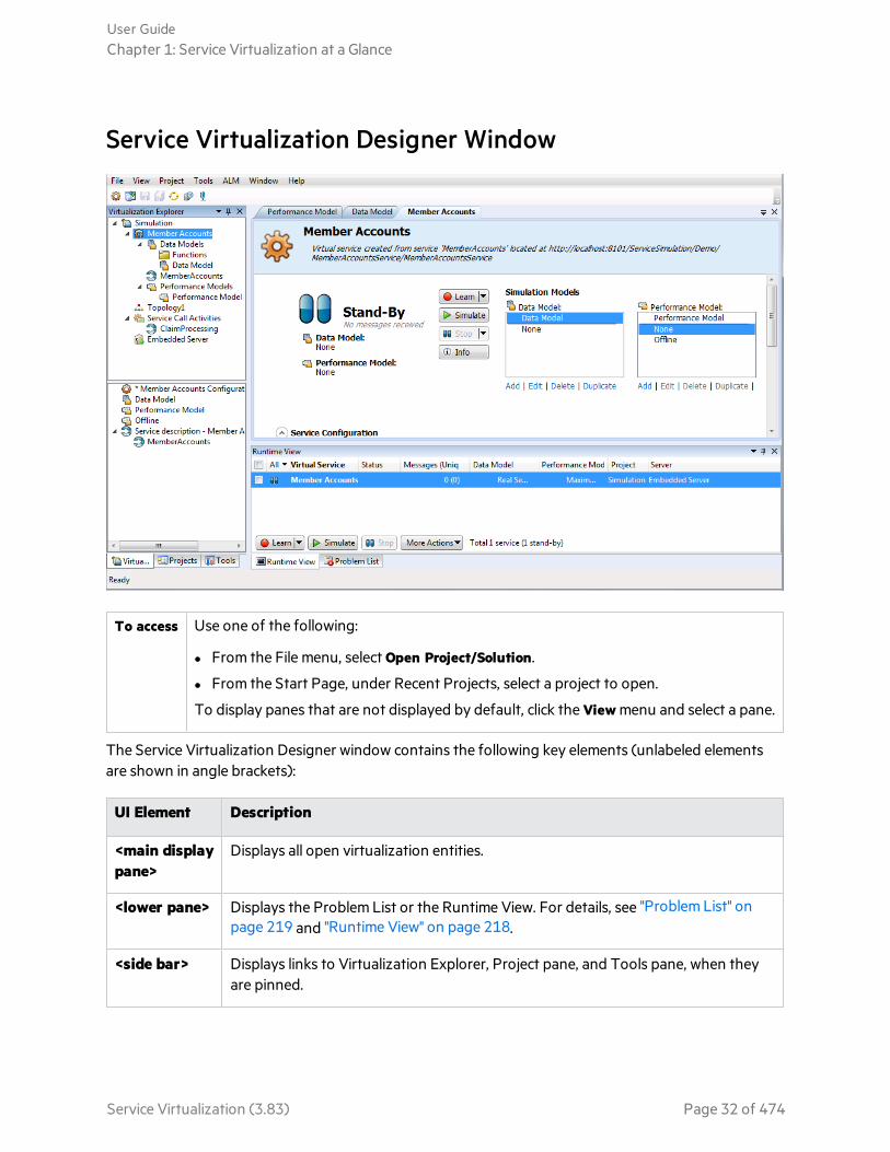
To access Use one of the following:
l From the File menu, select Open Project/Solution.
l From the Start Page, under Recent Projects, select a project to open.
To display panes that are not displayed by default, click the View menu and select a pane.
The Service Virtualization Designer window contains the following key elements (unlabeled elementsare shown in angle brackets):
UI Element Description
<main displaypane>
Displays all open virtualization entities.
<lower pane> Displays the Problem List or the Runtime View. For details, see "Problem List" onpage 219 and "Runtime View" on page 218.
<side bar> Displays links to Virtualization Explorer, Project pane, and Tools pane, when theyare pinned.
User GuideChapter 1: Service Virtualization at a Glance
Service Virtualization (3.83) Page 32 of 474
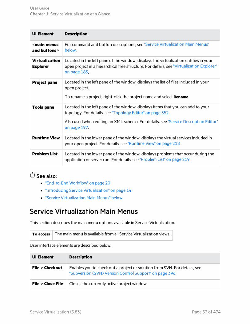
UI Element Description
<main menusand buttons>
For command and button descriptions, see "Service Virtualization Main Menus"below.
VirtualizationExplorer
Located in the left pane of the window, displays the virtualization entities in youropen project in a hierarchical tree structure. For details, see "Virtualization Explorer"on page 185.
Project pane Located in the left pane of the window, displays the list of files included in youropen project.
To rename a project, right-click the project name and select Rename.
Tools pane Located in the left pane of the window, displays items that you can add to yourtopology. For details, see "Topology Editor" on page 352.
Also used when editing an XML schema. For details, see "Service Description Editor"on page 197.
Runtime View Located in the lower pane of the window, displays the virtual services included inyour open project. For details, see "Runtime View" on page 218.
Problem List Located in the lower pane of the window, displays problems that occur during theapplication or server run. For details, see "Problem List" on page 219.
See also:l "End-to-End Workflow" on page 20
l "Introducing Service Virtualization" on page 14
l "Service Virtualization Main Menus" below
Service Virtualization Main MenusThis section describes the main menu options available in Service Virtualization.
To access The main menu is available from all Service Virtualization views.
User interface elements are described below.
UI Element Description
File > Checkout Enables you to check out a project or solution from SVN. For details, see"Subversion (SVN) Version Control Support" on page 396.
File > Close File Closes the currently active project window.
User GuideChapter 1: Service Virtualization at a Glance
Service Virtualization (3.83) Page 33 of 474

UI Element Description
File > CloseProject/Solution
Closes the open project.
File > ExportProject
Enables you to save your project as a file in the file system. The file is saved withthe default file extension .vproja.
File > New> Topology
Opens the Summary of New Topology dialog box, enabling you to create a newtopology. For details, see "Summary of New Topology Dialog Box" on page 352.
Note: Available in an open project.
File > New> VirtualService
Launches the new virtual service wizard. For details, see "Create New VirtualService Wizard" on page 153.
Note: Available in an open project.
File > New> MultipleVirtual Services
Create multiple SOAP virtual services simultaneously.
Note: Available in an open project.
File > New> VirtualService fromTemplate
Opens the Choose Template for Virtual Service dialog box, enabling you tocreate a new virtual service based on an existing template. For details, see "Createa Virtual Service" on page 130.
Note: Available in an open project.
File > New> VirtualizationProject
Enables you to create a new virtualization project. For details, see "Summary ofVirtualization Project Dialog Box" on page 152.
File > OpenProject/Solution
Opens your file system browser, enabling you to select a virtualization project toopen.
File > RecentProjects
Displays list of recently opened projects, enabling you to select a project to open.
Select Clear recent project list to delete the list.
File > ReloadFile
Not in use.
User GuideChapter 1: Service Virtualization at a Glance
Service Virtualization (3.83) Page 34 of 474

UI Element Description
File > ReloadSolution
Reloads solution from file system.
File > Save Saves changes made in the editor window in which you are currently working.
File > Save All Saves changes made in all open editor windows.
File > SaveProject As
Makes a copy of the open project, and saves it with a new name.
View > ProblemList
Displays the Problem List in the bottom pane of the Service Virtualizationwindow. For details, see "Problem List" on page 219.
View > Projects Opens the Projects pane, displaying the files included in the open project.
View > RuntimeView
Displays the Runtime View in the bottom pane of the Service Virtualizationwindow. For details, see "Runtime View" on page 218.
View > ServiceAdministration
Displays the Service Administration window. For details, see "ServiceAdministration" on page 221.
View > StartPage
Opens the Service Virtualization Start Page. For details, see "Start Page" on page27.
View > TaskList
Opens the Task List pane. For details, see "Topology Editor" on page 352.
View > Tools Opens the Tools pane, displaying a toolbox of items for the Topology editor, andalso for the XML and XML schema editor.
View > Tools> Files
Opens the Files pane, displaying your local file system in a browser.
View > Tools> SearchResults
Not in use.
View > Tools> XPath Query
Not in use.
Project > OpenFolder inExplorer
Opens the open project's folder in your file system browser, displaying the filesincluded in the project.
User GuideChapter 1: Service Virtualization at a Glance
Service Virtualization (3.83) Page 35 of 474
UI Element Description
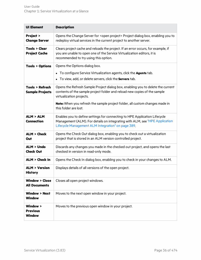
Project >Change Server
Opens the Change Server for <open project> Project dialog box, enabling you toredeploy virtual services in the current project to another server.
Tools > ClearProject Cache
Clears project cache and reloads the project. If an error occurs, for example, ifyou are unable to open one of the Service Virtualization editors, it isrecommended to try using this option.
Tools > Options Opens the Options dialog box.
l To configure Service Virtualization agents, click the Agents tab.
l To view, add, or delete servers, click the Servers tab.
Tools > RefreshSample Projects
Opens the Refresh Sample Project dialog box, enabling you to delete the currentcontents of the sample project folder and reload new copies of the samplevirtualization projects.
Note: When you refresh the sample project folder, all custom changes made inthis folder are lost.
ALM > ALMConnection
Enables you to define settings for connecting to HPE Application LifecycleManagement (ALM). For details on integrating with ALM, see "HPE ApplicationLifecycle Management ALM Integration" on page 389.
ALM > CheckOut
Opens the Check Out dialog box, enabling you to check out a virtualizationproject that is stored in an ALM version controlled project.
ALM > UndoCheck Out
Discards any changes you made in the checked out project, and opens the lastchecked in version in read-only mode.
ALM > Check In Opens the Check In dialog box, enabling you to check in your changes to ALM.
ALM > VersionHistory
Displays details of all versions of the open project.
Window > CloseAll Documents
Closes all open project windows.
Window > NextWindow
Moves to the next open window in your project.
Window >PreviousWindow
Moves to the previous open window in your project.
User GuideChapter 1: Service Virtualization at a Glance
Service Virtualization (3.83) Page 36 of 474
See also:l "End-to-End Workflow" on page 20
l "Introducing Service Virtualization" on page 14
l "Service Virtualization Main Menus" on page 33
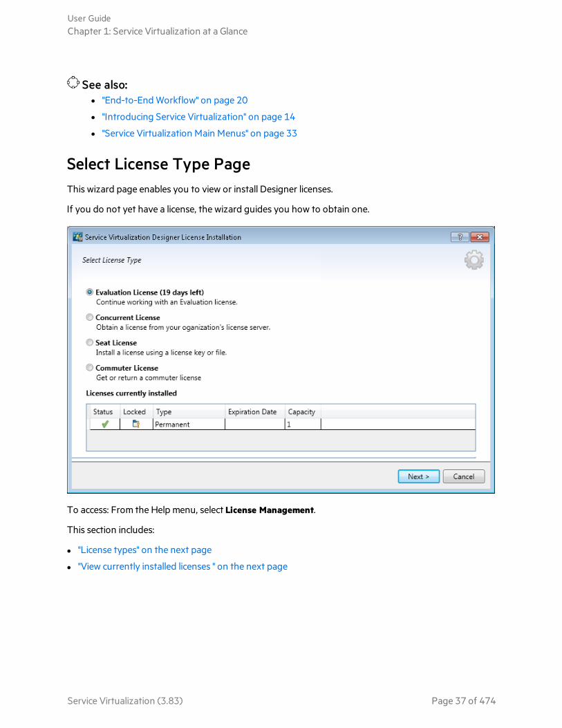
Select License Type PageThis wizard page enables you to view or install Designer licenses.
If you do not yet have a license, the wizard guides you how to obtain one.
To access: From the Help menu, select License Management.
This section includes:
l "License types" on the next page
l "View currently installed licenses " on the next page
User GuideChapter 1: Service Virtualization at a Glance
Service Virtualization (3.83) Page 37 of 474
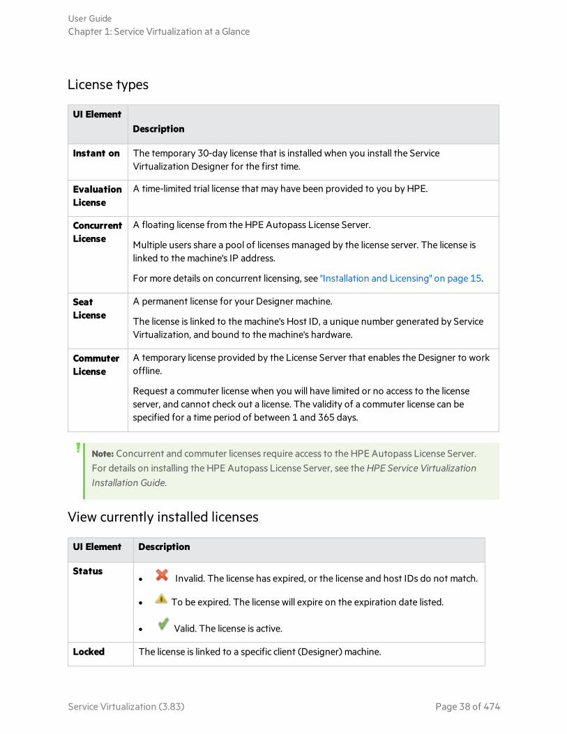
License types
UI ElementDescription
Instant on The temporary 30-day license that is installed when you install the ServiceVirtualization Designer for the first time.
EvaluationLicense
A time-limited trial license that may have been provided to you by HPE.
ConcurrentLicense
A floating license from the HPE Autopass License Server.
Multiple users share a pool of licenses managed by the license server. The license islinked to the machine's IP address.
For more details on concurrent licensing, see "Installation and Licensing" on page 15.
SeatLicense
A permanent license for your Designer machine.
The license is linked to the machine's Host ID, a unique number generated by ServiceVirtualization, and bound to the machine's hardware.
CommuterLicense
A temporary license provided by the License Server that enables the Designer to workoffline.
Request a commuter license when you will have limited or no access to the licenseserver, and cannot check out a license. The validity of a commuter license can bespecified for a time period of between 1 and 365 days.
Note: Concurrent and commuter licenses require access to the HPE Autopass License Server.For details on installing the HPE Autopass License Server, see the HPE Service VirtualizationInstallation Guide.
View currently installed licenses
UI Element Description
Statusl Invalid. The license has expired, or the license and host IDs do not match.
l To be expired. The license will expire on the expiration date listed.
l Valid. The license is active.
Locked The license is linked to a specific client (Designer) machine.
User GuideChapter 1: Service Virtualization at a Glance
Service Virtualization (3.83) Page 38 of 474

UI Element Description
Type The type of license that is installed. For details, see "License types" on the previouspage.
ExpirationDate
Displays the date on which the license will expire.
Note: When a floating license expires, it is automatically renewed if you arestill working in the Designer.
Capacity Quantity of available licenses.
See also:l "Installation and Licensing" on page 15
l "License Installation Pages" below
l "Service Virtualization Editions" on page 16
License Installation PagesThese wizard pages enable you to request and install Designer licenses.
Note: Concurrent and commuter licenses require access to the HPE Autopass License Server.For details on installing the HPE Autopass License Server, see the HPE Service VirtualizationInstallation Guide
To access: From the Help menu, select License Management. Then select the type of license to install ormanage.
This section includes:
l "Concurrent License " on the next page
l "Seat License " on page 41
l "Commuter License" on page 42
User GuideChapter 1: Service Virtualization at a Glance
Service Virtualization (3.83) Page 39 of 474

Concurrent License
Configure a license server. Get or return a concurrent license
UIElement Description
ChangeServer
Enables you to configure a license server.
Enter the following details:
Host: The host name or IP address of the HPE Autopass License Server.
Port: The communications port of the license server. By default, 5814.
Protocol: Select HTTP or HTTPS.
GetFloatingLicense
Retrieves a license from the license server. Concurrent licenses are valid for a period of 15minutes, after which they are automatically renewed.
If you are using a concurrent license model and have access to a license server, a license isautomatically checked out each time you open the Designer. When you close theDesigner, the concurrent license is returned to the license server.
User GuideChapter 1: Service Virtualization at a Glance
Service Virtualization (3.83) Page 40 of 474

UIElement Description
ReturnFloatingLicense
If you no longer need the license, you can return it to the license server.
Alternatively, closing the Designer returns the license to the server.
Seat License
The seat license page includes the following options:
UI Element Description
Obtain a new Seatlicense
Click the HPE Licensing for Software link to connect to HPE, and sign in torequest a license.
Host ID Record this detail. It is required when you submit a request for a new seatlicense.
Click Copy to Clipboard to copy the Host ID.
Install your Seatlicense
Select an installation option. Browse to select a license file, or enter a licensekey.
User GuideChapter 1: Service Virtualization at a Glance
Service Virtualization (3.83) Page 41 of 474

UI Element Description
Next Opens the License File Content page. Select a license to install.
Commuter License
The commuter license page includes the following options:
UI Element Description
License Server The address of your license server, if one is configured.
RequestedCommuterLicenseDuration
Specify a duration between 1 and 365 days.
Online Operations: (For use when you have access to the license server)
Get CommuterLicense
Request a license from the license server that you can use offline for a specificnumber of days.
RecoverCommuterLicense
Download a new copy of your commuter license if the license was lost.
User GuideChapter 1: Service Virtualization at a Glance
Service Virtualization (3.83) Page 42 of 474

UI Element Description
ReturnCommuterLicense
Returns the commuter license to the license server when you no longer need it.
Offline Operations: (For use when you cannot access the license server.)
Create a Fileto GetCommuterLicense
Generates a license input file used for requesting a new commuter license. You cansend the file to a user with access to the license server. A license server user canthen check out a license, and send it back to you.
InstallCommuterLicense
Installs the license from the license file.
Create a Fileto ReturnCommuterLicense
Generates a license file that contains the license information, in order to return acommuter license to the license server. You can then send the file to a user withaccess to the license server.
See also:l "Installation and Licensing" on page 15
l "Select License Type Page" on page 37
l "Service Virtualization Editions" on page 16
User GuideChapter 1: Service Virtualization at a Glance
Service Virtualization (3.83) Page 43 of 474
Chapter 2: Service Virtualization AgentsThis chapter includes:
• Service Virtualization Agents 45• Configure Agents 45• Forward HTTP Agent Communication Through an HTTP Proxy 76• Agents User Interface 76
Service Virtualization (3.83) Page 44 of 474

Service Virtualization AgentsThis chapter provides instructions on configuring Service Virtualization Agents. Agents handlecommunication between a client and a real or virtual service. Each agent handles communication specificto the transport and message protocols you are using. You must configure the Service Virtualizationagent for each protocol your services are using.
The Service Virtualization agents must be configured on each server (embedded or standalone) onwhich the services are deployed. You can add multiple instances of an agent to the same server,configuring each one differently.
Note: Not all agents are installed by default. For details on installing an agent manually, see therelevant help section on the agent you require.
Next steps:l "Configure Agents" below
Configure AgentsThis task describes how to configure Service Virtualization agents. There are several pre-configuredagent instances with default configurations. You can use these instances, modify them, or define newinstances.
Note:
l This task is part of a higher-level task. For details, see "End-to-End Workflow" on page 20.
l To learn more about Service Virtualization Agents, see "Service Virtualization Agents" above.
To configure an agent:
1. From the main menu, select Tools > Options and click the Agents page.
2. In the left pane, expand the server to display the available agents and configurations.
3. Select the agent you want to configure, and fill in the properties.
4. To add another configuration of an agent, choose one of the following:
l Click Add. A new configuration is added and you can modify its settings.
l Click Import. Select an agent configuration file that was exported from a Service VirtualizationServer (embedded or standalone) and saved on the file system.
If the configuration file you are importing contains multiple configurations, you can select whichconfigurations you want to import.
If you choose to import an agent configuration that is identical to a configuration that alreadyexists on your server, you can choose to overwrite your existing configuration, or create a new,additional configuration.
User GuideChapter 2: Service Virtualization Agents
Service Virtualization (3.83) Page 45 of 474

You can also delete, duplicate, and export agent configurations. For user interface details, see "AgentsPage" on page 77.
This section also includes:
• Configure the File System/File System FTP Agents 47• Configure the HTTP/HTTPS Gateway Agents 47• Configure the HTTP(S) Proxy Agent 49• Configure the IBM IMS TM Agent 49• Configure the Java Agent 50• Configure the JDBC Agent 52• Configure the JMS Generic Agent 57• Configure the MSMQ Agent 58• Configure the Oracle AQ Agent 59• Configure the SAP Agent 60• Configure the TIBCO EMS Non Intrusive Agent 62• Configure the WebMethods SAP Agent 63• Configure the WebSphere MQ Non-Intrusive Agent 66• Configure the WebSphere MQ Agent 74
User GuideChapter 2: Service Virtualization Agents
Service Virtualization (3.83) Page 46 of 474
See also:l "Virtualize SAP IDoc Communication" on page 142
l "Virtualize Fixed-Length Communication" on page 143
Configure the File System/File System FTP AgentsThis task describes how to configure the File System agent and the File System FTP agent. The FileSystem agents are used to virtualize communication of services that are communicating over the filesystem or FTP.
For each service you want to virtualize, you need to create four File System agent configurations:
l Input - the location in which the service checks for new or modified files (the requests). Create oneagent configuration for the real service, and one for the virtual service.
l Output - the location to which the service writes (the responses). Create one agent configuration forthe real service, and one for the virtual service.
To configure the File System/File System FTP agent:
From the main Service Virtualization menu, select Tools > Options. On the Agents Page, select FileSystem or File System FTP. For user interface details, see the "File System Agent Settings" on page 77.
After you create the agent configurations, you can use them in a virtual service. The following ServiceVirtualization protocols can work with the File System agents:
l Binary messages over file system
l CSV messages over file system
l Text-delimited messages over file system
l XML messages over file system
For details on creating a virtual service that uses one of these protocols, see "Create New Virtual ServiceWizard" on page 153.
Configure the HTTP/HTTPS Gateway AgentsThis task describes how to configure the Service Virtualization HTTP/HTTPS gateway agents.
The HTTP/HTTPS Gateway Agents serve to virtualize HTTP communication. A virtual HTTP endpointis created to mediate between a client and a real service HTTP endpoint. During the learning process,real communication is forwarded to a real service HTTP endpoint and the communication is recorded.
User GuideChapter 2: Service Virtualization Agents
Service Virtualization (3.83) Page 47 of 474

To configure the HTTP/HTTPS Gateway agents
1. Configure the agent settings
From the main menu, select Tools > Options. On the Agents Page, select HTTP Gateway orHTTPS Gateway. For user interface details, see "HTTP/HTTPS Gateway Agent Settings" on page81.
2. Forward unknown endpoint requests
If you are not able to reconfigure clients on a service basis (i.e. changing the endpoint of eachservice to a virtual service), and all of your HTTP(S) services reside on a single host, you can use theForwarded to Host option on the Agents Page.
Example: The client is calling several backend services:
http://esb.demo.hpe.com:8080/BackendServices/MemberAccounts
http://esb.demo.hpe.com:8080/BackendServices/ExchangeRate
http://esb.demo.hpe.com:8080/BackendServices/Approval
You are only virtualizing the MemberAccounts service but are only able to reconfigure theapplication to use another host for all services rather than changing the endpoint of justthe one MemberAccounts service in the application.
You reconfigure your application to use the SV Server HTTP Gateway at:
http://svserver.hpe.com:7200 instead of http://esb.demo.hpe.com:8080
The application will access backend services at these endpoints:
http://svserver.hpe.com:7200/BackendServices/MemberAccounts
http://svserver.hpe.com:7200/BackendServices/ExchangeRate
User GuideChapter 2: Service Virtualization Agents
Service Virtualization (3.83) Page 48 of 474

http://svserver.hpe.com:7200/BackendServices/Approval
You create the MemberAccounts service so this functions but the other services would beinaccessible for the application until you virtualized all of them.
To avoid the virtualization of all backend services set the DEFAULT TARGET HOST to
http://esb.demo.hpe.com:8080
Now all requests to non-virtualized services are forwarded to the
http://esb.demo.hpe.com:8080 host and are reaching the real services you do not intendto virtualize now.
Note: The Forwarded to Host field can contain a base URL in several formats: the host,
optional port, and optional base path, i.e.: http://esb.demo.hpe.com,http://esb.demo.hpe.com:8080.
3. Configure a proxy agent
To set the proxy agent configuration properties, see "Configure the HTTP(S) Proxy Agent" below.
Configure the HTTP(S) Proxy AgentThis task describes how to configure the Service Virtualization HTTP(S) proxy agent.
The HTTP(S) Proxy Agent serves to virtualize HTTP and HTTPS communication. No endpoint iscreated, and an HTTP(S) proxy is used to receive and forward client communication to a real serviceHTTP or HTTPS endpoint.
1. Configure the agent settings
The HTTP(S) proxy agent dynamically generates certificates for requested hosts on the fly. Thecertificates are signed by the configured certificate authority (CA). Configure the CA certificate andprivate key in the HTTP(S) Proxy agent configuration.
From the main menu, select Tools > Options. On the Agents Page, select HTTP(S) Proxy. For userinterface details, see the "HTTP(S) Proxy Agent Settings" on page 84.
2. Configure the client
The client must trust certificates signed using a configured CA or the communication may fail dueto rejection by the client.
Configure the IBM IMS TM AgentThis task describes how to configure the IBM IMS TM agent. The IBM IMS TM Agent is used tovirtualize IBM IMS Transaction Manager (TM) services that are exposed using the IMS Connect
User GuideChapter 2: Service Virtualization Agents
Service Virtualization (3.83) Page 49 of 474

protocol over a TCP/IP network.
The IBM IMS TM agent is used as an IMS TM gateway. The clients communicate directly with the agent.Then the agent either forwards the traffic to the actual IMS TM during pass-through (Standby mode)or recording (Learning mode), or simulates the response. The communication is always forwarded toIMS TM if it does not belong to any of the deployed services. For more details, see "Create a VirtualService" on page 130.
1. Prerequisites
The following types of integration scenarios are supported:
l A client using IMS Connect API.
l A client using IMS TM Resource Adapter (managed and unmanaged).
2. Configure the agent settings
From the main menu, select Tools > Options. On the Agents Page, select IBM IMS TM and clickAdd. Define settings for the new configuration. For user interface details, see the "IBM IMS TMAgent Settings" on page 86.
Configure the Java AgentThis task describes how to configure the Service Virtualization Java agent to virtualize a Javaapplication.
There are two components required for Java virtualization:
l Java agent. The Service Virtualization Java agent listens for requests from your application undertest.
l Java instrumentator. Service Virtualization provides a Java instrumentator(HP.SV.JavaInstrumentator.jar). You download the instrumentator from inside the ServiceVirtualization application, and use an XML configuration file to define the classes and methods thatyou want to virtualize. The download includes the instrumentator, a sample XML configuration file,and a readme file.
Note: The Service Virtualization Java instrumentator supports OpenJDK and Oracle Java 1.5or later. For the most up-to-date information on supported versions, refer to the supportmatrix on the HPE Software Support site at:https://softwaresupport.hpe.com/group/softwaresupport/support-matrices.
How to configure the Java agent
1. Prerequisite:
If Java security is enabled for the application that is being virtualized, the Java InstrumentationAgent requires the following permissions:
permission java.io.FilePermission "<<ALL FILES>>", "read, write";permission java.lang.RuntimePermission "createClassLoader";
User GuideChapter 2: Service Virtualization Agents
Service Virtualization (3.83) Page 50 of 474
permission java.lang.RuntimePermission "accessClassInPackage.sun.misc";permission java.lang.RuntimePermission "accessDeclaredMembers";permission java.lang.RuntimePermission"accessClassInPackage.com.sun.org.apache.xerces.internal.jaxp";permission java.lang.RuntimePermission"accessClassInPackage.com.sun.org.apache.xerces.internal.dom";permission java.io.SerializablePermission "enableSubclassImplementation";permission java.lang.reflect.ReflectPermission "suppressAccessChecks";permission java.net.SocketPermission "*", "connect, resolve";permission java.util.PropertyPermission "*", "read";
2. Configure the Service Virtualization Java agent settings:
From the main Service Virtualization menu, select Tools > Options. On the Agents Page, select JavaAgent. For user interface details, see the "Java Agent Settings" on page 88.
3. Download and unzip the Service Virtualization Java instrumentator:
On the Agents page, select Download Java Application Instrumentator.
4. Create and configure an XML configuration file:
There is a sample file included with the Java instrumentator download.
You need to configure two parts of the XML configuration file:
l Managed Classes: Classes that the Java Instrumentation Agent takes care of. Managed classescan be virtualized, but do not need to be.
l Service Virtualization Agent Endpoint: In the format http://<machine_name>:<listening_port>
where:
machine_name = the computer on which the Service Virtualization Java agent is located
listening_port = the port defined on the "Java Agent Settings" on page 88 page.
Additional information on how to configure the file is included in the sample configuration file.
5. Configure virtualized classes in a new or existing virtual service:
When a class is being virtualized, it makes network calls to the Service Virtualization Server.
You can define virtualized classes in the following ways:
l When you create a new virtual service. For details, see "Create a Virtual Service" on page 130.
l Define or modify the classes for an existing virtual service. For details, see "Service PropertiesPage" on page 158.
6. Start your Java application with Service Virtualization instrumentation:
l For the instrumentation of a generic Java application:
Run the Java application with parameter -javaagent:<path toHP.SV.JavaInstrumentator.jar>=<path to configuration xml file>.
For example:
java -javaagent:c:/sv/HP.SV.JavaInstrumentator.jar=c:/sv/config.xml -jarapplication.jar
User GuideChapter 2: Service Virtualization Agents
Service Virtualization (3.83) Page 51 of 474

l For the instrumentation of a Java application deployed to an application server (AS):
Add the -javaagent parameter into the Java process that runs the AS. This can generally bedone either by using settings in the Management Console of the AS, or by amending the start-up script that starts the AS. The start-up script typically includes variables such as JAVA_OPTION that define the Java parameters. Add the -javaagent parameter to the relevantvariable.
The instrumentator processes everything in the AS (including the AS itself) and not only theapplication that you want to virtualize.
JBoss Application Server
If the HP.SV.JavaInstrumentator is used on JBoss Application Server 7.X or later (including WildFlyversions), you must set the HP.SV.JavaInstrumentator as a global module. This is becauseHP.SV.JavaInstrumentator amends a bytecode of managed classes so that they call componentswithin the HP.SV.JavaInstrumentator.
To set the HP.SV.JavaInstrumentator as a global module, specify the following command linearguments for the Java process that runs JBoss/Wildfly:
-javaagent:<path to instrumentator>=<path to configuration xml file>
-Djava.util.logging.manager=org.jboss.logmanager.LogManager
-Xbootclasspath/p:%JBOSS_HOME%\modules\system\layers\base\org\jboss\logmanager\main\jboss-logmanager-1.5.2.Final.jar
-Djboss.modules.system.pkgs=org.jboss.byteman,org.jboss.logmanager,com.hp.sv.java,org.eclipse.persistenceThe version of jboss-logmanager jar (in this case it was jboss-logmanager-1.5.2.Final.jar) can varyso make sure to use the correct version for your server.
For example, on a Windows machine you can add these parameters by amending the JBoss startupscript located at <JBoss Home Folder>/bin/standalone.cmd.
On a Linux system you can add these parameters by amending the <JBoss HomeFolder>/bin/standalone.sh.
These are only examples, and may be specified differently in your environment.
See also:l "Java Agent Settings" on page 88
Configure the JDBC AgentThis task describes how to configure the JDBC agent. The JDBC agent is used to virtualize both J2EEand J2SE applications that are using JDBC™ API to access persistent storage.
Service Virtualization provides these two components:
User GuideChapter 2: Service Virtualization Agents
Service Virtualization (3.83) Page 52 of 474

l JDBC agent. You configure the JDBC agent in Service Virtualization. The agent listens for requestsfrom the JDBC driver.
l JDBC driver. You install the JDBC driver in your application under test. The driver communicatesremotely with the JDBC agent in Service Virtualization. It intercepts each JDBC API call anddepending on the current service mode, forwards the traffic accordingly. If the virtual service is ineither Standby or Learning mode, the driver forwards the traffic to the actual JDBC driver. If thevirtual service is in Simulating mode, the virtual service simulates the API response.
The JDBC driver is uniquely generated according to the configuration of the JDBC agent and agenthost that you define in Service Virtualization. The driver is invoked only if either a virtualization JDBCconnection string is used (J2SE), or if the virtual data source is explicitly created and used by theapplication (J2EE). If a non-virtualization connection string or data source is used, the virtualizationJDBC driver is inactive and has no impact on the application under test.
To configure the JDBC agent:
1. Prerequisites:
The following types of integration scenarios are supported:
l A J2SE application using JDBC 3.0 or 4.0/4.1 API.
l A Java™ based application deployed on a J2EE application server (J2EE version 1.4 or later).
2. Configure the agent settings:
From the main Service Virtualization menu, select Tools > Options. On the Agents Page, selectJDBC Agent. For user interface details, see the "JDBC Agent Settings" on page 90.
3. Reconfigure a standard J2SE or J2EE application:
l J2SE
l J2EE
Reconfigure a standard J2SE application
To reconfigure a typical Java Standard Edition (J2SE) application for JDBC API virtualization:
a. Make sure you have configured the agent settings correctly.
b. Download the JDBC driver. On the Agents Page, click Create JDBC driver for thisconfiguration.
c. Deploy the driver in the application class path.
d. In some cases, you may need to override JDBC default type mapping. To override default JDBCtype mapping, add the typeMapping property to your connection string. For example:jdbc:hpsv:db2://svdb2.hpswlabs.adapps.hp.com:50000/DEV:typeMapping=META-INF/myTypeMappingProperties
To learn more, see "JDBC type to Java type mapping" on page 56.
e. Create an SQL over JDBC virtual service, and use the actual JDBC connection string as theVirtual Service Real Connection String.
f. Reconfigure the application under test to use virtual endpoint. If you are working with JDBC
User GuideChapter 2: Service Virtualization Agents
Service Virtualization (3.83) Page 53 of 474
version 3.0, you must also update the JDBC driver class name to the virtualization driver classname. The virtual driver class name is com.hp.sv.jdbc.agent.jdbc3.VirtualDriver.
Reconfigure a standard J2EE application
To reconfigure a typical Java Enterprise Edition (J2EE) application using JDBC data sources, forJDBC API virtualization:
a. Make sure you have configured the agent settings correctly.
b. Download the JDBC driver. On the Agents Page, click Create JDBC driver for thisconfiguration.
c. Create an additional J2EE data source using the newly created virtual JDBC driver that youdownloaded from the Service Virtualization Agents page. See the J2EE application serverdocumentation for more details.
d. Reconfigure the application under test to use the newly created data source.
e. Create an SQL over JDBC virtual service, and use the name of the newly created data source asthe Real Connection String.
4. Configure your application server:
l WebLogic 12c
l WebSphere 8
l WebSphere 6
l WebMethods
Add a virtual data source to a WebLogic 12c application server
a. Place the JDBC driver that you downloaded from the Service Virtualization Agents page in WL_HOME\server\lib.
b. Modify WEBLOGIC_CLASSPATH in WL_HOME\common\bin\commEnv.cmd (or commEnv.sh), asdescribed in the WebLogic documentation.
c. In the WebLogic Server Administration Console, create a new data source. Provide the JNDIname of the real data source, using the RealDataSourceName property.
Alternatively, you can set up the JNDI virtual driver to use a direct connection to the database,by specifying the realUrl property. For example:realUrl=jdbc:oracle:thin:@database.host.com:1521:orcl.
d. In some cases, you may need to override JDBC default type mapping. To override default JDBCtype mapping, add the typeMapping property with the location of the mapping file to yourdata source.
To learn more, see "JDBC type to Java type mapping" on page 56.
e. Restart the WebLogic server.
Add a virtual data source to a WebSphere 8 application server
a. In the WebSphere administrative console, in Resources > JDBC > JDBC Providers, add a new
User GuideChapter 2: Service Virtualization Agents
Service Virtualization (3.83) Page 54 of 474

virtual JDBC provider.
database type: user-defined
implementation class name: com.hp.sv.jdbc.agent.jdbc4.VirtualDataSource
classpath: enter the path to the downloaded virtual JDBC driver
b. Create a new data source using the newly created JDBC Provider and enter custom properties.
Provide the JNDI name of the real data source, using the realDataSourceName property.
Alternatively, you can set up the JNDI virtual driver to use a direct connection to the database,by specifying the realUrl property. For example:realUrl=jdbc:oracle:thin:@database.host.com:1521:orcl.
You do not need to define properties for username and password if you use the JAAS - J2Cauthentication data alias in the security settings for the virtual data source.
c. In some cases, you may need to override JDBC default type mapping. To override default JDBCtype mapping, add the typeMapping property with the location of the mapping file to yourdata source.
To learn more, see "JDBC type to Java type mapping" on the next page.
d. Run the WebSphere test connection operation on the virtual data source.
Add a virtual data source to a WebSphere 6 application server
a. In the WebSphere administrative console, in Resources > JDBC > JDBC Providers, add a newvirtual JDBC provider.
database type: user-defined
implementation class name: com.hp.sv.jdbc.agent.jdbc3.VirtualDataSource
classpath: enter the path to the downloaded virtual JDBC driver
b. Create a new virtual data source using the newly created JDBC provider.
c. In some cases, you may need to override JDBC default type mapping. To override default JDBCtype mapping, add the typeMapping property with the location of the mapping file to yourdata source.
To learn more, see "JDBC type to Java type mapping" on the next page.
d. Disable statement caching. In the WebSphere Application Server data source properties, setStatement Cache size to 0.
e. Define custom properties for the virtual data source:
Provide the JNDI name of the real data source, using the realDataSourceName property.
Alternatively, you can set up the JNDI virtual driver to use a direct connection to the database,by specifying the realUrl property. For example:realUrl=jdbc:oracle:thin:@database.host.com:1521:orcl.
You do not need to define properties for username and password if you use the JAAS - J2Cauthentication data alias in the security settings for the virtual data source.
f. Run the WebSphere test connection operation on the virtual data source.
User GuideChapter 2: Service Virtualization Agents
Service Virtualization (3.83) Page 55 of 474

Configure a WebMethods Integration Server
In the Other Properties field of the JDBC Adapter, use the realUrl property in place ofrealDataSourceName, and enter the connection string to the real database. Use a semicolon (;) tospecify multiple properties, such as serverHost and serverPort. The Other Properties field cannotcontain spaces.
realUrl=jdbc:oracle:thin:@database.host.com:1521:svdb2QA;serverHost=virtualization.com;serverPort=12345
Note: In some cases, you may need to override JDBC default type mapping. To overridedefault JDBC type mapping, add the typeMapping property with the location of themapping file to your data source. To learn more, see "JDBC type to Java type mapping"below.
JDBC type to Java type mapping
Different JDBC drivers can have different mappings of JDBC types (or SQL types) to Java types.Because the Service Virtualization virtual JDBC driver does not know what database runs behind yourreal JDBC driver, the mapping cannot be performed automatically. In some cases, you may need tomanually amend or override the default mapping.
Mapping file syntax is a simple key-value pair, where a number on the left side represents the JDBCtype, and the Java class which should be used for this particular JDBC type is on the right. For examplethis is a default mapping file:
Example:
# According to JDBC recommendation
# TINYINT:
-6 = java.lang.Integer
# SHORTINT:
5 = java.lang.Integer
JDBC type to Java type mapping can be different for different databases, but you can have only onevirtual JDBC driver on the classpath. For that reason, Service Virtualization enables you to overridedefault mapping file for each connection you create via the Service Virtualization JDBC driver.
To override default type mapping, you need to specify the typeMapping property. For J2SE you defineit in the connection string. For J2EE you define it in the typeMapping property of the data source.
Define the value of the typeMapping property as follows:
User GuideChapter 2: Service Virtualization Agents
Service Virtualization (3.83) Page 56 of 474

l For a resource on the classpath: typeMapping=META-INF/myTypeMappingProperties
l For a file on the file system: typeMapping=file:///c:/myMapping.properties
See also:
l "Configure the JDBC Agent" on page 52
Configure the JMS Generic AgentThis task describes how to configure the Service Virtualization Generic JMS agent.
The Generic JMS Agent serves to virtualize JMS communication in any JMS provider (IBM®WebSphere® MQ, Weblogic, JBoss, ...). It uses general JMS API and JNDI to lookup and work with JMSresources (context factories, connection factories, queues, topics). It loads Java JVM (Java VirtualMachine) with JMS provider libraries required for JMS communication in process.
Note: The Generic JMS Agent only supports JMS BytesMessage and TextMessage according tothe SOAP over JMS specifications.
To configure the Generic JMS agent:
1. Prerequisites
The Generic JMS Agent uses a standard JMS API with JNDI lookups. You must first configure anenvironment with JMS resources.
a. Configure JMS. Create virtual destination(s) in JMS server (Webpshere MQ, Weblogic, JBoss, …)
i. Create a Virtual Request destination.
ii. If you want to use a permanent ReplyTo destination, create a Virtual Reply destination. Ifnot, a temporary ReplyTo destination is used.
b. Configure JNDI. Configure JNDI mapping for virtual destinations enable the agent to lookup
User GuideChapter 2: Service Virtualization Agents
Service Virtualization (3.83) Page 57 of 474

destinations in JNDI.
i. Configure mapping for the Virtual Request destination.
ii. If a permanent ReplyTo destination is used, configure mapping for the Virtual Replydestination.
2. Configure the agent settings
From the main menu, select Tools > Options. On the Agents Page, select JMS. For user interfacedetails, see the "JMS Generic Agent Settings" on page 92.
Configure the MSMQ AgentThis task describes how to configure the Microsoft Message Queuing (MSMQ) Agent.
Configure the Agent
1. Prerequisites
The following Windows feature must be installed on the Service Virtualization machine:
Microsoft Message Queue (MSMQ) Server > MSMQ Active Directory Domain Services Integration(for computers joined to a Domain)
For details, refer to Microsoft documentation.
2. Configure the agent settings
From the main menu, select Tools > Options. On the Agents Page, select Microsoft MQ. For userinterface details, see the "MSMQ Agent Settings" on page 95.
MSMQ Agent Limitations
Service Virtualization uses Direct Format Names. MSMQ queues and hosts defined in ServiceVirtualization are converted, as in the following example:
Example:
Host: www.example.com
Queue: private$\request.virtual.queue
Result: DIRECT=OS:www.example.com\private$\request.virtual.queue
The following are not supported:
l Different authentication for different MSMQ queues. The same user is used for running the ServiceVirtualization Server (embedded or standalone) and for authentication of all MSMQ queues definedin virtual MSMQ services on the Service Virtualization Server.
l ActiveX messages over MSMQ
User GuideChapter 2: Service Virtualization Agents
Service Virtualization (3.83) Page 58 of 474
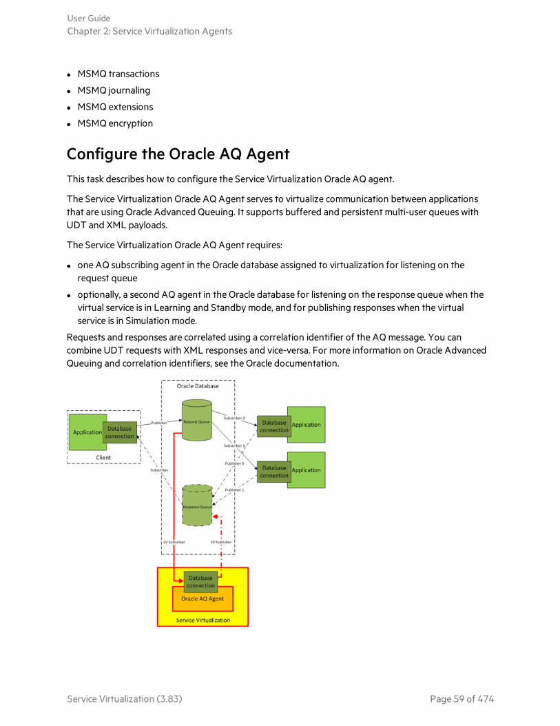
l MSMQ transactions
l MSMQ journaling
l MSMQ extensions
l MSMQ encryption
Configure the Oracle AQ AgentThis task describes how to configure the Service Virtualization Oracle AQ agent.
The Service Virtualization Oracle AQ Agent serves to virtualize communication between applicationsthat are using Oracle Advanced Queuing. It supports buffered and persistent multi-user queues withUDT and XML payloads.
The Service Virtualization Oracle AQ Agent requires:
l one AQ subscribing agent in the Oracle database assigned to virtualization for listening on therequest queue
l optionally, a second AQ agent in the Oracle database for listening on the response queue when thevirtual service is in Learning and Standby mode, and for publishing responses when the virtualservice is in Simulation mode.
Requests and responses are correlated using a correlation identifier of the AQ message. You cancombine UDT requests with XML responses and vice-versa. For more information on Oracle AdvancedQueuing and correlation identifiers, see the Oracle documentation.
User GuideChapter 2: Service Virtualization Agents
Service Virtualization (3.83) Page 59 of 474
To configure the Oracle agent:
1. Prerequisites
a. To enable Service Virtualization to access the Oracle database, you must install Oracle DataProvider for .NET 11g on the Service Virtualization machine running the Service VirtualizationOracle AQ agent. The Oracle AQ agent requires Oracle Data Provider for .NET 11g to accessthe Oracle database. Oracle Data Provider for .NET 11g is a part of ODAC 11.2, which can bedownloaded from the Oracle download site.
Note: The Oracle AQ agent was tested with ODAC 11.2 only and may not work withother versions.
b. You must create a subscribing agent in the Oracle database dedicated to virtualizing messagescoming to the request queue (SV Subscriber in the image above) and optionally a second onededicated to virtualizing messages coming to the response queue (SV Publisher in the imageabove).
2. Configure the agent settings
From the main menu, select Tools > Options. On the Agents Page, select OracleAQ. For userinterface details, see the "Oracle AQ Agent Settings" on page 99.
Configure the SAP AgentThis task describes how to configure the SAP agent. The SAP agent handles SAP RFC or SAP IDOCcommunication between a SAP® or SAP NetWeaver® Process Integration (PI) system, and a real orvirtual SAP service.
Prerequisites
Make sure that the following are configured on each Service Virtualization Designer or ServiceVirtualization standalone server machine on which you are using the SAP Agent:
1. SAP Java Connector version 3.0.11 or later.
a. Download the SAP Java Connector library from the SAP support site, as follows:o For Designer or 32-bit Service Virtualization Server: Download the 32-bit library. (It may be
listed as IA32.)o For 64-bit Service Virtualization Server: Download the 64-bit library. (It may be listed as
x64.)
b. Extract and copy the following files from the Java libraries to the Service Virtualizationinstallation directory's \bin folder: sapjco3.jar, sapjco3.dll, and sapjco3.pdb.
c. Restart the Service Virtualization Server.
2. SAP GUI.
User GuideChapter 2: Service Virtualization Agents
Service Virtualization (3.83) Page 60 of 474

Alternatively, if you do not have SAP GUI installed, you can update the Windows services file,located in %WinDir%\System32\drivers\etc.
Add the following line, replacing xx with your SAP system number:
l sapgwxx 33xx/tcp
Configure the agent settings
From the main menu, select Tools > Options. On the Agents Page, select SAP. For user interface details,see the "Agents Page" on page 77.
Reconfigure the client to point to the virtual service
For a SAP Server: If your source SAP system is a SAP Server, you must reconfigure the SAP RFCdestination to point to the virtual service.
1. On the SAP server, navigate to transaction sm59. Locate and delete the original destination.
2. Under TCP/IP Connections, create a new destination and configure the following:
RFCdestination
Assign the same name as the original destination.
RegisteredServerProgram
Select this option, and enter the Program ID. The value you assign to Program IDmust be identical to the Program ID entered in the virtual service's properties inService Virtualization.
GatewayOptions
Enter the SAP Gateway Host and Gateway Service Name These values must beidentical to the values entered in the Service Virtualization Agents page.
3. Click Connection Test to test your configuration. Your virtual service must be deployed to carry outthis test.
For SAP PI : If your source SAP system is SAP PI, you must reconfigure the communication channel.
In SAP PI Integration Builder, navigate to the appropriate RFC receiver communication channel, andconfigure the following:
RFC Server Type Select External RFC Server.
Application Server(Gateway)
Enter the SAP Gateway Host (the PI System). The value must be identical tothe value entered in the Service Virtualization Agents page.
Application ServerService (Gateway)
Enter the SAP Gateway Service Name. The value must be identical to thevalues entered in the Service Virtualization Agents page.
Program ID The value you assign must be identical to the Program ID entered in thevirtual service's properties in Service Virtualization.
User GuideChapter 2: Service Virtualization Agents
Service Virtualization (3.83) Page 61 of 474
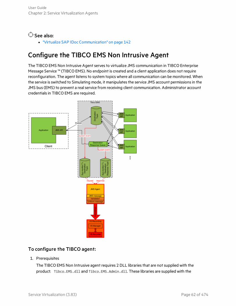
See also:l "Virtualize SAP IDoc Communication" on page 142
Configure the TIBCO EMS Non Intrusive AgentThe TIBCO EMS Non Intrusive Agent serves to virtualize JMS communication in TIBCO EnterpriseMessage Service ™ (TIBCO EMS). No endpoint is created and a client application does not requirereconfiguration. The agent listens to system topics where all communication can be monitored. Whenthe service is switched to Simulating mode, it manipulates the service JMS account permissions in theJMS bus (EMS) to prevent a real service from receiving client communication. Administrator accountcredentials in TIBCO EMS are required.
To configure the TIBCO agent:
1. Prerequisites
The TIBCO EMS Non Intrusive agent requires 2 DLL libraries that are not supplied with theproduct: Tibco.EMS.dll and Tibco.EMS.Admin.dll. These libraries are supplied with the
User GuideChapter 2: Service Virtualization Agents
Service Virtualization (3.83) Page 62 of 474

installation of TIBCO Enterprise Message Service ™ (EMS), located in the bin directory in the EMSinstallation folder. The typical default location is c:\tibco\ems\6.0\bin\.
Note: The TIBCO dll libraries are available in both 32-bit and 64-bit versions. The dll versionmust be the same version as the Service Virtualization Server.
Copy the 2 libraries to the bin folder of the Service Virtualization installation directory:
l If you are working with the Service Virtualization Server: By default, the Server installationfolder is located in C:\Program Files\HPE\HPE Service Virtualization Server\Server\bin.
l If you are working with the Designer's embedded server: By default, the Designer installationfolder is located in C:\Program Files (x86)\HPE\HPE Service VirtualizationDesigner\Designer\bin.
Note: After copying the libraries to the directory, you must restart Service Virtualization.
2. Configure the agent settings
From the main menu, select Tools > Options. On the Agents Page, select TIBCO EMS Non Intrusive.For user interface details, see the "TIBCO EMS Agent Settings" on page 105.
Configure the WebMethods SAP AgentThis task describes the virtualization process, and how to configure the Service VirtualizationWebMethods SAP agent.
The agent enables you to virtualize RFC communication or IDOC document exchange between flowservices hosted in WebMethods Integration Server and a SAP system using JVM instrumentation.
The agent consists of two components:
Javainstrumentation
Provides an instrumentation of the WebMethods Integration Server andcaptures data exchanged between the service and the SAP system. You mustconfigure the JVM of the WebMethods Integration Server so that it cancommunicate with the WebMethods SAP agent running on the ServiceVirtualization Server.
WebMethodsSAP agent
Provides an interface between the Java instrumentation component and theService Virtualization Server.
The Virtualization Process
This section describes the process of virtualizing IDOC services running on the WebMethodsIntegration Server, as an example.
The scenario we want to virtualize is as follows:
User GuideChapter 2: Service Virtualization Agents
Service Virtualization (3.83) Page 63 of 474

l The WebMethods Integration Server hosts flow services.
l The flow services use the WebMethods SAP Adapter to publish IDOCs to a remote SAP system.
l The remote SAP system publishes IDOC responses through the WebMethods SAP Adapter back tothe flow services hosted by the WebMethods Integration Server.
When the virtual service is in Learning or Standby mode, the SV Remote Agent on the WebMethodsIntegration Server communicates with Service Virtualization to record or transmit data.
User GuideChapter 2: Service Virtualization Agents
Service Virtualization (3.83) Page 64 of 474

During simulation, the Service Virtualization WebMethods SAP agent completely simulates thecommunication between the WebMethods SAP Adapter and the remote SAP system.
Configure the WebMethods SAP Agent
1. Prerequisites
a. WebMethods Integration Server 8.2 with SAP Adapter 7.1.
b. In order for the virtual service to connect to the remote SAP server, the WebMethodsSAP Agent requires all prerequisites that are required for the SAP agent. For details, see"Configure the SAP Agent" on page 60.
2. Configure the agent settings
From the main menu, select Tools > Options. On the Agents Page, select WebMethods SAP andclick Add. Define settings for the new configuration. For user interface details, see the"WebMethods SAP Agent Settings" on page 107.
3. Configure Java Instrumentation
a. Navigate to the WebMethods folder under the Service Virtualization installation directory. Bydefault:
For Service Virtualization Server: C:\Program Files\HPE\HPE Service VirtualizationServer\Tools\WebMethods
For the Designer: C:\Program Files (x86)\HPE\HPE Service VirtualizationDesigner\Tools\WebMethods
User GuideChapter 2: Service Virtualization Agents
Service Virtualization (3.83) Page 65 of 474

b. Copy the following files into the WM_IS_HOME\lib\jars folder in the installation directory of theWebMethods Integration Server, for example C:\SoftwareAG\IntegrationServer.o HP.SV.JavaBcAgent.jaro javassist.jaro HP.SV.WmSapRemote.jar
c. Add the following to the WM_IS_HOME\bin\server.bat file:
set JAVA_AGENT=-javaagent:WM_IS_HOME\lib\jars\HP.SV.JavaBcAgent.jar
set JAVA_OPTS=%JAVA_AGENT% %JAVA_OPTS%
Configure the WebSphere MQ Non-Intrusive AgentThis task describes how to configure the Service Virtualization IBM WebSphere MQ Non-IntrusiveAgent, configure your WebSphere MQ Server, and virtualize MQ communication.
This section includes:
l "Overview" below
l "Supported platforms" on page 68
l "Configure the Service Virtualization Agent" on page 68
l "Agent limitations" on page 69
l "Configure the WebSphere MQ server" on page 70
l "Additional queue manager configuration options" on page 72
l "Create a new virtual service" on page 74
Overview
The Service Virtualization WebSphere MQ Non-Intrusive agent enables you to virtualize WebSphereMQ communication without the need for any reconfiguration of your applications under test. You needonly to deploy several libraries to the MQ server and reconfigure a queue manager. No virtual queuesare required.
User GuideChapter 2: Service Virtualization Agents
Service Virtualization (3.83) Page 66 of 474
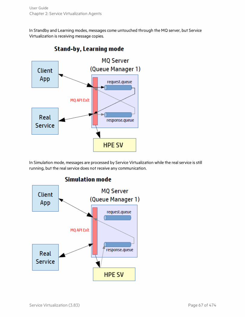
In Standby and Learning modes, messages come untouched through the MQ server, but ServiceVirtualization is receiving message copies.
In Simulation mode, messages are processed by Service Virtualization while the real service is stillrunning, but the real service does not receive any communication.
User GuideChapter 2: Service Virtualization Agents
Service Virtualization (3.83) Page 67 of 474
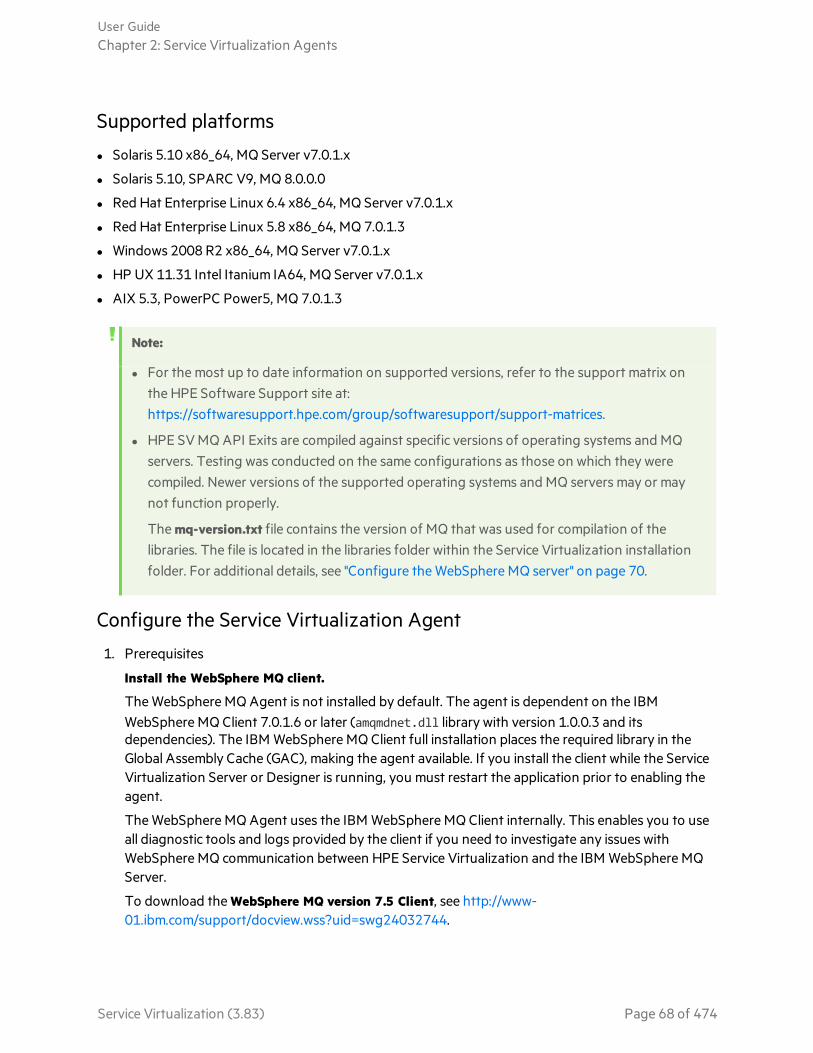
Supported platforms
l Solaris 5.10 x86_64, MQ Server v7.0.1.x
l Solaris 5.10, SPARC V9, MQ 8.0.0.0
l Red Hat Enterprise Linux 6.4 x86_64, MQ Server v7.0.1.x
l Red Hat Enterprise Linux 5.8 x86_64, MQ 7.0.1.3
l Windows 2008 R2 x86_64, MQ Server v7.0.1.x
l HP UX 11.31 Intel Itanium IA64, MQ Server v7.0.1.x
l AIX 5.3, PowerPC Power5, MQ 7.0.1.3
Note:
l For the most up to date information on supported versions, refer to the support matrix onthe HPE Software Support site at:https://softwaresupport.hpe.com/group/softwaresupport/support-matrices.
l HPE SV MQ API Exits are compiled against specific versions of operating systems and MQservers. Testing was conducted on the same configurations as those on which they werecompiled. Newer versions of the supported operating systems and MQ servers may or maynot function properly.
The mq-version.txt file contains the version of MQ that was used for compilation of thelibraries. The file is located in the libraries folder within the Service Virtualization installationfolder. For additional details, see "Configure the WebSphere MQ server" on page 70.
Configure the Service Virtualization Agent
1. Prerequisites
Install the WebSphere MQ client.
The WebSphere MQ Agent is not installed by default. The agent is dependent on the IBMWebSphere MQ Client 7.0.1.6 or later (amqmdnet.dll library with version 1.0.0.3 and itsdependencies). The IBM WebSphere MQ Client full installation places the required library in theGlobal Assembly Cache (GAC), making the agent available. If you install the client while the ServiceVirtualization Server or Designer is running, you must restart the application prior to enabling theagent.
The WebSphere MQ Agent uses the IBM WebSphere MQ Client internally. This enables you to useall diagnostic tools and logs provided by the client if you need to investigate any issues withWebSphere MQ communication between HPE Service Virtualization and the IBM WebSphere MQServer.
To download the WebSphere MQ version 7.5 Client, see http://www-01.ibm.com/support/docview.wss?uid=swg24032744.
User GuideChapter 2: Service Virtualization Agents
Service Virtualization (3.83) Page 68 of 474

To download the WebSphere MQ version 8.0 Client, see http://www-01.ibm.com/support/docview.wss?uid=swg24037500.
Note:
l An individual IBM ID is required for the downloads.
l WebSphere MQ 8.0 is not supported on Windows Server 2008.
2. Configure the Service Virtualization agent settings
From the main menu, select Tools > Options. On the Agents Page, select WebSphere MQ Non-Intrusive. For user interface details, see the "WebSphere MQ Non-Intrusive Agent Settings" onpage 109.
3. Optional: Perform additional global configuration
You can configure additional settings using the Service Virtualization configuration files.
a. Open the appropriate file:o Standalone Server configuration file:
%[INSTALLLOCATION]%\Server\bin\HP.SV.StandaloneServer.exe.config
o Designer configuration file:
%[INSTALLLOCATION]%\Designer\bin\VirtualServiceDesigner.exe.config
b. You can define the following element in the appSettings section of the configuration files. Thisconfiguration element sets up global behavior for processing WebSphere MQ messages.
o<add key="MQAgent.DefaultCharacterSet" value="0"/>
Configures the default character set for simulated XML responses. Use this configuration ifthe character set is not recorded as message metadata. If the value is set to 0 the characterset is not set.
Agent limitations
l The WebSphere MQ Non-Intrusive Agent instance can only use queues from a single Queuemanager.
l The WebSphere MQ Non-Intrusive Agent instance can only use a single TCP channel to connect tothe Queue manager.
l CCSID configuration in the WebSphere MQ Non-Intrusive Agent instance requires an applicationrestart.
l CCSID configuration is global for whole the application. There cannot be two agents with differentCCSIDs.
User GuideChapter 2: Service Virtualization Agents
Service Virtualization (3.83) Page 69 of 474
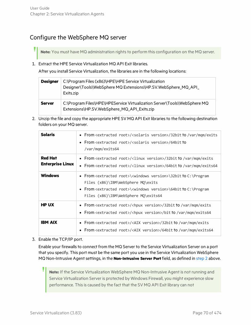
Configure the WebSphere MQ server
Note: You must have MQ administration rights to perform this configuration on the MQ server.
1. Extract the HPE Service Virtualization MQ API Exit libraries.
After you install Service Virtualization, the libraries are in the following locations:
Designer C:\Program Files (x86)\HPE\HPE Service VirtualizationDesigner\Tools\WebSphere MQ Extensions\HP.SV.WebSphere_MQ_API_Exits.zip
Server C:\Program Files\HPE\HPEService Virtualization Server\Tools\WebSphere MQExtensions\HP.SV.WebSphere_MQ_API_Exits.zip
2. Unzip the file and copy the appropriate HPE SV MQ API Exit libraries to the following destinationfolders on your MQ server.
Solaris l From <extracted root>/<solaris version>/32bit to /var/mqm/exits
l From <extracted root>/<solaris version>/64bit to/var/mqm/exits64
Red HatEnterprise Linux
l From <extracted root>/<linux version>/32bit to /var/mqm/exits
l From <extracted root>/<linux version>/64bit to /var/mqm/exits64
Windows l From <extracted root>\<windows version>\32bit to C:\ProgramFiles (x86)\IBM\WebSphere MQ\exits
l From <extracted root>\<windows version>\64bit to C:\ProgramFiles (x86)\IBM\WebSphere MQ\exits64
HP UX l From <extracted root>/<hpux version>/32bit to /var/mqm/exits
l From <extracted root>/<hpux version>/bit to /var/mqm/exits64
IBM AIX l From <extracted root>/<AIX version>/32bit to /var/mqm/exits
l From <extracted root>/<AIX version>/64bit to /var/mqm/exits64
3. Enable the TCP/IP port.
Enable your firewalls to connect from the MQ Server to the Service Virtualization Server on a portthat you specify. This port must be the same port you use in the Service Virtualization WebSphereMQ Non-Intrusive Agent settings, in the Non-Intrusive Server Port field, as defined in step 2 above.
Note: If the Service Virtualization WebSphere MQ Non-Intrusive Agent is not running andService Virtualization Server is protected by Windows Firewall, you might experience slowperformance. This is caused by the fact that the SV MQ API Exit library can not
User GuideChapter 2: Service Virtualization Agents
Service Virtualization (3.83) Page 70 of 474
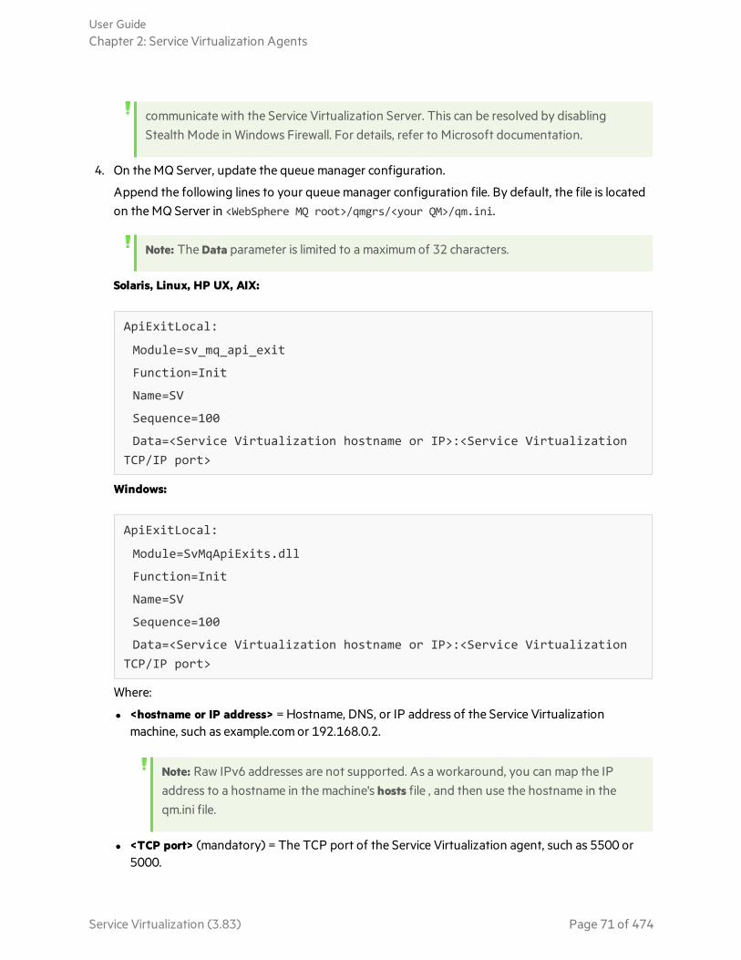
communicate with the Service Virtualization Server. This can be resolved by disablingStealth Mode in Windows Firewall. For details, refer to Microsoft documentation.
4. On the MQ Server, update the queue manager configuration.
Append the following lines to your queue manager configuration file. By default, the file is locatedon the MQ Server in <WebSphere MQ root>/qmgrs/<your QM>/qm.ini.
Note: The Data parameter is limited to a maximum of 32 characters.
Solaris, Linux, HP UX, AIX:
ApiExitLocal:
Module=sv_mq_api_exit
Function=Init
Name=SV
Sequence=100
Data=<Service Virtualization hostname or IP>:<Service VirtualizationTCP/IP port>
Windows:
ApiExitLocal:
Module=SvMqApiExits.dll
Function=Init
Name=SV
Sequence=100
Data=<Service Virtualization hostname or IP>:<Service VirtualizationTCP/IP port>
Where:
l <hostname or IP address> = Hostname, DNS, or IP address of the Service Virtualizationmachine, such as example.com or 192.168.0.2.
Note: Raw IPv6 addresses are not supported. As a workaround, you can map the IPaddress to a hostname in the machine's hosts file , and then use the hostname in theqm.ini file.
l <TCP port> (mandatory) = The TCP port of the Service Virtualization agent, such as 5500 or5000.
User GuideChapter 2: Service Virtualization Agents
Service Virtualization (3.83) Page 71 of 474

For additional configuration parameters, see "Additional queue manager configuration options"below.
5. Stop and then restart your queue manager. On a Windows system, you may need to also stop andrestart the IBM MQ system service.
Additional queue manager configuration options
You can define additional configuration parameters in the queue manager configuration file fordebugging and timeout settings.
In qm.ini, configure the Data section of MQ API Exit definition in the following format (up to 32characters):
<hostname or IP address>:<TCP port><timeout><log level>
Where:
l <timeout> (optional) = The TCP connection timeout value, according to the table below.
l <loglevel> (optional) = The log level of the API exit, according to the table below.
Note:l The logs can consume large quantities of your disk space. This feature should be enabled
for debugging only, and should be turned off by default.
l When logging is enabled, log files with the pattern sv_mqexit_*.log are created. Those filesare placed in the following folders on the MQ server machine:
o Windows: The default temp folder C:\temp.
o Linux/UNIX: The default temp folder /tmp.
You must assign write permissions for MUSR_ADMIN and other MQ-related user accountsin order to successfully generate log files and prevent the exit from crashing.
Timeout parameter values
Letter Timeout (ms)
A 1
B 5
C 10
D 25
E 50
User GuideChapter 2: Service Virtualization Agents
Service Virtualization (3.83) Page 72 of 474

Letter Timeout (ms)
F 100
G 150
H 200
I 250 (default)
J 300
K 400
L 500
M 600
N 700
O 800
P 900
Q 1000
R 1250
S 1500
T 1750
U 2000
V 3000
W 4000
Log level parameter values
Letter Log level
o OFF
e ERROR
w WARNING
i INFO
User GuideChapter 2: Service Virtualization Agents
Service Virtualization (3.83) Page 73 of 474

Letter Log level
d DEBUG
t TRACE
Example
Example: sv.domain.com:5501Ki
where:
l hostname = sv.domain.com
l TCP port number = 5501
l connection timeout = 400 ms
l log level = INFO
Create a new virtual service
Create a new virtual service, and select the appropriate WebSphere MQ Non-Intrusive option for yourmessaging protocol. For user interface details, see "Create New Virtual Service Wizard" on page 153.
You can now virtualize any request/response queue pair from the queue manager.
Configure the WebSphere MQ AgentThis task describes how to configure the WebSphere MQ Agent.
The WebSphere MQ Agent uses the IBM WebSphere MQ Client internally. This enables you to use alldiagnostic tools and logs provided by the client if you need to investigate any issues with WebSphereMQ communication between HPE Service Virtualization and the IBM WebSphere MQ Server.
User GuideChapter 2: Service Virtualization Agents
Service Virtualization (3.83) Page 74 of 474

Prerequisites
The WebSphere MQ Agent is not installed by default. The agent is dependent on the IBM WebSphereMQ Client 7.0.1.6 or later (amqmdnet.dll library with version 1.0.0.3 and its dependencies). The IBMWebSphere MQ Client full installation places the required library in the Global Assembly Cache (GAC),making the agent available. If you install the client while the Service Virtualization Server or Designer isrunning, you must restart the application prior to enabling the agent.
The WebSphere MQ Agent uses the IBM WebSphere MQ Client internally. This enables you to use alldiagnostic tools and logs provided by the client if you need to investigate any issues with WebSphereMQ communication between Service Virtualization and the IBM WebSphere MQ Server.
To download the WebSphere MQ version 7.5 Client, see http://www-01.ibm.com/support/docview.wss?uid=swg24032744.
To download the WebSphere MQ version 8.0 Client, see http://www-01.ibm.com/support/docview.wss?uid=swg24037500.
Note:
l An individual IBM ID is required for the downloads.
l WebSphere MQ 8.0 is not supported on Windows Server 2008.
Configure the agent settings
From the main menu, select Tools > Options. On the Agents Page, select WebSphere MQ. For userinterface details, see the "WebSphere MQ Agent Settings" on page 114.
Optional: Perform additional global configuration
You can configure additional settings using the Service Virtualization configuration files.
1. Open the appropriate file:
l Standalone Server configuration file:
%[INSTALLLOCATION]%\Server\bin\HP.SV.StandaloneServer.exe.config
l Designer configuration file:
%[INSTALLLOCATION]%\Designer\bin\VirtualServiceDesigner.exe.config
2. You can define the following element in the appSettings section of the configuration files. Thisconfiguration element sets up global behavior for processing WebSphere MQ messages.
User GuideChapter 2: Service Virtualization Agents
Service Virtualization (3.83) Page 75 of 474

l<add key="MQAgent.DefaultCharacterSet" value="0"/>
Configures the default character set for simulated XML responses. Use this configuration if thecharacter set is not recorded as message metadata. If the value is set to 0 the character set is notset.
Agent limitations
l The WebSphere MQ Agent instance can only use queues from a single Queue manager.
l The WebSphere MQ Agent instance can only use a single TCP channel to connect to the Queuemanager.
l CCSID configuration in the WebSphere MQ Agent instance requires an application restart.
l CCSID configuration is global for whole the application. There cannot be two agents with differentCCSIDs.
Forward HTTP Agent Communication Through anHTTP ProxyThis task explains how to forward HTTP/HTTPS communication between the HTTP Gateway/HTTPSGateway/HTTP(S) Proxy agents and a real service through an additional proxy (proxy chaining).
To enable proxy chaining:
1. From the main menu, select Tools > Options. On the Agents Page, select one of the following:
l HTTP Gateway
l HTTP(S) Proxy
l HTTPS Gateway
For user interface details, see the "Agents Page" on the next page.
2. Select the Use another proxy server to communicate with real services option, and click Settings.
3. In the Proxy Settings Dialog Box, configure the settings. For user interface details, see "ProxySettings Dialog Box" on page 120.
Agents User InterfaceThis section includes:
• Agents Page 77• Proxy Settings Dialog Box 120
User GuideChapter 2: Service Virtualization Agents
Service Virtualization (3.83) Page 76 of 474
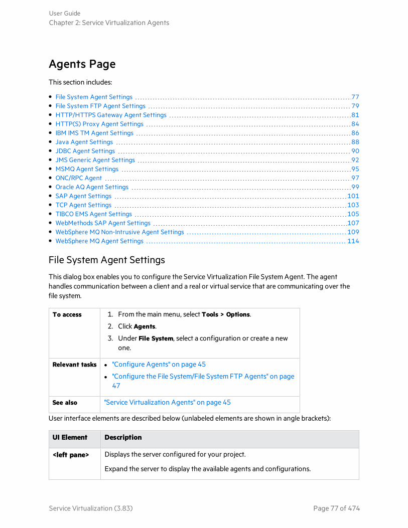
Agents PageThis section includes:
• File System Agent Settings 77• File System FTP Agent Settings 79• HTTP/HTTPS Gateway Agent Settings 81• HTTP(S) Proxy Agent Settings 84• IBM IMS TM Agent Settings 86• Java Agent Settings 88• JDBC Agent Settings 90• JMS Generic Agent Settings 92• MSMQ Agent Settings 95• ONC/RPC Agent 97• Oracle AQ Agent Settings 99• SAP Agent Settings 101• TCP Agent Settings 103• TIBCO EMS Agent Settings 105• WebMethods SAP Agent Settings 107• WebSphere MQ Non-Intrusive Agent Settings 109• WebSphere MQ Agent Settings 114
File System Agent Settings
This dialog box enables you to configure the Service Virtualization File System Agent. The agenthandles communication between a client and a real or virtual service that are communicating over thefile system.
To access 1. From the main menu, select Tools > Options.
2. Click Agents.
3. Under File System, select a configuration or create a newone.
Relevant tasks l "Configure Agents" on page 45
l "Configure the File System/File System FTP Agents" on page47
See also "Service Virtualization Agents" on page 45
User interface elements are described below (unlabeled elements are shown in angle brackets):
UI Element Description
<left pane> Displays the server configured for your project.
Expand the server to display the available agents and configurations.
User GuideChapter 2: Service Virtualization Agents
Service Virtualization (3.83) Page 77 of 474
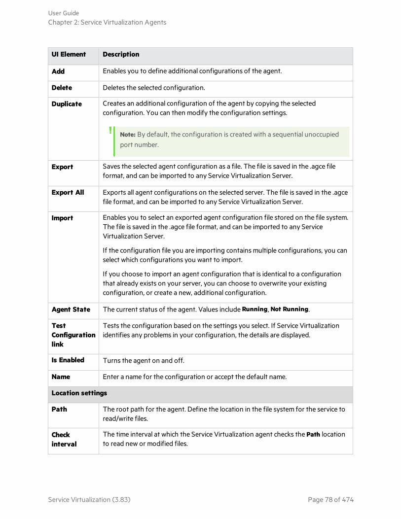
UI Element Description
Add Enables you to define additional configurations of the agent.
Delete Deletes the selected configuration.
Duplicate Creates an additional configuration of the agent by copying the selectedconfiguration. You can then modify the configuration settings.
Note: By default, the configuration is created with a sequential unoccupiedport number.
Export Saves the selected agent configuration as a file. The file is saved in the .agce fileformat, and can be imported to any Service Virtualization Server.
Export All Exports all agent configurations on the selected server. The file is saved in the .agcefile format, and can be imported to any Service Virtualization Server.
Import Enables you to select an exported agent configuration file stored on the file system.The file is saved in the .agce file format, and can be imported to any ServiceVirtualization Server.
If the configuration file you are importing contains multiple configurations, you canselect which configurations you want to import.
If you choose to import an agent configuration that is identical to a configurationthat already exists on your server, you can choose to overwrite your existingconfiguration, or create a new, additional configuration.
Agent State The current status of the agent. Values include Running, Not Running.
TestConfigurationlink
Tests the configuration based on the settings you select. If Service Virtualizationidentifies any problems in your configuration, the details are displayed.
Is Enabled Turns the agent on and off.
Name Enter a name for the configuration or accept the default name.
Location settings
Path The root path for the agent. Define the location in the file system for the service toread/write files.
Checkinterval
The time interval at which the Service Virtualization agent checks the Path locationto read new or modified files.
User GuideChapter 2: Service Virtualization Agents
Service Virtualization (3.83) Page 78 of 474
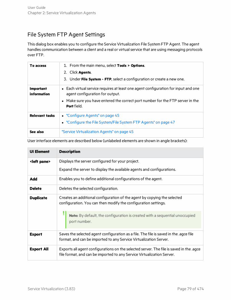
File System FTP Agent Settings
This dialog box enables you to configure the Service Virtualization File System FTP Agent. The agenthandles communication between a client and a real or virtual service that are using messaging protocolsover FTP.
To access 1. From the main menu, select Tools > Options.
2. Click Agents.
3. Under File System - FTP, select a configuration or create a new one.
Importantinformation
l Each virtual service requires at least one agent configuration for input and oneagent configuration for output.
l Make sure you have entered the correct port number for the FTP server in thePort field.
Relevant tasks l "Configure Agents" on page 45
l "Configure the File System/File System FTP Agents" on page 47
See also "Service Virtualization Agents" on page 45
User interface elements are described below (unlabeled elements are shown in angle brackets):
UI Element Description
<left pane> Displays the server configured for your project.
Expand the server to display the available agents and configurations.
Add Enables you to define additional configurations of the agent.
Delete Deletes the selected configuration.
Duplicate Creates an additional configuration of the agent by copying the selectedconfiguration. You can then modify the configuration settings.
Note: By default, the configuration is created with a sequential unoccupiedport number.
Export Saves the selected agent configuration as a file. The file is saved in the .agce fileformat, and can be imported to any Service Virtualization Server.
Export All Exports all agent configurations on the selected server. The file is saved in the .agcefile format, and can be imported to any Service Virtualization Server.
User GuideChapter 2: Service Virtualization Agents
Service Virtualization (3.83) Page 79 of 474
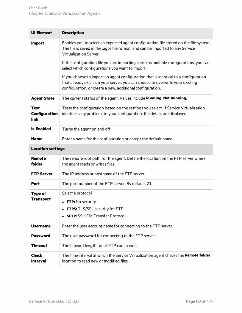
UI Element Description
Import Enables you to select an exported agent configuration file stored on the file system.The file is saved in the .agce file format, and can be imported to any ServiceVirtualization Server.
If the configuration file you are importing contains multiple configurations, you canselect which configurations you want to import.
If you choose to import an agent configuration that is identical to a configurationthat already exists on your server, you can choose to overwrite your existingconfiguration, or create a new, additional configuration.
Agent State The current status of the agent. Values include Running, Not Running.
TestConfigurationlink
Tests the configuration based on the settings you select. If Service Virtualizationidentifies any problems in your configuration, the details are displayed.
Is Enabled Turns the agent on and off.
Name Enter a name for the configuration or accept the default name.
Location settings
Remotefolder
The remote root path for the agent. Define the location on the FTP server wherethe agent reads or writes files.
FTP Server The IP address or hostname of the FTP server.
Port The port number of the FTP server. By default, 21.
Type ofTransport
Select a protocol:
l FTP: No security.
l FTPS: TLS/SSL security for FTP.
l SFTP: SSH File Transfer Protocol.
Username Enter the user account name for connecting to the FTP server.
Password The user password for connecting to the FTP server.
Timeout The timeout length for all FTP commands.
Checkinterval
The time interval at which the Service Virtualization agent checks the Remote folderlocation to read new or modified files.
User GuideChapter 2: Service Virtualization Agents
Service Virtualization (3.83) Page 80 of 474

HTTP/HTTPS Gateway Agent Settings
This dialog box enables you to configure the Service Virtualization HTTP/HTTPS Gateway Agent. Theagent handles communication between a client and a real or virtual service.
To access 1. From the main menu, select Tools > Options.
2. Click Agents.
3. Under HTTP(S) Gateway, select a configuration.
Importantinformation
l For additional important configuration information, see the task "Configure theHTTP/HTTPS Gateway Agents" on page 47.
l You can define multiple configurations for each agent.
Relevanttasks
l "Configure Agents" on page 45
l "Forward HTTP Agent Communication Through an HTTP Proxy" on page 76
See also "Service Virtualization Agents" on page 45
User interface elements are described below (unlabeled elements are shown in angle brackets):
UI Element Description
<left pane> Displays the server configured for your project.
Expand the server to display the available agents and configurations.
Add Enables you to define additional configurations of the agent.
Delete Deletes the selected configuration.
User GuideChapter 2: Service Virtualization Agents
Service Virtualization (3.83) Page 81 of 474

UI Element Description
Duplicate Creates an additional configuration of the agent by copying the selectedconfiguration. You can then modify the configuration settings.
Note: By default, the configuration is created with a sequentialunoccupied port number.
Export Saves the selected agent configuration as a file. The file is saved in the .agcefile format, and can be imported to any Service Virtualization Server.
Export All Exports all agent configurations on the selected server. The file is saved in the.agce file format, and can be imported to any Service Virtualization Server.
Import Enables you to select an exported agent configuration file stored on the filesystem. The file is saved in the .agce file format, and can be imported to anyService Virtualization Server.
If the configuration file you are importing contains multiple configurations,you can select which configurations you want to import.
If you choose to import an agent configuration that is identical to aconfiguration that already exists on your server, you can choose to overwriteyour existing configuration, or create a new, additional configuration.
Agent State The current status of the agent. Values include Running, Not Running.
Test Configurationlink
Tests the configuration based on the settings you select. If ServiceVirtualization identifies any problems in your configuration, the details aredisplayed.
Is Enabled Turns the agent on and off.
Name Enter a name for the configuration or accept the default name.
Use SSL Enables SSL over TCP/IP. If enabled, you must provide certificate file andpassword details.
User GuideChapter 2: Service Virtualization Agents
Service Virtualization (3.83) Page 82 of 474
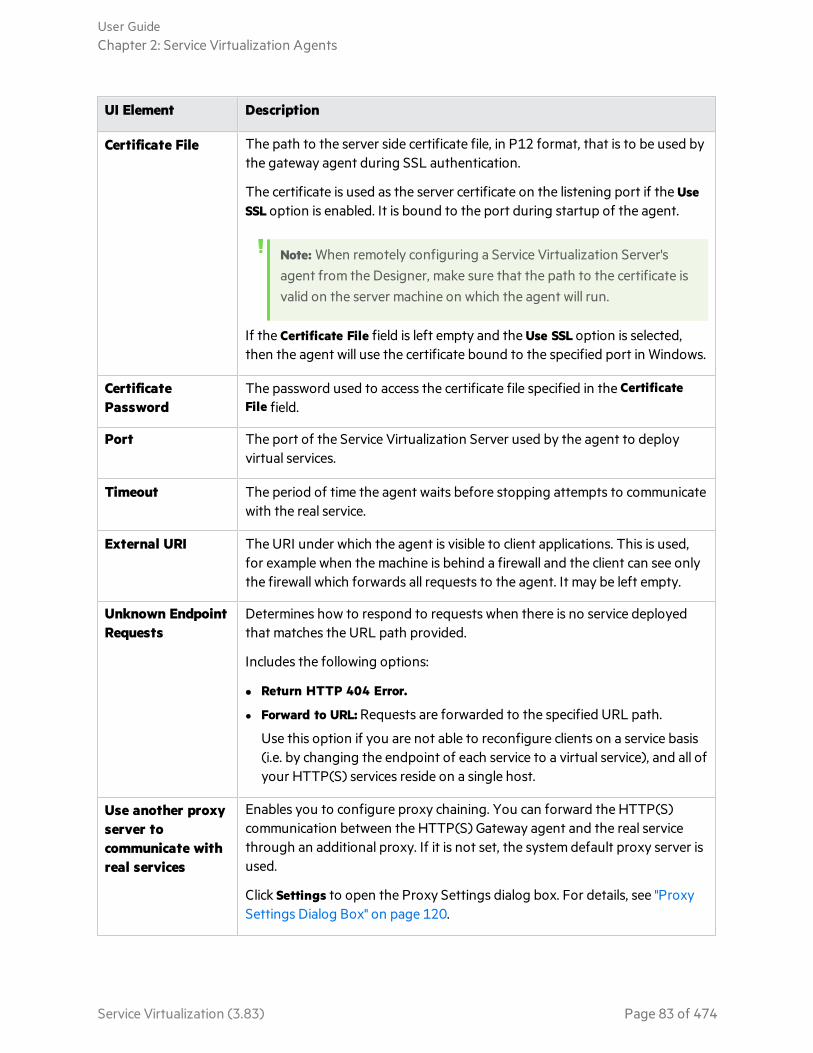
UI Element Description
Certificate File The path to the server side certificate file, in P12 format, that is to be used bythe gateway agent during SSL authentication.
The certificate is used as the server certificate on the listening port if the UseSSL option is enabled. It is bound to the port during startup of the agent.
Note: When remotely configuring a Service Virtualization Server'sagent from the Designer, make sure that the path to the certificate isvalid on the server machine on which the agent will run.
If the Certificate File field is left empty and the Use SSL option is selected,then the agent will use the certificate bound to the specified port in Windows.
CertificatePassword
The password used to access the certificate file specified in the CertificateFile field.
Port The port of the Service Virtualization Server used by the agent to deployvirtual services.
Timeout The period of time the agent waits before stopping attempts to communicatewith the real service.
External URI The URI under which the agent is visible to client applications. This is used,for example when the machine is behind a firewall and the client can see onlythe firewall which forwards all requests to the agent. It may be left empty.
Unknown EndpointRequests
Determines how to respond to requests when there is no service deployedthat matches the URL path provided.
Includes the following options:
l Return HTTP 404 Error.
l Forward to URL: Requests are forwarded to the specified URL path.
Use this option if you are not able to reconfigure clients on a service basis(i.e. by changing the endpoint of each service to a virtual service), and all ofyour HTTP(S) services reside on a single host.
Use another proxyserver tocommunicate withreal services
Enables you to configure proxy chaining. You can forward the HTTP(S)communication between the HTTP(S) Gateway agent and the real servicethrough an additional proxy. If it is not set, the system default proxy server isused.
Click Settings to open the Proxy Settings dialog box. For details, see "ProxySettings Dialog Box" on page 120.
User GuideChapter 2: Service Virtualization Agents
Service Virtualization (3.83) Page 83 of 474

HTTP(S) Proxy Agent Settings
This dialog box enables you to configure the Service Virtualization HTTP(S) Proxy Agent. The agenthandles communication between a client and a real or virtual service.
To access 1. From the main menu, select Tools > Options.
2. Click Agents.
3. Under HTTP(S) Proxy, select a configuration.
Importantinformation
l For additional important configuration information, see the task "Configure theHTTP(S) Proxy Agent" on page 49.
l In case of Java based clients running on JDK 6 or later, and in the case of self-signedcertificates, it may be necessary to add the “-Dsun.security.ssl.allowUnsafeRenegotiation=true” startup parameter or the clientmay reject communication with the HTTPS Agent. For more details, see Javadocumentation.
l You can define multiple configurations for each agent.
Relevanttasks
l "Configure Agents" on page 45
l "Forward HTTP Agent Communication Through an HTTP Proxy" on page 76
See also "Service Virtualization Agents" on page 45
User interface elements are described below (unlabeled elements are shown in angle brackets):
UI Element Description
<left pane> Displays the server configured for your project.
Expand the server to display the available agents and configurations.
User GuideChapter 2: Service Virtualization Agents
Service Virtualization (3.83) Page 84 of 474

UI Element Description
Add Enables you to define additional configurations of the agent.
Delete Deletes the selected configuration.
Duplicate Creates an additional configuration of the agent by copying the selectedconfiguration. You can then modify the configuration settings.
Note: By default, the configuration is created with a sequentialunoccupied port number.
Export Saves the selected agent configuration as a file. The file is saved in the .agcefile format, and can be imported to any Service Virtualization Server.
Export All Exports all agent configurations on the selected server. The file is saved inthe .agce file format, and can be imported to any Service VirtualizationServer.
Import Enables you to select an exported agent configuration file stored on the filesystem. The file is saved in the .agce file format, and can be imported to anyService Virtualization Server.
If the configuration file you are importing contains multiple configurations,you can select which configurations you want to import.
If you choose to import an agent configuration that is identical to aconfiguration that already exists on your server, you can choose tooverwrite your existing configuration, or create a new, additionalconfiguration.
Agent State The current status of the agent. Values include Running, Not Running.
Test Configurationlink
Tests the configuration based on the settings you select. If ServiceVirtualization identifies any problems in your configuration, the details aredisplayed.
Is Enabled Turns the agent on and off.
Name Enter a name for the configuration or accept the default name.
Host The name by which the agent is visible to client applications. It may be leftempty.
Timeout The period of time the agent waits before stopping attempts tocommunicate with the real service.
User GuideChapter 2: Service Virtualization Agents
Service Virtualization (3.83) Page 85 of 474
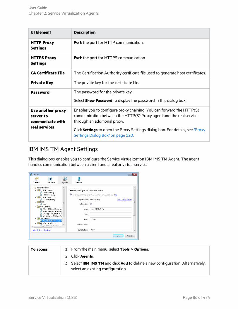
UI Element Description
HTTP ProxySettings
Port: the port for HTTP communication.
HTTPS ProxySettings
Port: the port for HTTPS communication.
CA Certificate File The Certification Authority certificate file used to generate host certificates.
Private Key The private key for the certificate file.
Password The password for the private key.
Select Show Password to display the password in this dialog box.
Use another proxyserver tocommunicate withreal services
Enables you to configure proxy chaining. You can forward the HTTP(S)communication between the HTTP(S) Proxy agent and the real servicethrough an additional proxy.
Click Settings to open the Proxy Settings dialog box. For details, see "ProxySettings Dialog Box" on page 120.
IBM IMS TM Agent Settings
This dialog box enables you to configure the Service Virtualization IBM IMS TM Agent. The agenthandles communication between a client and a real or virtual service.
To access 1. From the main menu, select Tools > Options.
2. Click Agents.
3. Select IBM IMS TM and click Add to define a new configuration. Alternatively,select an existing configuration.
User GuideChapter 2: Service Virtualization Agents
Service Virtualization (3.83) Page 86 of 474

Importantinformation
l For additional important configuration information, see the task "Configure theIBM IMS TM Agent" on page 49.
l You can define multiple configurations for each agent.
Relevant tasks l "Configure Agents" on page 45
l "Forward HTTP Agent Communication Through an HTTP Proxy" on page 76
See also "Service Virtualization Agents" on page 45
User interface elements are described below (unlabeled elements are shown in angle brackets):
UI Element Description
<left pane> Displays the server configured for your project.
Expand the server to display the available agents and configurations.
Add Enables you to define additional configurations of the agent.
Delete Deletes the selected configuration.
Duplicate Creates an additional configuration of the agent by copying the selectedconfiguration. You can then modify the configuration settings.
Note: By default, the configuration is created with a sequential unoccupiedport number.
Export Saves the selected agent configuration as a file. The file is saved in the .agce fileformat, and can be imported to any Service Virtualization Server.
Export All Exports all agent configurations on the selected server. The file is saved in the .agcefile format, and can be imported to any Service Virtualization Server.
Import Enables you to select an exported agent configuration file stored on the file system.The file is saved in the .agce file format, and can be imported to any ServiceVirtualization Server.
If the configuration file you are importing contains multiple configurations, you canselect which configurations you want to import.
If you choose to import an agent configuration that is identical to a configurationthat already exists on your server, you can choose to overwrite your existingconfiguration, or create a new, additional configuration.
Agent State The current status of the agent. Values include Running, Not Running.
User GuideChapter 2: Service Virtualization Agents
Service Virtualization (3.83) Page 87 of 474

UI Element Description
TestConfigurationlink
Tests the configuration based on the settings you select. If Service Virtualizationidentifies any problems in your configuration, the details are displayed.
Is Enabled Turns the agent on and off.
Name Enter a name for the configuration or accept the default name.
Host The hostname of the interface on which the agent is listening.
Port The port on the local machine on which the agent is listening.
Remote Host The hostname or IP address of the IMS TM server.
Remote Port The remote port of the IMS TM server.
Code Page The character set as defined on the IMS TM server. Used to interpret both requestsand responses.
Use SSL Enables SSL over TCP/IP. If enabled, you must provide certificate file and passworddetails.
CertificateFile
The server side P12/PFX certificate file used by the IBM IMS TM Agent during SSLauthentication.
CertificatePassword
The password used to access the certificate file specified above.
Java Agent Settings
This dialog box enables you to configure the Service Virtualization Java Agent for virtualizing Javaapplications.
To access 1. From the main menu, select Tools > Options.
2. Click Agents.
3. Under Java, select a configuration or create a newone.
Relevant tasks l "Configure the Java Agent" on page 50
l "Configure Agents" on page 45
See also "Service Virtualization Agents" on page 45
User interface elements are described below (unlabeled elements are shown in angle brackets):
User GuideChapter 2: Service Virtualization Agents
Service Virtualization (3.83) Page 88 of 474
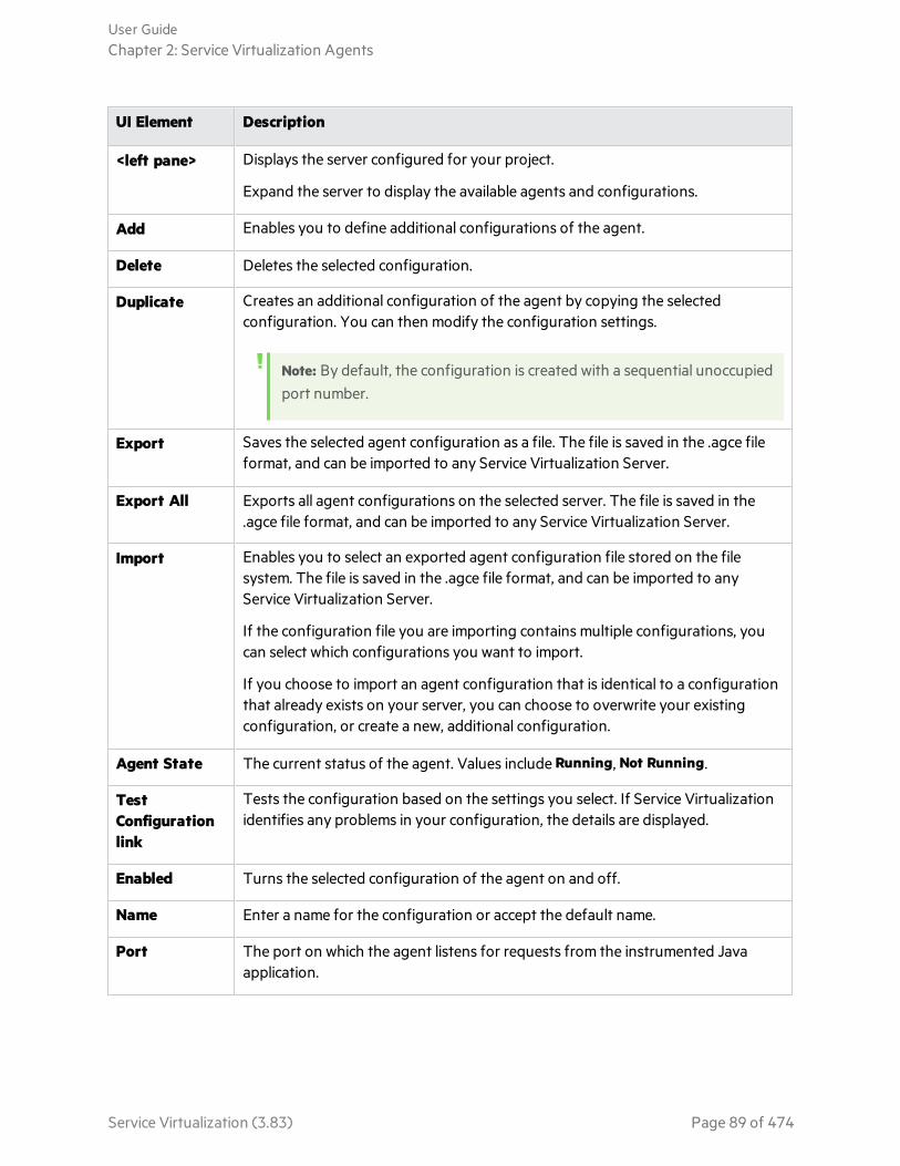
UI Element Description
<left pane> Displays the server configured for your project.
Expand the server to display the available agents and configurations.
Add Enables you to define additional configurations of the agent.
Delete Deletes the selected configuration.
Duplicate Creates an additional configuration of the agent by copying the selectedconfiguration. You can then modify the configuration settings.
Note: By default, the configuration is created with a sequential unoccupiedport number.
Export Saves the selected agent configuration as a file. The file is saved in the .agce fileformat, and can be imported to any Service Virtualization Server.
Export All Exports all agent configurations on the selected server. The file is saved in the.agce file format, and can be imported to any Service Virtualization Server.
Import Enables you to select an exported agent configuration file stored on the filesystem. The file is saved in the .agce file format, and can be imported to anyService Virtualization Server.
If the configuration file you are importing contains multiple configurations, youcan select which configurations you want to import.
If you choose to import an agent configuration that is identical to a configurationthat already exists on your server, you can choose to overwrite your existingconfiguration, or create a new, additional configuration.
Agent State The current status of the agent. Values include Running, Not Running.
TestConfigurationlink
Tests the configuration based on the settings you select. If Service Virtualizationidentifies any problems in your configuration, the details are displayed.
Enabled Turns the selected configuration of the agent on and off.
Name Enter a name for the configuration or accept the default name.
Port The port on which the agent listens for requests from the instrumented Javaapplication.
User GuideChapter 2: Service Virtualization Agents
Service Virtualization (3.83) Page 89 of 474

UI Element Description
Download JavaApplicationInstrumentator
A built-in java-instrumentator project that internally uses the virtual Javaframework. After you download the instrumentator, use the enclosed XMLconfiguration file to define the classes and methods that you want to virtualize.To run your Java application with Service Virtualization instrumentation, youinclude the path to the configuration file.
JDBC Agent Settings
This dialog box enables you to configure the Service Virtualization JDBC Agent. The agent handlescommunication between a client and a real or virtual service.
To access 1. From the main menu, select Tools > Options.
2. Click Agents.
3. Under JDBC, select a configuration.
Importantinformation
l For additional important configuration information, see the task "Configurethe JDBC Agent" on page 52.
l You can define multiple configurations for each agent.
Relevant tasks l "Configure Agents" on page 45
l "Forward HTTP Agent Communication Through an HTTP Proxy" on page 76
See also "Service Virtualization Agents" on page 45
User interface elements are described below (unlabeled elements are shown in angle brackets):
User GuideChapter 2: Service Virtualization Agents
Service Virtualization (3.83) Page 90 of 474

UI Element Description
<left pane> Displays the server configured for your project.
Expand the server to display the available agents and configurations.
Add Enables you to define additional configurations of the agent.
Delete Deletes the selected configuration.
Duplicate Creates an additional configuration of the agent by copying the selectedconfiguration. You can then modify the configuration settings.
Note: By default, the configuration is created with a sequential unoccupiedport number.
Export Saves the selected agent configuration as a file. The file is saved in the .agce fileformat, and can be imported to any Service Virtualization Server.
Export All Exports all agent configurations on the selected server. The file is saved in the.agce file format, and can be imported to any Service Virtualization Server.
Import Enables you to select an exported agent configuration file stored on the filesystem. The file is saved in the .agce file format, and can be imported to anyService Virtualization Server.
If the configuration file you are importing contains multiple configurations, youcan select which configurations you want to import.
If you choose to import an agent configuration that is identical to a configurationthat already exists on your server, you can choose to overwrite your existingconfiguration, or create a new, additional configuration.
Agent State The current status of the agent. Values include Running, Not Running.
TestConfigurationlink
Tests the configuration based on the settings you select. If Service Virtualizationidentifies any problems in your configuration, the details are displayed.
Is Enabled Turns the selected configuration of the agent on and off.
Name Enter a name for the configuration or accept the default name.
Host/Port The machine and port on which the JDBC agent is listening. Required forcommunication with the JDBC driver installed on the application under test.
User GuideChapter 2: Service Virtualization Agents
Service Virtualization (3.83) Page 91 of 474
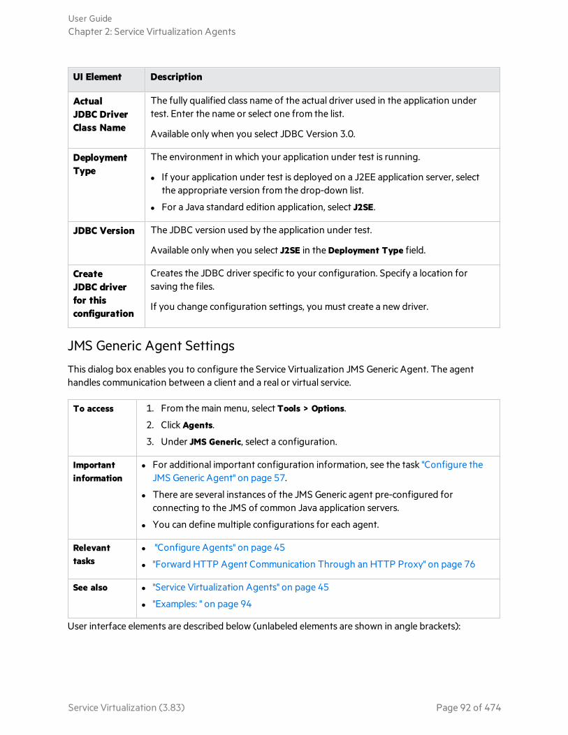
UI Element Description
ActualJDBC DriverClass Name
The fully qualified class name of the actual driver used in the application undertest. Enter the name or select one from the list.
Available only when you select JDBC Version 3.0.
DeploymentType
The environment in which your application under test is running.
l If your application under test is deployed on a J2EE application server, selectthe appropriate version from the drop-down list.
l For a Java standard edition application, select J2SE.
JDBC Version The JDBC version used by the application under test.
Available only when you select J2SE in the Deployment Type field.
CreateJDBC driverfor thisconfiguration
Creates the JDBC driver specific to your configuration. Specify a location forsaving the files.
If you change configuration settings, you must create a new driver.
JMS Generic Agent Settings
This dialog box enables you to configure the Service Virtualization JMS Generic Agent. The agenthandles communication between a client and a real or virtual service.
To access 1. From the main menu, select Tools > Options.
2. Click Agents.
3. Under JMS Generic, select a configuration.
Importantinformation
l For additional important configuration information, see the task "Configure theJMS Generic Agent" on page 57.
l There are several instances of the JMS Generic agent pre-configured forconnecting to the JMS of common Java application servers.
l You can define multiple configurations for each agent.
Relevanttasks
l "Configure Agents" on page 45
l "Forward HTTP Agent Communication Through an HTTP Proxy" on page 76
See also l "Service Virtualization Agents" on page 45
l "Examples: " on page 94
User interface elements are described below (unlabeled elements are shown in angle brackets):
User GuideChapter 2: Service Virtualization Agents
Service Virtualization (3.83) Page 92 of 474
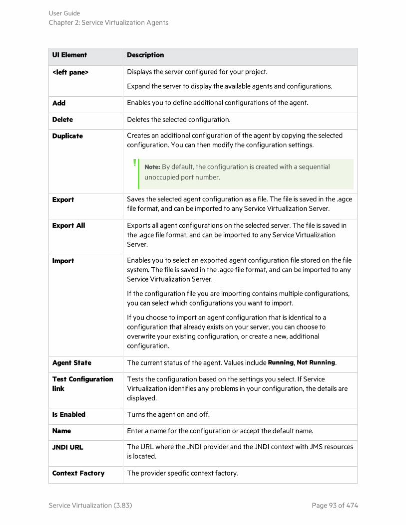
UI Element Description
<left pane> Displays the server configured for your project.
Expand the server to display the available agents and configurations.
Add Enables you to define additional configurations of the agent.
Delete Deletes the selected configuration.
Duplicate Creates an additional configuration of the agent by copying the selectedconfiguration. You can then modify the configuration settings.
Note: By default, the configuration is created with a sequentialunoccupied port number.
Export Saves the selected agent configuration as a file. The file is saved in the .agcefile format, and can be imported to any Service Virtualization Server.
Export All Exports all agent configurations on the selected server. The file is saved inthe .agce file format, and can be imported to any Service VirtualizationServer.
Import Enables you to select an exported agent configuration file stored on the filesystem. The file is saved in the .agce file format, and can be imported to anyService Virtualization Server.
If the configuration file you are importing contains multiple configurations,you can select which configurations you want to import.
If you choose to import an agent configuration that is identical to aconfiguration that already exists on your server, you can choose tooverwrite your existing configuration, or create a new, additionalconfiguration.
Agent State The current status of the agent. Values include Running, Not Running.
Test Configurationlink
Tests the configuration based on the settings you select. If ServiceVirtualization identifies any problems in your configuration, the details aredisplayed.
Is Enabled Turns the agent on and off.
Name Enter a name for the configuration or accept the default name.
JNDI URL The URL where the JNDI provider and the JNDI context with JMS resourcesis located.
Context Factory The provider specific context factory.
User GuideChapter 2: Service Virtualization Agents
Service Virtualization (3.83) Page 93 of 474

UI Element Description
Class Path The class path with all necessary JMS provider specific libraries for JMSimplementation.
Note: To ensure maximum compatibility, use the same JMS/J2EE jar librariesfor the agent class path that are in use by the client application. If notpossible, follow your application server documentation for selection of thecorrect J2EE/JMS libraries.
Username/Password Optional credentials for the JNDI provider/registry.
Select Show Password to display the password in this dialog box.
Trust Store File Enables mutual SSL authentication.
Enter the location of the JMS server's certificate, or certification authoritywhich issued the server's certificate. The certificate must be in a Java keystore (.jks) file.
Available for JMS on a WebLogic server only.
Key Store File Enables mutual SSL authentication.
Enter the location of the single certificate and corresponding private key touse as the client certificate by Service Virtualization during communication.The certificate must be in a Java key store (.jks) file.
Available for JMS on a WebLogic server only.
Examples:
Agent configuration for WebLogic 10.3
l JNDI URL: t3://czvm58.devlab.ad:7001/
l Context Factory: weblogic.jndi.WLInitialContextFactory
l Class Path:
C:\Temp\WL103\wlthint3client.jar
Note: The above sample used WebLogic Thin T3 Client. In case of issues, please use otherWeblogic Client libraries (e.g. “WebLogic Full Client” using “wlfullclient.jar”). See chapter 2 of“Overview of Stand-alone Clients” in your “Oracle® Fusion Middleware Programming Stand-alone Clients for Oracle WebLogic Server 11g Release 1” documentation for more details.
Agent configuration for MQ-7.0.1.3 on WAS-6.1.0
l JNDI URL: corbaloc::czvm24.devlab.ad:2809/NameServiceServerRoot
User GuideChapter 2: Service Virtualization Agents
Service Virtualization (3.83) Page 94 of 474

l JNDI URL: corbaloc::czvm24.devlab.ad:2809/NameServiceServerRoot
l JNDI URL: corbaloc::czvm24.devlab.ad:2809/NameServiceServerRoot
l Class Path:
C:\Temp\WAS6\com.ibm.mq.jar;
C:\Temp\WAS6\com.ibm.mq.jmqi.jar;
C:\Temp\WAS6\com.ibm.mqjms.jar;
C:\Temp\WAS6\com.ibm.ws.admin.client_6.1.0.jar;
C:\Temp\WAS6\com.ibm.ws.runtime_6.1.0.jar;
C:\Temp\WAS6\connector.jar;
C:\Temp\WAS6\dhbcore.jar;
C:\Temp\WAS6\fscontext.jar;
C:\Temp\WAS6\ibmorb.jar;
C:\Temp\WAS6\jms.jar;
C:\Temp\WAS6\jndi.jar;
C:\Temp\WAS6\ldap.jar;
C:\Temp\WAS6\providerutil.jar
Agent configuration for JBoss 6.0
l JNDI URL: jnp://[machine-name]:1099/
l Context Factory: org.jnp.interfaces.NamingContextFactory
l Class Path:
C:\Temp\JBAS6\concurrent.jar;
C:\Temp\JBAS6\hornetq-core-client.jar;
C:\Temp\JBAS6\hornetq-jms-client.jar;
C:\Temp\JBAS6\jboss-client.jar;
C:\Temp\JBAS6\jboss-ejb3-core-client.jar;
C:\Temp\JBAS6\jboss-ejb3-ext-api.jar;
C:\Temp\JBAS6\jboss-jms-api_1.1_spec.jar;
C:\Temp\JBAS6\jboss-logging.jar;
C:\Temp\JBAS6\jnp-client.jar;
C:\Temp\JBAS6\netty.jar
MSMQ Agent Settings
This dialog box enables you to configure the Service Virtualization MSMQ Agent. The agent handlescommunication between a client and a real or virtual service. You can virtualize binary and XMLmessages over MSMQ.
User GuideChapter 2: Service Virtualization Agents
Service Virtualization (3.83) Page 95 of 474
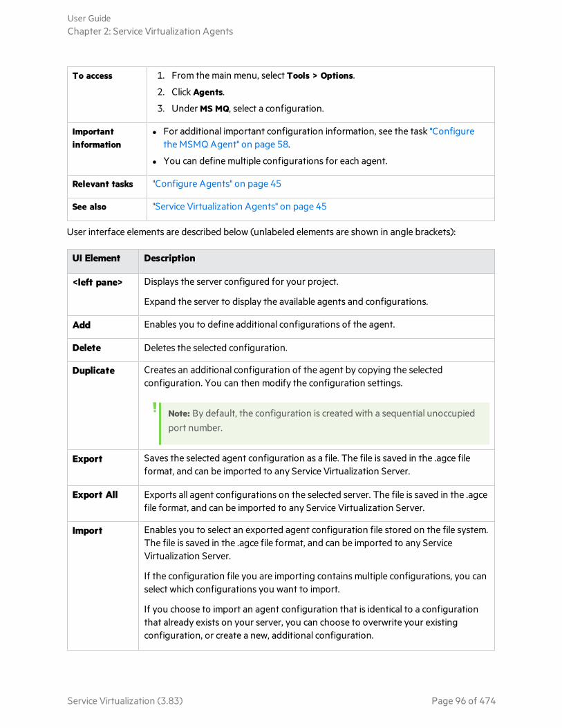
To access 1. From the main menu, select Tools > Options.
2. Click Agents.
3. Under MS MQ, select a configuration.
Importantinformation
l For additional important configuration information, see the task "Configurethe MSMQ Agent" on page 58.
l You can define multiple configurations for each agent.
Relevant tasks "Configure Agents" on page 45
See also "Service Virtualization Agents" on page 45
User interface elements are described below (unlabeled elements are shown in angle brackets):
UI Element Description
<left pane> Displays the server configured for your project.
Expand the server to display the available agents and configurations.
Add Enables you to define additional configurations of the agent.
Delete Deletes the selected configuration.
Duplicate Creates an additional configuration of the agent by copying the selectedconfiguration. You can then modify the configuration settings.
Note: By default, the configuration is created with a sequential unoccupiedport number.
Export Saves the selected agent configuration as a file. The file is saved in the .agce fileformat, and can be imported to any Service Virtualization Server.
Export All Exports all agent configurations on the selected server. The file is saved in the .agcefile format, and can be imported to any Service Virtualization Server.
Import Enables you to select an exported agent configuration file stored on the file system.The file is saved in the .agce file format, and can be imported to any ServiceVirtualization Server.
If the configuration file you are importing contains multiple configurations, you canselect which configurations you want to import.
If you choose to import an agent configuration that is identical to a configurationthat already exists on your server, you can choose to overwrite your existingconfiguration, or create a new, additional configuration.
User GuideChapter 2: Service Virtualization Agents
Service Virtualization (3.83) Page 96 of 474
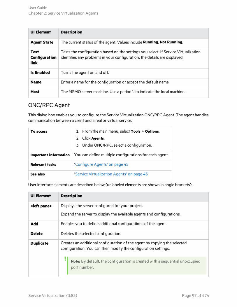
UI Element Description
Agent State The current status of the agent. Values include Running, Not Running.
TestConfigurationlink
Tests the configuration based on the settings you select. If Service Virtualizationidentifies any problems in your configuration, the details are displayed.
Is Enabled Turns the agent on and off.
Name Enter a name for the configuration or accept the default name.
Host The MSMQ server machine. Use a period '.' to indicate the local machine.
ONC/RPC Agent
This dialog box enables you to configure the Service Virtualization ONC/RPC Agent. The agent handlescommunication between a client and a real or virtual service.
To access 1. From the main menu, select Tools > Options.
2. Click Agents.
3. Under ONC/RPC, select a configuration.
Important information You can define multiple configurations for each agent.
Relevant tasks "Configure Agents" on page 45
See also "Service Virtualization Agents" on page 45
User interface elements are described below (unlabeled elements are shown in angle brackets):
UI Element Description
<left pane> Displays the server configured for your project.
Expand the server to display the available agents and configurations.
Add Enables you to define additional configurations of the agent.
Delete Deletes the selected configuration.
Duplicate Creates an additional configuration of the agent by copying the selectedconfiguration. You can then modify the configuration settings.
Note: By default, the configuration is created with a sequential unoccupiedport number.
User GuideChapter 2: Service Virtualization Agents
Service Virtualization (3.83) Page 97 of 474

UI Element Description
Export Saves the selected agent configuration as a file. The file is saved in the .agce fileformat, and can be imported to any Service Virtualization Server.
Export All Exports all agent configurations on the selected server. The file is saved in the .agcefile format, and can be imported to any Service Virtualization Server.
Import Enables you to select an exported agent configuration file stored on the file system.The file is saved in the .agce file format, and can be imported to any ServiceVirtualization Server.
If the configuration file you are importing contains multiple configurations, you canselect which configurations you want to import.
If you choose to import an agent configuration that is identical to a configurationthat already exists on your server, you can choose to overwrite your existingconfiguration, or create a new, additional configuration.
Agent State The current status of the agent. Values include Running, Not Running.
TestConfigurationlink
Tests the configuration based on the settings you select. If Service Virtualizationidentifies any problems in your configuration, the details are displayed.
Is Enabled Turns the agent on and off.
Name Enter a name for the configuration or accept the default name.
Host The hostname or IP address of the Service Virtualization Server where the agent isdeployed.
Port The port of the Service Virtualization Server used by the agent to deploy virtualservices.
Remote Host The hostname or IP address of the real service.
Remote Port The remote port of the real service.
Use SSL Enables SSL over TCP/IP. If enabled, you must provide certificate file and passworddetails.
User GuideChapter 2: Service Virtualization Agents
Service Virtualization (3.83) Page 98 of 474

UI Element Description
CertificateFile
The path to the server side certificate file, in P12 format, that is to be used by thegateway agent during SSL authentication.
The certificate is used as the server certificate on the listening port if the Use SSLoption is enabled. It is bound to the port during startup of the agent.
Note: When remotely configuring a Service Virtualization Server's agentfrom the Designer, make sure that the path to the certificate is valid on theserver machine on which the agent will run.
If the Certificate File field is left empty and the Use SSL option is selected, then theagent will use the certificate bound to the specified port in Windows.
CertificatePassword
The password used to access the certificate file specified in the Certificate File field.
Oracle AQ Agent Settings
This dialog box enables you to configure the Service Virtualization Oracle AQ Agent. The Oracle agenthandles communication between applications that are using Oracle Advanced Queuing.
To access 1. From the main menu, select Tools > Options.
2. Click Agents.
3. Select OracleAQ and click Add to define a new configuration. Alternatively,select an existing configuration.
User GuideChapter 2: Service Virtualization Agents
Service Virtualization (3.83) Page 99 of 474

Importantinformation
l For additional important configuration information, see the task "Configure theOracle AQ Agent" on page 59.
l To connect to the Oracle database, you can specify either a connection string orspecific database connection properties.
l When specifying database connection properties, you can enter either thedatabase name or SID.
Relevant tasks "Configure Agents" on page 45
See also "Service Virtualization Agents" on page 45
User interface elements are described below (unlabeled elements are shown in angle brackets):
UI Element Description
<left pane> Displays the server configured for your project.
Expand the server to display the available agents and configurations.
Add Enables you to define additional configurations of the agent.
Delete Deletes the selected configuration.
Duplicate Creates an additional configuration of the agent by copying the selectedconfiguration. You can then modify the configuration settings.
Note: By default, the configuration is created with a sequentialunoccupied port number.
Export Saves the selected agent configuration as a file. The file is saved in the .agcefile format, and can be imported to any Service Virtualization Server.
Export All Exports all agent configurations on the selected server. The file is saved inthe .agce file format, and can be imported to any Service VirtualizationServer.
Import Enables you to select an exported agent configuration file stored on the filesystem. The file is saved in the .agce file format, and can be imported to anyService Virtualization Server.
If the configuration file you are importing contains multiple configurations,you can select which configurations you want to import.
If you choose to import an agent configuration that is identical to aconfiguration that already exists on your server, you can choose tooverwrite your existing configuration, or create a new, additionalconfiguration.
User GuideChapter 2: Service Virtualization Agents
Service Virtualization (3.83) Page 100 of 474

UI Element Description
Agent State The current status of the agent. Values include Running, Not Running.
Test Configurationlink
Tests the configuration based on the settings you select. If ServiceVirtualization identifies any problems in your configuration, the details aredisplayed.
Is Enabled Turns the selected configuration of the agent on and off.
Name Enter a name for the configuration or accept the default name.
Host/Port The host machine and port for the Oracle database.
Database Name The name of the Oracle database.
SID The Oracle system ID.
Connection String The connection string for connecting to the Oracle database.
Username/Password Enter credentials for a user with permissions to access the Oracle database.
Although the connection string may contain a password, it is recommendedto specify the password in this password box.
SAP Agent Settings
This dialog box enables you to configure the Service Virtualization SAP Agent. The agent handlesSAP RFC or SAP IDOC communication between a SAP® or SAP NetWeaver® Process Integration (PI)system, and a real or virtual SAP service.
To access 1. From the main menu, select Tools > Options.
2. Click Agents.
3. Under SAP, select a configuration.
Importantinformation
l For additional important configuration information, see the task "Configurethe SAP Agent" on page 60.
l You can define multiple configurations for each agent.
Relevant tasks l "Configure Agents" on page 45
l "Forward HTTP Agent Communication Through an HTTP Proxy" on page 76
l "Virtualize SAP IDoc Communication" on page 142
See also "Service Virtualization Agents" on page 45
User interface elements are described below (unlabeled elements are shown in angle brackets):
User GuideChapter 2: Service Virtualization Agents
Service Virtualization (3.83) Page 101 of 474

UI Element Description
<left pane> Displays the server configured for your project.
Expand the server to display the available agents and configurations.
Add Enables you to define additional configurations of the agent.
Delete Deletes the selected configuration.
Duplicate Creates an additional configuration of the agent by copying the selectedconfiguration. You can then modify the configuration settings.
Note: By default, the configuration is created with a sequential unoccupiedport number.
Export Saves the selected agent configuration as a file. The file is saved in the .agce fileformat, and can be imported to any Service Virtualization Server.
Export All Exports all agent configurations on the selected server. The file is saved in the .agcefile format, and can be imported to any Service Virtualization Server.
Import Enables you to select an exported agent configuration file stored on the file system.The file is saved in the .agce file format, and can be imported to any ServiceVirtualization Server.
If the configuration file you are importing contains multiple configurations, you canselect which configurations you want to import.
If you choose to import an agent configuration that is identical to a configurationthat already exists on your server, you can choose to overwrite your existingconfiguration, or create a new, additional configuration.
Agent State The current status of the agent. Values include Running, Not Running.
TestConfigurationlink
Tests the configuration based on the settings you select. If Service Virtualizationidentifies any problems in your configuration, the details are displayed.
Is Enabled Turns the agent on and off. To enable the agent, the prerequisites must first bemet.
Name Enter a name for the configuration or accept the default name.
GatewayHost
The IP address or host name of the SAP gateway.
Alternatively, you may enter the SAP Router String for communication through theSAP firewall.
User GuideChapter 2: Service Virtualization Agents
Service Virtualization (3.83) Page 102 of 474

UI Element Description
GatewayService Name
The SAP gateway service name.
TCP Agent Settings
This dialog box enables you to configure the Service Virtualization TCP Agent. The agent handlescommunication between a client and a real or virtual service.
To access 1. From the main menu, select Tools > Options.
2. Click Agents.
3. Under Fixed Length TCP, select a configuration.
Important information You can define multiple configurations for each agent.
Relevant tasks l "Configure Agents" on page 45
l "Virtualize Fixed-Length Communication" on page143
See also "Service Virtualization Agents" on page 45
User interface elements are described below (unlabeled elements are shown in angle brackets):
UI Element Description
<left pane> Displays the server configured for your project.
Expand the server to display the available agents and configurations.
Add Enables you to define additional configurations of the agent.
Delete Deletes the selected configuration.
Duplicate Creates an additional configuration of the agent by copying the selectedconfiguration. You can then modify the configuration settings.
Note: By default, the configuration is created with a sequential unoccupiedport number.
Export Saves the selected agent configuration as a file. The file is saved in the .agce fileformat, and can be imported to any Service Virtualization Server.
Export All Exports all agent configurations on the selected server. The file is saved in the .agcefile format, and can be imported to any Service Virtualization Server.
User GuideChapter 2: Service Virtualization Agents
Service Virtualization (3.83) Page 103 of 474
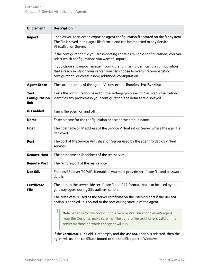
UI Element Description
Import Enables you to select an exported agent configuration file stored on the file system.The file is saved in the .agce file format, and can be imported to any ServiceVirtualization Server.
If the configuration file you are importing contains multiple configurations, you canselect which configurations you want to import.
If you choose to import an agent configuration that is identical to a configurationthat already exists on your server, you can choose to overwrite your existingconfiguration, or create a new, additional configuration.
Agent State The current status of the agent. Values include Running, Not Running.
TestConfigurationlink
Tests the configuration based on the settings you select. If Service Virtualizationidentifies any problems in your configuration, the details are displayed.
Is Enabled Turns the agent on and off.
Name Enter a name for the configuration or accept the default name.
Host The hostname or IP address of the Service Virtualization Server where the agent isdeployed.
Port The port of the Service Virtualization Server used by the agent to deploy virtualservices.
Remote Host The hostname or IP address of the real service.
Remote Port The remote port of the real service.
Use SSL Enables SSL over TCP/IP. If enabled, you must provide certificate file and passworddetails.
CertificateFile
The path to the server side certificate file, in P12 format, that is to be used by thegateway agent during SSL authentication.
The certificate is used as the server certificate on the listening port if the Use SSLoption is enabled. It is bound to the port during startup of the agent.
Note: When remotely configuring a Service Virtualization Server's agentfrom the Designer, make sure that the path to the certificate is valid on theserver machine on which the agent will run.
If the Certificate File field is left empty and the Use SSL option is selected, then theagent will use the certificate bound to the specified port in Windows.
User GuideChapter 2: Service Virtualization Agents
Service Virtualization (3.83) Page 104 of 474
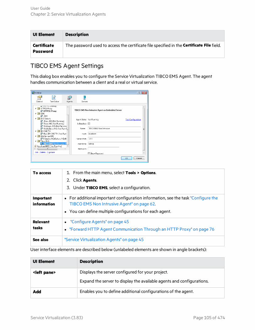
UI Element Description
CertificatePassword
The password used to access the certificate file specified in the Certificate File field.
TIBCO EMS Agent Settings
This dialog box enables you to configure the Service Virtualization TIBCO EMS Agent. The agenthandles communication between a client and a real or virtual service.
To access 1. From the main menu, select Tools > Options.
2. Click Agents.
3. Under TIBCO EMS, select a configuration.
Importantinformation
l For additional important configuration information, see the task "Configure theTIBCO EMS Non Intrusive Agent" on page 62.
l You can define multiple configurations for each agent.
Relevanttasks
l "Configure Agents" on page 45
l "Forward HTTP Agent Communication Through an HTTP Proxy" on page 76
See also "Service Virtualization Agents" on page 45
User interface elements are described below (unlabeled elements are shown in angle brackets):
UI Element Description
<left pane> Displays the server configured for your project.
Expand the server to display the available agents and configurations.
Add Enables you to define additional configurations of the agent.
User GuideChapter 2: Service Virtualization Agents
Service Virtualization (3.83) Page 105 of 474
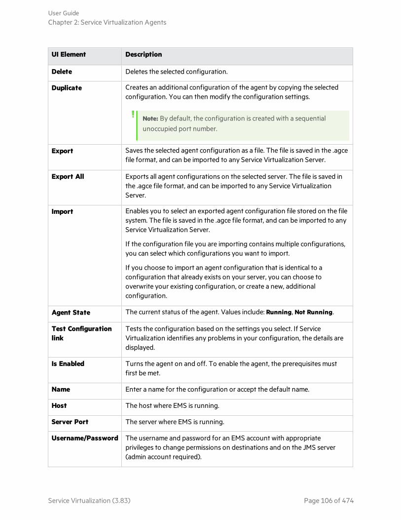
UI Element Description
Delete Deletes the selected configuration.
Duplicate Creates an additional configuration of the agent by copying the selectedconfiguration. You can then modify the configuration settings.
Note: By default, the configuration is created with a sequentialunoccupied port number.
Export Saves the selected agent configuration as a file. The file is saved in the .agcefile format, and can be imported to any Service Virtualization Server.
Export All Exports all agent configurations on the selected server. The file is saved inthe .agce file format, and can be imported to any Service VirtualizationServer.
Import Enables you to select an exported agent configuration file stored on the filesystem. The file is saved in the .agce file format, and can be imported to anyService Virtualization Server.
If the configuration file you are importing contains multiple configurations,you can select which configurations you want to import.
If you choose to import an agent configuration that is identical to aconfiguration that already exists on your server, you can choose tooverwrite your existing configuration, or create a new, additionalconfiguration.
Agent State The current status of the agent. Values include: Running, Not Running.
Test Configurationlink
Tests the configuration based on the settings you select. If ServiceVirtualization identifies any problems in your configuration, the details aredisplayed.
Is Enabled Turns the agent on and off. To enable the agent, the prerequisites mustfirst be met.
Name Enter a name for the configuration or accept the default name.
Host The host where EMS is running.
Server Port The server where EMS is running.
Username/Password The username and password for an EMS account with appropriateprivileges to change permissions on destinations and on the JMS server(admin account required).
User GuideChapter 2: Service Virtualization Agents
Service Virtualization (3.83) Page 106 of 474
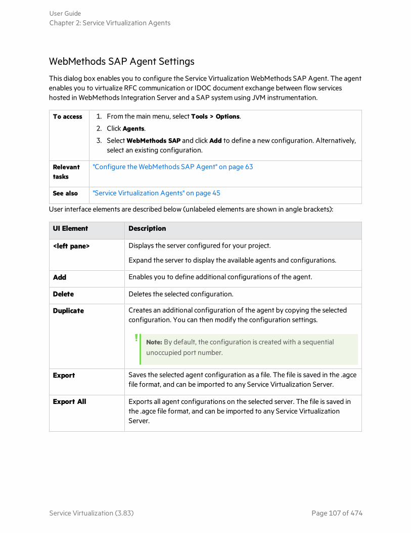
WebMethods SAP Agent Settings
This dialog box enables you to configure the Service Virtualization WebMethods SAP Agent. The agentenables you to virtualize RFC communication or IDOC document exchange between flow serviceshosted in WebMethods Integration Server and a SAP system using JVM instrumentation.
To access 1. From the main menu, select Tools > Options.
2. Click Agents.
3. Select WebMethods SAP and click Add to define a new configuration. Alternatively,select an existing configuration.
Relevanttasks
"Configure the WebMethods SAP Agent" on page 63
See also "Service Virtualization Agents" on page 45
User interface elements are described below (unlabeled elements are shown in angle brackets):
UI Element Description
<left pane> Displays the server configured for your project.
Expand the server to display the available agents and configurations.
Add Enables you to define additional configurations of the agent.
Delete Deletes the selected configuration.
Duplicate Creates an additional configuration of the agent by copying the selectedconfiguration. You can then modify the configuration settings.
Note: By default, the configuration is created with a sequentialunoccupied port number.
Export Saves the selected agent configuration as a file. The file is saved in the .agcefile format, and can be imported to any Service Virtualization Server.
Export All Exports all agent configurations on the selected server. The file is saved inthe .agce file format, and can be imported to any Service VirtualizationServer.
User GuideChapter 2: Service Virtualization Agents
Service Virtualization (3.83) Page 107 of 474
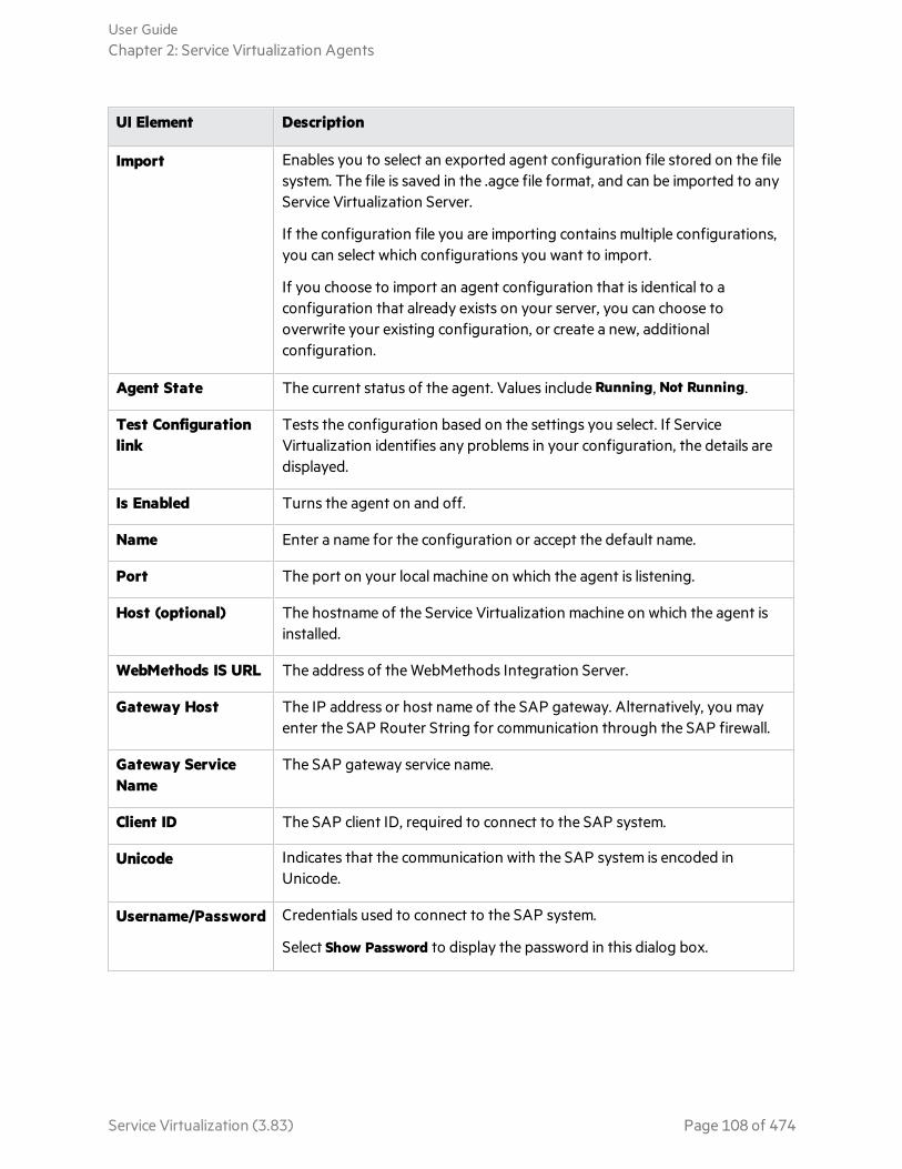
UI Element Description
Import Enables you to select an exported agent configuration file stored on the filesystem. The file is saved in the .agce file format, and can be imported to anyService Virtualization Server.
If the configuration file you are importing contains multiple configurations,you can select which configurations you want to import.
If you choose to import an agent configuration that is identical to aconfiguration that already exists on your server, you can choose tooverwrite your existing configuration, or create a new, additionalconfiguration.
Agent State The current status of the agent. Values include Running, Not Running.
Test Configurationlink
Tests the configuration based on the settings you select. If ServiceVirtualization identifies any problems in your configuration, the details aredisplayed.
Is Enabled Turns the agent on and off.
Name Enter a name for the configuration or accept the default name.
Port The port on your local machine on which the agent is listening.
Host (optional) The hostname of the Service Virtualization machine on which the agent isinstalled.
WebMethods IS URL The address of the WebMethods Integration Server.
Gateway Host The IP address or host name of the SAP gateway. Alternatively, you mayenter the SAP Router String for communication through the SAP firewall.
Gateway ServiceName
The SAP gateway service name.
Client ID The SAP client ID, required to connect to the SAP system.
Unicode Indicates that the communication with the SAP system is encoded inUnicode.
Username/Password Credentials used to connect to the SAP system.
Select Show Password to display the password in this dialog box.
User GuideChapter 2: Service Virtualization Agents
Service Virtualization (3.83) Page 108 of 474

WebSphere MQ Non-Intrusive Agent Settings
This dialog box enables you to configure the Service Virtualization WebSphere MQ Non-IntrusiveAgent. The agent handles communication between a client and a real or virtual service.
To access 1. From the main menu, select Tools > Options.
2. Click Agents.
3. Under WebSphere MQ Non-Intrusive, select a configuration.
Importantinformation
l For additional important configuration information, see the task "Configure theWebSphere MQ Non-Intrusive Agent" on page 66.
l The WebSphere MQ Non-Intrusive Agent is not able to automatically reconnectwhen a TCP connection to the WebSphere MQ Server is lost. Each service using theagent must be restarted. Alternately, restart the whole application.
l You can define multiple configurations for each agent.
Relevanttasks
l "Configure the WebSphere MQ Non-Intrusive Agent" on page 66
l "Forward HTTP Agent Communication Through an HTTP Proxy" on page 76
See also "Service Virtualization Agents" on page 45
User interface elements are described below (unlabeled elements are shown in angle brackets):
UI Element Description
<left pane> Displays the server configured for your project.
Expand the server to display the available agents and configurations.
Add Enables you to define additional configurations of the agent.
Delete Deletes the selected configuration.
Duplicate Creates an additional configuration of the agent by copying the selectedconfiguration. You can then modify the configuration settings.
Note: By default, the configuration is created with a sequentialunoccupied port number.
Export Saves the selected agent configuration as a file. The file is saved in the .agcefile format, and can be imported to any Service Virtualization Server.
Export All Exports all agent configurations on the selected server. The file is saved inthe .agce file format, and can be imported to any Service VirtualizationServer.
User GuideChapter 2: Service Virtualization Agents
Service Virtualization (3.83) Page 109 of 474

UI Element Description
Import Enables you to select an exported agent configuration file stored on the filesystem. The file is saved in the .agce file format, and can be imported to anyService Virtualization Server.
If the configuration file you are importing contains multiple configurations,you can select which configurations you want to import.
If you choose to import an agent configuration that is identical to aconfiguration that already exists on your server, you can choose tooverwrite your existing configuration, or create a new, additionalconfiguration.
Agent State The current status of the agent. Values include Running, Not Running.
Test Configurationlink
Tests the configuration based on the settings you select. If ServiceVirtualization identifies any problems in your configuration, the details aredisplayed.
Is Enabled Turns the agent on and off. To enable the agent, the prerequisites mustfirst be met.
Name Enter a name for the configuration or accept the default name.
Non-Intrusive ServerPort
The unique TCP/IP port on the Service Virtualization Server machine thatwill be used for accepting incoming connections from the ServiceVirtualization MQ API Exit library.
Queue ManagerName
The name of the queue manager for the agent to connect to.
Note: The WebSphere MQ Non-Intrusive Agent instance can only usequeues from a single Queue manager.
Channel Name The name of the TCP channel for the agent to use to connect to the QueueManager.
Note: The WebSphere MQ Non-Intrusive Agent instance can only use asingle TCP channel to connect to the Queue Manager.
Host The name of the server hosting the queue manager.
Port The TCP port where the channel listens for client connections.
User GuideChapter 2: Service Virtualization Agents
Service Virtualization (3.83) Page 110 of 474

UI Element Description
CCSID The character set used by the host.
Note:
l CCSID configuration in the WebSphere MQ Non-Intrusive Agentinstance requires that you restart the application.
l CCSID configuration is global for the whole application. There cannot betwo agents with different CCSIDs.
Username/Password The username and password for connecting to the queue manager.
Note: When you create a new virtual service, you can searchWebSphere MQ queues and select a destination, provided the virtualagent has sufficient permissions.
To browse MQ destinations, the specified user must be able toperform the following in the WebSphere MQ client:
l put and inq operations on theSYSTEM.ADMIN.COMMAND.QUEUE
l get, inq, and dsp operations on theSYSTEM.DEFAULT.MODEL.QUEUE
l dsp operations on queues to which the user has accesspermission
To create or delete a virtual destination, the specified user requiresadditional permissions, such as administrator permissions.
For details, see "Browse Destinations Dialog Box" on page 179.
SSL
CipherSpec The algorithm used for secure SSL communication.
Enter a value or select a value from the list. The CipherSpec value must bethe same as the value specified in the WebSphere MQ channelconfiguration.
User GuideChapter 2: Service Virtualization Agents
Service Virtualization (3.83) Page 111 of 474

UI Element Description
Key Repository The path of the WebSphere MQ SSL key repository, which contains theWebSphere MQ Queue Manager certificate. If you are using mutualauthentication, it also contains the certificate and private key of the ServiceVirtualization MQ Non-Intrusive agent.
Enter the path to the WebSphere MQ key database file (.kdb), but withoutthe file extension. This file is similar to the file specified in the key repositoryparameter in WebSphere MQ Queue Manager configuration.
Thresholds
Max. Connections The maximum number of cached connections to Queue Manager allowedfor sending messages. More connections enable more messages to be sentconcurrently.
Advanced Settings
Message ContextMode
Options for accessing the MQ queue.
l None.
l Set Identity. Corresponds to the MQC.MQOO_SET_IDENTITY_CONTEXT property.
l Set All. Corresponds to the MQC.MQOO_SET_ALL_CONTEXT property.
StripXML Declarations
Removes XML declarations (<?xml ...>) from text messages beforeprocessing in Service Virtualization. Text messages are in Unicode.
Use UTF Methods Service Virtualization considers MQ text messages as created by theWriteUTF() method instead of the WriteString() method.
When using an XML service, the message can be either transferred as astring (with a specified character set) or as binary data (UTF). By default,the agent reads and writes messages as a string. Select this option to usebinary messages with UTF content instead.
User GuideChapter 2: Service Virtualization Agents
Service Virtualization (3.83) Page 112 of 474
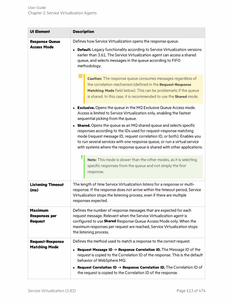
UI Element Description
Response QueueAccess Mode
Defines how Service Virtualization opens the response queue.
l Default. Legacy functionality according to Service Virtualization versionsearlier than 3.61. The Service Virtualization agent can access a sharedqueue, and selects messages in the queue according to FIFOmethodology.
Caution: The response queue consumes messages regardless ofthe correlation mechanism (defined in the Request-ResponseMatching Mode field below). This can be problematic if the queueis shared. In this case, it is recommended to use the Shared mode.
l Exclusive. Opens the queue in the MQ Exclusive Queue Access mode.Access is limited to Service Virtualization only, enabling the fastestsequential picking from the queue.
l Shared. Opens the queue as an MQ shared queue and selects specificresponses according to the IDs used for request-response matchingmode (request message ID, request correlation ID, or both). Enables youto run several services with one response queue, or run a virtual servicewith systems where the response queue is shared with other applications.
Note: This mode is slower than the other modes, as it is selectingspecific responses from the queue and not simply the firstresponse.
Listening Timeout(ms)
The length of time Service Virtualization listens for a response or multi-response. If the response does not arrive within the timeout period, ServiceVirtualization stops the listening process, even if there are multipleresponses expected.
MaximumResponses perRequest
Defines the number of response messages that are expected for eachrequest message. Relevant when the Service Virtualization agent isconfigured to use Shared Response Queue Access Mode only. When themaximum responses per request are reached, Service Virtualization stopsthe listening process.
Request-ResponseMatching Mode
Defines the method used to match a response to the correct request.
l Request Message ID -> Response Correlation ID. The Message ID of therequest is copied to the Correlation ID of the response. This is the defaultbehavior of WebSphere MQ.
l Request Correlation ID -> Response Correlation ID. The Correlation ID ofthe request is copied to the Correlation ID of the response.
User GuideChapter 2: Service Virtualization Agents
Service Virtualization (3.83) Page 113 of 474

WebSphere MQ Agent Settings
This dialog box enables you to configure the Service Virtualization WebSphere MQ Agent. The agenthandles communication between a client and a real or virtual service.
To access 1. From the main menu, select Tools > Options.
2. Click Agents.
3. Under WebSphere MQ, select a configuration.
Importantinformation
l For additional important configuration information, see the task "Configure theWebSphere MQ Agent" on page 74.
l The WebSphere MQ Agent is not able to automatically reconnect when a TCPconnection to the WebSphere MQ Server is lost. Each service using the agent mustbe restarted. Alternately, restart the whole application.
l You can define multiple configurations for each agent.
Relevanttasks
l "Configure Agents" on page 45
l "Forward HTTP Agent Communication Through an HTTP Proxy" on page 76
See also "Service Virtualization Agents" on page 45
User interface elements are described below (unlabeled elements are shown in angle brackets):
UI Element Description
<left pane> Displays the server configured for your project.
Expand the server to display the available agents and configurations.
Add Enables you to define additional configurations of the agent.
Delete Deletes the selected configuration.
User GuideChapter 2: Service Virtualization Agents
Service Virtualization (3.83) Page 114 of 474
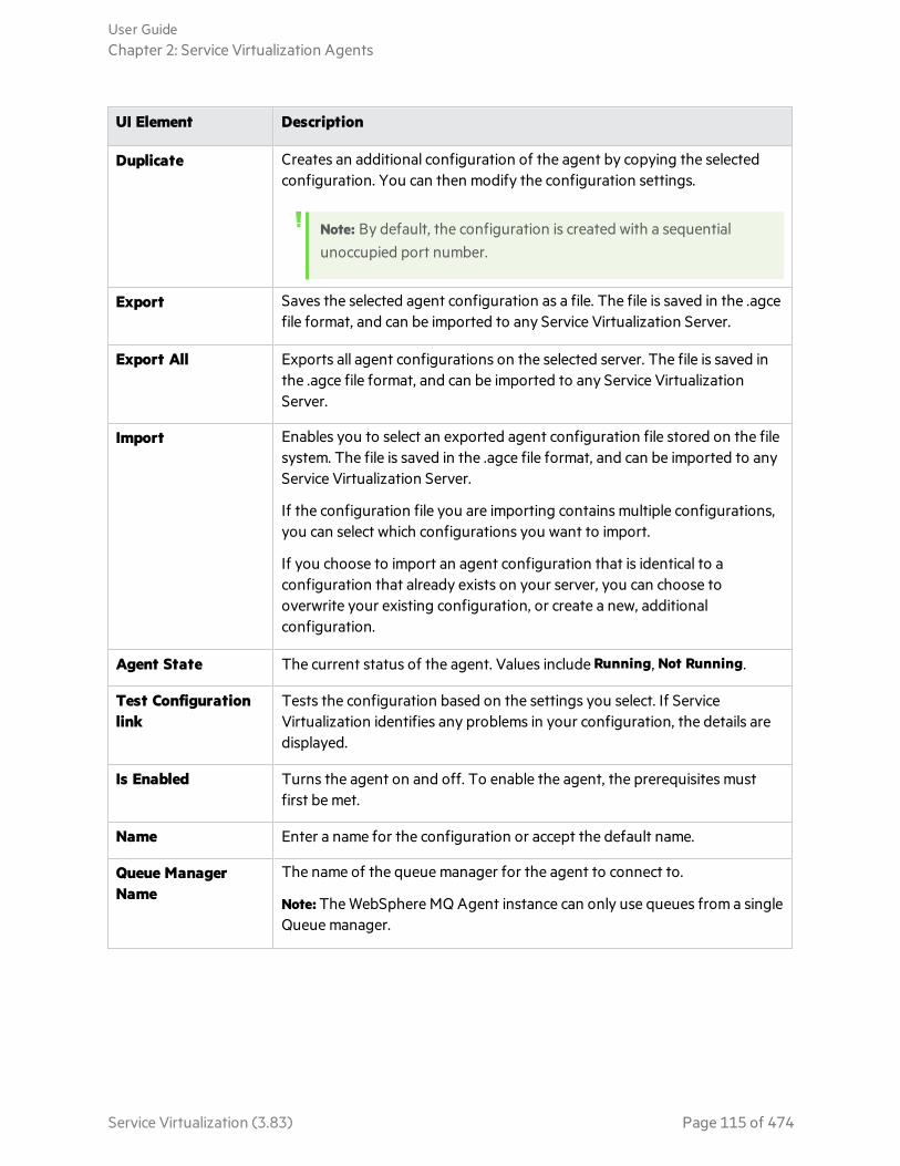
UI Element Description
Duplicate Creates an additional configuration of the agent by copying the selectedconfiguration. You can then modify the configuration settings.
Note: By default, the configuration is created with a sequentialunoccupied port number.
Export Saves the selected agent configuration as a file. The file is saved in the .agcefile format, and can be imported to any Service Virtualization Server.
Export All Exports all agent configurations on the selected server. The file is saved inthe .agce file format, and can be imported to any Service VirtualizationServer.
Import Enables you to select an exported agent configuration file stored on the filesystem. The file is saved in the .agce file format, and can be imported to anyService Virtualization Server.
If the configuration file you are importing contains multiple configurations,you can select which configurations you want to import.
If you choose to import an agent configuration that is identical to aconfiguration that already exists on your server, you can choose tooverwrite your existing configuration, or create a new, additionalconfiguration.
Agent State The current status of the agent. Values include Running, Not Running.
Test Configurationlink
Tests the configuration based on the settings you select. If ServiceVirtualization identifies any problems in your configuration, the details aredisplayed.
Is Enabled Turns the agent on and off. To enable the agent, the prerequisites mustfirst be met.
Name Enter a name for the configuration or accept the default name.
Queue ManagerName
The name of the queue manager for the agent to connect to.
Note: The WebSphere MQ Agent instance can only use queues from a singleQueue manager.
User GuideChapter 2: Service Virtualization Agents
Service Virtualization (3.83) Page 115 of 474
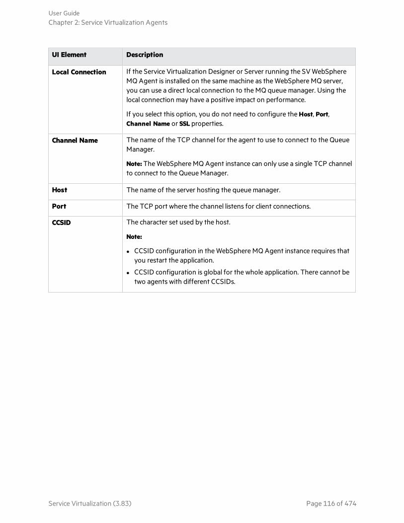
UI Element Description
Local Connection If the Service Virtualization Designer or Server running the SV WebSphereMQ Agent is installed on the same machine as the WebSphere MQ server,you can use a direct local connection to the MQ queue manager. Using thelocal connection may have a positive impact on performance.
If you select this option, you do not need to configure the Host, Port,Channel Name or SSL properties.
Channel Name The name of the TCP channel for the agent to use to connect to the QueueManager.
Note: The WebSphere MQ Agent instance can only use a single TCP channelto connect to the Queue Manager.
Host The name of the server hosting the queue manager.
Port The TCP port where the channel listens for client connections.
CCSID The character set used by the host.
Note:
l CCSID configuration in the WebSphere MQ Agent instance requires thatyou restart the application.
l CCSID configuration is global for the whole application. There cannot betwo agents with different CCSIDs.
User GuideChapter 2: Service Virtualization Agents
Service Virtualization (3.83) Page 116 of 474

UI Element Description
Username/Password The username and password for connecting to the queue manager.
Note: When you create a new virtual service, you can searchWebSphere MQ queues and select a destination, provided the virtualagent has sufficient permissions.
To browse MQ destinations, the specified user must be able toperform the following in the WebSphere MQ client:
l put and inq operations on theSYSTEM.ADMIN.COMMAND.QUEUE
l get, inq, and dsp operations on theSYSTEM.DEFAULT.MODEL.QUEUE
l dsp operations on queues to which the user has accesspermissions
To create or delete a virtual destination, the specified user requiresadditional permissions, such as administrator permissions.
For details, see "Browse Destinations Dialog Box" on page 179.
SSL
CipherSpec The algorithm used for secure SSL communication.
Enter a value or select a value from the list. The CipherSpec value must bethe same as the value specified in the WebSphere MQ channelconfiguration.
Key Repository The path of the WebSphere MQ SSL key repository, which contains theWebSphere MQ Queue Manager certificate. If you are using mutualauthentication, it also contains the certificate and private key of the ServiceVirtualization MQ agent.
Enter the path to the WebSphere MQ key database file (.kdb), but withoutthe file extension. This file is similar to the file specified in the key repositoryparameter in WebSphere MQ Queue Manager configuration.
Thresholds
User GuideChapter 2: Service Virtualization Agents
Service Virtualization (3.83) Page 117 of 474

UI Element Description
Max. Connections The maximum number of cached connections to Queue Manager allowedfor sending messages. More connections enable more messages to be sentconcurrently.
Advanced Settings
Message ContextMode
Options for accessing the MQ queue.
l None.
l Set Identity. Corresponds to the MQC.MQOO_SET_IDENTITY_CONTEXT property.
l Set All. Corresponds to the MQC.MQOO_SET_ALL_CONTEXT property.
StripXML Declarations
Removes XML declarations (<?xml ...>) from text messages beforeprocessing in Service Virtualization. Text messages are in Unicode.
Use UTF Methods Service Virtualization considers MQ text messages as created by theWriteUTF() method instead of the WriteString() method.
When using an XML service, the message can be either transferred as astring (with a specified character set) or as binary data (UTF). By default,the agent reads and writes messages as a string. Select this option to usebinary messages with UTF content instead.
User GuideChapter 2: Service Virtualization Agents
Service Virtualization (3.83) Page 118 of 474

UI Element Description
Response QueueAccess Mode
Defines how Service Virtualization opens the response queue.
l Default. Legacy functionality according to Service Virtualization versionsearlier than 3.61. The Service Virtualization agent can access a sharedqueue, and selects messages in the queue according to FIFOmethodology.
Caution: The response queue consumes messages regardless ofthe correlation mechanism (defined in the Request-ResponseMatching Mode field below). This can be problematic if the queueis shared. In this case, it is recommended to use the Shared mode.
l Exclusive. Opens the queue in the MQ Exclusive Queue Access mode.Access is limited to Service Virtualization only, enabling the fastestsequential picking from the queue.
l Shared. Opens the queue as an MQ shared queue and selects specificresponses according to the IDs used for request-response matchingmode (request message ID, request correlation ID, or both). Enables youto run several services with one response queue, or run a virtual servicewith systems where the response queue is shared with other applications.
Note: This mode is slower than the other modes, as it is selectingspecific responses from the queue and not simply the firstresponse.
Listening Timeout(ms)
The length of time Service Virtualization listens for a response or multi-response. If the response does not arrive within the timeout period, ServiceVirtualization stops the listening process, even if there are multipleresponses expected.
MaximumResponses perRequest
Defines the number of response messages that are expected for eachrequest message. Relevant when the Service Virtualization agent isconfigured to use Shared Response Queue Access Mode only. When themaximum responses per request are reached, Service Virtualization stopsthe listening process.
Request-ResponseMatching Mode
Defines the method used to match a response to the correct request.
l Request Message ID -> Response Correlation ID. The Message ID of therequest is copied to the Correlation ID of the response. This is the defaultbehavior of WebSphere MQ.
l Request Correlation ID -> Response Correlation ID. The Correlation ID ofthe request is copied to the Correlation ID of the response.
User GuideChapter 2: Service Virtualization Agents
Service Virtualization (3.83) Page 119 of 474
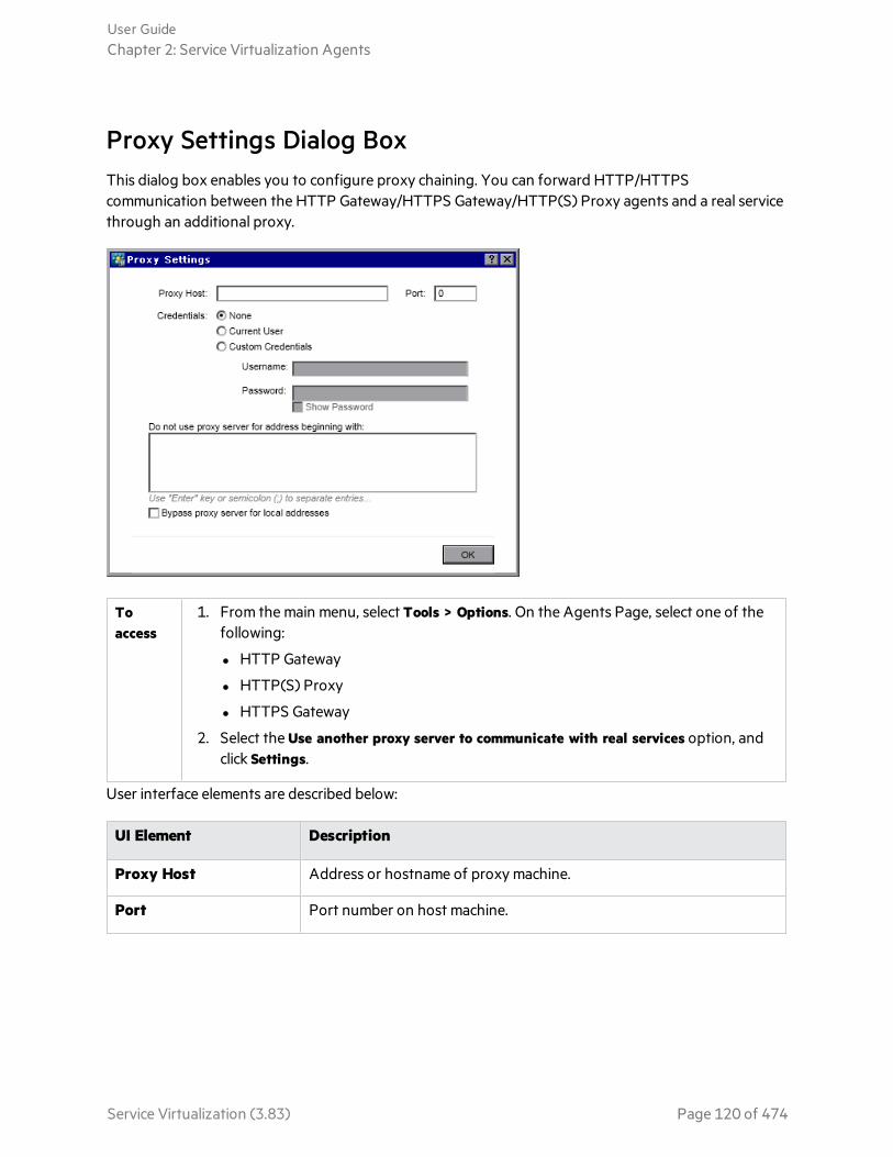
Proxy Settings Dialog BoxThis dialog box enables you to configure proxy chaining. You can forward HTTP/HTTPScommunication between the HTTP Gateway/HTTPS Gateway/HTTP(S) Proxy agents and a real servicethrough an additional proxy.
Toaccess
1. From the main menu, select Tools > Options. On the Agents Page, select one of thefollowing:
l HTTP Gateway
l HTTP(S) Proxy
l HTTPS Gateway
2. Select the Use another proxy server to communicate with real services option, andclick Settings.
User interface elements are described below:
UI Element Description
Proxy Host Address or hostname of proxy machine.
Port Port number on host machine.
User GuideChapter 2: Service Virtualization Agents
Service Virtualization (3.83) Page 120 of 474
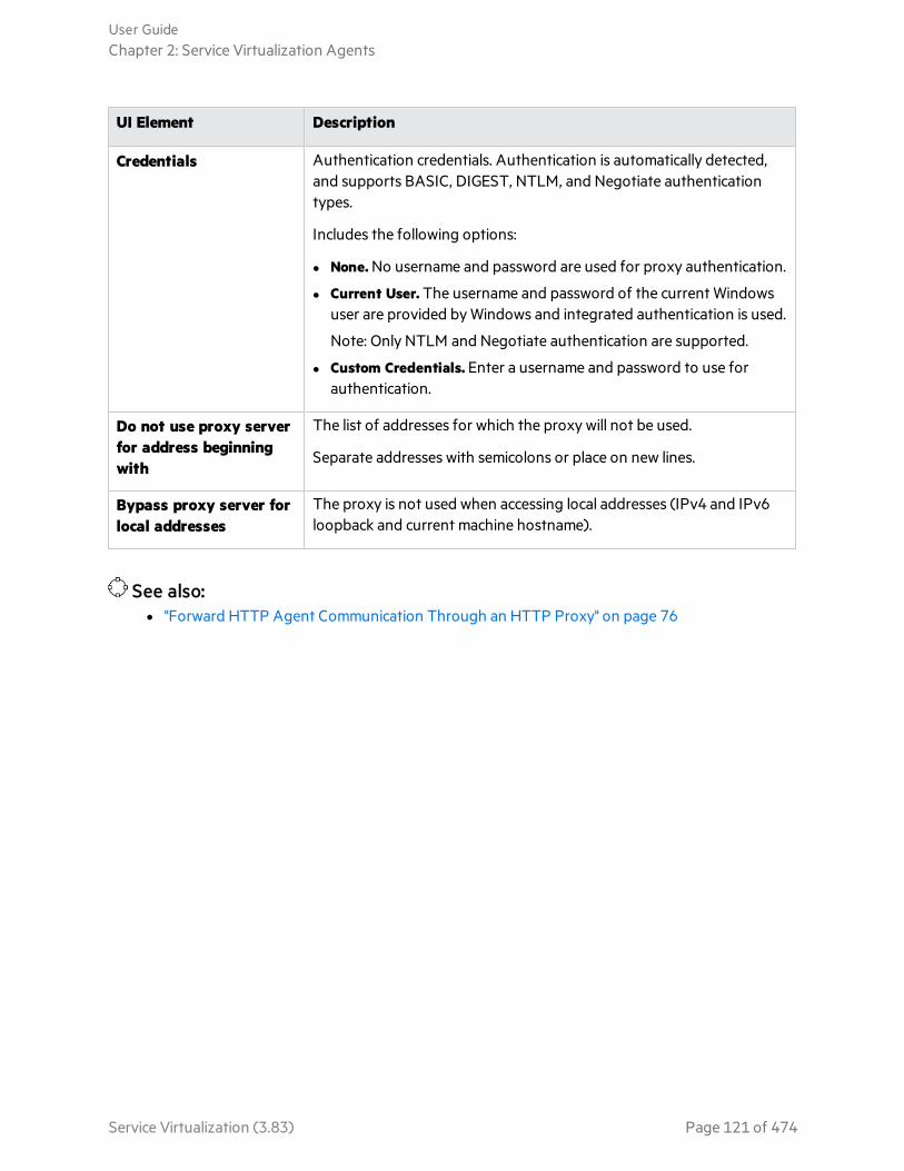
UI Element Description
Credentials Authentication credentials. Authentication is automatically detected,and supports BASIC, DIGEST, NTLM, and Negotiate authenticationtypes.
Includes the following options:
l None. No username and password are used for proxy authentication.
l Current User. The username and password of the current Windowsuser are provided by Windows and integrated authentication is used.
Note: Only NTLM and Negotiate authentication are supported.
l Custom Credentials. Enter a username and password to use forauthentication.
Do not use proxy serverfor address beginningwith
The list of addresses for which the proxy will not be used.
Separate addresses with semicolons or place on new lines.
Bypass proxy server forlocal addresses
The proxy is not used when accessing local addresses (IPv4 and IPv6loopback and current machine hostname).
See also:l "Forward HTTP Agent Communication Through an HTTP Proxy" on page 76
User GuideChapter 2: Service Virtualization Agents
Service Virtualization (3.83) Page 121 of 474

Chapter 3: Virtual ServicesThis chapter includes:
• Virtual Services 123• Create a Virtual Service 130• Configure Virtual Services 132• HTTP Service Discovery 134• Manage Virtualization Projects 135• Edit a Service Description 136• Define the URI Space 140• Virtualize SAP IDoc Communication 142• Virtualize SAP RFC Communication 143• Virtualize Fixed-Length Communication 143• Message Logging 148• Log Files 150• Virtual Services User Interface 151
Service Virtualization (3.83) Page 122 of 474
Virtual ServicesService Virtualization places a virtual service between the client application (application under test) andthe real service you want to simulate.
To simulate the behavior of the real service, you create a virtual service and configure it to meet yourneeds. After you design your virtual service, you reconfigure your client application to use this virtualservice endpoint, in place of the real service.
Task How to
Create virtual services. Import an existing service description document, or create anew service based on one of the Service Virtualization supported protocols.
Create service templates. After creating a service, you can save it as a template inorder to reuse the service in multiple testing environments, or reuse the service'sconfiguration, custom functions, data, and views.
"Create aVirtualService" onpage 130
Configure your virtual service. Design data and performance models to simulate realservice behavior. You can record real service activity, and use it to create thesemodels, or manually customize the models.
"ConfigureVirtualServices" onpage 132
Virtualization projects. The basis of organizing your virtual service is thevirtualization project. The virtualization project includes your virtual services, thesimulation models you use to simulate real service behavior, and other configurationentities you can customize to meet your needs.
"VirtualizationProjects"below
Manage virtual services. Manage your services by manipulating the virtual servicemode. The modes include Learning, Standby, and Simulating.
"Simulation"on page 213
See also:l "Virtual Service Types" on the next page
Virtualization ProjectsThe basis of organization within Service Virtualization is the virtualization project.
The virtualization project includes your virtual services, the simulation models you use to simulate realservice behavior, and other configuration entities you can customize to meet your needs.
You view your project structure in the Virtualization Explorer. For details, see "Virtualization Explorer"on page 185.
When you create a project, it is created within a solution. A solution is a container for one or moreprojects that you want to maintain as a group. You can view your project and solution in the Projectspane.
User GuideChapter 3: Virtual Services
Service Virtualization (3.83) Page 123 of 474

Update your projects
Projects created in earlier versions of Service Virtualization are fully compatible with ServiceVirtualization 3.83. When you open a project created in a previous version of Service Virtualization, apop up window displays, informing you that the project contains resources in an older format. Click Yesto confirm that you want to update your existing project.
For more details, see "Project Migration" in the HPE Service Virtualization Installation Guide.
Group related services
You may want to keep a group of related virtual services together in a single project. However, if thereare too many services in a single project, they may be difficult to manage. The recommended limit isapproximately 20 virtual services per project. In this case, it is recommended to create an additionalproject.
Add projects to a solution
You can add new or existing projects to an existing solution. One advantage to having multiple projectswithin one solution is that you can manage all the services within the Runtime view. The Runtime viewprovides an overview of the communication through the virtual services during Learning or Simulationsessions.
Export projects
You can save your project as an archive file in the file system.
Tip: For enhanced security, you can encrypt the project file. For more details on encryption, see"Password Encryption" on page 371.
See also:l For task details, see "Manage Virtualization Projects" on page 135.
Virtual Service TypesWhen you create a new virtual service, you specify a transport protocol and a message protocol that theservice will use. This section provides additional information required for some service types.
l For the full list of supported protocols and versions, refer to the support matrix on the HPE SoftwareSupport site at: https://softwaresupport.hpe.com/group/softwaresupport/support-matrices, orcontact support.
l For details on creating virtual services, see "Create a Virtual Service" on page 130.
User GuideChapter 3: Virtual Services
Service Virtualization (3.83) Page 124 of 474
In this topic:
l "XML Services" below
l "Binary Services" below
l "SOAP Services" below
l "REST Services" below
l "IBM IMS TM Virtual Services" on the next page
l "COBOL over IBM CICS TS HTTP Services" on page 127
l "SQL Services" on page 127
l "SAP IDoc and SAP RFC Services" on page 127
l "ONC/RPC Services" on page 128
XML Services
In addition to creating an XML virtual service to simulate a real XML service, you can also create an XMLvirtual service to simulate a SOAP service. You can import an .xsd file when creating the virtual service.
Binary Services
If the service is using an unknown transport protocol, creating a binary service is the best solution. IfService Virtualization cannot understand the message format, it can record it in binary format, althoughit is not able to fully recognize the structure.
SOAP Services
You can create SOAP services in the following ways:
l Import WSDL documents directly into Service Virtualization to describe SOAP services. To laterupdate a SOAP service description, you can load a new service description document.
l Import a schema from an .xsd file.
l Create a new service without importing a service description. You can then place the virtual service inLearning mode to record real service behavior.
l Run service discovery to discover all the services used by an application.
REST Services
There are several ways to design REST services.
Record the real service: After you create a new REST virtual service, you can record real servicebehavior to learn the structure of the service.
Import OpenAPI specification: You can also use OpenAPI (Swagger), the JSON-based format fordescribing REST APIs, to create a REST service. You create a new virtual service by importing yourswagger file and associated .json files.
User GuideChapter 3: Virtual Services
Service Virtualization (3.83) Page 125 of 474

The following parts of the OpenAPI standard are supported:
l Service location metadata
l Uri paths
l Request headers, request message body, query parameters, path parameters
l Response headers, response message body
l JSON references
l Inheritance
The following parts of the OpenAPI standard are NOT supported:
l Most constraints that can be placed on data types are not supported, such as patterns,enumerations, min & max values, and min & max array items.
l XML-based messages
Run HTTP Service Discovery: Run HTTP Service Discovery to record communication passing throughthe HTTP(S) Proxy agent, and then create new REST virtual services based on the discovered services.
IBM IMS TM Virtual Services
Depending on the client transport and message level protocol, there are multiple options for virtualizingIBM® Information Management System Transaction Manager (IMS™ TM) services.
The following is an overview of protocols with full message structure parsing. Each requires a COBOLcopybook.
1. COBOL payload over IBM IMS TM Resource Adapter
a. The client is J2EE application using IBM IMS TM Resource Adapter to access IMS TM.
b. The payload are COBOL messages based on known COBOL copybooks.
c. The virtual service is created based on one or more of the following: TPipe name, Client ID,Datastore Name, Transaction Code.
2. COBOL payload over IBM IMS Connect API protocol
a. The client is J2SE application using IBM IMS Connect Java API to access IMS TM.
b. The payload are COBOL messages based on known COBOL copybooks.
c. The virtual service is created based on one or more of the following: LTerm name, Client ID,Datastore Name, Transaction Code.
If full message structure parsing is not required, or if the COBOL copybook is not available, thefollowing protocols provide the best alternatives. Note that the payload is a binary object and notstructured.
1. Binary messages over IMS
a. Any client type using IMS TM over a TCP/IP network.
b. Any payload type.
c. The virtual service is created based on one or more of the following: TPipe name, Client ID,Datastore Name, Transaction Code.
User GuideChapter 3: Virtual Services
Service Virtualization (3.83) Page 126 of 474

2. Binary messages over WebSphere MQ
a. The client is using IMS-MQ bridge to access IMS TM.
b. Any payload type.
COBOL over IBM CICS TS HTTP Services
If the client communicates with the service using COBOL messages over HTTP transport, such as IBMCICS Transaction Server web-aware applications for example, you can use the following protocols forservice simulation. Both HTTP Proxy and HTTP Gateway agent types are supported.
1. COBOL messages over IBM CICS TS HTTP
a. The client is any application using COBOL messages based on known COBOL copybook(s).
b. The virtual service is created based on HTTP URI path.
c. The message is fully structured.
2. Binary messages over HTTP
a. The client is any application using any messages (including COBOL).
b. The virtual service is created based on HTTP URI path.
c. The message is not structured. Only HTTP headers are shown.
COBOL services over IBM CICS TS HTTP transport usually use two encodings – one encoding for theHTTP protocol and the other for the COBOL messages. Service Virtualization expects the HTTPtransport to be encoded using US-ASCII. However, the exact COBOL message encoding may beselected during virtual service creation.
SQL Services
You can create virtual SQL services for working with JDBC. A virtual SQL service can simulate both J2SEand J2EE client applications.
When you configure the Service Virtualization JDBC agent to work with JDBC services, you enterparameters for the specific target environment in which you are working. Service Virtualization thenconfigures a unique agent for your system.
SAP IDoc and SAP RFC Services
You can import RFC functions or IDoc operations from a SAP server, or learn the functions andoperations by recording real service behavior.
Service Virtualization supports the following:
l SAP RFC or SAP IDOC communication between two SAP® servers or between a SAP server and aSAP NetWeaver® Process Integration (PI) system.
l TCP/IP SAP destination only.
l Only basic authentication for connection to a SAP system.
User GuideChapter 3: Virtual Services
Service Virtualization (3.83) Page 127 of 474

l Supported RFC communication includes synchronous, or any of the three asynchronous types(Asynchronous, Transactional, or Queued). In the case of asynchronous types, requests are collectedand then processed in a batch.
ONC/RPC Services
To create an ONC/RPC virtual service, you must provide the ONC scheme in the form of a .x file. Fordetails, see "Import Real Service Description Page" on page 154.
Service DescriptionsIn order to virtualize a service, Service Virtualization needs to know what the service does and whatendpoints it uses.
Overview
You can provide a service description in several ways:
Learning When you place a virtual service in Learning mode, Service Virtualization learns aboutthe real service structure, and automatically updates the virtual service. If there areadditional changes that you want to make, you can then edit the service descriptionmanually. Service description learning is available for XML, REST, SOAP, SQL, andSAP services.
Importservicedescriptiondocuments
Service Virtualization provides an import wizard that analyzes the content of thedocument, and enables you to associate it with a particular virtualized service.
Configurea servicedescription
You can the add operations and URI spaces, import and edit XML schemas, andconfigure other components of your services. For example, after you create a RESTservice, you can record real service behavior to learn the structure of the service. Youcan then edit the service description in Service Virtualization.
Importing Service Description Documents
You can import the following service description document types into Service Virtualization:
WSDL Web-Service Definition Language documents are the most common way to describeSOAP services. They often contain references to other WSDLs and XSDs that must beavailable in the referenced locations in order to import them and correctly describe theservices they define.
User GuideChapter 3: Virtual Services
Service Virtualization (3.83) Page 128 of 474

XSD XML Schema documents may also describe XML services. They often containreferences to additional XML Schema Definitions (XSDs) that must be available in thereferenced locations in order to import them and correctly describe the services theydefine.
COBOLCopybook
COBOL copybook documents describe input and output message structure for legacymainframe applications.
ONCscheme
To create an ONC/RPC virtual service, import the ONC scheme in the form of a .x file.
OpenAPI(Swagger)
OpenAPI (Swagger) files, the JSON-based format for describing REST APIs.
For task details, see "Create a Virtual Service" on the next page.
Configuring Service Descriptions
You can edit a service description within Service Virtualization. You can configure the followingcomponents:
Note: To update a SOAP service description, you can also load a new service descriptiondocument. You can edit HTTP metadata, and set session identifiers within Service Virtualization,which are not part of the service's WSDL document.
Operationsand URIspaces
For an XML service, you can add new operations. For REST services, you can createmore URI spaces in which to place the data. This enables you to split your data intosmaller groups according to the URI path of the resources.
Metadata Metadata are parameters that contain some protocol-specific information such as timestamps, correlation information, or status codes. They are part of the protocolmessage, but external to the message body, such as URL parameters, or HTTPheaders. You can edit this metadata in Service Virtualization.
Some types of metadata, such as HTTP Headers, are not required for testedapplications; they may be important for the protocol, but the application does notrequire them and they are not learned for purposes of virtualization. By default theyare disabled in the request but it is possible to enable them and edit the data for use ina simulation. Metadata such as URI Parameters are generally used by testedapplications and are enabled by default.
XMLschemas
For XML, REST, or SOAP services. You can add, edit, or remove XML schemas.
User GuideChapter 3: Virtual Services
Service Virtualization (3.83) Page 129 of 474

Sessionidentifiers
To perform stateful simulation, you need to be able to identify requests that originatefrom the same source. For example, you may want to identify all requests coming froma single browser session. Service Virtualization uses this information to create differenttracks based on learned data, and uses the tracks to create different sessions duringsimulation. Service Virtualization assigns default session identifiers based on theservice's protocol, which you can then modify.
Dataformats
You can add or remove request and response data formats. You add a new dataformat to your service description by copying from an existing URI space (in aREST service), or by creating a new format.
Datamasking
To hide sensitive data, you can scramble specific data elements. For example, theremay be sensitive data that you are not permitted to store to disk. You can configurethe elements for data masking, so that data recorded during Learning is masked andcannot be viewed in the data model.
For task details, see "Edit a Service Description" on page 136.
Create a Virtual ServiceThis task describes how to create a virtual service. For additional details on specific service types, see"Virtual Service Types" on page 124.
Note:
l This task is part of a higher-level task. For details, see "End-to-End Workflow" on page 20.
l To learn more about virtual services, see "Virtual Services" on page 123.
Optional: Create a new projectWhen you select a task from the Get Started page, these tasks first create a new virtualization projectand then a new virtual service. For user interface details, see "Start Page" on page 27.
For details on how to manually create a new virtualization project, see "Manage Virtualization Projects"on page 135.
Open an existing projectSelect one of the following:
l On the Start Page, under Recent Projects, select a project.
l From the main menu, select File > Open Project/Solution.
Note: Projects created in earlier versions of Service Virtualization are fully compatible with
User GuideChapter 3: Virtual Services
Service Virtualization (3.83) Page 130 of 474

Service Virtualization 3.83.
When opening a project created in a previous version of Service Virtualization, a pop up windowdisplays, informing you that the project contains resources in an older format. Click Yes toconfirm that you want to update your existing project.
For more information on virtualization projects, see "Virtualization Projects" on page 123.
Create a virtual serviceDo one of the following:
Create a virtual service
In an existing project, select one of the following to launch the new virtual service wizard:
l From the main menu, select File > New > Virtual Service.
l In the Virtualization Explorer, right-click a virtualization entity and select Add > Virtual Service.
For user interface details, see "Create New Virtual Service Wizard" on page 153.
Create multiple virtual services in one step
Note: Available for SOAP over HTTP(S) services only.
You can create multiple virtual services by specifying a list of .wsdl files, or by providing a .csv filecontaining the paths to .wsdl files.
1. In an open project, select one of the following:
l From the main menu, select File > New > Multiple Virtual Services.
l In the Virtualization Explorer, right-click a virtualization entity and select Add > Multiple VirtualServices.
2. In the Import Real Service Description dialog box, enter a list of paths to your .wsdl files, separatedby semicolons.
For example,
C:\Services\ShoppingCart.wsdl;C:\Services\MemberAccounts.wsdl;C:\Services\ClaimProcessing.wsdlAlternatively, enter the path to a CSV file containing the paths to the .wsdl files.
3. Follow the on-screen instructions.
For user interface details, see "Create Multiple Virtual Services Wizard" on page 183.
User GuideChapter 3: Virtual Services
Service Virtualization (3.83) Page 131 of 474
Run service discovery
l For creating SOAP services: Discover all the services used by an application. For details, see "ModelComposite Applications" on page 349.
l For creating REST services: Run HTTP Service Discovery to record communication passing throughthe HTTP(S) Proxy agent, and then create new REST virtual services based on the discoveredservices. For details, see "HTTP Service Discovery" on page 134.
Optional: Create a service template1. To save a service as a template: In the Virtualization Explorer, right-click the service and select Save
as Template.
2. To create a new service from a template: From the main menu, select File > New > Virtual Servicefrom Template.
See also:l "Learning a REST Service Tutorial" on page 444
l "Interactive REST Authoring Tutorial" on page 453
Configure Virtual ServicesThis task describes how to configure your virtual service to meet your needs.
Note:
l This task is part of a higher-level task. For details, see "End-to-End Workflow" on page 20.
l To learn more about configuring virtual services, see "Virtual Services" on page 123.
This task includes the following steps:
l "Select simulation models" below
l "Configure virtual service endpoints" on the next page
l "Configure Service Virtualization agents" on the next page
l "Enable message logging" on the next page
l "Disable schema learning" on the next page
l "Edit the service description" on the next page
l "Set security options" on page 134
l "Change servers" on page 134
Select simulation modelsIn the Virtual Service Editor, select existing data and performance models to use with your virtual
User GuideChapter 3: Virtual Services
Service Virtualization (3.83) Page 132 of 474

service, or add new models.
For task details on simulation models, see "Manage Simulation Models" on page 248.
Configure virtual service endpointsYou can modify real and virtual service endpoint information that you provided when creating thevirtual service, or in some cases, configure additional options.
In the Virtual Service Editor, under Service Configuration, click Edit to open the Edit Endpoints dialogbox.
In the Edit Endpoints dialog box, you can click Show Endpoint Topology to display a diagram of yourservice endpoint configuration.
Configure Service Virtualization agentsYou can modify agent information that you selected when creating the virtual service. In the VirtualService Editor, under Service Configuration, click Configure. The Agents page opens.
For user interface details, see "Agents Page" on page 77.
Enable message loggingTo enable logging, in the Virtual Service Editor, under Service Configuration, select Message Logging.
For more details, see "Message Logging" on page 148.
Disable schema learningYou can block changes to the service description during learning or message import.
This is useful, for example, when the service was created from an existing WSDL or schema, and youwant to ensure that messages with a different structure do not modify it.
For more details, see "Virtual Service Editor" on page 186.
Edit the service descriptionYou can modify the service description associated with your virtual service. Depending on the servicetype, you can do the following:
l add/remove operations/URI spaces
l edit request/response metadata
l add/remove/edit XML schemas
l add/remove data formats
l define session identifiers
User GuideChapter 3: Virtual Services
Service Virtualization (3.83) Page 133 of 474

For task details, see "Edit a Service Description" on page 136.
For user interface details, see "Service Description Editor" on page 197.
Set security optionsIn the Virtual Service Editor, under Security Settings, define authentication credentials and messagesecurity.
Note: This may be required before you can connect to the real service.
For task details, see "Set Security" on page 361.
Change serversYou can redeploy the virtual services in your project to a different server, if required.
From the main menu, select Project > Change Server to open the Change Server for <current project>Project dialog box.
Alternatively, in the Virtualization Explorer, right-click the project tree and select Change Server.
HTTP Service DiscoveryRun HTTP Service Discovery to record communication passing through the HTTP(S) Proxy agent, andthen create new REST virtual services based on the discovered services.
Create REST virtual services using HTTP Service Discovery
1. Create or open a virtualization project.
2. From the main menu, select File > New > Virtual Services From HTTP Service Discovery.
3. Click Start Discovery. Communication passing through HTTP(S) Proxy agents is recorded anddisplayed.
Note: Communication intercepted by already existing virtual services is not recorded.
4. Select all discovered endpoints that should constitute the new service you want to create.
Tip: You can filter discovered calls by host name, endpoint path, and content type.
5. Click Create Service. You can review and change pre-filled details, such as service name, endpoints,and agent before creating the virtual service.
Known limitations
The following scenarios can cause unexpected behavior and are not supported:
User GuideChapter 3: Virtual Services
Service Virtualization (3.83) Page 134 of 474

l Simultaneously running HTTP Service Discovery and service discovery inside the Topology Editor.
l Simultaneously running HTTP Service Discovery from two Designers connected to the same ServiceVirtualization Server.
See also:l "Create a Virtual Service" on page 130
Manage Virtualization ProjectsThis task describes how to create and manage virtualization projects.
Note: To learn more about Service Virtualization projects, see "Virtualization Projects" on page123.
Create a new projectSelect one of the following:
l Select a task from the Get Started page. These tasks first create a new virtualization project and thena new virtual service. For user interface details, see "Start Page" on page 27.
l Create a new virtualization project. From the main menu, select File > New > Virtualization Project.For user interface details, see "Summary of Virtualization Project Dialog Box" on page 152.
Add projects to an existing solutionYou can add new or existing projects to a solution.
1. From the main menu, select View > Projects to display the Projects pane.
2. Right-click the solution name and select one of the following:
a. Add > New Virtualization Project
b. Add > Existing Project
Open a projectTo open a project, select one of the following:
l On the Start Page, under Recent Projects, select a project.
Tip: Hover over a project name to see the full path to the saved project.
l From the main menu, select File > Open Project/Solution. By default, projects are stored in thefollowing location in the file system: <Your Documents folder>\HPE Service Virtualization\Projects.
User GuideChapter 3: Virtual Services
Service Virtualization (3.83) Page 135 of 474

Change the default project locationFrom the main menu, select Tools > Options > General tab. Then select Projects and Solutions.
Close a projectFrom the main menu, select File > Close Project/Solution.
View server informationIn the Virtualization Explorer, expand a project. The server is displayed as the last item in the tree. Clickthe server to display its details in the lower pane.
Move virtual services to a different serverThe virtual services in your project are deployed on the Service Virtualization server specified for theproject.
To change the server:
1. In the Virtualization Explorer, expand a project.
2. Right-click the server and select Change Server.
Alternatively, from the main menu, select Project > Change Server.
For user interface details, see "Change Server Dialog Box" on page 194.
Export a projectSave your project as an archive file in the file system. From the main menu, select File > Export Project.The file is saved with the default file extension .vproja.
Encrypt projectsYou can encrypt your projects using a password you define.
1. From the main menu, select Tools > Options.
2. On the General page, click Projects and Solutions and enter a project encryption password.
For more details on encryption, see "Password Encryption" on page 371.
Edit a Service DescriptionThis task describes how to edit a service description. This includes service editing and URI space editing.
User GuideChapter 3: Virtual Services
Service Virtualization (3.83) Page 136 of 474

Note: To learn more about service descriptions, see "Service Descriptions" on page 128.
This task includes the following steps:
l "Open a service description" below
l "Edit metadata " below
l "Manage XML schemas" below
l "Add or remove an operation" below
l "Add, delete, or rename a URI space" on the next page
l "Add or remove data formats" on the next page
l "Define session identifiers" on page 139
l "Hide data" on page 139
l "Update a SOAP or Swagger service description" on page 139
Open a service descriptionIn the Virtual Service Editor, under Service Description, click Edit. For user interface details, see "ServiceDescription Editor" on page 197.
Edit metadataYou can add, delete, enable, disable, and edit metadata.
In the Service Description Editor, under Request Metadata or Response Metadata, click Edit. For userinterface details, see "Edit Metadata Dialog Box" on page 209.
Manage XML schemasIn the Service Description Editor, under XML Schemas, select an option to add, edit, or removeXML schemas. For user interface details, see "Service Description Editor" on page 197.
Add or remove an operationYou can add operations to your service.
In the Service Description Editor, in the bottom left of the Operations pane, click Add Operation. Selectinput and output message types. You must assign each operation a unique input message type.
SAP services: For a SAP service, the Add Operation dialog box enables you to import RFCfunctions or IDoc operations from a SAP server. For more details on SAP IDoc communication,see "Virtualize SAP IDoc Communication" on page 142.
User GuideChapter 3: Virtual Services
Service Virtualization (3.83) Page 137 of 474

Add, delete, or rename a URI spaceAdd: You can create additional URI spaces for data in your REST virtual services.
In the Service Description Editor, in the bottom left of the Operations pane, click Add URI Space.
Alternatively, right-click in the Operations pane and select Add URI Space.
Enter details for the new URI space.
l Segments are separated with a '/' and the wildcard characters * and ** are used for several charactersor segments. For instructions on defining a URI space, see "Define the URI Space" on page 140.
l If the new URI space contains a variable, the variable is converted to *. In the Add URI Space dialogbox, the Normalized URI field is displayed, showing the adjusted URI space name.
Example:
New URI Space: my/{id}
Normalized (adjusted) URI: my/*
l Caution: If a URI Space is in conflict with an existing URI Space and the new URI Space is morespecific, the conflicting URI Space is split to several new URI Spaces and data from all associated rulesare moved to these new URI Spaces.
Delete: To delete a URI space, in the left pane of the Service Description Editor, select the URI space andclick Delete URI Space.
Alternatively, right-click a URI space and select Delete URI Space.
Select an option:
l Delete the URI space, including all data
l Move data into another existing URI space. This option enables you to add and delete URI spaces atany time without losing any data.
Rename: To rename a URI space, right-click the URI space name and select Rename URI Space.
l You can choose to rename the URI space only, or the URI space and associated URI paths in existingdata rows in the data model.
l Review the examples displayed in the dialog box to make sure that the planned changes meet yourexpectations.
Add or remove data formatsData formats can be added and removed from a URI space as either request or response data formats.
User GuideChapter 3: Virtual Services
Service Virtualization (3.83) Page 138 of 474
1. In the Service Description Editor, in the operations pane on the left side, select a URI space.
2. Under Data Formats > Request Data Formats or Response Data Formats, click Add.
For user interface details, see "Add Data Format Dialog Box" on page 211.
Define session identifiersTo simulate a stateful service, in which the order of requests can impact the responses that are returned,you can configure the virtual service to create separate simulation sessions. For more information, see"Stateful Simulation" on page 331.
To enable stateful simulation, set session IDs to identify client requests that originate from the samesource.
1. Prerequisite: Service Virtualization must have information on the message structure that the clientuses. The structure of request/response messages is stored in the service description. You providethis information by doing one of the following:
l Placing the virtual service in Learning mode to record real service behavior. For example, for aREST service.
l Importing a service description document, such as when creating a SOAP service using animported .wsdl service description document.
l Importing messages into the virtual service's data model.
2. In the Service Description Editor, under Session IDs Definition, click Edit.
3. In the wizard pages that open, specify values for session identifiers, and click Finish. For userinterface details, see "Session ID Definition Wizard" on page 200.
4. Learn data again. Service Virtualization uses the session IDs to create different tracks based on thelearned data, and uses the tracks to create different sessions during simulation.
Hide dataConfigure data masking to protect sensitive data. Data recorded during Learning is masked and cannotbe viewed in the data model.
Do one of the following:
l In the Service Description Editor, under Data Masking, view the data masking configuration for yourvirtual service. To configure data masking, click Edit.
l In the Data Model Editor, right-click a column header and select Mask.
For user interface details, see "Data Masking Dialog Box" on page 205.
Update a SOAP or Swagger service descriptionYou may need to update a service description after a virtual service is created. A service commonlyevolves over time, along with its service description document, requiring an update of the virtual service.
You can update the service description in the following ways:
User GuideChapter 3: Virtual Services
Service Virtualization (3.83) Page 139 of 474
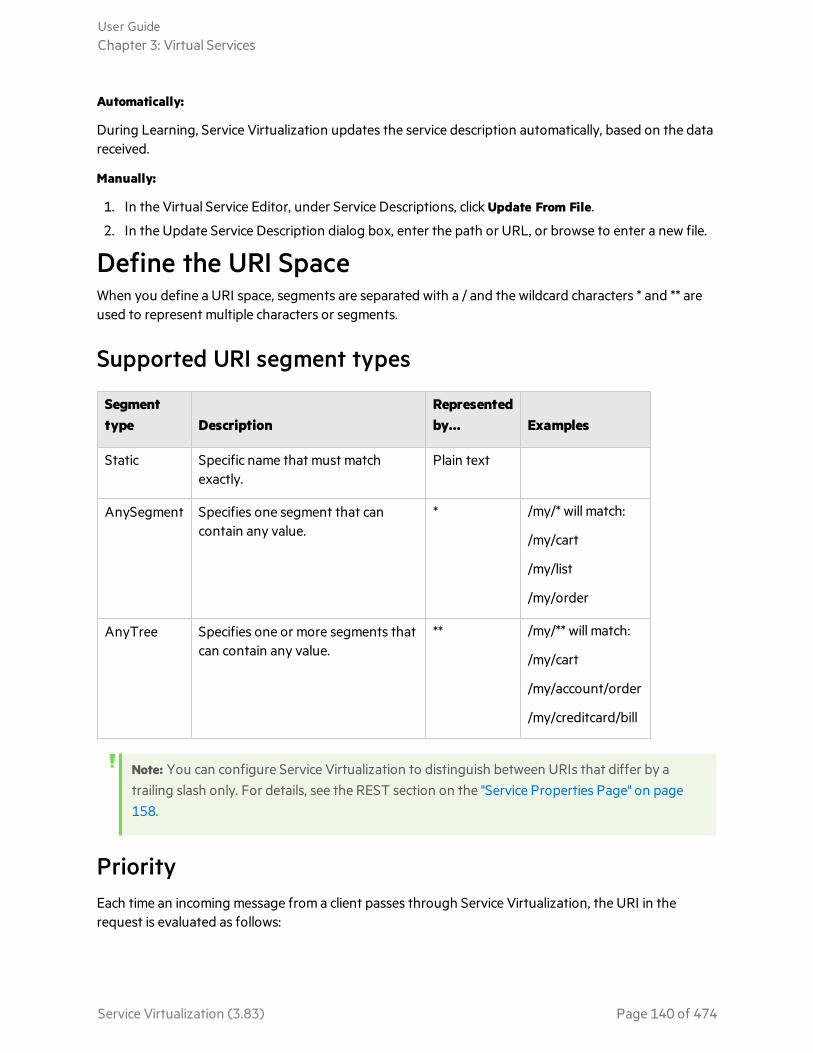
Automatically:
During Learning, Service Virtualization updates the service description automatically, based on the datareceived.
Manually:
1. In the Virtual Service Editor, under Service Descriptions, click Update From File.
2. In the Update Service Description dialog box, enter the path or URL, or browse to enter a new file.
Define the URI SpaceWhen you define a URI space, segments are separated with a / and the wildcard characters * and ** areused to represent multiple characters or segments.
Supported URI segment types
Segmenttype Description
Representedby... Examples
Static Specific name that must matchexactly.
Plain text
AnySegment Specifies one segment that cancontain any value.
* /my/* will match:
/my/cart
/my/list
/my/order
AnyTree Specifies one or more segments thatcan contain any value.
** /my/** will match:
/my/cart
/my/account/order
/my/creditcard/bill
Note: You can configure Service Virtualization to distinguish between URIs that differ by atrailing slash only. For details, see the REST section on the "Service Properties Page" on page158.
PriorityEach time an incoming message from a client passes through Service Virtualization, the URI in therequest is evaluated as follows:
User GuideChapter 3: Virtual Services
Service Virtualization (3.83) Page 140 of 474
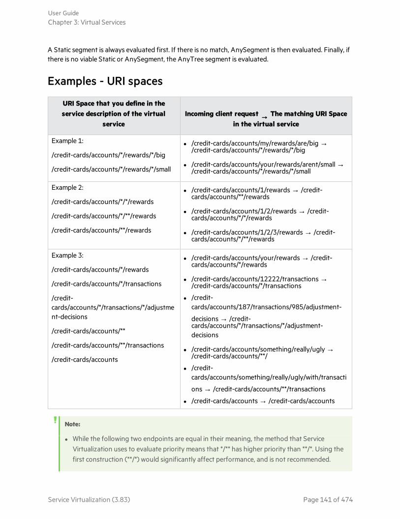
A Static segment is always evaluated first. If there is no match, AnySegment is then evaluated. Finally, ifthere is no viable Static or AnySegment, the AnyTree segment is evaluated.
Examples - URI spaces
URI Space that you define in theservice description of the virtual
serviceIncoming client request → The matching URI Space
in the virtual service
Example 1:
/credit-cards/accounts/*/rewards/*/big
/credit-cards/accounts/*/rewards/*/small
l /credit-cards/accounts/my/rewards/are/big →/credit-cards/accounts/*/rewards/*/big
l /credit-cards/accounts/your/rewards/arent/small →/credit-cards/accounts/*/rewards/*/small
Example 2:
/credit-cards/accounts/*/*/rewards
/credit-cards/accounts/*/**/rewards
/credit-cards/accounts/**/rewards
l /credit-cards/accounts/1/rewards → /credit-cards/accounts/**/rewards
l /credit-cards/accounts/1/2/rewards → /credit-cards/accounts/*/*/rewards
l /credit-cards/accounts/1/2/3/rewards → /credit-cards/accounts/*/**/rewards
Example 3:
/credit-cards/accounts/*/rewards
/credit-cards/accounts/*/transactions
/credit-cards/accounts/*/transactions/*/adjustment-decisions
/credit-cards/accounts/**
/credit-cards/accounts/**/transactions
/credit-cards/accounts
l /credit-cards/accounts/your/rewards → /credit-cards/accounts/*/rewards
l /credit-cards/accounts/12222/transactions →/credit-cards/accounts/*/transactions
l /credit-cards/accounts/187/transactions/985/adjustment-
decisions → /credit-cards/accounts/*/transactions/*/adjustment-decisions
l /credit-cards/accounts/something/really/ugly →/credit-cards/accounts/**/
l /credit-cards/accounts/something/really/ugly/with/transacti
ons → /credit-cards/accounts/**/transactions
l /credit-cards/accounts → /credit-cards/accounts
Note:
l While the following two endpoints are equal in their meaning, the method that ServiceVirtualization uses to evaluate priority means that */** has higher priority than **/*. Using thefirst construction (**/*) would significantly affect performance, and is not recommended.
User GuideChapter 3: Virtual Services
Service Virtualization (3.83) Page 141 of 474

/credit-cards/accounts/**/*/rewards
/credit-cards/accounts/*/**/rewards
l The expression **/** can be used in a URI Space, but it widens the search scan and is notrecommended for performance reasons.
l The same set of URI masks added to a URI Space will always have identical results, regardlessof the order they are listed.
See also:l For details on adding or editing URI spaces to a service description, see "Edit a Service Description"
on page 136.
Virtualize SAP IDoc CommunicationThis task describes how to set up your systems to virtualize SAP IDoc message transfer. You can recordand simulate asynchronous IDoc message transfer between two SAP systems.
1. Prerequisites: Make sure you have configured the Service Virtualization SAP agent. For details, see"Configure the SAP Agent" on page 60.
2. Configure your SAP systems:
l Configure the source SAP system for IDoc message processing.
l Configure the target SAP system for IDoc message processing.
For an example of setting up the SAP systems, see the SAP IDoc Demo readme file, located in thesample project folder.
3. Create a SAP IDoc virtual service. For details, see "Create a Virtual Service" on page 130.
4. If you have different sets of credentials for logging on to your source and target SAP systems, youmust edit the Service Virtualization credential store. For user interface details, see "Edit CredentialStore Dialog Box" on page 373.
5. Add a SAP IDoc operation, and select corresponding fields to use for request and (optionally)response messages. In the Service Description Editor, in the bottom left of the Operations pane,click Add Operation.
Note: The selected fields cannot be empty.
6. Optional: Import IDoc messages from SAP. In the data model, select an operation and expand arule. Right-click and select Import Message. Enter IDoc numbers to retrieve messages from the SAPsystem.
7. Learn. If you have not imported IDoc messages, place the virtual service into Learning mode torecord the real service behavior - the destination SAP system responses.
a. On the SAP source system, create and send request messages.
b. On the SAP target system, create and send response messages.
User GuideChapter 3: Virtual Services
Service Virtualization (3.83) Page 142 of 474
8. Simulate. Place the virtual service into Simulating mode On the SAP source system, create and sendrequest messages. The virtual service responds.
Virtualize SAP RFC CommunicationThis task explains how to virtualize RFC services running on a WebMethods Integration Server.
1. Configure theWebMethodsSAP agent
"Configure the WebMethods SAP Agent" on page 63
2. Create a newvirtual service
1. Run the New Virtual Service wizard. For details, see "Create a VirtualService" on page 130.
2. You will need some information from the WebMethods IntegrationServer, including:
l full name of the flow service and its steps
l name of the RFC function you need to call
The virtual service can contain multiple endpoints (steps) from one flowservice.
For details, see "Service Properties Page" on page 158.
3. Create a newoperation
Create a new operation to call the relevant RFC function from theWebMethods Integration Server. For details, see "Service Description Editor"on page 197.
4. Record realservice behavior
1. Put the virtual service into Learning mode.
2. On the WebMethods Integration Server, run the desired communicationthrough the flow service.
3. Stop Learning mode.
For details, see "Virtual Service Editor" on page 186.
5. Simulate "Run Simulations" on page 214
Virtualize Fixed-Length CommunicationThis task describes how to virtualize fixed-length field based communication using a text-based servicedescription. You can create a virtual service based on fixed-length service description files, enabling thevirtual service to learn and understand the messages and message structure. After learning the newfixed-length messages, they are displayed in the data model, structured according to the servicedescription files you provide.
A virtual service with a fixed-length service description supports the following:
l TCP/IP, WebSphere MQ, and Filesystem/FTP protocols.
l Multiple responses.
User GuideChapter 3: Virtual Services
Service Virtualization (3.83) Page 143 of 474

l Multiple service description files can be used to create the virtual service. For more details, see"Creating the text file" on page 146.
l Variable-length records/occurring structures are not supported.
In this topic:
l "Virtualize fixed-length communication" below
l "Service description format" below
l "Supported data types" on page 146
l "Creating the text file" on page 146
l "Service description file naming" on page 147
Virtualize fixed-length communicationVirtualizing fixed-length communication includes these high-level steps:
1. Create and configure a Service Virtualization agent.
a. From the main menu, select Tools > Options.
b. Click Agents.
c. Select a supported agent and click Add to add a new configuration.
For user-interface details, see "Agents Page" on page 77.
2. Build a service description for the fixed-length protocol. See below for detailed instructions.
3. Create a new virtual service, and select the option to use a service description.
l Select the .txt files you created to define the service description.
l Select one of the supported fixed-length protocols.
For more details on creating a virtual service, see "Create a Virtual Service" on page 130.
Service description formatDefine the service description in a text file, including the following information:
Name Custom, unique name of the field as it is displayed in the Data Model Editor.
Offset Binary offset, indicating the starting location of the field's data. For example, in amessage that is 100 bytes in length with an offset of 5, the field starts at the 6th byte.
Length Binary length of the field data. The field is read as a sub-array from the offset positionto the offset + length position.
Type Service Virtualization internal data type. See "Supported data types" on page 146 fordetails.
User GuideChapter 3: Virtual Services
Service Virtualization (3.83) Page 144 of 474
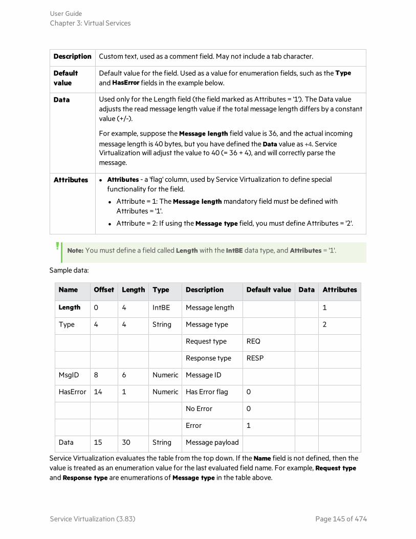
Description Custom text, used as a comment field. May not include a tab character.
Defaultvalue
Default value for the field. Used as a value for enumeration fields, such as the Typeand HasError fields in the example below.
Data Used only for the Length field (the field marked as Attributes = '1'). The Data valueadjusts the read message length value if the total message length differs by a constantvalue (+/-).
For example, suppose the Message length field value is 36, and the actual incomingmessage length is 40 bytes, but you have defined the Data value as +4. ServiceVirtualization will adjust the value to 40 (= 36 + 4), and will correctly parse themessage.
Attributes l Attributes - a 'flag' column, used by Service Virtualization to define specialfunctionality for the field.
l Attribute = 1: The Message length mandatory field must be defined withAttributes = '1'.
l Attribute = 2: If using the Message type field, you must define Attributes = '2'.
Note: You must define a field called Length with the IntBE data type, and Attributes = '1'.
Sample data:
Name Offset Length Type Description Default value Data Attributes
Length 0 4 IntBE Message length 1
Type 4 4 String Message type 2
Request type REQ
Response type RESP
MsgID 8 6 Numeric Message ID
HasError 14 1 Numeric Has Error flag 0
No Error 0
Error 1
Data 15 30 String Message payload
Service Virtualization evaluates the table from the top down. If the Name field is not defined, then thevalue is treated as an enumeration value for the last evaluated field name. For example, Request typeand Response type are enumerations of Message type in the table above.
User GuideChapter 3: Virtual Services
Service Virtualization (3.83) Page 145 of 474

Messages can be shorter than defined by the Length column. Unpopulated fields are set to the NotPresent value in the Data Model.
Supported data types
Data format
Service Virtualizationdataformat (for Message type inservice description) Note
ASCII,Alphanumeric,String
String ASCII characters only
UTF-8, Unicode BInary Any non-ASCII charset
Numeric Numeric Numbers in ASCII, For example,“000010” or “-000020”.
Decimal Decimal Numbers in ASCII + decimal separator.For example, “0005.4” or “-005.4”.
Fixed decimal String Fixed decimal places. For example, forfinancial applications: “00100.00”.
Integer, Short (big-endian, networkbyte order)
IntBE Supported byte length is 4 bytes orless.
More information:http://en.wikipedia.org/wiki/EndiannessInteger, Short (little-
endian, Intel x86)IntLE
Binary, other non-specified
Binary
Creating the text fileThe text file must be structured as follows:
l Use tab-separated files with .txt extension.
l Each message type requires a separate file with .txt extension.
l You can create separate files for requests and responses. See "Service description file naming" on thenext page for details.
l The structure of the message definition file must be as follows:
The first line (header) is used to define columns for field definition.
User GuideChapter 3: Virtual Services
Service Virtualization (3.83) Page 146 of 474

Example:
Name-->Offset-->Length-->Type-->Description-->Default Value-->Data-->Attributes
Each additional line defines one field of the message. Define the field's column values using tab-separated columns.
Example:
Message number-->12-->4-->Numeric-->Unique message identification number.-->-->-->
where (-->) indicates a tab, and an extra tab marker (-->) indicates a column with no value. In thisexample:
Name = Message number
Offset = 12
Length = 14
Type = Numeric
Description = Unique message identification number
Default Value, Data, and Attributes are not defined.
Service description file namingService description text files named in the format <message_name>.txt will be used for both requestsand responses.
To use files for either requests or responses only, the filenames must be as follows:
Request filename pattern Response filename pattern
*_req.txt *_resp.txt
*_request.txt *_response.txt
*_rq.txt *_rs.txt
*-req.txt *_resp.txt
*-request.txt *-response.txt
*-rq.txt *-rs.txt
*.req.txt *.resp.txt
User GuideChapter 3: Virtual Services
Service Virtualization (3.83) Page 147 of 474

Request filename pattern Response filename pattern
*.request.txt *.response.txt
*.rq.txt *.rs.txt
Message Logging
You can log request and response data generated during learning, simulation, andstandby modes.
Message logs enable you to:
l Review the messages more closely to troubleshoot problems you may have.
l Check the responses generated for specific requests.
l Save and share logged messages with other users.
l Examine protocol data that is not stored elsewhere.
What do you want to do?
l "(Prerequisite): Enable logging" below
l "View log files in the Designer message viewer" on the next page
l "Access log files stored on the file system" on the next page
l "Save logs to your local machine" on page 150
l "Import logged messages to the Data Model" on page 150
l "Set maximum message read size" on page 150
(Prerequisite): Enable loggingEnable message logging for a virtual service.
In the Virtual Service Editor, under Service Configuration, toggle the Message Logging switch toEnabled.
Note:
l The message logging state (enabled/disabled) in the Designer or Service VirtualizationManagement is loaded when the virtual service is first opened. If the state is changed in theDesigner or SVM, the state change may not display in the other instance of the Designer orSVM until the service page is reopened.
l Message logs store raw message data. If you configure data masking in the virtual service,message logging will be automatically disabled.
User GuideChapter 3: Virtual Services
Service Virtualization (3.83) Page 148 of 474

You can modify the default behavior, so that messages will be logged and a warning writtento the Problem List. To enable message logging even if data masking is configured in thevirtual service, edit the following line in the Designer or Server application configuration file:
<add key="MessageLogger.LogMessagesWithDataMaskingEnabled" value="False" />
Set value="True".
View log files in the Designer message viewerIn the Virtual Service Editor, under Service Configuration, click Show Logged Messages to open themessage viewer.
By default, the message viewer displays 20 request and response pairs in the list. To view more items,click Fetch more items.
Filtering: Use the filter options to limit the messages displayed. By default, the viewer displays messagesfrom the current date, or the last date on which messages were logged.
Access log files stored on the file systemLog files are stored in the following locations:
l For a service running on the embedded server: Messages are stored in the Designer log folder%APPDATA%\Hewlett Packard Enterprise\HPE Service Virtualization Designer\logs\ in thesubfolder messages\[Virtual Service Name]-[Virtual Service ID], created when the firstmessage is logged.
To open the Designer log folder, from the Windows Start menu, select Service Virtualization >Designer > Designer Log Folder.
l For a service running on a Service Virtualization Server: Messages are stored in the Server logfolder %ALLUSERSPROFILE%\Hewlett Packard Enterprise\HPE Service VirtualizationServer\logs\, in the subfolder messages\[Virtual Service Name]-[Virtual Service ID], createdwhen the first message is logged.
To open the Server log folder, from the Windows Start menu, select Service Virtualization > Server> Server Log Folder.
Each message is stored in a single file named message-[Message Order Number]-[Message Id].log.
Tip: If you do not have access to the Server machine directly, you can open the server logs in theDesigner message viewer, and save them to your local machine. For details, see "MessageLogging" on the previous page.
User GuideChapter 3: Virtual Services
Service Virtualization (3.83) Page 149 of 474

Save logs to your local machine1. In the Virtual Service Editor, under Service Configuration, use the click here link to open the
message viewer.
2. Click Save raw [request/response] data and selection a location.
Import logged messages to the Data Model1. In the Virtual Service Editor, under Service Configuration, use the click here link to open the
message viewer.
2. Select messages to import.
3. Go to the Data Model Editor and expand a rule. You can import messages into the Learned Datarule or a custom rule.
4. Expand the rule, right-click inside the rule, and select Import Selected Logged Messages. You canselect to import the request part of the messages, the response part, or entire messages.
Set maximum message read sizeTo prevent logged messages that are too big to display, Service Virtualization configures a maximumsize limit for messages that can be viewed in the Designer message viewer. You can modify the messagesize limit using the application configuration files.
1. Navigate to the appropriate configuration file:
l Service Virtualization Server configuration file: HP.SV.StandaloneServer.exe.config, locatedon the Service Virtualization Server machine in the server installation folder. By default,C:\Program Files\HPE\HPEService Virtualization Server\Server\bin.
l Designer configuration file: VirtualServiceDesigner.exe.config, located on the Designer machinein the installation folder. By default, C:\Program Files (x86)\HPE\HPEService VirtualizationDesigner\Designer\bin\.
2. Modify the value in the following line:
<add key="MessageLogger.MaxReadMessageSize" value="20000"/>
The value is in kilobytes (kb).
Log FilesThe Service Virtualization application logs include messages related to each of the Service Virtualizationsoftware components - Designer, Server, and Service Virtualization Management, as well as relatedbackup and restore, installation, and licensing logs.
User GuideChapter 3: Virtual Services
Service Virtualization (3.83) Page 150 of 474

Open logsYou can access the Service Virtualization logs from the Windows Start menu, under All Programs > HPESoftware > HPE Service Virtualization Designer/Server > Designer/Server Log Folder.
Log locationsl Designer:
%APPDATA%\Hewlett Packard Enterprise\VirtualServiceDesigner\logs
l Server:
%ALLUSERSPROFILE%\Hewlett Packard Enterprise\HPE Service VirtualizationServer\logs
Configure loggingMessages are written to the log files based on the log levels that are defined in the applicationconfiguration files. Log levels include WARN, DEBUG, INFO, and ERROR.
You can change log levels using the Service Virtualization configuration files:
l Service Virtualization Server configuration file:
%[INSTALLLOCATION]%\Server\bin\HP.SV.StandaloneServer.exe.config
l Designer configuration file:
%[INSTALLLOCATION]%\Designer\bin\VirtualServiceDesigner.exe.config
Changes made to the logging configuration are effective immediately, and do not require an applicationrestart. To disable the ability to make changes without restarting the application, locate the followingline in the configuration file and set the value to False:
<add key="log4net.Config.Watch" value="True"/>
Virtual Services User InterfaceThis section includes:
• Summary of Virtualization Project Dialog Box 152• Create New Virtual Service Wizard 153• Create Multiple Virtual Services Wizard 183
User GuideChapter 3: Virtual Services
Service Virtualization (3.83) Page 151 of 474

• Endpoint Validation Dialog Box 184• Virtualization Explorer 185• Virtual Service Editor 186• Edit Endpoints Dialog Box 192• Change Server Dialog Box 194• Projects and Solutions Page 196• Service Description Editor 197• Session ID Definition Wizard 200• Data Masking Dialog Box 205• Replace Algorithm Configuration Dialog Box 207• Edit Metadata Dialog Box 209• Add Data Format Dialog Box 211
Summary of Virtualization Project Dialog BoxThis dialog box enables you to create a new virtualization project.
To access From the main menu, select File > New > Virtualization Project.
Relevant tasks "End-to-End Workflow" on page 20
See also "Introducing Service Virtualization" on page 14
User interface elements are described below:
UIElement Description
Project Displays the default name for the project you are creating.
Path Displays the default location in the file system where the project is created.
User GuideChapter 3: Virtual Services
Service Virtualization (3.83) Page 152 of 474

UIElement Description
Server Displays the default server to be used with the new project.
All services in the project are deployed on this server.
Change Opens the Change Project dialog box, enabling you to modify the following details:
l Project. Enter a name for the project or accept the default name.
l Path. Enter a path for the project or accept the default path.
l Server. Select the server on which to deploy the virtual service.
You can select the Designer's embedded server, or a standalone Service VirtualizationServer. For details on adding Service Virtualization Servers, see "Manage ServiceVirtualization Servers" on page 22.
Create Creates the new project according to your specified settings.
Create New Virtual Service WizardThis wizard enables you to create a new virtual service.
To access To launch the new virtual service wizard, in an existing project, select one of thefollowing:
l From the main menu, select File > New > Virtual Service.
l In the Virtualization Explorer, right-click a virtualization entity and select Add >Virtual Service.
Wizard map This wizard contains:
"Import Real Service Description Page" on the next page > "Choose Service ProtocolPage" on page 155 > "Service Properties Page" on page 158 > "Summary ofVirtualization Page" on page 181
Importantinformation
l If you are creating a new virtual service from the Get Started page, a newvirtualization project is created for the service.
l For additional details on specific service types, see "Virtual Service Types" on page124.
Relevanttasks
"Create a Virtual Service" on page 130
See also l "Virtual Services" on page 123
l "Service Descriptions" on page 128
User GuideChapter 3: Virtual Services
Service Virtualization (3.83) Page 153 of 474
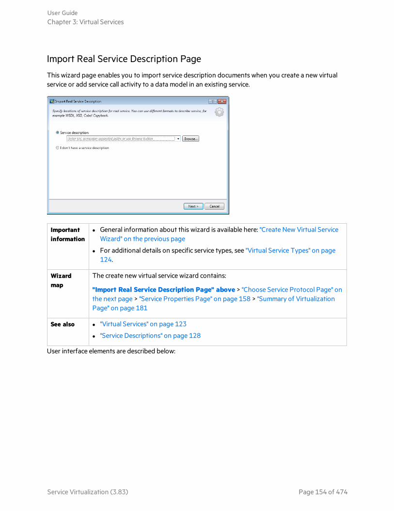
Import Real Service Description Page
This wizard page enables you to import service description documents when you create a new virtualservice or add service call activity to a data model in an existing service.
Importantinformation
l General information about this wizard is available here: "Create New Virtual ServiceWizard" on the previous page
l For additional details on specific service types, see "Virtual Service Types" on page124.
Wizardmap
The create new virtual service wizard contains:
"Import Real Service Description Page" above > "Choose Service Protocol Page" onthe next page > "Service Properties Page" on page 158 > "Summary of VirtualizationPage" on page 181
See also l "Virtual Services" on page 123
l "Service Descriptions" on page 128
User interface elements are described below:
User GuideChapter 3: Virtual Services
Service Virtualization (3.83) Page 154 of 474
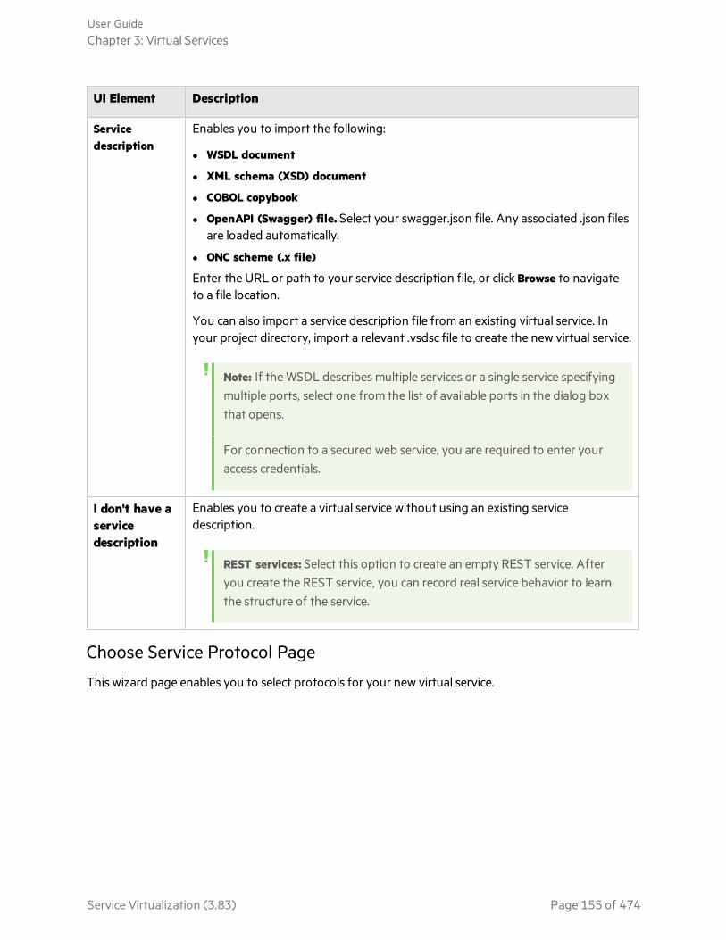
UI Element Description
Servicedescription
Enables you to import the following:
l WSDL document
l XML schema (XSD) document
l COBOL copybook
l OpenAPI (Swagger) file. Select your swagger.json file. Any associated .json filesare loaded automatically.
l ONC scheme (.x file)
Enter the URL or path to your service description file, or click Browse to navigateto a file location.
You can also import a service description file from an existing virtual service. Inyour project directory, import a relevant .vsdsc file to create the new virtual service.
Note: If the WSDL describes multiple services or a single service specifyingmultiple ports, select one from the list of available ports in the dialog boxthat opens.
For connection to a secured web service, you are required to enter youraccess credentials.
I don't have aservicedescription
Enables you to create a virtual service without using an existing servicedescription.
REST services: Select this option to create an empty REST service. Afteryou create the REST service, you can record real service behavior to learnthe structure of the service.
Choose Service Protocol Page
This wizard page enables you to select protocols for your new virtual service.
User GuideChapter 3: Virtual Services
Service Virtualization (3.83) Page 155 of 474

Importantinformation
l General information about this wizard is available here: "Create New Virtual ServiceWizard" on page 153
l For additional details on specific service types, see "Virtual Service Types" on page124.
Wizardmap
The create new virtual service wizard contains:
"Import Real Service Description Page" on page 154 > "Choose Service ProtocolPage" on the previous page > "Service Properties Page" on page 158 > "Summary ofVirtualization Page" on page 181
See also "Virtual Services" on page 123
User interface elements are described below (unlabeled elements are shown in angle brackets):
UI Element Description
<filter textbox>
Enter text to filter the available protocols.
Filter by To filter the protocol list, select protocols from the message and transportprotocol drop-down lists.
<list ofprotocols>
Select a protocol configuration for your new virtual service.
Message Type Page
This wizard page enables you to define the structure of input and output messages, when working witha COBOL copybook.
User GuideChapter 3: Virtual Services
Service Virtualization (3.83) Page 156 of 474
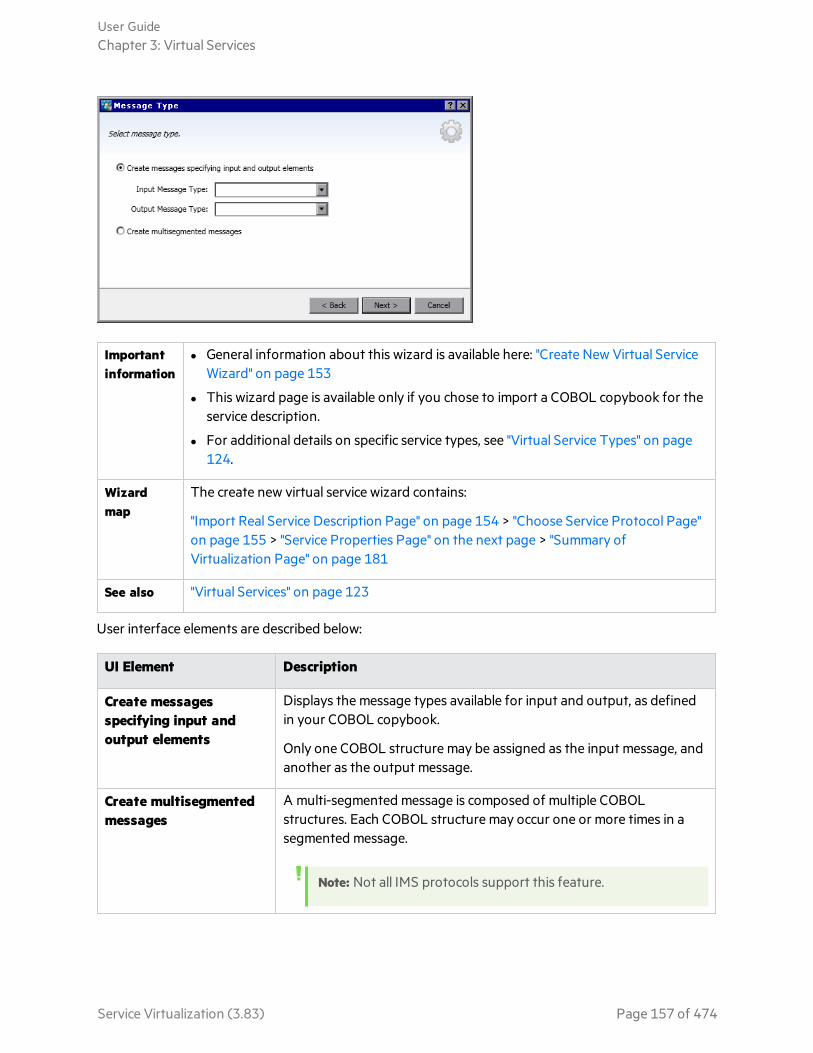
Importantinformation
l General information about this wizard is available here: "Create New Virtual ServiceWizard" on page 153
l This wizard page is available only if you chose to import a COBOL copybook for theservice description.
l For additional details on specific service types, see "Virtual Service Types" on page124.
Wizardmap
The create new virtual service wizard contains:
"Import Real Service Description Page" on page 154 > "Choose Service Protocol Page"on page 155 > "Service Properties Page" on the next page > "Summary ofVirtualization Page" on page 181
See also "Virtual Services" on page 123
User interface elements are described below:
UI Element Description
Create messagesspecifying input andoutput elements
Displays the message types available for input and output, as definedin your COBOL copybook.
Only one COBOL structure may be assigned as the input message, andanother as the output message.
Create multisegmentedmessages
A multi-segmented message is composed of multiple COBOLstructures. Each COBOL structure may occur one or more times in asegmented message.
Note: Not all IMS protocols support this feature.
User GuideChapter 3: Virtual Services
Service Virtualization (3.83) Page 157 of 474

Service Properties Page
This wizard page enables you to define protocol-specific properties for your virtual service.
Importantinformation
l General information about this wizard is available here: "Create New Virtual ServiceWizard" on page 153
l The properties available on the page depend on the protocols you select for thenew service on the Choose Service Protocol page.
l After the virtual service is created, you can edit these properties. In the VirtualService Editor, under Service Configuration, click Edit to open the Edit Endpointsdialog box.
l For additional details on specific service types, see "Virtual Service Types" on page124.
Wizardmap
The create new virtual service wizard contains:
"Import Real Service Description Page" on page 154 > "Choose Service Protocol Page"on page 155 > "Service Properties Page" above > "Summary of Virtualization Page"on page 181
See also "Virtual Services" on page 123
This section includes:
l "Common" on the next page
l "Filesystem" on the next page
l "HTTP" on page 162
l "IBM IMS TM" on page 163
l "IBM CICS TS HTTP" on page 163
l "Java" on page 164
l "JDBC" on page 164
User GuideChapter 3: Virtual Services
Service Virtualization (3.83) Page 158 of 474

l "JMS" on page 164
l "MSMQ" on page 167
l "ORACLE AQ" on page 170
l "REST" on page 170
l "SAP RFC" on page 172
l "SAP IDOC" on page 172
l "TIBCO EMS" on page 173
l "Service Properties Page" on the previous page
l "WebMethods IS SAP RFC" on page 174
l "WebSphere MQ" on page 174
l "WebSphere MQ Non-Intrusive" on page 177
User interface elements are described below:
Common
Field Description
Show Endpoint Topology Displays a diagram of your service endpoint configuration.
Test Endpoints Checks that the real service endpoints are accessible.
Filesystem
Define the real and virtual service properties.
Note: Each virtual service requires 4 agent configurations - one each for virtual service reading,virtual service writing, real service reading, real service writing.
Property Description
Virtual/Real Service
Read filesfrom
Select the Service Virtualization agent to use for incoming requests.
Write files to Select the Service Virtualization agent to use for outgoing responses.
User GuideChapter 3: Virtual Services
Service Virtualization (3.83) Page 159 of 474
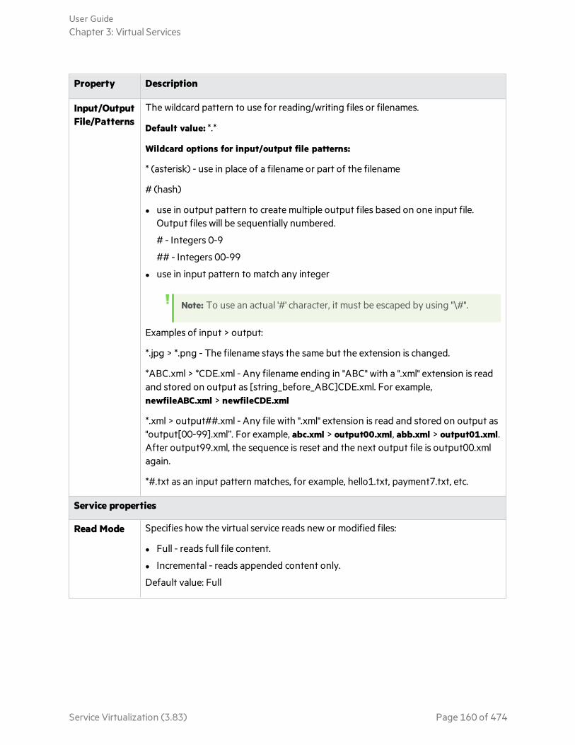
Property Description
Input/OutputFile/Patterns
The wildcard pattern to use for reading/writing files or filenames.
Default value: *.*
Wildcard options for input/output file patterns:
* (asterisk) - use in place of a filename or part of the filename
# (hash)
l use in output pattern to create multiple output files based on one input file.Output files will be sequentially numbered.
# - Integers 0-9
## - Integers 00-99
l use in input pattern to match any integer
Note: To use an actual '#' character, it must be escaped by using "\#".
Examples of input > output:
*.jpg > *.png - The filename stays the same but the extension is changed.
*ABC.xml > *CDE.xml - Any filename ending in "ABC" with a ".xml" extension is readand stored on output as [string_before_ABC]CDE.xml. For example,newfileABC.xml > newfileCDE.xml
*.xml > output##.xml - Any file with ".xml" extension is read and stored on output as"output[00-99].xml”. For example, abc.xml > output00.xml, abb.xml > output01.xml.After output99.xml, the sequence is reset and the next output file is output00.xmlagain.
*#.txt as an input pattern matches, for example, hello1.txt, payment7.txt, etc.
Service properties
Read Mode Specifies how the virtual service reads new or modified files:
l Full - reads full file content.
l Incremental - reads appended content only.
Default value: Full
User GuideChapter 3: Virtual Services
Service Virtualization (3.83) Page 160 of 474

Property Description
Write Mode Specifies how the virtual service writes outgoing files:
l Full - writes full content into the output file. (If the file already exists, the newcontent overwrites the old content.)
l Incremental - responses are appended to the end of the output file.
Default value: Full
File filters
Filter bytime
If selected, the virtual service processes only the files that are older than the definedvalue.
Default value: 00:00:00 (processes every change)
Examples: 00:01:00 (one minute), 12:13:14, (12hrs, 13min and 14secs)
Filter by size If selected, the virtual service processes only the files or changes that are larger thanthe defined value.
Possible values: 0-2147483647
Default value: 0 (processes every file)
Additional settings
File cleanup Deletes files after they are processed by the virtual service.
Possible values: True, False
Default value: False
Additional settings for CSV over file system
First row asheader
Select this if the first row in the CSV file is a header row.
Possible values: True, False
Default value: False
Delimiter Indicates the delimiter between columns in the CSV file.
Possible values: Any string.
Default value: , (comma)
Additional settings for Text-delimited over file system
User GuideChapter 3: Virtual Services
Service Virtualization (3.83) Page 161 of 474

Property Description
Messagedelimiter
Indicates the delimiter between messages.
Possible values: Any string. When using special characters, this parameter must beencoded.
Default value: \r\n (carriage return + newline symbol)
Fielddelimiter
Indicates the delimiter between fields.
Possible values: Any string. When using special characters, this parameter must beencoded.
Default value: ; (semi-colon)
Valuedelimiter
Indicates the delimiter between key-value pairs.
Possible values: Any string. When using special characters, this parameter must beencoded.
Default value: =
Field as aprefix
Switches between text-delimited formats. The value of the prefix is used as the fieldname.
Possible values: True, False
Default value: False
Prefix size The size of the prefix.
Possible values: 0-2147483647
Default value: 0
HTTP
Define the real service endpoints.
Property Description
Endpoints Enter the real service endpoint (URL).
To enter multiple endpoints, separate them by a space, comma, semicolon, or type eachendpoint on a new line.
Note: When using the HTTP or HTTPS Gateway agent, the virtual service mayhave only one specified endpoint.
User GuideChapter 3: Virtual Services
Service Virtualization (3.83) Page 162 of 474

IBM IMS TM
Define the real service properties. Values are case-sensitive and should be provided by yourIMS TM System Administrator or Operator.
Property Description
Client ID Identification of the client for services with dedicated persistent socket connections.For shareable persistent socket connections, leave this value undefined.
TransactionCode
The alphanumeric code used to invoke IMS message processing program.
TPipe Name The transactional pipe (TPipe) value, used to maintain a logical association betweenclient and service. The OTMA TPipe name is similar to the IMS Connect logicalterminal (LTerm) name.
LTermName
Logical Terminal Name. The IMS logical association between client and service.Similar to OTMA TPipe name.
DatastoreID
The service datastore name (IMS Destination ID).
Any value Clear this option to define a filter for the corresponding property. If you enter aspecific value for a property, only messages matching the specified value areprocessed during Learning and Simulation sessions.
IBM CICS TS HTTP
Define virtual and real service properties.
PropertyDescription
Virtual Service Parameters:
Path The relative URI that defines on which URI path the virtual service is to be deployed.
Real Service Properties:
Endpoint The relative or absolute endpoint, depending on the agent type, that defines where theactual COBOL service is listening. For details, see "Virtual Service Types" on page 124.
Encoding COBOL content encoding.
User GuideChapter 3: Virtual Services
Service Virtualization (3.83) Page 163 of 474

Java
Define the virtual service properties.
Property Description
Agent Select an agent on which to deploy the virtual service, and the server on which theagent is deployed.
Click Manage Agents if you want to define a new agent or modify an existingconfiguration.
VirtualizedClasses
Enter the names of the classes or methods that you want to virtualize.
If you do not specify a method for a class, all methods in the class will be virtualized.
These classes are used by the Java Instrumentation Agent(HP.SV.JavaInstrumentator.jar). For more details, see "Configure the Java Agent" onpage 50.
New Class Adds a new class to the virtual service. Double-click the class name to edit.
NewMethod
Adds a new method to the virtual service. Double-click the method name to edit.
Remove Select the class or method you want to delete and click Remove.
JDBC
Define the real service properties.
Property Description
ConnectionString
Define one of the following:
l The JDBC Connection string used in the application under test. This is used primarywhen working with J2SE applications.
l The JNDI datasource name used by the application under test. This is used only ifthe application is deployed on a J2EE application server.
JMS
Define virtual and real service properties.
User GuideChapter 3: Virtual Services
Service Virtualization (3.83) Page 164 of 474

Virtual Service Properties:
MultipleAgents
Select Enable multiple JMS providers to enable the use of different JNDI contexts forincoming/outgoing messages or for request/response activities.
l You can define an agent configuration for each JNDI context you require. Fordetails, see "Agents Page" on page 77.
l Select agent configurations for your virtual service using the Agent and ReplyAgent fields in this dialog box. A virtual service has virtual and real serviceendpoints, and each endpoint has an input and an output agent, resulting in fourpossible agent assignments.
Example:
The following use cases are examples only. You can configure the agents inany combination to meet your needs.
l Use one agent configuration (agent 'A') for handling communication forrequest processing, and another agent configuration (agent 'B') forhandling communication for response processing.
l Use one agent configuration (agent 'A') for communication between yourclient (AUT) and Service Virtualization, and another agent configuration(agent 'B') for communication between Service Virtualization and the realservice.
User GuideChapter 3: Virtual Services
Service Virtualization (3.83) Page 165 of 474
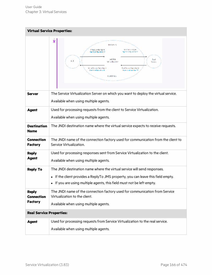
Virtual Service Properties:
Server The Service Virtualization Server on which you want to deploy the virtual service.
Available when using multiple agents.
Agent Used for processing requests from the client to Service Virtualization.
Available when using multiple agents.
DestinationName
The JNDI destination name where the virtual service expects to receive requests.
ConnectionFactory
The JNDI name of the connection factory used for communication from the client toService Virtualization.
ReplyAgent
Used for processing responses sent from Service Virtualization to the client.
Available when using multiple agents.
Reply To The JNDI destination name where the virtual service will send responses.
l If the client provides a ReplyTo JMS property, you can leave this field empty.
l If you are using multiple agents, this field must not be left empty.
ReplyConnectionFactory
The JNDI name of the connection factory used for communication from ServiceVirtualization to the client.
Available when using multiple agents.
Real Service Properties:
Agent Used for processing requests from Service Virtualization to the real service.
Available when using multiple agents.
User GuideChapter 3: Virtual Services
Service Virtualization (3.83) Page 166 of 474
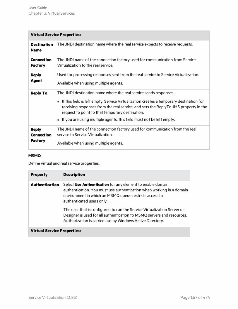
Virtual Service Properties:
DestinationName
The JNDI destination name where the real service expects to receive requests.
ConnectionFactory
The JNDI name of the connection factory used for communication from ServiceVirtualization to the real service.
ReplyAgent
Used for processing responses sent from the real service to Service Virtualization.
Available when using multiple agents.
Reply To The JNDI destination name where the real service sends responses.
l If this field is left empty, Service Virtualization creates a temporary destination forreceiving responses from the real service, and sets the ReplyTo JMS property in therequest to point to that temporary destination.
l If you are using multiple agents, this field must not be left empty.
ReplyConnectionFactory
The JNDI name of the connection factory used for communication from the realservice to Service Virtualization.
Available when using multiple agents.
MSMQ
Define virtual and real service properties.
Property Description
Authentication Select Use Authentication for any element to enable domainauthentication. You must use authentication when working in a domainenvironment in which an MSMQ queue restricts access toauthenticated users only.
The user that is configured to run the Service Virtualization Server orDesigner is used for all authentication to MSMQ servers and resources.Authorization is carried out by Windows Active Directory.
Virtual Service Properties:
User GuideChapter 3: Virtual Services
Service Virtualization (3.83) Page 167 of 474
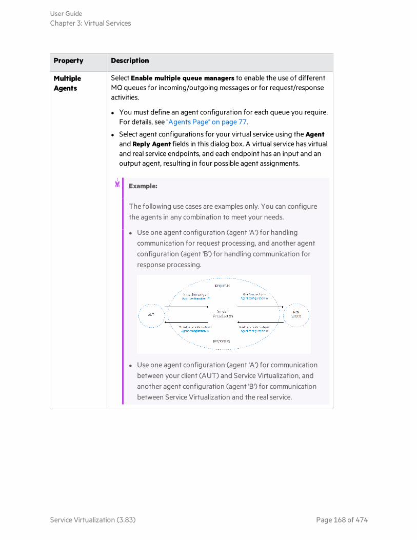
Property Description
MultipleAgents
Select Enable multiple queue managers to enable the use of differentMQ queues for incoming/outgoing messages or for request/responseactivities.
l You must define an agent configuration for each queue you require.For details, see "Agents Page" on page 77.
l Select agent configurations for your virtual service using the Agentand Reply Agent fields in this dialog box. A virtual service has virtualand real service endpoints, and each endpoint has an input and anoutput agent, resulting in four possible agent assignments.
Example:
The following use cases are examples only. You can configurethe agents in any combination to meet your needs.
l Use one agent configuration (agent 'A') for handlingcommunication for request processing, and another agentconfiguration (agent 'B') for handling communication forresponse processing.
l Use one agent configuration (agent 'A') for communicationbetween your client (AUT) and Service Virtualization, andanother agent configuration (agent 'B') for communicationbetween Service Virtualization and the real service.
User GuideChapter 3: Virtual Services
Service Virtualization (3.83) Page 168 of 474
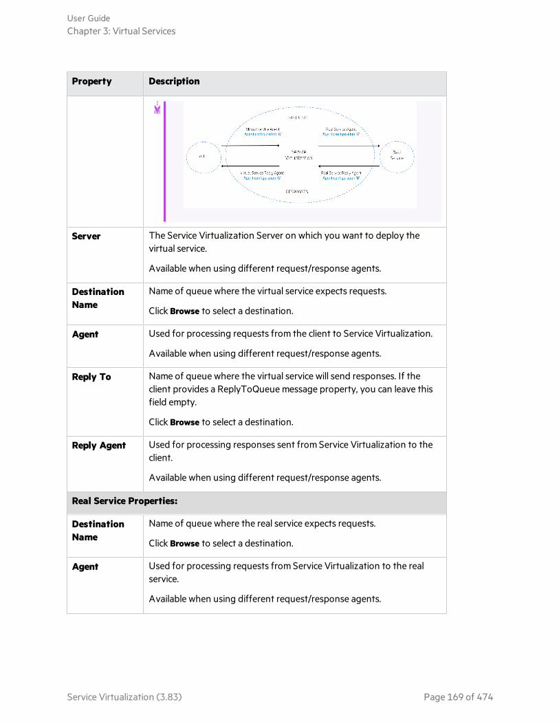
Property Description
Server The Service Virtualization Server on which you want to deploy thevirtual service.
Available when using different request/response agents.
DestinationName
Name of queue where the virtual service expects requests.
Click Browse to select a destination.
Agent Used for processing requests from the client to Service Virtualization.
Available when using different request/response agents.
Reply To Name of queue where the virtual service will send responses. If theclient provides a ReplyToQueue message property, you can leave thisfield empty.
Click Browse to select a destination.
Reply Agent Used for processing responses sent from Service Virtualization to theclient.
Available when using different request/response agents.
Real Service Properties:
DestinationName
Name of queue where the real service expects requests.
Click Browse to select a destination.
Agent Used for processing requests from Service Virtualization to the realservice.
Available when using different request/response agents.
User GuideChapter 3: Virtual Services
Service Virtualization (3.83) Page 169 of 474

Property Description
Reply To Name of queue where the real service sends responses. Click Browse toselect a destination.
Note: This field may not be left empty.
Reply Agent Used for processing responses sent from the real service to ServiceVirtualization.
Available when using different request/response agents.
ORACLE AQ
Define the following properties for the request queue, and optionally, for the response queue.
Property Description
Subscription AgentName
The AQ Agent name that Service Virtualization uses to consumemessages.
Queue Name The name of the AQ queue.
Dequeue Condition A condition you can define to limit messages consumed by ServiceVirtualization.
REST
Define the real service properties
Property Description
Endpoints Enter the real service endpoint (URL).
To enter multiple endpoints, separate them by a space, comma, semicolon, or type eachendpoint on a new line.
User GuideChapter 3: Virtual Services
Service Virtualization (3.83) Page 170 of 474
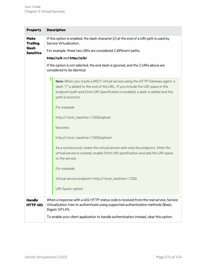
Property Description
MakeTrailingSlashSensitive
If this option is enabled, the slash character (/) at the end of a URI path is used byService Virtualization.
For example, these two URIs are considered 2 different paths:
http://a/b and http://a/b/
If the option is not selected, the end slash is ignored, and the 2 URIs above areconsidered to be identical.
Note: When you create a REST virtual service using the HTTP Gateway agent, aslash “/” is added to the end of the URL. If you include the URI space in theendpoint path and Strict URI Specification is enabled, a slash is added and thepath is incorrect.
For example
http://<host_machine>:7200/sqlrest
becomes
http://<host_machine>:7200/sqlrest/
As a workaround, create the virtual service with only the endpoint. After thevirtual service is created, enable Strict URI specification and add the URI spaceto the service.
For example:
Virtual service endpoint: http://<host_machine>:7200
URI Space: sqlrest
HandleHTTP 401
When a response with a 401 HTTP status code is received from the real service, ServiceVirtualization tries to authenticate using supported authentication methods (Basic,Digest, NTLM).
To enable your client application to handle authentication instead, clear this option.
User GuideChapter 3: Virtual Services
Service Virtualization (3.83) Page 171 of 474
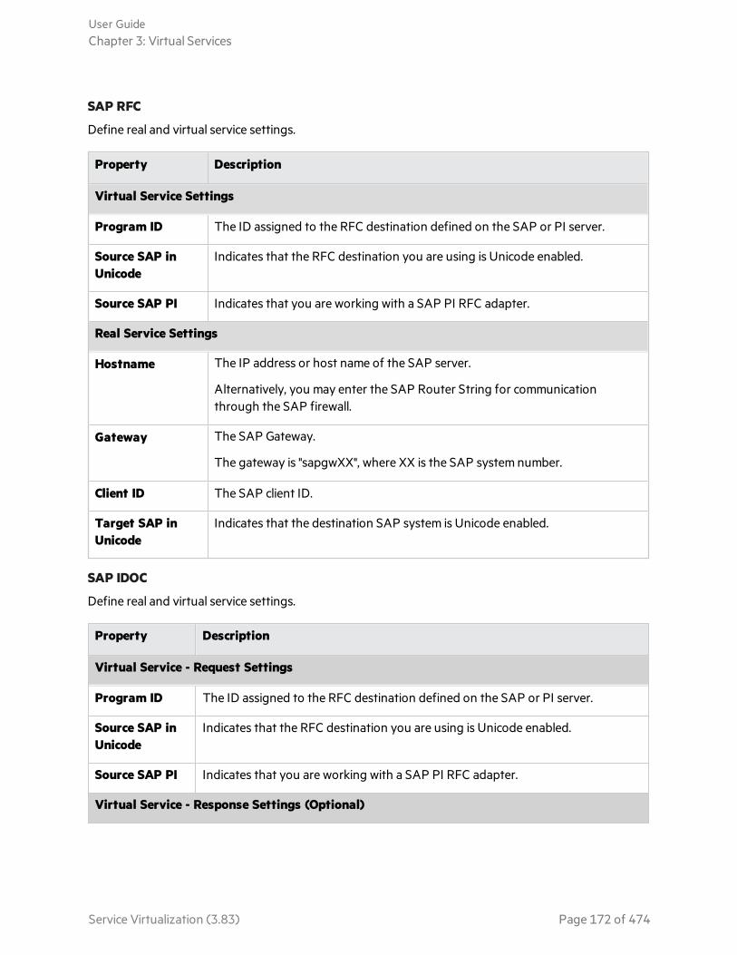
SAP RFC
Define real and virtual service settings.
Property Description
Virtual Service Settings
Program ID The ID assigned to the RFC destination defined on the SAP or PI server.
Source SAP inUnicode
Indicates that the RFC destination you are using is Unicode enabled.
Source SAP PI Indicates that you are working with a SAP PI RFC adapter.
Real Service Settings
Hostname The IP address or host name of the SAP server.
Alternatively, you may enter the SAP Router String for communicationthrough the SAP firewall.
Gateway The SAP Gateway.
The gateway is "sapgwXX", where XX is the SAP system number.
Client ID The SAP client ID.
Target SAP inUnicode
Indicates that the destination SAP system is Unicode enabled.
SAP IDOC
Define real and virtual service settings.
Property Description
Virtual Service - Request Settings
Program ID The ID assigned to the RFC destination defined on the SAP or PI server.
Source SAP inUnicode
Indicates that the RFC destination you are using is Unicode enabled.
Source SAP PI Indicates that you are working with a SAP PI RFC adapter.
Virtual Service - Response Settings (Optional)
User GuideChapter 3: Virtual Services
Service Virtualization (3.83) Page 172 of 474
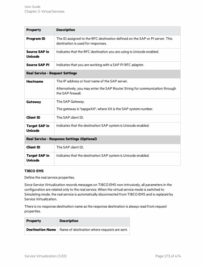
Property Description
Program ID The ID assigned to the RFC destination defined on the SAP or PI server. Thisdestination is used for responses.
Source SAP inUnicode
Indicates that the RFC destination you are using is Unicode enabled.
Source SAP PI Indicates that you are working with a SAP PI RFC adapter.
Real Service - Request Settings
Hostname The IP address or host name of the SAP server.
Alternatively, you may enter the SAP Router String for communication throughthe SAP firewall.
Gateway The SAP Gateway.
The gateway is "sapgwXX", where XX is the SAP system number.
Client ID The SAP client ID.
Target SAP inUnicode
Indicates that the destination SAP system is Unicode enabled.
Real Service - Response Settings (Optional)
Client ID The SAP client ID.
Target SAP inUnicode
Indicates that the destination SAP system is Unicode enabled.
TIBCO EMS
Define the real service properties.
Since Service Virtualization records messages on TIBCO EMS non-intrusively, all parameters in theconfiguration are related only to the real service. When the virtual service mode is switched toSimulating mode, the real service is automatically disconnected from TIBCO EMS and is replaced byService Virtualization.
There is no response destination name as the response destination is always read from requestproperties.
Property Description
Destination Name Name of destination where requests are sent.
User GuideChapter 3: Virtual Services
Service Virtualization (3.83) Page 173 of 474
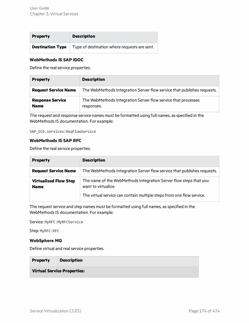
Property Description
Destination Type Type of destination where requests are sent.
WebMethods IS SAP IDOC
Define the real service properties.
Property Description
Request Service Name The WebMethods Integration Server flow service that publishes requests.
Response ServiceName
The WebMethods Integration Server flow service that processesresponses.
The request and response service names must be formatted using full names, as specified in theWebMethods IS documentation. For example:
SAP_EC6.services:ReqFlowService
WebMethods IS SAP RFC
Define the real service properties.
Property Description
Request Service Name The WebMethods Integration Server flow service that publishes requests.
Virtualized Flow StepName
The name of the WebMethods Integration Server flow steps that youwant to virtualize.
The virtual service can contain multiple steps from one flow service.
The request service and step names must be formatted using full names, as specified in theWebMethods IS documentation. For example:
Service: MyRFC:MyRFCService
Step: MyRFC:RFC
WebSphere MQ
Define virtual and real service properties.
Property Description
Virtual Service Properties:
User GuideChapter 3: Virtual Services
Service Virtualization (3.83) Page 174 of 474
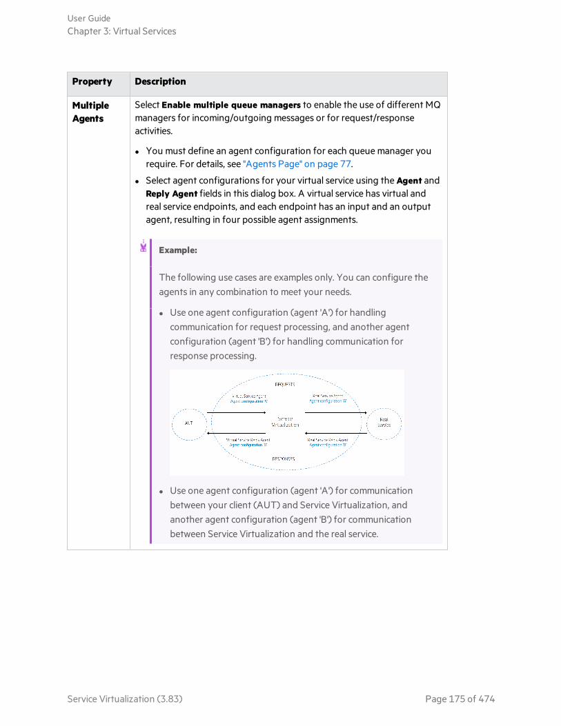
Property Description
MultipleAgents
Select Enable multiple queue managers to enable the use of different MQmanagers for incoming/outgoing messages or for request/responseactivities.
l You must define an agent configuration for each queue manager yourequire. For details, see "Agents Page" on page 77.
l Select agent configurations for your virtual service using the Agent andReply Agent fields in this dialog box. A virtual service has virtual andreal service endpoints, and each endpoint has an input and an outputagent, resulting in four possible agent assignments.
Example:
The following use cases are examples only. You can configure theagents in any combination to meet your needs.
l Use one agent configuration (agent 'A') for handlingcommunication for request processing, and another agentconfiguration (agent 'B') for handling communication forresponse processing.
l Use one agent configuration (agent 'A') for communicationbetween your client (AUT) and Service Virtualization, andanother agent configuration (agent 'B') for communicationbetween Service Virtualization and the real service.
User GuideChapter 3: Virtual Services
Service Virtualization (3.83) Page 175 of 474

Property Description
Server The Service Virtualization Server on which you want to deploy the virtualservice.
Available when using different request/response agents.
DestinationName
Name of queue where the virtual service expects requests.
Click Browse to select an actual destination or to virtualize a destination.
Agent Used for processing requests from the client to Service Virtualization.
Available when using different request/response agents.
Reply To Name of queue where the virtual service will send responses. If the clientprovides a ReplyToQueue message property, you can leave this fieldempty.
Click Browse to select an actual destination or to virtualize a destination.
ReplyAgent
Used for processing responses sent from Service Virtualization to theclient.
Available when using different request/response agents.
Real Service Properties:
DestinationName
Name of queue where the real service expects requests.
Click Browse to select an actual destination or to virtualize a destination.
Agent Used for processing requests from Service Virtualization to the realservice.
Available when using different request/response agents.
User GuideChapter 3: Virtual Services
Service Virtualization (3.83) Page 176 of 474
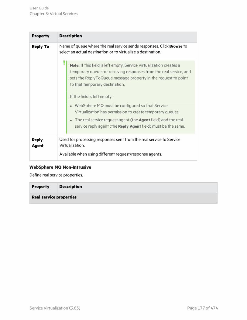
Property Description
Reply To Name of queue where the real service sends responses. Click Browse toselect an actual destination or to virtualize a destination.
Note: If this field is left empty, Service Virtualization creates atemporary queue for receiving responses from the real service, andsets the ReplyToQueue message property in the request to pointto that temporary destination.
If the field is left empty:
l WebSphere MQ must be configured so that ServiceVirtualization has permission to create temporary queues.
l The real service request agent (the Agent field) and the realservice reply agent (the Reply Agent field) must be the same.
ReplyAgent
Used for processing responses sent from the real service to ServiceVirtualization.
Available when using different request/response agents.
WebSphere MQ Non-Intrusive
Define real service properties.
Property Description
Real service properties
User GuideChapter 3: Virtual Services
Service Virtualization (3.83) Page 177 of 474

Property Description
MultipleAgents
Select Enable multiple queue managers to enable the use of different MQ managersfor incoming/outgoing messages or for request/response activities.
l You must define an agent configuration for each queue manager you require. Fordetails, see "Agents Page" on page 77.
l Select agent configurations for your virtual service using the Agent and ReplyAgent fields in this dialog box. A virtual service has virtual and real serviceendpoints, and each endpoint has an input and an output agent, resulting in fourpossible agent assignments.
Example:
The following use cases are examples only. You can configure the agents inany combination to meet your needs.
l Use one agent configuration (agent 'A') for handling communication forrequest processing, and another agent configuration (agent 'B') forhandling communication for response processing.
l Use one agent configuration (agent 'A') for communication between yourclient (AUT) and Service Virtualization, and another agent configuration(agent 'B') for communication between Service Virtualization and the realservice.
User GuideChapter 3: Virtual Services
Service Virtualization (3.83) Page 178 of 474

Property Description
Server The Service Virtualization Server on which you want to deploy the virtual service.
Available when using different request/response agents.
DestinationName
Name of queue where the real service expects requests.
Click Browse to select an actual destination or to virtualize a destination.
Agent Used for processing requests from Service Virtualization to the real service.
Available when using different request/response agents.
Reply To Name of queue where the real service sends responses. Click Browse to select anactual destination or to virtualize a destination.
Note: If this field is left empty, Service Virtualization creates a temporaryqueue for receiving responses from the real service, and sets theReplyToQueue message property in the request to point to that temporarydestination.
If the field is left empty:
l WebSphere MQ must be configured so that Service Virtualization haspermission to create temporary queues.
l The real service request agent (the Agent field) and the real service replyagent (the Reply Agent field) must be the same.
ReplyAgent
Used for processing responses sent from the real service to Service Virtualization.
Available when using different request/response agents.
Browse Destinations Dialog Box
This wizard page enables you to select and virtualize an MQ destination to use in your virtual service.
User GuideChapter 3: Virtual Services
Service Virtualization (3.83) Page 179 of 474

Importantinformation
l General information about this wizard is available here: "Create New Virtual ServiceWizard" on page 153
l For additional details on specific service types, see "Virtual Service Types" on page124.
l This dialog box opens when you click Browse for a destination in the ServiceProperties dialog box.
Note: To view MQ destinations, the user defined for the WebSphere MQvirtual agent must have sufficient permissions. For details, see "WebSphereMQ Agent Settings" on page 114.
Wizardmap
The create new virtual service wizard contains:
"Import Real Service Description Page" on page 154 > "Choose Service Protocol Page"on page 155 > "Service Properties Page" on page 158 > "Summary of VirtualizationPage" on the next page
See also l "Virtual Services" on page 123
l "WebSphere MQ Agent Settings" on page 114
User interface elements are described below (unlabeled elements are shown in angle brackets):
UI Element Description
<search box> Enter a destination name or part of a name to filter the list of destinationsdisplayed.
VirtualizedDestinationsOnly
Displays only the list of destinations that are virtualized.
User GuideChapter 3: Virtual Services
Service Virtualization (3.83) Page 180 of 474

UI Element Description
RelevantAgents
Displays only the list of destinations that you may use.
For example, filters out any destinations for which the agent does not havesufficient permissions to access, or agents that are not defined on the server withwhich you are working.
<destinationslist>
List of available destinations. The destinations displayed are based on theWebSphere MQ queue managers defined in the WebSphere MQ ServiceVirtualization agent configurations.
Actual destinations.
Virtualized destinations.
ManageAgents
Opens the Agents page, enabling you to add, delete, or reconfigure settings forvirtual service agents. For details, see "Agents Page" on page 77.
VirtualizeSelected
Select an actual destination and click Virtualize Selected. Creates a duplicate, virtualdestination that you can use for your virtual service.
In the dialog box that opens, accept the default name for the virtual destination, orenter a different name.
Available for: WebSphere MQ
UnvirtualizeSelected
Deletes the virtual destination.
Available for: WebSphere MQ
Summary of Virtualization Page
This wizard page enables you to review your information. You can confirm or change details of the realservice, virtual service, or project.
User GuideChapter 3: Virtual Services
Service Virtualization (3.83) Page 181 of 474

Importantinformation
l General information about this wizard is available here: "Create New Virtual ServiceWizard" on page 153.
l If you are creating a new virtual service from the Get Started page, a newvirtualization project is created for the service. Click Change to modify project name,path, or agent.
l For additional details on specific service types, see "Virtual Service Types" on page124.
Wizardmap
The create new virtual service wizard contains:
"Import Real Service Description Page" on page 154 > "Choose Service Protocol Page"on page 155 > "Service Properties Page" on page 158 > "Summary of VirtualizationPage" on the previous page
See also "Virtual Services" on page 123
User interface elements are described below:
UIElement Description
VirtualService
Displays details of the virtual service you are creating.
RealService
Displays the parameters you defined for the real service.
User GuideChapter 3: Virtual Services
Service Virtualization (3.83) Page 182 of 474

UIElement Description
Project If you are creating a new virtual service from the Get Started page, a new virtualizationproject is created for the service. Click Change to modify the following details:
l Project. Enter a name for the project or accept the default name.
l Path. Enter a path for the project or accept the default path.
l Server. Select the server on which to deploy the virtual service.
You can select the Designer's embedded server, or a standalone Service VirtualizationServer. For details on server status indicators, or on adding additional ServiceVirtualization Servers, see "Manage Service Virtualization Servers" on page 22.
Change Opens a dialog box for the selected component, enabling you to modify settings foryour virtual service or real service.
When you are also creating a new project, you can also edit the project settings.
Note: It is recommended to run the endpoint test, located in the Change VirtualService dialog box.
Virtualize Creates a new virtual service.
Create Multiple Virtual Services WizardThis wizard enables you to create multiple SOAP virtual services based on WSDL documents.
Note: Available for SOAP over HTTP(S) services only.
Toaccess
To launch the Multiple Virtual Services wizard, in an existing project, select one of thefollowing:
l From the main menu, select File > New > Multiple Virtual Services.
l In the Virtualization Explorer, right-click a virtualization entity and select Add > MultipleVirtual Services.
Import Real Service Descriptions Page
Specify locations of service descriptions for real services. Enter a list of paths to .wsdl files, separated bysemicolons, or the path to a CSV file containing the paths to the .wsdl files.
If you are using a CSV file, each wsdl path/URL must be in its own row, and optionally may contain logincredentials if they are required, separated by commas. For example,http://server/service?wsdl,user,password.
User GuideChapter 3: Virtual Services
Service Virtualization (3.83) Page 183 of 474
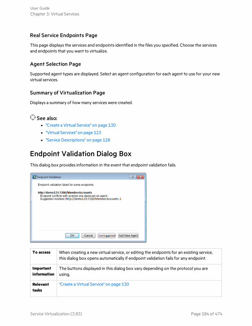
Real Service Endpoints Page
This page displays the services and endpoints identified in the files you specified. Choose the servicesand endpoints that you want to virtualize.
Agent Selection Page
Supported agent types are displayed. Select an agent configuration for each agent to use for your newvirtual services.
Summary of Virtualization Page
Displays a summary of how many services were created.
See also:l "Create a Virtual Service" on page 130
l "Virtual Services" on page 123
l "Service Descriptions" on page 128
Endpoint Validation Dialog BoxThis dialog box provides information in the event that endpoint validation fails.
To access When creating a new virtual service, or editing the endpoints for an existing service,this dialog box opens automatically if endpoint validation fails for any endpoint.
Importantinformation
The buttons displayed in this dialog box vary depending on the protocol you areusing.
Relevanttasks
"Create a Virtual Service" on page 130
User GuideChapter 3: Virtual Services
Service Virtualization (3.83) Page 184 of 474
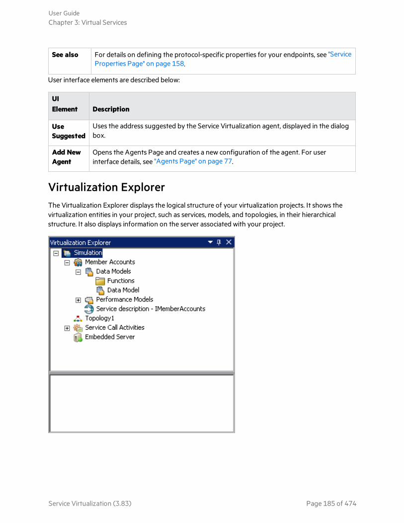
See also For details on defining the protocol-specific properties for your endpoints, see "ServiceProperties Page" on page 158.
User interface elements are described below:
UIElement Description
UseSuggested
Uses the address suggested by the Service Virtualization agent, displayed in the dialogbox.
Add NewAgent
Opens the Agents Page and creates a new configuration of the agent. For userinterface details, see "Agents Page" on page 77.
Virtualization ExplorerThe Virtualization Explorer displays the logical structure of your virtualization projects. It shows thevirtualization entities in your project, such as services, models, and topologies, in their hierarchicalstructure. It also displays information on the server associated with your project.
User GuideChapter 3: Virtual Services
Service Virtualization (3.83) Page 185 of 474
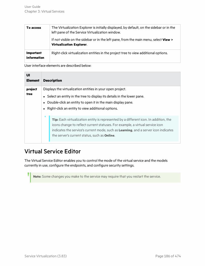
To access The Virtualization Explorer is initially displayed, by default, on the sidebar or in theleft pane of the Service Virtualization window.
If not visible on the sidebar or in the left pane, from the main menu, select View >Virtualization Explorer.
Importantinformation
Right-click virtualization entities in the project tree to view additional options.
User interface elements are described below:
UIElement Description
projecttree
Displays the virtualization entities in your open project.
l Select an entity in the tree to display its details in the lower pane.
l Double-click an entity to open it in the main display pane.
l Right-click an entity to view additional options.
Tip: Each virtualization entity is represented by a different icon. In addition, theicons change to reflect current statuses. For example, a virtual service iconindicates the service's current mode, such as Learning, and a server icon indicatesthe server's current status, such as Online.
Virtual Service EditorThe Virtual Service Editor enables you to control the mode of the virtual service and the modelscurrently in use, configure the endpoints, and configure security settings.
Note: Some changes you make to the service may require that you restart the service.
User GuideChapter 3: Virtual Services
Service Virtualization (3.83) Page 186 of 474
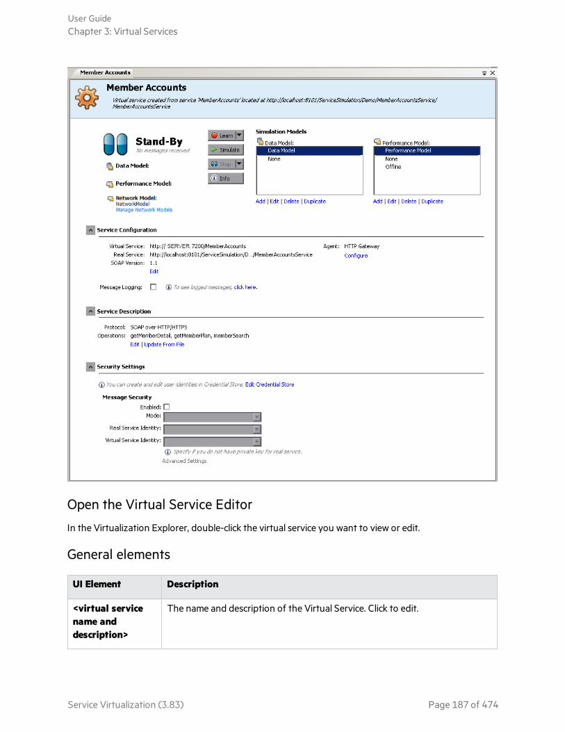
Open the Virtual Service Editor
In the Virtualization Explorer, double-click the virtual service you want to view or edit.
General elements
UI Element Description
<virtual servicename anddescription>
The name and description of the Virtual Service. Click to edit.
User GuideChapter 3: Virtual Services
Service Virtualization (3.83) Page 187 of 474

UI Element Description
<status area> Located in the upper-left part of the window, indicates the following:
l The current mode of the service: Learning, Simulation, Standby or Offline.
l The data and performance models currently in use.
Puts the selected service into Learning Mode. Any communication throughthe Virtual Service is added to the Simulation Model in this mode.
Use the drop down arrow to select which models to update:
l Data & Performance (default)
l Data Model
l Performance Model
Starts the simulation according to the simulation models selected in the VirtualService Editor.
If the service was in Learning mode, Service Virtualization first finishes thelearning session and adds any data learned in the session to the SimulationModel.
Puts the service into Standby Mode with the option of maintaining ordisposing of learned data.
Opens the Runtime Report to display current information about the service.
Simulation Models area
Manage the models associated with the virtual service.
UI Element Description
Data Model Select a data model to use with the service.
None. Enables you to pass messages to the real service and receive responses, whilestill simulating performance according to the selected Performance Model.
PerformanceModel
Select a performance model to use with the service.
None. Causes the virtual service to respond as quickly as possible.
Offline. Simulates the unavailability of the service.
User GuideChapter 3: Virtual Services
Service Virtualization (3.83) Page 188 of 474
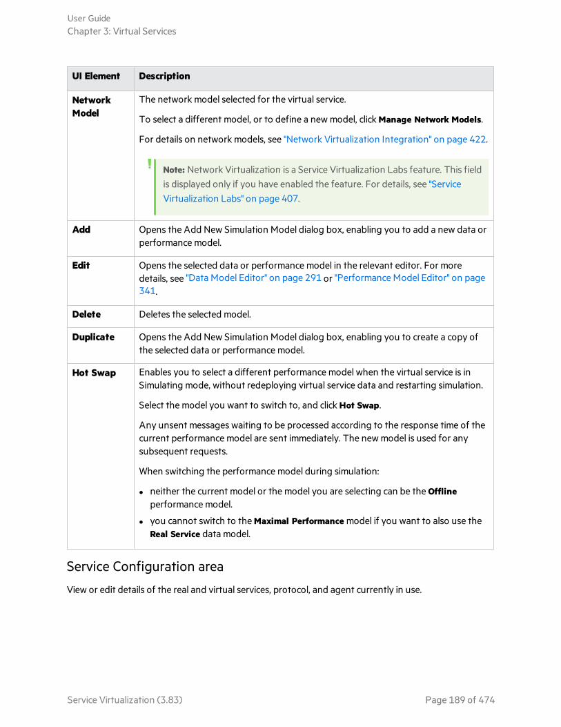
UI Element Description
NetworkModel
The network model selected for the virtual service.
To select a different model, or to define a new model, click Manage Network Models.
For details on network models, see "Network Virtualization Integration" on page 422.
Note: Network Virtualization is a Service Virtualization Labs feature. This fieldis displayed only if you have enabled the feature. For details, see "ServiceVirtualization Labs" on page 407.
Add Opens the Add New Simulation Model dialog box, enabling you to add a new data orperformance model.
Edit Opens the selected data or performance model in the relevant editor. For moredetails, see "Data Model Editor" on page 291 or "Performance Model Editor" on page341.
Delete Deletes the selected model.
Duplicate Opens the Add New Simulation Model dialog box, enabling you to create a copy ofthe selected data or performance model.
Hot Swap Enables you to select a different performance model when the virtual service is inSimulating mode, without redeploying virtual service data and restarting simulation.
Select the model you want to switch to, and click Hot Swap.
Any unsent messages waiting to be processed according to the response time of thecurrent performance model are sent immediately. The new model is used for anysubsequent requests.
When switching the performance model during simulation:
l neither the current model or the model you are selecting can be the Offlineperformance model.
l you cannot switch to the Maximal Performance model if you want to also use theReal Service data model.
Service Configuration area
View or edit details of the real and virtual services, protocol, and agent currently in use.
User GuideChapter 3: Virtual Services
Service Virtualization (3.83) Page 189 of 474
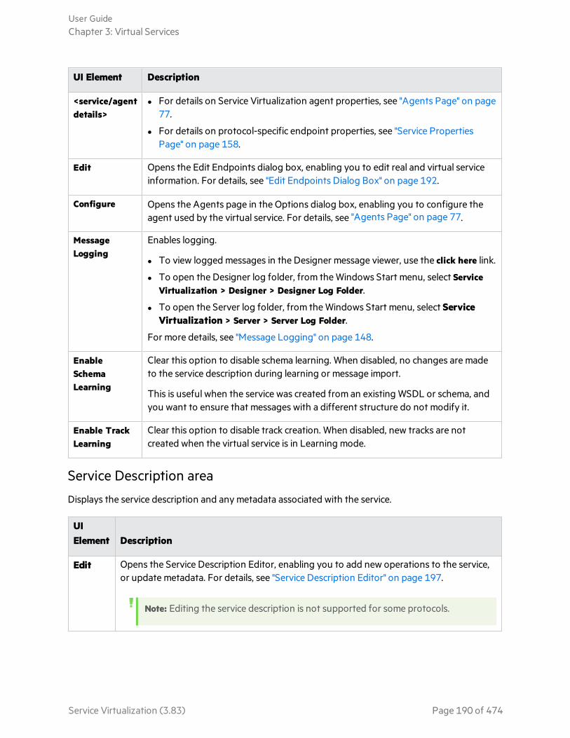
UI Element Description
<service/agentdetails>
l For details on Service Virtualization agent properties, see "Agents Page" on page77.
l For details on protocol-specific endpoint properties, see "Service PropertiesPage" on page 158.
Edit Opens the Edit Endpoints dialog box, enabling you to edit real and virtual serviceinformation. For details, see "Edit Endpoints Dialog Box" on page 192.
Configure Opens the Agents page in the Options dialog box, enabling you to configure theagent used by the virtual service. For details, see "Agents Page" on page 77.
MessageLogging
Enables logging.
l To view logged messages in the Designer message viewer, use the click here link.
l To open the Designer log folder, from the Windows Start menu, select ServiceVirtualization > Designer > Designer Log Folder.
l To open the Server log folder, from the Windows Start menu, select ServiceVirtualization > Server > Server Log Folder.
For more details, see "Message Logging" on page 148.
EnableSchemaLearning
Clear this option to disable schema learning. When disabled, no changes are madeto the service description during learning or message import.
This is useful when the service was created from an existing WSDL or schema, andyou want to ensure that messages with a different structure do not modify it.
Enable TrackLearning
Clear this option to disable track creation. When disabled, new tracks are notcreated when the virtual service is in Learning mode.
Service Description area
Displays the service description and any metadata associated with the service.
UIElement Description
Edit Opens the Service Description Editor, enabling you to add new operations to the service,or update metadata. For details, see "Service Description Editor" on page 197.
Note: Editing the service description is not supported for some protocols.
User GuideChapter 3: Virtual Services
Service Virtualization (3.83) Page 190 of 474

UIElement Description
UpdateFromFile
Opens the Update Service Description dialog box, enabling you to replace the servicedescription file.
Note: Available only for SOAP services.
Security Settings area
This area enables you to view and edit security settings.
UIElement Description
EditCredentialStore
Opens the Edit Credential Store dialog box, enabling you to create and edit useridentities. For details, see "Edit Credential Store Dialog Box" on page 373.
Enabled Turns message security on or off.
Mode Default supported message security modes. For details, see "Set Message Security" onpage 362.
RealServiceIdentity
The identity of the real service, its certificate, is stored in the Credential Store. Thissetting is used if a service uses a certificate for message security. The public key of thecertificate is used to encrypt messages sent to the real service.
VirtualServiceIdentity
The identity of the virtual service, its certificate, is stored in the Credential Store.
l If the Real Service Identity contains the certificate with a private key, this settingdoes not need to be configured. In this scenario, the Real Service Identity is also usedas the identity of the virtual service.
l If the Real Service Identity contains only a certificate without a private key, thissetting must be configured to provide the identity of the virtual service. Theconfigured identity must contain a certificate with a private key, as the servicerequires the private key to decrypt the messages coming from the client.
l Clients must trust the certificate used as the identity of the virtual service.
SecurityAppliedTo
Indicates on which message parts security is applied - request elements, responseelements, or both.
Default: Request and response.
AdvancedSettings
Opens the Advanced Message Security Settings dialog box. For details, see "AdvancedMessage Security Settings Dialog Box" on page 374.
User GuideChapter 3: Virtual Services
Service Virtualization (3.83) Page 191 of 474

See also:l "Configure Virtual Services" on page 132
l "Virtual Services" on page 123
l "Service Virtualization Main Menus" on page 33
Edit Endpoints Dialog BoxThis dialog box enables you to edit the real and virtual service endpoints configured for your virtualservice.
To access In the Virtual Service Editor, under Service Configuration, click Edit.
User interface elements are described below:
UI Element Description
Virtual/RealService
Virtual and real service information.
Note:
l For details on Service Virtualization agent properties, see "AgentsPage" on page 77.
l For details on protocol-specific endpoint properties, see "ServiceProperties Page" on page 158.
Show EndpointTopology
Displays a diagram of your service endpoint configuration.
Test Endpoints Checks that your endpoint is configured correctly.
Advanced Settings - Available for SOAP services over HTTP, TIBCO EMS, and JMS
Ignore WSAddressing
WS-Addressing headers are not processed by Service Virtualization.
Do Not SendMTOM
By default, if an MTOM message is received when a virtual service is in Standbyor Learning mode, the message is passed to the real service also as MTOM. Thisoption instructs Service Virtualization to pass the message as a normal XMLmessage with base64 content instead.
User GuideChapter 3: Virtual Services
Service Virtualization (3.83) Page 192 of 474
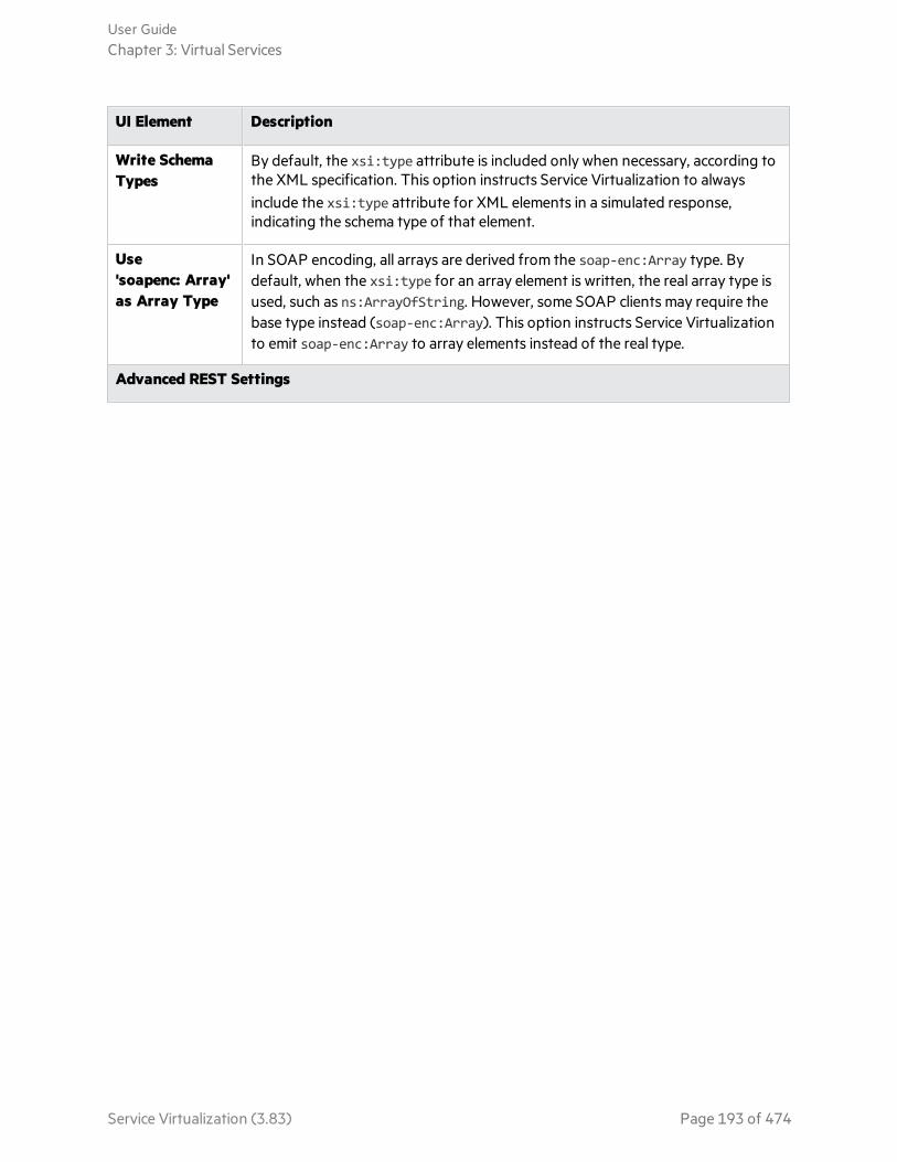
UI Element Description
Write SchemaTypes
By default, the xsi:type attribute is included only when necessary, according tothe XML specification. This option instructs Service Virtualization to alwaysinclude the xsi:type attribute for XML elements in a simulated response,indicating the schema type of that element.
Use'soapenc: Array'as Array Type
In SOAP encoding, all arrays are derived from the soap-enc:Array type. Bydefault, when the xsi:type for an array element is written, the real array type isused, such as ns:ArrayOfString. However, some SOAP clients may require thebase type instead (soap-enc:Array). This option instructs Service Virtualizationto emit soap-enc:Array to array elements instead of the real type.
Advanced REST Settings
User GuideChapter 3: Virtual Services
Service Virtualization (3.83) Page 193 of 474

UI Element Description
StrictURI specification
If this option is enabled, the slash character (/) at the end of a URI path is usedby Service Virtualization.
For example, these two URIs are considered 2 different paths:
http://a/b and http://a/b/
If it is not selected, the end slash is ignored, and the 2 URIs above are consideredto be identical.
Note: When you create a REST virtual service using the HTTP Gatewayagent, a slash “/” is added to the end of the URL. If you include the URIspace in the endpoint path and Strict URI Specification is enabled, a slashis added and the path is incorrect.
For example
http://<host_machine>:7200/sqlrest
becomes
http://<host_machine>:7200/sqlrest/
As a workaround, create the virtual service with only the endpoint. Afterthe virtual service is created, enable Strict URI specification and add theURI space to the service.
For example:
Virtual service endpoint: http://<host_machine>:7200
URI Space: sqlrest
Change Server Dialog BoxThese pages enable you to move the virtual services in a project to a different server.
User GuideChapter 3: Virtual Services
Service Virtualization (3.83) Page 194 of 474
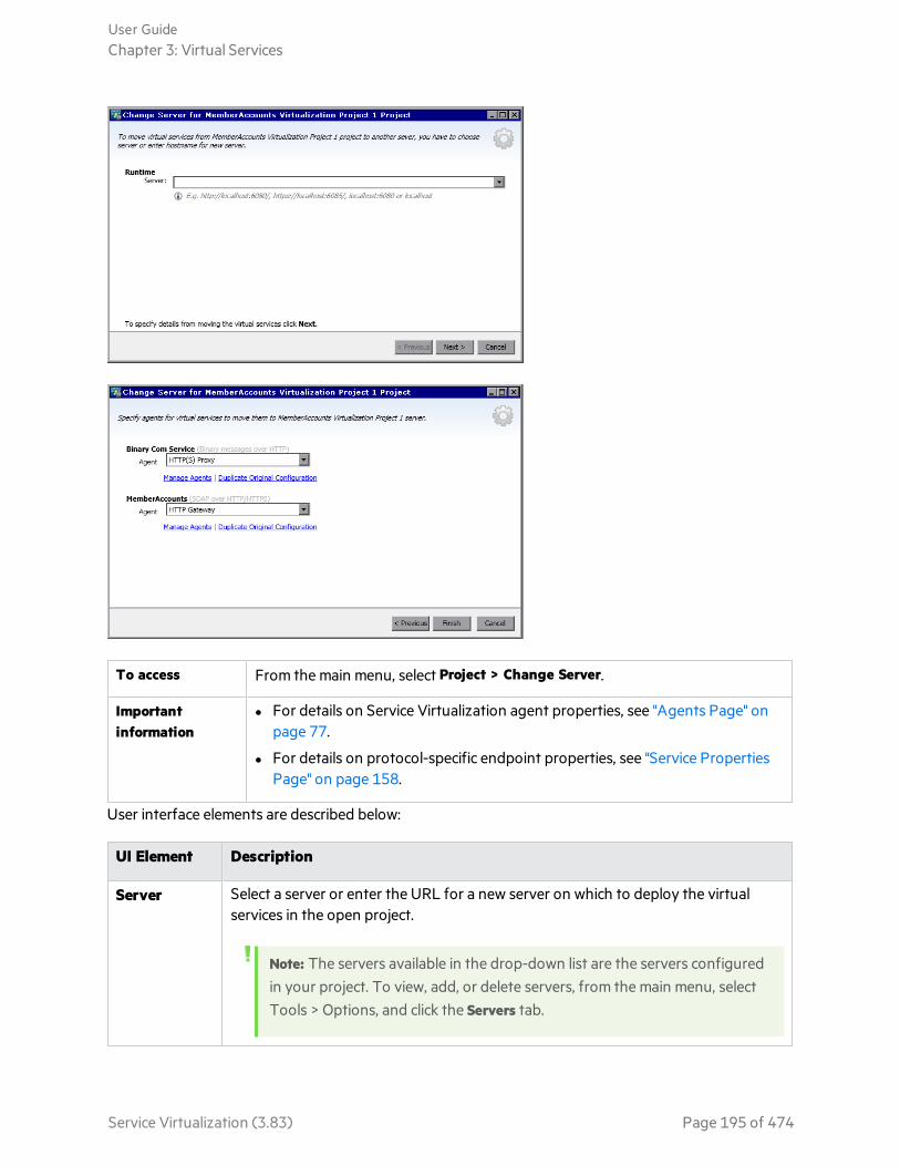
To access From the main menu, select Project > Change Server.
Importantinformation
l For details on Service Virtualization agent properties, see "Agents Page" onpage 77.
l For details on protocol-specific endpoint properties, see "Service PropertiesPage" on page 158.
User interface elements are described below:
UI Element Description
Server Select a server or enter the URL for a new server on which to deploy the virtualservices in the open project.
Note: The servers available in the drop-down list are the servers configuredin your project. To view, add, or delete servers, from the main menu, selectTools > Options, and click the Servers tab.
User GuideChapter 3: Virtual Services
Service Virtualization (3.83) Page 195 of 474

UI Element Description
Agent Select an agent for each service.
ManageAgents
Opens the Agents page, enabling you to add, delete, or reconfigure settings forvirtual service agents. For details, see "Agents Page" on page 77.
DuplicateOriginalConfiguration
Opens the Agents page, and copies the configuration on the current server tocreate a configuration on the new server. You can modify the settings of the newconfiguration.
Projects and Solutions PageThe Projects and Solutions page enables you to:
l define the default location for saving projects in the file system
l set a password for project encryption
To access 1. From the main menu, select Tools > Options.
2. On the General page, click Projects andSolutions.
Relevant tasks "Manage Virtualization Projects" on page 135
See also l "Virtualization Projects" on page 123
l "Password Encryption" on page 371
User interface elements are described below:
User GuideChapter 3: Virtual Services
Service Virtualization (3.83) Page 196 of 474

UIElement Description
Defaultprojectlocation
Enter a location in the file system for storing virtualizationprojects.
Loadprevioussolutionon startup
When you open the Designer, Service Virtualization opens thesolution in which you were previously working.
Projectencryptionpassword
Enter a password to encrypt sensitive project data.
For more details on encryption, see "Password Encryption" onpage 371.
Showpassword
Temporarily displays the project encryption password.
Service Description EditorThe Service Description Editor enables you to edit a virtual service description, including editingmetadata, managing XML schemas, adding and removing operations, and defining session identifiers.
User GuideChapter 3: Virtual Services
Service Virtualization (3.83) Page 197 of 474
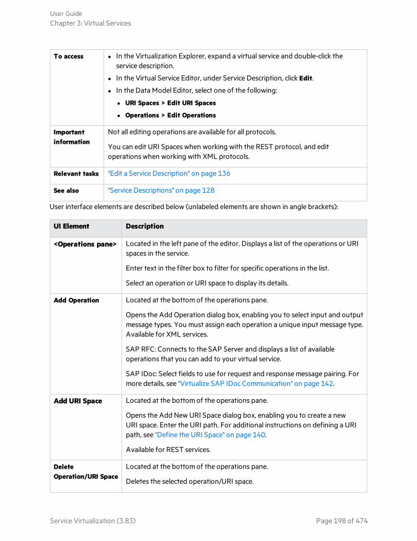
To access l In the Virtualization Explorer, expand a virtual service and double-click theservice description.
l In the Virtual Service Editor, under Service Description, click Edit.
l In the Data Model Editor, select one of the following:
l URI Spaces > Edit URI Spaces
l Operations > Edit Operations
Importantinformation
Not all editing operations are available for all protocols.
You can edit URI Spaces when working with the REST protocol, and editoperations when working with XML protocols.
Relevant tasks "Edit a Service Description" on page 136
See also "Service Descriptions" on page 128
User interface elements are described below (unlabeled elements are shown in angle brackets):
UI Element Description
<Operations pane> Located in the left pane of the editor. Displays a list of the operations or URIspaces in the service.
Enter text in the filter box to filter for specific operations in the list.
Select an operation or URI space to display its details.
Add Operation Located at the bottom of the operations pane.
Opens the Add Operation dialog box, enabling you to select input and outputmessage types. You must assign each operation a unique input message type.Available for XML services.
SAP RFC: Connects to the SAP Server and displays a list of availableoperations that you can add to your virtual service.
SAP IDoc: Select fields to use for request and response message pairing. Formore details, see "Virtualize SAP IDoc Communication" on page 142.
Add URI Space Located at the bottom of the operations pane.
Opens the Add New URI Space dialog box, enabling you to create a newURI space. Enter the URI path. For additional instructions on defining a URIpath, see "Define the URI Space" on page 140.
Available for REST services.
DeleteOperation/URI Space
Located at the bottom of the operations pane.
Deletes the selected operation/URI space.
User GuideChapter 3: Virtual Services
Service Virtualization (3.83) Page 198 of 474

UI Element Description
IDoc CorrelationSettings
Enables you to edit settings for asynchronous IDoc message transferbetween two SAP systems.
For details, see "Virtualize SAP IDoc Communication" on page 142.
Available for a SAP IDoc service.
Session IDDefinition
Defines the elements used to identify requests coming from the same sourceduring a Learning session.
The following identifiers are configured by default:
l For HTTP: ClientAddress metadata
l For MQ: UserID metadata
Other transport protocols (TibcoEMS, GenericJMS, JDBC) do not havedefault session identifiers. Tracks are created after each Learning session.
Click Edit to modify the settings. For details, see "Session ID DefinitionWizard" on the next page.
Message Metadata Enables you to edit request and response metadata. Click Edit to open theEdit Metadata dialog box. For details, see "Edit Metadata Dialog Box" on page209.
XML Schemas Lists all XML schema defined in the service description. You can add anXML schema, or edit or remove schemas.
l Add. Opens the Import XML Schema dialog box, enabling you to enter afile location for an existing schema (.xsd file), and add it to the servicedescription.
l Edit. Opens the schema in an XML editor, enabling you to modify theschema. Click the Tools pane to access tools for editing the schema.
l Delete. Removes the schema from the service description.
URI SpaceProperties
Displays the URI space path.
Data Formats Lists the available request and response data formats.
Click Add to add a new data format. For details, see "Add Data Format DialogBox" on page 211.
Available for URI spaces.
Data Masking Enables you to hide specific data elements, to protect sensitive data. Fordetails, see "Data Masking Dialog Box" on page 205.
User GuideChapter 3: Virtual Services
Service Virtualization (3.83) Page 199 of 474
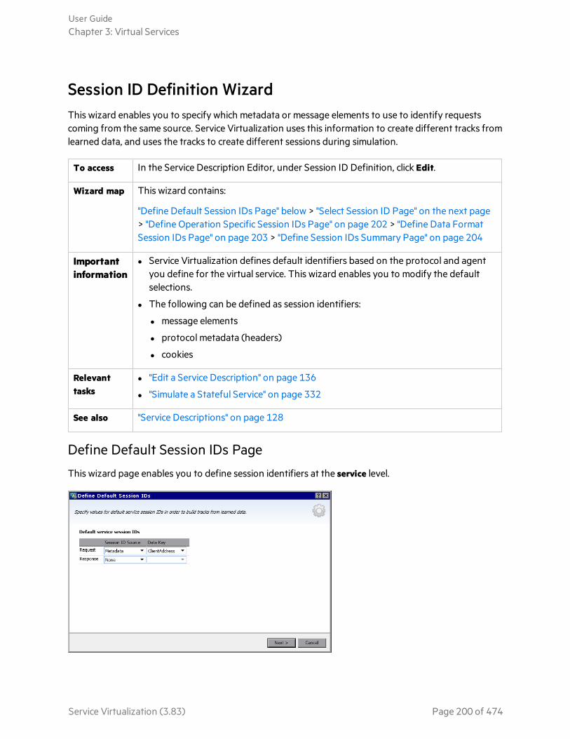
Session ID Definition WizardThis wizard enables you to specify which metadata or message elements to use to identify requestscoming from the same source. Service Virtualization uses this information to create different tracks fromlearned data, and uses the tracks to create different sessions during simulation.
To access In the Service Description Editor, under Session ID Definition, click Edit.
Wizard map This wizard contains:
"Define Default Session IDs Page" below > "Select Session ID Page" on the next page> "Define Operation Specific Session IDs Page" on page 202 > "Define Data FormatSession IDs Page" on page 203 > "Define Session IDs Summary Page" on page 204
Importantinformation
l Service Virtualization defines default identifiers based on the protocol and agentyou define for the virtual service. This wizard enables you to modify the defaultselections.
l The following can be defined as session identifiers:
l message elements
l protocol metadata (headers)
l cookies
Relevanttasks
l "Edit a Service Description" on page 136
l "Simulate a Stateful Service" on page 332
See also "Service Descriptions" on page 128
Define Default Session IDs Page
This wizard page enables you to define session identifiers at the service level.
User GuideChapter 3: Virtual Services
Service Virtualization (3.83) Page 200 of 474

Importantinformation
General information about this wizard is available here: "Session ID Definition Wizard"on the previous page
Wizardmap
The Session ID Definition wizard contains:
"Define Default Session IDs Page" on the previous page > "Select Session ID Page"below > "Define Data Format Session IDs Page" on page 203 > "Define Session IDsSummary Page" on page 204
User interface elements are described below:
UI Element Description
Request/Response Displays current settings for request and response elements.
Session ID Source The source for identifying sessions. Options include:
l Metadata. Enables you to define which metadata to use as a sessionidentifier. Select an option from the Data Key list.
l None. The data is not placed into tracks based on metadata values.
Data Key The metadata (protocol header) used to identify a unique session.
Available when you select Metadata in the Session ID Source field.
Click Edit to change the selection.
Select Session ID Page
This wizard page enables you to select an element to use as a session identifier.
Importantinformation
General information about this wizard is available here: "Session ID Definition Wizard"on the previous page
User GuideChapter 3: Virtual Services
Service Virtualization (3.83) Page 201 of 474
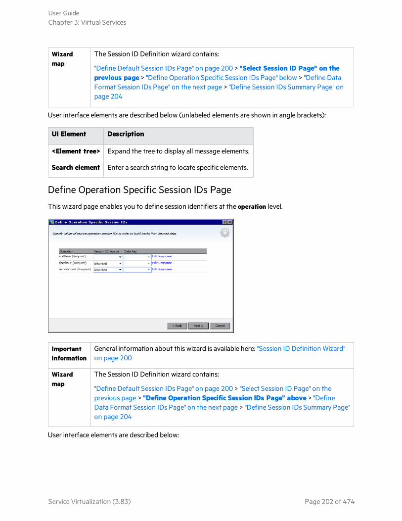
Wizardmap
The Session ID Definition wizard contains:
"Define Default Session IDs Page" on page 200 > "Select Session ID Page" on theprevious page > "Define Operation Specific Session IDs Page" below > "Define DataFormat Session IDs Page" on the next page > "Define Session IDs Summary Page" onpage 204
User interface elements are described below (unlabeled elements are shown in angle brackets):
UI Element Description
<Element tree> Expand the tree to display all message elements.
Search element Enter a search string to locate specific elements.
Define Operation Specific Session IDs Page
This wizard page enables you to define session identifiers at the operation level.
Importantinformation
General information about this wizard is available here: "Session ID Definition Wizard"on page 200
Wizardmap
The Session ID Definition wizard contains:
"Define Default Session IDs Page" on page 200 > "Select Session ID Page" on theprevious page > "Define Operation Specific Session IDs Page" above > "DefineData Format Session IDs Page" on the next page > "Define Session IDs Summary Page"on page 204
User interface elements are described below:
User GuideChapter 3: Virtual Services
Service Virtualization (3.83) Page 202 of 474

UIElement Description
Operation The operations in the virtual service.
SessionID Source
The source for identifying sessions. Options include:
l In Message. Enables you to define an element within the message to use as a sessionidentifier. Select an option from the Data Key list.
l Inherited. Uses the setting that is defined at the service level.
l None. The data is not placed into tracks based on values at the operation level.
Data Key The message element used as the session identifier. The data key can be a messageheader or a field.
Available when you select In Message in the Session ID Source field.
Click Edit to change the selection.
EditResponse
Enables you to select fields for response-specific data.
DeleteResponse
Removes the response-specific session ID row.
Edit DataFormats
Opens the Define Data Format Session IDs page, enabling you to define sessionidentifiers per data format type. For details, see "Define Data Format Session IDs Page"below.
Define Data Format Session IDs Page
This wizard page enables you to define session identifiers per data format type.
User GuideChapter 3: Virtual Services
Service Virtualization (3.83) Page 203 of 474

Importantinformation
General information about this wizard is available here: "Session ID Definition Wizard"on page 200
Wizardmap
The Session ID Definition wizard contains:
"Define Default Session IDs Page" on page 200 > "Select Session ID Page" on page 201> "Define Operation Specific Session IDs Page" on page 202 > "Define Data FormatSession IDs Page" on the previous page > "Define Session IDs Summary Page"below
User interface elements are described below:
UI Element Description
DataFormat
The data formats available in the service.
SessionID Source
The source for identifying sessions. Options include:
l In Message Enables you to define an element within the message to use as a sessionidentifier. Select an option from the Data Key list.
l Inherited. Uses the setting that is defined at the operation level.
l None. The data is not placed into tracks based on data format.
Data Key The message element used as the session identifier. Select a value.
Available when you select In Message in the Session ID Source field.
Click Edit to change the selection.
Define Session IDs Summary Page
This wizard page displays a summary of how Service Virtualization can organize your learned data intotracks.
Based on the session identifiers you have defined, Service Virtualization will create a separate track foreach unique session identifier value.
Note: Learned data is grouped into tracks after the next Learning session.
User GuideChapter 3: Virtual Services
Service Virtualization (3.83) Page 204 of 474

Importantinformation
l General information about this wizard is available here: "Session ID DefinitionWizard" on page 200
l In the event of an error, click Back to modify your settings.
Wizardmap
The Session ID Definition wizard contains:
"Define Default Session IDs Page" on page 200 > "Select Session ID Page" on page 201> "Define Operation Specific Session IDs Page" on page 202 > "Define Data FormatSession IDs Page" on page 203 > "Define Session IDs Summary Page" on theprevious page
User interface elements are described below:
UI Element Description
Learned Datapie chart
Displays the expected results based on current learned data.
Mapped The percentage of current learned data that can be mapped to a distinct session,based on your session ID selections.
Not mapped The percentage of current learned data that cannot be mapped to a distinctsession, based on your session ID selections.
Finish Saves your selections. Learned data is grouped into tracks after the next Learningsession.
Data Masking Dialog BoxThis dialog box enables you to hide specific request and response data elements.
User GuideChapter 3: Virtual Services
Service Virtualization (3.83) Page 205 of 474

To access Use one of the following:
l In the Service Description Editor, under Data Masking, click Edit.
l In the Data Model Editor, right-click a column header and select Mask.
Importantinformation
l When you set or change data masking settings, all data from associated operationsin all data models in the service are removed.
l In the Data Model Editor, columns that are configured for data masking are markedwith a red hash sign (#) in the column header.
l If message logging is enabled for the virtual service, and you then configure datamasking, message logging will be disabled. For details on message logging, see"Message Logging" on page 148.
Relevanttasks
"Edit a Service Description" on page 136
See also "Service Descriptions" on page 128
User interface elements are described below (unlabeled elements are shown in angle brackets):
UI Element Description
Searchelement
Search for a specific request or response element.
User GuideChapter 3: Virtual Services
Service Virtualization (3.83) Page 206 of 474
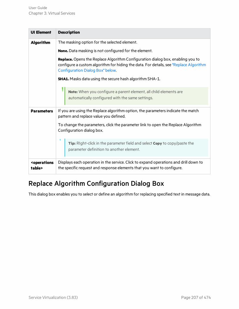
UI Element Description
Algorithm The masking option for the selected element.
None. Data masking is not configured for the element.
Replace. Opens the Replace Algorithm Configuration dialog box, enabling you toconfigure a custom algorithm for hiding the data. For details, see "Replace AlgorithmConfiguration Dialog Box" below.
SHA1. Masks data using the secure hash algorithm SHA-1.
Note: When you configure a parent element, all child elements areautomatically configured with the same settings.
Parameters If you are using the Replace algorithm option, the parameters indicate the matchpattern and replace value you defined.
To change the parameters, click the parameter link to open the Replace AlgorithmConfiguration dialog box.
Tip: RIght-click in the parameter field and select Copy to copy/paste theparameter definition to another element.
<operationstable>
Displays each operation in the service. Click to expand operations and drill down tothe specific request and response elements that you want to configure.
Replace Algorithm Configuration Dialog BoxThis dialog box enables you to select or define an algorithm for replacing specified text in message data.
User GuideChapter 3: Virtual Services
Service Virtualization (3.83) Page 207 of 474

To access In the Data Masking dialog box, select a data element, and do one of the following:
l Under Algorithm, select Replace.
l For an element already configured to use the Replace function, click in theParameters column.
Importantinformation
When you set or change data masking settings, all data from associated operationsin all data models in the service are removed.
Relevanttasks
"Modify Virtual Service Behavior" on page 261
See also "Data Modeling" on page 251
User interface elements are described below:
User GuideChapter 3: Virtual Services
Service Virtualization (3.83) Page 208 of 474

UI Element Description
Replace using static value Enter a string to use to replace the strings that match yourspecifications.
For example, you might want to replace credit card data with thefollowing value: XXXX-XXXX-XXXX-XXXX
From File. Browse the file system to select a file. The data is maskedusing the contents of the selected file.
Replace using regularexpression
Enables you to define a regular expression to match a particularstring of text.
You can use regular expressions in the Match pattern and Replacevalue fields.
For help on creating regular expressions, see "Configure RegularExpressions" on page 282.
Match pattern Enter the string that you want to match, or click the drop-downarrow to select a previously entered string.
Replace value The value you want to use to replace the data that matches yourMatch pattern.
Enter the string that you want to use to mask the data you arereplacing.
Change all occurrences ofregular expression
Updates all elements in all data models in the service that are usingthis regular expression for data masking.
Test Input Enter a string to test your settings.
Test Output Displays the masked output based on the settings you defined.
Edit Metadata Dialog BoxThe Edit Metadata dialog box enables you to edit metadata for the current service description.Metadata are parameters that contain some protocol-specific information such as time stamps,correlation information, or status codes. They are part of the protocol message, but external to themessage body, such as URL parameters, or HTTP headers.
User GuideChapter 3: Virtual Services
Service Virtualization (3.83) Page 209 of 474

To access In the Service Description Editor, under Request Metadata or ResponseMetadata, select Edit.
Importantinformation
Items displayed in gray are disabled.
Relevant tasks l "Edit a Service Description" on page 136
l "Call External Services" on page 286
See also "Service Descriptions" on page 128
User interface elements are described below:
UIElement
Description
Enable Activate the selected metadata. This is the default status.
Disable Deactivate the selected metadata. Disabled metatada are not available for viewing orediting in the Data Model Editor, and values for disabled metadata are not learned orsimulated.
Disabled metadata are displayed in gray.
Add Opens the Add New Metadata dialog box. Enter a name and select a type for the newmetadata. The types available vary based on the protocol with which you are working.
Edit Enables you to modify the selected item.
User GuideChapter 3: Virtual Services
Service Virtualization (3.83) Page 210 of 474

UIElement
Description
Delete Removes the metadata from all data models in the virtual service, and deletes themetadata's related data.
Add Data Format Dialog BoxThis dialog box enables you to add a new data format to your service description. You can copy from anexisting URI space, or create a new format.
To access 1. In the Service Description Editor, in the operations pane on the left side, select aURI space.
2. Under Request or Response Data Format, click Add.
Relevanttasks
"Edit a Service Description" on page 136
See also "Service Descriptions" on page 128
"Service Description Editor" on page 197
User interface elements are described below.
UI ElementDescription
URI Space Enter the path of the existing URI space you want to copy.
User GuideChapter 3: Virtual Services
Service Virtualization (3.83) Page 211 of 474

UI ElementDescription
DataFormat
Lists supported data formats.
Type The data format types available in the schema.
Available for XML data format only.
ExternalFile
Opens the Import XML Schema dialog box, enabling you to import a schema from anexternal file.
User GuideChapter 3: Virtual Services
Service Virtualization (3.83) Page 212 of 474

Chapter 4: SimulationThis chapter includes:
• Simulation 214• Run Simulations 214• Service Locking 217• Simulation User Interface 217
Service Virtualization (3.83) Page 213 of 474

SimulationAfter a virtual service is created, you define simulation data. You can do this by manual design, or byrecording real service activity in order to learn about the requests and responses of the real service. Youcan then use the recorded data to create data and performance models that define how the virtualservice should behave during simulation.
Select simulation models
Before a simulation session, you can select which simulation models to use. You can simulate variousscenarios:
l Use both a data model and a performance model to simulate the real service. Both data andperformance are simulated, and the real service does not receive any communication.
l Turn off data simulation to let the real service respond. Only performance is simulated using one ofthe performance models.
l Turn off performance simulation. Response times are not affected. Only data is simulated using oneof the data models.
l Simulate the unavailability of a service.
Manage simulation
You manage the simulation process by manipulating virtual service modes:
Learningmode
The virtual service works as a proxy to record and learn the behavior of a real service.The virtual service forwards the real communication between a client and a service. Inthis mode, any communication through the virtual service is added to the virtualservice's simulation models.
Standbymode
The virtual service redirects requests to the real service, and redirects responses fromthe real service back to the client. The virtual service is not learning, and not simulating.
Simulatingmode
The virtual service responds to client requests according to learned behavior. This isthe main use of the virtual service, and the mode you use for testing purposes.
During learning or simulating sessions, you can monitor service behavior.
See also:l "The Simulation Process" on page 259
l "Run Simulations" below
Run SimulationsThis task describes how to run simulations using your virtual services.
User GuideChapter 4: Simulation
Service Virtualization (3.83) Page 214 of 474

Note:
l This task is part of a higher-level task. For details, see "End-to-End Workflow" on page 20.
l To learn more about virtual services, see "Simulation" on the previous page.
l If a service is locked by another client, a message displays in the Virtual Service Editor. Fordetails, see "Service Locking" on page 217.
This task includes the following steps:
"Prerequisites" below
"Reconfigure clients" below
"Define simulation data" below
"Learn real service behavior" below
"Select simulation models" on the next page
"Simulate" on the next page
"Monitor all services" on the next page
"Review message logs" on page 217
"Optional: Adjust simulation models" on page 217
1. Prerequisites
Create and configure virtual services.
2. Reconfigure clients
Reconfigure your client to use the virtual service endpoints in place of the real service endpoints.This is required in cases where Service Virtualization can only perform intrusive virtualization.
3. Define simulation data
You can define the data from scratch in the Data Model Editor. For task details, see "Modify VirtualService Behavior" on page 261.
Alternatively, you can define the data by recording real service behavior, as described in the nextstep.
4. Learn real service behavior
Record the behavior of the real service in order to see the actual requests and responses.
Note: You can learn and simulate both one-way (request only) and two-way (request-response) communication within a single operation in your data model. This functionality isavailable for messaging protocols IBM® WebSphere® MQ, Oracle® AQ, JMS, and SAP IDoc.
a. In the Virtual Service Editor, click Learn to record real service activity. The information is savedin the virtual service's data and performance models. For user interface details, see "Virtual
User GuideChapter 4: Simulation
Service Virtualization (3.83) Page 215 of 474

Service Editor" on page 186.
Alternatively, you can choose to save only some of the collected data. Click the Learn drop-down arrow to select a simulation model to which you want to save recorded data.
b. Run the application communicating with the real service. Service calls are recorded.
c. To view the learned data after recording, open the Data Model Editor and click the LearnedData rule. For user interface details, see "Data Model Editor" on page 291.
5. Select simulation models
In the Virtual Service Editor, select a data model and a performance model to use during simulation.
To simulate the unavailability of a service, select the Offline performance model.
You can also choose to use just one of the simulation models, by selecting None for either the dataor performance model.
l If you select a performance model only, the real service responds and only the performance issimulated.
l If you select a data model only, response times are not affected, and only data is simulated.
6. Simulate
a. In the Virtual Service Editor, click Simulate to place the virtual service in Simulating mode. Thevirtual service is ready to respond to client requests . The real service does not receive anycommunication.
b. Run your client application. The virtual service responds to requests, and returns responsesbased on its associated simulation models.
c. When you want to complete the simulation session, click Stop to move the virtual service intoStandby mode. Client requests are then answered by the real service.
7. Monitor all services
You can monitor virtual service activity in the following ways:
Runtime View View and control all of the virtual services in your project. During a learning orsimulation session, the Runtime View provides an overview of thecommunication through the virtual services. From the main menu, select View> Runtime View.
Problem List View errors, warnings, and informational messages about events thatoccurred during the application or server run. From the main menu, selectView > Problem List.
ServiceAdministration
View and manage all services from configured servers, without openingindividual projects. On the Start Page, click Service Administration.
Alternatively, from the main menu, select View > Service Administration.
ServiceVirtualizationManagement
View and manage services from multiple Service Virtualization projects andservers in a web browser, without opening the projects. For details, see"Service Virtualization Management" on page 224.
User GuideChapter 4: Simulation
Service Virtualization (3.83) Page 216 of 474
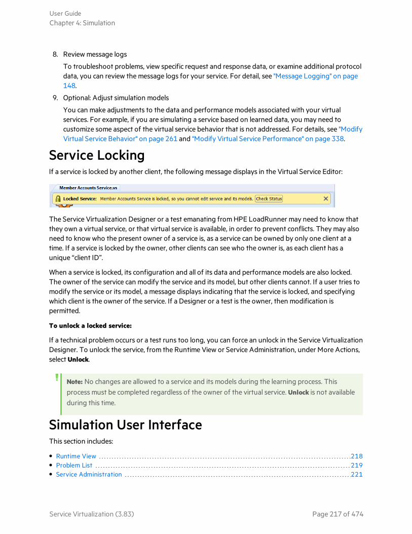
8. Review message logs
To troubleshoot problems, view specific request and response data, or examine additional protocoldata, you can review the message logs for your service. For detail, see "Message Logging" on page148.
9. Optional: Adjust simulation models
You can make adjustments to the data and performance models associated with your virtualservices. For example, if you are simulating a service based on learned data, you may need tocustomize some aspect of the virtual service behavior that is not addressed. For details, see "ModifyVirtual Service Behavior" on page 261 and "Modify Virtual Service Performance" on page 338.
Service LockingIf a service is locked by another client, the following message displays in the Virtual Service Editor:
The Service Virtualization Designer or a test emanating from HPE LoadRunner may need to know thatthey own a virtual service, or that virtual service is available, in order to prevent conflicts. They may alsoneed to know who the present owner of a service is, as a service can be owned by only one client at atime. If a service is locked by the owner, other clients can see who the owner is, as each client has aunique “client ID”.
When a service is locked, its configuration and all of its data and performance models are also locked.The owner of the service can modify the service and its model, but other clients cannot. If a user tries tomodify the service or its model, a message displays indicating that the service is locked, and specifyingwhich client is the owner of the service. If a Designer or a test is the owner, then modification ispermitted.
To unlock a locked service:
If a technical problem occurs or a test runs too long, you can force an unlock in the Service VirtualizationDesigner. To unlock the service, from the Runtime View or Service Administration, under More Actions,select Unlock.
Note: No changes are allowed to a service and its models during the learning process. Thisprocess must be completed regardless of the owner of the virtual service. Unlock is not availableduring this time.
Simulation User InterfaceThis section includes:
• Runtime View 218• Problem List 219• Service Administration 221
User GuideChapter 4: Simulation
Service Virtualization (3.83) Page 217 of 474
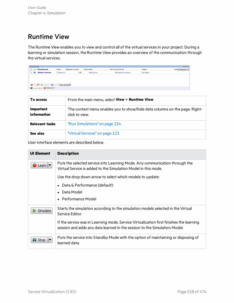
Runtime ViewThe Runtime View enables you to view and control all of the virtual services in your project. During alearning or simulation session, the Runtime View provides an overview of the communication throughthe virtual services.
To access From the main menu, select View > Runtime View.
Importantinformation
The context menu enables you to show/hide data columns on the page. Right-click to view.
Relevant tasks "Run Simulations" on page 214
See also "Virtual Services" on page 123
User interface elements are described below.
UI Element Description
Puts the selected service into Learning Mode. Any communication through theVirtual Service is added to the Simulation Model in this mode.
Use the drop down arrow to select which models to update:
l Data & Performance (default)
l Data Model
l Performance Model
Starts the simulation according to the simulation models selected in the VirtualService Editor.
If the service was in Learning mode, Service Virtualization first finishes the learningsession and adds any data learned in the session to the Simulation Model.
Puts the service into Standby Mode with the option of maintaining or disposing oflearned data.
User GuideChapter 4: Simulation
Service Virtualization (3.83) Page 218 of 474

UI Element Description
Includes the following:
Info. Opens the Runtime Report to display current information about the service.
Unlock. Unlocks the selected service. For more details, see "Service Locking" on page217.
Undeploy. Undeploys the selected service.
All Enables you to filter the displayed services according to virtual service mode.
Click the arrow to display the filter options.
Data Model The data model currently in use for the selected service.
Click the name link to open the model in the Data Model Editor.
Endpoints The URL of the real service.
Info Located under the More Actions menu. Opens the Runtime Report to display currentinformation about the service.
Messages(Unique)
The number of messages and unique messages passed through the virtual serviceduring the current learning or simulation session.
PerformanceModel
The performance model currently in use for the selected service.
Click the name link to open the model in the Performance Model Editor.
Project The project to which the service belongs.
Server The server running the selected service.
Status The number of problems that occurred.
Undeploy Located under the More Actions menu. Undeploys the selected service.
Unlock Located under the More Actions menu. Unlocks the selected service. For moredetails, see "Service Locking" on page 217.
VirtualService
Displays the list of all services from configured servers. Click on a service name toopen the service in the Virtual Service Editor.
Problem ListThe Problem List displays errors, warnings, and informational messages about events that occurredduring the application or server run. The source of problems can be either runtime errors in the
User GuideChapter 4: Simulation
Service Virtualization (3.83) Page 219 of 474

application, or a problem occurring during a service lifecycle. For example, during deployment, or whilein Standby, Learning, or Simulating modes.
To access From the main menu, select View > Problem List.
Importantinformation
By default, the information displayed is automatically filtered according to the editorthat is open. For example, if you open the Virtual Service Editor, the Problem Listdisplays problems related to the service. If you open the Data Model Editor, problemsare filtered for issues related to the data model.
Relevanttasks
"Run Simulations" on page 214
See also "Simulation" on page 214
User interface elements are described below (unlabeled elements are shown in angle brackets):
UI Element Description
<message filter> Enables you to filter the messages according to type: Errors, Warnings,Information.
By default, only Errors and Warnings are displayed. Click the arrow tochange the filter options.
Type The problem category and number of occurrences.
Fix It If the problem can be resolved with user interaction, a link is displayed.The link connects you to the part of the application that may be thesource of the problem.
Source Service Filter Enables you to filter for a specific service call or display All Sources.
Description A description of the problem.
Time Time and date that the problem occurred.
User GuideChapter 4: Simulation
Service Virtualization (3.83) Page 220 of 474

Service AdministrationThis page enables you to view and manage all services from configured servers, without openingindividual projects. All virtual services are displayed with their statues, associated models, and serverlocations. You can change selections for simulation models in use, and view the server on which a serviceis deployed.
To access From the Start Page, click Service Administration.
Importantinformation
The context menu enables you to show/hide data columns on the page. Right-click to view.
Relevant tasks "Run Simulations" on page 214
See also "Virtual Services" on page 123
User interface elements are described below:
UI Element Description
Not enabled in Service Administration. To place services in Learning mode, you mustuse the Virtual Service Editor in an open project.
Starts the simulation according to the selected simulation models. You can choosedifferent models using the Data Model and Performance Model columns.
If the service was in Learning mode, Service Virtualization first finishes the learningsession and adds any data learned in the session to the Simulation Model.
Puts the service into Standby Mode with the option of maintaining or disposing oflearned data.
User GuideChapter 4: Simulation
Service Virtualization (3.83) Page 221 of 474
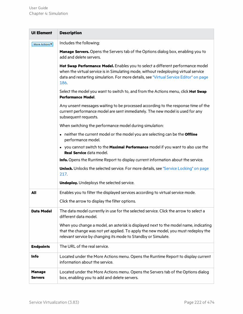
UI Element Description
Includes the following:
Manage Servers. Opens the Servers tab of the Options dialog box, enabling you toadd and delete servers.
Hot Swap Performance Model. Enables you to select a different performance modelwhen the virtual service is in Simulating mode, without redeploying virtual servicedata and restarting simulation. For more details, see "Virtual Service Editor" on page186.
Select the model you want to switch to, and from the Actions menu, click Hot SwapPerformance Model.
Any unsent messages waiting to be processed according to the response time of thecurrent performance model are sent immediately. The new model is used for anysubsequent requests.
When switching the performance model during simulation:
l neither the current model or the model you are selecting can be the Offlineperformance model.
l you cannot switch to the Maximal Performance model if you want to also use theReal Service data model.
Info. Opens the Runtime Report to display current information about the service.
Unlock. Unlocks the selected service. For more details, see "Service Locking" on page217.
Undeploy. Undeploys the selected service.
All Enables you to filter the displayed services according to virtual service mode.
Click the arrow to display the filter options.
Data Model The data model currently in use for the selected service. Click the arrow to select adifferent data model.
When you change a model, an asterisk is displayed next to the model name, indicatingthat the change was not yet applied. To apply the new model, you must redeploy therelevant service by changing its mode to Standby or Simulate.
Endpoints The URL of the real service.
Info Located under the More Actions menu. Opens the Runtime Report to display currentinformation about the service.
ManageServers
Located under the More Actions menu. Opens the Servers tab of the Options dialogbox, enabling you to add and delete servers.
User GuideChapter 4: Simulation
Service Virtualization (3.83) Page 222 of 474

UI Element Description
Messages(Unique)
The number of messages and unique messages passed through the virtual serviceduring the current learning or simulation session.
PerformanceModel
The performance model currently in use for the selected service. Click the arrow toselect a different performance model.
When you change a model, an asterisk is displayed next to the model name, indicatingthat the change was not yet applied. To apply the new model, you must redeploy therelevant service by changing its mode to Standby or Simulate.
Project The project to which the service belongs.
Server The server running the selected service.
Status The number of problems that occurred. Click to display details in the Problems List.
Undeploy Located under the More Actions menu. Undeploys the selected service.
Unlock Located under the More Actions menu. Unlocks the selected service. For moredetails, see "Service Locking" on page 217.
View Enables you to filter the displayed services according to server. Click the arrow todisplay the filter options.
VirtualService
Displays the list of all services from configured servers. Click on a service name toopen the service in the Virtual Service Editor.
User GuideChapter 4: Simulation
Service Virtualization (3.83) Page 223 of 474

Chapter 5: Service VirtualizationManagementThis chapter includes:
• Service Virtualization Management 225• Get Started Using Service Virtualization Management 226
Service Virtualization (3.83) Page 224 of 474

Service Virtualization ManagementService Virtualization Management enables you to view and control services from multiple ServiceVirtualization projects and servers in one location, without opening the projects. You can:
l View a summary of all service activity on a server.
l Start and stop simulations.
l Undeploy services.
l Deploy additional virtualization projects and services located in HPE Application LifecycleManagement (ALM) or in the file system.
l View server health and utilization statistics.
Deploy services
After you create and configure virtual services in the Service Virtualization Designer, the services can bedeployed on any Service Virtualization Server. Service Virtualization Management provides aconvenient method for allowing others to access and manage virtual services deployed on any ServiceVirtualization Server. For example, anyone performing testing can work with the virtual services from abrowser window, with no additional installation or configuration.
Share services
In addition, Service Virtualization Management enables you to consume virtual services that are storedin a network location. You can download virtual services to your Service Virtualization Server, withoutthe need to install the Service Virtualization Designer.
Note:
l When you are working with a secured Service Virtualization Server, the actions available toyou and the information displayed vary, based on your user access permissions. For example,a user who is not assigned to any of the Service Virtualization user groups cannot view anyagent data or any services deployed on the server. For details on the Service Virtualizationuser groups, see the HPE Service Virtualization Installation Guide.
l The Service Virtualization service, Server, and Management versions must match. If theservice/project was created in an earlier version, open it in the Designer to upgrade theproject to the new version.
See also:l "Get Started Using Service Virtualization Management" on the next page
User GuideChapter 5: Service Virtualization Management
Service Virtualization (3.83) Page 225 of 474

Get Started Using Service VirtualizationManagementThis task describes how to start working with the Service Virtualization Management interface.
Note: To learn more about Service Virtualization Management, see "Service VirtualizationManagement" on the previous page.
This section includes:
l "Prerequisites" below
l "Start/stop the Service Virtualization Management service" below
l "Open Service Virtualization Management" on the next page
l "Manage virtual services in Service Virtualization Management" on the next page
l "Troubleshoot" on the next page
Prerequisitesl To log in to Service Virtualization Management, you must be a member of the SVM Users group on
the Service Virtualization Server machine. For details on the Service Virtualization user groups, seethe HPE Service Virtualization Installation Guide.
l Make sure you are using a supported browser. For details, see the HPE Service VirtualizationInstallation Guide.
Note: For the most up-to-date list of supported browsers and versions, refer to the supportmatrix on the HPE Software Support site at:https://softwaresupport.hpe.com/group/softwaresupport/support-matrices, or contactsupport.
l Make sure that the Service Virtualization Server is running.
Start/stop the Service Virtualization Management service1. On the Service Virtualization Server machine, from the Windows Start menu, select All Programs >
HPE Software > HPE Service Virtualization > Server 3.83 > Start Services of HPE ServiceVirtualization Server.
This option starts both the Service Virtualization Server service and the Service VirtualizationManagement service.
2. To stop the service, from the Windows Start menu, select All Programs > HPE Software > HPEService Virtualization > Server 3.83 > Stop Services of HPE Service Virtualization Server.
User GuideChapter 5: Service Virtualization Management
Service Virtualization (3.83) Page 226 of 474

This option stops both the Service Virtualization Server service and the Service VirtualizationManagement service.
Open Service Virtualization ManagementOpen a browser window and enter one of the following URLs:
l The Service Virtualization Management URL:
https://<Service Virtualization Server IP or hostname>:<ServiceVirtualization Management port>
By default, the Service Virtualization Management port is 6086.
l The Service Virtualization Server URL:
<Service Virtualization Server IP or hostname>:<HTTP/HTTPS portnumber>/management
For more details on Service Virtualization network ports, see the HPE Service Virtualization InstallationGuide.
Manage virtual services in Service VirtualizationManagementFor details on working with Service Virtualization Management, see the online help inside ServiceVirtualization Management. In the upper-right corner, click the down arrow and select Help.
TroubleshootIf an issue arises, review the web server and proxy logs, located in %ProgramData%\Hewlett PackardEnterprise\HPE Service Virtualization Server\ManagementInterface\logs.
User GuideChapter 5: Service Virtualization Management
Service Virtualization (3.83) Page 227 of 474

Chapter 6: Command Line ManagementThis chapter includes:
• Command Line Management 229• Manage Virtual Services from the Command Line 230• Deploy a Virtual Service on Multiple Service Virtualization Servers 244• Automation example 246
Service Virtualization (3.83) Page 228 of 474

Command Line ManagementYou can manage virtual services deployed on a Service Virtualization Server using the SVConfiguratorcommand line interface.
SVConfigurator is Java-based and can be used by both Windows and Unix/Linux operating systems.
How can this help me?
l Work with virtual services without needing to open virtualization projects in the Designer.
l Automate virtual service management when working with HPE test automation tools. For details onworking with the HPE test automation tools, see "HPE Test Automation Tools Integration" on page377.
l Deploy a virtual service on multiple Service Virtualization Servers. For details, see "Deploy a VirtualService on Multiple Service Virtualization Servers" on page 244.
Using the SVConfigurator command line tool, you can:
l deploy virtual services to any Service Virtualization Server
l change the runtime mode of a virtual service
l view virtual service details, such as service name, ID, mode, deployment state, and data andperformance models
l switch the performance model during simulation
l list all deployed virtual services on a Service Virtualization Server
l list the services in a project
l unlock a virtual service locked by another user
l undeploy services
l update services with learned data recorded on a Service Virtualization Server
l export projects and services
Note: You can also use SVConfigurator as an Apache Ant™ plugin. For details, refer to thedocumentation, located in the following locations:
l <Service Virtualization installation folder>\Tools\SVConfigurator\doc\AntTasks\index.html
l In the HP.SV.SVConfigurator.jar file, located in the <Service Virtualization installationfolder>\Tools\SVConfigurator\bin folder.
By default, the Service Virtualization installation folder is located in:
l Server: C:\Program Files\HPE\HPE Service Virtualization Server
l Designer: C:\Program Files (x86)\HPE\HPE Service Virtualization Designer
User GuideChapter 6: Command Line Management
Service Virtualization (3.83) Page 229 of 474

See also:l For task details, see "Manage Virtual Services from the Command Line" below.
Manage Virtual Services from the Command LineThis task describes how to manage virtual services deployed on a Service Virtualization Server using theSVConfigurator command line interface.
This section includes:
l "Notes and Guidelines" below
l "Prerequisites" below
l "Deploy services" on the next page
l "Change service mode" on page 232
l "Export" on page 235
l "Switch performance models during simulation" on page 236
l "View service details" on page 238
l "List deployed services" on page 239
l "List services in a project" on page 241
l "Unlock services" on page 241
l "Manage Virtual Services from the Command Line" above
l "Update a service" on page 243
Notes and Guidelinesl Log file: When you run SVConfigurator, a log file is created in your Windows user profile directory.
l Parameter values may not include spaces. If a value includes spaces, you must put it in quotationmarks. For example, the path "C:\Users\Default\Documents\HPE ServiceVirtualization\Projects\ShoppingCart Virtualization Project\ShoppingCart VirtualizationProject\ShoppingCart Virtualization Project.vproj".
l Some Service Virtualization configurations may deploy individual services on multiple ServiceVirtualization Servers. If you have defined the servers.properties file for virtual service deploymenton multiple servers, you can use some of the SVConfigurator commands to simultaneously performactions on all of the virtual services, using the --servers parameter. For details on multiple serverdeployment, see "Deploy a Virtual Service on Multiple Service Virtualization Servers" on page 244.
PrerequisitesTo work with an encrypted project, you must install Java Cryptography Extension (JCE) UnlimitedStrength Jurisdiction. Select one of the following, based on the Java version with which you areworking:
User GuideChapter 6: Command Line Management
Service Virtualization (3.83) Page 230 of 474

l For JDK 1.6: http://www.oracle.com/technetwork/java/javase/downloads/jce-6-download-429243.html
l For JDK 1.7: http://www.oracle.com/technetwork/java/javase/downloads/jce-7-download-432124.html
Deploy servicesDeploy or undeploy a virtualization project, or a single service from the project to the ServiceVirtualization Server.
1. Do one of the following:
l On the Service Virtualization Server, open a command prompt. Navigate to the \bin folder underthe Service Virtualization Server installation folder. By default, C:\Program Files\HPE\HPEService Virtualization Server\Tools\SVConfigurator\bin\.
l On the Service Virtualization Designer machine, open a command prompt. Navigate to the \binfolder under the Designer installation folder. By default, C:\Program Files (x86)\HPE\HPEService Virtualization Designer\Tools\SVConfigurator\bin\.
2. Run SVConfigurator.cmd DEPLOYPROJECT [parameters] <project file> at the command line, usingthe following options:
Note: For Linux, use SVConfigurator.sh.
Parameter Description
Required parameters
<project file> Path to a project file (.vproj or .vproja) whose services youwant to deploy on the server.
Optional parameters
-w or--project-password <arg>
If the project is encrypted, specifies a password to decryptthe project content.
-f or--force
Force mode. If the service to be deployed is locked, thecommand automatically unlocks it. It is then automaticallylocked by SVConfigurator. Use caution with this option asyou can delete another user’s data.
-u or--undeploy
Undeploys the project or service from the server.
-s or--service <arg>
Deploys only the specified service. You can specify a serviceby its name or ID.
Tip: Use the List or View commands to find a service ID.
User GuideChapter 6: Command Line Management
Service Virtualization (3.83) Page 231 of 474

Parameter Description
-url or--mgmt-url <arg>
URL of the server’s management endpoint.
-usr or--username <arg>
Username for the server’s management endpoint.
-pwd or--password <arg>
Password for the server’s management endpoint.
--servers <arg> The path to the servers.properties file containing a list ofService Virtualization Servers and their properties -management URL, username, and password.
Used to deploy the project or service on multiple ServiceVirtualization Servers.
Note: You can also use the --use-server parameterto indicate an individual Service VirtualizationServer on which to deploy the project or services.
--use-server <arg> Selected server ID from the list of servers in theservers.properties file. Only the specified server will be used.
Must be used together with the --servers parameter.
--first-agent-fallback Automatically uses the first compatible agent if it cannotfind the exact agent specified in the virtual service.
-remap<vprojAgentID=serverAgentID>
Switches the agent currently used in the project for thesame type of agent on a different server.
Use the parameter once for each agent in the project thatyou want to switch.
Change service modeChange the runtime mode of a service on the Service Virtualization Server to Learning, Simulating, orStandBy mode.
1. Do one of the following:
l On the Service Virtualization Server, open a command prompt. Navigate to the \bin folder underthe Service Virtualization Server installation folder. By default, C:\Program Files\HPE\HPEService Virtualization Server\Tools\SVConfigurator\bin\.
User GuideChapter 6: Command Line Management
Service Virtualization (3.83) Page 232 of 474
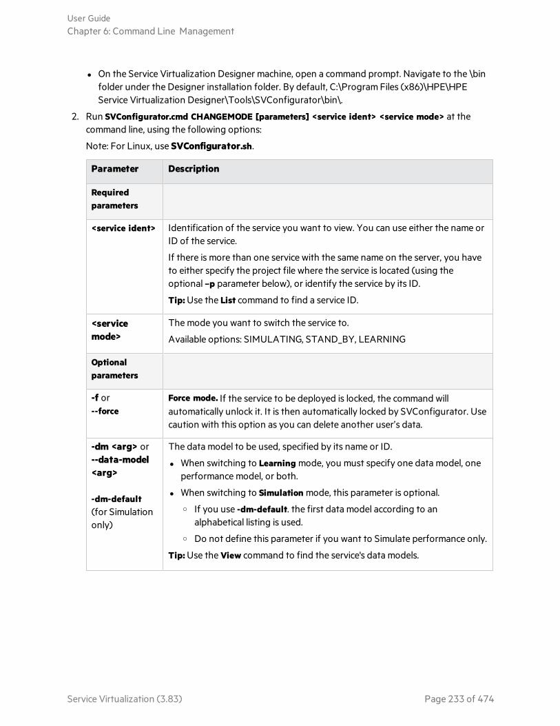
l On the Service Virtualization Designer machine, open a command prompt. Navigate to the \binfolder under the Designer installation folder. By default, C:\Program Files (x86)\HPE\HPEService Virtualization Designer\Tools\SVConfigurator\bin\.
2. Run SVConfigurator.cmd CHANGEMODE [parameters] <service ident> <service mode> at thecommand line, using the following options:
Note: For Linux, use SVConfigurator.sh.
Parameter Description
Requiredparameters
<service ident> Identification of the service you want to view. You can use either the name orID of the service.
If there is more than one service with the same name on the server, you haveto either specify the project file where the service is located (using theoptional –p parameter below), or identify the service by its ID.
Tip: Use the List command to find a service ID.
<servicemode>
The mode you want to switch the service to.
Available options: SIMULATING, STAND_BY, LEARNING
Optionalparameters
-f or--force
Force mode. If the service to be deployed is locked, the command willautomatically unlock it. It is then automatically locked by SVConfigurator. Usecaution with this option as you can delete another user’s data.
-dm <arg> or--data-model<arg>
-dm-default(for Simulationonly)
The data model to be used, specified by its name or ID.
l When switching to Learning mode, you must specify one data model, oneperformance model, or both.
l When switching to Simulation mode, this parameter is optional.o If you use -dm-default. the first data model according to an
alphabetical listing is used.o Do not define this parameter if you want to Simulate performance only.
Tip: Use the View command to find the service's data models.
User GuideChapter 6: Command Line Management
Service Virtualization (3.83) Page 233 of 474
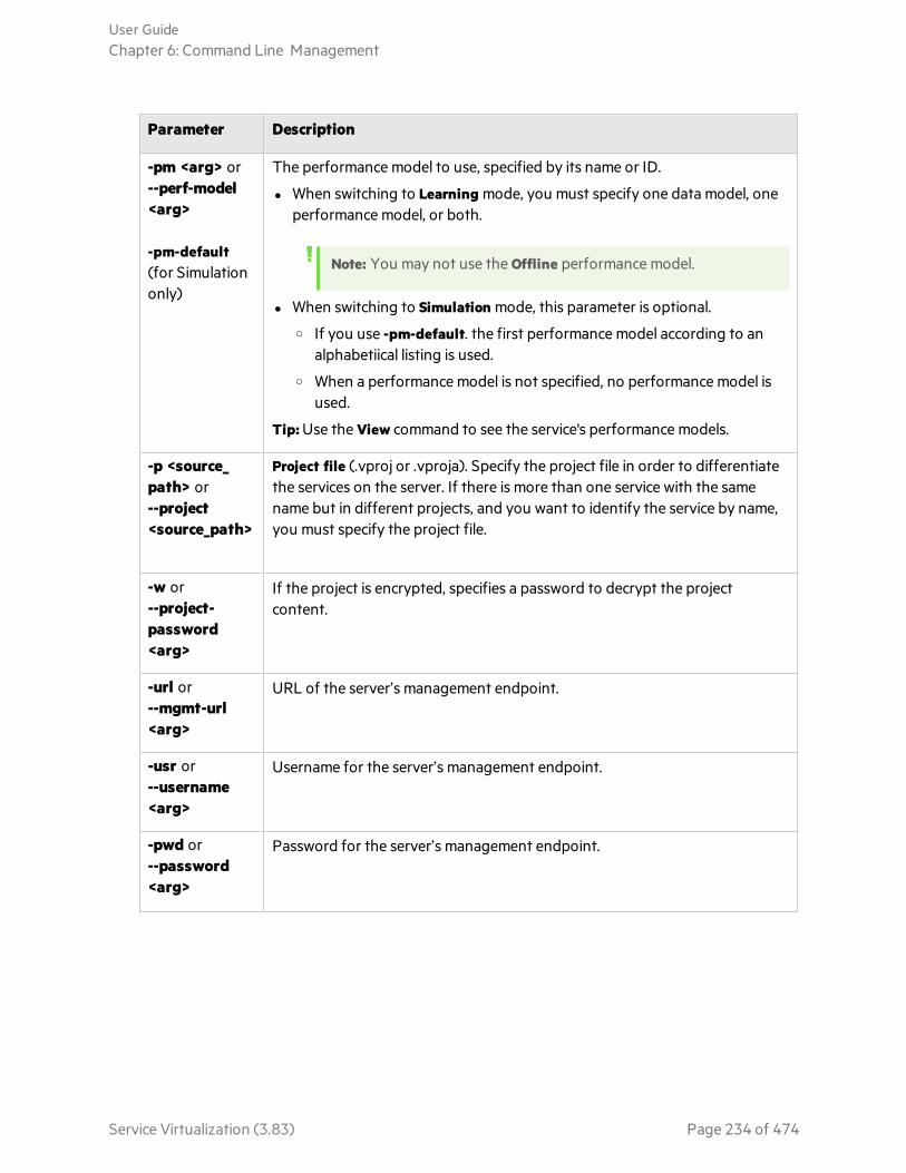
Parameter Description
-pm <arg> or--perf-model<arg>
-pm-default(for Simulationonly)
The performance model to use, specified by its name or ID.
l When switching to Learning mode, you must specify one data model, oneperformance model, or both.
Note: You may not use the Offline performance model.
l When switching to Simulation mode, this parameter is optional.o If you use -pm-default. the first performance model according to an
alphabetiical listing is used.o When a performance model is not specified, no performance model is
used.
Tip: Use the View command to see the service's performance models.
-p <source_path> or--project<source_path>
Project file (.vproj or .vproja). Specify the project file in order to differentiatethe services on the server. If there is more than one service with the samename but in different projects, and you want to identify the service by name,you must specify the project file.
-w or--project-password<arg>
If the project is encrypted, specifies a password to decrypt the projectcontent.
-url or--mgmt-url<arg>
URL of the server’s management endpoint.
-usr or--username<arg>
Username for the server’s management endpoint.
-pwd or--password<arg>
Password for the server’s management endpoint.
User GuideChapter 6: Command Line Management
Service Virtualization (3.83) Page 234 of 474

Parameter Description
--servers <arg> The path to the servers.properties file containing a list of ServiceVirtualization Servers and their properties - management URL, username, andpassword.
Used to change the mode of the virtual service on all Service VirtualizationServers on which is it deployed.
Note: You can also use the --use-server parameter to indicate anindividual Service Virtualization Server on which to perform theaction.
--use-server<arg>
Selected server ID from the list of servers in the servers.properties file. Onlythe specified server will be used.
Must be used together with the --servers parameter.
ExportExport all projects and services, or a single service, deployed on a Service Virtualization Server.
1. Do one of the following:
l On the Service Virtualization Server, open a command prompt. Navigate to the \bin folder underthe Service Virtualization Server installation folder. By default, C:\Program Files\HPE\HPEService Virtualization Server\Tools\SVConfigurator\bin\.
l On the Service Virtualization Designer machine, open a command prompt. Navigate to the \binfolder under the Designer installation folder. By default, C:\Program Files (x86)\HPE\HPEService Virtualization Designer\Tools\SVConfigurator\bin\.
2. Run SVConfigurator.cmd EXPORT [parameters] <d> at the command line, using the followingoptions:
Parameter Description
Requiredparameters
-d or--directory<arg>
The output folder. Specify a location for the exported services.
Optionalparameters
User GuideChapter 6: Command Line Management
Service Virtualization (3.83) Page 235 of 474
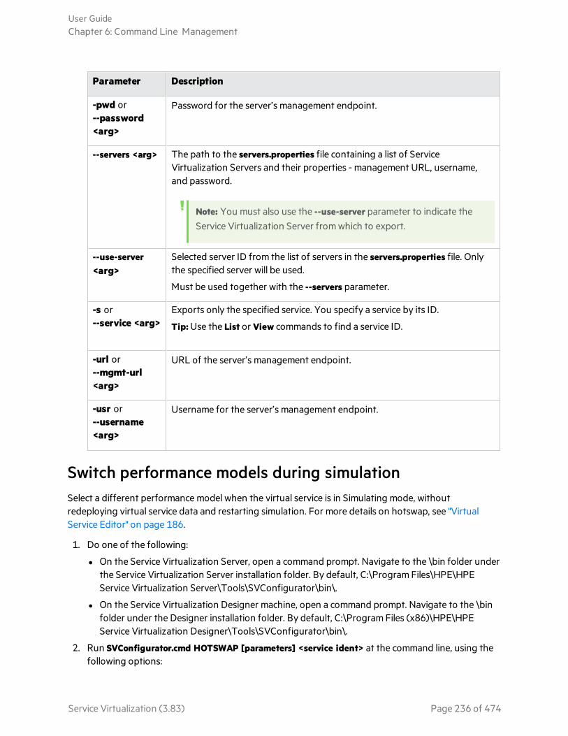
Parameter Description
-pwd or--password<arg>
Password for the server’s management endpoint.
--servers <arg> The path to the servers.properties file containing a list of ServiceVirtualization Servers and their properties - management URL, username,and password.
Note: You must also use the --use-server parameter to indicate theService Virtualization Server from which to export.
--use-server<arg>
Selected server ID from the list of servers in the servers.properties file. Onlythe specified server will be used.
Must be used together with the --servers parameter.
-s or--service <arg>
Exports only the specified service. You specify a service by its ID.
Tip: Use the List or View commands to find a service ID.
-url or--mgmt-url<arg>
URL of the server’s management endpoint.
-usr or--username<arg>
Username for the server’s management endpoint.
Switch performance models during simulationSelect a different performance model when the virtual service is in Simulating mode, withoutredeploying virtual service data and restarting simulation. For more details on hotswap, see "VirtualService Editor" on page 186.
1. Do one of the following:
l On the Service Virtualization Server, open a command prompt. Navigate to the \bin folder underthe Service Virtualization Server installation folder. By default, C:\Program Files\HPE\HPEService Virtualization Server\Tools\SVConfigurator\bin\.
l On the Service Virtualization Designer machine, open a command prompt. Navigate to the \binfolder under the Designer installation folder. By default, C:\Program Files (x86)\HPE\HPEService Virtualization Designer\Tools\SVConfigurator\bin\.
2. Run SVConfigurator.cmd HOTSWAP [parameters] <service ident> at the command line, using thefollowing options:
User GuideChapter 6: Command Line Management
Service Virtualization (3.83) Page 236 of 474
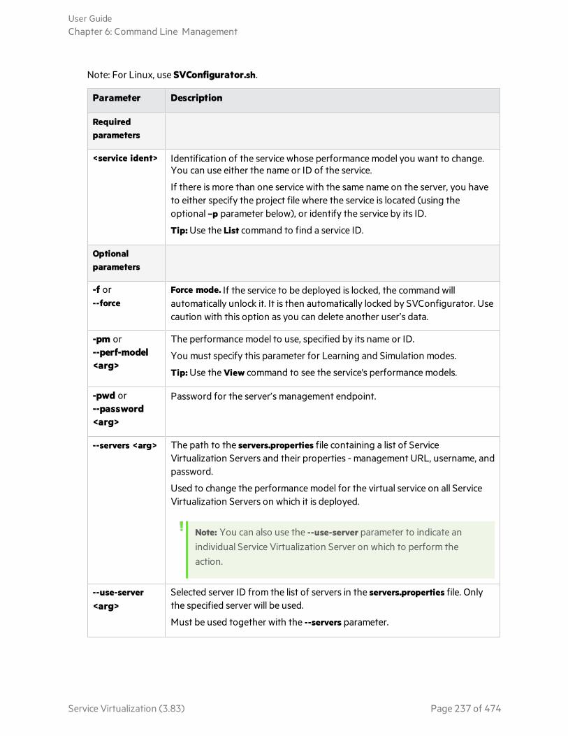
Note: For Linux, use SVConfigurator.sh.
Parameter Description
Requiredparameters
<service ident> Identification of the service whose performance model you want to change.You can use either the name or ID of the service.
If there is more than one service with the same name on the server, you haveto either specify the project file where the service is located (using theoptional –p parameter below), or identify the service by its ID.
Tip: Use the List command to find a service ID.
Optionalparameters
-f or--force
Force mode. If the service to be deployed is locked, the command willautomatically unlock it. It is then automatically locked by SVConfigurator. Usecaution with this option as you can delete another user’s data.
-pm or--perf-model<arg>
The performance model to use, specified by its name or ID.
You must specify this parameter for Learning and Simulation modes.
Tip: Use the View command to see the service's performance models.
-pwd or--password<arg>
Password for the server’s management endpoint.
--servers <arg> The path to the servers.properties file containing a list of ServiceVirtualization Servers and their properties - management URL, username, andpassword.
Used to change the performance model for the virtual service on all ServiceVirtualization Servers on which it is deployed.
Note: You can also use the --use-server parameter to indicate anindividual Service Virtualization Server on which to perform theaction.
--use-server<arg>
Selected server ID from the list of servers in the servers.properties file. Onlythe specified server will be used.
Must be used together with the --servers parameter.
User GuideChapter 6: Command Line Management
Service Virtualization (3.83) Page 237 of 474

Parameter Description
-url or--mgmt-url<arg>
URL of the server’s management endpoint.
-usr or--username<arg>
Username for the server’s management endpoint.
View service detailsView information about a service deployed on the Service Virtualization Server, such as service name,ID, mode, deployment state, and data and performance models.
1. Do one of the following:
l On the Service Virtualization Server, open a command prompt. Navigate to the \bin folder underthe Service Virtualization Server installation folder. By default, C:\Program Files\HPE\HPEService Virtualization Server\Tools\SVConfigurator\bin\.
l On the Service Virtualization Designer machine, open a command prompt. Navigate to the \binfolder under the Designer installation folder. By default, C:\Program Files (x86)\HPE\HPEService Virtualization Designer\Tools\SVConfigurator\bin\.
2. Run SVConfigurator.cmd VIEW [parameters] <service> at the command line, using the followingoptions:
Note: For Linux, use SVConfigurator.sh.
Parameter Description
Requiredparameters
<service> Identification of the service you want to view. You can use either the name orID of the service.
If there is more than one service with the same name on the server, you haveto either specify the project file where the service is located (using theoptional –p parameter below), or identify the service by its ID.
Tip: Use the List command to find a service ID.
Optionalparameters
-ror--report
Displays the runtime report for the service.
User GuideChapter 6: Command Line Management
Service Virtualization (3.83) Page 238 of 474

Parameter Description
-p <source_path> or--project<source_path>
Project file (.vproj or .vproja). Specify the project file in order to differentiatethe services on the server. If there is more than one service with the samename but in different projects, and you want to identify the service by name,you must specify the project file.
-w or--project-password<arg>
If the project is encrypted, specifies a password to decrypt the projectcontent.
-url or--mgmt-url<arg>
URL of the server’s management endpoint.
-usr or--username<arg>
Username for the server’s management endpoint.
-pwd or--password<arg>
Password for the server’s management endpoint.
--servers <arg> The path to the servers.properties file containing a list of ServiceVirtualization Servers and their properties - management URL, username, andpassword.
Note: You must also use the --use-server parameter to indicate theService Virtualization Server on which the service is deployed.
--use-server<arg>
Selected server ID from the list of servers in the servers.properties file. Onlythe specified server will be used.
Must be used together with the --servers parameter.
List deployed servicesList the services deployed on the Service Virtualization Server, and view basic service information, suchas service name, mode (learning, simulating, standby, offline), and ID.
1. Do one of the following:
l On the Service Virtualization Server, open a command prompt. Navigate to the \bin folder underthe Service Virtualization Server installation folder. By default, C:\Program Files\HPE\HPEService Virtualization Server\Tools\SVConfigurator\bin\.
User GuideChapter 6: Command Line Management
Service Virtualization (3.83) Page 239 of 474

l On the Service Virtualization Designer machine, open a command prompt. Navigate to the \binfolder under the Designer installation folder. By default, C:\Program Files (x86)\HPE\HPEService Virtualization Designer\Tools\SVConfigurator\bin\.
2. Run SVConfigurator.cmd LIST [parameters] at the command line, using the following optionalparameters:
Note: For Linux, use SVConfigurator.sh.
Parameter Description
-p <source_path>or--project<source_path>
Project file (.vproj or .vproja). Specify the project file in order to list only thedeployed services in the specified project.
-pwdor--password
<arg>
Password for the server’s management endpoint.
--servers <arg> The path to the servers.properties file containing a list of ServiceVirtualization Servers and their properties - management URL, username,and password.
Note: You must also use the --use-server parameter to indicate theService Virtualization Server on which to perform the List action.
--use-server<arg>
Selected server ID from the list of servers in the servers.properties file. Onlythe specified server will be used.
Must be used together with the --servers parameter.
-url or--mgmt-url<arg>
URL of the server’s management endpoint.
-usr or--username<arg>
Username for the server’s management endpoint.
-w or--project-password<arg>
If the project is encrypted, specifies a password to decrypt the projectcontent.
User GuideChapter 6: Command Line Management
Service Virtualization (3.83) Page 240 of 474

List services in a projectList the services in a project file.
1. Do one of the following:
l On the Service Virtualization Server, open a command prompt. Navigate to the \bin folder underthe Service Virtualization Server installation folder. By default, C:\Program Files\HPE\HPEService Virtualization Server\Tools\SVConfigurator\bin\.
l On the Service Virtualization Designer machine, open a command prompt. Navigate to the \binfolder under the Designer installation folder. By default, C:\Program Files (x86)\HPE\HPEService Virtualization Designer\Tools\SVConfigurator\bin\.
2. Run SVConfigurator.cmd LISTPROJECT [parameters] <project file> at the command line, using thefollowing optional parameters:
Note: For Linux, use SVConfigurator.sh.
Parameter Description
Requiredparameters
<project file> Path to a project file (.vproj or .vproja) whose contents you want to view.
Optionalparameters
-w or--project-password <arg>
If the project is encrypted, specifies a password to decrypt the projectcontent.
Unlock servicesUnlock a service deployed on the Service Virtualization Server that is locked by another user. You canthen lock it by your client.
1. Do one of the following:
l On the Service Virtualization Server, open a command prompt. Navigate to the \bin folder underthe Service Virtualization Server installation folder. By default, C:\Program Files\HPE\HPEService Virtualization Server\Tools\SVConfigurator\bin\.
l On the Service Virtualization Designer machine, open a command prompt. Navigate to the \binfolder under the Designer installation folder. By default, C:\Program Files (x86)\HPE\HPEService Virtualization Designer\Tools\SVConfigurator\bin\.
2. Run SVConfigurator.cmd UNLOCK [parameters] <service_identification> at the command line,using the following options:
User GuideChapter 6: Command Line Management
Service Virtualization (3.83) Page 241 of 474

Parameter Description
Requiredparameters
<service> Identification of the service you want to unlock. You can use either the nameor ID of the service.
If there is more than one service with the same name on the server, you haveto either specify the project file where the service is located (using theoptional –p parameter below), or identify the service by its ID.
Tip: Use the List or View commands to find a service ID.
Optionalparameters
-p <source_path>or--project<source_path>
Project file (.vproj or .vproja). Specify the project file in order to differentiatethe services on the server. If there is more than one service with the samename but in different projects, and you want to identify the service by name,you must specify the project file.
-l or--lock
Locks the service by your client lock immediately after unlocking.
-w or--project-password<arg>
If the project is encrypted, specifies a password to decrypt the projectcontent.
-url or--mgmt-url<arg>
URL of the server’s management endpoint.
-usr or--username<arg>
Username for the server’s management endpoint.
-pwd or--password<arg>
Password for the server’s management endpoint.
User GuideChapter 6: Command Line Management
Service Virtualization (3.83) Page 242 of 474

Parameter Description
--servers <arg> The path to the servers.properties file containing a list of ServiceVirtualization Servers and their properties - management URL, username, andpassword.
Used to unlock the virtual service on all Service Virtualization Servers onwhich it is deployed.
Note: You can also use the --use-server parameter to indicate anindividual Service Virtualization Server on which to perform theaction.
--use-server<arg>
Selected server ID from the list of servers in the servers.properties file. Onlythe specified server will be used.
Must be used together with the --servers parameter.
Update a serviceDownload learned data from the Service Virtualization Server to update the data model, performancemodel, and service description of a specified service.
Note: The UPDATE command is not supported for service call activity.
For an example of how to automate this process, see "Automation example" on page 246.
1. Do one of the following:
l On the Service Virtualization Server, open a command prompt. Navigate to the \bin folder underthe Service Virtualization Server installation folder. By default, C:\Program Files\HPE\HPEService Virtualization Server\Tools\SVConfigurator\bin\.
l On the Service Virtualization Designer machine, open a command prompt. Navigate to the \binfolder under the Designer installation folder. By default, C:\Program Files (x86)\HPE\HPEService Virtualization Designer\Tools\SVConfigurator\bin\.
2. Run SVConfigurator.cmd UPDATE [parameters] <project_file> at the command line, using thefollowing optional parameters:
Parameter Description
Requiredparameters
project_file The project file (.vproj) that you want to update.
User GuideChapter 6: Command Line Management
Service Virtualization (3.83) Page 243 of 474

Parameter Description
Optionalparameters
-pwd or--password<arg>
Password for the server’s management endpoint.
--servers <arg> The path to the servers.properties file containing a list of ServiceVirtualization Servers and their properties - management URL, username,and password.
Note: You must also use the --use-server parameter to indicate theService Virtualization Server from which to download the learneddata.
--use-server<arg>
Selected server ID from the list of servers in the servers.properties file. Onlythe specified server will be used.
Must be used together with the --servers parameter.
-s or--service <arg>
The service that you want to update. You can specify the service by its nameor ID.
Tip: Use the List or View commands to find a service ID.
-url or--mgmt-url<arg>
URL of the server’s management endpoint.
-usr or--username<arg>
Username for the server’s management endpoint connection.
-w or--project-password<arg>
If the project is encrypted, specifies a password to decrypt the projectcontent.
See also:l "Command Line Management" on page 229
Deploy a Virtual Service on Multiple ServiceVirtualization ServersYou may want to deploy the same virtual service on several Service Virtualization Servers.
User GuideChapter 6: Command Line Management
Service Virtualization (3.83) Page 244 of 474

What do I need to do?
l Create a Java format .properties file in which you list the URLs/endpoints of the Service VirtualizationServers, and the Server logon credentials (user name and password).
l Use the SVConfigurator command line interface to simultaneously perform actions on the virtualservice on all of the Service Virtualization Servers on which it is deployed, by providing the path tothe .properties file.
To deploy a virtual service on multiple Service Virtualization Servers:
1. Create a servers.properties file to store the Service Virtualization Server properties. Configure thefile according to the Java Properties file format.
For each Server, define the Server management URL and logon credentials (user name andpassword), as follows:
<server ID1>.url=https://<secured.server.url:port>/management
<server ID1>.username=<user name>
<server ID1>.password=<password>
<server ID2>.url=http://<not.secured.server.url:port>/management (No logon credentials arerequired for an unsecured server.)
where <server ID> is a name you assign to the server.
Example:
srv1.url=https://demoserver:6085/management
srv1.username=admin
srv1.password=pass1234
srv2.url=http://localhost:6080/management
2. Deploy the virtual service using SVConfigurator's DEPLOYPROJECT command with the --serversparameter to provide the path to the servers.properties file.
3. Manage the virtual service simultaneously on all of the Service Virtualization Servers on which it isdeployed, using the --servers parameter to indicate the location of the servers.properties file.
You can use the following SVConfigurator commands to perform actions on a virtual service that isdeployed on multiple servers:
l CHANGEMODE - to change the service mode
l HOTSWAP - to switch the performance model during simulation
l UNLOCK - to unlock a service that is locked by another user
User GuideChapter 6: Command Line Management
Service Virtualization (3.83) Page 245 of 474

l UNDEPLOY - to undeploy a service deployed on a Service Virtualization Server
Other SVConfigurator commands are used for a single Service Virtualization Server only.
See also:l For details on using the SVConfigurator command line interface, see "Manage Virtual Services from
the Command Line" on page 230.
Automation exampleThis example demonstrates how to use the SVConfigurator command line interface to update your localproject with data recorded during learning on a Service Virtualization Server. The update commandupdates the data model, performance model, and service description of a specified service.
For details on using SVConfigurator, see "Manage Virtual Services from the Command Line" on page230.
1. Deploy your virtual service using the SVConfigurator DEPLOYPROJECT command.
2. Switch the virtual service into Learning mode using the SVConfigurator CHANGEMODE command.
3. Start working with your AUT or client application while Service Virtualization records the realservice behavior.
4. Stop learning on the Service Virtualization Server by switching the virtual service to STAND_BY orSIMULATING mode, using the SVConfigurator CHANGEMODE command.
5. Update your local project with the data learned on the Service Virtualization Server, using theSVConfigurator UPDATE command.
6. Remove the virtual service from the Service Virtualization Server, using the SVConfiguratorUNDEPLOY command.
User GuideChapter 6: Command Line Management
Service Virtualization (3.83) Page 246 of 474

Chapter 7: Simulation ModelingThis chapter includes:
• Simulation Modeling 248• Manage Simulation Models 248
Service Virtualization (3.83) Page 247 of 474

Simulation ModelingSimulation models define the functional and performance behavior that the virtual service suppliesduring simulation. You can manually customize simulation models, or put the virtual service in Learningmode to record real service behavior and performance. This learned data is then added to the virtualservice's models, for use during simulation.
When you create a virtual service, Service Virtualization creates a data model and a performance model,and links them to the virtual service. These models serve as the default models for learning andsimulation sessions. You can associate each virtual service with multiple data and performance models.Prior to a learning or simulation session, you can select which data and performance models to use.
l Data Model
The Data Model enables you to record actual requests and responses for a real service and then usethis data for simulation using a virtual service. You can create and customize the data model to meetyour needs. You can use recorded data as a basis for your data model, and also add new learned data,add service calls, and model stateful behavior to simulate a service where the order of requests isimportant. You can also add custom data, or add data from an external data source. This enables youto model the interaction between the service under test and the simulated service to meet manyintegration test cases. For details, see "Data Modeling" on page 251.
l Performance Model
The Performance Model enables you to record the performance for a real service and then use this asa model for a virtual service. You can customize the performance criteria of the model to meet manyperformance use cases. For details, see "Performance Modeling" on page 337.
See also:l "Manage Simulation Models" below
Manage Simulation ModelsThis task describes how to manage simulation models in your virtualization project.
Note:
l This task is part of a higher-level task. For details, see "End-to-End Workflow" on page 20.
l To learn more about simulation models, see "Simulation Modeling" above.
Create a simulation model
By default, each virtual service is associated with one data model and one performance model, which arecreated together with the virtual service. You can create additional models and associate them with avirtual service.
l To add a new simulation model, in the Virtual Service Editor, under Simulation Models, click Add.
l To create a new simulation model by copying an existing model, select a model and click Duplicate.
User GuideChapter 7: Simulation Modeling
Service Virtualization (3.83) Page 248 of 474

For user interface details, see "Virtual Service Editor" on page 186.
Edit a simulation model
In the Virtual Service Editor, under Simulation Models, select the model you want to edit and click Edit,or double-click the model to open.
Alternatively, in the Virtualization Explorer, select a model and double-click to open it in the relevanteditor.
For user interface details, see "Data Model Editor" on page 291 and "Performance Model Editor" onpage 341.
For task details, see "Modify Virtual Service Behavior" on page 261 and "Modify Virtual ServicePerformance" on page 338.
User GuideChapter 7: Simulation Modeling
Service Virtualization (3.83) Page 249 of 474

Chapter 8: Data ModelingThis chapter includes:
• Data Modeling 251• The Simulation Process 259• Modify Virtual Service Behavior 261• Data Model User Interface 290• FAQs: Data Model Editor 327
Service Virtualization (3.83) Page 250 of 474

Data ModelingThe data model enables you to customize message requests and responses to manipulate the simulatedbehavior of a virtual service.
OverviewEach virtual service is associated with at least one data model which can contain the recorded behaviorof the service and also customized data for simulation. Each data model contains a set of rules definingdata behavior for each operation in the service, and tracks to determine the order of stateful behavior.
When you create a virtual service, Service Virtualization creates a data model associated with it. The datamodel can be customized to set specific data rules for its individual operations.
Each virtual service can have multiple data models. Prior to a Learning session, in which real servicebehavior is recorded, you can select the data model to which you want to save the learned behavior.After recording, you can use this data model to mimic real service behavior during simulation.
Data RulesThe data model consists of a set of data rules for each operation in the service. You can configure themodel using the Service Virtualization default rules and functions, or create your own to customizesimulated behavior.
The following types of rules are available:
LearnedDataRule
The Learned Rule stores the requests and responses from learning sessions. In general,you do not customize this data but you may want to set conditions to ignore parts ofthe requests and responses and add service call activity.
DefaultResponseRule
The Default Response provides a custom response for each response type or dataformat, to apply in cases where there is no other data, or where you want to ignorespecific parts of recorded response data. The default responses are generatedautomatically, but you can edit them. The Default Response is used if no other rulematches the response data.
User GuideChapter 8: Data Modeling
Service Virtualization (3.83) Page 251 of 474

CustomRules
Custom Rules enable you to manipulate some aspect of the simulated behavior. You canset custom responses and service call activity to specific requests enabling you toperform various testing use cases.
There are two types of custom rules:
l Blank rules. New, empty rules enable you to customize any element of a message. Forexample, you may find that your learned data rule is too specific, providing you withan incomplete response. You can create a new rule to customize one element of themessage, enabling you to continue to use learned data for other elements.
l Data driven rules. Data driven rules are used to bind request and response data froman external data source. The data can then be used by multiple applications orexported from external applications, such as HPE LoadRunner or HPE UnifiedFunctional Testing. The data source can be edited by an external application and thenrefreshed in the data model.
Data Rule ConfigurationYou can configure rules in the following ways:
l "Rule Prioritization" below
l "Service Call Activity" below
l "Tracks" on the next page
l "Import Messages" on the next page
l "Multi Response" on the next page
Rule Prioritization
You can set the priority of multiple rules to determine the order in which each rule is applied duringsimulation. This enables you to meet various simulation testing use cases. Generally, rules are applied inthe following order:
1. Custom rules or external data rules. Custom rules can be used, for example, for requests thatcannot be recorded or have not yet been recorded.
They can be placed before or after the Learned Data rule.
2. The Learned Data rule, to provide typical responses and service call activity of the real service.
3. The Default Response rule, to provide a single generic response or generic parts of response datawhere other rules do not apply.
You can also temporarily disable a rule. A disabled rule is not applied during simulation.
Service Call Activity
In many cases, the simulated service can call another service to perform some particular operation or toreceive some additional data. Virtual services can simulate this behavior by adding service call activity to
User GuideChapter 8: Data Modeling
Service Virtualization (3.83) Page 252 of 474

an operation. You can define static request data for the service call activity for any row in the rule orcopy data from the virtual service request or from the response of another service call activity. If a calledservice also has a response, you can copy some response data from a service call activity to a virtualservice response.
Tracks
Another main feature of the data model are tracks. Tracks determine the order of the simulated servicebehavior.
In many test cases, the order of requests is important because a service may return different responsesfor the same request depending on the current state of the service. Service Virtualization enables you tosimulate this stateful behavior using tracks. Tracks enable you to construct sequences of requestsand responses in the data model for the service. During a simulation session, Service Virtualizationmoves along the tracks according to test requests that match the requests in the track and returns theappropriate response. For example, if the simulated service can return an approve or deny responsewhich is determined by a particular state of the service, you can determine which response to return byspecifying the sequence of requests and responses in the track.
Import Messages
New rows can be added to a rule by learning new data, by adding a new row and manually editing itscells, or by importing messages.
Importing messages is useful in the case when it is not possible or it is difficult to learn communicationbetween a tested application and a simulated service directly, but it is possible to listen to thecommunication and log transported messages via another tool. It is possible to import a request and/orresponse part of the message in the same format as it is sent via communication protocol from aclipboard or from a file. For example, you may have an SDK that includes sample messages which youcan copy. If a message is imported from a file, the file may contain only the request or response part ofone message.
Multi Response
In addition to the simple simulation of a request-response pattern, Service Virtualization can simulate arequest-response pattern where 0 to n responses are given per request. The number of responses canvary based on the service state. An operation may have a one-way pattern, such as clearing a shoppingcart, or may include multiple responses. For example, as part of an order processing update, responsescould include “order received”, “order opened”, and “order shipped”.
Service Virtualization enables both the learning and editing of multiple responses, their types, and theirservice states. For performance simulation, learning and simulation is limited to the response time of thefirst response. If learned data includes multiple responses, Service Virtualization looks only at the firstresponse time. During simulation, all responses are sent at that first response time.
These features are available on both the Service Virtualization standalone server, and the embeddedserver. The supported protocols are XML and binary services over WebSphere MQ and JMS.
User GuideChapter 8: Data Modeling
Service Virtualization (3.83) Page 253 of 474

See also:l To learn more about how simulation works in Service Virtualization, see "The Simulation Process"
on page 259.
l For task details, see "Modify Virtual Service Behavior" on page 261.
Rule FunctionsThe data model is made up of rules that define the behavior of the virtual service.
Overview
The rules in the data model are made up of rows, in which each row represents a response/request pair.Rule functions are used to define the behavior of the responses, in order to directly impact thesimulation. Functions are set on a per column, per operation basis.
Each rule contains the following:
Conditionfunctions
Mainly used to evaluate data in request columns, to determine the appropriateresponse.
Actionfunctions
Used to manipulate data in response columns. Action functions cannot be used inrequest columns.
When the simulation is in progress, the simulator engine walks through each rule according to rulepriorities, looking for a single row in each rule that most precisely conforms to the condition functionsused. When a single data row is selected, all the action functions are applied to that row.
Example:
Suppose your scenario is to retrieve credit card data according to customer name.
l The name data is your request, and you would define it with the Is condition function.
l The credit card data is your response, and you would define it with the Set action function.
So, if the customer name is Jane Doe and her credit card number is 1234-5678-1234-5678, onerow in your rule would be as follows:
The request data is Jane Doe, where the function used = Is.
The response data uses the function Set, which sets the response to 1234-5678-1234-5678.
User GuideChapter 8: Data Modeling
Service Virtualization (3.83) Page 254 of 474

There are several categories of functions in Service Virtualization, listed below.
l "Basic default functions" below
l "Array functions" below
l "Dynamic data functions" on the next page
l "Custom functions" on page 257
Basic default functions
Default condition functions:
Is If the incoming message data matches the value of this field, Service Virtualization performsthe response action defined in this row.
Ignore If the incoming message data matches the value of this field, Service Virtualization ignoresthe data. It does not impact the simulation.
Default action functions:
Set The simulation returns the response that is listed in this field.
Copy from The simulation takes the value of another field and returns it as the response.
Note:
l For the Learned Data rule, request columns are defined as Is, and response columns aredefined as Set.
l In a new, custom rule, the default function for all columns is Ignore. The data in the columndoes not influence the simulation in any way.
l If you type a value in a cell, the function is automatically set to Is or Set.
Array functions
The following functions are available for use when the message includes an array data structure:
Condition functions:
Compareordered
This condition is met when items in an array match and are in the same order.This isthe default condition function for arrays.
Compareunordered
This condition is met when items in an array match, but may be in a different order.
Action functions:
User GuideChapter 8: Data Modeling
Service Virtualization (3.83) Page 255 of 474

Replacearray
Sets the response to the relevant array values. Generates array items for the responsedata according to the number of array items in the rule's matching row.
Setarrayitemscount
Enables you to define a set number of array items for the action to create in theresponse.
Copyarrayitemscount
Generates the same number of array items as are in an array that you select. (You selectthe source array the same way you select a source element for the Copy From function.)
Arraytemplate
Does not generate any array items in the response, but fills existing array items withvalues from array items in the rule's matching row. If the rule's matching row does notcontain enough array items to fill values in all existing array items in the response, thisaction uses the value of the last array item as a template for all the remaining array itemsin the response.
Example:
You can create a rule with the highest priority in the data model, and use the Set Array ItemsCount to create a specified number of empty array items. Assign an Ignore action to the arrayitems so that they remain empty and another rule can overwrite their values.
Then create a lower priority rule, using the Array Template action, with a Set action on the arrayitems to fill in the values in the response. You can also use one of the dynamic data functions,such as the random number generator function, to fill the values of the array items withmeaningful response data.
Dynamic data functions
You can generate dynamic data in certain elements of the responses using the Service Virtualizationdata generator functions.
There are several types of dynamic data functions:
Sequentialnumbergenerator
Generates a series of increasing/decreasing numbers in a specified format. Thenumber increases/decreases by a predefined value with each received request.
User GuideChapter 8: Data Modeling
Service Virtualization (3.83) Page 256 of 474

Set relativedate/time
Generates a date and/or time that is relative to the time of the request arrival. Forexample: time of request arrival plus 2 hours and 5 minutes.
Setdate/timerelative to
Generates a date and/or time that is relative to a date/time that is stored in anyelement of the request. For example: time stored in a certain element minus 3 daysand 5 hours.
Randomnumbergenerator
Generates a random sequence of integers.
Substring The simulation takes a substring of a value in another field that you select, andreturns it as the response.
Custom functions
You can define custom functions to manage more complex conditions. These are to be used by anadvanced user aware of the complete system structure. Complex conditions can be set with structuredquery language.
There are two classes of variables:
Input($input_*)
Input variables are those present in a processing row during simulation. A more simplifiedexplanation of Input variables is that they are data from requests.
Data($data_*)
Data variables represent data written in the cell.
See also:l "Define Rule Functions" on page 264
Data DrivingTo facilitate data-driven testing, you can add external data sources to your virtual services.
When you associate an external data source with a virtual service, you need to create mappings betweenthe data columns in the external file, and the columns/headers in your data rule. You do this byconfiguring binding in the data model.
Array Binding
You can also bind array data. When the message structure contains an array that needs to be data-driven, you need to work with a properly structured Excel file. The file must contain database-like
User GuideChapter 8: Data Modeling
Service Virtualization (3.83) Page 257 of 474

relationships, using primary and foreign keys, which allow the mapping of one row to many. You cancreate the file manually, or by exporting learned data that is in the desired format to a new Excel file.
The following example shows the relationship between a search definition and the search result. Arecord in the Search worksheet is identified via its primary key ‘id’, and referenced from the SearchResult worksheet via the foreign key ‘searchId’. This enables the return of two rows for a search with id3, or zero rows for search of id 4.
Data Format Binding
When binding to an Excel worksheet column where the response can contain different data formats(such as for the REST protocol), different response types (such as for the SOAP protocol), or a messagestructure which can be considered to contain different types, you can also configure binding for this inyour data model.
You can configure mappings between real types or formats and cell values, and provide a default valuethat is used when no value from the mapping table matches. You can configure a value for each possibletype or format.
For task details, see "Work With External Data Sources" on page 283.
Simulation PreviewSimulation Preview enables you to view in real time how changes in the data model affect yoursimulation.
You can:
Test changes Make changes to a data rule, or to data in a row, and examine the impact onthe simulated response.
Assess changeimpact
Make a change in one part of the data model, and examine the impact on thesimulation.
User GuideChapter 8: Data Modeling
Service Virtualization (3.83) Page 258 of 474

Troubleshoot Determine why a learned request does not match any rules in your datamodel.
See also:l "Assess Change Impact" on page 289
l "Simulation Preview Pane" on page 302
The Simulation ProcessDuring simulation, a client, such as your AUT, sends a request, and the virtual service must respond. Asclient requests come in, Service Virtualization creates simulation responses based on the data modeldefined for the virtual service.
A virtual service contains at least one data model, which defines the functional behavior that the virtualservice supplies during simulation. You can manually customize data models, or put the virtual service inLearning mode to record real service behavior. This learned data is then added to the virtual service'smodel, for use during simulation. For more details, see "Data Modeling" on page 251.
OverviewThe data model includes:
l operations, as described in the virtual service descriptionl rules within the operations, that define data behavior for each operation in the servicel conditions, that define the specific message data that must match the rule, andl actions, that define the virtual service response for specific requests
Service Virtualization creates a response based on the rules in the particular operation. All rules haveexactly the same structure (data columns) and are ordered by priority, with the highest priority rule atthe top.
Each rule contains a set of condition and action functions. Service Virtualization uses conditionfunctions to select a data row from every rule that matches the request. As a result, at most, one datarow is selected from each rule. You define the functions you want to use for each data column.
Then, Service Virtualization uses action functions from matching rules to formulate the response,resulting in a response that may be compiled from parts of different rules. One part of a response may
User GuideChapter 8: Data Modeling
Service Virtualization (3.83) Page 259 of 474

come from one rule, with other parts coming from other rules. If two rules want to write to the samecolumn, then the rule with the higher priority, that is higher in the list, determines the response.
Simulation step-by-stepService Virtualization evaluates an incoming request as follows:See additional details below.
Examine the first rule
Service Virtualization examines the first rule in the data model, the highest priority rule. If the requestdata matches the conditions of one of the rows in the rule, Service Virtualization starts to compile theresponse.
Start compiling the response
Service Virtualization uses the matching row to start to compile the service response, by performing therule's Action functions, and executing Service Call Activity.
Perform the rule's Action functions
When the request data matches a row in the rule, the rule's Action functions are performed (such as Setor CopyFrom). The parts of the message that were not yet written to, or were written by a lower priority
User GuideChapter 8: Data Modeling
Service Virtualization (3.83) Page 260 of 474

rule only, are filled. Data written by a rule with a lower priority may be overwritten by a rule with a higherpriority.
Execute Service Call Activity
If Service Call Activity is defined in the data model, and was not yet executed, and its request is fullydefined, it is executed now. The response is stored in the Service Call Activity response column.
Are there more rules in the data model?
If there are additional, lower priority rules in the data model, Service Virtualization continues to the nextrule, and starts the evaluation process again.
After all the rules were processed, were changes made to the response?
If at least one of the rules modified a part of the response, Service Virtualization goes over the rulesagain, starting with the first, highest priority rule. If something has changed, one of the rules which maynot have matched the request data may now match. This can cause a change in the response.
Send the response to the client
When there are no additional rules to evaluate, and no changes were made to the response on the lastpass through the rules, the response is complete. The virtual service returns the response to the client.
See also:l To learn more about customizing virtual service behavior to meet your needs, see "Data Modeling"
on page 251.
l For task details, see "Modify Virtual Service Behavior" below.
Modify Virtual Service BehaviorThis task describes how you can edit a data model, and customize it to meet your needs.
Note: To learn more about data models, see "Data Modeling" on page 251.
This task includes the following steps:
l "Add data" on the next page
l "Select columns to display" on the next page
l "Create custom rules" on the next page
l "Add external data sources" on the next page
l Call external services
l "Import logged messages" on page 263
User GuideChapter 8: Data Modeling
Service Virtualization (3.83) Page 261 of 474
l "Preview changes" on the next page
l "Apply changes" on the next page
Add dataYou can add data to your data model in the following ways:
l Learn Data. Put the virtual service into Learning mode to record real service behavior. When you arefinished recording, the learned data is added to the data model. For user interface details, see "VirtualService Editor" on page 186.
l Import Messages. Import existing messages from a file, or copy/paste message formats into the datamodel. For user interface details, see "Import Request/Response Message Dialog Box" on page 307.
l Enter data manually.
Select columns to displayYou can specify which columns are displayed in the data table of a rule. In the Data Model Editor, selectColumns > Change Columns, or right-click a column header and select Change Columns. For userinterface details, see "Change Columns Dialog Box" on page 319.
Create custom rulesIf you need to manipulate some aspect of the simulated behavior, create a new rule.
You can create your own customized rules to modify the responses used during simulation. One typicaluse case is when you want to use learned data for simulation, but want to modify some part of theresponse.
Create one of the following:
l Blank rule. Create a new, empty rule. In the Data Model Editor, click New Rule > Blank Rule.
l Data driven rule. Create a new rule using an external file as a data source. See the next step onadding external data sources.
For details on configuring the rules, see "Define Rule Functions" on page 264.
Add external data sourcesYou can add additional data from external data sources to a data model for testing purposes. Thesupported format for this data is Microsoft Excel documents (.xls, .xlsx).
In the Data Model Editor, click New Rule > Data Driven Rule. Fill in the details. For user interface details,see "New Data Driven Rule Dialog Box" on page 313.
For more details on working with external data sources, see "Work With External Data Sources" on page283.
User GuideChapter 8: Data Modeling
Service Virtualization (3.83) Page 262 of 474

Call external servicesYou can configure a virtual service to call external services.
Note: Service call activity is supported for:
l SOAP services over HTTP or JMS
l XML services over HTTP, JMS, WebSphere MQ, or Filesystem
l REST services
1. In the Data Model Editor, select the operation from which you want to call the external service.
2. Click Activity > Import Activities.
For more details, see "Call External Services" on page 286.
Import logged messagesIf you have enabled message logging for your virtual service, you can import logged messages to theData Model. In addition to learned data, this enables you to access messages that were recorded byService Virtualization during Standby or Simulation modes.
For example, if you are simulating a REST service and receive an incorrect response, you can import theproblematic message to the Data Model and update the response as needed.
For details on logging messages, see "Message Logging" on page 148.
Preview changesYou can view in real time how changes in the data model are affecting your simulation. In the DataModel Editor, select a row, and then select View Options > Simulation Preview.
The Simulation Preview pane displays a simulation of a message whose request matches the currentlyselected message in the Data Model Editor table. The message is passed to the simulation engine andthe result is displayed in the response section.
For user interface details, see "Simulation Preview Pane" on page 302.
Apply changesTo apply changes, you must restart your simulation. In the Data Model Editor, click Restart Simulation.
Navigating the Data Model Editor
For more actions you can perform in the Data Model Editor, see "Data Model Editor Context Menus" onpage 297.
For additional tips on working in the Data Model Editor, see "FAQs: Data Model Editor" on page 327.
User GuideChapter 8: Data Modeling
Service Virtualization (3.83) Page 263 of 474
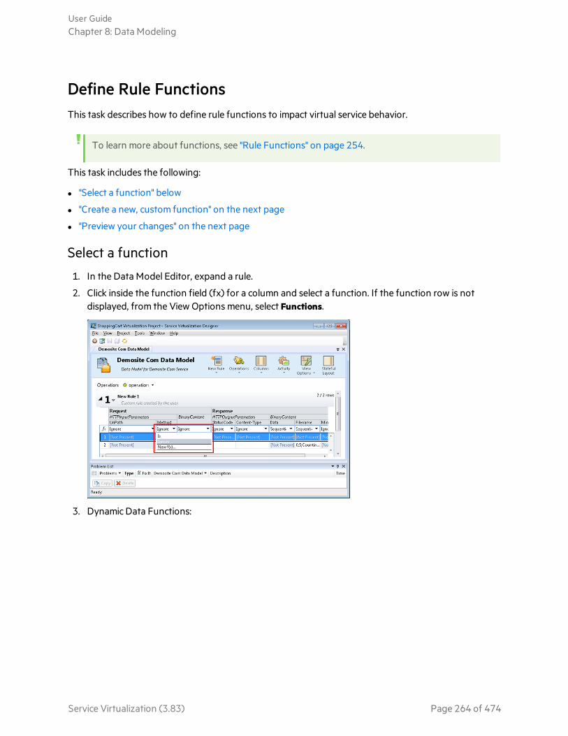
Define Rule FunctionsThis task describes how to define rule functions to impact virtual service behavior.
To learn more about functions, see "Rule Functions" on page 254.
This task includes the following:
l "Select a function" below
l "Create a new, custom function" on the next page
l "Preview your changes" on the next page
Select a function
1. In the Data Model Editor, expand a rule.
2. Click inside the function field (fx) for a column and select a function. If the function row is notdisplayed, from the View Options menu, select Functions.
3. Dynamic Data Functions:
User GuideChapter 8: Data Modeling
Service Virtualization (3.83) Page 264 of 474

a. Click inside the function field (fx) of a response column and select a function.
Note: Dynamic data functions are available for lowest level headers only. Complexheaders that include lower level headers under them are displayed in italic text(header). To display lower level headers, double-click the column header.
b. Configure the output format for the function. For details on configuring dynamic datafunctions, see "Configure Dynamic Data Functions" below.
Create a new, custom function
1. In the Data Model Editor, expand a rule.
2. Click inside the function field (fx) for a column and select New f(x). For user interface details, see"New/Edit Function Dialog Box" on page 318.
Custom Functions: Service Virtualization provides a number of pre-defined variables that you canuse when creating and configuring custom functions. For details, see "Define Custom Functions" onpage 281.
Preview your changes
Simulation Preview displays in real time how changes in the data model are affecting the simulation.
In the Data Model Editor, select View Options > Simulation Preview. The Simulation Preview panedisplays a simulation of a message whose request matches the currently selected message in the DataModel Editor. The message is passed to the simulation engine and the result is displayed in the responsesection.
Configure Dynamic Data FunctionsYou can configure the following data generator functions in Service Virtualization.
User GuideChapter 8: Data Modeling
Service Virtualization (3.83) Page 265 of 474

Data generator function How to
Sequential number generator "Configure the Sequential Number Generator Function" below
Random number generator "Configure the Random Number Generator Function" on page 271
Date/time functions "Configure the Date/Time Functions" on page 275
Substring function "Configure the Substring Function" on page 279
See also:l "Rule Functions" on page 254
Configure the Sequential Number Generator Function
This task describes how to configure the sequential number generator function.
This section includes:
l "Prerequisite: Select the function" below
l "Configure the function" on the next page
l "Format special sequences" on the next page
l "Examples" on page 269
Prerequisite: Select the function
1. In the Data Model Editor, expand a rule.
2. Click inside the function field (fx) of a response column and select Sequential number generator. Ifthe function row is not displayed, from the View Options menu, select Functions.
User GuideChapter 8: Data Modeling
Service Virtualization (3.83) Page 266 of 474

Note: Dynamic data functions are available for lowest level headers only. Complex headersthat include lower level headers under them are displayed in italic text (header). To displaylower level headers, double-click the column header.
Configure the function
In each cell under this function, enter a value in the following format:
Offset;Increment;FormatString
where:
l Offset is an integer. Used as the starting point for generating the output of the sequential numbergenerator.
Note: To generate a sequence of numbers that differs for each request/response, each cellwith this generator function has an internal numerical counter. When the simulation starts,this counter is always set to 0. Each time a generator function is called, the output value isdetermined based on the offset and counter. After the output is determined, the value of thecounter is increased by the value of the increment, or decreased if the increment is a negativenumber.
l Increment is a positive or negative integer. Indicates the change to make from one number in thesequence to the next.
l FormatString defines the format of the output of the sequential number generator.
The format string includes:
l a regular text string
l (optional) one or more special sequences to define the format of the numerical output of thegenerator
To determine the output of the number generator, Service Virtualization goes through the formatstring and constructs an output string using specific rules, explained below.
Format special sequences
Special sequences enable you define the format of the numerical output of the function.
You construct special sequences as follows:
l Each special sequence must start and end with the '#' character.
l Each special sequence must contain one or more ‘D’ characters. These characters act like a digitwildcard for a number that will be generated by this generator function. The number will alwaysoccupy exactly the number of specified digits. If the number does not occupy all digits, zeros areadded before it so that it does.
User GuideChapter 8: Data Modeling
Service Virtualization (3.83) Page 267 of 474

Example:
- If the special sequence is #DDDD#
- and the number generated by the function is 568
- the output is 0568.
l A special sequence may also contain 'd' characters. These characters act as placeholders. If the outputof the generator function requires this space, then it will hold a number. If the generated numberdoes not occupy all digits, then the extra spaces are left empty, and not populated with zeros. 'd'characters may only be placed before 'D' characters.
Example:
- If the special sequence is #ddDDD#
- and the number generated by the function is 9857
- the output is 9857.
For the number 125:
- the sequence #DDDDD# outputs 00125
- the sequence #ddDDD# outputs 125
- and the sequence ##dDDDD outputs 0125.
l You can construct a format string with multiple special sequences.
Example: You can enter a special sequence to resemble a credit card number format:
- if the special sequence is #DDDD#-#DDDD#-#DDDD#-#DDDD#
- and the number generated is 1234567812345678
- the output is 1234-5678-1234-5678
Service Virtualization defines the output of the generator according to the following additionalguidelines:
User GuideChapter 8: Data Modeling
Service Virtualization (3.83) Page 268 of 474

l If the number is greater than the maximal number that can be stored within the digits, it is truncatedso that it fits within (e.g. if the number was 3456 and the special sequence was #DDD#, the outputwill be 456).
l If the number is negative, it is truncated the same way as above. Then an additional offset is applied.The value of this offset is based on the number of digits and is selected so that -1 becomes thebiggest number that fits within these digits. For example, if the special sequence was #DDDDD#, -1becomes 99999. If it was #DD#, -67813 becomes -13 which then becomes 87.
l For each empty special sequence (when there are two ‘#’ characters next to each other), a single ‘#’character is inserted into the output string.
l The numerical output of the generator will be a number that has exactly as many digits as there are'D' characters in all of the special sequences in the field combined.
l Any characters that are not part of a special sequence are copied to the output string.
Examples
Example:Increasing sequence
The typical use case is generating strings that make use of an increasing number sequence.
Example: Your input, typed in the cell under the sequential number generator function:
0;1;Visitor###DDD#
will produce the sequence Visitor#000, Visitor#001, Visitor#002...
Decreasing sequence
In cases where remaining time or another resource that is being depleted may identify someobject, the decreasing sequences are used to generate such identifiers.
Example: The real service may be generating identifiers based on time remaining until someevent starts.
Your input, typed into cell under the sequential number generator function:
10000;-100;SnapshotTimeTMinus:#DDDDD#
This cell produces the output sequence: SnapshotTimeTMinus:10000,SnapshotTimeTMinus:09900, SnapshotTimeTMinus:09800, etc.
Multiple independent sequences
When generating several classes of identifiers for various products, you want to maintain an
User GuideChapter 8: Data Modeling
Service Virtualization (3.83) Page 269 of 474
independent sequence of identifiers for each class. You can achieve that by creating a separaterule for each class and use just one row in every rule. Use the Is function in the request todistinguish classes from each other. Each rule has a separate counter for the sequential numbergenerator function, so that the sequences are independent.
Example: The 3 product lines have to have easily distinguishable ids. Class 1 has the „1“ set asthe first digit, class 2 has 2 etc.
Rule 1, Row 1, your input typed in the cell: 100000;1;codeNR-#DDDDDD#
Rule 2, Row 1, your input typed in the cell: 200000;1; codeNR-#DDDDDD#
Rule 3, Row 1, your input typed in the cell: 300000;1; codeNR-#DDDDDD#
If the service requests IDs in the following sequence {1,2,2,1,3,2,3,1}, the output results are asfollows:
codeNR100000-, codeNR-200000, codeNR-200001, codeNR-100001, codeNR-300000,codeNR-200002, codeNR-300001, codeNR-100002
Multiple dependent sequences
Consider following the previous use case with just one rule containing all rows instead ofseparate rules. In such a case, the internal counter is shared. Therefore, the sequences are notindependent and the output relies on the previous sequence of calls even though they were nottriggering the current row.
Example:
Rule 1,Row 1,your input typed in the cell: 10;10;X1-#DDD#
Rule 1,Row 2, your input typed in the cell: 100;100;X2-#DDD#
If we invoke the virtual service hitting the Row1, Row2, Row1, the output is „X1-010; X2-110;X1-120“
If the two rows were in separate rules, the output would be: „X1-010; X2-100; X1-020“
Multiple number occurrences
It is possible to split the number that is being computed by SNG into multiple parts in the outputstring. This is achieved by repeating the #DDD# sequence. Note that the 'Ds' sequences within asingle row may differ in length.
Example: A cell with the following format, such as a credit card number format:
User GuideChapter 8: Data Modeling
Service Virtualization (3.83) Page 270 of 474

1234567890123456;1;#DDDD#-#DDDD#-#DDDD#-#DDDD#
produces the following output sequence:
1234-5678-9012-3456
1234-5678-9012-3457
1234-5678-9012-3458
1234-5678-9012-3459
See also:l "Rule Functions" on page 254
Configure the Random Number Generator Function
This task describes how to configure the random number generator function.
This section includes:
l "Prerequisite: Select the function" below
l "Configure the function" on the next page
l "Format special sequences" on the next page
l "Examples" on page 274
Prerequisite: Select the function
1. In the Data Model Editor, expand a rule.
2. Click inside the function field (fx) of a response column and select Random number generator. Ifthe function row is not displayed, from the View Options menu, select Functions.
User GuideChapter 8: Data Modeling
Service Virtualization (3.83) Page 271 of 474
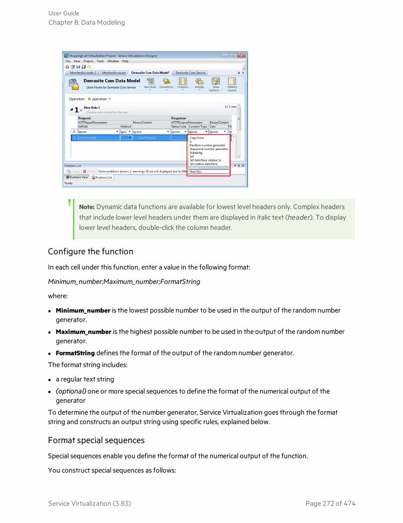
Note: Dynamic data functions are available for lowest level headers only. Complex headersthat include lower level headers under them are displayed in italic text (header). To displaylower level headers, double-click the column header.
Configure the function
In each cell under this function, enter a value in the following format:
Minimum_number;Maximum_number;FormatString
where:
l Minimum_number is the lowest possible number to be used in the output of the random numbergenerator.
l Maximum_number is the highest possible number to be used in the output of the random numbergenerator.
l FormatString defines the format of the output of the random number generator.
The format string includes:
l a regular text string
l (optional) one or more special sequences to define the format of the numerical output of thegenerator
To determine the output of the number generator, Service Virtualization goes through the formatstring and constructs an output string using specific rules, explained below.
Format special sequences
Special sequences enable you define the format of the numerical output of the function.
You construct special sequences as follows:
User GuideChapter 8: Data Modeling
Service Virtualization (3.83) Page 272 of 474
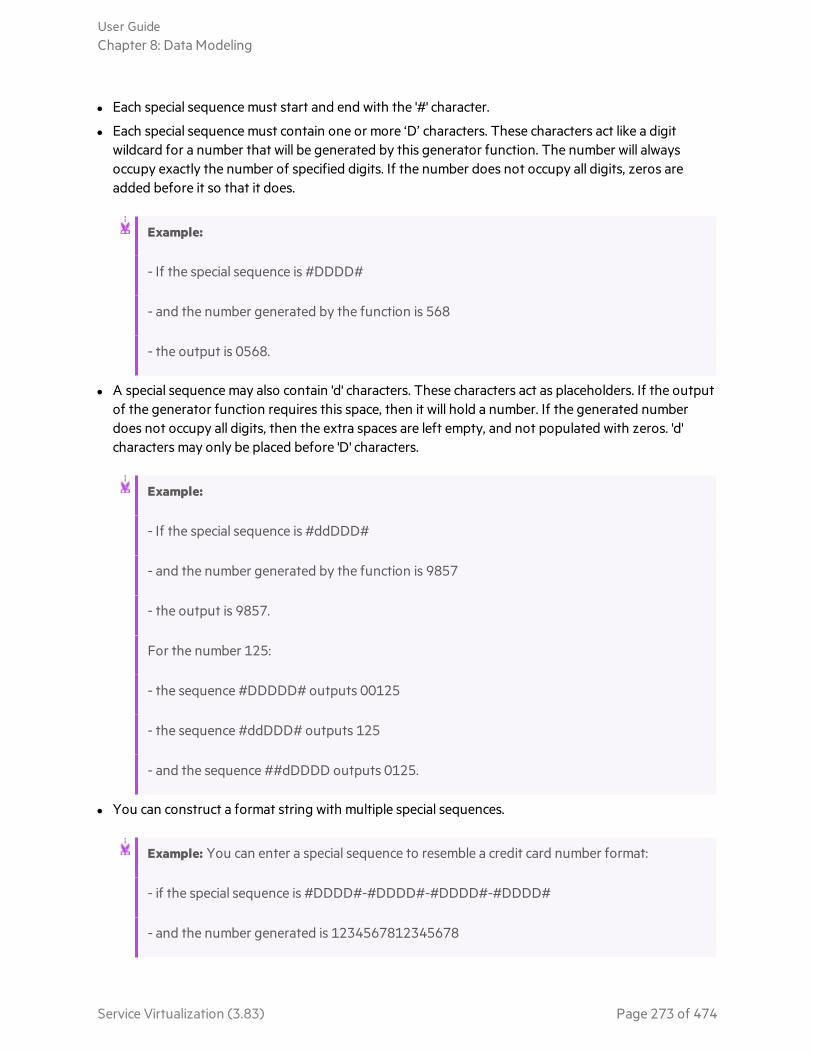
l Each special sequence must start and end with the '#' character.
l Each special sequence must contain one or more ‘D’ characters. These characters act like a digitwildcard for a number that will be generated by this generator function. The number will alwaysoccupy exactly the number of specified digits. If the number does not occupy all digits, zeros areadded before it so that it does.
Example:
- If the special sequence is #DDDD#
- and the number generated by the function is 568
- the output is 0568.
l A special sequence may also contain 'd' characters. These characters act as placeholders. If the outputof the generator function requires this space, then it will hold a number. If the generated numberdoes not occupy all digits, then the extra spaces are left empty, and not populated with zeros. 'd'characters may only be placed before 'D' characters.
Example:
- If the special sequence is #ddDDD#
- and the number generated by the function is 9857
- the output is 9857.
For the number 125:
- the sequence #DDDDD# outputs 00125
- the sequence #ddDDD# outputs 125
- and the sequence ##dDDDD outputs 0125.
l You can construct a format string with multiple special sequences.
Example: You can enter a special sequence to resemble a credit card number format:
- if the special sequence is #DDDD#-#DDDD#-#DDDD#-#DDDD#
- and the number generated is 1234567812345678
User GuideChapter 8: Data Modeling
Service Virtualization (3.83) Page 273 of 474
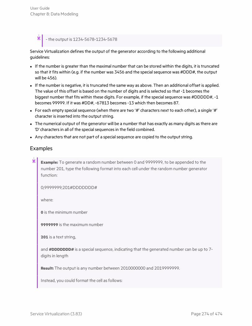
- the output is 1234-5678-1234-5678
Service Virtualization defines the output of the generator according to the following additionalguidelines:
l If the number is greater than the maximal number that can be stored within the digits, it is truncatedso that it fits within (e.g. if the number was 3456 and the special sequence was #DDD#, the outputwill be 456).
l If the number is negative, it is truncated the same way as above. Then an additional offset is applied.The value of this offset is based on the number of digits and is selected so that -1 becomes thebiggest number that fits within these digits. For example, if the special sequence was #DDDDD#, -1becomes 99999. If it was #DD#, -67813 becomes -13 which then becomes 87.
l For each empty special sequence (when there are two ‘#’ characters next to each other), a single ‘#’character is inserted into the output string.
l The numerical output of the generator will be a number that has exactly as many digits as there are'D' characters in all of the special sequences in the field combined.
l Any characters that are not part of a special sequence are copied to the output string.
Examples
Example: To generate a random number between 0 and 9999999, to be appended to thenumber 201, type the following format into each cell under the random number generatorfunction:
0;9999999;201#DDDDDDD#
where:
0 is the minimum number
9999999 is the maximum number
201 is a text string,
and #DDDDDDD# is a special sequence, indicating that the generated number can be up to 7-digits in length
Result: The output is any number between 2010000000 and 2019999999.
Instead, you could format the cell as follows:
User GuideChapter 8: Data Modeling
Service Virtualization (3.83) Page 274 of 474

0;9999999;201#dddDDDD#
Result: The output is any number between 2010000 and 2019999999.
See also:l "Rule Functions" on page 254
Configure the Date/Time Functions
This task describes how to configure the Set Relative Date/Time and the Set Date/Time Relative tofunctions.
This section includes:
l "Prerequisite: Select a date/time function" below
l "Configure the function" on the next page
l "Configure the offset" on the next page
l "Configure the date/time format" on page 277
Prerequisite: Select a date/time function
1. In the Data Model Editor, expand a rule.
2. Click inside the function field (fx) of a response column and select one of the following functions:
a. Set relative date/time. The date and/or time value is calculated by adjusting the date/timewhen the request was received, using an Offset that you define.
b. Set date/time relative to. The date and/or time value is calculated by adjusting a specifieddate/time, using an Offset that you define. This function requires you to select a source columnthat contains the date/time to be adjusted.
User GuideChapter 8: Data Modeling
Service Virtualization (3.83) Page 275 of 474
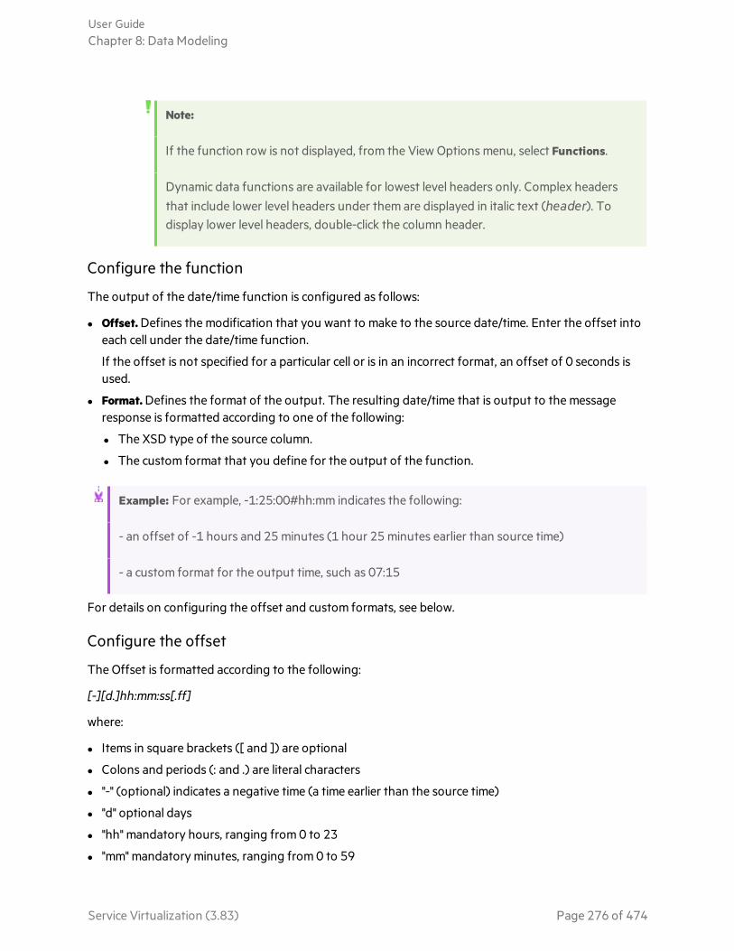
Note:
If the function row is not displayed, from the View Options menu, select Functions.
Dynamic data functions are available for lowest level headers only. Complex headersthat include lower level headers under them are displayed in italic text (header). Todisplay lower level headers, double-click the column header.
Configure the function
The output of the date/time function is configured as follows:
l Offset. Defines the modification that you want to make to the source date/time. Enter the offset intoeach cell under the date/time function.
If the offset is not specified for a particular cell or is in an incorrect format, an offset of 0 seconds isused.
l Format. Defines the format of the output. The resulting date/time that is output to the messageresponse is formatted according to one of the following:
l The XSD type of the source column.
l The custom format that you define for the output of the function.
Example: For example, -1:25:00#hh:mm indicates the following:
- an offset of -1 hours and 25 minutes (1 hour 25 minutes earlier than source time)
- a custom format for the output time, such as 07:15
For details on configuring the offset and custom formats, see below.
Configure the offset
The Offset is formatted according to the following:
[-][d.]hh:mm:ss[.ff]
where:
l Items in square brackets ([ and ]) are optional
l Colons and periods (: and .) are literal characters
l "-" (optional) indicates a negative time (a time earlier than the source time)
l "d" optional days
l "hh" mandatory hours, ranging from 0 to 23
l "mm" mandatory minutes, ranging from 0 to 59
User GuideChapter 8: Data Modeling
Service Virtualization (3.83) Page 276 of 474

l "ss" mandatory seconds, ranging from 0 to 59
l "ff" optional fractional seconds, consisting of 1 to 7 decimal digits
Example:
l -54.12:00:59.1234567
l 0:00:00.001
l 365.0:00:00
Note: If you are using the set relative date/time function, the resulting date is generatedaccording to the UTC+0 time zone.
Examples:
You are located in UTC-8 and have created a function with an offset of +1 day.
At 20:00 (8:00 P.M.), the generated relative time will be 4:00 (4 A.M.) the day after tomorrow,calculated as follows:
20:00(today) + 1 day (your requested offset) + 8 hours (to adjust for your time zone) =4:00 (the day after tomorrow)
To maintain the same date/time as your time zone, adjust for the difference using theoffset.
For example, if you are located in UTC-8 and you want to define +1 day offset, you must alsosubtract 8 hours, as follows:
16:00:00#dd-MM-yyyy# (where 16:00:00 represents 1 day - 8 hours)
For an offset of +1 day, if you are located in the UTC+2 time zone:
1:02:00:00#dd-MM-yyyy# (where 1:02:00:00 represents 1 day + 2 hours)
Configure the date/time format
Service Virtualization can set the format based on autodetection of the XSD type, or by a customformat that you enter.
XSD Type
Service Virtualization can auto-detect the following XSD date/time types
User GuideChapter 8: Data Modeling
Service Virtualization (3.83) Page 277 of 474

l xsi:date - "yyyy-MM-dd" (Example of output: 1984-11-28)
l xsi:time - "HH:mm:ss" (Example of output: 23:59:59)
l xsi:dateTime - "yyyy-MM-ddThh:mm:ss" (Example of output: 2001-12-13T10:15:33)
If detected, the format of the output of the date/time function is based on the XSD type, provided thatyou have not defined a custom format.
No other formats, including JSON date/time formats, can be detected, as their internal type is xsi:string.If the application cannot detect the format from the element's type, xsi:dateTime's format is used bydefault. If you want to specify other output formats, you can define a custom format.
Custom Format
To configure a custom format, enter the following into each cell under the date/time function:
Offset#CustomFormat
You define a custom format using the following:
l "d" - The day of the month, from 1 through 31.
l "dd" - The day of the month, from 01 through 31.
l "f" .. "fffffff" - Fractions of a second, number of "f" characters specifies number of digits to print.
l "h" - The hour, using a 12-hour clock from 1 to 12.
l "hh" - The hour, using a 12-hour clock from 01 to 12.
l "H" - The hour, using a 24-hour clock from 0 to 23.
l "HH" - The hour, using a 24-hour clock from 00 to 23.
l "m" - The minute, from 0 through 59.
l "mm" - The minute, from 00 through 59.
l "M" - The month, from 1 through 12.
l "MM" - The month, from 01 through 12.
l "s" - The second, from 0 through 59.
l "ss" - The second, from 00 through 59.
l "tt" - The AM/PM designator.
l "yyyy" - The year, four digit number.
l regular characters (all characters except the ones mentioned above) - generated "as is". To generate acharacter that has a special meaning (is part of one of the custom formats above, such as “s”), place a'\' before it.
Example:
If today's date is December 10, 2012:
User GuideChapter 8: Data Modeling
Service Virtualization (3.83) Page 278 of 474
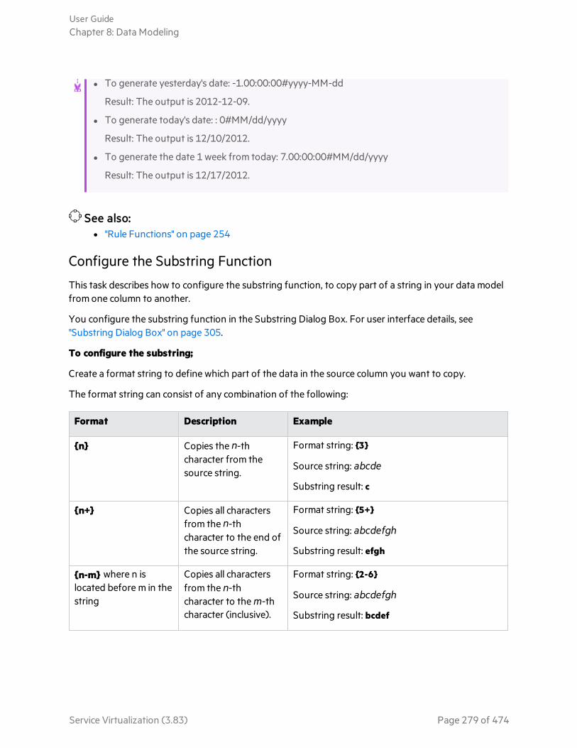
l To generate yesterday's date: -1.00:00:00#yyyy-MM-dd
Result: The output is 2012-12-09.
l To generate today's date: : 0#MM/dd/yyyy
Result: The output is 12/10/2012.
l To generate the date 1 week from today: 7.00:00:00#MM/dd/yyyy
Result: The output is 12/17/2012.
See also:l "Rule Functions" on page 254
Configure the Substring Function
This task describes how to configure the substring function, to copy part of a string in your data modelfrom one column to another.
You configure the substring function in the Substring Dialog Box. For user interface details, see"Substring Dialog Box" on page 305.
To configure the substring;
Create a format string to define which part of the data in the source column you want to copy.
The format string can consist of any combination of the following:
Format Description Example
{n} Copies the n-thcharacter from thesource string.
Format string: {3}
Source string: abcde
Substring result: c
{n+} Copies all charactersfrom the n-thcharacter to the end ofthe source string.
Format string: {5+}
Source string: abcdefgh
Substring result: efgh
{n-m} where n islocated before m in thestring
Copies all charactersfrom the n-thcharacter to the m-thcharacter (inclusive).
Format string: {2-6}
Source string: abcdefgh
Substring result: bcdef
User GuideChapter 8: Data Modeling
Service Virtualization (3.83) Page 279 of 474
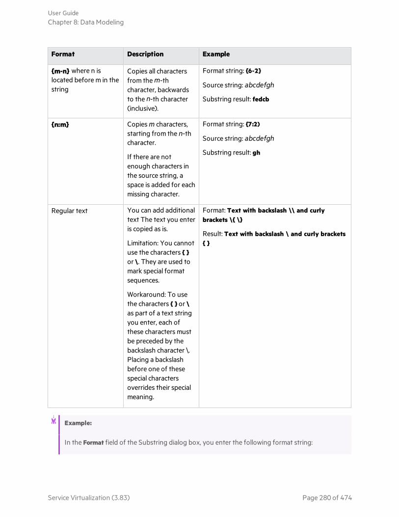
Format Description Example
{m-n} where n islocated before m in thestring
Copies all charactersfrom the m-thcharacter, backwardsto the n-th character(inclusive).
Format string: {6-2}
Source string: abcdefgh
Substring result: fedcb
{n:m} Copies m characters,starting from the n-thcharacter.
If there are notenough characters inthe source string, aspace is added for eachmissing character.
Format string: {7:2)
Source string: abcdefgh
Substring result: gh
Regular text You can add additionaltext The text you enteris copied as is.
Limitation: You cannotuse the characters { }or \. They are used tomark special formatsequences.
Workaround: To usethe characters { } or \as part of a text stringyou enter, each ofthese characters mustbe preceded by thebackslash character \.Placing a backslashbefore one of thesespecial charactersoverrides their specialmeaning.
Format: Text with backslash \\ and curlybrackets \{ \}
Result: Text with backslash \ and curly brackets{ }
Example:
In the Format field of the Substring dialog box, you enter the following format string:
User GuideChapter 8: Data Modeling
Service Virtualization (3.83) Page 280 of 474

All characters:{1+}. Only 6th and 8th characters: {6}{8}. Result of \{5:5\} is: {5:5}. First 13characters reversed: {13-1}.
The source string is: 123456789ABCDEF
The result, output to the cell configured with the substring function is:
All characters:123456789ABCDEF. Only 6th and 8th characters: 68. Result of {5:5} is:56789. First 13 characters reversed: DCBA987654321.
See also:l "Rule Functions" on page 254
Define Custom FunctionsYou can create new functions to use in a data model. For user interface details, see "New/EditFunction Dialog Box" on page 318.
Note: Custom functions are executed directly on the database layer. If your existing virtualservices contain custom functions, changing the database provider from MS SQL to Oracle orvice versa during installation or upgrade can render them non-functional.
Custom function variables
You can use the following variables to configure a new, custom function:
Variable Description
$input_string
The original string is automatically quoted in the place of usage.
$input_string_unquoted
The original string is not automatically quoted.
$input_int The original string is converted to the int data type, for integer data. It containsNULL if the input string is not of this data type.
$input_float The original string is converted to the float data type, for floating point numericdata. It contains NULL if the input string is not of this data type.
User GuideChapter 8: Data Modeling
Service Virtualization (3.83) Page 281 of 474
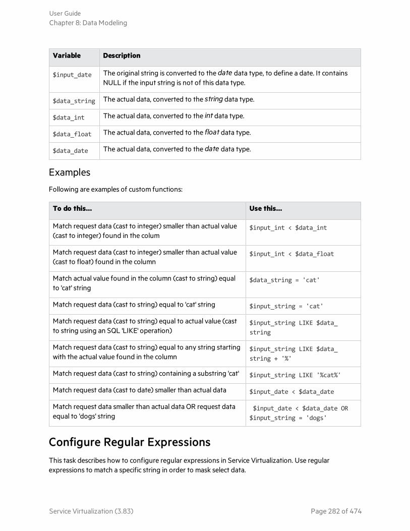
Variable Description
$input_date The original string is converted to the date data type, to define a date. It containsNULL if the input string is not of this data type.
$data_string The actual data, converted to the string data type.
$data_int The actual data, converted to the int data type.
$data_float The actual data, converted to the float data type.
$data_date The actual data, converted to the date data type.
Examples
Following are examples of custom functions:
To do this... Use this...
Match request data (cast to integer) smaller than actual value(cast to integer) found in the colum
$input_int < $data_int
Match request data (cast to integer) smaller than actual value(cast to float) found in the column
$input_int < $data_float
Match actual value found in the column (cast to string) equalto 'cat' string
$data_string = 'cat'
Match request data (cast to string) equal to 'cat' string $input_string = 'cat'
Match request data (cast to string) equal to actual value (castto string using an SQL 'LIKE' operation)
$input_string LIKE $data_string
Match request data (cast to string) equal to any string startingwith the actual value found in the column
$input_string LIKE $data_string + '%'
Match request data (cast to string) containing a substring 'cat' $input_string LIKE '%cat%'
Match request data (cast to date) smaller than actual data $input_date < $data_date
Match request data smaller than actual data OR request dataequal to 'dogs' string
$input_date < $data_date OR$input_string = 'dogs'
Configure Regular ExpressionsThis task describes how to configure regular expressions in Service Virtualization. Use regularexpressions to match a specific string in order to mask select data.
User GuideChapter 8: Data Modeling
Service Virtualization (3.83) Page 282 of 474

In the Replace Algorithm Configuration dialog box, you can enter a regular expression in the Matchpattern and Replace value fields. (For user interface details, see "Replace Algorithm ConfigurationDialog Box" on page 207.)
In addition, when you use regular expressions in the Replace value field, the expression can referencegroups from the search pattern you entered in the Match pattern field.
Example:
Match pattern fieldReplace valuefield
Sampleinput
Sampleoutput
\b(\w+)(\s)(\w+)\b $3$2$1 one two two one
\b(?<word1>\w+)(\s)(?<word2>\w+)\b
${word2}${word1}
one two two one
For information on creating regular expressions and some examples of their use, visit this site: RegularExpression Language - Quick Reference.
Work With External Data SourcesThis task describes how to work with an external data source to import or export data.
This task includes the following steps:
"Add an external data file" below
"Bind the data" on the next page
"Bind array data" on page 285
"Bind other data" on page 285
"Configure import/export settings" on page 285
"Refresh the data" on page 285
"Change the path of the data source" on page 285
"Disconnect external data" on page 286
Add an external data file
You can associate a data rule with an external data file in order to import or export data.
In the Data Model Editor, select New Rule > Data Driven Rule. Select one of the following options:
User GuideChapter 8: Data Modeling
Service Virtualization (3.83) Page 283 of 474

Create new data file. The Service Virtualization Designer creates a new Excel file, structured accordingto the schema (message structure) associated with the virtual service. Rule columns are automaticallybound to the worksheet columns.
Use existing data file. You must then manually bind rule columns to worksheet columns. After binding,the external data is imported to the Data Model.
For details, see "New Data Driven Rule Dialog Box" on page 313.
Result: A "preview" of your external data file displays within the rule.
Note that the worksheets in the external file are displayed as tabs at the bottom of the data table.
Bind the data
If you selected an existing data file, you must bind the data. You create mappings between the datacolumns in the external file, and the columns/headers in your data rule.
1. In a column header, click bind data. If it is not visible, click View Options > Data Binding.
Headers must be expanded down to the lowest level in order to bind.
2. Click a column in the displayed external data source table to bind that column.
3. Repeat steps a and b for all columns you need to bind.
4. Click OK. The data is imported.
User GuideChapter 8: Data Modeling
Service Virtualization (3.83) Page 284 of 474

Bind array data
When the message structure contains an array that needs to be data-driven, you need to work with aproperly structured Excel file. The file must contain database-like relationships, using primary andforeign keys, which allow the mapping of one row to many.
When binding an array item, the Edit Sheet Relations dialog box opens automatically, enabling you todefine the relationships between worksheets that are required for array binding. . For user interfacedetails, see "Edit Sheet Relations Dialog Box" on page 321.
Alternatively, right-click the rule or column header and select External Data Properties. See the SheetRelations area.
Bind other data
You can configure binding for working with different data formats (REST protocol), different responsetypes (SOAP protocol), or a message structure containing different types.
When you start to bind to an Excel worksheet column where the response can contain these types ofdata, the relevant dialog box opens automatically (The Data Format, Response Type, or Choice DataBinding dialog boxes). For user interface details, see "Data Format/Response Type/Choice BindingDialog Box" on page 323.
Configure import/export settings
You can configure rules to import or export data, or configure settings for rules already associated withan external data file.
Learned Datarule
To export learned data, right-click the Learned Data rule and select Export Data.
Blank/customrule
To import data from or export data to an external data file, right-click the rule andselect Import Data or Export Data.
Data drivenrule
For a rule already associated with an external file, you can change settings. Right-click the rule and select External Data Properties.
Refresh the data
If you have selected the Data Synchronization option for your rule, the data is automatically re-imported or exported.
To manually refresh data, right-click the rule and select Refresh Data. The data is imported or exported,depending on how the rule is configured.
Change the path of the data source
To change the location of the external data file, right-click the rule and select External Data Properties.
User GuideChapter 8: Data Modeling
Service Virtualization (3.83) Page 285 of 474

Disconnect external data
To disconnect a rule from an external data source and remove bindings, right-click the rule and selectDisconnect External Data.
See also:l "Modify Virtual Service Behavior" on page 261
l "Data Driving" on page 257
l "Working with External Data Sources - Use-case Example" below
Working with External Data Sources - Use-case Example
This section provides an example of working with an external data file.
Note: For a task related to this example, see "Work With External Data Sources" on page 283.
It can be difficult to manually configure an Excel worksheet when your data has a particular complexstructure. As an alternative to manually setting up a file and configuring binding in the Data Model, youcan create a new data driven rule, and have Service Virtualization create a new data file for you,according to your message structure.
1. Create a virtual service.
2. In the Data Model, create a new data driven rule and select Create new data file. ServiceVirtualization will create the new file according to your message structure, and bind the columns.
3. Select Data Synchronization to automatically re-import data in the new file before Simulation.
Alternatively, clear the Data Synchronization check box. You can choose to import at a later time.
4. After the new data file is created, you can add data to it. If you selected Data Synchronization,when you place your virtual service into Simulating mode, the external data is re-imported. If youdid not select Data Synchronization, you can choose to refresh the data manually at any time, orreconfigure the rule for data synchronization.
Call External ServicesThis task describes how to configure a virtual service to call external services.
Note:
l This task is part of a higher-level task. For details, see "Modify Virtual Service Behavior" onpage 261.
l Service call activity is supported for:
User GuideChapter 8: Data Modeling
Service Virtualization (3.83) Page 286 of 474
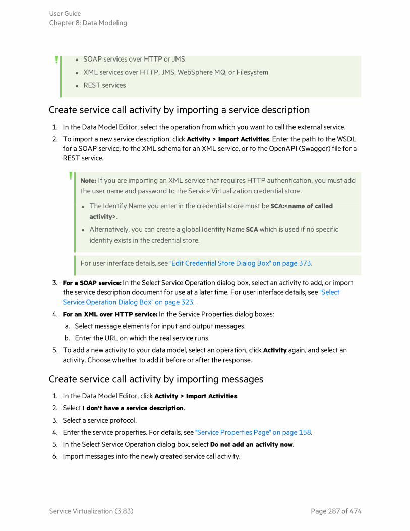
l SOAP services over HTTP or JMS
l XML services over HTTP, JMS, WebSphere MQ, or Filesystem
l REST services
Create service call activity by importing a service description
1. In the Data Model Editor, select the operation from which you want to call the external service.
2. To import a new service description, click Activity > Import Activities. Enter the path to the WSDLfor a SOAP service, to the XML schema for an XML service, or to the OpenAPI (Swagger) file for aREST service.
Note: If you are importing an XML service that requires HTTP authentication, you must addthe user name and password to the Service Virtualization credential store.
l The Identify Name you enter in the credential store must be SCA:<name of calledactivity>.
l Alternatively, you can create a global Identity Name SCA which is used if no specificidentity exists in the credential store.
For user interface details, see "Edit Credential Store Dialog Box" on page 373.
3. For a SOAP service: In the Select Service Operation dialog box, select an activity to add, or importthe service description document for use at a later time. For user interface details, see "SelectService Operation Dialog Box" on page 323.
4. For an XML over HTTP service: In the Service Properties dialog boxes:
a. Select message elements for input and output messages.
b. Enter the URL on which the real service runs.
5. To add a new activity to your data model, select an operation, click Activity again, and select anactivity. Choose whether to add it before or after the response.
Create service call activity by importing messages
1. In the Data Model Editor, click Activity > Import Activities.
2. Select I don't have a service description.
3. Select a service protocol.
4. Enter the service properties. For details, see "Service Properties Page" on page 158.
5. In the Select Service Operation dialog box, select Do not add an activity now.
6. Import messages into the newly created service call activity.
User GuideChapter 8: Data Modeling
Service Virtualization (3.83) Page 287 of 474
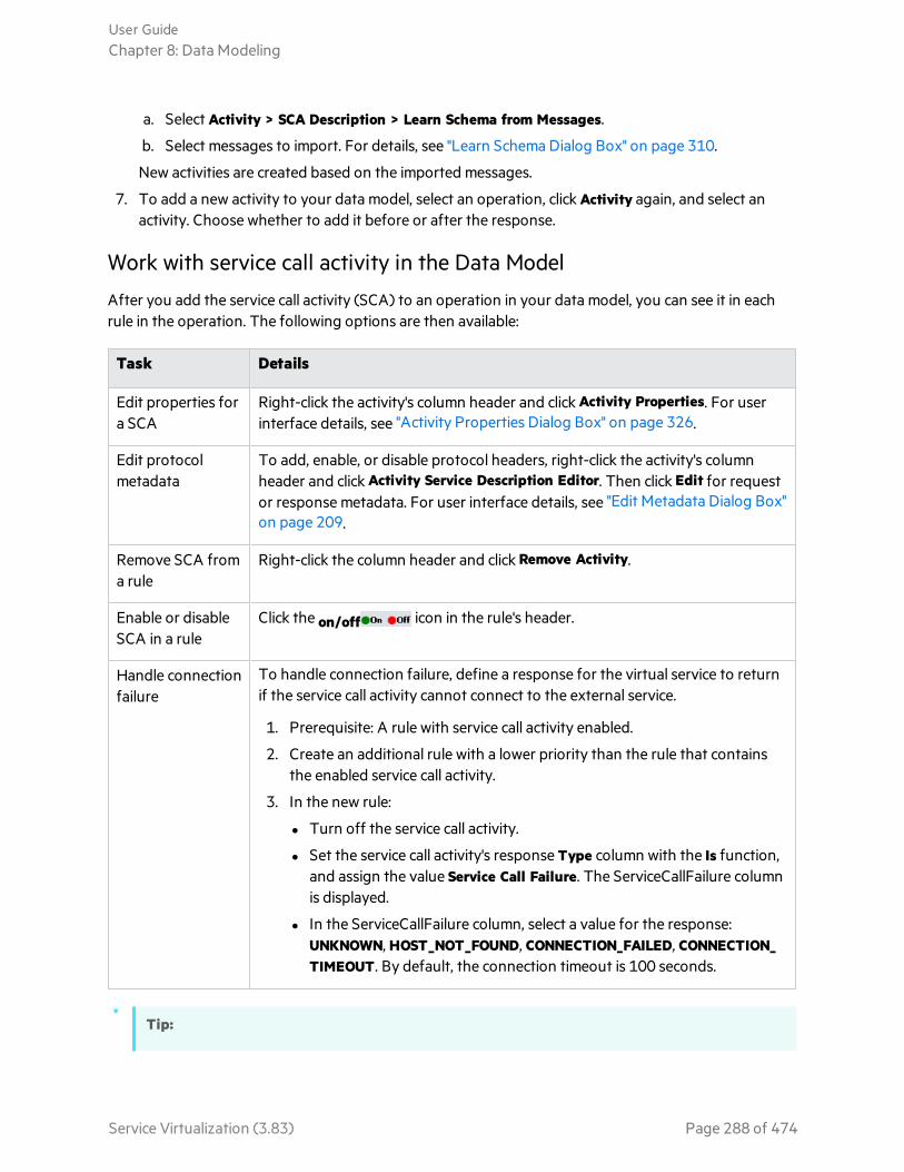
a. Select Activity > SCA Description > Learn Schema from Messages.
b. Select messages to import. For details, see "Learn Schema Dialog Box" on page 310.
New activities are created based on the imported messages.
7. To add a new activity to your data model, select an operation, click Activity again, and select anactivity. Choose whether to add it before or after the response.
Work with service call activity in the Data Model
After you add the service call activity (SCA) to an operation in your data model, you can see it in eachrule in the operation. The following options are then available:
Task Details
Edit properties fora SCA
Right-click the activity's column header and click Activity Properties. For userinterface details, see "Activity Properties Dialog Box" on page 326.
Edit protocolmetadata
To add, enable, or disable protocol headers, right-click the activity's columnheader and click Activity Service Description Editor. Then click Edit for requestor response metadata. For user interface details, see "Edit Metadata Dialog Box"on page 209.
Remove SCA froma rule
Right-click the column header and click Remove Activity.
Enable or disableSCA in a rule
Click the on/off icon in the rule's header.
Handle connectionfailure
To handle connection failure, define a response for the virtual service to returnif the service call activity cannot connect to the external service.
1. Prerequisite: A rule with service call activity enabled.
2. Create an additional rule with a lower priority than the rule that containsthe enabled service call activity.
3. In the new rule:
l Turn off the service call activity.
l Set the service call activity's response Type column with the Is function,and assign the value Service Call Failure. The ServiceCallFailure columnis displayed.
l In the ServiceCallFailure column, select a value for the response:UNKNOWN, HOST_NOT_FOUND, CONNECTION_FAILED, CONNECTION_TIMEOUT. By default, the connection timeout is 100 seconds.
Tip:
User GuideChapter 8: Data Modeling
Service Virtualization (3.83) Page 288 of 474

l You can use the Copy from function on any service call request column, or virtual serviceresponse column. Select the Copy from function. The columns that you can use as a sourceare highlighted. Click the desired source column.
l Use the Row Detail dialog box for easier configuration of the service call activity. For details,see "Row Detail Dialog Box" on page 303.
Assess Change ImpactThis task describes how to test the impact that changes in the data model have on simulation.
This task includes the following:
l "Open the Simulation Preview pane" below
l "Test the impact of a change on the simulation" below
l "Troubleshoot" below
Open the Simulation Preview pane
In the Data Model Editor, select View Options > Simulation Preview. For user interface details, see"Simulation Preview Pane" on page 302.
Preview a simulated response
1. Open Simulation Preview.
2. Select a row in a data rule. The simulated response is displayed.
3. Edit the request data to view the impact on the response.
Test the impact of a change on the simulation
1. Open Simulation Preview.
2. Select a row in a data rule.
3. Click to pin the row to Simulation Preview.
4. Select an existing row in a data rule, or create a custom rule with a higher priority to view the impacton the simulation.
5. View the impact on the message response in the pinned row in Simulation Preview.
Troubleshoot
If you have a message request that is not matching any rule in your data model, you can compare it torows in the data rules to look for a problem in your rule definitions.
User GuideChapter 8: Data Modeling
Service Virtualization (3.83) Page 289 of 474

1. Open Simulation Preview.
2. Do one of the following:
a. Select an existing row in a data rule.
b. Right-click in Simulation Preview and select Import Request.
3. Click to pin the row to Simulation Preview.
4. Select another row in a data rule to compare the two rows.
5. Click Show Differences to highlight the differences in the Data Model Editor table.
Note: The columns displayed in the Data Model Editor table may change when you arecomparing rows. To restore the display the previously defined column settings, click RestoreColumns.
See also:l "Simulation Preview" on page 258
Data Model User InterfaceThis section includes:
• Data Model Editor 291• Data Model Editor Context Menus 297• Data Model Editor Options Page 301• Simulation Preview Pane 302• Row Detail Dialog Box 303• Substring Dialog Box 305• Import Request/Response Message Dialog Box 307• Replace Request/Response Message Dialog Box 309• Learn Schema Dialog Box 310• Export Rows Dialog Box 311• Request/Response Pairing Dialog Box 312• New Data Driven Rule Dialog Box 313• Import/Export Data Dialog Box 314• External Data Properties Dialog Box 317• New/Edit Function Dialog Box 318• Change Columns Dialog Box 319• Edit Sheet Relations Dialog Box 321• Data Format/Response Type/Choice Binding Dialog Box 323• Select Service Operation Dialog Box 323• Service Properties for XML Service Call Activity 325• Activity Properties Dialog Box 326
User GuideChapter 8: Data Modeling
Service Virtualization (3.83) Page 290 of 474

Data Model EditorThe Data Model Editor enables you to view and edit a data model. You can configure requests,responses, and service activity calls for individual operations of a virtual service.
To access Use one of the following:
l In the Virtualization Explorer, double-click a data model.
l In the Virtual Service Editor, under Data Models, select a data model and click Edit.
Importantinformation
l Many of the actions you can perform in the Data Model Editor are available onlyfrom context menus. For details, see "Data Model Editor Context Menus" on page297.
l Service Virtualization supports MIME attachments that are recorded during learningof the real service behavior, for services using the following protocols over HTTP:REST, SOAP, binary, and XML services
Tip:
l To search the data model, click Ctrl+F.
l To find and replace data, click Ctrl+H.
l To access the Data Model Editor menus, press the Alt key and press anumber from 1 - 6. For example, to open the View Options menu, press Alt+ 5.
User GuideChapter 8: Data Modeling
Service Virtualization (3.83) Page 291 of 474
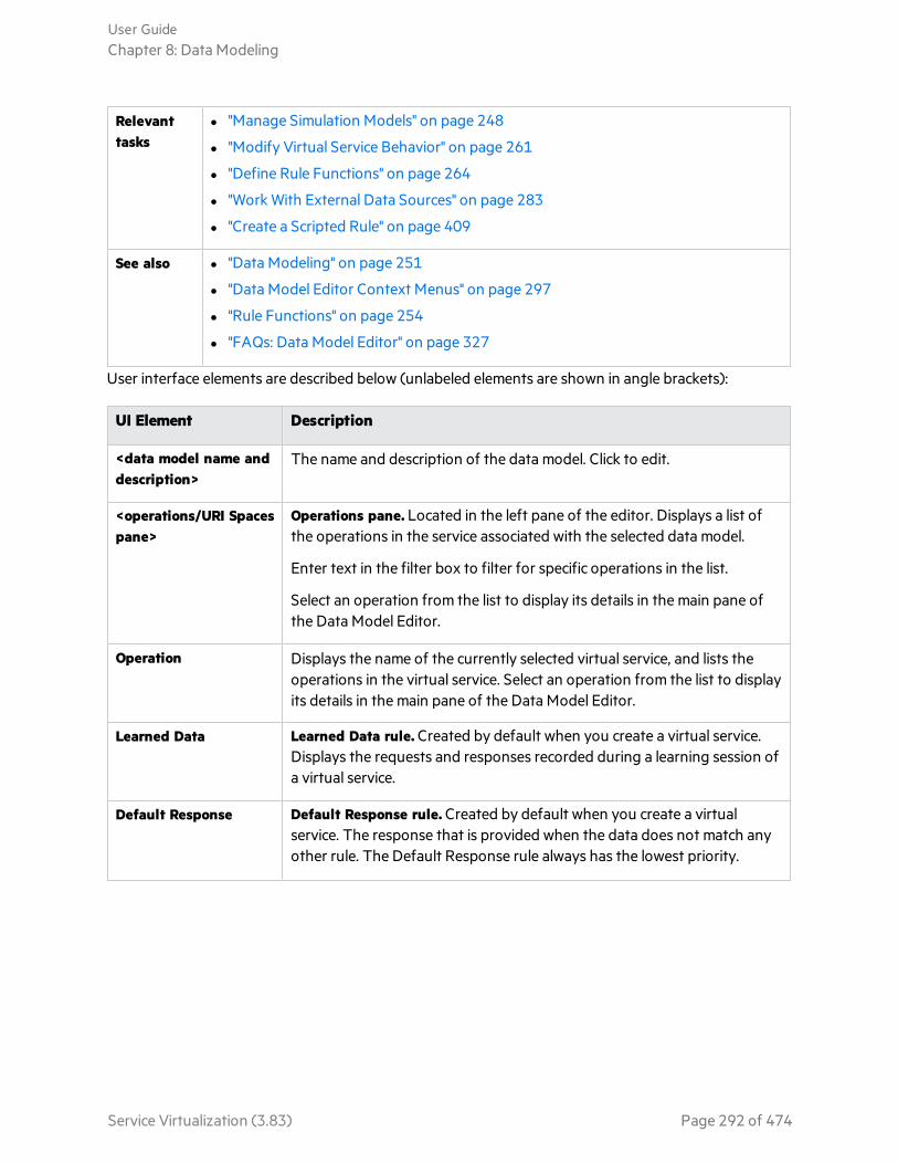
Relevanttasks
l "Manage Simulation Models" on page 248
l "Modify Virtual Service Behavior" on page 261
l "Define Rule Functions" on page 264
l "Work With External Data Sources" on page 283
l "Create a Scripted Rule" on page 409
See also l "Data Modeling" on page 251
l "Data Model Editor Context Menus" on page 297
l "Rule Functions" on page 254
l "FAQs: Data Model Editor" on page 327
User interface elements are described below (unlabeled elements are shown in angle brackets):
UI Element Description
<data model name anddescription>
The name and description of the data model. Click to edit.
<operations/URI Spacespane>
Operations pane. Located in the left pane of the editor. Displays a list ofthe operations in the service associated with the selected data model.
Enter text in the filter box to filter for specific operations in the list.
Select an operation from the list to display its details in the main pane ofthe Data Model Editor.
Operation Displays the name of the currently selected virtual service, and lists theoperations in the virtual service. Select an operation from the list to displayits details in the main pane of the Data Model Editor.
Learned Data Learned Data rule. Created by default when you create a virtual service.Displays the requests and responses recorded during a learning session ofa virtual service.
Default Response Default Response rule. Created by default when you create a virtualservice. The response that is provided when the data does not match anyother rule. The Default Response rule always has the lowest priority.
User GuideChapter 8: Data Modeling
Service Virtualization (3.83) Page 292 of 474
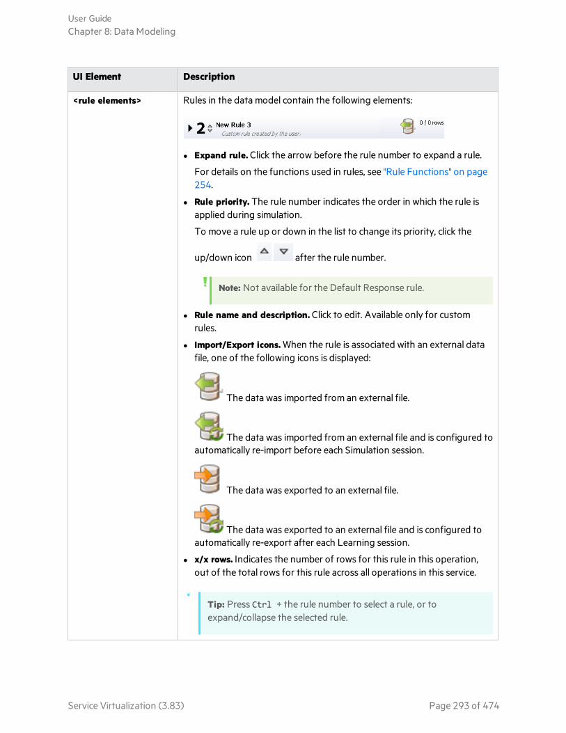
UI Element Description
<rule elements> Rules in the data model contain the following elements:
l Expand rule. Click the arrow before the rule number to expand a rule.
For details on the functions used in rules, see "Rule Functions" on page254.
l Rule priority. The rule number indicates the order in which the rule isapplied during simulation.
To move a rule up or down in the list to change its priority, click the
up/down icon after the rule number.
Note: Not available for the Default Response rule.
l Rule name and description. Click to edit. Available only for customrules.
l Import/Export icons. When the rule is associated with an external datafile, one of the following icons is displayed:
The data was imported from an external file.
The data was imported from an external file and is configured toautomatically re-import before each Simulation session.
The data was exported to an external file.
The data was exported to an external file and is configured toautomatically re-export after each Learning session.
l x/x rows. Indicates the number of rows for this rule in this operation,out of the total rows for this rule across all operations in this service.
Tip: Press Ctrl + the rule number to select a rule, or toexpand/collapse the selected rule.
User GuideChapter 8: Data Modeling
Service Virtualization (3.83) Page 293 of 474

UI Element Description
Enables you to create a new custom rule. Custom rules apply to alloperations in the service. Includes the following options:
l Blank Rule. Enables you to create a new, custom rule with an embeddeddata source, used to modify some aspect of simulation, such as torewrite part of the response, add service call activity, or add more data.
The blank rule can be added before or after the default Learned Datarule.
l Scripted Rule (Beta). Enables you to create a new, custom rule with ascript to access request data and set response data. For details, see"Scripted Rules" on page 409.
Note: Scripted rules are a Service Virtualization Labs feature.This field is displayed only if you have enabled the feature. Fordetails, see "Service Virtualization Labs" on page 407.
l Data Driven Rule. Opens the New Data Drive Rule dialog box, enablingyou to create a new rule using an external file as a data source, such asan Excel file. A new read-only rule is created for this data source.
Select the data source file, and assign a name to the data source.
Select First row contains names of columns to use the header row ofthe source file for the rule's column names.
The data driven rule can be added before or after the default LearnedData rule.
For more details on rules, see "Rule Functions" on page 254.
User GuideChapter 8: Data Modeling
Service Virtualization (3.83) Page 294 of 474

UI Element Description
Depending on the virtual service, displays options for the operations orURI spaces defined in the virtual service.
Includes the following options:
l Browse and Search Operations/URI Spaces. Opens the Operations pane,displaying the list of operations included in the service.
In the search box, enter a name or part of a name to search and filter forspecific operations in the list.
Select an operation from the list to display its details in the main pane ofthe Data Model Editor.
l Edit Operations/URI Spaces. Opens the Service Description Editor,enabling you to modify the operations or URI spaces, their dataformats, and metadata. For details, see "Service Description Editor" onpage 197.
Note: Available only for supported protocols.
l Recently Used Operations/URI Spaces. Lists your most recently usedoperations or URI spaces, allowing you quick access.
Includes the following options:
l Change Columns. Opens the Change Columns dialog box, enabling youto select the headers to display for the operation. For details, see"Change Columns Dialog Box" on page 319.
l Flat/Structured Headers. Toggles between flat and structured columnheaders.
Includes the following option:
Insert Path. Enables you to select a path to a Service Virtualizationelement, and add it to a scripted rule.
Note: Scripted rules are a Service Virtualization Labs feature. Thisfield is displayed only if you have enabled the feature. For details,see "Service Virtualization Labs" on page 407.
User GuideChapter 8: Data Modeling
Service Virtualization (3.83) Page 295 of 474

UI Element Description
Enables you to configure the virtual service to call an external service:
l Import Activities. Opens the Import Real Service Description dialog box,enabling you to import a service description of a service whoseoperations you can use as service call activities.
Available for: SOAP and XML over HTTP.
Note: After import, the on/off icon displays in the activity columnheader in the rule, enabling you to enable/disable the service callfor the rule.
Includes the following options:
l Functions. Displays the function row within rules, enabling you to setconditions for data columns.
l Highlight Columns. Displays column headers in different colorsaccording to function type: Action, Condition, and Ignore.
Default value: Off.
To change the colors or restore the default color coding, from the mainmenu, select Tools > Options, and click the Data Model Editor tab. Fordetails, see "Data Model Editor Options Page" on page 301.
l Data Binding. Displays the data binding row within rules, enabling youto configure binding. For more details, see "Data Driving" on page 257.
l Time Stamp. Displays the time stamp column within rules, which showsthe time of creation or last modification of the rule.
l Operations/URI Spaces Pane. Opens the Operations/URI Spaces pane,displaying the list of operations/URI spaces included in the service.
l Simulation Preview. Displays how changes in the data model areaffecting the simulation. For user interface details, see "SimulationPreview Pane" on page 302.
User GuideChapter 8: Data Modeling
Service Virtualization (3.83) Page 296 of 474

UI Element Description
Displays the Track Position column within rules, and opens the track paneon the right side of the editor. For details, see "Stateful Layout View" onpage 334.
For details on simulating stateful behavior, see "Simulate a StatefulService" on page 332.
Data Model Editor Context MenusYou can perform additional actions on rules in the Data Model Editor by accessing the context menus.
To access Right-click a rule, column header, or row and select an option.
See also l "Data Model Editor" on page 291
l "Data Modeling" on page 251
Relevant tasks l "Modify Virtual Service Behavior" on page 261
l "Create a Scripted Rule" on page 409
User interface elements are described below.
Rule actions
The following items are available when you right-click a rule.
UI Element Description
DeleteRule
Deletes the selected rule.
Available for: Custom rules
DisableRule
Deactivates the selected rule. The rule is not applied during simulation.
To reactivate the rule, right-click and select Enable Rule.
DisconnectExternalData
Disconnects the rule from the external data file with which it is synchronizing. Thisdiscontinues any import/export actions.
Available for: Data driven rules
User GuideChapter 8: Data Modeling
Service Virtualization (3.83) Page 297 of 474

UI Element Description
DuplicateRule
Creates a copy of the rule. This can be useful when you want to work on modifying arule while leaving the original rule intact.
ExportData
Opens the Export Data dialog box, enabling you to export data to an external data file.For details, see "Import/Export Data Dialog Box" on page 314.
ExternalDataProperties
Opens the External Data Properties dialog box, enabling you to modify yourconfiguration for working with an external data source. For details, see "External DataProperties Dialog Box" on page 317.
Available for: Data driven rules
ImportData
Opens the Import Data dialog box, enabling you to import data from an external datafile. For details, see "Import/Export Data Dialog Box" on page 314.
Available for: Blank custom rule
New Rule Creates a new custom rule.
OpenExternalData
Inside the data table, displays the data from the external file with which your rule issynchronized.
Available for: Data driven rules
RefreshData
Depending on whether your rule is configured for import or export to an external datafile, re-imports or re-exports the data.
Available for: Data driven rules
Column header actions
The following items are available when you expand a rule and right-click a column header.
UI Element Description
ActivityProperties
Opens the Activity Properties dialog box, enabling you to modify properties for aservice call activity. For details, see "Activity Properties Dialog Box" on page 326.
ActivityServiceDescriptionEditor
Opens the Activity Service Description Editor, enabling you to edit protocolmetadata (add/enable/disable protocol headers). For user interface details, see"Edit Metadata Dialog Box" on page 209.
ChangeColumns
Opens the Change Columns dialog box, enabling you to specify which columns aredisplayed in the data table of a rule. For details, see "Change Columns Dialog Box"on page 319.
User GuideChapter 8: Data Modeling
Service Virtualization (3.83) Page 298 of 474

UI Element Description
Import/ExportData
Opens the Import/Export Data dialog box, enabling you to import/export datafrom/to an external data file. For details, see "Import/Export Data Dialog Box" onpage 314.
Mask
ChangeMasking
Opens the Data Masking dialog box, enabling you to hide specific request andresponse data elements. For details, see "Data Masking Dialog Box" on page 205.
RemoveActivity
Removes the selected activity from the rule.
Reset ColumnWidth
Resets default column widths.
Sort Sorts the rows within the rule.
Row actions
The following items are available when you right-click a row within a rule.
UI Element Description
Add Row Creates a new row in the data table.
Add toTrack
Opens the Stateful Layout view of the Data Model Editor, enabling you to orderrequest/response pairs to define the sequence in which they are used during astateful simulation. For details, see "Stateful Layout View" on page 334.
Binary Data Enables you to:
l import a binary file to the cell
l edit the file using the internal Service Virtualization editor or an external editor
l export the file
Copy/Paste Copy the row contents and paste into a new row or another existing row.
You can also copy/paste part of the row:
l Paste Request - paste only the request part of the copied row.
l Paste Response - paste only the response part of the copied row.
For example, you have an imported row that is returning an invalid response. Youwant to replace it with the response from a row of learned data. You select Copy onthe learned row, and then Paste Response into the imported row.
User GuideChapter 8: Data Modeling
Service Virtualization (3.83) Page 299 of 474
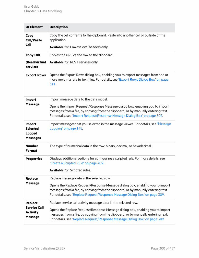
UI Element Description
CopyCell/PasteCell
Copy the cell contents to the clipboard. Paste into another cell or outside of theapplication.
Available for: Lowest level headers only.
Copy URL
(Real/virtualservice)
Copies the URL of the row to the clipboard.
Available for: REST services only.
Export Rows Opens the Export Rows dialog box, enabling you to export messages from one ormore rows in a rule to text files. For details, see "Export Rows Dialog Box" on page311.
ImportMessage
Import message data to the data model.
Opens the Import Request/Response Message dialog box, enabling you to importmessages from a file, by copying from the clipboard, or by manually entering text.For details, see "Import Request/Response Message Dialog Box" on page 307.
ImportSelectedLoggedMessages
Import messages that you selected in the message viewer. For details, see "MessageLogging" on page 148.
NumberFormat
The type of numerical data in the row: binary, decimal, or hexadecimal.
Properties Displays additional options for configuring a scripted rule. For more details, see"Create a Scripted Rule" on page 409.
Available for: Scripted rules.
ReplaceMessage
Replace message data in the selected row.
Opens the Replace Request/Response Message dialog box, enabling you to importmessages from a file, by copying from the clipboard, or by manually entering text.For details, see "Replace Request/Response Message Dialog Box" on page 309.
ReplaceService CallActivityMessage
Replace service call activity message data in the selected row.
Opens the Replace Request/Response Message dialog box, enabling you to importmessages from a file, by copying from the clipboard, or by manually entering text.For details, see "Replace Request/Response Message Dialog Box" on page 309.
User GuideChapter 8: Data Modeling
Service Virtualization (3.83) Page 300 of 474
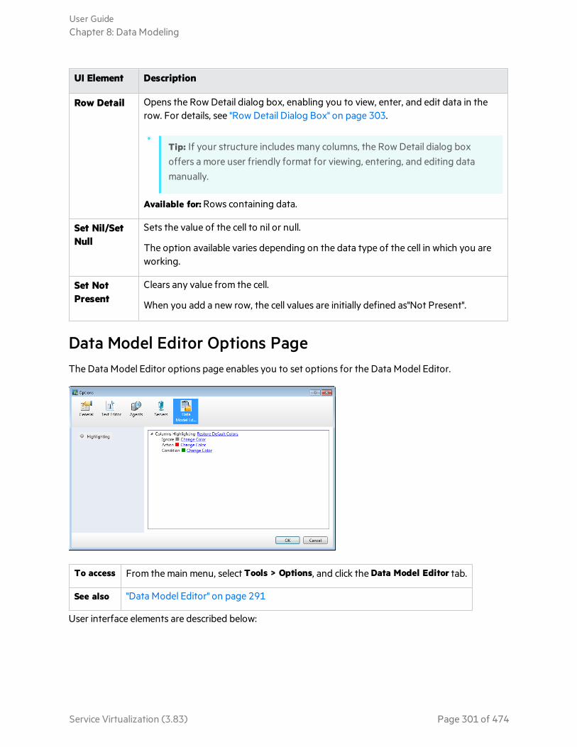
UI Element Description
Row Detail Opens the Row Detail dialog box, enabling you to view, enter, and edit data in therow. For details, see "Row Detail Dialog Box" on page 303.
Tip: If your structure includes many columns, the Row Detail dialog boxoffers a more user friendly format for viewing, entering, and editing datamanually.
Available for: Rows containing data.
Set Nil/SetNull
Sets the value of the cell to nil or null.
The option available varies depending on the data type of the cell in which you areworking.
Set NotPresent
Clears any value from the cell.
When you add a new row, the cell values are initially defined as"Not Present".
Data Model Editor Options PageThe Data Model Editor options page enables you to set options for the Data Model Editor.
To access From the main menu, select Tools > Options, and click the Data Model Editor tab.
See also "Data Model Editor" on page 291
User interface elements are described below:
User GuideChapter 8: Data Modeling
Service Virtualization (3.83) Page 301 of 474
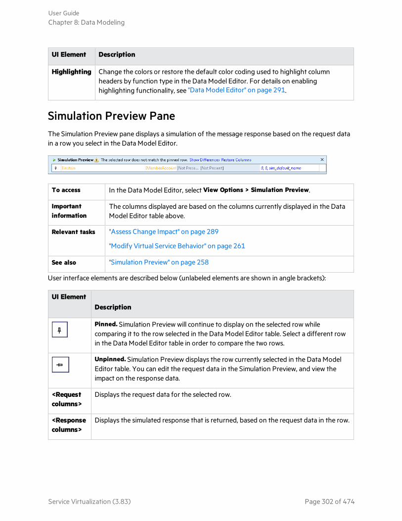
UI Element Description
Highlighting Change the colors or restore the default color coding used to highlight columnheaders by function type in the Data Model Editor. For details on enablinghighlighting functionality, see "Data Model Editor" on page 291.
Simulation Preview PaneThe Simulation Preview pane displays a simulation of the message response based on the request datain a row you select in the Data Model Editor.
To access In the Data Model Editor, select View Options > Simulation Preview.
Importantinformation
The columns displayed are based on the columns currently displayed in the DataModel Editor table above.
Relevant tasks "Assess Change Impact" on page 289
"Modify Virtual Service Behavior" on page 261
See also "Simulation Preview" on page 258
User interface elements are described below (unlabeled elements are shown in angle brackets):
UI ElementDescription
Pinned. Simulation Preview will continue to display on the selected row whilecomparing it to the row selected in the Data Model Editor table. Select a different rowin the Data Model Editor table in order to compare the two rows.
Unpinned. Simulation Preview displays the row currently selected in the Data ModelEditor table. You can edit the request data in the Simulation Preview, and view theimpact on the response data.
<Requestcolumns>
Displays the request data for the selected row.
<Responsecolumns>
Displays the simulated response that is returned, based on the request data in the row.
User GuideChapter 8: Data Modeling
Service Virtualization (3.83) Page 302 of 474
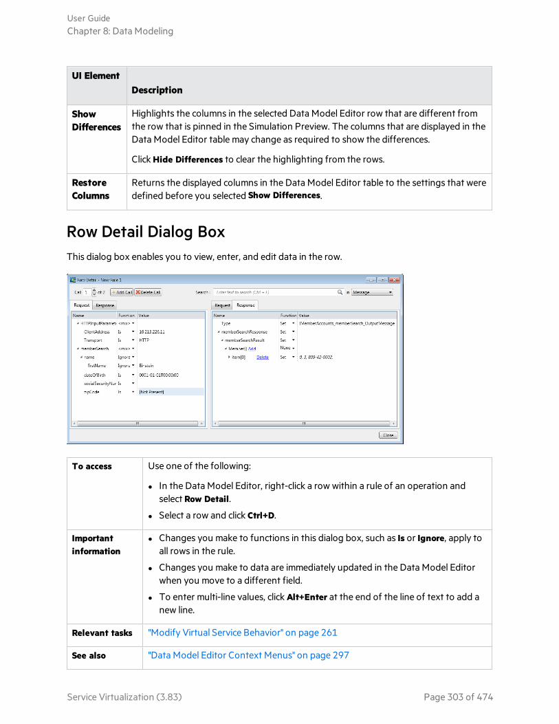
UI ElementDescription
ShowDifferences
Highlights the columns in the selected Data Model Editor row that are different fromthe row that is pinned in the Simulation Preview. The columns that are displayed in theData Model Editor table may change as required to show the differences.
Click Hide Differences to clear the highlighting from the rows.
RestoreColumns
Returns the displayed columns in the Data Model Editor table to the settings that weredefined before you selected Show Differences.
Row Detail Dialog BoxThis dialog box enables you to view, enter, and edit data in the row.
To access Use one of the following:
l In the Data Model Editor, right-click a row within a rule of an operation andselect Row Detail.
l Select a row and click Ctrl+D.
Importantinformation
l Changes you make to functions in this dialog box, such as Is or Ignore, apply toall rows in the rule.
l Changes you make to data are immediately updated in the Data Model Editorwhen you move to a different field.
l To enter multi-line values, click Alt+Enter at the end of the line of text to add anew line.
Relevant tasks "Modify Virtual Service Behavior" on page 261
See also "Data Model Editor Context Menus" on page 297
User GuideChapter 8: Data Modeling
Service Virtualization (3.83) Page 303 of 474
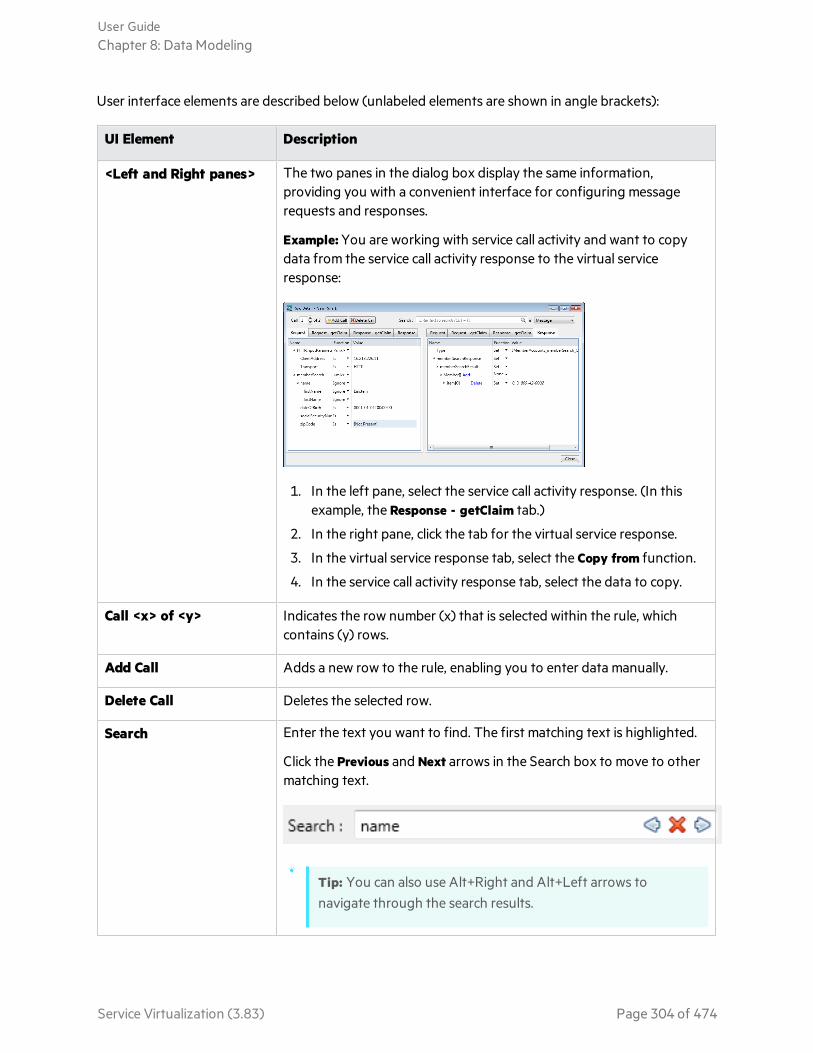
User interface elements are described below (unlabeled elements are shown in angle brackets):
UI Element Description
<Left and Right panes> The two panes in the dialog box display the same information,providing you with a convenient interface for configuring messagerequests and responses.
Example: You are working with service call activity and want to copydata from the service call activity response to the virtual serviceresponse:
1. In the left pane, select the service call activity response. (In thisexample, the Response - getClaim tab.)
2. In the right pane, click the tab for the virtual service response.
3. In the virtual service response tab, select the Copy from function.
4. In the service call activity response tab, select the data to copy.
Call <x> of <y> Indicates the row number (x) that is selected within the rule, whichcontains (y) rows.
Add Call Adds a new row to the rule, enabling you to enter data manually.
Delete Call Deletes the selected row.
Search Enter the text you want to find. The first matching text is highlighted.
Click the Previous and Next arrows in the Search box to move to othermatching text.
Tip: You can also use Alt+Right and Alt+Left arrows tonavigate through the search results.
User GuideChapter 8: Data Modeling
Service Virtualization (3.83) Page 304 of 474
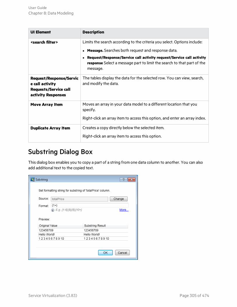
UI Element Description
<search filter> Limits the search according to the criteria you select. Options include:
l Message. Searches both request and response data.
l Request/Response/Service call activity request/Service call activityresponse Select a message part to limit the search to that part of themessage.
Request/Response/Service call activityRequests/Service callactivity Responses
The tables display the data for the selected row. You can view, search,and modify the data.
Move Array Item Moves an array in your data model to a different location that youspecify.
Right-click an array item to access this option, and enter an array index.
Duplicate Array Item Creates a copy directly below the selected item.
Right-click an array item to access this option.
Substring Dialog BoxThis dialog box enables you to copy a part of a string from one data column to another. You can alsoadd additional text to the copied text.
User GuideChapter 8: Data Modeling
Service Virtualization (3.83) Page 305 of 474
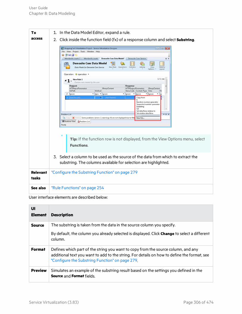
Toaccess
1. In the Data Model Editor, expand a rule.
2. Click inside the function field (fx) of a response column and select Substring.
Tip: If the function row is not displayed, from the View Options menu, selectFunctions.
3. Select a column to be used as the source of the data from which to extract thesubstring. The columns available for selection are highlighted.
Relevanttasks
"Configure the Substring Function" on page 279
See also "Rule Functions" on page 254
User interface elements are described below:
UIElement Description
Source The substring is taken from the data in the source column you specify.
By default, the column you already selected is displayed. Click Change to select a differentcolumn.
Format Defines which part of the string you want to copy from the source column, and anyadditional text you want to add to the string. For details on how to define the format, see"Configure the Substring Function" on page 279.
Preview Simulates an example of the substring result based on the settings you defined in theSource and Format fields.
User GuideChapter 8: Data Modeling
Service Virtualization (3.83) Page 306 of 474

UIElement Description
Change Enables you to select a source column for the substring of data to be copied.
More Opens the Service Virtualization help to assist you in defining the substring format.
Import Request/Response Message Dialog BoxThis dialog box enables you to import messages from a file, by copying from the clipboard, or bymanually entering text. You can also import multiple files simultaneously.
To access In the Data Model Editor, expand a rule.
l To import messages to a specific operation/URI space, select theoperation/URI space in the Operations/URI Spaces pane. Right-click inside the ruleand select Import Message.
l To import messages at the service level, select the service in theOperations/URI Spaces pane. Right-click the rule and select Import Message.(Available for SOAP and XML services only.)
l You can also import data to replace a selected row in the rule. Right click the row,and select Replace Message.
Available for: Custom rules and the Learned Data rule.
User GuideChapter 8: Data Modeling
Service Virtualization (3.83) Page 307 of 474

Importantinformation
l Importing multiple messages at the service level: The messages are placed in theproper operations.
If a message contains a new schema/message structure that does not currently existin any operations in the service:
l For an XML service, a new operation is created.
l For a SOAP service, an error message displays.
l Importing multiple messages directly into a specific operation:
If a message contains a new schema/message structure that does not currently existin the operation:
l For a REST service, a new data format is created.
l For an XML or SOAP service, an error message displays.
Relevanttasks
"Modify Virtual Service Behavior" on page 261
See also "Data Modeling" on page 251
User interface elements are described below:
UI Element Description
Expand/Collapse. Click to show/hide message content.
Request/ResponseMessage
Enter request and response message content.
You can import request messages, response messages, or both.
User GuideChapter 8: Data Modeling
Service Virtualization (3.83) Page 308 of 474
UI Element Description
From File Click to select a file from the file system. Each file may contain only the requestor response part of a single message.
To import multiple messages, select multiple files to import. ServiceVirtualization matches pairs of request and response messages by file name,according to one of the following methods:
l Files are matched according to any numerical index present within the filename.
l The index can be located at the beginning or end of the file name, or as aseparate part of the file name, . For example: 5_req.xml, req5.xml,req.5.xml
l The index must be in the same location in all files.
l Example: 9984_req1.xml and 9984_req2.xml. The files are comparedaccording to index numbers are 1 and 2 (not 9984).
l Files with the same name are paired.
File name extensions are ignored.
Tip: Place request and response files in separate folders to ease theimport process.
From Clipboard Pastes clipboard content into the message box.
Logged Message Import messages that were previously logged in Service Virtualization. Fordetails, see "Message Logging" on page 148.
Replace Request/Response Message Dialog BoxThis dialog box enables you to replace messages in a data model row from a file, by copying from theclipboard, or by manually entering text.
To access In the Data Model Editor, expand a rule and do one of the following:
l Right-click a row and select Replace Message.
l To replace service call activity data, right-click the row and select Replace ServiceCall Activity Message.
You can replace the messages in only one row at a time.
Relevanttasks
"Modify Virtual Service Behavior" on page 261
See also "Data Modeling" on page 251
User GuideChapter 8: Data Modeling
Service Virtualization (3.83) Page 309 of 474
User interface elements are described below:
UI Element Description
Expand/Collapse. Click to show/hide message content.
Request/ResponseMessage
Enter request and response message content.
You can replace the request message, response message, or both.
From File Click to select a file from the file system. Each file may contain only the requestor response part of a single message.
Tip: Place request and response files in separate folders to ease theprocess.
From Clipboard Pastes clipboard content into the message box.
Logged Message Import messages that were previously logged in Service Virtualization. Fordetails, see "Message Logging" on page 148.
Learn Schema Dialog BoxThis dialog box enables you to learn the service call activity's schema using sample messages.
To access:
1. In the Data Model, create an empty service call activity. For details on the process, see "Call ExternalServices" on page 286.
2. Select Activity > SCA Description > Learn Schema from Messages.
UI Element Description
Expand/Collapse. Click to show/hide message content.
Request/ResponseMessage
Enter request and response message content.
You can replace the request message, response message, or both.
From File Click to select a file from the file system. Each file may contain only the requestor response part of a single message.
Tip: Place request and response files in separate folders to ease theprocess.
User GuideChapter 8: Data Modeling
Service Virtualization (3.83) Page 310 of 474
UI Element Description
From Clipboard Pastes clipboard content into the message box.
Logged Message Import messages that were previously logged in Service Virtualization. Fordetails, see "Message Logging" on page 148.
Export Rows Dialog BoxExport messages and the related protocol headers to text files from one or more rows in a rule.
To access 1. In the Data Model Editor, expand a rule.
2. Right-click a row, or select multiple rows and right-click, and select ExportRows.
See also l "Import Request/Response Message Dialog Box" on page 307
l "Message Logging" on page 148
l "Data Model Editor" on page 291
l Export request and/or response data. Each request or response part of a message is saved in aseparate text file. The request headers and response headers are also exported each as a separatefile.
l Specify an output folder on the file system for exported data.
l Define a meaningful prefix and suffix for exported filenames, or accept the default values.
By default, files are named as follows:
<file prefix>-<row number>-<request or response>.<file suffix>
where the file prefix is composed from export-<date>-<time(24-hour clock)>.
For example, export-20150602-192739-1-request.txt.
Tip: Use the Select Requests/Select Responses links at the bottom to quickly select only request orresponse data.
Note: Only populated fields are exported.
Sample export:
User GuideChapter 8: Data Modeling
Service Virtualization (3.83) Page 311 of 474

Request/Response Pairing Dialog BoxThis dialog box enables you to review and make changes to the request/response message pairingperformed by Service Virtualization.
To access Opens automatically when you select to import multiple messages in the ImportRequest/Response Message dialog box, or replace current messages.
User GuideChapter 8: Data Modeling
Service Virtualization (3.83) Page 312 of 474

Importantinformation
l Service Virtualization pairs request and response files according to file names. Foradditional details, see "Import Request/Response Message Dialog Box" on page307.
l A file that does not match another file is also imported. For example, if there is arequest file, but no corresponding response file, the request file is still imported.
Relevanttasks
"Modify Virtual Service Behavior" on page 261
See also "Data Modeling" on page 251
User interface elements are described below:
UI Element Description
Request/ResponseFile
The request and response files to import.
To make changes to the request/response file pairing, select a request orresponse file and move it up or down in the list.
Create a Track Places the imported messages into a separate track in the data model.
New Data Driven Rule Dialog BoxThis dialog box enables you to create a new rule connected to an external data source.
User GuideChapter 8: Data Modeling
Service Virtualization (3.83) Page 313 of 474

To access 1. In the Data Model Editor, select New Rule > Data Driven Rule.
2. Select one of the following:
l Create new data file.
l Use existing data file.
Importantinformation
Creating a new data file: The Service Virtualization Designer creates a new Excel file,structured according to the schema (message structure) associated with the virtualservice. Rule columns are automatically bound to the worksheet columns.
Using an existing data file: After you create the rule you must then manually bind rulecolumns to worksheet columns. After binding, the external data is imported to theData Model.
Relevanttasks
l "Modify Virtual Service Behavior" on page 261
l "Work With External Data Sources" on page 283
See also "Data Modeling" on page 251
User interface elements are described below:
UI Element Description
New/ExistingExternal DataFile
To use an existing data file: Select a file from the drop-down list, or click thebrowse button to navigate to the file location.
To create a new data file: Type a name for the file and specify its path, or clickthe browse button to navigate to the file location.
Column Names If you are adding an existing file, this option indicates that the first row of yourfile is a header row, containing the names of each column.
Datasynchronization
The rule is configured to import data automatically from the external data filebefore each simulation.
ServiceOperations
The operations in your virtual service for which you want to import data.
By default, all of the virtual service's operations are selected for import. Tochange this selection, click Change and edit the list of operations for import.
Import/Export Data Dialog BoxThe Import Data dialog box enables you to import data from an external data file to your data model.
User GuideChapter 8: Data Modeling
Service Virtualization (3.83) Page 314 of 474
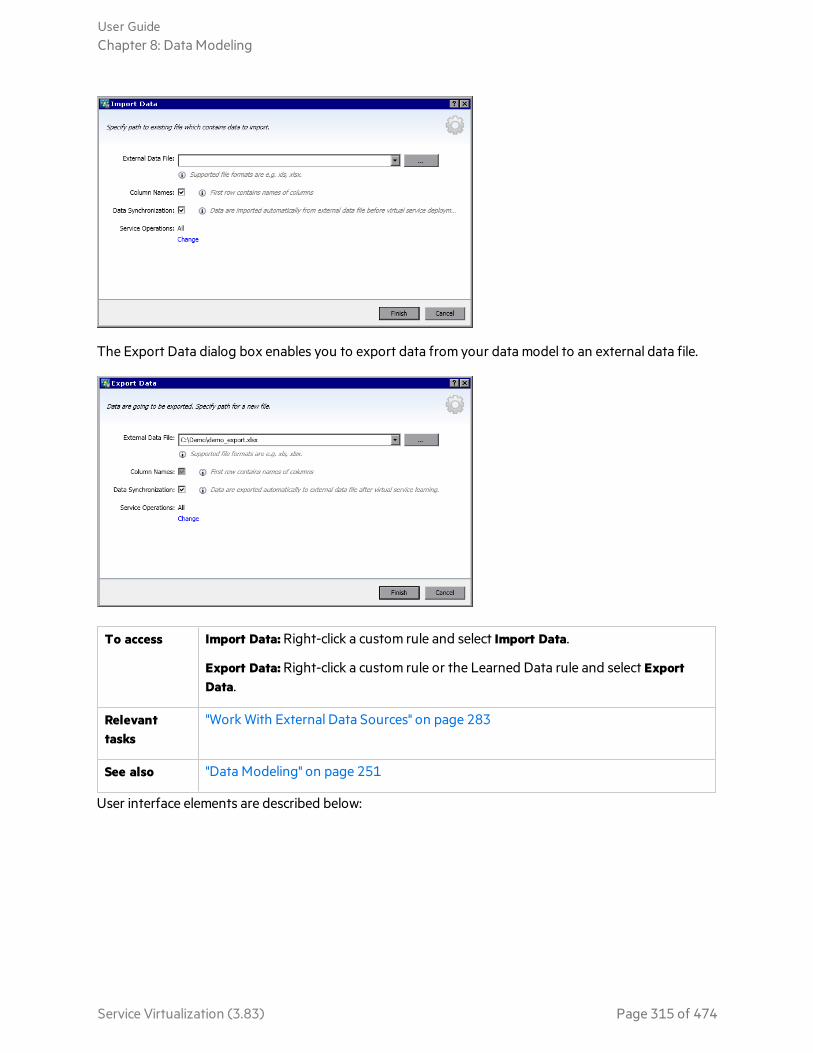
The Export Data dialog box enables you to export data from your data model to an external data file.
To access Import Data: Right-click a custom rule and select Import Data.
Export Data: Right-click a custom rule or the Learned Data rule and select ExportData.
Relevanttasks
"Work With External Data Sources" on page 283
See also "Data Modeling" on page 251
User interface elements are described below:
User GuideChapter 8: Data Modeling
Service Virtualization (3.83) Page 315 of 474
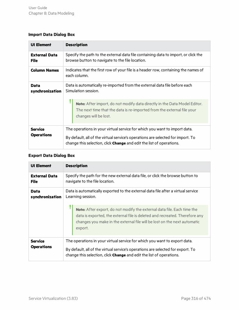
Import Data Dialog Box
UI Element Description
External DataFile
Specify the path to the external data file containing data to import, or click thebrowse button to navigate to the file location.
Column Names Indicates that the first row of your file is a header row, containing the names ofeach column.
Datasynchronization
Data is automatically re-imported from the external data file before eachSimulation session.
Note: After import, do not modify data directly in the Data Model Editor.The next time that the data is re-imported from the external file yourchanges will be lost.
ServiceOperations
The operations in your virtual service for which you want to import data.
By default, all of the virtual service's operations are selected for import. Tochange this selection, click Change and edit the list of operations.
Export Data Dialog Box
UI Element Description
External DataFile
Specify the path for the new external data file, or click the browse button tonavigate to the file location.
Datasynchronization
Data is automatically exported to the external data file after a virtual serviceLearning session.
Note: After export, do not modify the external data file. Each time thedata is exported, the external file is deleted and recreated. Therefore anychanges you make in the external file will be lost on the next automaticexport.
ServiceOperations
The operations in your virtual service for which you want to export data.
By default, all of the virtual service's operations are selected for export. Tochange this selection, click Change and edit the list of operations.
User GuideChapter 8: Data Modeling
Service Virtualization (3.83) Page 316 of 474
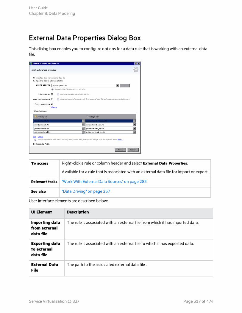
External Data Properties Dialog BoxThis dialog box enables you to configure options for a data rule that is working with an external datafile.
To access Right-click a rule or column header and select External Data Properties.
Available for a rule that is associated with an external data file for import or export.
Relevant tasks "Work With External Data Sources" on page 283
See also "Data Driving" on page 257
User interface elements are described below:
UI Element Description
Importing datafrom externaldata file
The rule is associated with an external file from which it has imported data.
Exporting datato externaldata file
The rule is associated with an external file to which it has exported data.
External DataFile
The path to the associated external data file .
User GuideChapter 8: Data Modeling
Service Virtualization (3.83) Page 317 of 474

UI Element Description
Column Names Indicates that the first row of your file is a header row, containing the names ofeach column.
Available for import only.
DataSynchronization
For import: Data is automatically re-imported from the external data file beforeeach Simulation session.
For export: Data is automatically exported to the external data file after a virtualservice Learning session.
ServiceOperations
The operations in your virtual service that are configured for import or export.
By default, all of the virtual service's operations are selected. To change thisselection, click Change and edit the list of operations.
Sheet Relations Binding configuration for working with array data. You can define therelationships between worksheets that is required for array binding.
Primary/Foreign Key: The drop-down lists display the columns in the externaldata file. The format of the keys is <worksheet_name>.<column_name>. Select avalue for each key to define the relationship.
Add Adds a row, enabling you to define an additional relationship between primaryand foreign keys.
Available when working with array data.
Delete Removes the selected row.
Available when working with array data.
Refresh Data onConfirm
Updates the data according to your new settings. For example, if you changedthe setting from Import to Export, the data is exported to the external file whenyou click Finish.
New/Edit Function Dialog BoxThe New Function f(x) dialog box enables you to create a new function to use in your data model. Youcan then edit functions from the Edit Function dialog box.
User GuideChapter 8: Data Modeling
Service Virtualization (3.83) Page 318 of 474
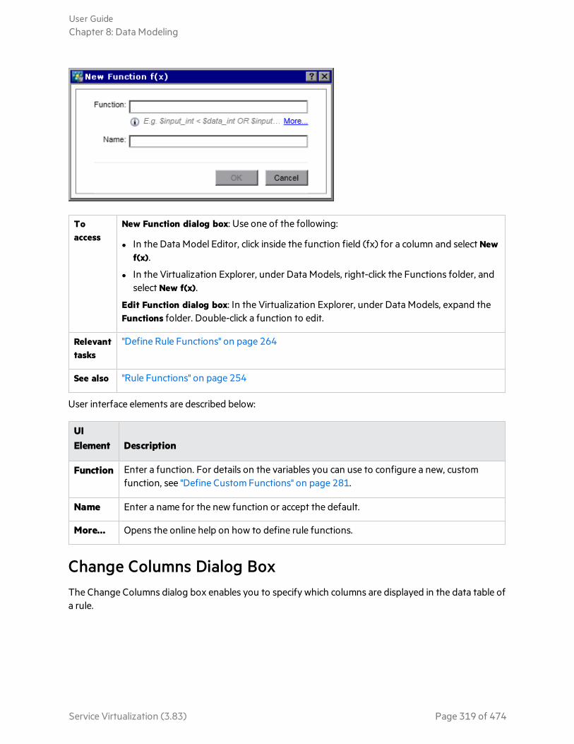
Toaccess
New Function dialog box: Use one of the following:
l In the Data Model Editor, click inside the function field (fx) for a column and select Newf(x).
l In the Virtualization Explorer, under Data Models, right-click the Functions folder, andselect New f(x).
Edit Function dialog box: In the Virtualization Explorer, under Data Models, expand theFunctions folder. Double-click a function to edit.
Relevanttasks
"Define Rule Functions" on page 264
See also "Rule Functions" on page 254
User interface elements are described below:
UIElement Description
Function Enter a function. For details on the variables you can use to configure a new, customfunction, see "Define Custom Functions" on page 281.
Name Enter a name for the new function or accept the default.
More... Opens the online help on how to define rule functions.
Change Columns Dialog BoxThe Change Columns dialog box enables you to specify which columns are displayed in the data table ofa rule.
User GuideChapter 8: Data Modeling
Service Virtualization (3.83) Page 319 of 474
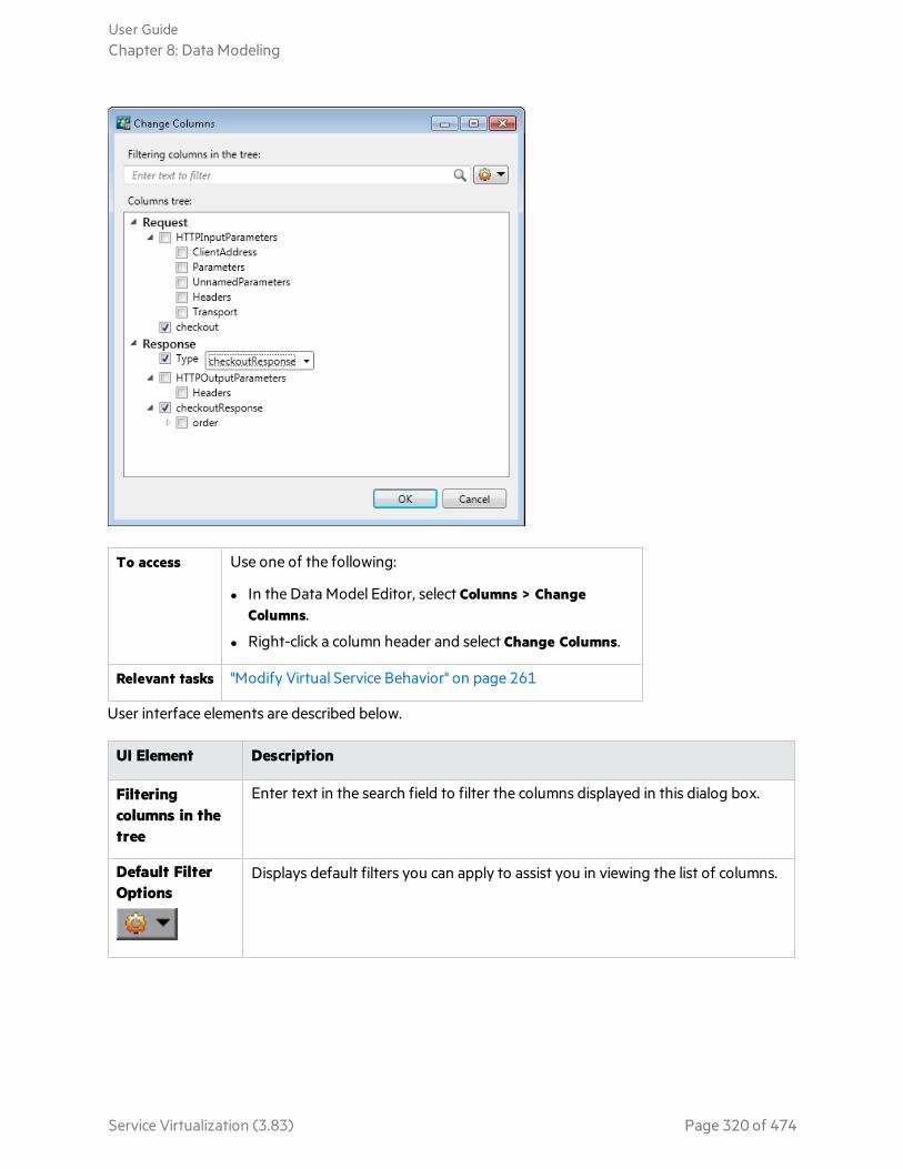
To access Use one of the following:
l In the Data Model Editor, select Columns > ChangeColumns.
l Right-click a column header and select Change Columns.
Relevant tasks "Modify Virtual Service Behavior" on page 261
User interface elements are described below.
UI Element Description
Filteringcolumns in thetree
Enter text in the search field to filter the columns displayed in this dialog box.
Default FilterOptions
Displays default filters you can apply to assist you in viewing the list of columns.
User GuideChapter 8: Data Modeling
Service Virtualization (3.83) Page 320 of 474

UI Element Description
Column tree Select the columns that you want to display in the data table.
l When you click on a column name, it is highlighted for you in the currentlyopen model.
l Select an option from the drop-down list to change the current view in theopen model.
l Right-click an item in the tree to display additional options forshowing/hiding branches/children.
Note: Selecting a header level checkbox does not select all child headers.
In this example, the Request box is selected, indicating that you haveselected the Request header to display in the Data Model Editor.
The shaded box for the Request header indicates that one or more childheaders are selected.
OK/Cancel Saves/discards your selections.
Edit Sheet Relations Dialog BoxThis dialog box enables you to configure binding for an array. You can define the relationships betweenworksheets that are required for array binding.
User GuideChapter 8: Data Modeling
Service Virtualization (3.83) Page 321 of 474
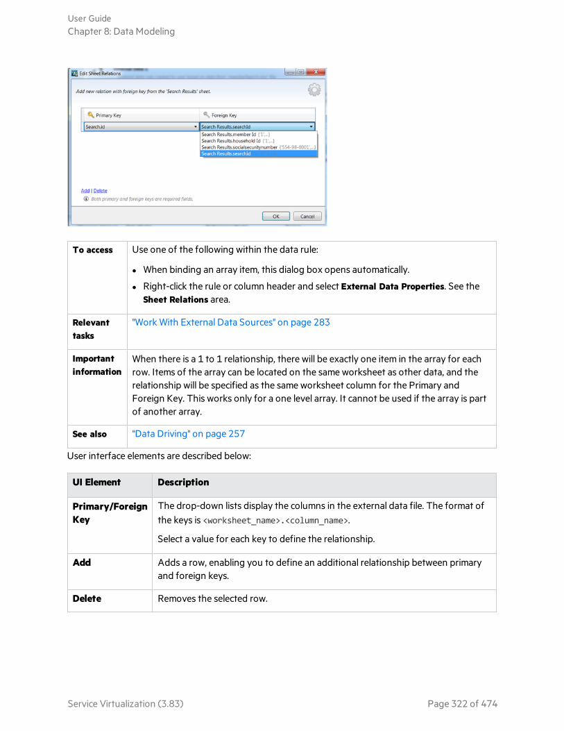
To access Use one of the following within the data rule:
l When binding an array item, this dialog box opens automatically.
l Right-click the rule or column header and select External Data Properties. See theSheet Relations area.
Relevanttasks
"Work With External Data Sources" on page 283
Importantinformation
When there is a 1 to 1 relationship, there will be exactly one item in the array for eachrow. Items of the array can be located on the same worksheet as other data, and therelationship will be specified as the same worksheet column for the Primary andForeign Key. This works only for a one level array. It cannot be used if the array is partof another array.
See also "Data Driving" on page 257
User interface elements are described below:
UI Element Description
Primary/ForeignKey
The drop-down lists display the columns in the external data file. The format ofthe keys is <worksheet_name>.<column_name>.
Select a value for each key to define the relationship.
Add Adds a row, enabling you to define an additional relationship between primaryand foreign keys.
Delete Removes the selected row.
User GuideChapter 8: Data Modeling
Service Virtualization (3.83) Page 322 of 474
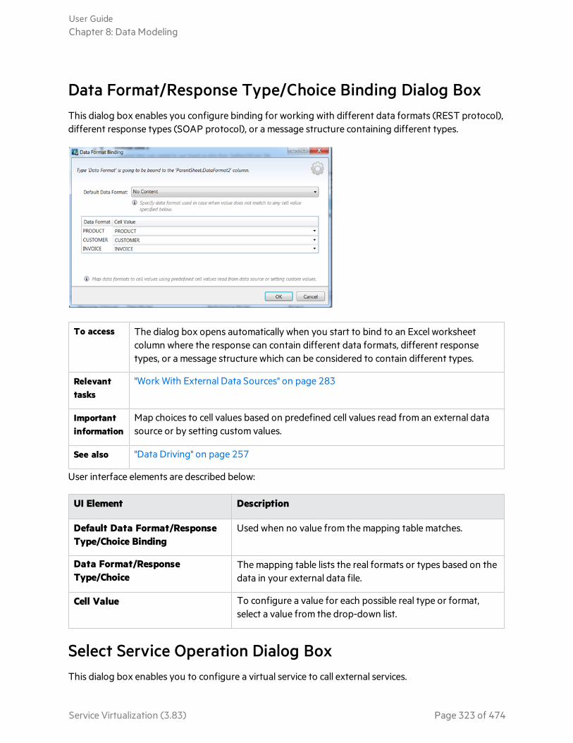
Data Format/Response Type/Choice Binding Dialog BoxThis dialog box enables you configure binding for working with different data formats (REST protocol),different response types (SOAP protocol), or a message structure containing different types.
To access The dialog box opens automatically when you start to bind to an Excel worksheetcolumn where the response can contain different data formats, different responsetypes, or a message structure which can be considered to contain different types.
Relevanttasks
"Work With External Data Sources" on page 283
Importantinformation
Map choices to cell values based on predefined cell values read from an external datasource or by setting custom values.
See also "Data Driving" on page 257
User interface elements are described below:
UI Element Description
Default Data Format/ResponseType/Choice Binding
Used when no value from the mapping table matches.
Data Format/ResponseType/Choice
The mapping table lists the real formats or types based on thedata in your external data file.
Cell Value To configure a value for each possible real type or format,select a value from the drop-down list.
Select Service Operation Dialog BoxThis dialog box enables you to configure a virtual service to call external services.
User GuideChapter 8: Data Modeling
Service Virtualization (3.83) Page 323 of 474

To access 1. In the Data Model Editor, select the operation from which you want to callthe external service.
2. Click Activity > Import Activities, enter the path to the WSDL schema, andclick Next.
Importantinformation
Service call activity is supported for:
l SOAP services over HTTP or JMS
l XML services over HTTP, JMS, WebSphere MQ, or Filesystem
l REST services
Relevant tasks "Modify Virtual Service Behavior" on page 261
See also "Data Modeling" on page 251
User interface elements are described below:
UI Element Description
Service operation The list of operations available for the service callactivity.
Add the activity after response Runs the activity after the response is sent to theclient.
By default, the service call activity is added to therule before the response.
Do not add an activity now. Import theservice description for later use.
Imports the service description document. Noactivity is added to the current rule.
User GuideChapter 8: Data Modeling
Service Virtualization (3.83) Page 324 of 474

Service Properties for XML Service Call ActivityThese dialog boxes enable you to configure an XML virtual service to call external services.
To access 1. In the Data Model Editor, select the operation from which you want to call theexternal service.
2. Click Activity > Import Activities. Enter the path to the XML schema (.xsd file),and click Next.
Relevanttasks
l "Modify Virtual Service Behavior" on page 261
l "Call External Services" on page 286
See also "Data Modeling" on page 251
User interface elements are described below:
User GuideChapter 8: Data Modeling
Service Virtualization (3.83) Page 325 of 474
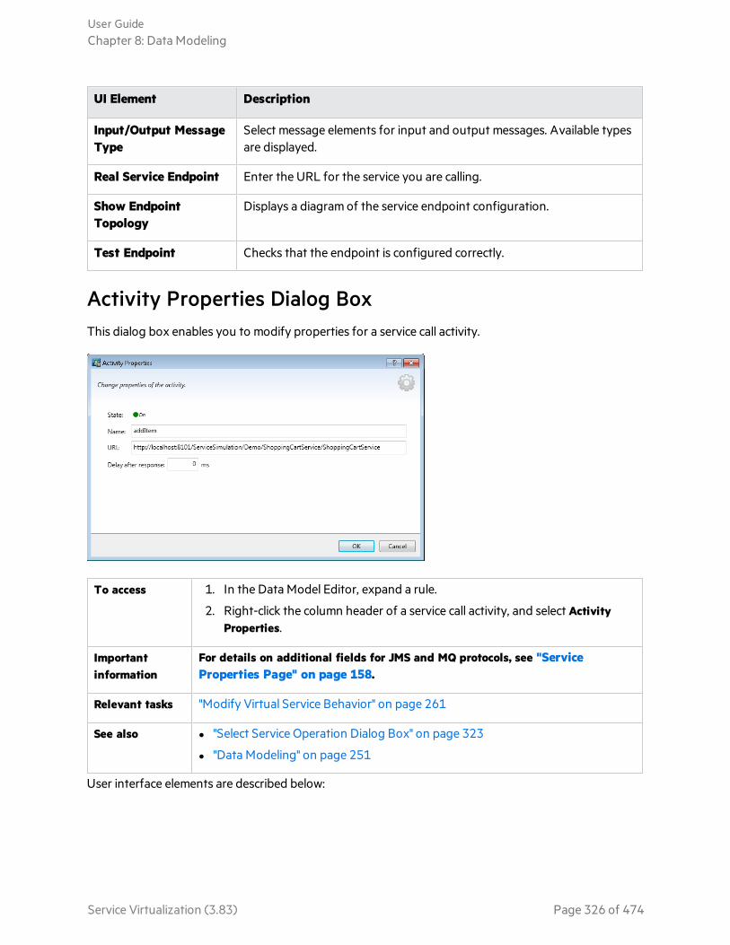
UI Element Description
Input/Output MessageType
Select message elements for input and output messages. Available typesare displayed.
Real Service Endpoint Enter the URL for the service you are calling.
Show EndpointTopology
Displays a diagram of the service endpoint configuration.
Test Endpoint Checks that the endpoint is configured correctly.
Activity Properties Dialog BoxThis dialog box enables you to modify properties for a service call activity.
To access 1. In the Data Model Editor, expand a rule.
2. Right-click the column header of a service call activity, and select ActivityProperties.
Importantinformation
For details on additional fields for JMS and MQ protocols, see "ServiceProperties Page" on page 158.
Relevant tasks "Modify Virtual Service Behavior" on page 261
See also l "Select Service Operation Dialog Box" on page 323
l "Data Modeling" on page 251
User interface elements are described below:
User GuideChapter 8: Data Modeling
Service Virtualization (3.83) Page 326 of 474

UI Element Description
State Indicates if the service call activity is currently enabled or disabled for the rule.
Click the on/off icon to change the state.
Name The name of the activity.
By default, this is the name of the operation in the called service.
Tip: You can edit this field. If you add multiple activities calling the sameoperation in the same service, give each activity a different name.
URL The endpoint location of the called service.
Agent Select an existing agent to use for the service call, or click Manage Agents toconfigure a new agent.
Timeout Timeout value for the service call activity in milliseconds.
Delay afterresponse
Indicates the amount of time, in milliseconds, to wait after sending a response to theclient, before running the activity.
Available only for a service call activity that is scheduled for after the response.
MessageFormat
Determines how the data is transported. Binary or text.
Available for: JMS, WebSphere MQ
FAQs: Data Model EditorThis section provides tips on working in the Data Model Editor.
For task details, see "Modify Virtual Service Behavior" on page 261.
I can't see all my columns. Can I configure what is displayed?
To show/hide columns, use the Change Columns dialog box. To access, click the Columns button, andselect Change Columns.
Alternatively, click the x in a column header to hide a specific column.
Can I view the entire header structure?
Double-click headers to drill down within the header structure.
Some column headers are in italic text (header). What does that mean?
These are complex headers that include lower level headers under them. Double-click the header todisplay its lower level headers, or change your selections in the Change Columns dialog box.
User GuideChapter 8: Data Modeling
Service Virtualization (3.83) Page 327 of 474

How does the 'Copy from' function work?
When you select the Copy from function for a column and then scroll over the other columns, anindicator displays to show whether a source column is compatible with the target column.
Indicates a column that you can use as a source.
Indicates a column that you cannot use as a source.
Click the desired source column to select.
What's the best way to work with array data?
It is recommended to work directly in the data row within the rule.
It's hard to work with all the columns in my message data. Is there a better way?
If your structure includes many columns, the Row Detail dialog box offers a more user friendly formatfor viewing, entering, and editing data manually. Right-click a row and select Row Detail.
I want to move some array data in my data model. Is there an easy way to do that?
Yes. In the Row Detail dialog box, right-click an array item and select Move Array Item.
How can I search a data model?
Click Ctrl+F to search the data model.
Click Ctrl+H to find and replace data.
Can I search within a row?
The Row Detail dialog box enables you to search the row to find specific text. Right-click a row andselect Row Detail.
I exported data to an Excel file, but I can't find the file. Where is it?
Hover over the import/export icon in the data rule to see the location of your external data file.
You can also right-click the rule and select External Data Properties for more information on theexternal file.
How can I update column bindings for a data-driven rule?
Do one of the following:
l Expand a rule, and click the bind icon . A "preview" of your external data file displays within therule.
l Right-click a rule and select Open External Data.
User GuideChapter 8: Data Modeling
Service Virtualization (3.83) Page 328 of 474

I see more columns than I need to. How can I hide some of them?
To show/hide columns, use the Change Columns dialog box. To access, click the Columns button, andselect Change Columns.
Why is part of the row gray, with no visible data?
The headers are showing a different message structure. Double-click on the grayed area to switchheader structure.
How can I add data as a message?
Right-click a rule and select Import Message.
I see metadata, but no actual data. Why don't I see the data?
The columns (headers) that contain the data are hidden. Click the Columns button, and select selectChange Columns to change the display settings.
Some column headers are marked with a red hash sign (#). What does that mean?
These columns are configured for data masking. For details, see "Data Masking Dialog Box" on page205.
User GuideChapter 8: Data Modeling
Service Virtualization (3.83) Page 329 of 474

Chapter 9: Stateful SimulationThis chapter includes:
• Stateful Simulation 331• Simulate a Stateful Service 332• Stateful Layout View 334
Service Virtualization (3.83) Page 330 of 474

Stateful SimulationWhen simulating a service, the order of requests is often important. A service may return differentresponses to the same request depending on the current state of the service. Service Virtualization cansimulate this type of stateful behavior.
A virtual service uses tracks to simulate stateful behavior. Tracks enable you to order request/responsepairs in a virtual service’s data model, to define the sequence in which they are used during simulation.
Service Virtualization creates tracks during learning. You can also manually create and edit tracks.
During simulation, Service Virtualization evaluates each request to determine which track it fits into, andin which position in the track, and returns the appropriate response.
How are tracks created?
Service Virtualization creates tracks automatically based on learned data. During learning, tracks aresplit according to client sessions. Each session, as identified by a unique session ID, is placed into aseparate track.
How are different client sessions identified?
Service Virtualization identifies client sessions according to a specific message element or metadata.Depending on the transport protocol a virtual service is using, Service Virtualization assigns a defaultsession identifier to the service. To achieve the result you want, you can modify the session identifierthat is used for a specific virtual service. For example, for SOAP services over HTTP, the default sessionID is the IP address of a client sending requests. In the case of a proxy server, requests from severalclients may appear to be coming from the same IP address, and will not be split into separate tracks.
What happens during learning?
When you record real service behavior, Service Virtualization splits the learned data into separate tracksaccording to the session ID. Each time you place the virtual service into Learning mode, new tracks areadded, and identical tracks are removed to ensure that each track is unique. If you are using externaldata sources in your data model, one linear track is created for each data driven rule.
What happens during simulation?
During simulation, separate sessions are simulated for each unique session ID.
Service Virtualization matches incoming client requests to data in the data model according to thesession ID and the relevant operation in the virtual service, and returns the appropriate response.
If incoming requests do not match a track exactly, heuristic simulation is performed to determine themost similar track, with newer tracks taking priority. Service Virtualization calculates the probabilities ofall track positions in all tracks simultaneously to determine where in the simulated scenario this requestmost likely fits.
User GuideChapter 9: Stateful Simulation
Service Virtualization (3.83) Page 331 of 474

See also:l For task details, see "Simulate a Stateful Service" below.
Simulate a Stateful ServiceThis task describes how to configure a virtual service to simulate stateful behavior.
This task includes the following:
l "Virtualize stateful behavior" below
l "Edit tracks" on the next page
l "Reorder tracks" on the next page
l "Create stateful behavior manually" on the next page
Virtualize stateful behavior1. Prerequisite:
Service Virtualization must have information on the message structure that the client uses. Thestructure of request/response messages is stored in the service description. You provide thisinformation by doing one of the following:
l Placing the virtual service in Learning mode to record real service behavior. For example, for aREST service.
l Importing a service description document, such as when creating a SOAP service using animported .wsdl service description document.
l Importing messages into the virtual service's data model.
2. Define session identifiers:
a. In the Service Description Editor, under Session IDs Definition, click Edit.
b. In the wizard pages that open, specify values for session identifiers, and click Finish.
Client-initiated sessions: For a service in which sessions are determined based on a clientrequest, you can select an element of the request data to use as a session identifier. Forexample, a user ID.
Server-initiated sessions: For a service in which sessions are determined based on a serverresponse, you can select an element of the response data to use as a session identifier. Forexample, a client may send a login request, and the server returns a session ID that will identifythe client session.
For user interface details, see "Session ID Definition Wizard" on page 200.
3. Learn data again:
Service Virtualization uses the session IDs to create different tracks based on the learned data, anduses the tracks to create different sessions during simulation.
User GuideChapter 9: Stateful Simulation
Service Virtualization (3.83) Page 332 of 474

Edit tracksView and modify tracks using the Stateful Layout view of the Data Model Editor. For user interfacedetails, see "Stateful Layout View" on the next page.
On the Data Model Editor toolbar, click Stateful Layout to display the track pane.
l Filter tracks. Select an option under Current Rule Tracks to display all tracks or tracks for current ruleonly.
l Edit a track.
l Click inside a track name to edit.
l Drag and drop items within a track to reorder.
l Delete a track. Delete the track only, or also delete the rows that include track positions of theselected track.
Reorder tracksBy default, tracks are ordered based on the track position's timestamp. For example, the first trackcreated would be used first during simulation, the second track used next, and so on.
You can manually reorder that the tracks to redefine the sequence in which they are used duringsimulation.
At the bottom of the track pane, select a track you want to move and click the up/down arrows.
Create stateful behavior manually1. In the Data Model Editor, create a blank rule and add data rows.
2. Create a new track. On the toolbar, click Stateful Layout to display the track pane.
3. Drag and drop rows from the data rule into the Stateful Layout track pane, in the order that youwant.
For user interface details, see "Data Model Editor" on page 291 and "Stateful Layout View" on the nextpage.
User GuideChapter 9: Stateful Simulation
Service Virtualization (3.83) Page 333 of 474
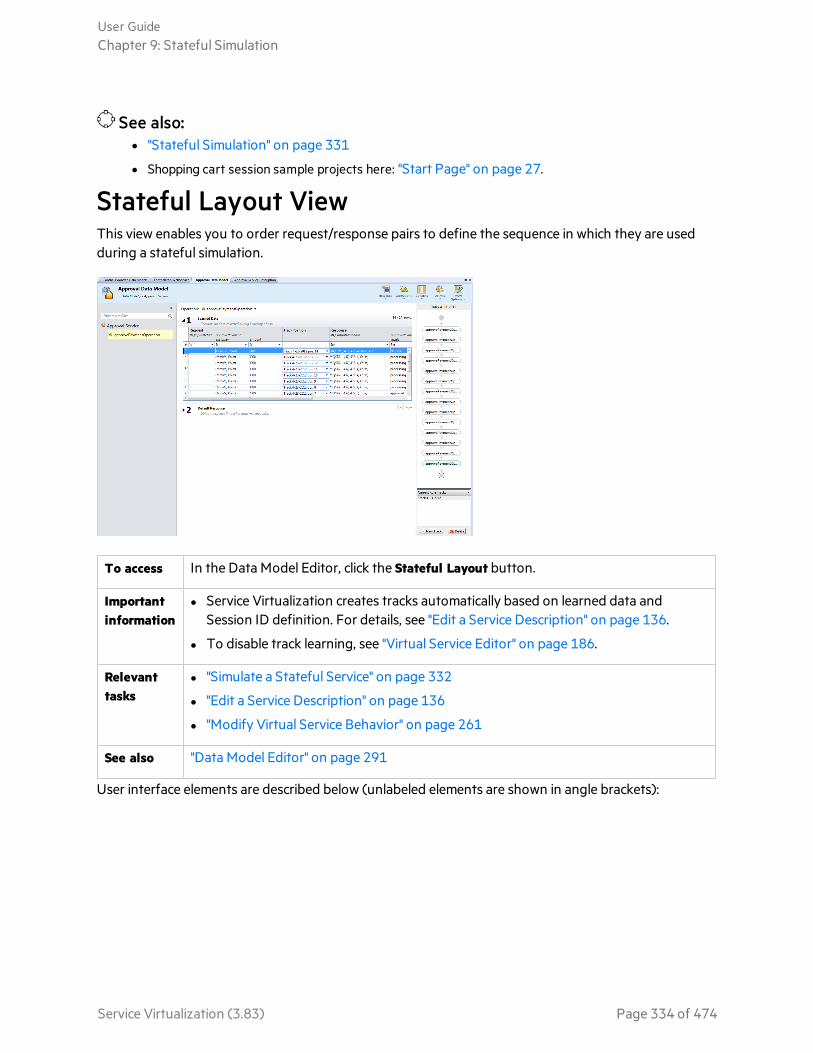
See also:l "Stateful Simulation" on page 331
l Shopping cart session sample projects here: "Start Page" on page 27.
Stateful Layout ViewThis view enables you to order request/response pairs to define the sequence in which they are usedduring a stateful simulation.
To access In the Data Model Editor, click the Stateful Layout button.
Importantinformation
l Service Virtualization creates tracks automatically based on learned data andSession ID definition. For details, see "Edit a Service Description" on page 136.
l To disable track learning, see "Virtual Service Editor" on page 186.
Relevanttasks
l "Simulate a Stateful Service" on page 332
l "Edit a Service Description" on page 136
l "Modify Virtual Service Behavior" on page 261
See also "Data Model Editor" on page 291
User interface elements are described below (unlabeled elements are shown in angle brackets):
User GuideChapter 9: Stateful Simulation
Service Virtualization (3.83) Page 334 of 474
UIElement Description
TrackPositioncolumn
Located in the main pane of the Data Model Editor, indicates the track and track positionof the selected row. If the row is a part of multiple tracks, each instance is highlighted inthe tracks pane.
Right-click in the Track Position column for a given row and click Add to Track to add thecall to the sequence of calls in the track. You can add the row again to the same track, orto a different track.
<trackpane>
Located in the right pane, displays the sequence of calls in the track. The order reflectshow the calls are used in a stateful simulation.
Select a call to highlight its row in the rule.
<trackname>
Located at the top of the track pane. Click to edit.
<trackfilter>
List of tracks in the data model. Options include:
l Current Rule Tracks
l All Tracks
You can display all tracks or tracks for the currently selected rule only.
Tip: Select multiple tracks and expand the track pane to view several tracks sideby side.
NewTrack
Creates a new track.
Delete Deletes the currently displayed track. You can choose to delete the track only, or alsodelete the rows that include track positions of the selected track.
User GuideChapter 9: Stateful Simulation
Service Virtualization (3.83) Page 335 of 474

Chapter 10: Performance ModelingThis chapter includes:
• Performance Modeling 337• Modify Virtual Service Performance 338• Performance Model User Interface 340
Service Virtualization (3.83) Page 336 of 474

Performance ModelingThe Performance Model enables you to customize the performance of a service during simulation.
OverviewWhen you create a Virtual Service, Service Virtualization creates a Performance Model associated with it.This model is then available to learn the performance of the real service and can be customized to setspecific performance rules either for the whole service, or its individual operations.
Each virtual service can have multiple performance models. Prior to a Learning session, in which realservice behavior is recorded, you can select the performance model to which you want to save thelearned behavior. Prior to simulation, you can select which model to use to mimic real service behavior,including non-customizable models to ignore the performance or simulate the unavailability of a service.For details on working with simulation models, see "Manage Simulation Models" on page 248.
Performance MetricsYou can manipulate virtual service performance using the following performance metrics:
Basic Performance Criteria
Set levels for the following performance criteria for specific operations of the service:
Response Time [ms] The time for the service to process a request and return a relevantresponse.
Threshold [hits/s] The maximum number of requests and responses the service can processwithout any impact on performance.
Throughput Limit[MB/s]
The maximum data capacity the service can process.
Transaction Limit[transactions/s]
The maximum number of responses per second that the virtual servicecan send.
Advanced Performance Criteria
In addition to the basic criteria, set levels for the following criteria for specific operations of the service:
Tolerance [%] The acceptable range of variation in performance for the operation.
Maximum Hits perSecond
The maximum number of requests and responses the operation is allowedto process.
Maximum ResponseTime
The maximum time for a response at peak performance levels.
User GuideChapter 10: Performance Modeling
Service Virtualization (3.83) Page 337 of 474

Boosters
There are a number of boosters available which you can use to manipulate some aspect of the serviceperformance. Service Virtualization applies the selected boost to the relevant performance criteriaduring simulation.
The boosters include:
CPU CPU power multiplication factor. Impacts the response time of the service.
Network Network throughput multiplication factor. Impacts the throughput limit.
Cluster Scalability multiplication factor. Impacts all measures simultaneously - response time,hit rate, threshold, and throughput limit.
Expert Multiplication factors for response time, hit rate, and throughput limit values. You canchange each measure separately.
Batch Simulation/Message SchedulingTo simulate a real service in which responses are delayed or postponed, you can create a schedule todetermine when message responses are generated and sent from the virtual service to the client.
For example, users of a banking application may enter transactions during the day, but the transactionsare not actually processed until the night. Or a user of an online shopping site may make a purchasewhere some part of order is out of stock. The application must hold onto the request until the item isavailable, and only then process the order.
To simulate the real service, consider these questions:
l When do you want to send the responses? At specific times? With a delay after requests arereceived?
l How many responses should be returned at once?
l Do you want to continue sending responses periodically at set intervals, or at specific times?
You can configure a message schedule to publish responses according to your answers.
See also:l For task details, see "Modify Virtual Service Performance" below.
l For user interface details, see "Performance Model Editor" on page 341.
Modify Virtual Service PerformanceThis task describes how to edit the performance model to manipulate simulation behavior.
User GuideChapter 10: Performance Modeling
Service Virtualization (3.83) Page 338 of 474
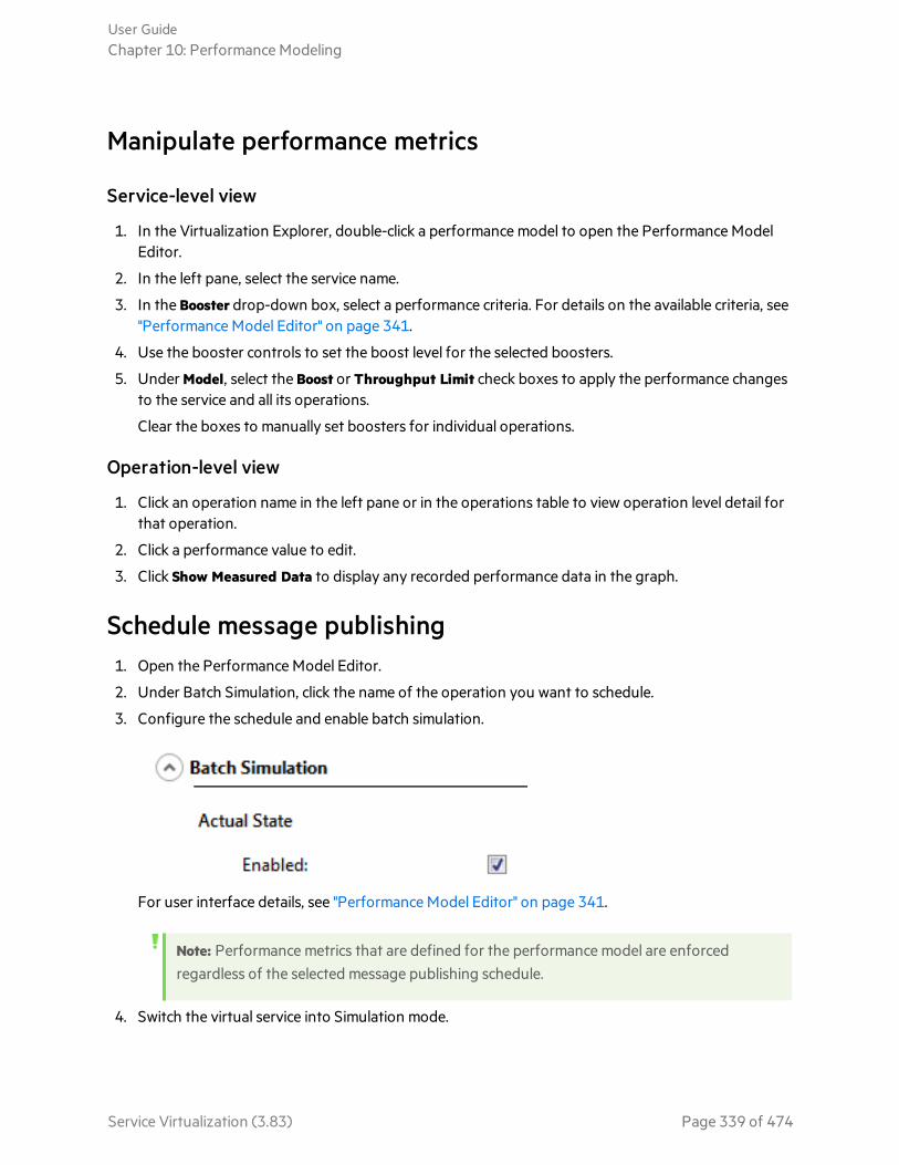
Manipulate performance metrics
Service-level view
1. In the Virtualization Explorer, double-click a performance model to open the Performance ModelEditor.
2. In the left pane, select the service name.
3. In the Booster drop-down box, select a performance criteria. For details on the available criteria, see"Performance Model Editor" on page 341.
4. Use the booster controls to set the boost level for the selected boosters.
5. Under Model, select the Boost or Throughput Limit check boxes to apply the performance changesto the service and all its operations.
Clear the boxes to manually set boosters for individual operations.
Operation-level view
1. Click an operation name in the left pane or in the operations table to view operation level detail forthat operation.
2. Click a performance value to edit.
3. Click Show Measured Data to display any recorded performance data in the graph.
Schedule message publishing1. Open the Performance Model Editor.
2. Under Batch Simulation, click the name of the operation you want to schedule.
3. Configure the schedule and enable batch simulation.
For user interface details, see "Performance Model Editor" on page 341.
Note: Performance metrics that are defined for the performance model are enforcedregardless of the selected message publishing schedule.
4. Switch the virtual service into Simulation mode.
User GuideChapter 10: Performance Modeling
Service Virtualization (3.83) Page 339 of 474

See also:l "Performance Modeling" on page 337
Performance Model User InterfaceThis section includes:
• Performance Model Editor 341
User GuideChapter 10: Performance Modeling
Service Virtualization (3.83) Page 340 of 474

Performance Model EditorThe Performance Model Editor enables you to configure performance metrics for a virtual service to useduring simulation. You can configure the performance for the whole service or for its individualoperations.
To access Use one of the following:
l In the Virtualization Explorer, double-click a performance model.
l In the Virtual Service Editor, under Performance Models, select a performancemodel and click Edit.
Importantinformation
l Click a value to edit.
l Throughput Limit and Transaction Limit performance metrics are not affected bylearned data. Learning does not modify these values.
Relevanttasks
l "Manage Simulation Models" on page 248
l "Modify Virtual Service Performance" on page 338
See also "Performance Modeling" on page 337
User interface elements are described below (unlabeled elements are shown in angle brackets).
Common Areas
UI Element Description
<performancemodel name anddescription>
The name and description of the data model. Click to edit.
<operations> Located in the left pane of the editor. Displays a list of the operations in theservice associated with the selected performance model.
By default, the service name is selected, and a performance overview isdisplayed in the main pane of the Performance Model Editor. For details, seeService Level View.
Enter text in the filter box to filter for specific operations in the list.
Select an operation from the list to display its details in the main pane of thePerformance Model Editor. For details, see Operation Level View.
Edit ServiceDescription
Opens the Service Description Editor. For details, see "Service DescriptionEditor" on page 197.
User GuideChapter 10: Performance Modeling
Service Virtualization (3.83) Page 341 of 474

Service Level View
UI Element Description
Booster A set of boosters to provide high-level control of the operations selected in theoperation table.
Available boosters include:
l CPU. CPU power multiplication factor.
l Network. Network throughput multiplication factor.
l Cluster. Scalability multiplication factor.
l Expert. Multiplication factors for Response Time, Hit Rate, and Throughput Limitvalues.
l None. Turn off all boosters.
Note: You must restart the simulation to apply changes.
<boostercontrols>
The sliding controls and inputs enable you to set the boost level for the selectedbooster. The setting affects the various performance criteria displayed in theoperation table.
PerformanceMetrics
Enables you to set more granular settings for individual performance criteria forindividual operations. You can set the following:
l Response Time [ms]. The time for the service to process a request and return arelevant response.
l Threshold [hits/s]. The maximum number of requests and responses the servicecan process without any impact on performance.
l Throughput Limit [MB/s]. The maximum data capacity the service can process.
l Transaction Limit [transactions/s]. The maximum number of responses that thevirtual service can send per second.
To apply the performance changes to the service and all of its operations, select theBoost, Throughput Limit, or Transaction Limit check boxes at the top of the table.
Alternatively, select options separately for the service and per operation.
Click an operation name to open the operation level view for the specific operation.
Note: Throughput Limit and Transaction Limit are not affected by learneddata. Learning does not modify these values.
User GuideChapter 10: Performance Modeling
Service Virtualization (3.83) Page 342 of 474

UI Element Description
BatchSimulation
Enables you to define a schedule for sending responses back to the clientapplication.
Click an operation name to open the operation level view for the specific operation.
For details, see "Batch Simulation" on page 345.
Operation Level View
Performance Metrics
UI Element Description
<performancegraph>
The graph displays the expected performance based on the criteria set for theoperation.
Select Show Measured Data to view any recorded performance data in the graph.Note: This option is displayed only after data is recorded for the service.
The graph is interactive. Move the graph elements to show the effects onperformance.
User GuideChapter 10: Performance Modeling
Service Virtualization (3.83) Page 343 of 474

UI Element Description
<performancecriteria>
Displays the advanced performance criteria for the operation with the option to editthem. The following additional criteria are available:
l Multi Response Interval. When generating multiple responses for a singlerequest, the interval at which responses are sent.
Example: You define the following parameters for use during simulation:
Response Time = 3000ms
Multi Response Interval = 100ms
A request is intercepted during simulation, and the simulator determinesthat it needs to return 4 different responses. Simulation will look like this:
[3000ms] The first response is sent.
[3100ms] The second response is sent.
[3200ms] The third response is sent.
[3300ms] The fourth response is sent.
This metric is available only for protocols that support multiple responses.
l Tolerance [%]. The acceptable range of variation in performance for theoperation.
l Maximum Hits per Second. The maximum number of requests and responses theoperation is allowed to process.
l Maximum Response Time. The maximum time for a response at peakperformance levels.
Click a value to edit.
User GuideChapter 10: Performance Modeling
Service Virtualization (3.83) Page 344 of 474

Batch Simulation
UIElement Description
ActualState
Enable batch simulation.
Select a response sending strategy:
l Sequential (Single Threaded). Sends responses in a single thread, according to theorder in which they are simulated.
l Parallel (Multi Threaded). Sends responses concurrently, according to the numberof system CPUs. Responses are sent in a random order,
SchedulingStart
Defines when the virtual service will start publishing message responses.
l After simulation launch with delay <x>. Set the amount of time after the start ofsimulation that you want the virtual service to begin sending response messages.
l At <time x> of the simulation start day. Define a set time on the day that simulationis started to begin sending response messages.
User GuideChapter 10: Performance Modeling
Service Virtualization (3.83) Page 345 of 474

UIElement Description
SendResponses
Defines when or how often response messages are sent.
Note: Responses are created immediately after the request is received by the virtualservice. This is important, for example, when the virtual service includes service callactivity, or date/time generator functions.
Options include:
l Periodically.
Send messages every <x> amount of time.
If you do not specify a number in the Number of Messages field, all waitingresponses are sent.
l At defined times. Send <x> messages at the specified time period.
In the first row, define the number of messages to send when the schedule starts.
Click Add to add a new row.
Double-click the time or message boxes to edit. Define time periods and the numberof messages to send at each time period.
Each row represents the amount of time to wait, after the previous time period,before additional messages are sent.
For the last time period in the schedule, the Number of Messages field may not befilled in. All remaining messages are sent.
User GuideChapter 10: Performance Modeling
Service Virtualization (3.83) Page 346 of 474
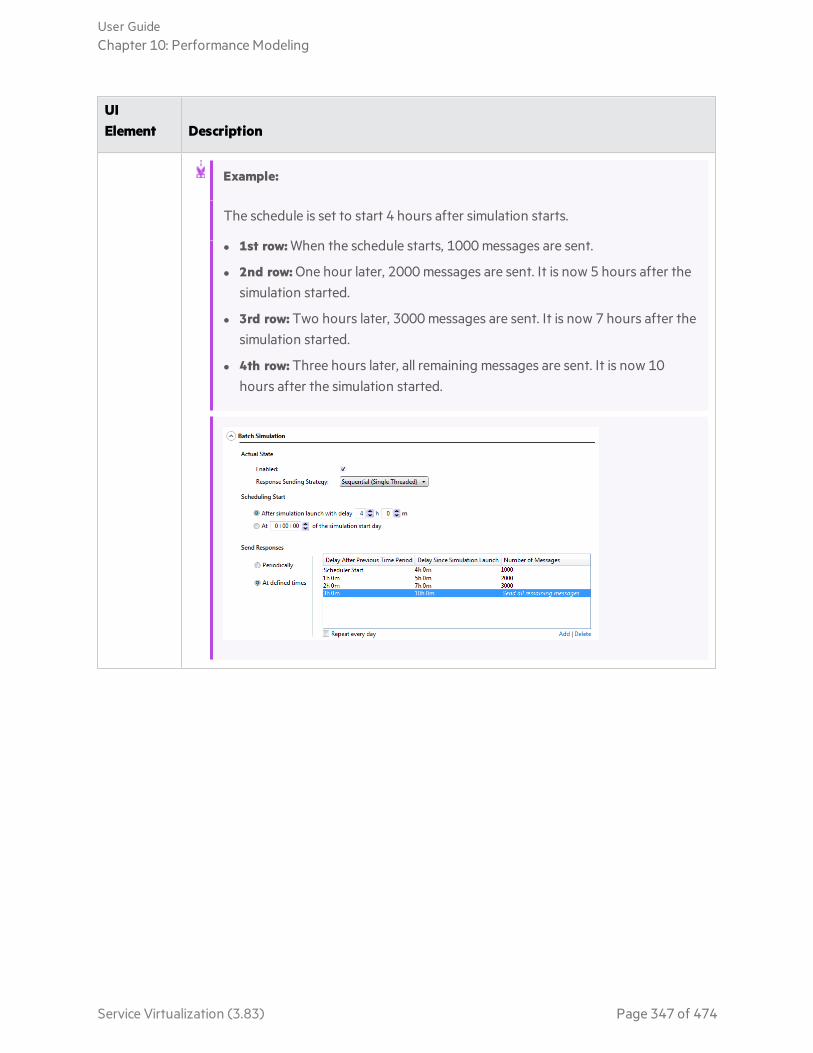
UIElement Description
Example:
The schedule is set to start 4 hours after simulation starts.
l 1st row: When the schedule starts, 1000 messages are sent.
l 2nd row: One hour later, 2000 messages are sent. It is now 5 hours after thesimulation started.
l 3rd row: Two hours later, 3000 messages are sent. It is now 7 hours after thesimulation started.
l 4th row: Three hours later, all remaining messages are sent. It is now 10hours after the simulation started.
User GuideChapter 10: Performance Modeling
Service Virtualization (3.83) Page 347 of 474

Chapter 11: Composite Application TopologyThis chapter includes:
• Composite Application Topology 349• Model Composite Applications 349• Topology User Interface 351
Service Virtualization (3.83) Page 348 of 474

Composite Application TopologyModel composite applications by creating a visual map of services, called a topology. You can groupthem into larger composites, mark their types, and display the service calls between them.
For task details, see "Model Composite Applications" below.
Model Composite ApplicationsThis task describes how to create and configure a topology to model and test your compositeapplication.
This task includes the following steps:
"Optional: Discover services" below
"Create a topology" below
"Configure the topology" on the next page
"Test your composite application" on the next page
"Virtualize services" on the next page
"Reconfigure clients" on the next page
"Learn service behavior" on page 351
"Simulate service behavior" on page 351
1. Optional: Discover services
You can use Service Discovery to find all the services used by an application via a proxy agent.
Note: Supported for SOAP services only.
a. On the Start Page, click Discover Services to create a new virtualization project and starts thediscovery process, enabling you to find all services used by an application.
Alternatively, you can discover services in an existing project. In the Topology Editor, right-clickand select Start Service Discovery.
b. In the Service Discovery dialog box, configure your client application to use the ServiceVirtualization proxies. You must configure the proxies before running Service Discovery. Foruser interface details, see "Service Discovery Dialog Box" on page 357.
c. Run your client application under test .
d. When services are discovered, click Stop Discovery. The discovered services are stored in agroup called Discovered Services. You can use them in your topology.
2. Create a topology
From the main menu, select File > New > Topology. For user interface details, see "Summary ofNew Topology Dialog Box" on page 352.
User GuideChapter 11: Composite Application Topology
Service Virtualization (3.83) Page 349 of 474
The new topology opens in the Topology Editor. By default, Service Virtualization creates the newtopology with one service which calls another, limited access service.
3. Configure the topology
You configure your topology using the Topology Editor. To model your composite application,create a visual map of your services, their types, and the connections between them.
a. From the Tools pane in the Topology Editor, add items to the topology.
b. Connect services using service call connectors. Move the cursor to the right edge of the callingservice until the hand icon displays. Then click and drag the connector to the called service.
c. To mark additional services as limited or secure, right-click a service and select Set LimitedAccess or Set Secure. For additional configuration options, right-click a service to view thecontext menu.
For user interface details, see "Topology Editor" on page 352.
4. Test your composite application
The process of testing your composite application includes the following steps:
a. virtualize services
b. reconfigure clients
c. learn services
d. simulate services
To test a service, in the Topology Editor, right-click the service and select Test. Services with limitedaccess, or services that may require reconfiguration are indicated with unique icons in the TopologyEditor. When you select to test a service that calls other limited access services, the Task List openson the right side of the Topology Editor. The Task List provides step-by-step instructions to guideyou through the process required to virtualize, learn, and simulate the limited access service thatyour service under test calls.
For user interface details, see the Task List section of the "Topology Editor" on page 352.
In addition, you can add and virtualize individual components, as described in the subsequent stepsin this task.
5. Virtualize services
In the Topology Editor, right-click a service and select Create Virtual Service. You can select anexisting virtual service from a drop-down list, or choose to create a new virtual service.For userinterface details on creating a new virtual service, see "Create New Virtual Service Wizard" on page153.
If a service is marked as secure and does not already have any associated authentication ServiceVirtualization cannot access the service and prompts you to provide authentication. For details onsetting authentication credentials, see "Set Security" on page 361.
6. Reconfigure clients
When you virtualize services, the services that call them may require reconfiguration to use the newvirtual service in place of the real service.
a. A service that requires reconfiguration is displayed in the Topology Editor with an exclamationpoint icon. Click the icon to open the Reconfigure Service dialog box, and update endpoint
User GuideChapter 11: Composite Application Topology
Service Virtualization (3.83) Page 350 of 474

details for real and virtual services as required.
b. When you have reconfigured the calling component, click Mark Completed and close the dialogbox. The exclamation point icon is no longer displayed.
7. Learn service behavior
You can learn the behavior of individual services in the topology of a composite application.
a. Prerequisites: Edit the topology, marking limited and secured services, and import servicedescriptions for the services you want to learn.
b. In the Topology Editor, right-click each service for which you want to record the real servicebehavior and select Learn.
c. Run your test through the composite application using a client or test script. ServiceVirtualization records the requests and responses for the virtualized services and createssimulation models for each one.
As you run your test, the Runtime View, located in the lower pane of the window, displaysdetails for each virtual service.
d. When you have finished recording, right-click each service you are recording and select StopLearning. The services are placed in Simulate Mode.
Alternatively, select Simulate and the application stops the learning process and switchesdirectly to simulating.
8. Simulate service behavior
You can test your composite application using the virtual services in your topology to simulate thebehavior of the real services.
a. Prerequisites: Learn the behavior of the services you want to simulate.
b. In the Topology Editor, right-click each service that you want to simulate and select Simulate.The service is placed in Simulate mode.
c. Run your test through the composite application using a client or test script. ServiceVirtualization processes the requests to each virtualized service and returns responses basedon the simulation model for each.
As you run your test, the Runtime View, located in the lower pane of the window, displaysdetails for each virtual service.
See also:l "End-to-End Workflow" on page 20
Topology User InterfaceThis section includes:
• Summary of New Topology Dialog Box 352• Topology Editor 352• Service Discovery Dialog Box 357
User GuideChapter 11: Composite Application Topology
Service Virtualization (3.83) Page 351 of 474
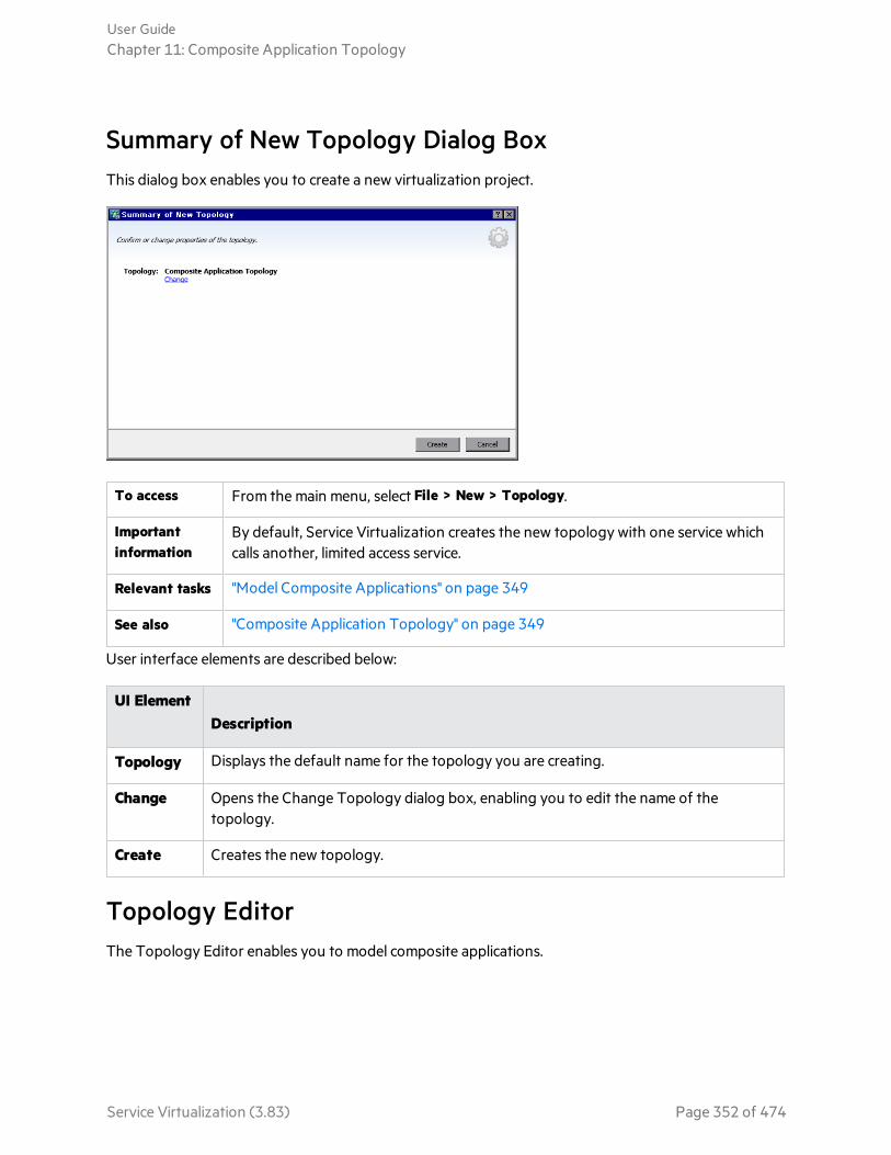
Summary of New Topology Dialog BoxThis dialog box enables you to create a new virtualization project.
To access From the main menu, select File > New > Topology.
Importantinformation
By default, Service Virtualization creates the new topology with one service whichcalls another, limited access service.
Relevant tasks "Model Composite Applications" on page 349
See also "Composite Application Topology" on page 349
User interface elements are described below:
UI ElementDescription
Topology Displays the default name for the topology you are creating.
Change Opens the Change Topology dialog box, enabling you to edit the name of thetopology.
Create Creates the new topology.
Topology EditorThe Topology Editor enables you to model composite applications.
User GuideChapter 11: Composite Application Topology
Service Virtualization (3.83) Page 352 of 474

To access In the Virtualization Explorer, double-click the topology you want to view or edit.
Relevant tasks "Model Composite Applications" on page 349
See also "Composite Application Topology" on page 349
User interface elements are described below.
Tools Pane
Located on the left side of the editor, enables you to drag and drop the following items to add to yourtopology:
Note: If the Tools pane is not displayed by default, from the main menu, select View > Tools.
UI Element Description
Service A service with no particular notation.
LimitedService
A service marked as having limited access. Access to such services may be limited dueto time or financial constraints.
SecuredService
A service marked as requiring authentication.
Group A box enabling you to organize services into larger composites for purposes of visualmapping.
Context menu
Note: To discover services, right-click inside the Topology Editor and select Start Service
User GuideChapter 11: Composite Application Topology
Service Virtualization (3.83) Page 353 of 474

Discovery. For details on service discovery, see "Service Discovery Dialog Box" on page 357.
Right-click a service in the Topology Editor to access the following commands:
MenuItem Description
Set/UnsetLimitedAccess
Marks or unmarks the selected service as having limited access.
Set/UnsetSecuredAccess
Marks or unmarks the selected service as requiring authentication. For details on settingauthentication credentials, see "Set Security" on page 361.
Test Marks the selected service, indicating that it is "under test".
Service Virtualization analyzes calls, suggests services to virtualize, and creates a task inthe Task List.
When you select this option for a service that uses other services with limited access, theTask List opens, displaying step-by-step instructions for testing the compositeapplication. For details, see Task List.
PreviewTestImpact
Enables/disables the Test Impact highlighting bar.Service Virtualization analyzes clientcalls and highlights services that you may want to virtualize.
Learn andSimulate
Enables you to create a new virtual service or import an existing service, and then placesthe service in Learning mode.
CreateVirtualService
Enables you to create a new virtual service or import an existing service. If you chooseto create a new virtual service, launches the Create Virtual Service wizard. For details,see "Create New Virtual Service Wizard" on page 153.
Rename Enables you to rename the selected service.
Delete Removes the selected service from the topology.
Service Annotation
The annotation for each service varies depending on its settings and various stages of configuration.
User GuideChapter 11: Composite Application Topology
Service Virtualization (3.83) Page 354 of 474

Service Diagram Description
An empty service.
A service marked as having limited access.
A service marked as secure, requiring credentials to access.
A virtualized service.
A virtualized service in Learning Mode. Service Virtualization records anyrequests and responses through this service and adds them to theassociated Simulation Model.
A virtualized service in Simulating Mode. Service Virtualization monitors anyrequests to this service and returns responses based on the associatedSimulation Model.
Indicates a service that is "under test".
A service suggested for virtualization.
A service requiring attention because it calls a virtualized service and mayrequire reconfiguration to call the virtual service instead of the real one.
Click the exclamation point icon to open the Reconfigure Service dialog box.
Task List
When you select to test a service that calls other limited access services, the Task List opens on the rightside of the Topology Editor. The Task List guides you through the process of testing your compositeapplication.
Note: The options in a step become available only after you have completed all previous(prerequisite) steps. When you pass or skip a step, the options in that step are automaticallydisabled.
User GuideChapter 11: Composite Application Topology
Service Virtualization (3.83) Page 355 of 474

UI Element Description
VirtualizeServices
Includes the following options:
l Virtualize Services. Enables you to define a new virtual service or import anexisting service. If you choose to create a new virtual service, launches the CreateVirtual Service wizard. For details, see "Create New Virtual Service Wizard" on page153.
This option enables you to virtualize all relevant services as indicated in the TaskList.
l Customize Virtualization of Services. Enables you to select the services that youwant to virtualize. Select the desired services and click Virtualize Selected Service.
When all the missing information for each service in complete, Virtualize Services ismarked as complete and you proceed to Reconfigure Clients.
Service Virtualization adds the virtual services, any new service descriptions, and adata and performance model for each service to the Virtualization Explorer.
ReconfigureClients
Reconfigure the client to use the endpoints of virtual services in place of the realservice endpoints. This is required in cases where Service Virtualization can onlyperform intrusive virtualization.
Includes the following:
l View. Displays instructions for reconfiguring clients.
l Save As. Saves the instructions as a text file.
l Mark as Completed. Marks the service under test as complete when you havereconfigured it to use the virtual services in place of real services.
LearnServices
Includes the following options:
l Learn Services. Places the virtual services in your composite application in Learningmode. For details on Learning mode, see "Virtual Services" on page 123.
Run your test through the composite application using a client or test script.Service Virtualization records the request and responses for each virtualizedservice and creates a simulation model for each. As you run your test, the RuntimeView, located in the lower pane of the window, displays details for each virtualservice.
l Skip to Simulate Services. Proceed to service simulation without recording anyadditional service communication. Select this option if you already have simulationmodels for your composite application.
User GuideChapter 11: Composite Application Topology
Service Virtualization (3.83) Page 356 of 474
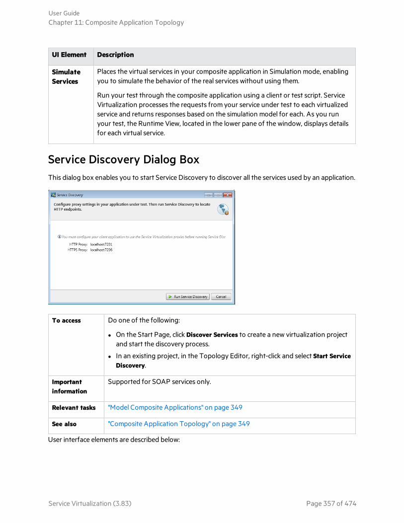
UI Element Description
SimulateServices
Places the virtual services in your composite application in Simulation mode, enablingyou to simulate the behavior of the real services without using them.
Run your test through the composite application using a client or test script. ServiceVirtualization processes the requests from your service under test to each virtualizedservice and returns responses based on the simulation model for each. As you runyour test, the Runtime View, located in the lower pane of the window, displays detailsfor each virtual service.
Service Discovery Dialog BoxThis dialog box enables you to start Service Discovery to discover all the services used by an application.
To access Do one of the following:
l On the Start Page, click Discover Services to create a new virtualization projectand start the discovery process.
l In an existing project, in the Topology Editor, right-click and select Start ServiceDiscovery.
Importantinformation
Supported for SOAP services only.
Relevant tasks "Model Composite Applications" on page 349
See also "Composite Application Topology" on page 349
User interface elements are described below:
User GuideChapter 11: Composite Application Topology
Service Virtualization (3.83) Page 357 of 474

UI Element Description
Server Currently supported for the Service Virtualization embedded server only.
ServiceVirtualizationproxies
You must configure your client application to use the Service Virtualizationproxies before running Service Discovery.
See also:l "Model Composite Applications" on page 349
l "Composite Application Topology" on page 349
l "HTTP Service Discovery" on page 134
User GuideChapter 11: Composite Application Topology
Service Virtualization (3.83) Page 358 of 474
Chapter 12: SecurityThis chapter includes:
• Virtual Service Security 360• Set Security 361• Password Encryption 371• Security User Interface 372
Service Virtualization (3.83) Page 359 of 474

Virtual Service SecurityThis section describes how security is handled by Service Virtualization. Service Virtualization supportsvirtualization of secured services using either HTTP transport level security or a subset of SOAPmessage level security.
Security components
Confidentiality The data is encrypted. Only an ultimate recipient can read the data.
Service Virtualization Help Center must be able to decrypt the message passedto the virtual service in order to learn the service. It must also be able to encryptmessages passed to the real service.
Integrity The data is signed. A recipient can validate that the data has not been modifiedduring transmissions.
Service Virtualization Help Center must be able to validate signatures inmessages received from clients and from the real service. It must also be able tosign messages sent to clients and the real service.
Authentication The identity of a client is transferred with the message.
Service Virtualization does not validate received client credentials. In somescenarios, incoming credentials are secured and are not directly readable.Therefore, the virtual service must have these credentials (certificates withprivate keys or user names with passwords) defined in Service Virtualization'sCredential Store, to be able to compute the secured value and pass it to the realservice.
Authorization The service validates that an authenticated client can execute the requiredoperation.
Service Virtualization does not handle authorization. Authorization logic is leftfor the real service.
User GuideChapter 12: Security
Service Virtualization (3.83) Page 360 of 474

Security levels
TransportSecurity
Transport level security is point-to-point. Security is ensured only on the transport levelconnection between two machines. Transport level integrity and confidentiality isensured through SSL / TLS (HTTP(s) Proxy agent or the HTTPS Gateway agent) andtransport level authentication is ensured with HTTP authentication mechanisms.
Transport authentication in service virtualization is used only in Stand-By and Learningmodes to access the real service. It is transparently managed by the HTTP Gateway orHTTP(S) proxy agents. Transport authentication only requires that correctlyconfigured credentials are available in Service Virtualization's Credential Store.
MessageSecurity
Message level security is end-to-end. Security is ensured on the message level – securityis part of message data which can be passed through many intermediaries (manyconnections) without revealing unsecured message content.
Message security in Service Virtualization is used for Stand-By, Learning, andSimulation modes.
MixedSecurity
Mixed security uses transport security to ensure confidentiality and integrity andmessage security to pass client credentials (authentication). This security configurationrequires the use of the HTTPS agent and message security modes with names endingwith OverTransport.
See also:l For task details, see "Set Security" below.
Set SecurityThis task describes how to set security for your virtual service.
In this topic:
l "Set authentication credentials" below
l "Set message security" on the next page
l "Set transport security" on the next page
Set authentication credentialsSome services may require client authentication on either the transport or message level. Whenvirtualizing these services, Service Virtualization needs to know the client credentials used to connect tothe real service. The only exception is a scenario wherein a real service with HTTP transportauthentication (Basic, Digest, NTLM) is virtualized through the HTTP(S) proxy agent. In this scenario,authentication requests are forwarded. Service Virtualization does not need to have the credentials inthe service’s credential store.
User GuideChapter 12: Security
Service Virtualization (3.83) Page 361 of 474

In the Virtual Service Editor, expand Security Settings and click Edit Credential Store to configure therequired settings.
For user interface details, see "Edit Credential Store Dialog Box" on page 373.
Set message securitySet message security for your virtual service in the Virtual Service Editor. For task details, see "SetMessage Security" below.
Set transport securityTransport authentication in Service Virtualization is used in Standby and Learning modes to access thereal service. It is transparently managed by the HTTP Gateway or HTTP(S) proxy agents. Transportauthentication only requires that correctly configured credentials are available in Service Virtualization'sCredential Store.
For task details, see "Set Transport Security" on page 369.
See also:l "End-to-End Workflow" on page 20.
l "Virtual Service Security" on page 360
Set Message SecurityThis task describes how to configure settings for the default message security modes.
Note:
l This task is part of a higher-level task. For details, see "Set Security" on the previous page.
l To learn more about Service Virtualization security, see "Virtual Service Security" on page 360.
In the Virtual Service Editor, under Security Settings, configure one of the following security modes foryour virtual service:
l "Configure CertificateOverTransport mode" on the next page
l "Configure DigestPasswordAndUserNameOverTransport mode" on the next page
l "Configure MutualCertificate mode" on page 364
l "Configure MutualCertificateDuplex mode" on page 365
l "Configure SignOnlyWithMutualCertificate mode" on page 367
l "Configure SupportingCertificateOverTransport mode" on page 367
l "Configure UserNameOverTransport mode" on page 368
User GuideChapter 12: Security
Service Virtualization (3.83) Page 362 of 474

Configure CertificateOverTransport mode
Certificate over transport mode uses an endorsing supporting binary token over HTTPS:
l Transport security binding
l Algorithm suite: Basic256
l Layout: Strict
l Endorsing supporting token
l X509Token (WssX509V3Token10) always included to recipient
l Inclusion type: MustSupportRefThumbprint / RequireThumbprintReference
To configure CertificateOverTransport mode:
1. Prerequisites:
a. You must have created a virtual service.
b. The Service Virtualization Credential Store must contain an identity with each used clientcertificate.
c. Certificates must contain a private key.
2. In the Virtual Service Editor, expand Security Settings. Under Message Security, select Enabled.
3. In the Mode drop-down box, select CertificateOverTransport.
Note: Do not configure Real Service Identity or Virtual Service Identity
4. Click Advanced Settings to open the Advanced Message Security Settings dialog box, andconfigure as follows:
l Protection Level. This setting has no effect because encryption and signing are provided by thetransport level (HTTPS).
l Message Protection Order. This setting has no effect because encryption and signing areprovided by the transport level (HTTPS).
l Message Security Version. Only WS-Security 1.1 is supported because this configuration moderequires thumbprint token inclusion mode which is not supported in WS-Security 1.0.
l Require Derived Keys. This setting should not be changed.
l Include Timestamp. This setting must be checked because the endorsing supporting tokenpassed in the request must sign the timestamp header.
l Allow Serialized Signing Token on Reply. This setting has no effect.
Configure DigestPasswordAndUserNameOverTransport mode
Requires a username security token within the request message and forwards the token into theoutgoing request to a real service during Learning and Standby modes. It ignores the responsemessage, leaving any token (if present) to be learned as part of the response. During simulation, learnedresponse tokens are used.
User GuideChapter 12: Security
Service Virtualization (3.83) Page 363 of 474

Example of the request security header containing the username token:
Example:
<o:Security s:mustUnderstand="1" xmlns:o="http://docs.oasis-open.org/wss/2004/01/oasis-200401-wss-wssecurity-secext-1.0.xsd">
<wsse:UsernameToken wsu:Id="uuid-c7f6a73a-6da9-479c-8383-f9ae4766e1a3-26"xmlns:wsse="http://docs.oasis-open.org/wss/2004/01/oasis-200401-wss-wssecurity-secext-1.0.xsd" xmlns:wsu="http://docs.oasis-open.org/wss/2004/01/oasis-200401-wss-wssecurity-utility-1.0.xsd">
<wsse:Username>requestSample</wsse:Username><wsse:Password Type="http://docs.oasis-open.org/wss/2004/01/oasis-200401-
wss-username-token-profile-1.0#PasswordDigest">opF+QBL2BzrO9+H7CPcp3XF1uro=</wsse:Password>
<wsse:Nonce>aLtQ7CsnEdssRz+PrqN4Vw==</wsse:Nonce><wsu:Created>2015-05-25T11:38:21Z</wsu:Created>
</wsse:UsernameToken></o:Security>
To configure DigestPasswordAndUserNameOverTransport mode:
1. Prerequisites:
a. You must have created a virtual service.
b. The Service Virtualization Credential Store must contain an identity with each used clientcertificate.
c. Certificates must contain a private key.
2. In the Virtual Service Editor, expand Security Settings. Under Message Security, select Enabled.
3. In the Mode drop-down box, select DigestPasswordAndUserNameOverTransport.
Note: Do not configure Real Service Identity, Virtual Service Identity, or Security Applied To.
Configure MutualCertificate mode
MutualCertificate is a mode with asymmetric security binding (WS-Security 1.0) which uses both clientand server certificates to secure messages over unsecured transport (HTTP):
l Assymetric security binding
l Initiator token: X509Token (WssX509V3Token10) always included to recipient.
l Recipient token: X509Token (WssX509V3Token10) never included.
l Algorithm suite: Basic256
l Layout: Strict
l Token inclusion type:
User GuideChapter 12: Security
Service Virtualization (3.83) Page 364 of 474

o MustSupportRefKeyIdentifiero MustSupportRefIssueSerial
To configure MutualCertificate mode:
1. Prerequisites:
a. You must have created a virtual service.
b. The Service Virtualization Credential Store must contain an identity with a real servicecertificate.
If the certificate does not contain a private key, the Credential Store must also contain anidentity for the virtual service, with a certificate containing a private key.
c. The Credential Store must contain an identity with each used client certificate.
d. Client certificates must contain a private key.
2. In the Virtual Service Editor, expand Security Settings. Under Message Security, select Enabled.
3. In the Mode drop-down box, select MutualCertificate.
4. In the Real Service Identity drop-down box, select an identity configured in the Credential Store.
If the identity for the real service does not contain a certificate with a private key, or if you want touse separate identity for the virtual service, select an identity configured in the Credential Store forVirtual Service Identity. This identity must contain a certificate with a private key.
5. Click Advanced Settings to open the Advanced Message Security Settings dialog box, andconfigure as follows:
l Protection Level. Configures the level of security applied to each message.
l Message Protection Order. Configures the order of protection operations used to securemessages.
l Message Security Version. Use only WS-Security 1.0.
l Require Derived Keys. This setting should not be changed.
l Include Timestamp. This setting controls if requests and responses must contain a securitytimestamp.
l Allow Serialized Signing Token on Reply. This setting has no effect.
Configure MutualCertificateDuplex mode
MutualCertificateDuplex mode with asymmetric security binding (WS-Security 1.0 and 1.1) uses bothclient and server certificates to secure messages over unsecured transport (HTTP). The differencebetween MutualCertificate and MutualCertificateDuplex is that MutualCertificateDuplex security modealso sends the recipient’s signing token back to the initiator.
l Assymetric security binding
l Initiator token: X509Token (WssX509V3Token10) always included to recipient.
l Recipient token: X509Token (WssX509V3Token10) always included to initiator.
User GuideChapter 12: Security
Service Virtualization (3.83) Page 365 of 474

l Algorithm suite: Basic256
l Layout: Strict
l Token inclusion type depends on WS-Security version configured in Advanced settings::o WS-Security 1.0
l MustSupportRefKeyIdentifier
l MustSupportRefIssueSerialo WS-Security 1.1
l MustSupportRefThumbprint / RequireThumbprintReference
To configure MutualCertificateDuplex mode:
1. Prerequisites:
a. You must have created a virtual service.
b. The Service Virtualization Credential Store must contain an identity with a real servicecertificate.
If the certificate does not contain a private key, the Credential Store must also contain anidentity for the virtual service, with a certificate containing a private key.
c. The Credential Store must contain an identity with each used client certificate.
d. Client certificates must contain a private key.
2. In the Virtual Service Editor, expand Security Settings. Under Message Security, select Enabled.
3. In the Mode drop-down box, select MutualCertificateDuplex.
4. In the Real Service Identity drop-down box, select an identity configured in the Credential Store.
If the identity for the real service does not contain a certificate with a private key, or if you want touse separate identity for the virtual service, select an identity configured in the Credential Store forVirtual Service Identity. This identity must contain a certificate with a private key.
5. Click Advanced Settings to open the Advanced Message Security Settings dialog box, andconfigure as follows:
l Protection Level. Configures the level of security applied to each message.
l Message Protection Order. Configures the order of protection operations used to securemessages.
l Message Security Version. this setting defines how the binary token is referenced in the requestmessage.o Message security versions using WS-Security 1.0 requires either issuer serial number or key
identifier of the certificate.o Message security versions using WS-Security 1.1 requires thumbprint of the certificate.
l Require Derived Keys. This setting should not be changed.
l Include Timestamp. This setting controls if requests and responses must contain a securitytimestamp.
l Allow Serialized Signing Token on Reply. You must select this setting because the recipient’ssigning token is always send back to an initiator.
User GuideChapter 12: Security
Service Virtualization (3.83) Page 366 of 474
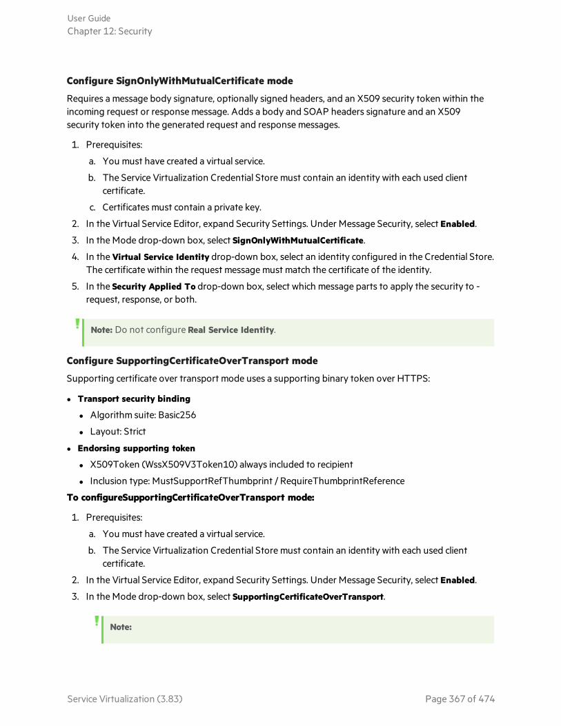
Configure SignOnlyWithMutualCertificate mode
Requires a message body signature, optionally signed headers, and an X509 security token within theincoming request or response message. Adds a body and SOAP headers signature and an X509security token into the generated request and response messages.
1. Prerequisites:
a. You must have created a virtual service.
b. The Service Virtualization Credential Store must contain an identity with each used clientcertificate.
c. Certificates must contain a private key.
2. In the Virtual Service Editor, expand Security Settings. Under Message Security, select Enabled.
3. In the Mode drop-down box, select SignOnlyWithMutualCertificate.
4. In the Virtual Service Identity drop-down box, select an identity configured in the Credential Store.The certificate within the request message must match the certificate of the identity.
5. In the Security Applied To drop-down box, select which message parts to apply the security to -request, response, or both.
Note: Do not configure Real Service Identity.
Configure SupportingCertificateOverTransport mode
Supporting certificate over transport mode uses a supporting binary token over HTTPS:
l Transport security binding
l Algorithm suite: Basic256
l Layout: Strict
l Endorsing supporting token
l X509Token (WssX509V3Token10) always included to recipient
l Inclusion type: MustSupportRefThumbprint / RequireThumbprintReference
To configureSupportingCertificateOverTransport mode:
1. Prerequisites:
a. You must have created a virtual service.
b. The Service Virtualization Credential Store must contain an identity with each used clientcertificate.
2. In the Virtual Service Editor, expand Security Settings. Under Message Security, select Enabled.
3. In the Mode drop-down box, select SupportingCertificateOverTransport.
Note:
User GuideChapter 12: Security
Service Virtualization (3.83) Page 367 of 474
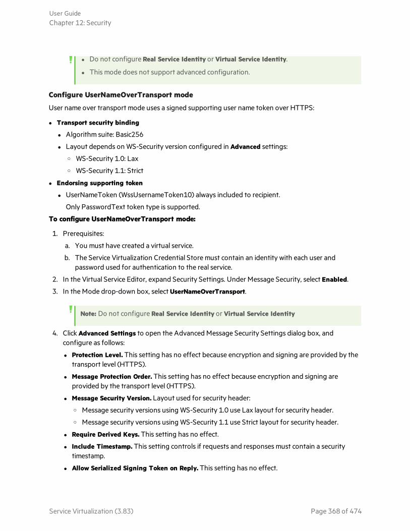
l Do not configure Real Service Identity or Virtual Service Identity.
l This mode does not support advanced configuration.
Configure UserNameOverTransport mode
User name over transport mode uses a signed supporting user name token over HTTPS:
l Transport security binding
l Algorithm suite: Basic256
l Layout depends on WS-Security version configured in Advanced settings:o WS-Security 1.0: Laxo WS-Security 1.1: Strict
l Endorsing supporting token
l UserNameToken (WssUsernameToken10) always included to recipient.
Only PasswordText token type is supported.
To configure UserNameOverTransport mode:
1. Prerequisites:
a. You must have created a virtual service.
b. The Service Virtualization Credential Store must contain an identity with each user andpassword used for authentication to the real service.
2. In the Virtual Service Editor, expand Security Settings. Under Message Security, select Enabled.
3. In the Mode drop-down box, select UserNameOverTransport.
Note: Do not configure Real Service Identity or Virtual Service Identity
4. Click Advanced Settings to open the Advanced Message Security Settings dialog box, andconfigure as follows:
l Protection Level. This setting has no effect because encryption and signing are provided by thetransport level (HTTPS).
l Message Protection Order. This setting has no effect because encryption and signing areprovided by the transport level (HTTPS).
l Message Security Version. Layout used for security header:o Message security versions using WS-Security 1.0 use Lax layout for security header.o Message security versions using WS-Security 1.1 use Strict layout for security header.
l Require Derived Keys. This setting has no effect.
l Include Timestamp. This setting controls if requests and responses must contain a securitytimestamp.
l Allow Serialized Signing Token on Reply. This setting has no effect.
User GuideChapter 12: Security
Service Virtualization (3.83) Page 368 of 474

Set Transport SecurityThis task describes how to set transport security for your virtual service.
Note:
l This task is part of a higher-level task. For details, see "Set Security" on page 361.
l To learn more about Service Virtualization security, see "Virtual Service Security" on page 360.
Transport level security is completely handled by the HTTP based agent. The virtual and real servicescan use HTTP authentication to prevent unauthorized use. The service can use basic, digest, NTLMauthentication, or Mutual HTTPS.
This task includes the following:
l "HTTPS and mutual authentication" below
l "HTTP authentication over HTTP(S) Proxy agent" on the next page
l "HTTP authentication over HTTP / HTTPS Gateway agent" on the next page
l "Windows accounts for HTTP authentication" on page 371
HTTPS and mutual authentication
Services secured with HTTPS are supported by either the HTTPS Gateway agent or the HTTP(S) Proxyagent. Both agent types also support Mutual HTTPS where the client authenticates itself with a clientcertificate. To use Mutual HTTPS, the credential store must contain a client certificate and its privatekey for every client accessing the virtual service. For details on setting authentication credentials, see"Edit Credential Store Dialog Box" on page 373
The mutual HTTPS authentication for the HTTPS Gateway agent is handled by the client operatingsystem. Therfore, the certificate of the certification authority that issued all client certificates in use mustbe imported into the local computers’s Trusted Root Certificate Authorities store.
To import the Certification Authority's certificate into the local system's certificate store:
1. From the command line or Windows Start menu Search bar, type mmc to run Microsoft ManagementConsole.
2. From the File menu, select Add/Remove Snap-in.
3. From the Available Snap-ins list, select Certificates and click Add. In the screens that follow, selectComputer account, and then Local Computer. Click Finish.
4. To import the certificates, expand the Certificates (Local Computer) node, as shown below. UnderTrusted Root Certification Authorities, right-click Certificates and select All Tasks > Import.
User GuideChapter 12: Security
Service Virtualization (3.83) Page 369 of 474

5. Follow the on-screen directions to import the certificates.
HTTP authentication over HTTP(S) Proxy agent
When using a proxy agent and running the virtual service in Stand-By or Learning mode, theauthentication is fully transparent and the virtual service does not need any further configuration. Theentire security handshake is passed from the client to the real service through the proxy, and clientcredentials are validated just by the real service.
HTTP authentication is not used when the service is in Simulating mode.
HTTP authentication over HTTP / HTTPS Gateway agent
When using the gateway agent and running the virtual service in Stand-By or Learning mode, the clientauthenticates to the virtual service and the virtual service authenticates to the real service. The virtualservice must be able to validate a client’s credentials and pass them to the real service, meaning that theservice must have all user names and passwords in the credential store.
There are several steps to set this authentication:
1. All users who are authenticating to your service must be present in the Windows system where thevirtual service is running. They can be added as local users of the machine or added to the domainto which the computer belongs. The username and password must be the same as the one theclient uses to authenticate to the real service.
Note: HTTP digest authentication only works with domain users, not local ones. The domain musthave reversibly encrypted passwords. See IIS documentation for details.
2. To delegate requests to the real service (when learning or in stand-by mode), the username andpassword must be in the service's credential store.
a. In the Virtual Service Editor, expand Security Settings and click Edit Credential Store.
b. Click Add Identity.
c. Enter Identity details and supply a certificate if required.
d. Click OK to add the identity and OK again to close the Credential Store.
User GuideChapter 12: Security
Service Virtualization (3.83) Page 370 of 474
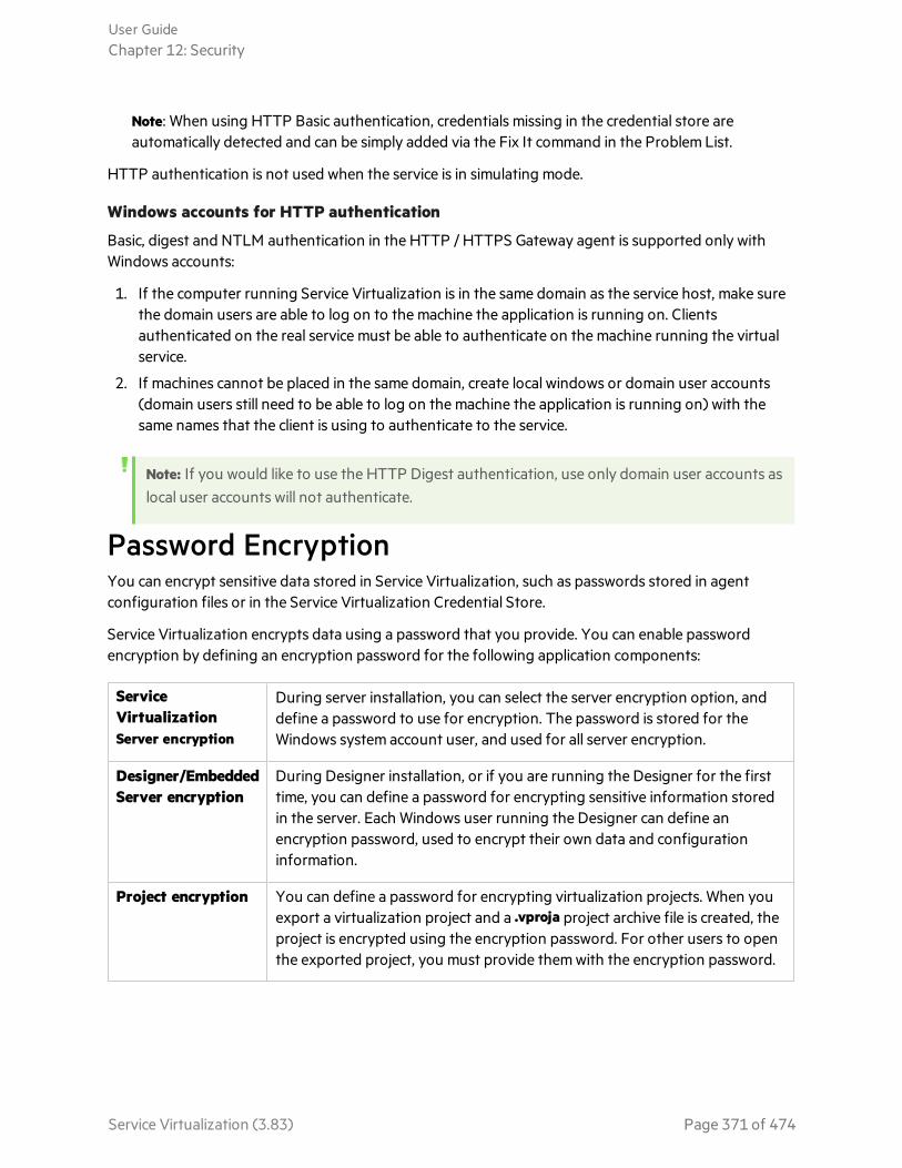
Note: When using HTTP Basic authentication, credentials missing in the credential store areautomatically detected and can be simply added via the Fix It command in the Problem List.
HTTP authentication is not used when the service is in simulating mode.
Windows accounts for HTTP authentication
Basic, digest and NTLM authentication in the HTTP / HTTPS Gateway agent is supported only withWindows accounts:
1. If the computer running Service Virtualization is in the same domain as the service host, make surethe domain users are able to log on to the machine the application is running on. Clientsauthenticated on the real service must be able to authenticate on the machine running the virtualservice.
2. If machines cannot be placed in the same domain, create local windows or domain user accounts(domain users still need to be able to log on the machine the application is running on) with thesame names that the client is using to authenticate to the service.
Note: If you would like to use the HTTP Digest authentication, use only domain user accounts aslocal user accounts will not authenticate.
Password EncryptionYou can encrypt sensitive data stored in Service Virtualization, such as passwords stored in agentconfiguration files or in the Service Virtualization Credential Store.
Service Virtualization encrypts data using a password that you provide. You can enable passwordencryption by defining an encryption password for the following application components:
ServiceVirtualizationServer encryption
During server installation, you can select the server encryption option, anddefine a password to use for encryption. The password is stored for theWindows system account user, and used for all server encryption.
Designer/EmbeddedServer encryption
During Designer installation, or if you are running the Designer for the firsttime, you can define a password for encrypting sensitive information storedin the server. Each Windows user running the Designer can define anencryption password, used to encrypt their own data and configurationinformation.
Project encryption You can define a password for encrypting virtualization projects. When youexport a virtualization project and a .vproja project archive file is created, theproject is encrypted using the encryption password. For other users to openthe exported project, you must provide them with the encryption password.
User GuideChapter 12: Security
Service Virtualization (3.83) Page 371 of 474

See also:l For details on enabling project encryption, see "Projects and Solutions Page" on page 196.
l For additional options for configuring password encryption in Service Virtualization, refer to the HPEService Virtualization Installation Guide.
Security User InterfaceThis section includes:
• Edit Credential Store Dialog Box 373• Advanced Message Security Settings Dialog Box 374
User GuideChapter 12: Security
Service Virtualization (3.83) Page 372 of 474

Edit Credential Store Dialog BoxThis dialog box enables you to add, modify, or delete the users or certificates in the credential store forthe selected service.
To access In the Virtual Service Editor, expand Security Settings and click Edit Credential Store.
Importantinformation
When creating credentials for transport security over the HTTP(S) Gateway agent, theuser of the virtual service must be a valid Windows account. This Windows account canbe one of the following:
l A domain account. This is supported automatically.
l A local account. If it does not already exist, you must create a local Windows accounton the machine hosting the Service Virtualization Designer or standalone server.You must use the same user name and password.
Relevanttasks
"Set Security" on page 361
See also "Virtual Service Security" on page 360
User interface elements are described below (unlabeled elements are shown in angle brackets):
UIElement Description
<usergrid>
Displays the users and credentials defined in the credential store for this service.
User GuideChapter 12: Security
Service Virtualization (3.83) Page 373 of 474

UIElement Description
AddIdentity
Opens the Add Identity dialog box, enabling you to define a new identity to add to thecredential store.
Enter a username and password. Empty values are also permitted. These credentials canrepresent either a Windows account (for transport security - Basic, Digest, or NTLM) orother type of user credentials used by the real service (for message security).
Click Show password to display the password.
Click the browse button to select a certificate to add. The following certificate types aresupported: .pfs, .p12, .cer, .der, .crt. Click OK. If the certificate's private key requires apassword, you are prompted to enter the password. You can also export an existingcertificate.
Edit Enables you to modify user credentials, or export a certificate. Select an identity and clickEdit to open the Edit Identity dialog box.
Delete Enables you to remove user credentials. Select one or more identities in the grid and clickDelete.
Import Enables you to select identities to add to the service.
In the Import Identities dialog box, under Services, select the virtual service containing theidentity you want to import. Then under Identities, select the identity to import into yourvirtual service.
Advanced Message Security Settings Dialog BoxThis dialog box enables you to set advanced options for message security.
User GuideChapter 12: Security
Service Virtualization (3.83) Page 374 of 474
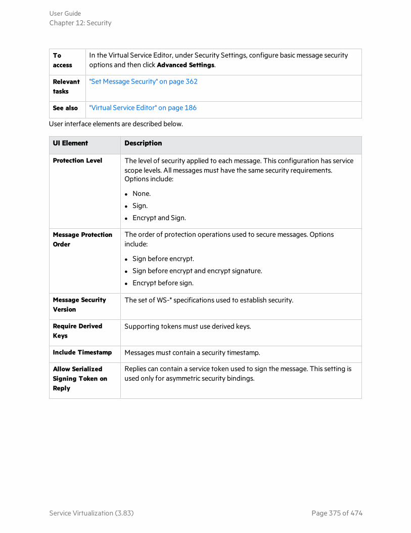
Toaccess
In the Virtual Service Editor, under Security Settings, configure basic message securityoptions and then click Advanced Settings.
Relevanttasks
"Set Message Security" on page 362
See also "Virtual Service Editor" on page 186
User interface elements are described below.
UI Element Description
Protection Level The level of security applied to each message. This configuration has servicescope levels. All messages must have the same security requirements.Options include:
l None.
l Sign.
l Encrypt and Sign.
Message ProtectionOrder
The order of protection operations used to secure messages. Optionsinclude:
l Sign before encrypt.
l Sign before encrypt and encrypt signature.
l Encrypt before sign.
Message SecurityVersion
The set of WS-* specifications used to establish security.
Require DerivedKeys
Supporting tokens must use derived keys.
Include Timestamp Messages must contain a security timestamp.
Allow SerializedSigning Token onReply
Replies can contain a service token used to sign the message. This setting isused only for asymmetric security bindings.
User GuideChapter 12: Security
Service Virtualization (3.83) Page 375 of 474

Chapter 13: HPE Test Automation ToolsIntegrationThis chapter includes:
• HPE Test Automation Tools Integration 377• User Authentication 377• Unified Functional Testing 377• Performance Center and LoadRunner 377• Performance Counters 378
Service Virtualization (3.83) Page 376 of 474
HPE Test Automation Tools IntegrationService Virtualization can be integrated with HPE test automation tools. The virtual services aremanaged via the tests, and the performance monitors exposed by the virtual services are used by theperformance testing tools.
Service Virtualization Help Center integrates with HPE Unified Functional Testing, HPE LoadRunner,and HPE Performance Center. For details on currently supported versions, see the Integrations Page onthe HPE Software Support Online web site at: https://softwaresupport.hpe.com/.
User AuthenticationFor integration of Service Virtualization with another HPE test automation tool, follow theserecommendations:
When logging in to the Service Virtualization machine and the integrating tool's machine:
l do not use local users with the same user names but different passwords
l it is preferable to log in with domain users only
l if permitted by your Windows administrative policy, set the Account lockout threshold to 0
In Windows Performance Monitor on the LoadRunner/Performance Center Controller machine, verifythat you are using the correct username, password, and computer name format for the relevant ServiceVirtualization performance counters.
Unified Functional TestingService Virtualization projects can be integrated with Unified Functional Testing (UFT). For details, seeUFT documentation.
The virtual services are then managed by the test after the integration.
l The simulation start is triggered by the test start. Make sure that the virtual services are alreadydeployed on the Service Virtualization Server.
l Particular data and performance models can be selected for the test.
l Simulating or Standby modes using the real service are chosen during the test.
Performance Center and LoadRunnerService virtualization projects can be integrated with the Performance Center or LoadRunner Scenarios.For details, see Performance Center or LoadRunner Documentation.
The virtual services are then managed by the test after the integration.
l The simulation start is triggered by the test start. Make sure that the virtual services are alreadydeployed on the Service Virtualization Server.
l Specific data and performance models can be selected for the test.
l Simulating or Standby modes using the real service are selected during the test.
User GuideChapter 13: HPE Test Automation Tools Integration
Service Virtualization (3.83) Page 377 of 474

Performance monitors exposed by virtual services are used immediately in the Performance Center orLoadRunner Controller. The performance monitors exposed by Service Virtualization are namedServices and Operations.
l The Services performance counter provides measurement data per virtual service.
l The Operations performance counter provides data per virtual service and service operation.
For more details, see "Performance Counters" below.
Performance CountersYou can monitor Service Virtualization message processing using predefined performance counters.The performance counters are created during installation of either the Service Virtualization Designeror the Service Virtualization Server. You can then view the counters in Windows Performance Monitor.You can also use the performance counters to monitor Service Virtualization that is running on aremote machine. The uninstallation of both the Designer and Server delete the counters from theWindows system.
This section includes:
l "Performance Counter Categories" below
l "Performance Counter Instances" on page 380
l "Remote Monitoring" on page 380
l "Troubleshoot Performance Counters" on page 381
Performance Counter CategoriesThere are several Service Virtualization performance counter categories added to the WindowsPerformance Monitor:
HPE ServiceVirtualization- Services
The Services performance counters provide measurement data per virtual service.Both the Designer and the Server write their data to these same counters. Fordetails, see Services.
HPE ServiceVirtualization- Operations
The Operations performance counters provide data per virtual service and serviceoperation. Both the Designer and the Server write their data to these samecounters. For details, see Operations.
HPE ServiceVirtualization- ServerStatistics
The Server Statistics performance counters provide data for a standalone ServiceVirtualization Server, and for the services deployed on the server. Only the ServiceVirtualization Server writes data to these counters. For details, see Server Statistics.
User GuideChapter 13: HPE Test Automation Tools Integration
Service Virtualization (3.83) Page 378 of 474
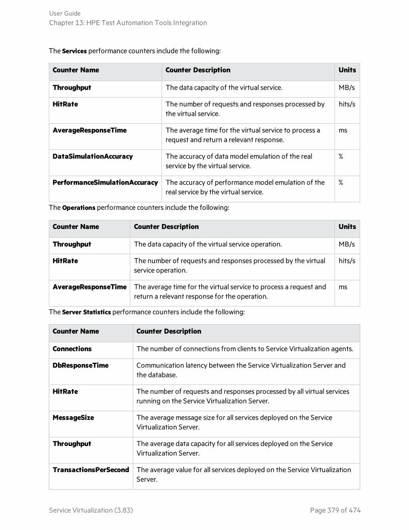
The Services performance counters include the following:
Counter Name Counter Description Units
Throughput The data capacity of the virtual service. MB/s
HitRate The number of requests and responses processed bythe virtual service.
hits/s
AverageResponseTime The average time for the virtual service to process arequest and return a relevant response.
ms
DataSimulationAccuracy The accuracy of data model emulation of the realservice by the virtual service.
%
PerformanceSimulationAccuracy The accuracy of performance model emulation of thereal service by the virtual service.
%
The Operations performance counters include the following:
Counter Name Counter Description Units
Throughput The data capacity of the virtual service operation. MB/s
HitRate The number of requests and responses processed by the virtualservice operation.
hits/s
AverageResponseTime The average time for the virtual service to process a request andreturn a relevant response for the operation.
ms
The Server Statistics performance counters include the following:
Counter Name Counter Description
Connections The number of connections from clients to Service Virtualization agents.
DbResponseTime Communication latency between the Service Virtualization Server andthe database.
HitRate The number of requests and responses processed by all virtual servicesrunning on the Service Virtualization Server.
MessageSize The average message size for all services deployed on the ServiceVirtualization Server.
Throughput The average data capacity for all services deployed on the ServiceVirtualization Server.
TransactionsPerSecond The average value for all services deployed on the Service VirtualizationServer.
User GuideChapter 13: HPE Test Automation Tools Integration
Service Virtualization (3.83) Page 379 of 474

Performance Counter InstancesService Virtualization creates instances of all the performance counters for each virtual service that isdeployed locally, either on the Service Virtualization Designer's embedded server, or on the ServiceVirtualization Server.
Instance names are created in the following format:
l For services: <service_name>
l For operations: <service_name>_<operation_name>
l For server statistics: server statistics. The instance is created during installation of the ServiceVirtualization Server. Data is updated on the Server machine only, when the Server is running.
For example, for a locally deployed virtual service called HelloWorld which has two operations namedHello and Bye, the performance counters in the local system have the following instances:
CounterCategory Counter Name Counter Instance Name
Helloworld Service
Services AverageResponseTime helloworld
HitRate helloworld
Throughput helloworld
DataSimulationAccuracy helloworld
PerformanceSimulationAccuracy helloworld
HelloOperation
ByeOperation
Operations AverageResponseTime helloworld_hello
helloworld_bye
HitRate helloworld_hello
helloworld_bye
Throughput helloworld_hello
helloworld_bye
Remote MonitoringYou can use the performance counters to monitor Service Virtualization that is running on a remotemachine.
User GuideChapter 13: HPE Test Automation Tools Integration
Service Virtualization (3.83) Page 380 of 474
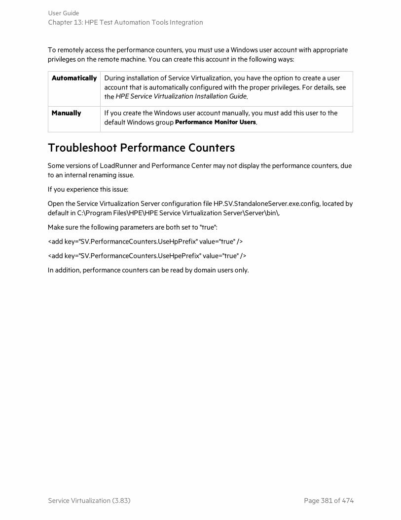
To remotely access the performance counters, you must use a Windows user account with appropriateprivileges on the remote machine. You can create this account in the following ways:
Automatically During installation of Service Virtualization, you have the option to create a useraccount that is automatically configured with the proper privileges. For details, seethe HPE Service Virtualization Installation Guide.
Manually If you create the Windows user account manually, you must add this user to thedefault Windows group Performance Monitor Users.
Troubleshoot Performance CountersSome versions of LoadRunner and Performance Center may not display the performance counters, dueto an internal renaming issue.
If you experience this issue:
Open the Service Virtualization Server configuration file HP.SV.StandaloneServer.exe.config, located bydefault in C:\Program Files\HPE\HPE Service Virtualization Server\Server\bin\.
Make sure the following parameters are both set to "true":
<add key="SV.PerformanceCounters.UseHpPrefix" value="true" />
<add key="SV.PerformanceCounters.UseHpePrefix" value="true" />
In addition, performance counters can be read by domain users only.
User GuideChapter 13: HPE Test Automation Tools Integration
Service Virtualization (3.83) Page 381 of 474
Chapter 14: Continuous IntegrationThe HPE Application Automation Tools plugin for the Jenkins continuous integration server provides amechanism for incorporating virtual services into a build script. This open source plugin enables you toadd steps to your Jenkins build job to:
l deploy and undeploy virtual services
l start and stop simulation and learning
l export virtual services
This section describes several testing scenarios that you can automate using Jenkins.
For detailed instructions on using the plugin to complete these tasks, see https://wiki.jenkins-ci.org/display/JENKINS/HPE+Application+Automation+Tools
Note: The HPE Application Automation Tools Plugin for Jenkins is a java application that can berun on a Jenkins server running on Windows or on any Linux platform.
General prerequisitesBefore you begin setting up a job in Jenkins, make sure to:
l Create a virtual service. In the Service Virtualization Designer, create or open the virtual service thatyou want to use in your build job.
l Deploy the virtual service. Try to deploy the virtual service to the target Service Virtualization Serverto verify that all required agents are ready.
l Use source control. It is recommended to commit virtual service files to source control to enable easydistribution to build machines.
Configure the connection to your ServiceVirtualization ServerConfigure the Jenkins connection to your Service Virtualization Server, according to the plugindocumentation.
Test the connection to verify the setup.
You can configure connections to multiple Service Virtualization Servers in Jenkins. The Servers arethen available for selection when you create build steps.
Use a virtual service in a Jenkins testA virtualized service may be very useful when your tests need to use services which are not available inyour testing environment.
Service Virtualization (3.83) Page 382 of 474

Create a build job in Jenkins
1. Create a new free-style project.
2. Specify source control options to checkout your tests and virtual service files.
3. Add the SV: Deploy Virtual Service build step to deploy the virtual service on the ServiceVirtualization Server.
Specify the Service Virtualization project path relative to the checkout directory. You can optionallychoose to specify a specific virtual service from the project, if you do not want to deploy all thevirtual services.
4. Run the build to verify the source control connection, paths, and the connection to the ServiceVirtualization Server.
Review the build log to confirm the names and IDs of the deployed virtual services and thesimulation models that were used. The names or IDs are also needed for setting up the subsequentsteps in the build job.
Example:
5. Add the SV: Change Mode of Virtual Service build step to change the virtual service mode toSimulate. Specify the Service Virtualization Server, virtual service, and data and performancemodels to use.
6. Add a build step to run your Jenkins tests that are using the virtual service.
7. At the end of the job, add the SV: Undeploy Virtual Service build step to undeploy the virtualservice from the Service Virtualization Server.
Automate the update of virtual service modelsThis section describes how to set up a Jenkins job to automatically update a simulation model (data orperformance) in your service. A virtual service with a periodically updated model can be used as a freshbackup of the real service in the event of unexpected failure.
User GuideChapter 14: Continuous Integration
Service Virtualization (3.83) Page 383 of 474
Prerequisite: Prepare the virtual service.
Create or open a virtual service and create a simulation model. The data model can be empty.
Create a build job in Jenkins
1. Perform steps 1-4 of "Use a virtual service in a Jenkins test" on page 382.
2. Add the SV: Change Mode of Virtual Service build step to change the virtual service mode to Learn.
3. Add a build step to run your Jenkins tests that are using the virtual service, in order to record data.
4. Add the SV: Export Virtual Service build step to export the virtual service. The export step createsa new folder named according to the virtual service name in the target directory that you specify .
Note: Before export, the virtual service must be switched from Learning to Stand-By modeto stop learning and generate the updated simulation models. Make sure to select theoption to switch the service to Stand-By mode before export.
5. Add the SV: Undeploy Virtual Service build step to undeploy the virtual service from the ServiceVirtualization Server.
6. Add a post-build action to select a storage option for the exported service. For example, you canuse the built-in Jenkins Archive the artifacts option to download the updated data model files.Alternatively, zip the files using the Compress Artifacts plugin, check the files back in to sourcecontrol, upload the files via FTP, and so on.
Use a virtual service in a LoadRunner scenarioThis section describes how to setup a Jenkins job for a LoadRunner scenario that is using a virtualservice.
Prerequisite: Prepare the virtual service
1. Create or open a virtual service in the Designer. Prepare simulation models to use in theLoadRunner scenario.
2. Try to deploy the virtual service on the Service Virtualization Server to verify the settings.
3. Commit all virtual service files to your version control system or place them on shared storage sothey are accessible by the Jenkins job.
Prerequisite: Prepare the LoadRunner script
1. In the Virtual User Generator, create a LoadRunner script that calls the virtual service.
2. In the LoadRunner Controller, create a LoadRunner scenario that consumes the script from theprevious step.
3. In the Design tab of the LoadRunner scenario, open the Service Virtualization Setup dialog box .
User GuideChapter 14: Continuous Integration
Service Virtualization (3.83) Page 384 of 474

4. Enter the management endpoint (URL) of the Service Virtualization Server, and related credentials,to view the list of deployed services on your Service Virtualization Server.
5. Select your virtual service, models, and virtual service mode.
6. Try to run the LoadRunner scenario from LoadRunner Controller to verify the settings.
7. Commit all LoadRunner scenario files to your version control system or place them on sharedstorage so they are accessible by the Jenkins job.
Create a build job in Jenkins
1. Perform steps 1-4 of "Use a virtual service in a Jenkins test" on page 382.
2. Add the Execute HP tests from file system build step to execute the LoadRunner scenario, asdescribed in the plugin documentation. This step runs the scenario, and switches your virtualservice to Simulate mode, using the simulation models defined in the LoadRunner scenario.
3. Add the SV: Undeploy Virtual Service build step to undeploy the virtual service from the ServiceVirtualization Server.
4. Add a post-build action to publish the LoadRunner test results.
Use Service Virtualization build steps in a Jenkinspipeline scriptThe functionality of the Service Virtualization build steps in the HP Application Automation ToolsPlugin is also available for use in Jenkins Pipeline Scripts. For more details, see the plugindocumentation.
This example presents a commented script that uses all four of the Service Virtualization build stepsfrom the plugin.
node {// name of Service Virtualization Server configuration defined// in Jenkins Configuration sectiondef serverName ='localhost'def virtualServiceUrl =
'http://localhost:6070/OlympicMedalSummaryService'
stage 'Checkout'checkout scm: [$class : "SubversionSCM",
locations: [[remote :'https://svnserver/svn/Demo/OlympicMedalSummaryRestDemo',
credentialsId: 'SvnCreds', local: 'Demo']]]// Try to undeploy service first to be sure that following deployment// will not failstage 'Undeploy service from server'svUndeployStep continueIfNotDeployed: true, force: true, serverName:
serverName,serviceSelection: [projectPassword: '', selectionType: 'SERVICE',
User GuideChapter 14: Continuous Integration
Service Virtualization (3.83) Page 385 of 474

service: 'OlympicMedalSummaryService']
stage 'Deploy service'svDeployStep firstAgentFallback: true, force: false, projectPassword:
'',projectPath: 'Demo\\Simulation\\OlympicMedalSummaryService.vproj',serverName: serverName, service: ''
// Switch service to learning mode using empty 'AutoUpdate DM'stage 'Switch service to Learning'svChangeModeStep force: false, mode: 'LEARNING', serverName:
serverName,dataModel: [dataModel: 'AutoUpdate DM', selectionType: 'BY_NAME'],performanceModel: [selectionType: 'NONE'],serviceSelection: [projectPassword: '', selectionType: 'SERVICE',
service: 'OlympicMedalSummaryService']
// Compile test applicationstage 'Build test client'bat 'msbuild Demo\\Application\\OlympicMedalSummaryRestDemo.csproj'
// Run test application against virtual service in learning mode.// This application contains client & server in one executable.// Output of client thread is prefixed with "c:"// and output of server thread is prefixed with "s:".// We should see server & client outputs in log because virtual service
is in// learning mode and forwards real service.stage 'Run test client'bat 'Demo\\Application\\bin\\Debug\\OlympicMedalSummaryRestDemo.exe ' +
virtualServiceUrl
// Switching service from learning to simulation mode updates datamodel.
stage 'Switch service to Simulating'svChangeModeStep force: false, mode: 'SIMULATING', serverName:
serverName,dataModel: [dataModel: 'AutoUpdate DM', selectionType: 'BY_NAME'],performanceModel: [selectionType: 'NONE'],serviceSelection: [projectPassword: '', selectionType: 'SERVICE',
service: 'OlympicMedalSummaryService']
// Run test application against virtual service in simulation mode// We should see only client outputs in log because virtual service// simulates responses without touching real service.stage 'Run test client'bat 'Demo\\Application\\bin\\Debug\\OlympicMedalSummaryRestDemo.exe ' +
virtualServiceUrl
User GuideChapter 14: Continuous Integration
Service Virtualization (3.83) Page 386 of 474

// Export of updated data model.stage 'Export service'svExportStep cleanTargetDirectory: true, force: false, serverName:
serverName,serviceSelection: [projectPassword: '', selectionType: 'SERVICE',
service: 'OlympicMedalSummaryService'],switchToStandByFirst: true, targetDirectory: 'freshModel'
// Undeploy virtual service to release server resources at the end oftest.
stage 'Undeploy service from server'svUndeployStep continueIfNotDeployed: true, force: true, serverName:
serverName,serviceSelection: [projectPassword: '', selectionType: 'SERVICE',
service: 'OlympicMedalSummaryService']}
User GuideChapter 14: Continuous Integration
Service Virtualization (3.83) Page 387 of 474
Chapter 15: HPE Application LifecycleManagement (ALM) IntegrationThis chapter includes:
• HPE Application Lifecycle Management ALM Integration 389• Work with HPE ALM 389• FAQs: ALM Integration 392
Service Virtualization (3.83) Page 388 of 474
HPE Application Lifecycle Management ALMIntegrationThe integration of Service Virtualization with HPE Application Lifecycle Management (ALM) enablesyou to store your Service Virtualization projects as test resources in ALM. This can facilitate the use ofthe virtual services by other users, or by testing tools.
For details on currently supported versions of ALM, see the Integrations Page on the HPE SoftwareSupport Online web site at: https://softwaresupport.hpe.com/.
The ALM integration enables you to:
Save avirtualizationproject inALM
When you save a virtualization project, you can save it in the file system, or in theALM repository . If you choose to save the virtualization project in ALM, it is storedas a resource in the Test Resources module of the selected ALM project.
Collaborateon virtualservicedesign
Multiple users can work with a virtualization project that is stored in ALM. ALMenables you to control this process by ensuring that changes are made by only oneuser at a time.
Reuse avirtualizationproject
You can copy a project that is stored in ALM, and save it in either ALM or in the filesystem.
Tip: You can also add a project to existing solutions. For more details onworking with projects, see "Manage Virtualization Projects" on page 135.
See also:l "Work with HPE ALM" below
Work with HPE ALMThis task describes how to integrate Service Virtualization with HPE Application Lifecycle Management(ALM).
This task includes the following:
"Prerequisite: Connect to ALM" on the next page
"Save a virtualization project in ALM" on the next page
"Open a virtualization project saved in ALM" on page 391
"Copy a virtualization project" on page 391
"Work with service templates" on page 391
User GuideChapter 15: HPE Application Lifecycle Management (ALM) Integration
Service Virtualization (3.83) Page 389 of 474

"Troubleshoot lost connection to ALM" on the next page
"Work with an ALM version controlled project" on page 392
Prerequisite: Connect to ALMTo perform any of the steps in this task, you must first connect to ALM.
1. From the main menu, select ALM > ALM Connection.
2. Enter the ALM URL, in the following format: <ALM server name or IP address>:<portnumber>/qcbin.
3. Enter a username and password for connecting to the server. Click Connect.
4. Select an ALM domain and project, and click Login.
5. Select Restore Connection on Startup to automatically log in to ALM each time you start theService Virtualization Designer.
Save a virtualization project in ALMYou can save new and existing projects in ALM.
To create a new project and save it in ALM:
When you create a new virtualization project, you can choose to save the project in the file system, or inALM.
1. From the main menu, select File > New > Virtualization Project. For more details on creating a newproject, see "Manage Virtualization Projects" on page 135.
2. In the Summary of Virtualization Project dialog box, click Change to modify the Path field.
3. In the Change Project dialog box, click the Browse button to select a place to save the new project.
4. In the Browse dialog box, select ALM Resources to save the new project on the ALM server towhich you are connected.
Tip: Create a new folder under ALM Resources for your virtualization project. All projectfiles and services will be saved under that folder.
To save an existing project in ALM:
1. In the Service Virtualization Designer, open a project that is saved in the file system.
Tip: On the Start Page, under Recent Projects, hover over a project name to see the fullpath to the saved project.
2. From the main menu, select File > Save Project As. In the Save dialog box, select ALM Resources tosave a copy of the project on the ALM server to which you are connected.
User GuideChapter 15: HPE Application Lifecycle Management (ALM) Integration
Service Virtualization (3.83) Page 390 of 474

Open a virtualization project saved in ALMTo open a project, do one of the following:
l From the main menu, select File > Open Project/Solution. In the Open dialog box, select ALMResources, and select a project.
l On the Start Page, under Recent Projects, select a project.
Tip: Hover over a project name to see the full path to the saved project. Projects saved inALM are displayed with the [ALM-RESOURCE] prefix.
If you try to open a project that is already opened, you are notified that the project is locked by anotheruser. If you choose to open the project, it is opened in read-only mode.
Copy a virtualization projectYou can copy a Service Virtualization project stored in ALM.
1. Open the project in Service Virtualization.
2. From the main menu, select File > Save Project As. Select a location in ALM or in the file system,and enter a name for the new project.
Work with service templatesYou can save a service as a template in ALM, and create new services from templates saved in ALM.
To save a service as a template in ALM:
1. In the Virtualization Explorer, right-click the service and select Save as Template.
2. In the Save dialog box, select ALM Resources, and select a folder for saving the service template.
To create a virtual service from a template saved in ALM:
1. Select one of the following:
a. From the main menu, select File > New > Virtual Service From Template.
b. In the Virtualization Explorer, right-click a virtualization entity and select Add > Virtual ServiceFrom Template.
2. In the Open dialog box, select ALM Resources, and select a template for creating the new virtualservice.
Troubleshoot lost connection to ALMWhen you make changes to your project, they are saved both locally and also in ALM.
User GuideChapter 15: HPE Application Lifecycle Management (ALM) Integration
Service Virtualization (3.83) Page 391 of 474
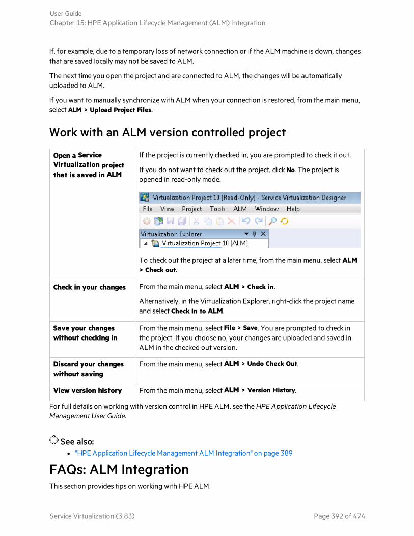
If, for example, due to a temporary loss of network connection or if the ALM machine is down, changesthat are saved locally may not be saved to ALM.
The next time you open the project and are connected to ALM, the changes will be automaticallyuploaded to ALM.
If you want to manually synchronize with ALM when your connection is restored, from the main menu,select ALM > Upload Project Files.
Work with an ALM version controlled project
Open a ServiceVirtualization projectthat is saved in ALM
If the project is currently checked in, you are prompted to check it out.
If you do not want to check out the project, click No. The project isopened in read-only mode.
To check out the project at a later time, from the main menu, select ALM> Check out.
Check in your changes From the main menu, select ALM > Check in.
Alternatively, in the Virtualization Explorer, right-click the project nameand select Check In to ALM.
Save your changeswithout checking in
From the main menu, select File > Save. You are prompted to check inthe project. If you choose no, your changes are uploaded and saved inALM in the checked out version.
Discard your changeswithout saving
From the main menu, select ALM > Undo Check Out.
View version history From the main menu, select ALM > Version History.
For full details on working with version control in HPE ALM, see the HPE Application LifecycleManagement User Guide.
See also:l "HPE Application Lifecycle Management ALM Integration" on page 389
FAQs: ALM IntegrationThis section provides tips on working with HPE ALM.
User GuideChapter 15: HPE Application Lifecycle Management (ALM) Integration
Service Virtualization (3.83) Page 392 of 474

My ALM connection was lost while I was in the middle of working. What now?
Any changes you make are saved locally. When the connection to ALM is restored, your changes areautomatically uploaded to ALM.
Can a Service Virtualization solution include projects saved both in the file system and inALM?
Yes. You can create a solution with projects that are saved both in the file system and in ALM. You canalso add a new project to your existing solution, and save it in ALM. For details on creating a newproject within an existing solution, see "Manage Virtualization Projects" on page 135.
In the event that a project saved in ALM is unavailable when you open the solution, a message displays.After the connection to ALM is restored, you can reload the solution to work on the ALM projects.From the main menu, click File > Reload Solution.
Note: All virtualization projects within a solution must be saved in the same ALM project, as youcan connect to only one ALM project at a time.
Can I see my Service Virtualization projects from within ALM?
Yes. You can view the following details in your saved projects in the ALM Test Resources module:
l Resource type. Service Virtualization projects and services are created as the Test Resource resourcetype.
l Resource description. In the resource Details tab, the Description area lists the services included inthe project, and details on each service. For example, you can see the service endpoints, which arerequired to reconfigure your application under test.
l Resource filename. Select a resource and click the Resource Viewer tab. Service Virtualizationresources are identified as follows:
l Virtualization project: .vproj file extension.
l Virtual service: .vs file extension.
l Virtual service template: .vstz file extension.
l Relationships between virtualization projects and services. Select a resource and click theDependencies tab.
l For a virtualization project: displays the services in the project.
l For a virtual service: displays the virtualization project in which it is located.
Can I share my services?
You can make your Service Virtualization projects and services available to others to download anddeploy to other Service Virtualization Servers. This functionality is enabled using the ServiceVirtualization Management. For details, see "Service Virtualization Management" on page 224.
User GuideChapter 15: HPE Application Lifecycle Management (ALM) Integration
Service Virtualization (3.83) Page 393 of 474

I want to view a project in the Designer but not make any changes. What should I do?
You can open the project in read-only mode. This prevents you from inadvertently making any changes.It also allows another user to open the project for editing.
When opening a project that is saved in ALM, select Open in read-only mode in the Open dialog box.
Tip: After you close the project, the Recent Projects list on the Start Page indicates that youpreviously opened it in read-only mode.
If you open the project again from the Recent Projects list, it is opened in read-only mode.
User GuideChapter 15: HPE Application Lifecycle Management (ALM) Integration
Service Virtualization (3.83) Page 394 of 474

Chapter 16: Version Control SupportThis chapter includes:
• Subversion (SVN) Version Control Support 396• Work with SVN 396
Service Virtualization (3.83) Page 395 of 474

Subversion (SVN) Version Control SupportYou can manage the version control of your virtualization projects from within the Service VirtualizationDesigner. Service Virtualization supports integration with Apache Subversion, using the TortoiseSVNclient.
When you open a virtualization project that is under version control, standard SVN options are availablein the Service Virtualization Designer. These options open the TortoiseSVN interface, enabling you tomanage versioning from within your virtualization project. For more details on specific SVNfunctionality, see the TortoiseSVN documentation.
See also:l For task details, see "Work with SVN" below.
Work with SVNThis task describes how to work with virtualization projects that are under SVN version control.
This task includes the following steps:
l "Prerequisites" below
l "Upgrade your project to the current version of TortoiseSVN" below
l "Check out a virtualization project" on the next page
l "Open a version controlled project" on the next page
l "Manage version control" on the next page
l "View version status" on page 398
l "Add a Service Virtualization project to an SVN repository" on page 398
Prerequisites1. Integration with SVN requires that TortoiseSVN version 1.8 is installed on the Service
Virtualization Designer machine. You can download TortoiseSVN from http://tortoisesvn.net.
2. Check in your virtualization project or solution using TortoiseSVN.
Upgrade your project to the current version ofTortoiseSVNIf your Service Virtualization project is under version control using a TortoiseSVN client version earlierthan 1.8, you must upgrade your working copy.
In the Virtualization Explorer or in the Projects pane, right-click a solution or project and select SVNUpgrade working copy.
User GuideChapter 16: Version Control Support
Service Virtualization (3.83) Page 396 of 474

Note: The upgrade process is performed on the complete working copy, even if the virtualizationproject is only a part of the directory.
Check out a virtualization projectYour virtualization project must be committed to an SVN repository.
From the main menu, select File > Checkout. This accesses the TortoiseSVN user interface, and you canproceed to check out a project to the file system.
Open a version controlled projectYou can open a project or solution, or add a project to an existing solution.
1. Select one of the following:
l Open an existing project or solution. From the main menu, select Open Project/Solution.
l Add an existing project to a solution. In the Projects pane, right-click a solution and select Add> Existing Project.
2. Navigate to and select a checked out project located in the file system.
Manage version controlWhen a virtualization project is under version control, standard SVN actions are available in the ServiceVirtualization Designer.
Select one of the following:
l In the Virtualization Explorer, right-click a project name and select an SVN action.
l From the main menu, select View > Projects to display the Projects pane. Right-click a solution orproject and select an SVN action.
The following options are available:
Commit Commit your changes to the SVN repository.
Revert Undo changes you made since the last update.
Subversion Opens a sub-menu with additional SVN actions you can perform.
The TortoiseSVN user interface opens, enabling you to manage version control for the project. Formore details on SVN actions, see the TortoiseSVN documentation.
User GuideChapter 16: Version Control Support
Service Virtualization (3.83) Page 397 of 474

View version statusFrom the main menu, select View > Projects to display the Projects pane. SVN icons indicate the versioncontrol status of your project's files.
Add a Service Virtualization project to an SVN repository1. In a non-versioned project, from the main menu, select View > Projects to display the Projects
pane.
2. Right-click the project or solution name and select SVN Import.
The TortoiseSVN user interface opens, enabling you to add your project to a repository. For moredetails, see the TortoiseSVN documentation.
See also:l "Subversion (SVN) Version Control Support" on page 396
User GuideChapter 16: Version Control Support
Service Virtualization (3.83) Page 398 of 474
Chapter 17: TroubleshootingThis chapter includes troubleshooting help on the following topics:
• Runtime View Errors 400• Configuring HTTP Proxy on Clients 400• Setting HTTP Proxy in Designer 403• Slow Designer Responsiveness 405• Application Timeouts 406• Validation error during JMS Generic agent configuration 406
Service Virtualization (3.83) Page 399 of 474

Runtime View ErrorsRuntime view doesn't respect selected data model when changing mode.
Problem: User chooses a simulation model in the Service Editor and starts a new learning/simulationfrom the Runtime View. Instead of using the new simulation, the simulation model from the previouslearning/simulation is used again.
Solution: Runtime View is used just to change service modes, not configurations. To change thesimulation model, open the Service Editor, select a new simulation model and start a newlearning/simulation from the Service Editor.
Cannot start learning service 'My Service'.
Problem: Real Data model or Performance model must be selected in service configuration.
Solution: This error may happen when all data and performance models are deleted from the serviceconfiguration and the user tries to start a new learning/simulation session from the Runtime View. Tosolve the problem, create a new Data/Performance Model and start a new learning/simulation sessionfrom the Service Editor.
Configuring HTTP Proxy on ClientsProblem: A virtual service is created on a proxy agent and the user is unable to record messages.
Solution: Configure the HTTP Proxy on clients.
All examples below of specific client configurations are using the proxy server HTTP(S) Proxy Agentlistening on address hostnamewith port 6071.
This section includes:
l "HTTP Proxy in .NET Client" below
l "HTTP Proxy in Java Client" on page 402
l "HTTP Proxy in WebLogic" on page 402
l "HTTP Proxy in WebSphere" on page 402
l "HTTP Proxy in JBoss" on page 403
HTTP Proxy in .NET Client
The .NET client can be configured to use a default proxy server or a specific proxy server.
If using the default proxy server, take HTTP Proxy Agent settings to configure the default proxyserver. This is done in MS Windows or Internet Explorer in Internet Properties > Connections > LANsettings > Proxy server. You must then configure the client to use the default proxy. This is set in theapplication configuration file either for application in element <defaultProxy>:
<configuration>
User GuideChapter 17: Troubleshooting
Service Virtualization (3.83) Page 400 of 474

<system.net>
<defaultProxy enabled="true">
<proxy usesystemdefault="true"/>
</defaultProxy>
</system.net>
</configuration>
Or for a specific binding in a binding element:
<configuration>
<system.serviceModel>
<bindings>
<basicHttpBinding>
<binding name="myHttpBinding" bypassProxyOnLocal="false"useDefaultWebProxy="true">
</binding>
</basicHttpBinding>
</bindings>
</system.serviceModel>
</configuration>
The same configuration file can be used to set a specific proxy server. This is an example of clientconfiguration for application:
<configuration>
<system.net>
<defaultProxy enabled="true">
<proxy proxyaddress="http://hostname:6071"/>
</defaultProxy>
</system.net>
</configuration>
, or for specific binding:
<configuration>
<system.serviceModel>
<bindings>
<basicHttpBinding>
User GuideChapter 17: Troubleshooting
Service Virtualization (3.83) Page 401 of 474

<binding name="myHttpBinding" bypassProxyOnLocal="false"useDefaultWebProxy="false" proxyAddress=" http://hostname:6071">
</binding>
</basicHttpBinding>
</bindings>
</system.serviceModel>
</configuration>
HTTP Proxy in Java Client
The proxy settings for Java client are given to the JVM via command line arguments. This is an exampleof how to run the client from the command line with proxy configuration:
java -Dhttp.proxyHost=hostname -Dhttp.proxyPort=6071 MyJavaClient
HTTP Proxy in WebLogic
Add the Java proxy parameters to Java options in JAVA_OPTIONS environment variable in the propersection of script %WL_HOME%\common\bin\commEnv.cmd for MS Windows or in ${WL_HOME}/common/bin/commEnv.sh for Unix/Linux. This is example of setting proxy configuration in filecommEnv.cmd (MS Windows):
set JAVA_OPTIONS=%JAVA_OPTIONS% -Dhttp.proxyHost=hostname -Dhttp.proxyPort=6071
, or in file commEnv.sh (Unix/Linux):
JAVA_OPTIONS="${JAVA_OPTIONS} -Dhttp.proxyHost=hostname -Dhttp.proxyPort=6071
HTTP Proxy in WebSphere
The HTTP proxy on the WebSphere application server can be configured via setting transportproperties http.proxyHost and http.proxyPort. These HTTP transport properties can be set via:
1. Using wsadmin.
2. Using an assembly tool.
3. Using the JVM custom property panel in the administrative console.
To learn more about (1) and (2), see the Configuring additional HTTP transport propertiesdocumentation in WebSphere. To configure the HTTP proxy properties using (3) use theadministrative console with the following steps:
1. Open the administrative console.
2. Click Servers > Application Servers > server > Java and Process Management > Process definition> Java Virtual Machine > Custom Properties.
3. (Optional) If the property is not listed, create a new property name.
4. Enter the name http.proxyHost and value hostname.
User GuideChapter 17: Troubleshooting
Service Virtualization (3.83) Page 402 of 474
5. Enter the name http.proxyPort and value 6071.
6. Restart the server.
HTTP Proxy in JBoss
Add the Java proxy parameters to Java options in JAVA_OPTS environment variable in the startup script%JBOSS_HOME%\bin\run.bat or run.conf.bat for MS Windows or in ${JBOSS_HOME}/bin/run.sh orrun.conf for Unix/Linux. This is an example of setting the proxy configuration in JAVA_OPTSenvironment variable in file run.conf.bat (MS Windows):
set "JAVA_OPTS=-Dhttp.proxyHost=hostname -Dhttp.proxyPort=6071
, or in file run.conf (Unix/Linux):
JAVA_OPTS="-Dhttp.proxyHost=hostname -Dhttp.proxyPort=6071
Setting HTTP Proxy in DesignerProblem: User is unable to access any remote WSDL or Service Virtualization Server.
Solution: Proxy setting needs to be configured in Designer.
This section includes:
l "How to Set HTTP Proxy in Designer" below
l "Setting HTTP Proxy in the Designer configuration file " below
l "System HTTP Proxy" on the next page
l "Specific HTTP Proxy" on the next page
l "Setting Credentials for Authenticated HTTP Proxy" on the next page
How to Set HTTP Proxy in Designer
In some cases Service Virtualization Designer communicates with external services using the HTTPprotocol. The first case is the communication with Service Virtualization Server, where the service is theserver management API. The second case is the import of the a real service WSDL. In some situations,the Designer’s HTTP communication must be forwarded through an external HTTP Proxy. In thatsituation, the HTTP Proxy settings must be placed in the Designer’s configuration file.
Note: The setting of HTTP Proxy for agents is not done in the Designer configuration file. For details,see "Forward HTTP Agent Communication Through an HTTP Proxy" on page 76.
Setting HTTP Proxy in the Designer configuration file
In order to use an external HTTP Proxy for the Designer HTTP communication with a server and theimport of a WSDL from real services, the Designer configuration file must be modified. This file islocated at %[INSTALLLOCATION]%\Designer\bin\VirtualServiceDesigner.exe.config.
In the configuration file the element <defaultProxy> holds the HTTP Proxy configuration. Thiselement is located in the document in elements <configuration><system.net>. By default, HTTP Proxyis disabled by <defaultProxy enabled="false"/>.
User GuideChapter 17: Troubleshooting
Service Virtualization (3.83) Page 403 of 474

The Designer can be configured to use the system HTTP Proxy or to use a specific HTTP Proxy.Detailed documentation can be found at http://msdn.microsoft.com/library/kd3cf2ex.aspx. TheDesigner must be restarted in order to apply the changes in the configuration file.
System HTTP Proxy
If using the system HTTP Proxy, ensure that the HTTP Proxy is configured in the system. The settingsare available in Windows Internet Explorer® menu Internet Properties > Connections > LAN settings >Proxy server. The Designer must be configured to use the same proxy in the configuration file in theelement <defaultProxy> like this:
<configuration>
<system.net>
<defaultProxy enabled="true">
<proxy usesystemdefault="true"/>
</defaultProxy>
</system.net>
</configuration>
Specific HTTP Proxy
If using a specific HTTP Proxy other than the system one, follow this example of Designerconfiguration:
<configuration>
<system.net>
<defaultProxy enabled="true">
<proxy proxyaddress="http://foo.com:8080"/>
</defaultProxy>
</system.net>
</configuration>
Setting Credentials for Authenticated HTTP Proxy
If the Designer is configured to use HTTP Proxy with authentication, some additional modificationsmay be required in the Designer configuration file. This will allow the supplying of credentials for theHTTP Proxy. These modifications are required in the case of HTTP communication with the servermanagement API. In the case of WSDL imports, these modifications are only optional as the Designerwill prompt the user for credentials if needed.
In order to set credentials for authenticated HTTP Proxy in the Designer, this section must be enabledin the configuration file VirtualServiceDesigner.exe.config:
<configuration>
User GuideChapter 17: Troubleshooting
Service Virtualization (3.83) Page 404 of 474

<system.net>
<defaultProxy enabled="true" useDefaultCredentials="false">
<module type ="HP.SOAQ.ServiceVirtualization.ServerManagementClient.Remote.AuthenticatedProxy,HP.SV.ServerManagementClient" />
</defaultProxy>
</system.net>
</configuration>
The credentials for the authenticated HTTP Proxy are set in application keys section. Example ofcredential settings follows:
<configuration>
<appSettings>
<add key="proxyUserName" value="user1" />
<add key="proxyPassword" value="pass1" />
<add key="proxyAddress" value="http://foo.com:8080" />
</appSettings>
</configuration>
Where keys are defined as:
proxyUserName User name for authenticated proxy credentials
proxyPassword Password for authenticated proxy credentials
proxyAddress Address of authenticated proxy (e.g. http://foo.com:8080). If this value is emptythen the Proxy Server address in the system proxy is used.
Once the credentials and the proxy settings are configured as described above then the Designer willuse them both for HTTP communication with the server management API and WSDL imports from realservices.
Slow Designer ResponsivenessProblem: After installing the new version of Service Virtualization, or making a change to yourcomputer, such as installing an update or new software, the Designer responds very slowly, especiallywhen working in the Data Model Editor.
Solution: Modify the Designer configuration file, VirtualServiceDesigner.exe.config, located in %[INSTALLLOCATION]%\Designer\bin\. To edit the file, you must have administrator privileges on themachine.
User GuideChapter 17: Troubleshooting
Service Virtualization (3.83) Page 405 of 474
Open the file in a text editor and change the value of SeV.Global.EnableAutomationFix from False toTrue. If the Designer is open, close it and restart.
If this does not solve the problem, do the following:
1. Change the value of SeV.Global.EnableAutomationFix back to False.
2. Change the value of SeV.Global.ClearAutomationEvents from False to True.
3. If the Designer is open, close it and restart.
Application TimeoutsProblem: Operations from an application that connects to Service Virtualization Server are timing out.Applications could include the Designer, Resource Manager, and other applications such as the HPEtest automation tools (LoadRunner, Performance Center, Unified Functional Testing).
Solution: Modify the timeout setting in the application's configuration file.
1. Open the relevant application's configuration file. For example:
l For the Service Virtualization Designer: VirtualServiceDesigner.exe.config, located by default inC:\Program Files (x86)\HPE\HPE Service Virtualization Designer\Designer\bin.
l For the Service Virtualization Resource Manager migration tool: ResourceManager.exe.config,located by default in C:\Program Files\HPE\HPE Service Virtualization Server\Server\bin.
2. Add the following key and modify the default timeout value of 5000.
<appSettings><add key="SeV.Global.PingTimeout" value="5000" /></appSettings>
Validation error during JMS Generic agentconfigurationProblem: When using Apache ActiveMQ 5.12 with the JMS Generic agent, an error occurs duringvalidation of the agent configuration.
Apache ActiveMQ 5.12 includes the SLF4J logging library. Both Service Virtualization Java runtime andthe Apache ActiveMQ framework use SLF4J, causing the error.
Solution: Remove the org.apache.commons.logging directory from activemq-all-5.12.0.jar.
User GuideChapter 17: Troubleshooting
Service Virtualization (3.83) Page 406 of 474

Chapter 18: Service Virtualization LabsService Virtualization Labs enable you to try out new, experimental features.
Note: The features in this section are being delivered at “beta level”, and are subject to change.
l They may stop working at any time.
l They may be removed, temporarily or permanently, from future patches or versions.
l They may change when and if they are implemented as fully supported features.
We welcome your comments. Send feedback to [email protected].
This chapter includes:
• Enable Lab Features 408• Scripted Rules 408• Network Virtualization Integration 421• PCAP File Import 423• WebSphere MQ Root Element Routing 424• ISO 8583 Support 425• Simulation Report 425• Preserve XML Namespace Prefixes 439• Content-Based Correlation 440
Service Virtualization (3.83) Page 407 of 474

Enable Lab FeaturesThis task enables you to try out new, experimental features.
Note: For more details on Lab Features, see "Service Virtualization Labs" on the previous page.
To enable a lab feature
1. From the main menu, select Tools > Options.
2. Click the Labs tab.
3. In the left pane, select a feature and then select the Enable option to turn on the feature.
4. Click OK to save your selections and enable the features.
Troubleshooting lab features
If you encounter any problems while you have a Lab feature enabled, here are some steps you can take:
l Disable the feature.
l Scripting feature - delete the rule using the script and restart simulation.
l Contact support.
Scripted RulesThis section includes:
• Scripted Rules 409• Create a Scripted Rule 409• Configure C# Security 416• Use a third-party library in a C# rule 418• Debug a C# scripted rule 419• Changing data structure types in a C# scripted rule 420
User GuideChapter 18: Service Virtualization Labs
Service Virtualization (3.83) Page 408 of 474
Scripted RulesUsing a Service Virtualization scripted rule, you can create a script to access request data and setresponse data.
Using a scripted rule, you can:
l JavaScript: use any expression from ECMAScript5 strict mode, together with exposed ServiceVirtualization objects
l C#: code any algorithmic implementation designed to process messages that are received by ServiceVirtualization
l define the script for different contexts, including for a server, service, operation, session, or servicecall
l define logging in the script. Messages are logged to the Service Virtualization log file
l create a custom log file to log request and response data for a specific data element
l edit the rule in an external text editor
For task details, see "Create a Scripted Rule" below.
Create a Scripted RuleYou can write a customized script inside a rule in the data model.
In this topic:
l "Prerequisite: Enable the Scripting lab feature" below
l "Create a new scripted rule" below
l "Edit a script" on the next page
l "Script guidelines" on the next page
l "Configure logging for scripted rules" on page 414
l "Set options for the scripted rule" on page 416
Prerequisite: Enable the Scripting lab feature
For details on enabling Service Virtualization lab features, see "Enable Lab Features" on the previouspage.
Create a new scripted rule
In the Data Model Editor, click New Rule > Scripted Rule and select an option:
l JavaScript
l C#
User GuideChapter 18: Service Virtualization Labs
Service Virtualization (3.83) Page 409 of 474

Edit a script
Select one of the following:
What do you want todo?
Availablefor: Instructions:
Edit script in the datamodel
C#/JavaScriptrules
Expand the rule to configure the script.
Edit script in a separatetab
C#/JavaScriptrules
Select Script > Edit in New Tab.
The scripted rule content remains locked until you saveyour changes and close the tab.
Edit script in anexternal editor
C#/JavaScriptrules
Opens the rule as a .cs or .js file in your default editor.
1. Select Script > Edit in External Editor.
2. When you finish making changes, save them in theexternal editor.
3. In Service Virtualization, reload the modified scriptwhen prompted.
4. Save the data model.
Edit script in a VisualStudio project
C# rule only Opens the rule as a .csproj Visual Studio project in yourdefault editor.
All IntelliSense and code completion features are available.
1. Select Script > Edit in Visual Studio project.
2. When you finish making changes, save them in theexternal editor.
3. In Service Virtualization, reload the modified scriptwhen prompted.
4. Save the data model.
Script guidelines
Write the script content according to the following guidelines:
Note: The rules contain commented out configuration assistance and sample scripts.
l JavaScript: Use any JavaScript expression from ECMAScript 5 strict mode along with ServiceVirtualization exposed objects.
l C#: You can code any algorithmic implementation designed to process messages that are received by
User GuideChapter 18: Service Virtualization Labs
Service Virtualization (3.83) Page 410 of 474
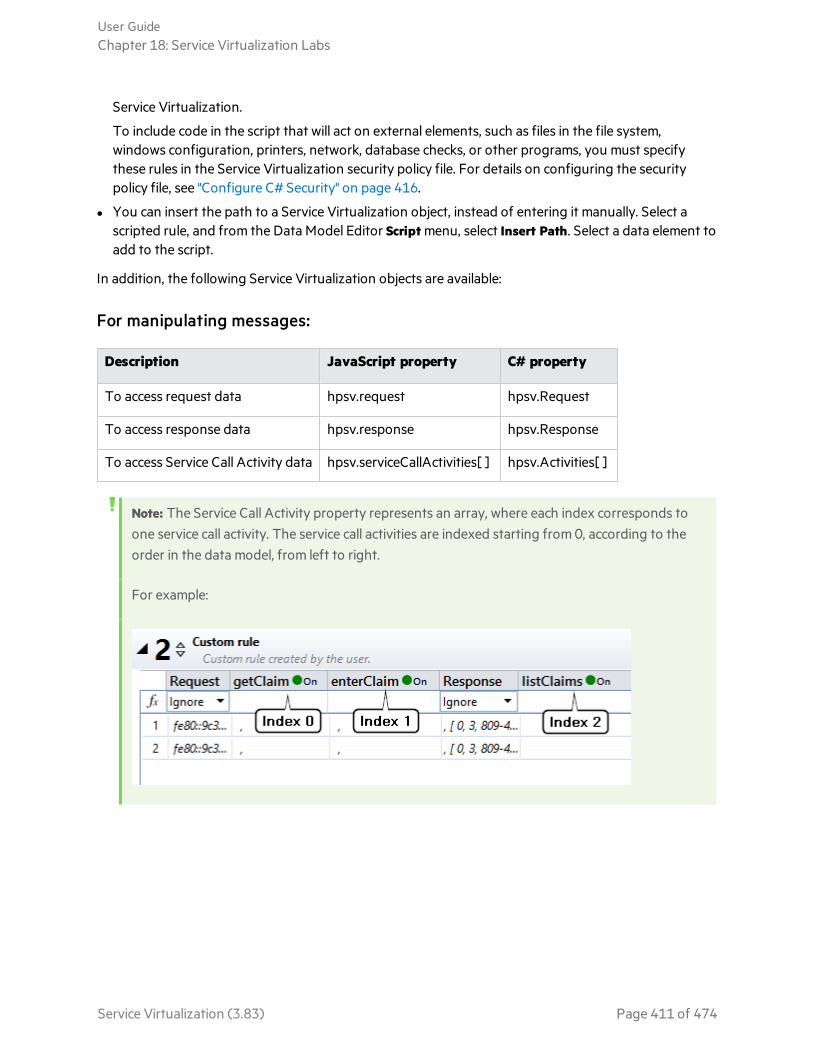
Service Virtualization.
To include code in the script that will act on external elements, such as files in the file system,windows configuration, printers, network, database checks, or other programs, you must specifythese rules in the Service Virtualization security policy file. For details on configuring the securitypolicy file, see "Configure C# Security" on page 416.
l You can insert the path to a Service Virtualization object, instead of entering it manually. Select ascripted rule, and from the Data Model Editor Script menu, select Insert Path. Select a data element toadd to the script.
In addition, the following Service Virtualization objects are available:
For manipulating messages:
Description JavaScript property C# property
To access request data hpsv.request hpsv.Request
To access response data hpsv.response hpsv.Response
To access Service Call Activity data hpsv.serviceCallActivities[ ] hpsv.Activities[ ]
Note: The Service Call Activity property represents an array, where each index corresponds toone service call activity. The service call activities are indexed starting from 0, according to theorder in the data model, from left to right.
For example:
User GuideChapter 18: Service Virtualization Labs
Service Virtualization (3.83) Page 411 of 474

For stateful behavior, define a context for the script:
Context JavaScript property C# property Description
Server hpsv.context.server hpsv.Contexts.Server The data is visible to all services onthe server that are simulating.Data is deleted when the serverrestarts.
Service hpsv.context.service hpsv.Contexts.Service The data is visible only to theservice for all simulated messages.Data is deleted when the servicesimulation ends.
Operation hpsv.context.operation hpsv.Contexts.Operation The data is visible only to requestsof the current operation. Data isdeleted when the servicesimulation ends.
Session hpsv.context.session hpsv.Contexts.Session The data is visible only to requestscoming from the same usersession. Data is deleted when theuser session ends.
Call hpsv.context.call hpsv.Contexts.call The data is visible only to oneservice call (= simulated request).Data is deleted when thesimulation of that request ends.
Note: If you want to add complex objects such as DTOs into the Context object, you must firstmake the complex object serializable so that it can be stored inside the Context object.
To search the content of contexts:
It can be helpful to search the contexts of your script, to check for possible memory leaks, for example.
To take advantage of this functionality, use the property 'Keys' from any context.
Example: These examples are for a C# rule. (For a JavaScript rule, replace 'Contexts' with'context'.)
To search for existing keys:
string[] listOfExistingKeys = hpsv.Contexts.Server.Keys;
User GuideChapter 18: Service Virtualization Labs
Service Virtualization (3.83) Page 412 of 474
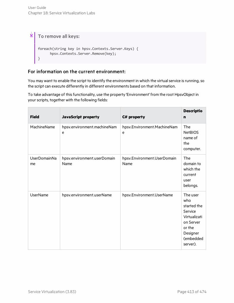
To remove all keys:
foreach(string key in hpsv.Contexts.Server.Keys) {hpsv.Contexts.Server.Remove(key);
}
For information on the current environment:
You may want to enable the script to identify the environment in which the virtual service is running, sothe script can execute differently in different environments based on that information.
To take advantage of this functionality, use the property 'Environment' from the root HpsvObject inyour scripts, together with the following fields:
Field JavaScript property C# propertyDescription
MachineName hpsv.environment.machineName
hpsv.Environment.MachineName
TheNetBIOSname ofthecomputer.
UserDomainName
hpsv.environment.userDomainName
hpsv.Environment.UserDomainName
Thedomain towhich thecurrentuserbelongs.
UserName hpsv.environment.userName hpsv.Environment.UserName The userwhostarted theServiceVirtualization Serveror theDesigner(embeddedserver).
User GuideChapter 18: Service Virtualization Labs
Service Virtualization (3.83) Page 413 of 474
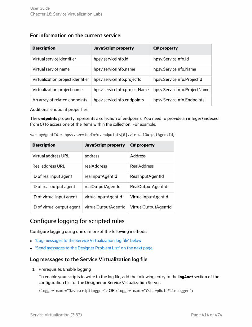
For information on the current service:
Description JavaScript property C# property
Virtual service identifier hpsv.serviceInfo.id hpsv.ServiceInfo.Id
Virtual service name hpsv.serviceInfo.name hpsv.ServiceInfo.Name
Virtualization project identifier hpsv.serviceInfo.projectId hpsv.ServiceInfo.ProjectId
Virtualization project name hpsv.serviceInfo.projectName hpsv.ServiceInfo.ProjectName
An array of related endpoints hpsv.serviceInfo.endpoints hpsv.ServiceInfo.Endpoints
Additional endpoint properties:
The endpoints property represents a collection of endpoints. You need to provide an integer (indexedfrom 0) to access one of the items within the collection. For example:
var myAgentId = hpsv.serviceInfo.endpoints[0].virtualOutputAgentId;
Description JavaScript property C# property
Virtual address URL address Address
Real address URL realAddress RealAddress
ID of real input agent realInputAgentId RealInputAgentId
ID of real output agent realOutputAgentId RealOutputAgentId
ID of virtual input agent virtualInputAgentId VirtualInputAgentId
ID of virtual output agent virtualOutputAgentId VirtualOutputAgentId
Configure logging for scripted rules
Configure logging using one or more of the following methods:
l "Log messages to the Service Virtualization log file" below
l "Send messages to the Designer Problem List" on the next page
Log messages to the Service Virtualization log file
1. Prerequisite: Enable logging
To enable your scripts to write to the log file, add the following entry to the log4net section of theconfiguration file for the Designer or Service Virtualization Server.
<logger name="JavascriptLogger"> OR <logger name="CsharpRuleFileLogger">
User GuideChapter 18: Service Virtualization Labs
Service Virtualization (3.83) Page 414 of 474
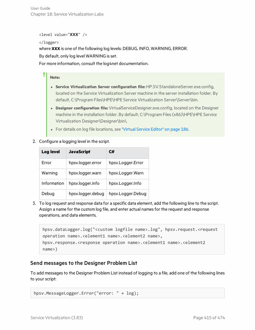
<level value="XXX" />
</logger>where XXX is one of the following log levels: DEBUG, INFO, WARNING, ERROR.
By default, only log level WARNING is set.
For more information, consult the log4net documentation.
Note:
l Service Virtualization Server configuration file: HP.SV.StandaloneServer.exe.config,located on the Service Virtualization Server machine in the server installation folder. Bydefault, C:\Program Files\HPE\HPE Service Virtualization Server\Server\bin.
l Designer configuration file: VirtualServiceDesigner.exe.config, located on the Designermachine in the installation folder. By default, C:\Program Files (x86)\HPE\HPE ServiceVirtualization Designer\Designer\bin\.
l For details on log file locations, see "Virtual Service Editor" on page 186.
2. Configure a logging level in the script.
Log level JavaScript C#
Error hpsv.logger.error hpsv.Logger.Error
Warning hpsv.logger.warn hpsv.Logger.Warn
Information hpsv.logger.info hpsv.Logger.Info
Debug hpsv.logger.debug hpsv.Logger.Debug
3. To log request and response data for a specific data element, add the following line to the script.Assign a name for the custom log file, and enter actual names for the request and responseoperations, and data elements.
hpsv.dataLogger.log("<custom logfile name>.log", hpsv.request.<requestoperation name>.<element1 name>.<element2 name>,hpsv.response.<response operation name>.<element1 name>.<element2name>)
Send messages to the Designer Problem List
To add messages to the Designer Problem List instead of logging to a file, add one of the following linesto your script:
hpsv.MessageLogger.Error("error: " + log);
User GuideChapter 18: Service Virtualization Labs
Service Virtualization (3.83) Page 415 of 474

hpsv.MessageLogger.Warn("warn: " + log);
hpsv.MessageLogger.Info("info: " + log);
hpsv.MessageLogger.Debug("debug: " + log);
You can then view logged messages in the Problem List.
By default, only errors and warnings are displayed in the Problem List. You can set the filter to displaymessages from other log levels as well. For details, see "Problem List" on page 219.
Set options for the scripted rule
By default, the scripted rule is executed during each pass through the rules. (For more details on howsimulation is performed, see "The Simulation Process" on page 259.)
To change this default setting and reduce CPU time during simulation, configure the rule's properties.
Right-click the scripted rule and select Properties to display the options.
l Skip the first simulation pass. To modify or complete data filled in by another rule, the scripted rulemust be have a higher priority than the rule you want to override. However, during the firstsimulation pass, all the response data for the script has not yet been filled in by the other rules. In thiscase, you may want to skip the scripted rule during the first simulation pass.
l Execute the rule only once. As an example, you may be using the script to add an item into an array,such as assigning an ID to a user. Each time the script is run, the rule will modify the response, causingthe simulation process to continue repeatedly. In this case, use this option to properly execute thesimulation.
See also:l "Configure C# Security" below
l "Use a third-party library in a C# rule" on page 418
l "Debug a C# scripted rule" on page 419
Configure C# SecurityThe C# scripted rule enables you to code any algorithmic implementation designed to process messagesthat are received by Service Virtualization.
To include code in the script that will act on external elements, such as files in the file system, windowsconfiguration, printers, network, database checks, or other programs, you must specify these rules inthe Service Virtualization security policy file.
If you run your C# rule, and are missing appropriate permissions, an error message is displayed in theProblem List, and also written to the Designer/Server application log. The message indicates the XMLnode that you must add to the security policy file to enable the actions to execute.
User GuideChapter 18: Service Virtualization Labs
Service Virtualization (3.83) Page 416 of 474
Note: If the current user running the Designer or Server has limited permissions outside ofService Virtualization (such as Windows permissions or permissions to a specific externalapplication), granting permissions in the security policy does not override that. You must havethe appropriate permissions for both Windows and any program that Service Virtualizationneeds to interact with.
For details Microsoft’s .NET system security permissions for controlling access to operations andresources based on policy, see http://msdn.microsoft.com/en-us/library/system.security.permissions(v=vs.110).aspx.
This section includes:
l "Configure C# rule security" below
l "Disable C# rule security" on the next page
Configure C# rule security
1. Prerequisite: Create a C# scripted rule. For details, see "Create a Scripted Rule" on page 409.
2. Open the CodeSecurityPolicy.xml file for your Service Virtualization application, based on whereservice is running:
l Designer (embedded server): On the Service Virtualization Designer machine, navigate to the\bin folder under the Designer installation folder. By default, C:\Program Files (x86)\HPE\HPEService Virtualization Designer\Designer\bin.
l Service Virtualization Server: On the Service Virtualization Server, navigate to the \bin folderunder the Service Virtualization Server installation folder. By default, C:\ProgramFiles\HPE\HPE Service Virtualization Server\Server\bin.
3. To configure the permissions, copy the relevant text from the Service Virtualization error messagein the Problem List into the CodeSecurityPolicy.xml file .
Example:
<IPermission class="System.Security.Permissions.FileIOPermission, mscorlib,Version=4.0.0.0, Culture=neutral, PublicKeyToken=b77a5c561934e089" version="1"Write="C:\demo\pirate.txt" />
4. Restart the relevant application to apply the changes:
l Designer: Close and reopen the Designer.
l Service Virtualization Server: Restart the Service Virtualization Server service.
User GuideChapter 18: Service Virtualization Labs
Service Virtualization (3.83) Page 417 of 474
Disable C# rule security
By default, Service Virtualization implements C# rule security by running the scripted rule in a sandboxenvironment. When you run a C# rule, the CodeSecurityPolicy.xml file that you configured is loaded andapplied.
Running in sandbox mode may have some performance impact. In addition, you cannot reference third-party libraries in the sandbox environment. In that case, you may want to disable C# security and run inunsecured mode. While this will provide the maximal possible performance, the C# rules are thencompletely unrestricted.
To disable C# rule security:
1. Open the Service Virtualization configuration file:
l Service Virtualization Server configuration file: HP.SV.StandaloneServer.exe.config, located onthe Service Virtualization Server machine in the server installation folder. By default, C:\ProgramFiles\HPE\HPE Service Virtualization Server\Server\bin.
l Designer configuration file: VirtualServiceDesigner.exe.config, located on the Designer machinein the installation folder. By default, C:\Program Files (x86)\HPE\HPE Service VirtualizationDesigner\Designer\bin\.
2. Edit the following line, and set value="false":
<add key="Simulator.Scripting.Sandbox" value="true"/>
Use a third-party library in a C# ruleYou can add external libraries to your C# scripted rules.
For example, you may want to:
l use a third-party library for reading an Excel file or accessing a database
l share your own library across multiple rules or services instead of duplicating the code in everyrule/service
Caution: Referencing a third-party library can introduce risk. It may not function properly, ormay negatively impact Service Virtualization Server functionality.
Use a third-party library
1. Disable C# rule sandbox mode. For details, see "Configure C# Security" on page 416.
2. Copy the external library that you want to use (for example, MyCompany.MyLibrary.dll) to theExtensions folder of the Service Virtualization Designer or Server, depending on where the virtualservice will run.
User GuideChapter 18: Service Virtualization Labs
Service Virtualization (3.83) Page 418 of 474
l <Designer installation folder>\HPE Service Virtualization Designer\Designer\Extensions
l <Server installation folder>\HPE Service Virtualization Server\Server\Extensions
3. Enable the C# rule to reference your third-party library/assembly.
a. Open the appropriate file for Designer or Server:
<Designer installation folder>\HPE Service VirtualizationDesigner\Designer\bin\Config\scripted-rule-context.xml
<Server installation folder>\HPE Service Virtualization Server\Server\bin\Config\scripted-rule-context.xml
b. Add your assembly reference to the ReferenceAssemblies section, as follows:
<property name="ReferenceAssemblies"value="System,System.Core,<MyCompany.MyLibrary>" />
4. Restart the relevant application to apply the changes:
l Designer: Close and reopen the Designer.
l Service Virtualization Server: Restart the Service Virtualization Server service.
Debug a C# scripted ruleDebug a Service Virtualization C# scripted rule in a Visual Studio project, using the debugging featuresof Visual Studio, or of another C# IDE.
For example, you may want to trace the flow of your script and inspect values inside the variables tobetter understand what is happening when your script runs. This can help you to more effectivelytroubleshoot your issues.
Enable debugging
To debug a Service Virtualization C# scripted rule in an external tool, enable the debug feature inService Virtualization Designer. If your virtual service is deployed on Service Virtualization Server,enable the debug feature on the Server machine as well.
1. Edit the file scripted-rule-context.xml located in <Service Virtualization installationfolder>\bin\Config.
For example, for the Designer, the file is located by default in C:\Program Files\HPE\HPE ServiceVirtualization Designer\Designer\bin\Config\scripted-rule-context.xml.
2. Change the value of DynamicAssemblyCompilation value to Debug.
3. Change the value ScriptCompilation to Debug.
Debug the script
1. From the Data Model Editor, open the C# rule in a Visual Studio project.
2. Add a breakpoint (F9).
User GuideChapter 18: Service Virtualization Labs
Service Virtualization (3.83) Page 419 of 474

3. Attach the debugger to the VirtualServiceDesigner process (Ctrl+Alt+P).
4. In Service Virtualization, switch your virtual service to Simulating mode.
5. Open Simulation preview and click on a row in the data model.
Alternatively, perform another action that triggers the execution of your script, such asintercepting a request.
While the script runs, the debugger will hit your breakpoints when the flow of execution reaches them.When hit, you can view the content of your variables, step through the code, inspect the script internals,and resume execution when you are ready.
Changing data structure types in a C# scripted ruleIf two or more subtypes of an object in your script include fields with the same name but differentstructures, automatic type selection may not work as required.
In order to identify the correct field, use the following methods:
l Is to determine if your object is a specific type.
Format as follows:
<your object name>.Is<your object’s subtype name>()l As to indicate which subtype you want the rule to access.
Format as follows:
<your object name>.As<your object’s subtype name>()
Sample Scenario
You have an object called Order and would like to access its Items property in a C# rule, as inOrder.Items. However, the object Order may have multiple types. For example:
l LightweightOrder where Items is just a list of string values.
l DetailedOrder where Items is a list of detailed complex objects describing each item of an order.
Problem: How can I determine which order type the object is?
Solution: Call Order.IsDetailedOrder(). A response of 'true' indicates the object is the DetailedOrder type.
Problem: When accessing items of an order such as Order.Items.s[1], the C# rule complains that Items isnot a list of string values.
Solution: This is because by default, the C# rule tries to access the Order object as it was of theDetailedOrder subtype. You need to first test what type the Order is, and if it is LightweightOrder, tellthe rule to access it as such, as follows:
If(Order.IsLightweightOrder()) {string secondItem = Order.AsLightweightOrder().Items.s[1];}
User GuideChapter 18: Service Virtualization Labs
Service Virtualization (3.83) Page 420 of 474

Problem: My request has the Order object populated with DetailedOrder data but I need to generate itas just the LightweightOrder. How can I change the type of order from DetailedOrder toLightweightOrder?
Solution: You can use Order = new LightweightOrder(). Note that you need to create the internalproperties of this object before you use them. For example;
Order.Items = new ItemsStringArray()
Tip: Use the Insert Path functionality to generate a code snippet to get to any field of datamodel you need to use within your scripts. For details, see "Create a Scripted Rule" on page 409.
Network Virtualization IntegrationThis section includes:
• Network Virtualization Integration 422• Virtualize Network Conditions 422
User GuideChapter 18: Service Virtualization Labs
Service Virtualization (3.83) Page 421 of 474

Network Virtualization IntegrationThe Service Virtualization integration with HPE Network Virtualization capabilities enables you tosimulate a real network to use together with your virtual services.
You can simulate real network communication between a client and server by setting origin anddestination locations, and by introducing network conditions such as latency, packet loss, andbandwidth.
For task details, see "Virtualize Network Conditions" below.
Virtualize Network ConditionsThis task describes how to define a virtual network environment for your virtual services to use.
Note: To learn more about virtualizing network conditions, see "Network VirtualizationIntegration" above.
1. Prerequisites
a. Enable the Network Virtualization lab feature.
For details on Service Virtualization lab features, see "Service Virtualization Labs" on page 407.
b. The NV Agent and the NV Location Editor must be installed on the Service VirtualizationServer machine.
For information on supported versions, refer to the support matrix on the HPE SoftwareSupport site at: https://softwaresupport.hpe.com/group/softwaresupport/support-matrices.
c. Configure the Service Virtualization Server to connect to Network Virtualization.
Navigate to the HP.SV.StandaloneServer.exe.config file, located on the ServiceVirtualization Server machine in the server installation folder. By default, C:\ProgramFiles\HPE\HPE Service Virtualization Server\Server\bin.
Configure the properties in the following sections according to your Network Virtualizationsystem definitions:o Shunra Network Virtualization - NV Agent (Engine).
Edit the Host, Port, Protocol, UserName, and Password properties. The parameters enablethe Service Virtualization Server to access the Network Virtualization engine.
o Shunra Network Virtualization - Location Editor
Edit the Host, Port, Protocol, UserName, and Password properties. These connectionproperties enable the Service Virtualization Designer to browse the Network VirtualizationLocation Editor Web Site.
2. Configure network models
Define a set of network characteristics to use with your virtual services.
User GuideChapter 18: Service Virtualization Labs
Service Virtualization (3.83) Page 422 of 474

a. From the main menu, select Tools > Options and click the Network Virtualization page.
b. Click Add. The Network Virtualization interface for setting virtualization options opens.
Select one of the following:o Import from library. Import an existing location.o Custom. Define network settings manually.
o Advanced. Select a predefined .ntxx emulation file that was created in the NetworkVirtualization Network Editor and saved in the file system.
o Copy an existing model. Select an existing network model and click Duplicate. A copy ismade of the model you selected. You can edit the settings and save it as a new networkmodel.
3. Assign a network model to an agent configuration
Select a network model for an HTTP agent configuration. The network model is then used by allvirtual services that use the agent configuration.
a. From the main menu, select Tools > Options and click the Agents page.
b. Select an existing HTTP agent configuration, or define a new one.
c. In the right pane, click the Network Virtualization tab.
d. Select a network model for the agent to use.
e. To configure network models, click Manage Network Models.
4. Edit network models
To modify existing network models:
From the main menu, select Tools > Options and click the Network Virtualization page.
For each network model, the right pane displays the Service Virtualization agents that are using themodel. You can attach or detach an agent from the selected network model.
Click an agent name link to view details on the agent.
PCAP File ImportThis section includes:
• Packet Capture (pcap) File Import 424• Import .pcap Files 424
User GuideChapter 18: Service Virtualization Labs
Service Virtualization (3.83) Page 423 of 474
Packet Capture (pcap) File ImportYou can import .pcap files to use captured network traffic in your simulation.
For example, when you cannot use Service Virtualization learning to record real service behavior, youmay be able to use a packet analyzer (sniffer) to collect the data you need. After completing the packetcapture, you can import .pcap files into Service Virtualization.
Service Virtualization enables you to import all data streams in the file or select specific streams only.
For task details, see "Import .pcap Files" below.
Import .pcap FilesYou can import .pcap files to use captured network traffic in your simulation.
Note:
l To learn more about importing pcap files, see "Packet Capture (pcap) File Import" above.
l Pcap file import is available for services using HTTP transport only.
1. Prerequisite: Enable the Pcap lab feature. For details on Service Virtualization lab features, see"Service Virtualization Labs" on page 407.
2. In the Data Model Editor, expand a rule.
3. In the Operations pane, make sure the virtual service name is selected, and not an individualoperation.
4. Right-click the data rule and select Import Pcap.
5. Select a .pcap file stored in the file system.
6. For REST services, select a specific URI space to import the data into.
7. In the Select Streams dialog box, select one or more streams to import.
The Select Streams dialog box displays all usable TCP streams in the .pcap file. ServiceVirtualization discards TCP streams with gaps.
The Size column displays the total number of bytes in the request and response streams.
Tip: Click a source or destination address to view the full source/destination path of theTCP connection.
WebSphere MQ Root Element RoutingYou can share an IBM WebSphere MQ request or response queue with several virtual services, enablingyou to split a large service into multiple, smaller virtual services. In each virtual service you can define
User GuideChapter 18: Service Virtualization Labs
Service Virtualization (3.83) Page 424 of 474

which messages should be consumed by specifying the root element of the relevant messages.
Note: Available for SOAP and XML services over WebSphere MQ.
To configure root element routing:
1. Prerequisite: Enable the WebSphere MQ lab feature.
For details on enabling Service Virtualization lab features, see "Enable Lab Features" on page 408.
2. When creating a new virtual service, define the Request Root Element field for the virtual service,and the Response Root Element field for the real service.
l SOAP service: The name of the first element within the message body.
l XML service: The root element of the message.
3. To modify an existing virtual service, edit the endpoint properties. In the Virtual Service Editor,under Service Configuration, click Edit to access the Edit Endpoints dialog box.
ISO 8583 SupportThis Service Virtualization beta feature introduces support for the ISO 8583 protocol, the messagingsystem used for card based electronic transactions.
Service Virtualization supports ISO 8583 indirectly, by converting messages into XML using the jPOSserver, an open source implementation of the international ISO 8583 standard.
Service Virtualization provides an external extension based on jPOS that works with an XML virtualservice. The extension is located in the Service Virtualization Tools folder. By default:
l Designer: C:\Program Files (x86)\HPE\HPE Service Virtualization Designer\Tools\Iso8583
l Server: C:\Program Files\HPE\HPE Service Virtualization Server\Tools\Iso8583
For details on configuring jPOS to work with Service Virtualization, see the step by step instructions inthe Iso8583 folder:
...Tools\Iso8583\SV_ISO8583_ConfigurationGuide.pdf
Simulation ReportThe simulation report provides a detailed look into the simulation process. The report shows the stepsthat were performed by the simulation engine when processing request data and generating aresponse, before sending the response back to the client. To learn more about how simulation works,see "The Simulation Process" on page 259.
Troubleshooting simulation
The simulation process is inherently complex. If your data model consists of many rules, conditions, andactions, it can be difficult to troubleshoot to find the source of unexpected results of the simulation.While Simulation Preview can assist you in assessing one rule at a time, the Simulation Report provides
User GuideChapter 18: Service Virtualization Labs
Service Virtualization (3.83) Page 425 of 474

much more detail. You can see the complete sequence of steps performed to create the final response.The report also provides timing information which can help you identify performance bottlenecks.
In this topic:
l "Generate a simulation report" below
l "Understanding the simulation report" on the next page
l "Simulation Report" on the previous page
l "Known limitations" on page 430
Generate a simulation report1. Prerequisites:
a. Enable the Simulator lab feature.
For details on enabling Service Virtualization lab features, see "Enable Lab Features" on page408.
b. Enable the simulation report for a virtual service for which you want to generate a report.
In the Virtual Service Editor, under Service Configuration, enable Simulation Report.
Caution: Enable simulation reports for a minimum period only. For example, enable thereports, run a short simulation, and then disable the reports. Service Virtualizationgenerates a new file for every request. The file can be quite large, depending on the sizeand complexity of your data model. This has a significant impact on ServiceVirtualization performance.
2. Generate the report.
To generate the report, run the virtual service in Simulation mode, or open Simulation Preview.
3. View the report.
Use one of the following to access the report from the Designer:
l In the Virtual Service Editor, under Service Configuration, click Show Generated Reports.
l If your service is configured for message logging, you can also access the report from within themessage viewer, using the Open Simulation Report link.
This option is available only for reports generated during simulation.
Alternatively, you can access the reports from the file system. Generated reports are stored as asubdirectory of the logging directory:
For the embedded server inthe Service VirtualizationDesigner
%APPDATA%\Hewlett Packard Enterprise\HPE ServiceVirtualization Designer\logs\reports\<service name_serviceid>
User GuideChapter 18: Service Virtualization Labs
Service Virtualization (3.83) Page 426 of 474
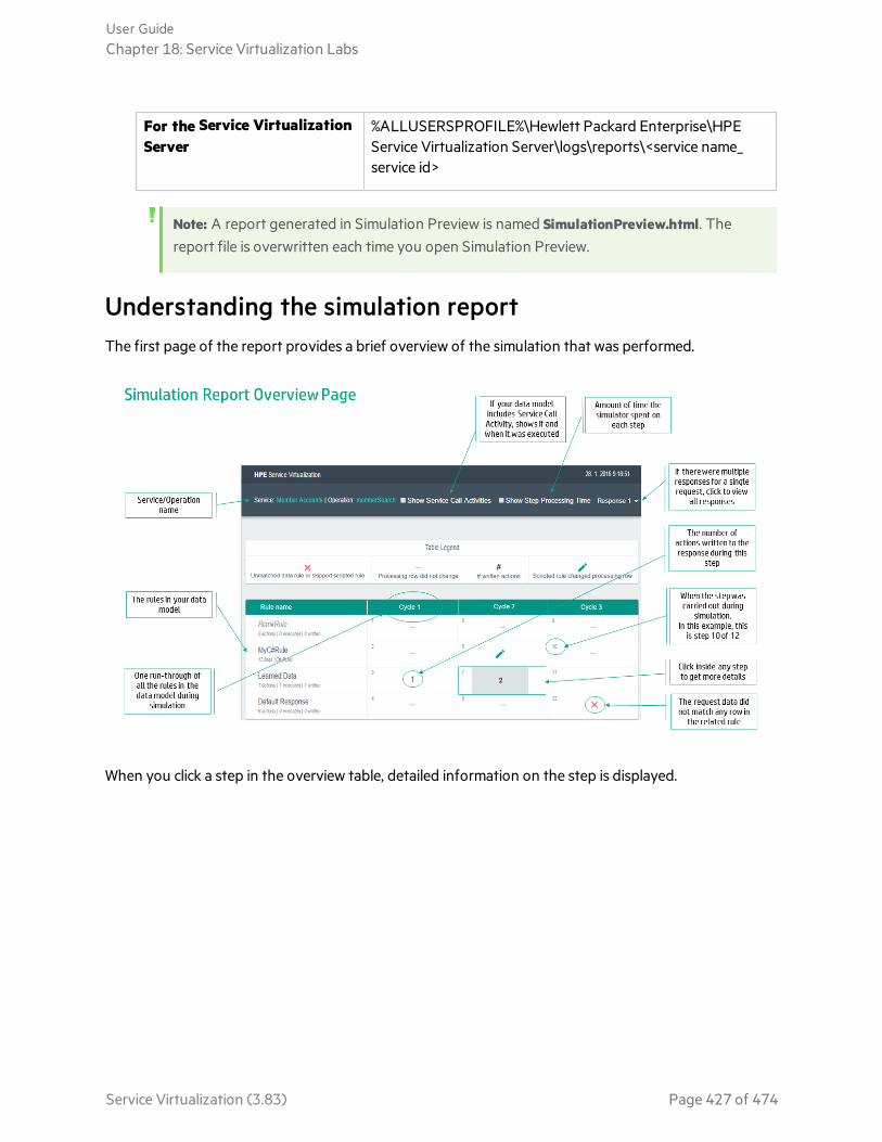
For the Service VirtualizationServer
%ALLUSERSPROFILE%\Hewlett Packard Enterprise\HPEService Virtualization Server\logs\reports\<service name_service id>
Note: A report generated in Simulation Preview is named SimulationPreview.html. Thereport file is overwritten each time you open Simulation Preview.
Understanding the simulation reportThe first page of the report provides a brief overview of the simulation that was performed.
When you click a step in the overview table, detailed information on the step is displayed.
User GuideChapter 18: Service Virtualization Labs
Service Virtualization (3.83) Page 427 of 474

Leftpane
Details of the processing row.
The processing row refers to the internal data structure being used and compiled by ServiceVirtualization. The processing row contains a request section and a response section. If thedata model contains Service Call Activities, the processing row contains request andresponse sections for these as well.
Before the simulation process begins, the request section is initialized from the incomingrequest. Then the simulator starts the first cycle of evaluating all data rules one at a timebased on their priority, and begins to compile the response. When all rules have beenevaluated the simulator starts another cycle. As soon as the simulator completes a cycle withno changes to the processing row, the simulation process ends. The response section of theprocessing row is then sent back to the client as the Service Virtualization response.
Filter Select an option to filter the detail view. This is particularly useful when viewing a complexprocessing row.
Show All. Displays all data for the processing row.
Show Actions. Displays only the values that have an associated action within the rule.
Show Conditions. Displays only the values that have an associated condition within the rule.
Show Changed Nodes. Displays only the values that were changed during the selected step.
User GuideChapter 18: Service Virtualization Labs
Service Virtualization (3.83) Page 428 of 474

Rightpane
Details of the value selected in the processing row.
No matching row: When no matching row was found in the data rule during a step, you canview and compare the processing row value with the rule values for each condition. Selectany node in the processing row to display its details in the right pane.
Matching row. When there was a matching row in the data rule, you can see the originalvalue and the new value in the processing rule. You can also see the priority of the rule thatwrote the value.
User GuideChapter 18: Service Virtualization Labs
Service Virtualization (3.83) Page 429 of 474
Known limitationsOnly the first difference is displayed. When the simulator tries to find a matching row in a data rule, itstops when it detects the first difference, although there may be multiple conditions for which the rulerow does not match the processing row. Only the first such difference is shown in the simulation report.Therefore, if for example you modify the rule row to match according to this single difference, the rowmay still not match due to other differences not originally shown in the report.
Only a subset of rows is included within the report. The simulation report includes up to ten rows foreach rule. When the rule does not match, only this subset of ten rows per rule are shown on the detailpage of the report. Information on the additional rows is not currently available.
Scripted rule details are not available. The simulation report shows the processing row as of the end ofeach step. That means that if the scripted rule performs several changes to a processing row within aparticular step, this sequence is not provided. Only the final result is displayed. In addition, a scriptedrule can write a value to several contexts. These additional contexts are not visible from the report.
Report size. Since the simulation report is a single self-contained file, it needs to fit into browsermemory. Some browsers may refuse to display extremely large reports.
Security limitation. If you send the report file to another computer, it may not open in Internet Explorer.This is due to Windows security. To enable Internet Explorer to open the report, right-click the reportfile, select Properties, go to the General tab, and select Unblock.
Supported browsers. The simulation report as a Lab Feature supports only recent versions of browsers.These currently include:
l Internet Explorer version 10 or later
l Firefox version 43 or later
l Chrome version 48 or later
Simulation Report Use CasesWhy didn't the client request match any rules in my data model? Why didn't my rule write any responsedata?
Explore these common use case scenarios to help you answer those questions:
l "Simulation Report Scenario 1" on the next page
l "Simulation Report Scenario 2" on page 437
User GuideChapter 18: Service Virtualization Labs
Service Virtualization (3.83) Page 430 of 474
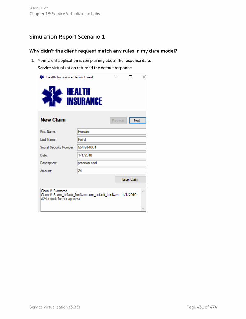
Simulation Report Scenario 1
Why didn't the client request match any rules in my data model?
1. Your client application is complaining about the response data.
Service Virtualization returned the default response:
User GuideChapter 18: Service Virtualization Labs
Service Virtualization (3.83) Page 431 of 474

2. Enable the Simulation Report lab feature:
From the main menu, select Tools > Options.
3. In your virtual service, enable Message Logging and Simulation Report:
In the Virtual Service Editor, expand Service Configuration, and enable the options.
User GuideChapter 18: Service Virtualization Labs
Service Virtualization (3.83) Page 432 of 474

4. Generate a simulation report:
Send the request again. Messages are logged and the simulation report is generated.
Click Logged Messages to open the message viewer.
5. Review the logged messages:
The first operation called was memberSearch. It returned the default response. We want to fix this.
User GuideChapter 18: Service Virtualization Labs
Service Virtualization (3.83) Page 433 of 474

6. Open the simulation report:
At the bottom of the message viewer, click Open Simulation Report.
7. The simulation report indicates that the Learned Rule did not match any data during simulation.
8. Let's look at the first step of Cycle 1:
Click inside the step to get more details.
User GuideChapter 18: Service Virtualization Labs
Service Virtualization (3.83) Page 434 of 474
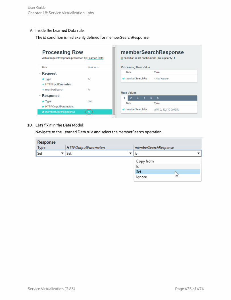
9. Inside the Learned Data rule:
The Is condition is mistakenly defined for memberSearchResponse.
10. Let's fix it in the Data Model:
Navigate to the Learned Data rule and select the memberSearch operation.
User GuideChapter 18: Service Virtualization Labs
Service Virtualization (3.83) Page 435 of 474
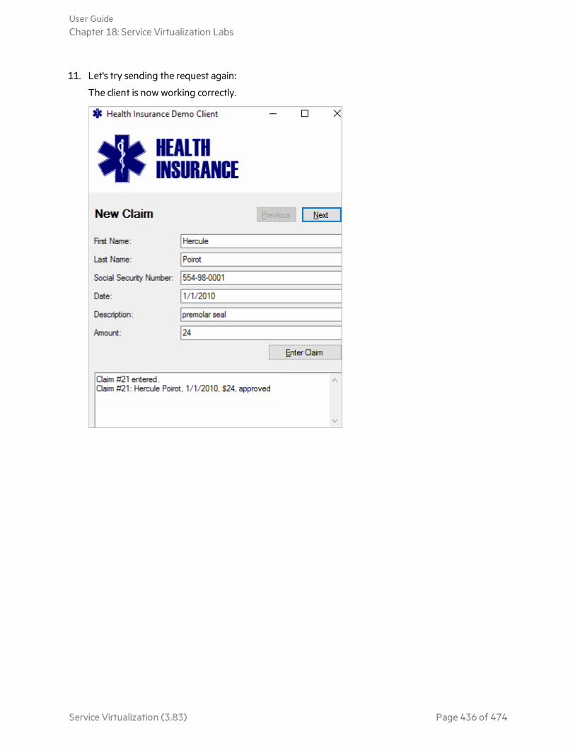
11. Let's try sending the request again:
The client is now working correctly.
User GuideChapter 18: Service Virtualization Labs
Service Virtualization (3.83) Page 436 of 474
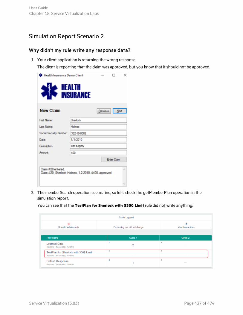
Simulation Report Scenario 2
Why didn't my rule write any response data?
1. Your client application is returning the wrong response.
The client is reporting that the claim was approved, but you know that it should not be approved.
2. The memberSearch operation seems fine, so let’s check the getMemberPlan operation in thesimulation report.
You can see that the TestPlan for Sherlock with $300 Limit rule did not write anything:
User GuideChapter 18: Service Virtualization Labs
Service Virtualization (3.83) Page 437 of 474
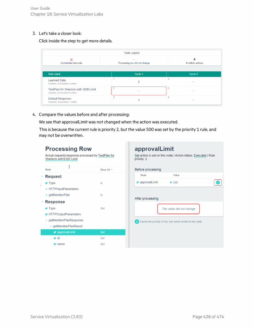
3. Let's take a closer look:
Click inside the step to get more details.
4. Compare the values before and after processing:
We see that approvalLimit was not changed when the action was executed.
This is because the current rule is priority 2, but the value 500 was set by the priority 1 rule, andmay not be overwritten.
User GuideChapter 18: Service Virtualization Labs
Service Virtualization (3.83) Page 438 of 474

5. Let’s go to the Data Model Editor and increase the rule priority so it's higher than the Learned Datarule.
Then restart simulation.
6. The client is now working as expected.
Preserve XML Namespace PrefixesOverride Service Virtualization default functionality to preserve original namespace prefixes in yourmessages.
When simulating SOAP and XML messages, Service Virtualization normalizes the namespace prefixesby default. This means that some messages are simulated using different XML namespace prefixes thanthe prefixes that were learned or imported from the real service.
User GuideChapter 18: Service Virtualization Labs
Service Virtualization (3.83) Page 439 of 474

This new lab feature instructs Service Virtualization to keep the original prefixes, and use them duringsimulation.
Supported for these messaging protocols: SOAP, XML
Preserve namespace prefixes
1. Prerequisite: Enable the Enable Learning XML Namespace Prefixes lab feature. For details onService Virtualization lab features, see "Service Virtualization Labs" on page 407.
2. Enable the feature in your virtual service.
In the Service Description Editor, under XML Schemas, select Learn XML Namespace Prefixes.
3. Learn or import messages from the real service.
Result: During simulation, prefixes are maintained.
Disabling the feature
If you disable the feature, Service Virtualization continues to use the learned/imported prefixes. Toremove that metadata, you need to relearn or reimport messages after disabling the feature.
Content-Based CorrelationThis lab features enables you to define content-based correlation for operations in your virtual service.
OverviewThe request-response communication pattern used by the majority of virtualized services needs to beable to correlate (pair) requests sent from client to server with their responses sent from the server backto the client.
Typically, transport level correlation is used. For example:
l Services using HTTP transport, such as SOAP or REST, use HTTP-based correlation in which theresponse is sent in the same HTTP (TCP) connection as the request.
l Many other types of services using messaging transports, such as JMS, WebSphere MQ, or MicrosoftMQ, typically use Message ID & Correlation ID headers to correlate requests with their responses.
In some services, however, message correlation is carried out on the application level instead of usingthe more common transport level correlation. For example, there may be a “correlation ID” storedsomewhere in the XML message body of an XML over MQ service, such as in the following example:
Example:Request:
User GuideChapter 18: Service Virtualization Labs
Service Virtualization (3.83) Page 440 of 474
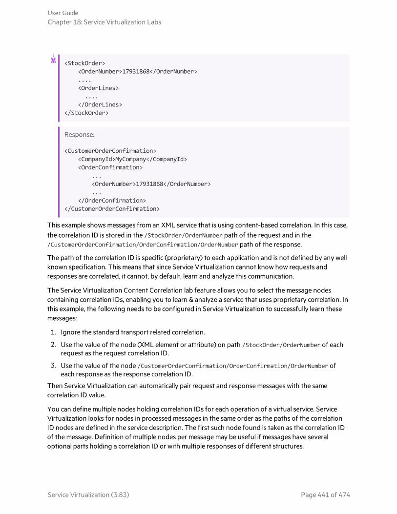
<StockOrder><OrderNumber>17931868</OrderNumber>....<OrderLines>....
</OrderLines></StockOrder>
Response:
<CustomerOrderConfirmation><CompanyId>MyCompany</CompanyId><OrderConfirmation>
...<OrderNumber>17931868</OrderNumber>...
</OrderConfirmation></CustomerOrderConfirmation>
This example shows messages from an XML service that is using content-based correlation. In this case,the correlation ID is stored in the /StockOrder/OrderNumber path of the request and in the/CustomerOrderConfirmation/OrderConfirmation/OrderNumber path of the response.
The path of the correlation ID is specific (proprietary) to each application and is not defined by any well-known specification. This means that since Service Virtualization cannot know how requests andresponses are correlated, it cannot, by default, learn and analyze this communication.
The Service Virtualization Content Correlation lab feature allows you to select the message nodescontaining correlation IDs, enabling you to learn & analyze a service that uses proprietary correlation. Inthis example, the following needs to be configured in Service Virtualization to successfully learn thesemessages:
1. Ignore the standard transport related correlation.
2. Use the value of the node (XML element or attribute) on path /StockOrder/OrderNumber of eachrequest as the request correlation ID.
3. Use the value of the node /CustomerOrderConfirmation/OrderConfirmation/OrderNumber ofeach response as the response correlation ID.
Then Service Virtualization can automatically pair request and response messages with the samecorrelation ID value.
You can define multiple nodes holding correlation IDs for each operation of a virtual service. ServiceVirtualization looks for nodes in processed messages in the same order as the paths of the correlationID nodes are defined in the service description. The first such node found is taken as the correlation IDof the message. Definition of multiple nodes per message may be useful if messages have severaloptional parts holding a correlation ID or with multiple responses of different structures.
User GuideChapter 18: Service Virtualization Labs
Service Virtualization (3.83) Page 441 of 474
Implement content-based correlation1. Prerequisites:
a. On the Labs page, review the list of supported protocols, and enable the Content Correlationlab feature.
For details, see "Enable Lab Features" on page 408.
b. The service description of the virtual service must first be familiar with the message schema ofthe real service, to allow you to browse and select its nodes. A virtual service with a knownmessage schema may be created by selecting XSD files during service creation, or by importingsample messages into the data model from the Data Model Editor.
2. In the Service Description Editor, under Message Correlation, define correlation details:
a. For each operation, select User-defined by Message Content.
b. Click Add or Edit to select the message nodes to use for correlation.
3. Depending on your application, the following two steps are usually necessary for successfulsimulation after learning.
In the Learned Data rule in the date model:
a. Set the Ignore function on the request column containing the correlation ID, according to thenodes you selected in step 2. This is required because the ID is usually unique. If correlation IDis not set to Ignore, future requests to the virtual service during simulation that have differentvalues than the correlation ID will not match the recorded rules and will return defaultresponses only.
b. Set the Copy from function on the response column containing the correlation ID, according tothe nodes you selected in step 2. This copies the proper value of the correlation ID from therequest to the simulated response. If the correlation ID is not copied, your real client applicationmay not be able to correlate its own requests with the responses received from the virtualservice.
User GuideChapter 18: Service Virtualization Labs
Service Virtualization (3.83) Page 442 of 474

Chapter 19: TutorialsExplore these tutorials to learn about creating REST services.
"Learning aRESTService Tutorial"on the nextpage
Learning data from live communication is often the easiest way to create datamodels for your virtual services. This tutorial demonstrates how to learn datafor a REST service using one of Service Virtualization's demo services.
"InteractiveREST AuthoringTutorial" onpage 453
This tutorial demonstrates how to interactively design data models for virtualservices without recording real service communication, using only a clientapplication and sample response messages.
Service Virtualization (3.83) Page 443 of 474
Learning a REST Service TutorialLearning data from live communication is often the easiest way to create data models for your virtualservices. Let’s see how to learn data for a REST service using one of Service Virtualization's demoservices.
Let’s assume you would like to test a service, which is dependent on another service. The other, 3rdparty service is not available from Wednesday to Friday. Today is Tuesday and you know you need touse this 3rd party service by tomorrow to finish all the testing in time, as you are already running late.Fortunately, you can clone the 3rd party service in the form of a virtual service. We’ll demonstrate thisusing the Claim Processing Demo service.
Tip: Find more details about the concepts presented here or about how to perform any of thesteps in this tutorial by searching the Service Virtualization Help.
Prerequisites1. Install HPE Service Virtualization Designer.
2. Start the MemberAccounts REST Demo service:
a. In the sample projects folder, locate and run ClaimProcessingRestDemo\run-xml.bat to openthe Health Insurance demo client.
The sample project folders are located, by default, in <Your Documents folder>\HPE ServiceVirtualization\Demos.)
b. In the Health Insurance demo client, click Enter Claim.
User GuideChapter 19: Tutorials
Service Virtualization (3.83) Page 444 of 474
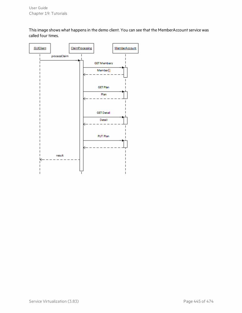
This image shows what happens in the demo client. You can see that the MemberAccount service wascalled four times.
User GuideChapter 19: Tutorials
Service Virtualization (3.83) Page 445 of 474
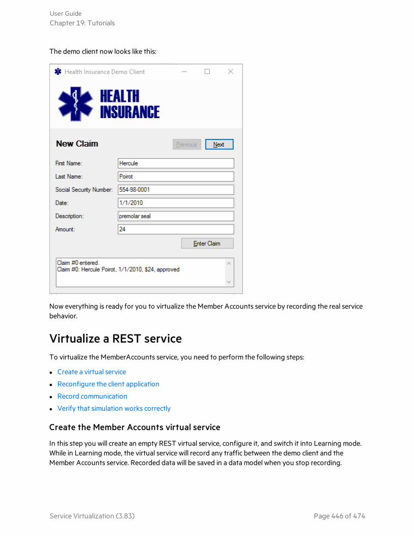
The demo client now looks like this:
Now everything is ready for you to virtualize the Member Accounts service by recording the real servicebehavior.
Virtualize a REST serviceTo virtualize the MemberAccounts service, you need to perform the following steps:
l Create a virtual service
l Reconfigure the client application
l Record communication
l Verify that simulation works correctly
Create the Member Accounts virtual service
In this step you will create an empty REST virtual service, configure it, and switch it into Learning mode.While in Learning mode, the virtual service will record any traffic between the demo client and theMember Accounts service. Recorded data will be saved in a data model when you stop recording.
User GuideChapter 19: Tutorials
Service Virtualization (3.83) Page 446 of 474
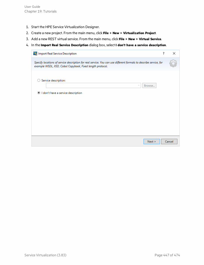
1. Start the HPE Service Virtualization Designer.
2. Create a new project. From the main menu, click File > New > Virtualization Project.
3. Add a new REST virtual service. From the main menu, click File > New > Virtual Service.
4. In the Import Real Service Description dialog box, select I don't have a service description.
User GuideChapter 19: Tutorials
Service Virtualization (3.83) Page 447 of 474

5. In the Choose Service Protocol dialog box, select the REST protocol.
6. In the Service Properties dialog box, specify the endpoint of the "real" service, as follows:
http://<hostname>:8101/ServiceSimulation/Demo/MemberAccounts
User GuideChapter 19: Tutorials
Service Virtualization (3.83) Page 448 of 474
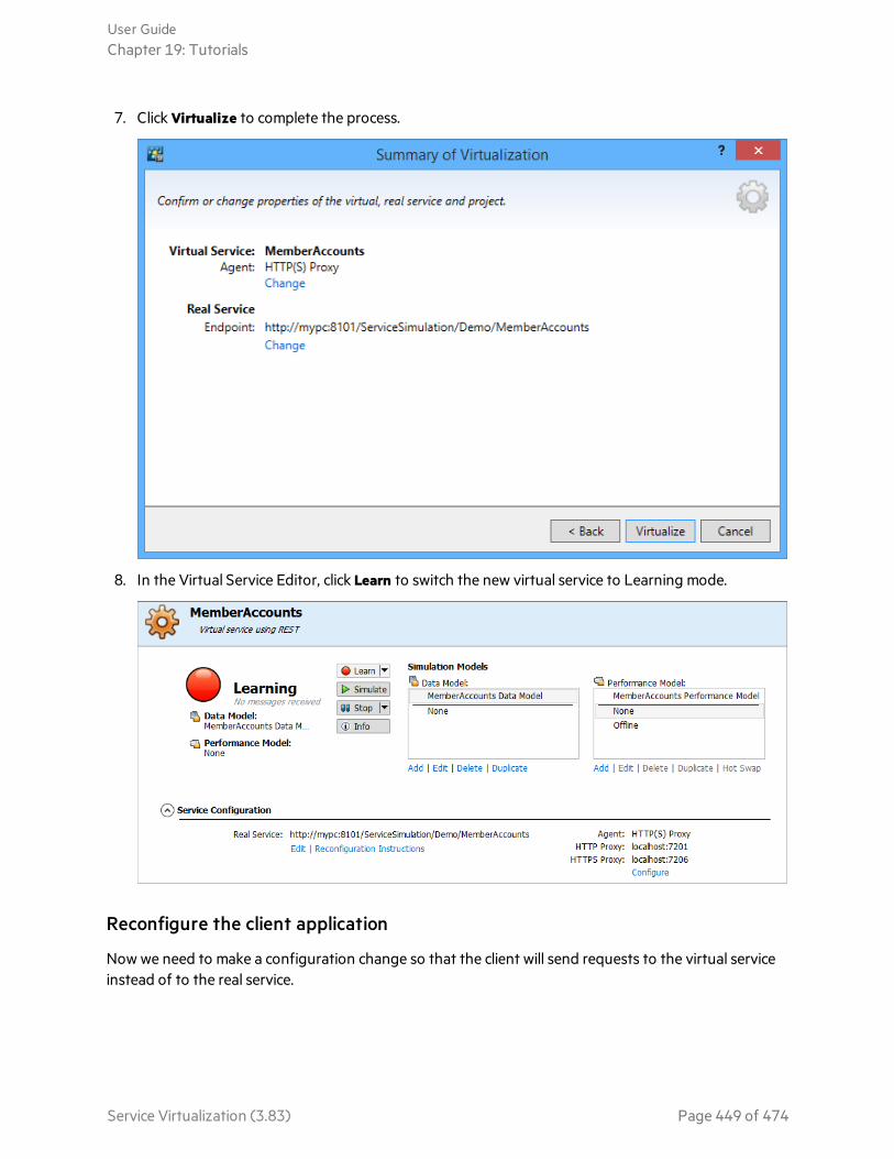
7. Click Virtualize to complete the process.
8. In the Virtual Service Editor, click Learn to switch the new virtual service to Learning mode.
Reconfigure the client application
Now we need to make a configuration change so that the client will send requests to the virtual serviceinstead of to the real service.
User GuideChapter 19: Tutorials
Service Virtualization (3.83) Page 449 of 474

We know that the client application is using the system proxy, so we need to change it, as follows:
1. Set your machine's proxy server to the same proxy server that the virtual service is using.
2. Make sure that the proxy will be used for local addresses as well. In Windows 10, you must clear theDon't use the proxy server for local (intranet) addresses option.
Record communication between the client application and the real service
In the demo client, click Enter Claim to send the request again.
User GuideChapter 19: Tutorials
Service Virtualization (3.83) Page 450 of 474
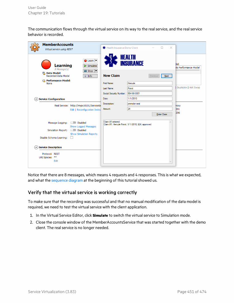
The communication flows through the virtual service on its way to the real service, and the real servicebehavior is recorded.
Notice that there are 8 messages, which means 4 requests and 4 responses. This is what we expected,and what the sequence diagram at the beginning of this tutorial showed us.
Verify that the virtual service is working correctly
To make sure that the recording was successful and that no manual modification of the data model isrequired, we need to test the virtual service with the client application.
1. In the Virtual Service Editor, click Simulate to switch the virtual service to Simulation mode.
2. Close the console window of the MemberAccountsService that was started together with the democlient. The real service is no longer needed.
User GuideChapter 19: Tutorials
Service Virtualization (3.83) Page 451 of 474

3. Send the request again from the demo client.
The demo client should now show the same message as during recording or as before wereconfigured the proxy.
SummaryIn this tutorial, we populated a data model for our virtual service with four recorded request-responsepairs by recording communication between the client and the real service. To route requests to ourvirtual service, we reconfigured the system proxy. Finally, we verified that the virtual service is simulatingproperly.
User GuideChapter 19: Tutorials
Service Virtualization (3.83) Page 452 of 474

Interactive REST Authoring TutorialThis tutorial demonstrates how to interactively design data models for virtual services withoutrecording real service communication. We will use only the client application and sample responsemessages.
Let’s assume you would like to test a service, which is dependent on another service. The other, 3rdparty service is not available. You have your client application, which can send requests. You also havesome sample responses according to what your application would expect. This is all you need to create anew virtual service. We will demonstrate it using the Claim Processing demo service.
Tip: Find more details about concepts and steps in this tutorial by searching the ServiceVirtualization Help.
Prerequisites1. Install HPE Service Virtualization Designer.
2. Start the MemberAccounts REST Demo service:
a. In the sample projects folder, locate and run ClaimProcessingRestDemo\run-xml.bat to openthe claim processing demo client.
The sample project folders are located, by default, in <Your Documents folder>\HPE ServiceVirtualization\Demos.
b. In the Health Insurance demo client, click Enter Claim.
User GuideChapter 19: Tutorials
Service Virtualization (3.83) Page 453 of 474

This image shows what happens in the demo client. You can see that the MemberAccount service wascalled four times.
Now let’s assume that the MemberAccounts Service is not available.
Close the console window of the MemberAccountsService that was started together with the democlient.
User GuideChapter 19: Tutorials
Service Virtualization (3.83) Page 454 of 474

In the demo client, click Enter Claim again to trigger a new request. Because we closed theMemberAccountsService, it should fail.
Now everything is ready to virtualize the Member Accounts service interactively.
Virtualize a REST service interactivelyTo virtualize the MemberAccounts service interactively, you need to perform the following steps:
l Create a virtual service
l Reconfigure the client application
l Add data for "GET /accounts" call
l Add data for "GET accounts/{accountId}/plan" call
l Add data for "GET accounts/{accountId}/detail" call
l Add data for "PUT accounts/{accountId}/plan" call
User GuideChapter 19: Tutorials
Service Virtualization (3.83) Page 455 of 474

Create a virtual service
In this step we’ll create an empty REST virtual service, properly configured to simulate default responsesfor whatever request it receives.
1. Start HPE Service Virtualization Designer.
2. Create a new project. From the main menu, click File > New > Virtualization Project.
3. Add a new REST virtual service. From the main menu, click File > New > Virtual Service.
4. In the Import Real Service Description dialog box, select I don't have a service description.
User GuideChapter 19: Tutorials
Service Virtualization (3.83) Page 456 of 474

5. In the Choose Service Protocol dialog box, select the REST protocol.
6. In the Service Properties dialog box, specify the endpoint of the "real" service, as follows:
http://<hostname>:8101/ServiceSimulation/Demo/MemberAccounts
User GuideChapter 19: Tutorials
Service Virtualization (3.83) Page 457 of 474
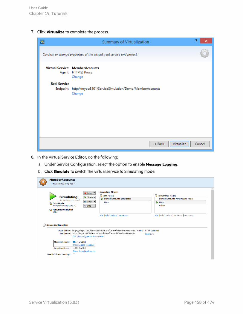
7. Click Virtualize to complete the process.
8. In the Virtual Service Editor, do the following:
a. Under Service Configuration, select the option to enable Message Logging.
b. Click Simulate to switch the virtual service to Simulating mode.
User GuideChapter 19: Tutorials
Service Virtualization (3.83) Page 458 of 474

Reconfigure the client application
Now we need to make a configuration change so that the client will send requests to the virtual serviceinstead of to the real service.
We know that the client application is using the system proxy, so we need to change it.
1. Set your machine's proxy server to the same proxy server that the virtual service is using.
Make sure proxy will be used for local addresses as well.
In Windows 10 you must clear the option Don’t use the proxy server for local (intranet) addressesas shown below.
User GuideChapter 19: Tutorials
Service Virtualization (3.83) Page 459 of 474

2. In the demo client, click Enter Claim to send the request again. Now it should reach the virtualservice.
Notice that the error message is different now. The virtual service responded with the default response,which is currently empty.
Now let’s start designing the data model interactively.
User GuideChapter 19: Tutorials
Service Virtualization (3.83) Page 460 of 474

Add data for "GET /accounts" call
Because you enabled message logging, you now have the exact request message from the client loggedinside Service Virtualization. You can use it in your data model, as we will explain in this step. Theresponse part however you will need to provide. Let’s check the logged messages.
1. In the Virtual Service Editor, under Service Configuration, click Show Logged Messages to open themessage viewer. Select the last request-response message pair so it will be available to import.
You can see that the request was a simple GET request on endpoint
http://hostname:8101/ServiceSimulation/Demo/MemberAccounts/accounts?firstname=Hercule&lastname=Poirot&SSN=554-98-0001, and the response was just HTTP Status code 200 with nopayload.
User GuideChapter 19: Tutorials
Service Virtualization (3.83) Page 461 of 474
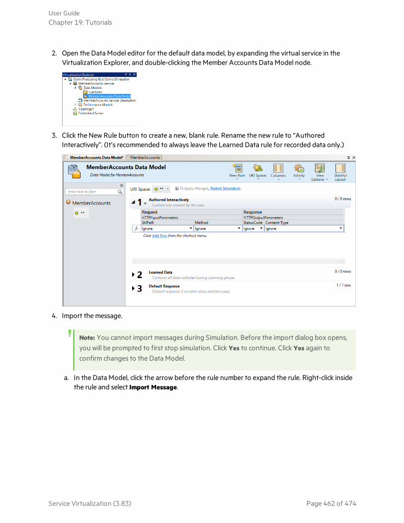
2. Open the Data Model editor for the default data model, by expanding the virtual service in theVirtualization Explorer, and double-clicking the Member Accounts Data Model node.
3. Click the New Rule button to create a new, blank rule. Rename the new rule to “AuthoredInteractively”. (It’s recommended to always leave the Learned Data rule for recorded data only.)
4. Import the message.
Note: You cannot import messages during Simulation. Before the import dialog box opens,you will be prompted to first stop simulation. Click Yes to continue. Click Yes again toconfirm changes to the Data Model.
a. In the Data Model, click the arrow before the rule number to expand the rule. Right-click insidethe rule and select Import Message.
User GuideChapter 19: Tutorials
Service Virtualization (3.83) Page 462 of 474

b. Request Message - click Logged message to get the request message you selected earlier in themessage viewer.
c. Response Message - copy the following:
Payload:
<?xml version="1.0" encoding="utf-8"?><MemberAccountsxmlns="http://schemas.datacontract.org/2004/07/HP.SOAQ.ServiceSimulation.Demo"><Member><householdId>0</householdId><memberId>1</memberId><socialSecurityNumber>554-98-0001</socialSecurityNumber>
</Member></MemberAccounts>
User GuideChapter 19: Tutorials
Service Virtualization (3.83) Page 463 of 474

The Import Request/Response Message dialog box should now look like this:
Click OK to create the new row in the data model.
5. In the Virtualization Explorer, double-click the virtual service name to return to the Virtual Service
User GuideChapter 19: Tutorials
Service Virtualization (3.83) Page 464 of 474

Editor.
6. Switch the virtual service back to Simulating mode.
7. In the demo client, click Enter Claim to send the request again. You should now see 4 messagesinstead of 2 in the Designer. The error in the demo client is different as well.
User GuideChapter 19: Tutorials
Service Virtualization (3.83) Page 465 of 474

Add data for "GET accounts/{accountId}/plan" call
Our claim processing application was able to get one step further, but the client application is stillshowing an error. This means we need to continue adding data to our data model. This time, we need toadd data for the GET plan operation.
1. In the message viewer, select the relevant message pair - the one after the pair we imported in thelast step.
Notice that the GET on following endpoint was called:
http://hostname:8101/ServiceSimulation/Demo/MemberAccounts/accounts/1/plan2. Open the Import Request/Response Message dialog box in the data model again, and enter the
following:
a. Request Message - import from logged messages.
b. Response Message - copy the following:
Payload:
<?xml version="1.0" encoding="utf-8"?><Planxmlns="http://schemas.datacontract.org/2004/07/HP.SOAQ.ServiceSimulation.Demo"><approvalLimit>1000</approvalLimit><id>1</id><name>Allpay Total 1000</name><totalClaimed>0</totalClaimed>
</Plan>
User GuideChapter 19: Tutorials
Service Virtualization (3.83) Page 466 of 474
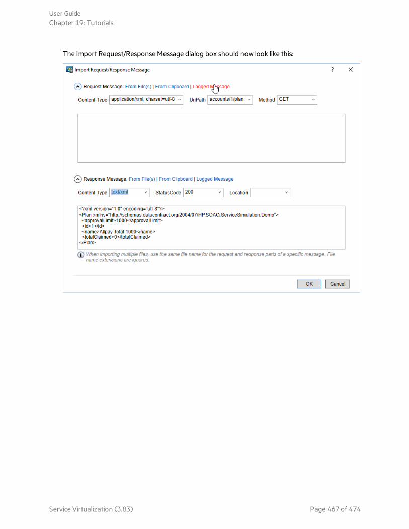
The Import Request/Response Message dialog box should now look like this:
User GuideChapter 19: Tutorials
Service Virtualization (3.83) Page 467 of 474

3. Switch the virtual service back to Simulating mode again, and send another request from the democlient. You can now see 6 messages in the Designer, and a different error in the demo clientapplication.
However, it is now complaining about another endpoint that we have not virtualized yet. Let’s fix it.
Add data for "GET accounts/{accountId}/detail" call
We moved one step ahead, but the claim processing application is sending a new request now, requiringus to further adapt our data model.
1. Check the logged messages in the message viewer again, and select the last message pair in the list.
2. Open the Import Request/Response Message dialog box again, and do the following:
a. Request Message - import the logged request.
b. Response Message - copy in the following:
Payload:
<?xml version="1.0" encoding="utf-8"?><Detailxmlns="http://schemas.datacontract.org/2004/07/HP.SOAQ.ServiceSimulation.Demo"xmlns:i="http://www.w3.org/2001/XMLSchema-instance"><address><city>Smithfield London W1</city><country>Great
User GuideChapter 19: Tutorials
Service Virtualization (3.83) Page 468 of 474

Britain</country><line1>56B Whitehaven Mansions</line1><line2>CharterhouseSquare</line2><state>England</state><zip i:nil="true" /></address><householdId>0</householdId><memberId>1</memberId><person><dateOfBirth>1876-04-01T00:00:00</dateOfBirth><gender>Male</gender><name><firstName>Hercule</firstName><lastName>Poirot</lastName><middleName
i:nil="true" /><prefix i:nil="true" /> <suffix i:nil="true" /></name><socialSecurityNumber>554-98-0001</socialSecurityNumber>
</person><phone i:nil="true" />
</Detail>
The Import Request/Response Message dialog box should now look like this:
Let's test it.
User GuideChapter 19: Tutorials
Service Virtualization (3.83) Page 469 of 474

3. Switch the virtual service back to Simulating mode again, and send another request from the democlient. Again we can see more messages were simulated, and a different error message is displayedin the client.
User GuideChapter 19: Tutorials
Service Virtualization (3.83) Page 470 of 474

Add data for "PUT accounts/{accountId}/plan" call
1. Let's check the logged messages again and select the one we want to import.
2. Open the Import Request/Response Message dialog box and fill in the data:
a. Request Message - import the logged request.
b. Response Message - no payload this time.
User GuideChapter 19: Tutorials
Service Virtualization (3.83) Page 471 of 474

Header: In Status Code field, enter 204.
User GuideChapter 19: Tutorials
Service Virtualization (3.83) Page 472 of 474

3. Test the simulation: Switch the virtual service to Simulating mode and send another request fromthe claim processing demo client.
Eight messages and no errors. We are done!
SummaryIn this tutorial, we populated the data model with four request-response pairs. All requests were takendirectly from the log file, so they perfectly matched what the client is sending. All response messageswere manually created, so they matched what we were expecting in our application.
User GuideChapter 19: Tutorials
Service Virtualization (3.83) Page 473 of 474

Send Us Feedback
Let us know how we can improve your experience with the User Guide.Send your email to: [email protected]
User GuideSend Us Feedback
Service Virtualization (3.83) Page 474 of 474