service oam fault management implementation … · lag meg link aggregation group maintenance...
TRANSCRIPT

MEF 30.1 © The Metro Ethernet Forum 2013. Any reproduction of this document, or any portion thereof, shall
contain the following statement: "Reproduced with permission of the Metro Ethernet Forum." No user of
this document is authorized to modify any of the information contained herein.
Technical Specification
MEF 30.1
Service OAM Fault Management
Implementation Agreement:
Phase 2
April 2013

MEF 30.1 © The Metro Ethernet Forum 2013. Any reproduction of this document, or any portion thereof, shall
contain the following statement: "Reproduced with permission of the Metro Ethernet Forum." No user of
this document is authorized to modify any of the information contained herein.
Disclaimer
The information in this publication is freely available for reproduction and use by any recipient
and is believed to be accurate as of its publication date. Such information is subject to change
without notice and the Metro Ethernet Forum (MEF) is not responsible for any errors. The MEF
does not assume responsibility to update or correct any information in this publication. No
representation or warranty, expressed or implied, is made by the MEF concerning the complete-
ness, accuracy, or applicability of any information contained herein and no liability of any kind
shall be assumed by the MEF as a result of reliance upon such information.
The information contained herein is intended to be used without modification by the recipient or
user of this document. The MEF is not responsible or liable for any modifications to this docu-
ment made by any other party.
The receipt or any use of this document or its contents does not in any way create, by implication
or otherwise:
any express or implied license or right to or under any patent, copyright, trademark or trade
secret rights held or claimed by any MEF member company which are or may be associated with
the ideas, techniques, concepts or expressions contained herein; nor
any warranty or representation that any MEF member companies will announce any product(s)
and/or service(s) related thereto, or if such announcements are made, that such announced
product(s) and/or service(s) embody any or all of the ideas, technologies, or concepts contained
herein; nor
any form of relationship between any MEF member companies and the recipient or user of this
document.
Implementation or use of specific Metro Ethernet standards or recommendations and MEF
specifications will be voluntary, and no company shall be obliged to implement them by virtue of
participation in the Metro Ethernet Forum. The MEF is a non-profit international organization
accelerating industry cooperation on Metro Ethernet technology. The MEF does not, expressly or
otherwise, endorse or promote any specific products or services.
© The Metro Ethernet Forum 2013. All Rights Reserved.

Service OAM Fault Management Implementation Agreement: Phase 2
MEF 30.1 © The Metro Ethernet Forum 2013. Any reproduction of this document, or any portion thereof, shall
contain the following statement: "Reproduced with permission of the Metro Ethernet Forum." No user of
this document is authorized to modify any of the information contained herein.
Page i
Table of Contents
1. Abstract ................................................................................................................................ 1
2. Terminology and Acronyms............................................................................................... 1
3. Scope..................................................................................................................................... 5
4. Compliance Levels .............................................................................................................. 6
5. Introduction ......................................................................................................................... 7
5.1 OAM Domains .................................................................................................................. 7 5.2 OAM Architecture ............................................................................................................. 8 5.3 Default Behaviors .............................................................................................................. 9
6. Related Activity on OAM Fault Management Requirements ...................................... 10
6.1 MEF 6.1 ........................................................................................................................... 10
6.2 MEF 7.1 ........................................................................................................................... 10 6.3 MEF 10.2 ......................................................................................................................... 10
6.4 MEF 12.1 ......................................................................................................................... 10 6.5 MEF 12.1.1 ...................................................................................................................... 10 6.6 MEF 16 ............................................................................................................................ 10
6.7 MEF 17 ............................................................................................................................ 11 6.8 MEF 20 ............................................................................................................................ 11
6.9 MEF 26.1 ......................................................................................................................... 11 6.10 MEF 31 ............................................................................................................................ 11 6.11 MEF 38 ............................................................................................................................ 11
7. Maintenance Entity Groups ............................................................................................. 12
7.1 Generic MEG Requirements ........................................................................................... 12
7.2 MEG Security Considerations ......................................................................................... 13 7.3 SOAM PDU Processing Capacity ................................................................................... 14
7.4 Subscriber MEG .............................................................................................................. 14 7.5 Test MEG ........................................................................................................................ 15
7.5.1 Limitations ............................................................................................................................ 17 7.6 EVC MEG ....................................................................................................................... 17 7.7 Service Provider MEG..................................................................................................... 18 7.8 Operator MEG ................................................................................................................. 20 7.9 UNI MEG ........................................................................................................................ 20
7.9.1 UNI-C MEP Requirements ................................................................................................... 21 7.9.2 UNI-N MEP Requirements ................................................................................................... 21
7.10 ENNI MEG ...................................................................................................................... 21 7.11 LAG MEG ....................................................................................................................... 21 7.12 LAG Link MEG............................................................................................................... 22
8. Fault Management Protocols ........................................................................................... 23
8.1 MEG ID / MAID ............................................................................................................. 23 8.2 Continuity Check ............................................................................................................. 24
8.2.1 Remote Defect Indication Signal .......................................................................................... 26 8.3 Loopback ......................................................................................................................... 26

Service OAM Fault Management Implementation Agreement: Phase 2
MEF 30.1 © The Metro Ethernet Forum 2013. Any reproduction of this document, or any portion thereof, shall
contain the following statement: "Reproduced with permission of the Metro Ethernet Forum." No user of
this document is authorized to modify any of the information contained herein.
Page ii
8.4 Linktrace .......................................................................................................................... 29
8.5 Alarm Indication Signal................................................................................................... 29
8.6 Locked Signal .................................................................................................................. 33 8.7 Test Signal ....................................................................................................................... 34 8.8 Client Signal Fail ............................................................................................................. 36
9. SOAM FM Interaction With Other Protocols ............................................................... 38
9.1 SOAM FM Interaction with Link Aggregation ............................................................... 38 9.1.1 LAG Fault Management........................................................................................................ 39 9.1.2 Link Aggregation Link Management .................................................................................... 40
9.2 SOAM FM Interaction with E-LMI ................................................................................ 41 9.2.1 EVC Status Information Element .......................................................................................... 42
9.2.1.1 EVC Active ......................................................................................................................... 42 9.2.1.2 EVC Partially Active ......................................................................................................... 42 9.2.1.3 EVC Not Active .................................................................................................................. 43
9.2.2 CFM to E-LMI Interworking with UTA ............................................................................... 43 9.2.2.1 Interface Status isUP ......................................................................................................... 44 9.2.2.2 Interface Status isDown ..................................................................................................... 44 9.2.2.3 Interface Status isTesting ................................................................................................... 44
10. References .......................................................................................................................... 45
11. Appendix A – FM Scenarios [Informative] .................................................................... 46
11.1.1 UNI Failure ........................................................................................................................... 46 11.1.1.1 UNI Without Intervening Bridges ...................................................................................... 46 11.1.1.2 UNI With Intervening Bridges ........................................................................................... 47
11.1.2 ENNI Failure ......................................................................................................................... 48 11.1.3 Operator NE Failure .............................................................................................................. 49
12. Appendix B – VLAN Tagging Implications on SOAM Treatment [Informative] ...... 50
13. Appendix C – Mapping Between 802.1Q and Y.1731 Terms [Informative] ............... 53
14. Appendix D – Examples of Client MEGs for Injecting AIS and LCK [Informative] 54
List of Figures
Figure 1 – Example SOAM Maintenance Entities ......................................................................... 8 Figure 2 – OAM Domain ................................................................................................................ 9
Figure 3 – Point-To-Point Test MEG, Example 1 ........................................................................ 16 Figure 4 – Point-To-Point Test MEG, Example 2 ........................................................................ 16 Figure 5 – Example SP MEG With UTA ..................................................................................... 19
Figure 6 – Example MP Placements With UTA ........................................................................... 19 Figure 7 – MAID Field Format ..................................................................................................... 23 Figure 8 – AIS Example 1 ............................................................................................................ 31 Figure 9 – AIS Example 2 ............................................................................................................ 32
Figure 10 – LCK Example ............................................................................................................ 34 Figure 11 – MEP Placement ......................................................................................................... 35 Figure 12 – CSF Example ............................................................................................................. 36
Figure 13 – LinkAgg MEPs .......................................................................................................... 39 Figure 14 – SOAM FM Interaction With E-LMI ......................................................................... 41
Service OAM Fault Management Implementation Agreement: Phase 2
MEF 30.1 © The Metro Ethernet Forum 2013. Any reproduction of this document, or any portion thereof, shall
contain the following statement: "Reproduced with permission of the Metro Ethernet Forum." No user of
this document is authorized to modify any of the information contained herein.
Page iii
Figure 15 – UNI Failure Without Intervening Bridges ................................................................. 46
Figure 16 – UNI Failure With Intervening Bridges ...................................................................... 47
Figure 17 – ENNI Failure ............................................................................................................. 48 Figure 18 – Operator NE Failure .................................................................................................. 49 Figure 19 – VLAN Tagging Reference Diagram ......................................................................... 50 Figure 20 – VLAN Tagging Cases ............................................................................................... 51 Figure 21 – SOAM Frame Formats .............................................................................................. 52 Figure 22 – Example Network ...................................................................................................... 54
List of Tables
Table 1 – Definitions ...................................................................................................................... 4 Table 2 – Suggested MEGs and Usages ......................................................................................... 7 Table 3 – Default MEG Levels ..................................................................................................... 12
Table 4 – Minimum Number of EVC MEPs at a UNI-N ............................................................. 18 Table 5 – Terminology Mappings................................................................................................. 53
Service OAM Fault Management Implementation Agreement: Phase 2
MEF 30.1 © The Metro Ethernet Forum 2013. Any reproduction of this document, or any portion thereof, shall
contain the following statement: "Reproduced with permission of the Metro Ethernet Forum." No user of
this document is authorized to modify any of the information contained herein.
Page 1
1. Abstract
This document specifies an Implementation Agreement (IA) for Service Operations, Administra-
tion, and Maintenance (OAM) that builds upon the framework and requirements specified by
MEF 17 [16]. In particular, this IA specifies Service OAM requirements for Maintenance Entity
Groups (MEGs) and for Fault Management (FM). Service OAM in general and FM in particular
are defined in IEEE 802.1Q [3] and ITU-T Y.1731 [7]. This IA details how to use these func-
tions to achieve the MEF requirements of Service OAM in general and Service OAM FM in
particular.
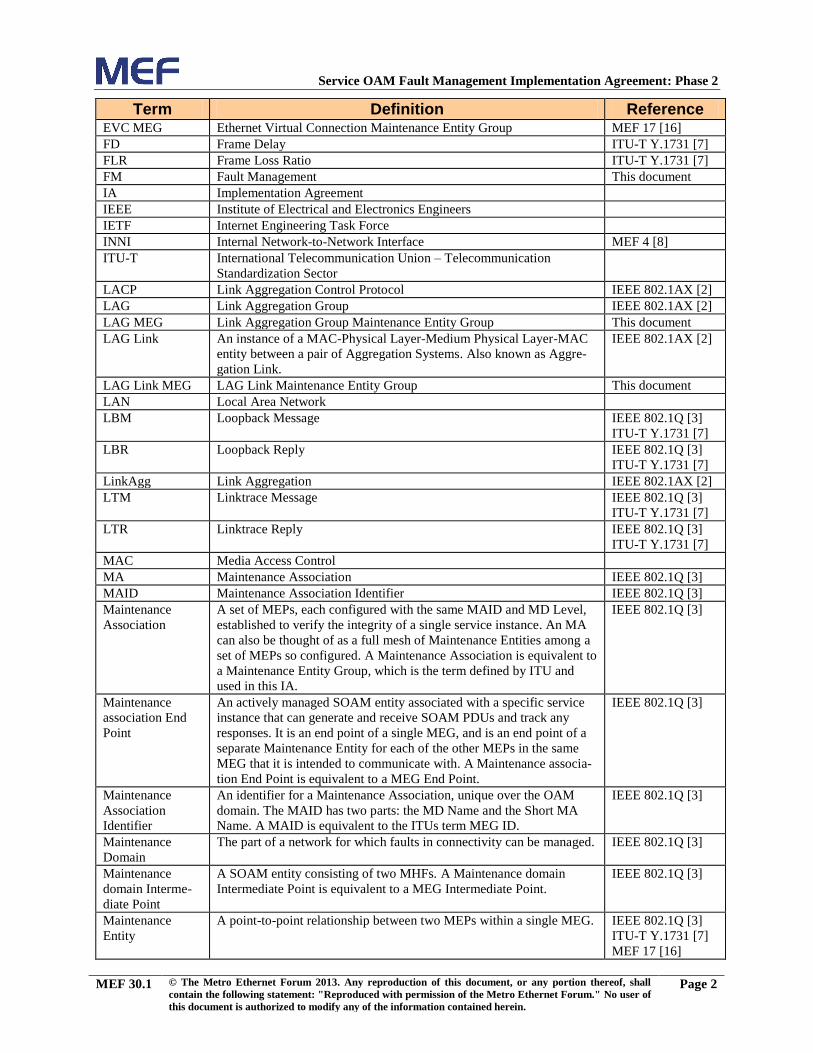
2. Terminology and Acronyms
Term Definition Reference AIS Alarm Indication Signal ITU-T G.8021 [6]
BBF Broadband Forum
Carrier Ethernet
Network
A network supporting Carrier Ethernet services. MEF 12.1 [12]
CCM Continuity Check Message IEEE 802.1Q [3]
ITU-T Y.1731 [7]
CEN Carrier Ethernet Network MEF 12.1 [12]
CE-VLAN ID Customer Edge VLAN ID MEF 10.2 [11]
CFM Connectivity Fault Management IEEE 802.1Q [3]
C-VID Customer VLAN Identifier IEEE 802.1Q [3]
Down MEP A MEP residing in a Bridge that receives SOAM PDUs from, and
transmits them towards, the direction of the LAN1. See also Up MEP.
IEEE 802.1Q [3]
EC Ethernet Services Layer Connection MEF 12.1 [12]
E-LAN An Ethernet service type that is based on a Multipoint-to-Multipoint
EVC.
MEF 6.1 [9]
E-Line An Ethernet service type that is based on a Point-to-Point EVC. MEF 6.1 [9]
E-LMI Ethernet Local Management Interface MEF 16 [14]
EMS Element Management System
ENNI External Network Network Interface MEF 4 [8]
ENNI-N The functional element comprising one half of an ENNI, administered
by the Operator whose Operator CEN terminates at the functional
element.
MEF 26.1 [19]
ENNI MEG External Network Network Interface Maintenance Entity Group MEF 17 [16]
ETH Ethernet MAC layer network ITU-T Y.1731 [7]
Ethernet Virtual
Connection
An association of two or more UNIs that limits the exchange of
Service Frames to UNIs in the Ethernet Virtual Connection.
MEF 10.2 [11]
ETH-AIS Ethernet Alarm Indication Signal function ITU-T Y.1731 [7]
ETH-CC Ethernet Continuity Check function (see also CCM) ITU-T Y.1731 [7]
ETH-CSF Ethernet Client Signal Fail function ITU-T Y.1731 [7]
ETH-LB Ethernet Loopback function (see also LBM) ITU-T Y.1731 [7]
ETH-LCK Ethernet Lock signal function ITU-T Y.1731 [7]
ETH-LT Ethernet Linktrace function (see also LTM) ITU-T Y.1731 [7]
ETH-RDI Ethernet Remote Defect Indication function ITU-T Y.1731 [7]
ETH-Test Ethernet Test function ITU-T Y.1731 [7]
E-Tree An Ethernet service type that is based on a Rooted-Multipoint EVC. MEF 6.1[9]
EVC Ethernet Virtual Connection MEF 10.2 [11]
1In this context, the LAN is a transmission facility for egress, rather than towards the Bridge Relay Entity.
Service OAM Fault Management Implementation Agreement: Phase 2
MEF 30.1 © The Metro Ethernet Forum 2013. Any reproduction of this document, or any portion thereof, shall
contain the following statement: "Reproduced with permission of the Metro Ethernet Forum." No user of
this document is authorized to modify any of the information contained herein.
Page 2
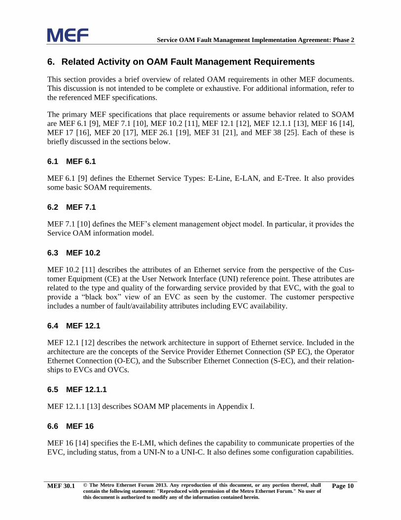
Term Definition Reference EVC MEG Ethernet Virtual Connection Maintenance Entity Group MEF 17 [16]
FD Frame Delay ITU-T Y.1731 [7]
FLR Frame Loss Ratio ITU-T Y.1731 [7]
FM Fault Management This document
IA Implementation Agreement
IEEE Institute of Electrical and Electronics Engineers
IETF Internet Engineering Task Force
INNI Internal Network-to-Network Interface MEF 4 [8]
ITU-T International Telecommunication Union – Telecommunication
Standardization Sector
LACP Link Aggregation Control Protocol IEEE 802.1AX [2]
LAG Link Aggregation Group IEEE 802.1AX [2]
LAG MEG Link Aggregation Group Maintenance Entity Group This document
LAG Link An instance of a MAC-Physical Layer-Medium Physical Layer-MAC
entity between a pair of Aggregation Systems. Also known as Aggre-
gation Link.
IEEE 802.1AX [2]
LAG Link MEG LAG Link Maintenance Entity Group This document
LAN Local Area Network
LBM Loopback Message IEEE 802.1Q [3]
ITU-T Y.1731 [7]
LBR Loopback Reply IEEE 802.1Q [3]
ITU-T Y.1731 [7]
LinkAgg Link Aggregation IEEE 802.1AX [2]
LTM Linktrace Message IEEE 802.1Q [3]
ITU-T Y.1731 [7]
LTR Linktrace Reply IEEE 802.1Q [3]
ITU-T Y.1731 [7]
MAC Media Access Control
MA Maintenance Association IEEE 802.1Q [3]
MAID Maintenance Association Identifier IEEE 802.1Q [3]
Maintenance
Association
A set of MEPs, each configured with the same MAID and MD Level,
established to verify the integrity of a single service instance. An MA
can also be thought of as a full mesh of Maintenance Entities among a
set of MEPs so configured. A Maintenance Association is equivalent to
a Maintenance Entity Group, which is the term defined by ITU and
used in this IA.
IEEE 802.1Q [3]
Maintenance
association End
Point
An actively managed SOAM entity associated with a specific service
instance that can generate and receive SOAM PDUs and track any
responses. It is an end point of a single MEG, and is an end point of a
separate Maintenance Entity for each of the other MEPs in the same
MEG that it is intended to communicate with. A Maintenance associa-
tion End Point is equivalent to a MEG End Point.
IEEE 802.1Q [3]
Maintenance
Association
Identifier
An identifier for a Maintenance Association, unique over the OAM
domain. The MAID has two parts: the MD Name and the Short MA
Name. A MAID is equivalent to the ITUs term MEG ID.
IEEE 802.1Q [3]
Maintenance
Domain
The part of a network for which faults in connectivity can be managed. IEEE 802.1Q [3]
Maintenance
domain Interme-
diate Point
A SOAM entity consisting of two MHFs. A Maintenance domain
Intermediate Point is equivalent to a MEG Intermediate Point.
IEEE 802.1Q [3]
Maintenance
Entity
A point-to-point relationship between two MEPs within a single MEG. IEEE 802.1Q [3]
ITU-T Y.1731 [7]
MEF 17 [16]

Service OAM Fault Management Implementation Agreement: Phase 2
MEF 30.1 © The Metro Ethernet Forum 2013. Any reproduction of this document, or any portion thereof, shall
contain the following statement: "Reproduced with permission of the Metro Ethernet Forum." No user of
this document is authorized to modify any of the information contained herein.
Page 3
Term Definition Reference Maintenance
Entity Group
Equivalent to a Maintenance Association (MA). A set of MEs that
exist in the same administrative boundary, with the same MEG Level
and MEG ID. A Maintenance Entity Group is equivalent to a Mainte-
nance Association.
ITU-T Y.1731 [7]
MD Maintenance Domain IEEE 802.1Q [3]
ME Maintenance Entity IEEE 802.1Q [3]
ITU-T Y.1731 [7]
MEF 17 [16]
MEF Metro Ethernet Forum
MEG Maintenance Entity Group ITU-T Y.1731 [7]
MEG End Point An actively managed SOAM entity associated with a specific service
instance that can generate and receive SOAM PDUs and track any
responses. It is an end point of a single MEG, and is an end point of a
separate Maintenance Entity for each of the other MEPs in the same
MEG that it is intended to communicate with. A MEG End Point is
equivalent to a Maintenance association End Point.
ITU-T Y.1731 [7]
MEG ID Equivalent to the IEEE term Maintenance Association Identifier
(MAID). An identifier for a MEG, unique over the domain that SOAM
is to protect against the accidental concatenation of service instances.
ITU-T Y.1731 [7]
MEG Intermedi-
ate Point
An intermediate point in a MEG that is capable of reacting to some
SOAM PDUs, but does not initiate SOAM PDUs. A MEG Intermedi-
ate Point is equivalent to a Maintenance domain Intermediate Point.
ITU-T Y.1731 [7]
MEG Level A small integer in a field in a SOAM PDU that is used, along with the
VID in the VLAN tag, to identify to which MEG among those
associated with the SOAM PDU’s VID, and thus to which ME, a
SOAM PDU belongs. The MEG Level determines the MPs a) that are
interested in the contents of a SOAM PDU, and b) through which the
frame carrying that SOAM PDU is allowed to pass. This term is
equivalent to MD Level, which is used in IEEE 802.1Q [3].
ITU-T Y.1731 [7]
MEP Maintenance association End Point (IEEE 802.1Q [3]), or equivalently
MEG End Point (ITU-T Y.1731 [7])
IEEE 802.1Q [3]
ITU-T Y.1731 [7]
MHF MIP Half Function IEEE 802.1Q [3]
MIP Maintenance domain Intermediate Point (IEEE 802.1Q [3]) or
equivalently MEG Intermediate Point (ITU-T Y.1731 [7]).
IEEE 802.1Q [3]
ITU-T Y.1731 [7]
MIP Half
Function
A SOAM entity, associated with a single MD, and thus with a single
MD Level and a set of VIDs, that can generate SOAM PDUs, but only
in response to received SOAM PDUs.
IEEE 802.1Q [3]
MP Maintenance Point. One of either a MEP or a MIP. IEEE 802.1Q [3]
MTU Maximum Transmission Unit MEF 10.2 [11]
MEF 26.1 [19]
NE Network Element
NNI Network-to-Network Interface MEF 4 [8]
NMS Network Management System
OAM Operations, Administration, and Maintenance
OAM Domain Equivalent to Maintenance Domain (MD). MEF 17 [16]
OAM Flow Space The portions of an end-to-end flow where SOAM frames are seen as
SOAM frames (as opposed to being seen as data frames when double
tagged).
Operator MEG Operator Maintenance Entity Group MEF 17 [16]
Operator Virtual
Connection
An association between specific External Interfaces, e.g., a UNI and an
ENNI.
MEF 26.1 [19]
OVC Operator Virtual Connection MEF 26.1 [19]
P2P Point-to-Point

Service OAM Fault Management Implementation Agreement: Phase 2
MEF 30.1 © The Metro Ethernet Forum 2013. Any reproduction of this document, or any portion thereof, shall
contain the following statement: "Reproduced with permission of the Metro Ethernet Forum." No user of
this document is authorized to modify any of the information contained herein.
Page 4
Term Definition Reference PCP Priority Code Point IEEE 802.1Q [3]
PDU Protocol Data Unit
Priority Code
Point
This is the 3-bit field of a tag that specifies the priority of a tagged
Ethernet frame.
IEEE 802.1Q [3]
RDI Remote Defect Indication IEEE 802.1Q [3]
ITU-T Y.1731 [7]
RFC Request For Comment
RUNI Remote UNI MEF 28 [20]
Service Provider The organization providing Ethernet service(s) to the subscriber. MEF 10.2 [11]
Service Provider
MEG
Service Provider Maintenance Entity Group This document
SP Service Provider MEF 10.2 [11]
SP-EC Service Provider EC MEF 12.1 [12]
SP MEG Service Provider Maintenance Entity Group This document
SOAM Service Operations, Administration, and Maintenance MEF 17 [16]
SOAM frame Service OAM frame. Specifically, an Ethernet frame containing a
SOAM PDU.
This document
SOAM PDU Service OAM Protocol Data Unit. Specifically, those PDUs defined in
IEEE 802.1Q [3], ITU-T Y.1731 [7], or MEF specifications.
This document
Subscriber MEG Subscriber Maintenance Entity Group MEF 17 [16]
S-VID Service VLAN Identifier IEEE 802.1Q [3]
Test MEG Test Maintenance Entity Group MEF 20 [17]
UNI User Network Interface MEF 10.2 [11]
UNI-C Subscriber side UNI functions MEF 4 [8]
UNI MEG User Network Interface Maintenance Entity Group MEF 17 [16]
UNI-N Network side UNI functions MEF 4 [8]
Up MEP A MEP residing in a Bridge that transmits SOAM PDUs towards, and
receives them from, the direction of the Bridge Relay Entity. See also
Down MEP.
IEEE 802.1Q [3]
UTA UNI Tunnel Access MEF 28 [20]
VID VLAN Identifier IEEE 802.1Q [3]
VLAN Virtual LAN IEEE 802.1Q [3]
VUNI Virtual UNI MEF 28 [20]
Table 1 – Definitions
Note: IEEE 802.1Q [3] and ITU-T Y.1731 [7] define some of the same OAM concepts with
different terminology. This document uses the ITU-T Y.1731 terminology, except for MAID
(and MA in the context of discussing the MAID), which is used in addition to MEG ID to clarify
the formatting of the MEG ID. See Appendix C for a mapping between the two sets of terms.

Service OAM Fault Management Implementation Agreement: Phase 2
MEF 30.1 © The Metro Ethernet Forum 2013. Any reproduction of this document, or any portion thereof, shall
contain the following statement: "Reproduced with permission of the Metro Ethernet Forum." No user of
this document is authorized to modify any of the information contained herein.
Page 5
3. Scope
The scope of this document is an Implementation Agreement (IA) that specifies functional
requirements for Fault Management (FM) for Metro Ethernet Forum (MEF) services. These
requirements are primarily driven by MEF 17 [16] and leverage the OAM functions defined by
IEEE 802.1Q [3] and ITU-T Y.1731 [7]. When and if necessary, this IA may define enhance-
ments to existing functions to satisfy Service OAM (SOAM) requirements. These functions are
defined as generically as possible.
In particular this IA is targeted at the following Maintenance Entity Groups (MEGs) defined and
in use by the MEF:
Subscriber MEG
Test MEG
EVC MEG
Service Provider MEG
Operator MEG
UNI MEG
ENNI MEG
LAG MEG
LAG Link MEG
This IA also discusses the following OAM functions:
Continuity Check
Remote Defect Indication
Loopback
Linktrace
Alarm Indication Signal
Locked Signal
Test Signal
Client Signal Fail
This IA attempts to maintain consistent functionality and requirements across the various MEGs.
Generic SOAM requirements and Fault Management elements are covered in this IA. SOAM
Performance Management capabilities are covered in MEF 35 [24].

Service OAM Fault Management Implementation Agreement: Phase 2
MEF 30.1 © The Metro Ethernet Forum 2013. Any reproduction of this document, or any portion thereof, shall
contain the following statement: "Reproduced with permission of the Metro Ethernet Forum." No user of
this document is authorized to modify any of the information contained herein.
Page 6
4. Compliance Levels
The key words "MUST", "MUST NOT", "REQUIRED", "SHALL", "SHALL NOT",
"SHOULD", "SHOULD NOT", "RECOMMENDED", "MAY", and "OPTIONAL" in this
document are to be interpreted as described in IETF RFC 2119 [5]. All key words must be in
upper case, bold text.
A paragraph preceded by [Rx], where x indicates a sequentially increasing number throughout
the document, specifies a mandatory requirement that MUST be followed. A paragraph preceded
by [Dy], where y indicates a sequentially increasing number throughout the document, specifies a
desired requirement that SHOULD be followed. A paragraph preceded by [Oz], where z indi-
cates a sequentially increasing number throughout the document, specifies an optional require-
ment that MAY be followed.
A paragraph preceded by [CRa]<, where a indicates a sequentially increasing number through-
out the document, specifies a mandatory requirement that MUST be followed if the condition(s)
following the “<” have been met. For example, “[CR1]<[D38]” indicates that conditional
requirement 1 must be followed if desired requirement 38 has been met. A paragraph preceded
by [CDb]<, where b indicates a sequentially increasing number throughout the document,
specifies a desired requirement that SHOULD be followed if the condition(s) following the “<”
have been met. A paragraph preceded by [COc]<, where c indicates a sequentially increasing
number throughout the document, specifies an optional requirement that MAY be followed if the
condition(s) following the “<” have been met.

Service OAM Fault Management Implementation Agreement: Phase 2
MEF 30.1 © The Metro Ethernet Forum 2013. Any reproduction of this document, or any portion thereof, shall
contain the following statement: "Reproduced with permission of the Metro Ethernet Forum." No user of
this document is authorized to modify any of the information contained herein.
Page 7
5. Introduction
SOAM FM describes the use of standard protocols, mechanisms, and procedures for monitoring
and investigating the status of Ethernet Virtual Connections (EVCs), Operator Virtual Connec-
tions (OVCs), and External Interfaces across a defined OAM Domain, where that domain can be
a large network (or subnetwork), or a simple link. SOAM FM uses the protocols of IEEE 802.1Q
[3] and ITU-T Y.1731 [7] in order to determine the status of and troubleshoot connectivity across
a particular domain. See Appendix C for a discussion of the use of IEEE 802.1Q and ITU-
T Y.1731 terminology.
The requirements in this IA are primarily from the perspective of the Network Element (NE)
rather than the administrator of the NE. However, some requirements represent requirements on
how NEs are implemented and used. These requirements are specified to make NE OAM func-
tionality simpler and more likely to interoperate.
5.1 OAM Domains
As discussed in MEF 17 [16], SOAM allows a network to be partitioned into a set of hierarchical
domains, where a domain is a contiguous (sub)-network, and each domain can be further parti-
tioned into additional (sub)-domains. OAM domains are intended to represent administrative
boundaries. The OAM domains relevant to this IA are listed in Table 2:
MEG Suggested Usage
Subscriber MEG Subscriber monitoring of an Ethernet service
Test MEG Service Provider isolation of subscriber reported problems
EVC MEG Service Provider monitoring of provided service
Service Provider MEG Service Provider monitoring of Service Provider network
UTA SP MEG Service Provider monitoring of UNI Tunnel Access
Operator MEG Network Operator monitoring of the portion of a network
UNI MEG Service Provider monitoring of a UNI
ENNI MEG Network Operator monitoring of an ENNI
UNI LAG Link MEG Service Provider monitoring of LAG link across a UNI
ENNI LAG Link MEG Network Operator monitoring of a LAG link across an ENNI
Table 2 – Suggested MEGs and Usages
Fault Management will be discussed for each OAM domain. For a further discussion of these
Maintenance/OAM Domains, refer to MEF 17 [16]. The Test MEG was introduced in MEF 20
[17], and is described in Appendix A of that IA. The Service Provider MEG is introduced in this
document in section 7.7. The LAG MEG is introduced in this document in section 7.11. The
LAG Link MEG is introduced in this document in section 7.12.

Service OAM Fault Management Implementation Agreement: Phase 2
MEF 30.1 © The Metro Ethernet Forum 2013. Any reproduction of this document, or any portion thereof, shall
contain the following statement: "Reproduced with permission of the Metro Ethernet Forum." No user of
this document is authorized to modify any of the information contained herein.
Page 8
5.2 OAM Architecture
Figure 1 (which is derived from Figure 1 from MEF 20, which in turn is based on Figure 5 from
MEF 17) illustrates pairs of MEPs (thus MEs) and MIPs that may be communicating across the
various OAM domains discussed in this IA, and also illustrates the hierarchical relationship
between these domains.
Figure 1 – Example SOAM Maintenance Entities
Note 1: The given MEP and MIP locations, and MEP orientations, are for example purposes
only. There are cases where the locations and orientations may differ. As shown with the exam-
ple of the Subscriber ME, the ends of a ME are not required to be the same (i.e., both Up MEPs
or both Down MEPs). Requirements and recommendations for the orientation of MEPs are
provided in later sections of this IA.
Note 2: The use of MIPs, as shown in Figure 1, by a Service Provider or an Operator at the
Subscriber MEG Level would allow a Subscriber to determine that traffic has traversed the
intended External Interfaces (EIs) through the network(s). Additionally, MIPs configured by an
Operator at the SP MEG Level could allow a Service Provider to determine if a connectivity
problem exists in a particular Operator network (via the SP MEG MIPs).
When flowing from subscriber equipment at one location to subscriber equipment at another
location, a frame can have tags added or removed. Appendix B explains the impact of VLAN ID
(VID) manipulation on Service OAM PDUs and the implications for OAM domain delineation.
Sometimes this requires Subscribers, Providers, and Operators to share the MEG Levels and
mutually agree on the use of each MEG Level.

Service OAM Fault Management Implementation Agreement: Phase 2
MEF 30.1 © The Metro Ethernet Forum 2013. Any reproduction of this document, or any portion thereof, shall
contain the following statement: "Reproduced with permission of the Metro Ethernet Forum." No user of
this document is authorized to modify any of the information contained herein.
Page 9
Figure 2 looks more closely at one particular OAM domain and the MEs of a particular mul-
tipoint EVC. The OAM domain consists of the Maintenance Entity Group {MEP1, MEP2, MEP3,
MEP4} where each unique MEP pair (i.e., {{MEP1, MEP2}, {MEP1, MEP3}, {MEP1, MEP4},
{MEP2, MEP3}, {MEP2, MEP4}, {MEP3, MEP4}}) constitutes a separate ME.
Figure 2 – OAM Domain
5.3 Default Behaviors
One of the important functions of this document is to simplify the provisioning of OAM across a
Carrier Ethernet Network (CEN). To this end, a default value for an attribute of a maintenance
object is defined as the value to be used for that attribute when no other value has been specified
during the creation of that object. The use of default values aids interoperability.
Note that the specification of default values does not relieve equipment or service providers of
being capable of using a different value if one of the parties has an issue. In other words, specifi-
cation of a default value assumes that the value is settable and that other values could be used.
The default value is suggested as a value to shorten or obviate the need for negotiations in most
cases. However, other mandatory values are to be available for those cases where the default
may not be suitable to one of the parties.
SOAM
Domain
MEP1 MEP2
MEP4 MEP3
Service OAM Fault Management Implementation Agreement: Phase 2
MEF 30.1 © The Metro Ethernet Forum 2013. Any reproduction of this document, or any portion thereof, shall
contain the following statement: "Reproduced with permission of the Metro Ethernet Forum." No user of
this document is authorized to modify any of the information contained herein.
Page 10
6. Related Activity on OAM Fault Management Requirements
This section provides a brief overview of related OAM requirements in other MEF documents.
This discussion is not intended to be complete or exhaustive. For additional information, refer to
the referenced MEF specifications.
The primary MEF specifications that place requirements or assume behavior related to SOAM
are MEF 6.1 [9], MEF 7.1 [10], MEF 10.2 [11], MEF 12.1 [12], MEF 12.1.1 [13], MEF 16 [14],
MEF 17 [16], MEF 20 [17], MEF 26.1 [19], MEF 31 [21], and MEF 38 [25]. Each of these is
briefly discussed in the sections below.
6.1 MEF 6.1
MEF 6.1 [9] defines the Ethernet Service Types: E-Line, E-LAN, and E-Tree. It also provides
some basic SOAM requirements.
6.2 MEF 7.1
MEF 7.1 [10] defines the MEF’s element management object model. In particular, it provides the
Service OAM information model.
6.3 MEF 10.2
MEF 10.2 [11] describes the attributes of an Ethernet service from the perspective of the Cus-
tomer Equipment (CE) at the User Network Interface (UNI) reference point. These attributes are
related to the type and quality of the forwarding service provided by that EVC, with the goal to
provide a “black box” view of an EVC as seen by the customer. The customer perspective
includes a number of fault/availability attributes including EVC availability.
6.4 MEF 12.1
MEF 12.1 [12] describes the network architecture in support of Ethernet service. Included in the
architecture are the concepts of the Service Provider Ethernet Connection (SP EC), the Operator
Ethernet Connection (O-EC), and the Subscriber Ethernet Connection (S-EC), and their relation-
ships to EVCs and OVCs.
6.5 MEF 12.1.1
MEF 12.1.1 [13] describes SOAM MP placements in Appendix I.
6.6 MEF 16
MEF 16 [14] specifies the E-LMI, which defines the capability to communicate properties of the
EVC, including status, from a UNI-N to a UNI-C. It also defines some configuration capabilities.

Service OAM Fault Management Implementation Agreement: Phase 2
MEF 30.1 © The Metro Ethernet Forum 2013. Any reproduction of this document, or any portion thereof, shall
contain the following statement: "Reproduced with permission of the Metro Ethernet Forum." No user of
this document is authorized to modify any of the information contained herein.
Page 11
6.7 MEF 17
MEF 17 [16] provides a high level overview of SOAM architecture and capabilities, and dis-
cusses some of the requirements for MEF Service OAM. According to these requirements,
SOAM provides the ability to determine Connectivity Status, one-way Frame Loss Ratio, two-
way Frame Delay, and one-way Frame Delay Variation for point-to-point EVCs.
6.8 MEF 20
MEF 20 [17] provides requirements for UNI Type II devices. Included in the MEF 20 specifica-
tion are some Fault Management requirements for the Subscriber MEG, Test MEG, and UNI
MEG. This document provides a superset of those requirements.
6.9 MEF 26.1
MEF 26.1 [19] provides details about the External Network Network Interface (ENNI).
MEF 26.1 defines elements related to the ENNI, including the ENNI MEG, for which this
document defines SOAM requirements.
6.10 MEF 31
MEF 31 [21] provides SNMP managed objects for use with SOAM implementations.
6.11 MEF 38
MEF 38 [25] provides YANG managed objects for use with SOAM implementations.

Service OAM Fault Management Implementation Agreement: Phase 2
MEF 30.1 © The Metro Ethernet Forum 2013. Any reproduction of this document, or any portion thereof, shall
contain the following statement: "Reproduced with permission of the Metro Ethernet Forum." No user of
this document is authorized to modify any of the information contained herein.
Page 12
7. Maintenance Entity Groups
This section describes requirements that are specific to Maintenance Entity Groups (MEGs),
both generically and per specific Maintenance Entity Group.
7.1 Generic MEG Requirements
This section details the MEGs that must be supported by NEs in a Carrier Ethernet Network
(CEN). Figure 1 illustrates the MEGs relevant to OAM.
[R1] The MEG Level for each MEG MUST be configurable with any valid MEG
Level value (0…7).
[R2] The default value for the MEG Level for each MEG MUST be in conformance
with Table 3:
MEG Default MEG Level
Subscriber MEG 6
Test MEG 5
EVC MEG 4
Service Provider MEG 3
UTA SP MEG 3
Operator MEG 2
UNI MEG 1
ENNI MEG 1
UNI LAG Link MEG 0
ENNI LAG Link MEG 0
Table 3 – Default MEG Levels
Note 1: Table 3 is more specific than that given in MEF 17 [16], but is consistent with MEF 17.
Note 2: Assignment of numerical MEG Levels to Subscriber (or customer) role, Service Provider
role, and Operator role is somewhat arbitrary since those terms imply business relationships that
cannot be standardized. For example, a Subscriber (or customer) may also be an Operator
seeking a service from another Operator. The MEG Level default values are consistent with a
shared MEG Level model across Subscriber, Operators, and Service Providers.
Note 3: The MEF and Broadband Forum (BBF) are not aligned on the use of MEG Level 5. If
interworking between an MEF compliant implementation and a BBF compliant implementation
is required, an agreement on the use of MEG Level 5 is required between the two parties.
[R3] When a MEG uses tagged SOAM frames, the VLAN ID (VID) of the MEG
MUST be configurable with any valid VID value (1-4094).

Service OAM Fault Management Implementation Agreement: Phase 2
MEF 30.1 © The Metro Ethernet Forum 2013. Any reproduction of this document, or any portion thereof, shall
contain the following statement: "Reproduced with permission of the Metro Ethernet Forum." No user of
this document is authorized to modify any of the information contained herein.
Page 13
7.2 MEG Security Considerations
The OAM architecture is designed such that a MEP at a particular MEG Level transparently
passes SOAM traffic at a higher MEG Level, terminates traffic at its own MEG Level, and
discards SOAM traffic at a lower MEG Level. This results in a nesting requirement where a
MEG with a lower MEG Level cannot exceed the boundary of a MEG with a higher MEG Level.
IEEE 802.1Q [3] discusses this nesting in Clause 18.3.
The domain hierarchy provides a mechanism for protecting a Maintenance Point (MP) — either
a MEP or a MIP — from other MPs with which the MP has not been designed to communicate.
However, this protection does not guard against Denial of Service attacks at a MEG Level where
communications are allowed. It is possible for an MP (through error or deliberately) to flood one
or more of its peer (or apparently peer) MPs with SOAM PDUs. This can result in a denial of
service by forcing the receiving MPs to use computing resources for processing the SOAM
PDUs from the flooding MP.
The following requirement is designed to ensure that Network Elements (NEs) are not suscepti-
ble to a denial of service attack via SOAM PDUs.
[R4] An NE supporting MPs MUST support a mechanism to limit the number of
SOAM PDUs per second that are processed. This limit may be per network el-
ement, or a limit per sub-object on a network element (e.g., per interface, per
card, per MP, etc.).
The intent is that the performance of an NE supporting MPs is to not be compromised by SOAM
PDUs transmitted in excess of the limit mentioned above.
To meet this requirement, the NE is allowed to discard SOAM PDUs when the rate of SOAM
PDUs exceeds capabilities of the NE. The performance of the NE, in this context, is the external-
ly seen (or black-box) behavior of the NE. The mechanism is to be designed so that the discard
of excess SOAM PDUs is not noticeable by any user of the system except in specifically de-
signed alarms/statistics.
[R5] An NE MUST indicate that SOAM PDUs have been discarded due to exceed-
ing the NE’s capabilities.
[D1] An NE SHOULD indicate the number of SOAM PDUs that have been discard-
ed due to exceeding the NE’s capabilities, using the inOamFramesDiscarded at-
tribute described in MEF 7.1 [10].
Note that this mechanism is most vital in applications where either the MEPs within a MEG are
under different administrative authority (e.g., at the ENNI MEG), or when a MIP is made
available for Linktrace functions to MEPs under different administrative authorities (e.g., making
a MIP at the ENNI visible to a subscriber MEG). However, the requirement is NE-specific and
independent of the deployment location so that the function is applicable no matter where the NE
is deployed.

Service OAM Fault Management Implementation Agreement: Phase 2
MEF 30.1 © The Metro Ethernet Forum 2013. Any reproduction of this document, or any portion thereof, shall
contain the following statement: "Reproduced with permission of the Metro Ethernet Forum." No user of
this document is authorized to modify any of the information contained herein.
Page 14
7.3 SOAM PDU Processing Capacity
It is important to users of network elements to understand the capacity of the network element to
initiate and respond to SOAM PDUs. The requirements of this section demonstrate a minimal
OAM capacity to be supported by all network elements.
[R6] An MP capacity (maximum number of MPs that can be guaranteed to be able to
be simultaneously instantiated on the NE) MUST be specified for a network el-
ement.
[R7] A remote MEP capacity (maximum number of remote MEPs that can be guar-
anteed to be able to be simultaneously communicated with by the NE) MUST
be specified for a network element.
[R8] An NE MUST be able to receive at least 1 SOAM PDU per second per remote
MEP.
[R9] An NE MUST be able to transmit at least 1 SOAM PDU per second per instan-
tiated MP.
[D2] An MP SHOULD support receiving at least 10 SOAM PDUs per second per
remote MEP.
Note: The requirement for receiving 1 SOAM PDU per second provides for very minimal CCM
processing. The desired amount of at least 10 SOAM PDUs per second provides for additional
messages, for example, LBM/LBR PDUs, LTM/LTR PDUs, and/or performance monitoring
PDUs.
These requirements allow NEs of varying MP capacities. An NE need only support a minimal
number of SOAM PDUs based on its stated MP capacity. E.g., if a NE claims to support 1000
MPs, it must be able to receive and transmit at least 1000 SOAM PDUs per second.
7.4 Subscriber MEG
The Subscriber MEG is assigned to the Subscriber.
[R10] A UNI-C MUST be able to support a MEP on the Subscriber-MEG for each
configured EVC.
[D3] A UNI-N SHOULD be capable of enabling a MIP for each supported Subscrib-
er MEG.
[D4] SOAM Frames on a Subscriber MEG monitoring an EVC to which untagged
and priority-tagged Data Service Frames are mapped SHOULD NOT be C-
tagged at the UNI.
[R11] SOAM Frames on a Subscriber MEG monitoring an EVC to which only C-
tagged Data Service Frames are mapped MUST be C-tagged at the UNI.
[D5] Subscriber MEG SOAM Frames that are C-tagged SHOULD use a C-VID val-
ue equal to the lowest CE-VLAN ID that maps to that EVC.

Service OAM Fault Management Implementation Agreement: Phase 2
MEF 30.1 © The Metro Ethernet Forum 2013. Any reproduction of this document, or any portion thereof, shall
contain the following statement: "Reproduced with permission of the Metro Ethernet Forum." No user of
this document is authorized to modify any of the information contained herein.
Page 15
No preference is expressed for whether a MEP corresponding to the Subscriber MEG at the UNI-
C is an Up MEP or a Down MEP.
7.5 Test MEG
The Test MEG is assigned to the Service Provider for isolation of subscriber reported problems
or service activation testing. The Test MEG uses a MEP placed in the subscriber’s equipment (at
the UNI-C), at the UNI-N, or at the ENNI-N; and another MEP is located somewhere else within
the Service Provider’s network. The Test MEG is not necessarily active at all times, and is used
generally on an on-demand basis.
This section contains requirements for the use of Test MEGs in point-to-point EVCs. Test MEGs
in multipoint EVCs are considered outside the scope of this IA.
Note: For additional information about the Test MEG, see Appendix A of MEF 20 [17].
[R12] If one or more Test MEGs are supported on a CE, the UNI-C MUST be able to
support at least one MEP on each Test MEG.
[D6] A UNI-C SHOULD be able to support a MEP on a Test MEG for each config-
ured EVC.
[D7] When the CE implementing the UNI-C is an IEEE 802.1Q [3] Bridge, the MEP
corresponding to a Test-MEG on a UNI-C SHOULD be a Down MEP.
[D8] When C-Tagged, the SOAM frames on a Test MEG SHOULD be able to use
the CE-VLAN ID with the lowest VID value that is mapped into the corre-
sponding EVC.
The SP coordinates with the customer to activate a MEP in a Test MEG at the UNI-C. The SP
configures a MEP in its own network at a point that is CE-VLAN ID aware. SOAM-FM func-
tions can be performed between the MEP at the UNI-C and the MEP within the SP network.
Example Test MEGs are illustrated in Figure 3 and Figure 4.

Service OAM Fault Management Implementation Agreement: Phase 2
MEF 30.1 © The Metro Ethernet Forum 2013. Any reproduction of this document, or any portion thereof, shall
contain the following statement: "Reproduced with permission of the Metro Ethernet Forum." No user of
this document is authorized to modify any of the information contained herein.
Page 16
Figure 3 – Point-To-Point Test MEG, Example 1
Figure 3 shows the Test ME extending from the UNI-N at device 2 to the UNI-C at device 8. In
this case the Test ME includes all of the EVC ME.
Figure 4 – Point-To-Point Test MEG, Example 2

Service OAM Fault Management Implementation Agreement: Phase 2
MEF 30.1 © The Metro Ethernet Forum 2013. Any reproduction of this document, or any portion thereof, shall
contain the following statement: "Reproduced with permission of the Metro Ethernet Forum." No user of
this document is authorized to modify any of the information contained herein.
Page 17
In Figure 4, the Test ME extends from the UNI-C at device 1 to the UNI-N at device 2. The rest
of the EVC is not included in the Test ME. This view is fairly limited in scope and is different
from the UNI ME because it is on a specific EVC rather than at the port level as is the UNI ME.2
[R13] The Service Provider MUST be able to add a MEP to the Test MEG at the UNI-
N.
[O1] The MEPs of the Test MEG MAY be Up MEPs or Down MEPs, as required by
the situation.
Instantiation of a Test MEG may impact lower-level MEGs that extend past the Test MEG
location. If the SP selects a point that is CE-VLAN ID aware and a MEP at that point breaks the
MEG nesting rules of SOAM, lower level MEGs may be adversely affected. Instantiation of a
Test MEG may also have an adverse impact on MIPs in a higher-level MEG than the Test MEG.
7.5.1 Limitations
The Test MEG as specified in this IA has some significant limitations. These include the ability
to test only point-to-point configurations, having to place the Test MEG MEP in the SP network
at a point that is CE-VLAN ID aware, and possibly impacting other lower or higher MEG Level
MEs. For example, if the Test ME is instantiated in NE 7 as shown in Figure 3, the MIP at the
Subscriber ME is impacted. In this case, the Test ME becomes the lowest ME without a MEP
and therefore the MIP at the Subscriber ME is automatically deleted. The Test MEG’s usefulness
is also predicated on the agreement between the subscriber and the SP to implement it. This
requires coordination of MEG ID, MEP ID, and other values either in advance or at the time that
the SP determines they need to implement the Test MEG.
7.6 EVC MEG
An EVC MEG is intended to provide the most complete view of an EVC. The MEPs in an EVC
MEG are to be placed as close to the UNI reference point as possible.
[R14] A UNI-N MUST be capable of enabling a MEP for the EVC MEG associated
with each EVC.
[R15] A VUNI MUST be capable of enabling a MEP for the EVC MEG associated
with each EVC.
[D9] By default, an EVC MEG SHOULD have an Up MEP placed in the UNI-N or
VUNI.
[R16] An EVC MEG SOAM frame MUST have a C-tag when a C-VID is necessary
to determine the EVC to which the frame belongs.3
[D10] When a C-VID is not necessary, an EVC MEG SOAM frame SHOULD not
have a C-tag.
2 In the case of a Link Aggregation Group (LAG), the “port” would be the LAG, not a single physical port. See
section 9.1 for more details. 3 See also the MIB attribute dot1agCfmDefaultMdPrimaryVid in IEEE 802.1Q [3] for which C-tag to use when
multiple C-tags are possible.
Service OAM Fault Management Implementation Agreement: Phase 2
MEF 30.1 © The Metro Ethernet Forum 2013. Any reproduction of this document, or any portion thereof, shall
contain the following statement: "Reproduced with permission of the Metro Ethernet Forum." No user of
this document is authorized to modify any of the information contained herein.
Page 18
[D11] An ENNI-N SHOULD be capable of enabling a MIP on any EVC MEG transit-
ing the ENNI.
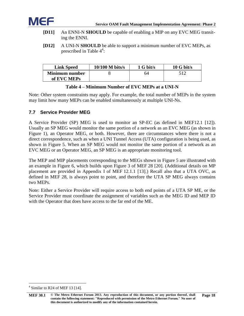
[D12] A UNI-N SHOULD be able to support a minimum number of EVC MEPs, as
prescribed in Table 44:
Link Speed 10/100 M bits/s 1 G bit/s 10 G bit/s
Minimum number
of EVC MEPs
8 64 512
Table 4 – Minimum Number of EVC MEPs at a UNI-N
Note: Other system constraints may apply. For example, the total number of MEPs in the system
may limit how many MEPs can be enabled simultaneously at multiple UNI-Ns.
7.7 Service Provider MEG
A Service Provider (SP) MEG is used to monitor an SP-EC (as defined in MEF12.1 [12]).
Usually an SP MEG would monitor the same portion of a network as an EVC MEG (as shown in
Figure 1), an Operator MEG, or both. However, there are circumstances where there is not a
direct correspondence, such as when a UNI Tunnel Access (UTA) configuration is being used, as
shown in Figure 5. When an SP MEG would not monitor the same portion of a network as an
EVC MEG or an Operator MEG, an SP MEG is an appropriate monitoring tool.
The MEP and MIP placements corresponding to the MEGs shown in Figure 5 are illustrated with
an example in Figure 6, which builds upon Figure 3 of MEF 28 [20]. (Additional details on MP
placement are provided in Appendix I of MEF 12.1.1 [13].) Recall also that a UTA OVC, as
defined in MEF 28, is always point to point, and therefore the UTA SP MEG always contains
two MEPs.
Note: Either a Service Provider will require access to both end points of a UTA SP ME, or the
Service Provider must coordinate the assignment of variables such as the MEG ID and MEP ID
with the Operator that does have access to the far end of the ME.
4 Similar to R24 of MEF 13 [14].

Service OAM Fault Management Implementation Agreement: Phase 2
MEF 30.1 © The Metro Ethernet Forum 2013. Any reproduction of this document, or any portion thereof, shall
contain the following statement: "Reproduced with permission of the Metro Ethernet Forum." No user of
this document is authorized to modify any of the information contained herein.
Page 19
Figure 5 – Example SP MEG With UTA
Figure 6 – Example MP Placements With UTA

Service OAM Fault Management Implementation Agreement: Phase 2
MEF 30.1 © The Metro Ethernet Forum 2013. Any reproduction of this document, or any portion thereof, shall
contain the following statement: "Reproduced with permission of the Metro Ethernet Forum." No user of
this document is authorized to modify any of the information contained herein.
Page 20
[D13] An ENNI-N SHOULD be capable of enabling a MIP on any SP MEG transiting
the ENNI.
Note: The capabilities of [D11] and [D13] cannot both be instantiated on a given VLAN at a
given ENNI-N at the same time.
[D14] The Access Provider SHOULD provision a MIP at an ENNI-N Access Provider
side on the UTA SP MEG.
[R17] A UNI-N, VUNI, or RUNI MUST be capable of enabling a MEP on the SP
MEG.
[D15] A MEP corresponding to a Service Provider MEG SHOULD be an Up MEP.
[D16] A MEP corresponding to a UTA SP MEG SHOULD be a Down MEP at a
VUNI and an Up MEP at a RUNI.
Note: A suggested practice is for the SP to use a MEP ID default of 2 at an RUNI and 1 at a
VUNI.
7.8 Operator MEG
If an Operator wishes to monitor an OVC, then the Operator MEG would be the appropriate
MEG to use.
[R18] An ENNI-N MUST be capable of enabling a MEP on each Operator MEG ter-
minating at the ENNI-N.
[D17] A MEP corresponding to the Operator MEG on an ENNI-N SHOULD be an Up
MEP.
[R19] A UNI-N or VUNI MUST be capable of enabling a MEP on the Operator MEG
associated with each EVC or OVC.
[D18] A MEP corresponding to the Operator MEG on a UNI-N or VUNI SHOULD
be an Up MEP.
7.9 UNI MEG
The UNI MEG allows monitoring the connectivity between the UNI-C and the UNI-N. For non-
LAG, port-based UNI MEGs, the desire is to support untagged SOAM frames. In the event that
this is not supported, using tagged SOAM frames for a non-LAG, port-based UNI MEG is
acceptable, if agreed to by both parties in the UNI MEG. For LAG-based UNI MEGs, tagged
SOAM frames should be used as described in section 9.1.1.
[R20] A non-LAG, port-based UNI MEG MUST support untagged SOAM frames.
[O2] A port-based UNI MEG MAY support C-Tagged SOAM frames.
[D19] The UNI MEG SHOULD default to using untagged SOAM frames.
[D20] If tagged SOAM frames are used for the UNI MEG, then a default VLAN-ID of
4091 SHOULD be used in the C-Tag of the frames.
This IA neither requires nor prohibits support for per-service monitoring across a UNI.

Service OAM Fault Management Implementation Agreement: Phase 2
MEF 30.1 © The Metro Ethernet Forum 2013. Any reproduction of this document, or any portion thereof, shall
contain the following statement: "Reproduced with permission of the Metro Ethernet Forum." No user of
this document is authorized to modify any of the information contained herein.
Page 21
7.9.1 UNI-C MEP Requirements
[R21] A UNI-C MUST be able to support a MEP on the UNI MEG, regardless of
whether any EVC is configured for that UNI or not.
[D21] When the CE implementing the UNI-C is an IEEE 802.1Q [3] Bridge, the MEP
corresponding to the UNI MEG on a UNI-C SHOULD be a Down MEP.
7.9.2 UNI-N MEP Requirements
[R22] A UNI-N MUST be able to support a MEP on the UNI MEG, regardless of
whether any EVC is configured for that UNI or not.
[D22] When the NE implementing the UNI-N is an IEEE 802.1Q [3] Bridge, the MEP
corresponding to the UNI MEG on a UNI-N SHOULD be a Down MEP.
7.10 ENNI MEG
The ENNI MEG allows monitoring the connectivity between adjacent ENNI-Ns. For non-LAG,
port-based ENNI MEGs, the desire is to support untagged SOAM frames. In the event that this is
not supported, using tagged SOAM frames for a non-LAG, port-based ENNI MEG is acceptable,
if agreed to by both parties in the ENNI MEG. For LAG-based ENNI MEGs, tagged SOAM
frames should be used as described in section 9.1.1.
[R23] A non-LAG, port-based ENNI MEG MUST support untagged SOAM frames.
[O3] A port-based ENNI MEG MAY support S-Tagged SOAM frames.
[D23] If tagged SOAM frames are used for the ENNI MEG, then a default VLAN-ID
of 4091 SHOULD be used in the S-Tag of the frames.
[R24] An ENNI-N MUST be able to support a MEP on the ENNI MEG, regardless of
whether any EVC is supported across that ENNI or not.
[D24] A MEP corresponding to the ENNI MEG on an ENNI-N SHOULD be a Down
MEP.
This IA neither requires nor prohibits support for per-service monitoring across an ENNI.
7.11 LAG MEG
The UNI LAG MEG and the ENNI LAG MEG are simply types of the UNI MEG and the ENNI
MEG, respectively. Accordingly, the requirements for UNI MEGs apply to UNI LAG MEGs,
and the requirements for ENNI MEGs apply to ENNI LAG MEGs, except requirements for port-
based UNI / ENNI.
Specific requirements relating to LAG MEGs, and further information, can be found in section
9.1.1.

Service OAM Fault Management Implementation Agreement: Phase 2
MEF 30.1 © The Metro Ethernet Forum 2013. Any reproduction of this document, or any portion thereof, shall
contain the following statement: "Reproduced with permission of the Metro Ethernet Forum." No user of
this document is authorized to modify any of the information contained herein.
Page 22
7.12 LAG Link MEG
The LAG Link MEG is used to monitor an individual LAG link. A LAG Link MEG running
across a UNI is known as a UNI LAG Link MEG. A LAG Link MEG running across an ENNI is
known as an ENNI LAG Link MEG.
Specific requirements relating to LAG Link MEGs, and further information, can be found in
section 9.1.2.

Service OAM Fault Management Implementation Agreement: Phase 2
MEF 30.1 © The Metro Ethernet Forum 2013. Any reproduction of this document, or any portion thereof, shall
contain the following statement: "Reproduced with permission of the Metro Ethernet Forum." No user of
this document is authorized to modify any of the information contained herein.
Page 23
8. Fault Management Protocols
This section lists the Service OAM Fault Management requirements that are protocol specific.
8.1 MEG ID / MAID
The MEG ID is required to be unique within a CEN, Operator’s network, where an Operator and
customer connect, or where two Operators interconnect. When a MEG has MEPs in more than
one network, then all involved parties must agree to the naming format. This section proposes
desired default formats, although any format can be used that is agreed upon by involved parties.
Although this IA generally uses the terminology of ITU-T Y.1731 [7], this section of the IA uses
the Maintenance Association (MA) and Maintenance Association Identifier (MAID) terminology
of IEEE 802.1Q [3] to clarify the formatting of the MEG ID / MAID.
As specified per IEEE 802.1Q, a MAID has two components consisting of the MD Name and the
Short MA Name.
[D25] The Maintenance Domain Name Format field of the MAID SHOULD have a
value of 1, as defined in Table 21-19 of IEEE 802.1Q, which indicates that the
MD Name field is not present.
When the MD Name is not present, the format is as shown in Figure 7 below (from Table 21-18
of IEEE 802.1Q):
Figure 7 – MAID Field Format
[D26] The Short MA Name Format Field of the MAID SHOULD support values of
{1, 2, 3, 4, or 32}, as defined in Table 21-20 of IEEE 802.1Q.
[D27] The Short MA Name Format Field of the MAID SHOULD default to 2, which
indicates a format of Character String.
[D28] The Short MA Name Field of the MAID SHOULD be uniquely related (but not
necessarily equal) to the UNI ID, EVC ID, ENNI ID, or UTA OVC ID as fol-
lows:
a. Representative value of the UNI ID, shared by the Subscriber and Service Pro-
vider, for the default (untagged) UNI MEG.
b. Representative value of the EVC ID, shared as needed by the Service Provider
and Operator, for the EVC MEG.

Service OAM Fault Management Implementation Agreement: Phase 2
MEF 30.1 © The Metro Ethernet Forum 2013. Any reproduction of this document, or any portion thereof, shall
contain the following statement: "Reproduced with permission of the Metro Ethernet Forum." No user of
this document is authorized to modify any of the information contained herein.
Page 24
c. Representative value of the EVC ID, shared as needed by the Subscriber and the
Service Provider, for the Test MEG.
d. Representative value of the ENNI ID, shared by both Operators, for the default
(untagged) ENNI MEG.
e. Representative value of the UTA OVC ID, shared by both Operators, for the
UTA SP MEG.
Note: Using UNI ID or EVC ID values as the value for the Short MA Name may lead to trunca-
tion problems. MEF 10.2 [11] specifies that UNI ID and EVC ID attributes must be unique
across the CEN, but does not specify a maximum length. MEF 16 [14] truncates the UNI ID and
EVC ID to 100 and 64 octets, respectively, when mapping these attributes into information
elements. As such, these MEF identifiers can be larger than can possibly fit into a Short MA
Name5, which has a maximum possible length of 48 octets, and truncation does not necessarily
produce unique identifiers. However, there is no issue if the ID is at most 45 octets.
[D29] The UNI ID and EVC ID SHOULD be no longer than 45 octets.
Note: MEF 26.1 [19] specifies a maximum length of 45 bytes for the OVC ID.
8.2 Continuity Check
The following requirements apply to the implementation of the Continuity Check Message
(CCM) function as an operation that runs on a MEP for service monitoring. These requirements
define default protocol values and the protocol options that are required for MEF Service OAM.
[R25] MEPs MUST support the CCM messages and processes as defined in
IEEE 802.1Q [3].
[R26] MEPs MUST have the capability to be administratively configured to enable
and disable CCM transmissions.
[D30] CCM transmissions SHOULD be disabled by default on the Subscriber MEG,
the Test MEG, the EVC MEG, the SP MEG, and the Operator MEG.
[D31] CCM transmissions SHOULD be enabled by default on the UTA SP MEG, the
UNI MEG, ENNI MEG, and the LAG Link MEG.
The following requirements define the parameters that control CCM behavior.
[R27] The PCP of tagged CCM frames MUST be configurable.
[D32] The default value of the PCP of a tagged CCM frame SHOULD be a PCP value
that yields the lowest frame loss objective for the EVC or OVC.
[D33] Untagged CCM frames SHOULD be transmitted with the highest priority sup-
ported by the NE.
[R28] A MEP MUST support the CCM PDU transmission periods of {1 s, 10 s}.
[D34] The default CCM transmission period for a MEP in a UTA SP MEG, non-LAG
UNI MEG, non-LAG ENNI MEG, or LAG Link MEG SHOULD be 1 second.
5 See Table 21-18 of IEEE 802.1Q [3].

Service OAM Fault Management Implementation Agreement: Phase 2
MEF 30.1 © The Metro Ethernet Forum 2013. Any reproduction of this document, or any portion thereof, shall
contain the following statement: "Reproduced with permission of the Metro Ethernet Forum." No user of
this document is authorized to modify any of the information contained herein.
Page 25
[D35] The default CCM transmission period for a MEP in a MEG other than a UTA
SP MEG, non-LAG UNI MEG, non-LAG ENNI MEG, or LAG Link MEG
SHOULD be 10 seconds.
[D36] A MEP SHOULD support the CCM PDU transmission periods of {3.33 ms,
10 ms, 100 ms}.
Note: There may be a direct correlation between the CCM PDU transmission periods supported
and the level of resiliency a network element can offer a specific EVC. Three consecutive CCM
messages must be lost before a failure is detected across a specific MEG. For protection switch-
ing mechanisms that use CCM messages to detect connectivity failures across an ME (e.g.,
ITU-T G.8031, G.8032) a failure must be detected before any protection switching mechanisms
can enable a new path through the network. E.g., to enact a protection switching mechanism that
claims a maximum switching time of 50 ms and which uses CCMs to detect the failure, the CCM
PDU transmission period must be 10 ms or less. Otherwise, just detecting the failure would take
more than 50 ms.
[D37] A MEP SHOULD provide a count of the number of CCM frames transmitted.
[D38] A MEP SHOULD support the CC defect and fault alarm hierarchy specified in
clause 20.1.2 of IEEE 802.1Q.
[R29] A UNI MEG MEP located at a UNI-N or at a UNI-C on a Type 2 UNI MUST
support the CC defect and fault alarm hierarchy specified in clause 20.1.2 of
IEEE 802.1Q.
[CR1]< [D38] The highest priority alarm MUST be made available to manage-
ment.
[CD1]< [D38] The highest priority alarm SHOULD mask lower priority alarms.
[R30] A UNI MEG MEP located at a UNI-N or at a UNI-C on a Type 2 UNI MUST
support the minimum CC fault priority level specified in IEEE 802.1Q for
which a CC alarm will be generated.
Note: An alarm will be generated only if the fault has equal or greater priority than the minimum
CC fault priority level.
[CD2]< [D38] The default minimum CC fault priority level SHOULD be set to
RDI.
[CR2]< [D38] A MEP MUST support a CC fault alarm time and a CC fault reset
time.
[CD3]< [D38] The default CC fault alarm time SHOULD be set to 2.5 seconds,
as specified in 20.33.3 of IEEE 802.1Q.
[CD4]< [D38] The default CC fault reset time SHOULD be set to 10 seconds, as
specified in 20.33.4 of IEEE 802.1Q.
This IA does not require any specific TLV in the CCM PDUs; however their use is recommend-
ed, including Sender ID (IEEE 802.1Q 21.5.3), Port Status (IEEE 802.1Q 21.5.4), and Interface
Status (IEEE 802.1Q 21.5.5).

Service OAM Fault Management Implementation Agreement: Phase 2
MEF 30.1 © The Metro Ethernet Forum 2013. Any reproduction of this document, or any portion thereof, shall
contain the following statement: "Reproduced with permission of the Metro Ethernet Forum." No user of
this document is authorized to modify any of the information contained herein.
Page 26
A Sender ID TLV, if included, indicates the Chassis ID, the Management Domain, and the
Management Address of the source of the CCM frame. Although including the management
address of a remote device rather than just its MAC address can make the identification of the
device possible in a large network where MAC addresses are not well-known, it is not recom-
mended and is considered a security risk.
[D39] A MEP SHOULD include the Sender ID TLV in CCM PDUs by default.
[D40] The Management Domain field SHOULD be empty in the Sender ID TLV by
default.
[D41] The Management Address field SHOULD be empty in the Sender ID TLV by
default.
The Port Status and Interface Status TLVs indicate the bridging and interface statuses of the
sender of the CCM. These can be used to indicate to the far end that the local UNI or ENNI
interface is down. An example usage is to indicate customer-customer connectivity is failed even
though the MEPs on the EVC MEG continue to receive CCMs.
[D42] A MEP SHOULD include the Port Status TLV in CCM PDUs by default.
[D43] A MEP SHOULD include the Interface Status TLV in CCM PDUs by default.
[R31] A MEP MUST include the Interface Status TLV in CCM PDUs on a UTA SP
MEG by default.
[R32] A MEP located at a leaf in an E-Tree service SHOULD NOT report an alarm
for a MEP at a remote leaf in the same MEG.6
8.2.1 Remote Defect Indication Signal
The following requirement applies to the implementation of the Ethernet Remote Defect Indica-
tion Signal (ETH-RDI) function as a communicative means for a MEP to indicate the presence
of a defect condition to peer MEPs. This requirement defines default protocol values and the
protocol options that are required for a compliant MEF Service OAM implementation. Note that
this function requires the ETH-CC function to be enabled since RDI is an information element
within the CCM PDU.
[R33] A MEP MUST support the RDI operations, information elements, and process-
es as defined in IEEE 802.1Q [3].
8.3 Loopback
The following requirements apply to the implementation of the Ethernet Loopback (ETH-LB)
function as an operation that runs on-demand on a MEP for service troubleshooting. These
6 One way to help accomplish this is by adding all MEPs to the dot1agCfmMaMepListTable, but only setting
dot1agCfmMepDbRMepIsActive for root MEPs. For both MIB objects, see Table 17-11 of IEEE 802.1Q [3].

Service OAM Fault Management Implementation Agreement: Phase 2
MEF 30.1 © The Metro Ethernet Forum 2013. Any reproduction of this document, or any portion thereof, shall
contain the following statement: "Reproduced with permission of the Metro Ethernet Forum." No user of
this document is authorized to modify any of the information contained herein.
Page 27
requirements define default protocol values and the protocol options that are required for a
compliant MEF Service OAM implementation.
For the purposes of this section, an LB Session is defined as a sequence that begins with man-
agement initiating the transmission of n periodic LBM PDUs from a MEP to a peer MIP or MEP.
An LB Session ends normally when the last LBR PDU is received or incurs a timeout.
[R34] An MP MUST support the LBM/LBR messages and processes as defined in
IEEE 802.1Q [3].
[R35] A MEP MUST support the ability to be administratively configured to initiate
and stop LB Sessions.
The following requirements define the parameters that must be provided when initiating an LB
Session.
[R36] A MEP MUST be configurable to use any Unicast MAC DA as the destination
address of an LBM.
[D44] A MEP SHOULD also support multicast class 1 MAC destination addresses
(see section 10.1 of ITU-T Y.1731 [7]).
[R37] A MEP MUST be able to process and respond to both Unicast and Multicast
LBM frames.
[D45] A MEP that supports transmitting LBM frames with multicast MAC addresses
SHOULD be able to report the originating MAC in at least one LBR sent in re-
sponse to the LBM.
[R38] For each LB session using tagged LBM frames, the PCP of the tagged LBM
frames MUST be configurable.
[D46] The default value of the PCP of a tagged LBM frame SHOULD be a PCP value
that yields the lowest frame loss objective for the EVC or OVC.
Note: According to 802.1Q, the returned LBR has the same priority as the received LBM, which
would therefore also default to be a PCP value with the lowest frame loss objective.
[D47] Untagged LBM/LBR frames SHOULD be transmitted with the highest priority
supported by the NE.
[D48] For each LB session, the timeout for an expected LBR result after a LBM
transmission SHOULD be configurable.
[D49] The default value of the LBR timeout SHOULD be 5 seconds.
[R39] The number of LBM transmissions to perform in an LB session MUST be con-
figurable in the range of at least 1 through 1024.
[D50] The default value for the number of LBM transmissions in an LB session
SHOULD be 3.
[R40] For an LB Session, the time interval between LBM transmissions MUST be
configurable in the range of at least 0 seconds through 60 seconds.
Note: A value of 0 seconds indicates that the LBMs are to be sent with no enforced delay be-
tween them.

Service OAM Fault Management Implementation Agreement: Phase 2
MEF 30.1 © The Metro Ethernet Forum 2013. Any reproduction of this document, or any portion thereof, shall
contain the following statement: "Reproduced with permission of the Metro Ethernet Forum." No user of
this document is authorized to modify any of the information contained herein.
Page 28
[D51] For an LB Session, the time interval between LBM transmissions SHOULD be
configurable with a granularity of at least 100 milliseconds.
[R41] For an LB Session, the time interval between LBM transmissions MUST be
configurable with a granularity of at least 1 second.
[D52] The default value for the time interval between LBM transmissions in a LB Ses-
sion SHOULD be 1 second.
[R42] For an LB Session, the size of the LBM frame MUST be configurable to any
Ethernet frame size between 64 bytes and the maximum transmission unit of the
EVC.
[R43] The Data TLV MUST be supported in LBMs/LBRs. The inclusion of the Data
TLV in a specific LBM is dependent on the frame size requested.
[D53] The default value of the LBM frame size SHOULD be 64 bytes.
As with CCMs, a Sender ID TLV, if included, indicates the Chassis ID, the Management Do-
main, and the Management Address of the source of the LBM PDU. Although including the
management address of a remote device rather than just its MAC address can make the identifi-
cation of the device possible in a large network where MAC addresses are not well-known, it is
not recommended. Including the management address, which gets sent in the clear, is considered
a security risk.
[D54] A MEP SHOULD include the Sender ID TLV in the LBM PDUs by default.
[D55] The Management Domain field SHOULD be empty in the Sender ID TLV by
default.
[D56] The Management Address field SHOULD be empty in the Sender ID TLV by
default.
The following requirements define the Loopback information that is to be maintained for each
LB session that is sent to a Unicast address.
[R44] For an LB Session, the initiating MEP MUST be able to report the number of
LBMs transmitted and the number of LBRs received.
[D57] For an LB Session, the initiating MEP SHOULD be able to report the percent-
age of responses lost (timed out).
[D58] For an LB session, the round trip time (RTT) min/max/average statistics
SHOULD be supported by the initiating MEP.
[D59] A responding MP SHOULD be able to report the aggregate number of LBMs
received and the aggregate number of LBRs transmitted during a time period.
Note: The statistics that can be gleaned from LB RTT measurements can be useful for fault
detection. For performance management, more precise measurements need to be used, as de-
scribed in MEF 35 [24].

Service OAM Fault Management Implementation Agreement: Phase 2
MEF 30.1 © The Metro Ethernet Forum 2013. Any reproduction of this document, or any portion thereof, shall
contain the following statement: "Reproduced with permission of the Metro Ethernet Forum." No user of
this document is authorized to modify any of the information contained herein.
Page 29
8.4 Linktrace
The following requirements apply to the implementation of the Ethernet Linktrace (ETH-LT)
function as an operation that runs on-demand on a MEP for service troubleshooting. These
requirements define default protocol values and the protocol options that are required for a MEF-
compliant Service OAM implementation.
[R45] An MP MUST support the LTM/LTR messages and processes as defined in
IEEE 802.1Q [3].
[R46] The PCP of the tagged LTM frames MUST be configurable.
[D60] The default value of the PCP of a tagged LTM frame SHOULD be a PCP value
that yields the lowest frame loss objective for the EVC or OVC.
Note: According to 802.1Q, the returned LTR has the same priority as a CCM, which would
therefore also default to be a PCP value with the lowest frame loss objective.
[D61] Untagged LTM/LTR frames SHOULD be transmitted with the highest priority
supported by the NE.
As with CCMs, a Sender ID TLV, if included, indicates the Chassis ID, the Management Do-
main, and the Management Address of the source of the LTM PDU. Although including the
management address of a remote device rather than just its MAC address can make the identifi-
cation of the device possible in a large network where MAC addresses are not well-known, it is
not recommended. Including the management address, which gets sent in the clear, is considered
a security risk.
[D62] A MEP SHOULD include the Sender ID TLV in the LTM PDUs by default.
[D63] The Management Domain field SHOULD be empty in the Sender ID TLV by
default.
[D64] The Management Address field SHOULD be empty in the Sender ID TLV by
default.
The following requirements define the Linktrace information that is to be maintained.
[R47] An initiating MEP MUST be able to report the number of LTMs transmitted
and the number of LTRs received.
[D65] A responding MP SHOULD be able to report the number of LTMs received
and the number of LTRs transmitted.
8.5 Alarm Indication Signal
The following requirements apply to the implementation of the Ethernet Alarm Indication Signal
(ETH-AIS) function as an operation that runs following the detection of a fault. These require-
ments define default protocol values and the protocol options that are required for a MEF-
compliant Service OAM implementation.
ETH-AIS exists to suppress alarms that might otherwise be raised at MEPs receiving AIS. It also
exists to allow higher level MEGs to run slower CCMs by relying on AIS from link level (UNI
Service OAM Fault Management Implementation Agreement: Phase 2
MEF 30.1 © The Metro Ethernet Forum 2013. Any reproduction of this document, or any portion thereof, shall
contain the following statement: "Reproduced with permission of the Metro Ethernet Forum." No user of
this document is authorized to modify any of the information contained herein.
Page 30
or ENNI) MEGs that are running CCMs at a faster rate. Both of these can require additional
coordination between providers when the sender and receiver of the AIS are in different man-
agement networks.
AIS is not intended to be used in multi-point services. Use of AIS in multi-point services is not
recommended by this IA.
[D66] An MP SHOULD support the ETH-AIS operations, information elements, and
processes as defined in ITU-T Y.1731 [7] and ITU-T G.8021 [6].
As defined in ITU-T Y.1731 and ITU-T G.8021, AIS is injected by a MEP in a given MEG, into
one or more client MEGs. The MEG that the MEP injecting the AIS belongs to is referred to
here as the “injecting MEG”. A client MEG is conceptually the “next higher MEG” that encom-
passes the injecting MEG. This conceptual relationship can be realized in a number of ways. In
the simplest case, the client MEG is the MEG at the next higher configured MEG Level above
the injecting MEG. Alternatively, a client MEG could be a MEG whose CFM PDUs are “tun-
neled” at the injecting MEP's interface, because they are encapsulated in additional VLAN tags
and hence are treated as service frames rather than SOAM frames (i.e., they belong to a different
OAM Flow Space, see Appendix B).
In the latter case, there may be a number of client MEGs, each encapsulated with a different
VID. There may be up to 4094 client MEGs (i.e., one per VID) if the client MEGs have one
more VLAN tag than the injecting MEG; or up to 4094 * 4094 (i.e., 16,760,836) client MEGs if
they have two more VLAN tags than the injecting MEG (for instance at an ENNI MEP). Where
the client MEGs have additional VLAN tags, no relationship can be assumed between the MEG
Level of the injecting MEG and the MEG Level of the client MEGs. In particular, the client
MEG Level may be lower than the MEG Level of the injecting MEG.
[CD5]< [D66] AIS generation SHOULD be enabled at a MEP only if the MEP is
capable of injecting AIS into all of its client MEGs.
Having determined the set of client MEGs, there are two ways that a MEP can inject AIS into
each client MEG:
If the client MEG has a MEP on the same interface as the injecting MEP, then injecting an
AIS is a simple matter of passing an indication internally within the device from one MEP to
the other. In this case, no AIS PDU is transmitted. This is referred to as an “AIS Indication”.
Note that as the client MEG is defined to be a MEG that encompasses the injecting MEG, the
two MEPs will by definition face the same direction, i.e., both Up MEPs or both Down
MEPs.
If the client MEG does not have a MEP on the same interface as the injecting MEP, i.e., it
has a MIP or has no MP at all, then injecting an AIS involves transmitting an AIS PDU at the
client MEG Level, with the appropriate VLAN tags for the client MEG, in the opposite direc-
tion to that in which the MEP normally sends CFM frames (that is, an Up MEP would send
AIS PDUs out towards the wire, and a Down MEP would send AIS PDUs in towards the
bridging function). Note that in this case, the injecting MEP requires knowledge (e.g., by
configuration) of the MEG Level and (where the client MEGs have additional VLAN tags)
the primary VID for each client MEG.

Service OAM Fault Management Implementation Agreement: Phase 2
MEF 30.1 © The Metro Ethernet Forum 2013. Any reproduction of this document, or any portion thereof, shall
contain the following statement: "Reproduced with permission of the Metro Ethernet Forum." No user of
this document is authorized to modify any of the information contained herein.
Page 31
Examples showing various different cases of client MEGs can be found in Appendix D.
Each MEP is configured individually, and therefore the MEPs of a MEG may not necessarily all
have the same configuration (either in terms of whether AIS is enabled or which MEGs to insert
AIS into). An example of this is shown in Figure 8. In this case, both MEPs in the ENNI ME are
configured to inject AIS to the SP ME. NE 2 and NE 3 inject AIS PDUs at the level of the SP
ME, towards the SP ME MEPs in NE 1 and NE 4, respectively. The SP ME MEP in NE 1 injects
an AIS indication to the EVC ME MEP in NE 1. This is called an AIS indication since it is not
actually an AIS PDU but is some indication within the NE. The EVC ME MEP in NE1 is not
configured to enable AIS, and hence it does not propagate the AIS to the Subscriber ME. In NE4,
as in NE1, the SP ME MEP injects an AIS indication to the EVC ME MEP. However, unlike on
NE1, on NE4 the EVC ME MEP is configured to enable AIS and hence it injects an AIS PDU at
the level of the Subscriber ME, towards the Subscriber.
Figure 8 – AIS Example 1
Figure 9 provides an example of a different use case for AIS. In this case, the ENNI MEP on
NE 3 is not configured to support AIS. Instead, the Operator ME MEP has an active Continuity
Check process, and detects the port failure on the ENNI and sends an Interface Status TLV of
isDown to the other MEP in the ME. The Operator ME MEP in NE 4 is configured to support
AIS. The Interface Status TLV isDown status causes the Operator ME MEP to inject an AIS
indication to the SP ME MEP, which in turn injects an AIS indication to the EVC ME MEP. The
EVC ME MEP then injects AIS PDUs at the level of the Subscriber ME, towards the Subscriber
ME MEP. This use case shows that not all devices in a CEN have to be configured to support
AIS as long as key devices are configured to support it.

Service OAM Fault Management Implementation Agreement: Phase 2
MEF 30.1 © The Metro Ethernet Forum 2013. Any reproduction of this document, or any portion thereof, shall
contain the following statement: "Reproduced with permission of the Metro Ethernet Forum." No user of
this document is authorized to modify any of the information contained herein.
Page 32
Figure 9 – AIS Example 2
[CD6]< [D66] The default value for the AIS PDU transmission period SHOULD
be 1 second.
Note: In some cases it can be useful to send the first three AIS PDUs using a short transmission
period (e.g., 3.33 ms or 10 ms) in order to enable quick alarm suppression and/or fast service
protection on higher MEG Levels. AIS PDUs could be affected by changes in network topology
that result from the same fault which is causing the AIS to be generated. By sending multiple
PDUs during the initial second, the probability of the AIS PDU being received at the destination
increases.
[CD7]< [D66] The default value of the PCP of a tagged AIS frame SHOULD be
a PCP value that yields the lowest frame loss objective for the EVC or
OVC.
[CD8]< [D66] Untagged AIS frames SHOULD be transmitted with the highest
priority supported by the NE.
[CD9]< [D66] AIS transmissions SHOULD be disabled on a MEP by default.
[CD10]< [D66] Any condition that would cause RDI (see 8.2.1) to be sent in
CCMs SHOULD also result in AIS transmission.
[CD11]< [D66] Receipt of AIS indication, AIS PDU, LCK indication, or LCK
PDU SHOULD cause transmission of AIS frames if CCM is not ena-
bled in the MEP receiving the AIS or LCK.
[CO1]< [D66] Receipt of AIS indication, AIS PDU, LCK indication, or LCK
PDU MAY cause transmission of AIS frames if CCM is enabled in the
MEP receiving the AIS or LCK.

Service OAM Fault Management Implementation Agreement: Phase 2
MEF 30.1 © The Metro Ethernet Forum 2013. Any reproduction of this document, or any portion thereof, shall
contain the following statement: "Reproduced with permission of the Metro Ethernet Forum." No user of
this document is authorized to modify any of the information contained herein.
Page 33
Note: Generating AIS on receipt of AIS or LCK when CCM is enabled can help propagate the
defect condition more quickly than waiting for a CCM timeout. However, this goes beyond the
recommendations in ITU-T G.8021 [6].
[CO2]< [D66] Receipt of RDI MAY cause AIS injection.
[CD12]< [D66] For down MEPs, interface down events or other lower-level faults
SHOULD cause AIS indication or transmission to the client.
Note: Server MEPs are not within the scope of these requirements.
[CD13]< [D66] AIS injections SHOULD be enabled only on MEPs in point to
point MEGs.
[CR3]< [D66] A MEP MUST support configuration of the client MEG(s) to
which AIS indication or transmission is to be sent.
Note: How configuration of the client MEG(s) is done is a local matter. It could be by configura-
tion of a list of VLAN IDs and associated MEG Levels, by automatic determination, or by other
means.
[CR4]< [D66] AIS SHOULD NOT be configured to be injected into any client
MEGs that are not point-to-point.
[CR5]< [D66] If an AIS PDU needs to be generated, then the AIS PDU MUST
be sent to the multicast Class 1 address7 for the configured level(s).
[CO3]< [D66] Although the primary reason for using AIS is to suppress alarm
generation, reception of an AIS MAY be used as a defect indication to
trigger RDI (at alarm level priority of MACStatus) and other mecha-
nisms beyond the scope of this document, including, but not limited to
protection.
8.6 Locked Signal
The following requirements apply to the implementation of the Ethernet Locked Signal (ETH-
LCK) function as a communicative means for a MEP receiving a Locked signal to differentiate
between an administratively locked MEP and a defect condition. These requirements define
default protocol values and the protocol options that are required for a compliant MEF Service
OAM implementation.
LCK is not intended to be used in multi-point services. Use of LCK in multi-point services is not
recommended by this IA.
The selection of which client MEGs on which ETH-LCK should be sent is decided and config-
ured in the same manner as for ETH-AIS. From each locked MEP, LCK PDUs are sent in both
directions on the client MEGs. Figure 10 shows an example of this where ETH-LCK is asserted
at an Operator MEP and LCK PDUs are sent on the client SP MEG. When ETH-LCK is assert-
ed, client traffic is blocked at the point of LCK insertion, but not SOAM PDUs at the same level
as the ETH-LCK level. For more information, see Section 7.6 of ITU-T Y.1731 [7]. Assertion of
7 See Section 10.1 of ITU-T Y.1731 [7].

Service OAM Fault Management Implementation Agreement: Phase 2
MEF 30.1 © The Metro Ethernet Forum 2013. Any reproduction of this document, or any portion thereof, shall
contain the following statement: "Reproduced with permission of the Metro Ethernet Forum." No user of
this document is authorized to modify any of the information contained herein.
Page 34
ETH-LCK is controlled by an internal admin state, MI_Admin_State, defined in ITU-T G.8021
[6].
Figure 10 – LCK Example
[D67] A MEP SHOULD support the ETH-LCK operations, information elements, and
processes as defined in ITU-T Y.1731 and ITU-T G.8021.
[CD14]< [D67] The default value for the LCK PDU transmission period
SHOULD be 1 second.
[CD15]< [D67] The default value of the PCP of a tagged LCK frame SHOULD be
a value that yields the lowest frame loss objective for the EVC or OVC.
[CD16]< [D67] Untagged LCK frames SHOULD be transmitted with the highest
priority supported by the NE.
[CD17]< [D67] LCK injections SHOULD be enabled only on MEPs in point to
point MEGs.
[CD18]< [D67] LCK generation SHOULD be enabled at a MEP only if the MEP
is capable of injecting LCK into all of its client MEGs.
[CD19]< [D67] LCK SHOULD NOT be configured to be injected into any client
MEGs that are not point-to-point.
[R48] If ETH-Test is supported for out of service diagnostic testing, then ETH-LCK
MUST be supported.
8.7 Test Signal
The following requirements apply to the implementation of the Ethernet Test Signal (ETH-Test)
function as a means for performing one-way in-service or out-of-service diagnostic testing
between a pair of MEPs. These requirements define default protocol values and the protocol
options that are required for a compliant MEF Service OAM implementation. Note that, as
specified in ITU-T Y.1731 [7], when performing out-of-service diagnostic testing, the ETH-LCK

Service OAM Fault Management Implementation Agreement: Phase 2
MEF 30.1 © The Metro Ethernet Forum 2013. Any reproduction of this document, or any portion thereof, shall
contain the following statement: "Reproduced with permission of the Metro Ethernet Forum." No user of
this document is authorized to modify any of the information contained herein.
Page 35
is used in conjunction with ETH-Test. (However, note that ETH-LCK can be used without ETH-
Test.)
Based on MEP placement within a device, the ability to measure throughput using the ETH-Test
functionality may be limited. MEPs monitoring “green” (in-profile) frames need to be placed in
locations where “green” (in-profile) frames can be measured. Figure 11 illustrates two EVCs
across a UNI, one consisting of a single C-Tagged flow (EVC-X) and another consisting of two
C-Tagged flows (EVC-Y). For measurements taken from a Service Provider or Operator per-
spective, MEPs need to be placed on the CEN side of the bandwidth profile function associated
with the ESCF for the UNI-N. This corresponds to MEPs associated with SP, EVC, or Operator
MEGs. For measurements taken from a Subscriber perspective, MEPs need to be placed on the
UNI side of the ESCF for the UNI-C. This corresponds to MEPs associated with Test or Sub-
scriber MEGs. (Additional details on MEP placement are provided in Appendix I of MEF 12.1.1
[13].).
Figure 11 – MEP Placement
Furthermore, it should be noted that the ETH-LB function with a test pattern in the Data TLV
could be used instead of the ETH-Test functionality to perform the same testing, although it may
create additional stress on the OAM processor. This may be preferable to the ETH-Test func-
tionality since it can be performed as a single-ended test8. For this reason, ETH-Test is not
required.
8 The one-way testing that can be accomplished with ETH-Test could be accomplished by recording the information
from incoming LBM frames at one end and comparing them (or at least a count of them) to incoming LBR frames at
the other end.

Service OAM Fault Management Implementation Agreement: Phase 2
MEF 30.1 © The Metro Ethernet Forum 2013. Any reproduction of this document, or any portion thereof, shall
contain the following statement: "Reproduced with permission of the Metro Ethernet Forum." No user of
this document is authorized to modify any of the information contained herein.
Page 36
Additional tools that could be used instead of the ETH-Test functionality, like ETH-LM or ETH-
DM (as defined in ITU-T Y.1731), are outside the scope of this document.
[O4] A MEP MAY support the ETH-Test operations, information elements, and pro-
cesses as defined in ITU-T Y.1731 and ITU-T G.8021 [6].
[CD20]< [O4] When ETH-Test is supported for in-service diagnostic testing, the
default value of the PCP of a tagged Test frame SHOULD be a value
that yields the lowest frame loss objective for the EVC or OVC.
[CD21]< [O4] Untagged Test frames SHOULD be transmitted with the highest
priority supported by the NE.
8.8 Client Signal Fail
The following requirements apply to the implementation of the Ethernet Client Signal Fail
(ETH-CSF) function as a means for informing a peer MEP of the detection of a failure or defect
in communication with a client when the client itself does not support a means of notification to
its peer, such as ETH-AIS or the RDI function of ETH-CC. The use of ETH-CSF is illustrated in
Figure 12. These requirements define default protocol values and the protocol options that are
required for a compliant MEF Service OAM implementation.
Figure 12 – CSF Example
[O5] A MEP MAY support the ETH-CSF operations, information elements, and pro-
cesses as defined in ITU-T Y.1731 [7] and ITU-T G.8021 [6]
[CD22]< [O5] ETH-CSF transmissions SHOULD be disabled on a MEP by de-
fault.
Service OAM Fault Management Implementation Agreement: Phase 2
MEF 30.1 © The Metro Ethernet Forum 2013. Any reproduction of this document, or any portion thereof, shall
contain the following statement: "Reproduced with permission of the Metro Ethernet Forum." No user of
this document is authorized to modify any of the information contained herein.
Page 37
[CD23]< [O5] ETH-CSF transmissions SHOULD be enabled only on MEPs in
point to point MEGs.
[CR6]< [O5] Transmission periods of 1 second and 1 minute MUST be support-
ed for ETH-CSF.
[CD24]< [O5] The ETH-CSF default transmission period SHOULD be 1 second.
Note 1: Conditions under which ETH-CSF is sent are a local matter not defined by this docu-
ment. Most of these conditions would also result in an Interface Status TLV being sent with a
status of "link down" if CCMs are enabled and the Interface Status TLV is included, as described
in section 8.2.
Note 2: What is done with a received ETH-CSF is a local matter not defined by this document.

Service OAM Fault Management Implementation Agreement: Phase 2
MEF 30.1 © The Metro Ethernet Forum 2013. Any reproduction of this document, or any portion thereof, shall
contain the following statement: "Reproduced with permission of the Metro Ethernet Forum." No user of
this document is authorized to modify any of the information contained herein.
Page 38
9. SOAM FM Interaction With Other Protocols
SOAM FM does not exist in isolation from other protocols. This section describes how SOAM
FM interacts with other protocols of interest, specifically Link Aggregation and E-LMI.
9.1 SOAM FM Interaction with Link Aggregation
Link Aggregation (LinkAgg), as defined in IEEE 802.1AX [2] provides a protection mechanism
for Ethernet facilities, and the ability to support higher bandwidth than provided by a single
facility. In this discussion, we are concerned with only the support of protection mechanisms.
LinkAgg has been defined to be supported on ENNIs in MEF 26.1 [19] and on UNIs in MEF 20
[17]. Because the requirements for LinkAgg within MEF 26.1 are more detailed than those in
MEF 20, the SOAM FM structure is built around the requirements for LinkAgg on ENNIs.
ENNI LinkAgg is specified in MEF 26.1 to always use Link Aggregation Control Protocol
(LACP) and to be in the Active/Standby mode when used for ENNI protection. This means that
one link is in the active mode (carrying traffic), and one link is in the standby mode (not carrying
traffic).
Managing LinkAgg for faults consists of two pieces. The first piece is the traffic traversing the
Link Aggregation Group (LAG) as a whole. Determining when there is a loss of connectivity
across the LAG is very important so that the MEPs associated with the EVCs and OVCs affected
by the loss of connectivity can be notified of the fault. In turn, this information can be used by
these MEPs to propagate AIS and to limit the number of alarms generated within the network. A
method of determining when traffic is not traversing a LAG is required. Using SOAM FM to
manage connectivity across the LAG is the recommended way of doing this. For an ENNI that
supports LAG, the ENNI ME is used to verify this connectivity. The ENNI ME is not used at the
link level, but instead is configured over the LAG as a whole. The UNI ME is used to verify
connectivity of a LAG at a UNI. When LinkAgg is used internally to a provider’s network, the
ME to use to monitor an INNI is beyond the scope of this document.
The second piece of a LinkAgg that requires management is the individual links that make up the
LAG. The state of these links is important to the operation of the LAG. If a link fails and that
failure goes undetected, the protection provided by the LAG may be compromised in the event of
a second link failure. Using the ENNI as an example, there are two links in a LAG, as specified
in MEF 26.1. There are two methods that can be used to verify the state of these links: Link
OAM as defined in Clause 57 of IEEE 802.3 [4], and SOAM FM. However, the ability to pass
link OAM status may be unknown, such as when the two end points of the LAG are not directly
connected. An additional concern is that while Link OAM PDUs may pass successfully between
the two LAG end points, the speed of fault detection provided by Link OAM may not be fast
enough to meet the requirements for External Interfaces (EI) fault detection and switching. A
requirement for switching between EIs in <500 ms is provided in MEF 32 [22]. A desirable
requirement to switch between EIs in <250 ms has also been provided in MEF 32. To meet these
objectives, a fast protocol detecting a fault on the link may be required. It is not believed that
Link OAM can meet the lower of these objectives. A LAG group is informed quickly of some
catastrophic failures, but some more subtle failures (that can be detected by CCMs) are not
detected quickly. The protocol does not exchange status messages fast enough to detect a fault
and perform the switching in the allotted time period. To ensure that the links that make up the

Service OAM Fault Management Implementation Agreement: Phase 2
MEF 30.1 © The Metro Ethernet Forum 2013. Any reproduction of this document, or any portion thereof, shall
contain the following statement: "Reproduced with permission of the Metro Ethernet Forum." No user of
this document is authorized to modify any of the information contained herein.
Page 39
LAG can be managed regardless of any intermediate devices between the two LAG endpoints
and that the switching timeframe objectives for EIs are met, it is recommended that SOAM FM
be used to manage these links. It is also recommended that AIS not be activated on the MEGs
managing individual links that make up a LAG. This is because a single link failure does not
represent a LAG failure and if individual links in the LAG generated AIS, false failures could be
indicated to client levels.
9.1.1 LAG Fault Management
Managing the traffic traversing a LAG ensures that data frames are actually able to cross the
LAG and that the LAG is providing protection to traffic. To verify the LAG’s ability to pass
traffic, CCMs must be generated so that they traverse the LAG. To do this, MEPs must be placed
on the LAG itself, as opposed to individual LAG links. The CC Interval used to manage the
LAG must be fast enough to quickly identify a fault on the LAG, but must be slow enough so
that switching of traffic between links takes place before a fault is declared on the ME traversing
the LAG. If the ME traversing the LAG declares a fault too quickly, traffic may still be protected
by the LAG, and a false failure indication could be reported. The ME that monitors the LAG at a
UNI or ENNI is the UNI ME or ENNI ME, respectively, and therefore uses MEG Level 1 as a
default and is subject to the requirements specified in 7.9 or 7.10, respectively. Additional MEs
can monitor the individual links of the LAG as shown in Figure 13.
Figure 13 – LinkAgg MEPs
By verifying that traffic is traversing the LAG, in the event of a fault on the LAG, notification of
the fault can be generated. This could be a simple trap or could involve using AIS to indicate the
fault to and suppress alarms in a client MEG. Using the ENNI example, a fault detected by the
ENNI ME can result in AIS being inserted into a higher level MEG, perhaps the SP ME, to
suppress alarms at MEGs on OVCs or EVCs. See 8.5 for more details.

Service OAM Fault Management Implementation Agreement: Phase 2
MEF 30.1 © The Metro Ethernet Forum 2013. Any reproduction of this document, or any portion thereof, shall
contain the following statement: "Reproduced with permission of the Metro Ethernet Forum." No user of
this document is authorized to modify any of the information contained herein.
Page 40
[D68] A LAG SHOULD support a LAG MEG to monitor the LAG.
A LAG MEG is either a UNI MEG or an ENNI MEG, and therefore the requirements in sections
7.9 or 7.10 apply, except as described below.
[CD25]< [D68] A LAG MEG SHOULD use tagged SOAM frames.
Note: Section 22.1.8 of IEEE 802.1Q [3] recommends that MEPs on a LAG be VLAN-based.
Therefore there is no requirement that a LAG MEG be able to support the use of untagged
SOAM PDUs.
[CR7]< [D68] The CC Interval of a LAG MEG MUST be greater than the
switching interval of the LAG.
[CR8]< [D68] CCMs generated by MEPs in a LAG MEG MUST use the same
source MAC address as has been implemented for the LAG.
9.1.2 Link Aggregation Link Management
Management of service affecting faults on a LAG link is similar to using SOAM FM to manage
other Ethernet facilities. Based on the requirement for fast fault detection and to enable the
management of the individual links that make up the LAG regardless of the capabilities to pass
Link OAM states, SOAM FM is recommended for each link.
[D69] Each link of a LAG SHOULD support a LAG Link MEG for monitoring that
link.
[CR9]< [D69] A LAG Link MEG MUST support untagged SOAM frames.
[CR10]< [D69] A LAG Link MEG MUST have a down MEP at each end of the
Ethernet facility that makes up the link.
[CR11]< [D69] A LAG Link MEG MUST support a CC Interval of 100 ms.
Note: A CC Interval of 100 ms enables a fault detection time of approximately 300 ms, which is
less than the mandatory switching timeframe of ≤500 ms specified in MEF 32 [22].
[CD26]< [D69] A LAG Link MEG SHOULD support a CC Interval of 10 ms.
Note: A CC Interval of 10 ms enables a fault detection time of approximately 30 ms, which is
less than the optional switching timeframe of ≤250 ms specified in MEF 32.
[CD27]< [D69] The CC Interval SHOULD be the same for all LAG Link MEGs
within a single LAG.
Note: Running a slower CC interval on a standby link could cause a failure on the standby link to
not be detected as quickly as on the active link.
[CR12]< [D69] AIS MUST not be configured on MEPs within the LAG Link
MEG. This is because a LAG link fault might not be a service affecting
fault.

Service OAM Fault Management Implementation Agreement: Phase 2
MEF 30.1 © The Metro Ethernet Forum 2013. Any reproduction of this document, or any portion thereof, shall
contain the following statement: "Reproduced with permission of the Metro Ethernet Forum." No user of
this document is authorized to modify any of the information contained herein.
Page 41
[CR13]< [D69] The CCM state for each link in a LAG MUST be fed into the
LinkAgg state machine. This ensures that a loss of connectivity is in-
cluded in the switch decisions.
9.2 SOAM FM Interaction with E-LMI
Because customer equipment may exist that does not support SOAM FM but that does support
Ethernet Local Management Interface (E-LMI, specified in MEF 16 [14]), it is useful to be able
to interwork between E-LMI and SOAM FM. Interworking SOAM FM with E-LMI allows for
faults detected by SOAM FM to be communicated to the subscriber via E-LMI. Of specific
interest are faults detected on an EVC that can be communicated to the subscriber via the EVC
Status Information Element defined in Section 5.3.3.7 of MEF 16. An example of this is shown
in Figure 14. Communicated faults include loss of CCM, RDI, AIS, and other failure conditions
defined in ITU-T G.8021 [6].
Figure 14 – SOAM FM Interaction With E-LMI
[D70] Interworking of SOAM FM to E-LMI SHOULD be performed at the UNI-N.
[CR14]< [D70] A fault detected by SOAM FM MUST result in an Asynchronous
Status Message, as defined in Section 5.6.6 of MEF 16, being sent to
from the UNI-N to the UNI-C.
[CR15]< [D70] An EVC Status Information Element MUST be included in all E-
LMI Asynchronous Status Messages, indicating the current status of the
EVC, as described in 9.2.1.
[CR16]< [D70] All other E-LMI operations dealing with the EVC Status Infor-
mation Element defined in MEF 16 MUST be supported.

Service OAM Fault Management Implementation Agreement: Phase 2
MEF 30.1 © The Metro Ethernet Forum 2013. Any reproduction of this document, or any portion thereof, shall
contain the following statement: "Reproduced with permission of the Metro Ethernet Forum." No user of
this document is authorized to modify any of the information contained herein.
Page 42
9.2.1 EVC Status Information Element
E-LMI notifies subscriber equipment of the availability state of a configured EVC using the EVC
Status Information Element, which can have values: Active, Not Active, or Partially Active.
MEPs on the EVC MEG use the SOAM FM messages to determine the status of the EVC. This
section describes the relationship between the SOAM FM information received by the MEP9 at
the EVC level, and the status of the EVC indicated by the E-LMI.
9.2.1.1 EVC Active
When an EVC has an E-LMI EVC Status of “Active”, it is in the CE-VLAN ID/EVC Map and
fully operational between all of the UNIs in the EVC. An EVC at a given UNI is in an “Active”
state if all of the following are true:
The MEP at the EVC MEG has all the variables someRDIdefect, xconCCMdefect,
errorCCMdefect, and someRMEPCCMdefect (as defined in IEEE 802.1Q [3]) set to
FALSE
The MEP at the EVC MEG does not detect a LCK condition (as defined in ITU-
T Y.1731 [7]
The MEP at the EVC MEG does not detect an AIS condition (as defined in ITU-
T Y.1731)
The MEP at the EVC MEG has the variables rMEPportStatusDefect and
rMEPinterfaceStatusDefect (as defined in IEEE 802.1Q) set to FALSE for all remote
MEPs
9.2.1.2 EVC Partially Active
The E-LMI EVC Status of “Partially Active” is applicable for Multipoint-to-Multipoint EVCs.
When a Multipoint-to-Multipoint EVC is “Partially Active”, it is in the CE-VLAN ID/EVC Map
and it is capable of transferring traffic among some but not all of the UNIs in the EVC. An EVC
at a given UNI is in a “Partially Active” state if all of the bullets under Group 1 are true and at
least one of the bullets under Group 2 are true.
Group 1:
The MEP is in a multipoint-to-multipoint EVC
The MEP at the EVC MEG has the variables xconCCMdefect and errorCCMdefect (as
defined in IEEE 802.1Q [3]) set to FALSE
Group 2:
The MEP at the EVC MEG has at least one of the following variables set to TRUE for at
least one but not all of the remote MEP(s):
o rMEPCCMdefect (as defined in IEEE 802.1Q)
9 Unless mentioned otherwise, MEPs in this section refer to the local MEP at the same UNI-N as the E-LMI
interface.

Service OAM Fault Management Implementation Agreement: Phase 2
MEF 30.1 © The Metro Ethernet Forum 2013. Any reproduction of this document, or any portion thereof, shall
contain the following statement: "Reproduced with permission of the Metro Ethernet Forum." No user of
this document is authorized to modify any of the information contained herein.
Page 43
o rMEPportStatusDefect (as defined in IEEE 802.1Q)
o rMEPinterfaceStatusDefect (as defined in IEEE 802.1Q)
The MEP at the EVC MEG has rMEPlastRDI (as defined in IEEE 801Q) set to TRUE for
at least one of the remote MEP(s)
9.2.1.3 EVC Not Active
When an EVC has an E-LMI EVC Status of “Not Active”, it is in the CE-VLAN ID/EVC Map
but not capable of transferring traffic among any of the UNIs in the EVC. An EVC at a given
UNI is in a “Not Active” state if any of the following are true:
For Point-to-Point EVCs only, the MEP at the EVC MEG detects an AIS defect condition
as described in ITU-T Y.1731 [7]
For Point-to-Point EVCs only, the MEP at the EVC MEG detects a LCK defect condition
as described in ITU-T Y.1731
The MEP at the EVC MEG has at least one of the following variables set to TRUE:
o xconCCMdefect (as defined in IEEE 802.1Q [3]
o errorCCMdefect (as defined in IEEE 802.1Q)
The MEP at the EVC MEG has at least one of the following variables set to TRUE for
every remote MEP:
o rMEPCCMdefect (as defined in IEEE 802.1Q)
o rMEPportStatusDefect (as defined in IEEE 802.1Q)
o rMEPinterfaceStatusDefect (as defined in IEEE 802.1Q)
9.2.2 CFM to E-LMI Interworking with UTA
The UNI Tunnel Access (UTA) defined in MEF 28 [20] uses a Remote UNI (RUNI) which is
not EVC aware. An example of this is shown in Figure 5, where faults detected by a UTA SP
ME would be reflected into the IF Status TLV sent in CCMs by the EVC MEPs at the VUNI.
The IF Status TLVs would then result in an E-LMI status of "Not Active" or "Partially Active"
being sent over the UNI on the left side of the diagram. This allows normal interworking with E-
LMI at the UNI-N in the presence of RUNIs.
If the following requirements are met, then it is possible for E-LMI to reflect accurately the state
of the EVC at the UNI-N. However, a UNI-C connected to a RUNI cannot use E-LMI to know
the state of its EVCs because more than one EVC may be associated with the UTA SP ME.
Therefore, it is not possible for the RUNI to know the status of each EVC its directly connected
UNI-C is sending service frames to. E-LMI cannot run on RUNI because the RUNI is not EVC
aware.
[CR17]< [D70] The EVC MEPs present at a VUNI MUST reflect, in the Interface
Status TLV of the CCMs they transmit, any fault detected by the UTA
SP MEP on the VUNI, as described in the remainder of this section.

Service OAM Fault Management Implementation Agreement: Phase 2
MEF 30.1 © The Metro Ethernet Forum 2013. Any reproduction of this document, or any portion thereof, shall
contain the following statement: "Reproduced with permission of the Metro Ethernet Forum." No user of
this document is authorized to modify any of the information contained herein.
Page 44
9.2.2.1 Interface Status isUP
The EVC MEPs present at a VUNI that are running CCM transmit an IF Status of isUp as
defined in IEEE 802.1Q [3] when all of the following requirements are met:
The MEP at the UTA SP MEG at the VUNI has the four variables
someRMEPCCMdefect, someRDIdefect, xconCCMdefect, and errorCCMdefect, as de-
fined in IEEE 802.1Q, set to FALSE
The MEP at the UTA SP MEG at the VUNI does not detect a LCK condition, as defined
in ITU-T Y.1731 [7]
The MEP at the UTA SP MEG at the VUNI does not detect an AIS condition, as defined
in ITU-T Y.1731
The MEP at the UTA SP MEG at the VUNI has the variable rMEPportStatusDefect, as
defined in IEEE 802.1Q, set to FALSE for the remote MEP
The MEP at the UTA SP MEG at the VUNI has the variable rMEPinterfaceStatusDefect,
as defined in IEEE 802.1Q, set to FALSE for the remote MEP
9.2.2.2 Interface Status isDown
The EVC MEPs present at a VUNI that are running CCM transmit an IF Status of isDown as
defined in IEEE 802.1Q [3] when any of the following requirements are met:
The MEP at the UTA SP MEG at the VUNI has at least one of the three variables
someRDIdefect, xconCCMdefect, and errorCCMdefect, as defined in IEEE 802.1Q, set
to TRUE
The MEP at the UTA SP MEG at the VUNI has at least one of the following variables set
to TRUE for the remote MEP:
o rMEPportStatusDefect, as defined in IEEE 802.1Q
o rMEPCCMdefect, as defined in IEEE 802.1Q
o rMEPinterfaceStatusDefect, as defined in IEEE 802.1Q
The MEP at the UTA SP MEG at the VUNI detects an AIS defect condition as described
in ITU-T Y.1731 [7]
9.2.2.3 Interface Status isTesting
The EVC MEPs present at a VUNI that are running CCM transmit an IF Status of isTesting
when the following requirements are met:
None of the conditions of 9.2.2.2 are met
The MEP at the UTA SP MEG at the VUNI detects a LCK defect condition as described
in ITU-T Y.1731 [7]

Service OAM Fault Management Implementation Agreement: Phase 2
MEF 30.1 © The Metro Ethernet Forum 2013. Any reproduction of this document, or any portion thereof, shall
contain the following statement: "Reproduced with permission of the Metro Ethernet Forum." No user of
this document is authorized to modify any of the information contained herein.
Page 45
10. References
[1] IEEE 802.1ag, "Virtual Bridged Local Area Networks -- Amendment 5: Connectivity
Fault Management", 2007 [Note: 802.1ag has been incorporated into and superseded
by 802.1Q-2011.]
[2] IEEE 802.1AX, "Link Aggregation", 2008
[3] IEEE 802.1Q, "Virtual Bridged Local Area Networks", 2011
[4] IEEE 802.3, “Carrier sense multiple access with Collision Detection (CSMA/CD)
Access Method and Physical Layer Specifications”, 2008
[5] IETF RFC 2119, “Key words for use in RFCs to Indicate Requirement Levels”, 1997
[6] ITU-T G.8021, “Characteristics of Ethernet Transport Network Equipment Functional
Blocks”, 2012
[7] ITU-T Y.1731, "OAM functions and mechanisms for Ethernet based Networks",
2011
[8] MEF 4, “Metro Ethernet Network Architecture Framework – Part 1: Generic Frame-
work”, 2004
[9] MEF 6.1, “Ethernet Services Definition – Phase 2”, 2008
[10] MEF 7.1, “EMS-NMS Information Model – Phase 2”, 2009
[11] MEF 10.2, “Ethernet Service Attributes – Phase 2”, 2009
[12] MEF 12.1, “Carrier Ethernet Network Architecture Framework Part 2: Ethernet Ser-
vices Layer”, 2010
[13] MEF 12.1.1, “Carrier Ethernet Network Architecture Framework Part 2: Ethernet
Services Layer, - External Interface Extensions”, 2011
[14] MEF 13, “User Network Interface (UNI) Type 1 Implementation Agreement”, 2005
[15] MEF 16, “Ethernet Local Management Interface”, 2006
[16] MEF 17, “Service OAM Requirements and Framework – Phase 1”, 2007
[17] MEF 20, “UNI Type II Implementation Agreement”, 2008
[18] MEF 23.1, “Carrier Ethernet Class of Service – Phase 2”, 2012
[19] MEF 26.1, “External Network Network Interface (ENNI) – Phase 2”, 2012
[20] MEF 28, “External Network Network Interface (ENNI) Support for UNI Tunnel Ac-
cess and Virtual UNI”, 2010
[21] MEF 31, “Service OAM Fault Management Definition of Managed Objects”, 2011
[22] MEF 31.0.1, “Amendment to Service OAM SNMP MIB for Fault Management”,
2012
[23] MEF 32, “Requirements for Service Protection Across External Interfaces”, 2011
[24] MEF 35, “Service OAM Performance Monitoring Implementation Agreement”, 2012
[25] MEF 38, “Service OAM Fault Management YANG Modules”, 2012

Service OAM Fault Management Implementation Agreement: Phase 2
MEF 30.1 © The Metro Ethernet Forum 2013. Any reproduction of this document, or any portion thereof, shall
contain the following statement: "Reproduced with permission of the Metro Ethernet Forum." No user of
this document is authorized to modify any of the information contained herein.
Page 46
11. Appendix A – FM Scenarios [Informative]
This appendix describes a few of the possible failure scenarios that could occur, and how they
would be dealt with.
11.1.1 UNI Failure
A UNI failure is any failure in the function of the UNI, including the equipment providing the
UNI-C or UNI-N and the equipment providing communication between the UNI-C and UNI-N.
There are two cases to consider, the single-hop UNI and the multi-hop UNI.
11.1.1.1 UNI Without Intervening Bridges
If the UNI is a single-hop, MEPs will detect the UNI failure if their MEGs include the UNI, or if
they are positioned on the Ethernet interface of the UNI-C and UNI-N which realize the UNI.
This is illustrated by Figure 15:
Figure 15 – UNI Failure Without Intervening Bridges
The Subscriber Up MEP on the UNI-C will not immediately detect the UNI failure since it is not
positioned on the Ethernet interface which realizes the UNI. However, the MEP will be isolated
and CCM, if running, will detect a loss of connectivity. The MEP and its peer MEP(s) will raise
Remote MEP alarms. If CCM is running, the peer MEPs will also raise RDI (by setting the RDI
bit in their CCM frames).
Note: Remote MEP alarms can be raised through the dot1agCfmFaultAlarm MIB attribute
described in section 12.14.7.7, Table 17-1, and section 17.5 of IEEE 802.1Q [3].
The Test Down MEP on the UNI-C would detect the UNI failure. However, CCM is not ex-
pected to be running in the Test MEG and no further behavior is triggered.
The UNI-N will detect the UNI failure and the EVC Up MEP will report the fault to peer MEP(s)
via CCM and the Interface Status TLV, if CCM is running. These peer MEP(s) will set MAC
Status defects.
1
2
UNI-C
UNI ME
UNI-N
Subscriber ME
Test ME
EVC ME
Operator ME
X
X

Service OAM Fault Management Implementation Agreement: Phase 2
MEF 30.1 © The Metro Ethernet Forum 2013. Any reproduction of this document, or any portion thereof, shall
contain the following statement: "Reproduced with permission of the Metro Ethernet Forum." No user of
this document is authorized to modify any of the information contained herein.
Page 47
Note: IEEE 802.1Q 20.33.6 defines the variable someMACstatusDefect. This can be useful to set
because with an Up MEP, one can still send CCMs even with a defect in the equipment outside
of the ME which the MEP the covers.
The Operator Up MEP on the UNI-N will detect the UNI failure and report the fault to peer
MEP(s) via CCM and the Interface Status TLV. These peer MEP(s) will set MAC Status defects.
The UNI Down MEP on the UNI-C and UNI-N will detect the UNI failure. Furthermore, both
MEPs will be isolated and CCM will detect a loss of connectivity. Both MEPs will raise Remote
MEP alarms.
11.1.1.2 UNI With Intervening Bridges
If there are intervening bridges between the UNI-C and the UNI-N, and a failure occurs at an
intermediate point (where SOAM protocols are not running), only those MEPs whose MEG
spans the UNI will detect the UNI failure. This is illustrated by Figure 16.
Figure 16 – UNI Failure With Intervening Bridges
The Subscriber Up MEP on the UNI-C will not immediately detect the UNI failure. However,
the MEP will be isolated and CCM, if running, will detect a loss of connectivity. The MEP and
its peer MEP(s) will raise Remote MEP alarms. The MEP and its peer MEP(s) will also raise
RDI (by setting the RDI bit in their CCM SOAM PDUs).
The Test Down MEP, when present and operating on the UNI-C, would detect the UNI failure if
CCM were to be running. However, CCM is generally not expected to be running on the Test
MEG. Also, the Test MEP is not expected to always be present and operating, being often used
for failure verification and not necessarily for failure detection (as per MEF 20 [17]).
The EVC Up MEP on the UNI-N will not detect the UNI failure.
The Operator Up MEP on the UNI-N will not detect the UNI failure.
The UNI Down MEP on the UNI-C and UNI-N will not immediately detect the UNI failure.
However, both MEPs will be isolated and CCM will detect a loss of connectivity. Both MEPs
will raise Remote MEP alarms.
1
2
UNI-C
UNI ME
UNI-N
Subscriber ME
Test ME
EVC ME
Operator ME
X
X

Service OAM Fault Management Implementation Agreement: Phase 2
MEF 30.1 © The Metro Ethernet Forum 2013. Any reproduction of this document, or any portion thereof, shall
contain the following statement: "Reproduced with permission of the Metro Ethernet Forum." No user of
this document is authorized to modify any of the information contained herein.
Page 48
11.1.2 ENNI Failure
Upon an ENNI failure, a MEP on one side of the ENNI will be isolated from all peer MEP(s) on
the other side of the ENNI, but not from peer MEP(s) on the same side of the ENNI.
MEPs will detect the ENNI failure if their MEG spans the ENNI, or if they are positioned on the
Ethernet interface of the ENNI-N which realizes the ENNI. This is illustrated by Figure 17.
Figure 17 – ENNI Failure
The Subscriber Up MEP on the UNI-C will not immediately detect the ENNI failure since it is
not positioned on the Ethernet interface which realizes the ENNI. However, the MEP will be at
least partially isolated and CCM, if running, will detect a loss of connectivity. The MEP and its
peer MEP(s) will raise Remote MEP alarms. The MEP and its peer MEP(s) will also raise RDI
(by setting the RDI bit in their CCM frames).
The Test Down MEP on the UNI-C would detect the ENNI failure if CCM were to be running.
However, CCM is generally not expected to be running on Test MEG.
The EVC Up MEP on the UNI-N will not immediately detect the ENNI failure. However, the
MEP will be at least partially isolated and CCM will detect a loss of connectivity, if CCM is
running. The MEP and its peer MEP(s) will raise Remote MEP alarms. The MEP and its peer
MEP(s) will also raise RDI (by setting the RDI bit in their CCM frames).
The Operator Up MEP on the ENNI-N will detect the ENNI failure and report the fault to peer
MEP(s) via CCM and the Interface Status TLV, if CCM is running. These peer MEP(s) will raise
MAC Status defects.
The ENNI Down MEP on each ENNI-N will detect the ENNI failure. Furthermore, both MEPs
will be isolated and CCM will detect a loss of connectivity. Both MEPs will raise Remote MEP
alarms.
4
ENNI-N
ENNI ME
ENNI-N
Subscriber ME
Test ME
EVC ME
X
X
5
Operator ME
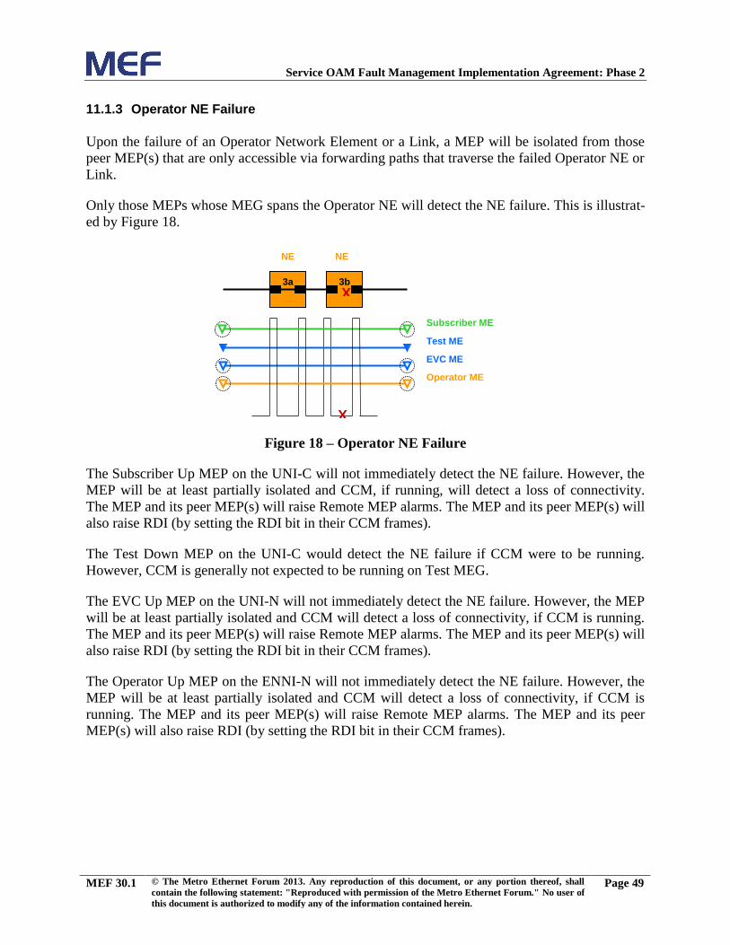
Service OAM Fault Management Implementation Agreement: Phase 2
MEF 30.1 © The Metro Ethernet Forum 2013. Any reproduction of this document, or any portion thereof, shall
contain the following statement: "Reproduced with permission of the Metro Ethernet Forum." No user of
this document is authorized to modify any of the information contained herein.
Page 49
11.1.3 Operator NE Failure
Upon the failure of an Operator Network Element or a Link, a MEP will be isolated from those
peer MEP(s) that are only accessible via forwarding paths that traverse the failed Operator NE or
Link.
Only those MEPs whose MEG spans the Operator NE will detect the NE failure. This is illustrat-
ed by Figure 18.
Figure 18 – Operator NE Failure
The Subscriber Up MEP on the UNI-C will not immediately detect the NE failure. However, the
MEP will be at least partially isolated and CCM, if running, will detect a loss of connectivity.
The MEP and its peer MEP(s) will raise Remote MEP alarms. The MEP and its peer MEP(s) will
also raise RDI (by setting the RDI bit in their CCM frames).
The Test Down MEP on the UNI-C would detect the NE failure if CCM were to be running.
However, CCM is generally not expected to be running on Test MEG.
The EVC Up MEP on the UNI-N will not immediately detect the NE failure. However, the MEP
will be at least partially isolated and CCM will detect a loss of connectivity, if CCM is running.
The MEP and its peer MEP(s) will raise Remote MEP alarms. The MEP and its peer MEP(s) will
also raise RDI (by setting the RDI bit in their CCM frames).
The Operator Up MEP on the ENNI-N will not immediately detect the NE failure. However, the
MEP will be at least partially isolated and CCM will detect a loss of connectivity, if CCM is
running. The MEP and its peer MEP(s) will raise Remote MEP alarms. The MEP and its peer
MEP(s) will also raise RDI (by setting the RDI bit in their CCM frames).
3a
NE NE
Subscriber ME Test ME EVC ME
X
3b
Operator ME
X

Service OAM Fault Management Implementation Agreement: Phase 2
MEF 30.1 © The Metro Ethernet Forum 2013. Any reproduction of this document, or any portion thereof, shall
contain the following statement: "Reproduced with permission of the Metro Ethernet Forum." No user of
this document is authorized to modify any of the information contained herein.
Page 50
12. Appendix B – VLAN Tagging Implications on SOAM Treatment [Informative]
This appendix reviews some different ways in which VLAN tagging may occur for Subscriber
Service Frames, and discusses the implications on Service OAM flows in an 802.1ad network.
Figure 19 provides the reference diagram for this discussion. Here, NE 1 and NE 6 are owned by
the Subscriber, while NE 2, NE 3, NE 4, and NE 5 are owned by a Service Provider and/or one
or more Operators.
Figure 19 – VLAN Tagging Reference Diagram
At a UNI, the Subscriber can send into the Service Provider network:
• Untagged frames, or
• C-tagged frames.
If the network receives untagged frames, the Service Provider can transform the frame in many
ways, including:
• Add a C-tag, or
• Add an S-tag, or
• Add both a C-tag and an S-tag.
If the network receives C-tagged frames, the Service Provider can transform the frame in many
ways, including:
• Continue the C-tag and not add another tag, or
• Remove the C-tag and add an S-tag, or
• Add an S-tag to the C-tag, creating a double tagged frame.
This leads to several tagging cases, illustrated in Figure 20 below:
1
2
3
5
6
Subscriber
NE Subscriber
NE Service Provider
ENNI ME
Subscriber ME EVC ME
Three OAM Flows, at different MEG Levels, within a single OAM Flow Space
Operator A NEs Operator B NEs 4

Service OAM Fault Management Implementation Agreement: Phase 2
MEF 30.1 © The Metro Ethernet Forum 2013. Any reproduction of this document, or any portion thereof, shall
contain the following statement: "Reproduced with permission of the Metro Ethernet Forum." No user of
this document is authorized to modify any of the information contained herein.
Page 51
Figure 20 – VLAN Tagging Cases
In cases A, B, C, and D, a SOAM frame is initiated by the customer, and as it flows over the data
path it continues to be processed and treated as a SOAM frame. These frames exist in the OAM
Flow Space seen by the Service Provider and Operator. Therefore, MEG Levels used at any
point can be seen by any other point in the path (subject to the IEEE 802.1Q [3] restrictions of
the extent of various MEG Levels). Stated otherwise, different parties, such as the Service
Provider and Operator, must coordinate the use of any levels that they share.
Cases E and F are different from the prior cases. The SOAM frames that were inserted in the
untagged or single-tagged portions of the path are invisible to all points that are double tagged.
This is because the double-tagged portion of the path (i.e., “the tunnel”) has hidden the fact that a
frame is a SOAM frame with the addition of a second (outer) tag. These frames do not exist in
the OAM Flow Space seen by the Service Provider and Operator. Within the double-tagging,
SOAM frames can be inserted and they can use any desired MEG Level without having to
consider the MEG Levels used by SOAM frames that use single tags.
This is illustrated for case F, in Figure 21 below:
Frame is C-tagged from Subscriber
Frame is untagged from Subscriber
S-tag (1st tag) is added by Service
Provider on entrance to network
Frame is untagged from Subscriber
S-tag (2nd
tag) is added by Service Provider within the network
C-tag is added by Service Provider on entrance to network
Frame is C-tagged from Subscriber
C-tag is continued by Service Provider
Case A:
Case B:
Case C:
Case E:
Case F:
Frame is untagged from Subscriber
C-tag (1st tag) is added by Service
Provider on entrance to network
Frame is C-tagged from Subscriber
Case D:
C-tag is removed and S-tag is added by Service Provider on entrance to network
S-tag (2nd
tag) is added by Service Provider (immediately or later)

Service OAM Fault Management Implementation Agreement: Phase 2
MEF 30.1 © The Metro Ethernet Forum 2013. Any reproduction of this document, or any portion thereof, shall
contain the following statement: "Reproduced with permission of the Metro Ethernet Forum." No user of
this document is authorized to modify any of the information contained herein.
Page 52
Figure 21 – SOAM Frame Formats

Service OAM Fault Management Implementation Agreement: Phase 2
MEF 30.1 © The Metro Ethernet Forum 2013. Any reproduction of this document, or any portion thereof, shall
contain the following statement: "Reproduced with permission of the Metro Ethernet Forum." No user of
this document is authorized to modify any of the information contained herein.
Page 53
13. Appendix C – Mapping Between 802.1Q and Y.1731 Terms [Informative]
The relationship between the relevant terms used by IEEE 802.1Q [3] and ITU-T Y.1731 [7] is
shown in Table 5.
ITU-T Y.1731 Term IEEE 802.1Q Term Comments
Maintenance Entity Group (MEG) Maintenance Association
(MA)
This document uses MEG.
Maintenance Entity Group
Identifier (MEG ID)
Maintenance Association
Identifier (MAID)
This document uses both
MEG ID and MAID.
— Maintenance Domain (MD) There is no ITU equiva-
lent of this term. This
document uses MD only
when describing the
format of a MAID.
Maintenance Entity Group Level
(MEG Level)
Maintenance Domain Level
(MD Level)
This document uses
MEG Level.
Table 5 – Terminology Mappings

Service OAM Fault Management Implementation Agreement: Phase 2
MEF 30.1 © The Metro Ethernet Forum 2013. Any reproduction of this document, or any portion thereof, shall
contain the following statement: "Reproduced with permission of the Metro Ethernet Forum." No user of
this document is authorized to modify any of the information contained herein.
Page 54
14. Appendix D – Examples of Client MEGs for Injecting AIS and LCK [Informative]
Consider the network shown in Figure 22 below:
Figure 22 – Example Network
In this example, the UNI and ENNI MEGs use untagged SOAM frames, the Operator MEGs use
S-tagged SOAM frames, and the EVC and Subscriber MEGs use SOAM frames that are C-
tagged at the UNI, and double tagged with a C-tag and an S-tag at the ENNI. As shown, there
may be several Operator MEGs in each Operator, using different S-tags. Likewise, there are a
number of EVCs and Subscribers, and hence a number of EVC MEGs and Subscriber MEGs,
each using potentially different C-tags and S-tags.
As described in Appendix B, each of these three OAM flow spaces has an independent set of
MEG Levels. If the default levels described in Table 3 are used, then each MEG has a higher
level than those shown below it in the diagram. However, if non-default levels are configured,
then it may be the case that, for example, the Operator MEGs have a lower level than the UNI or
ENNI MEGs, or that the EVC MEGs have a lower level than the Operator MEG with the same
S-VID. On the other hand, since the EVC and Subscriber MEGs are in the same OAM flow
space, the Subscriber MEG must have a higher MEG Level than the EVC MEG with the same C-
VID and S-VID.
It is possible, although highly unlikely in practice, that the EVC MEGs do not all use the same
level, and the same applies to the Operator MEGs within one operator. It is somewhat more
likely that different Subscriber MEGs use different levels.

Service OAM Fault Management Implementation Agreement: Phase 2
MEF 30.1 © The Metro Ethernet Forum 2013. Any reproduction of this document, or any portion thereof, shall
contain the following statement: "Reproduced with permission of the Metro Ethernet Forum." No user of
this document is authorized to modify any of the information contained herein.
Page 55
The client MEGs for each MEG in this example can be determined as follows. Note that concep-
tually, this determination is very simple: in each case, the client MEGs for a particular MEG are
the MEGs that appear directly above it in the figure.
For the UNI MEG, the client MEGs are the Subscriber MEGs that flow over the UNI. There
could be up to 4094 of these, each with a different C-VID. At the UNI-C, injecting an AIS
involves just sending an AIS indication, since both the UNI MEG and the subscriber MEG
have a MEP on the UNI-C. However, at the UNI-N an AIS PDU would be sent for each Sub-
scriber MEG. Note that although the Operator and EVC MEGs have MEPs at the UNI-N,
they are not client MEGs of the UNI MEG, since they do not encompass it, i.e., the SOAM
PDUs for those MEGs do not flow over the UNI.
For the ENNI MEG, the client MEGs are the EVC MEGs for the EVCs that flow over the
ENNI. There could be up to 16,760,836 of these, i.e., 4094 C-VIDs for each of 4094 S-VIDs,
although of course this upper bound is unlikely to be reached in practice10
. Injecting an AIS
at an ENNI involves sending an AIS PDU for each EVC. Note that as in the case of the UNI
MEG, the Operator MEG is not a client of the ENNI MEG, since the Operator MEG SOAM
PDUs do not flow over the ENNI. In addition, the Subscriber MEGs are not clients of the
ENNI MEG since they are not conceptually the next highest MEGs: the EVC MEGs are in
between.
For an Operator MEG using a given S-VID, the client MEGs are the EVC MEGs that flow
over that S-VID, i.e., whose SOAM frames have an outer tag containing that S-VID. There
could be up to 4094 such EVC MEGs, each with a different C-VID. At the UNI-N, both the
Operator MEG and the EVC MEGs have a MEP, and hence injecting an AIS involves just
sending an AIS indication. At the ENNI, the EVC MEGs do not have a MEP and so injecting
an AIS involves sending an AIS PDU for each EVC MEG with the matching S-VID.
For an EVC MEG using a given S-VID and C-VID, there is a single client MEG, i.e., the
Subscriber MEG that uses the same S-VID and C-VID. In this case since the two MEGs are
within the same OAM Flow Space, the Subscriber MEG must have a higher level. There is
no Subscriber MEP at the UNI-N, and so injecting an AIS involves sending an AIS PDU at
the Subscriber MEG Level, for the single Subscriber with the matching S-VID and C-VID.
The Subscriber MEG is conceptually the highest MEG, and hence has no client MEGs and
never injects AIS.
10
In fact, in the most common deployment scenario, the EVC MEG would use S-tagged, not double-tagged, SOAM
frames and hence the ENNI MEP would only need to insert up to 4094 AIS PDUs. The example given in this
appendix is somewhat contrived, in order to cover all the possible cases.