service news-lmasc
TRANSCRIPT

Previous Page Table of Contents Next Page

PRODUCT SUPPORT
J. L. GAFFNEY — DIRECTOR
FIELD SUPPLY TECHNICAL RM&S CUSTOMERSUPPORT SUPPORT PUBLICATIONS DESIGN TRAINING
J. D. Adams J. L. Bailey G. M. Lowe H. D. Hall S. S. Clark
In Support of the Hercules OperatorThe Hercules has enjoyed an outstanding history of over 40
years, something everyone associated with this aircraft should beproud of. In many ways the C-130 Hercules is unique, but as any-one who has ever worked with airplanes understands, an aircraft’soperation and performance are totally dependent on the programsset up to support it. In this, the Hercules is no different.
In 1978, a small group of dedicated individuals created anorganization intent on developing electronic ground support equip-ment specifically for Lockheed aircraft. This organization evolvedover the years to become the Lockheed Martin Electronic SupportEquipment Engineering Department. Today, we not only continue tobuild the very best in electronic support equipment, but we are alsoable to offer our professional services to Hercules customers in otherareas, including the design and development of electronic flyinghardware, avionics repair, aircraft battery servicing, and the develop-ment of aircraft wiring formboards.
Aircraft operators today face economic and technological chal-lenges that were unknown a decade ago. As budgets tighten, owners and operators increasingly findthat they cannot afford the luxury of paying high prices to outside contractors for maintenance services.The economic advantages of doing maintenance work in-house, whenever possible, are becomingmore and more apparent. At the same time, modern electronic systems are getting more complex, andrequire more sophisticated test equipment and more highly skilled technical personnel to maintain.
The Electronic Support Equipment Engineering Department is in a position to offer our customersseveral options for solving this dilemma. The first is our line of highly automated test equipment. Ourphilosophy is to manufacture portable, software-driven, automatic test equipment that tests the equip-ment for which it is designed thoroughly, but is at the same time convenient and straightforward to use.In this issue of Service News, Scott Lavender describes a new test set for checking encoding altime-ters and altitude alerters.This microprocessor-based tester is an excellent example of a design thatcombines sophisticated troubleshooting efficiency with ease of operation.
A second option is our expert repair service. The Electronic Support Equipment EngineeringDepartment includes a group that specializes in avionic component overhaul and repair, as well as pre-cision calibration of customer equipment. These expert engineers and technicians have the resourcesto ensure the quickest possible response time, whether the repair is routine or AOG. Our large inven-tory of spare parts allows us to offer unusually rapid turnaround time, and continuous on-site qualityassurance inspection ensures that all work is performed to the highest quality standards.
The third option we make available to customers is our wide range of capabilities as a full-serviceorganization. It is our business to offer to you the broadest possible spectrum of problem-solvingknowhow, and this is an area where we think we excel. Elsewhere in this issue, Don Coia describes inmore detail some these capabilities and a few of the services we can provide.
Dedicated to the support of the C-130 and all of Lockheed’s aircraft, we constantly strive to besensitive to the needs of each of our customers. Although the Electronic Support EquipmentEngineering Department has grown considerably over the years, its overall goals have not changed.The same vision seen in 1978, to support the customer with professional services and quality products,remains the underlying objective of each individual within our department today.
Sincerely,
Mike Fortenberry, ManagerElectronic Support EquipmentEngineering Department
Vol. 22, No. 2, April - June 1995
CONTENTS
2 Focal PointMike Fortenberry, ManagerElectronic Support EquipmentEngineering Department
3 Setting The Hercules Parking BrakeProper engagement of the parking brake is the key to keeping your air-craft securely in place on the ramp.
5 The Encoding Altimeter/Alerter AnalyzerA versatile new test set provides quickand accurate testing for a crucial aircraft instrumentation system.
7 Bleed Air Duct CorrosionImproved materials, new procedureshelp bring a duct corrosion problem under control.
11 Electronic Support EngineeringThis multifaceted, customer-oriented engineering organization offersa unique array of specialized services.
Covers: Based at Hickham AFB, a newC–130H operated by the 204th AirliftSquadron, Hawaii Air National Guard, is putthrough its paces against a backdrop of thePacific island chain’s storied natural beauty.
Cover photographs by John Rossino.
Service Newsis published by Lockheed Martin AeronauticalSystems, a unit of Lockheed Martin Corporation. The informationcontained in this issue is considered by Lockheed Martin to beaccurate and authoritative; it should not be assumed, however, thatthis material has received approval from any governmental agencyor military service unless specifically noted. This publication isintended for planning purposes only, and must not be construed asauthority for making changes on aircraft or equipment, or as super-seding any established operational or maintenance procedures orpolicies. Written permission must be obtained from LockheedMartin Aeronautical Systems before republishing any material inthis periodical. Copyright 1995, Lockheed Martin Corporation.
Address all communications to Editor, Service News,Department 66-14, Lockheed Martin Aeronautical Systems,Marietta, GA 30063-0601. Tel. 770-494-2100; Fax 770-494-1017.
EditorCharles I. Gale
Art DirectionAnne G. Anderson
Mike Fortenberry
LOCKHEED MARTINAERONAUTICAL SYSTEMS
A SERVICE PUBLICATION OFLOCKHEED MARTINAERONAUTICAL SYSTEMS
Focal Point
Previous Page Table of Contents Next Page

The function of the parking brake system on theHercules aircraft is to hold the aircraft in posi-tion for short-term parking. Proper setting of this
system is extremely important to prevent the aircraftfrom rolling prior to installing wheel chocks after flightand during post-maintenance engine runs. If the aircraftis to be parked for longer periods of time, wheel chocksmust be used. The appropriate maintenance manualshould be consulted for complete information on prop-er wheel chock usage.
The parking brake T-handle is located in front ofthe pilot’s seat and to the right of the pilot’s foot rest.When the handle is pulled, a flexible cable pulls a pawlplate into a detent in the brake control levers to lock thepedals in a brakes-on position. With the brake controllevers locked in this position, and the anti-skid switchin the ON position, a solenoid in the anti-skid valve willbe deenergized to block the return port of the anti-skidvalve. This ensures that the hydraulic pressure requiredby the parking brake will be maintained for a period oftime after power is removed from the aircraft to allowfor the placement of wheel chocks.
Some Hercules operators have reported incidentswhere their aircraft have rolled after having set theparking brake. Subsequent investigations of theseevents have revealed that the parking brake was notproperly set.
Setting the Parking Brake
In order to set the parking brake properly, a partic-ular set of steps is required:
1. Ensure that the auxiliary hydraulic pump is
3Lockheed Martin SERVICE NEWS V22N2
PARKING BRAKE !Setting the Herclues
PARKING BRAKE !PARKING BRAKE !
by Michael R. Jones, Aircraft Design Engineer, SeniorC-130 Flight Controls Department
PARKING BRAKE !PARKING BRAKE !PARKING BRAKE !
Previous Page Table of Contents Next Page

switched on and that the auxiliary andemergency brake system gages readapproximately 3000 psi.
2. Place the emergency brake selector switchin the EMERGENCY position.
3. Fully depress the toe section of the rudderpedals. Monitor the emergency brake sys-tem pressure gage for a momentary dip inpressure as the parking brake is applied.
4. Pull the parking brake T-handle to its stop.
5. Slowly release the brake pedals while con-tinuing to pull on T-handle.
6. Verify that the parking brake is set by light-ly pressing on the toe section of the rudderpedals. If the brake is properly set, the ped-als will have a solid feel and resist the toepressure; if it is not, they will depress easi-ly and spring back to the “brakes off” posi-tion.
These steps must be followed exactlyto ensure thatthe pawl plate engages the detent in the brake controllevers. If these steps are not followed, it is possible forthe pawl plate to miss the detent and rest on the lip ofthe detent.
Should this occur, there may be a false sense thatthe brakes are set, when in reality they are not. Oneresult can be that the parking brake will later releaseinadvertently. Another possibility under these circum-stances is that the solenoid valve which blocks thereturn port of the anti-skid control valve will fail todeenergize. Unless the hydraulic pumps happen to beoperating, the pressure in the braking system will thensoon bleed down, allowing the aircraft to roll.
Verifying Brake Engagement
Remember that the most important step in settingthe parking brake is to check for proper engagement byapplying light pressure to the toe section of the rudderpedals. The presence of solid resistance to the effort todepress the pedals confirms that the brakes are correct-ly set. Never attempt to verify parking brake engage-ment by tapping on the T-handle. This can result indamage to the parking brake flexible cable.
Application of the parking brake in the Herculesaircraft is basically a straightforward procedure thatachieves positive, reliable results. Rigorous adherenceto the steps described above will give the parking brakea chance to do the job it is designed to do, and avoid thepotentially costly consequences of suddenly finding anunsecured aircraft in motion on the ramp.
Mike Jones may be reached at 770-494-3343.
4 Lockheed Martin SERVICE NEWS V22N2
The parking brake control assembly, with brake mechanism disengaged, and (right) engaged.
Previous Page Table of Contents Next Page

he integrity and accuracy of both the encodingaltimeter and altitude alerter are essential to theproper flight operations on board many versions
of the Hercules aircraft. The digitally encoded altitudedata output provided by the encoding altimeter is usedby IFF and ATC systems and by some area/inertial nav-igation systems. The coarse and fine synchro signal out-puts representing the current barometric altitude of theaircraft are used by the altitude alerter which controlsthe altitude select mode of the flight director. It is there-fore vital that these altitude signals be tested and veri-fied to ensure the proper operation of the other depen-dent systems.
Lockheed Martin Aeronautical Systems has dev-eloped a new, multifunction test set for testing theencoding altimeter and altitude alerter used on C-130Eand C-130H aircraft. The Encoding Altimeter/AltitudeAlerter Analyzer, PN ES125030-1, is designed for useon board the aircraft and in the shop environment inconjunction with such typical ancillary equipment as acalibrated air pressure source and digital voltmeter.
Multifunction Capabilities
When used for testing the encoding altimeter, thetest set converts the encoded altitude Gray code into ausable binary code that drives a five-digit display repre-senting altitude in feet. The operator can then comparethe analyzer’s display with the actual altimeter to deter-mine if the altimeter is functioning and to evaluate itsaccuracy. The coarse and fine synchro outputs are con-verted with synchro-to-digital circuitry and displayed asdegrees with 0.1 degree resolution. The user can selectwhich synchro signal, coarse or fine, is displayed.
As an altitude alerter test set, the operator sets thedesired altitude on the alerter. The operator can thenchange the simulated altitude on the test set in 10-footincrements. Circuitry within the test set performs a dig-ital-to-synchro conversion, and outputs both the coarseand fine synchro signals to the alerter. Functional test-ing is performed by stepping the test altitude from aboveand below the set altitude while monitoring the alerteroutput.
5Lockheed Martin SERVICE NEWS V22N2
by Scott T. Lavender,Senior Electronics EngineerElectronic Support Equipment Engineering Department
T
Courtesy Wyoming Air National Guard
The Encoding Altimeter/AlerterAnalyzer
A New Multi-Purpose Test Set:
The Encoding Altimeter/AlerterAnalyzer
Previous Page Table of Contents Next Page

This test set can also be used as an analyzer. In theanalyzer mode, the test set serves as the source ofencoded altitude. This operator-controlled, encodedaltitude signal allows the testing of all aircraft systemsthat require encoded altitude independently of analtimeter or static pressure source.
The Encoding Altimeter/Altitude Alerter AnalyzerTest Set is supplied with all the cables necessary forinterfacing with the following components:
ALTIMETERS
B451521002 518-28007-204B451521003 518-28007-921B451521004 518-28007-923
ALTITUDE ALERTERS
540-25100-004540-25100-005
An additional cable is included for connecting thetest set to the aircraft when it is being used as an ana-
lyzer. Cables are also provided for connection to bothshop and aircraft power.
Further Information
For further information concerning this test set,please contact:
(U.S. Government)Lockheed Martin Aeronautical SystemsCustomer Supply Business ManagementDept. 65-11Marietta, GA 30063-0577Telephone: 1-770-494-7529Fax: 1-770-494-7657
(International and Commercial)Lockheed Aeronautical Systems Support CompanyP.O. Box 121Marietta, GA 30061-0121Telephone: 1-770-431-6664Fax: 1-770-431-6666
Scott Lavender can be contacted at 770-916-2642.
6 Lockheed Martin SERVICE NEWS V22N2
The Encoding Altimeter/Alerter Analyzer, PN ES125030-1
Previous Page Table of Contents Next Page

Several important systems of the Hercules airlifter,including the engine starting system and the en-vironmental control system, depend upon com-
pressed air for their operation. These pneumaticallypowered systems can be supplied by the APU/GTC orfrom ground sources before the main engines are start-ed. During normal operation with the engines running,however, these same systems are powered by hot com-pressed air which is “bled” (hence the term bleed air)from the 14th stage of the engine compressors.
Operating Parameters
Each engine can provide approximately 155pounds of air flow per minute at 635F and 125 poundsper square inch of gage pressure. The combined outputof the four engines is more than enough to supply all thepneumatic requirements of the airplane.
In the mid-1970s, a bleed air regulator and shutoffvalve was added in each nacelle. The purpose of thesevalves is to reduce the operating pressure in the bleedair ducting system. During wing and empennage anti-icing operation, the regulation mode of these valves canbe overridden to provide the higher bleed air pressuresand temperatures that are required.
Duct Design
As can be seen from the foregoing, the bleed airducts are exposed to significant amounts of both heatand pressure, and must therefore be strongly construct-ed, free of leaks, and well insulated. In the Hercules air-craft, these ducts have typically been made of stainlesssteel tubing covered with insulation and encased in anintegral phenolic fiberglass shell. This design has his-torically provided a highly satisfactory combination of
7Lockheed Martin SERVICE NEWS V22N2
by Dave Jefferies,Staff EngineerStructural Integrity Engineering Department
Previous Page Table of Contents Next Page

strength, light weight, and durability that are requiredfor this type of application.
Bleed Air Ducts
The bleed air sources in the engine nacelles areconnected to the pneumatic systems and to each otherby insulated metal ducts. The most significant sectionsof the ducting are as follows:
1. The bleed air manifold. This is the mainduct which extends across the front beam ofthe wing and interconnects the bleed airoutlets from the engine compressors. Thismain duct also supplies air to the wing anti-icing system.
2. Ducting routed forward from the bleed airmanifold to the flight station air condition-ing.
3. Ducting routed aft from the bleed air mani-fold to the empennage anti-icing system.
4. Ducting routed through the right wheel wellto the cargo compartment air conditioningsystem and underfloor heating system.
5. Ducting routed through the left wheel welland on down to the APU and the groundhigh-pressure air connection.
Duct Failures
Sudden rupture of a bleed air duct has the poten-tial to cause significant damage to the structure,wiring, and cables in the area adjacent to where thebreak occurs. There is also the possibility of the loss,or partial loss, of functionality in important systemssuch as the environmental control system and the anti-icing systems.
The bleed air system installed in C-130 aircrafthas performed satisfactorily for many years. In themid-1980’s, however, Lockheed began receivingreports of sudden bleed air duct failures from the field.Although the number of cases was small, LockheedField Support and Engineering personnel immediatelyfocussed their efforts on finding the cause of theseincidents.
These studies soon produced clear indicationsabout the origin of the problem. In all cases of ductfailure that have been subjected to metallurgicalexamination at Lockheed Martin, the cause has beentraced to corrosion sites along the welded seams of thestainless steel tubing used for fabrication of the duct.
Duct Redesign
In order to eliminate any potential for future ductcorrosion, Lockheed redesigned the high-pressureducting using Inconel 625 in lieu of the type 321 stain-less steel. These Inconel ducts were incorporated intoproduction aircraft Lockheed serial numbers LAC5271, 5276, and 5283 and up, and are now available forreplacement ducting on previously delivered aircraft.
Maintenance Actions
Lockheed Martin Engineering has developed twooptions to assist operators in maintaining the integrityof the bleed air ducting on delivered aircraft. Oneoption provides for the systematic inspection of thestainless steel bleed air ducts at specified intervals. Thesecond option is a combination of duct replacementusing the new Inconel 625 ducts and periodic inspec-tion of the remaining type 321 stainless steel ducting.
These inspection requirements and replacementInconel ducts for delivered aircraft are published inService Bulletin 382-36-5/B2-637, which applies toFAA-certified aircraft and military C-130 aircraft pur-chased directly from Lockheed Martin. The inspection
8 Lockheed Martin SERVICE NEWS V22N2
Weakened by corrosion, this duct ruptured under pressure.
Previous Page Table of Contents Next Page

9Lockheed M
artin SE
RV
ICE
NE
WS
V22N
2
Previous P
age Table of Contents N
ext Page

procedure for the ducts requires removal of the phe-nolic fiberglass shell and insulation shown in the illus-tration above.
The shell and insulation must be removed to gainaccess to the external surface of the stainless steel ductto permit a thorough visual inspection. The need for thisaccess is dictated by the fact that the corrosion sitesidentified in previous cases of duct failure clearly beganon the exterior surface of the stainless steel tubing.
Complete procedures for bleed air duct insulationremoval and inspection are all contained in the servicebulletin. Operators are encouraged to report theirinspection findings to the factory to help provide asbroad a data base as possible on this subject. LockheedMartin Engineering will continue to evaluate thesefindings and issue appropriate revisions to the servicebulletins when justified.
The U.S. Air Force has addressed the question ofbleed air duct corrosion by issuing a technical orderrequiring the replacement of certain ducts while retain-ing their current inspection requirements. This order,TCTO 1C-130-1397, is applicable to certain C-130 air-craft purchased by the USAF, either directly or underthe FMS program.
A Note on Parts Listings
A complete listing of the available replacementInconel duct part numbers, aligned with the 321 stain-less steel part numbers, is contained in the latest avail-able revision of Service Bulletin 382-36-5/62-637.
The operator should establish a list of the ducts thatare actually installed on his aircraft, either from theapplicable IPB or directly from the aircraft. He maythen determine if an Inconel replacement duct is avail-able by consulting the listing provided in ServiceBulletin 382-36-5/82-637.
When requesting a price quote from LockheedMartin for Inconel ducts by part numbers, the correctselection of the replacement ducts can be verified if theoperator also submits the listing of the stainless steelducts on his aircraft.
Attention to these procedures will help avoiddelays and confusion in assisting operators with theirorders. Lockheed Martin retains records of the deliv-ered configuration of each aircraft; however, the currentconfiguration status may differ due to operator-installedmodification or part replacements.
To order Lockheed Martin-approved bleed airducts, please contact the following:
(U.S. Government)Lockheed Martin Aeronautical Systems Customer Supply Business ManagementDepartment 65-11Marietta, GA 30063-0577Telephone: 404-494-7529Fax: 404-494-7657
(International and Commercial)Lockheed Aeronautical Systems Support Co.P.O. Box 121Marietta, GA 30061-0121Telephone 404-431-6664Fax 404-431-6666
The author and Service Newswish to extend spe-cial thanks to Doug Hamilton of Lockheed MartinEngineering for his valued advice and assistance in thepreparation of this article. We also wish to thank DaveWetzel, who appears in the illustration on page 7.Photographic support was provided by Rita King.
For operator assistance, please contact Dave Wetzel,Lockheed Aeronautical Systems Support Co., 770-431-6551 (voice) or 770-431 6556 (fax).
10 Lockheed Martin SERVICE NEWS V22N2
The application of insulation and insulation covering tobleed air ducts.
Previous Page Table of Contents Next Page

During modifications and updates to the famousC-130 Hercules and other Lockheed Martinaircraft, many different types of problems can
arise. Typical problems encountered by the aircraftmanufacturer in connection with electronic equipmentupgrades include testing and integrating the updatedequipment in a laboratory environment, interfacing thenew systems with existing aircraft systems, and effi-
cient design, fabrication, and functional testing of newwire harness assemblies for use in installing these sys-tems into the aircraft.
To maintain Lockheed Martin’s reputation for thequality and the supportability of its aircraft, it is impor-tant to identify the electronic support equipment that isneeded to sustain the new systems at all maintenancelevels as soon as the decision to incorporate them ismade. For customers who do not have repair capabili-ties, or who choose to farm out their maintenance work,it is also necessary to identify qualified repair facilitiesable to service their installed equipment when needed.
Providing Solutions
For solutions to many of these aircraft problems,Lockheed Martin does not have to look further than afew miles down the road from its huge airframe pro-duction facility in Marietta, Georgia, where the C-130is assembled. The Lockheed Martin Aeronautical
11Lockheed Martin SERVICE NEWS V22N2
ElectronicSupport EquipmentEngineeringby Don Coia, Lead EngineerElectronic Support Equipment Engineering Department
ElectronicSupport EquipmentEngineering
Repairing an AC generator control panel, using the PN 3402749-5 test set.
Previous Page Table of Contents Next Page

Systems Electronic Support Equipment EngineeringDepartment, located on nearby New Market Parkway,not only designs and produces electronic support equip-ment, but is also a valued team member experienced inproviding expert solutions for problems encounteredduring aircraft system upgrades and modification.
Led by Mike Fortenberry (please see the FocalPoint article, page 2 of this issue), the Departmentoffers unique expertise in the following areas:
• Electronic Support Equipment
• Electronic Equipment Design
• FAA Certified Repair
• Aircraft Wire Harness Layouts
Our department’s capabilities in these areas benefitsignificantly from its close, ongoing relationship withmany different aircraft operators worldwide. Engineersfrom our department regularly travel to customer facil-ities to demonstrate equipment and experience firsthandthe individual customer’s and unique aircraft or equip-ment maintenance problems. Let us take a closer look atthe scope of our organization’s capabilities.
Electronic Support Equipment
The Electronic Support Equipment EngineeringDepartment designs and fabricates test equipment toanalyze and diagnose electrical and electronic systemson the C-130 and other Lockheed aircraft at all mainte-nance levels: organizational, intermediate, and depot.From the very first Hercules to the state-of-the-artC–130J, these test sets support every version of this
versatile airlifter with the professionalism, exper-tise, and quality that has always been a trademarkof Lockheed Martin Aeronautical Systems prod-ucts. The Department’s capabilities also extendwell beyond the production of individual test sets,and include the ability to provide our customerswith complete avionics maintenance complexes.
The quality and timeliness of the test equip-ment we manufacture is further enhanced by thecomprehensive knowledge gained by our engi-neers during the development phases of the vari-ous models of the C-130. When new versions ofthe Hercules aircraft reach the customer, all newtest sets required, as well as any upgrades neededfor existing test sets, will be ready and available.The current development of new test equipmentfor the C-130J is a good example of this, and itleads us to our next topic.
Electronic Equipment Design
During the development of new versions ofthe C-130, or upgrades of previous versions of anyLockheed aircraft, there are often requirements forsystem hot mockups for engineering and systemintegration labs. The Electronic Support Equip-ment Engineering Department has designed,updated, and fabricated such mockups for manyversions of the C-130, including every electricaland electronic system being incorporated in theC–130J. The department has also been responsiblefor the design and fabrication of system develop-ment labs for upgrades of the P-3 and S-3 aircraft.
12 Lockheed Martin SERVICE NEWS V22N2
The AP-105/FD-109 Integrated System Test Set: C-130 field level.
Previous Page Table of Contents Next Page

The integration of new systems sometimes requiresthat special new electronic boxes be designed. TheDepartment’s engineers provide the expertise and capa-bility to design the required circuits, and build produc-tion-quality equipment in time to meet aircraft assem-bly or modification schedules. The Threat WarningLamp Driver Unit and the ALE-47 Bypass Inverter areexamples of devices which were developed to performspecific functions in conjunction with current C-130defensive systems. Currently, an audible fire warningunit is being developed to provide C-130 pilots with anaudible warning notification in their headsets in case ofan engine fire.
Repair
All Hercules electrical and electronic systems areimportant, and some are truly critical. For more than 35years, Lockheed Martin’s engineering departmentshave maintained programs that specifically address therepair and testing of aircraft parts in support ofLockheed Martin aircraft. The repair capabilities weoffer include virtually every electrical and elec-tronic component used on our aircraft, rangingfrom intercom systems to critical power genera-tion and distribution systems. Radar, navigational,instrument landing systems (ILS), and radio com-munication systems are also fully supported.
As a certified FAA repair facility, theDepartment maintains the expertise and resourcesneeded to service all types of components andequipment. This includes everything from basictroubleshooting to complete “reverse engineering”redesign to accomplish repair or replacement ofobsolete parts. The Department specializes in pro-viding the state-of-the-art testing, engineeringexpertise, and professional technical support need-ed in today’s demanding aircraft environment.
Wire Harness Layouts
During the production of the C-5B, the needarose for laying out wire harness formboardsquickly and efficiently. Acknowledged as expertsin printed circuit layouts, the Department wastasked to develop a computerized process forformboard layouts. The process which was devel-oped met all requirements while greatly cuttingdevelopment time and cost.
In recent years, many enhancements havebeen incorporated to keep abreast of layout form-
board manufacturing needs. These include the automa-tion of a functional test program for testing assembliesand developing a process by which boards could bereconfigured quickly for use with different assemblies.Since the inception of our program, we have designedthousands of layouts for the C-5B and C-130 aircraft.Thanks to our organization’s efforts in this area, thetime, space, and budget requirements for the productionof aircraft wire harness assemblies have been signifi-cantly reduced.
The Synergy of Expertise
Each of the four areas of expertise within theElectronic Support Equipment Engineering Departmentcomplement one another to create an efficient, knowl-edgeable, and uniquely synergistic organization. Withthe knowledge gained from our experience in the repairsector, the department is able to design better test setsand associated manuals. The knowledge gained fromdesigning and fabricating test sets improves designs forspecial electronic hardware and hot mockups for system
13Lockheed Martin SERVICE NEWS V22N2
The PN ES125051 Instrumentation Test Set: multi-aircraft,organizational level.
Previous Page Table of Contents Next Page
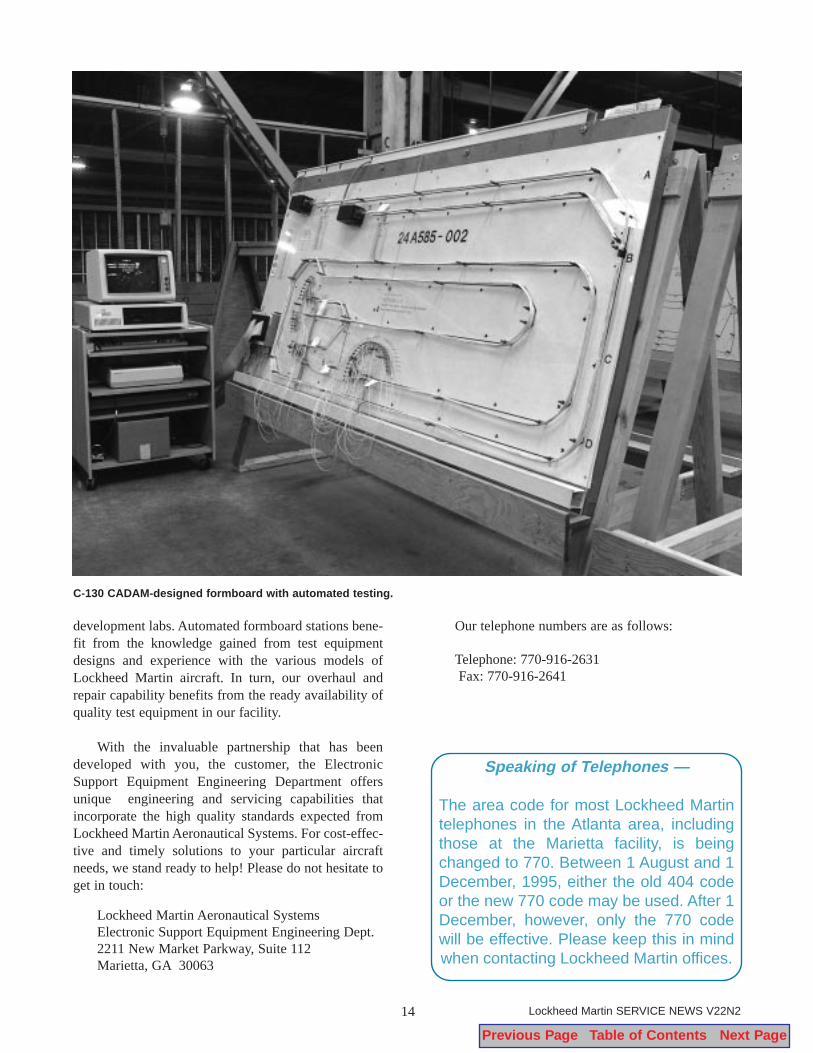
development labs. Automated formboard stations bene-fit from the knowledge gained from test equipmentdesigns and experience with the various models ofLockheed Martin aircraft. In turn, our overhaul andrepair capability benefits from the ready availability ofquality test equipment in our facility.
With the invaluable partnership that has beendeveloped with you, the customer, the ElectronicSupport Equipment Engineering Department offersunique engineering and servicing capabilities thatincorporate the high quality standards expected fromLockheed Martin Aeronautical Systems. For cost-effec-tive and timely solutions to your particular aircraftneeds, we stand ready to help! Please do not hesitate toget in touch:
Lockheed Martin Aeronautical SystemsElectronic Support Equipment Engineering Dept.2211 New Market Parkway, Suite 112Marietta, GA 30063
Our telephone numbers are as follows:
Telephone: 770-916-2631Fax: 770-916-2641
14 Lockheed Martin SERVICE NEWS V22N2
C-130 CADAM-designed formboard with automated testing.
Speaking of Telephones —
The area code for most Lockheed Martintelephones in the Atlanta area, includingthose at the Marietta facility, is beingchanged to 770. Between 1 August and 1December, 1995, either the old 404 codeor the new 770 code may be used. After 1December, however, only the 770 codewill be effective. Please keep this in mindwhen contacting Lockheed Martin offices.
Previous Page Table of Contents Next Page

15Lockheed Martin SERVICE NEWS V22N2
Lockheed Classics:
The EC-121 Constellation by Terry Linehan, Service Analyst
Lockheed Aeronautical Systems Support Company
Wing Span - 123' Power Plants - Four Curtis-WrightLength - 116'2" R3350-42 reciprocating enginesHeight - 24'9" Max. Speed - 295 knotsGross Weight - 152,500 lbs. Cruising Speed - 190+ knots.Empty Weight - 93,000 lbs. Service Ceiling - 27,500'
This aircraft, a variant of the Lockheed Super Constellation, was operated by the U. S. Navyand, together with the similar USAF RC-121, provided the early warning radar screenaround the Arctic during the height of the Cold War. The main detection equipment was
housed in two large radomes, one below the center section, and the other on top of the fuselage.The “Connie” was uniquely suited for this mission because its tall landing gear provided ade-quate ground clearance for the lower dome. In addition, by increasing the height of the triple finand rudder configuration, the designers were able to offset the stubborn directional stabilityinduced by the large upper radome. The EC- and RC-121s, which performed their vital missionfaithfully for more than 20 years, were gradually phased out of service in the late 1970s.
Photo courtesy of Robert E. HerndonTerry Linehan may be reached at 770-431-6594.
Previous Page Table of Contents Next Page

Aeronautical SystemsCustomer Training Systems DepartmentLockheed Martin – LMASMarietta, GA 30063-0601
Previous Page Table of Contents Next Page